
SECTION 12A - BATTERY & CABLES
CAUTION:
This vehicle will be equipped with a Supplemental Restraint System (SRS). A SRS will consist of either
seat belt pre-tensioners and a driver’s air bag, seat belt pre-tensioners and a driver’s and front
passenger’s air bags or seat belt pre-tensioners, driver’s and front passenger’s air bags and left and
right-hand side air bags. Refer to SAFETY PRECAUTIONS, Section 12 M Supplemental Restraint System
in the VT Series I Service Information before performing any service operation on, or around any SRS
components, the steering mechanism or wiring. Failure to follow the SA FETY PRECAUTIONS could
result in SRS deployment, resulting in possible personal injury or unnecessary SRS system repairs.
CAUTION:
This vehicle may be equipped with LPG (Liquefied Petroleum Gas). In the interests of safety, the LPG fuel
system should be isolated by turning 'OFF' the manual service valve and then draining the LPG service
lines, before any service work is carried out on the vehicle. Refer to the LPG leaflet included with the
Owner's Handbook for details or the appropriate Section of this Service Information CD for more specific
servicing information.
1. GENERAL INFORMATION
All models in the VT Series II range of vehicles are fitted with a 12 volt low maintenance battery, with a Rated
Reserve Capacity of 95 minutes and a Rated Cold Cranking Current of 400 amps minimum. This battery is the
same as that fitted to VT Series Berlina and Calais with a V6 engine, and all VT Series models with a V8 engine.
Details of this battery are contained in Section 12A BATTERY & CABLES in the VT Series I Service Information.
Details on the battery charging system are contained in Section 6D1-1 CHARGING SYSTEM — V6 ENGINE or
Section 6D3-1 CHARGING SYSTEM — GEN III V8 ENGINE in the VT Series II Service Information.
Techline
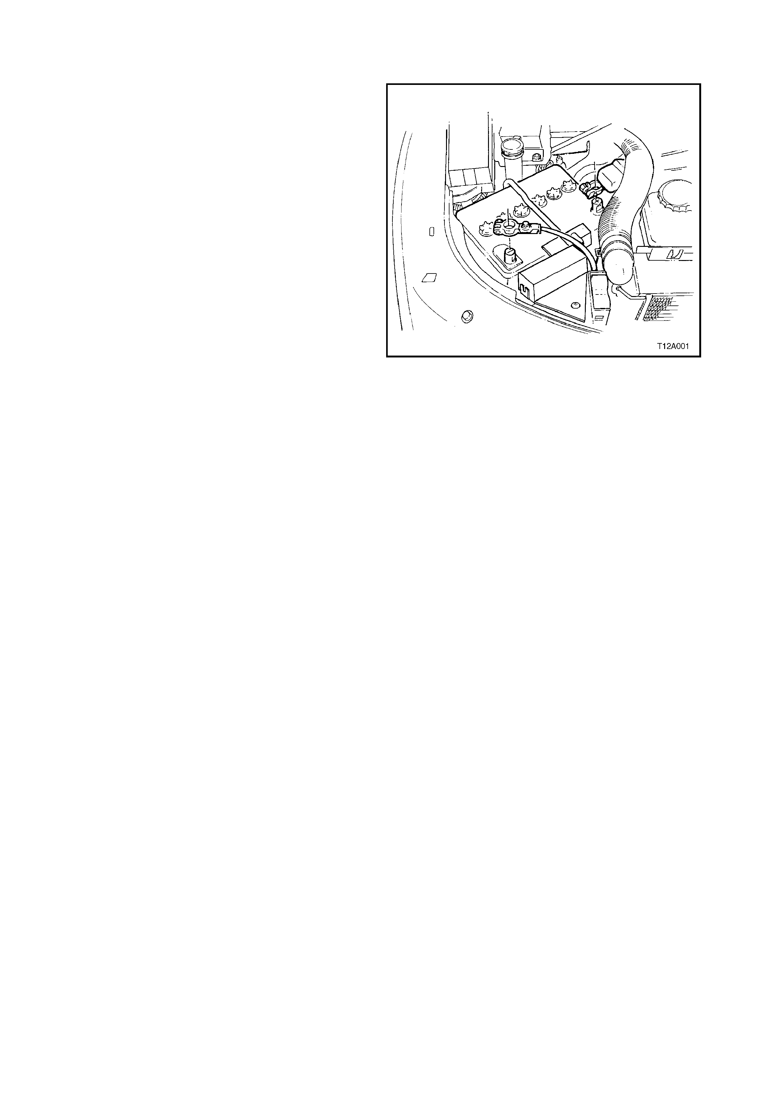
1.1 GENERAL DESCRIPTION
In all VT Series II models, the 12 volt battery is
located in the engine compartment behind the
driver’s side headlamp, refer to Fig. 12A-1. The
battery cables are attached to the battery terminals
by nut tightened clamps. The negative terminal is
earthed to the vehicle body at the fender inner
panel stud, and to the engine (at right-hand engine
mounting bracket for V6 engine and to the engine
block, forward of the right-hand engine mounting
bracket for the GEN III V8 engine).
The battery has four major functions in the vehicle
electrical system:
1. Provide a source of energy for cranking the
engine.
2. Acts as a voltage stabiliser for the electrical
system.
3. It can, for a limited time, provide energy when
the electrical load used exceeds the output of
the generator.
4. Provides power for accessories when the
engine is not running.
Figure 12A-1


2. SERVICE OPERATIONS
CAUTION: Do not allow liquid from battery to
contact eyes, skin, clothing or painted surfaces.
Battery fluid contains sulfuric acid which
causes injury and damage in the event of
contact. In the event of an accident, flush area
immediately with large amounts of water. Also,
in the case of eye contact, see a physician
immediately.
Lead acid batteries produce ex plosive gases. Keep
sparks, flames and lighted cigarettes away from
battery when charging or working around battery
area in an enclosed area. Failure to follow this
warning could cause the battery to explode.
Take care with all metal objects including items of
jewellery (rings and metal watch bands) and tools
when working near battery term inals. Metal objects
that touch a battery term inal can cause spark s and
serious heat burns to the user or wearer.
Ensure that the ignition is switched off when
connecting or disconnecting battery cables, battery
chargers or jumper cables. Failing to do so may
damage vehicle electronic components.
It is advisable to always disconnect the battery
negative cable from the battery first, and connect it
to the battery last, to avoid the possibility of shorting
to earth with the spanner while working on the
connections of the positive cable. Spanners
shorting to earth from either end of the positive
cable would carry high amperage and heat quick ly,
causing serious burns to the hand.
2.1 BATTERY INSPECTION
The battery inspection details are contained in
Section 12A BATTERY & CABLES in the VT
Series I Service Information.
If battery water usage is considered excessive and
inspection reveals that the battery case is OK, the
generator may be overcharging. Check generator
output as described in Section 6D1-1 CHARGING
SYSTEM — V6 ENGINE or Section 6D3-1
CHARGING SYSTEM — GEN III V8 ENGINE in
the VT Series II Service Information.
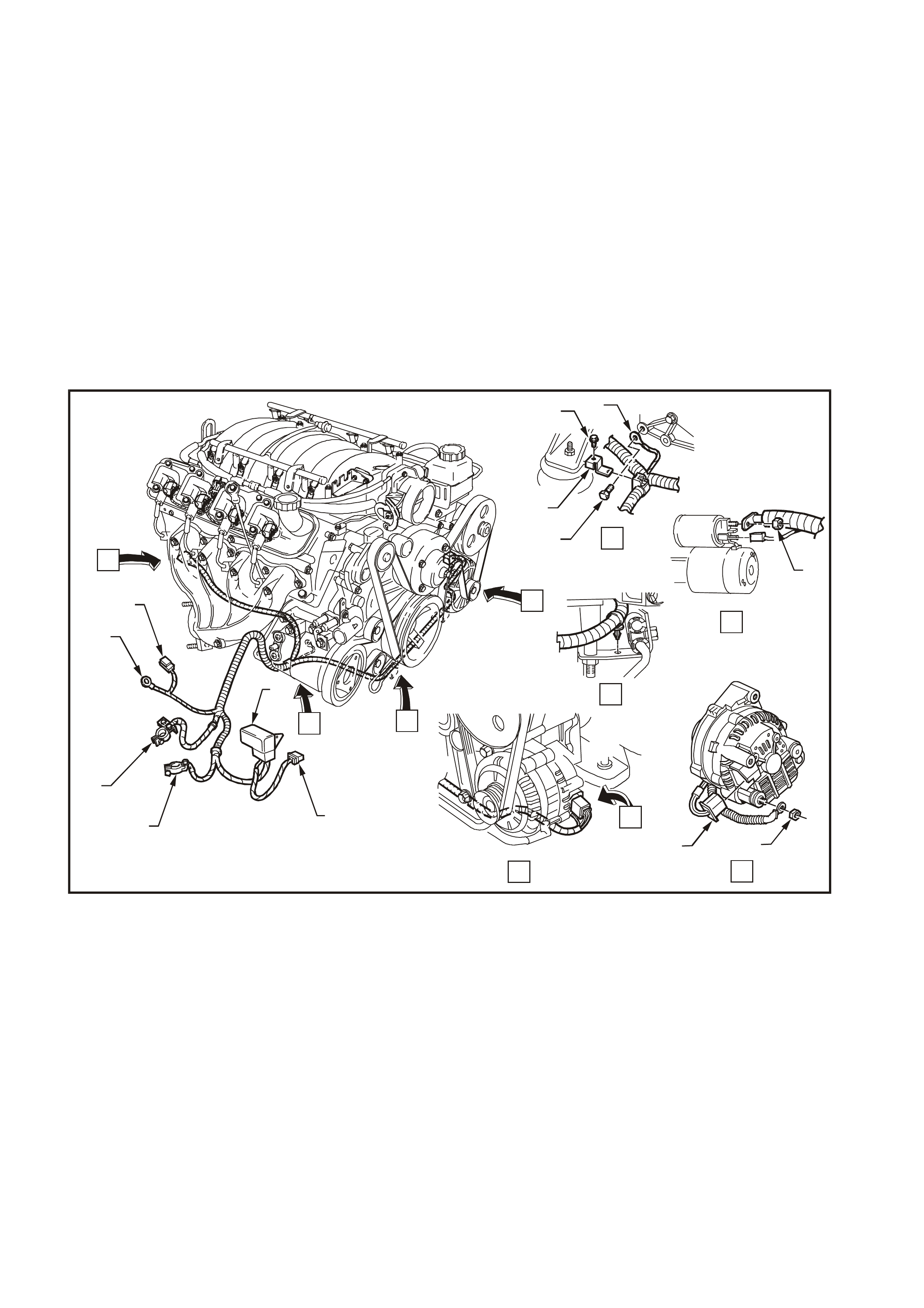
The engine battery harness installation details for
all VT Series Models with a V6 engine are
contained in Section 12A BATT ERY & CABLES in
the VT Series I Service Information. T he details for
a GEN III V8 engine are shown in Fig. 12A-2.
T212A005
13
12
11
10 9
76
8
3
4
2
1
5
A
B
C
DE
B
AC
D
E
Figure 12A-2
1. Harness bracket-to-engine mounting attaching
bolt 8. Fusible link housing
2. Engine earth 9. Engine/Condenser fan connector
3. Engine earth attaching bolt 10. Battery negative terminal harness connector
4. Harness bracket 11. Battery positive terminal harness connector
5. Harness-to-solenoid attaching nut 12. Body earth
6. Harness-to-B+ terminal attaching nut 13. Main wiring harness connector
7. Generator connector


4. SPECIFICATIONS
VT SERIES II ALL MODELS
Rated Voltage .................................................... 12 volts
Charge Acceptance............................................ 10 amps minimum
Rapid Discharge Current (RCC) ........................ 400 amps minimum
Reserve Capacity (RRC).................................... 95 minutes minimum
20 Hour Discharge............................................. 55 amp-hour minimum
5 Second Voltage @ 25°C................................. 150 amps 10.6 volts ±0.2 volt
......................................................................... 400 amps 8.4 volts ±0.2 volt
Number of Plates (per cell) ................................ 11
NOTE: Specified ratings when tested in accordance with Australian Standard AS 2149-1990