
SECTION 12C - INSTRUMENTS, WIPERS/WASHERS
& HORN
CAUTION:
This vehicle will be equipped with a Supplemental Restraint System (SRS). A SRS will consist of either
seat belt pre-tensioners and a driver's air bag, seat belt pre-tensioners and driver's and front
passenger's air bags or seat belt pre-tensioners, driver’s and front passenger’s air bags and left and
right-hand side air bags. Refer to SAFETY PRECAUTIONS, Section 12M Supplemental Restraint System
in the VT Series I Service Information before performing any service operation on, or around any SRS
components, the steering mechanism or wiring. Failure to follow the SAFETY PRECAUTIONS could
result in SRS deployment, resulting in possible personal injury or unnecessary SRS system repairs.
CAUTION:
This vehicle may be equipped with LPG (Liquefied Petroleum Gas). In the interests of safety, the LPG
fuel system should be isolated by turning 'OFF' the manual service valve and then draining the LPG
service lines, before any service work is carried out on the vehicle. Refer to the LPG leaflet included with
the Owner's Handbook for details or the appropriate Section of this Service Information CD for more
specific servicing information.
1. GENERAL DESCRIPTI ON
Two versions of instrument clusters are used on VT Series II models, one with a single window trip computer
display and the other with a triple window display. Many features and service operations are similar to the existing
VT Series, and these are detailed in Sectio n 12C INSTRUM ENTS, W IPERS/WASHERS & HORN in the VT Series
I Service Information.
Fig. 12C-1 illustrates the single window display instrument cluster, while Fig. 12C-2 illustrates the triple window
display instrument cluster.
On models fitted with the triple window display, the automatic transmission gear selection is shown on the
instrument cluster between the speedometer and the tachometer.
The audible warning chime incorporated in the instrument cluster in the VT Series II is similar to that fitted to the
VT Series, with the exception that the park brake chime now repeats at a 1 minute interval while the vehicle is
travelling above 10 km/h until the park brake is released.
The POWER lamp on the instrument cluster illuminates when the driver selects the Power Mode on the
ECONOMY/POW ER button. For vehicles fitted with V6 and V6 Supercharged engines, the POW ER lamp rem ains
illuminated when cruise control is engaged. However, for vehicles fitted with the GEN III V8 engine, the POWER
lamp extinguishes when cruise control is engaged, and illuminates again when cruise control is disengaged.
For further details on the instrument cluster, refer to Section 12C INSTRUM ENTS, WIPERS/WASHERS & HORN
in the VT Series I Service Information.
Techline
Techline
Techline
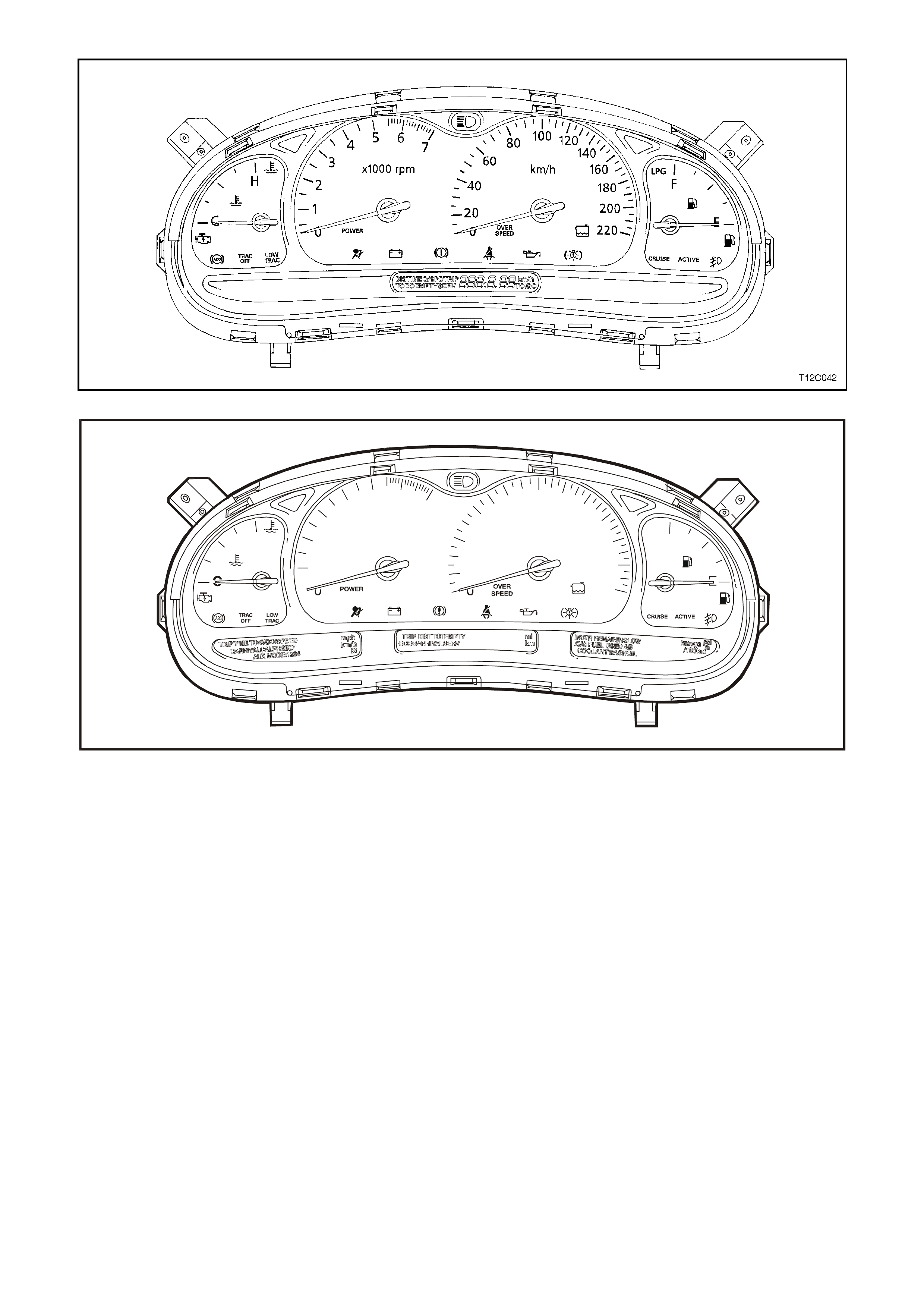
Figure 12C-1
T212C043
H
7
6
x1000 rpm km h
5
4
3
2
120
1
2
3
D
N
RP
4060 80 100 120140
160 F
180
200
220
LPG
Figure 12C-2
1.1 INSTRUME NT FACIA SWITCHES
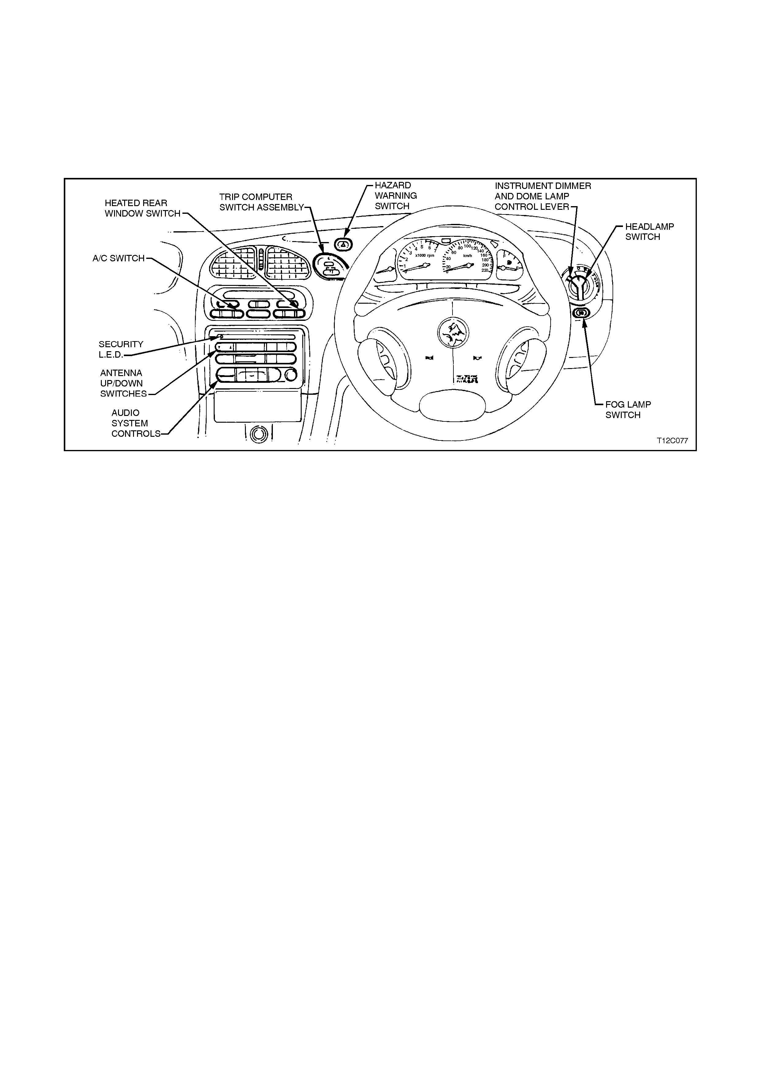
Fig. 12C-3 illustrates the various switch locations in the instr um ent fac ia for the VT Series II, which are the sam e as
the VT Series. Refer to Section 12C INSTRUMENTS, WIPERS/WASHERS & HORN in the VT Series I Service
Information.
For testing of the instrum ent facia switches, refer to Section 12B, LIGHTING SYSTEM in the VT Series I Service
Information.
Figure 12C-3


1.4 TRIP COMPUTER — S I NGLE WINDOW TYPE
OPERATION
The operation of the single window type trip computer on the VT Series II is the same as for that fitted to the
VT Series. Refer to Section 12C INSTRUMENTS, WIPERS/WASHERS & HORN in the VT Series I Service
Information.
BASIC FUNCTIONS
The basic func tions of the single window type trip com puter on the VT Series II are the same as f or that f itted to the
VT Series. Refer to Section 12C INSTRUMENTS, WIPERS/WASHERS & HORN in the VT Series I Service
Information.
ADDITIONA L FUNCTIONS
The additional functions of the s ingle window type trip computer on the VT Series II are the same as f or that f itted to
the VT Series. Refer to Section 12C INSTRUMENTS, WIPERS/WASHERS & HORN in the VT Series I Service
Information.
1.5 TRIP COMPUTER — TRIPLE WINDOW TYPE
OPERATION
The operation of the triple window type trip
computer on the VT Series II is the same as for
that fitted to the VT Series. Refer to Section 12C
INSTRUMENTS, WIPERS/WASHERS & HORN in
the VT Series I Service Information.
BASIC FUNCTIONS
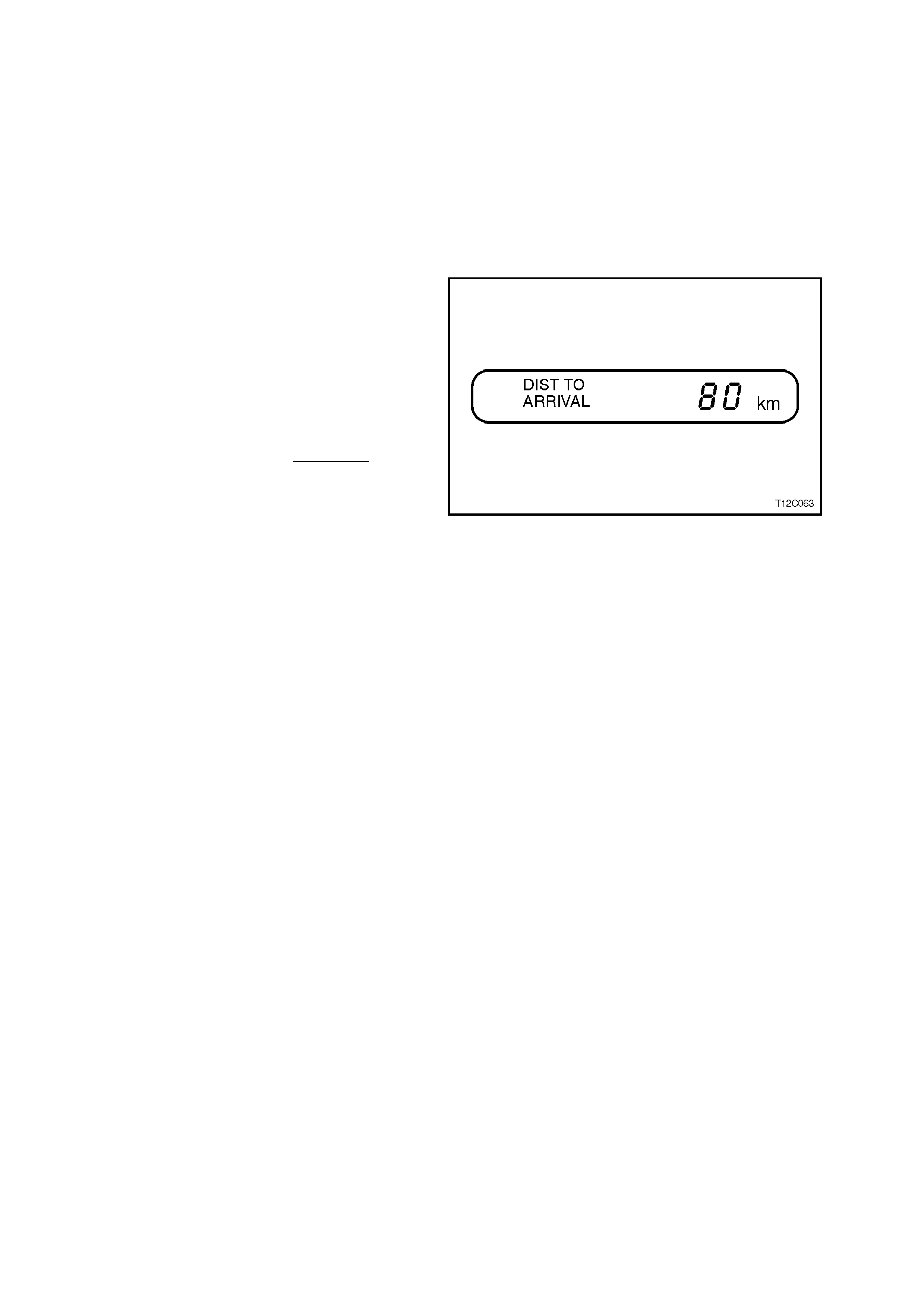
Distance to Arrival
At the start of a trip estimate distance to arrival
(from maps, road signs etc.). Tap the ▲ or ▼
buttons until the display shows estimated trip
distance. When the vehicle is driven the computer
will constantly update time to arrival, based on
changing driving speeds. The ▲ or ▼ buttons can
be used to adjust the kilometres any time this
display is shown.
Even if DISTANCE T O ARRIVAL is tur ned of f us ing
customise mode, it can still be temporarily turned
on by the following quick method:
Press MODE button until the TRIP display is
shown, press the ▲ and ▼ buttons together to zero
the trip display, then increase the distance up by
pressing the ▲ button.
However, when the trip distance reaches zero the
function will turn off again. Use the customise mode
to permanently turn the above displays on.
Figure 12C-4
The remaining basic functions of the triple window
type trip com puter on the VT Series II are the same
as for that fitted to the VT Series. Refer to
Section 12C INSTRUMENTS, WIPERS /
WASHERS & HORN in the VT Series I Service
Information.
ADDITIONA L FUNCTIONS
The additional functions of the triple window type
trip computer on the VT Series II are the same as
for that fitted to the VT Series. Refer to
Section 12C INSTRUMENTS, WIPERS /
WASHERS & HORN in the VT Series I Service
Information.


2.2 INSTRUME NT CLUS TER INPUTS
The instrument cluster inputs are the same as for that fitted to the VT Series. Refer to
Section 12C INSTRUMENTS, WIPERS/WASHERS & HORN in the VT Series I Service Information.
CHECK
To check the input voltage or wiring continuity between the various sensors/senders to the instrument cluster
connector, refer to 5. DIAGNOSTICS in this Section.

2.3 SE NDER UNITS
VEHICLE SPEED SENDER
Manual Transmission
For all details of the manual transmission vehicle speed sensor removal, testing, installation instructions, refer to
Section 6C1 POWERTRAIN MANAGEMENT - V6 ENGINE in the VT Series I Service Information, or
Section 7B3 MANUAL TRANSMISSION - GEN III V8 ENGINE in the VT Series II Service Information in this
Service Information CD
Automatic Transmission
For all details of the automatic transm ission vehicle speed sens or removal, tes ting, installation instructions , refer to
Section 6C1 POWERTRAIN MANAGEMENT - V6 ENGINE in the VT Series I Service Information, or
Section 6C3-3 SERVICE OPERATIONS - GEN III V8 ENGINE in the VT Series II Service Information in this
Service Information CD.
FUEL GAUGE SENDER UNIT
The service operations for the fuel gauge sender unit on the VT Series II are the same as for that fitted to the
VT Series. Refer to Section 12C INSTRUMENTS, WIPERS/WASHERS & HORN in VT Series I Service
Information.
LOW COOLANT SENDER UNIT
The service operations for the low coolant sender unit fitted to the GEN III V8 engine are detailed in
Section 6C3-3 SERVICE OPERATIONS - GEN III V8 ENGINE in the VT Series II Service Information.


5. INSTRUMENT DIAGNOSTICS
5.1 BASIC KNOWLEDGE REQUIRED
Before attempting to diagnose the instrument cluster you must have a good understanding of electrical system
basics and the use of circuit testing tools. Without this basic knowledge it will be difficult to use the diagnostic
procedures detailed in this Section.
Some electr ical basics, as well as basic troubleshooting proc edures and hints as the use of circuit testing tools are
covered in Section 12P WIRING DIAGRAMS in the VT Series I Service Information.
Basic Electrical Circuits - You should understand the basic theory of electricity, series and parallel circuits, and
voltage drops across series resistors. You should know the meaning of voltage (volts), current (amps), and
resistanc e (ohms). You should understand what happens in a circuit with an open or shorted wire (shor ted either to
voltage or earth). You should also be able to read and understand a wiring diagram.
Additionally, a knowledge of AC theory including; inductance, capacitance and impedance would be useful.
Use of Circuit Testing Tools - You should know how to use a jumper lead to test circuits. You should be familiar with
the use of a high input im pedance ( 10 Mohm ) digital type multim eter s uch as T ool No. J39200 or equivalent and be
able to measure voltage, current, and resistance. You should be familiar with the proper use of the TECH 2
Diagnostic Scan Tool.
NOTE: The vehicle’s battery must be removed before performing any earth resistance checks with a high
impedance multimeter.
Techline

5.2 PRELIMINARY SYSTEM DIAGNOSIS
When investigating any complaint of an instrument cluster problem or malfunction, always begin diagnosis with a
circuit check, refer to 5.8 INSTRUMENT DIAGNOSTIC PROCEDURES, DIAGNOSTIC CIRCUIT CHECK chart in
this Section.
The diagnostic circuit check is a preliminary procedure that checks to ensure the instrument cluster is
communicating on the serial data line as well as helping to identify the problem.

5.3 INSTRUME NT CLUS TER DIAGNOSTICS
The instrum ent cluster is equipped with a self-diagnos tic capability that can detec t and isolate instrum ent problems
or failures. W hen a fault is detected, the instrument cluster sets a Diagnostic Trouble Code (DTC) that represents
that particular problem or failure. W hen a DTC is set, an icon is shown in the left-hand instrument window on
high series vehicles, or the message SERV ERROR on low series. However, DTC 16 to DTC 20 do not set the
icon/message on the instrument cluster as these represent a fault condition logged by one of the various vehicle
control modules.
DIAGNOSTIC TROUBLE CODES
There are two types of DTC, current and history.
• A Current DT C is active only for the period that the fault is pres ent and is indic ated by the icon/mes s age on the
instrument cluster. When the fault is cleared, the Current DTC and the icon/message are also cleared.
• The History DTC is set at the same time as the Current DTC, and is stored in memory within the instrument
cluster to pr ovide inform ation on vehicle system operation over a period of tim e. History DTC are c leared from
memory 100 ignition cycles after the last DTC of any type was set.
DIAGNOSTIC MODE OPERATION
To enter the instrument cluster diagnostic mode, press the trip computer switch MODE button down together with
the ▲
▲▲
▲ button while turning the ignition from off to on. Further pressing the MODE button will step through the various
instrument cluster information displays.
When the Diagnostic Mode Display is reached, pressing the ▲
▲▲
▲ button increments the DTC number and related
inform ation displayed, while the ▼
▼▼
▼ button can be used to decrement the DTC number and related information. To
exit the instrument cluster diagnostic mode, press both the ▲
▲▲
▲ button and the ▼
▼▼
▼ button together.
A DTC is shown on the Diagnostic Mode Display as ‘t NN XY’ , where:
t = diagnostic trouble code (DTC),
NN = the actual DTC number,
X = the history DTC status (H for active and – for inactive), and
Y = the current DTC status (C for active and – for inactive).
In instances where the DTC is disabled due to the particular model configuration the letters nu (not used) appear in
the XY position. For example, a vehicle which is not fitted with ABS or ABS/ETC will have DTC 8 shown as ‘t 08 nu’.
Similarly, DTC 4, DTC 5 and DTC 6 will appear as not used on a vehicle which is not fitted with LPG.
It is important to note that an open circuit fuel (petrol) gauge sender unit is recognised by the instrument cluster self-
diagnostics as ‘t 00 H C’, whereas the TECH 2 Diagnostic Tool will recognise the same fault as DTC 3.
A DTC may also be cleared from the instrument cluster using the trip computer switches while in the diagnostic
mode. With the DTC displayed in the instrument cluster window, press both the ▲
▲▲
▲ button and the ▼
▼▼
▼ button together
for more than 2 seconds. Pressing these buttons for less than 2 seconds will exit the instrument cluster diagnostic
mode.
Faults can be identified by using TECH 2 to test instruments and force values and conditions into the instrument
cluster. The results of these tests can be used to diagnose problems in the instrument cluster such as inoperative
bulbs and faulty gauges and switches.
Faults within other components can be identified after using TECH 2 to confirm correct operation of the instruments.
For example, if there was a reported fault with the speedometer gauge and TECH 2 diagnosed the gauge as
working correctly, then the fault would lie in the Powertrain Control Module (PCM) or in the harness from the speed
sensor to the PCM, both of which would then require further testing.
USE OF TECH 2 DIA GNOSTIC TOOL WITH INTERMITTENT FAULTS
The TECH 2 Diagnostic Tool allows manipulation of wiring harnesses, while observing the TECH 2 Diagnostic Tool
readout. If the problem seems to be related to certain parameters that can be checked on the TECH 2 Diagnostic
Tool, they should be checked while driving the vehicle. If there does not seem to be any connection between the
problem and any specific circuit, the TECH 2 Diagnostic Tool can be used to monitor each parameter, watching for
a period of time to see if there is any change in the readings that indicates intermittent operation.
The TECH 2 Diagnostic Tool saves time in diagnosis and helps to prevent the replacement of good parts. The key
to using the TECH 2 Diagnostic Tool successfully is the technicians ability to understand the system being
diagnosed, as well as understanding the TECH 2 Diagnostic Tool operation and limitations. The technician should
read the TECH 2 User’s Guide to become familiar with the TECH 2 Diagnostic Tool operation.
With an understanding of the data which the tool displays, and knowledge of the circuits involved, the tool can be
very useful in obtaining information which would be more difficult or impossible to obtain with other equipment.
The TECH 2 Diagnostic Tool does not make the use of diagnostic charts unnecessary, nor can it indicate exactly
where a problem is in a particular circuit. Diagnostic charts incorporate diagnostic procedures that require the use
of a TECH 2 Diagnostic Tool.
5.4 DIAGNOSING FAULTS NOT COVERED BY TECH 2 DIAGNOSTIC TOOL
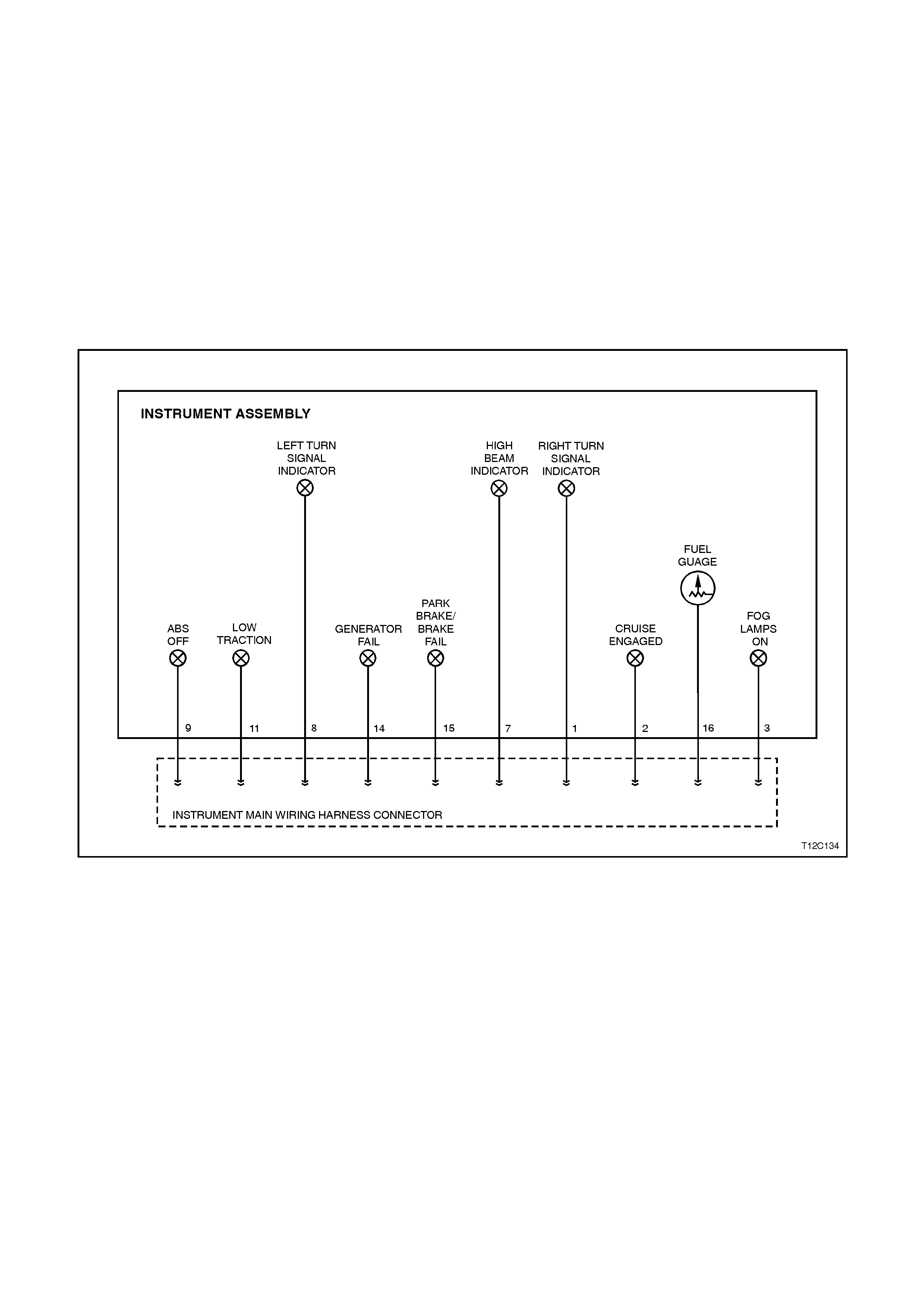
Some components of the instrument cluster cannot be diagnosed by the TECH 2, although their operation can be
tested using the F4: Mis cellaneous T est s func tion of the T ECH 2. T hese com ponents m ust be dealt with separately
and include the following instrument tell-tale lamps:
• Fog lamps on lamp
• Cruise engaged lamp
• Low traction lamp
• ABS off lamp
• Park brake/brake fail warning lamp
• Generator lamp
• Turn signal indicator lamps
• High beam lamp
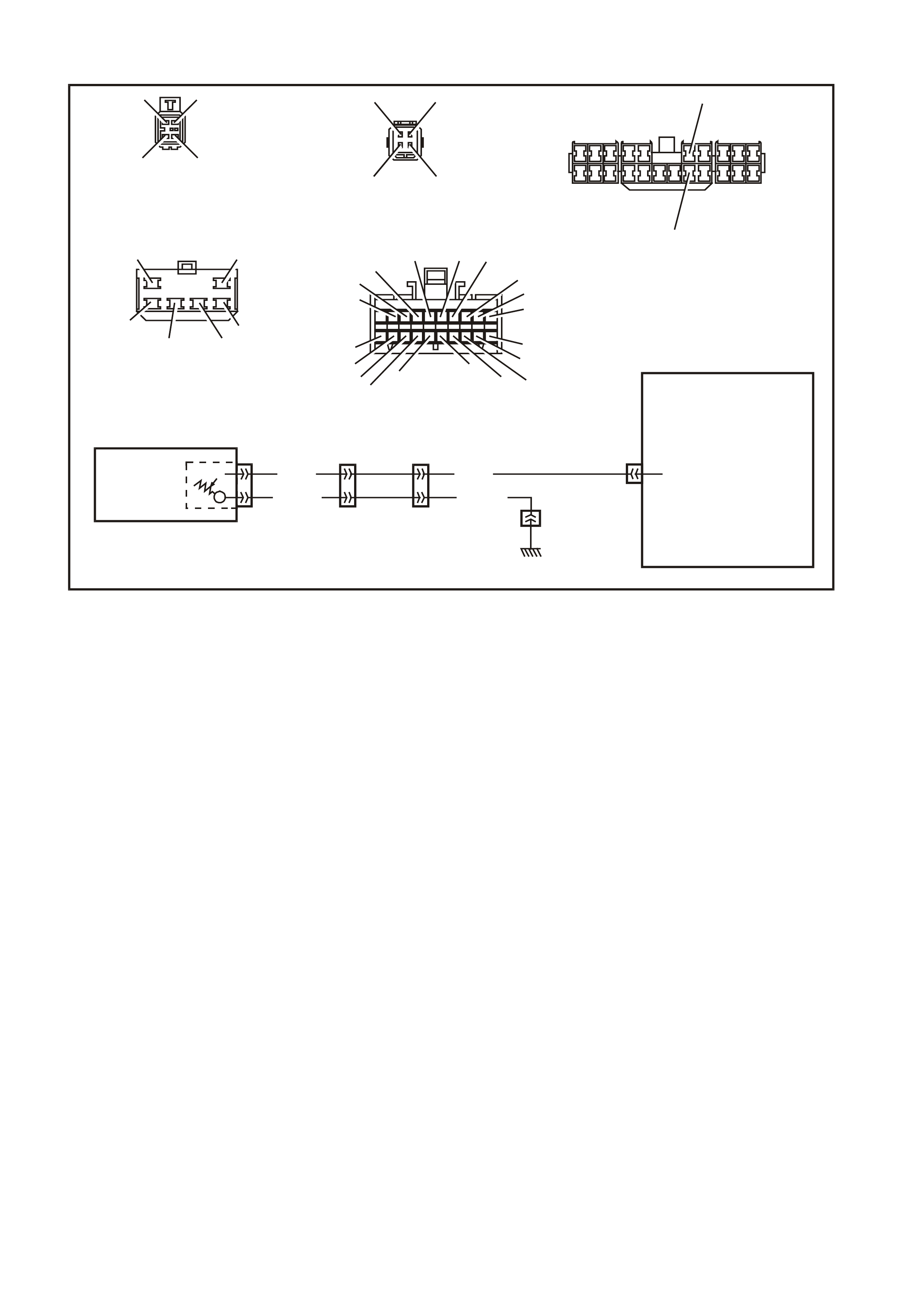
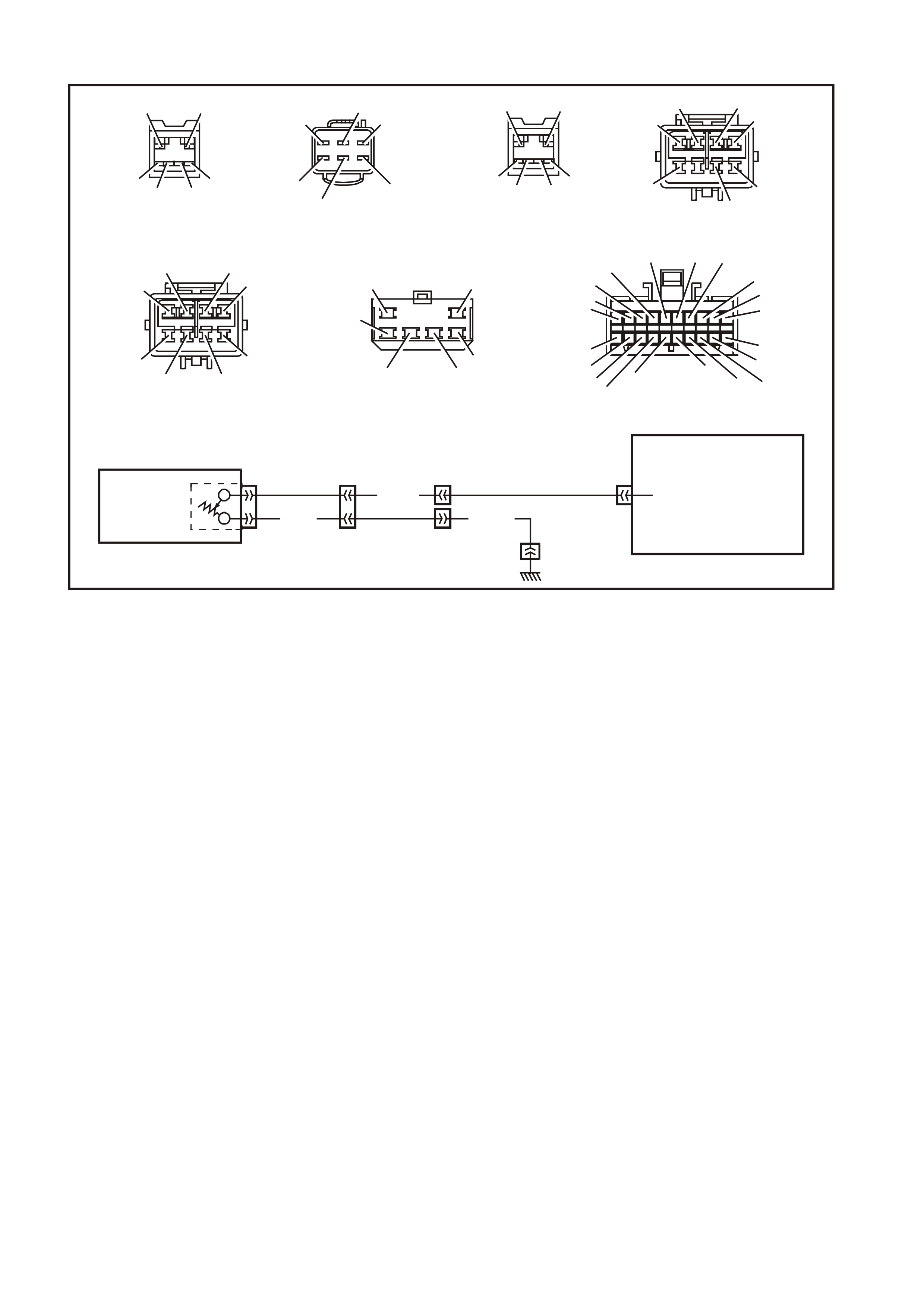
Fig. 12C-5 illustrates the components of the instrument cluster which are exclusively not on the serial data line.
Figure 12C-5

Warning Lamp Application Chart
The following table indicates the wiring configuration for the instrument cluster warning lamps.
NOTE: Some lamps may not be installed in all models.
LAMP CONFIGURATION SINGLE
WINDOW
DISPLAY
TRIPLE
WINDOW
DISPLAY
LAMP CONFIGURATION SINGLE
WINDOW
DISPLAY
TRIPLE
WINDOW
DISPLAY
High Beam HW X X High
Temperature SD — X
Left Turn HW X X Check
Powertrain SD X X
Right Turn HW X X ABS Of f HW X X
Power Shift SD X X Traction Off SD X
Overspeed INT X X Low Coolant SD X X
LPG SD X X Low Tract i on HW X
Air Bag SDXXCruise SDXX
Gen Fail HW X X Cruise Active HW X X
Brake Park/Fail HW X X Fog Lamps HW X X
Seat Belt INT X X Low Fuel INT X X
Oil Pres sure S D X X Sel ector Lever
Position SD — X
Rear Lamp Fail SD — X (PRND123)
INT = Internal HW = Hard Wired SD = Serial Data
Fuel Gauge Sender
When investigating complaints regarding the operation of the fuel gauge, use the TECH 2 diagnostic tool to
ascertain whether the problem lies in the fuel sender or in the fuel gauge.
If the fuel gauge does not respond to any of the control tests, ie the gauge remains stationary below the empty
mark, then there may be a faulty connection between the fuel sender and the instrument cluster. Verify that these
connections are reliable before commencing any further diagnostic work.
To check the fuel sender, connect TECH 2 to the data link connector as detailed in 5.6 CONNECTING TECH 2
FOR SYSTEM DIAGNOSIS in this Section.
Refer to 5.9 USING TECH 2 TO DIAGNOSE THE INSTRUMENT CLUSTER in this Sect ion to initiate the diagnostic
procedures. Select F1: Diagnostic Trouble Codes and then F0: Read DTC Information. If any trouble codes have
been logged by the fuel sender, these will appear as DTC 1, 2 or 3 for petrol, or as DTC 4, 5 or 6 for LPG.
IMPORTANT: An open circuit fuel gauge sender unit is shown as DTC 3 on the TECH 2, whereas the instrum ent
cluster diagnostic mode display shows the same fault as ‘t 00 H C’.
If no diagnostic trouble codes relating to the fuel sender have been logged, the operation of the fuel gauge can be
check ed by performing c ontrol tes ts , refer to 5.9 USING TECH 2 T O DIAGNOSE THE INSTRUM ENT CLUSTER in
this Section to initiate the diagnostic procedures. Select F4: Miscellaneous Tests and then F7: Control Tests. Fuel
Gauge can be selected and it is possible to verify that the gauge operates accurately within the specified ranges.
If, when performing the control test, the fuel level indicated by the fuel gauge varies more than 3° than the
commanded fuel level (at empty, half and full marks) then the instrument cluster will need to be replaced, and a new
one installed and programmed.
Fog Lamps On Indicator Lamp
A failure of the fog lamps on indicator lamp can be caused by any of the following:
• Faulty connection from fog lamp switch connector (Violet/Red wire).
• Faulty connection on pin 3 on the instrument cluster harness connector.
• A non-functioning fog lamps on indicator lamp bulb.
Cruise Engaged (ACTIVE) Lamp
A failure of the cruise engaged warning lamp can be caused by any of the following:
• Faulty connection from the cruise control actuator harness connector (White wire) to instrument harness
connector terminal 2, resulting in cruise engaged lamp failing to operate at all.
• A non-functioning cruise engaged lamp.

Low Traction Warning Lamp
A failure of the low traction warning lamp can be caused by any of the following:
• Faulty connection from the ABS/ETC module harness connector (Yellow/Red wire) to instrument harness
connector terminal 11, resulting in low traction lamp failing to operate at all.
• A non-functioning low traction warning lamp.
ABS Off Warning Lamp
The ABS off warning lamp is illuminated when the ABS or ABS/ETC module is disabled due to a fault with the
module. A failure of the ABS off warning lamp can be caused by any of the following:
• Faulty connection from the ABS/ETC m odule harnes s connec tor (G reen wire) to instr um ent harness connector
terminal 9, resulting in low traction lamp failing to operate at all.
• A non-functioning ABS off warning lamp.
Park Brake/Brake Fail Warning Lamp
A failure of the park brake/brake warning lamp can be caused by any of the following:
• Faulty connection from the brake fail warning switch connector (Brown/Orange wire) to instrument harness
connector terminal 15, resulting in park brake/brake fail warning lamp activated only by the park brake switch.
• Faulty connection from the park brake s witch connector (Brown/Orange wire) to ins trum ent harness connector
terminal 15, resulting in park brake/brake fail warning lamp activated only by the brake fail warning switch.
• A non-functioning brake fail warning switch.
Genera tor Warning Lamp
A failure of the generator warning lamp can be caused by any of the following:
• Faulty connection from the generator harness connector (Brown wire) to instrument harness connector
terminal 14, resulting in generator lamp failure to operate at all.
• Short circuit of Brown wire to earth between instrument harness connector and generator harness connector,
resulting in generator warning lamp continually on.
• A non-functioning generator warning lamp bulb.
Turn Signal Indicator Lamps
A failure in one or both of the turn signal indicator lamps can be caused by any of the following:
• Faulty connection from terminal 49aL (Light Blue wire) from the turn signal switch (characterised by left-hand
turn signals inoperative).
• Faulty connection from term inal 49aR (Blue wire) from the turn signal switch (characterised by right-hand turn
signals inoperative).
• Faulty connection on pins 8 (left-hand indicator bulb) or 1 (right-hand indicator bulb) on the instrument cluster
harness connector.
• A non-functioning turn signal lamp bulb.
High Beam Indicator Lamp
A failure of the high beam indicator lamp can be caused by any of the following:
• Faulty connection from terminal turn signal switch 1 connector (Blue/Yellow wire) from flash/dip switch.
• Faulty connection on pin 7 on the instrument cluster harness connector.
• A non-functioning high beam indicator lamp bulb.
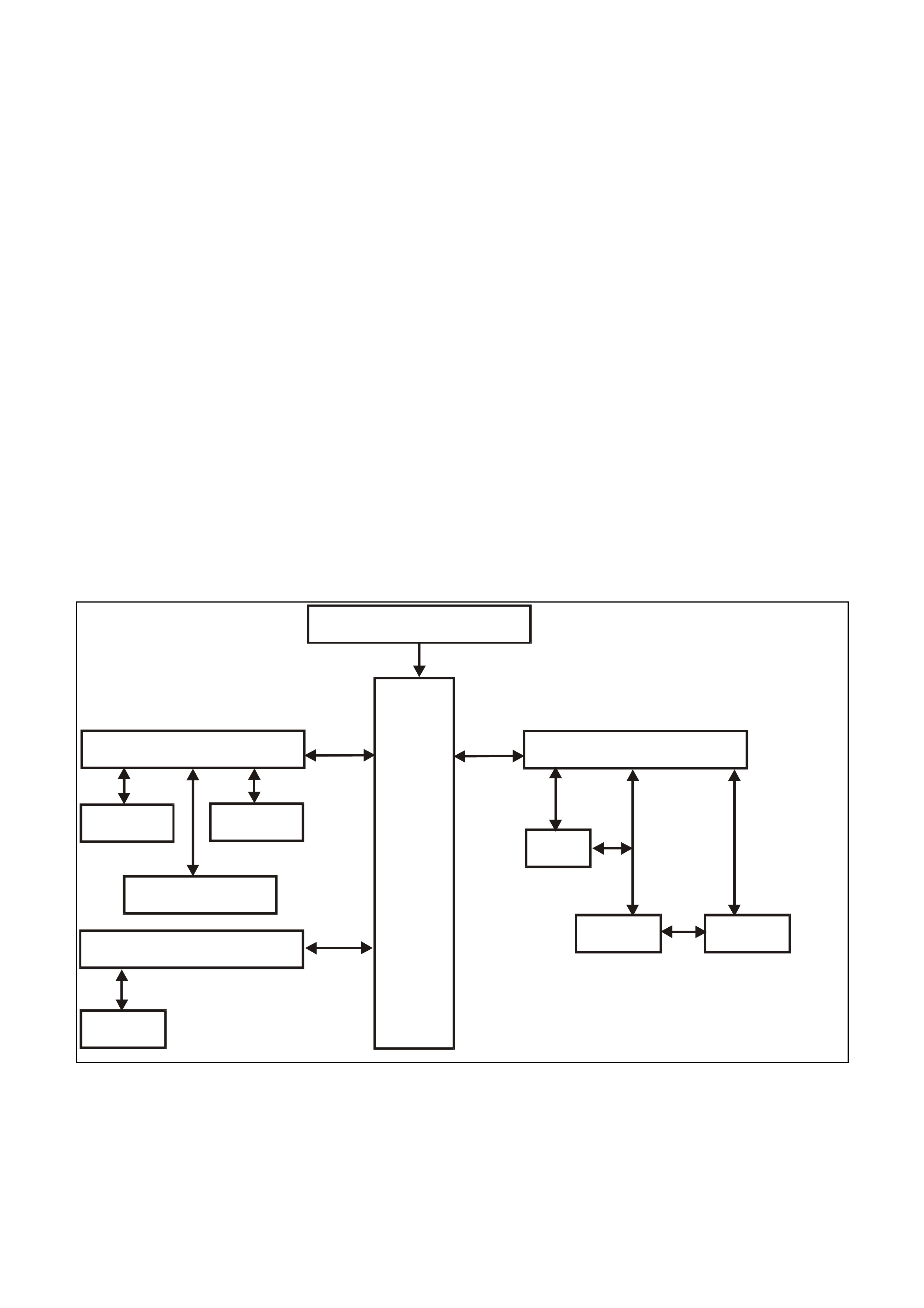
5.5 SERIAL DATA COMMUNICATION
GENERAL INFORMATION
The VT Series II model uses a BUS MASTER communication system, where the BCM is the bus master.
The BCM periodically polls (surveys) each device on the bus and requests status data.
The devices connected are:
• Body Control Module (BCM).
• Powertrain Control Module (PCM) for V6 and V6 supercharged engines.
• Powertrain Interface Module (PIM) for GEN III V8 engines only.
• Electronic Climate Control (ECC).
• Instrument Cluster (INS).
• Anti-lock Brake (ABS) or Anti-lock Brake / Electronic Traction Control (ABS/ETC).
• Supplementary Restraint System (SRS).
• External diagnostic tool (TECH 2).
The data provided by each device may be utilised by any device connected to the bus.
Each device has a unique response Message Identifier Word (MIW) for ease of identification.
The bus m aster ( BCM) polls each device with a ser ial data mes sage which includes that device’s MIW . T he device
responds by putting a serial data message onto the bus which includes its MIW and data, which is retrieved and
utilised by any device requiring it.
The BCM polls each device for a status update, once ever y 300 m illiseconds . The exception to this being the PCM
(V6) and PIM (GEN III V8) which are polled twice every 300 milliseconds.
The TECH 2 diagnostic tool can be used to read serial data on the data bus and analyse faults in the instrument
cluster and its related components.
BATTERY POWER
BCM
SERIAL DATA MA IN
DLC
SERIAL DATA AUX
ABS/ETC ECC
INSTRUMENTS
SRS SERIAL DATA AUX PIM PCM
SRS
GEN III V8
ENGINE V6 & V6 S/C
ENGINE
T212J2011
Figure 12C-6
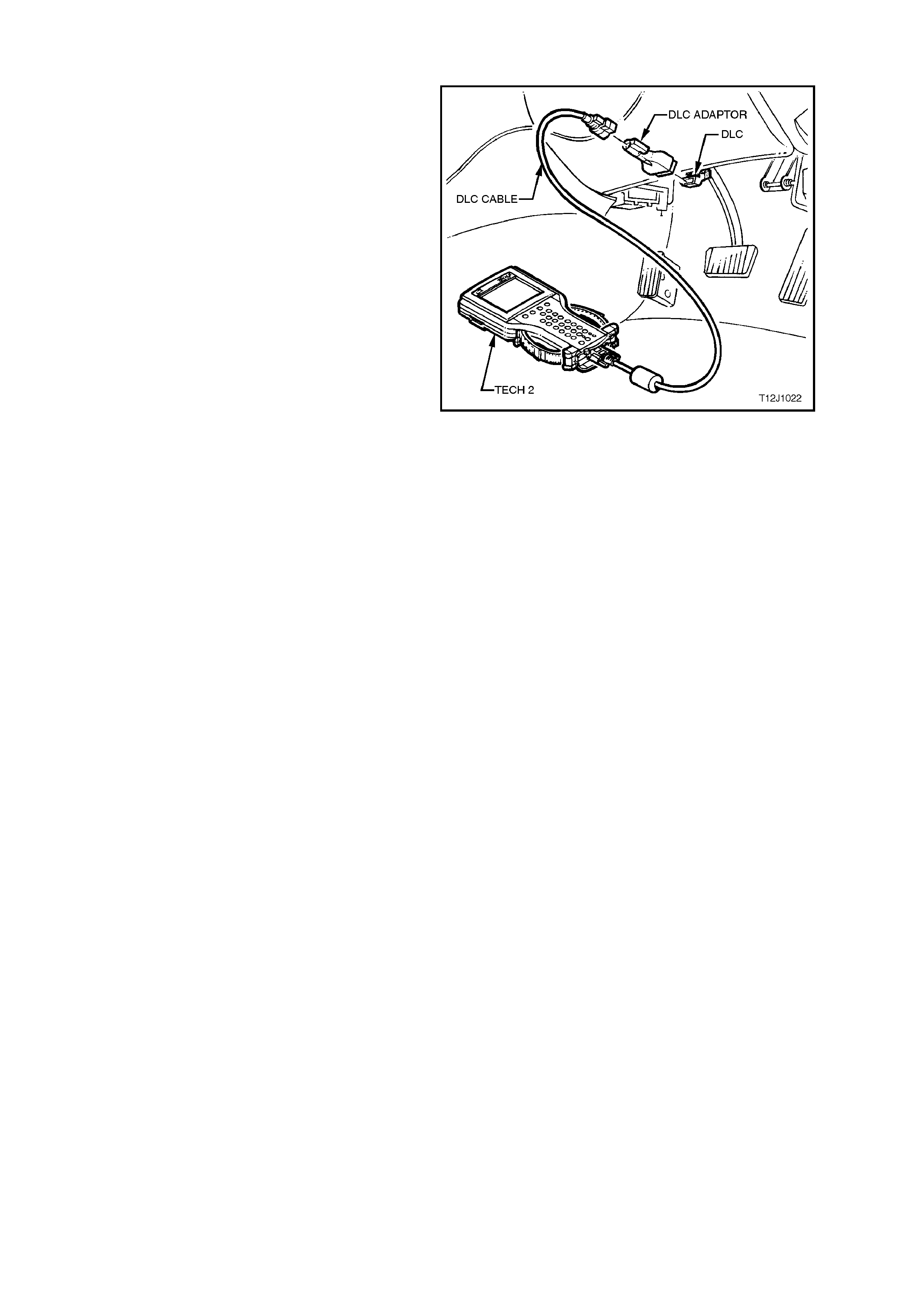
5.6 CONNECTING TECH 2 FOR SYSTEM DIAGNOSIS
TECH 2, with the appropriate sof tware, c ables and
adaptors, when connected to the Data Link
Connector (DLC) is capable of reading the
instrument cluster serial data. The DLC is
connected to the instrument panel lower right
hand-trim, to the right of the steering column.
For additional general information on connecting
and operating TECH 2, refer to
Section 0C TECH 2 in the VT Series II Service
Information.
Figure 12C-7

5.7 TECH 2 TEST MODES AND DISPLAYS FOR INSTRUMENT DIAGNOSIS
A prerequisite of this diagnostic section is for the
user to be familiar with the proper use of TECH 2.
The f ollowing pages illus trate only the m ajor T ECH
2 screen displays and provide a brief explanation of
their function for diagnosing the Instruments. If
additional information is required on the operation
of TECH 2, reference should be made to either
Section 0C TECH 2 in the VT Series II Service
Information or the TECH 2 User’s Guide.
W ith the ignition turned of f, connect the TECH 2 to
the Data Link Connector (DLC) using the DLC
Adaptor, refer to 5.6 CONNECTING TECH 2 FOR
SYSTEM DIAGNOSIS in this Section.
MAIN MENU
Turn the ignition on and press the power button
(PWR) on the TECH 2.
The TECH 2 will perform a series of self-
diagnosing power on self tests (POST). Once this
has been completed successfully, the TECH 2
startup screen will be displayed. Press the Enter
key to continue.
The Main Menu screen should look as follows.
Press the F0 function button or Select F0:
Diagnostics by using the arrow keys until F0:
Diagnostics is highlighted and press the Enter key.
Ma in Me n u
F0: D iagnostics
F2: V iew C apture D ata
F4: Dow nload/Upload Help
F1: Service Program m ing System (SPS)
F3: Tool Options
T12C136A
Figure 12C-8
Model Year
Select the appropriate Model Year and press
Enter.
V e hicle Identificatio n
(X) 1999
(W)1998
(V) 1997
Select one of the follow ing
Model Year(s)
T212C137
Figure 12C-9
Vehicle Identification Menu
Select the VT Commodore vehicle type and press
Enter.
Vehicle Identification
VT Commodore
WH Statesman & Capr ice
VS Commodor e
Corsa
Tigra
Astra - F
Astra - G
Zafira
Vectra - B
Omega - B
Select one of the following
Vehicle Type(s)
T212C138
Figure 12C-10
SYSTEM SELECTION MENU
Select F3: Body from the System Selection Menu
and press Enter.
S ystem Se lection M en u
F0:
F1:
F2:
F3:
(X) 1999 VT Com m odore
T212C139
Engine
Transmission
Chassis
Body
Figure 12C-11
Vehicle Identification Screen
Select Instrument and press Enter.
V e hicle Identificatio n
B ody Control M odule
Po we rtrain In terfa ce M o du le
SRS
Instrument
Electronic Clim ate Co ntrol
DTC Check
Other
S ele ct on e of the follow ing
Body
T212C141
Figure 12C-12
System Identification Screen
Turn the ignition on (as requested) and press
Confirm soft key to continue.
S ystem Ide ntifica tio n
Turn On Ignition!
(X) 1999 VT Commodore
Electronic S ystem: Instrum ent
T212C142
Figure 12C-13
The part number of the instrument cluster will be
displayed. Press the More soft key to display more
detailed information about the part.
S ystem Ide ntifica tio n
Partnumber XXXXXXXX
(X) 1999 VT Commodore
Electronic S ystem: Instrum ent
T212C143
Figure 12C-14

Press the Confirm soft key to confirm these details.
S ystem Ide ntifica tio n
Partnumber
Software Date
Data Version Number
V A P Process Number
XXXXXXXX
XXXXXX
XX
XXX
(X) 1999 VT Commodore
Electronic System: Instrum ent
T212C144
Figure 12C-15
The Vehicle Identification Number/TIS Hardware
Key Number will now be displayed. Press Confirm
soft key to continue.
S ystem Ide ntifica tio n
V
e hic le Id entific atio n N u m b e r / T IS
Hardware Key Number
123456
(X) 1999 VT Commodore
Electronic System: Instrum ent
T212C145
Figure 12C-16
BODY MENU
This m enu provides the TECH 2 us er with acc ess to
the various functions used to diagnose faults in the
instrument cluster and its related components. The
six functions F0 to F5 are explained in more detail in
5.9 USING TECH 2 TO DIAGNOSE THE
INSTRUMENT CLUSTER in this Section.
F0: Normal Mode
The instrument normal mode data list is used to
view serial data being sent from the instrument
cluster.
F1: Diagnostic Trouble Codes
In this m ode Diagnostic T rouble Codes can be read
and cleared.
F2: Data Display
In this test mode, TECH 2 displays the status of
inputs and outputs of the instrument cluster.
F3: Snapshot
In this test mode, the TECH 2 captures data before
and after a forced manual error. This is not
applicable to instrument diagnostics.
F4: Miscellaneous Tests
In this test mode, the TECH 2 can test and
diagnose faults in the instrument cluster. Telltale
lamps and instrument gauges can be tested in this
mode.
F5: Program
Instruments and options can be programmed when
this mode is selected.
Body
F0:
F1:
F2:
F3:
F4:
F5:
T12C140
Norm al Mode
Diagnostic Trouble Codes
Data Display
Snapshot
Miscellaneous Tests
Program
Figure 12C-17
5.8 INSTRUMENT DIAGNOSTIC PROCEDURES
INTRODUCTION:
The following charts are designed to provide fast and efficient fault location of the instruments. Each diagnostic
chart consists of: a ‘diagnostic chart’ and pertinent information including Diagnostic Trouble Code (DTC) setting
parameters and, in most charts, circuit diagrams.
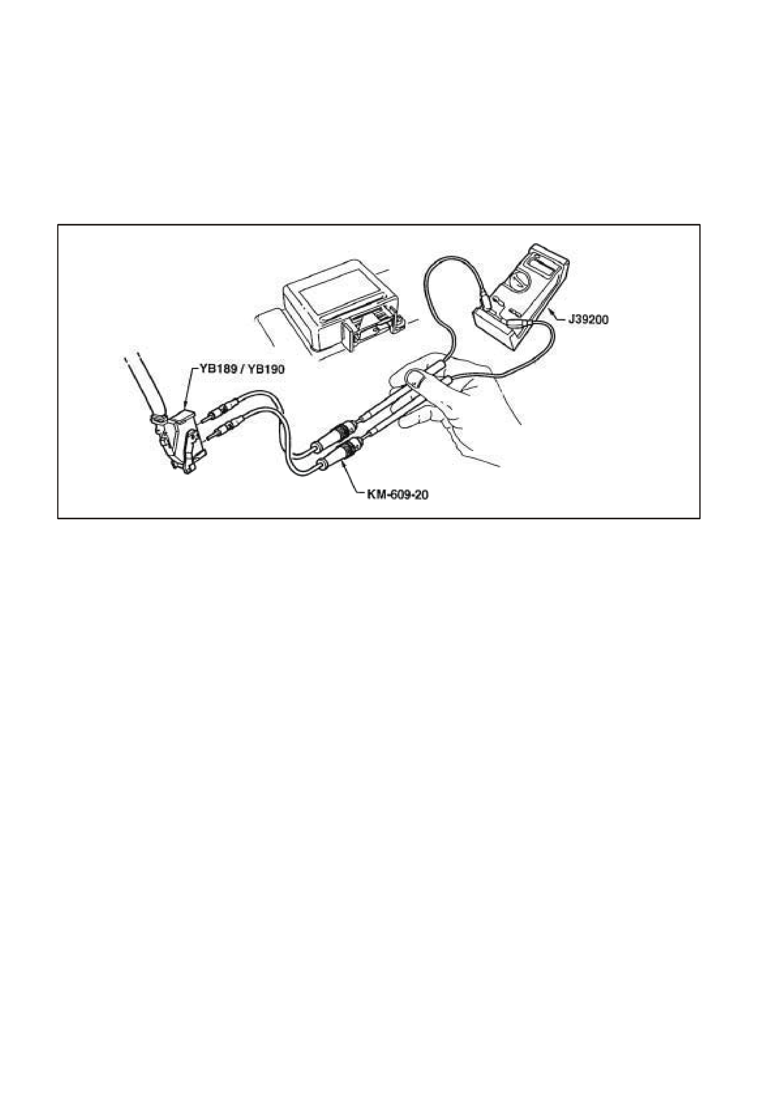
W hen carrying out wiring checks as directed by the diagnostic charts, rather than probe terminals and connectors
with incorrect sized multimeter connections, use the adaptors contained in connector test adaptor kit KM-609, as
shown in the following illustration. This will prevent any possibility of spreading or damaging wiring harness
terminals which may later cause a system intermittent failure.
T12C194
Figure 12C-18
DIAGNOSTIC CIRCUIT CHECK
Circuit Description:
W hen investigating any com plaint of an instrum ent cluster problem or m alfunction, always begin diagnosis with the
following diagnostic circuit check. This check is a preliminary procedure that checks to ensure the instrument
cluster is com m unic ating on the serial data line as well as helping to identif y a problem or m alf unction and dir ecting
the reader to the appropriate diagnostic chart in this Section.
With TECH 2 connected to the DLC and the ignition switched on, TECH 2 should display serial data
communication. If TECH 2 does not display serial data, the serial data circuit maybe open or shorted.
There are several other control modules that are connected to the serial data line (PCM, PIM (GEN III V8 only)
BCM, ABS or ABS/ETC, ECC and SRS). ANY one of these control modules could cause a fault on the serial data
line. This fault could result in TECH 2 not being able to display serial data.

DIAGNOSTIC CIRCUIT CHECK PROCEDURE
STEP ACTION VALUE YES NO
1• Turn the ignition on.
• Do any instrument cluster warning lamps
illuminate?
Go to Step 5. Go to Step 2.
2• Check instrument cluster fuses F11, F13 and F21
in instrument panel compartment.
• Are any fuses blown?
Replace blown
fuses. Go to Step 3.
3• Check continuity of circuit 155 (Black/Yellow wire)
between instrument cluster connector YB66 and a
known good earth.
• Is there continuity?
Go to Step 4. Check and repair
open in circuit 155.
4• With ignition on, check for voltage at instrument
cluster connector YB66, terminals 19 and 20.
• Is voltage as specified?
B+ Replace instrument
cluster, refer to 2.1
INSTRUMENT
CLUSTER in this
Section.
Check and repair
circuits 44 and/or
1340 as necessary.
5• Turn ignition off.
• Connect TECH 2 to DLC.
• Turn ignition on.
• Push power button on TECH 2.
Does TECH 2 power up? (Screen should illuminate
and display TECH 2).
Go to Step 6. Go to TECH 2
diagnosis, refer to
Section 0C TECH 2
in the VT Series I
Service Information.
6• At the TECH 2 title screen press the Enter key.
• Select Diagnostics \ 1999 \ VT Commodore \ Body
\ Instrument.
• Does TECH 2 display Instrument System
Identification (ie. Part Number)?
Go to Step 7. Go to DTC-14 No
Serial
Communication In
this Section.
7• With TECH 2 still connected and instruments
selected, select Diagnostic Trouble Codes.
• Does TECH 2 display any DTC?
Refer to
corresponding
diagnostic chart.
Refer to 5.4
DIAGNOSING
FAULTS NOT
COVERED BY
TECH 2
DIAGNOSTIC TOOL
in this Section.
WHEN ALL DIAGNOSIS AND REPAIRS ARE COMPLETED, CLEAR ALL DTC AND VERIFY CORRECT OPERATION

DTC 1 FUEL GAUGE SENDER UNIT — SHORT CIRCUIT
T (30)
B/Y (155)
YB74
BODY HAR NES S CONNE CT OR
T212C185A
YR44 YR32 YB74 YB66
YE114
LOC. E3
FUEL
GAUGE
SENDER
T (30)
T (30)
B/Y (155)B/Y (155)
INSTRUMENT
CLUSTER
16
Y
R32
FUEL TANK HARNESS
CONNECTOR
V/W (1120) S/C ONLY
OR
V (1 20)
T (30)
B/Y (155)
B/BL U (156 )
OR
B/W (489) S/C ONLY
YB66
INSTRUMENTS CONNECTOR
10
20 1
11
B/Y (155) GY (8) BR/W (19)
BLU/Y (10)
T (30)
V/W (123)
BR/O (33)
BR (25)
V/R (234)
W ( 85 )
BLU (15)
Y/R (88)
G/W (1 220 )
BLU/B (94 6 )
LBLU (14)
G (8 75)
O/Y (1 340)
P/BLU (44)
BR/R (121)
YR44
FUEL TANK HA RNESS
CONNECTOR
T (30)B/BL U (156 )
B/Y (155) V (120)
YE114
MAIN WIRING HARNESS
CONNECTOR
B/R (157)
B/G (151)
B/W (152) B (150) B/Y (155)
B/R (157)
CIRCUIT DESCRIPTION:
The instrum ent cluster supplies a 12 volt reference voltage and an earth circuit to the fuel gauge sender unit. The
fuel sender provides a resistanc e value to the instrum ent cluster bas ed on its position relative to the fuel level. T he
fuel sender resistance will vary between 37.5 ohms and 253.3 ohms from no fuel in the tank to full tank.
DTC 1 Will Set If:
• The fuel sender resistanc e is less than 12.9 ohm s for a period of 30 seconds . The DTC is r eset when the fuel
sender resistance returns to its normal operating range for a period of 60 seconds. The DTC is logged as a
History DTC.
When a DTC 1 is set the fuel gauge will display the fuel tank level as empty irrespective of actual fuel level.
Test Description:
Number(s) below refer to step number(s) in the following diagnostic chart.
2-4. Use of TECH 2 to view data being sent from f uel s ender. If voltage is not within corr ect operating s pec if ic ations
then there is either an open circuit, short c ircuit or a faulty fuel sender. If open- or shor t-circuit then chec ks will
be made to locate the circuit interruption.
5. Use of TECH 2 to drive the gauge on the instrument cluster to verify that gauge is functioning correctly.
6. With the f uel sender disconnec ted, the fuel sender signal r esistance value should be between 37.5 and 253.3
ohms, which is dependant on fuel level.
7. Continuity check of harness between voltage circuit 30 and earth circuit 155 at harness connector YB74 will
indicate a short circuit in harness between YB74 and instrument cluster.
8. Continuity check of harness between voltage circuit 30 and earth circuit 155 at harness connector YR32 will
indicate a short circuit in harness between YB74 and YR32.
9. Rem oval of fuel tank allows access to fuel sender . Continuity check of harnes s between voltage circuit 30 and
earth circuit 155 at harness connector YR44 will indicate a short circuit in harness between YR32 and YR44,
otherwise there is a fault in the fuel sender.

Diagnostic Aids:
The TECH 2 diagnos tic tool reads f uel sender position as a voltage between 0 and 12 volts. The fuel s ender signal
resistance should be between 37.5 to 253.3 ohms when the fuel sender is functioning correctly. The fuel sender
voltage should increase at a steady rate as the fuel level increases.
The multimeter allows continuity of the wiring harness to be checked. Harness voltage can also be confirmed at
connector locations.
Check for any damage to the harness which could cause an intermittent open or short to earth or backed-out
terminals at the instrument cluster connectors, broken connector locks, improperly formed or damaged terminals.

DTC 1 TEST PROCEDURE
STEP ACTION VALUE YES NO
1 • Was the Diagnostic Circuit Check performed? Go to Step 2. Go to Diagnostic
Circuit Check in this
Section.
2• Connect TECH 2 to DLC.
• Select 1999 \ VT Commodore \ Diagnostics \
Body \ Instrument \ Data Display \ Instrument.
• Check the petrol sender signal.
• Is petrol sender signal voltage 0V?
Short circuit from fuel
sender to instrument
cluster, go to Step 5.
Go to Step 3.
3• Is petrol sender signal voltage 5V? Open circuit from fuel
sender to instrument
cluster, go to Step 5.
Go to Step 4.
4• Is petrol sender signal voltage between 0V and
5V? Go to Step 5. Replace faulty fuel
sender. Refer to
Section 8A FUEL
TANK in the VT
Series I Service
Information.
5• Using TECH 2, run Control Tests, refer to 5.14
F4: MISCELLANEOUS TEST in this Section.
• Does the fuel gauge operate correctly?
Go to Step 6. Replace instrument
cluster. Refer to 2.1
INSTRUMENT
CLUSTER in this
Section.
6• Disconnect battery.
• Disconnect fuel tank harness from body harness
connector YR32 located under the rear of vehicle.
• Using an ohmmeter, check resistance across fuel
sender circuits 30 (Tan wire) and 155
(Black/Yellow wire) on fuel tank harness.
• Is resistance within specified range?
Between
37.5 ohms
and
253.3 ohms
Go to Step 7. Replace faulty fuel
sender. Refer to
Section 8A FUEL
TANK in the VT
Series I Service
Information.
7• Using an ohmmeter check continuity between
main wiring harness circuit 155 (Black/Yellow
wire) and circuit 30 (Tan wire) at connector YB74
in the passenger compartment.
• Is there continuity?
Short circuit in main
wiring harness
between YB74 and
YB66. Repair
harness.
Go to Step 8.
8• Using an ohmmeter, check continuity between
body harness circuit 155 (Black/Yellow wire) and
circuit 30 (Tan wire) at connector YR32 under the
vehicle.
• Is there continuity?
Short circuit in body
harness between
YR32 and YB74.
Repair harness.
Go to Step 9.
9• Drain and remove fuel tank, refer to Section 8A
FUEL TANK in the VT Series I Service
Information.
• Using an ohmmeter, check continuity between
fuel tank harness circuit 155 (Black/Yellow wire)
and circuit 30 (Tan wire) at connector YR44
under the vehicle.
• Is there continuity?
Short circuit in fuel
tank harness
between YR44 and
YR32. Repair
harness.
Replace faulty fuel
sender. Refer to
Section 8A FUEL
TANK in the VT
Series I Service
Information.
10 • Use TECH 2 to cle ar DTC.
• Has DTC cle ared? End of diagnostic
checking. Refer to
corresponding
diagnostic chart.
WHEN ALL DIAGNOSIS AND REPAIRS ARE COMPLETED, CLEAR ALL DTC AND VERIFY CORRECT OPERATION
DTC 2 FUEL GAUGE SENDER UNIT — INTERMITTENT
T (30)
B/Y (155)
YB74
BODY HAR NES S CONNE CT OR
T212C185A
YR44 YR32 YB74 YB66
YE114
LOC. E3
FUEL
GAUGE
SENDER
T (30)
T (30)
B/Y (155)B/Y (155)
INSTRUMENT
CLUSTER
16
Y
R32
FUEL TANK HARNESS
CONNECTOR
V/W (1120) S/C ONLY
OR
V (1 20)
T (30)
B/Y (155)
B/BL U (156 )
OR
B/W (489) S/C ONLY
YB66
INSTRUMENTS CONNECTOR
10
20 1
11
B/Y (155) GY (8) BR/W (19)
BLU/Y (10)
T (30)
V/W (123)
BR/O (33)
BR (25)
V/R (234)
W ( 85 )
BLU (15)
Y/R (88)
G/W (1 220 )
BLU/B (94 6 )
LBLU (14)
G (8 75)
O/Y (1 340)
P/BLU (44)
BR/R (121)
YR44
FUEL TANK HA RNESS
CONNECTOR
T (30)B/BL U (156 )
B/Y (155) V (120)
YE114
MAIN WIRING HARNESS
CONNECTOR
B/R (157)
B/G (151)
B/W (152) B (150) B/Y (155)
B/R (157)
CIRCUIT DESCRIPTION:
The instrum ent cluster supplies a 12 volt reference voltage and an earth circuit to the fuel gauge sender unit. The
fuel sender provides a resistanc e value to the instrum ent cluster bas ed on its position relative to the fuel level. T he
fuel sender resistance will vary between 37.5 ohms and 253.3 ohms from no fuel in the tank to full tank.
DTC 2 Will Set If:
• T here is an inter m ittent fault in the c onnection between the fuel sender and the ins trum ent c luster. T he DT C is
set when the fuel sender resist ance is gr eater than 290 ohms f or 30 seconds or if the fuel sender res istance is
less than 37.5 ohms f or 30 seconds. T he DTC is reset when the fuel sender is detec ted as being open cir cuit
or short circuit or the sender resistance is within its normal operating range for a period of 60 seconds. The
DTC is logged as a History DTC.
Test Description:
Number(s) below refer to step number(s) in the following diagnostic chart.
2-4. Use of TECH 2 to view data being sent from f uel s ender. If voltage is not within corr ect operating s pec if ic ations
then there is either an open circuit, short c ircuit or a faulty fuel sender. If open- or shor t-circuit then chec ks will
be made to locate the circuit interruption.
5. Use of TECH 2 to drive the gauge on the instrument cluster to verify that gauge is functioning correctly.
6-9. Tes t driving the car and m anipulating the harness es while viewing the serial data sent f rom the fuel sender will
indicate the presenc e of a c irc uit inter ruption as the voltage will fluc tuate in the event of an open c irc uit or shor t
circuit.
Additionally, viewing the DTC will indicate the pres ence of the interm ittent f ault if triggered by m anipulating the
relevant harness.

Diagnostic Aids:
By manipulating the harnesses at the various connector s it is poss ible to isolate the caus e of the cir cuit interr uption.
By working through the chart in the specified order it is possible to work out which harness contains the fault. This
harness can then be removed and repaired.
The TECH 2 diagnos tic tool reads f uel sender position as a voltage between 0 and 12 volts. The fuel s ender signal
resistance should be between 37.5 to 253.3 ohms when the fuel sender is functioning correctly. The fuel sender
voltage should increase at a steady rate as the fuel level increases.
The multimeter allows continuity of the wiring harness to be checked. Harness voltage can also be confirmed at
connector locations.
Check for any damage to the harness which could cause an intermittent open or short to earth or backed out
terminals at the instrument cluster connectors, broken connector locks, improperly formed or damaged terminals.

DTC 2 TEST PROCEDURE
STEP ACTION VALUE YES NO
1 • Was the Diagnostic Circuit Check performed? Go to Step 2. Go to Diagnostic
Circuit Check in this
Section.
2• Connect TECH 2 to DLC.
• Select 1999 \ VT Commodore \ Diagnostics \ Body
\ Instrument \ Data Display \ Instrument.
• Check the petrol sender signal.
• Is petrol sender signal voltage 0V?
Short circuit from
fuel sender to
instrument cluster,
go to Step 5.
Go to Step 3.
3• Is petrol sender signal voltage 5V? Open circuit from
fuel sender to
instrument cluster,
go to Step 5.
Go to Step 4.
4• Is petrol sender signal voltage between 0V and
5V? Go to Step 5. Replace faulty fuel
sender. Refer to
Section 8A FUEL
TANK in the VT
Series I Service
Information.
5• Using TECH 2, run Control Tests, refer to 5.14 F4:
MISCELLANEOUS TEST in this Section.
• Does the fuel gauge operate correctly?
Go to Step 6. Replace instrument
cluster. Refer to 2.1
INSTRUMENT
CLUSTER in this
Section.
6• Clear DTC 2 by selecting Diagnostics \ 1999 \
VT Commodore \ Body \ Instrument \ Diagnostic
Trouble Codes \ Clear DTC Information.
• Turn ignition off then on.
• Select Diagnostics \ 1999 \ VT Commodore \ Body
\ Instrument \ Data Display \ Instrument and view
petrol sender signal data.
• Take vehicle for a test drive and monitor the petrol
sender signal.
• Did the voltage of the petrol sender signal vary
during the manipulations, or
• Did DTC 2 set again?
Repair faulty main
wiring harness. Go to Step 7.
7• Clear DTC 2 by selecting Diagnostics \ 1999 \
VT Commodore \ Body \ Instrument \ Diagnostic
Trouble Codes \ Clear DTC Information.
• Turn ignition off then on.
• Select Diagnostics \ 1999 \ VT Commodore \ Body
\ Instrument \ Data Display \ Instrument and view
petrol sender signal data.
• Have assistant manipulate harness at connector
YB74 in the passenger compartment to induce an
intermittent fault.
• Did the voltage of the petrol sender signal vary
during the manipulations, or
• Did DTC 2 set again?
Repair faulty body
harness or faulty
main wiring harness.
Go to Step 8.
8• Have assistant manipulate harness at connector
YR32 under the vehicle to induce an intermittent
fault.
• Did the voltage of the petrol sender signal vary
during the manipulations, or
• Did DTC 2 set again?
Repair faulty body
harness or faulty fuel
tank harness.
Go to Step 9.
9• Drain and remove fuel tank, refer to Section 8A
FUEL TANK in the VT Series I Service Information.
• Have assistant manipulate harness at connector
YR44 under the vehicle to induce an intermittent
fault.
• Did the voltage of the petrol sender signal vary
during the manipulations, or
• Did DTC 2 set again?
Repair faulty fuel
tank harness. Replace faulty fuel
sender. Refer to
Section 8A FUEL
TANK in the VT
Series I Service
Information.
10 • Use TECH 2 to cle ar DTC.
• Has DTC cle ared? End of diagnostic
checking. Refer to
corresponding
diagnostic chart.
WHEN ALL DIAGNOSIS AND REPAIRS ARE COMPLETED, CLEAR ALL DTC AND VERIFY CORRECT OPERATION

DTC 3 FUEL GAUGE SENDER UNIT — OPEN CIRCUIT
T (30)
B/Y (155)
YB74
BODY HAR NES S CONNE CT OR
T212C185A
YR44 YR32 YB74 YB66
YE114
LOC. E3
FUEL
GAUGE
SENDER
T (30)
T (30)
B/Y (155)B/Y (155)
INSTRUMENT
CLUSTER
16
Y
R32
FUEL TANK HARNESS
CONNECTOR
V/W (1120) S/C ONLY
OR
V (1 20)
T (30)
B/Y (155)
B/BL U (156 )
OR
B/W (489) S/C ONLY
YB66
INSTRUMENTS CONNECTOR
10
20 1
11
B/Y (155) GY (8) BR/W (19)
BLU/Y (10)
T (30)
V/W (123)
BR/O (33)
BR (25)
V/R (234)
W ( 85 )
BLU (15)
Y/R (88)
G/W (1 220 )
BLU/B (94 6 )
LBLU (14)
G (8 75)
O/Y (1 340)
P/BLU (44)
BR/R (121)
YR44
FUEL TANK HA RNESS
CONNECTOR
T (30)B/BL U (156 )
B/Y (155) V (120)
YE114
MAIN WIRING HARNESS
CONNECTOR
B/R (157)
B/G (151)
B/W (152) B (150) B/Y (155)
B/R (157)
CIRCUIT DESCRIPTION:
The instrum ent cluster supplies a 12 volt reference voltage and an earth circuit to the fuel gauge sender unit. The
fuel sender provides a resistanc e value to the instrum ent cluster bas ed on its position relative to the fuel level. T he
fuel sender resistance will vary between 37.5 ohms and 253.3 ohms from no fuel in the tank to full tank.
IMPORTANT: An open circuit fuel gauge sender unit is shown as DTC 3 on the TECH 2, whereas the instrument
cluster diagnostic mode display shows the same fault as ‘t 00 H C’.
DTC 3 Will Set If:
• The fuel sender circuit provides a resistance above 290 ohms for a duration longer than 30 seconds. The DTC
is reset when the f uel sender resistance r eturns to its norm al operating range for a period of 60 sec onds. The
DTC is logged as a History DTC.
When a DTC 3 is set the fuel gauge will display the fuel tank level as empty irrespective of actual fuel level.
Test Description :
Number(s) below refer to step number(s) in the following diagnostic chart.
2-4. Use of TECH 2 to view data being sent from f uel s ender. If voltage is not within corr ect operating s pec if ic ations
then there is either an open circuit, short c ircuit or a faulty fuel sender. If open- or shor t-circuit then chec ks will
be made to locate the circuit interruption.
5. Use of TECH 2 to drive the gauge on the instrument cluster to verify that gauge is functioning correctly.
6. With the fuel sender disconnected, the fuel sender signal resistance value should be between 37.5 and
253.3 ohms, which is dependant on fuel level.
7. Pr obing circ uit 155 with a multim eter c onnected to body earth check s the f uel sender earth circ uit at connector
YR32.
8. Pr obing circ uit 155 with a multim eter c onnected to body earth check s the f uel sender earth circ uit at connector
YB74.
9. Probing circuit 30 with a multimeter connected to B+ checks the fuel sender voltage circuit at connector YR32.
10. Probing circuit 30 with a multimeter connected to B+ checks the fuel sender voltage circuit at connector YB74.
11. Removing fuel tank to gain access to fuel sender enables fuel tank harness, which can then be checked for
continuity at each end (ie, no circuit breaks).

Diagnostic Aids:
The TECH 2 diagnostic tool reads fuel sender position as a voltage between 0 and 12 volts. The fuel sender signal
resistance should be between 37.5 to 253.3 ohms when the fuel sender is functioning correctly. The fuel sender
voltage should increase at a steady rate as the fuel level increases.
The multimeter allows continuity of the wiring harness to be checked. Harness voltage can also be confirmed at
connector locations.
Check for any damage to the harness which could cause an intermittent open or short to earth or backed-out
terminals at the instrument cluster connectors, broken connector locks, improperly formed or damaged terminals.

DTC 3 TEST PROCEDURE
STEP ACTION VALUE YES NO
1 • Was the Diagnostic Circuit Check performed? Go to Step 2. Go to Diagnostic
Circuit Check in this
Section.
2• Connect TECH 2 to DLC.
• Select 1999 \ VT Commodore \ Diagnostics \ Body
\ Instrument \ Data Display \ Instrument.
• Check the petrol sender signal.
• Is petrol sender signal voltage 0V?
Short circuit from
fuel sender to
instrument cluster,
go to Step 5.
Go to Step 3.
3• Is petrol sender signal voltage 5V? Open circuit from
fuel sender to
instrument cluster,
go to Step 5.
Go to Step 4.
4• Is petrol sender signal voltage between 0V and
5V? Go to Step 5. Replace faulty fuel
sender. Refer to
Section 8A FUEL
TANK in the VT
Series I Service
Information.
5• Using TECH 2, run Control Tests, refer to 5.14 F4:
MISCELLANEOUS TEST in this Section.
• Does the fuel gauge operate correctly?
Go to Step 6. Replace instrument
cluster. Refer to 2.1
INSTRUMENT
CLUSTER in this
Section.
6• Disconnect battery.
• Disconnect fuel tank harness from body harness
connector YR32 located under the rear of the
vehicle.
• Using an ohmmeter, check resistance across fuel
sender circuits 30 (Tan wire) and 155
(Black/Yellow wire) on fuel tank harness.
• Is resistance within specified range?
Between
37.5 ohms
and
253.3 ohms
Go to Step 7. Replace faulty fuel
sender. Refer to
Section 8A FUEL
TANK in the VT
Series I Service
Information.
7• Using an ohmmeter, check continuity of body
harness circuit 155 (Black/Yellow wire) connector
YR32 to body earth using suitable body earth
location.
• Is there continuity?
Go to Step 9. Go to Step 8.
8• Using an ohmmeter, check continuity of body
harness circuit 155 (Black/Yellow wire) at
connector YB74 to earth using suitable body earth
location.
• Is there continuity?
Repair open circuit
between connectors
YR32 and YB74.
Repair open circuit
between YB74 and
YE114.
9• Using a multimeter, check voltage across circuit 30
(Tan wire) at connector YR32 to suitable body
earth location.
• Is voltage as specified?
+12V Go to Step 11. Go to Step 10.
10 • Using a multimeter, check voltage of body harness
circuit 30 (Tan wire) at connector YB74 to suitable
body earth location.
• Is voltage as specified?
+12V Repair open circuit
between connectors
YR32 and YB74.
Repair open circuit
between connectors
YB74 and YB66.
11 • Drain and remove fuel tank, refer to Section 8A
FUEL TANK in the VT Series I Service Information.
• Using an ohmmeter, check for continuity of fuel
tank harness at YR44 between circuits 155
(Black/Yellow wire) and 30 (Tan wire).
• Is there continuity?
Go to Step 13. Go to Step 12.
12 • Disconnect fuel sender harness from fuel sender.
• Using an ohmmeter, check continuity across fuel
sender.
• Is there continuity?
Repair open circuit
in fuel tank harness. Replace faulty fuel
sender. Refer to
Section 8A FUEL
TANK in the VT
Series I Service
Information.
13 • Use TECH 2 to cle ar DTC.
• Has DTC cle ared? End of diagnostic
checking. Refer to
corresponding
diagnostic chart.
WHEN ALL DIAGNOSIS AND REPAIRS ARE COMPLETED, CLEAR ALL DTC AND VERIFY CORRECT OPERATION

DTC 4 LPG GAUGE SENDER UNIT — OPEN CIRCUIT
YB51YR50 (SEDAN)
YR51 (WAGON)
YE112
YE110 YE114
LOC. E3
B (155)
Y (1030)
LPG
GAUGE
SENDER
YB66
INSTRUMENT
CLUSTER
10
T212C186A
Y
B66
INST R UMENTS CONNECTOR
1
11
B/Y (155) GY (8) BR/W (19)
BLU/Y (10)
T (30)
V/W (123)
BR/O (33)
BR (25)
V/R (234)
W (85)
BLU (15)
Y/R (88)
G/W (1220)
BLU/B (946)
LBLU (14)
G (875)
Y (1030)
LPG ONLY
O/Y (1340)
P/BLU (44)
BR/R (121)
YE114
MAIN WIRING HARNESS
CONNECTOR
B/R (157)
B/G (151)
B/W (152)
B (150) B/Y (155)
B/R (157)
YE112
ENGINE CONNECTOR (3)
BR/BLU (42) O/B (740)
BR/R (121) P/B (39)
BL U (774)
R/B (1221) LG (24)
Y (1030)
LPG ONLY
Y
E110
ENGINE CONNECTOR (1)
BLU/W (304) P/BLU (339)
Y (1049) V/W (123)
BLU/O (936)
O/W (1426)
B/Y (155)
G/W (465)
W/G (937) B/R (750) BLU/Y (965)B (155)
B/R (750)
Y (1030)
W/G (937)
P/G (1035)
B (155)
Y(1030)
P/G (1035)
BLU/Y (965)
YR50
LP G TANK CONNECTOR
(SEDAN)
YR51
LPG TANK CONNECTOR
(WAGON)
W/G (937) B/R (750)
B (155)
Y(1030)
P/BLU (1035)
BLU/Y (965)
YB51
LPG BODY HARNESS
CONNECTOR
10
20
CIRCUIT DESCRIPTION:
The ins trument cluster supplies a 12 volt refer ence voltage and an earth circuit to the LPG gauge sender unit. T he
LPG sender provides a resistance value to the instrument cluster based on its position relative to the LPG level. The
LPG sender resistance will vary between 37.5 ohms and 256.3 ohms from no LPG in the tank to full tank.
NOTE: If a vehicle is not fitted with LPG, DTC 4 will always be displayed on the instrument cluster as ‘t 04 nu’
(where nu indicates not used).
DTC 4 Will Set If:
• The LPG sender circuit provides a resistance above 290 ohms for a duration longer than 30 seconds. The
DTC is res et when the LPG sender res is tances r eturn to its nor mal operating range for a period of 60 seconds.
The DTC is logged as a History DTC.
When a DTC 4 is set the LPG gauge will display the LPG tank level as empty when LPG mode is selected
irrespective of actual fuel level.
Test Description:
Number(s) below refer to step number(s) in the following diagnostic chart.
2-4. Use of TECH 2 to view data being sent from LPG sender. If voltage is not within correct operating
specifications then there is either an open circuit, short circuit or a faulty LPG sender. If open- or short-circuit
then checks will be made to locate the circuit interruption.
5. Use of TECH 2 to drive the gauge on the instrument cluster to verify that gauge is functioning correctly.
6. With the LPG sender disconnected, the LPG sender signal resistance value should be between 37.5 and
253.3 ohms, which is dependant on LPG level.
7. Probing circuit 155 with a multimeter connected to body earth checks the LPG sender earth circuit at connector
YB51.
8. Probing circuit 155 with a multimeter connected to body earth checks the LPG sender earth circuit at connector
YE110.
9. Probing circuit 1030 with a multimeter connected to B+ checks the LPG sender voltage circuit at connector
YB51.
10. Probing circuit 1030 with a multimeter connected to B+ checks the LPG sender voltage circuit at connector
YE112.
11. Enables the LPG tank harness to be checked for continuity at both ends.

Diagnostic Aids:
The TECH 2 diagnostic tool reads LPG sender position as a voltage between 0 and 12 volts. The LPG sender
signal resistance should be between 37.5 to 253.3 ohms when the LPG sender is functioning correctly. The LPG
sender voltage should increase at a steady rate as the LPG level increases.
The multimeter allows continuity of the wiring harness to be checked. Harness voltage can also be confirmed at
connector locations.
Check for any damage to the harness which could cause an intermittent open or short to earth or backed out
terminals at the instrument cluster connectors, broken connector locks, improperly formed or damaged terminals.

DTC 4 TEST PROCEDURE
STEP ACTION VALUE YES NO
1 • Was the Diagnostic Circuit Check performed? Go to Step 2. Go to Diagnostic
Circuit Check in this
Section.
2• Connect TECH 2 to DLC.
• Select 1999 \ VT Commodore \ Diagnostics \ Body
\ Instrument \ Data Display \ Instrument.
• Check the LPG sender signal.
• Is LPG sender signal voltage 0V?
Short circuit from
LPG sender to
instrument cluster,
go to Step 5.
Go to Step 3.
3• Is LPG sender signal voltage 5V? Open circuit from
LPG sender to
instrument cluster,
go to Step 5.
Go to Step 4.
4• Is LPG sender signal voltage between 0V and 5V? Go to Step 5. Replace faulty LPG
sender. Refer to
Section 2 for
Sedans, or
Section 2A for
Wagons in the VT
Series I Service
Information.
5• Using TECH 2, run Control Tests, refer to 5.14 F4:
MISCELLANEOUS TEST in this Section.
• Does the fuel gauge operate correctly?
Go to Step 6. Replace instrument
cluster, refer to 2.1
INSTRUMENT
CLUSTER in this
Section.
6• Disconnect battery.
• Disconnect LPG tank harness from body harness
YB51 located in the left-hand footwell.
• Using an ohmmeter, check resistance across LPG
sender circuits 1030 (Yellow wire) and 155 (Black
wire) on LPG tank harness.
• Is resistance within specified range?
Between
37.5 ohms
and
253.3 ohms
Go to Step 7. Replace faulty LPG
sender. Refer to
Section 2 in for
Sedans, or
Section 2A for
Wagons in the VT
Series I Service
Information.
7• Using an ohmmeter, check continuity of body
harness circuit 155 (Black wire) connector YB51 to
body earth using suitable body earth location.
• Is there continuity?
Go to Step 9. Go to Step 8.
8• Using an ohmmeter, check continuity of body
harness circuit 155 (Black/Yellow wire) at
connector YE110 to earth using suitable body
earth location.
• Is there continuity?
Repair open circuit
between connectors
YB51 and YE110.
Repair open circuit
between YE110 and
YE114.
9• Using a multimeter, check voltage across circuit
1030 (Yellow wire) at connector YB51 to suitable
body earth location.
• Is voltage as specified?
+12V Go to Step 11. Go to Step 10.
10 • Using a multimeter, check voltage of body harness
circuit 1030 (Yellow wire) at connector YE112 to
suitable body earth location.
• Is voltage as specified?
+12V Repair open circuit
between connectors
YB51 and YE112.
Repair open circuit
between connectors
YE112 and YB66.
11 • Using an ohmmeter, check for continuity of LPG
tank harness at YR50 (or YR51 for wagon)
between circuits 155 (Black wire) and 1030 (Yellow
wire).
• Is there continuity?
Go to Step 13. Go to Step 12.
12 • Disconnect LPG sender harness from LPG sender.
• Using an ohmmeter, check continuity across LPG
sender.
• Is there continuity?
Repair open circuit
in LPG tank
harness.
Replace faulty LPG
sender. Refer to
Section 2 for
Sedans, or
Section 2A for
Wagons in the VT
Series I Service
Information.
13 • Use TECH 2 to cle ar DTC.
• Has DTC cle ared? End of diagnostic
checking. Refer to
corresponding
diagnostic chart.
WHEN ALL DIAGNOSIS AND REPAIRS ARE COMPLETED, CLEAR ALL DTC AND VERIFY CORRECT OPERATION

DTC 5 LPG GAUGE SENDER UNIT — SHORT CIRCUIT
YB51YR50 (SEDAN)
YR51 (WAGON)
YE112
YE110 YE114
LOC. E3
B (155)
Y (1030)
LPG
GAUGE
SENDER
YB66
INSTRUMENT
CLUSTER
10
T212C186A
Y
B66
INST R UMENTS CONNECTOR
1
11
B/Y (155) GY (8) BR/W (19)
BLU/Y (10)
T (30)
V/W (123)
BR/O (33)
BR (25)
V/R (234)
W (85)
BLU (15)
Y/R (88)
G/W (1220)
BLU/B (946)
LBLU (14)
G (875)
Y (1030)
LPG ONLY
O/Y (1340)
P/BLU (44)
BR/R (121)
YE114
MAIN WIRING HARNESS
CONNECTOR
B/R (157)
B/G (151)
B/W (152)
B (150) B/Y (155)
B/R (157)
YE112
ENGINE CONNECTOR (3)
BR/BLU (42) O/B (740)
BR/R (121) P/B (39)
BL U (774)
R/B (1221) LG (24)
Y (1030)
LPG ONLY
Y
E110
ENGINE CONNECTOR (1)
BLU/W (304) P/BLU (339)
Y (1049) V/W (123)
BLU/O (936)
O/W (1426)
B/Y (155)
G/W (465)
W/G (937) B/R (750) BLU/Y (965)B (155)
B/R (750)
Y (1030)
W/G (937)
P/G (1035)
B (155)
Y(1030)
P/G (1035)
BLU/Y (965)
YR50
LP G TANK CONNECTOR
(SEDAN)
YR51
LPG TANK CONNECTOR
(WAGON)
W/G (937) B/R (750)
B (155)
Y(1030)
P/BLU (1035)
BLU/Y (965)
YB51
LPG BODY HARNESS
CONNECTOR
10
20
CIRCUIT DESCRIPTION:
The ins trument cluster supplies a 12 volt refer ence voltage and an earth circuit to the LPG gauge sender unit. T he
LPG sender provides a resistance value to the instrument cluster based on its position relative to the LPG level. The
LPG sender resistance will vary between 37.5 ohms and 253.3 ohms from no LPG in the tank to full tank.
NOTE: If a vehicle is not fitted with LPG, DTC 5 will always be displayed on the instrument cluster as ‘t 05 nu’
(where nu indicates not used).
DTC 5 Will Set If:
• The LPG sender resistance is less than 12.9 ohms for a period of 30 seconds. The DTC is reset when the LPG
sender resistance returns to its normal operating range for a period of 60 seconds. The DTC is logged as a
History DTC.
When a DTC 5 is set the LPG gauge will display the LPG tank level as empty when LPG mode is selected
irrespective of actual fuel level.
Test Description:
Number(s) below refer to step number(s) in the following diagnostic chart.
2-4. Use of TECH 2 to view data being sent from LPG sender. If voltage is not within correct operating
specifications then there is either an open circuit, short circuit or a faulty LPG sender. If open- or short-circuit
then checks will be made to locate the circuit interruption.
5. Use of TECH 2 to drive the gauge on the instrument cluster to verify that gauge is functioning correctly.
6. With the LPG sender disconnected, the LPG sender signal resistance value should be between 37.5 and
253.3 ohms, which is dependant on LPG level.
7. Continuity check of harness between voltage circuit 1030 and earth circuit 155 at harness connectors
YB110/YB112 will indicate a short circuit in harness between YE112 and instrument cluster.
8. Continuity check of harness between voltage circuit 1030 and earth circ uit 155 at harness connector YB51 will
indicate a short circuit in harness between YB51 and YE112.
9. Continuity check of harness between voltage circuit 1030 and earth circuit 155 at harness connector
YR50/YR51 will indicate a short circ uit in harness between YR50/YR51 and YB51, otherwise there is a fault in
the LPG sender.

Diagnostic Aids:
The TECH 2 diagnostic tool reads LPG sender position as a voltage between 0 and 12 volts. The LPG sender
signal resistance should be between 37.5 to 253.3 ohms when the LPG sender is functioning correctly. The LPG
sender voltage should increase at a steady rate as the LPG level increases.
The multimeter allows continuity of the wiring harness to be checked. Harness voltage can also be confirmed at
connector locations.
Check for any damage to the harness which could cause an intermittent open or short to earth or backed out
terminals at the instrument cluster connectors, broken connector locks, improperly formed or damaged terminals.

DTC 5 TEST PROCEDURE
STEP ACTION VALUE YES NO
1 • Was the Diagnostic Circuit Check performed? Go to Step 2. Go to Diagnostic
Circuit Check in this
Section.
2• Connect TECH 2 to DLC.
• Select 1999 \ VT Commodore \ Diagnostics \ Body
\ Instrument \ Data Display \ Instrument.
• Check the LPG sender signal.
• Is LPG sender signal voltage 0V?
Short circuit from
LPG sender to
instrument cluster,
go to Step 5.
Go to Step 3.
3• Is LPG sender signal voltage 5V? Open circuit from
LPG sender to
instrument cluster,
go to Step 5.
Go to Step 4.
4• Is LPG sender signal voltage between 0V and 5V? Go to Step 5. Replace faulty LPG
sender. Refer to
Section 2 for
Sedans, or
Section 2A for
Wagons in the VT
Series I Service
Information.
5• Using TECH 2, run Control Tests, refer to 5.14 F4:
MISCELLANEOUS TEST in this Section.
• Does the fuel gauge operate correctly?
Go to Step 6. Replace instrument
cluster. Refer to 2.1
INSTRUMENT
CLUSTER in this
Section.
6• Disconnect battery.
• Disconnect LPG tank harness from body harness
connector YB51 located in the left-hand footwell.
• Using an ohmmeter, check resistance across LPG
sender circuits 1030 (Yellow wire) and 155 (Black
wire) on LPG tank harness.
• Is resistance within specified range?
Between
37.5 ohms
and
253.3 ohms
Go to Step 7. Replace faulty LPG
sender. Refer to
Section 2 for
Sedans, or
Section 2A for
Wagons in the VT
Series I Service
Information.
7• Using an ohmmeter check continuity between
body harness circuit 155 (Black/Yellow wire) at
connector YE110 and circuit 1030 (Yellow wire) at
connector YE112 in the engine compartment.
• Is there continuity?
Short circuit in body
harness between
YE112 and YB66.
Repair harness.
Go to Step 8.
8• Using an ohmmeter, check continuity between
body harness circuit 155 (Black wire) and circuit
1030 (Yellow wire) at connector YB51.
• Is there continuity?
Short circuit in body
harness between
YB51 and YE112.
Repair harness.
Go to Step 9.
9• Using an ohmmeter, check continuity between
body harness circuit 155 (Black) and circuit 1030
(Yellow wire) at connector YR50 (or YR51 for
wagon) located at the LPG tank.
• Is there continuity?
Short circuit in body
harness between
YR50/YR51 and
YB51. Repair
harness.
Replace faulty LPG
sender. Refer to
Section 2 for
Sedans, or
Section 2A for
Wagons in the VT
Series I Service
Information.
10 • Use TECH 2 to cle ar DTC.
• Has DTC cle ared? End of diagnostic
checking. Refer to
corresponding
diagnostic chart.
WHEN ALL DIAGNOSIS AND REPAIRS ARE COMPLETED, CLEAR ALL DTC AND VERIFY CORRECT OPERATION
DTC 6 LPG GAUGE SENDER UNIT — INTERMITTENT
YB51YR50 (SEDAN)
YR51 (WAGON)
YE112
YE110 YE114
LOC. E3
B (155)
Y (1030)
LPG
GAUGE
SENDER
YB66
INSTRUMENT
CLUSTER
10
T212C186A
Y
B66
INST R UMENTS CONNECTOR
1
11
B/Y (155) GY (8) BR/W (19)
BLU/Y (10)
T (30)
V/W (123)
BR/O (33)
BR (25)
V/R (234)
W (85)
BLU (15)
Y/R (88)
G/W (1220)
BLU/B (946)
LBLU (14)
G (875)
Y (1030)
LPG ONLY
O/Y (1340)
P/BLU (44)
BR/R (121)
YE114
MAIN WIRING HARNESS
CONNECTOR
B/R (157)
B/G (151)
B/W (152)
B (150) B/Y (155)
B/R (157)
YE112
ENGINE CONNECTOR (3)
BR/BLU (42) O/B (740)
BR/R (121) P/B (39)
BL U (774)
R/B (1221) LG (24)
Y (1030)
LPG ONLY
Y
E110
ENGINE CONNECTOR (1)
BLU/W (304) P/BLU (339)
Y (1049) V/W (123)
BLU/O (936)
O/W (1426)
B/Y (155)
G/W (465)
W/G (937) B/R (750) BLU/Y (965)B (155)
B/R (750)
Y (1030)
W/G (937)
P/G (1035)
B (155)
Y(1030)
P/G (1035)
BLU/Y (965)
YR50
LP G TANK CONNECTOR
(SEDAN)
YR51
LPG TANK CONNECTOR
(WAGON)
W/G (937) B/R (750)
B (155)
Y(1030)
P/BLU (1035)
BLU/Y (965)
YB51
LPG BODY HARNESS
CONNECTOR
10
20
CIRCUIT DESCRIPTION:
The instrument cluster supplies a 5 volt reference voltage and an earth circuit to the LPG gauge sender unit. The
LPG sender provides a resistance value to the instrument cluster based on its position relative to the LPG level. The
LPG sender resistance will vary between 37.5 ohms and 253.3 ohms from no LPG in the tank to full tank.
NOTE: If a vehicle is not fitted with LPG, DTC 6 will always be displayed on the instrument cluster as ‘t 06 nu’
(where nu indicates not used).
DTC 6 Will Set If:
• There is an intermittent fault in the connection between the LPG sender and the instrument cluster. The DTC is
set when the LPG sender r esistance is gr eater than 290 ohms for 30 s econds or if the LPG sender r esistance
is less than 37.5 ohms for 30 seconds. The DTC is reset when the LPG sender is detected as being open
circuit or short cir cuit or the s ender is within its norm al oper ating range for a period of 60 seconds. T he DT C is
logged as a History DTC.
Test Description:
Number(s) below refer to step number(s) in the following diagnostic chart.
2-4. Use of TECH 2 to view data being sent from LPG sender. If voltage is not within correct operating
specifications then there is either an open circuit, short circuit or a faulty LPG sender. If open- or short-circuit
then checks will be made to locate the circuit interruption.
5. Use of TECH 2 to drive the gauge on the instrument cluster to verify that gauge is functioning correctly.
6-9. Test driving the car and manipulating the harnesses while viewing the serial data sent from the LPG sender will
indicate the presenc e of a c irc uit inter ruption as the voltage will fluc tuate in the event of an open c irc uit or shor t
circuit.
Additionally, viewing the DTC will indicate the pres ence of the interm ittent f ault if triggered by m anipulating the
relevant harness.

Diagnostic Aids:
By manipulating the harnesses at the various connector s it is poss ible to isolate the caus e of the cir cuit interr uption.
By working through the chart in the specified order it is possible to work out which harness contains the fault. This
harness can then be removed and repaired.
The TECH 2 diagnos tic tool reads f uel sender position as a voltage between 0 and 12 volts. The fuel s ender signal
resistance should be between 37.5 to 253.3 ohms when the fuel sender is functioning correctly. The fuel sender
voltage should increase at a steady rate as the fuel level increases.
The multimeter allows continuity of the wiring harness to be checked. Harness voltage can also be confirmed at
connector locations.
Check for any damage to the harness which could cause an intermittent open or short to earth or backed out
terminals at the instrument cluster connectors, broken connector locks, improperly formed or damaged terminals.

DTC 6 TEST PROCEDURE
STEP ACTION VALUE YES NO
1 • Was the Diagnostic Circuit Check performed? Go to Step 2. Go to Diagnostic
Circuit Check in this
Section.
2• Connect TECH 2 to DLC.
• Select 1999 \ VT Commodore \ Diagnostics \ Body
\ Instrument \ Data Display \ Instrument.
• Check the LPG sender signal.
• Is LPG sender signal voltage 0V?
Short circuit from
LPG sender to
instrument cluster,
go to Step 5.
Go to Step 3.
3• Is LPG sender signal voltage 5V? Open circuit from
LPG sender to
instrument cluster,
go to Step 5.
Go to Step 4.
4• Is LPG sender signal voltage between 0V and 5V? Go to Step 5. Replace faulty LPG
sender. Refer to
Section 2 for Sedans,
or Section 2A for
Wagons in the VT
Series I Service
Information.
5• Using TECH 2, run Control Tests, refer to 5.14 F4:
MISCELLANEOUS TEST in this Section.
• Does the fuel gauge operate correctly?
Go to Step 6. Replace instrument
cluster. Refer to 2.1
INSTRUMENT
CLUSTER in this
Section.
6• Clear DTC 6 by selecting Diagnostics \ 1999 \
VT Commodore \ Body \ Instrument \ Diagnostic
Trouble Codes \ Clear DTC Information.
• Turn ignition off then on.
• Select Diagnostics \ 1999 \ VT Commodore \ Body
\ Instrument \ Data Display \ Instrument and view
LPG sender signal data.
• Take vehicle for a test drive and monitor the LPG
sender signal.
• Did the voltage of the LPG sender signal vary
during the manipulations, or
• Did DTC 6 set again?
Repair faulty wiring
harness. Go to Step 7.
7• Clear DTC 6 by selecting Diagnostics \ 1999 \
VT Commodore \ Body \ Instrument \ Diagnostic
Trouble Codes \ Clear DTC Information.
• Turn ignition off then on.
• Select Diagnostics \ 1999 \ VT Commodore \ Body
\ Instrument \ Data Display \ Instrument and view
LPG sender signal data.
• Have assistant manipulate harness at connectors
YE112 and YE110 in the engine compartment to
induce an intermittent fault.
• Did the voltage of the LPG sender signal vary
during the manipulations, or
• Did DTC 6 set again?
Repair faulty wiring
harness. Go to Step 8.
8• Have assistant manipulate harness at connector
YB51 in the left-hand footwell to induce an
intermittent fault.
• Did the voltage of the LPG sender signal vary
during the manipulations, or
• Did DTC 6 set again?
Repair faulty wiring
harness. Go to Step 9.
9• Have assistant manipulate harness at connector
YR50 (or YR51 for wagon) located at the LPG tank
to induce an intermittent fault.
• Did the voltage of the LPG sender signal vary
during the manipulations, or
• Did DTC 6 set again?
Repair faulty wiring
harness. Replace faulty LPG
sender. Refer to
Section 2 for Sedans,
or Section 2A for
Wagons in the VT
Series I Service
Information.
10 • Use TECH 2 to cle ar DTC.
• Has DTC cle ared? End of diagnostic
checking. Refer to
corresponding
diagnostic chart.
WHEN ALL DIAGNOSIS AND REPAIRS ARE COMPLETED, CLEAR ALL DTC AND VERIFY CORRECT OPERATION
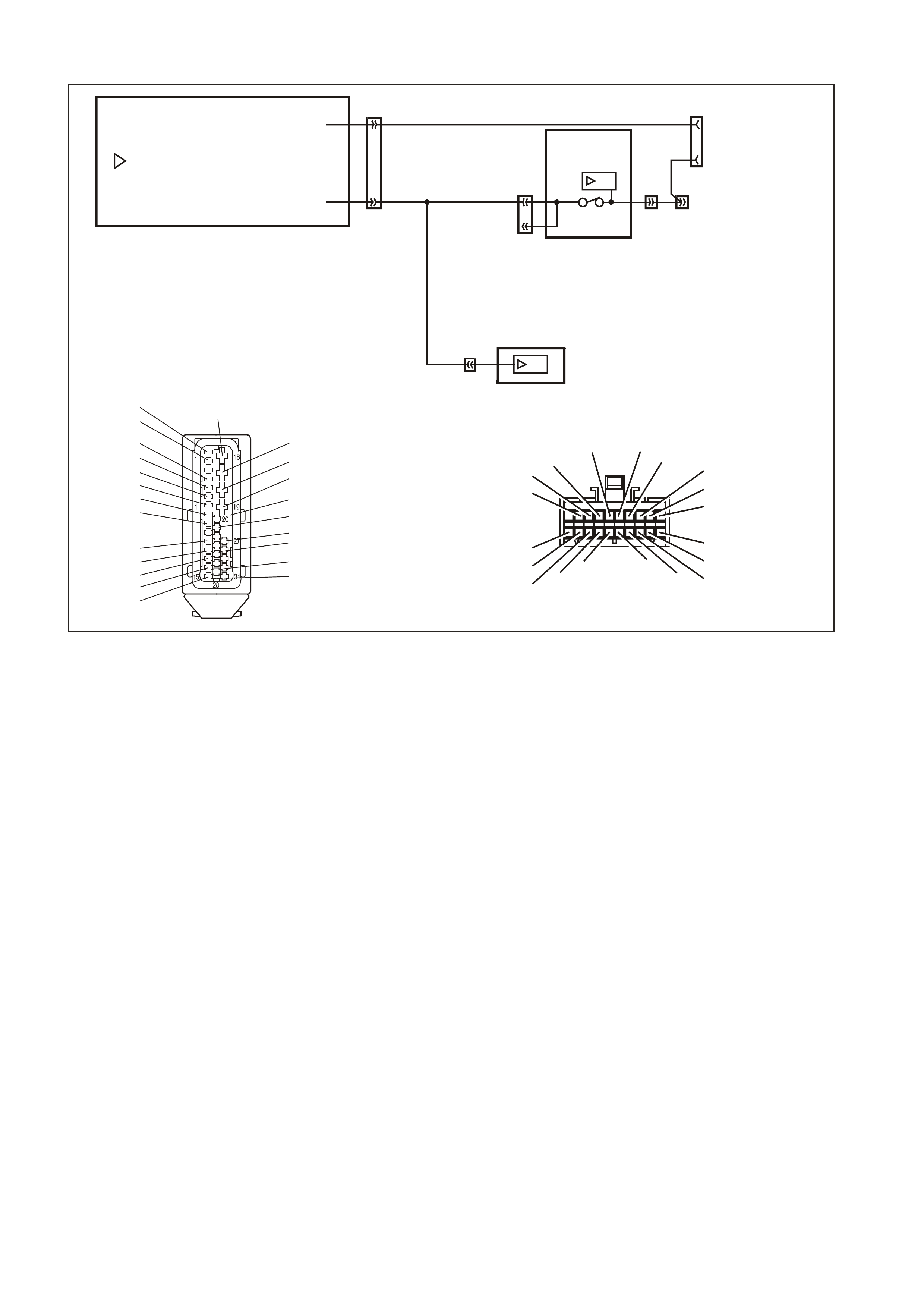
DTC 8 NO SERIAL DATA FROM ABS
T212C188
ABS OR AB S/ETC MOD ULE
YE98 YB128
DIAG _ENABLE
SER IAL DATA
12
11
SDI
12
9
YB164
YB175 3
92
2
YB164
YB175
YE112
13
3
BODY
CONTROL
MODULE
SDI
INSTRUMENT
CLUSTER
DATA LINK
CONNECTOR
BLU/B (863)
G/W
(1220)
12
YB66
YE98
ABS MODU LE CONNECTO R
B/O (154)
R (2R)
R (2R)
B (150)
Y/R (88)
G (875)
B/W (1427)
R/W (1429)
B R /R (1 2 1)
R (855 )
BLU/R (20)
O/W (1 426)
BLU/B (863)
G/W (1 220)
V ( 884)
Y ( 885)
B R (830)
GY (833)
W (872)
R (873 )
B (882))
B LU (883)
YB66
INST RU MEN TS CO NNE CTO R
10
20 1
11
B/Y (155) GY (8)BR/W (19)
BLU/Y (10)
T (30)
V/W (123) BR/O (33)BR (25)
V/R (234)
W (85)
BLU (15)
Y/R (88)
G /W (1220)
BLU/B (946)
LBLU (14)
G (875)
O/Y (1340)
P/BLU (44)
BR /R (121 )
G Y /B (1 6 87 )
CIRCUIT DESCRIPTION:
The ABS (or ABS/ETC) module sends serial data along the serial data line, circuit 1220. This is read by the
instrum ent cluster to indic ate the status of the trac tion control. If trac tion control has been disabled by the ABS/ETC
module, the Traction Control Off lamp will illuminate.
NOTE: In the VT Series II, DT C 8 is only enabled on vehicles fitted with ABS/ETC. For all other vehicles , DTC 8 will
be displayed on the instrument cluster as ‘t 08 nu’ (where nu indicates not used).
DTC 8 Will Set If:
• There is no ABS data message on the SDI bus for m ore than 10 seconds. In practice the trouble code is set
somewhere between 10 and 20 seconds after the last ABS data m essage is received by the instrument. T he
DTC is reset within 10 seconds of the arr ival of an ABS data mess age on the SDI bus . T he DTC is logged as a
History DTC.
Test Description:
Number(s) below refer to step number(s) in the following diagnostic chart.
1. Ensures that the Diagnostic Circuit Check has been performed.
2. Determines if the TECH 2 is powered up and operating correctly.
3. Checks for the presence of serial data from the ABS module. If this data can be read this indicates that the
problem is intermittent.
4. Checks the continuity of the serial data line (circuit 1220) between the ABS module and the instrument cluster.
5. If the DTC can be cleared, the fault is intermittent. If the DTC cannot be cleared, the instrument cluster is
faulty.
Diagnostic Aids:
By manipulating the harnesses at the various connectors it is often possible to isolate the cause of the circuit
interruption. This harness can then be removed and repaired.
Check for any damage to the harness which could cause an intermittent open or short to earth or backed out
terminals at the instrument cluster connectors, broken connector locks, improperly formed or damaged terminals.
The multimeter allows continuity of the wiring harness circuit 1220 to be checked.
If the f ault cannot be found in the harness then the f ault may lie in the ABS module or the BCM, both of which can
be diagnosed in their relevant Sections.

DTC 8 TEST PROCEDURE
STEP ACTION VALUE YES NO
1 • Was the Diagnostic Circuit Check performed? Go to Step 2. Go to Diagnostic
Circuit Check in this
Section.
2• Connect TECH 2 to DLC.
• Turn ignition on.
• Push power button on TECH 2.
• Does TECH 2 power up? (Screen should illuminate
and display TECH 2).
Go to Step 3. Go to TECH 2
diagnosis, refer to
Section 0C TECH 2
in the VT Series I
Service Information.
3• At the TECH 2 title screen press the Enter key.
• Select Diagnostics \ 1999 \ VT Commodore \
Chassis \ ABS/ETC.
• Turn on the ignition and press the Confirm soft
key.
• Does TECH 2 display the Electronic System:
ABS/ETC information (ie. Part Number / System ID
/ System)?
Go to Step 4. Go to Section 12L
ABS & ABS/ETC in
the VT Series I
Service Information
for V6 engine, or in
the VT Series II
Service Information
for GEN III V8
engine.
4• Using an ohmmeter, check for continuity of circuit
1220 (Green/White wire) between ABS/ETC
module connector YE98 and instrument cluster
connector YB66.
• Is there continuity?
Go to Step 5. Find source of open
circuit and repair
faulty main wiring
harness.
5• Use TECH 2 to cle ar DTC.
• Has DTC cle ared? DTC 8 is
intermittent. Check
circuit 1220
(Green/White wire)
between ABS/ETC
module and
instrument cluster
for an intermittent
fault.
Check the
instrument cluster
and ABS/ETC
module connectors
for terminal
retention. If OK
replace instrument
cluster, refer to 2.1
INSTRUMENT
CLUSTER in this
Section.
WHEN ALL DIAGNOSIS AND REPAIRS ARE COMPLETED, CLEAR ALL DTC AND VERIFY CORRECT OPERATION

DTC 9 NO SERIAL DATA FROM BCM
T212C189A
YB66
INSTRUMENTS CONNECTOR
10
20 1
11
B/Y (155) GY (8)BR/W (19)
BLU/Y (10)
T (30)
V/W (123) BR/O (33)BR (25)
V/R (234)
W (85)
BLU (15)
Y/R (88)
G/W (1220)
BLU/B (946)
LBLU (14)
G (875)
O/Y (1340)
P/BLU (44)
BR/R (121)
1
11
10
20
B/G (151)
B/R (1144)
P/B (39) GY (8)
YB164
BCM CONNE CTOR (3)
LOW SERIES
P/BLU (44)
G/ W ( 1220)
R/B (1221)
Y (26 6)
BR/G (271)
V/R (229)
W (1220)/G
B (1150)
GY/R (1391)
GY (83)
R/W (248)
BLU/W (97)
O (291)
W/BLU (494)
LBLU (94)
YB128
SDI
9
YB164
YB175 3
92
2
YB164
YB175
YE112
13
3
BODY
CONTROL
MODULE
SDI
INSTRUMENT
CLUSTER
DAT A LIN K
CONNECTOR
G/W
(1220)
12YB66
Y/R (143)
Y (43 )
O/BLU (640 )
P/B (39)
GY/R (1391)
20
28
Y/B (260)
B/R (1144)
R/W (261)
21 12
LBLU (161)
W/BLU (494)
W ( 160)
13 6
GY/B (96) B/Y (556)
W (1220)
R/B (1221)
V/R (229)
BR/G (271)
Y (266)
G/W (1220)
Y/B (272)
W ( 717)
W/R (308)
/G
1
7
Y
B175
BCM CONNECTOR (3)
HI GH S ERIES
B (1150)
BLU/W (97)
GY (83)
LBLU (94)
O/W (840)
CIRCUIT DESCRIPTION:
The BCM s ends serial data along the ser ial data line, circuit 1220. T his is read by the instrum ent cluster to indicate
the status of the various components on the serial data line.
DTC 9 Will Set If:
• There is no BCM data mes sage on the SDI bus for m ore than 10 sec onds. In practice the trouble c ode is set
som ewhere between 10 and 20 sec onds after the last BCM data mes sage is received by the instrum ent. The
DTC is reset within 10 seconds of the arr ival of a BCM data m ess age on the SDI bus. T he DT C is logged as a
History DTC.
Test Description:
Number(s) below refer to step number(s) in the following diagnostic chart.
1. Ensures that the Diagnostic Circuit Check has been performed.
2. Determines if the TECH 2 is powered up and operating correctly.
3. Check s for the presence of s erial data fr om the BCM. If this data can be read this indicates that the pr oblem is
intermittent.
4. Checks the continuity of the serial data line (circuit 1220) between the BCM and the instrument cluster.
5. If the DTC can be cleared, the fault is intermittent. If the DTC cannot be cleared, the instrument cluster is
faulty.
Diagnostic Aids:
By manipulating the harnesses at the various connectors it is often possible to isolate the cause of the circuit
interruption. This harness can then be removed and repaired.
Check for any damage to the harness which c ould cause an interm ittent open circuit or backed out ter minals at the
instrument cluster connectors, broken connector locks, improperly formed or damaged terminals.
The multimeter allows continuity of the wiring harness circuit 1220 to be checked.
If the f ault cannot be found in the harness then the f ault may lie in the BCM, which c an be diagnos ed in the relevant
Section.

DTC 9 TEST PROCEDURE
STEP ACTION VALUE YES NO
1 • Was the Diagnostic Circuit Check performed? Go to Step 2. Go to Diagnostic
Circuit Check in this
Section.
2• Connect TECH 2 to DLC.
• Turn ignition on.
• Push power button on TECH 2.
• Does TECH 2 power up? (Screen should illuminate
and display TECH 2).
Go to Step 3. Go to TECH 2
diagnosis, refer to
Section 0C TECH 2
in the VT Series I
Service Information.
3• At the TECH 2 title screen press the Enter key.
• Select Diagnostics \ 1999 \ VT Commodore \ Body
\ Body Control Module.
• Turn on the ignition and press the Confirm soft
key.
• Does TECH 2 display the Electronic System: BCM
information (ie. BCM Level / BCM Type)?
Go to Step 4. Go to BCM Serial
Data
Communication
Diagnosis in Section
12J-1 LOW SERIES
BODY CONTROL
MODULE, or Section
12J-2 HIGH SERIES
BODY CONTROL
MODULE in the VT
Series II Service
Information.
4• Using an ohmmeter, check for continuity of circuit
1220 (Green/White wire) between BCM connector
YB164 and instrument cluster connector YB66
(Low Series BCM) or YB175 and YB66 (High
Series BCM).
• Is there continuity?
Go to Step 5. Find source of open
circuit and repair
faulty main wiring
harness.
5• Use TECH 2 to cle ar DTC.
• Has DTC cle ared? DTC 9 is
intermittent. Check
circuit 1220
(Green/White wire)
between BCM and
instrument cluster
for an intermittent
fault.
Check the
instrument cluster
and BCM connectors
for terminal
retention. If OK
replace instrument
cluster, refer to 2.1
INSTRUMENT
CLUSTER in this
Section.
WHEN ALL DIAGNOSIS AND REPAIRS ARE COMPLETED, CLEAR ALL DTC AND VERIFY CORRECT OPERATION
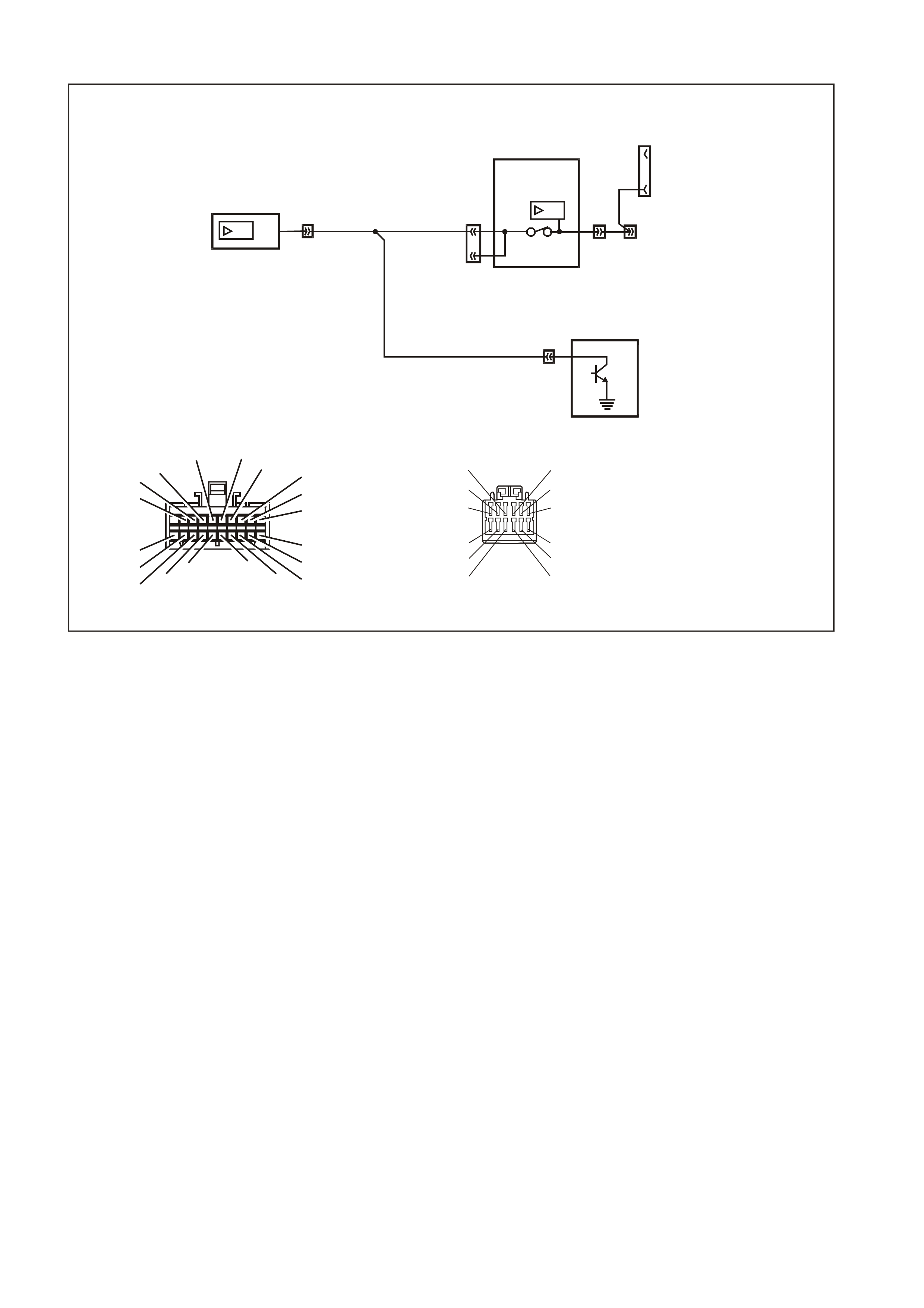
DTC 10 NO SERIAL DATA FROM ECC
T212C190
YB87
EC C CO NNECTOR
GY (8)P/BLU (44)
Y/B (52)
G/W (1220)
LG/B (735)
G (342)
BLU/B (734)
B/Y (155)
B/R (292)
Y (51)
16
712
B/R (64)
BR/W (19)
YB66
INSTRUMENTS CONNECTOR
10
20 1
11
B/Y (155) GY (8)BR/W ( 19)
BLU/Y (10)
T (3 0)
V/W (123) BR/O (33)BR (25)
V/R (234)
W ( 85)
BLU (15)
Y/R (88)
G/W (1220)
BLU/B (946)
LBLU (14)
G (875)
O/Y (1340)
P/BLU (44)
BR/ R ( 121 )
YB128
SDI
9
YB164
YB175 3
92
2
YB164
YB175
YE112
13
3
BODY
CONTROL
MODULE
SDI
INSTRUMENT
CLUSTER
ELECTRONIC
CLIMATE
CONTROL
MODULE
DATA LINK
CONNECTOR
G/W
(1220)
YB87 6
12 YB66
CIRCUIT DESCRIPTION:
The ECC module sends serial data to the instrument cluster along the serial data line, circuit 1220.
DTC 10 Will Set If:
• There is no ECC data message on the SDI bus for m ore than 10 seconds . In practice the trouble code is set
som ewhere between 10 and 20 seconds af ter the last ECC data m essage is received by the instrum ent. T he
DTC is reset within 10 seconds of the arr ival of a ECC data m essage on the SDI bus . T he DT C is logged as a
History DTC.
Test Description:
Number(s) below refer to step number(s) in the following diagnostic chart.
1. Ensures that the Diagnostic Circuit Check has been performed.
2. Determines if the TECH 2 is powered up and operating correctly.
3. Checks for the presence of serial data from the ECC module. If this data can be read this indicates that the
problem is intermittent.
4. Checks the continuity of the serial data line (circuit 1220) between the ECC module and the instrument cluster.
5. If the DTC can be cleared, the fault is intermittent. If the DTC cannot be cleared, the instrument cluster is
faulty.
Diagnostic Aids:
By manipulating the harnesses at the various connectors it is often possible to isolate the cause of the circuit
interruption. This harness can then be removed and repaired.
Check for any damage to the harness which could cause an intermittent open or short to earth or backed out
terminals at the instrument cluster connectors, broken connector locks, improperly formed or damaged terminals.
The multimeter allows continuity of the wiring harness circuit 1220 to be checked.
If the fault cannot be found in the harness then the fault m ay lie in the ECC module or the BCM, both of which can
be diagnosed in their relevant Sections.

DTC 10 TEST PROCEDURE
STEP ACTION VALUE YES NO
1 • Was the Diagnostic Circuit Check performed? Go to Step 2. Go to Diagnostic
Circuit Check in this
Section.
2• Connect TECH 2 to DLC.
• Turn ignition on.
• Push power button on TECH 2.
• Does TECH 2 power up? (Screen should illuminate
and display TECH 2).
Go to Step 3. Go to TECH 2
diagnosis, refer to
Section 0C TECH 2
in the VT Series I
Service Information.
3• At the TECH 2 title screen press the Enter key.
• Select Diagnostics \ 1999 \ VT Commodore \ Body
\ Electronic Climate Control.
• Turn on the ignition and press the Confirm soft
key.
• Does TECH 2 display the Electronic System: ECC
information?
Go to Step 4. Refer to Section 2F
AIR CONDITIONING
- ECC -
DIAGNOSTICS in
the VT Series I
Service Information.
4• Using an ohmmeter, check for continuity of circuit
1220 (Green/White wire) between ECC module
connector YB87 and instrument cluster connector
YB66.
• Is there continuity?
Go to Step 5. Repair faulty main
wiring harness.
5• Use TECH 2 to cle ar DTC.
• Has DTC cle ared? DTC 10 is
intermittent. Check
circuit 1220
(Green/White wire)
between ECC
module and
instrument cluster
for an intermittent
fault.
Check the
instrument cluster
and ECC module
connectors for
terminal retention. If
OK replace
instrument cluster,
refer to 2.1
INSTRUMENT
CLUSTER in this
Section.
WHEN ALL DIAGNOSIS AND REPAIRS ARE COMPLETED, CLEAR ALL DTC AND VERIFY CORRECT OPERATION

DTC 11 NO SERIAL DATA FROM PCM
CIRCUIT DESCRIPTION:
The PCM sends serial data to the BCM along the main serial data line, circuit 1221. Serial data is then sent to the
instrum ent cluster along the auxiliar y s erial data line, circuit 1220. Th is is r ead by the ins trument cluster to indicate
the status of the check power train lamp and the oil pressure warning lamp.
As the PCM used in conjunction with the GEN III V8 engine is different to that used with the V6 engine, a Powertrain
Interface Module (PIM) is required to convert the serial data generated by the PCM into serial data which is
compatible with the BCM.
DTC 11 Will Set If:
• There is no PCM data mes sage on the SDI bus for m ore than 10 sec onds. In practice the trouble c ode is set
somewhere between 10 and 20 seconds af ter the last PCM data message is received by the instrum ent. The
DTC is reset within 10 seconds of the arr ival of a PCM data m ess age on the SDI bus. T he DT C is logged as a
History DTC.
Test Description:
Number(s) below refer to step number(s) in the following diagnostic chart.
1. Ensures that the Diagnostic Circuit Check has been performed.
2. Determines if the TECH 2 is powered up and operating correctly.
3. Check s for the presence of s erial data fr om the PCM. If this data can be read this indicates that the pr oblem is
intermittent.
4. Checks the continuity of the serial data line (circuit 1221) between the BCM and the PCM (V6 engine).
5. Checks the continuity of the serial data line (circuit 1221) between the BCM and the PIM (GEN III V8 engine).
6. Checks the continuity of the serial data line (circuit 1049) between the PCM and the PIM (GEN III V8 engine).
7. Checks the continuity of the serial data line (circuit 1220) between the BCM and the instrument cluster.
8. If the DTC can be cleared, the fault is intermittent. If the DTC cannot be cleared, the instrument cluster is
faulty.
Diagnostic Aids:
By manipulating the harnesses at the various connectors it is often possible to isolate the cause of the circuit
interruption. This harness can then be removed and repaired.
Check for any damage to the harness which could cause an intermittent open or short to earth or backed out
terminals at the instrument cluster connectors, broken connector locks, improperly formed or damaged terminals.
The multimeter allows continuity of the wiring harness circuits to be checked.
If the fault cannot be found in the harness then the fault may lie in the PCM, PIM (GEN III V8 only) or the BCM, all of
which can be diagnosed in their relevant Sections.
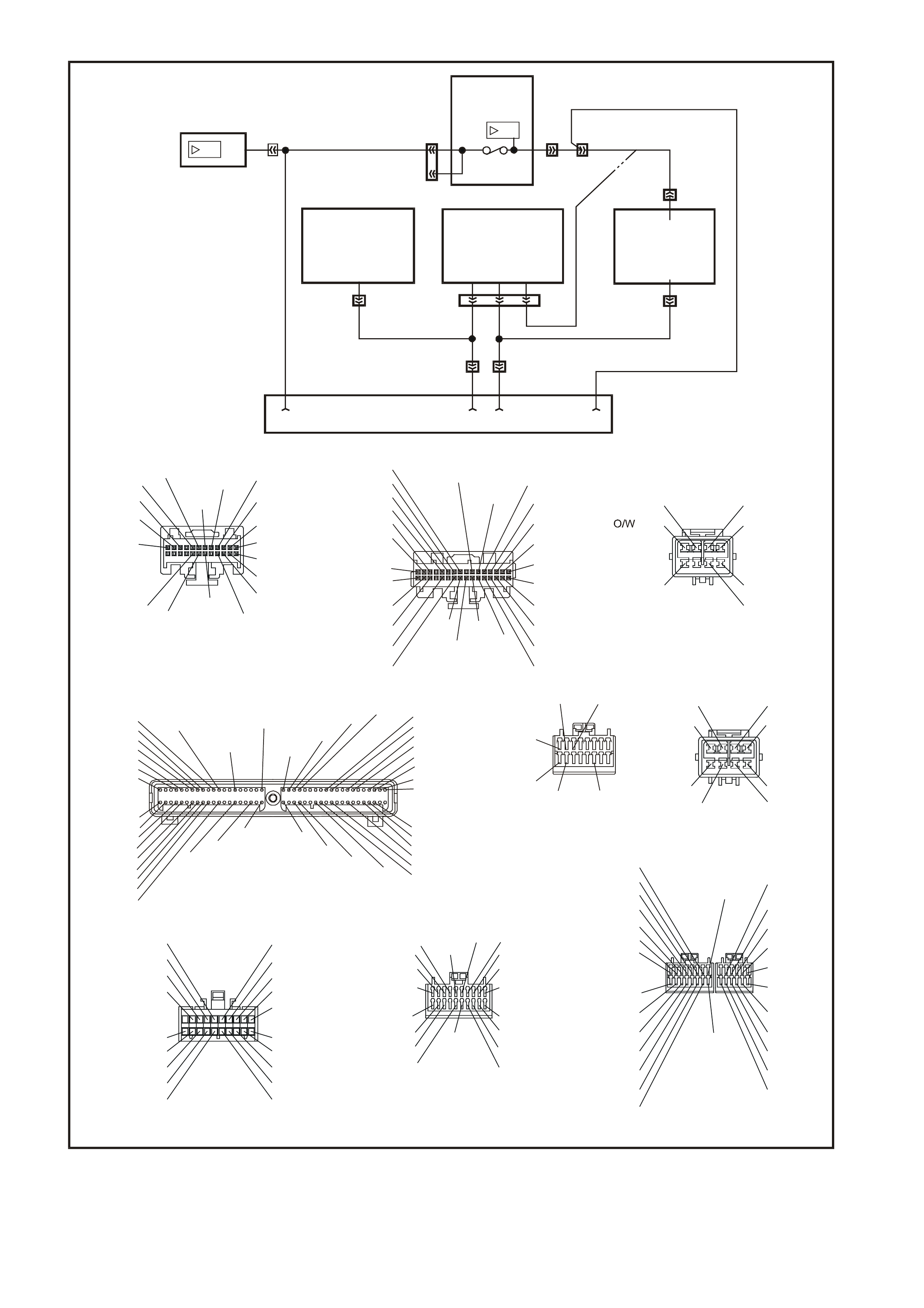
T212C191A
SDI
SDI
12 YB66
BODY
CONTROL
MODULE
G/W (1220)
YB164
YB175
INSTRUMENT
CLUSTER
POWERTRAIN
CONTROL MODULE
GEN lll V8 ENGINE
J1-58
POWERTRAIN
INTERFACE MODULE
GEN lll V8 ENGINE POWERTRAIN
CONTROL
MODULE
V6 ENGINE
711 6
A3
F14
12
69
YE122
YE110 YE111
YB215
YB188
R/B (1221)
YB194
W/B(451)
Y(1049)
YE112
YB164
YB175
3
9
13
3
2
2
YB128
DA TA LINK CONNECTOR
20
11
10
1
(494)
(291)
(94)
(1144)
(97)
(248)
(1391)
P/B G/W
R/B
Y
BR/G
V/R
W/G
B
O
LBLU
B/R
BLU/W
R/W
GY/R
(39) (1220)
(1221)
(266)
(271)
(229)
(1220)
(1150)
(83)
GY GY
(8)
B/G
(151)
P/BLU
(44)
1
BR/G
G/W
Y
Y/B
W
W/R
V/R
R/B
W/G
B/Y
GY/B
W
LBLU
(271)
(266)
(1220)
(272)
(717)
(308)
(229)
(1221)
(1220)
(556)
(96)
(160)
(161)
(143)
(43)
(640)
(39)
(1150)
(97)
(83)
(94)
(260)
(1144)
(840)
Y/RY
O/BLU
P/B
GY/R
(1391)
B
BLU/W
GY
LBLU
O/W
Y/B
B/R
613
20
28
21 12
7
(494)
W/BLU
R/W
(261)
A1
B1
A12
B12
(481)
(417)
(740)
(1227)
(410) (472)
(259)
(750)
(750)
(750)
(750)
(1221)
(39)
(465)
(416)
(740)
B/R
B/R
B/R
B/R
R/B
P
G/B
BR
Y
G/W
GY
O/B
R
BLU
O/B B/Y
(415)
V/W
(1456)
LG
(875)
(14)
(10)
(155)
(1340)
(44)
(121)
(123)
(30) (33)
(25)(946)
(1220)
(88)
(15)
(85)
(19)
(8)
B/Y
BLU/Y
LBLU
G
O/Y
P/BLU
BR/R
V/WT
GY
BR/W
W
BLU
Y/R
G/W
BLU/B
BR
BR/O
1
11
10
20
V/R
(234)
(1426)
(304)
BLU/W P/BLU
G/W
V/W
B/W
(339)
(465)
(123)
(1427)
(482)
(481)
(59)
(366)
R
LG/B
LG
G
GY
G
P
(434)
(129)
(451)
(439)
Y
(1049)
W/B
W/BLU
YE110
ENGIN E CONNE CTOR (1)
YE111
ENGINE CONNECTOR (2)
YB175
BCM CONNECTOR (3)
HIGH SERIES
YB164
BCM CONNECTOR (3)
LO W SE R I ES
YB66
INSTRUMENTS CONNECTOR
YB194
PCM CONNECTOR (3)
V6 ENGINE
YB188
PCM CONNECTOR (2)
V6 ENGINE
YE122
PCM CONNECTOR (1)
GEN lll V8 ENGINE
YB215
PIM CONN ECTOR
GE N lll V8 EN GI N E
LG/B
(366)
G
(843)
B/W
F16
B/Y
BR/Y
(1228)
(469)
Y
(776)
(451)
F1
P
GY Y
BLU/W
(841)
BLU
V
E1
LBLU
GY/BLU
(845)
BLU
B
(1226)
W
W/B
BLU/W
(1434)
V
R
(435)
(31)
(1229)
GY
(1224)
Y
(846)
GY
(842)
(452)
(774) (304)
BR/Y
(411)
(439)
(773) (772)(771)
GY/BLU
BLU
(1225)
E16
(1427)
(429)
(844)
B/O
GY
(434)MAN
OR AUTO
G
(69)
GY/B
(455)
BLU/W
(771)
G/W
(897)
BR
(86)
LG
(848)
W
(776)
GY
(845)
GY
(1412)
BLU
(841)
Y
(410)
G
(355)
Y
(846)
BR
(633)
R/W
(632)
B/Y
(452)
Y
(1049)
O
(740)
B
(421)
B/W
(1230)
W/R
(815)
V/W
(414)
V/W
(415)
BR/Y
(844)
P/B
(847)
B/R
(750)
LBLU/W
(646)
V
(843)
G
(842)
BLU/Y
(334)
GY
(416)
LBLU
(826)
BLU
(643)
B/R
(750)
Y
(772)
BLU
(774)
V
(412)
BLU/B
(413)
GY/B
(1413)
LBLU/B
(647)
O
(740)
P
(39)
GY
(1226)
Y
(1225)
1
41
40
80
(AUTO)
(1434)
GY/BLU
GY
(434)
(MAN)
B/R
(750)
P
(39)
W/B
(451)
Y
(1049)
R/B
(1221)
NO SERIAL DATA FROM PCM

DTC 11 TEST PROCEDURE
STEP ACTION VALUE YES NO
1 • Was the Diagnostic Circuit Check performed? Go to Step 2. Go to Diagnostic
Circuit Check in this
Section.
2 • Connect TECH 2 to DLC.
• Turn ignition on.
• Push power button on TECH 2.
• Does TECH 2 power up? (Screen should illuminate
and display TECH 2).
Go to Step 3. Go to TECH 2
diagnosis, refer to
Section 0C TECH 2
in the VT Series I
Service Information.
3 • At the TECH 2 title screen press the Enter key.
• Select Diagnostics \ 1999 \ VT Commodore \
Engine \ select appropriate engine.
• Turn on the ignition and press the Confirm soft
key.
• Does TECH 2 display the Engine System:
Identification information (ie. PROM Identification)?
V6 engine, go to
Step 4.
GEN III V8 engine,
go to Step 5.
Refer to Section 6C1
POWERTRAIN
MANAGEMENT - V6
ENGINE in the VT
Series I Service
Information or
Section 6C3-2
DIAGNOSIS -
GEN III V8 ENGINE
in the VT Series II
Service Information.
4 • Using an ohmmeter, check for continuity of circuit
1221 (Red/Black wire) between BCM connector
YB164 (Low Series BCM), or YB175 (High Series
BCM) and PCM connector YB188.
• Is there continuity?
Harness from BCM
to PCM OK. Go to
Step 7.
Repair faulty wiring
harness from BCM
to PCM.
5 • Using an ohmmeter, check for continuity of circuit
1221 (Red/Black wire) between BCM connector
YB164 (Low Series BCM), or YB175 (High Series
BCM) and PIM connector YB215.
• Is there continuity?
Harness from BCM
to PIM OK. Go to
Step 6.
Repair faulty wiring
harness from BCM
to PIM.
6 • Using an ohmmeter, check for continuity of circuit
1049 (Yellow wire) between PCM connector YE122
and PIM connector YB215.
• Is there continuity?
Harness from PCM
to PIM OK. Go to
Step 7.
Repair faulty wiring
harness from PCM
to PIM.
7 • Using an ohmmeter, check for continuity of circuit
1220 (Green/White wire) between BCM connector
YB164 (Low Series BCM), or YB175 (High Series
BCM) and instrument cluster connector YB66.
• Is there continuity?
Harness from BCM
to instrument cluster
OK. Go to Step 8.
Repair faulty wiring
harness from BCM
to instrument.
8 • Use TECH 2 to clea r DTC.
• Has DTC cle ared? DTC 11 is
intermittent. Check
circuit 1221
(Red/Black wire)
between BCM and
PCM (V6 engine) or
BCM and PIM
(GEN III V8 engine),
circuit 1049 (Yellow
wire) between PCM
and PIM (GEN III V8
engine) and circuit
1220 (Green/White
wire) between BCM
and instrument
cluster (both
engines) for an
intermittent fault.
Check the
instrument cluster,
PCM, PIM and BCM
connectors as
appropriate for
terminal retention. If
OK replace
instrument cluster,
refer to 2.1
INSTRUMENT
CLUSTER in this
Section.
WHEN ALL DIAGNOSIS AND REPAIRS ARE COMPLETED, CLEAR ALL DTC AND VERIFY CORRECT OPERATION

DTC 12 NO SERIAL DATA FROM SDM
CIRCUIT DESCRIPTION:
The SRS Sensing and Diagnostic Module (SDM) sends serial data along the serial data line, via the BCM. This is
read by the instrument cluster to indicate the status of the SDM.
NOTE: There are two versions of SDM used by the SRS. Version 8.0 is used on vehicles with either 2-loop (left-
hand drive only), 3-loop or 4-loop systems, while version 8.1 is used on vehicles with a 6-loop system. For more
information, refer to Section 12M SUPPLEMENTAL RESTRAINT SYSTEM in the VT Series I Service Information.
DTC 12 Will Set If:
• There is no serial data being received from the SDM. The DTC is reset within 10 seconds of the arrival of a
SDM data message on the SDI bus. The DTC is logged as a History DTC.
Test Description:
Number(s) below refer to step number(s) in the following diagnostic chart.
1. Ensures that the Diagnostic Circuit Check has been performed.
2. Determines if the TECH 2 is powered up and operating correctly.
3. Check s for the presence of s erial data fr om the SDM. If this data c an be read this indic ates that the problem is
intermittent.
4. Checks the continuity of the serial data line (circuit 1220) between the SDM and the BCM.
5. Checks the continuity of the serial data line (circuit 1220) between the BCM and the instrument cluster.
6. If the DTC can be cleared, the fault is intermittent. If the DTC cannot be cleared, the instrument cluster is
faulty.
Diagnostic Aids:
By manipulating the harnesses at the various connectors it is often possible to isolate the cause of the circuit
interruption. This harness can then be removed and repaired.
Check for any damage to the harness which could cause an intermittent open or short to earth or backed out
terminals at the instrument cluster connectors, broken connector locks, improperly formed or damaged terminals.
The multimeter allows continuity of the wiring harness circuit 1220 to be checked.
If the fault cannot be found in the harness then the fault may lie in the SDM or the BCM, both of which can be
diagnosed in their relevant Sections.
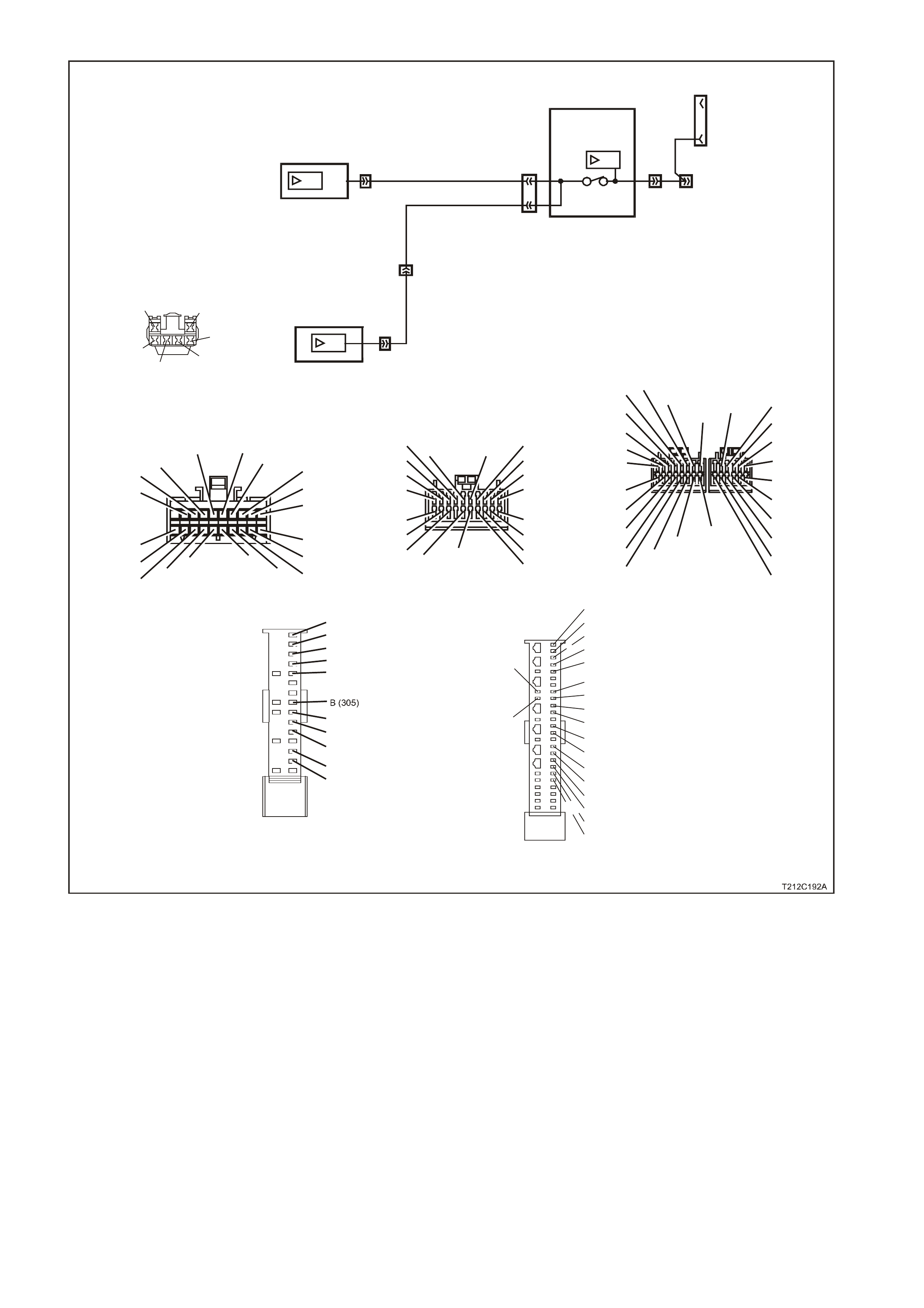
YB128
SDI
9
YB164
YB175 3
92
2
YB164
YB175
YE112
13
3
BODY
CONTROL
MODULE
SDI
SDI
INSTRUMENT
CLUSTER
DATA LINK
CONNECTOR
G/W (1220)
W (1220)/G
12 YB66
YB189
YB190
YB191
9
SRS SENSING AND
DIAGNOSTIC MODULE
YB66
INSTRUMENTS CONNECTOR
10
20 1
11
B/Y (155) GY (8)BR/W (19)
BLU/Y (10)
T (30)
V/W (123) BR/O (33)BR (25)
V/R (234)
W ( 85)
BLU (15)
Y/R (88)
G/W (1220)
BLU/B (946)
LBLU (14)
G (875 )
O/Y (1340)
P/BLU (44)
BR/R (121)
Y/R (143)
Y (43)
O/BLU (640)
P/B (39)
GY/R (1391)
20
28
Y/B (260)
B/R (1144)
R/W (261)
21 12
LBLU (161)
W/BLU (494)
W (160 )
13 6
GY/B (96) B/Y (556)
W/ (1220 )
R/B (1221)
V/R (229)
BR/G (271)
Y (266)
G/W (1220)
Y/B (272)
W ( 717)
W/R (308)
G
1
7
Y
B175
BCM CONNECTOR (3)
HI G H SE RIES
B (11 50)
BLU / W (9 7 )
GY (83)
LBLU (94)
O/W (840)
1
11
10
20
B/G (151)
B/R (1144)
P/B (39) GY (8)
Y
B164
BCM CONNE CTOR (3)
LOW SERIES
P/BLU (44)
G/W (1220)
R/B ( 1221)
Y (26 6)
BR/G (271)
V/R (229)
W (1220)/G
B (1150)
GY/R (1391)
GY ( 83)
R/W (248)
BLU/ W (97)
O (291)
W/BLU (494)
LBLU (94)
YB189
8.1 SDM WIRI NG HA RNESS
CONNECTOR
BR/B (393)
26
50 25
1
BLU/B (351)
R/B (352)
BR/W (353)
Y/R (354)
P/B (739)
B (305)
W (1220)/G
W (3 47)
G (348)
Y/B (349)
GY/B (3 50)
Y/G (385)
BR/G (386)
Y/W (387)
BR/W (388)
Y/BLU (392)
GY/W (407)
LBLU (408)
YB190
8.0 SDM WIRI NG HA RNESS
CONNECTOR
BLU/B (351)
R/B (352)
BR/W (353)
Y/R (354)
P/B (739)
W (122 0)/G
W (347)
G (348)
Y/B (349)
GY/B (350)
P/B
(739) W
(1220)
/G
G (348)
GY/B
(350)Y/B (349)
W (347)
YB191
AI R BA G I NTE RFAC E
CONNECTOR
NO SERIAL DATA FROM SDM

DTC 12 TEST PROCEDURE
STEP ACTION VALUE YES NO
1 • Was the Diagnostic Circuit Check performed? Go to Step 2. Go to Diagnostic
Circuit Check in this
Section.
2• Connect TECH 2 to DLC.
• Turn ignition on.
• Push power button on TECH 2.
• Does TECH 2 power up? (Screen should illuminate
and display TECH 2).
Go to Step 3. Go to TECH 2
diagnosis, refer to
Section 0C TECH 2
in the VT Series I
Service Information.
3• At the TECH 2 title screen press the Enter key.
• Select Diagnostics \ 1999 \ VT Commodore \ Body
\ SRS.
• Turn on the ignition and press the Confirm soft
key.
• Does TECH 2 display the Electronic System:
Identification information (ie. Part Number /
Production Date)?
Go to Step 4. Refer to Section
12M
SUPPLEMENTAL
RESTRAINT
SYSTEM in the VT
Series I Service
Information.
4• Disable the SRS, refer to Section 12M
SUPPLEMENTAL RESTRAINT SYSTEM in the VT
Series I Service Information.
• Using an ohmmeter and Tool KM-609-20, check
harness for continuity of circuit 1220 (White/Green
wire) between SDM connector YB189/YB190 and
BCM connector YB164 (Low Series BCM), or
YB189/YB190 and YB175 (High Series BCM).
• Is there continuity?
Harness from SDM
to BCM OK. Go to
Step 5.
Repair faulty wiring
harness from SDM
to BCM.
5• Using an ohmmeter, check for continuity of circuit
1220 (Green/White wire) between BCM connector
YB164 (Low Series BCM), or YB175 (High Series
BCM) and instrument cluster connector YB66.
• Is there continuity?
Harness from BCM
to instrument cluster
OK. Go to Step 6.
Repair faulty wiring
harness from BCM
to instrument cluster.
6• Enable the SRS, refer to Section 12M
SUPPLEMENTAL RESTRAINT SYSTEM in the VT
Series I Service Information.
• Use TECH 2 to cle ar DTC.
• Has DTC cle ared?
DTC 12 is
intermittent. Check
circuit 1220
(White/Green wire)
between SDM and
BCM, and circuit
1220 (Green/White
wire) between BCM
and instrument
cluster for an
intermittent fault.
Check the
instrument cluster,
SDM and BCM
connectors for
terminal retention. If
OK replace
instrument cluster,
refer to 2.1
INSTRUMENT
CLUSTER in this
Section.
WHEN ALL DIAGNOSIS AND REPAIRS ARE COMPLETED, CLEAR ALL DTC AND VERIFY CORRECT OPERATION
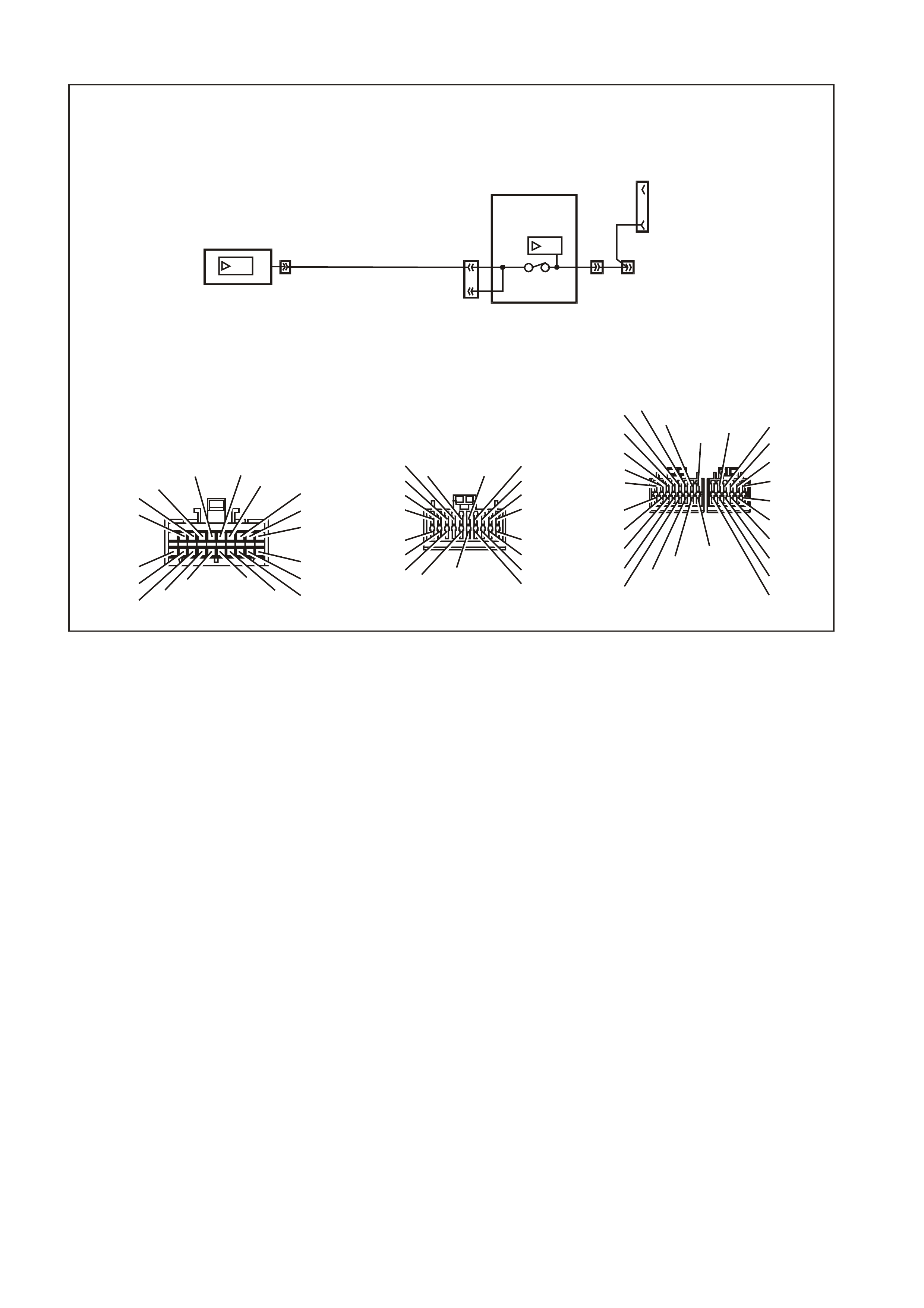
DTC 13 NO INSTRUMENT POLL FROM BCM
T212C189A
YB66
INSTRUMENTS CONNECTOR
10
20 1
11
B/Y (155) GY (8)BR/W (19)
BLU/Y (10)
T (30)
V/W (123) BR/O (33)BR (25)
V/R (234)
W (85)
BLU (15)
Y/R (88)
G/W (1220)
BLU/B (946)
LBLU (14)
G (875)
O/Y (1340)
P/BLU (44)
BR/R (121)
1
11
10
20
B/G (151)
B/R (1144)
P/B (39) GY (8)
YB164
BCM CONNE CTOR (3)
LOW SERIES
P/BLU (44)
G/ W ( 1220)
R/B (1221)
Y (26 6)
BR/G (271)
V/R (229)
W (1220)/G
B (1150)
GY/R (1391)
GY (83)
R/W (248)
BLU/W (97)
O (291)
W/BLU (494)
LBLU (94)
YB128
SDI
9
YB164
YB175 3
92
2
YB164
YB175
YE112
13
3
BODY
CONTROL
MODULE
SDI
INSTRUMENT
CLUSTER
DAT A LIN K
CONNECTOR
G/W
(1220)
12YB66
Y/R (143)
Y (43 )
O/BLU (640 )
P/B (39)
GY/R (1391)
20
28
Y/B (260)
B/R (1144)
R/W (261)
21 12
LBLU (161)
W/BLU (494)
W ( 160)
13 6
GY/B (96) B/Y (556)
W (1220)
R/B (1221)
V/R (229)
BR/G (271)
Y (266)
G/W (1220)
Y/B (272)
W ( 717)
W/R (308)
/G
1
7
Y
B175
BCM CONNECTOR (3)
HI GH S ERIES
B (1150)
BLU/W (97)
GY (83)
LBLU (94)
O/W (840)
CIRCUIT DESCRIPTION:
The BCM uses the serial data line (circuit 1220) to poll the instrument cluster for information.
DTC 13 Will Set If:
• There is no instrument poll from the BCM for more than 10 seconds. In practice the trouble code is set
somewhere between 10 and 20 seconds after the last instrum ent poll is received by the instrument. T he DTC
is reset within 10 seconds of the arrival of an instrument poll from the BCM. The DTC is logged as a History
DTC.
Test Description:
Number(s) below refer to step number(s) in the following diagnostic chart.
1. Ensures the Diagnostic Circuit Check has been performed.
2. Determines if the BCM can communicate with the TECH 2.
3. Checks if fault is common with other control modules connected to the serial data circuit.
4. Checks internal switch in BCM for open circuit.
5. Checks circuit 1220 and determines if fault is in wiring or a control module.
6. Checks circuit 1220 for open circuit.
7. Checks integrity of earth circuits for the instruments.
8. If the DTC can be cleared, the fault is intermittent. If the DTC cannot be cleared, the instrument cluster is
faulty.
Diagnostic Aids:
By manipulating the harnesses at the various connectors it is often possible to isolate the cause of the circuit
interruption. This harness can then be removed and repaired.
Check for any damage to the harness which could cause an intermittent open or short to earth or backed out
terminals at the instrument cluster connectors, broken connector locks, improperly formed or damaged terminals.
The multimeter allows continuity of the wiring harness circuit 1220 to be checked.
If the f ault cannot be found in the harness then the f ault may lie in the BCM, which c an be diagnos ed in the relevant
Section.

DTC 13 TEST PROCEDURE
STEP ACTION VALUE YES NO
1 • Was the Diagnostic Circuit Check performed? Go to Step 2. Go to Diagnostic
Circuit Check in this
Section.
2• Connect TECH 2 to the DLC.
• Select Bod y / DTC Check / F0: DTC Check.
• Can TECH 2 communicate with the BCM?
NOTE: If ‘No Data’ is displayed next to the BCM, then
there is no communication between TECH 2 and the
BCM. If 'No DTC' or 'DTCs Set' is displayed then there
is communication between the TECH 2 and the BCM.
Go to Step 3. Go to BCM Serial
Data
Communication
diagnostics in
Section 12J-1 LOW
SERIES BODY
CONTROL
MODULE, or Section
12J-2 HIGH SERIES
BODY CONTROL
MODULE in the VT
Series II Service
Information.
3• In Step 2, was TECH 2 able to communicate with
all the other control modules, except the
Instruments, fitted to the vehicle (ABS or
ABS/ETC, ECC, SRS)?
NOTE: If ‘No Data’ is displayed next to a control
module, then there is no communication between
TECH 2 and that control module.
Go to Step 6. Go to Step 4.
4• Using an ohmmeter, check continuity of circuits
1220 (Green/White wire) and 1221 (Red/Black
wire) between BCM connector YB164, terminals 2
and 3
(
Low Series BCM
)
or YB175, terminals 2 and
9 (High Series BCM).
• Does continuity exist?
Go to Step 5. Replace BCM, refer
to Section 12J-1
LOW SERIES BODY
CONTROL
MODULE, or Section
12J-2 HIGH SERIES
BODY CONTROL
MODULE in the VT
Series II Service
Information.
5• Check circuit 1220 for open, short to earth or short
to voltage between BCM and individual control
modules.
• Is circuit 1220 okay?
NOTE: Disconnect each control module in circuit 1220
one at a time to isolate the fault in the circuit or to
identify the control module causing the fault.
Refer to the
appropriate
diagnostic procedure
for the faulty control
module.
Repair circuit 1220
as necessary.
6• Using an ohmmeter, check for continuity between
BCM connector YB164, terminal 3 (Low Series
BCM) or YB175, terminal 9 (High Series BCM) and
instruments connector YB66, terminal 12
(Green/White wire).
• Does continuity exist?
Go to Step 7. Repair open in
circuit 1220.
7• Check the integrity of the Instruments earth circuit
by performing a voltage drop on circuit 155
between instrument connector YB66, terminal 6
and earth point E3.
• With ignition on, is voltage less than the specified
value?
0.15 volt Go to Step 8. Repair earth circuit
as necessary.
8• Use TECH 2 to cle ar DTC.
• Has DTC cle ared? DTC 13 is
intermittent. Check
circuit 1220
(Green/White wire)
between BCM and
instrument cluster
for an intermittent
fault.
Check the
instrument cluster
and BCM connectors
for terminal
retention. If OK
replace instrument
cluster, refer to 2.1
INSTRUMENT
CLUSTER in this
Section.
WHEN ALL DIAGNOSIS AND REPAIRS ARE COMPLETED, CLEAR ALL DTC AND VERIFY CORRECT OPERATION

DTC 14 NO SERIAL COMMUNICATION
CIRCUIT DESCRIPTION:
When investigating any complaint of an Instrument problem or malfunction, always begin diagnosis with the
diagnostic cir cuit check . This check is a prelim inary procedure that check s that the Instr uments are com munic ating
on the serial data line as well as helping to identify a problem or malfunction and directing the reader to the
appropriate diagnostic chart in this section.
W ith TECH 2 connected to the DLC and ignition switched on, TECH 2 should display serial data com munication. If
TECH 2 does not display serial data, the serial data circuit maybe open or shorted.
There are several other control modules that are connected to the serial data line (PCM, PIM (GEN III V8 only),
BCM, ECC, ABS or ABS/ETC, instruments and SDM). Any of these control modules could cause a fault on the
serial data line. This fault could result in TECH 2 not being able to display serial data.
Test Description:
Number(s) below refer to step number(s) in the following diagnostic chart.
1. Ensures the Diagnostic Circuit Check has been performed.
2. Determines if the BCM can communicate with the TECH 2.
3. Checks if fault is common with other control modules connected to the serial data circuit.
4. Checks internal switch in BCM for open circuit.
5. Checks circuit 1220 and determines if fault is in wiring or a control module.
6. Checks circuit 1220 for open circuit.
7. Checks integrity of earth circuits for the instruments.
8. If the DTC can be cleared, the fault is intermittent. If the DTC cannot be cleared, the instrument cluster is
faulty.
Diagnostic Aids:
A fault with the serial data circuit could be caused by one or more of the several control m odules connected to this
serial data circuit. Isolate the fault by disconnecting each control module, one at a time, until serial data
communication is restored.
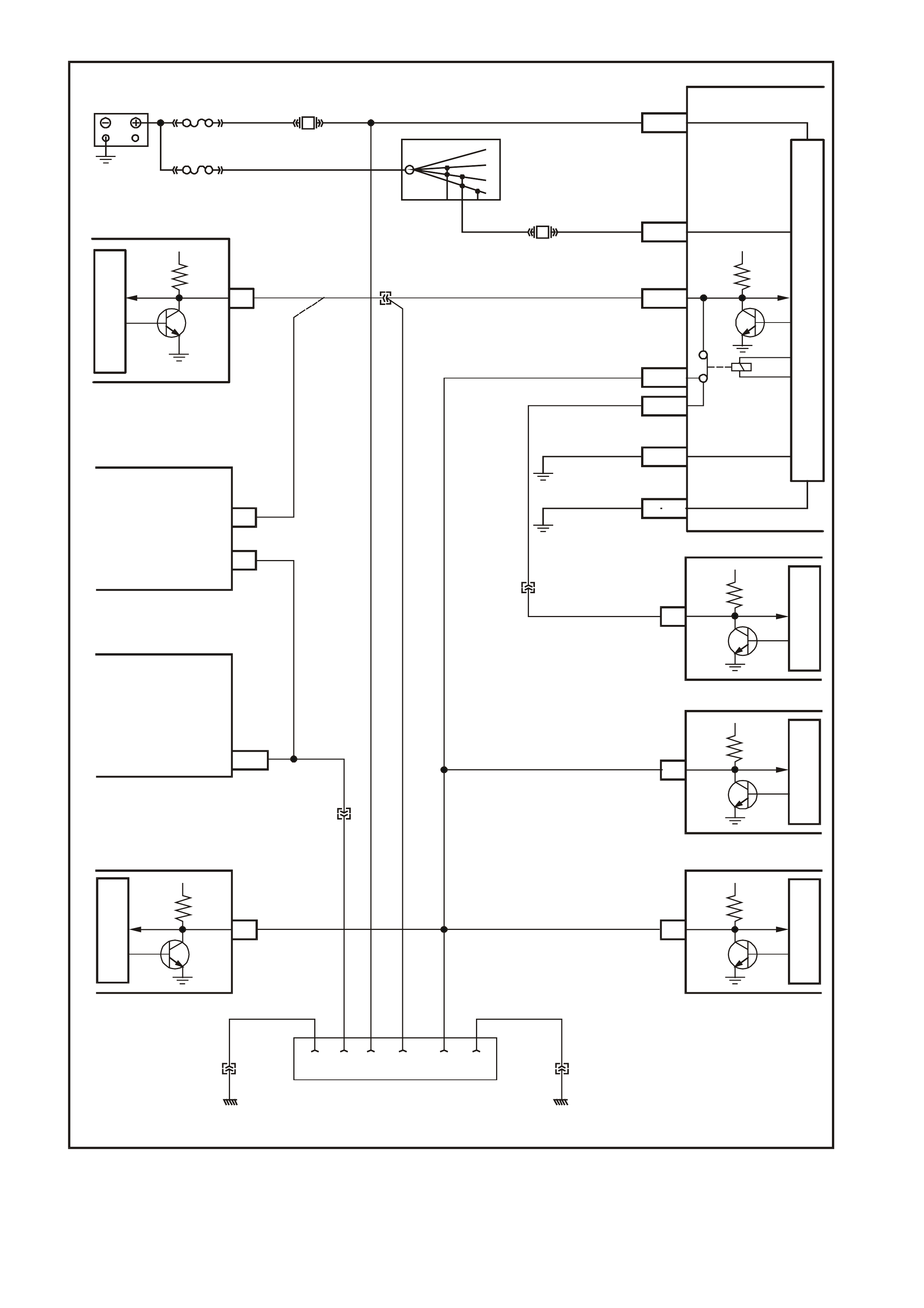
T212C193A
BATTERY
30 OFF/ON
LOCK
ACC.
IGN.
START
15A 15 50
P (3) P/B (39)
R/B (1221)
F13
BCM
SDM
ECC
INSTRUMENTSABS/ETC
PI M - GEN III V8
PCM - GEN III V8
PCM - V6
M
I
C
R
O
P
R
O
C
E
S
S
O
R
M
I
C
R
O
M
I
C
R
O
BATTERY MAIN POWER
A3
5V
SERIAL
DATA
YB188 YE112
FS
FJ
(1040)
R (2H)
F31
IGNITION SWITCH
A
5/A6
E20/D6
E2/D2
E9/D3
E3/D13
B10/B11
A1/A5
O/B (740)
YB176/
YB165
YB175/
YB164 IGNITION ON
SERIAL
DATA
MAIN
SERIAL
DAT A AUX.
HIGH CURR ENT
EARTH
5V
5V
5V
5V5V
G/W (1220)
W/G (1220)
B/G (151)
B/Y (155)
LOC. E3
LOC. E3
YB174/
YB163
YB176/
YB165
ELECTRONIC EARTH
M
I
C
R
O
M
I
C
R
O
M
I
C
R
O
SERIAL
DATA
SERIAL
DATA
SERIAL
DATA
SERIAL
DATA
YB189
YB190
YB87
YB66YE98
YB215
YE122
YE110
Y (1049)
9
6
1211
7
6
J1-58
YB191
POWERTRAIN
INTERFACE
MODULE
(GEN III V8 ENGINE
ONLY)
POWERTRAIN
CONTROL
MODULE
(GEN III V8 ENGINE
ONLY)
YE114 YE114
LOC. E3LOC. E3
B/Y (155) B (150)
5216 9 14
Y
B128
DAT A LINK CONNECTOR
CLAS S 2 SERIAL DA TA
SERIAL DATA CIRCUIT

DTC 14 TEST PROCEDURE
STEP ACTION VALUE YES NO
1 • Was the Diagnostic Circuit Check performed? Go to Step 2. Go to Diagnostic
Circuit Check in this
Section.
2• Connect TECH 2 to the DLC.
• Select Bod y / DTC Check / F0: DTC Check.
• Can TECH 2 communicate with the BCM?
NOTE: If ‘No Data’ is displayed next to the BCM, then
there is no communication between TECH 2 and the
BCM. If 'No DTC' or 'DTCs Set' is displayed then there
is communication between the TECH 2 and the BCM.
Go to Step 3. Go to BCM Serial
Data
Communication
diagnostics in
Section 12J-1 LOW
SERIES BODY
CONTROL
MODULE, or Section
12J-2 HIGH SERIES
BODY CONTROL
MODULE in the VT
Series II Service
Information.
3• In Step 2, was TECH 2 able to communicate with
all the other control modules, except the
Instruments, fitted to the vehicle (ABS or
ABS/ETC, ECC, SRS)?
NOTE: If ‘No Data’ is displayed next to a control
module, then there is no communication between
TECH 2 and that control module.
Go to Step 6. Go to Step 4.
4• Using an ohmmeter, check continuity of circuits
1220 (Green/White wire) and 1221 (Red/Black
wire) between BCM connector YB164, terminals 2
and 3
(
Low Series BCM
)
or YB175, terminals 2 and
9 (High Series BCM).
• Does continuity exist?
Go to Step 5. Replace BCM, refer
to Section 12J-1
LOW SERIES BODY
CONTROL
MODULE, or Section
12J-2 HIGH SERIES
BODY CONTROL
MODULE in the VT
Series II Service
Information.
5• Check circuit 1220 (Green/White wire) for open,
short to earth or short to voltage between BCM and
individual control modules. Note that the wire
colour for circuit 1220 between the BCM and the
SDM is White/Green.
• Is circuit 1220 okay?
NOTE: Disconnect each control module in circuit 1220
one at a time to isolate the fault in the circuit or to
identify the control module causing the fault.
Refer to the
appropriate
diagnostic procedure
for the faulty control
module.
Repair circuit 1220
as necessary.
6• Using an ohmmeter, check for continuity between
BCM connector YB164, terminal 3 (Low Series
BCM) or YB175, terminal 9 (High Series BCM) and
instruments connector YB66, terminal 12
(Green/White wire).
• Does continuity exist?
Go to Step 7. Repair open in
circuit 1220.
7• Check the integrity of the Instruments earth circuit
by performing a voltage drop on circuit 155
between instrument connector YB66, terminal 6
and earth point E3.
• With ignition on, is voltage less than the specified
value?
0.15 volt Go to Step 8. Repair earth circuit
as necessary.
8• Use TECH 2 to cle ar DTC.
• Has DTC cle ared? DTC 14 is
intermittent. Check
circuit 1220
(Green/White wire)
between BCM and
instrument cluster
for an intermittent
fault.
Check the
instrument cluster
and BCM connectors
for terminal
retention. If OK
replace instrument
cluster, refer to 2.1
INSTRUMENT
CLUSTER in this
Section.
WHEN ALL DIAGNOSIS AND REPAIRS ARE COMPLETED, CLEAR ALL DTC AND VERIFY CORRECT OPERATION

DTC 15 NO SUB-CLOCK
CIRCUIT DESCRIPTION:
The sub-clock is part of the printed circuit board housed within the instrument cluster, and provides timing pulses
required for the operation of the instrument cluster liquid crystal display when the ignition is off. If a DTC 15 has
been set, then the instrument cluster will need to be replaced.
DTC 15 Will Set If:
• An attempt to switch the low power sub-clock fails. This occurs 20 seconds after the ignition is switched off.
The DTC is reset when a switch to the low power sub-clock is successful. The DTC is logged as a History
DTC.
DTC 15 TEST PROCEDURE
STEP ACTION VALUE YES NO
1 • Was the Diagnostic Circuit Check performed? Go to Step 2. Go to Diagnostic
Circuit Check in this
Section.
8• Use TECH 2 to cle ar DTC.
• Has DTC cle ared? Instrument cluster
OK. End of
diagnostic testing.
Replace instrument
cluster, refer to 2.1
INSTRUMENT
CLUSTER in this
Section.
WHEN ALL DIAGNOSIS AND REPAIRS ARE COMPLETED, CLEAR ALL DTC AND VERIFY CORRECT OPERATION

DTC 16 ABS OR ABS/ETC FAULT LOGGED
CIRCUIT DESCRIPTION:
The ABS or ABS/ETC module informs the instrument via the serial data bus whenever an ABS or ABS/ETC DTC
has been set. DTC 16 does not set the icon/message on the instrument cluster. Refer to
Section 12L ABS & ABS/ETC in the VT Series I Service Information for fault diagnostic procedures on the V6
engine, or in the VT Series II Service Information for the GEN III V8 engine.
DTC 16 is logged as a History DTC.

DTC 17 BCM FAULT LOGGED
CIRCUIT DESCRIPTION:
The BCM inf orms the instrum ent via the serial data bus whenever a BCM DT C has been set. DT C 17 does not set
the icon/m es s age on the instr ument clus ter. Refer to Sect ion 12J- 1 LO W SERIES BODY CO NT RO L MODUL E, or
Section 12J-2 HIGH SERIES BODY CONTROL MODULE in the VT Series II Service Information for fault
diagnostic procedures.
DTC 17 is logged as a History DTC.

DTC 18 ECC FAULT LOGGED
CIRCUIT DESCRIPTION:
The ECC module informs the instrum ent via the s erial data bus whenever an ECC DT C has been set. DTC 18 does
not set the icon/message on the instrument cluster. Refer to Section 2F AIR CONDITIONING - ECC in the VT
Series I Service Informationfor fault diagnostic procedures.
DTC 18 is logged as a History DTC.

DTC 19 PCM FAULT LOGGED
CIRCUIT DESCRIPTION:
The PCM inf orms the instrum ent via the serial data bus whenever a PCM DT C has been set. DT C 19 does not set
the icon/message on the instrument cluster. Refer to Section 6C1 POWERT RAIN MANAGEM ENT - V6 ENGINE in
the VT Series I Service Information, or Section 6C3-2 DIAGNOSIS - GEN III V8 ENGINE in the VT Series II
Service Information for fault diagnostic procedures.
DTC 19 is logged as a History DTC.

DTC 20 SDM FAULT LOGGED
CIRCUIT DESCRIPTION:
The SDM inf orms the ins trument via the s erial data bus whenever an SDM DT C has been s et. DTC 20 does not s et
the icon/mes sage on the instr um ent cluster. Ref er to Sect ion 12M SUPPL EM ENTAL RESTRAINT SYST EM in the
VT Series I Service Information for fault diagnostic procedures.
DTC 20 is logged as a History DTC.
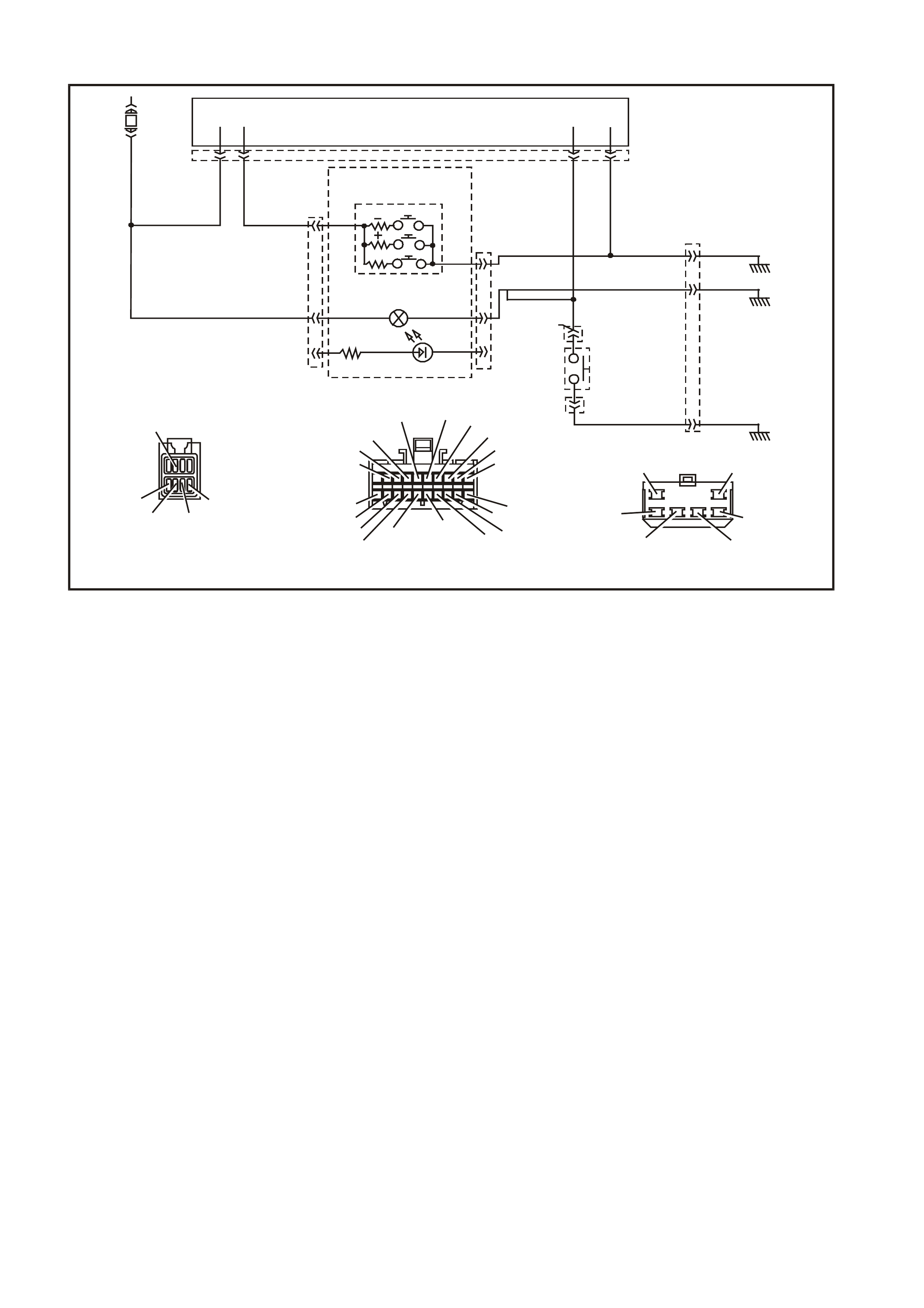
DTC 21 TRIP SWITCH SHORT CIRCUIT
T212C195A
YB66
INSTRUM ENTS CONNE CTOR
V/W (123) BLU/B (946)
10
20 1
11
B/Y (155) GY (8) BR /W (19)
BLU/Y (10)
T (30) BR/O (33)BR (25)
V/R (234)
W (85)
BLU (15)
Y/R (88)
G/W (1220)
LBLU (14)
G (875)
O/Y (1340)
P/BLU (44)
BR/R (121)
EXEC
INSTRUMENT CLUSTER
413 YB 66
YB 56
YB 56
BR/W (19)
TRIP COMPUTER
SWIT CH
SECURITY LED
T RIP CO MP UT E R S WIT C H
ILL UMINAT ION
MODE
BLU/B (946)
F 11
65
GY
B/Y
YE114
B/Y (155)
(8)
(155)
GND
B/G (151)
YB 33
YB 33
LIG HT
SWITCH
DIMM ER
BERLINA
CALAIS
YB56
MAIN WIRING HARNESS
CONNECTOR
BR /W (19)
BLU/B (946)
GY (8)
LBL U (263 )
B/Y (155)
YE114
MAIN WIRING HARNESS
CONNECTOR
B/R (157)B/G (151)
B/W (152)
B (150) B/Y (155)
B/R (157)
CIRCUIT DESCRIPTION:
The res istance pr esented to the instr um ent cluster on term inal 13 is dependent upon the button s elected on the tr ip
computer switch.
DTC 21 Will Set If:
• When the trip computer switch resistance is less than 1000 ohms for 10 seconds. The DTC is reset as soon as
the switch resistance is greater than 1000 ohms. The DTC is logged as a History DTC.
Test Description:
Number(s) below refer to step number(s) in the following diagnostic chart.
1. Ensures the Diagnostic Circuit Check has been performed.
2. Determines if the BCM can communicate with the TECH 2.
3. Check for obvious physical damage or fault.
4. Continuity check of switch to determine if the switch is functioning correctly .
5. Check of main wiring harness circuit 946 (Blue/Black wire) for a short to earth.
6. If the DTC can be cleared, the fault is intermittent. If the DTC cannot be cleared, the instrument cluster is
faulty.
Diagnostic Aids:
By manipulating the harnesses at the various connectors it is often possible to isolate the cause of the circuit
interruption. This harness can then be removed and repaired.
Check for any damage to the harness which could cause an intermittent open or short to earth or backed out
terminals at the instrument cluster connectors, broken connector locks, improperly formed or damaged terminals.
The multimeter allows continuity of the wiring harness circuit 946 to be checked.

DTC 21 TEST PROCEDURE
STEP ACTION VALUE YES NO
1 • Was the Diagnostic Circuit Check performed? Go to Step 2. Go to Diagnostic
Circuit Check in this
Section.
2• Connect TECH 2 to the DLC.
• Select Bod y / DTC Check / F0: DTC Check.
• Can TECH 2 communicate with the BCM?
NOTE: If ‘No Data’ is displayed next to the BCM, then
there is no communication between TECH 2 and the
BCM. If 'No DTC' or 'DTCs Set' is displayed then there
is communication between the TECH 2 and the BCM.
Go to Step 3. Go to BCM Serial
Data
Communication
diagnostics in
Section 12J-1 LOW
SERIES BODY
CONTROL
MODULE, or Section
12J-2 HIGH SERIES
BODY CONTROL
MODULE in the VT
Series II Service
Information.
3• Check the switch for obvious signs of damage. Replace the switch,
refer to 2.4 TRIP
COMPUTER
SWITCH
ASSEMBLY in this
Section.
Go to Step 4.
4• Remove the switch, refer to 2.4 TRIP COMPUTER
SWITCH ASSEMBLY in this Section.
• Using an ohmmeter, test the switch as detailed in
2.4 TRIP COMPUTER SWITCH ASSEMBLY in this
Section.
• Switch tests OK?
Go to Step 5. Replace the switch,
refer to 2.4 TRIP
COMPUTER
SWITCH
ASSEMBLY in this
Section.
5• Disconnect instrument cluster connector YB66.
• Using an ohmmeter, check main wiring harness
circuit 946 (Blue/Black wire) for a short to earth.
• Short to earth exists?
Repair faulty main
wiring harness and
verify repair.
Go to Step 6.
6• Use TECH 2 to cle ar DTC.
• Has DTC cle ared? DTC 21 is
intermittent. Check
circuit 946
(Blue/Black wire)
between switch and
instrument cluster
for an intermittent
fault.
Check the
instrument cluster
and switch
connectors for
terminal retention. If
OK replace
instrument cluster,
refer to 2.1
INSTRUMENT
CLUSTER in this
Section.
WHEN ALL DIAGNOSIS AND REPAIRS ARE COMPLETED, CLEAR ALL DTC AND VERIFY CORRECT OPERATION

DTC 22 TRIP SWITCH BUTTON STUCK
T212C195A
YB66
INSTRUM ENTS CONNE CTOR
V/W (123) BLU/B (946)
10
20 1
11
B/Y (155) GY (8) BR /W (19)
BLU/Y (10)
T (30) BR/O (33)BR (25)
V/R (234)
W (85)
BLU (15)
Y/R (88)
G/W (1220)
LBLU (14)
G (875)
O/Y (1340)
P/BLU (44)
BR/R (121)
EXEC
INSTRUMENT CLUSTER
413 YB 66
YB 56
YB 56
BR/W (19)
TRIP COMPUTER
SWIT CH
SECURITY LED
T RIP CO MP UT E R S WIT C H
ILL UMINAT ION
MODE
BLU/B (946)
F 11
65
GY
B/Y
YE114
B/Y (155)
(8)
(155)
GND
B/G (151)
YB 33
YB 33
LIG HT
SWITCH
DIMM ER
BERLINA
CALAIS
YB56
MAIN WIRING HARNESS
CONNECTOR
BR /W (19)
BLU/B (946)
GY (8)
LBL U (263 )
B/Y (155)
YE114
MAIN WIRING HARNESS
CONNECTOR
B/R (157)B/G (151)
B/W (152)
B (150) B/Y (155)
B/R (157)
CIRCUIT DESCRIPTION:
The res istance pr esented to the instr um ent cluster on term inal 13 is dependent upon the button s elected on the tr ip
computer switch.
DTC 22 Will Set If:
• When any button on the trip computer is pressed for longer than 120 seconds. The DTC is reset as soon as
the button is released, and the DTC is logged as a History DTC.
Test Description:
Number(s) below refer to step number(s) in the following diagnostic chart.
1. Ensures the Diagnostic Circuit Check has been performed.
2. Determines if the BCM can communicate with the TECH 2.
3. Check for obvious physical damage or fault.
4. Continuity check of switch to determine if the switch is functioning correctly .
5. If the DTC can be cleared, the fault is intermittent. If the DTC cannot be cleared, the instrument cluster is
faulty.
Diagnostic Aids:
By manipulating the harnesses at the various connectors it is often possible to isolate the cause of the circuit
interruption. This harness can then be removed and repaired.
Check for any damage to the harness which could cause an intermittent open or short to earth or backed out
terminals at the instrument cluster connectors, broken connector locks, improperly formed or damaged terminals.

DTC 22 TEST PROCEDURE
STEP ACTION VALUE YES NO
1 • Was the Diagnostic Circuit Check performed? Go to Step 2. Go to Diagnostic
Circuit Check in this
Section.
2• Connect TECH 2 to the DLC.
• Select Bod y / DTC Check / F0: DTC Check.
• Can TECH 2 communicate with the BCM?
NOTE: If ‘No Data’ is displayed next to the BCM, then
there is no communication between TECH 2 and the
BCM. If 'No DTC' or 'DTCs Set' is displayed then there
is communication between the TECH 2 and the BCM.
Go to Step 3. Go to BCM Serial
Data
Communication
diagnostics in
Section 12J-1 LOW
SERIES BODY
CONTROL
MODULE, or Section
12J-2 HIGH SERIES
BODY CONTROL
MODULE in the VT
Series II Service
Information.
3• Check the switch for obvious signs of a stuck
button. Replace the switch,
refer to 2.4 TRIP
COMPUTER
SWITCH
ASSEMBLY in this
Section.
Go to Step 4.
4• Remove the switch, refer to 2.4 TRIP COMPUTER
SWITCH ASSEMBLY in this Section.
• Using an ohmmeter, test the switch as detailed in
2.4 TRIP COMPUTER SWITCH ASSEMBLY in this
Section.
• Switch tests OK?
Go to Step 5. Replace the switch,
refer to 2.4 TRIP
COMPUTER
SWITCH
ASSEMBLY in this
Section.
5• Use TECH 2 to cle ar DTC.
• Has DTC cle ared? DTC 22 is
intermittent. Check
circuit 946
(Blue/Black wire)
between switch and
instrument cluster
for an intermittent
fault.
Replace instrument
cluster, refer to 2.1
INSTRUMENT
CLUSTER in this
Section.
WHEN ALL DIAGNOSIS AND REPAIRS ARE COMPLETED, CLEAR ALL DTC AND VERIFY CORRECT OPERATION
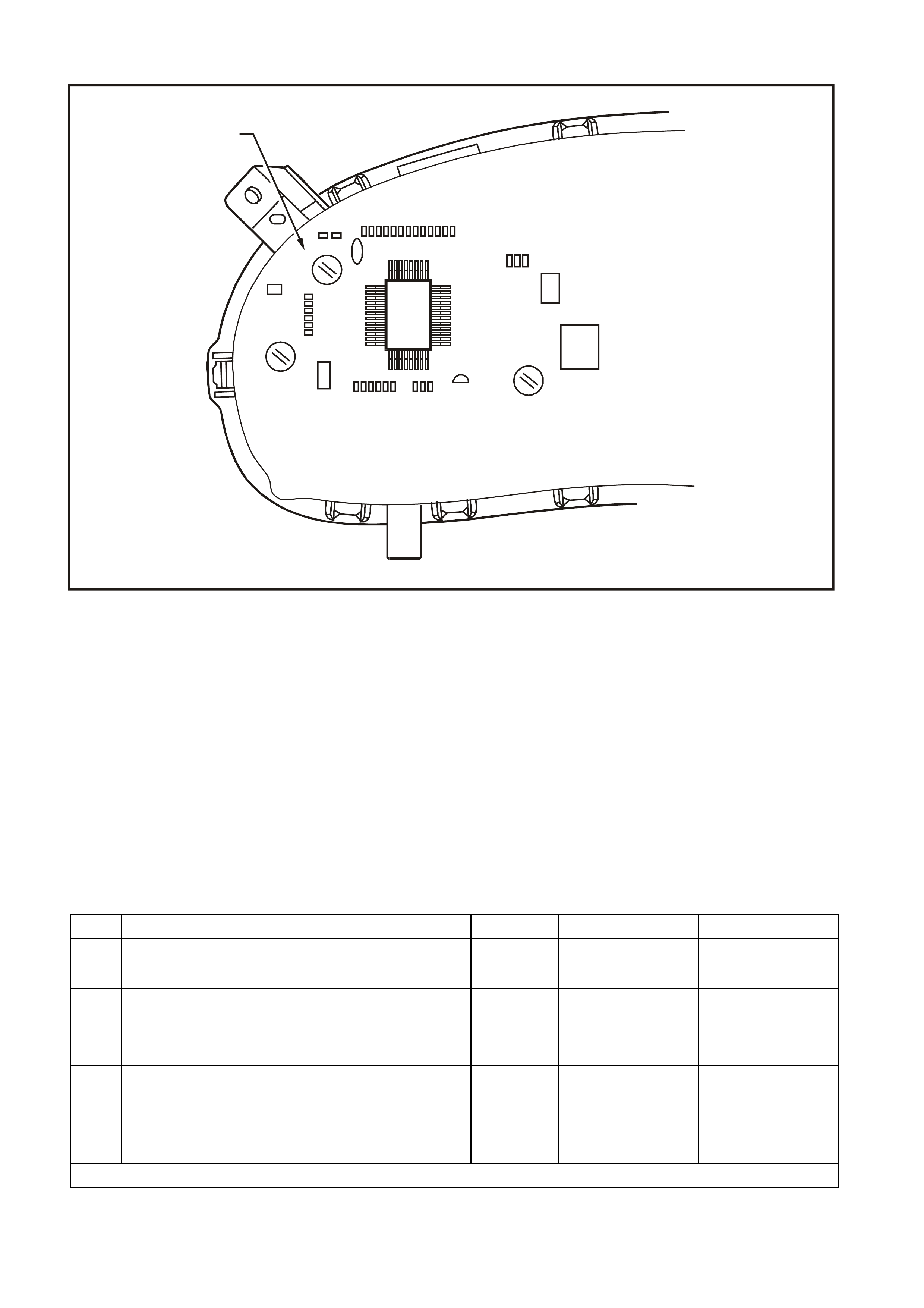
DTC 24 EE CHECKSUM = FAILURE
T12C187
EEPROM
INSTRUME NT ASSEMBLY
CIRCUIT DESCRIPTION:
The EEPROM (Electrically Erasable Program mable Read Only Memory) is part of the printed circuit board housed
within the instrument cluster. It stores variables required in the operation of the instrument cluster and in the
interpretation of the inc oming data and can be pr ogrammed f or dif f erent ins tr ument levels. If a DTC 24 was set as a
result of interrupted instrument programming then the following diagnostic table will need to be followed.
DTC 24 Will Set If:
• The EEPROM chec ksum is inc orrect. T he testing of the EEPROM check sum occurs every tim e the ignition is
turned on. The DTC is res et when the EEPROM chec ksum is tested as being c orr ec t. T he DTC is logged as a
History DTC.
Diagnostic Aids:
If the programmed instrument cluster values are c orrupted, repr ogram m ing can be car ried out via T ECH 2 to rectif y
the fault, refer to Section 5.15 F5: PROGRAM in this Section.
DTC 24 TEST PROCEDURE
STEP ACTION VALUE YES NO
1 • Was the Diagnostic Circuit Check performed? Go to Step 2. Go to Diagnostic
Circuit Check in the
Section.
2• Go to Section 5.15 F5: PROGRAM in this Section.
• Is programming completed successfully? Go to Step 3. Replace instrument
cluster, refer to 2.1
INSTRUMENT
CLUSTER in this
Section.
3• Use TECH 2 to cle ar DTC.
• Has DTC cle ared? Instrument cluster
OK. End of
diagnostic testing.
EEPROM failed.
Replace instrument
cluster, refer to 2.1
INSTRUMENT
CLUSTER in this
Section.
WHEN ALL DIAGNOSIS AND REPAIRS ARE COMPLETED, CLEAR ALL DTC AND VERIFY CORRECT OPERATION

DTC 25 ROM CHECKSUM = FAILURE
CIRCUIT DESCRIPTION:
The ROM (Read Only Memory) is part of the printed circuit board housed within the instrument cluster. It stores
variables required to initialise the instr um ent cluster. If a DTC 25 has been set, then the instr um ent cluster will need
to be replaced.
DTC 25 Will Set If:
• The ROM checksum is incorrect. The testing of the ROM checksum occurs when the instrument cluster is
reset (due to batter y removal or low power crank ing). T he DT C is res et when the ROM check sum is tested as
being correct. The DTC is logged as a History DTC.
Diagnostic Aids:
If the ROM checksum is incorrect, the instrument cluster may need to be replaced and reprogrammed.
DTC 25 TEST PROCEDURE
STEP ACTION VALUE YES NO
1 • Was the Diagnostic Circuit Check performed? Go to Step 2. Go to Diagnostic
Circuit Check in this
Section.
2• Use TECH 2 to cle ar DTC.
• Has DTC cle ared? Instrument cluster
OK. End of
diagnostic testing.
ROM checksum
error.
Replace instrument
cluster, refer to 2.1
INSTRUMENT
CLUSTER in this
Section.
WHEN ALL DIAGNOSIS AND REPAIRS ARE COMPLETED, CLEAR ALL DTC AND VERIFY CORRECT OPERATION

DTC 26 INTERNAL FAULT
CIRCUIT DESCRIPTION:
The instrument cluster is equipped with self-diagnostic capability that can detect an internal fault within the
instrument cluster. If a DTC 26 has been set, then the instrument cluster will need to be replaced.
DTC 26 Will Set If:
• The instrument has detected an internal fault. The DTC is reset when the RAM checksum is tested as being
correct. The DTC is logged as a History DTC.
DTC 26 TEST PROCEDURE
STEP ACTION VALUE YES NO
1 • Has diagnostic circuit test been carried out ? Go to Step 2. Go to Diagnostic
Circuit Check in this
Section.
2• Use TECH 2 to cle ar DTC.
• Has DTC cle ared? Instrument cluster
OK. End of
diagnostic testing.
Internal fault.
Replace instrument
cluster, refer to 2.1
INSTRUMENT
CLUSTER in this
Section.
WHEN ALL DIAGNOSIS AND REPAIRS ARE COMPLETED, CLEAR ALL DTC AND VERIFY CORRECT OPERATION

TRIP COMPUTER DIAGNOSTIC FUNCTIONS — SINGLE WINDOW DISPLAY
Description
On low series BCM equipped vehicles the instrument cluster is fitted with a single window trip computer. The
purpose of this diagnostic chart is to determine if there is a fault with any of the display functions.
Because there ar e no repairable item s within the instrum ent cluster , if a f ault is detected the ins trum ent clus ter is to
be replaced, refer to 2.1 INSTRUMENT CLUSTER in this Section.
To enter DIAGNOSTIC MODE :
Press the MODE button down together with ▲
▲▲
▲ button while turning ignition from off to on.
Action Window Displays
First display (Software Version)
YYMMDD
Press MODE but ton (GMH Part Num ber)
Pn XXXX
Press MODE button (Button Voltage)
V CUD0.0
Press MODE but ton (Battery Voltage)
V 00.0
Press MODE button (Petrol S ender V ol tage)
V P 0.0
Press MODE button (LPG Fuel Sender Vol t age)
V L 0.0
Press MODE but ton (Fuel Remai ni ng)
F 00.0 L
Press MODE button (Instantaneous Fuel)
F 00.0 l/h
Press MODE but ton (Engine Tem perature)
T 34°C
Press MODE button (Speedometer Reading)
SPD 000 km/h
Press MODE button (Tachom et er Readi ng)
T XXXXX
Press MODE button (Park Lamps On/O ff)
P [ On/Off]

Action Window Displays
Press MODE button (Diagnosti c Mode Display — ref er to Note)
t 00 - -
Press MODE button All segments on
All lamps on
Buzzer = 1 kHz
Temperature Gauge = 50%
Fuel Gauge = 50%
Tachom et er = 3000 rpm
Speedometer = 100 km/h
To exit DIAGNOSTIC MODE :
Press the ▲
▲▲
▲ button together with ▼
▼▼
▼ button
Press ▲
▲▲
▲ & ▼
▼▼
▼ button to exit (Odomet er Readi ng)
000000.0
NOTE: The diagnostic mode display uses the format t NN XY , where:
t = diagnostic trouble code (DTC),
NN = the actual DTC number,
X = the history DTC status (H for active and – for inactive), and
Y = the current DTC status (C for active and – for inactive).
IMPORTANT: An open circuit fuel gauge sender unit is s hown by the instrum ent c luster diagnos tic m ode display as
‘t 00 H C’ whereas the TECH 2 shows the same fault as DTC 3.

TRIP COMPUTER DIAGNOSTIC FUNCTIONS — TRIPLE WINDOW DISPLAY
Description
On high series BCM equipped vehicles the instrument cluster is fitted with a triple window trip computer. The
purpose of this diagnostic chart is to determine if there is a fault with any of the display functions.
Because there ar e no repairable item s within the instrum ent cluster , if a f ault is detected the ins trum ent clus ter is to
be replaced, refer to 2.1 INSTRUMENT CLUSTER in this Section.
To enter DIAGNOSTIC MODE :
Press the MODE button down together with ▲
▲▲
▲ button while turning ignition from off to on.
Action Window 1 Displays Window 2 Displays Window 3 Displays
First di splay (Battery V ol tage)
V 00.0 (Software Vers i on)
YYMMDD (GMH Part Number)
XXXX P
Press MODE button (LPG Fuel Sender Voltage)
V L 0.0 (Button Voltage/But t on Test)
B V CUD 0.0 (Fuel S ender V ol tage)
FUEL 0.0
Press MODE button (Park Lamps On/Off)
P [ On/Off] (Engine Temperature)
TEMP 34°C (Instantaneous Fuel )
INST
FUEL 00.0 l/h
Press MODE button (Speedometer Reading)
SPEED 000 km/h
(Tachom et er Readi ng)
T XXXXX (Fuel Remaini ng)
REMAINING
FUEL 00.0 L
Press MODE button (Diagnosti c Mode Display —
refer to Note)
t 00 - -
Press MODE button All segments on All s egments on
All lamps on
Buzzer = 1 kHz
Temperature Gauge = 50%
Fuel Gauge = 50%
Tachom et er = 3000 rpm
Speedometer = 100 km /h
Sequential illum i nat ion of
PRND321 LEDs
All s egments on
To exit DIAGNOSTIC MODE :
Press the ▲
▲▲
▲ button together with ▼
▼▼
▼ button
Press ▲
▲▲
▲ & ▼
▼▼
▼ button to exit (Odomet er readi ng)
00000.0
NOTE: The diagnostic mode display uses the format t NN XY , where:
t = diagnostic trouble code (DTC),
NN = the actual DTC number,
X = the history DTC status (H for active and – for inactive), and
Y = the current DTC status (C for active and – for inactive).
IMPORTANT: An open circuit fuel gauge sender unit is s hown by the instrum ent c luster diagnos tic m ode display as
‘t 00 H C’ whereas the TECH 2 shows the same fault as DTC 3.
5.9 USING TE CH 2 TO DIAGNOSE THE INSTRUMENT CLUSTER
A prerequisite to this diagnostic section is that the
user is f amiliar with the proper use of T ECH 2. T he
following pages illustrate only the major TECH 2
screen displays and provide a brief explanation of
their function for diagnosing the Instruments. If
additional information is required on the operation
of TECH 2, reference should be made to either
Section 0C TECH 2 in the VT Series II Service
Informationor the TECH 2 User’s Guide.
System Selection Menu
This mode contains all functions to test, diagnose,
monitor and program the vehicles body systems
including the Instruments as well as providing the
opportunity to check all DT C that may be set in the
vehicle.
With TECH 2 connected to the DLC:
• select F0: Diagnostics from the Main Menu,
• select the appropriate model year at the
vehicle Identification Menu,
• select the appropriate vehicle type at the next
screen, and
• select F3: Body at the System Selection
Menu.
S ystem Se lection M en u
F0:
F1:
F2:
F3:
(X) 1999 VT Com m odore
T212C139
Engine
Transmission
Chassis
Body
Figure 12C-19
Vehicle Identification Menu
Once F3: Body has been selec ted from the System
Selection Menu, Instrument can be selected.
Select Instrument.
NOTE: If information regarding DTC set for the
vehicle is required, select DTC Check and press
enter to continue. T o return to the Instrum ent m ode
option from the DTC Check mode option screen
display, simply press the Exit key on TECH 2.
Once Instrument has been selected, the following
two Sys tem Identif ication scr eens will appear which
require action.
V e hicle Identificatio n
B ody Control M odule
Po we rtrain In terfa ce M o du le
SRS
Instrument
Electronic Clim ate Control
DTC Check
Other
S elect one o f the follow ing
Body
T212C141
Figure 12C-20
System Identification
Turn the ignition on (as requested) and press
Confirm soft key to continue.
S ystem Ide ntifica tio n
Turn On Ignition!
(X) 1999 VT Commodore
Electronic System: Instrum ent
T212C142
Figure 12C-21

The part number of the instrument cluster will be
displayed. Press the More soft key to display more
detailed information about the part.
S ystem Ide ntifica tio n
Partnumber XXXXXXXX
(X) 1999 VT Commodore
Electronic S ystem: Instrum ent
T212C143
Figure 12C-22
Press the Confirm soft key to confirm these details.
S ystem Ide ntifica tio n
Partnumber
Software Date
Data Version Number
V A P Process Number
XXXXXXXX
XXXXXX
XX
XXX
(X) 1999 VT Commodore
Electronic S ystem: Instrum ent
T212C144
Figure 12C-23
The Vehicle Identification Number / TIS Hardware
Key Number will be displayed.
S ystem Ide ntifica tio n
V
e hic le Id entific atio n N u m b e r / T IS
Hardware K ey Number
123456
(X) 1999 VT Commodore
Electronic S ystem: Instrum ent
T212C145
Figure 12C-24
Body Menu
The Body Menu will be displayed.
Body
F0:
F1:
F2:
F3:
F4:
F5:
T12C140
Norm al Mode
Diagnostic Trouble Codes
Data Display
Snapshot
Miscellaneous Tests
Program
Figure 12C-25

5.10 F0 : NORMAL MODE
The instrument normal mode data list is used to
view serial data being sent from the instrument
cluster.
Norm al Mode
Engine O il Life Reset
T ransm ission Fluid Life Reset
C ruise C ontrol En gaged
SRS Configuration
Fu el L ev el - P etro l
Fu el Level - LPG
INS DTC Status
No
No
No
6 Loop SR S
0 L
0 L
No DTC
T12C182
Figure 12C-26
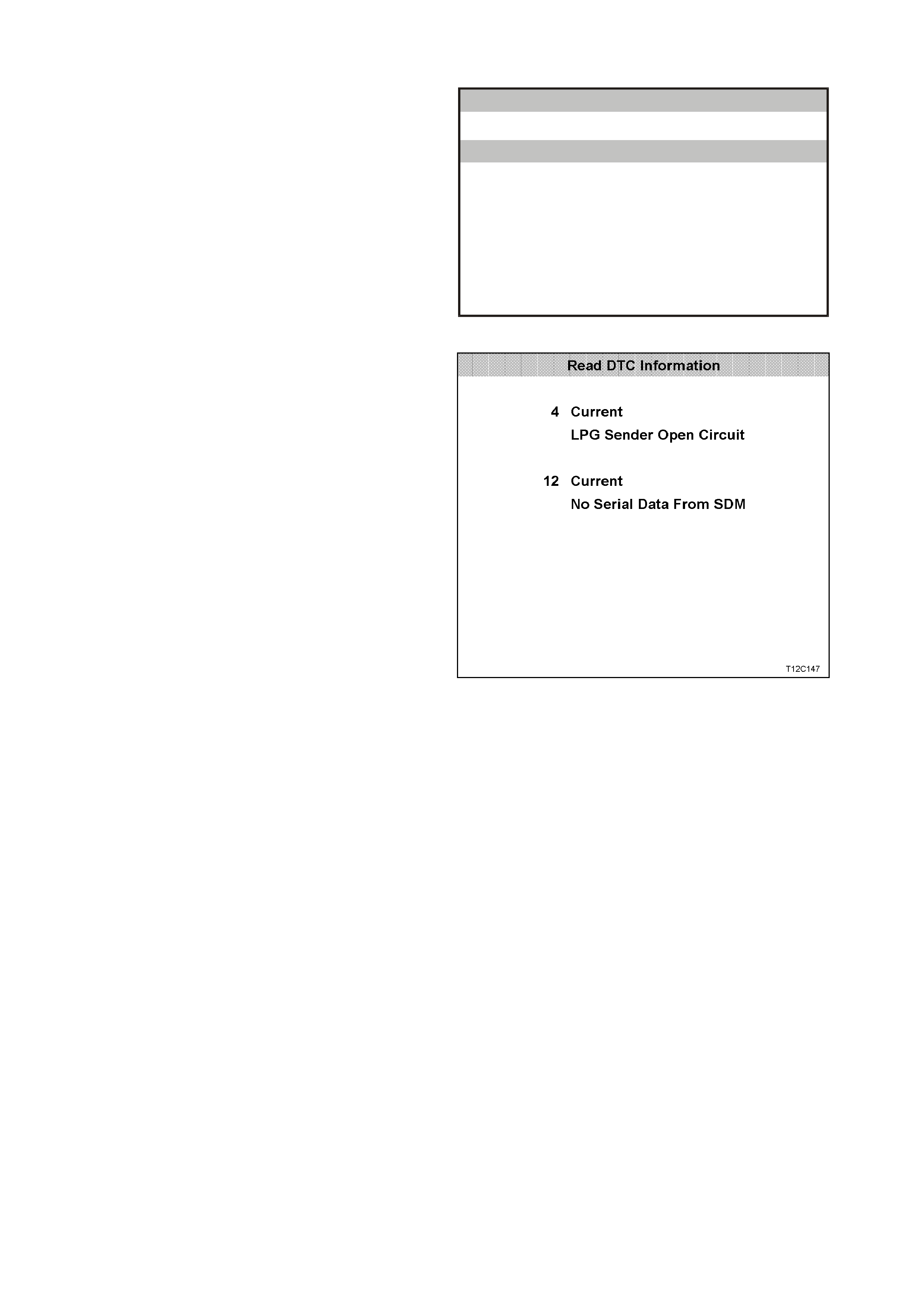
5.11 F1: DIAGNOSTIC TROUBLE CODES
Diagnostic Trouble Codes Menu
F0: Read DTC Information - If this mode is
selected, a lis ting of all (if any) DT C that have been
set by the instrument cluster will be displayed.
NOTE: If any DTC are set, reference should be
made to the relevant diagnostic charts in this
Section.
F1: Clear DTC Information - DTC can be cleared
in this mode by simply selecting F1: Clear DTC
Information, pressing the Enter button on TECH 2
and confirming the action as instructed by TECH 2.
NOTE: TECH 2 will display Clear DTC Information
Failed if any DTC are still current.
Diagnostic Trouble Codes
F0: Read DTC Information
F 1 : C le a r D T C In fo rma tio n
T12C146
Figure 12C-27
Read DTC Information
Select F0: Read DTC Information.
Use the following table to assist in diagnosing and
rectifying DTC.
NOTE: Sc reen shot shows an exam ple of two DTC
only.
Figure 12C-28

The following chart sets out all the possible TECH 2 diagnostic trouble codes.
DTC CODE DESCRIPTION ICON
ACTIVATED ADDITIONAL
ENABLE BIT
1 Fuel gauge sender unit — short circuit Yes None
2 Fuel gauge sender unit — intermittent Yes None
3 Fuel gauge sender unit — open circuit (refer to Note 1) Yes None
4 LPG gauge sender unit — open circuit Yes LPG lamp enable
5 LPG gauge sender unit — short circuit Yes LPG lamp enable
6 LPG gauge sender unit — intermittent Yes LPG lamp enable
8 No serial data from ABS Yes Traction off enable
(refer to Note 2)
9 No serial data from BCM Yes None
10 No serial data from ECC Yes None
(refer to Note 3)
11 No serial data from PCM Yes None
12 No serial data from SDM Yes SRS lamp enable
13 No instrument poll from BCM Yes None
14 No serial communication Yes None
15 No Sub-clock Yes None
16 ABS or ABS/ETC fault logged No None
17 BCM fault logged No None
18 ECC fault logged No None
19 PCM fault logged No None
20 SDM fault logged No None
21 Trip switch short circuit Yes None
22 Trip switch button stuck Yes None
24 EE checksum error Yes None
25 ROM checksum error Yes None
26 Internal fault Yes None
NOTE 1: DTC 3 is recognised by the instrument cluster self-diagnostics as ‘t 00 H C”.
NOTE 2: DTC 8 is not enabled in vehicles fitted with ABS only.
NOTE 3: The ECC EEPROM enable bit is programmed active for the high series vehicles and inactive for the low series
vehicles during manufacture.
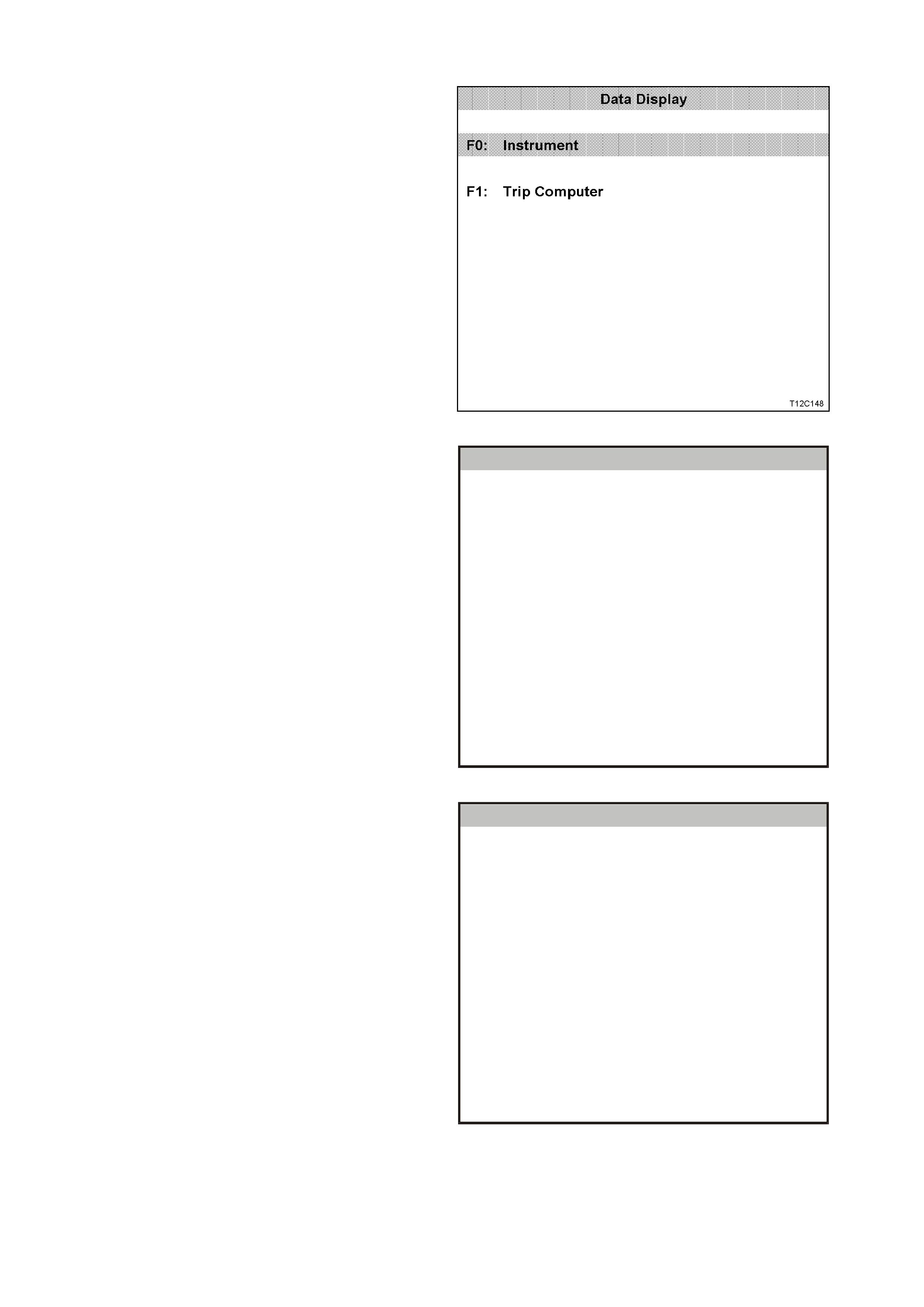
5.12 F2: DATA DISPLAY
In this test mode, the status of the instrument
cluster inputs and outputs can be monitored.
Select either F0: Instrument or F1: Trip Computer
from the data display screen, and press Enter to
continue.
Figure 12C-29
F0: Instrument
The serial data from the instruments can be
check ed and tes ted by selecting the instr ument and
pressing the Select Items soft key. The list can be
scrolled by using the Up and Down arrow keys.
Instrument
Battery V o ltage xx.x V
V ehicle Speed xxx km/h
Ignition Switch On
Engi ne Spe ed xxxx RPM
Instrument Lamps xxx %
Park Lamp Input Off
Park Brake And Brake Fail Lamp On
Rear Lamp Failure Warning Lamp Off
Seat Belt Lamp Off
T212C149
Figure 12C-30
Use the Up and Down arrow keys to navigate
through the items.
NOTE: The PRNDL Position will show as Invalid for
a vehicle with manual transmission, or the gear
selected for a vehicle with automatic transmission.
Instrument
SRS La mp Off
Cr ui se C ontrol En ga g ed Input O ff
Cruise Control On Lamp Off
Low Fuel Lamp Off
Overspeed Lamp Off
Power Shift Lamp Off
PRN D L Pos itio n Inva lid
Oil Pre ssure La mp Off
High Coolant Temperature Lamp Off
T212C180
Figure 12C-31

NOTE: Traction control data list parameters are
only applicable if ABS/ETC is fitted.
Instrument
Low Coolant Level Lam p O ff
E ng ine C o olant T e m p erature x xx C
Check P ow ertrain Lam p O ff
Trac tio n C o ntro l O ff La m p O ff
LPG In U se Lam p O ff
LPG Sender Signal xx.x V
LPG Sender Resistance xxx Ohm
Fuel Gauge Display xxx
Petrol Sender Signal xx.x V
Petrol Sender Resistance xxx Ohm
o
T12C181
Figure 12C-32
F1: Trip Computer
Trip C o m p u ter
Off
Off
Off
5.0 V
Off
Off
Off
Off
Off
Mode Button
Up Button
Down Button
Trip Co mp ute r Sw it c h
LPG Mode
Park Lamps
C ruise Eng aged
Se a t Be lt In p ut
P a rk Brake Inpu t
T12C150A
Figure 12C-33
Trip C o m p u ter
Fuel Flow 0.0 L/hour
100.0 %
100.0 %D istan ce C alib ration N umber
Fuel Calibration Num ber
T12C151
Figure 12C-34

The following table lists each item contained in the data stream together with a brief description of its meaning.
DATA STREAM / SCREEN DISPLAY DESCRIPTION UNIT
Battery Voltage Displays current battery voltage (approximately
12 volts) Volts
Vehicle Speed Displays current vehicle speed km/h
Ignition Switch Displays the current status of the ignition switch On/Off
Engine Speed Displays current engine speed rpm
Instrument Lamps Displays the current level of instrument lamps
illumination (0-100%) %
Park Lamp Input Displays status of the park lamps switch On/Off
Park Brake and Brake Fail Lamp Used to check operation of brake lamp On/Off
Rear Bulb Failed Warning Lamp Used to check operation of bulb failed warning lamp On/Off
Seat Belt Lamp Used to check operation of seat belt lamp On/Off
SRS Lamp Used to check operation of SRS lamp On/Off
Cruise Control Engaged Input Displays status of cruise control input On/Off
Cruise Control On Lamp Used to check operation cruise control lamp On/Off
Low Fuel Lamp Used to check operation of low fuel lamp On/Off
Overspeed Lamp Used to check operation of overspeed lamp On/Off
Power Shift Lamp Displays status of power shift button On/Off
PRNDL Position Displays pos ition of automatic transmissi on selector
lever P/R/N/D/1/2/3/
INVALID
Oil Pressure Lamp Used to check operation of oil pressure lamp On/Off
High Coolant Temperature Lamp Used to check operation of high coolant
temperature lamp On/Off
Low Coolant Level Lamp Used to check operation of low coolant level lamp On/Off
Engine Coolant Temperature Displays signal from engine temperature On/Off
Check Powertrain Lamp Used to check operation of check powertrain lamp On/Off
Traction Control Off Lamp Used to check operation of traction control disabled
lamp On/Off
LPG In Use Lamp Used to check operation LPG in use lamp On/Off
LPG Gauge Sender Signal Displays signal from LPG gauge sender unit 0 – 5 volts
variable
LPG Sender Resistance Displays LPG gauge sender unit resistance 35.2 – 256.3
ohms variable
Fuel Gauge Display Used to check operation of fuel gauge display %
Petrol Gauge Sender Signal Displays signal from fuel gauge sender unit 0 – 5 volts
variable
Petrol Sender Resistance Displays petrol gauge sender unit resistance 35.2 – 256.3
ohms variable

5.13 F3: SNAPSHOT
In this test mode, the TECH 2 captures data list information before and/or after a forced manual trigger.

5.14 F4: MISCELLANEOUS TESTS
Miscellaneous Tests allows for the testing of
various com ponents of the instrum ent c luster, s uch
as instrument and warning lamps, switches and
instrument gauges.
F0: Lamps - once this mode is selected, lamps in
the instrument cluster may be tested.
F1: Buzzer - operation of the buzzer can be tes ted
with this function.
F2: PRNDL Lamps - operation of the automatic
transmission gear shift lever pattern can be tested
with this function.
F3: Trip Computer Buttons - once this mode is
selected, the buttons on the trip computer may be
tested.
F4: LPG Mode - once this mode is selected, the
LPG mode may be tested.
F5: Park Lamp Input - once this m ode is selec ted,
the park lamp input may be tested.
F6: Brake (Park And Fail) Input - once this mode
is selected, the park br ake and brak e fail input m ay
be tested.
F7: Control Tests - this func tion is used to tes t the
operation of the speedometer, tachometer, engine
coolant temperature, fuel gauge and sets the
function lamps illumination.
Miscellaneous Tests
F0: Lam ps
F3: Trip Computer Buttons
F2: PRNDL Lamps
F5: P ark Lam p Input
F7: C ontrol Tests
F1: B uzzer
F4: LPG M ode
F6: Brake (P ark and Fail) Input
T12C152
Figure 12C-35
F0: Lamps
F0: Lam ps f unc tion provides a means of tes ting the
correct operation of various warning/status lamps in
the instrument cluster.
Use the Up and Down arrow keys to scroll through
the list and highlight a lamp.
Press the Enter button to test the selected lamp.
Lamps
Brake (Park and Fail) Lam p
Over Speed Lamp
Low Fuel Lamp
Oil Pressure Lamp
Cruise Control On Lamp
SRS Lam p
Seat Belt Lamp
Check P o w ertrain Lam p
Power Shift Lamp
T12C153
Figure 12C-36
The adjacent figure shows the remainder of the
F0: Lamps menu.
Lamps
H igh Coo lant Te m perature Lam p
Traction C ontrol Off Lam p
Low Coolant Level Lam p
Rear Lamp Failure Warning Lamp
L P G In U s e L a m p
T12C154
Figure 12C-37

Once a lamp has been highlighted and selected,
the TECH 2 will show the following screen.
Current serial data will be shown at the top of the
screen and the s elected lam p and its cur rent s tatus
will be displayed at the bottom.
Press the On soft key to turn the selected lamp on
and note its status on the instrument cluster.
If the lamp does not come on and the TECH 2
display indicates that it is, there is a fault in the
lamp and the bulb will need to be replaced.
Press the Off soft key to turn the lamp off.
Press the Quit soft key to continue and return to the
previous screen.
Park Brake And Brake Fail Lamp
(X) 1999 VT Commodore
V eh icle Sp eed x xx km /h
Battery Voltage xx.x V
Engine Speed xxxx RPM
Park Lamp Input Off
Park Brake And Fa Off
E lectronic Sy stem: Instrum en t
Ignition Sw itch O n
Instrument Lamps 100 %
T212C155
Figure 12C-38
F1: Buzzer
The operation of the buzzer can be tested, and a 1
kHz tone will be emitted from the instrument
buzzer.
Soft keys: Quit, On and Off.
F2: PRNDL Lamps
The operation of the automatic transmission gear
shift lever pattern can be tested by sequentially
illuminating the P, R, N, D, 1, 2 and 3 LEDs.
The appropriate lamp is indicated at the bottom of
the TECH 2 screen. Lamp control is provided by
the Quit, Off, On and Next Lamp soft keys.
F3: Trip Computer Buttons
F0: Mode Button
With this test a mode button press can be
sim ulated. This is to tes t if the button is st uck or the
instrument is not working properly.
F1: Up Button
W ith this test an up button press c an be simulated.
This is to test if the button is stuck or the instrument
is not working properly.
F2: Down Button
With this test a down button press can be
sim ulated. This is to tes t if the button is st uck or the
instrument is not working properly.
F4: LPG Mode
This function allows the TECH 2 user to enable or
disable the instrument LPG mode for testing
purposes. T he LPG lamp will illum inate and the f uel
gauge will indicate the level of the LPG tank.
F5: Park Lamp Input
This test allows the TECH 2 user to enable or
disable the park lamps input. This will dim the
Power, Cruise and LPG lamps only. It will have no
effect on the other warning lamps or instrument
cluster illumination.
F6: Brake (Park And Fail) Input
This function allows the TECH 2 user to enable or
disable the brake (park and fail) input.
F7: Control Tests
Control Tests allow the TECH 2 user to force
known values into the speedometer, tachometer,
engine coolant temperature gauge and fuel gauge
to verify their correct operation.
F0: Vehicle Speed
This function controls the speedometer.
Commanded vehicle speed can be adjusted up or
down in 20 km /h steps from 0 km /h to a m aximum
value of 220 km/h. Ensure that the speedometer is
accurate according to the following table.
F1: Engine Speed
This functions controls the tachometer.
Commanded engine s peed can be adjus ted up and
down in 1000 rpm steps with a maximum value of
6000 rpm. Ensure that the tachometer is accurate
according to the following table.
F2: Engine Coolant Temperature
This function controls the temperature gauge.
There are three s teps when testing the temperatur e
gauge; cold, mid and hot. The test is conducted
using the Up and Down soft keys.
F3: Fuel Gauge
This function controls the fuel gauge. There are
three steps when testing the fuel gauge; empty, half
and full. The test is conducted using the Up and
Down soft keys.
F4: Function Lamps Illumination
This function controls the function lamps. Note that
this test applies only to the Power, Cruise and LPG
lamp illumination level. The illumination can be
adjusted in increments of 20% from 0% to 100%.
The function lamps are turned on automatically
when the test is being performed.
Control Tests
F0:
F1:
F2:
F3:
F4:
T12C156A
V e hicle Sp eed
Engine Speed
Engine Coolant Temperature Gauge
Fuel Gauge Level
Function Lam ps Illum ination
Figure 12C-39
Commanded
Vehicle Speed Speedo Error Acceptable
Readings on
Speedometer
60 km / h –1/+3 km/h 59 – 63 km / h
100 km / h –1/+3 km /h 99 – 103 km / h
160 km / h –1/+5 km /h 159 – 165 km/ h
Commanded Engine
Speed Acceptable Readings on
Tachometer
1000 rpm 860 – 1140 rpm
3000 rpm 2860 – 3140 rpm
5000 rpm 4860 – 5140 rpm

5.15 F5: PROGRAM
Turn ignition off.
Connect TECH 2 to the vehicle, refer to
5.6 CONNECTING THE TECH 2.
Navigate through the TECH 2 m enus to display the
Body Menu.
Select F5: Program from the Body Menu.
Body
F0: N orm al M ode
F2: Data Display
F1: D iagnostic Trouble Codes
F3: Snaps hot
F4: Miscellaneous T ests
F5: Program
T12C157
Figure 12C-40
F0: Instrument Configuration
Select F0: Instrument Configuration.
Program
F0: Ins t rum e nt Co nf iguration
F2: Odometer V alue
F1: Options
F3: Fuel Gauge Calibration
F4: Reset Service Interval
F 5: R eset U s er C alib rat i o n
T212C159
Figure 12C-41
Using the Next soft key, step through each
parameter and modify as necessary.
Press the Confirm soft key to continue.
In s tru me n t C o nfig u rat io n
(X) 1999 VT Commodore
Step Through Ea ch Pa ram eter And M odify
If Necessary .
C onfirm Program m ing At The End.
E lectronic Sy stem: Instrum en t
T212C158
Figure 12C-42
Techline
Techline
1. SR S Configuration
Press Modify soft key to set to one of the
following options:
• No SRS
• 2 Loop SRS
• 3 Loop SRS
• 4 Loop SRS
• 6 Loop SRS
NOTE: Configuration of the various SRS
systems is as follows:
• a 2-loop system is for left-hand drive
vehicles with pre-tensioners only.
• a 3-loop system is for vehicles with pre-
tensioners and driver’s air bag only.
• a 4-loop system is for vehicles with pre-
tensioners, driver’s air bag and front
passenger’s air bag only.
• a 6-loop system is for vehicles with pre-
tensioners, driver’s air bag, front
passenger’s air bag and side air bags.
In s tru me n t C o nfig u ra tio n
(X) 1999 VT Commodore
SR S C onfiguration 6 Loop SR S
E lectronic Sy stem: Instrum en t
T212C160
Figure 12C-43
2. SRS Lamp
Press Modify soft key to set to –
Enabled/Disabled.
• For all models, set to Enabled.
In s tru me n t C o nfig u ra tio n
(X) 1999 VT Commodore
SRS Lam p Enabled
E lectronic Sy stem: Instrum en t
T212C161
Figure 12C-44
3. Speedometer Pulses
Press Modify soft key to set the speedometer
pulses per kilometre for the correct tyre size.
Nominal value is 6250 pulses per km.
• Tyre size 205 65 R15, select 6272 pulses.
• Tyre size 215 60 R15, select 6285 pulses.
• Tyre size 215 60 R16, select 6077 pulses.
• Tyre size 225 50 R16, select 6391 pulses.
• Tyre size 225 55 R16, select 6087 pulses.
• Tyre size 225 60 R15, select 6238 pulses.
• Tyre size 235 45 R17, select 6301 pulses.
In s tru me n t C o nfig u ra tio n
(X) 1999 VT Commodore
Speedometer Pulses 6250
E lectronic Sy stem: Instrum en t
T212C162
Figure 12C-45
Techline
Techline
4. Speedometer Calibration
If the Police Mode has been enabled at
F5: Program / F1: Options, the speedometer
calibration screen appears next. This allows
the speedometer to be calibrated.
Press the Modify soft key to adjust the
speedometer calibration, or the Next soft key
to continue.
Instrument Configuration
(X) 1 999 VT Com m od or e
Speedometer Calibration 100%
Electronic System: Instrument
T212C198
Figure 12C-46
5. Tachometer Ratio
Pr ess Modif y s oft k ey to set to - V6 or V8 Gen
3.
• Only V6 and V8 Gen 3 are applicable to
the VT Series II.
Instrument Configuration
(X) 1 999 VT Com m od or e
Tachomet er Ratio V6
Electronic System: Instrument
T212C163
Figure 12C-47
6. High Voltage Tachometer
Press Modify soft key to set to - Disabled.
• For V6 engine, set to Disabled.
• For GEN III V8 engine, set to Disabled.
In s tru me n t C o nfig u ra tio n
(X) 1999 VT Commodore
High V oltage Tachometer Disabled
E lectronic Sy stem: Instrum en t
T212C164
Figure 12C-48
7. ECC Equipped
Press Modify soft key to set to –
Enable/Disabled.
• For vehicles equipped with a triple
window display set to - Enable.
• For vehicles equipped with single window
display set to - Disable.
Inst ru me nt Configuration
(X) 1999 VT Co mm o dore
Electronic Sys tem: Inst rument
ECC Option Enabled
T212C164A
Figure 12C-48A

8. Program Instrument Confirm
Press Abort soft key to abandon process, or
press Program soft key to confirm parameters.
Press Confirm soft key when programming is
completed.
Inst ru me nt Configuration
(X) 1999 VT Co mm o dore
Electronic Sys tem: Inst rument
SRS Configuration
SRS Lamp
Speedometer Pulses
Speedometer Calibration
Tac hom eter R atio
H igh Voltage Tachometer
ECC Option
6 Loo p SR S
Enabled
6250
100%
V6
Disabled
Enabled
T212C165A
Figure 12C-49
F1: Options
Options such as instrument lamp illumination
enable/disable and Police Mode can be set by
selecting F1: Options from the Program Menu.
Program
F0: Ins t rum e nt Co nf iguration
F2: Odometer V alue
F1: Options
F3: Fuel Gauge Calibration
F4: Reset Service Interval
F 5: R eset U s er C alib rat i o n
T212C159
Figure 12C-50
Using the Next soft key, step through each
parameter and modify as necessary.
Press Confirm soft key to continue.
Options
(X) 1999 VT Commodore
Step Through Ea ch Pa ram eter And M odify
If Necessary .
C onfirm P rogram m ing At The En d.
E lectronic Sy stem: Instrum en t
T212C183
Figure 12C-51
1. Rear Lamp Failure Lamp
Press Modify soft key to set to –
Enabled/Disabled.
• For Calais, set to Enabled.
• For all other models, set to Disabled.
Options
(X) 1999 VT Commodore
Rear Lamp Failure Lamp Enabled
E lectronic Sy stem: Instrum en t
T212C167
Figure 12C-52
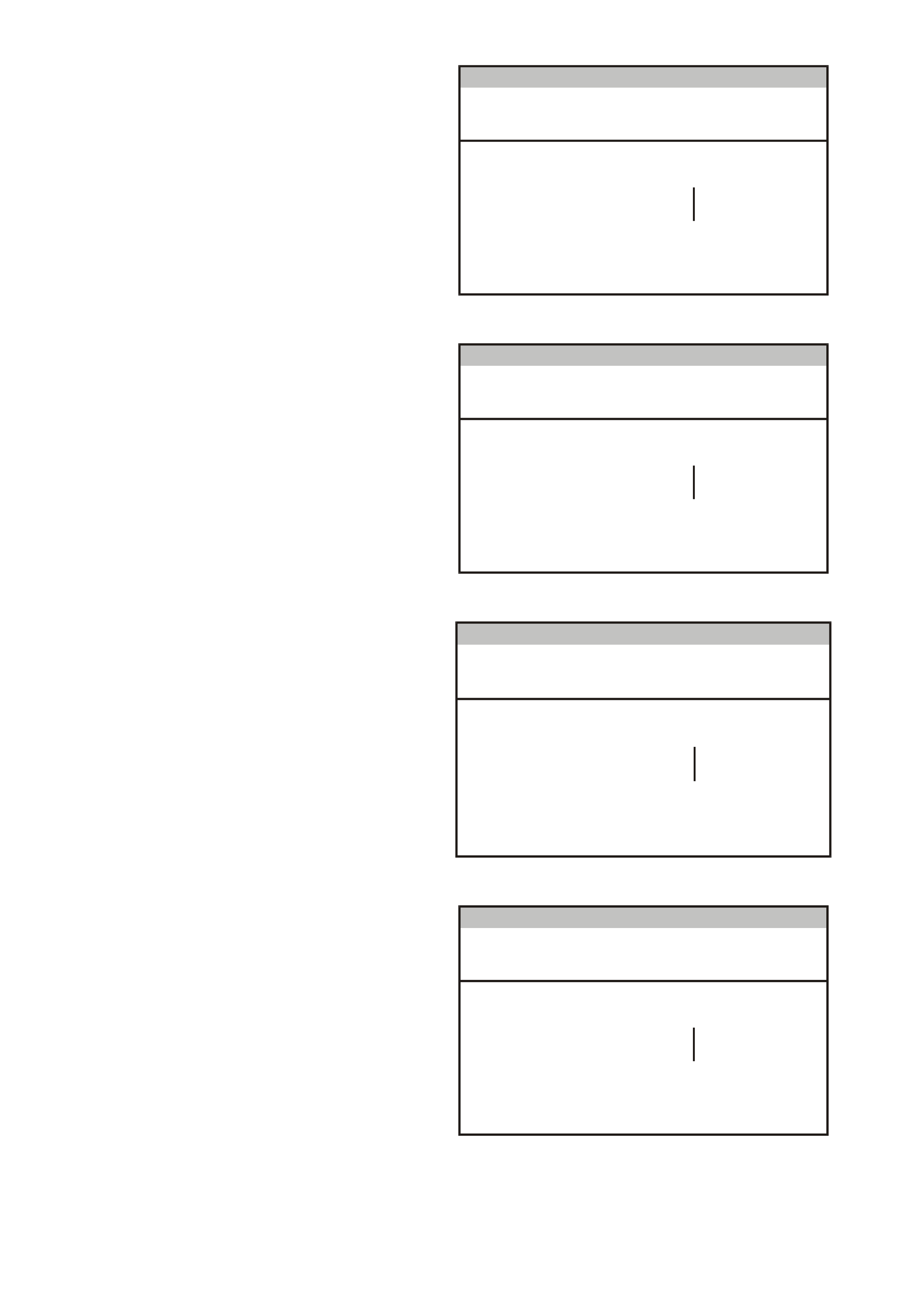
2. Traction Control Off Lamp
Press Modify soft key to set to –
Enabled/Disabled.
• For Calais, set to Enabled.
• For other models, check if the option is
fitted. If not fitted, set to Disabled.
Options
(X) 1999 VT Commodore
Traction C ontrol Off Lam p Enabled
E lectronic Sy stem: Instrum en t
T212C168
Figure 12C-53
3. LPG Lamp
Press Modify soft key to set to -
Enabled/Disabled.
• For V6 engine, check if the option is
fitted. If not fitted, set to Disabled.
• For GEN III V8 engine, set to Disabled.
Options
(X) 1999 VT Commodore
LPG Lam p Disabled
E lectronic Sy stem: Instrum en t
T212C169
Figure 12C-54
4. Cruise On Lamp
Press Modify soft key to set to -
Enabled/Disabled.
• For Berlina and Calais, set to Enabled.
• For other models, check if the option is
fitted. If not fitted, set to Disabled.
Options
(X) 1999 VT C omm odo re
C ruise On La m p Enabled
E lectro nic Sy stem : In strument
T212C170
Figure 12C-55
5. Police Mode
Press Modify soft key to set to -
Enabled/Disabled.
• For Police vehicles only, set to Enabled.
• For all other vehicles, set to Disabled.
Options
(X) 1999 VT Commodore
Police Mo de Disabled
E lectronic Sy stem: Instrum en t
T212C171
Figure 12C-56
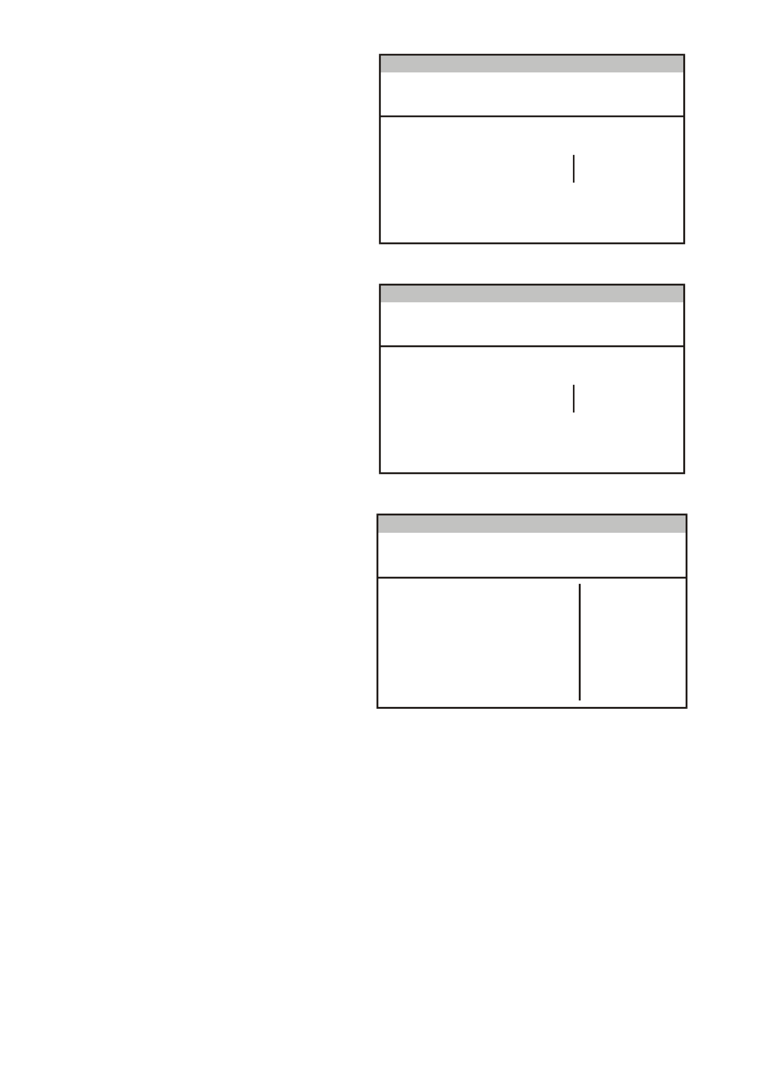
6. Low Coolant Lamp
Press Modify soft key to set to –
Enabled/Disabled.
• For V6 engine, set to Disabled.
• For GEN III V8 engine, set to Enabled.
Options
(X) 1999 VT Commodore
Low Co olant Lam p Disabled
E lectronic Sy stem: Instrum en t
T212C172
Figure 12C-57
7. High Temperature Lamp
Press Modify soft key to set to - Enabled.
Options
(X) 1999 VT Commodore
High Temperature Lamp Enabled
E lectronic Sy stem: Instrum en t
T212C184
Figure 12C-58
8. Program Options Confirm
Press Abort soft key to abandon process, or
press Program soft key to confirm parameters.
Press Confirm soft key when programming is
completed.
Options
(X) 1999 VT C omm odo re
Trac t io n C o n t ro l L a mp Enabled
R ear Lam p F ailure Lam p Enab led
C ruise On La m p Enabled
Low Co olant Lam p Disabled
High Temperature Lamp Enabled
E lectro nic Sy stem : In strument
LPG Lam p Disabled
Po lic e Mo de Disabled
T212C173
Figure 12C-59

9. Speedometer Calibration
NOTE: This is only available in TECH 2 when
instrument has been configured to Police
mode.
Turn the ignition off.
Hold down the MODE button as well as the ▲
and ▼ buttons on the trip computer.
Turn the ignition on while holding down the
three buttons.
Release the MODE button after 3 seconds,
then release the other two buttons. The
calibration value will now be flashing and C will
be displayed.
The calibration value (in percentage) can now
be adjusted with the ▲ and ▼ buttons. Set to
80% - 120% as necessary.
W hen the calibration has been achieved, press
the MODE button to lock in the c alibration data
and return to the normal display.
F2: Odometer Value
NOTE: It is only possible to program the odometer
reading on an instrument once the TIS approval
code has been obtained and on an instrument
which presently reads no more than 100 km.
F3: Fuel Gauge Calibration
Select F3: Fuel Gauge Calibration.
Program
F0: Ins t rum e nt Co nf iguration
F2: Odometer V alue
F1: Options
F3: Fuel Gauge Calibration
F4: Reset Service Interval
F 5: R eset U s er C alib rat i o n
T212C159
Figure 12C-60
The next screen displays the instrument Code
Index and Code Version. If these need to be
updated, pres s the Modif y soft key, otherwise press
the Okay soft key.
Fuel Gauge C alibration
(X) 1999 VT Commodore
C ode Index
Code Version 1
0
E lectronic Sy stem: Instrum en t
T212C196
Figure 12C-61

Select the vehic le type, press Enter and wait for the
programming to be completed.
Press the Confirm soft key when programming is
completed.
F u e l Ga u g e Ca lib r at io n
(X ) 199 9 VT C o mmodo re
E lectro n ic System: Instru me nt
T212C197
Se dan Calibration
Wagon C alibration
Figure 12C-62
F4: Reset Service Interval
Select F4: Reset Service Calibration.
Press the Abor t soft k ey to abandon the proces s, or
press the Reset soft key to reset the service
interval.
Press the Confirm soft key when programming is
completed.
Re se t Se rvi ce In te rva l
(X) 1 999 VT Com m od or e
Re set Service Interv a l ?
Electronic System: Instrument
T212C199
Figure 12C-63
F5: Reset User Calibration
Select F5: Reset Service Calibration.
Press the Abor t soft k ey to abandon the proces s, or
press the Reset soft key to reset the following
parameters:
• Trip Distance Calibration
• Fuel Used Calibration
• Speedometer Calibration
Press the Confirm soft key when programming is
completed.
Reset User Calibration
(X) 1 999 VT Com m od or e
Reset User Cali brat i o n ?
Electronic System: Instrument
T212C200
Figure 12C-64

