
SECTION 12E – CRUISE CONTROL
CAUTION:
This vehicle will be equipped with a Supplemental Restraint System (SRS). A SRS will consist of either
seat belt pre-tensioners and a driver’s air bag, seat belt pre-tensioners and a driver’s and front
passenger’s air bags or seat belt pre-tensioners, driver’s and front passenger’s air bags and left and
right-hand side air bags. Refer to SAFETY PRECAUTIONS, Section 12M SUPPLEMENTAL RESTRAINT
SYSTEM in the VT Series I Service Information before performing any service operation on, or around
SRS components, the steering mechanism or wiring. Failure to follow the SAFETY PRECAUTIONS could
result in SRS deployment, resulting in possible personal injury or unnecessary SRS system repairs.
CAUTION:
This vehicle may be equipped with LPG (Liquefied Petroleum Gas). In the interests of safety, the LPG fuel
system should be isolated by turning 'OFF' the manual service valve and then draining the LPG service
lines, before any service work is carried out on the vehicle. Refer to the LPG leaflet included with the
Owner's Handbook for details or the appropriate Section of this Service Information CD for more specific
servicing information.
CAUTION:
Whenever any component that forms part of the ABS or ABS/ETC (if fitted), is disturbed during Service
Operations, it is vital that the complete ABS or ABS/ETC system is checked, using the procedure as
detailed in 4 DIAGNOSIS, ABS or ABS/ETC FUNCT ION CHECK, in Section 12L ABS & ABS/ETC, in either
of the VT Series I Service Inf ormation for th e V6 Engine or in the VT Series II Service Informat ion for the
GEN III V8 Engine of this Service Information CD.
1. GENERAL INFORMATION
Cruise control is a vehicle speed control system which m aintains a desired vehicle speed without the driver having
to continually apply foot pressure to the accelerator pedal.
Depending on the model variant, cruise control is available as either standard or optional equipment on all VT
Series II models with either automatic or manual transmission.
The cruise control system is the same as that fitted to previous VT Series models. It is an Electro-motor system
that is vacuum independent. The Electro-motor cruise control system uses a stepper motor to control vehicle speed.
On m odels fitted with GEN III V8 engines and trac tion control, a throttle relax er servo is f itted as part of the trac tion
control system to provide engine torque c ontrol. T he throttle relaxer m om entarily reduces the throttle opening angle
when traction loss occurs.
There is no electronic interface between the throttle relaxer and the cruise control module.
1.1 SYSTEM OPERATION
The main components of the Electro-motor cruise control system are the cruise control module, cruise control
switches (m ounted on the turn signal stalk ), brake pedal electr ical release switch, brak e pedal stop lam p switch,
clutch pedal switch (manual transmission models), cruise control cable and electrical wiring (incorporated into
the main wiring harnes s ).
The cruis e control m odule also us es an output fr om the Powertrain Control Module ( PCM) f or vehicle speed, and
an input to the Body Control Module (BCM) to send a serial data message to the instruments (cruise control
interface).
W hen the cruise control module is powered up via the cruise control ON-OFF switch, the cruise control m odule
activates an input to the BCM. The BCM sees this line as active and sends a serial data message to the
instrument c luster to turn its CRUISE lamp on.
W hen the SET-COAST switch is depressed (provided the vehicle speed is above 40 km/h and either the brake
or clutch pedal is not depressed) the cruise control module lights up the ACTIVE lamp in the instrument cluster
and in turn, informs the PCM to use a specific transmission shift pattern. This is designed primarily for cruise
mode, having fewer transmission down shifts and reduced transmission gear change activity. For further
information about the BCM cruise control interface, refer to either Section 12J-1 LOW SERIES BCM, or
Section 12J-2 HIGH SERIES BCM in the VT Ser ies II Ser vice Inf or mation.
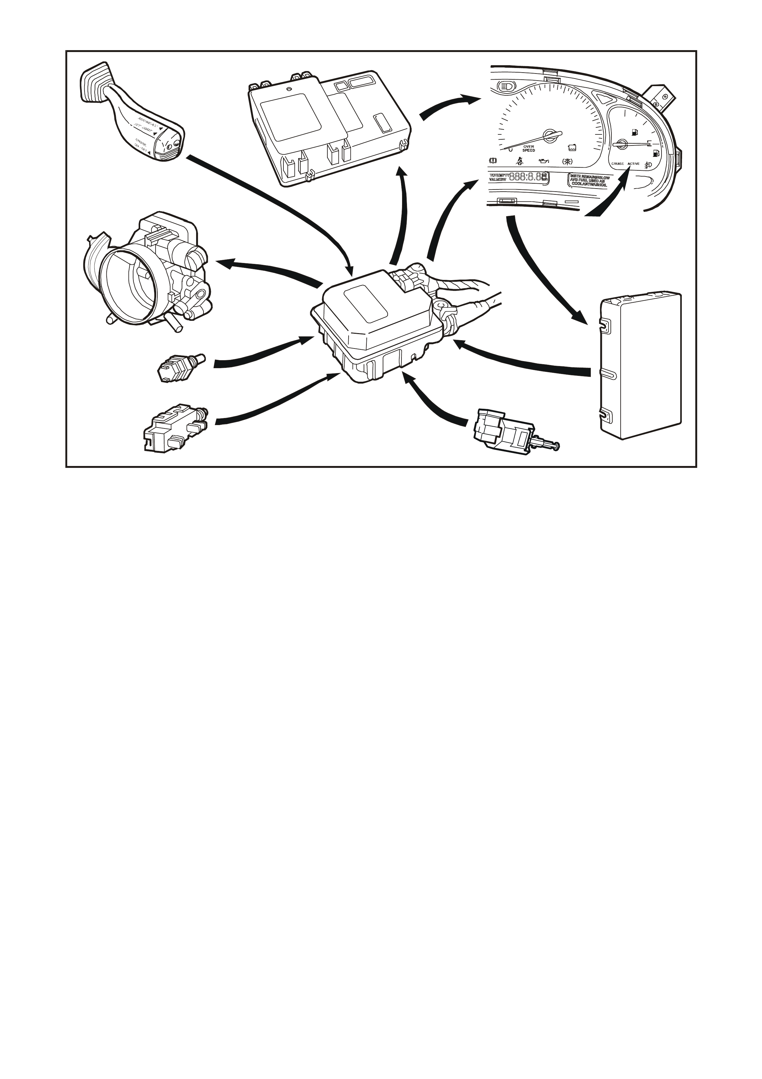
Fig. 12E-1 illustrates the component relationship for the cruise control system.
Techline
T212E001
kmh
20
1
2
3
D
N
RP
40
60 80 100120
140
160 F
180
200
220
LPG
6
5
8
7
9
10
1
2
3
4
Figure 12E-
1. Cruise control module
2. Brake pedal electrical release switch (Switch B)
3. Brake (Stop lamp) switch A
4. Throttle body
5. Cruise control switches
6. Body control module
7. Instrument cluster
8. CRUISE and ACTIVE lamps
9. Powertrain control module
10. Clutch switch
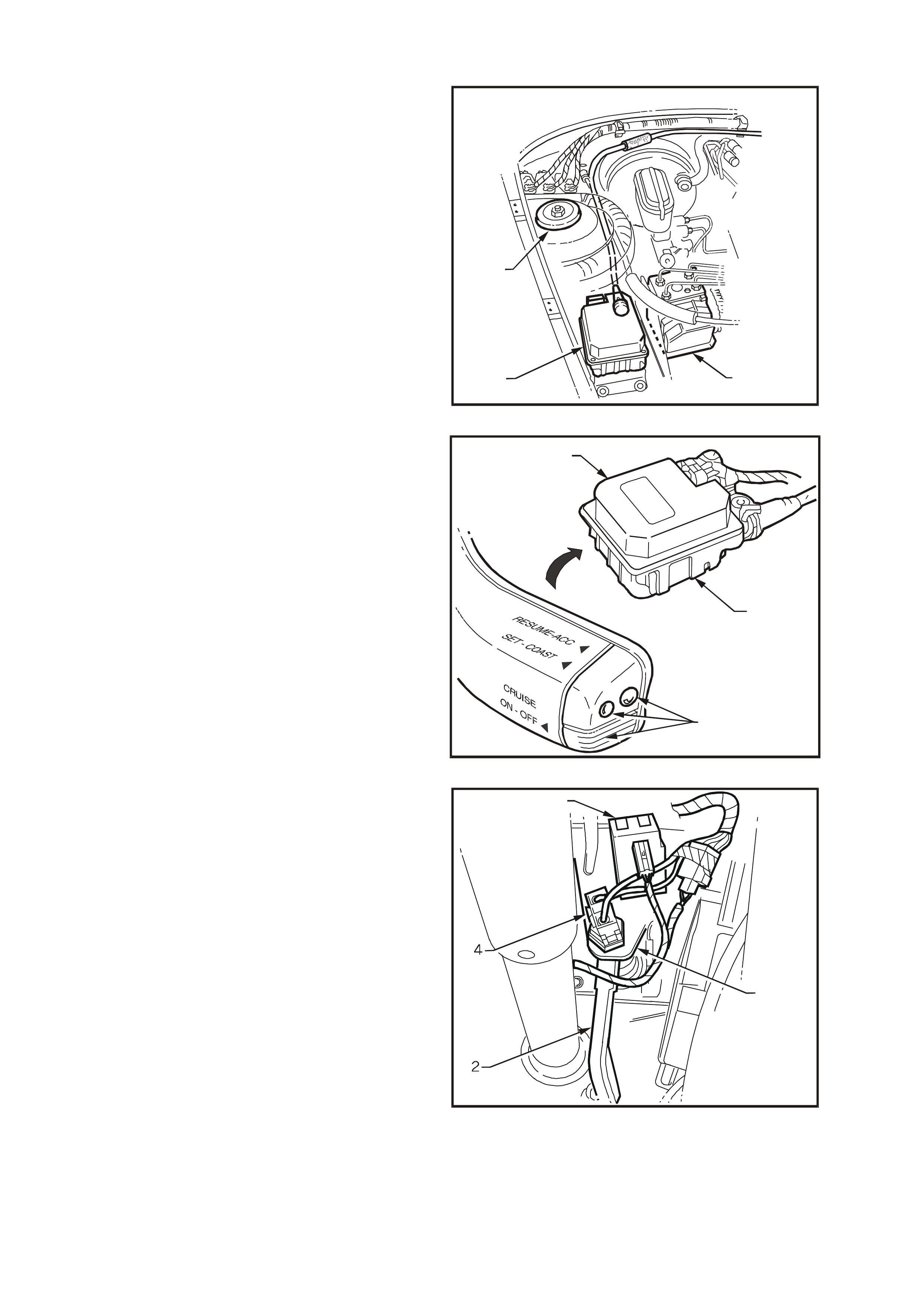
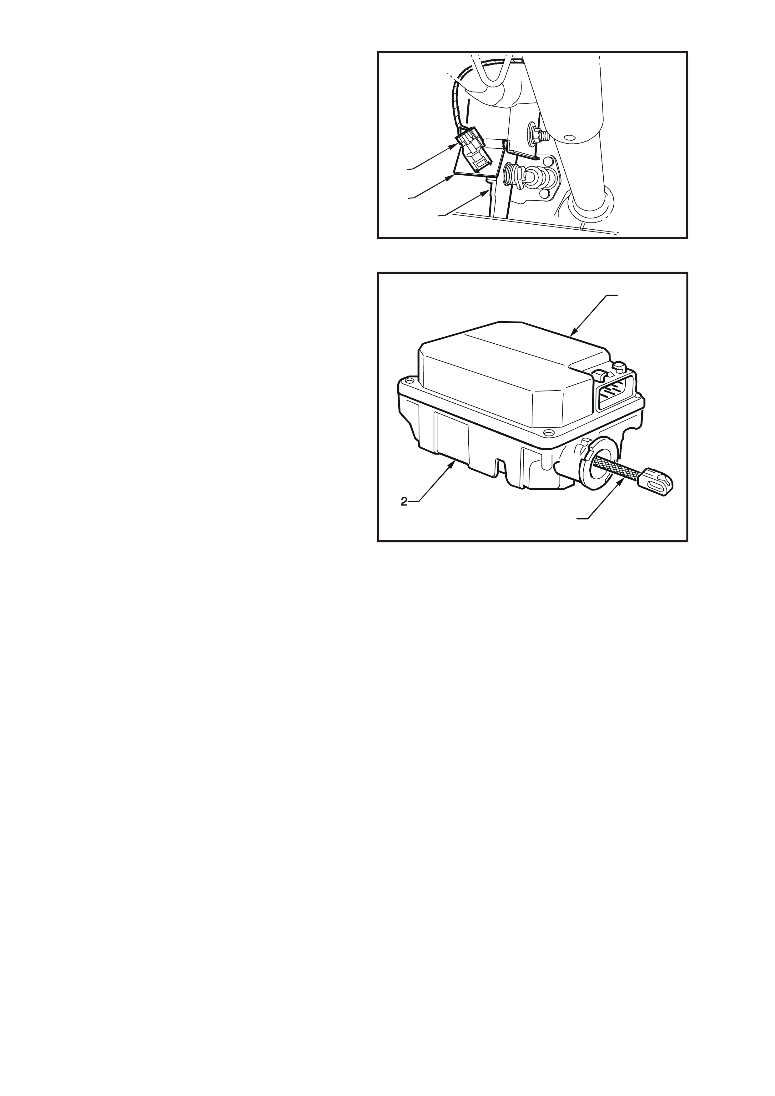
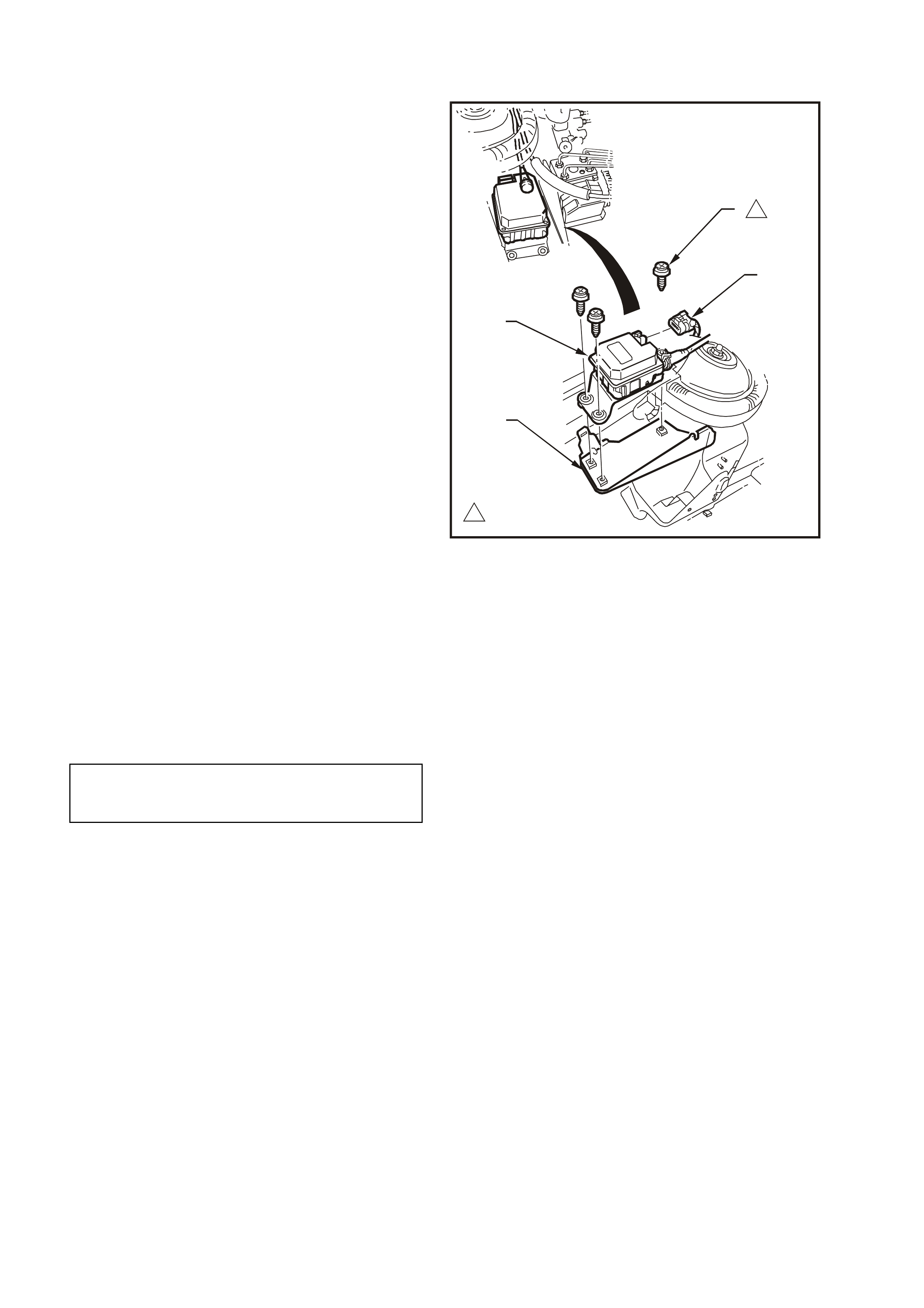
COMPONENTS
The cruise control module (1) is mounted forward
of the right-hand s trut tower (2) and adjacent to the
optional ABS module (3), regardless of the engine
variant.
T212E002
2
13
Figure 12E-2
The cruise control module functionally integrates an
electronic controller (1) with an electric stepper
motor (2).
The electronic controller monitors vehicle speed
from a signal generated by the PCM which in turn,
operates the electric stepper motor.
The stepper motor, in response to the electronic
controller, adjusts the throttle position to maintain
the desired vehicle set speed. The electronic
controller is operated by the cruise control system
control switches (3) located at the tip of the
headlamp and turn signal stalk control switch
assembly.
T212E025
1
2
3
Figure 12E-3
Two switches, mounted on the br ake pedal suppor t
(1), disengage the cruise control system
electronically when the brake pedal (2) is
depressed.
The upper switch (3) is the cruise control electrical
release switch (Switch B). The two rear terminals
are used for the cruise control system.
NOTE: Using the f ront set of term inals will result in
the cruise control not functioning.
The lower switch (4) is the brake pedal stop lamp
switch (Switch A), and is used to illum inate the s top
lamps and signal the cruise control module to
disengage.
With the brake pedal at rest, the stop lamp contacts
in the lower switch are open, and closed when the
brake pedal is depressed.
With the brake pedal at rest, the electrical release
contacts in the upper switch are closed, and open
when the brake pedal is depressed.
Both switches are used to signal the cruise control
module so that if one s hould fail, the sec ond switch
will still generate a signal to the cruise control
module to disengage the cruise control function.
T212E003
1
3
Figure 12E-4
For vehicles with a manual transmission, a clutch
pedal switch (1) mounted on the clutch pedal
support (2), has been incorporated into the cruise
control system. When the driver depresses the
clutch pedal (3) to change gear, the cruise control
is disengaged.
When the clutch pedal is depressed a signal is
transmitted to the cruise control module to
disengage the cruise control function.
With the clutch pedal at rest, the contacts of the
clutch switch are c losed, and open when the clutch
pedal is depressed.
T212E034
1
23
Figure 12E-5
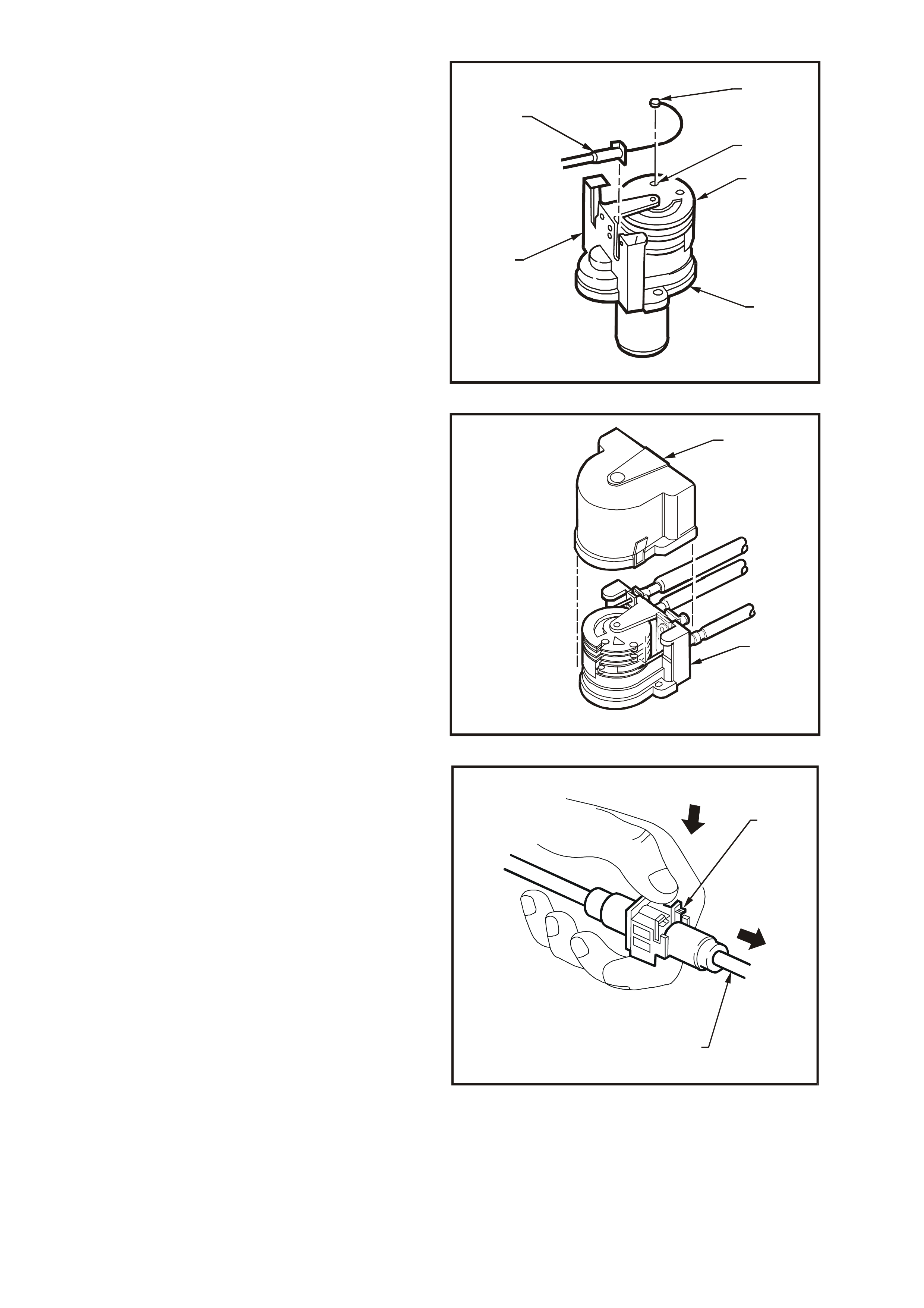
The cruise control module comprises an electronic
controller (1) and electric stepper motor, solenoid
operated clutch and gear train assemblies (2), and
a connecting strap (3).
The electronic controller receives signals from the
cruise control electrical release switch, stop lamp
switch, clutch pedal switch and vehicle speed
output. It then generates signals to control the
stepper m otor and solenoid operated cr uise control
module clutch.
The electric stepper motor is a brushless type
motor with a four pole per manent m agnet arm ature
and three phase stator. The motor provides torque
through a mechanical gear train to a control cable,
which actuates the throttle linkage.
When the brake pedal electrical release switch is
activated (brake pedal depressed) the stepper
motor begins to spin the motor back to the zero
motor position. If the signal at pin G (refer to
Fig. 12E-39) of the cruise control module is pulled
high, it will cause the stepper motor clutch to de-
energise in about 0.75 seconds . In most c ases, the
stepper motor will be in the zero position when the
module clutch is disengaged. This time delay
period is introduced to prevent the accelerator
pedal from slapping while the throttle is still held
open. The stepper motor relies on the throttle
return spr ing to return the s tepper motor to the zero
position as the spring on the drum gear is not
strong enough to return the throttle/cruise to zero.
The internal components of the control module are
not serviceable.
CAUTION: Do not attempt to repair the control
module assembly if faulty. Unauthorised repair
of the control module will affect vehicle safety.
T212E004
1
3
Figure 12E-6
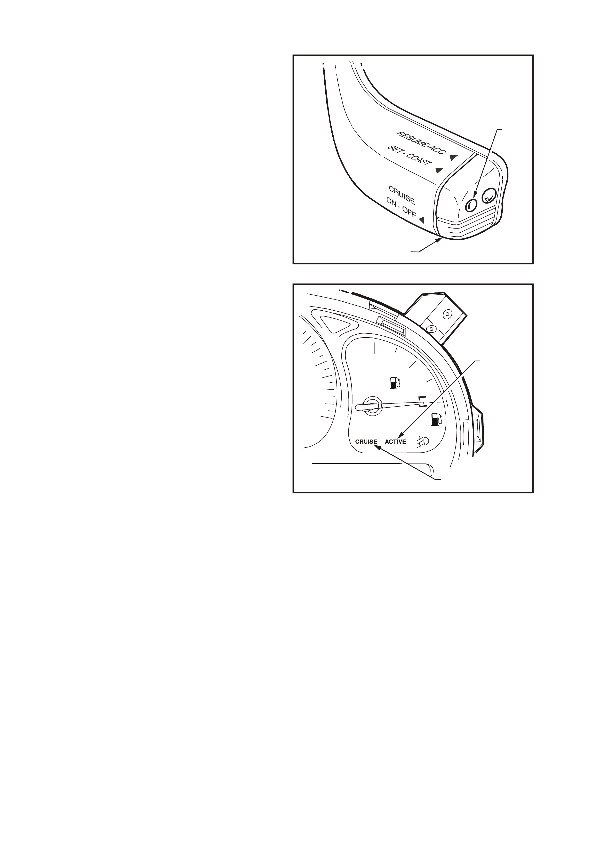
CRUISE CONTROL SWITCH OPERATION
Engaging the Cruise Control
W ith the ignition switched on, press the cruise ON-
OFF button (1). This will cause the CRUISE lamp in
the instrument cluster to illuminate, refer to
Fig. 12E-8, indicating power is on.
Accelerate the vehicle to the desired cruise speed
(above 40 km/h) and depress and release the
SET-COAST button (2), then release the
accelerator pedal.
T212E029
1
2
Figure 12E-7
The CRUISE lamp (1) in the instrument cluster will
illuminate when the cruise control system is turned
on at the control switch located on the turn signal
stalk.
The ACTIVE lamp (2) in the instrument cluster will
illuminate when the cruise control system is
engaged. The cruise speed will be automatically
ma intained, provided the vehicle speed is above 40
km/h.
T212E005
F
LPG
1
2
Figure 12E-8
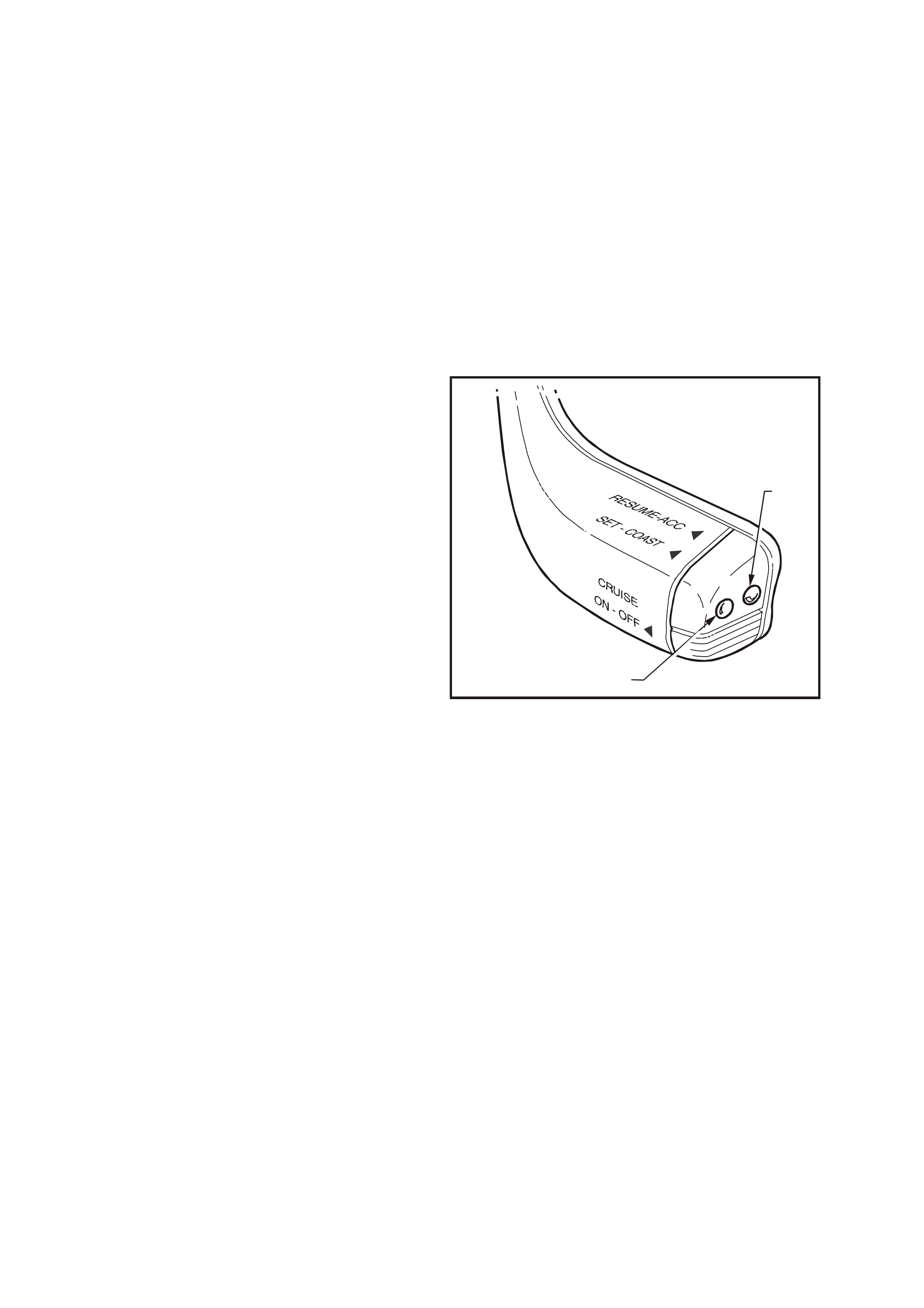
To Change Cruise Speed
To reset the cruise control to a higher speed,
accelerate the vehicle to the desired speed,
depress the SET-COAST button (1) and release it.
Depressing the RESUME-ACC (2) button will cause
an increase in cruise speed and the vehicle will
accelerate at a controlled rate until the RESUME-
ACC button is released. The vehicle will now cruis e
at this higher set speed.
To decrease the cruise speed, press the SET-
COAST button. The vehicle will decelerate,
coasting to a slower speed at a controlled rate until
the SET-COAST button is released. The vehicle will
now continue to cruise at the reduced set speed.
NOTE: While holding the SET-COAST button, the
ACTIVE lamp in the instrument cluster (refer to
Fig. 12E-8) will turn OFF. The ACTIVE lamp will
illuminate when the SET-COAST button is
released.
The cruise control switches also provide the f acility
for TAP UP and TAP DOWN for smaller
incremental adjustments in vehicle cruise speed.
TAP UP is achieved by quickly depressing the
RESUME-ACC button and the cruise speed will
increase by 2.0 km/h for every TAP UP. Quickly
depressing the SET-COAST button (TAP DOWN)
will decrease the cruise control speed by 2.0 km/h
for every TAP DOW N. TAP DOW NS are limited to
the minimum cruising speed of 40 km/h.
T212E030
1
2
Figure 12E-9

To Override the Cruise Control System
The accelerator pedal may be depressed at any time to override the cruise control system. Release of the
accelerator pedal will return the vehicle to the previous set cruise speed.
To Disengage the Cruise Control System
The system is disengaged when:
1. The brake pedal is depressed.
2. The clutch pedal is depressed (for vehicles with manual transmission).
3. The ON-OFF button is depressed switching the cruise control system to the STANDBY mode.
IMPORTANT: W hen vehicles fitted with Electronic Trac tion Control are in a low traction situation, the cruis e control
will disengage.
When the cruise control system is disengaged, the ACTIVE lamp goes out but the CRUISE lamp remains on.
To resume the previous set cruise control memory speed after changing gear, braking, stopping, or pressing the
ON-OFF switch once, first accelerate, if required, until the vehicle speed is greater than 40 km/h, then press the
RESUME-ACC button (for less than one second). The vehicle will then automatically accelerate to the previous
cruise speed setting.
The cruise control module will retain the previous set speed in memory for as long as the CRUISE lamp is
illuminated. Depressing the clutch pedal or brake pedal, or pressing the ON-OFF switch once while the ACTIVE
lamp is on, will not erase the vehicle set speed from the control module memory.
Pressing the ON-OFF switch while only the CRUISE lamp is on or turning the ignition off, will erase the previous
cruise set speed from the control module memory.
NOTE: Each time the ignition is c ycled, the CRUISE and ACTIVE lamps will go out. T o r eac tivate the cr uis e c ontrol,
the cruise control ON-OFF switch will have to be pressed.
2. SERVICE OPERATIONS
2.1 CRUISE CONTROL CABLE
REMOVE
1. On vehicles with V6 engine, push the outer
cable retaining tang (1) at the throttle cable
bracket (2) away from the throttle body and
pull outer cable (3) out of throttle cable
bracket.
2. On vehicles with V6 engine, remove the inner
cable retaining clip (4) from the throttle body
linkage lever stud by pushing the retaining c lip
off the stud with the aid of a screwdriver.
T212E006
1
3
2
4
Figure 12E-10
3. On vehicles with GEN III V8 engine and
without traction control, remove four dome
nuts (2) securing engine dress cover
assem bly (1) to intake m anifold studs. Lift and
remove dress cover assembly.
T26D3105
21
Figure 12E-11
4. On vehicles with GEN III V8 engine and
without traction control, use a screwdriver to
prise end of c ruise control inner cable (1) f rom
throttle body lever stud (2). Lever outer cable
retaining tang (3) at cable mounting bracket
(4) and pull outer cable (5) upwards from
cable mounting bracket.
T212E037
5
3
4
12
Figure 12E-12
5. On vehicles with GEN III V8 engine and
traction control, remove cover (1) from throttle
relaxer (2) by depressing tabs (3) on both
sides of cover. Refer to Fig. 12E-13 and
Fig. 12E-22.
T212E038
1
2
3
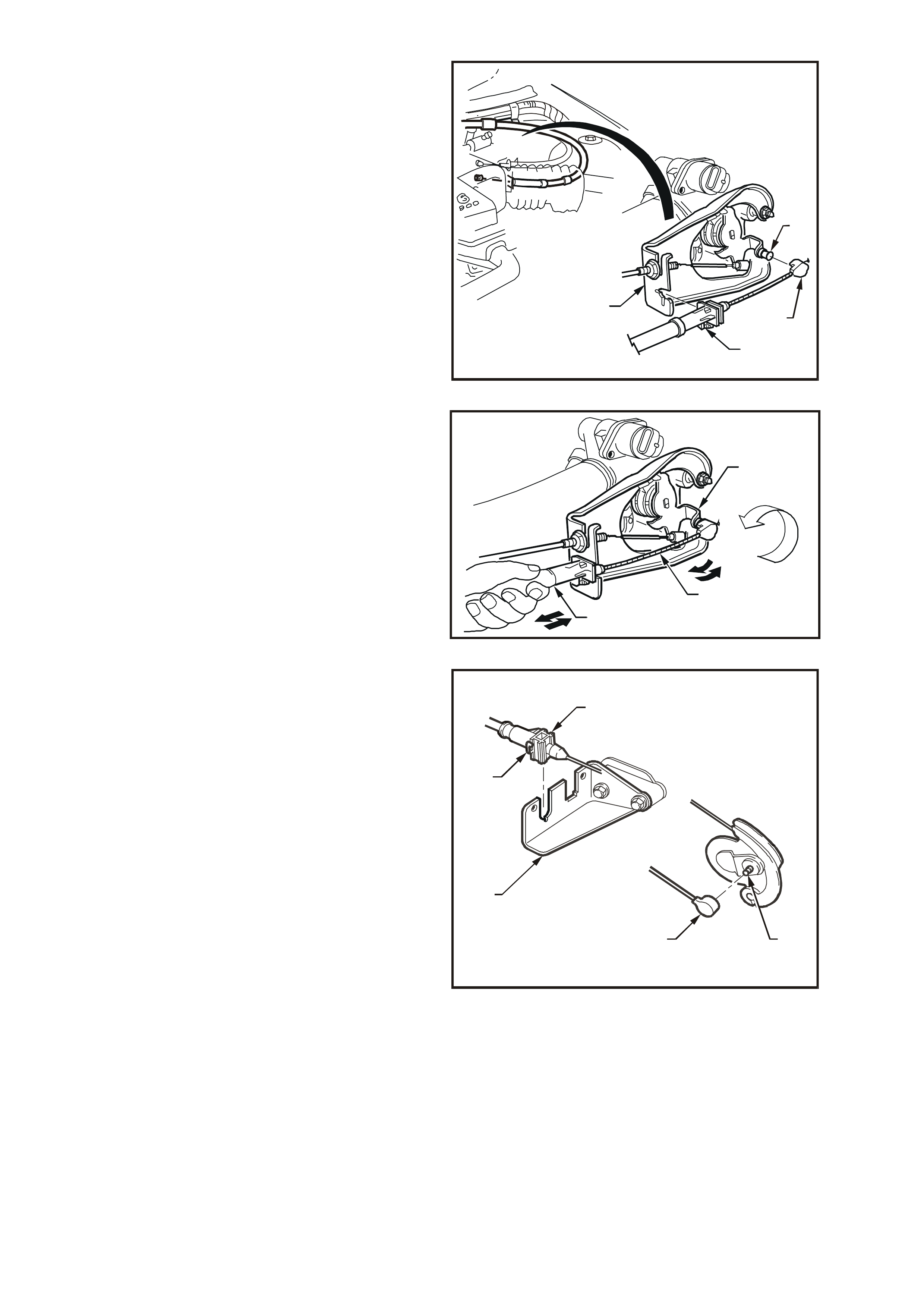
Figure 12E-13
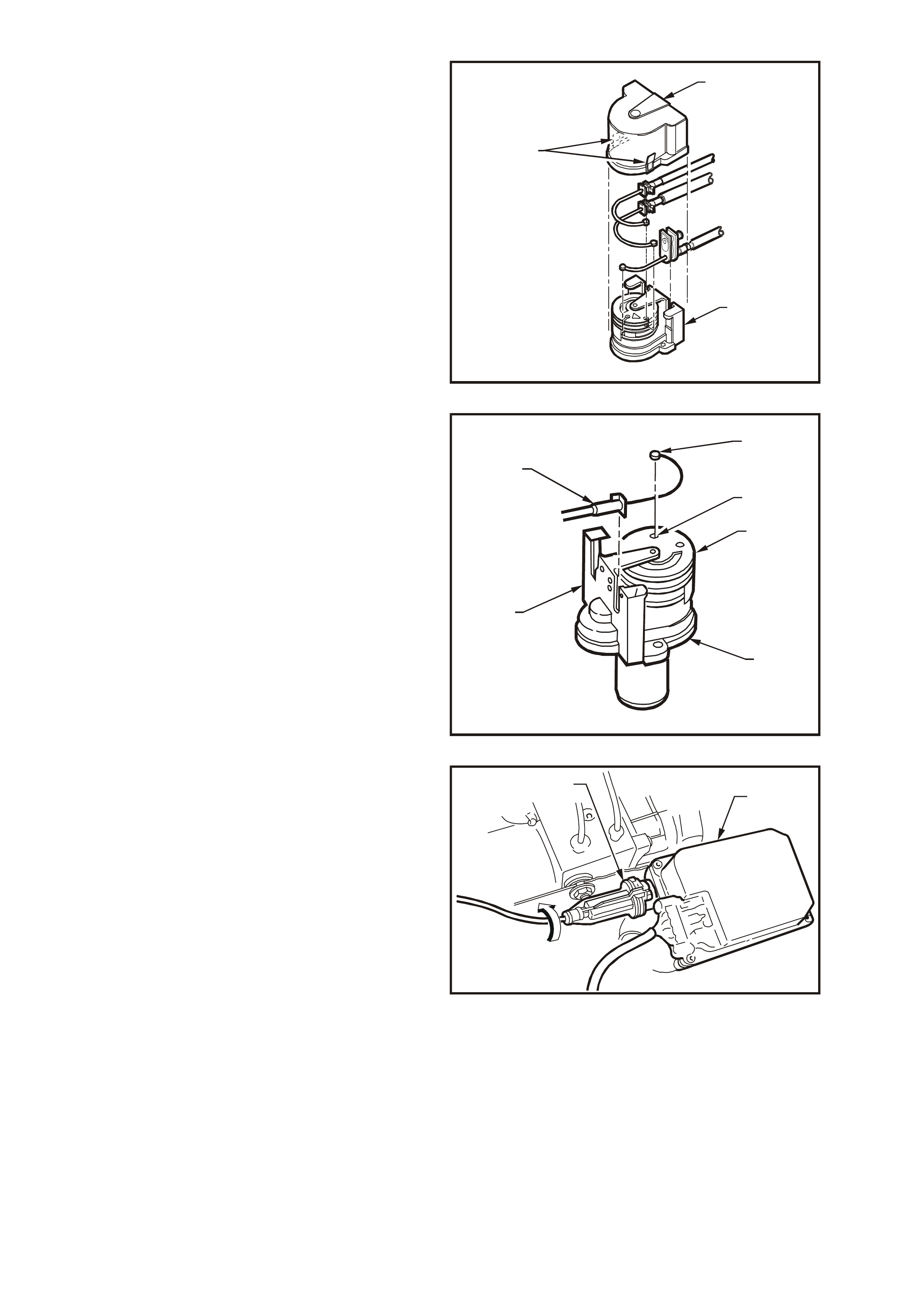
6. Rotate top cam (1) of throttle relaxer (2) and
rem ove ferr ule ( 3) of cr uise control inner cable
from locating slot (4) in throttle c am. Lever out
retaining tang of outer cable (5) then lift cable
away from throttle relaxer mounting
bracket (6).
T212E039
5
3
4
1
6
2
Figure 12E-14
7. At the control module (1), turn the outer
control cable (2) towards the engine (approx.
45°) to release the cable lock mechanism (3)
from the control module.
T212E009
3 1
2
45
O
Figure 12E-15
8. Pull the outer cable (1) from control module (2)
and disconnect inner cable (3) from electric
stepper m otor str ap end fitting (4) by lifting the
cable upward, approximately 45°, allowing it to
be released from the end fitting.
T212E010
CC
41
23
Figure 12E-16
9. Release cruise control cable from main wiring
harness/cable clip (1) by holding the upper
retention clip (2) and then pushing the lower
retention clip (3) inward and down to release
the powertrain wiring harness (4), throttle
cable (5), cruise control cable (6), and for
wagon only, the rear washer hose (7).
NOTE: Depending on m odel and har ness /c able c lip
location, clip may also retain accelerator pedal
cable and wiper motor harness.
10. Remove cruise control cable.
T212E011
2
31
7
6
5
Figure 12E-17
REINSTALL
1. Ensuring that the motor strap (1) is not
twisted, attach inner cable end ( 2) to the motor
strap end fitting (3) at the control module (4).
T212E012
CC
432
1
Figure 12E-18
2. W hile holding the inner cable (1) at the throttle
body linkage lever stud connection end, slide
outer cable (2) over the motor strap until the
outer cable sits flush with the control module
housing (3).
3. Turn outer c able towards the r ight-hand f ender
(approx. 45°) to lock the outer cable locking
mechanism to the control module, refer to
Fig. 12E-19.
4. Ensuring that the cr uise contr ol cable is r outed
correctly, lock the cable into the main wiring
harness/c able clips. Ref er to Fig. 12E-20 (V6),
Fig. 12E-21 and Fig. 12E-22 (GEN III V8).
T212E013
45
o
3
2
1
Figure 12E-19
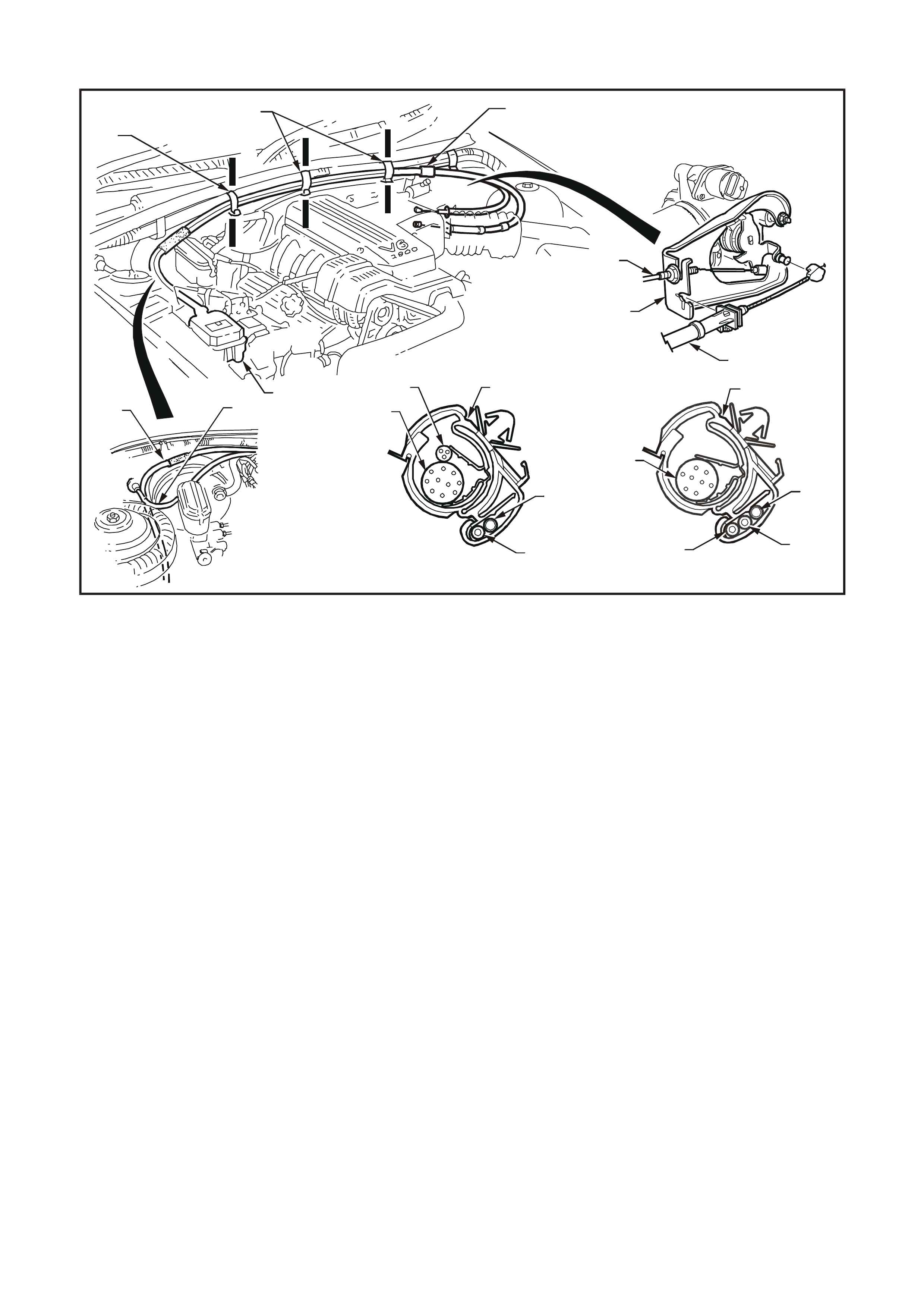
CABLE ROUTING: V6 engine
T212E014
123
589
1
2
10
A-A
65
4
7
1
A
A
B
BB
B
B-B
8
7
1
2
4
Figure 12E-20
1. Cruise control cable
2. Throttle cable
3. Cruise control module
4. Powertrain wiring harness
5. Harness/cable clip (Section A-A)
6. Wiper motor harness
7. Rear washer hose (W agon only)
8. Harness/cable clip (Section B-B, three places)
9. Cruise control outer cable adjuster/lock
10. Throttle cable bracket
NOTE: Cruise control cable routing for V6 Supercharged
engine is the same.
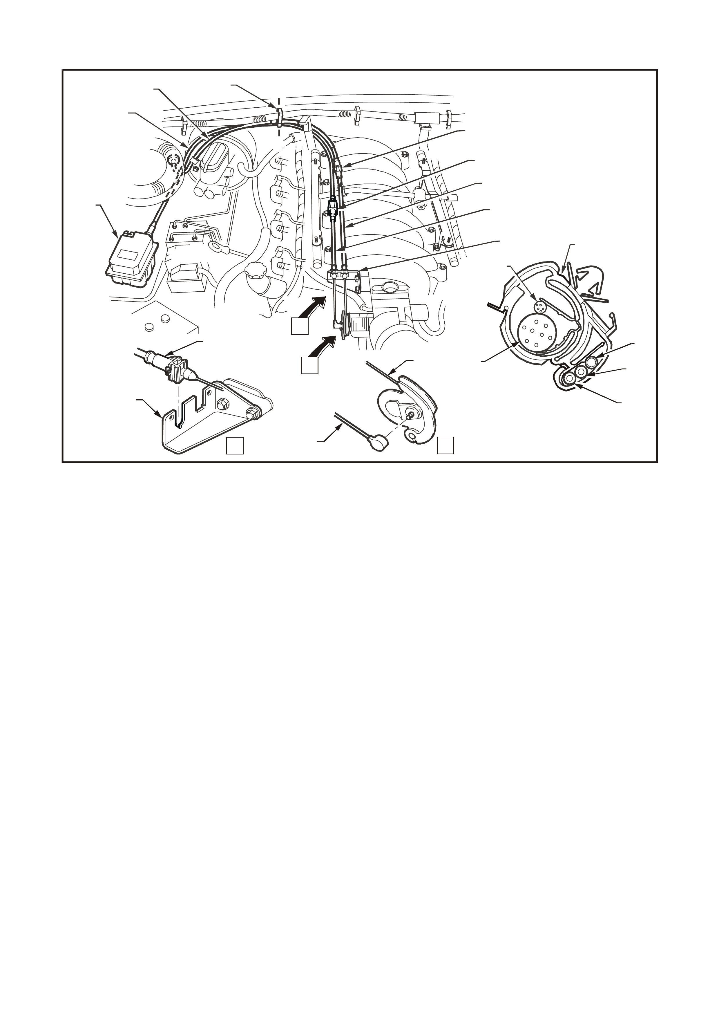
CABLE ROUTING: GEN III V8 engine without throttle relaxer
T212E035
2
3
2
4
9
10
4
2
3
A
1
2
7
4
7
6
5
2
4
8
A-A
A
A
A
B
B
Figure 12E-21
1. Cruise control module
2. Cruise control cable
3. Throttle cable bracket
4. Throttle cable
5. Powertrain harness
6. Wiper motor harness
7. Harness/cable clip (Section A-A)
8. Rear washer hose (W agon only)
9. Throttle outer cable adjuster/lock
10. Cruise control outer cable adjuster/lock
CABLE ROUTING: GEN III V8 engine with throttle relaxer
T212E036
A-A
5
4
6
7
3
2
4
11
7
3
2
4
13
23
7
10
14
B-B C-C
B
B
C
C
A
A
10
9
13
12
11
3
8
15
14
6
10
3
2
15
Figure 12E-22
1. Cruise control module
2. Cruise control cable
3. Accelerator pedal cable
4. Powertrain harness
5. Wiper motor harness
6. Harness/cable clip (Section A-A)
7. Rear washer hose (W agon only)
8. Throttle cable bracket
9. Throttle outer cable adjuster/lock
10. Throttle cable
11. Harness /cable clip (Section B-B)
12. Cruise control outer cable adjuster/lock
13. Harness/cable clip (Section C-C)
14. Throttle relaxer
15. Throttle relaxer cover
5. Unlock the c r uise c ontr ol outer c able by pulling
the lock tangs on the outer cable adjus ter/lock
(1) in the direction indicated by the arrows in
Fig. 12E-23.
T212E016
1
Figure 12E-23
6. On vehicles with V6 engine, push the outer
cable retainer (1) into the throttle cable brac k et
(2).
7. On vehicles with V6 engine, push the inner
cable retaining clip (3) onto the throttle body
linkage lever stud (4).
T212E031
1
23
4
Figure 12E-24
8. On vehicles with V6 engine, adjust the cruise
control outer cable (1) at the cable
adjuster/lock (refer to Fig. 12E-23) to achieve
minimum slack of the inner cable (2) while
ensuring that the throttle lever (3) is in the fully
closed position (4). Refer to Fig. 12E-25.
T212E020
1
3
2
4
Figure 12E-25
9. On vehicles with GEN III V8 engine without
traction control push the inner cable retainer
clip (1) onto throttle body linkage lever stud
(2). Push outer cable retainer (3) into throttle
cable bracket (4) ensuring that the cable
retaining tang (5) locks into throttle cable
bracket.
T212E041
4
12
3
5
Figure 12E-26
10. On vehicles with GEN III V8 engine and
traction control, rotate top cam (1) of throttle
relaxer (2) and install inner cable ferrule (3)
into slot in cam (4). Ensure that inner cable is
properly in groove on cam. Push outer cable
retainer (5) onto throttle relaxer mounting
bracket (6) ensuring that the cable retaining
tang locks into the mounting bracket.
T212E039
5
3
4
1
6
2
Figure 12E-27
11. On vehicles with GEN III V8 engine and
traction control, install cover (1) on throttle
relaxer (2).
T212E042
1
2
Figure 12E-28
12. Allow the internal spring of the cable
adjuster/lock mechanism (1) to take up the
free play of the outer cable (2). Push down on
the outer cable lock ing retainer to fix the outer
cable to the corr ect self adjusted length. Refer
to Fig. 12E-29.
NOTE: After the cable is fitted, ensure that the
throttle opens without binding and returns to the
fully closed position under throttle return spring
tension.
13. On vehicles with GEN III V8 engine without
traction control, install the engine cover.
T212E021
2
1
Figure 12E-29
2.2 CRUISE CONTROL MODULE
REMOVE
1. Remove the cruise control cable, refer to
2.1 CRUISE CONTROL CABLE in this
Section.
2. Pull up tang on wiring harness connector (1),
and pull connector from control module (2).
3. Remove the three screws (3) securing the
control module to the ABS/cruise control
module mounting bracket (4) and remove
control module.
T212E022
1
1
2 ~ 5 Nm
4
3
1
2
Figure 12E-30
REINSTALL
Installation of the cruise control module is the
reverse of the removal operation, noting the
following:
1. To install the cruise control cable, refer to
2.1 CRUISE CONTROL CABLE in this
Section.
2. Tighten all fasteners to the correct torque
specification.
3. Connect the wiring harness connector
ensuring that the connector tang is secure.
CONTROL MODULE
SECURING SCREW
TORQUE SPECIFICATION 2 – 5 Nm
2.3 CRUISE CONTROL SWITCH ASSEMBLY
REMOVE AND REINSTALL
The cruise control switches are integrated with the
headlamp and turn signal control switch stalk
located to the right of the steering column.
Removal and installation instructions for the right-
hand switch stalk are described in Section 12B
LIGHTING SYSTEM in the VT Series I Service
Information.
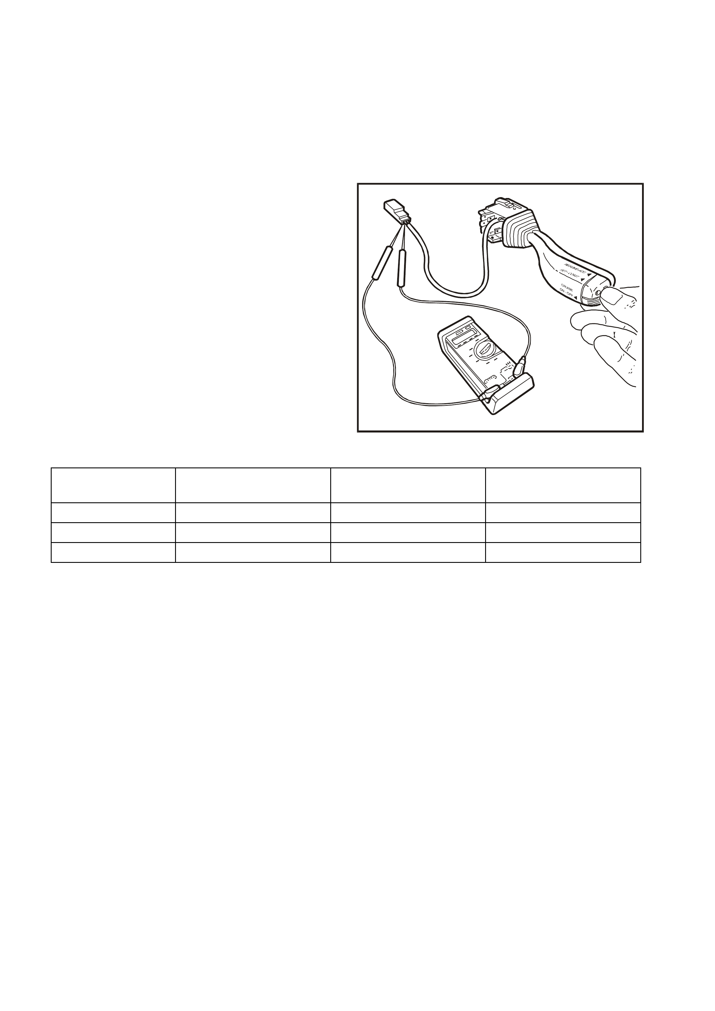
CHECKING SWITCH CONTACTS
With the cruise control system control switch lead
disconnected from the main wiring harness, check
the cruise control switch contacts as follows:
Attach an ohmmeter to the appropriate terminals
nominated in the following chart and depress and
hold switches as indicated.
T212E033
Figure 12E-31
SWITCH OHMMETER CONNECTED RESISTANCE RESISTANCE
BETWEEN SWITCH DEPRESSED SWITCH RELEASED
ON-OFF RED wire & GREY wire Approximatel y 470 ΩOpen Ci rcuit
SET-COAST BLUE wire & RED wire Approximatel y 470 ΩOpen Ci rcuit
RESUME-A CC RED wire & GREEN wire Approximatel y 470 ΩOpen Ci rcuit
If the resistance is not to specification, replace the
cruise control switch assembly.
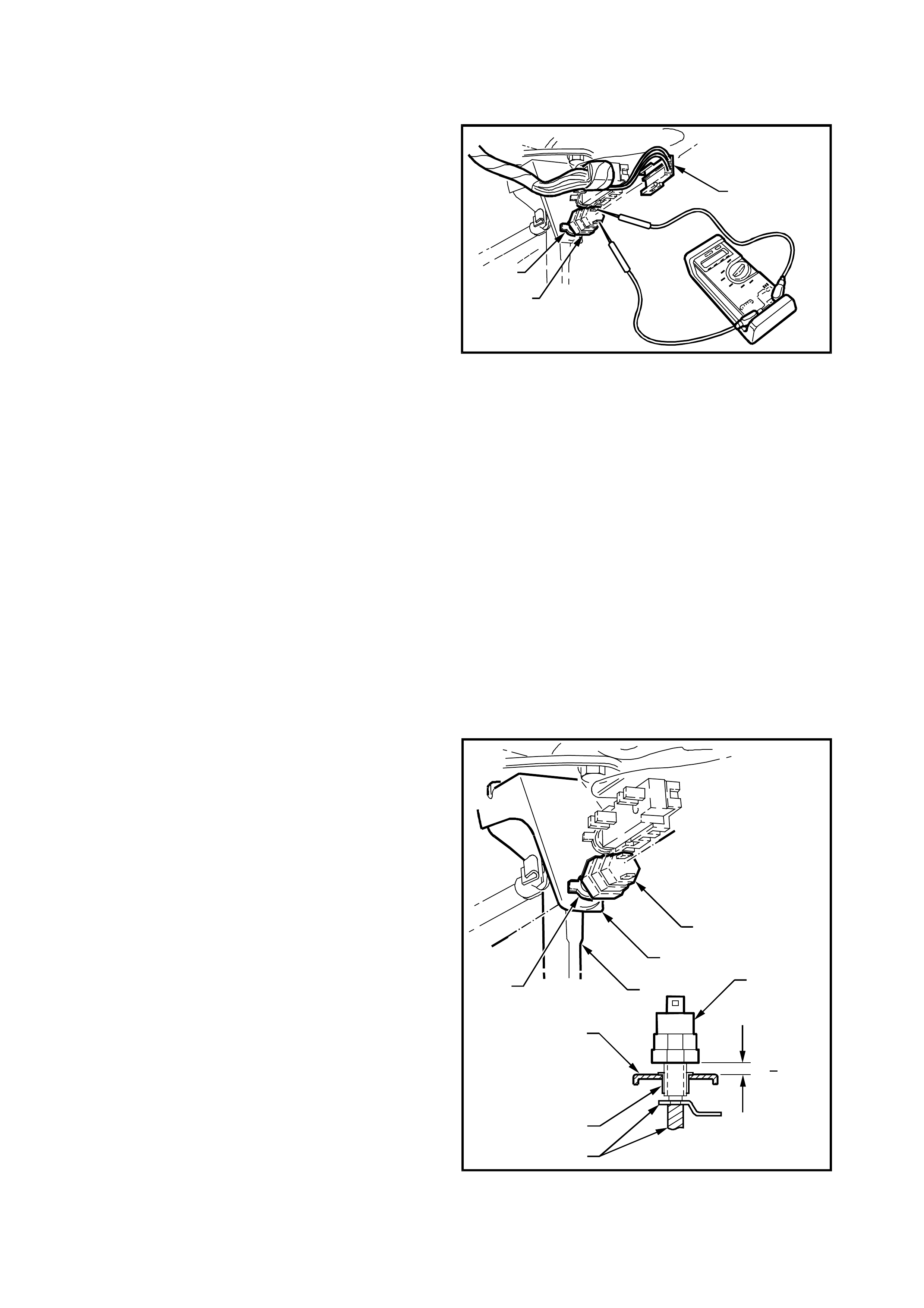
2.4 STOP LAMP SWITCH(SWITCH A)
TESTING SWITCH CONTACTS
1. Check adjustment of the stop lam p switch (1),
refer to the following switch installation and
adjustment proc edure and adj us t the switch as
required.
Ensure that the stop lamps are operating when
the brake pedal is depressed.
If stop lamps are not operating, repair as
necessary, refer to Section 12B LIGHTING
SYSTEM in the VT Series I Service
Information.
2. Remove wiring harnes s c onnec tor (2) f r om the
terminals of the stop lamp switch (1).
3. Connect an ohmmeter across the switch
terminals and the ohmmeter should indicate
open circuit with the brake pedal at rest.
Depress the brake pedal and the ohmmeter
should indicate continuity.
4. Replace the switch as per the following
removal procedure if the tests prove the switch
to be faulty.
5. If the test proves the switch to be serviceable,
connect the wiring harness connector to the
switch.
T212E045
2
3
1
Figure 12E-32
REMOVE
1. Disconnect wiring harness c onnec tors (2) f r om
the stop lamp switch (1).
2. Rotate switch anticlockwise and remove from
the mounting nut (3).
REINSTALL AND ADJUST
1. Install the stop lamp switch (1) into the
mounting nut (2) on the brake pedal support
(3).
2. With the brake pedal (4) in its rest position,
adjust the switch to the clearance dimension
shown in Fig. 12E-33.
3. Connect wiring harness connector to the
switch.
T212E046
1
3
2
4
6 0.5mm
A
A
1
3
4
2
A-A
+
Figure 12E-33
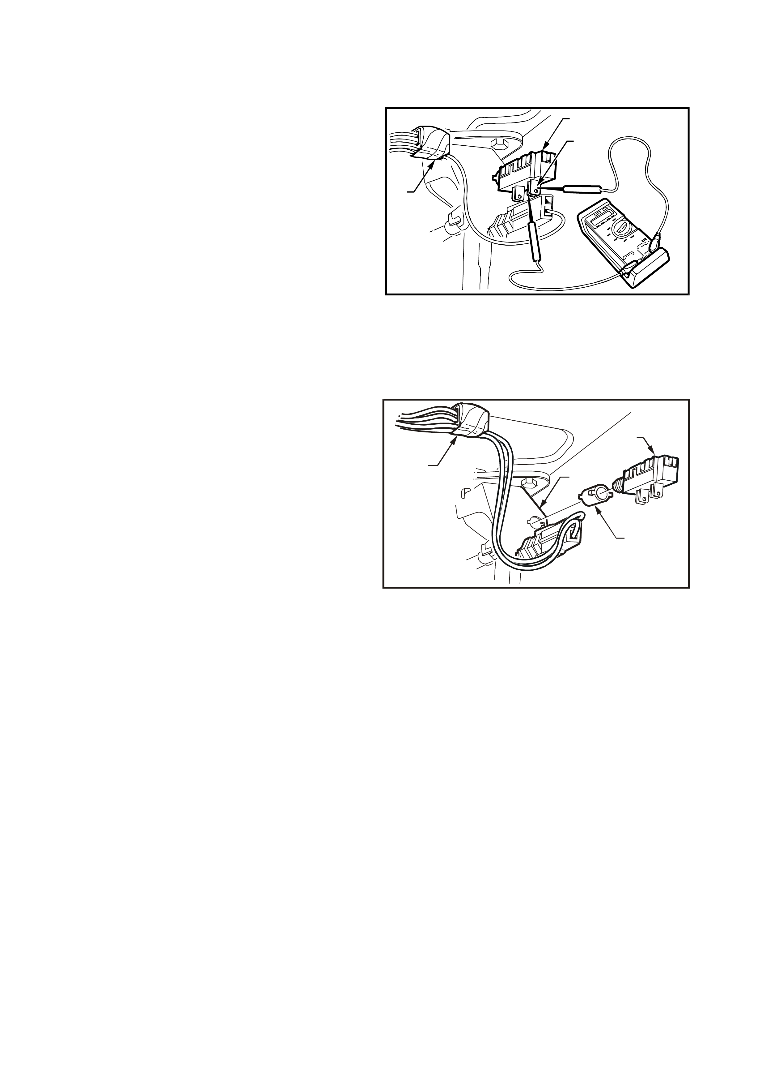
2.5 ELECTRICAL RELEASE S WITCH (SWITCH B)
TESTING SWITCH CONTACTS
1. Check adjustment of the electrical release
switch (1), refer to the following switch
installation and adjustment procedure and
adjust the switch as required.
2. Remove wiring harness connector from rear
most terminals (2) of switch.
3. Connect an ohmmeter across the switch
terminals and the ohmmeter should indicate
continuity with the brake pedal at rest.
Depress the brake pedal and the ohmmeter
should indicate an open circuit.
4. Replace the switch as per the following
removal procedure if the tests prove the switch
to be faulty.
5. If the test proves the switch to be serviceable,
connect the wiring harness connector to the
switch.
T212E023
1
3
2
Figure 12E-34
REMOVE
1. Disconnect wiring harness c onnec tors (1) f r om
electrical release switch (2).
2. Pull switch from tubular clip (3).
3. If necessary, remove clip from brake pedal
support (4).
T212E024
1
2
4
3
Figure 12E-35
REINSTALL AND A DJUST
1. If removed, install the tubular clip into the
mounting hole of the brake pedal support.
2. Holding the brake pedal in its depressed
position, install switch into tubular clip. Push
switch forward until the switch body locates in
the clip.
NOTE: Audible click s will be heard as the threaded
portion of switch assembly is pushed into the
tubular clip toward the brake pedal.
Pull brake pedal fully against pedal stop until
audible ‘click’ sounds can no longer be heard.
(Switch assembly is pushed back out from the clip
to provide correct switch position adjustment).
Depress the brake pedal again and repeat above
procedure to ensure that the switch adjustment is
correct (no click sounds).
3. Connect wiring harness connector to the
switch.
2.6 CLUTCH PE DAL SWITCH
TESTING SWITCH CONTACTS
1. Remove wiring harness connector from
terminals of clutch switch.
2. Connect an ohmmeter across the switch
term inals (1) and the ohm m eter should indic ate
continuity with the clutch pedal at rest.
Depress the clutch pedal and the ohm meter should
indicate an open circuit.
3. Replace the switch as per the following
removal procedure if the tests prove the switch
to be faulty.
4. If the test proves the switch to be serviceable,
connect the wiring harness connector to the
switch.
T212E040
1
Figure 12E-36
REMOVE
1. Disconnect wiring harness connectors from
switch.
2. T urn switch 90°, then pull switch ass embly out
from pedal support to remove.
REINSTALL AND A DJUST
1. Install new switch by pushing the switch
assembly through pedal support and turning
switch 90°.
2. Hold clutch pedal at its rest position.
3. Connect wiring harness connectors to clutch
switch.
4. Verify the operation of clutch switch by
operating cruise control and checking that
clutch switch stops operation of cruise control
when the clutch pedal is depressed.

3. DIAGNOSIS
3.1 PRELIMINARY DIAGNOSIS AND INSPECTION
NOTE: If a vehicle is fitted with traction control, the cruise contr ol system will disengage or f ail to engage whenever
the LOW TRAC lamp is illuminated in the instr ument c luster , and will not engage or re- engage until the LO W TRAC
lamp turns off.
When a vehicle is suspec ted of having a c ruise c ontrol system operation m alf unction, it is impor tant to carr y out the
following preliminary diagnosis. This diagnosis should be used to determine whether the cruise control system
problem is the result of an actual system defect, or the result of a problem with some other vehicle component.
Also, som e c ruise c ontrol system c om plaints m ay be a misunder standing by the driver about how the cr uise control
system f unctions . In that c ase, the oper ation of the s ystem s hould be ex plained in a manner the dr iver under stands .
A practical demonstration is very useful to explain system operation.
If it is decided the cruise control system is at fault, perform a visual inspection of all components in the system.
Cruise control system malfunctions can be caused by mechanical, electrical, or a combination of both problems.
Things to check are:
1. Switch inputs to cruise control module.
2. Dirty, corroded, or loose electrical connections.
3. Damaged or incorrectly adjusted stop lamp switch (Switch A). Refer to 2.4 STOP LAMP SWITCH in this
Section for test and adjustment procedure.
4. Damaged or incorrectly adjusted electrical release switch (Switch B). Refer to 2.5 ELECTRCAL RELEASE
SWITCH in this Section for test and adjustment procedure.
5. Damaged or inoperative clutch pedal switch. Refer to 2.6 CLUTCH PEDAL SWITCH in this Section for test
and adjustment procedure.
6. Binding or sticking throttle linkage.
7. Broken components (e.g. cruise control cable).
8. Bare, broken or disconnected wires.
9. Adjustment of control cable, refer to 2.1 CRUISE CONTROL CA BLE in this Section.
10. On vehicles fitted with GEN III V8 engine and traction control, ensure that the throttle relaxer is functioning
correctly. Refer to Section 12L ABS & ABS/ETC of the VT Series II Service Information.
If preliminary inspection reveals no problem, and the system is malfunctioning, refer to
3.3 SELF DIAGNOSTIC TEST in this Section.
NOTE: Verify that the problem exists before attempting any repairs. Sometimes normal operating characteristics
may be misunderstood as a problem.
Techline

3.2 CRUISE CONTROL SYSTEM FUNCTIONAL CHECK
The following procedur e should be used to c heck the operating m odes of the c ruise c ontrol system. T his procedure
should always be used after repair work has been completed on the cruise control system.
ROAD TEST PROCEDURE
1. Check ON-OFF activation: Ignition on, depress the cruise control ON-OFF button to turn the system on;
system CRUISE lamp should illuminate.
2. Check the low speed inhibit: Drive vehicle at 30 km/h. Depress SET-COAST button and release. Cruise
control must not engage and only the CRUISE lamp should be illuminated.
3. Check set speed: Drive vehicle at a steady speed of 60 km/h. Depress SET-COAST button and release.
Cruise control should engage at approximately 60 km/h and both the CRUISE and ACTIVE lamps must
illuminate.
4. Check brake release: With cruise control system engaged, depress brake pedal. The cruise control must
release the throttle, allowing vehicle speed to drop. The system must not re-engage when the brake pedal is
released. The ACTIVE lamp must go out but the CRUISE lamp will remain on.
5. Check clutch release: With cruise control system engaged, depress clutch pedal. The cruise control must
release the throttle, allowing vehicle speed to drop. The system must not re-engage when the clutch pedal is
released. The ACTIVE lamp must go out but the CRUISE lamp will remain on.
6. Check resume featu re: W ith vehicle speed at approximately 50 k m/h, depr ess the RESUME-ACC button and
release. The vehicle should accelerate to approximately 60 km/h and the CRUISE and ACTIVE lamp should
illuminate again.
7. Check coast feature: Depress the SET-COAST button and hold. Only the ACTIVE lamp must go out. Allow
the vehicle speed to drop to 50 km/h and release SET-COAST button. The cruise control should hold the
vehicle speed at approximately 50 km/h and both the ACTIVE and CRUISE lamps should be illuminated.
8. Check accelerator feature: Depress the RESUME-ACC button and hold. The vehicle speed should begin to
increase. Allow the speed to increase to 60 km/h and release switch. The cruise control should hold the vehicle
speed at approximately 60 km/h. Both the ACTIVE and CRUISE lamps should be illuminated.
9. Check coast down mode:
a) Press and r elease the ON-OFF button. T he vehicle should begin to slow down (this has the same effect
as holding the SET -COAST button). In this m ode, the cruise is deactivated and allows the vehicle to slow
down but the CRUISE lamp remains illuminated. Allow the vehicle to slow to approximately 50 k m/h then
press and release the RESUME- ACC button. The vehicle m ust return to approxim ately 60 k m/h and both
the CRUISE and ACTIVE lamps should be illuminated.
b) Press and release the ON-OFF button and allow vehicle to slow to approximately 50 km/h again and
press the SET-COAST button. The vehicle speed must hold at 50 km/h and both the CRUISE and
ACTIVE lamps should be illuminated.
c) Press the ON-OFF button again and allow the vehicle to coast down. Only the CRUISE lamp should be
illuminated.
d) Press the ON-OFF button again while in coast down m ode (Step c) to f ully turn the cr uise control s ystem
off. Both the CRUISE and ACTIVE lamps must go out.

3.3 SELF DIAGNOSTIC TEST
To provide a means of checking brake switches, clutch switch, cruise release switch, speed sensor inputs and
electro-motor operation, the cruise control system incorporates a self diagnostic facility.
Following the Self Diagnostic Test is a detailed Diagnostic Chart to pin point the cause of a cruise control system
malfunction. Refer to 3.5 CRUISE CONTROL SYSTEM DIAGNOSTIC CHART in this Section.
Carry out the Self Diagnostic Test as outlined.
Jack up vehicle and support on safety stands. Refer to Section 0A GENERAL INFORMATION in the VT Series I
Service Information for the location of jacking points. Ensure drive shafts are horizontal.
Follow Steps 1 – 23 in the SW IT CH DIAGNOSTIC T EST CHART following and perform the function as requested.
If at any stage during this test the system does not function as nom inated (CRUISE or ACTIVE lam p illumination),
repair fault as necessary.
NOTE: If at any tim e during Steps 1 – 23 of the diagnostic tes t the ignition is switched of f, the cruis e control s ystem
will exit diagnostic mode and return to normal operating conditions.

SWITCH DIAGNOSTIC TEST CHART
STEP PROCEDURE LAMPS COMMENTS
CRUISE ACTIVE
1. Turn ignition OFF OFF OFF Clears m emory of any pre-s et speed.
2. Press & Hold
ON-OFF button OFF OFF Triggers di agnostic test. ON-OFF but ton mus t be held until Step 13.
3. Turn ignit ion ON ON OFF
4. Wait 5 s econds ON OFF Waits for LOW TRAC warning lamp to switch OFF (if f i tted).
5. Press & hol d
SET-COAST button ON ON Tests SET-COAST function of cruise control switch assembly.
6. Release
SET-COAST button ON OFF
7. Press & hol d
RESUME-ACC
button
ON ON Checks RESUME-ACC function of cruise control switch assembly.
8. Release
RESUME- ACC
button
ON OFF
9. Press & hol d brake
pedal ON ON Checks cruise control electrical release switch (switch B).
10. Release brake pedal ON OFF
11. Press & hol d clutc h
pedal (man. trans. )
brake pedal (auto.
trans.)
ON ON This St ep i s included for vehicles with manual transmiss i on. If the vehi cle
is fi t ted with autom atic t ransmi ssion, then the brake pedal must be
pressed and released to enable t he c omplet i on of the switc h di agnostic
test.
12. Release clutch pedal
(man. t rans.) brake
pedal (auto. t rans.)
ON OFF
13. Release ON-OFF
button ON ON Enters the second stage of t he di agnostic mode to c heck the ON-OFF
switch and c rui se control warning lamps.
14. Press & hol d
ON-OFF button OFF OFF
15. Press & hol d brake
pedal OFF ON Checks stop lamp switch (switch A) and cruise c ontrol switc h i nputs to
cruise control module. I f not functioning, repai r as neces sary.
16. Release brake pedal OFF OFF
17. Press & hol d brake
pedal OFF ON
18. Release brake pedal OFF OFF
19. Release ON-OFF
button OFF ON Ent ers final stage of di agnostic mode, al l owing vehic l e to be road test ed
without having to hold cruise c ontrol func tion buttons.
20. Press & hol d brake
pedal
After motor stroki ng
OFF
OFF
OFF
ON
Checks stepper motor and cable operat i on.
Stepper motor will stroke and ret urn to rest (c losed thrott le) state. If not
funct i oni ng, repai r as neces sary.
21 Hold brake pedal &
start engi ne OFF X ACTIVE lamp can be either ON or OFF.
22. Select DRIVE, dri ve
vehicle & monit or
ACTIVE lamp
OFF FLASH ACTIVE lamp will flash with vehicle speed si gnal.
Checks speed sender input to cruis e control module. I f not func tioning as
specified, replace cruis e control module.
23. Select P ARK (auto.
trans.) & switch
engine OFF
OFF OFF Ends di agnostic mode. Ret urns cruise control t o normal operati ng
conditions.
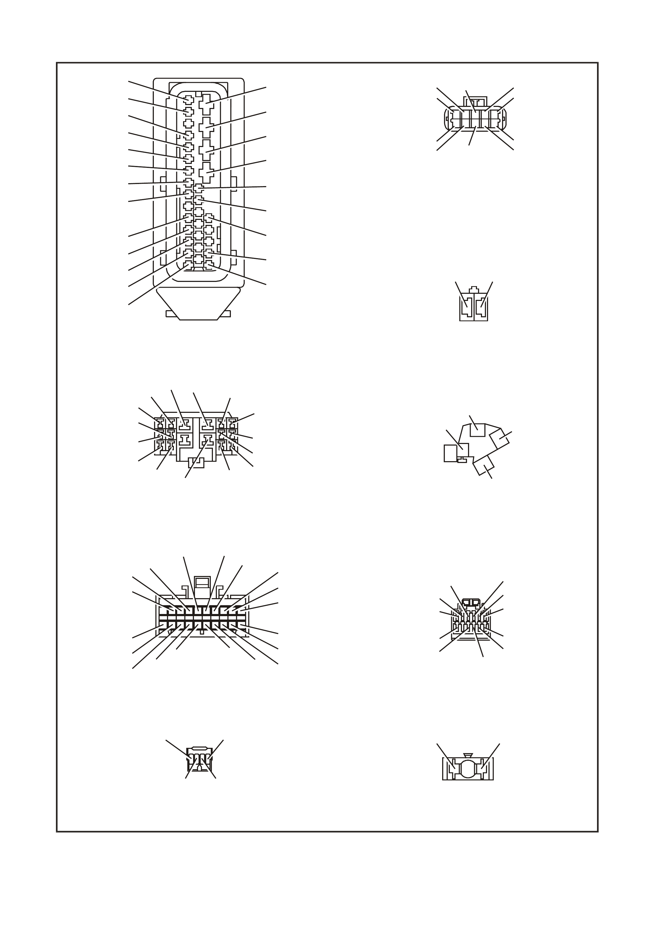
3.4 CRUISE CONTROL SYSTEM CONNECTORS & CIRCUIT DIAGRAM
V
(120)
LG
(200)
G
(117)
BLU
(15)
LBL U
(14)
BLU/R
(20)
BR
(9)
O/ Y
(1240)
LG
(24)
O/ B
(540)
BLU/O
(46)
BR/ B
(199)
Y/ BLU
(116)
BLU/B
(1 15)
V/ R
(192)
YB39
BODY HARNESS CONNECTOR
FGHJK
EDCB
A
BLU/R
P
(20)
(139)
B
BR
(150)
(86)
W
V/ W
(85)
(123)
GY/ G
BLU
(397)
(84)
GY
(83)
GY/ B
(87)
YE56
CRUISE CONTROL
CONNECTOR
Y
B66
I NSTRUM ENTS CONN ECTOR
10
20 1
11
B/ Y
(155)
GY
(8)
BR/ W
(19)
BLU/Y
(10)
T
(30)
V/ W
(123)
BR/ O
(33)
BR
(25)
V/ R
(234)
W
(85)
BLU
(15)
Y/ R
(88)
G/ W
(122 0)
BLU/ B
(946)
LBL U
(14)
G
(875)
O/ Y
(1340)
P/ BLU
(44)
BR/ R
(121)
T212E027
116
19
27
20
31
26
15
B/O
R
R
B
Y/ R
G
B/W
BR/ R
R/ W
(154)
(23)
(23)
(150)
(88)
(875)
(1427)
(121)
(1429)
BLU
B
R
W
GY
BR
Y
V
(883)
(882)
(873)
(872)
(833)
(830)
(885)
(884)
G/ W
BLU/B
O/ W
BLU/R
R
(1220)
(863)
(1426)
(20)
(855)
YE98
A.B.S. OR A.B.S./ E.T.C. CONTROL
MODULE & MODULATOR
CONNECTOR
BR
(86)
Y/ R
(88)
Y
B12
STOP LAMPS SWITCH B
CONNECTOR
YB161
STOP LA MPS SWI TCH A
CONNECTOR
BLU/R
(20)
O/ BLU
(640)
P/ BL U
(44)
6
12
BR/ W
(19)
1
7
Y
B87
E.C.C. C ONNECT OR
GY
(8 )
B/ Y
(155)
B/ R
(292)
Y
(51)
B/ R
(64)
Y/ B
(52)
G/ W
(1220)
LG/ B
(735)
BLU/B
(734)
GY/ B
(87)
GY/ G
(397)
BLU
(84)
P
(139)
YB152
CRUISE CONTROL S WITCH
CONNECTOR
Y
B44
IGNITION SWITCH
CONNECTOR
R
(2)
V
(5)
P
(3)
BR
(4)
Figure 12E-37
1
11
10
20
B/G
(151)
B/R
(1144)
P/B
(39)
GY
(8)
Y
B164
B.C.M CONNECTOR D(3)
(LOW SERIES )
G
(53)
G/W
(1220)
R/B
(1221)
Y
(266)
BR /G
(271)
V/R
(229)
W/G
(1220)
B
(1150)
GY/R
(1391)
GY
(83)
R/W
(248)
BLU/W
(97)
O
(291)
W/BLU
(494)
LBLU
(94)
T212E043
Y/R
Y
O/BLU
GY/R
P/B
(143)
(43)
(640)
(1391)
(39) 20
28
Y/B
(260)
B/R
(1144)
R/W
(261)
21 12
W/BLU
(494)
LBLU
(161)
W
(160)
13 6
GY /B
(96)
B/LG
(556)
W/G
R/B
V/R
BR /G
Y
G/W
Y/B
W
W/R
(1220)
(1221)
(229)
(271)
(266)
(1220)
(272)
(717)
(308)
1
7
YB175
B.C.M CONN ECTOR E(3)
(HIGH SERIES )
B
(1150)
BLU/W
(97)
GY
(83)
LBLU
(94)
O/W
(840)
YB193
V6 P.C.M CONNECTOR (1)
V
GY
GY/B
V
V/B
BR
BR
G/W
G/W
W/R
O/W
(430)
(1412)
(1413)
(412)
(413)
(418)
(418)
(897)
(897)
(815)
(1426)
C16
D16 D1
C1
W
(423)
T/B
(424)
T
(832)
LBLU/B
(647)
LG/W
(443)
LG/B
(444)
LBLU/B
(442)
LBLU
(441)
BLU/W
(831)
B/R
(453)
B
(630)
BR/W
(792)
GY/R
(422)
LG
(1222)
Y/B
(1223)
G/Y
(428)
V/W
(123)
Y
(173)
BR
(90)
O/B
(473)
Y
(196)
B/G
(151)
O/V
(440)
LBLU
(14)
O/B
(740)
BL U
(15)
V
(782)
1
6
5
12
YB174
B.C. M . CONN ECTO R B(2)
(HIGH SERIES)
GY
(8)
B/W
(1128)
B/Y
(28)
GY/BLU
(492)
B/Y
(155)
O/B
(740)
LBLU
(263)
1
5
4
8
YB176
B.C.M. CONNECTOR A(4)
(HIGH SERIES)
YE110
ENGINE CONNECTOR (1)
BLU/W
(304)
O/W
(1426)
P/BLU
(339)
G/W
(465)
V/W
(123)
B/W
(1427)
Y
(1049)
Y
E114
L OCATIO N E3 EA R TH CONNECTO R
B/G
(151)
B/W
(152)
B
(150)
B/Y
(155)
B/R
(157)
B/R
(157)
Y
E123
GEN III V8 P.C.M CONNECTOR (2)
GY /B
(1687)
G
(975)
B/R
(750)
B/R
(750)
T
(832)
G/O
(469)
BR /W
(331)
Y/B
(1223)
LBLU/B
(442)
G/W
(465)
LG
(432)
W
(971)
BR/Y
(1224)
B/Y
(1227)
BLU
(973)
BR
(418)
W/B
(631)
BL U/W
(831)
BR
(958)
Y
(838)
LBLU
(441)
BR
(121)
BR/W
(792)
Y
(977)
LBLU
(978)
V/W
(123)
LG/W
(443)
R
(1228)
G/Y
(428)
BL U
(417)
V
(959)
LG/B
(366)
G/B
(259)
W
(974)
LG
(976)
Y/B
(972)
LG
(1222)
LG/B
(444)
GY /BLU
(1229)
BLU/W
(304)
BR
(472)
GY
(773)
GY/R
(422)
G
(59)
RED J2
41 80
140
VW
(78)
Y/R
(88)
YB65
STOP LAMPS SWITCH B
CONNECTOR
Y
B69
CLUTCH SWITCH
CONNECTOR
VW
(78)
BR
(86)
Figure 12E-38
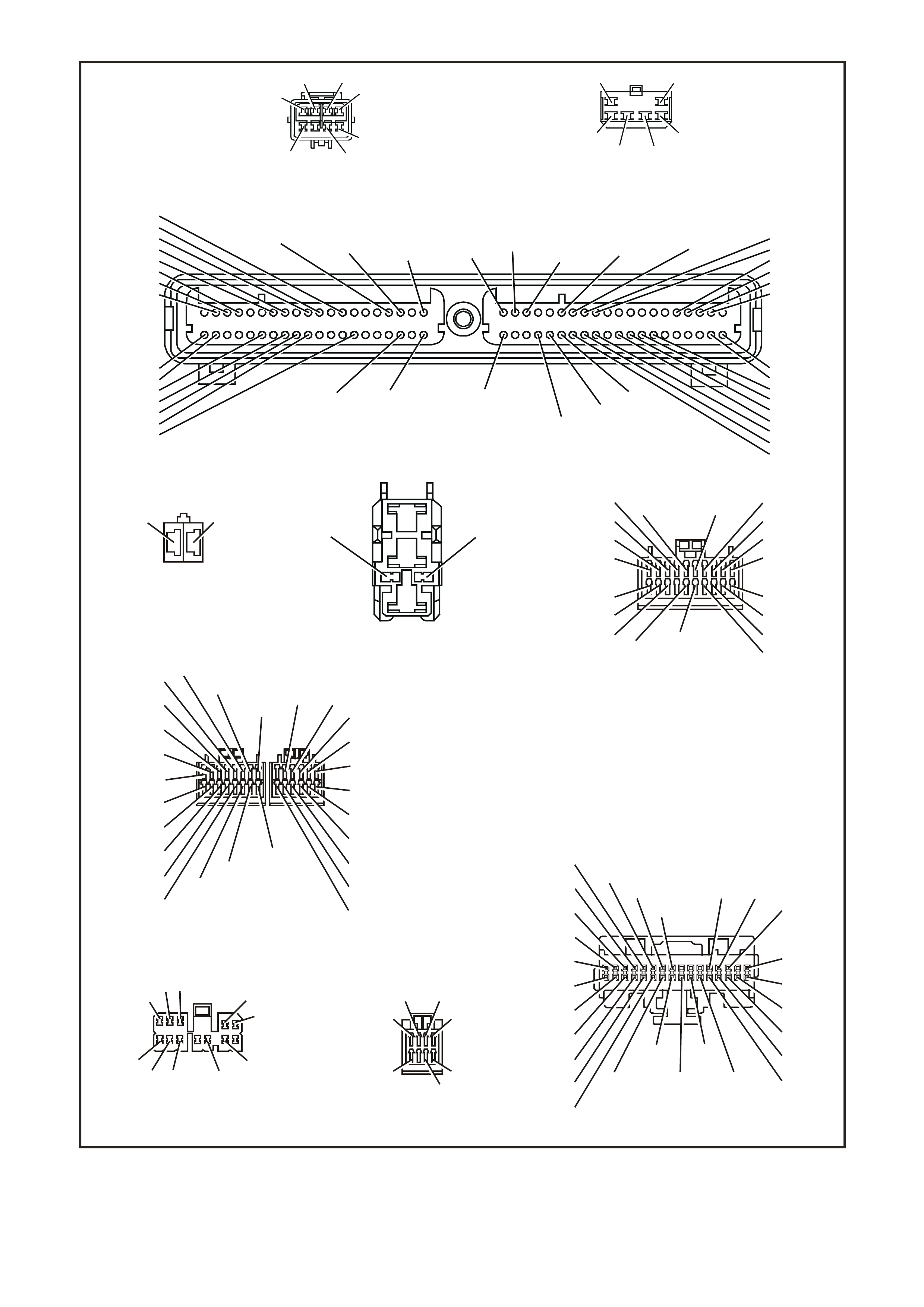
T212E026
FJ R(2)
BATTERY
FQ R(2)
FS
F5
YB176
YE114 YE114
LOC.E3
GD B F C H A J K
IGN
N/ C SET /
COAST IGNITION
CRUISE CONTRO L MODULE
RESUME /
ACC CRUISE
ON ON / OFF
N/ O
CUTOUT
SWITCHES
BLU/R (20)
BLU/R (20)
BR (86 )
6
YB87
YB39
ELECTRONIC
CLIMATE
CONTROL
STOP
LAMPS
LOC.E3
ELECTRONIC
GROUND POWER
GROUND
YB176 YB174
110
5YB175
YE129
Y/ R (88)
YB161
STOP
LAMPS
SWITCH A
STOP
LAMPS
SWITCH B
STOP LAMP S
SWITCH B
CLUTCH
SWITCH
YB12
YB161 YB12
YE122 YE123
YE110
YB193
C5
V/ W (123)
POWERTRAIN
CON T ROL MODULE
V6
J1-33
POWERTRAIN
CON TROL M ODULE
GEN III V8
J2-50
P ( 139)
G/ W (1220)
G/ W (1220)
GY (83)
G/ W (1220) G/ W (1220) G/ W 12
DIMMER
SDI
CRUIS E
ACTIVE
CRUISE
ON
2W
SPEEDO
V/ W (123)
INSTRUMENTS
17
V/ W
YE56
YE56 B (15 0 ) YE114 LOC.E3
E
GY/ B (87)
26
YB175 YB164
98
BODY CONTROL
MODULE BODY CONTROL
MODULE
CRUISE ON
LOW SERIES
BLU (84)
18
BODY
CONTROL
MODULE
(HI GH SERIES)
STOP FU SE SEN SE
F15
P (3)
YB66 YB66
INSTRUMENTS
19
YB65
YB69
YE98
YB152 P
GY/ G
GY
R
SWITCH
CRUIS E CONT ROL
ON / OFF
R/ A
S/ C
GY/ B
G
BLU BLU
20
11
TRACTION ON
A.B.S. OR
A
.B.S. / E.T.C.
MODULE
14
G/ W (1220)
BLU/R (20) 12V
YB65
YB69
YB12
BR (86)
BR (86 )
Y/ R (88) V/ W (78) P (139)
(FOR MANUAL
TRANS.)
YB12
TRACTION
OFF
LOW
TRACTION
F31
ENGINE
12V BUS
(1040)
O/ B 740
(155)
(151)
B/ Y
B/ G
BLU/ R (20)
BR (86)
BLU (84)
P (139)
GY/ B (87)
GY (83)
GY/ G (397)
W (85)
YB66
V/ W (123)
GY (83)
GY/ G (397)
G/ W (1220)
O/ BLU (640)
Y/ R (88)
(FOR AUTO T RANS) Y/ R (88)
SD1
LOC. E1
YB44
IGNITION SWITCH
YB44
F13 PP/ BLU (44)
30 OFF/ ON
LOCK
ACC.
IGN.
START
15A1550
CRUISE ON
HIGH SERIES
SERIAL DATA
Figure 12E-39

3.5 CRUISE CONTROL S YSTEM DIAGNOSTIC CHART
When using the following diagnostic chart, ref er also to the c ruise c ontrol system circuit diagr am and connector s on
the previous pages.
Test Description:
The numbers below refer to Step numbers in the diagnostic chart for the cruise control system.
1. Checks ignition supply to control module.
2. Checks for earth circuit to control module.
3. Checks circuits 84 and 87.
4. Checks if fault is in circuits 84 and 87, or with control module.
5. Checks RESUME-ACC function on cruise control switch assembly.
6. Checks for ignition supply to cruise control switch.
7. Checks RESUME-ACC function of cruise control switch.
8. Checks power supply to cruise control module at SET-COAST input.
9. Checks SET-COAST function of cruise control switch.
10. Determines if fault is with serial data communication (including BCM) or with stop lamp switch inputs.
11. Checks cruise control interface (serial data).
12. Checks circuit 83 for open circuit.
13. Checks for faulty stop lamp switch (switch A).
14. Checks for faulty electrical release switch (stop lamp switch B) and clutch switch.
15. Checks operation of ACTIVE lamp.
16. Determines if fault is in circuit 85 or in instrument cluster.
17. Checks for fault in circuit 123 and/or PCM.
18. Checks operation of cruise control system during road test.
19. Visual checks of cruise control cable for damage and adjustment.
20. Further diagnostic test that can be performed to help isolate any malfunctions within the system.

CRUISE CONTROL SYSTEM DIA GNOSTIC CHART
STEP ACTION VALUE YES NO
1. • Ignition OFF.
• Disconnect connector YE56 from cruise control
module.
• Ignition ON.
• Measure voltage between terminal F, circuit 139
(Pink wire) and a good earth.
• Is voltage as specified?
Approximately
12 Volts Go to Step 2. Check and repair
open in circuit
139 between
(and including)
fuse F15 and
connector YE56,
recheck and
verify repair.
2. • Ignition OFF.
• With connector YE56 still disconnected from control
module, check for continuity between control
module connector YE56, terminal E, circuit 150
(Black wire) and earth location E3.
• Does continuity exist?
Go to Step 3. Check and repair
open in circuit
150, recheck and
verify repair.
3. • Ignition ON.
• Measure voltage at connector YE56, terminal B,
circuit 84 (Blue wire) and terminal C, circuit 87
(Grey/Black wire) to earth.
• Is voltage as specified at either terminal?
Less than
1 Volt Go to Step 5. Go to Step 4.
4. • Ignition ON.
• Disconnect cruise control switch assembly
connector YB152 and measure voltage at terminals
B and C to earth on connector YE56 again.
• Is voltage as specified at either terminal?
Less than
1 Volt Replace cruise
control switch
assembly, refer
to 2.3 CRUISE
CONTROL
SWITCH in this
Section.
Check and repair
short to voltage
in circuit 84
and/or 87,
recheck and
verify repair.
5. • Ignition ON.
• Press and hold RESUME-ACC button on cruise
control switch assembly.
• Measure voltage between connector YE56, terminal
C, circuit 87 (Grey/Black wire) and earth.
• Is voltage as specified?
Greater than
9 Volts Go to Step 8. Go to Step 6.
6. • Ignition OFF.
• Disconnect cruise control switch assembly
connector YB152.
• Ignition ON.
• Measure voltage between connector YB152, circuit
139 (Pink wire) and earth.
• Does voltage exist?
Approximately
12 Volts Go to Step 7. Check and repair
open in circuit
139 between
(and including)
fuse F15 and
connector
YB152, recheck
and verify repair.
7. • Ignition OFF.
• Disconnect cruise control switch assembly
connector YB152.
• Press and hold the RESUME-ACC button and
check for continuity between Red and Green
terminals on cruise control switch assembly.
• Is resistance as specified?
Approximately
470 Ohms Check and repair
open in circuit
87, recheck and
verify repair.
Replace cruise
control switch
assembly, refer
to 2.3 CRUISE
CONTROL
SWITCH in this
Section.
8. • Ignition ON.
• Connect cruise control switch assembly connector
YB 152.
• Press and hold SET-COAST button on cruise
control switch assembly.
• Measure voltage between connector YE56, terminal
B, circuit 84 (Blue wire) and a good earth.
• Is voltage as specified?
Greater than
9 Volts Go to Step 10. Go to Step 9.
9. • Ignition OFF.
• Disconnect cruise control switch assembly
connector YB152.
• Press and hold the SET-COAST button and check
for continuity between Red and Blue terminals on
cruise control switch assembly.
• Is resistance as specified?
Approximately
470 Ohms Check and repair
open in circuit
84, recheck and
verify repair.
Replace cruise
control switch
assembly, refer
to 2.3 CRUISE
CONTROL
SWITCH in this
Section.

STEP ACTION VALUE YES NO
10. • Ignition OFF.
• Connect cruise control switch connector YB152 and
cruise control module connector YE56.
• Ignition ON.
• Repeatedly press the cruise ON-OFF button.
• Does the CRUISE lamp i n the instrument clus te r
toggle between on and off with switch operating?
Go to Step 13. Go to Step 11.
11. • Ignition ON.
• Back probe BCM connector YB175 (high series
BCM), terminal 26 or YB164 (low series BCM),
terminal 8,
circuit 83 (Grey wire) with a voltmeter to earth.
• Repeatedly press the cruise ON-OFF button again.
• Does the voltage vary as specified?
Switch
pressed:
approximately
12 Volts
Switch
released:
approximately
7 Volts
Go to CRUISE
CONTROL
INTERFACE
DIAGNOSIS in
Section 12J-1
LOW SERIES
BCM or 12J-2
HIGH SERIES
BCM in the VT
Series II Service
Information.
Go to Step 12.
12. • Ignition OFF.
• Disconnect connector YE56 from cruise control
module and connector YB175 (high series BCM) or
YB164 (low series BCM) from BCM.
• Check for continuity between connector YE56,
terminal H and connector YB175, terminal 26 or
YB164, terminal 8, circuit 83 (Grey wire).
• Does continuity exist?
Replace cruise
control module
assembly, refer
to 2.2 CRUISE
CONTROL
MODULE in this
Section.
Repair open in
circuit 83,
recheck and
verify repair.
13. • Remove connector YE56 from cruise control
module.
• Ignition ON.
• Measure voltage at connector YE56, terminal G,
circuit 20 (Blue/Red wire) to earth.
• Is voltage as specified?
Less than
1 Volt Go to Step 14. Check operation
of stop lamp
switch (switch A).
In particular, look
for improperly
adjusted stop
lamp switch.
Repair as
necessary,
recheck and
verify repair.
14. • With connector YE56 still disconnected from cruise
control module and ignition ON, measure voltage at
connector YE56, terminal D, circuit 86 (Brown wire)
to earth.
• Is voltage as specified?
Approximately
12 Volts Go to Step 15. Check operation
of electrical
release switch
(switch B) and
clutch switch. In
particular, look
for improperly
adjusted
switches or
check for open in
circuit 86. Repair
as necessary,
recheck and
verify repair.
15. • With connector YE56 still disconnected from cruise
control module and ignition ON (using an
appropriate jumper lead from KM 609) place a short
between cruise control connector YE56, terminal J
and earth.
• Does the cruise control ACTIVE lamp illuminate in
the instrument cluster?
Go to Step 17. Go to Step 16.
16. • Ignition OFF.
• Disconnect connector YB66 from instrument
cluster.
• Check for continuity between connector YE56,
terminal J and connector YB66, terminal 2, circuit
85 (White wire).
• Does continuity exist?
Check ACTIVE
lamp bulb, if OK,
replace
instrument panel
cluster, refer to
INSTRUMENTS,
WI PERS /
WASHERS &
HORN in the VT
Series I Service
Information.
Repair open in
circuit 85,
recheck and
verify repair.

STEP ACTION VALUE YES NO
17. • Jack up rear of vehicle and support on safety
stands.
• Back probe cruise control connector YE56, terminal
K, circuit 123 (Violet/White) with a Voltmeter to
earth.
• Ignition ON.
• Spin rear wheels by hand.
• Does voltage vary as specified?
Varies from
less than 1
Volt to greater
than 10 Volts
Go to Step 18. Check for open
or short to earth
in circuit 123
(Violet/White
wire) between
PCM and cruise
control module
connector YE56,
recheck and
verify repair
NOTE: If circuit
123 is OK, refer
to PCM
diagnosis in the
VT Series I
Service
Information for
V6 Engine, or in
the VT Series II
Service
Infomration for
GEN III V8
Engine of this
Service
Information CD.
18. • Connect all electrical connectors.
• Drive vehicle at approximately 50 km/h and press
the
SET-COAST button to set vehicle speed.
• Does the cruise fail to hold speed?
Go to Step 19. System OK.
19. • Check condition and adjustment of cruise control
cable, refer to 2. SERVICE OPERATIONS
• 2.1 CRUISE CONTROL CABLE, in this Se ction.
• Is cable OK?
Go to Step 20. Adjust or replace
as necessary the
cruise control
cable, refer to 2.
SERVICE
OPERATIONS
2.1 CRUISE
CONTROL
CABLE in this
Section.
20. • Perform switch diagnostic test, refer to 3.3 SELF
DIAGNOSTIC TEST, SWITCH DIAGNOSTIC TEST
CHART in this Secti on.
• Does test highlight a fault with the system?
Repair fault as
necessary,
recheck and
verify repair.
Replace cruise
control module
assembly, refer
to 2.2 CRUISE
CONTROL
MODULE in this
Section.

4. TORQUE WRENCH SPECIFI CATIONS
Nm
Cable Mounting Bracket Securing Bolt................................. 6 – 14
Control Module Securing Screw ........................................... 2 – 5
Lever Stud Nut...................................................................... 1 – 3
5. SPECIAL TOOLS
TOOL NO. REF IN TEXT TOOL DESCRIPTION COMMENTS
J39200 DIGITAL MULTIMETE R TOOL NO. J39200 PRE V IOUSLY
RELEASED, OR USE
COMMERCIALLY AVAILABLE
EQUIVALENT. MUST HAVE 10 MEG
OHM INPUT IMPEDANCE
KM-609 ELECTRONIC KIT USED IN CONJUNCTIO N WITH A
MULTIMETER FOR MEASURING
VOLTAGES AND RESISTANCES
WITHOUT DA MA GI NG WIRING
HARNESS CONNECTORS