SECTION 12M - SUPPLEMENTAL RESTRAINT
SYSTEM VERSIONS 8.0 & 8.1
CAUTION:
This vehicle will be equipped with a Supplemental Restraint System (SRS). A SRS will consist of either
seat belt pre-tensioners and a driver's air bag, seat belt pre-tensioners and a driver's and front
passenger's air b ags o r seat b elt p re-t ension ers, driv er’s an d f ron t p asseng er’s air bag and left and righ t
hand side air bags. Refer to SAFETY PRECAUTIONS, Section 12M Supplemental Restraint System of the
VT Series I Service Information before performing any service operation on, or around any SRS
components, the steering mechanism or wiring. Failure to follow the SAFETY PRECAUTIONS could
result in SRS deployment, resulting in possible personal injury or unnecessary SRS system repairs.
CAUTION:
This vehicle may be equipped with LPG (Liquefied Petroleum Gas). In the interests of safety, the LPG
fuel system should be isolated by turning 'OFF' the manual service valve and then draining the LPG
service lines, before any service work is carried out on the vehicle. Refer to the LPG leaflet included with
the Owner's Handbook for details or the appropriate Section of this Service Information CD for more
specific servicing information.
1. GENERAL INFORMATION
The Supplemental Restraint System (SRS) used on VT Series II Models carries over from the system that was
introduced in August 1998; versions 8.0 and 8.1 (refer Section 12M SUPPLMENTAL RESTRIANT SYSTEM
version 8.0 & 8.1 of the VT Service Information), noting the following change and corrections:
Coinciding with the release of the VT Series II, there has been a minor change to the wiring in the side air bag
circuits . T his c hange involved the terminal as s ignment in the side air bag harness connector, YB205 being swapped
around (circuit 387 with 388 – right hand side and 385 with 386 – left hand side).
The colour of the wire in circuit 1220, between the Body Control Module (BCM) and the Sensing and Diagnostic
m odule (SDM) has been incorrec tly identified in all previous ly published circuit diagr ams, including thos e published
of the VT Series I Service Information. The colour of the wire in circuit 1220 between the BCM and the SDM is
White/Green (circuit 1220 between the BCM and all the other control modules remains Green/White).
NOTE: These changes and corrections do not effect SRS operation or diagnostic procedures, however, it is
recommended that when diagnosing a SRS fault, particularly a side air bag circuit, reference to the latest wiring
diagrams in Section 12P WIRING DIAGRAMS of the VT Series II Service Information be made.
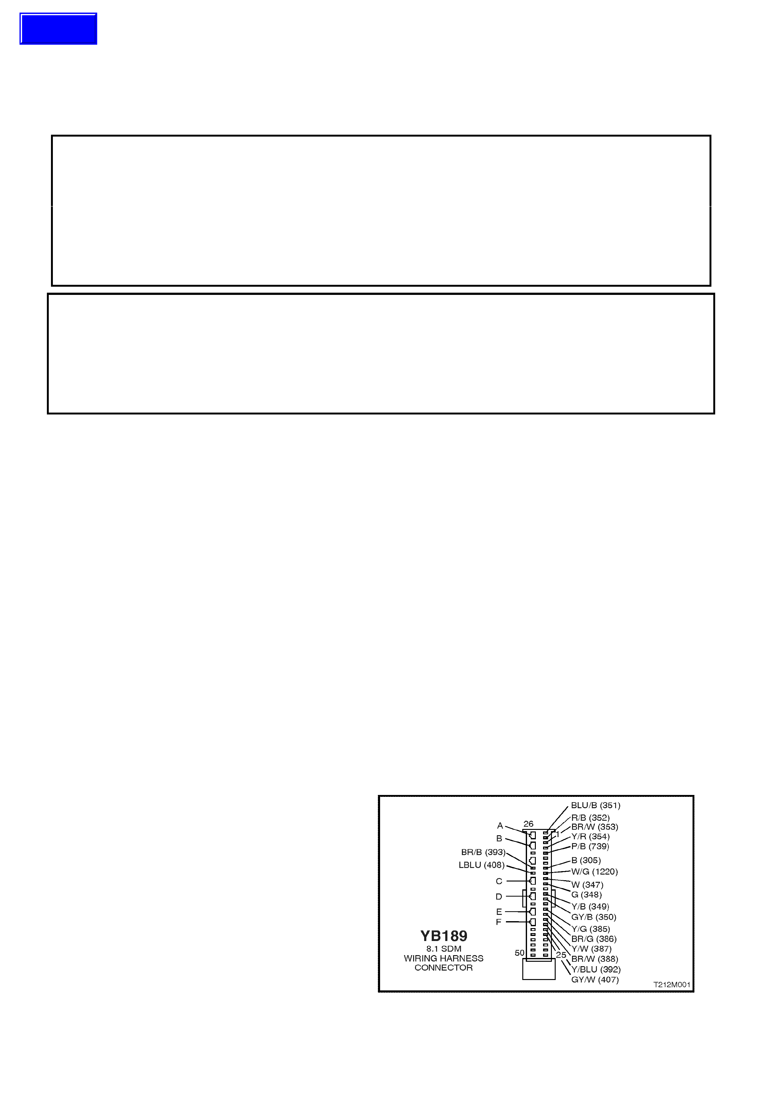
On vehicles with side air bags (SDM 8.1), it should be noted that SDM connector YB189 is equipped with shorting
link bus bars. W hile this does not effect the operation of the SRS, it will effect the diagnostic procedures detailed of
the VT Series I Service Information.
Whenever a diagnostic procedure asks a technician to check a circuit for an open or short while SDM connector
YB189 is disconnected, the technician will need to open the shorting link busbar for that particular circuit.
To open the shorting link busbar for a particular circuit, insert a spade type terminal, approximately 3 mm in
diameter ( or alter natively, use tool KM- 609-9 f rom the KM- 609 k it) into the openings (nom inated as A, B, C, D, E or
F in the following diagram) opposite the circuits terminal, refer Fig. 12M-1
SHORTING LINK BUSBAR
A Terminals 1 and 2 – left hand pre-tensioner
circuit
B Terminals 3 and 4 – right hand pre-tensioner
circuit
C Terminals 10 and 11 – drivers air bag circuit
D Terminals 13 and 14 – passenger’s air bag
circuit
E Terminals 16 and 17 left hand side air bag
circuit
F Terminals 18 and 19 right hand side air bag
circuit
Figure 12M-1
Techline