
SECTION 12N - FUSES, RELAYS AND
WIRING HARNESSES
CAUTION:
This vehicle will be equipped with a Supplemental Restraint System (SRS). A SRS will consist of either
seat belt pre-tensioners and a driver's air bag, seat belt pre-tensioners and a driver's and front
passenger's air bag s or seat belt pre- tensio ners, d riv er’s and fron t p asseng er’s air bag and lef t and rig ht
hand side air bags. Refer to SAFETY PRECAUTIONS, Section 12M Supplemental Restraint System of the
VT Series I Service Information before performing any service operation on, or around any SRS
components, the steering mechanism or wiring. Failure to follow the SAFETY PRECAUTIONS could
result in SRS deployment, resulting in possible personal injury or unnecessary SRS system repairs.
CAUTION:
This vehicle may be equipped with LPG (Liquefied Petroleum Gas). In the interests of safety, the LPG
fuel system should be isolated by turning 'OFF' the manual service valve and then draining the LPG
service lines, before any service work is carried out on the vehicle. Refer to the LPG leaflet included with
the Owner's Handbook for details or the appropriate Section of this Service Information CD for more
specific servicing information.
CAUTION:
Whenever any component that forms part of the ABS or ABS/ETC (if fitted), is disturbed during Service
Operations, it is vital that the complete ABS or ABS/ETC system is checked, using the procedure as
detailed in 4 DIAGNOSIS, ABS or ABS/ETC FUNCTION CHECK, in Section 12L ABS & ABS/ETC, in either
of the VT Series I Service Information (V6) or the VT Series II Service Information (GEN III V8) of this
Service Information CD.
1. GENERAL INFORMATION
1.1 FUSES AND CIRCUIT BREAKERS
All fuses and circuit breakers for VT Series II Models carryover from that described in Section 12N, FUSES,
RELAYS AND WIRING HARNESSES, of the VT Series I Service Information, except as follows:
1. In the engine compartment fuse and relay panel assembly, an additional fuse has been added. Fuse F36 for
the throttle relaxer on vehicles with GEN III V8 engine has been added to the location shown in Fig. 12N-1.
2. In the passenger compartment fuse and relay panel assembly, (refer Fig. 12N-3), fuse F10 (starting and
charging circuit) has been deleted.
Fuse F9 has been added for the L.P.G s ystem (this change was made during VT production and incor porated
into VT 1.5 wiring diagrams – of the VT Series I Service Information).
For all fuse and circuit breaker circuit protection details, refer to 1 POWER DISTRIBUITON circuit diagram in
Section 12P, WIRING DIAGRAMS, of the VT Series II Service Information.
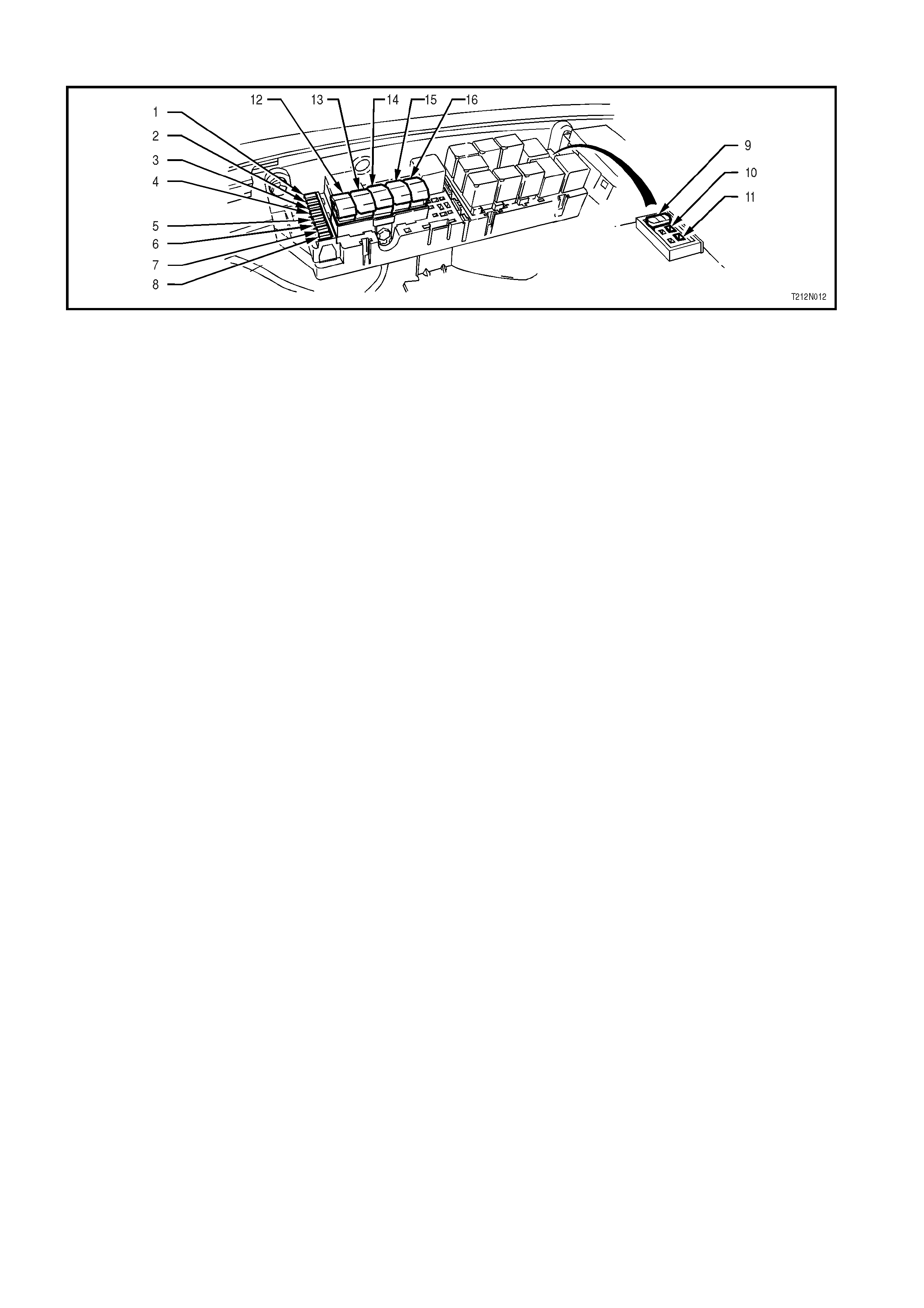
Figure 12N-1
Legend
1. F28: Fuel Pump – 15A
2. F29: Headlamps, Right Hand Side – 20A
3. F30: Headlamps, Left Hand Side – 20A
4. F31: Powertrain & Body Control Modules – 10A
5. F32: Automatic Transmission – 15A
6. F33: Engine Sensors – 15A
7. F34: Fuel Injectors & Ignition Module – 15A
8. F35: Fuel Injectors & Ignition Module – 15A
9. F36: Throttle Relaxer Control Module – 25A
10. F37: Spare
11. F38: Spare
12. Fusible Link FQ, Lighting 60A
13. Fusible Link FR, ABS 60A
14. Fusible Link FS, Engine 60A
15. Fusible Link FJ, Main 60A
16. Fusible Link FY, Blower 40A
1.2 RELAYS
All relays for VT Series II Models carryover from that described in Section 12N, FUSES, RELAYS AND WIRING
HARNESSES, of the VT Series I Service Information, except as follows:
1. The start relay has been relocated in the engine compartment fuse and relay panel assembly, refer Fig. 12N-2.
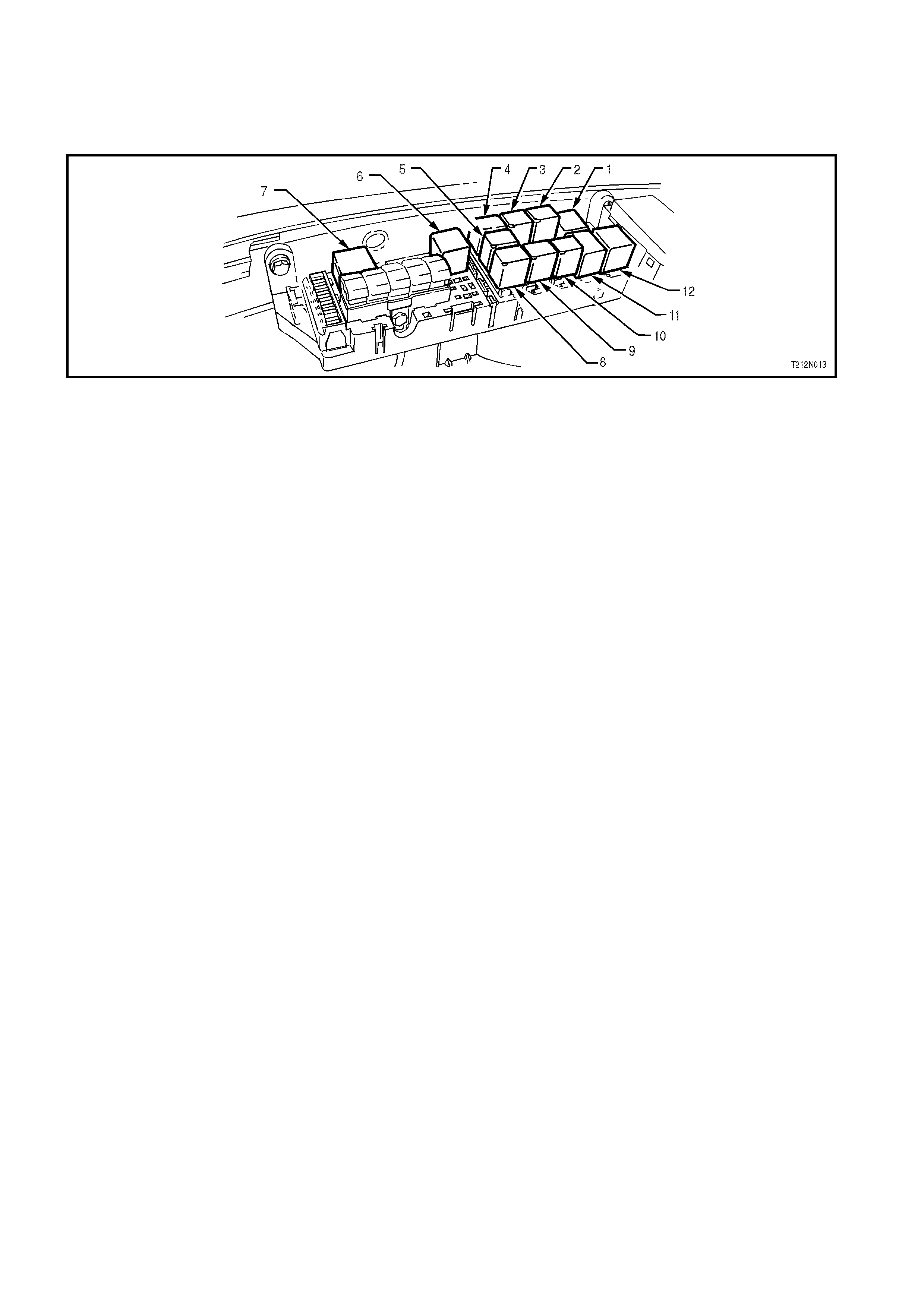
Figure 12N-2
Legend
1. High Speed Radiator Fan Relay
2. Fog Lamp Relay
3. Theft Deterrent Horn Relay
4. Horn Relay
5. Air Conditioning Compressor Relay
6. EFI Relay
7. Low Speed Radiator Fan Relay
8. Headlamp Low Beam Relay
9. Front Wiper Relay
10. Fuel Pump Relay
11. High Beam Relay
12. Start Relay
1. Two additional relays have been added to the passenger compartment fuse and relay panel assembly.
a. An interior illumination relay (YB134) has been added to the location shown in Fig. 12N-3 and is part of the
Body Control Module battery saver circuit. For further details refer to Section 12J-1 LOW SERIES BCM or
Section 12J-2 HIGH SERIES BCM in the VT Series II Service Information.
b. A LPG system relay (YB43) (change made during VT production and incorporated into VT 1.5 wiring
diagrams – in the VT Series I Service Information).
Fig. 12N-3 illustrates the passenger compartment fuse and relay panel assembly for VT Series II Models
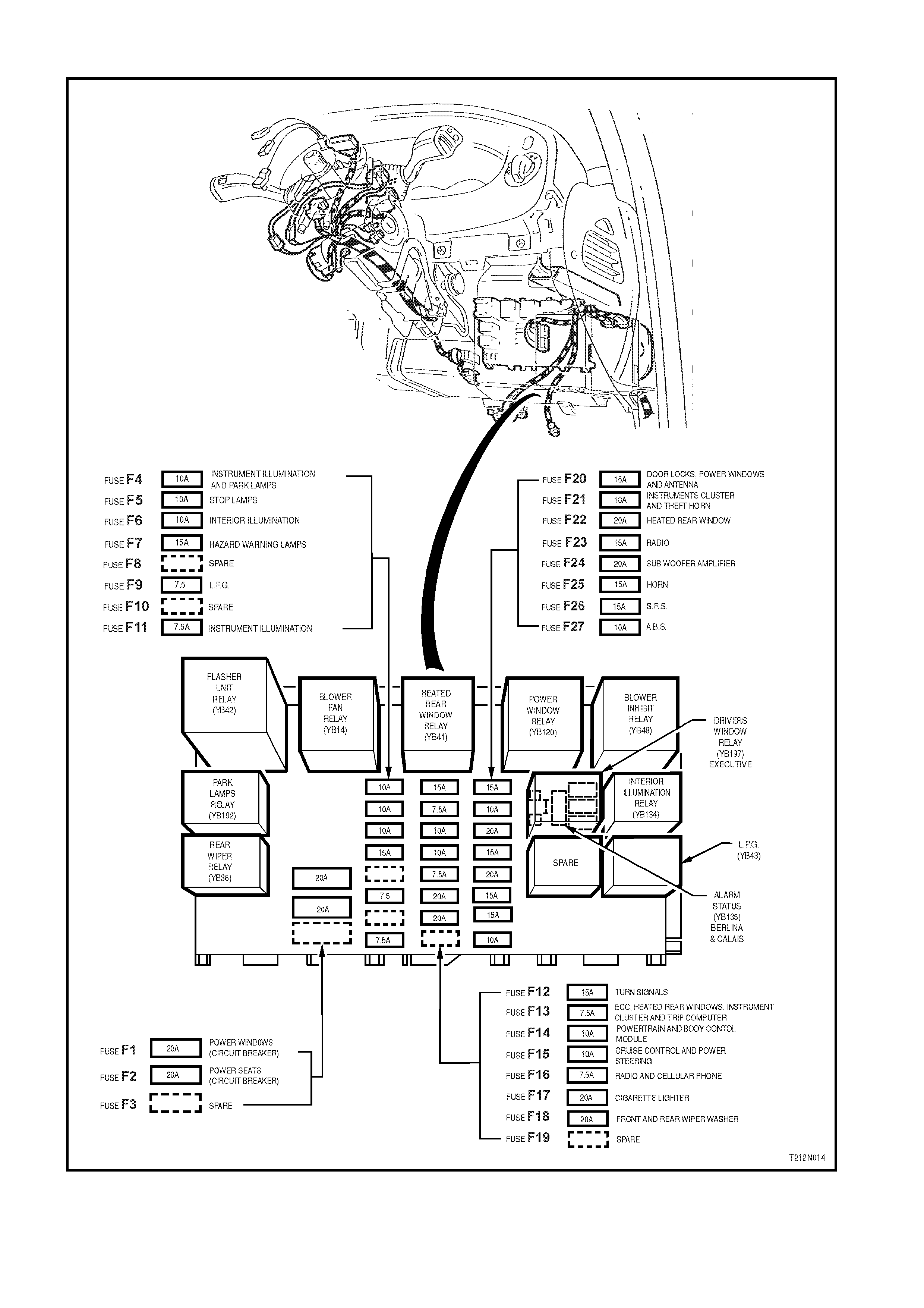
Figure 12N-3

3. WIRI NG INSTALLATION DIAGRAMS
The following figures in this Section illustrate the new vehicle wiring installation diagrams specific for VT Series II
Models. All rem aining wiring installation diagram s are carryover fr om VT and ar e covered in Section 12N, FUSES,
RELAYS AND WIRING HARNESSES, of the VT Series I Service Information.
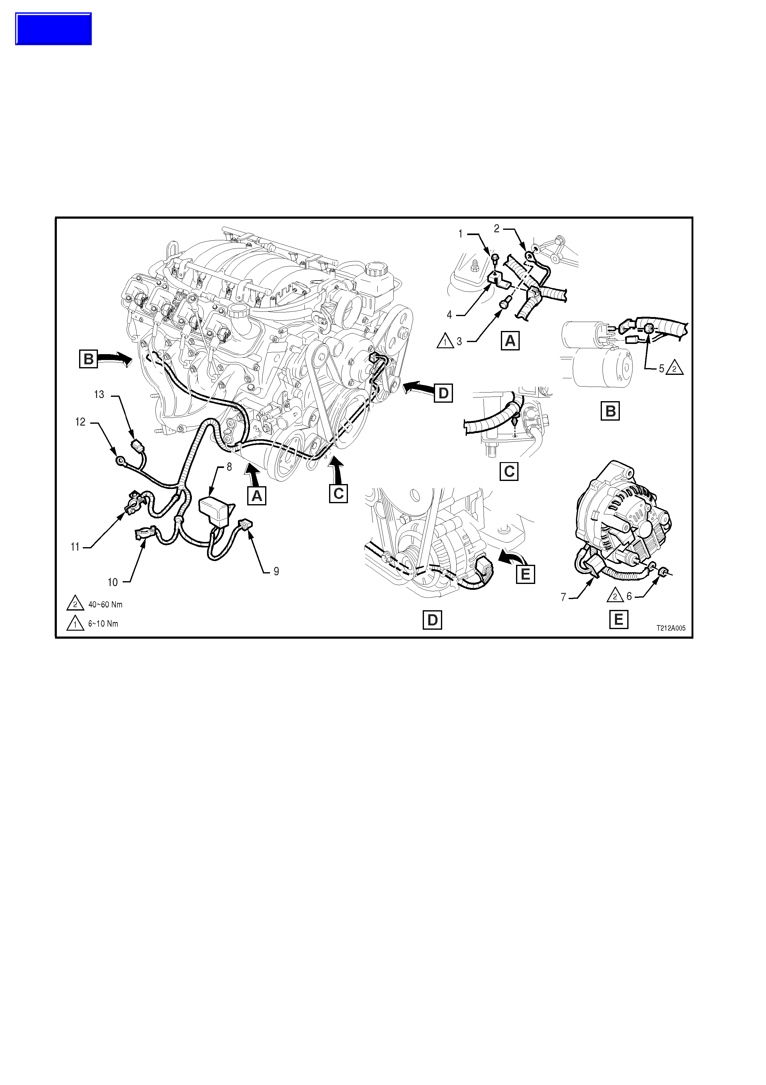
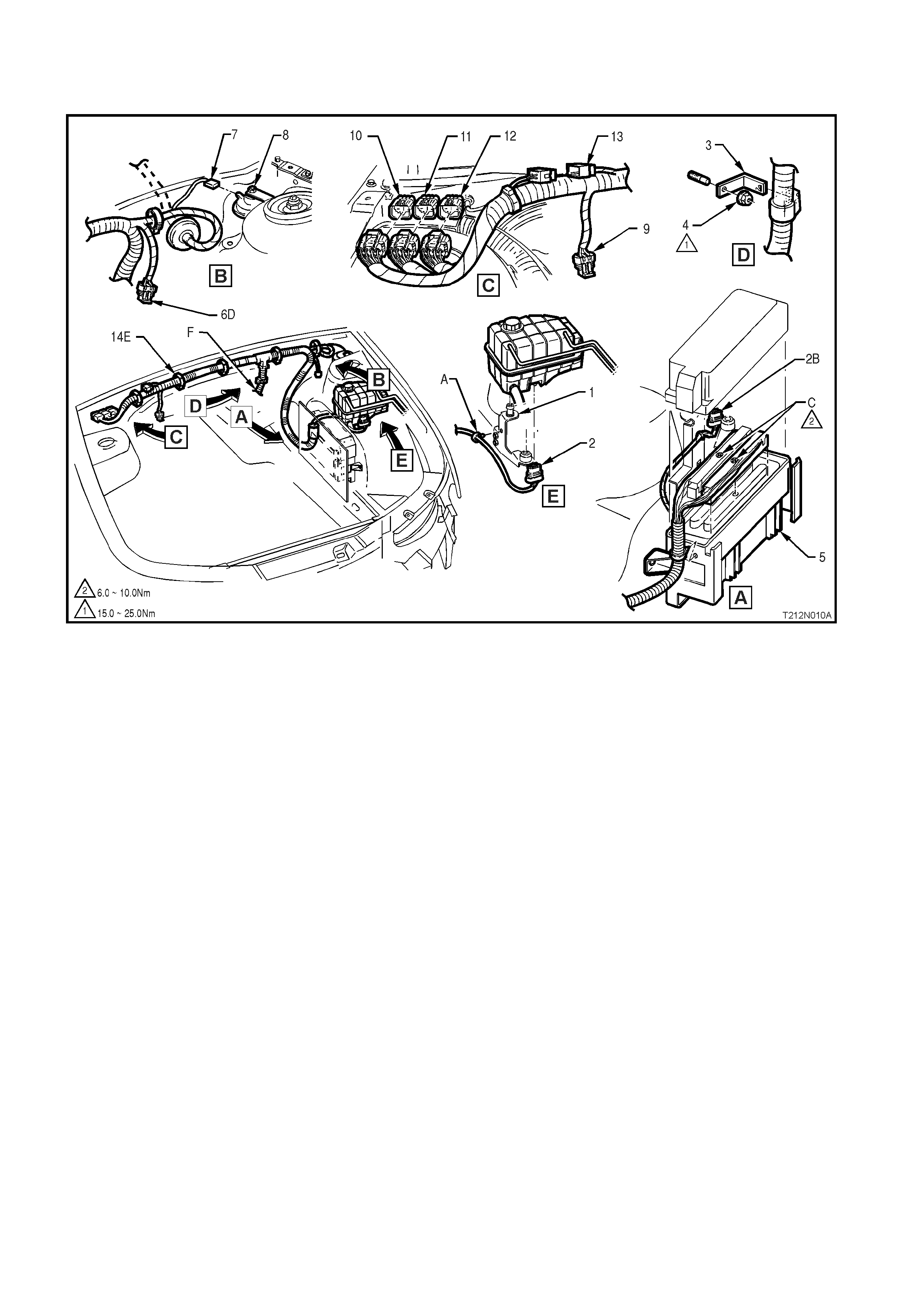
BATTERY HARNESS
All Models with Gen III V8 Engine
Legend
1. Battery Harness Bracket to Engine
Mounting Attaching Bolt
2. Battery Harness Engine Earth Terminal
3. Earth Terminal Bolt
4. Battery Harness Bracket
5. Batter y Harness to Starter Motor Solenoid
Attaching Nut
6. Battery Harness to Generator B+
Terminal Nut
7. Generator Connector
8. Engine Cooling Fan Fusible Link Housing
9. Engine/Condenser Fan Connector
10. Battery Harness Negative Terminal
11. Battery Harness Positive Terminal
12. Battery Harness to Body Earth Terminal
13. Battery Harness to Main Wiring Harness
Connector
14. Battery Harness Assembly
Techline
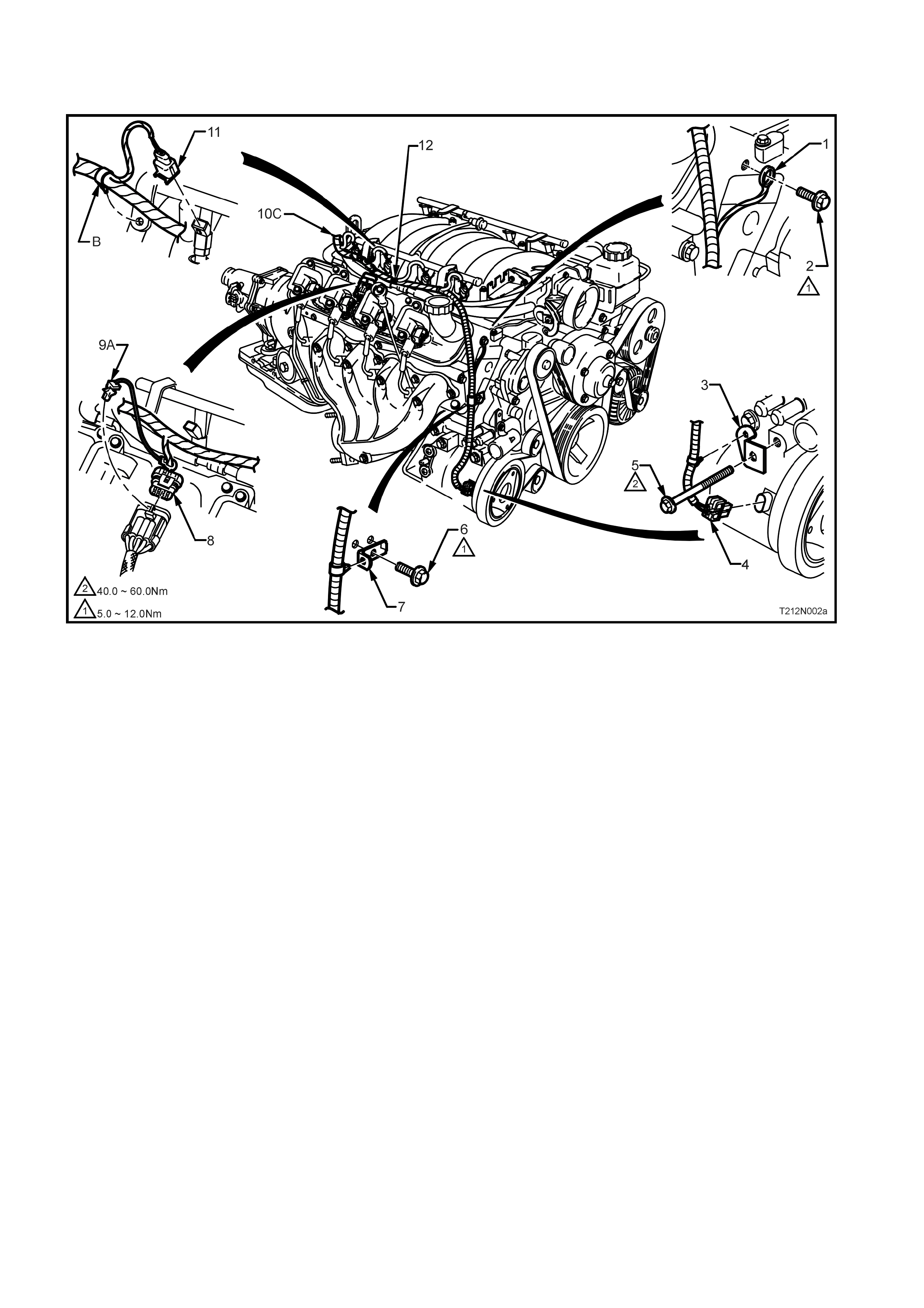
POWERTRAIN HARNESS – 1
All Models with Gen III V8 Engine
Legend
1. Coolant Surge Tank Bracket
2. Surge Tank Low Coolant Level Switch
Connector
3. Powertrain Harness Support Bracket
4. Nut
5. Powertrain Control Module (PCM)
6. Throttle Relaxer Connector (Domestic
Right Hand Drive Vehicles with Traction
Control)
7. Theft Deterrent Horn Connector
8. Theft Deterrent Horn
9. Throttle Relaxer Connector (Export Left
Hand Drive Vehicles with Traction
Control)
10. Powertrain Harness Engine Connector 3
11. Powertrain Harness Engine Connector 2
12. Powertrain Harness Engine Connector 1
13. Powertrain Harness Engine Connector 4
14. Harness Clip
A. Clip fitted to bracket before surge tank is fitted.
B. Lead for the surge tank low coolant level s witch
is to be routed on top of the PCM cover.
C. CAUTION: PCM connector attaching bolts not
to be overtightened.
D. Throttle relax er connector loc ation for dom es tic
right hand drive vehicles only.
E. For inst allation of clips, refer to POWERT RAIN
HARNESS – 1 diagram in Section 12N,
FUSES, RELAYS AND WIRING
HARNESSES, of the VT Series I Service
Information.
F. For continuation, refer to POWERTRAIN
HARNESS – No. 5 & No. 8 diagrams in this
Section.
POWERTRAIN HARNESS – 2
All Models with Gen III V8 Engine
Legend
1. Powertrain Harness to Engine Earth
Terminal
2. Earth Terminal Attaching Bolt
3. Air Conditioning Compressor Powertrain
Harness Support Bracket
4. Air Conditioning Compressor Connector
5. Air Conditioning Compressor Mounting
Bolt
6. Powertrain Harness Support Bracket Bolt
7. Powertrain Harness Support Bracket
8. Right Hand Bank Ignition Module
Connector
9. CPA Lock
10. Powertrain Harness Assembly
11. Fuel Injector Connector (4 places R/H
Side)
12. Compressor Clutch Diode
A. CPA Lock is part of the powertrain harness and
is inserted into the ignition module connector
on assembly.
B. Powertrain harness is secured to bracket in
two places on right hand side.
C. For continuation of the powertrain harness,
refer to POWERTRAIN HARNESS – diagrams
No. 4 & No. 5 or No. 8 & No. 9 in this Section.
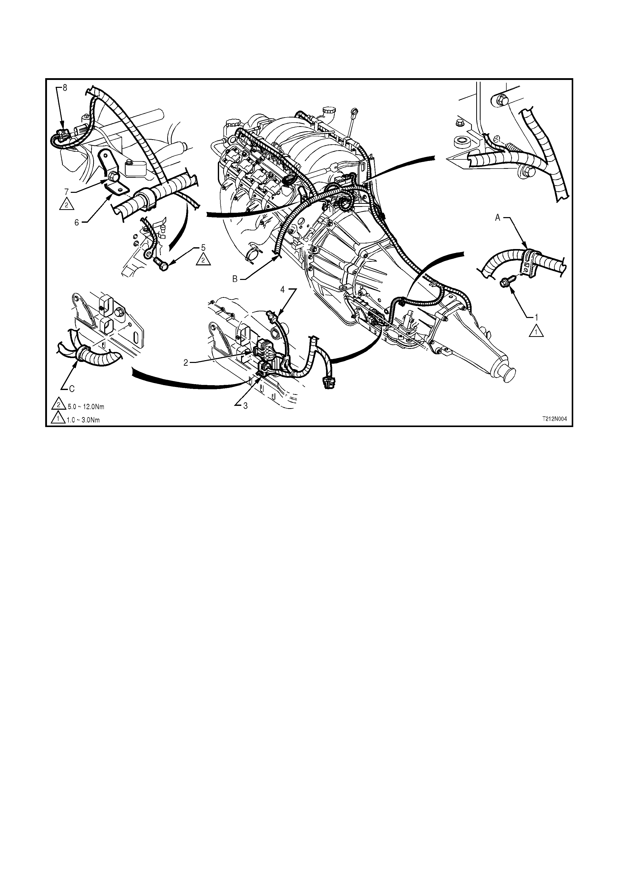
POWERTRAIN HARNESS – 3
All Models with Gen III V8 Engine
Legend
1. Fuel Injector Connector (4 places L/H
Side)
2. CPA Lock
3. Left Hand Bank Ignition Module
Connector
4. Canister Purge Connector
5. Powertrain Harness Assembly
6. Coolant Sensor Connector
7. Throttle Position Sensor Connector
8. Idle Air Control Motor Connector
A. CPA Lock is part of the powertrain harness and
is inserted into the ignition module connector
on assembly.
B. For continuation of the powertrain harness,
refer to POWERTRAIN HARNESS – No. 6
diagram in this Section.
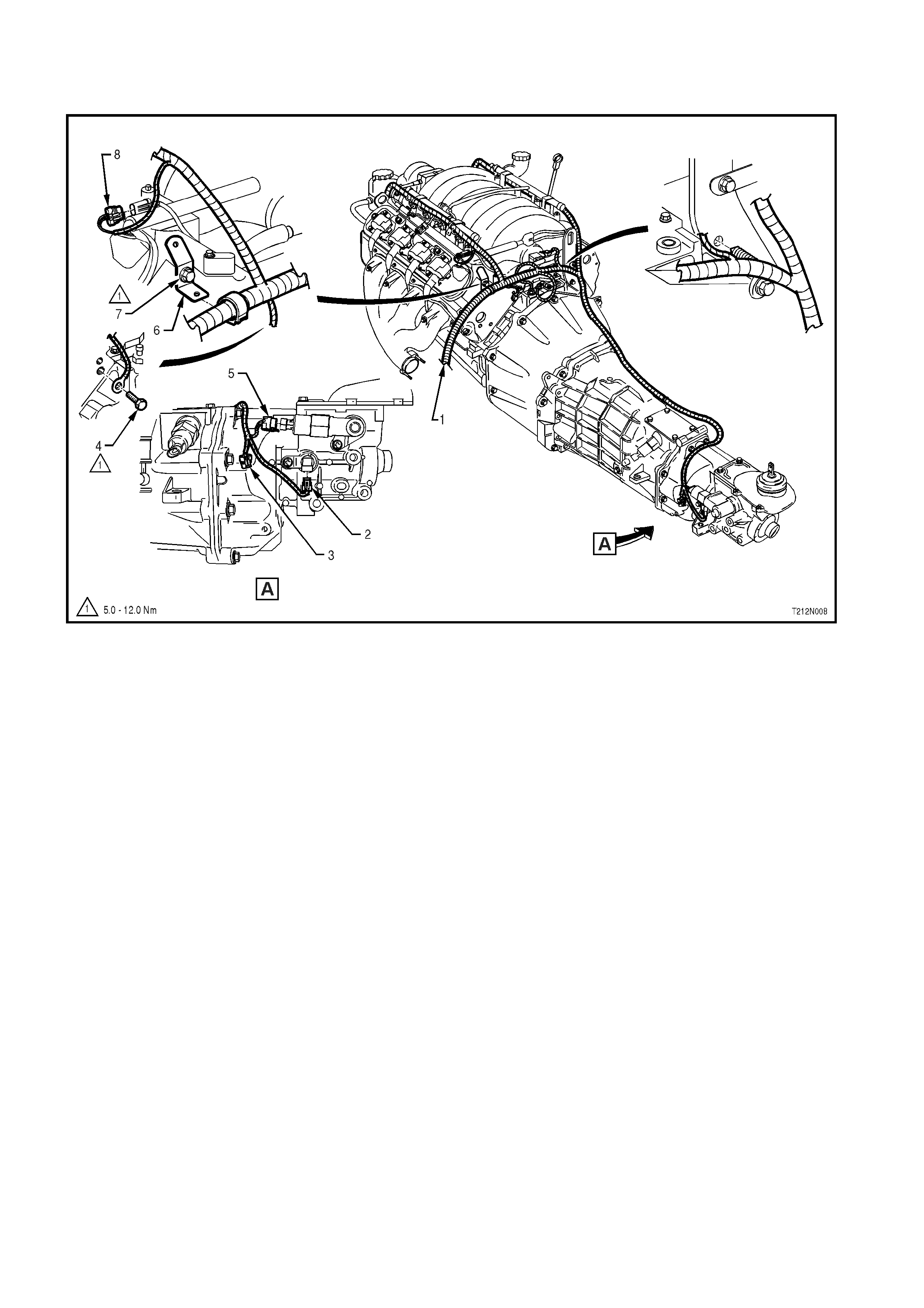
POWERTRAIN HARNESS – 4
All Models with Gen III V8 Engine
Legend
1. Powertrain Harness Attaching Bolt (2
Places)
2. Neutral Start/ Back-Up Lamp Switch
Connector
3. PRNDL Connector
4. CPA Lock
5. Powertrain Harness Earth Terminal
Attaching Bolt
6. Powertrain Harness Support Bracket
7. Bolt
8. Knock Sensor Connector
A. Clip (two places) bent over after fitting to
harness assembly.
B. For continuation of the powertrain harness,
refer to POWERTRAIN HARNESS – No. 1
diagram in this Section.
C. Neutral start and back-up lamp, and PRNDL
connectors to be inserted into s witch assem bly
before inserting harness retaining clip into hole.

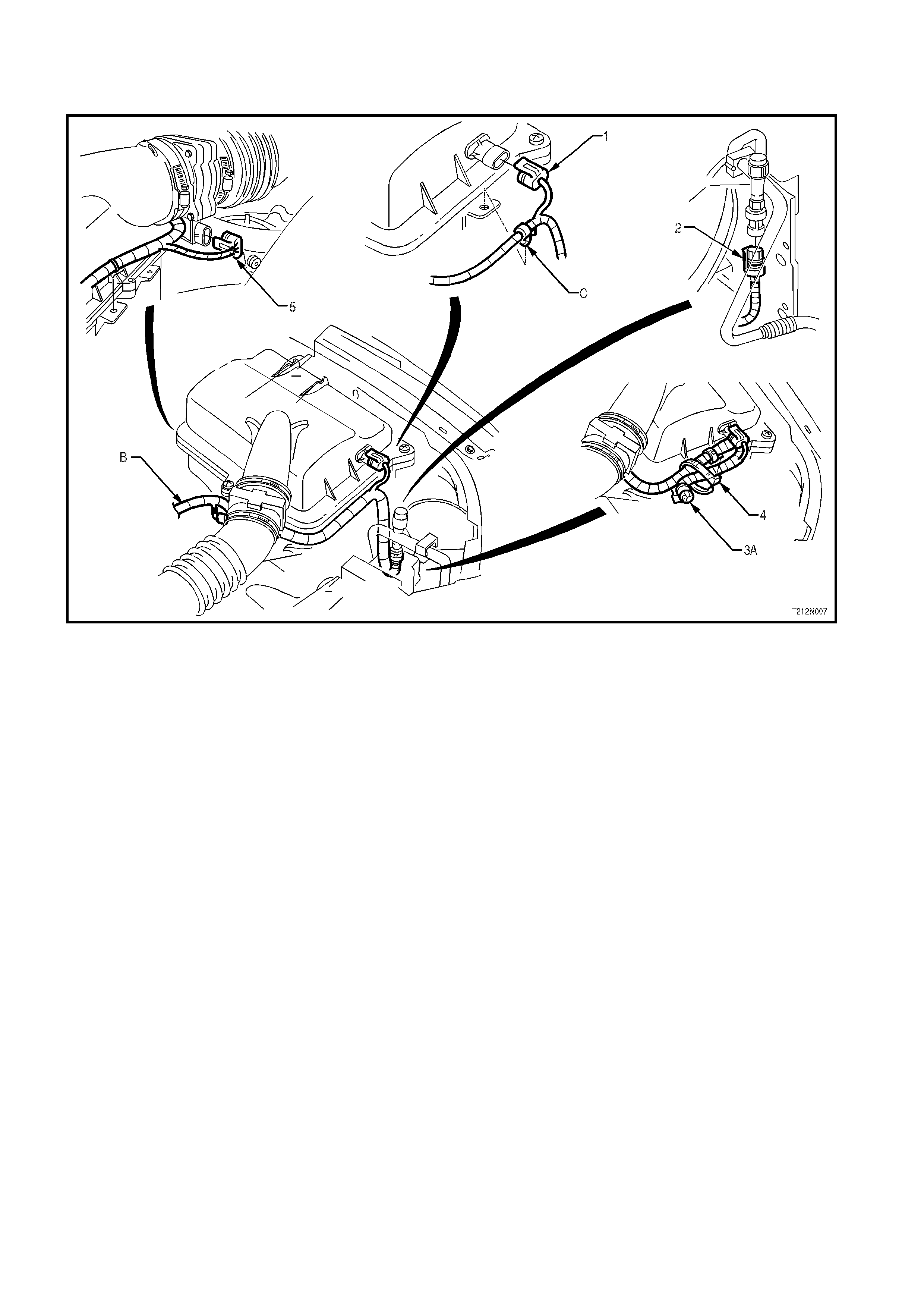
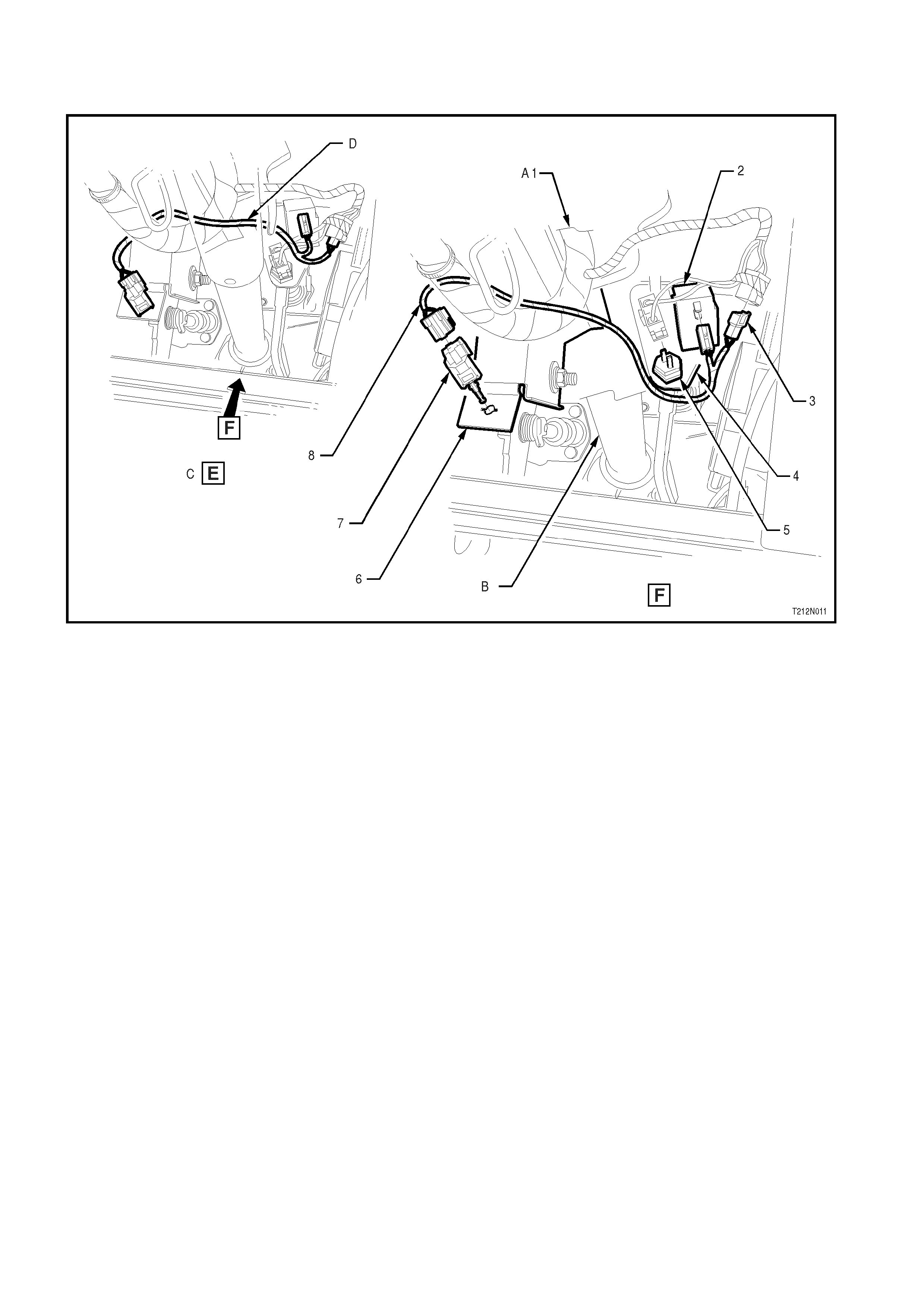
POWERTRAIN HARNESS – 5
All Models with Gen III V8 Engine
Legend
1. Crank Angle Sensor Connector
2. Powertrain Harness Transmission Pass-
Thru Connector
3. Oxygen Sensor Right Hand Side
Connector
4. Vehicle Speed Sensor Connector
5. Camshaft Position Sensor Connector
6. To Neutral Start/Back-Up Lamp Switch
Connector
7. Oil Pressure Sensor Connector
8. Manifold Absolute Pressure (MAP) Sensor
Connector
A. For continuation, refer to POWERTRAIN
HARNESS – No. 10 diagram in this Section.
B. For continuation, refer to POWERTRAIN
HARNESS – No. 1 diagram in this Section.
POWERTRAIN HARNESS – 6
All Models with Gen III V8 Engine
Legend
1. Air Temperature Sensor Connector
2. Air Conditioning Pressure Transducer
Switch Connector
3. Powertrain Harn ess
4. Tie Strap
5. Mass Air Flow (MAF) Sensor Connector
A. View for Vehicles fitted with non ECC Air
Conditioning.
B. For continuation, refer to POWERTRAIN
HARNESS – No. 3 diagram in this Section.
C. Powertrain harness secured to air cleaner
housing as shown.
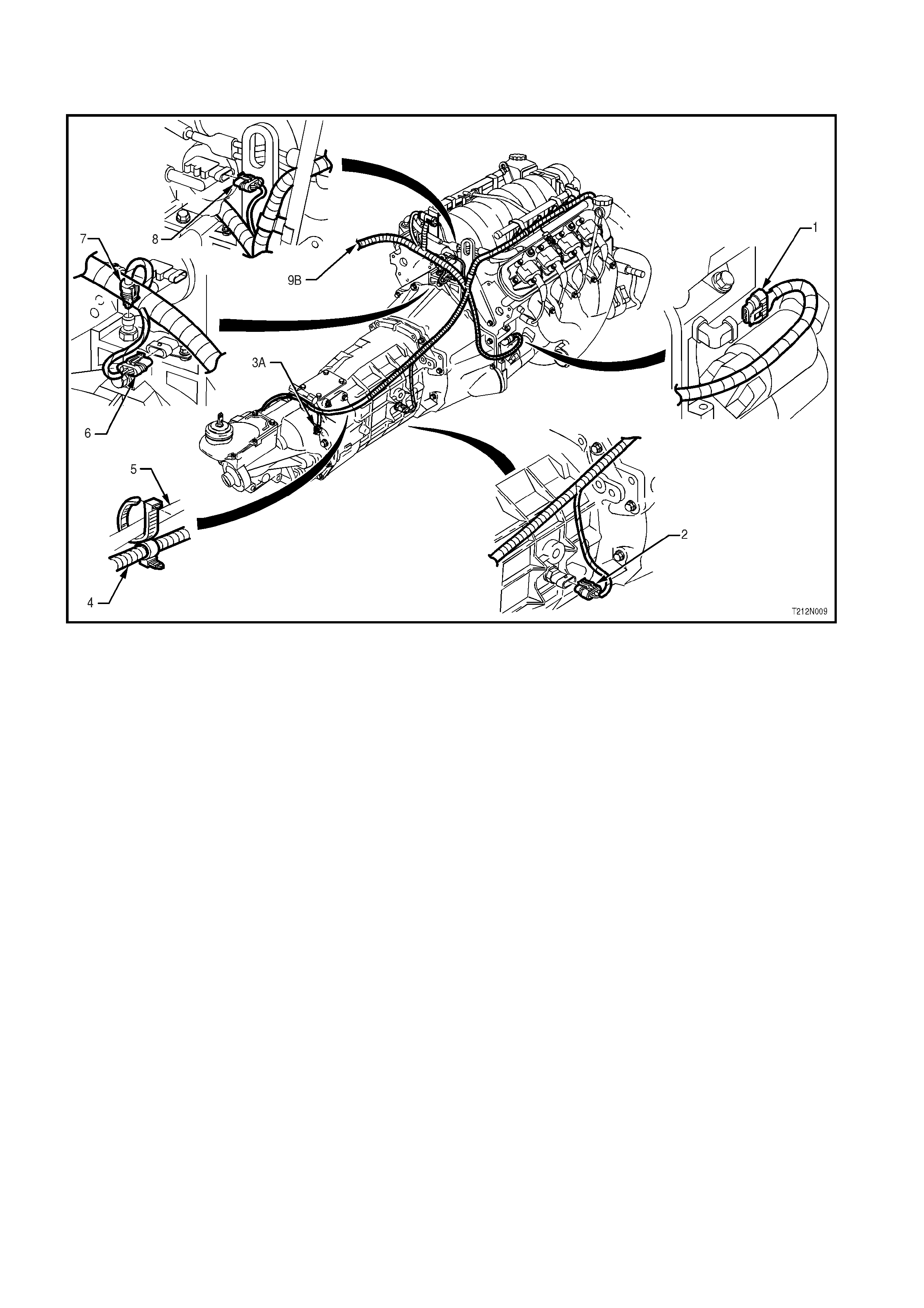
POWERTRAIN HARNESS – 8
All Models with Gen III V8 Engine
Legend
1. Crank Angle Sensor Connector
2. Reverse Lamp Switch Connector
3. Oxygen Sensor Right Hand Side
Connector
4. Powertrain Harn ess
5. Transmission Breather Assembly
6. Cam Sensor Connector
7. Oil Pressure Sensor Connector
8. Manifold Absolute Pressure (MAP)
Sensor Connector
9. Powertrain Harn ess
A. For continuation, refer to POWERTRAIN
WIRING HARNESS – No. 10 diagram in this
Section.
B. For continuation, refer to POWERTRAIN
WIRING HARNESS – No. 1 diagram in this
Section.
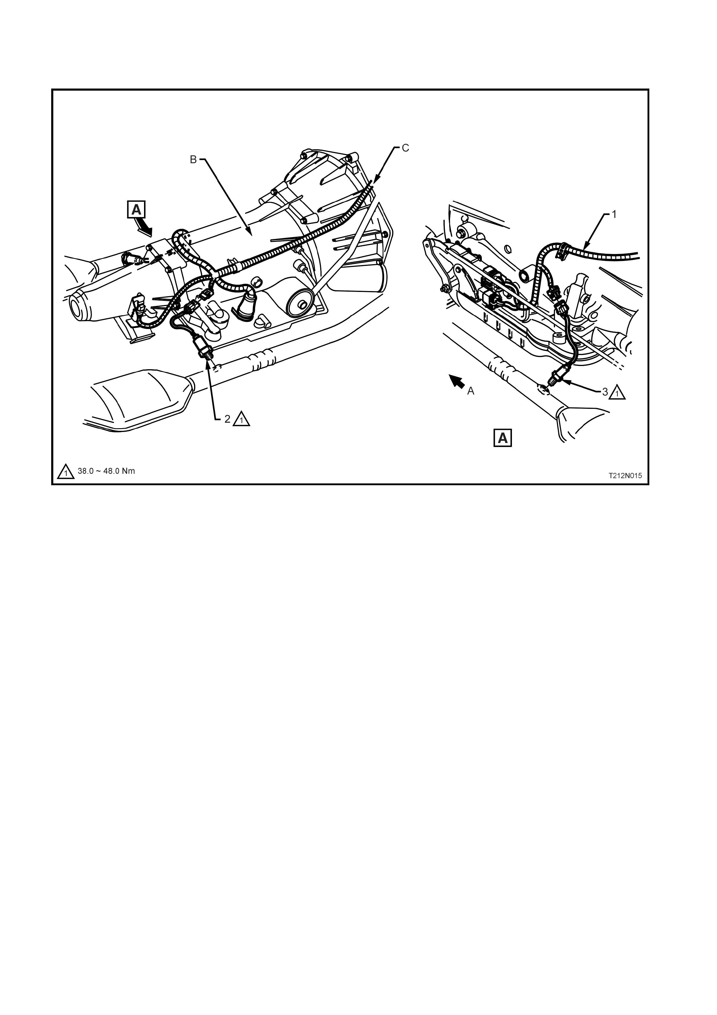
POWERTRAIN HARNESS – 9
All Models with Gen III V8 Engine
Legend
1. Powertrain Wiring Harness
2. Speed Sensor Connector
3. Exhaust Gas Oxygen Sensor Left Hand
Side Connector
4. Bolt
5. Reverse Lock Out Connector
6. Powertrain Harness Support Bracket
7. Bolt
8. Knock Sensor Connector
A. For continuation, refer to POWERTRAIN
WIRING HARNESS – No. 1 diagram in this
Section.
POWERTRAIN HARNESS – 10
All Models with Gen III V8 Engine
Legend
1. Powertrain Wiring Harness
2. Exhaust Gas Oxygen Sensor (Right Hand
Side)
3. Exhaust Gas Oxygen Sensor (Left hand
Side)
A. Front of vehicle.
B. View shows automatic transmission.
C. For continuation, refer to POWERTRAIN
WIRING HARNESS – diagrams
No. 1 & No. 4 in this Section.
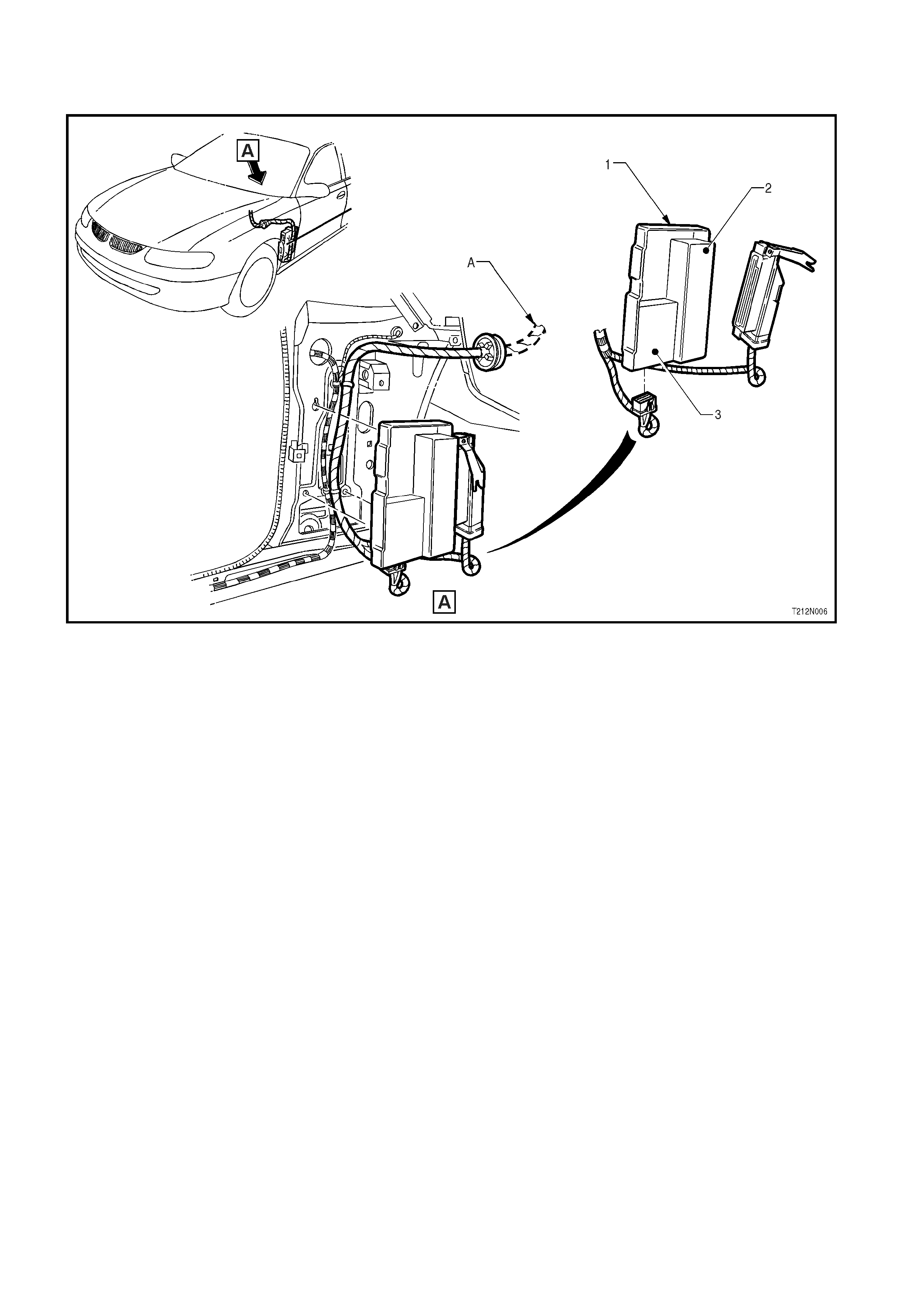
CRUISE CONTROL SWITCH HARNESS
All Models with Gen III V8 Engine
Legend
1. Main Wiring Harness
2. Cruise Control Brake Pedal Electrical
Release Switch
3. Cruise Control Harness to Main Wiring
Harness Connector
4. Brake Pedal Support Bracket
5. Stop Lamp Switch
6. Clutch Pedal Support Bracket
7. Cruise Control Clutch Pedal Electrical
Release Switch
8. Cruise Control Harness\
A. For continuation, refer to MAIN WIRING
HARNESS – 15 diagram in Section 12N,
FUSES, RELAYS AND WIRING
HARNESSES, of the VT Series I Service
Information.
B. Partial steering column shown for clarity.
C. For location of view E, refer to MAIN WIRING
HARNESS – 15 diagram in Section 12N
FUSES, RELAYS AND WIRING
HARNESSES, of the VT Series I Service
Information.
D. Ensure clutch harness is routed over main
wiring harness and steering column as shown.