
SECTION 6B3 - ENGINE COOLING -
GEN III V8 ENGINE
CAUTION:
This vehicle w ill be equipped with a Supplemental Restraint System (SRS). A SRS will consist of either seat
belt pre-tensioners and a driver's air bag, seat belt pre-tensioners and a driver's and front passenger's air
bags or seat belt pre-tensioners, driver’s and front passenger’s air bag and left and right hand side air bags.
Refer to SAFETY PRECAUTIONS, Section 12M, Supplemental Restraint System of the VT Series I Service
Information before performing any service operation on, or around any SRS components, the steering
mechanism or wiring. Failure to follow the SAFETY PRECAUTIONS could result in SRS deployment,
resulting in possible personal injury or unnecessary SRS system repairs.
CAUTION:
Whenever any component that forms part of the ABS or ABS/ETC (if fitted), is disturbed during Service
Operations, it is vital that the complete ABS or ABS/ETC system is checked, using the procedure as detailed
in 4. DIAGNOSIS, ABS or ABS/ETC FUNCTION CHECK, in Section 12L ABS & ABS/ETC, in either of the VT
Series I Service Information (V6) or the VT Series II Service Information (GEN III V8).
1. GENERAL INFORMATION
The c ooling system f or VT Series II Models with the GEN III V8 engine, consists of two, two-speed electr ic cooling f ans
mounted behind the radiator. Fan operation is dependent on engine coolant temperature, vehicle speed, A/C request
(where fitted) and A/C system pressure. Refer to Section 6C3 POWERTRAIN MANAGEMENT - GEN III V8 ENGINE
of the VT Series II Service Information.
Techline
Techline
Techline
Techline
Techline
1.1 GENERAL DESCRIPTION
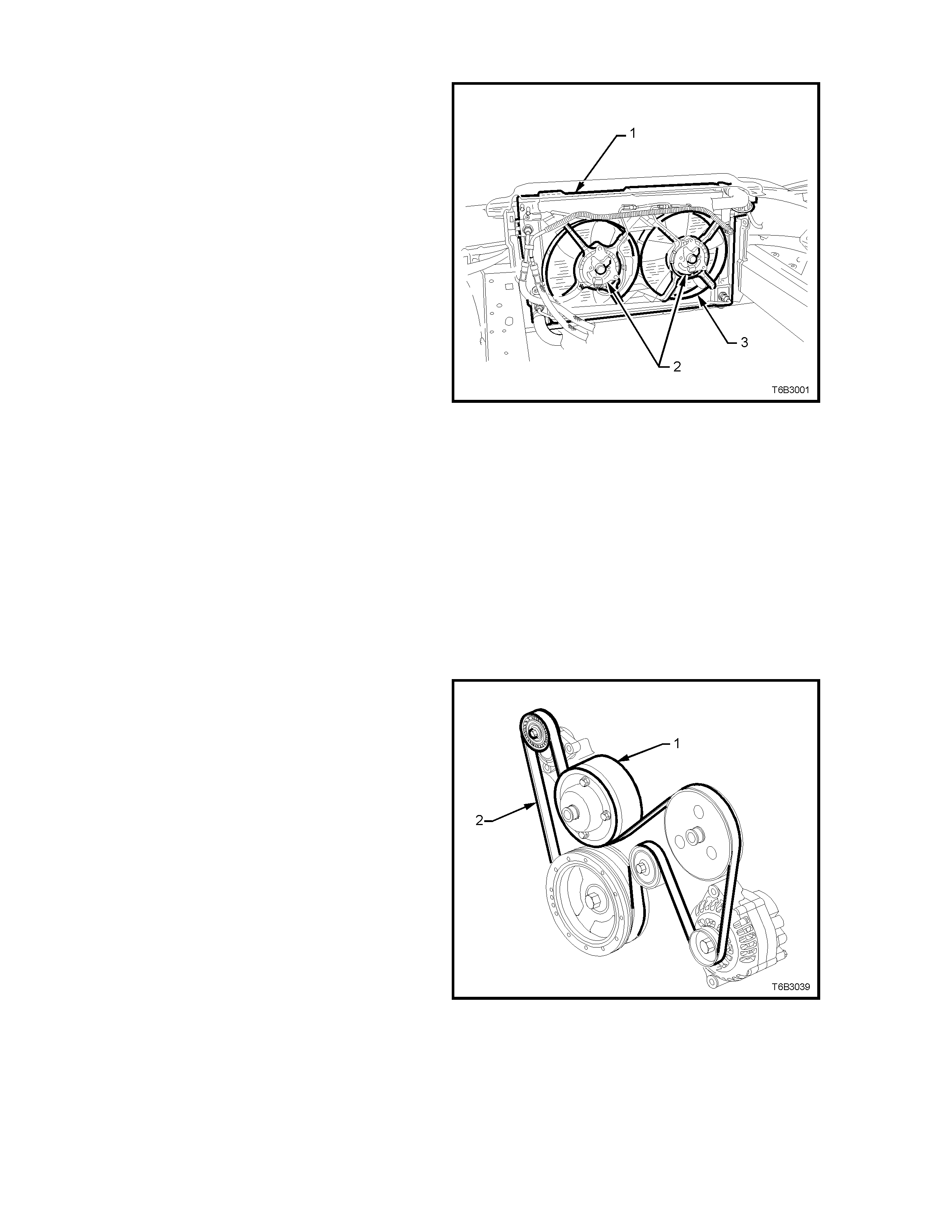
The radiator (1) is of the crossflow design and
consists of an aluminium core with plastic side
tanks attached to each end of the core.
For vehicles with automatic transmission,
transmission oil coolers are located in both the left
hand and right hand side tanks.
Pegs are attached to the lower frame and the upper
area of each side tank. These pegs are used to
support the radiator in four rubber mounts. The
assembly is held in position by two spring clips at
the upper mounting locations.
The radiator core side tanks or transmission oil
cooler CANNOT be replaced separately. If there is
a fault with any of these components, the radiator
assembly (1) must be replaced. Small core repairs
can be made using an Aluminised Silicon based
- Radiator Repair Procedure, in this Section.
The cooling fan and electric motor assemblies (2)
are supported in a polypropylene mounting bracket
that also forms the radiator shroud (3). The
mounting bracket and fan shroud (3) are moulded
as a one piece assembly and is attached to the
radiator side tanks.
The PCM determines operation of the two, two-
speed engine cooling fans based on A/C request,
A/C system pressure (where fitted), engine coolant
temperature and vehicle speed signal inputs. For
details of the engine cooling fan operation, see
Section 6C3 POWERTRAIN MANAGEMENT -
GEN III V8 ENGINE, of the VT Series II Service
Information.
Figure 6B3-1
The c oolant pump (1) is mounted to the front of the
cylinder block and is driven by the serpentine drive
belt (2). Coolant passes through the engine from
the coolant pump inlet, and exits via the coolant
outlet, located at the top of the coolant pump
housing.
Figure 6B3-2
liquid repair agent, refer to 2.16 RADIATOR
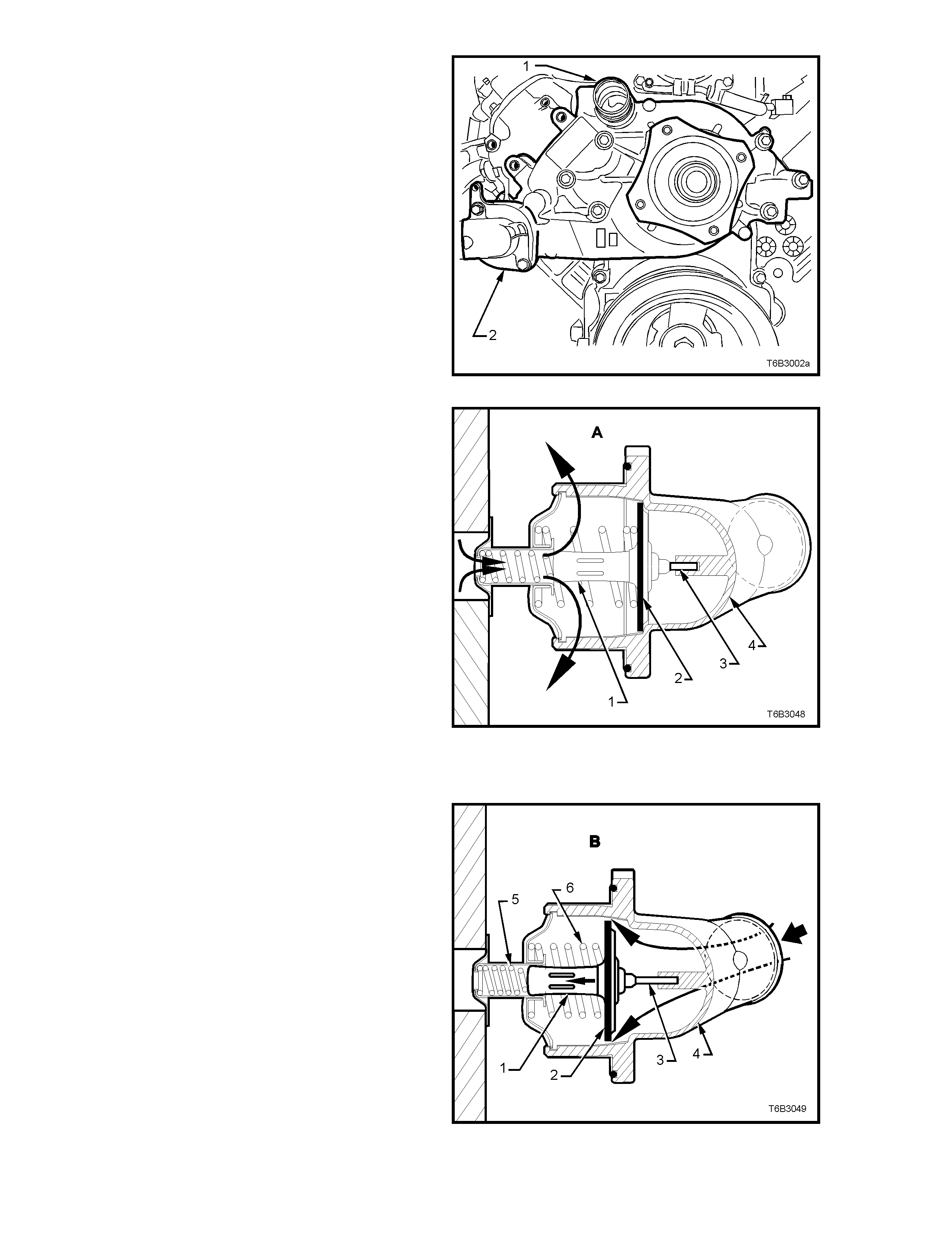
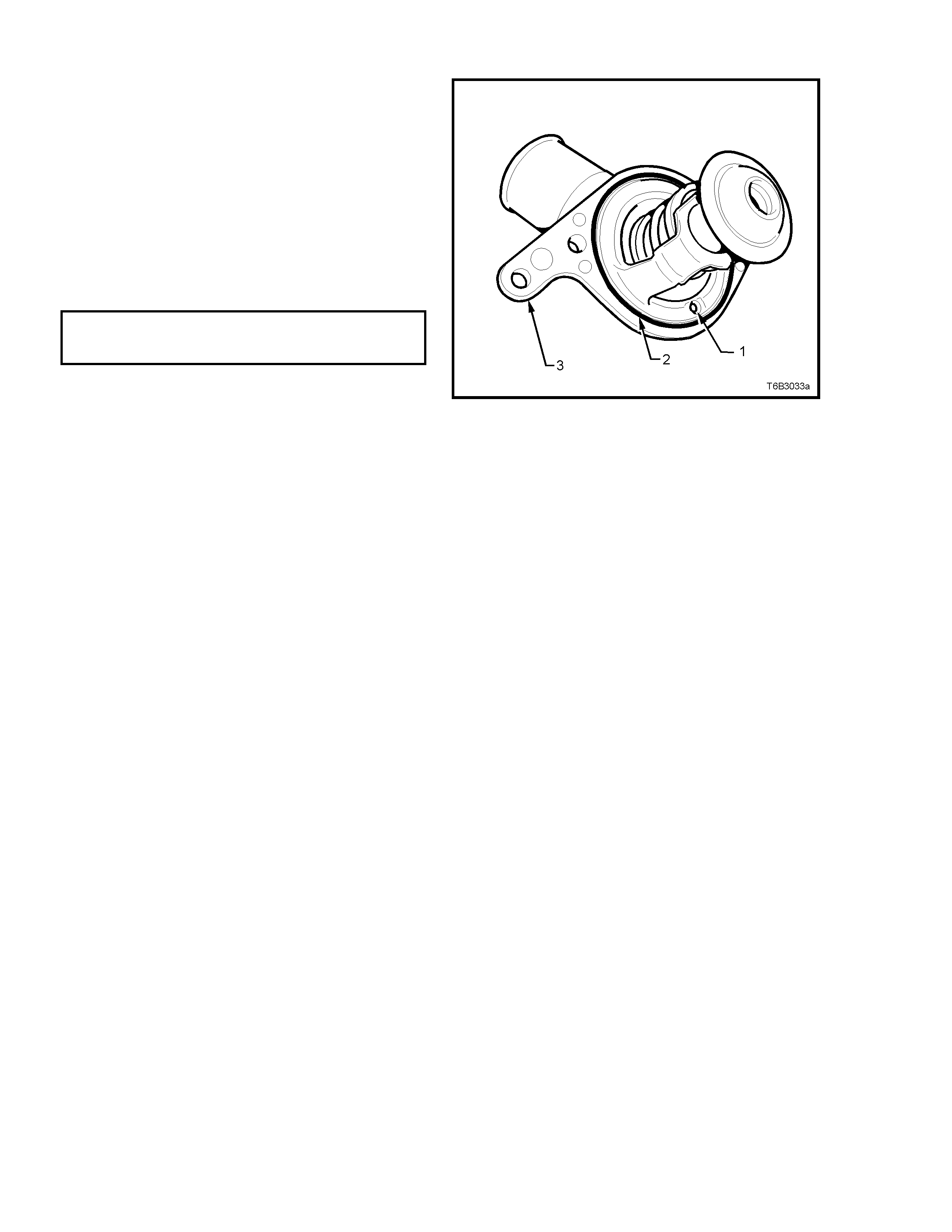
The coolant outlet (1) is located at the top of the
coolant pump housing.
The thermostat is also located in the coolant pum p
housing, at the coolant inlet fitting (2).
Figure 6B3-3
A wax pellet type thermostat is used in the coolant
inlet passage to control the flow of coolant,
providing fast engine warm up and regulating
coolant temperature.
The wax pellet or power element in the therm ostat,
expands when heated and contracts when cooled.
The wax pellet is located inside the brass body (1)
that forms an integral part of the flow control valve
(2). When the pellet is heated, pressure is exerted
against a piston and pin (3) that reacts against the
thermostat housing (4).
With cold coolant (view ‘A’), the flow control valve
(2) remains closed, preventing coolant flow from
the radiator to enter but coolant in the engine still
circulates, with hotter coolant from the cylinder
heads being directed through the end of the
thermostat, flowing over the wax pellet body.
This results in warming of the wax pellet at the
sam e rate as the temper ature rise of the coolant in
the engine.
Figure 6B3-4
As the coolant warms up (view ‘B’), the wax pellet
expands, causing the brass body (1) to move back
into the smaller spring cavity due to the reaction of
the piston and pin (3) against the thermostat
housing (4). As the body (1) moves back (bold
arrow), less of the engine bypass coolant flows
over the body, warm ing the wax inside but the flow
control valve (2) now opens, allowing coolant to
flow from the radiator and into the engine.
The rate that the control valve (2) opens, is
balanced between the force exerted by the
expanding wax and the c ombined f orce exterted by
the two springs (5 and 6).
This controlled flow of coolant during a cold start
and initial warming of the engine, provides a
controlled warming cycle, necessary to control
exhaust emissions during this critical period.
Figure 6B3-5
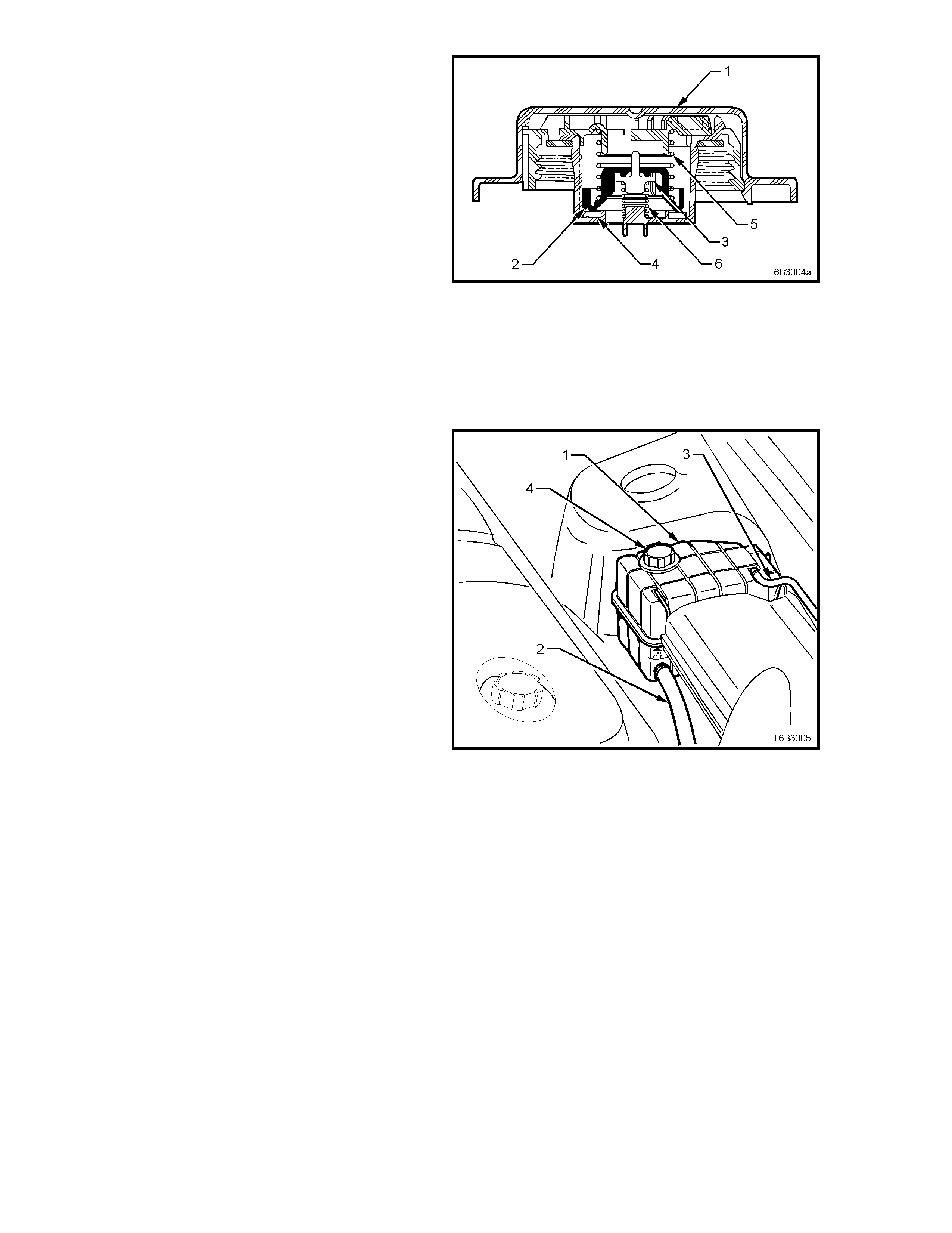
A screw-on pressure cap (1), fitted to the coolant
surge tank, causes the cooling system to operate at
higher than atmospheric pressure. This higher
pressure, raises the boiling point of the coolant,
resulting in increased engine cooling efficiency.
The pressure cap (1) contains a pressure valve (2)
and a vacuum (atmospheric) valve (3). The
pressure valve is held against its seat (4) by a
spring (5) which determines the maximum
operating pressure of the cooling system (100 kPa
for the G EN III V8 engine). The vacuum valve (3) is
held against its seat by a light spring (6). The
vacuum created during coolant cool down over-
comes the vacuum valve spring force and opens
the valve (3), preventing the radiator hoses from
collapsing.
The coolant is maintained at the ideal level by the
pressure cap and the coolant surge tank, resulting
in an increased cooling efficiency.
Figure 6B3-6
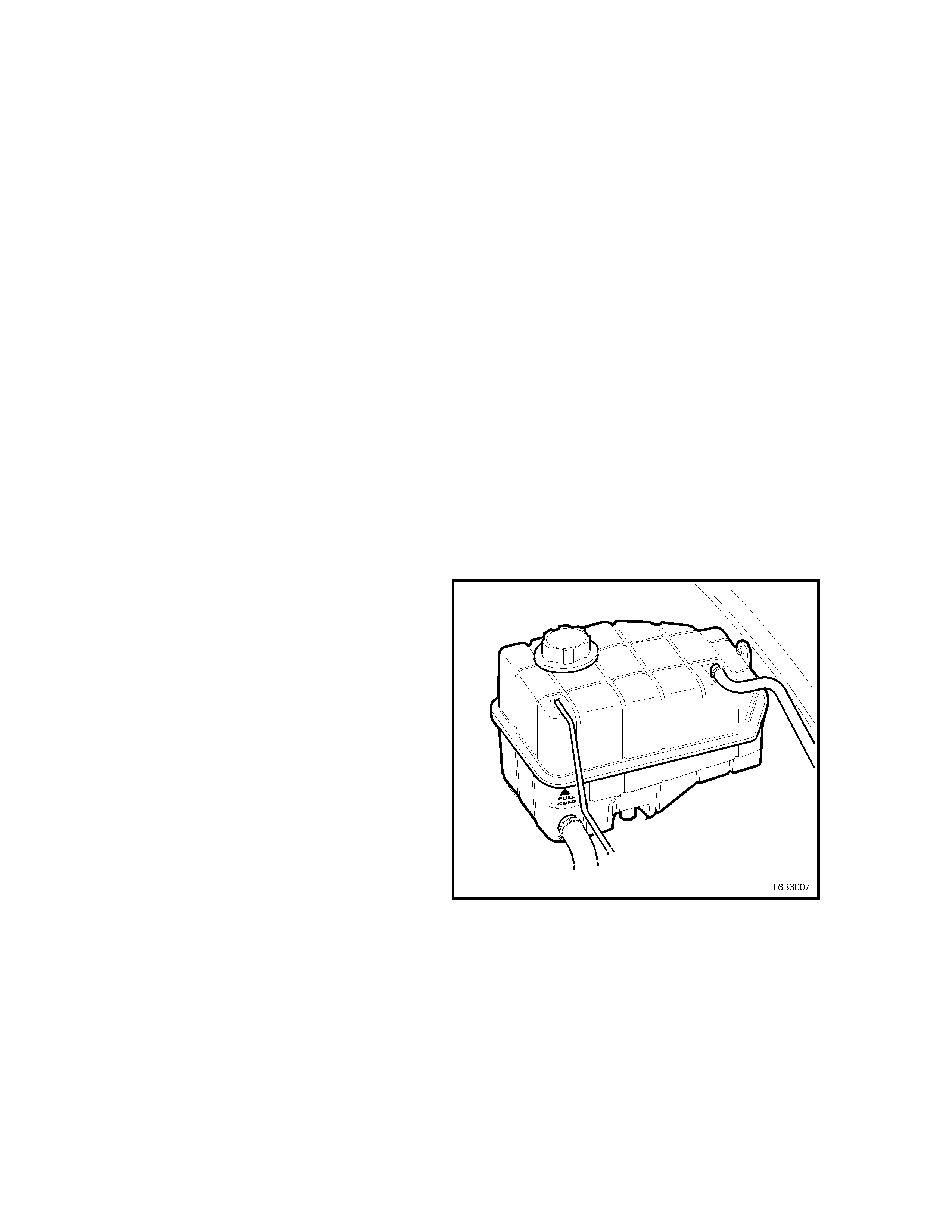
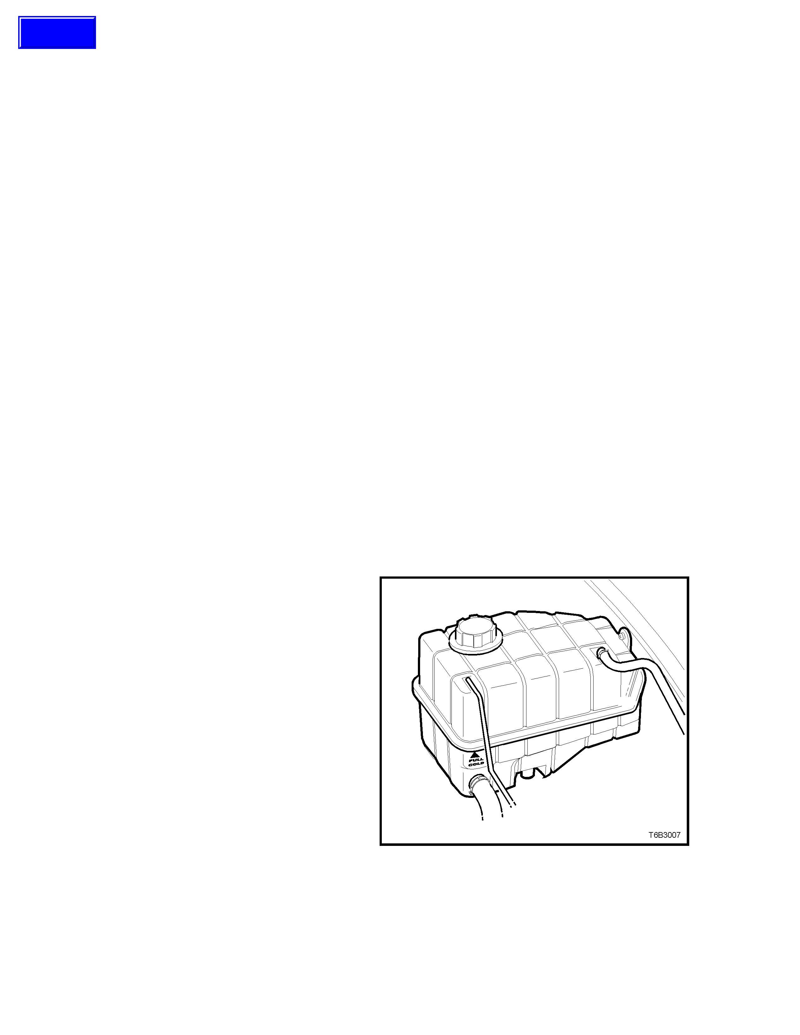
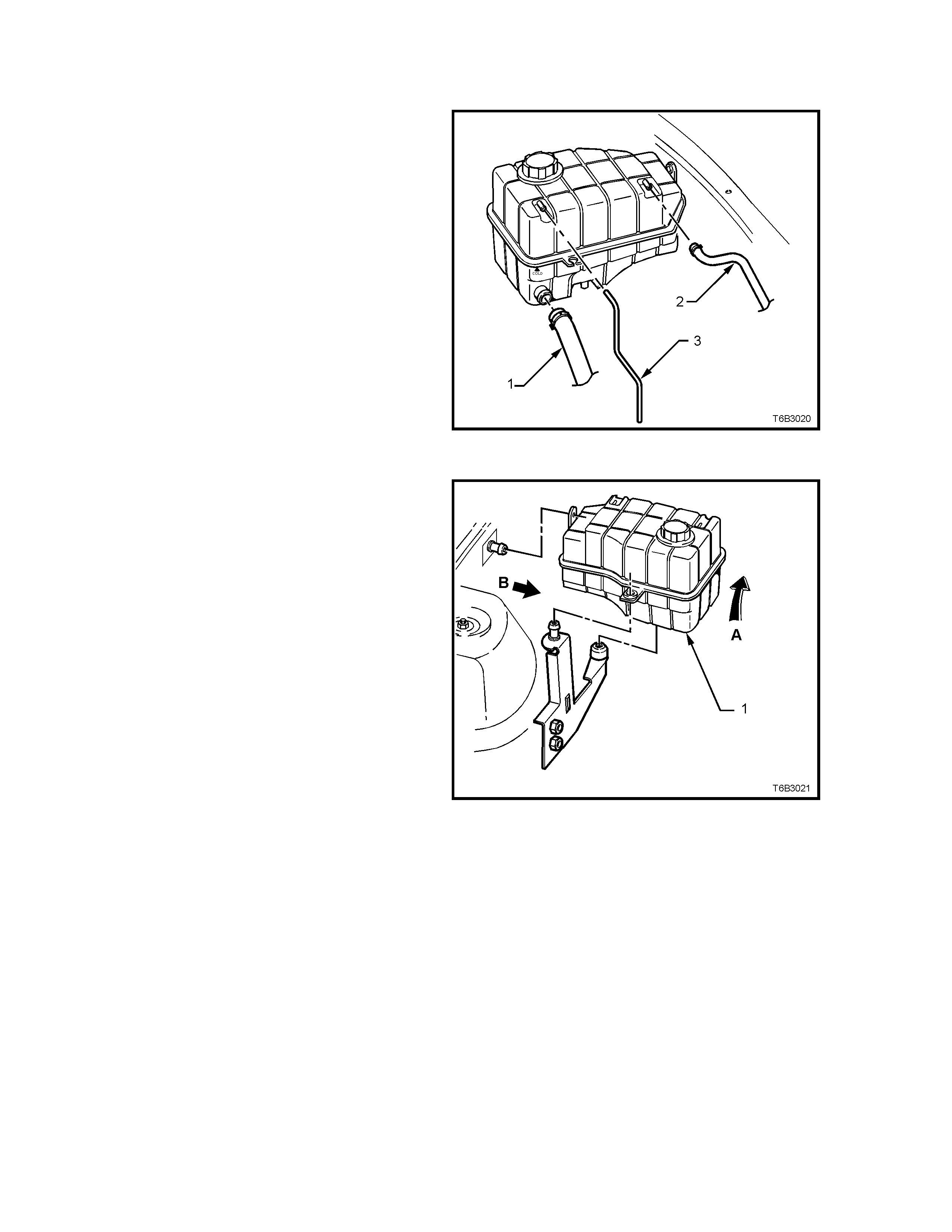
Located on the left hand inner fender skirt behind
the air cleaner as shown in Figure 6B3-7, the
coolant surge tank (1) is connected to the engine
cooling s ystem by a pressure hos e from the heater
connection at the coolant pump (2) and a vapour
hose (3) from the left hand radiator side tank.
As the engine temperature rises, the coolant heats
and expands. The fluid displaced by expansion
flows into the coolant surge tank. W hen the engine
is turned off, the coolant contracts as it cools and
the pressure in the surge tank returns to
atmospheric, by the unseating of the vacuum
valvein the screw-on pressure cap (4), if necessary.
Coolant level should be m aintained at the indicated
point on the side of the surge tank, when the
engine is cold, by sighting the level externally.
The cooling system is designed to use DEX-
COOL® coolant (to GM 6277M Specification) in a
concentration level of 50% DEX-COOL® to 50%
good quality, clean water. This mixture is required
to maintain the integrity of the cooling system, and
to prevent oxidation occurring within the engine.
CAUTION: Because the surge tank is
pressurised, the t emperature of t he coolant can
be considerably higher than 100°
°°
° C, without
boiling. Removing the screw-on pressure cap
when the engine is hot (high cooling system
pressure), will cause the coolant solution to
boil instantaneously.
This will result in the coolant spewing out over
the engine, fenders and the person removing
the cap, resulting in possible serious scalding.
Figure 6B3-7
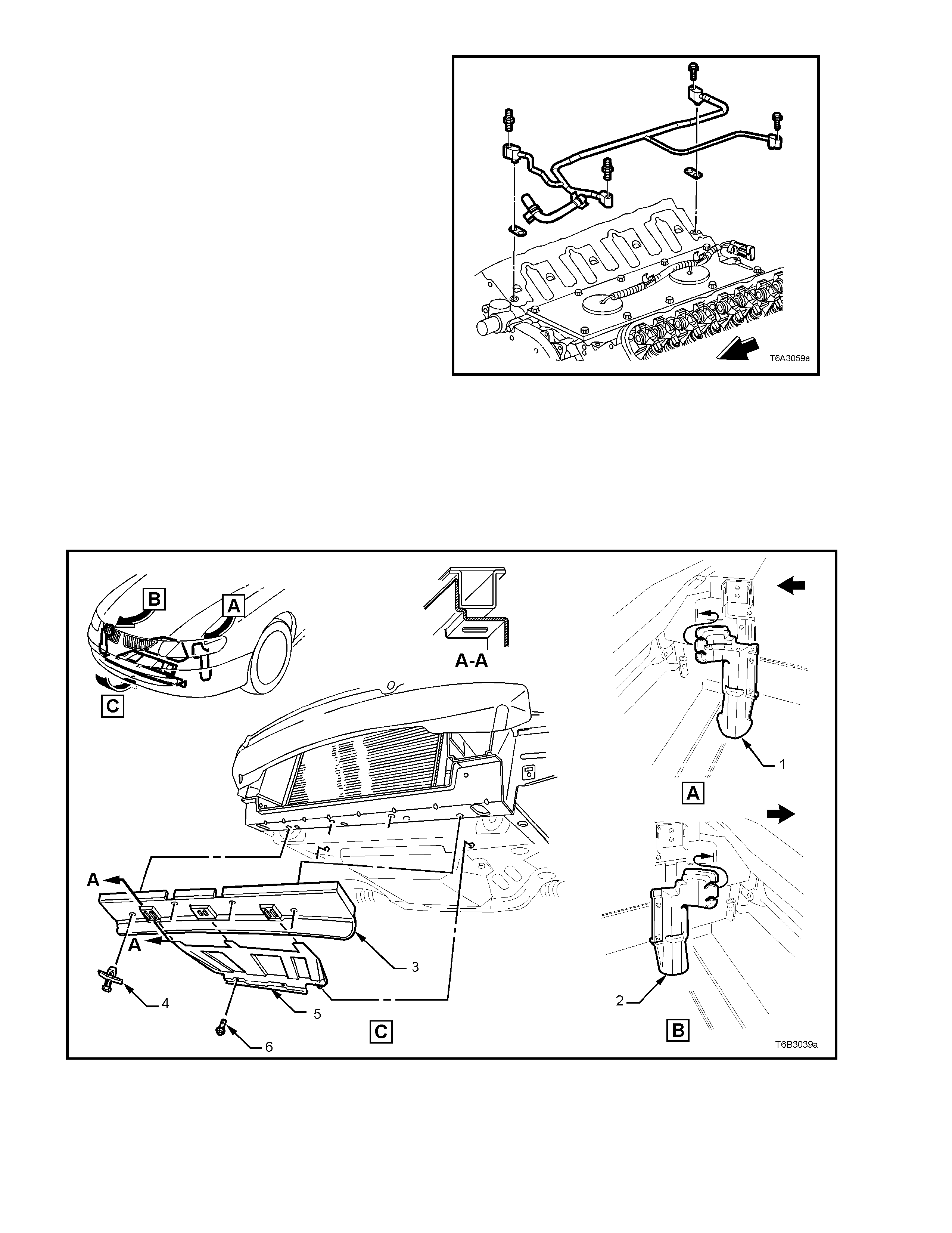
Any vapour that develops in the engine ( or air when
the cooling system is being filled), is routed back to
the coolant surge tank, through a vapor vent pipe
fastened to the cylinder heads in four places.
Vapour then flows via hoses, through the throttle
body, to the left hand radiator side tank. Another
hose then connects the left hand radiator side tank
with the coolant surge tank, thereby directing
vapour/air to that point.
Figure 6B3-8
Air baf f les and s ide c hutes are fitted to the front end of the vehicle to direc t and promote air flow through the radiator to
provide maximum cooling.
The purpos e of the air baff les is to create a low pressur e area behind the radiator and a high pressure area in front of
the radiator, when the vehicle is at speed.
This enables additional air flow through the radiator core to maintain the desired engine cooling.
The air baff les or side chutes should never be removed unless for service work . If either the air baf fles or side chutes
are damaged, this will reduce the cooling system efficiency, and therefore they must be replaced.
1. Left Hand Side Air Chute 3. Lower Front Air Chute Baffle 5. Lower Rear Air Chute Baffle
2. Right Hand Side Air Chute 4. Fastener (4 places) 6. Screw (2 places)
Figure 6B3-9
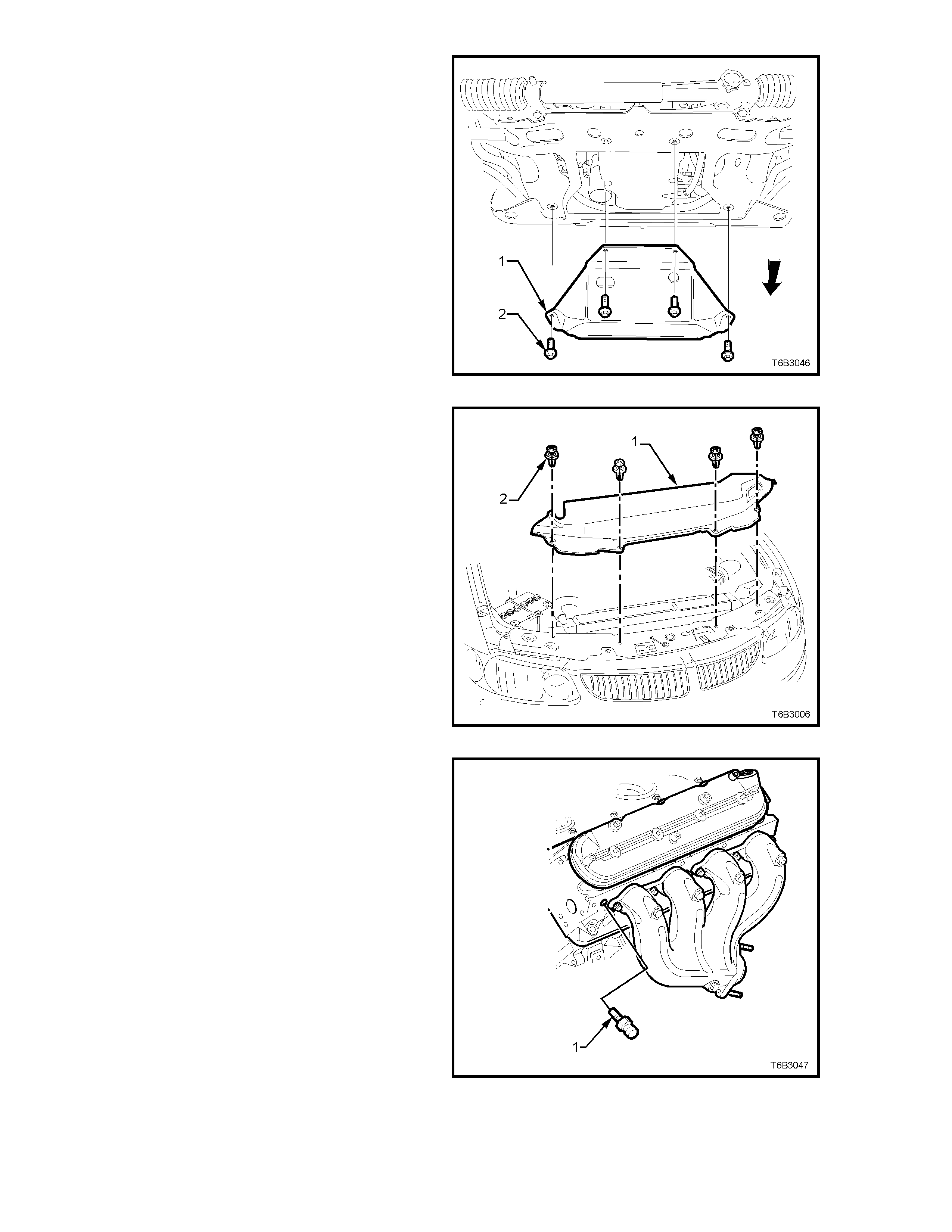
An oil pan under- tray (1) also f orm s an integral part
of the air f low system ar ound the GEN III V8 engine
and must always be reinstalled after removal for
service operations, such as engine oil draining and
oil filter replacement.
NOTE: This tray is not designed as an oil pan
stone guard.
Figure 6B3-10
An upper radiator shroud is fitted between the
upper radiator support panel and the radiator
assembly, to minimise the recirculation of hot air
from the rear of the radiator back over the core.
Figure 6B3-11
A coolant temper ature sens or (1) is m ounted in the
front of the left hand cylinder head.
The c oolant temperatur e sensor generates a signal
which is used by the Powertrain Control Module
(PCM) for calculation of the various powertrain
management functions. This information is
transmitted to other control modules, e.g.
Instrum ents for the temperature gauge f unction, on
the serial data bus.
Figure 6B3-12

2. SERVICE OPERATIONS
2.1 SERVICE NOTES
CAUTION: TO AVOID SERIOUS PERSONAL INJURY, NEVER REMOVE THE SCREW-ON SURGE TANK CAP
WHEN T HE ENGINE IS HOT , EVEN IF THE CO OLING SYST EM SHOULD REQUIRE FILL ING. SUDDEN RELEASE
OF COOLING SYSTEM PRESSURE IS VERY DANGEROUS.
Before r emoving the surge tank cap, allow the engine to cool, then place a shop rag over the surge tank cap and then
slowly turn the cap anti-clockwise, to loosen. DO NOT SPIN THE CAP OFF! If there is any residual pressure in the
cooling system, it can then be released into the dam under the cap and out through the drain hose onto the ground.
When all pressure has been dispersed in this way, the cap can then be fully removed.
The vehicle is fitted with twin radiator electric cooling fans. When working around the engine compartment with the
engine running or with the ignition on, keep clear of the fan as it may start operating without warning.
The cooling system requires little care except for maintaining the coolant to the correct level in the coolant surge tank
and periodic servicing at the time or distance intervals as outlined in the Owner's Handbook.
Periodic servicing includes:
1. Checking coolant level, refer to 2.3 DRAINING AND FILLING COOLING SYSTEM this Section.
2. Checking coolant concentration, refer to 2.2 COOLANT MAINTENANCE - Testing Coolant Concentration this
Section.
3. Pressure test cooling system and radiator cap, refer to 2.8 PRESSURE TESTING in this Section.
4. Check/tighten hose clam ps and inspect all hos es, ref er to 2.4 COOLANT HOSES in this Sec tion. Replac e hos es if
swollen or deteriorated.
CAUTION: ALWAYS WEAR PROTECTIVE SAFETY GLASSES WHEN WORKING WITH SPRING TYPE HOSE
CLAMPS. FAILURE TO DO SO COULD RESULT IN EYE INJURY.
5. Clean out cooling system, ref er 2.5 CL EANING COOLING SY ST EM, in this Sec tion and re f ill cooling system, ref er
to 2.3 DRAINING AND FILLING COOLING SYSTEM in this Section.
2.2 COOLANT MAINTENANCE
The cooling system is designed to use a specific
coolant (a mixture of DEX-COOL® coolant to GM
Specification 6277M coolant additive and water),
rather than plain water.
The use of this orange coloured coolant additive also
raises the boiling point and increases the cooling
system efficiency. For this reason, it is of the utmost
impor tance that the cor rect c oncentra tion level of DEX-
COOL® is maintained in the cooling system.
Addition of plain water into the cooling system when
'topping-up' may dilute the coolant mixture to a point
where the specific properties of
DEX-COOL® become ineffective.
The coolant should comprise of a mixture 50% DEX-
COOL® (GM Specification 6277M) with 50% clean,
good quality water.
NOTE: Do not mix different types of antifreeze or
corrosion inhibitors as they may be incompatible. If a
different type has been used in the cooling system,
flush the system with clean water, refer to
2.5 CLEANING COOLING SYSTEM in this Section
and refill the cooling system with the correct coolant,
refer to 2.3 DRAINING AND FILLING COOLING
SYSTEM in this Section.
TOPPING UP THE COOLING SYSTEM
The coolant level can be externally checked at the
coolant surge tank.
Pre-mixed coolant (50% DEX-COOL® to GM
Specification 6277M with 50% clean, good quality
water) may be added as necessary to bring the
level shown on the coolant surge tank but only
when the engine is cold.
Figure 6B3-13
TESTING COOLANT CONCENTRATION
To ensure the specified ethylene glycol concentration
is maintained in the engine coolant, the coolant
concentration m ust be checked at the time or distance
intervals outlined in the Owner's Handbook.
While a number of coolant concentration measuring
devices are available, the two preferred types are as
described. Check coolant concentration as follows:
METHOD 1 - RERACTOMETER
NOTE 1: Coolant tester, Tool No. J 26568,
automatically compensates for temperature.
NOTE 2: Ensure that the eyepiece of the tester is free
of coolant before looking through it.
NOTE 3: Before each use, swing back the plastic
cover at the slanted end of the coolant tester, exposing
the measuring window and the bottom of the plastic
cover. Carefully wipe the measuring window dry with a
tissue or clean, soft cloth. Close the plastic cover.
1. Check the calibration of the coolant tester as
follows:
a. Place a few drops of distilled water (between
21 - 29° C) onto the meas uring window, then
close the plastic cover.
b. Point the tester toward any light source, look
into the eyepiece and check that the
indicated reading is zero. If not, then re-
calibrate the tester as detailed in the next
service operation - Calibrating the Tester.
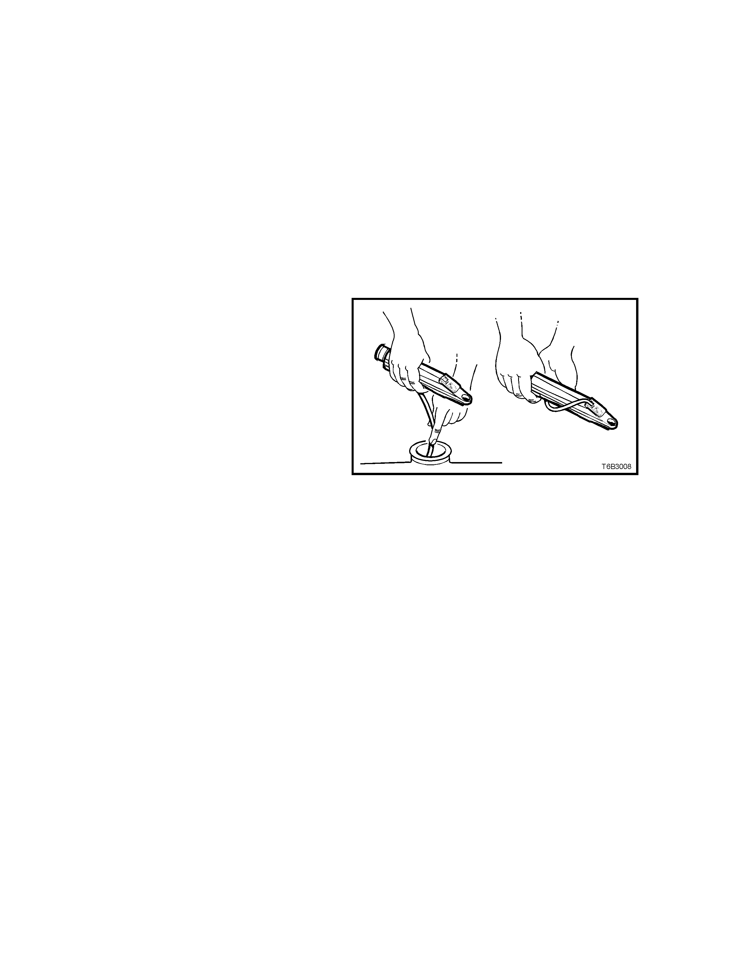
2. Release the tip of the bulb pump from under
the refractometer body. It is not necessary to
remove the complete pump from the tool.
3. Carefully remove the screw-on coolant surge
tank cap, refer to 2.1 SERVICE NOTES for
important safety items.
4. Insert the tube of the pump into the coolant,
then press the bulb to obtain a sample.
5. Bend the tube around and insert the end into
the cover plate opening.
6. Press the pum p bulb to deposit a f ew drops of
coolant onto the measuring surface. Do not
open the plastic cover when taking readings,
as water evaporation will change the reading
obtained.
Figure 6B3-14
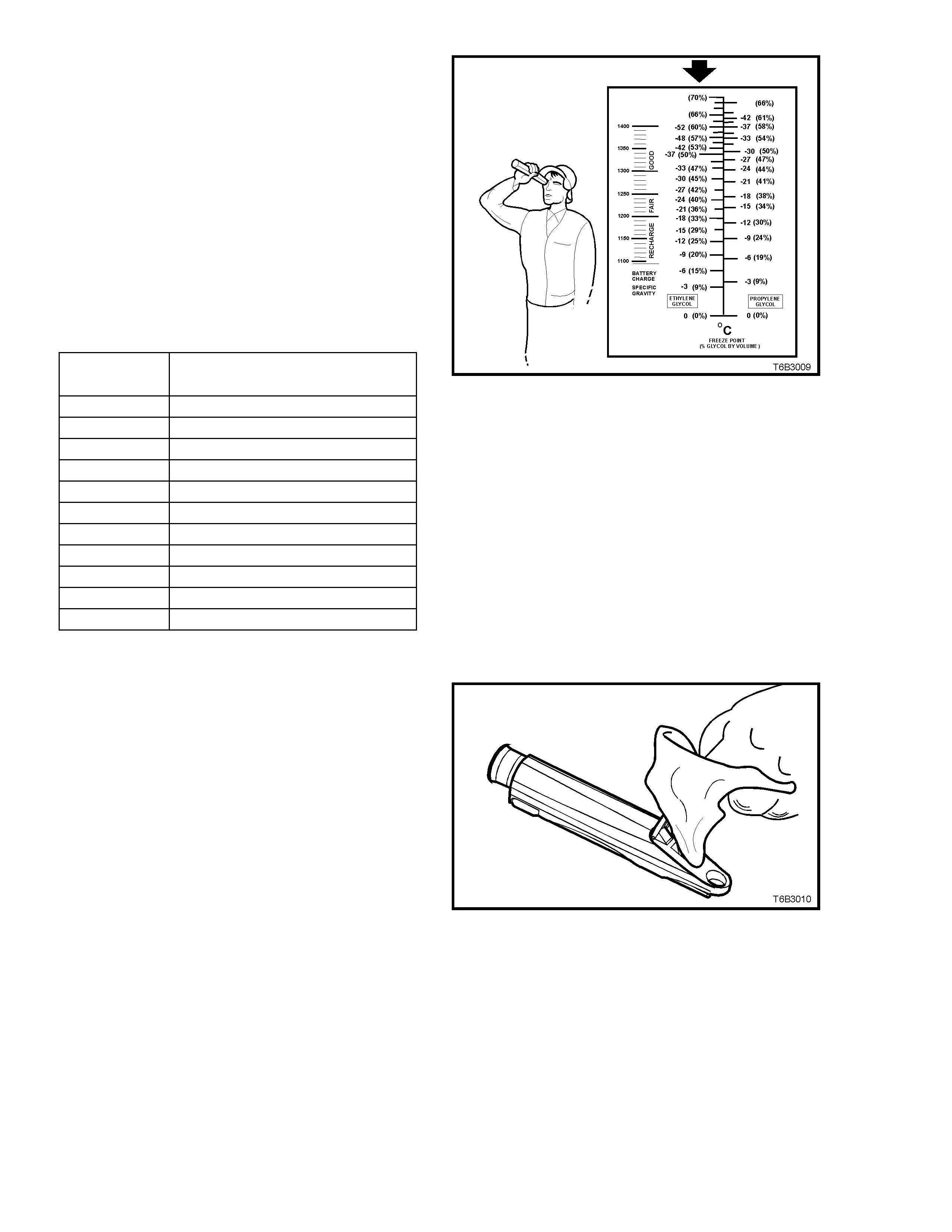
7. Point the coolant tester toward any light
source, looking into the eyepiece.
a. The coolant protection reading is at the
point where the dividing line between the
light and dark, crosses the scale.
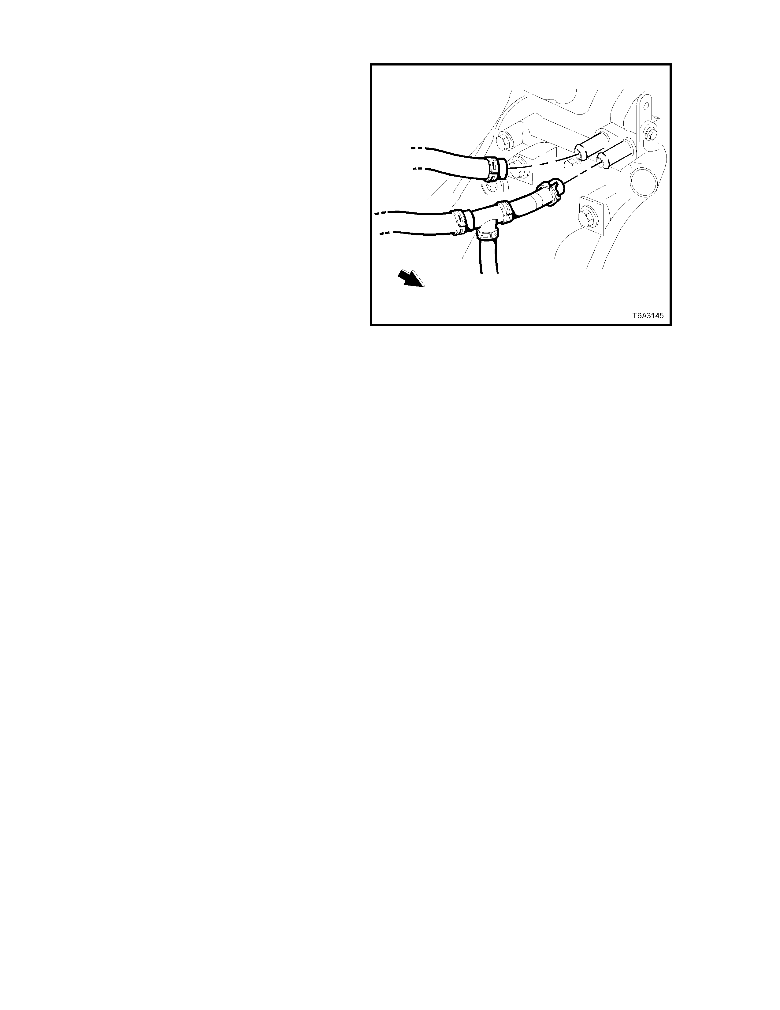
b. The scale for ethylene glycol (bold arrow)
is the reference scale for DEX-COOL®
coolant.
NOTE: The temperature scale is reversed from
that of a conventional thermometer. Below zero
readings are on the upper half of the scale.
8. A reading between -30 and -52° C
(corresponding to a coolant concentration
between 45 - 60%), is satis factor y for the GEN
III V8 engine cooling system.
Figure 6B3-15
NOTE: If the reading is not clear, then properly
clean and dry the measuring surface, then conduct
another test. Also ensure that there is sufficient
fluid on the measuring prism.
9. If the reading shows that the concentration
level of the coolant is inadequate, r ef er to the
previous table to determine the amount of
DEX-COOL® that needs to be added to the
surge tank.
10. Start and run the engine until normal
operating temperature is reached, to allow
the added coolant to be distributed
throughout the engine cooling system.
Figure 6B3-16
HYDRO-METER
READING % LITRES OF DEX-COOL® TO BE ADDED
0 6.0
5 5.7
10 5.3
15 4.9
20 4.5
25 4.0
30 3.4
35 2.8
40 2.0
45 1.1
50 0
Calibrating the Tester
While the coolant tester calibration is checked at
manufacture, if the calibration check detailed in step 1
of this m ethod s hows that the instrum ent is not reading
correctly, then conduct the following re-calibration
procedure;
1. Remove the sealant covering the adjustment
screw on the underneath of the tester.
2. With a distilled water sample on the measuring
surface, carefully adjust the screw until a zero
reading is obtained.
NOTE: DO NOT completely remove the screw.
3. After re-calibration, reseal the screw with a small
amount of silicone sealant.
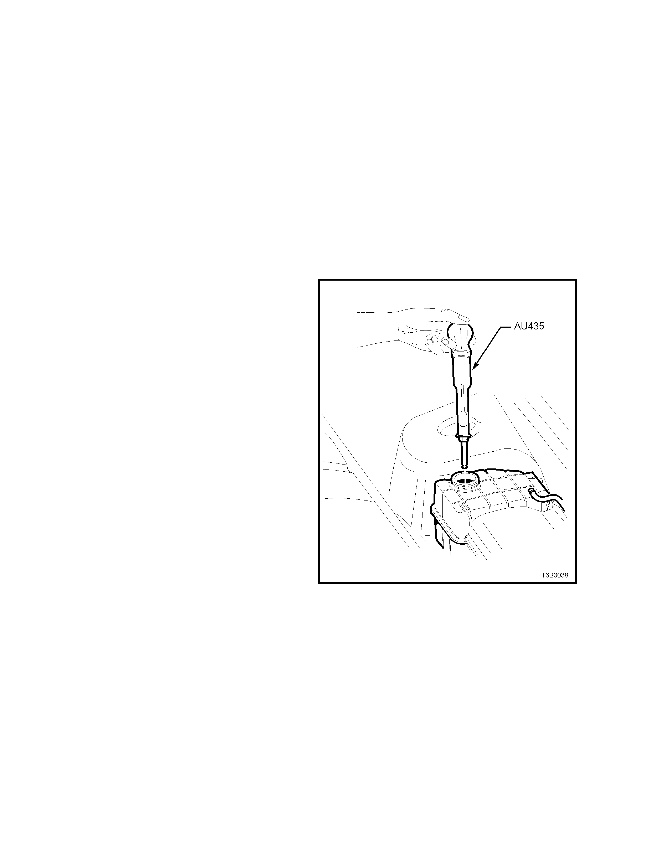
METHOD 2: - HYDROMETER
1. Cooling system should be at or close to ambient
temperature.
2. Carefully remove the screw-on pressure cap
from the surge tank and, while holding the
rubber bulb squeezed, insert nozzle of coolant
tester hydrometer, T ool No. AU435 into coolant.
Releasing the rubber bulb will then draw
sufficient coolant into the tester to float
hydrometer bulb freely.
3. Hold tester at eye level and read scale on
hydrometer bulb at coolant level.
The reading shows the percentage of ethylene
glycol antifreeze contained in the engine
coolant.
4. The hydrometer reading should show 50% if the
coolant concentration is correct.
If a reading of less than 50% is achieved, the
cooling system requires topping up with DEX-
COOL® ethylene glycol coolant additive to GM
Specification 6277M.
Refer to the chart shown for the previous
method to determine how much DEX-COOL®
ethylene glycol antifreeze is required to add to
the cooling system to bring the coolant to the
specified concentration.
5. Drain sufficient quantity of coolant from cooling
system to allow top-up with DEX-COOL®
coolant additive, then add the required amount.
Install screw-on pressure cap.
6. Start and run the engine until normal operating
temperature is reached, to allow the added
coolant to be distributed throughout the engine
cooling system.
Figure 6B3-17
NOTE: As an alternative to using the refractometer or
hydrometer, An anti-freeze hydrometer is available
from Snap-on® Tools Australia Pty Ltd under the part
number, EZRS102AUS.
2.3 DRAINING AND FILLING COOLING SYSTEM
DRAINING
CAUTION: To avoid the posibility of scalding, it is
recommended that this operation is only carried
out when the engine is cold.
The recommended method of draining the GEN III V8
engine cooling system, is to remove the screw-on
pressure cap from the surge tank, then remove the
hose clamp from the radiator hose at the lower left
hand radiator side tank, draining the cooling system
contents into a suitable clean container.
FILLING
As the GEN III V8 engine has a vapour pipe attached
to to both cylinder heads, that releases any air in the
cooling system, no special bleeding procedure is
required, apart from the following simple points:
1. Set the heater control to maximum.
2. Reinstall hose to radiator lower outlet on the left
hand side tank and tighten hose clamp.
3. Mix 6 litres of DEX-COOL ethylene glycol
antifreeze/inhibitor (to GM Specification 6277M)
with 6 litres of clean, good quality water.
NOTE 1: Do not mix different types of antifreeze or
corrosion inhibitors as they may be incompatible. If a
different type has been used in the cooling system,
flush the system with clean water, refer to
2.4 CLEANING COOLING SYSTEM in this Section.
NOTE 2: When using DEX-COOL® ethylene glycol
antifreeze/inhibitor (to GM Specification 6277M)
DO NOT add a pack of cooling system pellets to
the cooling system.
4. Carefully fill the cooling system by pouring the
pre-mixed coolant into the surge tank opening
until the level is correct.
5. Pressure test cooling system, refer to
2.8 PRESSURE TESTING in this Section.
6. Reinstall the screw-on pressure cap to the
resevoir.
7. Start and r un the engine until normal operating
temperature is reached, at which time the
added quantity of DEX-COOL® coolant
additive will have dispersed through the
engine’s cooling system.
Figure 6B3-18
Techline

2.4 COOLANT HOSES
Coolant hoses are installed as shown in the following illustrations.
Hose connections should be thoroughly cleaned before installing any new hose.
NOTE: Because of the production m ethod of inst alling the spring type hose clam ps, access to the clamp ends m ay not
be poss ible. Partic ularly for the c lam ps s ecuring the hos es to the lower bridging piece of the coolant intak e and coolant
surge tank hoses, it may be necessary to remove the complete hose assembly from the vehicle.
After any part of the cooling system is disturbed, the cooling system must always be refilled with the correct
concentration of coolant, r efer to 2.3 DRAINING AND FILLING COOLING SYST EM and pressure tes t cooling system,
refer to 2.8 PRESSURE TESTING in this Section.
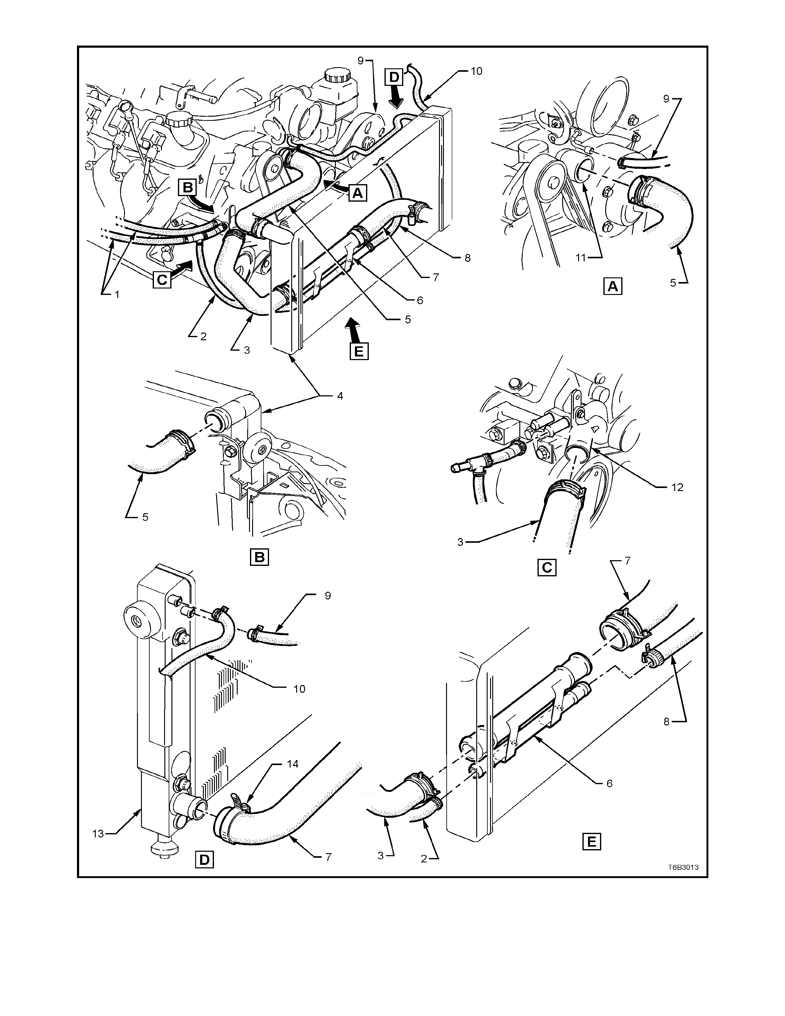
1. Hoses – Heater 5. Hose - Radiator Upper 9. Hose - V apour t o Radi ator
2. Hose - To Coolant Surge Tank 1 of 2 6. Bridging Pi pe - Radi ator Hoses 10. Hose - Vapour to Surge tank
3. Hose - Radiator Lower 1 of 2 7. Hose - Radiator Lower 2 of 2 11. Pump Coolant
4. Radiator 8. Hose - To Coolant S urge Tank 2 of 2 12. Housing - Thermostat
Figure 6B3-19 - Cooling System Hose Layout - GEN III V8 Engine
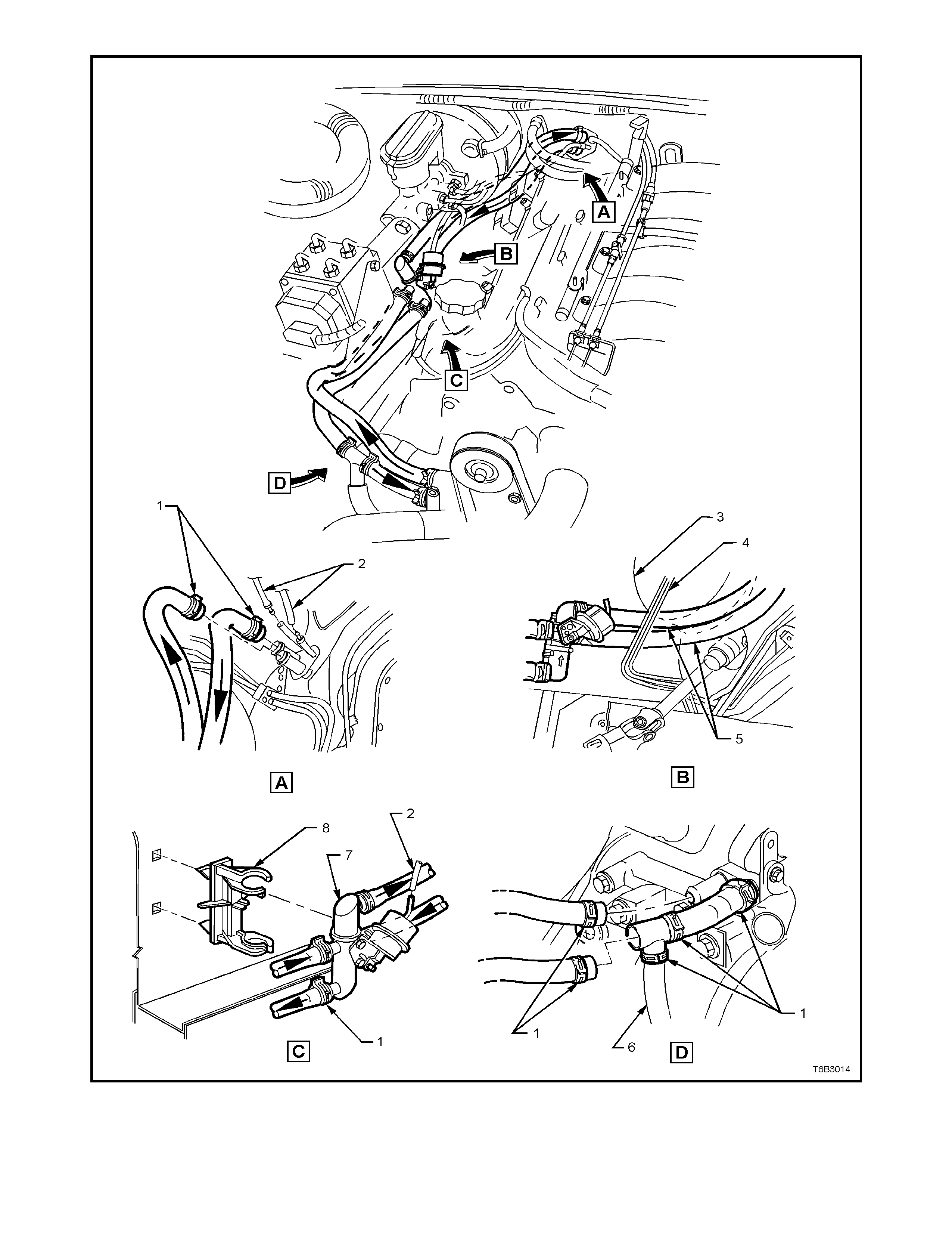
1. Clamps - Hose 4. Pipes – B rake 7. Valve - Coolant Fl ow Control
2. Hose - HVAC Vacuum 5. Hoses Heat er Tap t o Dash Panel 8. Clip - Coolant Fl ow Control V al ve
3. Booster - B rake 6. Hose - To Coolant S urge Tank 1 of 2
Figure 6B3-20 - Heater Hose Arrangement - GEN III V8 Engine
2.5 CLEANING COOLING SYSTEM
NOTE: Before carrying out reverse flushing
procedures , it is rec om m ended that a cleaning solution
be used to loosen scale and corrosion. Use Holden
radiator cleaner, P/N M39304, following the
instructions on the container.
COOLING SYSTEM REVERSE FLUSH
CAUTION: This operation should only be
carried out when the engine and radiator are at
ambient temperature.
When using specialised cooling system flushing
equipment, only connect as recommended by the
manufacturer.
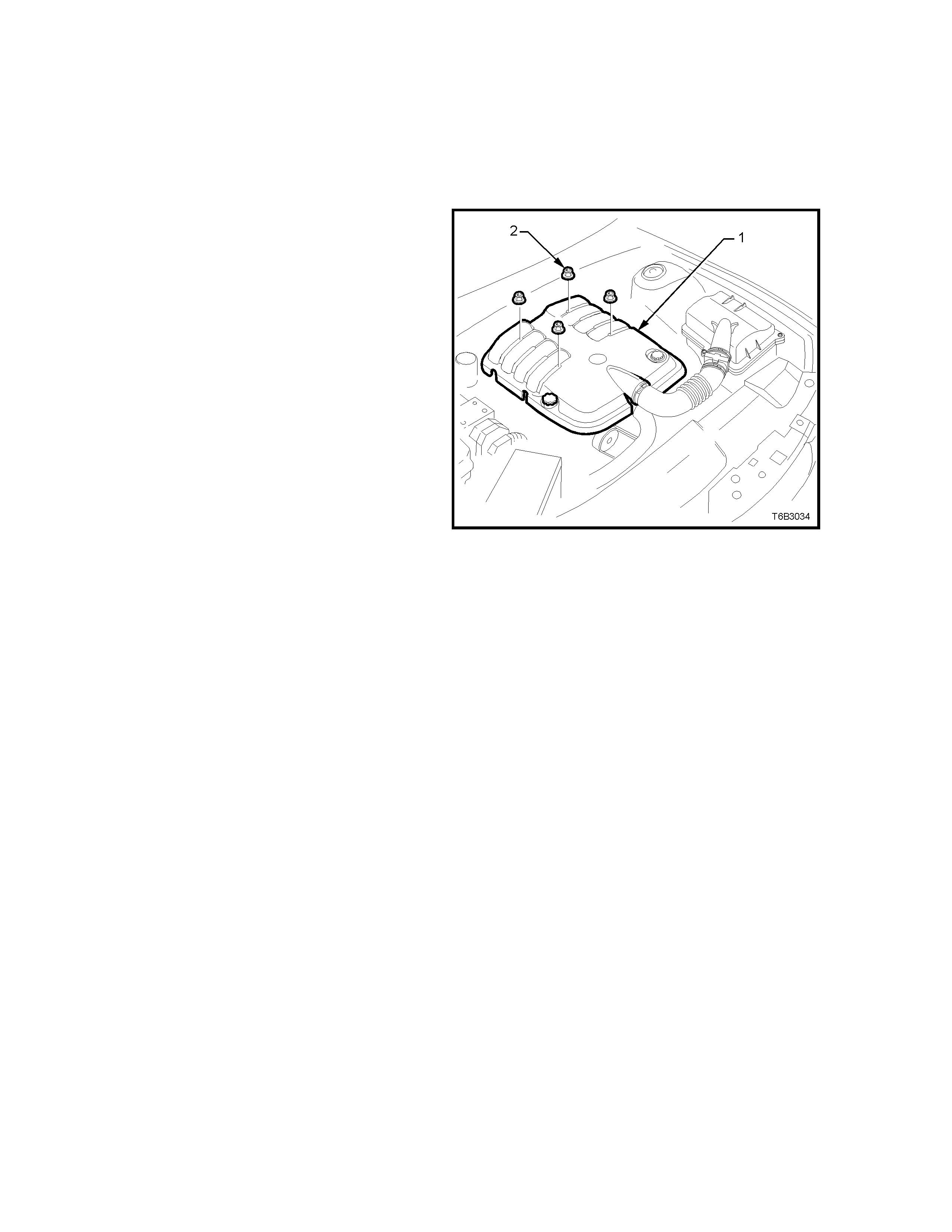
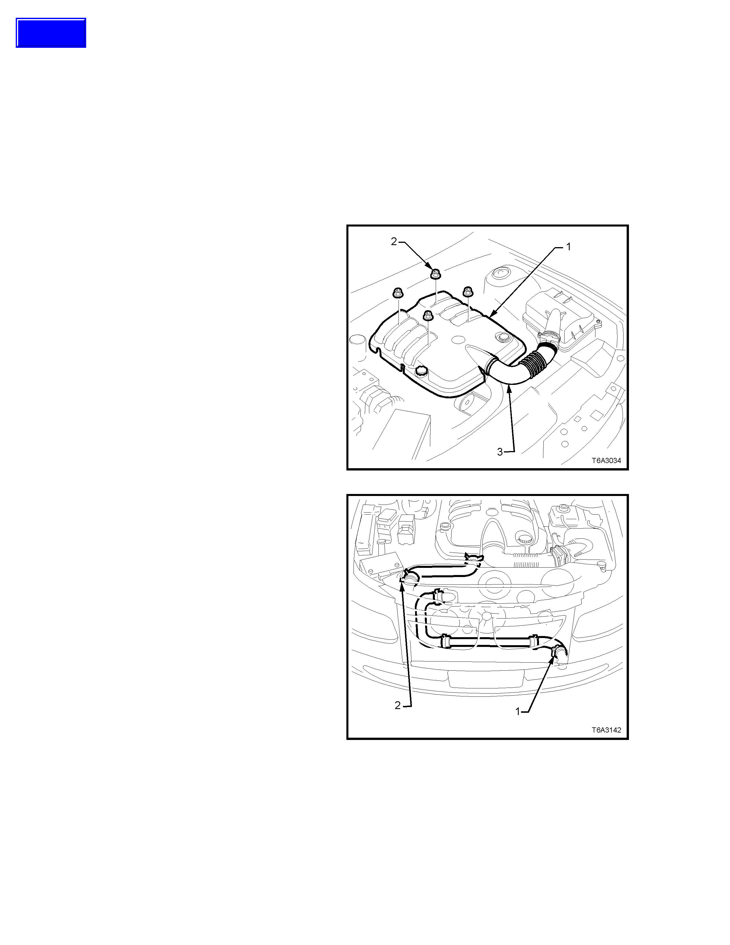
1. Remove the engine dress cover (1) after
removing the four decorative retaining nuts (2).
Figure 6B3-21
RADIA T OR:
1. Place suitable drain tray beneath vehicle.
2. Remove the screw-on pressure cap from the
coolant surge tank, taking care to release any
residual pressure before fully removing.
3. Remove the radiator hose clamp from the lower
left hand side radiator tank, draining the coolant
into the container.
4. Reinstall the hose and tighten the clamp.
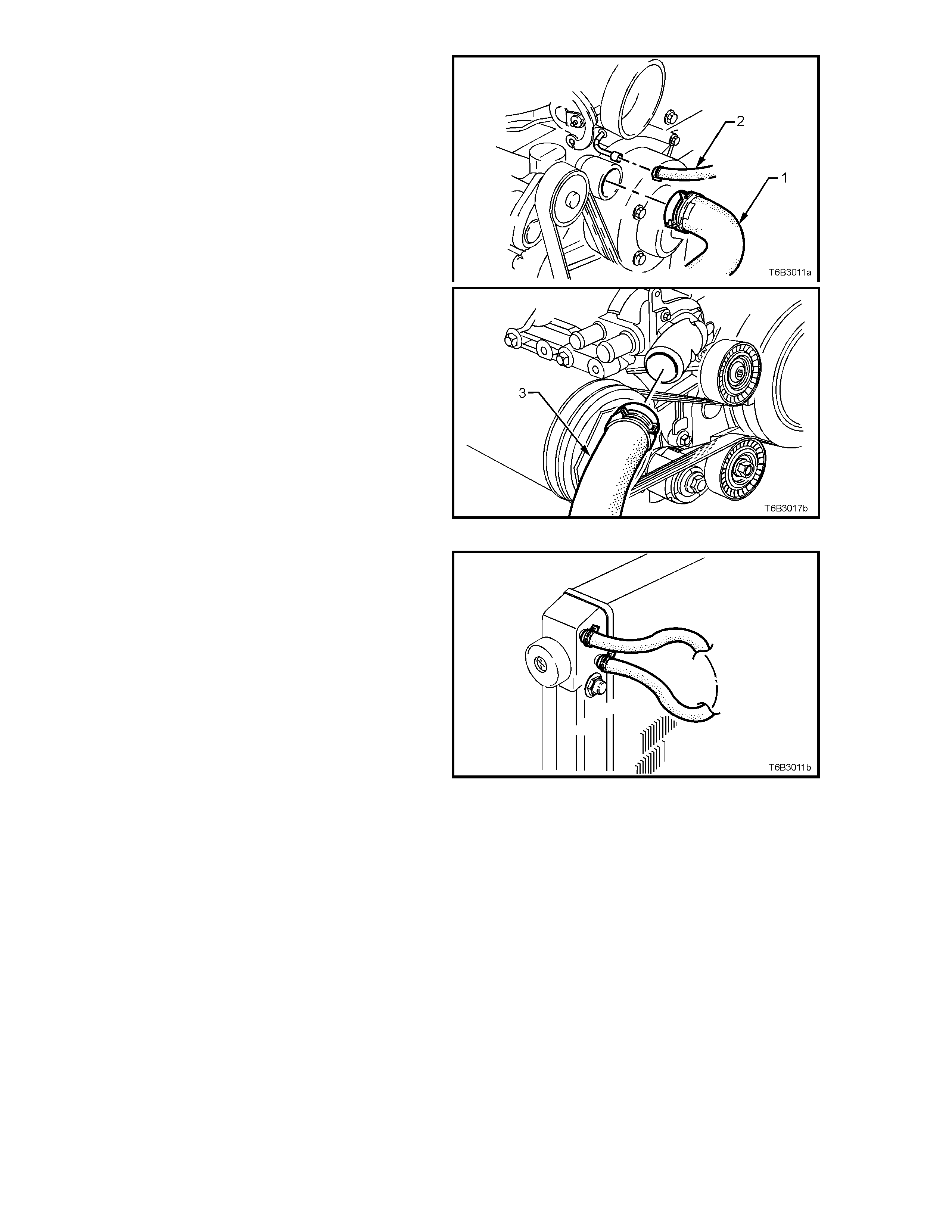
5. Remove the upper and lower radiator hoses (1
and 3) from the coolant pump connections.
CAUTION: ALWAYS WEAR PROTECTIVE
SAFETY GLASSES WHEN WORKING WITH
SPRING TY PE HOSE CLAMPS. FAILURE T O DO
SO COULD RESULT IN EYE INJURY.
Figure 6B3-22
6. Remove the vapour hose to coolant surge
tank connection at the radiator left hand tank.
7. Disconnect the vapour hose at the throttle
body (‘2’ in Figure 6B3-22 and reconnect to
the radiator tank.
8. Attach a lead-away hose at the radiator upper
hose outlet.
9. Attach a piece of hose between the flushing
gun and the radiator lower hose.
10. Connect and operate the flushing equipment
as recommended by the manufacturer.
NOTE: Apply air pressure gradually and not in
excess of 110 kPa. Otherwise radiator damage
will result.
11. Continue flushing until the water from the lead-
away hose runs clear.
12. Reinstall all disc onnected hoses, ensur ing that
spring hose clamps are positioned correctly
and/or tightened.
13. Fill the cooling system. Refer 2.3 DRAINING
AND FILLING COOLING SYSTEM, in this
Section.
14. Pressure test the cooling system to check for
leaks. Refer to 2.8 PRESSURE TESTING, in
this Section.
Figure 6B3-23
ENGINE:
1. With the coolant drained from the engine and
both radiator hoses disconnected, remove the
thermostat from the coolant pump housing.
Refer to 2.9 THERMOSTAT - Remove, in this
Section and dismantle from the thermostat
housing. Reinstall the thermostat housing
cover to the coolant pump.
2. Remove both heater hose connections from
the coolant pump, then seal both pump
openings, using a piece of sc rap hose and two
hose clamps.
3. Fit a lead-away hose to the thermostat
housing and a length of hose between the
coolant pump outlet fitting and the flushing
equipment.
4. Connect and operate the flushing equipment
as recommended by the manufacturer.
5. Continue flushing until the water fr om the lead-
away hose runs clear.
6. Reinstall all disc onnected hoses, ensur ing that
hose clamps are positioned correctly and/or
tightened.
CAUTION: ALWAYS WEAR PROTECTIVE
SAFETY GLASSES WHEN WORKING WITH
SPRING TY PE HOSE CLAMPS. FAILURE T O DO
SO COULD RESULT IN EYE INJURY.
Figure 6B3-24
7. Fill the cooling system . Refer 2.3 DRAINING AND
FILLING COOLING SYSTEM, in this Section.
8. Pressure test the cooling system to check for
leaks. Refer to 2.8 PRESSURE TESTING, in this
Section.
HEATER HOSES AND CORE:
1. It is as sum ed that the f ollowing have already been
carried out:
a. The engine is at ambient temperature.
b. The screw-on pressure cap has been
removed.
c. The coolant has been drained.
2. Set the heater control to maximum.
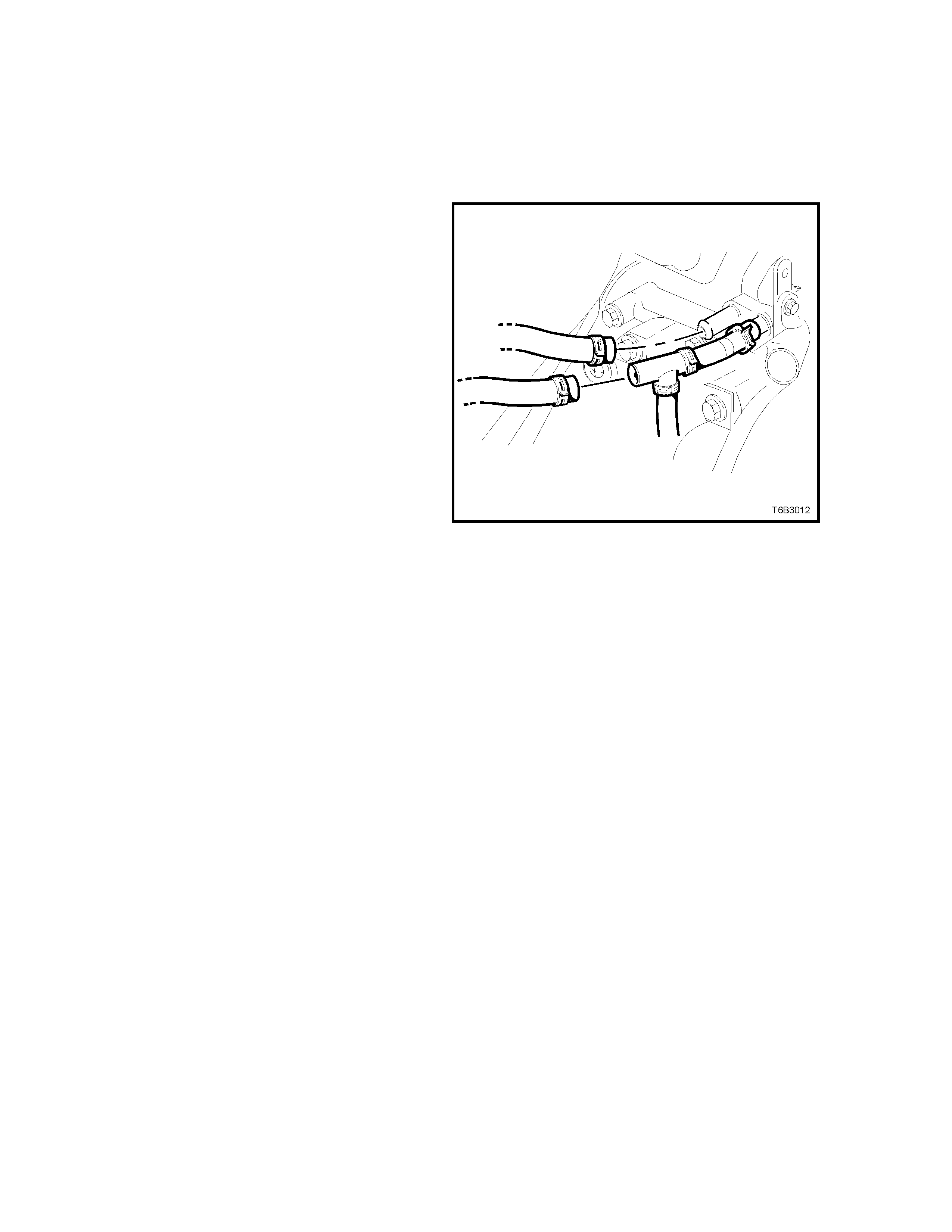
3. Disconnect the heater hose from the rear
coolant pump fitting and the other from the T-
piece, leaving the T-piece and coolant surge
tank hose still connected.
4. Direct the hose disconnected from the T-
piece, into a suitable container and the other
hose to the flushing gun.
5. Connect and operate the flushing equipment
as recommended by the manufacturer.
6. Continue flushing until the water fr om the lead-
away hose runs clear.
7. Reinstall all disc onnected hoses, ensur ing that
hose clamps are positioned correctly and/or
tightened.
CAUTION: ALWAYS WEAR PROTECTIVE
SAFETY GLASSES WHEN WORKING WITH
SPRING TY PE HOSE CLAMPS. FAILURE T O DO
SO COULD RESULT IN EYE INJURY.
8. Fill the cooling system. Refer 2.3 DRAINING
AND FILLING COOLING SYSTEM, in this
Section.
9. Pressure test the cooling system to check for
leaks. Refer to 2.8 PRESSURE TESTING, in
this Section.
Figure 6B3-25

COOLANT SURGE TANK AND HOSE:
1. It is as sum ed that the f ollowing have already been
carried out:
a. The engine is at ambient temperature.
b. The screw-on pressure cap has been
removed.
c. The coolant has been drained.
2. Remove the coolant surge tank hose from the T-
piece at the coolant pump and direct the open end
into a suitable container.
3. Connect the flushing equipment to the threaded
surge tank opening, then operate the equipment
as recommended by the manufacturer.
4. Continue flushing until the water from the lead-
away hose runs clear.
5. Reinstall all disconnected hoses, ensuring that
spring hose clamps are positioned correctly
and/or tightened.
CAUTION: ALWAYS WEAR PROTECTIVE SAFETY
GLASSES WHEN WORKING WITH SPRING TYPE
HOSE CLAMPS. FAILURE TO DO SO COULD
RESULT IN EYE INJURY.
6. Fill the cooling system . Refer 2.3 DRAINING AND
FILLING COOLING SYSTEM, in this Section.
7. Pressure test cooling system, refer to
2.8 PRESSURE TESTING in this Section and
check for external coolant leaks.
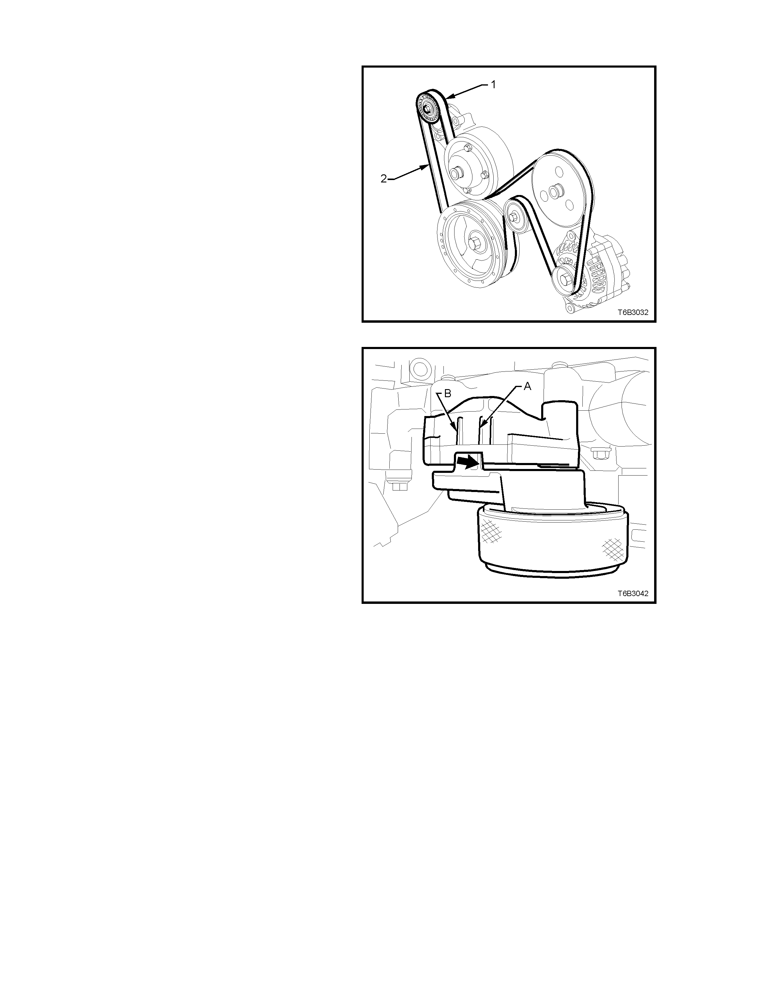
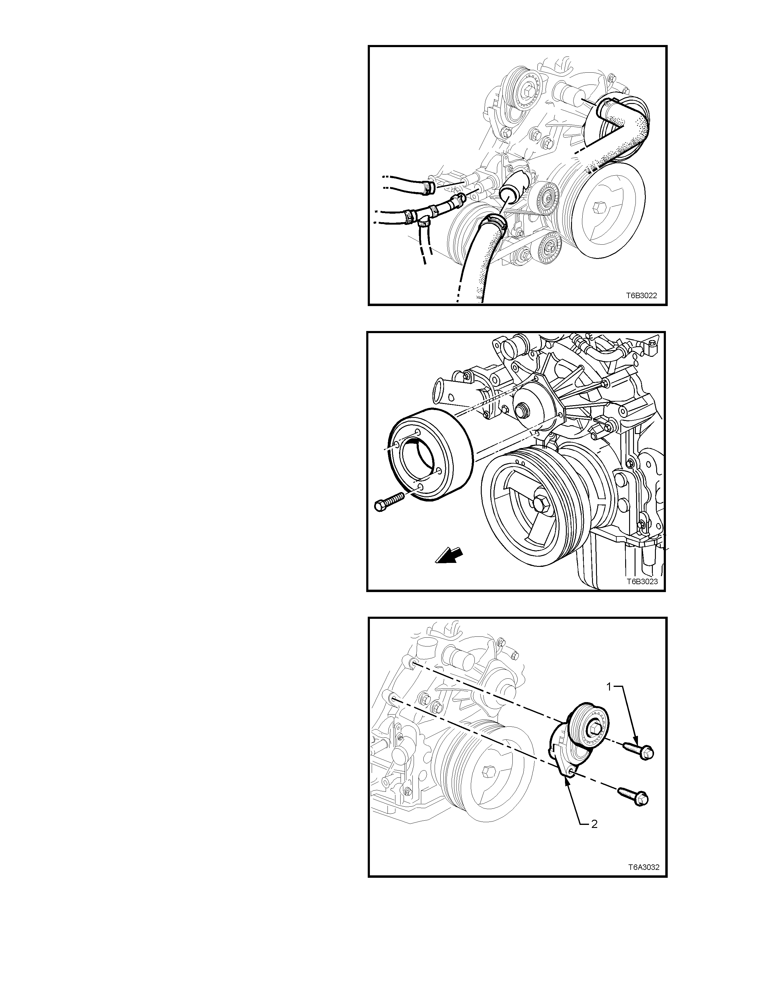
2.6 ENGINE ACCESSORY DRIVE BELT TENSION
Drive belt tension is provided by a tensioner
assembly (1). The tensioner is an idler pulley
mounted on a s pring-loaded arm that maintains the
drive belt (2) at the correct tension, without
imposing undue loads on the various components.
Figure 6B3-26
Drive belt tens ion is within the precribed lim its if the
indicator (ar row) on the tensioner is between points
‘A’ and ‘B’ on the tensioner bracket .
If replacement is indicated, refer to 2.7 ENGINE
ACCESSORY DRIVE BELT, in this Section.
Figure 6B3-27
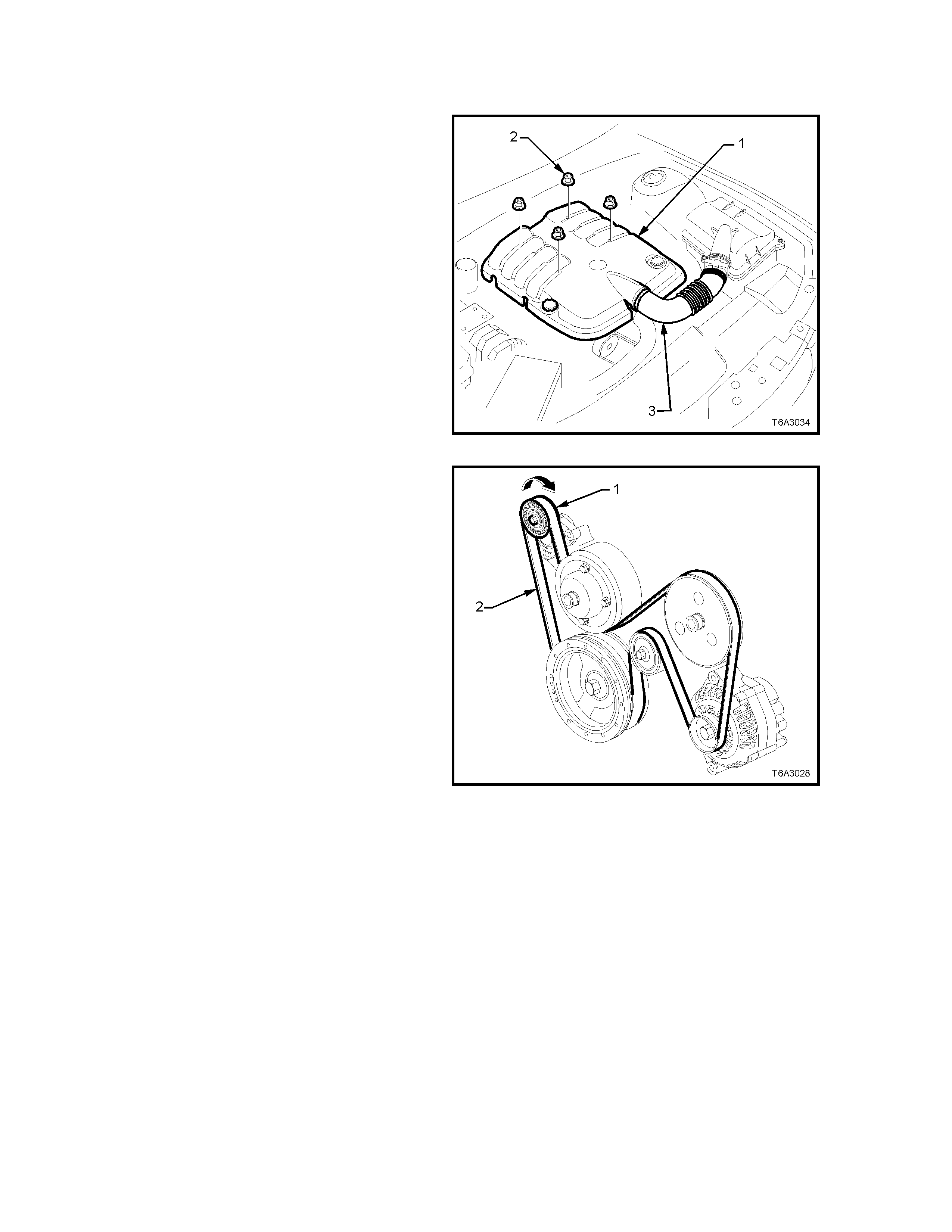
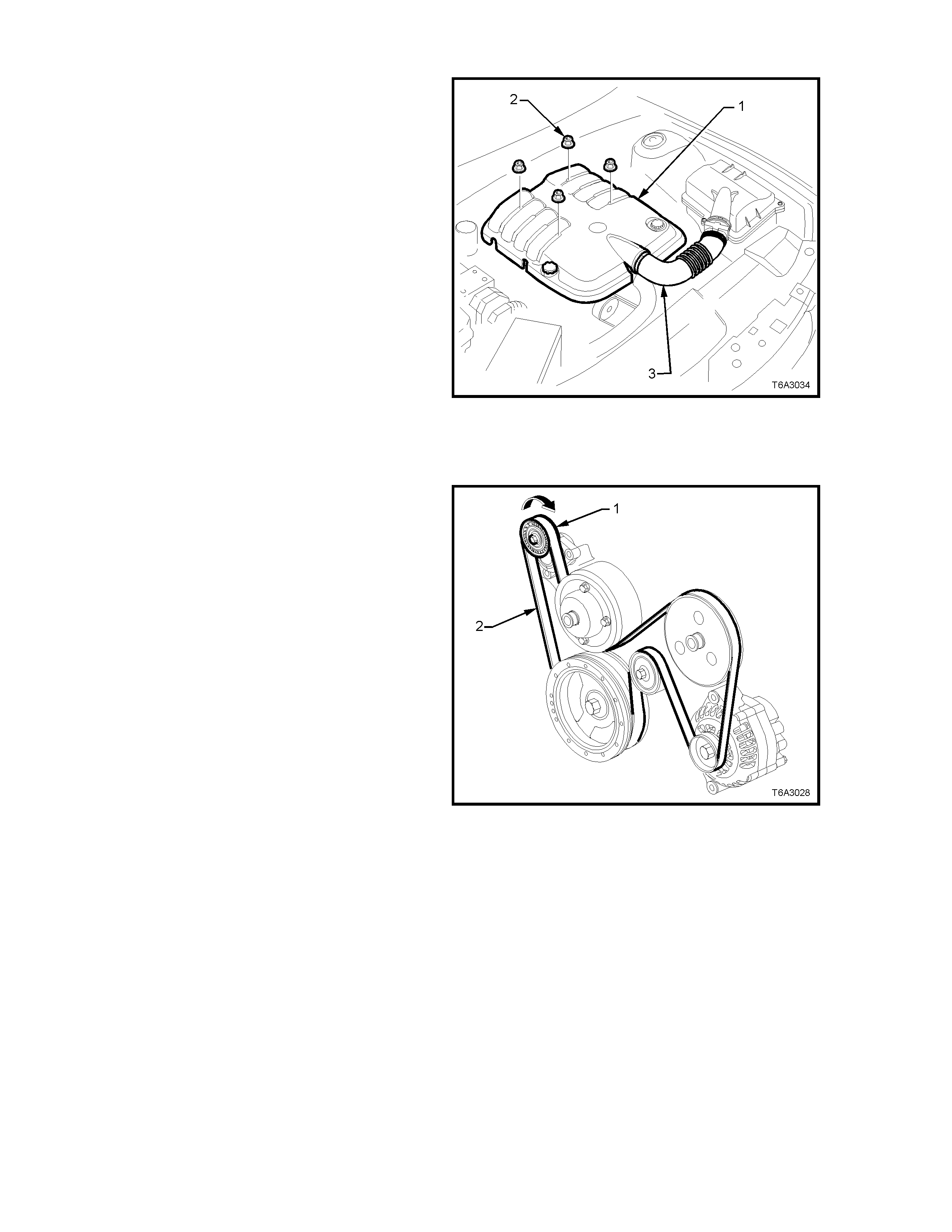
2.7 ENGINE ACCESSORY DRIVE BELT
REMOVE
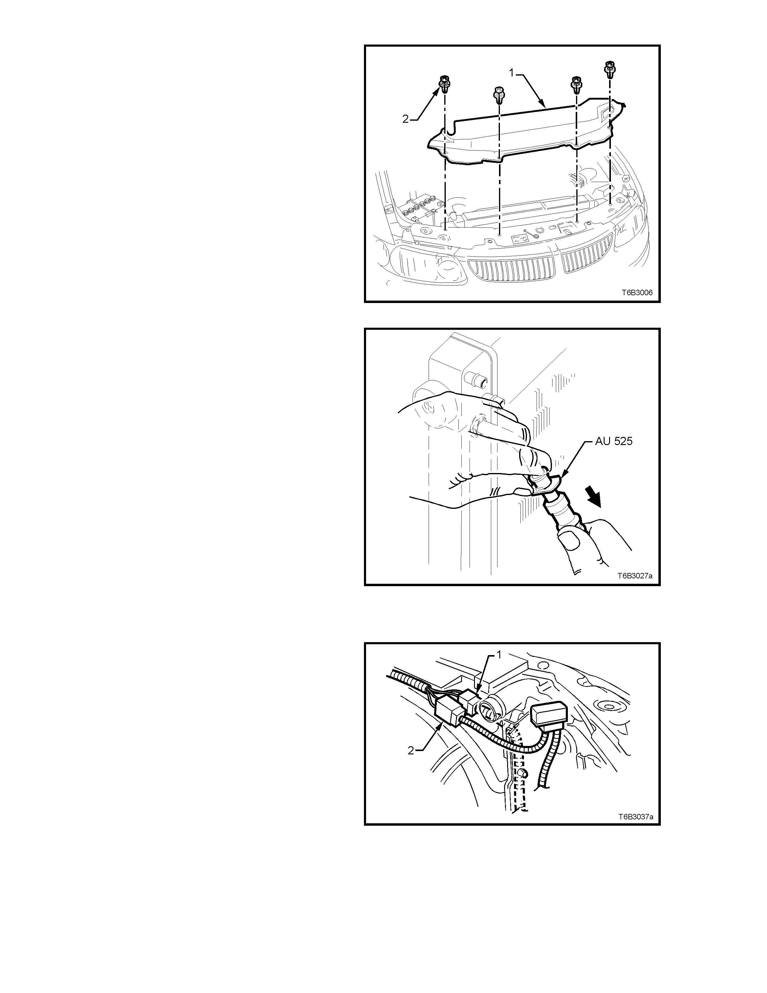
1. Remove the engine dress cover (1) after
removing the four decorative retaining nuts
(2).
Figure 6B3-28
2. Us ing a 15 mm ring spanner , rotate the engine
accessory drive belt tensioner (1) in the
direction indicated, to reduce belt tension.
3. While holding the tensioner in the reduced
tension position, remove the accessory drive
belt from the engine, taking note of the belt
routing.
Figure 6B3-29
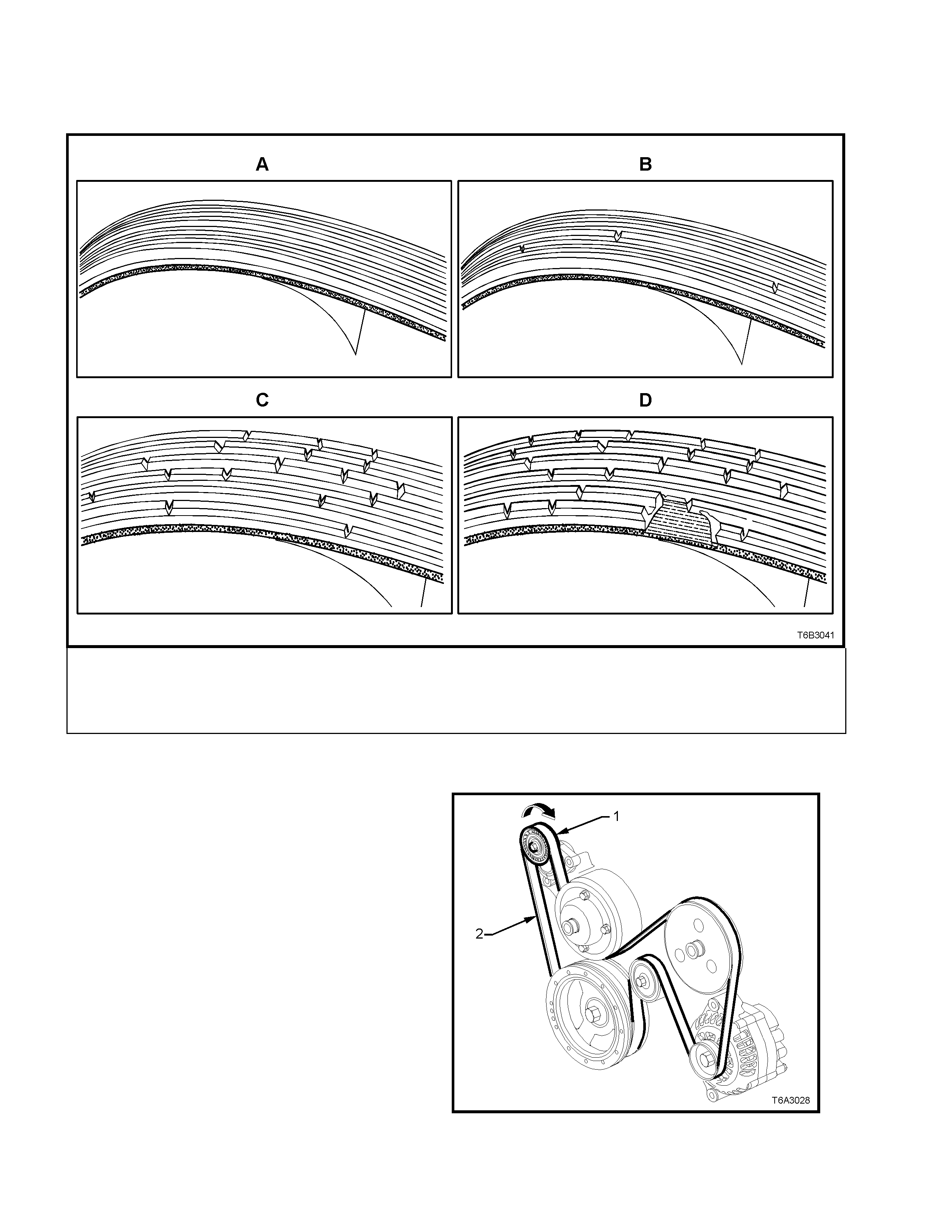
INSPECT
The four views in Figure 6B3-30 show the various stages of drive belt wear, to assist in belt replacement decisions.
NOTE: Condition of the belt ribs can be better assessed if the belt is wrapped over the coolant pump drive pulley.
Legend:
A New Belt: No cracks or chunks.
B Moderately Used Belt: Few cracks, with some wear on the ribs and in the grooves. Belt replacement not required.
C Severely Used Belt: Several cracks per 30 mm. Should be replaced before chunking occurs
D Failed Belt: Separation of rib material from backing (chunking). Belt must be replaced immediately.
Figure 6B3-30
REINSTALL
1. While having an assistant hold the tensioner in
the unloaded position (arr ow) with a 15 m m ring
spanner, install the engine accessory drive belt,
routing in the same manner as noted on
removal and as shown in Figure 6B3-31.
Figure 6B3-31
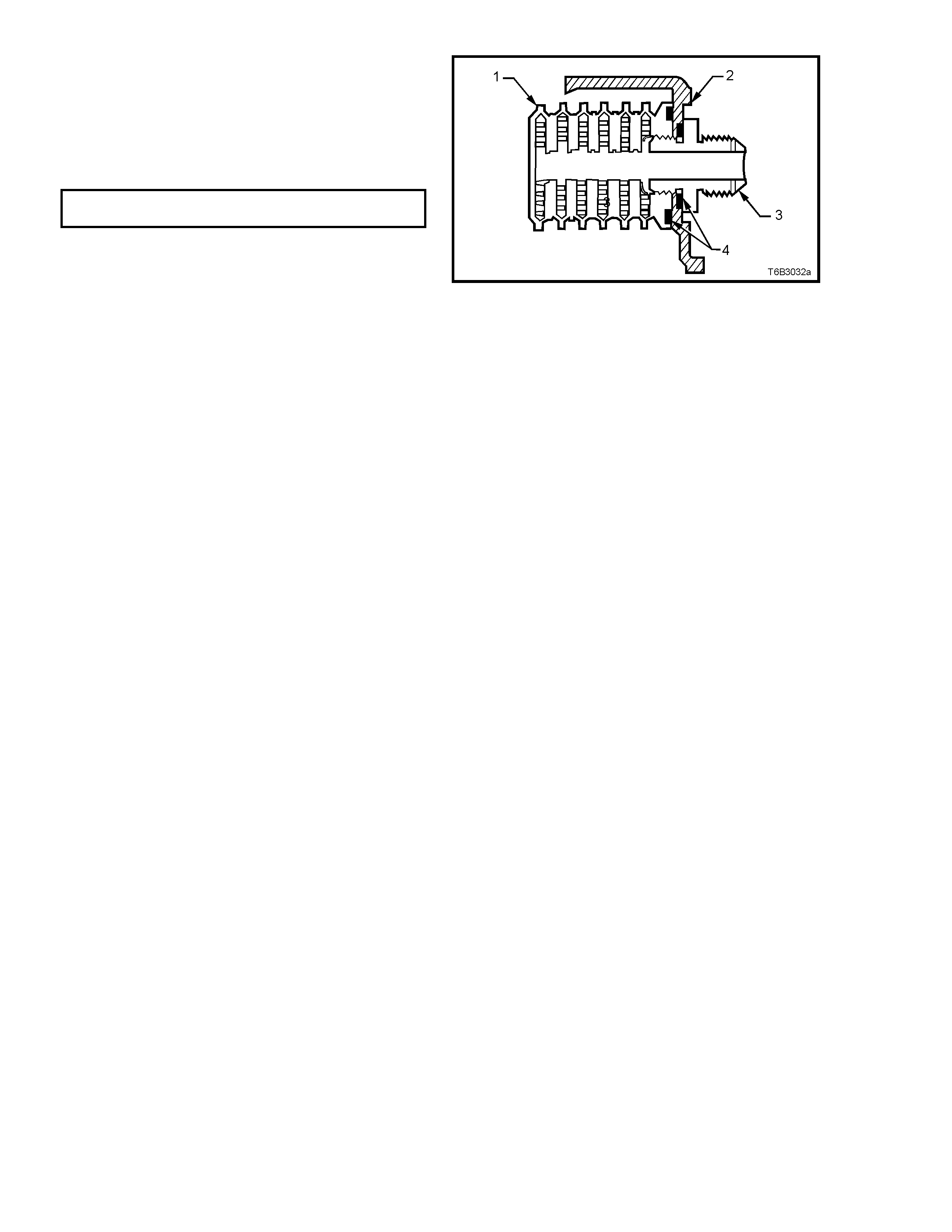
2.8 PRESSURE TESTING
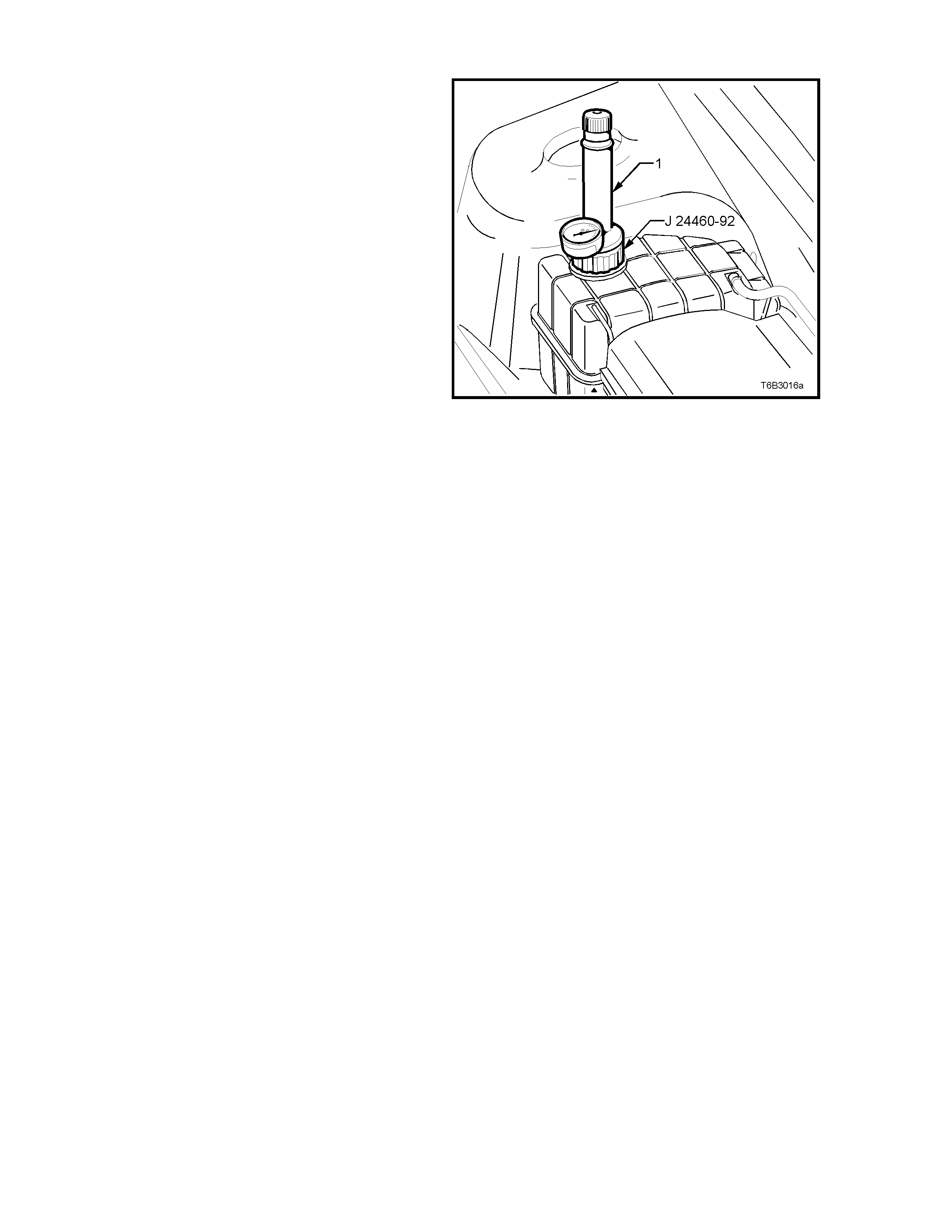
SCREW-ON PRESSURE CAP TESTING
1. Allow engine to cool to ambient temperature
(less than 50°C), then remove radiator cap.
CAUTION: DO NOT REMOVE SCREW-ON
PRESSURE CAP WHILE THE ENGINE
COOLANT TEMPERATURE IS ABOVE 50°
°°
°C, AS
PERSONAL INJURY WILL MOST LIKELY
OCCUR.
2. Thoroughly clean the threads and internal cap
parts, using clean cloth and water.
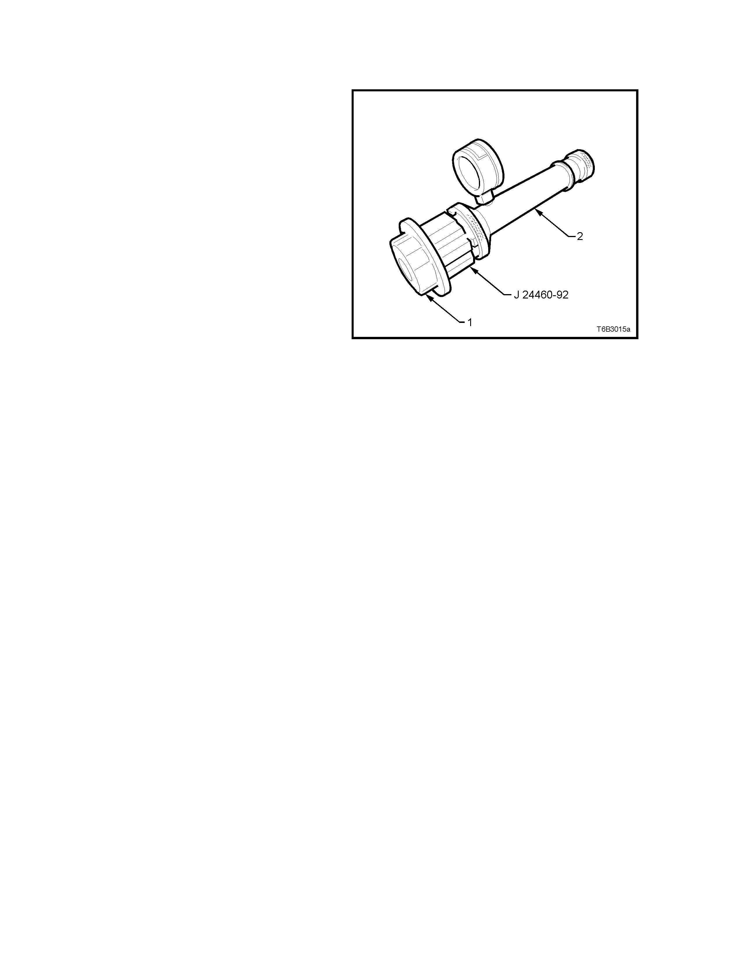
3. Install the the Screw-on Cap Test Adapter J
24460-92 onto a commercially available cooling
system pressure tester (2).
4. Install the pressure cap (1) onto the male
threaded half of the Test Adapter J 24460-92,
then slowly pressurise the cap using the
pressure tester hand pump, noting the point at
which the cap unloads.
The cap is serviceable if it unloads slightly
above the pressur e range of 100 kPa and holds
pressure. Should the cap fail to reach or hold
the specified pressure, install a new pressure
cap.
5. Prior to installing screw-on pressure cap, check
that the coolant surge tank filler neck threads
and cap seating surface are clean and
undamaged.
Figure 6B3-32
COOLING SYSTEM PRESSURE TESTING
1. Allow engine to cool to ambient temperature
(less than 50°C), then check that the coolant
level is correct.
CAUTION: DO NOT REM O VE SURGE TANK
CAP WHILE THE ENGINE COOLANT
TEMPERATURE IS ABOVE 50°
°°
°C, AS
PERSONAL INJURY MAY RESULT.
2. Carefully remove the screw-on pressure cap.
3. Connect the female half of Test Adapter J
24460-92 to a commercially available cooling
system pressure tester, then install the
assembly to the coolant surge tank filler neck.
Dry any residual coolant around radiator filler
neck with compressed air. Pressurise cooling
system to no more than 110 kPa and check
for leaks at the following points:
a. All hoses and hose connections.
b. Radiator seams and core.
c. Corroded or faulty engine core plugs.
d. Coolant pump and gaskets and O-ring
seals.
e. Vehicle heater system.
f. Check engine oil dipstick for evidence of
engine oil contamination with coolant.
4. If pressure will not hold, there is a leak in the
cooling system. Repair as required.
NOTE: If visible loss of coolant is not evident
from pressure testing, then the use of a dye
and black light, may be necessary. Refer to
3.4 BLACK LIGHT AND DYE LEAK DIAGNOSIS
METHOD, in this Section.
Figure 6B3-33
2.9 THERMOSTAT
REMOVE
1. Allow engine to cool to ambient temperature
(less than 50°C), then slowly remove the
screw-on pressure cap from the coolant surge
tank.
CAUTION: DO NOT REMOVE SURGE TANK
CAP WHILE THE ENGINE COOLANT
TEMPERATURE IS ABOVE 50°
°°
°C, AS PERSONAL
INJURY MAY RESULT.
2. Drain the engine coolant into a suitable
container. Refer to 2.3 DRAINING AND
FILLING COOLING SYSTEM, in this Section.
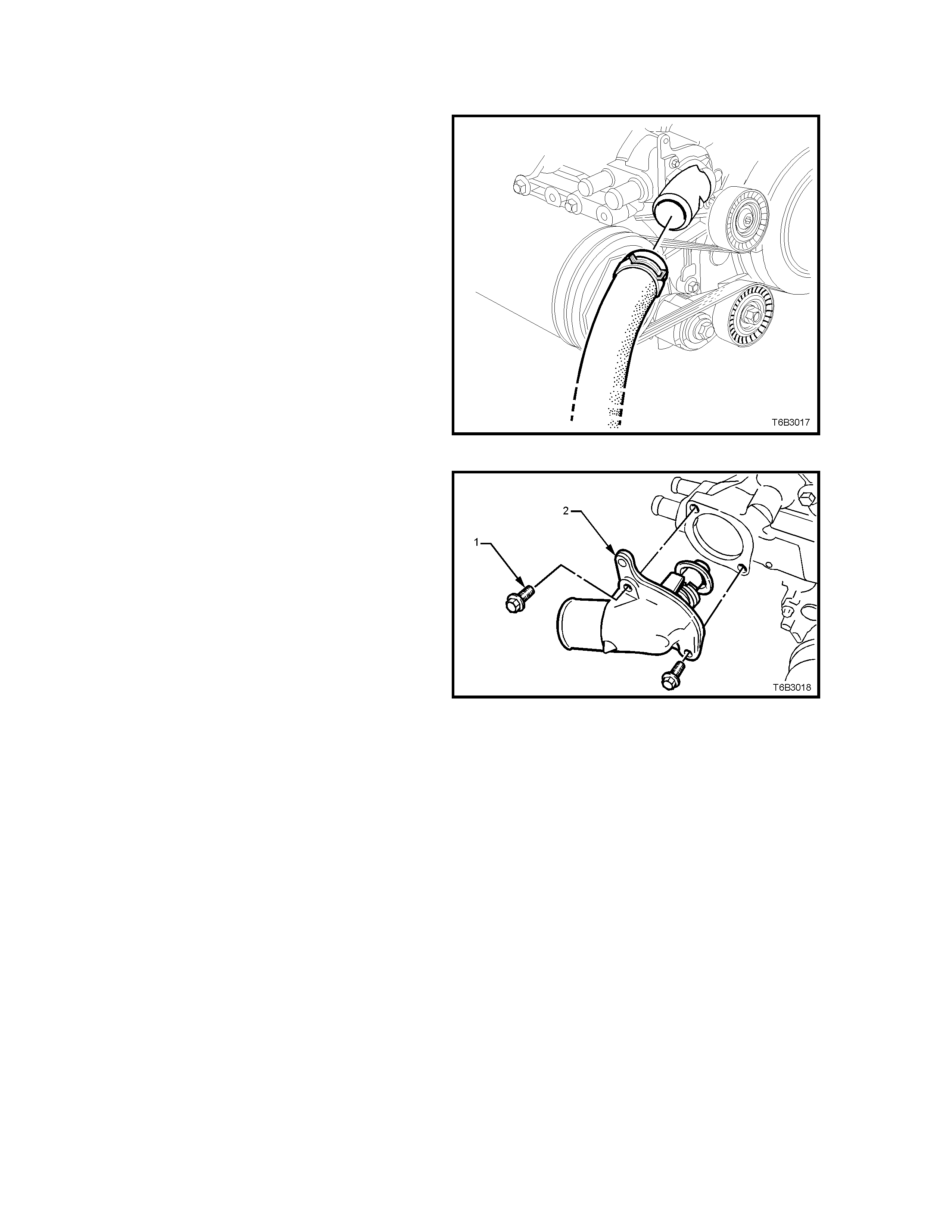
3. Disconnect radiator hose from coolant inlet at
the thermostat housing.
CAUTION: ALWAYS WEAR PROTECTIVE
SAFETY GLASSES WHEN WORKING WITH
SPRING TY PE HOSE CLAMPS. FAILURE T O DO
SO COULD RESULT IN EYE INJURY.
Figure 6B3-34
4. Remove thermostat housing bolts (1), then
remove the cover (2), thermostat and O-ring
seal from the coolant pump.
Figure 6B3-35
TEST
1. Suspend thermostat and a suitable thermometer
in a container of 50/50 DEX-COOL® and water.
NOTE: Neither the therm ostat nor ther mom eter should
rest on the bottom of the container bec ause of uneven
concentration of heat at this point when the container is
heated.
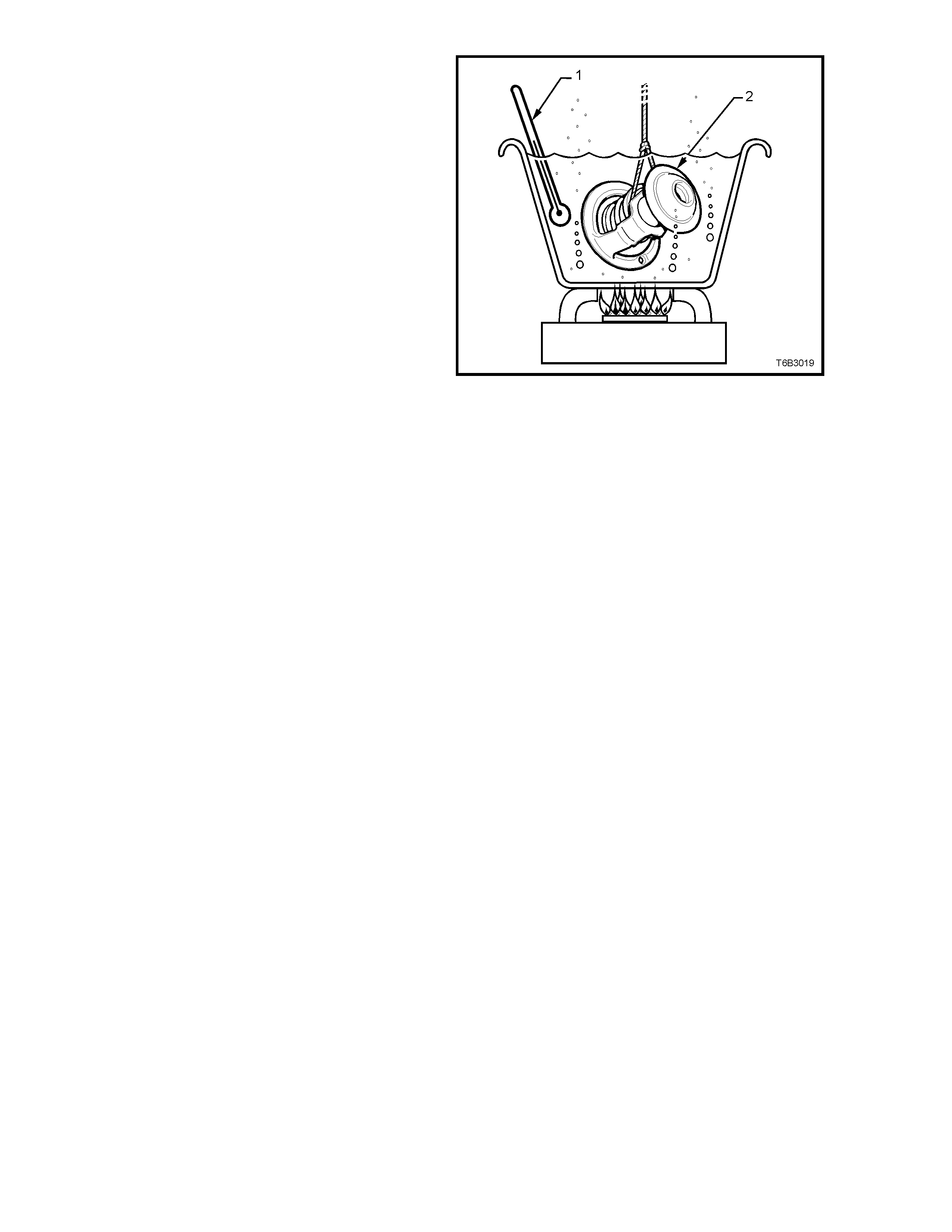
2. Heat c ontainer until therm os tat begins to open.
Agitate solution to ensure uniform temperature.
Note temperature and ensure thermostat
opens within specified temperature range.
3. Continue heating the solution until the
thermostat is fully open. Again agitate the
solution and take note of the temperature
4. Ins tall a new therm ostat if it does not meet the
specified temperatures.
Thermostat Specifications
Opening Temperature 86° C
Fully Open Temperature 100° C
Figure 6B3-36
DISMANTLE
Important: Only dismantle the thermostat if a
revese flushing operation of the cylinder block is to
be carried out. If testing shows that replacement is
required, the thermostat and housing are only
serviced as a complete assembly.
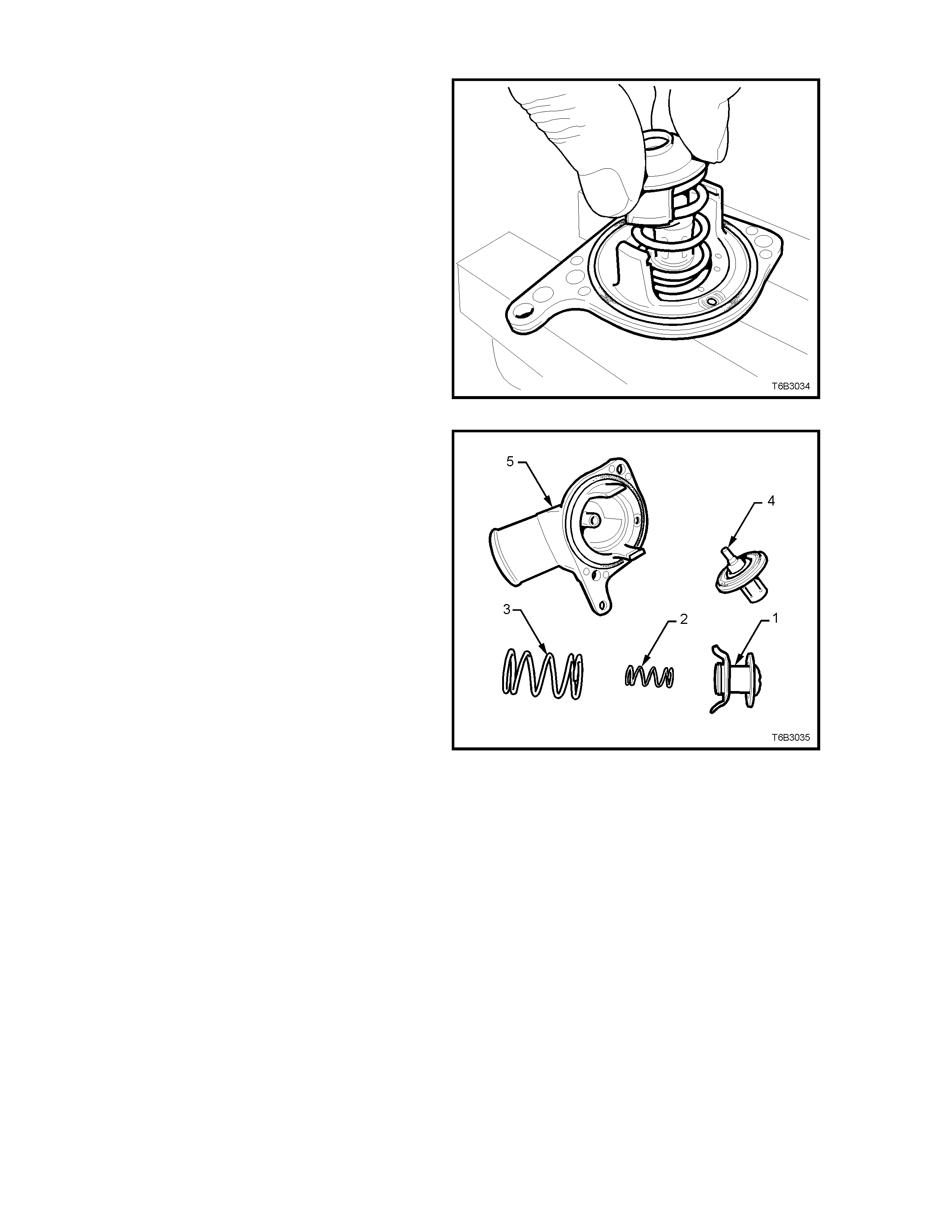
1. Sec ur e the thermos tat housing by gripping in a
vice fitted with soft jaws.
2. While compres sing the springs with one hand,
rotate the retaining bar from the housing lugs
and release.
CAUTION: Wear safety glasses to avoid
potential eye injury.
Figure 6B3-37
3. Carefull lay all parts out in order, for ease of
reassembly.
Legend:
1. Bypass Valve.
2. Bypass Valve Spring.
3. Thermostat Closing Spring.
4. Wax Pellet and Valve Assembly.
5. Thermostat Housing.
REASSEMBLE
Reassembly is the reverse of disassembly
procedures, except that the valve seat in the
thermostat housing m ust be checked for corrosion,
scratching or other damage and the valve seating
surface wiped with a clean rag.
Figure 6B3-38
REINSTALL
1. Shak e the therm ostat assem bly to ensure that
the air bleed check ball (1) in the housing is
free and not jammed.
2. Thoroughly clean the coolant pump to
thermostat housing sealing surfaces, taking
care not to scratch any machined alloy
surfaces.
3. Ins tall thermos tat assembly, with a new O-r ing
(2), fitted to the coolant pump housing (3).
4. Install thermostat housing to coolant pump
housing attaching bolts and tighten to the
correct torque specification.
THERMOSTAT HOUSING TO
COOLANT PUMP BOLT 13 - 15 Nm
TORQUE SPECIFICATION
5. Install radiator hose and clamp to thermostat
housing.
CAUTION: ALWAYS WEAR PROTECTIVE
SAFETY GLASSES WHEN WORKING WITH
SPRING TY PE HOSE CLAMPS. FAILURE T O DO
SO COULD RESULT IN EYE INJURY.
6. Refill cooling system, refer to 2.3 DRAINING
AND FILLING COOLING SYSTEM in this
Section.
7. Check for cooling system leaks, refer to
2.8 PRESSURE TESTING in this Section.
Figure 6B3-39
2.10 COOLANT RECOVERY SURGE TANK
REMOVE
1. Allow engine to cool to ambient temperature
(less than 50° C), then slowly remove the
screw-on pressure cap from the coolant surge
tank.
CAUTION: DO NOT REMOVE SURGE TANK
CAP WHILE THE ENGINE COOLANT
TEMPERATURE IS ABOVE 50°
°°
° C, AS
PERSONAL INJURY MAY RESULT.
2. Drain the engine coolant into a suitable
container. Refer to 2.3 DRAINING AND
FILLING THE COOLING SYSTEM, in this
Section.
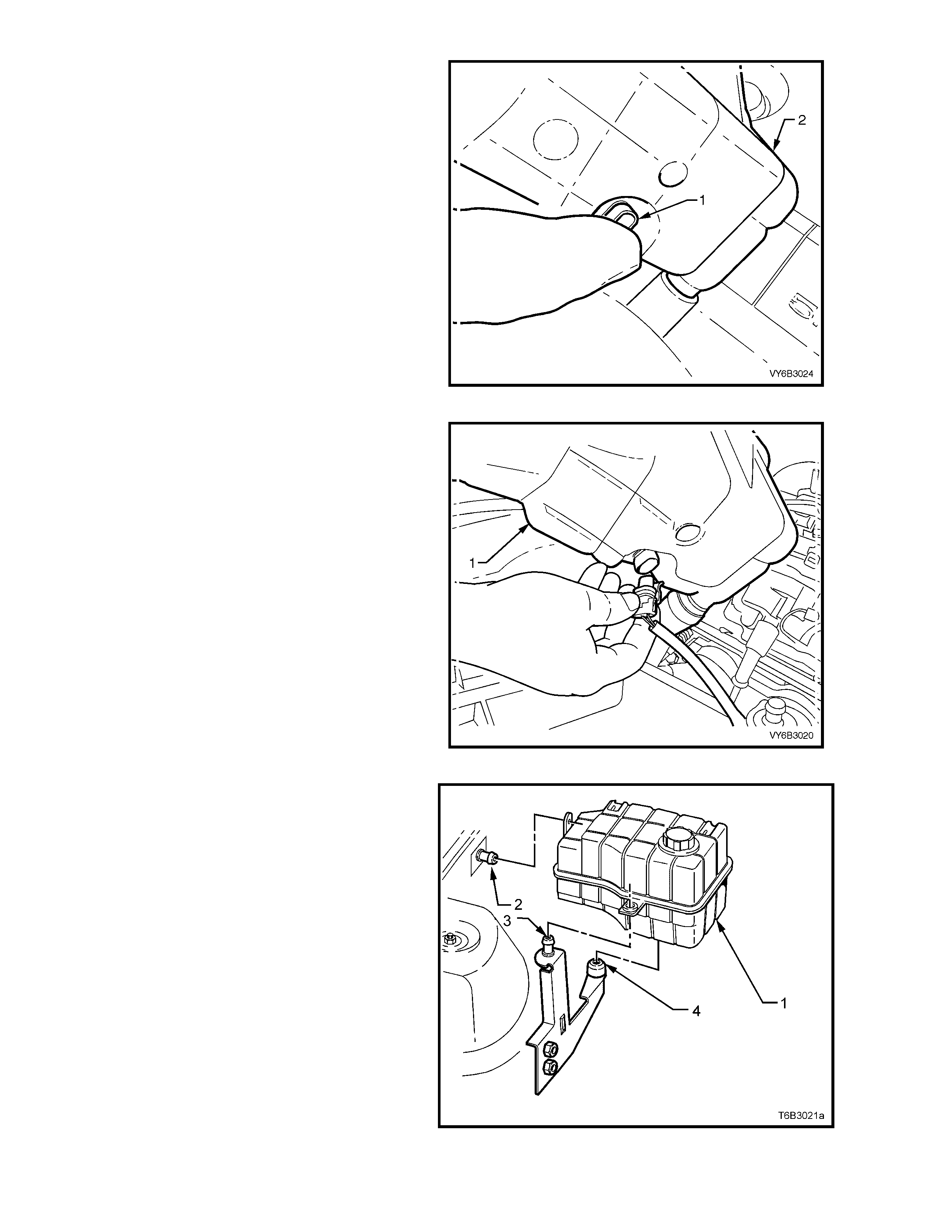
3. Dis connect radiator hose f rom s urge tank inlet
fitting (1), vapour hose (2) and overflow
hose (3).
CAUTION: ALWAYS WEAR PROTECTIVE
SAFETY GLASSES WHEN WORKING WITH
SPRING TY PE HOSE CLAMPS. FAILURE T O DO
SO COULD RESULT IN EYE INJURY.
Figure 6B3-40
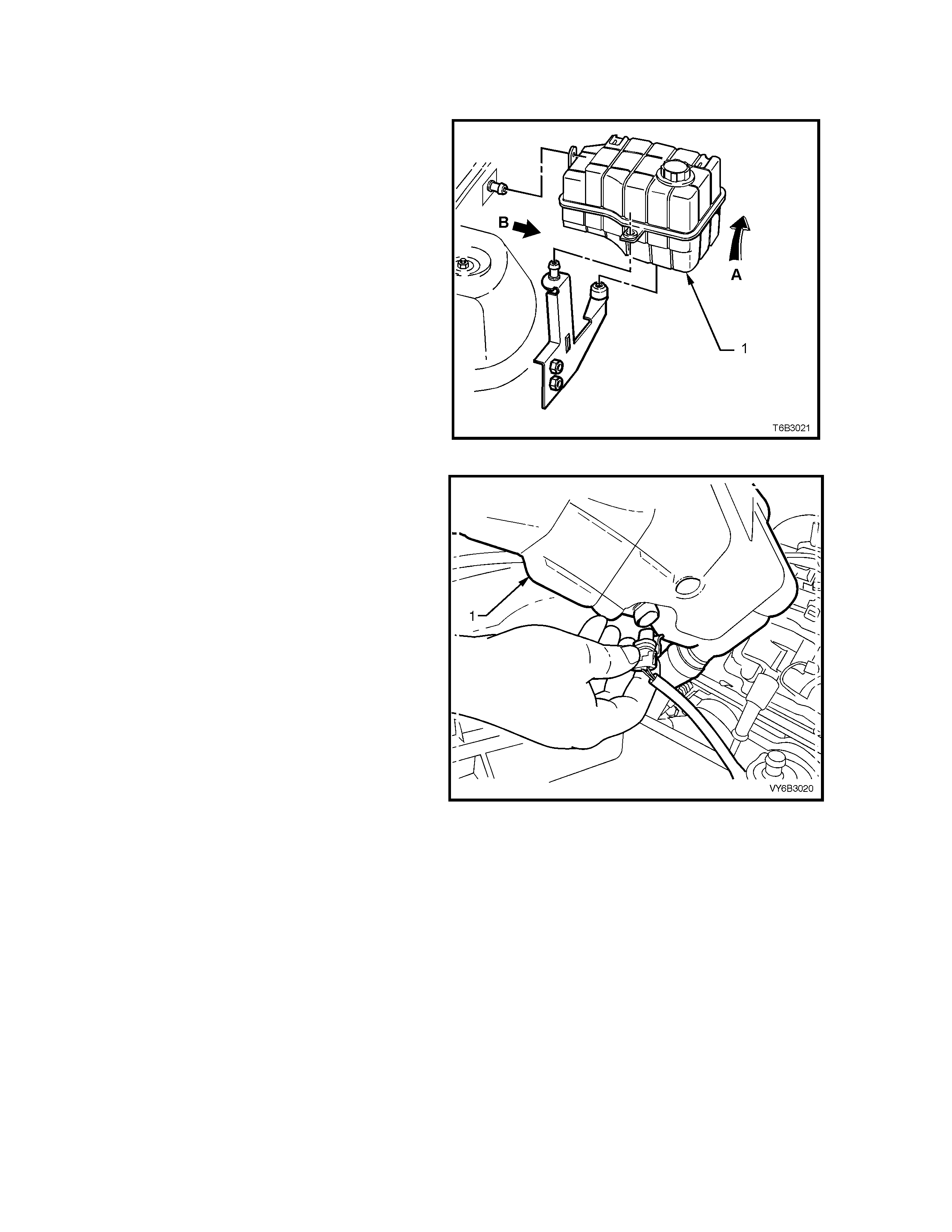
4. Grasp the surge tank (1) firmly with both
hands, pivot as shown (arrow ‘A’) to dislodge
the surge tank (1) from the rear anchor point,
then pull inboard (arr ow ‘B’) toward the engine
to remove from the anchor point attached to
the inner fender skirt.
Figure 6B3-41
INSPECT
1. Drain contents from surge tank assembly.
2. Clean surge tank assembly with water and dry,
using compressed air.
CAUTION: Wear safety glasses to avoid eye injury.
3. Check surge tank and assembly for damage, e.g.
abrasions, c r acks or dis tor tion. Install a new sur ge
tank assembly as required.
REINSTALL
Reinstallation of the surge tank assembly is the
reverse of removal procedures, noting the following
points:
1. Refill c ooling system , ref er to 2.3 DRAINING AND
FILLING COOLING SYSTEM in this Section.
2. Check for cooling system leaks, refer to
2.8 PRESSURE TESTING in this Section.
2.11 ENGINE COOLANT LEVEL SWITCH
REMOVE
1. With the coolant hoses still connected, grasp
the recovery surge tank (1) firmly with both
hands.
2. Pivot as shown (arrow ‘A’) to dislodge the
recovery surge tank (1) from the rear anchor
point, then pull inboard (arrow ‘B’) toward the
engine to remove from the anchor point
attached to the inner fender skirt.
Figure 6B3-42
5. Position the recovery surge tank (1) to gain
access to the engine coolant level switch.
6. Disconnect the coolant level switch harness
connector.
Figure 6B3-43
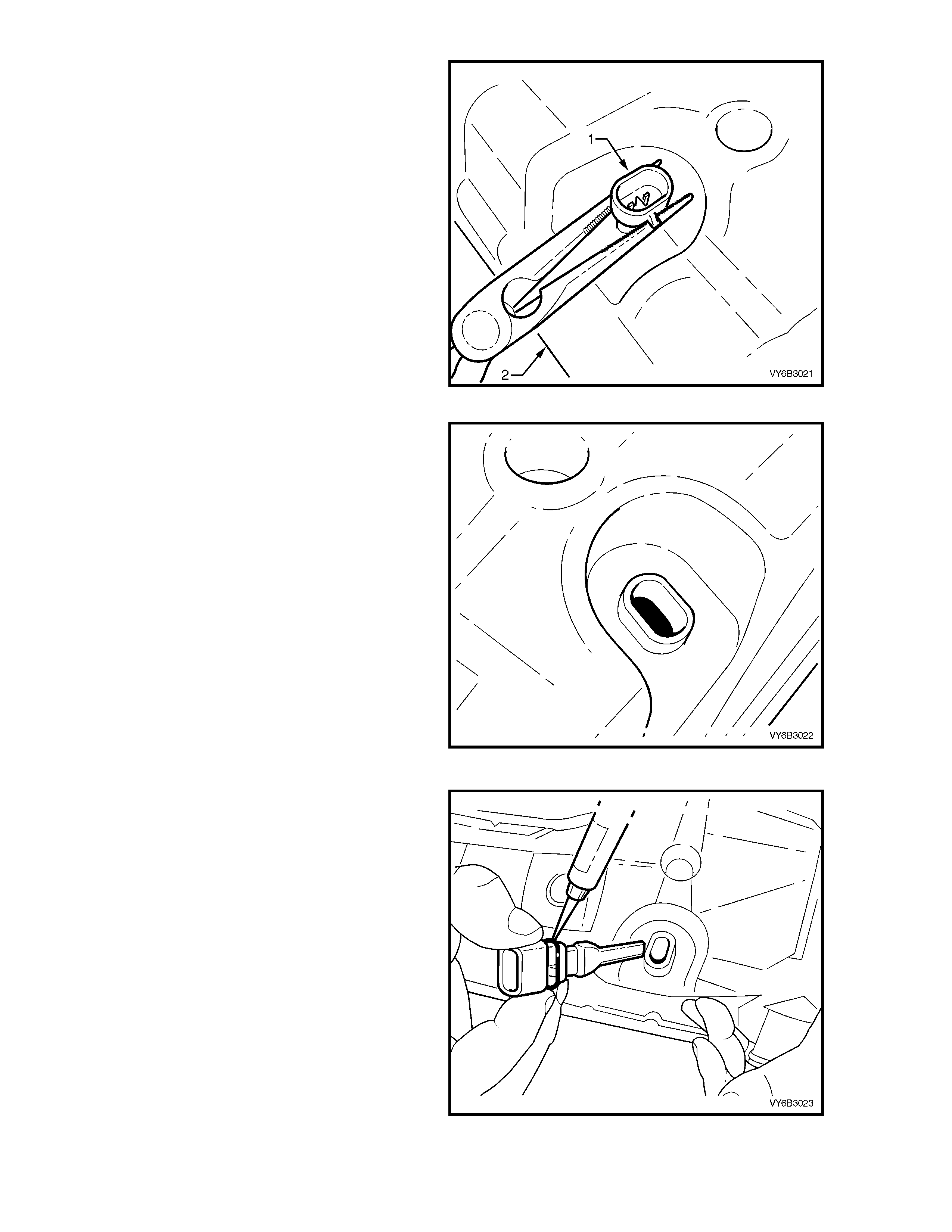
7. Using commercially available long nose pliers,
place the opened nose of pliers each side of
the coolant switch (1) between the recovery
surge tank (2) and the coolant level switch as
shown.
8. Using the r ecovery surge tank (2) as a place of
purchase, dislodge the coolant switch (1) from
the recovery surge tank by wiggling the switch
gently side to side while moving in an upward
direction away from the tank. The switch is a
very tight fit and will require a little force to
dislodge it from the recovery surge tank.
Figure 6B3-44
INSPECT
1. Clean the coolant level switch and tank
aperture area if required using compressed air.
CAUTION: Wear safety glasses to avoid eye
injury.
2. Check the free movement of the coolant level
float located in the recovery surge tank.
3. Check the recovery surge tank assembly for
damage, e.g. abrasions, cracks or distortion.
Install a new surge tank assembly as required,
refer to Section 2.10 COOLANT RECOVERY
SURGE TANK.
4. Chec k the operation of the coolant level s witch.
For coolant level switch diagnostics refer to
Section 6C3-2C FUNCTION CHECKS - GEN
III V8 - ENGINE COOLANT LEVEL SWITCH
DIAGNOSIS.
Figure 6B3-45
REINSTALL
1. Apply a sm all amount of lubricant to the seal of
the coolant level switch prior to installation.
Figure 6B3-46
2. Using suitable hand protection, install the
coolant level switch (1) by pushing it firmly into
the recovery surge tank (2) aperture.
3. Check the coolant level switch is completely
home in the surge tank aperture by trying to
remove it by hand only.
Figure 6B3-47
4. Connect the coolant level switch harness
connector to the recovery surge tank and
cool ant level switch assembly (1).
Figure 6B3-48
5. Re-install the recovery surge tank and coolant
level switch assembly (1) by pushing the tank
on to the anchor point attached to the inner
fender skirt (2), then push the tank on to the
rear anchor point (3) and bottom anchor point
(4).
6. Check the tank securely mounted to both
anchor points.
Figure 6B3-49
2.12 OIL P AN UNDER-TRAY
REMOVE
1. Raise front of vehicle and place on safety
stands. Refer to Section 0A GENERAL
INFORMATION of the VT Series I Service
Information for location of jacking points.
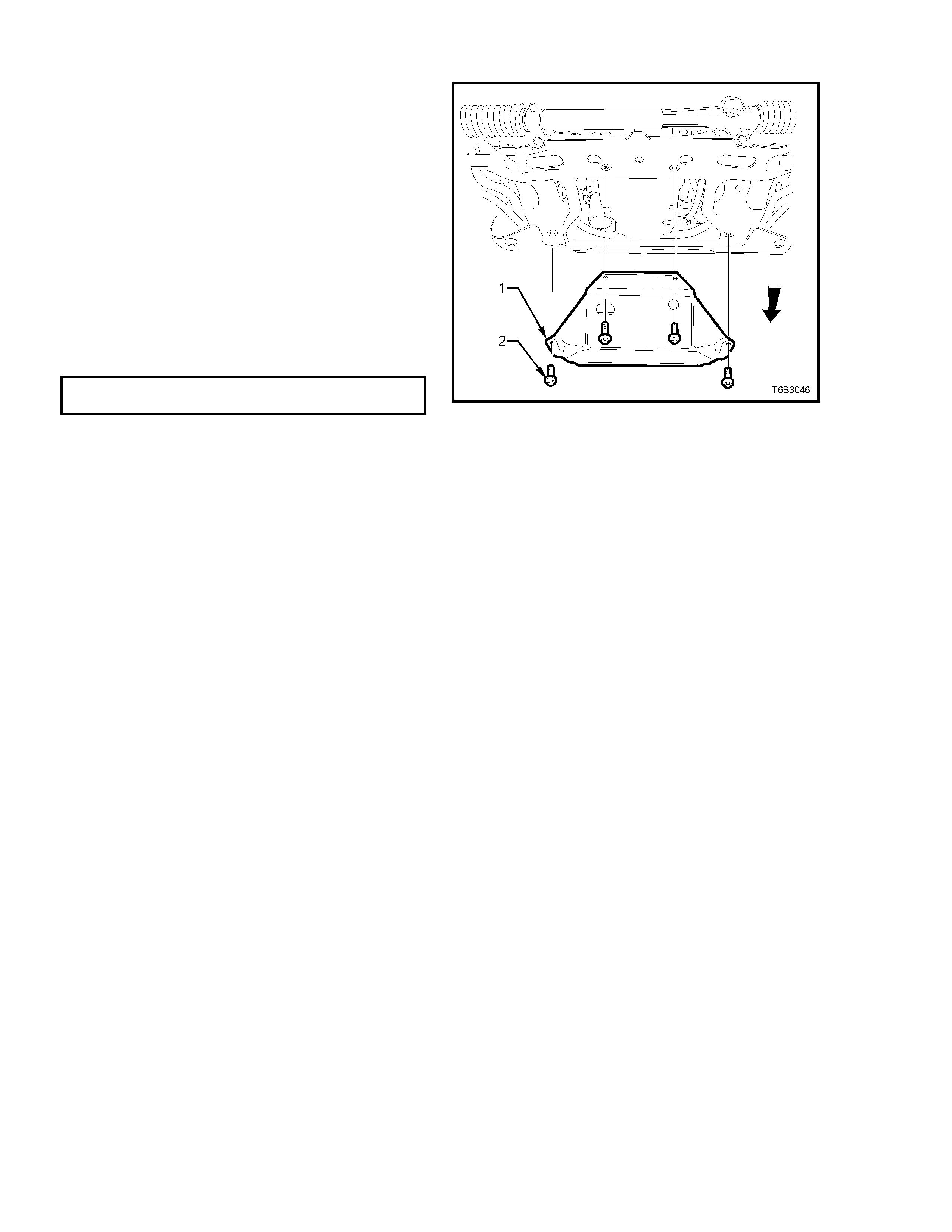
2. Rem ove the four bolts securing the under-tray
to the crossmember and remove tray from
vehicle.
REINSTALL
1. While holding the under-tray (1) up to the
crossmember with one hand, install all four
securing bolts (2).
2. Tighten all four bolts (2) to the correct torque
specification.
OIL PAN UNDER-TRAY BOLT
TORQUE SPECIFICATION 30 - 35 Nm
Figure 6B3-50
2.13 AIR BAFFLES
REMOVE
1. Raise front of vehicle and place on safety
stands. Refer to Section 0A GENERAL
INFORMATION of the VT Series I Service
Information for location of jacking points.
2. Remove the oil pan under-tray. Refer
2.12 OIL PAN UNDER-TRAY, in this Section.
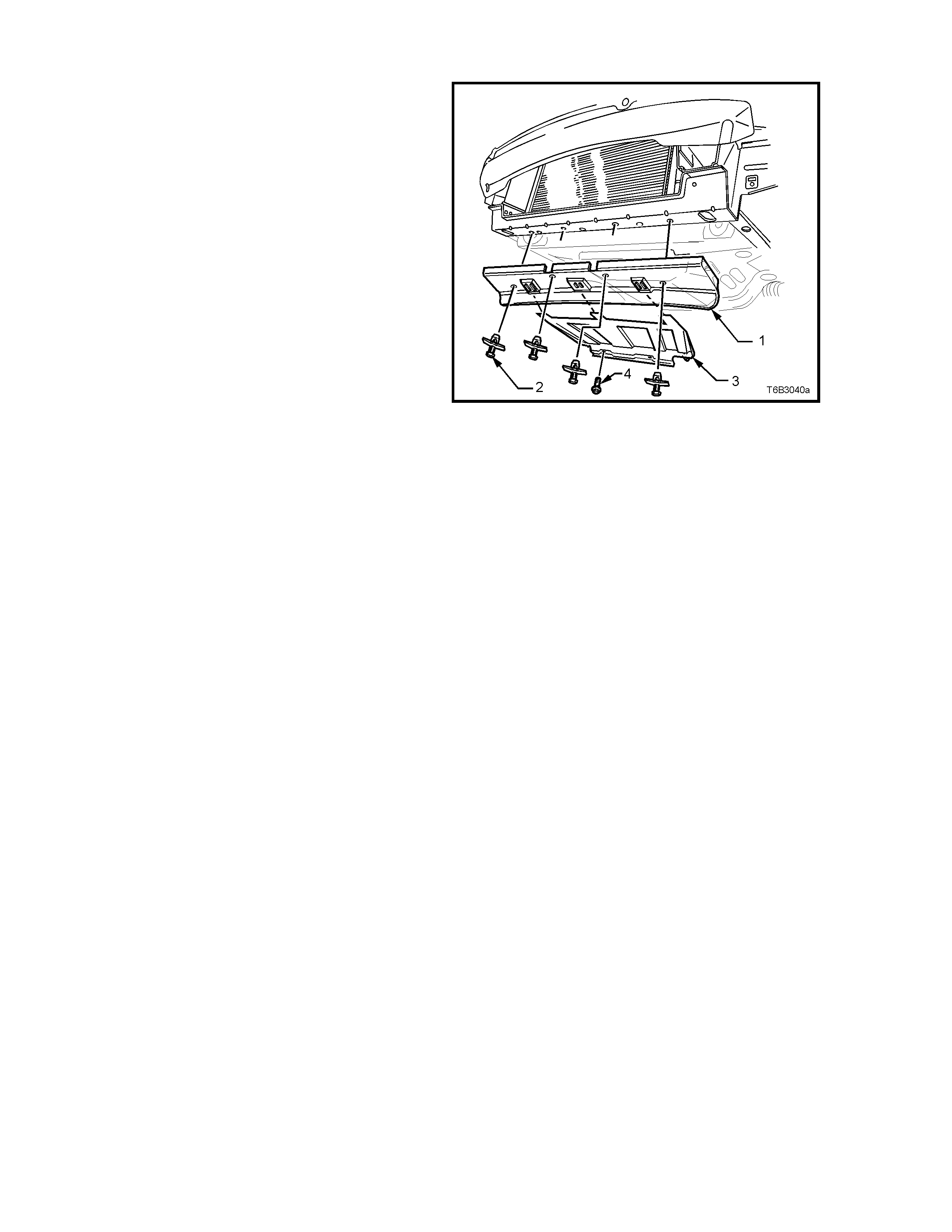
3. Rem ove the lower rear air chute baffle sc rews
(two places), lower the rear of the rear air
chute baffle (3), slide the baffle rearward to
disengage from the front baffle, then remove
from the vehicle.
4. Rem ove lower front baf fle (1) to cros smem ber
fasteners (2) (four places) and remove front
air chute baffle (1) from the vehicle.
REINSTALL
1. Reinstallation is the reverse to removal
procedures.
NOTE: Do not overtighten any of the fasteners.
Figure 6B3-51
2.14 COOLANT PUMP
REMOVE
NOTE: Apart from the rear cover, O-ring and
thermostat assembly, the coolant pump is not
serviceable and if found to be faulty must be
replaced as an assembly.
1. Allow engine to cool to ambient temperature
(less than 50°C), then s lowly remove sc rew-on
pressure cap from the coolant surge tank.
CAUTION: DO NOT REMOVE SCREW-ON
PRESSURE CAP WHILE THE ENGINE
COOLANT TEMPERATURE IS ABOVE 50°
°°
°C, AS
PERSONAL INJURY MAY RESULT.
2. Disconnect battery earth lead.
3. Remove engine dress cover decorative nuts
(2), then remove the cover (1).
4. Loosen the two intake hose clamps, then
remove the hose (3).
5. Loosen coolant pump drive pulley bolts.
Figure 6B3-52
6. Remo ve engine accessor y drive belt (2), using
a 15 mm ring spanner, refer to 2.7 ENGINE
ACCESSORY DRIVE BELT, in this Section.
Figure 6B3-53
7. Drain engine coolant. Refer to 2.3 DRAINING
AND FILLING COOLING SYSTEM, in this
Section.
8. Disconnect both heater hoses, the outlet and
inlet hoses from the coolant pump.
CAUTION: ALWAYS WEAR PROTECTIVE
SAFETY GLASSES WHEN WORKING WITH
SPRING TY PE HOSE CLAMPS. FAILURE T O DO
SO COULD RESULT IN EYE INJURY.
Figure 6B3-54
9. Remove the loosened four bolts securing the
coolant pump pulley to the hub. Remove
pulley .
Figure 6B3-55
10. Remove the two bolts (1) securing the drive
belt tensioner (2) to the coolant pump housing
and set the tensioner to one side.
Figure 6B3-56
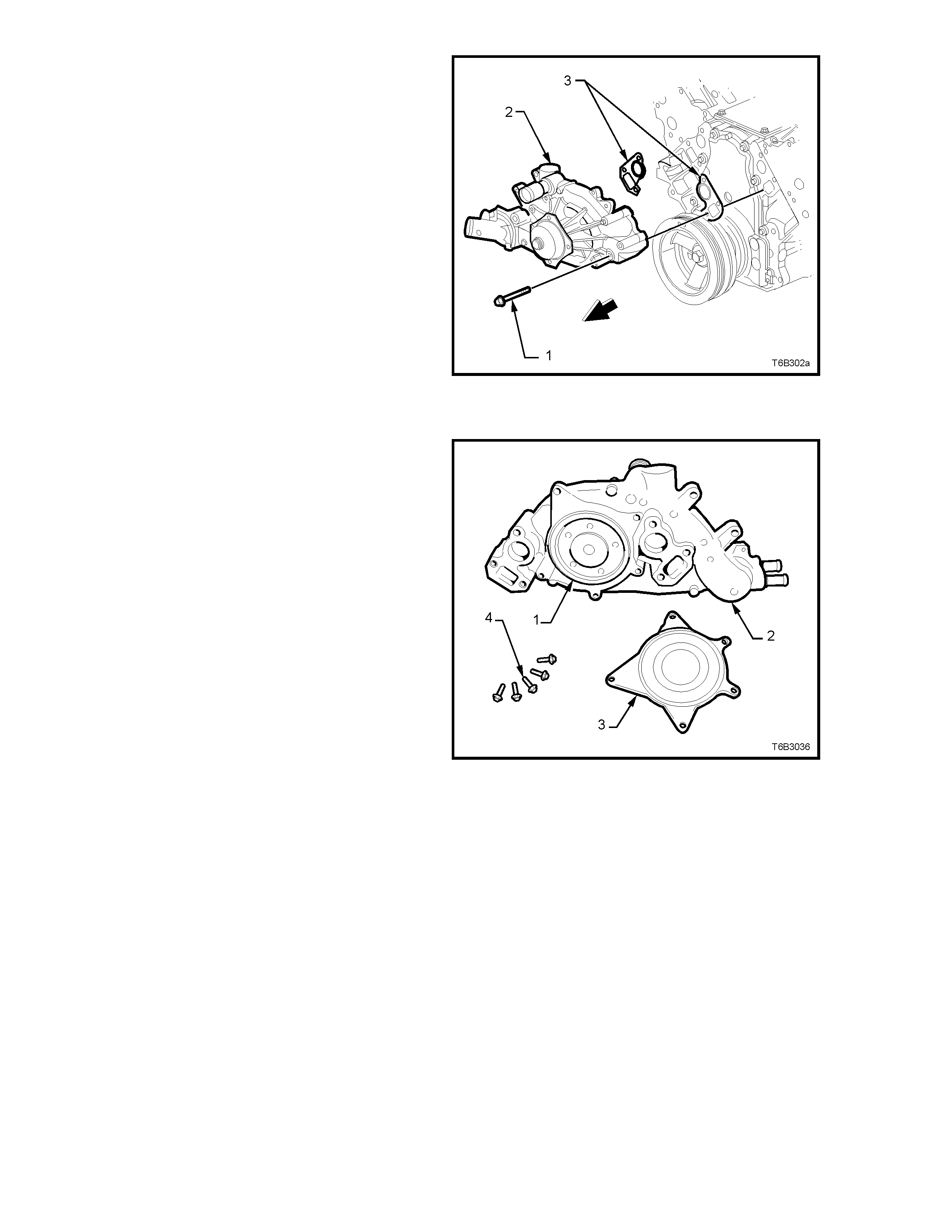
11. Loosen, then r em ove the six bolts ( 1) sec uring
the coolant pump (2) to the cylinder block.
12. If necessary, use a soft faced hammer to
lightly tap coolant pump housing (2) to
dislodge it from the cylinder block.
13. Remove coolant pump gaskets (3) and
discard.
Figure 6B3-57
DISMANTLE
NOTE: Apart from the ser vice operations des c ribed
here, there are no other serviceable parts in the
coolant pump assembly and if required, then the
assembly must be replaced as a complete unit.
1. If required, remove the five bolts (4) securing
the rear cover (3) to the coolant pum p (2). Tap
with a soft faced hammer to dislodge the cover
from the pump body.
2. Remove the sealing O-ring (1) from the
coolant pump body (2).
3. For thermostat remove, test and reinstall
procedures , refer to 2.9 THERMO STAT in this
Section.
Figure 6B3-58

CLEAN AND INSPECT
1. Remove the old gasket or gasket material from
the coolant pump sealing surfaces and cylinder
block, taking care not to scratch the machined
surfaces.
2. Clean all dirt and debris from the coolant pump
housing.
3. Inspect the coolant pump for the following:
• Gasket surfaces for excessive scratches or
gouging.
• Hose sealing sur faces f or scr atches, gouging
or corrosion.
• Restrictions, corrosion or evidence of
cavitation within the internal coolant
passages or on the pump impeller.
• Excessive side-to-side play in the pulley
shaft.
• A loose belt pulley or a pulley with excessive
wear or scoring on the belt tracking area.
• Evidence of coolant leakage at the coolant
outlet housing or rear cover gasket (if these
parts have not been removed).
• Leakage at the coolant pump vent hole. A
stain around the vent hole is acceptable. If
leakage occurs (dripping) with the engine
running and the cooling system pressurised,
replace the coolant pump.
REASSEMBLE
1. Install a new O-ring seal to the cleaned groove in
the pump housing, then install the cover and
retaining bolts.
2. Gradually tighten every second bolt until the
correct torque specification is reached.
COOLANT PUMP REAR COVER
BOLT TORQUE SPECIFICATION 13 - 15 Nm

REINSTALL
Reinstallation is the reverse to removal ecept for the
following items:
1. Ensure that the coolant pump and cylinder block
surfaces are clean and dry.
2. Using two bolts on each side as guides, install
NEW gaskets over them and install the coolant
pump to the cylinder block.
3. Install remaining bolts and tighten to the correct
torque specification, in two stages.
COOLANT PUMP BOLT Stage 1: 15 Nm
TORQUE SPECIFICATION Stage 2: 25 Nm
4. Install the coolant pump pulley and attaching
bolts, tightening to the correct torque specification.
COOLANT PUMP PULLEY BOLT Stage 1: 10 Nm
TORQUE SPECIFICATION Stage 2: 25 Nm
5. Install the engine accessory drive belt tensioner
and attaching bolts, tightening to the correct
torque specification.
ENGINE ACCESSORY DRIVE BELT
TENSIONER BOLT 40 - 60 Nm
TORQUE SPECIFICATION
6. Install all removed radiator hoses and clamps.
CAUTION: ALWAYS WEAR PROTECTIVE SAFETY
GLASSES WHEN WORKING WITH SPRING TYPE
HOSE CLAMPS. FAILURE TO DO SO COULD
RESULT IN EYE INJURY.
7. Install the engine accessory drive belt. Refer
2.7 ENGINE ACCESSORY DRIVE BELT, in this
Section.
8. Refill c ooling system , ref er to 2.3 DRAINING AND
FILLING COOLING SYSTEM in this Section.
9. Check for cooling system leaks, refer to
2.8 PRESSURE TESTING in this Section.
2.15 COOLING FAN AND SHROUD ASSEMBLY
REMOVE
1. Allow engine to cool to ambient temperature
(less than 50°C), then s lowly remove sc rew-on
pressure cap from the coolant surge tank.
CAUTION: DO NOT REMOVE SCREW-ON
PRESSURE CAP WHILE THE ENGINE
COOLANT TEMPERATURE IS ABOVE 50°
°°
°C, AS
PERSONAL INJURY MAY RESULT.
2. Disconnect battery earth lead.
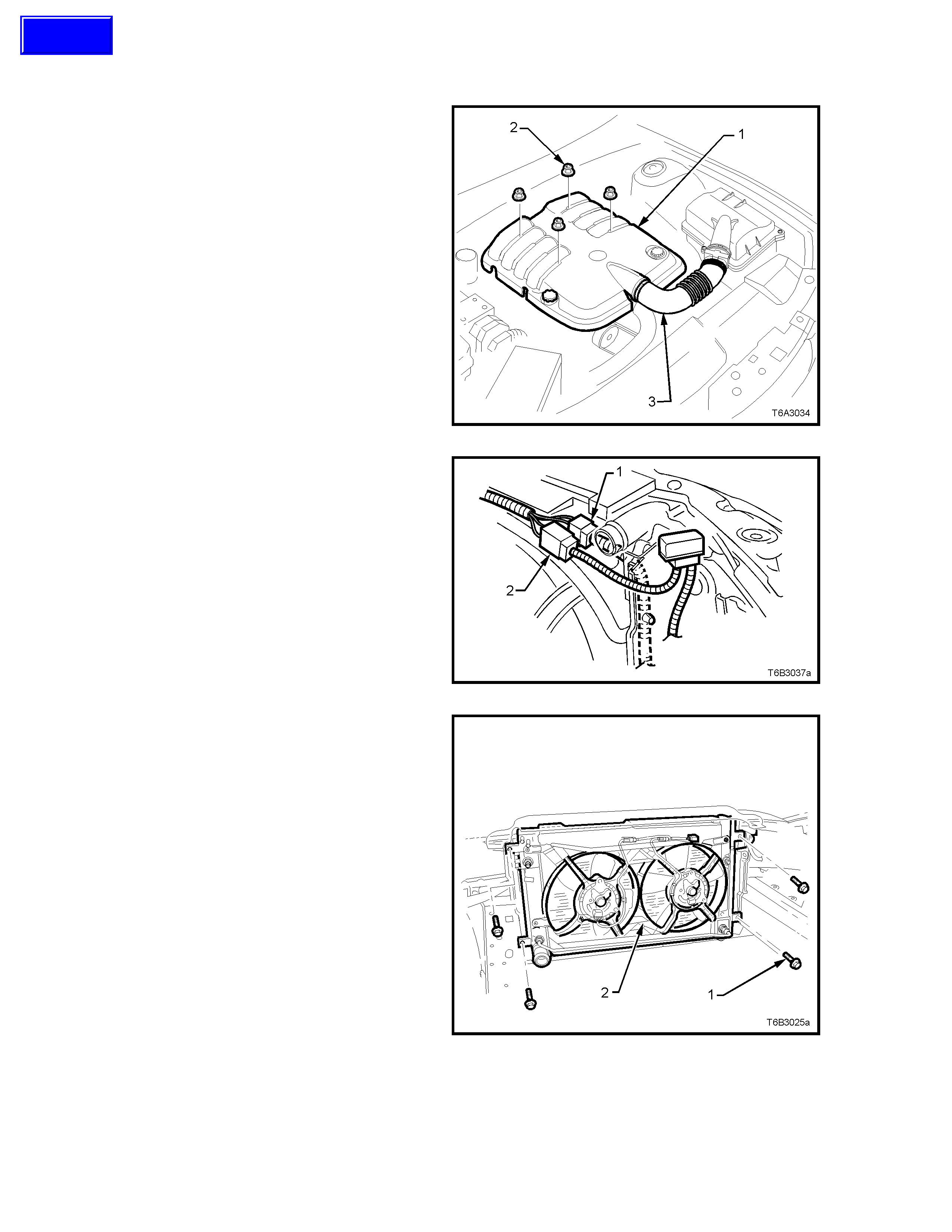
3. Remove engine dress cover decorative nuts
(2), then remove the cover (1).
4. Loosen the two intake hose clamps, then
remove the hose (3).
5. Drain engine coolant. Refer to 2.3 DRAINING
AND FILLING COOLING SYSTEM, in this
Section.
Figure 6B3-59
6. Press the retaining tangs on main wiring
harness to cooling fan motor wiring harness
connectors (1 and 2) and separate
connectors.
Figure 6B3-60
7. Remove cooling fan and shroud to radiator
attaching bolts (1), remove fan and shroud
assembly (2) from engine compartment.
Figure 6B3-61
Techline
DISASSEMBLE
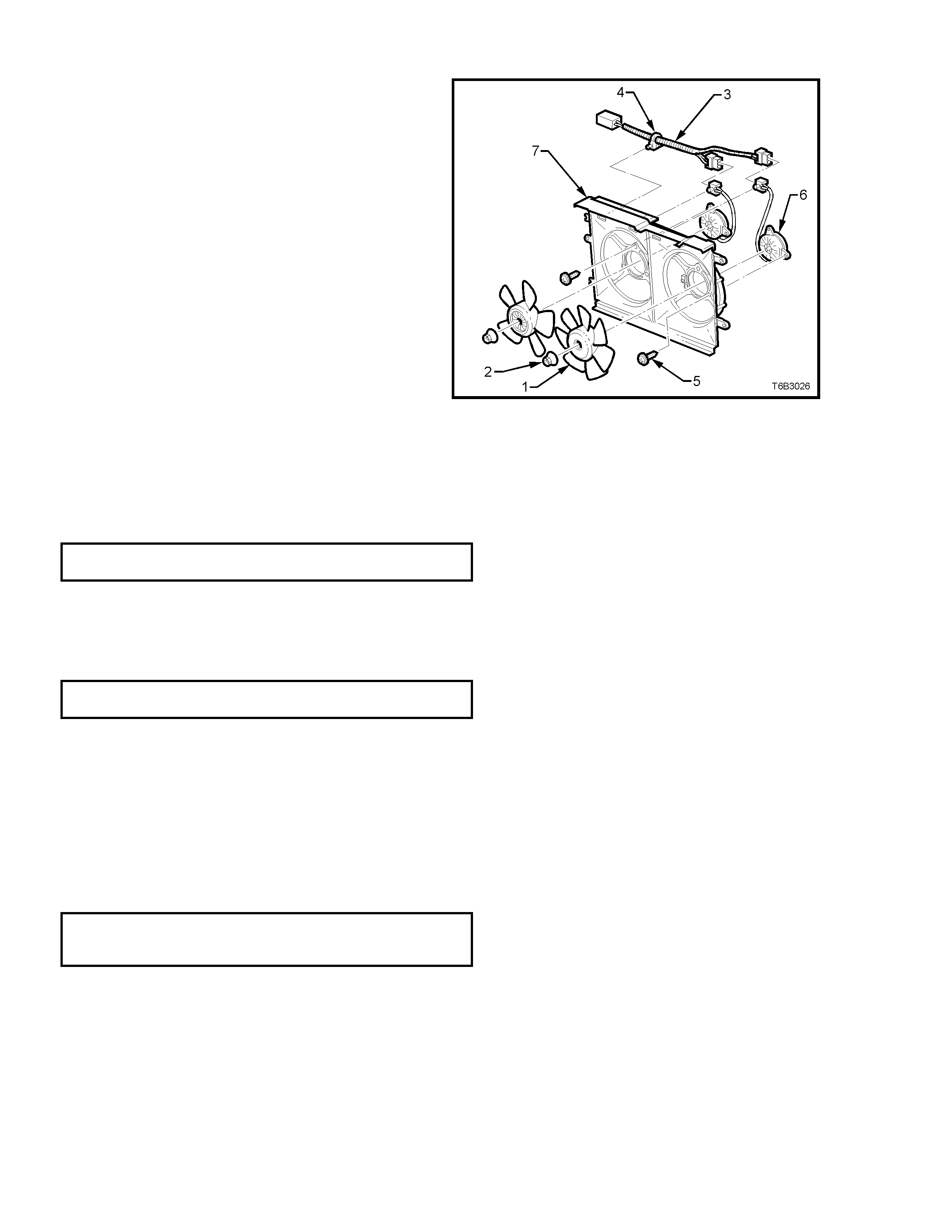
1. Holding f an blade assem bly (1), r emove f an to
motor shaft attaching nut (2) and remove fan.
2. If the f an blade assem bly is a tight fit on motor
shaft, proceed as follows;
a. Reinstall attaching nut (1) and leave
loose.
b. Holding fan blade assembly up, tap on
end of motor shaft with a soft faced
hammer. Remove attaching nut and fan
blade assembly.
3. Remove motor assembly wiring harness (3)
from the shroud clip and attaching straps (4).
4. Remove screws (5) attaching the motor
assembly (6) to the shroud (7), then remove
the motor.
Figure 6B3-62
REASSEMBLE
Reassembly is the reverse of disassembly
procedures, noting the following points:
1. Tighten motor to shroud attaching screws to the
correct torque specification. Do not over-tighten.
FAN MOTOR TO SHROUD SCREW
TORQUE SPECIFCATION 2.7 - 5.0 Nm
2. Install the fan blade assembly to motor shaft,
apply thread locking agent such as Loctite 242 or
equivalent to the motor shaft thread, install the
attaching nut and tighten to the correct torque
specification.
FAN TO MOTOR S HAFT ATTACHING
NUT TORQUE SPECIFICATION 5.0 - 7.5 Nm
3. Install new tie straps to secure the motor wiring
harness to the radiator shroud.
REINSTALL
Reinstallation of the cooling fan and shroud assembly
is the reverse of removal procedures, noting the
following points:
1. Ensure that fan and shroud assembly to radiator
attaching bolts are tightened to the correct torque
specification.
COOLING FAN AND SHROUD TO
RADIATOR ATTACHING BOLT 3 - 4.5 Nm
TORQUE SPECIFICATION
2. Check cooling fan operation, refer to
Section 6C3 POWERTRAIN MANAGEMENT -
GEN III V8 ENGINE of the VT Series II Service
Information. Check rotation direction of cooling
fan.
2.16 RADIATOR
REMOVE
1. Allow engine to cool to am bient temperature (less
than 50°C), slowly loosen screw-on pressure cap
at the coolant surge tank to relieve any residual
coolant pressure, then remove.
CAUTION: DO NOT REMOVE SURGE TANK CAP
WHILE THE ENGINE COOLANT TEMPERATURE IS
ABOVE 50°
°°
°C, AS PERSONAL INJURY MAY
RESULT.
2. Disconnect battery earth lead.
3. Remove engine dress cover decorative nuts
(2), then remove the cover (1).
4. Loosen the two intake hose clamps, then
remove the hose (3).
Figure 6B3-63
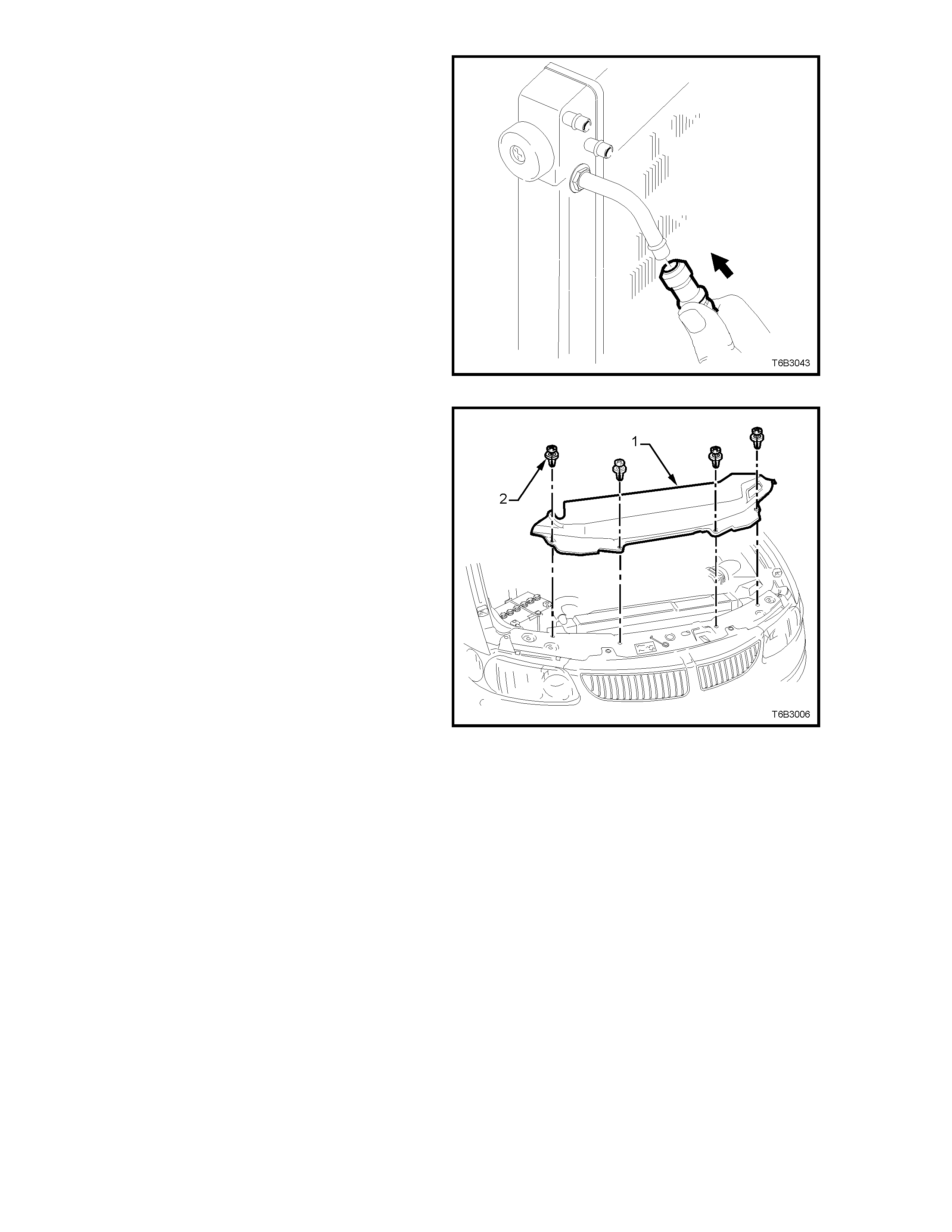
5. Loosen radiator lower hose worm drive clamp
from radiator connection (1), remove the hose
and allow coolant to drain into a suitable
splash tray.
6. Rem ove radiator upper hos e from r adiator (2),
after releasing the spring type hose clamp,
using suitable pliers.
CAUTION: ALWAYS WEAR PROTECTIVE
SAFETY GLASSES WHEN WORKING WITH
SPRING TY PE HOSE CLAMPS. FAILURE T O DO
SO COULD RESULT IN EYE INJURY.
Figure 6B3-64
Techline
7. Remove the 4 radiator upper shroud retainers
(2), release the vapour hose clip from the
radiator f an shr oud, then remove shroud (1) by
lifting on the driver’s side first to release the
locating tab on the left hand side.
Figure 6B3-65
8. If vehicle is equipped with an automatic
transmission, disconnect the transmission oil
cooler line quick connect fittings, using Tool
No. AU525.
Plug hoses and oil cooler unions to prevent
foreign matter entry.
Important: If the quick connect release tool is not
available and the coolant line, flar e nut connections
are rem oved at the lef t hand radiator tank , then it is
vital that a 25 mm back-up spanner is used on the
radiator tank fitting before loosening the pipe flare
nut.
If the f itting is loosened by mistak e, then it must be
replaced with a new part, as micro-encapsulated
sealant is used on the fitting threads that require
the part to be replaced.
Refer to RADIATOR REPAIR PROCEDURE, next
in this Section.
Figure 6B3-66
9. Disconnect the wiring harness to cooling fan
motor wiring harness connectors (1 and 2) by
pressing on the locking tangs. Separate the
connections.
Figure 6B3-67
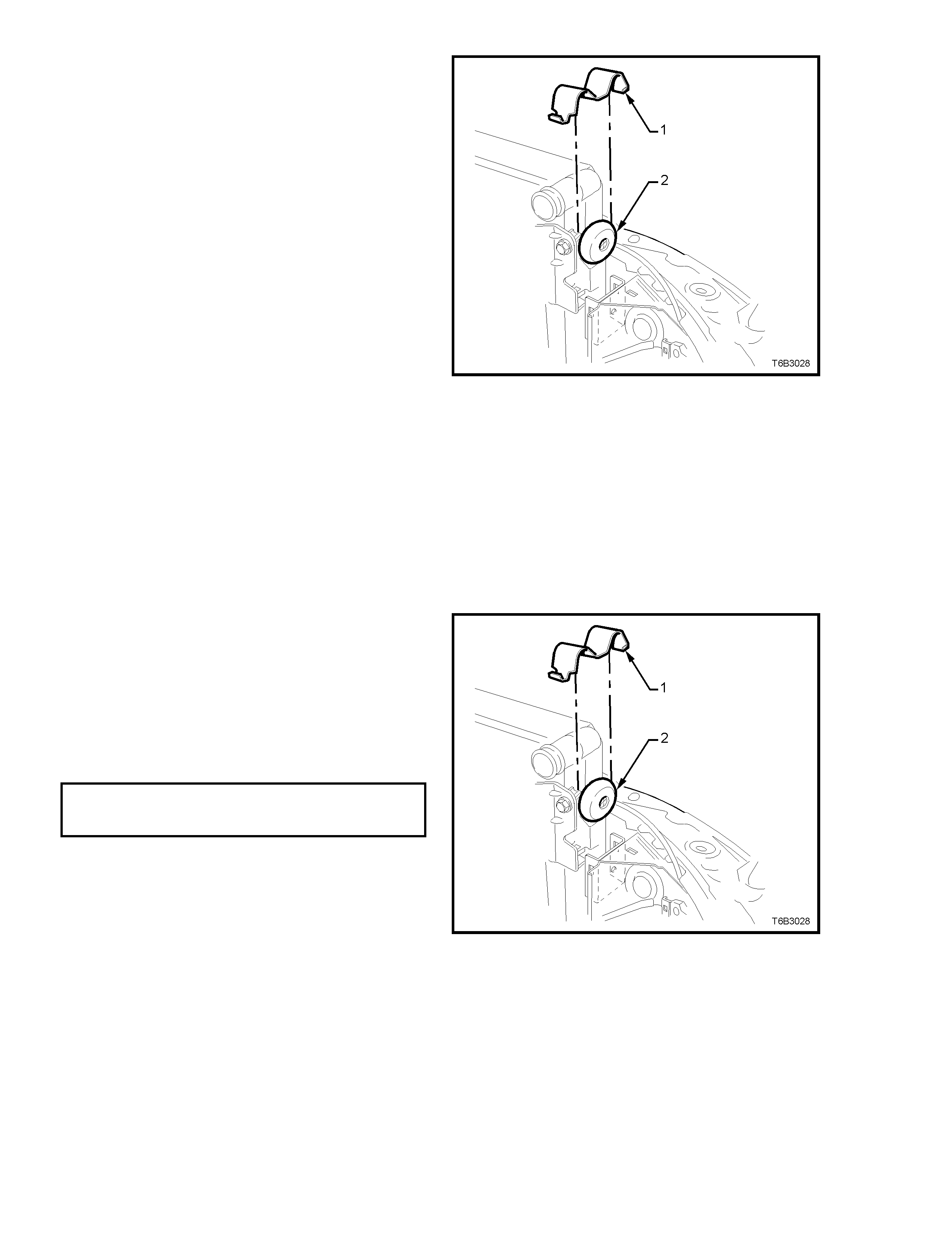
10. Using a screwdriver, compress and lever out
radiator retaining clip (1) from radiator upper
mounting bracket, on each side.
11. Lift radiator upwards out of lower insulators
and remove radiator assembly from vehicle.
Remove upper insulators (2) from radiator
upper mounting pins.
Figure 6B3-68
REINSTALL
Reinstallation of the radiator is the reverse of removal
procedures, noting the following points:
1. Before installing radiator, inspect core to ensure
that there is no foreign matter such as insects in
the core fins. Clean out between core fins with
com press ed air, work ing f rom the engine side and
blowing forwards.
2. Ensure that radiator lower mounting pins are
correctly located in lower insulators.
3. Ensure that upper insulators (2) are installed
on each of the upper mounting pins and
radiator retainers (1) are correctly installed on
each side of the radiator by chacking that the
clips engage on both sides of the channel
support bracket.
4. If removed, tighten cooling fan and shroud
assembly to radiator attaching bolts to the
correct torque specification.
COOLING FAN AND SHROUD TO
RADIATOR ATTACHING BOLT 3.0 - 4.5 Nm
TORQUE SPECIFICATION
Figure 6B3-69
5. If the vehicle is fitted with an automatic
transm ission, install both quic k connec t fittings
to the radiator cooler pipes, then tug on each
to ensure correct installation.
Figure 6B3-70
6. Reinstall the upper radiator shround (1),
reinstall the vapour hose clip to the radiator
fan shroud and secure with the four fasteners
(2).
NOTE: Do not over-tighten fasteners.
7. Refill cooling system, refer to 2.3 DRAINING
AND FILLING COOLING SYSTEM in this
Section.
8. Check for coolant leaks, refer to
2.8 PRESSURE TESTING in this Section.
9. Check cooling fan operation, refer to
Section 6C3 POWERTRAIN MANAGEMENT
- GEN III V8 ENGINE of the VT Series II
Service Information.
Figure 6B3-71
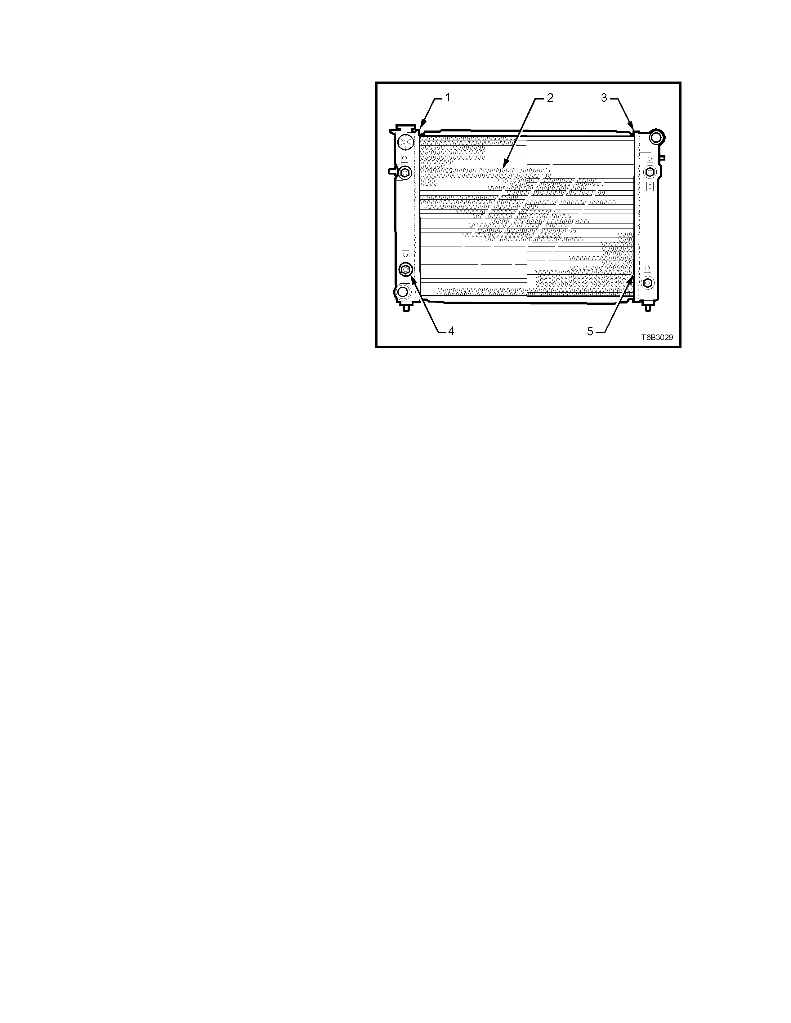
RADIATOR REPAIR PROCEDURE
REPAIRABLE LEAKS
There are two types of leaks that can be repaired
on the aluminium-plastic radiator; core leaks and
automatic transm ission oil cooler seal leak s. Leaks
in the plastic tanks or the seals between the side
tanks and the headers cannot be repaired,
therefore the radiator must be replaced.
Core leaks may occur in a tube or in the joints
between the tubes and the headers. Seal leaks
may occur in the joints between the plastic tanks
and the headers or in the joints between the oil
cooler f ittings and the tank (vehicles with autom atic
transmission).
While some leaks may be repaired while the
radiator is installed in the vehicle, it is strongly
recommended that the radiator is first removed
from the vehicle.
Legend:
1. Side Tank Seal
2. Core Tubes
3. Side Tank Seal
4. Oil Cooler Pipe Fittings
5. Joint Between Tube and Header
NOTE: Minor damage to tubes, or tube to header
joint (holes up to 1 mm diameter max.) can be
repaired. Core r eplacem ent is nec essar y if damage
is any greater.
Figure 6B3-72
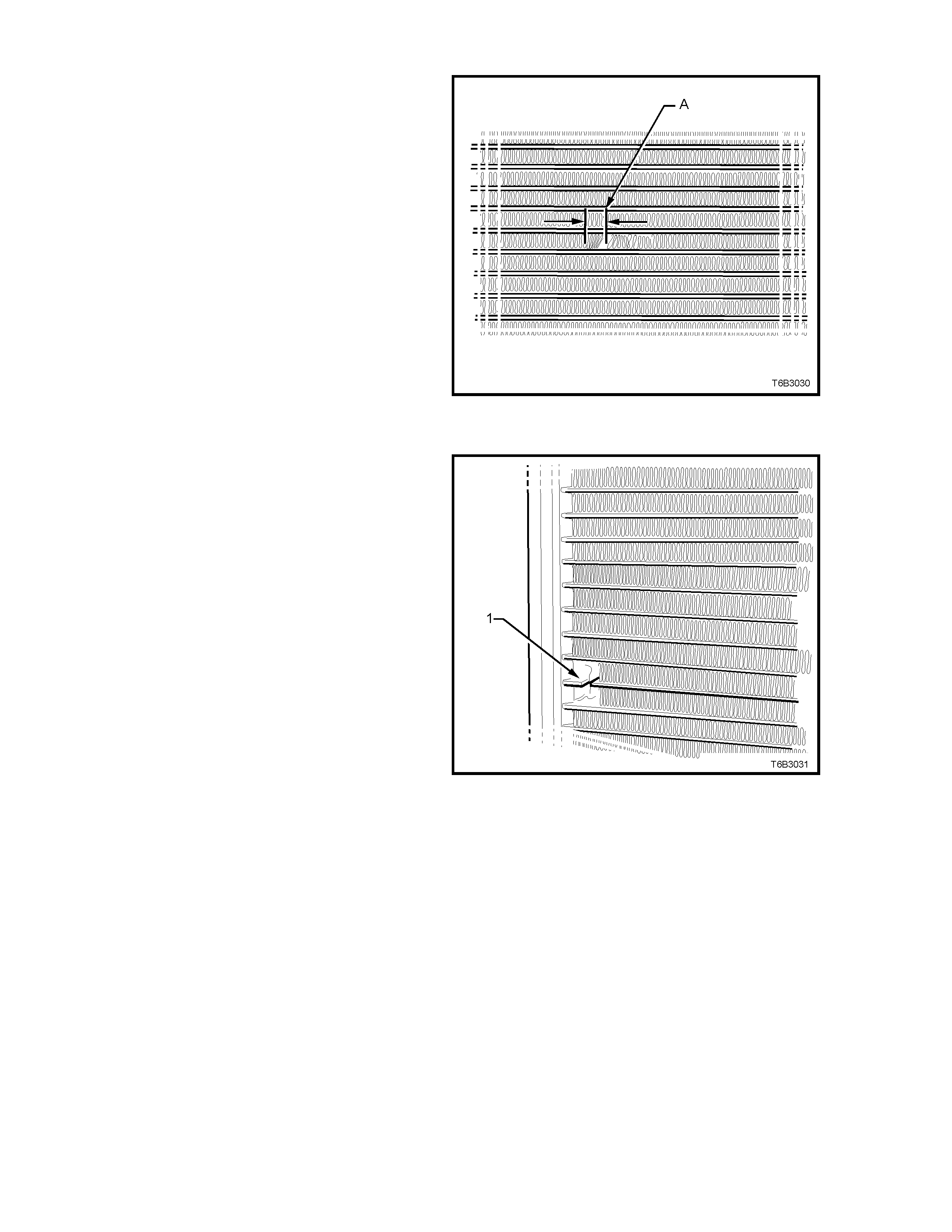
REPAIR METHOD
Repairs to the aluminium radiator core should only
be made using the recommended 'Aluminised
Silicon' based liquid repair agent, in accordance
with the recommended procedure outlined in
GENERAL CORE REPAIR, later in this Section.
Refer to Holden Parts Information for Aluminised
Silicon base liquid part number.
For damaged areas that are between the cooling
fins, it may be necessary to remove some of the
fins. Do not remove more fins than is necessary.
Usually 6 mm (distance ‘A’) beyond the leak or
damage area, up to a maximum of 25 mm of total
fin material, is enough to make an effective repair.
Figure 6B3-73
TUBE BLOCKING
If a tube is severely damaged, it can be blocked off.
NOTE: Do not block off more than two tubes in a
radiator. Blocking off more than two tubes will
reduce the cooling capacity of the system and
possibly result in an overheated engine.
The tube s hould be cut off six mm from the header
(1) and pinched shut before it is cleaned and
sealed, ref er to GENERAL CORE REPAIR, later in
this Section.
Figure 6B3-74

HEADER REPAIR
If the header or a tube near the header requires a repair, the side tank does not have to be removed.
GENERAL CORE REPAIR
The need for careful preparation of the surface in the repair area cannot be over-emphasised. If the leak area surface is
not clean, the repair material will not adhere to the surface.
1. Remove and drain the cooling system. Refer to 2.3 DRAINING AND FILLING COOLING SYSTEM in this Section.
2. If necessary, carefully cut away fins to expose the damaged area.
NOTE: Do not cut away more than 25 mm total of fin material.
3. Clean away dirt etc. with water. Dry the affected area using hot air from a hair drier.
NOTE: Do not apply flame to dry damaged area.
4. Clean affected area with petrol to remove any traces of oil.
5. Thoroughly stir contents of repair agent.
In cas es of extended shelf life, the silic on in solution m ay separate f rom the thinner carrier . Should this occur, m ix
contents well until agent is homogeneous again.
6. Apply repair agent sparingly to dam aged area. Do not apply an excessive am ount, as this will cause a bloc k age of
the radiator tube.
Use a clean, dry wooden applicator to 'drip' the repair agent onto damaged area of radiator.
7. Allow radiator to stand in a clean, dry area for a minimum of three hours (at ambient temperature of 20 - 30° C)
with adequate ventilation.
NOTE: Do not apply heat or flame to promote drying.
8. Install radiator, refer to 2.16 RADIATOR, Reinstall in this Section.
TRANSMISSION OIL COOLER LEAK TEST
If the transmission oil cooler is suspected of leaking transmission fluid, test it before removal as follows:
1. Disconnect oil cooler pipes from radiator connections, after holding the pipe fitting with a 25 mm back-up spanner.
Important: Always use a back-up spanner to hold the flare nut fitting screwed to the radiator header tank, before
loosening the cooler pipe connection.
2. Usuing suitable screwed connections, plug one of the connections and connect an air supply to the other
connection.
3. Lay the radiator flat on a bench top and fill with clean water until both hose fittings are full and visible.
4. Apply air pressure GRADUALLY, increasing it up to a maximum of 103 kPa.
If bubbles appear in the water visible in the radiator hose fittings, then the radiator assembly must be replaced.
TRANSMISSION OIL COOLER SEAL REPLACEMENT.
The oil cooler pipe fitting can be replaced without removing the side tank.
1. Remove radiator, refer to 2.16 RADIATOR, - REMOVE in this Section, and lay radiator on a flat surface.
2. Using a 25 mm socket and bar, carefully remove the cooler pipe fitting from the side tank.
3. Blow dry all surfaces on side tank and oil cooler.
4. Install a NEW flare nut fitting, without any
added lubricant or sealant. Take particular
care that the sealing O-rings are not displaced,
cut or damaged in any way, during the
installation and tightening process.
5. Tighten flare nut fitting to oil cooler, to the
correct torque specification.
OIL COOLER TO SIDE TANK NUT
TORQUE SPECIFICATION 20 Nm
6. Conduct a pressure check of the oil coolers.
See T r ansmiss ion O il Cooler Leak T es t, in this
Scetion.
7. Reinstall radiator, refer to 2.16 RADIATOR,
REINSTALL in this Section.
8. Fill the cooling system with the
recommmended coolant, refer to
2.3 DRAINING AND FILLING COOLING
SYSTEM, in this Section.
9. Check the cooling system for leaks, refer to
2.8 PRESSURE TESTING in this Section.
Figure 6B3-75

3. ENGINE COOLING SYSTEM DIAGNOSIS
3.1 ENGINE OVERHEATING
DEFINITION: Engine temperature lamp comes ON and stays ON, or the temperature gauge shows hot, or coolant
overflows from the surge tank onto the ground while the engine is running.
Step Action Value Yes No
1 1. Check for a loss of cool ant.
2. Ref er 2.2 COOLANT MAINTENANCE, Topping Up Cooling
System, in this Section.
Is there a l oss of coolant?
—
Refer 3.2 LOSS
OF COOLANT,
in this Section.
Go to Step 2
2 1. Check for weak engine coolant soluti on.
2. Ref er 2. 2 COOLANT MAINTENANCE, Testing Cool ant
Concentrat i on, i n this Section.
Does the engine still overheat?
—
Go to Step 3
System OK
3 Check for obst ructed radiator ai r flow or bent radiator fins.
2. I f necessary, rem ove or rel ocate added-on parts that block air
to the radiator. Clean away any insects, l eaves, or other
debris.
Does the engine still overheat?
—
Go to Step 4
System OK
4 1. Check for a loss of sys tem pres sure.
2. Conduc t a test on the pressure cap. Refer 2. 8 P RESSURE
TESTING, Screw-On Pressure Cap Testing, in thi s Section.
Does the engine still overheat?
—
Go to Step 5
System OK
5 1. Check for a faulty Engine Coolant Temperature (ECT) sensor.
Refer 6C3 POWERTRAI N MANAGEMENT - GEN III V 8
ENGINE, of the VT S e ri es II Servi ce Information.
2. Replace sensor as necessary.
Does the engine still overheat?
—
Go to Step 6
System OK
6 1. Check for a dam aged coolant surge tank.
2. Chec k for a leak i ng or kinked surge tank hose.
3. I f necess a ry, repl ace the surge t ank hose and/or repl ace the
coolant s urge tank. Ref er 2. 10 COOLANT SURGE TANK, in
this Section.
Does the engine still overheat?
—
Go to Step 7
System OK
7 1. Check the tens i on of the engine accessory dri ve belt.
Refer to 2.6 ENGINE ACCESSORY DRIVE BELT TENSION,
in this Section.
2. Replace the engine ac cessory dri ve belt as necessary. Ref er
to 2.7 ENGINE ACCESSORY DRIVE BELT, in this Section.
Does the engine still overheat?
—
Go to Step 8
System OK
8 1. Check for blocked cooling system passages.
2. Revers e flush the cooling system . Refer to 2.5 CLE A NING
THE COOLING SYSTEM, in this Section.
Does the engine still overheat?
—
Go to Step 9
System OK
9 1. Check for inco rrect or dam aged cooling fan blade(s).
2. Chec k for the correct f an bl ade(s) part num ber.
3. Replace fan/s as necessary. Refer 2.14 COOLING FANS AND
SHROUD ASSEMBLY, in this Section.
Does the engine still overheat?
—
Go to Step 10
System OK
10 1. Check for correct operation of cooling fans. Refer 6C3
POWERT RAIN MANAGEME NT - GE N III V 8 E NGINE,
of the VT Series II Service Inform ation.
2. Replace cooling fan/s and/ or motor, as necessary. Refer 2. 14
COOLING FANS AND SHROUD ASSEMBLY, in this Section.
Does the engine still overheat?
—
Go to Step 11
System OK
11 1. Check for correct thermostat operation. Ref e r 2. 9
THERMOSTAT, Test, in this Section.
2. Replace thermostat assem bl y as necessary. Refer 2.9
THERMOSTAT, in this Section.
Does the engine still overheat?
—
Go to Step 12
System OK
12 1. Check for correc t coolant pump operation.
2. Replace coolant pump ass embly as necessary. Refer 2.13
COOLANT PUMP, in this Section.
Does the engine still overheat?
—
Go to Step 13
System OK
13 1. Check the radiator cooling capacity.
Is the radi ator the correc t part for t he GE N III V 8 engi ne? —
System OK
Go to Step 14
14 1. Replace the radiator with t he correct part .
Is t he repai r complete? —
System OK —

3.2 LOSS OF COOLANT
DEFINITION: The coolant level in the surge tank continually requires topping up or there is evidence of a sudden
coolant loss from the surge tank.
Step Action Value Yes No
1 1. Check for an inco rrect or fault y screw-on pressure cap.
Conduct a t est on the pres sure cap. Ref er 2.8 PRESS URE
TESTING, Screw-On Pressure Cap Testing, in thi s Section.
2. Replace the screw-on pressure cap as necessary.
Is a coolant loss still evident ?
—
Go to Step 2
System OK
2 1. Check for a leaki ng or damaged cool ant surge tank.
2. Replace the coolant surge tank . Refer 2.10 COOLANT
SURGE TANK, in this Section.
Is a coolant loss still evident ?
—
Go to Step 3
System OK
3. 1. Conduc t a pressure test of t he cooling sys tem. Refer Refer 2.8
PRESSURE TESTING, Cooling Syst em Pres s ure Testing, i n
this Section.
Does tes t indicat e a pressure loss in the c ool i ng system?
—
Go to Step 4
System OK
4. Is there evi dence of an external coolant l eak? — Go to Step 5 Go to Step 12
5. 1. Chec k for loos e or damaged surge t ank, radiator and heat er
hoses. Ref er 2.4 COOLANT HOSES , i n this Sec tion.
2. Replace hose/s as necessary.
Is a coolant loss still evident ?
—
Go to Step 6
System OK
6. 1. Chec k for a cool ant l eak from the coolant pump gaskets.
2. Replace gasket s as necessary. Ref er 2. 13 COOLANT PUMP,
in this Section.
Is a coolant loss still evident ?
—
Go to Step 7
System OK
7. 1. Chec k for a cool ant l eak from the coolant pump, rear O-ring
seal and thermost at housing O-ring seal .
2. Replace O-ring seals as necessary. Ref er 2.9 THERMOSTAT
and 2.13 COOLANT PUMP, i n t hi s Secti on.
Is a coolant loss still evident ?
—
Go to Step 8
System OK
8. 1. Chec k for a cool ant l eak from the coolant pump, s haft seal.
2. Replace coolant pump as necessary. Refer 2.13 COOLANT
PUMP, in this Section.
Is a coolant loss still evident ?
—
Go to Step 9
System OK
9. Inspec t the radiator f or coolant leak s.
Are coolant l eaks from the radiat or evi dent? —
Go to Step 10
System OK
10. 1. If radiator leak s are mi nor, repai r as detailed i n 2. 15
RADIAT OR, Radiator Repair P rocedure, in thi s Sect i on.
2. I f radiator cool ant leaks are major, repl ace the radiator. Refer
2.15 RADIATOR, in t hi s Sect i on.
Is a coolant loss still evident ?
—
Go to Step 11
System OK
11. 1. Check f or coolant leak s from the heater core.
2. Replace heater core as necessary. Refer 2B A IR
CONDITIONING - RE MOVA L & INSTALLATION, of the VT
Series I Service Inform ation.
Is a coolant loss still evident ?
—
Go to Step 12
System OK
12. 1. Chec k for cool ant l eaks from the fol l owing;
• Engine bl ock plugs .
• Vapour pipe and/or fittings
• Cylinder head gasket/ s.
2. Make the necess a ry reapi rs or replace affected c omponents .
Refer ENGINE MECHANICAL - GEN III V8 ENGINE,
of the VT Seri es II S ervi ce Information.
Is/ are t he repai r/s complete?
—
System OK
—

3.3 ENGINE FAILS TO REACH NORMAL OPERATING TEMPERATURE
Step Action Value Yes No
1 1. Check for correct coolant level i n t he coolant s urge tank.
When checked col d, the level s houl d be at the FULL COLD
mark.
Is t he coolant level correct?
—
Go to Step 3
Go to Step 2
2 1. Top up with correct mixture of DEX-COOL® coolant additive
and clean, good quality water. Ref er 2.2 COOLANT
MAINTENANCE, in this Section.
Does the engine reach normal operating temperature now?
—
System OK
Go to Step 3
3 1. Check for a blockage i n the cooling s ystem passages.
2. Reverse f l ush the cooli ng system. Refer 2. 5 CLEANING
COOLING SYSTEM, in this Section.
Does the engine reach normal operating temperature now?
—
System OK
Go to Step
4 1. Check that the c orrect thermostat is fi tted.
2. Check that the thermost at is not stuck in the open posi tion.
3. Replace the therm ostat as necessary. Refer 2.9
THERMOSTAT, in this Section.
Are repairs complete?
—
System OK
—

3.4 BLACK LIGHT AND DYE LEAK DIAGNOSIS METHOD
Holden strongly recommends the use of the black light and dye method to diagnose fluid leaks. This method of leak
detection is a proven, reliable method that identifies the specific leak source and/or location. The black light kit is
suitable for various types of leak detection, when used with the appropriate tracer dye and can be used for detecting
engine coolant, engine oil, transm ission fluid, and air conditioning refrigerant leaks. The following is a summary of the
steps involved in detecting a cooling system fluid leak using black light and dye.
Important: Adding dye to the GEN III V8 engine cooling system, may change the colour of the coolant from an
orange colour to green. As the use of DEX-COOL® (to GM Specification 6277M) to this cooling system is
mandatory and is not to be mixed with other composition coolants, the green colour could be misleading for
future top-up operations.
Therefore, should the coolant change colour when the leak detection dye is added, then the cooling system
MUST be drained and new DEX-COOL® ( to GM Sp ecification 6277M ) coolant added . Refer 2.3 DRAINING AND
FILLING COOLING SYSTEM, in this Section.
1. Pour specified amount of dye into the coolant recovery surge tank. Refer 2.1 SAFETY NOTES in this Section.
2. Road test the vehicle under normal operating conditions.
3. Direct the blac k light towards the suspec t area. Any fluid leak will appear as a br ightly coloured path leading to the
source.
4. Repair fluid leak and recheck to ensure that leak has been rectified.
5. Refer to the manufacturer’s directions when using this method.

4. SPECIFICATIONS
RADIATOR CAP PRESSURE RATING..................... 100 kPa
COOLING SYSTEM CAPACITY................................ 12 Litres
COOLANT CORROSION INHIBITOR ....................... DEX-COOL® to GM Specification 6277M, approx. 6.0 litres
required when changing coolant.
THERMOSTAT
Type ........................................................................ Power element (wax pellet)
Start to open at........................................................ 86° C
Fully open at............................................................ 100° C
COOLANT PUMP
Type ........................................................................ Centrifugal
Drive........................................................................ Multi-ribbed, Serpentine V-belt
Bearing Type........................................................... Double-row ball bearing
RADIATOR
Core type................................................................. Aluminium crossflow core
Plastic tanks............................................................ Nylon 6,6
RADIATOR HOSES
Lower
Number and type................................................ Two, Moulded
Upper
Number and type................................................ One, Moulded
ENGINE COOLING FAN (1)
Number of blades.................................................... 5
Spacing ................................................................... Uneven
Material.................................................................... Polypropylene (20% glass filled)
Diameter.................................................................. 340 mm
Electric motor drive ................................................. 200 watts (nominal)
ENGINE COOLING FAN (2)
Number of blades.................................................... 7
Spacing ................................................................... Uneven
Material.................................................................... Polypropylene (20% glass filled)
Diameter.................................................................. 300 mm
Electric motor drive ................................................. 160 watts (nominal)
SEALANT
Cooling fan to motor shaft thread............................ Loctite 242 or equivalent (GM P/N 12345382)
Techline

5. TORQUE WRENCH SPECIFICATIONS
Nm
Engine Accessory Drive Belt Tensioner Bolt ........................ 40 - 60
Cooling Fan and Shroud to Radiator Attaching Bolt ............. 3.0 - 4.5
Coolant Pump to Cylinder Block Bolts Stage 1.................... 15
Stage 2.................... 25
Coolant Pump Pulley Attaching Bolts Stage 1.................... 10
Stage 2.................... 25
Coolant Pump Rear Cover Bolts........................................... 13 - 15
Fan Motor to Shroud Screw.................................................. 2.7 - 5.0
Fan to Motor Shaft Attaching Nut.......................................... 5.0 - 7.5
Oil Cooler to Side Tank Flared Nut Fitting............................ 20
Oil Pan Under-Tray Bolts...................................................... 30 - 35
Thermostat Housing to Coolant Pump Bolts......................... 13 - 15
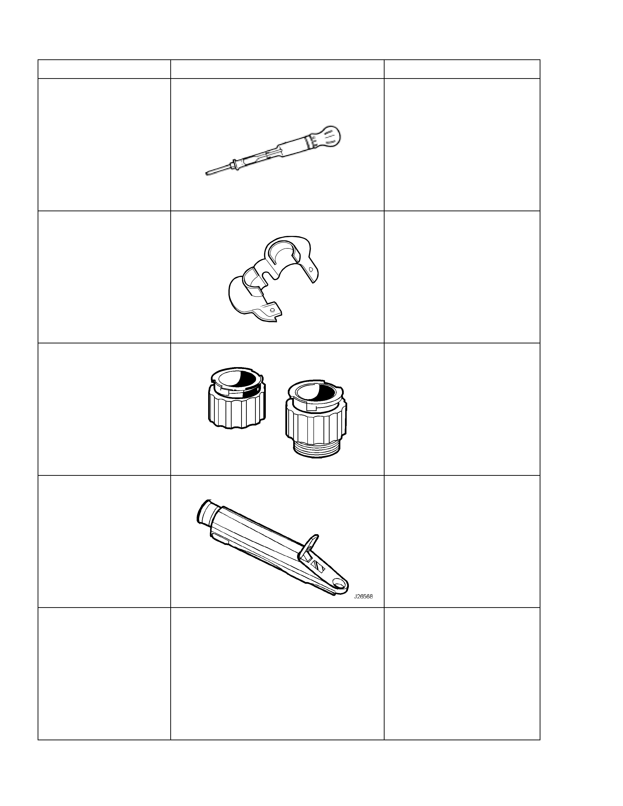
6. SPECIAL TOOLS
TOOL No. REF. IN TEXT TOOL DESCRIPTION COMMENTS
AU435 COOLING SYSTEM HYDROMETER Previously released.
AU525 QUICK CONNECT RELEASE TOOL
A
U525
New release.
Use to release the quick
connect fittings on the
automatic transmission fluid
cooler lines at the radiator end,
when the vehicle is so
equipped.
J 24460-92 COOLING SYSTEM TEST ADAPTERS
New release.
Used to pressure test the
screw-on cooling system
pressure cap and the cooling
system.
J 26568 REFRACTOMETER
Previously released, also under
the number, AU435.
N/A COOLING SYSTEM PRESSURE TESTER
Commercially available.
Used in conjunction with
adapters J 24460-92