
SECTION 6D1-1 - CHARGING SYSTEM -
V6 ENGINE & V6 SUPERCHARGED
CAUTION:
This vehicle will be equipped with a Supplemental Restraint System (SRS). A SRS will consist of either
seat belt pre-tensioners and a driver’s air bag, seat belt pre-tensioners and driver’s and front
passenger’s air bags or seat belt pre-tensioners, driver’s and front passenger’s air bags and left and
right-hand side air bags. Refer to SAFETY PRECAUTIONS, Section 12M Supplemental Restraint System
of the VT Series I Service Information performing any service operation on, or around any SRS
components, the steering mechanism or wiring. Failure to follow the SAFETY PRECAUTIONS could
result in SRS deployment, resulting in possible personal injury or unnecessary SRS system repairs.
CAUTION:
This vehicle may be equipped with LPG (Liquefied Petroleum Gas). In the interests of safety, the LPG
fuel system should be isolated by turning 'OFF' the manual service valve and then draining the LPG
service lines, before any service work is carried out on the vehicle. Refer to the LPG leaflet included with
the Owner's Handbook for details or the appropriate Sections of this Service Information CD for more
specific servicing information.
1. GENERAL INFORMATION
A Bosch KC-A Compact 90 Amp generator is fitted to VT Ser ies II Models equipped with the naturally aspirated V6
engine, and a Bosch KC-A Compact 100 Amp generator is fitted to models equipped with V6 supercharged
engines. Servicing inf orm ation related to the 90 Am p generator is contained in this Sec tion. For service inform ation
on the 100 Amp gener ator, refer to Sectio n 6D1-1 CHARG ING SYST EM — V6 ENGINE & V6 SUPERCHARGED
of the VT Series I Service Information.
A Mitsubishi 120 amp generator is fitted to those WH Series models with production option T82 (‘Headlamps on’).
All service information relating this generator can be found in 6D1-1 CHARGING SYSTEM – V6 ENGINE, in VT
Series Service Inforamtion.
Techline
1.1 GENERAL DESCRIPTION
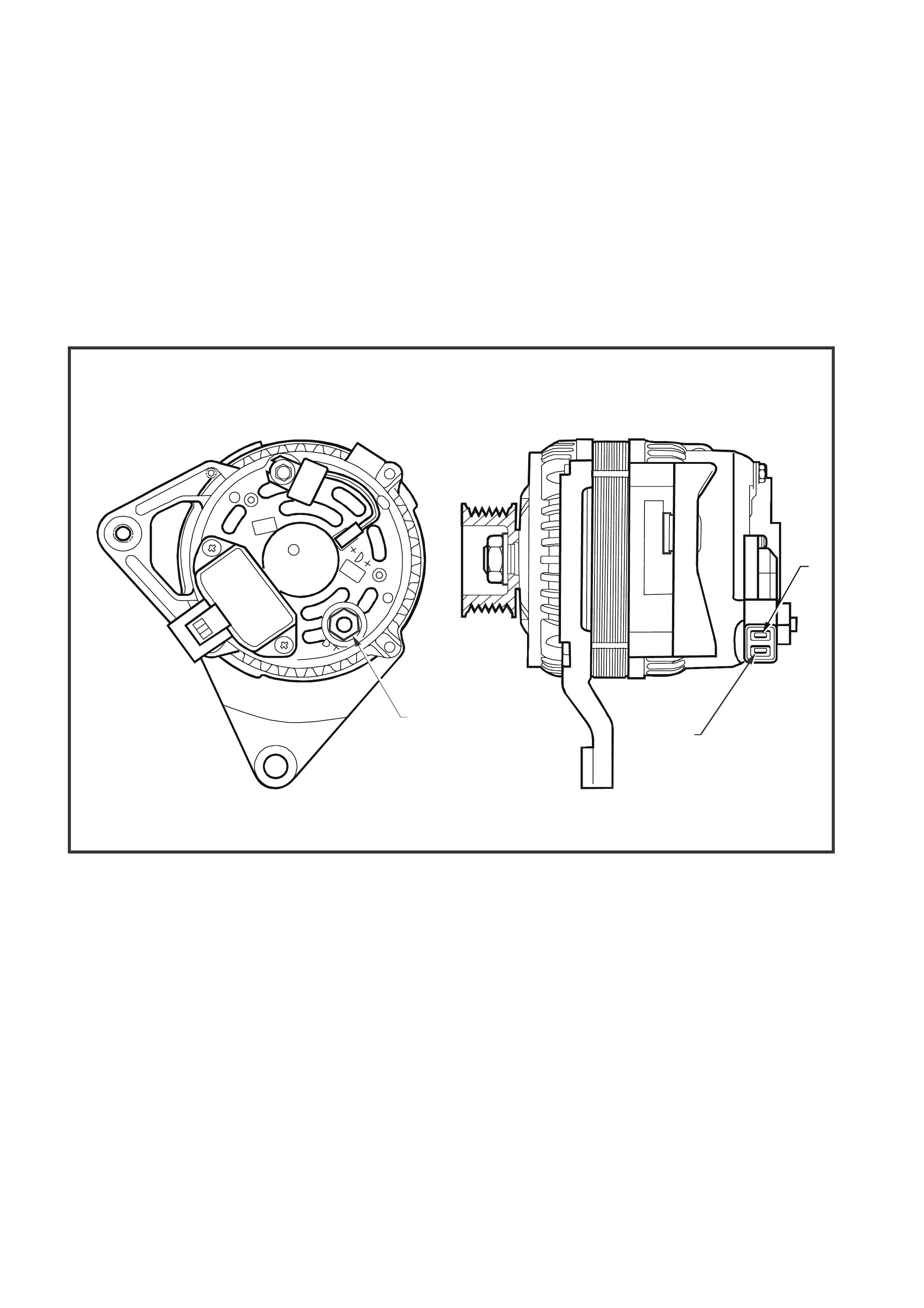
The generator as shown in Fig. 6D1-1-1 is a three-phase type, incorporating a rotor having 6 pole pairs fitted with
two cooling fans, one on the drive-end and the other on the slip-ring end. Rotor current is conveyed to the rotor
winding by a pair of slip-rings and carbon brushes via the voltage regulator. T he rotor is supported by ball bearings
in both the drive and slip-ring end housings. Surrounding the rotor is a stator, which is of a three-phase star
connected output winding construction on a ring shaped lamination pack.
The output of the stator winding is rectified by six diodes which are contained within the slip-ring end housing.
Excitation current is supplied to the rotor field coil via the voltage regulator, brushes and slip-rings. The electronic
voltage regulator requires no adjustment in service.
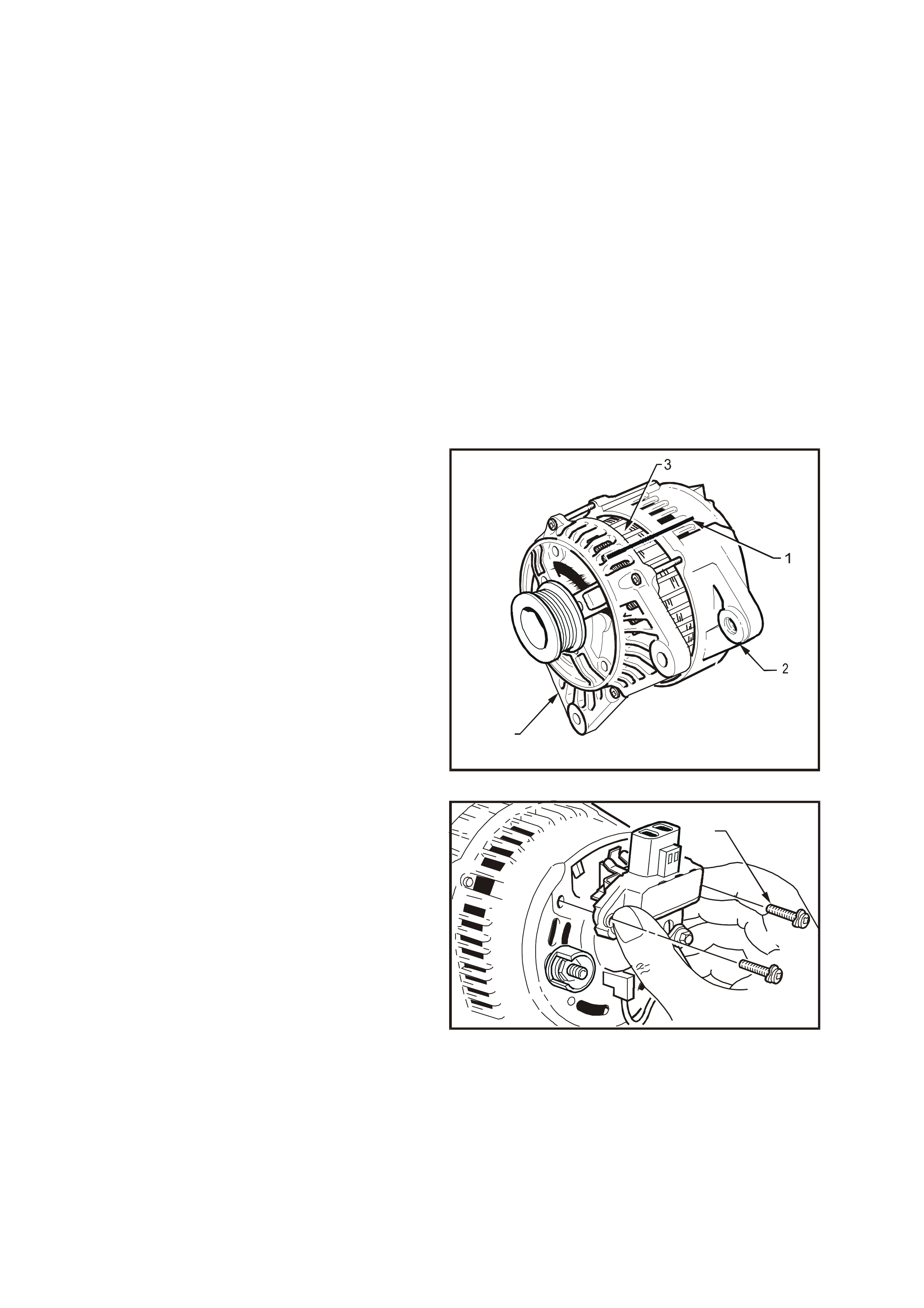
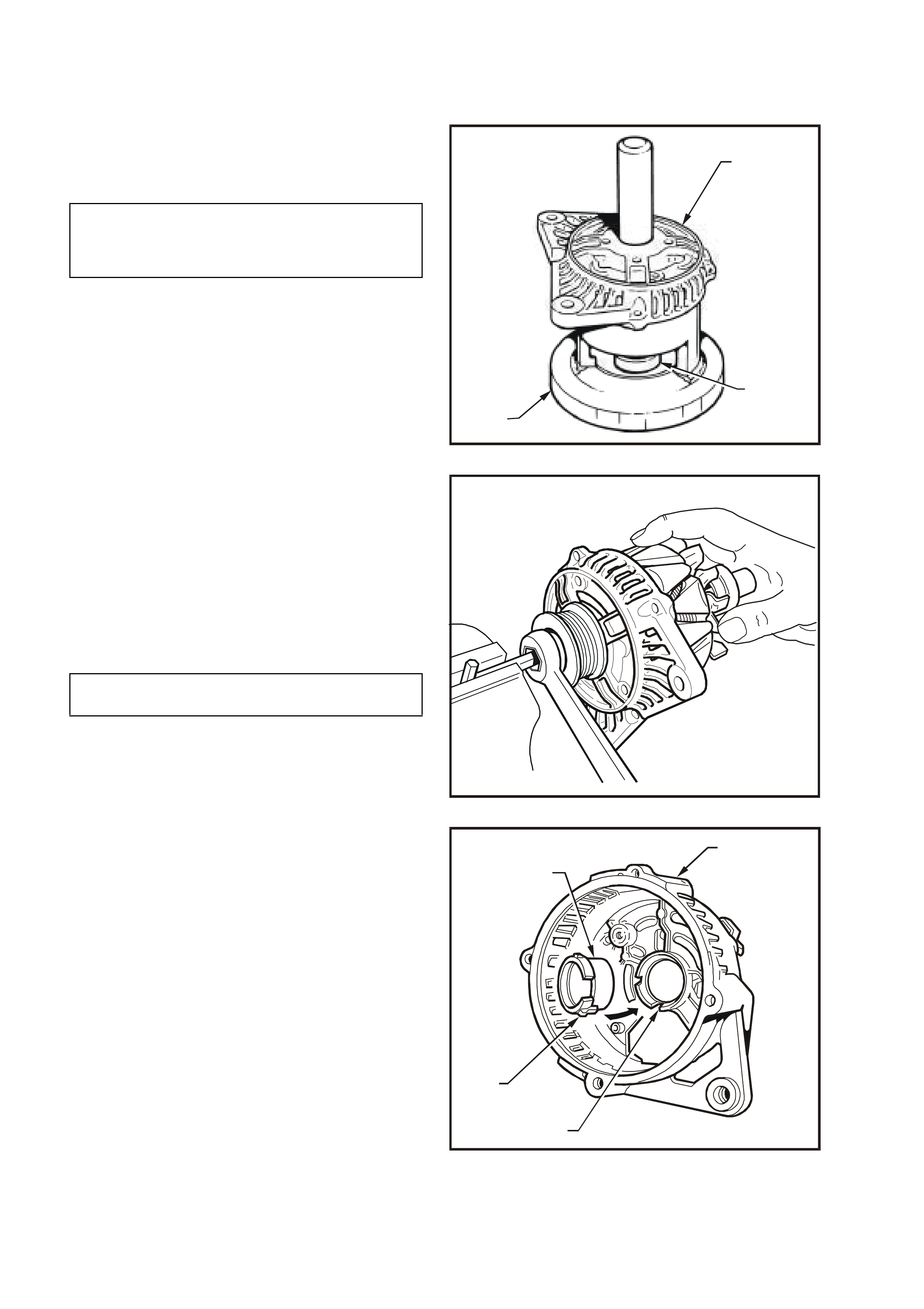
The generator has three external connections: the S lead (1) for battery voltage sensing, the L lead (2) to the
generator warning lamp (max. 2 watts), the B+ lead (3) to the battery positive terminal, and an earth connection,
refer Fig. 6D1-1-1.
NOTE: Do not reverse S and L connections or damage to the warning lamp circuit of the regulator will result.
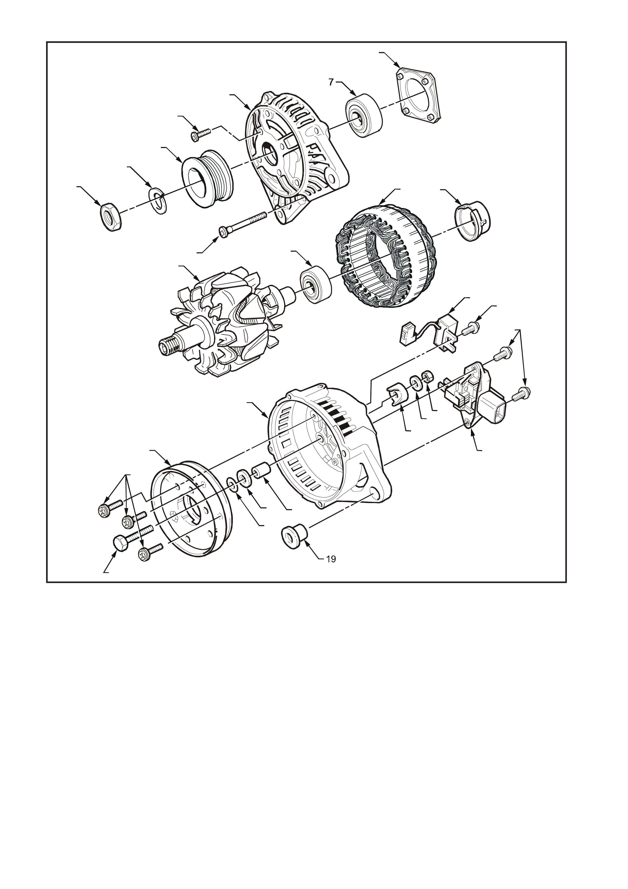
Fig. 6D1-1-2 provides an exploded view and parts identification of the 90 amp generator.
T26D1101
32
1
Figure 6D1-1-1
T26D1103
1
2
3
8
11 12
4
6
510
9
15
13
14
16
17 18
20
21 2223
27
26
24 25
Figure 6D1-1-2
1. Nut 15. Rectifier assembly
2. Lock washer 16. Mica insulating washer
3. Drive pulley 17. Insulating washer
4. Bearing retaining plate screw (4 off) 18. Spacer
5. Through bolt (4 off) 19. Slip-ring end housing lug sleeve
6. Drive end housing 20. Slip-ring end housing
7. Drive end bearing 21. Terminal cover bush
8. Bearing retaining plate 22. Flat washer
9. Rotor 23. B+ terminal retaining nut
10. Slip-ring end bearing 24. Suppressor
11. Stator 25. Suppressor attaching screw
12. Slip-ring end bearing support ring 26. Regulator and brush screws
13. Rectifier attaching screws 27. Regulator and brush assembly
14. B+ terminal bolt
1.2 OPERATION
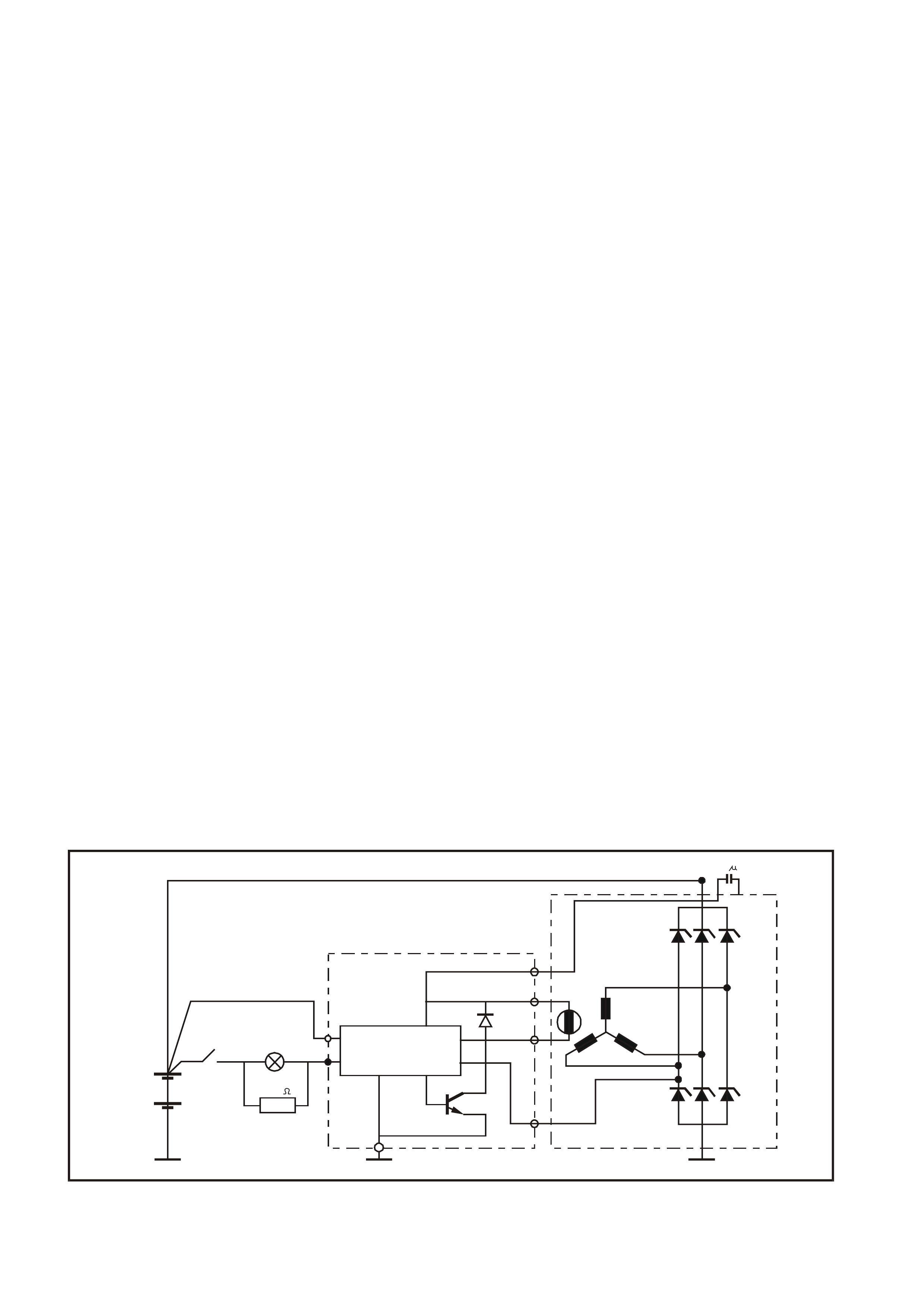
W ith the ignition switch turned to the ON position, current is supplied via the warning lamp to the L terminal of the
regulator. Base current from the regulator hybrid circuit is fed to the transistor T15 which turns on. Current then
flows from the B+ terminal through the rotor winding via the regulator brushes and the collector-emitter junction of
transistor T15 to earth, completing the circuit.
The curr ent in the rotor caus es a m agnetic field between adjacent poles to be created. T his f ield is rotated and c uts
the windings of the stator at right angles, inducing a voltage into them. As the speed is increased, this induced
voltage increases and results in current being rectified in the three-phase diode bridge and supplied as DC to the B+
output and hence to the battery. When the voltage at the B+ terminal to the battery reaches approximately
14.2 volts, the S terminal which is monitoring this voltage, turns off the regulator hybrid circuit base current to
transistor T15, removing rotor current. This results in a decrease in output voltage to below the regulating voltage,
transistor T15 base current is turned back on and the whole cycle is repeated very rapidly. Diode D38 protects
transistor T15 and the regulator against the back voltage developed across the rotor winding when transistor T15
tu rns off.
Should a situation arise where the main B+ cable or battery sense wire (S terminal) become disconnected, the
regulator will limit the output voltage to a safe level, approximately 1 to 3 volts above the regulator’s normal setting.
When the ignition switch is turned on and the engine is not running, the current to the rotor is reduced by switching it
on and off at a 50% duty cycle, the frequenc y is appr oximately 4 kHz and m ay be audible at tim es (this is norm al).
Once the engine is started, normal regulation commences.
Should the warning lamp fail, the generator will self excite by deriving a small current from the phase connection
allowing the voltage to build-up to regulating level.
IMPORTANT: No rotor winding current will flow when the engine is cranking.
The regulator incorporates internal diagnostics which will illuminate the warning lamp as a result of fault conditions
in the generator and/or external circuitry.
These conditions include:
1. An open circuit in the regulator battery sensing wire (S terminal).
2. An open circuit or excessive voltage drop in the B+ cable.
3. An open circuit in the generator phase connection.
4. Overcharging of the battery.
5. Regulator output stage short circuit.
6. Open circuit in the rotor winding.
The regulator compares the voltage at the B+ terminal with the voltage sensed at the S terminal connected to the
battery positive. If the voltage differential exceeds a predetermined threshold, the regulator will operate in backup
mode to limit the output voltage to a safe level. The warning lamp will remain illuminated as long as the fault
conditions prevail.
Sources of high resistance which will trigger the warning lamp are:
1. Poor contact in the wiring harness connectors.
2. Poor contact between the rectifier and the regulator.
3. High resistance in the fusible link assembly.
T26D1104
B+ 0.5 F
FIELD
D38
T15 PHASE
REGULATOR ASSEMBLY
REGULATOR
HYBRID
CIRCUIT
S
L
BATT. SENSE
IGN. SW. WARN. LAMP
1.2 WATT
300
12V BATT.
Figure 6D1-1-3

2. MI NOR SERVICE OPERATIONS
2.1 SAFETY PRECAUTIONS
Since the generator and voltage regulator are designed for use only on a negative earth system, the following
precautions must be observed. Failure to observe these precautions will result in serious damage to the generator.
1. When installing a battery, first f it pos itive (+) cable to batter y positive (+) term inal and then f it negative (–) c able
to battery negative (–) terminal.
2. W hen a slave battery is utilised for starting purposes, ensure that both batteries are connected in parallel, ie.
positive terminals together and negative terminals together.
3. When charging battery, disconnect both battery cables, thus isolating generator from battery and external
charging equipment.
4. The generator must not be operated on open circuit (this is without battery in circuit), and battery must not be
disconnected while the generator is running.
5. Do not attempt to polarise generator.
6. Always ensure that generator warning lamp glows when ignition switch is turned to ON position.
NOTE: As this circuit is related to and assists in the excitation of the rotor field windings, do not proceed until any
faults in the generator warning lamp circuit have been rectified.
7. The L terminal of the generator should never be connected to battery or ignition circuit (12 volts), as this will
damage the generator warning lamp circuit.
8. Some battery powered timing lights can produce high transient voltages when connected or disconnected. Only
disconnect or connect timing lights when the engine is switched off.

2.2 MAINTENANCE AND ON VEHICLE TESTING
At regular intervals, inspect the terminals of the generator for corrosion, loose connections and the wiring for
damaged insulation. Check the mounting bolts for tightness, check the drive belt for alignment and wear and the
drive pulley for damage. The drive belt adjustment for the engine ancillaries, such as the generator and water pump,
is provided by a spring loaded tensioner. The drive belt therefore, does not require any regular adjustment.
LUBRICATION
The ball bearings supporting the rotor shaft are prelubric ated and sealed, therefor e no lubrication is pos sible during
service.
The bearings used in this generator are high tolerance type. If the bearings are removed during the generator
disassembly, new bearings must be installed to restore the generator to original specification.
TESTING THE GENERATOR OUTPUT AND VOLTAGE REGULATOR
Testing Prerequisites
Before testing the generator output, m ake certain that the generator circuit is thoroughly check ed for loose or dirty
connections. The generator must always be connected to the battery during testing, otherwise damage to the
diodes could result.
The battery should be fully charged. Test the specific gravity of the individual cells. The readings should be within 10
points of each other. It is recommended that the average specific gravity should be 1.260 or higher.
A load test should be carried out to determ ine the ability of the battery to supply and accept current. T his is a good
indicator as to the general condition of the battery. Refer to Section 12A BAT T ERY AND CABLES of the VT Ser ies
I Service Information for details of battery testing.
The generator warning light, in addition to indic ating that the generator is charging, is also necessary for initial f ield
excitation.
Inspect drive belt and tensioner markings to determine if belt is within operating limits. Replace belt if it is
excessively worn or outside tensioner's operating range, refer to Section 6A1 ENGINE MECHANICAL — V6
ENGINE of the VT Series I Service Information for details.
Testing Generator Output
Regulating Voltage Test On The Vehicle
1. Ensure that all the electrical equipment is turned off, and the ignition switch is in the OFF position.
2. Disconnect battery earth cable at battery.
3. Disconnect the generator positive lead (red wire) from the B+ generator terminal.
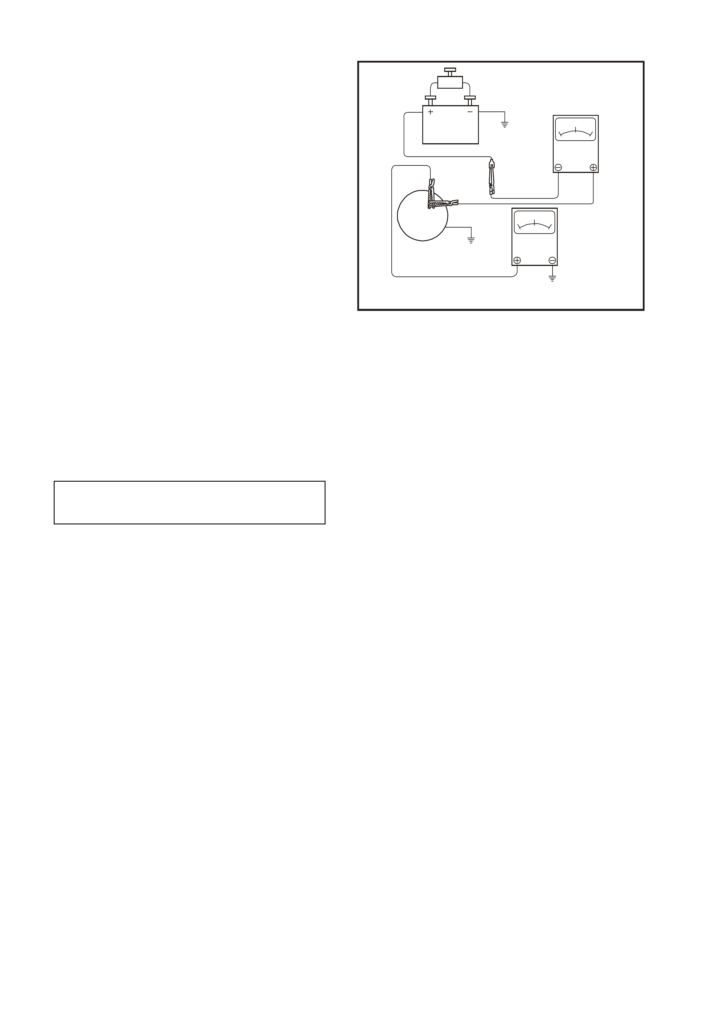
4. Connect the positive lead of an ammeter
(0 - 100 amp scale) to the generator
B+ terminal, and the negative am m eter lead to
the disconnected generator positive lead (red
wire).
5. Connect positive lead of a voltmeter (0 -
20 volt scale minimum) to the generator
B+ terminal, and negative voltmeter lead to a
good earth connection on the generator
housing.
NOTE: Insulate the generator positive lead (red
wire) terminal to prevent contact with any metal
part of the vehicle. If the terminal is earthed,
damage to the charging circuit will result when the
battery is reconnected.
6. Reconnect the battery earth cable. Fit a
loading device across battery terminals, ie. an
adjustable carbon pile.
IMPORTANT: Loading device must have a
minimum power consumption of 1000 watts.
7. Note and record the voltmeter reading before
starting the engine. This reading should
increase when the engine is running,
indicating generator output.
8. Start engine, raise engine speed and adjust
load (ammeter reading) to that nominated in
the following chart. Check generator output
(voltmeter reading) against specification.
T26D1105
ADJUSTABLE LOAD
CONNECT TO
GENERATOR BODY
GENERATOR
B+
TERMINAL
BATTERY
0+100-100
AMPS
020
VOLTS
Figure 6D1-1-4
Load Regulation Test
With the voltmeter, ammeter and carbon pile
connected as in previous test, increase engine
speed to 1900 rpm (approximately 6000 generator
rpm) and increase load to approximately
76.5 amps (90% of full output). A decrease in the
regulating voltage should not exc eed 0.5 volt of the
readings obtained in the previous test.
If the decrease in the regulating voltage is greater
than 0.5 volt, the regulator is defec tive and mus t be
replaced.
ENGINE RPM
LOAD
VOLTMETER READING
1275
5 – 10 Amps
14.0 – 14.2 Volts

Generator Output Test at Full Load
With the voltmeter, ammeter and carbon pile connected as in previous tests, increase engine speed to 1900 rpm
(approximately 6000 generator rpm) and increase load until the generator output voltage drops to 13.5 volts and
note ammeter reading.
Full output should be obtained under these conditions. It m ay be necessary to adjust the throttle so as to maintain
the desired engine speed.
NOTE: Keep the time for this test to a minimum so as to avoid undue heating and high engine speeds.
If generator does not provide rated output, it should be disassembled and inspected for faults, refer to
3.1 GENERATOR in this Section.
NOTE: On com pletion of the gener ator output testing, to prevent exc essive battery discharge occurr ing, the engine
should be resumed to idle speed and the loading device disconnected from battery terminals.
Disconnect the battery earth cable at battery. Remove the volt and am meters , then rec onnec t the generator pos itive
lead (red wire) to the generator B+ terminal. Reconnect the battery earth cable to the battery.
CHARGING CIRCUIT VOLTAGE DROP TEST
With normal connections made at generator, charging circuit can be checked for voltage drop as follows:
1. Connect a low range voltmeter between generator positive terminal and battery positive post.
2. Switch on headlamps, start engine and increase engine speed to approximately 2500 rpm and note voltm eter
reading.
3. Reduce engine speed and transfer voltmeter connections, negative to generator housing and positive to battery
negative post. Increase engine speed to approximately 2500 rpm and again note voltmeter reading.
4. If readings exceed 0.5 volt on positive side and 0.25 volt on negative side, there is a high resistance in
charging circuit which must be traced and corrected.
5. Reduce engine speed and transfer voltmeter connections, negative to generator body and positive to battery
negative post. Increase engine speed to approximately 2500 rpm and again note voltmeter reading.
6. If readings exceed 0.5 volt on positive side and 0.25 volt on negative side, there is a high resistance in
charging circuit which must be traced and corrected.
3. MAJOR SERVICE OPERATIONS
3.1 GENERATOR
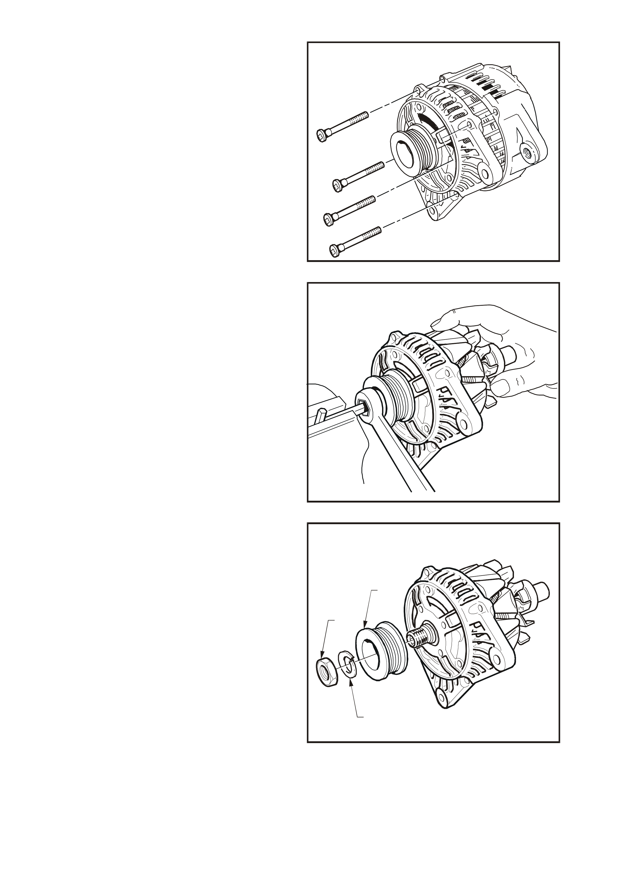
REMOVE
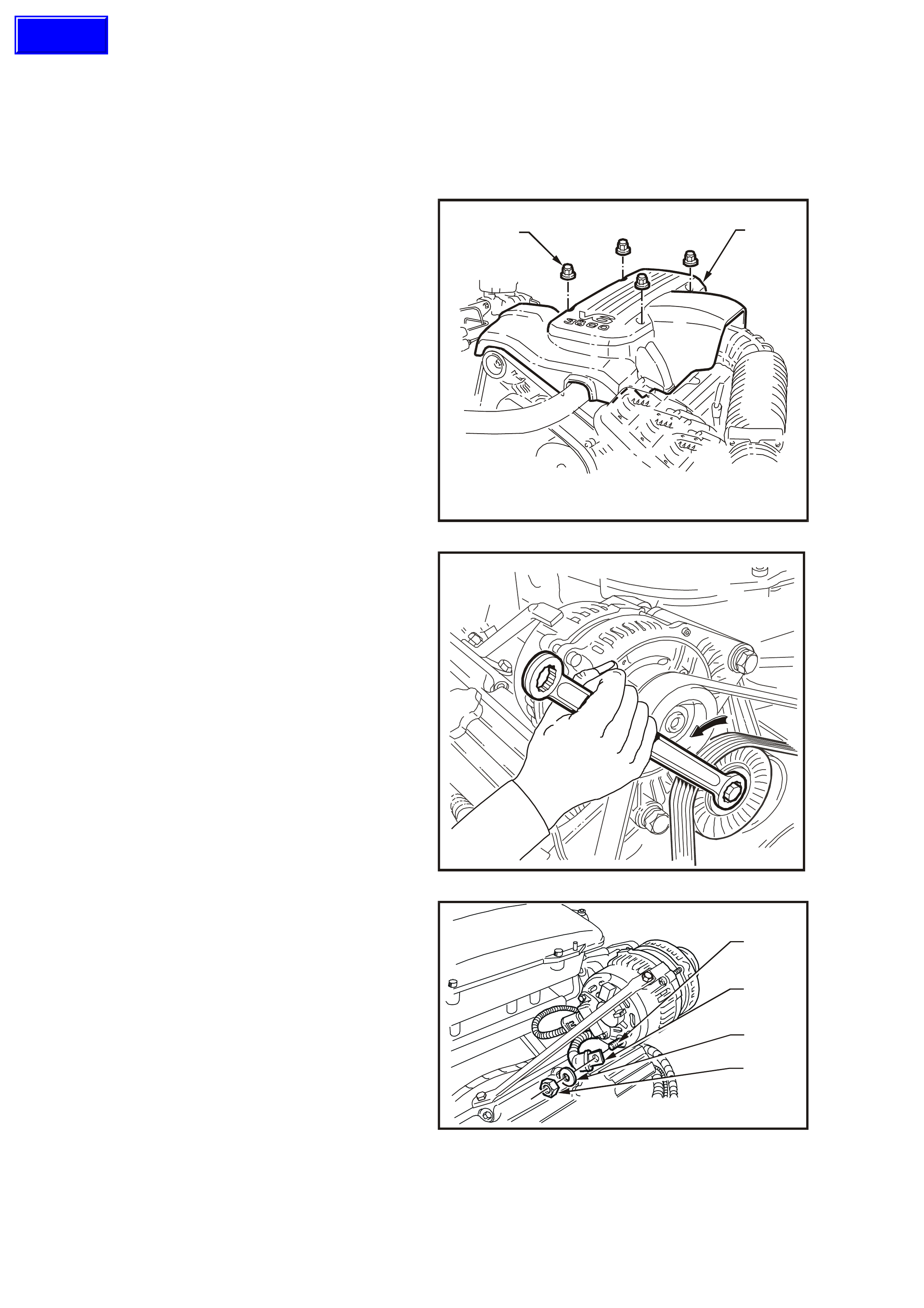
1. Disconnect battery earth lead.
2. Remove four dome nuts (1) securing engine
dress c over (2) to intak e manif old and rem ove
engine dress cover (2).
T26D1102
12
Figure 6D1-1-5
3. Using an 15 mm ring spanner on drive belt
tensioner pulley pivot bolt, rotate tensioner
pulley assembly anti-clockwise and remove
drive belt fr om generator dr ive pulley. Release
drive belt tensioner.
T26D1106
Figure 6D1-1-6
4. Pull back battery harness cap f rom B+ term inal
(4), remove nut (1), washer (2) and positive lead
(3).
3
2
1
4
T26D1107
Figure 6D1-1-7
Techline
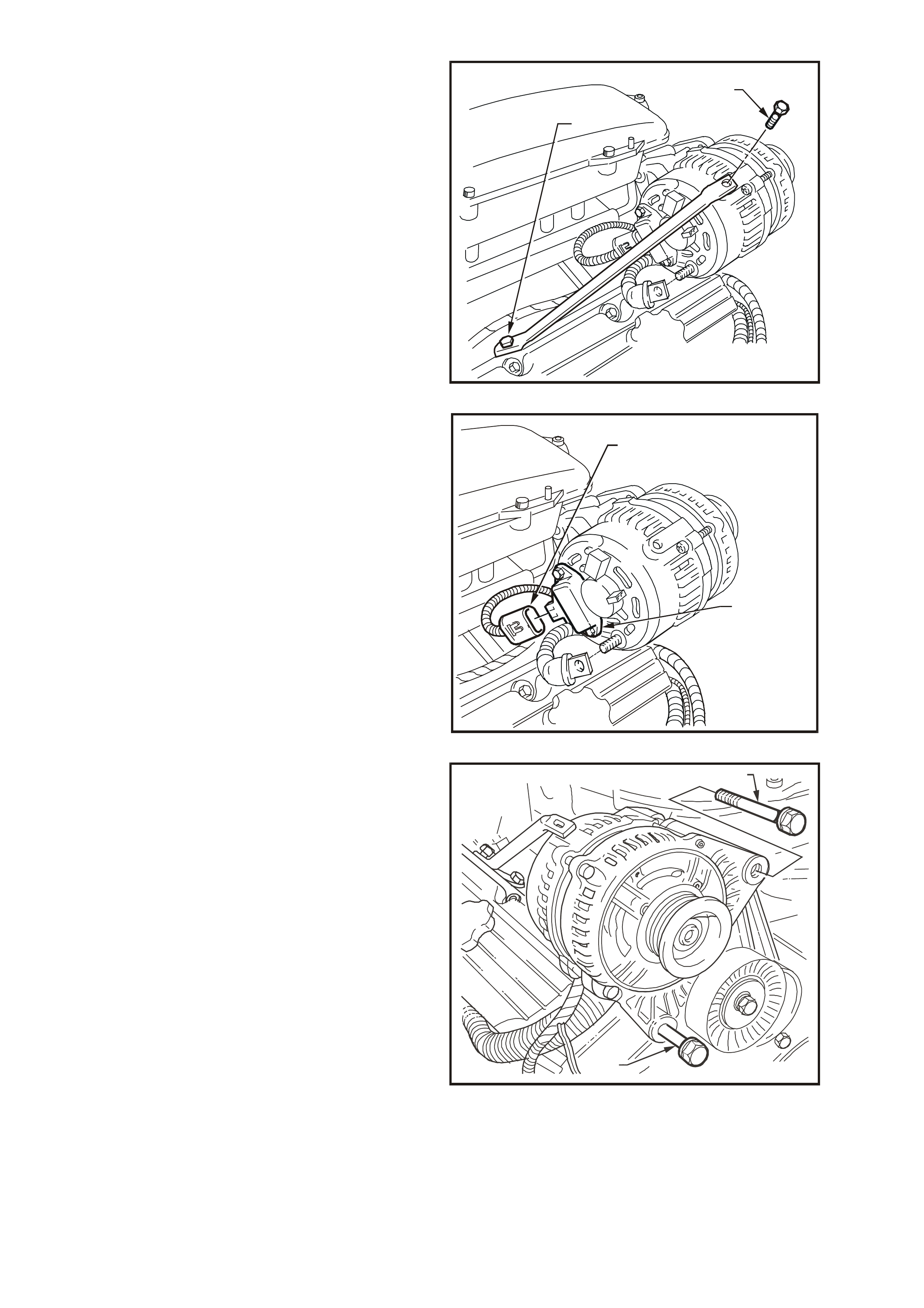
5. Remove generator brace to generator
attaching bolt (1) and loosen brace to engine
bracket attaching bolt (2).
T26D1130
1
2
Figure 6D1-1-8
6. Disconnect the generator connector (1) from
the regulator and brush assembly (2).
T26D1131
1
2
Figure 6D1-1-9
7. Remove generator mounting to drive belt
tensioner bracket attaching bolt (1).
8. Remove generator to drive belt tensioner
bracket lower bolt (2) and remove generator
assembly.
T26D1108T26D1108
2
1
Figure 6D1-1-10

REINSTALL
1. Assemble generator with drive-end housing
into support and brace mounting. Install
generator mounting bolt.
Swing generator down to drive belt tensioner
and install attaching bolt.
Tighten mounting and attaching bolts to the
correct torque specification.
2. Install battery harness positive lead (red
wire), washer and nut on B+ terminal.
Tighten nut to the correct torque
specification. Install cap ove B+ terminal
3. Connect wiring harness connector to
generator teminal block
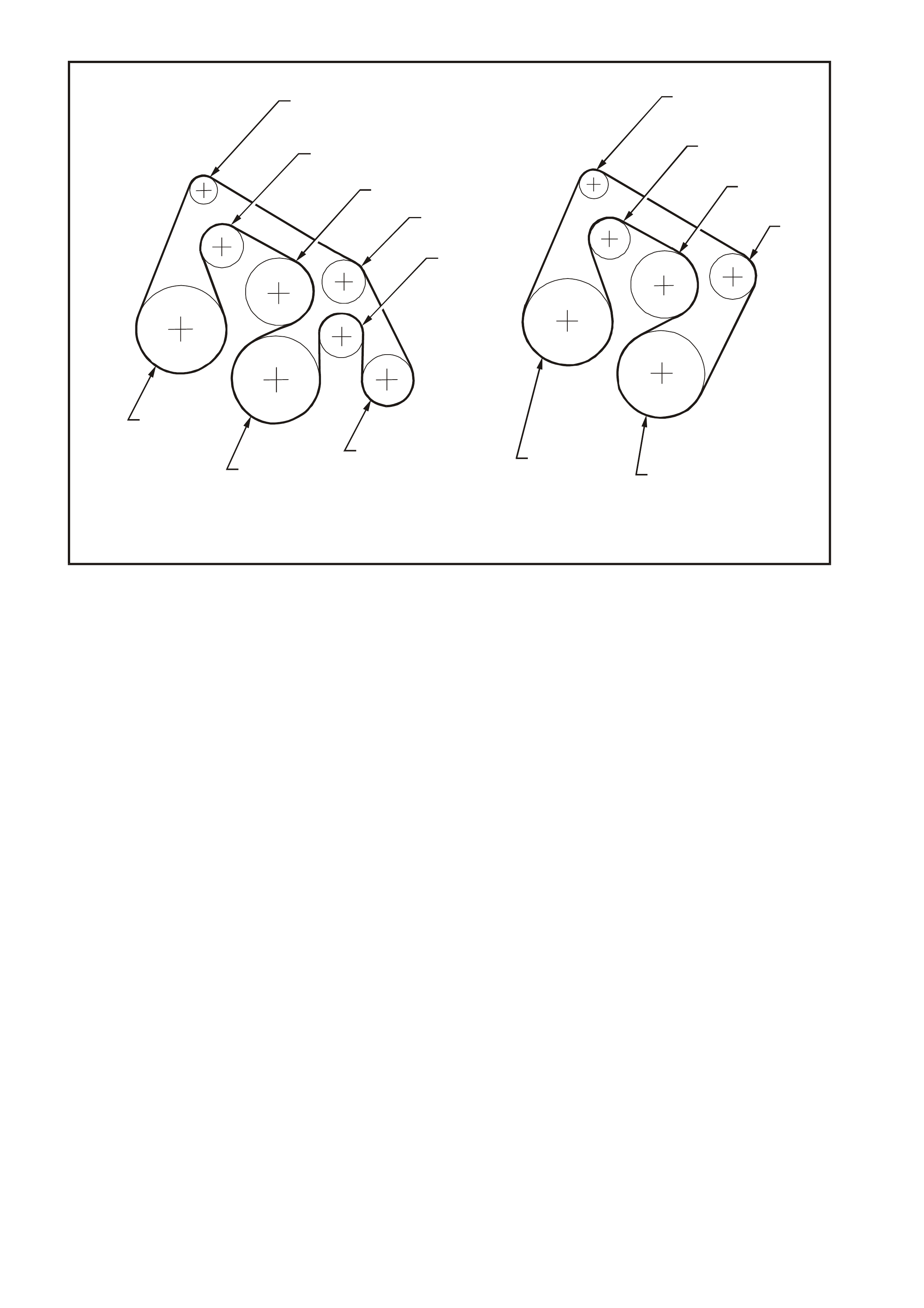
4. With aid of an 15 mm ring spanner, rotate
drive belt tensioner anti-clockwise and fit
drive belt to generator drive pulley. Ensure
that the drive belt is correctly routed, refer to
Fig. 6D1-1-11 (A for vehicles with air
conditioning or B for vehicles without air
conditioning). Release tensioner and ensure
that drive belt ribs are correctly installed into
all accessory drive pulleys and crankshaft
balancer drive belt grooves
5. Reconnect battery earth lead.
6. Start engine and check generator waring
lamp operation, drive belt alignment,
generator output and voltage regulator
operation.
B+ TERMINAL NUT
TORQUE SPECIFICATION 5 – 12 Nm
GENERATOR TO SUPPORT
AND BRACE MOUNTING BOLT
TORQUE SPECIFICATION 20 – 34 Nm
GENERATOR TO DRIVE BELT
TENSIONER BRACKET
MOUNTING BOLT
TORQUE SPECIFICATION
20 – 34 Nm
T26D1109
11
22
33
44
5
6
77
8
8
AB
Figure 6D1-1-11
1. Generator
2. Tensioner pulley
3. Water pump
4. Idler
5. Idler
6. Air conditioning compressor
7. Crankshaft
8. Power steering pump
DISASSEMBLE
The following precautions must be noted before
attempting to disassemble the generator and
checking for faulty components.
a. When testing the rectifier diodes with an AC
type tester, the RMS output must not exceed
12.0 volts. It is recommended that the stator
should be disconnected before testing the
diodes.
b. When testing diode breakdown voltage, all
diodes should have the same Zener voltage.
c. Insulation tests on the rotor and stator should
use a voltage not exceeding 110 volts for a
series test lamp. The rectifier must be
disconnected from the stator prior to testing.
d. Due to the very low resistance value of the
stator winding, it m ay not be possible to obtain
accurate readings using a conventional
ohmmeter.
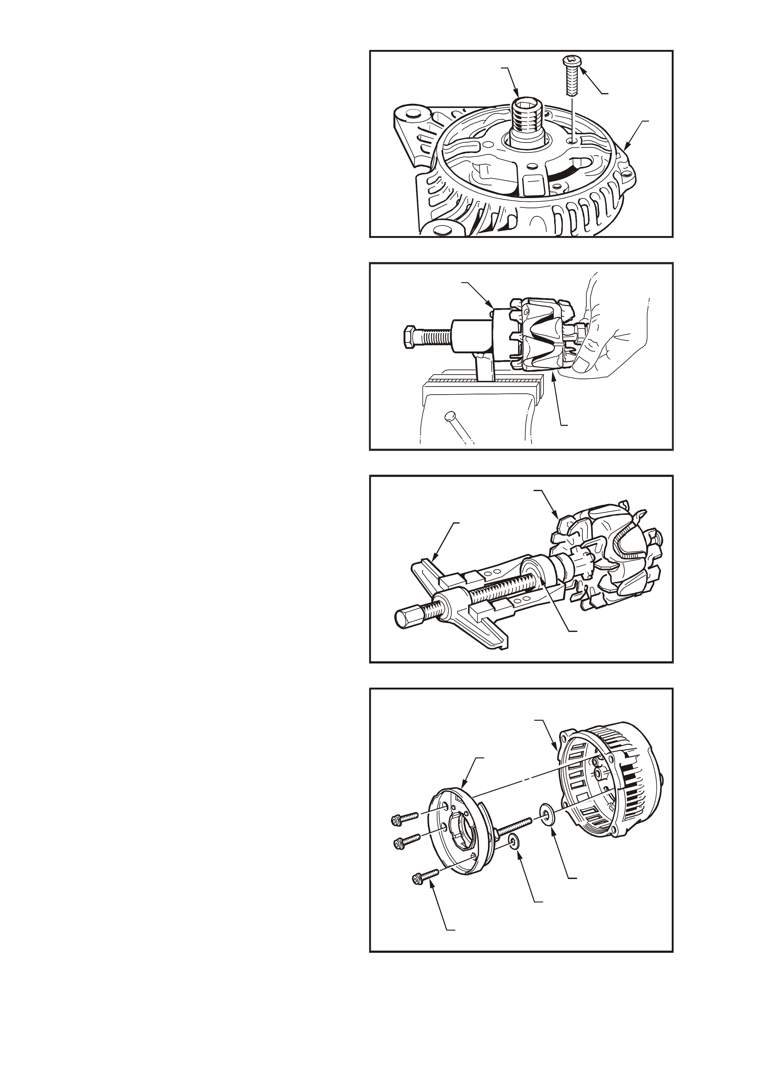
1. Using a permanent marking pen, draw a line
(1) to mark relative positions of slip-ring end
housing (2), stator frame (3) and drive-end
housing (4).
T26D1110
4
Figure 6D1-1-12
2. Remove two screws (1) securing regulator and
brush assembly to slip-ring end housing.
Holding the terminal bloc k of the regulator and
brush assembly, tilt the assembly up from the
slip-ring end housing and then lift out, taking
care not to damage the brushes.
T26D1111
1
Figure 6D1-1-13
3. Remove four through bolts.
4. Carefully separate the slip-ring end housing
and stator (as an assembly) from rotor and
drive-end housing, taking car e not to put strain
on the stator.
T26D1112
Figure 6D1-1-14
5. To remove the drive pulley, mount an 8 mm
Allen key in a vice with the long end pointing
out from the side of the vice.
Place a deep 24 mm socket with external hex
(commercially available) onto the pulley
attaching nut and place a suitable size
spanner over socket hex.
As an alternative, use a deep 24 mm socket
and weld a suitable length bar to the side of
the socket to act as a lever.
Position drive-end housing and rotor assem bly
with the internal hexagon of the rotor shaft
onto the Allen key.
Loosen drive pulley attaching nut. Remove
drive-end housing from Allen key.
NOTE: Under no circumstances is the rotor to be
mounted in the vice as the rotor and or cooling fans
will be damaged.
T26D1113
Figure 6D1-1-15
6. Remove drive pulley attaching nut (1), lock
washer (2) and drive pulley (3).
T26D1114
2
1
3
Figure 6D1-1-16
7. Remove four screws (1) securing the bearing
retaining plate to drive-end housing (3).
8. Push the rotor s haft (2) and f ront bearing f rom
the drive-end housing (3) by hand.
NOTE: The rotor must not be pressed from the
drive-end housing. If the rotor is pressed out, the
bearing retaining plate and drive-end housing will
be damaged or distorted. Parts removed in this way
MUST be replaced if the integrity of the generator
is to be maintained.
T26D1115
1
2
3
Figure 6D1-1-17
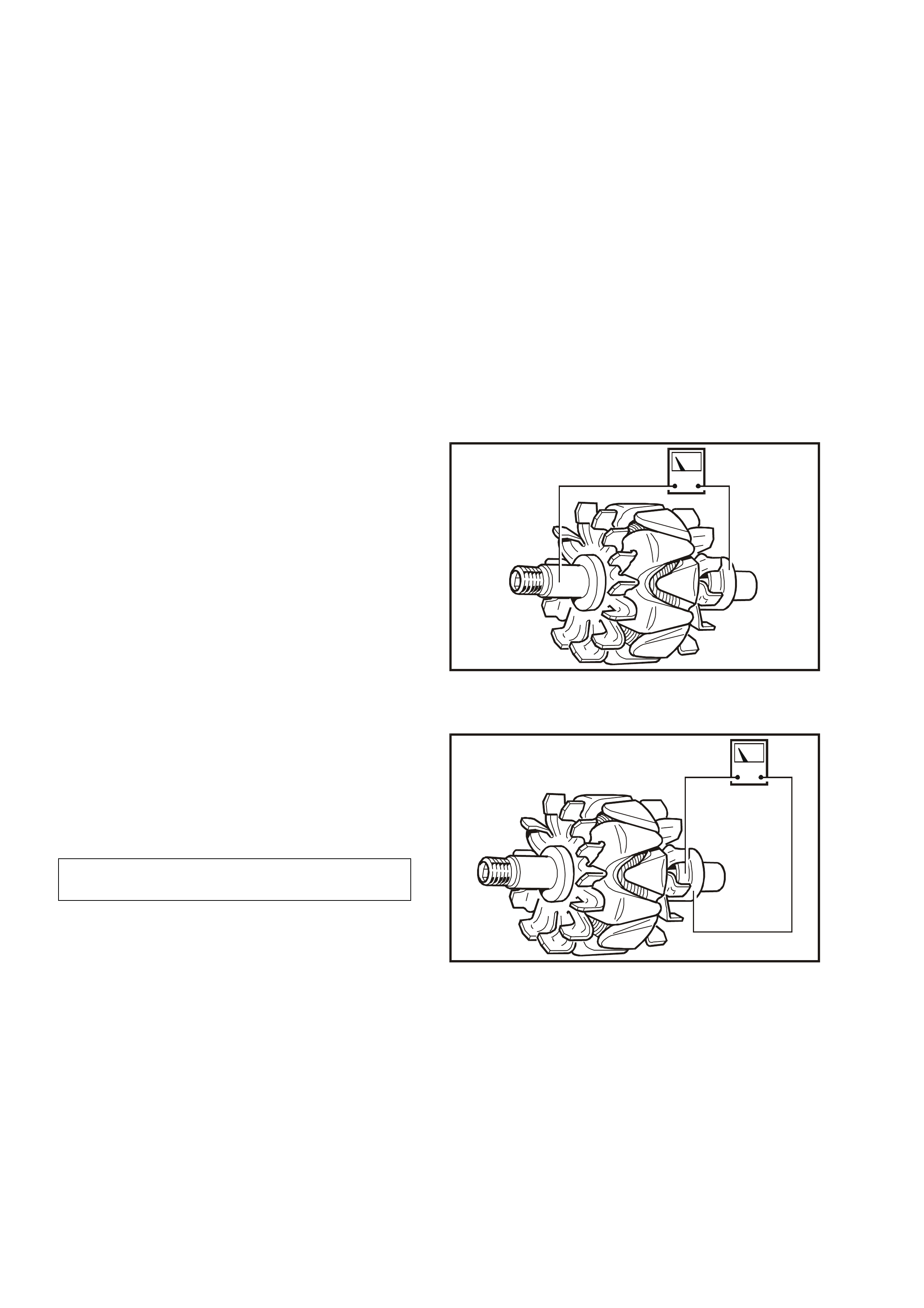
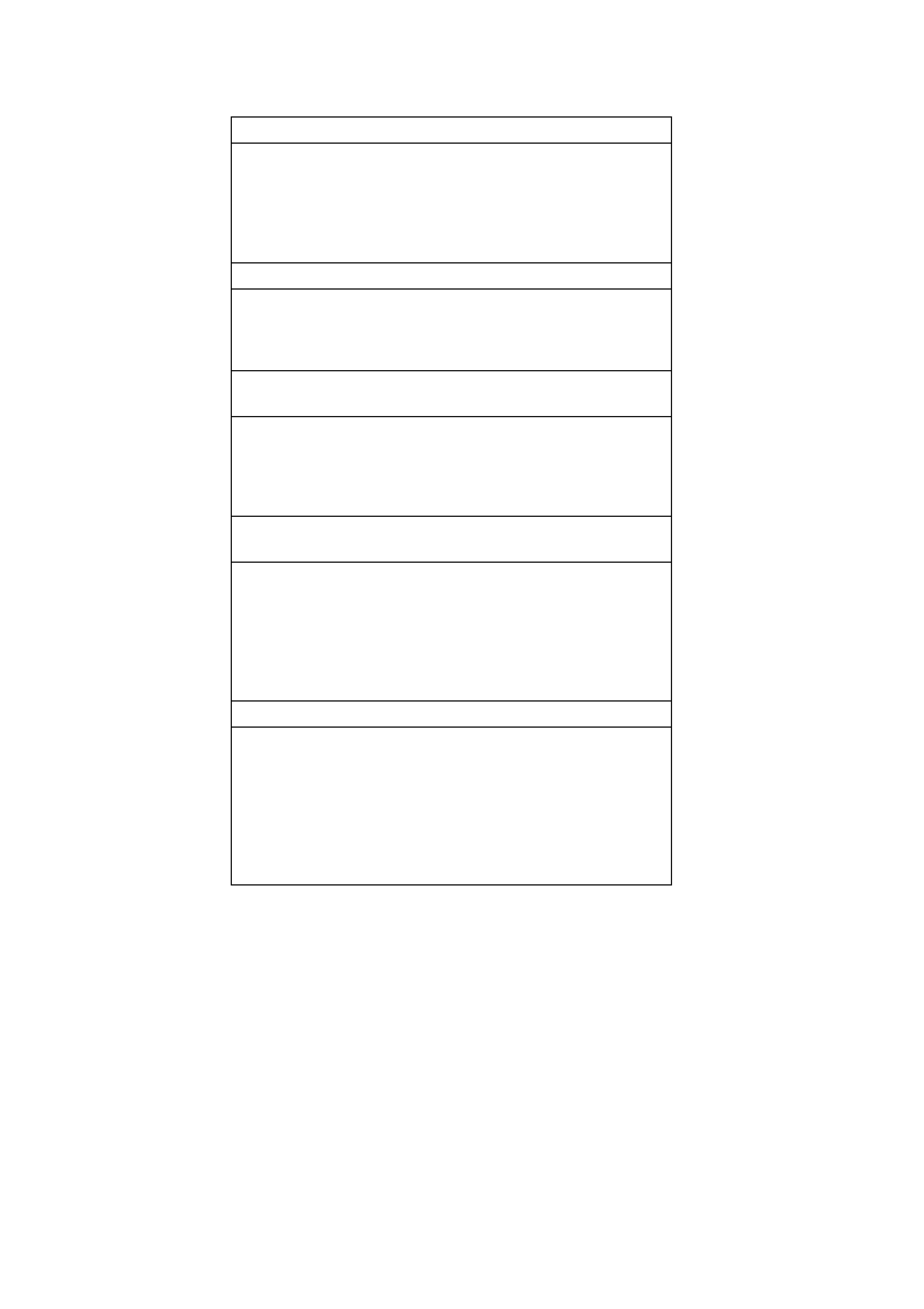
9. Using Special Tool 9981 066 601(1), remove
drive-end bearing from rotor shaft (2) taking
care not to distort the front fan during the
process.
T26D1116
1
2
Figure 6D1-1-18
10. Using the puller (1), remove slip-ring end
bearing (2) from rotor shaft, taking care not to
distort the rear fan (3) during the process.
Remove retaining plate from rotor shaft.
T26D1117
3
1
2
Figure 6D1-1-19
11. Remove nut, wave washer, flat washer and
insulating washer from the B+ terminal bolt.
12. Remove suppressor lead connection from
rectifier + terminal.
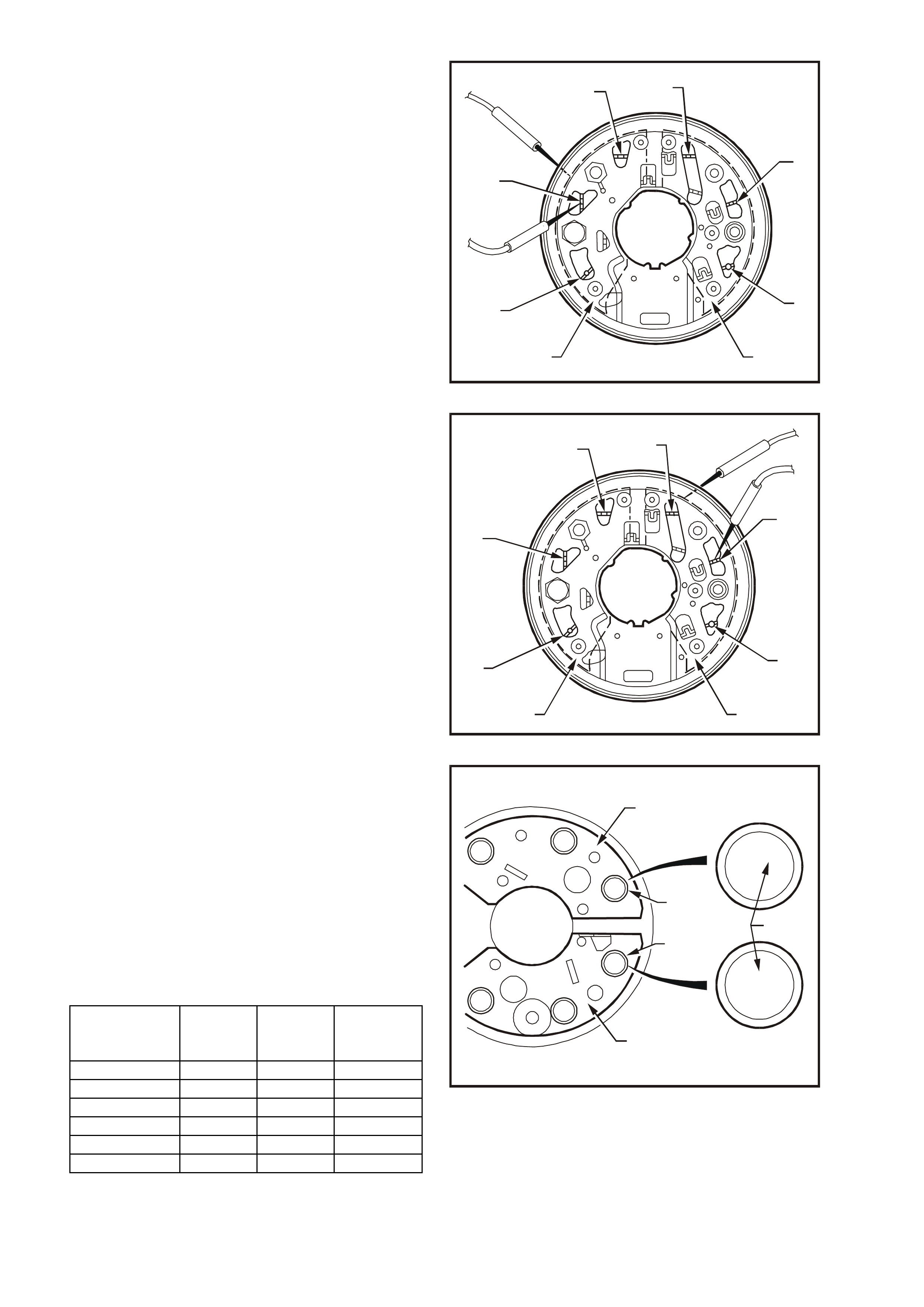
13. Remove three screws (1) attaching rectifier
assembly (2) to slip-ring end housing (3).
Remove the stator and rectifier as an
assembly. Remove spac er and mica ins ulating
washer (4) from B+ terminal bolt.
Remove second mica insulating washer (5)
from beneath rectifier positive heat sink.
(W asher may be adhered to boss on inside of
slip-ring end housing).
NOTE: Discard the two mic a insulating washers as
new washers and heat sink compound must be
used on reassembly.
T26D1118
3
4
5
1
2
Figure 6D1-1-20
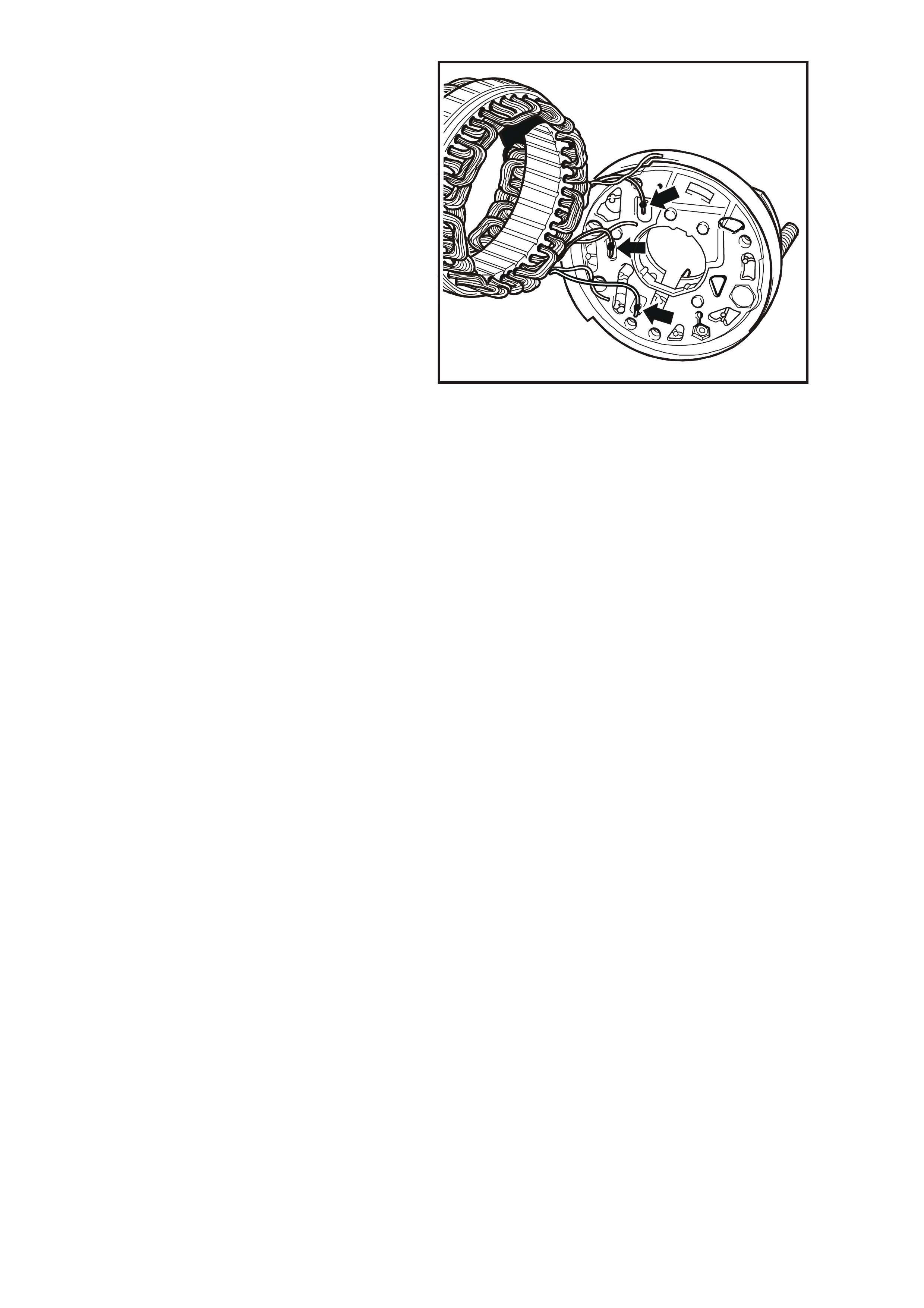
14. Separate stator from rectifier assembly by
unsoldering the three stator windings to
rectifier connections.
NOTE: Use only as much heat as required to melt
the solder. Excessive heat may damage the
diodes.
To disconnect the stator from the rectifier
assembly, grasp the stator wires close to the
wire loop with a pair of pointed nose pliers.
Heat the joint with a soldering iron and when
the solder at this point starts to melt, apply a
slight twisting motion to the wires, then pull
upwards to release.
IMPORTANT: The rect ifier assembly is ser viced as
an assem bly only. Individual replacement parts are
not available.
T26D1119
1
Figure 6D1-1-21
CLEANING AND INSPECTION
With generator completely disassembled,
components should be cleaned and inspected.
Wash all components except stator, rotor, rectifier
and regulator in a suitable cleaning solvent.
Carefully clean rotor and stator with compressed
air.
NOTE: Do not clean stator or rotor windings with
cleaning solvent or damage to the insulation could
result.
CAUTION: Clean all parts other than those
previously nominated using a non-volatile or
low inflammab le agent in a well v entilated area.
It is important that all parts are thoroughly
dried before assembly, taking care not to
breath in any vapours. Observe the safety
regulations and precautions issued by the
manufacturer of the cleaning agent in use.
COMPONENT CHECKING
If brush length is less than specified, replace
brushes as follows:
Brush Gear
Check the length of the brushes protruding from
the regulator brush holder. This is measured from
the brush holder to the end of the brush, along its
centre line.
1. Unsolder brush leads from regulator brush
holder connections (1) and bend back the
retaining lugs. Remove brushes and springs.
2. Inspect brush springs for discolouration,
breakage, corrosion or loss of tension. If any
of these conditions exist, replace springs.
3. Ensure that insulating sleeves are fitted over
new brush leads. Install brush springs over
brush leads. T hread new brus h leads up br us h
holder along with springs, pull the leads
through the tabs until the brush is protruding
12 mm from the holder. Bend down the tabs
and solder the brush leads to the regulator
connections. T ake car e not to allow the s older
to run up the lead which would reduce its
flexibility.
4. Check that brushes m ove smoothly in and out
of holder by pushing on end of brushes, and
then releasing.
T26D1120
1
Figure 6D1-1-22
Diodes
IMPORTANT: The rectifier assembly is not
repairable and should be r eplaced if any diode
proves to be faulty.
The following commercially available test
equipment is essential for correctly testing the
diodes within the rectifier assembly.
a. A diode tester or multimeter with a diode test
feature where the DC output at the test probes
does not exceed 14 volts , or in the case of AC
testers, 12 volts RMS.
This is necessary to ensure that when testing
the diodes, the forward and reverse voltage
checks are completed and are not masked by
the diode turning on due to Zener breakdown
voltage.
b. A Zener diode tester with a DC output in
excess of 30 volts. The tester should also
incorporate internal current limiting set to 5 mA
to prevent high currents during testing.
MINIMUM BRUSH
LENGTH 3.8 mm
1. Attach negative test probe of diode tester or
multimeter with diode test function to the
positive heat sink (1) of the rectifier assembly
and the positive probe alternatively to positive
diode connections A, B and C shown in Fig.
6D1-1-23.
A low resistance reading, or the forward
voltage drop across the diode should be
obtained.
Reverse probe connections and repeat test to
check that current is passed in one direction
only (high resistance reading or higher reverse
voltage should be obtained).
T26D1121
CD
E
F
21
A
B
Figure 6D1-1-23
2. Repeat proc edure on negative heat sink (2) by
attaching positive test probe to the negative
heat sink (2) and the negative probe
alternatively to negative diode connections D,
E and F shown in Fig. 6D1-1-24.
A low resistance reading, or the forward
voltage drop across the diode should be
obtained.
Reverse probe connections and repeat test to
check that current is passed in one direction
only (high resistance r eading or higher r everse
voltage should be obtained).
IMPORTANT: In Steps 1 and 2, ensure that the
reverse voltage applied is less than 14 volts DC, or
12 volts RMS when using an AC tester.
T26D1122
CD
E
F
21
A
B
Figure 6D1-1-24
3. Ensure that Steps 1 and 2 are carried out before
the diodes Zener voltage is tested. The diodes
are grouped together according to their Zener
voltage, ie. all diodes within a rectifier must have
the same Zener voltage.
Figure 6D1-1-25 illustrates the underside view
of the rectifier assembly showing negative heat
sink (1), negative diode (2), positive diode (3),
positive heat sink (4) and diode number (5).
To identify the Zener voltage of the diodes, ref er
to the numbers stamped into the base of each
diode and to the following chart.
T26D1123
0 3 6
1 1 7
0 3 5
1 1 7
0 3 6
1 1 7
0 3 5
1 1 7
0 3 6
1 1 7
0 3 5
1 1 7
0 3 6
1 1 7
0 3 5
1 1 7
1
2
3
4
5
Figure 6D1-1-25
Diode Zener
Voltage at 5 mA Positive
Diode
Number
Negative
Diode
Number
Forward
Current
Rating
17.8 – 19.2 031 032 35 A
18.8 – 20.2 033 034 35 A
19.8 – 21.2 035 036 35 A
20.8 – 22.2 037 038 35 A
21.8 – 23.2 038 040 35 A
22.8 – 24.2 041 042 35 A
4. To test the positive diode Zener voltage,
connect the positive lead of the tester to the
positive heat sink and the negative lead to
diode connections A, B and C, refer to Fig.
6D1-1-23 (reverse bias of the diode). Apply
the test voltage from the Zener diode tester
(current limited to 5 mA) and read Zener
breakdown voltage.
The voltage should be a steady reading and
not increase with increased voltage from the
tester.
5. Repeat Step 4 to test the negative diode Zener
voltage but with the tester's negative lead
attached to the negative heat sink and the
positive lead to diode connections D, E and F
in turn, refer to Fig. 6D1-1-24.
Rotor
Insulation Test
Using an insulation tester , or a series tes t lamp (up
to 110 V), check insulation between slip-rings and
rotor core or shaft. Test light should not glow or
insulation tester should indicate an open circuit
(greater than 1 Mohm). If an open circuit does not
exist replace rotor.
T26D1124
Figure 6D1-1-26
Open Circuit Test
Connect ohmmeter probes across slip-rings and
measure resistance of rotor windings.
Rotor winding resistance values are given in the
following chart.
IMPORTANT: If the resistance of the rotor winding
is not to specification, replace the rotor.
T26D1125
Figure 6D1-1-27
ROTOR WINDING
RESISTANCE @ 20° C 2.47 – 2.73 ohms
Slip-rings
Check slip-rings for wear or damage. If the slip-
rings are worn or out-of-round, they must be
machined to the minimum diameter specified as
follows and should have a run-out not exceeding
the following specification.
If the slip-ring is below these limits, the rotor must
be replaced.
NOTE: Extreme care must be exercised when
machining the slip-rings as it is possible for the
turning tool to foul the rotor's rear cooling fan.
Bearings
The bearings used in this generator are a high
tolerance type. Only genuine replacement bearings
are to be used. It is recommended that the
bearings be replaced during the reconditioning
process to restore the generator to original
specification.
Stator
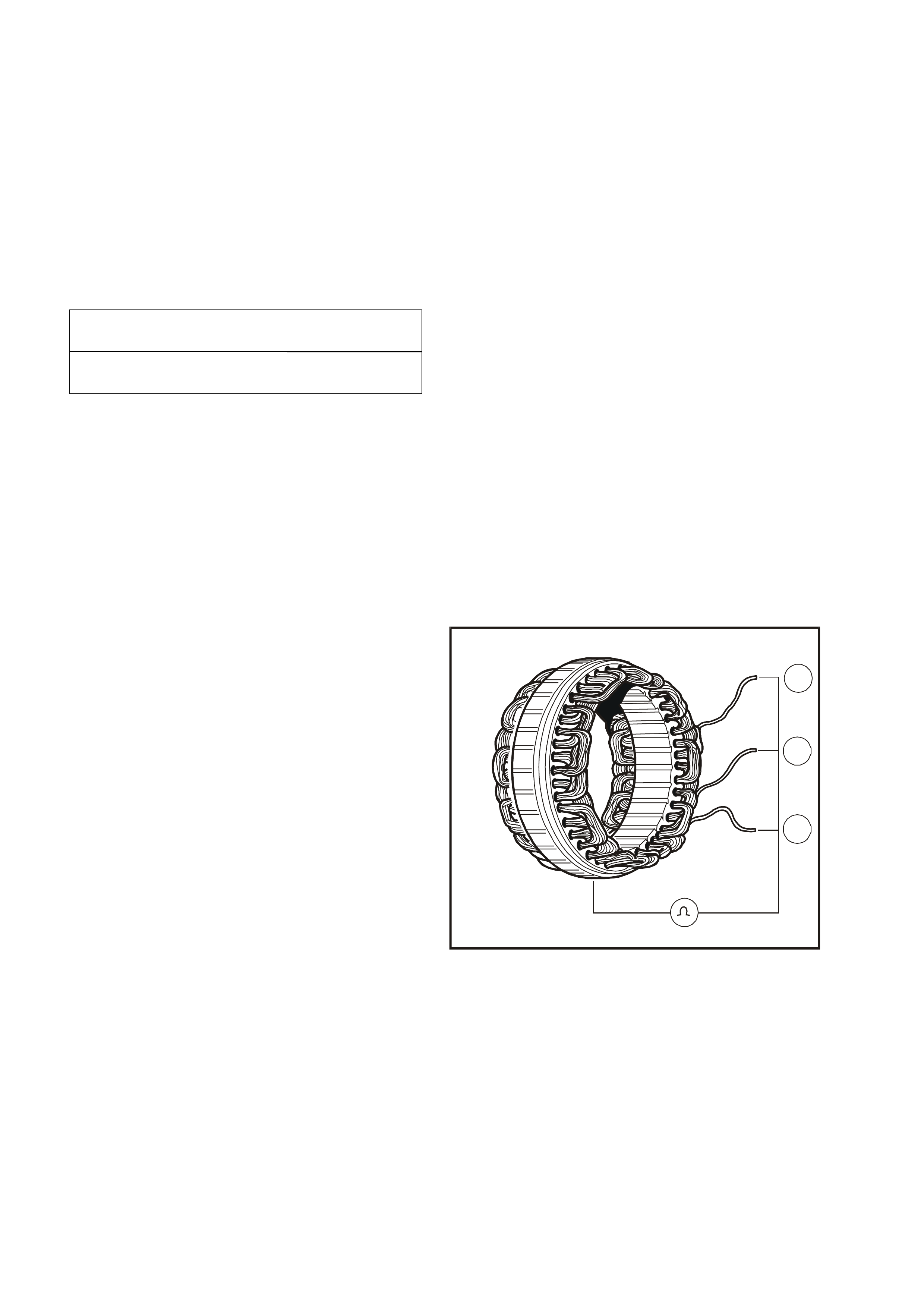
Insulation Test
Connect a powered test lamp (up to 40 V) or an
ohmmeter between any stator lead and stator
frame. If test lamp glows or ohmmeter reading is
low indicating that an open circuit does not exist,
replace stator.
T26D1126
3
2
1
Figure 6D1-1-28
SLIP-RING MINIMUM
DIAMETER 26.7 mm
SLIP-RING MAXIMUM
OUT-OF-ROUND 0.06 mm
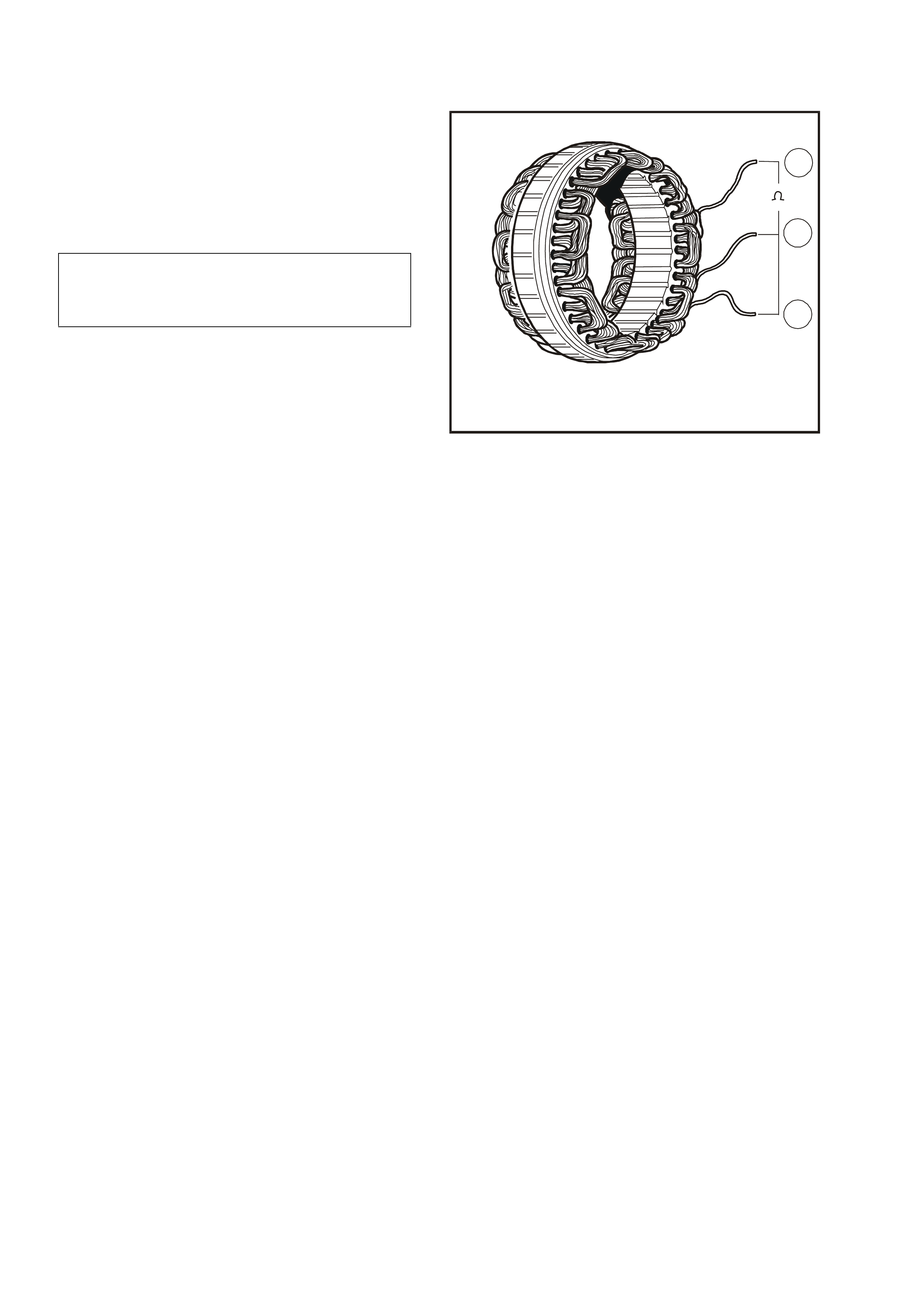
Open Circuit Test
1. Connect ohmmeter to any two stator leads.
Ohmmeter should not register any significant
resistance.
2. Repeat test on remaining stator leads. If
resistances are high, replace the stator.
The stator winding resistance is given in the
following chart.
T26D1127
3
2
1
Figure 6D1-1-29
STATOR WINDING
RESISTANCE @ 20° C
EACH PHASE
BETWEEN PHASES 0.027 ohm + 10%
0.054 ohm +10%
REASSEMBLE
Refer to Figure 6D1-1-2 for identification of
components.
1. Install new bearing into the drive-end housing
(1). Fit bearing plate and four retaining screws.
Tighten retaining screws to the correct torque
specification.
2. Insert new slip ring bearing (2) into recess in
Special Tool 9981 066 600 (3).
3. Insert rotor into special tool so that rotor shaft
is started into slip ring bearing.
4. Place drive end housing onto special tool,
install mandrel onto drive end housing and
press bearings into position on rotor.
T26D1128
2
1
3
Figure 6D1-1-30
5. Assem ble dr ive pulley, washer and nut to rotor
shaft.
6. Mount an 8 mm Allen key in a vice with the
long end pointing out from the side of the vice.
Place socket used for pulley nut removal onto nut.
Position drive-end housing with the internal
hexagon of the rotor shaft onto the Allen key.
Tighten drive pulley attaching nut to the correct
torque specification.
NOTE: Under no circumstances is the rotor to be
mounted in the vic e as the r otor and or c ooling
fans will be damaged.
T26D1113
Figure 6D1-1-31
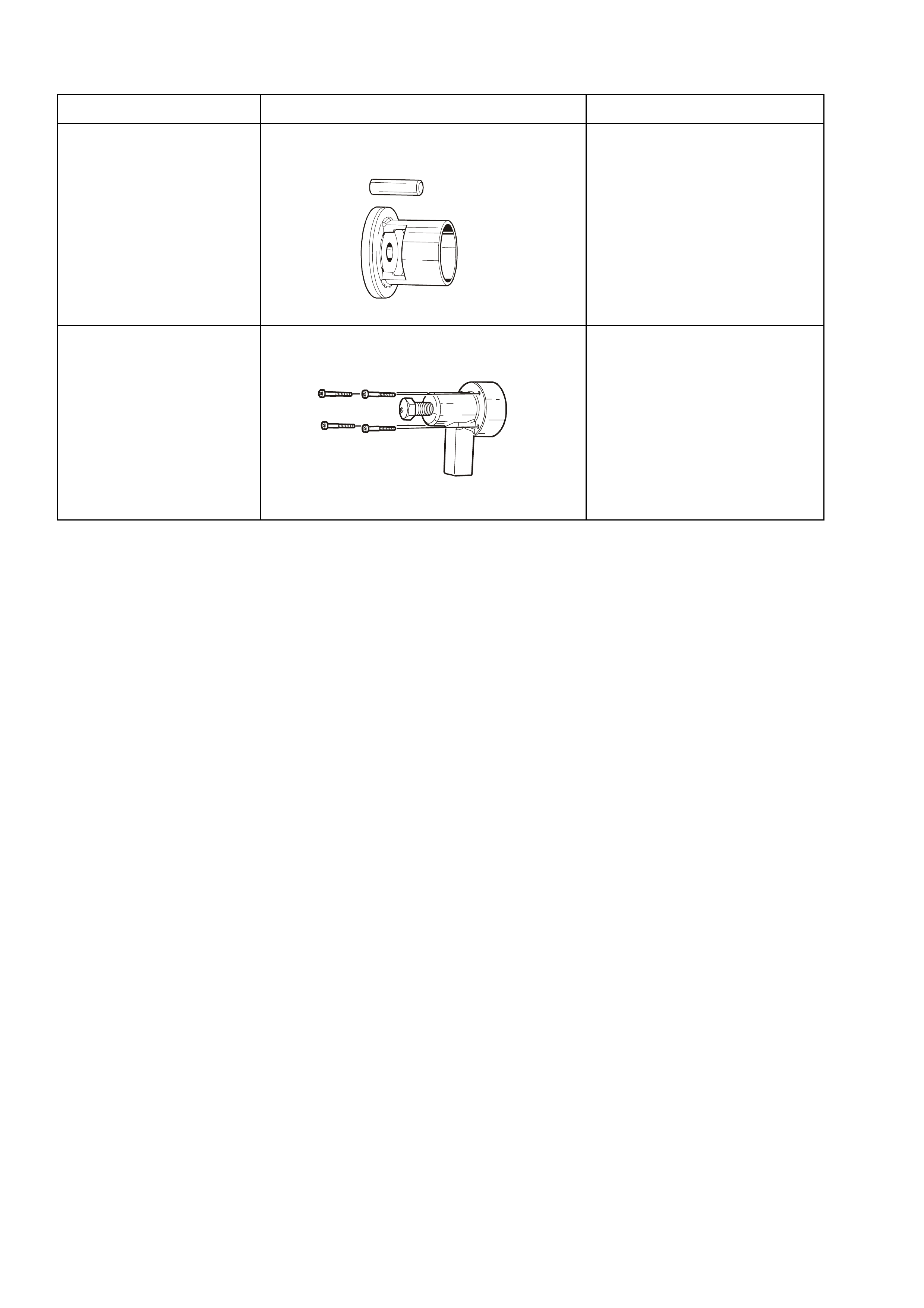
7. Inspect the slip-ring end bearing support ring
(1) for signs of damage. If in any doubt replace
the ring by pressing it into the slip-ring end
housing by hand. DO NOT USE EXCESSIVE
FORCE.
IMPORTANT: The slip-ring end bearing support
ring will only locate correctly into the slip-ring end
housing (2) in one location, ie with the long tang (3)
on its outer diameter locating into the mating slot
(4) in the slip-ring end housing (2).
T26D1129
1
2
3
4
Figure 6D1-1-32
DRIVE-END HOUSING
BEARING PLATE RETAINING
SCREW TORQUE
SPECIFICATION
2.1 – 3.0 Nm
DRIVE PULLEY ATTACHING
NUT TORQUE SPECIFICATION 54 – 68 Nm

8. Apply heat sink compound to both sides of
new rectifier positive heat sink mica washers.
Assemble mica washers to positive heat sink
with washer having largest hole fitted over the
B+ terminal bolt. The other mica washer is
fitted on the positive heat sink, around the hole
for the retaining screw.
9. Install spacer over B+ terminal bolt and
assemble rectifier into slip-ring end housing.
Install insulating washer, flat washer, wave
washer and nut on B+ terminal, leaving nut
finger tight.
10. Install and tighten rectifier retaining screws to
the correct torque specification.
Tighten B+ terminal nut to the correct torque
specification.
11. Ensure that the mating surfaces of the stator
frame, drive-end and slip-ring end housings
are clean and free from damage.
Fit the stator into the slip-ring end housing,
noting the correct lead positioning. Fit the
stator leads into the wire loops in the rectifier.
Using a pair of pointed nose pliers, squeeze
the loops to retain the stator leads prior to
soldering. Solder the leads into position using
60/40 resin cored solder.
Once completed, ensure the leads will clear the
internal fan when the rotor is assembled into
the stator.
12. Ass emble rotor and dr ive-end housing into the
stator and slip-ring end plate assembly,
aligning marks made during disassembly.
13. Install thr ough bolts and tighten evenly, and to
the correct torque specification.
IMPORTANT: Ensure that the slip-ring housing and
drive-end housing are seated squarely on the stator
frame. This ensures that the air gap between the
rotor and stator windings is equal at all points.
14. Install the regulator and brush assembly into
the slip-ring end housing, ensuring that the
regulator engages with the spring connectors
on the rectifier. Ensure the brushes are
located correctly onto the slip-rings.
Install the regulator and brush assembly
securing screws and tighten to the correct
torque specification.
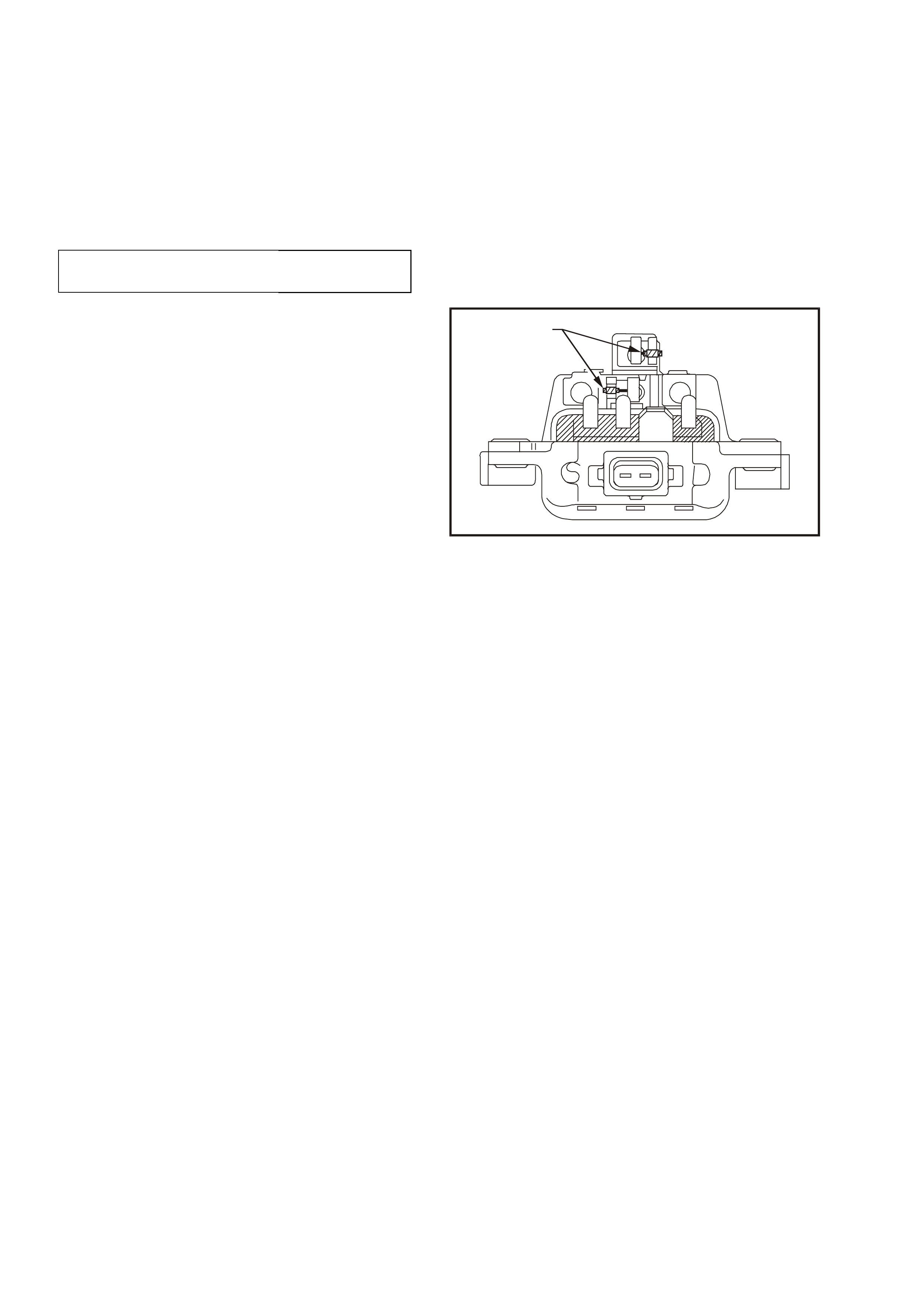
15. Connect suppressor lead to rectifier + terminal.
RECTIFIER RETAINING
SCREW TORQUE
SPECIFICATION 1.6 – 2.3 Nm
B+ TERMINAL NUT
TORQUE SPECIFICATION 7.5 – 8.5 Nm
THROUGH BOLT
TORQUE SPECIFICATION 3.8 – 5.5 Nm
REGULATOR AND BRUSH
ASSEMBLY SECURING SCREW
TORQUE SPECIFICATION 1.6 – 2.3 Nm
4. DIAGNOSIS
1. UNDERCHARGED BATTERY
a. Defective battery
b. Loose connection in charging system
c. Corroded connections in charging circuit
d. Defective wiring
e. Faulty generator
f. Faulty voltage regulator
2. OVERCHARGED BATTERY
a. Shorted battery cell
b. Faulty voltage regulator
c. Short circuit in rotor winding
d. Voltage drop in sense wire
3. FAULTY INDICATOR LIGHT OPERATION
(LIGHT DOES NOT GLOW]
a. Burnt out bulb
b. Defective bulb socket
c. Defective wiring
d. Defective rectifier
e. Defective regulator
4. FAULTY INDICATOR LIGHT OPERATION
(LIGHT REMAINS ON)
a. Negative diode failure
b. Defective voltage regulator
c. Faulty generator
d. B+ cable off or broken
e. S cable off or broken
f. Battery overcharged
g. Open circuit in rotor winding
5. NOISY GENERATOR OPERATION
a. Normal magnetic hum
b. Badly discharged battery
c. Generator mount brackets loose or bolts loose
d. Worn or frayed drive belt
e. Worn bearings
f. Loose drive pulley attaching nut
g. Open or shorted diodes
h. Open or shorted stator winding

5. SPECIFICATIONS
Earth Polarity ...............................................................................Negative
Nominal Voltage...........................................................................12 V
Nominal Output.............................................................................90 Amps
Stator Phases ..............................................................................3
Stator Winding Connections ........................................................Star
Number of Rotor Poles.................................................................12
Resistance of Rotor Winding (ohms @ 20°C)..............................2.47 – 2.73 Ω
Resistance of Stator Winding
Each Phase (ohms @ 20°C)..............................................0.027 Ω + 10%
Between Phases (ohms @ 20°C) ......................................0.054 Ω + 10%
Voltage Regulator Setting.............................................................14.0 – 14.2 V
Brush Length (measured in brush holder) ...................................12 mm (new), 3.8 mm (min)

6. TORQUE WRENCH SPECIFI CATIONS
Nm
Through Bolts...............................................................................3.8 – 5.5
Drive-end Housing Bearing Retaining Plate Screws ....................2.1 – 3.0
Drive Pulley Attaching Nut ...........................................................54 – 68
Regulator and Brush Assembly Securing Screws........................1.6 – 2.3
B+ terminal Nut.............................................................................7.5 – 8.5
Battery Harness Terminal to B+ Terminal Nut..............................5 – 12
Rectifier Retaining Screw.............................................................1.6 – 2.3
Capacitor Fixing Screw.................................................................1.5 – 2.2
Generator to Support and Brace Mounting Bolt ...........................20 – 34
Generator to Drive Belt Tensioner Bracket Mounting Bolt ...........20 – 34
7. SPECIAL TOOLS
TOOL NO. REF IN TEXT TOOL DESCRIPTION COMMENTS
9981 066 600 BEARING ASSEMBLY FIXTURE
81066600
9981 066 601 ROTOR BEARING REMOVAL TOOL
81066601