
SECTION 6D3-1 - CHARGING SYSTEM -
GEN III V8 ENGINE
CAUTION:
This vehicle will be equipped with a Supplemental Restraint System (SRS). A SRS will consist of either
seat belt pre-tensioners and a driver’s air bag, seat belt pre-tensioners and driver’s and front
passenger’s air bags or seat belt pre-tensioners, driver’s and front passenger’s air bags and left and
right-hand side air bags. Refer to SAFETY PRECAUTIONS, Section 12M Supplemental Restraint System
of the VT Series I Service Information before performing any service operation on, or around any SRS
components, the steering mechanism or wiring. Failure to follow the SAFETY PRECAUTIONS could
result in SRS deployment, resulting in possible personal injury or unnecessary SRS system repairs.
1. GENERAL INFORMATION
A Mitsubishi 140 amp generator is fitted to all VT Series II models with GEN III V8 engines. The generator is
mounted on the left-hand side of the engine below the power steering pum p. The generator can be identif ied by its
external appearance in that it has neither an external cooling fan nor an externally mounted regulator.
The generator is a three-phase type, incorporating a rotor having six pole pairs fitted with two cooling fans, one on
the drive end and the other on the slip-ring end. Rotor cur rent is c onveyed to the rotor winding by a pair of slip-r ings
and carbon brushes via the voltage regulator. T he rotor is supported by ball bearings in both the drive and s lip-ring
end housings. Surrounding the rotor is a field coil, which is of a three-phase star connected output winding
construction on a ring shaped lamination pack.
The output of the field coil winding is rectified by eight diodes which are contained within the slip-ring end housing.
Excitation current is supplied to the rotor field coil via the voltage regulator, brushes and slip-rings. The electronic
voltage regulator requires no adjustment in service.
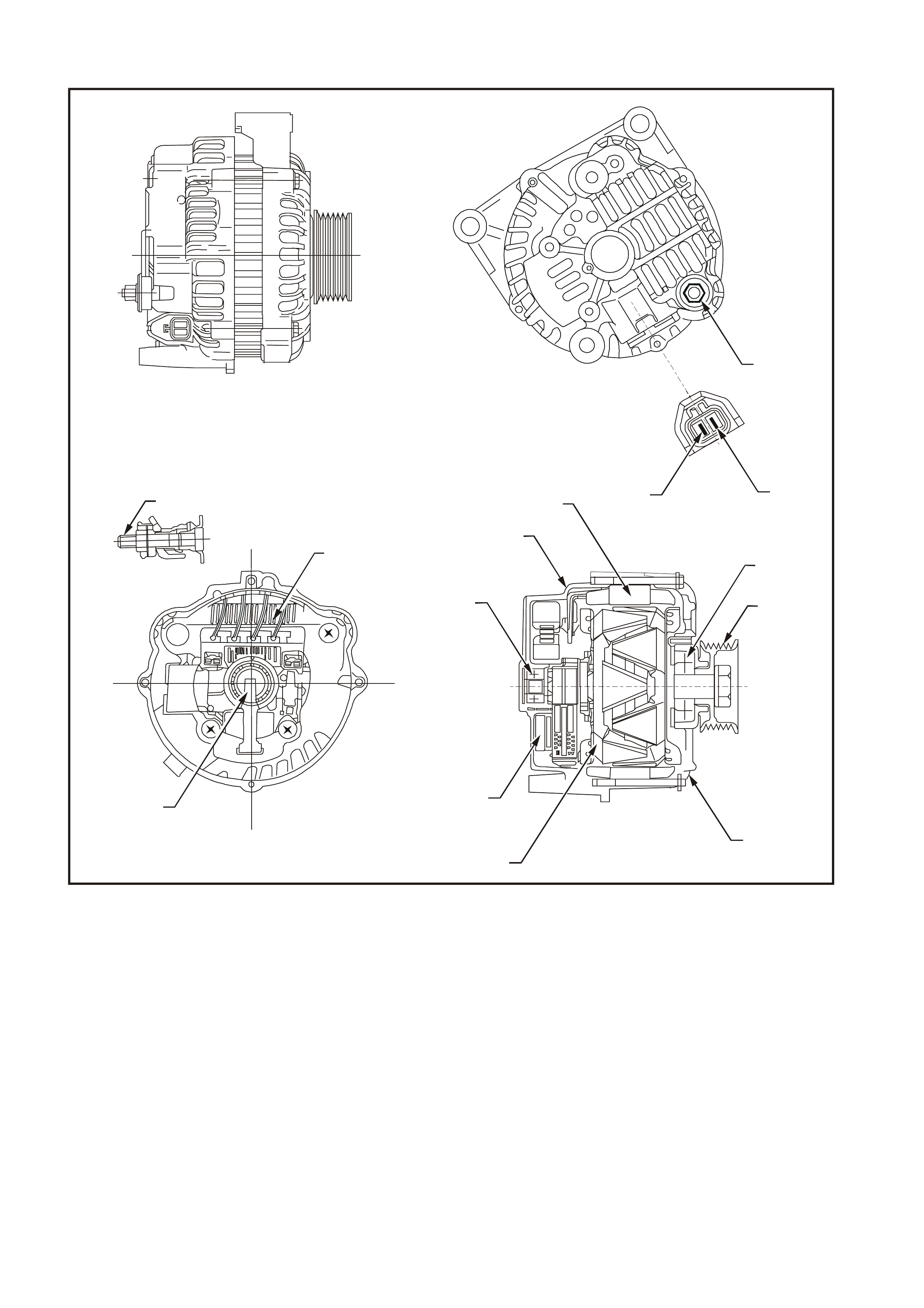
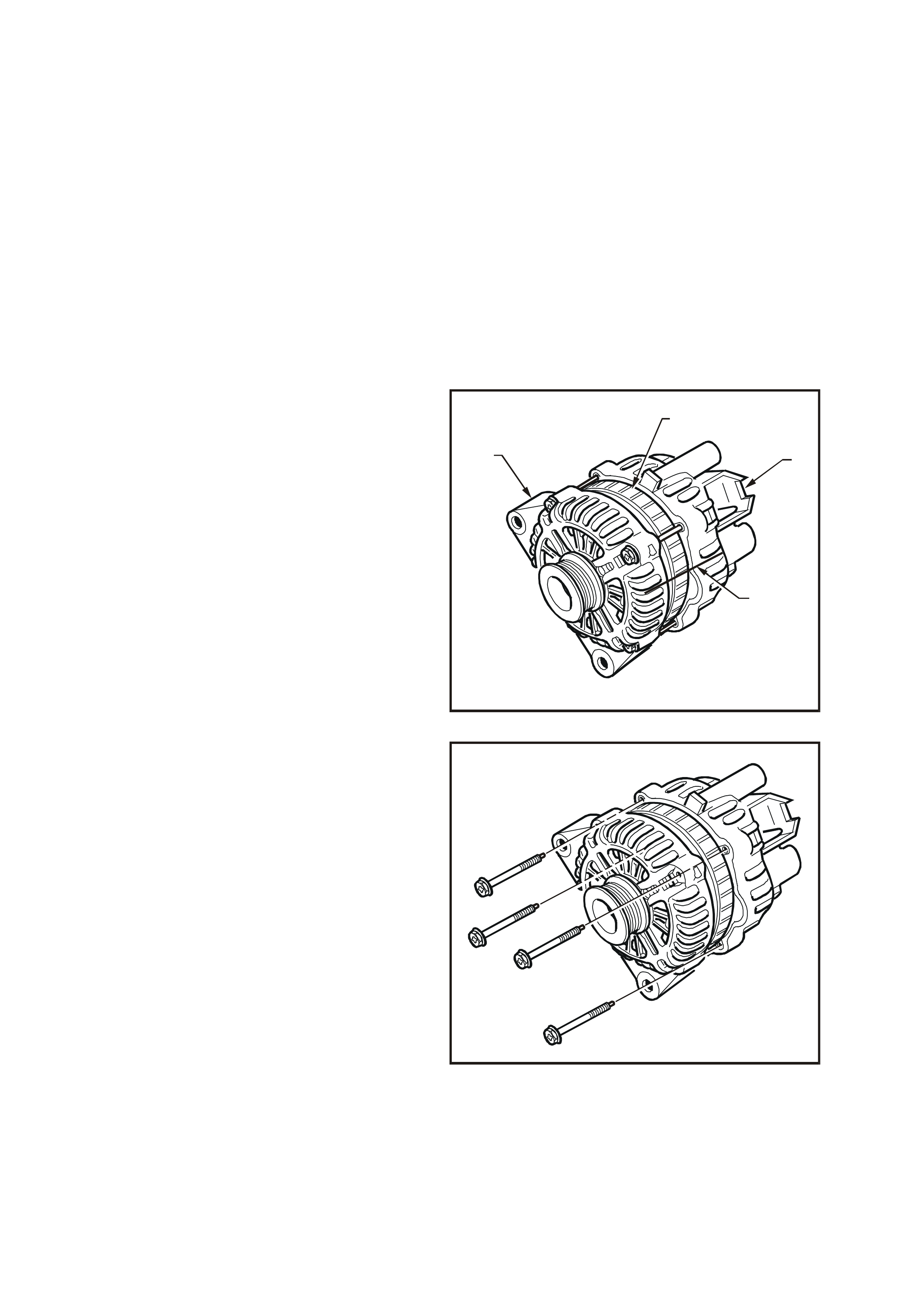
The generator has three external connections; the B+ lead to the battery positive terminal, the L lead to the
generator warning lamp (max. 2 watts), the S lead for battery voltage sensing, refer to Fig. 6D3-1-1.
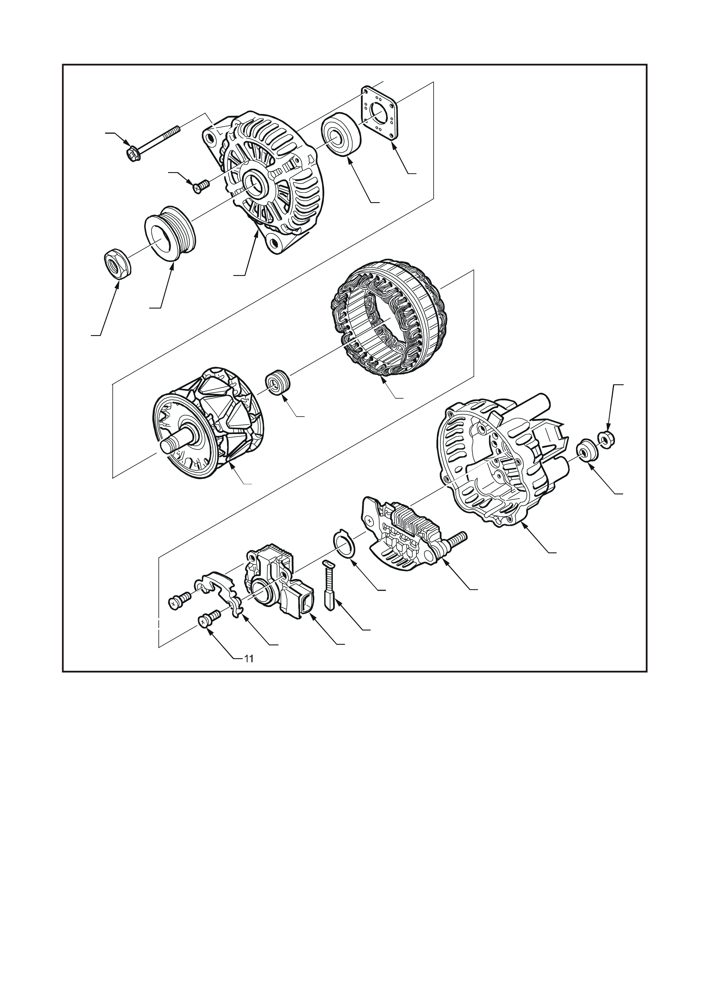
Fig. 6D3-1-2 shows an exploded view of the 140 amp generator.
T26D3101
2
3
9
1
6
7
8
5
4
12
13
14
11
10
Figure 6D3-1-1
1. Battery B+ Terminal
2. Wiring Lamp (L Terminal)
3. Battery Sensing (S Terminal)
4. Bearing
5. Pulley
6. Front Bracket
7. Rotor
8. IC Regulator
9. B+ Terminal Bolt
10. Rectifier
11. Brushes
12. Bearing
13. Rear Bracket
14. Field Coil
T26D3102
1
2
3
4
5
6
7
8
9
10
12 13 14
15 16
17
18
19
Figure 6D3-1-2
1. Through Bolt (4 off) 7. Bearing Retaining Plate 15. Thrust Washer
2. Bearing Retaining Plate Screw 8. Rotor 16. Rectifier Assembly
(4 off) 9. Slip-ring End Bearing 17. Rear Bracket Assembly (Includes
3. Nut 10. Field Coil Items 11 to 19)
4. Drive Pulley 11. Regulator and Brush Screws 18. Terminal Cover Bush
5. Front Bracket Assembly (Includes 12. Brush Retaining Plate 19. Nut
Items 2, 5, 6 and 7) 13. Regulator
6. Front Bearing 14. Brush
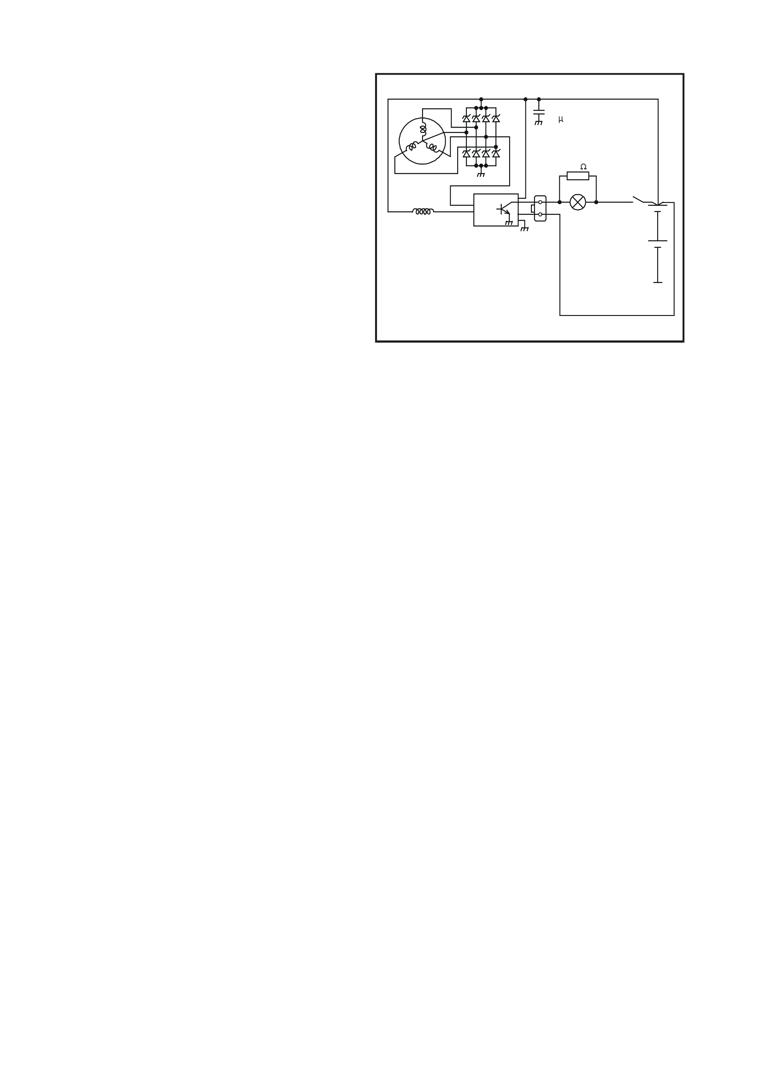
1.1 OPERATION
With the ignition switch turned to the on position,
current is supplied via the warning lamp to the
L terminal of the regulator. Current then flows from
the B+ terminal through the rotor winding via the
regulator brushes and the collector emitter junction
of the regulator switching transistor to earth,
completing the circuit.
The current in the rotor causes a magnetic field
between adjacent poles to be created, this field is
rotated and cuts the windings of the field coil at
right angles inducing a voltage into them. As the
speed is increased, this induced voltage increases
and results in current being rectified in the 3 phase
diode bridge and supplied as DC to the B+ output
and hence to the battery. When the voltage at the
B+ terminal to the battery reaches approximately
14.2 volts, the S terminal which is monitoring this
voltage, turns the regulator transistor base current
off, removing rotor current. This results in a
decrease in output voltage to below the regulating
voltage, turning the regulator transistor base
current back on and the whole cycle is repeated
very rapidly. An internal diode protects the
transistor and the regulator the against back
voltage developed across the rotor winding when
the regulator transistor turns off.
T26D3103
B+
0.5 F
80
IC REGULATOR
12V BATTERY
BATTERY SENSE
IGNITION
SWITCH
L
SWARNING LAMP
12 WATT
Figure 6D3-1-3
Should a situation arise where the main B+ cable
or battery sense wire (S terminal) become
disconnected or have a high resistance, the
regulator will limit the output voltage to a safe level
(backup mode), approximately 1 to 3 volts above
the regulators normal setting.
When the ignition switch is turned on and the
engine is not running, the current to the rotor is
reduced by switching it on and off at a 50% duty
cycle (active standby mode), the frequency is
approximately 4 kHz and may be audible at times
(this is norm al). Once the engine is s tarted, normal
regulation commences.

Should the warning lamp f ail, the generator will self
excite by deriving a small current from the phase
connection allowing the voltage to build up to
regulating level.
IMPORTANT: No rotor winding current will flow
when the engine is cranking.
The regulator incorporates internal diagnostics
which will illuminate the warning lam p as a result of
fault conditions in the generator and/or external
circuitry.
These conditions include:
1. Overcharging of the battery.
2. Regulator output stage short circuit.
3. Open circuit in the rotor winding.
4. Diode short circuit.
The regulator compares the voltage at the
B+ terminal with the voltage sensed at the
S terminal connected to the battery positive. If the
voltage differential exceeds a predetermined
threshold, the regulator will operate in backup
mode to limit the output voltage to a s af e level. T he
warning lam p will remain illum inated as long as the
fault conditions prevail.
Sources of high resistance which will trigger the
warning lamp are:
1. Poor contact in the wiring harness connectors.
2. Poor contact between the rectifier and the
regulator.
3. High resistance in the fusible link assem bly or
battery terminals and cables.

2. MI NOR SERVICE OPERATIONS
2.1 SAFETY PRECAUTIONS
Since the generator and voltage regulator are designed for use only on a negative earth system, the following
precautions must be observed. Failure to observe these precautions will result in serious damage to the generator.
1. When installing a battery, first f it positive (+) c able to battery positive (+) term inal and then f it negative (–) c able
to battery negative (–) terminal.
2. When a slave battery is utilised for starting purposes, ensure both batteries are connected in parallel, ie.
positive terminals together and negative terminals together.
3. When charging battery, disconnect both battery cables, thus isolating generator from battery and external
charging equipment.
4. The generator must not be oper ated on an open c irc uit (this is without the battery in the circuit), and the battery
must not be disconnected while the generator is running.
5. Do not attempt to polarise the generator.
6. Always ensure that generator warning lamp glows when ignition switch is turned to the ON position.
IMPORTANT: As this circuit is related to and assists in the exc itation of the r otor f ield windings, do not proc eed until
any faults in the generator warning lam p c ircuit have been rec tified. Ens ure that the warning lam p wattage does not
exceed 2 watts.
7. The L terminal of generator should never be connected to battery or ignition circuit (12 volts), as this will
damage generator warning lamp circuit.
8. Some battery powered timing lights can produce high transient voltages when connected or disconnected. Only
disconnect or connect timing lights when the engine is switched off.

2.2 MAINTENANCE AND ON - VEHICLE TESTING
At regular intervals, inspect the terminals of the generator for corrosion, check wiring for loose connectors or
damaged insulation. Check the mounting bolts for tightness, check the drive belt for alignment and wear and the
drive pulley for damage. The drive belt adjustment for the engine ancillaries, such as the generator and water pump,
is provided by a spring loaded tensioner. The drive belt therefore, does not require any regular adjustment.
LUBRICATION
The ball bearings supporting the rotor shaft are pre- lubr icated and s ealed, ther ef ore no lubr ic ation is poss ible during
service.
The bearings used in this generator are high tolerance type. If the bearings are removed during the generator
disassembly, new bearings must be installed to restore the generator to original specification.
TESTING THE GENERATOR OUTPUT AND VOLTAGE REGULATOR
Testing Prerequisites
Before testing the generator output, m ake certain that the generator circuit is thoroughly check ed for loose or dirty
connections. The generator must always be connected to the battery during testing, otherwise damage to the
diodes could result.
The battery should be fully charged. Test the specific gravity of the individual cells. The readings should be within
10 points of each other. It is recommended that the average specific gravity should be 1.260 or higher.
A load test should be carried out to determ ine the ability of the battery to supply and accept current. T his is a good
indicator as to the general condition of the battery. Refer to Section 12A BAT T ERY AND CABLES of the VT Ser ies
I Service Information for details of battery testing.
The generator warning light, in addition to indic ating that the generator is charging, is also necessary for initial f ield
excitation.
Inspect the drive belt and belt tens ioner markings to deter mine if the drive belt is within operating limits. Replac e the
belt if excessive wear is evident or outside the belt tensioner’s operating range, refer to Section 6A3 ENGINE
MECHANICAL — GEN III V8 ENGINE of the VT Series II Service Information for details.
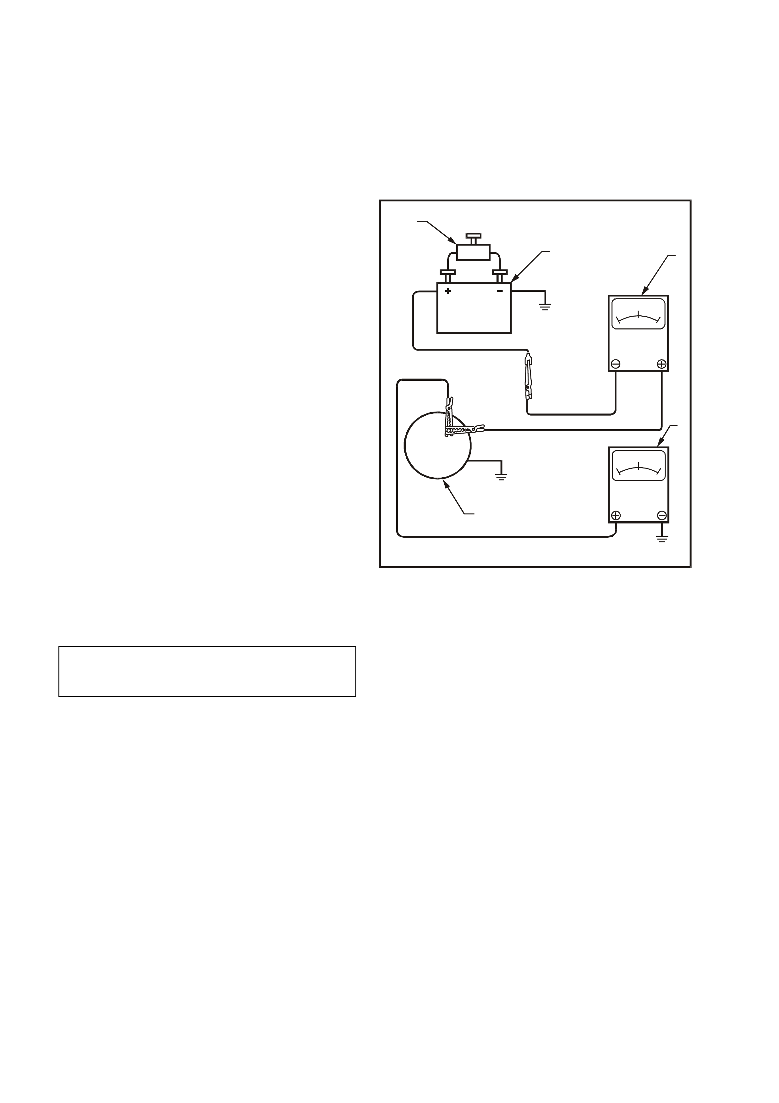
TESTING GENERATOR OUTPUT
Regulating Voltage Test on the Vehicle
1. Ensure that all the electrical equipment is
turned off, and the ignition switch is in the OFF
position.
2. Disconnect battery earth cable at battery.
3. Disconnect the generator positive lead (Red
wire) from the generator B+ terminal.
4. Connect the positive lead of an ammeter (1)
with a 0 - 100 am p scale to B+ term inal on the
generator (3), and the ammeter negative lead
to the disconnected generator positive lead
(Red wire).
5. Connect positive lead of a voltm eter (2) with a
minimum voltage scale of 0 - 20 volt to the
generator B+ terminal, and voltmeter negative
lead to a good earth connection on the
generator housing.
IMPORTANT: Insulate the generator positive lead
(red wire) terminal to prevent contact with any
metal part of the vehicle. If the terminal is earthed,
damage to the charging circuit will result when the
battery is reconnected.
6. Connect the earth cable to the battery (5). Fit a
loading device (4) across battery terminals, ie.
an adjustable carbon pile.
IMPORTANT: Loading device must have a
minimum power consumption of 1000 watts.
7. Record the voltmeter reading before starting
the engine. This reading s hould inc reas e when
the engine is running, indicating generator
output.
8. Start engine, raise engine speed and adjust
load (ammeter reading) to that nominated in
the following chart. Check generator output
(voltmeter reading) against specification.
T26D3104
B+
0+200-200
020
1
2
3
4
5
Figure 6D3-1-4
Load Regulation Test
With the voltmeter, ammeter and carbon pile
connected as in previous test, increase engine
speed to 2350 rpm (approximately 5000 generator
rpm ) and increas e load to approximately 126 am ps
(90% of full output). A decrease in the regulating
voltage should not exceed 0.5 volt of the readings
obtained in the previous test.
If the decrease in the regulating voltage is greater
than 0.5 volt, the regulator is defec tive and mus t be
replaced.
Generator Output Test at Full Load
With the voltmeter, ammeter and carbon pile
connected as in previous tests, increase engine
speed to 2350 rpm (approximately 5000 generator
rpm) and increase load until the generator output
voltage drops to 13.5 volts and note ammeter
reading.
ENGINE RPM
LOAD
VOLTMETER READING
1300
5 Amps
14.4 ±0.3 Volts

Full output (140 amps) should be obtained under
these conditions. It m ay be nec essary to adjust the
throttle so as to maintain the desired engine speed.
IMPORTANT: Keep the time for this test to a
minimum so as to avoid undue heating and high
engine speeds.
If the generator does not provide rated output, it
should be removed for repair, refer to
3.1 GENERATOR in this Section.
NOTE: On completion of the generator output
testing, to prevent excessive battery discharge
occurring, the engine should be returned to idle
speed and the loading device disconnected from
battery terminals.
9. Disconnect the battery earth cable at battery.
Remove the voltmeter and ammeter, then
reconnect the generator positive lead (Red
wire) to the generator B+ terminal. Reconnect
the battery earth cable to the battery.
CHARGING CIRCUIT VOLTAGE DROP TEST
With normal connections made at generator,
charging circuit can be checked for voltage
drop as follows:
1. Connect a low range voltmeter between
generator positive terminal and battery
positive post.
2. Switch on headlamps, start engine and
increase engine speed to approximately
2500 rpm and note voltmeter reading.
3. Reduce engine speed and transfer voltmeter
connections, negative to generator housing
and positive to battery negative post. Increas e
engine speed to approximately 2500 rpm and
again note voltmeter reading.
4. If readings exceed 0.5 volt on positive side
and 0.25 volt on negative side, there is a high
resistance in the charging circuit which must
be traced and corrected.
3. MAJOR SERVICE OPERATIONS
3.1 GENERATOR
REMOVE
CAUTION: Generator is in close proximity to
left-hand exhaust manifold. Allow engine to
cool before removing generator.
1. Disconnect battery earth lead.
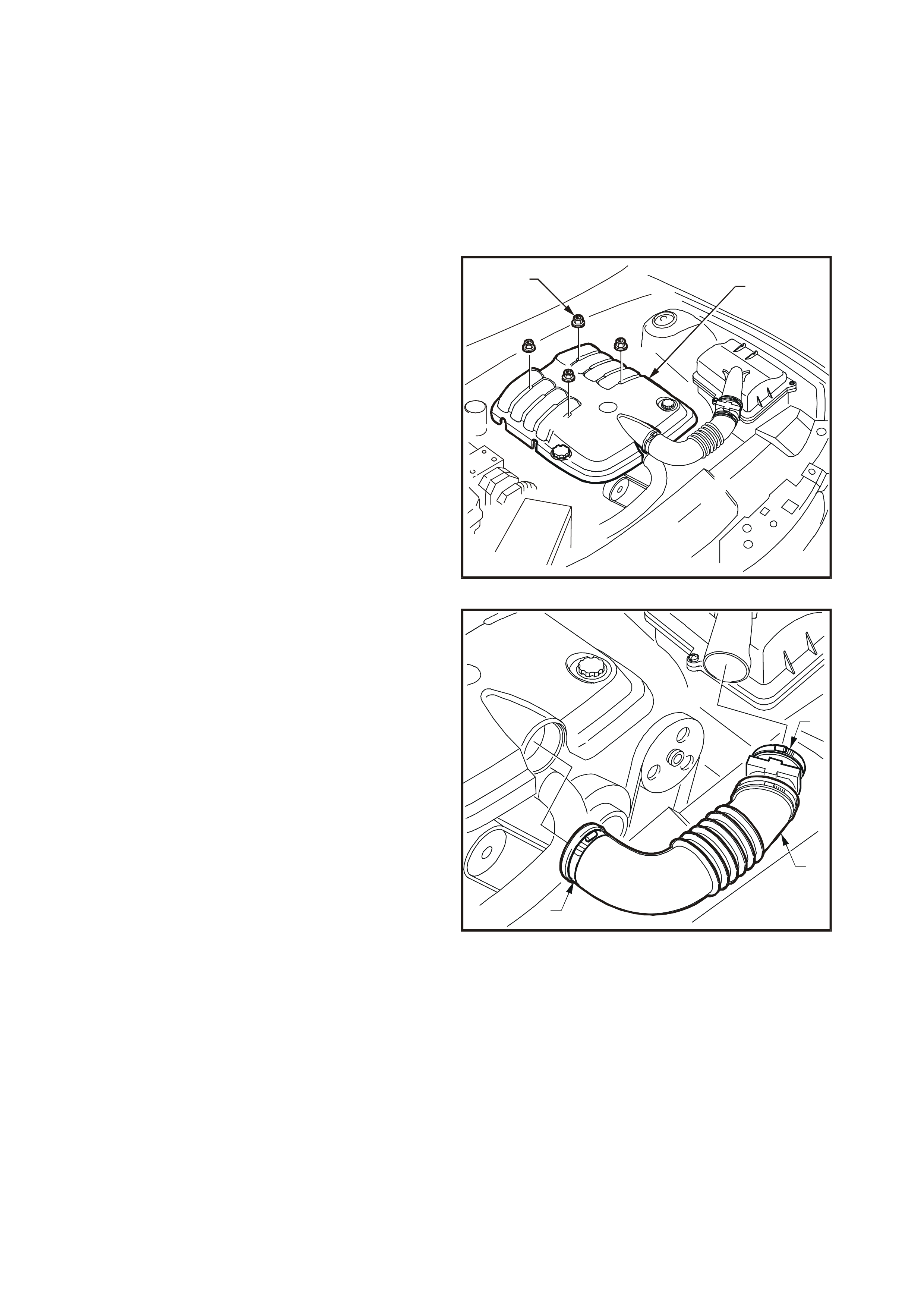
2. Remove four dome nuts (2) securing engine
dress cover assembly (1) to intake manifold
studs, then lift off and remove cover assembly.
T26D3105
21
Figure 6D3-1-5
3. Loosen clamps (1 ) s ec uring air intake hos e (2)
to throttle body and to air filter. Disconnect
wiring harness connector from mass airflow
meter and remove air intake hose and airflow
meter assembly.
T26D3106
1
1
2
Figure 6D3-1-6
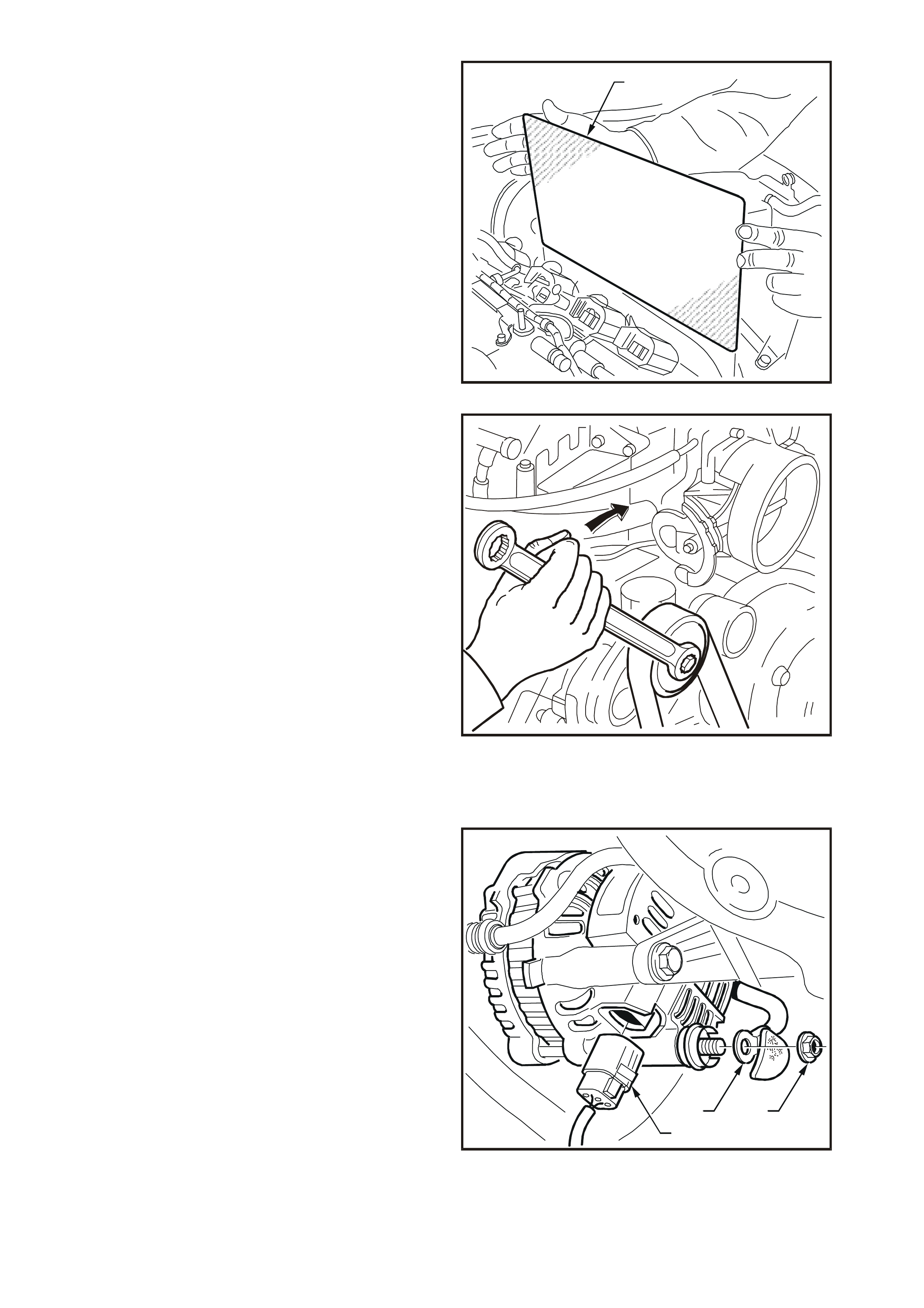
4. Lift and remove PCM heat shield (1) from
left-hand side of engine compartment.
5. Remove air filter housing assembly, refer to
Section 6C3-3 SERVICE OPERATIONS —
GEN III V8 ENGINE of the VT Series II
Service Information for details.
T26D3107
1
Figure 6D3-1-7
6. Using a 15 mm ring spanner on drive belt
tensioner pulley pivot bolt, rotate tensioner
pulley assembly clockwise and remove drive
belt from power steering pump and generator
drive pulleys. Release drive belt tensioner.
T26D3108
Figure 6D3-1-8
7. Remove power steering pump and reservoir,
refer to Section 9A STEERING of the VT
Series II Service Information for details.
8. Pull battery harness cap fr om B+ terminal, and
remove nut (1) and positive lead (2).
9. Press loc k tab on generator connec tor (3) and
remove generator connector (3) from
generator.
1
2
3
T26D3109
Figure 6D3-1-9
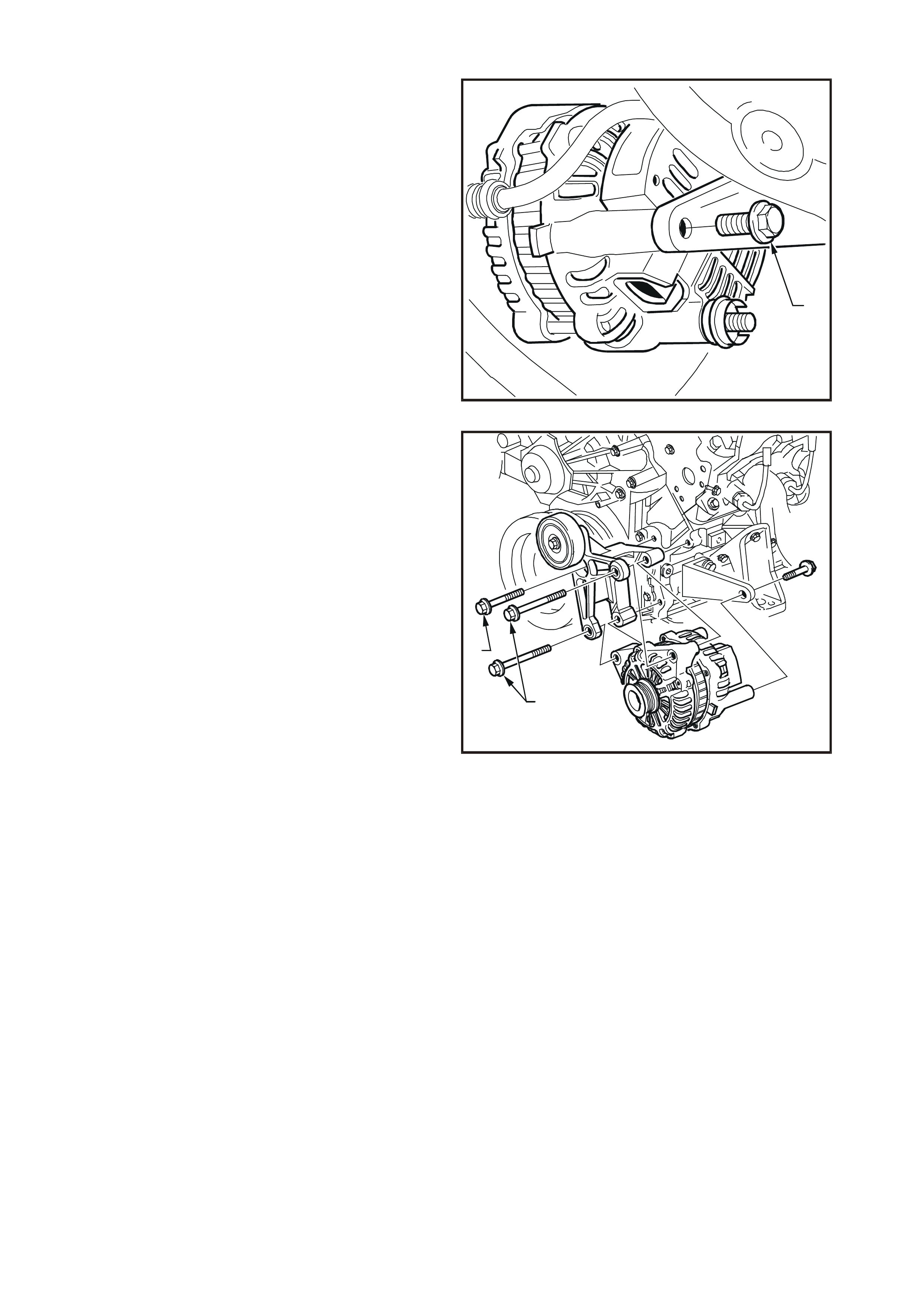
10. Remove bolt (1) securing rear of generator to
mounting bracket.
1
T26D3110
Figure 6D3-1-10
11. Remove two bolts (1) securing generator and
mounting br acket to the engine, then separate
generator from mounting bracket and lower
generator down onto stabiliser bar.
12. Remove bolt (2) securing generator and idler
pulley m ounting brack et to engine and r emove
mounting bracket and idler pulley assembly.
13. Lift generator up and out between engine and
radiator.
T26D3111
2
1
Figure 6D3-1-11

REINSTALL
1. Installation of generator is reverse of removal
procedure. Ensure that the mounting bracket
and generator retaining bolts are torqued to
specification.
2. Ensure that the nut retaining battery harness
positive lead to B+ terminal is torqued to
specification. Install cap over B+ terminal.
3. Install power steering pump, refer to Section
9A STEERING of the VT Series II Service
Information for details.
4. Using a 15 mm ring spanner on drive belt
tensioner pulley pivot bolt, rotate tensioner
pulley clockwise and install drive belt onto
power steering pump, generator and idler
pulleys.
Ensure that the drive belt is correctly routed
and that drive belt ribs are correctly installed
into all accessory drive belt pulleys and
crankshaft balancer drive belt grooves.
5. Install engine dress cover ensuring that stud
grommets in the dress cover remain in place.
Install dome nuts and tighten to correct torque
specification.
6. Reconnect battery earth lead.
7. Start engine and check generator warning lamp
operation, drive belt alignment, generator
output and voltage regulator operation.
ENGINE DRESS COVER TO
INTAKE MANIFOLD DOME NUT
TORQUE SPECIFICATION 4 – 6 Nm
GENERATOR
RETAINING BOLTS
TORQUE SPECIFICATION 40 – 60 Nm
B+ TERMINAL NUT
TORQUE SPECIFICATION 5-12 Nm
T26D3112
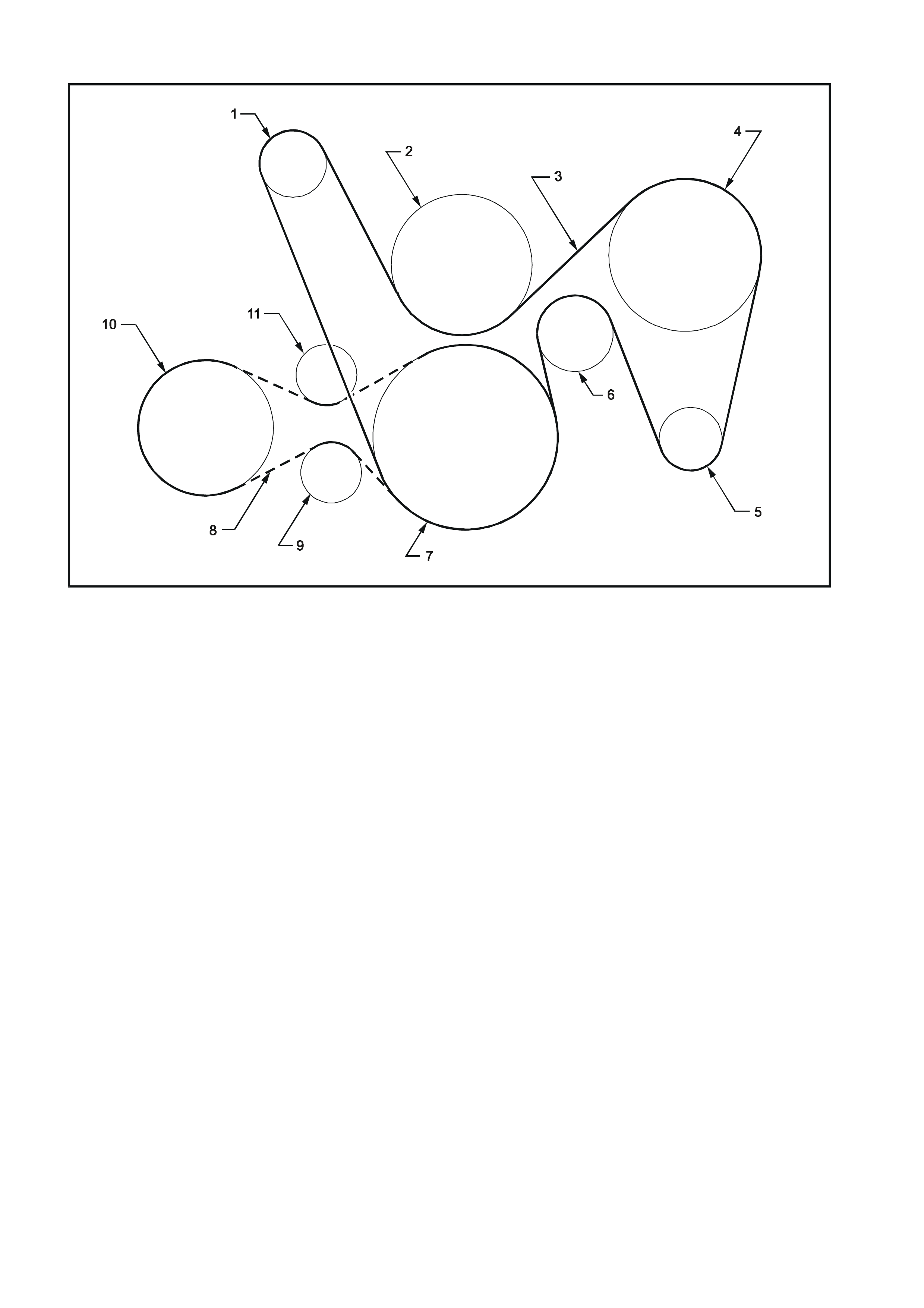
Figure 6D3-1-12
1. Tensioner
2. Water Pump
3. Drive Belt
4. Power Steering Pump
5. Generator
6. Idler
7. Crankshaft
8. Drive Belt (Air Conditioner Pump)
9. Tensioner (Air Conditioner Pump Drive Belt)
10. Air Conditioner Pump
11. Idler (Air Conditioner Pump Drive Belt)
DISASSEMBLE
The following precautions must be noted before
attempting to disassemble the generator to check
for faulty components.
• When testing the rectifier diodes with an AC
type tester, the RMS output must not exceed
12 volts. It is recommended that the field coil
should be disconnected before testing the
diodes.
• Insulation tests on the rotor and field coil should
use a voltage not exceeding 110 volts for a
series test lamp. The rectifier must be
disconnected from the field coil prior to testing.
• Due to the very low resistance value of the field
coil winding, it may not be possible to obtain
accurate readings using a conventional
ohmmeter.
1. Using a permanent marking pen align mark (4)
relative positions of front bracket (1), field coil
frame (2) and rear bracket (3).
T26D3113
1
2
3
4
Figure 6D3-1-13
2. Remove four through bolts.
3. Using a screwdriver, carefully prise between
the field coil and the front bracket, ensuring
that the screwdriver is not inserted too far or
the field coil will be damaged. Separate the
front bracket, pulley and rotor assembly away
from the field coil and rear bracket assembly.
T26D3114
Figure 6D3-1-14
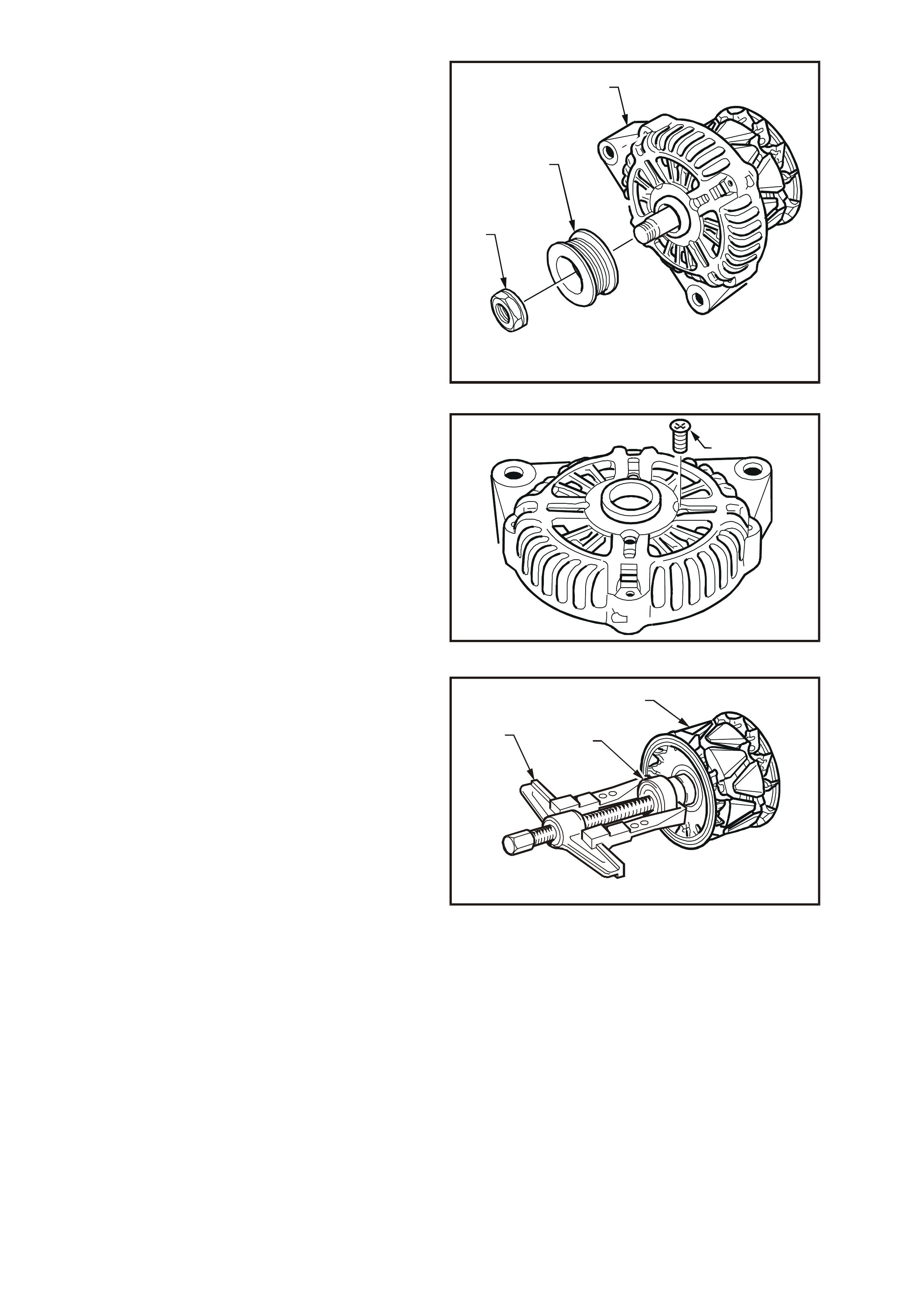
4. Clamp rotor in a vice, ensuring that the rotor
poles are not distorted, and remove drive
pulley attaching nut (1), drive pulley (2) and
front bracket (3).
T26D3115
1
2
3
Figure 6D3-1-15
5. Remove four screws (1) securing the bearing
retaining plate to front bracket.
6. Press the bearing from the f ront br ack et with a
suitable socket.
NOTE: The bearing MUST be replaced with a new
bearing on assembly.
T26D3116
1
Figure 6D3-1-16
7. Using a bearing puller (1), remove slip-ring
end bearing (2) from rotor shaft (3), taking
care not to damage the plastic side of the
slip-ring or distort the rear fan during the
process.
NOTE: The bearing MUST be replaced with a new
bearing on assembly.
T26D3117
12
3
Figure 6D3-1-17
8. Remove nut, wave washer, flat washer and
insulating washer from the B+ terminal bolt.
9. Remove the rectifier retaining screw and two
brush holder retaining screws. Separate the
field coil and rectifier assemblies as a unit
from the rear bracket.
10. Unsolder and remove each brush and spring
assembly.
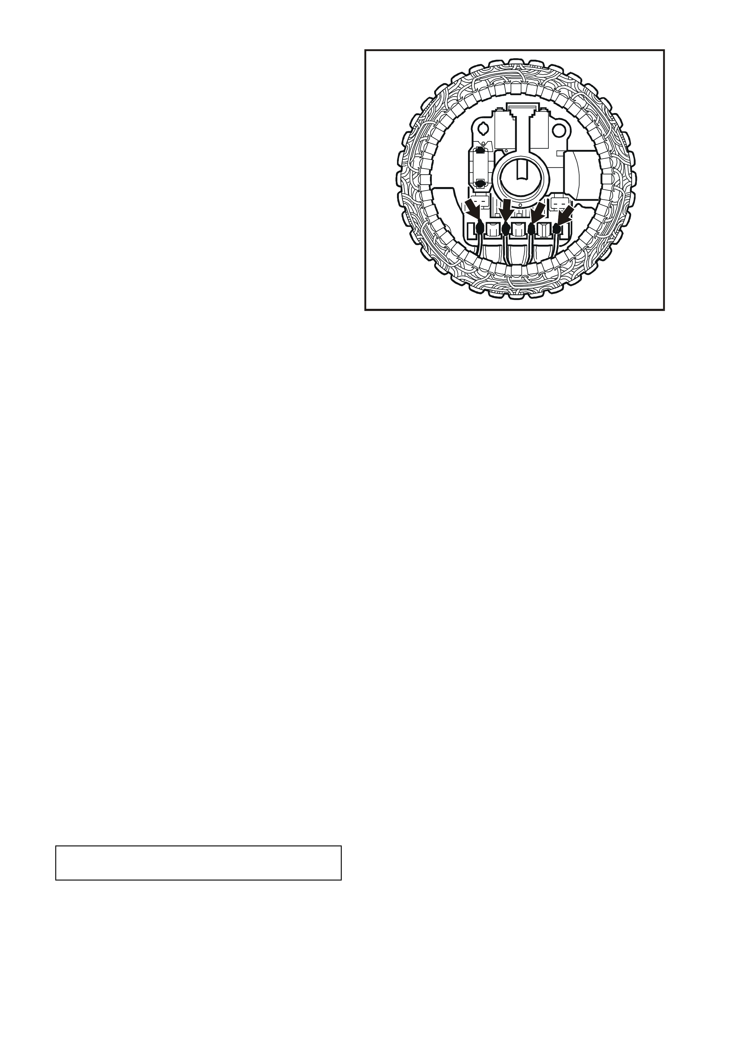
11. Separate field coil from rectifier assembly by
unsoldering the four field coil windings to
rectifier connections (arrowed in Fig. 6D3-1-
18).
NOTE: Use only as much heat as required to melt
the solder. Excessive heat may damage the
diodes.
IMPORTANT: T he rec tifier assemb ly is serviced as
an assembly only. Individual replacement parts are
not available.
T26D3118
Figure 6D3-1-18
12. Unsolder the two joints connecting the brush
holder and regulator assembly to the rectifier,
and remove the assembly from the rectifier.
CLEANING AND INSPECTION
With generator completely disassembled,
components should be cleaned and inspected.
Wash all components except field coil, rotor,
rectifier and regulator in a suitable cleaning solvent.
Carefully clean rotor and f ield coil with comp ressed
air.
NOTE: Do not clean field coils or rotor windings
with the cleaning solvent or damage to the
insulation could result.
NOTE: Clean all parts other than those previously
nominated using a non volatile or low inflammable
agent in a well ventilated area.
It is important that all parts are thoroughly dried
before assembly, taking care not to breath in any
vapours.
Observe the safety regulations and precautions
issued by the manuf actur er of the c leaning agent in
use.
COMPONENT CHECKING
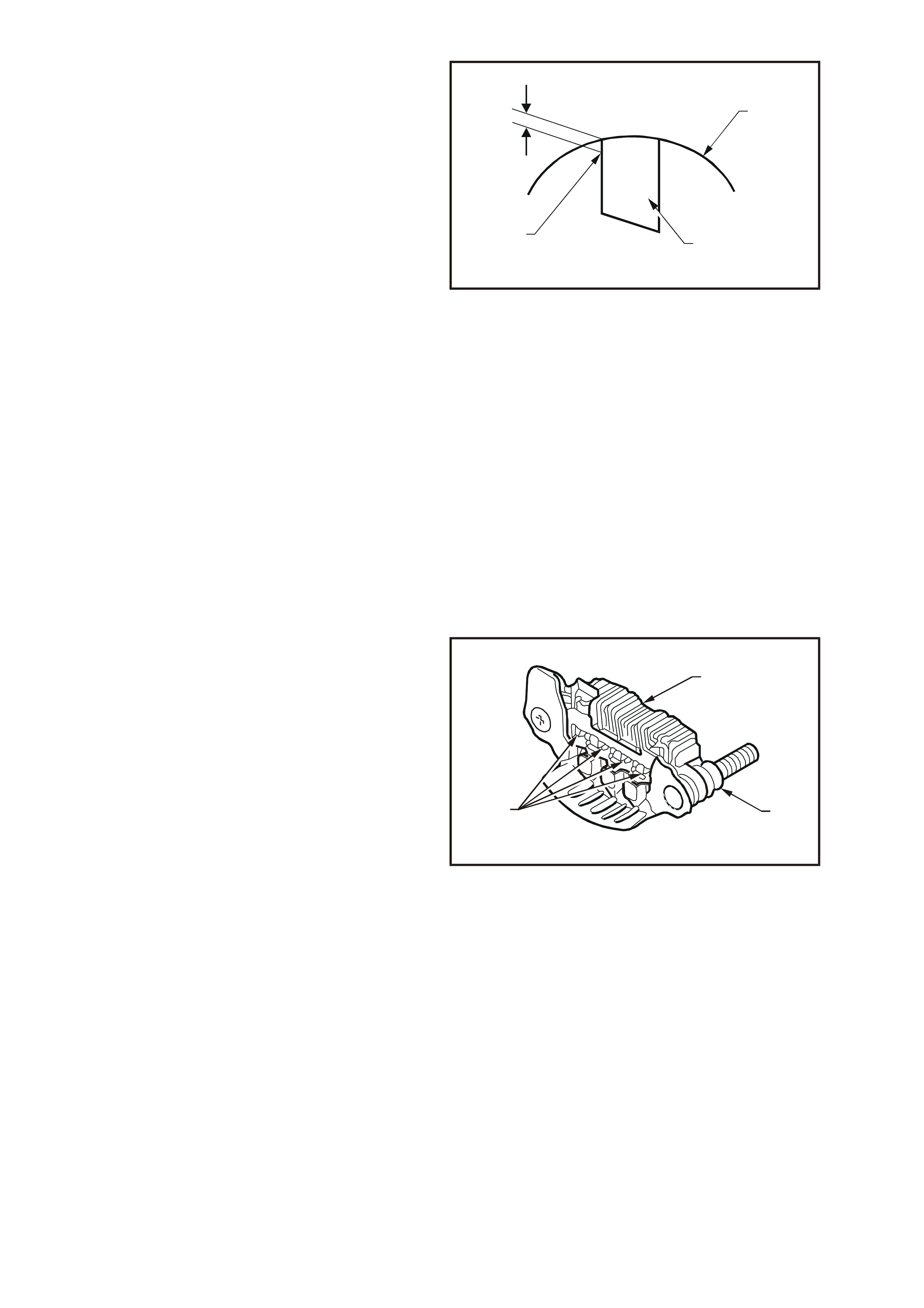
Brush Gear
Check the length of the brushes protruding from
the brush holder. Replace the brush and spring
assembly if the brush is worn down to the wear
limit. Also replace if abnormal wear or cracks are
noticed.
MINIMUM BRUSH
LENGTH 5.0 mm
Clean the brushes and brush holder, removing
particles by wiping with a clean cloth. Ensure that
the brush moves smoothly in the brush holder.
Replace if necessary.
Check the brush spring function. Push the brush
into the brush holder until the wear limit line of the
brush protrudes 1 mm from the brush holder
moulding and check the spring is functioning
correctly. Replace if necessary.
Check that brushes move smoothly in and out of
holder by pushing on end of brushes, and then
releasing. Replace if necessary.
T26D3119
1
2
3
Figure 6D3-1-19
Diodes
IMPORTANT: The rectifier assembly is not
repairable and should be replaced if any diodes
prove to be faulty.
The following commercially available test
equipment is essential for correctly testing the
diodes within the rectifier assembly.
A diode tester or multimeter with a diode test
feature where the DC output at the test pr obes
does not exceed 14 volts, or in the case of AC
testers, 12 volts RMS.
This is necessary so as to ensure that when
testing the diodes, the forward and reverse
voltage checks are completed and are not
masked by the diode turning on due to Zener
breakdown voltage.
IMPORTANT: In Steps 1 and 2, ensure that the
reverse voltage applied is less than 14 volts DC, or
12 volts RMS when using an AC tester.
1. Attach negative test probe of diode tester or
multimeter with diode test function to the
positive heatsink (1) of the rectifier assembly
and the positive probe alternatively to positive
diode connections (2).
A low resistance reading, or the forward
voltage drop across the diode should be
obtained.
Reverse probe connections and repeat test to
check that current is passed in one direction
only (high res istance r eading or higher r everse
voltage should be obtained).
If necessary, replace the rectifier assembly.
T26D3120
3
12
Figure 6D3-1-20
2. Repeat procedure on negative heatsink (3) by
attaching positive test probe to the negative
heatsink and the negative probe alternatively
to negative diode connections.
A low resistance reading, or the forward
voltage drop across the diode should be
obtained.
Reverse probe connections and repeat test to
check that current is passed in one direction
only (high res istance r eading or higher r everse
voltage should be obtained).
If necessary, replace the rectifier assembly.
Rotor
Clean any dirt or particles from the rotor with
compressed air or a clean cloth.
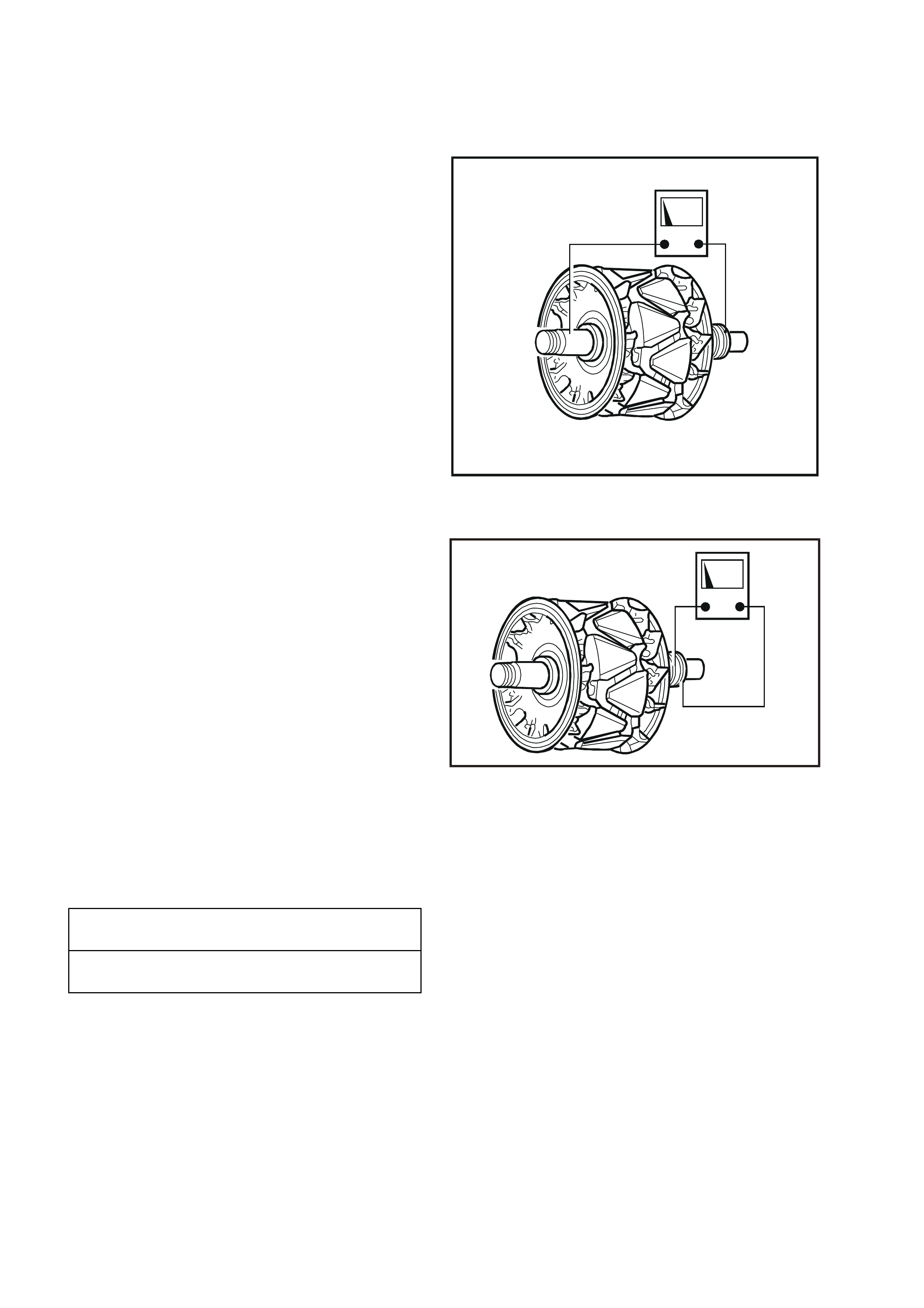
Insulation Test
Using an insulation tester, or a series test lamp (up
to 110 volts), check insulation between slip-rings
and rotor core or shaft. Test light should not glow or
insulation tester should indicate an open circuit
(greater than 1 Mohm). If an open circuit does not
exist replace rotor.
T26D3121
Figure 6D3-1-21
Open Circuit Test
Connect ohmmeter probes across slip-rings and
measure resistance of rotor windings.
If the rotor winding is open circuit, replace the rotor.
IMPORTANT:T he ac tual rotor winding resis tanc e is
too small to measure on a conventional multimeter.
T26D3122
Figure 6D3-1-22
Slip-rings
Check slip-rings for wear or damage. If the
slip-rings are worn, damaged or out-of-round, the
rotor must be replaced.
SLIP-RING
OUTER DIAMETER 22.7 mm
SLIP-RING
SERVICE LIMIT 22.1 mm
Bearings
The bearings used in this generator are a high
tolerance type. Only genuine replacem ent bearings
are to be used. It is recommended that the
bearings be replaced during the reconditioning
process to restore the generator to original
specification.
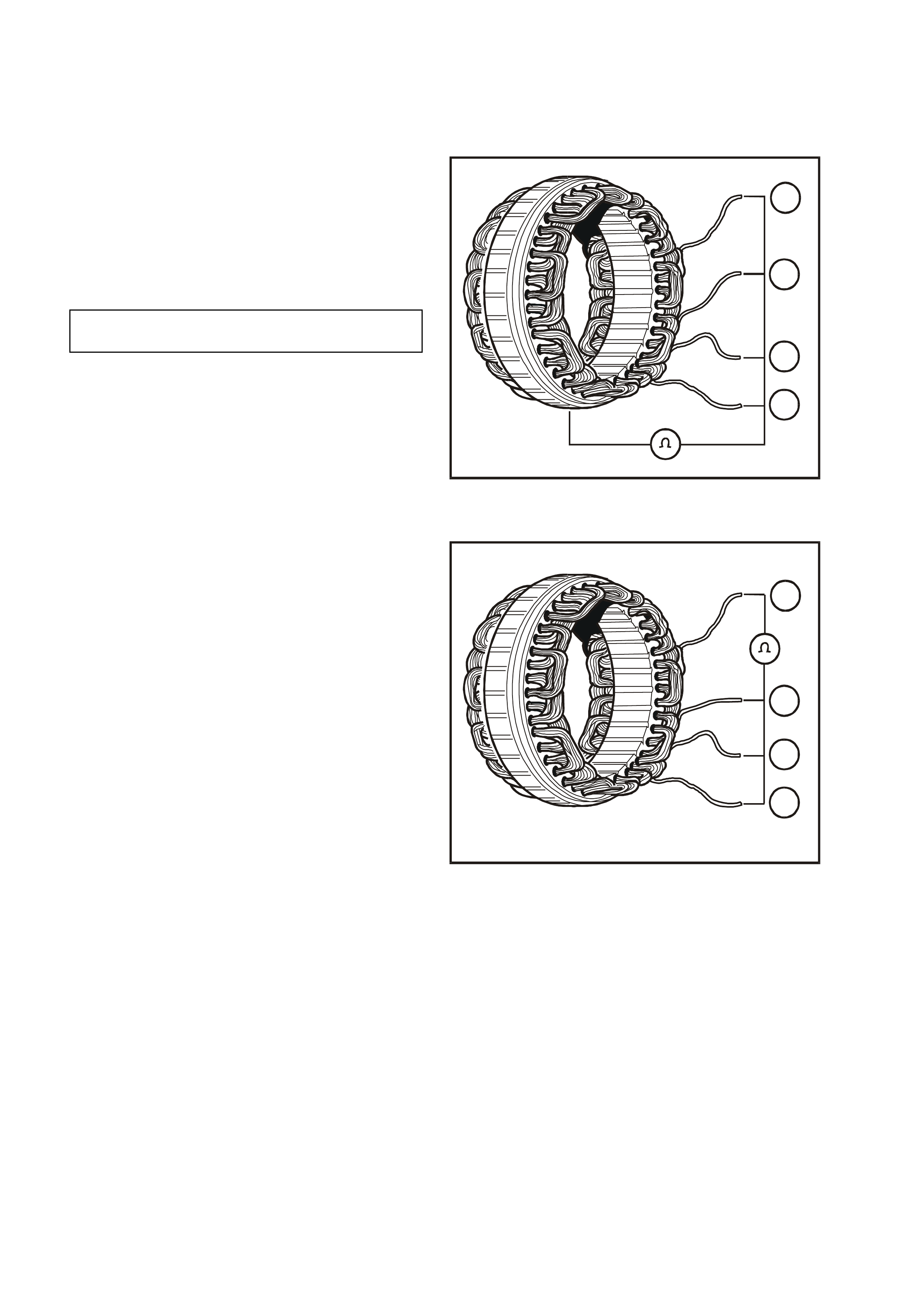
Field Coil
Inspect the f ield coil for damage, loose c onnec tions
or discoloured windings. Replace if necessary.
Insulation Test
Connect a powered test lam p (up to 40 volts) or an
ohmm eter between any field coil lead and field coil
frame. If test lamp glows or ohmmeter reading is
low indicating that an open circuit does not exist,
replace field coil.
T26D3123
4
3
2
1
Figure 6D3-1-23
Open Circuit Test
1. Connect ohmmeter to any two field coil leads.
Ohmmeter should not register any significant
resistance.
2. Repeat test on remaining field coil leads. If
resistances are high, replace the field coil.
T26D3124
2
1
3
4
Figure 6D3-1-24
REASSEMBLE
Reassembly of the alternator is the reverse of the
disassembly procedure, noting the following:
1. Do not lubricate the bearings as they are pre-
lubricated.
2. For rotor bearings with resin bands, grease
should not be applied. Remove oil completely
if found on the bearing box to prevent bearing
creep.
3. Use high temperature solder (melting point
230°C) and a 180 – 270 watts soldering iron.
Do not used exces sive heat as dam age to the
rectifier may result.
4. As the rotor bearing and rear bracket fitting is
tight, heat the area around the rear bracket
bearing box to 50 – 60°C before installing the
rotor into the rear bracket.
FIELD COIL RESISTANCE
@ 20°C 1.7 – 2.1
ohms
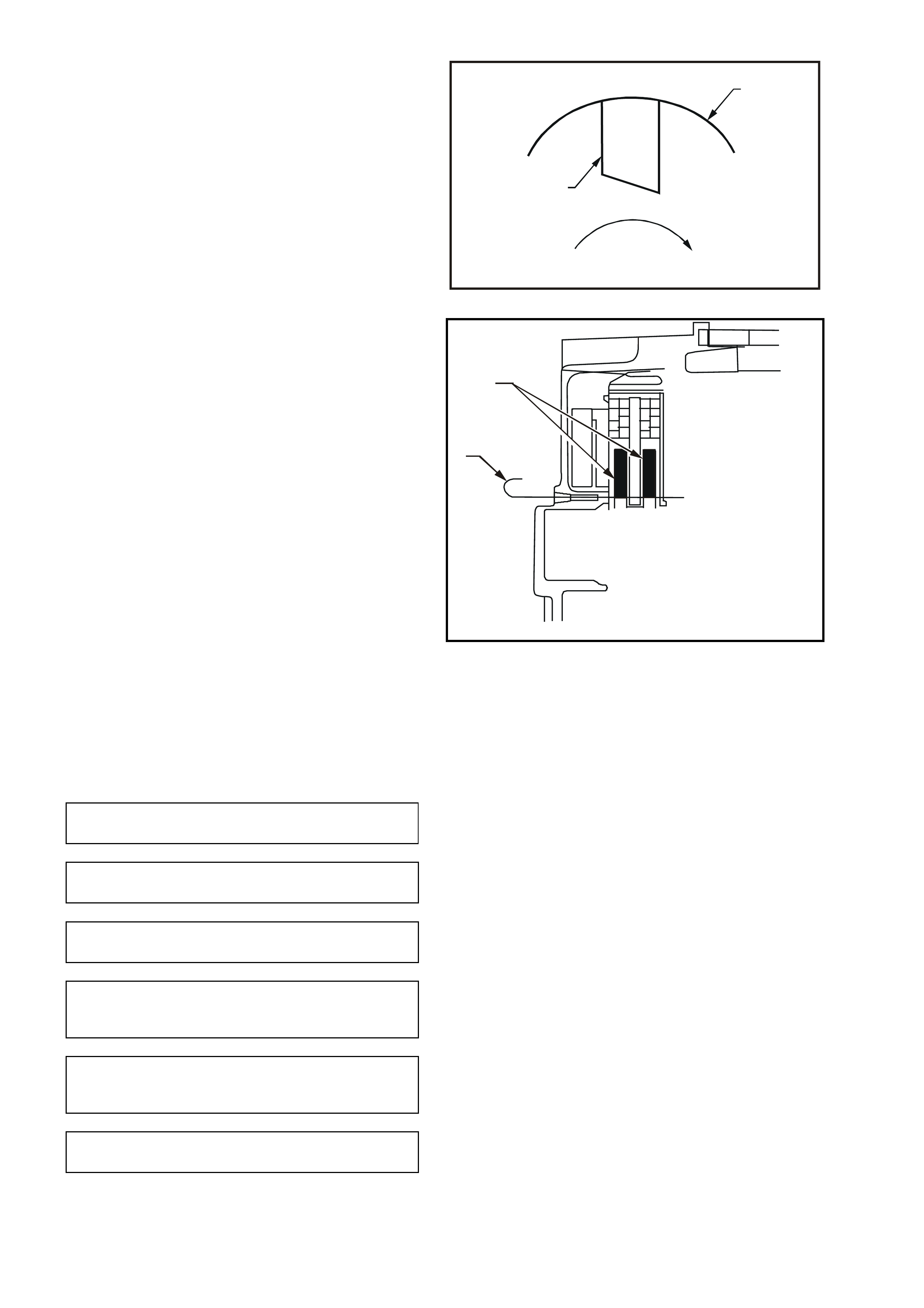
5. Position brushes (1) in the brush holder (2) in
relation to rotor rotating direction as indicated
by arrow in Fig. 6D3-1-25.
T26D3125
2
1
Figure 6D3-1-25
6. Before installing the rotor, push brushes (1)
into the brush holder and insert a wire (2) to
hold them in the raised position. Install the
rotor and remove the wire (2).
T26D3126
2
1
Figure 6D3-1-26
7. Do not over tighten the B+ terminal nut as
damage to the insulating washer will result.
8. After assembly, rotate the pulley slowly by
hand to verify that the rotor turns smoothly.
The following tightening torques apply.
DRIVE PULLEY ATTACHING
NUT TIGHTENING TORQUE 99 – 137 Nm
THROUGH BOLTS
TIGHTENING TORQUE 3.5 – 5.3 Nm
BEARING RETAINER SCREWS
TIGHTENING TORQUE 2.0 – 5.3 Nm
BRUSH HOLDER
RETAINING SCREWS
TIGHTENING TORQUE 2.0 – 5.3 Nm
RECTIFIER
RETAINING SCREWS
TIGHTENING TORQUE
2.0 – 5.3 Nm
B+ TERMINAL NUT
TIGHTENING TORQUE 12.8 – 18.6 Nm

4. DIAGNOSIS
1. UNDERCHARGED BATTERY
a. Defective battery.
b. Loose connection in charging system.
c. Corroded connections in charging circuit.
d. Defective wiring.
e. Faulty generator.
f. Faulty voltage regulator.
2. OVERCHARGED BATTERY
a. Shorted battery cell.
b. Faulty voltage regulator.
c. Short circuit in rotor winding.
d. Voltage drop in sense wire.
3. FAULTY INDICATOR LIGHT OPERATION
(LIGHT DOES NOT GLOW)
a. Burnt out bulb.
b. Defective bulb socket.
c. Defective wiring.
d. Defective rectifier.
e. Defective regulator.
4. FAULTY INDICATOR LIGHT OPERATION
(LIGHT REMAINS ON)
a. Negative diode failure.
b. Defective voltage regulator.
c. Faulty generator.
d. ‘B+’ cable off or broken.
e. ‘S’ cable off or broken.
f. Battery overcharged.
g. Open circuit in rotor winding.
5. NOISY GENERATOR OPERATION
a. Normal magnetic hum.
b. Badly discharged battery.
c. Generator mounting brackets loose or bolts loose.
d. Worn or frayed drive belt.
e. Worn bearings.
f. Loose drive pulley attaching nut.
g. Open or shorted diodes.
h. Open or shorted field coil winding.

5. SPECIFICATIONS
Earth Polarity......................................................................... Negative
Nominal Voltage.................................................................... 12 V
Nominal Output..................................................................... 140 Amps
Voltage Regulator Setting..................................................... 14.4 ±0.3 V
Field Coil Resistance @ 20°C............................................... 1.7 – 2.1 ohms
Rotor Resistance @ 20°C..................................................... Too small to measure
Slip-ring Outer Diameter....................................................... 22.7 mm
Slip-ring Service Limit........................................................... 22.1 mm
Brush Length New ................................................................ 18.5 mm
Brush Length Service Limit................................................... 5.0 mm
Direction of Rotation (viewed from pulley)............................ Clockwise

6. TORQUE WRENCH SPECIFI CATIONS
Nm
Engine Dress Cover to Intake Manifold Dome Nut............... 4 – 6
Through Bolts........................................................................ 3.5 – 5.3
Drive Pulley Attaching Nut .................................................... 99 – 137
B+ Terminal Nut.................................................................... 12.8 – 18.6
Battery Harness Terminal to B+ Terminal Nut...................... 5 – 12
Generator to Drive Belt Tensioner Attaching Bolts............... 40 – 50
Generator Support Brace Mounting Bolts............................. 20 – 30
Generator to Drive Belt Tensioner
Bracket Mounting Bolt........................................................... 20 – 34
Bearing Retainer Screws...................................................... 2.0 – 5.3
Brush Holder Retaining Screws............................................ 2.0 – 5.3
Rectifier Retaining Screws.................................................... 2.0 – 5.3