SECTION 6D3-2 - STARTING SYSTEM -
GEN III V8 ENGINE
CAUTION:
This vehicle will be equipped with a Supplemental Restraint System (SRS). A SRS will consist of either
seat belt pre-tensioners and a driver’s air bag, seat belt pre-tensioners and driver’s and front
passenger’s air bags or seat belt pre-tensioners, driver’s and front passenger’s air bags and left and
right-hand side air bags. Refer to SAFETY PRECAUTIONS, Section 12M Supplemental Restraint System
of the VT Series I Service Information before performing any service operation on, or around SRS
components, the steering mechanism or wiring. Failure to follow the SAFETY PRECAUTIONS could
result in SRS deployment, resulting in possible personal injury or unnecessary SRS system repairs.
1. GENERAL INFORMATION
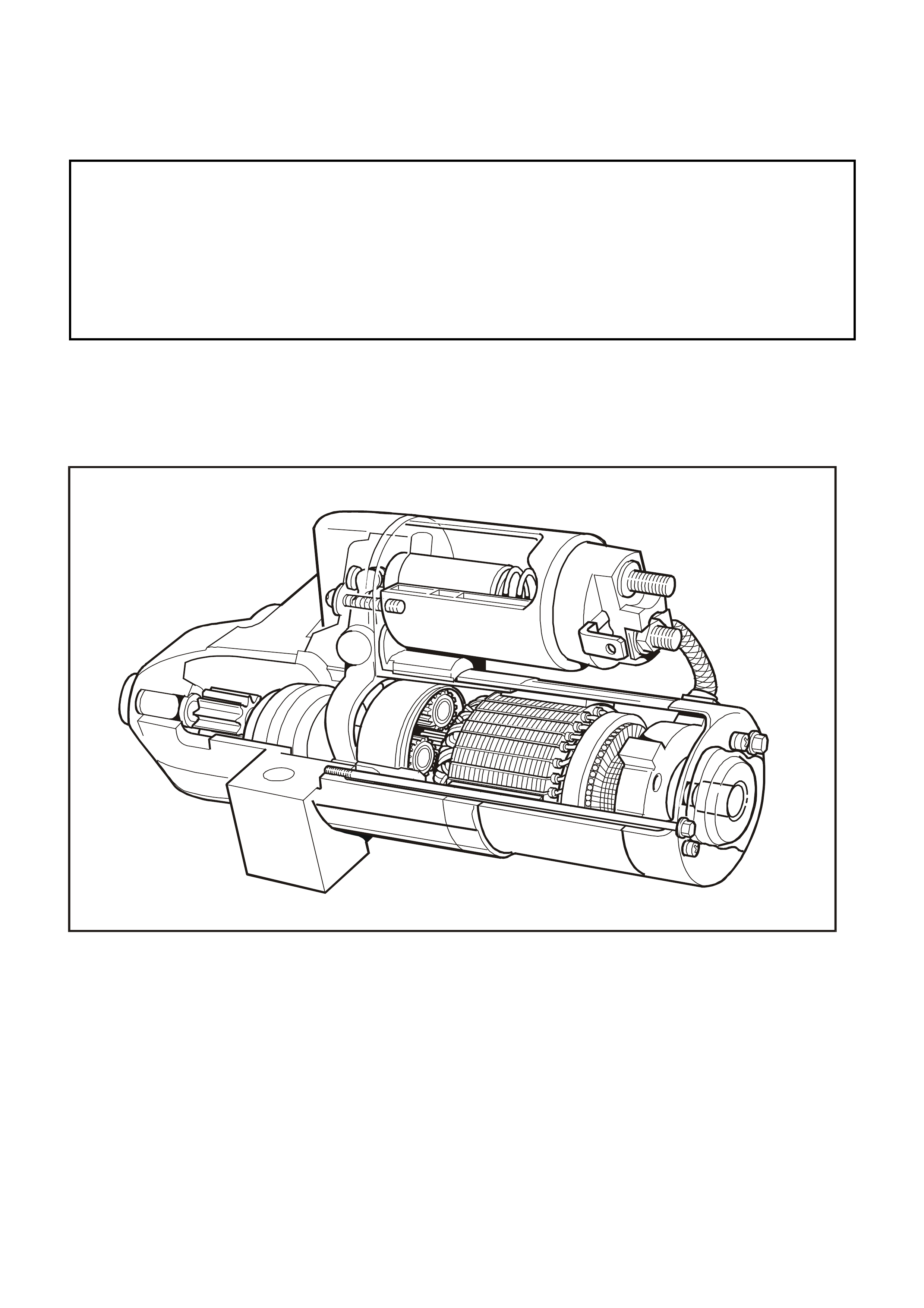
A Delco Remy, six-pole, four-brush starter motor is fitted to the VT Series II models with GEN III V8 engines. The
starter motor is a pre-engaged drive type with planetary reduction gears and is illustrated in Fig. 6D3-2-1.
T26D3228
Figure 6D3-2-1
1.1 GENERAL DESCRIPTION
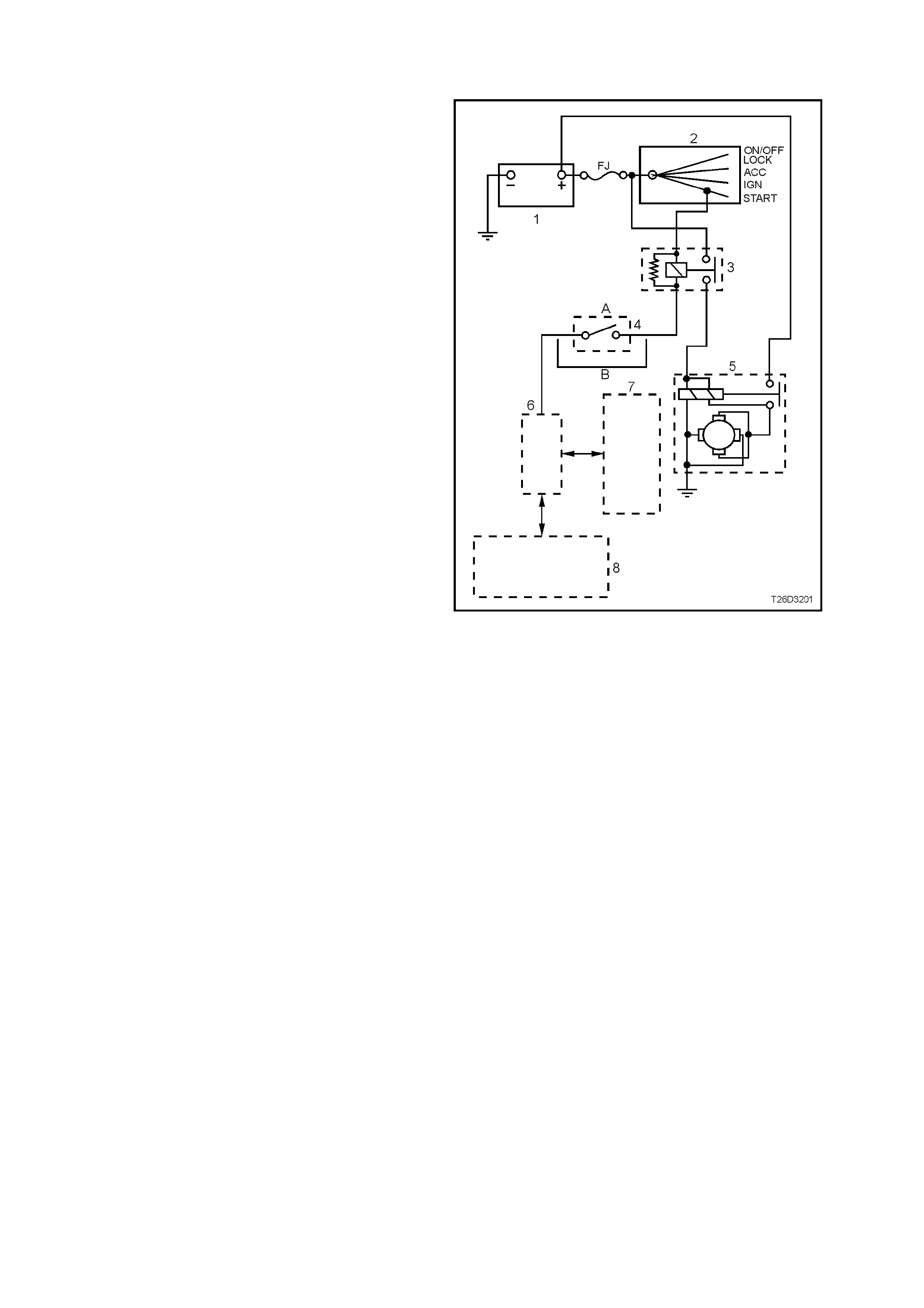
The starting system comprises the battery (1),
starter motor (5), ignition switch (2), start realay (3),
neutral/back -up switch (A - autom atic transm ission,
B – Manual transmission), Powertrain Interface
Module (PIM) (6), Powertrain Control Module
(PCM) (7), the Body Control Module (8) and related
electrical wiring. For additional infor m ation realating
to the interaction between the PIM, PCM and BCM,
refer to Section 12J-1 and Section 12J-2 of the
VT Series II Service Information
The s tarter m otor is a six pole, four brush type with
a planetary drive train. Each of the six poles is a
permanent magnet which is secured to the inside
diameter of the f ield f r ame ass embly. The armatur e
shaft which revolves centrally within the field f rame
assembly is supported at each end by metal
bushes pressed into the commutator end cover and
the inside of the planetary drive shaft.
The planetary drive train comprises a ring gear
(made from a high-grade polyamide compound with
mineral additives) with gear teeth on the inside
diameter, three planetary gear wheels and a
planetary drive shaft. When assembled, the
planetary drive shaft, which is flanged at one end
with three shafts machined onto the flange, is
positioned in the ring gear. The three gear wheels,
each m ounted on bushes, are f itted onto the shafts
on the flange of the planetary drive shaft where
they m esh with the internal teeth of the ring gear . A
metal bush is fitted into the recess in the flanged
end of the planetary drive shaft to provide a
mounting f or the end of the armature. A m etal ball,
also positioned in the recess limits the amount of
end float of the armature shaft. The cover plate is
positioned and secured over the gear end of the
assembly.
Figure 6D3-2-2
The drive assembly is installed onto the planetary drive shaft, meshed with the gear on the drive shaft and
secured to the shaft by a stop ring and ring retainer. The combined assembly is installed into position in the
starter m otor drive-end housing. The planetary drive shaft is supported by a bush in the drive-end housing, while
the ring gear is located by the drive-end housing, providing positive and secure mounting of the drive shaft and
drive assembly.
When the starter motor is assembled, the teeth of the gear on the armature shaft mesh with the teeth on the
three planetary gears wheels. W hen the s tarter m otor is oper ated, drive f rom the arm ature causes the planetary
gear wheels to rotate and revolve around the inner diameter of the r ing gear which is f ixed in pos ition. This ac tion
causes the planetar y drive shaft to rotate and impar t drive into the dr ive as sembly. During operation of the star ter
motor the armature rotates the drive assembly at a reduced speed of approximately 3.36:1.
The bushes and planetary gears require lubrication only at the time of an overhaul.
The f our brushes ar e supported by the brush holder assem bly which is s ecured to the com m utator end cover by
screws. T wo brushes are grounded to the starter m otor body, via the comm utator c over retaining sc rew, and two
are insulated from the housing and c onnected to the c ommutator. Per manent magnets are pos itioned ar ound the
inside diameter of the field frame assembly and secured by brackets.
On the drive-end housing, a polyamide fork is used to engage the drive assembly with the flexplate/ring gear.
The drive assembly transmits cranking torque to the flexplate/ring gear. To prevent the armature from being
driven at exces sive speed by the engine, an internal clutch allows the drive assem bly pinion gear to rotate fr eely
in relation to the planetary shaft and armature when the engine begins to operate.
T26D3201
1234
5
6
7
8
9
10
11
12
13
14
15
16
17
18
19
20
21
22
Figure 6D3-2-3
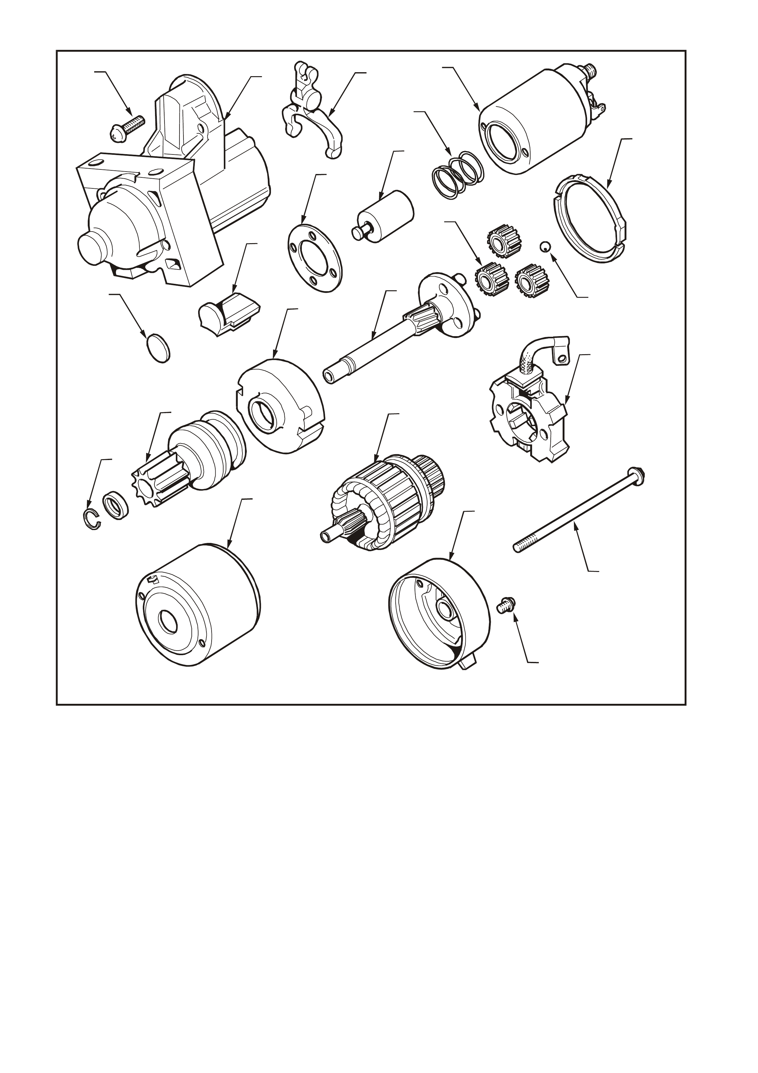
1. Solenoid switch to drive-end
housing mounting screw (2 off) 8. Rubber packing (Part of lever set) 15. Clutch gear assembly – Pinion (Part
of shaft assembly – clutch set)
2. Drive-end housing 9. Plate (Part of lever set) 16. Stopper ring and ring retainer (Part
of shaft assembly – clutch set)
3. Fork lever (Part of lever set) 10. Packing – sealing ring 17. Brush holder assembly
4. Solenoid switch 11. Ball 18. Armature
5. Return spring 12. Planetary gears (Part of shaft
assembly – clutch set) 19. Field frame assembly
6. Plunger 13. Drive shaft assembly (Part of shaft
assembly – clutch set) 20. Through bolt (2 off)
7. Solenoid switch to drive-end
housing spacer 14. Cover – gear assembly (Part of
shaft assembly – clutch set) 21. Brush holder retaining screw
22. Commutator end cover
2. SERVICE OPERATIONS
2.1 PERFORMANCE TESTING
The following tests involve the starter motor being
removed from the vehicle, refer to 2.2 STARTER
MOTOR in this Section.
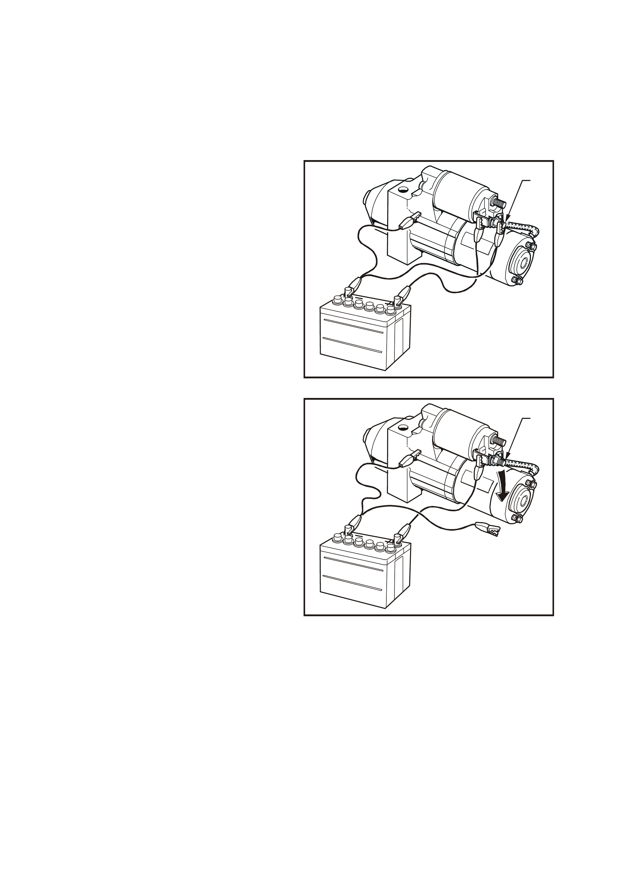
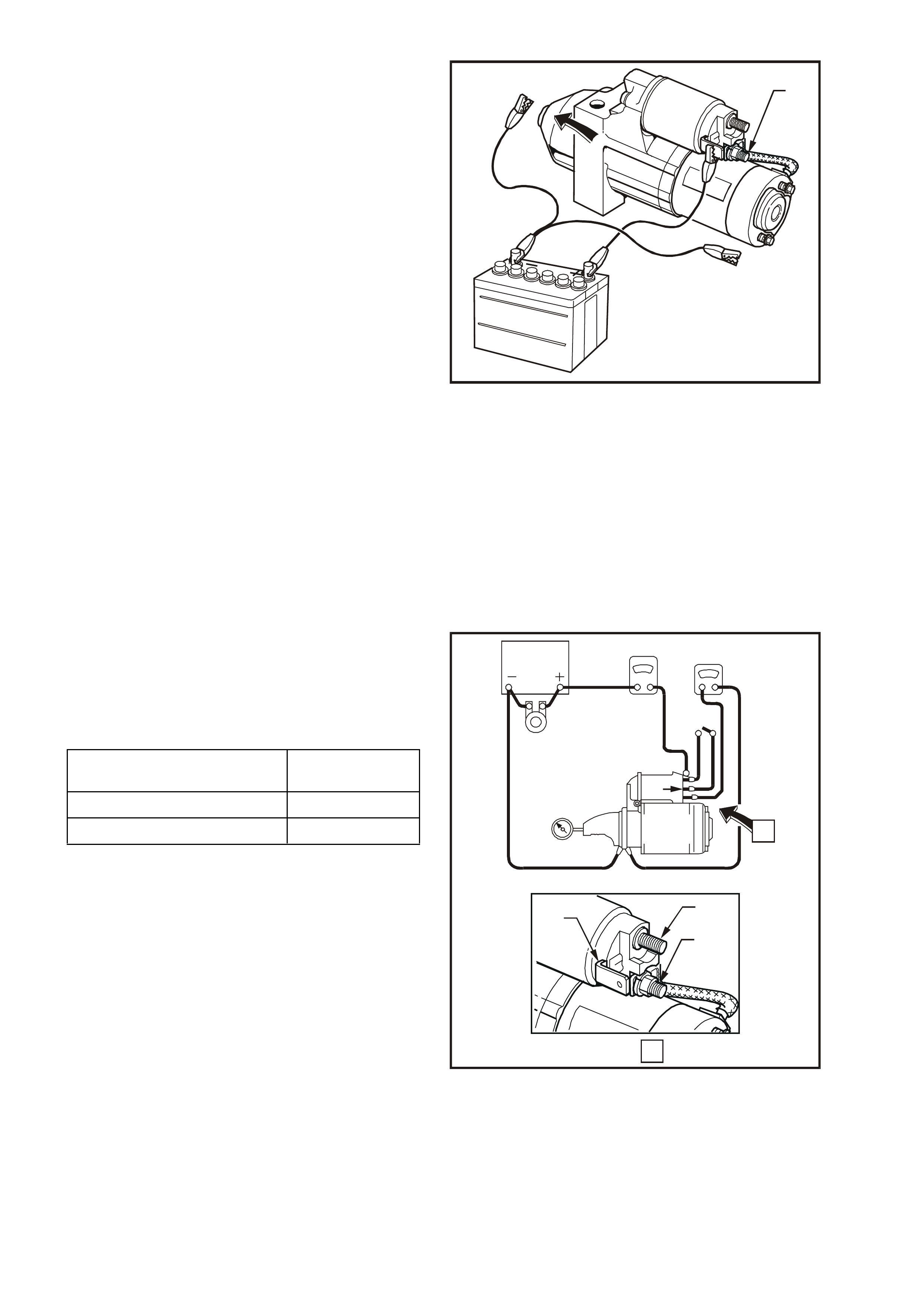
SOLENOID SWITCH TESTS
Pull-in Test
1. Remove nut and washer from solenoid switch
short threaded M terminal (1). Remove
braided cable and terminal from threaded
terminal.
2. Using suitable test leads and 12 volt battery,
connect as shown in Fig. 6D3-2-4. Check that
drive assembly moves outward.
If drive assembly does not move, replace
solenoid switch as described in this Section.
T26D3202
1
Figure 6D3-2-4
Hold-in Test
1. With battery connections to starter motor and
solenoid switch as shown for Pull-in Test,
disconnect negative lead from solenoid switch
short threaded M terminal (1).
2. Check that drive assembly remains outward.
If drive assembly returns inward, replace
solenoid switch as described in this Section.
T26D3203
1
Figure 6D3-2-5
Drive Assembly Return
1. With battery and connections to starter motor
and solenoid switch as at end of Hold-in Test,
disconnect negative lead from drive-end
housing.
2. Check that drive assembly returns inward.
If drive assembly does not return, replace
solenoid switch as described in this Section.
T26D3204
1
Figure 6D3-2-6
NO LOAD TEST
The drive assembly pinion should be checked for
freedom of operation by turning it on the planetary
drive shaft. The planetary drive and armature
should be check ed f or f reedom of r otation by prying
the drive assem bly pinion with a screwdriver. If the
planetary drive and armature do not rotate freely,
the starter motor should be disassembled
immediately. However, if the planetary drive and
armature do rotate freely, the starter motor should
be given a NO LOAD test before disassembly.
Clamp starter motor securely to a test bench and
make connections as shown to terminal 30 (1), M
term inal (2), ter minal 50 (3) and to the s tar ter motor
drive-end housing. Close the switch and compare
the rpm, current and voltage readings with the
following specifications.
If the NO LOAD test indicates that the starter motor
is defective, refer to 3. DIAGNOSIS in this Section
for probable cause of starter motor fault.
T26D3205
BATTERY AMMETER VOLTMETER
CARBON
PILE
SWITCH
SOLENOID
R.P.M.
INDICATOR
1
32
STARTER
MOTOR
A
VIEW
A
1
32
Figure 6D3-2-7
STARTER MOTOR SPEED
(ARMATURE RPM) 2500 rpm
STARTER MOTOR CURRENT 90 amp s
TERMINAL VOLTAGE 11 volts
2.2 STARTER MOTOR
REMOVE
CAUTION 1: Starter motor is in close proximity
to right-hand exhaust manifold. Allow engine to
cool before attempting to remove starter motor.
CAUTION 2: When steering column is
disconnected from steering rack, do not allow
the steering wheel to spin freely as damage to
the SRS clock spring may result rendering the
SRS inoperative. Maintain the steering column
in its original position to ensure that the SRS
clock spring remains in its centred position.
Refer to Section 12M SUPPLEMENTAL
RESTRAINT SYST EM of the VT Series I Service
Information.
1. Disable the SRS in accordance with Section
12M SUPPLEMENTAL RESTRAINT
SYSTEM of the VT Series I Service
Information.
2. Jack up front of vehicle and support on safety
stands. For jacking locations, refer to Section
0A GENERAL INFORMATION of the VT
Series I Service Information.
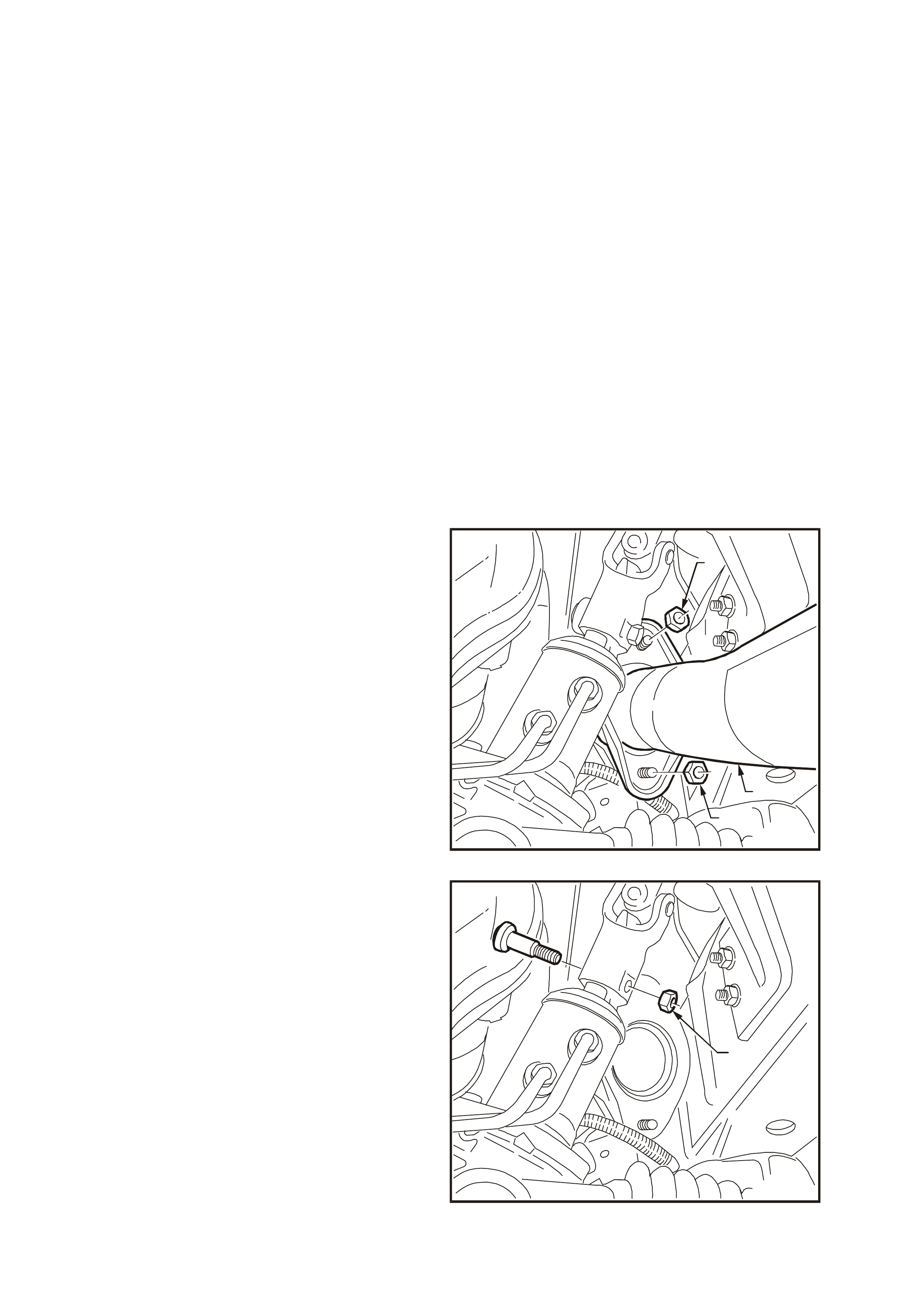
3. Remove nuts (1) securing right-hand side
exhaust engine pipe (2) to m anifold f lange and
remove bolts securing engine pipe to
intermediate pipe. Remove the engine pipe.
T26D3229
2
1
1
Figure 6D3-2-8
4. Remove nut (1) and bolt securing steering
column universal joint to steering rack input
shaft and remove universal joint from input
shaft.
T26D3230
1
Figure 6D3-2-9
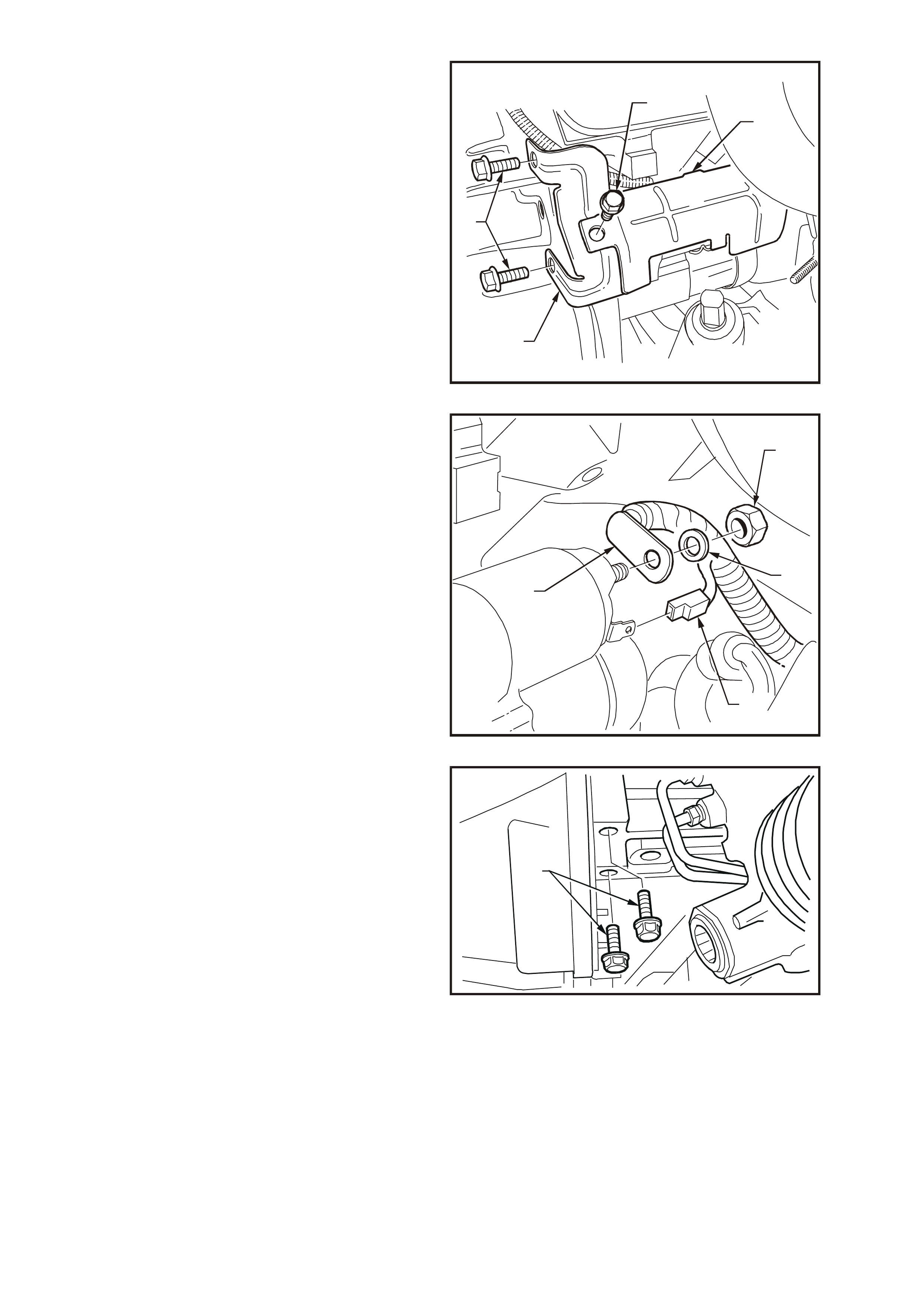
5. Remove bolt securing starter motor heat
shield to mounting bracket (1), unclip heat
shield from starter m otor solenoid and rem ove
heat shield (2).
6. Remove two bolts (3) securing starter motor
heat shield mounting bracket (4) to
transmission bell-housing and remove
mounting bracket.
T26D3231
1
4
3
2
Figure 6D3-2-10
7. Pull wiring harness connector from solenoid
switch terminal 50 (1).
8. Remove nut (2), washer (3) and battery lead
(4) from solenoid switch (B+) terminal 30.
T26D3207
2
1
3
4
Figure 6D3-2-11
9. Remove starter motor to cylinder block
mounting bolts (1).
T26D3206
1
Figure 6D3-2-12
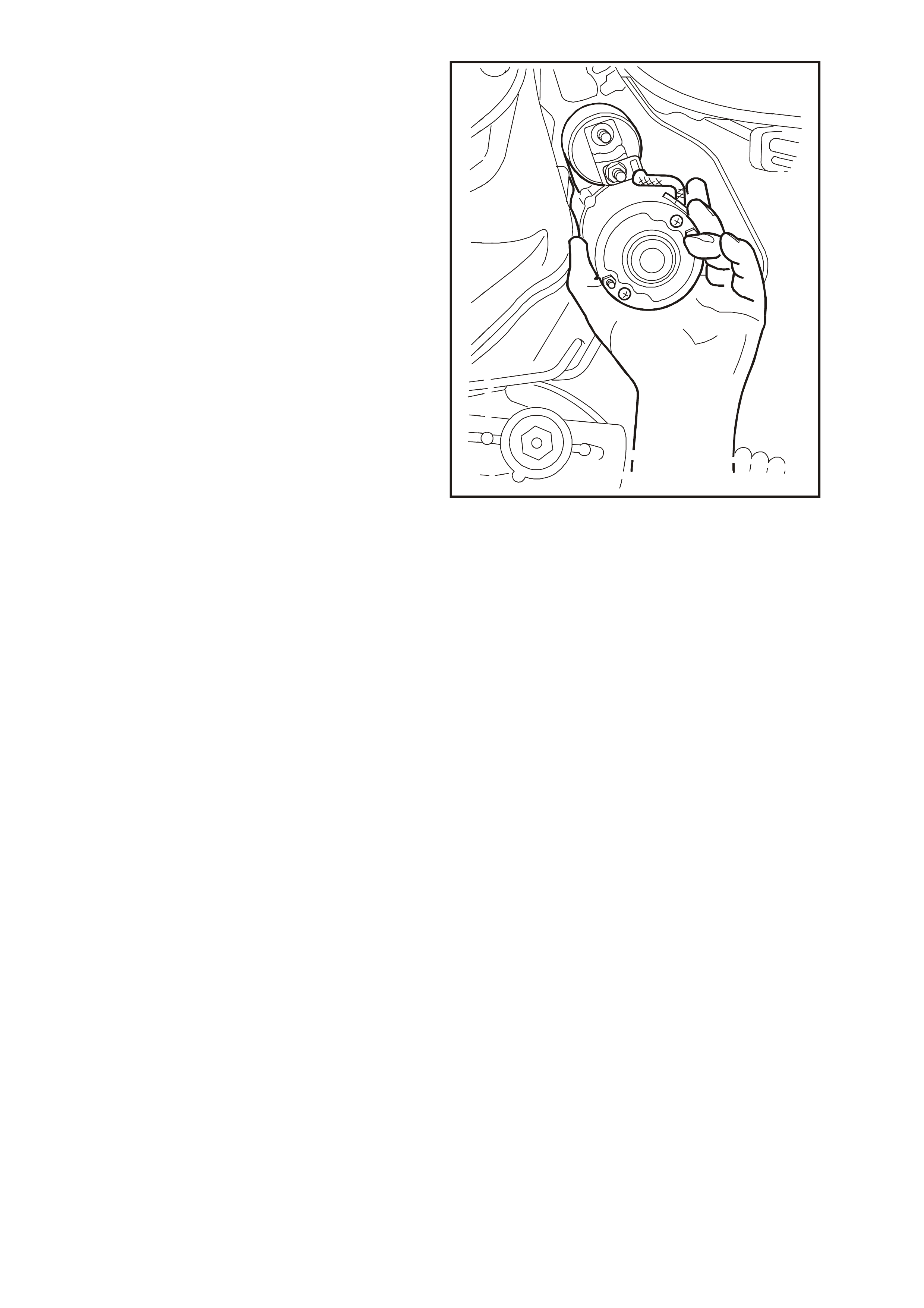
10. Manoeuvre starter motor out and down
between transmission bell-housing and body
sub-frame.
T26D3208
Figure 6D3-2-13

REINSTALL
CAUTION: When steering column is
disconnected from steering rack, do not allow
the steering wheel to spin freely as damage to
the SRS clock spring may result rendering the
SRS inoperative. Maintain the steering column
in its original position to ensure that the SRS
clock spring remains in its centred position.
Refer to Section 12M SUPPLEMENTAL
RESTRAINT SYST EM of the VT Series I Service
Information.
Installation of the starter motor is the reverse of
removal procedure, noting the following points:
1. Ensure that steering wheel and front wheels
are in straight ahead pos ition and that s teering
wheel is in mid-position from lock-to-lock.
2. Ensure that all fasteners are tightened to the
correct torque specification.
STAR TER MOTOR TO
CYLINDER BLOCK
MOUNTING BOLT
TORQUE SPECIFICATION 40 – 60 Nm
STARTER MOTOR
(B+) TERMINAL 30 NUT
TORQUE SPECIFICATION 6.0 – 10.0 Nm
3. Install exhaust engine pipe, ensuring that the
engine pipe is sufficiently clear of underbody
components. If interference with underbody
components is apparent, the exhaust system
will need to be loosened off and tightened in
correct sequence. Refer to Section 8B
EXHAUST SYSTEM of the VT Series II
Service Information.
4. Enable the SRS in accordance with Section
12M SUPPLEMENTAL RESTRAINT
SYSTEM of the VT Series I Service
Information.
5. Check starter motor operation.
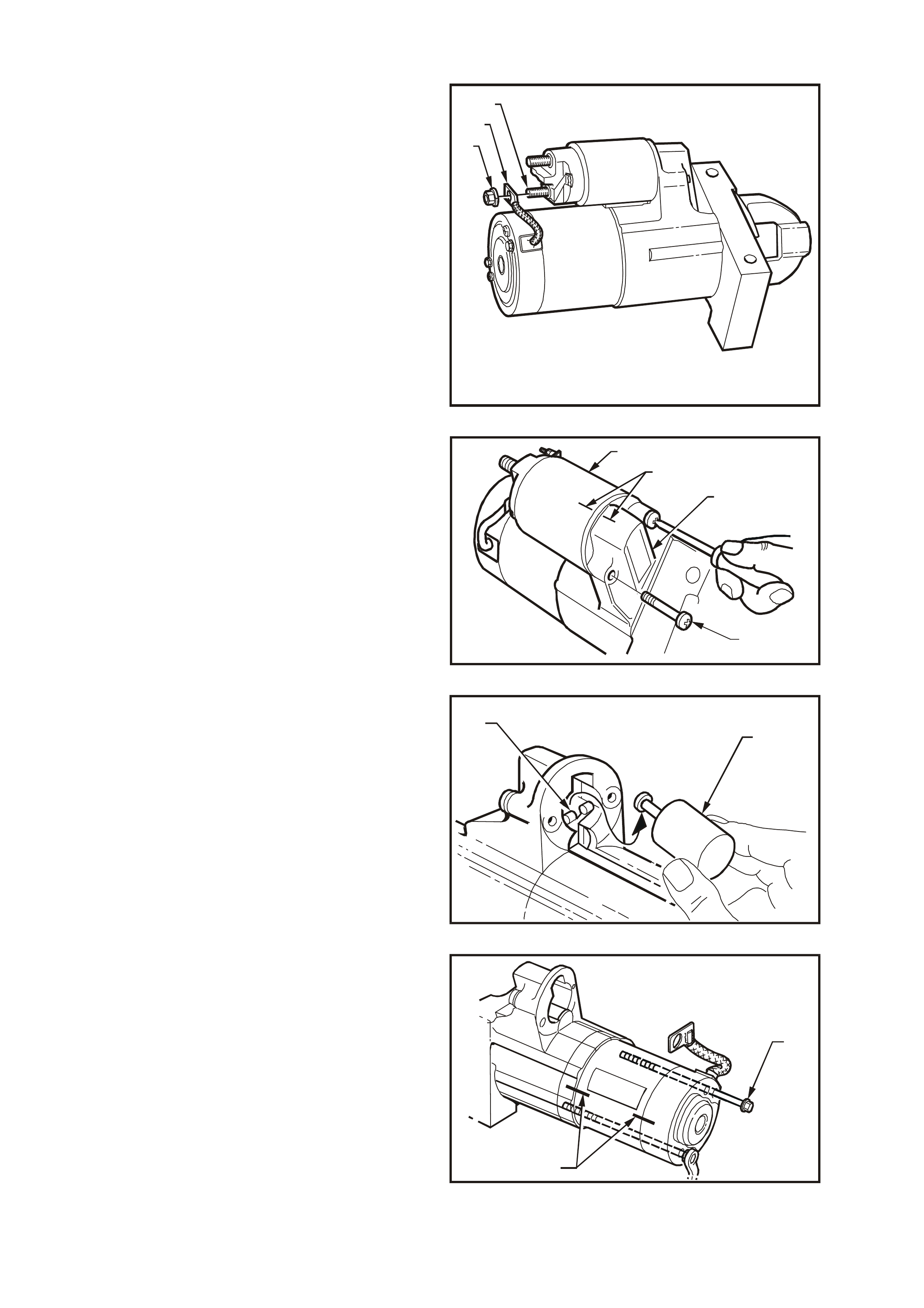
DISASSEMBLE
1. Remove nut (1) from solenoid switch short
threaded M terminal (3). Remove braided
cable and terminal (2) from solenoid terminal.
T26D3209
123
Figure 6D3-2-14
2. Scribe an aligning mark (1) on drive-end
housing (3) and solenoid switch housing (2) as
an aid for reassembly.
Remove the two solenoid switch-to-drive-end
housing mounting screws (4).
IMPORTANT: It may be necessary to loosen the
mounting screws using an impact driver. Ensure to
only lightly tap on the impact driver so as not to
damage the drive-end housing.
T26D3210
21
3
4
Figure 6D3-2-15
3. Pull solenoid switch from drive-end housing,
taking care not to lose the plunger return
spring. (Plunger may slide out from solenoid
switch and remain attached to drive assembly
fork lever).
4. Remove solenoid switch plunger (1) by lifting
up and out from drive assembly fork lever (2).
T26D3211
21
Figure 6D3-2-16
5. Scribe an aligning mark (1) on drive-end
housing, field frame assembly and
commutator end cover as an aid for
reassembly.
6. Loosen and remove the two through bolts (2)
securing the commutator end cover and field
frame assembly to the drive-end housing.
T26D3212
2
1
Figure 6D3-2-17
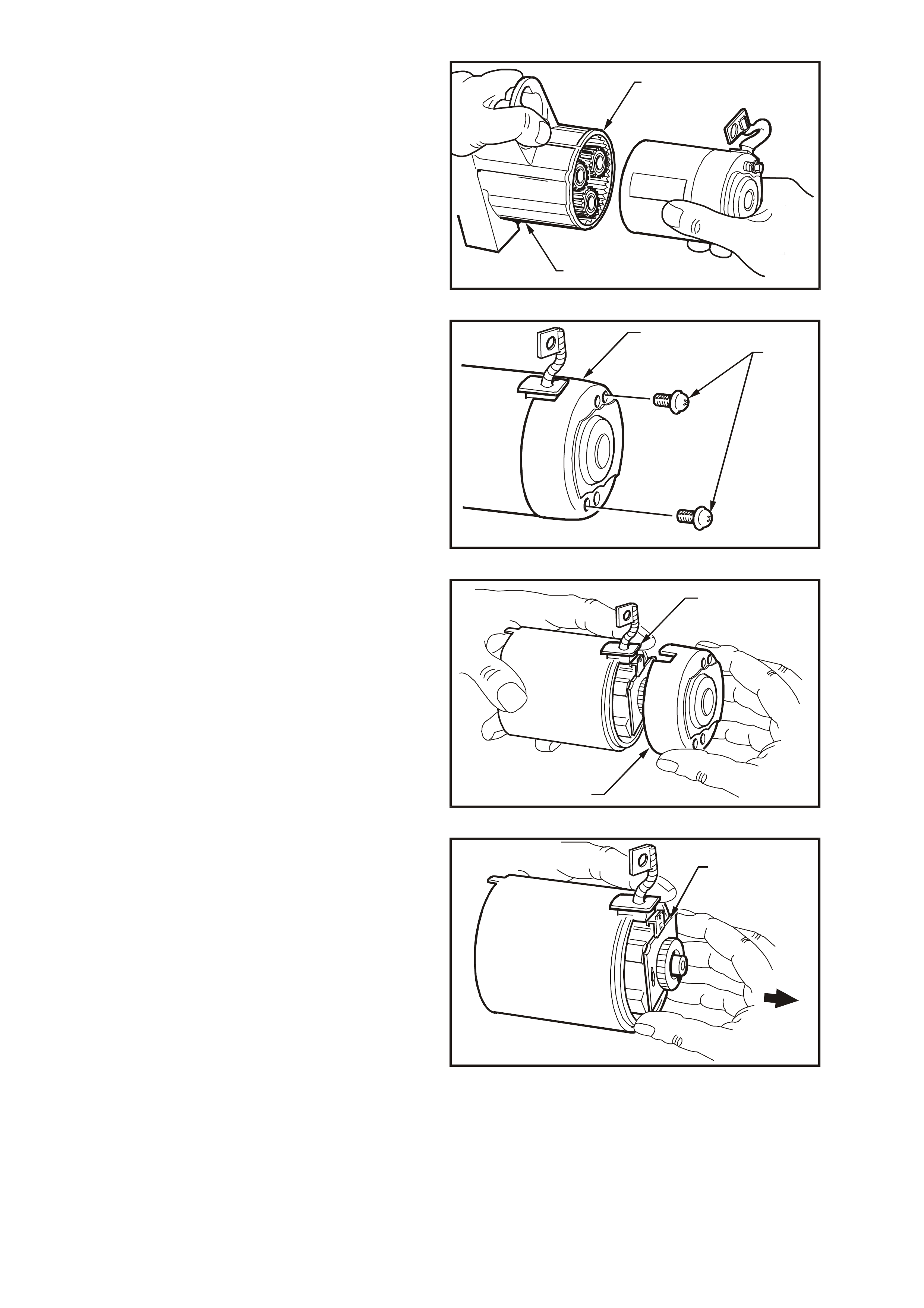
7. Keeping the sealing rubber (1) seated in the
drive-end housing ( 2), rem ove the c om m utator
end cover, field fram e assembly and armature
as an assembly from the drive-end housing.
T26D3213
1
2
Figure 6D3-2-18
8. Remove the screws (1) securing the
commutator end cover (2) to the brush holder.
T26D3214
1
2
Figure 6D3-2-19
9. While holding the braided cable and rubber
seal (1), remove commutator end cover (2).
T26D3215
1
2
Figure 6D3-2-20
10. Carefully rem ove the brush holder ( 1) from the
armature's commutator.
T26D3216
1
Figure 6D3-2-21
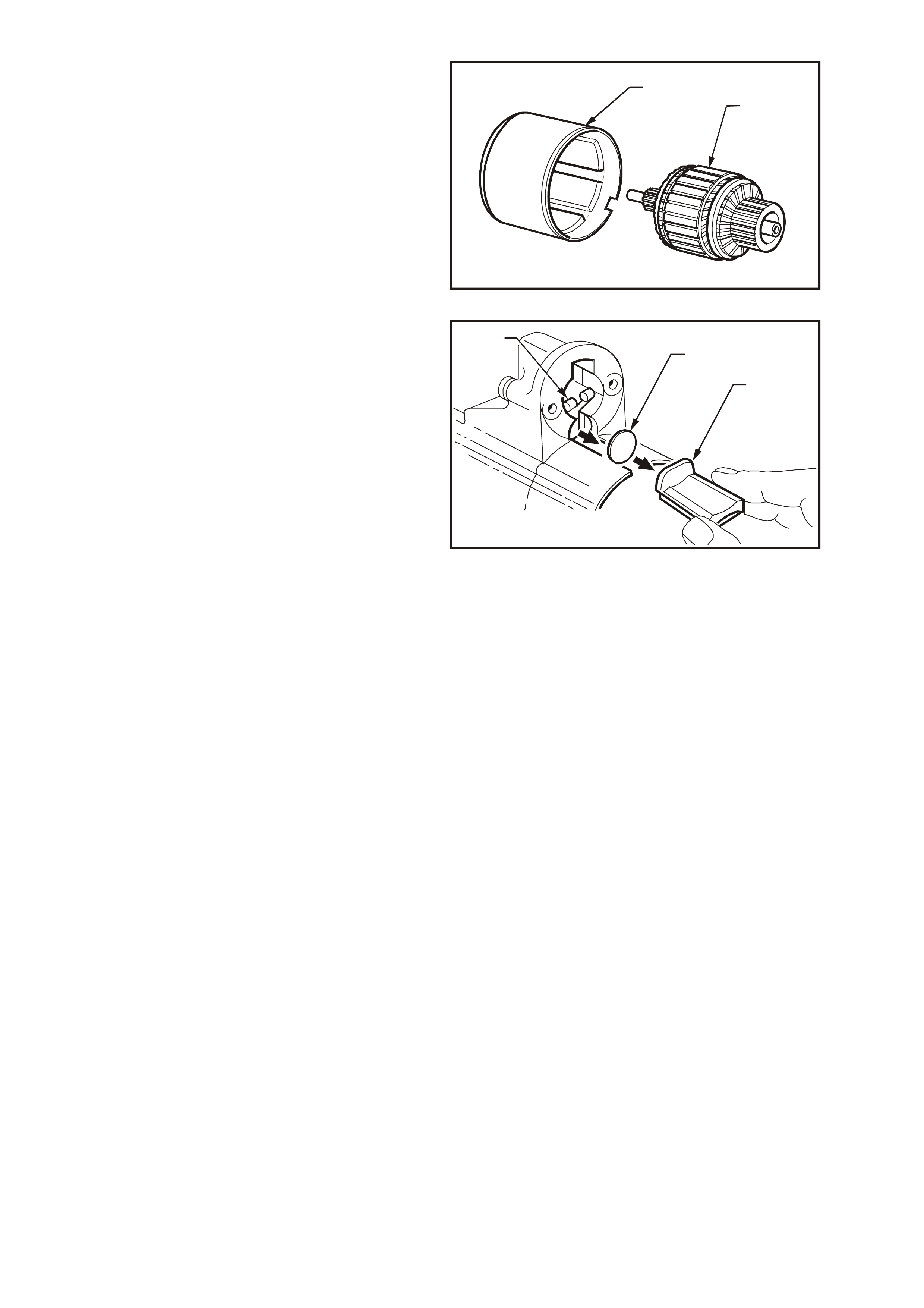
11. Remove the armature (1) from the field frame
assembly (2).
T26D3217
21
Figure 6D3-2-22
12. Remove the sealing rubber (1) from drive-end
housing, noting how it is installed.
13. Remove plate (2) the drive assem bly with fork
lever (3) and planetary drive assembly from
the drive-end housing.
14. Remove fork lever from drive assem bly noting
the orientation of the fork lever.
T26D3218
2
3
1
Figure 6D3-2-23
CLEANING AND INSPECTION
With the starter motor c ompletely disass embled, all
components should be cleaned and thoroughly
inspected.
Wash all components excluding the armature,
brushes, solenoid switch and drive assembly in a
suitable cleaning agent. Clean these components
with clean shop rags and compressed air.
NOTE: Do not clean armature with cleaning solvent
as damage to the insulation could occur.
Washing the drive assembly in solvent will wash
out all the lubricant, causing the drive assembly to
slip.
NOTE: Clean all parts other than those previously
nominated using non-volatile or low inflammable
agents in a well ventilated area. It is important that
all parts are thoroughly dried before assembly,
taking care not to breath in any vapours. Observe
the safety regulations and precautions issued by
the manufacturer of the cleaning agent in use.
COMPONENT CHECKING
Field Frame Assembly
Visually inspect field frame assembly for signs of
wear, breakage and/or burns (overheating). If this
condition is pres ent, the field f ram e assem bly mus t
be replaced.
Armature Insulation Test
Check armature insulation resistance to earth
using a 'meggar' or similar tester. A reading of 1
Mohm or greater should be expected.
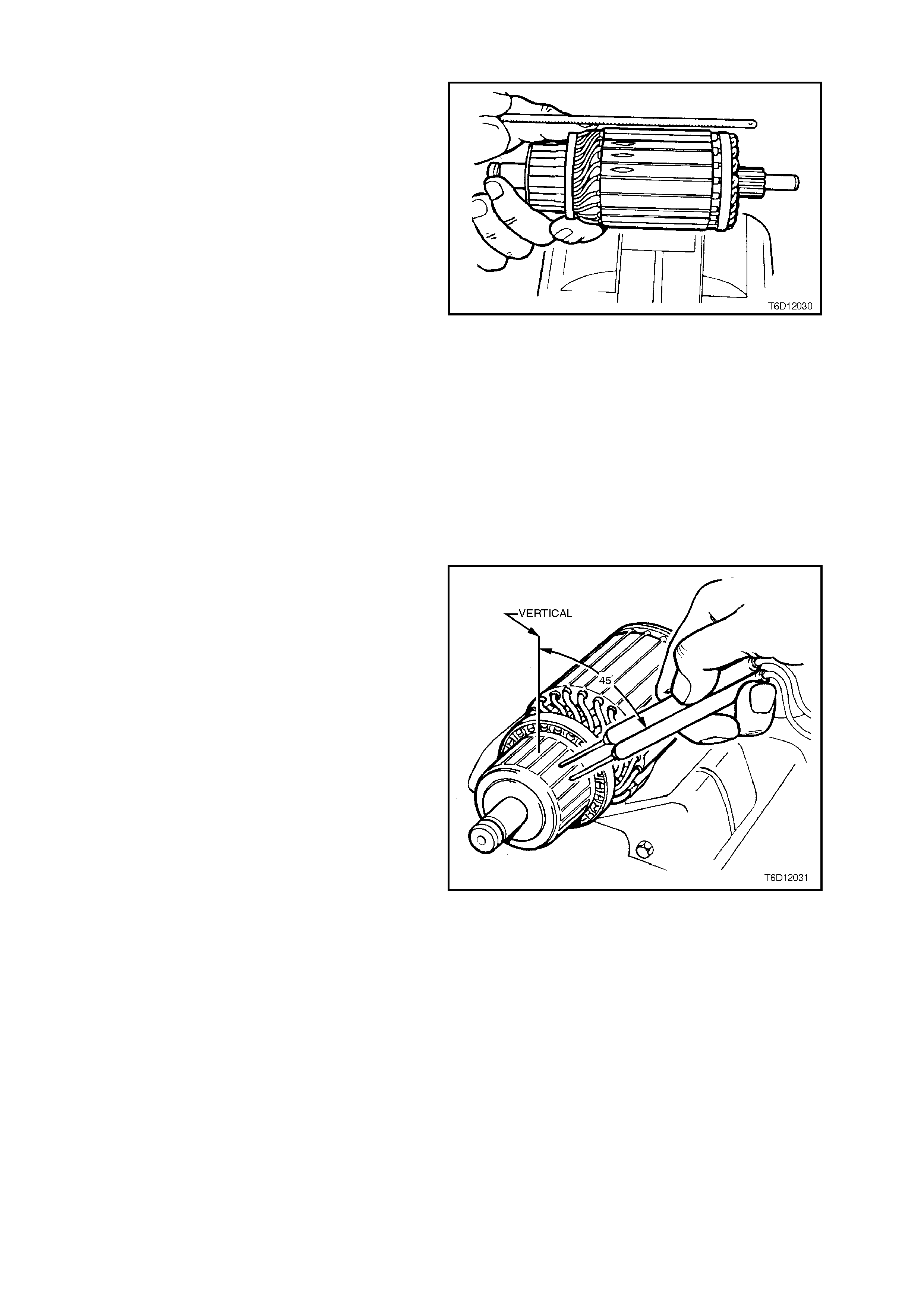
Armature Short Circuit Test
Test armature for short circuits on a growler.
1. Place the armature on a gr owler and s witch on
growler. Hold a hacksaw blade approximately
6 mm above armature core and rotate
armature.
2. If the hacksaw blade vibrates, undercut
between the commutator segments (to a depth
of approximately 0.8 mm) using a suitable
small file, then check armature again.
3. If hacksaw blade still vibrates, the armature is
short circuited and must be replaced.
Figure 6D3-2-24
Armature Continuity Test
An open circuit in the armature winding may
sometimes be detected by examining the
commutator for evidence of burnt or darkened
segments. A burnt or darkened commutator
segm ent is c aused by an arc for med every time the
segment connected to the open circuit winding
passes under the brush.
If a segment has been burnt or is darkened,
replace armature.
Test the armature for continuity on a growler.
1. Place the armature on a gr owler and s witch on
growler.
2. Using a voltmeter, measure the voltage
induced in the armature windings by touching
probes onto two adjacent commutator
segments.
IMPORTANT: T o obtain max im u m voltage r eading,
choose two segments which are approximately
45 degrees from the top of the commutator.
3. Rotate the armature in the growler so that the
next two commutator segments are in the
same position as the previous two segments
in Step 2. Measure voltage across adjacent
commutator segments.
4. Repeat Step 3 until voltage reading across all
adjacent sets of commutator segments has
been measured.
The voltage reading acr oss each adj acent pair
of commutator segments should be the same,
provided each adjacent set of segments are
positioned in the growler in the same location.
If a voltage reading ac ross any adjac ent set of
segments differs from the remainder, the
armature winding has an open circuit, and the
armature must be replaced.
Figure 6D3-2-25
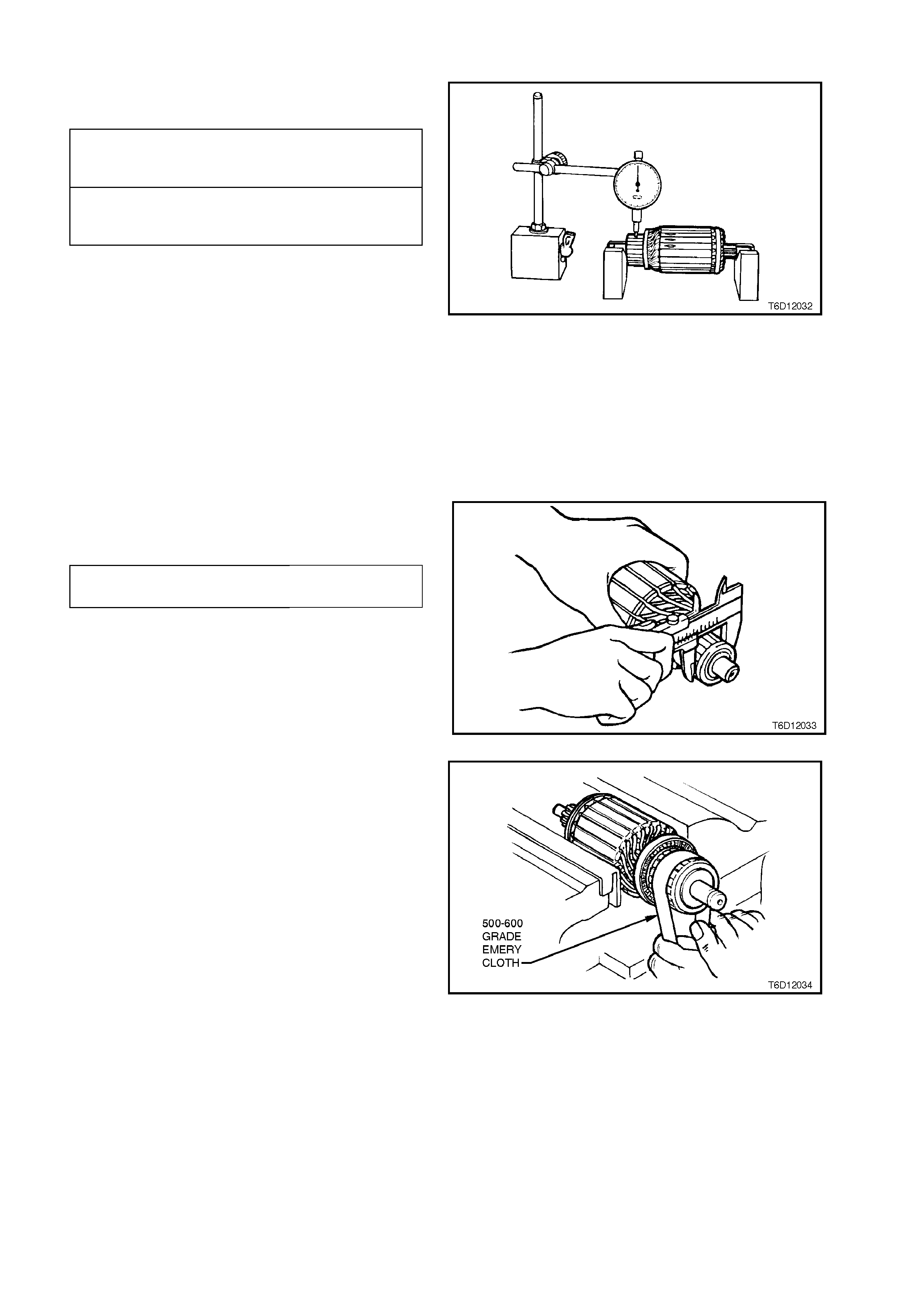
Commutator Sur face
Check commutator and armature laminations for
out-of-round.
If the armature is otherwise satisfactory but
commutator is worn, burnt, out-of round, or has
high insulation between the segments, the
commutator should be machined.
If the out-of-round check on the armature
laminations is greater than the specified value,
replace the armature.
Figure 6D3-2-26
IMPORTANT: Replace the armature if the
commutator diameter is below the dimension given
in the following chart.
When machining the armature, it must not be held
by the laminations. The armature must be held at
the drive end and supported at the c omm utator end
bearing surface.
It is recommended that the commutator be turned in
two stages, that is pre-turning and finish turning. Figure 6D3-2-27
Finish cut the armature using a fine tool. The cut
should be no more than 0.03 mm. After turning,
polish surface if necessary using 500-600 grade
emery cloth and then brush out the commutator
segment slots using a stiff brush.
Check the diameter of the c omm utator. If less than
the specified value, replace the armature.
Figure 6D3-2-28
COMMUT ATOR MAXIMUM
PERMISSIBLE
OUT-OF-ROUND 0.1 mm
MAXIMUM PERMISSIBLE
OUT-OF-ROUND OF
ARMATURE LAMINATIONS 0.1 mm
COMMUT ATOR MINI MUM
DIAMETER 28.4 mm
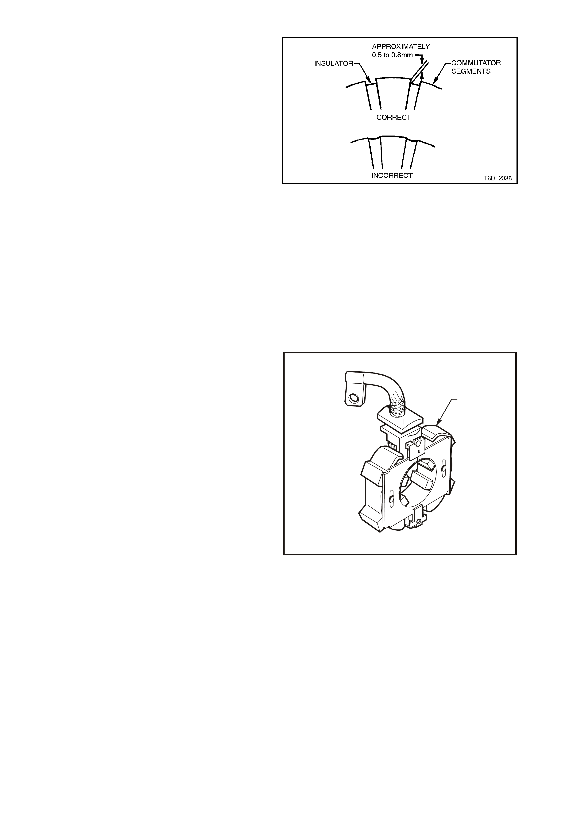
Check depth of insulating mica from commutator
surface. If depth is less than 0.2 mm, undercut
using a file to a depth of 0.5 to 0.8 mm.
CAUTION: It is important to use dust extraction
when undercutting commutators.
After under cutting, car efully clean all dirt and debr is
from commutator segment slots and lightly polish
commutator with fine emery cloth to remove any
burrs left by the undercutting operation. Clean
commutator and armature thoroughly using
compressed air.
Figure 6D3-2-29
Brushes
Check brush holder springs for breakage and
corrosion, replace as necessary.
Ensure that brushes slide sm oothly in their holders,
brush connec tions are good and brushes are clean
and not chipped.
Check brush length and spring retention. If brush
lengths vary or spring retention is uneven, replace
the complete br ush set and mac hine comm utator if
necessary.
Brush Holder Assembly
Check brush holder assembly (1) for cracks or
damage. Replace brush holder assembly as
necessary.
T26D3220
1
Figure 6D3-2-30
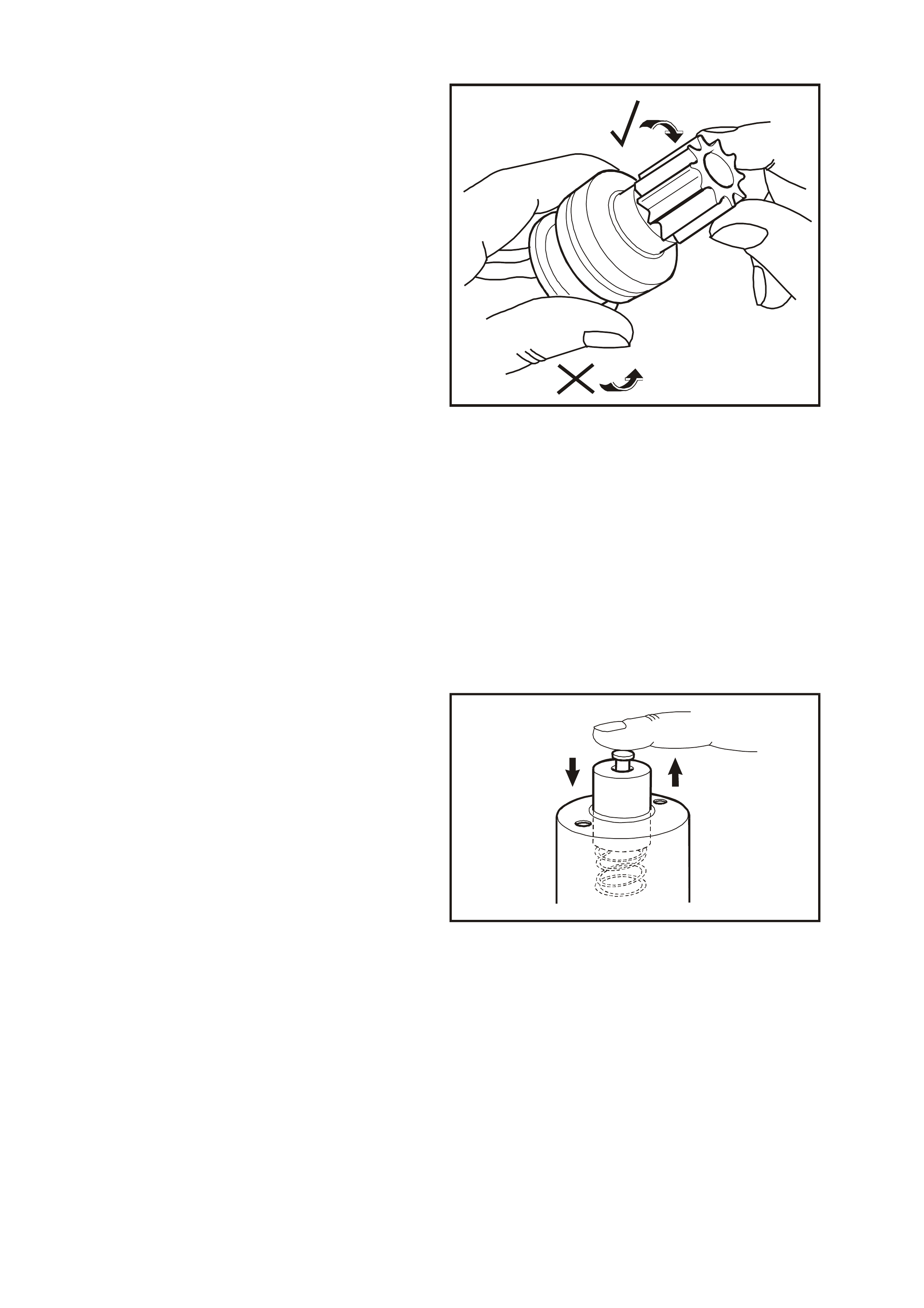
Drive Assembly Check
Inspect drive assembly pinion gear for burrs and
worn or chipped teeth.
Check the operation of the pinion. The pinion gear
should rotate free and smooth in relation to the
drive assembly pinion housing when turned in a
clockwise direction, but will not rotate when turned
in a counter-clockwise direction.
Replace the drive assembly if out of specification,
or if pinion gear is damaged or broken, inspect
flexplate/ring gear teeth and replace as necessary,
refer to Section 6A3 ENGINE MECHANICAL -
GEN III V8 ENGINE in this Service Information.
Inspect fork lever contact surfaces and pivots.
Replace fork lever if worn.
T26D3221
Figure 6D3-2-31
Bushes
Check the fit of the armature shaft in the
commutator end cover and the front end of the
planetary drive shaft in the drive-end housing.
If bushes are exc essively worn, the starter motor is
likely to operate inefficiently and/or the armature
may foul on the magnets in the field frame
assembly.
IMPORTANT: If excessive wear of the bushes is
evident, replacement of the housing in which the
bush is fitted will be necessary.
Solenoid Switch Testing
Inspect the solenoid switch for any external
damage.
Install return spring and plunger to solenoid switch.
Depress plunger and release it. T he plunger s hould
return quickly to its original position. If the plunger
sticks in the switch bore, replace solenoid switch
assembly.
T26D3222
Figure 6D3-2-32

Check the solenoid s witch windings DC res istanc es
using an ohm meter acr os s the ter minals nominated
in the following chart.
T26D3223
1
2
Figure 6D3-2-33
Replace solenoid switch if resistance readings are
not to specification.
T26D3224
1
2
Figure 6D3-2-34
PULL-IN WINDING
RESISTANCE @ 20° C 0.29 ohm
HOLD-IN WINDING
RESISTANCE @ 20° C 0.98 ohm
PULL-IN WINDING
RESISTANCE TERMINALS 50
AND M
HOLD-IN WINDING
RESISTANCE
TERMINAL 50 AND
SOLENOID
SWITCH HOUSING
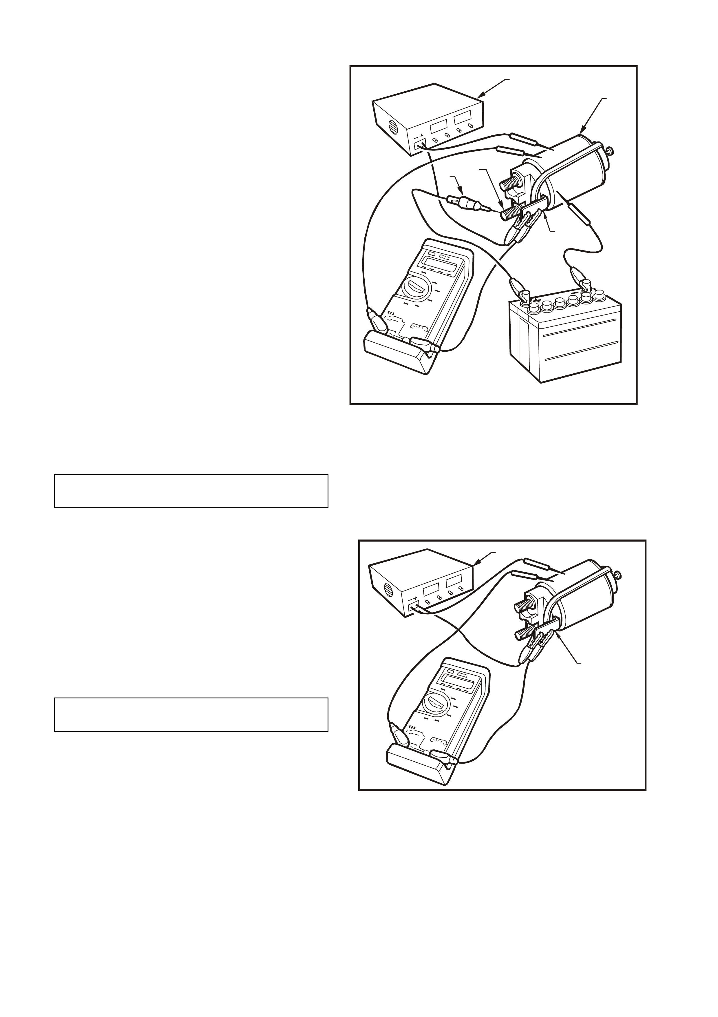
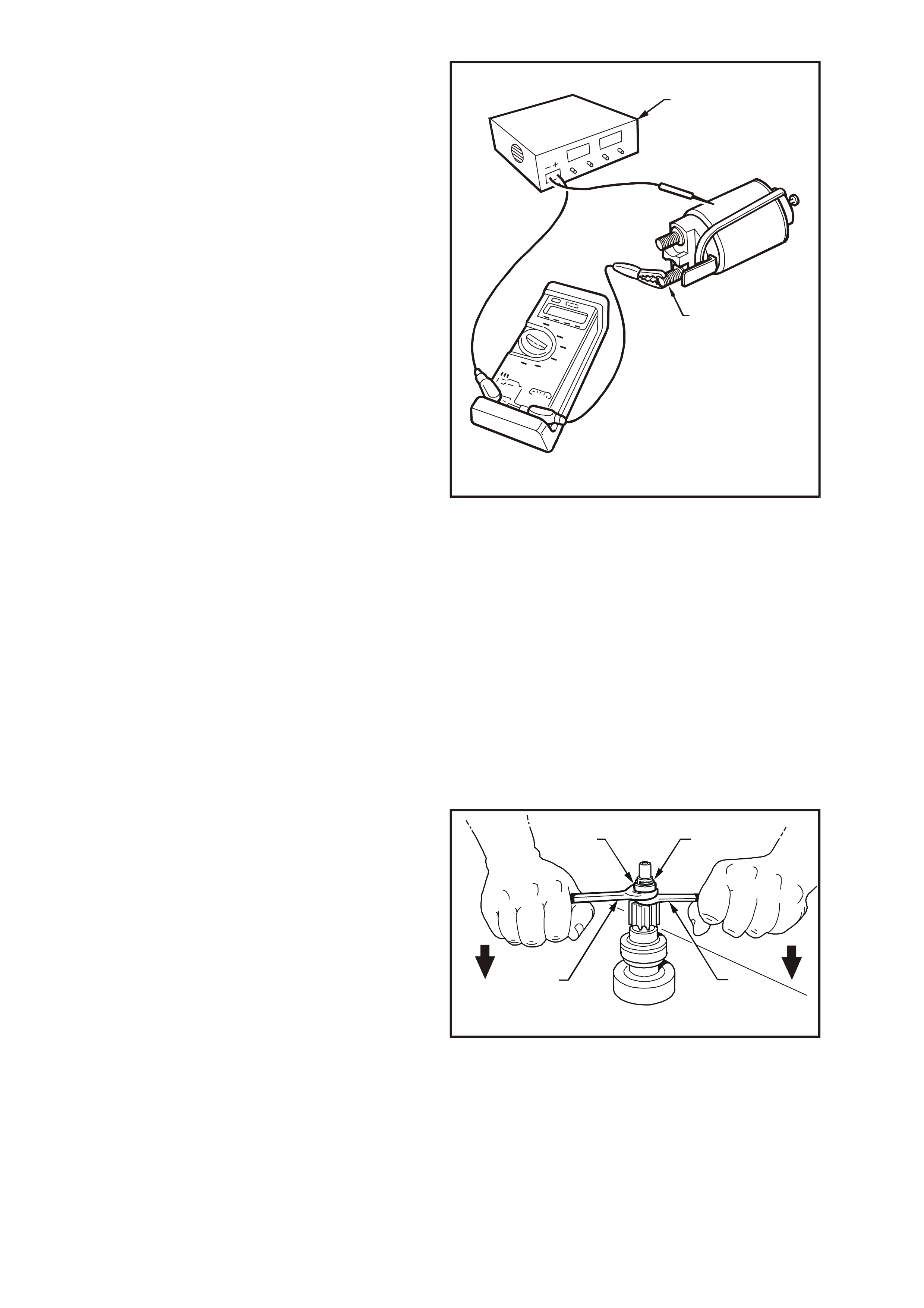
Testing Pull-in and Hold-in Voltages
During the following solenoid switch pull-in and
hold-in checks, the solenoid switch must be held
vertically, i.e. with the plunger uppermost. It is
recommended that a rubber band be fitted around
the plunger and solenoid switch housing to prevent
the plunger from flinging out during testing.
Using a power supply (1) capable of supplying 30
amps, set the voltage to 3.0 volts. A battery and a
variable resistor may also be used.
Connect the solenoid (2) to the power supply as
shown in Fig. 6D3-2-35.
Connect a 12 volt test lamp (3) between solenoid
switch terminal 30 (4) and +12 volt supply. Also,
connect a voltmeter between solenoid switch
terminal 50 (5) and earth.
Fully press in solenoid plunger until test lamp
illuminates. Allow the plunger to spring out by
approximately 8 - 10 mm and hold in this position.
IMPORTANT: The test duration for the following
pull-in voltage check should be no more than
2 seconds.
Slowly increase the voltage on terminal 50 until the
plunger pulls in, noting the voltm eter r eading. At the
same time, the test lamp must be fully illuminated
(check of solenoid switch main contact continuity).
Voltage reading should be as specified in the
following chart.
T26D3225
2
1
4
3
5
Figure 6D3-2-35
Set the power supply (1) to 12 volts and connect
the positive lead to solenoid switch term inal 50 (2).
Connect the negative lead to the solenoid switch
housing. Press the plunger in fully. It should rem ain
held in by the solenoid's hold-in winding.
Decrease the voltage until the winding will no
longer hold the plunger, noting the voltmeter
reading.
Voltage reading should be as specified in the
following chart.
Press the plunger until the solenoid switch c ontacts
close (indicated by test lamp illuminating).
It should be possible to depress the plunger into the
solenoid switch housing a further 1 mm or more. If
less than 1 mm is achieved, the solenoid switch
must be replaced.
T26D3226
1
2
Figure 6D3-2-36
HOLD-IN VOLTAGE TEST
SPECIFICATION 1.7 – 3.0 volts
@ 20°C
PULL-IN VOLTAGE TEST
SPECIFICATION 8.0 volts
A 24 volt supply (1) is required for this test.
Attach positive supply lead to solenoid switch
term inal 30 (2) and negative lead to solenoid switch
housing.
Press the plunger in fully and then release. The
plunger should return to its rest position by the
action of the return spring. If it does not, the
windings have interwinding short circuits.
W hen the solenoid switch is connected in this way,
the windings are differentially compounded, that is
their fields are in opposition to each other.
At end of solenoid switch testing, remove rubber
band retaining the plunger and return spring in the
solenoid switch housing.
T26D3227
1
2
Figure 6D3-2-37
REASSEMBLE
Reassembly of the starter motor is the reverse of
the disassembly procedure, noting the following
points:
1. Lubricate drive-end housing, commutator end
cover and drive assembly to planetary drive
bushes with clean engine oil.
2. Lightly coat helix on armature shaft, helix
inside drive assembly, inside of ring gear and
armature to commutator end cover thrust and
adjustment washers with Molybdenum
Disulphide grease (Holden Specification HN
1271 or equivalent). Pack some grease inside
of commutator end cover.
3. To install the stop ring retainer (2) over the
stop ring (1), clamp the front end of the
planetary drive shaft in a vice fitted with soft
jaws. Slide the stop ring retainer (2) up to the
stop ring (1) and f it two open end spanners ( 3)
in between the stop ring retainer and the drive
assembly gear.
4. Using a pin punch (4) and hammer, lightly tap
the stop ring (1) into the planetary drive shaft
groove. Then push down on the two spanners
(3) to force the stop ring retainer (2) over the
stop ring (1).
T26D3234
12
33
Figure 6D3-2-38
5. Slide drive assembly up and down planetary
drive shaft ensuring that it moves freely.
Check drive assembly clutch action.
6. Position fork lever on drive assembly yoke.

7. Install planetary drive shaft into the opening of
the drive-end housing, aligning the raised
sections on the planetary gear cover with the
corresponding recesses in the drive-end
housing. Slide the assembly into position
allowing the fork lever pivot to enter the drive-
end housing.
Install the plate and rubber pack ing behind the
fork lever pivot, ensuring that the rubber
packing is correctly installed in the drive-end
housing.
8. Assemble armature into the field frame
assembly with commutator exposed at rear of
housing.
Install brush holder over commutator by
angling the holder assembly onto the
commutator while pressing two adjacent
brushes into the brush holder. Press the
remaining brushes into the holder and
carefully push brush holder assembly onto
commutator. Do not use force.
Assemble end cover over brush holder and
onto commutator and align screw holes in dust
cover with brush holder. Install dust cover-to-
brush holder s crews and tighten to the corr ect
torque specification.
DUST COVER
SECURING SCREW
TORQUE SPECIFICATION 1.4 – 2.0 Nm
9. Assemble the field frame assembly to the
drive-end housing, aligning the alignment
marks. Carefully fit the armature into the
planetary drive. It may be necessary to rotate
the pinion gear slightly to enable the armature
gear to engage the planetary gears (do not
force entry).
10. Install through bolts and tighten to the correct
torque specification.
THROUGH BOLT
TORQUE SPECIFICATION 7.5 Nm
11. Lightly coat solenoid switch plunger with
Molybdenum Disulphide grease (Holden
Specification HN 1271 or equivalent).
IMPORTANT: Do not under any circumstances
allow grease on the rear f ace of the plunger. If
too much grease is applied, it may enter the
contact chamber of the solenoid switch and
cause contact problems.

12. Assemble return spring and plunger to
solenoid switch.
Pull pinion gear forward and assemble
solenoid switch assembly to drive-end
housing, ensuring that plunger is correctly
installed over drive assembly fork lever.
Align the alignment mark on the solenoid
switch housing with the corresponding mark
on the drive-end housing, ensuring that
terminal 30 is facing away from field frame
assembly. Install and tighten solenoid switch
to drive-end housing mounting screws to the
correct torque specification.
SOLENDOID SWITCH TO
DRIVE-END HOUSING
MOUNTING SCREW
TORQUE SPECIFICATION
5.5 Nm
13. Install braided cable and terminal over
solenoid switch lower threaded terminal. Install
washer and nut to threaded terminal and
tighten to the correct torque specification.
THREADED TERMINAL NUT
TORQUE SPECIFICATION 9 Nm
14. With the starter motor reassembled, a NO
LOAD test should be conducted, refer to
2.1 PERFORMANCE TESTING in this
Section.
Failure of the starter motor to perform
according to the NO LOAD specification may
be due to tight or dirty brushes or high
resistance connections. Rectify any faults
found.

3. DIAGNOSIS
Many starting problems can be categorised within the following classifications:
1. The starter motor will not crank the engine.
2. The engine will crank at normal speed, but will not start.
3. The starter cranks the engine very slowly.
If the engine is cranked over by the starter motor at the norm al speed, but will not start, the problem is in the
ignition system, fuel system or engine, rather than a fault in the starting system.
Bef ore r emoving the s tarter m otor, when investigating a starting pr oblem, f ollow the procedures outlined in the
accompanying diagnostic charts.
SYMPTOM PROBABLE FAULT
Speed, torque and current low. High resistance in motor. Check condition of brushes
and their connections and check for dirty brushes or
burnt comm ut a t or.
Speed and torque low, current hi gh. Tight or worn bearings, bent armature shaft,
insufficient end play, armature fouling pole shoe,
short-c i rcuit in armature, earthed arm ature.
Armature does not rotate. No current. Open circuit in arm ature or solenoid. If commutator is
badly burned, there may be poor contact between
brushes and commutator, owing to excessively worn
or sticking brus hes.
Armature does not rotate. High current. Short-circuit in solenoid switch. Armature physically
prevented from rotati ng.
Excessive brush movement causing arcing at
commutator. Low brush spring tension, worn or out-of-round
com mutator, 'thrown' or high segm ent on comm utator,
or insulat i on protruding between segm ents.
Excessive arcing at commutator. Defective armature windings, sticking brushes or dirty
commutator.
Armature rotates but pinion does not mesh with ring
gear. Pinion bearing fouled, burred, damaged flexplate/ring
gear or broken pinion t eet h.

NO CRANKING, NO SOUND FROM SOLENOID
STEP ACTION RESULT YES NO
1 Turn headlam ps and dome l amps on, turn ignit i on to start
position. Lamps di m? Go to Step 2. Go to Step 3.
2 Check bat tery.
Charge battery.
Check generat or.
Check c ranking volt age at battery posts.
Check c urrent draw.
Is 9. 6 vol t s
present? Go to Step 7. Test battery.
If OK, repai r
starter.
3 Turn on radio. Operate OK? Go to Step 4. Go to Step 6.
4 Check voltage at sol enoi d switch terminal 50. Is 7. 0 vol t s
present? Repair starter. Go to Step 5.
5 With key in st art posit i on, check at ignition terminal 50. Is 7. 0 vol t s
present? Repair wiring
ignition switch to
start er motor.
Replace ignition
switch.
6 Check engine main wiring harness fusi bl e l i nk and igniti on
connections.
7 Check voltage from engi ne bl ock t o negat i ve post, with key in
start position. (Posi tive lead on block). Is 0. 5 vol t s or
more pres ent? Clean and tighten
negative cable
connect i on, and/or
replace cabl e.
Go to Step 8.
8 Check c ranking voltage at starter B terminal. Is 9. 0 vol t s
present? Check fuse and
engine to MWH
connectors.
Clean and tight en
positi ve c abl e
connect i on, and/or
replace cabl e.
SLOW CRANKING, SOLENOID CLICKS OR CHATTERS
Check: Battery state of charge. Refer to Section 12A BATTERY AND CABLES of the VT Series I Service
Information.
Visual condition of battery cables and connections.
If battery needs charging, carry out generator and battery drain check , charge battery and check cranking again. If
trouble has not been found proceed.
Remove engine fuse link from engine compartment fuse housing. This prevents fuel injection and ignition during
engine cranking. Make all voltmeter readings with ignition key in start position.
STEP ACTION RESULT YES NO
1 Measure cranki ng vol tage at batt ery termi nal posts. Is 9. 6 vol t s or
more pres ent? Go to Step 2. Go to Step 3.
2 Measure voltage from battery negative terminal to engine
block (positive lead on bl ock). Is 0. 5 vol t or
more pres ent? Repair negative
cable and
connections.
Go to Step 4.
3 Charge and load test battery. Is bat t ery OK? Repair starter. Replace battery.
4 Measure voltage at solenoid s witch 30 (B+) terminal, clean
and tighten connections at starter. Is 9. 0 vol t s or
more pres ent? Repair starter. Go to Step 5.
5 Clean and tighten positive cable connec t i ons.
If OK replace cable.
This procedure is designed for use on engines and batteries at room temperature or normal operating
temperatures. It also assumes there are no engine defects which could cause cranking problems. To use it under
other conditions might result in misdiagnosis.

4. SPECIFICATIONS
Type ......................................................................... Delco Remy . Six-pole, four brush with
planetary drive train
Rotation (drive end view)............................................ Clockwise
Number of pinion teeth............................................... 10
No load test:
Maximum current ....................................................... 90 amps at 11 volts
rpm 2500
Lock test:
Maximum current (including solenoid) ....................... 760 amps
Volts 4 volts
Torque........................................................................ 19.5 Nm
Solenoid Test Solenoid detached from starter motor:
Pull in voltage............................................................. 8 volts @ 20°C
Hold-in voltage ........................................................... 1.7 – 3.0 volts @ 20°C
Hold-in winding resistance ......................................... 0.98 ohm @ 20°C
Pull-in winding resistance........................................... 0.29 ohm @ 20°C
Armature end play...................................................... 0.5 – 2.0 mm
Armature laminations permissible
out-of-round........................................................ 0.1 mm
Commutator:
Maximum permissible out-of-round............................ 0.1 mm
Diameter - New .......................................................... 29.4 mm
Minimum diameter...................................................... 28.4 mm
Depth of undercut....................................................... 0.5 mm
Brushes:
Minimum length.......................................................... 7.0 mm

5. TORQUE WRENCH SPECIFI CATIONS
Nm
Through bolts........................................................................ 7.5
Solenoid attaching screws.................................................... 5.5
'30' terminal nut..................................................................... 6.0 – 10.0
'50' terminal nut..................................................................... 9.0
Dust cover securing screws.................................................. 1.4 – 2.0
Starter motor to cylinder block mounting bolts...................... 40 – 60