
SECTION 6D3-3 - IGNITION SYSTEM –
GEN III V8 ENGINE
CAUTION:
This vehicle will be equipped with a Supplemental Restraint System (SRS). A SRS will consist of either
seat belt pre-tensioners and a driver's air bag, seat belt pre-tensioners and a driver's and front
passenge r's air bags or se at belt pre-ten sioner s, drive r’s an d fron t pass enger’ s air bag and left an d rig ht
hand side air bags. Refer to SAFETY PRECAUTIONS, Section 12M, Supplemental Restraint System of
this Service Information CD before performing any service operation on, or around any SRS
components, the steering mechanism or wiring. Failure to follow the SAFETY PRECAUTIONS could
result in SRS deployment, resulting in possible personal injury or unnecessary SRS system repairs.
CAUTION:
Whenever any component that forms part of the ABS or ABS/ETC (if fitted), is disturbed during Service
Operations, it is vital that the complete ABS or ABS/ETC system is checked, using the procedure as
detailed in 4. DIAGNOSIS, ABS or ABS/ETC FUNCTION CHECK, in Section 12L ABS & ABS/ETC, VT
Series I Service Information (V6) or VT Series II Service Information (GEN III V8).
1. GENERAL INFORMATION
The electronic ignition system fitted to the GEN III V8 engine, controls fuel combustion by providing a spark to
ignite the com pressed air/fue l mixture at the cor rect tim e. To prov ide optim um engine perform ance, f uel econom y,
and contr ol of exhaust emiss ions, the Powertrain Control Mod ule (PCM) c ontrols the s park advanc e of the ig nition
system. The electronic ignition system has the following advantages over a mechanical distributor system:
• No moving parts.
• Less maintenance.
• Remote mounting capability.
• No mechanical load on the engine.
• More coil cool down time between firing events.
• Elimination of mechanical timing adjustments.
• Increased available ignition coil saturation time.
For diagnostic and servicing operations not described in this Section, refer to 6C3-2A DIAGNOSTIC TABLES -
GEN III V8 ENGINE, 6C3-2C FUNCTIONAL CHECKS - G EN III V8 ENGINE or 6C3-3 S ERVIC E OPER ATIONS –
GEN II V8 ENGINE, of the VT Series II Service Information.
Techline
1.1 GENERAL DESCRIPTION
The electronic ignition system does not use a conventional distributor and coil but consists of the following
components/circuits:
• Eight Ignition Coils/Modules
• Eight Ignition Control (IC) Circuits
• Camshaft Position (CMP) Sensor
• 1X Camshaft Reluctor Wheel
• Crankshaft Position (CKP) Sensor
• 24X Crankshaft Reluctor Wheel
• Two Knock Sensors
• Powertrain Control Module (PCM)
• Related connecting wires
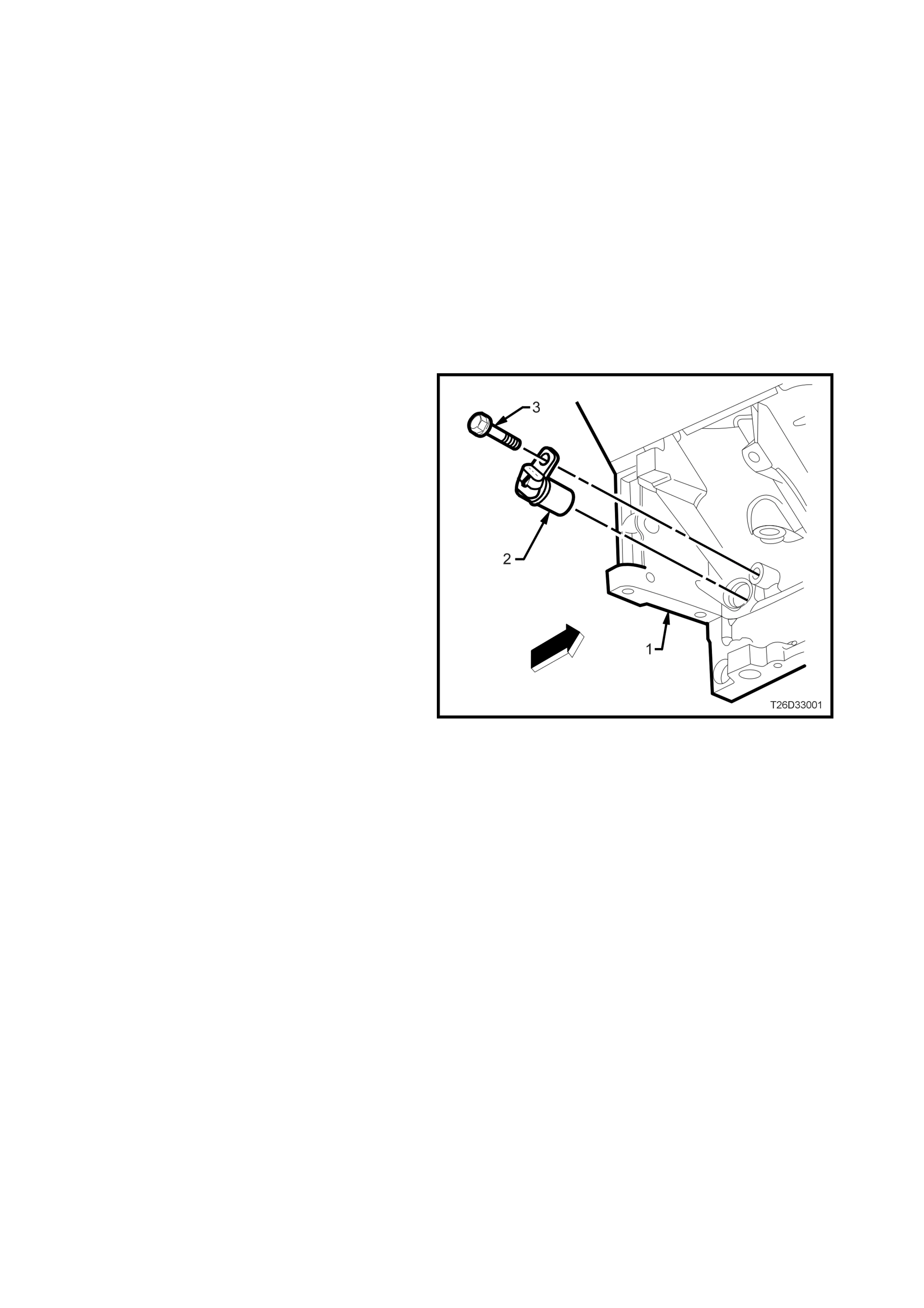
CRANKSHAFT POSITION SENSOR AND RELUCTOR WHEEL
The Crankshaft Position (CKP) sensor (2) is
located in the right rear of the engine (1), behind
the starter motor. The CKP sensor is a dual
magneto resistive type sensor and is not speed
dependent. The dual micro switches monitor both
notches of the reluctor wheel for greater accuracy.
The CKP sensor works in-conjunction with a 24X
reluctor wheel that is permanently mounted on the
rear of the crankshaft. The 24X reluctor wheel
uses two different width notches that are 15
degrees apart.
This Pulse Width Encoded pattern allows cylinder
position identification within 90 degrees of
crankshaft rotation. In some cases, cylinder
identification can be located in 45 degrees of
crankshaft rotation. This reluctor wheel also has
dual track notches that are 180 degrees out of
phase. The dual track design allows for quicker
starts and accuracy.
The PCM also receives a 4X signal from the
Crankshaft Position sensor. The PCM utilises the
4X signal for the following:
• Misfire
• Tachometer output
• Spark control
• Fuel control
• Certain diagnostics
Figure 6D3-3-1
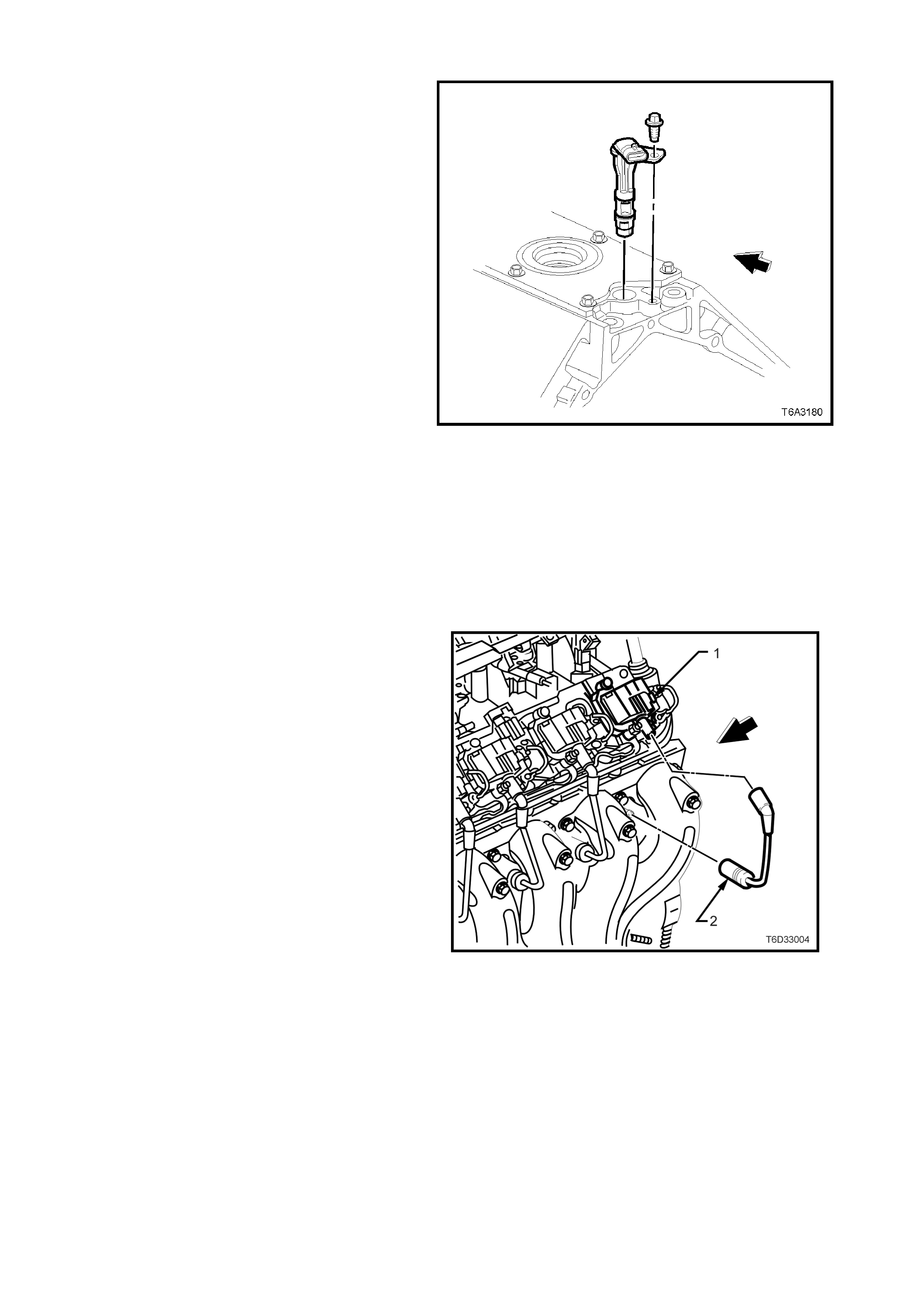
CAMSHAFT POSITION SENSOR
The Camshaft Position (CMP) sensor is mounted
through the top and at the rear of the engine
cylinder block. The CMP sensor works in-
conjunctio n with a 1X rel uctor whee l, locate d at the
rear of the camshaft. The CMP sensor is used to
determine whether a cylinder is on the firing or the
exhaust stroke.
As the camshaft rotates, the reluctor wheel
interrupts a magnetic field produced by a magnet
within the sensor. The CMP sensor internal
circuitry detects t his a nd pro duc es a s ign al wh ich is
used by the PCM. The PCM uses this signal in
combination with the CKP 24X signal to determine
crankshaft position and stroke.
While the CKP signal must be available for the
engine to start, the CMP signal is not needed to
start and operate the engine. The PCM can
determine when a particular cylinder is on either a
firing or exhaust stroke by the 24X signal. The
CMP sensor’s purpose is to determine what stroke
the engine is on. The system will attempt a
synchronised pattern and look for an increase in
the Mass Air Flow MAF signal. An increase in the
MAF signal i ndicates t he engine has starte d. If the
PCM does not detect an increase in the MAF
signal, another synchronised pattern will occur on
the opposite cam position. A slightly longer
cranking time may be a symptom of this condition.
Figure 6C3-3-2
IGNITION COILS/MODULE
The ignition system on this vehicle features a
multiple coil ignition (1) and is known as “coil near
plug”. The secondary ignition wires (2) are short
compared with a distributor ignition system wire
and are all of equal len gth.
Figure 6D3-3-3
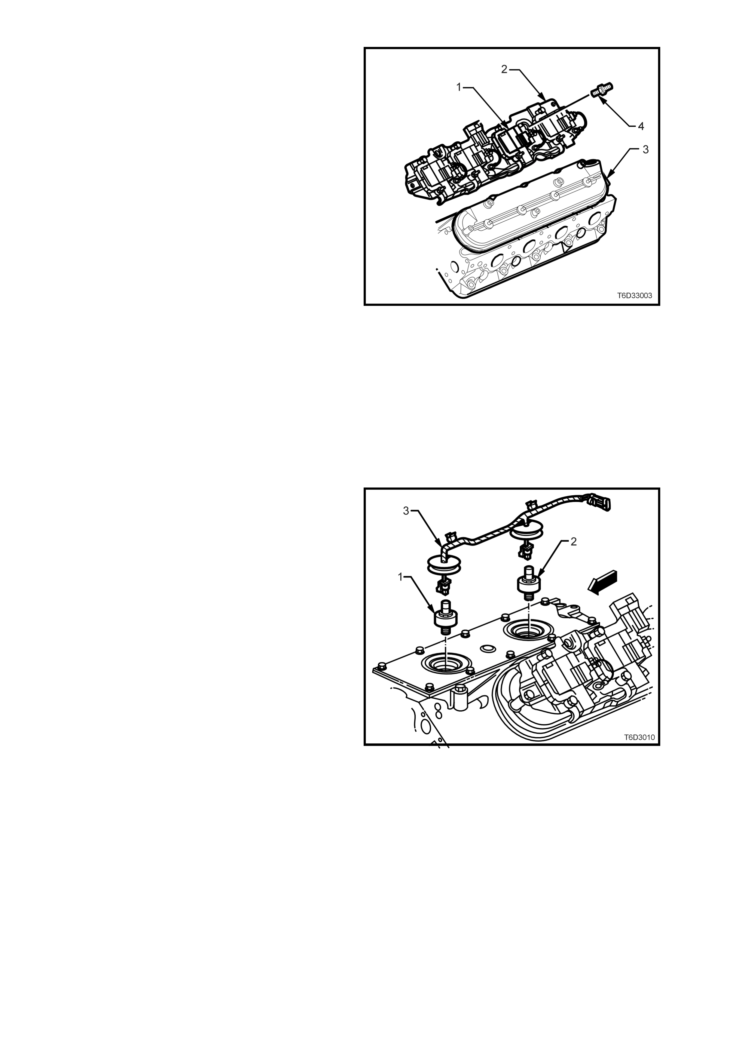
Eight ignition coils/modules (1) are individually
mounted above each cylinder on brackets (2)
attached to the rocker covers (3) by screws (4).
The coils/modules are fired sequentially.
There is an Ignition Control (IC) circuit for each
ignition coil/module and these eight ignition control
circuits are all connected to the PCM. All timing
decisions are made by the PCM, which triggers
each coil/module individually.
The ignition coil/modules are supplied with the
following circuits:
• Ignition feed circuit.
• Ignition control circuit.
• Ground circuit.
• Reference low circuit.
The ignition feed circuits are fused separately for
each bank of the engine. The two fuses also
supply the injectors for that bank of the engine.
Each coil/module is serviced separately.
This system develops a very high ignition energy
for plug firing and, because the ignition wires are
shorter, less energy is lost to ignition wire
resistance. Also, since the firing is sequential,
each coil h as seven e vents to s aturate as oppos ed
to the three in a waste spark arrangement.
Furthermore, no energy is lost to the resistance of
a waste spark system.
Figure 6D3-3-4
KNOCK SENSORS
A Knock Sensor (KS) system is used in order to
control eng in e spark knock .
The KS system used on the GEN III V8 engine
comprises two knock sensors (front ‘1’ and rear
‘2’), both located centrally in the engine valley
cover. A patch harness (3) connects the signals
generated by these piezo sensors with the PCM,
via the PCM wiring harness.
The GEN III V8 engine KS system is designed to
retard spark timing up to 20º in order to reduce
spark knock in the engine. This allows the engine
to use maximum spark advance to improve
driveability and fuel economy.
Figure 6D3-5

The knock sensor system is used to detect engine
detonation by the knock sensors producing an AC
voltage which is sent to the PCM. This AC signal
voltag e to the PCM is proces sed b y a Signal Nois e
Enhancement Filter (SNEF) module. The SNEF
module is used to determine if the AC signal
coming in, is noise or detonation.
This SNEF module is part of the PCM and cannot
be replaced. The PCM then adjusts the ignition
timing to r educe t he spar k adv ance. T he am ount of
timing retard is based upon the amount of time
knock that is detec ted and is lim ited to a m aximum
value of 20°.
After the detonation stops, the timing will gradually
return to it's calibrated value of spark advance.
The Knock Sensor system will only retard timing
after the following conditions are met:
• The engine run time is greater than 20 seconds.
• The engine speed is greater than 1650 RPM.
• The engine coolant temperature is greater than
70° C.
• The MAP is less than 60 kPa.
The TECH 2 scan tool has several positions for
diagnosing the KS circuit:
• Knock Retard indicates the am ount of spark the
PCM is removing from the IC spark advance in
response to the signal from the knock sensors.
• Spark indicates the amount of spark advance
being commanded by the PCM on the IC circuit.
Figure 6D3-6
CIRCUITS AFFECTING IGNITION CONTROL
To properly control ignition timing, the PCM relies
on the following information:
• Engine load (manifold pressure or vacuum)
• Atmospheric (barometric) pressure
• Engine temperature
• Intake air temperature
• Crankshaft position
• Engine speed (RPM)
• Engine detonat ion condition
The Ignition Control (IC) system consists of the
following components:
• Ignition coil/modules
• 24X crankshaft position sensor
• Powertrain Control Module (PCM)
• All connecting wires
The Ignition Control utilises the f ollowing to control
spark timing functions:
• 24X signal - The 24X crankshaft position
sensor sends a signal to the PCM. The PCM
uses this signal to determine crankshaft
position. The PCM also utilises this signal to
trigger the fuel injectors.
• Ignition Control (IC) circuits - The PC M uses
these circuits to trigger the ignition
coil/modules. The PCM uses the crankshaft
reference signal to calculate the amount of
spark advance needed.

NOTEWORTHY IGNITION INFORMATION
There are important considerations to note, when servicing the ignition system. The following information lists some
of these, to help the Technician in servicing this ignition system in a safe and efficient manner.
• Each ignition coil’s secondary voltage output capabilities is very high - more than 40,000 volts. Therefore,
avoid body contact with ignition high voltage secondary components when the engine is running, or personal
injury may result!
• The 24X crank shaf t position s ens or is th e m ost c ritical p art of the ig nition s ystem. If the sens or is d am aged s o
that pulses are not generated, the engine will not start!
• Crankshaft position sensor clearance is very important! The sensor must not contact the rotating interrupter
ring at any time, or sensor damage will result. If the interrupter ring is bent, the interrupter ring blades will
destro y the sensor.
• Ignition timing is not adjustable. There are no timing marks on the crankshaft balancer or timing chain cover.
• Be careful not to damage the secondary ignition wires or boots when servicing the ignition system. Rotate
each boot to dislo dge it from the plug or co il tower before pullin g it from either a spark plug or the ignition c oil.
Never pierce a secondary ignition wire or boot for any testing purposes! Premature failure of the leads will
result if probes or test lights are pushed through the insulation for testing purposes.
POWERTRAIN CONTROL MODULE (PCM)
The PCM is respons ible f or maintain ing prop er spark and fuel injecti on tim ing for all dr iving co nditions. To provide
optimum driveability and emissions, the PCM monitors input signals from the following components in calculating
Ignition Control (IC) spark timing:
• Engine Coolant Temperature (ECT) sensor.
• Intake Air Temperature (IAT) sensor.
• Mass Air Flow (MAF) sensor.
• Knock Sensor (KS).
• Selected automatic transmission range from the Transmission Fluid Pressure (TFP) switch assembly.
• Throttle Position (TP) sensor.
• Vehicle Speed Sensor (VSS).
RESULTS OF INCORRECT OPERATION
An ignition control circuit that is open, grounded, or shorted to voltage will set an ignition control circuit DTC. If a
fault occ urs in t he IC outpu t circuit when th e engi ne is runnin g, the e ngine will experi ence a m isf ire. DT C's P0351-
P0358 will set whe n a malfunction is detected with an Ignition Co ntrol circuit. When an Ignition contro l DTC sets,
the PCM will disable the injector for the appropriate cylinder.
The PCM uses information from the engine coolant temperature sensor in addition to RPM to calculate spark
advance va lues as follo ws:
• High RPM = more advance.
• Cold engine = more advance.
• Low RPM = less adva nc e.
• Hot engine = less adva nce.
Therefore, detonation could be caused by high resistance in the engine coolant temperature sensor circuit. Poor
performance could be caused by low resistance in the engine coolant temperature sensor circuit.
If the engine cranks but will not run or immediately stalls, refer to 6C3-2A DIAGNOSTIC TABLES - GEN III V8
ENGINE, ‘Engine Crank s But W ill Not Run’ diagnostic table of the VT Series II Service Inform ation to determ ine if
the failure is in the ignition or fuel systems.

2. SERVICE OPERATIONS
NOTE: For service information relating to ignition system components not described in this Section, refer to
Section 6C3-3 SERVICE OPERATIONS – GEN III V8 ENGINE of the VT Series II Service Information:
3.2 Powertrain Control Module.
3.3 Powertrain Interface Module
3.13 Camshaft Position Sensor.
3.17 Crankshaft Po sitio n Sen sor.
3.18 Knock Sensor/s .
2.1 SPARK PLUGS AND/OR LEADS
REMOVE
Important: The engine must be cold (below 50°
°°
° C) before removing the spark plugs. Failure to do so may
cause the spark plug/cylinder head threads to bind and result in tearing of the aluminium cylinder head
threads.
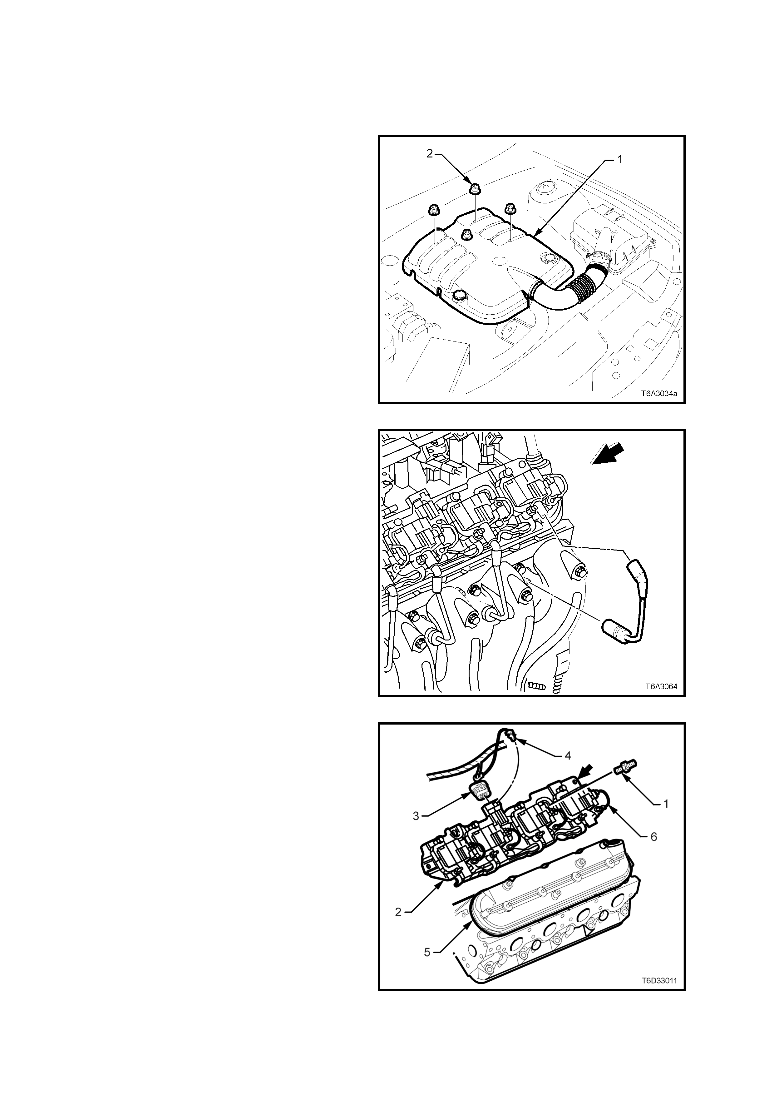
1. Remove the engine dress cover retaining nuts
(2), then remove the cover (1) from the engine
and set to one side.
Figure 6D3-3-7
2. Remove the spark plug lead/s, noting the
following:
a. When removing spark plug lead/s, only
handle the boot on each lead, twist to
break the seal, them pull to remove. DO
NOT pull on the lead itself.
b. Unless required, it is not necessary to also
rem ove the lead from the indi vidual c oil, as
shown in Fig. 6D3-3-8.
Figure 6D3-3-8
Techline
Techline
3. Remove the spark plug/s, taking note of the
following;
a. The engine MUST be cold. If not, then the
spark plug and cylinder head threads may
bind, causing the cylinder head threads to
be torn.
b. Loosen the spark plug/s, then re-tighten to
break away any carbon deposits on the
threads.
c. Loosen the spark plug/s once again but,
this time, only one or two turns. Then use
compressed air to remove any foreign
material that may otherwise enter the
combustion chamber.
CAUTION: Wear eye protection to avoid
injury.
d. Continue to remove the spark plug/s.
NOTE: When removing spark plugs always
keep them in order of removal. This will allow
the correct cylinder identification, if a non-
standard spark plug condition is evident
following spark plug inspection.
e. Following removal, plug spark plug hole/s
with rag to prevent foreign matter entering
the combustion chambers.
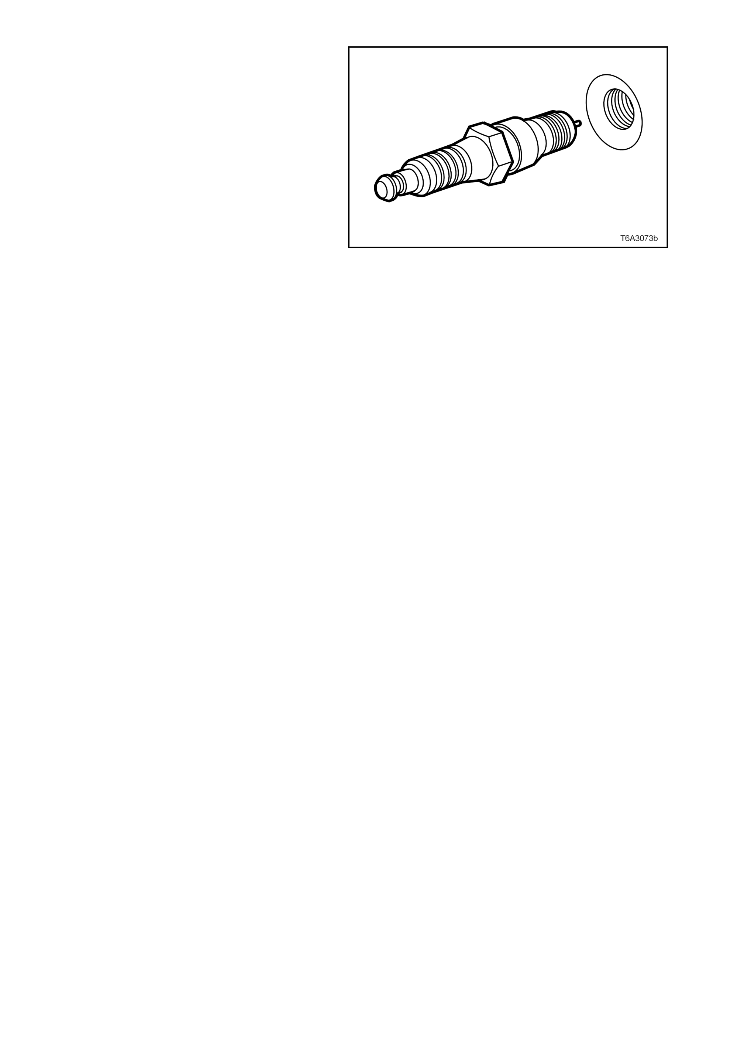
Figure 9A-9
INSPECT, CLEAN AND ADJUST
Spark Plugs
1. Carefully inspect spark plug insulators and
electrodes. Replace any spark plug with
cracked or broken insulation or loose
electrodes.
NOTE: Refer to 3. DIAGNOSIS in
Section 6D2-3 IGNITION SYSTEM - V8
ENGINE, of VT Series I Service Information,
for identification of various spark plug
conditions.
2. If spark plugs are oi ly, cle an with a degre asing
agent and dry with compressed air.
CAUTION: Wear eye protection to avoid
injury.
3. If required, clean spark plugs using
commercially available sand blast type of
cleaning machine. Always follow the
manufacturer’s instructions for correct
operation of the equipment.
4. Following cleaning operations, inspect the
spark plug condition aga in, as def ects ma y not
have been previously visible.
5. Check that s park plug threads ar e clean and in
good condition. If evidence of aluminium is
seen in the threads, then use a suitable spark
plug tap to ‘chase’ the threads in the cylinder
head before reinstallation.
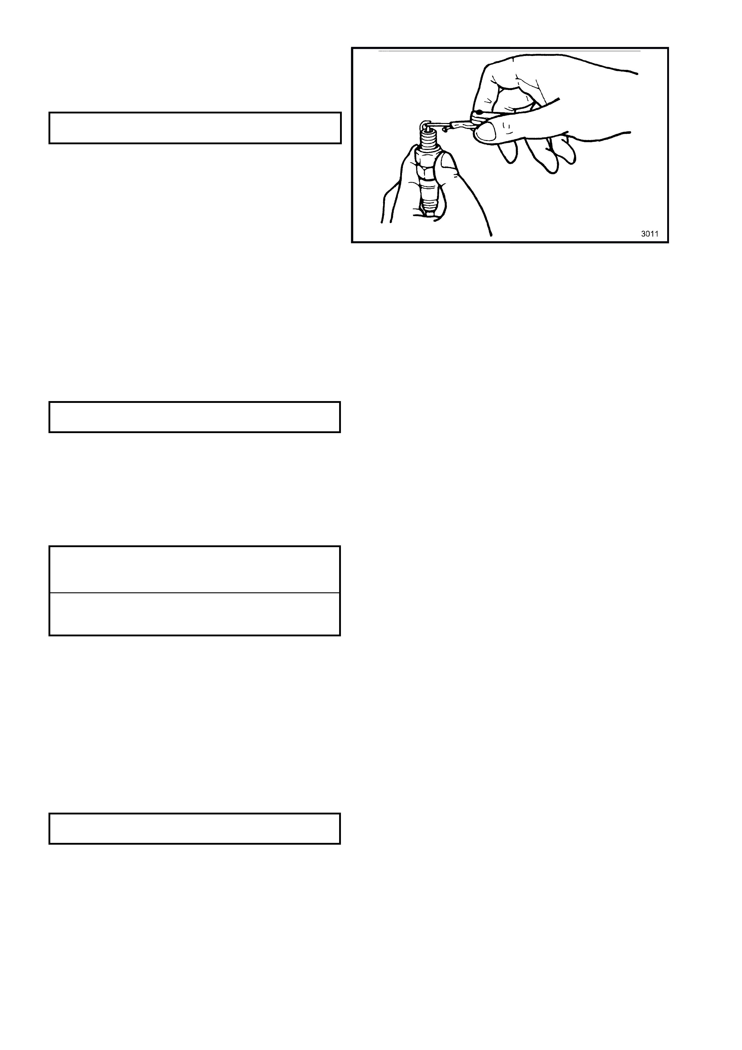
6. Use round wire f eeler gau ges to chec k the gap
between the spark plug electrodes.
7. Adjust the gap to the correct specification by
caref ull y bending the outer elec tr ode.
SPARK PLUG GAP 1.52 ± 0.05 mm
Figure 6D3-3-10
Spark Plug Leads
1. Carefully inspect the spark plug and ignition
coil boots on each lead for cracks, splits or
other deterioration. Replace any lead
exhibiting these conditions.
2. Connect an accurate Ohmmeter across each
spark plug lead. Replace any spark plug lead
that exceeds the specified resistance value.
SPARK PLUG LEAD 700 Ohm
RESISTANCE SPECIFICATION Maximum
REINSTALL
1. Remove rag from spark plug holes.
2. Reinstall spark plugs by hand and tighten to
the correct torq ue sp ecific ation, us ing a 16 m m
spark plug socket and a suitable torque
wrench.
SPARK PLUG TORQUE
SPECIFICATION WITH 15 Nm
ORIGINAL CYLINDER HEAD
SPARK PLUG TORQUE
SPECIFICATION WITH NEW 20 Nm
CYLINDER HEAD (‘COINING’)
3. Reinstall spark plug leads, taking note of the
following:
a. Always push each lead squarely onto both
the ignition coil and spark plug ends.
b. Ensure that the heat shield at the spark
plug end is secure and th at the connec tion
to the spark plug centre electrode is
correctly and fully engaged.
4. Reinstall the engine dress cover, install the
four decorative retaining nuts and tighten to
the correct torque specification.
ENGINE DRESS COVER NUT
TORQUE SPECIFICATION 8.0 – 12 Nm
2.2 IGNITION COIL/MODULE
REMOVE
1. Disconnect the battery earth (negative) cable
from the battery.
2. Remove the engine dress cover retaining nuts
(2), then remove the cover (1) from the engine
and set to one side.
Figure 6D3-3-11
3. Remove the spark plug lead/s, noting the
following:
a. When removing spark plug lead/s, only
handle the boot on each lead, twist to
break the seal, them pull to remove. DO
NOT pull on the lead itself.
b. Unless required, it is not necessary to also
remove the lead from the individual spark
plug as shown in Fig. 6D3-3-12.
Figure 6D3-3-12
4. Rem ove the CPA lock (4) from the ign ition coi l/
module m ain connector f rom the side on which
the ignition coil/module is to be removed.
5. Remove the wiring harness connector (3).
6. Rem ove the f our s tu ds ( 1) an d o ne s c re w (bo ld
arrow), securing the coil/module mounting
bracket (2) to the valve rocker arm cover (5).
7. Lift the ignition coils/modules, wiring and
bracket from the engine.
NOTE: The rear attaching screw (bold arrow) on
each coil/module mounting bracket is a
conventional screw and not a stepped stud.
Fitment of this screw in the correct position on
reassembly is important to avoid possible chaffing.
8. Remove the CPA lock (6) from the coil/module
to be removed, then remove the coil wiring
harness connector. Figure 6D3-3-13
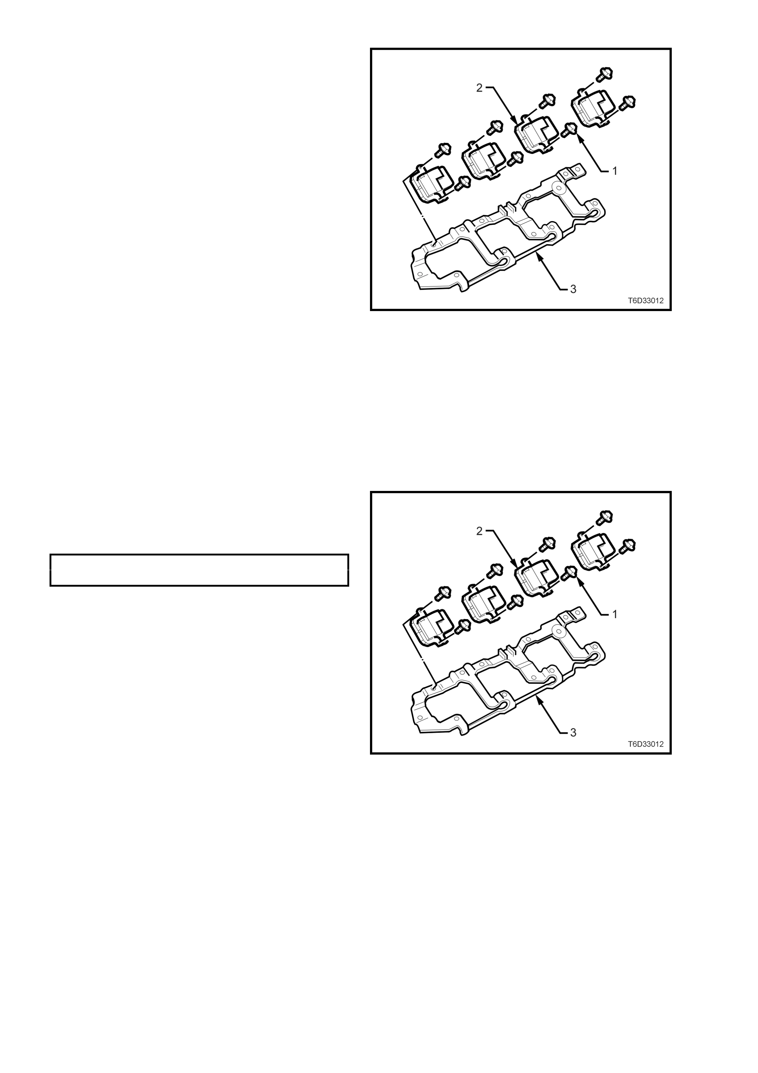
9. Remove the coil/module retaining screws (1)
holding the coil/module (2) to the mounting
plate (3).
10. Remove the coil/module (2) from the mounting
plate (3).
Figure 6D3-3-14
TEST
For ignition system checks, refer to
6C3-2C FUNCTIONAL CHECKS – GEN III
ENGINE, Electronic Ignition System Diagnosis, of
the VT Series II Service Information.
REINSTALL
Reinstallation is the reverse of removal operations
except for the following items.
1. Install the coil/module/s (2) to the mounting
plate (3) and secure with the retaining screws
(1), tightening to the correct torque
specification.
IGNITION COIL/MODULE RETAINING
BOLT TORQUE SPECIFICATION 12 Nm
Figure 6D3-3-15
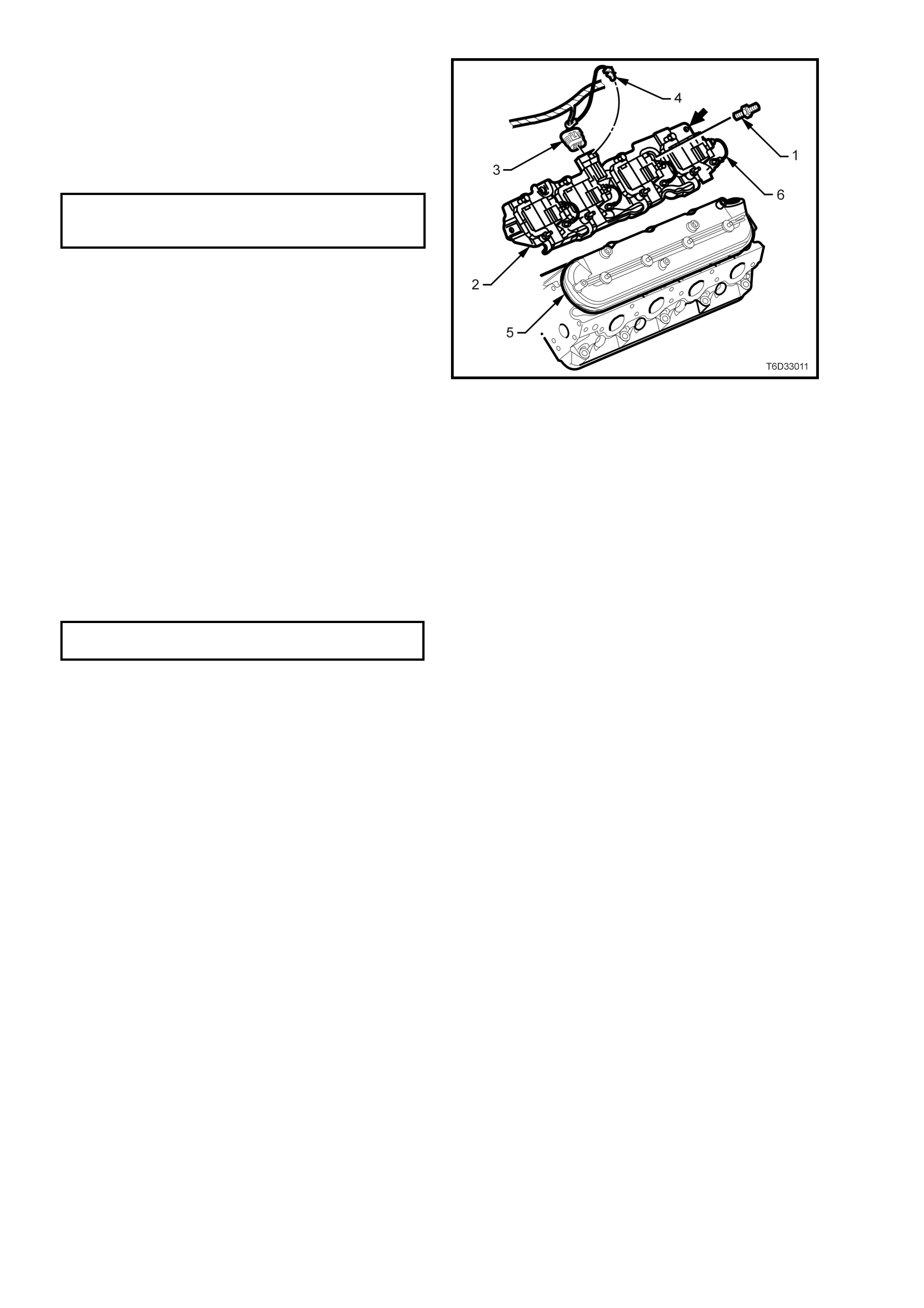
2. Ensure that the co il wiring har n ess c onnector is
fitted cor rectl y and t hat the C PA l ock (6) is full y
installed.
3. Install the coil/module mounting bracket to the
valve rocker arm cover (5), install the four
studs (1) and one screw (bold arrow) and
tighten to the correct torque specification.
IGNITION COIL/MODULE
BRACKET STUD/SCREW 12 Nm
TORQUE SPECIFICATION
NOTE: The rear attaching screw (bold arrow) on
each coil/module mounting bracket is a
conventional screw and not a stepped stud.
Fitment of this screw in the correct position is
important to avoid possible chaffing.
4. Install the ignition coil/module main wiring
connector (3) and secure with the CPA lock
(4).
5. Reinstall spark plug leads, taking note of the
following:
a. Always push each lead squarely onto both
the ignition coil and spark plug ends.
b. Ensure that the heat shield at the spark
plug end is secure and that the connection
to the spark plug centre electrode is
correctly and fully engaged.
Figure 6D3-3-16
6. Reinstall the engine dress cover, install the
four decorative retaining nuts and tighten to
the correct torque specification.
ENGINE DRESS COVER NUT
TORQUE SPECIFICATION 8.0 – 12 Nm
7. Reinstall the battery earth (negative) lead to
the battery.
8. Perform the ‘Idle Learn Procedure’ and the
‘Functional Check’. Refer to
Section 6C3-3 SERVICE OPERATIONS –
GEN III V8 ENGINE, 3.2 Powertrain Control
Module (PCM), of the VT Series II Service
Information.

3. DIAGNOSIS
For diagnosis of the ignition system, refer to Section 6C 3-2A D IAGNOSTIC TABLES – GEN III V8 ENG IN E, of the
VT Series II Service Information.
For diagnos is of s park plugs and /or their c ondi tion, refer to 3. DIAG NOSI S in Se ction 6D2-3 IGNIT ION SYST EM -
V8 ENGINE, of the VT Series I Service Information.

4. SPECIFICATIONS
Firing Order........................................................................... 1-8-7-2-6-5-4-3
Spark Plug Identification....................................................... AC 41-952
Spark Plug Part Number....................................................... 25171803
Spark Plug Heat Range........................................................ 2
Spark Plug Resistance ......................................................... 4 – 12 kΩ
Spark Plug Gap..................................................................... 1.52 ± 0.05 mm
Spark Plug Lead Resistance ................................................ 700 Ω maximum

5. TORQUE WRENCH SPECIFICATIONS
Nm
Engine Dress Cover Retaining Nut....................................... 8 - 12
Ignition Coil to Mounting Bracket Screw............................... 12
Ignition Coil Bracket to Rocker Cover Screw........................ 12
Spark Plugs........................................................................... 15
Spark Plugs (New Cylinder Head - ‘Coining’)....................... 20