SECTION 6E3 - EMISSION CONTROL -
GEN III V8 ENGINE
CAUTION:
This vehicle will be equipped with a Supplemental Restraint System (SRS). A SRS will consist of either
seat belt pre-tensioners and a driver's air bag, seat belt pre-tensioners and a driver's and front
passenge r's air bags or se at belt p re-ten sioner s, drive r’s an d fron t pass enger’ s air bag and left and righ t
hand side air bags. Refer to SAFETY PRECAUTIONS, Section 12M, Supplemental Restraint System of the
VT Series I Service Information before performing any service operation on, or around any SRS
components, the steering mechanism or wiring. Failure to follow the SAFETY PRECAUTIONS could
result in SRS deployment, resulting in possible personal injury or unnecessary SRS system repairs.
CAUTION:
Whenever any component that forms part of the ABS or ABS/ETC (if fitted), is disturbed during Service
Operations, it is vital that the complete ABS or ABS/ETC system is checked, using the procedure as
detailed in 4. DI AGNOSI S, ABS or ABS/ETC FUNCTION CHECK, in Section 12L ABS & ABS/ETC, in either
the VT Series I Service Information (V6) or in the VT Series II Service Information (GEN III V8) of this
Service Information CD.
1. GENERAL INFORMATION
In order for the GEN III V8 engine and associated systems to comply with legislated emission control regulations,
the vehicle must only operate with unleaded fuel. Twin, three-way catalytic converters are fitted to the exhaust
system.
This engine also features electronically controlled, sequential fuel injection and ignition systems.
In addition several other systems are fitted to VT Series II vehicles, with the GEN III V8 engine.
GEN III V8 ENGINE EM ISSIO N CONT RO L SYST EMS
ENGINE VENTILATION
EVAPOR ATIVE EMI SSIO N CONT RO L
EXHAUST EMISSION CONTROL
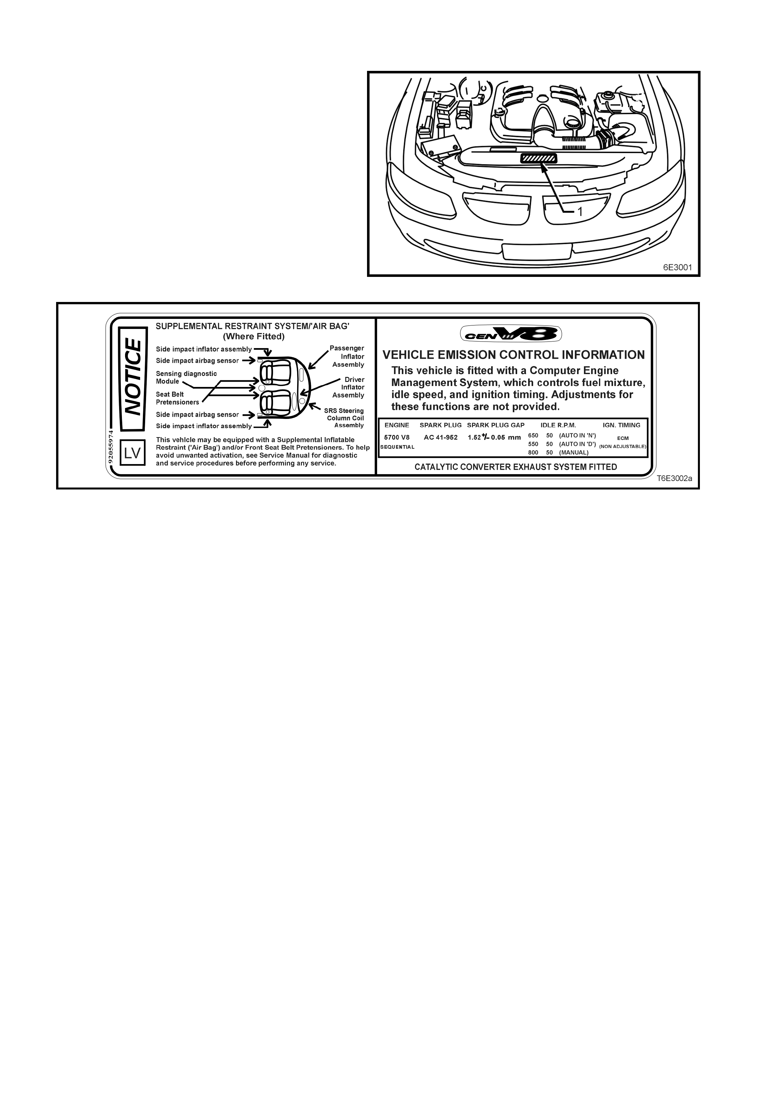
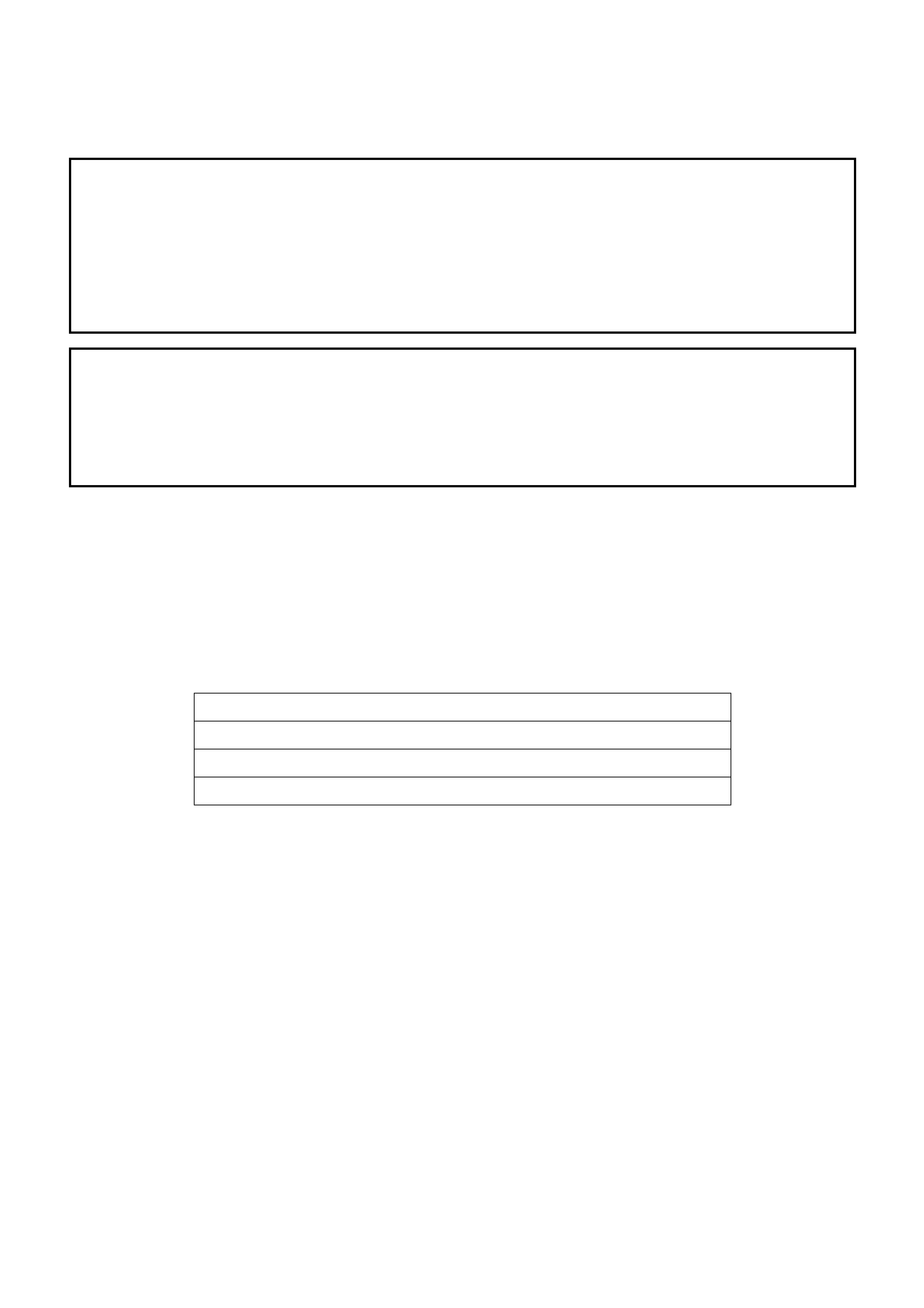
1.1 VEHICLE EMISSION CONTROL INFORMATION LABEL
The Veh icle Em is sion Con trol I nform ation Label ( 1)
is attached to the upper radiator shroud in the
centre, as shown.
This label contains important engine tune
conditions and information that must be complied
with, in order for the vehicle and its systems to
achieve the requ ired emis s ion le ve ls an d should be
referred to before making any adjustments to the
engine or related systems.
Figure 6E3-1
Figure 6E3-2
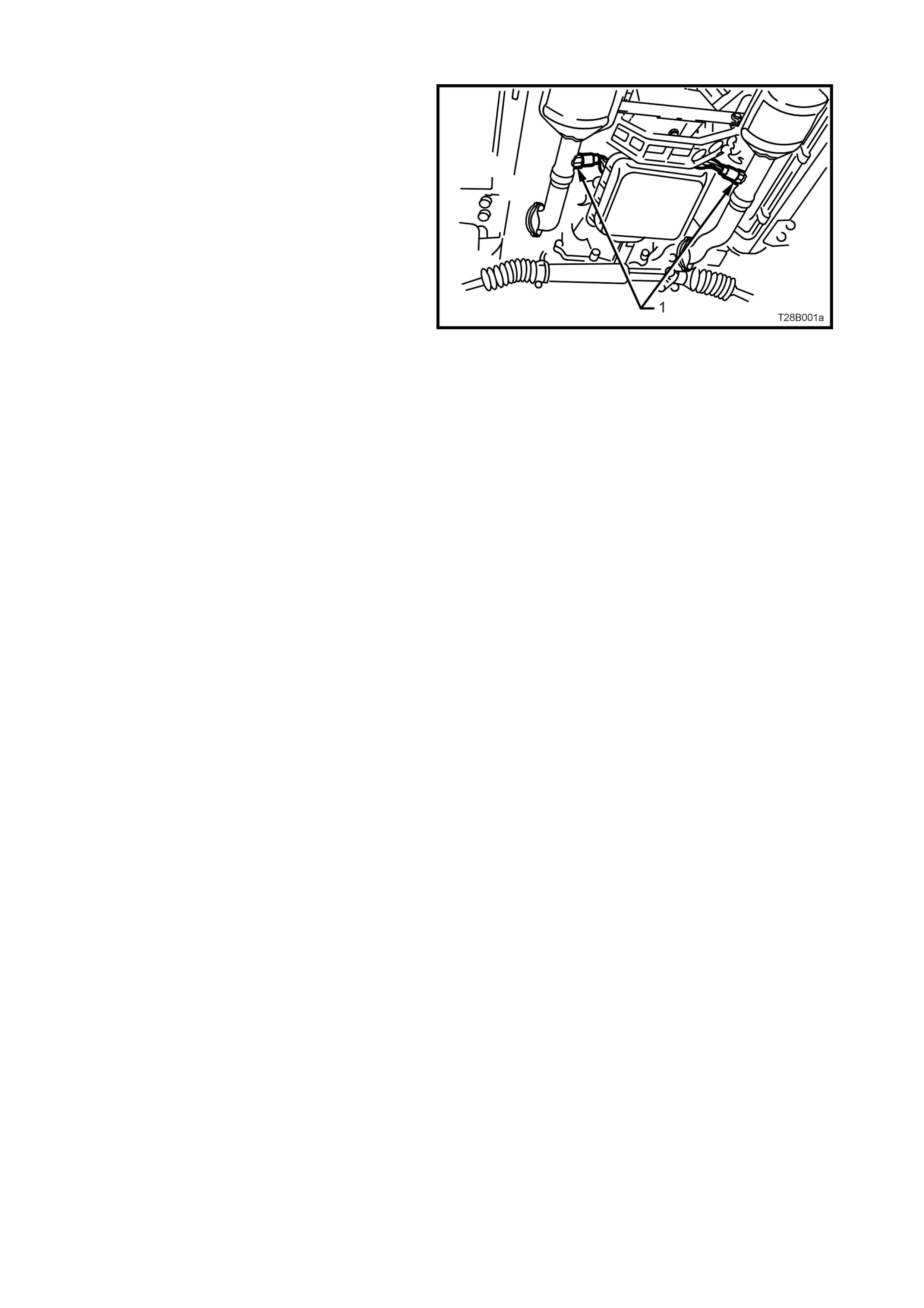
1.2 EMISSIONS MANAGEMENT
All aspects of engine air/fuel rati o and spar k tim ing
are controlled by the Powertrain Control Module
(PCM). T he mixtur e contr ol i s a cl osed lo op system
that incorporates dual oxygen sensors (1), located
in the exhaust system engine pipes, forward of
each catalytic converter.
Figure 6E3-3
While the Engine Ventilation System requires no
outside control, the operation of the Evaporative
Emission Control system is controlled by the PCM
via an EVAP canis ter purge va lve, mounte d on the
engine int ake manif old.
The PCM and assoc iated sys tem s are des cribe d in
6C3 POWERTRAIN MANAGEM ENT – GEN III V8
ENGINE, of the VT Series II Service Information.
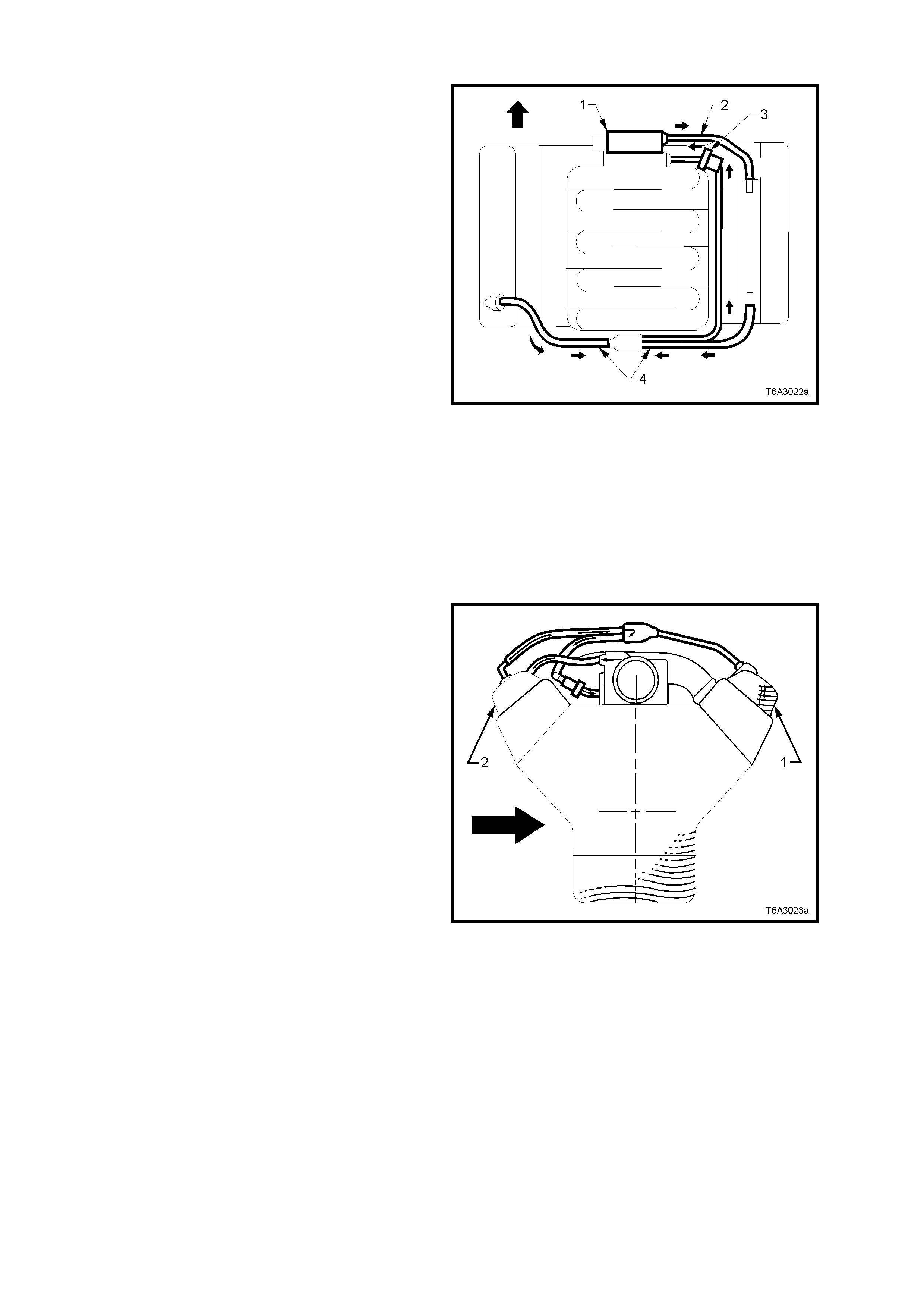
1.3 ENGINE VENTILATION SYSTEM
A closed crankcase ventilation system is used to
provide complete scavenging of crankcase
vapours. Fresh air from the throttle body (1) is
supplied to the crankcase, mixed with blow-by
gases and then passed through a crankcase
ventilation valve (3) into the intake manifold.
The engine ventilation system was developed to
minimise oil consumption and ensure that oil
ingestion could not occur during severe vehicle
handling manoeuvres.
Filtered fresh air is routed from upstream of the
throttle blade to the front of the right rocker cover
via a formed rubber hose (2). To reduce the
potential of oil pullover into the throttle bore area
due to back flow of the ventilation system, the
fitting in the right side rocker cover is located in a
“quiet” area located between, and shielded from,
the rocker arms. Crankcase blowby gases are
routed from the rear of bot h rocker c overs, through
moulded nylon lines to a tee fitting, located on the
centreline of the engine at the rear of the intake
manifold (4). From there, a single hose carries
crankcase vapours through an externally mounted,
horizontal PCV valve (3) and enters the intake
manifold behind the throttle body (1).
The hoses are foam insulated and the PCV valve
(3) is conduction-heated from the cylinder block by
a braided cable.
Figure 6E3-4
This “dual draw system” was developed to meet
high ‘g’ forces (bold arrow) incurred during severe
cornering manoeuvr es. During s ustained m axim um
lateral accelerations, the outboard rocker cover (1)
may fill with oil.
The “dual draw” system “passively switches”,
allowing the PC V valve to draw on the r ock er co ver
with the least resis tance. T his results in the s ystem
drawing on the air filled, or inboard, rocker cover
(2) and eliminates oil pullover that would result
from drawing on the oil filled outboard rocker cover.
Sectione d view s hown is looking re arward f rom the
engine front.
Figure 6E3-5
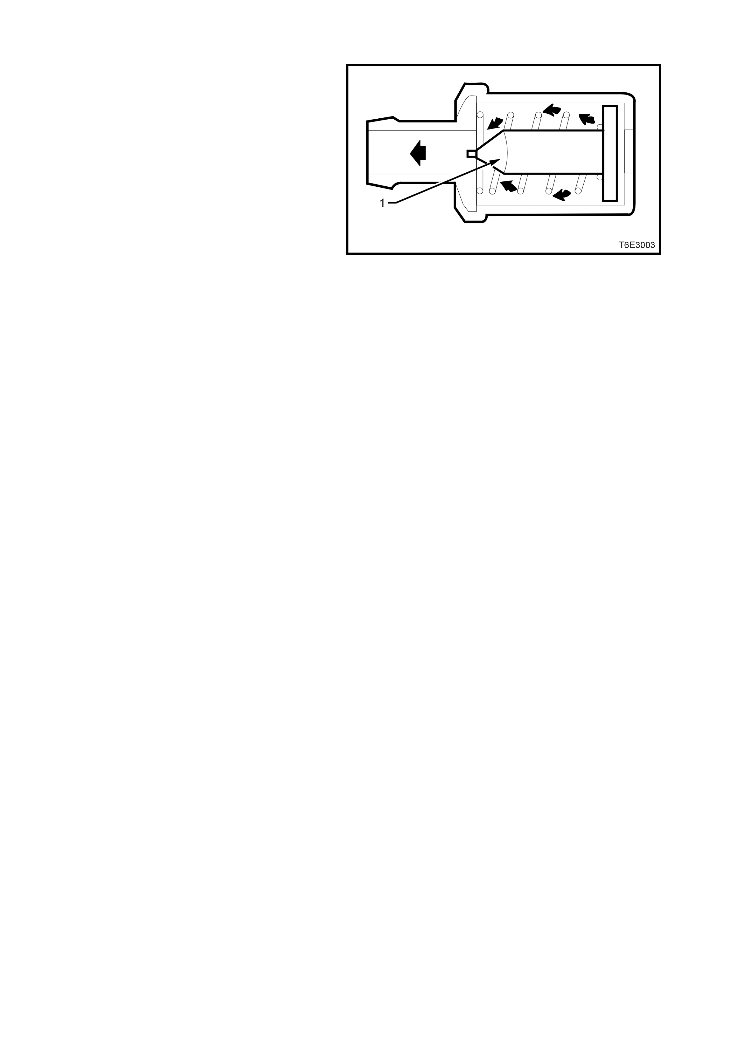
RESULTS OF INCORRECT OPERATION
A block ed or partial ly blocked PCV chec k val ve (1)
or hose may cause:
• Rough idle.
• Stalling or slow idle speed.
• Oil leaks.
• Sludge in engine.
A leaking valve or hose would cause:
• Rough idle.
• Stalling.
• High idle speed.
Figure 6E3-6
1.4 EVAPORATIVE EMISSION CONTROL
The Evaporative Emission Control System (EECS)
used on this vehicle is the charcoal canister
storage method.
This method transfers fuel vapour from the fuel
tank to an activated carbon (charcoal) storage
device located under the rear of the vehicle. This
canister is des igned to st ore the f uel vapour s when
the vehicle is not operating but allow the fuel
vapour is purged from the carbon element by
intake air flow, when the engine is running. In this
way, the fuel vapour is consumed in the normal
combus tion proc es s .
The EVAP canister purge valve is the means by
which intake manifold vacuum purges the canister
but only when the PCM supplies an earth signal to
energise the EVAP canister purge valve (purge
“ON”). The EVAP canister purge valve control is
Pulse W idth Modulated (PW M) or turned “ON” and
“OFF” several times a second.
The PCM controlled PWM output is commanded
when the appropriate conditions have been met,
such as:
• Engine coolant temperature is below 30°C at
cold start up.
• Engine has been running longer than 2
minutes.
or
• Engine coolant temperature is above 30 °C at
warm start up.
• Engine has been running longer than 30
seconds.
• Engine is not in Decel Fuel Cutoff Mode.
• Throttle opening is less than 96%.
• Engine is in Closed Loop mode or Open Loop
mode.
Figure 6E3-7
Legend
1. Air Vent Por t
2. Canister Purge Port
3. Vapour from Fuel Tank Port
4. Vapour Canister
A higher purge rate is used under conditions that
are likely to produce large amounts of vapour,
when the following conditions have been met:
• Intake Air Temperature (IAT) is above 50°C.
or
• Engine Coolant Temperature (ECT) is above
100 °C.
• Engine has been running for more than 15
minutes.
The EVAP purge PW M duty cycle varies according
to operating conditions, determined by mass air
flow, fuel trim and intake air temperature. The
EVAP canister purge valve (1) will be re-enabled
when TP angle decreases below 96%.
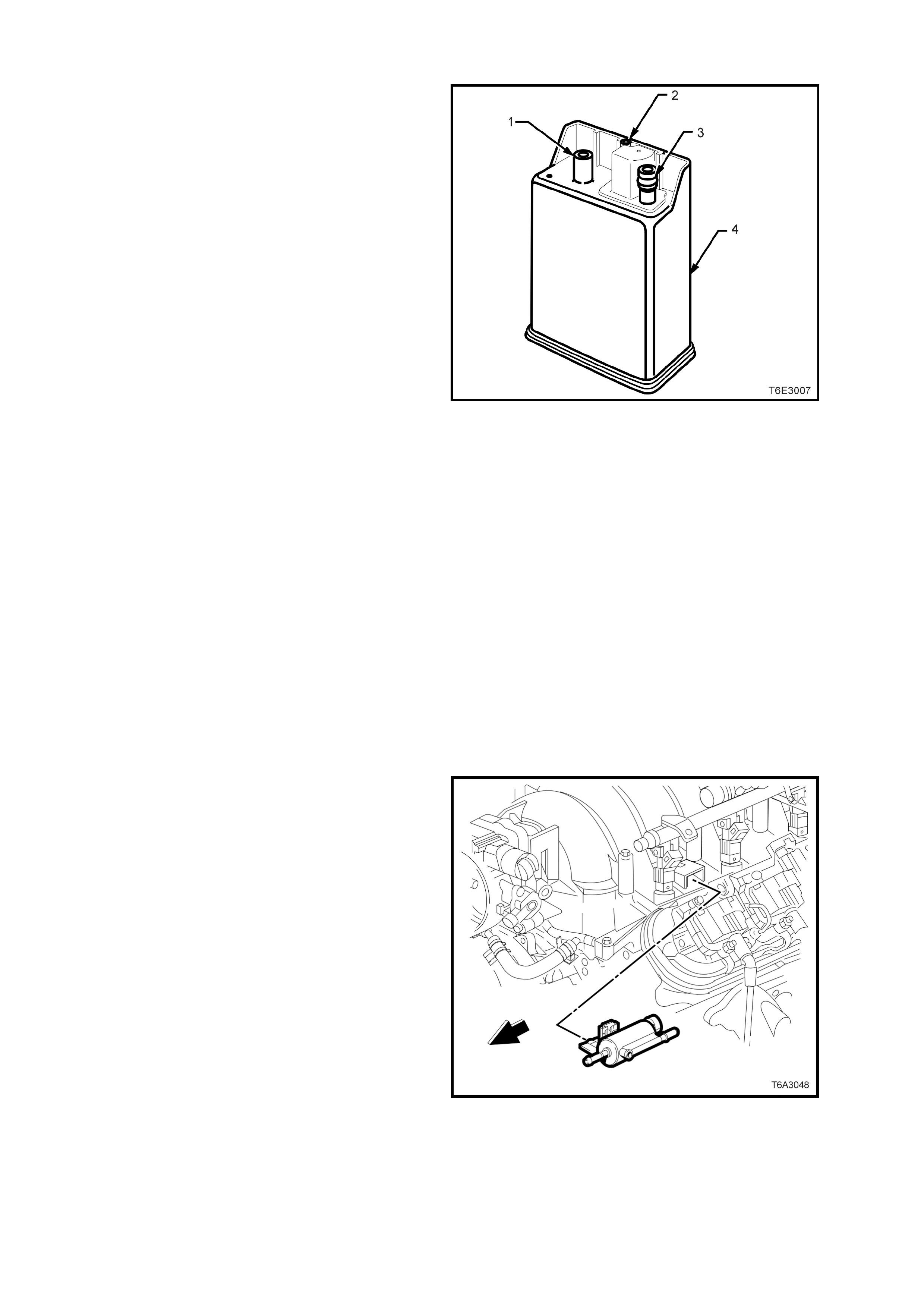
Figure 6E3-8

The c anister (loca ted under th e rear of the veh icle)
cannot be repaired, and is serviced only as an
assembly. Periodically check the canister at the
time or distance intervals specified in the vehicle
Series Owners Handbook.
The fuel vapour canister is mounted in a bracket
underneath the vehicle, near the fuel filter (4).
This canister is a three port design. The fuel
vapour is absorbed by the charcoal within the
canister. When the engine is running at idle speed
and above idle, air is drawn into the canister
through the air vent line (2) (atmospheric port) at
the top of the canister assembly.
The air m ixes with the fuel vapour and the mixture
is drawn into the intake manifold via the canister
purge line (1). Pur g in g of the ca nis ter v ia t his l in e is
controlled by a PCM controlled EVAP canister
purge valve. The EVAP canister purge valve
controls the manifold vacuum signal from the
throttle b ody. The remaining l in e i nto t he c a nis ter is
the vapour inlet f rom the f uel tank (3). T he f resh air
inlet port (2) (air vent port) on the canister is open
to the atmosphere via a hose that vents under the
vehicle. Figure 6E3-9
Legend
1. Canister Purge Port
2. Air Vent Por t
3. Vapour from Fuel Tank Port
4. External Fuel Filter
RESULTS OF INCORRECT OPERATION
Poor idle, stalling and poor driveability can be
caused by:
• Inoperative EVAP canister purge valve.
• Damaged canister.
• Hoses split, cracked and/or not connected to
the
correct locations.
• Throttle body and canister hoses interchanged
on the EVAP canister purge valve connections.
NOTE: The canister connection is marked with
"CAN".
Evidence of fuel loss or fuel vapour odour can be
caused by:
• Liquid fuel leaking from fuel lines.
• Cracked or damaged canister.
• Disconnected, misrouted, kinked, deteriorated
or damaged vapour hoses, or control hoses.
If the EVAP canister purge valve is stuck open, or
the control circuit is shorted to earth the canister
will purge to the intake manifold all the time. This
can allow extra fuel at idle or during warm-up,
which can cause rough or unstable idle or a rich
fuel operation.
If the canister purge solenoid is always closed, the
canister can become over loaded, with noticeable
fuel odour being evident.
Figure 6E3-10
Legend
1. Air Vent Por t
2. Canister Purge Port
3. Vapour from Fuel Tank Port
4. Evaporative Canister
5. Volume Compensator
6. Charcoal Bed
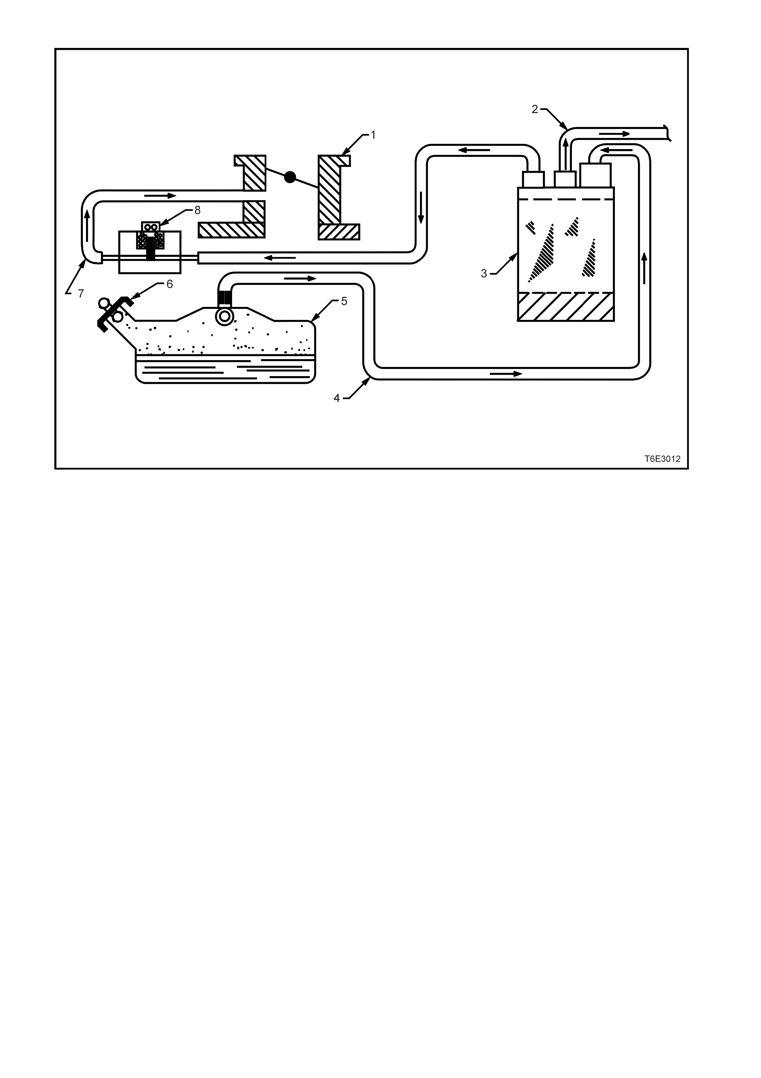
1. Throttle Body 5. Fuel Tank
2. Atmospheric Port Hose 6. Pressure/Vacuum Vented Fuel Filler Cap
3. Evaporative Emission Canister 7. Evaporative Purge Hose
4. Fuel Vapour Hose 8. EVAP Canister Purge Valve ( Normally Closed)
Figure 6E3-11 - Typical Evaporative Emission Control Schematic

1.5 EXHAUST EMISSION CONTROL SYSTEM
While no exhaust gas recirculation (EGR) system is required for the G EN III V8 engine t o meet legislated exhaus t
emission control limits, the exhaust system is fitted with a three-way catalytic converter, fitted to each of the twin
engine exhaus t pi pes.
The purpose of th ese catalyt ic con verters is to c onvert Carbon Monoxide (CO ), Unburned H ydrocarbons ( HC) and
Oxides of Nitrogen (NOx), into Carbon Dioxide (CO2), Water Vapour (H20)and Nitrogen (N2) gas.
For f urther infor mation r egarding th is s ystem , refer to 6E2 EMISSION CONT ROL - V8 ENGINE, of the VT Ser ies I
Service Information.

2. SERVICE OPERATIONS
For servicing operations related to any of the emission control systems or components referred to in this Section,
refer to either 6 E2 EMISSION CONT ROL – V8 ENG I NE, of the VT Series I Service Inf or mation or 6C3 -3 S ERVICE
OPERATIONS - GEN III V8 ENGINE, of the VT Series II Service Information.

3. DIAGNOSIS
POSITIVE CRANKCASE VENTILATION
CONDITION PROBABLE CAUSE CORRECTIVE ACTION
Rough, slow idle or stalling PCV valve blocked.
Blocked or damaged ventilation hose. Clean valve or replace.
Clean or replace hose.
Rough, fast idle or stalling PCV valve stuck in intermediate
position.
PCV valve leaking.
Clean valve or replace.
Replace PCV valve as necessary.
Check valve installation.
Excessive sludging or diluting of oil Engine is not being vented. Check for clogged PCV valve circuit
and/or clogged venti lation cir cuit .
EVAPORATIVE EMISSION CONTROL
CONDITION PROBABLE CAUSE CORRECTIVE ACTION
Loss of fuel from filler cap Unsatisfactory sealing between cap
and filler neck.
Malfunction of filler cap relief valve.
Replace filler cap or replace fuel tank if
filler neck is dam age d.
Replace filler cap.
Loss of fuel from fuel lines Loose line connection. Secure connection.
Loss of fuel from canister Fuel tank overfilled.
When the fuel warms up during parking
or warm weather operation, excess fuel
is discharged into the can ist er, flood ing
it.
Blocked, damage d or disco nne cted
purge hose at canister.
Remove excess fuel and avoid
overfilling.
Replace hose as required.
Collapsed fuel tank or pressure in tank Faulty fuel filler cap (in high
temperature operating conditions some
pressure may normally be encountered
in the fuel tank).
Blocked or kinked vent line.
Defective canister (usually internal
blocked).
EVAP canister purge valve is stuck
closed causing canister to become
overloaded.
Replace filler cap.
Replace damaged line.
Replace canister.
Rough idle Improperly routed or disconnected
purge line.
Purge solenoid valve is open or not
receiving power.
Route purge line correctly or reinstall
purge line.
Refer 6C3 POWERTRAIN
MANAGEMENT – GEN III V8 ENGINE
of the VT Series II Service Information.
For diagnosis of faults relating to vehicle performance, refer to Section 6C3 POWERTRAIN MANAGEMENT -
GEN III V8 ENGINE of the VT Series II Service Information.