SECTION 6F3 - ENGINE TUNE – GEN III V8 ENGINE
CAUTION:
This vehicle will be equipped with a Supplemental Restraint System (SRS). A SRS will consist of either
seat belt pre-tensioners and a driver's air bag, seat belt pre-tensioners and a driver's and front
passenger's air bag s or seat belt pre-tensio ners, driver’s an d f ront passenger’s air b ag an d lef t an d rig ht
hand side air bags. Refer to SAFETY PRECAUTIONS, Section 12M , Supplemental Restraint System of the
VT Series I Service Information before performing any service operation on, or around any SRS
components, the steering mechanism or wiring. Failure to follow the SAFETY PRECAUTIONS could
result in SRS deployment, resulting in possible personal injury or unnecessary SRS system repairs.
CAUTION:
Whenever any component that forms part of the ABS or ABS/ETC (if fitted), is disturbed during Service
Operations, it is vital that the complete ABS or ABS/ETC system is checked, using the procedure as
detailed in 4. DIAGNOSIS, ABS or ABS/ETC FUNCT ION CHECK, in Section 12L ABS & ABS/ETC, in either
the VT Series I Service Inforamation (V6) or in the VT Series II Service Information (GEN III V8) of this
Service Information CD.
1. GENERAL INFORMATION
Engine tuning, is sim plified by electronic control of both the air/fuel m ixture and the ignition timing. The ratio of the
air/fuel mixture is controlled to near optimum condition by the Powertrain Control Module (PCM) refer to Section
6C3 POWERTRAIN MANAGEMENT – GEN III V8 ENGINE in the VT Series II Service Information.
Should the air/fuel mixture operate outside specified limits, the PCM will set a Diagnostic Trouble Code and the
Check Engine Light will be illuminated.
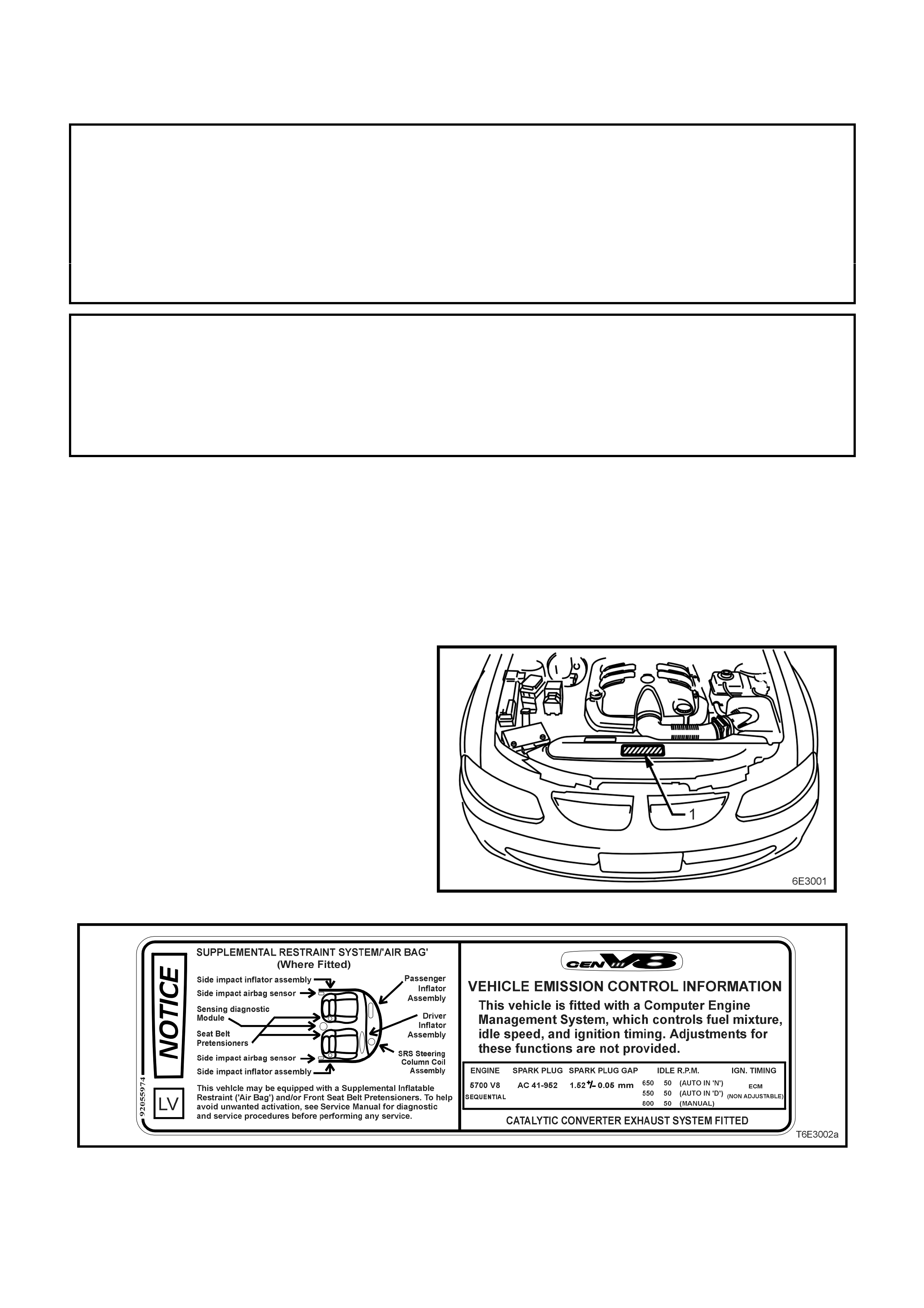
Engine tune specif ications nec essar y to achieve the
correct emission levels are located on the Vehicle
Emission Control Information Label, located in the
engine compartment (1). The label should be
referred to before making any adjustments.
To maintain the performance and emission control
levels specified for the vehicle, it is necessary for
regular m aintenanc e to be per f ormed in ac c ordanc e
with the schedule set out in the VT Series Owner's
Handbook.
Figure 6F3-1
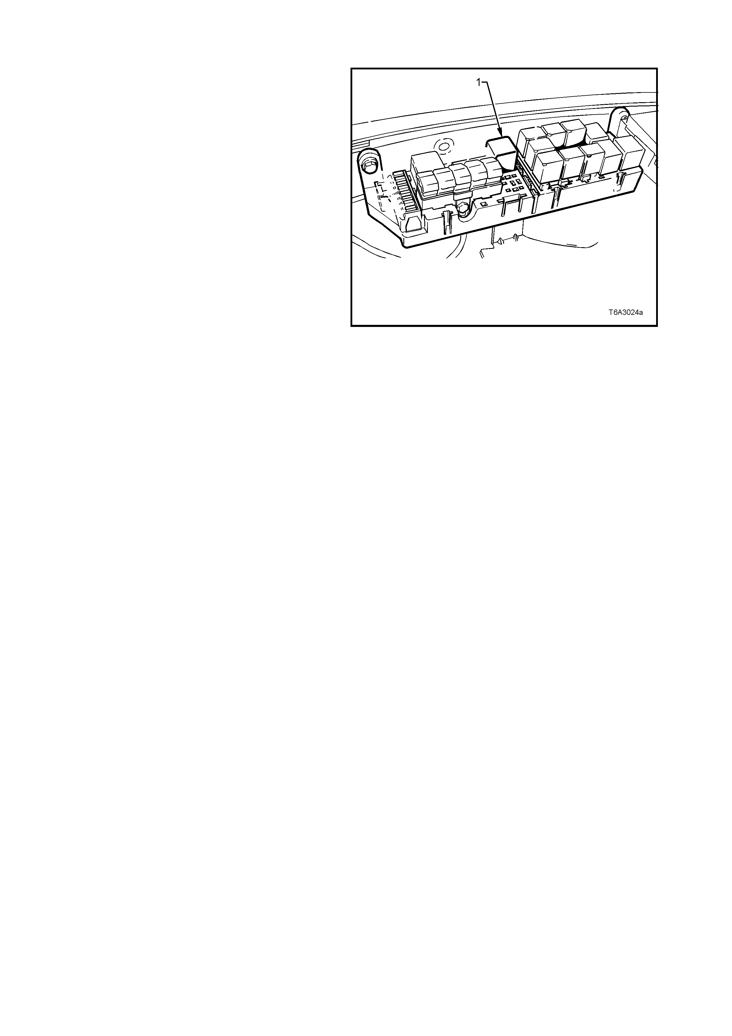
Figure 6F3-2

The chart set out in 2. ENGINE TUNE RECOMMENDATIONS details the recommended items requiring attention
during an engine tune and cross reference is provided to the appropriate source of information in the Service
Manual.
There is no pr ovis ion f or ignition timing, idle s peed and idle mixtur e adj ustments on VT Ser ies Models fitted with the
GEN III V8 engine, (refer to Section 6C3 POW ERTRAIN MANAGEM ENT – G EN III V8 ENGINE of the VT Series II
Service Information).

2. ENGINE TUNE RECOMMENDATIONS
ENGINE TUNE RECOMMENDATIONS VT SERVICE MANUAL
REFERENCE SECTION
ENGINE COMPRESSION TEST SECTION 6A3, ENGINE MECHANICAL – GEN
III V8 ENGINE. ALSO REFER TO 3.1 TUNING
SERVICE NOTES IN THIS SECTION.
ENGINE DRI VE BE LT CHECK SECTI ON 6A 3, ENGINE MECHANICAL – GEN
III V8 ENGINE.
COOLING SYSTEM CHECK FOR LEA K S SECTION 6B3, ENGINE COOLI NG – GE N III
V8 ENGINE.
VALVE LASH ADJUSTMENT NON-ADJUSTABLE HYDRAULIC LIFTERS
IDLE SPEED NON-ADJUSTABLE
IDLE MIXTURE NON-ADJUST ABLE
AIR CLEANER CHECK OR REPLACE, TEST FOR LEAKS SECTION 6C3, POWERTRAIN
MANAGEMENT – GEN III V8 ENGINE.
FUEL FILTER CHECK AND REPLACE SECTION 6C3, POWERTRAIN
MANAGEMENT – GEN III V8 ENGINE.
SPARK PLUGS CLEAN, ADJUST OR REPLACE SECTION 6D3-3, IGNITION SYSTEM – GEN
III V8 ENGINE.
SPARK PLUG LEADS TEST FOR CONTINUITY SECTION 6D3-3, IGNITION SYSTEM – GEN
III V8 ENGINE.
IGNITION TIMING NON-ADJUST ABLE
EXHAUST SYSTEM CHECK FOR EXCESSIVE BACK PRESSURE
AND GENERA L CONDITION SECTION 8B, EXHAUST SYSTEM AND
SECTION 6C3, P OWERTRAIN
MANAGEMENT – GEN III V8 ENGINE.
ENGINE VENTILATION CHECK SECTION 6E3, EMISSION CONTROL – GEN
III V8 ENGINE.
EVAPORATIVE EMISSION
CONTROL CHECK LINES, HOSES AND CANISTER SECTION 6E3, EMISSION CONTROL.
BATTERY AND CABLES CHECK SECTION 12A, BATTERY AND CABLES.

3. ENGINE TUNI NG DATA
ENGINE TYPE TRANSMISSION IDLE SPEED
ENGINE WARM
(rpm)
IGNITION TIMING SPARK PLUGS
5.7 LITRE P . F. I. –
GEN III V8 MANUAL
AUTOMATIC
TRANSMISSION
800 ± 50
650 ± 50
(IN NEUTRAL)
550 ± 50
(IN DRIV E)
NON-ADJUSTABLE
(PCM
CONTROLLED)
TYPE
AC 41-952
GAP (mm)
1.52 ± 0.05 mm
NOTE: Idle speed is non-adj ustable (PCM c ontrolled) and varies with: - Battery vol tage
- Engine temperature
- Air condi t i oni ng request
- Park/Neutral Switch Signal (Aut omati c Transmiss i on onl y)
3.1 TUNING SERVICE NOTE S
CAUTION: TO PREVENT BOTH FUEL BEING
INJECTED INTO THE CYLINDERS AND
IGNITION DURING CRANKING, REMOVE THE
EFI RELAY (1) WHEN PERFORMING A
COMPRESSION TEST.
For compression testing procedure and
specifications, refer to Section 6A3 ENGINE
MECHANICAL – GEN III V8 ENGINE, in this
Service Information CD.
1. DO NOT operate the engine with any spark
plugs or spark plug leads disconnected as
damage to the Ignition System or PCM may
result.
2. Make all engine checks with engine coolant
and oil at normal operating temperatures,
preferably achieved by driving.
3. Ensure that the air conditioner (where fitted) is
switched OFF.
4. Verify that check powertrain light is OFF with
the engine running.
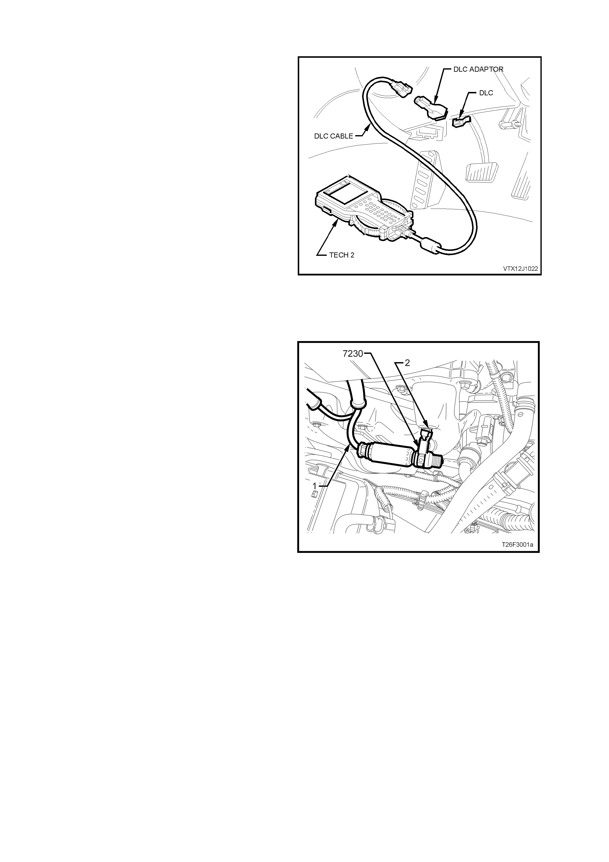
Figure 6F3-3
3.2 CYLINDE R BALANCE CHECK
1. Connect TECH 2 to the Data Link Connector
(refer to Section 0C T ECH 2 of the VT Series II
Service Information).
2. Select VT Commodore \ Engine \ Functional
Tests, Power Balance.
3. Perform Power Balance as directed by TECH 2.
NOTE 1: Engine rpm readings displayed on TECH
2 should be within 50 rpm for all cylinders.
NOTE 2: Any cylinder that does not cause a drop in
engine idle speed is misfiring.
Once the suspect cylinder has been isolated, the
cause of the problem will still need to be
determined. Reasons include fuel, spark or engine
mechanical problems.
The f ollowing are a few quick check s to help isolate
the cause of the engine misfire. For additional
diagnostic information refer to Section 6C3
POWERTRAIN MANAGEMENT – GEN III V8
ENGINE of the VT Series II Service Information. Figure 6F3-1
IGNITION
1. Remove spark plug lead (1) from plug and
engine harness connector from injector of
misfiring cylinder.
2. Install Test Plug, Tool No. 7230 and connect
to a good engine earth point (2).
Failure to properly earth the Test Plug 7230
can result in damage to ignition system
components due to excessive secondary
voltages required to fire the 7230.
NOTE: Avoid placing the Test Plug 7230 near
sensors, modules or other electronic equipment
that may be affected by electromagnetic
interference.
3. Start and run engine. If tester shows good
spark, check for faulty spark plug.
If weak or no spark, check lead for short to
earth, open or very high resistance in spark
plug lead.
NOTE: If any lead is open circuited, recheck coil
secondary resistance, as it may have been
damaged by high voltage produced by open circuit.
Figure 6F3-5
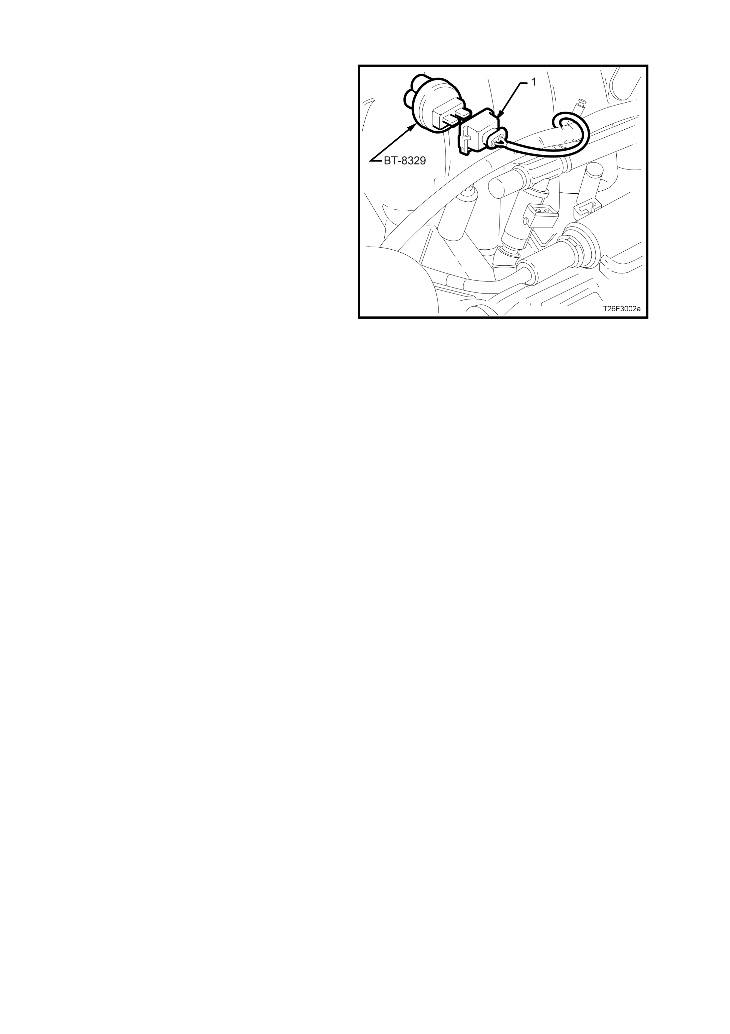
FUEL
1. Disconnect engine wiring harness connector
(1) from injector of cylinder that is misfiring.
Install injector node light tester, Tool No.
BT-8329 into connector (1) and start engine.
2. Check tester for light flashing.
a. If the light either does not flash or is
erratic, check engine harness between
connector and PCM for continuity.
b. If flashes are regular, check for blocked or
faulty injector (refer to Section 6C3
POWERTRAIN MANAGEMENT – GEN III
V8 ENGINE of the VT Series II Service
Information).
Figure 6F3-6
MECHANICAL
Perform compression test as outlined in
Section 6A3 ENGINE MECHANICAL - GEN
III V8 ENGINE in this Service Inforatmation
CD.
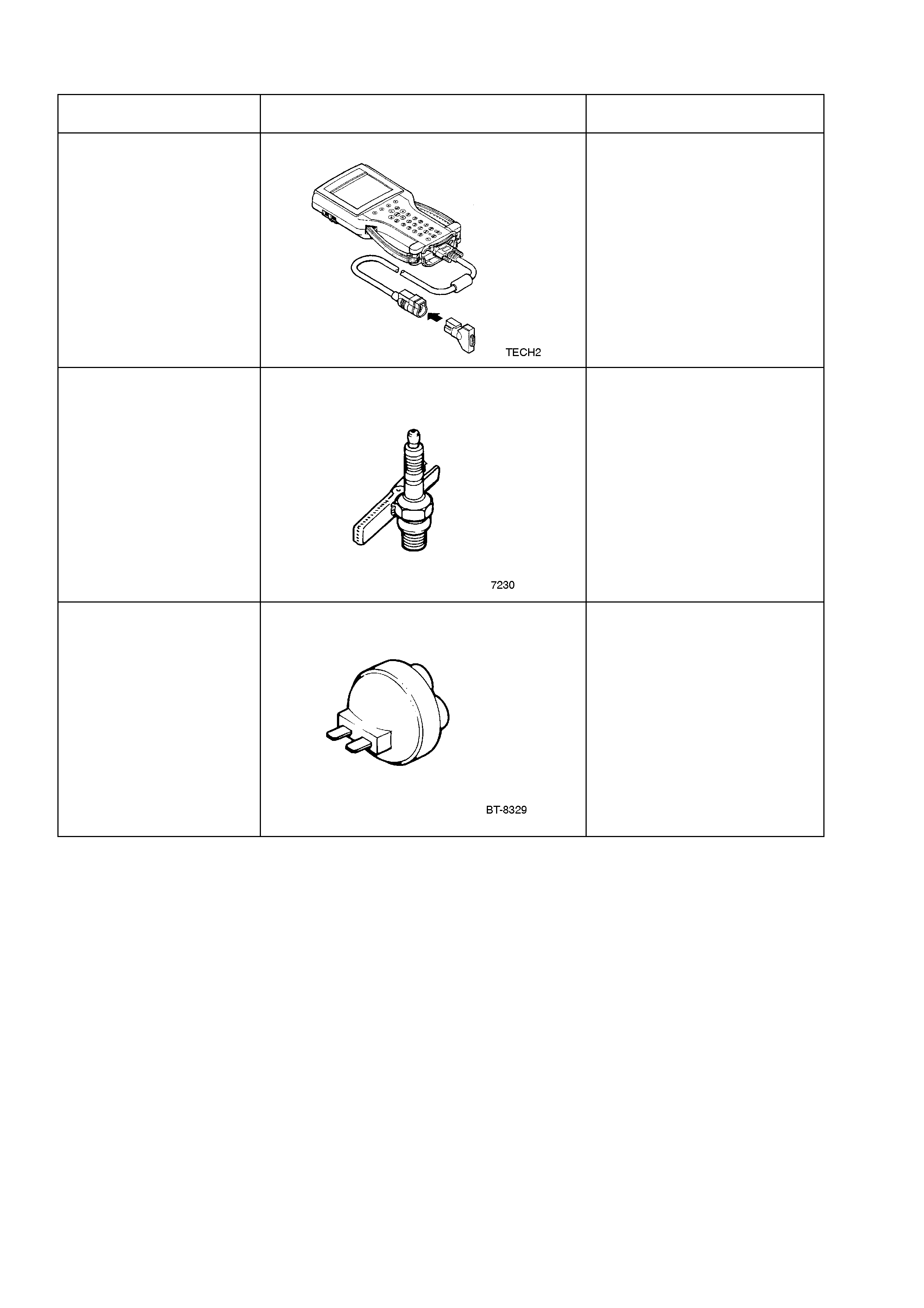
4. SPECIAL TOOLS
TOOL NO. REF IN TEXT TOOL DESCRIPTION COMMENTS
TECH 2 TECH 2 DIAGNOSTIC TOOL Previously released.
7230 TEST PLUG Previously released.
BT-8329 INJECTOR NODE LIGHT TESTER Previously released.