SECTION 8A - FUEL TANK
CAUTION:
This vehicle will be equipped with a Supplemental Restraint System (SRS). A SRS will consist of either
seat belt pre-tensioners and a driver's air bag, seat belt pre-tensioners and a driver's and front
passenger's air bags or seat belt pre-tensioners, driver’s and front passenger’s air bag and left and right
hand side air bags. Refer to SAFETY PRECAUTIONS, Section 12M, Supplemental Restraint System of
this Service Information CD before performing any service operation on, or around any SRS
components, the steering mechanism or wiring. Failure to follow the SAFETY PRECAUTIONS could
result in SRS deployment, resulting in possible personal injury or unnecessary SRS system repairs.
CAUTION:
Whenever any component that forms part of the ABS or ABS/ETC (if fitted), is disturbed during Service
Operations, it is vital that the complete ABS or ABS/ETC system is checked, using the procedure as
detailed in 4. DIAGNOSIS, ABS or ABS/ETC FUNCTION CHECK, in Section 12L ABS & ABS/ETC, in either
VT Series I Service Information (V6) or VT Series II Service Information (GEN III V8).
1. GENERAL INFORMATION
Apart from the deletion of the external vent pipe that occurred shortly after the start of production and the deletion of
the under-tank reinforcement plate, the fuel tank and related components for both V6 engines remains unchanged.
For service operations relating to the fuel tank on V6 engined, VT Series vehicles, refer to Section 8A FUEL TANK,
in the VT Series I Service Information. This Section then, will only detail the changes made to the fuel system as
they apply to the GEN III V8 engine.
The fuel system used with the GEN III V8 engine is a ‘single line’ system, which means that the previously used fuel
return line from the engine fuel rail, is no longer used.
A changed design, modular fuel sender assembly is located in the fuel tank, that incorporates a fuel pressure
regulator, a fuel reservoir, the fuel sender unit, roll-over valve and the fuel pump in the one modular unit.
Apart from the complete assembly, the only other serviced component in the modular fuel sender is the fuel sender
assembly.
Quick-connect fuel line fittings are used for all fuel line connections, including the modular fuel sender assembly,
fuel vapour canister, fuel filter, fuel feed line T-piece and at both the engine and fuel tank ends.
1.1 GEN III V8 ENGINE MODULAR FUEL SENDER OPERATION
The fuel control system used on the GEN III V8 is a “Returnless” or “Demand” system. The fuel system starts with
the fuel in the fuel tank. A single in-tank high pressure fuel pump with an integrated fuel pressure regulator (located
inside a modular fuel sender assembly) is used. From the high pressure pump, fuel flows through a fuel filter, then
back into the fuel tank via the fuel pressure regulator. Fuel is supplied to the fuel rail and injectors by a single feed
fuel line.
The high pressure in-tank single pump is capable of providing fuel at more than 410 kPa. A pressure regulator in
the modular fuel sender assembly maintains the fuel pressure at a regulated pressure of 410 kPa.
The fuel pump is energised by the PCM via the fuel pump relay The injectors, located in each runner of the intake
manifold just ahead of the inlet ports to the cylinder head, are controlled by the PCM.
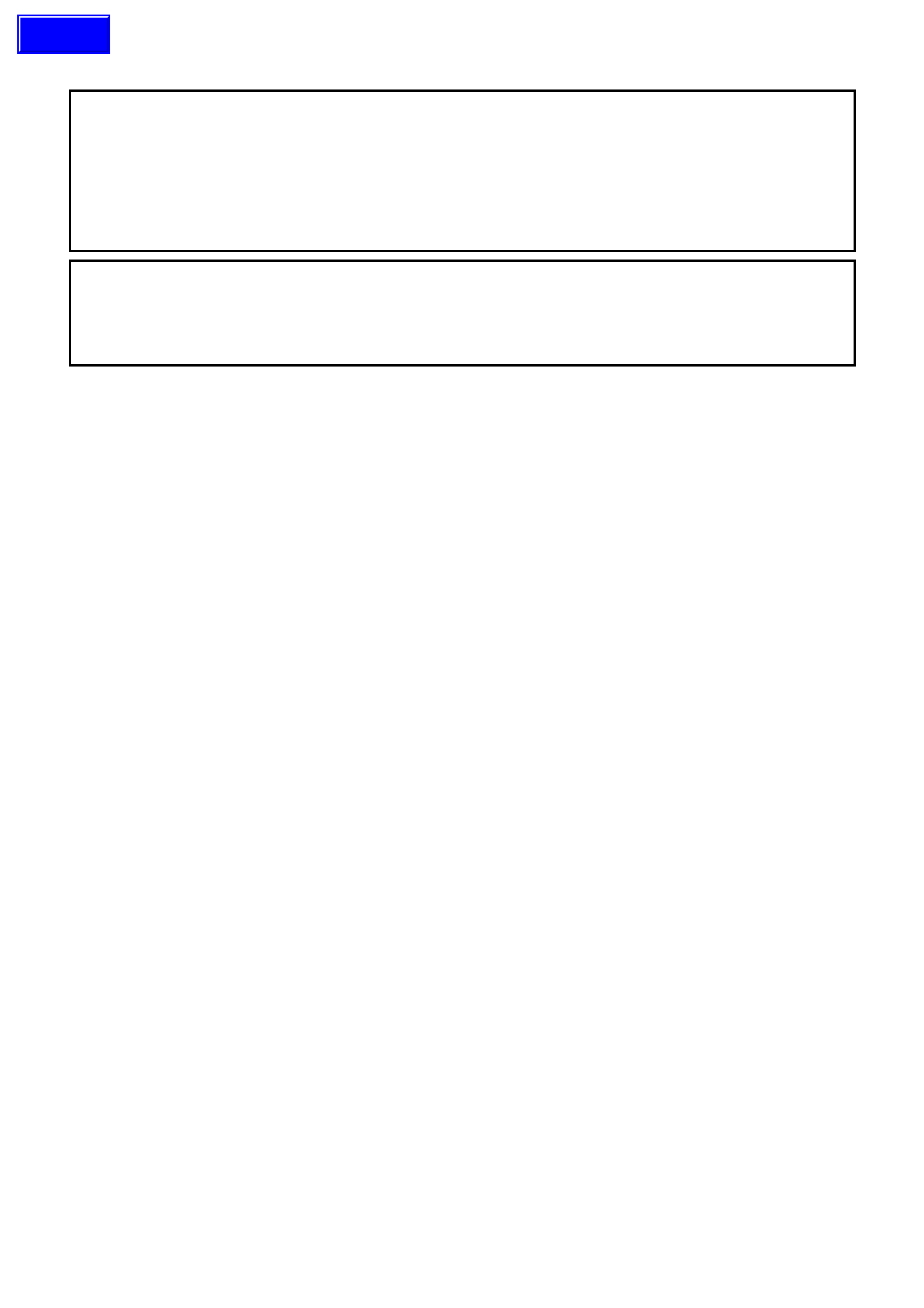
System Components
The Fuel Control System is made up of the following components (refer Fig. 8A-1):
• PCM
• Fuel Tank
• Modular fuel sender assembly, containing;
• Fuel pump assembly
• Fuel pressure regulator
• Fuel filter
• Fuel pressure supply line
• Fuel pump relay
• Fuel rail
• Injectors
Techline

1.2 FUEL DELIVERY SYSTEM
GEROTOR FUEL PUMP OPERATION
Fuel passes through the pump in two distinct stages;
1) Vapour Separation
The first fill impeller section of the pump assembly consists of an inlet body (4), im peller (6), umbrella check valve
(3), and inlet plate (8) . A seal (2) at the pum p inlet prevents air leak s and also f unctions as a vibration is olator. The
fuel pump is prim ed as bulk fuel enters the pump at the inlet body (4) and flows from the inlet body to the rotating
impeller (6). The centrifugal force set up by the impeller, separates and expels vapour from the fuel. Following
separation, liquid fuel is transferred to the high pressure section, while the separated vapour is forced back to the
tank through a vent at the pump inlet.
An um brella chec k valve ( 3) is us ed at the im peller sec tion to prevent air f rom enter ing through the vapour por t and
to vent any fuel vapour that may have collected in the pump during shut down. This allows for fast priming of the
fuel system, regardless of the fuel level.
2) High Pressure Vapour Separation
The s econd s tage of the pumping sec tion is a high pr ess ur e, positive dis plac ement Gerotor des ign pump (the same
as used in the GEN III V8 engine oil pump) that creates the high pressures required for the fuel injection system.
The G erotor s ection c ontains a c omposite bushing ( 21) , an inner and outer rotor ( 9), an inlet plate ( 8) and plate and
ring assembly (22). Stainless steel pins (10) keep the pump elements aligned.
As the inner rotor is tur ned, liquid f uel f r om the impeller se ction is dr awn into the high press ur e G erotor , thr ough the
inlet ports.
The inner and outer rotors then transport the fuel to the outlet porting at a constant volume, in order to reduce
pressure pulses.
The dec reasing volume of the pumping cham ber at the outlet ports cr eates positive flow to the engine fuel system.
Attached to the pump outlet is a divert er that allows the primary fuel volum e to flow into the flex pipe (10) and als o
deliver a portion of the flow to the jet pump assembly (A), via the diverter pipe (1) (refer Fig. 8A-3).
Action of this diverted fuel from the outlet of the fuel pump, passing through the jet pump, creates a low pressure
area at its base, causing the primary umbrella valve (4) to unseat, drawing cooler fuel into the reservoir.
Fuel enters the high pr ess ur e pump stage f rom the impeller sec tion at a low press ur e, and leaves thr ough the outlet
ports at a much higher pressure.
Legend
1. Shell 7. Driver 13 Relief Valve Ball 19. Field Magnet Assembly
2. Pump Inlet Seal 8. Inlet Plate 14. Check Valve Ball 20. Armature
3. Umbrella Check Valve 9. Gerotor Assembly 15. Valve Seat 21. Bushing
4. Pump Inlet Body 10. Alignment Pin 16. Relief Valve Spring 22. Plate & Ring Assembly
5. Pilot Pin 11. O-Ring 17. Relief Valve Retainer
6. Impeller 12. End Cap 18. Carrier Assembly
Figure 8A-2
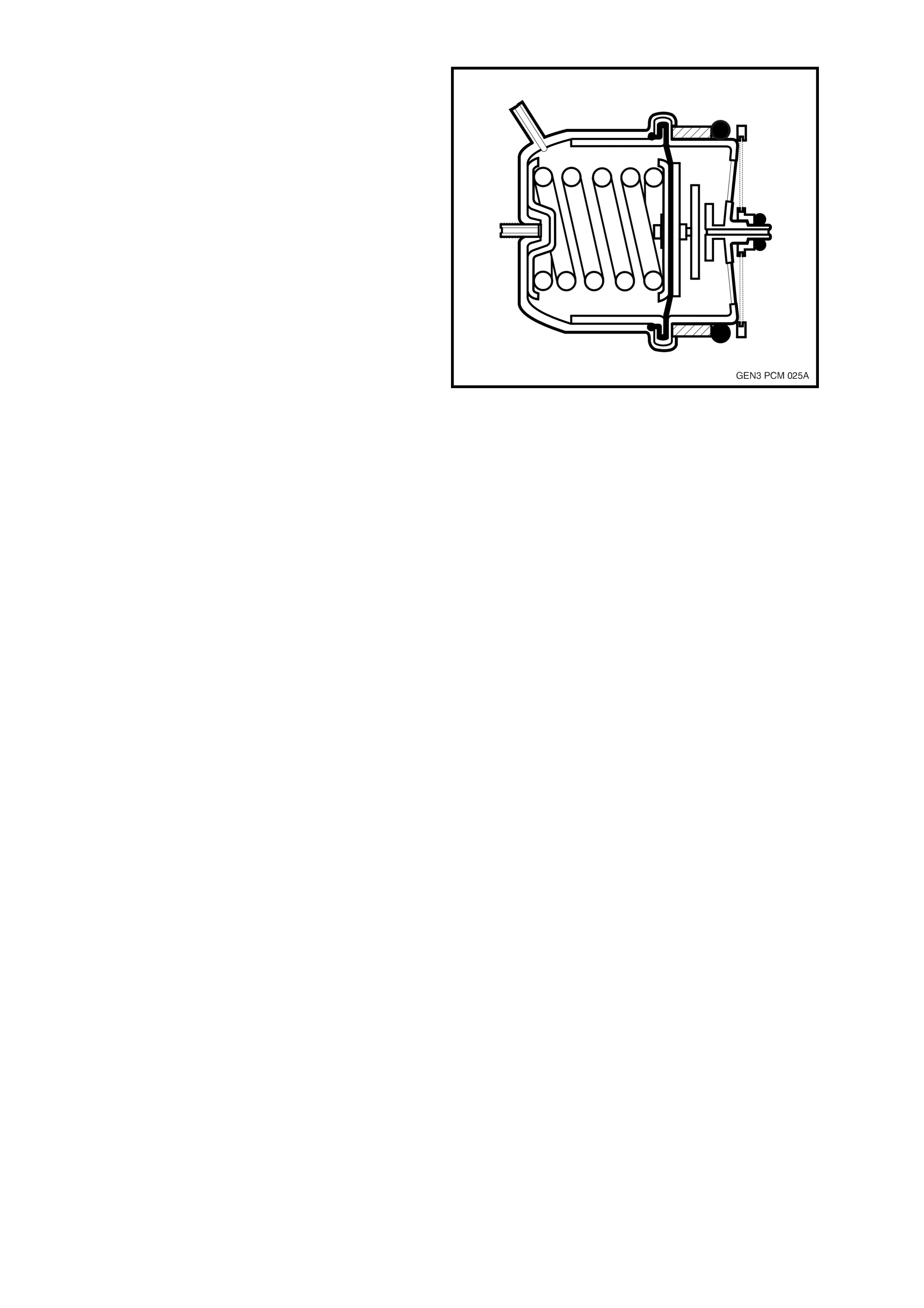
MODULAR FUEL SENDER OPERATION
During fuelling, fuel enters the reservoir (2) through the secondary umbrella valve (6), located in the bottom of the
reservoir , and self fills to the tank level without jet pum p operation. When the fuel pump is off, the reservoir rem ains
full through the one-way action of the two umbrella valves (4 and 6).
Maxim um pickup of f uel oc c urs at the ex ternal filter sc reen ( 5) and the primary umbrella valve ( 4) . Primary fuel flow
proceeds to the inter nal filter scr een (7) and the im peller s tage of the f uel pum p. Whenever the engine is running, a
portion of the pressurised fuel from the bleed at the end cap assembly is directed through the diverter pipe (1) to the
jet pump (A). Return fuel empties into the reservoir via the return line (11).
Fuel Sender Assembly Strainers
Fuel sender assembly strainers are located in the fuel tank to separate water from fuel and to prevent foreign
particles from entering the system. In low fuel conditions, the strainer fabric also acts as a wick to draw sufficient
fuel to the inlet of the fuel sender or pump. Should the external filter screen become blocked or restrict fuel entry,
then the secondary umbrella valve will unseat, allowing fuel to enter the reservoir area. Contaminants that pass
through the fuel pump are filtered out in the downstream, in-line fuel filter before reaching the injectors. Close
clearance control between the components prevents internal leakage, ensuring high efficiency pumping.
Single Line Fuel Delivery System
High pressure fuel from the Gerotor fuel pump
flows through the fuel pump flex pipe and exits the
assem bly through the fuel feed output fitting on the
cover. Fr om this point, fuel flows through the in-line
filter m ounted to a br ack et secur ed to the floor pan.
Fuel is then direc ted to the engine bay and fuel rail,
where the fuel delivery system then becomes
pressurised. When this pressure exceeds a pre-
determined value, the fuel pressure regulator
opens, allowing excess system pressure to
discharge back to the module reservoir.
Important: The procedure detailed in this Section
MUST be followed, both in the sequence of
removal and installation of a replacement filter.
Failure to obser ve this proc edur e will m os t probably
result in permanent damage to the flexible line (3),
requiring complete replacement of the fuel
pressure supply line.
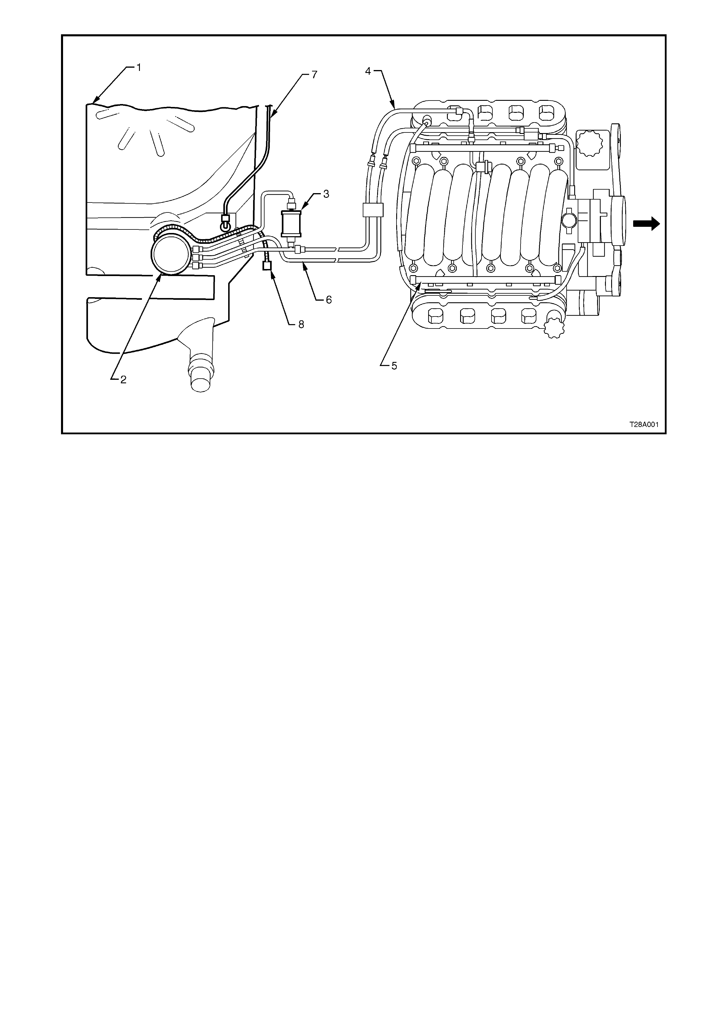
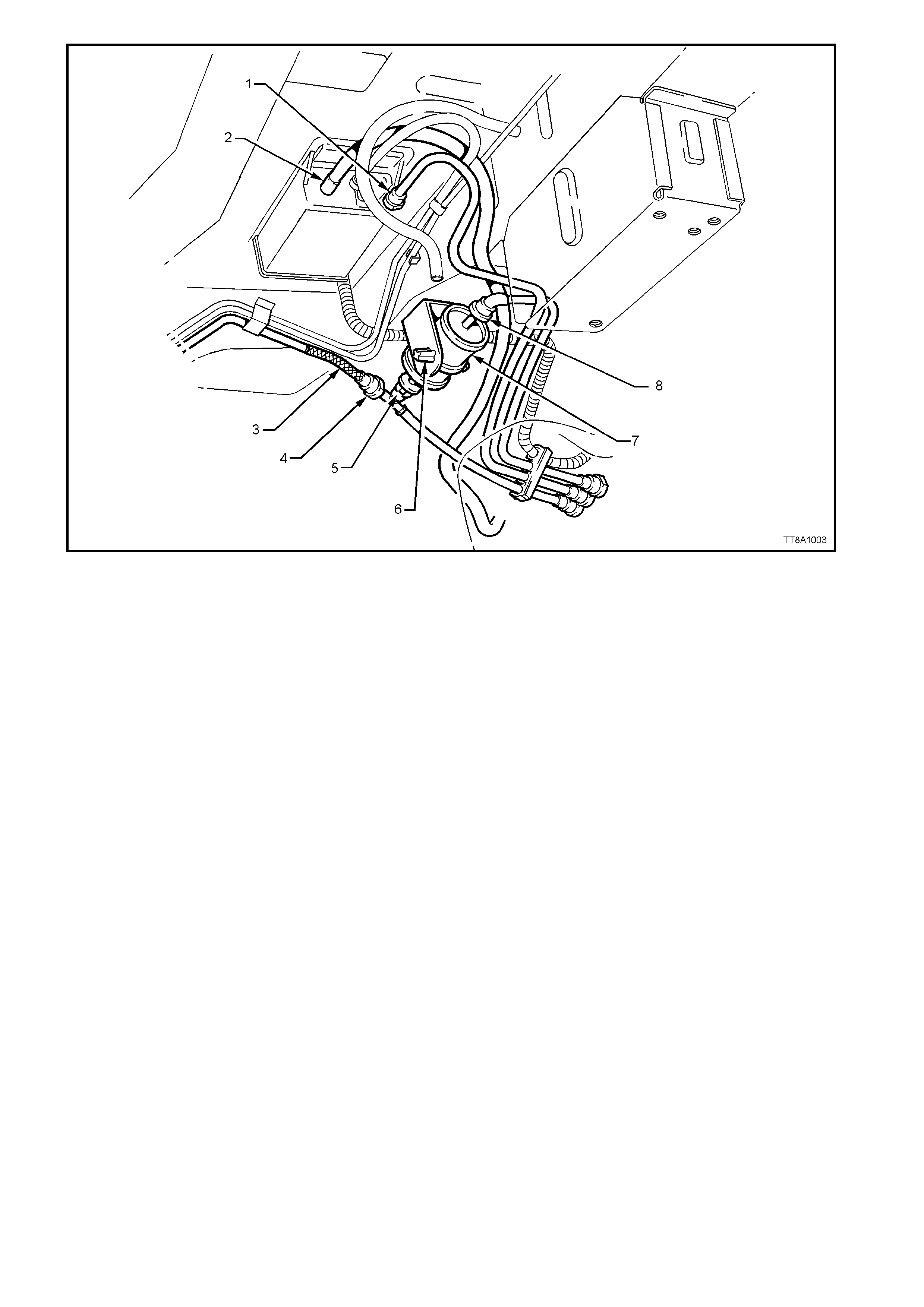
Legend
1. Quick Connect, Fuel Tank Vapour Line to
Canister
2. Filler Neck Breather Hose
3. Flexible Line, Fuel Feed to Engine
4. Quick Connect, Fuel Feed Line
5. Quick Connect, Fuel Filter ‘T’ piece
6. Retaining Tangs, Fuel Filter Strap
7. Fuel Filter
8. Quick Connect, Fuel Feed Line from Fuel Tank
Figure 8A-3
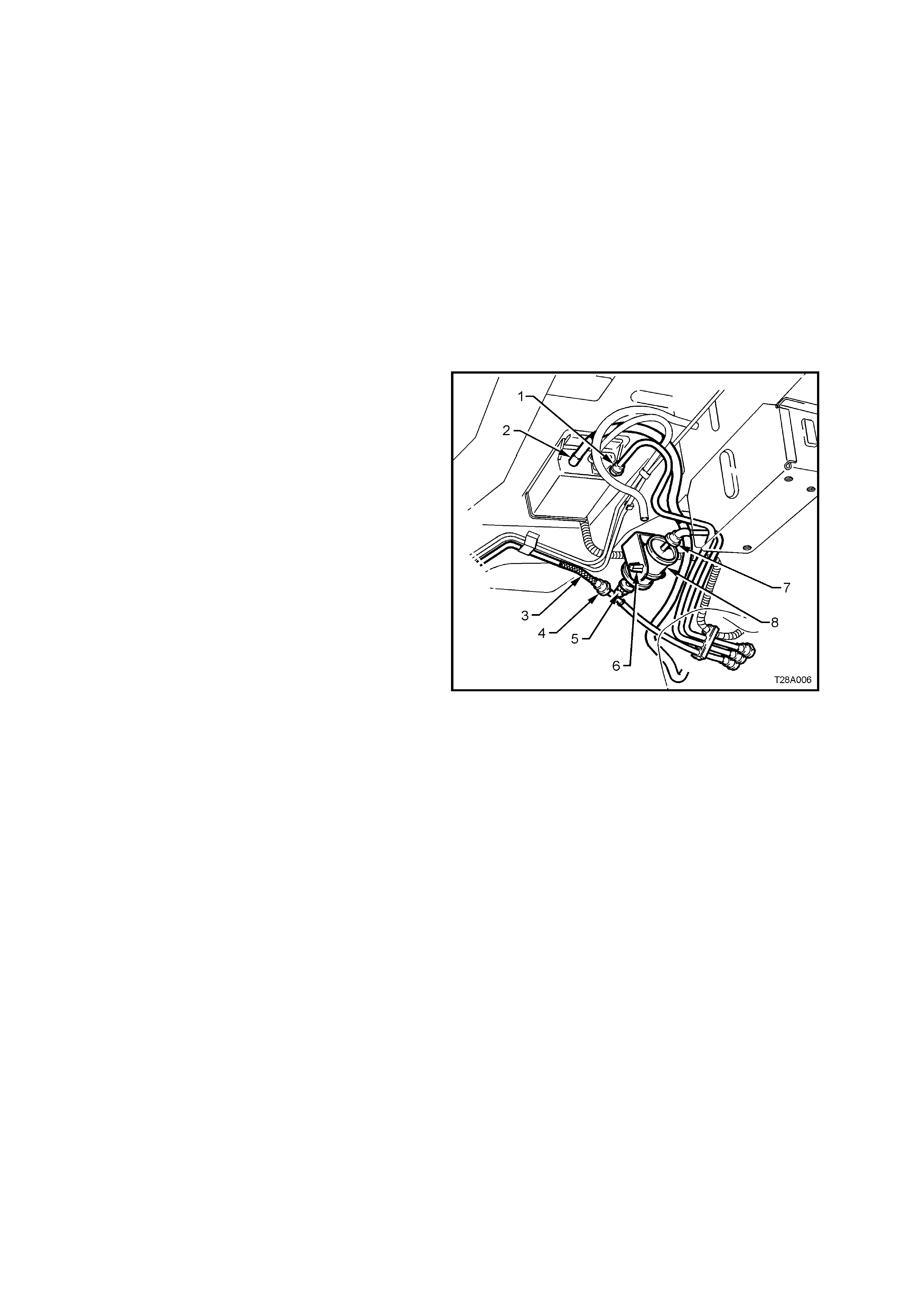
Legend
1. Diverter Pipe 5. External Filter Screen 9. Pressure Regulator
2. Reservoir 6. Secondary Umbrella Valve 10. Fuel Delivery Flex Pipe
3. Jet Pump Filter 7. Internal Filter Screen 11. Fuel Return Line
4. Primary Umbrella Valve 8. Gerotor Fuel Pump A Jet Pump Assembly
Figure 8A-4
Fuel Pressure Regulator
The fuel pressure regulator is a diaphragm
operated relief valve with fuel pump pressure on
one side and atmospheric pressure combined with
mechanical spring pressure on the other. The
function of the regulator is to maintain a regulated
pressure at the injectors at all times by controlling
the flow into the return line.
Figure 8A-5
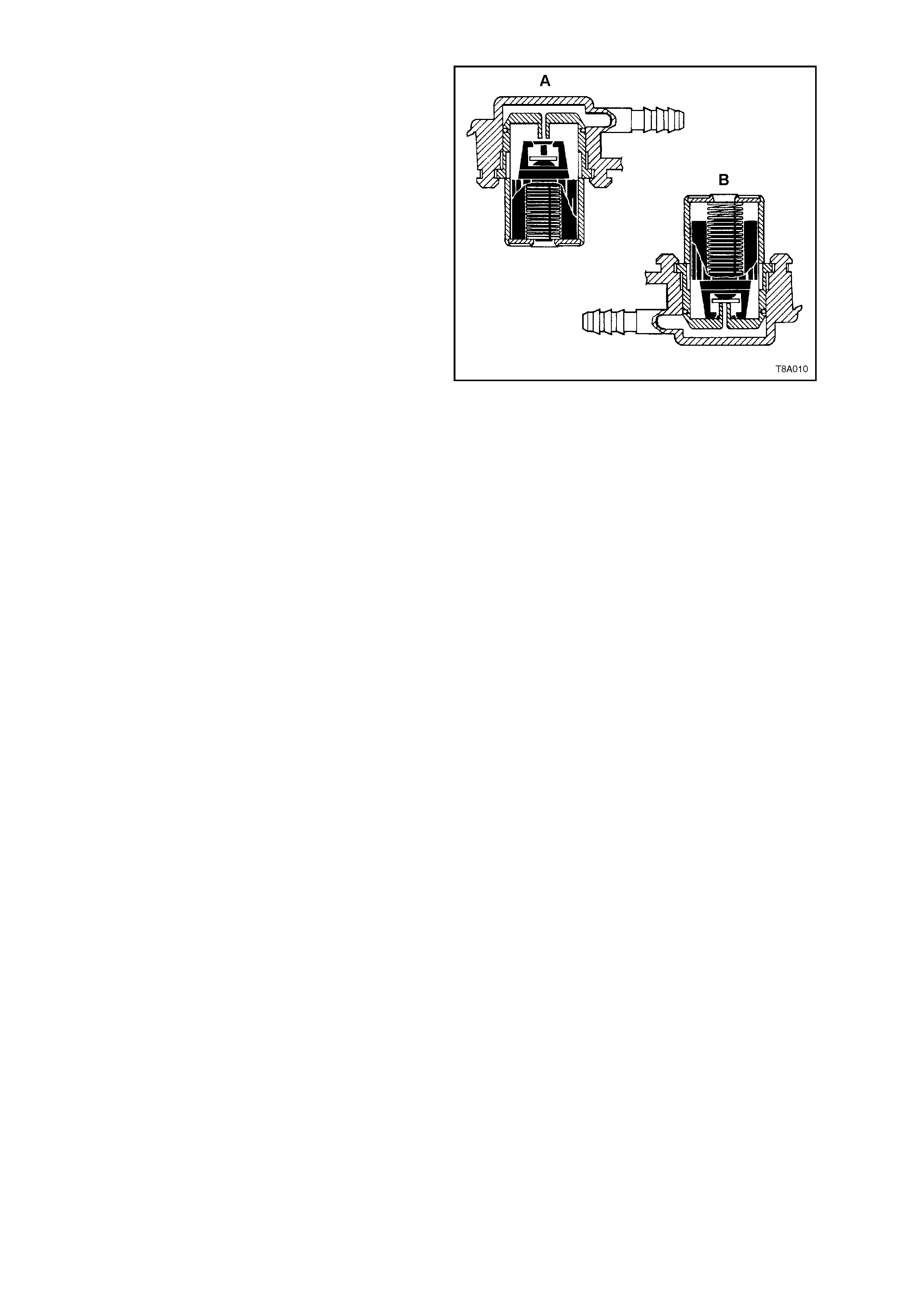
1.3 ROLL-OVER VALVE
As with the modular fuel sender assemblies used
with both the V6 engines, this assembly also
incorporates a ‘roll-over’ valve in its design that
limits vapour venting to the canister through the
use of a fixed sized orifice that is normally open
(view ‘A’). In the event that the vehicle rolls over
(view ‘B’), the vent line to the canister is safely shut
off by the roll-over valve, pr eventing liquid fuel fr om
flooding the canister.
Figure 8A-6
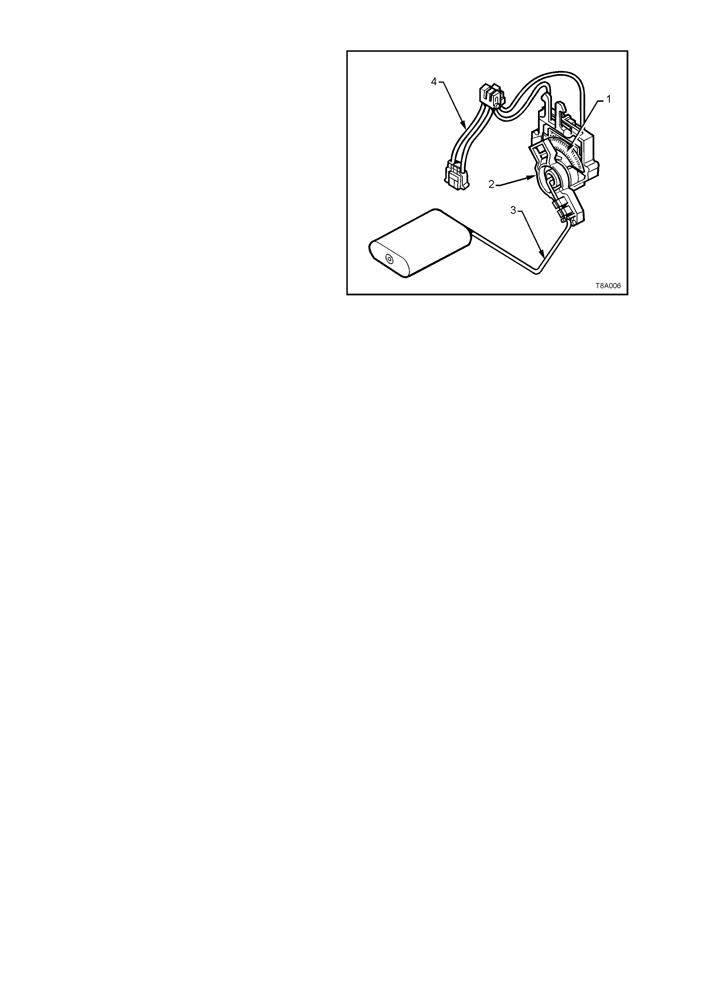
1.4 FUEL GAUGE TANK SENDER UNIT
The ceramic resistor card fuel level sensor
assembly, consists of a ceramic resistor card (1),
wiper arm (2), float arm assembly (3) and a below
cover, wiring harness (4). Action of these
components converts the fuel level in the fuel tank
into a variable electrical signal used to drive the fuel
gauge in the instrument panel.
The assembly is attached to the outside surface of
the modular fuel sender assembly and secured with
a retainer. The electrical harness (4) attached to
the f uel sender cover c onnects the c eram ic res istor
card to the vehicle wiring harness.
The function of the ceramic resistor card is to vary
the resistance, dependent upon the float position
and to send that signal to the Body Control Module
(BCM). This resistance signal changes, relative to
the wiper contact position on the conductive bars of
the ceramic resistor card.
New electronics in the BCM average out any slosh
variation, which means that fuel tank baffling is not
as critical to maintaining accurate gauge readings.
Figure 8A-7
1.5 FUEL FILLER CAP
The fuel filler cap remains the same for all VT
series models which is the 'SCREW ON' type with
a ratcheting feature to tighten. When installing the
cap, tighten it until a ratcheting (clicking) sound is
heard, indicating the cap is properly tightened.
Important: Should a replacement cap be required,
use only an all black fuel cap that is specified for
VT Series Models. Use of an incorrect cap will
cause malfunction of the emission control system.
The warning 'UNLEADED FUEL ONLY' is
embossed on the cap.
Figure 8A-8
Techline

2. SERVICE OPERATIONS
2.1 FUEL FILTER
REPLACE
IMPORTANT: The procedure detailed, MUST be followed, both in the sequence of removal and installation
of a replacement filter. Failure to observe these instructions will most probably result in permanent damage
to the flexible line, resulting in unnecessary parts replacement and expense.
NOTE: To dis connec t the ‘quick connect’ f ittings f rom the f uel filter , push the f itting inward to release seal press ure,
depress the locking tangs on each side, then pull to disconnect. Alternatively, Tool No. AU533 may be used to
assist in depressing the connector locking tangs.
1. De-pressurise the fuel system. Refer to Section 6A3 ENGINE MECHANICAL - GEN III V8 ENGINE or
Section 6C3-3 SERVICE OPERATIONS - GEN III V8 ENGINE, of the VT Series II Service Information.
CAUTION: Even though the fuel system may have been de-pressurised, the fuel filter and lines will contain
fuel th at will be spilled during service operat ions. Therefore, ensure that no naked flames or other ignit ion
sources are in the immediate area.
2. Using compressed air, remove any foreign material, dirt etc., within the release mechanism of the quick connect
fittings at each end of the fuel filter.
3. Disconnect the fuel feed line connector (8) from the fuel filter (7). Alternatively, fit the blue release tool No.
AU533 over the connector (8) to depress the connector locking tangs. Support the filter during the process.
4. Depress the fuel filter strap tangs (6) on the retainer strap, then remove the filter from the bracket.
5. To avoid perm anent damage to the flexible line at the T-piece end of the f ilter, support the T-piece then press
the filter into it while releas ing the quick connec t f itting (5) . Alter natively, fit the blue release tool No. AU533 over
the T-piece connector (5) to depress the connector locking tangs.
6. Remove the fuel filter (7) from the vehicle.
7. Install the support strap onto a replacement filter and, while supporting the T-piece (5), push the filter (7) into
the T-piece quick connect until fully seated.
8. Reinstall the filter strap retainer (6) to the bracket, then reinstall the quick connect (8) to the remaining end of
the filter (7).
9. Check that each connector is fully installed by firmly tugging on each, to ensure it is in the locked position.
10. Before starting the vehicle, carry out a fuel system leak test, as detailed in Section 6C3 POWERTRAIN
MANAGEMENT - GEN III V8 ENGINE of the VT Series II Service Information.
Techline
1 Quick Connect, Fuel Tank Vapour Line to Canister 5 Quick Connect, Fuel Filter ‘T’ piece
2 Hose, Filler Neck Breather 6 Retaining Tangs, Fuel Filter Strap
3 Flexible Line, Fuel Feed to Engine 7 Filter, Fuel
4 Quick Connect, Fuel Feed Line 8 Quick Connect, Fuel Feed Line from Fuel Tank
Figure 8A-9
2.2 FUEL TANK
REMOVE
1. De-pressurise the fuel system. Refer to
Section 6A3 ENGINE MECHANICAL - GEN III
V8 ENGINE or Section 6C3-3 SERVICE
OPERATIONS - GEN III V8 ENGINE, of the VT
Series II Service Information.
CAUTION: Even though the fuel system may
have been de-pressurised, the fuel filter and
lines will contain fuel that will be spilled during
service operations. Therefore, ensure that no
naked flames or other ignition sources are in
the immediate area.
2. Syphon fuel from tank, using commercially
available equipment.
CAUTION: Never drain or store fuel into an
open container, due to the possibility of fire or
explosion.
3. Raise vehicle, preferably on a hoist.
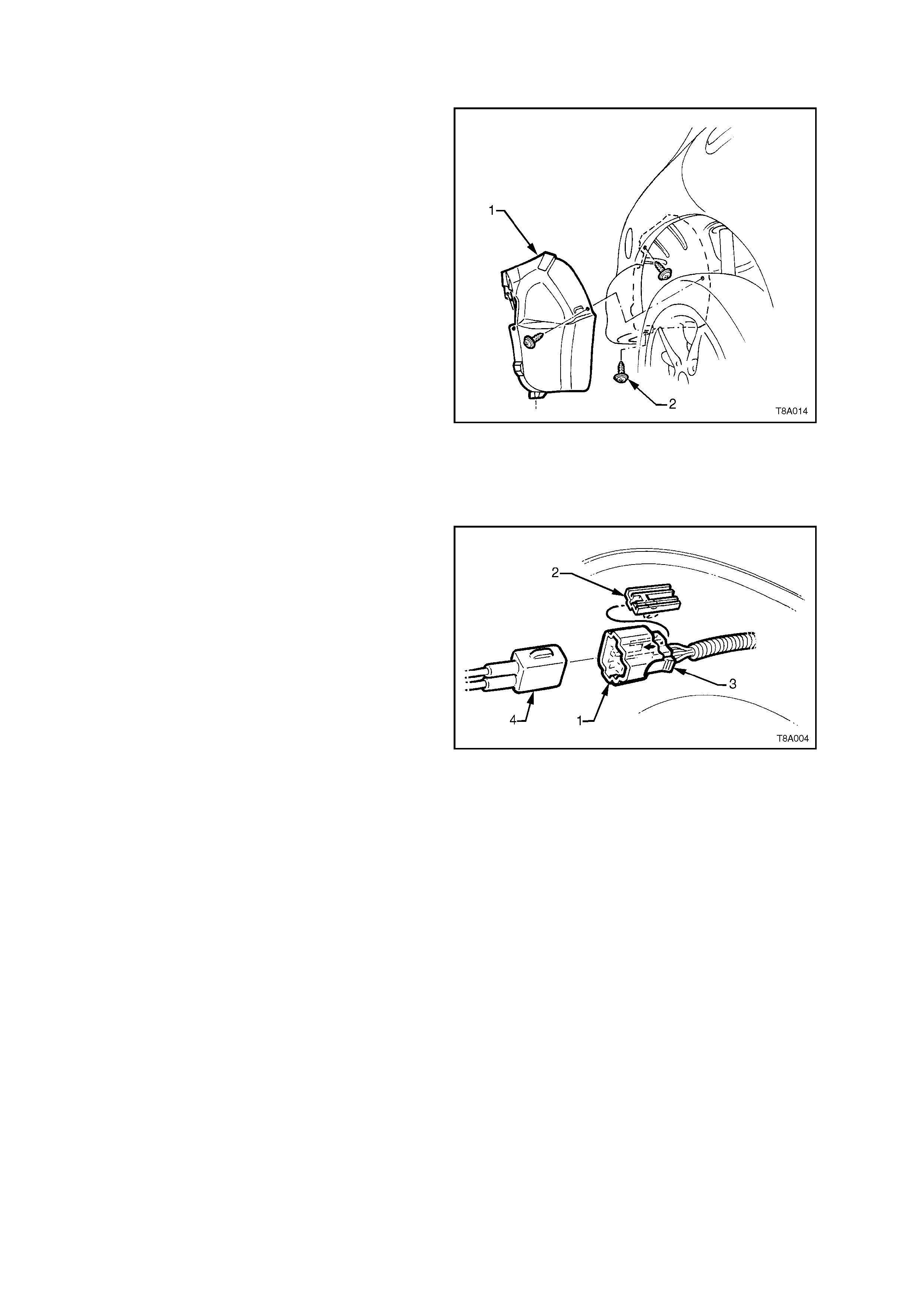
4. Remove three stone guard retaining screws
(2), then remove the stone guard (1), from
under the right hand rear fender.
Figure 8A-10
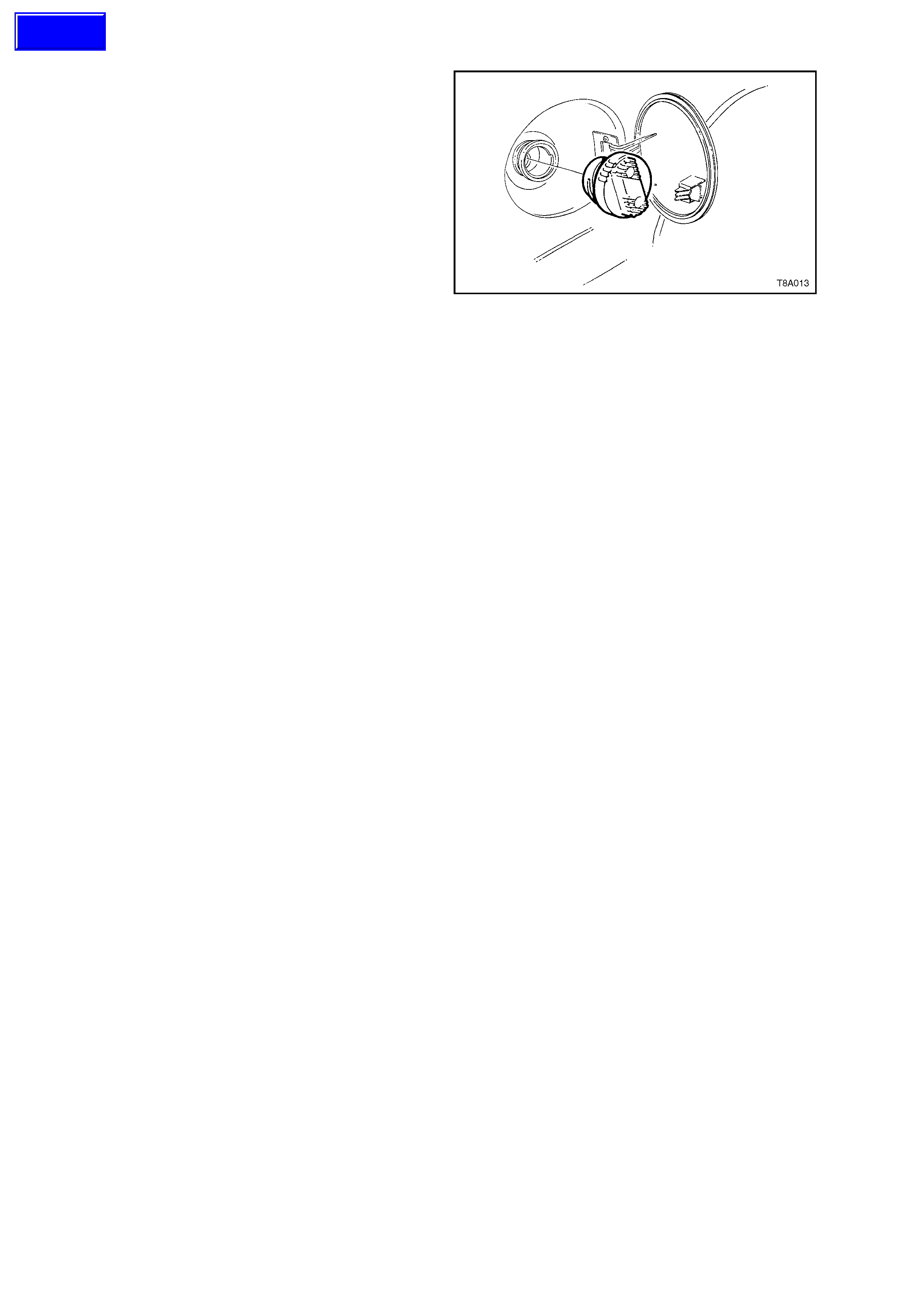
5. Remove the f uel sender electric al connector (1)
from its mounting foot (2) by pulling forward to
dislodge the assembled connector from the
foot. Once released, depress the locking tab
(3) and separate the connector halves (1 and
4).
6. Place a drain tray under the fuel filter area.
NOTE: Use compressed air to ensure that all dirt
and foreign material is removed from all fuel
connections, before removal.
7. Remove the fuel filter. Refer to Operation 2.1
FUEL FILTER, in this Section.
CAUTION: Fuel will spill from the disconnected
filter.
8. Remove the quick connect fitting to the vapour
canister (1), by pushing inwards to release the
seal pressure, depress the side tangs of the
connector, then pull to disconnect, refer
Figure 8A-6.
Figure 8A-11
9. Disconnect the filler neck breather hose from the canister (2), refer Figure 8A-6.
10. Disconnect the quick connect fitting (4) at the flexible pipe and filter ‘T’ piece, by supporting the quick connect
while pulling the fuel tank feed line from the fitting.
11. Disconnect the earth strap from the spade connector (A, in views A and E) under the front right hand strap
mounting bolt (4) of the right hand tank support strap (3), refer Figure 8A-9.
12. Remove the fuel tank support straps as follows;
Remove the centre strap (2, view D) by removing the rear retaining nut (5) and washer, then unhook the strap
from the front support (view C).
While s upporting the fuel tank in the centre, rem ove strap ( 3) (clos est to the filler nec k), af ter rem oving the bolt
at the front and unhooking the strap from the rear support (views A and B).
Finally remove strap (1) after removing the nuts and washers from each end of the strap (views C and D).
13. Lower the fuel tank from the vehicle, left side first, to release the fuel filler neck from the body opening.
REINSTALL
This is the reverse to removal except for the following;
1. Check that the insulation has not become dislodged from the top of the tank (Refer Figure 8A-10).
2. Offer up the fuel neck with the insulator installed, to the body opening, then raise the tank up, into place.
3. Fit the support straps in the following order:
a. Loosely install straps 1 and 3.
b. Check that the filler neck seal is correctly located in the body opening.
c. While pushing the f uel tank f irm ly to the right-hand side, tighten the str ap (1) bolt (4 in view C) and rear nut
(view D).
d. Tighten the front bolt (4 in view A) of strap (3). Ensure that the earth strap spade connector is also fitted.
e. Hook strap (2) into the front retainer (view C) and install the retaining nut and washer (5 in view D).
4. Tighten all strap fasteners to the correct torque specification.
FUEL TANK MOUNTING STRAP
BOLTS AND NUTS 15 - 25 Nm
TORQUE SPECIFICATION
5. Assemble the electrical connector, ensuring that both locking tabs are in place. Then engage the assembled
connector to its mounting foot and push rearwards to engage the locking tab.
6. Install the disconnected fittings to the fuel filter, canister and return line, routing correctly, as shown in
Figure 8A-6, using the following sequence:
a. Canister vent hose to canister (2).
b. Fuel tank vent line to canister (1).
c. Fuel feed line to flexible pipe quick connect (4).
d. Filter to T-piece quick connect (5), then filter strap retainer (6) to filter bracket.
e. Fuel filter to fuel feed line quick connect (8).
7. Reinstall the stone guard to the right-hand wheel opening, tightening the mounting screws to secure.
8. Before starting the vehicle, carry out a fuel system leak test, refer Section 6C3 POWERTRAIN MANAGEMENT
- GEN III V8 ENGINE of the VT Series II Service Information.
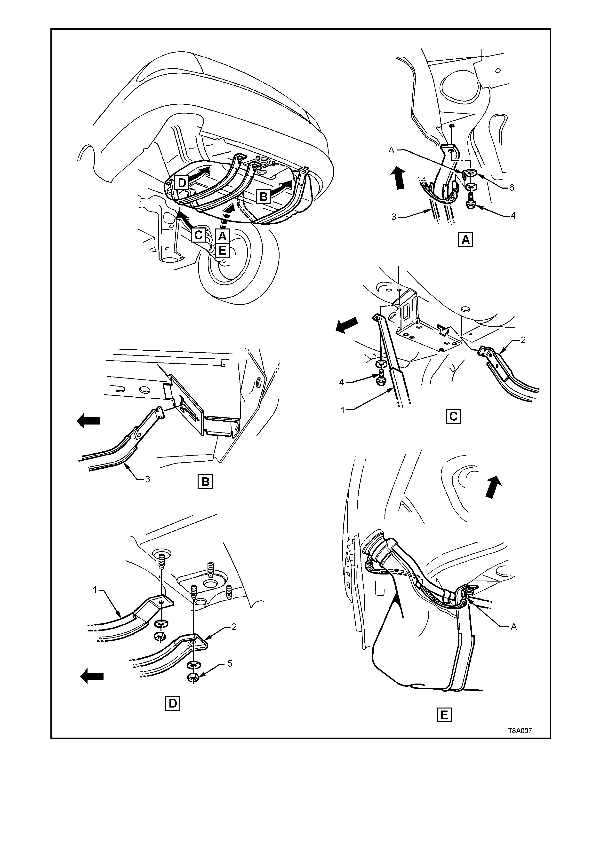
Figure 8A-12

2.4 FUEL PIPE ARRANGEMENT
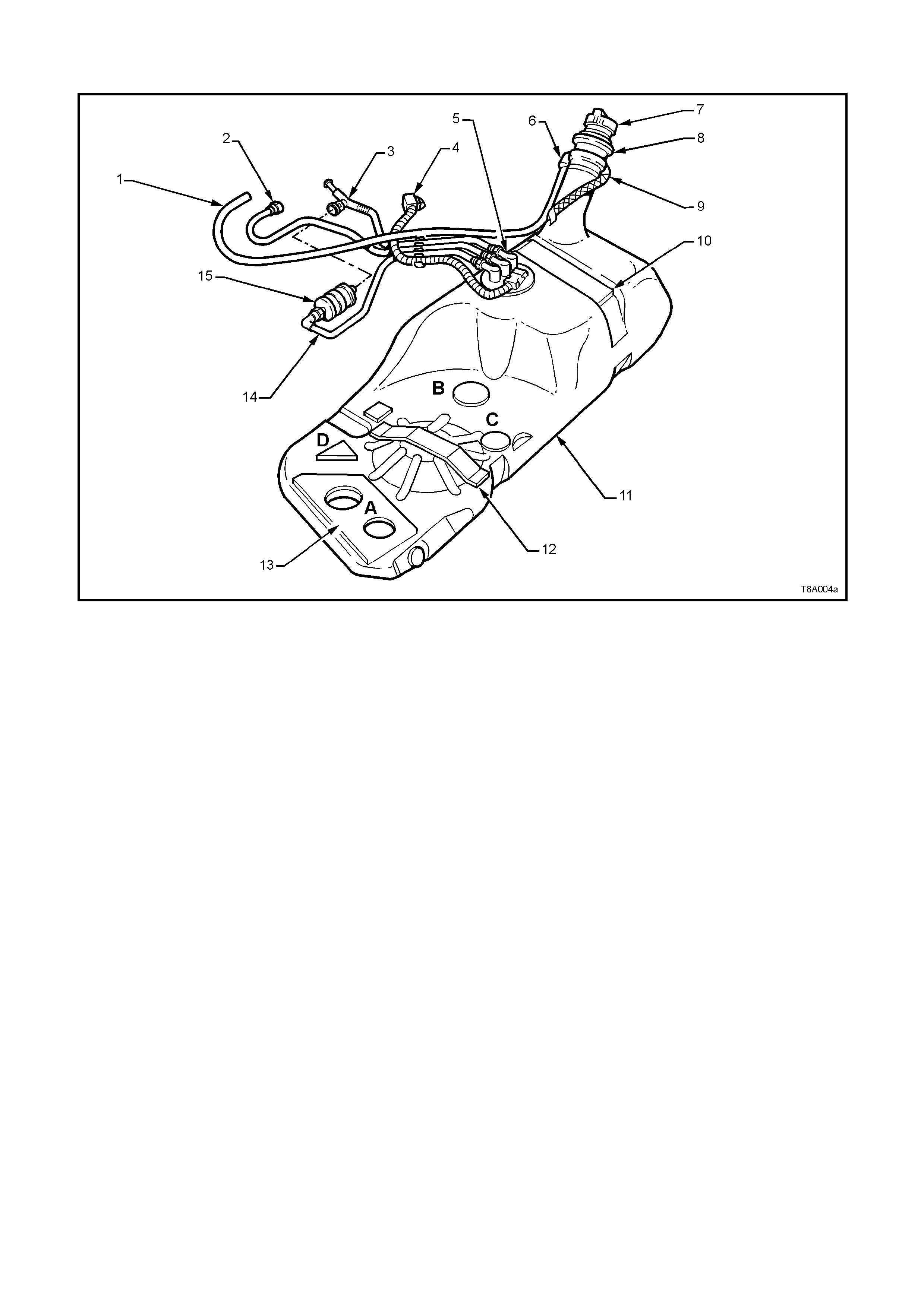
Figures 8A-13 and 8A-14 illustrate the fuel pipe layout and location of other fuel tank related items.
1. Hose, Filler Neck Breather 6. Fitting, Canister Vent Hose 11. Tank, Fuel
2. Hose, Fuel Tank Vent 7. Cap, Fuel Filler 12. Insulator
3. Hose, Fuel Return 8. Insulator, Fuel Filler Neck 13. Insulator Kit - A, B, C, D.
4. Connector Electrical Harness 9. Strap, Fuel Filler Earth 14. Pipe, Fuel Feed
5. Sender Assembly, Modular Fuel 10. Insulator - Top R.H. Side 15. Filter Fuel
Figure 8A-13
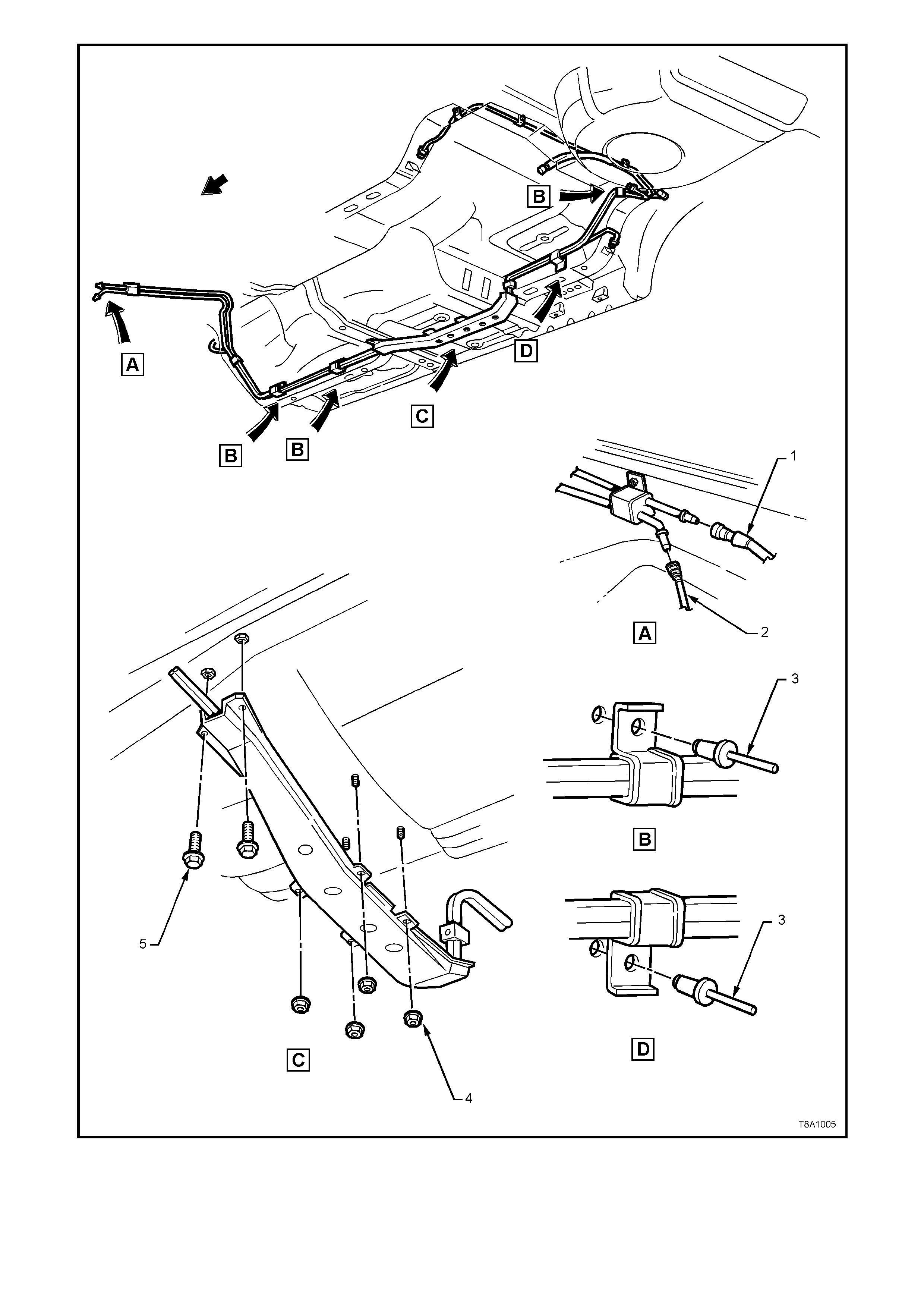
1. Hose, Fuel Feed to Engine 3. Rivet, Fuel Line Bracket Pop 5. Bolt, Stone Guard Securing
2. Hose, Fuel Vapour to Purge Valve 4. Nut, Stone Guard Securing
Figure 8A-14

3. SPECIFICATIONS
Fuel Tank Capacity:
All VT Models.......................................................... 75 litres
Fuel System:
Fuel Pump Type ............................................. Gerotor Pump - GEN III V8 Engine
Fuel delivery System Pressure................................ 400 ± 50 kPa with 12.5 ± 0.1 Volt applied

4. TORQUE WRENCH SPECIFICATIONS
Nm
Fuel Tank Strap Nuts/Bolts................................................... 15 - 25
Fuel Filter Bracket Screw...................................................... 5.0 - 8.0
Canister mounting Nut.......................................................... 2.0 - 5.0
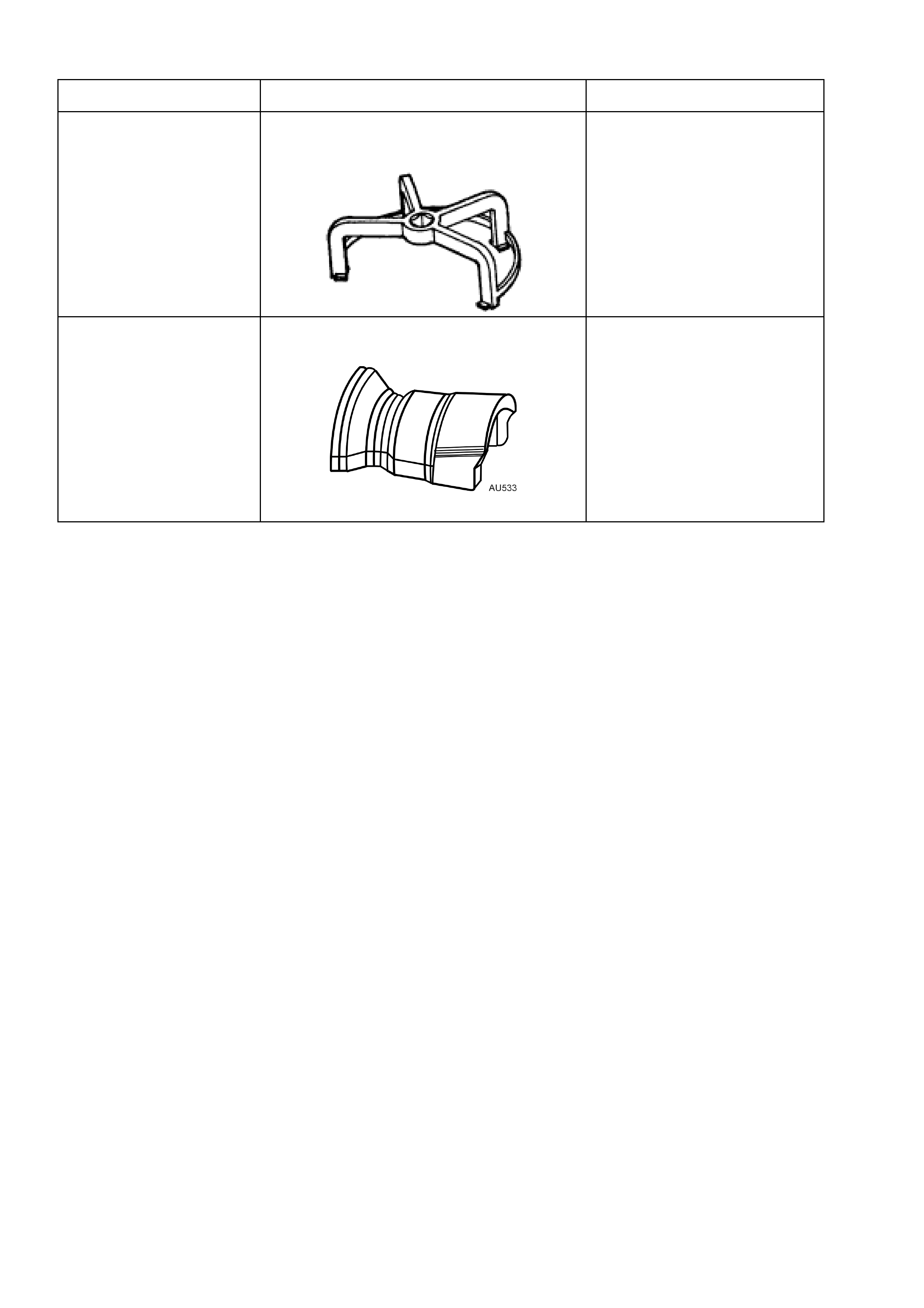
5. SPECIAL TOOLS
TOOL No. REF. IN TEXT TOOL DESCRIPTION COMMENTS
J39765 MODULAR FUEL SENDER ASSEMBLY
REMOVER/INSTALLER
Previously Released
AU533 QUICK CONNECT FITTING RELEASE
TOOL
Released in two sizes;
Red for 5/16” fittings and
Blue for 3/8” fittings.
Also available commercially
under P/N AUSP45