
SECTION 8B – EXHAUST SYSTEM
CAUTION:
This vehicle will be equipped with a Supplemental Restraint System (SRS). A SRS will consist of either
seat belt pre-tensioners and a driver's air bag, seat belt pre-tensioners and a driver's and front
passenge r's air bags or se at belt pre-t ensio ners, d river’s and f ront p asseng er’s a ir bag and lef t and right
hand side air bags. Refer to SAFETY PRECAUTIONS, Section 12M, Supplemental Restraint System of the
VT Series I Service Information before performing any service operation on, or around any SRS
components, the steering mechanism or wiring. Failure to follow the SAFETY PRECAUTIONS could
result in SRS deployment, resulting in possible personal injury or unnecessary SRS system repairs.
CAUTION:
Whenever any component that forms part of the ABS or ABS/ETC (if fitted), is disturbed during Service
Operations, it is vital that the complete ABS or ABS/ETC system is checked, using the procedure as
detailed in 4. DI AGNOSI S, ABS or ABS/ETC FUNCTION CHECK, in Section 12L ABS & ABS/ETC, in eithe r
the VT Series I Service Information (V6) or the VT Series II Service Inforamation (GEN III V8) of this
Service Information CD.
1. GENERAL DESCRIPTION
The exhaust system fitted to VT Series II vehicles, V6 and V6 supercharged engin es, carries over f rom the earlier
models. Therefore, for information and servicing procedures for these engines, refer to
Section 8B EXHAUST SYSTEM, in the VT Series I Service Information.
The engine exhaust manifolds for all engines connect to two equal length, symmetrical stainless steel front pipes.
With the GEN III V8 engine, the front exhaust pipes are of a dual wall air gap construction.
The design of the exhaust system for GEN III V8 engined VT Series II models is essentially the same as for the
earlier 5 litr e V8 engine; i.e. the s ystem features the low back pressur e exhaust s ystem and ret ains a dua l exhaust
system back to the rear of the twin intermediate mufflers. At this point, the exhaust converges into a single pipe and
rear muffler/tailpipe arrangement.
A catalytic converter is welded to each engine pipe, with a flanged, gasket joint connecting each converter to the
twin, intermediate exhaust pipes. A service catalytic converter is available for replacement purposes.
The two interm ediate exhaus t pipes are stiff ened by a welded bri dging piece an d bala nce p ipe, at points bef ore the
twin intermediate m uff ler s .
The GEN III V8 engine catalytic converters are supported by a bracket bolted to each converter and the
transm ission extensio n housing. The autom atic transm ission desig n is dif ferent to th at fitted t o the 6 sp eed m anual
transmission.
Further support for the exhaust system is provided by two rubber support rings attached to the rear suspension
crossmem ber and the re ar of eac h intermediat e muff ler . T he r ear m uff ler s uppor t is pr ov id ed by two r u bber bumper
supports att ached to br ackets welde d to the vehicl e underbod y, and brack ets attached to t he rear tail pip e, rear of
the rear muffler.
The rubber support rings are a common part for all locations and are secured by:
a. Clips at the intermediate muffler brackets, welded to the rear suspension crossmember and clips at the rear
body hanger bracket.
b. Flanged pegs at other locations .
Techline
2. SERVICE OPERATIONS
2.1 SERVICE NOTES
When installing any exhaust system component,
care must be taken to install each component in
the correct relationship to one another.
Incorrec t assem bly of exhaust s ystem c om ponents
can frequently be the cause of rattles and ‘booms'
due to incorrect alignment or clearance from body
or suspension parts.
When installing the exhaust system, ensure that
the correct assembly, installation, tightening
sequence and clearance for the system involved
are observed.
When exhaust system service work is required,
refer to the various illustrations and instructions
provided in this Section, for the necessary
information for the correct arrangement, alignment
and clearances for the GEN III V8 engine,
available in the VT Series II range of vehicles.
Step by step procedures for the replacement of
individual exhaust system components are not
included as special instructions are not required;
only normal workshop practices are necessary.
Both clearances and torque specifications for
fasteners are detailed in the illustrations included
in this Section.
A service replacement catalytic converter is
available, allowing the exhaust pipe to be welded
to the component. If removing or replacing the
converter and engine exhaust pipe, always ensure
that new sealing gaskets are installed on
reassembly.
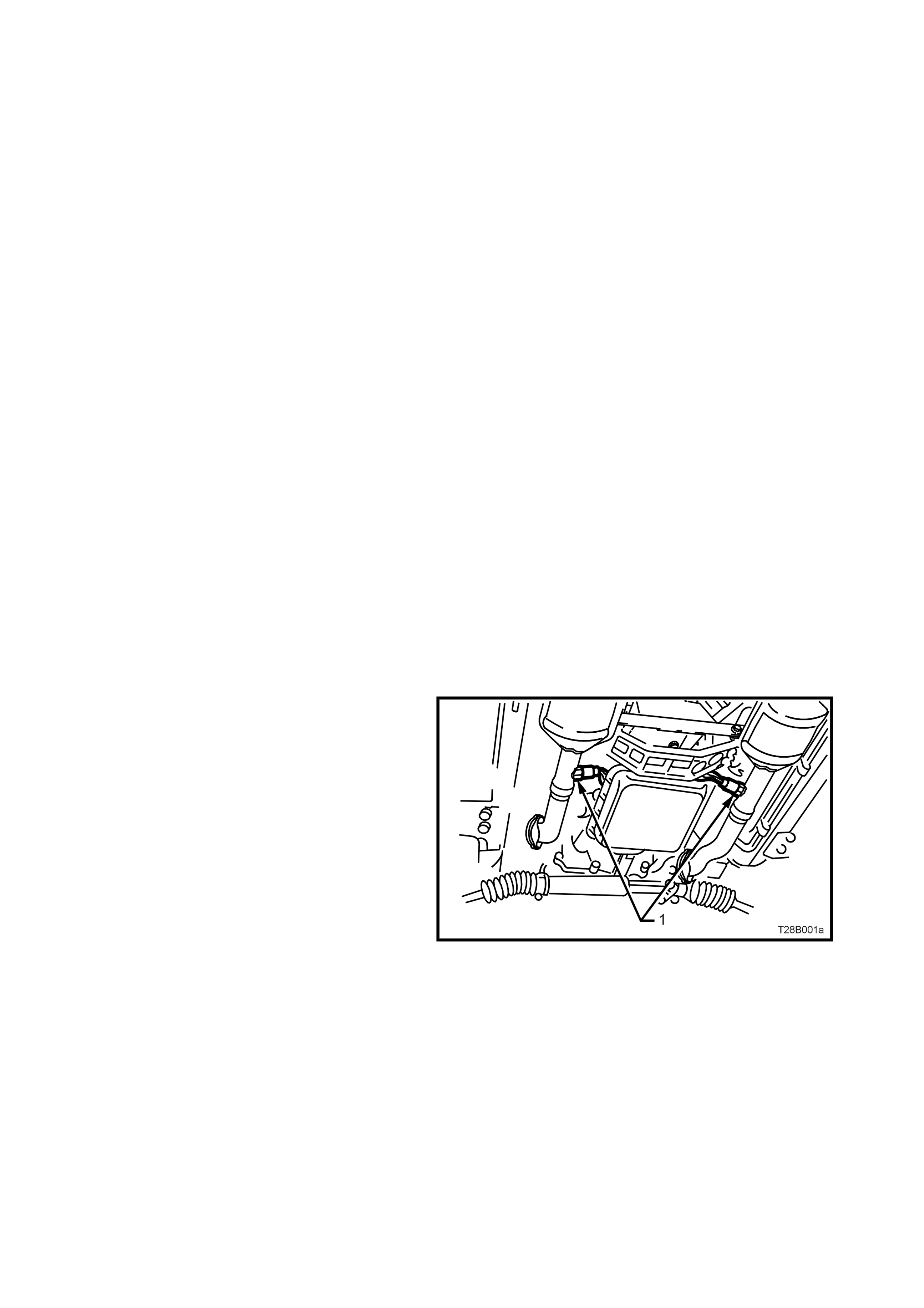
For Oxygen Sensor (1) replacement, refer to
Section 6C3 POWERTRAIN MANAGEMENT –
GEN III V8 ENGINE in the VT Series II Service
Information.
Figure 8B-1 Oxygen Sensor Location, GEN III V8 Engine
2.2 EXHAUST FITMENT AND TIGHTENING SEQUENCE - GEN III V8 E NGINE
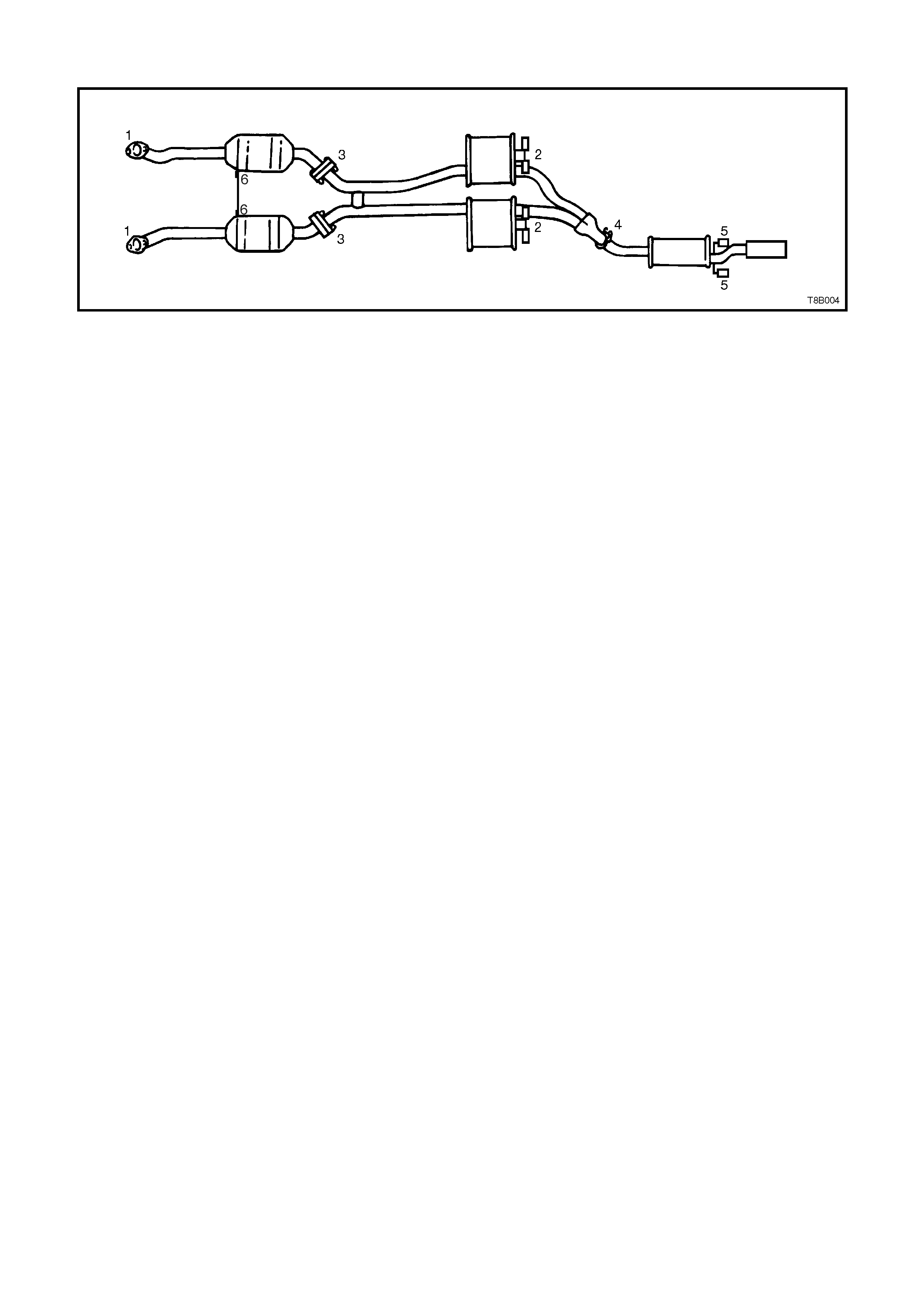
Figure 8B-2 GEN III V8 Engine Exhaus
Installation
Loosely install exhaust system as follows;
1. Attach front pipe and catalytic converter assembles, loosely to the exhaust manifolds (1).
2. Hook intermediate assembly to suspension brackets with four bum per rubbers (two per intermediate m uffler).
Fit four retaining clips to the suspension bracket ends (2).
3. Hand start bolts t o the inter m ediate exha ust pip e to c atal ytic co nverter f langes , af ter insta lling a new gas k et to
each flange (3).
4. Hand start the two bolts securing the catalytic converter bracket to the converters (6).
5. Install the intermediate muffler assembly to the rear muffler assembly and loosely install U-bolt clamp (4).
6. Attach the rear muffler assembly to the body mount hangers with two bumper rubbers (5) and retaining clips.
Tightening Sequence
1. Tighten the flange bolts at the rear of the catalytic converter (3).
2. Evenly tighten the U-bolt clamp nuts at the intermediate to rear muffler slip joint (4).
3. Tighten each of the flange nuts evenly, so that a similar amount of thread is showing on each (1).
4. Ensure that all bumper rubbers are under load (2 and 5). If this is not achieved, loosen exhaust joints in the
reverse order to the above. Load the hangers and re-tighten in the sequence described, from steps 1 to 3.
5. After all other operations have been completed, tighten the catalytic converter bracket bolts.
NOTE1: The exhaust system should be self-aligning and not require further adjustment, provided step 4 is
achieved.
NOTE 2: When tightening all fasteners related to the exhaust system, refer to
5. TORQUE WRENCH SPECIFICATIONS in this Section, for the correct values.
NOTE 3: An indication that the exhaust system is stressed is a bent bracket as shown in Figure 8B-3. W hen de-
stressed, the bracket will remain straight as shown in Figure 8B-4. Refer to TL101-0802
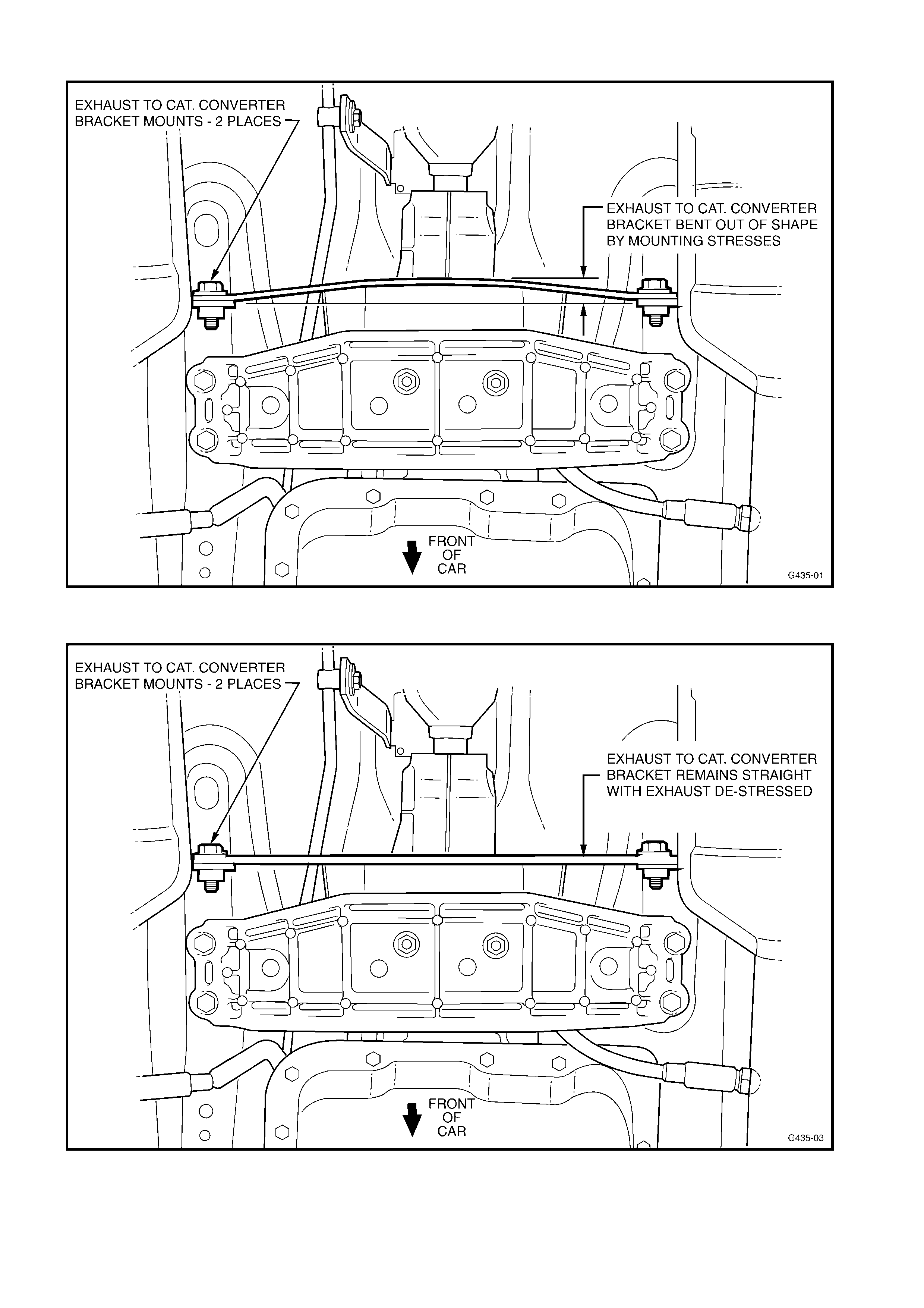
Figure 8B-3
Figure 8B-4
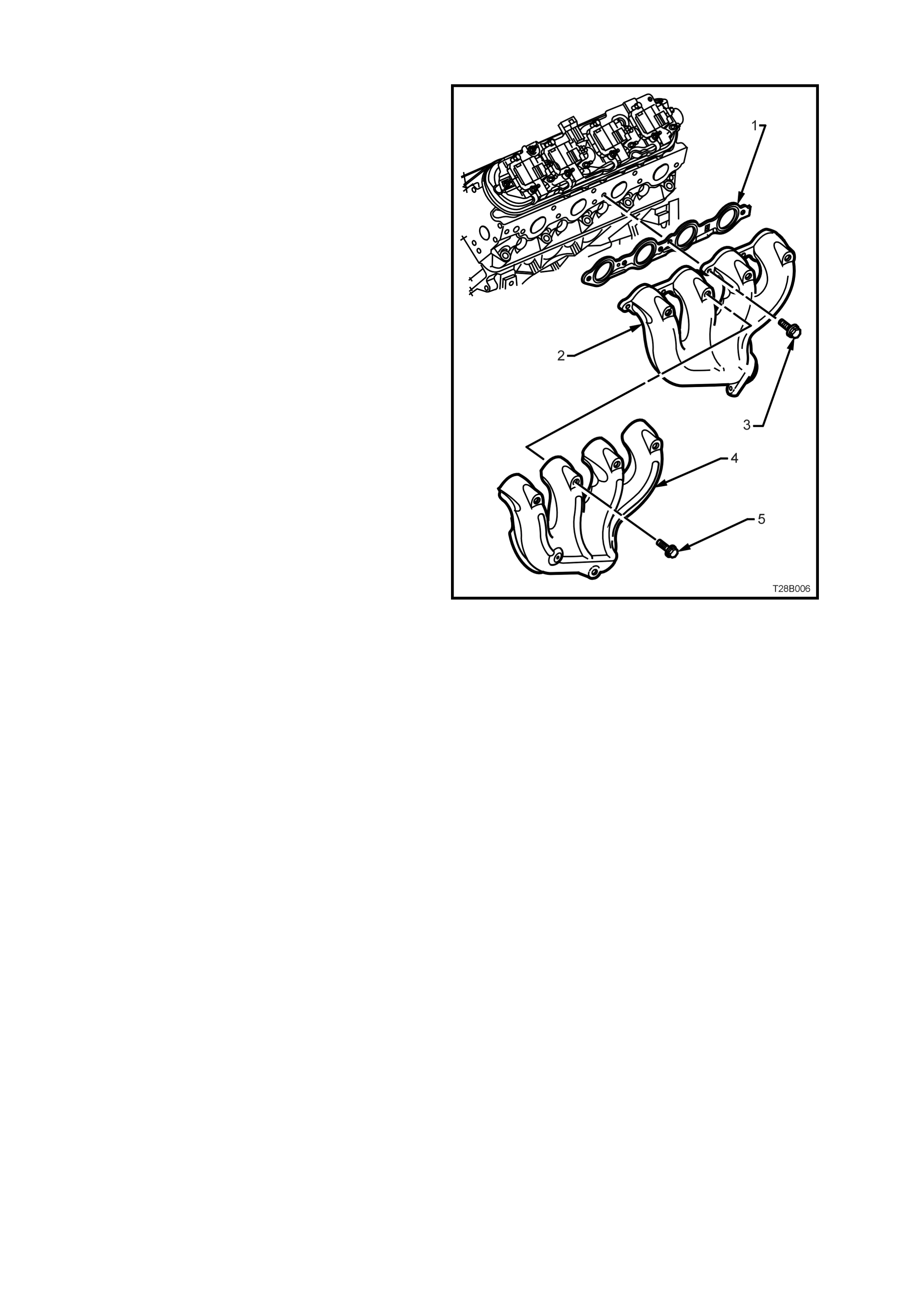
2.3 EXHAUST MANIFOLD INSTALLATIONS - GEN III V8 ENGINE
The exhaust manifolds fitted to the GEN III V8
engine, are of a one piece, high temperature
silicone molybdenum cast iron and direct exhaust
gases from the combustion chambers to the
exhaust system.
Each manifold (2) also has an externally mounted,
heat shield (4) attached, that is made from
aluminiumised steel. Each heat shield is attached
to the manifold by 5 screws (5).
NOTE: While the left hand exhaust manifold (2) is
shown, the right hand arrangement is similar.
Legend:
1. Gasket – Exhaust Manifold
2. Manifold – Exh aus t
3. Bolt – Exhaust Manifold to Cylinder Head
4. Shield – Exahust Manifold Heat
5. Screw – Heat Shiel dto Exahust Manifold (5
places).
Figure 8B-5

2.4 EXHAUST SYSTEM LAYOUT - GEN III V8 ENGINE
The f ollowing la yout d iagrams r elate to the exhaus t system used for the GEN II I V8 engine. T hey are arranged on
facing pages to provide maximum benefit.
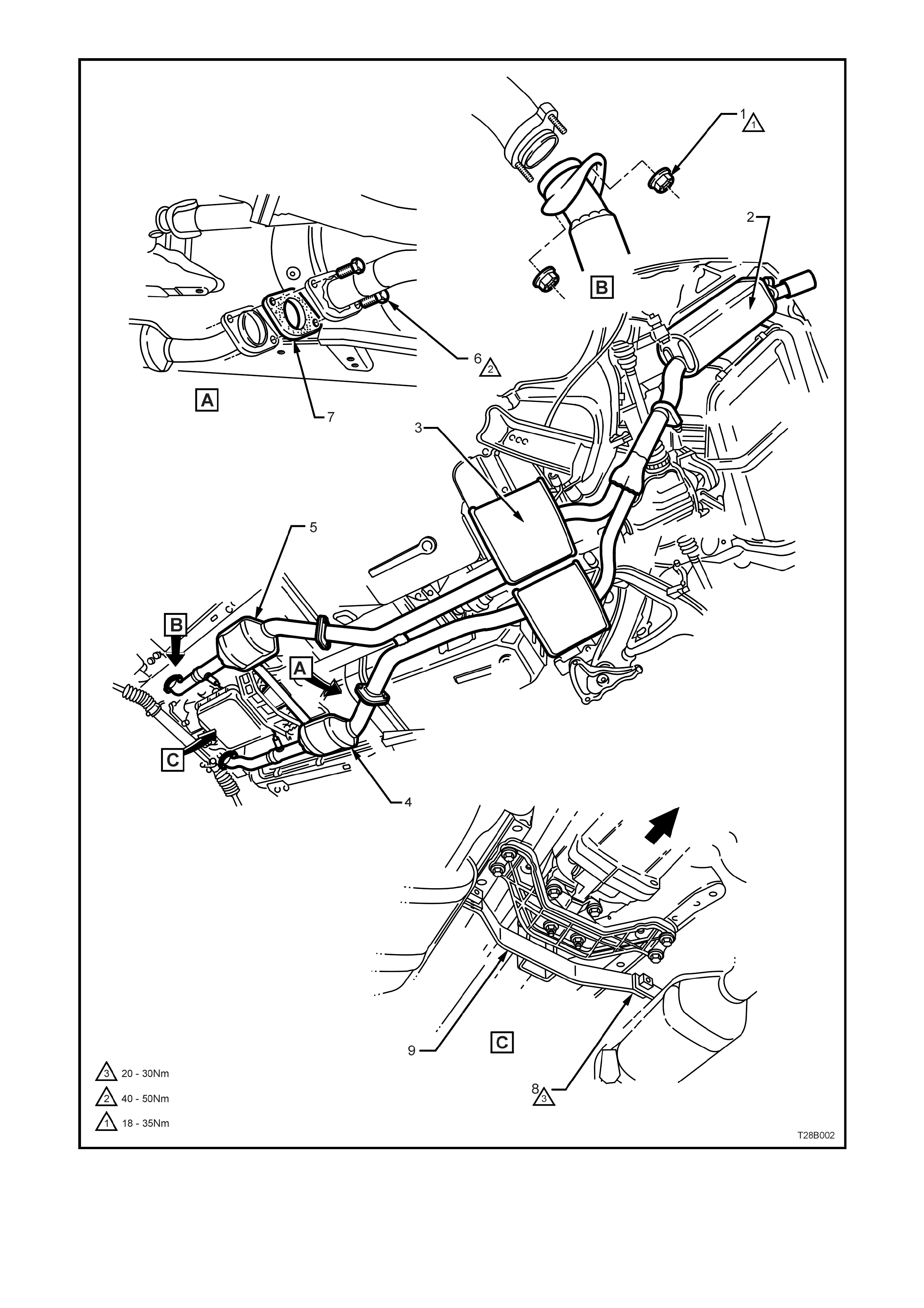
1. Nut - 2 places 4. Catalytic Converter LH 7. Gasket - 2 places
2. Muffler 5. Catalytic Converter RH 8. Bolt - 2 places
3. Intermediate Mufflers - Right and Left 6. Bolt - 4 places. 9. Catalytic Converter Bracket - Man. Trans.
Figure 8B-6 Exhaust System Layout, GEN III V8 Engine (Sheet 1 of 2)
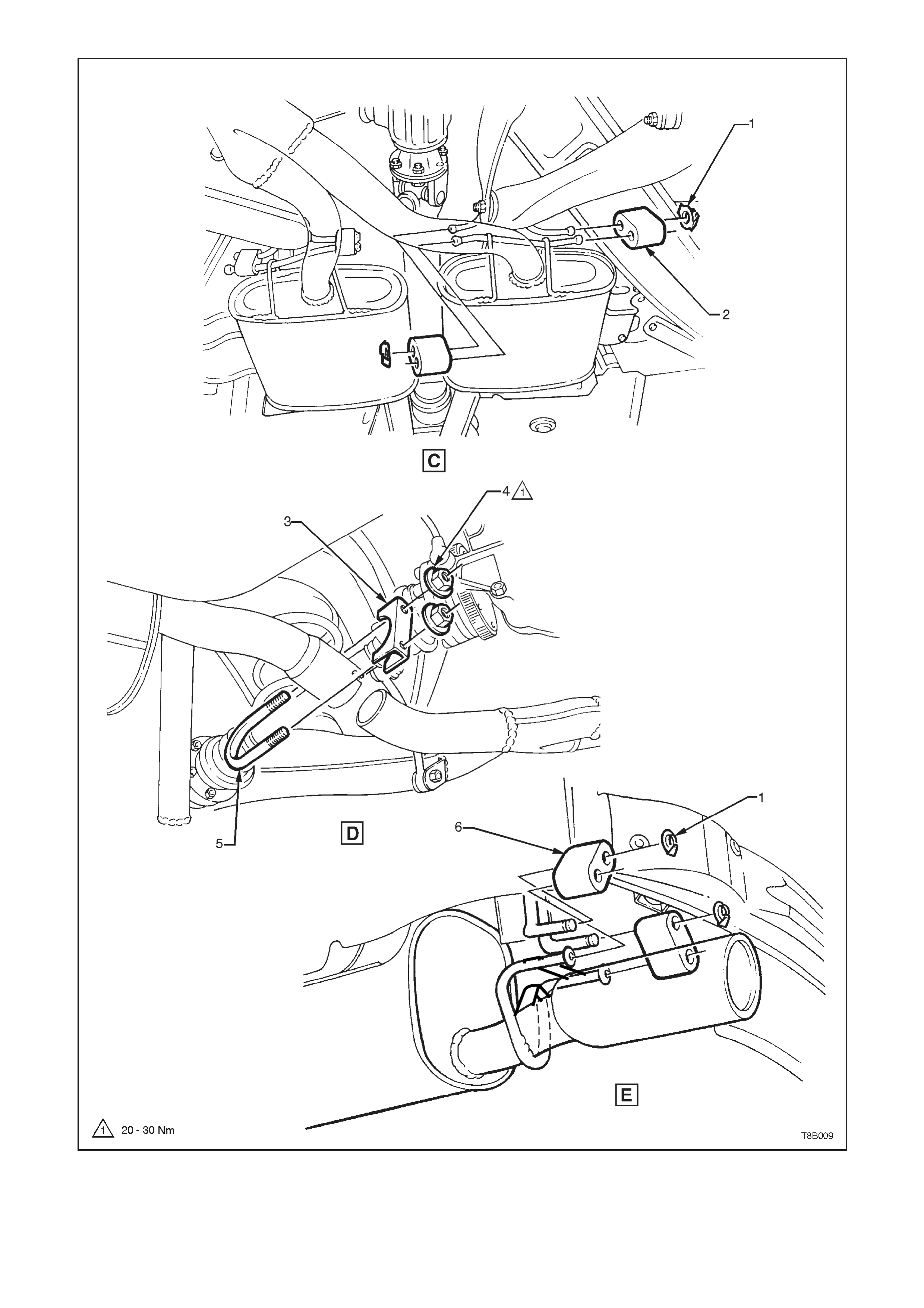
1. Retainer - 6 places 3. Clamp - U-bolt 5. U-bolt
2. Bumper Rubber - 4 places 4. Nut - 2 places 6. Bumper Rubber - 2 places
Figure 8B-7 Exhaust System Layout, GEN III V8 Engine (Sheet 2 of 2)
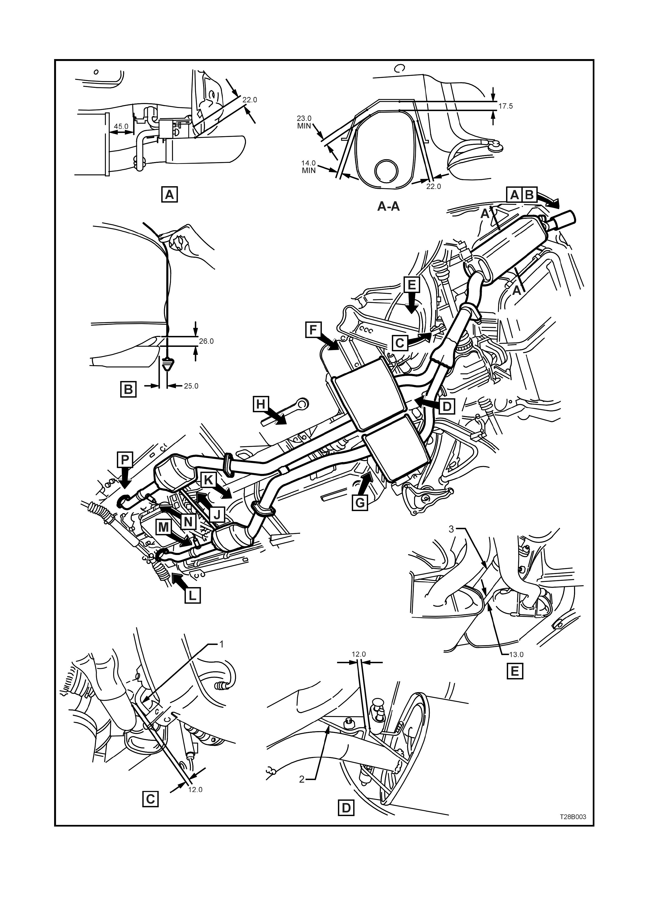
2.5 EXHAUST SYSTEM CLEARANCES - GEN III V8 ENGINE
1. Stabiliser Bar Link 2. Rear Suspension Control Arm Mount 3. Propeller Shaft
Figure 8B-8 Exhaust System Clearances, GEN III V8 Engine (Sheet 1 of 2)
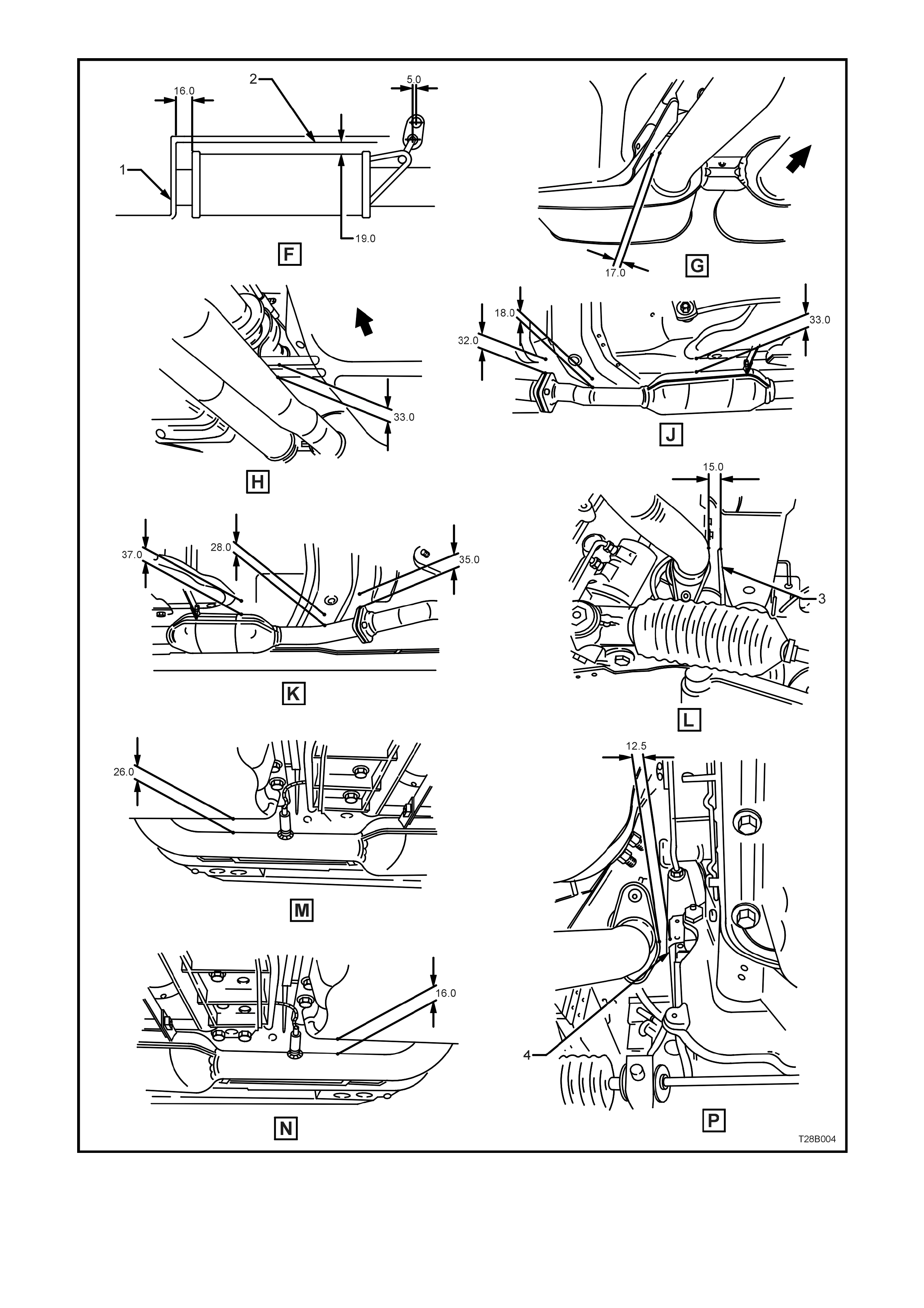
1. Rear Footwell 2. Intermediate Heat Shield 3. RH Sub Frame 4. Engine Block
Figure 8B-9 Exhaust System Clearances, GEN III V8 Engine (Sheet 2 of 2)
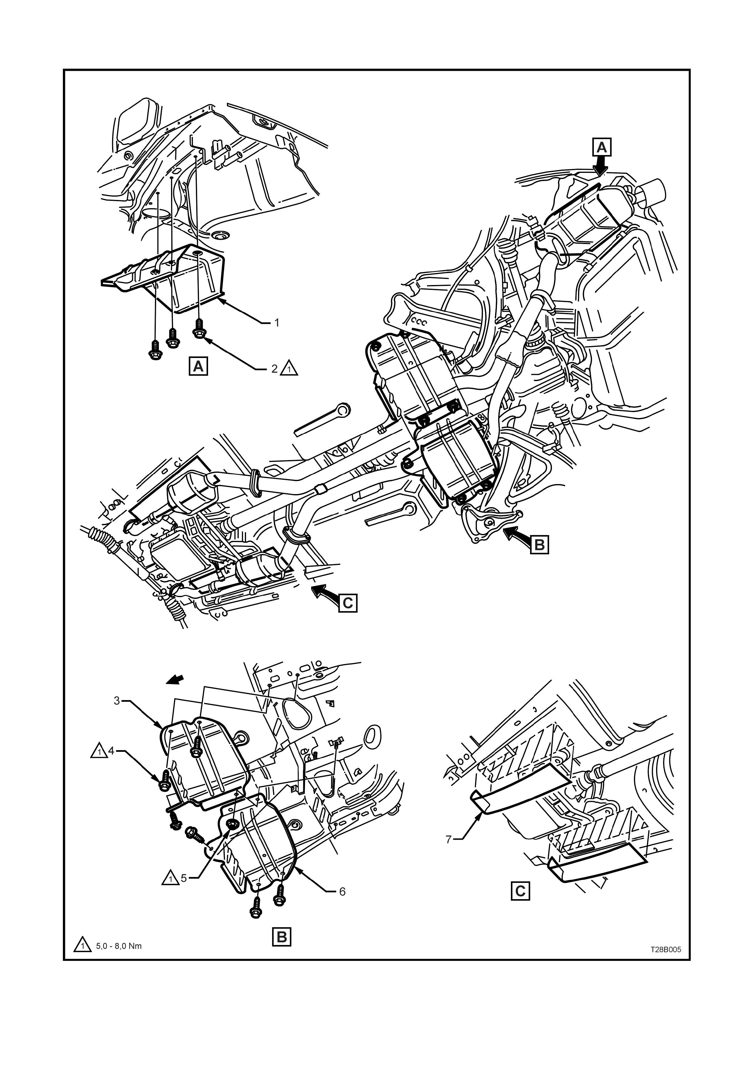
2.6 EXHAUST SYSTEM HEAT SHIELDS – GEN III V8 ENGINE
Figure 8B-10 - Heat Shields, GEN III V8 Engine

Legend, refer Figure 8B-8
1. Heat Shield - Rear Muffler 5. Nut - 2 places
2. Screw - 3 places 6. Heat Shield - RH Intermediate Muffler (all except V6)
3. Heat Shield - LH Intermediate Muffler 7. Self-adhesive Insulators (all except V6)
4. Screw - 6 places

3. EXHAUST SYSTEM DIAGNOSIS
CONDITION PROBABLE CAUSE CORRECTION
Leaking exhaust gases Leaks at pipe joints. Tighten U-bolt nuts and joint bolts
to the correct torque
specifications.
Damaged or improperly installed
converter sealing ring/gaskets. Replace gasket as necessary.
Bu rned or rusted out exhaust pipe
or muffler/s. Replace component as necessary.
Exhaust noises Leaks at manifold or pipe
connections. Tighten clamps at leaking
connections to the correct torque
specifications. Replace gasket as
required.
Burned or blown out pipe or
muffler/s. Replace pipe/muffler assembly as
necessary.
Exhaust manifold/s cracked or
broken. Replace manifold.
Leak between manifold/s and
cylinder hea d/s . Tighten manifold to cylinder head
studs to the correct torque
specification.
Loss of engine power, hesitation,
surging, poor fuel economy,
stalling or
Clogged catalytic converter (may
result from serious engine
malfunction).
Replace catalytic converter.
hard starting Crushed pipework. Replace pipework.
Internal rattling in muffler Dislodged tubes and/or baffles in
muffler. Replace muffler.
Catalytic converter monolith has
crumbled and pieces blown into
muffler.
Replace catalytic converter
assem bl y and aff ected muffler.
Techline

4. SPECIFICATIONS
TYPE:......................................................................... Single system
MATERIAL:
Engine Pipes.............................................................. 409 stainless steel
Intermediate Muffler ................................................... 409 stainless steel
Rear Muffler................................................................ 409 stainless steel
CATALYTIC CONVERTER:
Make ......................................................................... AC Australia
Type ......................................................................... Three way monolith
Outer Steel Shell
Material ............................................................ Stainless
Inlet Diameter................................................... 57 mm
Outlet Diameter................................................ 57 mm
Monolith
Material.................................................................... Extruded Cordierite
Volume
V6 Engine ........................................................... 1.6 litres
V6 Supercharged and GEN III V8...................... 1.4 litres each
Cells/in2................................................................... 400

5. TORQUE WRENCH SPECIFICATIONS
GEN III V8 Nm
Catalytic converter bracket bolt to converter........................ 40 - 50
Engine front pipe flange to exhaust manifold flange nut....... 18 - 35
Front exhaust pipe to intermediate pipe flange bolts............ 40 - 50
Exhaust manifold to cylinder head bolts; Stage 1............... 15
Stage 2............... 25
Exhaust manifold heat shield screw ..................................... 8 - 10
Exhaust U-bolt clamp nuts.................................................... 20 - 30
Heat shield screws/nuts to underbody.................................. 5 - 8