SECTION 0A - GENERAL INFORMATION
CAUTION:
This vehicle will be equipped with a Supplemental Restraint System (SRS). A SRS will consist of either
seat belt pre-tensioners and a driver's air bag, seat belt pre-tensioners and a driver's and front
passenger's air b ags o r seat b elt p re-t ension ers, driv er’s an d f ron t p asseng er’s air bag and left and righ t
hand side air bags. Refer to SAFETY PRECAUTIONS, Section 12M Supplemental Restraint System
before performing any se rvice operation on, or around any S RS components, the steering mechanism or
wiring. Failure to follow the SAFETY PRECAUTIONS could result in SRS deployment, resulting in
possible personal injury or unnecessary SRS system repairs.
CAUTION:
This vehicle may be equipped with LPG (Liquefied Petroleum Gas). In the interests of safety, the LPG
fuel system should be isolated by turning 'OFF' the manual service valve and then draining the LPG
service lines, before any service work is carried out on the vehicle. Refer to the LPG leaflet included with
the Owner's Handbook for details or the appropriate Section for more specific servicing information.
1. GENERAL INFORMATION
With the release of the VT Series II Model, Production Option A9W, comes the introduction of new features and
equipment changes, including an all new 5.7 litre V8 engine.
The following information summarises these new features and changes, with additional and more detailed
information provided in the relevant Section of this Service Information CD.
New paint colours.
New and revised exterior ornamentation including; Series II and Gen III V8 badging, new decor panels, and body,
drip, belt line, rocker panel and fascia mouldings.
Various new interior trim colours and materials (dependent on Model variant).
New side repeater lamps with clear lens.
New tail lamps on all Models.
New grille inserts.
New wheels and wheel trims (depended on Model variant).
Availability of cruise control for vehicles with manual transmission.
New instrument cluster with improved diagnostic capabilities and ‘PRND321’ display.
Revised engine cooling fans for vehciles with V6 engine.
Availability of a new V8 engine, Production Option LS1, and named the GEN III V8. This engine, replacing the
Holden 5.0 litre V8 engine, is an all new 5.7 litre V8 engine, featuring an alum inium cylinder block and heads, with
cast iron sleeves cast into the cylinder block.
The Powertrain Control Module (PCM) for the GEN III V8 engine is located in the engine compartment with a
Powertrain Interface Module (PIM), located behind the left hand cowl panel trim which enables communication
between the PCM and BCM.
Also available with the GEN III engine is an optional six speed Borg-Warner (Tremec) T56 manual transmission.
Production Option L67, supercharged V6 engine, now available on Berlina Models and standard for Calais.
Electronic Traction Control (ETC) available on vehicles with GEN III V8 engine (previously not available for vehicle
with V8 engine).
Upgraded BCM; which includes:
Remote deadlocking via remote key (two lock button presses within ten seconds).
Battery saver feature; turns off all internal lamps after one hour of the ignition being switched off.
This feature inc ludes a pre- delivery mode which sets the tim er to a shorter period of three m inutes until the vehic le
has travelled above 20km/h for a cumulative period of 30 m inutes. After this period, the battery saver timer sets to
one hour.
The standing current in the BCM has also been lowered from 18mA to 4mA.
Key off courtesy lamp; courtesy lamp comes on for 30 seconds when the ignition is switched off.
Disablement of the in-vehicle boot release button when security system armed.
Techline
Techline
Techline
Techline
Techline
Techline

Approach illumination entry (High Series BCM only); headlamps and par k lamps ar e turned on f or 30 s econds when
headlamp switch in AUTO position and the vehicle is unlocked via the remote key.
HSPO aftermarket alarm compatibility (TECH 2 selectable).
Deletion of two hour override (this change was implemented as a running change in July 1998)
Front and rear power windows standard on SS Models.
Front power windows standard on Acclaim and S Models.
Power antenna, full up and down, added as standard to SS Models.
For additional General Information not covered in this Section, refer to Section 0A GENERAL INFORMATION.
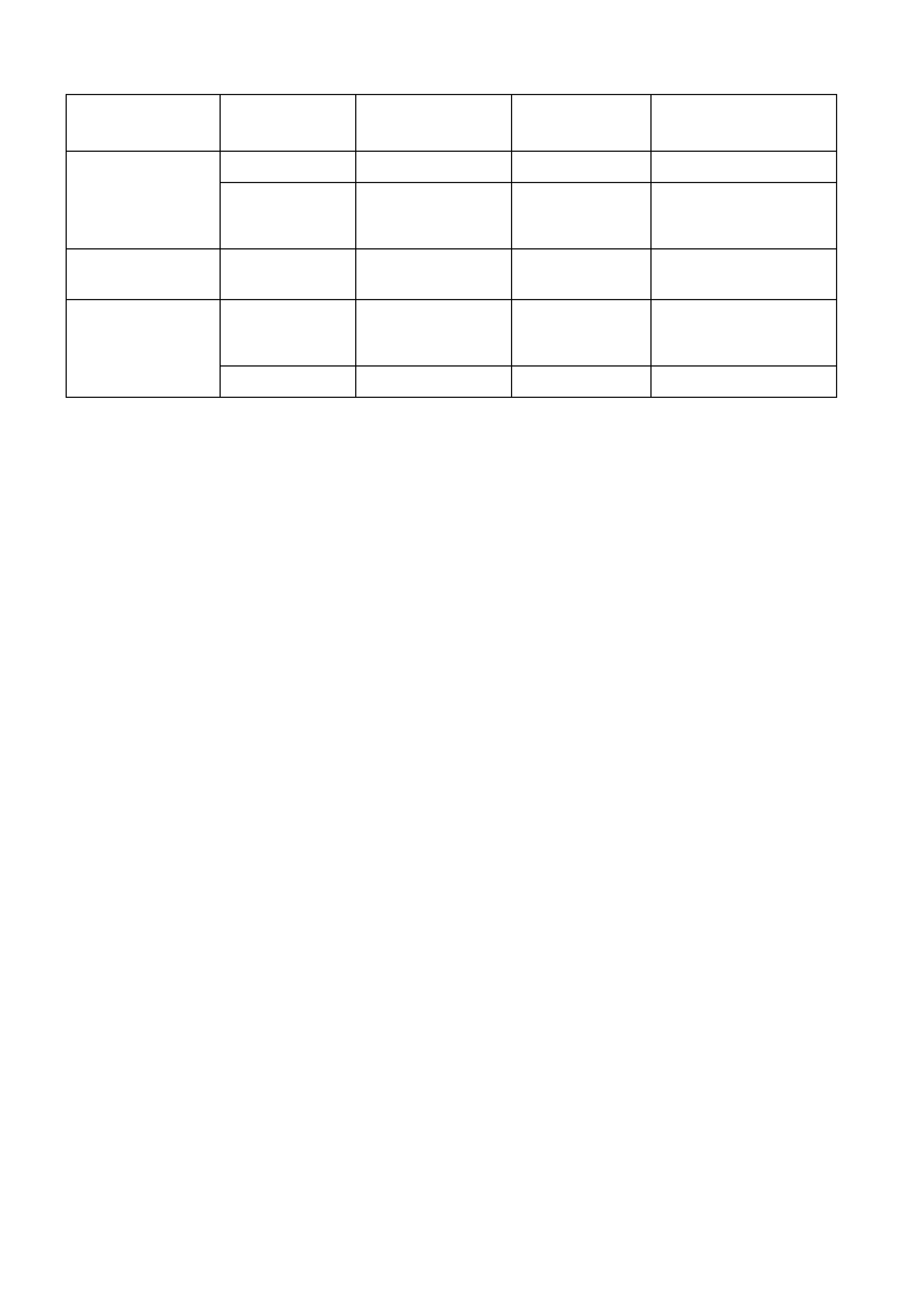
2. POWERTRAIN COMBINATIONS
ENGINE TRANSMISSION
TYPE MODEL
AVAILABILITY FIRST GEAR
RATIO REAR AXLE RATIO :1
3.8 LITRE PFI 5 Speed Manual Executive 3.829:1 3.08:1
4 Speed
Automatic Executive
Berlina
Calais
3.06:1 3.08:1
3.8 LITRE PFI
SUPERCHARGED 4 Speed
Automatic Berlina
Calais 3.06:1 3.08:1
5.7 LITRE PFI
(GEN III) 4 Speed
Automatic Executive
Berlina
Calais
3.06:1 3.08:1
6 Speed Manual Executive 2.66:1 3.46:1

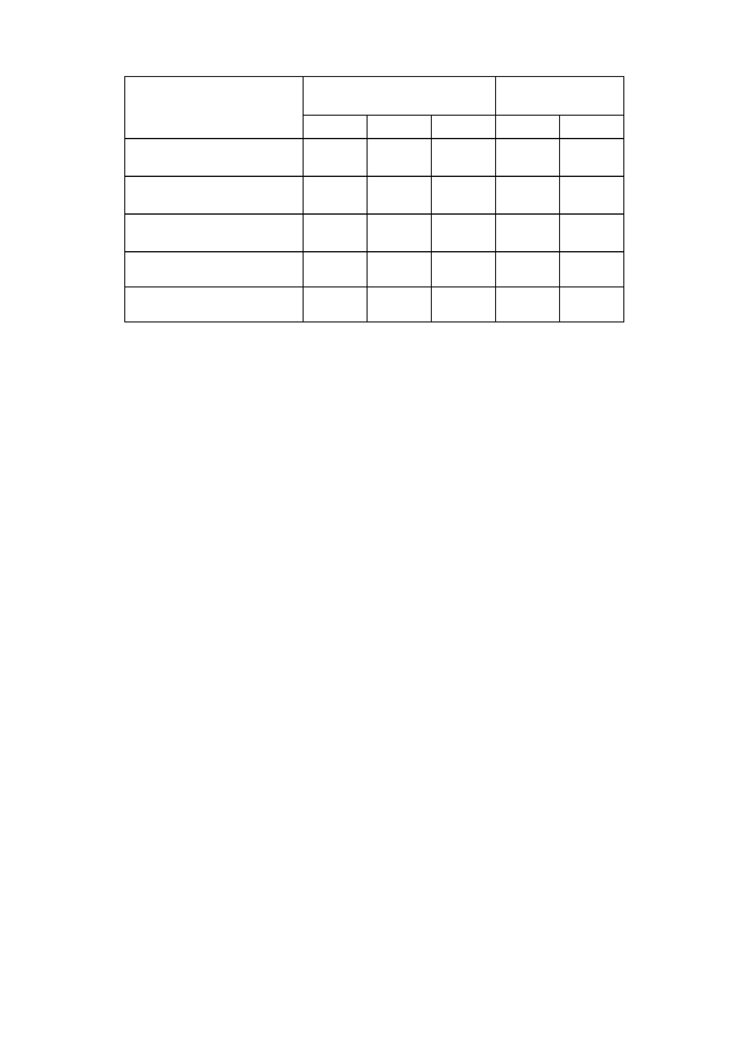
3. TRANSMISSION RATIOS
4 SPEED
AUTOMATIC 5 SPEED
MANUAL 6 SPEED
MANUAL
V6 & V8 engine V6 engine only V8 engine only
1ST 3.06:1 3.829:1 2.66:1
2ND 1.63:1 2.199:1 1.78:1
3RD 1.00:1 1.401:1 1.30:1
4TH 0.7:1 1.00:1 1.00:1
5TH - 0.809:1 0.74:1
6TH - - 0.50:1
REV 2.3:1 3.456:1 2.90:1

4. ENGINE DATA
ENGINE
DESIGNATION 3.8 LITRE PFI 3.8 LITRE
SUPERCHARGED 5.7 LITRE PFI
(GEN III)
Piston Displacement
Nom. - cm33791 3791 5667
Compression Ratio 9.4:1 8.5:1 10.1:1
Number of Cylinders 6 6 8
Bore x Stroke - mm 96.5 X
86.3 96.5 X
86.3 99 X 92
Taxable H.P.
RAC OR SAE 34.7 34.7 48.6
Power kW
DIN @ RPM 147 kW @ 5200 171 kW @ 5000
PULP* 220 kW @ 5200
Torque Nm
DIN @ RPM 304 Nm @ 3600 375 Nm @ 3200
PULP* 446 Nm @ 4000
*PULP – Premium Unleaded Petrol
5. VEHICLE WEIGHTS
VEHICLE SEDAN MODELS WAGON MODELS
WEIGHTS 8VK69 8VL69 8VX69 8VK35 8VL35
KERB MASS V6 1512 1555 1601 1572 1623
KERB MASS V8 1572 1602 1648 1632 1670
REAR AXLE LOAD V6 1140 1140 1140 1240 1240
REAR AXLE LOAD V8 1200 1200 1200 1340 1340
PAYLOAD (5 Pass. + Cargo) 408 408 408 480 480
NOTE: Figures are estimates only and measured in kg.
Payload figures must include luggage, goods, passengers, roof rack
load and a full tank of fuel. If you are towing, then the weight on the
tow bar ball must also be included.
Maximum Rear Axle Load is the maximum for all conditions.
6. SERIAL NUMBERS
The complete vehicle and various components of
the vehicle are identified by number plates or
numbers stamped into the part. It is essential that
when compiling warranty claims or product and
field reports, the vehicle identif ication num ber ( VIN)
is quoted in conjunction with the identification
number of the component affected.
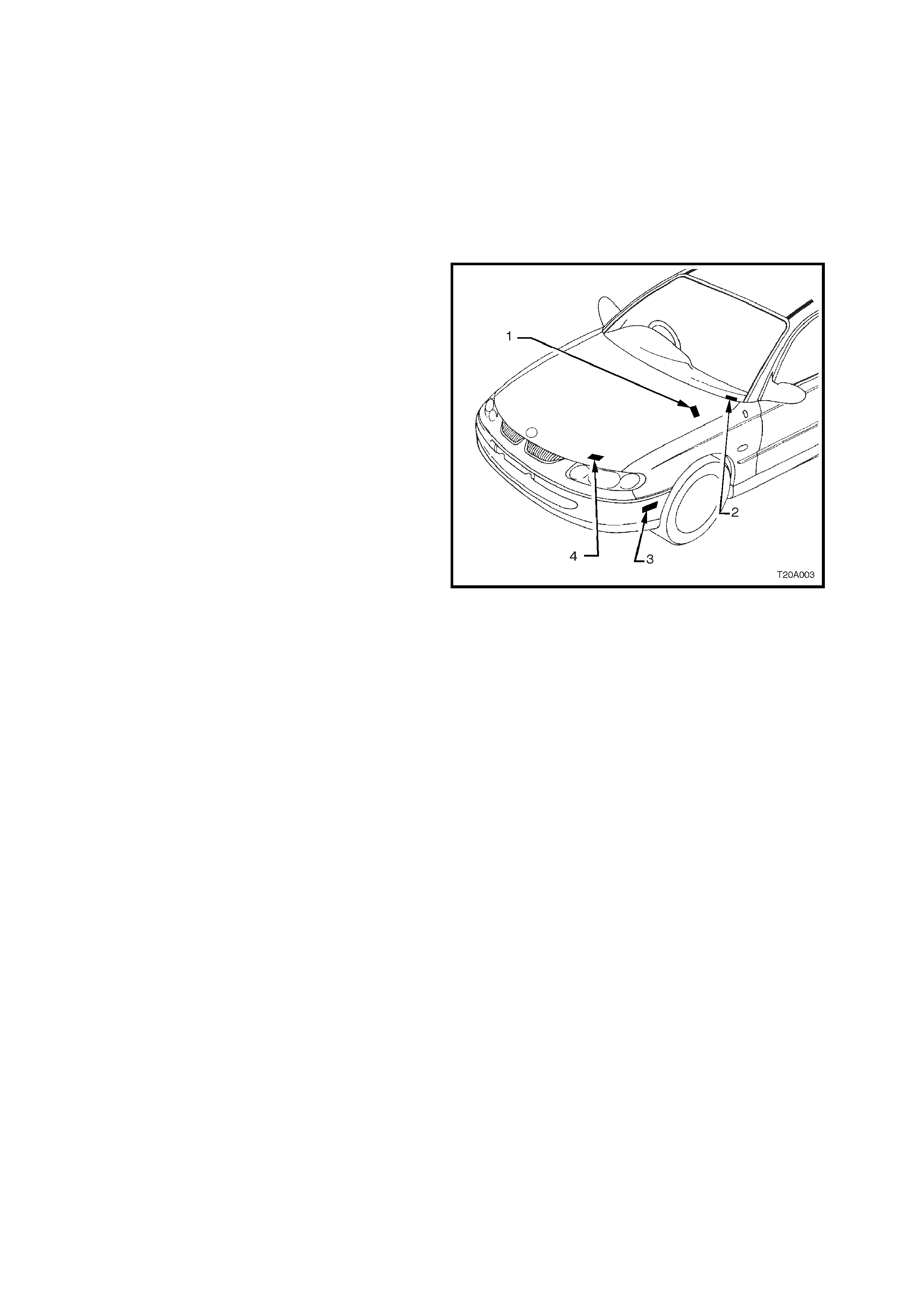
6.1 LOCATION OF IDENTIFICATION PLATES
Identification plates are attached to the upper right
side of the dash panel, front radiator s upport panel,
behind the bumper facia, and under the windshield
lower left corner, refer to Fig. 0A-.
1. Safety compliance plate
2. Vehicle Identification Number (VIN) plate
(windscreen)
3. Vehicle Identification Number (VIN) plate
(body)
4. Body and option identification plate
Figure 0A-1
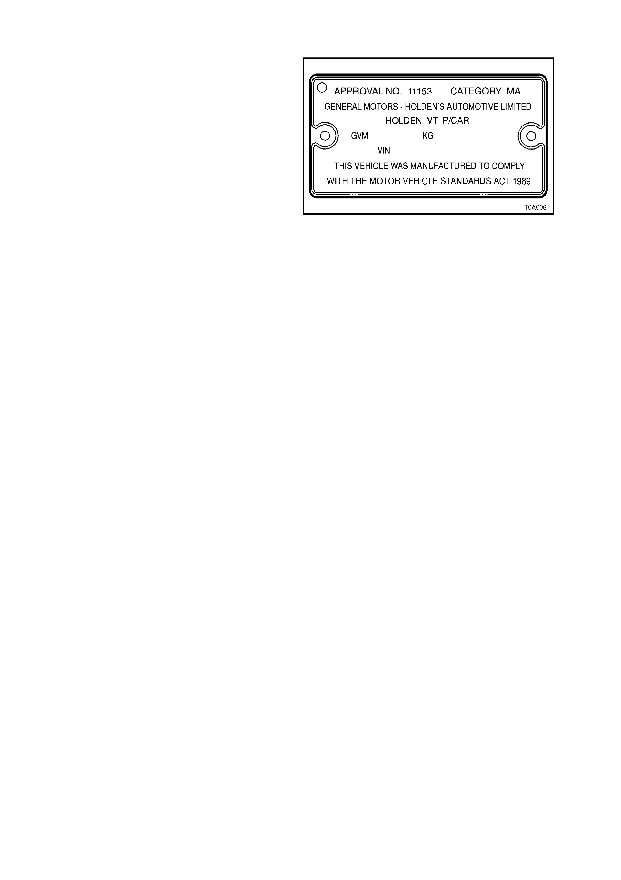
6.2 SAFETY COMPLIANCE PLATE
The Safety Compliance Plate, located on the
engine com partm ent side of the coc kpit m odule, is
stamped with the following information:
COMPLIANCE PLATE APPROVAL NUMBER.
VEHICLE CATEGORY CODE.
NAME APPEARING ON COMPLIANCE PLATE
APPROVAL.
MAKE/MODEL.
SEATING CAPACITY.
DATE OF MANUFACTURE (* Variable
information).
VEHICLE IDENTIFICATION NUMBER (* Variable
information). Figure 0A-2
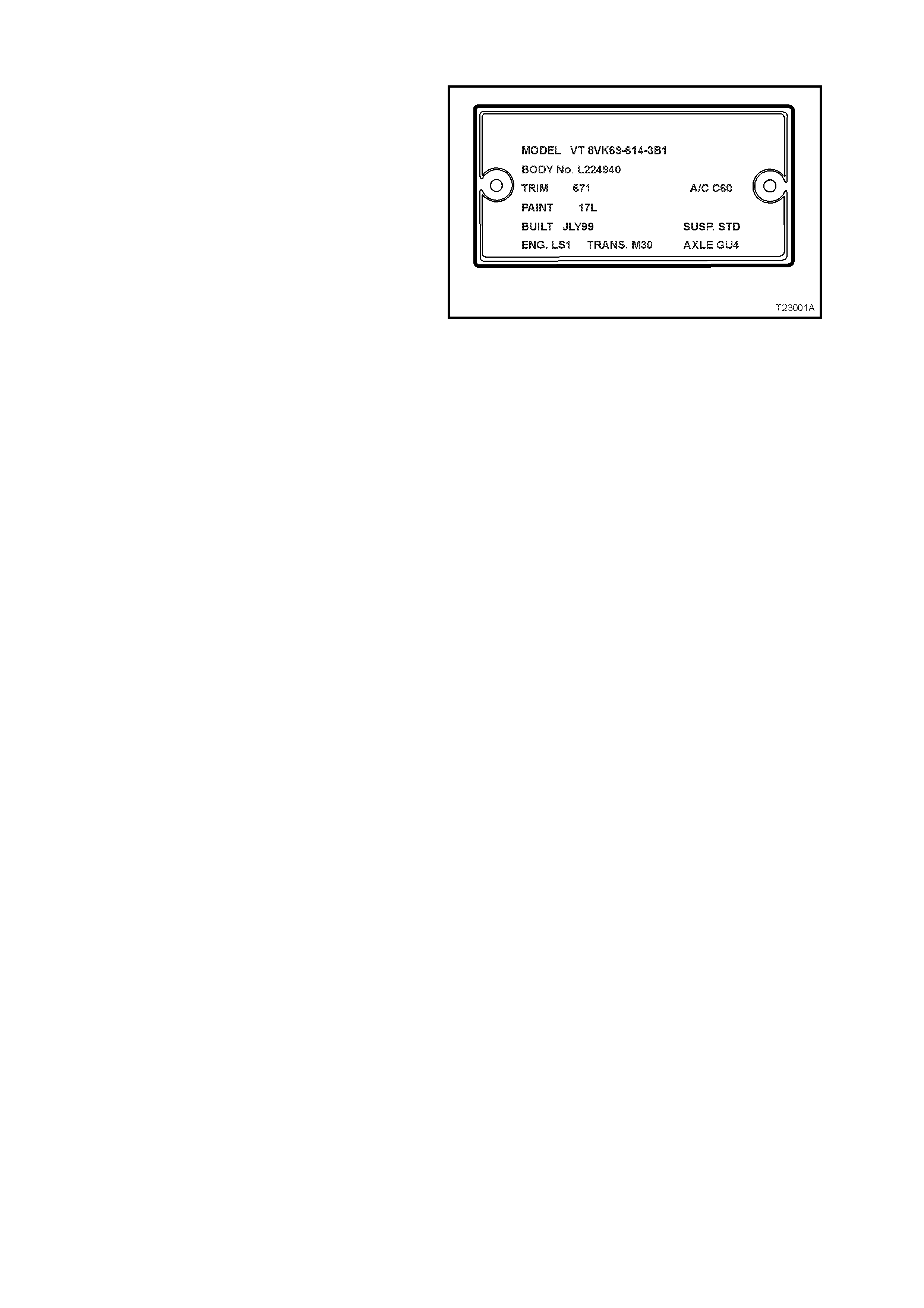
6.3 BODY AND OPTION IDENTIFICATION PLATE
The body option and identification plate, located to
the left hand side of the front panel upper, is
stamped with the following information:
MODEL:
Combination of letters and numbers identifying the
body style, the mechanical pack and smart pack
options.
A listing of Production Option num bers and Smark
Pack Option numbers, can be found by refering to
the latest spare parts information (Part Finder) for
the applicable model.
BODY:
Production build number; run in continuous
sequence regardless of model, body type and
series.
TRIM:
Trim combination.
PAINT:
Exterior paint material and colour identification.
BUILT:
The date of manufacture by calendar month and
year in which the body shell and power train are
conjoined and the vehicle is driven or moved from
the production line.
SUSP
Suspension option code identification, i.e. STD
(standard) or FE2 (sport).
ENGINE, TRANSMISSION AND AXLE
Identification option codes for specific engine,
transmission and rear axle.
A/C
Identification option code C60 is used for vehicles
fitted with air conditioning. C61 Identifies vehicles
fitted with Electronic Climate Control air
conditioning.
Figure 0A-3
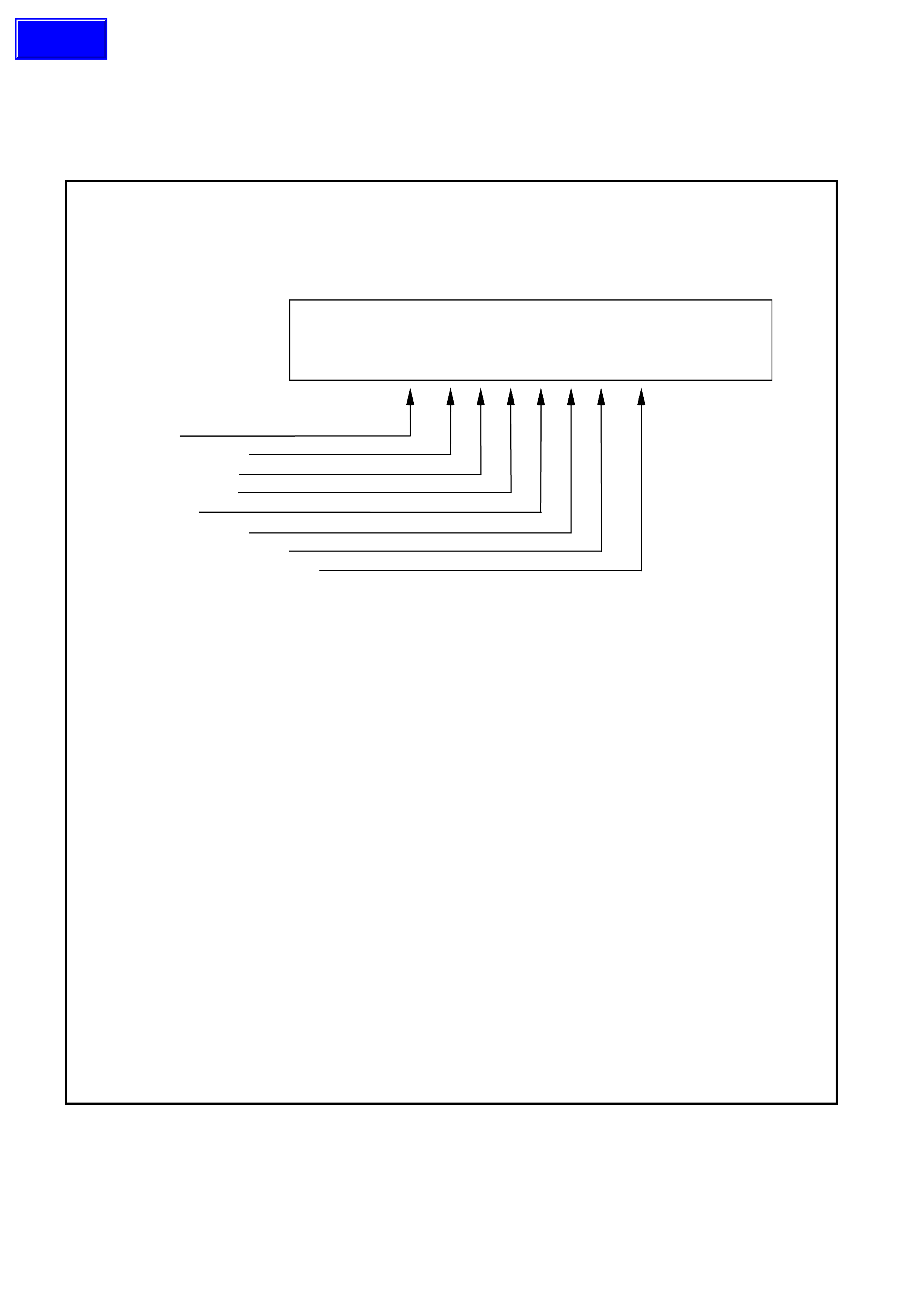
6.4 VEHICLE IDE NTIFICATION NUMBERING SYSTEM
There are two Vehicle Identification Number (VIN) plates attached to VT Series Models. The location of these plates
are: under the windscreen (viewed through the windscreen aperture) and under the front bumper on the left hand
side.
Figure 0A-4 details the vehicle identification numbering (VIN) system.
VEHICLE IDENTIFICATION NUMBERING SYSTEM
The Vehicle Identification Numbering System (VIN) is based on the uniform Car Model Designation
System. The reason for this is to identify the vehicle in one coded series of characters.
The significance of these characters or blocks of characters is explained below, using as an example
identification number 6H8 VT X 69 F X L 123456.
MODEL DESIGNATION
WMI Code
Model Series Code
Degree of Luxury
BODY STYLE CODE
ENGINE CODE
MODEL YEAR CODE
ASSEMBLY PLANT CODE
SERIAL SEQUENCE NUMBER
6H8 VT X 69 F X L 123456
MODEL DESIGNATION
WMI Code - 6H8 - World manufacturer's identifier allocated to Holden
Model Series Code - VT = VT Series
Degree of Luxury - K - EXECUTIVE
- L - BERLINA
- X - CALAIS
Body Style Code - 69 - Sedan 35 - Wagon
ENGINE CODE
Engine Identification Code (H - signifies 3.8 engine, S - signifies 3.8 supercharged engine,
F - signifies 5.7 engine)
MODEL YEAR CODE
X - Identifies Model Year W = 1998
X = 1999
This Letter relates to GM Internal Operation Only.
ASSEMBLY PLANT CODE
Australian Assembly Plant Identification Code:-
L - Adelaide (Elizabeth)
SERIAL (Sequence ) NUMBER
123456 - Sequential Production Serial Number
This designates the Serial Unit Number at the Vehicle Plant, starting at
(00001) and continues in Numerical Sequence regardless of vehicle type.
Figure 0A-4
Techline
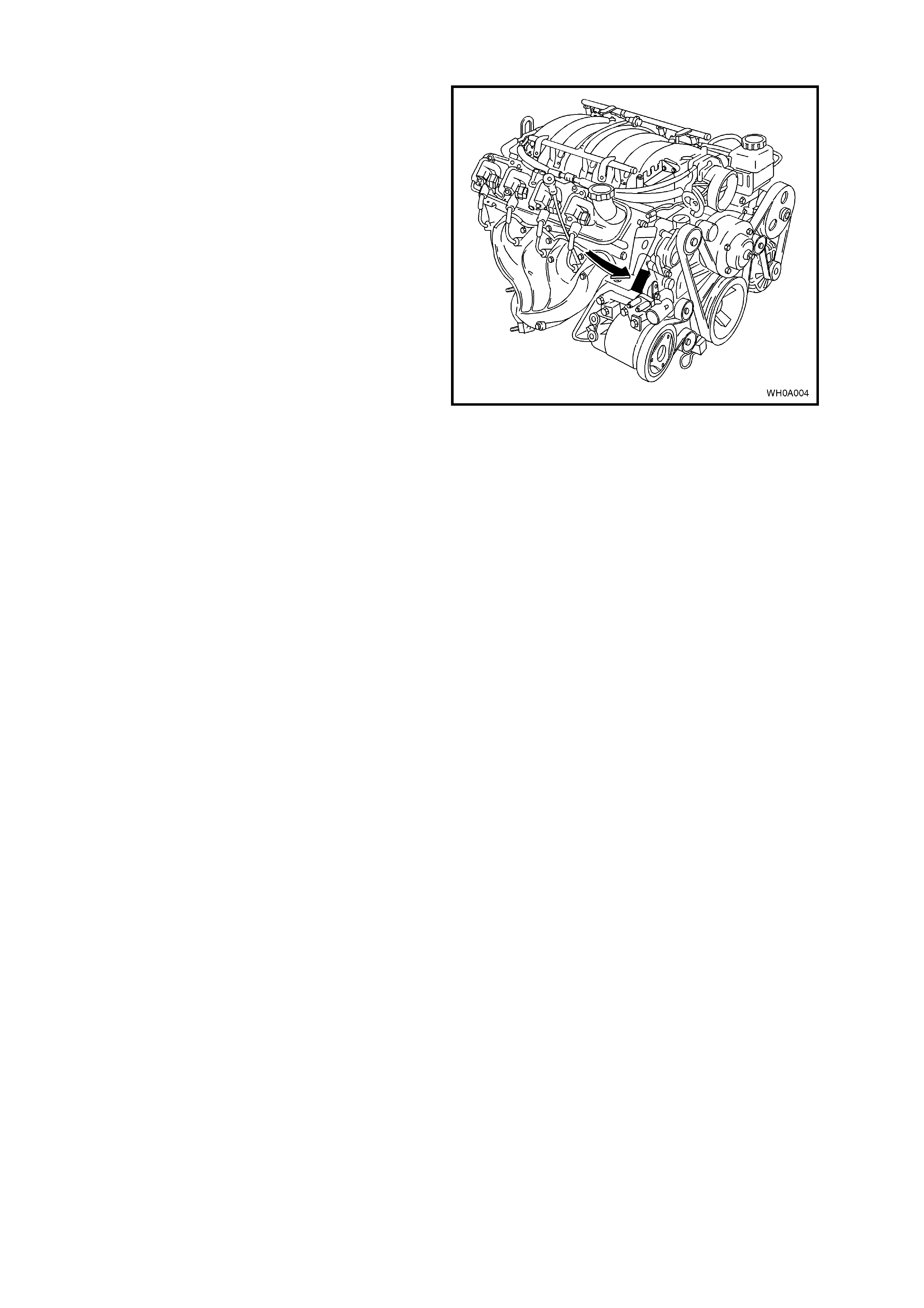
6.5 ENGINE SERIAL NUMBER
The 5.7litre Gen III V8 engine serial number is
stamped on a pad located adjacent to the engine
coolant outlet pipe, refer to Fig. 0A-5.
The engine number is prefixed by the letters ‘VF’.
Figure 0A-5
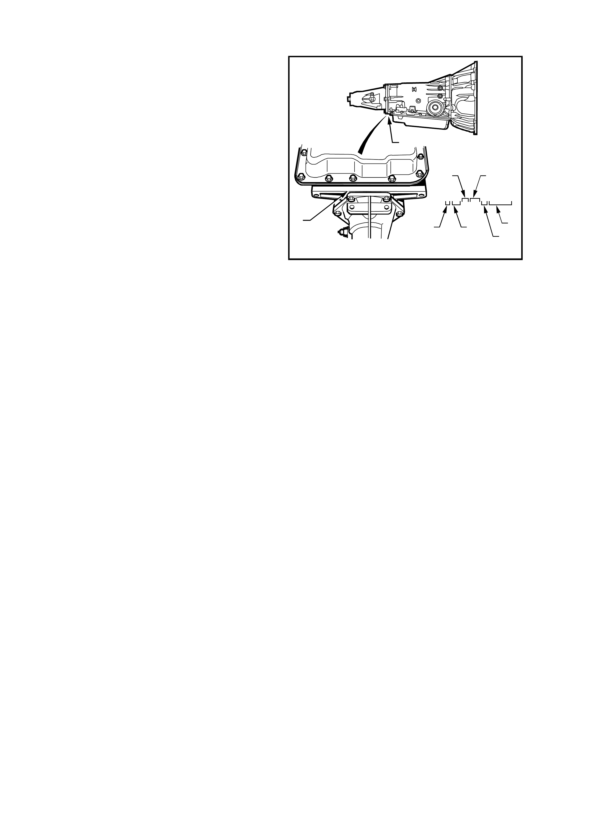
6.6 AUTOMATIC TRANSMISSION SERIAL NUMBER
The automatic transmission serial number is
stamped into a machined surface at the rear
underside of the transmission centre case, refer to
Fig. 0A-6.
1. Model Year (‘9’ = 1999)
2. Model: V8 – 5.7 litre ...................... HP
V6 – 3.8 litre ..................... HF
V6 Supercharged – 3.8 litre HN
3. Transmission Model Identifier (D = 4L60-E).
4. Julian Date (or day of year).
5. Shift Built (A, B, J = first shif t; C, H, W = second
shift).
6. Individual Transmission Serial Number.
7. Transmission Identification Number Location.
9HBD123 A 12345678
1
9 HB D 123 A 12345678
256
34
7
7
T20A001
Figure 0A-6
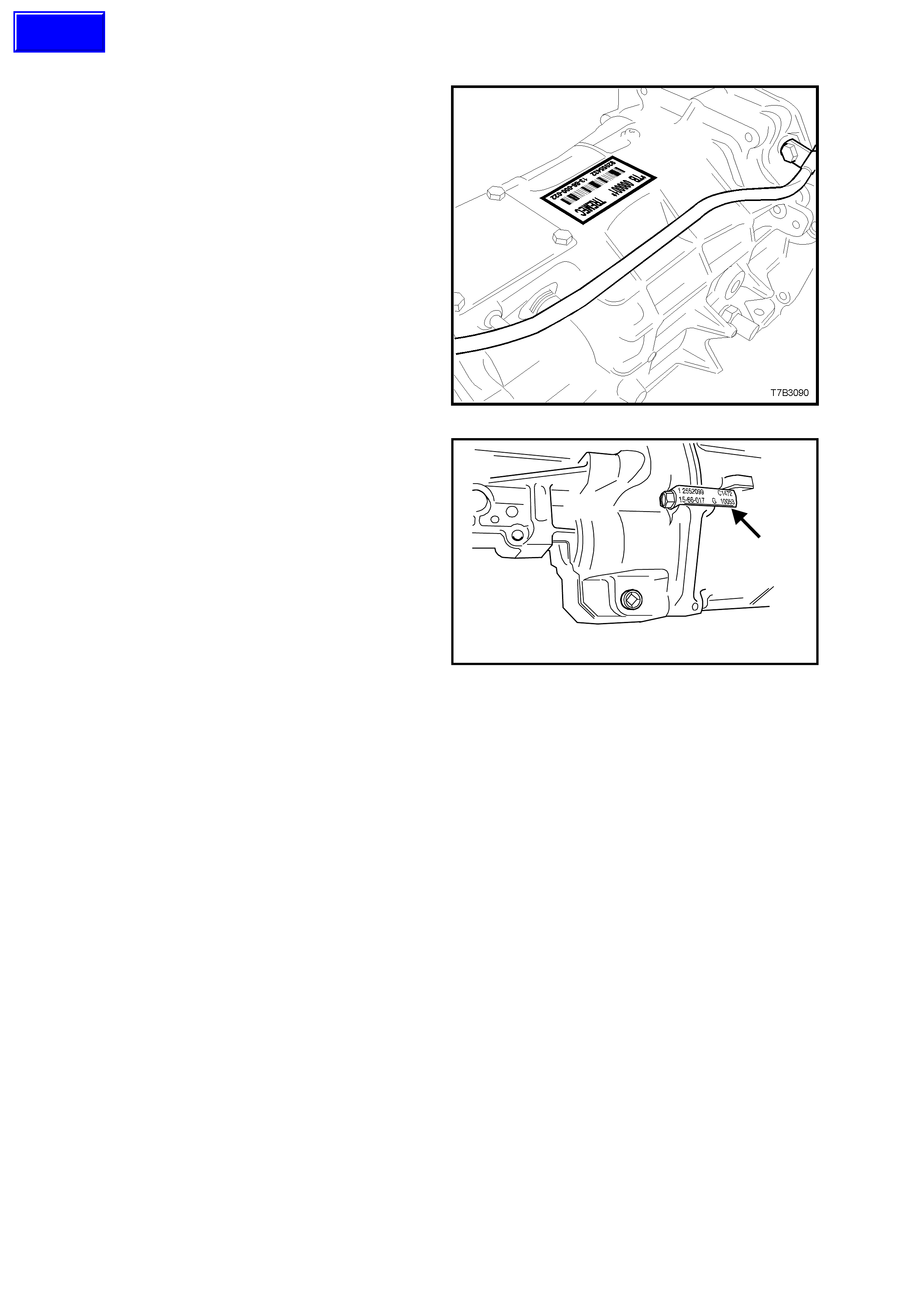
6.7 MANUAL TRANSMISSION SERIAL NUMBER
The Borg-Warner (Tremec) T56 six speed manual
transmission serial number is located on a self-
adhesive decal attached to the top of the
transmission case .
This number provides coded information which
could be significant to parts interpretation and
should be referred to when ordering replacement
parts.
In addition, an identification tag is attached to the
transmission under an extension housing bolt, on
the right hand side.
Figure 0A-7
T20A002
Figure 0A-8
Techline
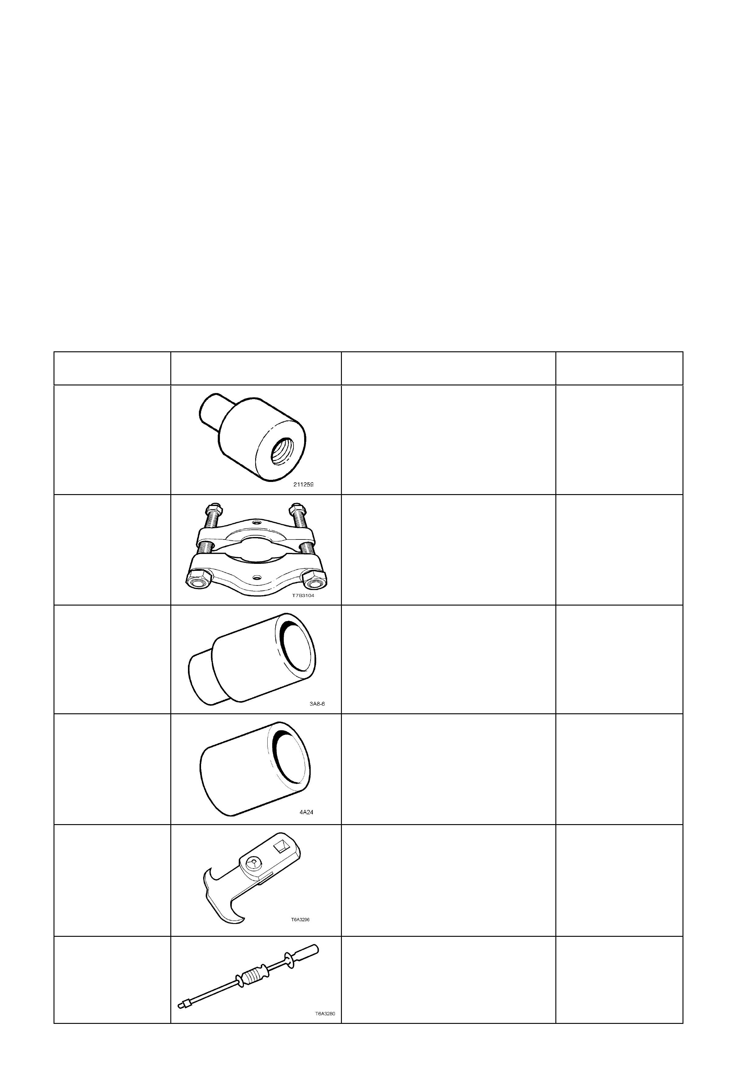
7. CONSOLIDATED TOOL LIST
The following pages list and illustrate additional special service tools required for use on VT Series II Models. This
list is to be used in conjunction with the consolidated tool list in Section 0A GENERAL INFORMATION of the VT
Series I Service Information.
NOTE: Some ser vice tools in this listing have pr eviously been published in Section 0A GENERAL INFORM AT ION
of the VT Series I Service Information.
The tools are listed in numerical / alphabetical order. The tools are also classified in accordance to the
specifications outlined in the “Holden policy and procedures manual” (unique, desirable or mandatory).
All Service Tools listed in this Section are, unless otherwise specified, available from:
SPX Australia Pty. Ltd.
OE Tool & Equipment Group
7 Expo Court
MT Waverley, Victoria 3149
Telephone: (03) 9544 6222
Facsimile: (03) 9544 5222
Email: ED@SPX.COM.AU
TOOL NUMBER ILLUSTRATION DESCRIPTION TOOL
CLASSIFICATION
211-259 LOWER PINION AND BEARING
REMOVER
Used to install the lower pinion and
bearing on the VT Series II steering
gear assembly.
New release.
Unique
22912-01 PRESS PLATES
Used in a number of different
applications in removing bearings
and other transmission components
when pressing operations are
required.
Previously released.
Unique
3A8-6 SLEEVE
Used to install the 1st/2nd gear
synchromesh hub to the mainshaft
on the Tremec 6 speed manual
transmission.
Previously released.
Unique
4A24 SLEEVE
Used to install the bearing cup into
the input shaft gear on the Tremec
6 speed manual transmission.
Previously released.
Unique
56750
(or E308) SEAL REMOVER
Used for a wide range of seal
removal applications, including use
on GEN III V8 engines and Tremec
6 speed manual transmission
Previously released.
Desirable
6125-1B SLIDE HAMMER
Used in conjunction with J 41818 to
remove main bearing caps GEN III
V8 engines.
Previously released.
Unique
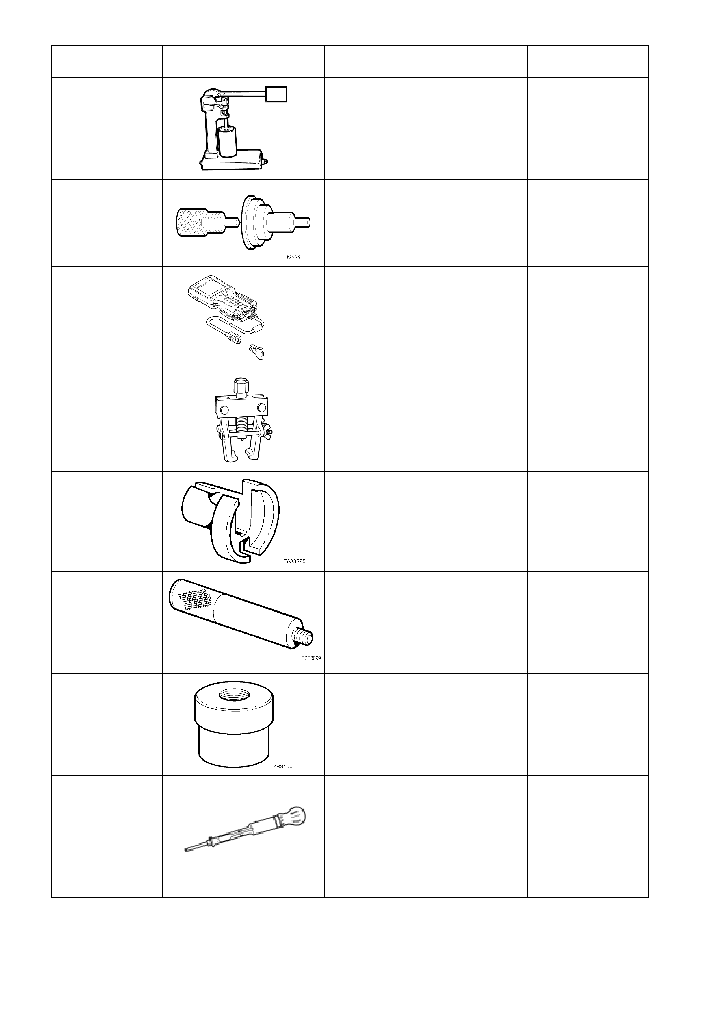
TOOL NUMBER ILLUSTRATION DESCRIPTION TOOL
CLASSIFICATION
6A23
T6A3114b
HYDRAULIC VALVE LIFTER TESTER
Used for testing valve lifters on V6 and
GEN III V8 engines
Previously released.
Used in conjunction with testing fluid
SPX No. E1151
Unique
6A24 VALVE LIFTER ASSEMBLY TOOLS
Used to assist in assembly of the
hydraulic valve lifters on V6 and GEN
III V8 engines
Previously released.
Unique
70000861 TECH 2 DIAGNOSTIC SCAN TOOL
Used for diagnosis of vehicle electrical
systems
Mandatory
7311 TIE ROD BALL JOINT REMOVER
New release to suit new steering
knuckle.
Can also be used on earlier ‘V’ cars for
the same purpose.
Desirable
7371 QUICK CONNECT RELEASE TOOL
Previously released for releasing fuel
line quick connects on V6
supercharged engine after fuel system
has been de-pressurised.
Used on GEN III V8 engine for the
same purpose
Desirable
7AT2 DRIVER HANDLE
Used in conjunction with 7AT5 to
remove/install the slip yoke bushing in
the extension housing on the Tremec 6
speed manual transmission.
Previously released.
Unique
7AT5 SLIP YOKE BUSH
REMOVER/INSTALLER
Used in conjunction with 7AT2 to
remove/install the slip yoke bushing in
the extension housing on the Tremec 6
speed manual transmission.
Previously released.
Unique
AU435
(No longer available
use J 26568)
COOLING SYSTEM HYDROMETER
Used for testing coolant concentrate.
Previously released.
Mandatory
TOOL NUMBER ILLUSTRATION DESCRIPTION TOOL
CLASSIFICATION
AU485
AU485
SIDE IMPACT AIR BAG
DUMMY LOAD
Used for SRS electronic diagnostic
check on side impact air bags.
Previously released.
Mandatory
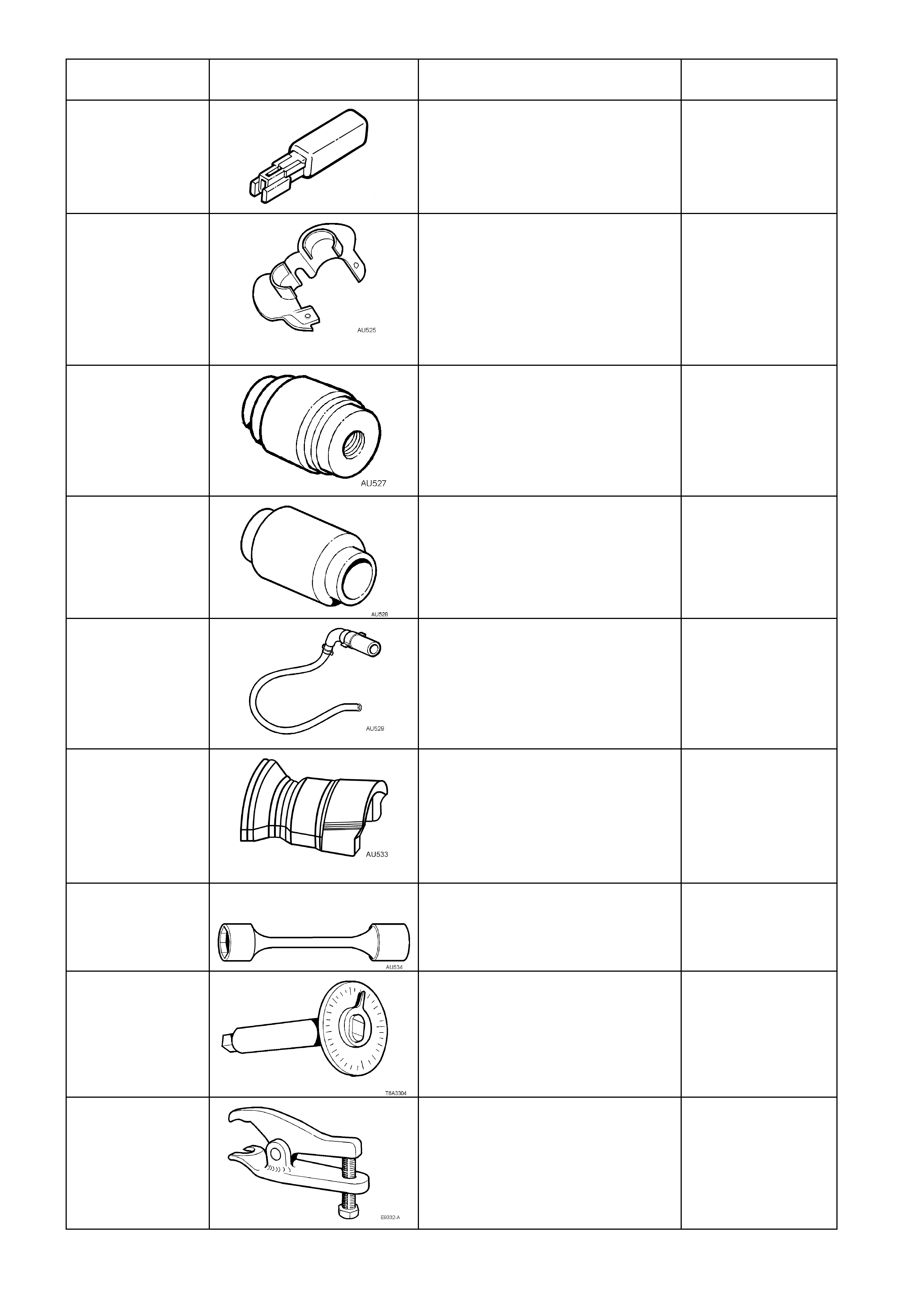
AU525 QUICK CONNECT RELEASE
TOOL
Use to release the quick connect
fittings on the automatic
transmission fluid cooler lines at the
radiator end, when the vehicle is so
equipped.
New release.
Mandatory
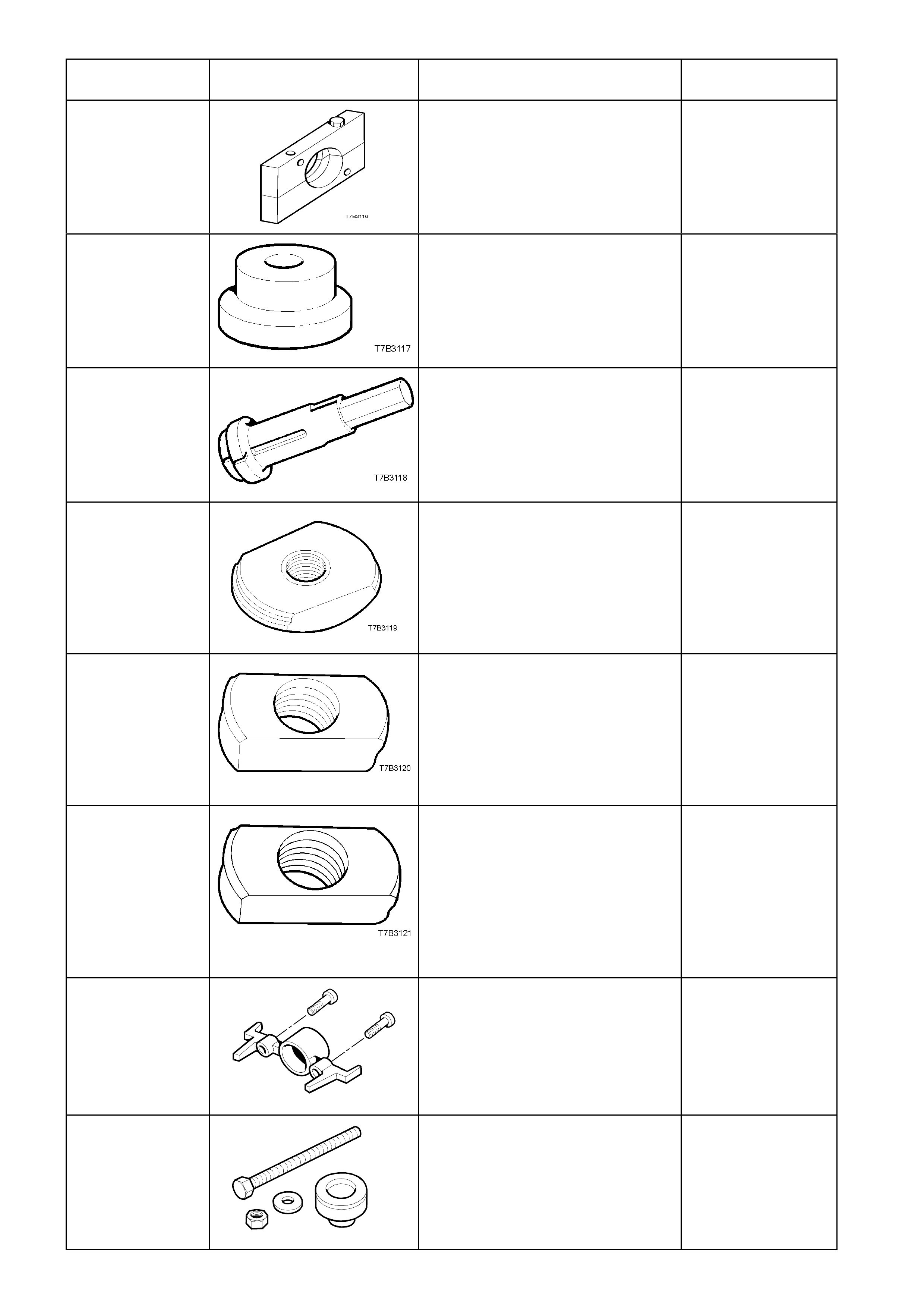
AU527 INTERMEDIATE BEARING AND
SEAL INSTALLER
Used to install the intermediate
bearing and seal on the VT Series
II steering gear assembly.
New release.
Unique
AU528 UPPER SEAL AND BEARING
INSTALLER
Used to install the upper seal and
bearing on the VT Series II steering
gear assembly.
New release.
Unique
AU529 CLUTCH SLAVE CYLINDER
BLEED TOOL
Used to bleed the clutch hydraulic
system on the Tremec 6 speed
manual transmission.
New release.
Desirable
AU533 QUICK CONNECT FITTING
RELEASE TOOL
Released in two sizes; Red for
5/16” fittings and Blue for 3/8”
fittings.
Also available commercially under
P/N AUSP45
Desirable
AU534 TORQUE LIMITING SOCKET
Released to allow the use of impact
gun to tighten road wheel nuts
Mandatory
E 7115 TORQUE ANGLE WRENCH
Used to accurately tighten
fasteners when an angle torque is
required.
Previously released.
Desirable
E 9332-A BALL JOINT RELEASE TOOL
Used to release the control arm ball
joint from the steering knuckle.
Desirable
TOOL NUMBER ILLUSTRATION DESCRIPTION TOOL
CLASSIFICATION
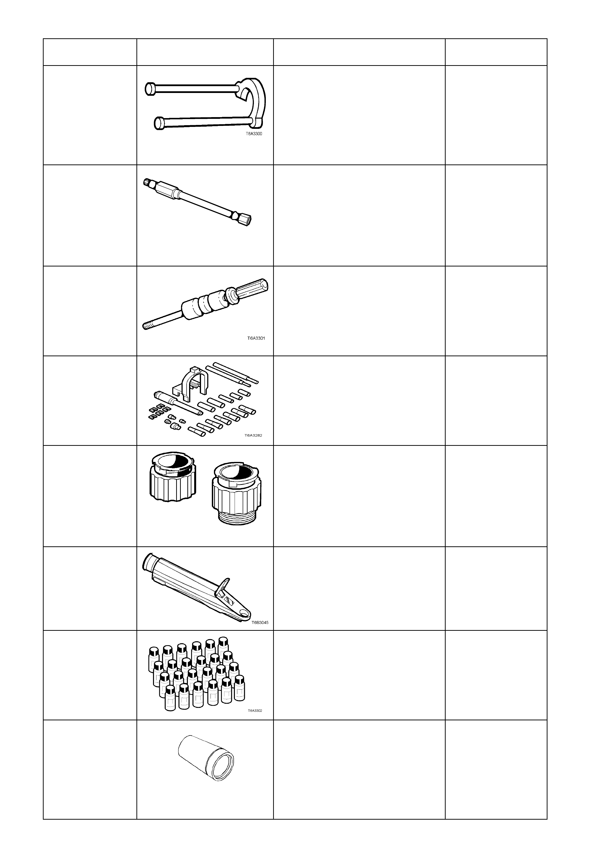
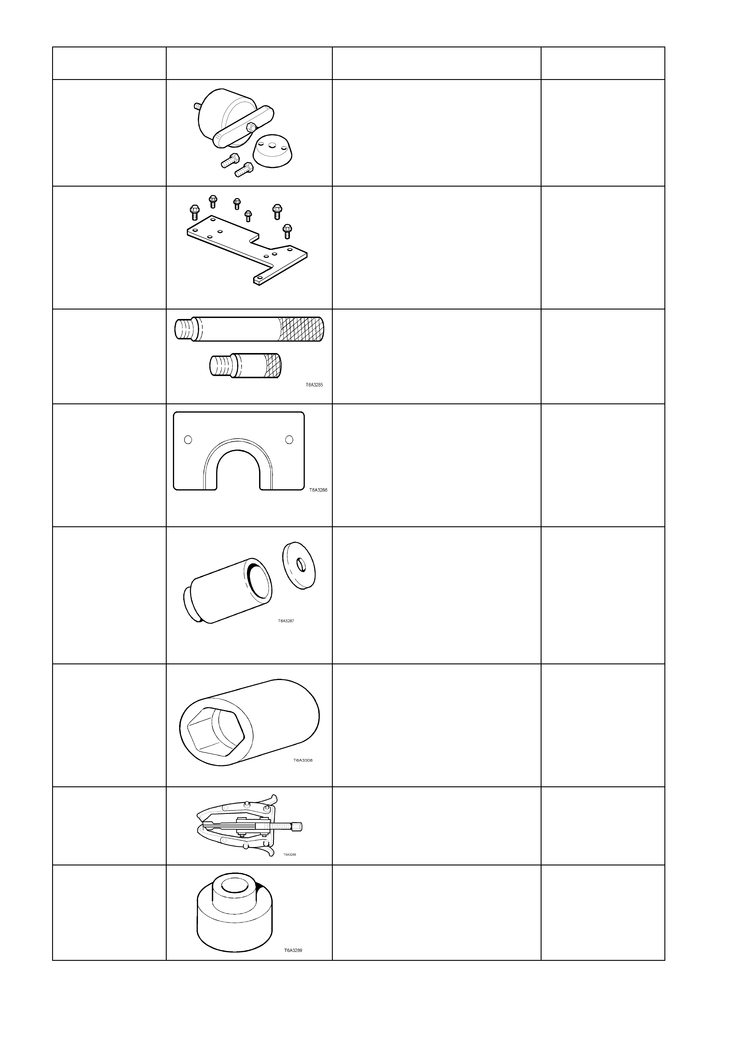
J 21427-01 PULLER ADAPTER
Used in conjunction with J 8433-1,
J 41558 and J 41816-2 to remove
crankshaft timing gear sprocket on
GEN III V8 engine.
Previously released to remove
automatic transmission speed
sensor ring.
Unique
J 22794
T6A3256a
ADAPTER
Used to facilitate the application of
air pressure to a cylinder when
replacing a valve spring or valve
stem oil seal with the cylinder head
installed.
New release.
Desirable
J 23907 SLIDE HAMMER
Used in conjunction with a number
of different pullers to remove
bushes and bearing cups in the
transmission
Previously released.
Unique
J 24086-C PISTON PIN
REMOVER/INSTALLER
Universal tool containing selective
components to suit multiple engine
applications.
New release.
Unique
J 24460-92 COOLING SYSTEM TEST
ADAPTERS
Used to pressure test the screw-on
cooling system pressure cap and
the cooling system on GEN III V8
engines.
New release.
Mandatory
J 26568 REFRACTOMETER
Used for testing coolant
concentrate.
Previously released, (replaces
AU435)
Mandatory
J 28431-B FLUID DYE
24 x 1 ounce bottles.
Used in conjunction with black light,
leak detection lamp J 42220 to
locate various types of vehicle fluid
leaks.
Previously released.
Desirable
J 28458 SEAL PROTECTOR AND
DIAPHRAM RETAINER
INSTALLER
Used to protect the power piston
seal and install the diaphram
retainer on the 4l60-E automatic
transmission
New release
Unique
TOOL NUMBER ILLUSTRATION DESCRIPTION TOOL
CLASSIFICATION
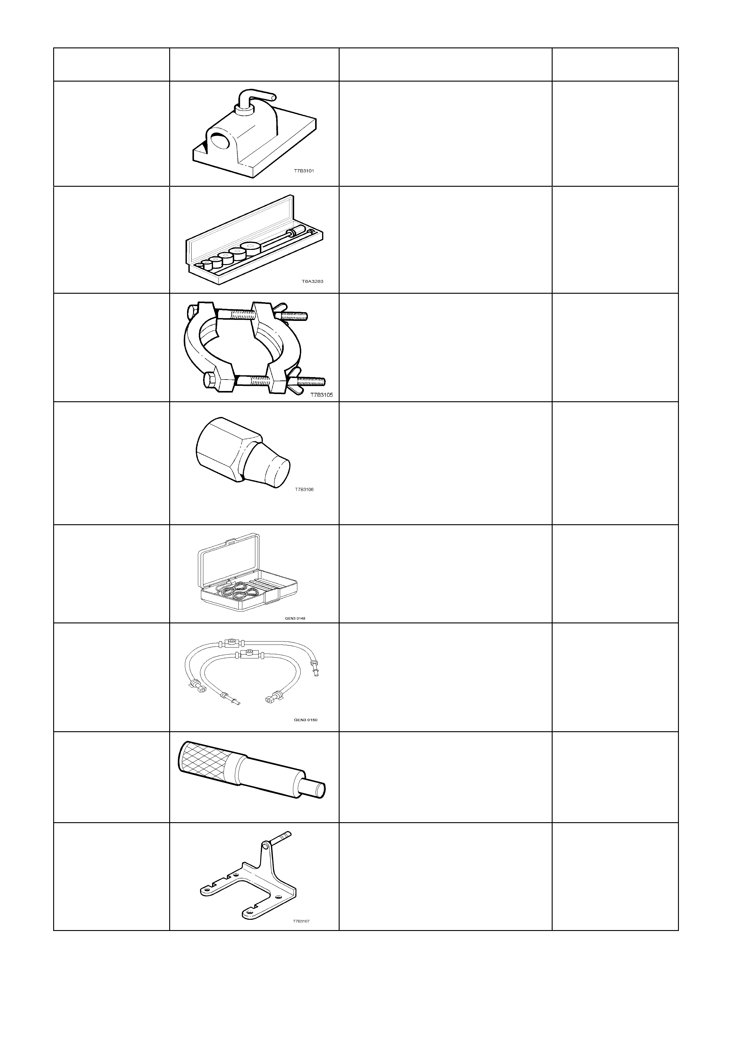
J 3289-20 BENCH HOLDING FIXTURE
Used as a bench fixture to support
a transmission.
Previously released.
Unique
J 33049 CAMSHAFT BEARING
REMOVER/INSTALLER
Universal tool containing selective
components to suit multiple engine
applications.
New release.
Unique
J 36513 PRESS PLATES
Used to press 1st/2nd speed
synchromesh assembly and 2nd
gear from the mainshaft on the
Tremec 6 speed manual
transmission.
New release.
Unique
J 36800 BUSHING REMOVER
Used to remove the shift rail
bushes in the adapter plate and
extension housing on the Tremec 6
speed manual transmission. Used
in conjunction with slide hammer
J 23907.
New release.
Unique
J 37027-A IAC MOTOR ANALYZER
Used to manualy operate and
check the idle air control valve
system operation.
New release.
Mandatory
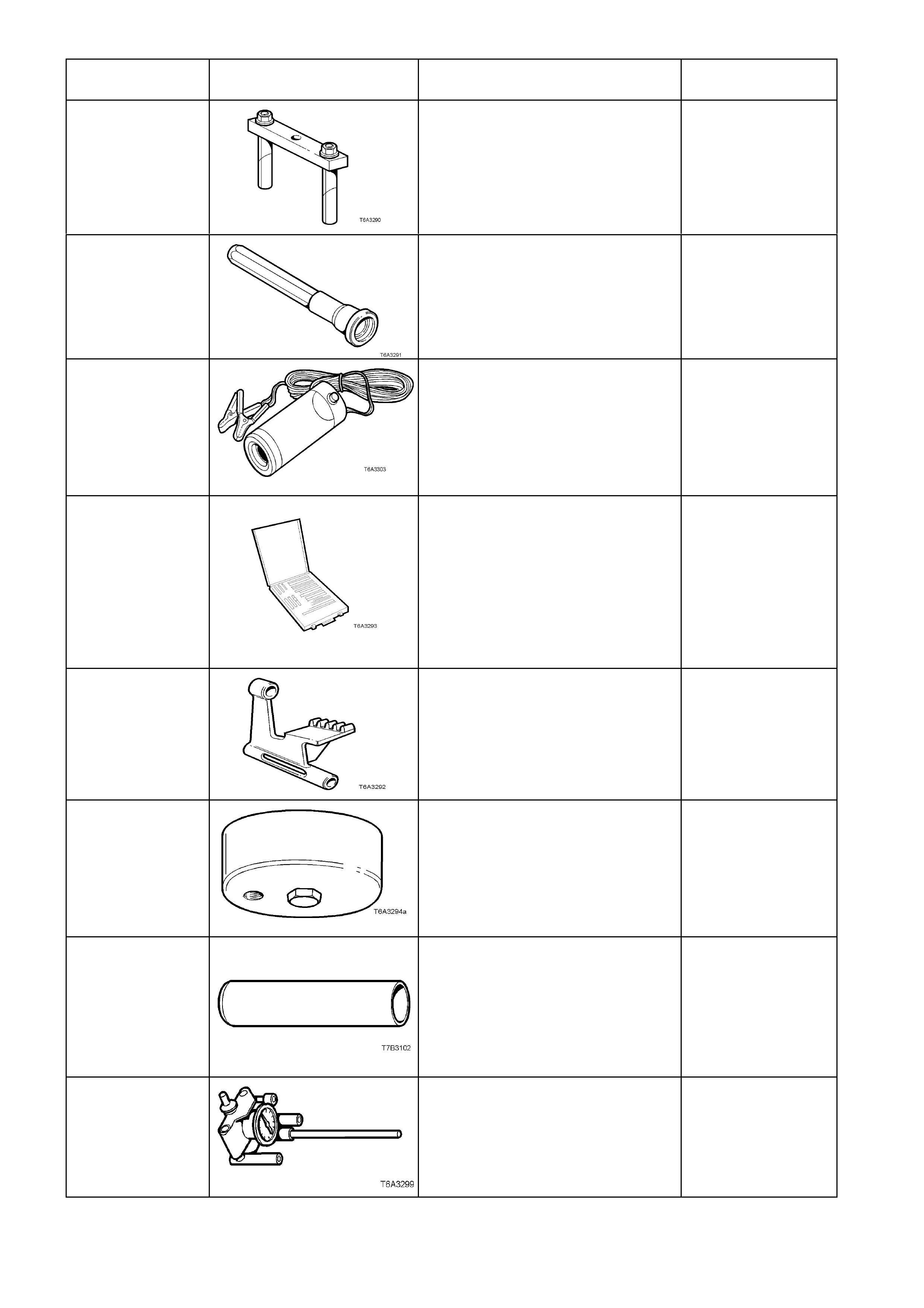
J 37287 INLET AND RETURN FUEL LINE
SHUT-OFF ADAPTERS
Used in conjunction with the fuel
pressure gauge for restricting the
fuel supply and return lines for
testing.
New release.
Mandatory
J 38836
T6A3 189b
PILOTED DRIVER
Used to install the spigot bush in
the crankshaft on GEN III V8
engines.
New release.
Unique
J 39430 TRANSMISSION HOLDING
FIXTURE
Used to mount the Tremec 6 speed
manual transmission to the bench
for unit repair operations.
New release.
Unique
TOOL NUMBER ILLUSTRATION DESCRIPTION TOOL
CLASSIFICATION
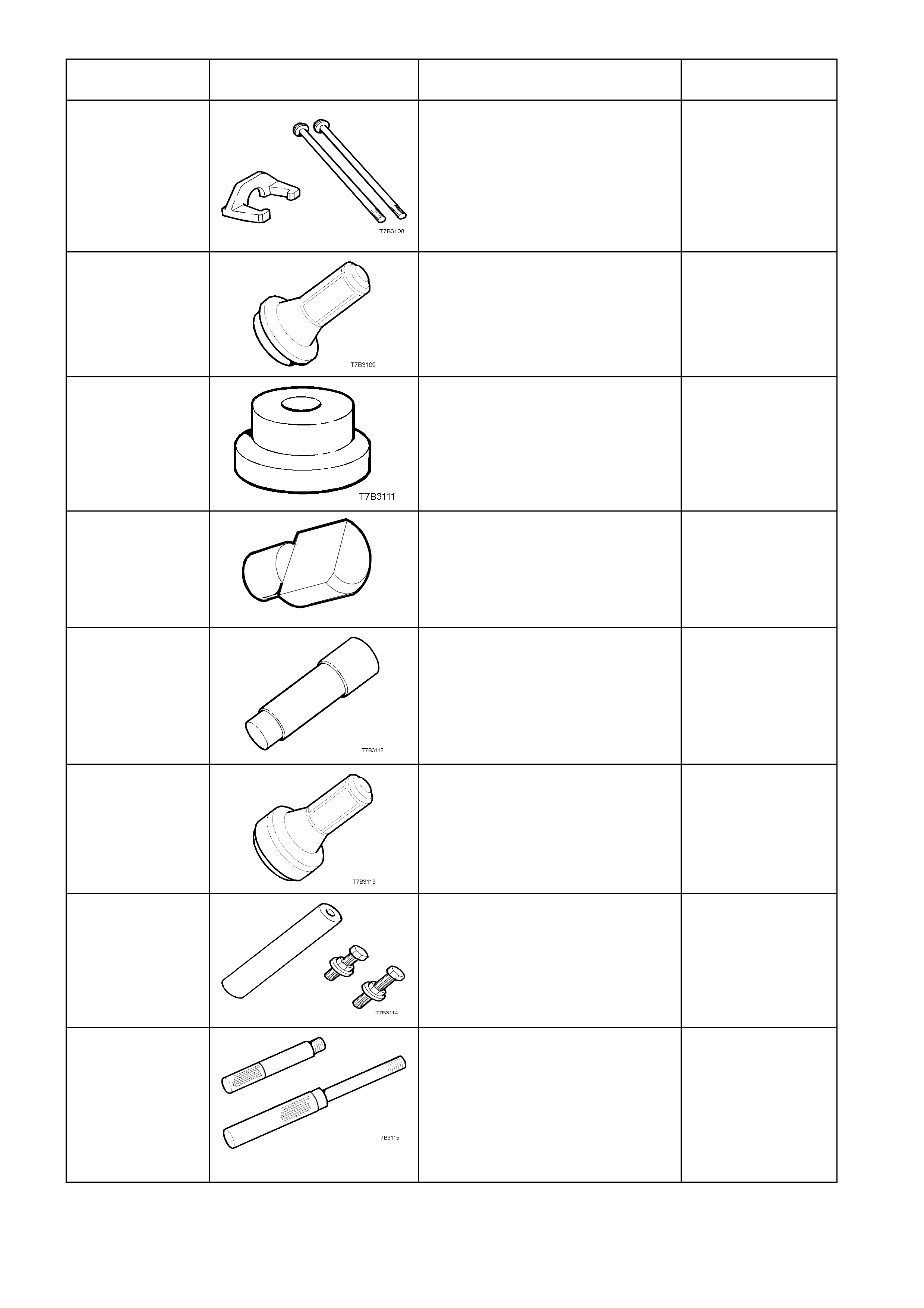
J 39431-1 & 2 REMOVER AND BOLTS
Used to remove the speedometer
pulse ring and the 5th/6th speed,
compound driven gear on the
Tremec 6 speed manual
transmission. Used in conjunction
with universal bridge puller J 8433.
New release.
Unique
J 39433 SEAL INSTALLER
Used to install the input shaft oil
seal on the Tremec 6 speed
manual transmission.
New release.
Desirable
J 39436 BEARING CUP INSTALLER
Used to install the countershaft rear
bearing cup on the Tremec 6 speed
manual transmission. Use in
conjunction with driver handle J
8092.
New release.
Unique
J 39437
J 39437
BUSHING INSTALLER
Used to install the selector shaft
bushes in the adapter plate, and
transmission case on the Tremec 6
speed manual transmission.
New release.
Unique
J 39439-1 BUSHING REMOVER/INSTALLER
Used to remove shift shaft bushes
from the transmission case and
extension housing on the Tremec 6
speed manual transmission.
New release.
Unique
J 39440 REAR SEAL AND BOOT
INSTALLER
Used to install the rear extension
seal on the Tremec 6 speed
manual transmission.
New release.
Desirable
J 39441 GEAR INSTALLER
Used to install the 5th/6th
compound driven gear and the
speedometer pulse ring on the
Tremec 6 speed manual
transmission.
New release.
Unique
J 39444-1 & 2 END PLAY RODS
Used to check the end float of the
countershaft gear (J 39444-1) and
countershaft gear extension
(J 39444-2) on the Tremec 6 speed
manual transmission.
New Releases.
Unique
TOOL NUMBER ILLUSTRATION DESCRIPTION TOOL
CLASSIFICATION
J 39511 SPLIT PLATE
Used to remove the front
countershaft gear bearing on the
Tremec 6 speed manual
transmission.
New release.
Unique
J 39546 BEARING CUP INSTALLER
Used to install the rear mainshaft
roller bearing cup on the Tremec 6
speed manual transmission. Used
in conjunction with driver handle J
8092.
New release.
Unique
J 39594 BEARING CUP REMOVER
Used in conjunction with slide
hammer J 23907 to remove the
mainshaft pilot bearing cup in the
input shaft gear on the Tremec 6
speed manual transmission.
New release.
Unique
J 39789 BEARING CUP REMOVER
Used to press out the rear
mainshaft roller bearing cup from
the extension housing on the
Tremec 6 speed manual
transmission. Used in conjunction
with driver handle J 8092.
New Release.
Unique
J 39790 BEARING CUP REMOVER
Used to press out the rear
mainshaft bearing cup from the
transmission case on the Tremec 6
speed manual transmission. Used
in conjunction with driver handle J
8092
New release.
Unique
J 39791 BEARING CUP REMOVER
Used to press out the rear
countershaft bearing cup from the
transmission case on the Tremec 6
speed manual transmission. Use in
conjunction with driver handle J
8092.
New release.
Unique
J 41476
T6A3257a
FRONT AND REAR COVER
ALIGNMENT TOOL
Used to align both the front and
rear engine covers during
installation on GEN III V8 engine.
New release.
Desirable
J 41478
T6A3258a
CRANKSHAFT FRONT OIL SEAL
INSTALLER
For GEN III V8 engine; threaded
bolt, nut and washer are also used
in conjunction with J 41665 to install
the crankshaft balancer.
New release.
Desirable
TOOL NUMBER ILLUSTRATION DESCRIPTION TOOL
CLASSIFICATION
J 41479
T6A3259a
CRANKSHAFT REAR OIL SEAL
INSTALLER
For GEN III engine.
New release
Desirable
J 41480
T6A3260a
FRONT AND REAR COVER
ALIGNMENT TOOL
Used in conjunction with alignment
tool J 41476, to correctly align the
front and rear engine covers on
GEN III V8 engines.
New release.
Desirable
J 41556 CONNECTING ROD GUIDES
Used to assist in piston and
connecting rod installation on GEN
III V8 engine.
New release.
Desirable
J 41558 CRANKSHAFT SPROCKET
REMOVER
Used in conjunction with the bolts
from J 21427-01 and pulley puller J
8433, to remove the crankshaft
sprocket on GEN III V8 engine.
New release.
Desirable
J 41665 CRANKSHAFT BALANCER
INSTALLER
Used in conjunction with the
threaded bolt, nut and washer of
Tool J 41478, to install the
crankshaft balancer and sprocket
on GEN III V8 engine.
New release.
Desirable
J 41712 OIL PRESSURE SENSOR
SOCKET
Used in conjunction with 3/8” drive
socket equipment to
remove/reinstall oil pressure sensor
on GEN III V8 engine.
New release.
Desirable
J 41816 THREE LEGGED PULLER
Used in conjunction with J 41816-2
to remove crankshaft balancer on
GEN III V8 engine.
New release.
Desirable
J 41816-2 ADAPTER
Used in conjunction with puller J
41816 to remove crankshaft
balancer on GEN III V8 engine.
New release.
Desirable
TOOL NUMBER ILLUSTRATION DESCRIPTION TOOL
CLASSIFICATION
J 41818 CRANKSHAFT BEARING CAP
REMOVER
Used in conjunction with slide
hammer J 6125-1B to remove main
bearing caps on GEN III V8 engine.
New release.
Desirable
J 42078 VALVE STEM OIL SEAL
INSTALLER
New release.
Desirable
J 42220 BLACK LIGHT, LEAK DETECTION
LAMP
Used with dye, Tool J 28431-B to
locate the source of various vehicle
fluid leaks.
Previously released.
Desirable
J 42385 THREAD REPAIR KIT
Comprises:
Cylinder Head/Rear Main
Bearing Cap Kit J 42385-
100
General Kit J 42385-200
Fixtures/Hardware Kit J 42385-
300 New release.
Unique
J 42386 FLYWHEEL HOLD ING TOOL
New release. Desirable
J 42907 OIL PRESSURE ADAPTER
Fitted to the oil filter adapter and
used in conjunction with a
commercially available oil pressure
gauge and hose.
New release.
Desirable
J 5590 PRESS TUBE
Used to install various components,
using a hydraulic press.
Previously released for 4L60-E
automatic transmission.
Unique
J 8087 CYLINDER BORE CHECKING
GAUGE
New release.
Unique
TOOL NUMBER ILLUSTRATION DESCRIPTION TOOL
CLASSIFICATION
J 8092 UNIVERSAL DRIVER HANDLE
Used in conjunction with various
other tools for removal and
installation of various bearing cups
in the transmission.
Previously released.
Unique
J 8433 UNIVERSAL BRIDGE PULLER
Used in conjunction with J 39431-1
& 2 to remove the speedometer
pulse ring and the 5th/6th speed,
compound driven gear on the
Tremec 6 speed manual
transmission.
Previously released.
Unique
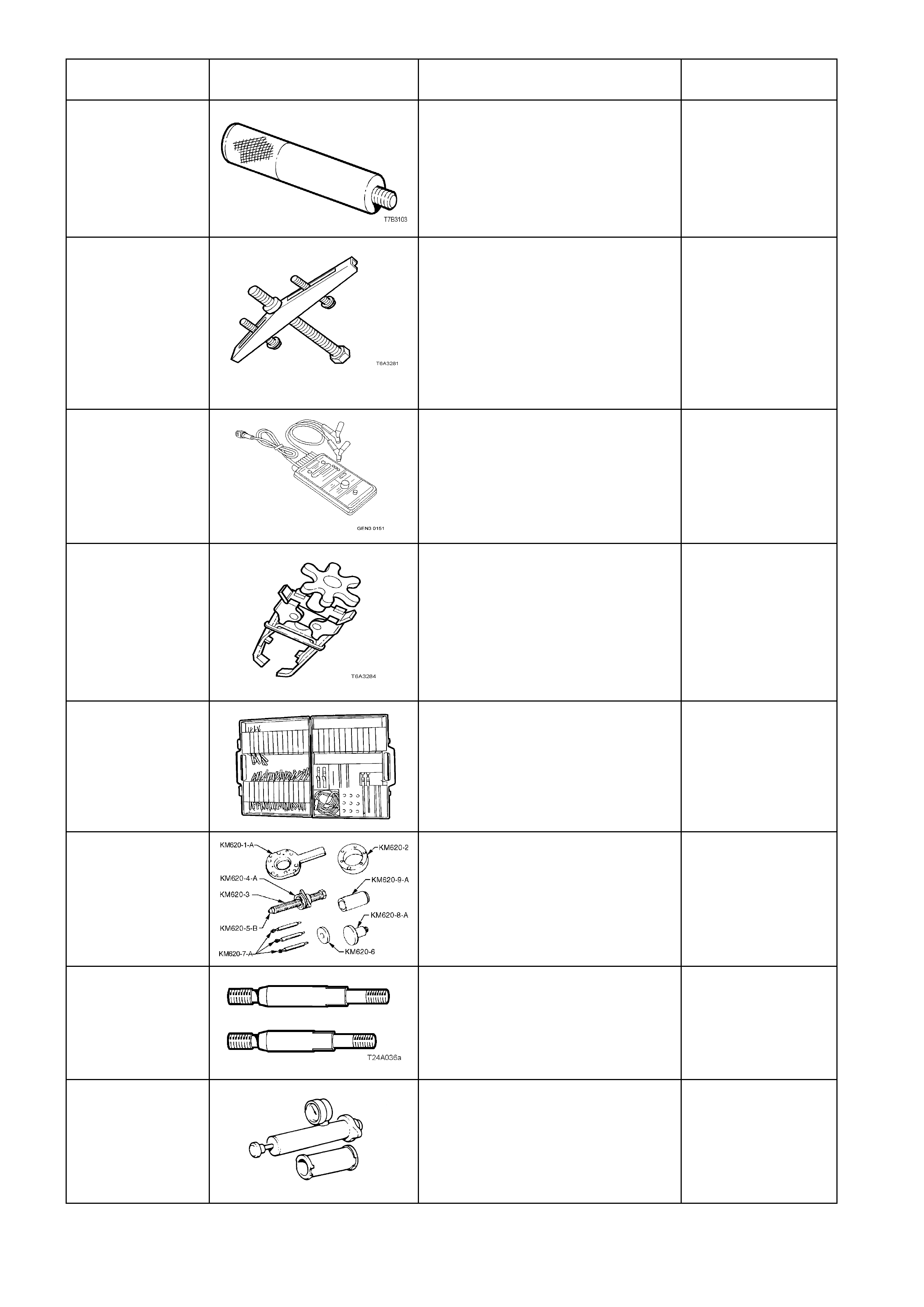
J 39021 FUEL INJECTOR COIL/BALANCE
TESTER
This tester is used in conjunction
with a digital multimeter for testing
fuel injector coils, and cylinder
injector balance testing.
New release.
Mandatory
KD 2078 VALVE SPRING COMPRESSOR
Used to remove valve springs with
cylinder head/s installed.
Used in conjunction with spark plug
adapter J 22794.
Previously released for the V6
engine.
Desirable
KM609 CONNECTOR TEST ADAPTOR
KIT
Used when carrying out electrical
diagnostic circuit checks.
Previously released.
Desirable
KM620-A REMOVER/INSTALLER
Used to remove and install trunnion
flange, rear wheel bearing and
trunnion assembly.
Desirable
KM620-7-AUS SUPPORTS
Used to support flange holding tool,
KM620-1-A when
removing/installing rear
trunnion/wheel bearing from newly
released trailing arm.
Desirable
N/A COOLING SYSTEM PRESSURE
TESTER
Commercially available.
Used in conjunction with adapters J
24460-92
Mandatory
TOOL NUMBER ILLUSTRATION DESCRIPTION TOOL
CLASSIFICATION
N/A TIS CD
Only available to Holden Dealers Mandatory
N/A CLUTCH CENTRING TOOL
Commercially available. Desirable