
SECTION 0C – TECH 2
CAUTION:
This vehicle will be equipped with a Supplemental Restraint System (SRS). A SRS will consist of either
seat belt pre-tensioners and a driver's air bag, seat belt pre-tensioners and a driver's and front
passenger's air bag s or seat belt pre- tensio ners, d riv er’s and fron t p asseng er’s air bag and lef t and rig ht
hand side air bags. Refer to SAFETY PRECAUTIONS, Section 12M Supplemental Restraint System of
this Service Information CD before performing any service operation on, or around any SRS
components, the steering mechanism or wiring. Failure to follow the SAFETY PRECAUTIONS could
result in SRS deployment, resulting in possible personal injury or unnecessary SRS system repairs.
CAUTION:
Whenever any component that forms part of the ABS or ABS/ETC (if fitted), is disturbed during Service
Operations, it is vital that the complete ABS or ABS/ETC system is checked, using the procedure as
detailed in 4 DIAGNOSIS, ABS or ABS/ETC FUNCT ION CHECK, in Section 12L ABS & ABS/ETC, in either
(V6) or (GEN III V8) of this Service Information CD.
1. GENERAL INFORMATION
The TECH 2 is a hand-held diagnostic computer designed specifically to help you diagnose and repair electronic
systems used on Holden vehicles.
When the TECH 2 is attached to a vehicle it can be a very versatile tool. W ith its large, easy-to-read display, the
TECH 2 guides you step-by-step through the testing procedur es. You respond to the TECH 2 through the k eyboard
commanding it to:
• Conduct the test you want to run
• Retrieve the diagnostic data you want
• Control the function you want to monitor
• Program or reprogram a Powertrain Control Module (PCM)
The T ECH 2 gets its power f rom the vehicle to be tes ted and c omm unic ates or inter f ac es with the vehic le elec tronic
systems through the Data Link Connector (DLC), attached to the instrument panel lower right hand trim, to the lef t
of the steering colum n. T ECH 2 can c om m unicate with the following control m odules , if the vehic le is equipped with
these systems.
• Body Control Module (BCM).
• Powertrain Control Module (PCM).
• Powertrain Interface Module (PIM)
• Instrument (INS).
• Supplemental Restraint System (SRS) Sensing and Diagnostic Module (SDM).
• Antilock Braking System / Electronic Traction Control System (ABS/ETC) Control Module.
When connected to the DLC, the TECH 2 can read Diagnostic Trouble Codes (DTC) and diagnostic data.
Depending on the application selected, TECH 2 can also control some systems for troubleshooting or automatic
testing. TECH 2 is also capable of programming Control Modules in conjunction with the Technical Information
System (TIS).
On VT Series II Models equipped with a GEN III engine the PCM does not contain a rem ovable PROM, it uses an
EEPROM (Flash Memory) which is non removable. The PCM is programmed from the factory with the proper
calibrations for vehicle operation. In the event that the PCM is replaced, or an updated calibration is required to
correc t a vehicle's operating c ondition, the PCM will have to be program m ed with the new calibration. Program m ing
is accomplished through the vehicle DLC using the TECH 2 Service Programming System (SPS) and the TIS.
A service replacement PCM EEPROM (Flash Memory) will not be programmed. DTC P0601 and P0602 indicates
the Flash Memory is not programmed or has malfunctioned.
This section of the Service information CD details only the Service Programming System, for all other TECH 2
information refer to Section 0C TECH 2 in the VT Series I Service Information.
Techline
Techline
Techline
Techline
Techline
Techline
Techline
Techline
2. SERVICE PROGRAMMING SYSTEM (SPS)
Caution: Before performing SPS inspect the
TECH 2 DLC cable and the DLC connector and
terminals for damage. Any damage that causes
an open circuit during the programming
procedure could result in irreparable damage to
the PCM.
Battery voltage must be between 12 and 14
volts. The vehicle to be programmed must not
be connected to a battery charger during the
programming procedure. Incorrect battery
voltage could cause programming failure
and/or PCM failure.
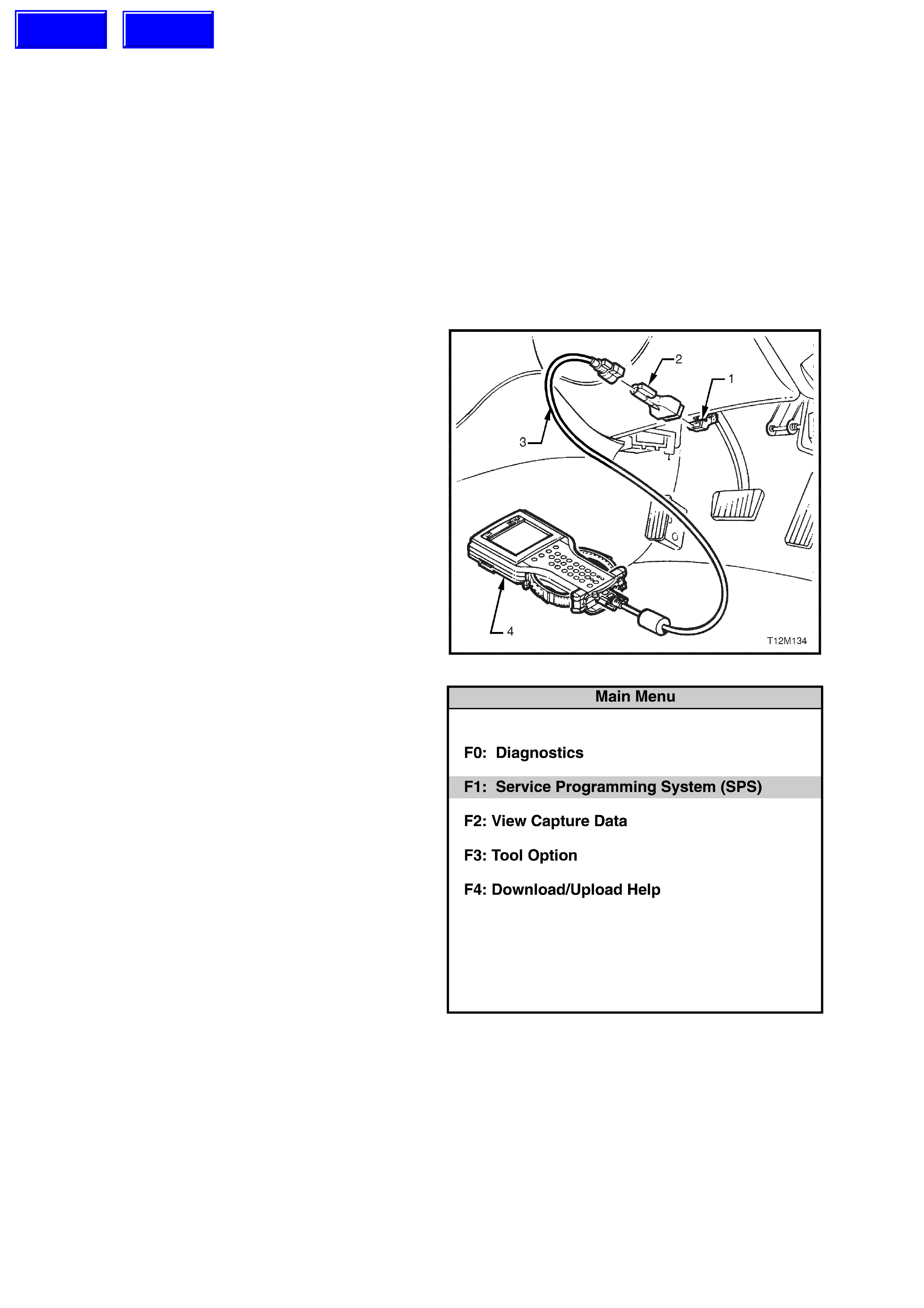
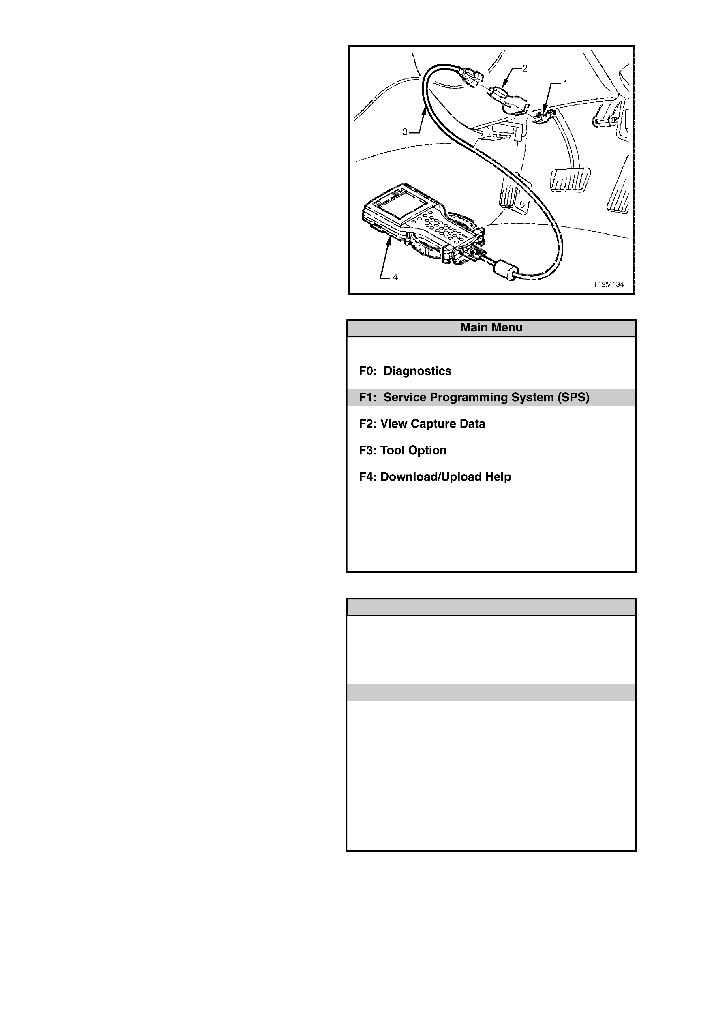
1. Connect DLC cable (3) to TECH 2 (4), DLC
adapter (2) to DLC cable (3) and then DLC
adapter to DLC (1).
Press the TECH 2 PWR button to turn on
TECH 2.
When the TECH 2 title screen is displayed,
press ENTER to continue.
Figure 0C-1 Connecting TECH 2 to the DLC
2. Select F1: Service Programming System
(SPS).
Figure 0C-2 Main Menu
Techline
Techline
3. Select F0: Request Info and follow the
instructions on the screen.
Service Program ming System (SPS)
Version 4.045
F0 : R equ est In fo
Te ch 2 is ready for data upload to TIS
Figure 0C-3 F0: Request Info
4. If there is data already stored, TECH 2 will
display the stored data.
If there is no data stored in TECH 2 then the
following Model Year selection screen (Figure
0C-5) will be displayed.
Press the Continue Soft Key to request new
information.
Keep Data
Service Programming System (SPS)
Version 4.045
Co ntinue and reques t new in fo ?
Data alread y stored in Tech 2!
VIN:
Hardware:
Software:
6H8VTX69FXL438292
----------------
92083995
ContinueMore
Figure 0C-4 Data Already Stored in TECH 2
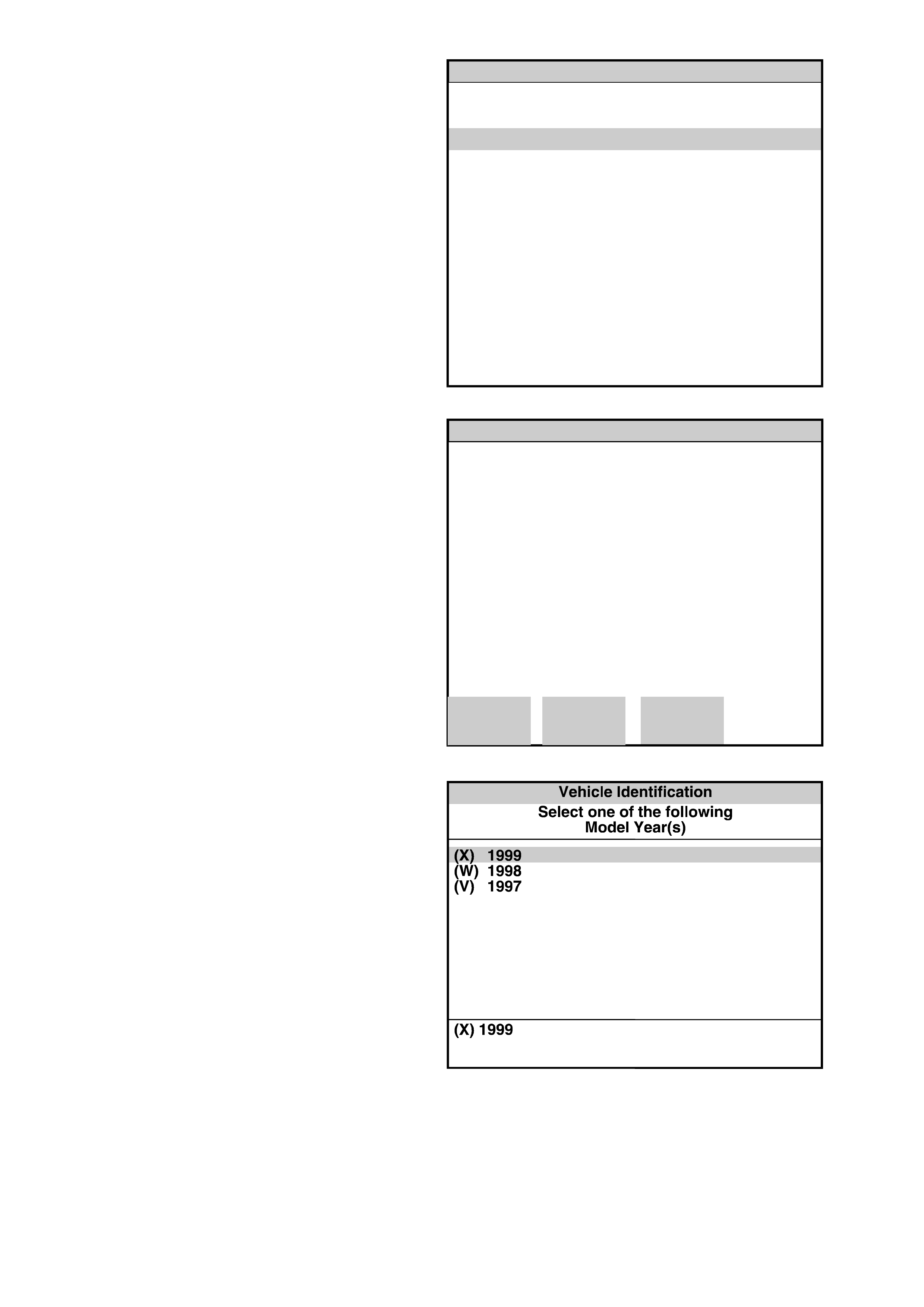
5. Select the correct Model Year for the vehicle
you are working on (X) 1999 with the arrow
keys and the press ENTER.
Figure 0C-5 Model Year Selection
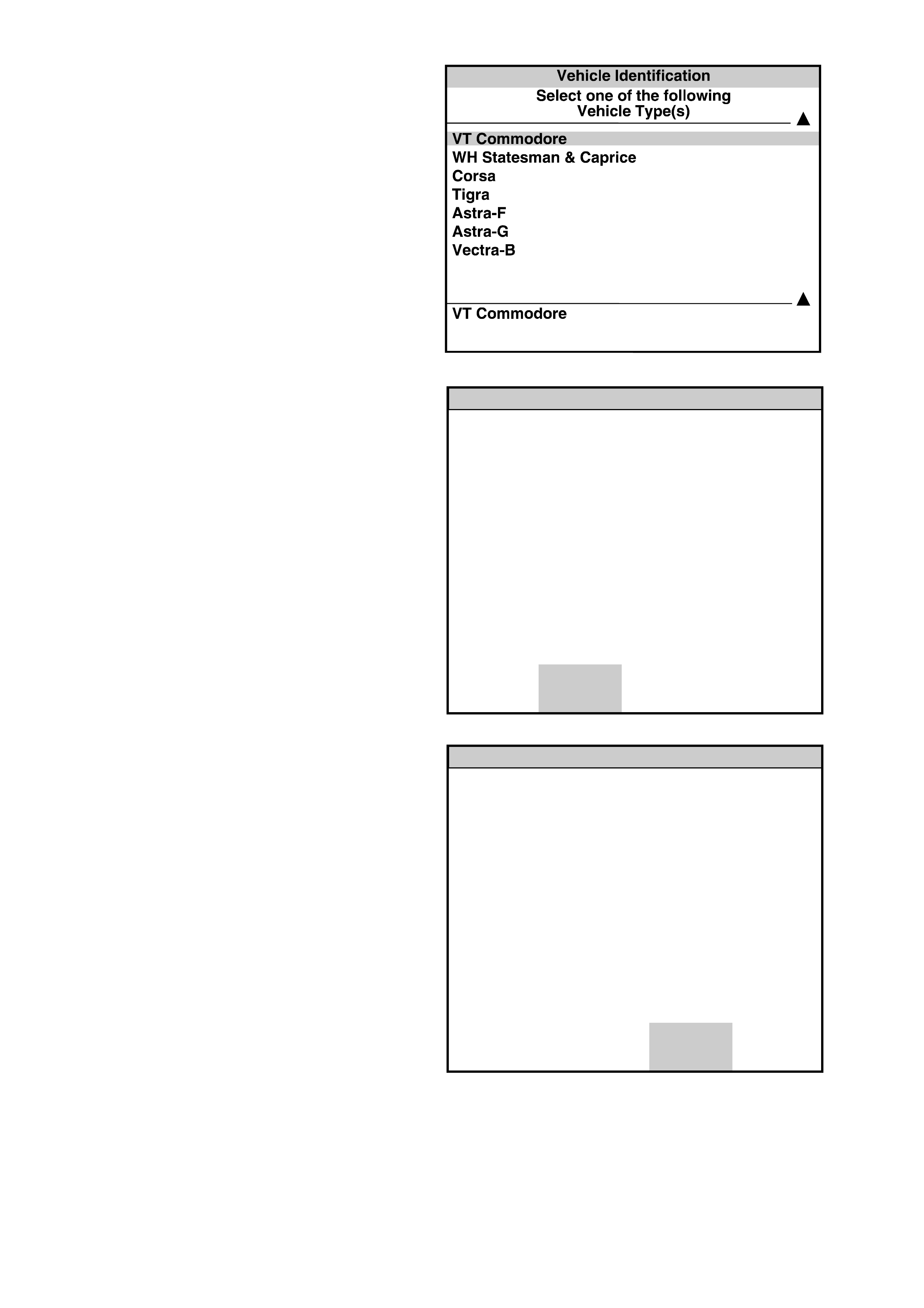
6. Select VT Commodore with the arrow keys
and then press ENTER.
Figure 0C-6 Vehicle Type Selection
7. Turn off Ignition!
Press the Okay soft key to continue.
Service Programming System (SPS)
Version 4.045
Turn off Ig nitio n!
Okay
Figure 0C-7 Service Programming System (SPS)
8. When Ignition is Switched Off! is displayed.
Press the Okay soft key to continue.
Service Programming System (SPS)
Version 4.045
Ignitio n S witched Off!
Okay
Figure 0C-8 Service Programming System (SPS)
9. Turn off all power consuming devices!
(i.e. A/C Headlamps etc).
Turn on ignition!
Engine off and Ignition on?
Press the Okay soft key to continue.
Service Programming System (SPS)
Version 4.045
Turn off all power con su m in g devices!
Tu rn on Ignition!
Eng ine off and ignitio n on?
Okay
Figure 0C-9 Service Programming System (SPS)
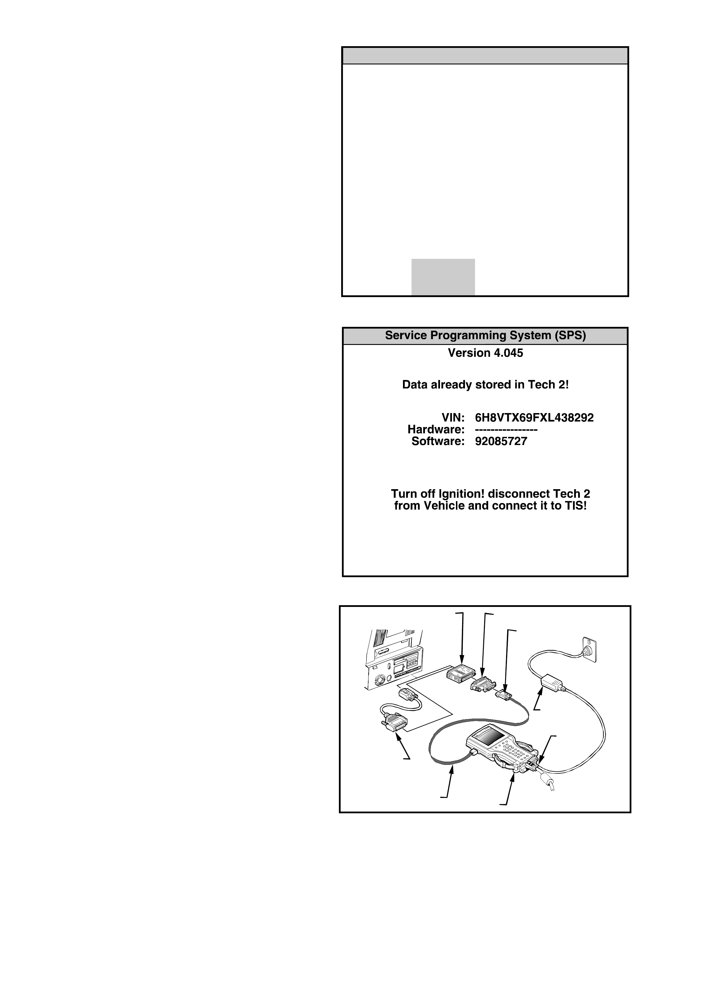
10. The TECH 2 will then read and display the
Vehicle Identification Number (VIN) and ECU
data.
When the TECH 2 screen opposite is
displayed;
Turn off Ignition.
Disconnect TECH 2 from the DLC.
NOTE: If programming a Service Replacement
PCM the VIN number will not be displayed.
Figure 0C-10 ECU Data
11. Connect the RS-232 cable (2) to the TECH 2
(1) RS-232 communication port. Connect the
other end of the RS-232 cable to the DB-9
adapter (3) and then c onnect the DB-9 adapter
(3) to the 25/9 pin adapter (4). Connect the
25/9 pin adapter to the Hardware Key (5) and
then connect the Hardware Key to the serial
port of a Personal Computer (PC) with TIS
installed.
NOTE: If your PC has a 9 pin serial
com munic ation port you will need to fit the 9/25
pin adapter (6) between the Hardware Key (5)
and the serial port of the TIS PC. Connect the
power supply (7) to the TECH 2 power supply
jack (8). Press the PWR button to turn on
TECH 2. TECH 2 should now be at the title
display screen.
54
6
3
8
7
1
2
Figure 0C-11 Connecting TECH 2 to the TIS Personal
Computer
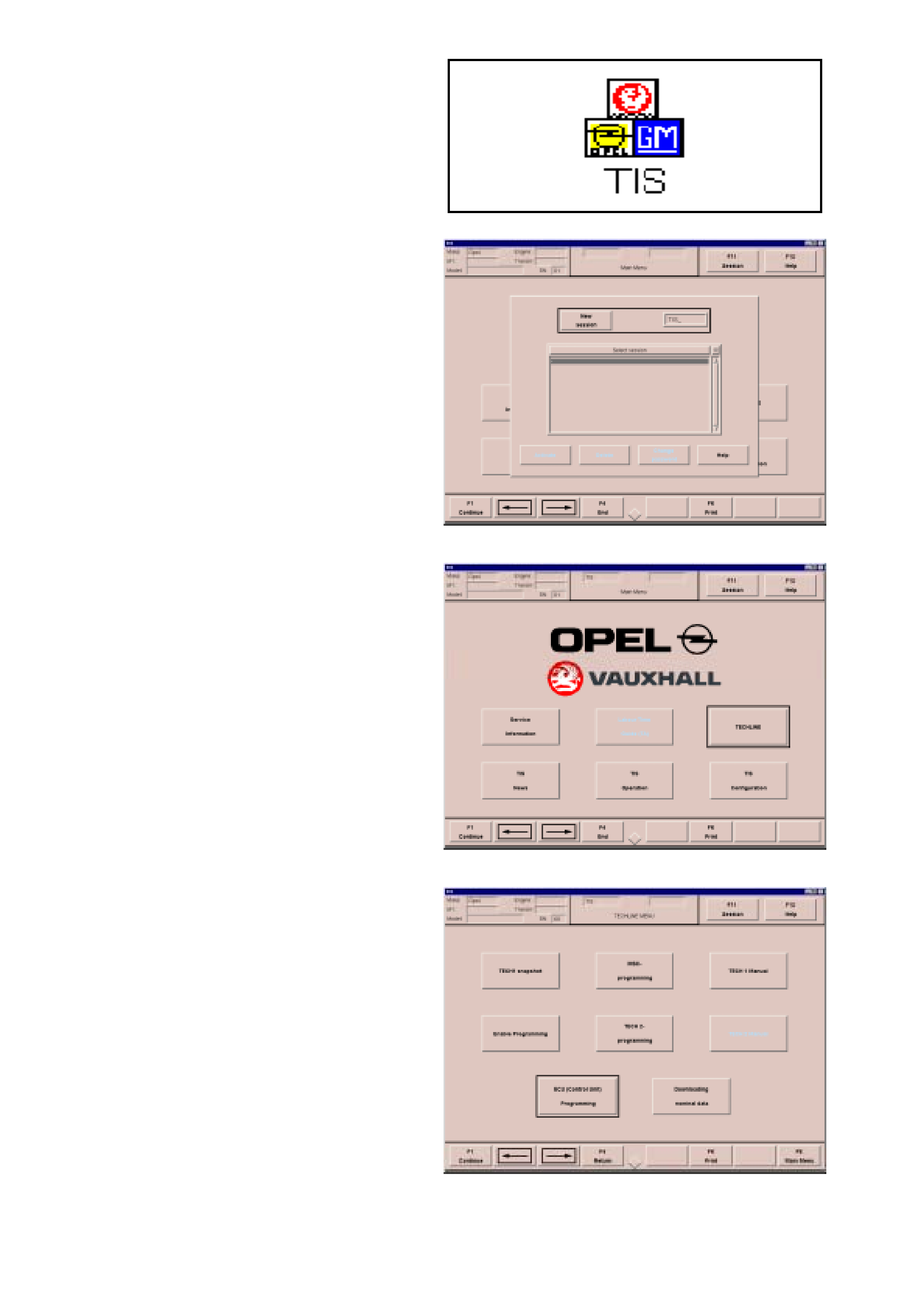
12. Open TIS by double-clicking the TIS Ico n.
Figure 0C-12 TIS Icon
13. Click on NEW SESSION or press ENTER. This
will open a new TIS session.
Figure 0C-13 New Session
14. Position the selection window with the ←
←←
← or →
→→
→
key on the TECHLINE key symbol.
Select F1 Continue or press ENTER to open
TECHLINE.
Figure 0C-14 TIS main Menu
15. Position the selection window with the ←
←←
← or →
→→
→
key on the ECU (Control Unit) Programming
key symbol.
Select F1 Continue or press ENTER to
continue.
Figure 0C-15 Techline Menu

16. Ensure the selection window is positioned on
the Program ECU key symbol. If necessary,
position the selection window with the ←
←←
← or →
→→
→
key.
Select F1 Continue or press ENTER to
continue.
Figure 0C-16 Service Programming System
17. Ensure that TECH 2 is turned on and the start
screen is displayed.
Select OK or press Enter to continue.
Figure 0C-17 Select OK or Press Enter To Continue
18. If the VIN is correct for the vehicle you are
working on go to (b)
If the VIN is to be changed go to (a) then (b)
(a) If the VIN number has to be changed,
position the select ion window with the ←
←←
← or
→
→→
→ key on the VIN dialogue box.
Delete the old VIN using the backspace
key. Then key in the new VIN and press
ENTER.
(b) Ensure the selection window is positioned
on the Engine selection list. If necessary
position the select ion window with the ←
←←
← or
→
→→
→ key.
Using the ↑
↑↑
↑ or ↓
↓↓
↓ key position the highlight bar
on 5.7 LV8 and press ENTER, then select F1
Continue.Figure 0C-18 Basic Vehicle Identification
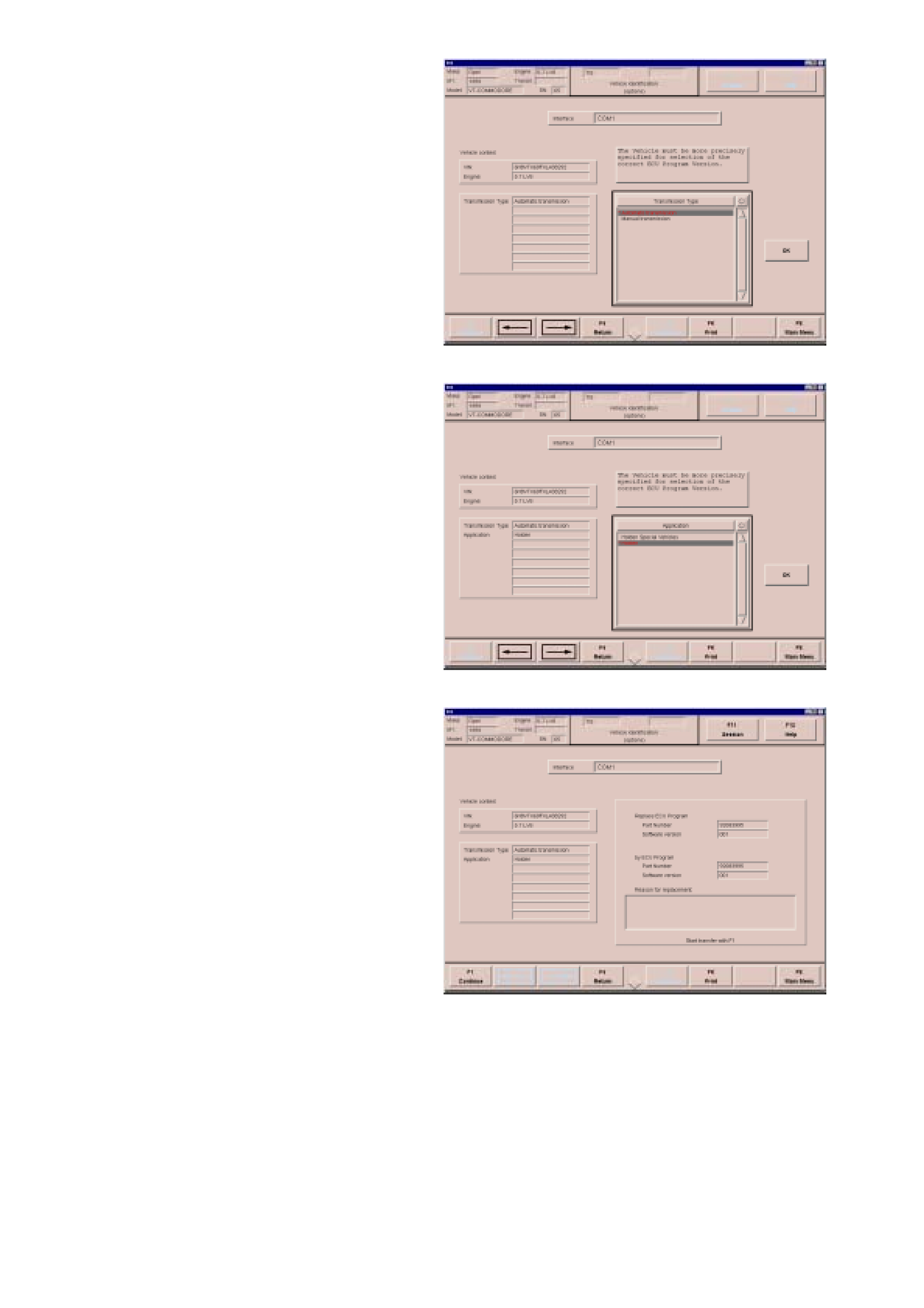
19. Using the ↑
↑↑
↑ or ↓
↓↓
↓ key position the highlight bar
on the correct transmission for the vehicle you
are working on, Automatic or Manual in the
selection list and then press ENTER.
If all the information is correct, position the
selection window using the ←
←←
← or →
→→
→ key on the
OK key symbol and then press ENTER.
Figure 0C-19 Application Identification Options
20. Using the ↑
↑↑
↑ or ↓
↓↓
↓ key position the highlight bar
on Holden in the selection list and then press
ENTER.
If all the information is correct, position the
selection window using the ←
←←
← or →
→→
→ key on the
OK key symbol and then press ENTER.
NOTE: If Holden Special Vehicles (HSV) is
selected, TIS will instruct you to contact HSV
for a replacement PCM. However, it is possible
to program the PCM from a HSV vehicle with
the Holden application. This will allow the
vehicle to be driven, until th e replacement PCM
is obtained from HSV.
Figure 0C-20 Application Identification Options
21. TIS will then display the part number and
software version of the ECU in the vehicle and
the replacement software version number.
Select F1 Continue to start the transfer of ECU
data.
Figure 0C-21 Part Number and Software Version Number
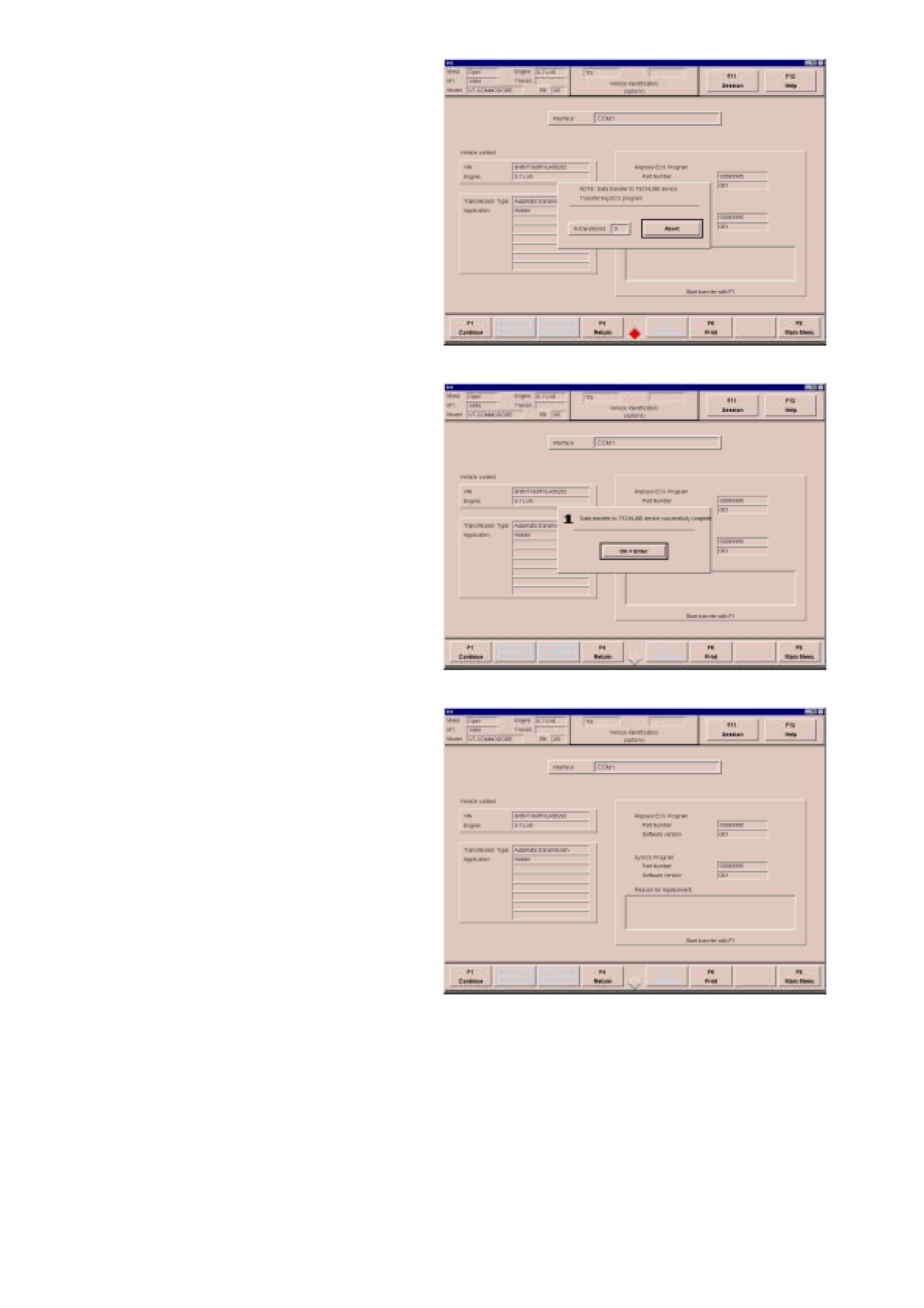
22. The screen display will indicate the progress of
the data transfer as a percentage.
NOTE: DO NOT INTERRUPT THE
CONNECTION.
Figure 0C-22 Data Transfer Percentage
23. When the screen opposite is displayed, the
transfer has been completed, press ENTER to
continue.
Figure 0C-23 Data Transfer successfully Completed
24. Select F8 Main Menu
Select F4 End and select YES to exit TIS.
Tur n off TECH 2.
Disconnect TECH 2 from the PC and the power
supply.
Figure 0C-24 Data Transfer successfully Completed
25. Reconnect TECH 2 to the DLC.
Press the TECH 2 PWR button to turn on
TECH 2.
When the TECH 2 title screen is displayed,
press ENTER to continue.
1 – DLC
2 – DLC Adapter
3 – DLC Cable
4 – TECH 2
Figure 0C-25 Connecting Tech 2 to the DLC (Typical)
26. Select F1: Service Programming System
(SPS).
Figure 0C-26 Main Menu
27. F1: Program ECU will be flashing. TECH 2 is
ready for ECU programming.
Select F1: Program ECU and follow the
instructions on the TECH 2 screen.
Service Programming System (SPS)
Te ch 2 is ready for EC U pro gramm ing !
Version 4.045
F0 : R equest In fo
F1 : Prog ram EC U
Figure 0C-27 Service Programming System (SPS)
28. Turn off all power consuming devices!
(i.e. A/C headlamps etc.).
Turn On Ignition
Engine off and Ignition on?
Press the Okay soft key to continue.
Service Programming System (SPS)
Ver si on 4.045
Turn off all pow er consu m ing d evices!
Tu rn On Ignition
Engine off and Ignition on?
Okay
Figure 0C-28 Service Programming System (SPS)
29. Tech 2 will begin programming the ECU. The
screen display will indicate the VIN Number,
the New End Model Number and the progress
of the download as a percentage.
NOTE: The End Model Number will vary
depending on the application and software
level.
Service Programming System (SPS)
Ver si on 4.045
VIN : 6H8VT X69F X L438292
New E nd M o del Num b er
92083995
Progress
Do wnloading Calibration File
%
Figure 0C-29 Programming in Progress
30. Programming successful ! will be displayed
when programming is completed.
Press the Exit soft key to continue.
Programming has been completed.
Turn off and disconnect TECH 2
Turn off Ignition.
NOTE: If a Service PCM or a PCM from another
vehicle has been installed, a BCM to PCM/PIM Link
will have to be performed. Refer BCM TO
PCM/PIM LINKING procedure in Section 12J-1
for Low Series BCM’s and Section 12J-2 for
High Series BCM’s in the VT Series II Service
Information.
Service Programming System (SPS)
Ver si on 4.045
Program m ing S uccessful
Press [EXIT] Key
Figure 0C-30 Programming Successful