SECTION 4A - REAR SUSPENSION
CAUTION:
This vehicle will be equipped with a Supplemental Restraint System (SRS). A SRS will consist of either
seat belt pre-tensioners and a driver's air bag, seat belt pre-tensioners and a driver's and front
passenge r's air bags or se at belt pre-ten sioner s, drive r’s an d fron t pass enger’ s air bag and left an d rig ht
hand side air bags. Refer to SAFETY PRECAUTIONS, Section 12M, Supplemental Restraint System of
this Service Information CD before performing any service operation on, or around any SRS
components, the steering mechanism or wiring. Failure to follow the SAFETY PRECAUTIONS could
result in SRS deployment, resulting in possible personal injury or unnecessary SRS system repairs.
CAUTION:
Whenever any component that forms part of the ABS or ABS/ETC (if fitted), is disturbed during Service
Operations, it is vital that the complete ABS or ABS/ETC system is checked, using the procedure as
detailed in 4. DIAGNOSIS, ABS or ABS/ETC FUNCTION CHECK, in Section 12L ABS & ABS/ETC (V6
Engine) or (GEN III V8 Engine) of this Service Infromation CD.
CAUTION:
This vehicle may be equipped with LPG (Liquefied Petroleum Gas). In the interests of safety, the LPG
fuel system should be isolated by turning ‘OFF’ the manual service valve and then draining the LPG
service lines , before an y servic e wo rk is car ried o ut o n t he v eh icl e. R ef er to th e L PG le aflet inclu ded w it h
the Owner's Handbook for details or the appropriate Sections of this Service Information CD for more
specific servicing information.
1. GENERAL INFORMATION
Apart from revisions to the suspension specifications to reflect the introduction of the GEN III V8 engine and to
optimise vehicle handling characteristics, all other service operations remain as detailed in 4A REAR
SUSPENSION of this Service Information CD.
2. SPECIFICATIONS
SUSPENSION
Type................................................................................ Independent sem i-tra ilin g arms
Travel
Compression (2/3 compression of bumper).............. Sedan, 85 mm. Station Wagon 98 mm
Rebound ................................................................... Sedan, 123 mm. Station Wagon, 111 mm.
Springs ........................................................................... 'Minibloc'
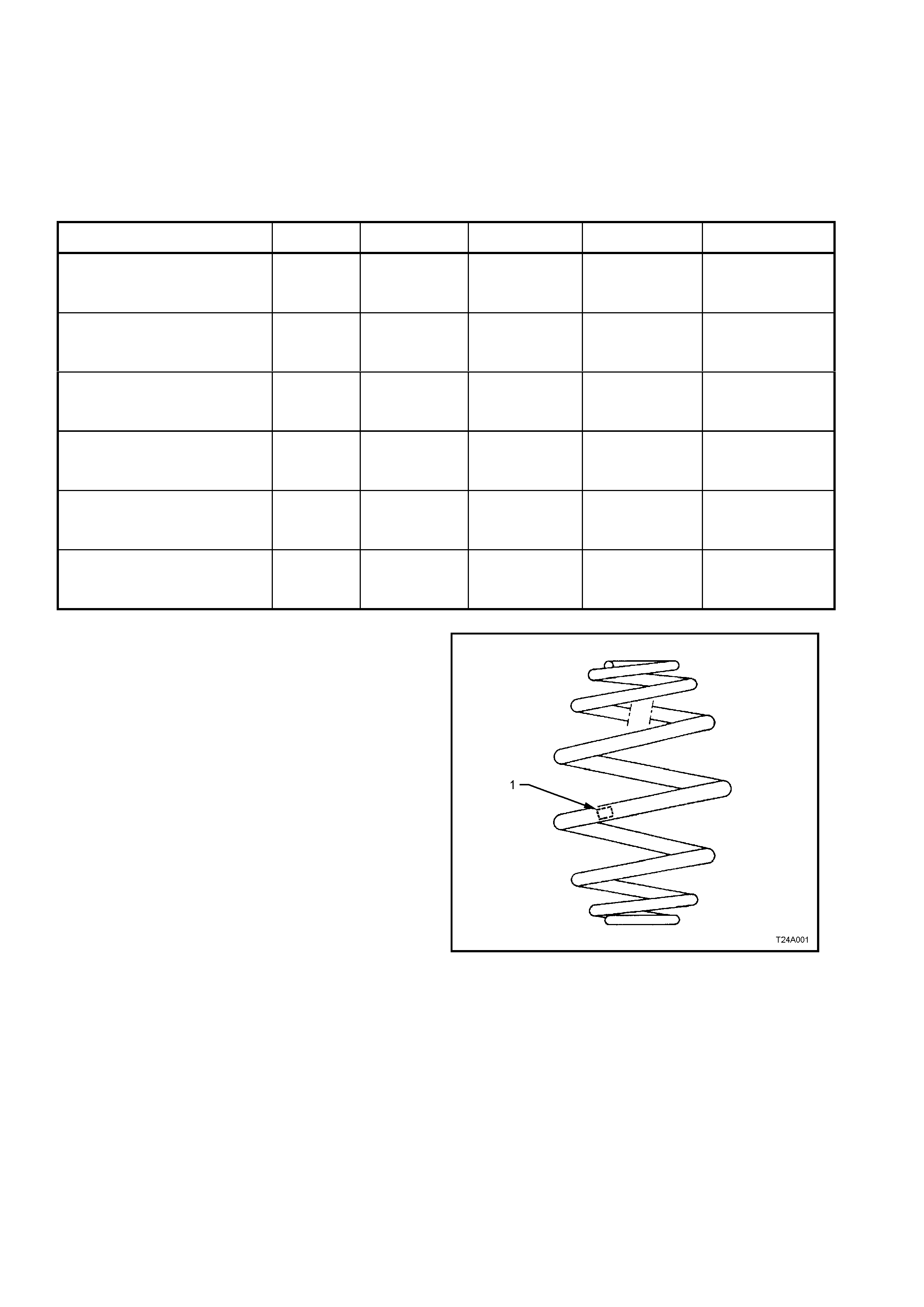
REAR SPRING DETAILS
MODEL TOTAL No.
COILS FREE LENGTH
mm OUTSIDE DIAM.
mm PROD. I.D. CODE
(Tag on spring) SPRING TYPE &
RATE
V6 & V8 ENGINE -
SEDA N MODELS -
STANDARD SUSPENSION 7.8 275 158 EJ VARIABLE
45.0/82.0 N/mm
(4400 ± 150 N @
177 mm)
V6 & V8 ENGINE -
SEDA N MODELS -
FE2 ‘SPORTS’ SUSPENSION 7.8 250 158 EM VARIABLE
51.0/90.0 N/mm
(4400 ± 150 N @
168 mm)
V6 & V8 ENGINE - STATION
WAGON MODELS -
STANDARD SUSPENSION 7.8 279 158 EK VARIABLE
51.0/90.0 N/mm
(5200 ± 150 N @
180 mm)
V6 ENGINE - STATION WAGON
MODE L S -
FE2 ‘SPORTS’ SUSPENSION 7.8 272 158 EL VARIABLE
51.0/90.0 N/mm
(4420 ± 150 N @
188 mm)
V6 ENGINE –
SEDA N MODELS –
V5W ‘COUNTRY PACK
SUSPENSION’
7.8 275 158 EJ VARIABLE
47.0/84.0 N/mm
(4400 ± 150 N @
188 mm)
V6 ENGINE –
STATION WAGON MODELS –
V5W ‘COUNTRY PACK
SUSPENSION’
7.8 279 158 EK VARIABLE
51.0/90.0 N/mm
(5200 ± 150 N @
180 mm)
Figure 4A-1
LEGEND
1. Production Identification Code Tag
REAR SHOCK ABSORBER DETAILS
Type
VT Sedan and Station Wagon Models...................... Twin tube hydraulic
VT Vehicles with FE2 or V5W suspension................ Twin tube hydraulic, gas pressurised
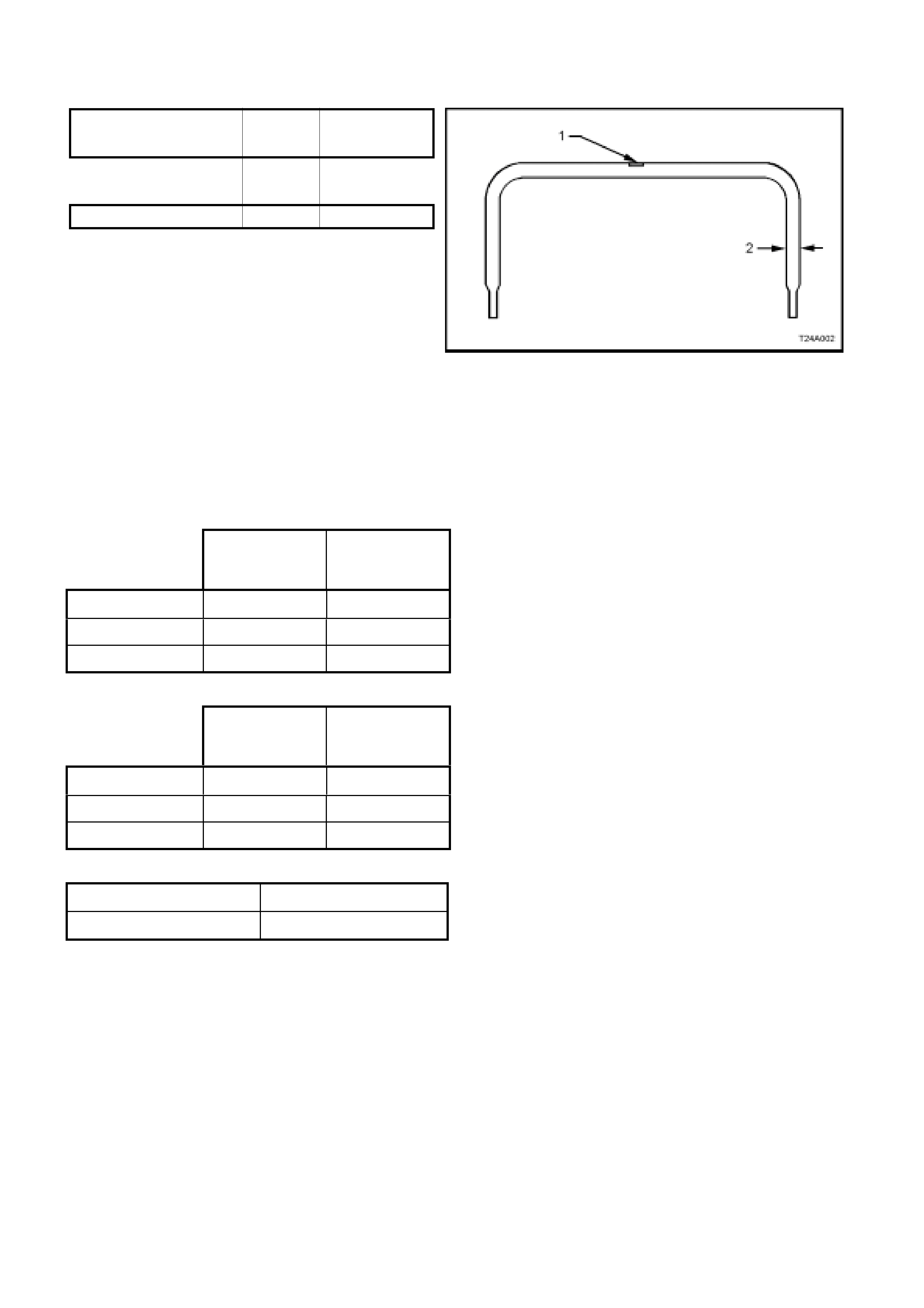
STABILISER BAR DETAILS
Type ........................................................................ Linkless
Dimension Production
MODEL ‘2’ Identification
(Fig 4 A-2) Code (‘1’)
All VT Series II Vehicles,
except for Sedan with FE2 15.0 mm FJ
Sedan Models with F E2 16.0 mm FK
Figure 4A-2
LEGEND
1. Production Identification Code Tag
2. Bar Diameter
REAR SUSPENSION: SERVICE ALIGNMENT DATA
SEDAN MODELS
STANDARD
and V5W
SUSPENSION
FE2
SUSPENSION
REAR TRACK 1586 mm 1592 mm
CAMBER -1° 9' to -2° 6' -1° 27' to -2° 29'
TOTAL TOE -0° 27' to +0° 19' -0° 19' to +0° 32'
STATION WAGON MODELS
STANDARD
and V5W
SUSPENSION
FE2
SUSPENSION
REAR TRACK 1579 mm 1589 mm
CAMBER -1° 7' to -1° 44’ -1° 17' to -2° 14'
TOTAL TOE -0° 27' to +0° 19' -0° 19' to +0° 32'
VARIATION SIDE TO SIDE (ALL MODELS)
Camber 0° 35’ Max.
Wheel Toe 0° 20’ Max
Dimensions shown are for a vehicle at curb height, i.e. vehicle ready to drive with all fluids at the recommended.
levels, the fuel tank full and without driver, passenger/s or luggage.
Refer 2.2 REAR W HEEL ALIGN MENT in Section 4A RE AR SUSPEN SION of the VT Series I Service Inform ation
for specific details