
SECTION 4C - PROPELLER SHAFT AND
UNIVERSAL JOINTS
CAUTION:
This vehicle will be equipped with a Supplemental Restraint System (SRS). A SRS will consist of either
seat belt pre-tensioners and a driver's air bag, seat belt pre-tensioners and a driver's and front
passenge r's air bags or se at belt pre-ten sioner s, drive r’s an d fron t pass enger’ s air bag and left an d rig ht
hand side air bags. Refer to SAFETY PRECAUTIONS, Section 12M, Supplemental Restraint System of
this Service Information CD before performing any service operation on, or around any SRS
components, the steering mechanism or wiring. Failure to follow the SAFETY PRECAUTIONS could
result in SRS deployment, resulting in possible personal injury or unnecessary SRS system repairs.
CAUTION:
Whenever any component that forms part of the ABS or ABS/ETC (if fitted), is disturbed during Service
Operations, it is vital that the complete ABS or ABS/ETC system is checked, using the procedure as
detailed in 4. DIAGNOSIS, ABS or ABS/ETC FUNCTION CHECK, in Section 12L ABS & ABS/ETC (V6
Engine) or (GEN III V8 Engine) of this Service Information CD.
1. GENERAL INFORMATION
W hile the propel ler s haf t a nd u ni vers a l j oin ts f itted t o VT Ser ies II ve hic l es remains unchanged f r om the as sem blies
fitted to VT ser ies models , the prop el ler shaf t as s embly fitte d to v ehicles with the G E N III V8 en gin e h as a cha nged
identification code.
Apart from this fact, all service operations remain as detailed in Section 4C PROPELLER SHAFT AND
UNIVERSAL JOINT S, of this Ser vic e Inf or mation CD, exc e pt f or the ‘Important Serv ice Information ’ no te con tained
in this Section.
W ith the change in propel ler shaft ident ification c odes, an abr idged Spec ifications Section has been repro duced in
this Section.
Techline
Techline
Techline
2. SERVICE OPERATIONS
2.1 GENERAL INFORMATION
IMPORTANT SERVICE INFORMATION
In maintaining the optimum driveline angles and
phasing, a spacer has been included between the
transmission support mounting and the extension
housing on those vehicles fitted with a V6 engine.
When a GEN III V8 engine is fitted to the vehicle,
the catalytic converter bracket is used to provide
the spacer thickness required.
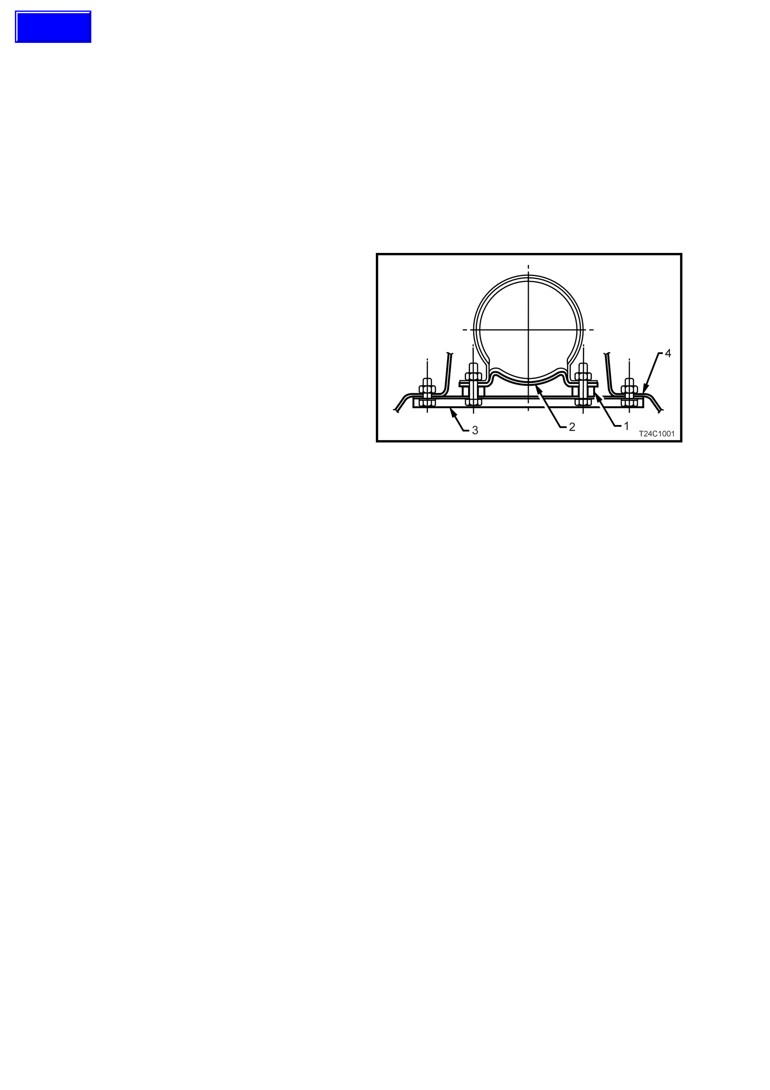
In addition to the transmission support spacer,
spacers (1) have also been placed between the
centre bearing carrier (3) and the centre bearing
cup guide (2), as shown.
Whenever the centre bearing carrier is separated
from the centre bearing cup guide, the original
spacers must be reinstalled in the original
positions. The spacers are NOT to be placed
between the carrier (3) and the underfloor
reinforcement (4).
NOTE 1: The spacer thickness is different for
station wagon models, compared to sedans.
NOTE 2: The centre bearing carrier (3) is offset
and the arrow symbol on the carrier must be
reinstalled, facing forward.
Apart from this information, all other service
operations remain as detailed in Section 4C
PROPELLER SHAFT AND UNIVERSAL JOINTS,
of this Service Information CD.
Figure 4C-1
Techline
3. SPECIFICATIONS
NOTE: For those specifications not included here, refer 4C PRO PEL LER SHAFT AND UNIVERSAL J OINTS, of
the VT Series I Servic e Inf or mation.
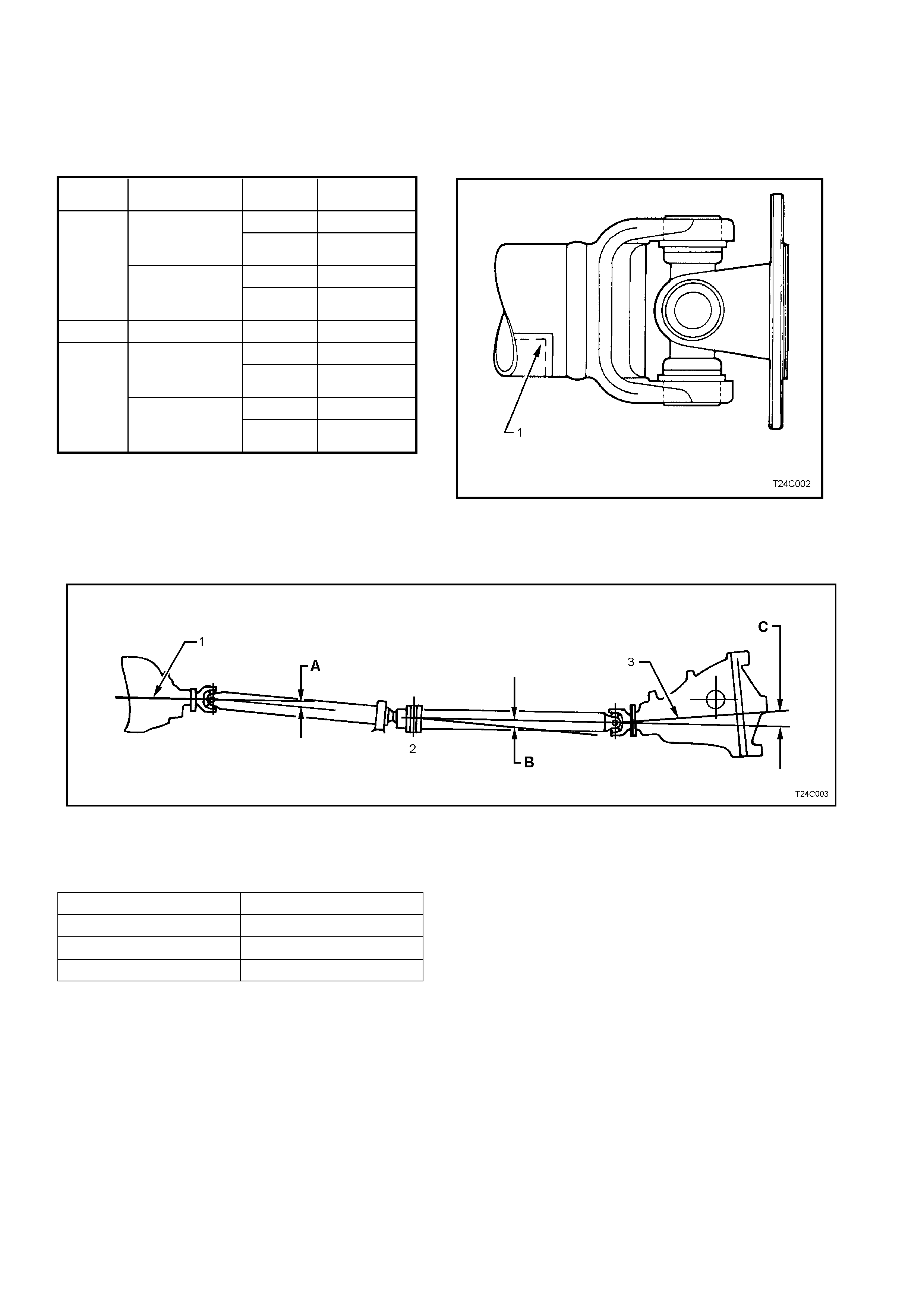
PROPELLER SHAFT IDENTIFICATION
DRIVE LINE ANGLES - VEHICLE AT CURB WEIGHT
1 Engine Crankshaft Centreline 2 Centre Joint 3 Pinion Shaft Centreline
ADriveline Angle ‘A’ BDriveline Angle ‘B’ CDriveline Angle ‘C’
Figure 4C-2
Driveline Angle Degrees – All Models
‘A’ + 0.0° ± 0.5°
‘B’ Greater than ± 1.0°
‘C’ 0.0° ± 0.5°
ENGINE
TYPE TRANSMISSION
TYPE BODY
STYLE PROPELLER
SHAFT CODE
SEDAN JD
MANUAL STATION
WAGON JF
V6 SEDAN JG
AUTOMATIC STATION
WAGON JH
V6 S/C AUTOMATIC SEDAN JG
SEDAN MA
GEN III MANUAL STATION
WAGON MB
V8
SEDAN
JJ
AUTOMATIC STATION
WAGON JK
Legend:
1. Identification Code (See table above).
Positioned in line with the low imbalance
mark on the rear flange. Figure 4C-2