
SECTION 7B3 - MANUAL TRANSMISSION -
GEN III V8 ENGINE
CAUTION:
This v ehicle will be equipped with a Supplemental Restraint System (SRS). An SRS will consist of either
seat belt pre-tensioners and a driver's side air bag, seat belt pre-tensioners and a driver's and front
passenger's side air bags or seat belt pre-tensioners and a driver's and front passenger's side air bags.
Refer to SAFETY PRECAUTIONS, Section 12M Supplemental Restraint System, of this Service
Information CD before performing any service operation on or around any SRS components, the steering
mechanism or wiring. Failure to follow the SAFETY PRECAUTIONS could result in SRS deployment,
resulting in possible personal injury or unnecessary SRS system repairs.
CAUTION:
Whenever any component that forms part of the ABS or ABS/ETC (if fitted), is disturbed during Service
Operations, it is vital that the complete ABS or ABS/ETC system is checked, using the procedure as
detailed in 4. DIAGNOSIS, ABS or ABS/ETC FUNCTION CHECK, in Section 12L ABS & ABS/ETC, VT
Series I Service Information (V6 Engine) or VT Series II Service Information (GEN III V8 Engine) of this
Service Information CD.
1. GENERAL INFORMATION
W ith the introduction of the GEN III V8 engine, the manual transmission available for fitment to this engine, is the
six speed, Tremec, Type T56 (production option MM6).
This manual transmission is optional equipment on GEN III V8 engined Executive models and Berlina.
The ‘T56’ manual transmission is a fully synchronised unit, including reverse gear, with blocking ring type
synchronisers.
The transmission primarily consists of a four piece construction comprising a clutch housing bolted to a front
adaptor plate, transmission case and extension housing. During disassembly, the major number of gear train
components and shift mechanism remain on the transmission front adaptor plate.
Techline
Techline
Techline
Techline
Techline
Techline
Techline
Techline
Techline
Techline
Techline
Techline
Techline

1.1 GENERAL DESCRIPTION
SYNCHRONISER ASSEMBLIES
Each of the four synchroniser hubs are splined to their respective shafts and secured by a snap ring. All
synchromesh blocking rings have a carbon fibre frictional material and are brass, except for 1st and 2nd gears.
The block ing r ings us ed on 1st and 2nd gear s are of a double c one c ons truc tion, with carbon f ibre fric tional material
on each side of the inner member. The purpose of the synchroniser assemblies is to permit clutching to the required
gear.
Synchroniser Action
During synchroniser operation, the synchroniser ring is moved into engagement by the appropriate fork, carrying
with it, three spring loaded synchroniser inserts, located in slots in the synchroniser hub.
The synchroniser ring, together with the inserts, is moved along the hub, placing a load on the three lugs of the
blocking ring.
This initial force is sufficient to seat the blocking ring and start pre-synchronisation because of the friction between
the cone on the constant mesh gear and the blocking ring.
At this stage, gear engagement is prevented as long as there is a dif ferenc e in speed between the mating s urfaces
of the blocking ring and cone of the constant mesh gear. As the speeds between the blocking ring and the gear
cone becom e synchronised, the teeth on the blocking r ing and gear c one line up with the internal splines of the ring,
allowing the ring to engage the teeth on the gear being engaged, completing gear selection.
REVERSE GEAR
The reverse idler gear is in constant mesh with the counter gear extension and the reverse gear, splined to the
mains haf t. When reverse gear is engaged, the revers e s ynchrom es h ring engages the rever se c ons tant mes h gear,
completing the selection.
BEARING SUPPORT
All shafts in the tr ansmis sion ar e suppor ted by taper roller bearings , exc ept f or a par allel roller bear ing at the rear of
the mains haft. The input shaf t gear, front counter shaft gear and rear c ountershaft gear extens ion bearing cups are
a sliding fit in their respective housings. Selective shims are located under each of the bearing cups to control
bearing pre-load or end float (for the countershaft extension).
Each of the constant mesh gears is supported by caged needle roller bearings, except for the reverse idler gear that
has a twin, caged needle roller bearing running on the reverse idler gear shaft.
LUBRICATION
Lubrication of all internal components is by splash feed, provided by the rotating countershaft gear assembly.
SELECTOR MECHANISM
The floor mounted, gearshift control lever operates through a remote lever arrangement onto a single rail
mec hanis m which extends into the tr ansmis sion r ear c as e. T he 1s t/2nd, 3rd/4th, 5th/6th and r ever se s hif t s haf t r ails
are all supported at each end, in the adaptor plate, transmission case or extension housing.
A shift interlock system, prevents engagement of m ore than one gear at a time. T he system consists of a selector
pin and interlock plate mounted on the 1st/2nd and 3rd/4th selector shaft rail.
When any gear is selec ted, the s elec tor pin is aligned with the par tic ular s hif t fork link or s hif t lever , with 5th/6th and
reverse gears. As this selector pin slides within the interlock plate, only the gear selected can be engaged.
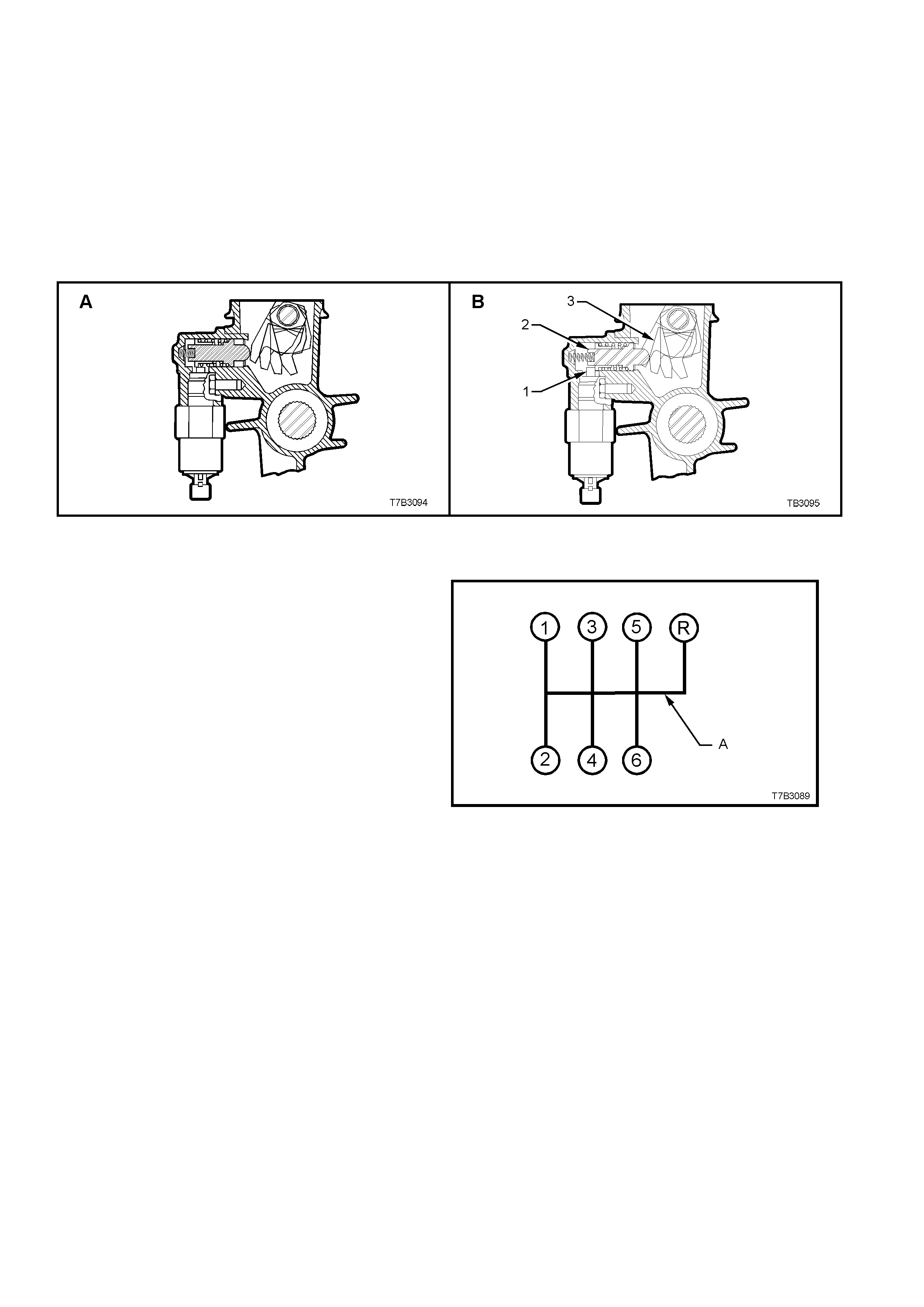
REVERSE LOCKOUT MECHANISM
The transmission is also fitted with a reverse
lockout solenoid assembly that prevents the
selection of reverse gear, above road speeds of 8
km/h. Above this speed, the Powertrain Control
Module (PCM), causes the solenoid plunger (1) to
block the movement of the spring loaded, reverse
lockout plunger (2) (See view ‘B, next).
W hen activated, the r ear offset lever (3) is blocked
from rotating to the reverse selection position.
Figure 7B3-1 - Reverse Lockout Mechanism
SHIFT PATTERN
The shif t pattern is as shown in Figure 7B3-2. Point
‘A’ indicates that reverse gear can be inhibited by
the reverse lockout solenoid assembly, just
described.
Figure 7B3-2 - Transmission Shift Pattern
Refer F igure 7B3-3 f or a sect ioned view of the type
T56 transmission (production option MM6) and
Figure 7B3-4 for an exploded view of the
transmission components.
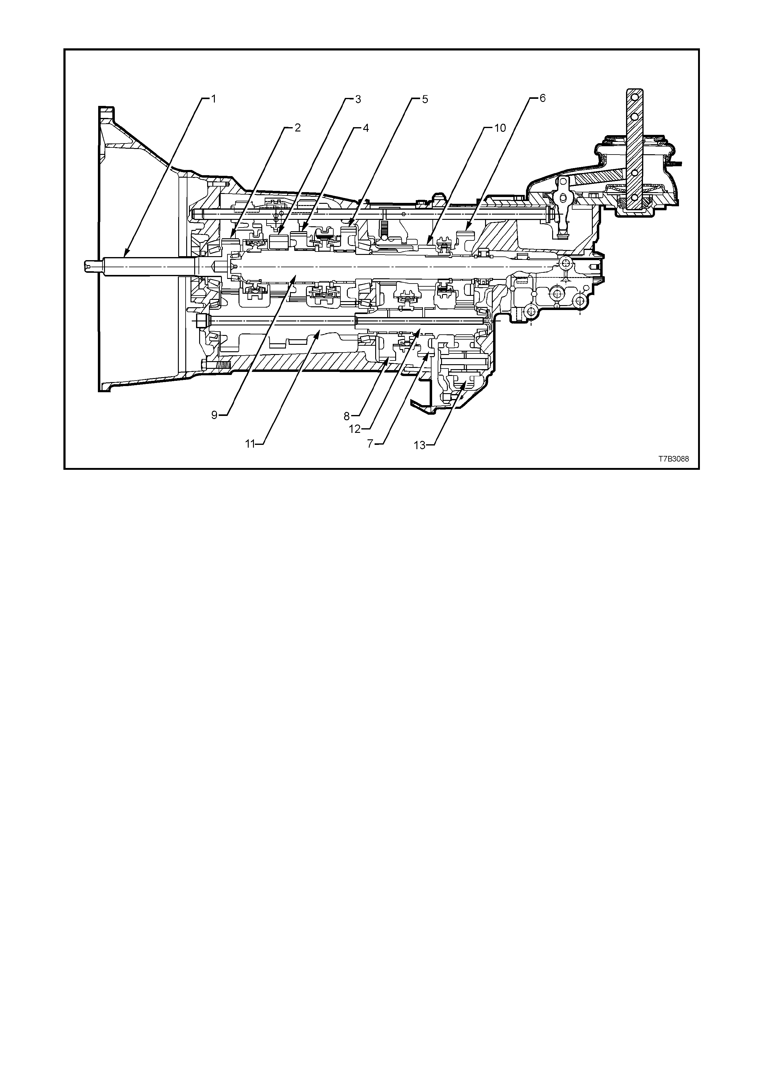
1. Input Shaft
2. Input Shaft Drive Gear
3. Third Speed Driven Gear
4. Second Speed Driven Gear
5. First Speed Driven Gear
6. Reverse Driven Gear
7. Fifth Speed Drive Gear
8. Sixth Speed Drive Gear
9. Mainshaft
10. 5th/6th Speed Compound Gear
11. Countershaft Gear
12. Countershaft Gear Extension
13. Reverse Idler Gear
Figure 7B3-3 - Type ‘T56’ Transmission, Sectioned View
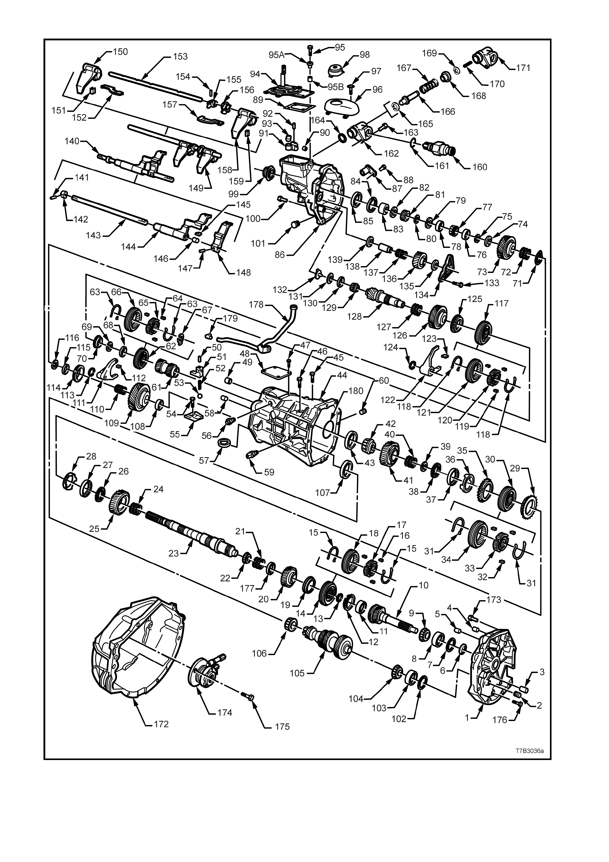
Figure 7B3-4 - Transmission Components

REF
No. PART NAME REF
No. PART NAME REF
No. PART NAME
1.
2.
3.
4.
5.
6.
7.
8.
9.
10.
11.
12.
13.
14.
15.
16.
17.
18.
19.
20.
21.
22.
23.
24
25.
26.
27.
28.
29.
30.
31.
32.
33.
34.
35.
36.
37.
38.
39.
40.
41.
42.
43.
44.
45.
46.
47.
48.
49.
50.
51.
52.
53.
54.
55.
56.
57.
58.
59.
60.
61.
62.
63.
Plate, Transmi ssion A dapt or
Plug
Pin, Dowel (2 plac es)
Pin, Dowel (2 plac es)
Bushing, Shift Rail
Seal, I nput Shaft
Shim , Input S haft
Cup, Input Shaft B eari ng
Bearing, I nput Shaft Tapered
Shaft, Input
Cup, Input Shaft B eari ng
Blocker Ring, 4t h Gear
Ring, Snap
Synchronis er Assembly, 3rd/ 4th
Spring, 3rd/ 4th Synchroniser
Key, 3rd/4th Synchroni ser
Hub, 3rd/4th Synchronis er
Ring, 3rd/4t h Synchronis er
Blocker Ring, 3rd Gear
Gear, 3rd Speed
Bearing, 3rd Gear Needle
Bearing, Mainshaft Small Tapered
Mainshaft
Bearing, 2nd Gear Needle
Gear, 2nd Speed
Washer, Thrust
Cone, Inner
Cone, Frict i on
Blocker Ring, 2nd Gear
Synchronis er Assembly, 1st/2nd
Spring, 1s t/2nd Sync hroni ser
Key, 1s t /2nd Synchroni ser
Hub, 1st / 2nd Synchronis er
Ring, 1st/2nd Sync hroni ser
Blocker Ring, 1s t Gear
Cone, Frict i on
Cone, Inner
Washer, Thrust
Ring, Snap
Bearing, 1s t Gear Needle
Gear, 1st Speed
Bearing, Mains haf t Large Tapered
Cup, Mainshaft Bearing
Case, Transmission
Bolt, Shift Lever Gui de
Bolt, Shift Lever Gui de
Bolt, Shift Detent Cover
Cover, Shift Detent
Bushing, Shift Rail
Pin, Front Offset Lever Rol l
Lever, Front Offset
Spring, S hi ft Detent
Ball, Shift Detent
Bolt, S hi ft Guide Pl ate
Plate, S hi f t Guide
Enhancer, Shift
Magnet (2 places)
Pin, Dowel (2 plac es)
Switch, B ack-up Lamp
Plug, Fill
Gear, 5th/6th Driven
Synchronis e r A ssembly, Reverse
Spring, Reverse Synchroniser
64.
65.
66.
67.
68.
69.
70.
71.
72.
73.
74.
75.
76.
77.
78.
79.
80.
81.
82.
83.
84.
85.
86.
87.
88.
89.
90.
91.
92.
93.
94.
95.
95a.
95b.
96.
97.
98.
99.
100.
101.
102.
103.
104.
105.
106.
107.
108.
109.
110.
111.
112.
113.
114.
115.
116.
117.
118.
119.
120.
121.
122.
Key, Revers e Synchronis er
Hub, Reverse S ync hroni ser
Ring, Reverse Synchronis er
Retainer, Reverse Synchroni ser
Key
Washer, Thrust
Ring, Snap
Blocker Ring, Revers e Gear
Washer, Wave
Bearing, Reverse Gear Needle
Gear, Reverse
Washer, Thrust
Ring, Snap
Spacer
Bearing, Rear Mains haf t Tapered
Spacer
Ring, Snap
Ring, Snap
Ring, Speedometer P ul se
Ring, Snap
Ring, Seal i ng
Ring, Snap
Cup, Mainshaft Bearing Rear
Housing, Transmi ssion E xtensi on
Sensor, Elect roni c Speed
Bolt, S peed Sensor
Gasket, Shifter Assembly Cover
Bushing, Shift Rail
Lever, Rear Offset Shi ft
Pin, Rear Of fset Shift Lever Rol l
Cup, Is ol at or
Shifter Assembly
Bolt, Shifter Assembly
Distance Piec e, Shif t Cover Bolt
Sleeve, I nsulati ng
Cover, Shifter Assembly
Screw, Shifter Assembly Cover
Boot, Shifter
Seal and Boot , Rear Output
Bolt, Transmi ssion Extens i on
Housing
Plug, Drain
Shim, Countershaft
Cup, Counters haf t Bearing
Bearing, Count ershaft Tapered
Countershaft
Bearing, Count ershaft Tapered
Cup, Counters haf t Bearing
Washer, Thrust
Gear, 6th Drive
Bearing, 6t h Gear Needl e
Fork, Reverse Shift
Pad, Reverse Shift Fork
Circlip
Blocker Ring, 6t h Gear
Spacer
Ring, Snap
Synchronis er Assembly, 5t h/6th
Spring, 5t h/6th Sync hroni ser
Key, 5th/6th Synchroniser
Hub, 5th/6th Synchroniser
Ring, 5th/ 6th Synchroniser
Fork, 5th/6th Shift
123.
124.
125.
126.
127.
128.
129.
130.
131.
132.
133.
134.
135.
136.
137.
138.
139.
140.
141.
142.
143.
144.
145.
146.
147.
148.
149.
150.
151.
152.
153.
154.
155.
156.
157.
158.
159.
160.
161.
162.
163.
164.
165.
166.
167.
168.
169.
170.
171.
172.
173.
174.
175.
176.
177.
178.
179.
180.
Pad, 5th/ 6th Shif t Fork
Circlip
Blocker Ring, 5t h Gear
Gear, 5th Drive
Bearing, 5t h Gear Needl e
Extension, Countershaft
Bearing, Count ershaft Extension
Tapered
Cup, Counters haf t Extension
Bearing
Shim , Countershaft Extens i on
Funnel, Oil
Bolt, Reverse Idler Shaft B racket
Brack et, Reverse Idler Shaf t
Washer, Reverse Idler Gear Thrust
Gear, Reverse I dl er
Bearing, Reverse Idler Gear Roll er
Shaft, Reverse Idl er Gear
Washer, Reverse Idler Gear Thrust
Rail As sem bl y, 5th/6th, Reverse
Shift
Pin, Roll
Collar
Rail, Shift
Lever, 5th/6th Shif t Rail
Pad, 5th/6th Shi f t Rail Lever
Bushing, 5th/6t h Shift Rai l Lever
Pin, Roll
Lever, Reverse S hi ft Rail
Rail As sembl y, 1st/2nd, 3rd/4th
Shift
Fork, 1s t /2nd Shift
Pad, 1st/2nd Shift Fork
Link, S hi ft
Rail, 1s t/2nd 3rd/4t h Shift
Pin, Roll
Pin, Selector
Plate, Interloc k
Link, S hi ft
Fork, 3rd/4th Shif t
Pad, 3rd/4t h Shift Fork
Solenoid, Reverse Lockout
O-Ring, Reverse Lockout Solenoid
Body Assem bl y, Reverse Lockout
Bolt, Reverse Lock out Assem bl y
O-Ring, Reverse Lockout Ass y
Circlip
Plunger, Revers e Lockout
Spring, Revers e Lockout Outer
Collar, Revers e Lockout
‘C’ Clip
Spring, Reverse Lockout Inner
Body, Revers e Lockout
Housing, Cl utch
Bolt, Cl utch Hous i ng t o Adaptor
Ass embly, Cl utch S l ave Cyl i nder
Bolt, Clutc h S l ave Cyl inder
Bolt, Transmi ssion A dapt or Plate
Spacer
Tube, Vent
Fitting, V ent Tube
O-Ring, Mainshaf t
Legend - Transmission Components

POWER FLOWS
The input s haft drive gear, third, sec ond and first speed gears ar e in constant mes h with the counters haft gear. As
the countershaf t gear extension is s plined to the end of the countershaf t gear, reverse drive gear at the end of this
extension, rotates with the countershaft gear.
Theref ore, when the engine is running with the clutch engaged, engine torque is trans ferred to the input shaf t drive
gear and through the countershaft gear to the third, second, first speed and reverse gears at all times.
The schematics in Figure 7B3-5 relate to the following descriptions:
Neutral
In neutral, with the clutch engaged, the input shaft drive gear turns the countershaft gear and countershaft
extension. The countershaft gear turns the constant mesh gears of 3rd, 2nd, 1st and reverse gears because no
synchroniser assemblies are engaged. As these constant mesh gears are supported on roller bearings, they will
also rotate with the countershaft gear.
As the 5th/6th compound gear is splined to the mainshaft, these constant mesh gears, mounted on the
countershaft extension, will remain stationery while the vehicle is stopped.
First Gear
In first gear, the first/second speed synchroniser ring is moved rearward to engage the first speed gear, which is
being turned by the counters haf t gear. Bec aus e the f irs t/s econd s peed s ynchroniser hub is splined to the mains haf t,
torque is transferred to the mainshaft from the first speed gear through the synchroniser ring and hub, at a speed
reduction of 2.66:1.
Second Ge ar
In second gear, the f ir st/s ec ond s peed synchroniser r ing is moved f or ward to engage the sec ond s peed gear , which
is being turned by the countershaft gear. Because the first/second speed synchroniser hub is splined to the
mainshaft, torque is transferred to the mainshaft from the second speed gear through the synchroniser ring and
hub, at a speed reduction of 1.78:1.
Third Gear
In selecting third gear, the first/second speed synchroniser ring moves to the neutral position and the third/fourth
speed synchroniser ring is moved rearward to engage the third speed gear. As this gear is being turned by the
countershaft gear, the engagement of the ring with the third speed gear, torque is transferred to the mainshaft
because the third/fourth speed synchroniser hub is splined to the mainshaft. The mainshaft the turns at a speed
reduction of 1.30:1
Fourth Gear
In fourth gear, the third/fourth speed synchroniser ring is moved forward to engage the input shaft drive gear.
This engagement of the input shaft drive gear with the third/fourth synchroniser ring and hub assembly, transfers
torque directly to the mainshaft.
While the countershaft gear and countershaft extension is still rotating, no torque transfer takes place but the
spinning gear continues to lubricate the internal transm ission c omponents by the ‘splash’ m ethod. As the m ainshaf t
is effectively joined to the input shaft, the drive is direct with a ratio of 1.00:1.
Fifth Gear
In fifth gear, which is the f irs t of the over drive r atios , the first/s ec ond and third/fourth s peed synchroniser r ings mus t
be in the neutral position. The fifth/s ixth speed synchroniser r ing is moved rearward to engage the f ifth speed drive
gear, supported on the countershaft extension by a caged needle roller bearing. This engagement of the ring with
the fifth speed constant mesh gear, allows torque to be transferred from the countershaft gear extension to the
mainshaft, via the splined synchromesh hub and the splined fifth/sixth speed compound driven gear. This speed
generates an overdrive ratio of 0.74:1.
Sixth Gear
In sixth gear, the fifth/sixth speed synchroniser ring is moved forward to engage the sixth speed drive gear,
supported on the countershaft extension by a caged needle roller bearing. This engagement of the ring with the
sixth speed constant mesh gear, allows torque to be transferred from the countershaft gear extension to the
mainshaft, via the splined synchromesh hub and the splined fifth/sixth speed compound driven gear. This speed
generates an overdrive ratio of 0.50:1.
Reverse Gear
In reverse gear, the reverse synchronis er ring is m oved rearward to engage the m ainshaft m ounted, rever se driven
gear. This allows torque to be transferred from the countershaft extension gear through the reverse idler gear
(revers ing direction of r otation) to the m ainshaft rever se driven gear. As the reverse synchromes h hub is splined to
the mains haft, this causes the mainshaf t to rotate in the opposite direction to the input shaf t drive gear, at a speed
reduction of 2.90:1.
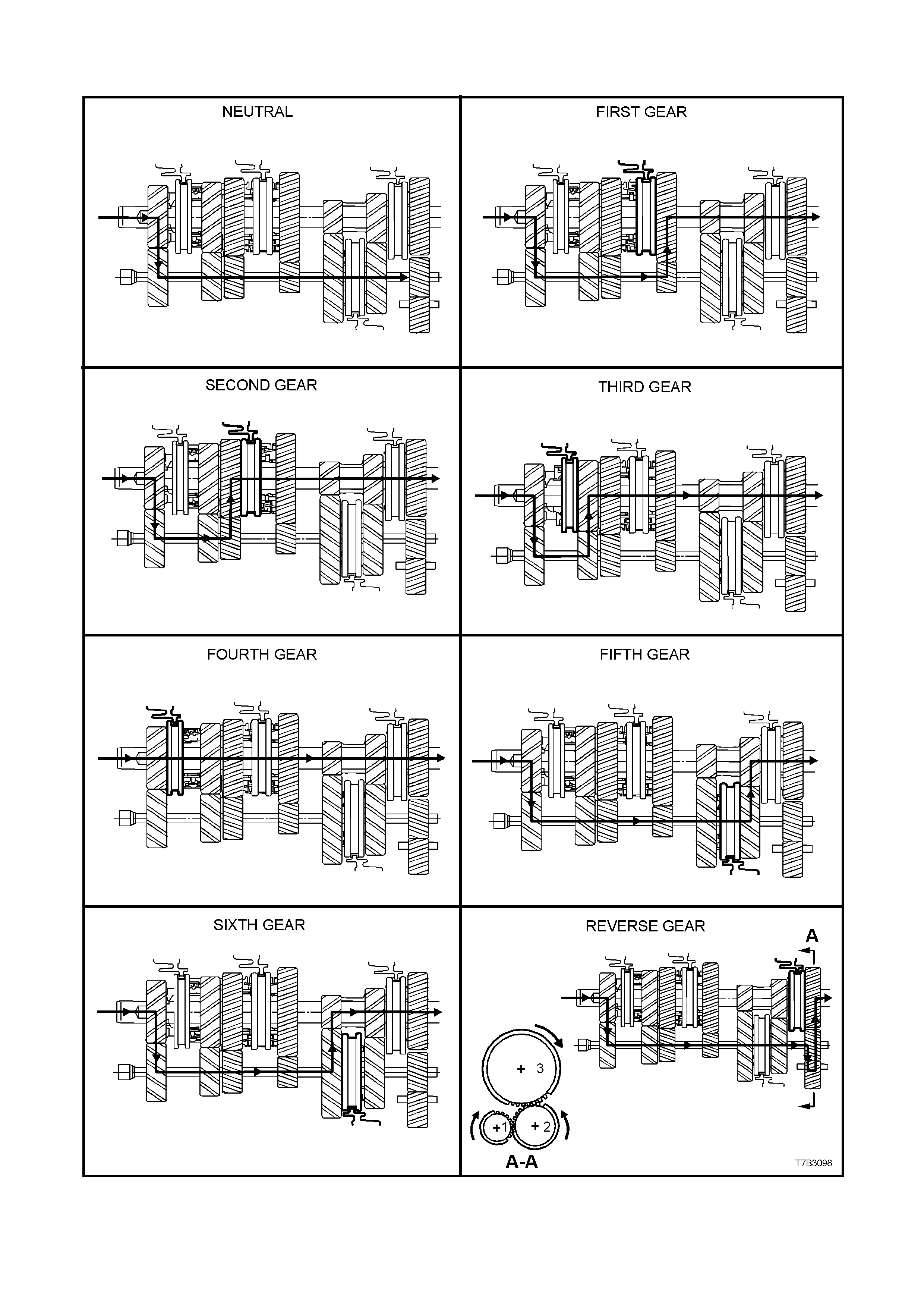
MANUAL TRANSMISSION POWER FLOWS
Figure 7B3-5
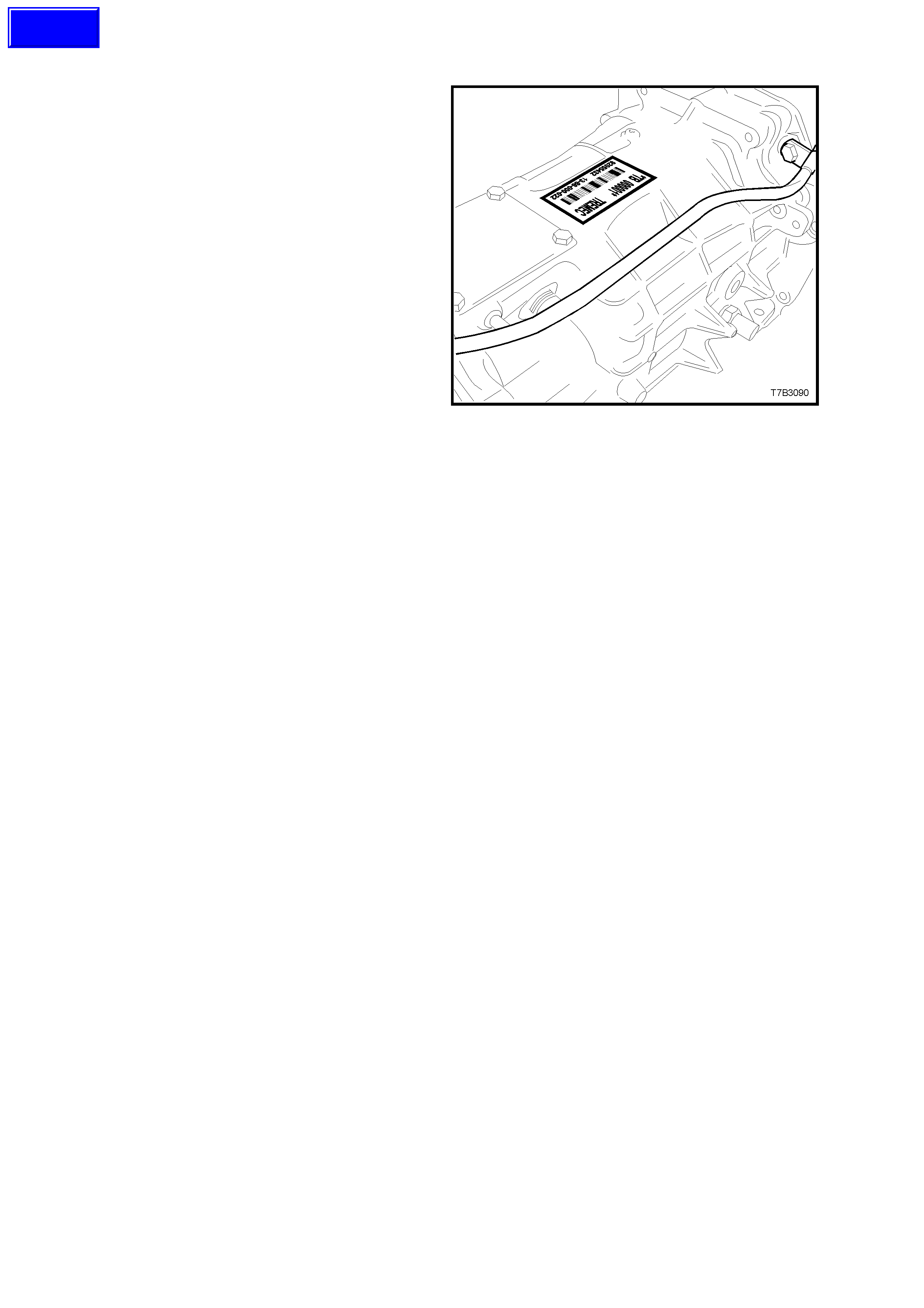
1.2 TRANSMISSION SERIAL NUMBER
The transmission serial number is located on a
self-adhesive decal attached to the top of the
transmission case.
This number provides coded information which
could be significant to parts interpretation and
should be referred to when ordering replacement
parts.
In addition, an identification tag is attached to the
transmission under an extension housing bolt, on
the right hand side. Refer Figure 7B3-8.
Figure 7B3-6
Techline

2.2 CHECKING TRANSMISSION LUBRICANT LEVEL
Important: This transmission is classified as
being a “Fill for Life” transmission and
checking the lubricant level is not
recommended.
The only time that fluid level checking would be
appropriate, would be after c orr ec tion of a f luid leak
that did not require the transmission to be fully
drained and/or removed from the vehicle.
1. Raise the vehicle f ront and r ear and support on
safety stands, ensuring that the vehicle is level.
Refer to Section 0A GENERAL
INFORMATION of the VT Series I Service
Information, for the location of jacking points.
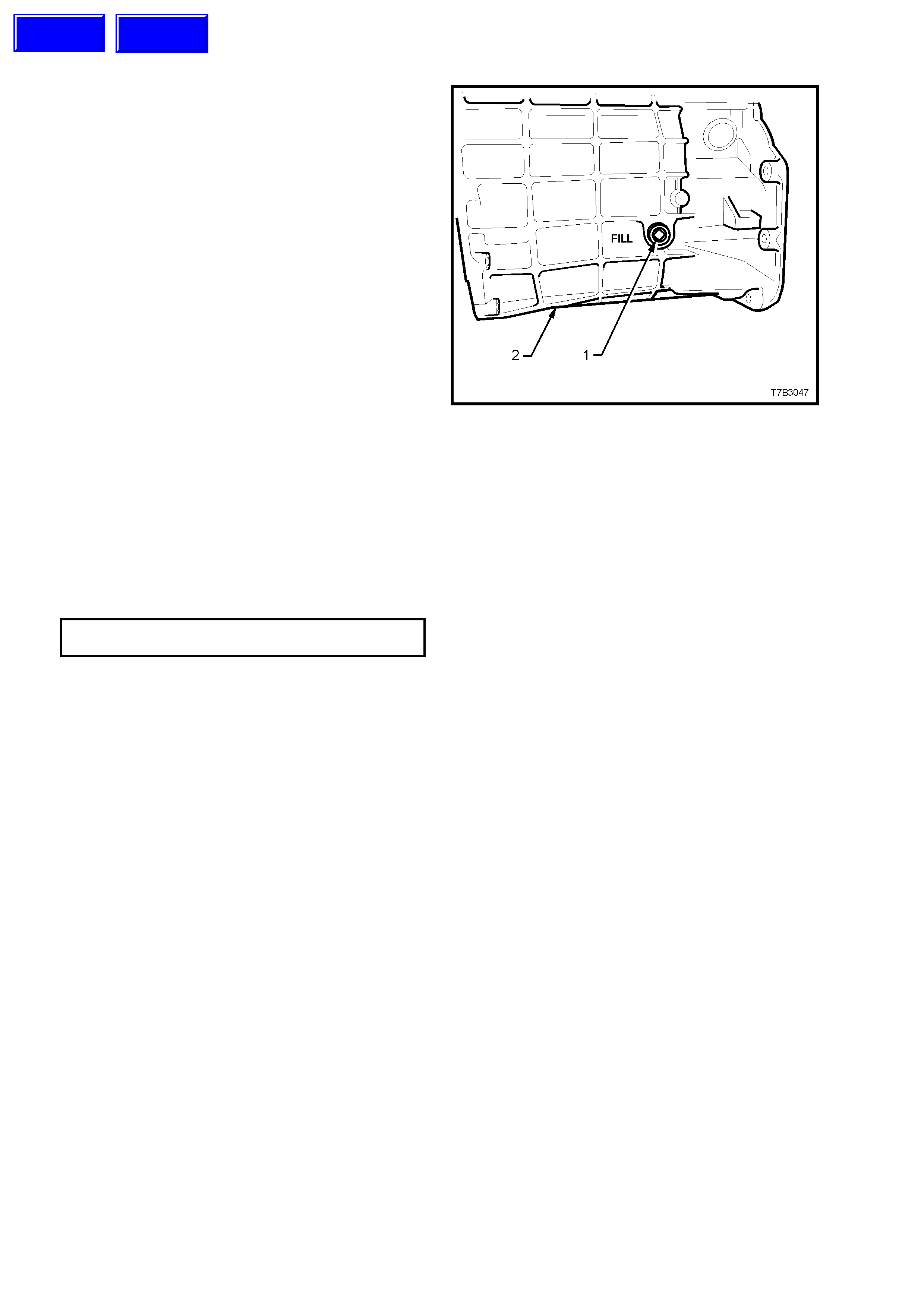
2. Place a drain tray beneath transmission and
remove transmission filler plug (1) from left
hand side of transmission case (2), using a 3/8”
drive socket bar.
NOTE: Depending on the severity of the loss, fluid
will probably flow from the filler plug hole, following
removal.
3. Allow excess fluid to drain until flow stops. If
required, top up fluid level until it does flow out.
4. Clean the threads of the f iller plug, apply thread
sealant such as Loctite 565 or equivalent (GM
P/N 12346004), then reinstall filler plug,
tightening to the correct torque specification.
Do not apply Teflon thread tape to the plug
threads.
TRANSMISSION FILLER PLUG
TORQUE SPECIFICATION 20 - 34 Nm
5. Rem ove the back- up lam p switch as detailed in
3.1 BACK-UP LAMP SWITCH, Replace in this
Section.
6. Using commercially available fluid dispensing
equipment, add a measured, 0.5 litres of the
recommended lubric ant to the trans miss ion, via
the back-up lamp switch threaded hole in the
transmission case.
7. Reinstall the back-up lamp switch, as detailed
in 3.1 BACK-UP LAMP SWITCH, Replace in
this Section, then lower the vehicle to the
ground.
Figure 7B3-1
Techline
Techline
2.3 DRAINING AND REFILLING TRANSMISSION
Should a lubricant change be required, then the
following procedure should be adopted.
1. To drain transmission, jack up vehicle front
and rear and support on safety stands.
Refer to Section 0A GENERAL
INFORMATION of the VT Series II Service
Information, for the location of jacking points.
2. Place a drain tray beneath transmission and
remove filler plug (refer ‘1’ in Figure 7B3-7)
and then the drain plug from the transmission
extension housing (‘1’ in Figure 7B3-8), using
a 3/8” drive socket bar.
3. After draining, clean the threads of the drain
plug, apply thread sealant such as Loctite 565
or equivalent (GM P/N 12346004) then
reinstall, tightening to the correct torque
specification.
NOTE: Do not apply Teflon thread tape to the plug
threads.
TRANSMISSION DRAIN PLUG 20 - 34
TORQUE SPECIFICATION Nm
4. Refill transmission to correct level, refer to
2.2 CHECKING TRANSMISSION
LUBRICANT LEVEL in this Section.
Figure 7B3-8
Techline
3. MI NOR SERVICE OPERATIONS
3.1 BACK-UP LAMP SW ITCH
REPLACE
1. Raise front of vehicle and support on safety
stands.
Refer to Section 0A GENERAL
INFORMATION of the VT Series II Service
Information, for the location of jacking points.
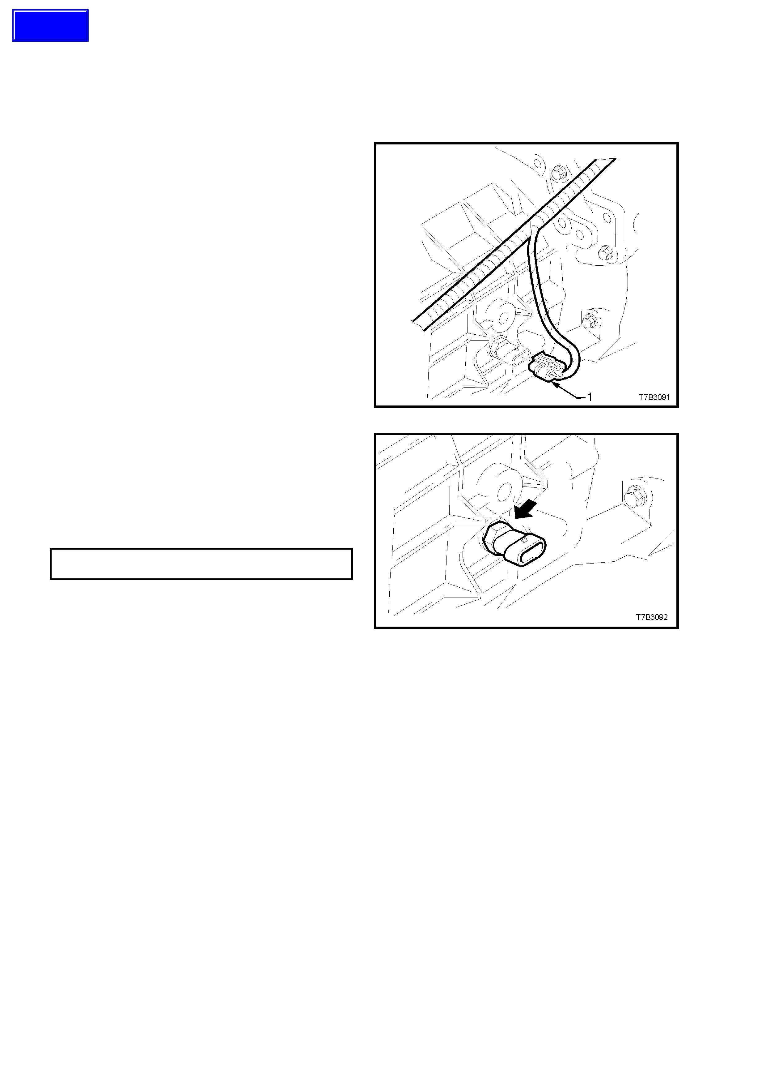
2. Remove wiring harness connector (1) from
switch, located on the right hand side of the
transmission case.
Figure 7B3-9
3. Loosen, then remove switch (arrow) from the
transmission case.
4. Apply Loctite 565 or equivalent (GM P/N
12346004), to the cleaned threads of the
back-up lamp switch.
5. Install switch to transmission case and tighten
to the correct torque specification.
BACK-UP LAMP SWITCH 20 - 34
TORQUE SPECIFICATION Nm
6. Install wiring harness connector to switch.
7. Remove safety stands and lower vehicle to
ground.
8. Check back-up lamp operation. Figure 7B3-10
Techline
3.2 SPEED SENSOR
REPLACE
1. Jack up vehicle front and rear and support on
safety stands. Refer to Section 0A GENERAL
INFORMATION of the VT Series II Service
Information, for the location of jacking points.
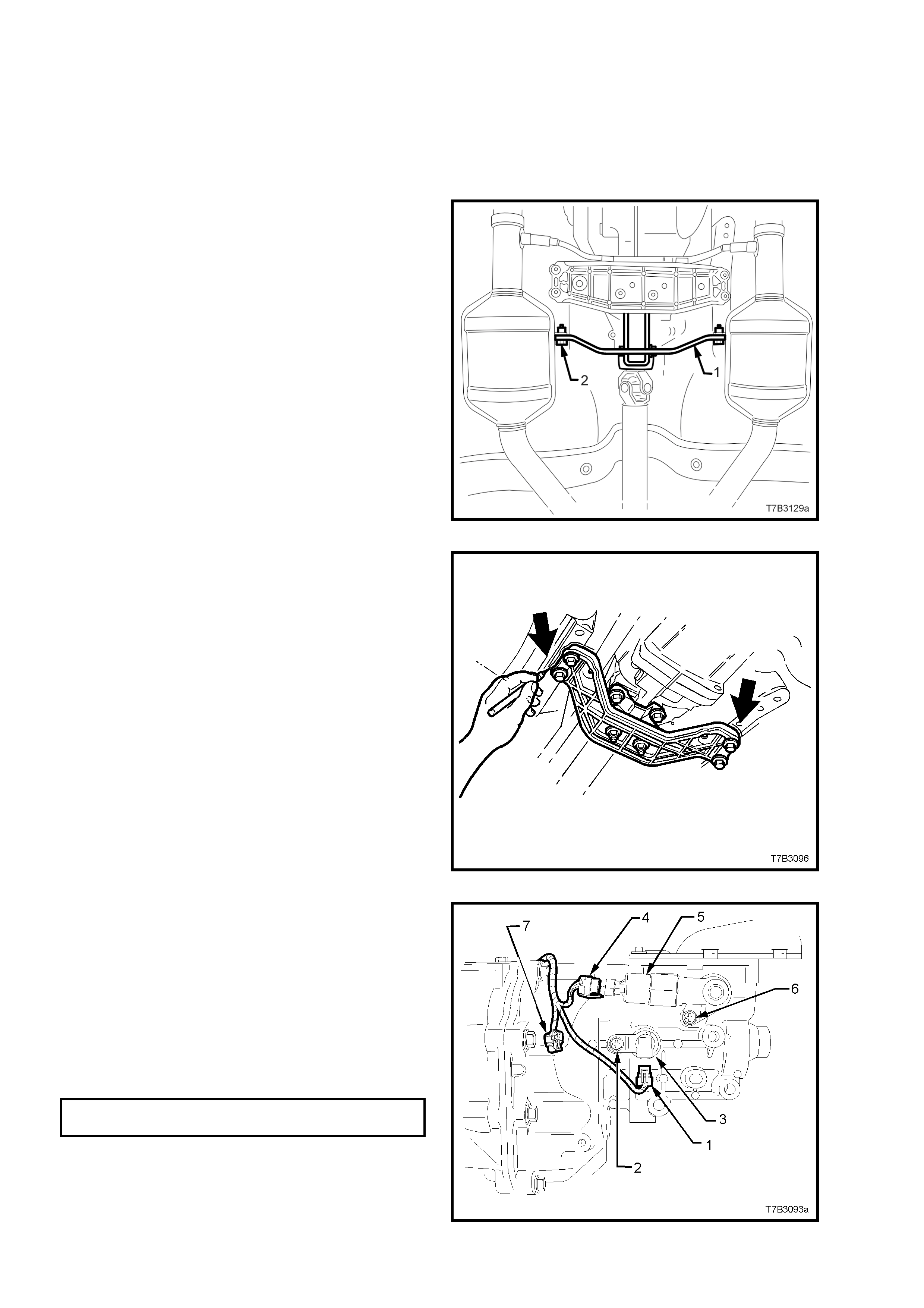
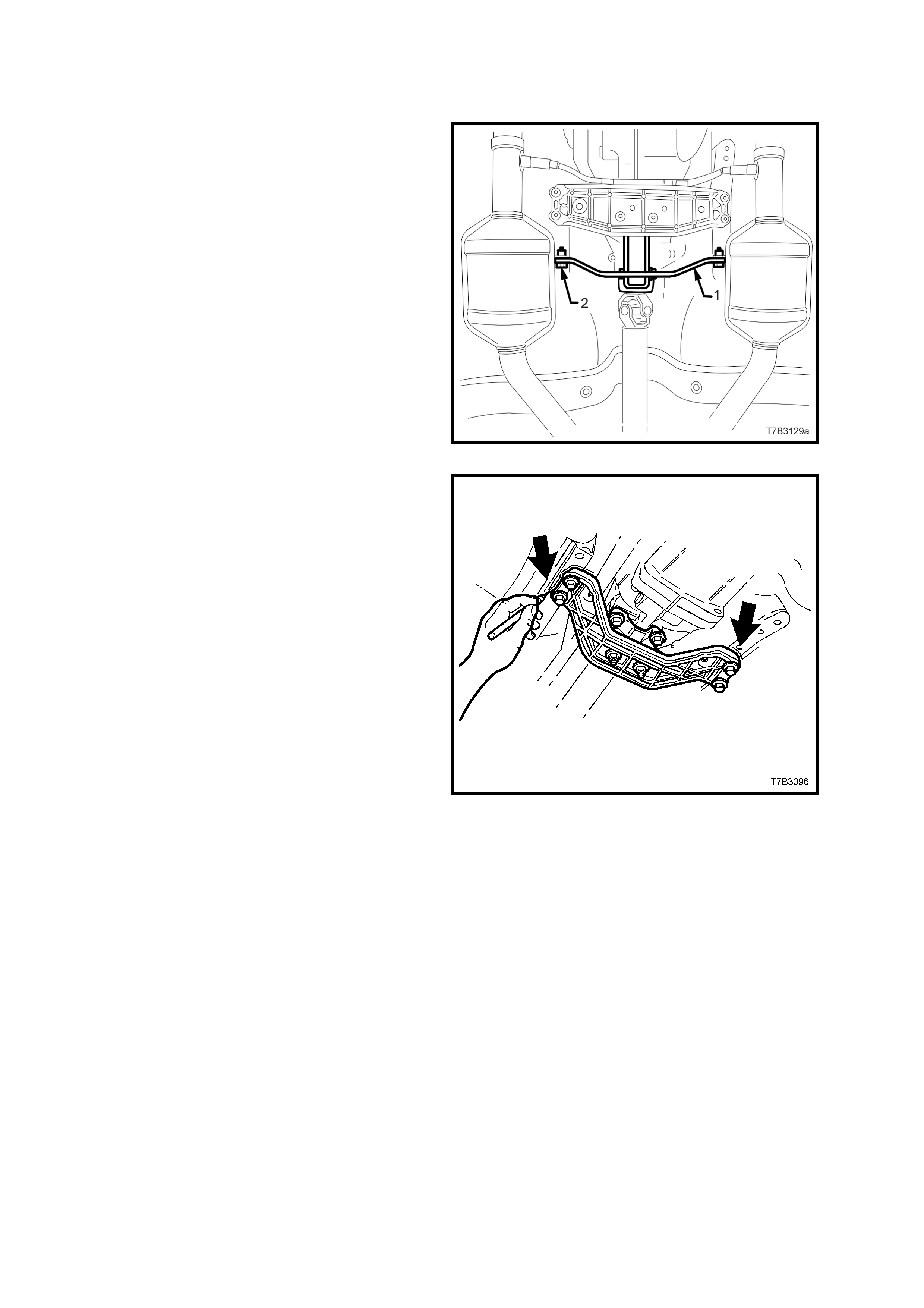
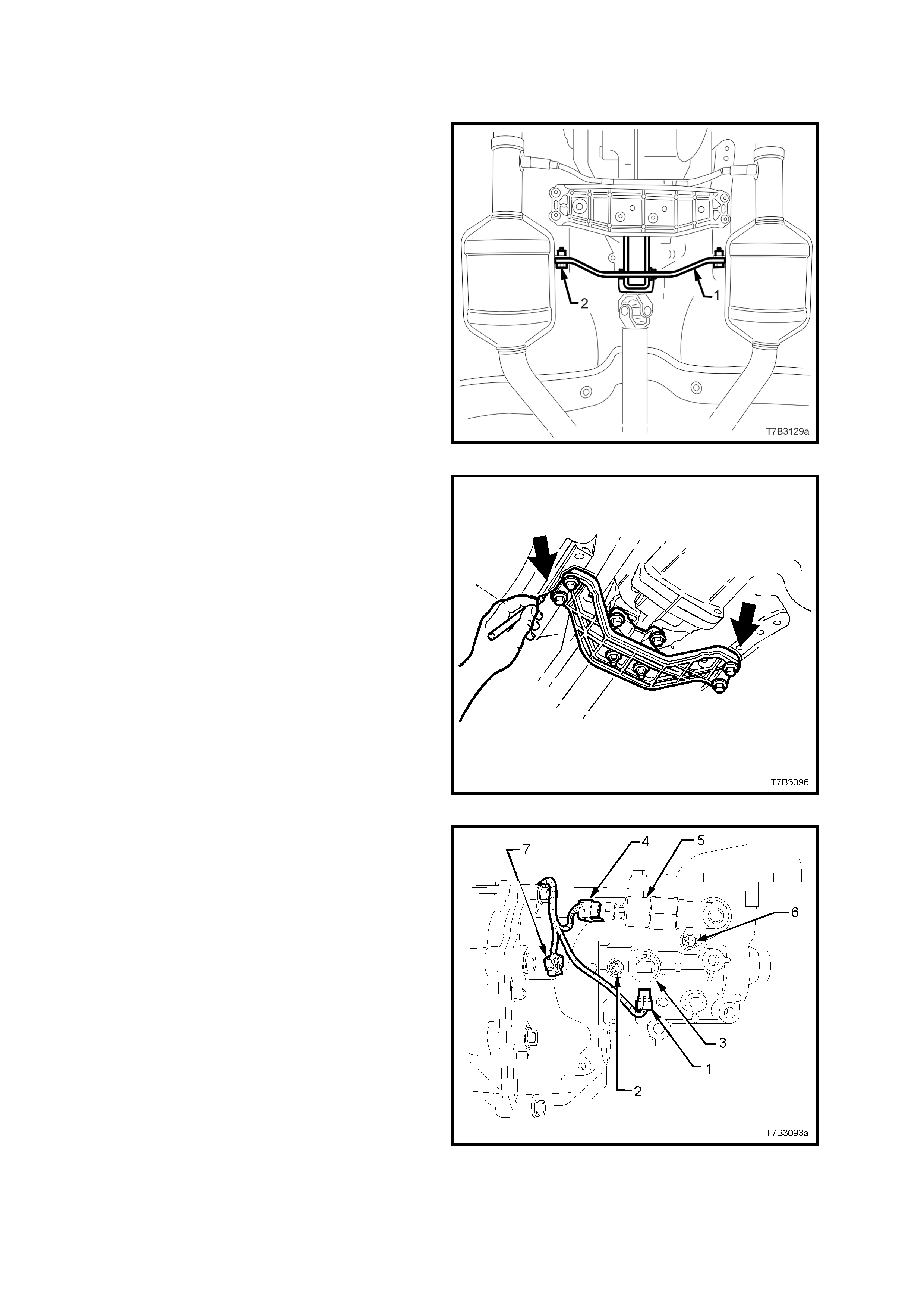
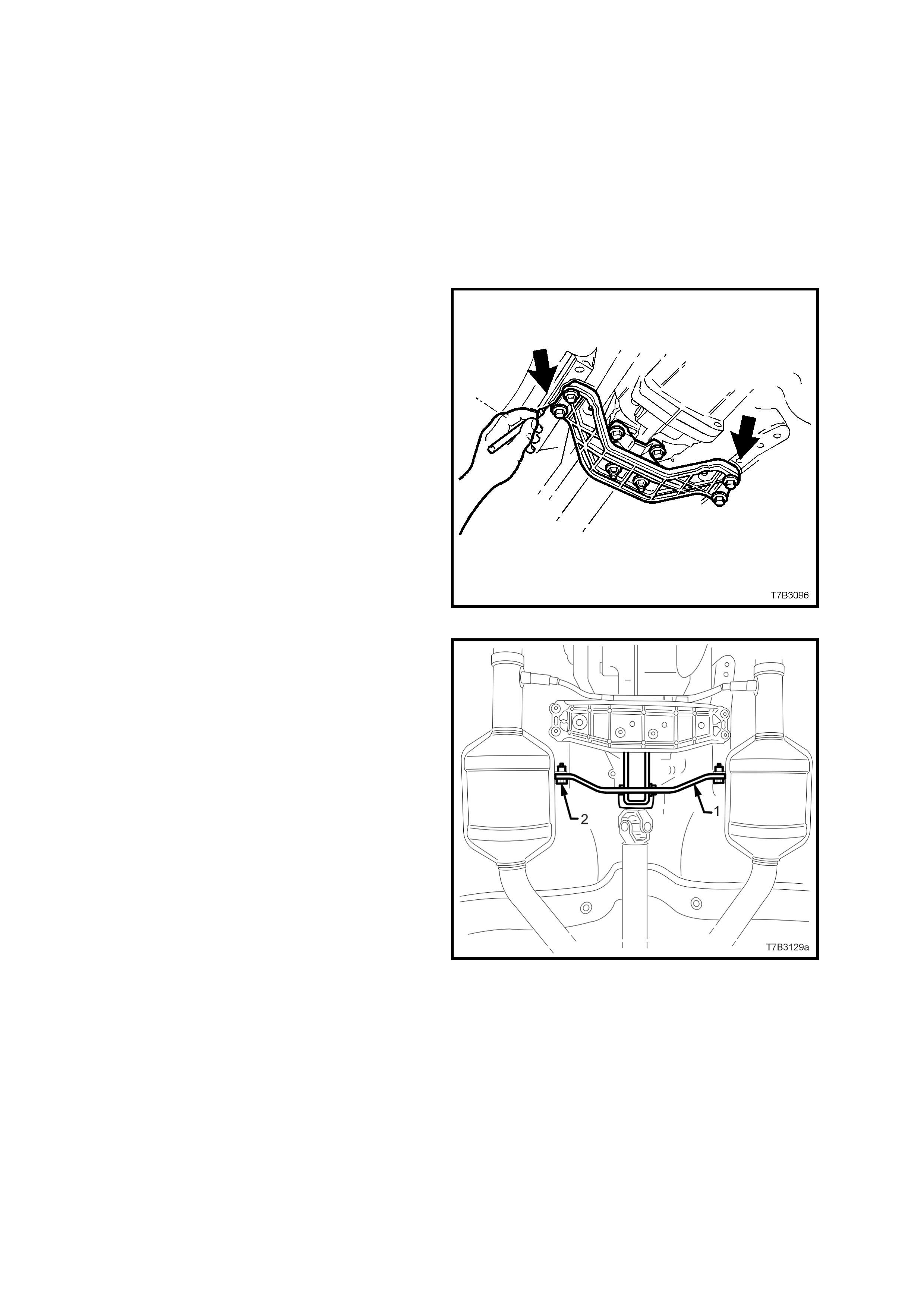
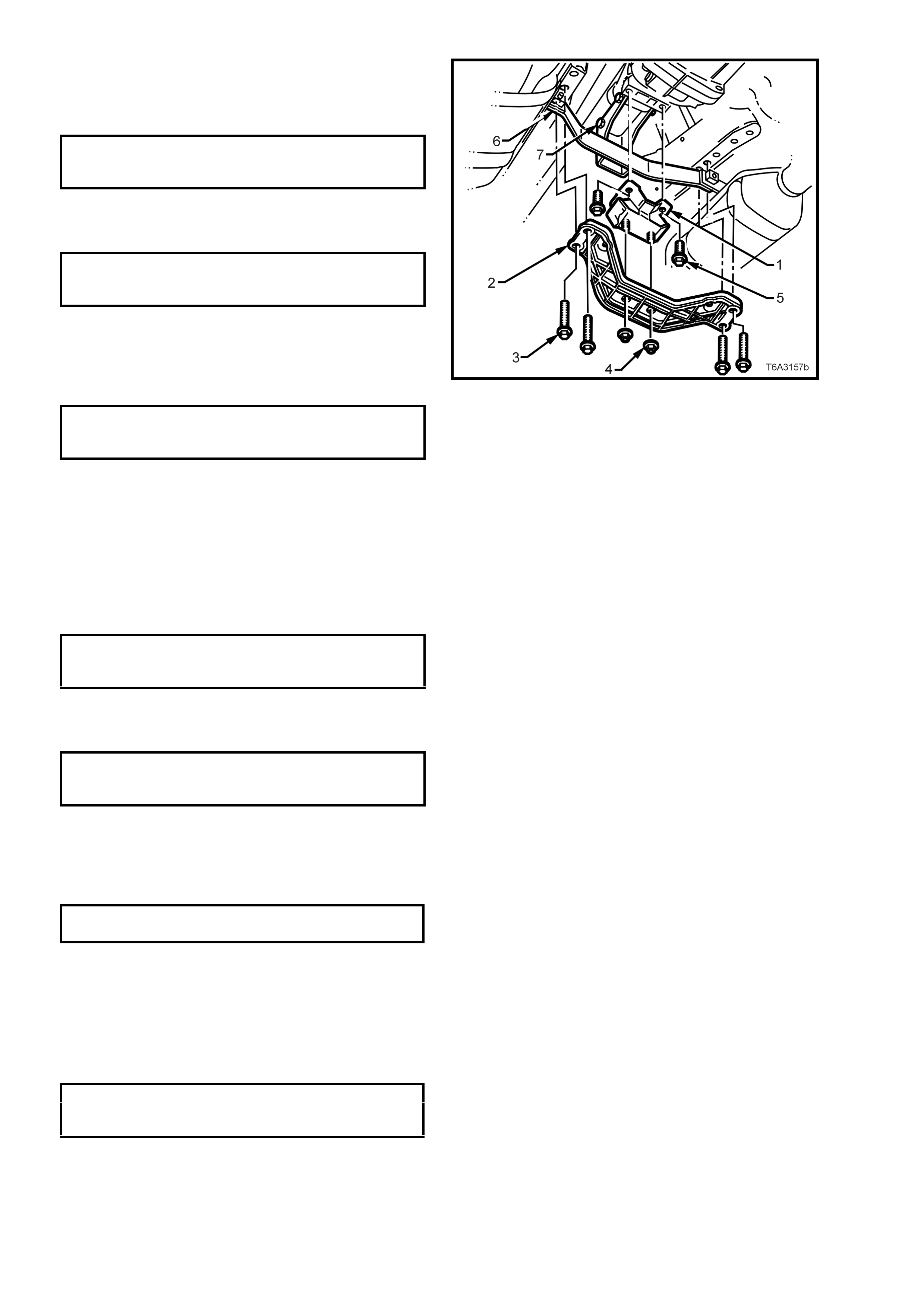
2. Remove the two bolts (2) securing the catalytic
converter bracket (1) to the catalytic
converters.
Figure 7B3-11
3. Scribe around each of the transmission
support crossmember mounting points to the
vehicle underbody, to provide an alignment
reference for reassembly.
NOTE: Th is step is critic al to the c orrec t powertr ain
alignment on reassembly. If not carried out, then
vehicle vibration and/or handling problems may
result.
4. Support the transmission with a suitable lifting
device, then rem ove the four engine m ounting
crossmember bolts, followed by the two rear
mount to crossmember nuts. Set the
crossmember to one side.
5. Lower the rear of the transmission enough to
gain clear access to the sensor.
Figure 7B3-12
6. Remove the speed sensor wiring harness
connector (1) from the sensor (3).
7. Remove speed sensor mounting bracket
screw (2) from the transmission extension
housing, then remove the sensor (3).
8. Installation is the reverse of removal except for
the following points;
a. Tighten the speed sensor to mounting
bracket retaining screw (2) to the correct
torque specification.
SPEED SENSOR BRACKET 8.0 - 12.0
SCREW TORQUE SPECIFICATION Nm
b Connect the speed s ensor lead c onnector
(1) to the sensor.
Figure 7B3-13
9. Raise the transmission, then install the four
crossmember to side frame bolts (3), aligning
the crossmember (2) with the scribed lines
made prior to disassembly. Tighten the bolts
(3) to the correct torque specification.
REAR CROSSMEMBER TO
SIDE FRAME MEMBER BOLT 50 - 65 Nm
TORQUE SPECIFICATION
10. Remove the lifting device from the
transmission, centralise the rear mount studs
in the crossmember holes, then reinstall the
nuts (4), tightening to the correct torque
specification.
REAR CROSSMEMBER TO REAR
MOUNTING ATTACHING NUT 20 - 30 Nm
TORQUE SPECIFICATION
11. Reinstall the two catalytic converter bracket (6)
bolts, tightening to the correct torque
specification.
CATALYTIC CONVERTER
BRACKET BOLT 20 - 30 Nm
TORQUE SPECIFICATION.
12. Lower the vehicle and road test to check
speedometer operation.
Figure 7B3-14
3.3 TRANSMISSION SUPPORT MOUNT
REPLACE
1. Jack up vehicle front and rear and support on
safety stands. Refer to Sect ion 0A GENERAL
INFORMATION of the VT Series II Service
Information, for the location of jacking points.
2. Remove the two bolts (2) securing the catalytic
converter bracket (1) to the catalytic
converters.
Figure 7B3-15
3. Scribe around each of the transmission
support crossmember mounting points to the
vehicle underbody, to provide an alignment
reference for reassembly.
NOTE: Th is step is critic al to the c orrec t powertr ain
alignment on reassembly. If not carried out, then
vehicle vibration and/or handling problems may
result.
4. Support the transmission with a suitable lifting
device, then rem ove the four engine m ounting
crossmember bolts.
5. Lower the transmission slightly, then remove
the two rear mount to crossmember nuts. Set
the crossmember to one side.
Figure 7B3-16
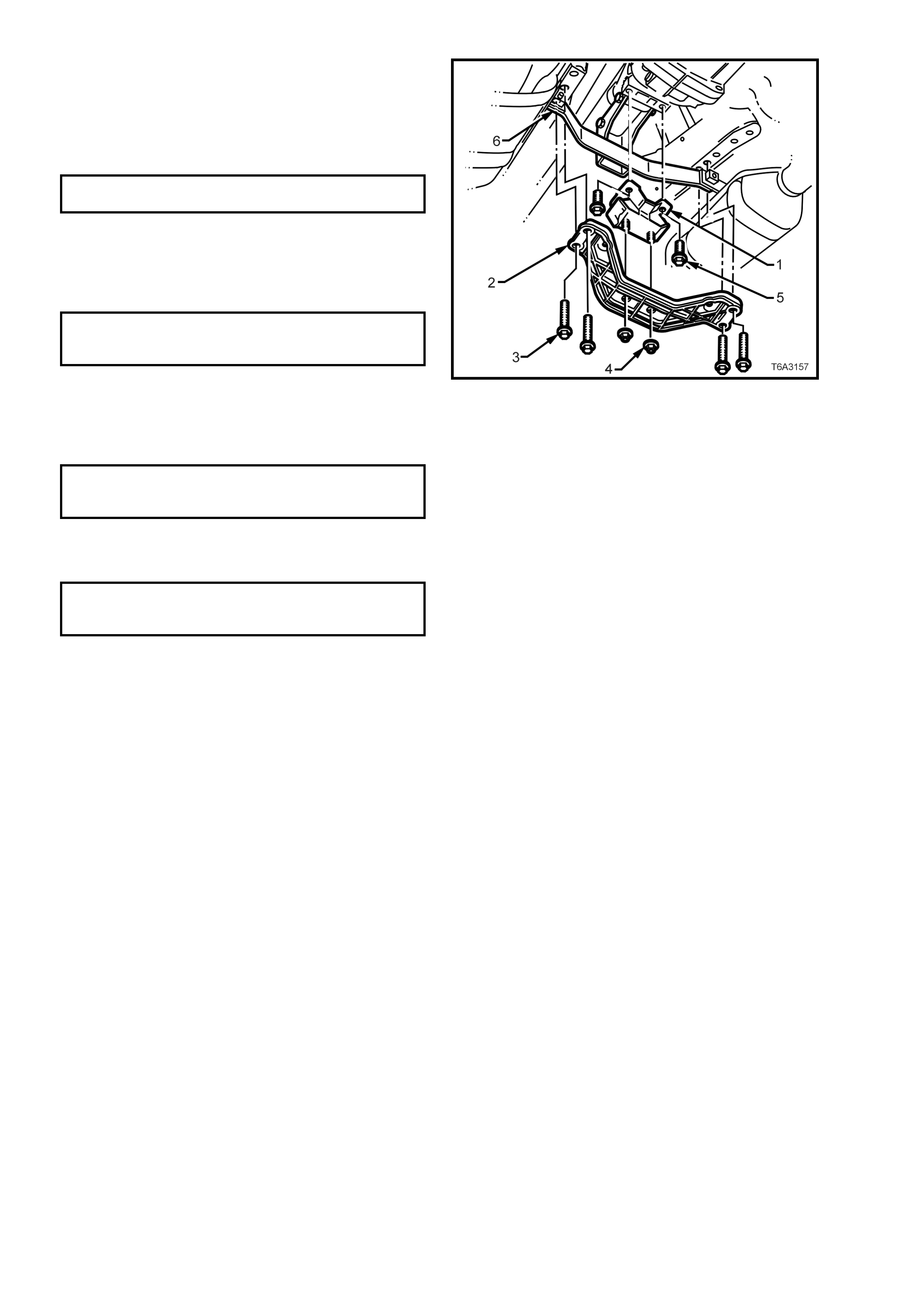
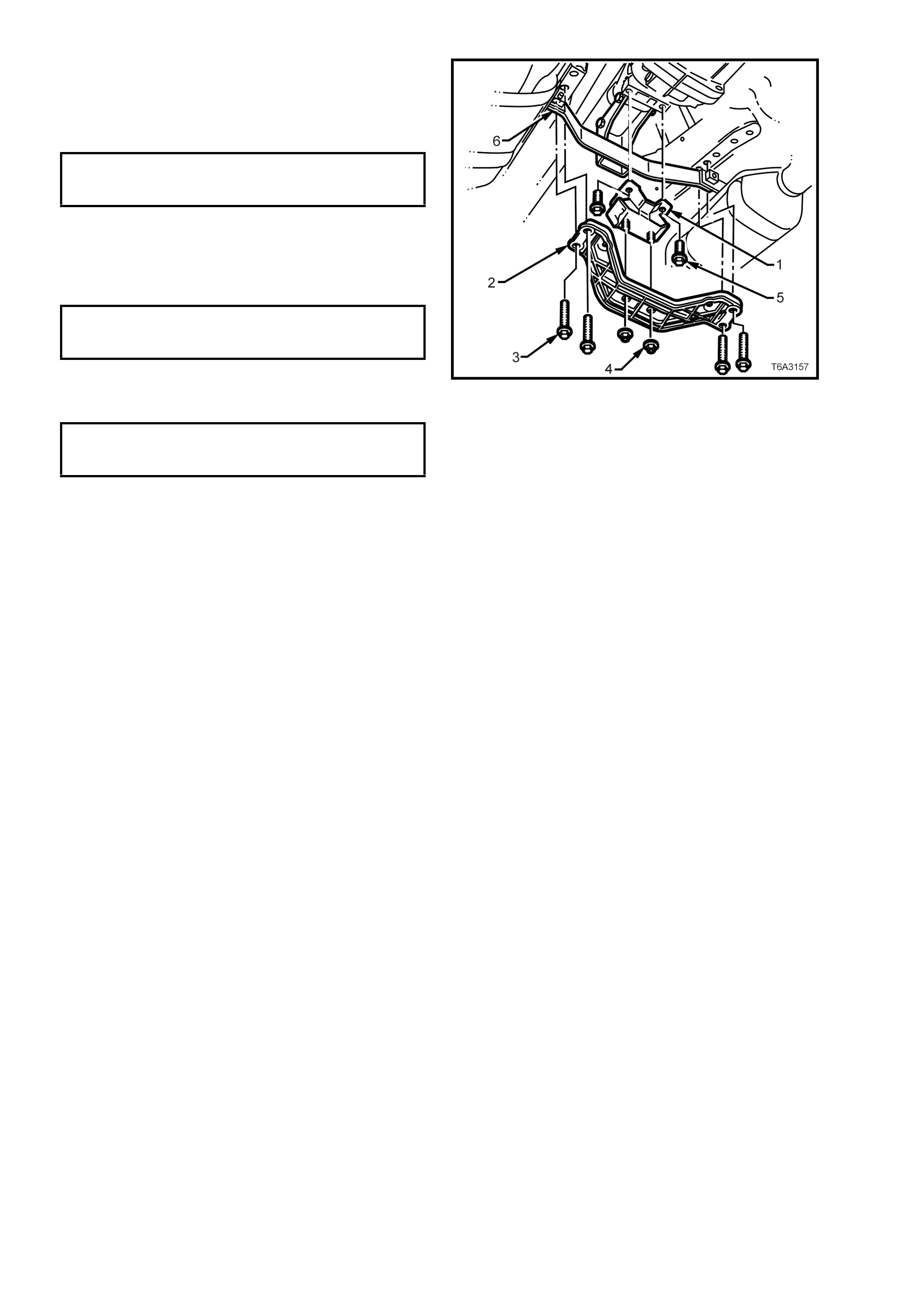
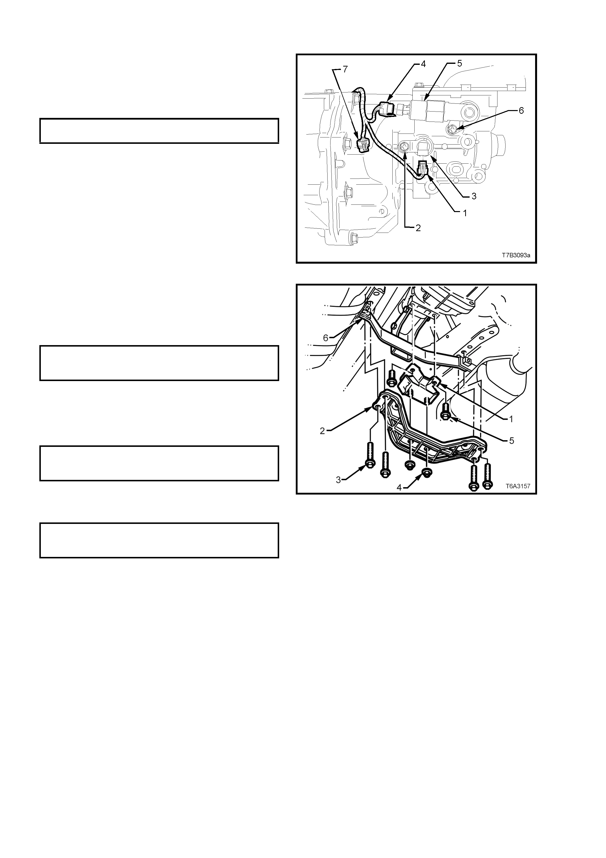
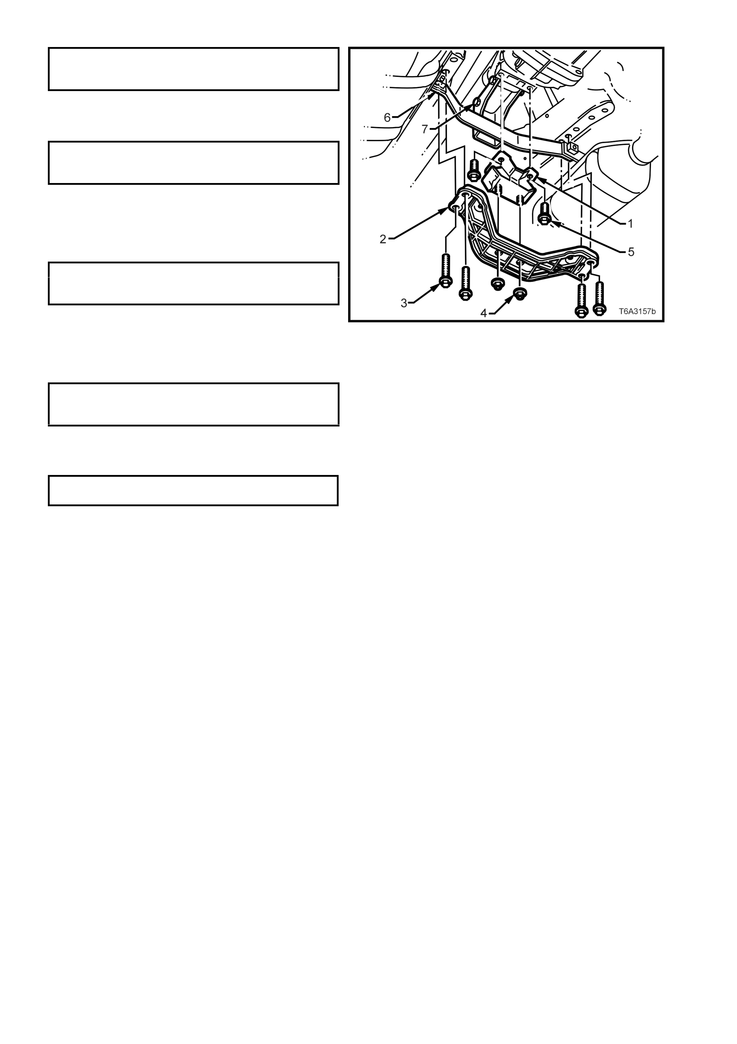
6. Remove the two bolts (5) securing the mount
(1) to the transmission extension housing,
then remove the mount from the vehicle.
7. Reinstall the mount (1) to the transmission
extension housing, ins tall the two bolts (5) and
tighten to the correct torque specification.
TRANSMISSION SUPPORT MOUNT
BOLT TORQUE SPECIFICATION 20 - 30 Nm
8. Raise the transmission slightly, then reinstall
the four crossmember to side frame bolts (3),
aligning the crossmember (2) with the scribed
lines made prior to disassembly. Tighten the
bolts (3) to the correct torque specification.
REAR CROSSMEMBER TO
SIDE FRAME MEMBER BOLT 50 - 65 Nm
TORQUE SPECIFICATION
9. Remove the lifting device from the
transmission, centralise the rear mount studs
in the crossmember holes, then reinstall the
nuts (4), tightening to the correct torque
specification.
REAR CROSSMEMBER TO REAR
MOUNTING ATTACHING NUT 20 - 30 Nm
TORQUE SPECIFICATION
10. Reinstall the two catalytic converter bracket (6)
bolts, tightening to the correct torque
specification.
CATALYTIC CONVERTER
BRACKET BOLT 20 - 30 Nm
TORQUE SPECIFICATION.
11. Lower the vehicle and road test to check
speedometer operation.
Figure 7B3-17
3.4 REVERSE LOCKOUT SOLENOID ASSEMBLY
REMOVE
1. Jack up vehicle front and rear and support on
safety stands. Refer to Sect ion 0A GENERAL
INFORMATION of the VT Series II Service
Information, for the location of jacking points.
2. Remove the two bolts (2) securing the catalytic
converter bracket (1) to the catalytic
converters.
Figure 7B3-18
3. Scribe around each of the transmission
support crossmember mounting points to the
vehicle underbody, to provide an alignment
reference for reassembly.
NOTE: Th is step is critic al to the c orrec t powertr ain
alignment on reassembly. If not carried out, then
vehicle vibration and/or handling problems may
result.
4. Support the transmission with a suitable lifting
device, then rem ove the four engine m ounting
crossmember bolts.
5. Lower the transmission slightly, then remove
the two rear mount to crossmember nuts. Set
the crossmember to one side.
Figure 7B3-19
6. Lower the transmission sufficiently to gain
access to the reverse lockout solenoid
assembly (5).
7. Remove wiring harnes s c onnec tor ( 4) f rom the
reverse lockout solenoid (5), after depressing
the locking tab.
8. Remove the reverse lockout solenoid
assembly mounting screw (6), then remove
the assembly from the transmission extension
housing by rotating back and forth while pulling
on the assembly.
Figure 7B3-20
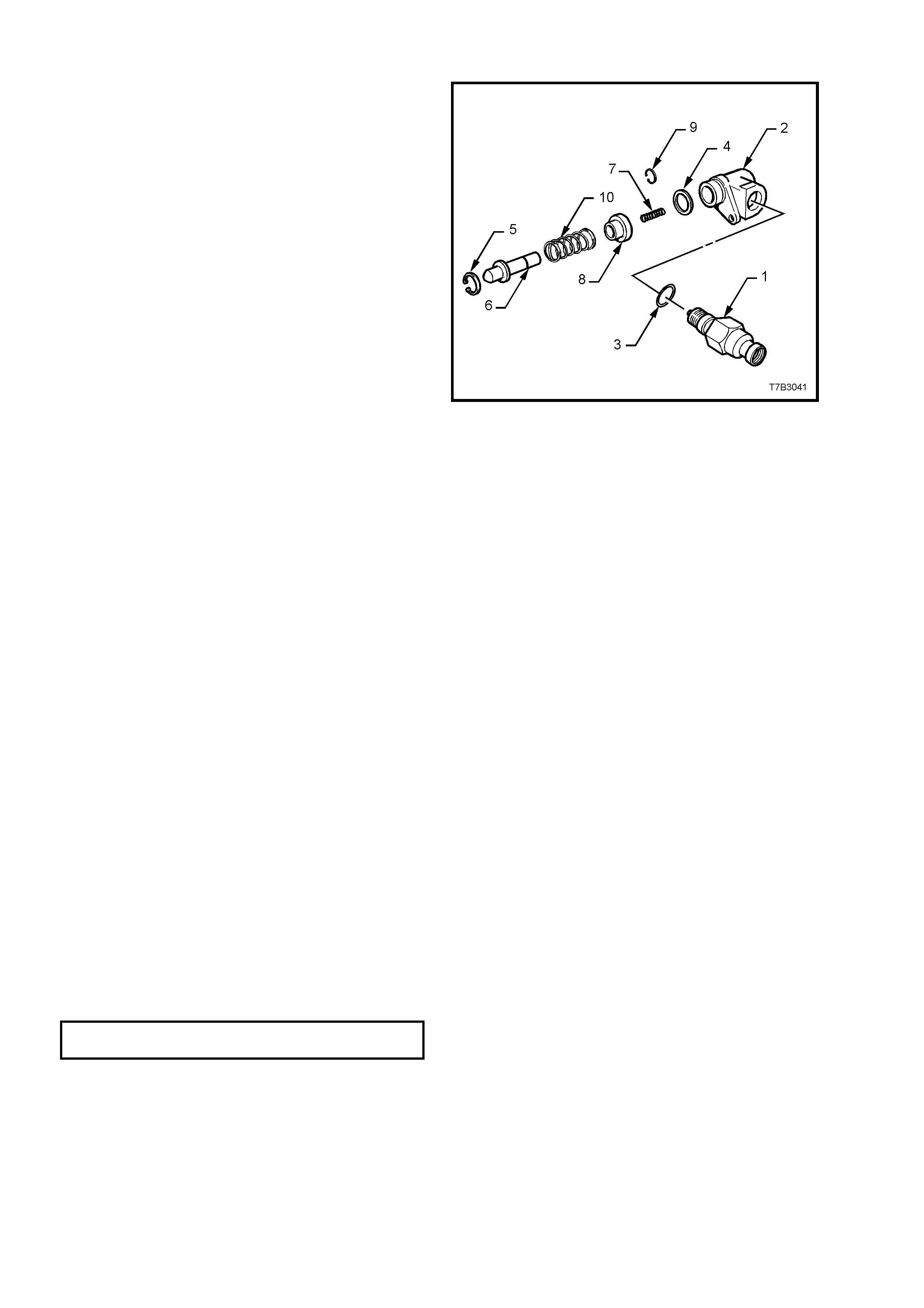
DISASSEMBLE
1. While holding the lockout body (2) in a vice
fitted with soft jaws, unscrew the reverse
lockout solenoid (1) from the body (2), then
remove the O-ring seal (3). If the O-ring seal
(3) is undamaged, it can be re-used.
2. Remove the O-ring (4) f rom the body (2). If the
O-ring seal is undamaged it can also be re-
used.
3. Remove circlip (5), using suitable pliers, from
the body (2).
4. Remove lockout plunger assembly (6) from
the body (2), then remove the inner spring (7).
5. Compress the reverse lock out plunger (6) and
collar (8) in a bench vice, then remove the ‘C’
clip (9).
CAUTION: The reverse lockout assembly is
under a strong spring force. Exercise care
when removing ‘C’ clip (9), as injury could
result.
6. Release the vice and disassemble the collar
(8) and spring (10) from the plunger (6).
7. Clean all parts in a suitable solvent and blow
dry with compressed air.
CAUTION: Wear safety glasses to avoid eye
injury.
8. Inspect all parts for damage or wear and
springs for broken or damaged coils.
9. For solenoid testing procedure, refer to
Section 6C3 POWERTRAIN MANAGEMENT
- GEN III V8 ENGINE, of the VT Series II
Service Information.
Figure 7B3-21
REASSEMBLE
NOTE: Refer Figure 7B3-21 for component
identification.
1. Compress the reverse lockout plunger (6),
spring (10) and collar (8) in a benc h vice, then
install the ‘C’ clip (9).
CAUTION: Wear safety glasses to avoid eye
injury.
2. Install the inner spring (7) into the end of the
lockout plunger assembly (6), then install the
assembly into the reverse lockout body (2).
3. Install circlip (5), using suitable pliers , to retain
the lockout plunger assembly (5).
4. Install the reverse lockout solenoid (1) and O-
ring, tightening to the correct torque
specification.
REVERSE LOCKOUT SOLENOID 34 - 48
TORQUE SPECIFICATION Nm
5. Install the O-ring (4) to the body (2).
REINSTALL
The installation process is the reverse of removal
operations except for the following:
1. After reinstalling the reverse lockout assem bly
(5), install the retaining bolt (6) and tighten to
the correct torque specification.
REVERSE LOCKOUT ASSEMBLY 15 - 20
BOLT TORQUE SPECIFICATION Nm
2. Reinstall the wiring harness connector (4) to
the reverse lockout solenoid.
Figure 7B3-22
3. Raise the transmission slightly, then reinstall
the four crossmember to side frame bolts (3),
aligning the crossmember (2) with the scribed
lines made prior to disassembly. Tighten the
bolts (3) to the correct torque specification.
REAR CROSSMEMBER TO
SIDE FRAME MEMBER BOLT 50 - 65 Nm
TORQUE SPECIFICATION
4. Remove the lifting device from the
transmission, centralise the rear mount studs
in the crossmember holes, then reinstall the
nuts (4), tightening to the correct torque
specification.
REAR CROSSMEMBER TO REAR
MOUNTING ATTACHING NUT 20 - 30 Nm
TORQUE SPECIFICATION
5. Reinstall the two catalytic converter bracket (6)
bolts, tightening to the correct torque
specification.
CATALYTIC CONVERTER
BRACKET BOLT 20 - 30 Nm
TORQUE SPECIFICATION.
6. Lower the vehicle and road test to check
speedometer operation.
Figure 7B3-23
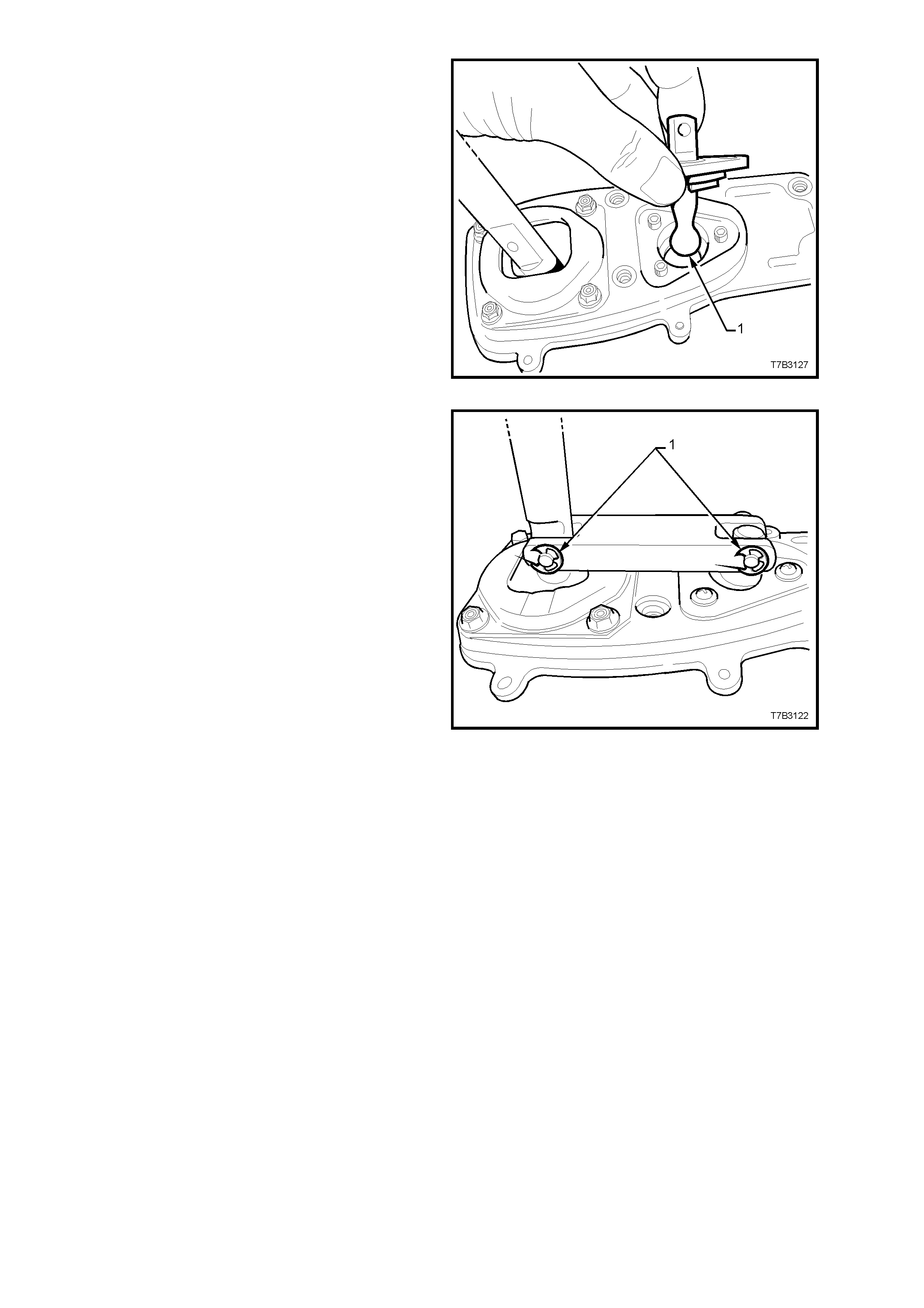
3.5 CONTROL LEVER KNOB AND BOOT ASSEMBLY
NOTE: The gearshift lever knob and console boot
are manufactured as a single component. Do not
attempt to remove the gearshift lever knob
separately to the boot.
REMOVE
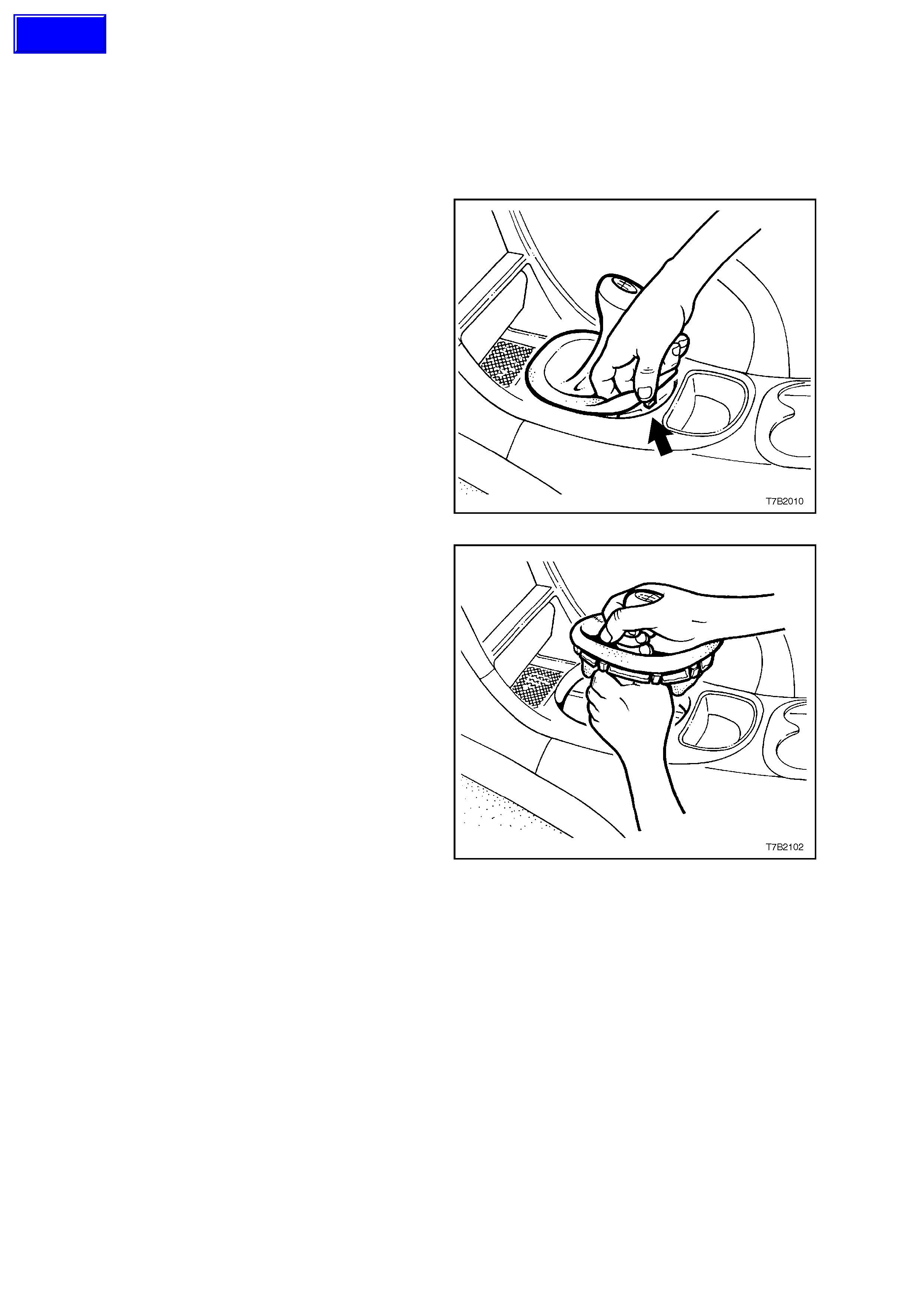
1. With the fingers of one hand hooked under the
edge of the gearshift lever boot as shown,
caref ully release each of the 8 plas tic retainer s
and free the gearshift lever boot from the
console cap.
Figure 7B3-24
2. Lift the gears hif t lever boot enough to enable a
firm grasp to be made on the gearshift lever
with the left hand, then grasp the gearshift
knob with the right.
3. W hile rocking the knob sideways, and with an
upward force applied, dislodge the knob
retaining claws from the lever.
4. Remove the gearshift lever knob and boot
assembly, from the gearshift lever.
Figure 7B3-25
REINSTALL
1. Reinstall the k nob and boot assembly over the
gearshift lever, align the knob in the correct
attitude and then bump the knob onto the
gearshif t lever until the retaining claws engage
with the groove in the lever.
2. Align the boot retaining clips with the hole in
the console cap, then carefully seat the boot
retainers into the console cap until each clip
engages correctly.
Techline
3.6 GEARSHIFT CONTROL LEVER AND REMOTE SHIFTER SHAFT BOOT
REMOVE
1. Disconnect the battery earth lead.
2. Remove the gearshift lever knob and boot
assembly, from the gearshift lever. Refer to
3.5 CONTROL LEVER KNOB AND BOOT
ASSEMBLY in this Section, f or the necessary
procedure.
3. Remove the centre console assembly,
including the console cap. Refer to
Section 1A3, INSTRUMENT PANEL AND
CONSOLE, of the VT Series I Service
Information for the necessary procedure.
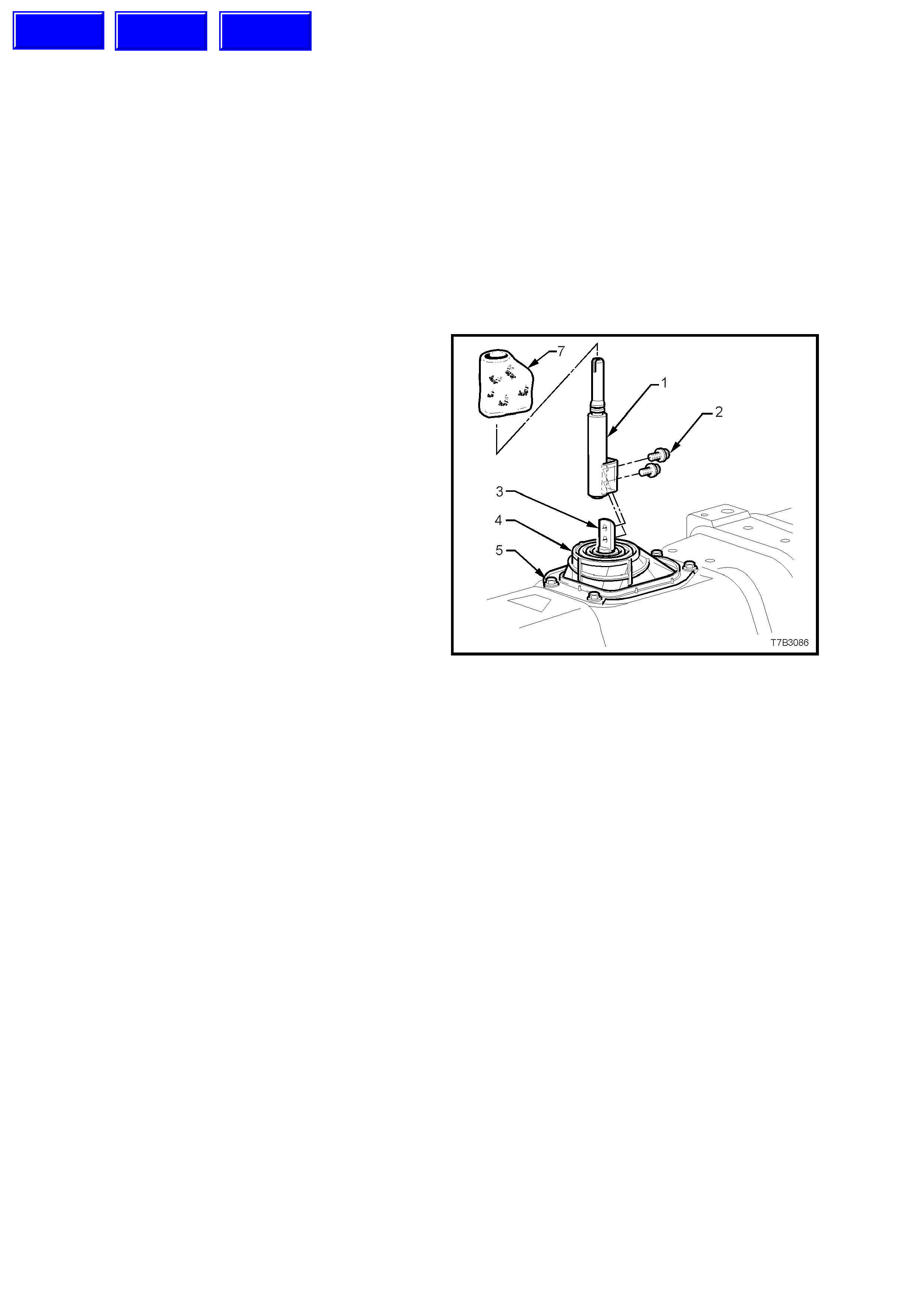
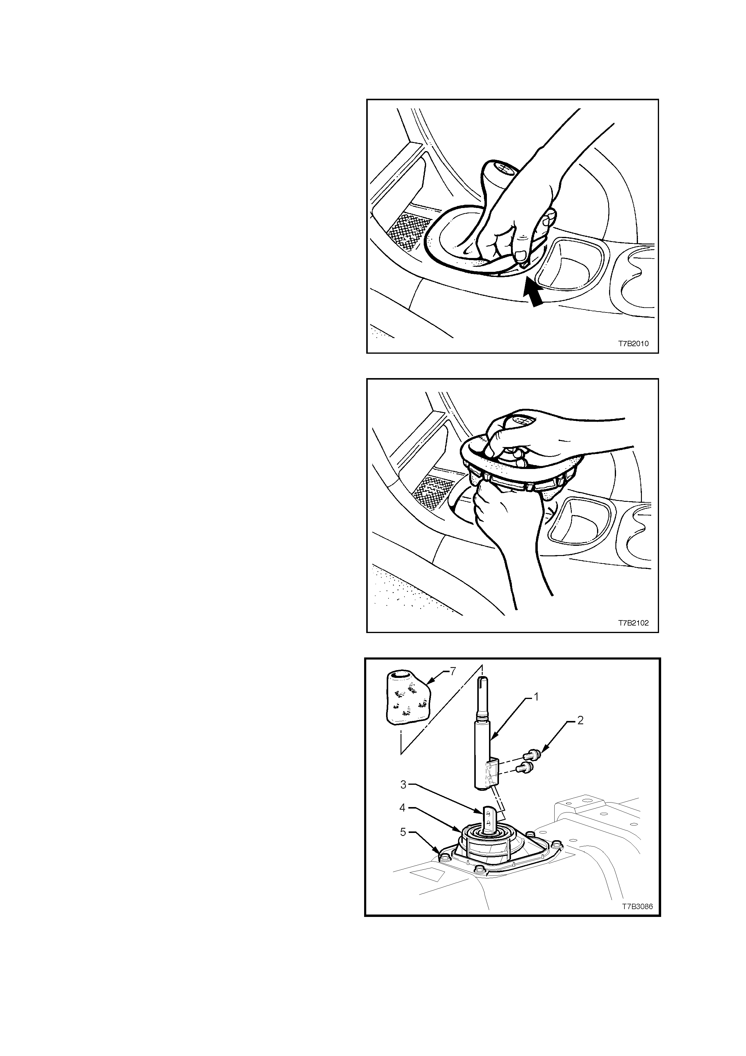
4. Slip the insulator sock (7) from the control
lever (1) and set it to one side.
5. Using a 10 mm socket, remove the two bolts
(2) securing the control lever (1) to the
gearshift remote shift lever shaft (3), then lift
the control lever free.
6. If required, remove the four bolts (5) securing
the gearshift remote shift lever boot retaining
plate (6) to the floor pan, then remove the boot
(4) and retaining plate (6).
CLEAN AND INSPECT
1. Inspect the gearshift remote shift lever boot (4)
for tears or other damage, replacing as
required.
2. Clean the threads of the control lever bolts (2)
and check for thread damage.
Figure 7B3-26
Techline
Techline
Techline

REINSTALL
1. If removed, install the gearshift remote lever
boot (4) and plate (6) and secure with the four
bolts (5), tightening to the correct torque
specification.
GEARSHIFT REMOTE LEVER
BOOT PLATE BOLT 6.0 - 14.0 Nm
TORQUE SPECIFICATION
2. Apply thread sealant such as Loctite 242 or
equivalent (to Holden’s Specification HN 1256
Class 2, T ype 2), to the cleaned threads of the
control lever retaining bolts (2).
3. Install the control lever (1) over the remote
shift lever shaft (3), install the two bolts (2),
tightening to the correct torque specification.
GEARSHIFT LEVER TO REMOTE
SHIFT LEVER SHAFT BOLT 15 - 35 Nm
TORQUE SPECIFICATION
4. Reinstall the insulator sock (7) over the
remote shift lever (1).
5. Reinstall centre console assembly, including
the console cap. Refer to
Section 1A3, INSTRUMENT PANEL AND
CONSOLE, of the VT Series I Service
Information for the necessary procedure.
6. Reinstall the gearshift knob and boot
assembly over the gearshift lever, align the
knob in the c orrect attitude and then bum p the
knob onto the gear shif t lever until the retaining
claws engage with the groove in the lever.
7. Align the gearshif t boot retaining clips with the
hole in the console cap, then c ar ef ully seat the
boot retainers into the console cap until each
clip engages correctly.
8. Reconnect battery earth lead.
9. Road test vehicle and check for correct
gearshift operations.
4. MAJOR SERVICE OPERATIONS
4.1 TRANSMISSION OUTPUT SHAFT SEAL AND BOOT
REMOVE
1. Disconnect battery earth lead.
2. Raise front and rear of vehicle, supporting on
safety stands. Refer to
Section 0A GENERAL INFORM AT ION of the
VT Series I Service Information, for the
location of jacking points.
3. Scribe around each of the transmission
support crossmember mounting points to the
vehicle underbody, to provide an alignment
reference for reassembly.
NOTE: Th is step is critic al to the c orrec t powertr ain
alignment on reassembly. If not carried out, then
vehicle vibration and/or handling problems may
result.
Figure 7B3-27
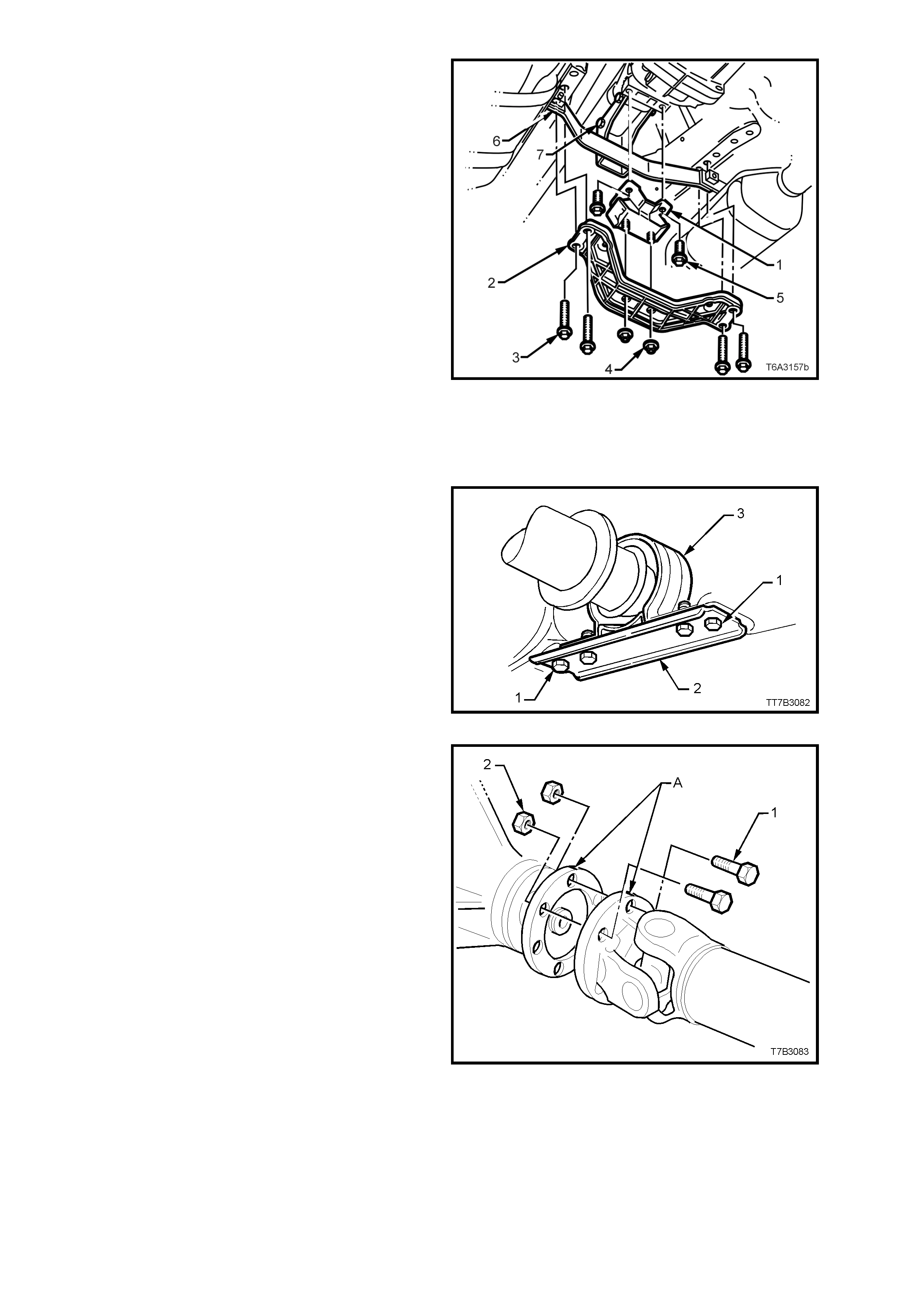
4. Remove the two bolts (2) securing the catalytic
converter bracket (1) to the catalytic
converters.
Figure 7B3-28
5. Support the transmission with a suitable lifting
device, then remove the four engine rear
crossmember to side frame attaching bolts (3).
6. Lower the transmission slightly, then remove
the two transmission mount to crossmember
nuts (4). Set the crossmember (2) to one side.
7. Remove the two bolts (5) securing the
transmission mount (1) to the transmission
extension, then remove the mount (1) and
bracket (6) from the vehicle.
NOTE: Illustration does not show transm ission j ack
in position, for clarity of the crossmember
orientation.
8. Remove the nuts from the two bolts (7)
securing the catalytic converter bracket (6) to
the transmission extension, remove the bolts
and bracket and set to one side.
9. Lower the transmission enough to provide
clearance for the propeller shaft rubber
coupling when the propeller shaft is removed.
Figure 7B3-29
10. Remove centre bearing carrier to underbody
reinforcement bolts and spacers.
NOTE: For correct reassembly, take particular note
of any spacer arrangement that may be fitted,
observing any side to side variations and the
orientation of the bracket offset.
11. Support centre bearing assembly to prevent
any angular deflection of the constant velocity
joint that exceeds 8°. Should this angle be
exceeded, then damage to the boot and/or
constant velocity joint may occur.
Figure 7B3-30
12. Place a drain tray beneath transmission.
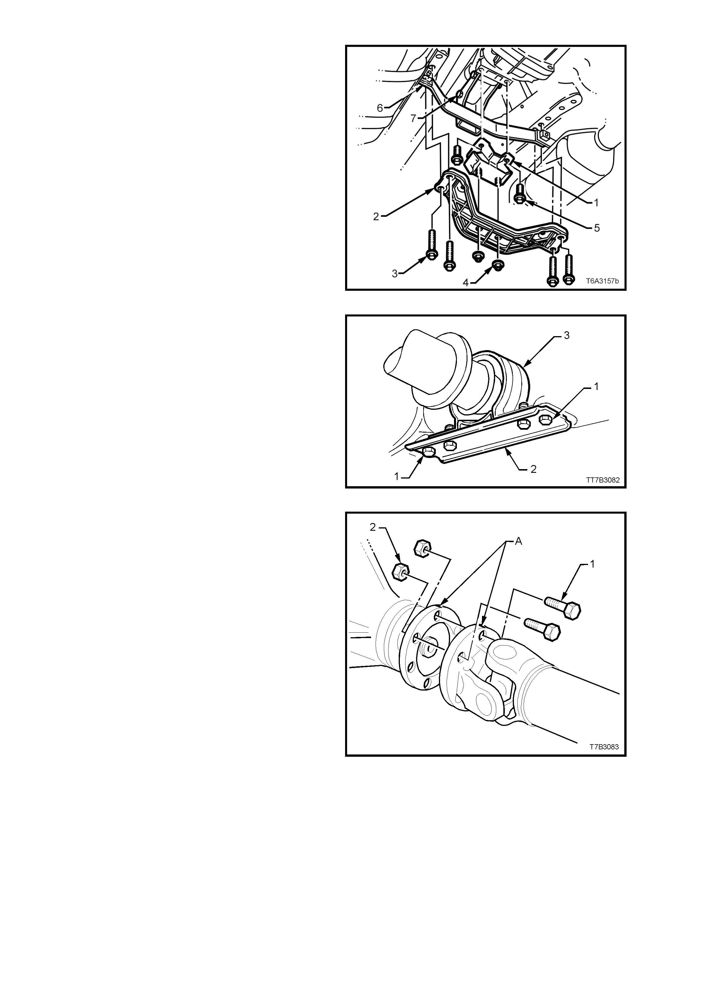
13. Remove nuts (2) and bolts (1) holding
propeller shaft rear universal joint flange to
pinion flange, then disengage rear universal
joint flange from pinion flange.
NOTE: The two flanges have paint alignment
marks (A) that are assembled as close together as
possible. If the mark s are not vis ible, scribe a mark
on both flanges so that they will be reinstalled in
their original position.
14. Disconnect the propeller shaft from the rear
flange and, moving the propeller shaft slightly
to the left hand side of the vehicle, pull the
assembly to the rear of vehicle, enough to
disengage the slip joint from the transmission
mainshaft.
Figure 7B3-31
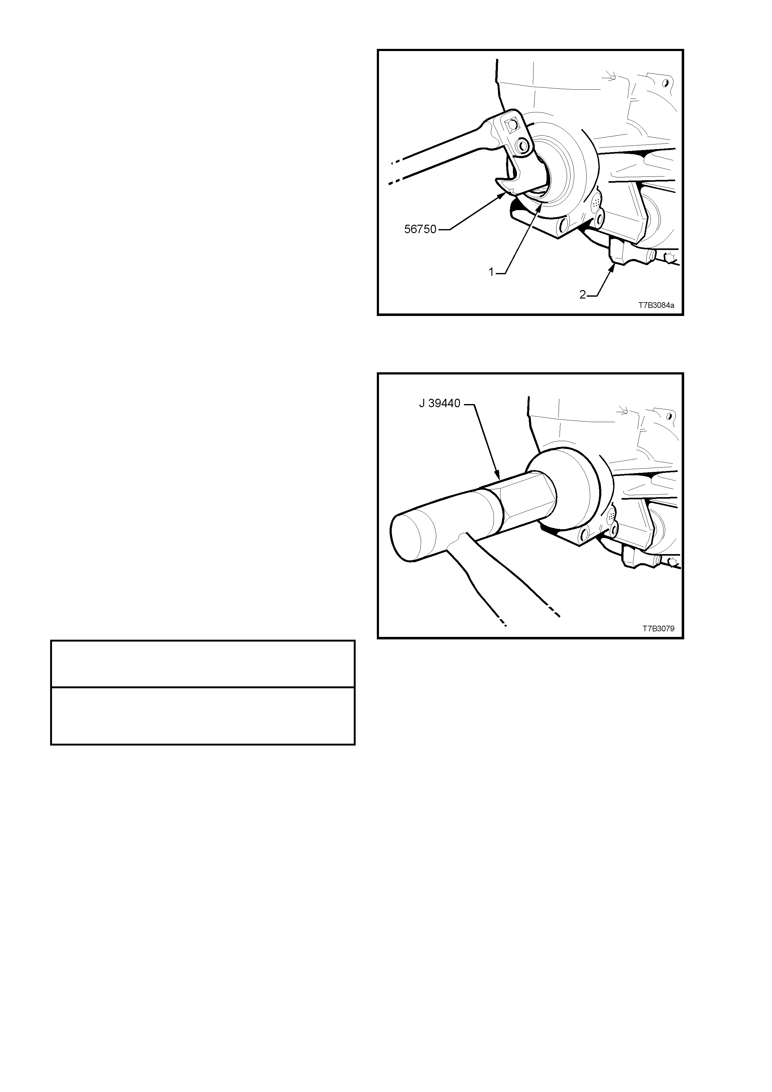
15. Using a seal rem over such as Tool No. 56750
(also released as E308), remove the seal (1)
from the transmission extension housing.
NOTE: Should Tool No. 56750 not be available,
then it will be necessary to remove the seal by
prising it from the extension hous ing with a suitable
lever such as a screwdriver. If this method is used,
take care not to scratch the bore of the extension
housing during the removal process.
Figure 7B3-32
REINSTALL
1. After lubricating the seal lip with transmission
lubricant, use s eal installer J 39440 and install
the new seal into the rear of the extension
housing.
2. Install the propeller slip joint into the rear of the
transmission, then lift the propeller shaft
upward (while maintaining and angular
deflection less than 8°) and install centre
bearing carrier to underbody reinforcement.
Ensure all spacers are replaced in the same
positions, noted on removal, then install
retaining bolts.
3. Assemble propeller shaft rear universal joint
flange to pinion flange and install attaching
bolts and nuts.
4. Tighten all propeller shaft attaching bolts to the
correct torque specification.
CENTRE BEARING CARRIER TO
UNDERBODY REINFORCEMENT 20 - 35 Nm
BOLT TORQUE SPECIFICATION
PROPELLER SHAFT REAR
UNIVERSAL JOINT FLANGE TO
PINION FLANGE BOLT 55 - 65 Nm
TORQUE SPECIFICATION
5. Reinstall the catalytic converter bracket (6) to
the transm ission extension, ins tall the bolts (7)
and nuts, then tighten to the correct torque
specification.
Figure 7B3-33
CONVERTER BRACKET TO
TRANSMISSION EXTENSION BOLT 40 – 60 Nm
TORQUE SPECIFICATION
6. Reinstall the transmission mount (1) to the
transmiss ion extension, install the two bolts (5)
and tighten to the correct torque specification.
TRANSMISSION MOUNT TO
EXTENSION HOUSING BOLT 20 - 30 Nm
TORQUE SPECIFICATION
7. Raise the transmission slightly, then reinstall
the four crossmember to side frame bolts (3),
aligning the crossmember (2) with the scribed
lines made prior to disassembly. Tighten the
bolts (3) to the correct torque specification.
REAR CROSSMEMBER TO
SIDE FRAME MEMBER BOLT 50 - 65 Nm
TORQUE SPECIFICATION
8. Remove the lifting device from the
transmission, centralise the rear mount studs
in the crossmember holes, then reinstall the
nuts (4), tightening to the correct torque
specification.
REAR CROSSMEMBER TO
TRANSMISSION MOUNT NUT 20 - 30 Nm
TORQUE SPECIFICATION
Figure 7B3-34
9. Reinstall the two catalytic converter bracket
(6) bolts, tightening to the correct torque
specification.
CATALYTIC CONVERTER BRACKET 20 - 30
BOLT TORQUE SPECIFICATION Nm
10. Check the transmission fluid level. Refer to
2.2 CHECKING TRANSMISSION
LUBRICANT LEVEL in this Section. Top up
as required.
11. Lower the vehicle reconnect battery ground
lead.
12. Lower the vehicle and road test to check
vehicle operation.
4.2 TRANSMISSION ASSEMBLY
REMOVE
1. Disconnect battery ground lead.
2. With the fingers of one hand hooked under the
edge of the gearshift lever boot as shown,
carefully release each of the 8 plastic retainers
and free the gearshift lever boot from the
console cap.
NOTE: The gearshift lever knob and console boot
are manufactured as a single component. Do not
attempt to remove the gearshift lever knob
separately to the boot.
Figure 7B3-35
3. Lift the gears hif t lever boot enough to enable a
firm grasp to be made on the gearshift lever
with the left hand, then grasp the gearshift
knob with the right.
4. W hile rocking the knob sideways, and with an
upward force applied, dislodge the knob
retaining claws from the lever.
5. Remove the gearshift lever knob and boot
assembly, from the gearshift lever.
Figure 7B3-36
6. Remove the centre console. Refer
Section 1A3 INSTRUMENT PANEL AND
CONSOLE, of the VT Series I Service
Information for the necessary procedure.
7. Slip the insulator sock (7) from the control
lever (1).
8. Using a 10 mm socket, remove the two bolts
(2) securing the control lever (1) to the remote
shifter shaft (3), then lift the control lever free.
9. Remove the f our bolts (5) securing the rem ote
shift lever boot retaining plate (6) to the floor
pan, then remove the boot (4) and retaining
plate (6).
10. Select third gear to allow the remote shifter
shaft (3) to clear the opening in the floor pan,
when the transmission is lowered for removal.
Figure 7B3-37
11. Raise vehicle, preferably on a ‘drive-on’ hoist
or a four post hoist. This preference is based
on the fact that the tr ansmiss ion is very heavy
and the use of a transmission jack will be
required for effective transmission removal
and installation.
12. Disconnect wiring harness connectors from
each of the two oxygen sensors.
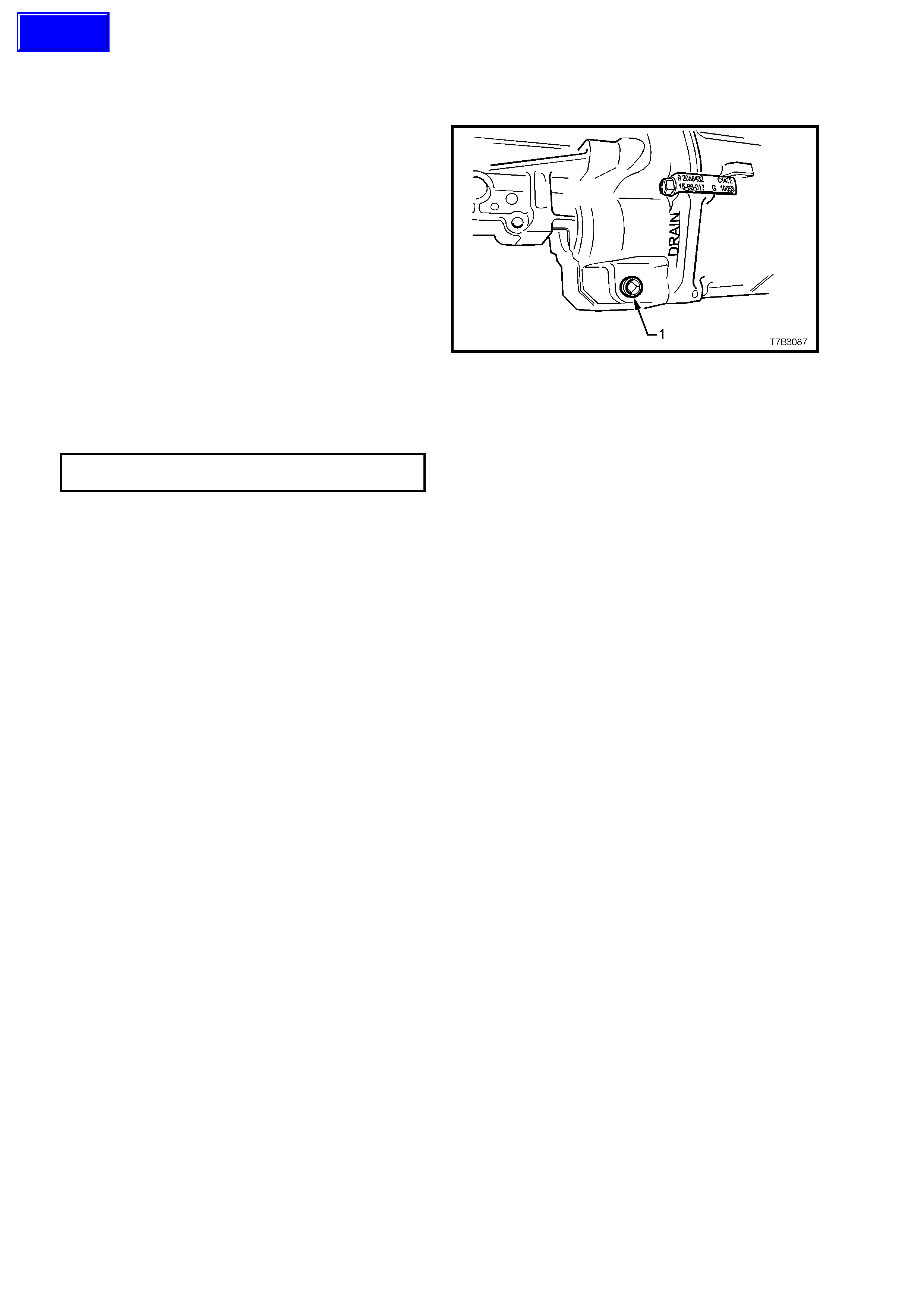
13. Depending on the reason for removal, it might
be appropriate to drain the transmission
lubricant into a clean container.
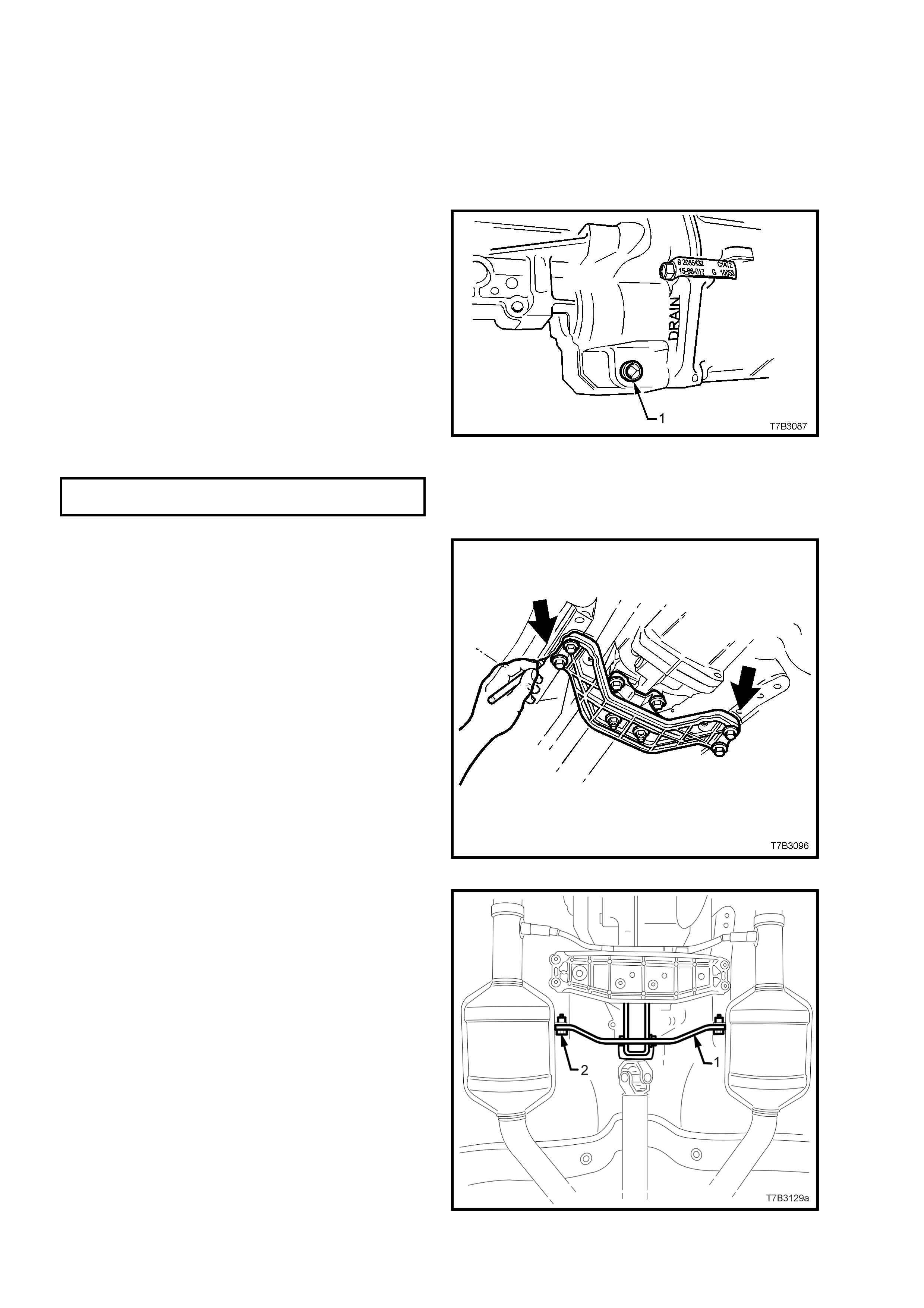
Place a drain tray beneath transmission and
remove the drain plug (1) using a 3/8” drive
socket bar.
When transmission has fully drained, clean the
threads of the drain plug, apply thread sealant
such as Loctite 565 or equivalent (GM P/N
12346004), then reinstall, tightening to the
correct torque specification, using a 3/8” drive
adaptor and a torque wrench.
NOTE: Do not apply Teflon thread tape to the plug
threads.
TRANSMISSION DRAIN PLUG 20 - 34
TORQUE SPECIFICATION Nm
Figure 7B3-38
14. Scribe around each of the transmission
support crossmember mounting points to the
vehicle underbody, to provide an alignment
reference for reassembly.
NOTE: Th is step is critic al to the c orrec t powertr ain
alignment on reassembly. If not carried out, then
vehicle vibration and/or handling problems may
result.
Figure 7B3-39
15. Remove the two bolts (2) securing the catalytic
converter bracket (1) to the catalytic
converters.
Figure 7B3-40
16. Support the transmission with a suitable lifting
device, then remove the four engine rear
crossmember to side frame attaching bolts (3).
17. Lower the transmission slightly, then remove
the two rear mount to crossmember nuts (4).
Set the crossmember (2) to one side.
18. Remove the two bolts (5) securing the rear
mount (1) to the transmission extension, then
set the mount to one side.
19. Remove the two nuts and bolts (7) securing
the catalytic converter bracket (6) to the
transmission extension, then remove the
bracket (6) from the vehicle.
NOTE: Illustration does not show transm ission j ack
in position, for clarity of the crossmember
orientation.
Figure 7B3-41
20. Remove centre bearing carrier (2) to
underbody reinforcement bolts (1) and
spacers, if fitted.
NOTE: For correct reassembly, take particular note
of any spacer arrangement that may be fitted,
observing any side to side variations and the
orientation of the bracket (2) offset.
21. Support centre bearing assembly (3) to
prevent any angular deflection of the constant
velocity joint that exceeds 8°. Should this
angle be exceeded, then damage to the boot
and/or constant velocity joint may occur.
Figure 7B3-42
22. Place a drain tray beneath transmission or
insert a plug into the rear of the extension
housing.
23. Remove nuts (2) and bolts (1) holding the
propeller shaft rear universal joint flange to
pinion flange, then disengage rear universal
joint flange from pinion flange.
NOTE: The two flanges have paint alignment
marks (A) that are assembled as close together as
possible. If the mark s are not vis ible, scribe a mark
on both flanges so that they will be reinstalled in
their correct position.
24. Disconnect the propeller shaft from the rear
flange and, moving the propeller shaft slightly
to the left hand side of the vehicle, pull the
assembly toward the rear of vehicle, sufficient
to disengage the slip joint from the
transmission mainshaft. Figure 7B3-43
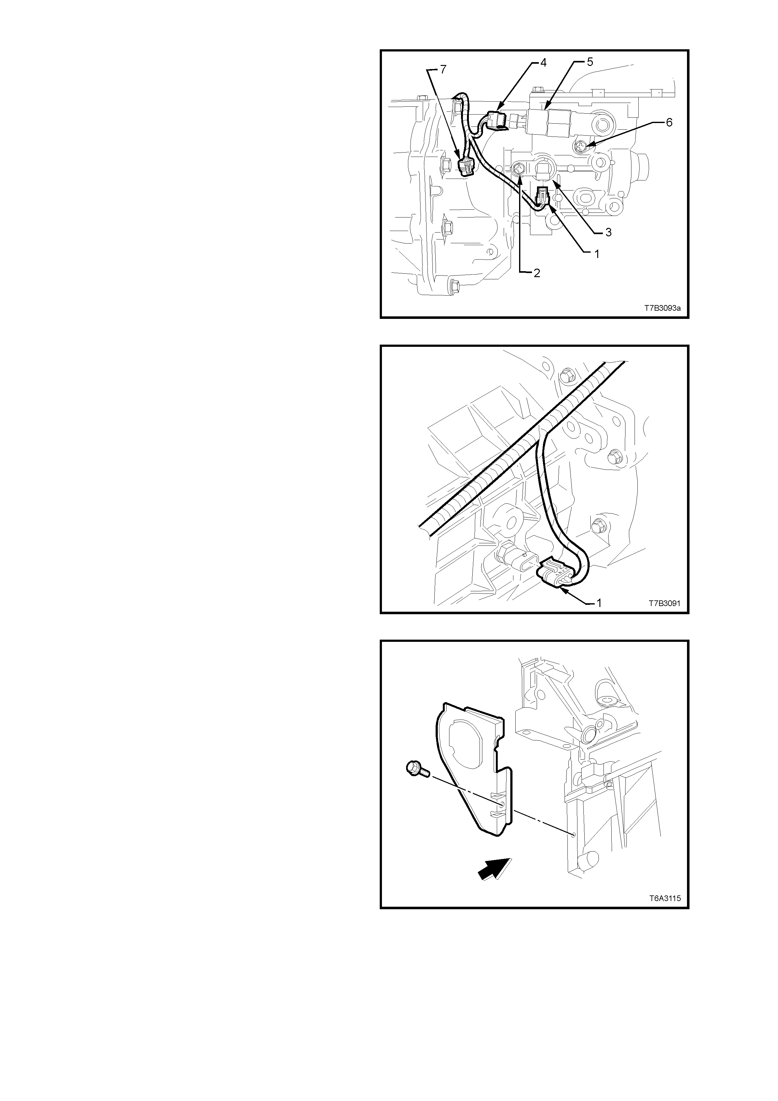
25. Remove the speed sensor wiring harness
connector (1) and the connector (4) from the
reverse lockout solenoid. (5).
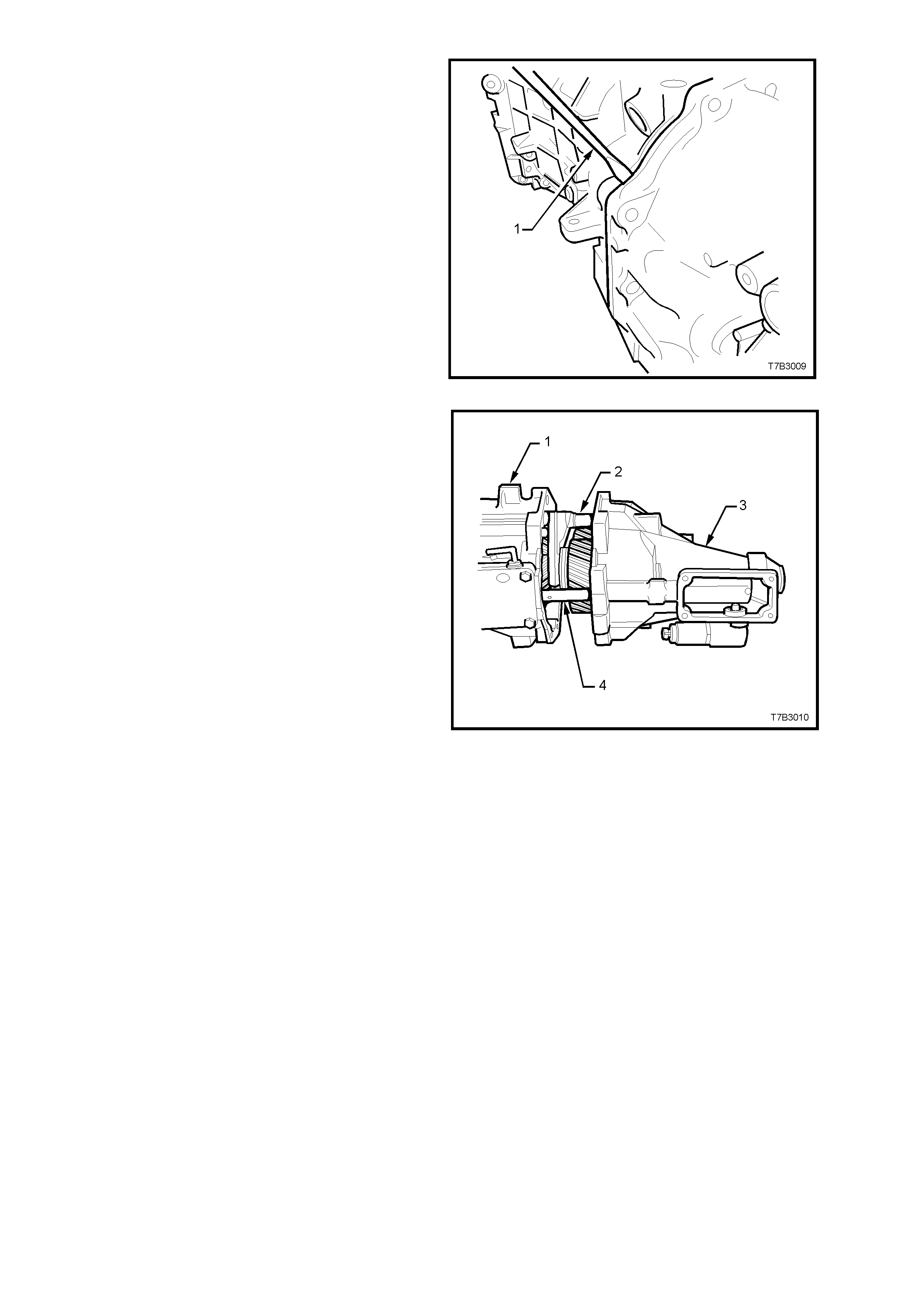
Figure 7B3-44
26. Remove the wiring harness connector from
the back-up lamp switch, located on the right
hand side of the transmission.
27. Cut the tie strap securing the powertrain
harness to the breather pipe (not shown),
remove the harness from the clip under the
right hand top extension housing bolt and
secure to one side.
Figure 7B3-45
28. Remove the starter motor. Refer to
Section 6D3-2, STARTING SYSTEM - GEN
III V8 ENGINE, of the VT Series II Service
Information, for the necessary procedure.
29. Remove the right close-out cover and bolt.
Figure 7B3-46
30. Remove the left close-out cover and bolt.
Figure 7B3-47
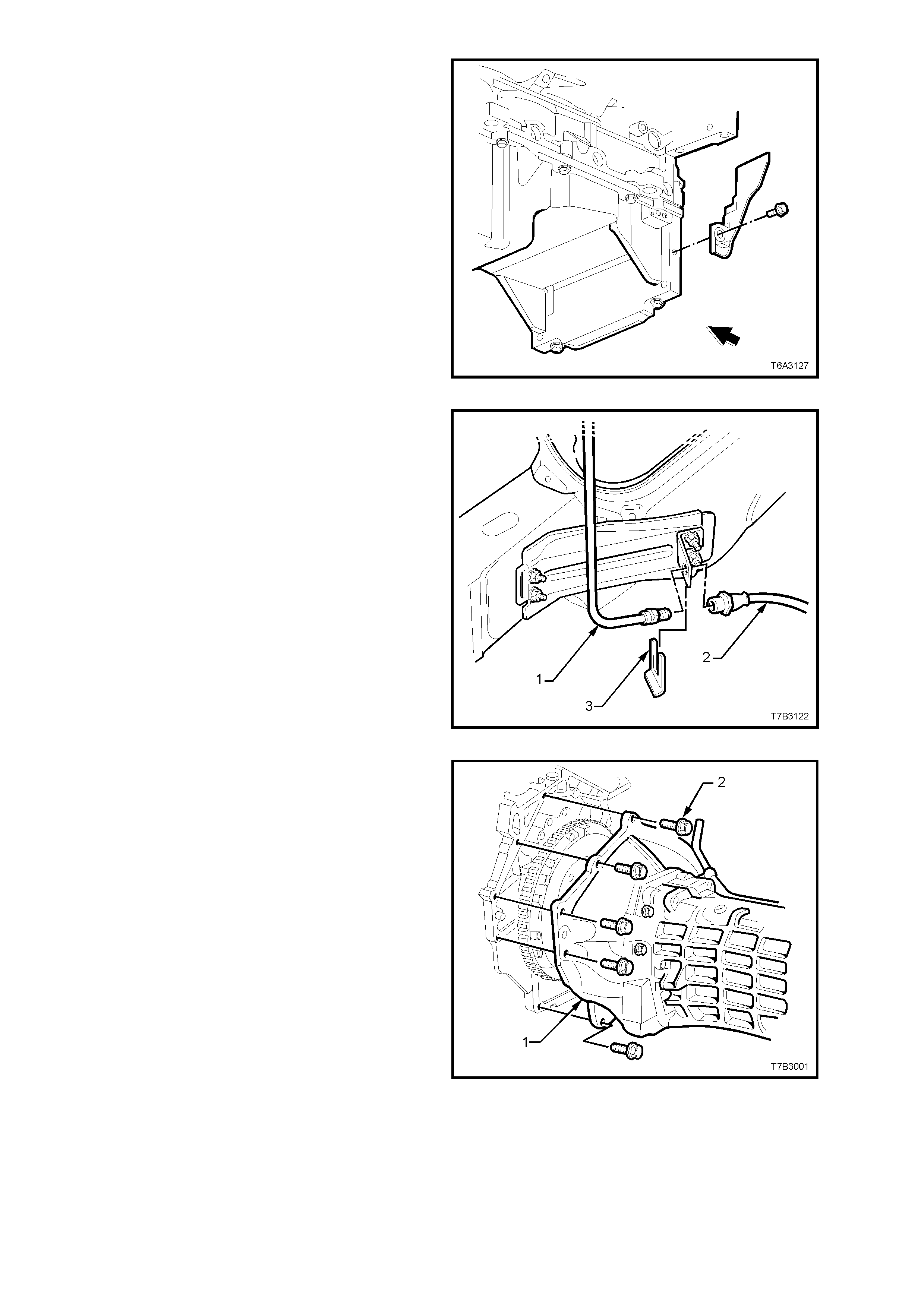
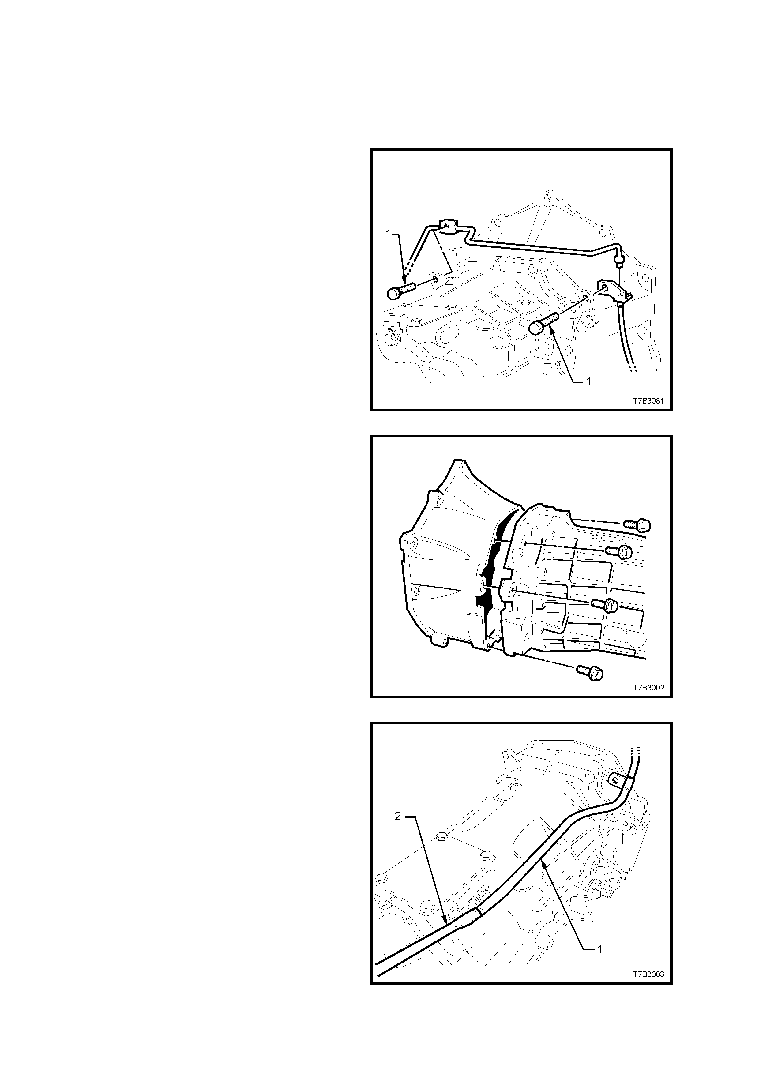
31. Place a suitable container under the clutch
hydraulic hose area, then disconnect the
hydraulic pipe (1) from the hydraulic hose (2),
at the bracket attached to the vehicle sub-
frame.
NOTE: Use a back-up spanner on the hydraulic
hose (2) when loosening the pipe fitting.
32. Remove the hose retaining clip (3) using
com bination plier s , then remove the hos e f r om
the bracket.
NOTE: Plug the hydraulic hose (2) and master
cylinder pipe (1) open ends to stop fluid loss and
dirt entry.
Figure 7B3-48
33. Lower the transmission enough to gain access
to the bolts (2) f astening the c lutch housing (1)
to the rear of the engine.
34. Progressively loosen then remove six of the
eight clutch housing to engine bolts (2).
Figure 7B3-49
35. After removing the two remaining bolts (1) that
also secure the starter motor heat shield (2),
unclip the heat shield from the starter motor
and set to one side.
36. Pull the transmission rearward, just enough to
clear the locating dowels, then rotate the
transmission through 90° to the right to gain
clearance at the floor pan.
37. With the transmission supported by the
transmission jack, continue to withdraw the
transmission, taking care not to place any
loading on the clutch driven plate centre
splines that could cause driven plate distortion.
NOTE: It is most important to prevent permanent
distortion of the driven plate, because replacement
would then be required.
38. When the transmission input shaft is clear of
the clutch pres sur e plate, the trans miss ion can
be lowered and removed from the vehicle.
NOTE: Take particular care when lowering the
transmission, that damage to the oxygen sensors
does not occur.
Figure 7B3-50
REINSTALL
1. Select 3rd gear.
2. If removed, install the clutch slave cylinder
pipe (1) to the slave cylinder (2), and tighten to
the correct torque specification.
CLUTCH FLUID PIPE FITTING TO
SLAVE CYLINDER 12 - 14 Nm
TORQUE SPECIFICATION
3. Sparingly apply 10% molybdenum disulphide
grease, such as Molybond GA 10 (or
equivalent to Holden’s Specification HN 1271)
to the bearing face of the clutch throwout
bearing, mounted to the slave cylinder (2), the
splines and spigot of the input shaft.
4. With the transmission on its side, with the top
surface facing the right hand side of the
vehicle, use a transmission jack to raise the
transmission and install input shaft into the
splines of clutch driven plate.
5. Push transmission in toward engine block. It
may be necessary to rotate the m ainshaf t after
temporarily installing the propeller shaft, to
assist in spline alignment.
Figure 7B3-51
6. When installed up to the locating dowel pins,
rotate the transmission counter-clockwise 90°,
then push fully home.
7. Clip the heat shield (2) onto the starter motor,
then install two clutch housing to engine block
bolts (1), to retain.
Figure 7B3-52
8. Install the remaining six clutch housing to
engine block bolts and tighten all bolts in the
sequence shown, to the specified torque.
CLUTCH HOUSING TO
ENGINE BLOCK BOLT 40 - 60 Nm
TORQUE SPECIFICATION
Figure 7B3-53

9. Reinstall wiring harness connectors to the
back up lamp switch, reverse lockout solenoid,
speed sensor and each of the oxygen
sensors.
10. Secure the powertrain wiring harness to the
transmission vent pipe, using a cable tie.
11. Reinstall propeller shaft slip joint into the
transm ission m ainshaft, s upporting the centre,
constant velocity joint at an angle not
exceeding 8°, to avoid damage to the joint
and/or boot.
12. Lift propeller shaft upward and install centre
bearing carrier to underbody reinforcement,
ensuring that all spacers are replaced in the
same positions, noted on removal. Install
retaining bolts.
13. Assemble propeller shaft rear universal joint
flange to pinion flange, aligning marks noted
on removal. Install attaching bolts and nuts.
14. Tighten all propeller shaft attaching bolts to
the correct torque specification.
CENTRE BEARING CARRIER TO
UNDERBODY REINFORCEMENT 20 - 35 Nm
TORQUE SPECIFICATION
PROPELLER SHAFT REAR
UNIVERSAL JOINT FLANGE BOLT 55 - 65 Nm
TORQUE SPECIFICATION
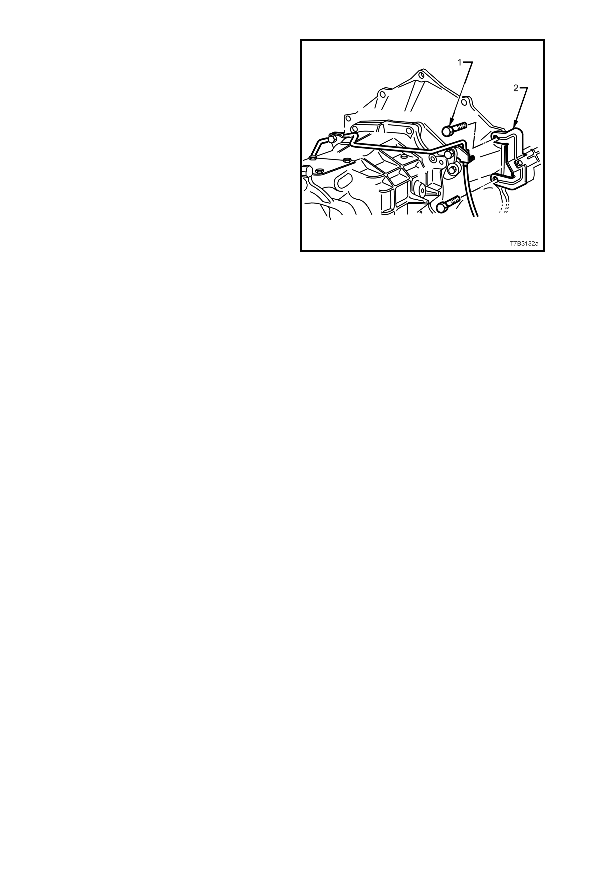
15. Reinstall the catalytic converter bracket (6) to
the transmission extension, reinstall the bolts
(7) and nuts, then tighten to the c orrect torque
specification.
CONVERTER BRACKET TO
TRANSMISSION EXTENSION BOLT 40 – 60 Nm
TORQUE SPECIFICATION
16. Reinstall the rear mount (1) to the
transmiss ion extension, install the two bolts (5)
and tighten to the correct torque specification.
TRANSMISSION MOUNT TO
EXTENSION HOUSING BOLT 20 - 30 Nm
TORQUE SPECIFICATION
17. Raise the transmission slightly, then reinstall
the four crossmember to side frame bolts (3),
aligning the crossmember (2) with the scribed
lines made prior to disassembly. Tighten the
bolts (3) to the correct torque specification.
REAR CROSSMEMBER TO
SIDE FRAME MEMBER BOLT 50 - 65 Nm
TORQUE SPECIFICATION
Important: This step is critical to the correct
powertrain alignment. If not carried out, then
vehicle vibration and/or handling problems may
result.
18. Remove the lifting device from the
transmission, centralise the rear mount studs
in the crossmember holes, then reinstall the
nuts (4), tightening to the correct torque
specification.
REAR CROSSMEMBER TO
TRANSMISSION MOUNT NUT 20 - 30 Nm
TORQUE SPECIFICATION
19. Reinstall the two catalytic converter bracket (6)
bolts, tightening to the correct torque
specification.
CATALYTIC CONVERTER
BRACKET BOLT 20 - 30 Nm
TORQUE SPECIFICATION.
20. Install clutch hydraulic hose to the bracket on
the sub-frame rail, then install the pipe fitting,
tightening to the correct torque specification.
Use a back-up spanner on the hydraulic hose
end fitting.
Figure 7B3-54
CLUTCH HYDRAULIC PIPE TO 12 - 14
TORQUE SPECIFICATION Nm
21. If transmission fluid was drained during the
removal operation, then refill, as described in
2.3 DRAINING AND REFILLING
TRANSMISSION, in this Section.
22. Reinstall the right and left close-out covers,
secure with a bolt in each and tighten to the
correct torque specification.
LEFT AND RIGHT CLOSE-OUT
COVER RETAINING BOLT 10 - 14 Nm
TORQUE SPECIFICATION
23. Reinstall the starter motor. Refer to
Section 6D3-2, STARTING SYSTEM - GEN
III V8 ENGINE of the VT Series II Service
Information, for the necessary procedure.
24. Lower vehicle to the ground.

25. Reinstall the remote shift lever boot and
retainer. Install the four bolts and tighten to the
correct torque specification.
REMOTE SHIFT LEVER BOOT PLATE 6.0 - 14
BOLT TORQUE SPECIFICATION Nm
26. Reinstall the gearshift control lever. Secure
with bolts that have Loctite 242 or equivalent
(to Holden’s Specification HN 1256 Class 2,
Type 2), applied to cleaned threads. Tighten to
the correct torque specification, then reinstall
the insulator over the control lever.
GEARSHIFT CONTROL LEVER BOLT 15 - 35
TORQUE SPECIFICATION Nm
27. Reinstall centre console assembly, including
the console cap. Refer to
Section 1A3, INSTRUMENT PANEL AND
CONSOLE, of the VT Series I Service
Information for the necessary procedure.
28. Reinstall the gearshift knob and boot
assembly over the gearshift lever, align the
knob in the c orrect attitude and then bum p the
knob onto the gear shif t lever until the retaining
claws engage with the groove in the lever.
29. Align the gearshif t boot retaining clips with the
hole in the console cap, then c ar ef ully seat the
boot retainers into the console cap until each
clip engages correctly.
30. Reconnect battery earth lead.
31. Road test vehicle and check transmission,
clutch and gearshift operations.
4.3 TRANSMISSION DISASSEMBLE
1. Remove transmission assembly from vehicle.
Refer 4.2 TRANSMISSION ASSEMBLY -
REMOVE, in this Section.
CLUTCH HOUSING AND SLAVE CYLINDER
2. Remove the two bolts (1) securing the clutch
slave cylinder pipe to the transmission,
unscrew the fitting from the slave cylinder and
remove the pipe and brackets from the
transmission.
Figure 7B3-55
3. Remove the 8 bolts holding the c lutch housing
to the transmission, then remove the housing.
Figure 7B3-56
4. Remove the plastic vent tube (1), by pushing
on the end of the tube with the flat blade of a
screwdriver (2), to s lide the tube from the vent
tube fitting, then set the pipe to one side.
Figure 7B3-57
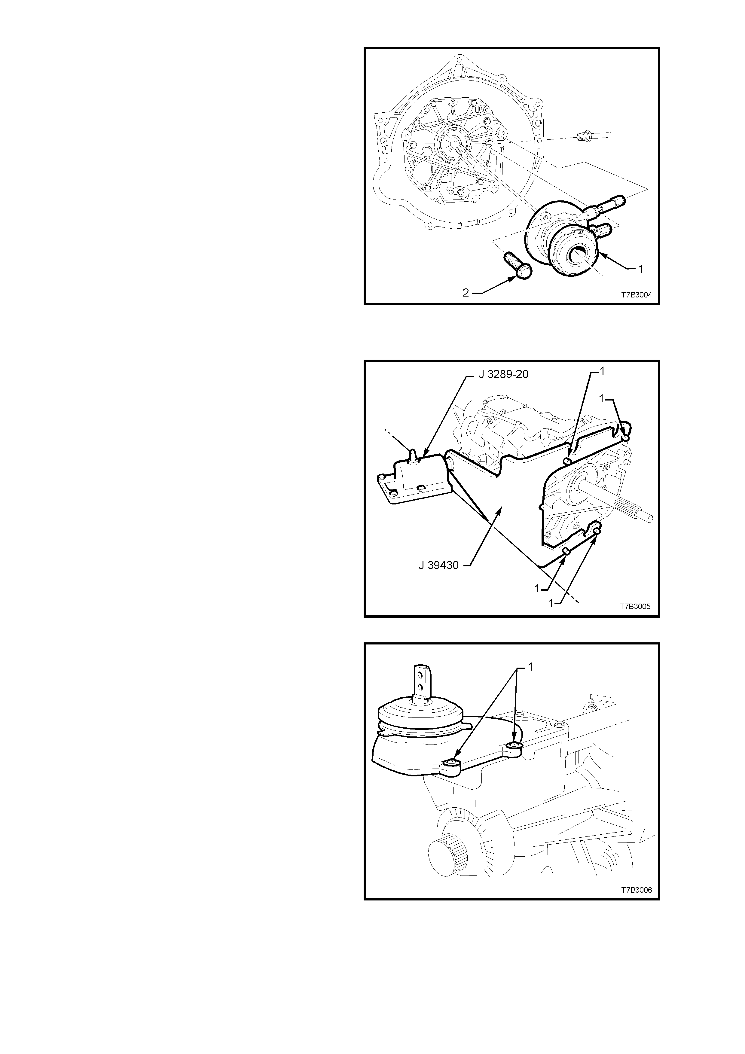
5. Remove the 2 bolts (2) securing the clutch
slave cylinder (1) to the transmission adaptor
plate, then set the slave cylinder assembly (1)
to one side.
Figure 7B3-58
EXTENSION HOUSING
1. Install holding tool J 39430 to the front of the
transmission, using 4 of the clutch housing
bolts (1).
2. Install holding tool J 39430 into the bench
holding fixture J 3289-20.
Figure 7B3-59
3. With the transmission in a horizontal position
with the shift lever up, drain the transmission
fluid (if not carried out previously).
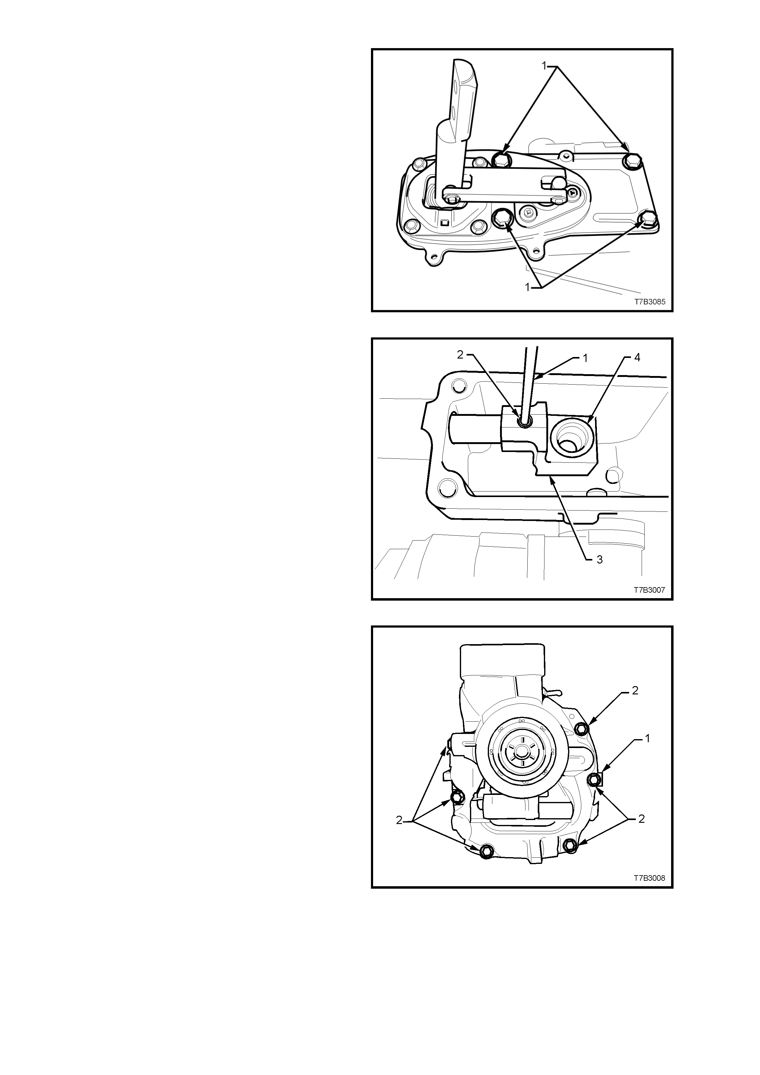
4. Remove the four screws securing the shift
lever cover, prise the cover loose, then
remove.
Figure 7B3-60
5. Select either 2nd or 4th gear.
6. Remove the 4 bolts (1) holding the shifter
assembly to the extension housing. If requir ed,
tap with a rubber or plastic hammer to break
the seal, then remove the assembly and
rubber seal from the extension housing.
Figure 7B3-61
7. Using a suitable pin punch (1), remove the
rear offset lever roll pin (2).
NOTE: Selecting 2nd or 4th gear shortens the shift
rail overhang, providing m or e support dur ing the roll
pin removal.
8. Remove the rear offset lever (3) and check
that the isolator cup (4) is secure in the lever.
If loose, discard both the isolator cup and the
rear offset lever.
Figure 7B3-62
9. Remove the 8 bolts (2) holding the extension
housing, noting the position of the
identification tag (1).
NOTE: The two top bolts (not shown) have sealant
applied to the threads.
Figure 7B3-63
10. With the transmission in a horizontal position,
break the sealant seal by levering in the point
provided, using a flat bladed screwdriver (1).
11. Tap the extension housing rearward, using a
plastic or rubber hammer to remove the
housing from the 2 locating dowel pins.
Figure 7B3-64
12. Slide the housing (3) f rom the s hift rails (2 and
4) and remove from the transmission case (1).
13. Remove both circular magnets located in the
recess in the rear of the transmission case
and set to one side.
Figure 7B3-65
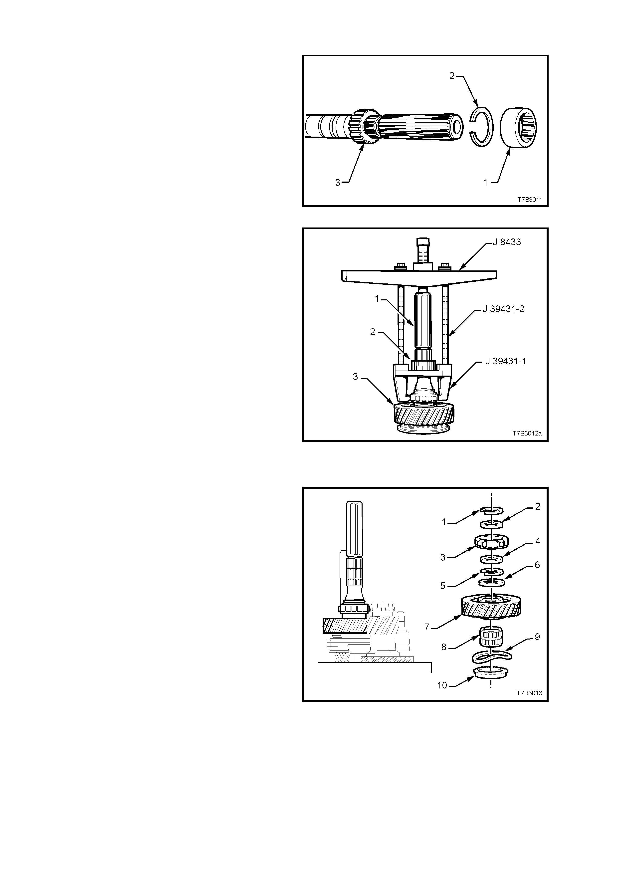
SPEEDOMETER PULSE RING
1. Slide the sealing ring (1) from the mainshaft.
2. Using suitable snap ring pliers, remove the
snap ring (2) from the speedom eter pulse ring
(3).
Figure 7B3-66
3. Assemble universal bridge puller J 8433 and
puller J 39431-1 using bolts J 39431-2, as
shown.
4. Remove the speedometer pulse ring (2) from
the mainshaft (1), then disassemble the tools.
5. Remove the second speedometer pulse ring
snap ring, using suitable snap ring pliers.
Figure 7B3-67
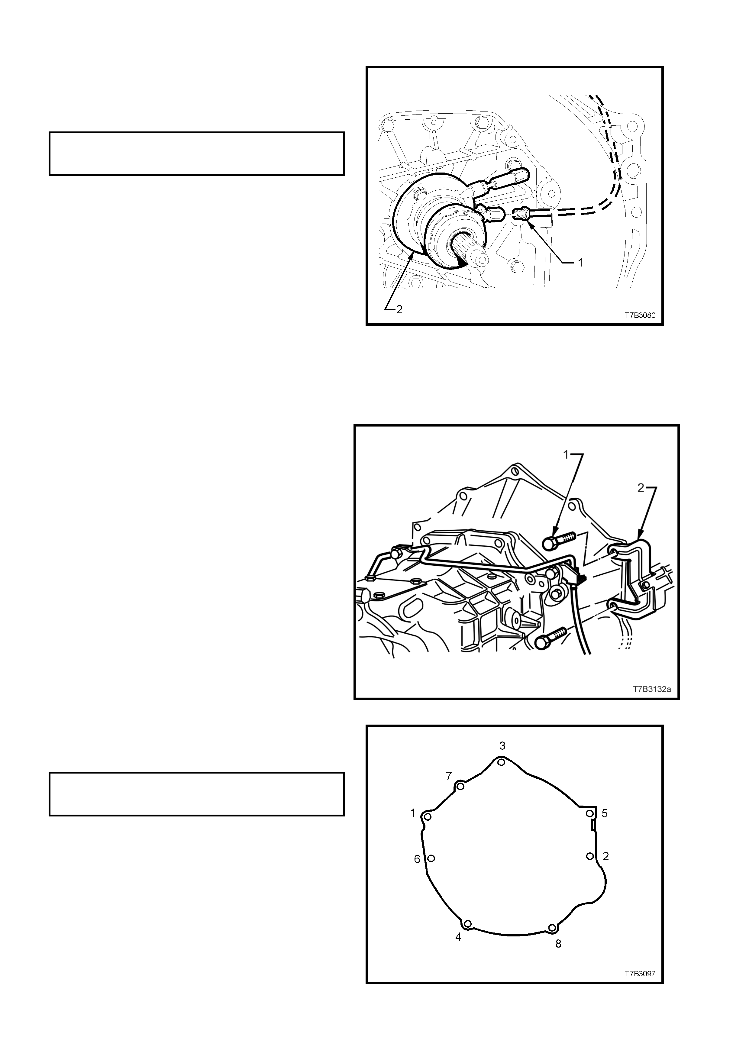
REVERSE AND 5TH/6TH DRIVEN GEAR
1. Remove the following components from the
mainshaft:
a. Snap ring (1).
b. Spacer (2).
c. Rear mainshaft roller race (3).
d. Spacer (4).
e. Snap ring (5).
f. Thrust washer (6).
g. Reverse gear (7).
h. Reverse gear, caged roller bearing (8).
i. Wave washer (9).
j. Reverse gear blocker ring (10).
Figure 7B3-68
2. Remo ve reverse synchromes h assembly snap
ring (3).
3. Remove circlip (2) from the reverse shift rail
and discard.
4. Remove the reverse synchromesh assembly
(4), thrust washer (not shown) and reverse
shift fork (1), as an assembly.
NOTE: The synchromesh hub (4) is a sliding fit to
the mainshaft splines.
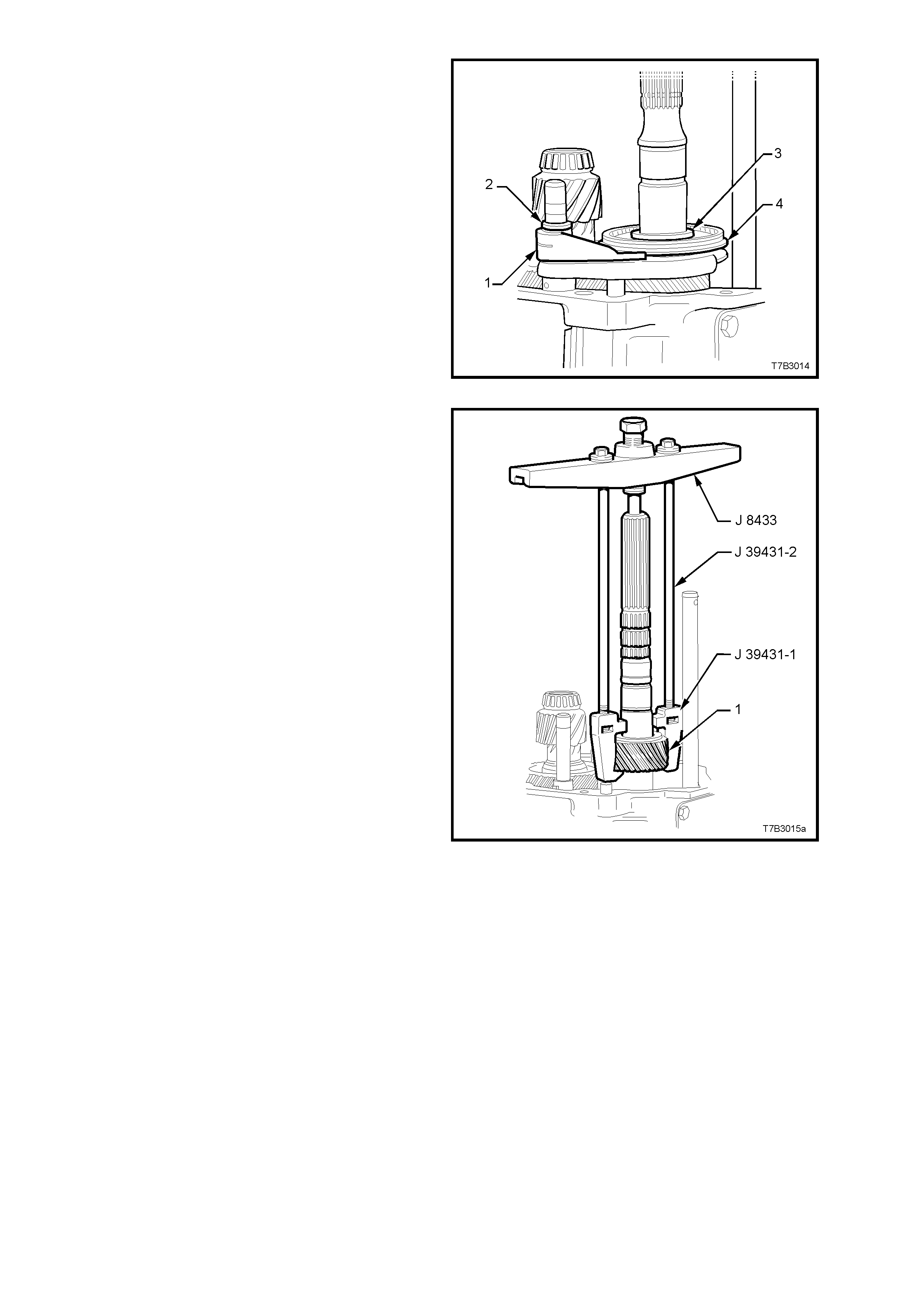
Figure 7B3-69
5. Assemble universal bridge puller J 8433 and
puller adaptor J 39431-1 using bolts J 39431-
2, as shown.
6. Remove 5th/6th driven gear (1), then
dismantle tools.
Figure 7B3-70
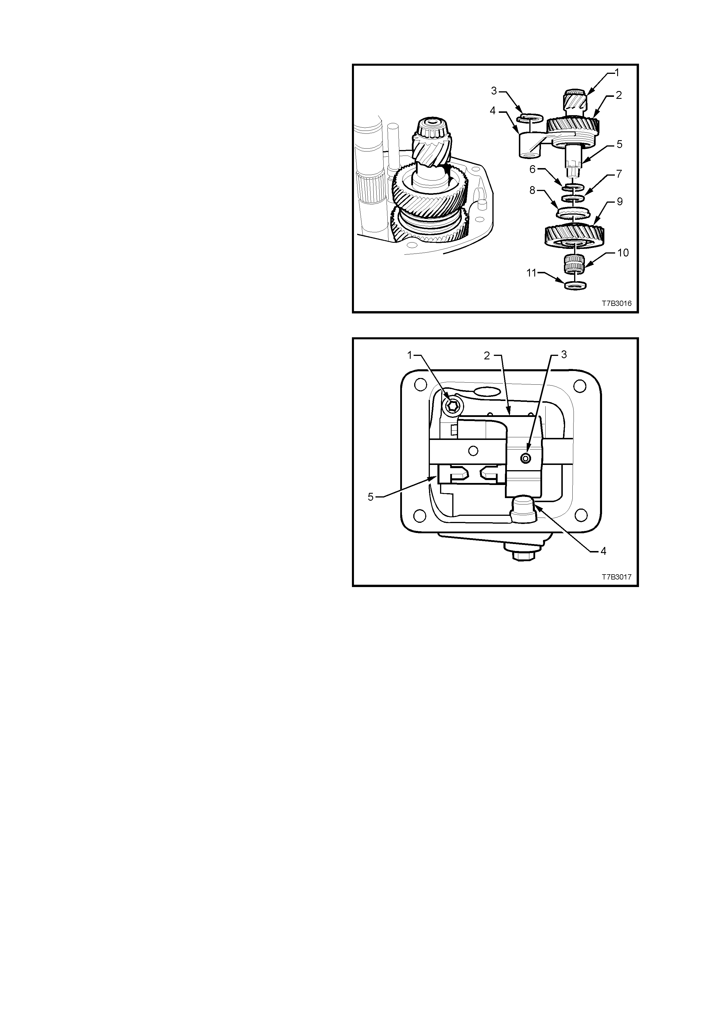
COUNTERSHAFT EXTENSION ASSEMBLY
1. Remove the circlip (3) from the 5th/6th shift
rail, then rem ove the following components as
an assembly; countershaft extension (1) with
the 5th drive gear (2), selector fork (4) and
synchromesh assembly (2), all secured by the
snap ring (6).
2. Remove the following components;
a. Spacer (7).
b. 6th gear, blocker ring (8).
c. 6th drive gear (9).
d. 6th drive gear, caged needle roller
bearing (10).
e. Thrust washer (11).
Figure 7B3-71
3. Remove the 4 bolts securing the guide plate
cover to the transmission case. Use a flat
bladed screwdriver and plastic hammer to
dislodge the cover sealant, then remove the
cover.
NOTE: Be careful not to bend the cover when
breaking the sealant grip.
4. Remove the shift enhancer (4) from the
transmission case using a suitable sized
socket.
5. Using a suitable sized pin punch, remove the
roll pin (3), from the front offset lever (2).
Figure 7B3-72
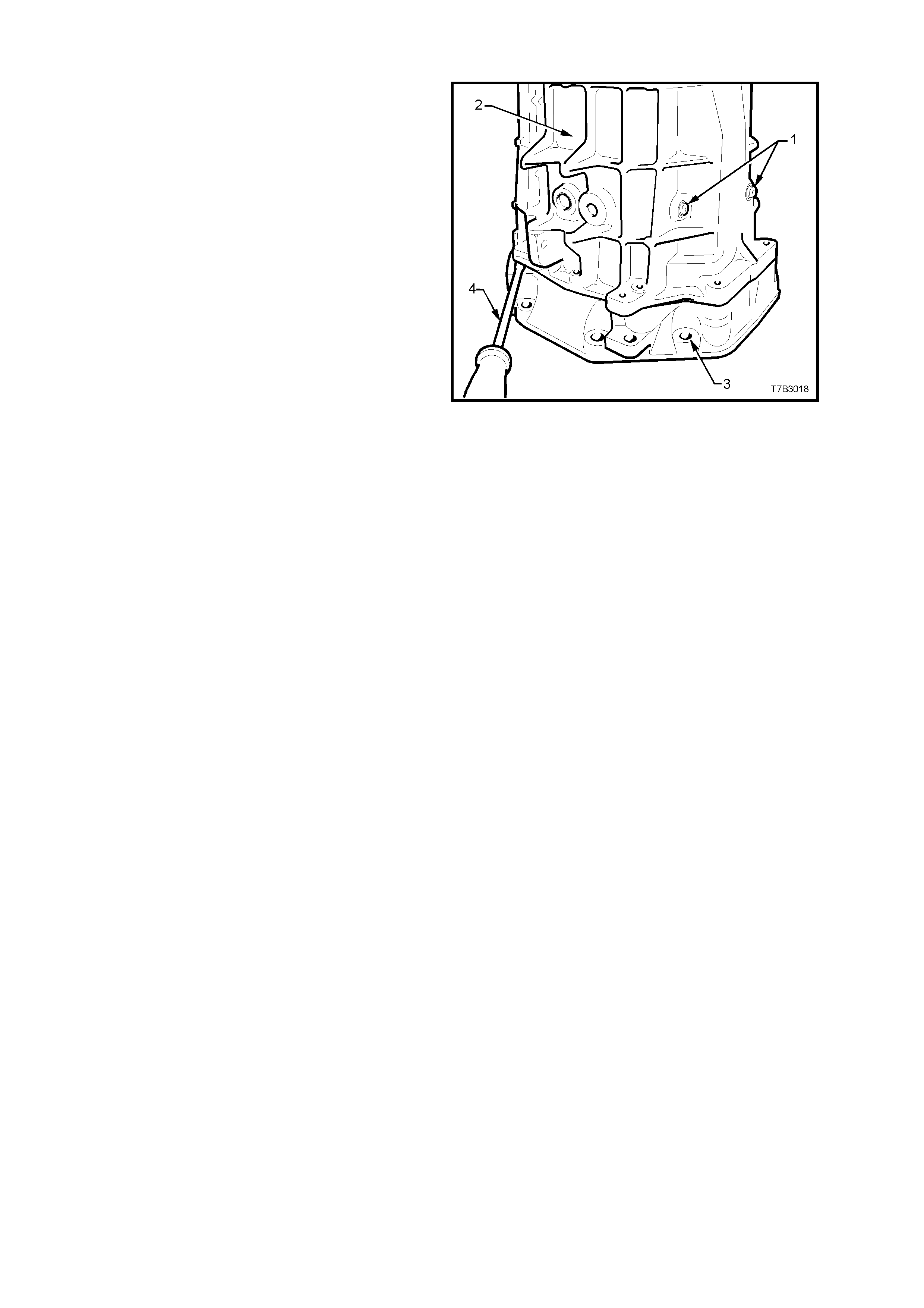
TRANSMISSION CASE
1. Remove the two T40 Torx bit screws securing
the shift lever guides (1).
NOTE: Both of these screws have thread sealant
applied and will be extremely difficult to remove
unless a hot air gun is used to soften the thread
sealant prior to loosening and during removal.
2. Remove the r ever se lamp s witch f r om the s ide
of the transmission case.
3. Remove the 10 adaptor plate to transmission
case bolts from the front of the transmission
(not shown).
4. Carefully rotate the transm ission into a vertical
position, then lever the transmission case (2)
from the adaptor plate (3), using a flat bladed
screwdriver (4) in the space pr ovided, to break
the sealant seal and clear the two dowel pins.
5. Lift the transmission case upward from the
gear train and shift rail components, while
supporting the front offset lever during the
process.
NOTE: Holding the front offset lever against the
guide plate during case removal, will reduce the
possibility of the detent ball and spring from being
dislodged.
6. Referring to Figure 7B3-70, use a T40 Torx
bit, to remove the 2 screws (1) from the guide
plate (5).
NOTE: In Figure 7B3-70, the front offset lever (2)
covers the second guide plate screw.
7. Remove the guide plate (5) from the
transmission case .
Figure 7B3-73
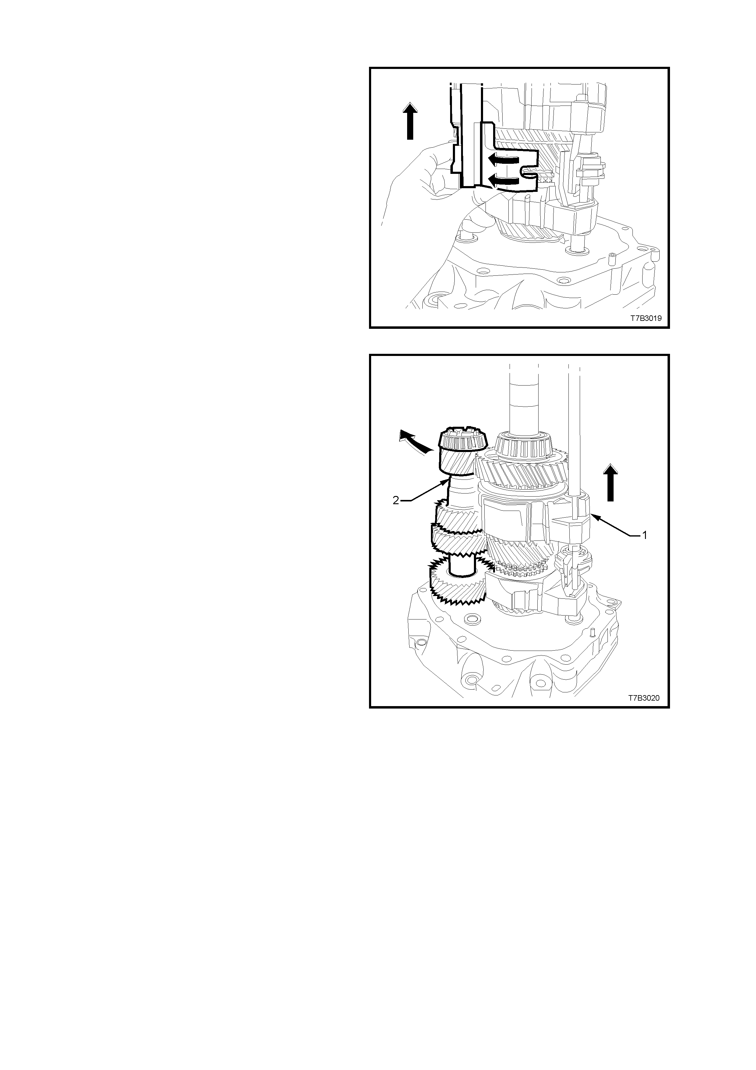
GEAR TRAINS AND SHIFT RAILS
1. Rotate the 5th/6th and Reverse shift levers
from the interlock plate (curved arrows), then
lift both shift rail assemblies from the adaptor
plate.
Figure 7B3-74
2. Lift the mainshaft and shift forks (1) to allow
counter gear (2) removal.
3. Carefully lift the mainshaft assembly with the
shift forks in place, from the input shaft and
set to one side.
4. Lift the input shaft from the adaptor plate and
set to one side.
Figure 7B3-75
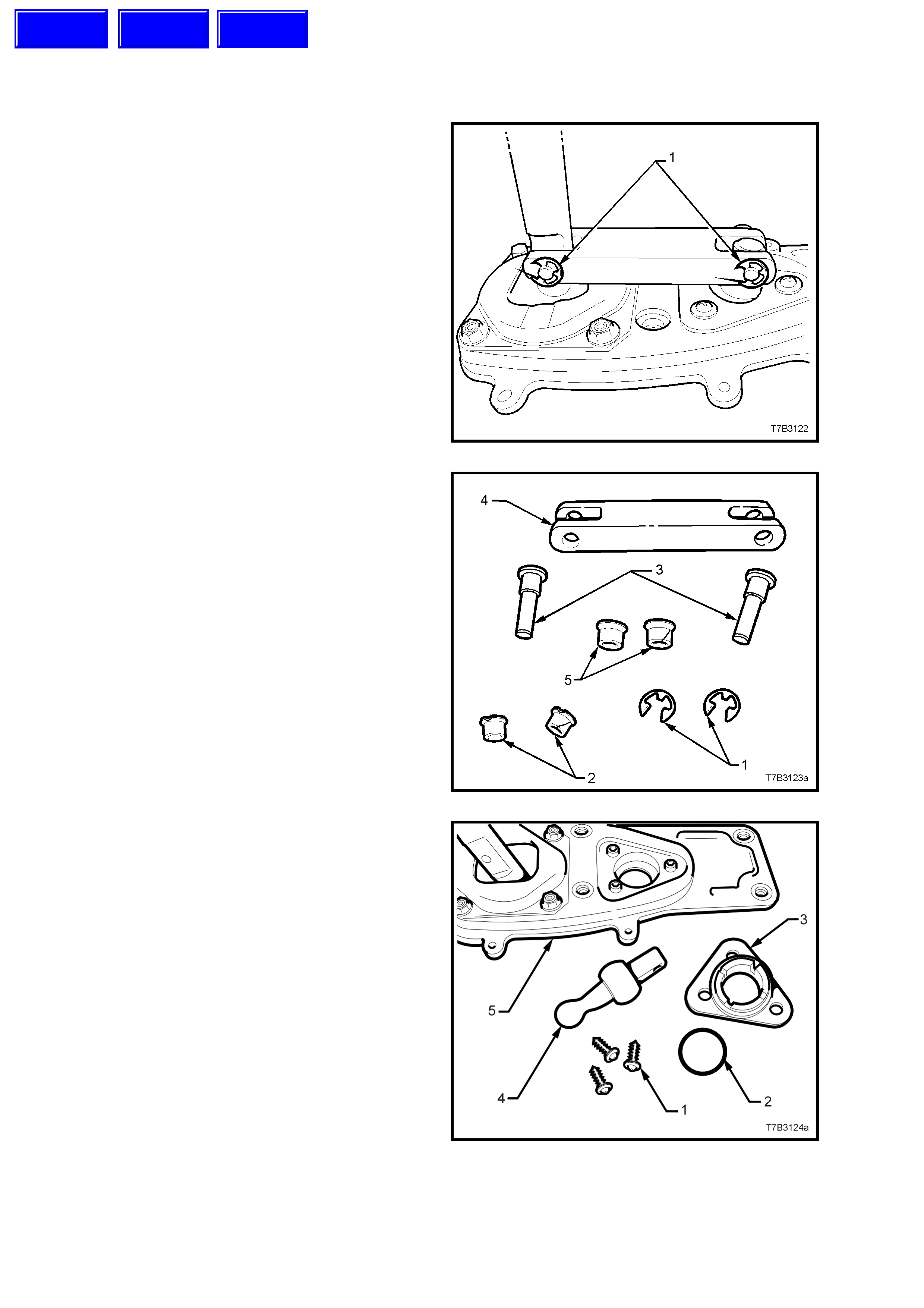
4.4 REMOTE CONTROL SHIFT MECHANISM
DISASSEMBLE
1. With the boot and dust cover removed, use a
small screwdriver to remove both ‘E’ clips (1).
CAUTION: Wear safety glasses to avoid
possible eye injury.
Figure 7B3-76
2. Tap the two pins (3) free from the bridging
piece (4). These two pins are an interference
fit into each of the two pivot pieces and must
be replaced after removal.
3. Remove both the smaller (2) and larger (5)
bushes from the bridging piece (4).
Figure 7B3-77
4. To disassemble the front pivot assembly,
unscrew the three self tapping screws (1),
using a Phillips No. 2 screwdriver.
5. By grasping the remote selector pivot (4), pull
the pivot (4) and seat assembly (3) from the
baseplate (5).
6. Remove the O-ring seal (2) from the seat (3).
7. Separate the selector pivot (3) from the seat
assembly (2) by supporting the seat assembly
over the open jaws of a vice assembly, then
tap the ball end of the selector pivot (3) free
from the seat (2).
Figure 7B3-78
Techline
Techline
Techline
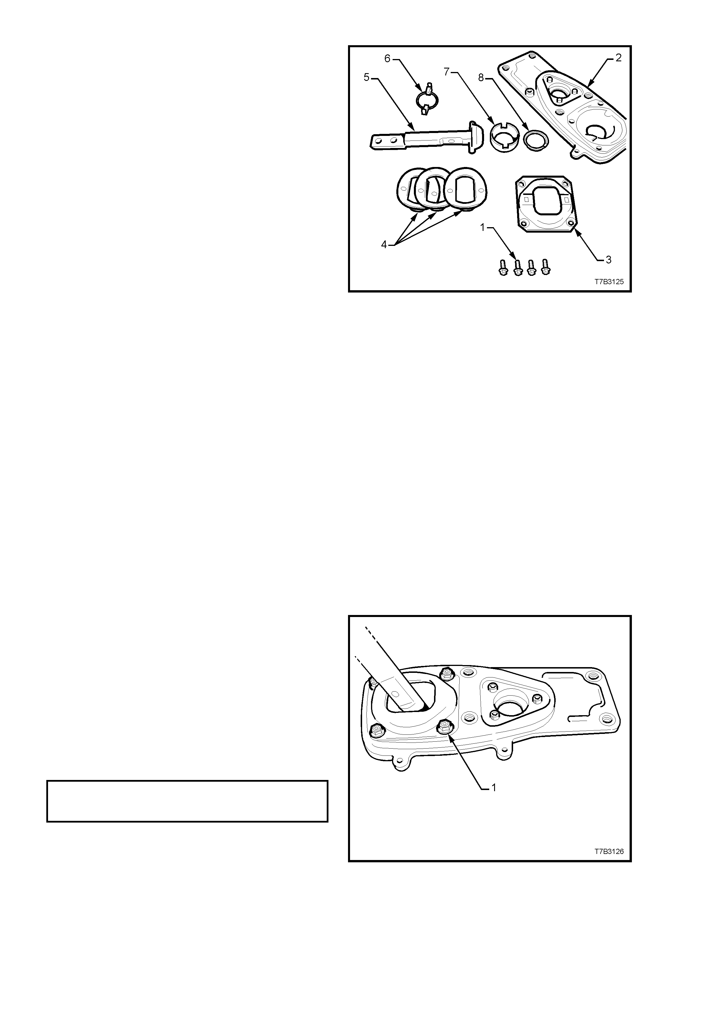
8. The rear remote shifter assembly can be
disassembled by first removing the four plate
(3) retaining bolts (1) from the baseplate (2).
9. Remove the wave springs (4), remote shifter
shaft (5) and guide (6), from the base plate
(2).
10. Finally, remove the ball seat (7) and seat
support ring (8) from the base plate (2).
Figure 7B3-79
CLEAN AND INSPECT
Clean
After removing rubber insulating bushes and seal
to the extension housing, thoroughly wash all
components in a suitable cleaning solvent. Dry all
parts with clean, dry compressed air.
CAUTION: Wear safety glasses to avoid eye
injury.
Inspect
1. Inspect pins, bushes, ball seats and other
com ponents for wear or damage, replac ing as
required.
2. Inspect the O-ring seal at the front pivot
assembly, the cover plate insulating rubber
bushes and seal to the extension housing, for
deterioration or damage, replacing as
required.
REASSEMBLE
While reassembly is the reverse to disassembly,
there are some specific procedures such as;
1. Apply 10% molybdenum disulphide grease
such as Moybond GA 10 or equivalent (to
Holden’s Specification HN 1271) to all moving
parts in the rear remote shifter assembly.
2. Reassemble all parts in the reverse order of
disassembly.
3. Install the four bolts (1) securing the plate to
baseplate, tightening to the correct torque
specification.
REAR REMOTE SHIFT LEVER
COVER BOLT 10 - 12 Nm
TORQUE SPECIFICATION
Figure 7B3-80
4. Apply NLGI No. 4 EP greas e to the ball s ock et
of the front pivot, then reassemble by tapping
the front remote pivot into the plastic socket.
5. Install the O-ring seal to the socket, replacing
with a new part if the original is damaged.
6. Reinstall the assembly (1) to the baseplate,
install the three retaining screws and tighten
securely.
Figure 7B3-81
7. Install the bridging piece to the two remove
lever assemblies.
8. Install new bushes to the bridging piece after
lubricating with NLGI No. 4 EP grease.
9. Install NEW pivot pins to each location and tap
home with a hammer.
NOTE: These pins are designed to be an
interference fit to the front and rear remote shifter
levers and not be free floating.
10. Fit new ‘E’ clips (1) to secure each pin.
CAUTION: Wear safety glasses to avoid eye
injury.
NOTE: the dust cover and boot assembly will be
installed after the remote shifter assembly is
installed to the transmission extension housing.
Figure 7B3-82
4.5 TRANSMISSION SUB-ASSEMBLIES
DISASSEMBLE
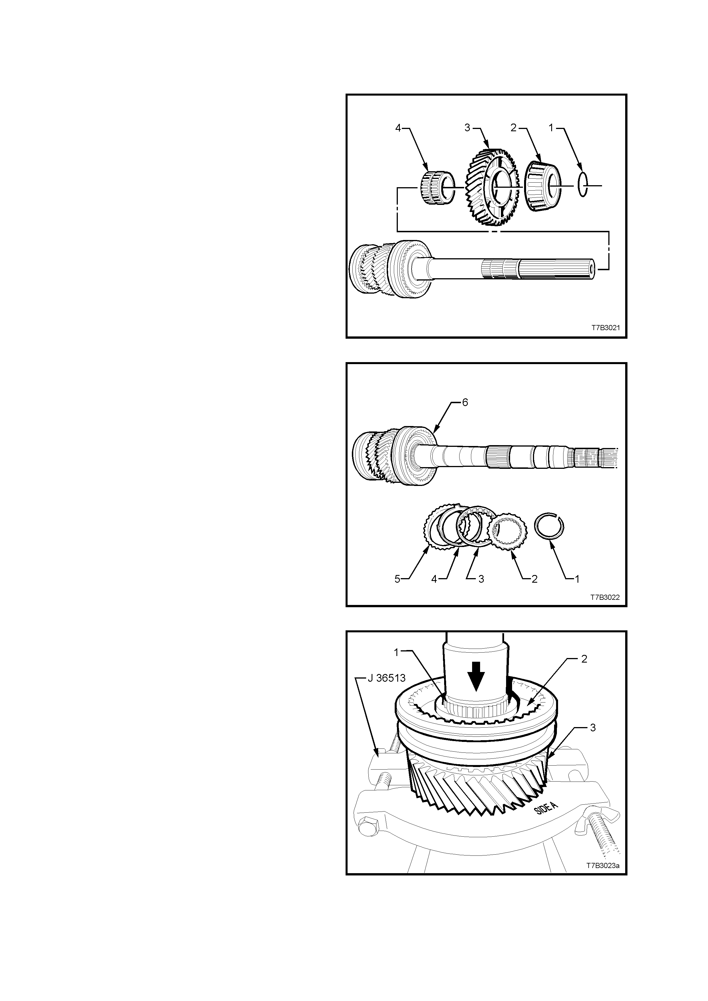
Mainshaft
NOTE: Do not mix any synchrom esh block er rings,
or any synchromesh components.
1. Remove the O-ring (1) behind the rear
mainshaft bearing (2).
2. Grasp the 1st speed gear (3) and slide from
the mainshaf t, rem oving the r ear tapered roller
bearing (2) in the process.
3. Remove the 1st speed gear, caged needle
roller bearing (4) from the mainshaft.
Figure 7B3-83
4. Remove the snap ring (1) s ecuring the 1st/2nd
synchromesh assembly (6).
5. Remove the thrust washer (2), inner cone (3),
friction cone (4), and blocker ring (5) from the
1st/2nd synchromesh assembly (6).
Figure 7B3-84
6. Install split press plates J 36513, with the flat
side (side A) against the 2nd speed constant
mesh gear (3).
7. Press the mainshaft (1) from the 2nd speed
constant mesh gear (3) and synchromesh
assembly (2). The components of the 2nd
speed synchromesh unit (2nd speed blocker
ring, friction cone, 2nd speed inner cone and
thrust washer), will also be removed in this
operation.
8. Remove the 2nd speed gear caged needle
roller bearing from the mainshaft.
Figure 7B3-85
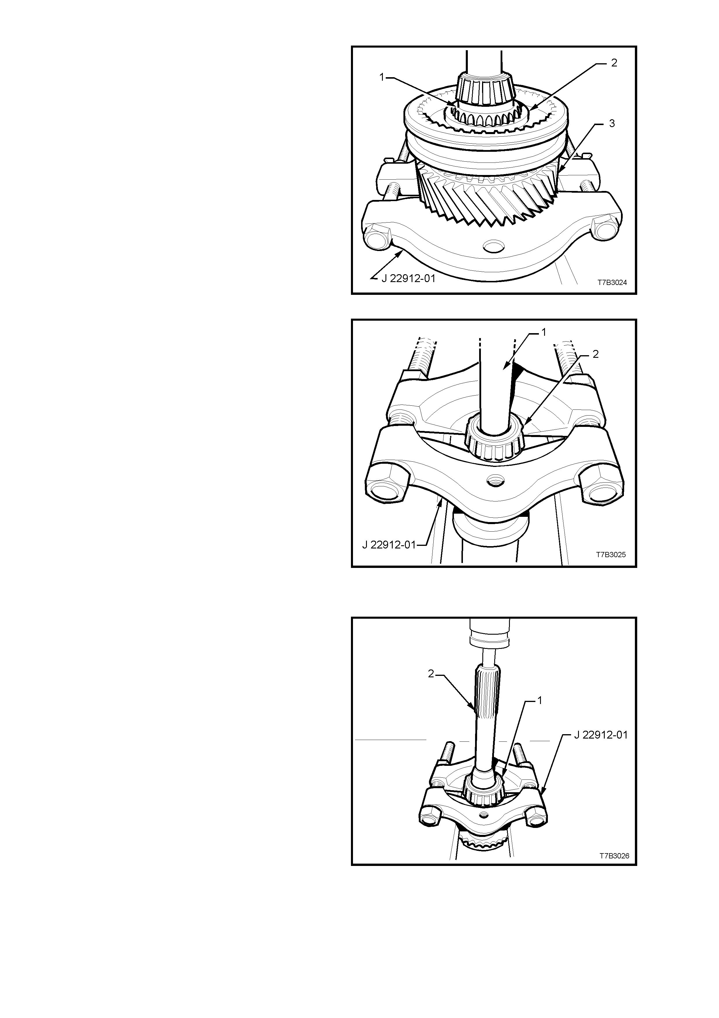
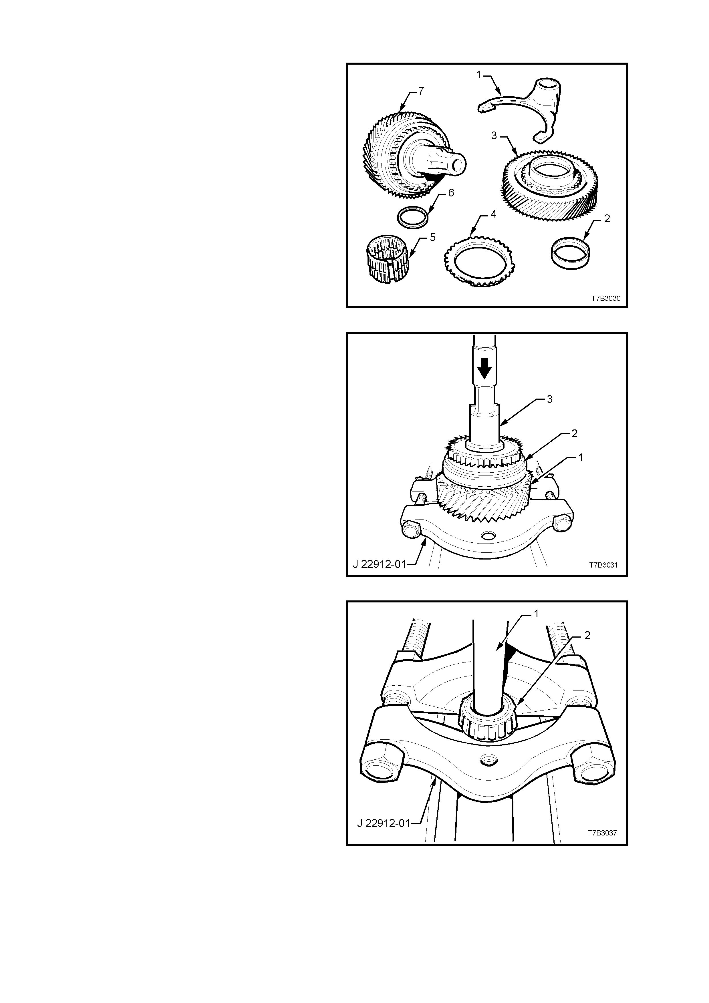
9. Remove the snap ring securing the 3rd/4th
synchromesh assembly.
10. Install split press plates J 22912-01 with the
flat side against the 3rd speed constant mesh
gear (3). Press the mainshaft (1) from the
3rd/4th synchromesh assembly (2). In the
process, the 3rd speed constant mesh gear
(3), 3rd speed blocker ring, friction cone, inner
cone and thrust washer will also be removed.
11. Remove the 3rd speed gear caged needle
roller bearing from the mainshaft.
Figure 7B3-86
12. Install split press plates J 22912-01 under the
pilot bearing (2) installed on the nose of the
mainshaft, tightening the bolts to secure.
Press the bearing (2) from the mainshaft,
using a suitable sized drift (1) (or socket
extension). Discard the bearing.
NOTE: Only remove this bearing if it is to be
replaced, as damage to the bearing during the
removal process will most likely occur.
Figure 7B3-87
Input Shaft
NOTE: Only remove the input shaft bearing or the
pilot bearing cup, if these components are to be
replaced.
1. Install split press plates J 22912-01 under the
input shaft bearing (1), tightening the bolts to
secure.
2. Press the bearing (1) from the input shaft (2).
3. Discard the removed bearing (1).
Figure 7B3-88
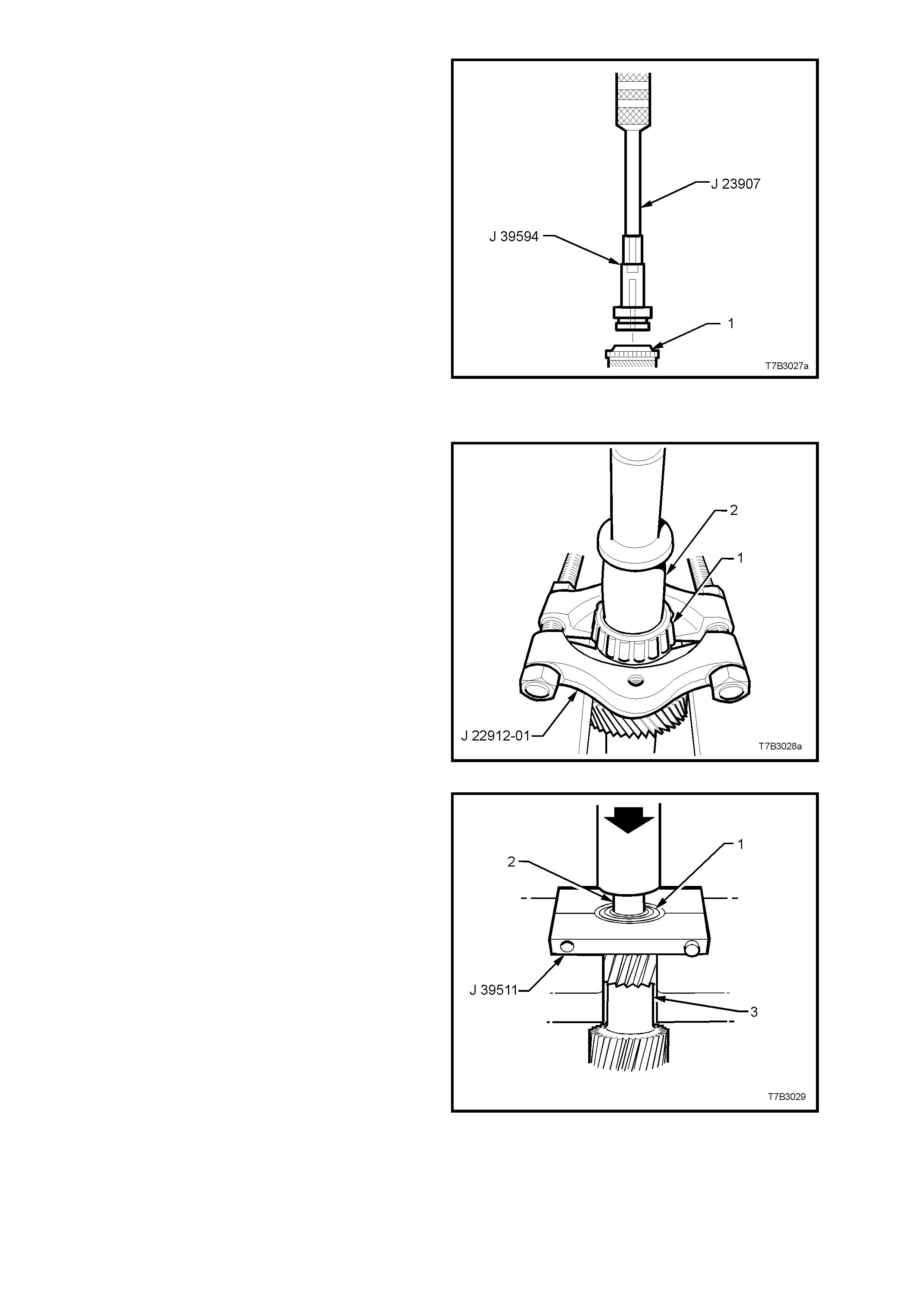
4. After assembling bearing remover J 39594 to
slide hammer J 23907, remove the front
mains haft bear ing cup f rom the input shaf t ( 1).
Discard the removed bearing cup.
Figure 7B3-89
Countershaft Gear
NOTE: Only remove either or both of the
countershaft bearing/s if replacement is required,
as damage will result from the removal procedure.
1. For the rear taper roller bearing (1);
a. Install press plates J 22912-01 under the
taper roller bearing (1), tightening the
bolts to secure.
b. Press the bearing (1) from the
countershaft gear, using a suitable size
drift (2) (or socket).
c. Discard the removed bearing.
Figure 7B3-90
2. For the front taper roller bearing;
a. Install split press plates J 39511 under
the front countershaft gear bearing (1),
tightening the bolts to secure.
b. Press the bearing (1) from the
countershaft gear (3), using a suitable
size drift (2) (or socket).
c. Discard the removed bearing.
Figure 7B3-91
Countershaft Extension
1. Remove the following components from the
countershaft gear extension (7);
a. 5th/6th gear shift fork (1)
b. Thrust washer (may be retained on
countershaft gear) (2).
c. 6th speed drive gear (3).
d. Synchromesh blocking ring (4).
e. Caged needle roller bearing (5).
f. Spacer (6).
Figure 7B3-92
2. Remove 5th/6th gear synchromesh assembly
snap ring.
3. With the flat sides of press plates J 22912-01
under the 5th speed drive gear (1), press the
gear and synchromesh assembly (2) from the
countershaft extension shaft (3), using a
suitable size drift.
Figure 7B3-93
4. Install split press plates J 22912-01 under the
tapered roller bearing (2), tightening the bolts
to secure.
5. Press the bearing (2) from the countershaft
extension, using a suitable sized drift (1) (or
socket extension). Discard the removed
bearing.
NOTE: Only remove this bearing if it is to be
replaced, as damage to the bearing during the
removal process will occur.
Figure 7B3-94
Synchromesh Assemblies
NOTE: Th is operation is not recom mended, unles s
considered to be absolutely necessary. If
disassembly is required, then extreme care must
be taken to identify each component and it’s exact
location, using liquid paper or a felt tipped pen for
the purpose.
All Assemblies Except Reverse Gear
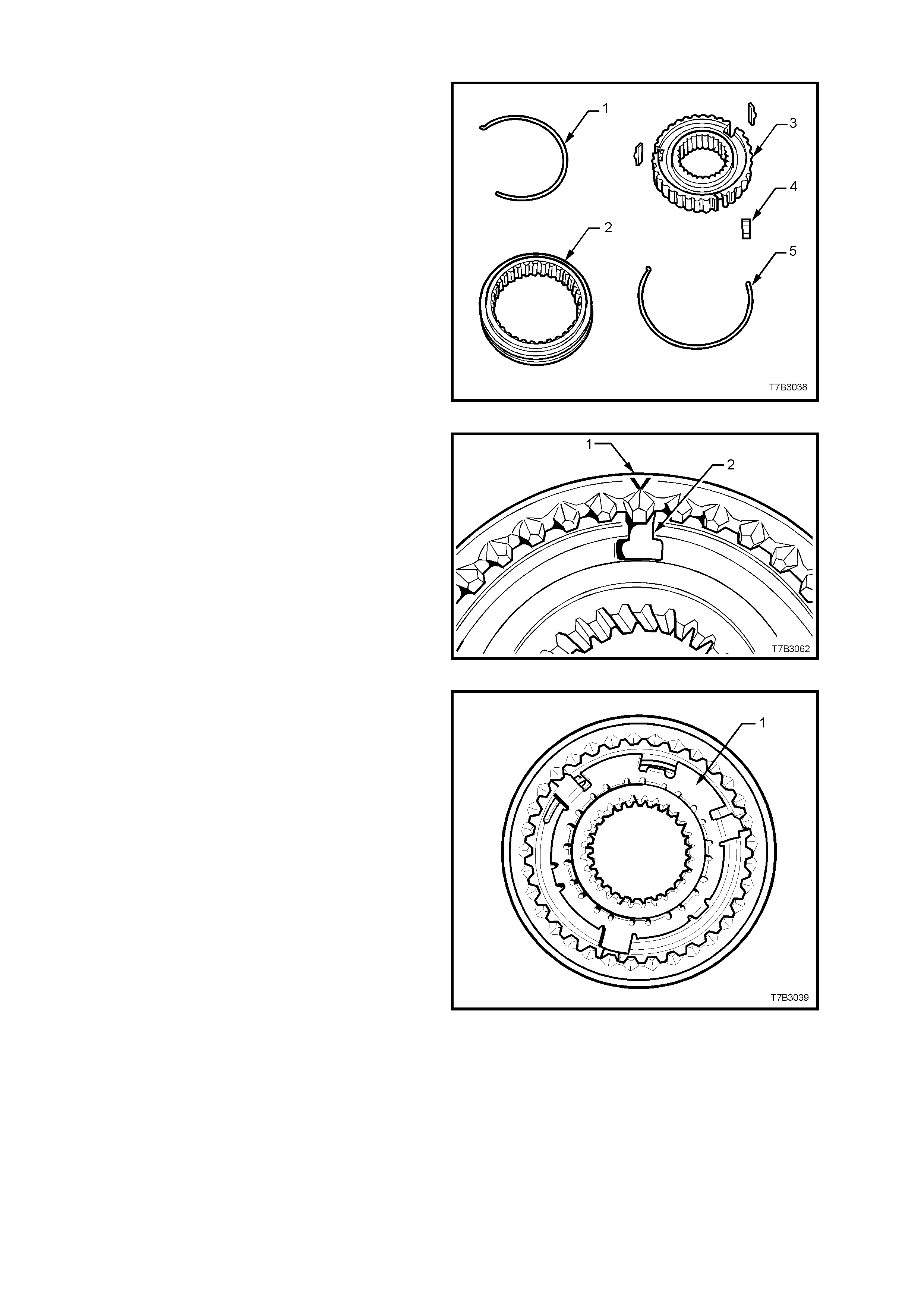
1. Using a small screwdriver, remove the
synchroniser springs (1 and 5).
CAUTION: Wear safety glasses to avoid eye
injury.
Figure 7B3-95
2. Note the location of the synchromesh
assembly ring ‘V’ mark (1) to the key location
in the hub (2), then slide the ring from the hub.
Figure 7B3-96
Reverse Gear Synchromesh Assembly
1. Using a small screwdriver, remove the
synchroniser spring from the reverse gear
side, taking care to avoid eye damage.
2. Note the location of the sy nchromesh
assembly ring mark (‘V’) to the key location in
the hub, then slide the ring from the hub.
3. Remove the three keys.
4. Remove the synchromesh key retainer (1),
using a pin punch through the hub key slots.
Discard the retainer.
5. Remove the second synchroniser spring,
using a small bladed screwdriver.
Figure 7B3-97
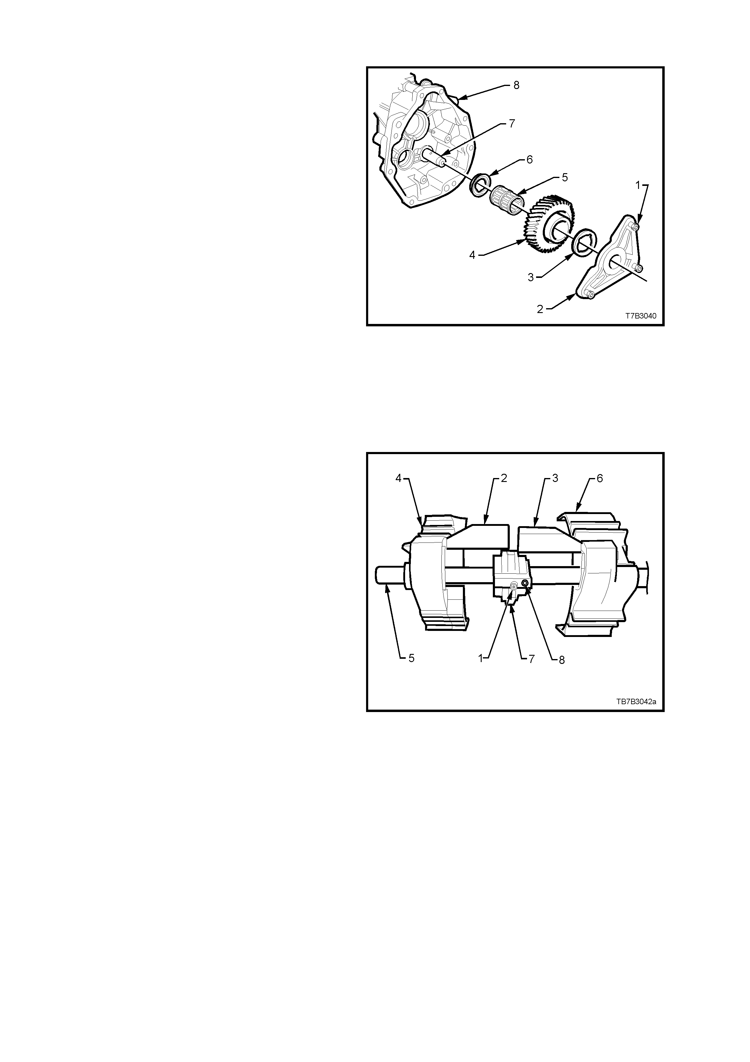
Reverse Idler Gear
1. Using Torx bit T40, remove the three screws
(1) securing the reverse idler gear shaft
support plate (2).
2. Remove the support plate (2), reverse idler
gear thrust washer (3), reverse idler gear (4),
caged needle roller bearing (5), the second
reverse idler gear thrust washer (6), and idler
gear shaft (7) from the extension housing (8).
Figure 7B3-98
Reverse Lockout Solenoid A ssembly
Refer to 3.4 REVERSE LOCKOUT SOLENOID
ASSEMBLY, in this Section, for the disassembly
description.
Shift Rail and Fork Assemblies
1st/2nd and 3rd/4th Shift Rail Assembly
1. Rotate the selector pin (1) until the interlock
plate (7) clears both shift plate links (2 and 3).
2. Slide the 3rd/4th shift f ork ( 4) and link ( 2) from
the shift rail (5).
3. Slide the 1st/2nd shif t f or k (6) and link ( 3) f r om
the shift rail (5).
4. Slide the interlock plate (7) from the shift rail
(5).
5. Using a suitable size pin punch and hammer,
remove the roll pin (8) from the selector pin
(1).
NOTE: While both shift f or k links ar e the sa me, it is
good practice to keep each link with its respective
fork.
Figure 7B3-99
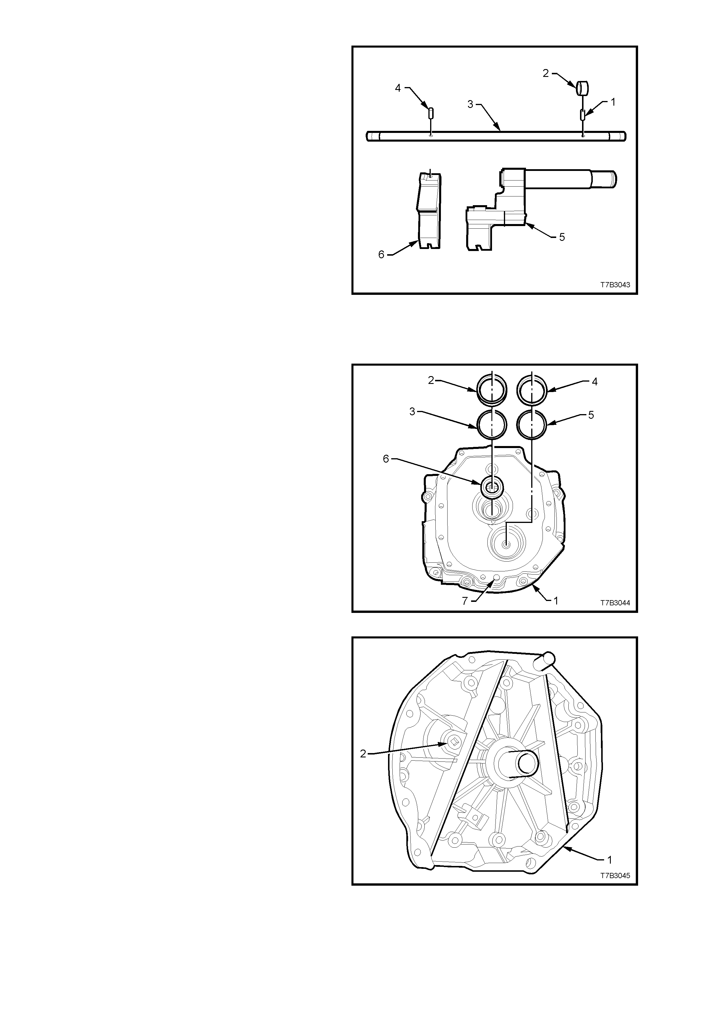
5th/6th and Reverse Shift Rail Assembly
6. Remove the roll pin (1) from the collar (2) and
shift rail (3), using a suitable size pin punch
and hammer.
7. Slide the 5th/6th shift rail lever (5) from the
shift rail (3).
NOTE 1: Only remove the bushes from the 5th/6th
shift rail if they are worn or damaged and require
replacement.
NOTE 2: While the sleeve can be pr ess ed f r om the
5th/6th shift rail lever (after removing the retaining
circlip), this operation is not recommended unless
parts are to be replaced.
8. Using a suitable size pin punch and hammer,
rem ove the r oll pin ( 4) holding the r ever s e s hif t
rail lever (6) to the shift rail (3). Slide the
reverse shift rail lever (6) from the shift rai l (3). Figure 7B3-100
Transmission Adaptor Plate
1. Slide the input shaft bearing cup (2) and
shim/s (3) by pulling with the finger tips of
each hand.
NOTE: Rotating the cup back and forth while
pulling, will reduce the problem of the bearing cup
cocking and jamming in the adaptor plate bore.
2. Repeat this process with the counter shaft
front bearing cup (4) and shim/s (5).
3. Prise the input shaft oil seal (6) from the
adaptor plate (1).
4. Only remove the dowel pins (7), if r eplacement
is required.
Figure 7B3-101
5. Using a 3/8” drive socket bar, remove the
adaptor plate plug (2) from the front of the
adaptor plate (1).
Figure 7B3-102
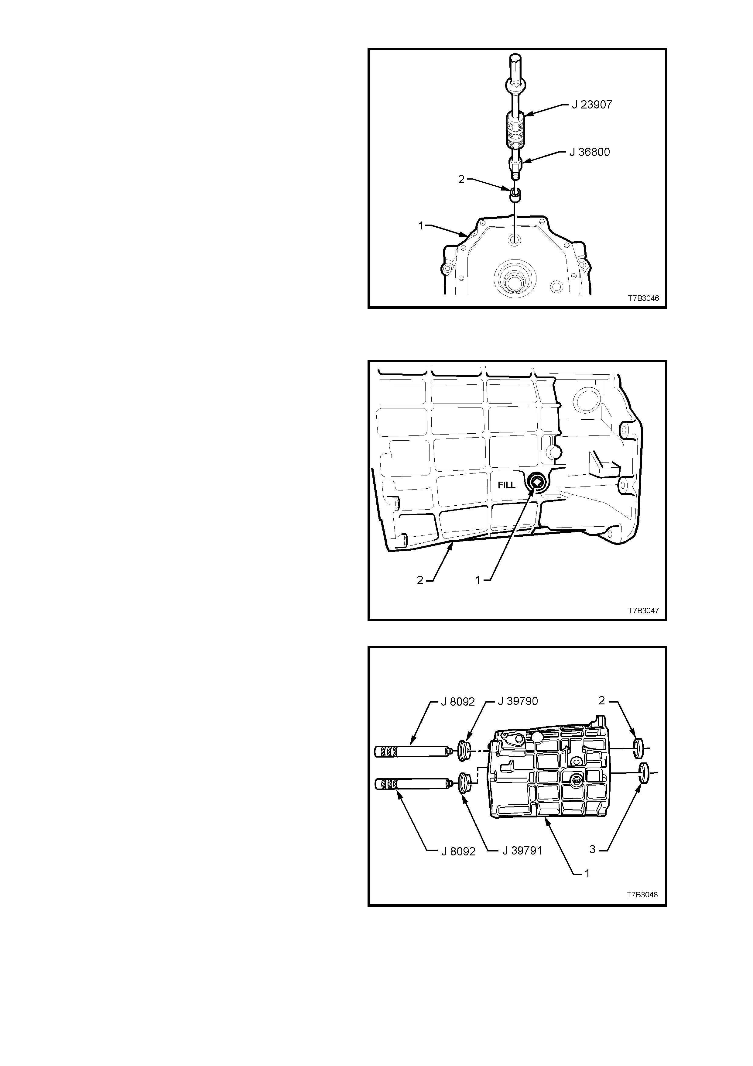
6. If worn or damaged, remove the 1st/2nd and
3rd/4th shift rail bushing (2), using the
following procedure;
a. Screw bushing remover J 36800 into the
shift rail bushing (2).
b. Screw slide hammer J 23907 into the
bushing rem over J 36800 and r emove the
bushing (2) from the adaptor plate (1).
Figure 7B3-103
Transmission Case
1. Using a 3/8” drive s ock et bar, rem ove the filler
plug (1) from the transmission case (2).
Figure 7B3-104
NOTE: Only remove the rear mainshaft bearing
cup (2) and/or rear countershaft gear bearing cup
(3) if these components are to be replaced.
2. Press the mainshaft bearing rear cup (2) from
the transmission case (1), using remover J
39790 and driver handle J 8092.
3. Press the countershaft gear rear bearing cup
(3) from the transmission case (1), using
remover J 39791 and driver handle J 8092.
4. Discard removed bearing cup/s.
Figure 7B3-105
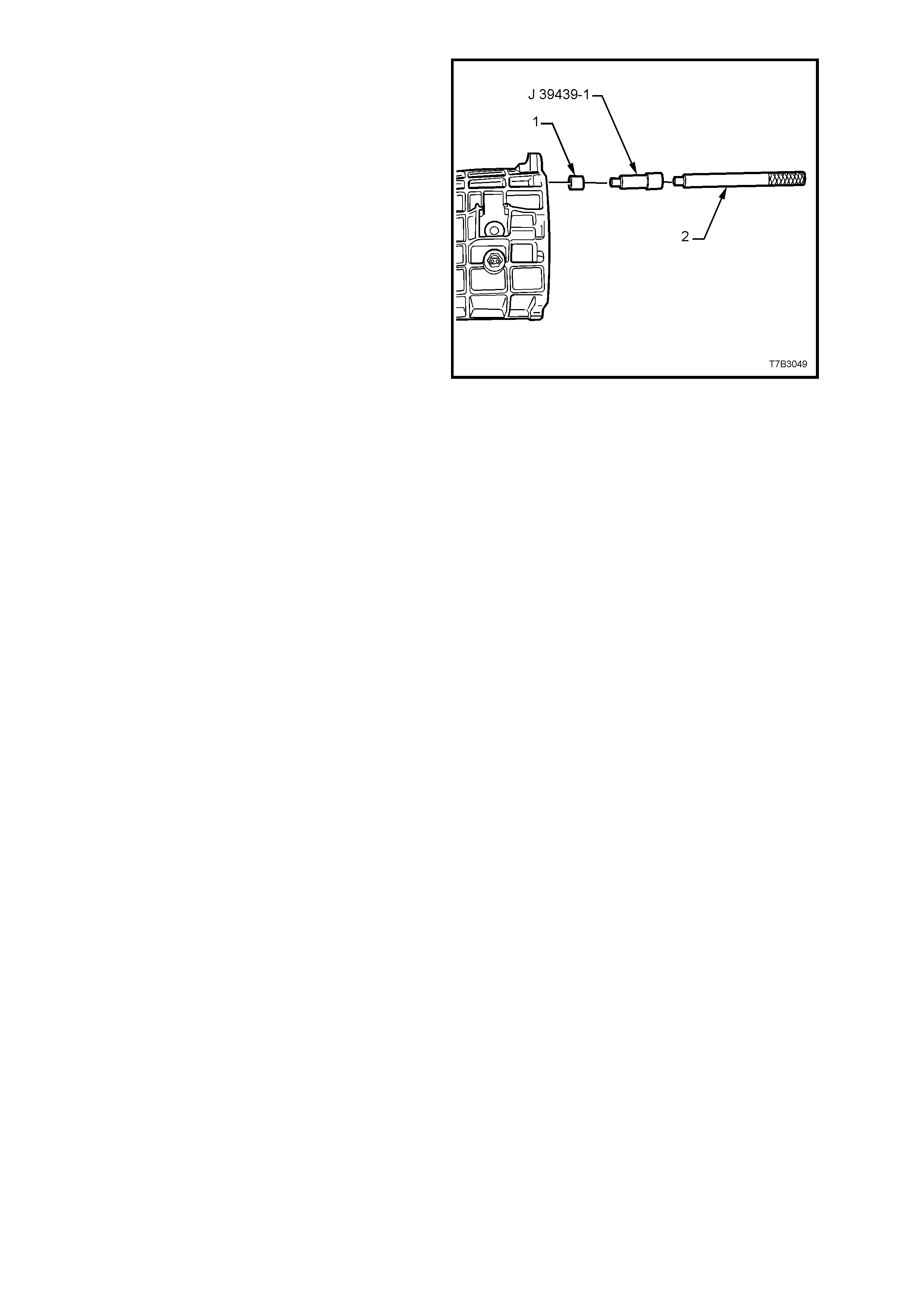
5. If worn or damaged, remove the shift rail
bushes (1), using bushing remover J 39439-1
and a suitable driver handle (2). Discard the
removed bushes.
Figure 7B3-106
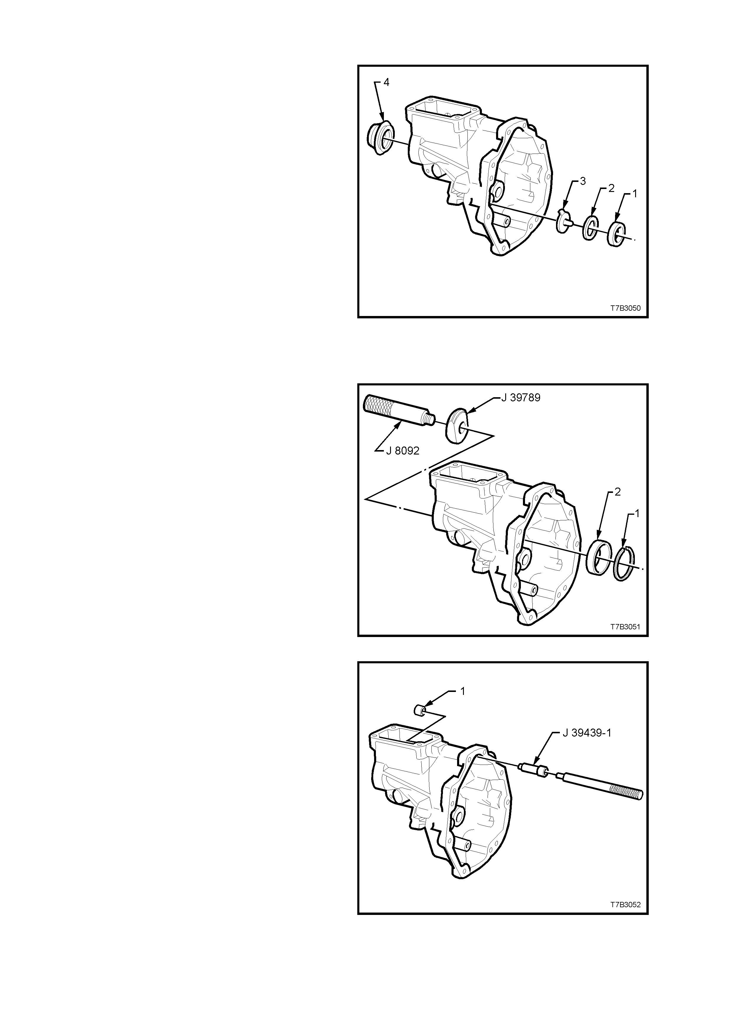
Extension Housing
NOTE: If not removed during the transmission
disassembly process, remove the following
components;
a. Drain Plug.
b. Reverse lockout solenoid and body
assembly.
c. Vehicle speed sensor.
d. Reverse idler gear assembly.
1. Slide the countershaft gear extension, rear
bearing cup (1), shim/s (2) and oil funnel (3) by
pulling with the finger tips of each hand.
NOTE: Rotating the rear bearing cup (1) back and
forth while pulling with the finger tips, will reduce
the problem of the bearing cup cocking and
jamming in the adaptor plate bore.
2. Prise the rear seal (4) from the extension
housing, using a suitable lever. Discard the
removed seal. Figure 7B3-107
NOTE: Only remove the mainshaft rear roller
bearing cup if the bearing assembly is to be
replaced.
3. Remove the mainshaft rear roller bearing cup
retaining snap ring (1) using suitable pliers.
4. Press the mainshaft rear bearing cup (2) from
the extension housing, using rem over J 39789
and driver handle J 8092.
Figure 7B3-108
5. If worn or damaged, remove the shift rail
bushing (1), us ing bushing rem over J 39439-1
and a suitable driver handle. Discard the
removed bushing.
Figure 7B3-109
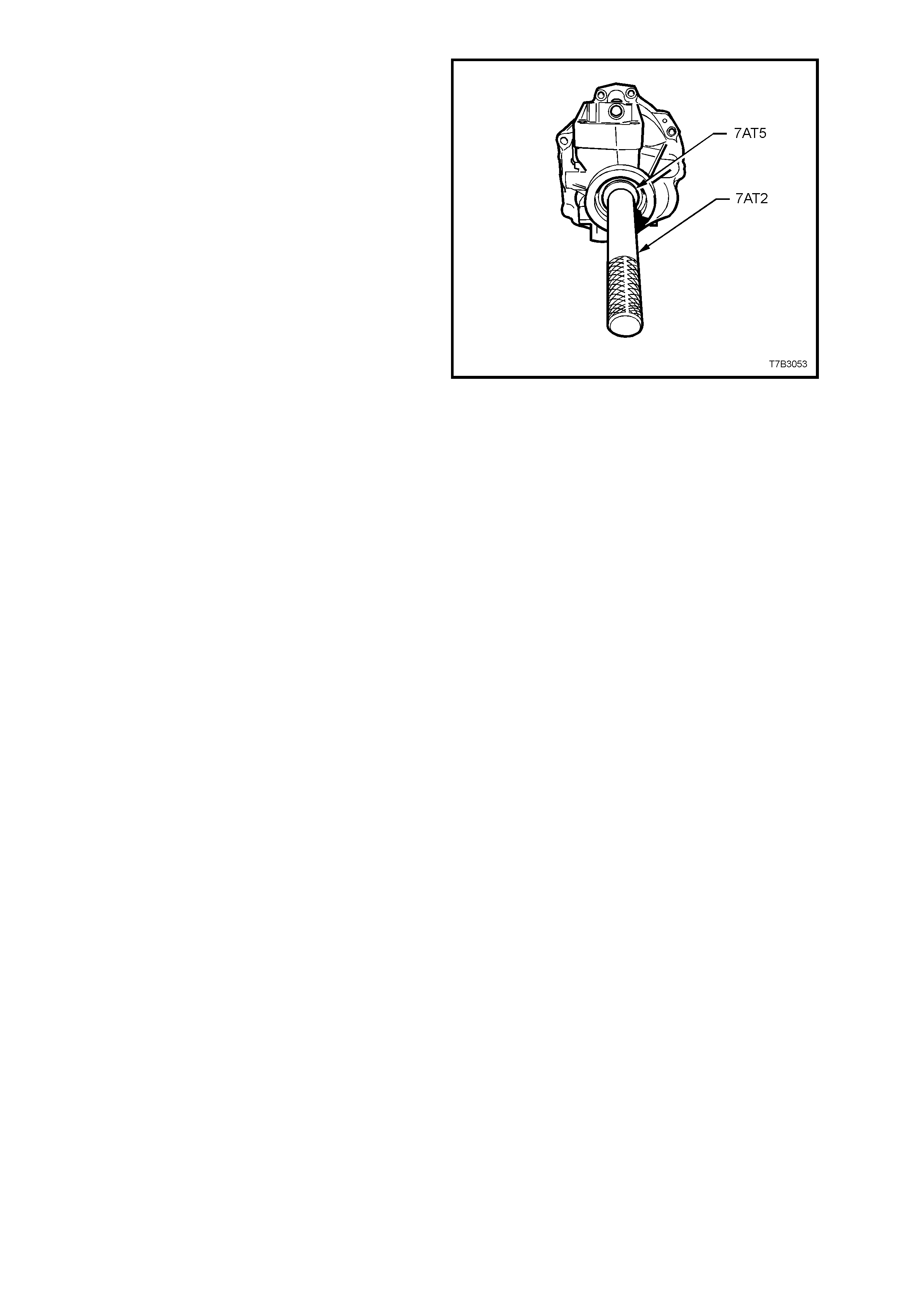
NOTE: Only remove the propeller shaft slip yoke
bush, it replacement is required.
6. If the extension oil seal has not been removed,
then refer to step 2 in this service operation.
7. Using Tool No. 7AT5 and driver handle 7AT2
(or equivalent), press bush from housing.
Figure 7B3-110
CLEAN AND INSPECT COMPONENTS
Clean
Thoroughly wash all components in a suitable
cleaning solvent. Dry all parts with clean, dry
compressed air.
CAUTION: Wear safety glasses to avoid eye
injury.
Use a wire brush or thread taps to clean thread
sealant from all fasteners that are to be re-used.
Inspect
1. Inspect transmission case, rear extension,
adaptor plate and clutch housings for any
cracks or defects that may cause lubricant
leakage.
2. Ensure that there is no damage to or sealant
on, the front face of transmission adaptor
plate that could cause misalignment between
case and clutch housing.
3. Check all m achined faces for burr s and traces
of sealant. If scraping of theses surfaces is
required, only use a plastic scraper to avoid
damaging finely machined alloy surfaces. If
burrs ar e found, dress them of f with a f ine m ill
file.
4. All roller and needle bearing assemblies
should be inspected closely and replaced if
there is any sign of wear. Inspect mainshaft
and internal surfaces of all gears where
needle bearings come in contact.
For diagnosis of tapered roller bearing
failures, refer to 4.3, 'DIFFERENTIAL AND
REAR AXLE BEARING DIAGNOSIS' in
Section 4B, REAR AXLE of the VT Series I
Service Information.
NOTE 1: If the countershaft gear bearings are
worn or damaged, refer to 4.5 TRANSMISSION
SUB-ASSEMBLIES, Disassemble, Countershaft
Gear, in this Section. If either bearing is rem oved,
it mus t be replaced with a new part as damage will
occur during the removal operation.
NOTE 2: If the input shaft bearing is worn or
damaged, refer to 4.5 TRANSMISSION SUB-
ASSEMBLIES, Disassemble, Input Shaft, in this
Section.
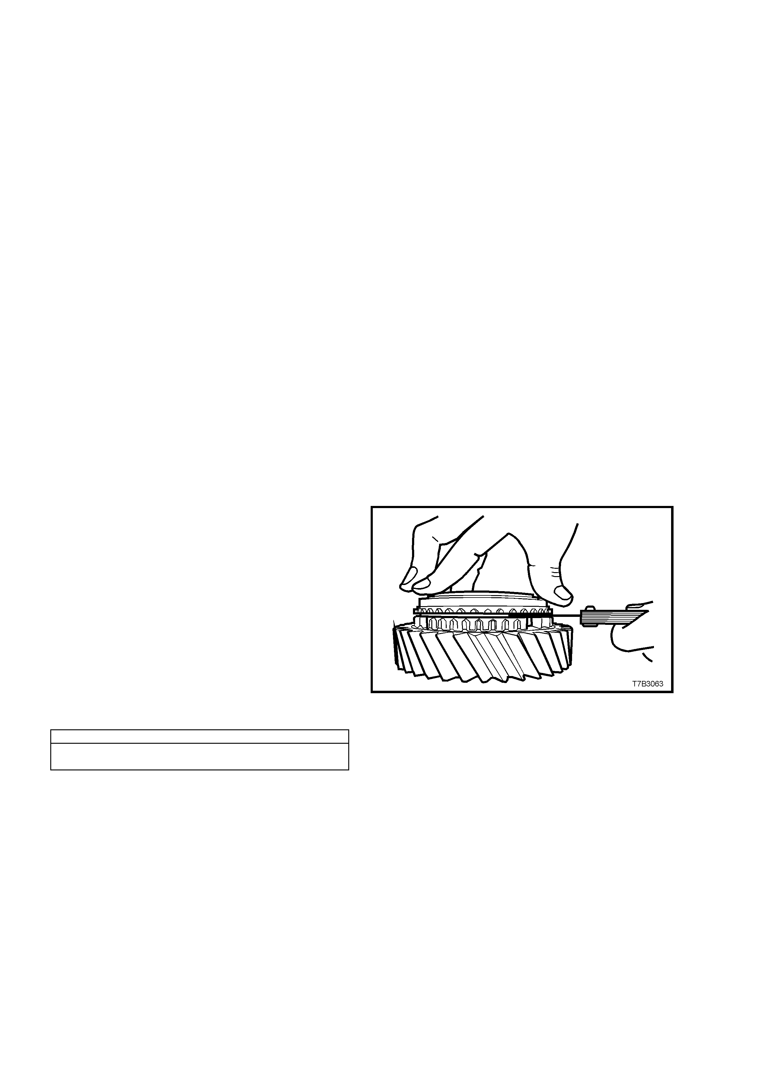
NOTE 3: As needle roller wear can be difficult to
see, it is good practice to replace all needle roller
bearings where the vehicle has travelled a
substantial distance.
5. Inspect all gears, sleeves, hubs, rings and
shafts for wear, sc oring, pitting, chips, nic k s or
burrs. Slight s cores or bur rs m ay be honed of f
with a fine stone but, if a gear is chipped or
unduly worn, it must be replaced.
6. Check synchroniser teeth on blocking rings
and gears. Replace any component that is
worn or damaged.
7. Inspect synchroniser hubs , outer rings, insert s
and springs for damage or wear. Check that
the synchroniser rings slide freely on their
hubs. Replace any worn component.
NOTE: Even though the synchromesh blocking
rings are the same, it is sound practice to keep
each ring with its respective gear, to pres erve wear
patterns.
8. Inspect reverse idler gear shaft, replacing if
worn.
9. Check all thrust washers, replace any that are
worn.
10. Inspect all shift control component, both
contact and sliding surfaces for wear,
scratches, projections or other damage.
11. Inspect breather tube to ensure that it is not
blocked.
12. Measure the wear of all blocker rings as
follows:
a. Place the three block ing ring components
onto the appropriate gear cone i.e. fifth
gear blocking ring assembly onto fifth
speed drive gear.
b. Hold rings square on the gear’s cone
surface and hold firmly in the seated
position.
c. Measure clearances in the location
shown.
d. Discard any blocker ring that measures
less than the minimum prescribed
clearance.
BLOCKER RING ASSEM BL Y TO GEAR CLEARANCE
1st to 6th GEARS INCLUSIVE........... 0.38 mm Minimum
REVERSE ......................................... 0.75 mm Minimum
Figure 7B3-111
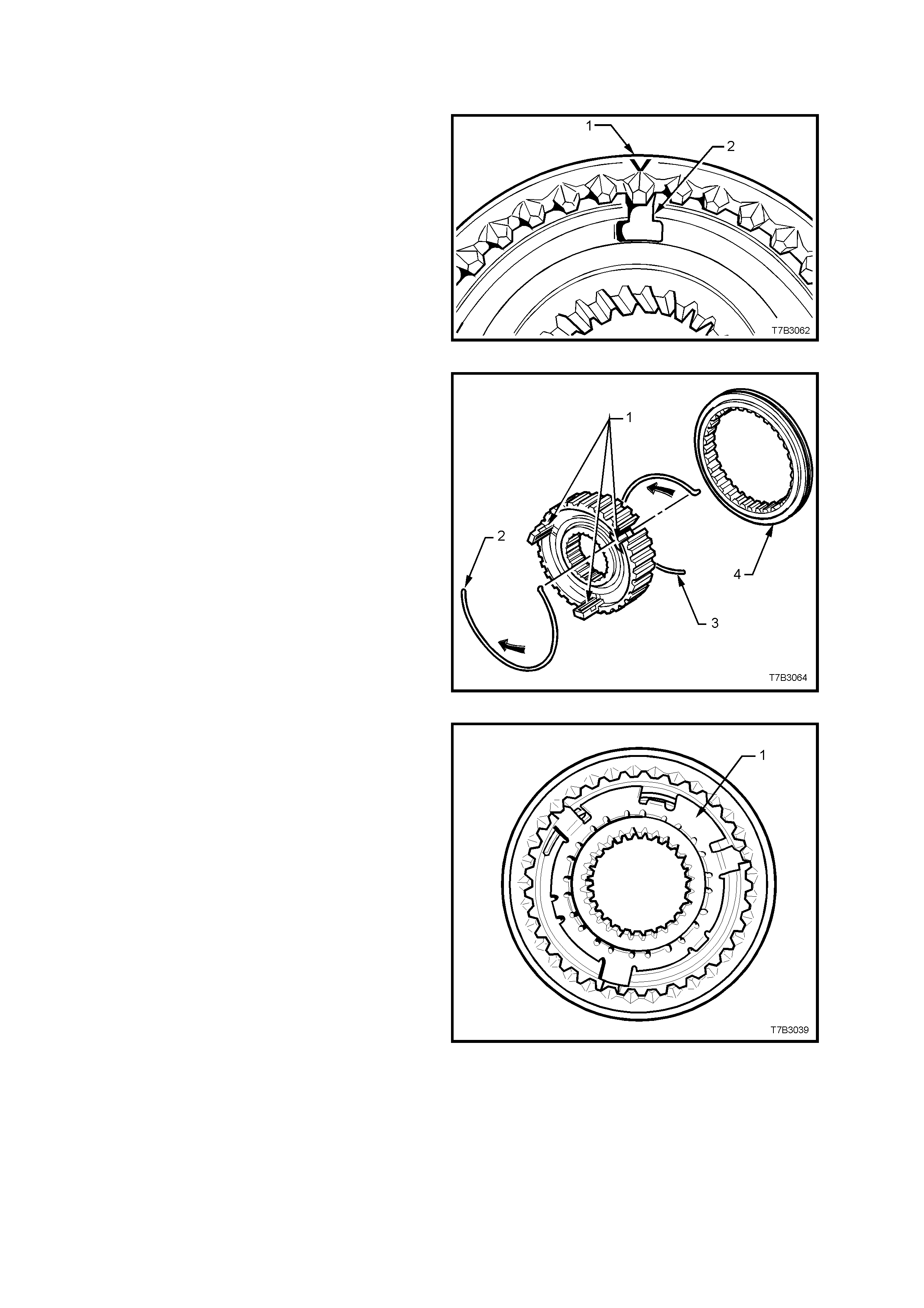
REASSEMBLE
Synchromesh Assemblies
All Assemblies
1. Install the synchromesh ring over the hub,
aligning the ‘V’ on the edge of the ring (1) with
one of the hub key openings (2).
NOTE: While each of the hubs has no offset, the
orientation of the outer synchroniser ring is s pecific,
depending on the application.
Figure 7B3-112
2. Install the three keys (1) with the protrusions
facing outward.
3. Install one synchroniser s pr ing (2) , locating the
spring tang in one of the synchroniser keys,
using a small screwdriver to assist.
CAUTION: Wear safety glasses to avoid eye
injury.
4. Turn the assembly over, then install the
second synchroniser spring (3), locating the
tang in the same key as before but in the
opposite direction to the first. Again use a
small screwdriver to assist.
NOTE: The synchromesh assem bly is shown in an
exploded state to more clearly show the
synchroniser spring arrangement.
Figure 7B3-113
Reverse Synchromesh Assembly Only
1. Install a NEW synchromesh key retainer (1),
locating the tangs over the synchromesh keys.
2. Using a suitable size sleeve such as Tool 3A8-
6 (or tube I.D. 50 mm, wall thickness 5 mm
maximum) and a hammer, install the key
retainer, securing it to the synchromesh hub
centre.
Figure 7B3-114
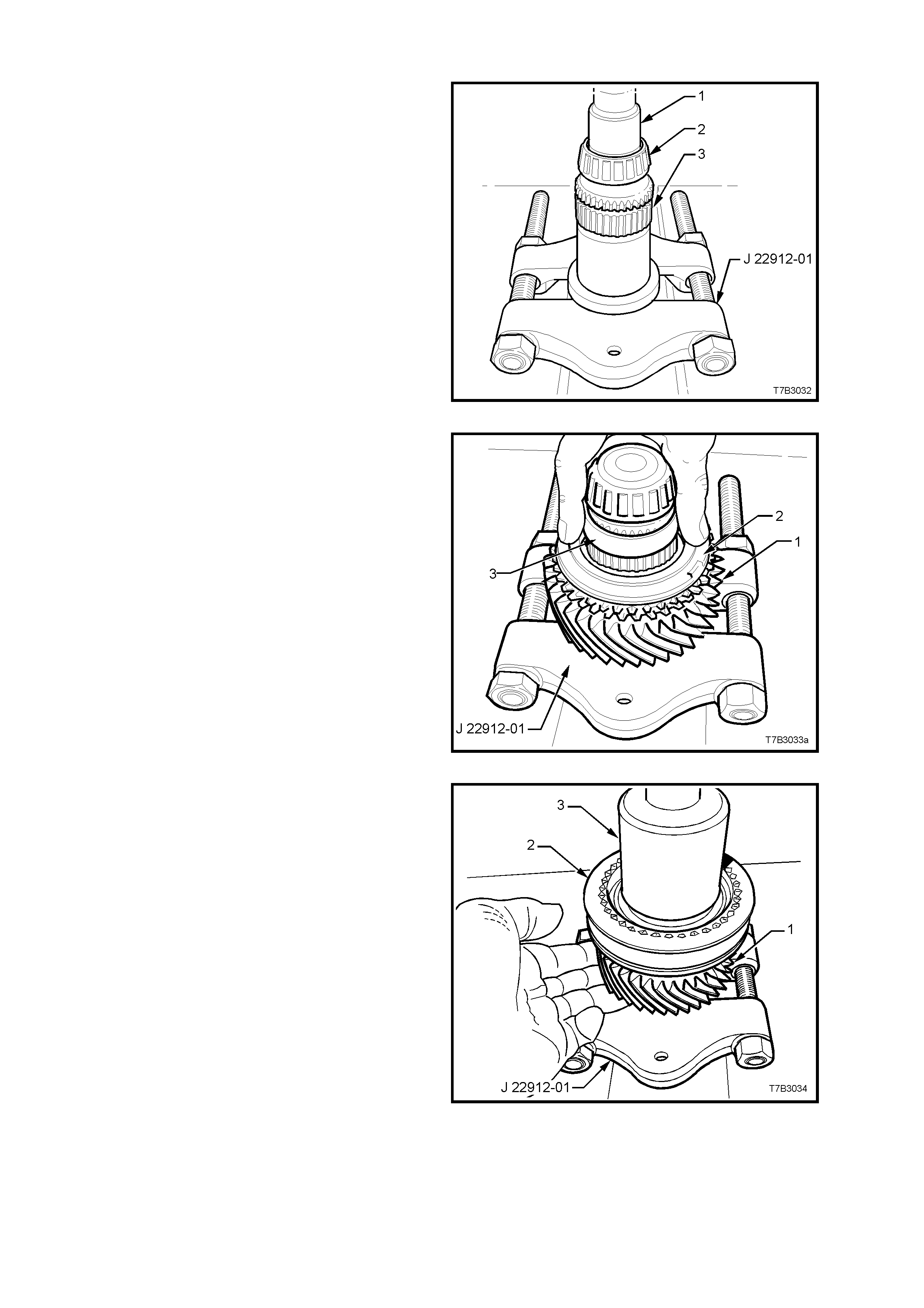
Mainshaft
1. With press plates J 22919-01 installed under
the mainshaft flange as shown, press a NEW
spigot taper roller bearing (2) onto the
mainshaft (3), using a suitable sleeve (1) (e.g.
21 mm socket).
Figure 7B3-115
2. With press plates J 22912-01, still installed
under the m ains haf t f lange, ins tall the 3rd gear
caged needle roller race, 3rd gear (1) and the
blocker ring (2).
3. Install plastic sleeve (3) over the mainshaft.
Figure 7B3-116
4. Install 3rd/4th synchromesh assembly (2) to
the mainshaf t splines , noting that the groove in
the outer ring faces forward (to 4th gear).
5. Press 3rd/4th synchromesh assembly to the
mainshaft, using a suitable size sleeve (3) (47
mm ID, minimum length 25 mm and wall
thickness 5 mm).
6. During the pressing proces s, hold the 3rd gear
(1) and blocker ring into place against the
synchromesh assembly (2) to ensure correct
location of the locating dogs on the blocker
ring, with the synchromesh keys.
Figure 7B3-117
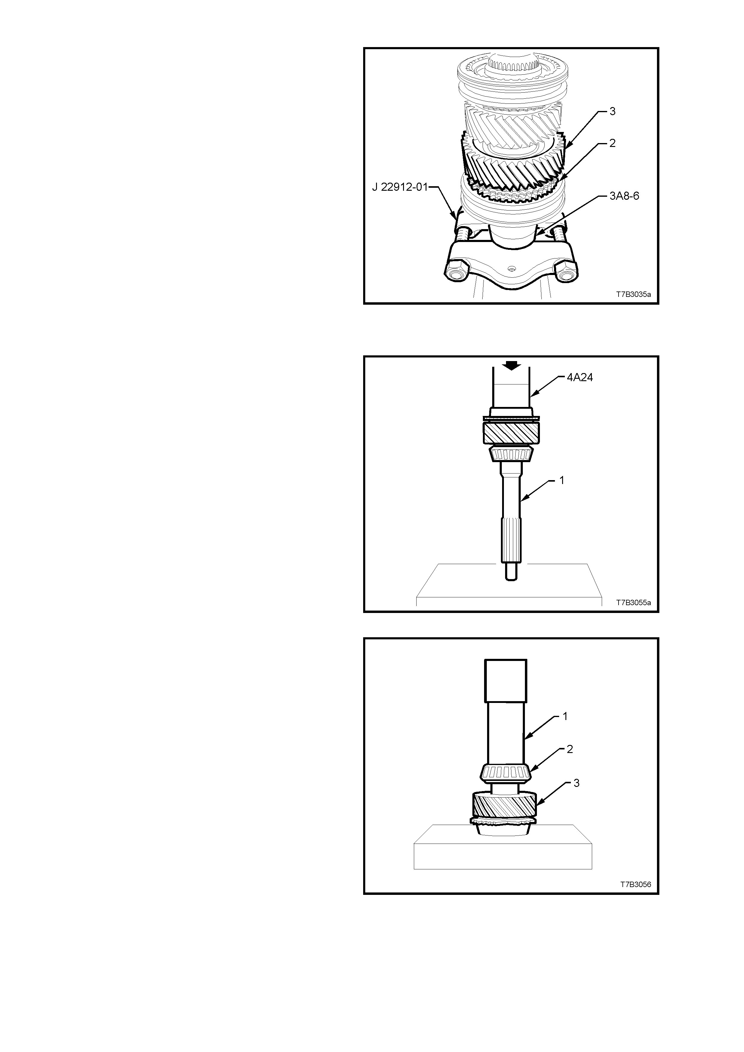
7. Install 2nd speed gear (3) and caged needle
roller bearing, the blocking ring and 1st/2nd
speed synchromesh assembly (2) to the
mainshaft, noting that the groove in the outer
ring of the synchromesh assembly faces
rearward (to 1st gear).
8. Using a suitable sleeve such as Tool 3A8-6 (1)
(or I.D. 50 mm, wall thickness 5 mm),
supported by press plates J 22912-01 as
shown, press the mainshaft into the 1st/2nd
speed synchromesh assembly (2).
NOTE: The locating dogs of the 2nd speed
blocking ring should be aligned with the
synchromesh keys during the pressing process,
allowing the 2nd speed gear (3) weight to keep the
assembly in place.
Figure 7B3-118
Input Shaft
1. Use tube 4A24 or equivalent size (O.D. 47
mm, length approximately 40 mm) and an
hydraulic press to install a new input shaft
bearing cup into the counter bore of the input
shaft (1).
Figure 7B3-119
2. Using a suitable size tube (1) (I.D. 32 m m, wall
thickness 5 mm maximum and length 200
mm), and an hydraulic press, install a new
tapered roller bearing (2) to the input shaft (3).
Figure 7B3-120
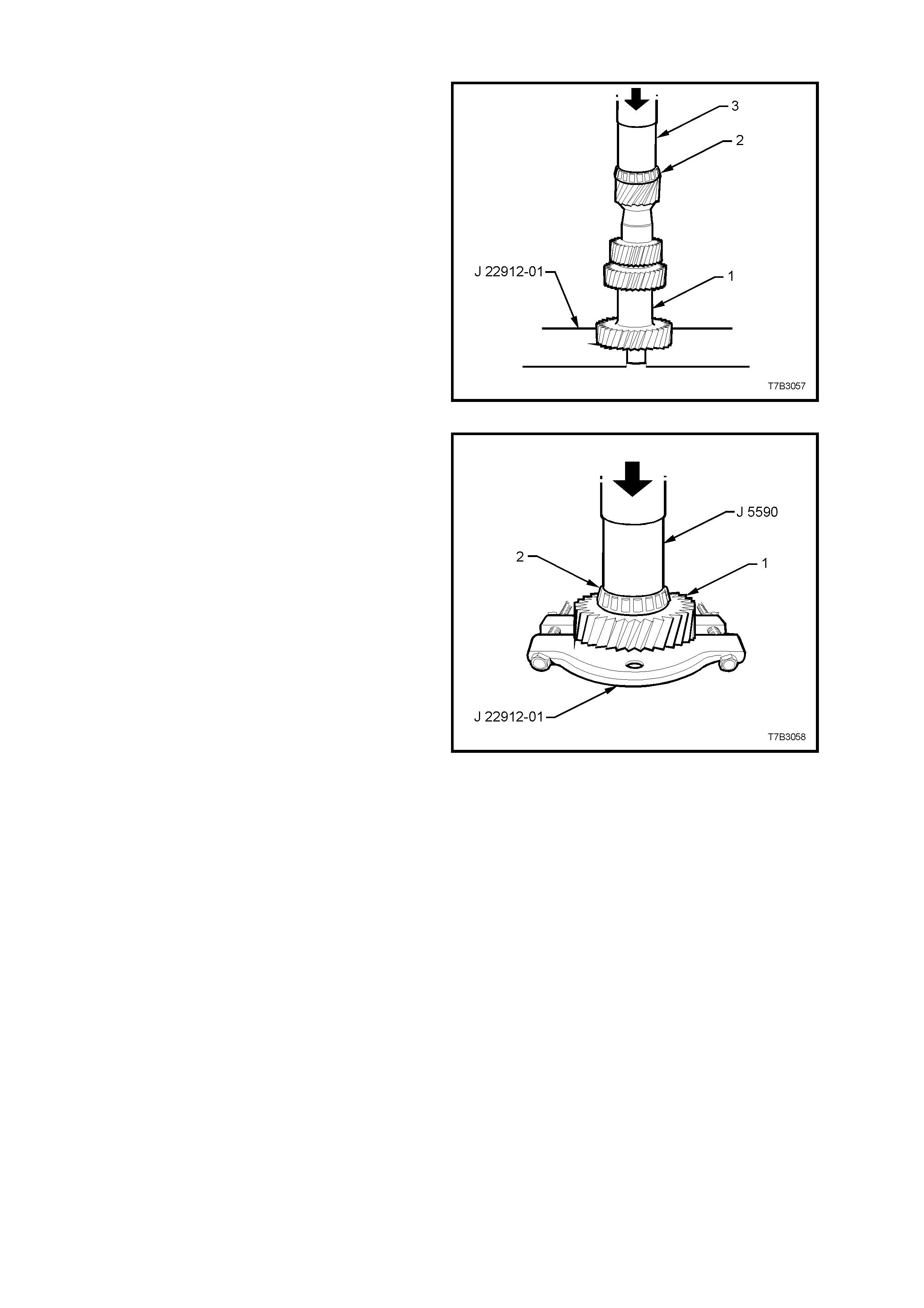
Countershaft Gear
1. Using press plates J 22912-01, support the
input gear of the countershaft gear (1).
2. Install a new bearing (2) to the small end of
the countershaft gear (1) , using a suitable size
sleeve (3) (I.D. 40 mm, wall thickness 4 mm
maximum) and an hydraulic press.
Figure 7B3-121
3. Using press plates J 22912-01, support the
input gear of the countershaft gear (1) as
shown.
4. Install a new bearing (2) to the lar ge end of the
countershaf t gear (1), us ing installer J 5590 or
a suitable sleeve (I.D. 36 m m , wall thicknes s 4
mm maximum) and an hydraulic press.
Figure 7B3-122
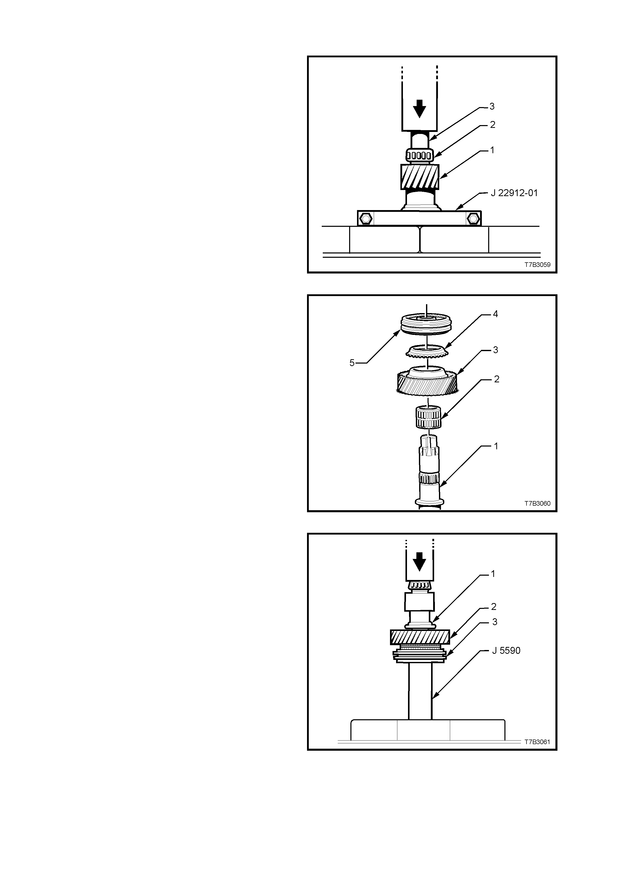
Countershaft Extension Gear
1. With press plates J 22912-01 installed under
the countershaft extension flange (1) as
shown, press a NEW taper roller bearing (2)
onto the extension (1), using a suitable sleeve
(3) (e.g. 21 mm socket).
Figure 7B3-123
2. Install the following components to the
countershaft extension (1):
a. 5th gear caged needle roller bearing (2).
b. 5th speed drive gear (3).
c. 5th speed synchromesh blocking ring (4).
d. 5th/6th speed synchromesh assembly (5).
Figure 7B3-124
3. With the assembly arranged as shown, press
the countershaft extension into the
synchromesh assembly hub, using tube J
5590.
NOTE: Index the blocking ring assembly with the
synchromesh keys before pressing operations.
4. Fit a NEW snap ring to the countershaft
extension to secure the synchromesh
assembly.
Illustration Key:
1. Countershaft gear extension.
2. 5th speed drive gear.
3. 5th/6th speed synchromesh assembly.
Figure 7B3-125
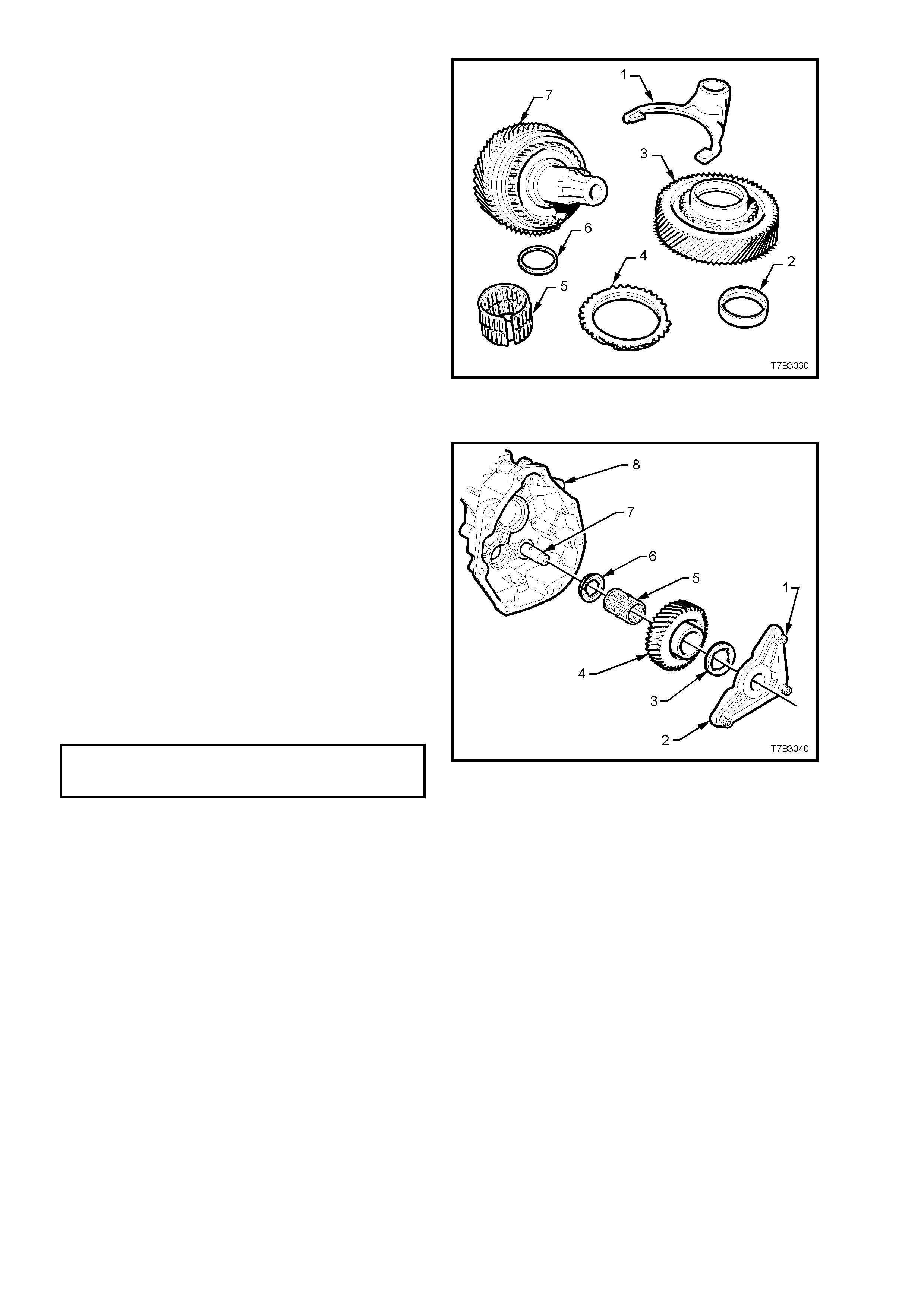
5. Install the spacer washer (6), caged needle
roller bearing (5), 6th speed blocking ring (4),
6th speed drive gear ( 3), and thr us t washer ( 2)
with the recessed side facing the countershaft
gear.
6. Install the 5th/6th shift fork (1) to the
synchromesh ring, in preparation for
installation.
Figure 7B3-126
Reverse Idler Gear
1. Install the reverse idler gear shaft (7) and
thrust washer (6) to the transmission
extension housing (8).
2. Lubricate the reverse idler gear (4) and caged
needle roller bearing (5) with clean
transmission fluid, then install both over the
idler gear shaft (7).
3. Install the outer thrust washer (3) and reverse
idler shaft retaining bracket (2).
4. After cleaning any thread sealant residue fr om
the threads of the three, Torx headed bracket
screws (1), apply thread sealant such as
Loctite 242 or equivalent (to Holden’s
Specific ation HN 1256 Class 2, T ype 2), to the
screw threads. Install and tighten the screws
to the correct torque specification.
REVERSE IDLE GEAR SHAFT
BRACKET SCREW 19 - 30 Nm
TORQUE SPECIFICATION Figure 7B3-127
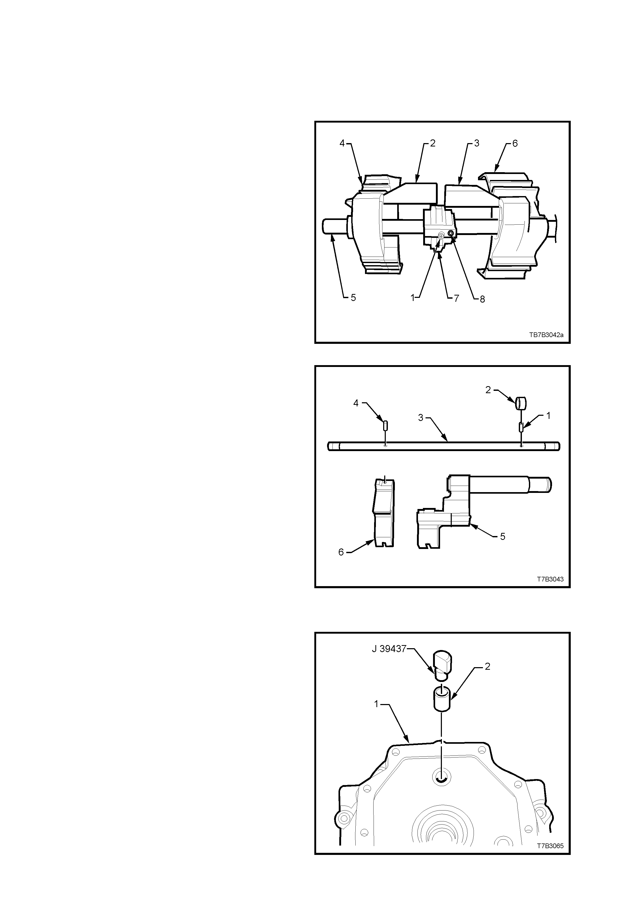
Reverse Lockout Assembly
Refer to 3.4 REVERSE LOCKOUT SOLENOID
ASSEMBLY, in this Section, for the reassembly
description.
Shift Rail and Fork Assemblies
1st/2nd and 3rd/4th Shift Rail Assembly
1. If removed, slide the selector pin (1) over the
shift rail (5) and secure with a new roll pin (8).
2. Install the interlock plate (7) over the selector
pin (1), then slide the 1st/2nd shift fork (6) and link
(3) over shift rail (5), rotating the interlock plate to
allow installation of the link (3).
3. Repeat step 2 for the 3rd/4th shift fork and link
(2).
4. Rotate the interlock plate (7) to engage both
shift fork links (2 and 3).
Figure 7B3-128
5th/6th and Reverse Shift Rail Assembly
1. Using a suitable size pin punch and hammer,
install a NEW roll pin (4) to secure the reverse
shift rail lever (6) to the shift rail (3).
2. Slide the 5th/6th shift rail lever assembly (5)
onto the shift rail (3).
3. Using a suitable size pin punch and hammer,
install a new roll pin (1) to secure the collar (2).
Figure 7B3-129
Transmission Adaptor Plate
1. If removed, install a new shift rail bush (2) to
the adaptor plate (1), using installer J 39437 or
equivalent stepped driver.
Figure 7B3-130
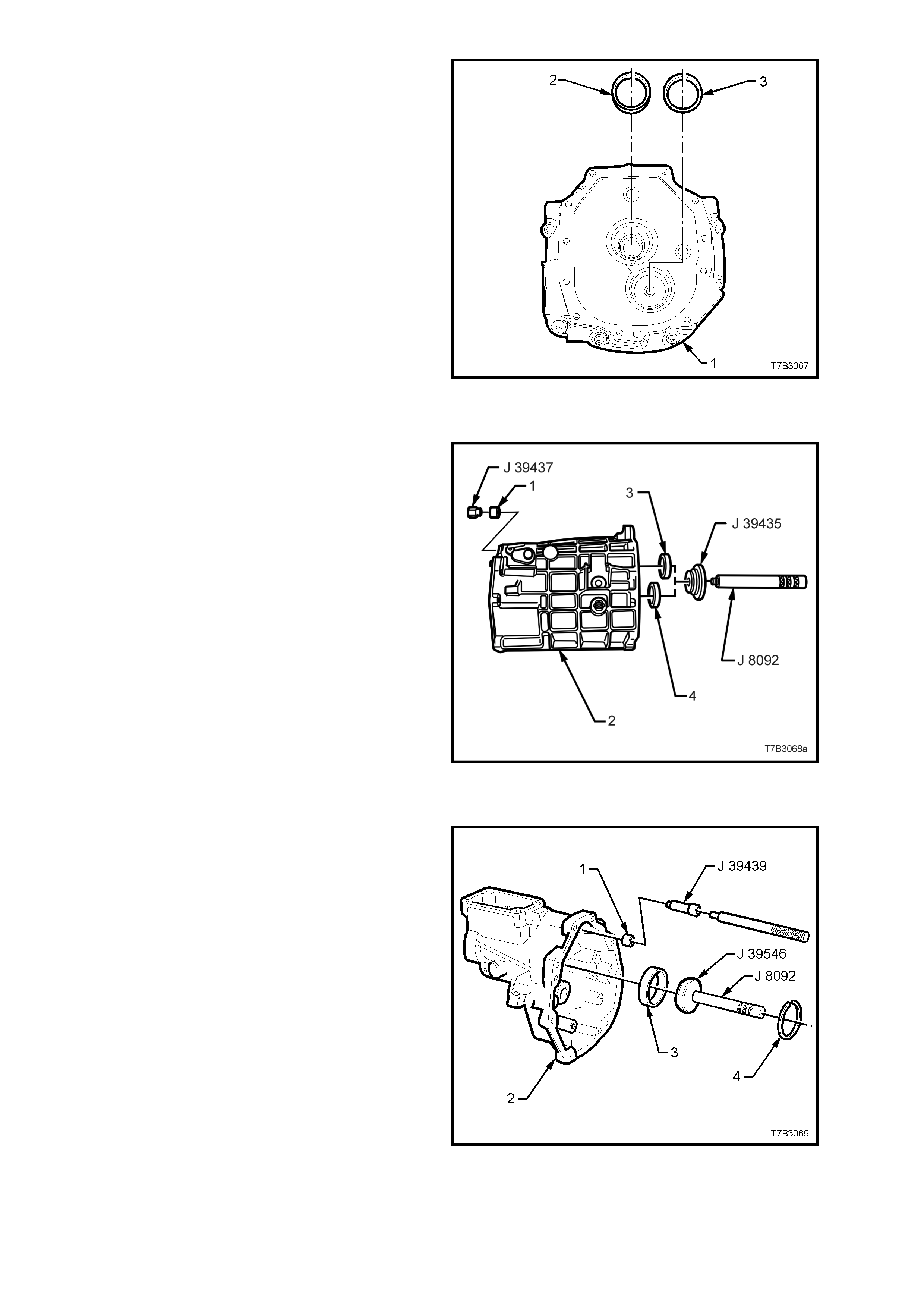
2. Install both the input shaft and front
countershaft bearing cups (2 and 3
respectively) to the adaptor plate (1),
WITHOUT any shims. The correct shim
thickness will be fitted during the assembly
operations, when shaft end floats are
determined.
Figure 7B3-131
Transmission Case
1. If removed, install new shift rail bushes (1) to
the transmission case (2), using installer J
39437 or equivalent stepped driver.
2. Install mainshaft bearing cup (3) and
countershaft bearing cup (4), using installer
J39435 and driver handle J 8092.
3. If removed, install new dowel pins.
4. Loosely install filler plug.
Figure 7B3-132
Extension Housing
1. If removed, install new shift rail bushing (1) to
the extension housing (2), using tool J 39439
or equivalent stepped driver.
2. Install mainshaft roller bearing cup (3), using
installer J39546 and driver handle J 8092.
3. Install roller bearing cup circlip (4), using
suitable pliers.
Figure 7B3-133
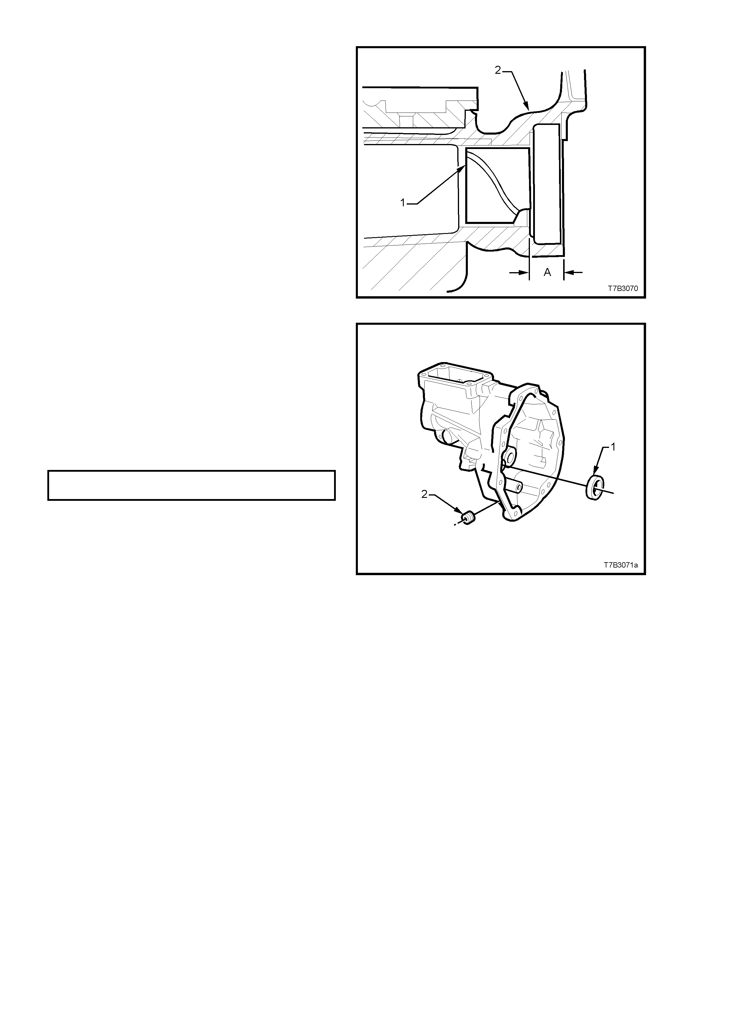
4. If required, install a new propeller shaft slip
yoke bush (1) to the extension housing (2),
using Tool No. 7AT5 and driver handle 7AT2
(or equivalent), taking note of the following
points;
a. Align the split join in the bush with the
bottom of the extension housing bore.
b. Install the bush (1) to a depth of 18 mm
(distance ‘A’), measured from the end of
the extension housing (2) to the end of
the bush.
Figure 7B3-134
5. Temporarily install the countershaft extension
bearing cup (1) WITHOUT any shims. Shim
selection will be determined during the end
float measuring procedure detailed in 4.6
BEARING SHIMMING PROCEDURES.
6. Apply sealant such as Loctite 565 or
equivalent (GM P/N 12346004), to the c leaned
threads of the transmission drain plug (2) and
install, tightening to the correct torque
specification.
TRANSMISSION DRAIN PLUG 15 - 25
TORQUE SPECIFICATION Nm
Figure 7B3-135
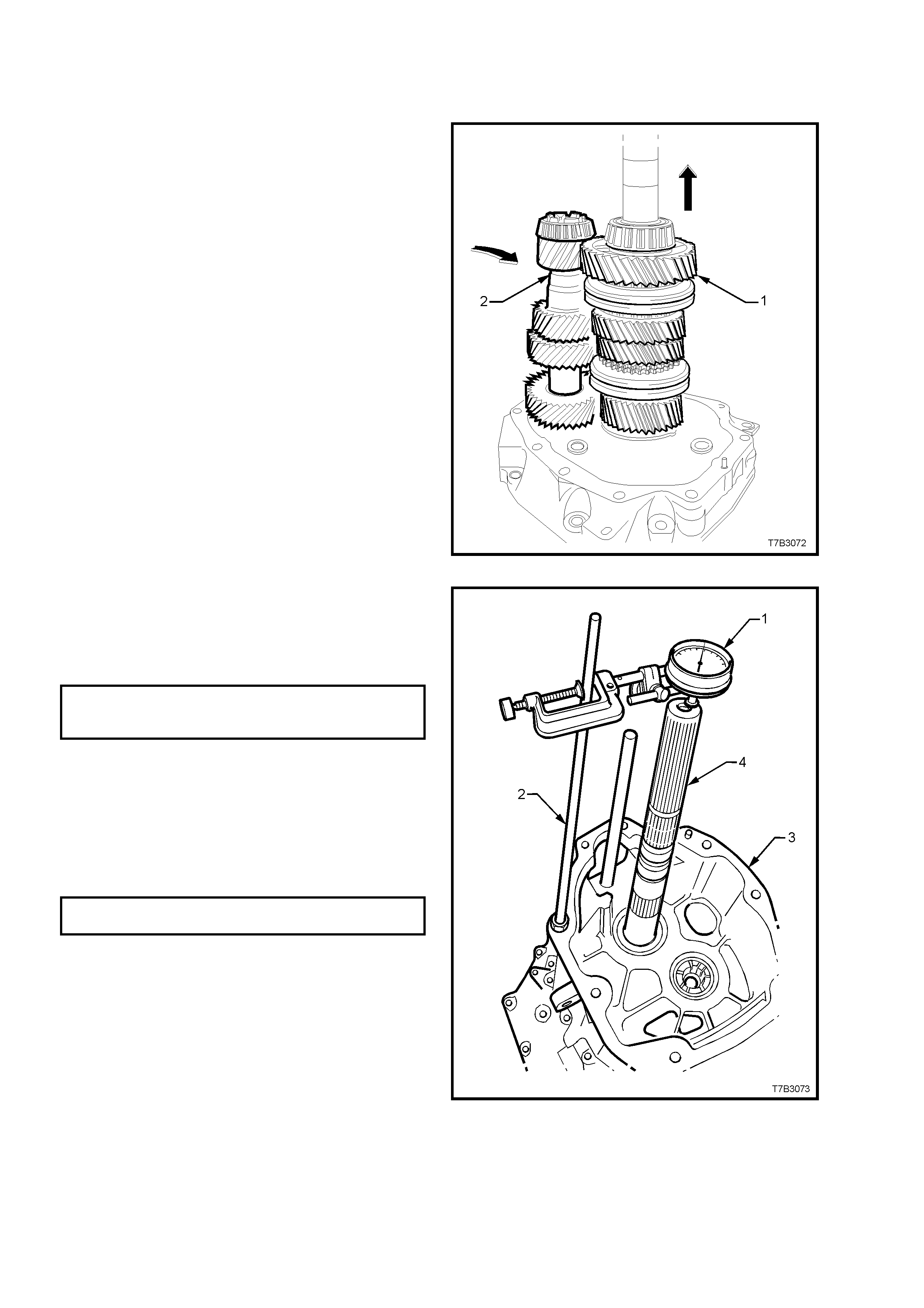
4.6 BEARING SHIMMING PROCEDURES
INPUT SHAFT/MAINSHAFT & COUNTERSHA FT
1. With the adaptor plate mounted to the
transmission holding fixture J 39430 that in
turn, is installed into bench fixture J 3289-20,
rotate to the vertical with the rear of the
adaptor plate facing up.
2. Install the input shaft, 4th speed blocking ring
and mainshaft into the front bearing cup.
Check that the blocker ring is c orrectly aligned
with the synchromesh assembly keys.
3. While slightly lifting the mainshaft, install the
countershaft to its front bearing.
Figure 7B3-136
4. Install the transmission case to the adaptor
plate and install the eight adaptor plate to ca se
bolts.
5. Tighten the eight bolts to the correct torque
specification.
ADAPTOR PLATE TO
TRANSMISSION CASE 30 - 41 Nm
TORQUE SPECIFICATION
6. Rotate the assembly through 180° and mount
a commercially available dial indicator (1) and
stand (2) to the end of the transmission case
(3), as shown. Zero the dial indicator, then lift
the mainshaft (4) up and down to obtain the
end play.
7. Select a shim pack to achieve the correct
bearing pre-load specification.
INPUT SHAFT/MAINSHAFT 0.00 - 0.05
PRE-LOAD SPECIFICATION mm
NOTE: There are 37 shim selections
available, ranging from 0.559 - 1.372 mm.
8. Remove the dial indicator assembly.
Figure 7B3-137
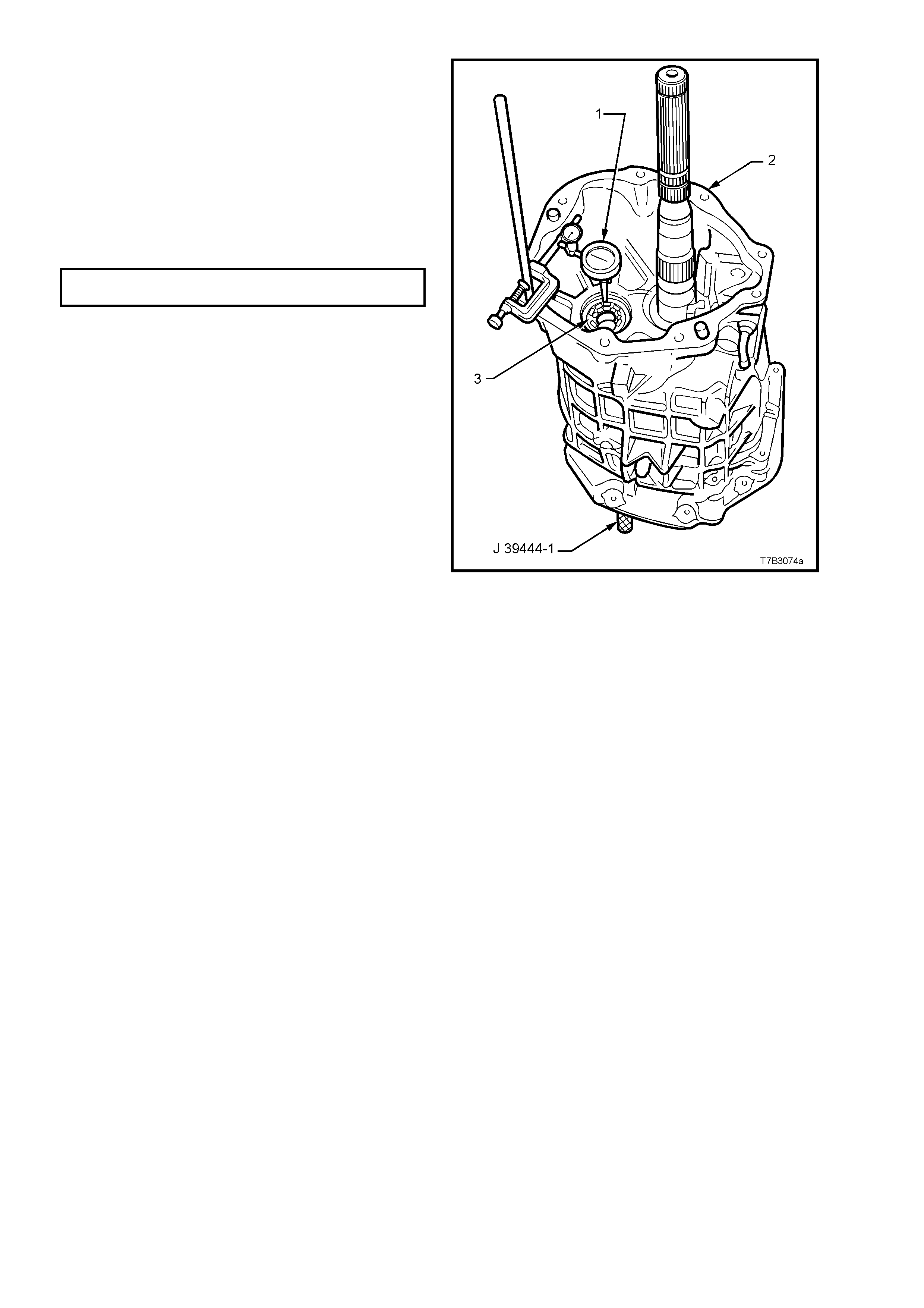
9. With the transmission assembly remaining in
the vertical position, mount a commercially
available dial indicator (1) to the transmission
case (2), with the probe sens ing the end of the
countershaft (3). Zero the dial indicator.
10. Insert countershaft end play rod J 39444-1 into
the adaptor plate plug hole, then use the rod to
move the countershaft up and down, enabling
an end play measurement to be taken.
11. Select a shim pack to achieve the correct
bearing pre-load specification.
COUNTERSHAFT PRE-LOAD 0.00 - 0.05
SPECIFICATION mm
NOTE: There are 33 shim selections available,
ranging from 0.356 - 1.372 mm.
12. Remove the dial indicator assembly.
Figure 7B3-138
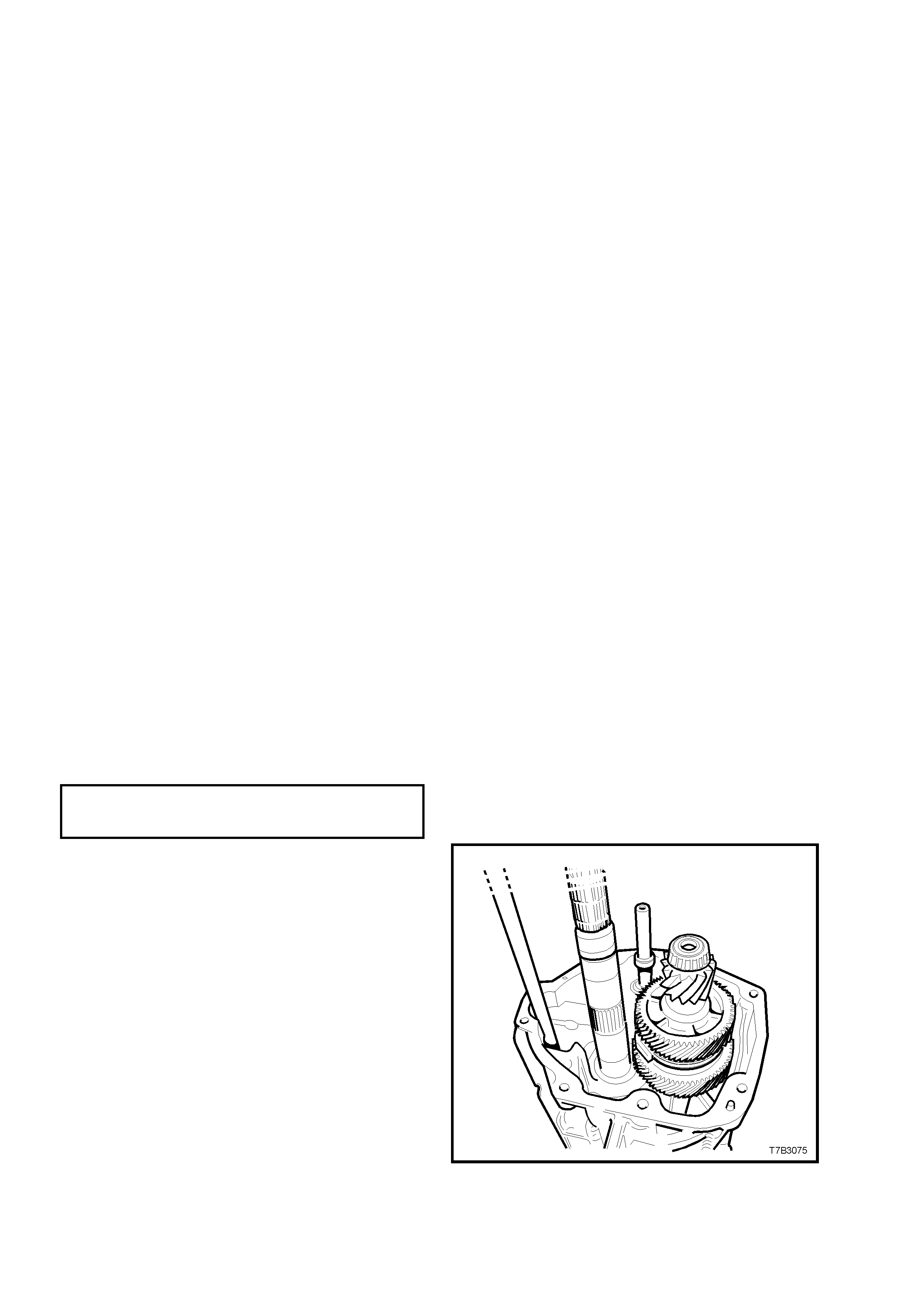
COUNTERSHAFT EXTENSION
Important: This procedure is not to be
undertaken until the correct shim stack has
been installed under the countershaft front
bearing cup.
1. Loosen then remove the adaptor plate to
transmission case bolts.
2. Lift the transmission case clear of the
mainshaft and countershaft.
3. Lift the m ainshaft slightly to allow counter shaft
removal.
4. Remove the mainshaft assembly, then lift the
input shaft and blocking rings f r om the adaptor
plate.
5. Remove the input shaft bearing cup, by pulling
with the finger tips of each hand.
NOTE: Rotating the bearing cup back and forth
while pulling, will reduce the pr oblem of the bear ing
cup cocking and jamming in the adaptor plate bore.
6. Repeat this process with the counter shaft
front bearing cup.
7. Install the calculated shim stack for the input
shaft/mainshaft and countershaft, previously
determined.
8. Reinstall the input shaft and countershaft
bearing cups.
9. Reinstall the input shaft, 4th speed blocking
rings and mainshaft, to the adaptor plate,
ensuring that the blocking rings engage
correctly with the synchromesh assembly
keys.
10. Reinstall the counters haft to the adaptor plate,
using the same procedure detailed previously.
11. Reinstall the transmission case over the
mainshaft, install the eight adaptor to
transmission case bolts and tighten to the
correct torque specification.
ADAPTOR PLATE TO
TRANSMISSION CASE 30 - 41 Nm
TORQUE SPECIFICATION
12. With the transmission in a vertical position,
install the countershaft extension, ensuring
that the recessed side of the thrust washer
faces toward the countershaft and that the
dogs on the extension fully engage with those
on the countershaft.
Figure 7B3-139
13. Install the extension housing over the
countershaft extension, install the eight bolts
and tighten to the correct torque specification.
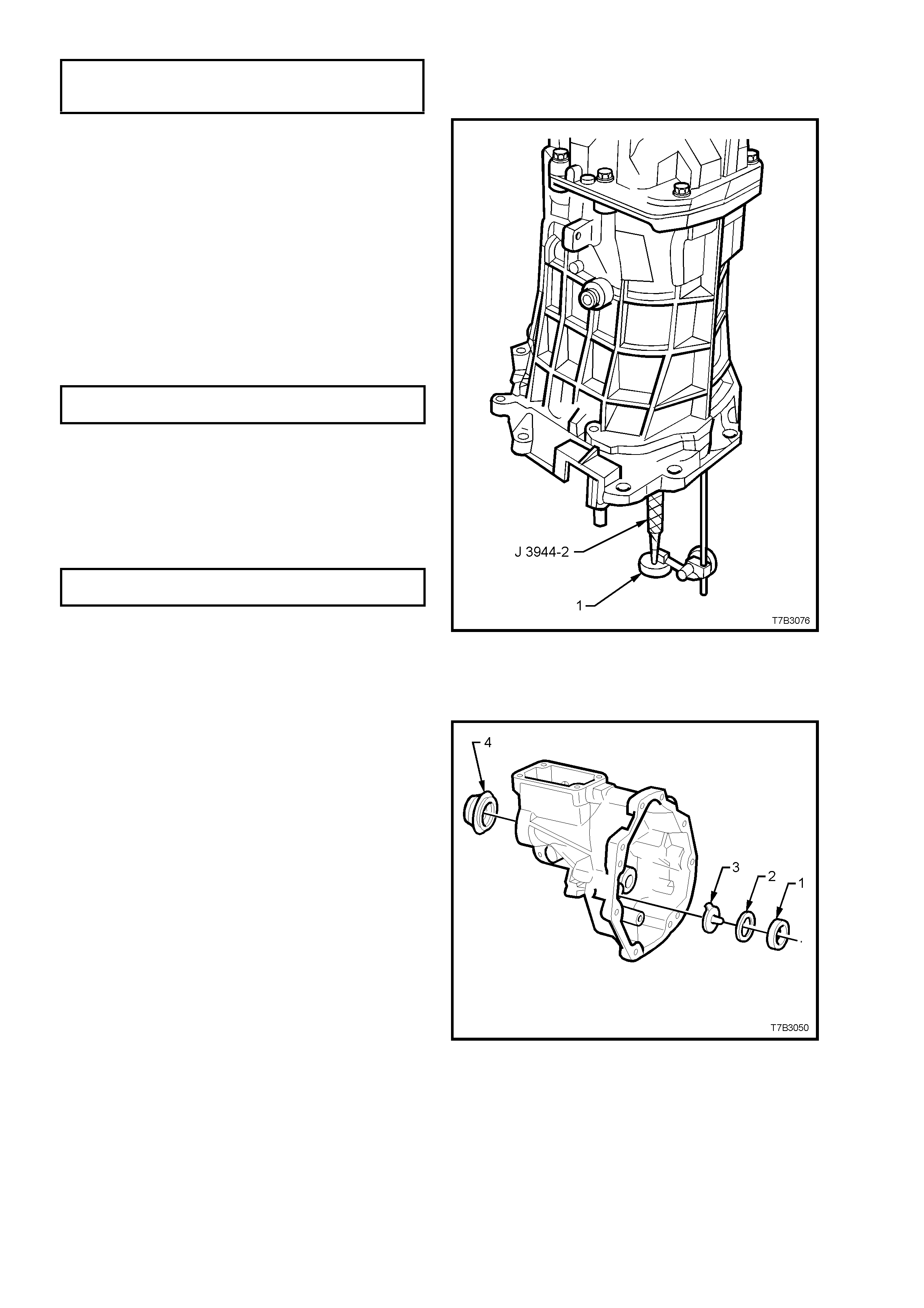
EXTENSION HOUSING TO
TRANSMISSION CASE BOLT 30 - 41 Nm
TORQUE SPECIFICATION
14. Insert countershaft extension, end play rod J
39444-2 through the adaptor plate plug hole
and hollow countershaft, then screw the rod
into the threaded end of the countershaft
extension.
15. Mount a commercially available dial indicator
to the adaptor plate, with the probe sensing
the end of the end play rod. Zero the dial
indicator.
16. Lift the end play rod J 39444-2 up and down to
determine the countershaft extension end
play.
17. Select a shim pack to achieve the correct end
play specification.
COUNTERSHAFT EXTENSION 0.05 - 0.13
END PLAY SPECIFICATION mm
NOTE: There are 33 shim selections available,
ranging from 0.559 - 1.372 mm.
18. Remove the dial indicator and end play rod.
19. Apply sealant such as Loctite 565 or
equivalent (GM P/N 12346004), to the c leaned
threads of the adaptor plug, install the plug
and tighten to the correct torque specification.
ADAPTOR PLATE PLUG 20 - 34
TORQUE SPECIFICATION Nm
Figure 7B3-140
20. Loosen then remove the eight extension
housing to transmission case bolts, then
remove the extension housing.
21. Slide the countershaft gear extension, rear
bearing cup (1) from the extension housing.
NOTE: Rotating the cup back and forth while
pulling with the finger tips, will reduce the problem
of the bearing cup cocking and jamming in the
adaptor plate bore.
22. Install the oil funnel (3), the shim pack
determined from the end play check (2), then
reinstall the countershaft extension rear
bearing cup (1).
Figure 7B3-141
23. Loosen then remove the eight adaptor plate to
transmission case bolts, then remove the
transmission case .
24. Lift the mainshaft assembly slightly to allow
countershaft removal, then remove the
mainshaft assembly and input shaft and
blocker rings.
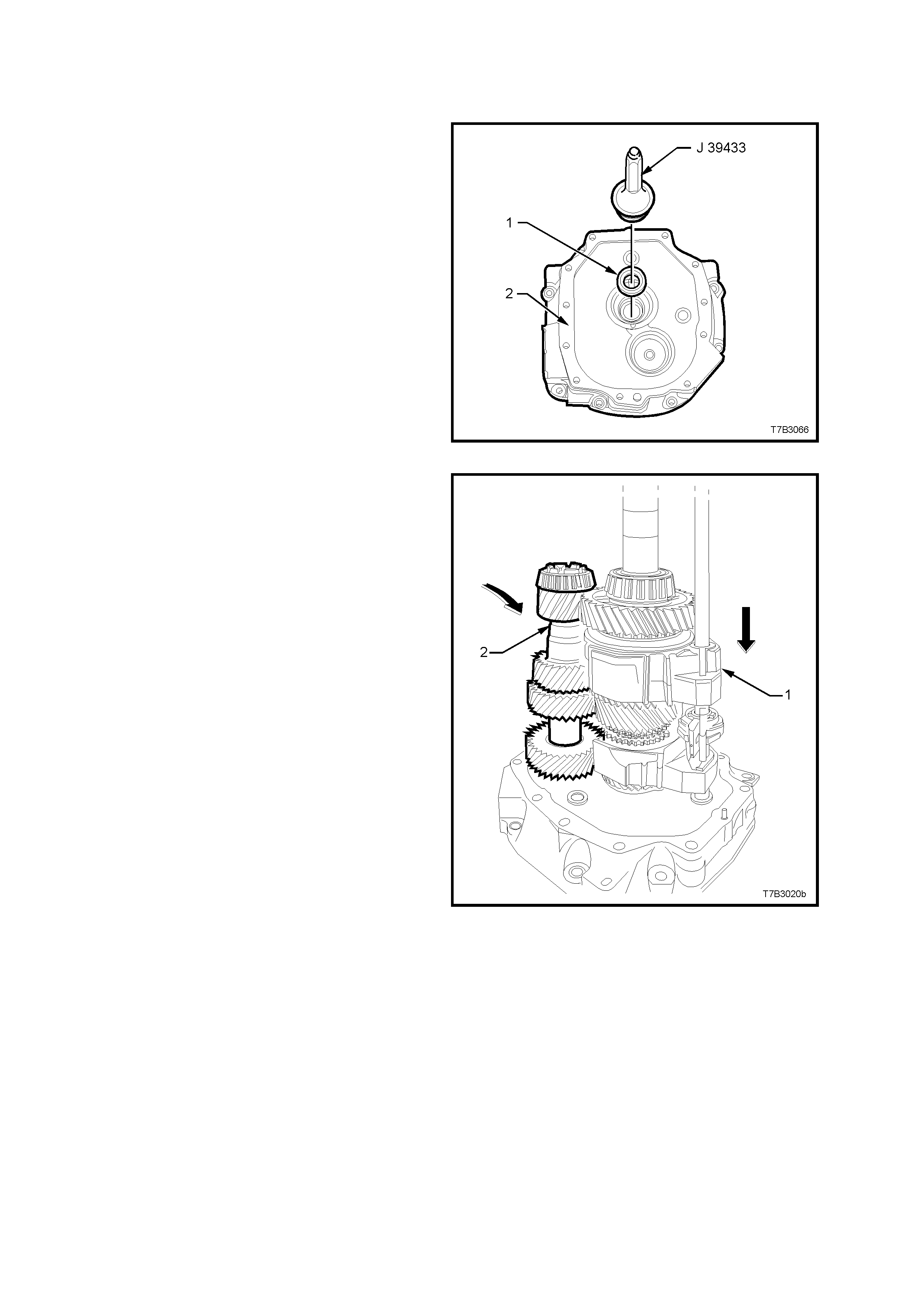
4.7 TRANSMISSION REASSEMBLE
GEAR TRAINS AND SHIFT RAILS
1. Using seal installer J 39433, install a new oil
seal (1) to the adaptor plate (2).
2. Lubricate the input shaft, taper roller bearing
and seal contact area of the input shaft with
clean transmission fluid, then reinstall the input
shaft to the adaptor plate.
3. Install the blocker rings to the input shaft gear.
Figure 7B3-142
4. Reinstall the mainshaft, together with the
1st/2nd, 3rd/4th shift shaft and forks (1) after
lubricating the spigot taper roller bearing and
shift shaft bush with clean transmission fluid.
Tak e care that the 4th speed block er rings ar e
correctly engaged with the synchromesh
assembly keys.
5. Lubricate the countershaft, front and rear taper
roller bearings with clean transmission fluid,
then reinstall the countershaft (2) to the
adaptor plate, after lifting the mainshaft
assembly (1) slightly, to allow installation
access.
Figure 7B3-143
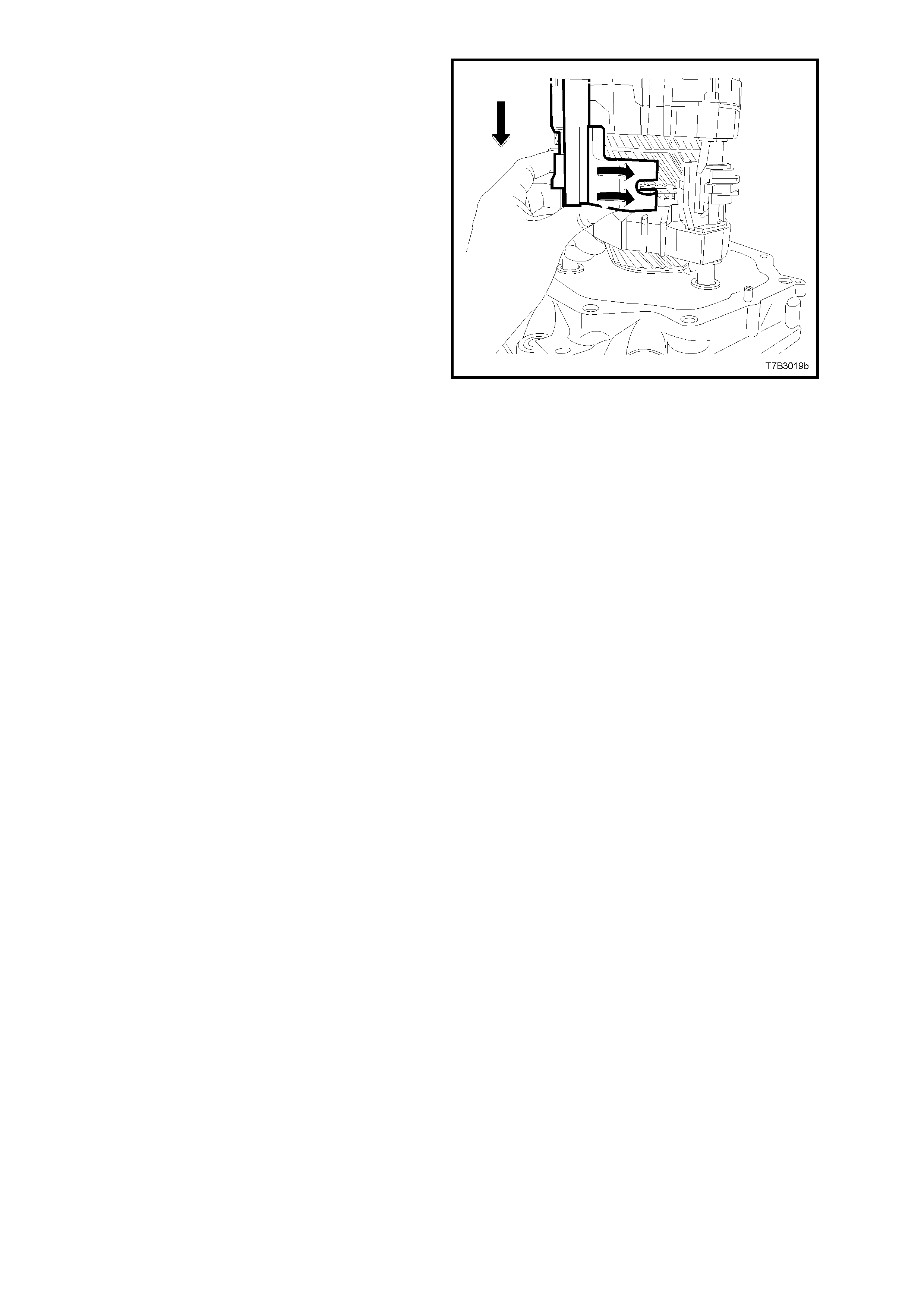
6. Install the 5th/6th and Reverse shift shaft
assembly, then align the slots in the shift rail
levers with the interlock plate and selector pin.
Figure 7B3-144
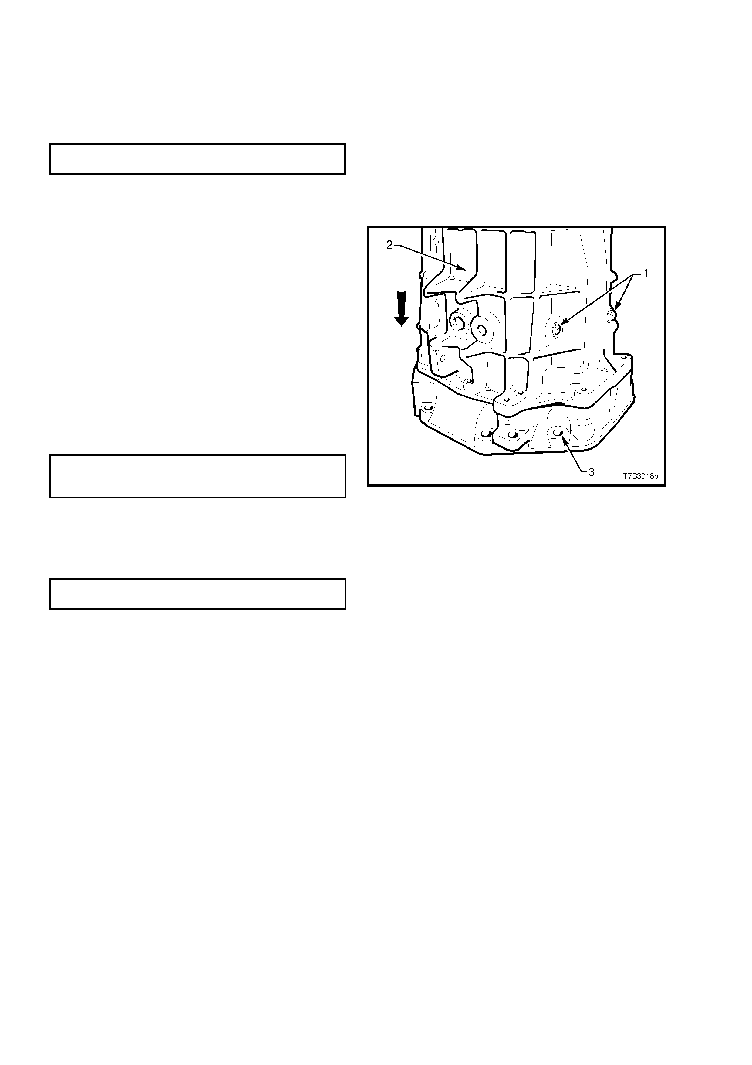
TRANSMISSION CASE
1. Install the front offset lever guide plate to the
transm iss ion case, install the two Torx headed
screws and tighten to the correct torque
specification, using a T40 Torx bit and
adaptor.
SHIFT GUIDE PLATE SCREW 16 - 27
TORQUE SPECIFICATION Nm
NOTE: The ‘H’ pattern in the guide plate m ust f ace
the rear of the transmission. i.e. to the extension
housing.
2. Apply a single bead of sealant such as Loctite
“Ultrablack” 598 or equivalent (GM P/N
12345739), to the cleaned, transmission case
to adaptor plate mating surface.
3. Reinstall the transmission case (2) over the
mainshaft and shift shaft. As the case is
installed, push the front off s et lever agains t the
detent ball and spring, holding the detent ball
against the guide plate, in the neutral plane
position, to align the front offset lever with the
shift shaft.
4. When the case is fully installed over the two
adaptor plate dowel pins, install the eight
adaptor to transm ission case bolts and tighten
to the correct torque specification.
ADAPTOR PLATE TO
TRANSMISSION CASE 30 - 41 Nm
TORQUE SPECIFICATION
5. Apply thread sealant such as Loctite 242 or
equivalent (to Holden’s Specification HN 1256
Class 2, T ype 2), to the cleaned threads of the
shift lever guide bolts (1), install and tighten to
the correct torque specification.
SHIFT LEVER GUIDE BOLT 20 - 34
TORQUE SPECIFICATION Nm
NOTE: It might be necessary to pull up on the
5th/6th and Reverse shift shaft to align the slot of
the interlock plate with the guide bolt hole.
Important: to maintain the shift rails in the correct
position during the remainder of the assembly
process, it is vital that these two guide bolts are
installed at this time.
Figure 7B3-145
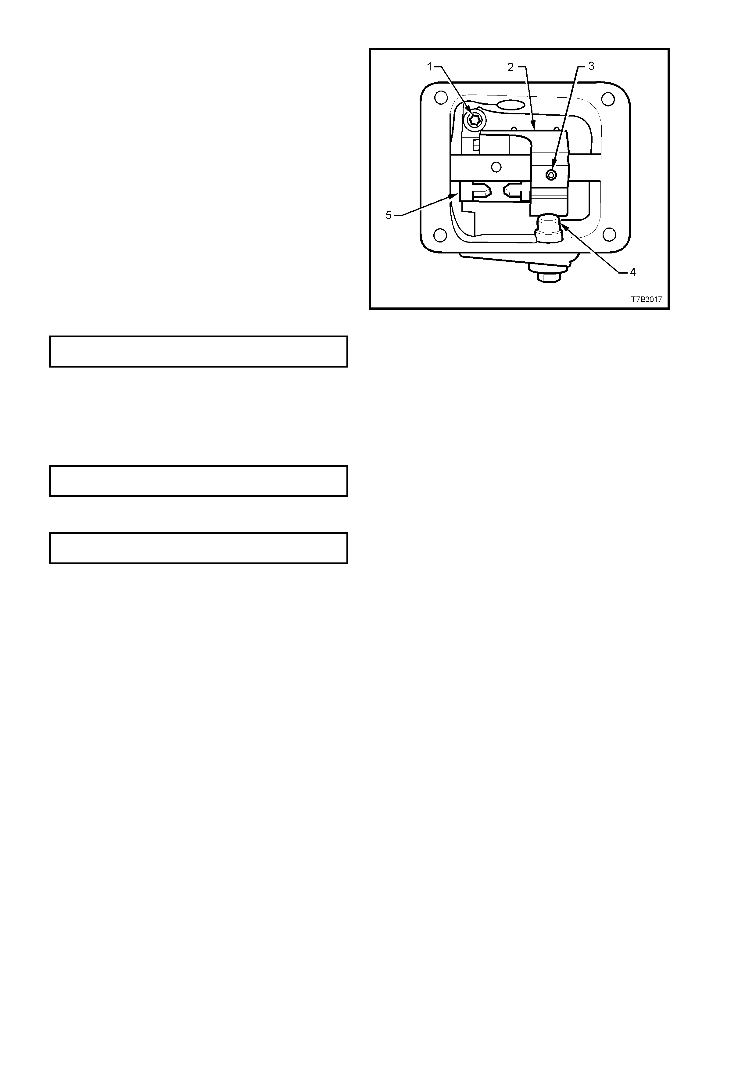
6. Align the front offset lever (2) with the hole in
the shift shaft, then install a new roll pin (3) to
secure, using a suitable size pin punch and
hammer.
NOTE: Insert a pin punch of suitable size into the
rear offset lever roll pin hole in the shift shaft and
check that the shif t shaf t is able to be ro tated f reely
through each of the detent ball positions. This will
ensure that the shift selector forks, interlock plate
and associated parts are all aligned correctly. If
difficulty is experienced in rotating the shift shaft,
then the transmission case must be removed and
the problem rectified before proceeding.
7. Apply thread sealant such as Loctite 242 or
equivalent (to Holden’s Specification HN 1256
Class 2, T ype 2), to the cleaned threads of the
shift enhancer (4), then, using a 24 mm
sock et, install and tighten to the cor rect torque
specification.
SHIFT ENHANCER 34 - 48
TORQUE SPECIFICATION Nm
8. Apply a continuous bead of sealant such as
Loctite “Ultrablack ” 598 or equivalent (GM P/N
12345739), to the mating surface of the cover
plate, then install to the transmission case.
9. Install the four cover bolts and tighten to the
correct torque specification.
FRONT OFFSET LEVER COVER 15 - 20
BOLT TORQUE SPECIFICATION Nm
10. Install the back-up lamp switch and tighten to
the correct torque specification.
BACK-UP LAMP SWITCH 20 - 34
TORQUE SPECIFICATION Nm
Figure 7B3-146
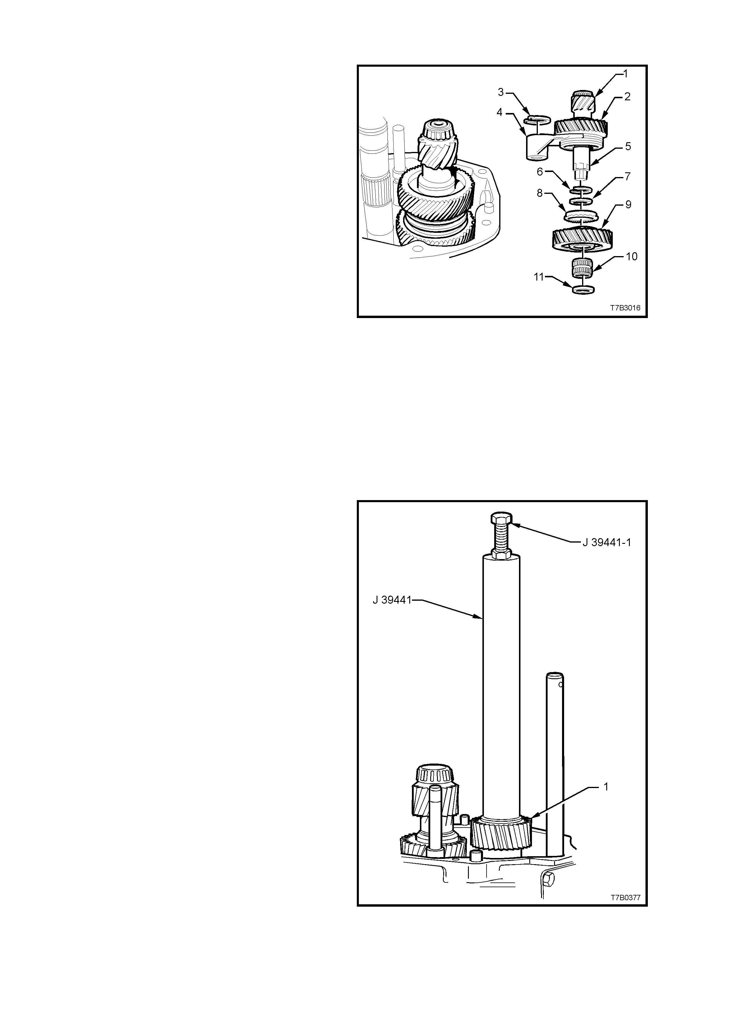
COUNTERSHAFT EXTENSION ASSEMBLY
1. Install the following components to the
countershaft extension (5);
a. Spacer (7).
b. 6th gear, blocker ring (8).
c. 6th drive gear (9).
d. 6th drive gear, caged needle roller
bearing (10).
e. Thrust washer (11).
NOTE 1: Ensure that the recessed side of the
thrust washer (11) faces the countershaft.
NOTE 2: Snap ring (6) was installed when the
5th/6th synchromesh assembly (2) was installed to
the countershaft extension (1). Refer page 7B3-51.
2. With the 5th/6th shift fork (4) positioned as
shown, install the countershaft extension
assembly onto the rear of the countershaft,
guiding the 5th/6th shift fork (4) over the
5th/6th shift rail lever sleeve.
3. Rotate the countershaft extension back and
forth to ensure that the dog teeth on the
countershaft extension mate with the
corresponding dogs on the end of the
countershaft.
4. Install a new circlip (3) to the groove in the
5th/6th shift rail lever sleeve to s ecure the s hift
fork.
Figure 7B3-147
5TH/6TH DRIVEN GEAR
1. Install the 5th/6th speed driven gear (1) over
the mainshaft with the smaller gear facing
inward.
2. Engage the inner gear splines with those on
the mainshaft and install, using installer J
39441 and bolt/nut J 39441-1.
NOTE: It may be necessary to rotate the 5th and
6th drive gears on the countershaft extension to
assist in gear meshing with the driven gear (1),
prior to the gear installation process.
Figure 7B3-148
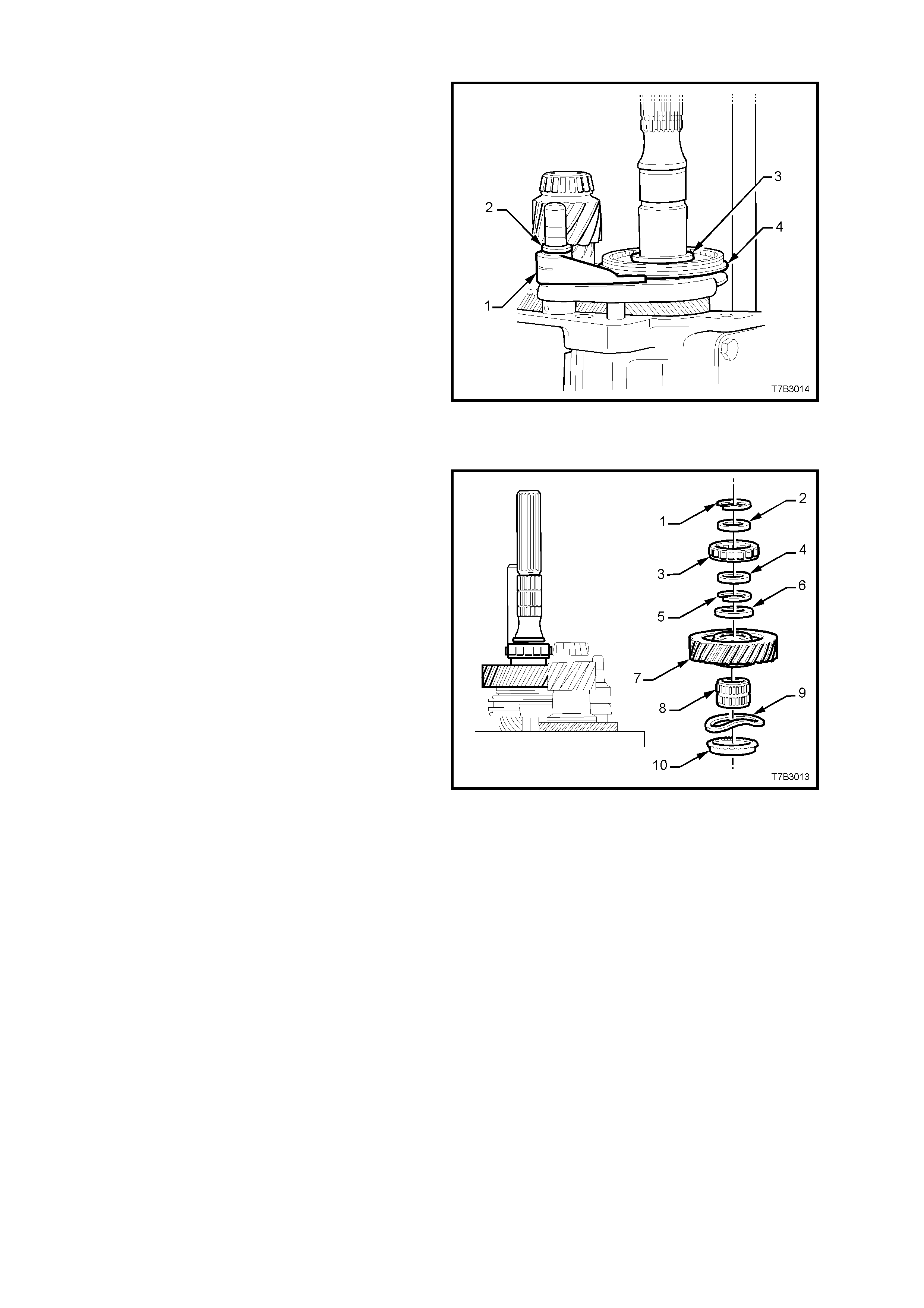
REVERSE SYNCHROMESH ASSEMBLY
1. With the reverse shift lever (1) positioned as
shown, install the reverse synchromesh
assembly (4) and shift lever (1) to the
mainshaft and shift shaft, ensuring that the
reverse synchromesh key retainer faces the
end of the 6th speed driven gear.
2. Fit a new circlip (2) to retain the shift fork (1)
and a new snap ring (3) to secure the reverse
synchromesh assembly (4).
Figure 7B3-149
REVERSE SPEED GEA R
1. Install the following components onto the
mainshaft, aligning the blocker rings with the
synchromesh keys, in the process;
a. Reverse gear blocker ring (10).
b. Wave washer (9).
c. Reverse gear, caged roller bearing (8).
d. Reverse gear (7).
e. Thrust washer (6).
2. Fit a new snap ring (5) to secure the reverse
driven gear (7).
3. Continue to install the components of the rear
mainshaft roller bearing, as follows;
a. Spacer (4).
b. Rear mainsh aft roller race (3).
c. Spacer (2).
4. Secure these components with a new snap
ring (1). Figure 7B3-150
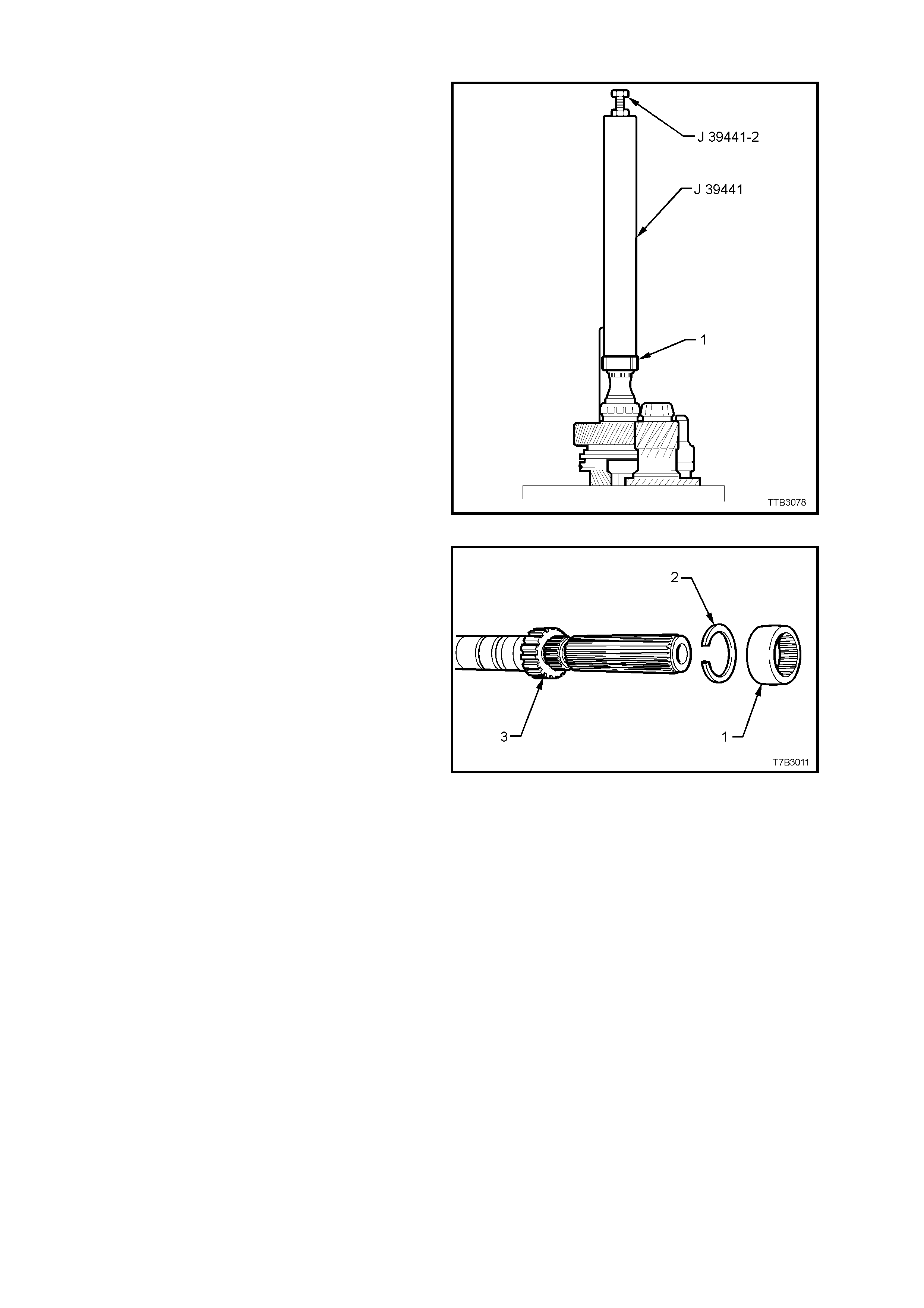
SPEEDOMETER PULSE RING
1. Install a new, inner snap ring to the
speedometer pulse ring groove in the
mainshaft.
2. Install the speedometer pulse ring to the
mains haft, using Installer J 39441 and bolt/nut
J 39441-2.
3. Tighten the nut of J 39441-2 until the pulse
ring bottoms against the snap ring.
4. Remove the tools.
Figure 7B3-151
5. Install a new snap ring (2) to the outer
speedometer pulse ring (3) groove in the
mainshaft.
6. Slide a new sealing ring (1) onto the
mainshaft.
Figure 7B3-152
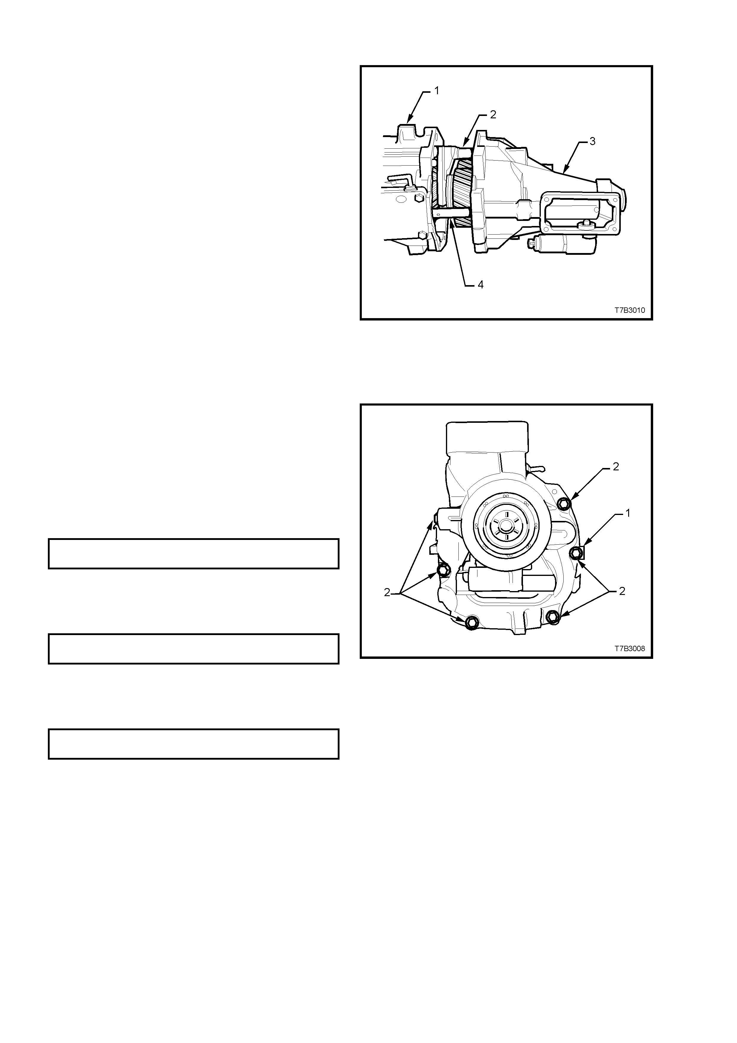
EXTENSION HOUSING
1. Rotate the transmission through 90° into the
horizontal position, then move the shift rail (4)
into the 2nd or 4th gear position to shorten the
shift rail length.
2. Lubricate the countershaft extension taper
roller bearing with clean transmission fluid.
3. Install the two circular magnets into the
grooved space in the transmission case.
4. Apply a continuous bead of sealant such as
Loctite “Ultrablack ” 598 or equivalent (GM P/N
12345739), to the extension housing to
transmission case mating surface.
5. Install the extension housing (3) over the
ma inshaft, aligning the shift r ails (4 and 2) with
the extension housing bushes.
NOTE: Because the 5th/6th and Reverse shift s haf t
is unsupported at this point, it will need to be
manipulated to align the end of the shaft with the
corresponding bore in the extension housing. Do
not try and force the extension housing over the
dowel pins.
Figure 7B3-153
6. Install all but the two upper extension housing
bolts. (not shown). Apply thread sealant such
as Loctite 565 or equivalent (GM P/N
12346004), to the cleaned threads of the two
upper bolts. Note that a wiring harness clip is
under the right hand upper bolt and also, the
position of the identification tag (1).
7. Tighten all 8 bolts (2) to the correct torque
specification.
EXTENSION HOUSING BOLT 30 - 41
TORQUE SPECIFICATION Nm
8. Install the O-ring to the reverse lockout
solenoid assembly, then install the assembly
and retaining bolt to the extension housing,
tightening to the correct torque specification.
REVERSE LOCKOUT SOLENOID 15 - 20
BOLT TORQUE SPECIFICATION Nm
9. Install the O-ring seal to the speedometer
sensor, then ins tall the s ens or to the ex tens ion
housing, retaining with a screw, tightened to
the correct torque specification.
SPEED SENSOR RETAINING 8.0 - 12.0
SCREW TORQUE SPECIFICATION Nm
Figure 7B3-154
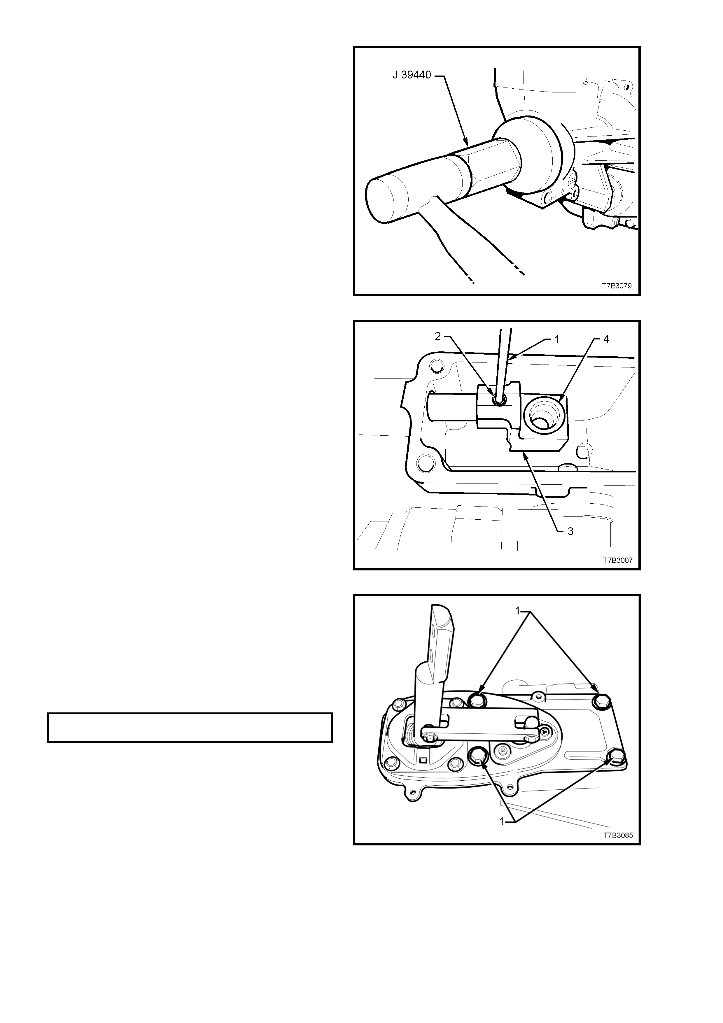
10. Using seal installer J 39440, install a NEW
rear seal to the extension housing.
Figure 7B3-155
11. Slide the rear offset lever (3) over the shift rail
and secure with a new roll pin (2), installed
with a suitable pin pinch (1) and hammer.
12. Apply Lithium grease NLGI No. 4 EP to the
isolator cup (4) in the rear offset shift lever (3).
Figure 7B3-156
13. If the remote shifter assembly, rubber seal is
undamaged, then it may be re-used.
Otherwise, fit a new seal to the extension
housing.
14. Install the remote shifter assembly to the
extension housing, install the insulating
grommets and four retaining bolts (1), then
tighten to the correct torque specification.
REMOTE SHIFTER RETAINING 15 - 20
BOLT TORQUE SPECIFICATION Nm
Figure 7B3-157
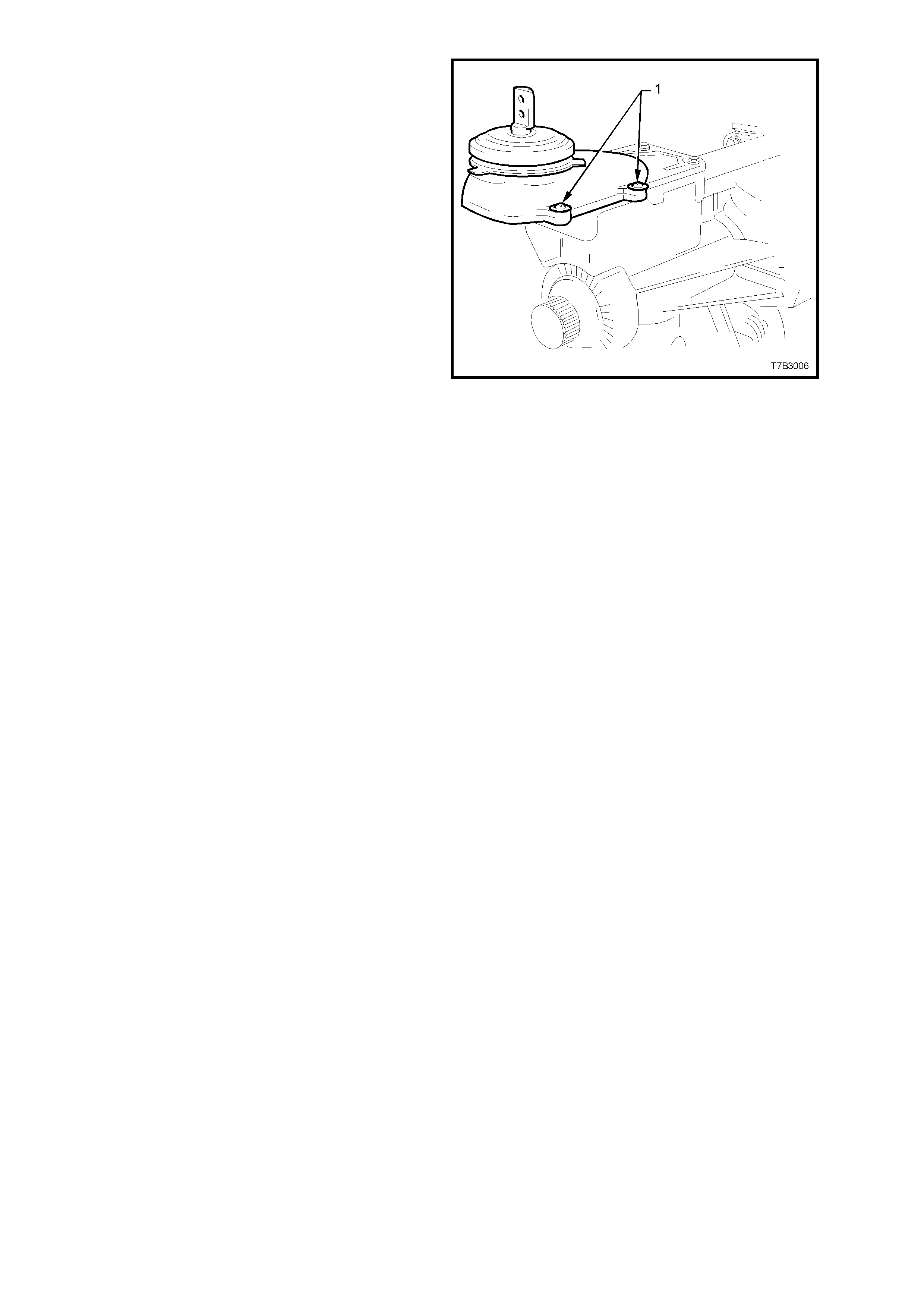
15. Install the cover over the remote shifter
assembly and secure with the 4 screws (1). Do
not over-tighten.
Figure 7B3-158
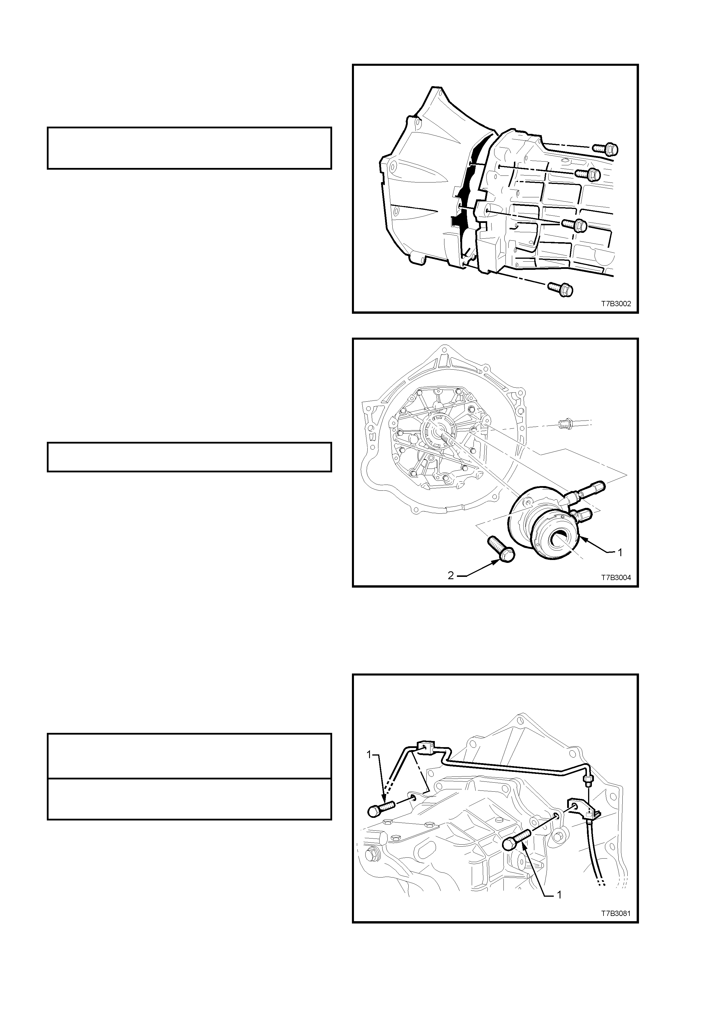
CLUTCH HOUSING AND SLAVE CYLINDER
1. Remove the transmission from the
transmission holding fixture J 39430.
2. Install the 10 clutch housing and bolts,
tightening to the correct torque specification.
CLUTCH HOUSING TO
ADAPTOR PLATE BOLT 30 - 41 Nm
TORQUE SPECIFICATION
Figure 7B3-159
3. Install the clutch slave cylinder (1) over the
input shaft.
4. Apply thread sealant such as Loctite 242 or
equivalent (to Holden’s Specification HN 1256
Class 2, Type 2), to the two slave cylinder
retaining bolts (2), install and tighten to the
correct torque specification.
CLUTCH SLAVE CYLINDER BOLT 7.5 - 12.5
TORQUE SPECIFICATION Nm
Important: Before tightening the two retaining
bolts, centralise the slave cylinder bleeder
screw in the transmission adaptor plate/clutch
housing aperture. This is necessary to ensure
access to the bleeder, after the transmission
has been installed.
5. Sparingly apply 10% molybdenum disulphide
grease, such as Molybond GA 10 (or
equivalent to Holden’s Specification HN 1271)
to the clutch throwout bearing contact face, the
splines and spigot of the input shaft.
Figure 7B3-160
6. Route the clutch fluid pipe around the
transmission housing, install the bracket
fasteners (1) and tighten to the correct torque
specification.
CLUTCH PIPE BRACKET SCREW
TO LEFT HAND SIDE 4.0 - 7.0 Nm
TORQUE SPECIFICATION
CLUTCH PIPE BRACKET SCREW
TO RIGHT HAND SIDE 6.0 - 14 Nm
TORQUE SPECIFICATION
Figure 7B3-161
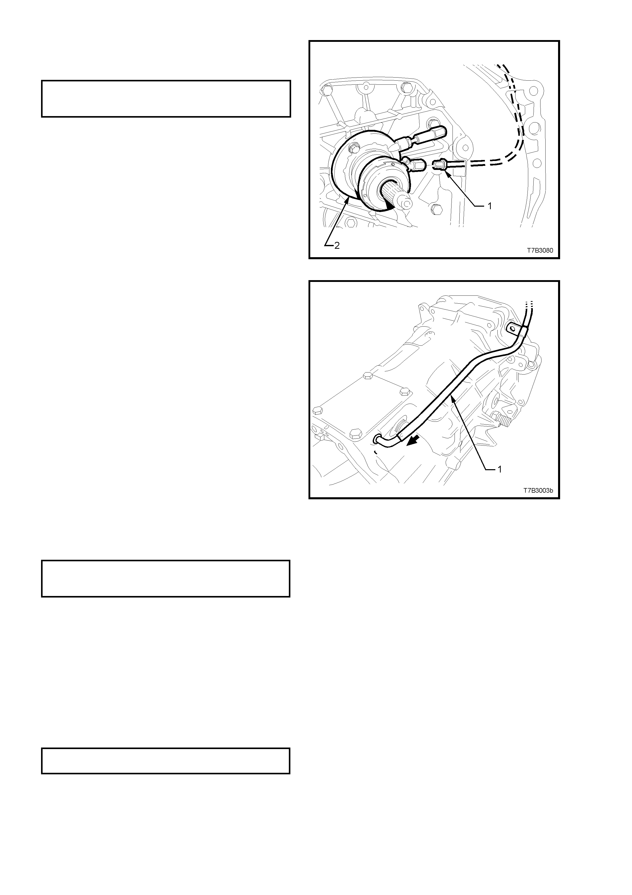
7. Install the clutch fluid pipe fitting (1) to the
slave cylinder (2) and tighten to the correct
torque specification.
CLUTCH FLUID PIPE FITTING TO
SLAVE CYLINDER 12 - 14 Nm
TORQUE SPECIFICATION
Figure 7B3-162
8. Install the transm ission vent tube (1), sliding it
over the pipe located at the front offset lever.
Figure 7B3-163
9. If removed, install the rear engine mount to
transmission extension bolts, tightening to the
correct torque specification.
TRANSMISSION MOUNT
TO EXTENSION HOUSING BOLT 20 - 30 Nm
TORQUE SPECIFICATION
10. Fit a suitable plug to the rear oil seal to
prevent dirt/dust entry.
11. Reinstall transmission into the vehicle. Refer
to 4.2 TRANSMISSION ASSEMBLY, in this
Section.
12. Fill transm is sion with 3.9 litres of Dexron III®
fluid (to Holden’s Specification HN 2126).
13. Apply sealant such as Loctite 565 or
equivalent (GM P/N 12346004), to the
cleaned threads of the filler plug and tighten
to the correct torque specification.
FILLER PLUG 20 - 34
TORQUE SPECIFICATION Nm
NOTE: Under no circumstances is Teflon thread
tape to be used on the filler, drain or adaptor plate
plugs.

5. DIAGNOSIS
5.1 TRANSMISSION SHIFTS HARD
DEFINITION: The transmission does not shift smoothly or without difficulty into another gear.
Step Action Value(s) Yes No
1Check the transmission for improper lubricant. Refer to 2.1
Recommended Lubricant.
Is the recommended lubricant being used? −Go to Step 2 Go to Step 3
2Check the transmission for loose shift lever housing bolts.
Are the bolts loose? −Go to Step 4 Go to Step 5
3Drain and refill the transmission with the recommended
lubricant. Refer to 2.3 DRAINING AND REFILLING
TRANSMISSION.
Does the transmission shift smoothly?
−System OK Go to Step 5
4Align the component parts and tighten the fasteners.
Refer to 7. TORQUE SPECIFICATIONS.
Does the transmission shift smoothly? −System OK Go to Step 5
5Check for proper clutch operation.
Was the clutch the cause of hard shifting? −System OK Go to Step 6
6
1. Remove the transmission. Refer to 4.2 TRANSMISSION
ASSEMBLY, Remove.
2. Disassemble the transmission. Refer to 4.3
TRANSMISSION DISASSEMBLE.
3. Look for the following list of causes:
• Binding shift rail.
• Mispositioned shift selector arm roll pin.
• Worn shift rail bores.
• Distorted oil seal.
4. Replace all worn or damaged parts.
−−−
Techline

5.2 TRANSMISSION HARD TO SHIFT INTO REVERSE
DEFINITION: The transmission does not shift smoothly into reverse gear or will not shift into reverse gear.
Step Action Value(s) Yes No
11. Turn the ignition switch to the ON position.
2. Check for voltage at the reverse lockout solenoid electrical
connector.
Is there voltage at the connector. 12 volts Go to Step 2 Go to Step 5
2
1. Remove the reverse lockout solenoid assembly from the
reverse lockout assembly. Refer to 3.4 REVERSE
LOCKOUT SOLENOID, Remove .
2. Apply 12 volts to the solenoid electrical connector.
Is the solenoid plunger extended?
−
Go to Step 3 Go to Step 6
3
Remove the reverse lockout assembly from the transmission.
Refer to REVERSE LOCKOUT SOLENOID ASSEMBLY,
Reinstall.
Can you easily depress the reverse lockout plunger with your
thumb?
−
Go to Step 4 Go to Step 7
4
1. Remove the transmission. Refer to 4.2 TRANSMISSION
ASSEMBLY, Remove.
2. Disassemble the transmission. Refer to
3. Look for the following list of causes:
• Worn or broken shift linkage parts.
• A worn or damaged synchroniser ring or hub.
4. Replace all worn or damaged parts.
−−−
5Repair the reverse lockout solenoid electrical circuit.
Is the circuit OK? −Go to Step 1 −
6Replace the solenoid.
Does the transmission shift OK now? −System OK −
7Repair or replace the reverse lockout assembly. Refer to 3.4
REVERSE LOCKOUT SOLENOID ASSEMBLY, Replace.
Does the transmission shift OK now? −System OK −

5.3 GEAR CLASH WHEN SHIFTING GEARS
DEFINITION: The transmission gears clash when shifting from one gear into another.
Step Action Value(s) Yes No
1Check for low oil level in the transmission. Refer to 2.2
CHECKING TRANSMISSION LUBRICANT LEVEL.
Is the oil level OK? −Go to Step 2 Go to Step 3
2Check the transmission for improper lubricant. Refer to 2.1
RECOMMENDED LUBRICANT.
Is the recommended lubricant being used? −Go to Step 5 Go to Step 4
3 Replenish the oil to the level of the oil fill plug. −−−
4Drain and refill the transmission with the recommended
lubricant. Refer to 2.3 DRAINING AND REFILLING
TRANSMISSION. −−−
5Check for proper clutch operation.
Is the clutch operating properly? −Go to Step 6 −
6
1. Remove the transmission. Refer to 4.2 TRANSMISSION
ASSEMBLY, Remove.
2. Disassemble the transmission. Refer to 4.3
TRANSMISSION DISASSEMBLE.
3. Look for the following list of causes:
3.1 Gearshift components are worn or damaged.
3.2 Synchroniser assemblies worn or damaged.
4. Replace all worn or damaged parts.
−−−

5.4 TRANSMISSION NOISY
DEFINITION: Transmission gear noise in evident in the passenger compartment.
Step Action Value(s) Yes No
1 Check for low oil level in the transmission. Refer to 2.2
CHECKING TRANSMISSION LUBRICANT LEVEL..
Is the oil level OK? −Go to Step 2 Go to Step 3
2Check the transmission for improper lubricant. Refer to 2.1
RECOMMENDED LUBRICANT.
Is the recommended lubricant being used? −Go to Step 5 Go to Step 4
3 Replenish the oil to the level of the oil fill plug. −−−
4Drain and refill the transmission with the recommended
lubricant. Refer to 2.3 DRAINING AND REFILLING
TRANSMISSION. −−−
5Check for loose clutch housing bolts. Refer to 7. TORQUE
WRENCH SPECIFICATIONS.
Are the bolts tightened to specifications? −Go to Step 6 Go to Step 7
6
1. Remove the transmission. Refer to 4.2 TRANSMISSION
ASSEMBLY, Remove.
2. Disassemble the transmission. Refer to 4.3
TRANSMISSION DISASSEMBLE.
3. Look for the following list of causes:
3.1 Gearshift components are worn or damaged.
3.2 Transmission gears are worn or damaged.
3.3 Bearing components are worn or damaged.
4. Replace all worn or damaged parts.
−−−
7 Tighten the clutch housing bolts to the specified torque. −−−

5.5 TRANSMISSION JUMPS OUT OF GEAR
DEFINITION: Transmission selects Neutral without any driver action.
Step Action Value(s) Yes No
1 Check for loose clutch housing bolts. Refer to 7. TORQUE
WRENCH SPECIFICATIONS.
Are the bolts tightened to specifications? −Go to Step 2 Go to Step 3
2 Tighten the clutch housing bolts to the specified torque. −−−
3
1. Remove the transmission. Refer to 4.2 TRANSMISSION
ASSEMBLY, Remove.
2. Disassemble the transmission. Refer to 4.3
TRANSMISSION DISASSEMBLE.
3. Look for the following list of causes:
3.1 Gearshift components worn or damaged.
3.2 Gear teeth worn or tapered.
3.3 Synchroniser assemblies worn or damaged.
3.4 Excessive end play in components.
3.5 Bearing components are worn or damaged.
4. Replace all worn or damaged parts.
−−−

5.6 TRANSMISSION DOES NOT SHIFT INTO ONE GEAR
DEFINITION: The transmission does not shift into one gear.
Step Action Value(s) Yes No
1 Remove the transmission. Refer to 4.2 TRANSMISSION
ASSEMBLY, Remove.
Check for worn or damaged gearshift components.
Are the gearshift components OK?
−Go to Step 2 Go to Step 3
2Disassemble the transmission. Refer to 4.3 TRANSMISSION
DISASSEMBLE.
Look for worn or damaged synchroniser assemblies.
Replace all worn or damaged parts. −−−
3 Replace the worn or damaged gearshift components. Refer to
Transmission Disassemble.
Will the transmission shift gears? −System OK Go to Step 2

5.7 TRANSMISSION LOCKED IN ONE GEAR
DEFINITION: The transmission cannot be shifted out of gear.
Step Action Value(s) Yes No
1 Remove the transmission. Refer to 4.2 TRANSMISSION
ASSEMBLY, Remove.
Are the gearshift components properly assembled? −Go to Step 2 Go to Step 3
2 Are the gearshift components worn, bent or broken? −Go to Step 4 Go to Step 5
3Disassemble the gearshift components. Properly assemble
the gearshift components. Refer to 4.3 TRANSMISSION
DISASSEMBLE.
Will the transmission shift gears?
−
System OK Go to Step 5
4Replace the worn or damaged parts. Refer to 4.3
TRANSMISSION DISASSEMBLE.
Will the transmission shift gears? −System OK Go to Step 5
5Disassemble the transmission geartrain. Refer to 4.3
TRANSMISSION DISASSEMBLE.
Look for worn, broken, or, damaged components.
Replace all worn, broken, or damaged components. −−−

6. SPECIFICATIONS
TRANSMISSION:
GEN III, V8 Powered Vehicles ................................ Borg Warner, Type T56 Manual Transmission.
Overdrive 5th and 6th Speed, Production Option MM6.
TRANSMISSION RATIOS:
1st ...................................................................... 2.66:1
2nd..................................................................... 1.78:1
3rd...................................................................... 1.30:1
4th...................................................................... 1.00:1
5th...................................................................... 0.74:1
6th...................................................................... 0.50:1
Reverse.............................................................. 2.90:1
NUMBER OF TEETH:
Input Gear ............................................................... 31
Mainshaft Gear
1st ...................................................................... 39
2nd..................................................................... 43
3rd...................................................................... 37
5th...................................................................... 37
6th...................................................................... 29
Reverse.............................................................. 35
Reverse Idler Gear.................................................. 23
Countershaft Gear Input.......................................... 36
Countershaft Gear
1st ...................................................................... 17
2nd..................................................................... 28
3rd...................................................................... 33
Countershaft Gear Extension
5th...................................................................... 58
6th...................................................................... 67
Reverse.............................................................. 14
SYNCHROMESH ASSEMBLIES:
Synchromesh Ring Wear
Replacement Clearance - All forward gears ..... less than 0.38 mm
- Reverse Gear.......... less than 0.75 mm
BEARING PRE-LOAD/END FLOAT:
Input Shaft/Mainshaft .............................................. 0.00 - 0.05 mm pre-load
Countershaft Gear................................................... 0.00 - 0.05 mm pre-load
Countershaft Gear Extension.................................. 0.05 - 0.13 mm end float
SELECTIVE SHIM WASHER THICKNESSES:
Input Shaft Bearing.................................................. 0.559 - 1.372 mm
Countershaft Gear................................................... 0.356 - 1.372 mm
Countershaft Gear Extension.................................. 0.559 - 1.372 mm
LUBRICANTS:
Transmission........................................................... Dexron III® fluid to Holden’s Specification HN 2126.
Capacity (Nominal).................................................. 3.9 litres
Rear Offset Lever Isolating Cup.............................. NLGI No. 4 EP
Clutch Throwout Bearing Contact Face .................. 10% molybdenum disulphide grease to Holden’s
Specification HN 1271
SEALANTS:
Thread Sealant in nominated locations................... Loctite 242 or equivalent (to Holden’s Specification
HN 1256 Class 2, Type 2)
Sealing Plugs and Bumper Bolt Threads ................ Loctite 565 or equivalent (GM P/N 12346004)
Adaptor Plate and Extension Housing to Case Loctite “Ultrablack” 598 or equivalent (GM P/N 12345739)

7. TORQUE WRENCH SPECIFI CATIONS
Nm
Adaptor Plate Plug..................................................................... 20 - 34
Adaptor Plate to Transmission Case Bolts ................................ 30 - 41
Backup Lamp Switch ................................................................. 20 - 34
Catalytic Converter Bracket Bolt to Catalytic Converter............. 20 – 30
Catalytic Converter Bracket Bolt to Transmission Extension..... 40 - 60
Centre Bearing Carrier to Underbody Reinforcement Bolt......... 20 - 35
Clutch Housing to Adaptor Plate Bolt......................................... 30 - 41
Clutch Housing to Engine Block Bolt ......................................... 40 - 60
Clutch Hydraulic Pipe Bracket Bolt (LHS).................................. 4.0 - 7.0
Clutch Hydraulic Pipe Bracket Bolt (RHS) ................................. 6.0 - 14.0
Clutch Hydraulic Pipe Fitting to Slave Cylinder.......................... 12 - 14
Clutch Hydraulic Pipe Fitting to Flexible Hose........................... 12 - 14
Clutch Slave Cylinder Bolt.......................................................... 7.5 - 12.5
Drain Plug .................................................................................. 20 - 34
Engine to Transmission Close-out Cover Bolts (Each Side) ..... 10 - 14
Extension Housing to Transmission Case Bolts........................ 30 - 41
Filler Plug................................................................................... 15 - 25
Front Offset Lever Cover Bolts .................................................. 20 - 34
Gearshift Control Lever to Remote Shift Lever Bolt................... 15 - 35
Propeller Shaft Rear Universal Joint to Pinion Flange Bolt........ 55 - 65
Rear Crossmember to Transmission Support Mount Nut ......... 20 - 30
Rear Crossmember to Side Frame Member Bolt...................... 50 - 65
Rear Remote Shift Lever Cover Bolt.......................................... 10 - 12
Remote Shift Lever Cover Bolts................................................. 15 - 20
Remote Shift Lever Boot Plate Bolt ........................................... 6.0 - 14
Reverse Idler Shaft Bracket Bolts.............................................. 19 - 30
Reverse Lockout Assembly Bolt................................................ 15 - 20
Reverse Lockout Solenoid......................................................... 34 - 48
Shift Enhancer Assembly........................................................... 34 - 48
Shift Lever Guide Bolts .............................................................. 20 - 34
Shift Guide Plate Bolts............................................................... 16 - 27
Speed Sensor Bracket to Extension Housing Bolt..................... 8.0 - 12.0
Transmission Support Mount to Extension Housing Bolt........... 20 - 30
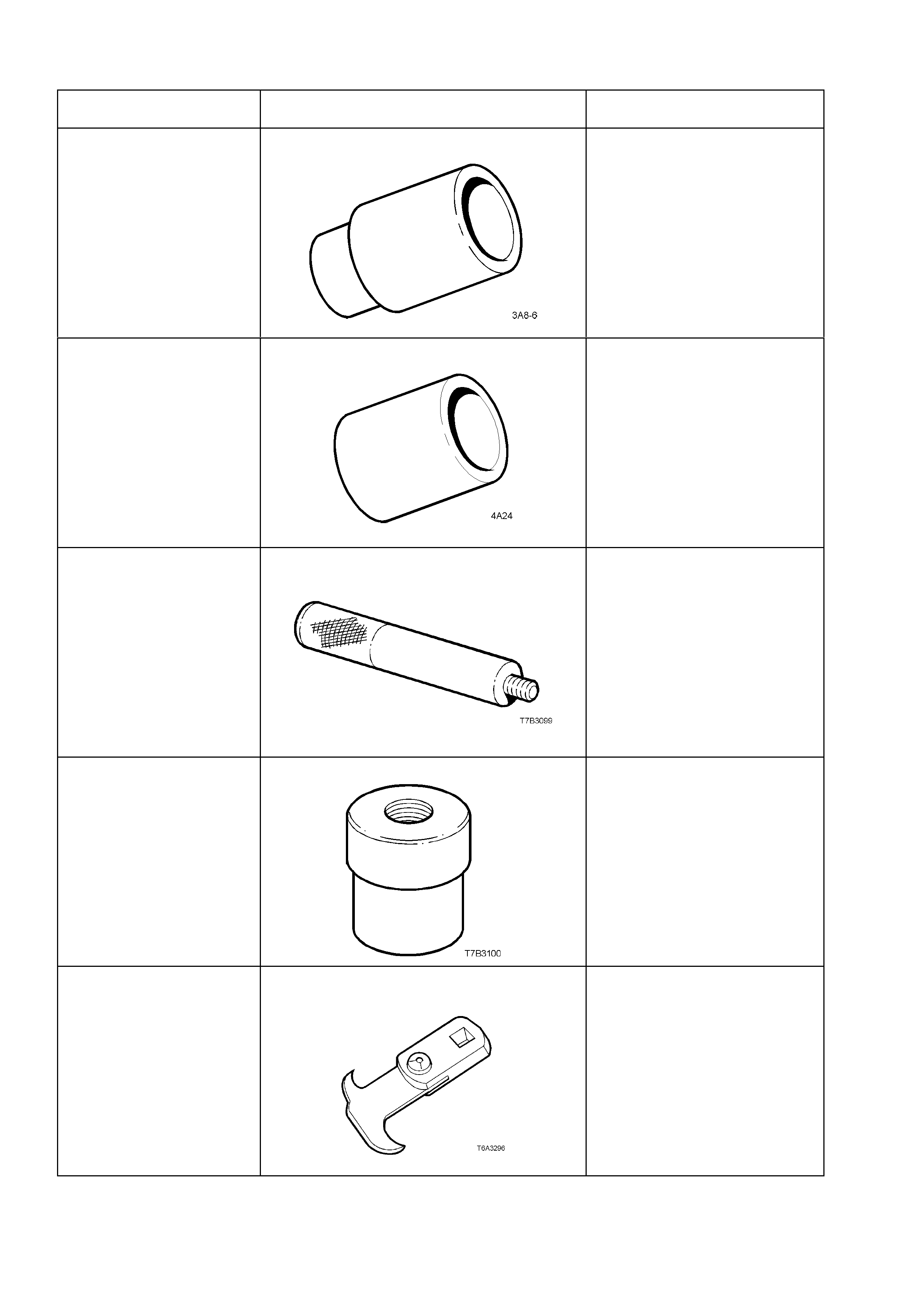
8. SPECIAL TOOLS
TOOL No. REF. in TEXT TOOL DESCRIPTION COMMENTS
3A8-6 SLEEVE Previously released.
Also numbered E1891-6.
Used to install the 1st/2nd gear
synchromesh hub to the
mainshaft.
4A24 SLEEVE Previously released.
Also numbered E1662.
Used to install the bearing cup
into the input shaft gear.
7AT2 DRIVER HANDLE Previously released.
Also numbered E1502.
Used in conjunction with 7AT5
to remove/install the slip yoke
bushing in the extension
housing.
7AT5 SLIP YOKE BUSH REMOVER/INSTALLER Previously released.
Also numbered E1505 and
J23062-14.
Used in conjunction with 7AT2
to remove/install the slip yoke
bushing in the extension
housing.
56750 SEAL REMOVER Previously released.
Also numbered E308 and
49V012001.
Used to remove the rear oil seal
from the extension housing.
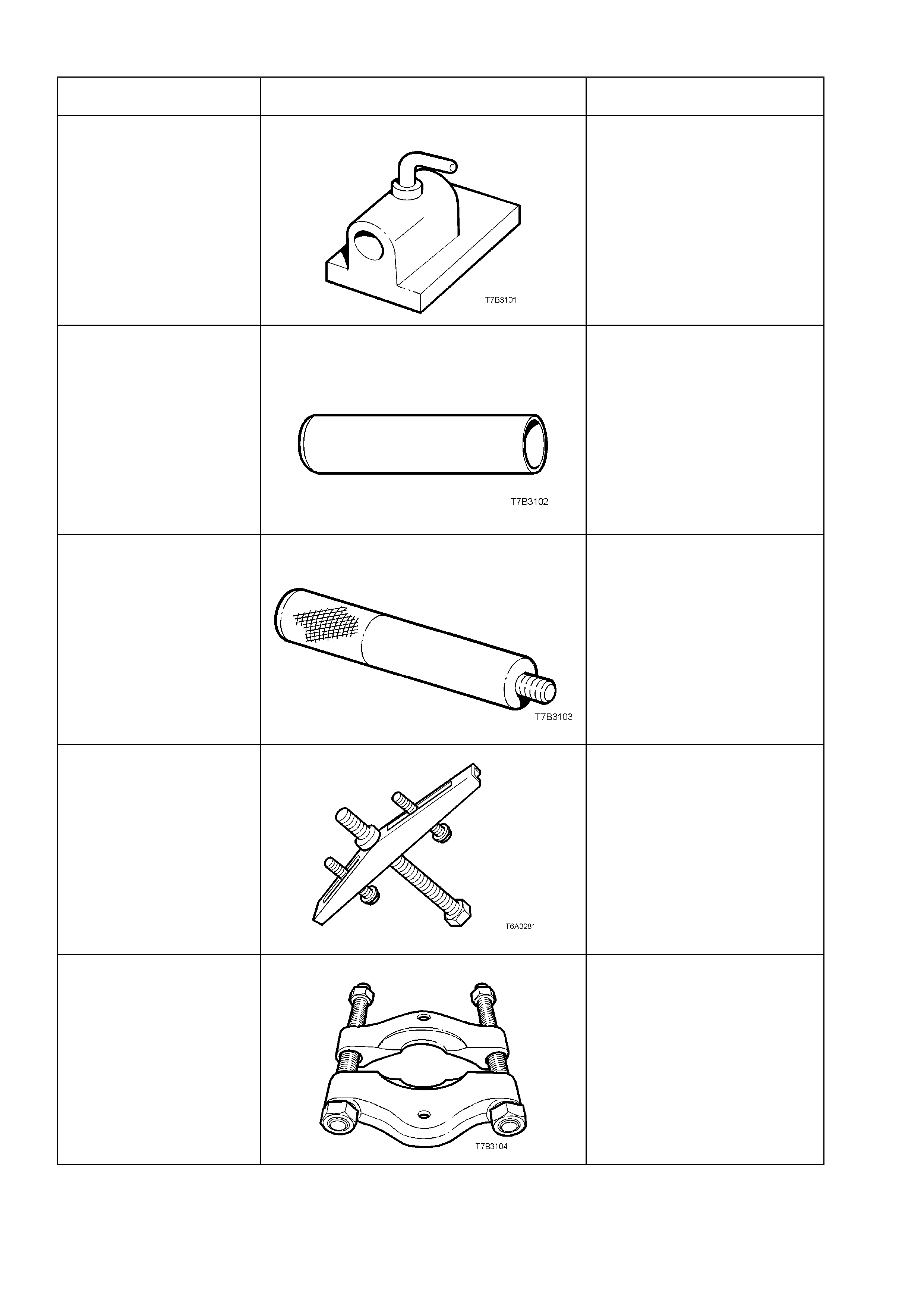
TOOL No. REF. in TEXT TOOL DESCRIPTION COMMENTS
J 3289-20 BENCH HOLDING FIXTURE Previously released.
Used as a bench fixture to
support a transmission.
J 5590 PRESS TUBE Previously released for 4L60-E
automatic transmission.
Used to install various
components, using an hydraulic
press.
J 8092 UNIVERSAL DRIVER HANDLE Previously released.
Used in conjunction with various
other tools for removal and
installation of various bearing
cups in the transmission.
J 8433 UNIVERSAL BRIDGE PULLER Previously released.
Used in conjunction with J
39431-1 & 2 to remove the
speedometer pulse ring and the
5th/6th speed, compound driven
gear.
J 22912-01 PRESS PLATES Previously released.
Used in a number of different
applications in removing
bearings and other transmission
components when pressing
operations are required.
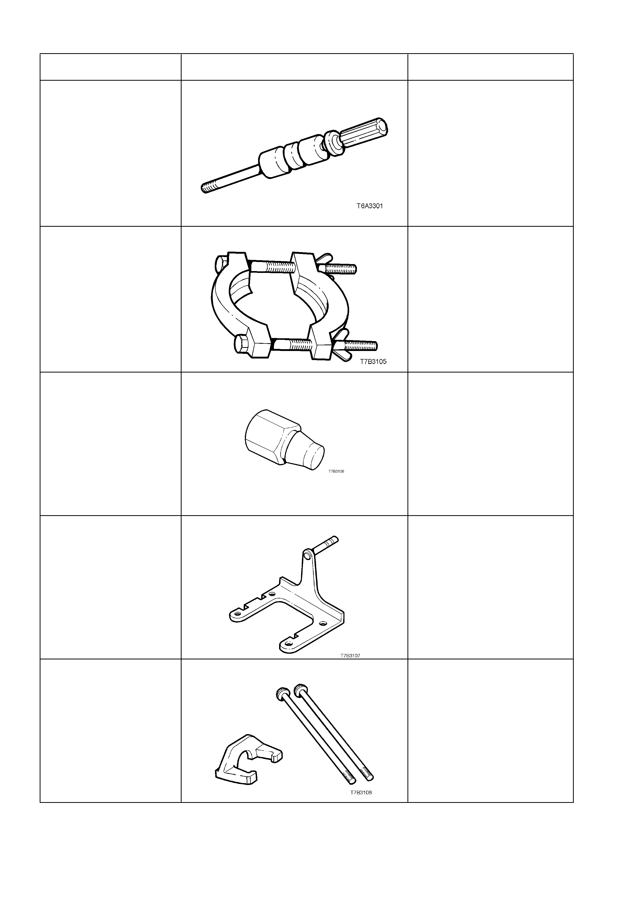
TOOL No. REF. in TEXT TOOL DESCRIPTION COMMENTS
J 23907 SLIDE HAMMER Previously released.
Used in conjunction with a
number of different pullers to
remove bushes and bearing
cups in the transmission
J 36513 PRESS PLATES New release.
Used to press 1st/2nd speed
synchromesh assembly and
2nd gear from the mainshaft.
J 36800 BUSHING REMOVER New release.
Used to remove the shift rail
bushes in the adaptor plate and
extension housing, in
conjunction with slide hammer J
23907.
J 39430 TRANSMISSION HOLDING FIXTURE New release.
Used to mount the transmission
to the bench for unit repair
operations.
J 39431-1 & 2 REMOVER AND BOLTS New release.
Used to remove the
speedometer pulse ring and the
5th/6th speed, compound driven
gear, in conjunction with
universal bridge puller J 8433.
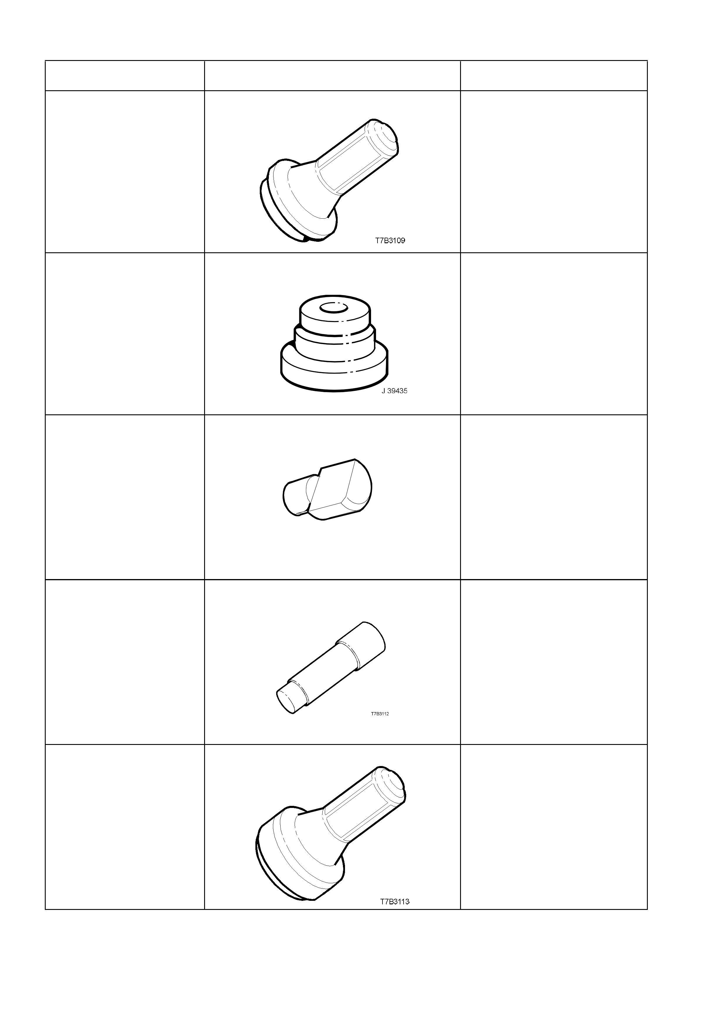
TOOL No. REF. in TEXT TOOL DESCRIPTION COMMENTS
J 39433 SEAL INSTALLER New release.
Used to install the input shaft oil
seal.
J 39435 BEARING CUP INSTALLER New release.
Used to install the rear
mainshaft bearing cup and the
rear countershaft bearing cup,
in conjunction with driver handle
J 8092.
J 39437 BUSHING INSTALLER
J 39437
New release.
Used to install the selector shaft
bushes in the adaptor plate, and
transmission case .
J 39439-1 BUSHING REMOVER/INSTALLER New release.
Used to remove shift shaft
bushes from the transmission
case and extension housing.
J 39440 REAR SEAL AND BOOT INSTALLER New Release.
Used to install the rear
extension seal.
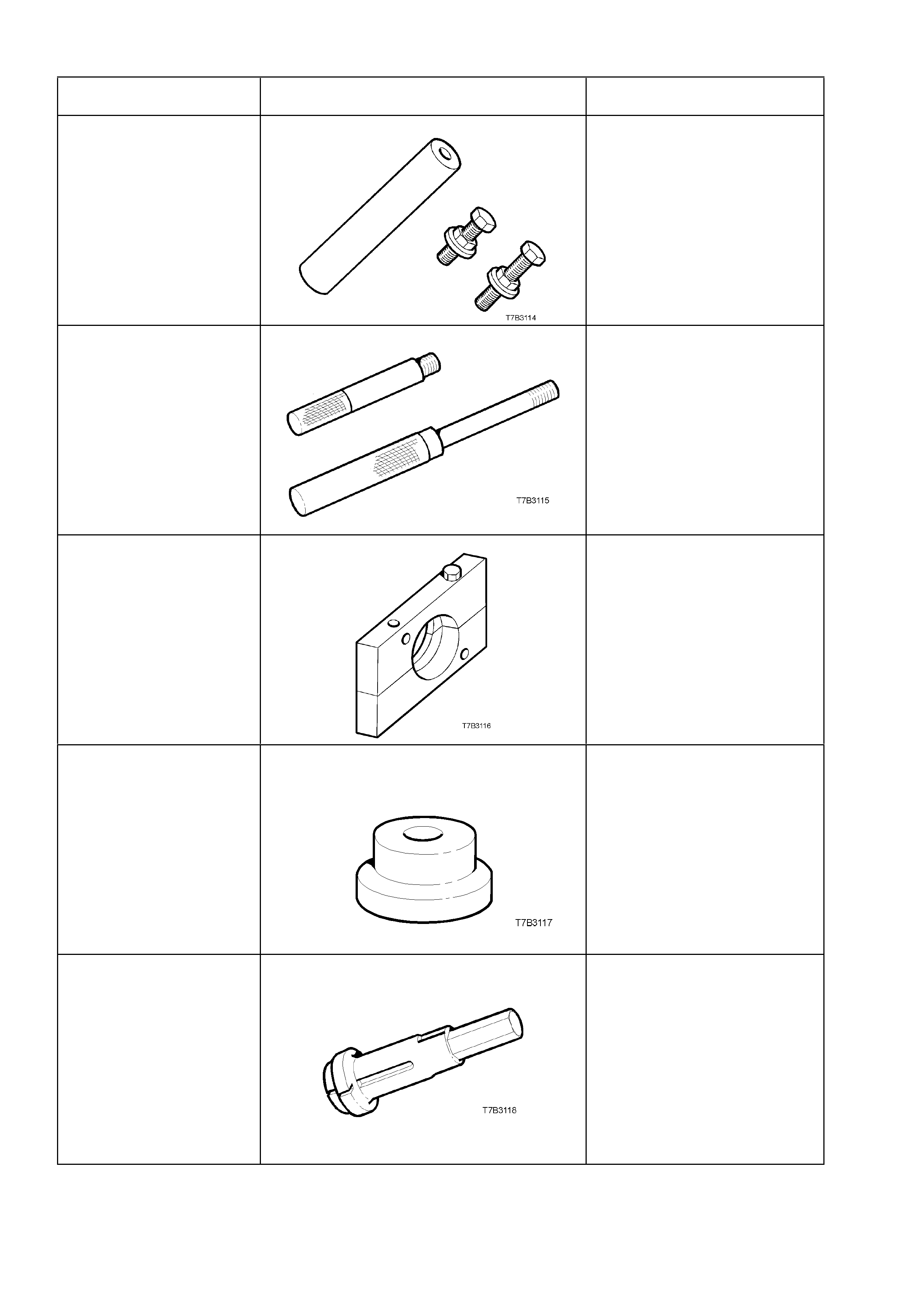
TOOL No. REF. in TEXT TOOL DESCRIPTION COMMENTS
J 39441 GEAR INSTALLER New release.
Used to install the 5th/6th
compound driven gear and the
speedometer pulse ring.
J 39444-1 & 2 END PLAY RODS New Releases.
Used to check the end float of
the countershaft gear (J 39444-
1) and countershaft gear
extension (J 39444-2).
J 39511 SPLIT PLATE New release.
Used to remove the front
countershaft gear bearing.
J 39546 BEARING CUP INSTALLER New release.
Used to install the rear
mainshaft roller bearing cup, in
conjunction with driver handle J
8092.
J 39594 BEARING CUP REMOVER New Release.
Used in conjunction with slide
hammer J 23907 to remove the
mainshaft pilot bearing cup in
the input shaft gear.
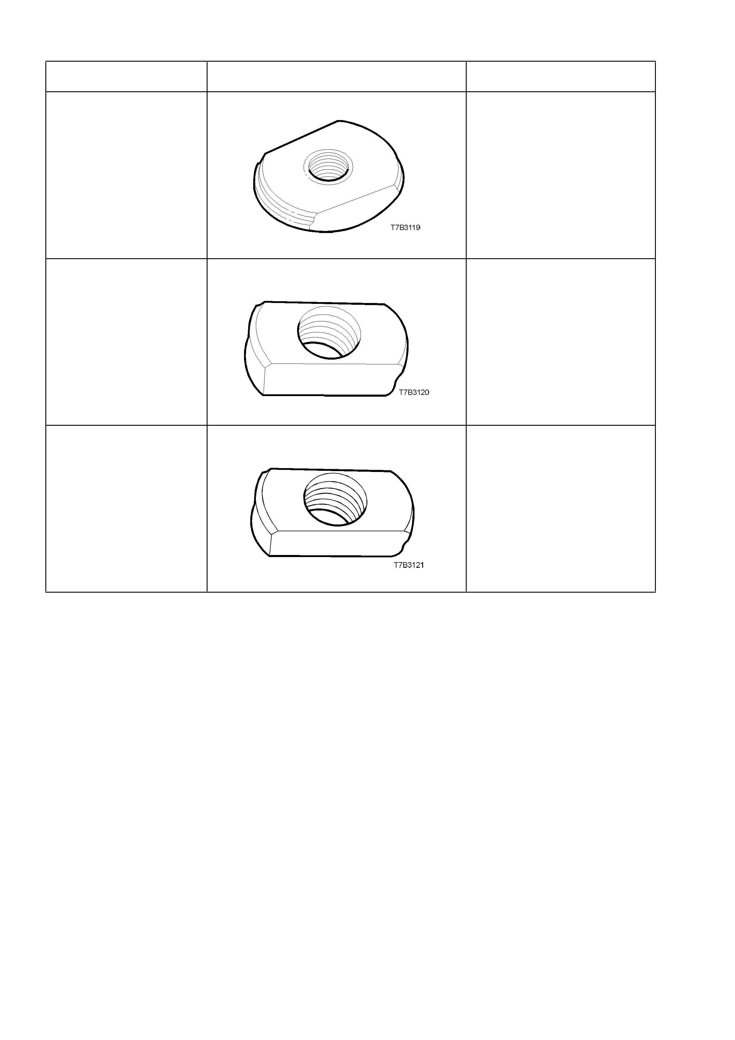
TOOL No. REF. in TEXT TOOL DESCRIPTION COMMENTS
J 39789 BEARING CUP REMOVER New release.
Used to press out the rear
mainshaft roller bearing cup
from the extension housing, in
conjunction with driver handle
J 8092.
J 39790 BEARING CUP REMOVER New release.
Used to press out the rear
mainshaft bearing cup from the
transmission case , in
conjunction with driver handle J
8092.
J 39791 BEARING CUP REMOVER New release.
Used to press out the rear
countershaft bearing cup from
the transmission case, in
conjunction with driver handle J
8092.