
SECTION 1A1 - BODY
IMPORTANT:
Before performing any Service Operation or other procedure described in this Section, refer to Section
00 CAUTIONS AND NOTES for correct workshop practices with regard to safety and/or property damage.
1. GENERAL DESCRI PTI O N
The VU Ser ies Utility is a new vehicle design. Sheetm etal forward of the 'B' pillar carryover from VX Series Models
while sheetmetal r ear ward of the 'B' pillar has been redes igned f or the new m odel. Inter ior trim, air conditioning, and
lighting systems in general carryover from VX Series with changes to suit the utility concept. Bumper facias
complement the new styling and accommodate below bumper engine cooling entry. Head, turn signal lamps, rear
lamps systems all carryover from VX Series Models with minor cosmetic changes.
For items not cover ed in this Sect ion ref er to the appr opriate sec tion of the VX Series Service Information for furt her
details.

2. SERVICE OPERATIONS
2.1 BODY SHELL PARTS REPLACEMENT
When replacing or repairing a part or sub-assembly, care must be taken to ensure that correct alignment and
strength of unit as a whole is maintained. In some instances, major damage to the body or frame can be more
eff ectively and econom ically repaired by replacing a part or sub-ass embly with a new one, rather than repairing the
damaged part.
Spot welding is used extensively for joining panels together, particularly around the flanged edges of dash panel,
windshield and back window openings, along edges of rocker panels and lower edge of the rear body.
W hen replacing a section that is normally attached by this method and spot-welding equipment is not available, or
the location of the par ts restric ts access , the part or ass embly should be attac hed by the welding method k nown as
‘Plug Welding’, which is as follows:
1. Remove the dam aged part by cutting through the spot welds between the panels with a thin-edged chisel or by
drilling the spot welds.
2. Drill f ive m m diameter holes in either the new or m ating part to cor respond with the spacing and location of the
original spot welds. Parts to be drilled are determined by accessibility for the following operations.
3. Clamp the new par t in pos ition and gas or arc weld the two parts together thr ough eac h hole, f inally dressing off
any high spots on exposed surfaces.
W hen replacing parts such as roof panels, rear quarter or rock er panels; where a butt or overlap weld is required,
the joint of the panels mus t be form ed below the normal c ontour. This allows f or filling over the join and elim inates
the possible reduction of sheet metal thickness following the necessary buffing or grinding of a normal welding
operation.
IMPORTANT: Following replacement or repair of body components, it is essential that effective rust proofing
techniques, as outlined in the following paragraphs, be observed.

2.2 ANTI-CORROSIVE TREATMENT
Precoated and galvanised s teel is us ed extens ively for various body panels for inc reas ed c orr os ion protec tion of the
body. Body panels such as the door and rear compartment lid outer panels are precoated on the inner surface of
the metal to improve corrosion protection. Other body structure members have complete double sided galvanised
protection.
In addition, a r us t pr eventative material is s pr ayed after paint application to areas s uch as inter ior s urfaces of doors,
etc.
Any repair or replacement of panels, assemblies, etc., that disturb this anti-corrosive treatment must be resealed
and should be included as part of the repair or replacement operation.
Anti-corrosive com pounds used for repairs should be light bodied materials designed to penetrate between metal-
to-metal surfaces such as pinch weld flanges and integral panel attaching points.
All bare metal sur f ac es must be tr eated with m etal c onditioner and pr imed. T hes e operations need to be c arr ied out
prior to the application of sealer s, waxes and s ound deadeners. Attac hing points of new replacem ent panels should
be resealed. The hemming flanges of replacement doors, tailgates and rear compartment lids will require resealing.
Open joins which require bridging of the sealer to close a gap should be sealed with a heavy bodied caulking
material. When colour application is required to restore repaired areas to original appearance, conventional
refinishing preparation, undercoat build-up and colour application techniques should be employed.
When deadeners are disturbed during damage repair, or a panel has been replaced, the deadener material must be
replaced with an equivalent material. The location and pattern for replacement material can be determined by
observing the original deadener application outlines.
IMPORTANT: Follow label directions for materials selected.

2.3 WATER AND DUST LEAK DIAGNOSIS
Diagnosis of body leaks are complicated by the fact that the appearance of water at one point can be caused by
seepage thr ough any one or m or e of many possible locations. As an ex ample of this indir ec t entry, the cause of wet
front floor coverings may be due to water entering past the door weatherstrip, through the door inner panel, between
the windshield and its adhesive compound or through any one of the joins in the floor panel, ventilator or dash
panels, therefore, point or points of water or dust entry must be established before effective resealing can be carried
out.
For additional information refer to the VU Series Body Structure Repair Manual.

2.4 BODY STRUCTURE PANELS
UNDERBODY
Listed below are assemblies and individual panels
that are available for replacement.
The purpose of these illustrations is to provide the
repairer with a better understanding of available
replacement panels.
1. Panel assembly – floor side
2. Reinforcement assembly – inner seat
attaching.
3. Reinforcement – front seat outer attaching.
4. Floor assembly – front.
5. Bracket – footrest.
6. Mount assembly – power unit rear.
7. Extension assembly – floor panel front.
8. Brace – longitudinal to front floor.
9. Panel assembly – front fender skirt.
10. Bracket assembly – anti theft horn mounting,
LH.
11. Bracket assembly – hydraulic modulator.
12. Tray assembly – battery.
13. Panel assembly – front.
14. Panel assembly – front upper.
15. Panel assembly – front headlamp.
16. Bracket assembly – side panel front end.
17. Bracket assembly - fender.
18. Member assembly – front lower.
19. Longitudinal assembly - complete.
20. Bracket – radiator support side.
21. Support assembly – front panel side.
22. Bracket – front bumper beam mounting.
23. Console – front panel.
24. Crossmember assembly - centre.
25. Reinforcement – floor panel side.
26. Carrier plate assembly.
27. Hook assembly – tie down.
28. Bracket – rear brake hose.
29. Extension assembly – longitudinal rear.
30. Rear longitudinal – complete.
31. Crossmember assembly – rear.
32. Support – spare wheel lateral, LH.
33. Crossmember – rear floor, LH.
34. Support – spare wheel longitudinal.
35. Support – spare wheel longitudinal.
36. Member assembly – hoist longitudinal.
37. Support – spare wheel lateral, RH.
38. Crossmember – rear floor, RH.
39. Panel – rear end inner.
40. Reinforcement assembly – endgate hinge mounting.
41. Panel – rear end outer.
42. Reinforcement – tonneau floor to wheelhouse.
43. Floor assembly – tonneau rear.
44. Bracket assembly – fuel tank mounting.
45. Floor assembly – tonneau front.
46. Bracket assembly – fuel vapour canister mounting.
47. Panel assembly – floor rear.
48. Support – intermediate heat shield.
49. Reinforcement assembly – centre bearing.
50. Support – pressure hose.
51. Bracket assembly – fuel tank mounting.
52. Reinforcement – seatback panel lower.
53. Panel assembly – rear seatback lower.
NOTE: Where a side is specified, part is fitted to that side only
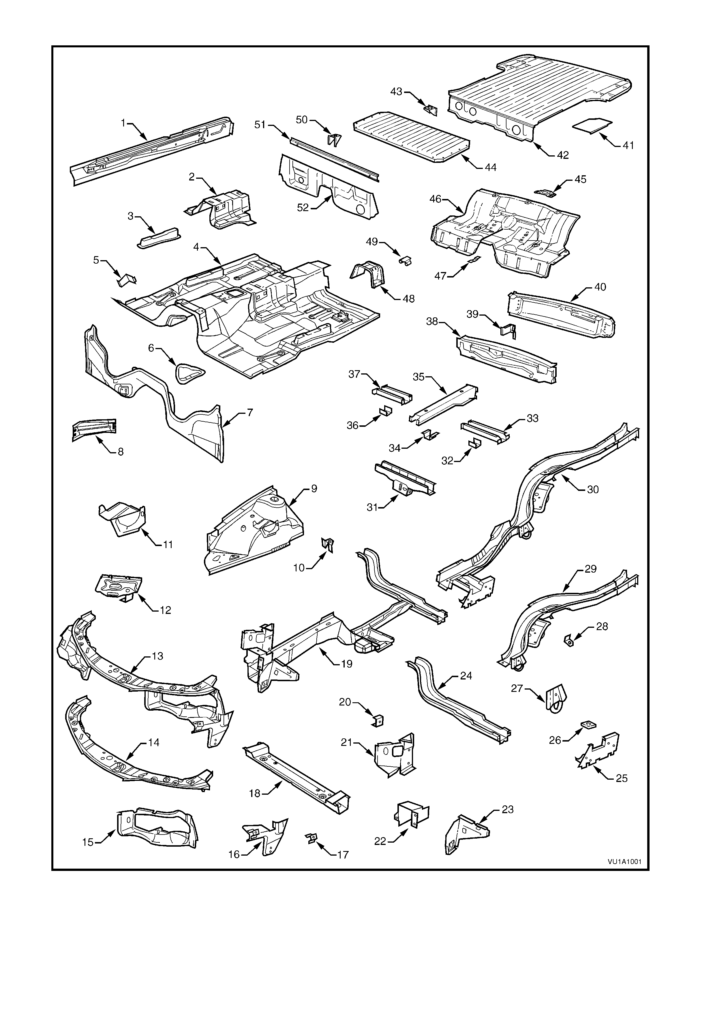
Figure 1A1-1 Underbody

UPPERBODY
Listed below are assemblies and individual panels
that are available for replacement.
The purpose of these illustrations is to provide the
repairer with a better understanding of available
replacement panels.
1. Rail assembly – windshield header.
2. Roof panel.
3. Reinforcement assembly – roof rear header.
4. Bracket – trim attachment.
5. Panel assembly – shroud side.
6. Pillar assembly – front body inner.
7. Frame – side front roof.
8. Panel – side inner upper front.
9. Reinforcement – sash guide mounting.
10. Cap – fuel filler, RH.
11. Patch – wheelhouse outer rear, RH.
12. Panel – seat back upper.
13. Bracket – load compartment front upper, RH.
14. Panel – load compartment front upper.
15. Panel – seat back outer.
16. Cover – side panel inner, rear.
17. Cover – side panel inner, front.
18. Wheelhouse - inner.
19. Bracket – tonneau lashing.
20. Panel – side inner upper.
21. Retainer – endgate lock striker mounting.
22. Panel – endgate pilar inner lower.
23. Extension piece – side panel inner.
24. Plate assembly – strut to engine hood mounting.
25. Reinforcement – wheelhouse rear.
26. Brace – tonneau floor side to underbody.
27. Extension assembly – tonneau floor side.
28. Panel – side inner.
29. Brace – wheelhouse to frame.
30. Extension piece – side panel outer.
31. Closing plate – side panel.
32. Gusset assembly – tail lamp.
33. Panel – side outer.
34. Frame assembly – door opening.
35. Support – jack outer.
36. Angle – fender lower.
37. Support - fender.
38. Anchor plate – door striker.
39. Reinforcement – A pillar upper.
40. Angle – fender upper.
41. Brace – wheelhouse
42. Fender
43. Bracket – rocker skirt front attaching
NOTE: Where a side is specified, part is fitted to that side only
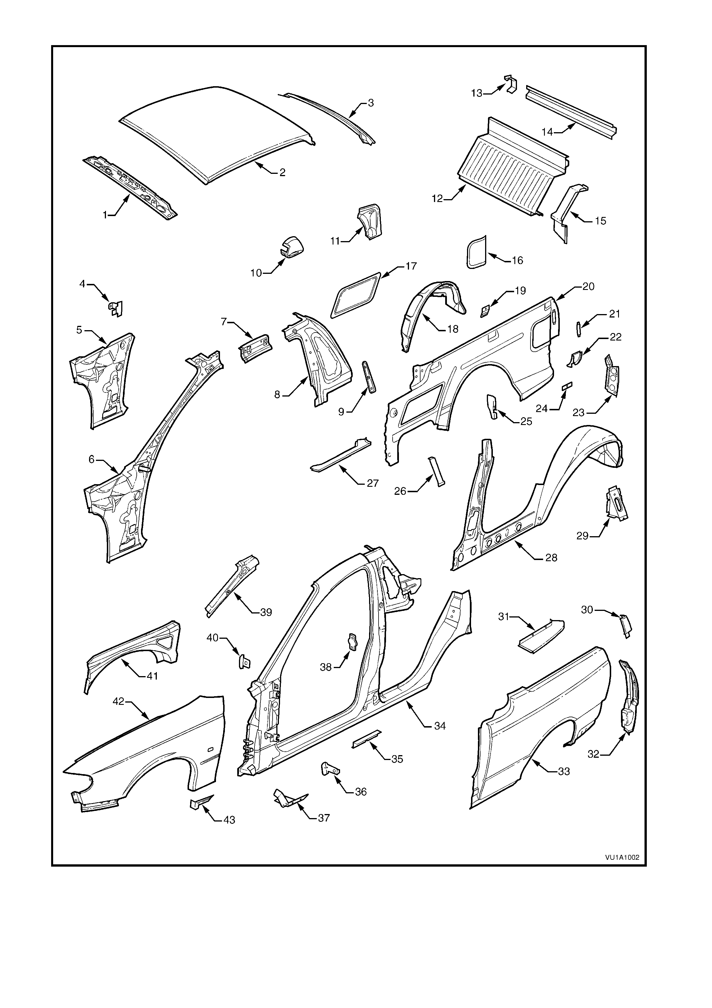
Figure 1A1-2 Upperbody

BODY ASSEMBLY
Listed below are assemblies and individual panels
that are available for replacement.
The purpose of these illustrations is to provide the
repairer with a better understanding of available
replacement panels.
1. Body assembly – in white, complete.
2. Dash panel assembly.
3. Beam assembly – bumper support.
4. Panel assembly – engine hood.
5. Hinge assembly – engine hood.
6. Panel assembly – front door outer.
7. Door assembly – front.
8. Flap – front door hinge (on door assembly).
9. Flap – front door hinge (on pillar).
10. Panel – endgate outer.
11. Panel assembly – endgate.
12. Hinge assembly – endgate.
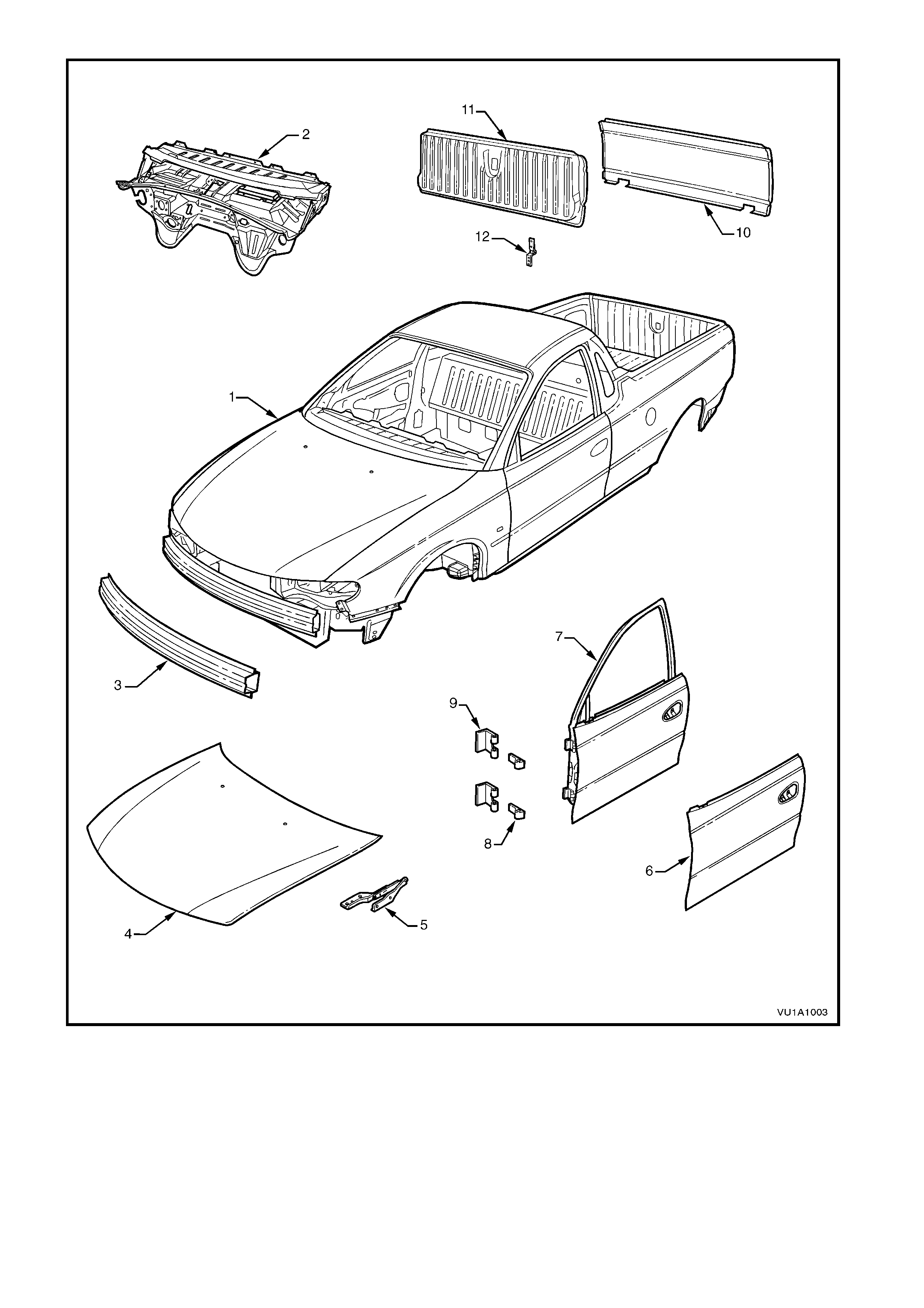
Figure 1A1-3 Body Assembly
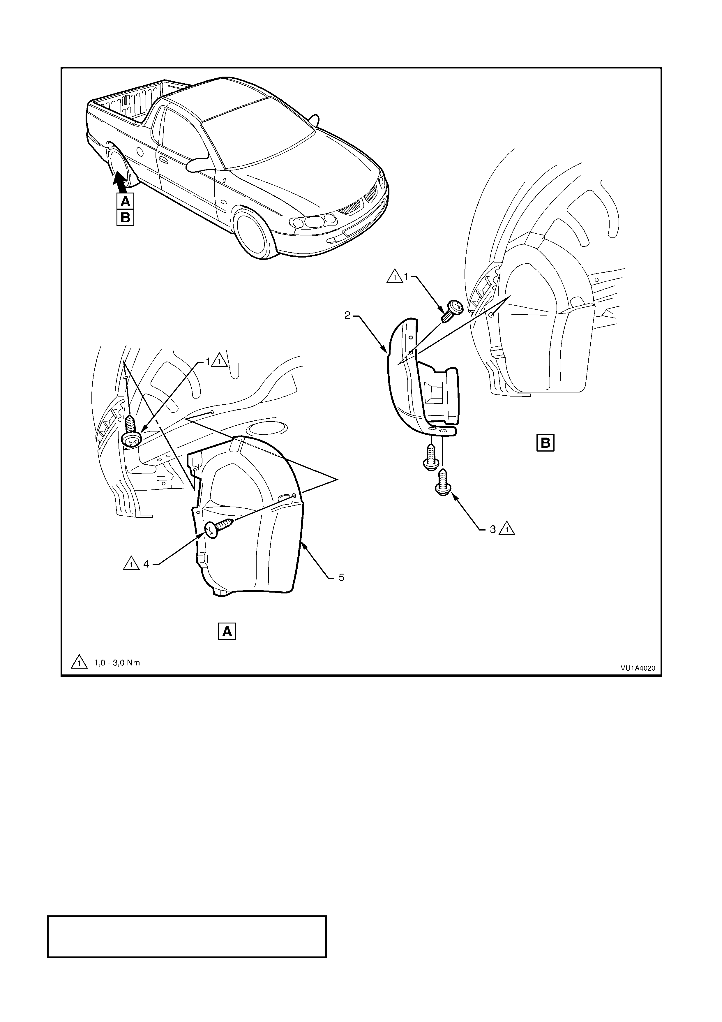
2.5 REAR WHEELHOUSE LINER
Figure 1A1-4
REMOVE
1. Remove the two screws (1) securing the front edge of the rear bumperette (2) to the rear wheelhouse
sheetmetal.
2. Remove the two screws (3) securing the lower edge of the rear bumperette to the rear wheelhouse sheetmetal.
3. Remove the screw (4) securing the rear wheelhouse liner (5) to the rear wheelhouse inner sheetmetal.\
4. W hile pulling the lower fr ont edge of the rear bum perette away from the rear wheelhouse, car efully manoeuvr e
the wheelhouse liner free of the bumperette.
5. Remove the rear wheelhouse liner
REINSTALL
The reinstallation procedure for the rear wheelhouse liner is the reverse of the removal procedure, noting the
following:
1. Ensure all fasteners are tightened to the correct torque specification.
REAR WHEELHOUSE LINER
ATTACHING SCREWS 1.0 - 3.0 Nm
TORQUE SPECIFICATION