
SECTION 1A3 - INSTRUMENT PANEL
AND CONSOLE
IMPORTANT:
Before performing any Service Operation or other procedure described in this Section, refer to Section
00 CAUTIONS AND NOTES for correct workshop practices with regard to safety and/or property damage.
1. GENERAL I NFORMATI O N
The instrument panel for VU Series Models carryover from VX Series Models with minor changes to the console
assembly to suit the utility design.
For Servic e Operations not covered in this Section ref er to Section 1A3 INST RUMENT PANEL AND CONSOLE of
the VT Series I Service Information.
Techline
Techline
Techline
2. SERVICE OPERATIONS
2.1 CENTRE CONSOLE
REMOVE
1. Adjust steering wheel to upper most position. Grasp right hand side of lower instrument panel cover firm ly and
pull towards rear of vehicle. Repeat procedure for left-hand side of cover and lower cover.
2. Slide both seats rearward and open the instrument panel compartment door.
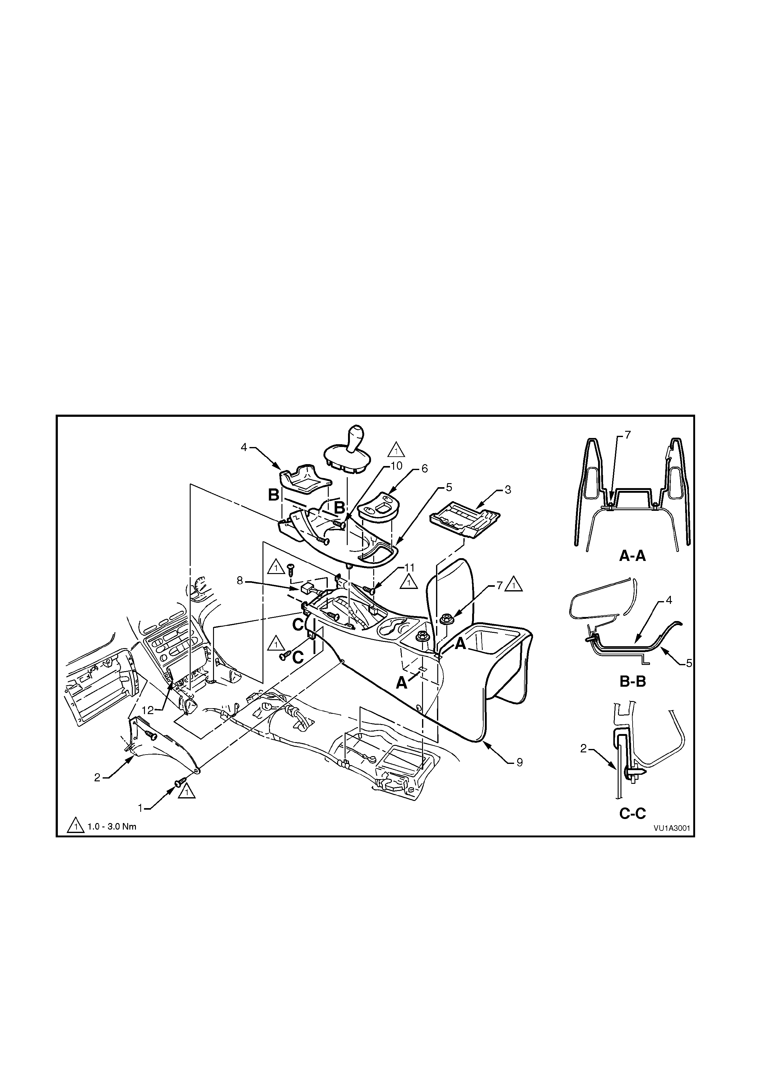
3. Remove sc rews s ecuring centre fac ia side extensions (ref er to Fig. 1A3- 1 item 2) and rem ove c entre fac ia side
extensions.
NOTE: There are four screws for the left-hand side extension and three screws for the right-hand side extension.
4. From inside centre console bin remove liner (3).
5. Remove two console retaining nuts (7).
6. Remove liner (4) from transmission console cap (5) and remove two securing screws (10), prise out
transmission console cap and disconnect window harness from power window switch assembly (6).
7. Remove two screws attaching storage compartment (12) to instrument console and remove storage
compartment.
8. Remove six screws (11) securing front of console to centre facia.
9. Partially remove centre console and disconnect wiring harness to centre console wiring connector (8).
Fully remove centre console (9) by raising rear end up and lifting assembly out.
Figure 1A3-1
Legend
1. Screw (4 places LH, 3 places RH)
2. Centre facia side extension (LH side shown)
3. Console bin liner
4. Liner
5. Transmission console cap
6. Power window switch assembly
7. Nut (2 places)
8. Console wiring harness connector
9. Centre console
10. Console cap securing screw
11. Screw (6 places)
12. Storage compartment
REINSTALL
Reinstallation is the reverse of removal operations.
CENTRE CONSOLE
RETAINING SCREW 1 - 3 Nm
TORQUE SPECIFICATION
CENTRE CONSOLE BIN
RETAINING SCREW 1 - 3 Nm
TORQUE SPECIFICATION
TRANSMISSION CONSOLE CAP
TO INSTRUMENT PANEL 1 - 3
RETAINING SCREW Nm
TORQUE SPECIFICATION
STORAGE COMPARTMENT
RETAINING SCREW 1 - 3 Nm
TORQUE SPECIFICATION

3. TORQUE WRENCH SPECIFICATIONS
Nm
Centre console securing screws........................................... 1 - 3
Centre console bin retaining nuts ......................................... 1 - 3
Screws securing transmission console cap
to instrument panel ............................................................... 1 - 3
Storage compartment retaining screws................................ 1 - 3