SECTION 1A4 - LOAD COMPARTMENT
AND ENDGATE
IMPORTANT:
Before performing any Service Operation or other procedure described in this Section, refer to Section
00 CAUTIONS AND NOTES for correct workshop practices with regard to safety and/or property damage.
1. GENERAL DESCRI PTI O N
The body sheetmetal is unique to the VU Utility, however m ost panels forward of the 'B' pillar are carried over from
the VX Ser ies Comm odore Sedan and Station W agon. In general the cons truction techniques are sim ilar to that of
the VX Wagon variant, although there are no common panels rearward of the B' pillar.
The load compartment has access panels for ease of service. The load area floor is manufactured from heavy
gauge steel with pressed ribs to provide a robust surface.
The front tonneau floor is removable to allow access to the fuel tank and associated equipment. Drainage is
provided at the forward edge of the front tonneau floor for enhanced corrosion protection. To maintain this
protection it is important that the drain holes be periodically cleared of obstructions, refer to 2.5 DRAIN TUBES in
this Section.
Removable caps and rails are fitted to the upper edges of the load area and endgate. T hese c aps and rails provide
the securing points for the tonneau cover. The removable caps and rails permit efficient repairs on these extreme
wear areas.
The spare wheel is situated below the rear tonneau floor and can be raised or lowered using a hoist. The hoist is
operated by inserting a handle into the aperture above the license plate and rotating the handle in the appropriate
direction to raise or lower the wheel.
Techline
Techline
Techline
2. SERVICE OPERATIONS
2.1 QUARTER PANEL UPPER MOULDING
REMOVE
1. Remove the tonneau cover and support bows.
2. Remove the 'B' pillar moulding, refer Section 1A9 EXTERIOR ORNAMENTATION.
3. Remove the B/C pillar upper trim. Refer to Section 1A8 HEADLINING AND REAR END TRIM in this
Supplement.
4. Remove the quarter window. Refer to Section 1A6 STATIONARY GLASS in this Supplement.
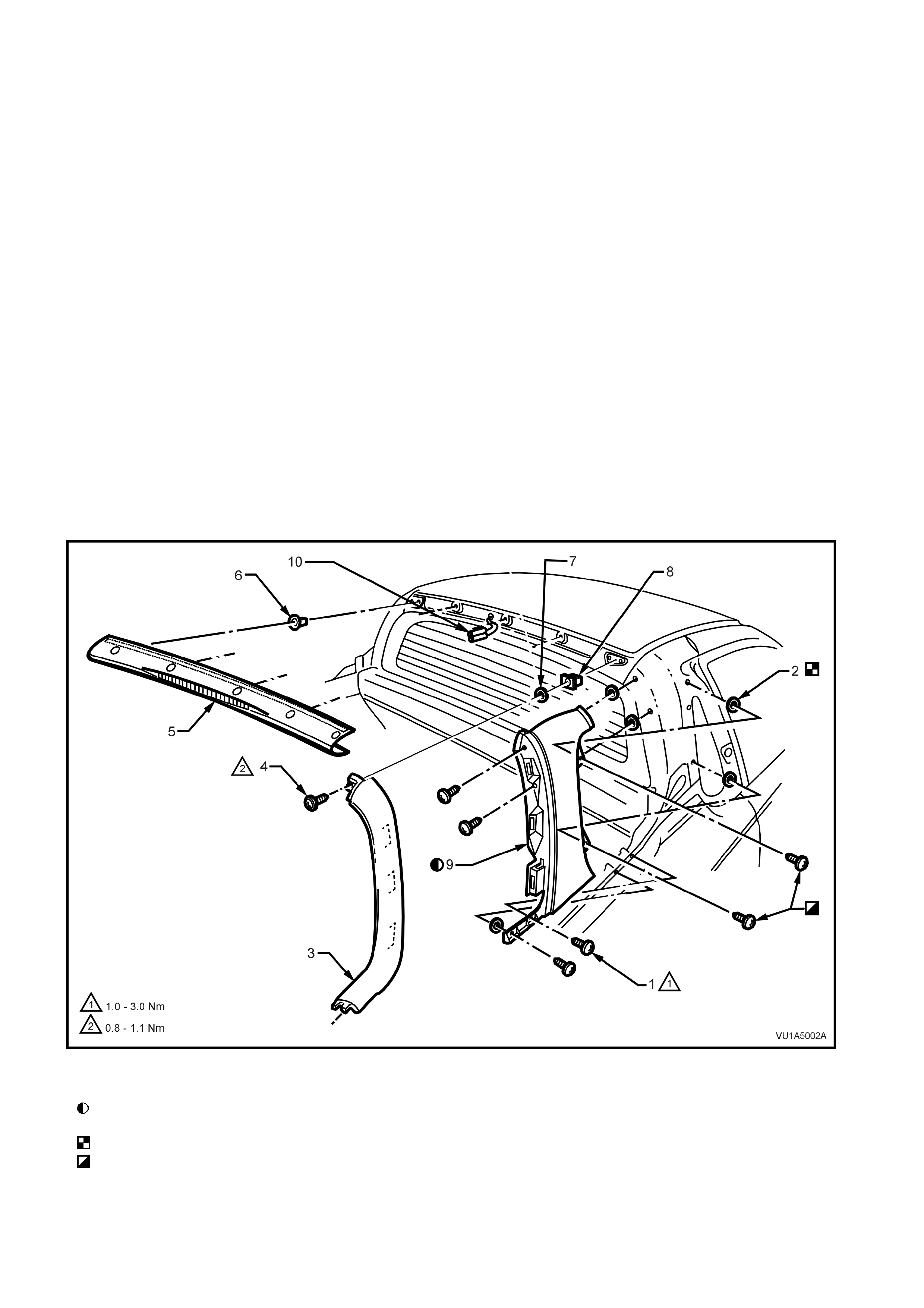
5. The outer edges of the roof centre rear capping (5) is secured with retaining tangs on the upper and lower
surf aces . The tangs engage the r oof s ide capping and s hould be disengaged by using a clean shop rag and flat
tip screw driver to slightly spread the ends of the centre roof capping and prying the capping rearwards, refer
Fig 1A4-1.
6. Remove the roof centre rear capping (5) by inserting a flat tip screw driver and clean shop rag between the
lower edge of the capping, and the bac k window. Carefully prising the capping upwards and rearwards until f r ee
from its location. Where fitted, dis connect the high m ounted s top light wiring connector ( 10) fr om the rear of the
roof centre capping, refer Fig 1A4-1.
NOTE 1:Top edge of roof centre rear capping is secured with double sided tape to Holden Specification HN2021.
7. Remove the upper screw (4) from the roof side capping (3), rotate top rearward to release 3 clips then, ease
lower end of capping forward from under side rails removing the roof side capping.
8. Remove the six s c rews ( 1) from the quar ter panel upper moulding car ef ully disengage top rear cor ner from roof
finisher moulding locating tab and remove the moulding.
Figure 1A4-1
Legend
Install quarter panel upper moulding from rear
engaging top first.
Foam washers must be stuck to body.
Insert front screws first.
1. Screw (6 places)
2. Foam washer (5 places)
3. Roof side capping
4. Screw (1 Place)
5. Roof centre rear capping
6. Clip (5 places)
7. Foam washer (5 places)
8. Nut (1 place R/H & L/H)
9. Quarter panel upper
moulding

REINSTALL
Reverse removal operations noting the following:
1. Replace foam washers and wax tipped screws if necessary on quarter panel upper to ensure proper water seal.
2. Replace centre cap double sided tape on top edge.
3. Replace centre cap mounting cups .
2.2 BODY LOAD AREA CAPS AND RAILS
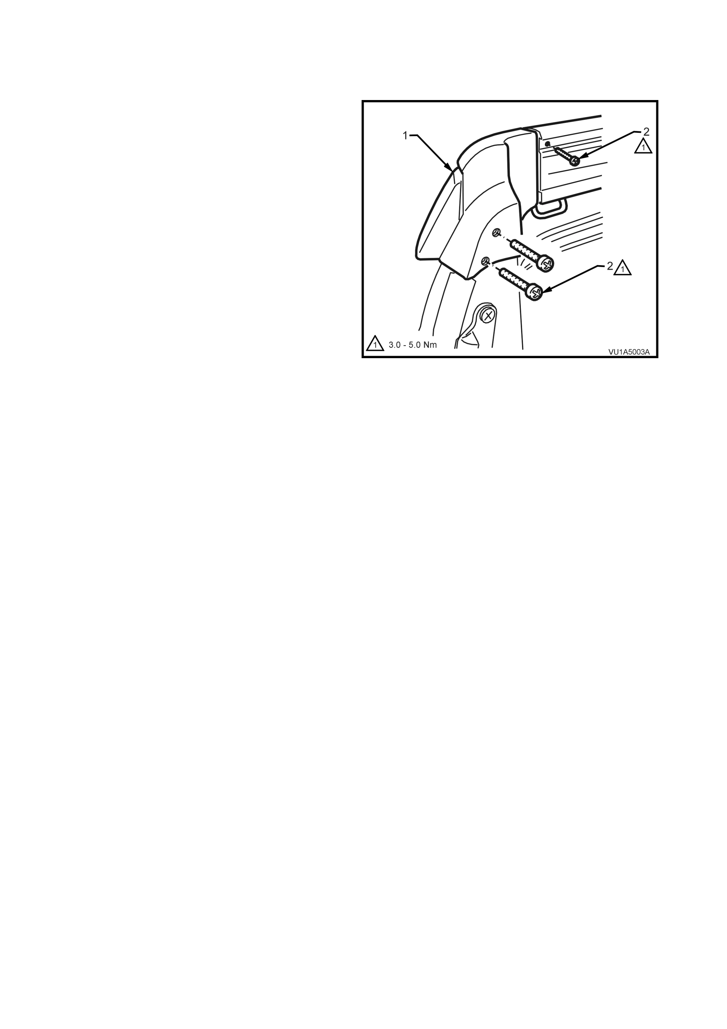
TAIL LAMP CAP - REMOVE
1. Remove the tonneau cover.
2. With the endgate open remove the screws (2)
securing the tail lamp cap assembly (1) and
remove.
Figure 1A4-2
SIDE BELT RAILS - REMOVE
NOTE: The side belt rails should only be removed after the tail lamp cap has been removed.
1. Remove the tonneau cover and support bows.
2. With the endgate open remove the (2) screws securing the tail lamp cap assembly and remove.
3. Remove the screws and bolts securing the side belt rail assembly to the quarter panel, refer to Fig. 1A4-3.
4. Carefully slide the side belt rail rearwards then lift the rail assembly from its position on the quarter panel.
ENDGATE RAIL - REMOVE
1. Lower the endgate
2. Remove the plugs (7) covering the endgate rail securing screws, refer to Fig. 1A4-3.
3. Remove the five socket head bolts and remove the rail from the endgate.
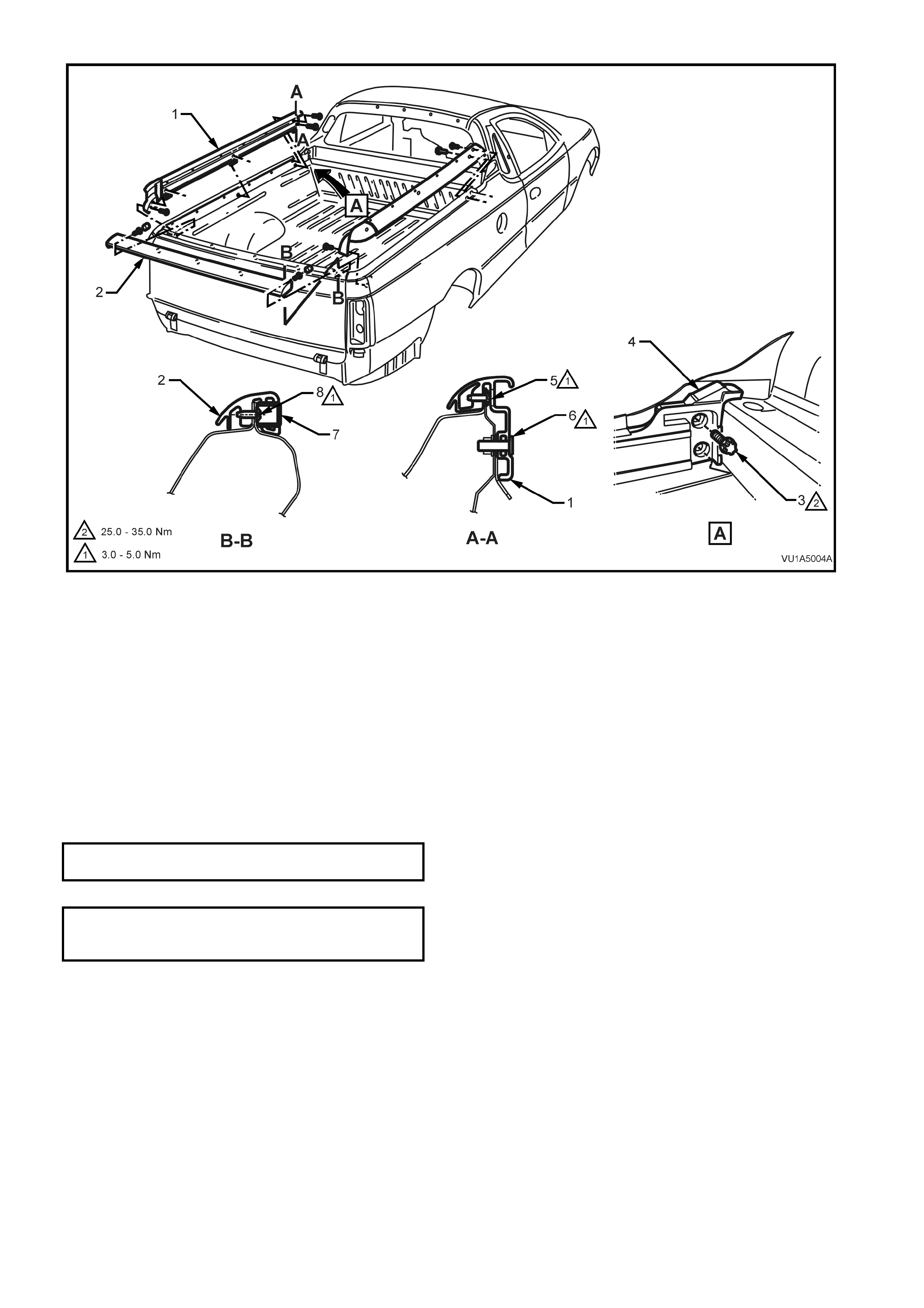
Figure 1A4-3
Legend
1. Side belt rail
2. Endgate rail
3. Bolts (2 places)
4. Front tonneau bow mounting bracket
5. Screw (6 places)
6. Bolt (3 places)
7. Plug (5 places)
8. Screw (5 places)
REINSTALL
Reinstallation procedures are reverse of removal procedures, caps and rails must be installed in the following
sequence:
a. Side roof capping
b. Side belt rail
c. Tail lamp cap
The endgate rail may be installed at any point.
SIDE RAIL SCREW/ BOLT 3 - 5
TORQUE SPECIFICATION Nm
FRONT TONNEAU BOW
MOUNTING BRACKET BOLT 25 - 35 Nm
TORQUE SPECIFICATION
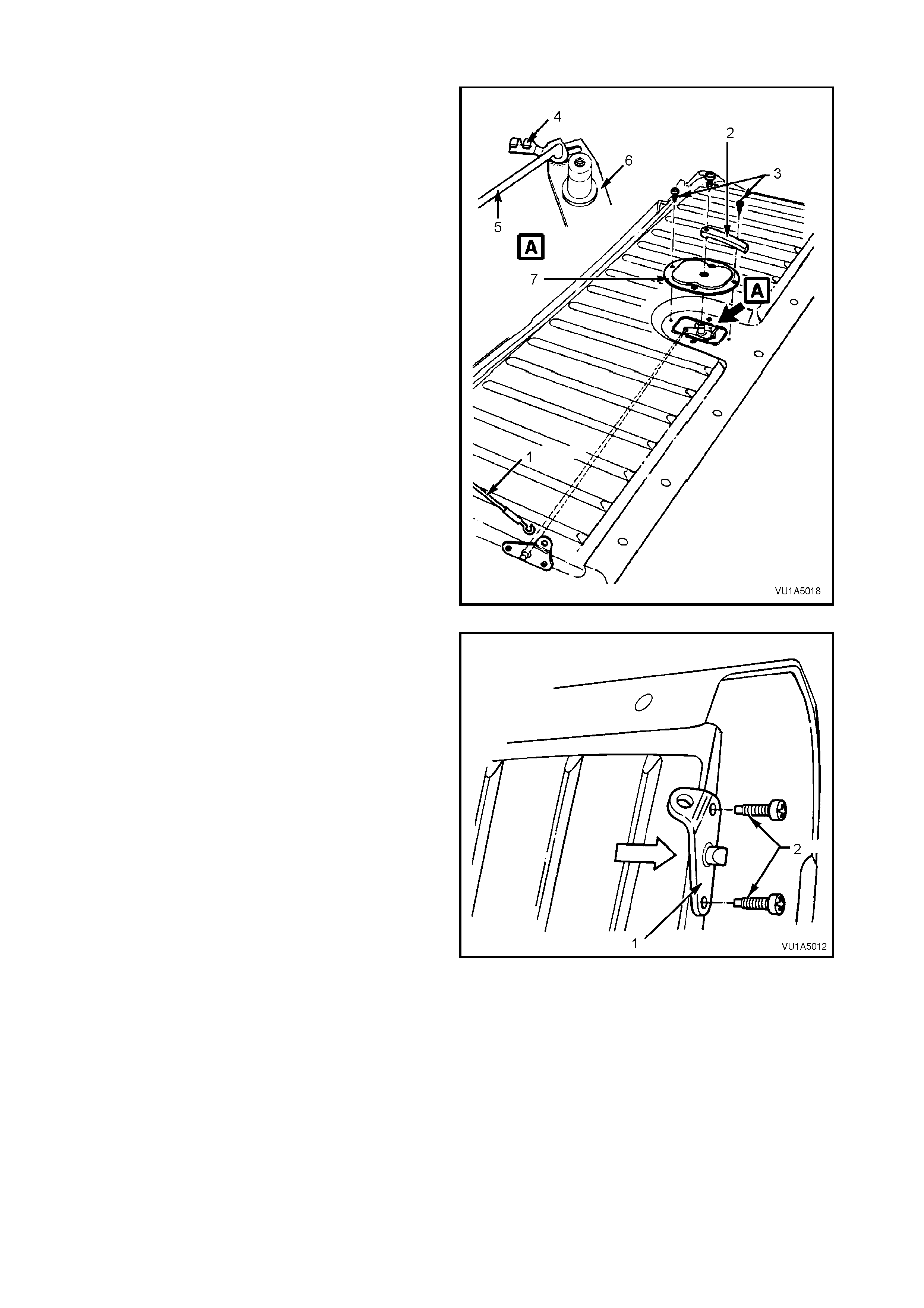
2.3 ENDGATE
REMOVE
1. Remove the tonneau cover.
2. Lower the endgate.
3. Position safety stands to support the endgate,
use suitable pieces of cloth to protect the
paintwork.
4. Raise the endgate slightly and unhook the lim it
cables (2) from the limit cable brackets (1).
Figure 1A4-4
5. Loosen the hinge bolts (1).
6. Have an assistant help support the endgate (2),
then remove the four hinge bolts (1) and slide
the endgate from the hinges.
Figure 1A4-5
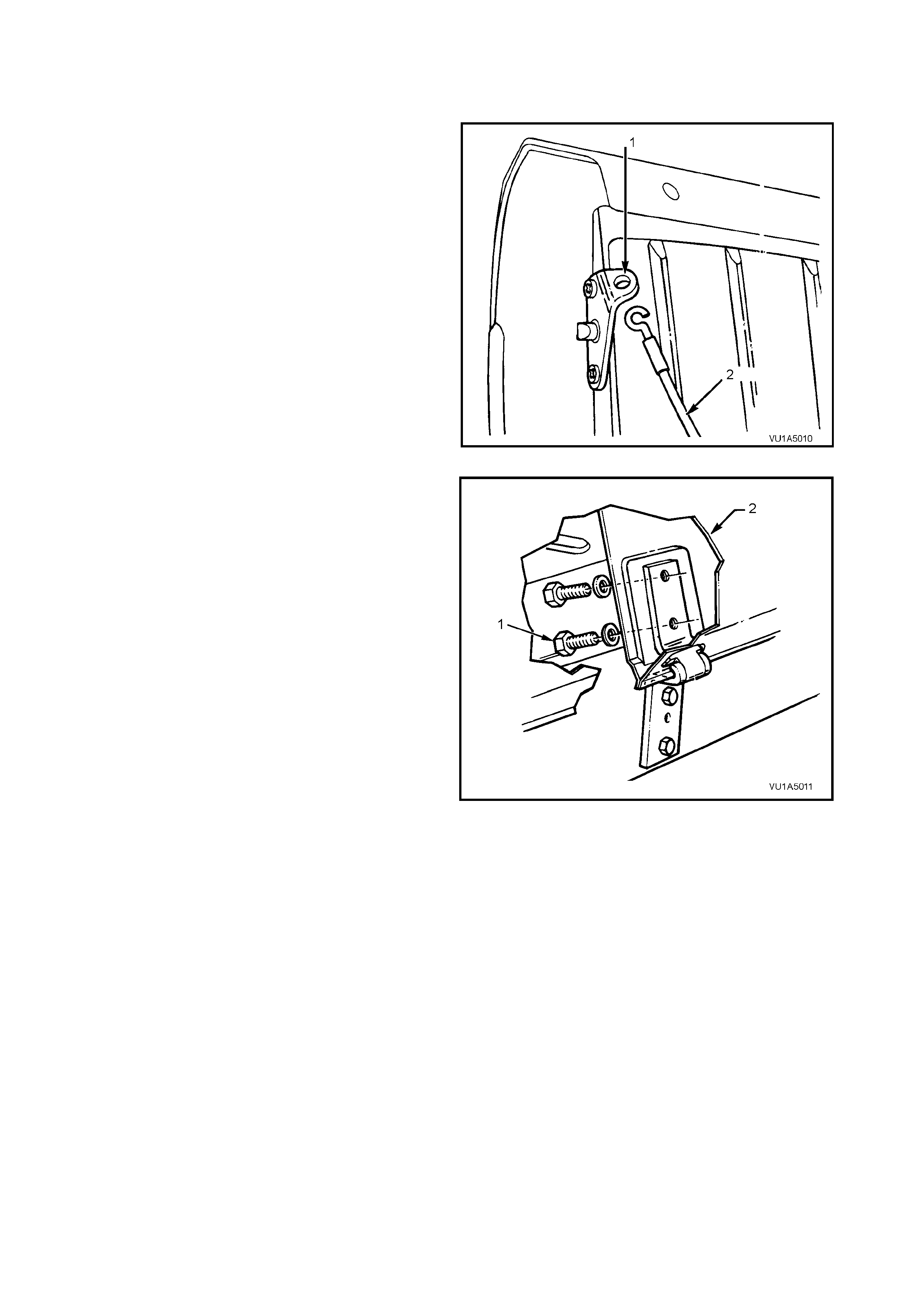
DISASSEMBLE
1. Lower and support the endgate (if necessary).
2. Unhook the limit cables (1) from the brackets.
3. Remove the screw from the remote control
handle (2) then disconnect the handle f rom the
lock spline.
4. Undo the two scr ews (3) and rem ove the cover
plate (7).
5. Using a screwdriver, disconnect the clips (4)
from the operating rods (5), then lift the rods
from the lever (6).
Figure 1A4-6
6. Remove the screws (2) from the limit cable
brack ets (1) , then withdraw the bracket and rod
assembly from the endgate.
Figure 1A4-7
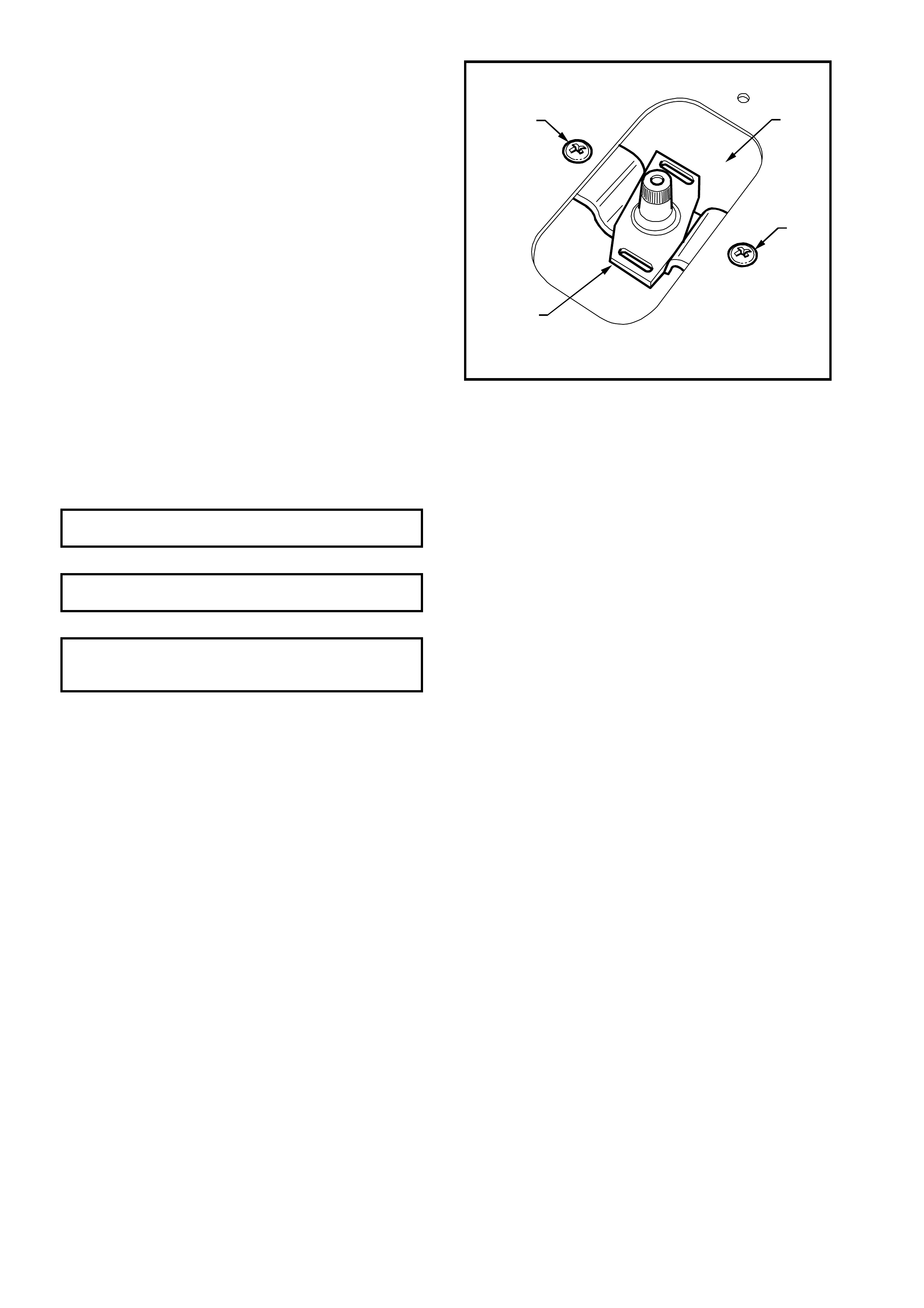
7. Loosen both screws (1) securing the lock
mechanism.
NOTE: Do not remove the screws at this point, if
the lock is not supported it will drop into the
endgate.
8. Hold the lock spline with one hand and remove
the sc rews. Manipulate the lock (2) through the
endgate opening (3).
VU1A5013
1
1
2
3
Figure 1A4-8
REASSEMBLE
Reassembly is reverse of the disassembly procedure.
NOTE: Pivot area should be coated with a suitable lubricant prior to assembly, and the rods installed into the lock
lever from the upper surface.
ENDGATE LOCK MECHANISM SCREW 1 - 3
TORQUE SPECIFICATION Nm
ENDGATE HINGE ATTACHING BOLT 20 - 25
TORQUE SPECIFICATION Nm
LIMIT CABLE BRACKET
ATTACHING BOLT 15 - 19 Nm
TORQUE SPECIFICATION
2.4 FRONT TONNEAU FLOOR
REMOVE
1. Remove the tonneau cover and support bow.
2. Where fitted remove the LPG cylinder and mounting hardware, refer to Section 8A2 LPG SYSTEM.
3. Remove screws securing tonneau floor.
3. Note direction of arrows (3) at rear of front tonneau floor.
4. Lift the floor using a suitable screwdriver or lever and a piece of wood as a fulcrum.
NOTE: The floor is sealed around the entire perimeter.
VU1A5014
2
1
3
Figure 1A4-9
Legend
1. Front tonneau floor 2. Screw (22 places) 3. Directional arrows
REINSTALL
Reinstallation is the reverse of the removal procedure noting the following;
1. Apply a bead of sealant (Holden Specification HN1005) to the lower perimeter of the tonneau floor.
2. Have an assistant help install the floor, ensure that the arrows are pointing towards the front of the vehicle.
3. Start all the screws before tightening in a progressive pattern.
4. Ensure that the drain holes are not obscured by sealant. For location of drain holes, refer to
2.5 DRAIN TUBES in this Section.
FRONT TONNEAU FLOOR SCREW 1 - 3
TORQUE SPECIFICATION Nm
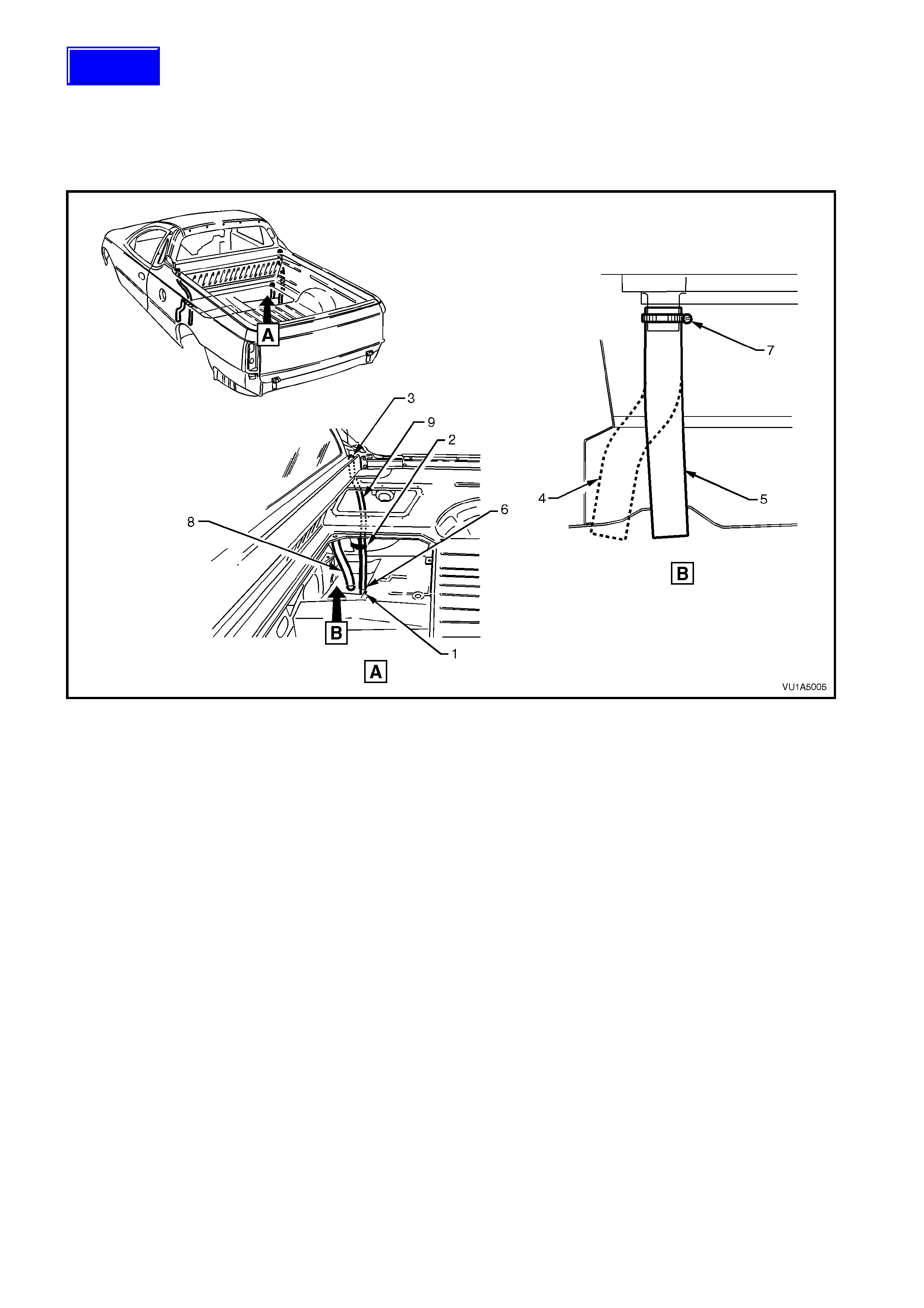
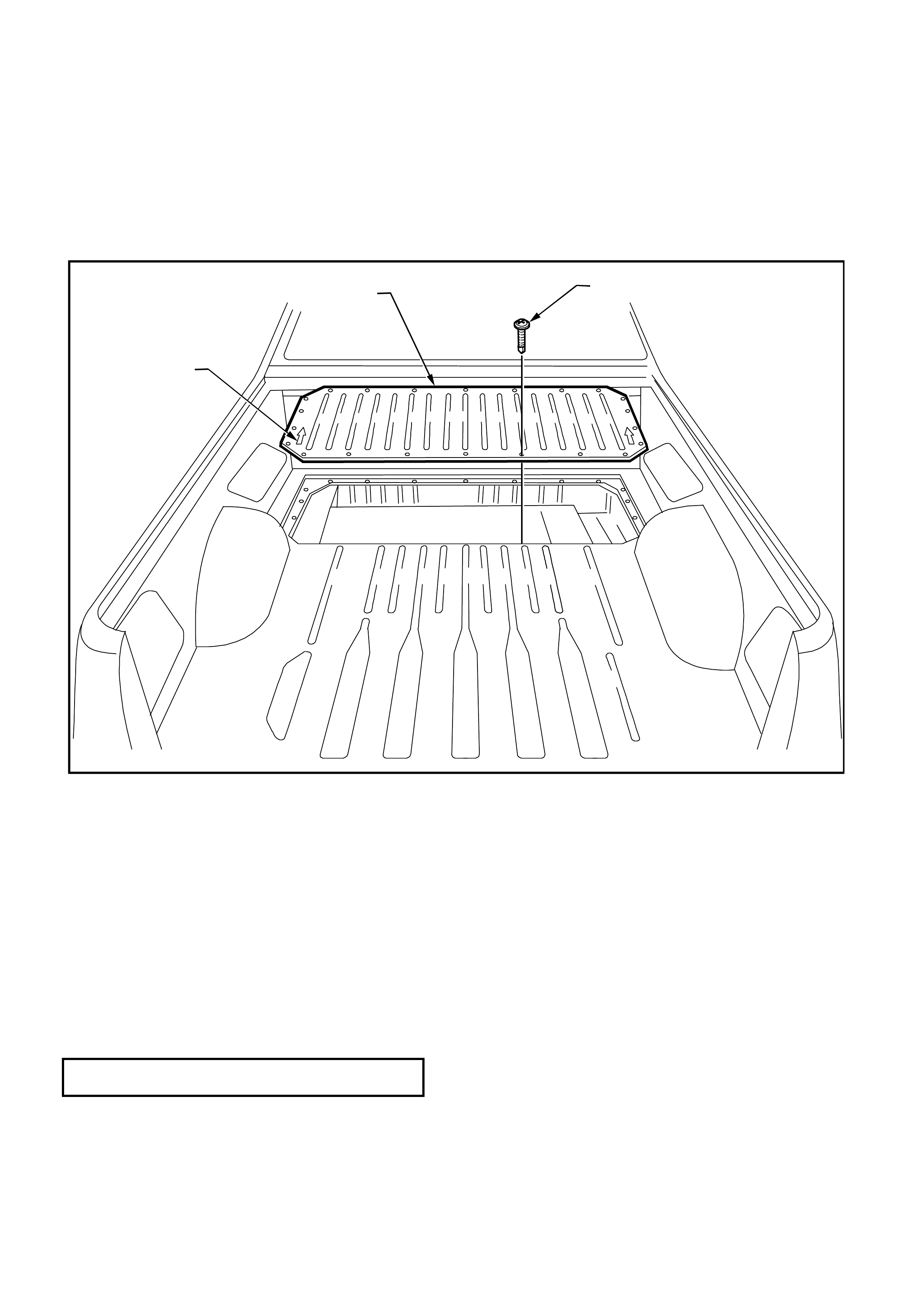
2.5 DRAIN TUBES
REMOVE
1. Remove the front tonneau floor, refer to 2.4 FRONT TONNEAU FLOOR in this Section.
2. Loosen the retaining clamps (7) and remove the drain tubes (4 and 5). Clear any obstruction from the tubes and
floor or underbody drain holes using a suitable tool, then reinstall the tubes.
Figure 1A4-10
Legend
1. 60° taper cut to assist installation
2. Drain tube tie strapped to brace
3. Insert tube assembly to hole, route to
floor drain hole
4. L/H side drain tube
5. R/H side
6. Insert into floor drain hole
7. Hose clamp
8. Tonneau floor drain tube
9. Grommet and drain tube
NOTE: Where water accumulates in the load area, some part of the drain may be obscured or restricted. To
prevent corrosion occurring, clear the restriction.
Periodically check the drain holes in the load area and below the vehicle, use a piece of stiff wire to clear the
entrance of the holes.
REINSTALL
Reinstallation is the reverse of the removal operations, noting the following:
1. Apply a bead of sealant (Holden Specification HN1005) to the lower perimeter of the tonneau floor.
2. Have an assistant help install the floor, ensure that the arrows are pointing towards the front of the vehicle.
3. Start all the screws before tightening in a progressive pattern.
Techline


3. TORQUE WRENCH SPECIFICATIONS
Nm
Roof Side Capping Attaching Screws................................... 1 - 3
Quarter Panel Upper Moulding Attaching Screws ................ 1 - 3
Quarter Window Plastic Securing Nuts................................. 1 - 3
Tail Lamp Cap Attaching Screws.......................................... 3 - 5
Endgate rail Attaching Screws.............................................. 3 - 5
Side belt rail Socket Head Attaching Screws........................ 3 - 5
Side belt rail Retaining Bolts................................................. 3 - 5
Front Tonneau Bow Mounting Bracket Attaching Screws .... 25 - 35
Endgate Hinge Attaching Bolts ............................................. 20 - 25
Limit Cable Bracket Attaching Screws.................................. 15 - 19
Tonneau Floor Attaching Screws.......................................... 1 - 3
Drain Tube Hose Clamp Screw............................................ 2 - 4
Spare Wheel Hoist Attaching Screws................................... 15 - 35