
SECTION 1A6 - STATIONARY GLASS
IMPORTANT:
Before performing any Service Operation or other procedure described in this Section, refer to Section
00 CAUTIONS AND NOTES for correct workshop practices with regard to safety and/or property damage.
1. GENERAL DESCRI PTI O N
Stationary glass on VU Series models is bonded to the body openings with the exception of the quarter window,
which is secured with plastic nuts.
The windshield, which is laminated and features a tinted upper band, is bonded in the body opening w ith urethane.
The rear window, w hich has an electrically heated demist facility, is also bonded in the body opening w ith urethane.
Toughened safety glass is used for all the windows except the windshield.
For replacement of urethane bonded glasses, urethane service kits have been developed and must be used to
ma intain original installation requirements . Glass installed with urethane requir es either partial or com plete rem oval of
the urethane when replacing the glass.
Two diff e rent ins tallation methods ar e us ed when replacing the windshield or r ear window, a ‘short m ethod’ and a ‘long
method’. Partial removal of the urethane is referred to as the ‘short method’. Complete removal of the urethane is
known as the ‘long method’.
The short method is used where original urethane left on body opening pinch weld flanges after glass removal can
serve as a base for the new glass.
This method would be used in cases of replacement of cracked windshields or removal of glass that is intact. The
amount of urethane left in the glass opening can be controlled during glass rem oval, leaving the maxim um am ount of
original urethane intact on the body opening flange.
The long method is to be used when the original urethane left in the window opening, after glass removal, cannot serve
as a base for replacement glass. This method would be used in cases needing metal work or where paint refinishing is
required in the body opening; or in cases where the glass has been previously replaced using the short method. In
such instances, the build up of urethane could position the glass too high in the body opening. In these cases, the
original urethane is completely removed and replaced with new urethane during glass installation.
Techline

2. SERVICE NOTES
CAUTION: Safety glasses and work gloves must be worn at all times when operating with glass.
Skinning ( partial curing) of the urethane c omm ences after ex posure to the atmos phere. At 23 degrees Celsius and
50 percent relative humidity, skinning commences after 30 minutes. Complete curing of the urethane at this
temperature and humidity takes 72 hours.
Urethane service kits are available from most windshield agents. Manufacturer’s instructions should always be
followed.
Window glass should be installed in the window opening within 5 minutes of the application of urethane.

3.2 BACK WINDOW
REMOVE
CAUTION: Safety glasses and work gloves must be worn at all times when operating with glass.
1. Disconnect battery ground cable.
2. Remove the centre rear roof capping, refer to Section 1A 4 LOAD COMPARTMENT AND ENDGATE.
3. Remove the sc rews s ec uring the lef t and r ight side rear roof capping, ease the capping forward disengaging the
capping from under the load compartment belt rail.
4. Place protective covering adjacent to back window to protect trim and paint finish.
5. Remove the rear window and 'B/C' pillar upper trim as sembly, refer to Section 1A8 HEADLINING AND REAR
END TRIM in this Supplement.
6. Carefully disconnect the back window electrical demister connectors and cellular telephone antenna if fitted.
7. Should the glass be broken, c arefully remove all f ragm ents of glass from the back window opening. Otherwise,
carefully cut out the back window glass by following the procedure set out in Steps 12 to 15 of
3.1 WINDSHIELD GLASS - Remove, Section 1A6 STATIONARY GLASS of the VT Series II Service
Information.
NOTE: It is not necessary to remove all traces of the original urethane. However, any original urethane remaining
must be smooth and firm.
REINSTALL
Reinstallation is the reverse of removal operations noting the following.
For glass reinstallation pr ocedures ref er to Section 1A6 ST ATIONARY G LASS - Reinst all of the VT Ser ies Servic e
Information.
Install back window moulding to lower edge of glass prior to installing back window glass.
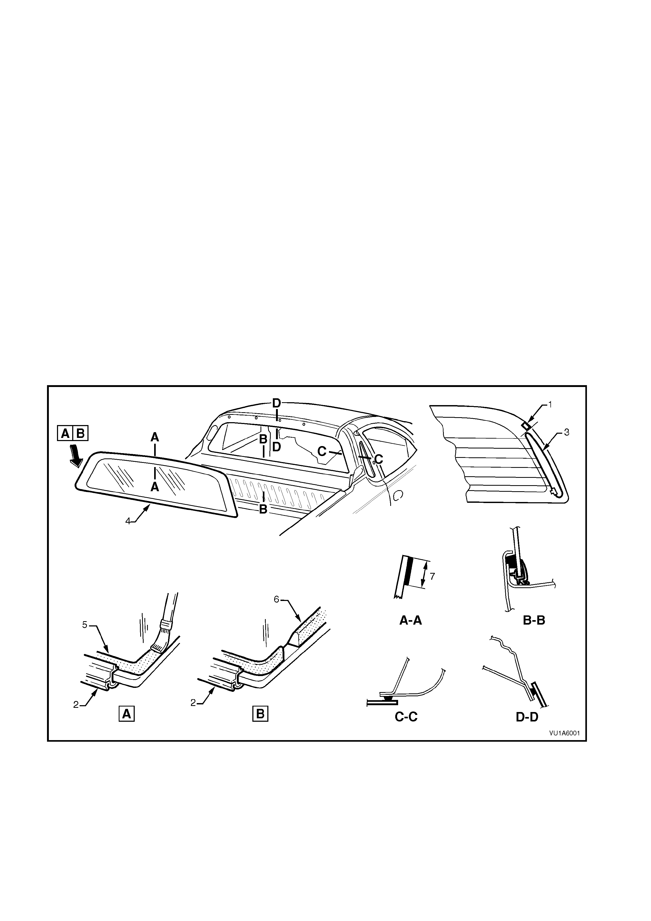
Figure 1A6-1
Legend
1. Position spacer on edge of glass adjacent
to end of bus bar (LH & RH)
2. Back window moulding
3. Bus bar
4. Rear window glass
5. Black glass primer
6. Urethane
7. Bonding surface
NOTE 1: The sectional views in Fig 1A6-1 show
the installed condition.
NOTE 2: Apply glass clear primer to Holden
Specification HN-2149 to the bonding surface (7)
over the width of the black caramic around the
entire per imeter of the glass , then imm ediately wipe
off with a clean, lint free shop rag
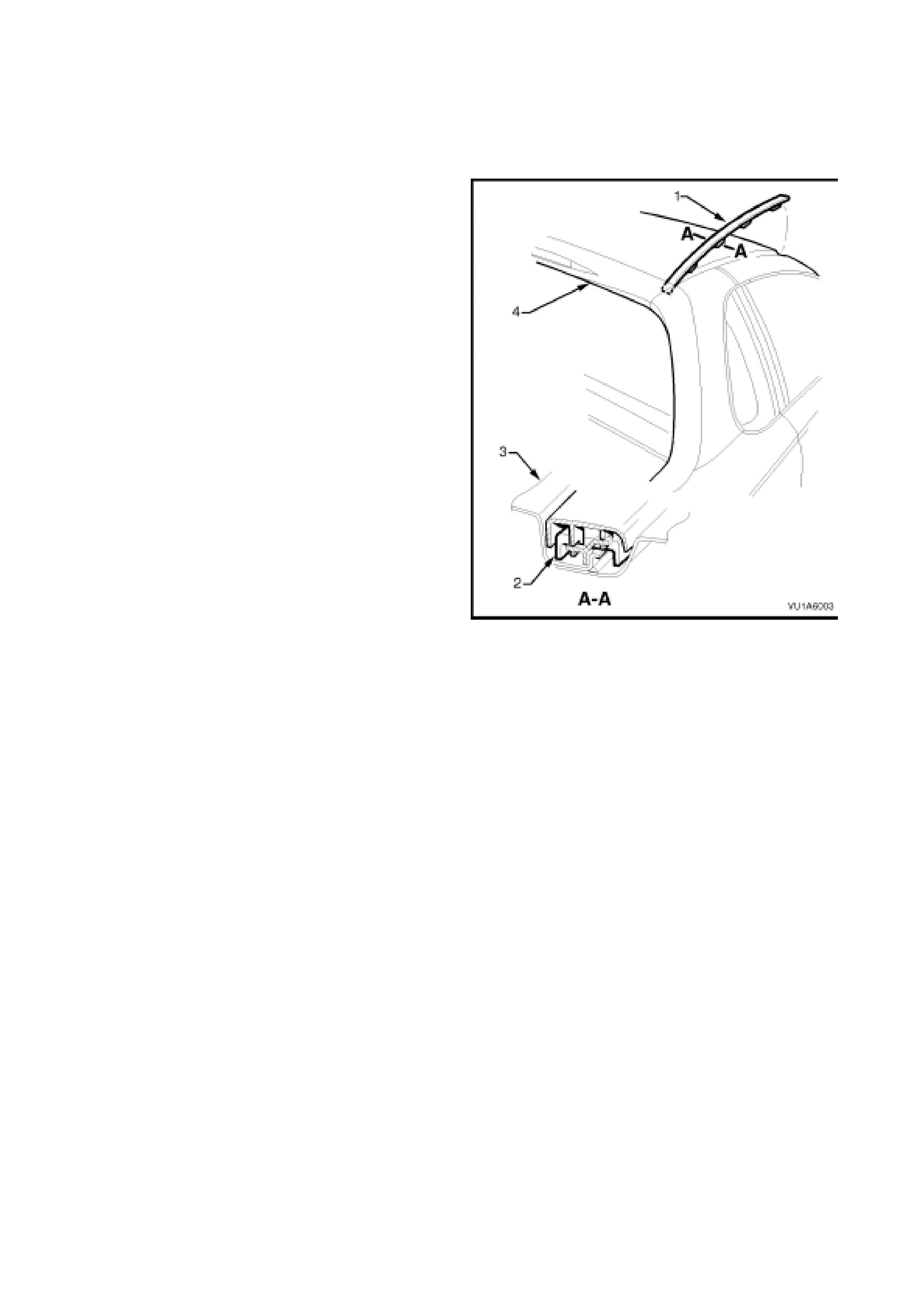
If removed or par tially removed, ens ur e that the roof
finisher moulding assembly is installed into the
channel of the roof panel as shown in Fig. 1A6-2.
Engage roof finisher moulding locating clips along
roof until roof finisher moulding assembly sits flush
against roof as shown in Section A-A, refer to
Fig. 1A6-2.
Legend
1. Roof finisher moulding.
2. Roof finisher moulding locating clips (four
places, ensure clips are engaged under
roof panel flange).
3. Roof panel.
4. Centre roof capping.
NOTE: Front of roof finisher moulding must be
installed under windshield moulding.
Figure 1A6-2
3.3 QUARTER WINDOW
REMOVE
1. Partially rem ove the door f ram e opening moulding and the ' B' pillar m oulding, refer to Sect ion 1A9 EXT ERIOR
ORNAMENTATION.
2. Remove the 'B/C' pillar upper trim assembly, refer to Section 1A8 HEADLINING AND REAR END TRIM.
3. Remove the six plastic nuts securing the window to the body opening and carefully lift the glass from the
vehicle.
REINSTALL
Reverse removal operations.
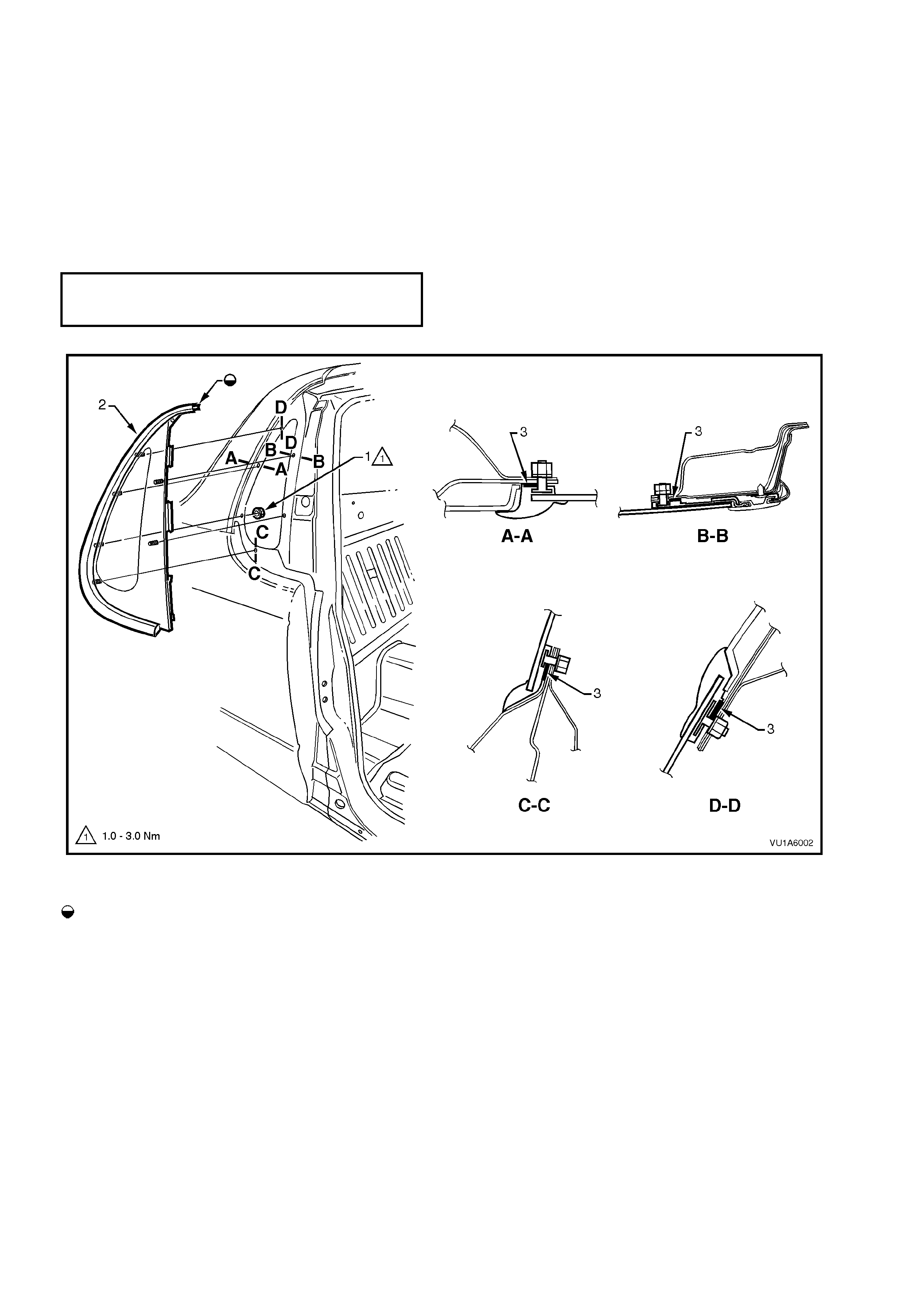
QUARTER WINDOW PLASTIC
MOUNTING NUT 1 – 3 Nm
TORQUE SPECIFICATION
Figure 1A6-3
Legend
Tab to engage with doorframe
opening moulding 1. Nut (6 places)
2. Quarter window assembly 3. Foam seal
NOTE: Sectional views show installed
condition


4. TORQUE WRENCH SPECIFICATIONS
Nm
Quarter Window Plastic Securing Nuts................................. 1 - 3
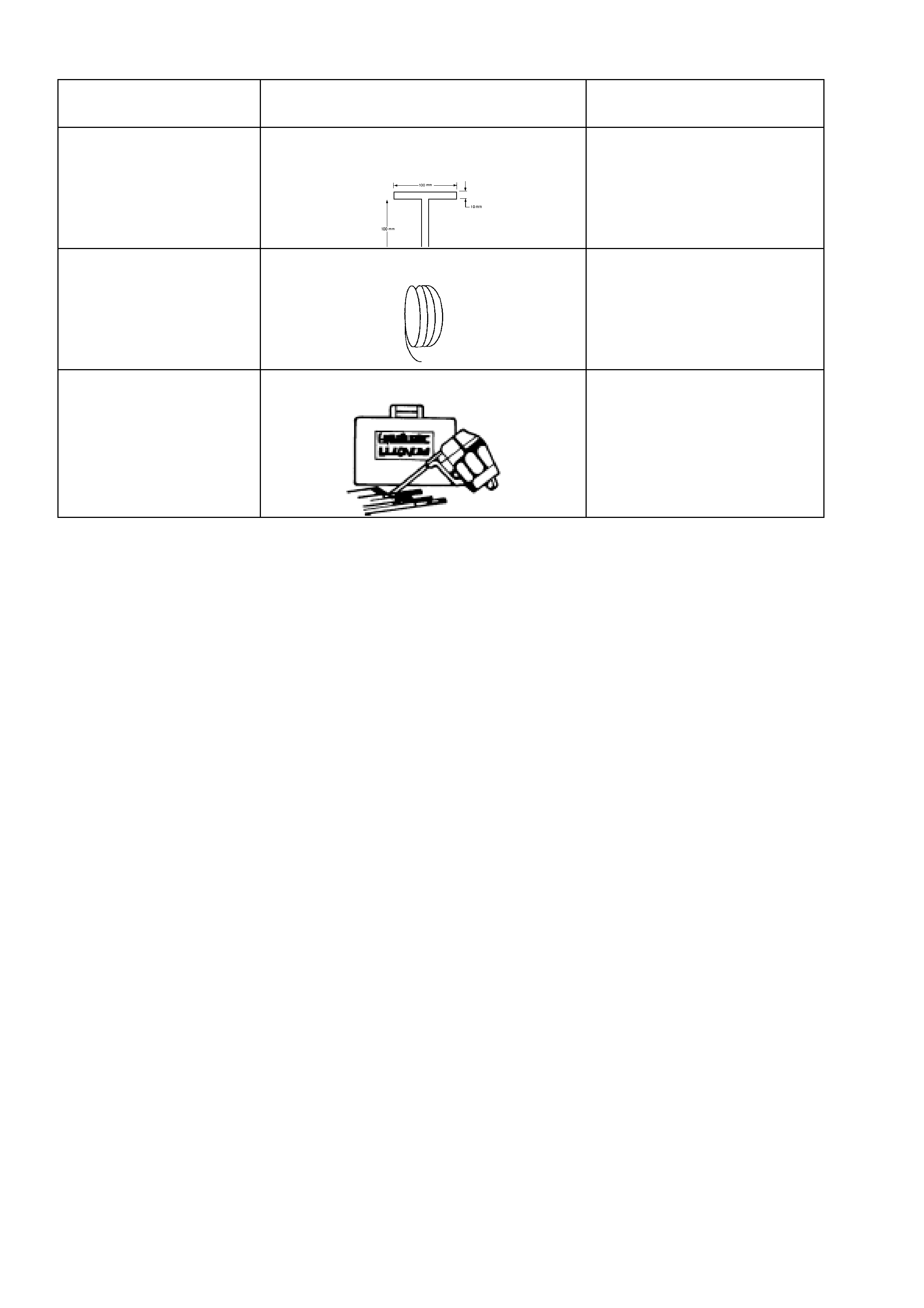
5. SPECIAL TOOLS
TOOL NO. REF IN TEXT TOOL DESCRIPTION COMMENTS
AU390
FABRICATED T HANDLE WINDSCREEN
REMOVAL TOOL AND PIANO WIRE
AU390-1
PIANO WIRE
J39032 STATIONARY GLASS REMOVAL TOOL