SECTION 1A8 - HEADLINING AND REAR END TRIM
IMPORTANT:
Before performing any Service Operation or other procedure described in this Section, refer to Section
00 CAUTIONS AND NOTES for correct workshop practices with regard to safety and/or property damage.
1. GENERAL DESCRI PTI O N
The headlining is a one-piece moulded trim and is of the same design for all model levels.
NOTE: Clean hands are essential when working on the body interior trim.
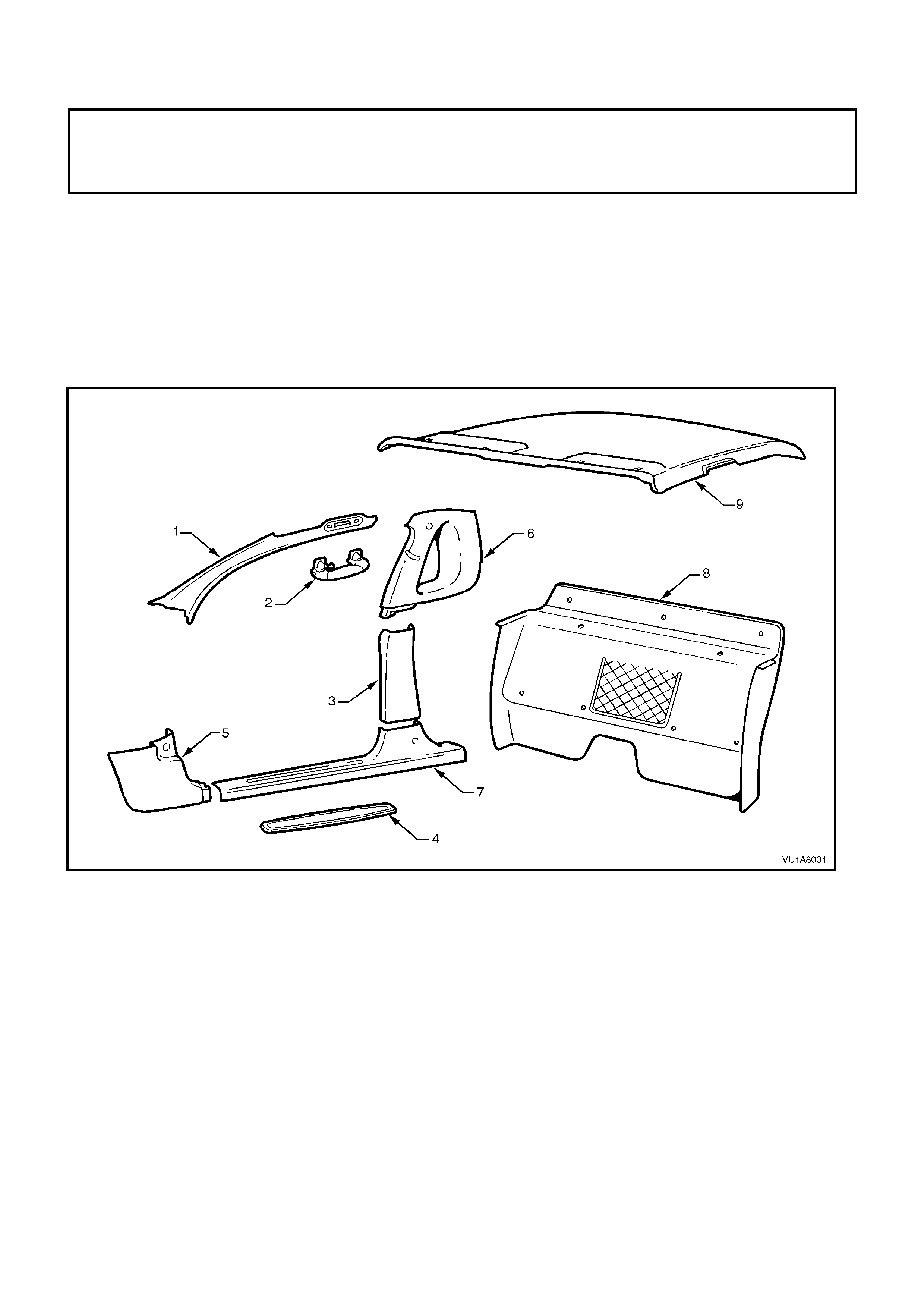
Figure 1A8-1 shows the interior trim components for VU Series Models.
For information not covered in this Section refer to either Section 1A1 BODY or Section 1A8 HEADLINING AND
REAR END TRIM of the VX Series Service Information.
Figure 1A8-1
Legend
1. 'A' pillar trim
2. Assist grip
3. 'B' pillar lower trim
4. Rocker panel cover insert
5. Cowl side lower trim
6. 'B/C' pillar upper trim assembly
7. Inner rocker panel cover
8. Back panel trim
9. Headlining assembly
2. SERVICE OPERATIONS
2.1 HEADLINING ASSEMBLY
REMOVE
1. Open both doors.
2. Place protective covering over interior trim.
3. Disconnect battery ground cable.
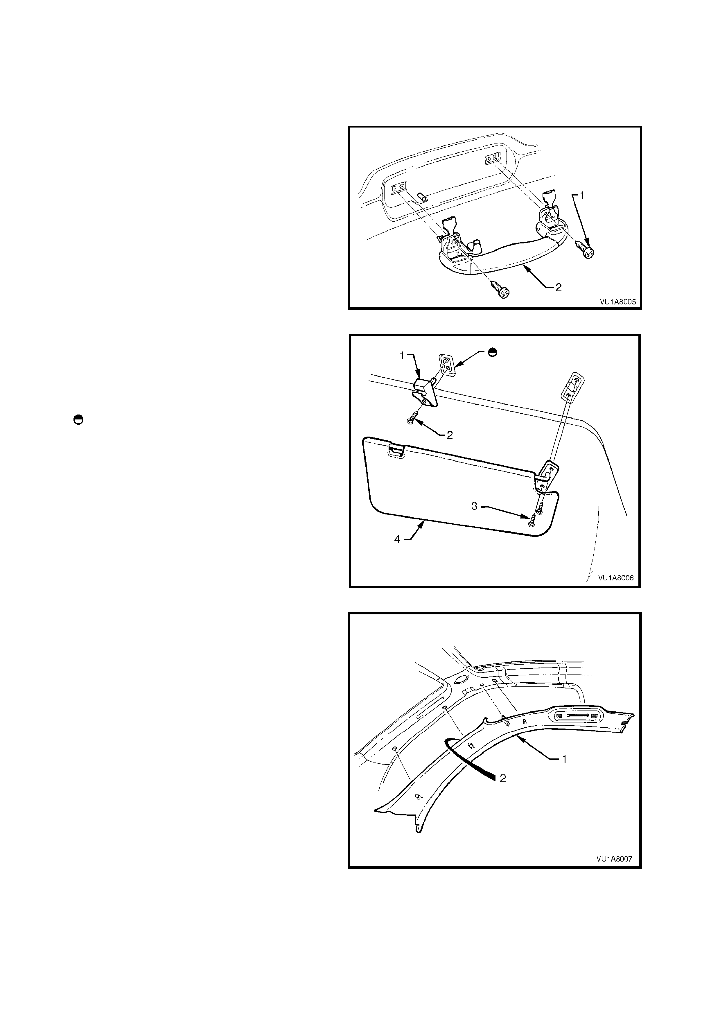
4. Prise open the interior assist grip retainer
screw covers and remove the two screws (1)
securing the assist grip, remove the assist grip
(2).
Figure 1A8-2
5. Remove the sun visor securing screws (3) and
remove sun visors (4).
6. Remove the screw (2) securing the sun visor
bracket (1), remove bracket from headlining.
Legend
Locate pin on bracket in rail before
installing screw.
Figure 1A8-3
7. Remove ‘B’ pillar lower trim, refer to
2.2 ’B/C’ PILLAR TRIM in this Section.
8. Remove ‘B/C pillar upper trim, refer to
2.2 ‘B/C’ PILLAR TRIM in this Section.
9. Release three clips (2) attaching ‘A’ pillar trim
(1) by carefully prising trim away from 'A' pillar.
10. Lean 'A' pillar trim towards centre of vehicle
and ease fr om its position on ' A' pillar removing
‘A’ pillar trim.
Figure 1A8-4
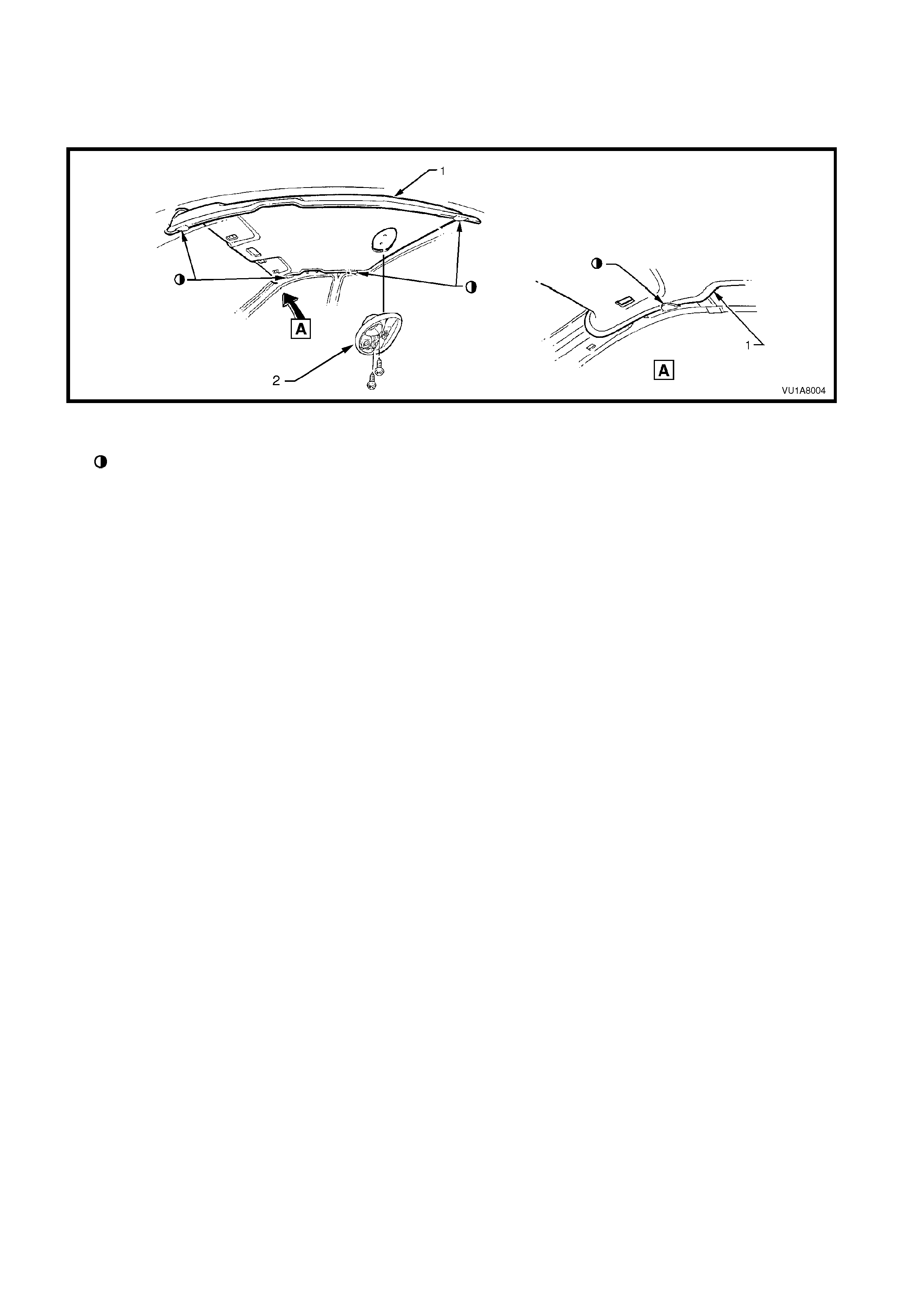
11. Prise lens from roof lamp, remove screws securing roof lamp. Remove roof lamp, disconnect headlining
harness connector from rear of roof lamp, refer to Section 12B LIGHTING SYSTEM in the VT Series Service
Information.
12. Ease headlining from its position behind temporary supporting 'D' tabs in roof rail, remove headlining via
passenger door.
Figure 1A8-5
Legend
'D' tabs for temporary support of headlining
1. Headlining assembly 2. Roof lamp
REINSTALL
Reverse removal oper ations, ens ur e lip of door f r ame opening seal is located on ex ter ior of tr im components dur ing
installation.
2.2 'B/C' PILLAR UPPER TRIM ASSEMBLY
REMOVE
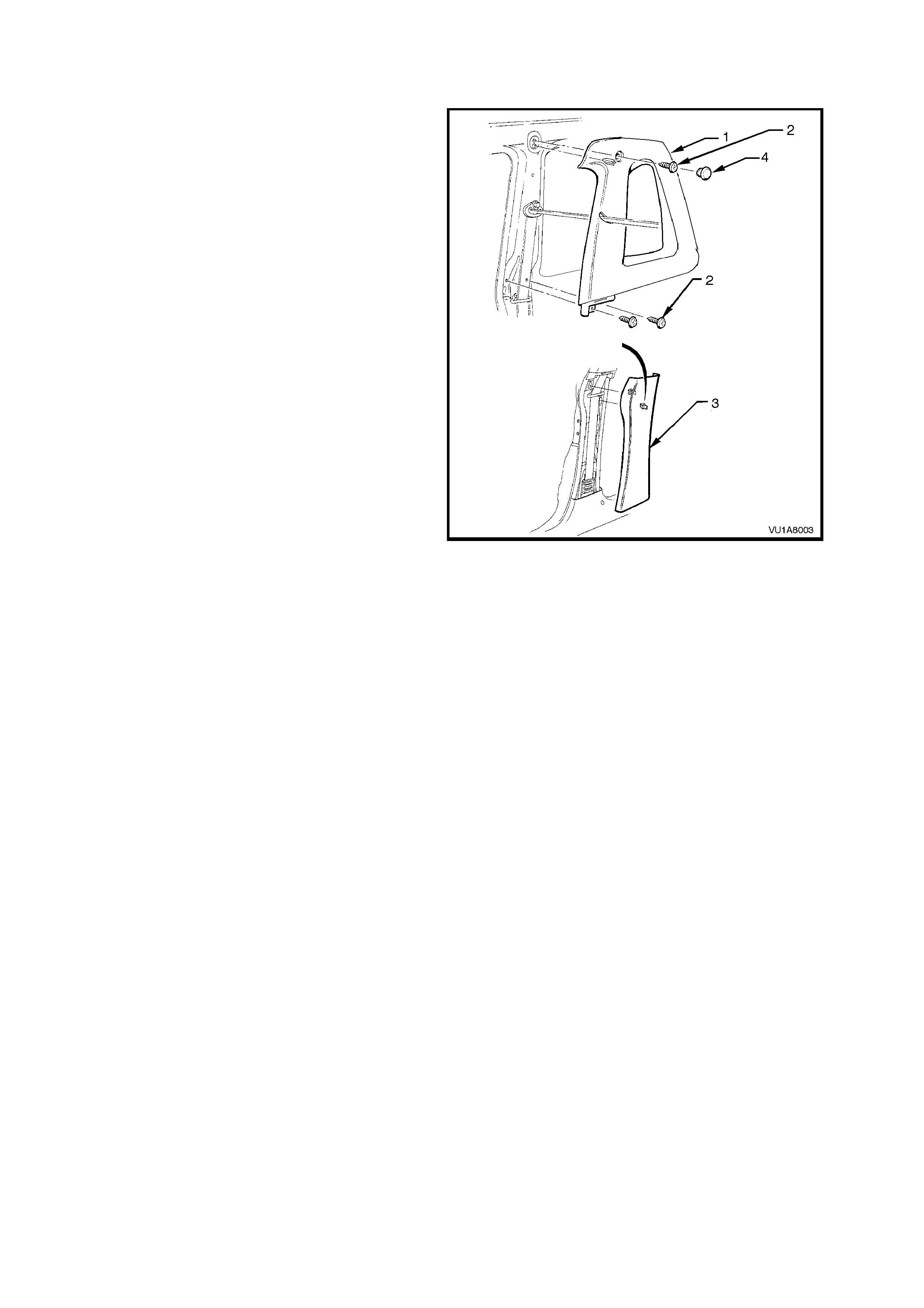
1. Unclip ‘B’ pillar lower trim (3) and remove.
2. Rem ove cap (4) covering upper 'B/C' pillar trim
retaining screw, remove screws (2) securing
upper ‘B/C’ pillar trim and remove.
3. Remove the seat belt lower retaining bolt and
feed seat belt through trim assembly removing
'B/C' pillar upper trim.
Figure 1A8-6
REINSTALL
Reverse removal oper ations, ens ur e lip of door f r ame opening seal is located on ex ter ior of tr im components dur ing
installation.
2.3 BACK PANEL TRIM
REMOVE
1. Remove the centre console, refer 2.1 CENTRE CONSOLE Section 1A3 INSTRUMENT PANEL AND
CONSOLE.
2. Move the passenger and drivers seat to the forward position.
3. Remove the rocker panel cover, refer 2.9 ROCKER PANEL COVER in Section 1A1 BODY of the VT Series
Service Information.
4. Remove the child restraint bracket and upper and lower 'B/C' pillar trim, refer 2.2 'B/C' PILLAR UPPER TRIM
ASSEMBLY in this Section.
5. Remove the screws securing the stowage net.
6. Rem ove the jack handle from its location behind the passenger seat and the fastners securing the back panel
trim, move the trim assembly forward and remove.
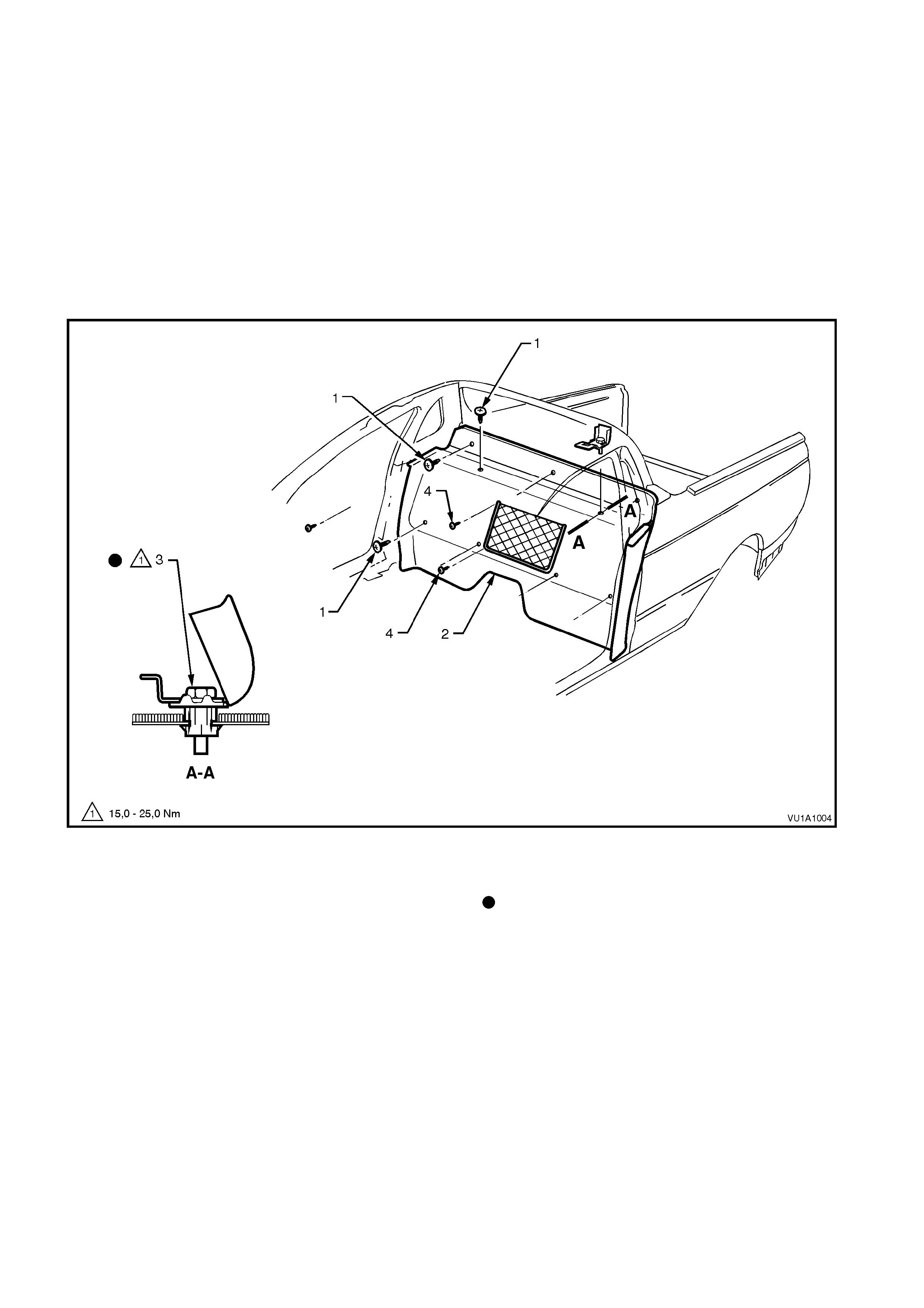
Figure 1A8-7
Legend
1. Back panel trim fastener (8 places)
2. Back panel trim
3. Child restraint anchor
4. Stowage net attaching screws (5 places)
Bolt should be hand started for minimum of five full
threads before tightening.
REINSTALL
Reverse removal operations.

3. TORQUE WRENCH SPECIFICATIONS
Nm
Assist Grip Retaining Screws................................................ 1 - 3
Sun Visor Bracket Attaching Screw...................................... 1 - 3
Sun Visor Attaching Screws.................................................. 1 - 3
‘B/C’ Pillar Trim Attaching Screws ....................................... 1 - 3
Interior Lamp Attaching Screws............................................ 1 - 3
Child Restraint Anchor Retaining Bolt................................... 15 - 25
Stowage Net Attaching Screws............................................. 1 - 3
Seat Belt Lower Retaining Bolt ............................................. 35 - 50