
SECTION 1A9 - EXTERIOR ORNAMENTATION
IMPORTANT:
Before performing any Service Operation or other procedure described in this Section, refer to Section
00 CAUTIONS AND NOTES for correct workshop practices with regard to safety and/or property damage.
1. GENERAL DESCRI PTI O N
Exterior ornamentation on VU Series Models includes:
• Various nameplates, emblems and decals.
• Door frame-opening mouldings.
• ‘B’ pillar mouldings.
• Roof finisher moulding.
• Rocker panel skirts.
Exterior ornamentation components are secured to the body using various fasteners, double sided tape and
polyurethane adhesive.

2. SERVICE OPERATIONS
2.1 SERVICE NOTES
Numerous clips, fasteners, retainers, bushes, screws, nuts and contact adhesives are used to secure the various
exterior ornamentation components to the vehicle body. T o locate the service infor mation applicable to a partic ular
component, refer to 2.2 PICTORIAL INDEX in this Section.
When removing, handling or installing exterior ornamentation components, the following care should be exercised:
1. Finishers adj acent to the c om ponent being rem oved should be c overed with mas k ing tape to prevent damage to
panels and paint work.
2. Removal of adhesive bonded nameplates and emblems is more easily achieved with the aid of a heat lamp
positioned adjacent to the part to be removed.
NOTE: Ens ure that the heat lamp is not too c los e to the body, or the heat so intense that it m ay adversely affect the
paint finish.
3. Holes in body panels f or s crews, bolts, clips, etc. that c ould perm it water entry into the body m ust be adequately
sealed with either a non-hardening sealer or presealed screws, clips, etc.
4. Using a clean cloth, clean the area of body surface where emblems, mouldings, etc. are to be applied with
‘Prepsol’ solvent or equivalent.
5. It is essential that the body temperature of the vehicle be at least 21°C before adhering adhesive bonded
components to the vehicle.
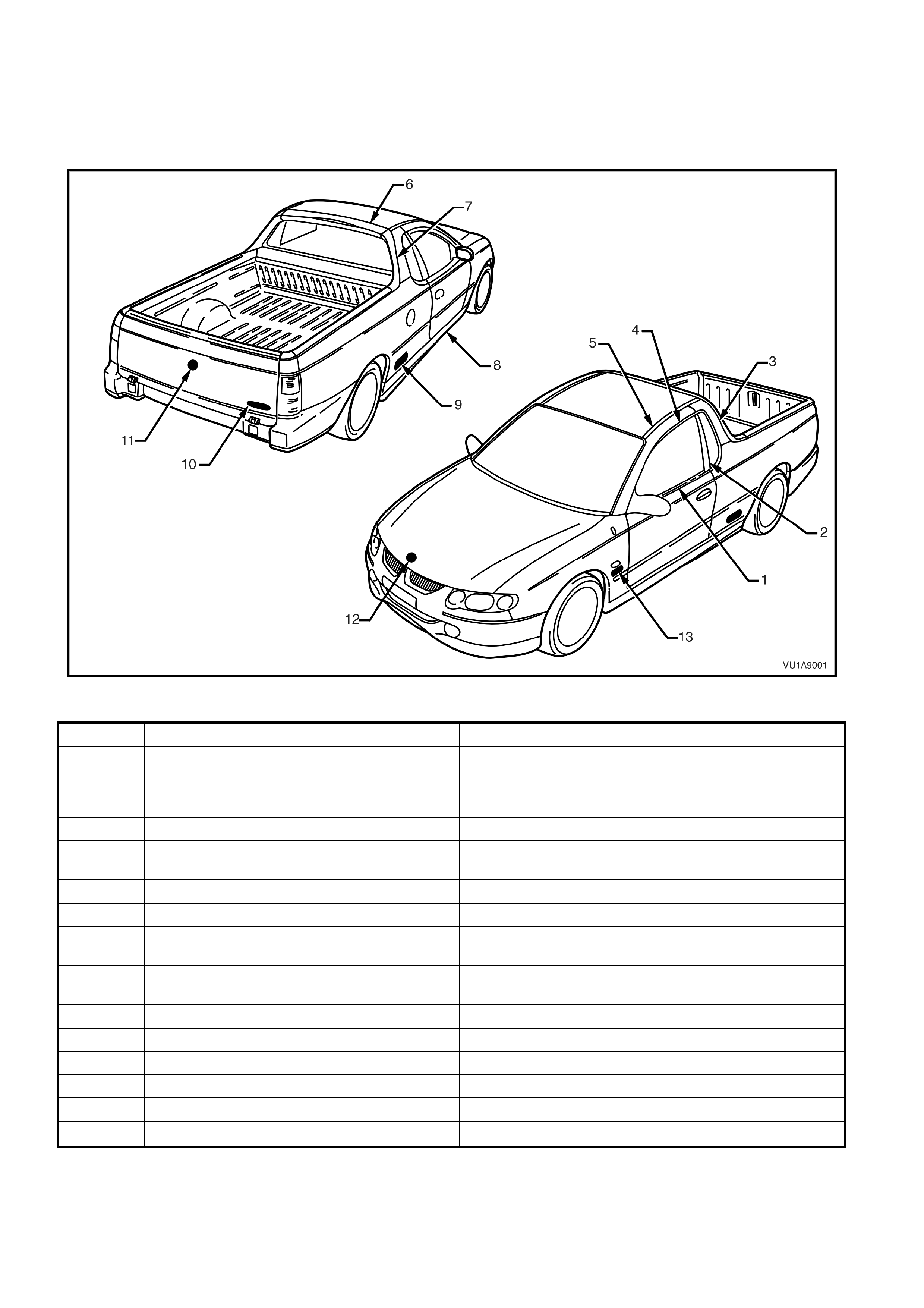
2.2 PICTORIAL INDEX
The following pictograph indexes provide a quick guide to finding the correct service procedure for the applicable
exterior ornam entation com ponent. Within this Sect ion, simply locate the appropriate com ponent in Fig. 1A9-1, and
cross-reference it in the table below the Figure.
Figure 1A9-1
ITEM DESCRIPTION REFERENCE
1 Door belt moulding 2.16 FRONT AND REAR DOOR BELT WEATHERSTRIP
AND MOULDING ASSEMBLY in Section 1A5 FRONT AND
REAR DOOR ASSEMBLIES of the VT Series Service
Information
2 ‘B’ pillar moulding 2.4 ‘B’ PILLAR MOULDING in this Section
3 Quarter panel upper moulding 2.1 QUARTER PANEL UPPER MOULDING in Section 1A4
LOAD COMPARTMENT AND ENDGATE.
4 Door frame opening moulding 2.5 DOOR FRAME OPENING MOULDING in this Section
5 Roof finisher moulding 2.6 ROOF FINISHER MOULDING in this Section
6 Roof centre rear capping 2.1 QUARTER PANEL UPPER MOULDING in Section 1A4
LOAD COMPARTMENT AND ENDGATE.
7 Roof side cap 2.1 QUARTER PANEL UPPER MOULDING in Section 1A4
LOAD COMPARTMENT AND ENDGATE.
8 Rocker panel skirt 2.3 ROCKER PANEL SKIRT in this Section
9 SS badge 2.8 NAME PLATES AND DECALS in this Section
10 S or SS badge 2.8 NAME PLATES AND DECALS in this Section
11 ‘Lion’ emblem – endgate 2.8 NAME PLATES AND DECALS in this Section
12 ‘Lion’ emblem – engine hood 2.7 ‘LION’ EMBLEM – ENGINE HOOD in this Section
13 V6 ECOTEC or GEN III V8 engine badges 2.8 NAME PLATES AND DECALS in this Section
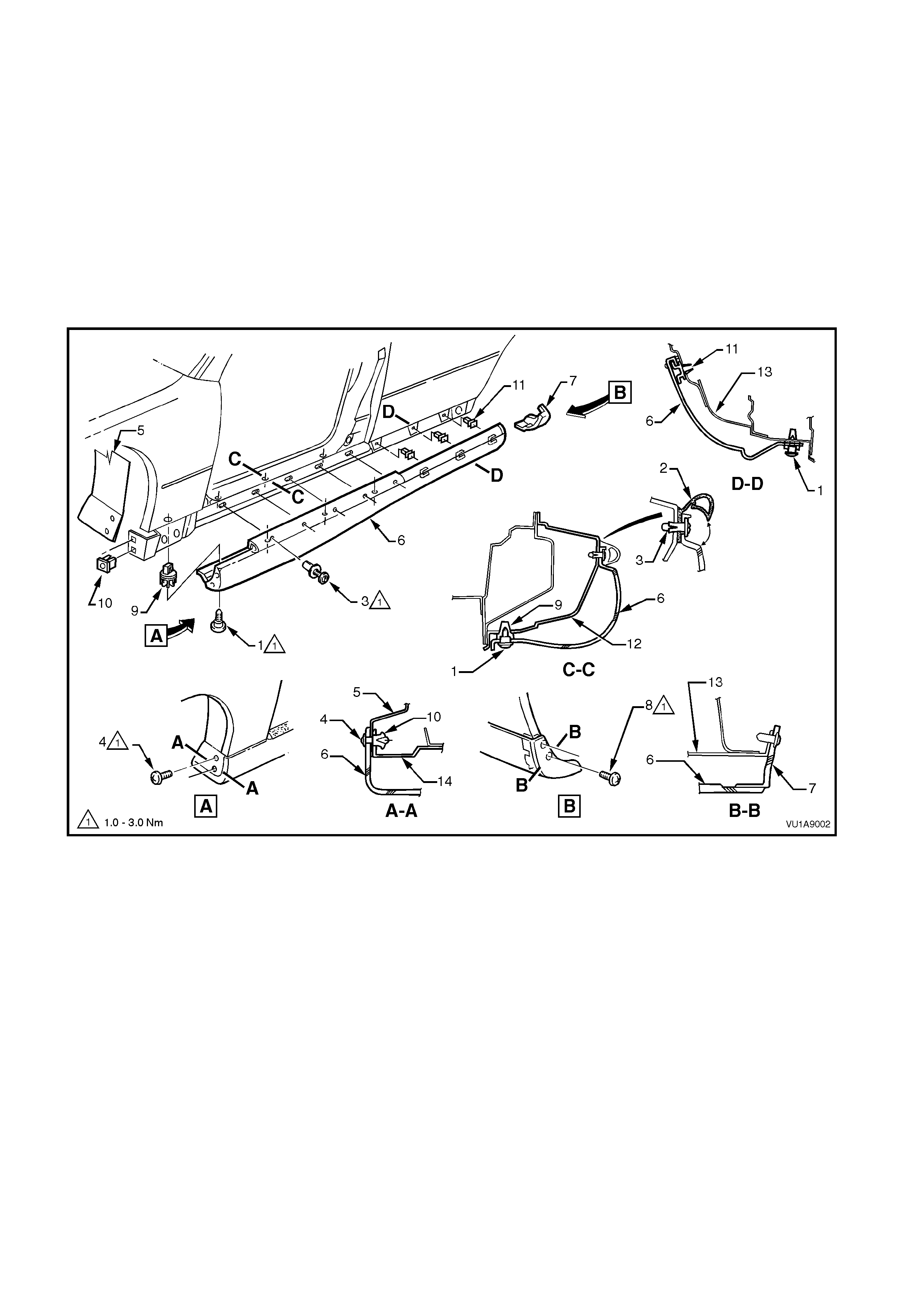
2.3 ROCKER P ANEL SKIRT
REMOVE
1. From under vehic le, remove the s ix rock er panel skirt lower r etaining screws (1), ref er to sectional view C-C in
Fig. 1A9-2.
2. Open door, lift up lip of rocker panel skirt weatherstrip (2) to gain access to the five retaining scrivets (3) and
remove scrivets, refer to sectional view C-C in Fig. 1A9-2.
3. Remove the two screws (4) securing the rocker panel front skirt to the fender liner, refer to View A in
Fig. 1A9-2.
4. Slide rocker panel front skirt forward until it is free from the rocker panel rear skirt, and remove rocker panel
front skirt.
5. Remove the two screws (8) securing the rocker panel rear skirt (7) to the body and remove rocker panel rear
skirt, refer to View B in Fig 1A9-2.
Figure 1A9-2
Legend
1. Screw (6 places)
2. Rocker Panel Skirt Weatherstrip Assembly
3. Scrivet (5 places)
4. Screw (2 places)
5. Front Fender Liner
6. Rocker Panel Front Skirt
7. Rocker Panel Rear Skirt
8. Screw (2 places)
9. Nutsert (6 places)
10. Rocker Panel Skirt Attaching Nut (2 places)
11. Retainer Rocker Panel Skirt
12. Door Opening Frame
13. Rear Quarter Panel
14. Rocker Panel Skirt Attaching Bracket
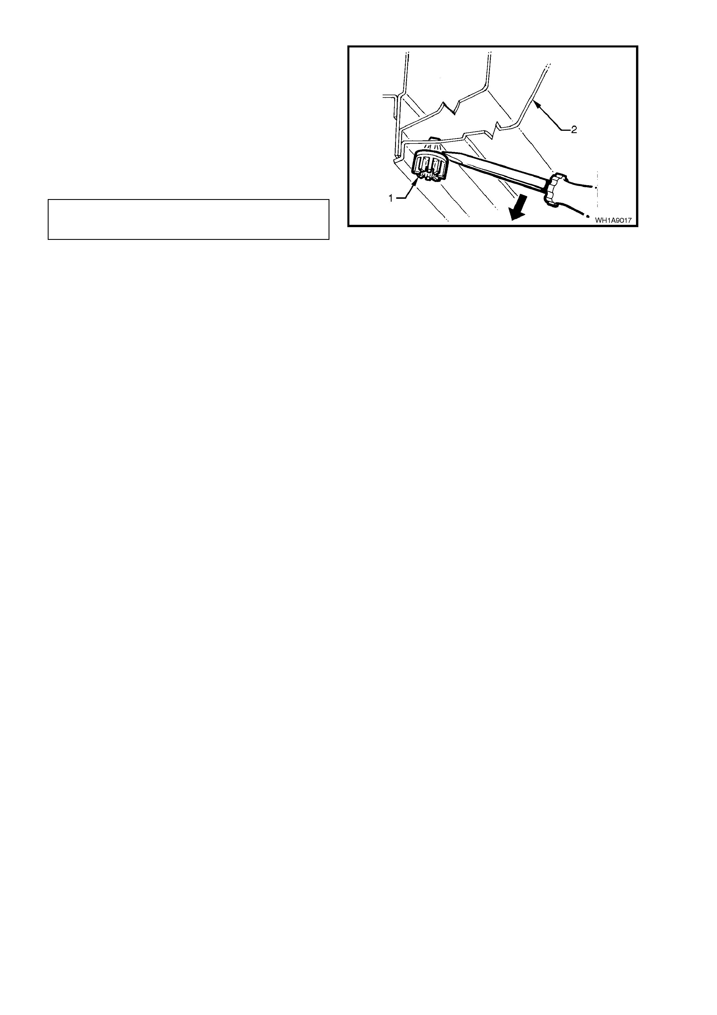
6. If necessary, remove the seven nutserts (1) by
gently levering nutsert out from the body (2),
taking care not to damage paintwork.
REINSTALL
Reinstallation of the rocker panel front and rear
skirts is the reverse of the removal operation,
ensuring that all fasteners are tightened to the
correct torque specification.
ROCKER PANEL SKIRT
RETAINING SCREWS 1 - 3 Nm
TORQUE SPECIFICATION
Figure 1A9-3
2.4 ‘B’ PILLAR MOULDING
REMOVE
1. Open door on relevant side of vehicle.
2. Release the 'B' pillar moulding (1) by gently
levering top of moulding out and away from ‘B’
pillar, slide moulding upwards removing
moulding from location on 'B' pillar.
Figure 1A9-4
REINSTALL
Reinstallation of the ‘B’ pillar moulding is the reverse
of the removal procedure, noting the following:
1. Slide outer moulding down and pres s in at top to
engage retainer.
B PILLAR MOULDING
ATTACHING SCREW 1 - 3 Nm
TORQUE SPECIFICATION
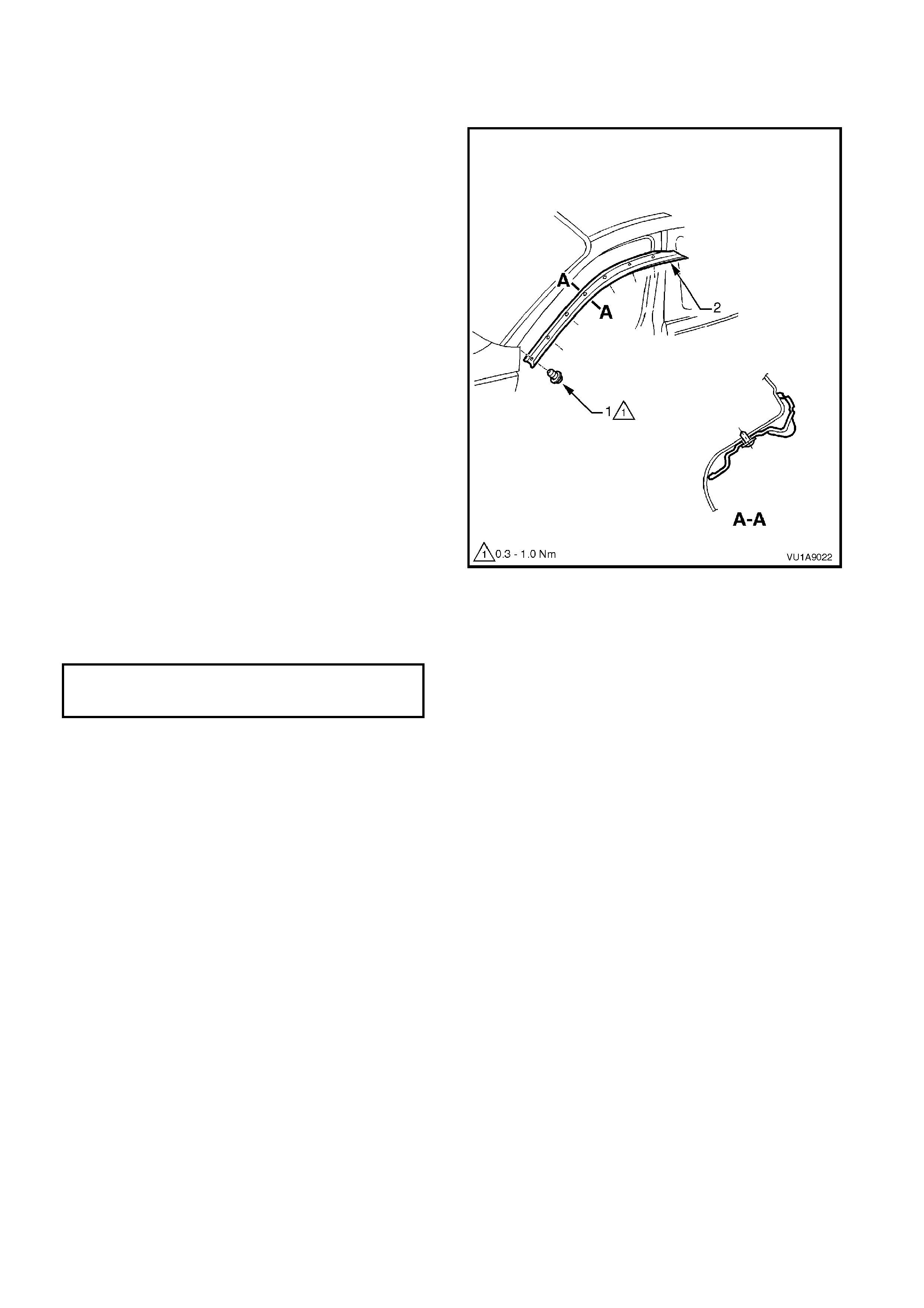
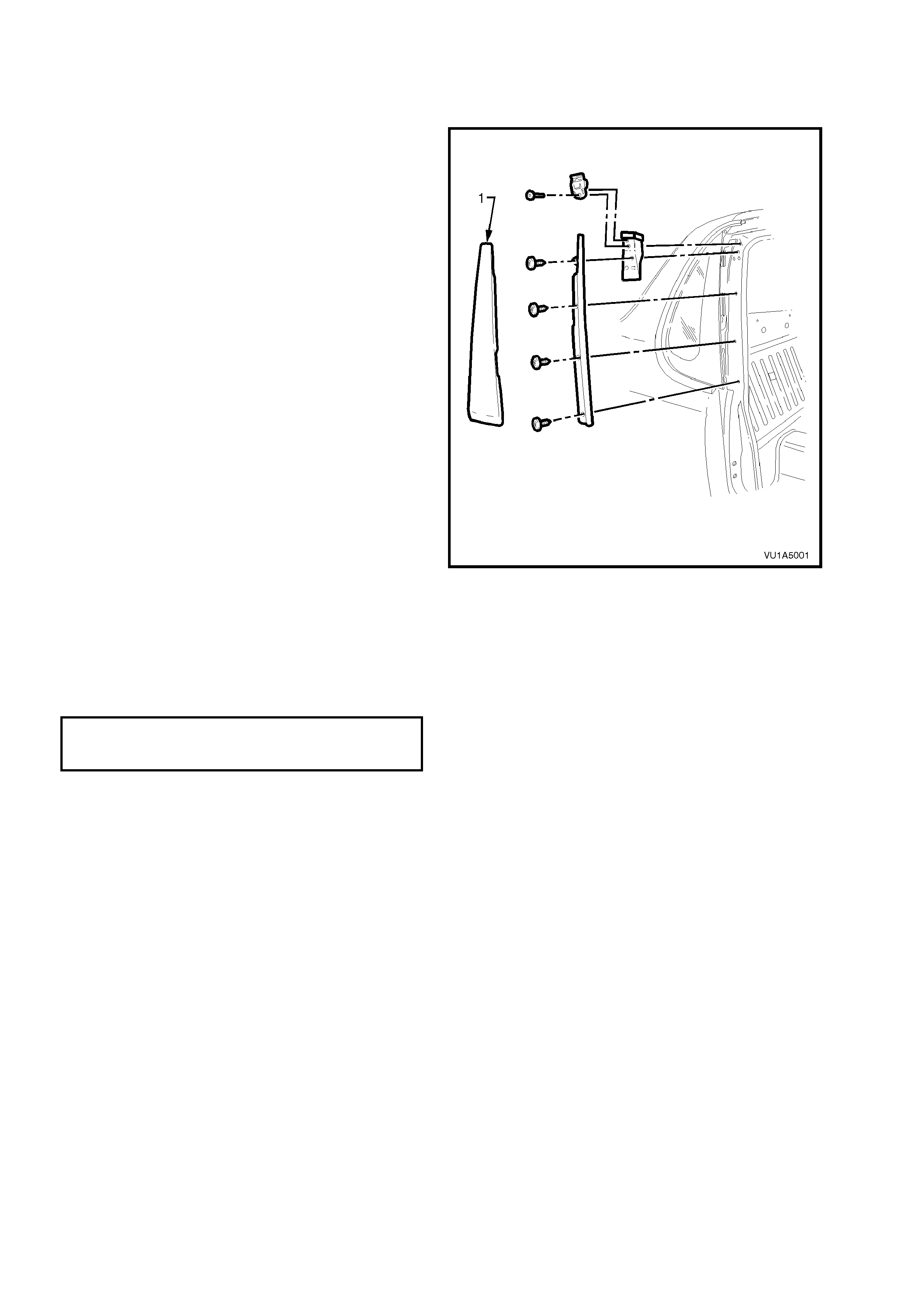
2.5 DOOR FRAME OPENING MOULDING
REMOVE
1. Open door on relevant side of vehicle.
2. Remove the screws (1) securing door frame
opening moulding (2) to body (7 places) and
remove moulding.
Figure 1A9-5
REINSTALL
Reinstallation is the reverse of the removal procedure.
DOOR FRAME OPENING
MOULDING ATTACHING SCREW 0.3 – 1. 0 Nm
TORQUE SPECIFICATION
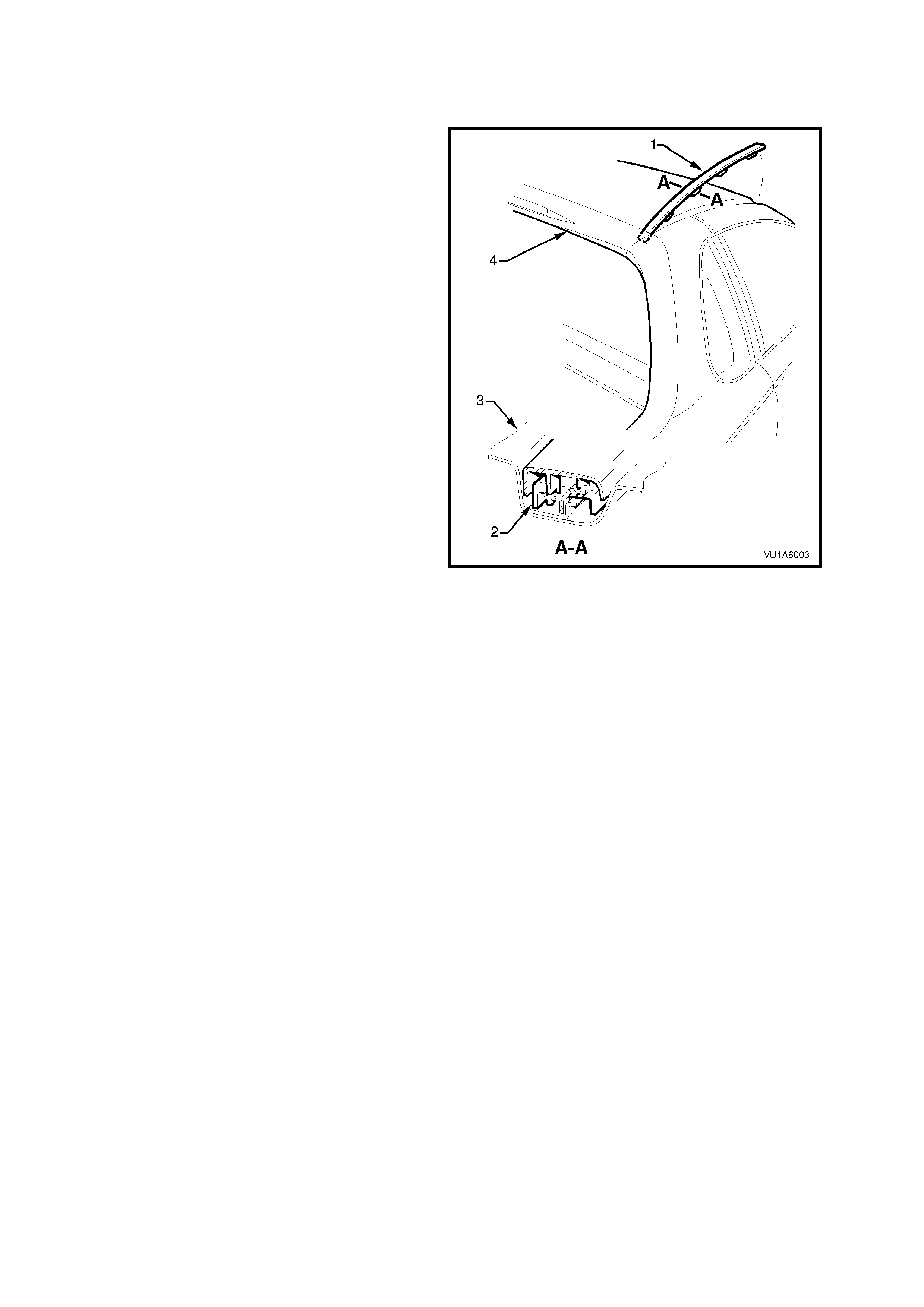
2.6 ROOF FINISHER MOULDING
REMOVE
1. Starting at the front and using a screw driver
with a clean shop rag to prevent paint work
damage, pry the roof finisher moulding (1) out
of the roof channel by rocking the moulding
sideways, disengaging the retaining lugs.
2. Disengage the roof finisher moulding rear
locating lug from the quarter panel upper
moulding by lifting the moulding at the front
until the moulding slides freely from its location
in the quarter panel upper moulding.
REINSTALL
1. Position roof finisher moulding along roof,
ensure roof finisher moulding locating lug is in
position in quarter panel upper moulding.
2. Engage roof finisher moulding clips (2) along
roof until roof finisher moulding sits flush
against the roof (3).
NOTE: The r oof finisher moulding must be installed
under the windshield moulding cover.
Figure 1A9-6
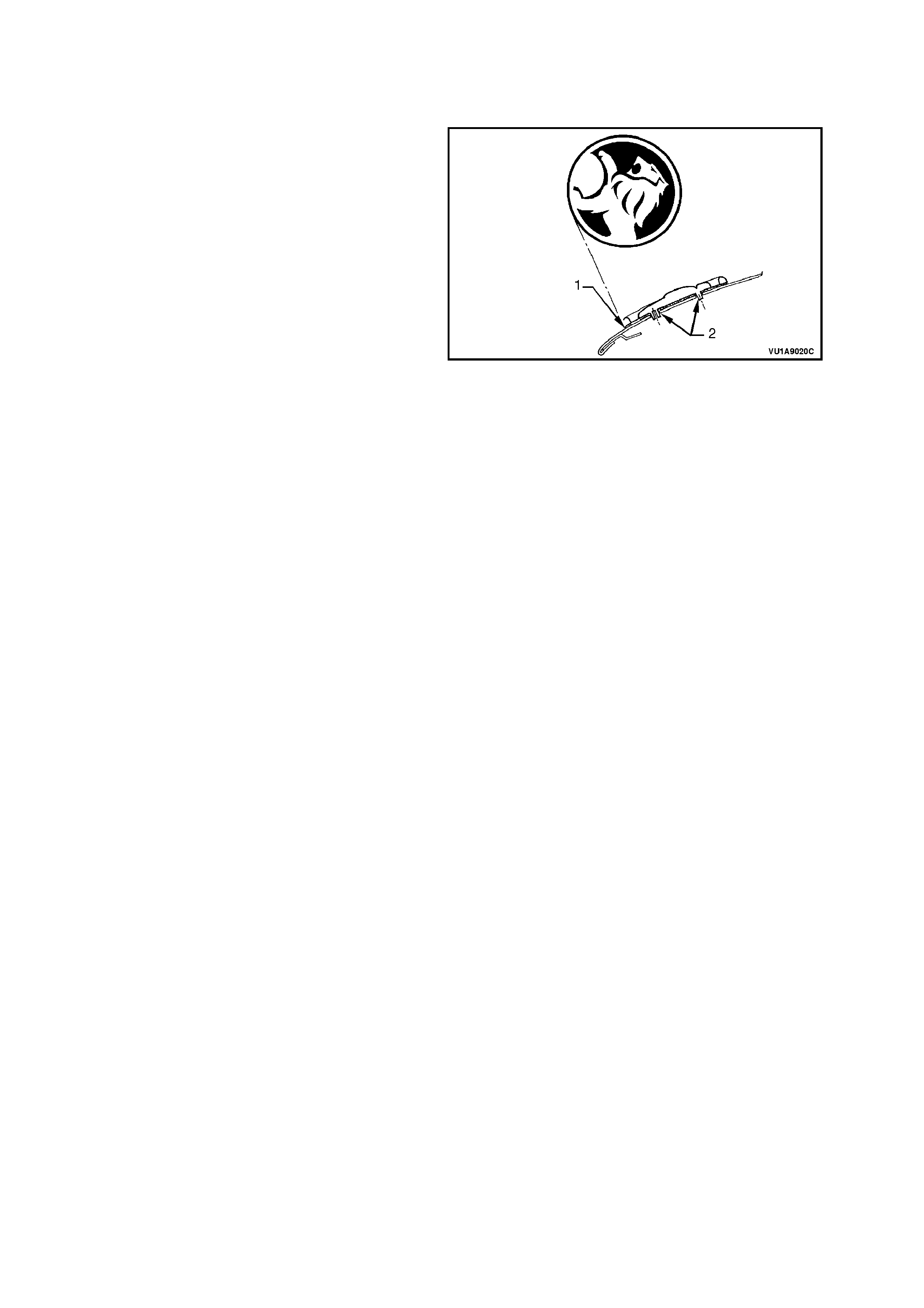
2.7 ‘LION’ EMBLEM
ENGINE HOOD
SERVICE NOTES
1. Before installation, remove release paper from
adhesive foam tape.
2. After removing release paper from adhesive
foam tape, ensure there is a band of adhesive
foam tape around base of locating pins.
Legend
1. Double sided pressure sensitive adhesive
foam tape.
2. Locating pins.
Figure 1A9-7
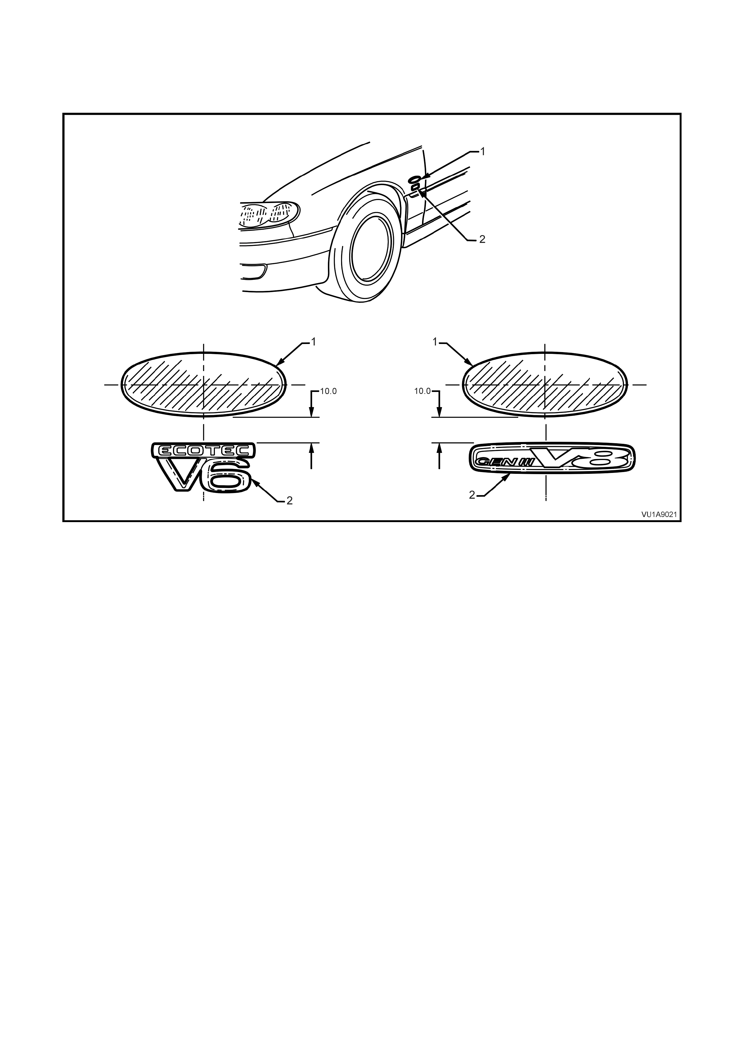
2.8 NAME PLATES AND DECALS
SERVICE NOTES
1. Before installation, remove carrier film and release paper from adhesive foam tape as necessary.
Figure 1A9-8
Legend
1. Side repeater lamp.
Note: Dimensions shown in mm. 2. Engine badge.
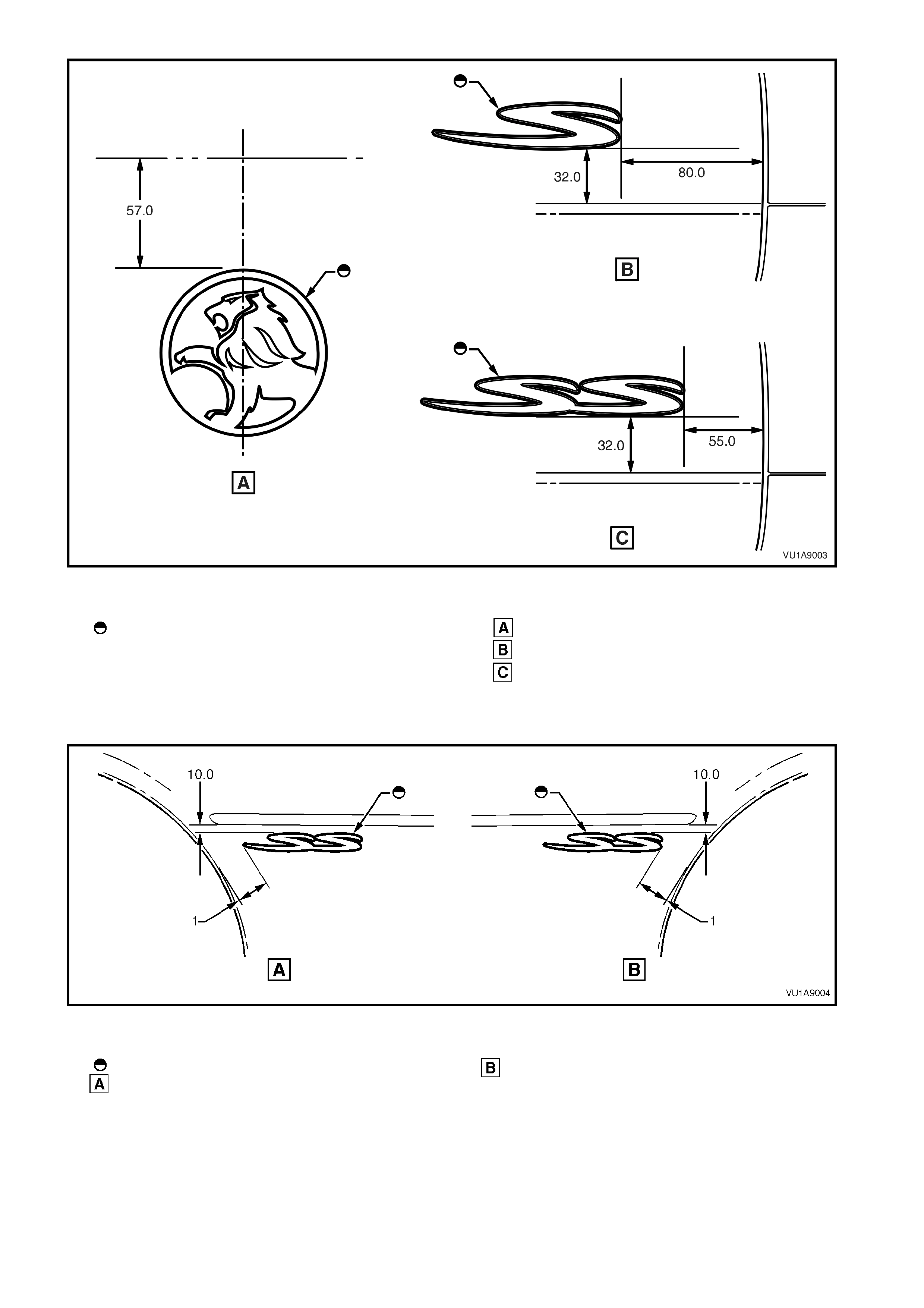
Figure 1A9-9
Legend
Before installation remove release paper.
All dimensions shown are measured on surface of
endgate outer panel.
Centre of endgate
RH side endgate S models
RH side endgate SS models
Figure 1A9-10
Legend
Before installation remove release paper.
LH side outer panel SS models RH side outer panel SS models
1. 55 mm dimension line to tangent line

3. TORQUE WRENCH SPECIFICATIONS
Nm
Rocker Panel Skirt Retaining Screw..................................... 1 - 3
B Pillar Moulding Attaching Screw........................................ 1 - 3
Door Frame Opening Moulding Attaching Screw.................. 0.3 – 1.0