
SECTION 12B - LIGHTING SYSTEM
IMPORTANT:
Before performing any Service Operation or other procedure described in this Section, refer to Section
00 CAUTIONS AND NOTES for correct workshop practices with regard to safety and/or property damage.
1. GENERAL I NFORMATI O N
The f r ont lamp ass emblies as f itted to VU Ser ies Models c arr y over from VX Ser ies Models . F or information relating
to the front lamp assemblies, refer to Section 12B LIGHTING SYSTEM in the VX Series Service Information.
The side, and interior lamp assemblies as fitted to VU Series Models carry over from VT Series Models. For
information relating to side or interior lamps as fitted to VU Series Models, refer to Section 12B LIGHTING
SYSTEM in the VT Series Service Information.
The rear lam p as sem blies as fitted to VU Ser ies Models carr y over f rom VT Series Wagon Models. T hey com prise
a turn signal lamp, stop and tail lamp and back-up lamp in one unit. For information regarding the rear lamp
assemblies not covered in this Section, refer to Section 12B LIGHTING SYSTEM in the VT Series Service
Information.
The high level s top lamp on VU Series SS Models is an LED type lam p assem bly. The high level stop lamp is only
serviced as an assembly and is mounted into the roof centre rear capping.
The licence plate lamps are unique to the VU Series Models.
Techline
Techline
2. SERVICE OPERATIONS
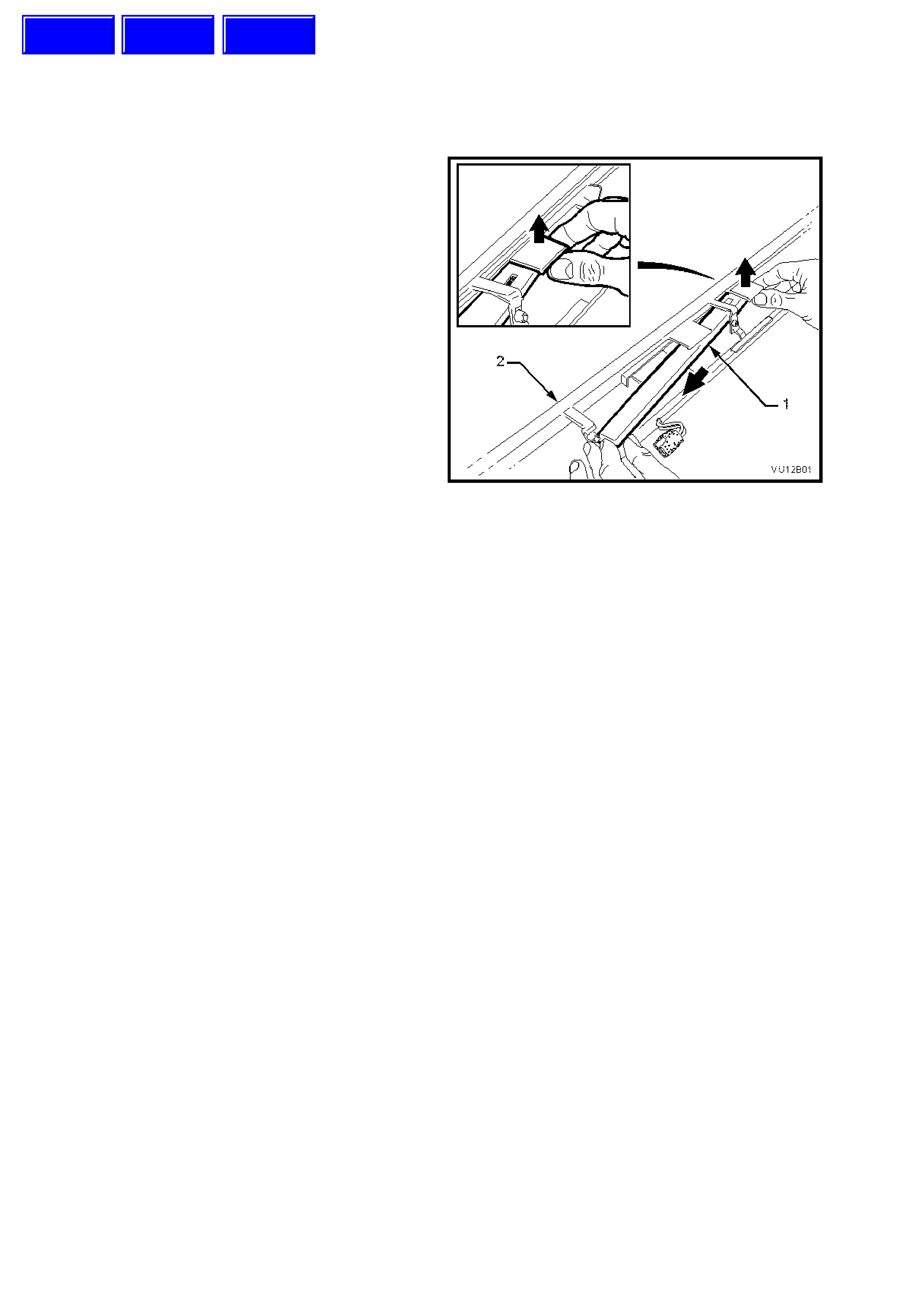
2.1 HIGH LEVEL STOP LAMP
REMOVE
1. Remove roof centre rear capping, refer to
Section 1A4 LOAD COMPARTMENT AND
ENDGATE.
2. Carefully disengage the retaining tangs from
the high level stop lamp (1) and moneuvre
lamp free of roof capping (2), refer to Fig.
12B-1.
Figure 12B-1
REINSTALL
Reinstallation of the high level stop lamp is the
reverse of the removal procedure.
Techline
Techline
Techline
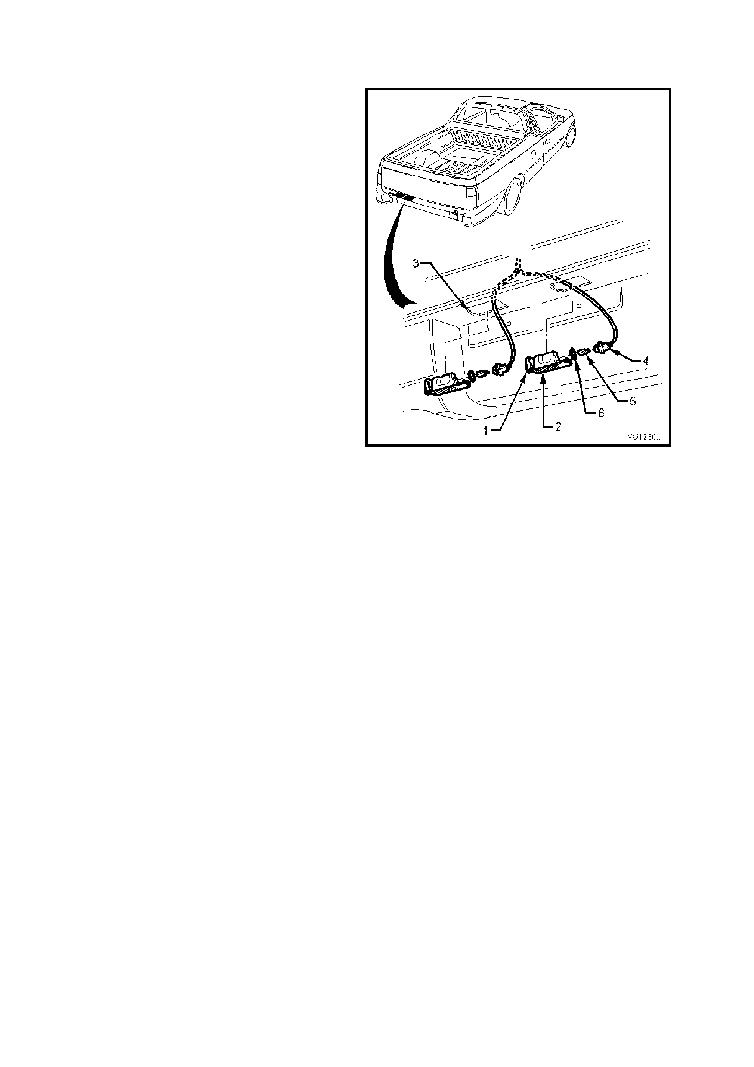
2.2 LICENCE PLATE LAMP/BULB
REMOVE
1. Press lens assembly retainer (1) towards the
lens assembly (2).
2. Pull the retainer end of the lens assembly
downwards until c lear of the hole (3) in the rear
sheetmetal.
3. Press the bulb socket (4) towards the lens
assembly and rotate counter clockwise until
bulb socket releases from lens assembly.
4. Remove and store 'O' ring (6) in a suitable
place
5. Pull bulb (5) from socket.
Figure 12B-2
REINSTALL
Reinstallation of the licence plate lamps is the
reverse of the removal procedure.
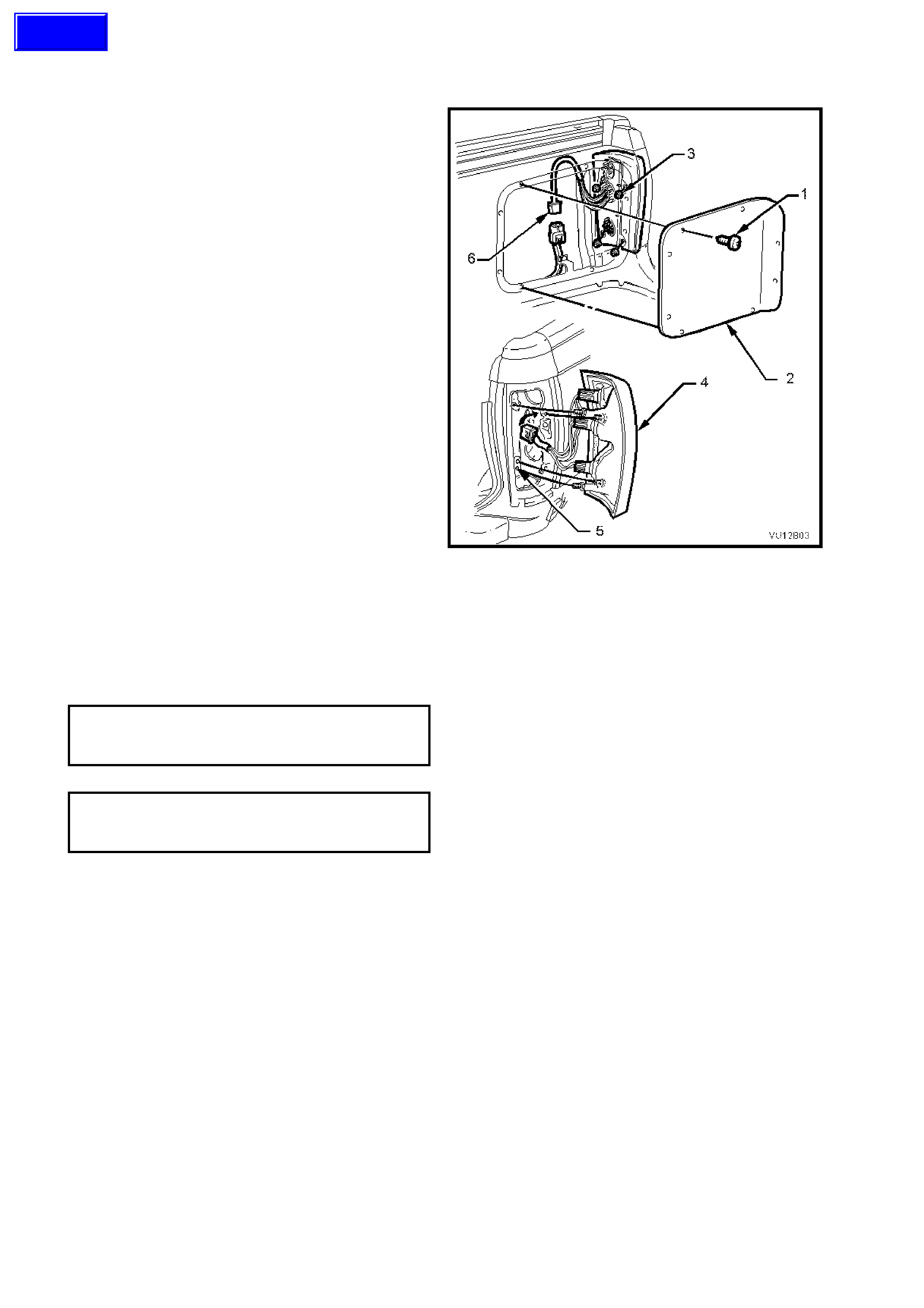
2.3 REAR LAMP ASSEMBLY
REMOVE
1. Remove the eight screws (1) securing the load
compartment side panel inner rear cover (2)
and remove cover.
2. Remove four nuts (3) retaining lamp assembly
(4) to rear panel (5).
3. Dis connect harnes s connector ( 6) and carefully
remove lamp assembly.
Figure 12B-3
REINSTALL
Reinstallation of the rear lamp assembly is the
reverse of the removal procedure, ensuring the
sealant on the load compartment side panel inner
rear cover (Holden specification HN1005) is
replaced.
LOAD COMPARTMENT SIDE
PANEL INNER REAR COVER
RETAINING SCREWS
1 – 3 Nm
REAR QUARTER LAMP HOUSING
TO BODY ATTACHING NUT
TORQUE SPECIFICATION
3 – 4 Nm
Techline
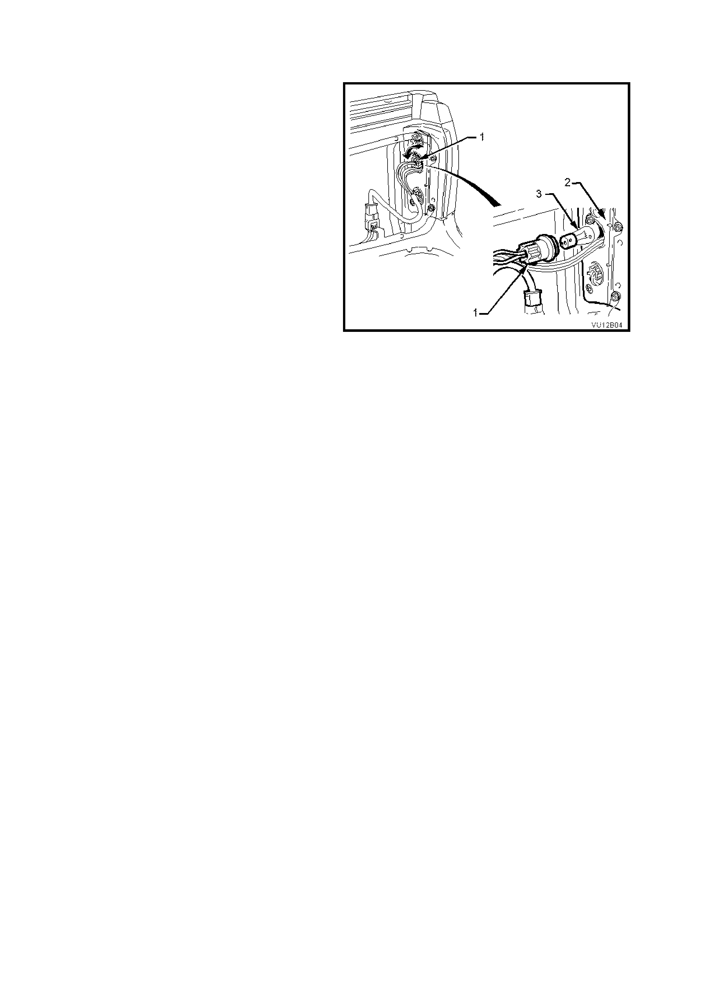
2.4 REAR LAMP BULBS
REMOVE
1. Remove the eight screws securing the load
compartment side panel inner rear cover and
remove cover, refer to Fig. 12B-3.
2. Remove appropriate bulb socket (1) by turning
and removing socket from lamp housing (2),
refer to Fig. 12B-4.
3. Remove bulb (3) from socket by depressing
bulb into its socket and then rotate to remove.
Figure 12B-4
REINSTALL
1. Inspect bulb socket to lamp housing seals for
damage, replace if necessary.
2. Insert new bulb into socket and refit socket into
lamp housing, ensuring socket locks securely
into place.
NOTE: There are different socket types for stop/tail
lamps and turn signal lamps. These are colour
coded and will only install to correct mating apertures
in housing.
3. Check rear lamp operation.
4. Refit load compartment side panel inner rear
cover ensuring the sealant (Holden specification
HN1005) is replaced.

3. SPECIFICATIONS
BULB POWER RATING - WATTS BASE TYPE
HIGH LEVEL STOP LAMP 45 L.E.D
LICENCE PLATE LAMP 5 Wedge

4. TORQUE WRENCH SPECIFICATIONS
Nm
Rear Lamp Housing Retaining Nuts ..................................... 3 – 4
Load Compartment Side Panel Inner Rear Cover Screws... 1 – 3