
SECTION 12N - FUSES, RELAYS AND WIRING
HARNESSES
IMPORTANT:
Before performing any Service Operation or other procedure described in this Section, refer to Section
00 CAUTIONS AND NOTES for correct workshop practices with regard to safety and/or property damage.
1. GENERAL I NFORMATI O N
1.1 FUSES AND CIRCUIT BREAKERS
All fuses and circuit breakers for VU Series Models carry over from that described in Section 12N, FUSES,
RELAYS AND WIRING HARNESSES in the VX Series Service Information.
For all fuse and circuit breaker circuit protection details, refer to circuit diagrams in Section 12P, WIRING
DIAGRAMS.


1.3 WIRING HARNESSES
All wiring harnesses for ward of the ‘A’ pillar in VU Ser ies Models c arry over from VX Series Models. For inform ation
relating to wiring harnesses fitted to VU Series Models not provided in this Section, refer to
Section 12N, FUSES, RELAYS AND WIRING HARNESSES in the VX Series Service Information. For wiring
diagrams relating to the VU Series Models, refer Section 12P WIRING DIAGRAMS.

2. SERVICE OPERATIONS
All the s ervice oper ations ass ociated with fuses, r elays and wiring harnes ses for VU Series Models car ry over from
VT Series I and VT Series II Models. For service operations relating to f uses relays and wiring harnesses, refer to
Section 12N FUSES, RELAYS AND WIRING HARNESSES in the VT Series I and VT Series II Service
Information.

3. WIRING INSTALLATION DIAGRAMS
The following figures in this Section illustrate the new vehicle wiring installation diagrams specific for VU Series
Models. All remaining wiring installation diagrams are carry over from VX Series Models, refer to
Section 12N, FUSES, RELAYS AND WIRING HARNESSES in the VX Series Service Information in conjunction
with Section 12N FUSES, RELAYS AND WIRING HARNESSES in the VT Series I and VT Series II Service
Information.
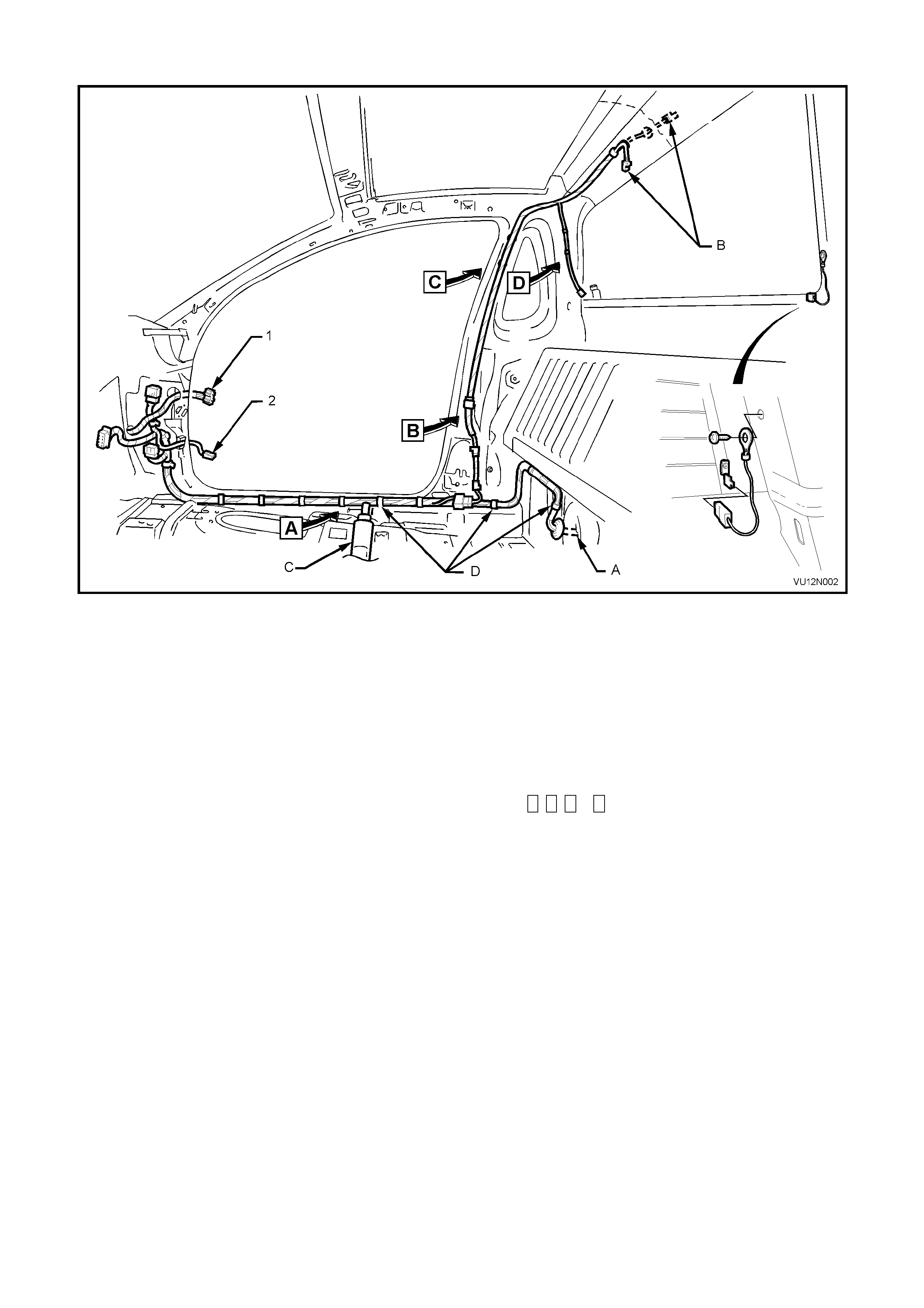
DOME LAMP & INTERIOR BODY WIRING HARNESS - 1
Figure 12N-1
Legend
1. Door harness connector A. For harness continuation, refer to BODY WIRING
2. Door jam switch connector HARNESS - FUEL TANK in this Section.
B. For harness continuation, refer to DOME LAMP
INTERIOR WIRING HARNESS in this Section.
C. For harness continuation, refer to INTERIOR BODY
WIRING HARNESS in this Section.
D. Harness clipped to underbody (10 places).
For View A , B , C & D , refer to DOME LAMP WIRING
HARNESS in this Section.
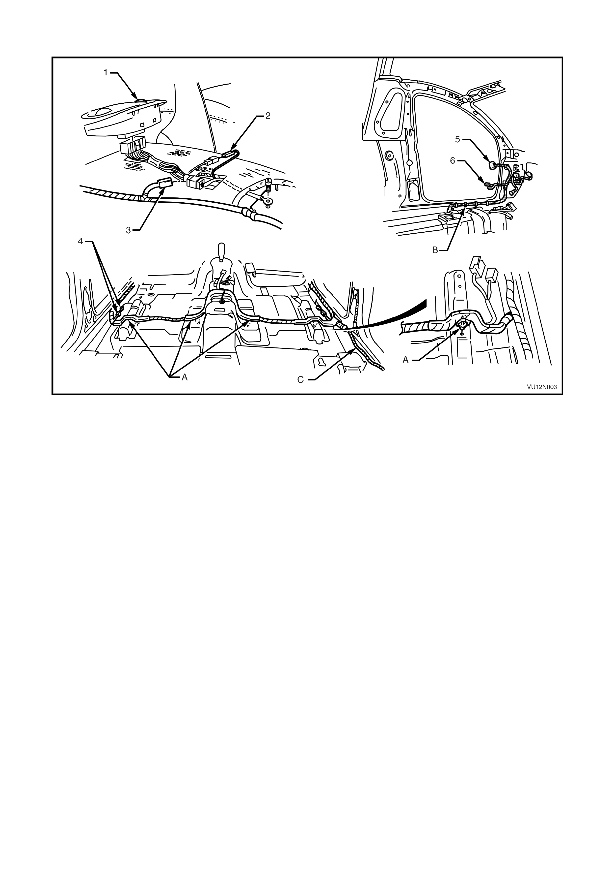
INTERIOR BODY WIRING HARNESS - 2
Figure 12N-2
Legend
1. Power window switch A. Harness clipped to underbody (4 places).
2. Hand brake connector B. Harness clipped to underbody (5 places).
3. Seat belt pre-tensioner connector C. For harness continuation, refer to DOME LAMP &
4. Door harness connector INTERIOR BODY WIRING HARNESS in this Section.
5. Door jam switch connector
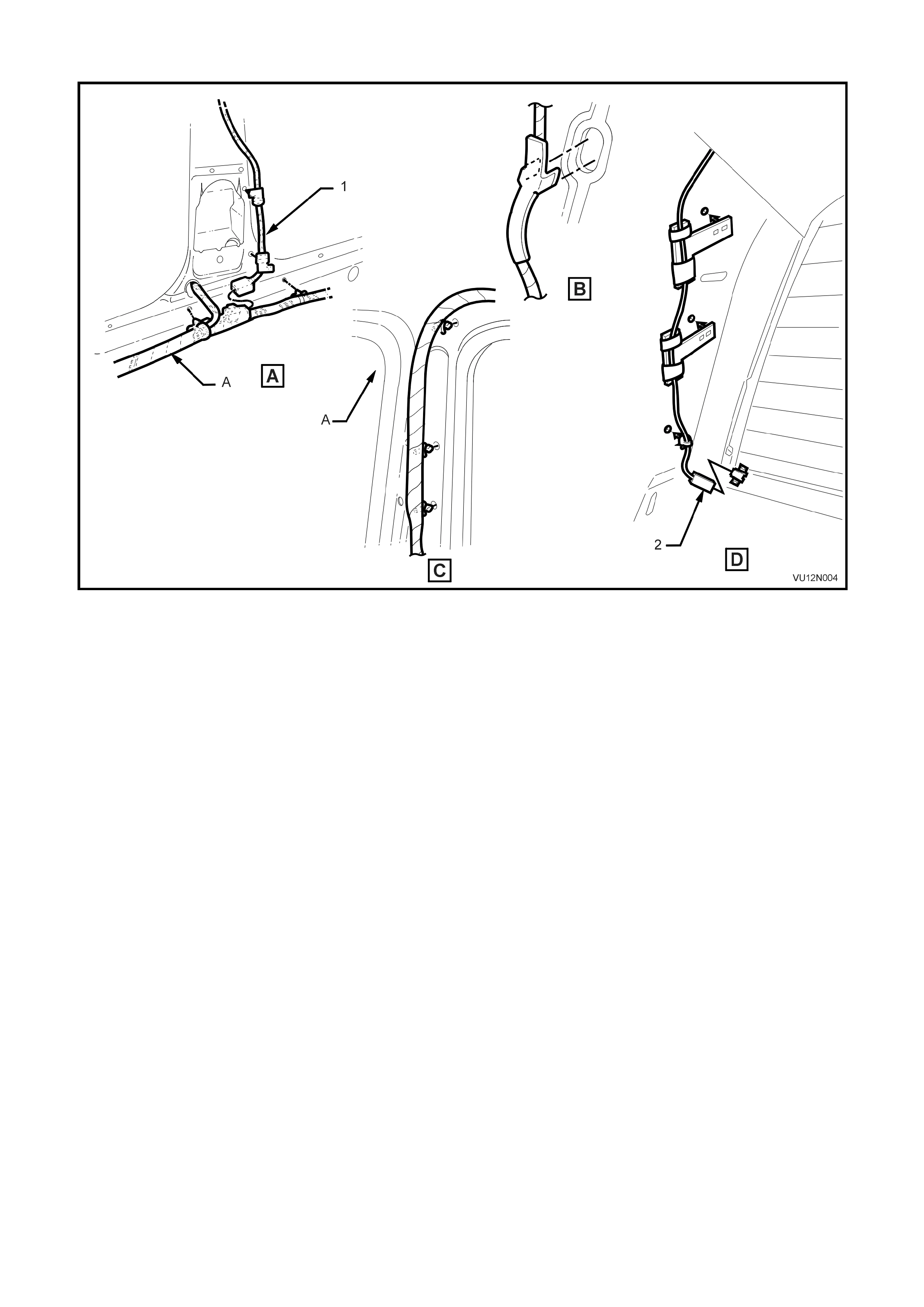
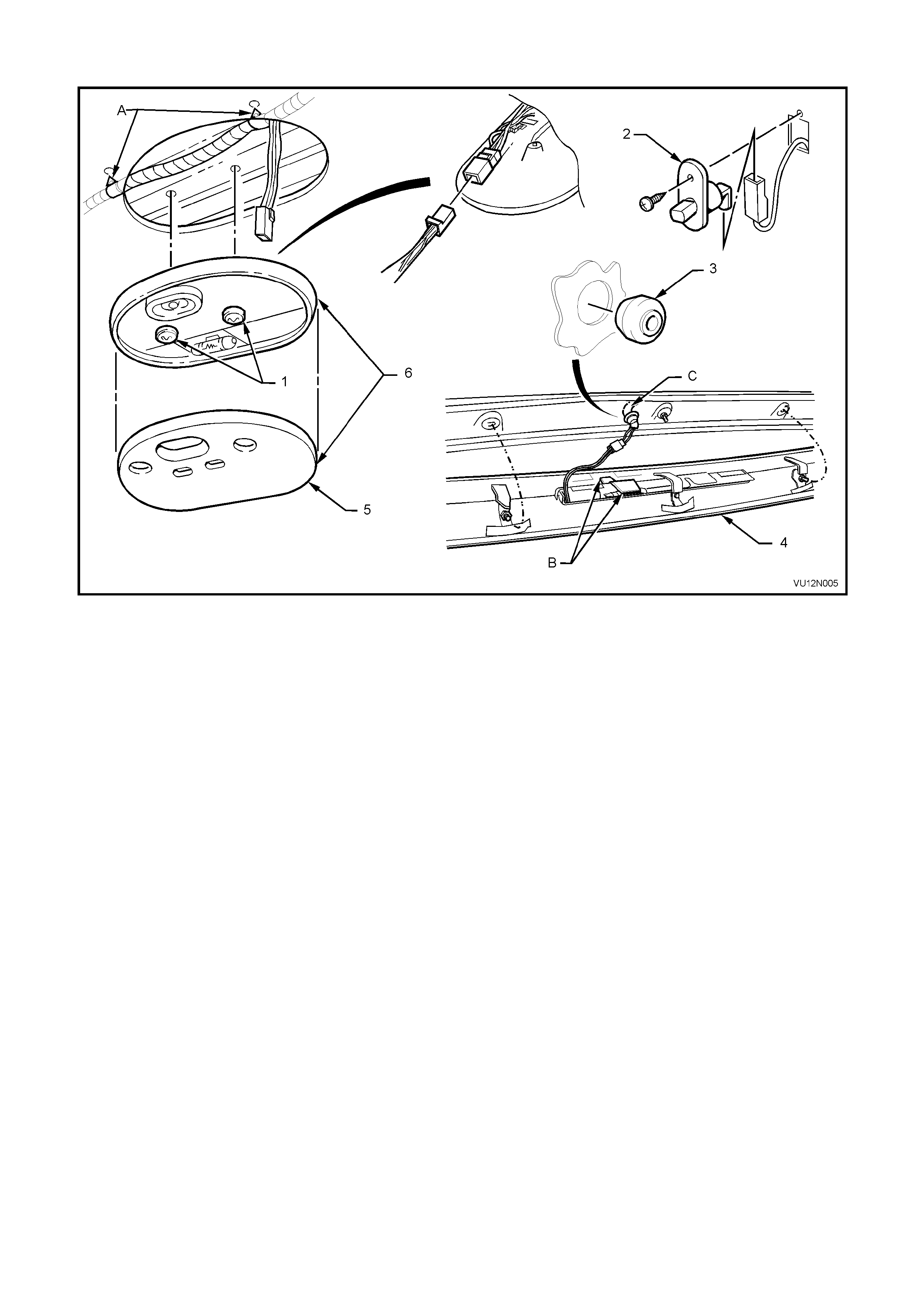
DOME LAMP WIRING HARNESS - 3
Figure 12N-4
Legend
1. Dome lamp screws A. Harness clipped to rear roof header reinforcement
2. Door jamb switch (2 places).
3. Harness blanking plug (exc. 'SS')Door jamb switch B. High level stop lamp harness stowed into roof centre
4. Roof rear centre capping capping rib.
5. Dome lamp lens C. For dome lamp harness continuation, refer DOME LAMP
6. Dome lamp assembly & INTERIOR BODY WIRING HARNESS in this
Section.
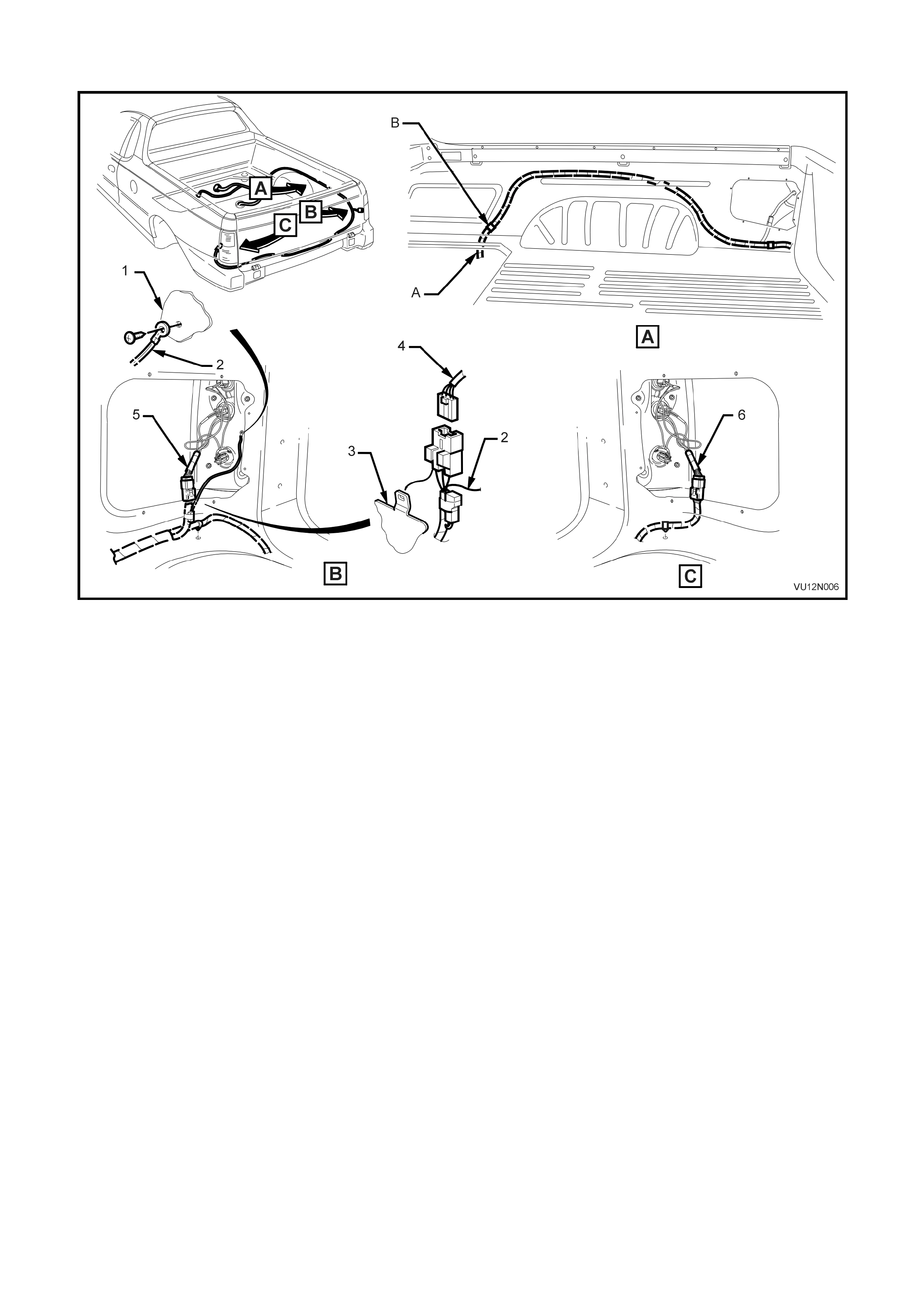
BODY WIRING HARNESS - LOAD COMPARTMENT
Figure 12N-5
Legend
1. Side panel inner extension A. For harness continuation, refer BODY WIRING
2. Body earth lead HARNESS – FUEL TANK in this Section.
3. Side inner upper panel B. Harness clipped to side inner upper panel (1 place).
4. Rear lamp harness connector
5. RH rear lamp harness
6. LH rear lamp harness
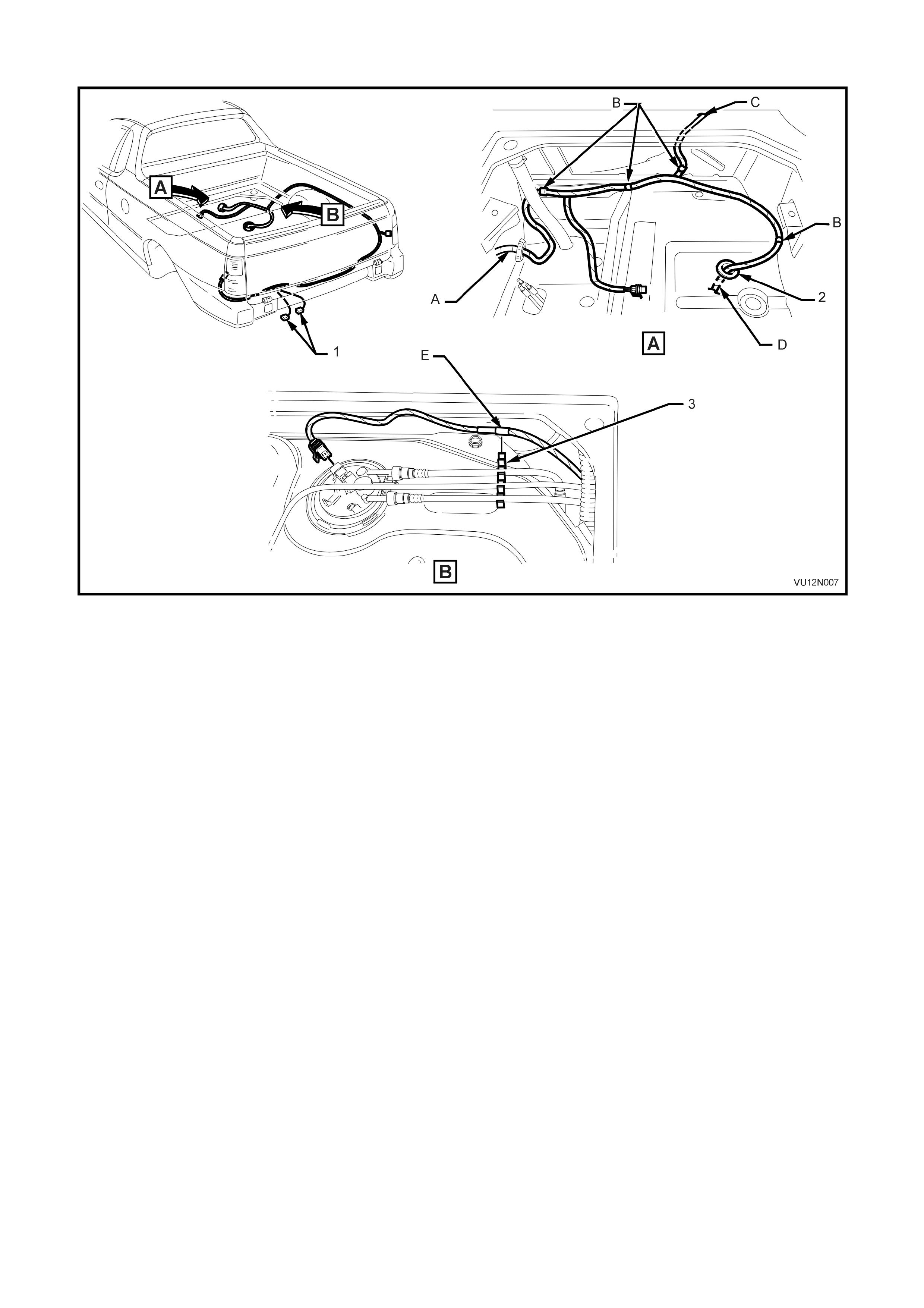
BODY WIRING HARNESS - FUEL TANK
Figure 12N-6
Legend
1. Licence plate lamp connectors A. For harness continuation, refer DOME LAMP &
Floor grommet INTERIOR BODY WIRING HARNESS in this Section.
2. Fuel tank harness clip B. Harness clipped to sheetmatel (3 places).
C. For harness continuation, refer BODY WIRING –
HARNESS LOAD COMPARTMENT in this Section.
D. For continuation, refer BODY WIRING HARNESS –
ABS in this Section.
E. Harness clipped to fuel tank.
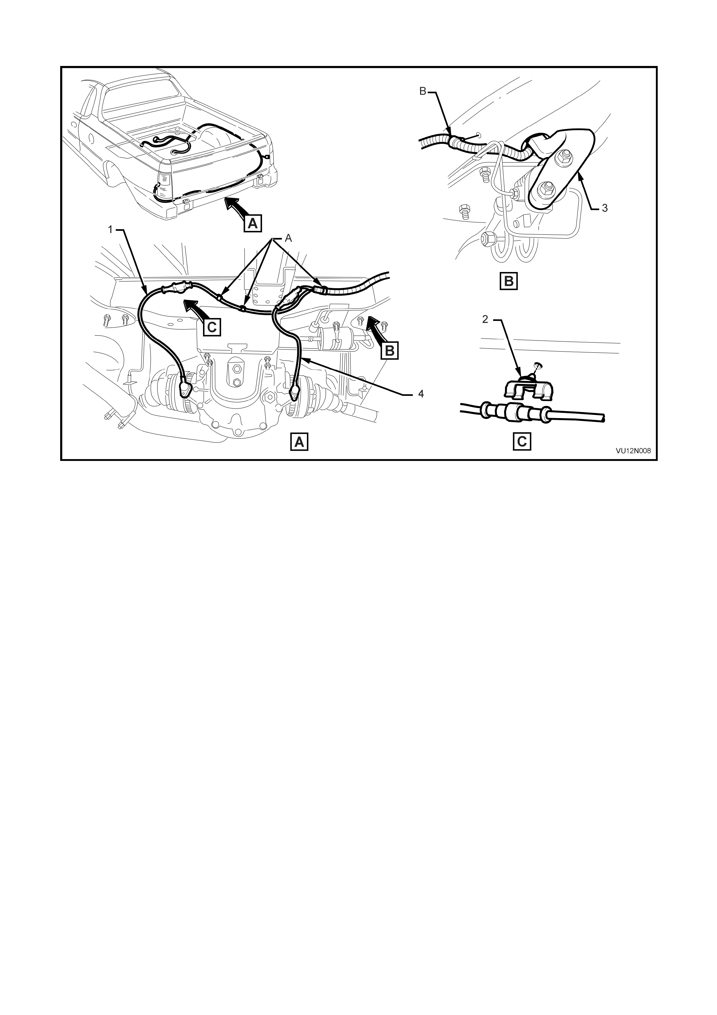
BODY WIRING HARNESS - ABS
Figure 12N-7
Legend
1. RH rear ABS speed sensor A. Harness clipped to rear crossmember (3 places).
2. Speed sensor connector clip (2 places) B. Harness clipped to underbody (1 place).
3. Load sensing proportioning valve
4. LH rear ABS speed sensor
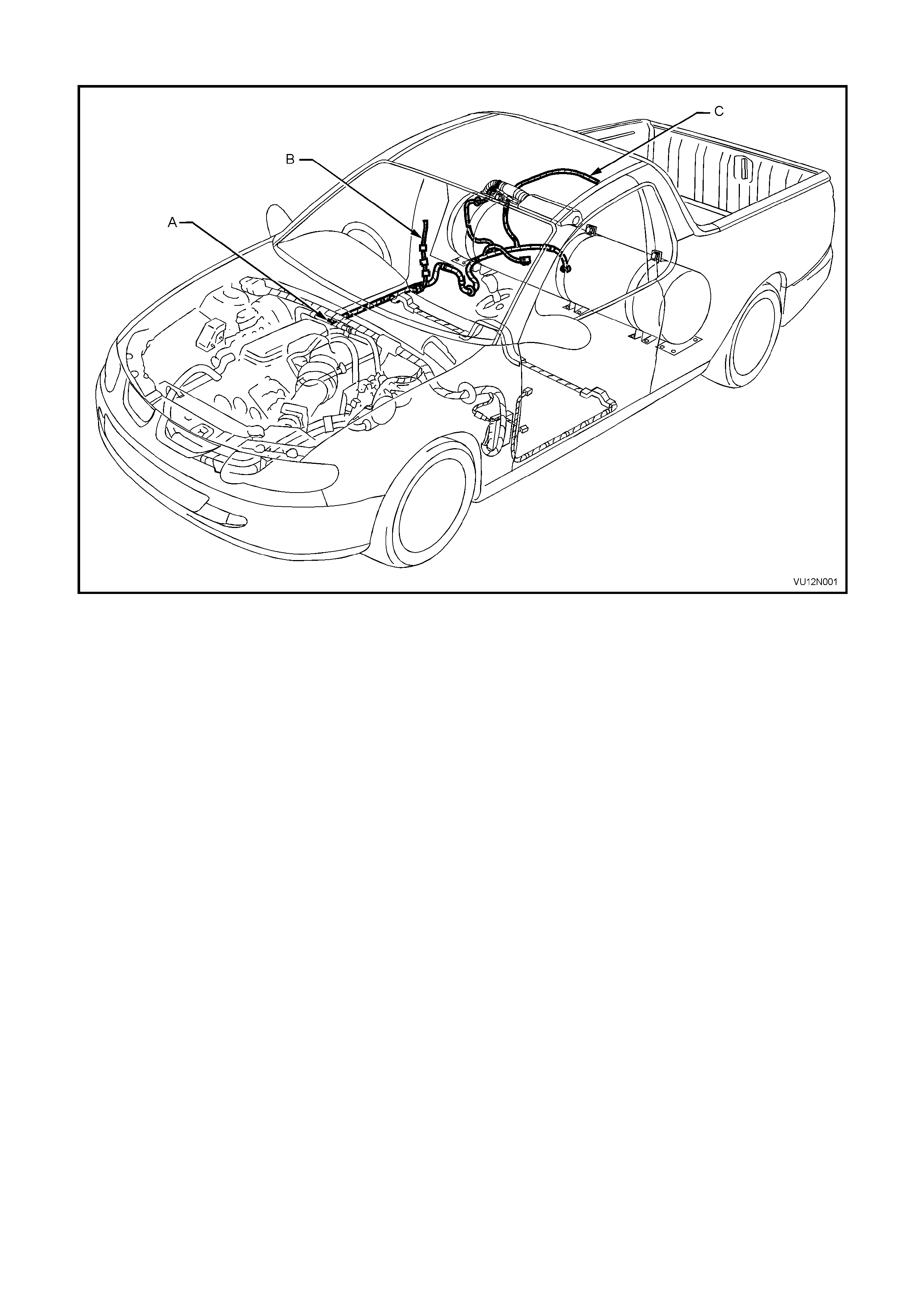
BODY WIRING HARNESS - LPG - 1
Figure 12N-8
Legend
A. For harness continuation and clipping, refer DOME LAMP & INTERIOR BODY WIRING HARNESS in this Section.
B. For dome lamp harness continuation, refer DOME LAMP & INTERIOR BODY WIRING HARNESS in this Section.
C. For rear lamp harness continuation, refer BODY WIRING HARNESS – LOAD COMPARTMENT in this Section.
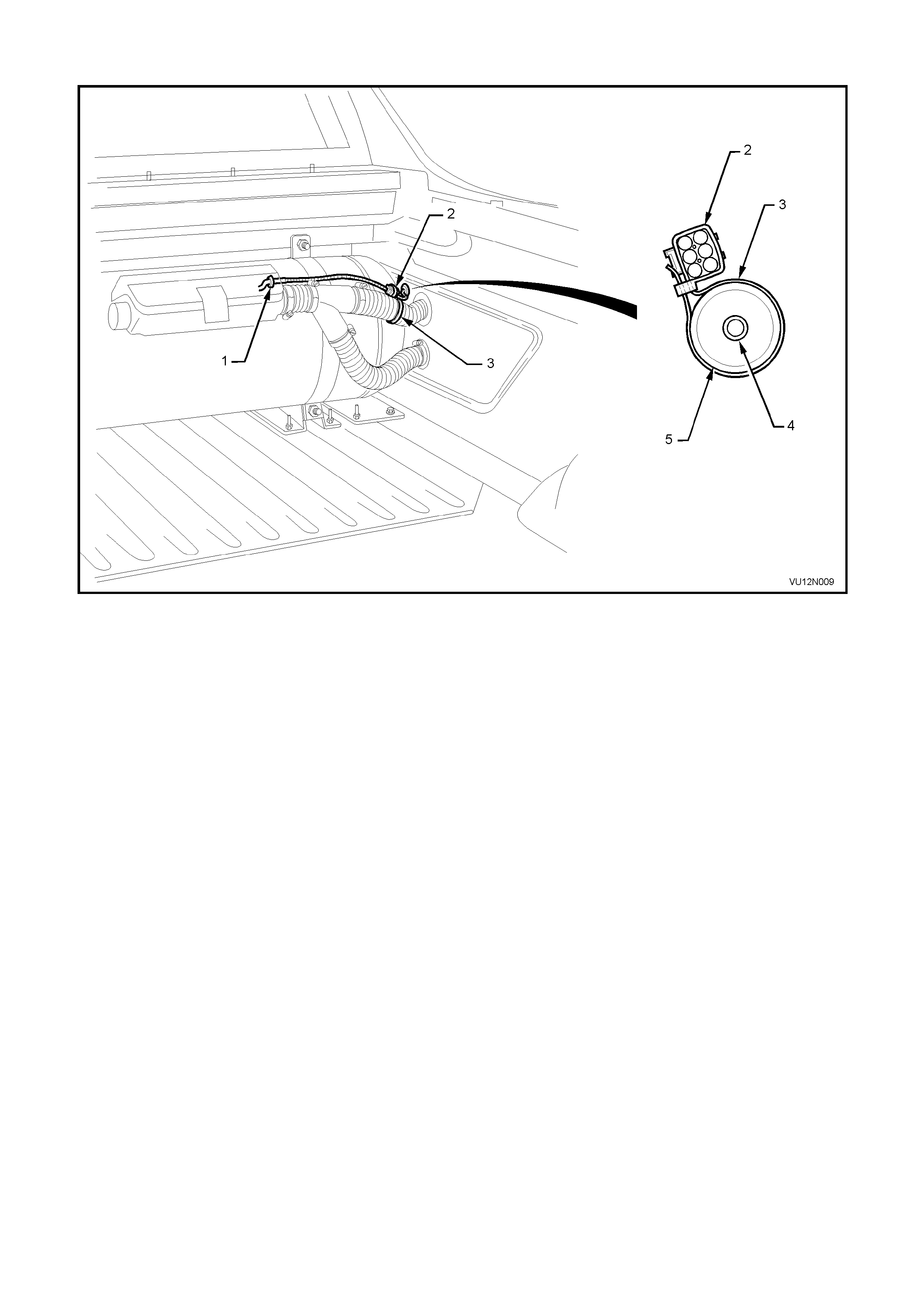
BODY WIRING HARNESS - LPG - 2
Figure 12N-9
Legend
1. LPG control valve harness 4. LPG supply hose
2. LPG control valve harness connector 5. LPG filler vent tube
3. LPG control valve harness retaining strap