
SECTION 8A1 - FUEL TANK
IMPORTANT:
Before performing any Service Operation or other procedure described in this Section, refer to Section
00 CAUTIONS AND NOTES for correct workshop practices with regard to safety and/or property
damage.
1. GENERAL INFORMAT ION
The VU Ser ies Mod els f uel s ystem m aintains c omm on link s with VT Seri es II Mod els wit h chan ges to suit t he utilit y
fuel tank assembly positioning beneath the load compartment tonneau floor.
The m odular f uel s en der assembly incor pora t es a fuel s ender u nit as sembl y, pick up s tr ain er an d tur b ine f ue l pump.
The assembly is retained in the fuel tank by a circlip.
The information in this Section should be read in conjunction with Section 8A FU EL TANK of the VT Series I and
VT Series II Servic e Infor m atio n.
Techline

2. SERVICE OPERATIONS
2.1 FUEL TANK
REMOVE
CAUTION: Ensure that there are no naked flames or other sources of ignition in the vicinity.
1. Depressurise the fuel system. For V6 engines refer to Section 6C1-3 POWERTRAIN MANAGEMENT - V6
ENGINE in the VX Series Service Information.
For GEN III V8 engines refer to either Section 6A3 ENGINE MECHANICAL - GEN III V8 ENGINE or
Section 6C3-3 PO WERTRAIN MANAGEMENT - GEN III V8 ENGINE in the VX Series Service Information.
2. Disconnect the negative cable from the battery terminal.
3. Remove th e front tonneau floor, refer to Section 1 A4 LOAD COMPARTMENT AND ENDG ATE. If necessary
remove the LPG cylinder, refer to Section 8A2 LPG SYSTEM.
4. Remove the screws (2) securing the load compartment side panel inner front cover (1), refer to Fig. 8A1-1. If
necessary remove the LPG filler and service lines, refer to Section 8A2 LPG SYSTEM.
6. Disconnect modular fuel sender harness connector (3).
7. Tag the fuel feed (7) and return (8) line connections located on top of the fuel tank.
NOTE: For ident if ic atio n pu r pos es, the f u e l return hose is tagg ed with a wh ite ban d near the con nec tor at the top of
the fuel tank.
8. Tag the vent pipe (9) on top of the fuel tank and disconnect by pulling hose from fuel tank vent fitting.
9. Disengage the fuel return line (8) and fuel feed line (7) quick connect fittings using special tool No. AU533.
10. Remove th e modular fuel sender assembly (refer 2.2 MODULAR FUEL SENDER ASSEMBLY) and drain the
entire co ntents of the f uel tank by pum ping or syphoni ng the fuel through t he sender ass embly hole in the f uel
tank.
NOTE: Due to a permanent restriction (flood gate) in the lower fuel filler neck, the fuel tank can not be drained
through the filler aperture.
11. Remove the four bolts (4), steel washers (5) and rubber isolators (10), then remove the tank by manipulating
the filler neck free of the filler neck grommet then past the inner quarter panel.
CAUTION: Fuel va pour rem ains in the tank even when com pletely em pty, seal the open ings in the f uel tank using
a suitable plastic plug and avoid all sources of ignition.
Techline
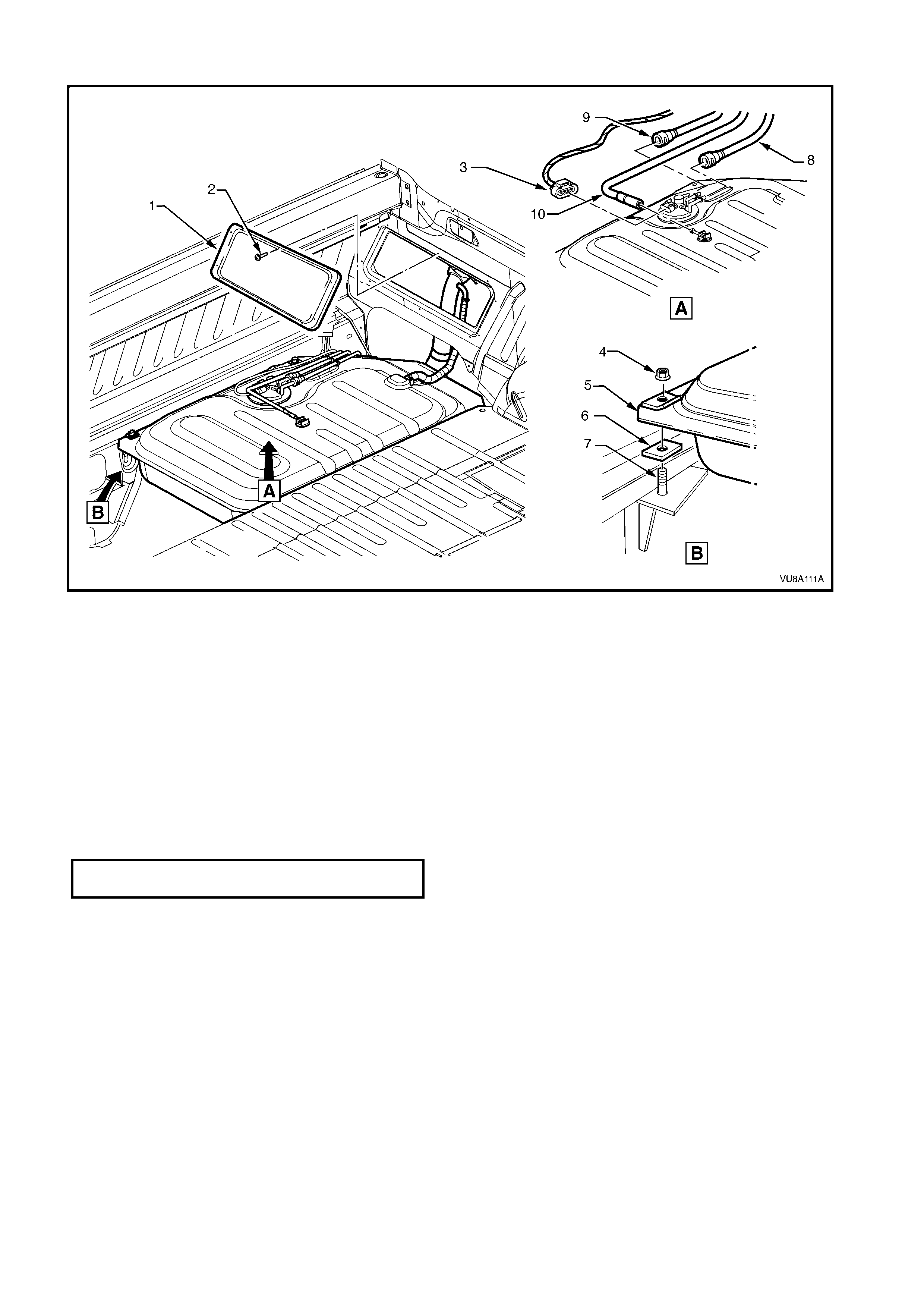
Figure 8A1-1
Legend
1. Side panel inner front cover
2. Side panel screw (10 places)
3. Fuel sender harness
connector
4. Fuel tank retaining nut
5. Fuel tank
6. Fuel tank isolator rubber
7. Fuel tank mounting stud
8. Fuel return line
9. Fuel feed line
10. Fuel tank vent hose
REINSTA LL
The reinstallation procedure for the fuel tank is the reverse of the removal procedure, noting the following:
a. Apply a bead of sealant (Holden's Specification HN1005) around the perimeter of the access covers and
tonneau floor before installation.
b. The connections for the fuel tank vent pipe is shown in view A Fig. 8A1-1.
FUEL TANK MOUNTING BOLT 25-30
TORQUE SPECIFICATION Nm
2.2 MODULAR FUEL SENDER ASSEMBLY
REMOVE
CAUTION: Ensure that there are no naked flames
or other sources of ignition in the vicinity.
1. Disconnect the negative cable from the battery
terminal.
2. Remove the front tonneau floor, refer to
Section 1A4 - LOAD COMPARTMENT AND
ENDGATE.
3. Disconnect the modular fuel sender assembly
harness connector, refer to Fig. 8A1-1.
4. Tag the fuel feed and return hoses from the
connections located on top of the fuel tank,
refer to Fig. 8A1-1.
5. Tag the vent pipe on top of the fuel tank and
disconnect by pulling hose from fuel tank vent
fitting, refer to Fig. 8A1-1.
6. Disengage th e f uel return li ne a nd fuel f eed li ne
quick connect fittings using special tool No.
AU533.
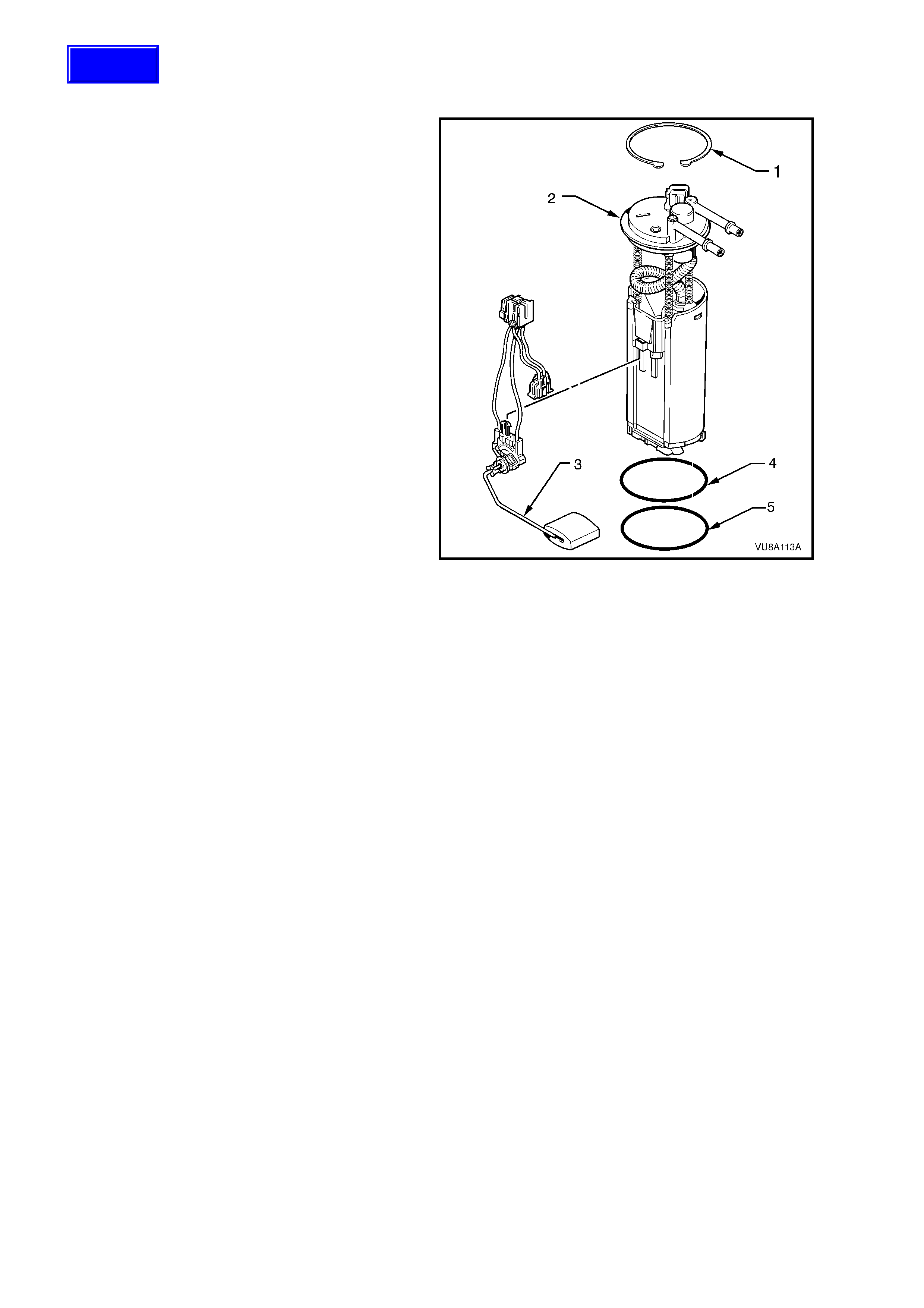
7. Remove the circlip (1) retaining the modular
fuel sender assembly (2) using circlip pliers.
8. Carefully lift the modular fuel sender assembly
from the fuel tank taking care not to damage
the fuel sender float arm (3). Take care not to
spill any fuel remaining in the reservoir.
NOTE: The fuel sender float arm for VU Series
Models is not serviced separately.
IMPORTANT: Pour any fuel remaining in the
reservoir into a suitable contai ne r.
9. Remove and discard sender assembly to fuel
tank O-ring (5).
NOTE:The modular fuel sender assembly as fitted
to VU Series Models with the Gen III V8 engine
contains a plastic spacer ring (4) between the O-
ring (5) and the top mounting face.
10. Cover all fuel tank openings to prevent foreign
matter entry.
Figure 8A1-2
REINSTA LL
The reinstallation procedure for the modular fuel
sender assembly is the reverse of the removal
procedures noting the following:
1. Install new O-ring (5) on fuel sender assembly,
refer to Fig. 8A1-2.
2. For VU Series Models with the GEN III V8,
ensure that the plastic spacer (4) is correctly
seated between the O-ring (5) and the top
mounting face of the modular fuel pump
sender assembly.
3. Install the modular fuel sender assembly into
the fuel tank.
4. Install the modular fuel sender assembly
retaining circlip (1).
5. Apply a bead of sealant (Holden's Specification
HN1005) around the perimeter of the access
covers and tonneau floor before installation.
Techline

3. TORQUE WRENCH SPECIFIC ATIONS
Nm
Fuel Tank Mounting Bolt................... ...................................... 25-30

4. SPECIFICATIONS
Fuel Tank Capacity:
All Models ................................................... 70 litres
Fuel Tank Material:
All Models ................................................... Steel
Fuel Filler Location:
All Models ................................................... RH rear quarter panel
Fuel Pump Type:
All Models ................................................... Single stage turbine with jet pump
Fuel Pump Location:
All Models ................................................... In tank
Fuel Pump Pressure:
V6 Models................................................... 350 kPa
GEN III V8 Models...................................... 400 kPa
Fuel Pump Flow Capacity:
V6 Models................................................... 1.6 litres @ 13.5 volts
GEN III V8 Models...................................... 2.5 litres @ 13.5 volts
Fuel Pump Current Draw:
V6 Models................................................... 6.7 amps maximum
GEN III V8 Models...................................... 9.6 amps maxim um
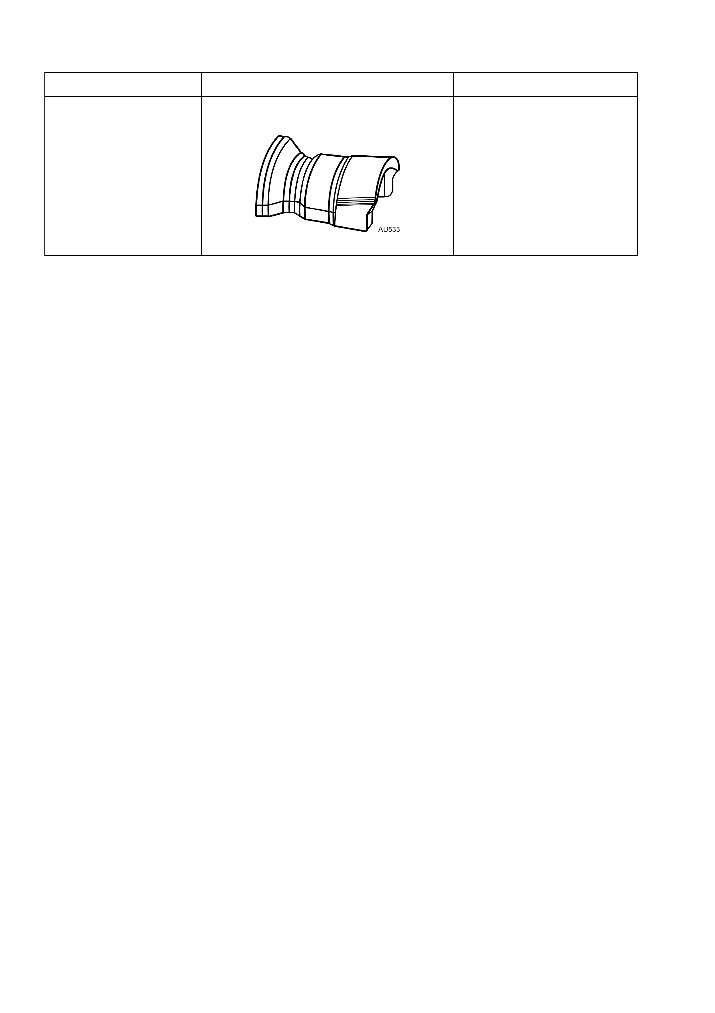
5. SPECIAL TOOLS
TOOL No. REF. IN TEXT TOOL DESCRIPTION COMMENTS
AU533 QUICK CONNECT FITTING RELEASE
TOOL
Released in two sizes;
Red for 5/16” fittings and
Blue for 3/8” fittings.
Also avai lab le com merc iall y
under P/N AUSP 45