
SECTION 0A - GENERAL INFORMATION
IMPORTANT:
Before p erf orming any Service O p eratio n o r ot her p roced ure describ ed in t his Sect ion , refer t o Sect ion
00 CAUTIONS AND NOTES for correct workshop practices with regard to safety and/or property
damage.
1.GENERAL I NFORMATION
The VU Series Utility is a new body design based on the VX Series Commodore featuring new headlamps,
sheet metal and tail lamps. The load compartment has been revised with replaceable rails on high wear areas
surrounding the load compartment and a new design tonneau cover. Independent rear suspension is standard
on all models.
A four speed, electronically controlled automatic transmission is optional equipment.
NOTE: VU Series Models must be operated only on unleaded fuel with a minimum research octane rating
of 91.
The following charts provide model availability, power train combinations, transmission ratios, engine data and
exterior dimensions for VU Series Models.
NOTE: When using a trolley jack to raise the vehicle it is important that the jack be positioned under the
suspens ion cross m em ber or hoist pad locations (1). Do not j ack under the s uspension c ontrol arm . T he vehicle
should always be supported by jack stands at the hoist pad locations when raised.
Figure 0A-1
Techline
Techline
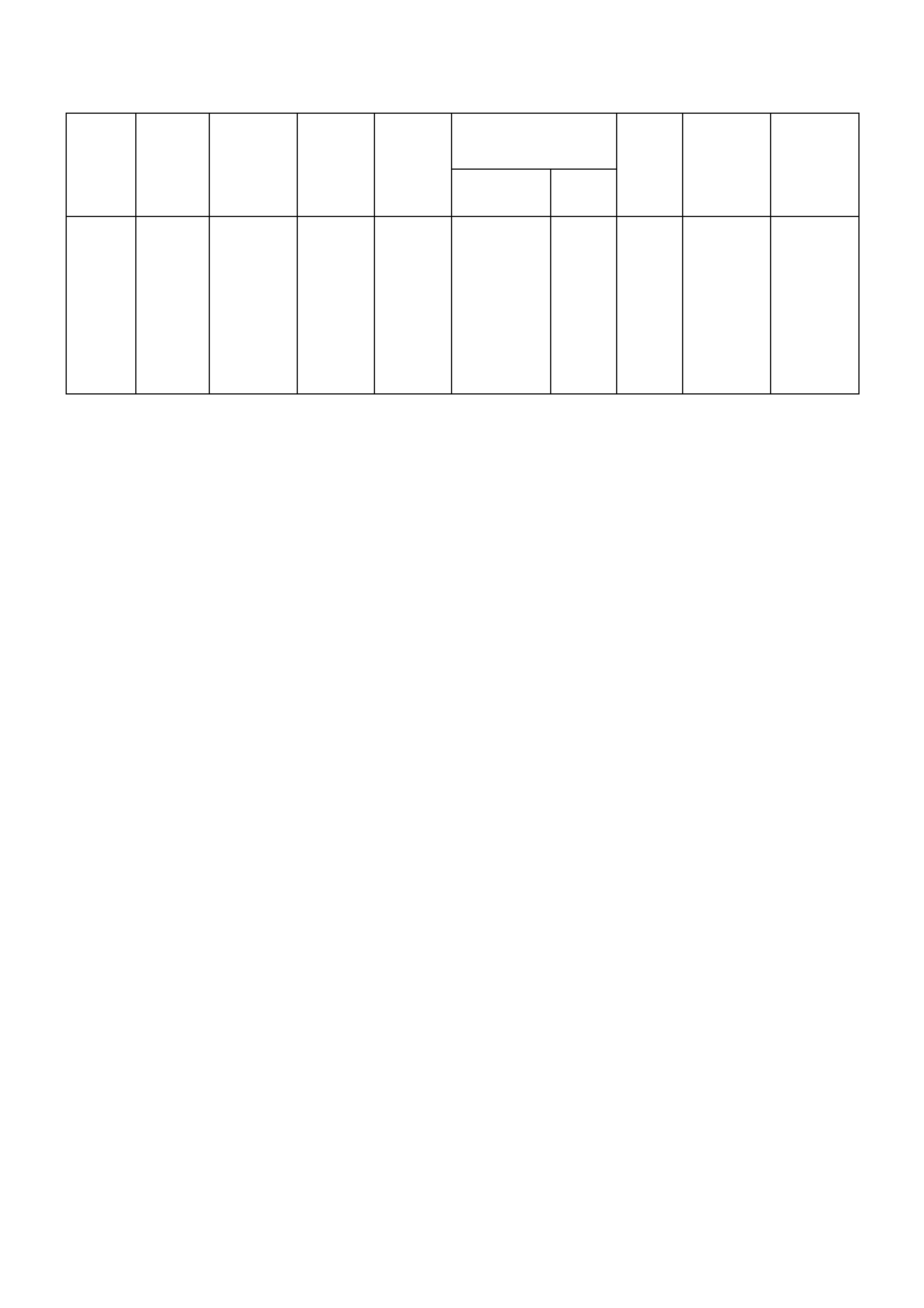
2. MODEL AVAILABILITY AND BASE EQUIPMENT
TRANSMISSION BODY
STYLE MODEL
NO. MODEL
NAME NO.OF
DOORS ENGINE
TYPE SHIFT
LOC.
FINAL
DRIVE
RATIO
TYRES WHEELS
Utility 8VK80
Utility
S
SS
2
3.8 PFI
3.8 PFI
5.7 PFI
5 Speed
Manual
5 Speed
Manual
6 Speed
Manual
Floor 3.46:1
205/65
R15 95H
225/55
R16 95V
235/45
R17 93V
7 x 15
Steel
7 x 16
Alloy
8 x 17
Alloy

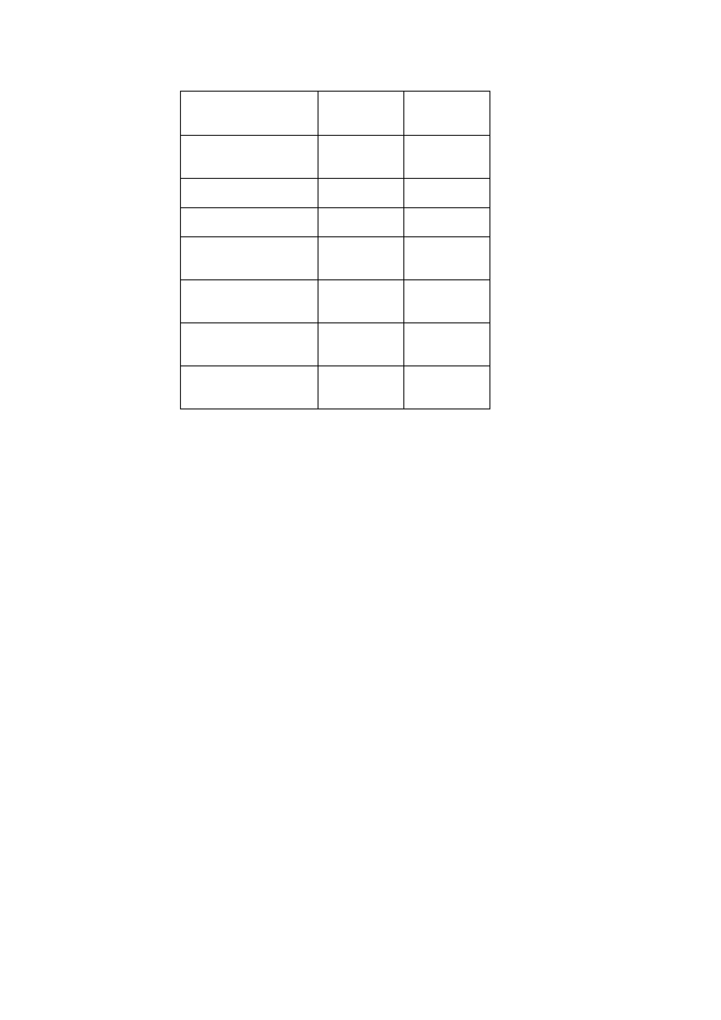
3. POWERTRAIN COMBINATIONS
ENGINE TRANSMISSION
TYPE MODEL
AVAILABILITY FIRST GEAR
RATIO FINAL DRIVE RA TIO
3.8 LITRE
PFI 5 Speed
Manual UTILITY, S 3.83:1 3.46:1
4 Speed
Automatic UTILITY, S 3.06:1 3.08:1
5.7 LITRE
PFI 6 Speed
Manual S, SS 2.66:1 3.46:1
4 Speed
Automatic S, SS 3.06:1 3.08:1

4. TRANSMISSION RATIOS
5 SPEED
MANUAL 6 SPEED
MANUAL 4 SPEED
AUTOMATIC
V6 GEN III V8 V6 & GEN III V8
1ST 3.829:1 2.66:1 3.06:1
2ND 2.199:1 1.78:1 1.63:1
3RD 1.401:1 1.30:1 1.00:1
4TH 1.00:1 1.00:1 0.70:1
5TH 0.809:1 0.74:1 -
6TH - 0.50:1 -
REV 3.456:1 2.90:1 2.29:1
5. ENGINE DATA
ENGINE
DESIGNA TION 3.8 LITRE
V6 5.7 LITRE
GEN III V8
Piston Displacement
Nom.cm3
3791
5667
Compression Ratio 9.4:1 10.1:1
Number of Cylinders 6 8
Bore x Stroke mm 96.5 X
86.3 99 X
92
Taxable H.P.
RAC OR SAE
34.7
48.6
Power kW
DIN @ RPM 152 kW
@ 5200 225 kW
5200
Torque Nm
DIN @ RPM 305Nm
@ 3600 460 Nm
@ 4400

6. EXTERIOR DIM ENSIONS
BODY DIMENSIONS
VEHICLE LENGTH 5049
VEHICLE WIDTH 1845
VEHICLE HEIGHT 1484
WHEELBASE 2939
OVERHANG - FRONT 933
OVERHANG - REAR 1178
TREAD - FRONT 1569
TREAD - REAR 1587
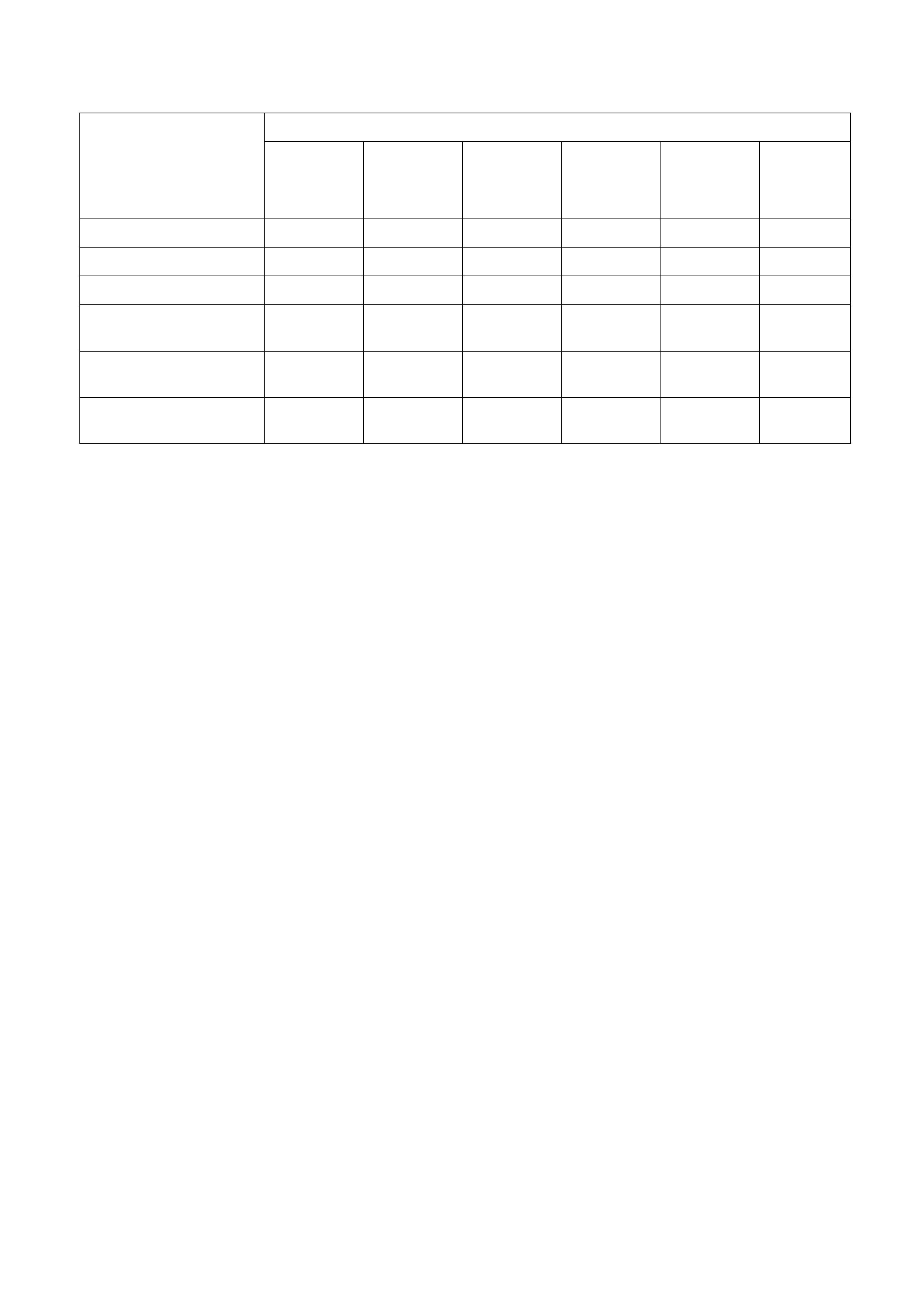
7. VEHICLE WEIGHTS
VU SERIES MODELS
VEHICLE
WEIGHTS
UTILITY
(MANUAL)
UTILITY
(AUTO)
'S'
(MANUAL)
'S'
(AUTO)
'SS'
(MANUAL)
'SS'
(AUTO)
Kerb Mass V6 1494 1519 1524 1549 N/A N/A
Kerb Mass GEN III V8 1557 1567 1587 1597 1610 1620
Rear Axle Load V6 1350 1350 1260 1260 N/A N/A
Rear Axle Load
GEN III V8 1350 1350 1260 1260 1260 1260
Payload V6
(2 Pass. + Cargo) 780 830 735 710 N/A N/A
Payload GEN III V8
(2 Pass. + Cargo) 790 780 670 660 665 655
NOTE: All figures are estimates only.
Payload figures must include luggage, goods,
passengers and a full tank of fuel. If you are towing,
then the weight on the tow bar ball must also be
included.
Maximum Rear Axle Load is maximum for all
conditions.
8. SERIAL NUMBERS
The complete vehicle and various components of the vehicle are identified by number plates or numbers
stam ped into the par t. It is ess ential that when compiling warranty claims or product and field reports, the vehicle
identification number (VIN) is quoted in conjunction with the identification number of the component affected.
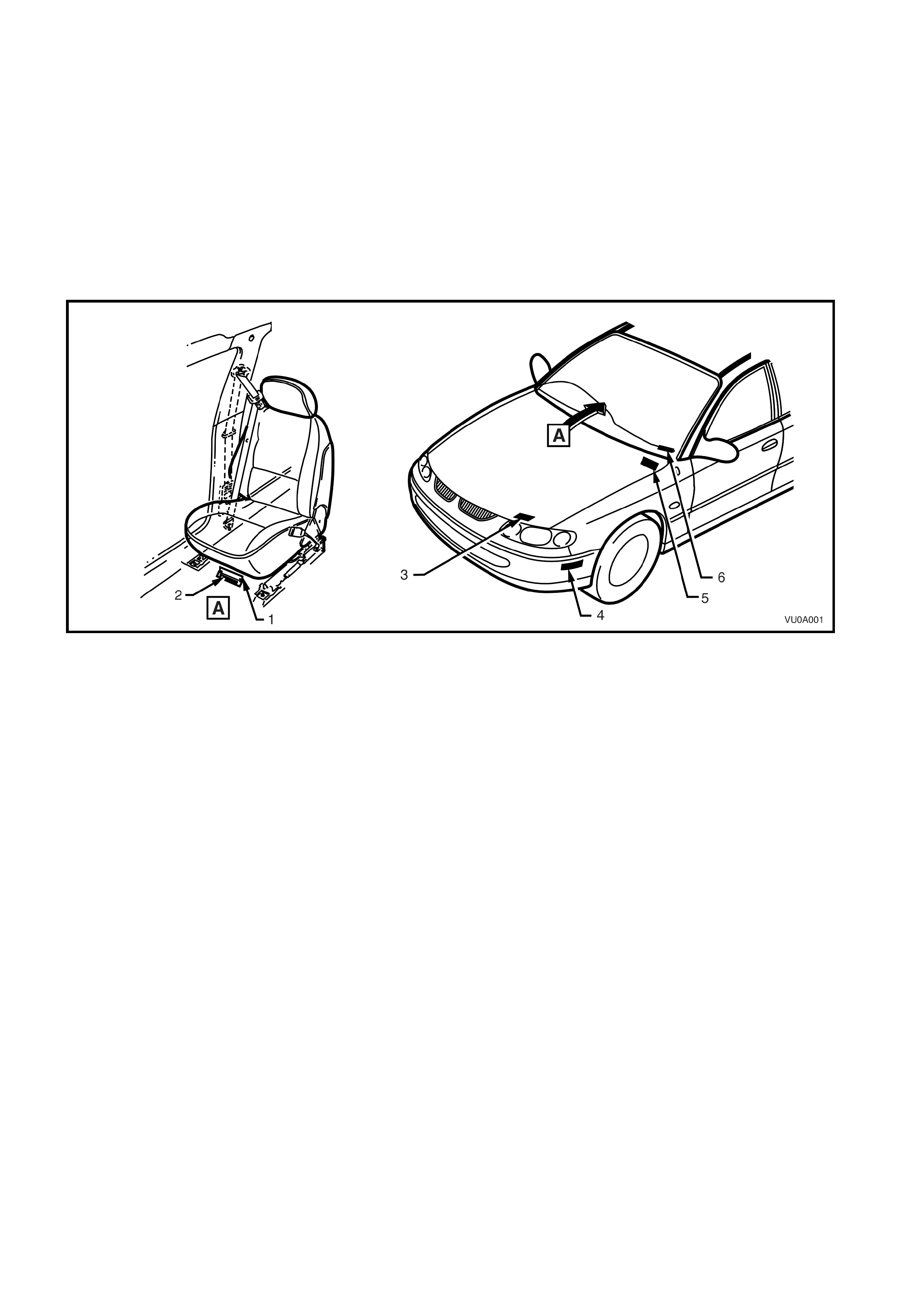
8.1 LOCATION OF IDENTIFICATION PLATES
Identification plates ar e attached to the upper lef t s ide of the das h panel, f ront r adiator suppor t panel, behind the
bumper facia and under the windshield lower left corner, refer to Fig. 0A-2.
NOTE: Stam ping of the VIN into the sheetm etal under the RH f ront seat will be introduced in VU Series Models
with a build date on or after Januar y 2001. The build date is stam ped on the body and option identification plate,
refer to Fig 0A-6.
Figure 0A-2
Legend
1. Carpet flap (under RH seat)
2. Vehicle Identification Number
(stamped under RH seat)
3. Body and Option Identification Plate
(front upper panel)
4. Vehicle Identification Number Plate (under facia)
5. Safety Compliance Plate
(engine side of dash panel)
6. Vehicle Identification Number Plate
(under windscreen)
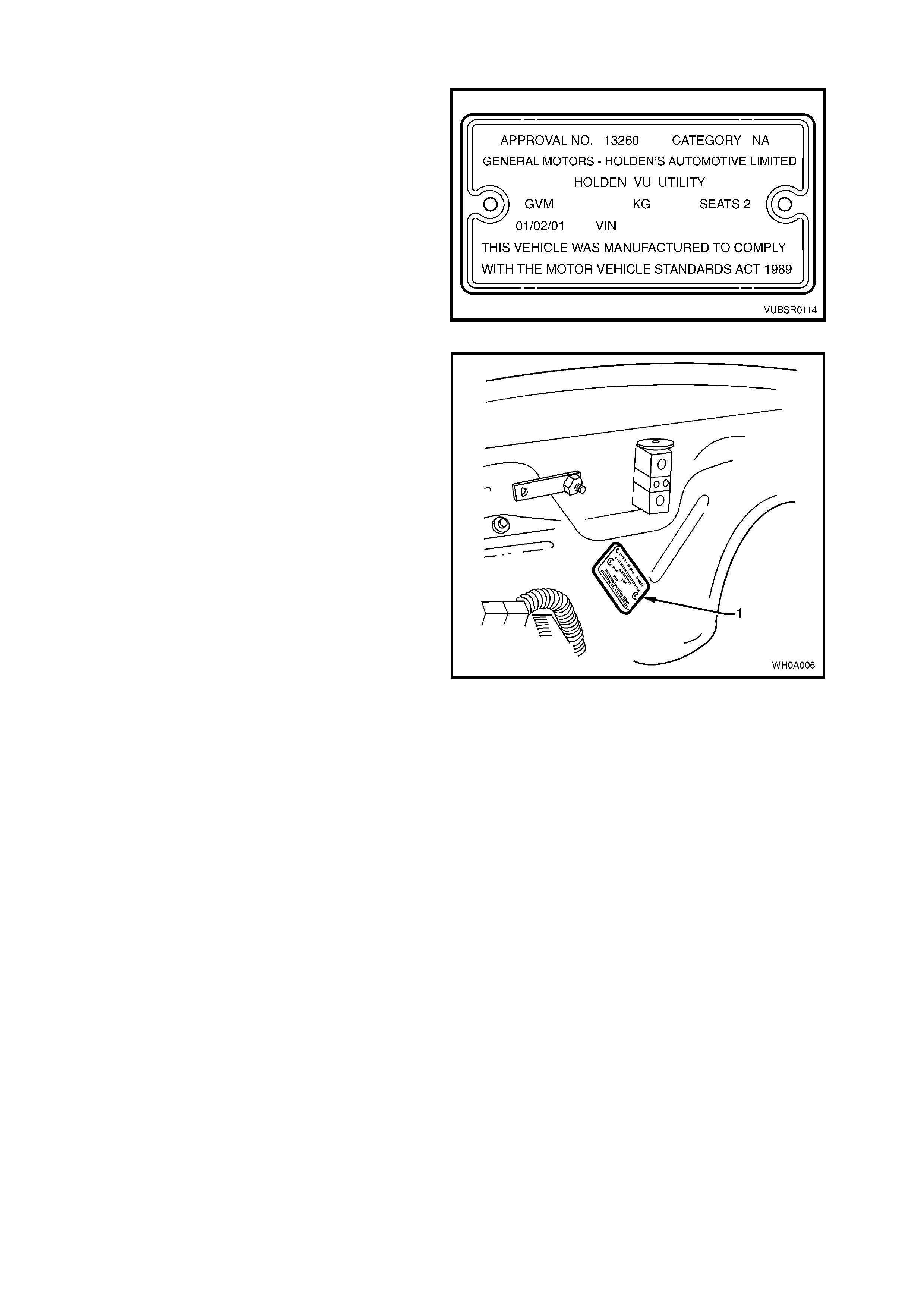
8.2 SAFETY COMPLIANCE PLATE (NOT APPLICABLE TO EXPORT)
Plate stamped with the following inform ation, Refer
to Fig. 0A-3:
COMPLIANCE PLATE APPROVAL NUMBER.
VEHICLE CATEGORY CODE.
NAME APPEARING ON COMPLIANCE PLATE
APPROVAL.
MAKE/MODEL.
SEATING CAPACITY.
DATE OF MANUFACTURE (* Variable
information).
VEHICLE IDENTIFICATION NUMBER (* Variable
information).
Figure 0A-3
Legend
1. Safety Compliance Plate.
Figure 0A-4
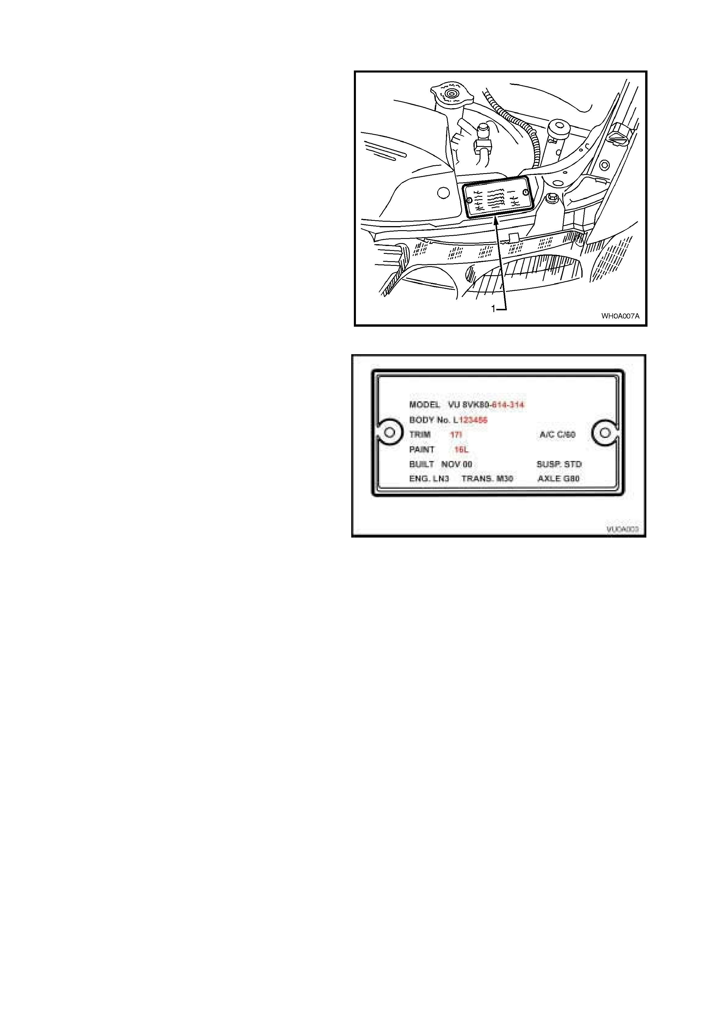
8.3 BODY AND OPTION IDENTIFICATION PLATE
The body and option identification plate (1) is
stamped with the following information, refer to
Fig. 0A-6.
Figure 0A-5
MODEL
Combination of letters and numbers identifying the
body style, the mechanical pack and smart pack
options.
NOTE: A listing of Production Option num bers and
Smart Pack Option numbers can be found by
referring to the latest spare parts information
(Partfinder) for the applicable model.
BODY
Production build number, in continuous sequence
regardless of model, body type and series.
TRIM
Trim combination.
PAINT
Exterior paint material and colour identification.
BUILT
The date of manufacture by calendar month and
year in which the body shell and power train are
conjoined and the vehicle is driven or moved from
the production line.
SUSP
Suspension option code identification number, i.e.
FE2.
ENGINE, TRANSMISSION AND AXLE
Identification option codes for specific engine,
transmission and final drive.
A/C
Identification option code C60 identifies vehicles
fitted with air conditioning.
Figure 0A-6
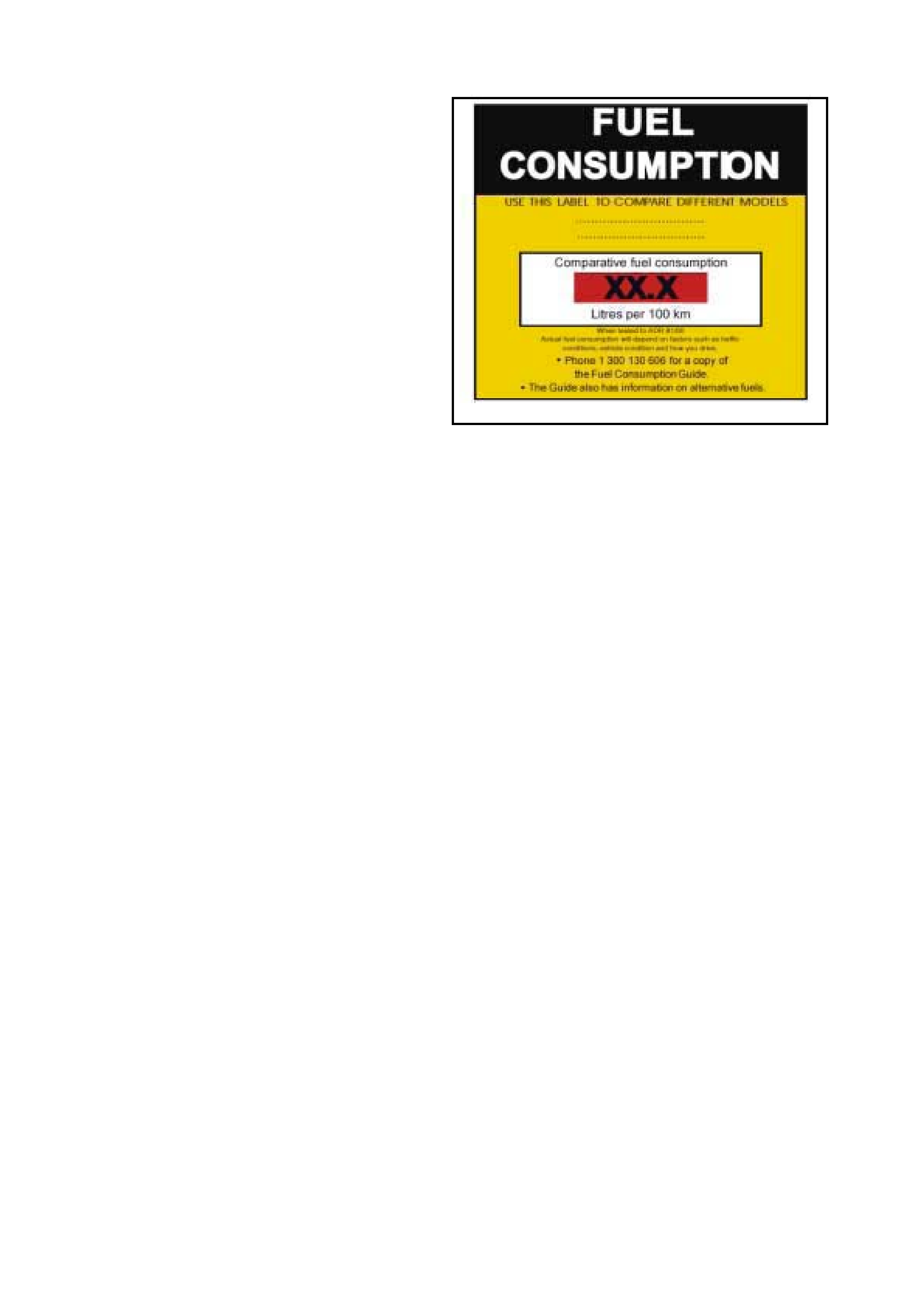
8.4 FUEL CONSUMP TION LABEL
ADR 81/00 requires that from 1st January 2001, a
label similar to that shown in Fig.0A–7 is attached
to the windscreen of any new vehicle which is
displayed for sale.
The f uel c onsumption f igur es quoted are the results
of tests carried out in accordance with an
Australian standard for fuel consumption testing.
Each vehicle is tested under identical conditions.
The results therefore enable a comparison to be
made between vehicles.
This label should be removed from the windscreen
immediately prior to the vehicle being delivered to
the owner.
Figure 0A-7
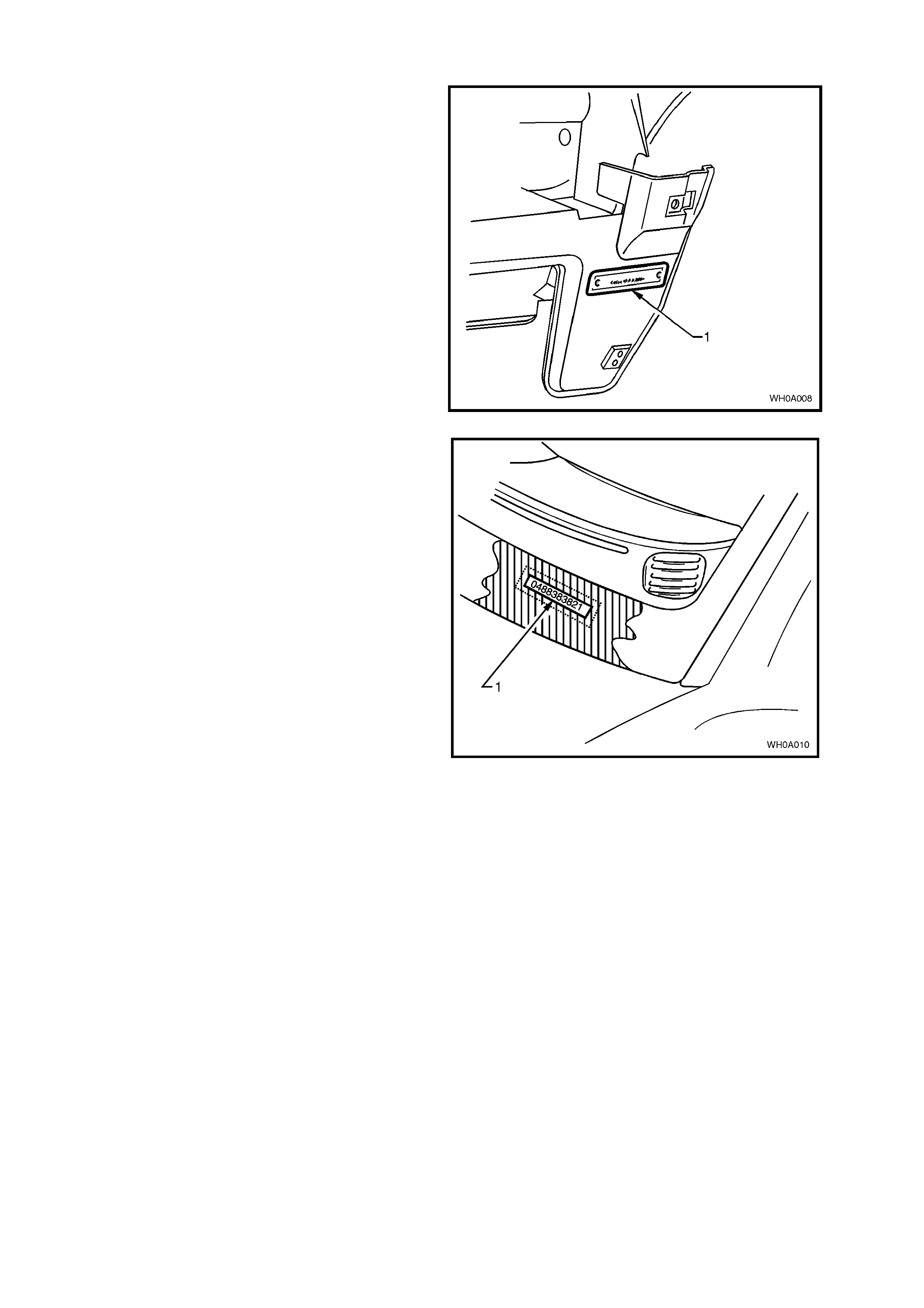
8.5 VEHICLE IDENTIFICATION NUMBER PLATE LOCATION (BODY LOCATION)
One of the body mounted Vehicle Identification
Number (VIN) plates (1) is located under the front
bumper on the left hand side.
NOTE 1: This plate will be deleted following the
introduction of the stamping of the VIN into the floor
sheetmetal under the front RH seat, refer to
8.1 LOCATION OF IDENTIFICATION PLATES in
this Section.
NOTE 2: Stamping of the VIN into the sheetmetal
under the RH front seat will be introduced in VU
Series Models with a build date on or af ter January
2001. The build date is stamped on the body and
option identification plate, refer to Fig 0A-6.
Figure 0A-8
The second body mounted Vehicle Identification
Number plate (1) is located under the windscreen
and is viewed through the windscreen aperture.
The VIN plate is secured to the body by unique
rosette headed rivets.
Figure 0A-9
8.6 VEHICLE IDE NTIFICATION NUMBERING SYSTEM
For details of Vehicle Identification Numbering (VIN) system, refer to Fig. 0A-10.
VEHICLE IDENTIFICATION NUMBERING SYSTEM
The Vehicle Identification Numbering (VIN) system is based on the uniform Car Model Designation
System. The reason for this is to identify the vehicle in one coded series of characters.
The significance of these characters or blocks of characters are explained below, using as an example
identification number 6H8 VU K 80 A Y L 123456.
MODEL DESIGNATION
WMI Code
Model Series Code
Degree of Luxury
BODY STYLE CODE
ENGINE CODE
MODEL YEAR CODE
ASSEMBLY PLANT CODE
SERIAL SEQUENCE NUMBER
6H8 VU K 80 A Y L 123456
MODEL DESIGNATION
WMI Code – 6H8 – World manufacturer’s identifier allocated to Holden
Model Series Code - VU = VU Series
Degree of Luxury - K – UTILITY
Body Style Code - 80 – Utility
ENGINE CODE
Engine Identification Code A – signifies 3.8 litre V6 engine,
F – signifies 5.7 litre GEN III V8 engine)
MODEL YEAR CODE
Y – Identifies Model Year Y = 2000
1 = 2001
This Letter relates to GM Internal Operation Only.
ASSEMBLY PLANT CODE
Australian Assembly Plant Identification Code:-
L – Adelaide (Elizabeth)
SERIAL (Sequence ) NUMBER
123456 – Sequential Production Serial Number
NOTE: This designates the Serial Unit Number at the Vehicle Plant, starting at
(00001) and continues in Numerical Sequence regardless of vehicle type.
Figure 0A-10
Techline
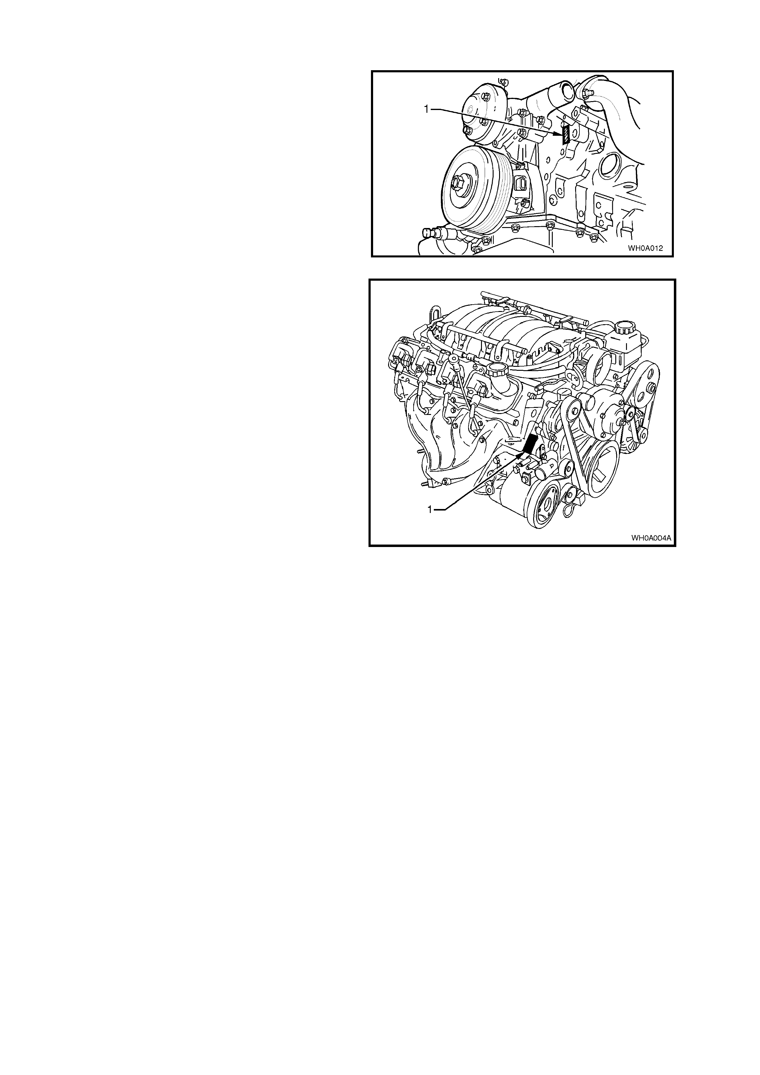
8.7 ENGINE SERIAL NUMBER
The engine number (1) for the 3.8 V6 engine is
stamped on the front face of the engine, below the
ignition coil as illustrated in Fig.0A-11.
Figure 0A-11
The 5.7 litre GEN III V8 engine number (1) is
stamped on a pad located adjacent to the engine
coolant outlet pipe, refer to Fig. 0A-12.
The engine number is prefixed by the letters 'VF'.
Figure 0A-12
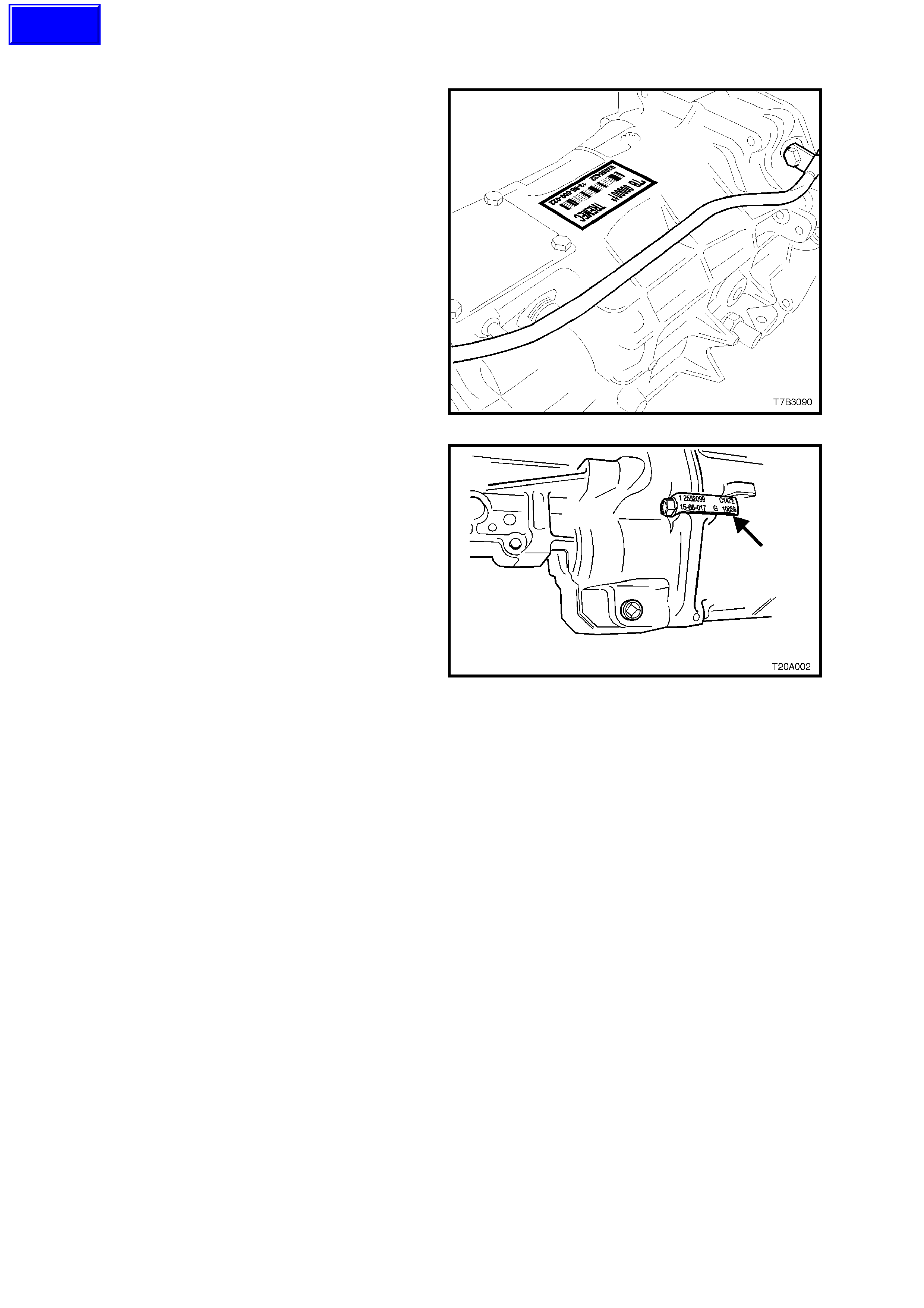
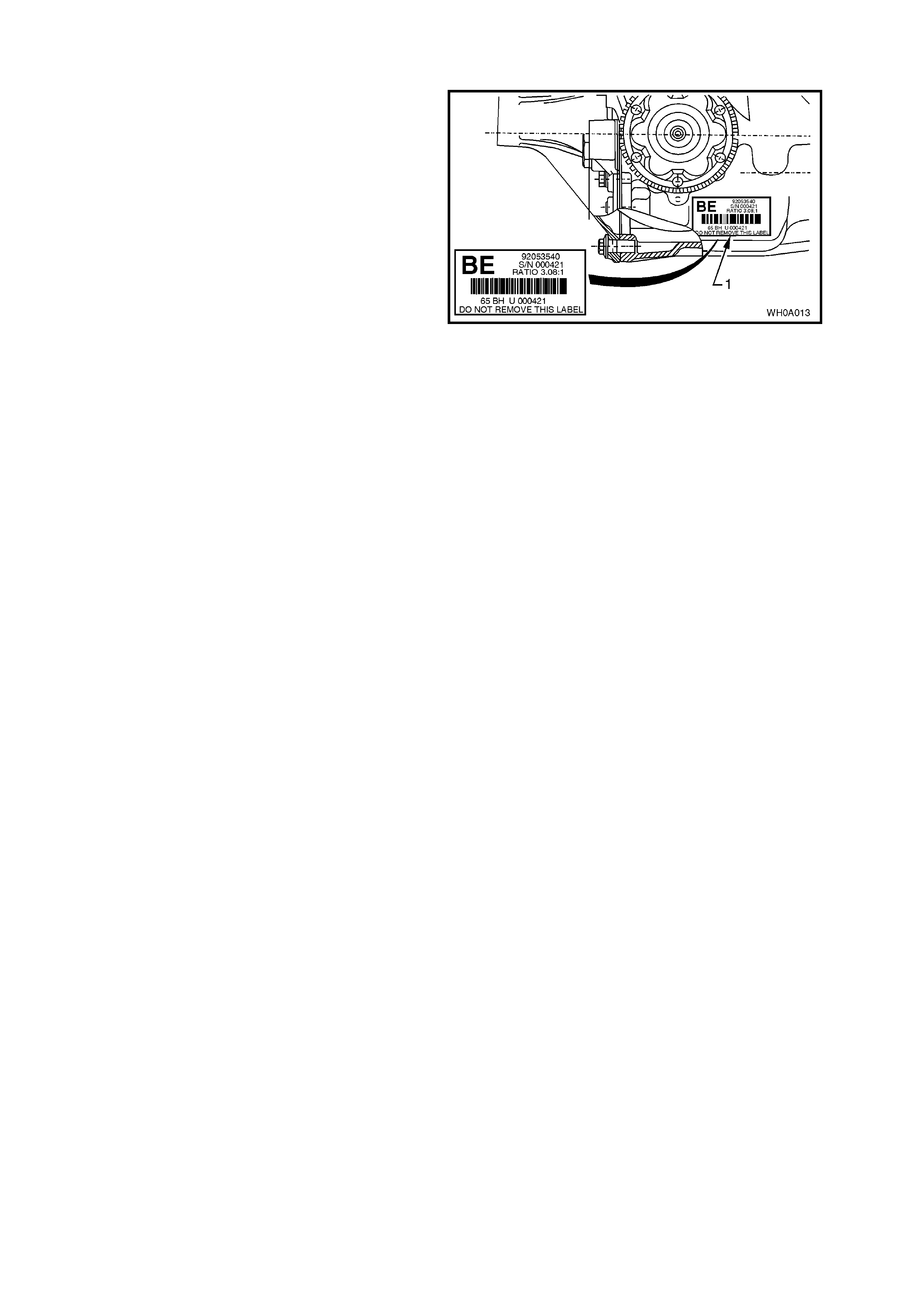
8.8 MANUAL TRANSMISSION SERIAL NUMBER
The Borg-W arner (Tremec) T56 six speed manual
transmission serial number is located on a self-
adhesive decal attached to the top of the
transmission case, refer to Fig. 0A-13.
This number provides coded information which
could be significant to parts interpretation and
should be referred to when ordering replacement
parts.
Figure 0A-13
In addition, an identification tag is attached to the
transmission under an extension housing bolt, on
the right-hand side, refer to Fig 0A-14.
Figure 0A-14
Techline
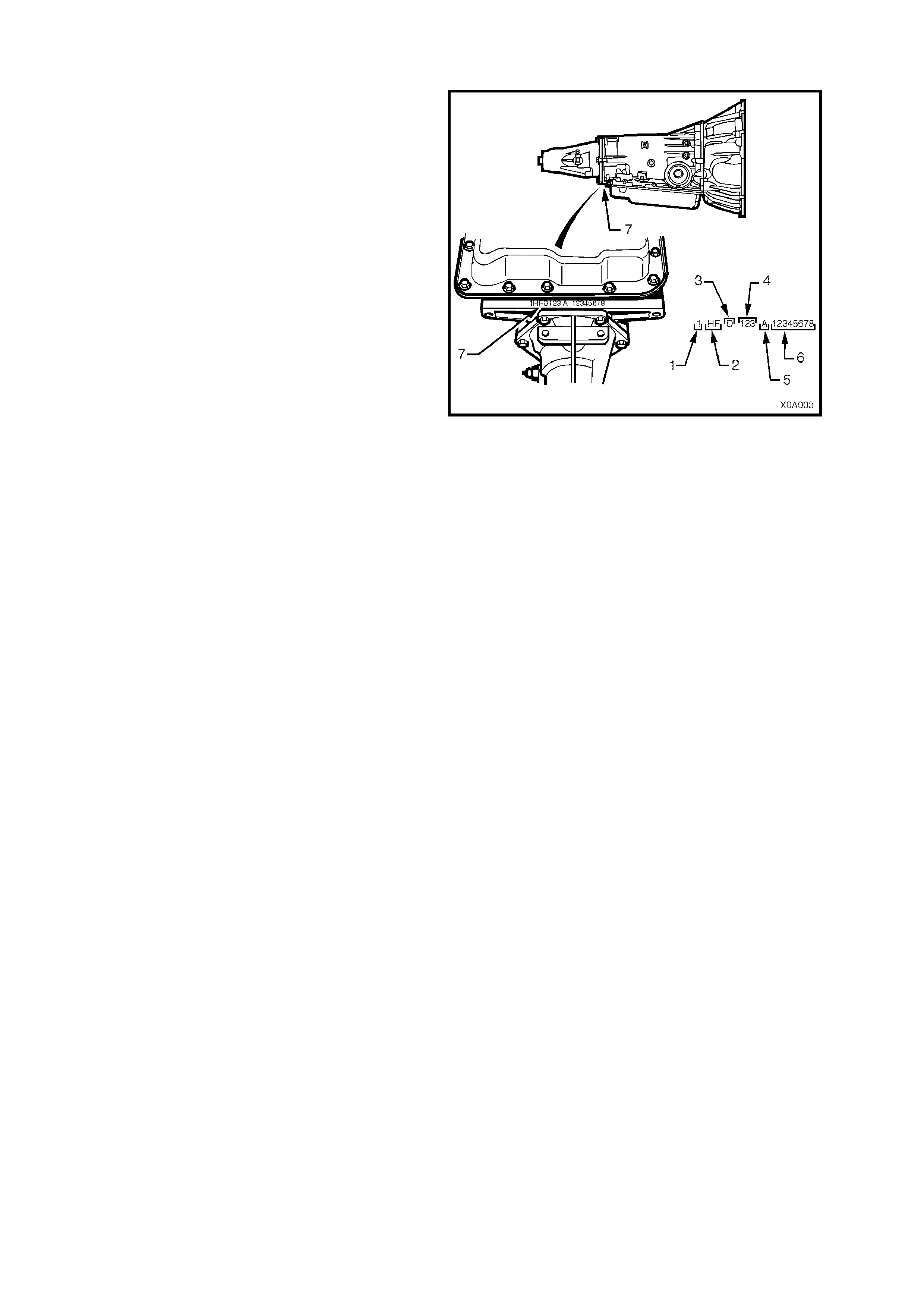
8.9 AUTOMATIC TRANSMISSION SERIAL NUMBER
The automatic transmission serial number is
stamped into a machined surface at the rear
underside of the transmission centre case, refer to
Fig. 0A-15.
1. Model Year (‘0’ = 2000 ‘1’ = 2001)
2. Model: V8 – 5.7 litre...................... HP
V6 – 3.8 litre ..................... HF
3. Transmission Model Identifier (D = 4L60-E).
4. Julian Date (or day of year).
5. Shif t Built (A, B, J = f irst s hift; C, H, W = second
shift).
6. Individual Transmission Serial Number.
7. Transmission Identification Number Location.
Figure 0A-15
8.10 FINAL DRIVE IDENTIFICATION
An identification tag ( 1) is adhered to the final drive
assembly to the RHS of the carrier housing, ref er to
Fig. 0A-16. T he tag car ries the Holden part num ber
for the final drive ass embly, the final drive ratio and
the serial number of the final drive assembly.
Figure 0A-16
9. ADDI TIONAL GENERAL INFORMATIO N
9.1 ELE CTRICAL TRANSIENTS AND RADIO FREQUENCY INTERFERENCE
Electronic circuits are used in VU Series Models to perform a number of functions associated with electronic
cruise control, electronic engine and transmission control systems etc. These circuits can be damaged or
malfunction as a result of electrical transients or excessive Radio Frequency (RF) radiation.
ELECTRICAL TRANSIENTS
Electrical transients are high voltage spikes produced by the sudden switching or interruption of electric currents.
Older style timing lights and battery chargers can produce serious transients, hence, it is important to use only
good quality equipment suitable for use with electronic systems.
It is also good practice to ensure that the battery is disconnected before using a battery charger.
Indiscriminate fitting of solenoids, indicators or relays can also cause transients.
RADIO FREQUENCY INTERFERENCE
One of the chief sources of RF interference is the ignition system. Other sources include CB radio and radio
telephones. The following are normally used to suppress RF interference.
Resistors eg. High Tension Cables and Connectors.
Capacitors and Choke Coils.
Metal Braid for screening leads or suppression covers made from conductive material for screening equipment.
To prevent damage to equipment:
Do not replace interference suppressed high tension ignition cables or connectors with unsuppressed types.
Do not remove or reposition interference suppression filters or capacitors.
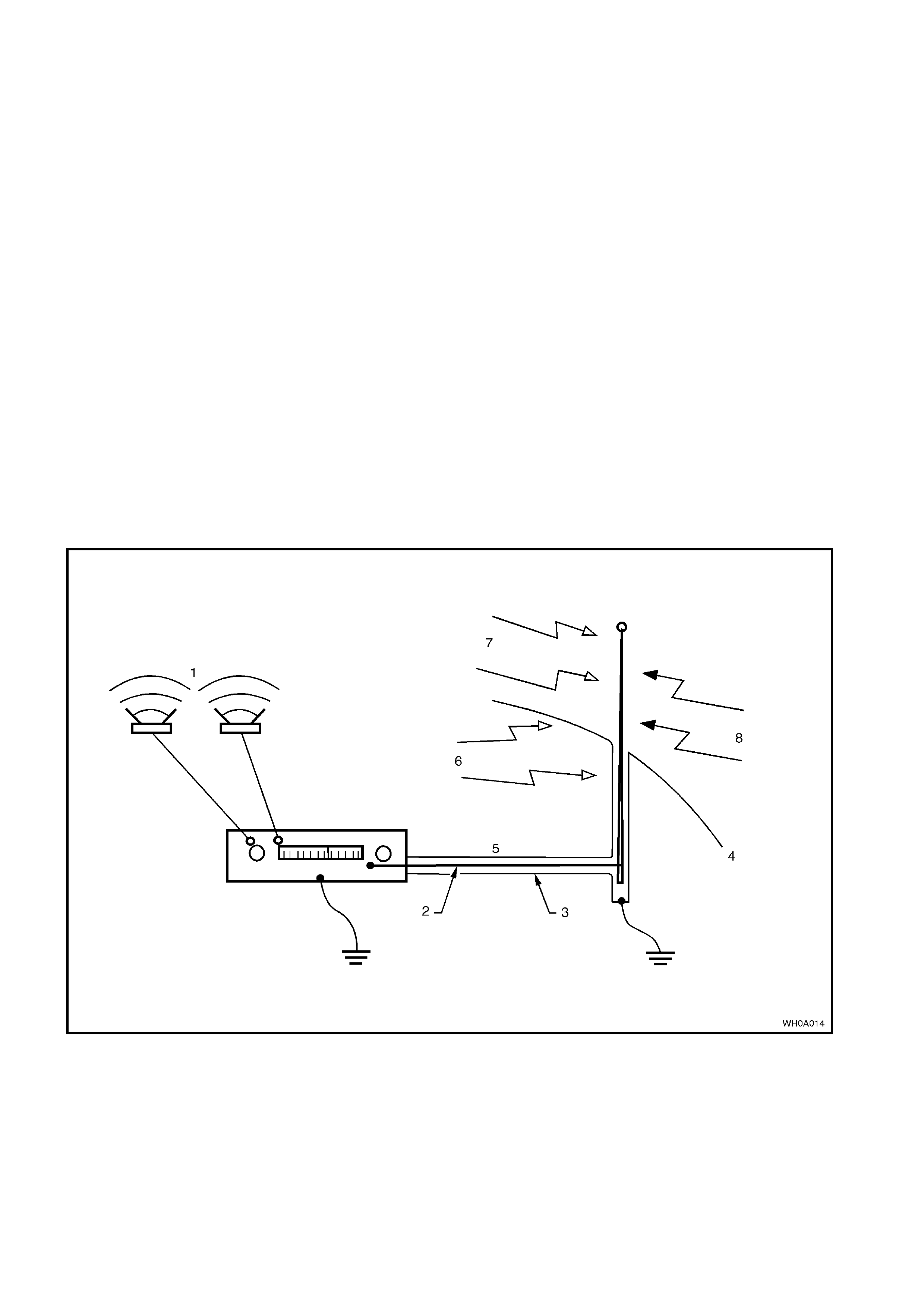
Figure 0A-17
Legend
1. Music
2. Core
3. Braid
4. Body
5. Antenna cable
6. Internal Interference
7. Signal from station
8. External interference

9.2 STATIC ELECTRICITY
Care should be exercised when handling electronic equipment e.g. the powertrain control module (PCM), to
avoid touching the terminals unnecessarily. Static electricity, which is present on every person, can cause
damage to some electronic components.

9.3 PUSH OR TOW STARTING
Do not push or tow start VU Ser ies Models. Pus h or tow starting can result in unburned f uel passing through the
exhaust to the catalytic converter, causing damage to the converter.
