SECTION 10 - WHEELS AND TYRES
IMPORTANT:
Before p erf orming any Service O p eratio n o r ot her p rocedu re describ ed in th is Sect ion , refer t o Sect ion
00 CAUTIONS AND NOTES for correct workshop practices with regard to safety and/or property
damage.
1. GENERAL I NFORMATION
All information relating to the wheels and tyres on VU Series Models not detailed in this Section carries over
from the information published for VX Series Models. Refer to Section 10 WHEELS AND TYRES in the VX
Series Service Information.
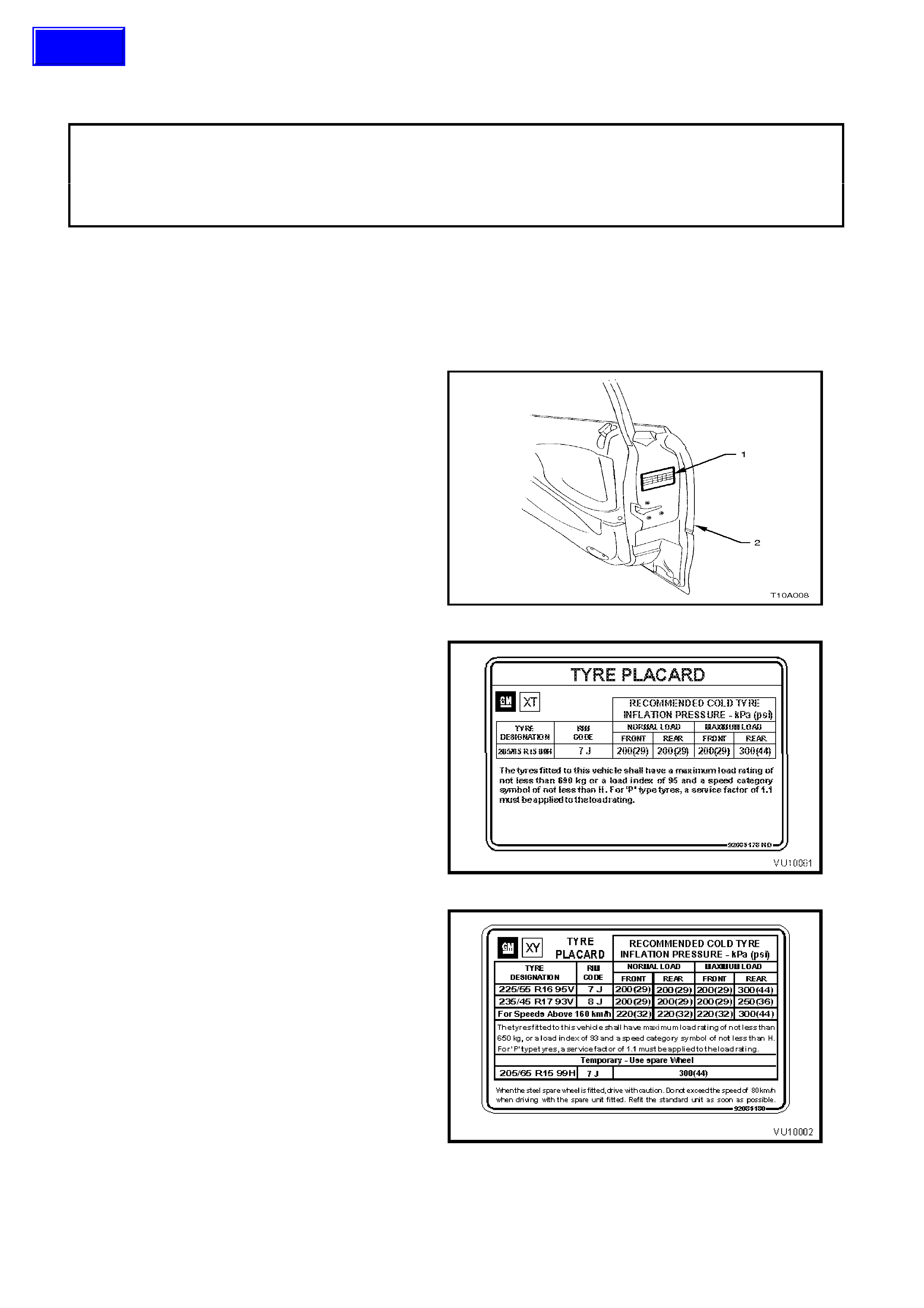
Wheel and tyre sizes, inflation pressures and load
capacity are specif ied on a tyr e placard (1), loc ated
on the end surface of the right-hand front door (2).
VU Series Models are fitted with unique tyre
placards.
For Utility, refer to Fig. 10-2.
For S and SS refer to Fig. 10-3.
Correct sizes and pressures are the subject of an
Australian Design Rule (ADR) and must be
observed at all times.
Figure 10-1
VU Series Utility Models feature 7.0J x 15 steel
wheels and centre cap with 205/65 R15 99H
tubeless tyres as used on VX Series Taxi pack
vehicles.
Fig. 10-2 illustrates tyre placard as fitted to VU
Series Utility.
Figure 10-2
VU Series S Models are fitted with 7.0J x 16 alloy
wheels as fitted to VX Series S Models fitted with
unique 225/55 R16 95V tyres.
VU Series SS Models use the 8.0J x 17 alloy
wheels fitted with 235/45 R17 93V tyres as used on
VX Series SS models.The spare wheel and tyre
fitted to all VU Series Models use the 7.0J x 15
steel wheel fitted with 205/65 R15 99H tyres as
fitted to the Utility model.
Fig. 10-3 illustrates tyre placard as fitted to VU
Series S and SS.
Figure 10-3
Techline
2. SERVICE OPERATIONS
A new spare tyre hoist is fitted to all VU Series Models. For infor m ation regarding the service operations relating
to the Wheels and T yres as fitted to VU Ser ies models not detailed in this Sec tion, ref er to Section 10 WHEELS
AND TYRES in the VX Series Service Information.
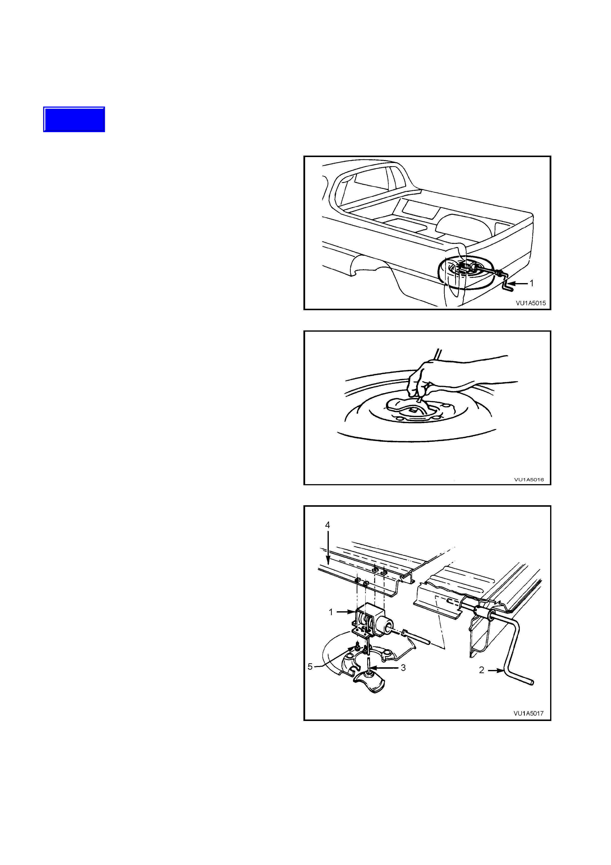
2.1 SPARE WHEEL HOIST
REMOVE
1. Insert the handle (1) into the aperture located
beside the licence plate.
Figure 1A4-4
2. Rotate the handle in a counter-clockwise
direction until the spare wheel is completely
lowered and some slack exists in the cable.
3. Support the wheel with one hand. Tilt the wheel
retainer upward, allowing the retainer to pass
through the wheel centre.
4. Remove the wheel from below the vehicle.
Figure 1A4-5
5. Remove the four screws (5) and lower the
hoist (1).
Legend
1. Hoist.
2. Handle.
3. Cable.
4. Frame.
5. Screw (four places).
Figure 1A4-6
Techline

REINSTALL
Reinstallation is the reverse of the removal
procedure.
NOTE: Ensure that the hoist is installed with the
square coupling towards the rear of the vehicle.
Tighten hoist attaching screws to the correct
torque specification.
SPARE WHEEL HOIST
ATTACHING SCREW 15-35 Nm
TORQUE SPECIFICATION

3. DIAGNOSIS
All inf ormation r egarding the diagnosis of the wheels and tyres fitted to VU Series Models carries over f rom VX
Series Models. For information regarding the diagnosis of the wheels and tyres as fitted to VU Series Models,
refer to Section 10 WHEELS AND TYRES in the VX Series Service Information.

4. SPECIFICATIONS
STEEL WHEEL
Rim Width Code...................................................... 7.0J (ISO)
Diameter Code........................................................ 15
Maximum Permissible Radial Run-out............... 0.6 mm
Maximum Permissible Lateral Run-out.............. 0.8 mm
Offset ................................................................. 43 mm (pos)
ALLOY WHEELS
Rim Width Code...................................................... 7.0J 8.0J
Diameter Code........................................................ 16 17
Maximum Permissible Radial Run-out
S......................................................................... 0.35 mm
SS ...................................................................... 0.35 mm
Maximum Permissible Lateral Run-out
All models........................................................... 0.35 mm
Offset
S......................................................................... 48 mm (positive)
SS ...................................................................... 48 mm (positive)
TYRES
Dynamic Balancing – All Models
Maximum Permissible Residual
Imbalance (Per Side) ......................................... 8 g
Maximum Tyre Load (per tyre)
Utility & Spare................................................... (205/65R15 99H) 675 kg
S....................................................................... (225/55R16 95V) 630 kg
SS .................................................................... (235/45R17 93V) 630 kg
RECOMMENDED COLD INFLATION
kPa
Normal Load Maximum Load
MODEL
WHEEL
TYRE
DESIGNATION Front Rear Front Rear
Utility 7.0J x 15
Steel 205/65 R15 99H 200 200 200 300
S 7.0J x 16
Alloy 225/55 R16 95V 200
220 (1) 200
220 (1) 200
220 (1) 300
300 (1)
SS 8.0J x 17
Alloy 235/45 R17 93V 200
220 (1) 200
220 (1) 220
220 (1) 250
300 (1)
(1) W her e vehicle is used for cons istent speed in exc ess of 160 k m /h, required cold inf lation pressur es are
to be as indicated.

5. TORQUE WRENCH SPECIFICATIONS Nm
Road Wheel Attaching Nuts.................................................. 110-140
Spare Wheel Hoist Attaching Bolts....................................... 15 - 35