
SECTION 4A - REAR SUSPENSION
1. GENERAL DESCRIPTION
2. SERVICE OPERATIONS
2.1 SUSPENSION AND TRIM HEIGHT, CHECK
2.2 REAR SHOCK ABSORBERS AND/OR BUSHES
REMOVE
LOWER BUSH, REPLACE
REINSTALL
3. SPECIFICATIONS
4. TORQUE WRENCH SPECIFCATIONS
5. SPECIAL TOOLS

SECTION 4A - REAR SUSPENSION
IMPORTANT:
Before performing any Service Operation or other procedure described in this Section, refer to Section
00 CAUTIONS AND NOTES for correct workshop practices with regard to safety and/or property damage.
1. GENERAL INFORM ATION
Independent rear suspension (IRS) is fitted as standard equipment on all VU Series Models. The IRS is equipped
with variable rate minibloc coil rear springs and direct acting shock absorbers.
The IRS fitted to VU Series Models carries over from VX Series Models noting the following:
1. The rear wheel bearing fitted to VU Series Models is a tapered roller type to accomodate increased load.
2. The rear camber angle has changed for VU Series Models for increased tyre life.
3. A unique lower shock absorber bush is fitted to the rear suspension of all VU Series Models.
For information relating to the rear suspension fitted to VU Series Models not covered in this Section, refer to
Section 4A REAR SUSPENSION in the VT Series I and VT Series II Service Information.

2.2 REAR SHOCK ABSORBERS AND/OR BUSHES
REMOVE
1. Using a floor jack under centre of differential
carrier, jack up rear of vehicle then place safety
stands under trailing arms to support weight of
vehicle.
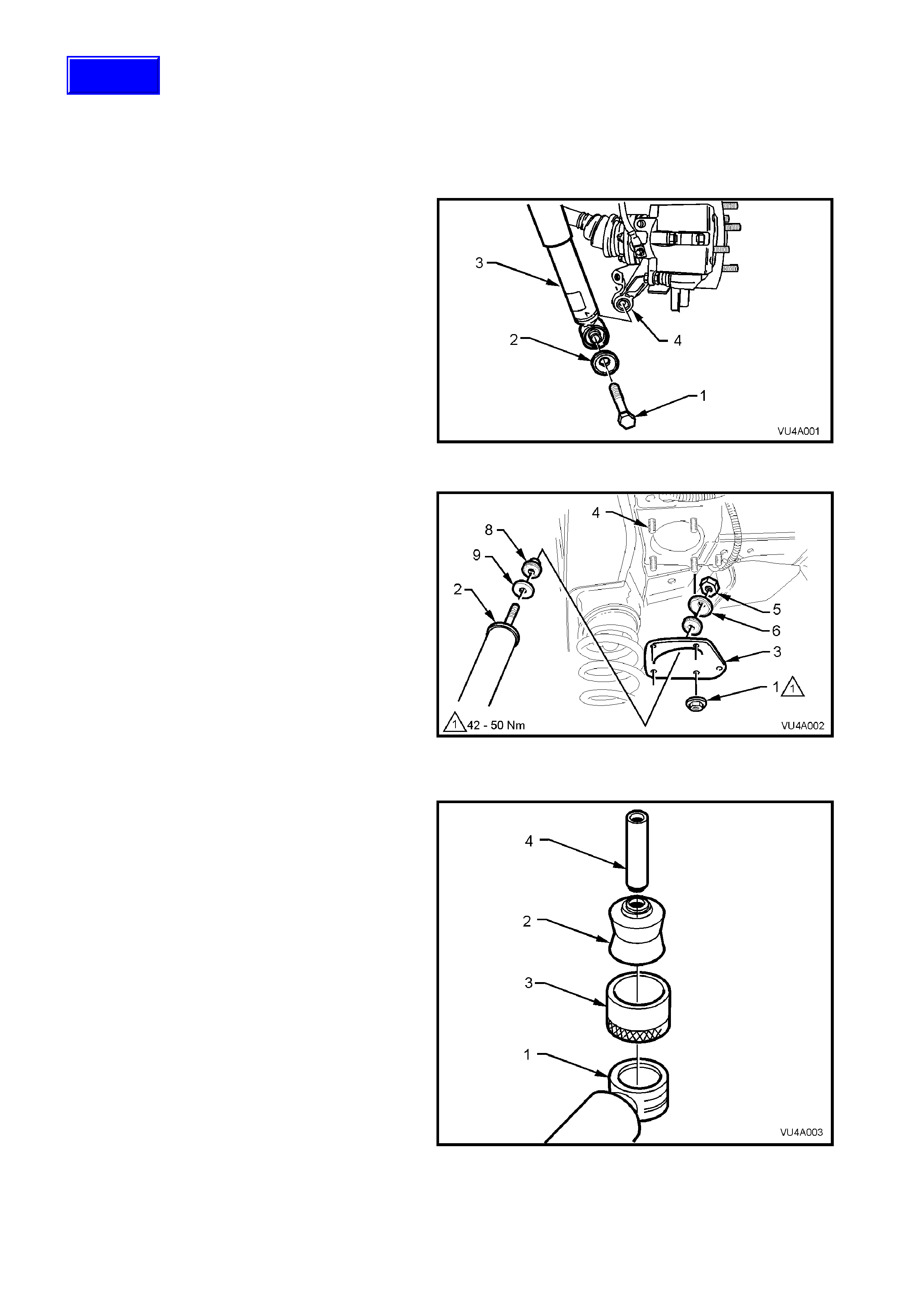
2. Loosen and remove shock absorber lower
mounting bolt (1) and washer (2) and remove
shock absorber (3) from the lower mounting
(4).
Figure 4A-1
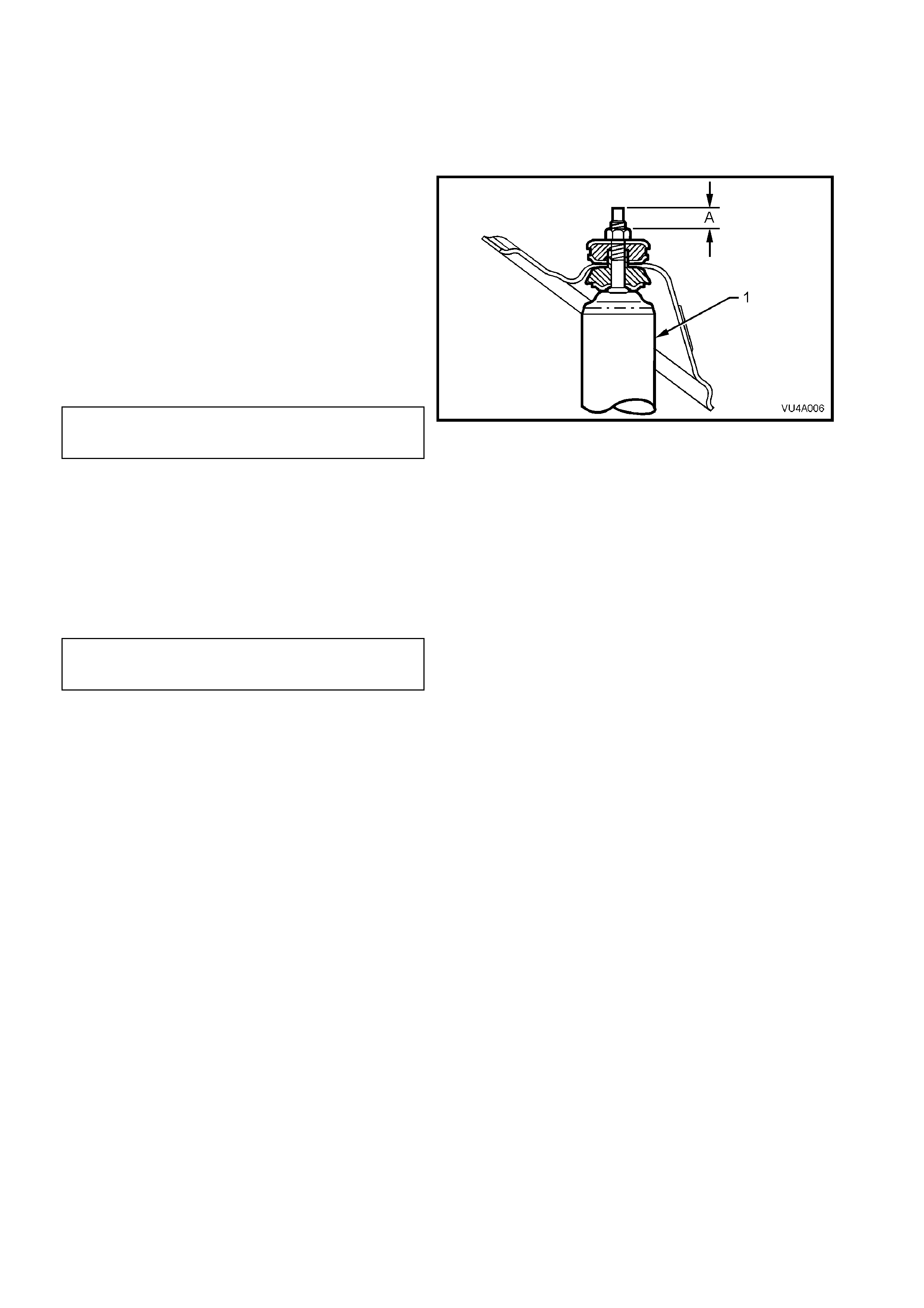
3. Remove the five upper mounting plate retaining
nuts (1).
4. Lower shock absorber (2) until upper mounting
plate (3) is free from mounting studs (4), and
carefully moneuvre shock absorber and
mounting plate assembly from vehicle.
5. Remove shock absorber upper mounting nut
(5), upper washer (6) and bush (7).
6. Remove the upper mounting plate from shock
absorber.
7. Remove upper mounting lower bush (8) and
lower washer (9) from shock absorber.
Figure 4A-2
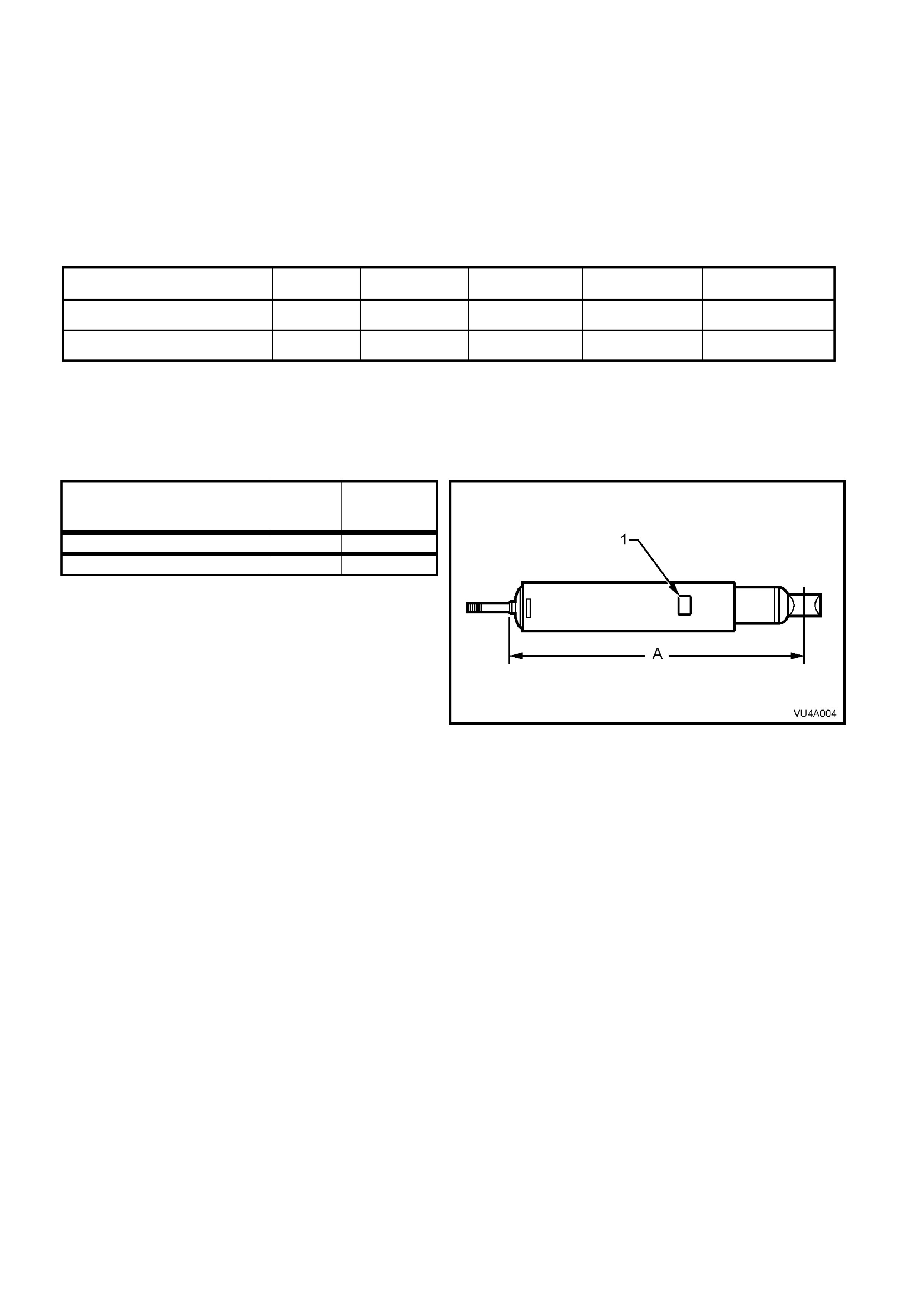
LOWER BUSH, REPLACE
1. With shock absorber lower mount (1)
supported on suitable press plates, press bush
(2) from mount.
2. Lubricate new bush with soapy water and place
in sleeve (3), Tool No. KM508-2.
3. With shock absorber lower mount supported on
press plates, position KM508-2 onto lower
mount. Press new bush into mount using
fabricated press tool (4).
Figure 4A-3
Techline
REINSTALL
1. Before installation, check shock absorber
action and inspect rubber bushes ; replacing as
required. See 3. DIAGNOSIS in Section 4A
REAR SUSPENSION in the VT Series Service
Information for testing details.
2. Assemble upper mounting lower washer and
bush to the shock absorber (1).
3. Install the upper mounting plate, upper
mounting upper bush and washer.
4. Install the retaining nut, tightening until
dimension ‘A’, between the top of the threaded
shaft and the nut is from 15.5 to 16.0 mm.
NOTE: Do not use power operated tools for this
operation, as thread damage will result.
5. Install the five upper mounting plate retaining
nuts and tighten nuts to the correct torque
specification.
UPPER SHOCK ABSORBER
MOUNTING PLATE RETAINING 30 - 40 Nm
NUT TORQUE SPECIFICATION
6. Install shock absorber lower mount into trailing
arm and install bolt agains t the side of the bush
that has the inner sleeve flush with rubber,
refer to Fig. 4A-1. Do not fully tighten at this
stage.
7. Lower vehicle to the ground, then bounce rear
of vehicle several times to settle suspension.
8. Tighten the shock absorber lower mounting
bolt to the correct torque specification.
SHOCK ABSORBER LOWER
MOUNTING BOLT 105 – 125 Nm
TORQUE SPECIFICATION
Figure 4A-4
3. SPECIFICATIONS
SUSPENSION DETAILS
Type ........................................................................ Independent semi-trailing arms
Travel
Compression (2/3 compression of bumper)....... 98 mm
Rebound............................................................. 111 mm
Springs.................................................................... 'Minibloc'
REAR SPRING DETAILS
MODEL TOTAL No.
COILS FREE LENGTH
mm OUTSIDE DIAM.
mm PROD. I.D. CODE
(Tag on spring) SPRING TYPE &
RATE
STANDA RD S USPENSI ON 8 263 158 EW VARIABLE
68.0/108.0 N/mm
FE2 ‘SPORTS’ SUSPE NS ION 8 272 158 EL VARIABLE
51.0/90.0 N/mm
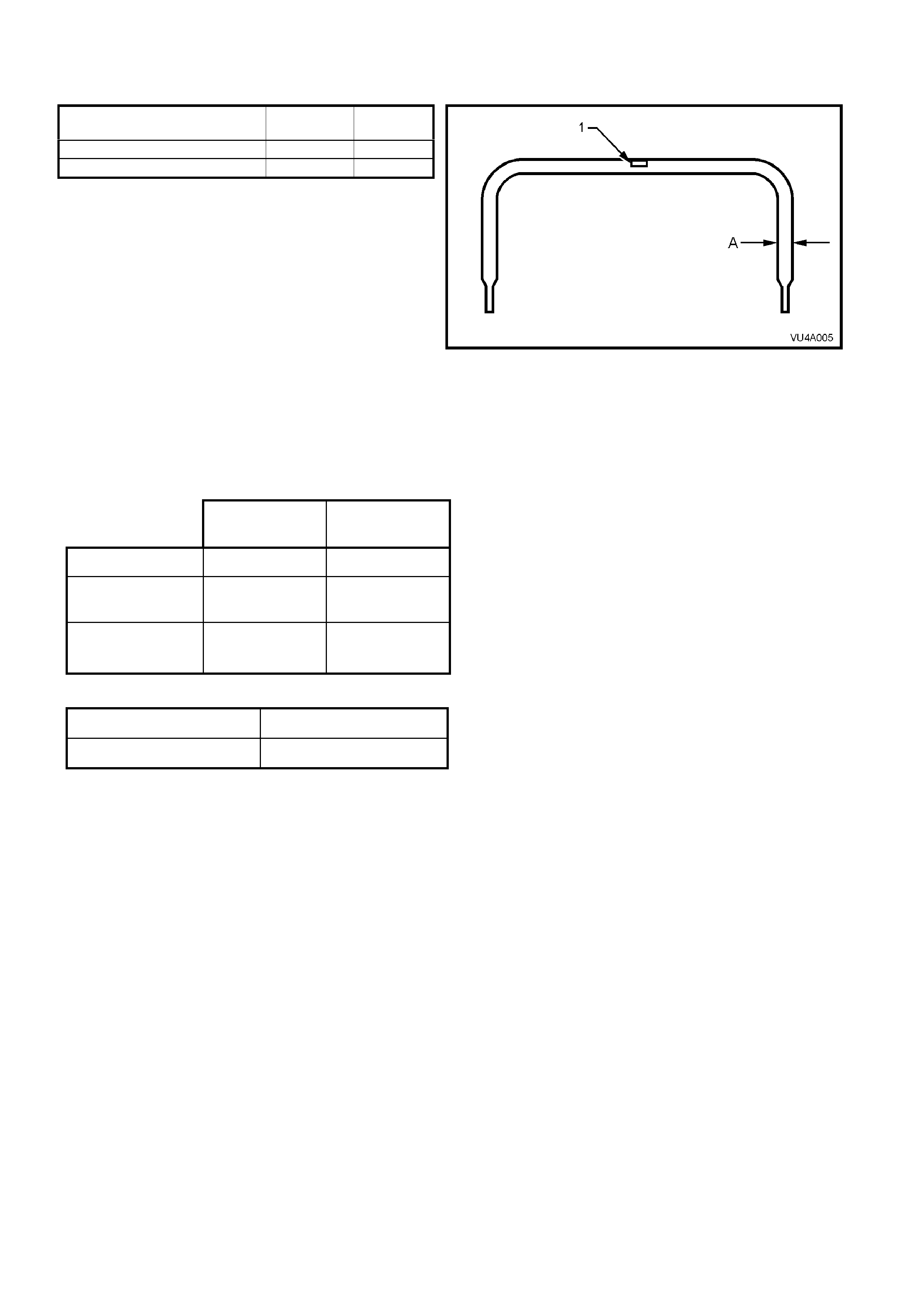
REAR SHOCK ABSORBER DETAILS
Suspension Type
Standard............................................................. Twin tube hydraulic
FE2..................................................................... Twin tube hydraulic, gas pressurised
PROD. I.D. NOMI NAL
MODEL LABEL EXTENDED
(RH/LH) LENGTH
STANDA RD SUSPE NSION MB/MC 670 mm
FE2 ‘SPORTS ’ S US P ENSION HT/HV 670 mm
Figure 4A-5
Legend
1. Production I.D. label
A. Extended length
STABILISER BAR DETAILS
Type ...........................................................................Direct acting link with rubber insulating bearings
MODEL DIAMETER PROD.
I.D. CODE
STANDARD SUSPENSION 13.0 mm FL
FE2 ‘SPORTS’ S US P ENSION 15.0 mm FJ
Figure 4A-6
Legend
1. Production I.D. label
A. Stabiliser bar diameter
REAR SUSPENSION: SERVICE ALIGNMENT DATA
STANDARD
SUSPENSION FE2
SUSPENSION
REAR TRACK 1586 mm 1586 mm
CAMBER +0° 31' to -0°
26' -0° 29' to -1°
21'
TOE (Degrees
per Wheel) -0° 26' to
+0°20’ -0° 00' to +0°
46'
VARIATION SIDE TO SIDE (ALL MODELS)
Camber 0° 35’ Maximum
Wheel Toe 0° 20’ Maximum
Dimensions shown are for a vehicle at curb height, i.e. vehicle ready to drive with all fluids at the recommended
levels, the fuel tank full and without driver, passenger/s or luggage.

4. TORQUE WRENCH SPECIFICATIONS
Nm
Shock Absorber Upper Mounting Nut ........................................ Shaft protrusion above nut, from
15.5 to 16.0 mm.
Shock Absorber Upper Mounting Plate Nut............................... 30 - 40
Shock Absorber Lower Mounting Bolt ....................................... 105 - 125
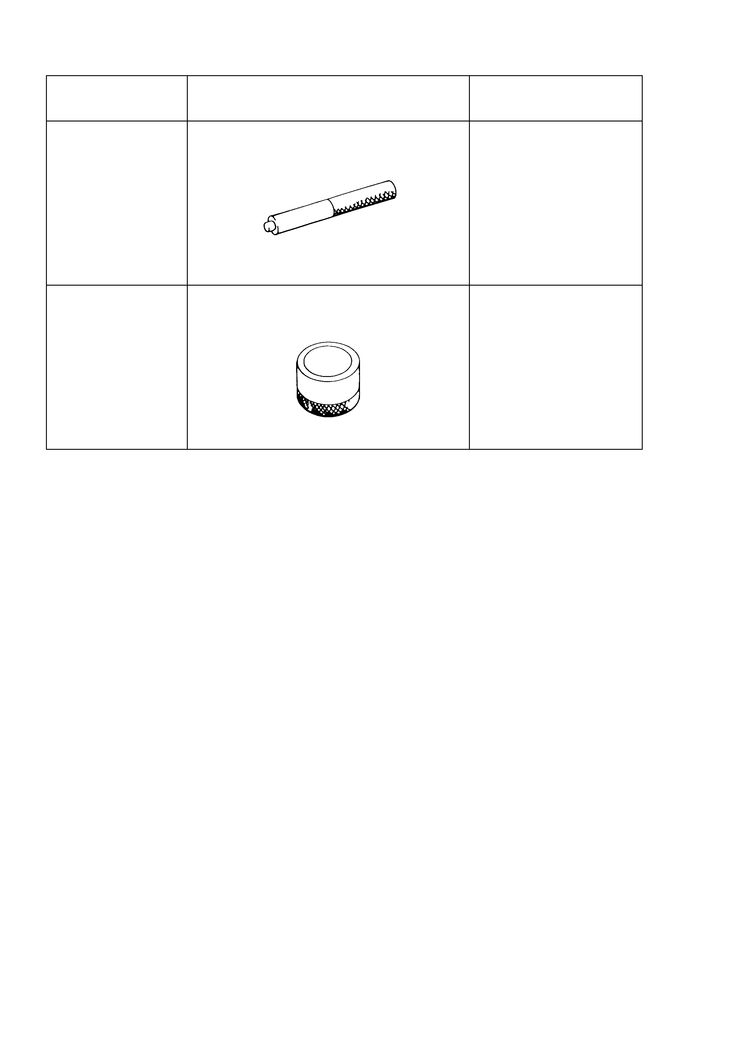
5. SPECIAL TOOLS
TOOL NO. REF
IN TEXT TOOL DESCRIPTION COMMENTS
AU385-4 PRESS TOOL
Previously released for V6
engine.
Used to remove and install
bushes into shock absorber
lower mount.
KM508-2 INSTALLING SLEEVE
Previously released for "J"
car.
Used to install new bush in
shock absorber lower mount.