
SECTION 0A - GENERAL INFORMATION
IMPORTANT:
Before performing any Service Operation or other procedure described in this Section, refer to Section
00 CAUTIONS AND NOTES for correct workshop practices with regard to safety and/or property damage.
1. GENERAL I NFORMATI O N
The VX Series Model is a development of the Holden VT Series Model and incorporates some minor cosmetic
changes, as well as various functional changes.
The following information briefly summarises these cosmetic and functional changes, with additional and more
detailed information provided in the relevant Sections of the VX Series Service Information.
• Compliance with Frontal Offset Side Impact Standards for occupant protection.
• Compliance with Side Impact Standards for occupant protection.
• New exterior colours.
• New grille inserts.
• New wheels and wheel trims (depended on Model variant).
• New and revised exterior ornamentation.
• Various new interior trim colours and materials (dependent on Model variant).
• Various exterior lighting changes and upgrades.
• New bumper facias.
• Deletion for the rear compartment lid lock cylinder – sedan only.
• A ‘soft top’ cup holder for Berlina and Calais Models.
• A ‘Flash Programmable’ Powertrain Control Module (PCM) for vehicles with a V6 engine.
• Traction control (ETC) for vehicles with manual transmissions.
• Revised engine cooling fans for vehicles with V6 supercharged engine (200 Watt, as per VT Series II
vehicles with a V6 engine).
• Dual rubber coupled propeller shaft and, on V6 manual transmission vehicles only, a differently designed
centre bearing area.
• Revised front stabiliser bar link design and minor changes to the front and rear spring / shock absorber
specifications.
• Minor change to the clutch master cylinder, including material and mounting.
• Upgraded audio system, to include a single CD player, for Executive, Acclaim and S Models.
• Steering wheel mounted remote audio controls for all Models.
• Changes to the automatic transmission coolers.
• Updated automatic transmission unit repair (re-written).
• Power antenna, full up and down, added as standard to Executive, Acclaim and S Models.
• Minor changes to the V6 engine inlet manifolds – to improve crankcase ventilation gas distribution.
NOTE: For additional General Information not covered in this Section, refer to Section 0A GENERAL
INFORMATION of the VT Series I and VT Series II Service Information. The information in these two Sections
should be read in conjunction with each other.
Techline

2. BASE MODEL AVAILABILITY AND EQUIPMENT
MODEL NAME COMMODORE
EXECUTIVE COMMODORE BERLINA CALAIS
BODY STYLE SEDAN WAGON SEDAN WAGON SEDAN
MODEL NUMBER 8VK69 8VK35 8VL69 8VL35 8VX69
NUMBER OF DOORS 4 5 4 5 4
ENGINE 3.8 LITRE PFI V6 3.8 LITRE PFI V6 3.8 LITRE PFI S/CHARGED
V6
TRANSMISSION
TYPE 5 SPEED MANUAL 4 SPEED AUTOMATIC 4 SPEED AUTOMATIC
FINAL DRIVE RA TIO 3.08:1 3.08:1 3.07:1
TYRES P205/65R15 95H P205/65R15 95H 225/55R16 95V
WHEELS 6.0J x 15 Steel 6.0J x 15 Alloy 7.0J x 16 Alloy

3. POWERTRAIN COMBINATIONS
ENGINE TRANSMISSION
TYPE MODEL
AVAILABILITY FIRST GEAR
RATIO REAR AXLE RATIO
5 Speed Manual Executive 3.83:1 3.08:1
3.8 LITRE PFI 4 Speed
Automatic Executive
Berlina
Calais
3.06:1 3.08:1
3.8 LITRE PFI
SUPERCHARGED 4 Speed
Automatic Berlina
Calais 3.06:1 3.07:1
4 Speed
Automatic Executive
Berlina
Calais
3.06:1 3.08:1
5.7 LITRE PFI
(GEN III) 6 Speed Manual Executive 2.66:1 3.46:1

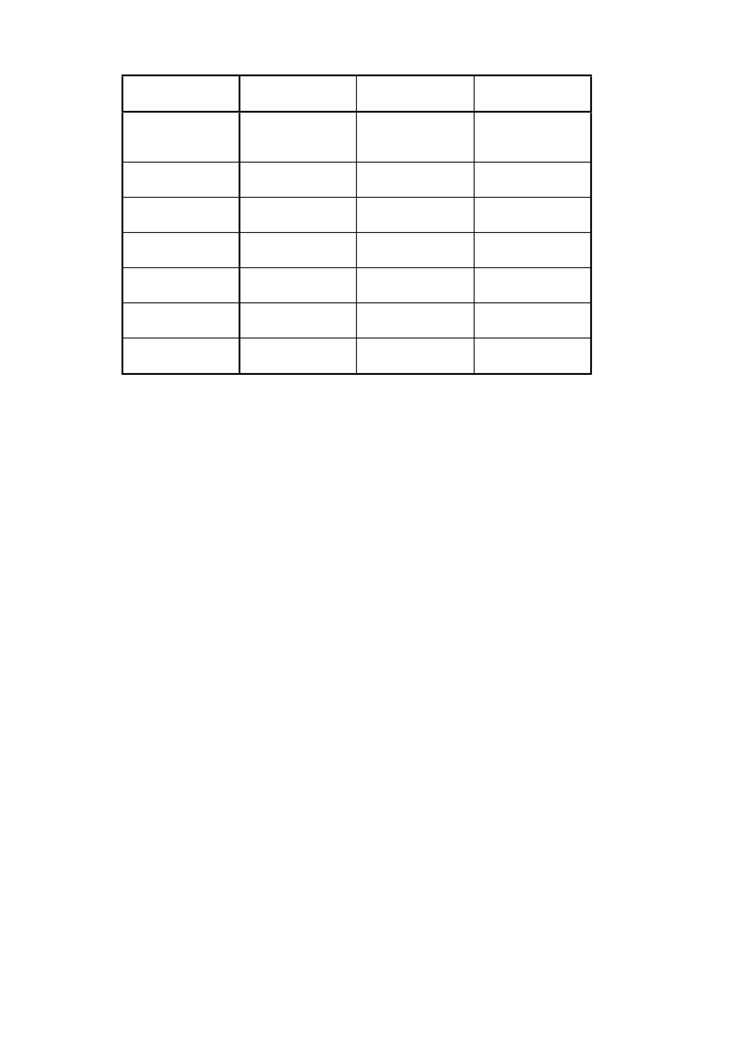
4. TRANSMISSION RATIOS
4 SPEED
AUTOMATIC
(V6 & V8 e ngine)
5 SPEED
MANUAL
(V6 engine only)
6 SPEED
MANUAL
(V8 engine only)
1ST 3.06:1 3.83:1 2.66:1
2ND 1.63:1 2.20:1 1.78:1
3RD 1.00:1 1.40:1 1.30:1
4TH 0.7:1 1.00:1 1.00:1
5TH - 0.81:1 0.74:1
6TH - - 0.50:1
REV 2.3:1 3.46:1 2.90:1
5. ENGINE DATA
ENGINE
DESIGNA TION 3.8 LITRE PFI 3.8 LITRE
SUPERCHARGED 5.7 LITRE PFI
(GEN III)
Piston
Displacement
Nom. - cm3
3791 3791 5667
Compression
Ratio 9.4:1 8.5:1 10.1:1
Number of
Cylinders 6 6 8
Bore x Stroke -
mm 96.5 X
86.3 96.5 X
86.3 99 X 92
Taxable H.P.
RAC OR SAE 34 34 48.6
Power kW
DIN @ RPM 152 kW @ 5200 171 kW @ 5200
PULP* 225 kW @ 5200
Torque Nm
DIN @ RPM 305 Nm @ 2800 375 Nm @ 3000
PULP* 460 Nm @ 4400
*PULP – Premium Unleaded Petrol

6. EXTERIOR DIME NSI O NS
SEDAN WAGON BODY
DIMENSIONS 8VK69 8VL69 8VX69 8VK35 8VL35
VEHICLE LENGTH 4891 4964 4964 5046 5084
VEHICLE WIDTH 1824 1824 1824 1824 1824
VEHICLE HEIGHT 1425 1425 1425 1521 1521
WHEELBASE 2788 2788 2788 2938 2938
OVERHANG – FRONT 933 972 972 933 972
OVERHANG REAR 1169 1203 1203 1174 1174
TREAD – FRONT 1569 1569 1569 1569 1569
TREAD - REAR 1587 1587 1587 1587 1587

7. VEHICLE WEIGHTS
SEDAN WAGON
VEHICLE
WEIGHTS 8VK69 8VL69 8VL69 8VK35 8VL35
KERB MASS – V6 MAN 1521 1577 - - -
KERB MASS - V6 AUTO 1549 1580 1636 1605 1642
KERB MASS – V6 S/C - 1609 1665 - -
KERB MASS – GENIII MAN 1597 - - 1651 -
KERB MASS – GENIII AUTO 1605 1638 1682 1658 1700
REAR AXLE LOAD – V6 1140 1140 1140 1240 1240
REAR AXLE LOAD - GENIII 1140 1140 1140 1240 1240
PAYLOAD (5 Pass. + Cargo) 408 408 480 480 408
NOTE: Figures are estimates only and measured in kg.
Payload figures must include luggage, goods, passengers, roof rack load and a full tank of fuel. If you are
towing, then the weight on the tow bar ball must also be included.
Maximum Rear Axle Load is the maximum for all conditions.
8. SERIAL NUMBERS
The complete vehicle and various com ponents of the vehicle are identified by num ber plates or numbers stamped
into the part. It is essential that when compiling warranty claims or product and field reports, the vehicle
identification number (VIN) is quoted in conjunction with the identification number of the component affected.
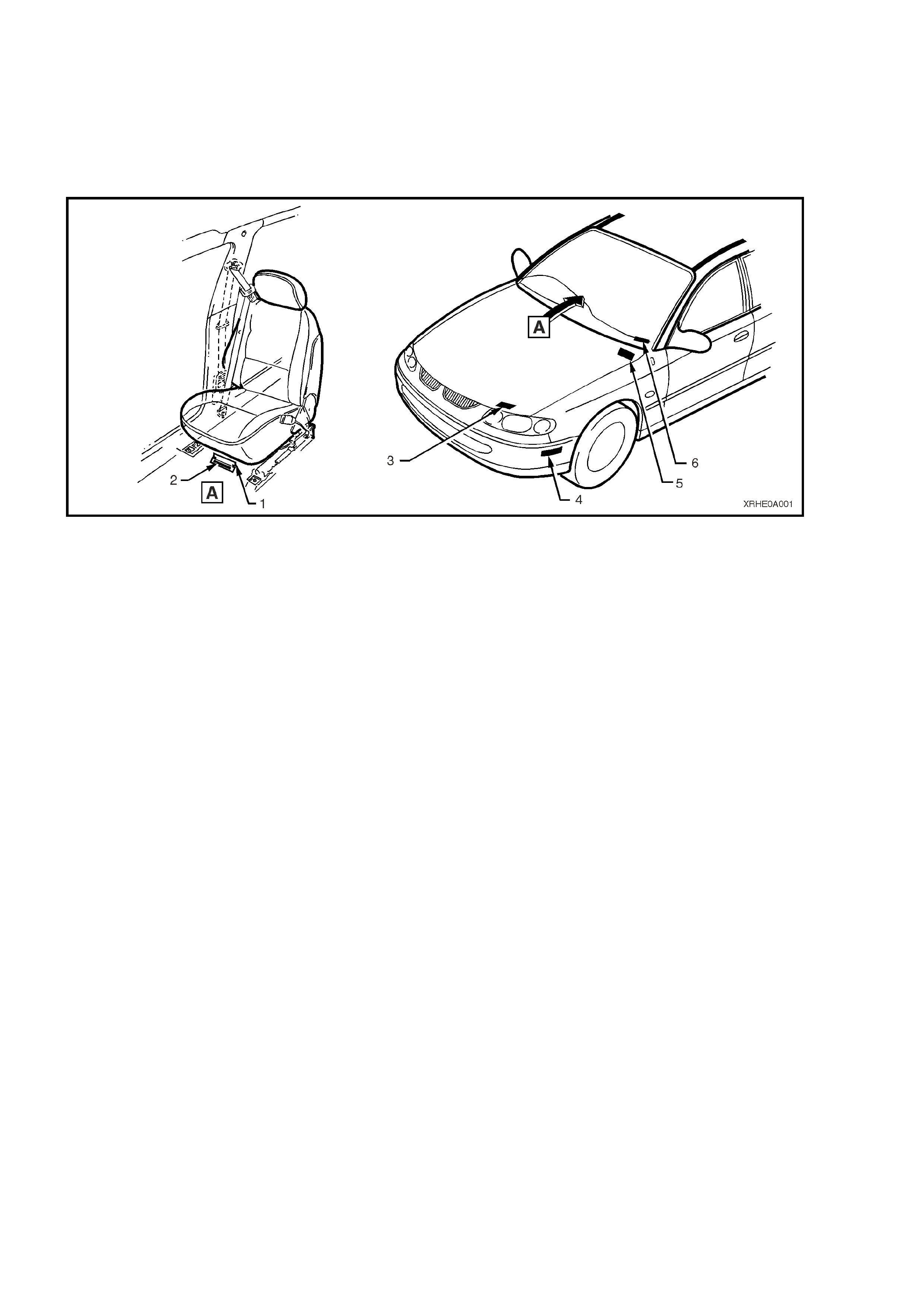
8.1 LOCATION OF IDENTIFICATION PLATES
Figure 0A-1 – Plate Location
Legend
1. Carpet flap
2. Vehicle identification number – under front seat
(Vehicles built from January 2001).
3. Body and Option identification plate - left hand side
of the front panel upper
4. Vehicle identification number plate – under the front
bumper, on the left hand side (Vehicles built prior to
January 2001)
5. Safety Compliance Plate – engine side of cockpit
module
6. Vehicle identification number plate – windscreen
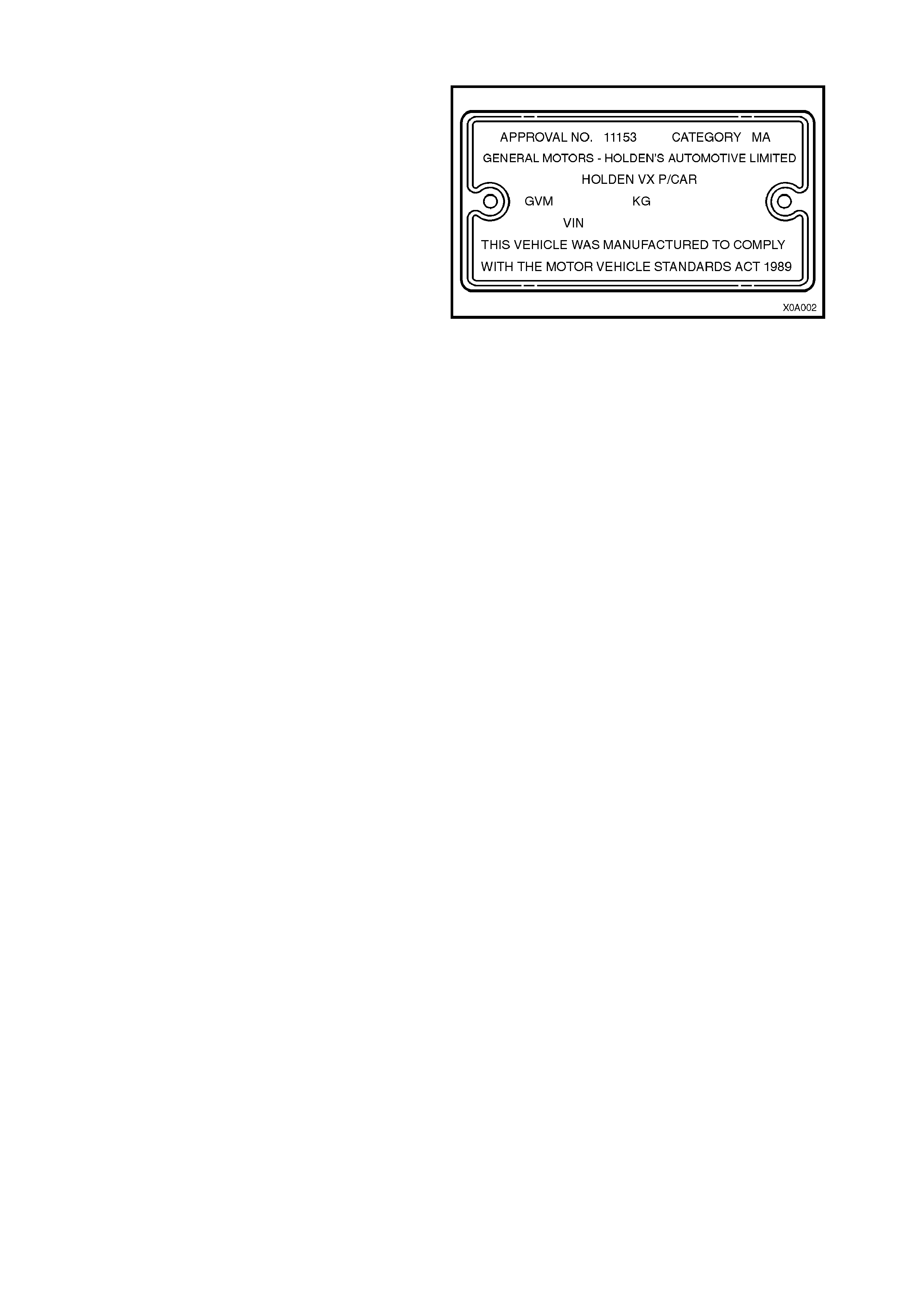
8.2 SAFETY COMPLIANCE PLATE
The Safety Compliance Plate, located on the
engine compartment side of the cockpit module, is
stamped with the following information:
COMPLIANCE PLATE APPROVAL NUMBER.
VEHICLE CATEGORY CODE.
NAME APPEARING ON COMPLIANCE PLATE
APPROVAL.
MAKE/MODEL.
SEATING CAPACITY.
DATE OF MANUFACTURE (* Variable
information).
VEHICLE IDENTIFICATION NUMBER (* Variable
information).
Figure 0A-2
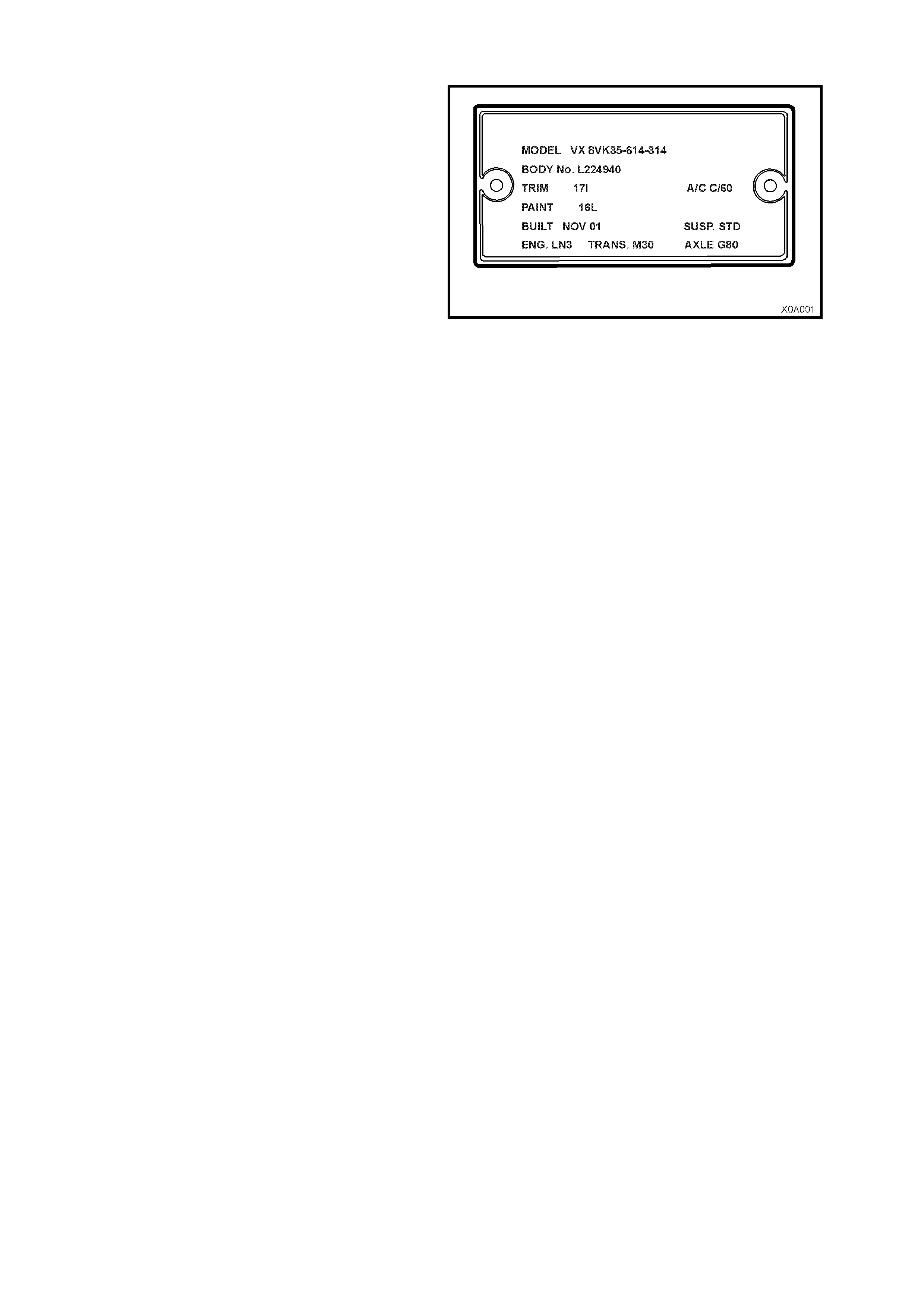
8.3 BODY AND OPTION IDENTIFICATION PLATE
The body option and identification plate, located to
the left hand side of the front panel upper, is
stamped with the following information:
MODEL:
Combination of letters and numbers identifying the
body style, the mechanical pack and smart pack
options.
NOTE: A listing of Production Option numbers and
Smart Pack Option numbers, can be found by
referring to the latest spare parts information (Part
Finder) for the applicable model.
BODY:
Production build number; run in continuous
sequence regardless of model, body type and
series.
TRIM:
Trim combination.
PAINT:
Exterior paint material and colour identification.
BUILT:
The date of manufacture by calendar month and
year in which the body shell and powertrain are
conjoined and the vehicle is driven or moved from
the production line.
SUSP
Suspension option code identification, i.e. STD
(standard) or FE2 (sport).
ENGINE, TRANSMISSION AND AXLE
Identification option codes for specific engine,
transmission and rear axle.
A/C
Identification option code C60 is used for vehicles
fitted with air conditioning. C61 Identifies vehicles
fitted with Electronic Climate Control air
conditioning.
Figure 0A-3
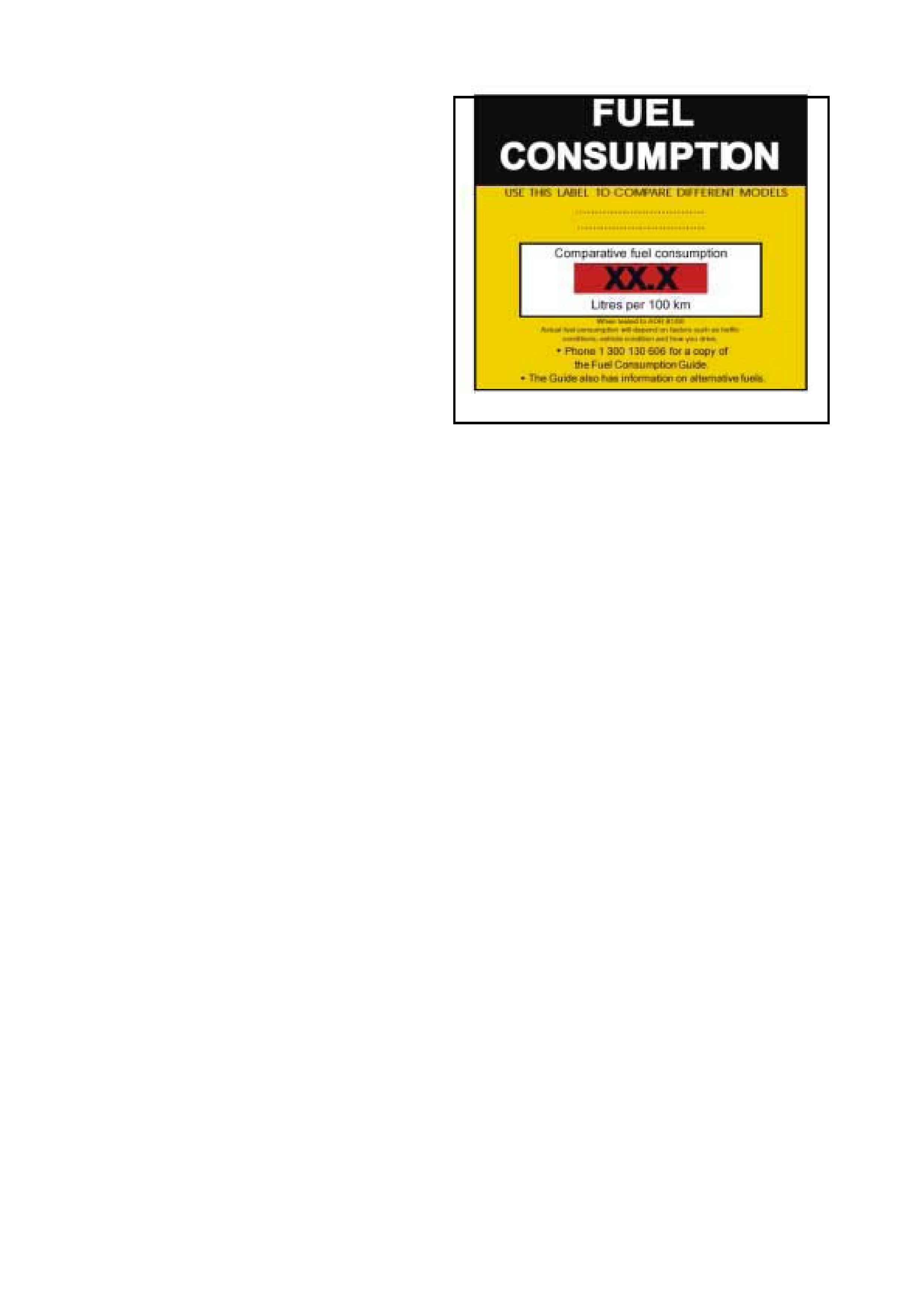
8.4 FUEL CONSUMP TION LABEL
ADR 81/00 requires that from 1st January 2001, a
label similar to that shown in Fig.0A–4 is attached
to the windscreen of any new vehicle which is
displayed for sale.
The f uel c onsumption f igures quoted are the results
of tests carried out in accordance with the City
Cycle test procedure of AS2877 – 1986, an
Australian standard for fuel consumption testing.
Each vehicle is tested under identical conditions.
The results therefore enable a comparison to be
made between vehicles.
This label should be removed from the windscreen
immediately prior to the vehicle being delivered to
the owner.
Figure 0A-4
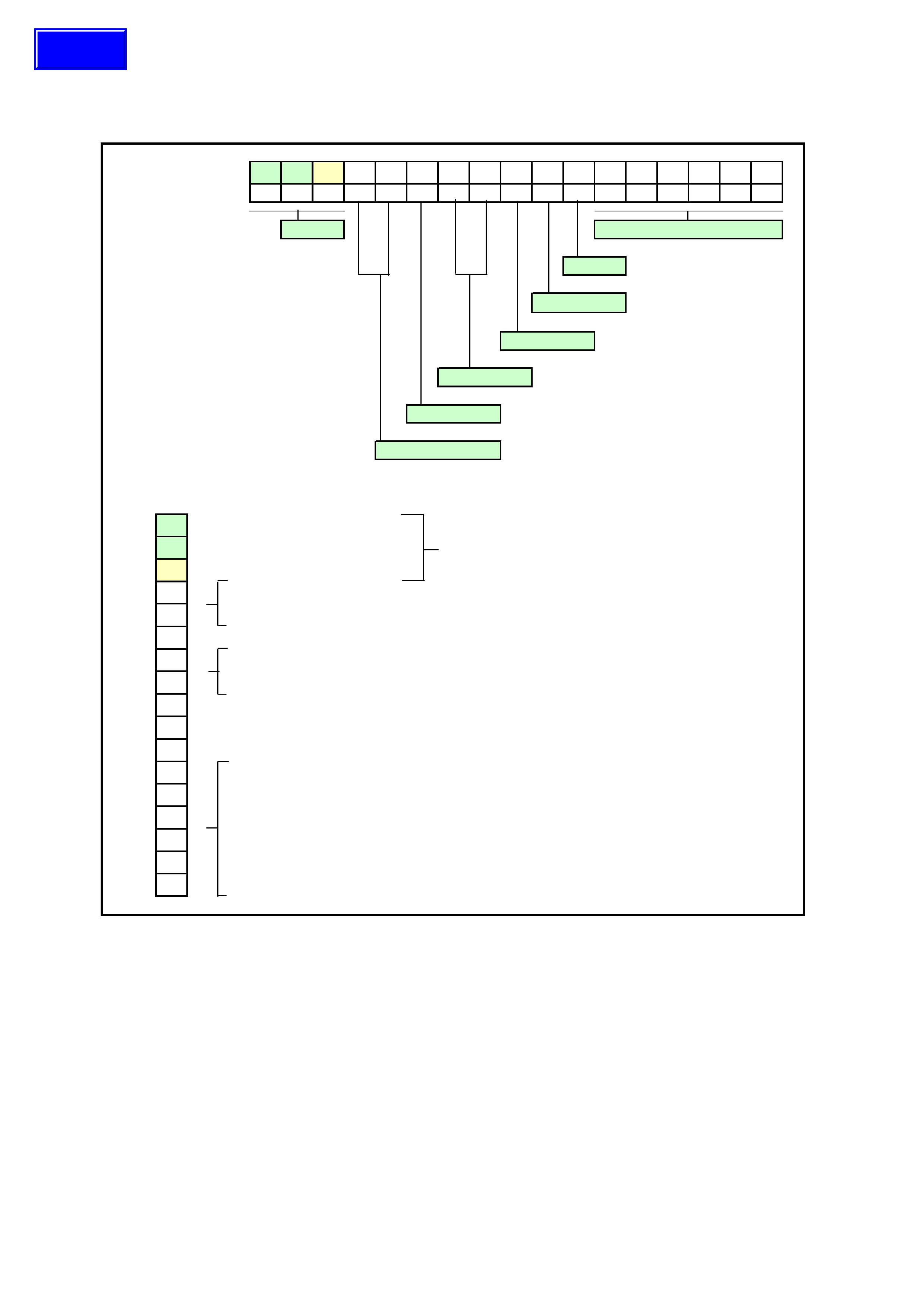
8.5 VEHICLE IDE NTIFICATION NUMBERING SYSTEM
There are two Vehicle Identification Number (VIN) plates attached to VX Series Models. The location of these plates
is under the windscreen (viewed through the windscreen aperture) and under the front bumper on the left hand side.
Figure 0A-5
Typical VIN 6H8 VXX69A1L400016
Position No 1234567891011121314151617
WMI Production sequence No
Plant
Model Yea
r
Engine
Body Style
Luxury Level
Carline Series
PNo
16Continent: 6 = Australia
2HCountry: H = Australia WMI
38Manufacturer: 8 = Holden
4VCarline Series: VX
5X
6XLuxury Level: K = Executive, L = Berlina, X = Calais
76 Body Style:
89 69 = 4 door sedan, 35 = Wagon
9AEngine type: A = 3.8 V6, R = S/C 3.8 V6, F = 5.7 V8
10 1Model Year : 1 = 2001
11 LPlant Code: L = Elizaberth
12 4
13 0
14 0Production
15 0Sequence No
16 1
17 6
Techline
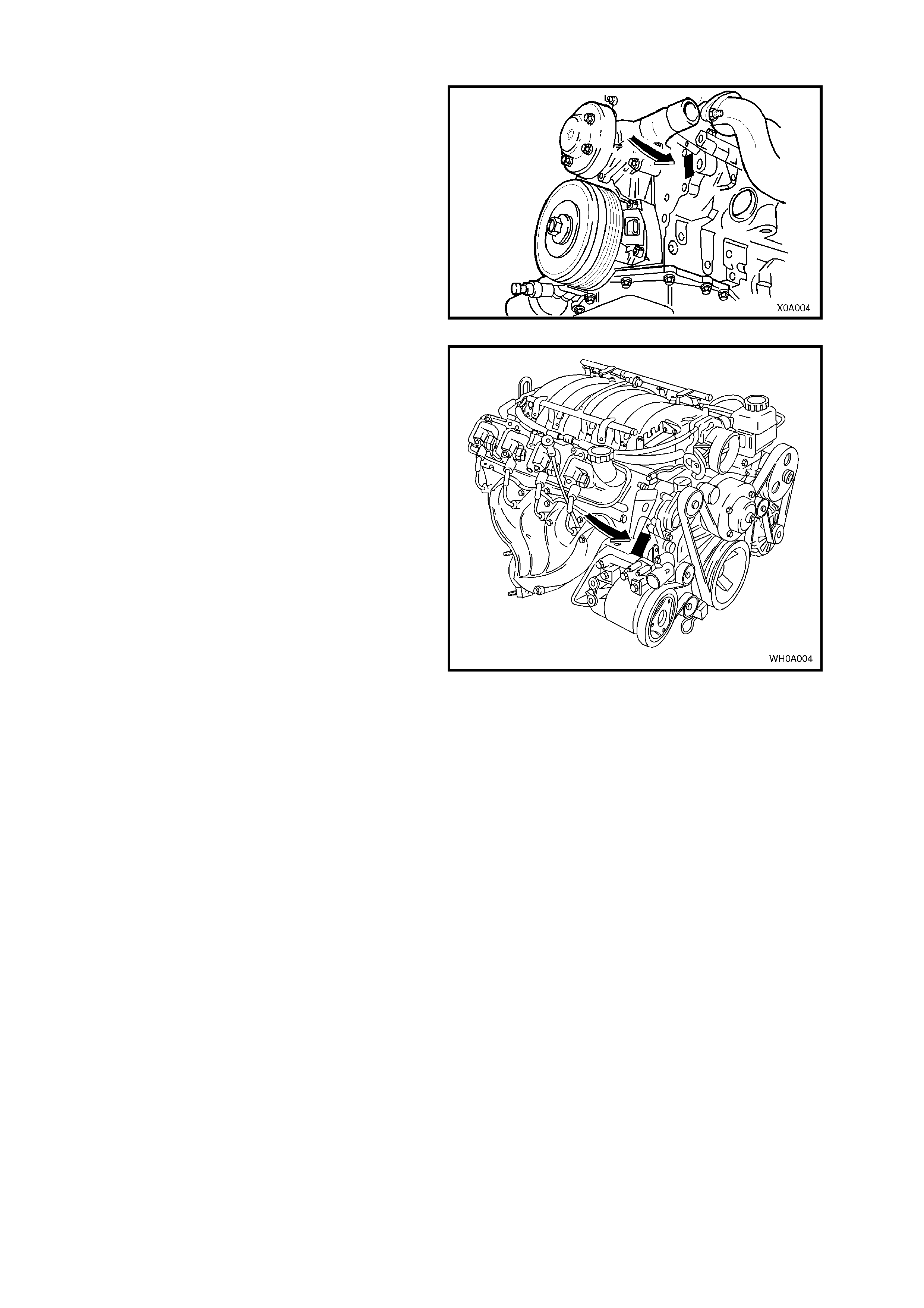
8.6 ENGINE SERIAL NUMBER
3.8 LITRE V6 ENGINE
The engine serial number for the 3.8 litre V6 and
V6 supercharged engines is stamped on a pad
located adjacent to the engine coolant outlet pipe,
refer Fig. 0A-6
Figure 0A-6
5.7 LITRE GEN III V8 ENGINE
The 5.7 litre Gen III V8 engine serial number is
stamped on a pad located adjacent to the engine
coolant outlet pipe, refer to Fig. 0A-7.
Figure 0A-7
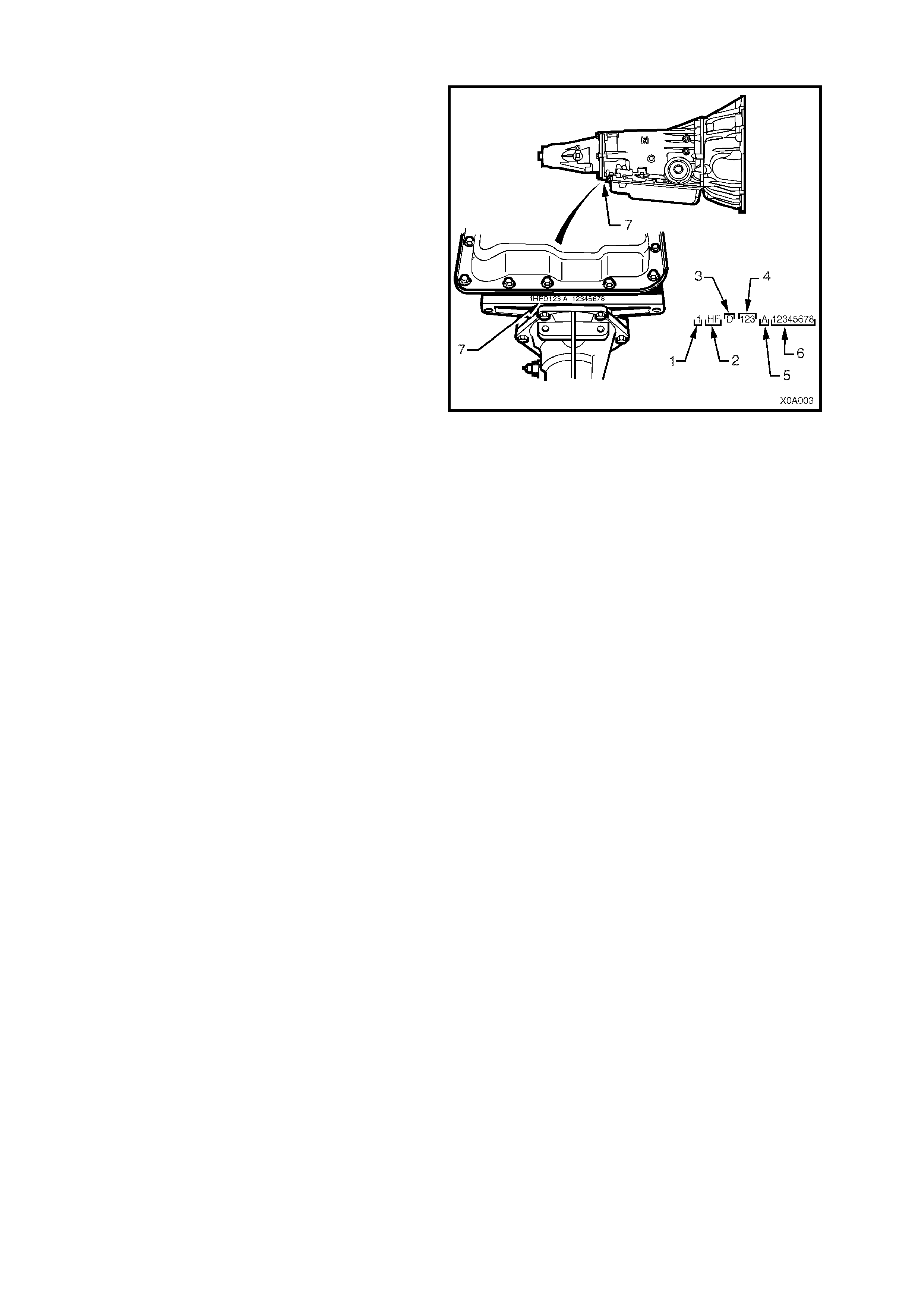
8.7 AUTOMATIC TRANSMISSION SERIAL NUMBER
The automatic transmission serial number is
stamped into a machined surface at the rear
underside of the transmission centre case, refer to
Fig. 0A-8.
1. Model Year (‘0’ = 2000 ‘1’ = 2001)
2. Model: V8 – 5.7 litre...................... HP
V6 – 3.8 litre ..................... HF
V6 Supercharged – 3.8 litre HN
3. Transmission Model Identifier (D = 4L60-E).
4. Julian Date (or day of year).
5. Shift Built (A, B, J = first shift; C, H, W = second
shift).
6. Individual Transmission Serial Number.
7. Transmission Identification Number Location.
Figure 0A-8
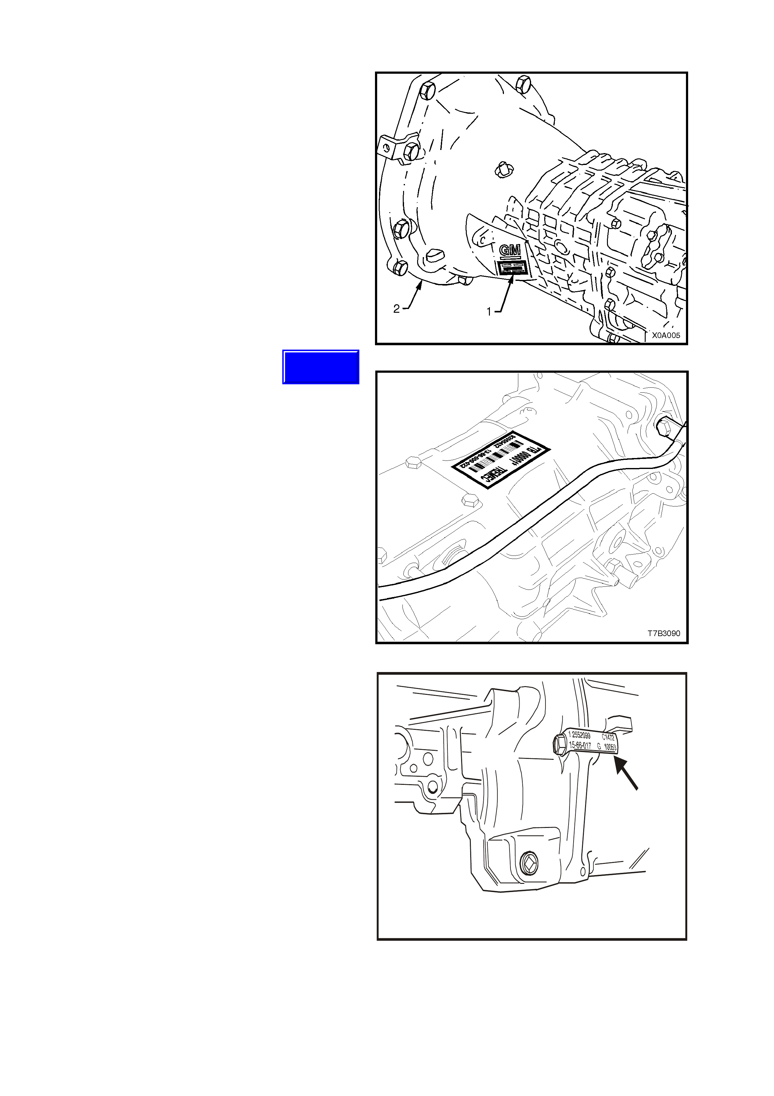
8.8 MANUAL TRANSMISSION SERIAL NUMBER
5 SPEED MANUAL TRANSMISSION
The Getrag 5 speed manual transmission serial
number is located on a self-adhesive label (1)
attached to the left side of the transmission front
cover.
This number provides coded information that could
be significant to parts interpretation and should be
referred to when ordering replacement parts.
NOTE: if this label is removed or becomes
unreadable, the s erial number is als o s tamped onto
the lower left hand side of the transmission front
cover (2).
Figure 0A-9
6 SPEED MANUAL TRANSMISSION
The Borg-W arner (Tremec) T56 six speed manual
transmission serial number is located on a self-
adhesive decal attached to the top of the
transmission case.
This number provides coded information that could
be significant to parts interpretation and should be
referred to when ordering replacement parts.
In addition, an identification tag is attached to the
transmission under an extension housing bolt, on
the right hand side.
Figure 0A-10
T20A002
Figure 0A-11
Techline
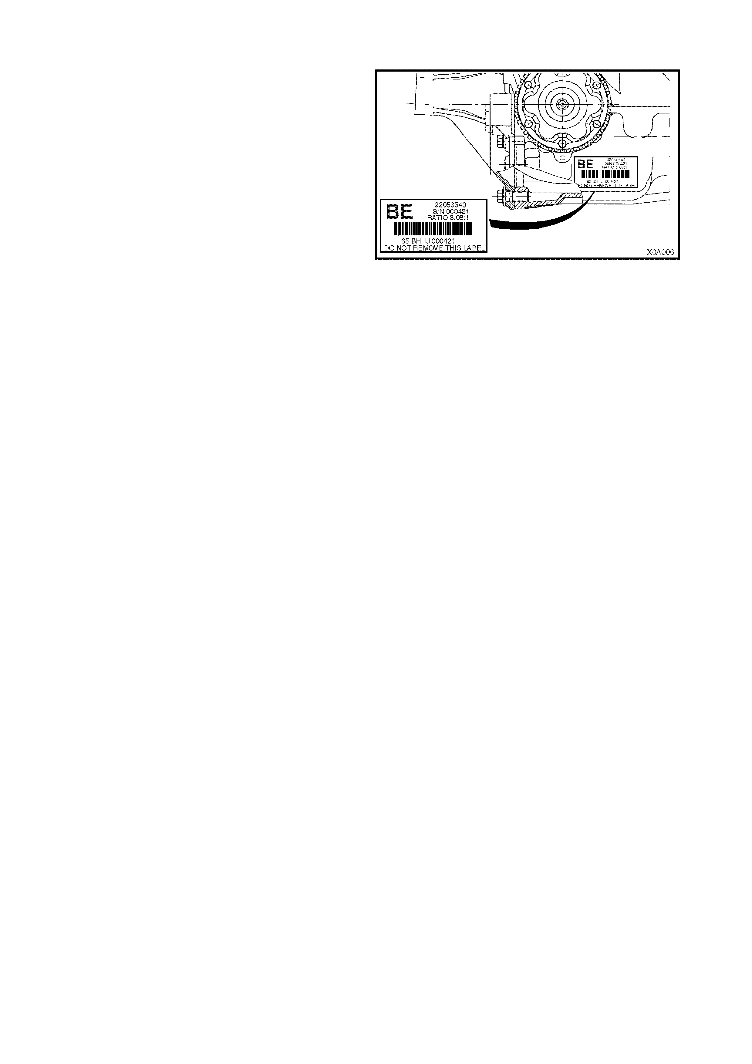
8.9 FINAL DRIVE ASSEMBLY IDENTIFICATION
An identification tag is adhered to the final drive
assembly to the RHS of the carrier housing, refer to
Fig. 0A-12. T he tag carries the Holden part number for
the assembly, the final drive ratio and the serial
number of the assembly.
Figure 0A-12
9. ADDI TIONAL GENERAL I NFORMATION
9.1 ELE CTRICAL TRANSIENTS AND RADIO FREQUENCY INTERFERENCE
Electronic c ircuits are us ed in VX Series Models to perform a num ber of f unctions ass ociated with electronic cruis e
control, electr onic engine and trans miss ion contr ol system s etc. T hes e c irc uits c an be damaged or malf unc tion as a
result of electrical transients or excessive radio frequency (RF) radiation.
ELECTRICAL TRANSIENTS
Electrical transients are high voltage spikes, produced by the sudden switching or interruption of electric currents.
Older s tyle tim ing lights and batter y chargers can pr oduc e ser ious tr ans ients, hence, it is important to us e only good
quality equipment suitable for use with electronic systems.
It is also good practice to ensure that the battery is disconnected before using a battery charger.
Indiscriminate fitting of solenoids, indicators or relays can also cause transients.
RADIO FREQUENCY INTERFERENCE
One of the chief sources of RF interference is the ignition system. Other sources include CB radio and radio
telephones. The following are normally used to suppress RF interference.
• Resistors eg. High Tension Cables and Connectors.
• Capacitors and Choke Coils.
• Metal Braid for screening leads or suppression covers made from conductive material for screening equipment.
To prevent damage to equipment:
Do not replace interference suppressed high tension ignition cables or connectors with unsuppressed types.
Do not remove or reposition interference suppression filters or capacitors.
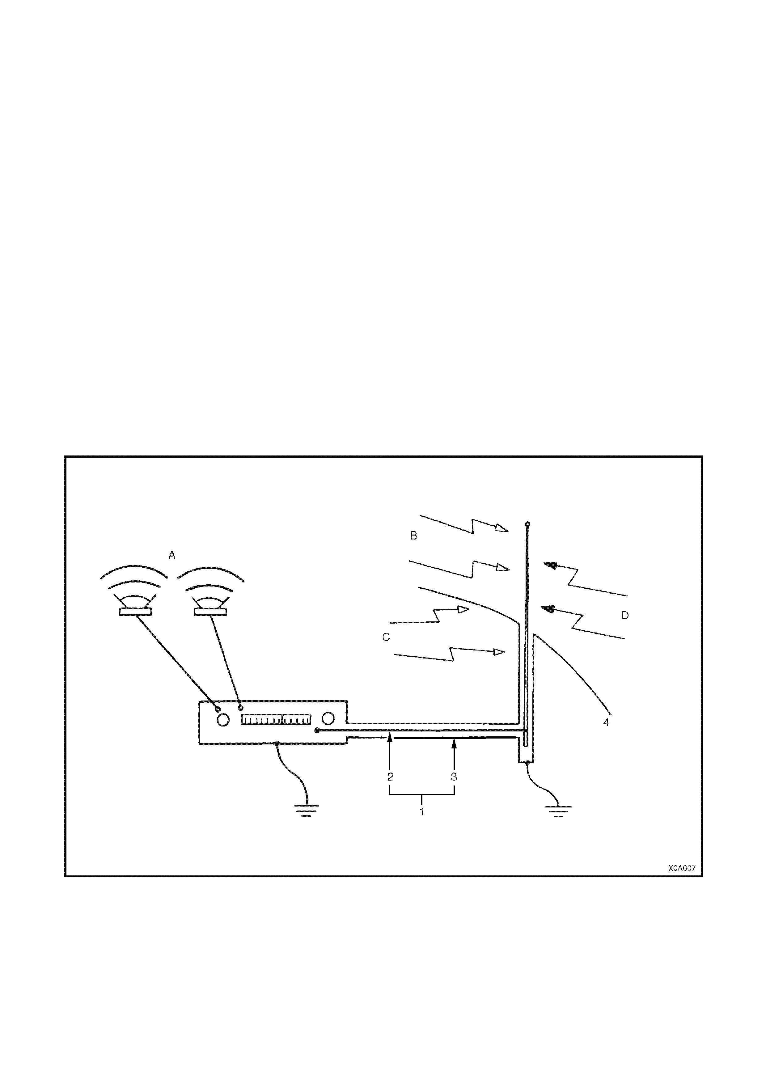
Figure 0A-13
A. Music
B. Signal from Radio Station
C. Internal Interference
D. External Interference
1. Antenna Cable
2. Cable Core
3. Cable Braid
4. Body

9.2 STATIC ELECTRICITY
Care should be exercised when handling electronic equipment eg. the Powertrain Control Module (PCM), to avoid
touching the terminals unnecessarily. Static electricity, which is present on every person, can cause damage to
some electronic components.

9.3 PUSH OR TOW STARTING
Do not push or tow start VX Series vehicles. Push or tow starting can result in un-burnt fuel passing through the
exhaust to the catalytic converter, causing damage to the converter.

10. CONSOLIDATED TOOL LIST
Special Ser vice Tools for VX Ser ies Models are the sam e as those used on VT Series Models and are as detailed
in Section 0A GENERAL INFORMATION of the VT Series I and VT Series II Service Information. It should be
noted that the lists in these two Sections should be read in conjunction with one another.