
SECTION 0B - LUBRICATION AND SERVICE
IMPORTANT
Before performing any Service Operation or other procedure described in this Section, refer to Section
00 CAUTIONS AND NOTES for correct workshop practices with regard to safety and/or property damage.
1. GENERAL I NFORMATI O N
All inf ormation r elating to lubrication and ser vice procedures car ries over from the inform ation published for the VT
Series models, noting the following:
• A revised oil specification is applicable for vehicles fitted with V6 engines and LPG.
• The lubricant level check and refill procedure for the Tremec 6 speed manual transmission (GEN III V8) has
been revised.
• Front door c heck link assem blies do not r equire lubrication at anytim e. Rear door check link assemblies should
be serviced according to the VT Series service schedule.
• The Abnormal Operating Conditions service schedule has been revised to include the required inspection
interval for the propeller shaft rubber couplings.
For all other information relating to lubrication and service procedures, refer to
Section 0B LUBRICATION AND SERVICE in the VT Series II Service Information.
Techline
Techline
Techline

2. ENGINE LUBRI CATION
2.1 ENGINE OIL VISCOSITY AND CLASSIFICATION RECOMMENDATIONS
For VX Series models fitted with V6 engines and LPG, engine oil to Holden Specification HN2314 must be used.
The specified oil classifications are as follows: BP Vanellus C3 15W/40 SH CG4
Mobil LPG Oil 15W/40 SH CG4
3. MANUAL TRANSMISSION LUBRI CATION AND SERVICE
3.1 LUBRICANT LEVEL
TREMEC 6 SPEED MANUAL TRANSMISSION (GEN III V8)
Important: This transmission is classified as
being a “ Fill for Life” transmission and periodic
checking of the lubricant level is not required.
The only time that fluid level checking is required, is
in the event of a f luid leak fr om the transmis sion, or
if the transmission has been removed from the
vehicle.
1. Raise the front and rear of the vehicle and
support on safety stands, ensuring that the
vehicle is level. Refer to
Section 0A GENERAL INFORMATION of the
VT Series I Service Information, for the
location of jacking points.
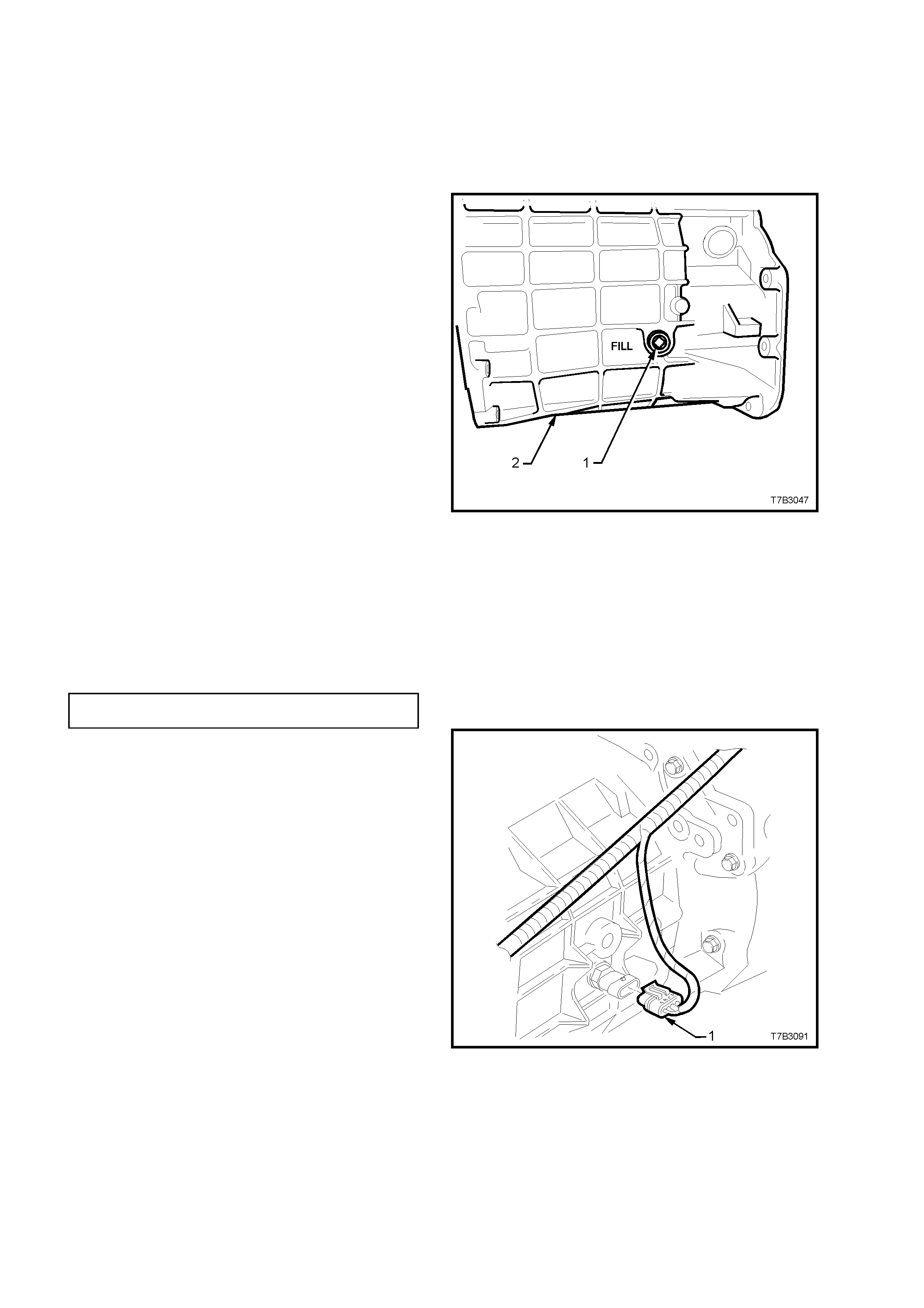
2. Place a drain tray beneath transmission and
remove transmission filler plug (1) from
left-hand side of transm ission case ( 2), using a
3/8” drive socket bar.
NOTE: Depending on the severity of the loss, fluid
will probably flow from the filler plug hole, following
removal.
3. Allow excess fluid to drain until flow stops. If
required, top up fluid level until it does flow out.
4. Clean the thr eads of the f iller plug, apply thread
sealant such as Loctite 567 or equivalent (GM
P/N 12346004), and then install filler plug,
tightening to the correct torque specification.
Do not apply Teflon thread tape to the plug
threads.
Figure 0B-1
TRANSMISSION FILLER PLUG
TORQUE SPECIFICATION 20 - 34 Nm
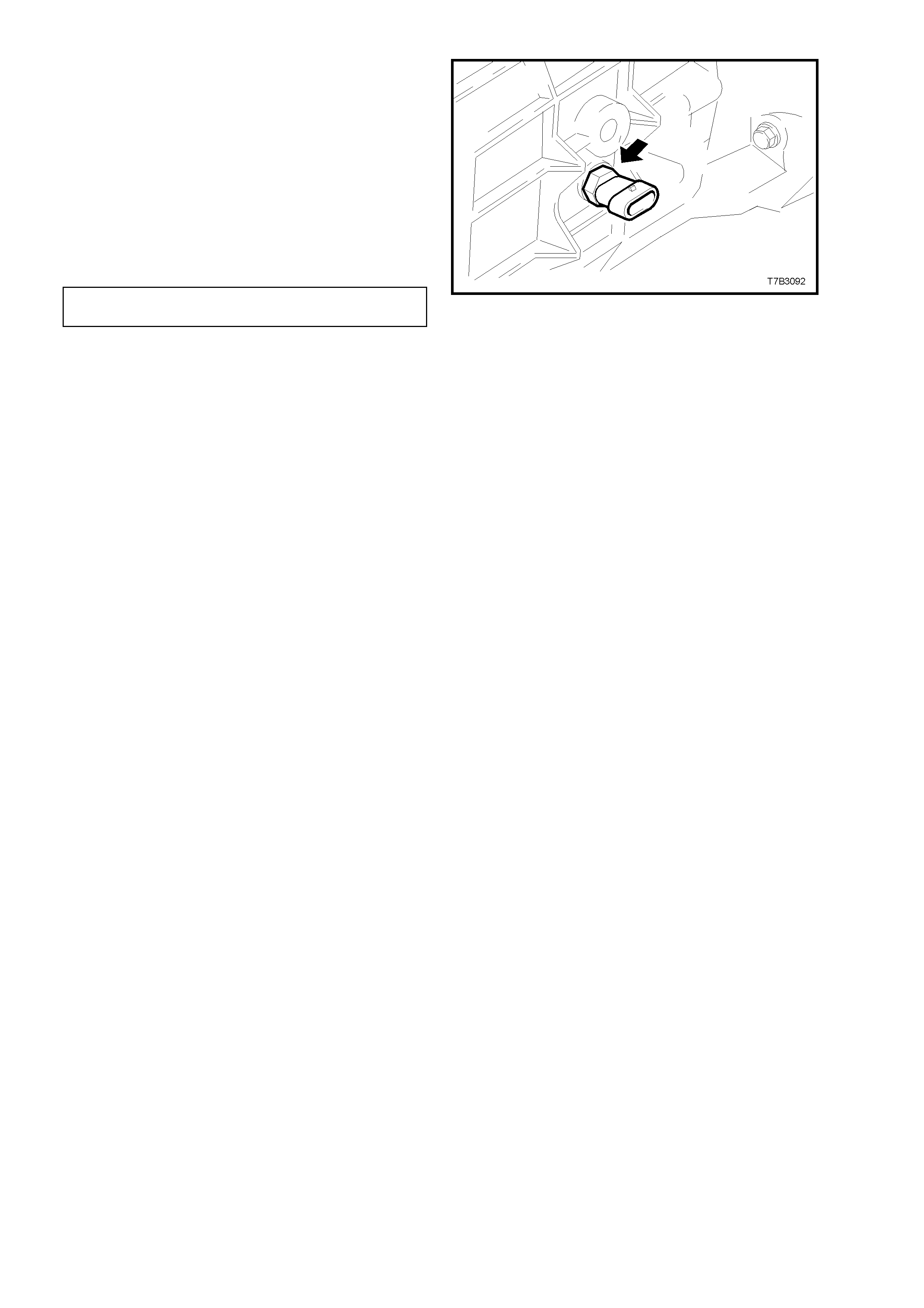
5. Remove the back-up lamp switch as follows:
a. Remove wiring harness connector (1) from
switch, located on the right-hand side of
the transmission case.
Figure 0B-2
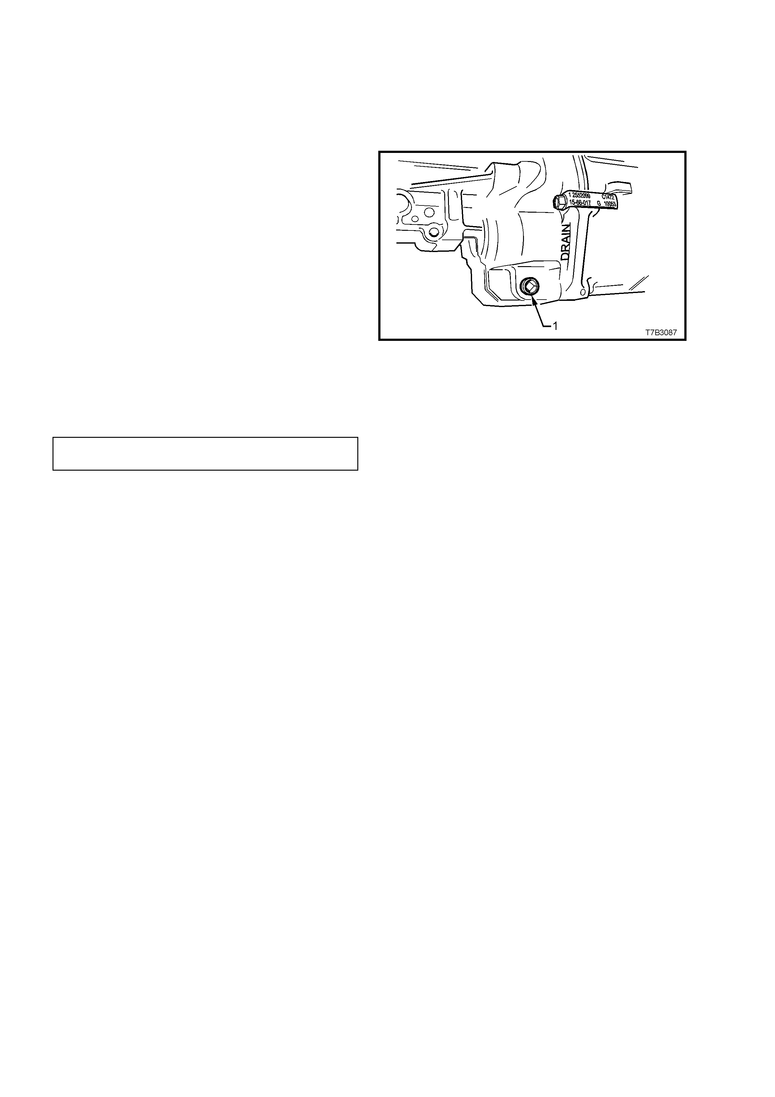
b. Loosen, and then remove switch (arrow)
from the transmission case.
6. Using commercially available fluid dispensing
equipment, add a measured, 0.5 litre of the
recomm ended lubr ic ant to the trans miss ion, via
the back-up lamp switch threaded hole in the
transmission case.
7. Apply Loctite 567 or equivalent
(GM P/N 12346004), to the cleaned threads of
the back-up lamp switch.
8. Install switch into transmission case and tighten
to the correct torque specification.
9. Install wiring harness connector into switch.
10. Remove safety stands and lower vehicle to
ground.
11. Check back-up lamp operation.
Figure 0B-3
BACK-UP LAMP SWITCH
TORQUE SPECIFICATION 20 - 34 Nm
3.2 DRAINING AND REFILLING TRANSMISSION
Should a lubricant change be required, then the
following procedure should be adopted.
NOTE: Periodic transmission lubricant changes are not
necessary. However, the lubricant should be changed
when overhauling the transmission.
1. Raise the front and rear of the vehicle and
support on safety stands, ensuring that the
vehicle is level. Refer to
Section 0A GENERAL INFORMATION of the
VT Series I Service Information, for the
location of jacking points.
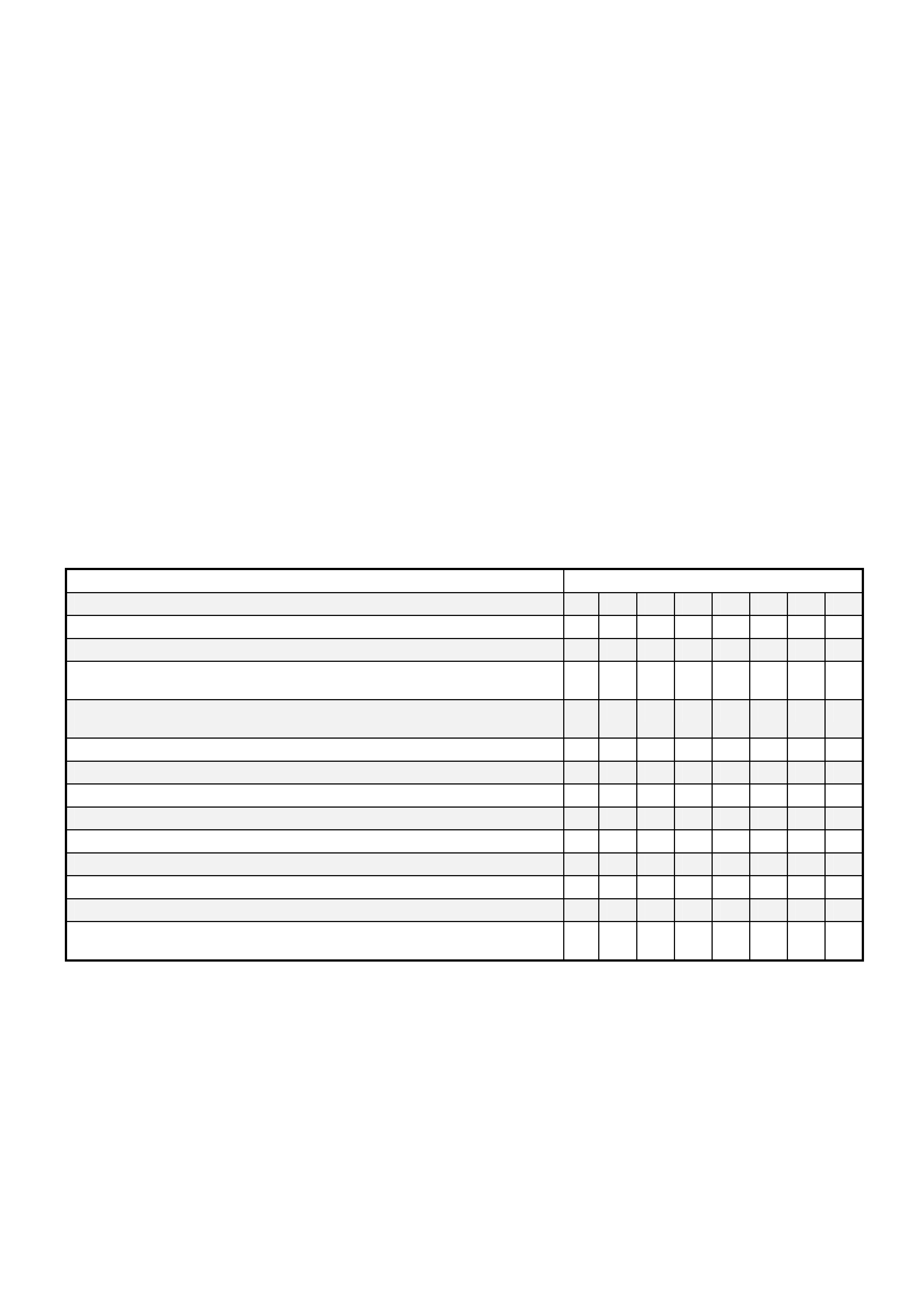
2. Place a drain tray beneath transmission and
remove filler plug (refer to ‘1’ in Figure 0B-1)
and then the drain plug (1) from the
transmission extension housing using a 3/8”
drive socket bar.
3. After draining, clean the threads of the drain
plug, apply thread sealant such as Loctite 567
or equivalent (GM P/N 12346004), then install,
tightening to the correct torque specification.
NOTE: Do not apply Teflon thread tape to the plug
threads.
4. Refill transmission to the correct level with
Dexron III transmission fluid (to Holden
specification HN2126) as outlined in
3.1 LUBRICANT LEVEL in this Section.
Figure 0B-4
TRANSMISSION DRAIN PLUG
TORQUE SPECIFICATION 20 - 34 Nm
4. SERVICING
4.1 ABNORMAL OPERATING CONDITIONS
If the vehicle is driven under any of the abnormal conditions listed below, it is recommended that some items be
serviced more frequently than in the maintenance plan.
The extra services are only required while the vehicle is driven under the abnormal conditions. If any of these
conditions are enc ounter ed on a one of f bas is, then any additional servicing should be for that time only. As a guide,
if the vehicle is operated continually over a period of 1 month or 1000 km under the abnormal conditions, then
additional servicing may be required.
ABNORMAL CONDITIONS
A When driving less than 10 000 km in 6 months.
B Dust, dirt, loose road material.
C Muddy and wet areas.
D Cold weather (below 5 C) and when most trips are less than 5 km.
E Stop-start driving, excessive idling or low speed operation as experienced in inner city driving
e.g. Taxi, door to door delivery.
F Caravan or trailer towing.
G Extended heavy load high speed operation in temperatures above 35 C.
H When driving more than 250 000 km per 5 years.
EXTRA SERVICES REQUIRED
SERVICE REQUIRED ABNORMAL CONDITION
Change engine oil @ 6 months A
Change automatic transmission fluid and strainer @ 4 years A
Change automatic transmission fluid and strainer @ 20 000 km E F G
Inspect front suspension and steering for leaks, wear or damage @
5000 km B C
Replace engine oil filter @ 5000 km or 3 months (whichever occurs
first) B
Change engine oil @ 5000 km or 3 months (whichever occurs first) B D F G
Relace air cleaner element @ 20 000 km B
Inspect and clean park brake linings @ 20 000 km B C
Change differential oil @ 20 000 km F G
Change brake fluid @ 1 year if 1600 kg (or higher) tow bar fitted * F
Change power steering fluid @ 50 000 km F G
GEN III V8 engine only: Change engine coolant H
Carbon canister: Inspect @ 20 000 km and change @ 80 000 km B C
Inspect rubber propeller shaft coupling @ 10 000 km after 160 000 km
of abnormal operating conditions F G
* Brake fluid deteriorates with time and should normally be replaced every 2 years. However, heavy duty towing
requires fresher fluid due to the higher demand on the brake system. Therefore, brake fluid should be replaced
each year if a 1600 kg (or higher) tow bar is fitted, so that the brake system can cope with the next year’s towing
requirements.