
SECTION 0C – TECH 2
IMPORTANT:
Before performing any Service Operation or other procedure described in this Section, refer to Section
00 CAUTIONS AND NOTES for correct workshop practices with regard to safety and/or property damage.
1. GENERAL I NFORMATI O N
The Tech 2 is a hand-held diagnostic com puter designed spec ifically to help Dealer ship Technicians diagnose and
repair electronic systems used on Holden vehicles.
For futher information on Tech 2 features refer to Section 0C - TECH 2 of the VT Series I Service Information.
Techline
Techline
Techline
Techline
Techline
Techline
Techline
Techline
Techline
Techline
2. PROGRAMM ING TECH 2
2.1 GENERAL INFORMATION
Before T ech 2 can be us ed on a vehicle it will have
to be programmed with the latest software. Tech 2
programming is used to update Tech 2. TIS 2000
contains the current Tech 2 applications (program)
and one preceding version. Tech 2 can be
programmed using the following procedure.
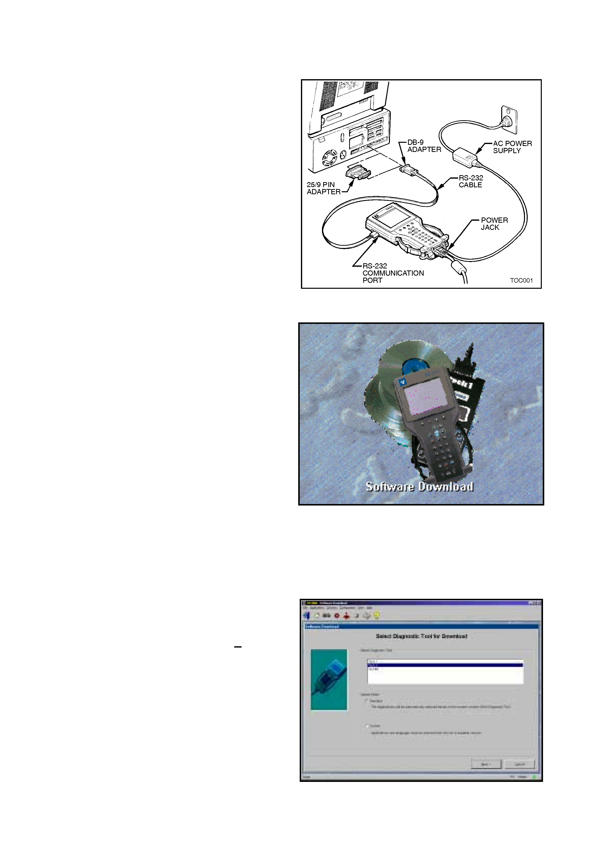
1. Connect the RS-232 cable to the Tech 2 RS-
232 communication port.
2. Connect the other end of the RS-232 cable to
the DB-9 adapter and then connect the DB-9
adapter to the s erial com munication por t of your
computer.
NOTE: If your computer has a 25 pin serial
com munication port you will need to fit the 25/9 pin
adapter between the nine pin DB-9 adapter and the
serial communication port.
3. Connect the AC power supply to the Tech 2
power jack.
4. Press the PWR button to turn on Tech 2.
Figure 0C-1 Connecting Tech 2 to the PC
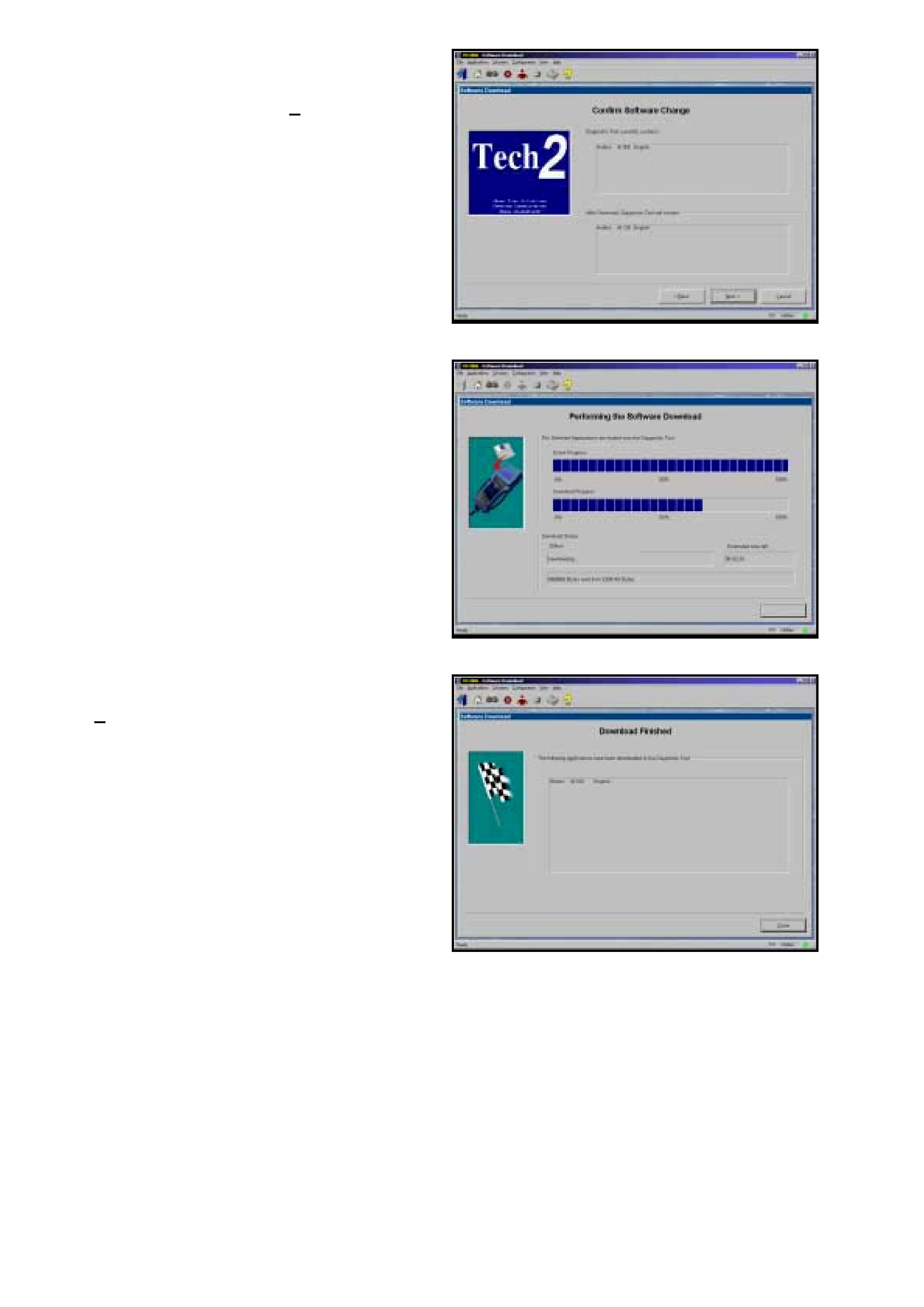
5. From the TIS 2000 Main Menu, click on the
Software Download icon.
There are two download modes: Standard and
Custom.
Standard installs the latest software version of
the currently programmed language and make
onto the Tech 2.
Custom allows you to perform backdating,
install different make software or alternate
languages onto the Tech 2.
STANDARD UPDATE
The procedure for performing a standard Tech 2
update using the TIS 2000 Software Download is
as follows:
1. Connect the Tec h 2 to the PC us ing the RS-232
cable, DB-9 adapter and the 25/9 pin adapter if
required.
2. Power up the Tech 2 us ing the AC power supply
that comes standard with the Tech 2 kit.
Tech 2 must be at the Title Screen.
Figure 0C-2 Software Download Icon
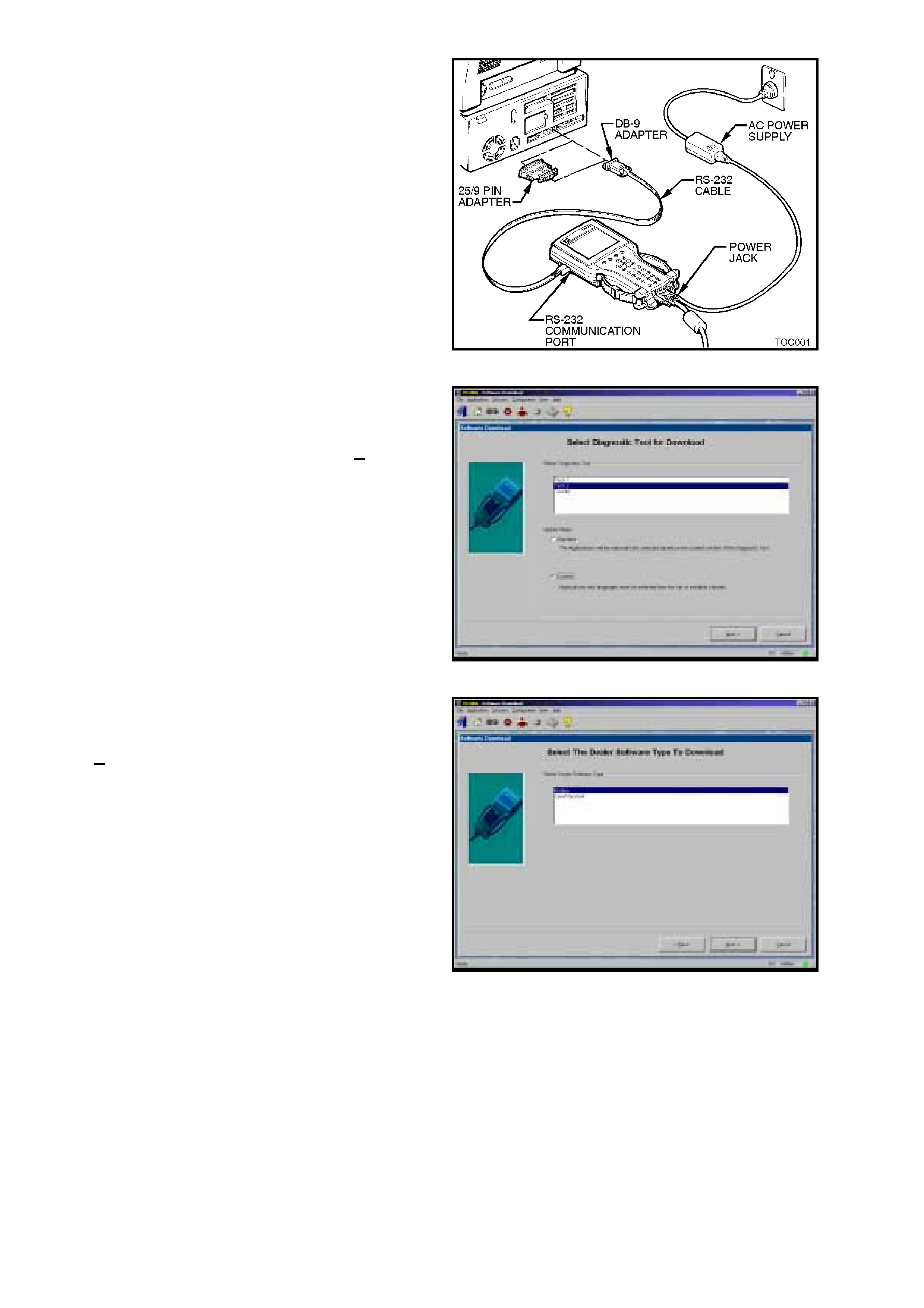
3. At the TIS 2000 Select Diagnostic Tool for
Download screen highlight your selection
(Tech 2) and select the Standard update mode.
After making your selections, click Next>. A
message will appear indicating the PC is
reading the contents of the diagnostic tool.
Figure 0C-3 Select Diagnostic Tool for Download
4. The PC will display a Confirm Software Change
screen showing what software version the Tech
2 currently contains and what it will contain after
the software download. Click Next> to continue.
Figure 0C-4 Confirm Software Changes
5. A Performing the Software Download screen
will appear. It tracks the status of the software
download.
Figure 0C-5 Software Download
6. When the software download is complete, a
Download Finished screen appears. Click on
Close to close the application. The scan tool
now contains the latest software.
Figure 0C-6 Download Finished
CUSTOM UPDATE
A custom update is used to backdate the Tech 2,
install Non-Holden software or install different
language software. After selecting Custom as the
update mode from the selection screen, do the
following:
1. Connect the Tech 2 to the PC using the RS-
232 cable, DB-9 adapter and the 25/9 pin
adapter if required.
2. Power up the Tech 2 using the AC power
supply that comes standard with the Tech 2 kit.
Tech 2 must be at the Title Screen.
Figure 0C-7 Connecting Tech 2 to the PC
3. At the TIS 2000 Select Diagnostic Tool for
Download screen highlight your selection
(Tech 2) and select the Custom update mode.
After making your selections, click Next>. A
message will appear indicating the PC is
reading the contents of the diagnostic tool.
Figure 0C-8 Select Diagnostic Tool for Download
4. The Select The Dealer Software Type to
Download screen will then be displayed.
Select the desired software type and the click
Next> to continue.
Figure 0C-9 Select The Dealer Software Type to Download
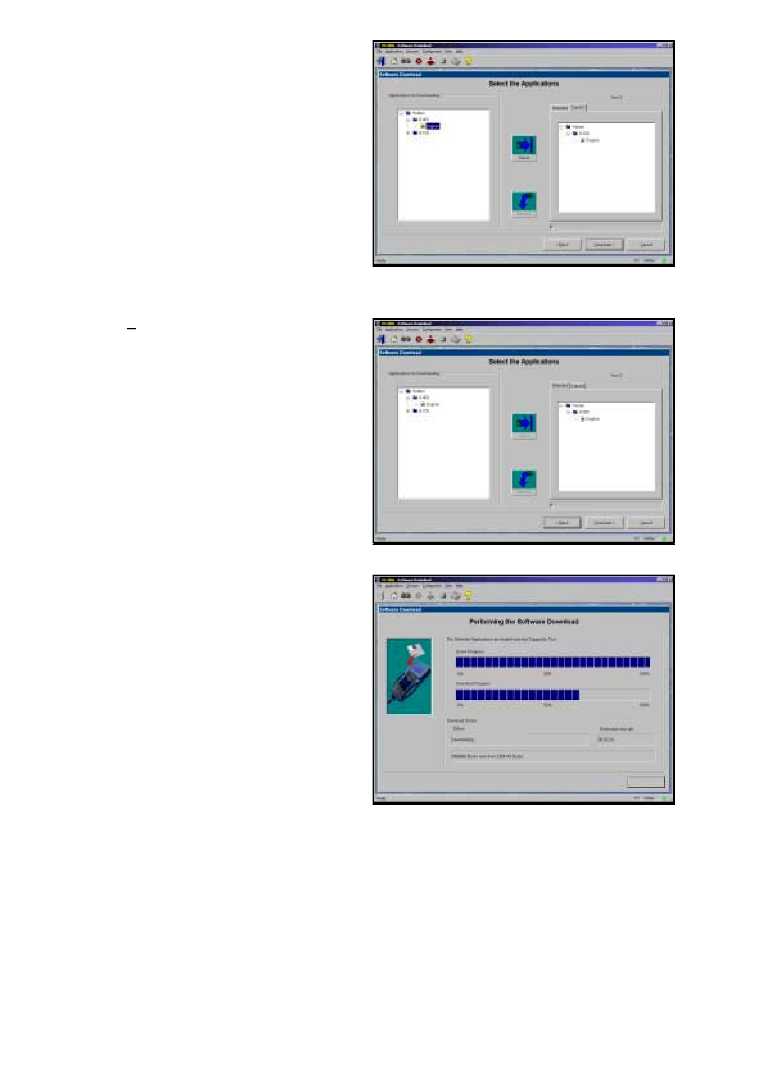
5. A Select the Applications screen will appear.
The left side of the screen lists software
release numbers . Click on the “+” sign to see a
list of different languages for each release.
6. Select the desired software version and
language by either double-clicking or clicking
the Select icon. The selected software will
appear in the right side of the screen.
To compare the current and selected Tech 2
software, click on the Current or Selected
tabs on the right side of the screen.
Figure 0C-10 Select The Application
7. Click on Download> to begin the update.
Figure 0C-11 Selected Software
8. A Performing t he Soft ware Dow nload screen
will appear. It tracks the status of the software
download.
Figure 0C-12 Software Download

9. When the software download is complete, a
Download Finished screen appears. Click on
Close to close the application. T he T ech 2 now
contains the selected software.
Figure 0C-13 Download Finished
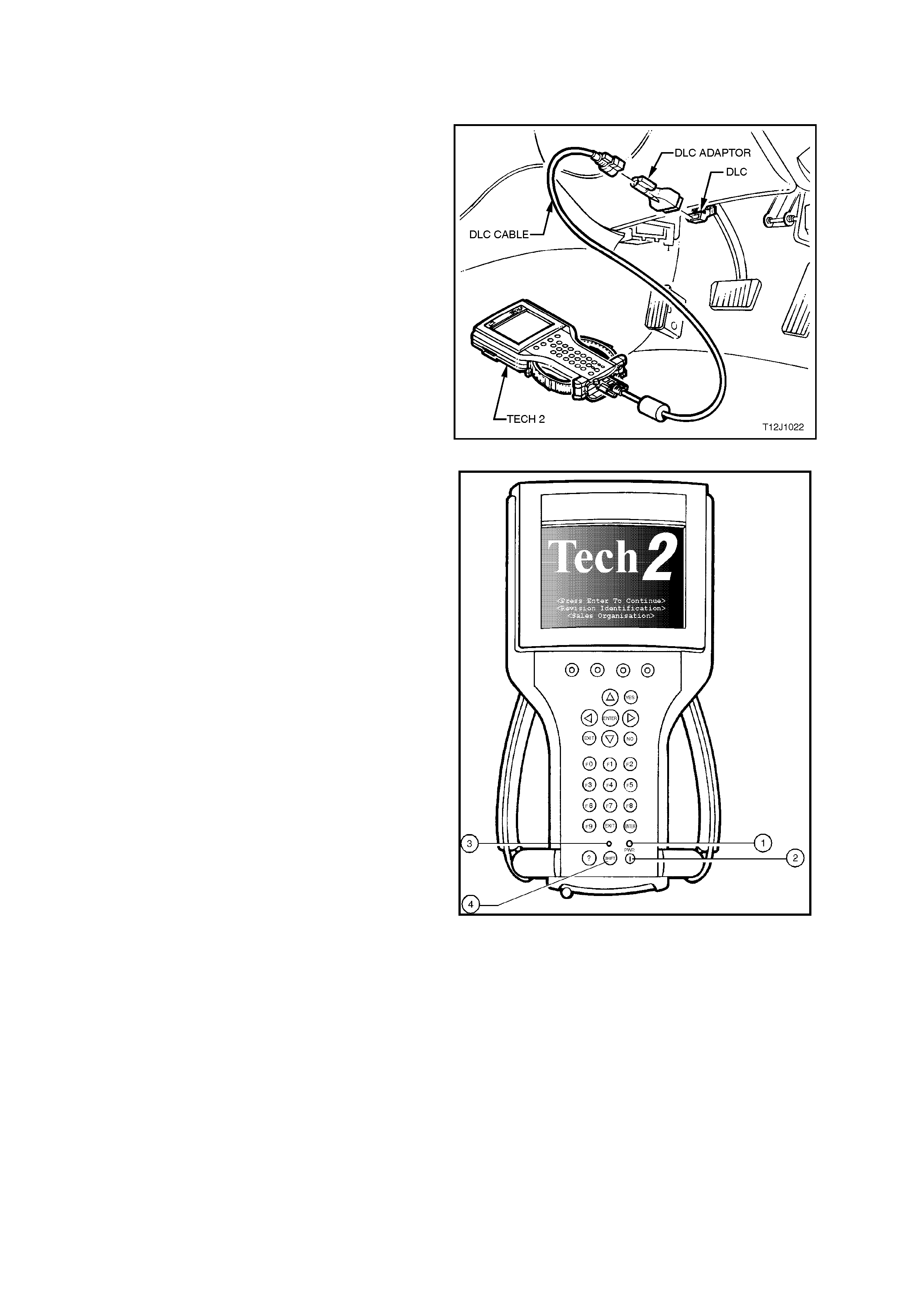
3. USING TECH 2 ON THE VEHICLE
3.1 CONNECTING THE TE CH 2 TO THE VEHICLE
1. Connect Tech 2 to the vehicle DLC, with the
DLC cable and the 16/19 pin adapter.
Figure 0C-14 Connecting the Tech 2 to the Vehicle
2. Switch the unit on by pressing the power button
(2). A green light ( 1) should c ome on indicating
that the tool is receiving power.
NOTE: At this time the technician should see the
Power On Self Test (POST) run. The POST is a
built in diagnostic self test for the Tech 2 that
should find most common system faults. The
POST is run on every power up to ensure the best
operation of the tool. After the completion of the
POST, the Tech 2 unit will briefly show the POST
results. If POST passes, the tool will continue onto
the title scr een. If POST f ails, r esults of all test s will
be displayed, and this should show which test
failed. POST failures may be classified as fatal or
non-fatal. A fatal error will not allow the user to
continue using the tool. Failur e of the keypad would
be an example of a fatal error. Non-fatal errors
found during the POST will allow continued use of
the Tech 2, but with some limitations. If either a
fatal or non-fatal error occurs, refer to the
Troubleshooting section of the Tech 2 User's
Guide.
1. Power Status Indicator Light
2. PWR (Power) Key
3. SHIFT Key Status Indicator Light
4. SHIFT Key
3. At the T ech 2 title screen press the ENTER key
to continue.
Figure 0C-15 Tech 2 PWR and SHIFT Keys
4. A selection can be made from the Main Menu,
either by using a function key or by using the
arrow keys to highlight a menu choice and
pressing ENTER.
NOTE: You will then need to supply some
additional information to the Tech 2. This requires
navigation through a series of lists (called picklis ts).
On some menus or picklists, the user can use a
function k ey to make a m enu selec tion, but m ost of
the picklists require using the selection and action
keys. If a m istak e is m ade in the selection process,
or if a different application or function is desired,
press EXIT to back up one level. Within an
application, there may be soft keys which are
available for use. These soft keys allow access to
additional tool functions without exiting a current
tool function. Soft keys are made up of sets which
will appear together. To see the next set of soft
keys, select the More soft key.
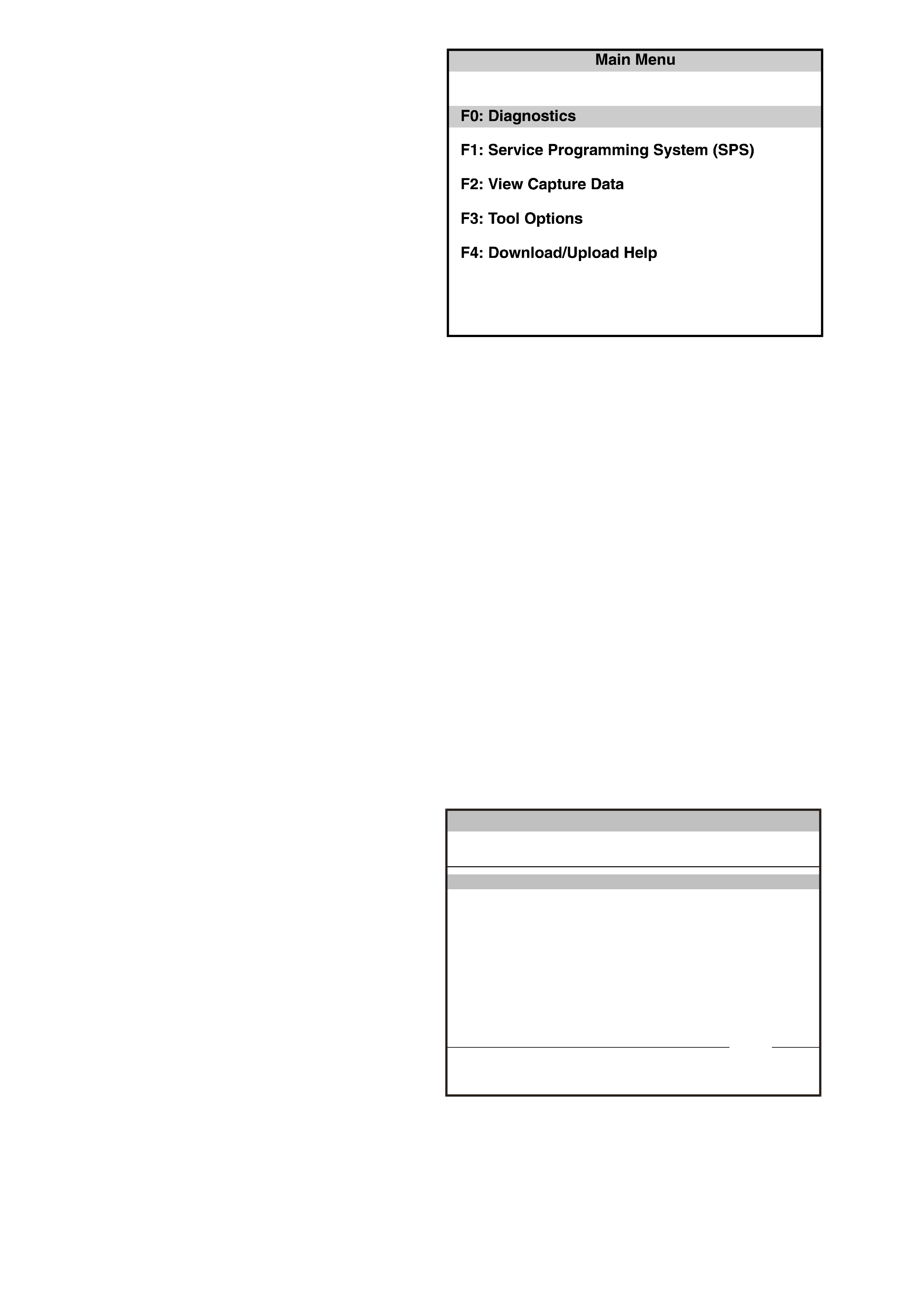
The Tech 2 Main Menu contains the following:
F0: Diagnostics
Contains all func tions to test, diagnos e, m onitor
and program the different vehicle systems.
Figure 0C-16 Tech 2 Main Menu
F1: Service Programming System (SPS)
SPS is used in conjunction with Technical
Information System (TIS) 2000 to program
vehicle control units.
F2: View Capture Data
Contains all functions to work with one or two
previously recorded snapshots on one or two
vehicles. This function is to enable the viewing
of captured data without a vehicle.
F3: Tool Options
Contains the Tech 2 self test, set clock, set
units, set screen contrast and Getting Started.
F4: Download/Upload Help
Contains help information on the downloading
and uploading from the T ech 2 to the TIS 2000
CD-ROM.
5. Select the correct Model Year with the arrow
keys and the press ENTER. The Vehicle
identification screen will then be displayed.
Vehicle Identification
Select one of the following
M odel Year(s)
(1)
(Y)
(X)
(W)
(V)
2001
2000
1999
1998
1997
(1) 2001
VX0C035
1 / 5
Figure 0C-17 Tech 2 Vehicle Identification Menu

6. Select the correct Vehicle Type with the arrow
keys and the press ENTER. The System Select
Menu will then be displayed.
Main Menu
Select one of the following
Vehicle Type(s)
VX0C005
VX Commodore
VU Utility
W H S tatesma n & Ca price
Corsa-B
Tigra
Astra-F
Astra-G
Vectra-B
Zafira
VX Commmodore 1 / 7
Figure 0C-18 Tech 2 Vehicle Identification
7. The desired system can be selected from the
System Select Menu with the function keys or
with arrow keys and then press ENTER.
F0: Engine contains all functions to test,
diagnose, and monitor the engine systems that
communicate with the Tech 2 via the
Powertrain Control Module (PCM).
F1: Transmission contains all functions to
test, diagnose, monitor and program the
transmission systems that communicate with
the Tech 2 via the Powertrain Control Module
(PCM).
F2: Chassis contains all functions to test,
diagnose, monitor and program the vehicles
chassis systems; ABS and Electronic Traction
Control modules.
F3: Body contains all functions to test,
diagnose, monitor and program the vehicles
body systems; Body Control Module,
Powertrain Interface Module, Electronic
Climate Control, Instruments, Supplemental
Restraint System and Telematics.
System S ele ct Men u
(1) 2 001 VX C om m od ore
F0: Engine
F1 : Tra nsmission
F2 : Ch assis
F3 : Body
Figure 0C-19 Tech 2 System Select Menu

3.2 ENGINE APPLICATION MENU
1. Select the correct engine from the Vehicle
Identification menu with the arrow keys, then
press ENTER.
Vehicle Identification
Select one of the following
Engine
V6
V8 GEN III
DTC Check
Other
V6
VX0C014
1 / 5
Figure 0C-20 Vehicle Identification Menu
2. Turn on the ignition and press the Confirm soft
key.
3. The Engine identification screen will then
display the PCM identification information,
which will vary depending upon engine type
and soft ware level. Press the Confirm soft key,
the engine application menu will then be
displayed.
Engine
(1) 2001 V X Commodore
Engine: V6
Turn Ignition On!
VX0C015
Confirm
Figure 0C-21 Engine Identification Menu
NOTE: If Tech 2 is able to communicate with
the PCM the Engine identification information
will be displayed. If Tech 2 is unable to
communicate with the PCM, Tech 2 will display
“Waiting for Data” if a V8 GEN III was selected
or “No Communication With Vehicle” if V6 was
been selected.
The following functions can be selected from the
engine application menu:
F0: Normal Mode
F1: Diagnostic Trouble Codes
F2: Data Display
F3: Snapshot
F4: Miscellaneous Tests
F5: Function Tests
F6: Field Service
F7: Stall Data
NOTE: Functions may vary depending on the
application s elected. For fur ther inf orm ation ref er to
Section 6C1 POWERTRAIN MANAGEMENT V6
or Section 6C3 POWERTRAIN MANAGEMENT
GEN III V8 Engine in the VX Series Service
Information.
Engine
(1) 2001 V X Commodore
Engine: V6
Part Numb er
Identifier 09356445
102
Part Numb er
VX0C016
Confirm
Figure 0C-22 Typical Engine Identification Menu

V6 ENGINE TECH 2 FUNCTIONS
F0: Normal Mode
In this test m ode, T ech 2 will display various engine and transm iss ion data param eters that are being transm itted to
other control modules via the normal mode message via the on the serial data circuit.
F1: Diagnostic Trouble Codes
In this test mode, DTCs stored by the PCM can be displayed or cleared. When F0: Diagnostic Trouble Codes an
there are an additional four modes:
F0: Read Current DTC: All current DTC(s) will be displayed.
F1: Read History DTC The PCM is capable of storing history data for four DTC’s.
F2: Clear Current DTC: Clears all current DTC(s) in the PCM memory.
F3: Clear History DTC: Clears all History DTCs and History data, also clears all current DTCs and Stall Data.
F2: Data Display
This mode displays data parameters for the engine being diagnosed. When entering this mode, there are three
modes;
F0: All Data: In this test mode, the Tech 2 continuously monitors and displays all engine data parameters.
F1: Inputs: In this test mode, the Tech 2 continuously monitors and displays all engine input data parameters.
F1: Outputs: In this test mode, the Tech 2 continuously monitors and displays all engine output data parameters.
F3: Snapshot
In this test m ode, the Tech 2 scan tool captures data before and af ter a selected snapshot triggering condition
which may or may not set a DTC.
F4: Miscellaneous Tests
In this test mode, the Tech 2 performs software override commands of the PCM, to assist in problem isolation
during diagnostics.
F0: Output Tests
F0: Fuel Pump: Fuel Pump Relay can be commanded on and off.
F1: A/C Clutch: A/C Compressor Clutch can be commanded on and off.
F2: Check Powertrain Lamp: Check Powertrain Lamp can be commanded on and off.
F3: High Fan: High Speed Cooling Fan operation can be commanded on and off.
F4: Canist er Purge: Canister Purge can be commanded on (99%) and off (0%).
F5: Starter Relay: Starter Relay can be c omm anded on and of f. When the relay is com manded O ff the engine will
not crank when the ignition is turned to the start position, when the relay is commanded On the engine should
crank when the ignition is turned to the start position.
F1: IAC System
F0: RPM Control: Us ed to command the desired engine s peed in 25 RPM inc rements f rom 600 RPM to 1675
RPM.
F1: IAC Control: Used to control IAC steps from 0 to 220 in 25 step increments.
F2: IAC Reset: Used to reset IAC if the PCM’s IAC position is lost or if IAC has been replaced.
F3: Base Idle: This tes t mode puts the engine managem ent system into a def ined state of oper ation so as to
allow the technician to monitor and adjust the base idle RPM setting. First the IAC valve is reset, then the IAC
steps are set to zero, then the bypass spark mode is commanded.
F2: EGR Control:
Used to control the EGR valve for 0% to 100% in steps of 25%.
F3: Reset Cells
Resets all Long Term Fuel Trim values to 0%
F4: Bypass Spark
Used to command either Bypass or EST modes.
F5: Air Fuel Ratio
Used to command the air fuel ratio from 11.7:1 to 17.7:1.
F6: LPG FCV Test
Used to command the LPG FCV from 0% to 100% in steps of 10%.
F7: LPG Enable Test
Used to enable the LPG operating mode. W hen comm anded On the PCM will switch to the LPG mode, when
commanded off the PCM will switch to the Petrol operating mode, refer following note.
NOTE: The PCM will only toggle between the Petrol and LPG mode if the ignition is on and the engine is not
running or if the engine speed is greater that 1200 RPM.

F5: Function Tests
In this test mode, Tech 2 performs various automated tests to assist in problem isolation during trouble
shooting. T o operate any of the F unction T est s, s im ply select the appropriate test m ode f rom the Func tion T est
application menu and follow the instructions as per Tech 2. When the Function Tests option is selected, the
following options will become available.
F0: IAC Circuit: T his f unction autom atically cycles the IAC valve in and out a calibrated num ber of s teps and
cycle times , and c ompar es the initial IAC valve s teps to the end IAC valve steps to determine if the IAC valve is
controlling RPM properly and not losing steps.
Preconditions: Coolant temperature greater than 80°C, vehicle speed zero km/h, engine running at idle, air
conditioning turned off and engine cooling fans turned on.
F1: O2 Sensor: This function allows you to command either a rich or lean mixture, while monitoring the O2
Sensor voltages to determine if they are operating correctly.
Preconditions: Vehicle speed less than two km/h, engine running at idle, air conditioning turned off.
F2: Power Balance: This f unction autom atic ally turns off eac h injec tor sequentially for f ive seconds , while the
engine RPM is monitored. At the end of the test the minimum RPM for each cylinder is displayed.
Preconditions: Vehicle speed less than two km/h, engine running at idle, air conditioning turned off and the
engine cooling fans are turned on.
F3: Wiring Harness: During this function test Tech 2 monitors the following inputs: RPM, ECT, MAF, TPS,
Battery Voltage, Injector Voltage and VSS. If a change occurs in these circuits greater than the limits listed
below, the Tech 2 logs the failure and prompts the technician to check the appropriate circuit.
Parameter RPM ECT MAF TPS
Tolerance 100 RPM 0.5 V 300 Hz 0.5 V
Parameter Bat. V Inj. V VSS
Tolerance 2 V 2 V 2 km/h
Preconditions: Engine running, vehicle speed less than two km/h.
F4: Low Fan: This function automatically sends out a Low Fan request to the BCM. The PCM Low Fan
request and the BCM response are displayed during the Test.
Preconditions: None, the test will time out after five seconds
F5: LPG Set Up: This function is used to set up the LPG system. During this test the PCM will command a
fixed spark and idle speed and a FCV duty cycle of 40%, you can then adjust the idle mixture while monitoring
the O2 sensor voltages.
Preconditions: Vehicle speed less than two km/h, engine running at idle, air conditioning turned off and the
engine cooling fans are turned on.
F6: Field Service
In this test m ode, with the ignition on and the engine not running, the T ech 2 will earth the diagnostic test term inal.
The system will then display all DTCs by causing the check powertrain lamp to flash.
F7: Stall Data
If and engine stall has oc curr ed the PCM will capture eleven data param eters , these data par am eters are dis play in
this mode. The PCM will store the first stall parameters, and then count the numbers of stalls after the first.
SERVICE PROGRAMMING SYSTEM
The VX V6 non super charged engine uses a PCM that does not contain a rem ovable PROM, it uses an EEPROM
(Flash Memory) which is non removable. T he PCM is program med fr om the fac tory with the proper calibr ations for
vehicle operation. In the event that the PCM is r eplaced, or an updated calibration is requir ed to correct a vehicle's
operating condition, a new calibration will have to be down loaded to the PCM EEPROM (Flash Memory).
Down loading is accomplished through the vehicle DLC using the Tech 2 Service Programming System
(SPS) and the Technical Information System (TIS) 2000. For further SPS information refer to
4. SERVICE PROGRAMMING SYSTEM in this Section.
BCM LINK TO PCM/PIM
If the PCM and/or BCM have been replaced, the m odules m ust be secur ity link ed to each other. If the pr ocedure is
not performed, the vehicle will not crank or run.
• For additional information regarding Tech 2 and this linking procedure, refer to
3.5 BODY APPLICATION MENU – BODY CONTROL MODULE in this Section.

V8 GEN III ENGINE TECH 2 FUNCTIONS
F0: Diagnostic Trouble Codes
In this test mode, DTCs stored by the PCM maybe displayed or cleared. When F0: Diagnostic Trouble Codes an
there are an additional four modes:
F0: Read DTC Info Ordered By Priority: DTC(s) will be displayed in numerical order.
F1: Clear DTC Information: Clears all DTC(s) in the PCM memory. Also clears Freeze Frame/Failure
Records, so before clearing DTC(s), be sure to retrieve Freeze Frame / Failure Record information.
F2: DTC Information: Shows DTC(s) which are set that match the criteria. Each DTC has it's own page of
information. If multiple DTCs are set, the user must page through the display of codes.
F0: History: This DTC search will display only DTC(s) that are stored in the PCM memory as Valid Faults.
F1: MIL SVS or Message Requested: This DTC search will display only DTC(s) for which the PCM is
requesting the Check Powertrain Lamp to turn "ON".
F2: Last Test Failed: This DTC search will display only DTCs that failed the last time the test ran.
F3: Test Failed Since Code Cleared: This DTC search will display all DTCs that have reported a test
failure since the last time DTCs were cleared.
F4: Not Ran Since Code Cleared: This DTC search will display only DTCs that have not ran since DT Cs
were last cleared. Any displayed DTCs have not run, therefore their condition (passing or failing) is
unknown.
F5: Failed This Ignition: This DTC search will display all DTCs that have failed at least once during the
current ignition cycle.
F3: Freeze Frame / Failure Records: Shows Freeze Frame / Failure Records information. Freeze Frame /
Failure Records are types of snapshots stored in the memory of the PCM and contain 32 data parameters.
F1: Data Display
This mode displays data parameters for the controller being diagnosed. When entering this mode, there are two
modes;
F0: Engine Data: In this test mode, the Tech 2 continuously monitors and displays system data, such as:
engine speed, engine coolant temperature etc.
F1: Fuel Trim Data: In this test mode, the Tech 2 scan tool continuously monitors and displays system data,
such as: engine speed data, engine coolant temperature, heated oxygen sensor, Fuel Trim Cell etc.
F2: Snapshot
In this test mode, the Tech 2 scan tool captures data before and after a snapshot triggering condition which
may or may not set a DTC.
F3: Miscellaneous Tests
In this test mode, the Tech 2 scan tool performs software override commands of the PCM, to assist in problem
isolation during diagnostics.
F0: Output Tests
F0: Fuel Pump: Fuel Pump Relay can be commanded on and off.
F1: A/C Clutch: A/C Compressor Clutch can be commanded on and off.
F2: Check Powertrain Lamp: Check Powertrain Lamp can be commanded on and off.
F3: High Fan: High Speed Cooling Fan operation can be commanded on and off.
F4: Canister Purge: Canister Purge can be commanded on (100%) and off (0%).
F1: IAC System
F0: RPM Control: Used to control engine RPM from 600 RPM to 1675 RPM.
F1: IAC Control: Used to control IAC steps from 0 to 120.
F2: IAC Reset: Used to reset IAC if the IAC is lost or if IAC has been replaced.
F3: Base Idle: Used to set the engine to base idle.
F2: Reset Cells
Resets all Long Term Fuel Trim values to 0%
F3: 02 Loop Status
With the engine running, Open or Closed Loop fuel control can be commanded.

F4: Function Tests
In this test mode, Tech 2 performs various automated tests to assist in problem isolation during trouble shooting. To
operate any of the Func tion Tests , simply select the appropriate tes t mode f rom the Func tion Test application menu
and follow the instructions as per Tech 2. When the Function Tests option is selected, the following options will
become available.
F0: IAC Circuit: This function automatically cycles the IAC valve in and out a calibrated number of steps and
cycle times , and c ompar es the initial IAC valve s teps to the end IAC valve steps to determine if the IAC valve is
controlling RPM properly and not losing steps.
Preconditions: Coolant temperature greater than 80°C, vehicle speed zero km/h, engine running at idle, air
conditioning turned off and engine cooling fans turned on.
F1: Power Balance: This function automatically turns off each injector sequentially for five seconds, while the
engine RPM is monitored. At the end of the test the minimum RPM for each cylinder is displayed.
Preconditions: Vehicle speed less than two km/h, engine running at idle, air conditioning turned off and the
engine cooling fans are turned on.
F3: Wiring Harness: During this function test Tech 2 monitors the following inputs: RPM, ECT, MAF, TPS,
Battery Voltage, Injector Voltage and VSS. If a change occurs in these circuits greater than the limits listed
below, the Tech 2 logs the failure and prompts the technician to check the appropriate circuit.
Parameter RPM ECT MAF TPS
Tolerance 100 RPM 0.5 V 300 Hz 0.5 V
Parameter IAT Bat. V Inj. V VSS
Tolerance 0.5 V 2 V 2 V 2 km/h
Preconditions: Engine running, vehicle speed less than two km/h.
F4: Fuel Injector Balance: This function is designed to check the fuel flow through each injector while the
engine is not running. A fuel pressure gauge has to be connected to the fuel rail. Tech 2 first turns on the fuel
pump. After pressure is established the fuel pump is turned off again and the injector is turned on for a
predetermined time. Pressure drop has to be read afterwards on the fuel gauge for each injector. This can be
performed only once per injector.
Preconditions: Vehicle speed less than 2 km/h, engine not running.
SERVICE PROGRAMMING SYSTEM
The VX GEN III V8 PCM does not contain a rem ovable PROM, it uses an EEPROM (Flash Memory) which is non
rem ovable. T he PCM is programm ed f rom the f actory with the proper calibrations for vehicle operation. In the event
that the PCM is replaced, or an updated calibration is required to correct a vehicle's operating condition, a new
calibration will have to be down loaded to the PCM EEPROM (Flash Memory). Down loading is accomplished
through the vehicle DLC using the Tech 2 Service Programming System (SPS) and the Technical Information
System (TIS) 2000. For further SPS information refer to 4. SERVICE PROGRAMMING SYSTEM in this Section.
BCM LINK TO PCM/PIM
If one or m ore of PCM, PIM or BCM have been r eplaced, the modules m ust be secur ity linked to each other. If the
procedure is not performed, the vehicle will not crank or run.
For additional inform ation regarding Tec h 2 and this linking procedur e, refer to 3.6 BODY APPLICATION M ENU –
BODY CONTROL MODULE in this Section.

3.3 TRANSMISSION APPLICATION MENU
1. Select the correct transmission from the
Vehicle Identific ation menu with the ar row keys,
then press ENTER and follow the screen
instructions.
Vehicle Identification
Select one of the following
Transmisssion
Automatic Transmission
GE N III Au tom atic Tran sm ission
DTC Check
Other
Automatic Transmission
VX0C031
1 / 3
Figure 0C-23 Vehicle Identification Menu
2. T urn on the ignition and press the Confirm soft
key.
2. The Transmission Identification screen will then
display the Part Number and Identifier. This
information will vary with engine type and
software level. Press the Confirm sof t key, the
transmission application menu will then be
displayed.
Transmission
(1) 2001 V X Commodore
Transmission
Turn Ignition On!
VX0C017
Confirm
Figure 0C-24 Transmission Identification
NOTE: If Tech 2 is able to communicate with
the PCM the Engine identification information
will be displayed. If Tech 2 is unable to
communicate with the PCM, Tech 2 will display
“Waiting for Data” if a GEN III Automatic
Transmission was selected or “No
Communication With Vehicle” if Automatic
Transmission was been selected.
The following functions are available in the
transmission application menu:
F0: Normal Mode
F1: Diagnostic Trouble Codes
F2: Data Display
F3: Snapshot
F4: Miscellaneous Tests
F5: Function Tests
F6: Field Service
NOTE: Functions may vary depending on the
application s elected. For fur ther inf orm ation ref er to
Section 6C1 POWERTRAIN MANAGEMENT V6
or Section 6C3 POWERTRAIN MANAGEMENT
GEN III V8 Engine in the VX Series Service
Information.
Transmission
(1) 2001 V X Commodore
Transmission
Part Numb er
Identifier 09356445
102
Part Numb er
VX0C018
Confirm
Figure 0C-25 Transmission Identification

V6 TRANSMISSION TECH 2 FUNCTIONS
F0: Normal Mode
In this test m ode, T ech 2 will display various engine and transm iss ion data param eters that are being transm itted to
other control modules via the normal mode message via the on the serial data circuit.
F1: Diagnostic Trouble Codes
In this test mode, DTCs stored by the PCM can be displayed or cleared. When F0: Diagnostic Trouble Codes an
there are an additional four modes:
F0: Read Current DTC: All current DTC(s) will be displayed.
F1: Read History DTC The PCM is capable of storing history data for four DTC’s.
F2: Clear Current DTC: Clears all current DTC(s) in the PCM memory.
F3: Clear History DTC: Clears all History DTCs and History data, also clears all current DTCs and Stall Data.
F2: Data Display
This mode displays data parameters for the engine being diagnosed. When entering this mode, there are three
modes;
F0: All Data: In this test mode, the Tech 2 continuously monitors and displays all engine data parameters.
F1: Inputs: In this test mode, the Tech 2 continuously monitors and displays all transmission input data
parameters.
F1: Outputs: In this test mode, the Tech 2 continuously monitors and displays all transmission output data
parameters.
F3: Snapshot
In this test mode, the Tech 2 scan tool captures data before and after a snapshot triggering condition which may or
may not set a DTC.
F4: Miscellaneous Tests
In this test mode, the Tech 2 performs software override commands of the PCM, to assist in problem isolation
during diagnostics.
F0: Shift Solenoids
1-2 Shift Solenoid A
This test allows to turn on and off the 1-2 Shift Solenoid A. Tech 2 take control of both solenoids (A and B), so in
this case solenoid B will be turned off.
Preconditions and running conditions: Engine not running.
2-3 Shift Solenoid B
This test allows to turn on and off the 2-3 Shift Solenoid B. Tech 2 take control of both solenoids (A and B), so in
this case solenoid A will be turned off.
Preconditions and running conditions: Engine not running.
3-2 Downshift Solenoid
This test allows to turn on and off the 3-2 Downshift Solenoid.
Preconditions and running conditions: Engine not running.
Gear Control: This function allows the user to incrementally command shift solenoid states to correspond to
relative gear states. Only single shift increments or decrements will be allowed and the test has a limit of 4200 RPM.
Preconditions and running conditions: Engine running, transmission in Drive.
Pressure Control Solenoid (PCS):
This function allows to control s tate of the pressur e control solenoid in increm ents of 100 m A. The test will start
at a value of 0.5A.
Preconditions and running conditions: Vehicle speed less than 2 km/h
TCC Solenoid
This test performs an on-off control of the TCC On-Off Solenoid.
Preconditions and running conditions: Engine not running.
TCC PWM Solenoid
The user will have the ability to control the TCC PWM duty cyc le. Although it is poss ible to com m and a f ull range of
solenoid duty cycle, this function will only turn on and off the solenoid; 100% and 0% PWM.
Preconditions and running conditions: Engine not running.
TCC Apply
This test performs an on - off control of the TCC. Tech 2 commands the PCM to apply the TCC.
Preconditions and running conditions: None.
F5: Function Tests
In this test mode, Tech 2 performs various automated tests to assist in problem isolation during trouble shooting. To
operate any of the Func tion Tests , simply select the appropriate tes t mode f rom the Func tion Test application menu
and follow the instructions as per Tech 2. When the Function Tests option is selected, the following options will
become available.

Transmission Fluid Pressure (TFP)
The Transmission Fluid Pressure (TFP) function test will prove the different gear shift states. Therefore it is
required to selec t eac h gear m anually and the ac cording s tates of the T FP switches are chec ked. T he r esult will
be displayed as Test Passed ! or Test Failed !.
Preconditions and running conditions: Vehicle speed less than 2 km/h, engine running at idle.
Wiring Harness
This func tion determ ines if the param eters (RPM, VSS, T FP A, T FP B, T FP C, Shif t A, Shift B, PCS, T FT , TCC)
are remaining stable if the wiring harness is wiggled.
Preconditions and running conditions: Vehicle speed less than 2 km/h, engine running @ stable idle.
Limits :
Parameter RPM VSS TFP A TFP B TFP C
Tolerance 100
RPM 2 km/h NCOS NCOS NCOS
Parameter Shift A Shift B PCS TFT TCC
Tolerance NCOS NCOS 0.5 A 0.5 V NCOS
NCOS = No Change of State
F6: Field Service
In this test m ode, with the ignition on and the engine not running, the T ech 2 will earth the diagnostic test term inal.
The system will then display all DTCs by causing the Check Powertrain Lamp (CPL) to flash.
SERVICE PROGRAMMING SYSTEM
The VX V6 PCM does not contain a removable PROM, it uses an EEPROM (Flash Memory) which is non
rem ovable. T he PCM is programm ed f rom the f actory with the proper calibrations for vehicle operation. In the event
that the PCM is replaced, or an updated calibration is required to correct a vehicle's operating condition, a new
calibration will have to be down loaded to the PCM EEPROM (Flash Memory). Down loading is accomplished
through the vehicle DLC using the Tech 2 Service Programming System (SPS) and the Technical Information
System (TIS) 2000. For further SPS information refer to 4. SERVICE PROGRAMMING SYSTEM in this Section.
BCM LINK TO PCM/PIM
If the PCM and/or BCM have been replaced, the m odules m ust be secur ity link ed to each other. If the pr ocedure is
not performed, the vehicle will not crank or run.
For additional inform ation regarding Tec h 2 and this linking procedur e, refer to 3.6 BODY APPLICATION M ENU –
BODY CONTROL MODULE in this Section.
V8 GEN III TRANSMISSION TECH 2 FUNCTIONS
F0: DIAGNOSTIC TROUBLE CODES
In this test mode, DTCs stored by the PCM maybe displayed or cleared. When F0: Diagnostic Trouble Codes an
there are an additional four modes:
F0: Read DTC Info Ordered By Priority: DTC(s) will be displayed in numerical order.
F1: Clear DTC Information: Clears all DTC(s) in the PCM memory. Also clears Freeze Frame/Failure
Records, so before clearing DTC(s), be sure to retrieve Freeze Frame / Failure Record information.
F2: DTC Information: Shows DTC(s) which are set that match the criteria. Each DTC has it's own page of
information. If multiple DTCs are set, the user must page through the display of codes.
F0: History: This DTC search will display only DTC(s) that are stored in the PCM memory as Valid Faults.
F1: MIL SVS or Message Requested: This DTC search will display only DTC(s) for which the PCM is
requesting the Check Powertrain Lamp to turn "ON".
F2: Last Test Failed: This DTC search will display only DTCs that failed the last time the test ran.
F3: Test Failed Since Code Cleared: This DTC search will display all DTCs that have reported a test
failure since the last time DTCs were cleared.
F4: Not Ran Since Code Cleared: This DTC search will display only DTCs that have not ran since DT Cs
were last cleared. Any displayed DTCs have not run, therefore their condition (passing or failing) is
unknown.
F5: Failed This Ignition: This DTC search will display all DTCs that have failed at least once during the
current ignition cycle.
F3: Freeze Frame / Failure Records: Shows Freeze Frame / Failure Records information. Freeze Frame /
Failure Records are types of snapshots stored in the memory of the PCM and contain 32 data parameters.

F1: Data Display
This mode displays data parameters for the controller being diagnosed. When entering this mode, there are two
modes;
F0: Transmission Data: In this test mode, the Tech 2 continuously monitors and displays transmission data,
such as: engine speed, transmission coolant temperature etc.
F1: 1- 2 Adapt Data: In this test mode, the T ech 2 scan tool continuous ly monitors and displays 1-2 shift adapt
data, such as: Adapt Cell, Adapt Pressure.
F2: 2-3 Adapt Data In this test mode, the T ech 2 scan tool continuously monitors and displays 2-3 shift adapt
data, such as: Adapt Cell, Adapt Pressure.
F3: Snapshot
In this test m ode, the T ech 2 scan tool captur es data bef ore and after a snapshot triggering condition whic h may
or may not set a DTC.
F4: Miscellaneous Tests
In this test mode, the Tech 2 performs software override commands of the PCM, to assist in problem isolation
during diagnostics.
F0: Shift Solenoids
1-2 Shift Solenoid A
This test allows to turn on and off the 1-2 Shift Solenoid A. Tech 2 take control of both solenoids (A and B), so in
this case solenoid B will be turned off.
Preconditions: No vehicle speed.
2-3 Shift Solenoid B
This test allows to turn on and off the 2-3 Shift Solenoid b. Tech 2 take control of both solenoids (A and B), so in
this case solenoid A will be turned off.
Preconditions: No vehicle speed.
3-2 Downshift Solenoid
This test allows to turn on and off the 3-2 Downshift Solenoid.
Preconditions: No vehicle speed.
Gear Control:
This function allows the user to incrementally command shift solenoid states to correspond to relative gear
states. Only single shift increments or decrements will be allowed and the test has a limit of 4200 RPM.
Preconditions and running conditions: Engine running, transmission in Drive.
Pressure Control Solenoid (PCS):
This function allows to control s tate of the pressur e control solenoid in increm ents of 100 m A. The test will start
at a value of 0.5A.
Preconditions and running conditions: Engine running and vehicle speed less than 2 km/h
TCC Solenoid
This test performs an on-off control of the TCC On-Off Solenoid.
Preconditions and running conditions: Engine not running.
TCC PWM Solenoid
The us er will have the ability to control the TCC PWM duty cyc le. Although it is pos s ible to command a f ull range
of solenoid duty cycle, this function will only turn on and off the solenoid; 100% and 0% PWM.
Preconditions and running conditions: Engine not running.
Reset TAP Cells
This test allow the user to reset the Transmission Adapt (TAP) cells by pressing the Reset soft key.
Preconditions: None

F5: Function Tests
In this test mode, Tech 2 performs various automated tests to assist in problem isolation during trouble shooting. To
operate any of the Func tion Tests , simply select the appropriate tes t mode f rom the Func tion Test application menu
and follow the instructions as per Tech 2. When the Function Tests option is selected, the following options will
become available.
Transmission Fluid Pressure (TFP)
The Transmission Fluid Pressure (TFP) function test will prove the different gear shift states. Therefore it is
required to selec t eac h gear m anually and the ac cording s tates of the T FP switches are chec ked. T he r esult will
be displayed as Test Passed ! or Test Failed !.
Preconditions and running conditions: Vehicle speed less than 2 km/h, engine running at idle.
Wiring Harness
This func tion determ ines if the param eters (RPM, VSS, T FP A, T FP B, T FP C, Shif t A, Shift B, PCS, T FT , TCC)
in mode 1 msg 3 are remaining stable if the wiring harness is wiggled.
Preconditions and running conditions: Vehicle speed less than 2 km/h, engine running @ stable idle.
Limits :
Parameter RPM VSS TFP A TFP B TFP C
Tolerance 100
RPM 2 km/h NCOS NCOS NCOS
Parameter Shift A Shift B PCS TFT TCC
Tolerance NCOS NCOS 0.5 A 0.5 V NCOS
NCOS = No Change of State
SERVICE PROGRAMMING SYSTEM
The VX GEN III V8 PCM does not contain a removable PROM, it uses an EEPROM (Flash Mem ory) which is non
rem ovable. T he PCM is programm ed f rom the f actory with the proper calibrations for vehicle operation. In the event
that the PCM is replaced, or an updated calibration is required to correct a vehicle's operating condition, a new
calibration will have to be down loaded to the PCM EEPROM (Flash Memory). Down loading is accomplished
through the vehicle DLC using the Tech 2 Service Programming System (SPS) and the Technical Information
System (TIS) 2000. For further SPS information refer to 4. SERVICE PROGRAMMING SYSTEM in this Section.
BCM LINK TO PCM/PIM
If one or m ore of PCM, PIM or BCM have been r eplaced, the modules m ust be secur ity linked to each other. If the
procedure is not performed, the vehicle will not crank or run.
For additional inform ation regarding Tec h 2 and this linking procedur e, refer to 3.6 BODY APPLICATION M ENU –
BODY CONTROL MODULE in this Section.
3.4 CHASSIS APPLICATION MENU
1. Select the correct chassis system from the
Vehicle Identification menu with the arrow
keys, then press ENTER and follow the
instructions on the screen.
Vehicle Identification
Select one of the following
Chassis
ABS/ETC
DTC Check
Other
ABS/ETC
VX0C033
1 / 3
Figure 0C-26 Vehicle Identification Menu
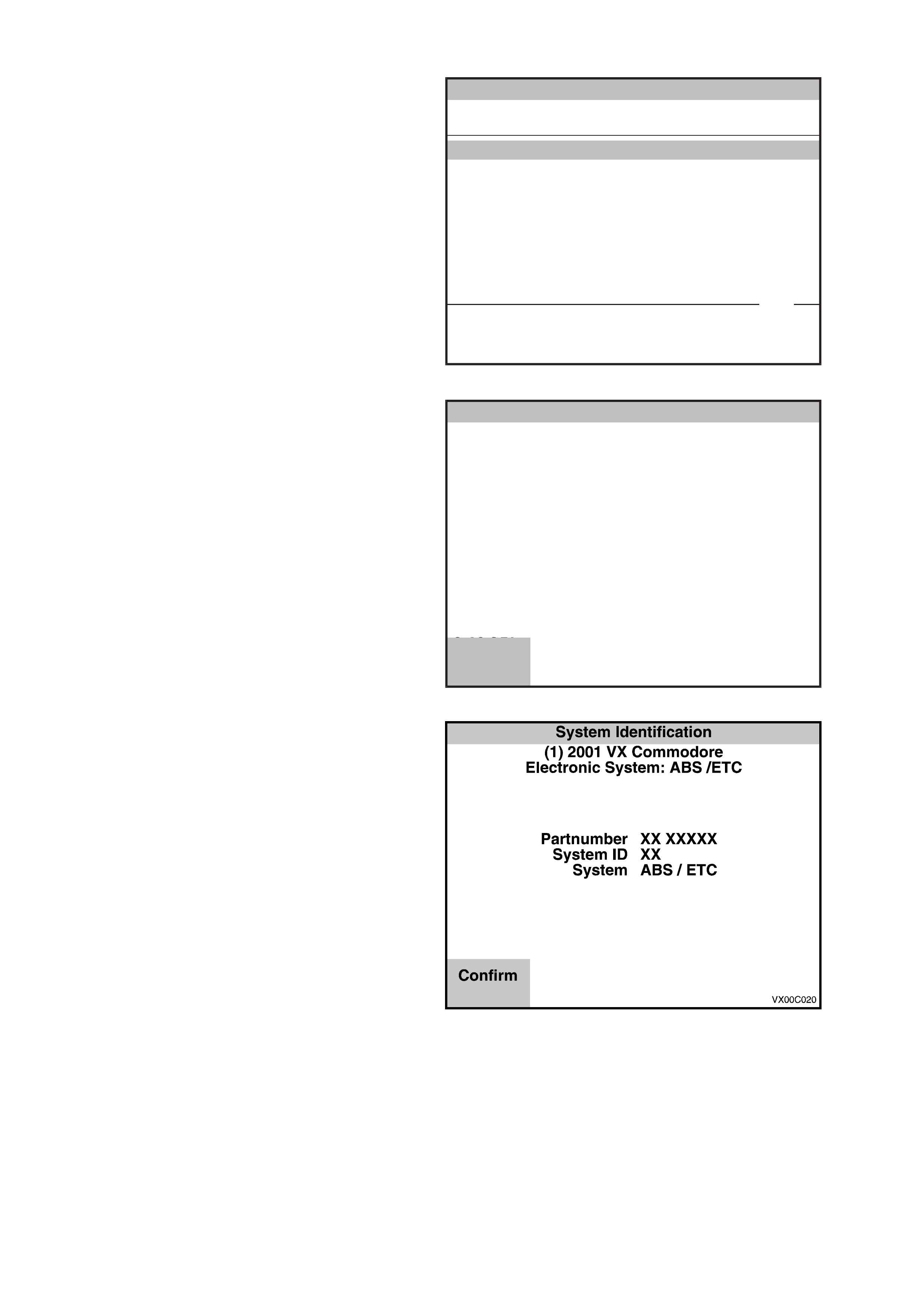
2. Tur n on the ignition and press the Confirm soft
key.
System Iden tificatio n
(1) 2001 V X Commodore
E lec tr o nic S y s t em : AB S / ETC
VX0C019
Turn On Ignition!
C 18 S EL
Confirm
Figure 0C-27 System Identification
3. The System identification screen will then
display the control module Partnumber , System
Identification and if the sys tem is an ABS or an
ABS/ETC system.
Press the Confirm soft key, and the ABS/ETC
application menu will then be displayed.
The following functions are available in the
ABS/ETC chassis application menu:
F0: Normal Mode
F1: Diagnostic Trouble Codes
F2: Data Display
F3: Snapshot
F4: Miscellaneous Tests
NOTE: Functions may vary depending on the
application s elected. For fur ther inf orm ation ref er to
Section 12L ABS & ABS/ETC in the VX Series
Service Information.
Figure 0C-28 System Identification

ABS/ETC TECH 2 FUNCTIONS
F0: Normal Mode
In this test m ode, Tech 2 will display various ABS/ETC data param eters that are being transm itted to other control
modules via the serial data circuit normal mode message.
F1: Diagnostic Trouble Codes
F0: Read DTC’s:
Displays a listing of all (if any) DTC’s num bers that have been set by the ABS or ABS/ETC control module will
be displayed. To obtain further information about a particular DTC, press the relevant function key and a DTC
data list will be displayed. From the information provided in this data list, you can determine when the DTC
occurred and the operating conditions of the system at the time.
F1 Clear DTC’s
DTC’s can be cleared by selecting F1 Clear Codes and pressing the ENTER key.
F2: Data Display
If the F2: DATA DISPLAY mode is selected, an additional application menu will appear giving the operator the
option of selecting ABS or ABS/ETC data while the system is either active or disabled.
F0: Active ABS/ETC
While the two data lis ts of f er s imilar inf ormation, the ac tive data list has the advantage of monitoring the ABS or
ABS/ETC systems while it they are operational, aiding in the diagnosis of intermittent faults.
F1: ABS/ETC Disabled
If the disabled data list is selected, the ABS warning lamp will be illuminated and the system will become
disabled.
F3: Snapshot
The snapshot mode will help to identify problems caused by speed sensor signals that may cause intermittent
operation of the ABS or ABS/ETC systems.
The SNAPSHOT mode captures data before and after a forced manual trigger condition.
F4: Miscellaneous Tests
In the miscellaneous tests mode, functional tests are available on the ABS and ABS/ETC systems that will help
identify proper operation. In this mode, error conditions can be further identified by testing and observing the test
results.
In the miscellaneous tests mode the following tests can be performed:
F0: Solenoids
These tests indicate whether specific solenoid valve in the hydraulic modulator releases and holds pressure to
assigned hydraulic wheel circuits. When this mode is selected the following test are available.
Front Left Solenoid Valve Test
Front Right Solenoid Valve Test
Rear Solenoid Valve Test (ABS Only)
Rear Left Solenoid Valve Test (ABS/ETC Only)
Rear Right Solenoid Valve Test (ABS/ETC Only)
TC Solenoid Valve Test (ABS/ETC Only)
F1: Auto Test
The auto tes t is performed autom atic ally by the contr ol module once dur ing each ignition c ycle when the vehicle
reaches approximately six k m/h. The T ech 2 will perform this test automatically during the ABS TESTS mode.
The AUTO test cycles each solenoid valve and the pump motor briefly to check component operation. If any
error is detected during this test, the control module will set a DTC and the ABS and or TRAC OFF warning
lamp will be illuminated.
F2: Brake Bleed
This test prompts the technician to bleed the brake system. The test is divided into two parts; a primary bleed
and a secondary bleed. A prim ary bleed is a m anual bleed of each hydraulic circuit. Dur ing a sec ondary bleed,
the ABS or ABS/ETC control module activates the solenoid and pump motor so that any air in these
components is expelled.
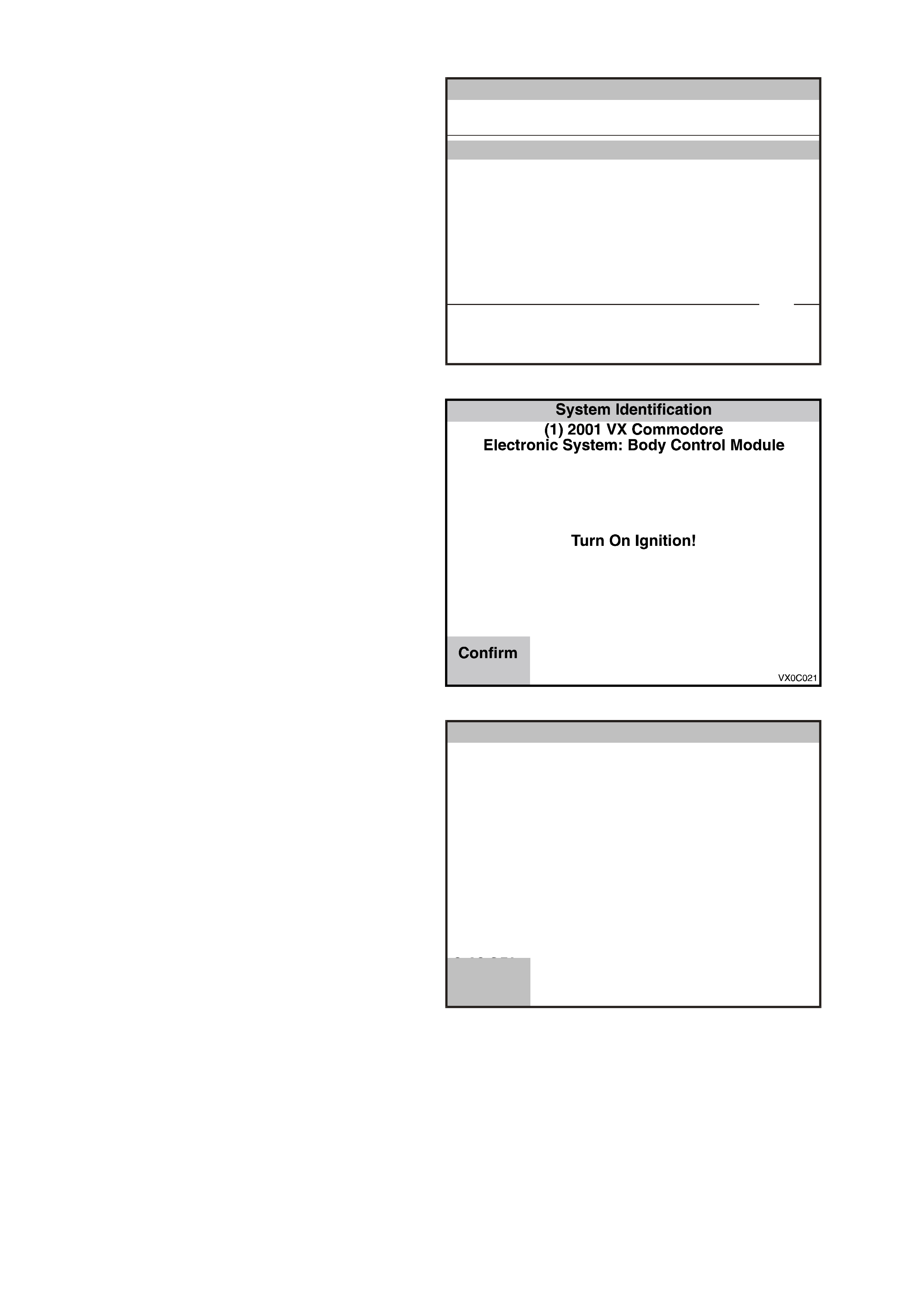
3.5 BODY APPLICATION MENU
BODY CONTROL MODULE
1. Select Body Control Module from the Vehicle
Identification menu with the arrow keys, then
press ENTER.
Vehicle Identification
Select one of the following
Body
Body Control Module
P ow e rtrai n Inte rfac e Modu le
SRS
Instrument
Electronic Cl ima te Control
DTC Check
Other
Body Control Module
VX0C032
1 / 7
Figure 0C-29 Vehicle Identification Menu
2. T urn on the ignition and press the Confirm soft
key.
Figure 0C-30 System Identification
3. The System Identification screen will then
display the following information:
BCM Level
BCM Type
Press the Confirm soft key, the BCM
application menu will then be displayed.
The following functions are available in the
BCM application menu:
F0: Normal Mode
F1: Diagnostic Trouble Codes
F2: Data Display
F3: Snapshot
F4: Miscellaneous Tests
F5: Program
F6: Security
NOTE: Functions may vary depending on the
application s elected. For fur ther inf orm ation ref er to
Section 12J-1 LOW SERIES BODY CONTROL
MODULE or Section 12J-2 HIGH SERIES BODY
CONTROL MODULE in the VX Series Service
Information.
System Iden tificatio n
(V) 1997 VT Commodo re
Ele ctronic Syste m : B o dy Co ntro l Mo du le
BCM Level XXXX
BCM Type X
C 18 S EL
Confirm
Figure 0C-31 System Identification

BCM TECH 2 FUNCTIONS
NOTE: Depending on the level of BCM som e functions m ay not be available. Func tions that are available for each
level of BCM can be identified by the following abbreviations:
ALL = All levels of BCM
HI = High
LU = LUX
MI = MID
LO = Low
AL = Alarm
F0: Normal Mode
In this mode, the Tech 2 monitors the communication between control modules on the serial data line. The
information displayed on the Tech 2 screen in this mode is what the BCM is communicating to the other modules
via the serial data circuit normal mode message.
F1: Diagnostic Trouble Codes
The following functions will be available in this mode:
Read Current DT C Information (ALL) : A lis ting of all ( if any) current DT C’s that have been s et by the BCM will
be displayed. A short description of what the DTC is, is also displayed in this mode.
Read Alarm Code Information (HI, LU, AL) : A description of stored alarm codes (if any) will be displayed.
Clear DTC Information: (ALL) Simply select Clear Codes, press the Enter button on Tech 2 and confirm the
action as instructed by Tech 2. Performing this function will also clear alarm codes.
F2: Data Display (ALL)
This mode displays data parameters for the BCM being diagnosed. W hen entering this mode, there can be up to
three modes available, depending on the level of the BCM. NOTE: When the Tech 2 is communicating with the
BCM, it also determines what type of BCM is fitted to the vehicle and therefore only the relevant data list and
functional tests will be displayed.
DATA LIST
In this test mode, the Tech 2 continuously monitors and displays all BCM data parameters.
POWER STEERING
In this test mode, the Tech 2 continuously monitors and displays all Power Steering data parameters.
PART NUMBER
In this test mode, the Tech 2 displays the BCM partnumber.
F3: Snapshot
In this test mode, Tech 2 captures BCM data before and after a selected trigger point. The purpose of the
SNAPSHOT test mode is to help isolate an intermittent or transient problem by storing BCM data parameters just
before and just after a problem occurs.
F4: Miscellaneous Tests
In this test mode, Tech 2 performs various functional tests to assist in problem isolation during trouble shooting.
When the Miscellaneous Tests option is selected, the following options will become available.
NOTE: Additional application menu screens will be displayed for Lamps, Wiper Tests, and Security Systems.
Lamps: If lam ps are selec ted, an additional application m enu will be displayed offer ing additional functional tes ts of
the vehicle’s lighting system.
Dome (ALL): W ith the dome lamp switch in either the Door or On position, Tech 2 can command the BCM to
switch on and off the interior lighting.
Lamp Delay Drive (ALL): In this mode with the ignition OFF and the headlamps and park lamps turned ON,
Tech 2 commands the BCM to switch OFF and ON the vehicle park lamps and headlamps.
Indicators (ALL): In this mode, Tech 2 commands the BCM to switch ON and OFF the turn signal indicator
lamps, including the warning lamps in the instrument cluster.
Bulb Fail Lamp (HI): In this m ode and with ignition switched ON, Tec h 2 com mands the BCM to switch on and
off rear light failure warning light in the instrument cluster.
Illumination (ALL): In this m ode, T ech 2 c omm ands the BCM to brighten or dim the instr ument c luster and trip
computer illumination lamps.
NOTE: if the ignition is O FF and the par k lamps ar e O N, only the instrum ent c luster lamps will be af f ec ted. If the
ignition is ON and the park lamps are ON, both the instrument cluster and trip computer will be affected.
Twilight Sentinel (HI): In this mode, with the ignition on and the headlamp switch in the Auto position, Tech 2
commands the BCM to turn the headlamps on and off.

A/C Test (MI, LO): In this mode, Tech 2 commands the BCM to switch the A/C on/off switch LED on and off.
Low Fan (ALL): In this mode, Tech 2 commands the BCM to switch ON and then OFF, (will switch OFF
automatically after a short period provided the PCM is not commanding the low fan on) the engine cooling low
speed fan relay.
Data Bus Isolator (ALL): In this mode, the BCM data bus isolator switch can be opened or closed.
To check if the data bus isolator is operating, while commanding the data bus isolator open with Tech 2, start
engine and monitor the trip com puters “ins tant fuel consum ption” display while varying the engine speed. W hen the
data bus isolator switch is opened, the trip computers instant fuel consumption display will not update.
NOTE: The data bus isolator will only be held open for five seconds.
Central Lock ing (ALL): In this mode, Tech 2 commands the BCM to operate all door lock actuators.
Heated Rear Window (MI, LO): In this m ode, the rear window dem ister can be tur ned on and off. W hen s witched
on, the heated rear window switch LED is illuminated and the relay can be heard to operate.
Wiper Tests (ALL): If Wipers are s elec ted, an additional applic ation menu will be displayed offer ing extra func tional
tests of the vehicles wiper system.
Front Wipers (ALL): In this mode, the front windshield wipers can be driven ON and OFF.
Rear Wipers (HI, LU, MI): In this mode, the rear screen wipers can be driven ON and OFF.
Window Down (HI, LU, MI): In this mode, the driver’s window can be driven down.
NOTE: Before entering and conducting this test, ensure that driver's side power window is fully up.
Antenna (HI, LU): In this mode, Tech 2 commands the BCM to raise or lower the antenna.
Horn (HI, LU): In this mode, the horn can be switched ON.
Power Steering (HI): In this test, Tech 2 commands the BCM to vary the current flow through the power steering
solenoid, thereby varying the amount of power steering assist.
Power Window Relay (HI, LU, MID): In this mode, Tech 2 commands the BCM to turn off the power window relay.
Illumination Drive Relay (ALL): In this mode, Tech 2 commands the illumination drive relay on or off.
Security System (ALL): If the security system mode is selected, an additional application menu will be displayed
offering additional functional tests of the vehicles security system.
Security LED (ALL): In this mode, Tech 2 commands the BCM to turn the theft deterrent alert indicator LED
ON and OFF.
Boot Release (ALL): In this mode, Tech 2 commands the BCM to activate the sedan rear compartment lock
actuator.
Theft Horn (HI): In this mode, the theft deterrent horns can be switched ON.
Key Priority (HI): In this m ode, the priority key status can be switched fr om priority one to pr iority two or priority
two to priority one.
Alarm Output (MI, LO, Not AL): In this m ode, the alarm st atus output can be s witched on or off (this feature is
for an after market alarm system).
Alarm Horn: (AL): In this mode, the theft deterrent horn can be switched ON.
F5: Program
In this test mode, T ec h 2 allows the progr amm ing of var ious f eatur es by turning the feature OFF or ON, or adjusting
settings (ie. twilight sentinel sensitivity).
In this test mode, T ec h 2 allows the progr amm ing of var ious f eatur es by turning the feature OFF or ON, or adjusting
settings to suit individual owner requests.
To operate any of the programming features, simply select the appropriate function to be changed from the
Program Application Menu and follow the instructions as per Tech 2.
When the Program option is selected, the following choices will become available.
Rear Wiper Control (HI, LU, M I): In this mode, the rear wiper intermittent c ontrol c an be dis abled. By disabling this
feature, it will prevent the rear wiper continuously sweeping the tailgate screen when the front intermittent wiper is
activated and reverse gear is selected.
Antenna Height Memory (HI, LU): In this mode, the antenna height m emory can be switched off, resulting in the
antenna mast fully extending each time the radio is switched on.
Two Stage Unlocking (ALL): In this mode, the two stage door unlock feature (one press of remote coded key
unlock button will unlock the driver’s door only, a second press will open all doors) can be disabled, thus enabling
single stage unlock (one press of remote coded key unlock button will unlock all doors).
Set Key to Priority 1 (HI): In this mode, the priority key in the ignition switch can be set to become priority one.
Tw ilight Sentinel (HI): In this mode, the s ensitivity of the twilight sentinel c an be adjusted from 0 to 7. All vehicles
will have the twilight sentinel set to a def ault value of 4. If the driver requests the lights to com e on latter (when it is
darker), the sensitivity of the twilight sentinel should be adjusted down (towards 0). If the driver requests the lights to
come on earlier (when it is lighter), the sensitivity of the twilight sentinel should be adjusted up (towards 7).
Battery Saver Shutdown Time (ALL): In this mode the battery saver shutdown mode time can be changed to
switch off after 2 minutes to 255 minutes.

Battery Saver Shutdown Time (ALL): In this mode the battery saver shutdown mode time can be changed to
switch off after 2 minutes to 255 minutes.
Pre-Delivery M ode (ALL): Pre-delivery mode is a function of the battery s aver feature allowing the vehic le to enter
battery saver mode after only three minutes. Pre-delivery mode can be enabled or disabled in this mode.
Ignition Off Courtesy Lamp (ALL): In this mode the ignition off courtesy lamp can be disabled or enabled.
Approach illumination (HI, LU): In this mode, approach illumination can be disabled or enabled.
Alarm Enable (MI, LO): In this mode the Alarm Option can be enabled or disabled. After changing the Alarm
Option Tech 2 will exit the system and the technician will then have to reselect the system in order to make changes
to the data list and available functions.
F6: Security
In this test mode, Tech 2 provides the user with the capability of: linking the PCM to the BCM, reading security
information (ie. radio pin numbers), and programming security features (ie. keys).
NOTE: A precondition to all s ecurity f eatures is: the theft deterr ent system mus t be disarmed and the ignition m ust
be switched ON with a programmed remote coded key.
When the security option is selected, the following choices will become available.
BCM Link to PCM/PIM (ALL): If the BCM is replac ed, the new BCM must be linked to the PIM/PCM otherwise, the
vehicle will not crank . Likewise, if the PIM and or PCM is replaced, the BCM mus t be link ed to the new PIM and or
PCM.
By selecting this mode, after the new BCM, PIM or PCM has been installed, Tech 2 will link these components.
Once BCM link to PCM/PIM is selected, simply following the Tech 2 instructions.
Security Information (ALL): In this mode, the following vehicle security information is displayed.
Radio PIN
Mechanical Key Number
Glove Box Key
Program (ALL)
In this mode, the following can be programmed. This can only be performed if the theft deterrent system is
disarmed.
Radio PIN
Mechanical Key Number
Glove Box Key
Program Remote Key
There are two options available in this mode; Extra Key and All New Key.
Extra Key: This mode allow you to program an extra remote key if a valid remote key is available.
All New Key: This mode allow y ou to program a new remote key if the security number is available.
POWERTRAIN INTERFACE MODULE
1. Select Powertrain Interface Module from the
Vehicle Identification menu with the arrow
keys, then press ENTER.
Vehicle Identification
Select one of the following
Body
Body Control Module
P ow e rtrai n Inte rfac e Modu le
SRS
Instrument
Electronic Cl ima te Control
Telematics Modul e
DTC Check
Other
P ow e rtrai n Inte rfac e Modu le
VX0C057
2 / 8
Figure 0C-32 Vehicle Identification Menu

2. T urn on the ignition and press the Confirm soft
key.
System Iden tifica tion
(1) 2 001 VX C om m od ore
Electron ic S ystem : Powe rtrain In terface Modu le
VX0C021P
Tu rn On Ignition!
C 18 SEL
Confirm
Figure 0C-33 System Identification
3. The System Identification screen will then
display the following information:
Software Version
Press the Confirm soft key, and the Powertrain
Interface Module application menu will then be
displayed.
The following functions are available in the
Powertrain Interface Module application menu:
F0: Normal Mode
F1: Diagnostic Trouble Codes
F2: Data Display
F3: Snapshot
F4: Miscellaneous Tests
NOTE: Functions may vary depending on the
application s elected. For fur ther inf orm ation ref er to
Section 6C-3 POWERTRAIN MANAGEMENT
GEN III V8 ENGINE in the VX Service Information.
VX0C034
System Iden tificatio n
(1) 2001 V X Commodore
Electron ic System: P owertrain Interface Module
Software Version 5.6
C 18 S EL
Confirm
Figure 0C-34 System Identification
PIM TECH 2 FUNCTIONS
F0: Normal Mode
In this test mode, Tech 2 will display various data parameters that are being transmitted to other control modules via
the serial data circuit normal mode message.
F1: Diagnostic Trouble Codes
In this tes t mode, PIM DT Cs can be dis played or cleared. When F0: Diagnostic Trouble Codes is s elected ther e ar e
an additional four modes:
F0: Read Current DTC Information: All current PIM DTC(s) will be displayed.
F1: Clear Current DTC Information: Clears all current PIM DTC(s).
F2: Data Display
In this test mode, the Tech 2 continuously monitors and displays all PIM data parameters.
F3: Snapshot
In the “F3: Snapshot” mode, Tech 2 enables the user to capture data before and after a forced manual trigger.
F4: Miscellaneous Tests
In this test mode, the T ec h 2 perfor ms s of tware over ride c ommands of the PIM, to ass is t in problem isolation during
diagnostics.
F0: Output Tests
Starter Relay: The starter relay can be commanded on and off. If the starter relay is commanded off the
engine will not crank when the ignition key is turned to the start position.
SUPPLEMENTAL RESTRAINT SYSTEM (SRS)
1. Select SRS from the Vehicle Identification
menu with the arrow keys, then press ENTER.
Vehicle Identification
Select one of the following
Body
Body Control Module
P ow e rtrai n Inte rfac e Modu le
SRS
Instrument
Electronic Cl ima te Control
Telematics Modul e
DTC Check
Other
SRS
VX0C058
3 / 8
Figure 0C-35 Vehicle Identification Menu
2. T urn on the ignition and press the Confirm soft
key.
Figure 0C-36 System Identification
3. The System Identification screen will then
display the following information:
Part number
Production Date
Module Type
System Identification
(1) 2001 V X Co m modore
E lectr on ic S ystem : SR S
Partnumber
Pro d uction D ate
Module Type
XXXXXXXX
XXXXXX
XX
C 18 S E L C 18 S E L
Confirm More
VX0C028
Figure 0C-37 System Identification

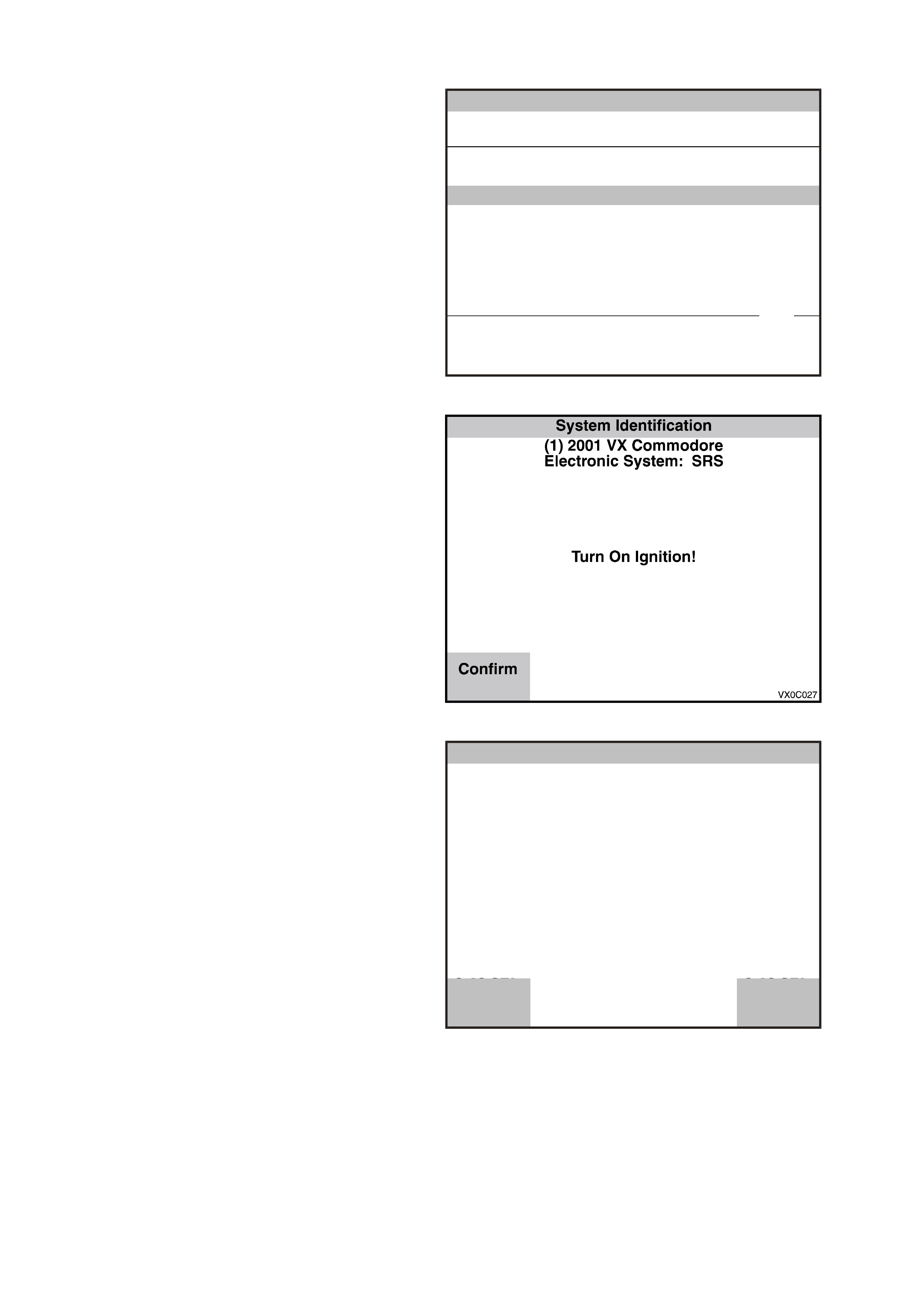
4. If the More soft key is pressed Tech 2 will
display the Part Number, VAP Proces s Num ber
and Vehicle Identification Number.
5. Press the Confirm soft key, the SRS
application menu will then be displayed.
T he following functions are available in the SRS
application menu:
F0: Normal Mode
F1: Diagnostic Trouble Codes
F2: Data Display
F3: Snapshot
F4: Program
NOTE: Functions may vary depending on the
application s elected. For fur ther inf orm ation ref er to
Section 12M SUPPLEMENTAL RESTRAINT
SYSTEM in the VX Series Service Information.
System Identification
(1) 2001 V X Co m modore
E lectr on ic S ystem : SR S
Partnumber
VAP Process N um ber
V ehicle Identification
XXXXXXXXX
X
XXXXX
C 18 S E L C 18 S E L
Confirm Back
VX0C029
Figure 0C-38 VAP Process Number
SRS TECH 2 FUNCTIONS
F0: NORMAL MODE
In this mode, the Tech 2 monitors the communication between control modules on the serial data line. The
information displayed on the Tech 2 screen in this mode is what the Sensing Diagnostic Module (SDM) is
communicating to the other modules via the serial data line.
F1: DIAGNOSTIC TROUBLE CODES
If F1: Diagnostic Trouble Codes’ is selected, a selection list is displayed which contains:
In this test m ode, DTCs stored by the SRS SDM can be displayed or c leared. W hen F 1: Diagnostic T rouble Codes
is selected there is an additional two modes:
F0: Read DTC Information - If this mode is selected, a listing of all (if any) DT Cs that have been set will be
displayed. Information displayed with the DTC number/s that have been set is; a short description of what the
DTC is and whether it is a current (fault present) or history (stored, but not necessarily on this ignition cycle)
DTC.
F1: Clear DTC Information - DTCs can be cleared in this mode by simply selecting F1: Clear DTC
Information, pressing the ENTER button on Tech 2 and confirming the action as instructed by Tech 2.
F2: DATA DISPLAY
In this test mode, Tech 2 displays the status of inputs and outputs of the SRS. NOTE: When the Tech 2 is
communicating with the SRS SDM, it also determines what type of SDM is fitted to the vehicle and therefore only
the relevant data list parameters will be displayed.
F3: SNAPSHOT
In the “F3: Snapshot” mode, Tech 2 enables the user to capture data before and after a forced manual trigger.
INSTRUMENT
1. Select Instrument from the Vehicle
Identification menu with the arrow keys, then
press ENTER.
Vehicle Identification
Select one of the following
Body
Body Control Module
P ow e rtrai n Inte rfac e Modu le
SRS
Instrument
Electronic Cl ima te Control
Telematics Modul e
DTC Check
Other
Instrument
VX0C059
4 / 8
Figure 0C-39 Vehicle Identification Menu
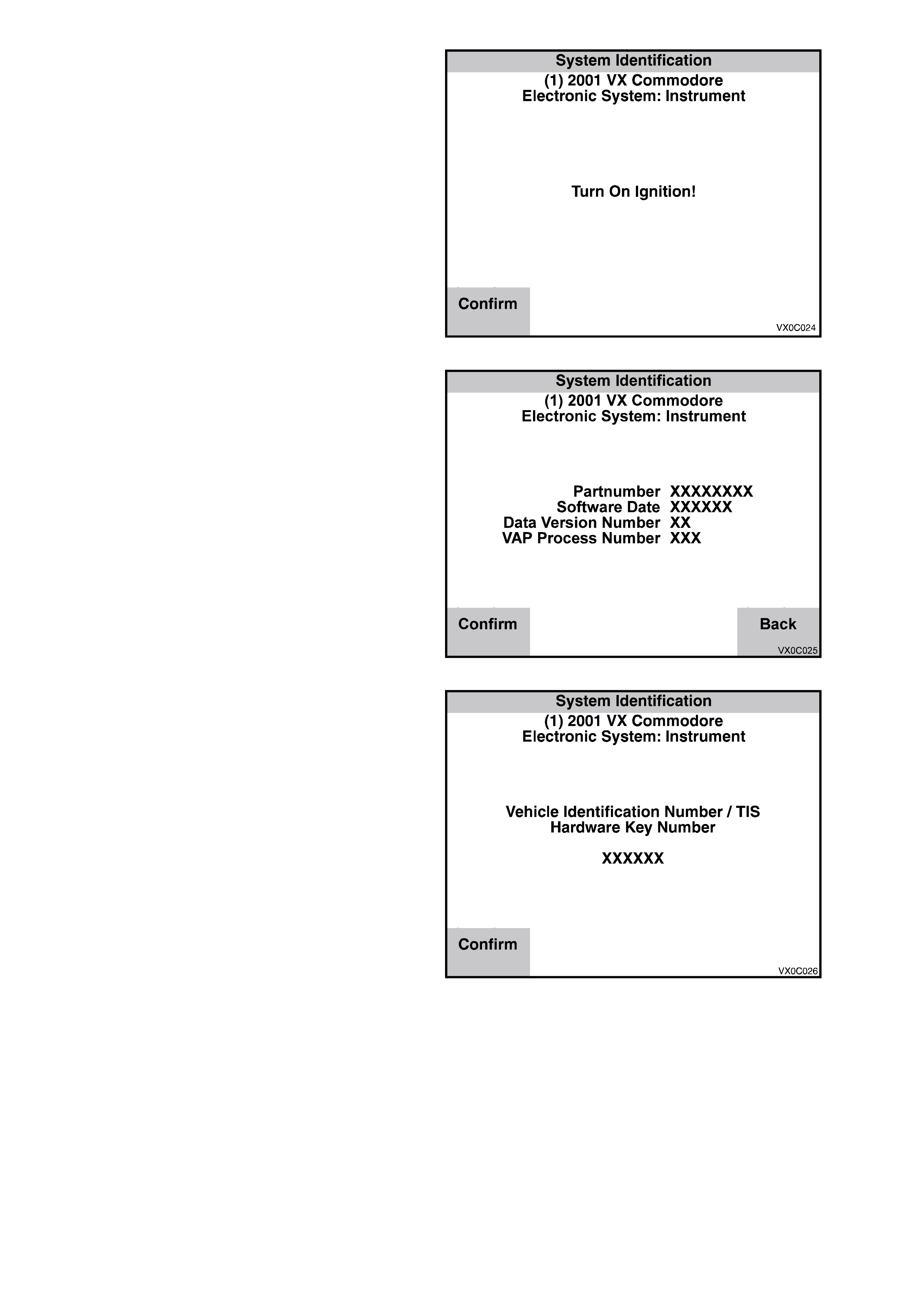
2. T urn on the ignition and press the Confirm soft
key.
Figure 0C-40 System Identification
The System Identification screen will then
display the Partnumber, if the More soft key is
pressed the Software Date, Data Version
Number and the VAP Process Number will also
be displayed.
Figure 0C-41 System Identification
3. Press the Confirm soft key, Tech 2 will then
display either the Vehicle Identification Number
or the TIS 2000 Hardware Key Number if the
Odometer has been reset.
4. Press the Confirm soft key again, the
Instrument application menu will then be
displayed.
The following functions are available in the
Instrument application menu:
F0: Normal Mode
F1: Diagnostic Trouble Codes
F2: Data Display
F3: Snapshot
F4: Miscellaneous Tests
F5: Program
NOTE: Functions may vary depending on the
application s elected. For fur ther inf orm ation ref er to
the Section 12C INSTRUMENT WIPERS,
WASHERS AND HORN in this Service Information.
Figure 0C-42 VIN or TIS 2000 Hardware Key Number

INSTRUMENT TECH 2 FUNCTIONS
F0: NORMAL MODE
In this mode, the Tech 2 monitors the communication between control modules on the serial data line. The
information displayed on the Tech 2 screen in this mode is what the instruments is communicating to the other
modules via the serial data circuit normal mode message.
F1: DIAGNOSTIC TROUBLE CODES
The following functions will be available in this mode:
F0: Read DTC Information: If this mode is selected, a listing of all (if any) DTCs that have been set by the
instrument cluster will be displayed. The Tech 2 will also display if the DTC is Current, Intermittent or History
F1: Clear DTC Information: DTC can be cleared in this m ode by simply selecting F1: Clear DTC Information,
pressing the Enter button on Tech 2 and confirming the action as instructed by Tech 2.
NOTE: Tech 2 will display Clear DTC Information Failed if any DTC is still current.
F2: DATA DISPLAY
This mode displays data parameters for the instrument being diagnosed. W hen F2: Data Display is selected there
are two modes available.
F1: INSTRUMENT
In this test mode, the Tech 2 continuously monitors and displays all instrument data parameters.
F2: TRIP COMPUTER
In this test mode, the Tech 2 continuously monitors and displays all trip computer data parameters.
F3: SNAPSHOT
In this test m ode, Tech 2 captures instrument or trip computer data before and after a forced m anual trigger. The
purpose of the SNAPSHOT test mode is to help isolate an intermittent or transient problem by storing instrument
data parameters just before and just after a problem occurs.
F4: MISCELLANEOUS TESTS
Miscellaneous Tests allows for the testing of various com ponents of the instrum ent cluster, suc h as instrument and
warning lamps, switches and instrument gauges to assist in problem isolation during trouble shooting. When this
mode is selected, the following options will become available.
F0: Lamps: Provides a means of testing the correct operation of various warning/status lamps in the instrument
cluster. The following lamps can be tested using Tech 2:
NOTE: Not all instrum ents are equipped with all of the following lamps. However all lamp test are available in this
mode.
Brake (brake and Fail) Lamp, Seat Belt lamp, Low Fuel lamp, Over Speed Lamp, Check Powertrain Lamp, Oil
Pressure lamp, Oil Pressure Lamp. Power Shift Lamp, Cruise Control On lamp, SRS Lamp, High Coolant
Temperature Lamp, Rear Lamp Failure Warning Lamp, Low Coolant Level Warning Lamp, Traction Control Off
Lamp and the LPG in Use Lamp.
F1: Buzzer: The operation of the buzzer can be tested, and a 1 kHz tone will be emitted from the instrument
buzzer.
F2: PRNDL Lamps: The operation of the automatic transmission gear shift lever pattern can be tested by
sequentially illuminating the P, R, N, D, 1, 2 and 3 LEDs.
F3: Trip Computer Buttons - once this mode is selected, the following the trip computer buttons may be tested.
F0: Mode Button: W ith this tes t a mode button pres s can be simulated. T his is to test if the button is stuck or
the instrument is not working properly.
F1: Up Button: W ith this test an up button press can be simulated. This is to test if the button is stuck or the
instrument is not working properly.
F2: Down Button: W ith this test a down button pres s can be sim ulated. This is to test if the button is stuck or
the instrument is not working properly.
F4: LPG Mode: This function allows the Tech 2 us er to sim ulate the instrum ent LPG m ode for testing pur poses.
The LPG lamp will illuminate (If fitted) and the fuel gauge will indicate the level of the LPG tank.
F5: Park Lamp Input: This test allows the Tech 2 user to simulate a park lamps input. This will dim the Power,
Cruise and LPG lamps only. It will have no effect on the other warning lamps or instrument cluster illumination.
Note: This function will only work on a triple window display instrument.

F6: Brake (Park And Fail) Input: This func tion allows the T ec h 2 us er to enable or dis able the brake (par k and fail)
input.
F7: Control Tests: Allow the T ech 2 us er to f orce k nown values into the speedom eter , tachom eter, engine c oolant
temperature gauge and fuel gauge to verify their correct operation.
F0: Vehicle Sp eed: This f unction controls the speedom eter. Com m anded vehic le speed can be adj usted up or
down in 20 km /h steps fr om 0 km /h to a m ax im um value of 220 k m /h. Ens ure that the speedom eter is accurate
according to the following table.
F1: Engine Speed: This f unc tions c ontrols the tac hometer. Comm anded engine s peed c an be adjus ted up and
down in 1000 rpm steps with a maxim um value of 6000 rpm . Ensure that the tachom eter is ac curate acc ording
to the following table.
F2: Engine Coolant Temperature: T his function contr ols the temperatur e gauge. There are three steps when
testing the temperature gauge; cold, mid and hot. The test is conducted using the Up and Down soft keys.
F3: Fuel Gauge: This function controls the fuel gauge. There are three steps when testing the fuel gauge;
empty, half and full. The test is conducted using the Up and Down soft keys.
F4: Function Lamps Illumination
This function controls the function lamps. Note that this test applies only to the Power, Cruise and LPG lamp
illumination level. The illum ination can be adjus ted in increm ents of 20% f rom 0% to 100%. T he function lam ps are
turned on automatically when the test is being performed.
Note: This function will only work on a triple window display instrument.
F5: PROGRAM
In this test mode, Tech 2 allows the programming of various instrument features and configuration by enabling or
disabling the feature. When the F5: Program option is selected, the following choices will become available.
F0: INSTRUMENT CONFIGURATION: ALLOWS THE CONFIGURATION OF THE INSTRUMENT TO MATCH THE VEHICLE.
THE FOLLOWING CONFIGURATIONS ARE AVAILABLE. STEP THROUGH EACH PARAMETER AND MODIFY IF
NECESSARY.
1. SRS Configuration
Press Modify soft key to set to one of the following options:
• No SRS
• 2 Loop SRS (a 2-loop system is for left-hand drive vehicles with pre-tensioners only)
• 3 Loop SRS (a 3-loop system is for vehicles with pre-tensioners and driver’s air bag only)
• 4 Loop SRS (a 4-loop system is for vehicles with pre-tensioners, driver’s air bag and front passenger’s air bag
only).
• 6 Loop SRS (a 6-loop system is for vehicles with pre-tensioners, driver’s air bag, front passenger’s air bag and
side air bags)
2. SRS Lamp
Enabled/Disabled.
3. Speedometer Pulses
Used to set the speedometer pulses per kilometre for the correct tyre size. Nominal value is 6250 pulses per
km.
• Tyre size 205 65 R15, select 6272 pulses.
• Tyre size 215 60 R15, select 6285 pulses.
• Tyre size 215 60 R16, select 6077 pulses.
• Tyre size 225 50 R16, select 6391 pulses.
• Tyre size 225 55 R16, select 6087 pulses.
• Tyre size 225 60 R15, select 6238 pulses.
• Tyre size 235 45 R17, select 6301 pulses.
4. Speedometer Calibration
If the Police Mode has been enabled at F 5: Program / F1: Options, the speedom eter calibration scr een appears
next. This allows the speedometer to be calibrated.
5. Tachometer Ratio
Used to set to the tachometer to either V6 or V8 Gen 3.
6. High Voltage Tachometer
Used to disable the or enable the tachometer for High Voltage.
NOTE: All VX vehicles should be set to Disabled.

7. ECC Equipped
Used to enabled or disable the Electronic Climate Control (ECC) option.
For vehicles equipped ECC set to Enabled.
For vehicles not equipped ECC set to Disabled.
F1: Options
Options such as instrument lamp illumination enable/disable and Police Mode can be set by selecting F1: Options
from the F5: Program Menu. The following Options are available: Step through each parameter and modify if
necessary.
1. Rear Lamp Failure Lamp
Used to enabled or disabled the rear lamp failure lamp.
For Calais, set to Enabled.
For all other models, set to Disabled.
2. Traction Control Off Lamp
Used to enable or disable the Traction Control Off Lamp.
For vehicles with ETC set to Enabled, if the vehicle is not equipped with ETC, set to Disabled .
3. LPG Lamp
Used to enable or disable the LPG Lamp.
For V6 vehicles with LPG set to Enabled, if the vehicle is not fitted with LPG, set to Disabled .
4. Cruise On Lamp
Used to enable or disable the Cruise On Lamp.
For vehicles equipped with cruise control set to Enabled, for vehicles not equipped with cruise control, set to
Disabled .
5. Police Mode
Used to enabled or disabled the Police Mode.
For Police vehicles only, set to Enabled for all other vehicles, set to Disabled.
6. Low Coolant Lamp
Used to enable or disable the Low Coolant.
For the GEN III V8 engine, set to Enabled, for V6 engines, set to Disabled.
7. High Temperature Lamp
Used to enable the High Temperature Lamp. The High Temperature Lamp should be enabled on all vehicle,
therefor there is only an enable soft key.
F2: ODOMETER VALUE
Used to program the odometer reading.
NOTE: It is only poss ible to program the odom eter reading on an instrum ent after T IS approval has been obtained
and only on an instrument which presently reads less than 100 km.
F3: FUEL GAUGE CALIBRATION
Used to program the Fuel Gauge Calibration
(Code Index and Code Version).
F4: RESET SERVICE INTERVAL
Used to reset the Service Interval reminder.
F5: RESET USER CALIBRATION
Used to reset the following User Calibrations.
• Trip Distance Calibration
• Fuel Used Calibration
• Speedometer Calibration
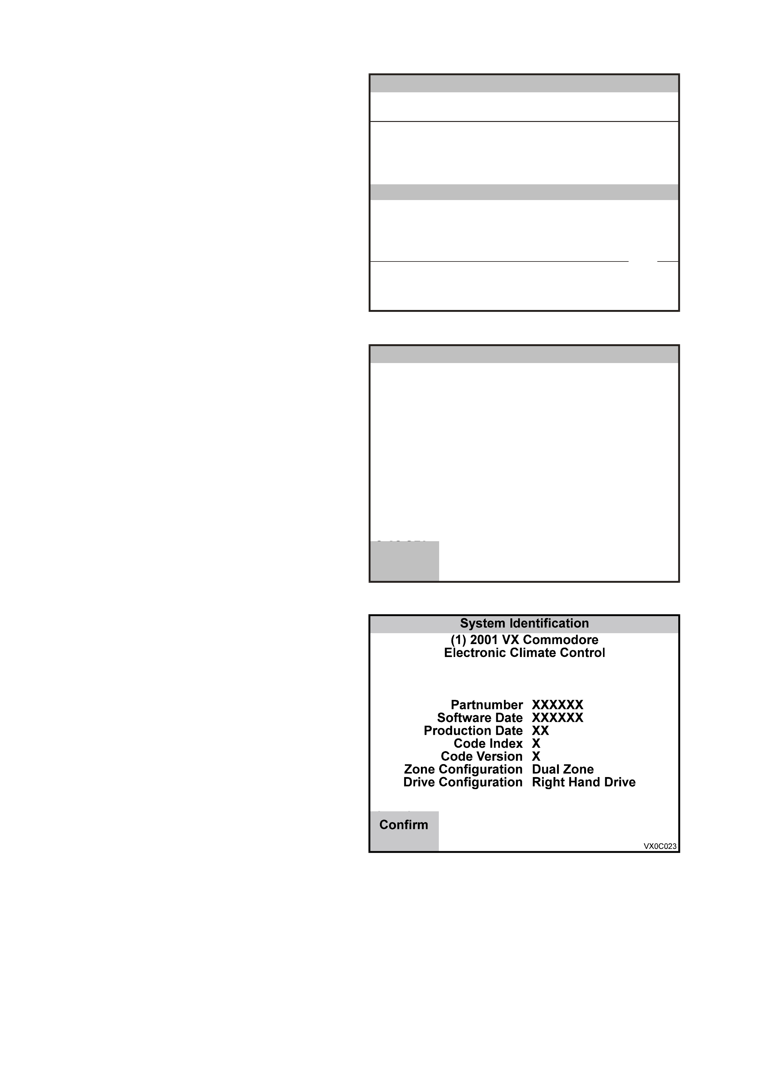
ELECTRONIC CLIMATE CONTROL
1. Select Electronic Climate Control from the
Vehicle Identification menu with the arrow
keys, then press ENTER.
Vehicle Identification
Select one of the following
Body
Body Control Module
P ow e rtrai n Inte rfac e Modu le
SRS
Instrument
Electronic Cl ima te Control
Telematics Modul e
DTC Check
Other
Electronic Cl ima te Control
VX0C060
5 / 8
Figure 0C-43 Vehicle Identification Menu
2. T urn on the ignition and press the Confirm soft
key
System Iden tificatio n
(1) 2001 V X Commodore
Elec tro nic Climate Control
VX0C022
Turn On Ignition!
C 18 SEL
Confirm
Figure 0C-44 System Identification
3. The System Identification screen will then
display the following information:
Partnumber
Software Date
Production Date
Code Index
Code Version
Zone Configuration
Drive Configuration
Press the Confirm soft key, the engine
application menu will then be displayed.
T he f ollowing functions ar e available in the BCM
application menu:
F0: Normal Mode
F1: Diagnostic Trouble Codes
F2: Data Display
F3: Snapshot
F4: Miscellaneous Tests
F5: Program
NOTE: Functions may vary depending on the
application s elected. For fur ther inf orm ation ref er to
the Section 2F AIR CONDITIONING - ECC
DIAGNOSTICS of the VX Series Service
Information..
Figure 0C-45 System Identification

ECC TECH 2 FUNCTIONS
F0: NORMAL MODE
In this test mode, Tech 2 will display various ECC data parameters that are being transmitted to other control
modules via the normal mode message via the on the serial data circuit.
F1: Diagnostic Trouble Codes (DTC)
If F1: Diagnostic Trouble Codes is selected, a selection list is displayed which contains:
F0: Read Current DTC Information: In this m ode, a listing of all (if any) current DTC numbers, together with a
brief description of the DTC, will be displayed.
F1: Read History DTC Information: In this mode, a listing of the last two stored DTC’s will be displayed,
together with a brief description of the DTC and the number of ignition cycles since the DTC occurred.
NOTE: If any DTC’s are set, reference should be made to the relevant diagnostic charts in this Section.
F2: Clear DTC Information: In this m ode, DTC’s c an be cleared by sim ply selec ting F2: Clear DTC Infor mation
and pressing the enter key on Tech 2.
F2: Data Display
If the F2: Data Display m ode is selected, an additional m enu will appear giving the operator the option of selecting
the ECC data list or ECC switch data.
F0: Data list - The data list displays inputs and outputs of the ECC.
F1: Switch Data - In this mode, the operator is able to test the function of each ECC module button and switch.
To test the ECC buttons and switches in this mode; activate each button and switch on the ECC module and view
the Tech 2 screen to see if display changes status from OFF to ON.
NOTE: The ECC module buttons will need to be held down when carrying out this test due to a slight delay in
information transfer.
F3: SNAPSHOT
In this test mode, the Tech 2 captures ECC data before and after a selected trigger point.
F4: MISCELLANEOUS TEST
In the Miscellaneous Test mode, functional tests are available on the ECC systems that will help identify proper
operation. In this mode, error conditions can be further identified by testing and observing the results.
In the Miscellaneous Test mode, the following tests can be performed:
DRIVERS SIDE AIR MIX DOOR
The purpose of this test is to monitor the face vent to verify that a temperature change takes place when opening
and closing the air mix door, indicating both air mix motor and door movement.
Pre-conditions: Engine running at operating temperature.
The Drivers Side Air Mix Door test can be conducted by using the increas e/decrease soft k eys on T ech 2 open
and close the air mix door.
When the door is open (increase), the temperature at the centre vent should increase.
When the door is closed (decrease), the temperature at the centre vent should decrease.
PASSENGER SIDE AIR MIX DOOR
The purpose of this test is to monitor the face vent to verify that a temperature change takes place when opening
and closing the air mix door, indicating both air mix motor and door movement.
Pre-conditions: Engine running at operating temperature.
The Passenger Side Air Mix Door test can be conducted by using the increase/decrease soft keys on Tech 2
open and close the air mix door.
When the door is open (increase), the temperature at the centre vent should increase.
When the door is closed (decrease), the temperature at the centre vent should decrease.
NOTE: This test is not available on single zone systems.
BLOWER SPEED
The purpose of this test is to ensure that all blower speeds are preset and the blower motor circuit is functional.
Pre-condition: Engine running
Using the increase soft key on Tech 2, command the blower fan to maximum (approx. 95 - 99%).
Using the decrease soft key on Tech 2, command the blower fan to minimum (approximately 22 - 26%).
NOTE: Percentage values (%) are dependant on vehicle battery voltage.
LCD DISPLAY TEST
The purpose of this test is to ensure all segments are displayed on the ECC module LCD screen. Using the
On/Off soft keys on Tech 2, activate and deactivate the LCD full segment display.

OUTLET MODE
The purpose of this test is to ensure that vacuum solenoids, vacuum supply and mode doors are functional.
Pre-condition - Engine running.
The Outlet Mode test can be conducted by using the up/down soft keys on Tech 2 and scrolling through each
mode position:
Foot
Foot/Face
Face
Demist/Foot
Demist (only).
The ECC Module LCD indicates the position (arrow) air will be directed to, in each mode the third blower fan
speed will automatically be selected and the Auto button will be illuminated.
NOTE 1: When the Foot Mode is selected, air is distributed from the floor.
NOTE 2: On dual zone systems , when the Face Vent Mode is selected, air will be distributed fr om left and right
or the centre face vent.
NOTE 3: When the Demist/Foot Mode is selected, air is distributed from demist ducts and the floor.
NOTE 4: When the Demist Mode is selected, air is distributed from demist ducts only.
MAXIMUM FAN R ELAY
The purpose of this test is to ensure a circuit exists between the ECC module, the relay and the blower fan.
Pre-condition: Engine running.
The Max imum F an Relay test can be conducted by using the On soft k ey to activate the r elay and max im um fan
speed and the Off soft key to deactivate relay and turn blower speed off.
REAR DEMIST RELAY
The purpose of this test is to check operation of circuit from ECC control to relay.
The Rear Demist Relay test c an be conduc ted by pressing the On sof t key to activate heated rear window relay;
the rear demist button will illuminate and ON will be displayed on the LCD display. Use the Off soft key to
deactivate relay; the rear demist button illumination will go out and OFF will be displayed on the LCD.
SOLENOIDS
Purpose of test: To ensure the ECC Module, electrical circuit is OK. This test allows you to test the following:
Face 1 Solenoid
Face 2 Solenoid
Foot 1 Solenoid
Foot 2 Solenoid
Recirc Solenoid
Water Val Solenoid
Pre-condition: Engine not running.
Procedure: Remove the left side footwell upper closing panel, locate the vacuum solenoid pack (rear of blower
housing). Conduct Solenoids test by Using the On soft key activate one solenoid at a time.
Listen or feel for the solenoids activating (clicking). Use the Off soft key to deactivate solenoids and likewise
listen or feel for solenoids activating (clicking).
A/C REQUEST
The purpose of this test is to ensure ECC Module, wiring, compressor relay and compressor clutch are
functional.
Pre-condition: Engine running.
The A/C Request test can be c onducted by using the On soft k ey to engage the com pressor c lutc h and the Off
soft key to disengage the compressor. Listen for clutch engagement noise.
NOTE: In this test a blower fan speed is automatically selected.
NOTE: A three second delay until compressor clutch engagement will occur, this is normal.
F5: PROGRAM
In this mode, Tech 2 allows the programming of the ECC control module.
When the Program option is selected, the following two choices will be available:
F0: Calibrate Air Mix Door - In this m ode, the air m ix door(s ) m ay be re-calibrated/progr am m ed so they drive to
the full hot and full cold stops.
The calibration mode looks at the full movement in either direction of the air mix doors/motors and compares the
actual voltage values to known base values. If they are different, the ECC software will compensate.
When the air m ix doors are r e- calibr ated Tech 2 will display the percentage of variation between the base value and
the pre-calibrated value. If this variation is greater than 5%, a noticeable difference should be felt and could have
contributed to a customer complaint.
NOTE: If pr ogramm ing is unsuccess ful, repeat the program again, as there m ay have been an error in transfer ring
the data.

NOTE: If pr ogramm ing is unsuccess ful, repeat the program again, as there m ay have been an error in transfer ring
the data.
NOTE: During pr ogramm ing, a DTC 21 or 24 could be set. If either of these codes are set, they should be c leared
using the Clear DTC Information function.
F1: Program Code Index - In this mode, the code index and progr ammed code vers ion ar e displayed, as well as
providing the operator the option of reprogramming the code version.
Code Index: The Code Index identifies the level ECC software. A higher number indicates the latest version of
software.
3 = Single Zone (SZ) Right Hand Drive.
4= Dual Zone (DZ) Right Hand Drive.
Code Vers ion:
The Code Vers ion identifies the program med level ECC c alibration. A higher num ber indicates the latest ver sion of
calibration.
There are two options available in the calibration mode:
1. Base Calibration - brings the ECC operating parameters to the latest level.
NOTE : Although ECC c ontrol m odules ar e supplied with a pre-programm ed c ode version, in s om e cases the T ech
2 software ver sion maybe latter, therefore, all new ECC contr ol modules should be r eprogramm ed using Tec h 2. If
the ECC s of t ware vers ion is latter than the Tech 2 ver s ion, T ec h 2 will display “Tech 2 does not inc lude data f or this
code index”, indicating that programming will not be necessary.
2. Custom Calibration - In this mode, the ECC system programming function can be re-calibrated to suit specific
customer complaints. (ie. Reduced Blower calibration will re-program the blower motor to operate at a slower
speed to reduce airflow or blower noise).
NOTE: If pr ogramm ing is unsuccess ful, repeat the program again, as there m ay have been an error in transfer ring
the data.
TELEMATICS MODULE
1. Select Telematics Module from the Vehicle
Identification menu with the arrow keys, then
press ENTER.
Vehicle Identification
Select one of the following
Body
Body Control Module
P ow e rtrai n Inte rfac e Modu le
SRS
Instrument
Electronic Cl ima te Control
Telematics Modul e
DTC Check
Other
Telematics Modul e
VX0C056
6 / 8
Figure 0C-46 Vehicle Identification Menu
2. Turn on the ignition and press the Confirm soft
key.
3. The System Identification screen will then
display the following information:
Identifier
(Diagnostic Data Identifier)
Partnumber
(telematics module part number)
Production Date
(telematics module production date)
BIM Software Version Number
(telematics module Body Interface Module
software version number)
IVU Software Version Number
(telematics module In Vehicle Unit software
version number)
VAP Process Number
(vehicle assembly plant process number)
Code Version
(software version number)
Code Index
(software index number)
Barcode
(telematics module barcode number)
TIS Hardware Key Number
(TIS 2000 Hardware Key Number)
VIN Digit 1-10
(Vehicle Identification Number digits 1-10)
VIN Digit 11-17
(Vehicle Identification Number digits 11-17)
Press the Confirm soft key, the telematics module
application menu will then be displayed. Press
the Confirm soft key, the telematics module
application menu will then be displayed.
The following functions are available in the
telematics module application menu:
F0: Data Display
F1: Snapshot
F2: Miscellaneous Tests
F3: Additional Functions
F4: Program
NOTE: Functions may vary depending on the
application s elected. For fur ther inf orm ation ref er to
the Section 12K TELEMATICS in this Service
Information.
System I den t ifi cat io n
(1) 2 001 V T Com mod ore
Telematics Mo dule
VX0C063
Turn On Ignition!
Confirm
Figure 0C-47 System Identification
Body
(1) 2001 V X Commodore
Telematics Mo dule
Identifier
Partnumber
Production Date
BIM Software Version Num ber
IVU Software Version N um ber
VAP Pr oc e ss N um b e r
Identifier
101
92102690
200200
22
140000
12
VX0C062
Confirm
1 / 8
Figure 0C-48 System Identification
TELEMATICS TECH 2 FUNCTIONS
F0: DATA DISPLAY
In this test mode, Tech 2 displays the status of inputs and outputs of the Telematics Module.
F1: SNAPSHOT
In the F1: Snapshot mode, Tech 2 enables the user to capture data before and after a forced manual trigger.
F2: MISCELLANEOUS TEST
Miscellaneous Tests allows for the testing of various components of the telematics system, such as the status
LEDs, radio mute or fuel pump circuit assist in problem isolation during trouble shooting. Each test will run for five
seconds further ac tivation of the sof t key will run the test for another f ive seconds. When this m ode is selected, the
following options will become available.
F0: Fuel Pump Circuit: Provides a means of activating and deactivating the fuel pump isolation circuit.
Precondition: System not in pre delivery mode.
F1: Red Status LED: Provides a means of turning the red status LED on and off.
Precondition: System not in pre delivery mode.

F2: Green Status LED: Provides a means of turning the green status LED on and off.
Precondition: System not in Pre delivery mode.
F3: Keypad Supply Voltage: This test provides the means of turning the supply voltage from the telematics
module to the keypad on and off.
Precondition: System not in pre delivery mode.
F4: Radio Mute: Provides a means of activating and deactivating the telematics radio mute circuit. When
activated the radio should mute and display “Phone”.
Precondition: System not in pre delivery mode.
F5: Backup Battery Charger: Provides a means of activating and deactivating the telematics backup battery
charging circuit.
Precondition: System not in pre delivery mode.
F6: Unlock Doors: Provides a m eans of unlock ing the doors . T ech 2 will request you to lock all door s, once all
the doors ane locked, and the unlock soft key is depressed the telematics module will send a request to the
BCM via the serial data bus, the BCM will then unlock all doors.
Precondition: System not in pre delivery mode.
F7: Indicators: Provides a means of f lashing the indicators. W hen this test is activated the telematics module
will send a request to the BCM to turn the indicators on and off, the BCM will then com mand the indicators on
and off.
Precondition: System not in pre delivery mode.
F3: Additional Functions
In this test mode Tech 2 commands the telematics module to initiate a functional test.
F1: Function Test: When this functional test in initiated the telematics module checks the functionality of the
following: Microphone circuit, speaker circuit and the keypad buttons. During this test you will be requested to
press each of the keypad button, each button press must be pressed before the function is completed. The
function test will take 45 seconds.
F4: Program
In this mode, Tech 2 allows the program ming of the telem atics module. W hen the Program option is selected, the
following three choices will be available:
F0: Program Code Index: In this mode, the code index and programmed code version are displayed, as well
as providing the operator the option of reprogramming the code version.
Code Index: The code index identifies the telematics software level. A higher number indicates the latest
version of software.
Code Version: The code version identifies the calibration level, each software level may have different
code versions. A higher number indicates the latest version of calibration.
F1: Speaker Volume: This programming mode allows you to program the speaker volume from one to eight,
one being the quietest and eight being the loudest.
F2: Operating Mode: This programming mode allows you to program the system operating mode.
F0: Pre Delivery Mode: In this m ode, the pre delivery mode can be enabled or disabled. Vehicles will be
delivered to the dealer with the telematics module in the pre delivery mode. In the pre delivery mode the
telematics system is turned off. The pre delivery mode must be disabled using this programming function
during the pre delivery inspection.
NOTE: TIS Approval is required to disable the pre delivery mode
F1: Service Mode: In this mode, the telematics service mode can be enabled and disabled. When the
service mode is enabled only the Holden Assist button will operate.

4. SERVICE PROGRAMMING SYSTEM (SPS)
4.1 GENERAL INFORMATION
On VX Series vehicles equipped with either a GEN III V8 engine or a V6 Non Supercharged Engine, the PCM
does not contain a removable PRO M, it uses an EEPRO M (Flas h Mem ory) which is non rem ovable. The PCM is
programmed from the factory with the proper calibrations for vehicle operation. In the event that the PCM is
replaced, or an updated c alibration is required to c orrect a vehic le's operating condition, the PCM will have to be
programmed with the new calibration. Programming is accomplished through the vehicle DLC using the Tech 2
Service Programming System (SPS) and TIS 2000.
A ser vice r eplacement PCM will not be programmed. DT C P0601 indic ates that the PCM is not pr ogrammed and
DTC P0602 indicates that programming has malfunctioned. For further DTC information and diagnostic
procedures refer to Section 6C1-2 for V6 Non Supercharged Engines and Section 6C3-2 for GEN III V8
Engines.
NOTE: A VX GEN III V8 PCM is different to a VT GEN III V8 PCM and both are not interchangeable. If you
are installing a new PCM ensure that the correct PCM is fitted to the vehicle. Refer to the latest parts
listing for part number identification.
Techline
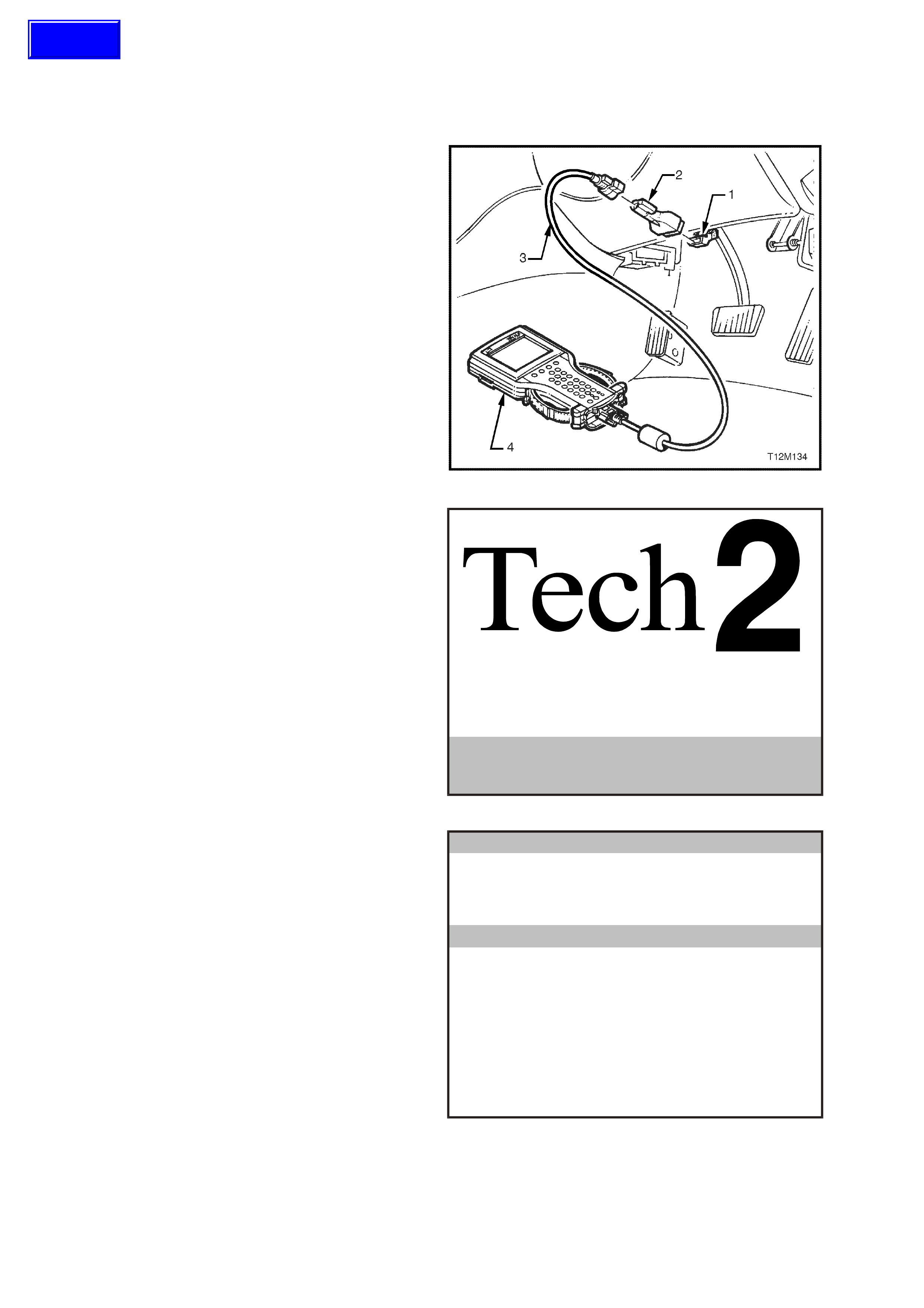
4.2 SPS PROCESS
CAUTION: Before performing SPS inspect the
Tech 2 DLC cable and the DLC connector and
terminals for damage. Any damage that causes
an open circuit during the programming
procedure could result in irreparable damage to
the PCM.
Battery voltage must be between 12 and 14
volts. The vehicle to be programmed must not
be connected to a battery charger during the
programming procedure. Incorrect battery
voltage could cause programming failure
and/or PCM failure.
1. Connect DLC cable (3) to Tech 2 (4), DLC
adapter (2) to DLC cable (3) and then DLC
adapter to DLC (1).
Press the Tech 2 PWR button to turn on Tech
2.
Figure 0C-49 Connecting Tech 2 to the DLC
2. When the Tech 2 title screen is displayed,
press ENTER to continue.
VX0C000
Pres s [EN T ER ] to continue .
Softwa re Ver sio n 8.200
Ho lden 199 7 - 2001
VX0C000
Figure 0C-50 Tech 2 Title Screen
3. Select F1: Service Programming System
(SPS).
Main Menu
VX0C001
F0 : Diagnostics
F1 : Service Pro gramm ing S ystem (SPS)
F2 : View Capture Data
F3 : Tool Options
F4 : Download/U pload Help
Figure 0C-51 Main Menu
Techline
4. Select F0: Request Info and follow the
instructions on the screen.
Service Programming System (SPS)
Ver si on 4.072
Te ch 2 is rea dy to reques t da ta from the
vehicle!
VX0C002
F0: Reques t Info
Figure 0C-52 F0: Request Info
5. If there is data already stored, Tech 2 will
display the stored data.
If there is no data stored in Tech 2 then the
following Model Year selection screen (Figure
0C-51) will be displayed.
Press the Continue Soft Key to request new
information.
Confirm Continue Keep Data
Service Programming System (SPS)
Ver si on 4.072
Continu e and request new info?
Data already stored in Tech 2!
VIN:
Hardware:
Software:
6H8VTX69FXL438292
--------------
92083995
VX0C003
Figure 0C-53 Data Already Stored in Tech 2
6. Select the correct Model Year for the vehicle
you ar e work ing on, for VX select (1) 2001 wi th
the arrow keys and the press ENTER.
Main Menu
Select one of the following
M odel Year(s)
VX0C004
(1)
(Y)
(X)
(W)
(V)
(1)
2001
2000
1999
1998
1997
1 / 5
2001
Figure 0C-54 Model Year Selection

7. Select VX Commodore with the arrow keys
and then press ENTER.
Main Menu
Select one of the following
Vehicle Type(s)
VX0C005
VX Commodore
W H S tatesma n & Ca price
Corsa-B
Astra-F
Astra-G
Vectra-B
Zafira
VX Commmodore 1 / 7
Figure 0C-55 Vehicle Type Selection
8. Turn off Ignition!
Press the Okay soft key to continue.
Okay
Service Programming System (SPS)
Ver si on 4.072
Turn off Ignitio n !
VX0C006
Figure 0C-56 Service Programming System (SPS)
9. When Ignition is Switched Off! is displayed,
press the Okay soft key to continue.
Service Programming System (SPS)
Ver si on 4.072
Ignitio n sw itched off!
VX0C007
Okay
Figure 0C-57 Service Programming System (SPS)
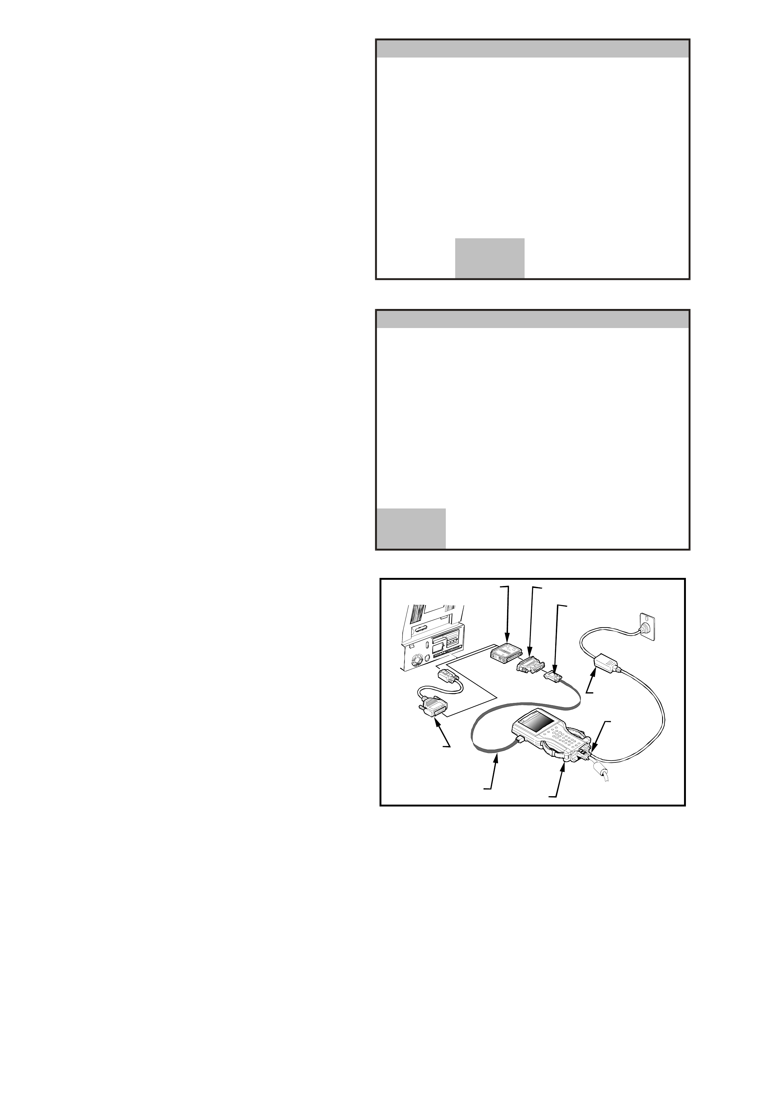
10. Turn off all power consuming devices!
(i.e. A/C Headlamps etc).
Turn on ignition!
Engine off and Ignition on?
Press the Okay soft key to continue.
Okay
Service Programming System (SPS)
Ver si on 4.072
Turn on Ignition!
Engine off and Ignition on!
Tu rn off all power co nsu m ing devices!
VX0C008
Figure 0C-58 Service Programming System (SPS)
11. The Tech 2 will then read and display the
Vehicle Identification Number (VIN) and ECU
data.
When the Tech 2 screen opposite is displayed;
Tur n off Tech 2.
Turn off Ignition.
Disconnect Tech 2 from the DLC.
NOTE: If programming a Service Replacement
PCM the VIN number will not be displayed.
More
Service Programming System (SPS)
Ver si on 4.072
Tu rn off Ig nition! D is con nec t Tech 2
from vehicle and conn ect it to TIS
Ex isting E CU Da ta!
VIN:
Hardware:
Software:
6H8VXX69F1L123456
12345678
92000000
VX0C009
Figure 0C-59 ECU Data
12. Connect the RS-232 cable (2) to the Tech 2
(1) RS-232 communication port. Connect the
other end of the RS-232 cable to the DB-9
adapter (3) and then connect the DB-9 adapter
(3) to the 25/9 pin adapter (4). Connect the
25/9 pin adapter to the Hardware Key (5) and
then connect the Hardware Key to the serial
port of a Personal Computer (PC) with TIS
2000 installed.
NOTE: If your PC has a 9 pin serial
com munic ation port you will need to fit the 9/25
pin adapter (6) between the Hardware Key (5)
and the serial port of the TIS PC. Connect the
power supply (7) to the Tech 2 power supply
jack (8). Press the PWR button to turn on Tech
2. Tech 2 should now be at the title display
screen.
54
6
3
8
7
1
2
Figure 0C-60 Connecting Tech 2 to the TIS Personal
Computer
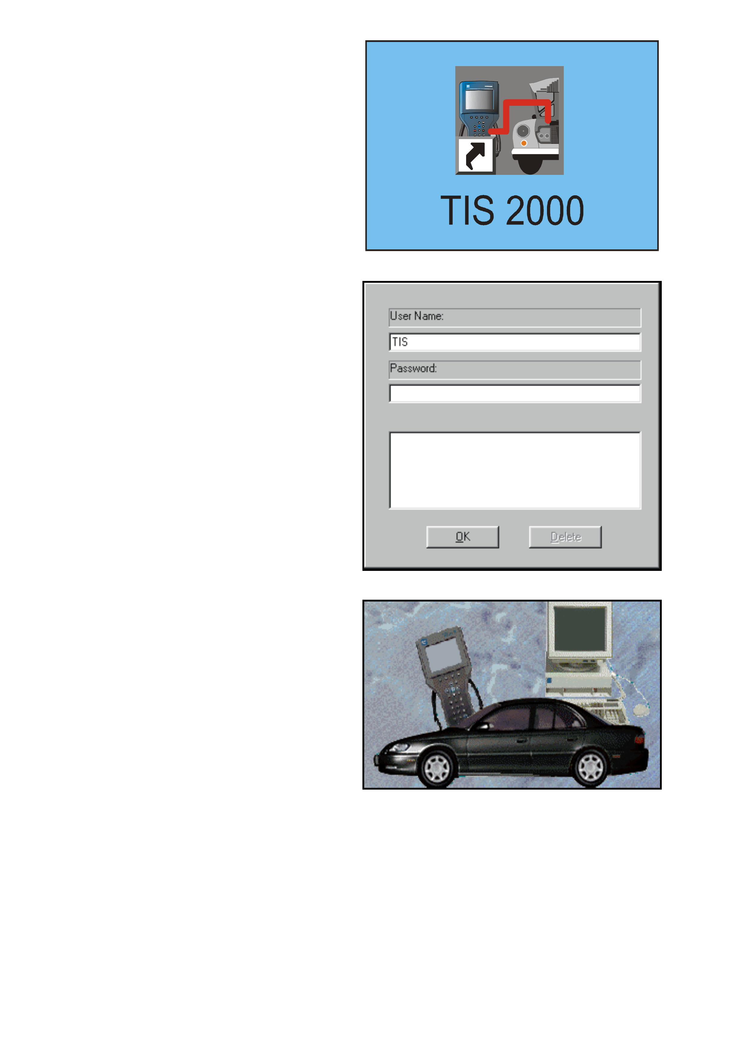
13. O pen TIS 2000 by double-click ing the T IS 2000
Icon.
Figure 0C-61 TIS 2000 Icon
14. The default user of TIS2000 is called "TIS".
This user does not have a password. Click the
"OK" icon to continue.
Figure 0C-62 TIS User
15. From the TIS 2000 Main Menu click on the
SPS icon to start the SPS application.
NOTE: If TIS 2000 does not detect a Hardware
Key the following error message will be
displayed.
Access to Service Programming Server was
denied. No Hardware Key was found!
Figure 0C-63 SPS Icon
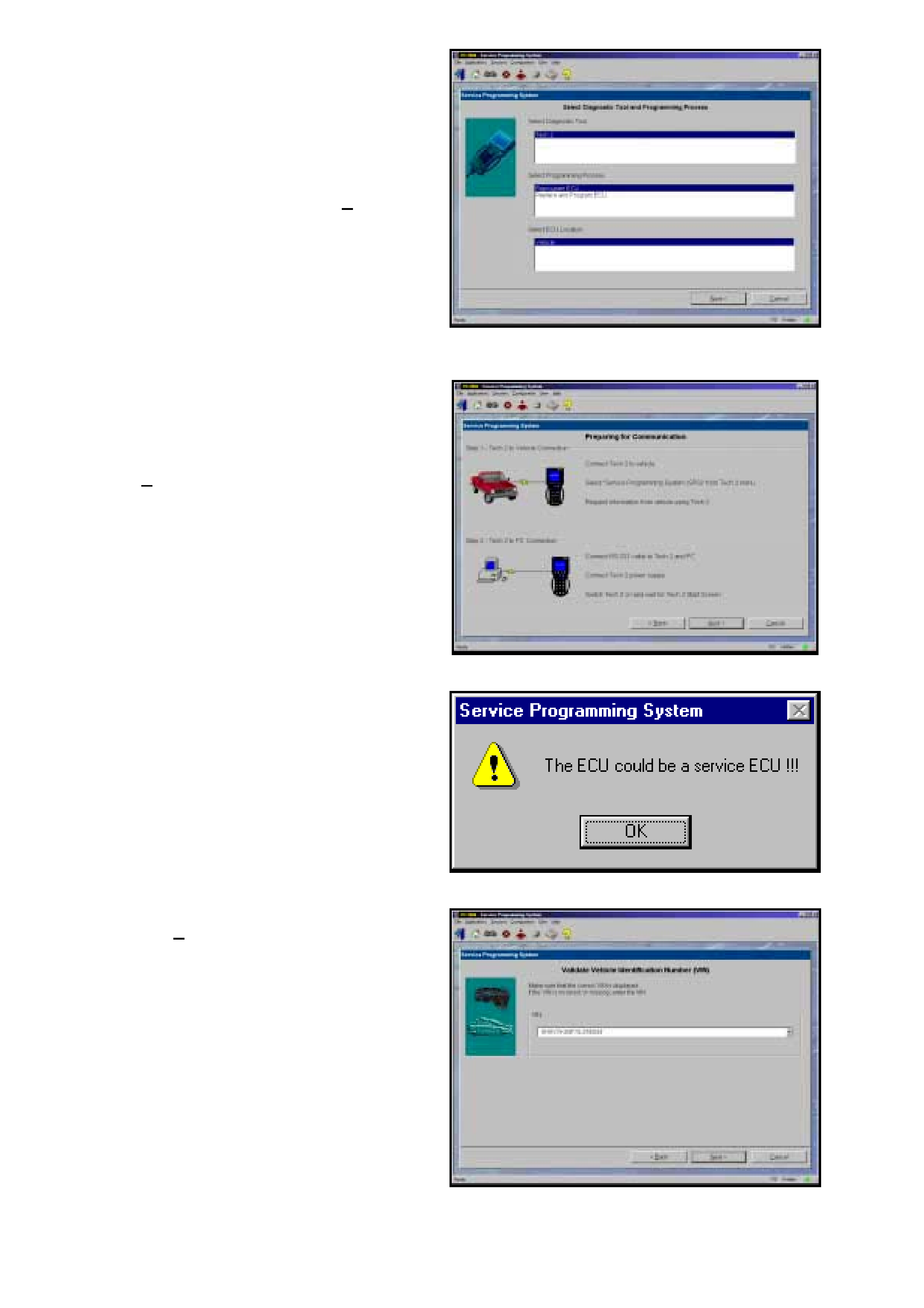
16. At Select Diagnostic T ool and Programming
Process click on desired selections for:
• Diagnostic tool being used: Tech 2.
• W hether you are reprogramming an existing
control unit or programming a new control
unit.
• Select ECU location: Vehicle.
17. After making your selections, select Next>.
Figure 0C-64 Select Diagnostic Tool and Programming
Process
18. At this point you should have already
Requested Info from the Vehicle and Tech 2
should be connected to the serial port of a
Personal Computer (PC) with TIS 2000
installed via the Hardware Key.
Select Next>. to continue.
Figure 0C-65 Connecting Diagnostic Tool
19. If a Service ECU has been installed the
warning opposite will be displayed at this time,
select OK to continue.
Figure 0C-66 Service ECU Warning
20. Confirm VIN or enter correct VIN, if required,
then select Next>.
Figure 0C-67 Validate Vehicle Identification Screen
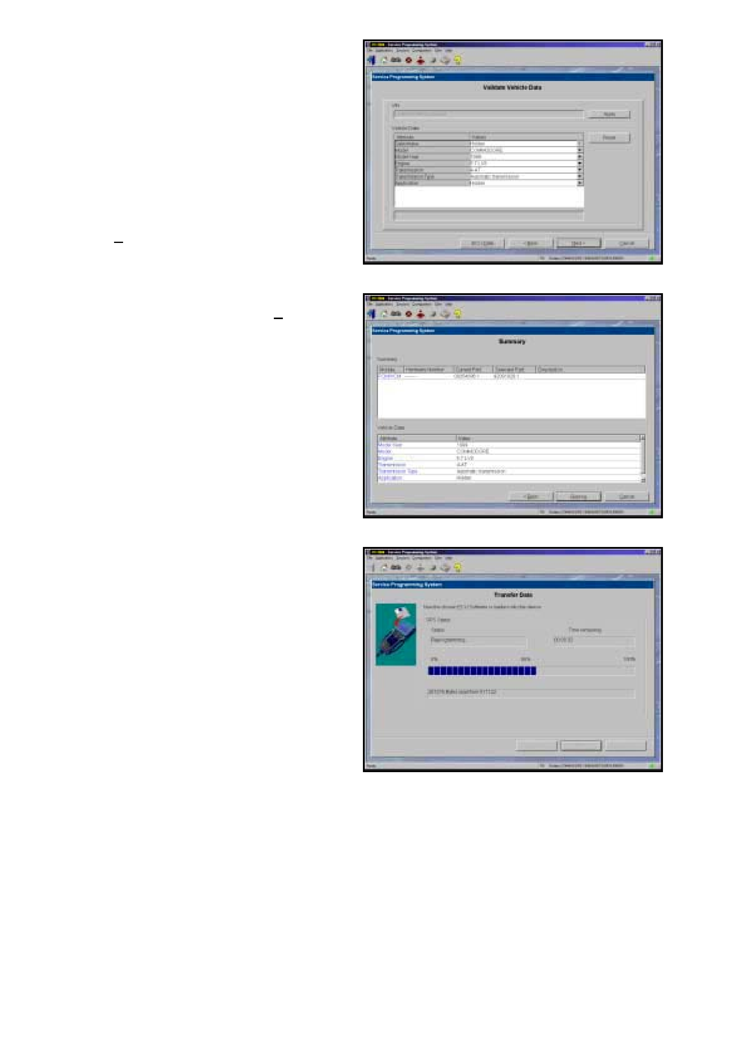
21. Validate vehicle data, and change if necessary
using the pull down menus.
NOTE: If you are programming a V8 GEN III
PCM and Holden Special Vehicles (HSV) is
selected, TIS 2000 will not allow you to
Reprogram the the ECU in step 22. You should
contact HSV for a replacement PCM.
However, it is possible to program the PCM
from a HSV vehicle w ith the Hold en applicatio n.
This w ill allow the vehicle to be driven, until the
replacement PCM is obtained from HSV.
22. Select Next>. button.
Figure 0C-68 Validate Vehicle Data
23. A Summary screen will appear, allowing you to
confirm your selection. Select Reprog to
continue.
Figure 0C-69 Summary Screen
24. A Transfer Data screen will appear. Select
Reprog button to initiate download of new
calibration file to Tech 2. The screen will track
progress of download.
Figure 0C-70 Transfer Data
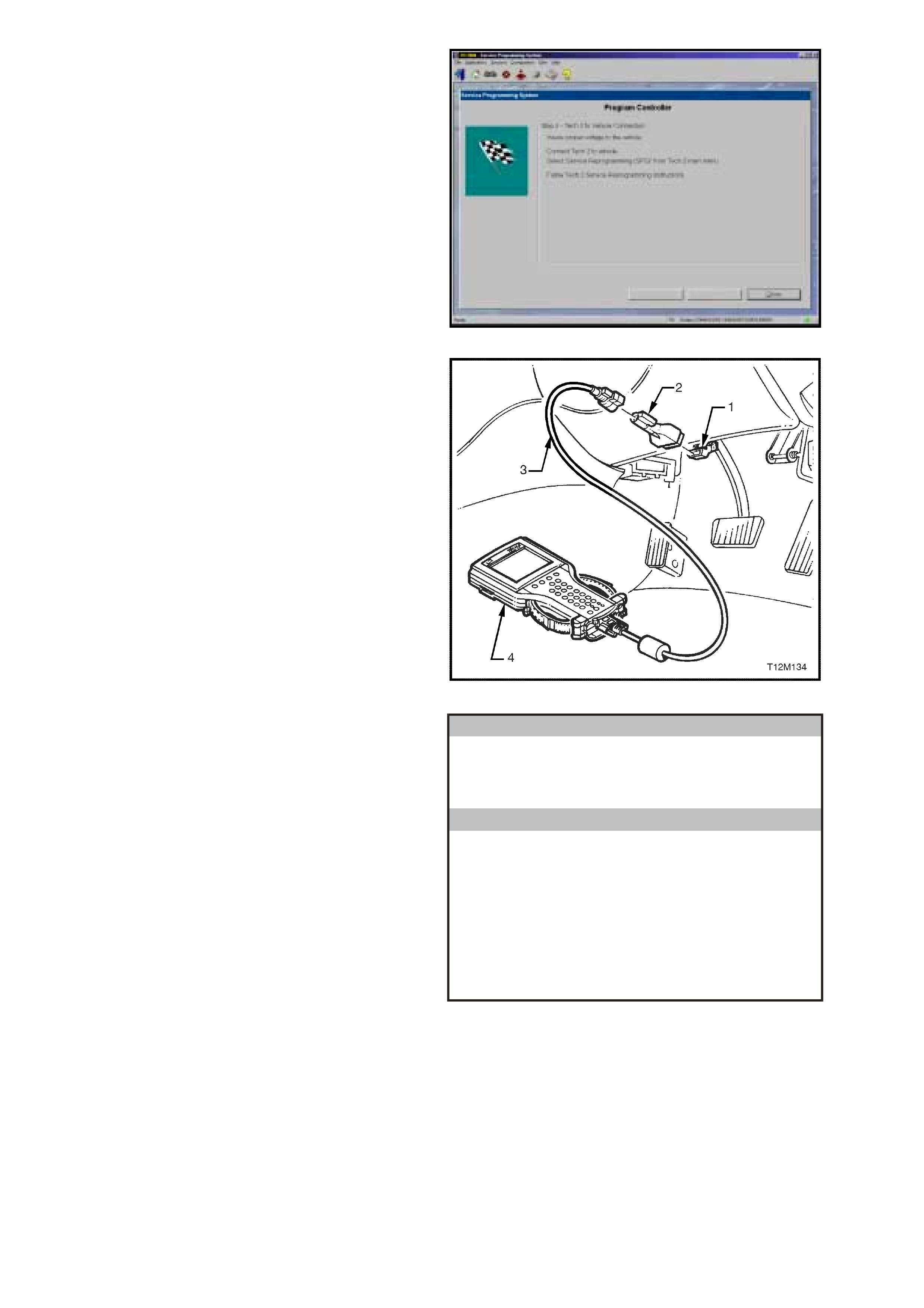
25. After download is complete a screen will
appear instructing you to connect Tech 2 to
vehicle to complete programming process.
Close the SPS application to retur n to TIS 2000
main menu; power down and then disconnect
Tech 2 from PC.
26. Return to the vehicle and complete the SPS
process.
Figure 0C-71 Download Complete
27. Reconnect Tech 2 to the DLC.
Press the Tech 2 PWR button to turn on Tech
2.
When the Tech 2 title screen is displayed,
press ENTER to continue.
1 – DLC
2 – DLC Adapter
3 – DLC Cable
4 – Tech 2
Figure 0C-72 Connecting Tech 2 to the DLC (Typical)
28. Select F1: Service Programming System
(SPS).
Main Menu
VX0C001
F0 : Diagnostics
F1 : Service Pro gramm ing S ystem (SPS)
F2 : View Capture Data
F3 : Tool Options
F4 : Download/U pload Help
Figure 0C-73 Main Menu

29. F1: Program ECU will be flashing. Tech 2 is
ready for ECU programming.
Select F1: Program ECU and follow the
instructions on the Tech 2 screen.
Service Programming System (SPS)
Ver si on 4.072
Te ch 2 is rea dy is ready for ECU program m ing !
VX0C010
F0: Reques t Info
F1: Program ECU
Figure 0C-74 Service Programming System (SPS)
30. Turn off all power consuming devices!
(i.e. A/C, headlamps etc.).
Turn On Ignition
Engine off and Ignition on?
Press the Okay soft key to continue.
Okay
Service Programming System (SPS)
Ver si on 4.072
Turn on Ignition!
Engine off and Ignition on!
Tu rn off all power co nsu m ing devices!
VX0C008
Figure 0C-75 Service Programming System (SPS)
31. Tech 2 will begin programming the ECU. The
screen display will indicate the VIN Number,
the New End Model Number and the progress
of the download as a percentage.
NOTE: The End Model Number will vary
depending on the application and software
level.
More
Service Programming System (SPS)
Ver si on 4.072
Tu rn off Ig nition! D is con nec t Tech 2
from vehicle and conn ect it to TIS
Ex isting E CU Da ta!
VIN:
Hardware:
Software:
6H8VXX69F1L123456
12345678
92000000
VX0C011
Figure 0C-76 Programming in Progress

32. Programming successful ! will be displayed
when programming is completed.
Press the Exit soft key to continue.
Programming has been completed.
Turn off and disconnect Tech 2
Turn off Ignition.
NOTE: If a Service PCM or a PCM from another
vehicle has been installed, a BCM to PCM/PIM
Link will have to be performed. Refer BCM TO
PCM/PIM LINKING procedure in Section 12J-1
for Low Series BCM’s and Section 12J-2 in for
High Series BCM’s of the VX Series Service
Information
Service Programming System (SPS)
Ver si on 4.072
Program m ing S uccessful
Press [Exit] Key
VX0C012
Figure 0C-77 Programming Successful
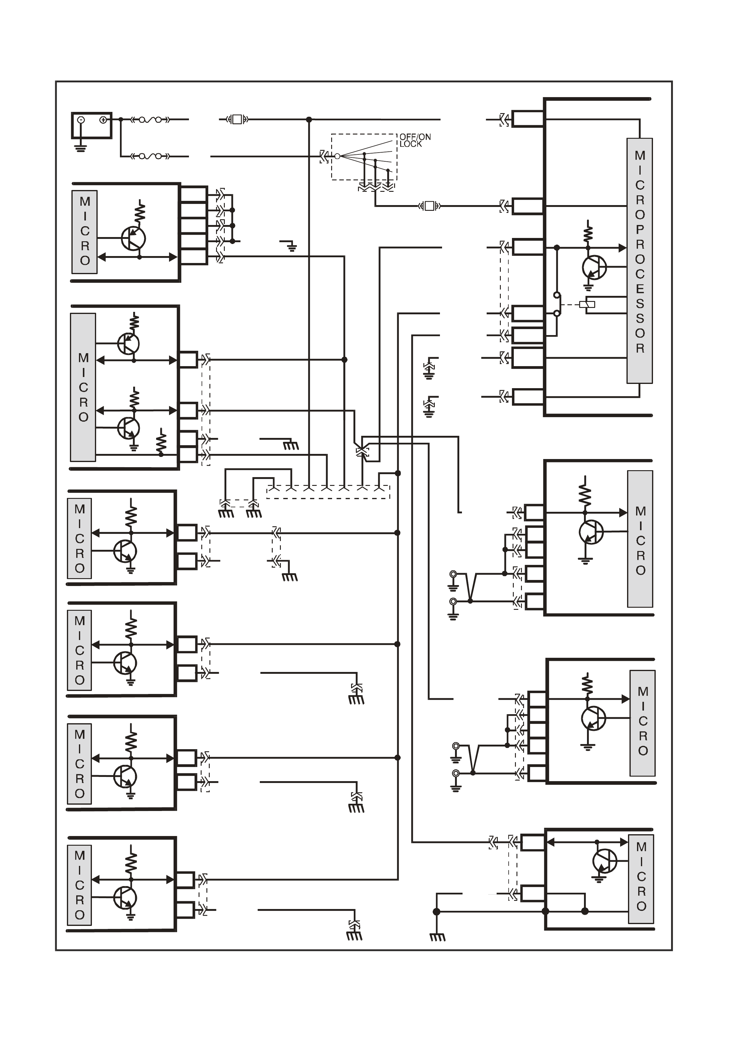
5. TECH 2 DIAGNOSIS
GEN III V8
VX12K112
BODY CONTROL MODULE
BATTERY
FS
F31
A
5/A6
O/B (740)
(1040)
BATTERY MAIN POWER
FJ
R (2)
F14
E20/D6
P/B
(39) IGNITION ON
15a 15 50
30
A
CC
IGN
START
IGNITION SWITCH
P
(3)
YB165
YB176
HIG H SERIES
BCM TERM INALS
NO MINATED FIRST
YB44
YB44
YB164
YB175
YE112
B/Y (155)
B/G (151)
LOC. E3
LOC. E3
R/B (1221)
G/W (1220)
W/G (1220)
YE114
YE114
7V
YE114
ELECTRONIC
CLIMATE CONTROL
6
YE87
LOC.E3
2B/Y (155)
SERIAL
DATA
5V
YE114
YE114
ABS/ETC
11
YE98
LOC.E3
LOC.E3
19 B (150)
SERIAL
DATA
5V
INSTRUMENTS
12
6
YB66
B/Y(155)
SERIAL
DATA
5V
ELECTRONIC E ARTH
HIGH CURRENT
EARTH
A1/A5
B10/
B11
YB176
YB165
YB174
YB163
YB164
YB175
E2/D2
E9/D3
E3/D13
SERIAL
DATA
MAIN
SERIAL
DATA AUX.
5V
LOC. E5/E15
GEN III V8 POWERTRAIN
CONTROL MODULE
J1-58
J2-01
J2-40
J1-40
J1-01
CLASS II
SERIAL DATA
YE122
B/R (750)
16
YB215
B/R (750)
POWERTRAIN
INTERFACE MODULE
SERIAL
DATA
7V
12V
5V
6
11
7
DIAG . ENA BLE
CLASS 2
SER IAL DATA
LOC.
E5/E15
SUPPLEMENTAL
RESTRAINT SYSTEM
9
8
YB190
YB189
LOC.G11
EARTH
SERIAL
DATA
B (3 05)
YB191
V
6 POWERTRAIN
CONTROL MODULE
F7
E7
SERIAL
DATA
5V
R/B (1221) C13
YB198
YB199
YB187
LOC. E 15
LOC. E 5
B5
A5
B/R
(750)
B/R
(750)
R/B (1221)
LOC. E5
SUPERCHARGED V6
POWERTRAIN
CONTROL MODULE
A
3
B2
B1
SERIAL
DATA
5V
Y
B188
LOC. E 15
A2
A1
B/R
(750)
B/R
(750)
LOC.E12
B/W(1151)
B/Y
(155)
B
(150)
LO C. E3 YB128
642516 91
DATA LINK
CONNECTOR
TELEMATICS
9
2
YB178
YR55
SERIAL
DATA
5V
Figure 0C-78 Serial Data Circuit
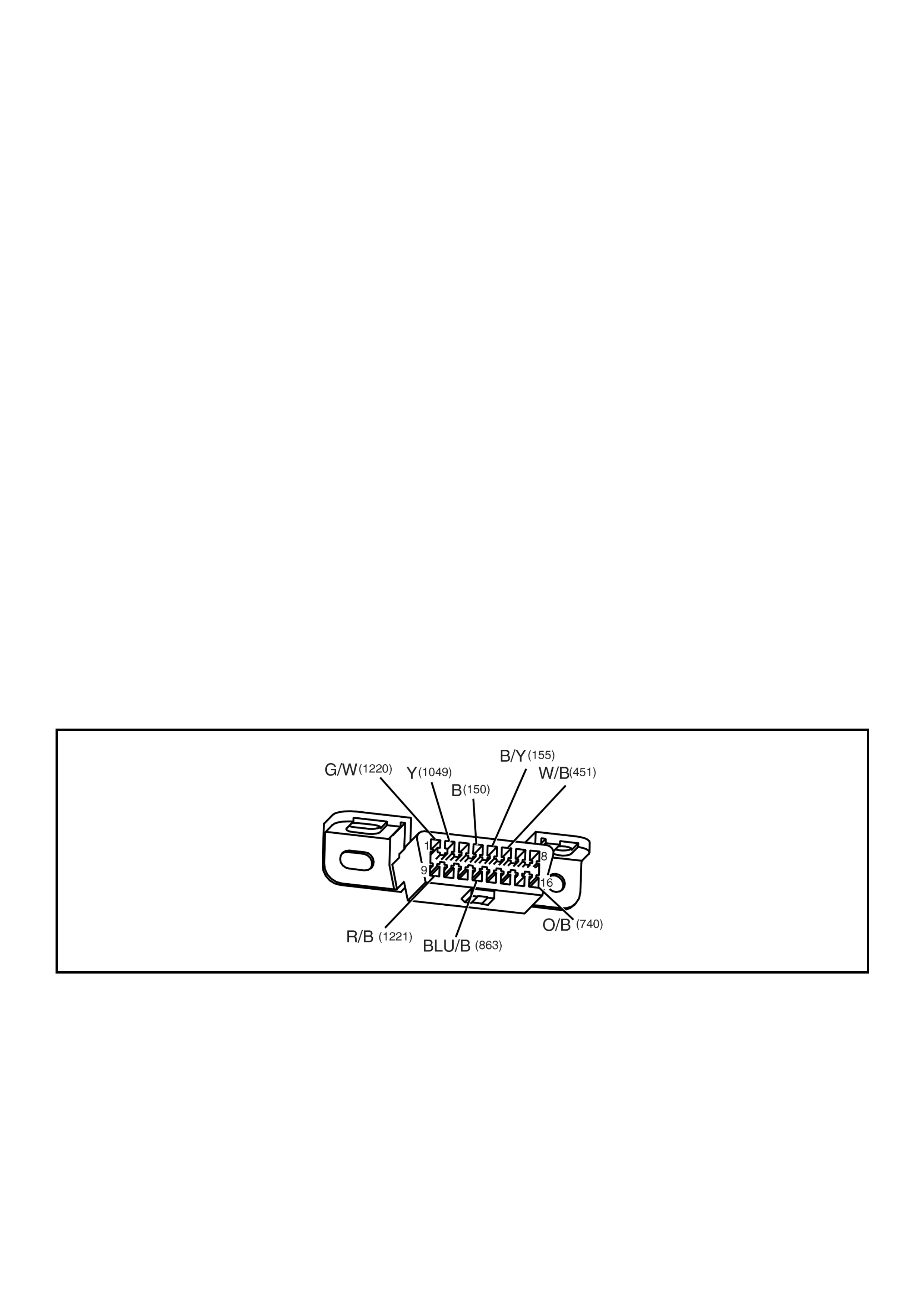
5.1 GENERAL INFORMATION
Tech 2 communicates with the vehicle via the UART serial data bus circuit 1221. Circuit 1221 is connected to
terminal 9 of the DLC (YB128) and the serial data earth circuit is via terminal 5 of the DLC and circuit 155.
The power supply for Tech 2 is from fuse F31 via circuit 740 to terminal 16 of the DLC. The earth circuit is via
terminal 4 and circuit 150.
Tec h 2 com m unicates with the following control m odules , via the UART s erial data bus c ircuit 1221, if the vehicle is
equipped with these sy stems.
• Body Control Module (BCM).
• Powertrain Control Module (PCM).
Engine and Automatic Transmission
• Powertrain Interface Module (PIM)
• Instrument (INS).
• Supplemental Restraint System (SRS).
• Antilock Braking System / Electronic Traction Control System (ABS/ETC).
TECH 2 COMMUNICATES WITH THE GEN III V8 PCM VIA THE CLASS 2 SERIAL DATA CIRCUIT 1049.
CIRCUIT 1049 IS CONNECTED TO TERMINAL 2 OF THE DLC (YB128).
TEST DESCRIPTION
The numbers below refer to step numbers on the following diagnostic chart.
1. Checks if Tech 2 is being powered up.
2. Checks if Tech 2 is programmed with correct Holden software.
3. Checks if Tech 2 can communicate with BCM If Tech 2 can communicate with BCM, serial data circuit 1221
is OK.
4. Checks continuity of serial data earth circuit.
5. Checks if fusible link FS is OK.
6. Checks if fuse F31 is OK.
7. Check if battery voltage is available for Tech 2.
8. Checks if an earth circuit is available for Tech 2.
9. All vehic le c ircuits have been f ound to be OK, f ault m ust be with T ech 2 or an inter m itted fault is causing T ech 2
not to operate correctly.
Figure 0C-79 Data Link Connector YB128

STEP ACTION VALUE YES NO
1. • Connect Tech 2 to the vehicle DLC, with the DLC
cable and the 16/19 pin adapter.
• Switch on Tech 2 by pressing the PWR button.
• Does a green light above the PWR button come ON?
Go to Step 2. Go to Step 5.
2. • Does Tech 2 display Title Screen illuminate and
display: Tech 2
Press [ENTER] To Continue
Software Version: 8.100
Holden 1997 - 2001
(Software Version should be greater than 8.100)
Go to Step 3. Program Tech 2
PCMCIA Card refer
to PROGRAMMING
Tech 2 is this
Section.
3. • At the Tech 2 title screen press the Enter key.
• Select F0: Diagnostics / 2001 /
VX Commodore / F3: Body / Body Control Module.
• Turn on ignition and press the confirm soft key.
• Does Tech 2 display the BCM System Identification
Screen?
Tech 2 is
functioning
correctly, refer to
system specific
diagnostics, if you
cannot
communicate with
a specific control
module.
Go to Step 4.
4. • Using an ohmmeter check continuity of circuit 155
(Black/Yellow wire) between DLC (YB128) terminal 5
and a known good earth.
• Is there continuity?
Go to BCM
diagnosis
SERIAL DATA
COMMUNICATION
Section 12J1 Low
Series BCM, or
Section 12J2 High
Series BCM in the
VX Service
Information.
Repair open in
circuit 155 between
DLC terminal 5 and
earth LOC. E3.
5. • Is Fusible link FS OK? Go to Step 6. Replace fusible link
and check cause of
blown fusible link.
Verify Repair.
6. • Is Fuse F31 OK? Go to Step 7. Replace fuse and
check cause of
blown fuse.
Verify Repair.
7. • Check for voltage between DLC (YB128) terminals 4
and 16.
• Is voltage at specified value?
B+ Go to Step 9. Go to Step 8.
8. • Ignition off.
• Check for voltage between DLC (YB128) terminals
16 and a known good earth.
• Is voltage above specified value?
B+ Repair open in
circuit 150 between
DLC Connector
terminal 4 and
earth LOC. E3.
Verify Repair.
Repair open in
circuit 740 and
1040 between DLC
Connector terminal
16 and fusible
link FS.
Verify Repair.
9. • Perform Tech 2 Self Test using 240 V AC power
supply. (Refer to Tech 2 User’s Guide).
• Does Tech 2 pass Self Test?
Check for incorrect
terminal sizing of
DLC YB128 or
intermittent fault in
DLC circui ts.
Send Tech 2 out for
repair.
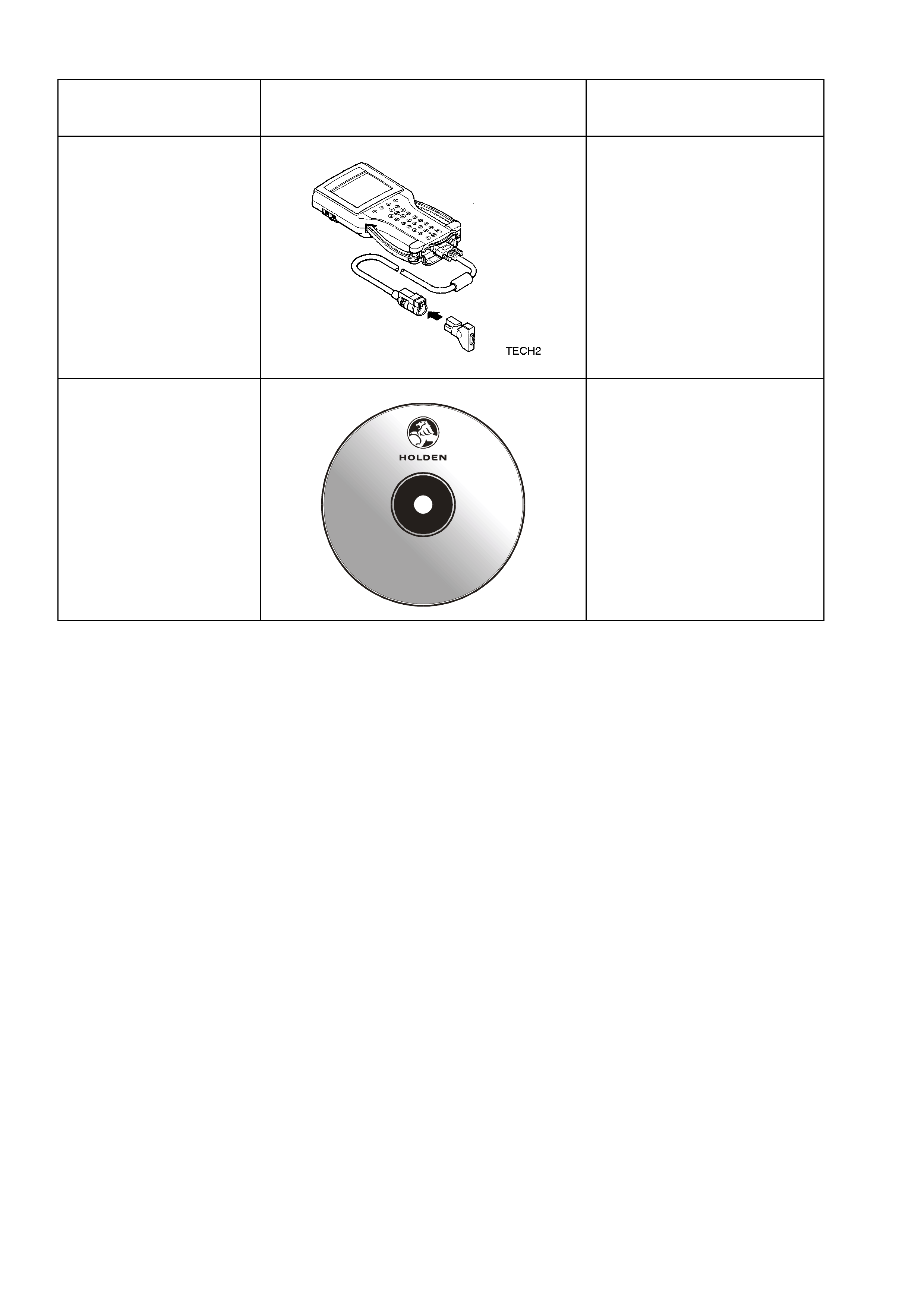
6. SPECIAL TOOLS
TOOL NO. REF
IN TEXT TOOL DESCRIPTION COMMENTS
Tech 2 TECH 2
Previously released
Technical Information
Sy stem
(TIS) 2000
TIS 2000 CD ROM
Version 11.0B
Tech 2 V er .
Hold en 10. 100
September
2000
DIAGNOSIS &
LABOUR TIMES
TIS2000
Data Copyright 2000
All Rights Reserved
SOFTWA RE Copyright 2000
Ser v ic e Ope r at ion s
General Motors Corp.
All Rights Reserved
This disc contains
copyrighted material. Any
reproducti on or pu bli cati on
of this information without
the expressed written
co nse n t of Ad am O pel AG ,
Russ e lsh eim, is prohibited
Previously released