
SECTION 1A1 - BODY
IMPORTANT
Before performing any Service Operation or other procedure described in this Section, refer to Section
00 CAUTIONS AND NOTES for correct workshop practices with regard to safety and/or property damage.
1. GENERAL I NFORMATI O N
All information relating to the vehicle body of the VX Series Model is as detailed in Section 1A1 BODY of the VT
Series I Service Information, noting the following:
To comply with the requirements of ADR-72 and ADR-73, Side Impact Protection standards and Frontal Offset
Impact standards, respectively, various structural changes to the body have been made.
Information in this Section details updated illus tr ations and listings of the body assemblies and individual panels that
are available for replacement. For more detailed information on this subject, reference to the VX Series Body
Structure Repair Information should be made.
NOTE: Some structural changes to the body were introduced as a running change to VT Series II Models
(approximately January 2000). For a detailed summary and additional information of these structural changes,
reference to the VT Series II & WH Series Body Structure Repair Update Information should be made.
Techline

2. SERVICE OPERATIONS
2.1 BODY STRUCTURE PANELS
The f ollowing lists and illustrations show assem blies and individual panels that ar e available for replac ement on VX
Series Models.
The purpose of this information is to provide the repairer with a better understanding of available replacement
panels for VX Series Models.

UNDERBODY – SEDAN
1. Panel assembly – floor side 22. Crossmember assembly – centre
2. Reinforcement assembly – inner seat attach 23. Longitudinal – complete
3. Reinforcement – front seat outer attach 24. Extension assembly – longitudinal
4. Floor assembly – front 25. Hook – tie down
5. Mount assembly – power unit rear 26. Carrier plate assembly
6. Extension assembly – floor panel front 27. Reinforcement – floor panel side
7. Brace – longitudinal to front floor 28. Brace assembly – rear bumper mounting
8. Panel assembly – front fender skirt 29. Bracket assembly – brake hose
9. Bracket assembly –theft deterrent horn mounting 30. Crossmember assembly – rear
10. Bracket assembly – hydraulic modulator 31. Reinforcement assembly – centre bearing
11. Tray assembly – battery 32. Reinforcement – rear floor front, RH
12. Panel assembly – front 33. Reinforcement – rear floor front, LH
13. Panel assembly – front upper 34 Anchor assembly – seat belt
14. Panel assembly – front headlamp 35. Panel assembly – rear floor front
15. Bracket assembly – side panel front end 36. Panel assembly – rear floor rear
16. Member assembly – front lower 37. Plate web – rear RH
17. Longitudinal assembly – complete 38. Plate web – rear LH
18. Bracket – radiator support side 39. Reinforcement assembly – fuel tank mounting
19. Support assembly – front panel side 40. Stand assembly – spare wheel
20. Bracket – front bumper beam mounting 41. Reinforcement assembly – panel back lower
21. Console – front panel 42. Panel assembly – back lower
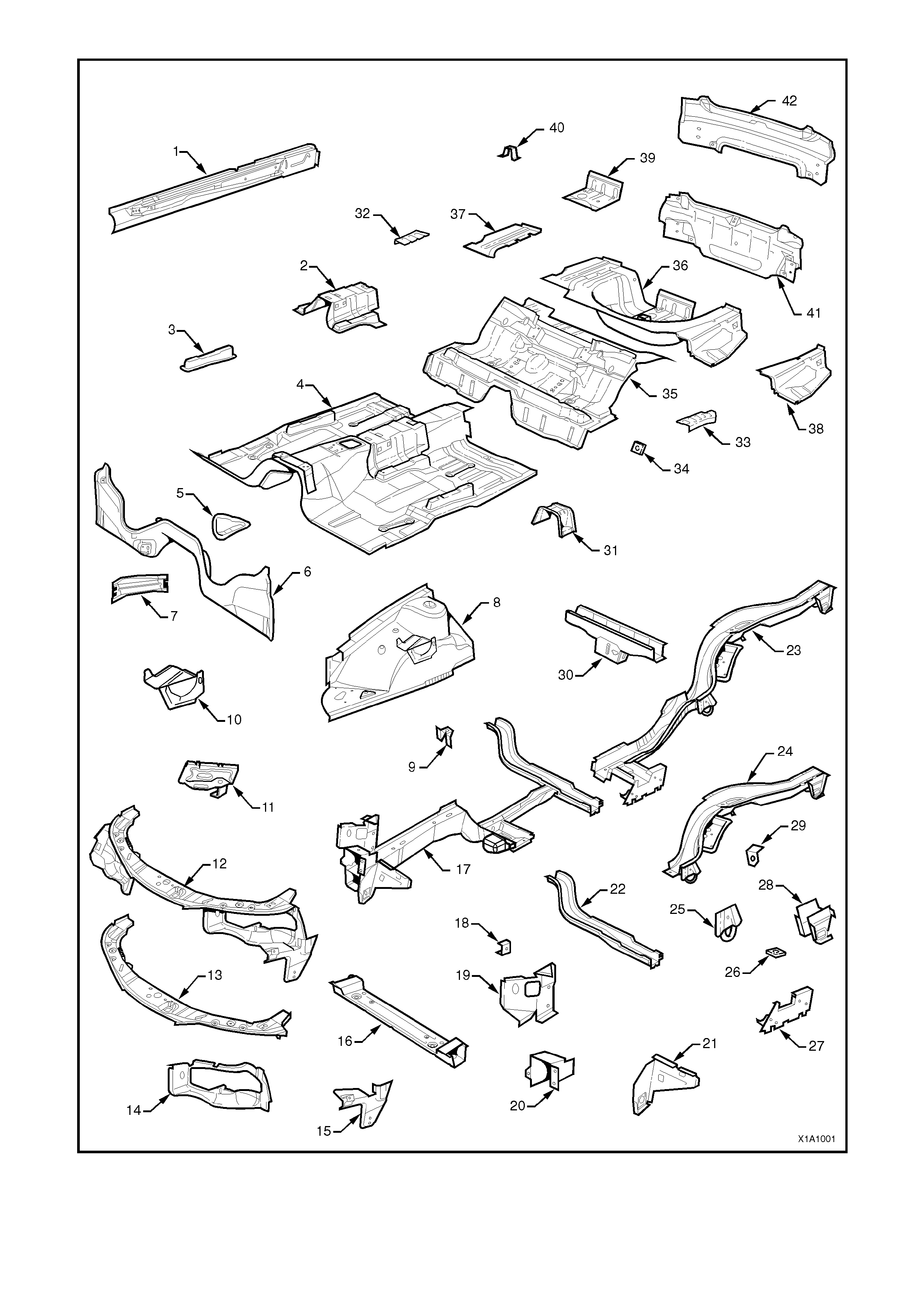
Figure 1A1-1
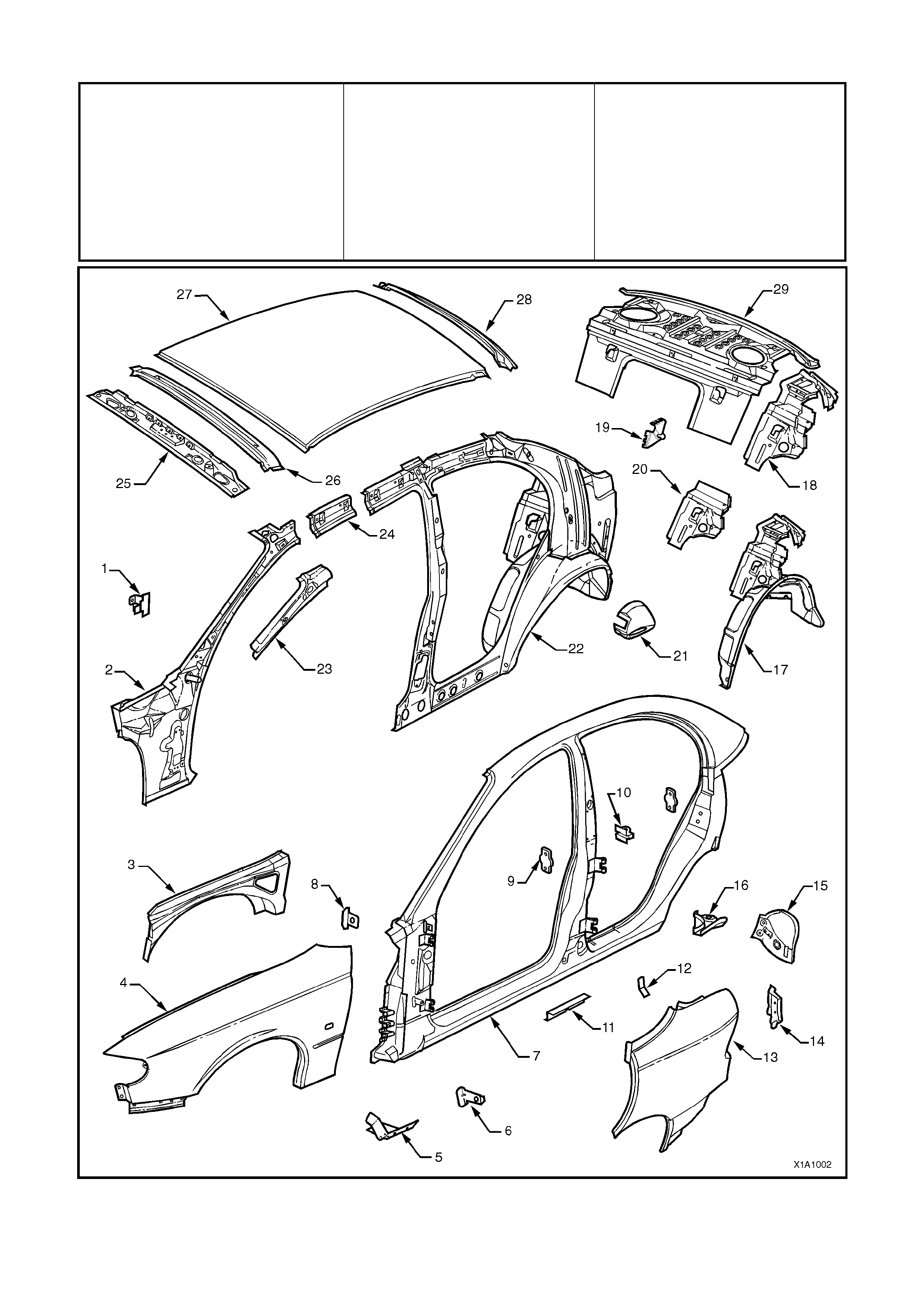
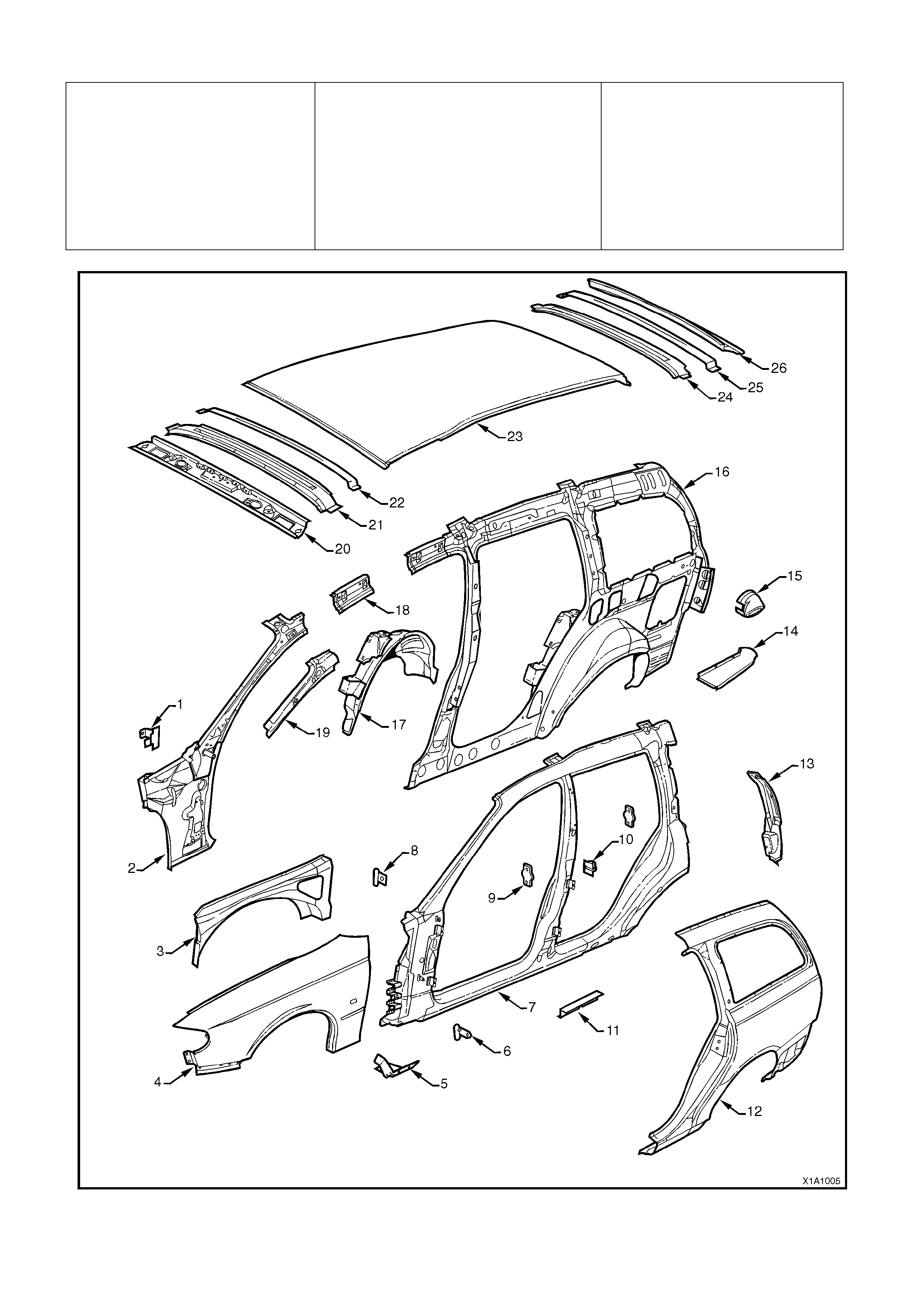
BODY SIDE - SEDAN
1. Bracket – trim attach 11. Support – centre jacking 21. Cap – fuel filler
2. Pillar assembly – front body inner 12. Clip – wiring harness 22. Side panel assembly – inner
3. Brace – wheelhouse 13. Panel – rear quarter outer 23. Reinforcement – A pillar upper
4. Fender – panel 14. Filler – side outer panel 24. Frame – side front roof
5. Support – fender to frame 15. Insert assembly – tail lamp 25. Rail – windshield header
6. Angle – fender lower to frame 16. Gusset – side panel outer 26. Support – roof
7. Frame assembly – door opening 17. Wheelhouse assembly – inner 27. Panel – roof
8. Angle – fender upper to frame 18. Brace assembly – wheelhouse 28. Frame – roof rear
9. Anchor plate – door striker 19. Bracket & ball assembly – strut 29. Panel assembly – back upper
10. Support – rear door check 20. Brace – upper wheelhouse
Figure 1A1-2
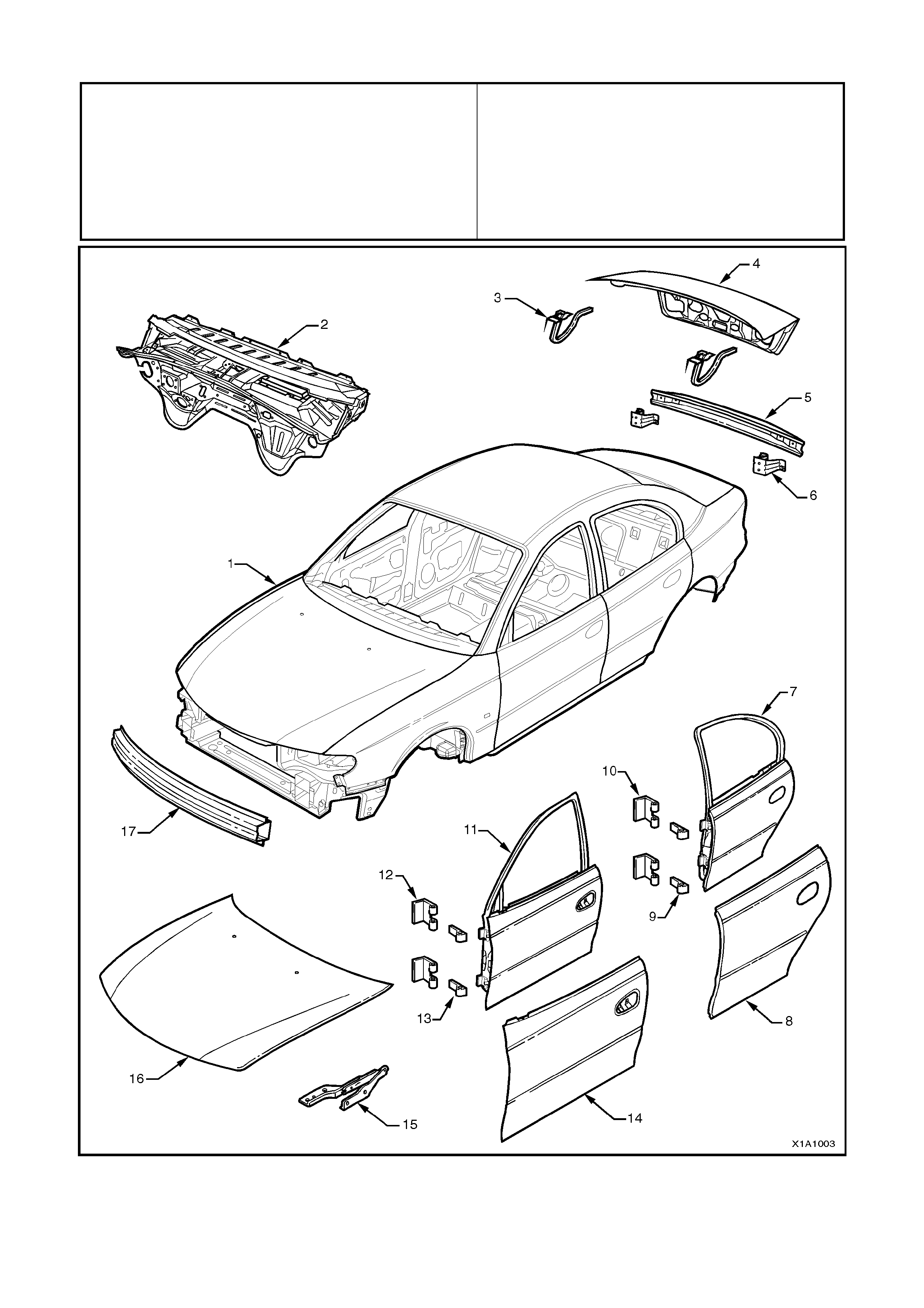
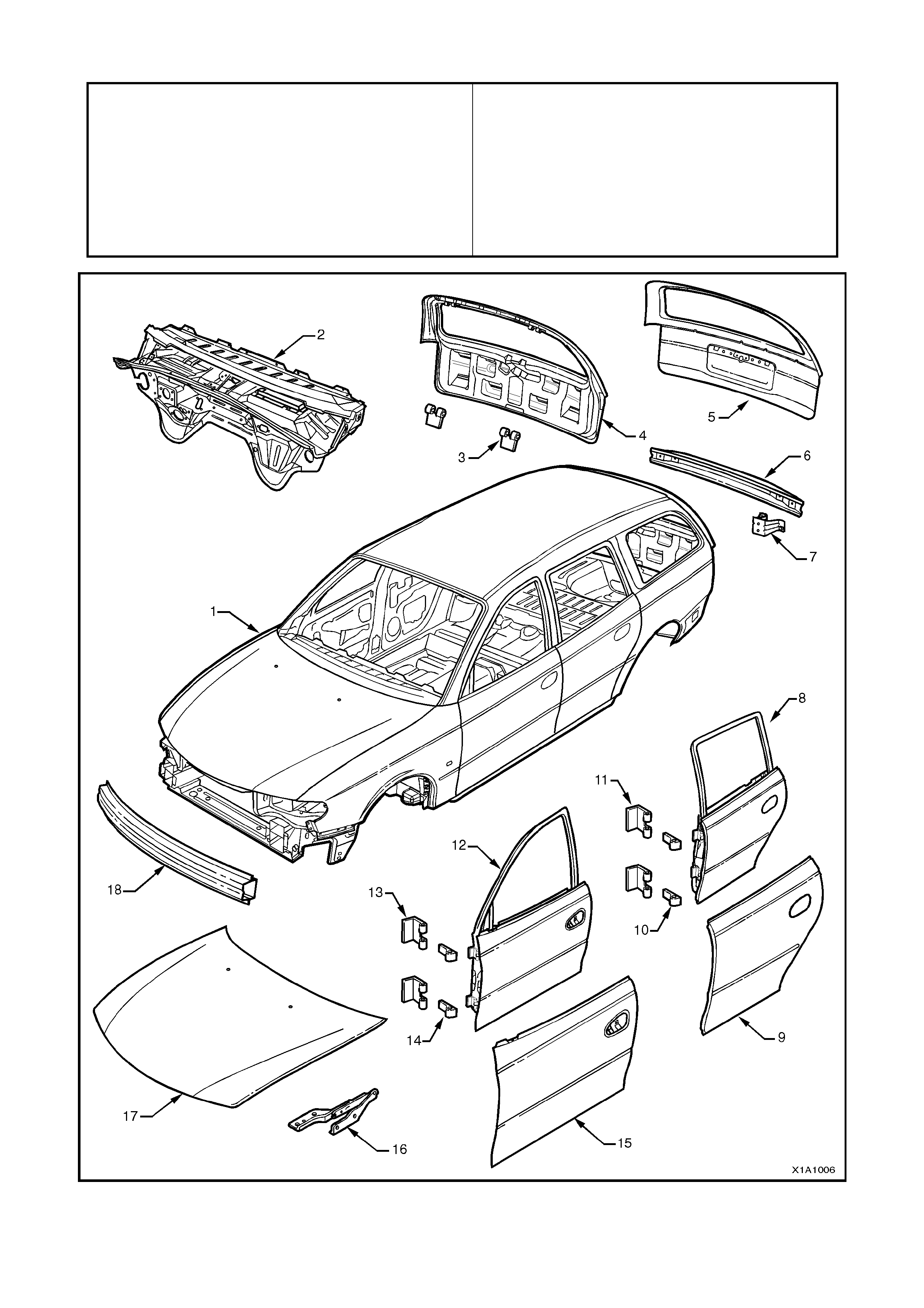
BODY SHELL - SEDAN
1. Body Assembly – in white, complete 10. Flap – rear door hinge (on hinge pillar)
2. Dash panel assembly 11. Door assembly – front
3. Arm & bracket assembly – deck lid hinge 12. Flap – front door hinge (on hinge pillar)
4. Deck lid assembly – rear compartment 13. Flap – front door hinge (on door assembly)
5. Beam assembly – bumper support 14. Panel assembly – front door outer
6. Bracket assembly – bumper support mounting 15. Hinge assembly – engine hood
7. Door assembly – rear 16. Panel assembly – engine hood
8. Panel assembly – rear door outer 17. Beam assembly – front facia support
9. Flap – rear door hinge (on door assembly)
Figure 1A1-3
UNDERBODY - WAGON
1. Panel assembly – floor side 22. Crossmember assembly – centre
2. Reinforcement assembly – inner seat attach 23. Longitudinal – complete
3. Reinforcement – front seat outer attach 24. Extension assembly – longitudinal
4. Floor assembly – front 25. Hook – tie down
5. Mount assembly – power unit rear 26. Carrier plate assembly
6. Extension assembly – floor panel front 27. Reinforcement – floor panel side
7. Brace – longitudinal to front floor 28. Brace assembly – rear bumper mounting
8. Panel assembly – front fender skirt 29. Bracket assembly – brake hose
9. Bracket assembly –theft deterrent horn mounting 30. Crossmember assembly – rear
10. Bracket assembly – hydraulic modulator 31. Reinforcement assembly – centre bearing
11. Tray assembly – battery 32. Anchor assembly – seat belt
12. Panel assembly – front 33. Panel assembly – rear floor front
13. Panel assembly – front upper 34. Panel assembly – rear floor rear
14. Panel assembly – front headlamp 35. Plate web – rear LH
15. Bracket assembly – side panel front end 36. Plate web – rear RH
16. Member assembly – front lower 37. Reinforcement assembly – fuel tank mounting
17. Longitudinal assembly – complete 38. Extension – back panel lower reinforcement
18. Bracket – radiator support side 39. Stand assembly – spare wheel
19. Support assembly – front panel side 40. Reinforcement assembly – panel back lower
20. Bracket – front bumper beam mounting 41. Panel assembly – back lower
21. Console – front panel
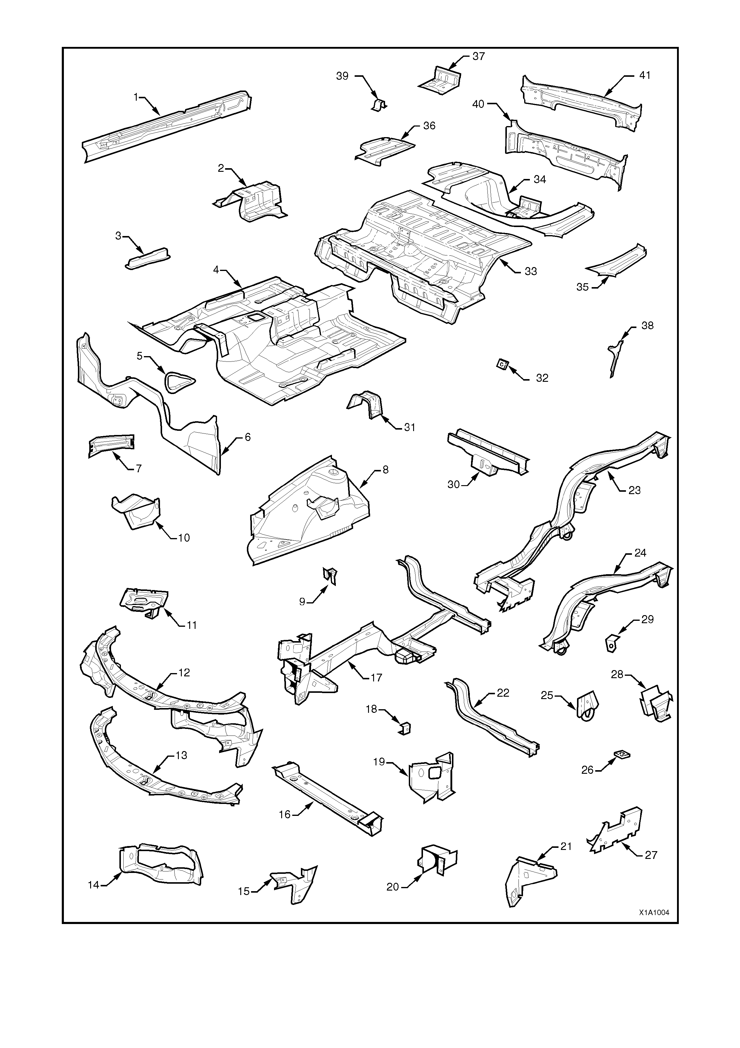
Figure 1A1-4
BODY SIDE – WAGON
1. Bracket – trim attachment
2. Pillar – front body inner
3. Brace – wheelhouse
4. Fender panel
5. Support – fender to frame
6. Angle – fender lower to frame
7. Frame – door opening
8. Angle – fender upper to frame
9. Anchor plate – door striker
10. Support – rear door check
11. Support – centre jacking
12. Panel – rear quarter outer
13. Gusset assembly – tail lamp
14. Plate – closing, side outer
15. Cap – fuel filler
16. Side panel assembly – inner
17. Wheelhouse assembly – inner
18. Frame – side inner roof
19. Reinforcement – ‘A’ pillar upper
20. Rail – windshield header
21. Support – roof no. 1
22. Support – roof no. 2
23. Panel – roof
24. Support – roof no. 3
25. Support – roof no. 4
26. Frame – roof rear
Figure 1A1-5
BODY SHELL – WAGON
1. Body Assembly – in white, complete 10. Flap – rear door hinge (on door assembly)
2. Dash panel assembly 11. Flap – rear door hinge (on hinge pillar)
3. Leg – tailgate hinge 12. Door assembly – front
4. Panel assembly – end gate 13. Flap – front door hinge (on hinge pillar)
5. Panel – tailgate outer 14. Flap – front door hinge (on door assembly)
6. Beam assembly – bumper support 15. Panel assembly – front door outer
7. Bracket assembly – bumper support mounting 16. Hinge assembly – engine hood
8. Door assembly – rear 17. Panel assembly – engine hood
9. Panel assembly – rear door outer 18. Beam assembly – support – front facia
Figure 1A1-6