
SECTION 1D - BUMPER BARS
IMPORTANT
Before performing any Service Operation or other procedure described in this Section, refer to Section
00 CAUTIONS AND NOTES for correct workshop practices with regard to safety and/or property damage.
1. GENERAL I NFORMATI O N
Front and r ear bumper bar facia ass emblies f itted to VX Series Models are of polypropylene material. The centre of
the front bumper bar facia is attached to a steel bumper support beam which, in turn, is attached to longitudinal
frame members and to the front fender sheet metal on each side.
The rear bumper bar facia is attached to the body at the sides and at the rear. Steel bumper support beam is
attached to rear longitudinally.

2. SERVICE OPERATIONS
2.1 PAINT SYSTEM
The paint system for the bumper bar facias is relatively straightforward as long as the correct materials are used.
Normal re-finish lacquers will not adhere to polypropylene/EPDM bumpers.
CAUTION: Thorough cleaning and the use of Holden’s approved paint and additives is required. Other
materials and methods may damage the plastic or lead to premature paint failure.
The f ollowing service rec om m endations ar e com piled to guide Dealers hips on the cor rect m ater ials and me thods to
be employed when re-finishing bumper bars and also preparing new parts for service installation.
RECOMMENDED MATERIALS
Front and rear bumper bars installed on VX Series models are made from high impact strength
Polypropylene/EDPM plastic.
It is essential that only Holden’s approved m ethods , materials , paints etc; be employed when paint repair operations
are performed and when preparing new parts for installation to the vehicles.
The Holden’s approved materials are:
-PPG* Bodykleen 920-35609
-PPG* Plastpak Universal Anti Static Cleaner 920-39237
-PPG* Plastpak Universal Primer 499-38571
-PPG* Plastpak Flexible Additive for Two Component Products 499-35484
-PPG* Cobra Basecoat - Colour 534 Line
-PPG* Base Builder (thinner) 920-43186
-PPG* 2K Clearcoat 455-30900
-PPG* 2K Acry lic Enamel Solid Colour 426 Line
-PPG* 2K MS Hardener Normal 980-35239
-PPG* 2K Reducer Fast 920-19148
* PPG is a registered trademark of PPG Industries Australia Pty Limited.
COLOUR FINISHING OF REPLACEMENT PARTS
Spare parts require priming and coating with approved topcoat colour before installation to the vehicle.
1. Order part and paint materials.
2. Read Safe Handling instructions further in this Section and obtain the required respirator.
3. Cleaning. Wash unpainted polypropylene bumper bar all over with a made-up solution of 9 parts fresh water:
one part PPG Bodykleen 920-35609. Apply with a clean non-metallic abrasive pad to scuff the surface.
4. Rinse with fresh cold water and dry thoroughly.
5. Using a c lean cloth saturated with PPG Plastpak Univer sal Anti-static cleaner 920- 39237, was h the entire part,
allowing contact for a minimum 15 seconds.
6. Dry thoroughly using a separate, clean, dry cloth.
7. Repeat steps 5 and 6 another three times. Each time using a separate clean dry cloth.
NOTE: If a static charge has built up on the bum per surf ace (after c ompleting all cleaning operations ) dampen the
surface with the Plastpak Universal Anti-static cleaner and allow to evaporate dry. This will impart full anti-static
properties to the bumper.
8. Prim ing: Apply one light double (approxim ately 3 - 8 µm D.F.B.) coat (unif orm ly wet) of PPG Plastpak Univer sal
primer 499-38571 to all the bumper surface intended for topcoat. Recommended air pressure range of
320 - 420 kPa.
9. Allow to air dry 15-20 minutes @ 20° C. DO NOT SAND.

PAINT
Solid Colour
To the matched colour, add Flexible Additive then Hardener and Reducer in the following ratios:
426 line colour - 5 parts by volume
Flexible Additive 499-35484 - one part by volume
2K MS Hardener 980-35239 - three parts by volume
2K Reducer 920-19148 - 10-20% by volume
Stir thoroughly and strain. Put on the air s upplied respirator. Using a 1.4 - 1.8 m m fluid nozzle on a standard spr ay
gun, apply one medium wet coat. Apply a further one or two coats to achieve coverage allowing a 3 - 5 minutes
flash-off time between coats. If low baking, this can be done immediately (no more than five minutes flash-off) at
60°C for 40 minutes. If air drying, allow 16 hours to dry (correct film thickness is 40 - 50 microns).
Cobra Basecoat, Metallic, Pearl or Solid Colour
Thin the matched basecoat colour with Cobra Basebuilder, 920 line at a 1:1 mix ratio and stir thoroughly, strain
material, and using a 1.4 - 1.6 mm gravity feed spray gun, apply one medium wet even coat. Allow to flash off f or
5 minutes before applying the next coat.
Apply one or two further coats to achieve a uniform and even coverage with five minutes flash-off between coats.
Allow 10 - 20 minutes drying before applying clearcoat.
Mix 2K Clearcoat with Flexible Additive then Hardener and Reducer in the following ratios:
-2K Clearcoat 455-30900 - five parts by volume
-Flexible Additive 499-35484 - one part by volume
-2K MS Hardener 980-35239 - three parts by volume
-2K Reducer 920-19148 - 20% by volume
Stir thoroughly and strain. Put on the air supplied respirator. Using a 1.4 - 1.8 mm fluid nozzle spray gun set-up,
apply one medium wet coat to the basecoat (after allowing the Basecoat 10 - 20 minutes drying time). Apply a
further one or two wet coats after a 3 - 5 minutes flash-off between coats. If low baking, this can be done
immediately after the last c oat but do not allow mor e than 5 m inutes flas h-off . Bak e at 60°C for 40 m inutes or, if air
drying, allow 16 hours.
REPAIRING COLOUR COAT
Superficial damage to the paint film and/or plastic surfaces may be rectified by sanding and repainting. Parts having
deep gouges in the plastic surface should be replaced because repair methods using filling materials and thinning
down of the plastic section may reduce overall impact strength.
For shallow paint damage, follow the procedure listed under “Colour finishing of replacement parts”, using P800
paper to sand down imperfections and using an abrasive pad or P1200 paper, scuff and key existing paintwork.
Basecoat and Clearcoat can be spot repaired by blending away the basecoat colour but spraying the complete
bumper with Clearcoat coats. Solid colours are best sprayed as complete panels. If the damage extends to the
plastic surface, this must be primed with Plastpak Universal primer after the correct cleaning procedure.
CAUTION: Drying of all products may be accelerated by heat, but to avoid distortion, unsupported bumpers
should not be heated in an oven or by lamp above 60°
°°
°C.

SAFE HANDLING OF ALL PAINTS CONTAINING PPG 2K MS HARDENER
PPG 2K MS Hardener contains not more than 0.3% free isocyanate monomer.
FOR AUTO MOTIVE AND INDUST RIAL USE ONLY. T his product requires prof essional equipment and experienc e
for safe handling. Not for use by the general public.
Read and under stand the inst ructions and warnings contained in data s heets and on the label of the c an containing
the base product before opening the can. Follow all directions and warnings carefully, otherwise DO NOT use this
product.
Warnings and precautions on the label also apply to the mixture of hardener and base.
Breathing of vapour, spray mist and dust from sanding is harmful and may cause lung irritation and allergic
respiratory reaction and irritation to skin and eyes.
W hen m ixed with the appropriate base, apply in a spray booth fitted with an effective exhaus t system. Com ply with
local legislation applicable to spray painting of motor vehicles. Wear a positive pressure air supplied full face
respirator (complying with Australian Standard 1716 - 1984) and gloves while spraying and during all subsequent
use. The spray booth area should be isolated from other people while spraying is in progress and until all spray mist
has been effectively dispersed.
FIRST AID: If affected by inhalation of vapour or spray mist, remove to fresh air. If breathing difficulty persists or
occurs later, consult a doctor and have label information available. In case of eye contact, flush immediately with
plenty of water for 15 m inutes; call a doctor. In case of skin contact, rem ove contam inated clothing and wash skin
thoroughly with soap and water. Im m ers e contam inated clothing in water f or 24 hours and do not re-use until it has
been laundered. In case of s pillage, abs orb onto dr y sand or earth, remove f rom the work ar ea, cover with water for
24 hours before disposal. Treat empty hardener cans in the same manner.
2.2 FRONT BUMPER BAR FACIA ASSEMBLY
EXECUTIVE, ACCLAIM, S AND SS
Remove
1. Raise engine hood.
2. Remove the two scrivets (4) from behind
number plate.
3. SS Models - From behind the bumper facia
assembly, disconnect the fog lamp wiring
harness connectors (one place for each lamp)
4. Remove s crews (1, 2 & 5) s ecuring facia sides
to front fender wheelarch opening and front
panel assembly.
5. With the facia supported, pull the facia side
members out, disconnect the facia side
supports, then s lide the fac ia forward rem oving
the facia assembly, refer to Fig. 1D-1
(Executive and Acclaim) or Fig. 1D-2 (S and
SS).
6. Place the front bumper bar facia assembly
face down on a clean protected surface.
NOTE: Support beam should not be removed
unless damaged, refer to the
VX Body Repair Information for alignment
details.
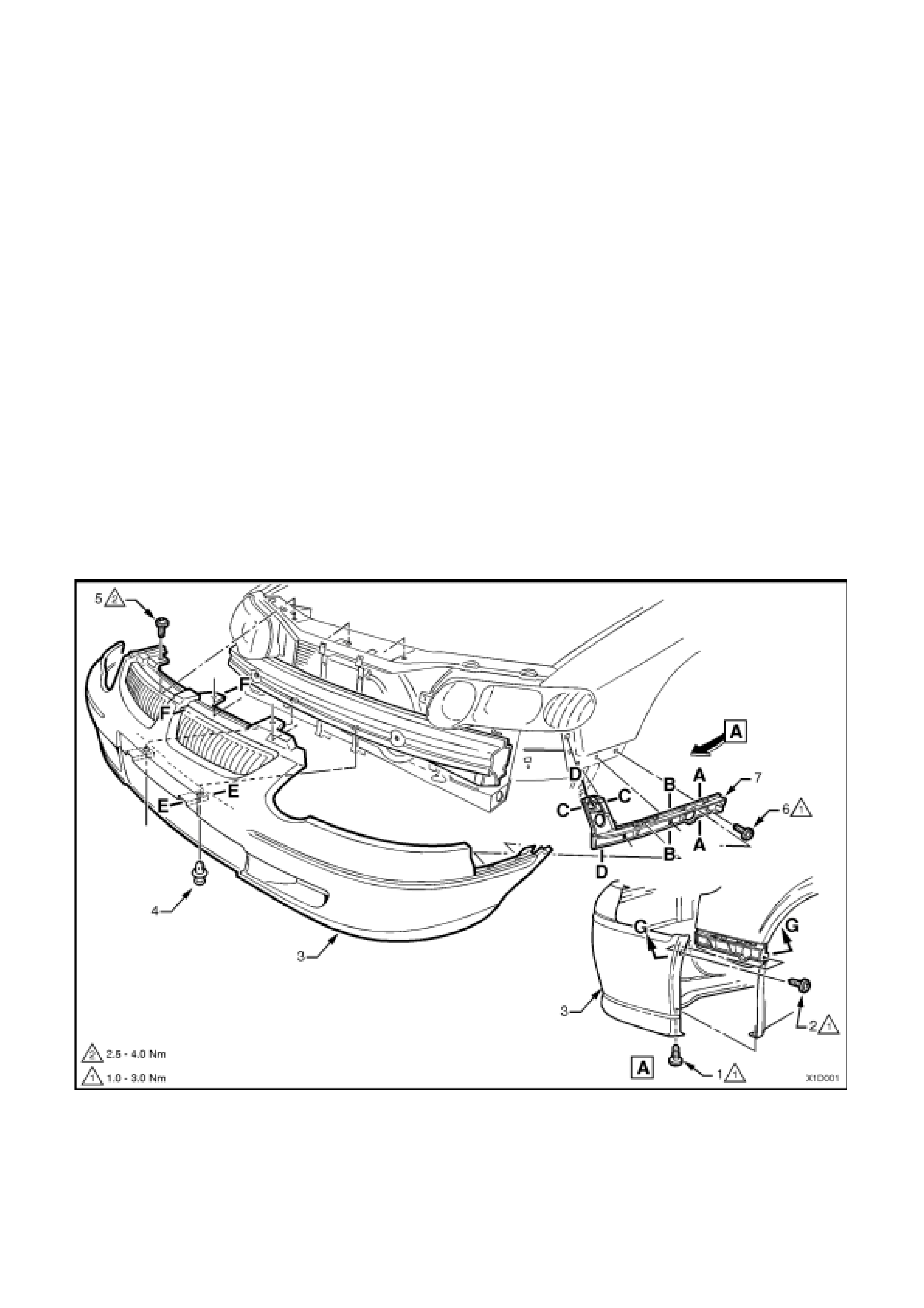
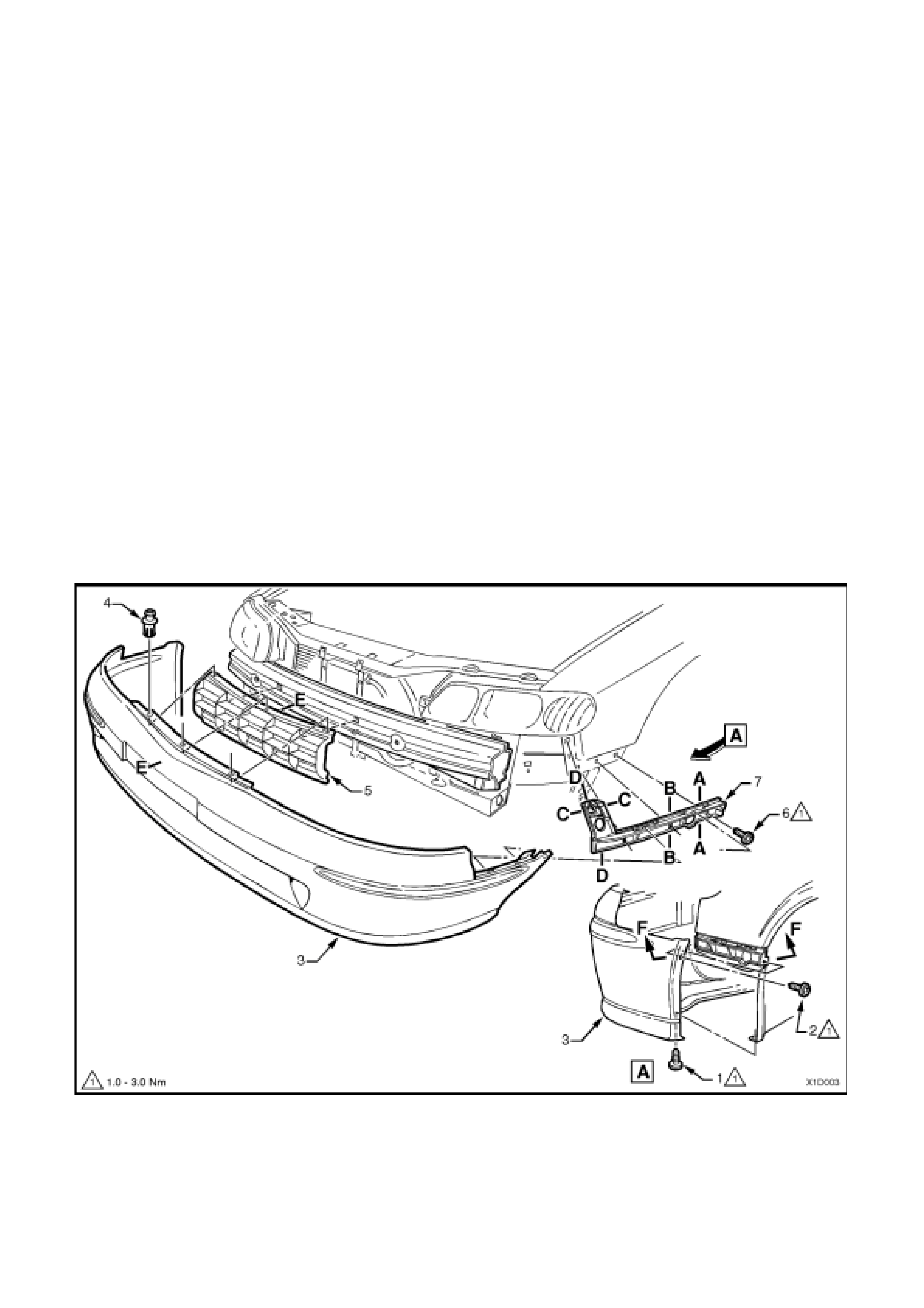
Figure 1D-1 FRONT BUMPER FACIA – EXECUTIVE & ACCLAIM
1. Screw (one place each side)
2. Screw (one place each side)
3. Facia assembly
4. Scrivet (two places)
5. Screw (three places)
6. Screw (three places each side)
7. Front bumper guide rail assembly
NOTE: For Sectional views A-A to G-G, refer to Fig. 1D-5 in
this Section.
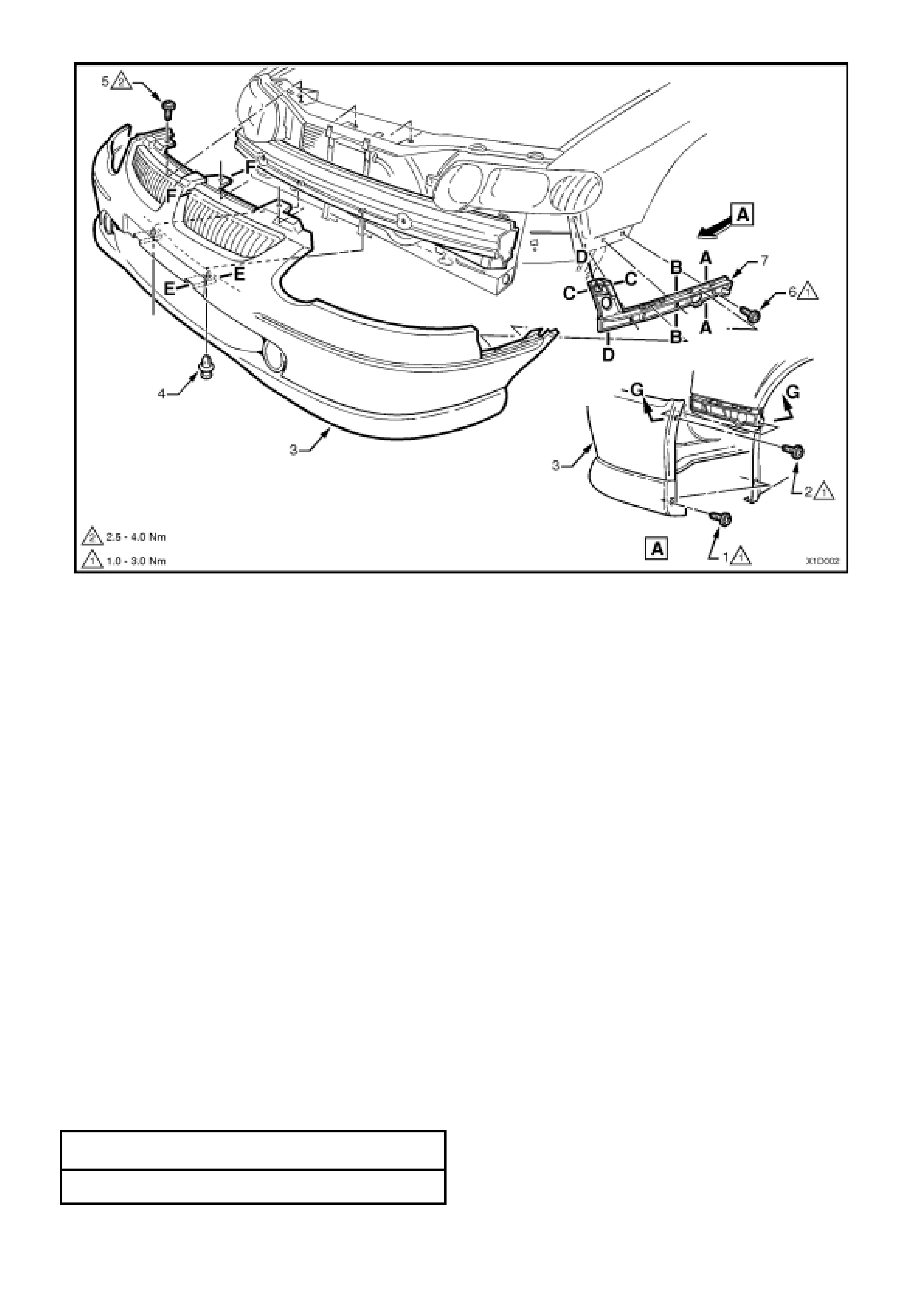
Figure 1D-2 FRONT BUMPER FACIA – S and SS
1. Screw (one place each side)
2. Screw (one place each side)
3. Facia assembly
4. Scrivet (two places)
5. Screw (three places)
6. Screw (three places each side)
7. Front bumper guide rail assembly
NOTE: For Sectional views A-A to G-G, refer to
Fig. 1D-5 in this Section.
Disassemble
1. Executive and Acclaim - remove the four screws
(1) securing the grille inserts (2) to the top of the
bum per facia assem bly (3) and lift grille inser ts up
and out (refer Fig. 1D-3 ).
2. S – from the rear of the bumper facia assembly,
squeeze the fog lamp blanking cover (1) retaining
tangs (two places on each cover) and push the
cover out from the facia assembly (4) (refer
Fig. 1D-4 ).
3. SS – f rom the rear of the bumper facia assem bly,
remove the fog lamp retaining nuts (3) (three
places for each lamp) and push the fog lamp
assembly (2) out of the facia assembly (refer
Fig. 1D-4 ).
Reassemble
Reassembly of the bumper facia assemblies is the
reverse of the disassembly operation, noting the
following:
Ensure all fasteners are tightened to the correct torque
specifications.
GRILLE INSERT RETAINING SCREW
TORQUE SPE CIFICATION 0.2 – 0.4 Nm
FOG LAMP ASSE MBLY RETAINING NUT
TORQUE SPE CIFICATION 2.0 – 2.5 Nm
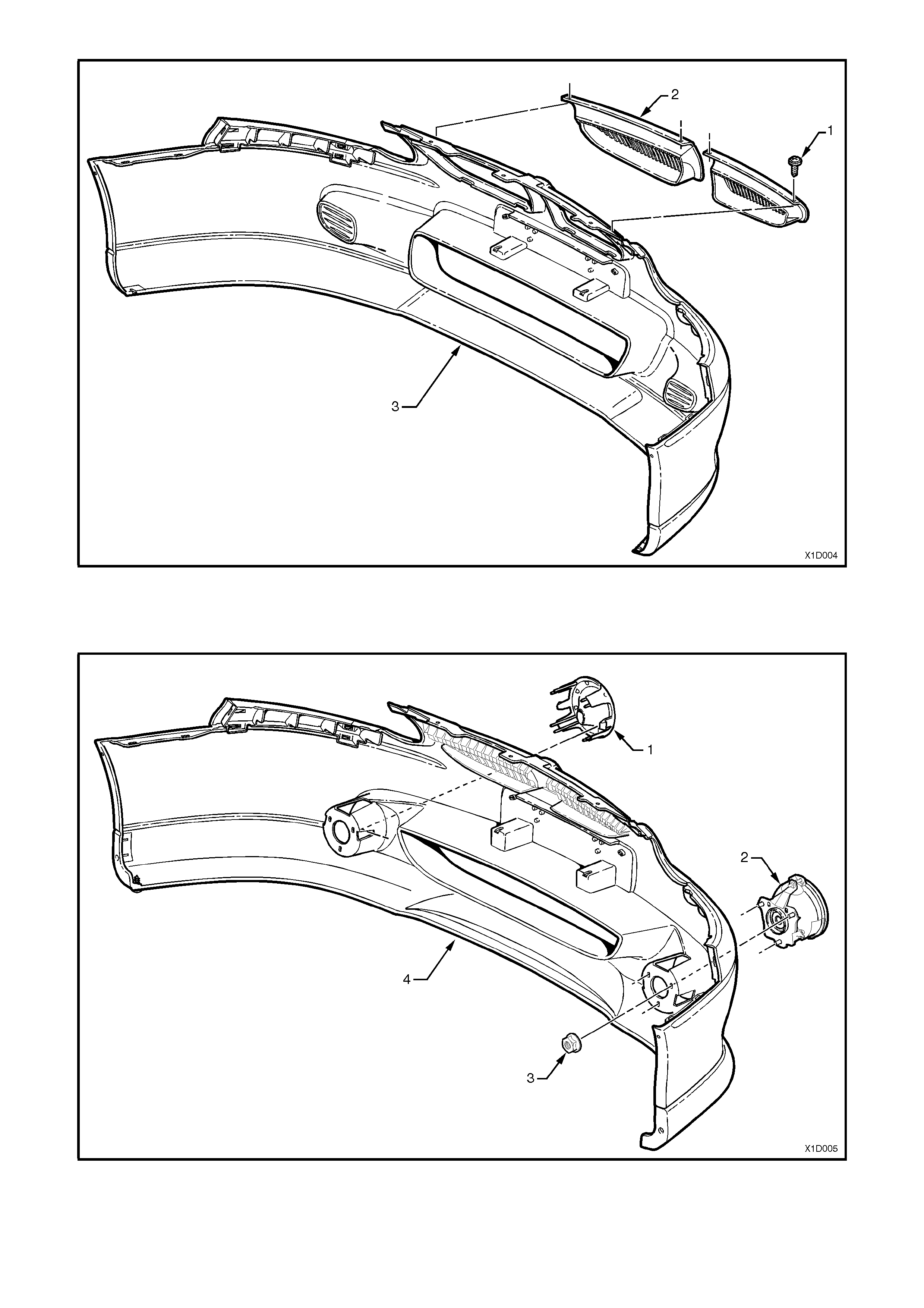
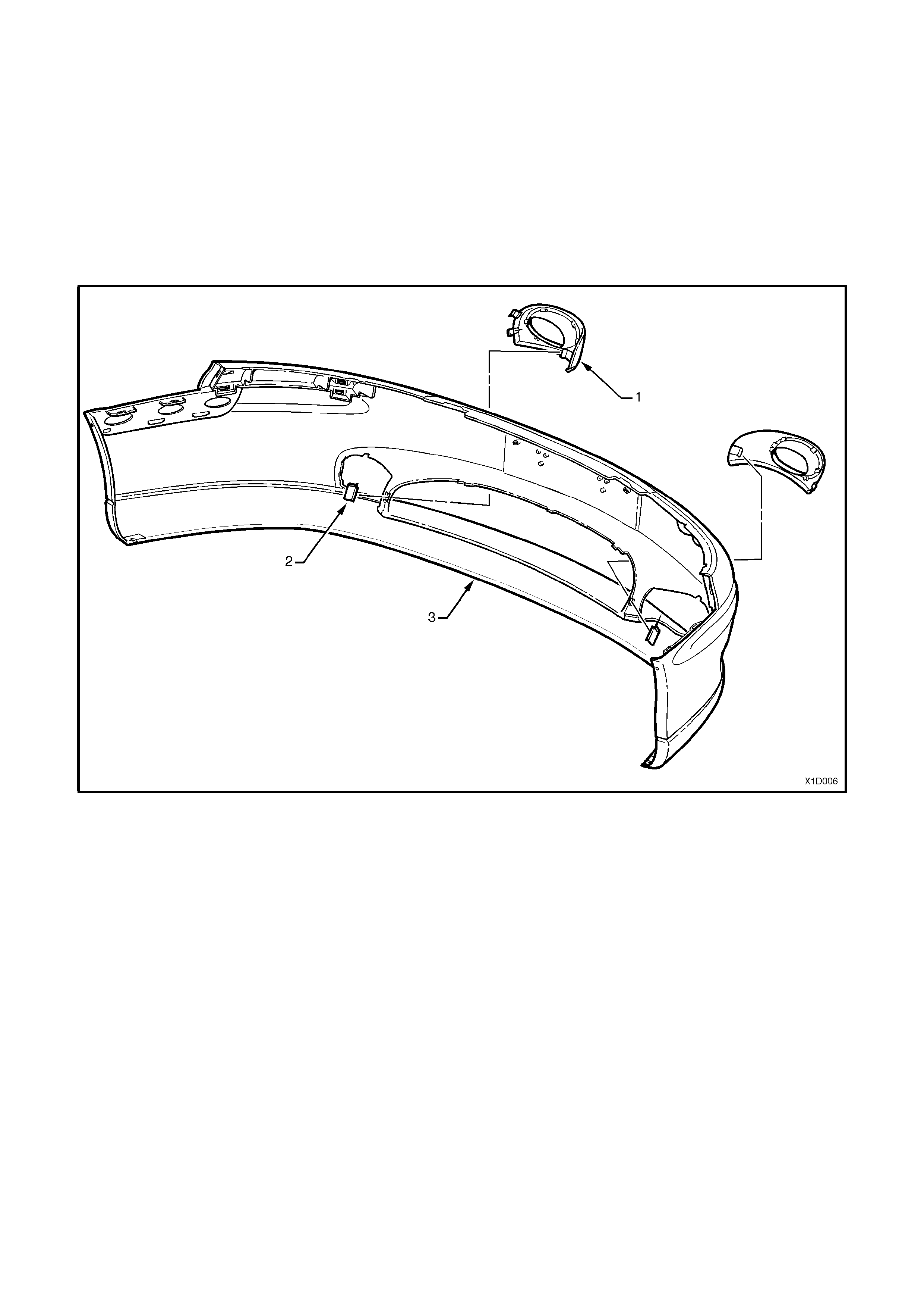
Figure 1D-3 FRONT BUMPER FACIA COMPONENTS – EXECUTIVE & ACCLAIM
1. Screw (two places each side)
2. Grille insert 3. Facia assembly
Figure 1D-4 FRONT BUMPER FACIA COMPONENTS – S & SS
1. Fog lamp blanking cover (S)
2. Fog lamp (SS) 3. Fog lamp retaining nut (three places for each lamp)
(SS)
4. Facia assembly
Reinstall
Reinstallation is the reverse of the removal operations
, noting the following:
1. Snap the facia onto retainers at guide rails, one
side at a time, (refer to Section C–C, in
Figs. 1D-1 or 1D-2 depending on Model variant)
then adjust the facia to ensure correct fender,
hood/headlamp clearance.
2. Ensure all fasteners are tightened to the correct
torque specifications.
GUIDE RAIL RETAINING SCREW
TORQUE SPE CIFICATION 1.0 – 3.0 Nm
BUMPER FACIA RETAINING SCREW
TORQUE SPE CIFICATION 1.0 – 3.0 Nm
BUMPER FACIA TO FRONT PANEL
RETAINI NG S CREW 1.0 – 3.0 Nm
TORQUE SPECIFICATION
3. On SS Models – check fog lamp operation and
aim, refer to
Section 12B LIGHTING SYSTEM of the VX
Series Service Information.
NOTE: To aid in the reinstallation of the bumper and
to ensure correct alignment, Fig. 1D-5 shows the
sectional views from Figs. 1D-1 and 1D-2 .
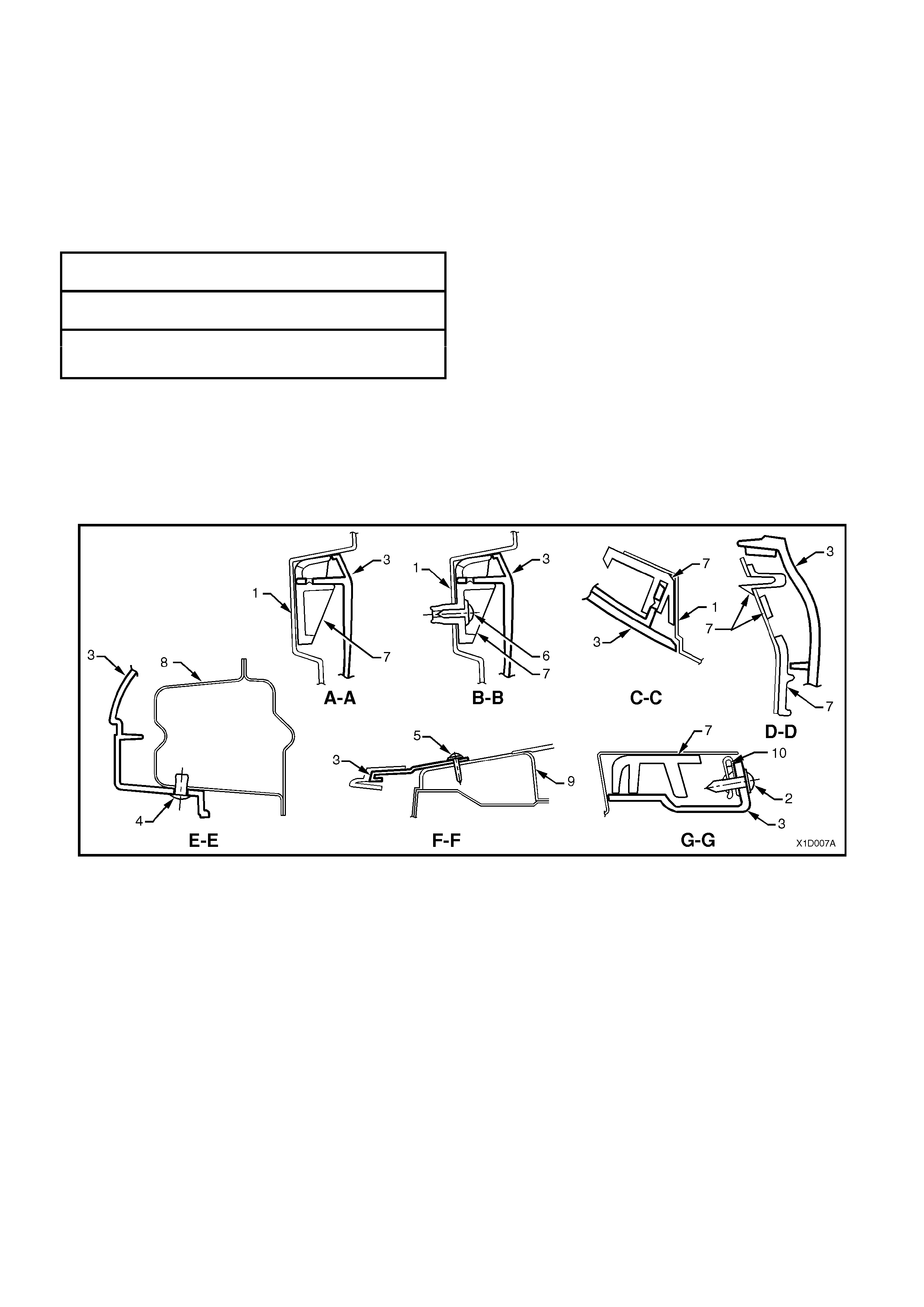
Figure 1D-5 FRONT BUMPER FACIA SECTIONAL VIEWS – EXECUTIVE, ACCLAIM, S & SS
1. Front fender panel
2. Screw
3. Front bumper facia
4. Scrivet
5. Screw
6. Screw
7. Guide rail
8. Front bumper support beam
9. Front panel upper
10. ‘J’ nut
BERLINA AND CALAIS
Remove
1. Raise engine hood.
2. Remove the grille insert, refer
Section 1C RADIATOR GRILLE of the VX
Series Service Information.
3. Remove the three scrivets (4) securing the
bumper facia assembly to the support beam.
4. Remove screws (1 & 2) securing facia sides
to front fender wheelarch opening and front
panel assembly.
5. With the facia supported, pull the facia side
members out, disconnect the facia side
supports, then slide the facia forward
removing the facia assembly, refer to
Fig. 1D-6 .
6. If necessary lift off the front centre support
assembly (5).
7. Place the front bumper bar facia assembly
face down on a clean protected surface.
NOTE 1: Support beam should not be
removed unless damaged, refer to the
VX Body Repair Information for alignment
details.
Figure 1D-6 FRONT BUMPER FACIA – BERLINA AND CALAIS
1. Screw (one place each side)
2. Screw (one place each side)
3. Facia assembly
4. Scrivet (three places)
5. Support assembly – centre
6. Screw (three places each side)
8. Front bumper guide rail assembly
NOTE: For sectional views A-A to F-F, refer to
Fig. 1D-8 in this Section.
Disassemble
NOTE: There are no removable components fitted to
the Berlina bumper facia assembly.
1. Calais – from the rear of the bumper facia
assembly, gently prise off the fog lamp bezel
retaining clip and slide the bezel inwards to
remove (refer Fig.1D-7 ).
Reassemble
Reassembly of the bumper facia assemblies is the
reverse of the disassembly operation.
Figure 1D-7 FRONT BUMPER FACIA COMPONENTS – CALAIS
1. Bezel assembly - fog lamp surround
2. Clip – fog lamp bezel to facia 3. Facia assembly

Reinstall
Reinstallation is the r evers e of the r emoval operations ,
noting the following:
1. Snap the facia onto retainers at guide rails, one
side at a tim e, (refer to sec tion C–C, in Fig 1D-6 )
then adjust the facia to ensure correct fender,
hood/headlamp clearance.
2. Ensure all fasteners are tightened to the correct
torque specifications.
GUIDE RAIL RETAINING SCREW
TORQUE SPE CIFICATION 1.0 – 3.0 Nm
BUMPER FACIA RETAINING SCREW
TORQUE SPE CIFICATION 1.0 – 3.0 Nm
BUMPER FACIA TO FRONT PANEL
RETAINI NG S CREW 1.0 – 3.0 Nm
TORQUE SPECIFICATION
NOTE: To aid in the reinstallation of the bumper and
to ensure correct alignment, Fig. 1D-8 shows the
sectional views from Fig. 1D-6 .
Figure 1D-8 FRONT BUMPER FACIA SECTIONAL VIEWS – CALAIS & BERLINA
1. Front fender panel
2. Screw
3. Front bumper facia
4. Scrivet
5. Support
6. Screw
7. Guide rail
8. ‘J’ nut
9. Reinforcement – front bumper
10. Radiator grille assembly
11. Front bumper support beam
2.3 REAR BUMPER BAR FACIA ASSEMBLY
SEDAN
Remove
1. Open the rear compartment lid.
2. Gently peel the rear compartment weatherstrip
(5) away from the upturned flange of the rear
compartment opening.
NOTE: Only partly peel the weatherstrip away f rom
the rear compartment opening to enable access to
the four bumper bar facia scrivets and to allow for
removal of the rear compartment crossmember
cover (1).
3. Remove the four screws (3), two scrivets (2)
and prise out the four fasteners (4) securing
the rear compartment crossmember trim and
remove the trim.
Figure 1D-9
4. Peel the rear compartment carpet back slightly
and remove the four nuts (5) securing the rear
bumper assembly to the rear quarter panel
(below tail lamps), refer Fig.1D-10.
5. Remove two sc r ews (2) ( one eac h side) sec ur ing
rear bumper facia at each upper wheelarch
opening and four screws (1) (two each side) at
the lower wheelarch opening.
6. Remove the four scrivets (4) at the upper edge
of facia and two scrivets (3) at lower edge of
facia.
7. With the facia supported, pull the facia side
members out to disconnect the facia side
supports, then slide the facia rearwards,
removing the facia.
8. Place the rear bumper bar facia assembly face
down on a clean protected surface.
NOTE: The support beam should not be removed
unless damaged, refer to the
VX Series Body Repair information of the
VX Series Service Information for alignment details.
Techline
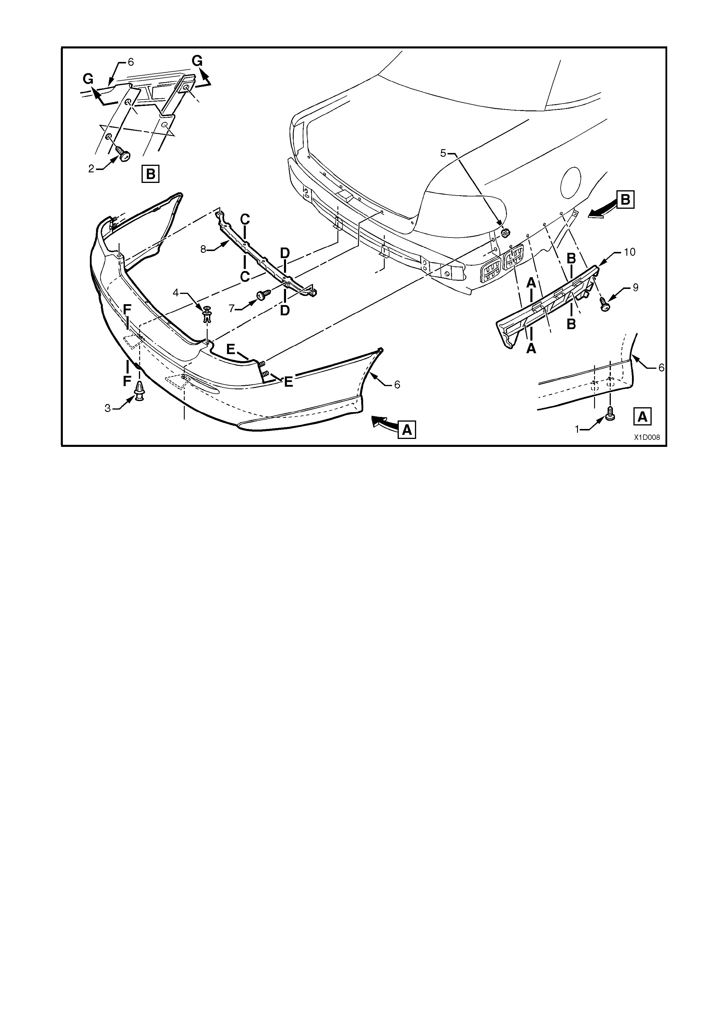
Figure 1D-10 REAR BUMPER FACIA – SEDAN
1. Screw (two places each side)
2. Screw (two place each side)
3. Scrivet (two places)
4. Scrivet (four places)
5. Nut (two places each side)
6. Facia assembly
7. Screw (six places)
8. Rear facia upper centre support
9. Screw (four places each side)
9. Rear bumper guide rail assembly (two places)
NOTE: For sectional views of A-A to G-G, refer to
Fig. 1D-12 in this Section.
Disassemble
1. If necessary gently prise out the tow bar blanking cover (3), refer Fig. 1D-11 in this Section.
2. On S and SS Models, remove the two screw (1) (one each side) securing the lens assemblies (2) to the rear
bumper facia assembly and push the lens assembly out), refer Fig. 1D-11 in this Section.
Reassemble
Reassembly of the bumper facia assembly is the reverse of the removal operation.
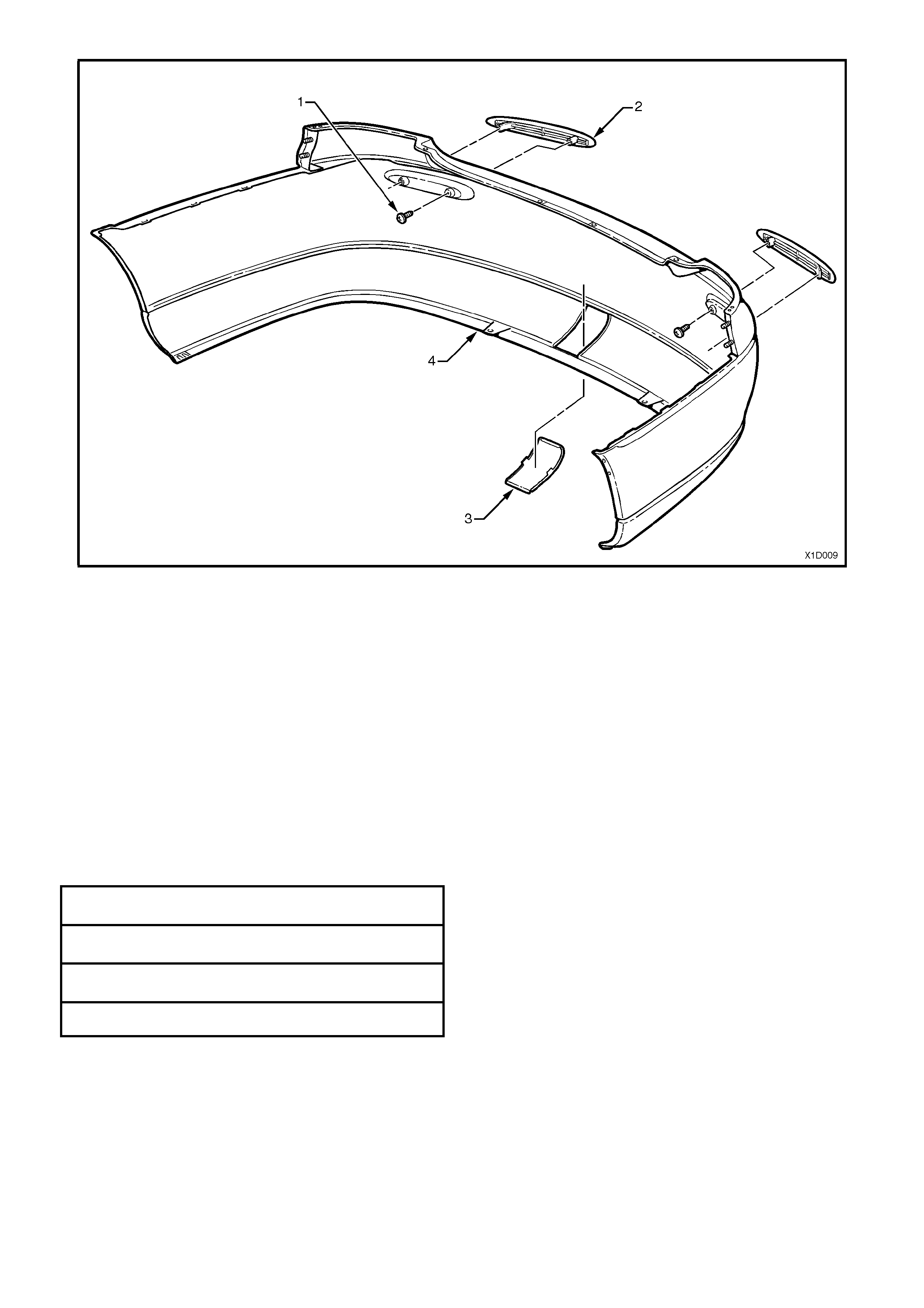
Figure 1D-11 REAR BUMPER FACIA COMPONENTS – SEDAN
1. Screw (one place each side)
2. Reflector Lens assembly (one place each side) 3. Blanking cover – tow bar
4. Facia assembly
Reinstall
Reinstallation of the rear bumper facia assembly is the
reverse of the removal operations , noting the
following:
1. Locate the studs (two places each side) on the
facia to the holes in the rear quarter panel.
2. Snap the facia onto retainers at guide rails, one
side at a time, (refer to sections A–A and B-B, in
Fig. 1D-10) then adjus t the f ac ia to ensur e cor rec t
clearance.
3. Ensure all fasteners are tightened to the correct
torque specifications.
GUIDE RAIL RETAINING SCREW
TORQUE SPE CIFICATION 1.0 – 3.0 Nm
BUMPER FACIA RETAINING SCREW
TORQUE SPE CIFICATION 1.0 – 3.0 Nm
BUMPER FACIA RETAINING NUT
TORQUE SPE CIFICATION 6.0 – 9.0 Nm
REFLECT OR LENS RETA INING SCREW
TORQUE SPE CIFICATION 2.0 – 2.5 Nm
NOTE: To aid in the reinstallation of the bumper and
to ensure correct alignment, Fig. 1D-12 shows the
sectional views from Fig.1D-10.
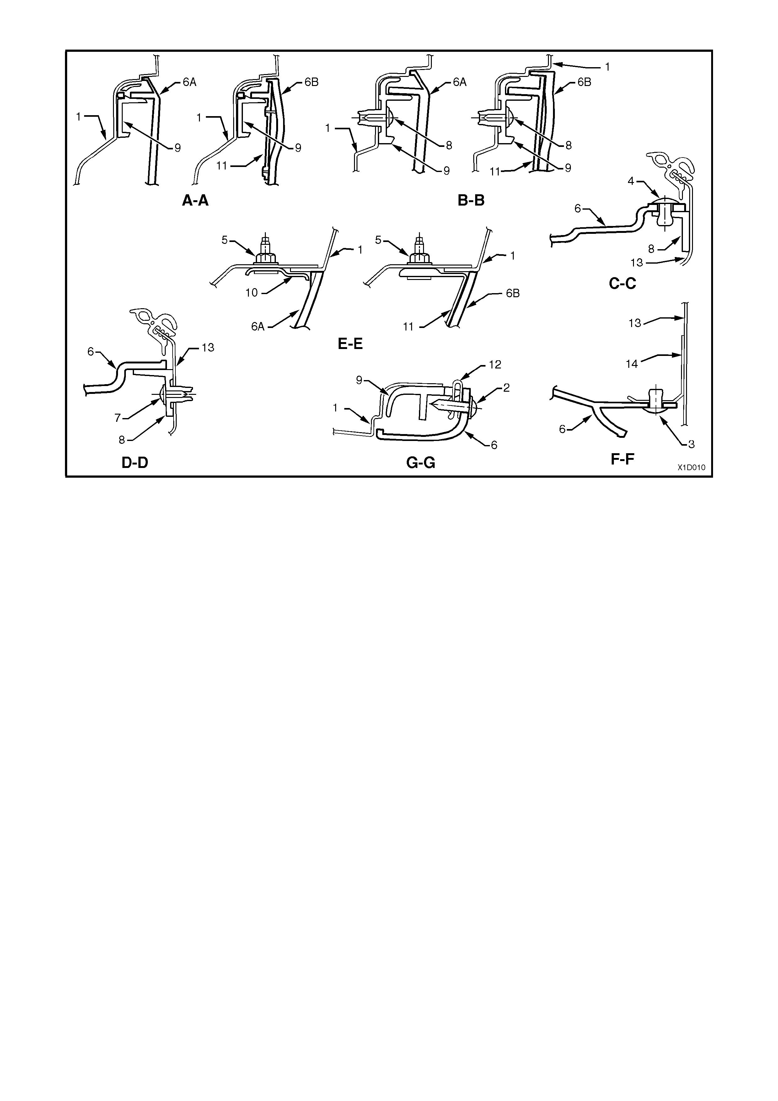
Figure 1D-12 REAR BUMPER FACIA SECTIONAL VIEWS – SEDAN
1. Side panel outer
2. Screw
3. Scrivet
4. Scrivet
5. Nut
6. Rear bumper facia
(6A – Executive, Acclaim, S & SS)
(6B – Berlina & Calais)
7. Screw
8. Rear facia upper centre support
9. Guide rail
10. Plate assembly
11. Bracket – rear facia to guide rail
12. ‘J’ nut
13. Reinforcement – back panel lower
14. Facia attaching bracket
WAGON
Remove
1. Remove the four screws (2) (two each side) securing r ear bumper f acia at each upper wheelarch opening and
four screws (1) (two each side) at the lower wheelarch opening, refer Fig. 1D-15 .
2. Remove the six scrivets (4) at the upper edge of the facia and the two scrivets (3) at the lower edge of the facia.
3. W ith the facia supported, pull the facia side members out to disconnect the facia side supports, then slide the
facia rearwards, removing the facia.
4. Place the rear bumper bar facia assembly face down on a clean protected surface.
NOTE: The support beam should not be removed unless damaged, refer to the VX
Series Body Repair information of the VX Series Service Information for alignment details.
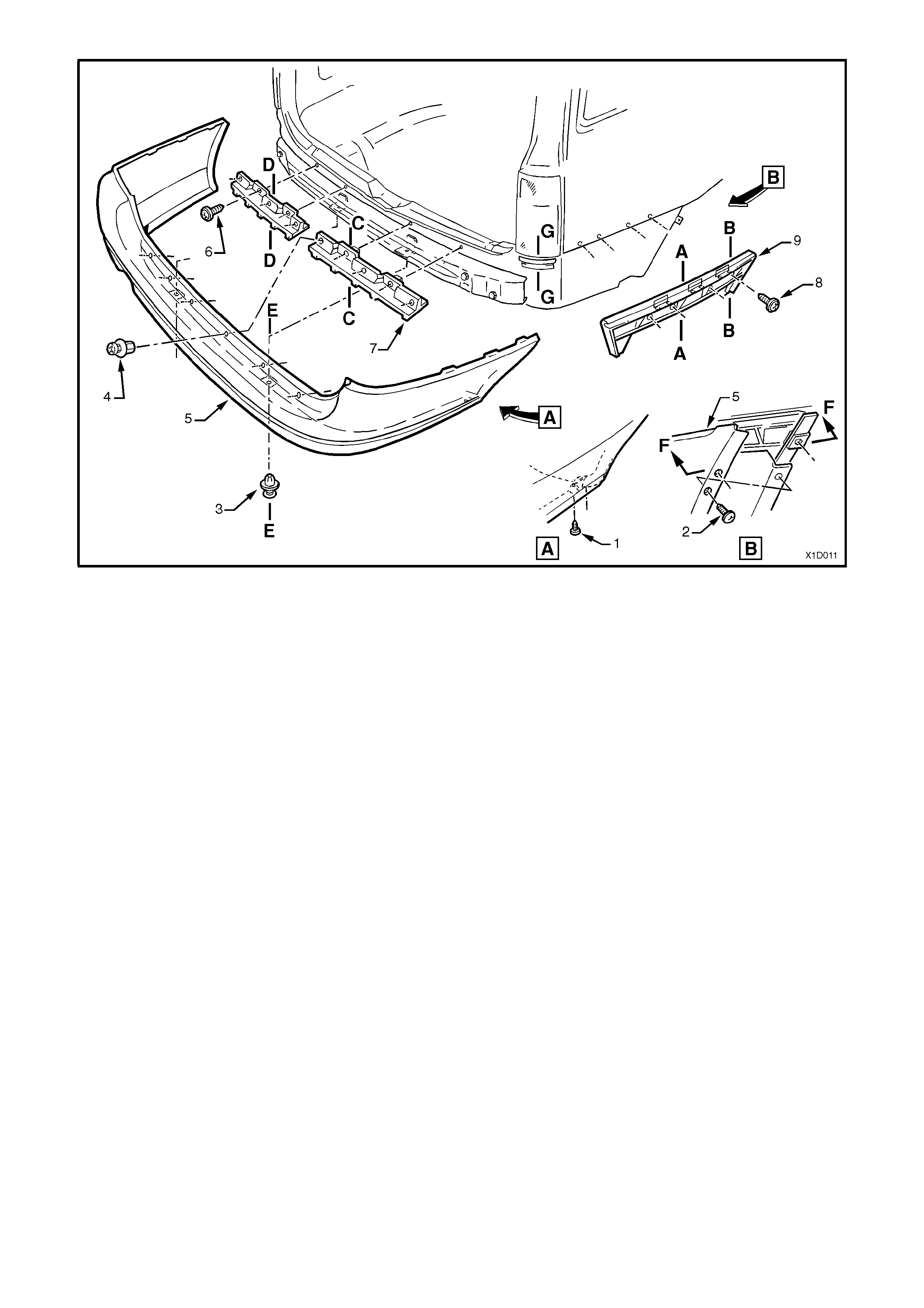
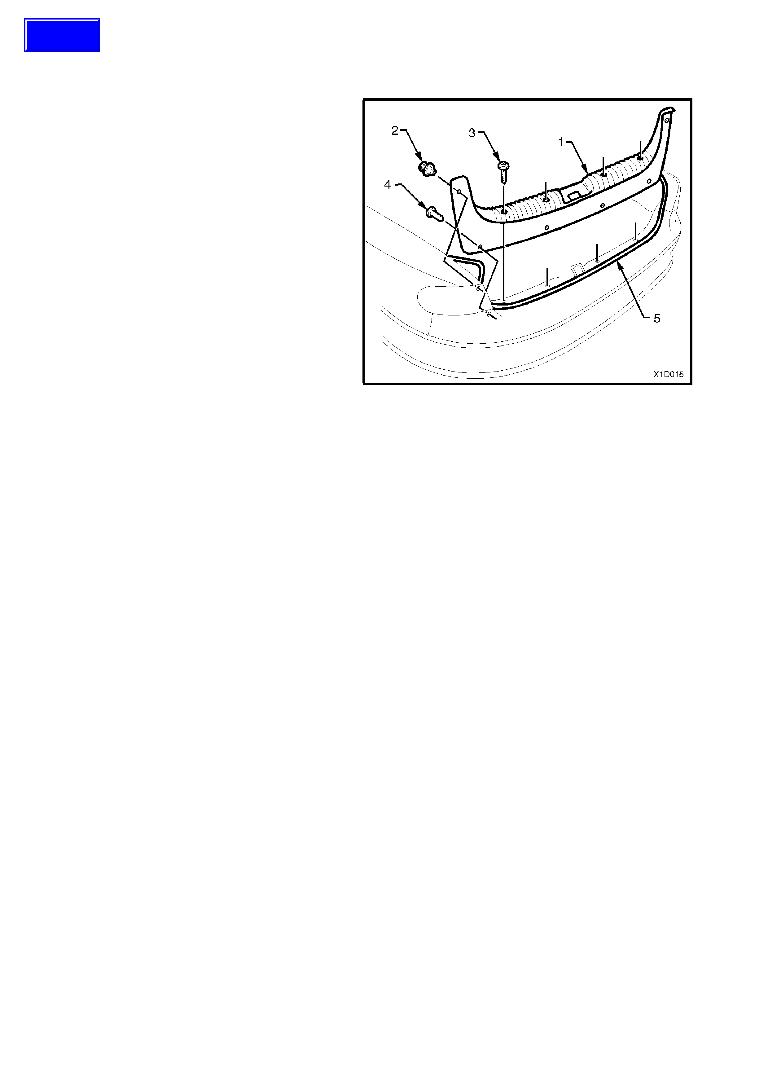
Figure 1D-13 REAR BUMPER FACIA – WAGON
1. Screw (two places each side)
2. Screw (two place each side)
3. Scrivet (two places)
4. Scrivet (six places)
5. Facia assembly
6. Screw (two places each side)
7. Support assembly – rear facia upper (two
places)
8. Screw (four places each side)
10. Rear bumper guide rail assembly (two
places)
NOT E: For sec tional views of A-A to F- F, r ef er to
Fig. 1D-15 in this Section.
Disassemble
1. If necessary gently prise out the tow bar blanking cover (2), refer Fig. 1D-14 .
Reassemble
Reassembly of the bumper facia assembly is the reverse of the removal operation.
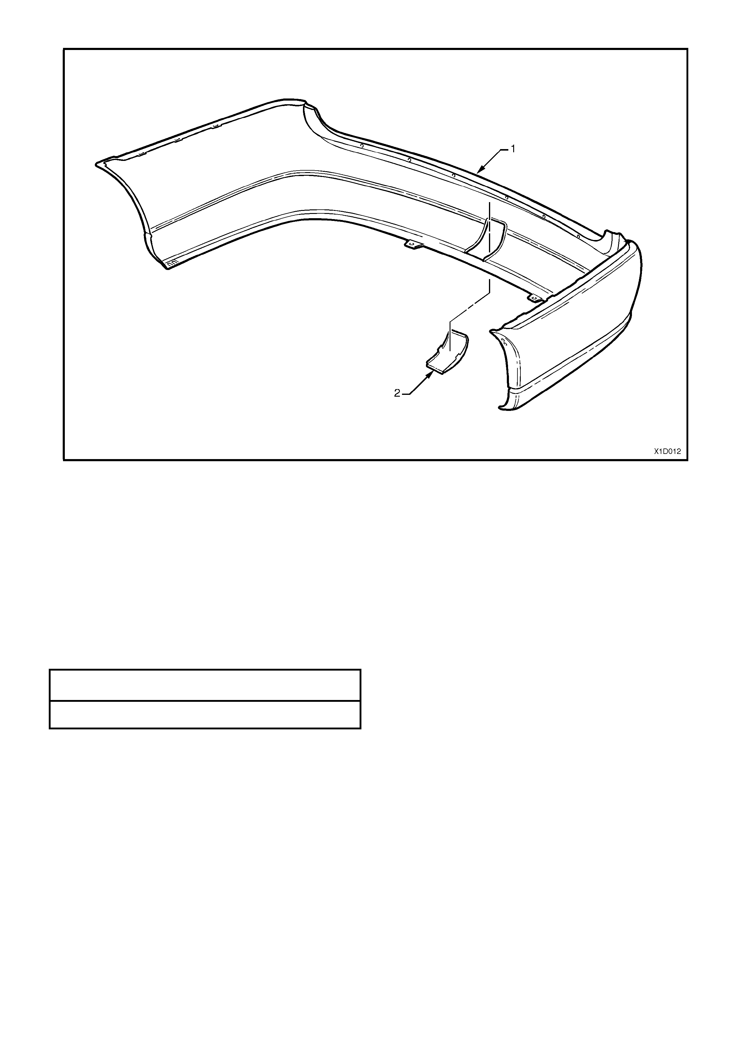
Figure 1D-14 REAR BUMPER FACIA COMPONENTS – WAGON
1. Blanking cover – tow bar
Reinstall
Reinstallation of the rear bumper facia assembly is the
reverse of the removal operations , noting the
following:
1. Snap the facia onto retainers at guide rails, one
side at a time, (refer to sections A–A and B-B, in
Fig. 1D-13) then adjust the fac ia to ens ure correc t
clearance.
2. Ensure all fasteners are tightened to the correct
torque specifications.
GUIDE RAIL RETAINING SCREW
TORQUE SPE CIFICATION 1.0 – 3.0 Nm
BUMPER FACIA RETAINING SCREW
TORQUE SPE CIFICATION 1.0 – 3.0 Nm
NOTE: To aid in the reinstallation of the bumper and
to ensure correct alignment, Fig. 1D-15 shows the
sectional views from Fig.1D-13.
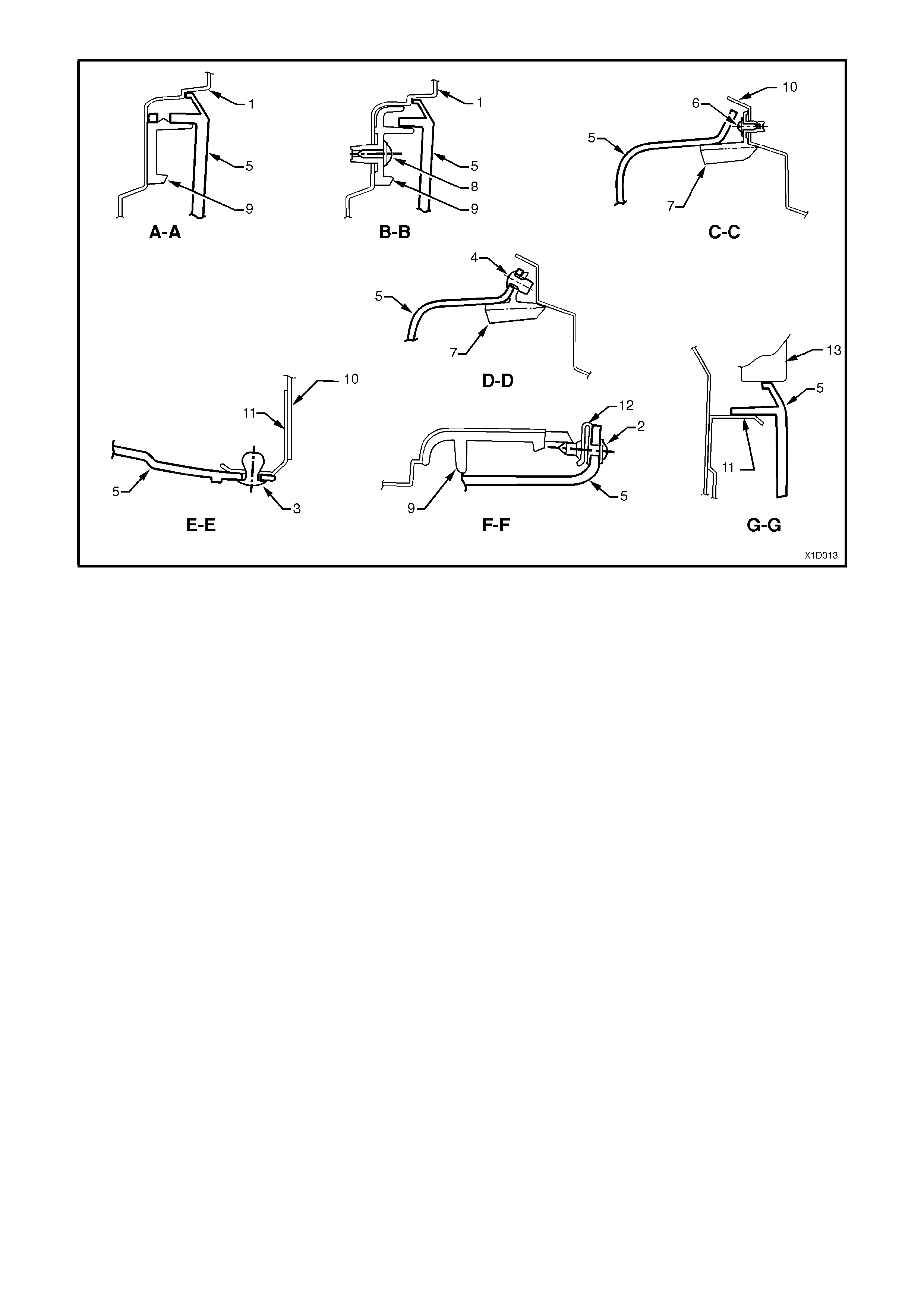
Figure 1D-15 REAR BUMPER FACIA SECTIONAL VIEWS – WAGON
1. Side panel outer
2. Screw
3. Scrivet
4. Scrivet
5. Rear bumper facia
6. Screw
7. Rear facia upper support
8. Screw
9. Guide rail
10. Reinforcement – back panel lower
11. Facia attaching bracket
12. ‘J’ nut
13. Rear tail lamp

3. TORQUE WRENCH SPECIFICATIONS
Nm
Bumper facia retaining screws ............................................. 1.0 - 3.0
Bumper facia to front panel retaining screw......................... 1.0 - 3.0
Fog lamp assembly retaining nut.......................................... 2.0 – 2.5
Grille insert retaining screw .................................................. 0.2 - 0.4
Guide rail retaining screw..................................................... 1.0 - 3.0
Rear bumper facia retaining nut........................................... 6.0 - 9.0
Reflector lens retaining screw .............................................. 2.0 – 2.5