
SECTION 12B - LIGHTING SYSTEM
IMPORTANT
Before performing any Service Operation or other procedure described in this Section, refer to Section
00 CAUTIONS AND NOTES for correct workshop practices with regard to safety and/or property damage.
1. GENERAL DESCRI PTI O N
With the introduction of the VX Series models, the following lighting components have been restyled:
• Front headlamp assemblies.
• Fog lamp assemblies.
• Sedan rear lamp, reflector and licence plate lamp assemblies.
Accord ingly, c ertain s ervice proc edures and s pecif ications f or thes e item s ar e specif ic to VX Series m odels and are
detailed in this Section.
All models continue to be fitted with dual pock et homofocal headlamps with halogen bulbs. However, all headlam p
assemblies now use the latest headlamp reflector technology.
Clear outer lens with complex reflector optics are used on high and low beam lamps for all models, providing a
significant improvement to overall headlamp performance. A bulb shield is permanently attached to the low beam
reflector to reduce glare and enhance the headlamp appearance.
Executive, Acclaim, S and SS models ar e fitted with a ‘teardrop’ style headlam p assem bly. Headlam ps fitted to SS
models have an additional styling feature in that the high/low beam separation bezel is blacked out. Berlina and
Calais models retain a revised slim line style headlamp assembly .
Headlamp adjusters are now integral with the headlamp assembly and are not a serviceable item.
Fog lam p assem blies on SS m odels are now of a circular appearance and are mounted in the front bum per facia.
Circular blanking covers are fitted in place of fog lamp assemblies on S models. Fog lamps on Calais models
rem ain as a rec tangular design m ounted onto the bumper s upport beam behind bumper facia m ounted oval bezels.
However the beam adjustment method and the bulb servicing procedure have changed. The aiming specification
has also been revised.
Rear lamp assemblies on sedan models now have turn signal lamps mounted above the stop/tail lamps and the
back-up lamps have been relocated from the decklid decor panel to the rear lamps. Berlina and Calais models
retain the additional stop/tail light assembly mounted in the revised design decor panel.
On all sedan m odels excluding Berlina and Calais, an ellipse style reflex reflector is fitted into a recess on the left
and right sides of the rear bum per facia. On Berlina and Calais models, the reflex reflector is mounted in the rear
tail lamp assembly.
Licence plate lam ps on all sedan m odels, excluding Berlina and Calais, are mounted into the body coloured decor
panel with clip-in tab holders. On Berlina sedan and Calais models the globe holders are attached to the decor
panel and the globes are accessed by removing the lens cover screws and covers from the decor panel.
Tail lamp as semblies on station wagon models remain unchanged. All inter ior lighting and lighting switches rem ain
unchanged on all models.
For all other information relating to the lighting system refer to Section 12B LIGHTING SYSTEM of the
VT Series I Service Information and of the VT Series II Service Information.
Techline
Techline
2. SERVICE OPERATIONS
2.1 AIMING OF HEADLAMPS AND FOG LAMP S
CAUTION: During headlamp aiming procedures,
do not use cloth or similar material to cover lens
of headlamp assembly not being adjusted.
Damage to headlamp assembly will result if
headlamp beam is obstructed in this manner.
The headlamps and fog lamps (if fitted) must be
correc tly aim ed in order to obtain the m aximum road
illumination and safety that has been built into the
vehicle lighting system. The headlamps and fog
lamps must be checked for correct aim whenever a
bulb or headlamp/fog lamp assembly is replaced,
and after any adjustments or repairs to the f ront end
sheet metal.
Headlamp aiming machines are in general use.
W hen us ing one of these mac hines, ensure that it is
in good condition and car efully follow the instr uctions
of the manufacturer.
Regardless of the method used for checking
headlamp and fog lamp aim, the vehicle must be at
kerb weight, that is, with full fuel level, oil, water and
spare tyre but no passengers. The tyres must be
uniformly inflated to their specified pressure.
NOTE: If the vehicle will regularly carry an unusual
load in the rear compartment or tow a trailer, these
loads should be on the vehicle when the
headlamps/fog lamps are checked.
HEADLAMP AIM
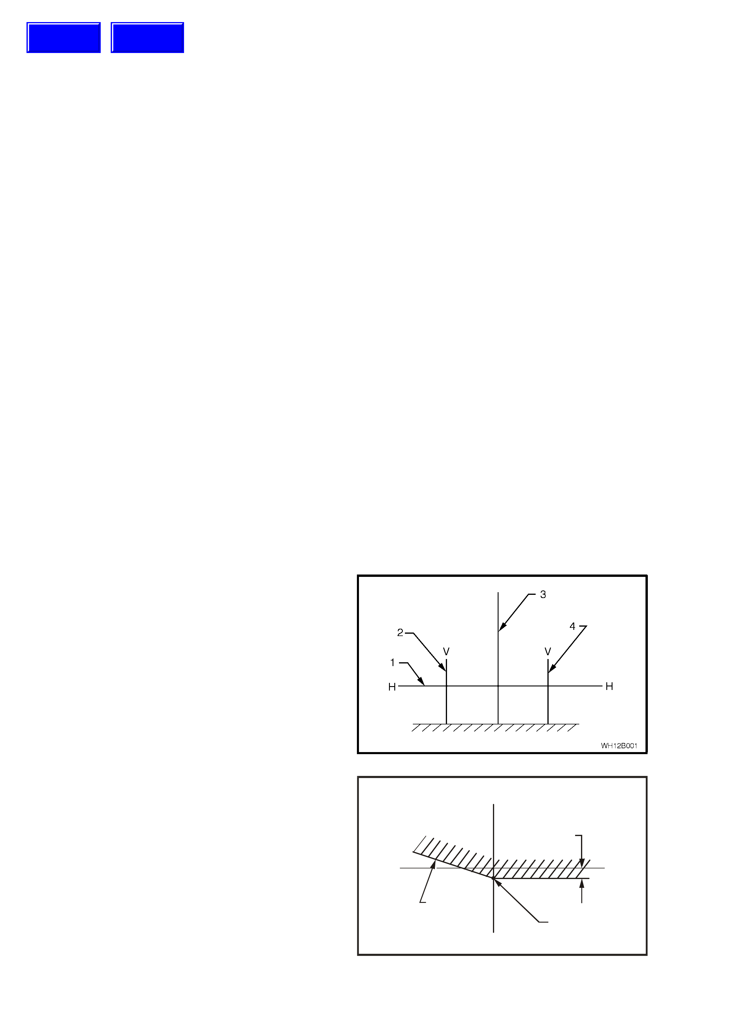
1. If suitable test equipment is not available, set
up a screen or use a vertical wall, in
conjunction with a flat horizontal floor. Park
vehicle im m ediately in front of scr een and mark
horizontal (1) and vertical c entre lines of left ( 2)
and right (4) headlamps (corresponding to the
centre of the low beam bulb) and vehicle centre
line (3) on the screen or wall.
2. Park vehicle 10 metres in front of screen or
wall ensuring that the vehicle is aligned with
vehicle centre line mark on screen.
Figure 12B-1
3. Individually aim each headlamp to a point (1)
on its vertical centre line, 110 mm below the
headlamp horizontal centre line. Item 2 is the
cut-off line.
WH12B002
V
HH
V
110 m m
2
1
Figure 12B-2
Techline
Techline
a. Adjust inboard adjuster (1) to achieve
correct vertical beam height.
b. Adjust outboard adjuster (2) to centralise
beam.
Aiming directions for each adjuster are visible
on the headlamp assembly.
Figure 12B-3
4. The allowable variations on headlamp aiming
point settings shown in Fig. 12B-1 are
specified as follows:
NOTE:Cut-off line must be within zone (1).
WH12B004
V
H
H
V
1V2
V1
HL
HR
Figure 12B-4
HEADLAMP AIMING
Acceptable Variations In Headlamp
Aiming Points
HL 100 mm
HR 0 mm
V1 100 mm
V2 120 mm
Maximum allo wable vertical vari ati on between any
pair of headlamps i s not to exceed 20 mm
FOG L AMP AIM
1. If suitable test equipment is not available, set
up a screen or use a vertical wall, in
conjunction with a flat horizontal floor. Park
vehicle im m ediately in front of scr een and mark
horizontal (1) and vertical c entre lines of left ( 2)
and right (4) fog lamps, and vehicle centre
line (3) on the screen.
2. Park vehicle 10 metres in front of screen,
ensuring the vehicle is aligned with centre line
mark on screen.
Figure 12B-5
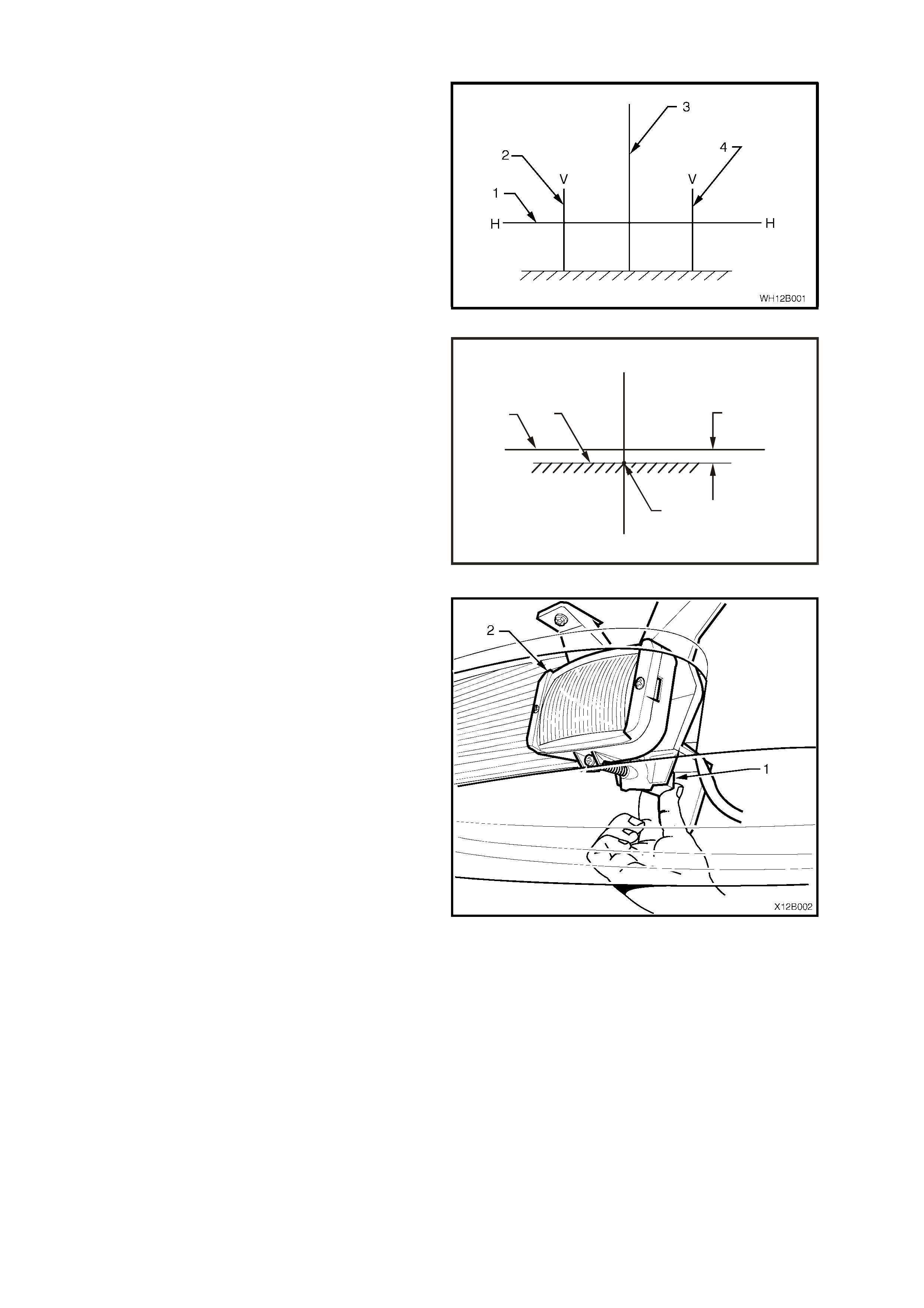
3. Turn fog lamps on. Individually aim each fog
lamp to a point on its vertical centre line (2),
with the cut off line ( 3) 200 m m below fog lamp
horizontal centre line (1).
WH12B005
200 m m
2
3
1
V
HH
V
Figure 12B-6
NOTE: There is no provision for horizontal
adjustment. Fog lamps are fixed to vertical centre
line.
On Calais models , adjustm ent is carried out by
rotating the adjuster knob (1) located below the
lamp housing (2). W hen facing the front of the
vehicle, turning the adjuster anti-clockwise
lowers the beam, turning clockwise raises the
beam. The adjustment can be carried out by
reaching under the bumper facia and rotating
the adjuster by hand.
Figure 12B-7
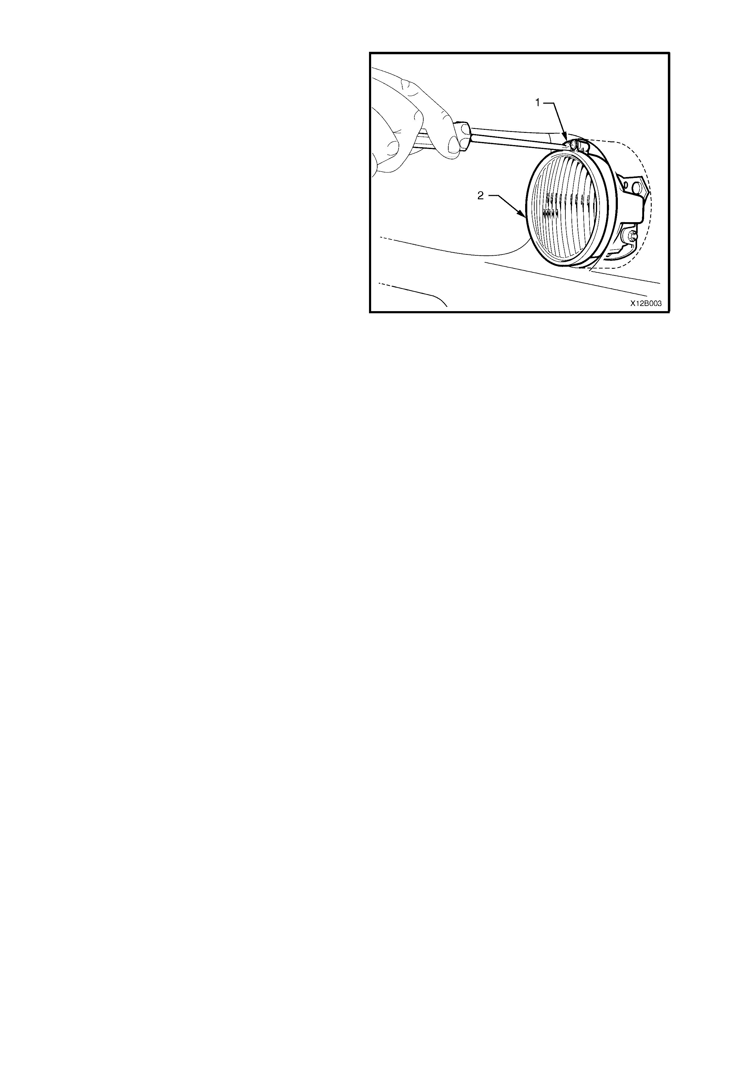
On SS models, fog lamp aim adjustment is
carried out by rotating the adjuster screw (1)
located above the lamp housing (2). Turning
the adjuster screw anti-clockwise lowers the
beam, turning clockwise raises the beam. The
adjustm ent can be car ried out by using a No. 2
Phillips head screw driver.
Figure 12B-8
2.2 HEADLAMP BULB
REPLACE
1. Open engine compartment.
Right-hand side headlamp only
V6 engine models:
Disconnect battery terminals, remove battery
retaining clamp and manoeuvre battery to gain
access to headlamp dust cap.
GEN III V8 engine models:
Remove four scrivets securing upper radiator
support cover and remove cover.
Disconnect battery terminals, remove battery
retaining clamp and manoeuvre battery to gain
access to headlamp dust cap.
Left-hand side only (with GEN III V8 engine)
Remove air inlet snorkel from air cleaner
housing by pulling snorkel straight out from air
cleaner housing.
Right and left-hand sides
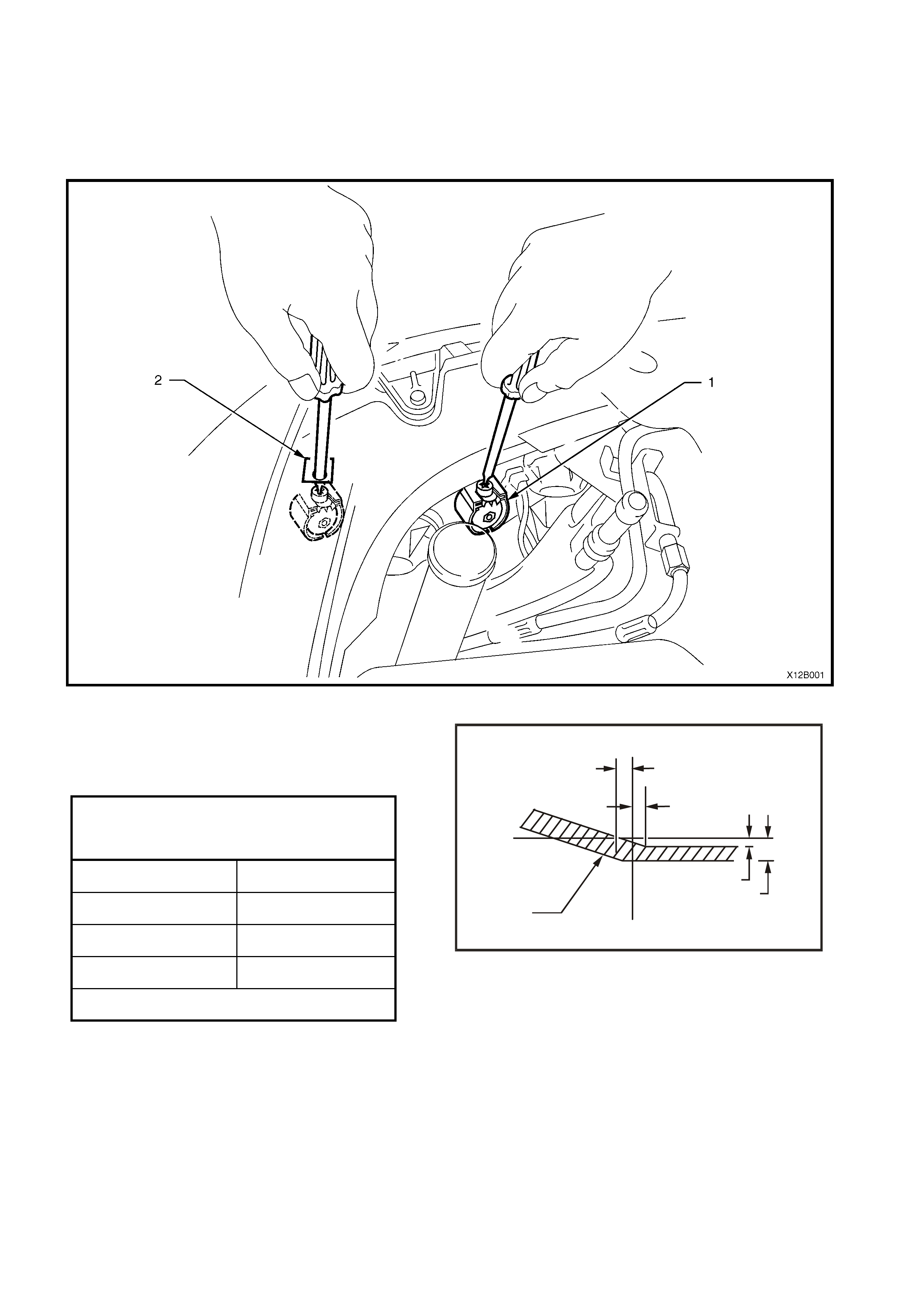
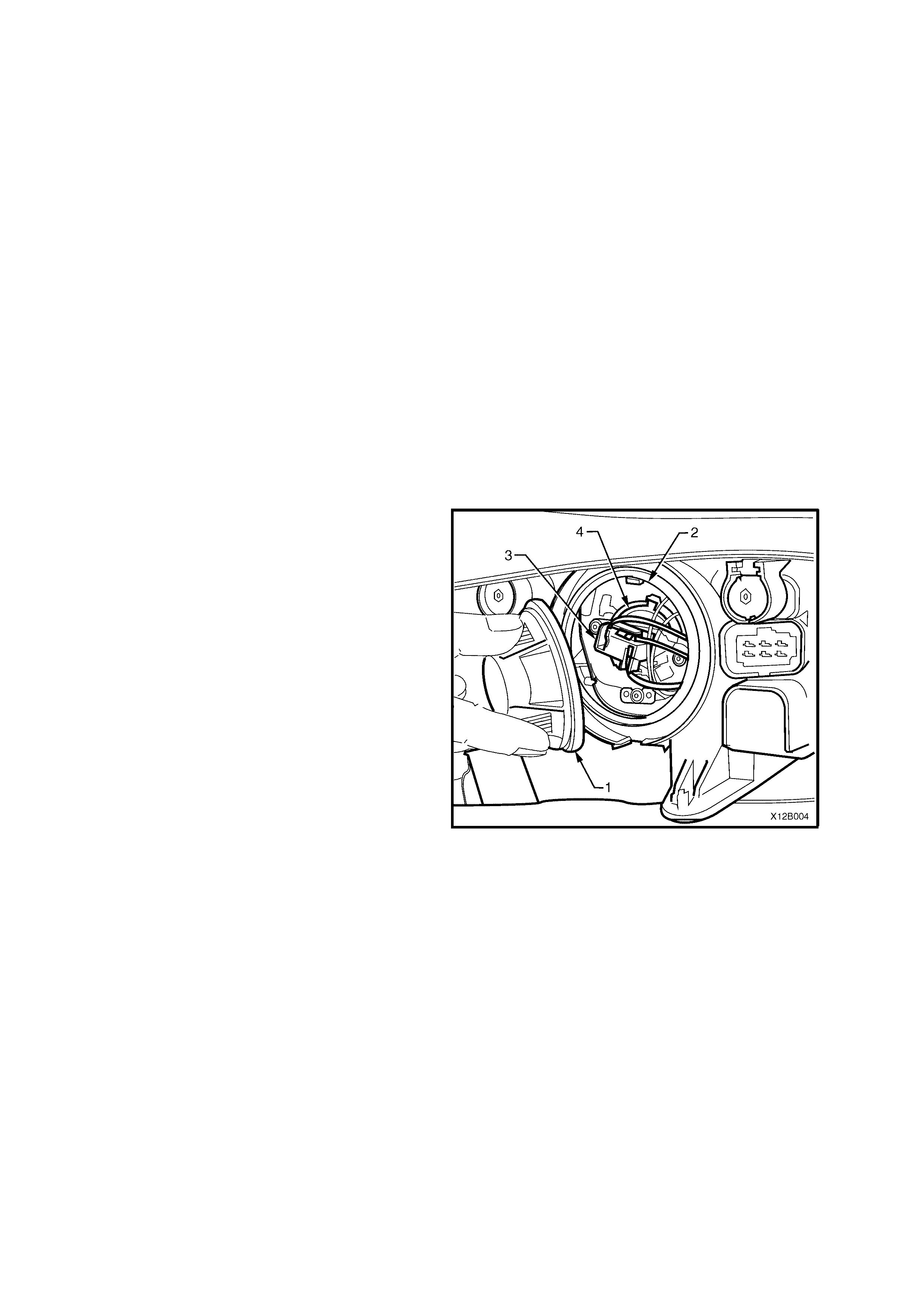
2. From inside engine compartment, remove dust
cap (1) from rear of headlamp housing
assembly (2) by turning dust cap anti-
clockwise, and pulling away from housing. If
dust cap seal stays on headlamp housing,
remove seal and install onto cap.
3. Carefully pull wiring harness connector (3) from
rear of bulb (4).
Figure 12B-9

4. Depres s and unc lip bulb spring retainer (1) and
pivot clear of bulb. Remove bulb (2) from
reflector.
NOTE: Do not handle quartz envelope of headlamp
bulb. If touched accidentally, wipe imm ediately with
methylated spirits or bulb performance will
deteriorate.
5. Install new bulb (2) into reflector, ensuring
correct mating of bulb base locating tangs with
reflector cut-outs. Install spring retainer (1) and
wiring harness connector.
NOTE: The different sized locating tangs on the
bulb base and mating c ut-outs in the ref lector allow
the bulb to seat correctly into the reflector in one
location only. This ensures correct relationship of
the bulb to the reflector.
6. Inspec t rubber seal in dust c ap to ensure that it
is not dam aged and that it is s eated corr ectly in
cap. Replace seal if damaged.
7. Install cap onto rear of headlamp housing with
cap tang located facing down. Lock cap into
place by turning clockwise.
Right-hand side only
Position battery in correct location and install
battery retaining clamp. Secure battery
retaining clamp and reconnect battery
terminals.
Right and left-hand sides
8. Check headlamp operation and re-aim
headlamps (headlamp aim varies from bulb to
bulb), refer to
2.1 AIMING OF HEADLAMPS AND FOG
LAMPS in this Section.
Left-hand side only (with GEN III V8 engine)
Install air inlet snorkel into air cleaner housing
by aligning s nork el with air cleaner housing and
pushing firmly into place.
Position upper radiator support cover and
install four scrivets to secure cover.
Figure 12B-10
2.3 PARKING LAMP BULB
REPLACE
1. Open engine compartment.
Right-hand side headlamp only
V6 engine models:
Disconnect battery terminals, remove battery
retaining clamp and manoeuvre battery to gain
access to headlamp dust cap.
GEN III V8 engine models:
Remove four scrivets securing upper radiator
support cover and remove cover.
Disconnect battery terminals, remove battery
retaining clamp and manoeuvre battery to gain
access to headlamp dust cap.
Left-hand side only (with GEN III V8 engine)
Remove air inlet snorkel from air cleaner
housing by pulling snorkel straight out from air
cleaner housing.
Right and left-hand sides
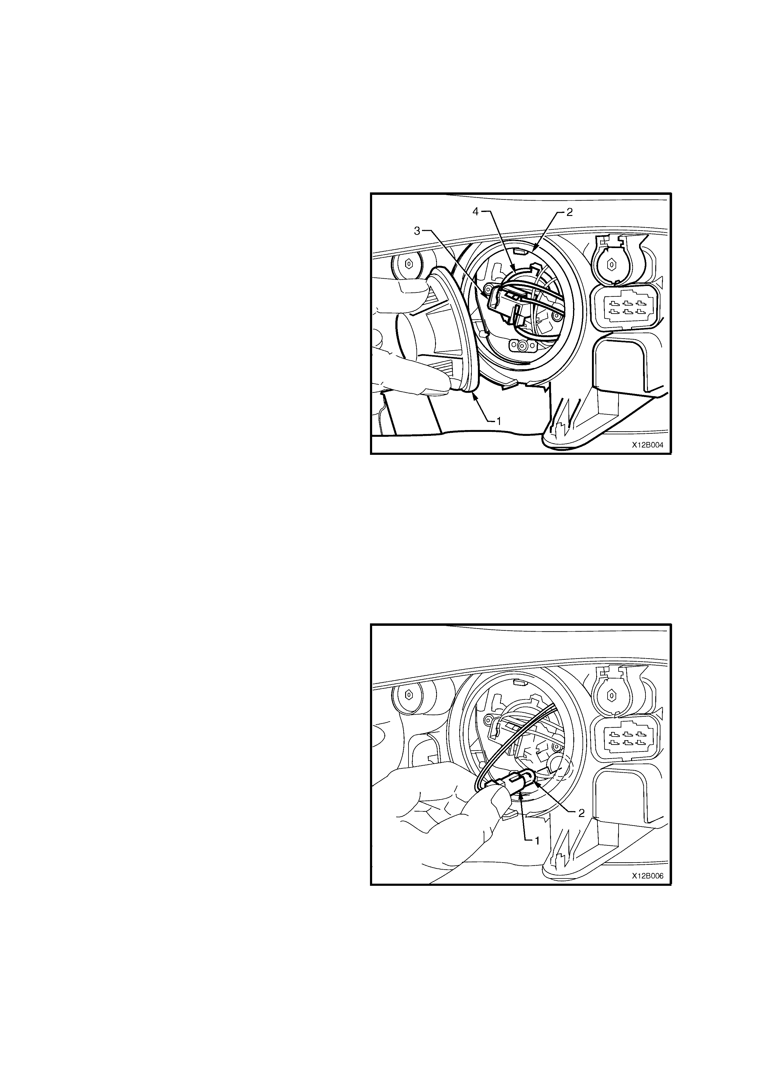
2. From inside engine compartment, remove dust
cap (1) from rear of headlamp housing
assembly (2) by turning dust cap anti-
clockwise, and pulling away from housing. If
dust cap seal stays on headlamp housing,
remove seal and install onto cap.
Figure 12B-11
3. Rem ove par k ing lam p sock et (1) from ref lector.
Alternatively, if access is difficult, remove the
headlamp bulb, and use index finger to
carefully push the bulb and holder from the
parking lamp socket. Pull bulb (2) from socket.
4. Insert new bulb into socket and install socket
into reflector.
5. Inspec t rubber seal in dust c ap to ensure that it
is not dam aged and that it is s eated corr ectly in
cap.
Install cap onto rear of headlamp housing and
lock cap into place by turning clockwise.
Right-hand side only
Position battery in correct location and install
battery retaining clamp. Secure battery
retaining clamp and reconnect battery
terminals.
Right and left-hand sides
6. Check parking lamp operation.
Left-hand side only (with GEN III V8 engine)
Install air inlet snorkel into air cleaner housing
by aligning s nork el with air cleaner housing and
pushing firmly into place.
Position upper radiator support cover and
install four scrivets to secure cover.
Figure 12B-12
2.4 INBOARD HIGH BEAMLAMP BULB
REPLACE
1. Open engine compartment.
Right-hand side headlamp only
V6 engine models:
Disconnect battery terminals, remove battery
retaining clamp and manoeuvre battery to gain
access to headlamp dust cap.
GEN III V8 engine models:
Remove four scrivets securing upper radiator
support cover and remove cover.
Disconnect battery terminals, remove battery
retaining clamp and manoeuvre battery to gain
access to headlamp dust cap.
Left-hand side only (with GEN III V8 engine)
Remove air inlet snorkel from air cleaner
housing by pulling snorkel straight out from air
cleaner housing.
Right and left-hand sides
2. From inside engine compartment, remove
inboard high beam dust cap (1) from rear of
headlamp hous ing ass em bly (2) by tur ning dust
cap anti-clockwise, and pulling away from
housing. If dust cap seal stays on headlamp
housing, remove seal and install onto cap.
Figure 12B-13
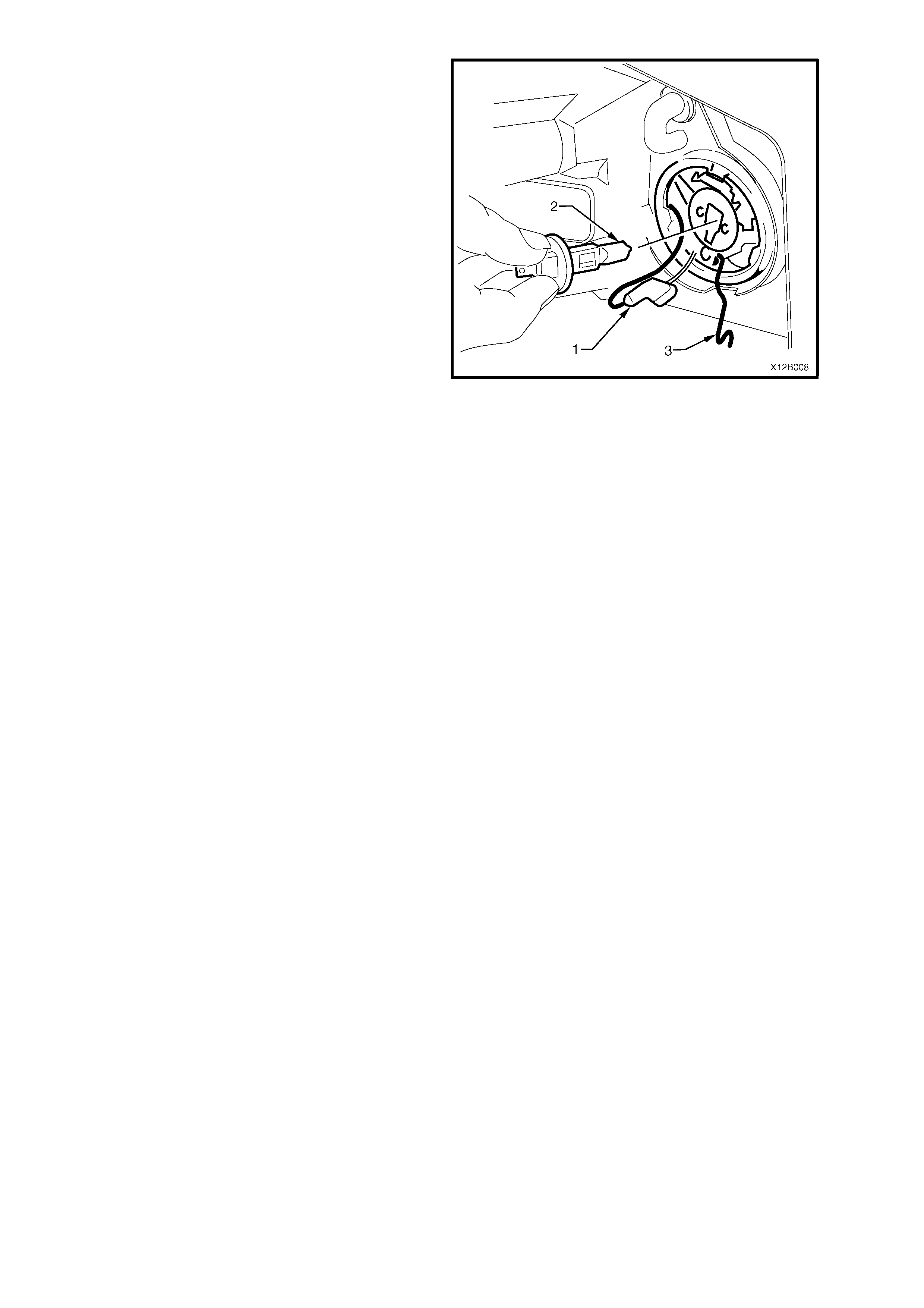
3. Disconnect harness connector (1) from
bulb (2). Depress and unclip bulb retaining
clip (3) to release, and allow to fall clear of
bulb.
NOTE: Do not handle quartz envelope of inboard
high beam bulb. If touched accidentally, wipe
immediately with methylated spirits or bulb
performance will deteriorate.
4. Pull out bulb. Install new bulb into reflector,
ensuring that locating lug on bulb housing
aligns with square edge on bulb and locating
lugs on bulb mate with holes on bulb housing.
Connect bulb retaining clip. Connect bulb
harness connector.
5. Inspec t rubber seal in dust c ap to ensure that it
is not damaged and that it is seated correctly.
Install dust cap onto rear of headlamp housing
and lock into place by turning clockwise.
Right-hand side only
Position battery in correct location and install
battery retaining clamp. Secure battery
retaining clamp and reconnect battery
terminals.
Figure 12B-14
Right and left-hand sides
6. Check inboard high beam lamp operation.
Left-hand side only (with GEN III V8 engine)
Install air inlet snorkel into air cleaner housing
by aligning s nork el with air cleaner housing and
pushing firmly into place.
Position upper radiator support cover and
install four scrivets to secure cover.
2.5 FRONT TURN SIGNALLAMP BULB
REPLACE
NOTE: If replacing a front turn signal lamp bulb,
ensure the correct type is fitted. For all models, the
bulb glass is coloured orange and has offset locating
pins.
1. Open engine compartment.
Right-hand side headlamp only
V6 engine models:
Disconnect battery terminals, remove battery
retaining clamp and manoeuvre battery to gain
access to turn signal bulb socket.
GEN III V8 engine models:
Remove four scrivets securing upper radiator
support cover and remove cover.
Disconnect battery terminals, remove battery
retaining clamp and manoeuvre battery to gain
access to turn signal bulb socket.
Left-hand side only (with GEN III V8 engine)
Remove air inlet snorkel from air cleaner
housing by pulling snorkel straight out from air
cleaner housing.
Right and left-hand sides
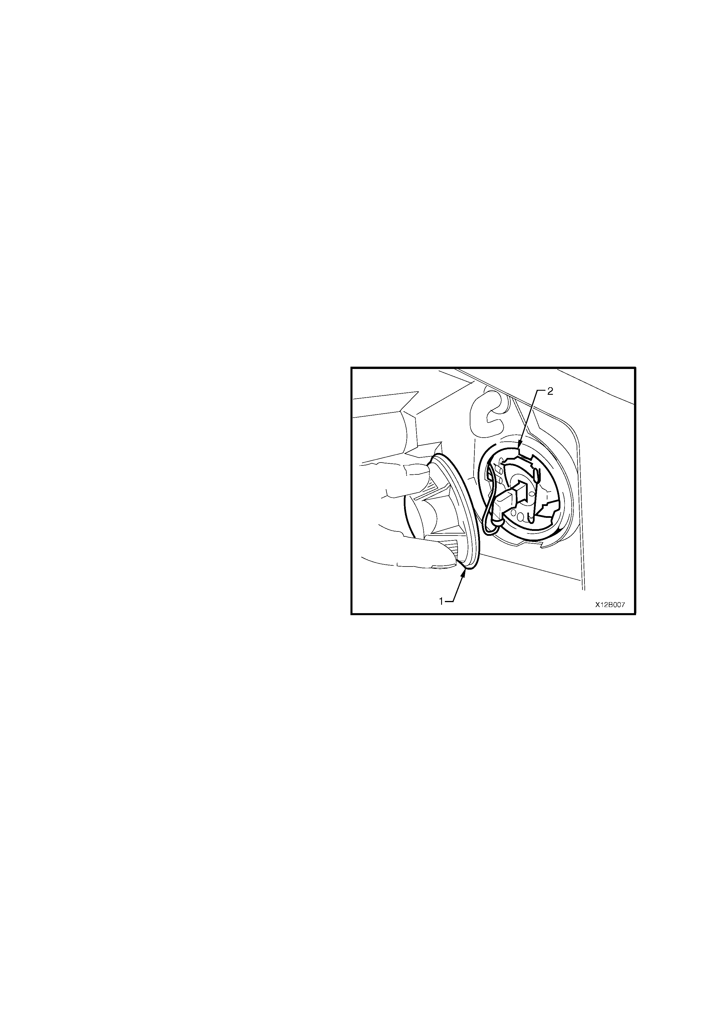
2. From inside engine compartment, twist to
release bulb socket (1) from behind headlamp
assembly (2).
3. Depress bulb into socket and rotate to remove.
4. Inspect O-ring on bulb socket for damage and
correct seating. Replace O-ring if necessary.
5. Install new bulb (3) into socket, install socket
into housing and twist to lock into position.
Right-hand side only
Position battery in correct location and install
battery retaining clamp. Secure battery
retaining clamp and reconnect battery
terminals.
Right and left-hand sides
6. Check turn signal lamp operation.
Left-hand side only (with GEN III V8 engine)
Install air inlet snorkel into air cleaner housing
by aligning s nork el with air cleaner housing and
pushing firmly into place.
Position upper radiator support cover and
install four scrivets to secure cover.
Figure 12B-15
2.6 HEADLAMP AND TURN SIGNAL/PARKING LAMP ASSEMBLY — EXECUTIVE,
ACCLAIM, S AND SS MODELS
REMOVE
1. Open engine compartment.
Right-hand side headlamp only
Disconnect the negative terminal from battery and move negative battery cable clear of battery. Remove the
screw sec ur ing engine cooling f an f us ible links holder to upper radiator s upport panel and move the holder clear
of the headlamp assembly.
Right and left-hand sides
2. F rom inside engine c om partm ent, disc onnect wiring harness c onnector f rom headlam p as sem bly. Remove turn
signal lamp bulb socket from headlamp assembly.
3. Remove the two scrivets from behind number plate, refer to Fig. 12B-16 (Executive and Acclaim) or Fig. 12B-17
(S and SS).
4. SS Model: From behind the bumper facia assembly, disconnect the fog lamp wiring harness connectors (one
place for each lamp).
5. Remove screws securing facia sides to front fender wheel arch opening and front panel assembly.
6. With the facia supported, pull the facia side members out, disconnect the facia side supports, then slide the
facia forward removing the facia assembly.
7. Place the front bumper bar facia assembly face down on a clean protective surface.
Figure 12B-16 FRONT BUMPER FACIA – EXECUTIVE and ACCLAIM
1. Screw (1 place each side)
2. Screw (1 place each side)
3. Facia assembly
4. Scrivet (2 places)
5. Screw (3 places)
6. Screw (3 places each side)
7. Front bumper guide rail assembly
NOTE: For Sectional views A-A to G-G,
refer to Section 1D BUMPER BARS in
the VX Series Service Information.
Techline
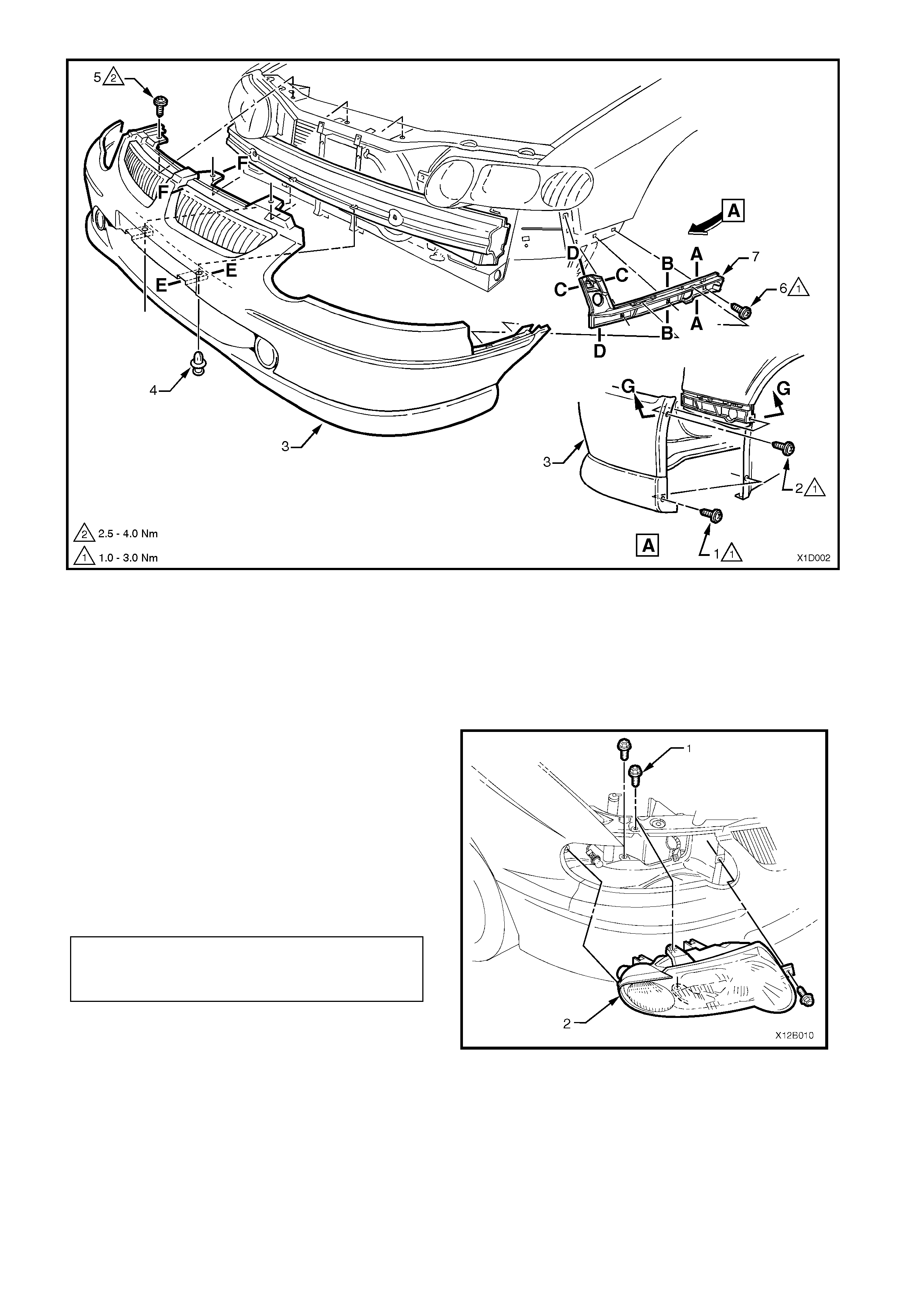
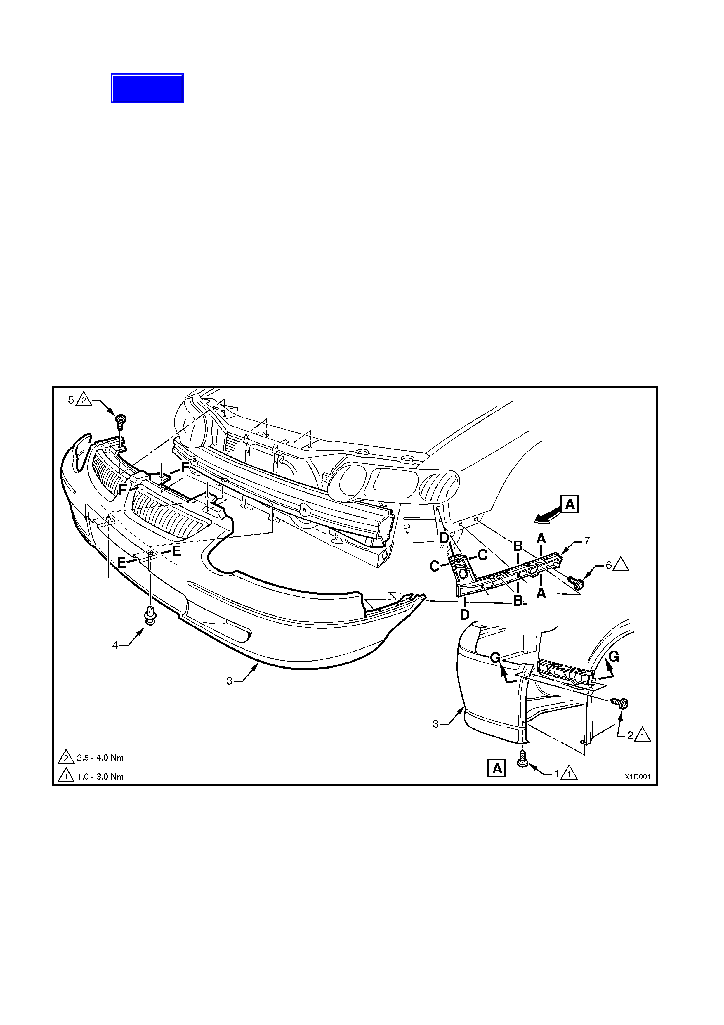
Figure 12B-17 FRONT BUMPER FACIA – S and SS
1. Screw (1 place each side)
2. Screw (1 place each side)
3. Facia assembly
4. Scrivet (2 places)
5. Screw (3 places)
6. Screw (3 places each side)
7. Front bumper guide rail assembly
NOTE: For Sectional views A-A to G-G,
refer to Section 1D BUMPER BARS in
the VX Series Service Information.
8. Remove three headlamp retaining screws (1)
and remove headlamp and turn signal/parking
lamp assembly (2).
REINSTALL
Installation of the headlam p and turn s ignal/parking
lamp assembly is the reverse of removal
procedure, noting the following points:
1. Install headlamp and turn signal/parking lamp
assembly (2) and tighten retaining screws (1) to
the correct torque specification.
2. Install front bumper facia assembly by
snapping the facia onto the retainers at guide
rails, one side at a time.
3. Ensure correct fender, hood and headlamp
clearance, adj ust f acia if nec essar y, refer to VX
Series Body Structure Repair Supplement.
4. Reconnect all wiring harness connectors and
check operation of headlamp and turn
signal/parking lamps and fog/cornering lamps.
Check headlamp (and fog lamps) aim, refer to
2.1 AIMING OF HEADLAMPS AND FOG LAMPS
in this Section.
Figure 12B-18
HEADLAMP AND TURN
SIGNAL /PARKING LAMP
ASSEMBLY RETAINING SCREW
TORQUE SPECIFICATION
2 – 5 Nm

2.7 HEADLAMP AND TURN SIGNAL/PARKING LAMP ASSEMBLY — BERLINA AND
CALAIS MODELS
REMOVE
1. Open engine compartment.
Right-hand side headlamp only
Disconnect the negative terminal from battery and move negative battery cable clear of battery. Remove the
screw sec ur ing engine cooling f an f us ible links holder to upper radiator s upport panel and move the holder clear
of the headlamp assembly.
Right and left-hand sides
2. F rom inside engine c om partm ent, disc onnect wiring harness c onnector f rom headlam p as sem bly. Remove turn
signal lamp bulb socket from headlamp assembly.
3. Remove the grille insert, refer to Section 1C RADIATOR GRILLE in the VX Series Service Information.
4. Remove the three scrivets securing the bumper facia assembly to the support beam, refer to Fig.12B-19.
5. Remove screws securing facia sides to front fender wheel arch opening and front panel assembly.
6. With the facia supported, pull the facia side members out, disconnect the facia side supports, then slide the
facia forward removing the facia assembly.
7. If necessary, lift off the front centre support assembly.
8. Place the front bumper bar facia assembly face down on a clean protective surface.
Figure 12B-19 FRONT BUMPER FACIA – BERLINA and CALAIS
1. Screw (1 place each side)
2. Screw (1 place each side)
3. Facia assembly
4. Scrivet (3 places)
5. Support assembly – centre
6. Screw (3 places each side)
7. Front bumper guide rail assembly
NOTE: For sectional views A-A to F-F,
refer to Section 1D BUMPER BARS in
the VX Series Service Information.
Techline
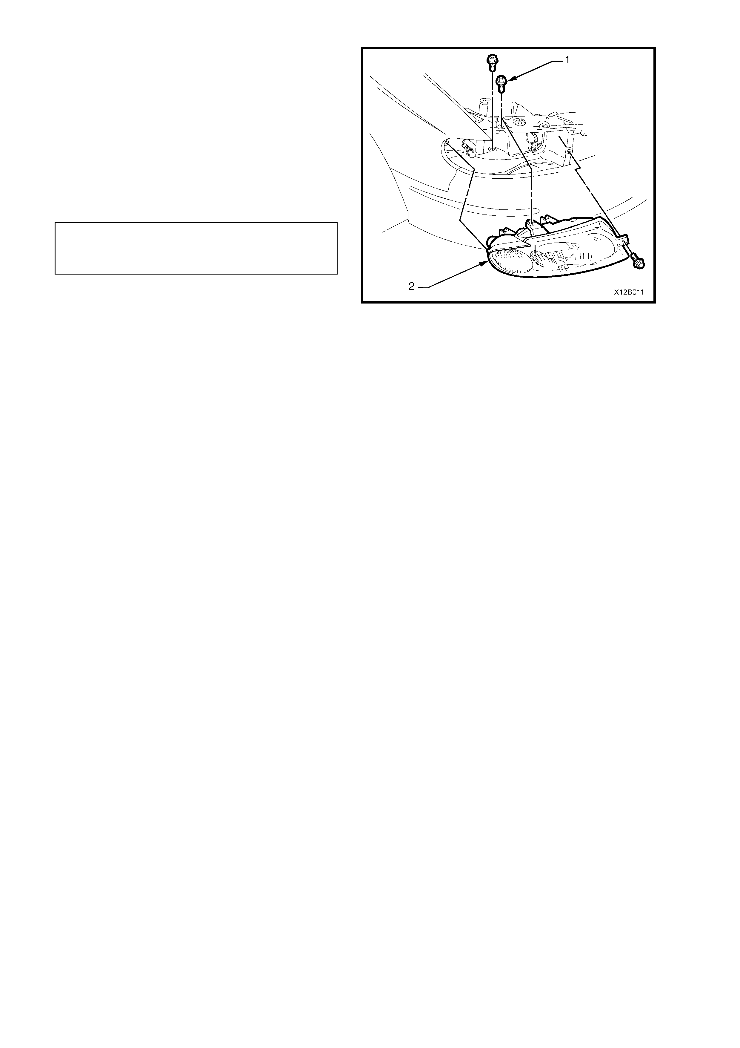
9. Remove three headlamp retaining screws (1)
and remove headlamp and turn signal/parking
lamp assembly (2).
REINSTALL
Installation of the headlam p and turn s ignal/parking
lamp assembly is the reverse of removal
procedure, noting the following points:
1. Install headlamp and turn signal/parking lamp
assembly (2) and tighten retaining screws (1) to
the correct torque specification.
2. Install front bumper facia assembly by
snapping the facia onto the retainers at guide
rails, one side at a time.
3. Ensure correct fender, hood and headlamp
clearance, adjust facia if necessary, refer to
VX Series Body Structure Repair Supplement.
4. Reconnect all wiring harness connectors and
check operation of headlamp and turn
signal/parking lamps and fog/cornering lamps.
Check headlamp (and fog lamps) aim, refer to
2.1 AIMING OF HEADLAMPS AND FOG LAMPS
in this Section.
Figure 12B-20
HEADLAMP AND TURN
SIGNAL/PARKING LAMP
ASSEMBLY RETAINING SCREW
TORQUE SP ECIFICATION 2 – 5 Nm
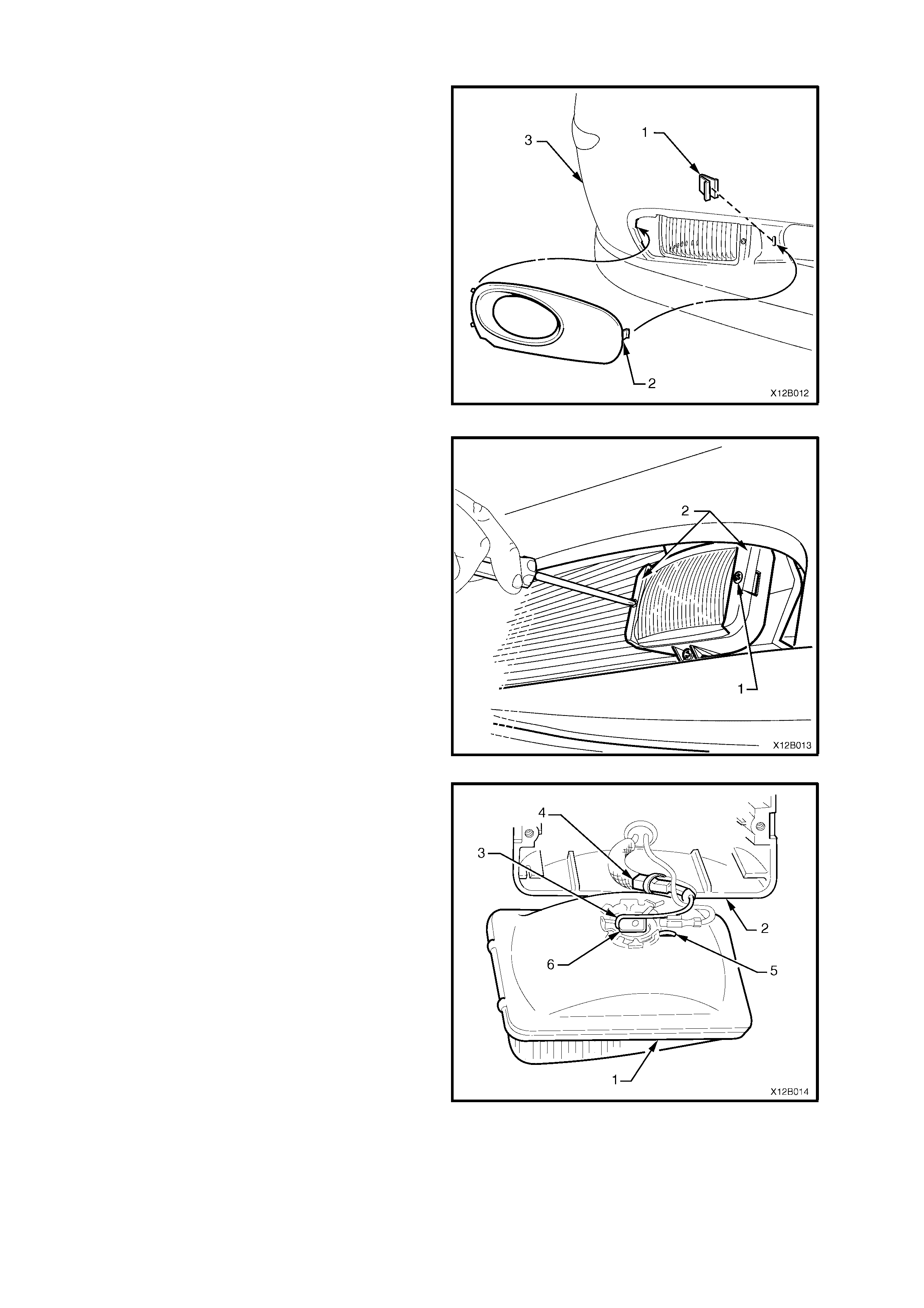
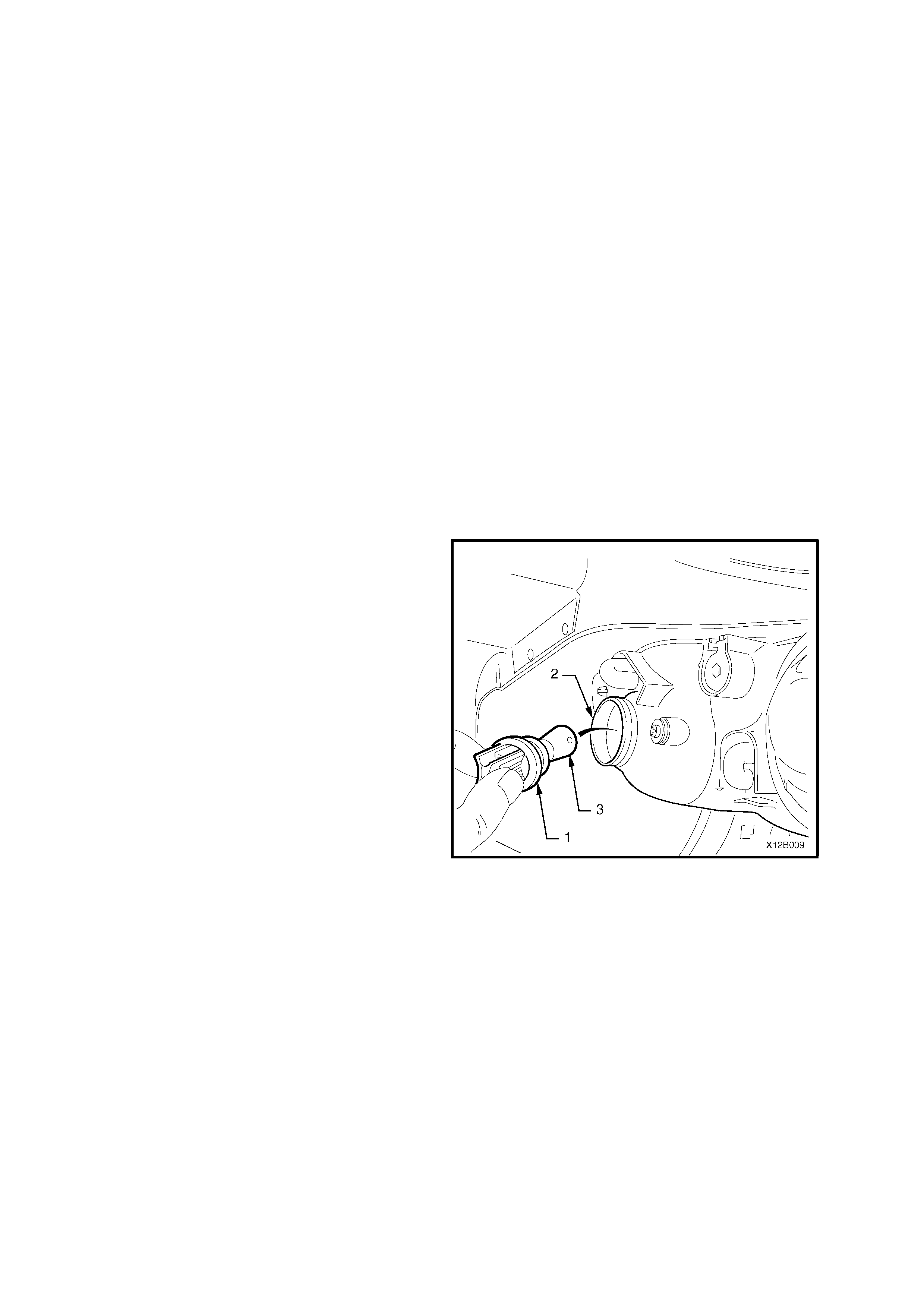
2.8 FOG LAMP BULB — CALAIS MODEL
REPLACE
1. Remove the clip (1) s ec uring fog lam p bezel (2)
to facia (3) and remove bezel.
Figure 12B-21
2. Remove lens and reflector assembly to housing
end cap retainer screws (1), remove end caps
(2).
Figure 12B-22
3. Pull lens and reflector assembly (1) out from
housing (2).
4. Disconnect bulb lead (3) from wiring harness
connector (4) located inside insulating sheath.
5. Squeeze halves of spring retainer (5) together
and pivot spring back ward clear of bulb. Lif t out
bulb (6) and remove.
NOTE: Do not handle quartz envelope of bulb. If
touched, wipe immediately with methylated spirits
or bulb performance will deteriorate.
6. Connect new bulb lead to wiring harness
connector, install bulb into correct locating
notches in reflector and reconnect spring
retainer.
7. Install lens and ref lector as sembly into housing.
Install end caps and screws, tighten screws.
8. Install fog lamp bezel and securing clip.
9. Check fog lamp operation and aim, refer to
2.1 AIMING OF HEADLAMPS AND FOG
LAMPS in this Section.
Figure 12B-23
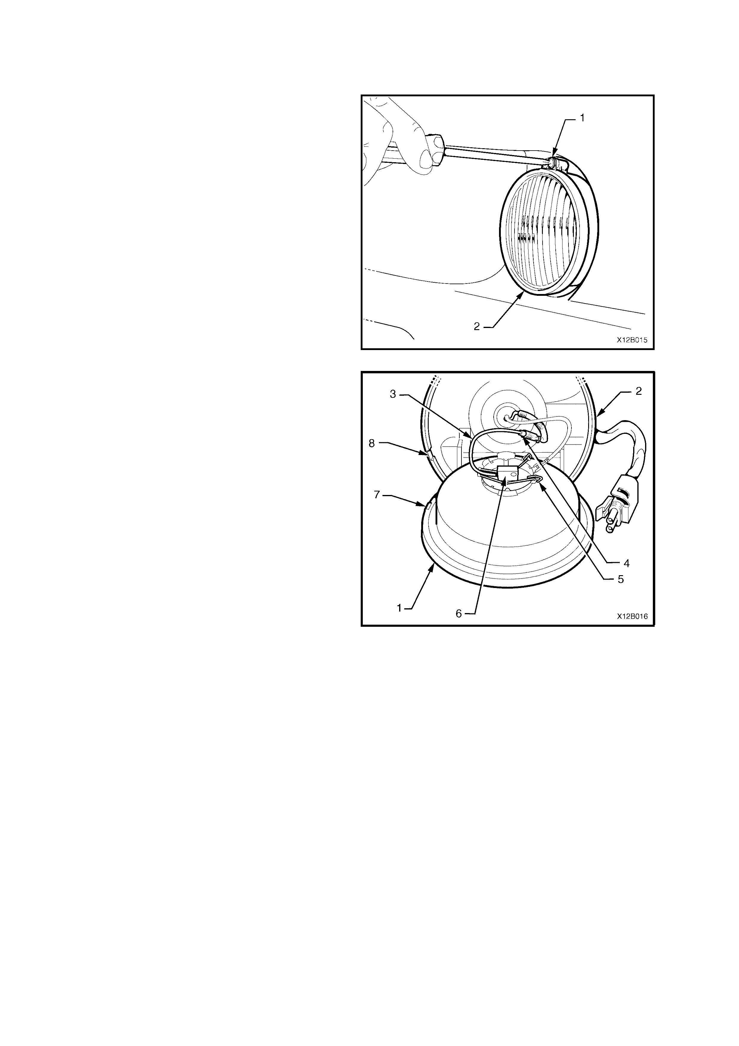
2.9 FOG LAMP BULB — SS MODEL
REPLACE
1. Remove screw (1) securing lens, reflector and
clamp ring assembly to fog lamp housing and
remove clamp ring (2).
Figure 12B-24
2. Pull lens and reflector assembly (1) out from
housing (2).
3. Disconnect bulb lead (3) from wiring harness
connector (4) located inside insulating sheath.
4. Squeeze halves of spring retainer (5) together
and pivot spring back ward clear of bulb. Lift out
bulb (6) and remove.
NOTE: Do not handle quartz envelope of bulb. If
touched, wipe immediately with methylated spirits
or bulb performance will deteriorate.
5. Connect new bulb lead to wiring harness
connector, install bulb into correct locating
notches in reflector and reconnect spring
retainer.
6. Install lens and reflector assem bly into housing
ensuring that protrusion (7) on rim of lens and
reflector assembly aligns correctly with cut-out
on rim of housing (8). Install clamp ring and
screw, tighten screw.
7. Check fog lamp operation and aim, refer to
2.1AIMING OF HEADLAMPS AND FOG
LAMPS in this Section.
Figure 12B-25
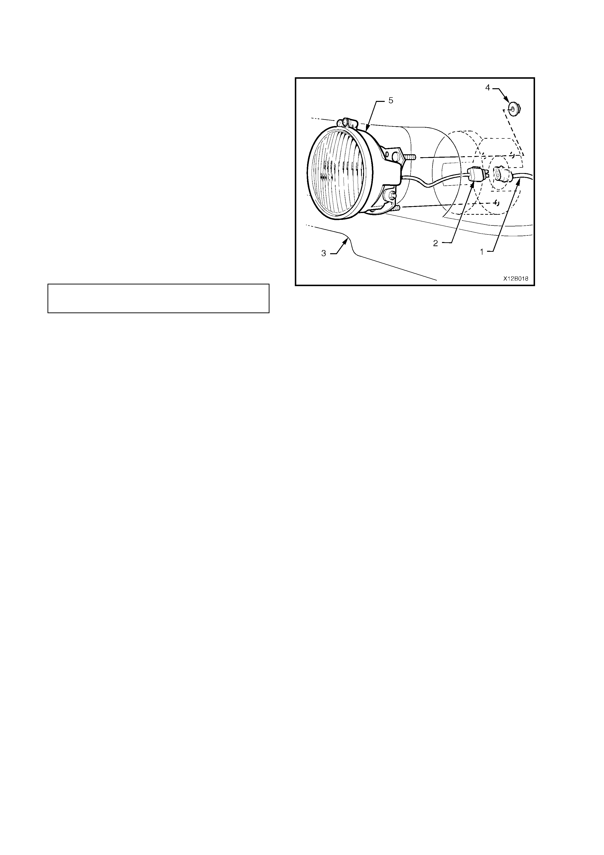
2.10 FOG LAMP ASSEMBLY — CALAIS MODEL
1. Remove the font bumper bar facia, refer to
2.7 HEADLAMP AND TURN
SIGNAL/PARKING LAMP ASSEMBLY —
BERLINA AND CALAIS MODELS in this
Section.
2. From inside wheelhouse, disconnect main
wiring harness connector (1) from fog lamp
harness connector (2).
3. From behind bumper bar, remove three
mounting bracket to bumper bar beam screws
(3), remove fog lamp assembly (4) from
bumper bar beam (5).
REINSTALL
Installation of the fog lam p assem bly is the re verse
of removal procedures, noting the following points:
1. Install fog lamp assembly onto bumper bar
beam, ensuring that locating lugs (6) on lamp
mounting br acket f it correc tly in the lug location
holes (7) in the bumper bar beam.
2. Tighten lamp mounting bracket to bumper bar
beam and facia screws to the correct torque
specification.
3. Check fog lamp operation and aiming, refer to
2.1 AIMING OF HEADLAMPS AND FOG
LAMPS in this Section.
Figure 12B-26
REMOVE
FOG LAMP MOUNTING BRACKET
TO BUMPER BAR BEAM
AND FACIA SCRE W
TORQUE SPECIFICATION
2 – 5 Nm
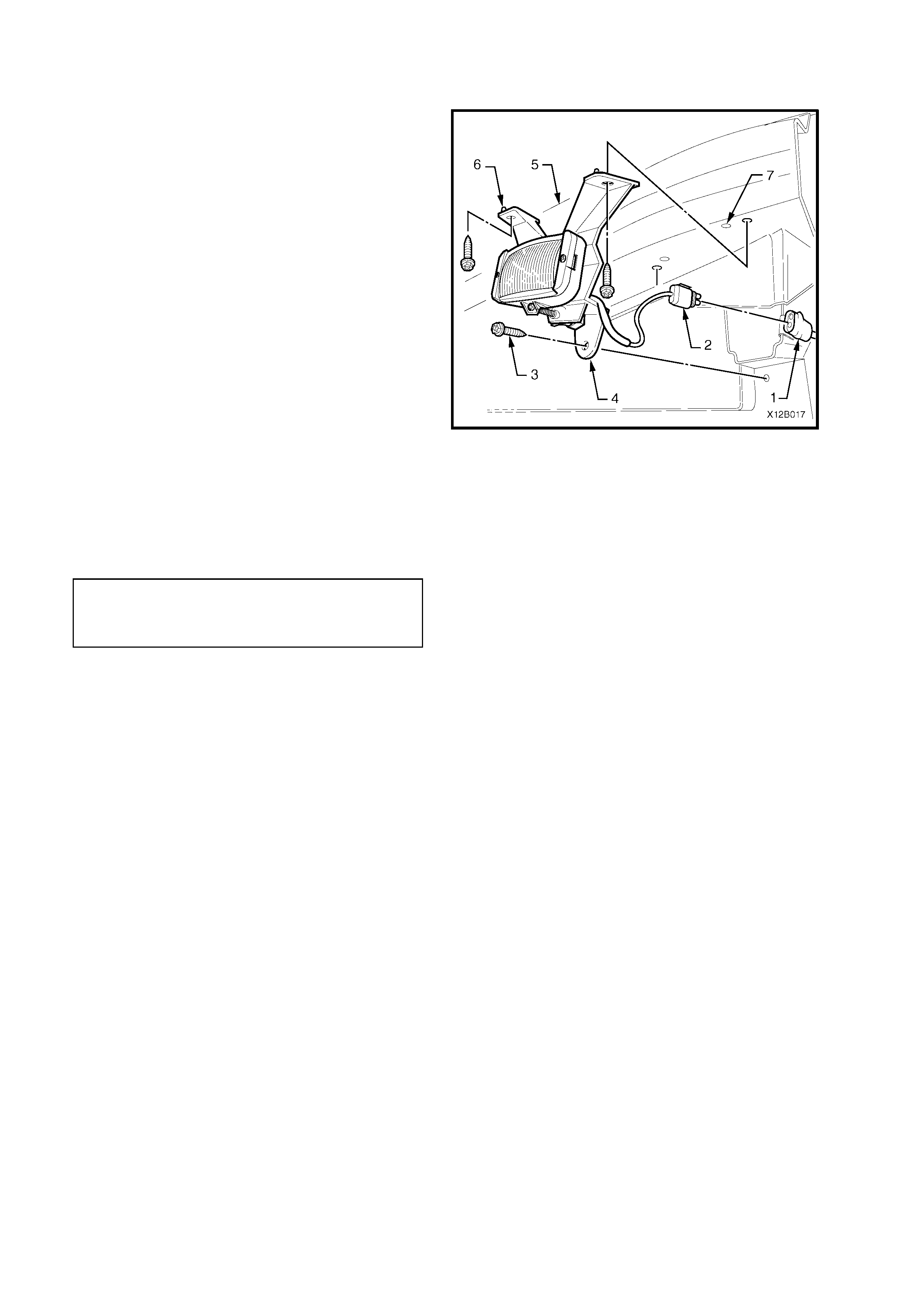
2.11 FOG LAMP ASSEMBLY — SS MODEL
REMOVE
1. From inside wheelhouse, disconnect main
wiring harness (1) from fog lamp harness
connector (2).
2. From behind bumper bar facia (3), remove
three nuts (4) securing fog lamp assembly (5)
to bumper bar facia remove fog lamp
assembly.
REINSTALL
Installation of the fog lam p assem bly is the re verse
of removal procedures, noting the following points:
1. Ensure that the fog lamp assembly is correctly
orientated with the beam adjustment screw
located to the top.
2. Tighten fog lamp housing to bumper bar facia
nuts to the correct torque specification.
3. Check fog lamp operation and aiming, refer to
2.1 AIMING OF HEADLAMPS AND FOG
LAMPS in this Section.
Figure 12B-27
FOG LAMP HOUSING TO BUMPER
BAR FACIA NUT
TORQUE SPECIFICATION 2 – 2.5 Nm
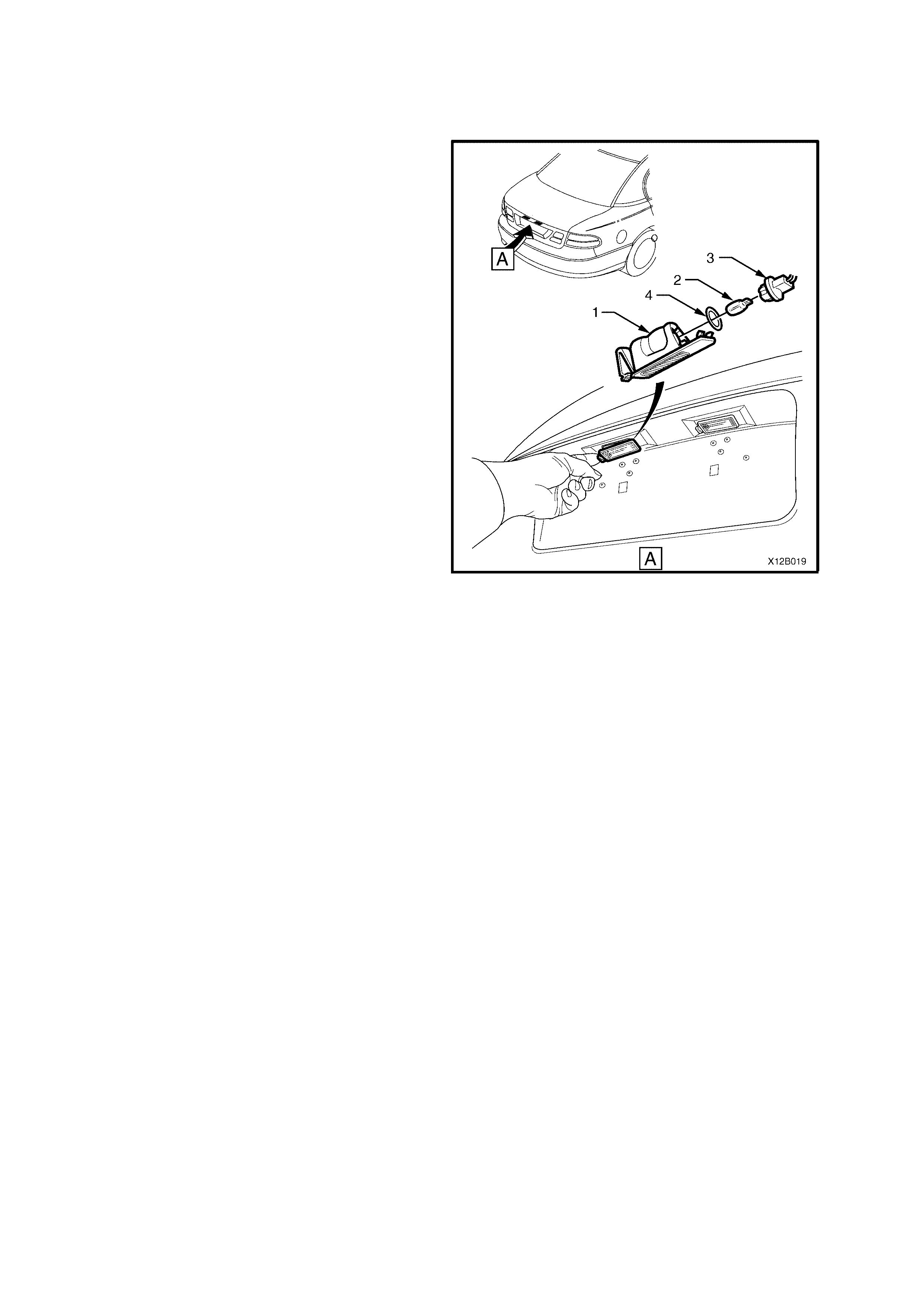
2.12 LICE NCE PLATE LAMP/BULB —EXECUTIVE AND ACCLAIM SEDAN,
S AND SS MODELS
REMOVE
1. Push locking tang located at end of lamp
holder (1) towards lamp and pivot lamp holder
assembly down to remove from decor panel
aperture.
2. Withdraw socket and bulb assembly from
holder.
3. Pull bulb (2) from socket (3).
4. Ins pect bulb sock et sealing ring (4) for damage
and replace if required.
REINSTALL
1. Push new bulb into bulb socket.
2. Install socket and bulb assembly into lamp
holder.
NOTE: Lamp holder will assemble to decor panel in
one direction only.
3. Install holder assembly into decor panel.
4. Check licence plate lamp operation.
Figure 12B-28
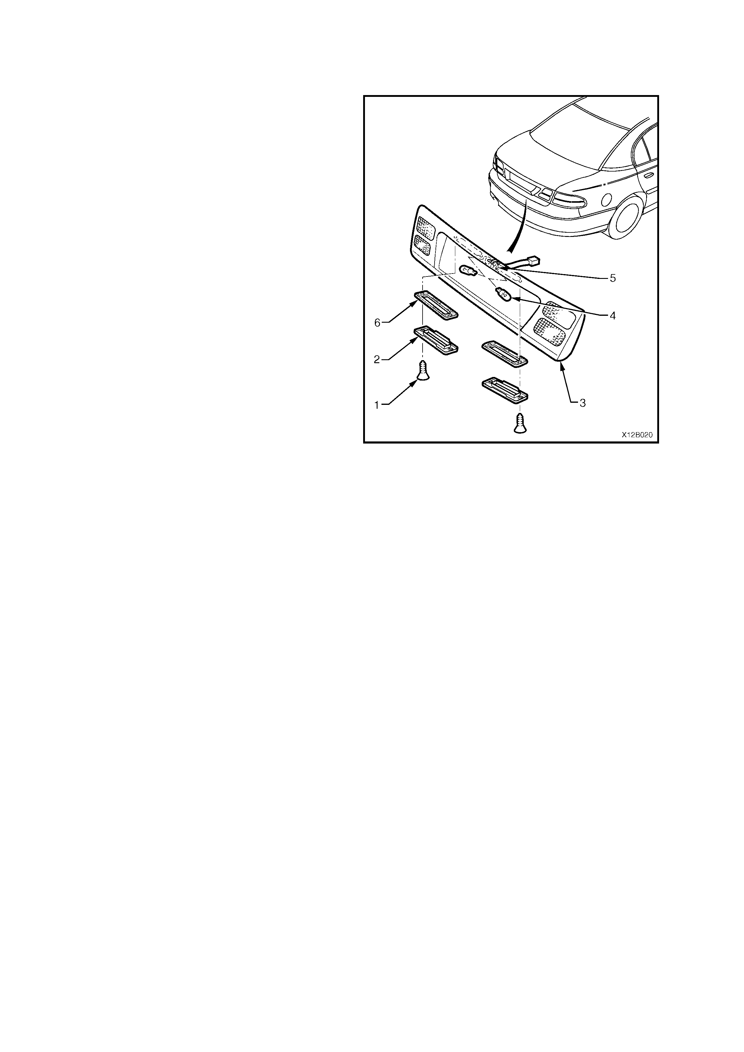
2.13 LICE NCE PLATE LAMP/BULB —BERLINA SEDAN AND CALAIS MODELS
REMOVE
1. Remove screws (1) securing lamp lens (2) to
decor panel (3) and remove lamp lens.
2. Pull bulb (4) from socket (5).
3. Inspect lens seal (6) for dam age and replace if
required.
REINSTALL
1. Push new bulb into bulb socket.
2. Check licence plate lamp operation.
3. Install lens onto decor panel.
Figure 12B-29

2.14 S EDAN REAR LAMP BULBS
STOP/TAIL LA MP BULBS (DECOR PANEL MOUNTED) — BERLINA AND CALAIS MODELS
REPLACE
1. Open rear compartment.
2. Through left or right access hole in decklid,
remove bulb socket by turning socket
anti-clockwise and removing socket.
3. Remove bulb from socket by depressing bulb
into its socket and then rotate to remove.
4. Insert new bulb into socket and install socket
into decor panel assembly, ensuring socket
locks securely into place.
5. Check rear lamp operation.
STOP/TAIL (REA R LAMP MOUNTED), BACK-UP AND TURN SIGNAL LAMP BULBS
REPLACE
1. Open rear compartment.
2. Remove rear lamp assembly refer to
2.15 REAR LAMP ASSEMBLY — SEDAN in
this Section.
3. Remove appropriate bulb socket by turning
socket anti-clockwise and removing socket,
refer to Fig.12B-30.
4. Remove bulb from socket by depressing bulb
into its socket and then rotate anti-clock wise to
remove.
5. Inspect bulb socket to lamp housing seals for
damage, replace if necessary.
6. Insert new bulb into socket and install socket
into lamp housing, ensuring socket locks
securely into place. Note that stop/tail lamps
and turn signal lam p sock ets ar e both coloured
white but have differing number of lugs to
prevent installation to incorrect rear lamp
location.
7. Check rear lamp operation.
Techline
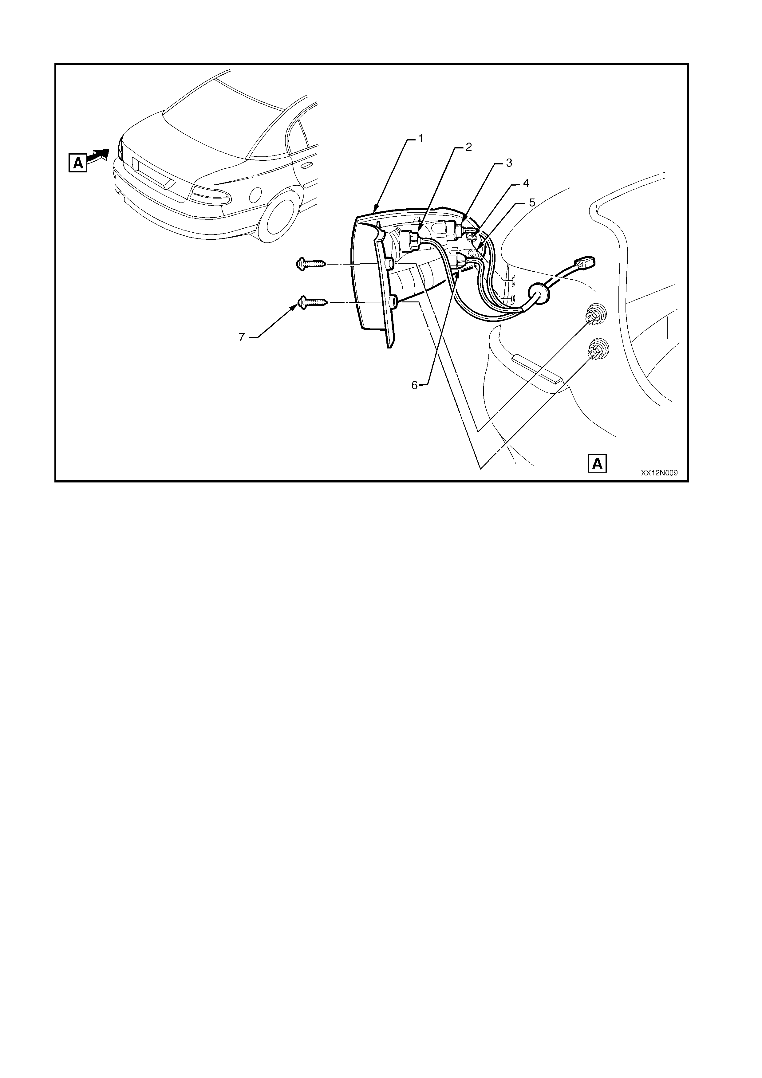
Figure 12B-30
1. Tail light housing
2. Back-up light socket (black – 4 lug)
3. Turn signal bulb socket (white – 4 lug)
4. Integral plastic guide peg (1 place each
side)
5. Metal locating peg (1 place each side)
6. Stop/tail light bulb socket (white – 3
lug)
7. Screw (2 places each side)
NOTE: Harness length will allow back-up
light socket and turn signal bulb socket to
be fitted to correct locations only.

2.15 REAR LAMP ASSEMBLY — SEDAN
REAR QUARTER LAMP ASSEMBLY
REMOVE
1. Open rear compartment.
2. Remove rear quarter lamp assembly to body
attaching screws, refer to Fig.12B-30.
3. Pull rear quarter lamp housing sideways out from
panel so that loc ating peg on s ide of lamp ass embly
snaps free from retainer.
4. While supporting lamp housing, remove back-up
light bulb socket, turn signal bulb socket and
stop/tail light bulb socket by turning socket
anti-clockwise and removing.
REINSTALL
1. Insert bulb sockets into rear quarter lamp housing,
ensuring sockets are correctly located and lock
securely into place.
2. Ensure that rear quarter lamp harness grommet is
seated correctly. Assemble lamp housing to body,
ensuring locating peg s naps into retainer and install
and tighten attaching screws to the correct torque
specification.
REAR QUARTER LAMP HOUSING T O
BODY A T T ACHING SCRE W
TORQUE SPECIFICATION
1 – 3 Nm
3. Check rear lamp operation.
Techline

DECOR PANEL ASSEMBLY
REMOVE
1. Open rear compartment.
2. From inside decklid, disconnect licence plate
wiring harness and push harness insulating
grommet through decklid panel, refer to
Fig.12B-31.
3. From inside decklid on Berlina and Calais
models, disconnect left and right stop/tail light
wiring harness from decor panel assembly.
4. Remove the two decor panel assembly to
decklid attaching nuts.
5. Remove the three decor panel assembly to
decklid attaching Torx head screws.
6. Remove the four decor panel assembly to
decklid attaching hexagon head screws.
7. Through access holes located inside decklid,
remove screws located in the four decor panel
mounting clips.
8. Pull decor panel assembly away from and
downward of decklid and remove from decklid.
REINSTALL
1. Check condition of decor panel to decklid
rubber sealing gasket and replace if damaged.
2. Remove the four decor panel mounting clips
from the decklid, and assemble to decor panel
with the four philips head screws.
3. Ass emble dec or panel to deck lid, ensuring that
licence plate wiring harness grommet is
correctly installed.
4. Install and tighten attac hing nuts and sc rews to
the correct torque specification.
5. Connect left and right stop/tail light wiring
harness on Berlina and Calais models.
6. Connect licence plate wiring harness.
7. Check rear lamp operation.
DECKLID DECOR PANE L A SSEMBLY
TO DECKLID ATTACHING NUT
TORQUE SPECIFICATION 1 - 3 Nm
DECKLID DECOR PANE L A SSEMBLY
TO DECKLID ATTACHING
(TORX HEAD) SCREW
TORQUE SPECIFICATION
2 - 5 Nm
DECKLID DECOR PANE L A SSEMBLY
TO DECKLID ATTACHING
(PHILLI P S HEAD) SCREW
TORQUE SPECIFICATION
2 - 3 Nm
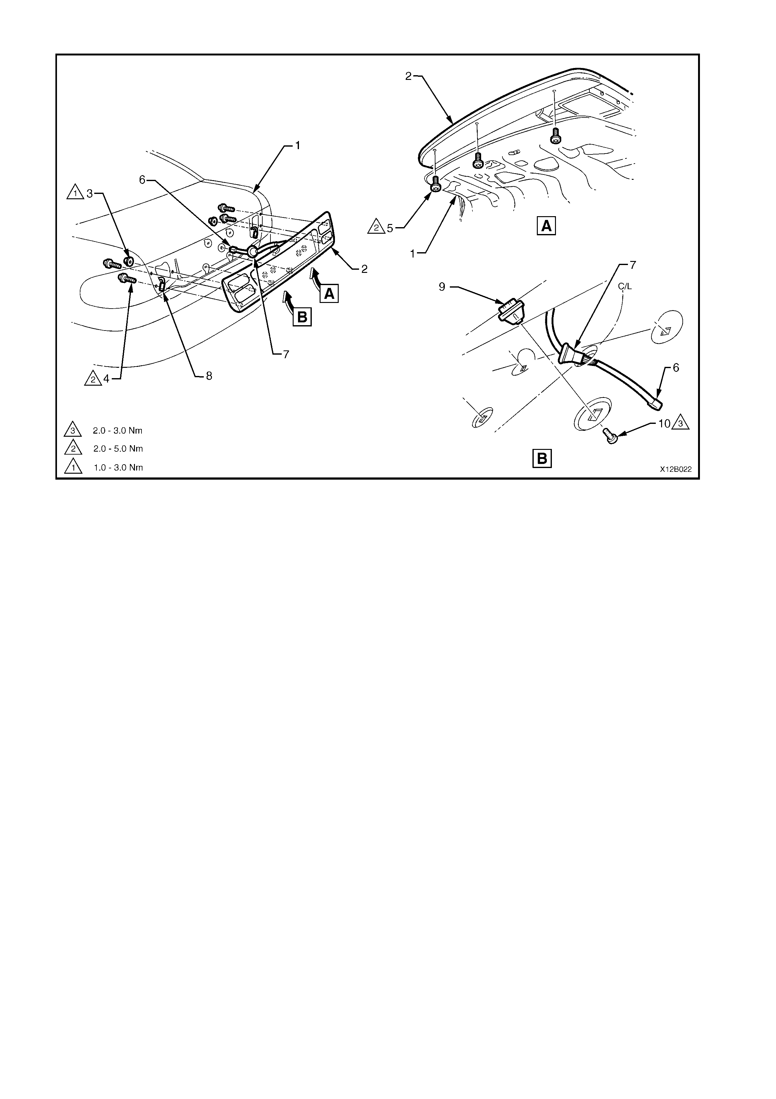
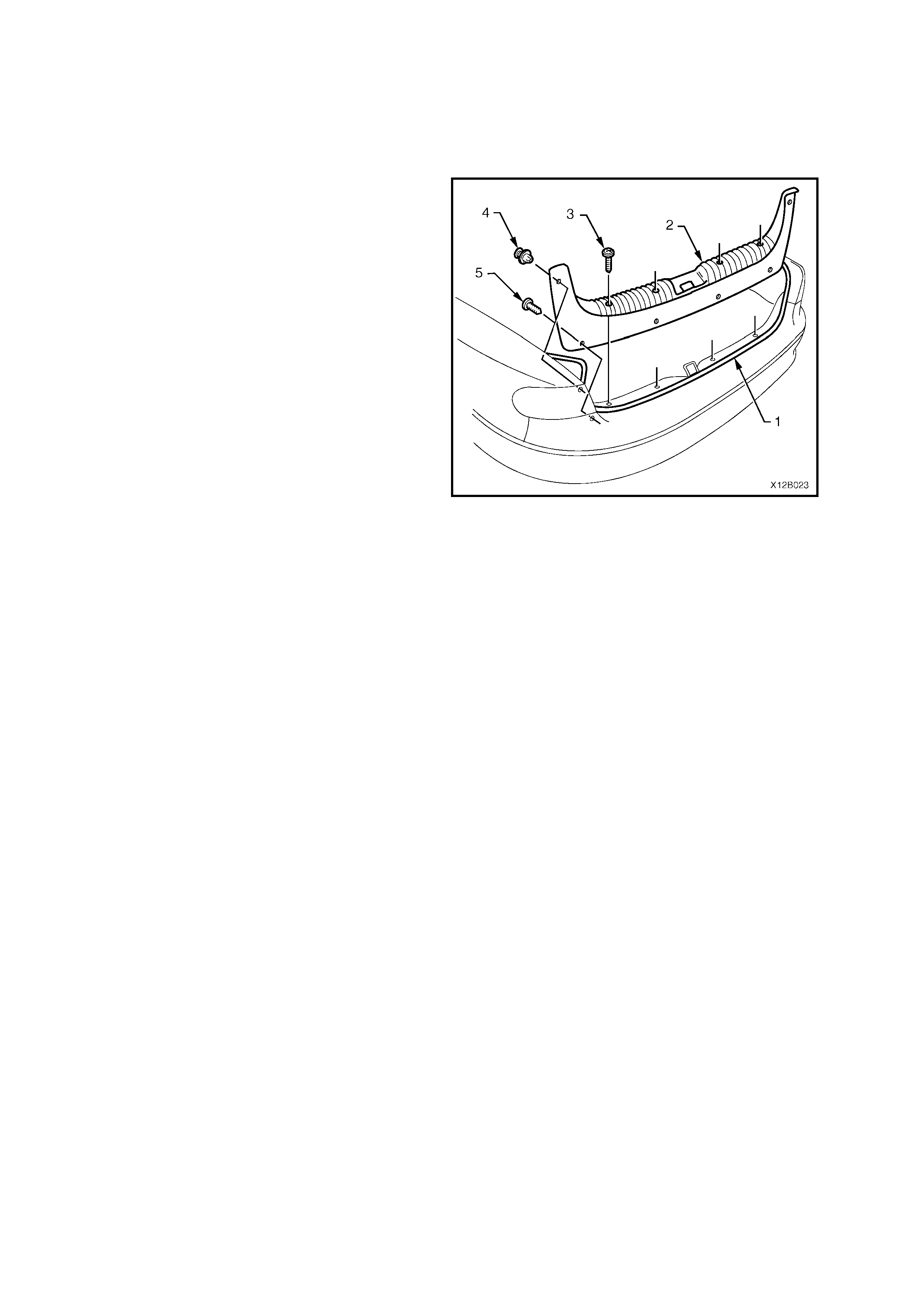
Figure 12B-31
1. Decklid
2. Decor panel assembly
3. Nut (1 place each side)
4. Screw (2 places each side)
5. Screw (3 places)
6. Licence plate wiring harness connector
7. Licence plate wiring harness grommet
8. Stop/tail light harness (1 place each
side — Berlina and Calais models
only )
9. Decor panel assembly to decklid
mounting clip (4 places)
10. Screw (4 places)
2.16 REFLECTOR LENS ASSEMBLY — EXECUTIVE AND ACCLAIM SEDAN, S AND SS
MODELS
REMOVE
1. Open the rear compartment lid.
2. Gently peel the rear compartment
weatherstrip (1) away from the upturned flange
of the rear compartment opening.
NOTE: Only partly peel the weatherstr ip away f rom
the rear compartment opening to enable access to
the four bumper bar facia scrivets and to allow for
removal of the rear compartment crossmember
cover (2).
3. Remove the four screws (3), two scrivets (4)
and prise out the four fasteners (5) securing
the rear compartment crossmember trim and
remove the trim.
4. Peel the rear compartment carpet back slightly
and remove the four nuts securing the rear
bumper assembly to the rear quarter panel
(below tail lamps), refer to Fig.12B-33.
5. Remove two screws (one each side) securing
rear bumper facia at each upper wheel arch
opening and four s crews (two each side) at the
lower wheel arch opening.
6. Remove the four scrivets at the upper edge of
facia and two scrivets at lower edge of facia.
7. With the facia supported, pull the facia side
members out to disconnect the facia side
supports, then slide the facia rearwards,
removing the facia.
8. Place the rear bumper bar facia assembly
underside face down on a clean protective
surface.
9. Remove reflector lens retaining screw and
remove reflector lens from rear facia, refer to
Fig.12B-34.
Figure 12B-32
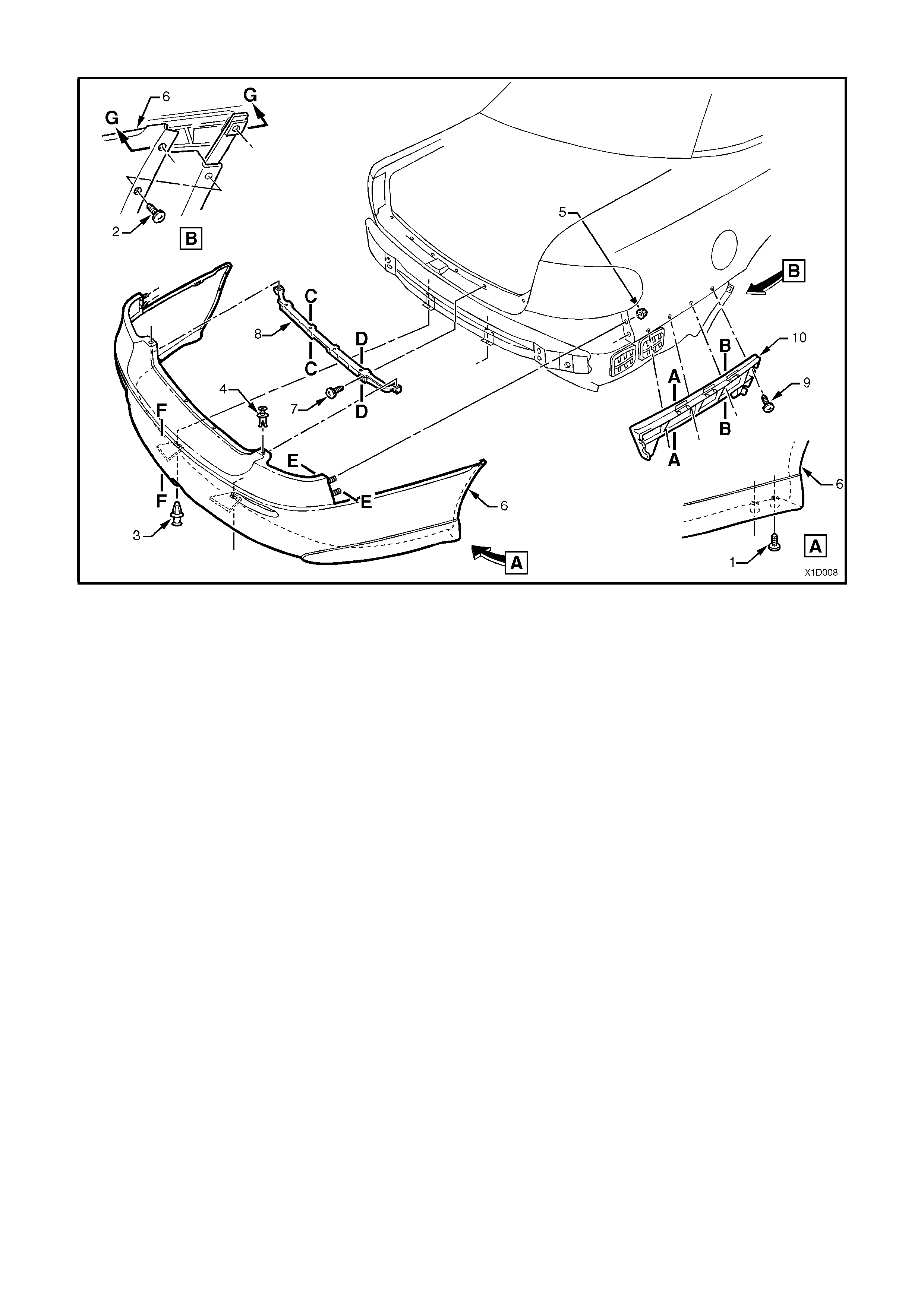
Figure 12B-33 REAR BUMPER FACIA – EXECUTIVE and ACCLAIM SEDAN, S and SS
1. Screw (2 places each side)
2. Screw (2 place each side)
3. Scrivet (2 places)
4. Scrivet (4 places)
5. Nut (2 places each side)
6. Facia assembly
7. Screw (6 places)
8. Rear facia upper centre support
9. Screw (4 places each side)
10. Rear bumper guide rail assembly (2 places)
NOTE: For sectional views of A-A to G-G, refer
to Section 1D BUM PER BARS in the VX Series
Service Information.

Figure 12B-34 REAR BUMPER FACIA COMPONENTS – EXECUTIVE and ACCLAIM SEDAN, S and SS
1. Screw (1 place each side)
2. Reflector lens assembly (1 place each side) 3. Blanking cover – tow bar
4. Facia assembly
REINSTALL
Installation of the reflector lens assembly is the
reverse of removal procedure, noting the following
points:
1. Install reflector lens assembly and tighten
retaining screw to the correct torque
specification.
2. Ins tall rear bum per fac ia assembly by snapping
the facia onto the retainers at guide rails, one
side at a time.
3. Ensure correct fender, and decklid clearance,
adjust rear bumper facia if necessary, refer to
VX Series Body Structure Repair Supplement.
REFLECTOR LENSE TO REAR FACIA
RETAINING SCREW
TORQUE SPECIFICATION 1 - 3 Nm

3. SPECIFICATIONS
BULB POWER RATING —
WA TTS BASE TYPE
HEADLAMPS
Hi/Lo Beam (Outboard)
Inboard High Beam
60/55
55
H4
H1
FOG LAMPS 55 H3
PARKI NG LA MPS (Front) 5 Wedge
TURN SIGNAL LA MPS (Front) 21 Offset Pin (Orange glas s)
SIDE REPEAT E R LAMPS 5 Wedge
TURN SIGNAL LAMPS
(Sedan — Rear)
21
Offset Pin (Orange glas s)
TURN SIGNAL LAMPS
(Wagon — Rear)
21
Offset Pin (Orange glas s)
BACK-UP LAMPS 21 Std. Parallel Pin
STOP AND TAIL LAMPS 21/5 Std. P aral l el P i n
LICENCE PLATE LA MPS 5 Wedge
INSTRUME NT CLUSTER
ILLUMINATION LA MPS
Executive, A cclaim, S and S S
Berlina and Calai s
3.6
5
Wedge
Wedge
INSTRUME NT CLUSTER
WARNING LAMPS
1.2
Wedge
TRIP COMPUTER ILLUMINATION
LAMPS
1.2
Wedge
REAR COMPARTMENT LAMP 10 Festoon
DOME (Courtesy) LAMP 10 Festoon
FRONT SEAT READING LAMP 5 Std. Parallel Pin
REAR SE A T RE ADING LAMP 5 Festoon
GLOVE COMPARTMENT LAMP 5 Festoon
FRONT FOOTWELL LAMPS 2.7 W edge
FRONT VANITY MIRROR LAMP 1.4 W edge
DOOR COURTESY LA MPS 5 Festoon
CONSOLE BI N LAMP 5 Festoon
HIGH MOUNTED STOP LA MP 18 Wedge
HIGH MOUNTED STOP LAMP —
(S and SS S poi l er mounted)
5
LED ass embly
FRONT AND REAR CIGAR
LIGHTER LAMPS
1.2
Wedge
IGNITION LOCK LAMP 1.4 W edge

4. TORQUE WRENCH SPECIFICATIONS
Nm
Headlamp assembly securing screws.................................. 2 – 5
Calais fog lamp mounting bracket to bumper
bar beam screws.................................................................. 2 – 5
SS fog lamp to front bumper facia nuts ............................... 2 – 2.5
Rear lamp housing retaining screw...................................... 1 – 3
Decor panel assembly attaching nuts.................................. 1 – 3
Decor panel assembly attaching screws (Torx head).......... 2 – 5
Decor panel assembly attaching screws (Phillips head)...... 2 – 3
Reflector lens to rear bumper facia retaining screw............. 1 – 3