
SECTION 12D - AUDIO SYSTEM
IMPORTANT
Before performing any Service Operation or other procedure described in this Section, refer to Section
00 CAUTIONS AND NOTES for correct workshop practices with regard to safety and/or property damage.
1. GENERAL I NFORMATI O N
The audio system used in VX Series models, is essentially the same audio system as used on VT Series models
with some upgraded features. The following provides a summary of these new features, together with the models
affected.
• The cassette player has been deleted on Executive, Ac claim, S and SS m odels. Thes e models are f itted with a
single CD player and radio combination as s tandar d. A ‘f ull up/f ull down’ power antenna, extended only when the
radio is ON, is also fitted as standard with this audio system.
• A radio / cass eette / s ingle CD player with ‘full up / full down power antenna (production Option UM3) is available
for Executive, Acc laim, S & SS m odels. T his is sim ilar to the unit fitted as standar d to Berlina models ex culding
antenna height adjustment feature.
• Berlina models continue to be fitted with a radio/cassette/single CD player and height adjustable antenna as
standard. However, an additional ‘TAPE’ button has been added to this audio system which allows the user to
switch between the radio and cassette player without having to eject the cassette.
In addition to this feature, a key off pinch roller release mechanism has been added to the cassette player.
• All VX Series models are fitted with steering wheel m ounted remote audio controls. Although this feature is the
sam e as the r em ote audio controls used on VT Series Calais m odels, the Executive, Acclaim , Berlina, S and SS
models have a minor difference to the wiring at the back of the audio unit. For additional information regarding
the wiring of audio systems, refer to Section 12P WIRING DIAGRAMS in the VX Series Service Information.
• Executive, Acclaim, Berlina, S and SS models have improved FM multi-path performance.
Service O perations aff ected by these new f eatures are inc luded in this Section. For all other inf ormation relating to
VX Series audio systems refer to Section 12D AUDIO SYSTEM of the VT Series I Service Information.
Techline
Techline
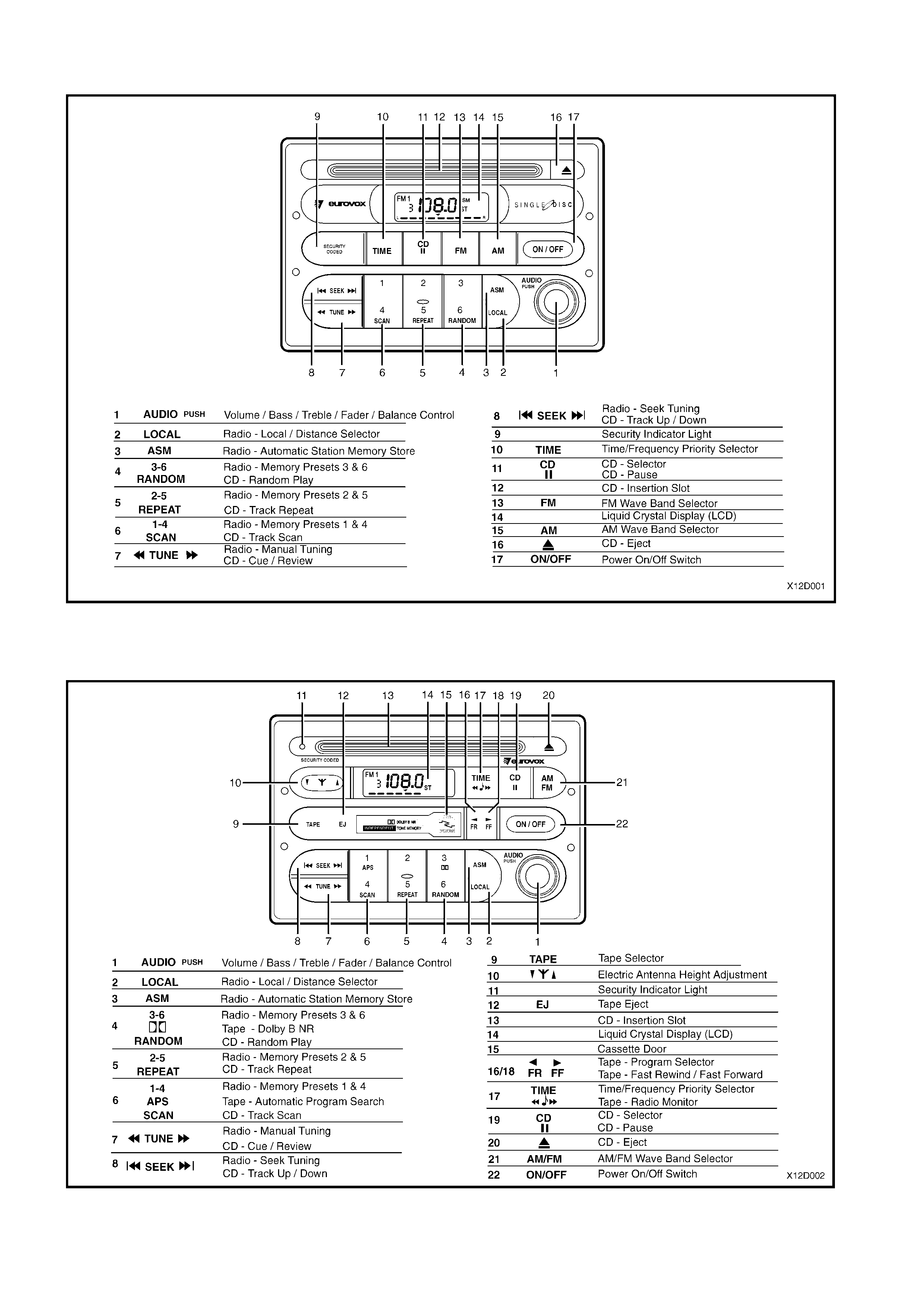
Fig.12D-1 shows the radio/CD player fitted to Executive, Acclaim, S and SS models.
Figure 12D-1
Fig.12D-2 shows the radio/cassette/CD player fitted to Excutive, Acclaim, ‘S’ & ‘SS’ modesl with
Production option UM3 and all Berlina models .
Figure 12D-2

2. DIAGNOSIS
2.1 DIAGNOSTIC PROCEDURES
When using the following diagnostic charts, refer also to Section 12P WIRING DIAGRAMS in the VX Series
Service Information.
TABLE NO. 1 - HORN BAR STEREO CONTROL FAULT DIAGNOSIS — EXECUTIVE, ACCLAIM, BERLINA,
S AND SS MODELS
STEP ACTION RESULT YES NO
1 • Switch system ON with key in ACC position.
• Do all switc hes operate correctly?
Reconfirm problem
with customer. Go to Step 2.
2 • Turn ignition to OFF position.
• With YB72 disconnected and using multimeter, check
resistance across circuit 515 (Brown wire) and circuit
1151 (Black/Whit e wire) at system connector YB72.
• Does resistance indicate open circuit with no horn bar
buttons pressed?
Go to Step 3. Replace switch
assemblies and veri fy
repair.
3 • Using multimeter, check continuity of harness between
horn bar audio controls and system, circuit 515 (Brown
wire) at connect ors YB148 and YB 72.
• Is there continuit y of the circ ui t ?
Go to Step 4. Repair harness and
verify repair.
4 • Using multimeter, check continuity of harness between
horn bar audio controls and system, circuit 1151
(Black/Whit e wire), at connect ors YB148 and YB72.
• Is there continuit y of the circ ui t ?
Go to Step 5. Repair harness and
verify repair.
5 • W ith Y B72 disconnec ted and using mul timeter, check t he
resistance of the circ ui t when each of the horn bar buttons
is pressed.
• Press MODE switch on left-hand side of steering wheel.
Is res i stance
between
20.6 kohms
and
22.8 kohms?
Go to Step 6. Replace switch
assemblies and veri fy
repair.
6 • Press NEXT ▲ switch on the left-hand side of steering
wheel. Is res i stance
between
11.1 kohms
and
12.3 kohms?
Go to Step 7. Replace switch
assemblies and veri fy
repair.
7 • Press NEXT ▼ switch on the left-hand side of steering
wheel. Is res i stance
between
6.7 kohms
and
7.4 kohms?
Go to Step 8. Replace switch
assemblies and veri fy
repair.
8 • Press MUTE switch on the right-hand side of steering
wheel. Is res i stance
between
3.5 kohms
and
3.9 kohms?
Go to Step 9. Replace switch
assemblies and veri fy
repair.
9 • Press VOL ▲ switch on the right-hand side of steering
wheel. Is res i stance
between
1.4 kohms
and
1.6 kohms?
Go to Step 10. Replace switch
assemblies and veri fy
repair.
10 • Press VOL ▼ switch on the right-hand side of steering
wheel. Does
multimeter
indicate
continuity?
Remove s ystem and
return for repair. Replace switch
assemblies and veri fy
repair.
Techline

TABLE NO. 2 - HORN BAR STEREO CONTROL FAULT DIAGNOSIS — CALAIS
STEP ACTION RESULT YES NO
1 • Switch system ON with key in ACC position.
• Do all switc hes operate correctly?
Reconfirm problem
with customer. Go to Step 2.
2 • Turn ignition to OFF position
• With YB73 disconnected and using multimeter, check
resist ance across circuit 515 (B rown wire) and circui t 701
(Black/Yell ow wire) at system c onnector YB 73.
• Does resistance indicate open circuit with no horn bar
buttons pressed?
Go to Step 3. Replace switch
assemblies and veri fy
repair.
3 • Using multimeter, check continuity of harness between
horn bar audio controls and system, circuit 515 (Brown
wire) at connect ors YB148 and YB 73.
• Is there continuit y of the circ ui t ?
Go to Step 4. Repair harness and
verify repair.
4 • Using multimeter, check continuity of harness between
horn bar audio controls and system, circuit 701
(Black/Yello w wire), at connectors Y B148 and YB73.
• Is there continuit y of the circ ui t ?
Go to Step 5. Repair harness and
verify repair.
5 • W ith Y B73 disconnec ted and using mul timeter, check t he
resistance of the circ ui t when each of the horn bar buttons
is pressed.
• Press MODE switch on left-hand side of steering wheel.
Is res i stance
between
20.6 kohms
and
22.8 kohms?
Go to Step 6. Replace switch
assemblies and veri fy
repair.
6 • Press NEXT ▲ switch on the left-hand side of steering
wheel. Is res i stance
between
11.1 kohms
and
12.3 kohms?
Go to Step 7. Replace switch
assemblies and veri fy
repair.
7 • Press NEXT ▼ switch on the left-hand side of steering
wheel. Is res i stance
between
6.7 kohms
and
7.4 kohms?
Go to Step 8. Replace switch
assemblies and veri fy
repair.
8 • Press MUTE switch on the right-hand side of steering
wheel. Is res i stance
between
3.5 kohms
and
3.9 kohms?
Go to Step 9. Replace switch
assemblies and veri fy
repair.
9 • Press VOL ▲ switch on the right-hand side of steering
wheel. Is res i stance
between
1.4 kohms
and
1.6 kohms?
Go to Step 10. Replace switch
assemblies and veri fy
repair.
10 • Press VOL ▼ switch on the right-hand side of steering
wheel. Does
multimeter
indicate
continuity?
Remove s ystem and
return for repair. Replace switch
assemblies and veri fy
repair.

3. SPECIFICATIONS
Radio/CD Player
Type ........................................................................ AM/FM Stereo/CD Play er
Power Output .......................................................... 4
× 15 watts
Speakers
Type
• Instrument Panel ............................................. 2 speakers — instrument facia mounted tweeters
• Front Door ....................................................... 2 speakers — front door trim mounted 150 mm full
range dual cone
• Rear Door........................................................ 2 speakers — rear door trim mounted 150 mm full
range dual cone
Impedance ......................................................... Instrument panel speakers — 2 ohms
Front and rear door speakers — 4 ohms
Radio/Cassette/CD Player
Type ........................................................................ AM/FM S tereo/Cassette/Single CD Play er
Power Output .......................................................... 4 × 15 watts
Speakers
Type
• Instrument Panel ............................................. 2 speakers — instrument facia mounted tweeters
• Front Door ....................................................... 2 speakers — front door trim mounted 150 mm full
range dual cone
• Rear Door........................................................ 2 speakers — rear door trim mounted 150 mm full
range dual cone
Impedance ......................................................... Instrument panel speakers — 2 ohms
Front and rear door speakers — 4 ohms