
SECTION 12H - ELECTRICALLY ADJUSTABLE
REAR VISION MIRRORS
IMPORTANT:
Before performing any Service Operation or other procedure described in this Section, refer to Section
00 CAUTIONS AND NOTES for correct workshop practices with regard to safety and/or property damage.
1. GENERAL I NFORMATI O N
The electric ally adjustable rear vis ion m irrors as f itted VX Series Models car ry over from VT Series I Models , noting
the following:
• A new exterior rear vision mirror control switch was introduced as a running change shortly after start of
production of VX Series Models.
For information relating to the electrically adjustable rear vision mirrors fitted to VX Series Models not covered in
this Section, refer to Section 12H ELECTRICALLY ADJUSTABLE REAR VISION MIRRORS in the VT Series I
Service Information.
2. SERVICE OPERATIONS
2.1 EXTERIOR RE AR VISION MIRROR CONTROL SWITCH
REMOVE
1. Remove door inner trim panel, r efer to Section 1A5 F RONT & REAR DOOR ASSEM BLIES in the VT Ser ies I
Service Information.
2. Disconnect the door electrical harness from the control switch harness assembly.
3. From inside of door trim assembly, push the control switch free and remove the switch.
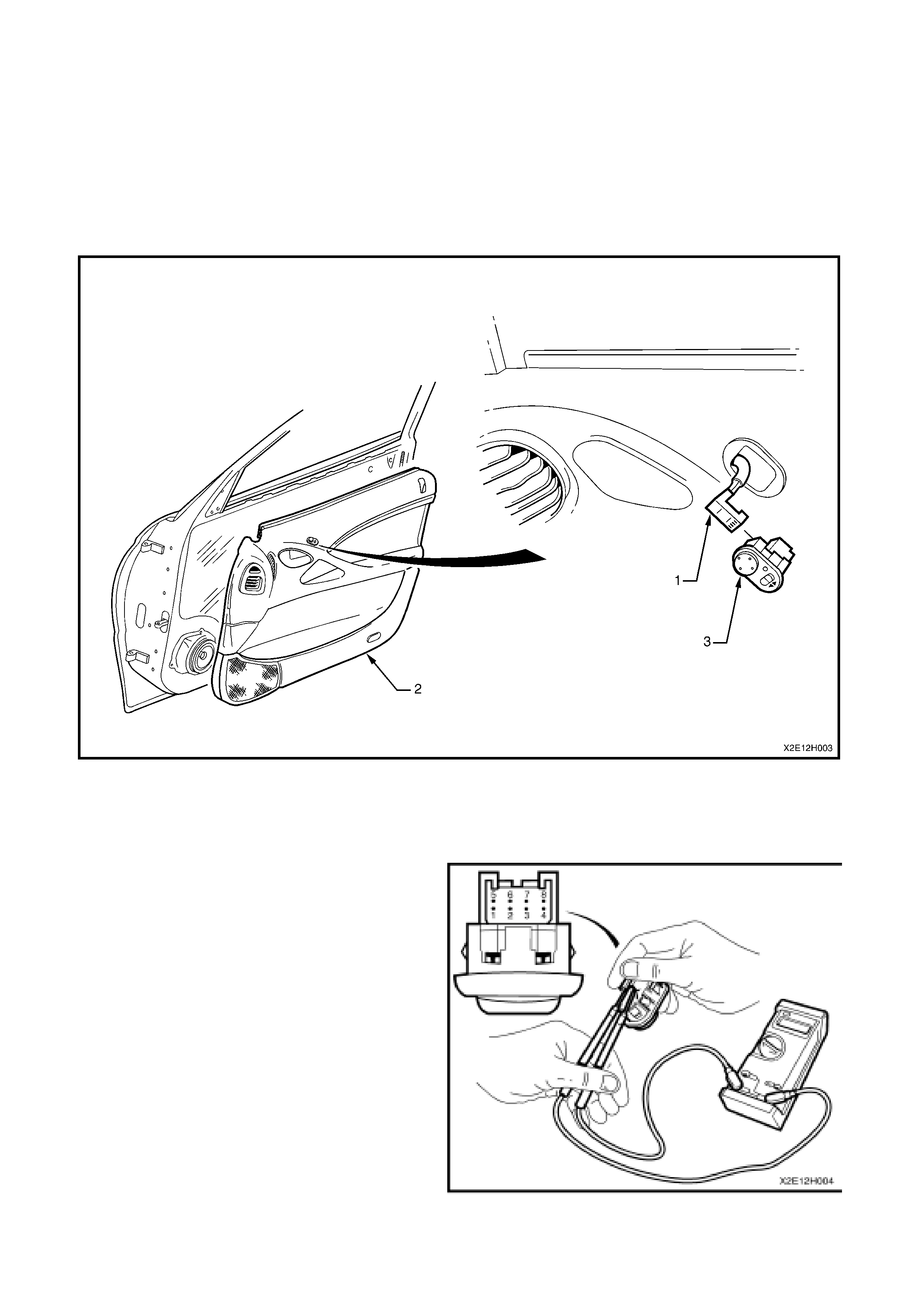
Figure 12H-1
Legend
1. Mirror switch harness connector 2. Front door inner trim panel 3. Mirror control switch assembly
TESTING SWITCH CONTACTS
With reference to the Figs. 12H-2 and 12H-3 and
the following three charts, the mirror control switch
contacts can be c heck ed for continuity between the
various terminals with the aid of an ohmmeter.
1. Attach an ohmmeter to the appropriate
terminals nominated in the following two charts.
2. Select the appropriate mirror on the select
switch, i.e. LH or RH and depres s the directional
toggle switch in the direction indicated in the
chart. The ohmmeter should indicate continuity
if the switch is OK.
Figure 12H-2
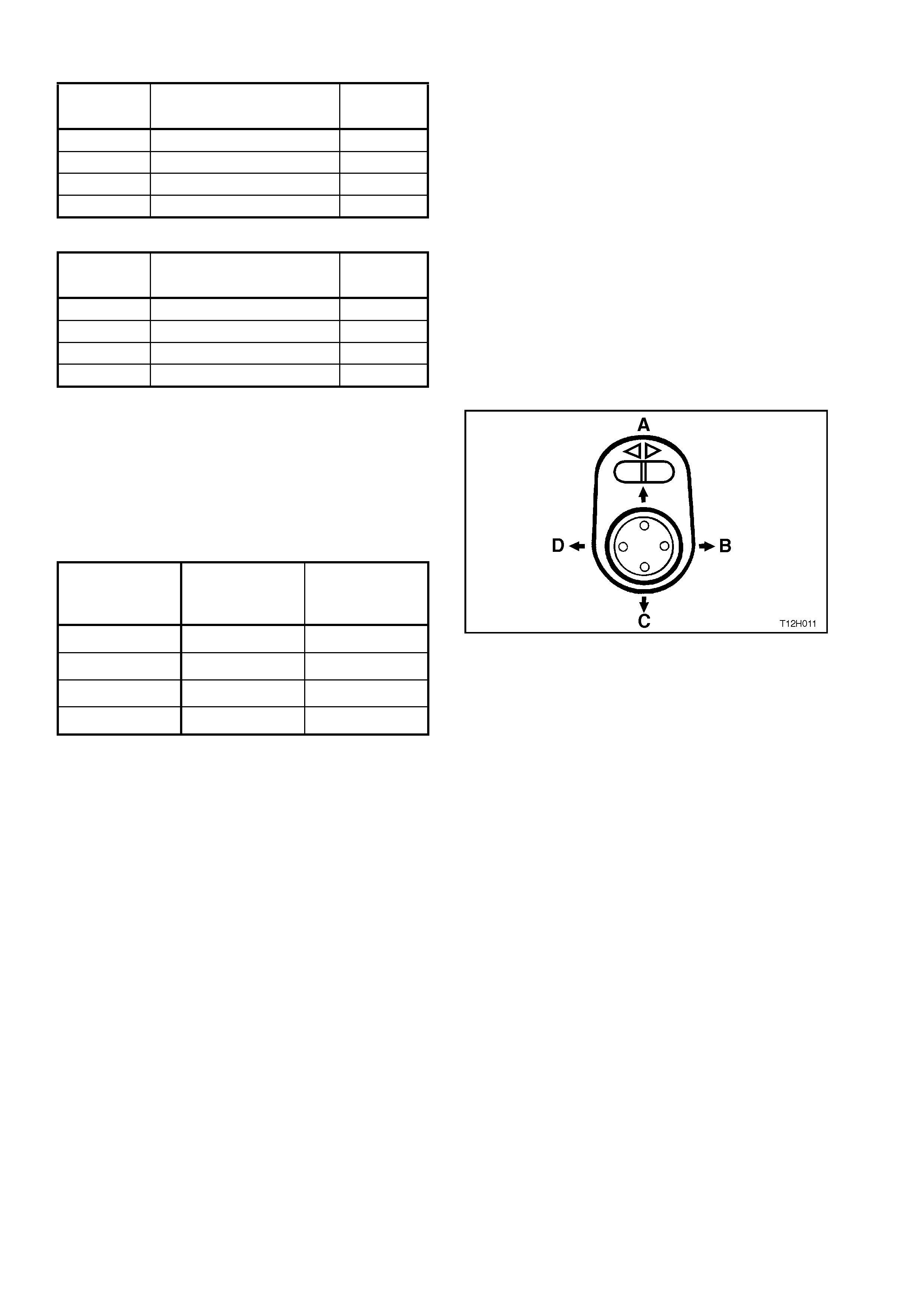
LEFT HAND MIRROR
FUNCTIONSWITCH TERMINAL
NUMBER VALUE
Out 5 and 7 Continuity
In 5 and 8 Continuity
Up 2 and 7 Continuity
Down 2 and 8 Continuity
RIGHT HAND MIRROR
FUNCTION
SWITCH WIRE
COLOURS VALUE
Out 1 and 7 Continuity
In 1 and 8 Continuity
Up 6 and 7 Continuity
Down 6 and 8 Continuity
3. For the following test of switch contacts, attach
an ohmmeter to the appropriate terminals
nominated in the following chart and then
depress and hold the direc tional toggle switch in
the direction indicated in the c hart and Fig. 12H-
3. The ohmmeter should indicate continuity if
the switch is OK.
TOGGLE
DIRECTION SWITCH
TERMINAL
NUMBERS
VALUE
A 4 and 8 Continuity
B 4 and 7 Continuity
C 4 and 7 Continuity
D 4 and 8 Continuity
Figure 12H-3
REINSTALL
The installation procedure for the exterior rear vision mirror control switch is the reverse of the removal procedure.
3. DIAGNOSIS
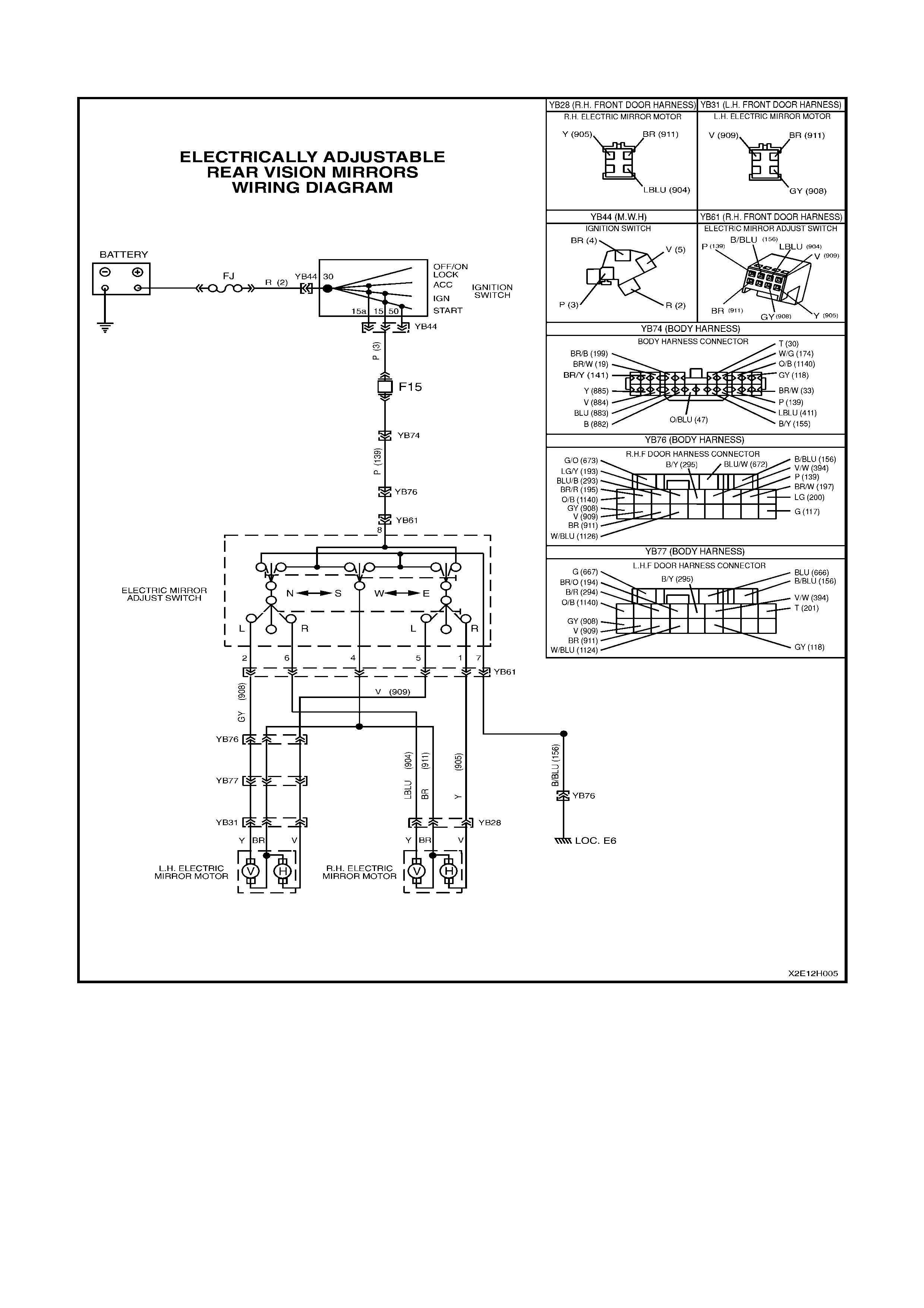
Figure 12H-4
3.1 ELECTRIC MIRROR/S INOPERATIVE
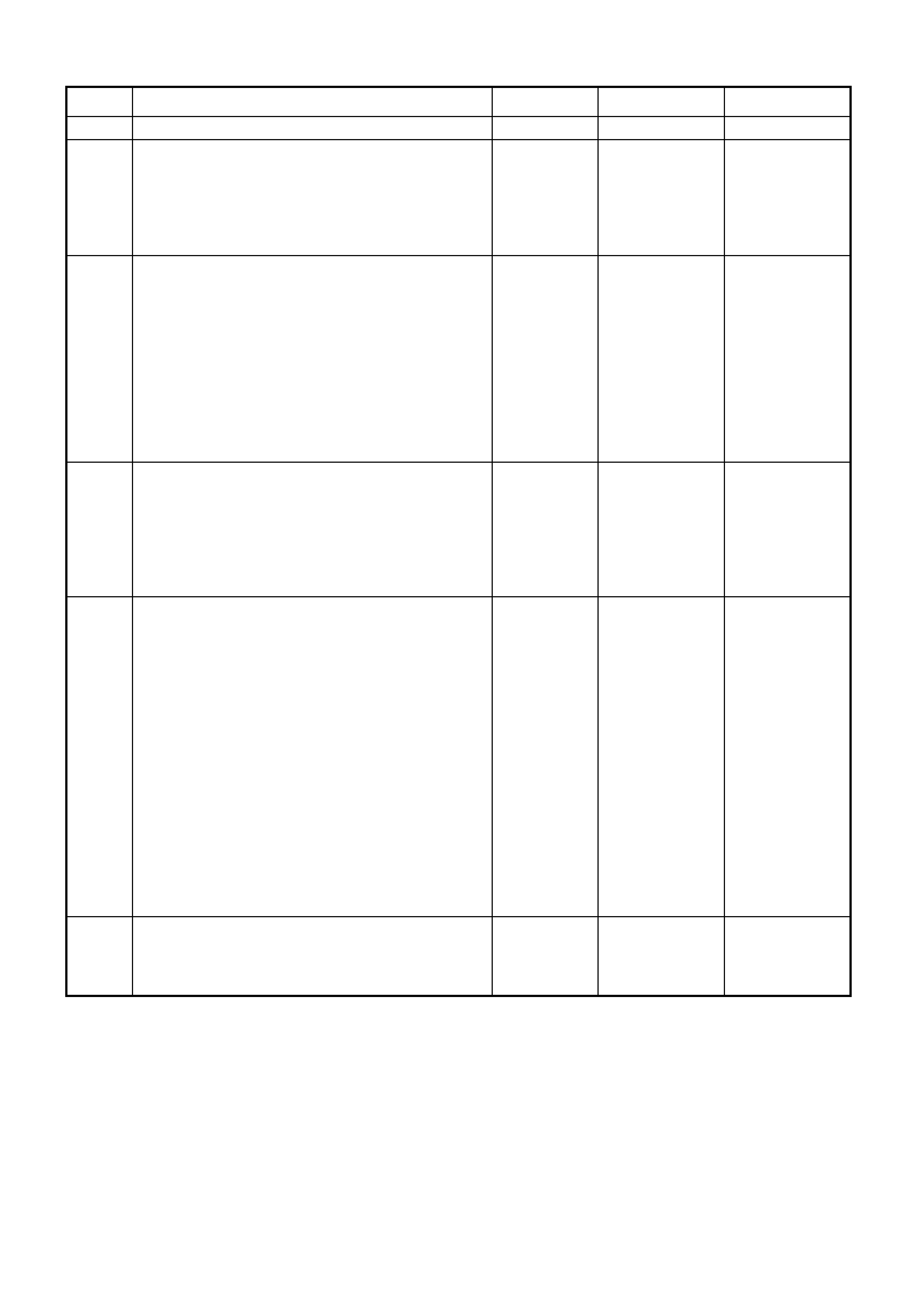
STEP ACTION VALUE YES NO
1. • Are both electric rear view mirrors inoperative? Go to Step 2. Go to Step 3.
2. • Is fuse F15 OK (located in fuse panel)? Go to step 3. Replace blown
fuse, check
wiring for cause
of fuse blowing.
Re-check
system.
3. • Remove RH front door inner trim panel, refer
to Section 1A5 FRONT AND REAR
DOOR.ASSEMBLIES, in the VT Series I
Service Information.
• Reconnect mirror control switch.
• Turn ignition ON.
• Using a test light at the switch side of
connector YB61, check for power at terminal
8.
• Does test light illuminate ?
Go to Step 4. Check and
repair open
circuit in circuit
139 (Pink wire)
from fuse F15
to control
switch.
Re-check
system.
4. • Using an ohmmeter, check circuit 156 for
continuity between connector YB61 (Black
wire) and earth connection (location E6).
• Is wiring OK ?
Go to Step 5. Check and
repair open
circuit in earth
circuit 156
(Black wire).
Re-check
system
5. • At connector YB61, check for continuity in the
following circuits:
Circuit 911 (Brown wire) to circuit 909 (Violet
wire)
(LH mirror horizontal motor).
Circuit 911 (Brown wire) to circuit 908 (Grey
wire).
(LH mirror vertical motor).
Circuit 911 (Brown wire) to circuit 905
(Yellow wire)
(RH mirror horizontal motor).
Circuit 911 (Brown wire) to circuit 904
(L/Blu e wire)
(RH mirror vertical motor).
• Is wiring OK ?
Go to Step 6. Check and
repair open
circuit.
Re-check
system.
6. • Check mirror control switch, refer to 2.1
MIRROR CONTROL SWITCH, in this Section.
• Is mirror control switch OK ?
System OK. Replace mirror
control switch.
Re-check
system.
3.2 EITHER MIRROR NOT WORKING IN ONE OR MORE DIRECTIONS
STEP ACTION VALUE YES NO
1. • Remove mirror control switch and test switch
contacts, refer to 2.1 MIRROR CONTROL
SWITCH in this Section.
• Are mirror switch contacts OK ?
Go to Step 2. Replace mirror
control switch.
Re-check
system.
2. • With connector YB61, check for continuity in
the following the particular circuit that the
mirror is operating:
LH mirror horizontal: circuit 911 (Brown wire)
to circuit 909 (Violet wire).
LH mirror vertical: circuit 911 (Brown wire) to
circuit 908 (Grey wire).
RH mirror horizontal: circuit 911 (Brown wire)
to circuit 905 (Yellow wire).
RH mirror vertical: circuit 911 (Brown wire) to
circuit 904 (L/Blue wire).
• Is wiring OK ?
Go to Step 3. Check and
repair open
circuit.
Re-check
system.
3. • Check faulty mirror assembly, refer to 2.1
MIRROR ASSEMBLY in this Section
• Is mirror OK ?
System OK. Replace mirror
assembly.
Re-check
system.