
SECTION 12J-1 - LOW SERIES BODY
CONTROL MODULE
IMPORTANT
Before performing any Service Operation or other procedure described in this Section, refer to Section
00 CAUTIONS AND NOTES for correct workshop practices with regard to safety and/or property damage.
1. GENERAL I NFORMATI O N
All inf ormation relating to the Low Series Body Control Module (BCM) for VX Ser ies Models is as detailed in Sec tion
12J-1 LOW SERIES BODY CONTROL MODULE of the VT Series I Service Information and of the
VT Series II Service Information, noting the following:
A minor change was made to the wiring harness connectors for the cooling fans, however, this change does not
effect the operation of the cooling fans.
Additionally, with the introduction of a new Powertrain Control Module (PCM) for VX Series Models with a V6
engine, the terminal assignment of the PCM is different to the terminal assignment of the VT Series Model PCM.
Therefore, to avoid any confusion, all BCM diagnostic procedures that are effected by this PCM change (including
the engine cooling fan diagnostics) have been updated and republished in full in this Section.
NOTE: Refer to Section 12J-1 Low Series Body Control Module, of the VT Series I Service Information and
VT Series II Service Information, which should be read in conjunction with each other.
Techline
Techline
Techline
Techline
Techline

2. DIAGNOSIS
2.1 PREREQUISITES TO DIAGNOSIS AND TROUBLESHOOTING
PRELIMINARY SYSTEM REQUIREMENTS
The prerequisites before proceeding with system checks are:
• Ensure no moisture is present in the wiring harness connections in either A-pillar.
• Ensure that sound ear th connections are available for all f unctioning com ponents, par ticularly at the body earth
connection (fender panel inner stud, adjacent to the battery).
• Ensure the battery is in good condition and adequately charged (above 11.5 volts) before carrying out any
electrical checks.
SAFETY REQUIREMENTS
Disconnect the battery when carrying out work which involves the risk of an electrical short circuit.
Do not touch mechanical components during function checks, to avoid the risk of a hand being caught in the
mechanism.
CHECKING EQUIPMENT
TECH 2 scan tool.
A digital multimeter, with a minimum 10 Megohm impedance MUST be used when undertaking any electrical
checks on these systems.
Exercise care when taking readings from wiring harness connectors. It is preferred that the back probing method
with individual connectors is employed wherever possible, to avoid terminal damage and subsequent connection
failure.
When carrying out wiring chec k s as direc ted to by the diagnostic charts, rather than probe terminals and connectors
with incorrect sized multimeter connections, use the adaptors contained in suitable connector test adaptor kit such
as KM-609. This will prevent any possibility of spreading or damaging wiring harness terminals.
IMPORTANT:
• ENSURE THAT THE IGNITION IS TURNED OFF AND THE BATTERY EARTH LEAD IS DISCONNECTED
BEFORE ANY TEST THAT REQUIRES DISCONNECTION OR RECONNECTION OF ANY OF THE BCM
CONNECTORS.
• When checking the complete system, the exact order of the test steps should be observed.
• If the requir ed nominal value is not ac hieved in any stage, then the problem must be rec tif ied before proc eeding
further.
• Unless the multimeter being used has an auto ranging function, check that the correct range, as specified, is
selected before the test is carried out.
• It will be necessary to lower the BCM down to gain access to BCM wiring harness connectors, refer to
2.2 LOW SERIES BCM in Section 12J-1 LOW SERIES BCM in of the VT Series II Service Information.
• Testing of the various systems will involve gaining access to specific wiring harness connectors. For the
location of these connectors, refer to Section 12N FUSES AND WIRING HARNESSES of the
VT Series I Service Information and of the VT Series I Service Information.
Techline
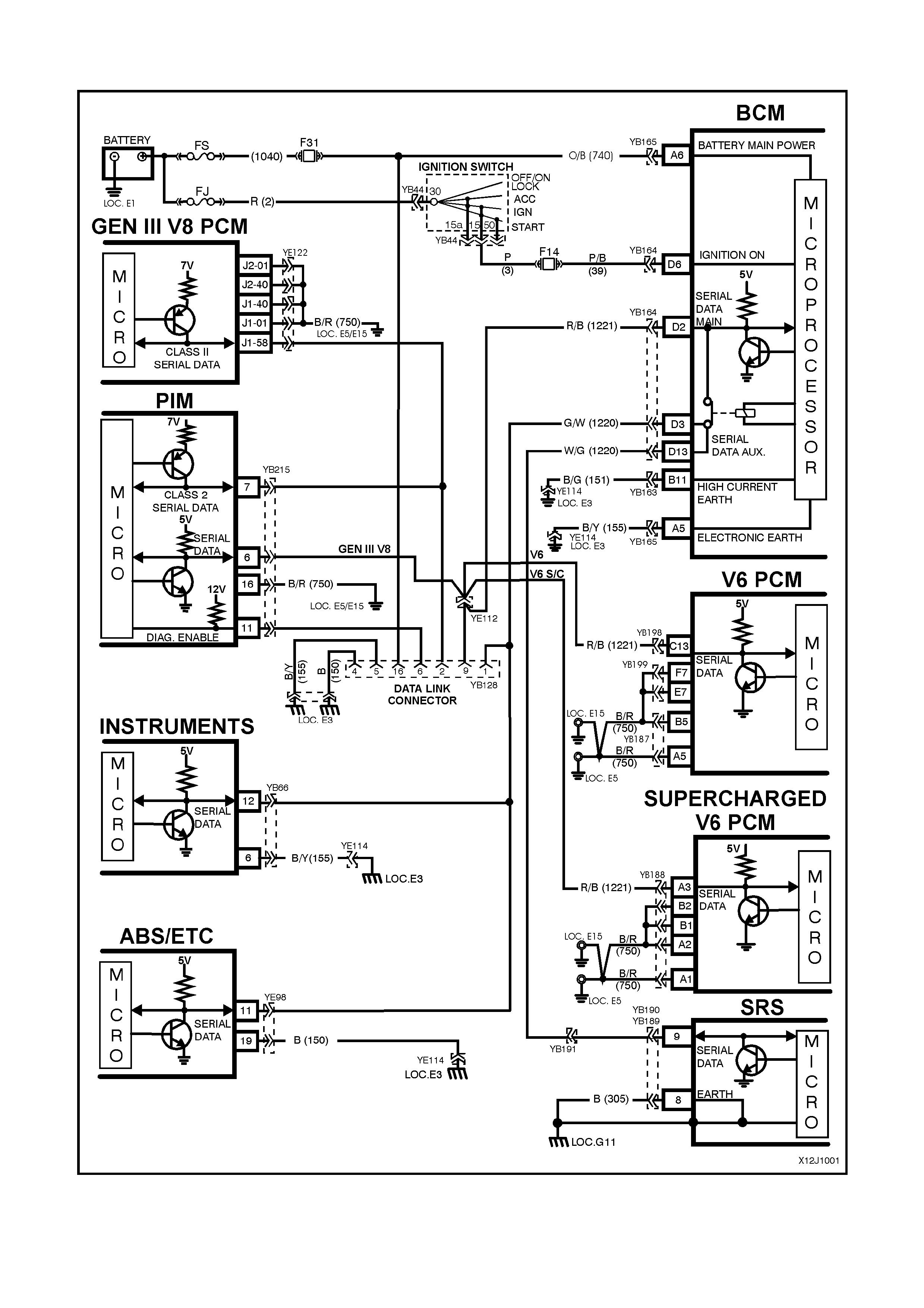
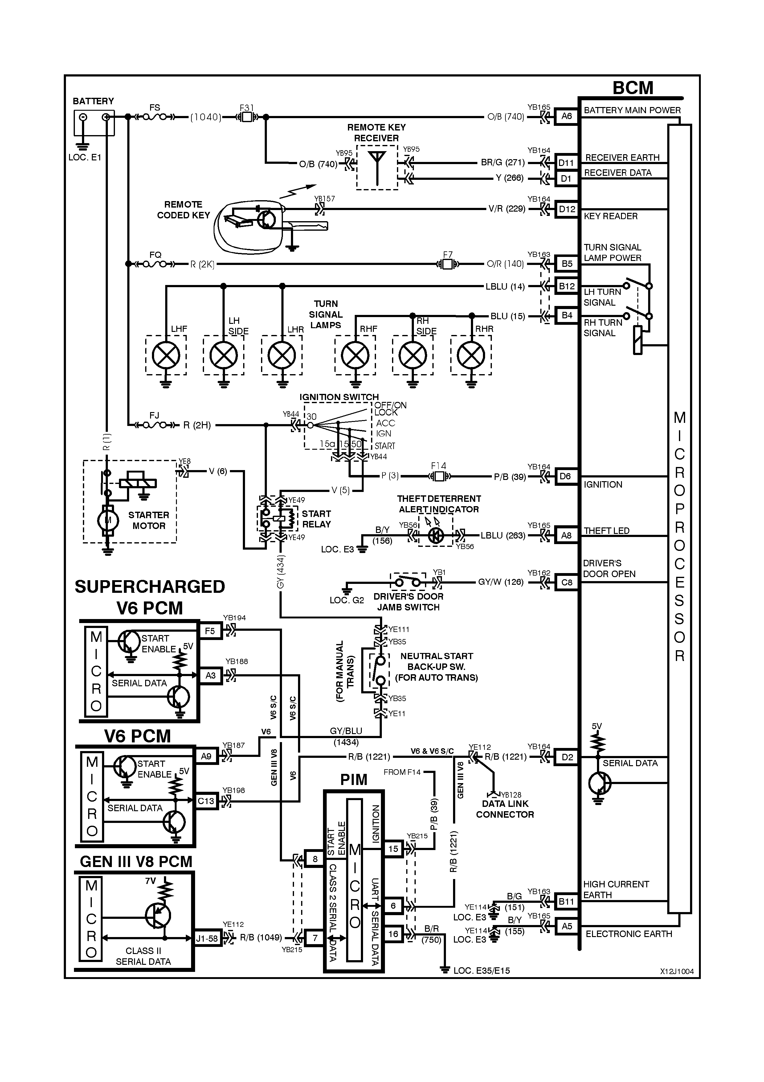
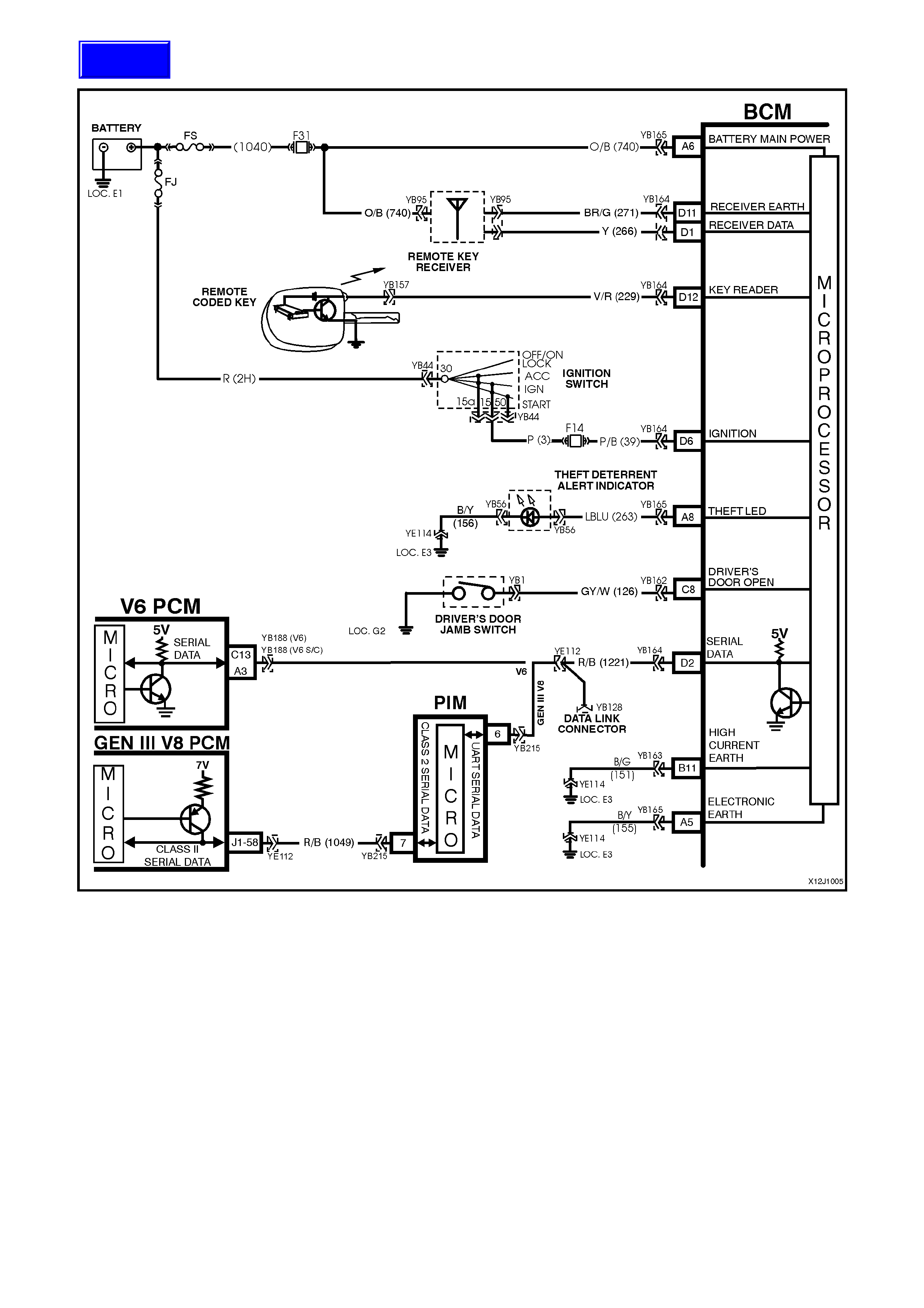
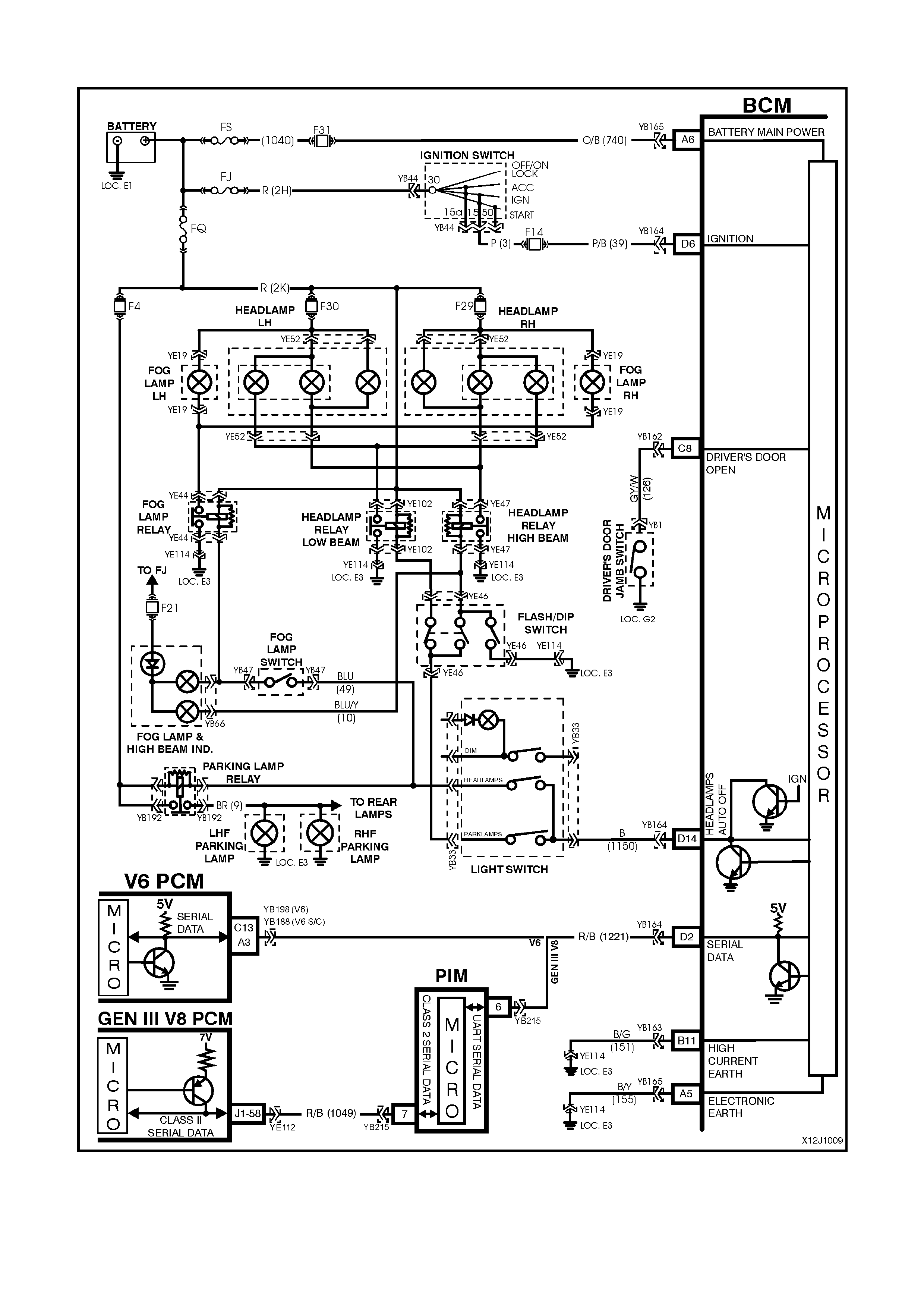
2.2 SERIAL DATA COMMUNICATION
Figure 12J-2-1

GENERAL INFORMATION
VT and VX Series Model use a bus master communication system where the BCM is the bus master.
The BCM periodically polls (surveys) each device on the bus and requests status data.
NOTE: The GEN III PCM communicates using a Class 2 communication protocol, all other control modules,
including the new V6 PCM, communicate using UART. Due to these two different communication protocols, a
Powertrain Interf ace Module (PIM) is requir ed to convert the Class 2 data into UART . For additional inform ation on
Class 2 and UART communication protocols and the PIM, refer to 1.2 SERIAL DATA COMMUNICATION (BUS
MASTER) in Section 12J-1 LOW SERIES BCM of the VT Series II Service Information.
The devices connected to the bus are:
• Body Control Module (BCM).
• V6 and V6 supercharged engine Powertrain Control Module (PCM).
• GEN III V8 engine Powertrain Control Module (PCM) via the Powertrain Interface Module (PIM).
• Instrument cluster (INS).
• Antilock Brake System / Electronic Traction Control (ABS/ETC) module.
• Supplemental Restraint System (SRS) Sensing and Diagnostic Module (SDM).
• External diagnostic scan tool (TECH 2).
The data provided by each device may be utilised by any device connected to the bus.
Each device has a unique response “Message Identifier Word” (MIW) for ease of identification.
The bus mas ter (BCM) polls eac h device with a serial data m essage which includes that device’s MIW. The device
responds by putting a serial data m essage back onto the bus. T he device’s m essage includes its MIW and data, of
which is retrieved and utilised by any device on the bus requiring it.
The BCM polls each device for a status update, once every 300 millisec onds. The ex ception to this being the PCM
(V6) and PIM (GEN III V8) which are polled twice every 300 milliseconds.
When the ignition switch is turned from the OFF position to the ON position, the BCM will communicate with the
PCM (via the PIM on vehic les with G EN III V8 engines ) f or theft deterrent pur poses . If the BCM does not rec eive an
OK TO START message from the PCM within 0.5 seconds of ignition on, the auxiliary data bus is isolated via
switching from the BCM.
The isolation of the auxiliary data bus during this period eliminates the possibility of a device failure other than the
BCM, PCM or PIM (GEN III V8 only), causing a problem on the bus and inhibiting antitheft communications.
This period (short loop time) continues until the PCM responds with an acknowledgment or a maximum of five
seconds after which the BCM will switch to the standard polling sequence.
Following succ essful theft deterrent com munica tions, the BCM begins sequential polling of devices on the bus and
normal system operation is established.
When the ignition switch is in the OFF position, the BCM continues to poll, allowing for TECH 2 communications
and external control of the bus prior to the ignition being switched on.
TEST DESCRIPTION
The numbers below refer to step numbers on the facing pages diagnostic chart.
1. Ensures TECH 2 is functioning correctly.
2. Checks if TECH 2 can communicate with the BCM.
3. Checks if TECH 2 can communicate with the V6 or V6 supercharged PCM (vehicles with V6 or V6
supercharged engines).
4. Checks if TECH 2 can communicate with the PIM (vehicles with GEN III V8 engines).
5. Checks if TECH 2 can communicate with the GEN III V8 PCM (vehicles with GEN III V8 engines).
6. Checks if TECH 2 can communicate with all the devices (SRS, ABS/ETC, INS) on the auxiliary serial data line.
7. Checks continuity of circuit 1221 between the BCM and the DLC.
8. Check s if no BCM com munication is caused by c ontrol module interf erence connected to the m ain or auxiliary
serial data line.
9. Checks if no BCM communication is caused by a short to battery + or earth on the main and auxiliary serial
data lines.
10. Check s continuity of circuit 1221 between the BCM and PCM, and if there is a pr oblem with the PCM (vehicles
with V6 and V6 supercharged engines).
11. Checks continuity of circuit 1221 between the BCM and PIM (vehicles with GEN III V8 engines).
12. Continuation of Step 6; determines if TECH 2 can communicate with at least one of the devices (SRS,
ABS/ETC, INS) on the auxiliary serial data line.
13. Check s to establis h whether lost comm unic ation between modules on the auxiliary serial data line and TECH 2
is due to an open in circuit 1220 or the module itself.
14. Check s to establis h whether loss of com munic ation on the auxiliary s erial data line is due to an open in circuit
1220 or the BCM.
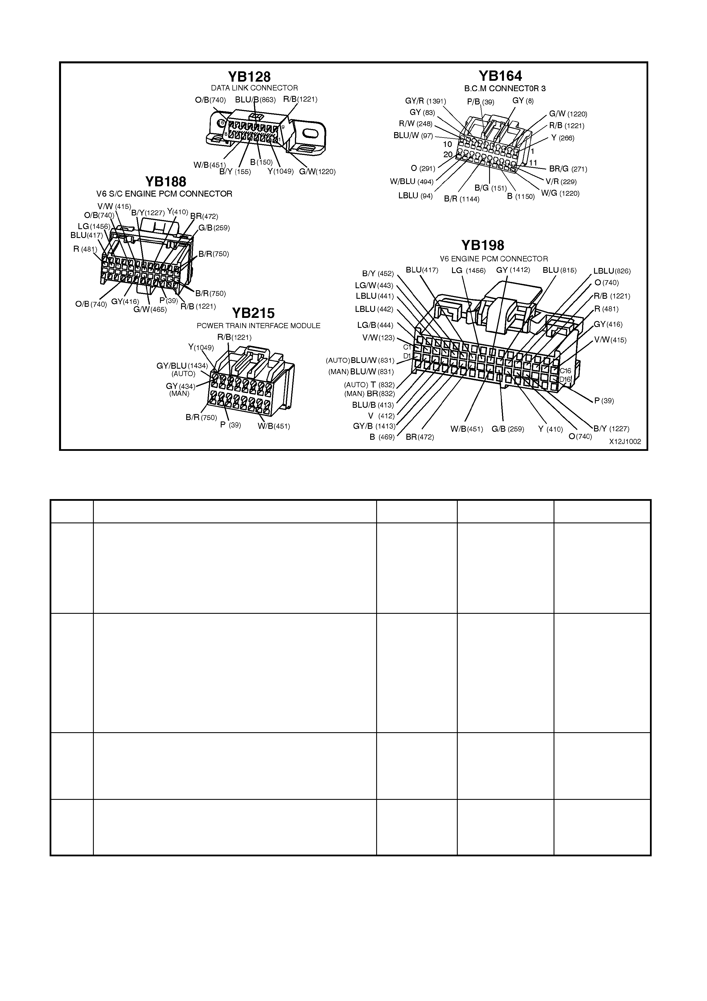
Figure 12J-2-2
SERIAL DA TA COMMUNICATION
STEP ACTION VALUE YES NO
1. • Connect TECH 2 to DLC.
• Turn ignition ON.
• Push power button on TECH 2.
• Does TECH 2 power up (screen will illuminate
display TECH 2)?
Go to Step 2. Go to TECH 2
diagnosis, refer
to Section 0C
TECH 2 of the
VT Series I
Service
Information.
2. • With TECH 2 still connected and ignition ON, select
Diagnostics / Body / Body Control Module.
• Does TECH 2 display BCM system identification
information (BCM level and type)?
Go to Step 3 -
vehicles with V6
or V6
supercharged
engines.
Go to Step 4 -
vehicles with
GEN III V8
engine
Go to Step 7.
3. • W ith TECH 2 still connected, ignition ON, exit BODY
and select Diagnostics / Engine / Engine Type (ie
V6, V6 Supercharged).
• Does TECH 2 display PCM system identification
information?
Go to Step 6. Go to Step 10.
4. • W ith TECH 2 still connected, ignition ON, exit BODY
Control Module and select Powertrain Interface
Module (PIM).
• Can TECH 2 communicate with the PIM?
Go to Step 5. Go to Step 11.

STEP ACTION VALUE YES NO
5. • W ith TECH 2 still connected, ignition ON, exit BODY
and select Diagnostics / Engine / Engine Type (ie V8
GEN III).
• Does TECH 2 display GEN III V8 PCM system
identification information?
Go to Step 6 Go to PCM
diagnostics in
Section 6C3
POWERTRAIN
MANAGEMEN T -
GEN III V8
ENGINE in the
VX Series
Service
Information.
6. • With TECH 2 still connected, ignition ON, exit Engine
Diagnostics and select Body / DTC Check / DTC
Check.
• Can TECH 2 communicate with all control modules
fitted to the vehicle (if NO DATA is displayed next to
a control module, then there is no communication
between TECH 2 and that control module)?
NOTE: If vehicle is not equipped with a particular
feature, ie. ABS/ETC, No Data will be displayed next to
this module in the TECH 2 display.
System OK. Go to Step 12.
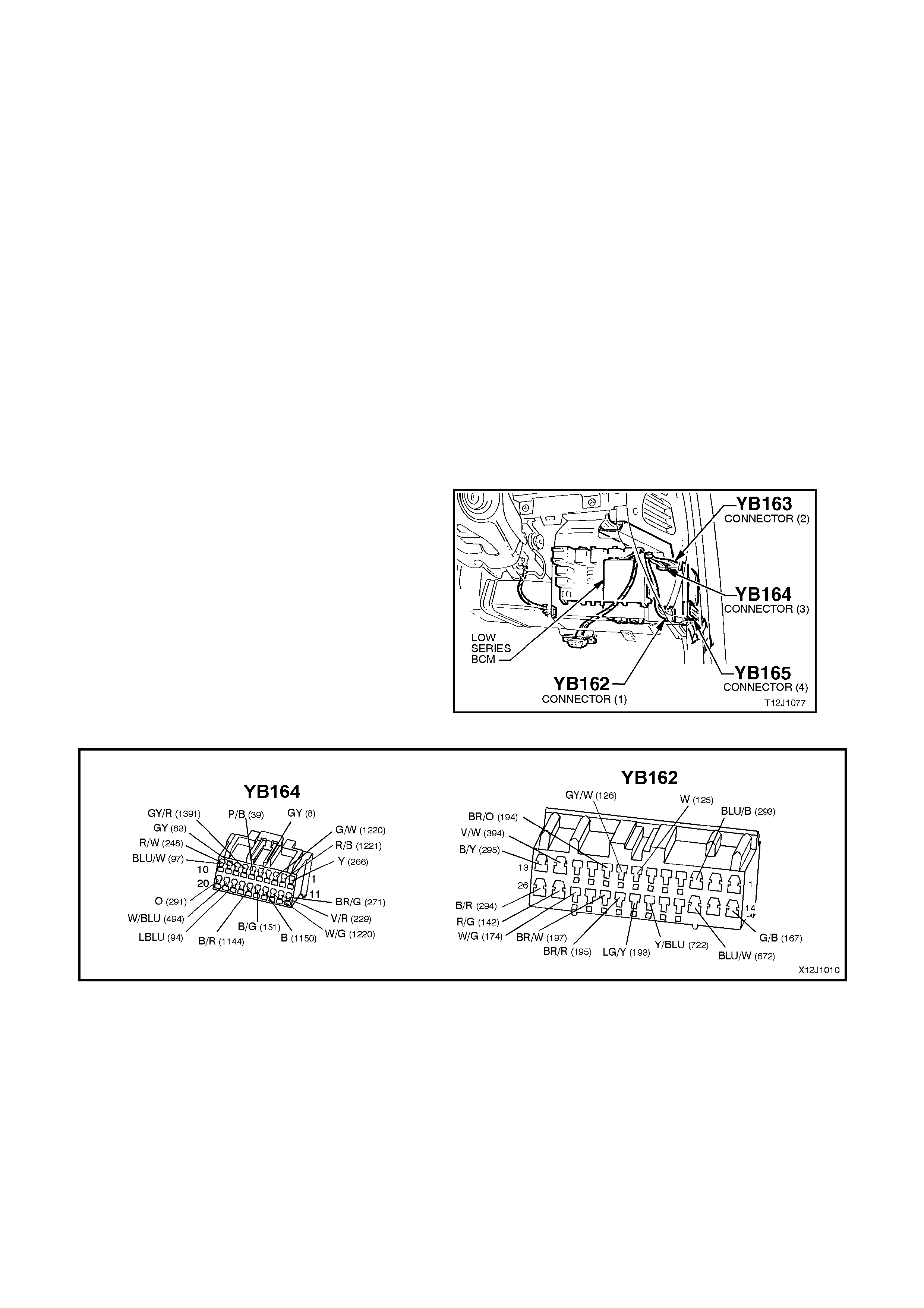
7. • Turn ignition OFF.
• Back probe DLC connector YB128, terminal 9, circuit
1221 (Red/Black wire) and BCM connector YB164,
terminal D2, circuit 1221 (Red/Black wire) with an
Ohmmeter.
• Is value as specified?
Below 1 ohm Go to Step 8. Check and repair
open in circuit
1221 between
DLC and BCM.
Recheck and
verify repair.
8. • Disconnect control modules on auxiliary serial data
line (ABS, ABS/ETC, SRS, INS) and the PCM (V6 &
V6 Supercharged engine) or PIM (GEN III V8
engine) on the main serial data line one at a time,
checking each time if TECH 2 can communicate with
the BCM (refer to Step 2).
• Does communication between the BCM and TECH 2
resume after disconnecting any of the control
modules?
Go to suspect
control module
diagnosis refer to
the relevant
Section in the VX
Series Service
Information.
Go to Step 9.
9. • Disconnect all control modules; ABS, ABS/ETC,
SRS, INS, PCM, PIM (GEN III only) and BCM.
• Check integrity (i.e. short to battery +, short to earth)
of circuits 1221 (Red/Black wire) and circuit 1220
(Green/White – White/Green wire).
• Are circuits 1221 and 1220 OK?
Replace BCM,
refer to 12J-1
LOW SERIES
BCM of the VT
Series II Service
Information.
Recheck and
verify repair.
Repair circuits
1221 or 1220 as
necessary.
Recheck and
verify repair.
10. • Turn ignition OFF.
• Back probe BCM connector YB164, terminal D2,
circuit 1221 (Red/Black wire) and PCM connector
YB198, terminal C13 (V6) or YB188, terminal A3 (V6
supercharged), circuit 1221 (Red/Black wire) with an
Ohmmeter.
• Is value as specified?
Below 1 ohm Go to PCM
diagnostics in
Section 6C1
POWERTRAIN
MANAGEMEN T -
V6 ENGINE in
the VX Series
Service
Information.
Check and repair
open in circuit
1221 between
PCM and BCM.
11. • Turn ignition OFF.
• Back probe BCM connector YB164, terminal D2,
circuit 1221 (Red/Black wire) and PIM connector
YB215, terminal 6, circuit 1221 (Red/Black wire) with
an Ohmmeter.
• Is value as specified?
Below 1 ohm Go to 2.4 THEFT
DETERRENT
diagnostics in
this Section.
Check and repair
open in circuit
1221 between
PIM and BCM.
12. • In Step 6, was TECH 2 able to communicate with at
least one of the control modules on the auxiliary
serial data line (ABS, ABS/ETC, INS, SRS)?
NOTE: TECH 2 will display No Data next to a control
module that it can not communicate with in the DTC
Check mode.
Go to Step 13. Go to Step 14.

STEP ACTION VALUE YES NO
13. • Check continuity between BCM and suspect control
module in circuit 1220 (Green/White – White/Green
wire).
• Does continuity exist?
Go to suspect
control module
diagnosis in the
relevant Section
in the VX Series
Service
Information.
Repair open in
circuit 1220
between suspect
control module
and the BCM.
Recheck and
verify repair.
14. • Check continuity between BCM and all control
modules on the auxiliary serial data line.
• Does continuity exist?
Replace BCM,
refer to 12J-1
LOW SERIES
BCM of the VT
Series II Service
Information.
Recheck and
verify repair.
Repair open in
circuit 1220.
Recheck and
verify repair.
CIRCUIT DESCRIPTION
The rear compartment lock actuator is controlled by
pressing the rear compartment lock switch located
in the glove compartment. The BCM disables the
lock switch when the vehicle speed is greater than
15 km/h or the theft deterrent system is armed via
the remote coded key, drivers door microswitch or
deadlocked.
The lock switch is only enabled when the theft
deterrent system is disarm ed via the rem ote coded
key or key reader (valid security code).
Figure 12J-1-4
TEST DESCRIPTION
The num ber s below refer to step num bers in the following
diagnostic chart.
1 & 2. Functional check to determine if system is
functioning correctly or if faulty, determines if fault is
with remote receiver/key or with boot release system.
3. Uses TECH 2 to operate the rear compartment lock
actuator to establis h whether problem is with the input
or output of BCM.
4. Uses TECH 2 to check BOOT RELEASE SWITCH
ON signal at microprocessor of BCM.
5. Checks for rear compartment lock actuator drive
signal at the output of the BCM when com manded by
TECH 2.
6. Checks circuit 142.
7. Checks circuit 156 and rear compartment lock
actuator.
8. Check s f or battery voltage supply at BCM (turn signal
/ boot solenoid supply).
9. Checks for BOOT SWITCH signal at input of BCM.
10. Checks circuit 1144.
11. Checks circuit 155 and rear compartment lock switch.
Figure 12J-1-5
BOOT RELEASE
STEP ACTION VALUE YES NO
1. • Activate boot release lock switch in glove
compartment with vehicle speed below 15 km/h.
• Does the rear compartment lid open?
Go to Step 2. Go to Step 3.
2. • Close rear compartment lid.
• Press the boot release button on the remote coded
key (within two metres of the rear of the vehicle).
• Does rear compartment lid open?
System OK. Go to remote
receiver
diagnosis, refer
to 2.5 REMOTE
RECEIVER /
KEY in this
Section.
3. • Connect TECH 2, ignition ON.
• Select Body / Body Control Module / Miscellaneous
Tests / Security System / Boot Release.
• Conduct test as instructed by TECH 2.
• Does boot lid open?
Go to Step 4. Go to Step 5.

STEP ACTION VALUE YES NO
4. • With TECH 2 still connected, exit Miscellaneous
Tests, select Data Display and scroll to Boot Release
Switch.
• Press boot release button in glove compartment.
• Does the screen display change to Boot Release
Switch On?
Replace BCM,
refer to 12J-1
LOW SERIES
BCM of the VT
Series II Service
Information.
Recheck and
verify repair.
Go to Step 9.
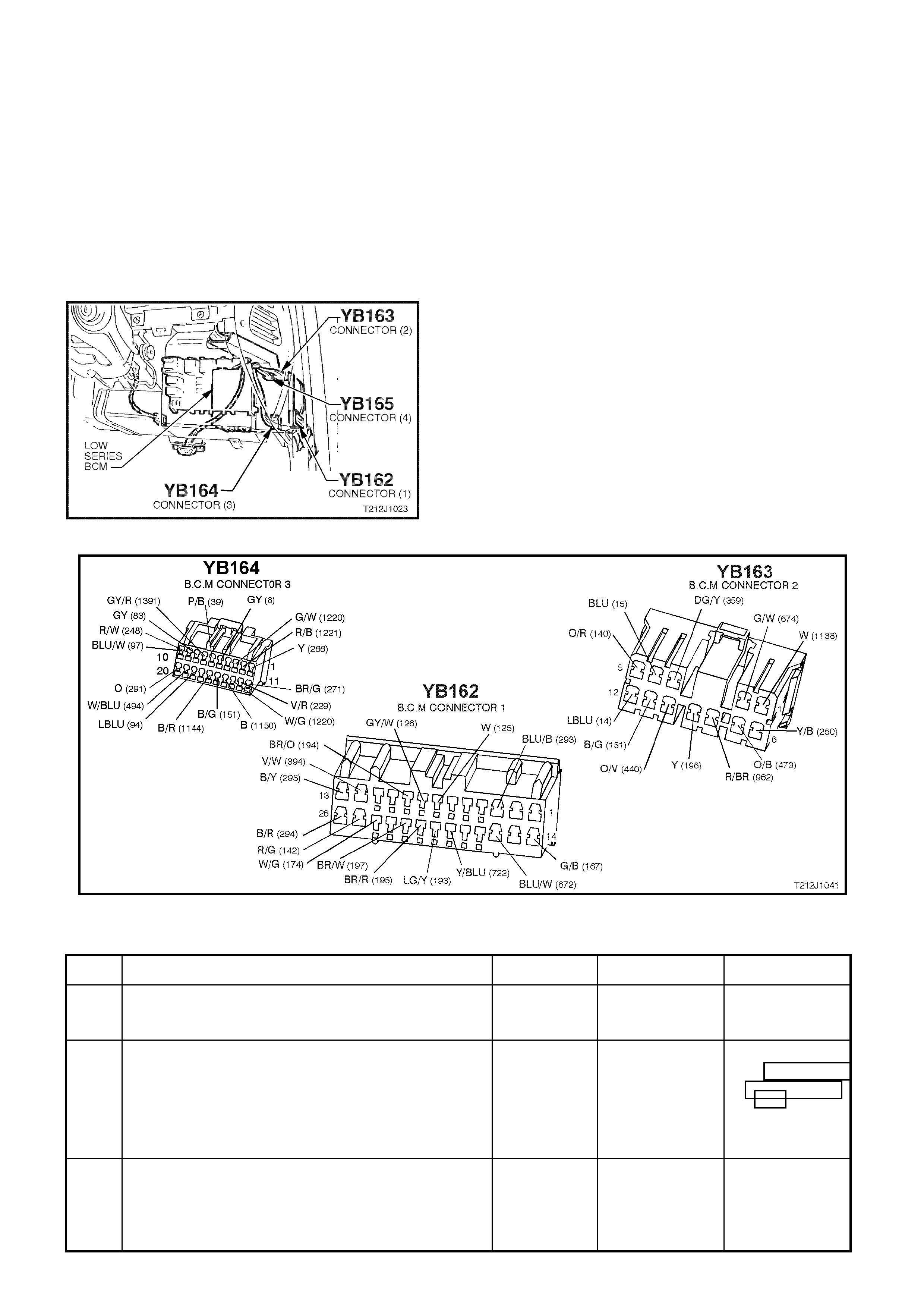
5. • Back probe BCM connector YB162, terminal C25,
circuit 142 (Red/Green wire) with a Voltmeter to
earth.
• Repeat TECH 2 Boot Release test and press release
button in glove compartment.
• Are voltages as specified?
Test not
conducted:
0 volts
Test
conducted:
12 volts
Go to Step 6. Go to Step 8.
6. • Back probe actuator connector YR6, circuit 142
(Red/Green wire) with Voltmeter to earth.
• Repeat TECH 2 Boot Release test and press release
button in glove compartment.
• Are voltages as specified?
Test not
conducted:
0 volts
Test
conducted:
12 volts
Go to Step 7. Repair open or
short in circuit
142. Recheck
and verify repair.
7. • Back probe actuator connector YR6 circuit 156
(Black/Blue wire) with an Ohmmeter to earth.
• Is reading as specified?
Below 1 ohm Replace rear
compartment
lock actuator,
refer to Section
1A4 REAR
COMPARTMENT
LID AND
TAILGATE of the
VT Series I
Service
Information.
Repair open in
circuit 156.
Recheck and
verify repair.
8. • Back probe BCM connector YB163, terminal B5,
circuit 140 (Orange/Red wire) with a Voltmeter to
earth.
• Is voltage as specified?
Battery + Replace BCM,
refer to 12J-1
LOW SERIES
BCM of the VT
Series II Service
Information.
Recheck and
verify repair.
Check and repair
open or short in
circuit 140
(including fuse
F7). Recheck
and verify repair.
9. • Back probe BCM connector YB164, terminal D16,
circuit 1144 (Black/Red wire) with an Ohmmeter to
earth.
• Activate the rear compartment lock switch.
• Is value as specified?
Below 1 ohm Replace BCM,
refer to 12J-1
LOW SERIES
BCM of the VT
Series II Service
Information.
Recheck and
verify repair.
Go to Step 10.
10. • Back probe rear compartment lock switch connector
YB13, circuit 1144 (Black/Red wire) with a
Ohmmeter to earth.
• Activate the rear compartment lock switch.
• Is value as specified?
Below 1 ohm Repair open or
short in circuit
1144. Recheck
circuit to verify
repair.
Go to Step 11.
11. • Back probe rear compartment lock switch connector,
YB13, circuit 155 (black/Yellow wire) with an
Ohmmeter to earth.
• Is reading as specified?
Below 1 ohms Replace rear
compartment
lock switch, refer
to Section 1A4
REAR
COMPARTMENT
LID AND
TAILGATE of the
VT Series I
Service
Information.
Repair open in
circuit 155.
Recheck and
verify repair.
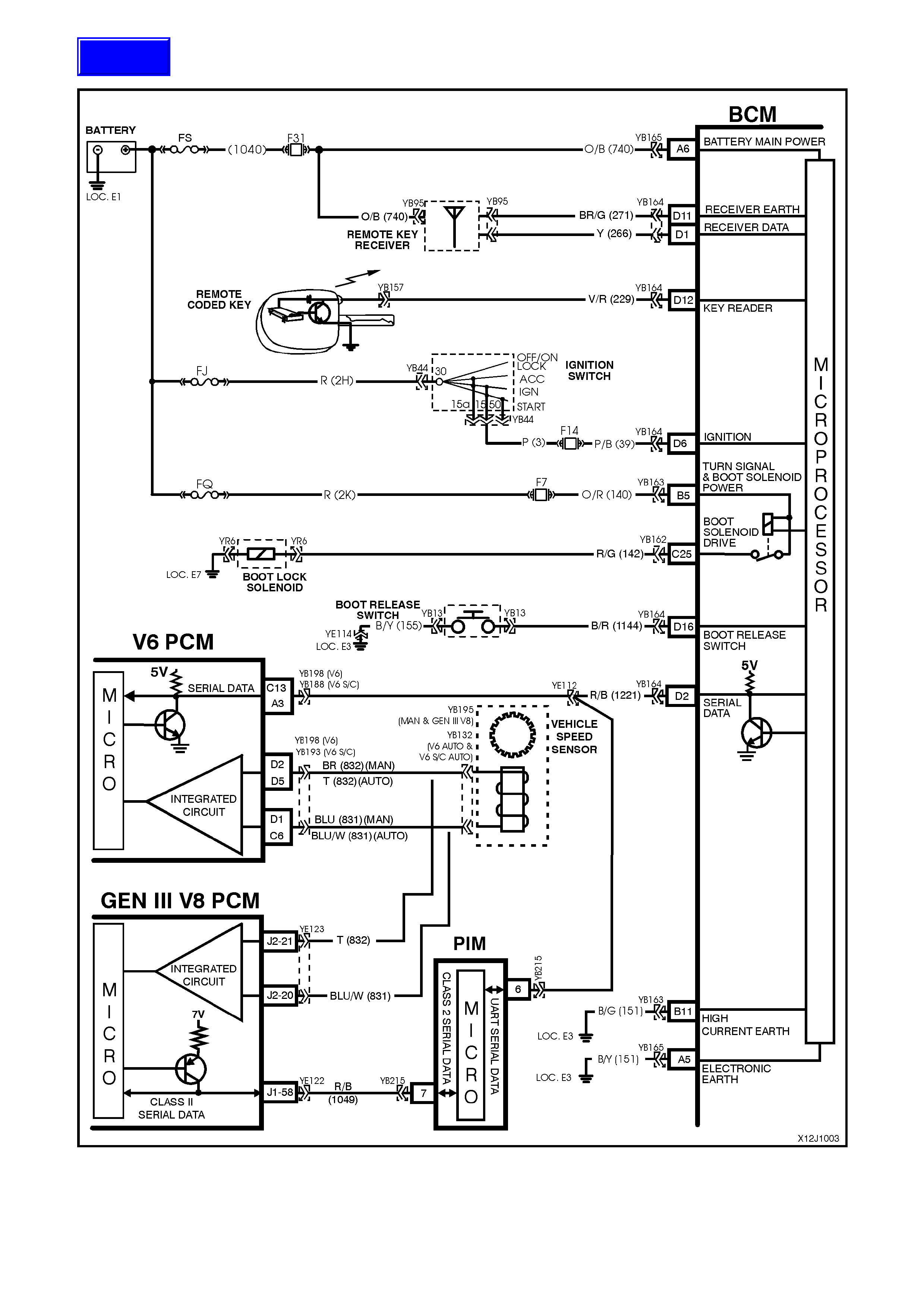
2.4 THEFT DETERRENT
Figure 12J-1-6

CIRCUIT DESCRIPTION
The theft deterrent system can be armed by pressing the lock button on the remote coded key when the driver’s
door is clos ed or passively armed autom atically by the BCM 30 seconds after the ignition is switched off . W hen the
system is armed, the Powertrain Control Module (PCM)(V6 and V6 supercharged engine) or Powertrain Interface
Module (PIM)(GEN III V8 engine) prevents the engine from starting.
The theft deterrent system can be disarmed in two ways:-
1. By pressing the unlock button on the remote coded key. This will unlock doors, turn the interior light on and
disarm the system for 30 seconds.
2. By inserting the remote coded key into the ignition switch cylinder and turning the ignition to the ON position.
This causes the BCM to read a security code serial data output from the remote coded key contact pin, via the
remote coded key reader assembly.
Should the s ystem not disar m (thef t deterrent LED of f) when the ignition switch is turned to the ON position (ie. due
to a m is aligned or f aulty remote coded key reader or faulty remote c oded key), then press the loc k or unlock button
on the remote key to disarm the theft deterrent system.
The remote coded key is powered by it’s own internal battery. If the battery fails, the remote coded key can be
powered by the rem ote coded k ey reader once the k ey is ins erted into the ignition cylinder and turned to either the
ON or START positions.
When pressing the lock button on the remote coded key to arm the system, the indicators will flash once and the
theft deterrent alert indicator (LED) will begin to flash.
W hen pres sing the unlock button on the rem ote coded key to disarm the system, the indicators will flash twice and
the theft deterrent alert indicator (LED) will go out.
On vehic les with V6 and V6 supercharged engines, when the ignition switch is tur ned to the ON position, the BCM
polls the PCM and sends an encrypted BCM/Key sec urity code (The s ecurity code is rec eived via the BCM slip ring
or re mote receiver in the event of no slip ring com m unication). T he PCM com pares the rec eived security code with
it’s stor ed security code and if the codes m atch, the PCM will enable injector fuelling and continue engine crank ing.
The PCM will return an OK TO START message, which tells the BCM to jump from SHORT LOOP mode to the
LONG LOOP mode.
On vehicles with GEN III V8 engines, when the ignition switch is turned to the ON position, the BCM polls the PIM
and sends an encrypted BCM/Key security code (The security code is received via the BCM slip ring or remote
receiver in the event of no slip ring comm unication). The PIM compares the received security code with it’s stored
security code and if the c odes match, the PIM will continue engine cr anking and send a s eparate enc rypted security
code to the PCM. T he PCM com pares this c ode with its stored security code and if the codes m atch, the PCM will
enable injector fuelling to continue. The PIM will return an OK TO START message, which tells the BCM to jump
from SHORT LOOP mode to the LONG LOOP mode.
TEST DESCRIPTION
The numbers below refer to step numbers in the following diagnostic chart.
1-10 . Functional check of system.
11. Checks if doors are not locking due to central door locking system or remote receiver/remote key.
12. Re-synchronisation of remote key rolling code in event of rolling code misalignment.
14. Uses TECH 2 to operate indicators (establish whether problem is with the BCM or other external problem).
15. Checks turn signal input at input to BCM.
16. Checks turn signal output at output of BCM when commanded by TECH 2.
17. Uses TECH 2 to operate the theft deterrent LED (establish whether problem is with the BCM or other
external problem).
18. Checks for theft deterrent LED output drive form the BCM when commanded by TECH 2.
19. Checks for short to earth in circuit 263 causing LED to be faulty.
20. Checks circuit 263.
21. Checks circuit 156 for open to establish if circuit is faulty or theft deterrent LED is faulty.
22. Checks if problem is confined to the key reader or remote serial data transfer.
23. Checks for poor remote coded key shaft earth contact.
24. Checks for poor contact of remote coded key pin with remote coded key reader.
25. Checks if problem is with remote coded key by trying a known good remote coded key.
26. Checks for BCM signal at remote key reader.
27. Checks ignition switch/cylinder earth.
28. Uses TECH 2 to check IGNITION ON signal at microprocessor of BCM.
29. Checks circuit 229 for open to establish if circuit is faulty or BCM is faulty.
30. Checks for short to earth in circuit 229.
31. Checks ignition ON signal at input to BCM.
32. Uses TECH 2 to check for PASSIVE MODE OFF signal at microprocessor of BCM to establish if fault is
with the BCM or PCM.
33. Continuation of functional check for vehicles with GEN III V8 engines.
34. Uses TECH 2 to check for PASSIVE MODE OFF signal at microprocessor of BCM to establish if fault is
with the BCM or PCM.
35. Using TECH 2, checks for communication with the PIM.
36. Uses TECH 2 to check for THEFT STATUS start signal at the microprocessor of the PIM.
37. Uses TECH 2 to drive the starter relay to determine if the fault is with the PIM or starter circuits.
38. Checks for ignition on (power feed) at the input to the PIM.
39. Checks circuit 750.
40. Checks circuit 1221.
41. Uses TECH 2 to check starter relay drive of PIM.
Figure 12J-1-7
Figure 12J-1-8

THEFT DETERRENT
STEP ACTION VALUE YES NO
1. • Close and lock all doors.
• Operate remote key UNLOCK button within four
meters of the driver’s side B pillar.
• Does the driver’s door unlock (two stage unlocking
programmed) or all doors unlock (single stage
unlocking programmed)?
Go to Step 2. Go to Step 11.
2. • In Step 1, did all indicator lights flash twice (both left
and right hand sides)? Go to Step 3. Go to Step 13.
3. • In Step 1, did the dome lamp illuminate? Go to Step 4. Go to dome lamp
delay diagnosis,
refer 12J-1 LOW
SERIES BCM of
the VT Series II
Service
Information.
4. • In Step 1, did the theft deterrent LED go out
immediately and begin flashing 30 seconds latter? Go to Step 5. Go to Step 17.
5. • Close all doors.
• Arm theft deterrent system by operating the LOCK
button on the remote coded key within four metres of
the driver’s side B pillar.
• Did all doors lock?
Go to Step 6. Go to central
door locking
diagnosis, refer
to 12J-1 LOW
SERIES BCM of
the VT Series II
Service
Information.
6. • In Step 5, did the dome lamp go out immediately
upon activating the lock button? Go to Step 7. Go to dome lamp
delay diagnosis,
refer 12J-1 LOW
SERIES BCM of
the VT Series II
Service
Information.
7. • In Step 5, did all indicator lights flash once (both left
and right hand sides)? Go to Step 8. Replace BCM,
refer to 12J-1
LOW SERIES
BCM of the VT
Series II Service
Information.
Recheck and
verify repair.
8. • Is the theft deterrent LED flashing? Go to Step 9. Replace BCM,
refer to 12J-1
LOW SERIES
BCM of the VT
Series II Service
Information.
Recheck and
verify repair.
9. • Unlock vehicle with remote coded key and wait for
the vehicle to passively arm (theft deterrent LED
flashing).
• W ith vehicle passively armed), insert the ignition key
into ignition switch and turn to the ON position.
• Does the theft deterrent LED extinguish?
Go to Step 10. Go to Step 22.
10. • Turn the ignition key to the START position.
• Does the vehicle crank and start? System OK. Go to Step 32 -
vehicles with V6
or V6
supercharged
engines.
Go to Step 33 -
vehicles with
GEN III V8
engines

STEP ACTION VALUE YES NO
11. • Insert ignition key into driver’s door lock cylinder and
operate door unlock microswitch (turn key to unlock
position).
• Do all doors unlock?
Go to Step 12. Go to central
door locking
diagnosis, refer
to 12J-1 LOW
SERIES BCM of
the VT Series II
Service
Information.
12. • Insert ignition key into ignition switch and cycle from
OFF - ON - OFF.
• Remove key and lock doors with driver’s door lock
cylinder switch.
• Operate UNLOCK button on remote key within four
metres of driver’s door B pillar.
• Does the driver’s door unlock (two stage unlocking
programmed) or all doors unlock (single stage
unlocking programmed)?
Go to Step 2. Go to remote
receiver
diagnosis, refer
to 2.5 REMOTE
RECEIVER /
KEY in this
Section.
13. • In Step 2, did at least one side of vehicle’s indicators
flash twice (either left or right hand side)? Go to Step 16. Go to Step 14.
14. • Driver’s door closed.
• Connect TECH 2 to DLC.
• Select BODY / BODY CONTROL MODULE /
MISCELLANEOUS TESTS / LAMPS / INDICATORS.
• Conduct test as instructed by TECH 2.
• Do all indicator lights illuminate?
Go to central
door locking
diagnosis, refer
to 12J-1 LOW
SERIES BCM of
the VT Series II
Service
Information.
Go to Step 15.
15. • Back probe BCM connector YB163, terminal B5,
circuit 140 (Orange/Red wire) with a Voltmeter to
earth.
• Is voltage as specified?
Approx. 12
volts Go to Step 16. Check and repair
open in circuit
140 (including
fuse F7), recheck
and verify repair.
16. • Back probe BCM connector YB163, terminals B12
and B4, circuits 14 & 15 (Light Blue wire and Blue
wire respectively) with a Voltmeter to earth.
• Repeat Tech 2 Indicator Illumination test as per Step
14.
• Is voltage as specified?
Approx. 12
volts Check and repair
circuits 14 (LH
indicator) and/or
15 (RH
indicator).
Recheck and
verify repair
Replace BCM,
refer to 12J-1
LOW SERIES
BCM of the VT
Series II Service
Information.
Recheck and
verify repair.
17. • Connect TECH 2 to DLC.
• Select BODY / BODY CONTROL MODULE /
MISCELLANEOUS TESTS / SECURITY SYSTEM /
SECURITY LED.
• Conduct test as instructed by TECH 2.
• Does theft deterrent LED illuminate?
Replace BCM,
refer to 12J-1
LOW SERIES
BCM of the VT
Series II Service
Information.
Recheck and
verify repair.
Go to Step 18.
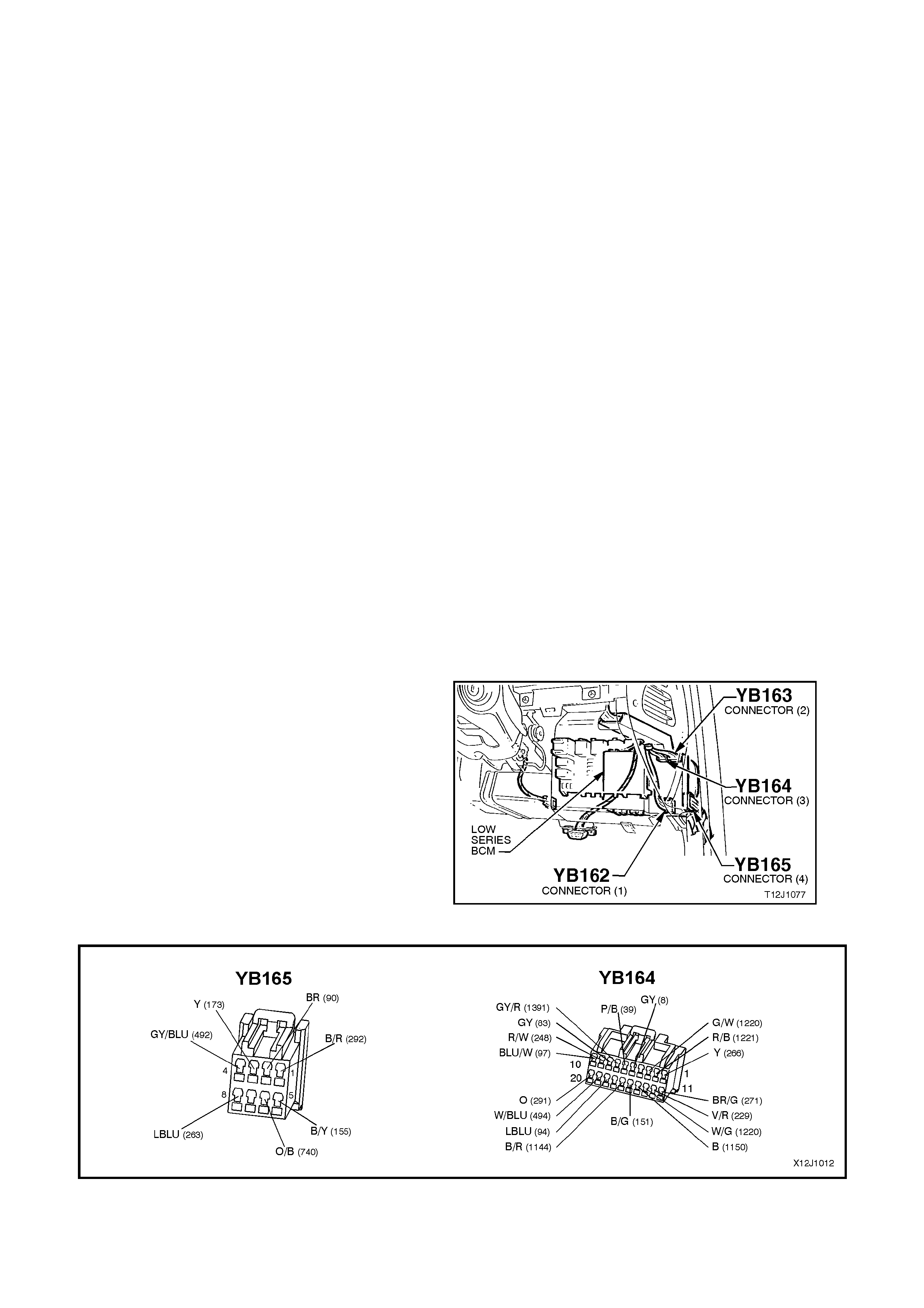
18. • Back probe BCM connector YB165, terminal A8,
circuit 263 (Light Blue wire) with a Voltmeter to earth.
• Repeat Security LED test as per Step 17.
• Are voltages as specified?
Approx 5 volts
LED on
Approx 0 volts
LED off
Go to Step 20. Go to Step 19.
19. • Back probe BCM connector YB165, terminal A8,
circuit 263 (Light Blue wire) with an Ohmmeter to
earth.
• Is value as specified?
Below 1 ohm. Repair short in
circuit 263.
Recheck and
verify repair.
Replace BCM,
refer to 12J-1
LOW SERIES
BCM of the VT
Series II Service
Information.
Recheck and
verify repair.

STEP ACTION VALUE YES NO
20. • Back probe theft deterrent LED connector YB56,
circuit 263 (Light Blue wire) with a Voltmeter to earth.
• Repeat Security LED test as per Step 17.
• Are voltages as specified?
Approx 5 volts
LED on
Approx 0 volts
LED off
Go to Step 21. Check and repair
open in circuit
263. Recheck
and verify repair.
21. • Back probe theft deterrent LED connector YB56,
circuit 156 (Black/Yellow wire) with a Ohmmeter to
earth.
• Is value as specified?
Below 1 ohm Replace theft
deterrent LED,
refer to 12C
INSTRUMENTS,
WIPERS /
WASHER &
HORN of the VT
Series I Service
Information.
Repair open in
circuit 156.
Recheck and
verify repair.
22. • With the ignition key in the ON position, operate the
unlock button on the remote coded key.
• Does the theft deterrent LED go out?
Go to Step 23. Go to remote
receiver
diagnosis, refer
to 2.5 REMOTE
RECEIVER /
KEY in this
Section.
23. • Remove remote key, key shaft and clean earth
contact (shaft earth).
• Reinstall key shaft and tighten screws to the correct
torque specification (0.7 - 0.9 Nm).
• With system passively armed (theft deterrent LED
flashing), insert key into ignition switch and turn key
to the ON position.
• Does the theft deterrent LED go out?
Go to Step 10. Go to Step 24.
24. • Turn ignition key to the ON position.
• Visually check to see if remote coded key contact pin
is making good contact with remote key reader (slip
ring).
• Is remote coded key contact pin making good
contact?
Go to Step 25. Check and
repair: remote
key reader or
alignment of
remote key
reader (refer step
12) or length of
key shaft or
remote key
contact pin
25. • Check function of second remote key.
• Is second key OK? Replace remote
coded key, refer
12J-1 LOW
SERIES BCM of
the VT Series II
Service
Information.
Recheck and
verify repair.
Go to Step 26
26. • Isolate remote coded key contact pin (use a thick
piece of paper to cover pin).
• Insert key into ignition switch and turn key to the ON
position.
• Measure voltage at the remote coded key reader
(slip ring) to a sound earth.
• Is voltage as specified?
Fluctuates
between 4 - 6
volts - AC
Go to Step 27. Go to Step 28.
27. • Check ignition switch earth using an Ohmmeter
connected between the ignition switch housing a
sound earth point.
• Is value as specified?
Below
100 ohms Replace BCM,
refer to 12J-1
LOW SERIES
BCM of the VT
Series II Service
Information.
Recheck and
verify repair.
Check and repair
open or poor
earth connection
at ignition switch.
Recheck and
verify repair.

STEP ACTION VALUE YES NO
28. • Connect TECH 2 to DLC.
• Select BODY / BODY CONTROL MODULE / DATA
DISPLAY / DATA LIST.
• Turn ignition ON as instructed by TECH 2.
• Scroll to Ignition Switch display.
• Does screen display Ignition Switch On?
Go to Step 29. Go to Step 31.
29. • Back probe BCM connector YB164, terminal D12,
circuit 229 (Violet/Red wire) with a Voltmeter to
earth.
• W ith remote coded key contact pin isolated (covered
with thick paper), insert ignition key into ignition
switch and turn ignition switch to the ON position.
• Is voltage as specified?
Fluctuates
between 4 - 6
volts - AC
Check and repair
open in circuit
229 or remote
key reader,
Recheck and
verify repair.
Go to Step 30.
30. • Check circuit 229 (Violet/Red wire) for short to earth.
• Is circuit 229 OK? Check and repair
short in circuit
229. Recheck
and verify repair.
Replace BCM,
refer to 12J-1
LOW SERIES
BCM of the VT
Series II Service
Information.
Recheck and
verify repair.
31. • Back probe BCM connector YB164, terminal D6,
circuit 39 (Pink/Black wire) with a Voltmeter to earth.
• Turn ignition ON.
• Is voltage as specified?
Approx. 12
volts Replace BCM,
refer to 12J-1
LOW SERIES
BCM of the VT
Series II Service
Information.
Recheck and
verify repair.
Check and repair
open in circuit 39
(including fuse
F14). Recheck
and verify repair.
32. • Connect TECH 2 to DLC.
• Select BODY / BODY CONTROL MODULE / DATA
DISPLAY / DATA LIST and scroll to PASSIVE
MODE.
• W ith system disarmed (theft deterrent LED off), does
the screen display Passive Mode OFF?
Go to PCM
diagnostics in
Section 6C1
POWERTRAIN
MANAGEMEN T -
V6 ENGINE in
the VX Series
Service
Information.
Replace BCM,
refer to 12J-1
LOW SERIES
BCM of the VT
Series II Service
Information.
Recheck and
verify repair.
33. • Turn the ignition to the START position.
• Does the engine crank and continue to crank after 1
second?
Go to PCM
diagnostics in
Section 6C3
POWERTRAIN
MANAGEMEN T -
GEN III V8 ENG
in the VX Series
Service
Information.
Go to Step 34.
34. • Connect TECH 2 to the DLC.
• Turn ignition ON.
• Select BODY / BODY CONTROL MODULE / DATA
DISPLAY / DATA LIST and scroll to PASSIVE
MODE.
• With the theft deterrent system disarmed (theft
deterrent LED off) does the screen display Passive
Mode OFF?
Go to Step 35. Replace BCM,
refer to 12J-1
LOW SERIES
BCM of the VT
Series II Service
Information.
Recheck and
verify repair.
35. • With TECH 2 still connected and ignition ON, exit
BODY CONTROL MODULE and select BODY /
POWERTRAIN INTERFACE MODULE (PIM).
• Can TECH 2 communicate with the PIM (i.e.
software version number displayed)?
Go to Step 36. Go to Step 38.

STEP ACTION VALUE YES NO
36. • Ensure the BCM has been linked to the PIM (Refer
BCM linking procedure in Section 12J-1 LOW
SERIES BCM of the VT Series II Service
Information).
• With TECH 2 still connected and ignition ON select
BODY / BODY CONTROL MODULE /
POW ERTRAIN INTERFACE MODULE / DATA LIST.
Scroll to THEFT STATUS.
• Does screen display Theft Status START?
Go to Step 37. Replace PIM,
refer Section 6C3
POWERTRAIN
MANAGEMEN T -
GEN III V8 ENG
in the VX Series
Service
Information.
37. • With TECH 2 connected and ignition ON, select
BODY / BODY CONTROL MODULE /
POWERTRAIN Interface Module /
MISCELLANEOUS TESTS / STARTER RELAY.
• Turn and hold the ignition switch in the START
position.
• Conduct starter relay test as instructed by TECH 2.
• Does the engine crank?
Replace PIM,
refer Section 6C3
POWERTRAIN
MANAGEMEN T -
GEN III V8 ENG
in the VX Series
Service
Information.
Go to Step 41.
38. • Back probe PIM connector YB215, terminal 15,
circuit 39 (Pink wire) with a voltmeter to earth.
• Turn ignition ON.
• Is voltage as specified?
12 volts Go to Step 39. Check and repair
open in circuit
39. Recheck and
verify repair.
39. • Turn ignition OFF.
• Back probe PIM connector YB215, terminal 16,
circuit 750 (Black/Red wire) with an ohmmeter to
earth.
• Is value as specified?
Below 1 ohm Go to Step 40. Check and repair
open in circuit
750. Recheck
and verify repair.
40. • Back probe BCM connector YB164, terminal D2,
circuit 1221 (Red/Black wire) and PIM connector
YB215, terminal 6, circuit 1221 (Red/Black wire) with
an ohmmeter.
• Is value as specified?
Below 1 ohm Replace PIM,
refer Section 6C3
POWERTRAIN
MANAGEMEN T -
GEN III V8 ENG
in the VX Series
Service
Information.
Check and repair
open in circuit
1221 between
PIM and BCM.
Recheck and
verify repair.
41. • Back probe PIM connector YB215, terminal 8, circuit
1434 (Grey/Blue wire) with a voltmeter to earth.
• Connect TECH 2 to the DLC and select BODY /
BODY CONTROL MODULE / POWERTRAIN
INTERFACE MODULE / MISCELLANEOUS TESTS /
STARTER RELAY.
• Turn and hold the ignition switch in the START
position.
• Conduct starter relay test as instructed by TECH 2.
• Is value as specified?
Below 1 volt Check the starter
circuits, including
fusible links,
circuits 1434,
434, 5, 6, 1,
starter relay,
neutral safety
switch and
starter motor.
Refer to the
appropriate
sections in the
VX Series
Service
Information.
Replace PIM,
refer Section 6C3
POWERTRAIN
MANAGEMEN T -
GEN III V8 ENG
in the VX Series
Service
Information..
2.5 REMOTE RECEIVER / KEY
Figure 12J-1-9
CIRCUIT DESCRIPTION
When operating the UNLOCK button on the remote coded key a Radio Frequency (RF) signal is transmitted.
Provided the signal is tr ansm itted within f our m etr es of the driver’s side B pillar f or 0.25 sec onds, the BCM rec eives
this unlock reques t from the r em ote coded k ey via the remote rec eiver, located in the instrument panel between the
demist grille. The BCM then proceeds to unlock all the doors (single stage unlock) or just the driver’s door (two
stage unlock), disarms the theft deterrent sy stem, turns on the dome lamp and flashes the indicators twice.
W hen operating the LOCK button on the remote coded key within four meters of the driver’s door B pillar for 0.25
seconds, an RF signal is again transmitted. The RF signal (lock request) is received by the BCM via the remote
receiver. The BCM then proceeds to lock all doors, arm the theft deterrent system, turn the dome lamp off (if
illuminated) and flash the indicators once.
W hen oper ating the boot release button on the rem ote coded k ey within two meter s of the boot f or 0.3 s econds, an
RF signal is transmitted to the BCM via the remote receiver. The BCM then proceeds to activate the rear
compartment lock actuator (provided the vehicle speed is less than 15 km/h).
The remote coded key is powered by it’s own internal battery. If this battery fails, no RF signal will be transmitted
when operating the lock, unlock and boot release buttons. However, if the battery does lose power, the remote
coded k ey reader has the ability to power the key once it is inserted into the ignition s witch key c ylinder and turned
to the IGN or START positions. This will then enable theft deterrent disarming.
Techline
TEST DESCRIPTION
The numbers below refer to step numbers in the following diagnostic chart.
1-7. Functional chec k to determ ine if system is f unctioning cor rect ly or if f aulty, determines if fault is with rem ote
receiver/key, central locking system or theft deterrent system.
8. Uses TECH 2 to chec k rem ote key signal - establish whether problem is with BCM or if f urther diagnosis is
required.
9. Uses TECH 2 to check for a rem ote key signal from a fully functional VT or VX Series vehicle to establish
whether problem is with remote key or if further diagnosis is required.
10. Checks for power supply to remote receiver.
11. Checks circuit 271.
12. Checks circuit 266.
13. Checks if problem is due to faulty BCM or remote receiver by swapping remote receiver with a fully
functional unit.
Figure 12J-1-10

REMOTE RECEIVER/KEY
STEP ACTION VALUE YES NO
1. Close and lock all doors.
Insert ignition key into driver’s door lock cylinder switch.
Operate unlock / lock.
Do all doors unlock and lock?
Go to Step 2. Go to central
door locking
diagnosis, refer
12J-1 LOW
SERIES BCM of
the VT Series II
Service
Information.
2. Insert ignition key into driver’s door lock cylinder switch
and unlock door.
With theft deterrent LED flashing, insert ignition key into
ignition switch and turn key to the ON position.
Does the theft deterrent LED turn off?
Go to Step 3. Go to theft
deterrent
diagnosis, refer
2.4 THEFT
DETERRENT in
this Section.
3. Insert ignition key into driver’s door lock cylinder switch
and lock all doors.
Operate the UNLOCK button on the remote coded key
within two metres of the driver’s door B pillar.
Does the driver’s door only (two stage unlock) or all
doors (single stage unlock) unlock?
Go to Step 4. Go to Step 8.
4. When performing Step 3, did all of the following occur
when the UNLOCK button on the remote coded key was
pressed?
Indicators flash twice.
Dome lamp illuminate (dome lamp switch in
doors position).
Theft deterrent LED go out.
Go to Step 5. Go to theft
deterrent
diagnosis, refer
2.4 THEFT
DETERRENT in
this Section.
5. Close all doors.
Operate LOCK button on remote coded key within two
metres of driver’s door B pillar.
Do all doors lock?
Go to Step 6. Go to Step 8.
6. When performing Step 5, did all of the following occur
when the LOCK button on the remote coded key was
pressed?
Theft deterrent LED began flashing.
Indicators flashed once.
Dome lamp went out (if illuminated & with
switch in the doors position).
Go to Step 7. Go to theft
deterrent
diagnosis, refer
2.4 THEFT
DETERRENT in
this Section.
7. Press the boot release button on the remote coded key
(within two metres of the rear of the vehicle) for two
seconds.
Does rear compartment lid lock actuator solenoid
activate?
System OK. Go to Step 8.
8. Connect TECH 2 to the DLC.
Select Body / Body Control Module / Data Display.
Scroll to Remote Door Signal and Remote Boot Signal
screen display.
Operate UNLOCK, LOCK and BOOT buttons on the
remote coded key.
Does the screen display change for the remote door
signal change from Off to Unlock / Lock to Off and the
remote boot signal change from Off to Open to Off?
Replace BCM,
refer to 12J-1
LOW SERIES
BCM of the VT
Series II Service
Information.
Recheck and
verify repair.
Go to Step 9.

STEP ACTION VALUE YES NO
9. On a VT or VX Series vehicle with a fully functional
remote coded key and receiver, connect TECH 2 to the
DLC.
Select Body / Body Control Module / Data Display.
Scroll to Remote Door Signal and Remote Boot Signal
screen display.
Operate UNLOCK, LOCK and BOOT buttons on the
remote coded key.
Does the screen display change for the remote door
signal change from Off to Unlock / Lock and the remote
boot signal change from Off to Invalid to Off?
Go to Step 10. Program a new
remote coded
key, refer to
12J-1 LOW
SERIES BCM of
the VT Series II
Service
Information.
Recheck and
verify repair
10. Return to original vehicle with suspected faulty remote
coded key/receiver.
Back probe remote receiver connector YB95, circuit 740
(Orange/Black wire) with a Voltmeter to earth.
Is voltage as specified?
Battery + Go to Step 11. Check and repair
open or short in
circuit 740.
recheck and
verify repair.
11. Check integrity of circuit 271 (Brown/Green wire).
Is circuit 271 OK? Below 1 ohm
Go to Step 12. Repair circuit 271
as necessary.
Recheck and
verify repair.
12. Check integrity of circuit 266 (Yellow wire).
Is circuit 266 OK? Below 1 ohm Go to Step 13. Repair circuit 266
as necessary.
Recheck and
verify repair.
13. Replace remote receiver with a known functional one
and connect TECH 2 to the DLC.
Select Body / Body Control Module / Data Display.
Scroll to Remote Door Signal screen display.
Operate UNLOCK and LOCK button on the remote
coded key.
Does the screen display change from Off to Unlock /
Lock Off?
Replace remote
receiver, refer to
12J-1 LOW
SERIES BCM of
the VT Series II
Service
Information.
Recheck and
verify repair.
Replace BCM,
refer to 12J-1
LOW SERIES
BCM of the VT
Series II Service
Information.
Recheck and
verify repair.
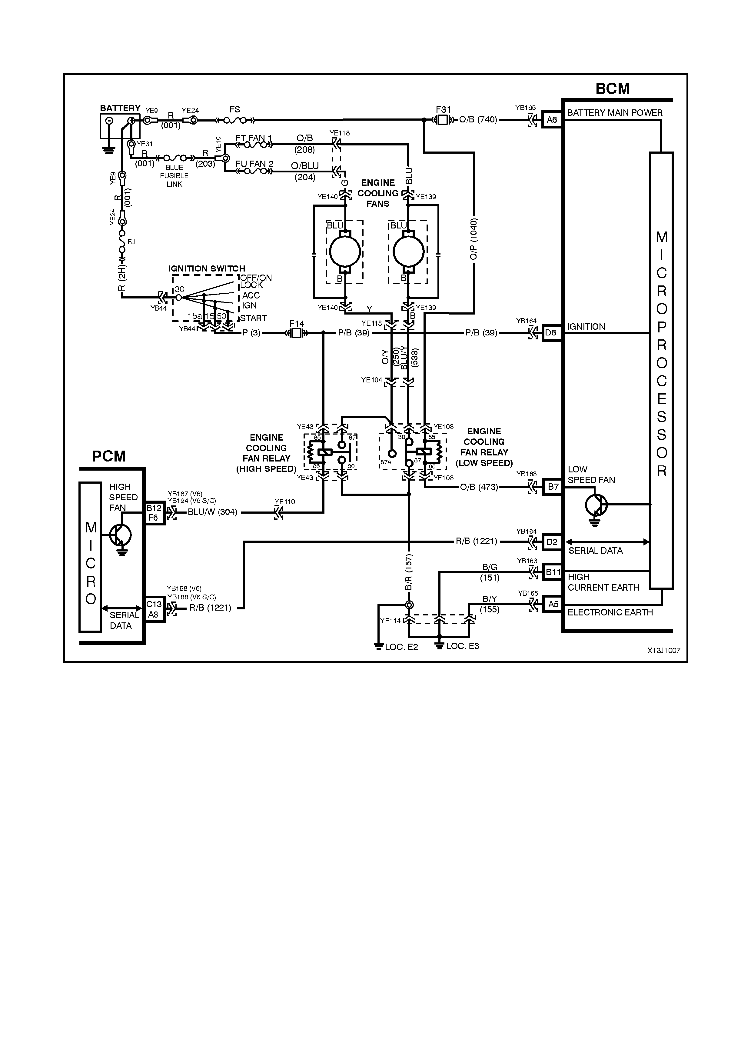
2.6 ENGINE COOLING LOW SPEED FAN CONTROL
Figure 12J-1-11 V6 AND V6 SUPERCHARGED ENGINE
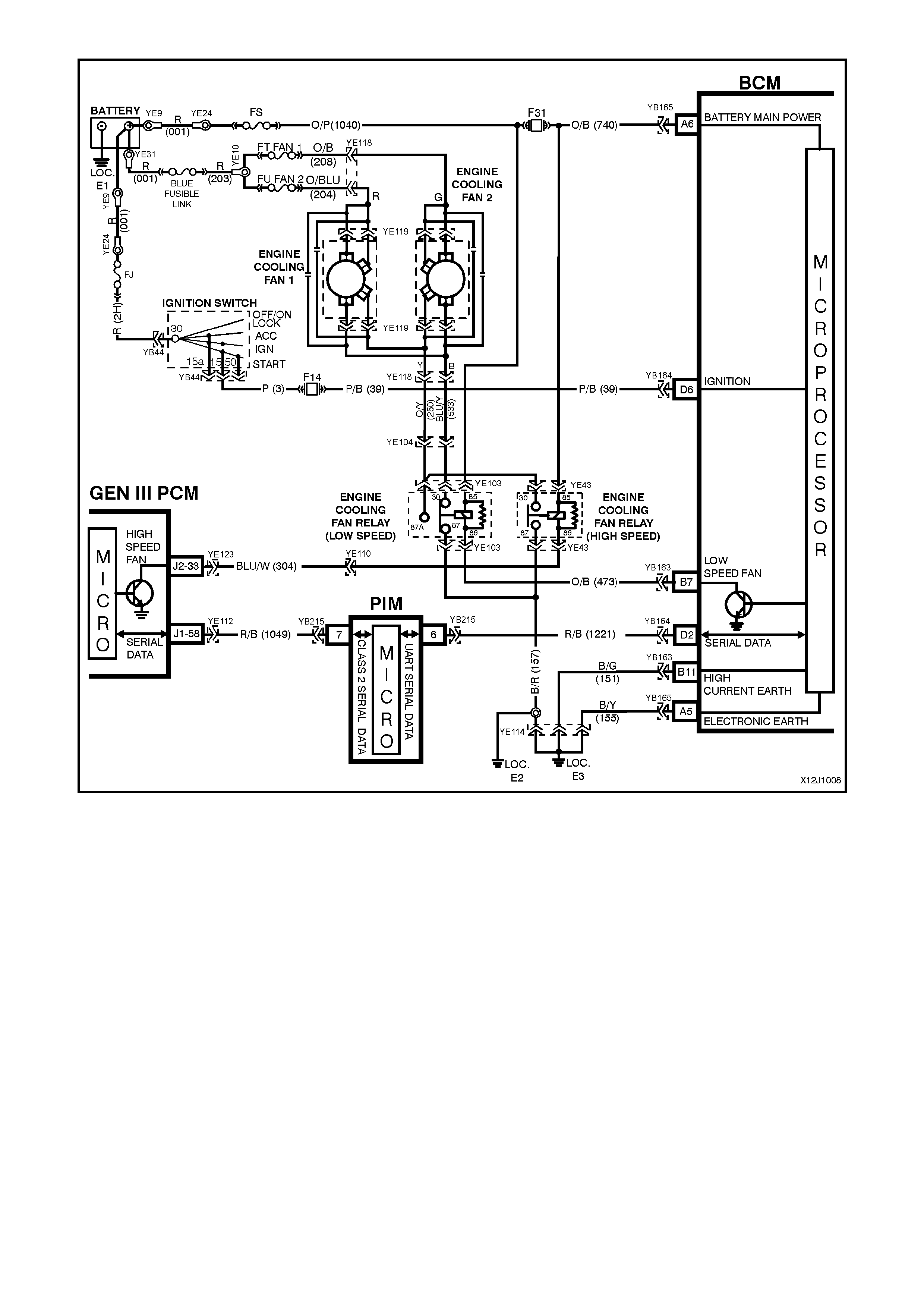
Figure 12J-1-12 GEN III V8 ENGINE
CIRCUIT DESCRIPTION
Regardless of the engine configuration, the low speed c ooling fan operation is enabled when the low speed engine
cooling f an micr o r elay (located in the engine compartment relay housing, labelled Lo Fan) is ener gis ed by the Body
Control Module (BCM) via a request from the Powertrain Control Module (PCM). The PCM will request low speed
fan enable and disable via serial data communication to the BCM on circuit 1221 (Red/Black wire).
The PCM determ ines when to enable the low speed fan r elay based on inputs from the A/C request signal, Cooling
Temperature Sensor (CTS) and the Vehicle Speed Sensor (VSS).
When the ignition switch is turned from O N to OF F and the engine coolant tem peratur e is above 117°C (V6 and V6
supercharged) / 113°C (GEN III V8). The BCM will continue to energise the low speed engine cooling fan micro
relay for four minutes.
On vehicles with GEN III V8 engines, the low speed cooling fan run on time has a minimum default value of 30
seconds.
TEST DESCRIPTION
The numbers below refer to step numbers in the following diagnostic chart.
1. Functional check of low speed cooling fan operation.
2. Uses TECH 2 to command the BCM to turn the low speed fan on.
3. Checks for battery voltage supply to engine cooling fan motor.
4. Checks low speed fan drive signal at output of BCM when.
5. Checks circuit 473.
6. Checks circuit 1040.
7. Checks circuit 157.
8. Checks engine cooling low speed fan motor.
9. Checks circuit 533 and engine cooling low speed fan relay.
10.
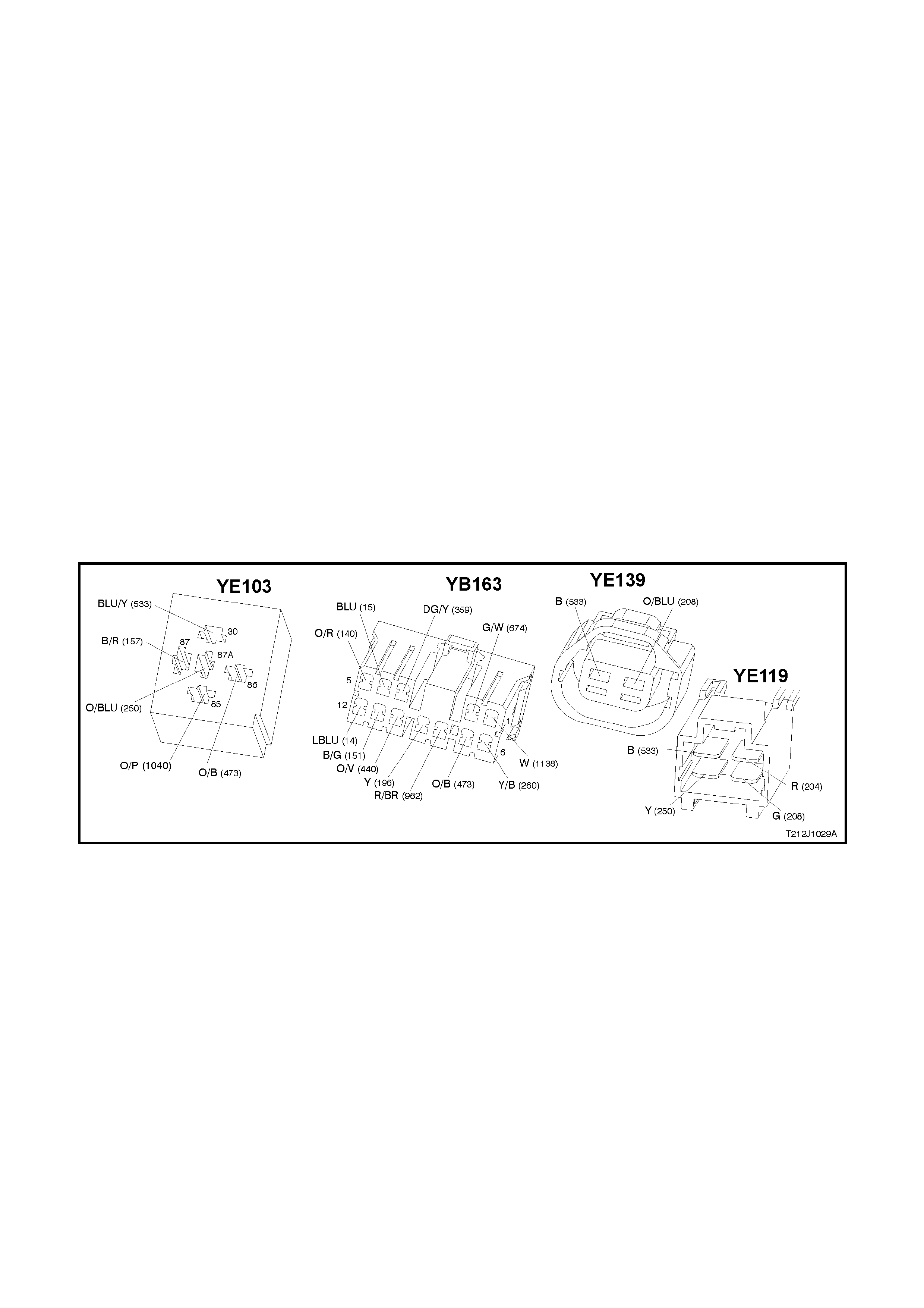
Figure 12J-1-13
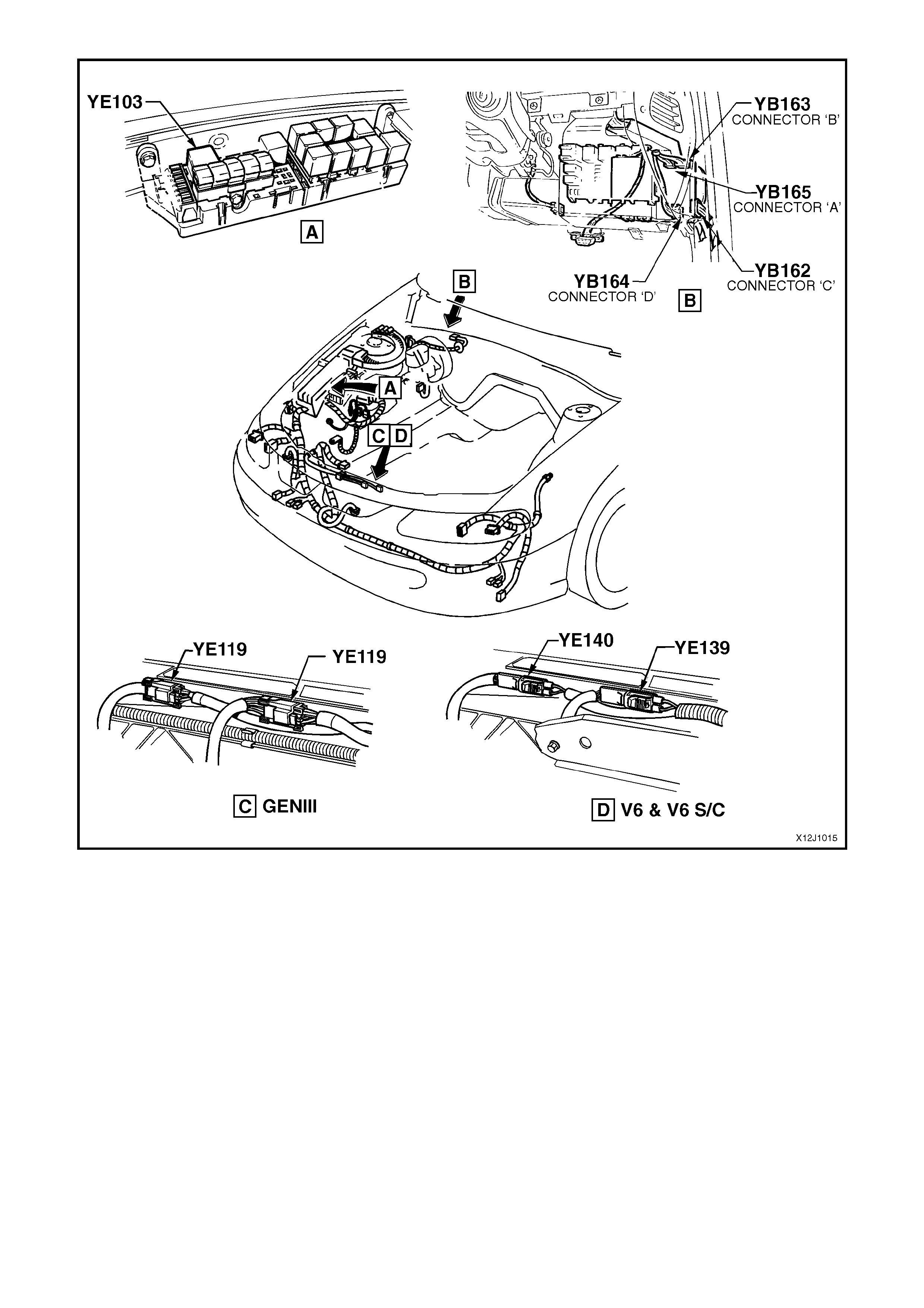
Figure 12J-1-14

ENGINE COOLING FAN LOW SPEED CONTROL
STEP ACTION VALUE YES NO
1. • With the engine coolant temperature greater than
104°C (V6 or V6 Supercharged engine) or 98°C
(GEN III V8 engine) is the low speed fan enabled?
System OK. Go to Step 2.
2. • Connect TECH 2 to the DLC.
• Select BODY / BODY CONTROL MODULE /
MISCELLANEOUS TESTS / LOW FAN.
• Conduct test as instructed by TECH 2 and enable
the low speed fan.
• Is the low speed fan enabled?
Go to PCM
Temperature
sensor diagnosis
in Section 6C1
POWERTRAIN
MANAGEMEN T -
V6 ENGINE (V6)
or 6C3
POWERTRAIN
MANAGEMENT
– GEN III V8
ENGINE in the
VX Series
Service
Information.
Go to Step 3.
3. • Back probe engine cooling fan motor connector
YE139 circuit 208 (Blue wire) on vehicles with a V6
or V6 supercharged engine or connector YE119,
circuit 208 (Green wire) on vehicles with a GEN III
V8 engine with a Voltmeter to earth.
• Is voltage as specified?
12 volts Go to Step 4. Check and repair
open in circuit
208. Recheck
and verify repair.
4. • Back probe BCM connector YB163, terminal B7,
circuit 473 (Orange/Black wire) with a jumper lead to
earth.
• Does low speed fan turn on?
0 volts Replace BCM,
refer to 12J-1
LOW SERIES
BCM of the VT
Series II Service
Information.
Recheck and
verify repair.
Go to Step 5.
5. • Back probe engine cooling fan low speed relay
connector YE103, terminal 86, circuit 473
(Orange/Black wire) with a jumper lead to earth.
• Does low speed fan turn on?
0 volts Go to Step 6. Check and repair
open in circuit
473. Recheck
and verify repair.
6. • Back probe engine cooling fan low speed relay
connector YE103, terminal 85, circuit 1040
(Orange/Pink wire) with a Voltmeter to earth.
• Is voltage as specified?
12 volts Go to Step 7. Check and repair
open in circuit
1040. Recheck
and verify repair.
7. • Back probe engine cooling fan low speed relay
connector YE103, terminal 87, circuit 157 (Black/Red
wire) with an Ohmmeter to earth.
• Is value as specified?
Below 1 ohm Go to Step 8. Check and repair
open in circuit
157. Recheck
and verify repair.
8. • Back probe engine cooling fan motor connector
YE139 (V6 and V6 supercharged) or YE119 (GEN III
V8), circuit 533 (Black wire) with a test light
connected to battery +.
• Connect TECH 2 to the DLC.
• Select BODY / BODY CONTROL MODULE /
MISCELLANEOUS TESTS / LOW FAN.
• Conduct test as instructed by TECH 2 and enable
the low speed fan.
• Does test lamp illuminate?
Replace engine
cooling fan
motor, refer to
either Section
6B1 ENGINE
COOLING - V6
ENGINE of the
VT Series I
Service
Information or
6B3 ENGINE
COOLING - GEN
III V8 ENGINE of
the VT Series II
Service
Information.
Recheck circuit
to verify repair.
Go to Step 9.
9. • With TECH 2 still connected, back probe engine
cooling fan low speed relay connector YE103,
terminal 30, circuit 533 (Blue/Yellow wire) with a test
light connected to battery +.
• Repeat TECH 2 LOW SPEED FAN test as again.
• Does test lamp illuminate?
Repair open in
circuit 533.
Recheck circuit
to verify repair .
Replace engine
cooling low
speed fan relay.
Recheck and
verify repair.
2.7 AUTOMATIC LIGHTS OFF CONTROL
Figure 12J-1-15
CIRCUIT DESCRIPTION
The automatic lights off control feature is designed
to automatically switch the headlights and parking
lights off when the driver leaves the vehicle.
In the event of a system failure, the default status
of the BCM light control output is in the ON state
when the ignition is in the ON position. This will give
direct control of the lights to the headlamp switch.
The sequence of events required to switch the
lights off automatically is as follows:
1. The vehicle road speed input to the BCM
indicates the vehicle speed is less than 10
km/h and there has not been a sudden loss of
speed (ignition being switched off with the
vehicle travelling above 10 km/h).
2. The BCM senses that the ignition switch is
turned from ON to OFF and remains in the
OFF position.
3. The headlamp switch has not been turned on
after the ignition switch was turned off.
4. The BCM senses the driver’s door has been
opened and turns the lights off.
When the ignition switch is turned back to the IGN
position, the lights will turn back on to the position
selected by the headlamp switch and mode of
headlamp operation.
Turning the headlamp switch off, deactivates the
auto lights off system.
TEST DESCRIPTION
The num ber s below refer to step num bers in the following
diagnostic chart.
1-6. Functional check of headlamp and park lamp system.
7. Tests fail safe function.
8. Tests to establish whether problem is due to no
output drive from the BCM or circuit problem beyond
the BCM.
9. Checks circuit 1150.
10. Uses TECH 2 to check for DRIVER’S DOOR OPEN
signal at microprocessor of BCM.
11. Uses TECH 2 to for false IGNITION ON signal at
microprocessor of BCM.
12. Checks for correct ignition signal level.
13. Checks DRIVER’S DOOR OPEN signal at input of
BCM.
14. Checks circuit 126.
15. Tests for false output drive from BCM or short circuit
in lamp circuits.
Figure 12J-1-16
Figure 12J-1-17

AUTOMATIC LIGHTS OFF CONTROL
STEP ACTION VALUE YES NO
1. • Turn ignition OFF.
• Turn headlamp switch from OFF position to
PARKLAMP position.
• Are the park lamps on?
Go to Step 2. Go to Step 6.
2. • Turn ignition OFF.
• Turn headlamp switch from PARKLAMP position to
HEADLAMP position.
• Are the headlamps on?
Go to Step 3. Check and repair
headlamp switch
assembly, fault in
wiring harness to
headlamp relay
and headlamp
circuits (including
fuses and
headlamp relay).
Recheck and
verify repair.
3. • Turn ignition ON.
• Driver’s door closed.
• Headlamp switch in HEADLAMP position.
• Turn ignition OFF.
• Open driver’s door.
• Do the headlamps turn off?
Go to Step 4. Go to Step 10.
4. • After headlamps have automatically be turned off
from test Step No. 3 and with the driver’s door open,
turn the ignition ON.
• Do headlamps turn ON?
Go to Step 5. Replace BCM,
refer to 12J-1
LOW SERIES
BCM of the VT
Series II Service
Information.
Recheck and
verify repair.
5. • Driver’s door open.
• Following on from test Step 4, turn ignition OFF
(headlamps will turn OFF).
• Turn headlamp switch from the HEADLAMP position
to the OFF position.
• Turn headlamp switch from the OFF position to the
HEADLAMP position.
• Do headlamps turn on?
System OK.
Replace BCM,
refer to 12J-1
LOW SERIES
BCM of the VT
Series II Service
Information.
Recheck and
verify repair.
6. • Turn ignition OFF.
• Turn headlamp switch to the HEADLAMP position.
• Are the headlamps on?
Check and repair
headlamp switch
assembly, fault in
wiring harness to
park lamp relay
and parking
lamps (including
fuses and park
lamp relay).
Recheck and
verify repair.
Go to Step 7.
7. • Turn ignition ON.
• Turn headlamp switch to HEADLAMP position.
• Are the headlamps on?
Replace BCM,
refer to 12J-1
LOW SERIES
BCM of the VT
Series II Service
Information.
Recheck and
verify repair.
Go to Step 8.
8. • Disconnect BCM connector YB164 and back probe
terminal D14 (harness earth) circuit 1150 (Black
wire) with a jumper wire and connect to a sound
earth point.
• Turn headlamp switch to PARKLAMP position.
• Do park lamps turn on?
12 volts Replace BCM,
refer to 12J-1
LOW SERIES
BCM of the VT
Series II Service
Information.
Recheck and
verify repair.
Go to Step 9.

STEP ACTION VALUE YES NO
9. • Reconnect BCM connector YB164 and back probe
terminal D14 circuit 1150 (Black wire) and headlamp
switch connector YB33 circuit 1150 (Black wire) with
an Ohmmeter.
• Is value as specified?
Below 1 ohm Check and repair
headlamp switch
assembly, fault in
wiring harness to
park lamp relay
and parking
lamps (including
fuses and park
lamp relay), and
headlamp
circuits. Recheck
and verify repair.
Repair open in
circuit 1150.
Recheck and
verify repair.
10. • Connect TECH 2 to DLC.
• Select Body / Body Control Module / Data Display
and scroll to Driver’s Door.
• Open driver’s door.
• Does screen display Driver’s Door Open?
Go to Step 11. Go to Step 13.
11. • With TECH 2 still connected and Data Display
selected, scroll to Ignition Switch.
• Turn ignition OFF.
• Does screen display Ignition On?
Go to Step 12. Go to Step 15.
12. • Turn ignition OFF.
• Back probe BCM connector YB165, terminal D6,
circuit 39 (Pink/Black wire) with a Voltmeter to earth.
• Is voltage as specified?
Ignition OFF
0 volts Replace BCM,
refer to 12J-1
LOW SERIES
BCM of the VT
Series II Service
Information.
Recheck and
verify repair.
Check and repair
fault in wiring
(particularly short
to B+) in circuit
39 or faulty
ignition switch.
Recheck and
verify repair.
13. • Driver’s door open.
• Back probe BCM connector YB162, terminal C8,
circuit 126 (Grey/White wire) with a Voltmeter to
earth.
• Is voltage as specified?
Below
0.5 volts Replace BCM,
refer to 12J-1
LOW SERIES
BCM of the VT
Series II Service
Information.
Recheck and
verify repair.
Go to Step 14.
14. • Disconnect BCM connector YB162.
• Back probe BCM connector YB162, harness end,
terminal C8, circuit 126 (Grey/White wire) and
driver’s door jamb switch connector YB1, circuit 126
(Grey/White wire) with an Ohmmeter.
• Is Value as specified?
Below 1 ohm Replace driver’s
door jamb switch,
refer to 12J-1
LOW SERIES
BCM of the VT
Series II Service
Information.
Recheck and
verify repair.
Repair open in
circuit 126.
Recheck and
verify repair.
15. • Turn ignition OFF.
• Headlamp switch in the HEADLAMP position.
• Driver’s door open.
• Disconnect BCM connector YB164.
• Do headlamps turn off?
Replace BCM,
refer to 12J-1
LOW SERIES
BCM of the VT
Series II Service
Information.
Recheck and
verify repair.
Check and repair
short circuit in
wiring to relays
and earth end of
lamps, faulty
relays (beyond
terminal D14).
Recheck and
verify repair.
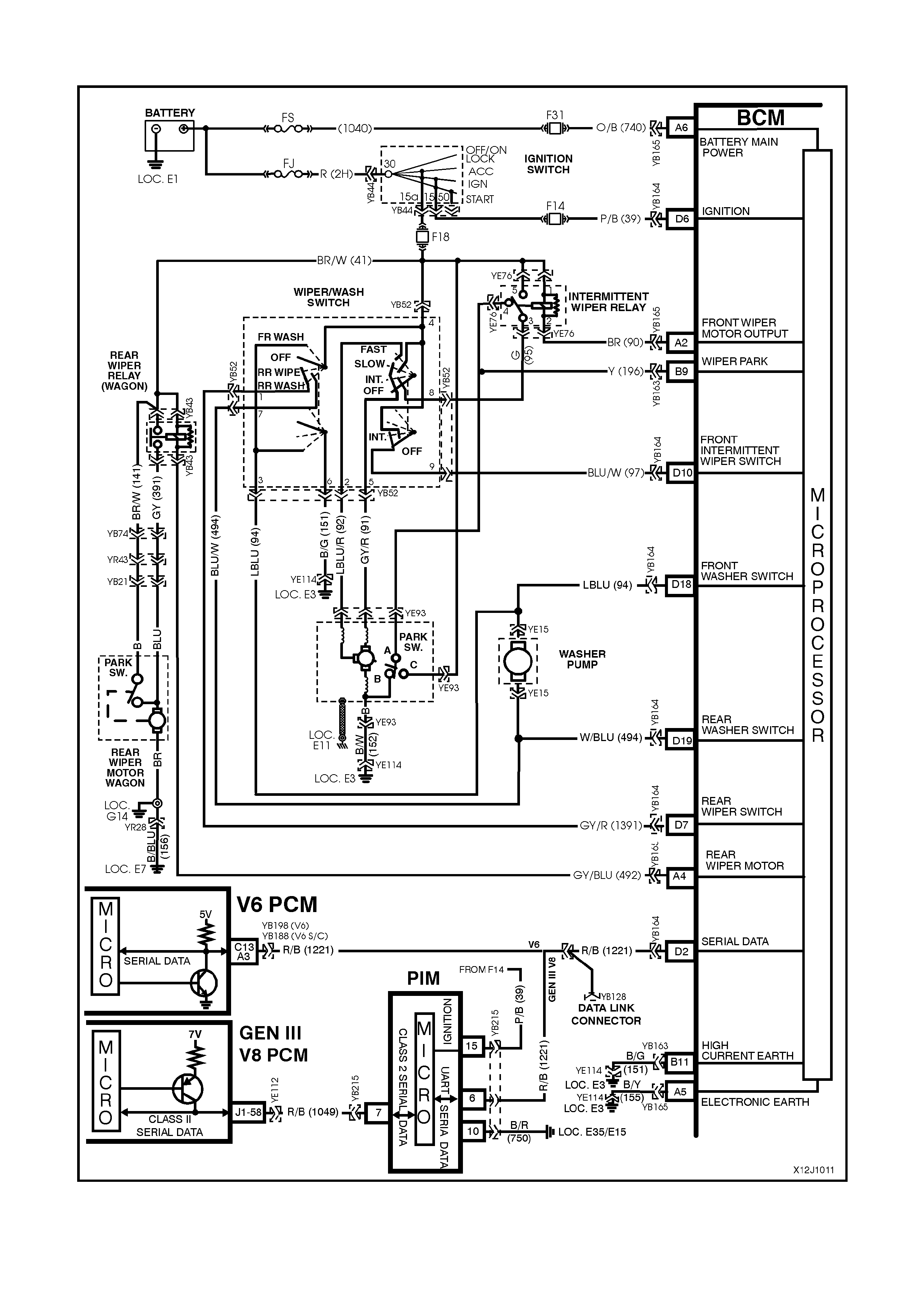
2.8 WIPER CONTROL SYSTEM
Figure 12J-1-18

CIRCUIT DESCRIPTION
This system controls the front intermittent and rear wiper function. The wiper dwell on vehicles with a low series
BCM has a fixed dwell period of approximately eight seconds and is non-adjustable. The rear wipers (on Wagon
models) are synchronised to the front wipers when the front wipers are in intermittent mode. Due to the different
wiper action between front and rear wipers, the wipers will start one quarter of a second before the front wipers. If
the option is set, the rear wiper (wagon with automatic transmission only) has the added function of wiping
continuously when the vehicle is in reverse gear and the rear wiper/washer switch is turned on
Reverse gear communication is between the PCM (and PIM – GEN III V8) and BCM via the serial data bus.
The f ront and rear wipers em ploy a “wipe after wash” function where, if the relevant was her pum p switch has been
pressed for more than 0.5 seconds, the wipers start sweeping at a low speed continuously until the washer pump
has been disengaged. Following which, the wiper will be held on for a calculated time period so that the following
number of sweeps can be completed:
• One additional sweep if washer switch pressed for less than 1 second.
• Two additional sweeps if washer switch is pressed for less than 1.5 seconds.
• Three additional sweeps if washer switch is pressed for more than 1.5 seconds
To correctly perform the number of additional sweeps, the wiper motor park switch is monitored. This allows the
wiper supply power to be transferred to the park switch at the optimum time.
NOTE: Battery Saver Mode – If the ignition switch is tur ned to the ACC position and the vehic le enters battery saver
mode, the intermittent wipers will not operate.
TEST DESCRIPTION
The numbers below refer to step numbers in the
following diagnostic chart.
1-11. Functional check of wiper control system.
12. Uses TECH 2 to operate front wiper
(establishes whether problem is with input or
output of BCM).
13 Uses TECH 2 to check for INTERMITTENT
WIPER/WASHER SWITCH ON signal at
microprocessor of BCM.
14. Checks for 12 volt supply to terminals 1 and 5
of intermittent relay.
15. Checks for BCM output drive of intermittent
wiper relay when commanded by TECH 2.
16. Checks circuit 90.
17. Checks intermittent wiper relay.
18. Checks for 12 volts at wiper motor when
commanded by TECH 2.
19. Checks circuit 152 / wiper motor.
20. Checks circuit 95.
21. Checks circuit 91 / wiper/washer switch.
22. Checks INTERMITTENT WIPER/WASHER
SWITCH ON signal at input to BCM.
23. Checks circuit 97.
24. Checks circuit 41 / wiper/washer switch.
25. Uses TECH 2 to check for WIPER PARK SW
signal at microprocessor of BCM.
26. Checks if continuous wiper operation is due to
faulty wiper/washer switch / continuous drive
from intermittent relay.
27. Checks WIPER PARK SW signal at input to
BCM.
28. Checks circuit 41.
29. Checks circuit 196 / wiper motor assembly
(internal park switch).
30 Checks for short in circuit 90, causing relay to
be always driven.
31. Checks intermittent wiper relay.
32. Checks FRONT WASHER SW signal at input to
BCM.
33 Checks circuit 94 / wiper/washer switch.
34 Uses TECH 2 to operate rear wiper (establish
whether problem is with input or output of BCM).
35 Uses TECH 2 to check REAR WIPE SWITCH ON
signal at microprocessor of BCM.
36 Checks for 12 volt supply to terminal 2 and 5 of rear
wiper relay.
37. Check s f or BCM output drive of rear wiper relay when
commanded by TECH 2 at rear wiper relay.
38. Checks rear wiper relay.
39. Checks circuit 391.
40. Checks rear wiper motor, circuit 156.
41. Checks for BCM output drive of rear wiper relay at
BCM when commanded by TECH 2.
42. Checks REAR WIPER SW signal to BCM.
43. Checks circuit 139 / wiper/washer switch.
44. Checks for short in circuit 492, causing relay to be
always driven.
45. Checks rear wiper relay.
46. Checks REAR WASHER SWITCH signal at input to
BCM.
47. Checks circuit 494 / wiper/washer switch.
48. Uses TECH 2 to check REVERSE GEAR signal at
microprocessor of PCM.
49. Uses TECH2 to check reverse gear signal on the
serial data bus.
Figure 12J-1-19
Figure 12J-1-20

WIPER CONTROL SYSTEM
STEP ACTION VALUE YES NO
1. • Turn ignition to ACC.
• Turn the wiper/washer switch to INTERMITTENT
position.
• Does the front wiper sweep?
Go to Step 2. Go to Step 12.
2. • In Step 1, did the front wiper only sweep once? Go to Step 3. Go to Step 25.
3. • While carrying out Step 1, time the period between
each sweep.
• Is the delay period as specified?
eight seconds Go to Step 4. Replace BCM,
refer to 12J-1
LOW SERIES
BCM of the VT
Series II Service
Information.
Recheck and
verify repair.
4. • Turn ignition to ACC.
• Operate the front wash switch for two seconds.
• Does the front wiper commence continuous
operation?
Go to Step 5. Go to Step 32.
5. • In Step 4, did the front wipers continue for three
additional sweeps after the front wash switch was
released?
Sedan - System
OK.
Wagon - Go to
Step 6.
Replace BCM,
refer to 12J-1
LOW SERIES
BCM of the VT
Series II Service
Information.
Recheck and
verify repair.
6. • Turn ignition to ACC.
• Turn the wiper/washer switch to REAR WIPE
position.
• Does the rear wiper sweep?
Go to Step 7. Go to Step 34.
7. • In Step 6, did the rear wiper only sweep once? Go to Step 8. Go to Step 44.
8. • While carrying out Step 6, time the period between
each sweep.
• Is the delay period as specified?
eight seconds Go to Step 9. Replace BCM,
refer to 12J-1
LOW SERIES
BCM of the VT
Series II Service
Information.
Recheck and
verify repair.
9. • Turn ignition to ACC.
• Operate the rear wash switch for two seconds.
• Does the rear wiper commence continuous
operation?
Go to Step 10. Go to Step 46.
10. • Turn ignition to ACC.
• Turn the wiper/washer switch to INTERMITTENT
position and REAR WIPER position.
• Are the front and rear wipers synchronised?
Go to Step 11. Replace BCM,
refer to 12J-1
LOW SERIES
BCM of the VT
Series II Service
Information.
Recheck and
verify repair.
11. • Using TECH 2, ensue the “rear wipe continuous
operation” option is active (Body / Body Control
Module / Program / Rear Wiper Control).
• Turn ignition ON.
• Turn the front intermittent wipers on.
• Do the rear wipers operate continuously when
reverse gear is selected?
System OK. Go to Step 48.
12. • Connect TECH to DLC.
• Select Body / Body Control Module / Miscellaneous
Tests / Wiper Tests / Front Wipers.
• Turn Ignition to the ACC position and conduct test as
instructed by TECH 2.
• Do front wipers sweep continuously?
Go to Step 13. Go to Step14.

STEP ACTION VALUE YES NO
13. • With TECH 2 still connected, exit Miscellaneous
Tests and select Data Display.
• Scroll to Front Wiper Intermittent Switch.
• Turn ignition to the ACC position.
• Turn the wiper/washer switch to INTERMITTENT
position.
• Does screen display Front Wiper Intermittent Switch
On?
Replace BCM,
refer to 12J-1
LOW SERIES
BCM of the VT
Series II Service
Information.
Recheck and
verify repair.
Go to Step 22.
14. • Turn ignition to the ACC position.
• Back probe intermittent wiper relay connector YE76,
terminal 5 and 1, circuit 41 (Brown/Green wire) with a
Voltmeter to earth.
• Is voltage as specified?
12 volts Go to Step 15. Check and repair
open in circuit 41
(including fuse
F18 and ignition
switch). Recheck
and verify repair.
15. • Back probe BCM connector YB165, terminal A2,
circuit 90 (Brown wire) with a jumper lead connected
to earth.
• Do wipers sweep?
0 volts Replace BCM,
refer to 12J-1
LOW SERIES
BCM of the VT
Series II Service
Information.
Recheck and
verify repair.
Go to Step 16.
16. • Back probe intermittent wiper relay connector YE76,
terminal 2, circuit 90 (Brown wire) with a jumper lead
connected to earth.
• Do wipers sweep?
0 volts Check and repair
open in circuit
90. Recheck and
verify repair.
Go to Step 17.
17. • Back probe intermittent wiper relay connector YE76,
terminal 3, circuit 95 (Green wire) with a Voltmeter to
earth.
• Turn ignition to the ACC position and conduct TECH
2 Front Wiper test.
• Is voltage as specified?
12 volts Go to Step 18. Replace
intermittent wiper
relay. Recheck
and verify repair.
18. • Back probe wiper motor connector YE93, circuit 91
(Grey/Red wire) with a Voltmeter to earth.
• Turn ignition to the ACC position and repeat TECH 2
Front Wiper test.
• Is voltage as specified?
12 volts Go to Step 19. Go to Step 20.
19. • Back probe front wiper motor connector YE93, circuit
152 (Black/White wire) with an Ohmmeter to earth.
• Is value as specified?
Below 1 ohm Replace front
wiper motor
assembly, refer
to 12C
INSTRUMENTS,
WIPERS /
WASHERS &
HORN of the VT
Series I Service
Information.
Check and repair
open in circuit
152. Recheck
and verify repair.
20. • Back probe wiper/washer switch connector YB52,
terminal 8, circuit 95 (Green wire) with a Voltmeter to
earth.
• Turn ignition to the ACC position and repeat TECH 2
Front Wiper test.
• Is voltage as specified?
12 volts Go to Step 21. Check and repair
open in circuit
95. Recheck and
verify repair.
21. • Back probe wiper/washer switch connector YB52,
terminal 5, circuit 91 (Grey/Red wire) with a
Voltmeter to earth.
• Turn ignition to the ACC position and repeat TECH 2
Front Wiper test.
• Is voltage as specified?
12 volts Check and repair
open in circuit
91. Recheck and
verify repair.
Replace
wiper/washer
switch, refer to
Section 12C
INSTRUMENTS,
WIPERS /
WASHERS &
HORN of the VT
Series I Service
Information

STEP ACTION VALUE YES NO
22. • Turn ignition to ACC.
• Back probe BCM connector YB164, terminal D10,
circuit 97 (Blue/White wire) with a Voltmeter to earth.
• Turn the wiper/washer switch to INTERMITTENT
position.
• Is voltage as specified?
12 volts Replace BCM,
refer to 12J-1
LOW SERIES
BCM of the VT
Series II Service
Information.
Recheck and
verify repair.
Go to Step 23.
23. • Turn ignition to ACC.
• Back probe wiper/washer switch connector YB52,
terminal 9, circuit 97 (Blue/White wire) with a
Voltmeter to earth.
• Turn the wiper/washer switch to INTERMITTENT
position.
• Is voltage as specified?
12 volts Check and repair
open in circuit
97. Recheck and
verify repair.
Go to Step 24.
24. • Turn ignition to ACC.
• Back probe wiper/washer switch connector YB52,
terminal 4, circuit 41 (Brown/White wire) with a
Voltmeter to earth.
• Is voltage as specified?
12 volts Replace
wiper/washer
switch, refer to
Section 12C
INSTRUMENTS,
WIPERS /
WASHERS &
HORN of the VT
Series I Service
Information.
Check and repair
open in circuit 41
(including fuse
F18). Recheck
and verify repair.
25. • Connect TECH 2 to DLC.
• Select Body / Body Control Module / Data Display
and scroll to Wiper Park Switch.
• Turn the wiper/washer switch to INTERMITTENT
position.
• Does screen display Wiper Park Switch On when
wiper is in the park position and Wiper Park Switch
Off when wiper is operating?
Go to Step 26. Go to Step 27.
26. • Turn ignition to ACC.
• Turn the wiper/washer switch to INTERMITTENT
position.
• Remove intermittent wiper relay.
• Do wipers operate continuously?
Replace
wiper/washer
switch, refer to
Section 12C
INSTRUMENTS,
WIPERS /
WASHERS &
HORN of the VT
Series I Service
Information.
Go to Step 30.
27. • Turn ignition to ACC.
• Turn the wiper/washer switch to INTERMITTENT
position.
• Back probe BCM connector YB163, terminal B9,
circuit 196 (Yellow wire) with a Voltmeter to earth.
• Are voltages as specified?
12 volts while
operating,
0 volts in park
Replace BCM,
refer to 12J-1
LOW SERIES
BCM of the VT
Series II Service
Information.
Recheck and
verify repair.
Go to Step 28.
28. • Turn ignition to ACC.
• Back probe wiper motor connector YE93, circuit 41
(Brown/White wire) with a Voltmeter to earth.
• Is voltage as specified?
12 volts Go to Step 29. Check and repair
open in circuit
41. Recheck and
verify repair.
29. • Turn ignition to ACC.
• Turn the wiper/washer switch to INTERMITTENT
position.
• Back probe wiper motor connector YE93, circuit 196
(Yellow wire) with a Voltmeter to earth.
• Are values as specified?
12 volts while
operating,
0 volts in park
Check and repair
open in circuit
196. Recheck
and verify repair.
Replace front
wiper motor,
refer Section 12C
INSTRUMENTS,
WIPERS /
WASHERS &
HORN of the VT
Series I Service
Information.
30. • Turn ignition to ACC.
• Remove intermittent relay.
• Disconnect BCM connector YB165.
• Back probe intermittent wiper relay connector YE76,
circuit 90 (Brown wire) with an Ohmmeter to earth.
• Is value as specified?
Below 1 ohm Check and repair
short to earth in
circuit 90.
Recheck and
verify repair.
Go to Step 31

STEP ACTION VALUE YES NO
31. • Reconnect BCM connector YB165.
• Swap intermittent wiper relay with a known good
relay.
• Turn ignition to ACC.
• Turn the wiper/washer switch to INTERMITTENT
position.
• Does only one sweep occur?
Replace
intermittent wiper
relay. Recheck
and verify repair.
Replace BCM,
refer to 12J-1
LOW SERIES
BCM of the VT
Series II Service
Information.
Recheck and
verify repair.
32. • Turn ignition to ACC.
• Back probe BCM connector YB164, terminal D18,
circuit 94 (Light Blue wire) with a Voltmeter to earth.
• Operate front wash switch.
• Is voltage as specified?
12 volts Replace BCM,
refer to 12J-1
LOW SERIES
BCM of the VT
Series II Service
Information.
Recheck and
verify repair.
Go to Step 33.
33. • Turn ignition to ACC.
• Back probe wiper/washer switch connector YB52,
terminal 3, circuit 94 (L Blue wire) with a Voltmeter to
earth.
• Operate front wash switch.
• Is voltage as specified?
12 volts Check and repair
open in circuit
94. Recheck and
verify repair.
Replace
wiper/washer
switch, refer to
Section 12C
INSTRUMENTS,
WIPERS /
WASHERS &
HORN of the VT
Series I Service
Information.
34. • Connect TECH 2 to DLC.
• Select Body / Body Control Module / Miscellaneous
Tests / Wiper Tests / Rear Wiper.
• Turn ignition to the ACC position and conduct test as
instructed by TECH 2.
• Does rear wiper operate continuously?
Go to Step 35. Go to Step 36.
35. • Turn ignition to ACC.
• With TECH 2 still connected, exit Miscellaneous
Tests and select Data Display.
• Scroll to Rear Wiper Switch.
• Turn wiper/washer switch to REAR W IPE position.
• Does screen display Rear Wiper Switch On?
Replace BCM,
refer to 12J-1
LOW SERIES
BCM of the VT
Series II Service
Information.
Recheck and
verify repair.
Go to Step 42.
36. • Turn ignition to ACC.
• Back probe rear wiper relay connector YB36,
terminals 2 and 5, circuit 41 (Brown/Green wire) with
a Voltmeter to earth.
• Is voltage as specified?
12 volts Go to Step 37. Check and repair
open in circuit
41. Recheck and
verify repair.
37. • Back probe rear wiper relay connector YB36,
terminal 1, circuit 492 (Grey/Blue wire) with a jumper
lead connected to earth.
• Does rear wiper operate?
Go to Step 41. Go to Step 38.
38. • Back probe rear wiper relay connector YB36,
terminal 3, circuit 391 (Green/Yellow wire) with a
Voltmeter to earth.
• Connect a jumper lead between wiper relay
connector, terminal 1 and earth.
• Turn ignition to the ACC position.
• Is voltage as specified?
12 volts Go to Step 39. Replace rear
wiper relay.
Recheck and
verify repair.
39. • Back probe rear wiper motor connector YR21, circuit
391 (Green/Yellow wire) with a Voltmeter to earth
• Connect a jumper lead between wiper relay
connector, terminal 1 and earth.
• Turn ignition to the ACC position.
• Is voltage as specified?
12 volts Go to Step 40. Check and repair
open in circuit
391. Recheck
and verify repair.

STEP ACTION VALUE YES NO
40. • Back probe rear wiper motor earth connection with
an Ohmmeter to earth.
• Is value as specified?
Below 1 ohm Replace rear
wiper motor,
refer Section 12C
INSTRUMENTS,
WIPERS /
WASHERS &
HORN of the VT
Series I Service
Information.
Check and repair
rear wiper motor
earth connection.
Recheck and
verify repair.
41. • Back probe BCM connector YB165, terminal A4,
circuit 492 (Grey/Blue wire) with a jumper lead
connected to earth.
• Turn ignition to the ACC position.
• Does the rear wiper operate?
Replace BCM,
refer to 12J-1
LOW SERIES
BCM of the VT
Series II Service
Information.
Recheck and
verify repair.
Check and repair
circuit 492 as
necessary.
Recheck and
verify repair.
42. • Turn ignition to ACC.
• Back probe BCM connector YB164, terminal D7,
circuit 1391 (Grey/Red wire) with a Voltmeter to
earth.
• Turn wiper/washer switch to REAR W IPE position.
• Is voltage as specified?
12 volts Replace BCM,
refer to 12J-1
LOW SERIES
BCM of the VT
Series II Service
Information.
Recheck and
verify repair.
Go to Step 43.
43. • Turn ignition to ACC.
• Back probe wiper washer switch connector YB52,
terminal 1, circuit 1391 (Grey/Red wire) with a
Voltmeter to earth.
• Turn wiper/washer switch to REAR W IPE position.
• Is voltage as specified?
12 volts Check and repair
open in circuit
1391. Recheck
and verify repair.
Replace
wiper/washer
switch, refer to
Section 12C
INSTRUMENTS,
WIPERS /
WASHERS &
HORN of the VT
Series I Service
Information.
44. • Remove rear wiper relay.
• Disconnect BCM connector YB165.
• Back probe rear relay connector YB36, terminal 1,
circuit 492 (Grey/Blue wire) with an Ohmmeter to
earth.
• Is value as specified?
Below 1 ohm Check and repair
short to earth in
circuit 492.
Recheck and
verify repair.
Go to Step 45.
45. • Reconnect BCM connector YB165.
• Replace rear wiper relay with a known good relay.
• Turn ignition to ACC.
• Turn wiper/washer switch to REAR W IPE position.
• Does only one rear wipe sweep occur?
Replace rear
wiper relay.
Recheck and
verify repair.
Go to Step 49.
46. • Turn ignition to ACC.
• Back probe BCM connector YB164, terminal D19,
circuit 494 (White/Blue wire) with a Voltmeter to
earth.
• Operate rear wash switch.
• Is voltage as specified?
12 volts Replace BCM,
refer to 12J-1
LOW SERIES
BCM of the VT
Series II Service
Information.
Recheck and
verify repair.
Go to Step 47

STEP ACTION VALUE YES NO
47. • Turn ignition to ACC.
• Back probe wiper/washer switch connector YB52,
terminal 7, circuit 494 (White/Blue wire) with a
Voltmeter to earth.
• Operate rear washer switch.
• Is voltage as specified?
12 volts Check and repair
open in circuit
494. Recheck
and verify repair.
Replace
wiper/washer
switch, refer to
Section 12C
INSTRUMENTS,
WIPERS /
WASHERS &
HORN of the VT
Series I Service
Information.
48. • Connect TECH 2 to DLC.
• Turn ignition to ACC.
• Vehicle in reverse gear.
• Select ENGINE / NORMAL MODE.
• Scroll to COMMANDED GEAR display.
• Does screen display R?
Replace BCM,
refer to 12J-1
LOW SERIES
BCM of the VT
Series II Service
Information.
Recheck and
verify repair.
Go to PCM
diagnostics in
Section 6C1
POWERTRAIN
MANAGEMEN T -
V6 ENGINE or
6C3
POWERTRAIN
MANAGEMENT
– GEN III V8
ENGINE in the
VX Series
Service
Information.
49. • Connect TECH 2 to DLC.
• Turn ignition to ACC.
• Vehicle in neutral gear.
• Select ENGINE / NORMAL MODE.
• Scroll to COMMANDED GEAR display.
• Does screen display R?
Go to PCM
diagnostics in
Section 6C1
POWERTRAIN
MANAGEMEN T -
V6 ENGINE or
6C3
POWERTRAIN
MANAGEMENT
– GEN III V8
ENGINE in the
VX Series
Service
Information.
Replace BCM,
refer to 12J-1
LOW SERIES
BCM of the VT
Series II Service
Information.
Recheck and
verify repair.
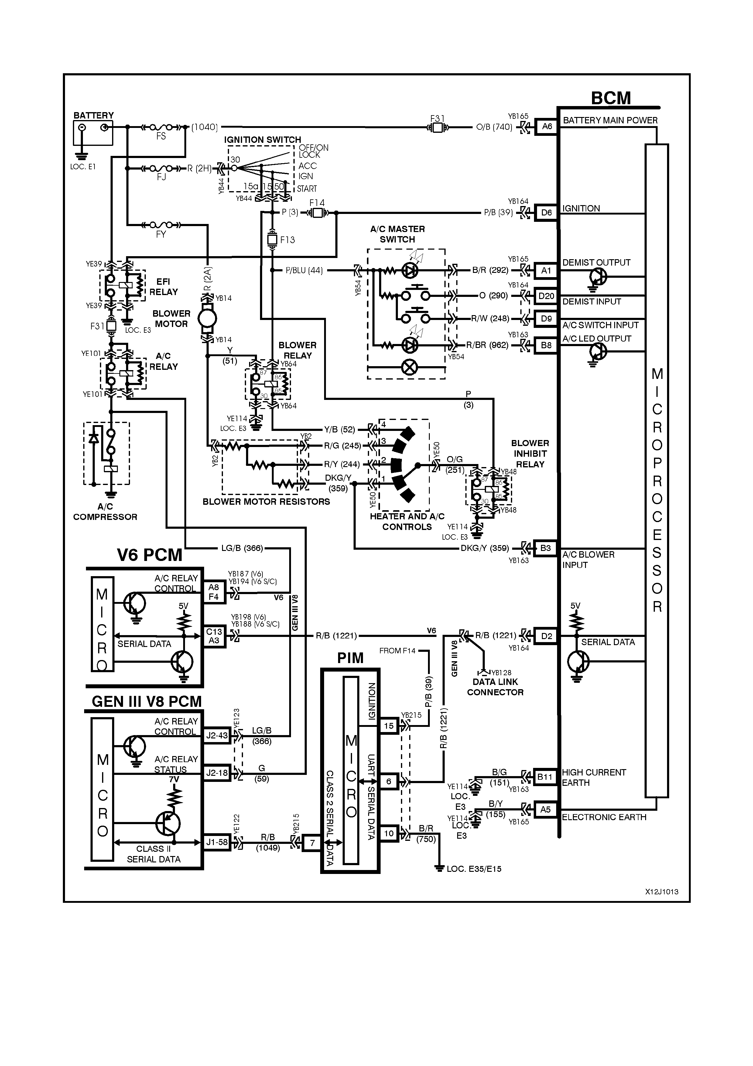
2.9 AIR CONDITIONING INTERFACE
Figure 12J-1-20
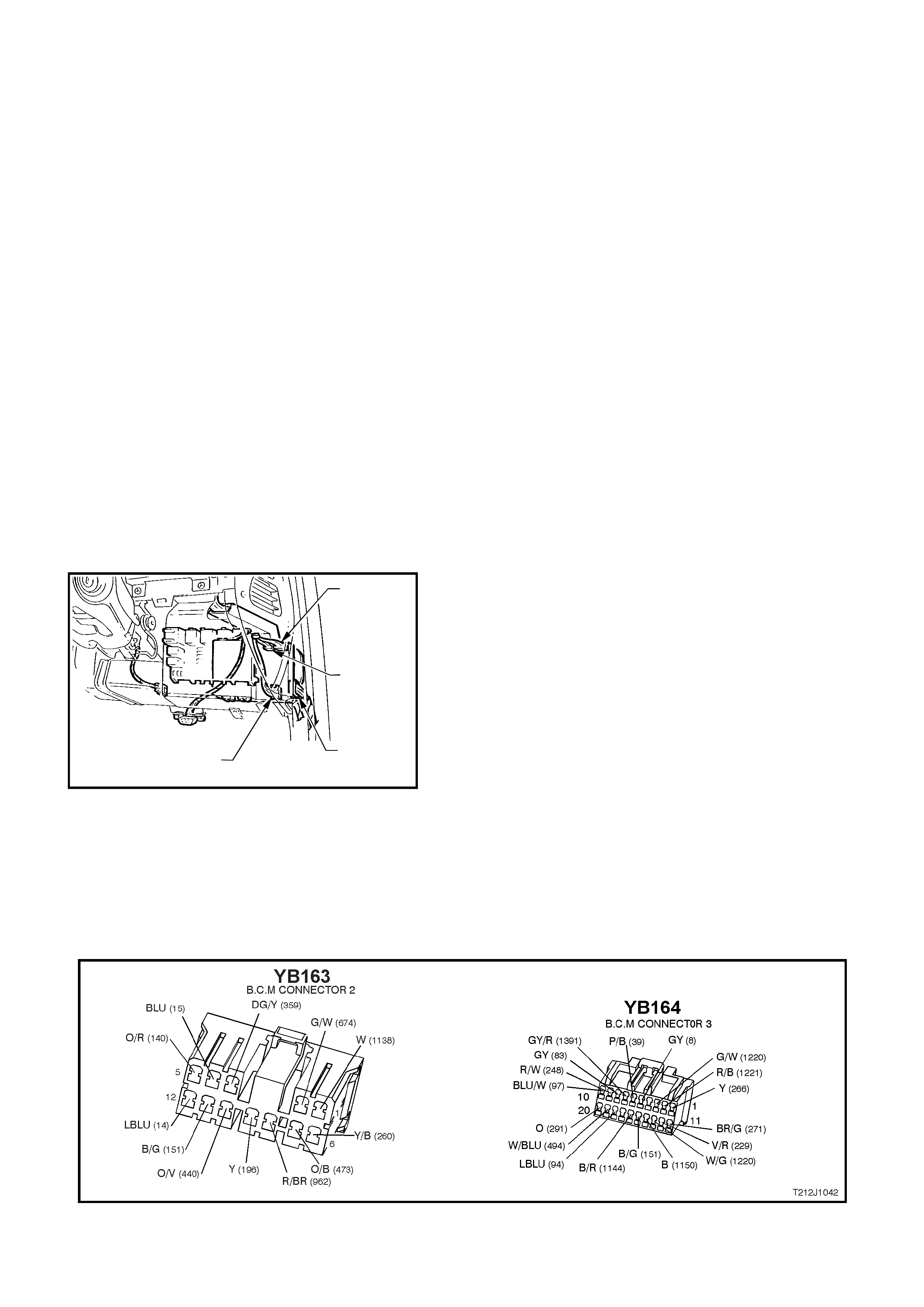
CIRCUIT DESCRIPTION
The air- conditioning interface is used to turn the air
conditioning s ystem on and off. The BCM reads the
momentary air conditioning switch signal, monitors
fan speed and if the ignition is on the BCM
requests the PCM ( via PIM on vehicles with GEN III
V8 engines) to turn on the air conditioning
compressor. The air conditioning status LED is
turned on by the BCM when the air conditioning
system is active (if the ignition is turned on) and will
toggle with the air conditioning select switch. The
status will be remembered when the ignition is
switched fr om ON to O FF or when the blower is off ,
but will reset to off when the battery is
disconnected. If the blower is off and the air
conditioning select button is pressed, then the next
time the blower is switched on, the air conditioning
status will also c om e on. T urning the ignition of f will
cancel this button press function.
The blower fan is controlled by the blower fan
inhibit relay, which is energised with the ignition
switch in the IGN position.
NOTE: The BCM has provision for an air
conditioning thermostat to prevent the evaporator
from icing up. In the abs enc e of this therm os tat, the
input is connected to ignition.
YB165
CONNECTOR (4)
YB163
CONNECTOR (2)
YB162
CONNECTOR (1)
YB164
CONNECTOR (1)
T12J1077A
Figure 12J-1-21
TEST DESCRIPTION
The num ber s below refer to step num bers in the following
diagnostic chart.
1-5. Functional check of air conditioning system.
6. Checks blower inhibit relay output switch.
7. Checks circuit 251.
8. Checks heater and air conditioning control switch.
9. Checks battery positive feed to blower motor (circuit
2A).
10. By-passes the resistor assembly (blower motor) to
determine problem with blower motor assembly.
11. Checks battery positive at blower inhibit relay.
12. Checks circuit 150.
13. Checks circuit 150 including blower inhibit relay.
14. Checks blower motor circuit 51.
15. Uses TECH 2 to conduct air conditioning
compressor/air conditioning status LED test.
16. Uses TECH 2 to check air conditioning select
ON/OFF signal at microprocessor of BCM.
17. Uses TECH 2 to check BLOWER FAN ON signal at
microprocessor of BCM.
18. Tes t to determ ine if air conditioning status LED is not
illuminated due to BCM or other circuits.
19. Checks for battery positive supply to air conditioning
master switch assembly.
20. Check s circ uit 962 and air conditioning m aster switch
assembly.
21. Check s AIR CONDITION ING SELECT signal at input
to BCM.
22. Check s circ uit 248 and air conditioning m aster switch
assembly.
23. Checks BLOWER FAN ON signal at input to BCM.
24. Check s if TECH 2 is able to com m unicate to BCM via
the serial data bus.
25. Uses TECH 2 to com mand the PCM to switch the air
conditioning compressor on.
26. Checks blower relay drive signal.
27. Checks battery positive feed to blower relay.
28. Checks blower relay switch output.
29. Checks circuit 52 and heater and air conditioning
control switch
30. Checks circuit 150 and blower relay.
Figure 12J-1-22

AIR CONDITIONING INTERFACE
STEP ACTION VALUE YES NO
1. • Turn ignition ON.
• Heater and air conditioning control switch speed 1.
• Does blower motor operate?
Go to Step 2. Go to Step 6.
2. • Turn ignition ON.
• Heater and air conditioning control switch speed 1.
• Toggle air conditioning select switch.
• Does air conditioning status LED illuminate?
Go to Step 3. Go to Step 15.
3. • Turn ignition ON.
• Heater and air conditioning control switch speed 1.
• Toggle air conditioning select switch to ON.
• Does air conditioning compressor operate?
Go to Step 4. Go to Step 24.
4. • Turn ignition ON.
• Heater and air conditioning control switch speed 4.
• Does blower motor operate?
Go to Step 5. Go to Step 26.
5. • Turn ignition ON.
• Heater and air conditioning control switch speed 4.
• Toggle air conditioning select switch to ON.
• Does air conditioning compressor operate?
System OK. Check blower
motor resistor
assembly, refer
to 2 AIR
CONDITIONING
of the VT Series I
Service
Information.
6. • Turn ignition ON.
• Back probe blower inhibit relay connector YB48,
terminal 87, circuit 251 (Orange/Green wire) with a
Voltmeter to earth.
• Is voltage as specified?
100 mVolts Go to Step 7. Go to Step 11.
7. • Back probe heater and air conditioning control switch
connector YB50, circuit 251 (Orange/Green wire)
with a Voltmeter to earth.
• Is voltage as specified?
100 mVolts Go to Step 8. Repair open in
circuit 251.
Recheck circuit
to verify repair.
8. • Back probe heater and air conditioning control switch
connector YB50, circuit 359 (Dark Green/Yellow
wire) with an Voltmeter to earth.
• Is voltage as specified?
100 mVolts Go to Step 9. Replace heater
and air
conditioning
control switch,
refer to 2 AIR
CONDITIONING
of the VT Series I
Service
Information.
9. • Back probe blower motor connector YB14, circuit 2A
(Red wire) with a Voltmeter to earth.
• Is voltage as specified?
12 volts Go to Step 10. Check and repair
fault in circuit 2A
(including fusible
link FY).
Recheck and
verify repair
10. • Disconnect blower motor resister connector YB2.
• Back probe blower resistor connector YB2 (harness
end) circuit 51 (Yellow wire) with a jumper lead and
connect to earth.
• Does the blower motor operate?
Check blower
motor resistor. Go to Step 14.
11. • Turn ignition ON.
• Back probe blower inhibit relay connector YB48,
terminal 86, circuit 3 (Pink wire) with a Voltmeter to
earth.
• Is voltage as specified?
12 volts Go to Step 12. Check and repair
fault in circuit 3.
Recheck and
verify repair
12. • Back probe blower inhibit relay connector YB48,
terminal 85, circuit 150 (Black wire) with a jumper
lead connected to earth.
• Turn ignition ON.
• Does the blower motor operate?
Check and repair
fault in circuit
150. Recheck
and verify repair.
Go to Step 13.

STEP ACTION VALUE YES NO
13. • Back probe blower inhibit relay connector YB48,
terminal 30, circuit 150 (Black wire) with an
Ohmmeter to earth.
• Is value as specified?
Below 1 ohm Replace blower
inhibit relay.
Recheck and
verify repair.
Check and repair
open in circuit
150 Recheck and
verify repair.
14. • Back probe blower motor connector YB14, circuit 51
(Yellow wire) with a jumper lead and connect to
earth.
• Does blower motor operate?
Check and repair
open in circuit
51. Recheck and
verify repair.
Replace blower
motor, refer to 2
AIR
CONDITIONING
of the VT Series I
Service
Information.
15. • Connect TECH 2 to DLC.
• Select Body / Body Control Module / Miscellaneous
Tests / Lamps / A/C Test.
• Conduct test as instructed by TECH 2 and switch the
A/C compressor status LED on.
• Does Air conditioning status LED illuminate?
Go to Step 16. Go to Step 18.
16. • With TECH 2 connected, exit Miscellaneous Test
and select Data Display.
• Scroll to A/C Switch.
• Does screen display AC Switch On / Off when
toggling air conditioning select switch?
Go to Step 17. Go to Step 21.
17. • With TECH 2 connected and Data Display selected,
scroll to A/C Blower Switch .
• Switch heater and air conditioning control switch to
speed 1.
• Does screen display A/C Blower Switch On?
Replace BCM,
refer to 12J-1
LOW SERIES
BCM of the VT
Series II Service
Information.
Recheck and
verify repair.
Go to Step 23.
18. • Turn ignition ON.
• Back probe BCM connector YB163, terminal B8,
circuit 962 (Red/Brown wire) with a jumper lead and
connect to earth.
• Does air conditioning status LED illuminate?
Replace BCM,
refer to 12J-1
LOW SERIES
BCM of the VT
Series II Service
Information.
Recheck and
verify repair.
Go to Step 19.
19. • Back probe air conditioning master switch connector
YB54, circuit 44 (Pink/Blue wire) with a Voltmeter to
earth.
• Turn ignition ON.
• Is voltage as specified?
12 volts Go to Step 20. Check and repair
fault in circuit 44
(including fuse
F13). Recheck
and verify repair.
20. • Turn ignition ON.
• Back probe air conditioning master switch connector
YB54, circuit 962 (Red/Brown wire) with a jumper
lead and connector to earth.
• Does air conditioning status LED illuminate?
Check and repair
open in circuit
962. Recheck
and verify repair.
Replace heater
and air
conditioning
control switch,
refer to 2 AIR
CONDITIONING
of the VT Series I
Service
Information.
21. • Turn ignition ON.
• Back probe BCM connector YB164, terminal D9,
circuit 248 (Red wire) with a Voltmeter to earth.
• Is voltage as specified when air conditioning switch
is activated?
Switch closed
(held in)
12 volts
Switch open
(rest position)
0 volts
Replace BCM,
refer to 12J-1
LOW SERIES
BCM of the VT
Series II Service
Information.
Recheck and
verify repair.
Go to Step 22.

STEP ACTION VALUE YES NO
22. • Turn ignition ON.
• Back probe air conditioning master switch connector
YB54, circuit 248 (Red/White wire) with a Voltmeter
to earth.
• Is voltage as specified when air conditioning switch
is activated?
Switch closed
(held in)
12 volts
Switch open
(rest position)
0 volts
Check and repair
open in circuit
248. Recheck
and verify repair.
Replace heater
and air
conditioning
control switch,
refer to 2 AIR
CONDITIONING
of the VT Series I
Service
Information.
23. • Turn ignition ON.
• Back probe BCM connector YB163, terminal B3,
circuit 359 (Dark Green/Yellow wire) with a
Voltmeter to earth.
• Is voltage as specified?
100 mVolts Replace BCM,
refer to 12J-1
LOW SERIES
BCM of the VT
Series II Service
Information.
Recheck and
verify repair.
Check and repair
open in circuit
359. Recheck and
verify repair.
24. • Connect TECH 2 to DLC.
• Select Body / Body Control Module.
• Does TECH 2 display system identification
information (BCM type)?
Go to Step 25 Go to serial data
communications
diagnosis, refer to
2.2 SERIAL DATA
COMMUNICATIO
N in this Section.
25. • With TECH 2 connected, exit Body and select
Engine / appropriate engine / Data Display /
Miscellaneous Tests and command AC Compressor
On.
• Does air conditioning compressor operate?
Replace BCM,
refer to 12J-1
LOW SERIES
BCM of the VT
Series II Service
Information.
Recheck and
verify repair.
Go to PCM
diagnostics in
Section 6C1
POWERTRAIN
MANAGEMEN T -
V6 ENGINE or
6C3
POWERTRAIN
MANAGEMEN T –
GEN III V8
ENGINE in the VX
Series Service
Information.
26. • Turn ignition ON.
• Switch heater and air conditioning control switch to
speed 4.
• Back probe blower relay connector YB64, terminal
85, circuit 52 (Yellow/Black wire) with a Voltmeter to
earth.
• Is voltage as specified?
100 mVolts Go to Step 27. Go to Step 29.
27. • Turn ignition ON.
• Back probe blower relay connector YB64, terminal
86, circuit 44 (Pink/Blue wire) with a Voltmeter to
earth.
• Is value as specified?
12 volts Go to Step 28. Check and repair
open in circuit 44.
Recheck and
verify repair.
28. • Turn ignition ON.
• Switch heater and air conditioning control switch to
speed 4.
• Back probe blower relay connector YB64, terminal
87, circuit 51 (Yellow wire) with a Voltmeter to earth
• Is voltage as specified?
100 mVolts Check and repair
open in circuit
51. Recheck and
verify repair
Go to Step 30.
29. • Turn ignition ON.
• Switch heater and air conditioning control switch to
speed 4.
• Back probe heater and air conditioning control
switch connector YB50, circuit 52 (Yellow/Black
wire) with a Voltmeter to earth.
• Is voltage as specified?
100 mVolts Check and repair
open in circuit
52. Recheck and
verify repair.
Replace heater
and air
conditioning
control switch,
refer to 2 AIR
CONDITIONING
of the VT Series I
Service
Information.
30. • Back probe blower relay connector YB64, terminal
30, circuit 150 (Black wire) with a Voltmeter to earth.
• Is voltage as specified?
100 mVolts Replace blower
relay. Recheck
and verify repair.
Check and repair
open in circuit
150. Recheck and
verify repair.

2.10 SRS DEPLOYMENT VEHICLE SHUTDOWN
Figure 12J-1-23
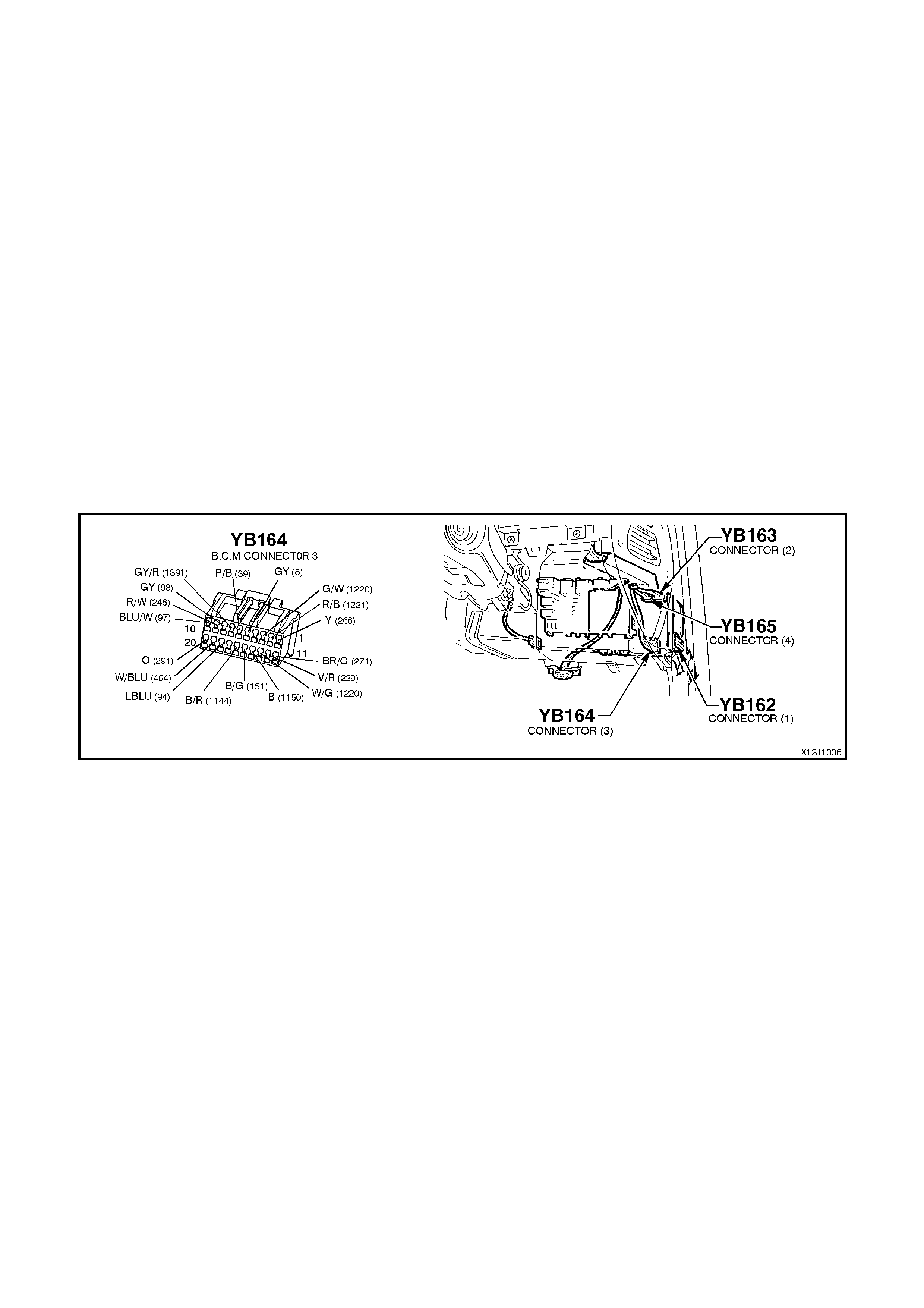
CIRCUIT DESCRIPTION
In the event of SRS (Supplemental Restraint System) deployment, the Sensing Diagnostic Module (SDM) sets a
flag and sends serial data via the SRS Serial Data (SDI) bus to the BCM. Within the BCM, the SRS SDI bus is
linked to the auxiliary serial data via a wire link. The SDM advises various vehicle systems via the auxiliary bus to
take appropriate shutdown action.
The BCM will monitor this serial data and perform the following actions once the appropriate data is identified and
the vehicle speed is zero for 10 seconds:
1. Turn the dome lamp ON continuously.
2. Unlock all doors.
The dom e lam p will be switched OFF when the ignition switch is cycled from OFF to ON, or when the BCM is re set
(ie. via battery disconnection)
TEST DESCRIPTION
The numbers below refer to step numbers in the diagnostic chart below.
1. Checks the Main SDI bus communication.
2 & 3. Checks Auxiliary SDI bus communication to the SDM and instruments.
4. Checks the BCM internal link, SRS SDI bus connection to the SDI auxiliary bus.
5. Checks circuit 1220 (Green/White wire) (BCM to SDM).
NOTE 1: This diagnostic chart assumes that the central door locking system, dome lamp and indicator functions
(controlled by the BCM) are operating correctly.
NOTE 2: TECH 2 is capable of identifying the SDM type; 6.2, or type 8.0/8.1, refer to Section 12M
SUPPLEMENTAL RESTRAINT SYSTEM of the VT Series I Service Information for additional information.
Figure 12J-1-24

SRS DEPLOYMENT VEHICLE SHUTDOWN
STEP ACTION VALUE YES NO
1. • Connect TECH 2 to the DLC.
• Select Body / Body Control Module.
• Turn ignition ON (as requested by TECH 2).
• Does screen display BCM system identification?
Go to Step 2. Go to serial data
communications
diagnosis, refer to
2.2 SERIAL DATA
COMMUNICATION
in this Section.
2. • With TECH 2 still connected, exit Body Control
Module selection.
• Select Body / SRS.
• Turn ignition ON (as requested by TECH 2).
• After five seconds, is TECH 2 able to communicate
with the SDM?
Go to SRS
diagnosis in
Section 12M SRS
in the VT Series I
Service
Information(6.2
SDM) or in the VX
Series Service
Information (8.0 &
8.1 SDM).
Go to Step 3.
3. • With TECH 2 still connected, exit SRS selection.
• Select Body / Instruments.
• Turn ignition ON (as requested by TECH 2).
• After five seconds, is TECH 2 able to communicate
with the instruments?
Go to Step 4. Go to serial data
communications
diagnosis, refer to
2.2 SERIAL DATA
COMMUNICATION
in this Section.
4. • Turn ignition OFF.
• Back probe BCM connector YB164, terminal D13,
circuit 1220 (White/Green wire) and BCM
connector YB164, terminal D3, circuit 1220
(Green/White wire) with an Ohmmeter.
• Is value as specified?
Below 1 ohm Go to Step 5. Replace BCM, refer
to 12J-1 LOW
SERIES BCM of
the VT Series II
Service
Information.
Recheck and verify
repair.
5. • Turn ignition OFF.
• Back probe BCM connector YB164, terminal D13,
circuit 1220 (White/Green wire) and, using Tool
Km-609-20, SDM connector YB189 / YB190,
terminal 9, circuit 1220 (W hite/Green wire) with an
Ohmmeter.
• Is value as specified?
Below 1 ohm Go to SRS
diagnosis in
Section 12M SRS
in the VT Series I
Service
Information (6.2
SDM) or in the VX
Series Service
Information (8.0 &
8.1 SDM).
Repair open in
circuit 1220.
Recheck circuit to
verify repair.
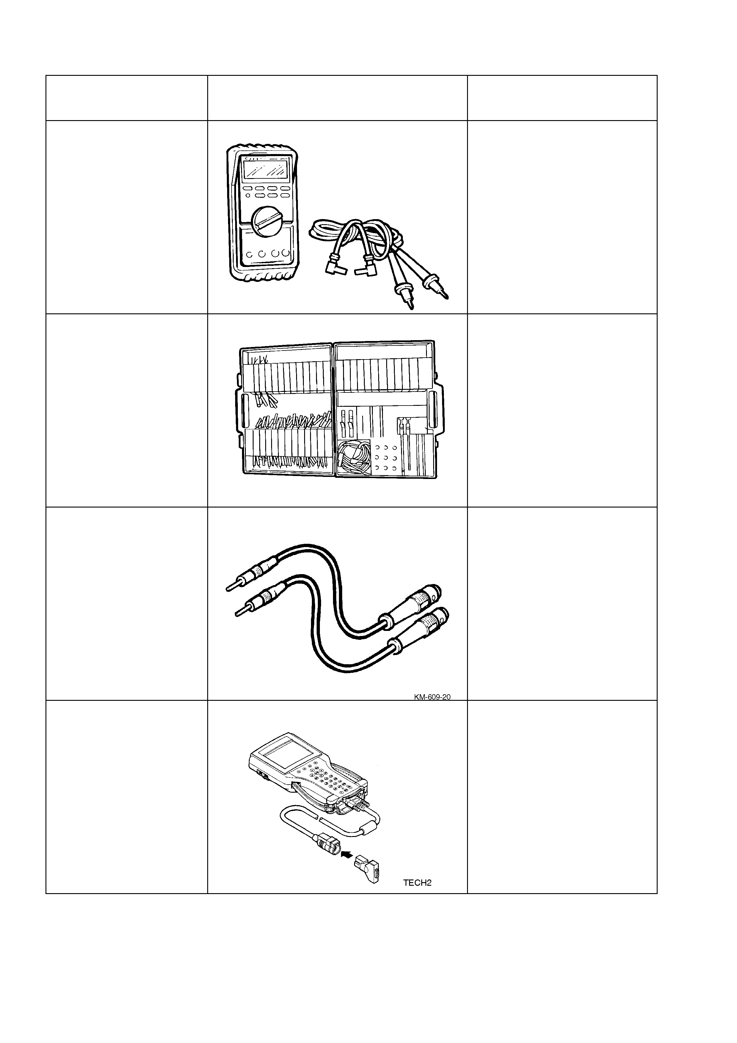
3 SPECIAL TOOLS
TOOL NO. REF
IN TEXT TOOL DESCRIPTION COMMENTS
J39200 DIGITAL MULTIMETER
TOOL NO. J39200
PREVIOUSLY RELEASED, OR
USE COMMERCIALLY
AVAILABLE EQUIVALENT.
MUST HAVE 10 MOHM INPUT
IMPEDANCE AND BE
CAPABLE OF READING
CAPACITANCE
KM-609 ELECTRONIC KIT
USED IN CONJUNCTION
WITH A MULTIMETER FOR
MEASURING VOLTAGES AND
RESISTANCE’S WITHOUT
DAMAGING WIRING
HARNESS CONNECTORS
KM-609-20 SRS TEST LEAD SET
PREVIOUSLY RELEASED
TECH 2 DIAGNOSTIC SCAN TOOL
PREVIOUSLY RELEASED