
SECTION 12L - ANTI-LOCK BRAKING &
ELECTRONIC TRACTION CONTROL
IMPORTANT
Before performing any Service Operation or other procedure described in this Section, refer to Section
00 CAUTIONS AND NOTES for correct workshop practices with regard to safety and/or property damage.
1. GENERAL I NFORMATI O N
The Anti-lock Brak ing System (ABS) and Anti-lock Braking System / Electronic T raction Control ( ABS/ETC) s ystem
used on VX Series Models are the same as those used on VT Series Models, with the introduction of ABS/ETC
becoming available for vehicles with a manual transmission.
W ith the introduction of ETC to vehicles with a manual transmission, come some minor deviations to the systems
used on vehicles with an autom atic transmission. This Section only covers these deviations, therefore, for all other
information relating to ABS and ABS/ETC systems, refer to Section 12L ABS & ABS/ETC of the
VT Series I Service Information or of the VT Series II Service Information.
To accommodate the use of ETC on a vehicle with a manual transmission, there have been some minor software
changes made to the ABS/ETC control module and the Powertrain Control Module (PCM).
Changes to the ABS/ETC control module do not effect the operation, servicing or diagnosis of the ABS/ETC
system.
Refer to Section 6C1 POWERTRAIN MANAGEMENT - V6 ENGINE or Section 6C3 POWERTRAIN
MANAGEMENT - GEN III V8 Engine VX Series Service Information for information regarding the PCM.
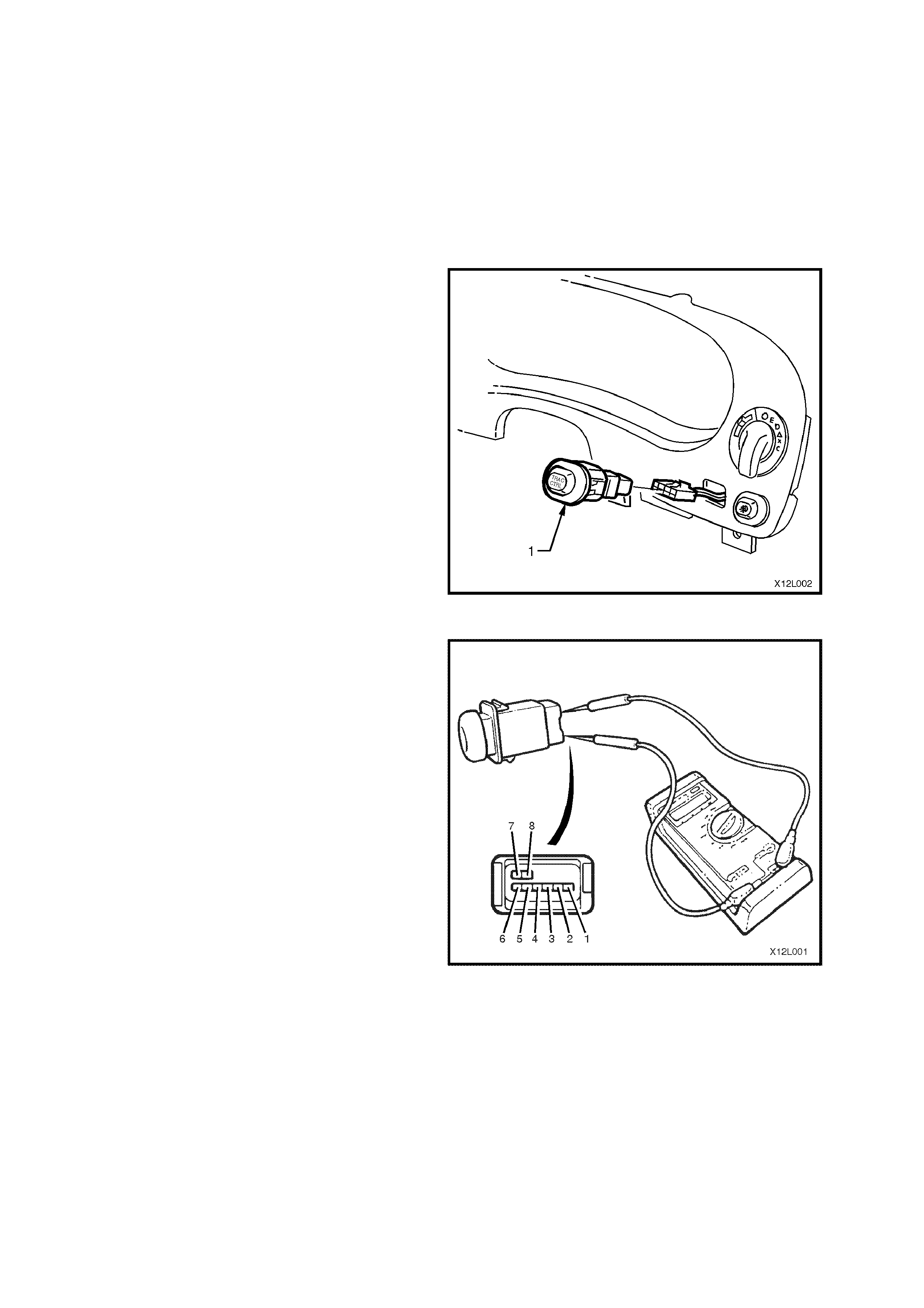
On vehicles with a manual transmission, the switch to disable the electronic traction control system (TRAC CTRL) is
located below the headlamp switch in the instrument panel facia.
Techline
2. SERVICE OPERATIONS
With exception to the following Service Operation, all ABS and ABS/ETC Service Operations for VX Series
Models carry over from those described in Section 12L ABS & ABS/ETC of the
VT Series I Service Information and of the VT Series II Service Information.
2.1 TRACTION CONTROL SWITCH
(TRAC CTRL) - VEHICLES WITH MANUAL TRANSMISSION)
REMOVE
1. Disconnect battery earth lead.
2. Remove instrument panel facia far enough to
gain access to switch connectors attached to
the instrument panel facia (traction control (1),
headlamp, fog lam p, trip computer, hazard and
(vehicles with P.O. 9C1 or A8V) interior lights
out switch. Refer to
Section 1A3 INSTRUMENT PANEL AND
CONSOLE of the VT Series I Service
Information.
3. Disconnect wiring harness connectors from
each switch and remove the instrument panel
facia.
4. From behind the instrument panel facia,
squeeze together the traction control switch to
instrument panel facia tangs and push switch
out from tangs.
Figure 12B-1
TEST
Using an ohmmeter connected to the TRAC CTRL
switch, check for continuity between the following
terminals with the switch held IN:
• Ter. 1 and Ter. 2
• Ter. 1 and Ter. 5
• Ter. 2 and Ter. 5
If the ohmmeter indicates an open circuit, replace
the switch assembly.
REINSTALL
Reinstallation of the traction control switch is the
reverse of the removal operation.
Figure 12L-1

3. ABS & ABS/ETC DIAGNOSIS
All diagnosis inf or mation fo r the ABS and ABS/ETC system s fitted to VX Series Models is as detailed in Section 12L
ABS & ABS/ETC of the VT Series I Service Information and of the VT Series II Service Informatio n, noting the
following:
If an ABS/ETC control module from a vehicle with an automatic transmission is fitted to a vehicle with a manual
transmission, or visa versa, the control module will set an ‘Incorrect Option Coding’ fault (DTC 78). Refer to the
diagnostic charts in Section 12L ABS & ABS/ETC of the VT Series I Service Information for additional information.
When using TECH 2 on a VX Series Model, ensure the correct Model Year and Vehicle Type is selected:
(Y) 2000
(1) 2001 VX Commodore
(2) 2002
Techline
Techline