
SECTION 12N - FUSES, RELAYS AND
WIRING HARNESSES
IMPORTANT
Before performing any Service Operation or other procedure described in this Section, refer to Section
00 CAUTIONS AND NOTES for correct workshop practices with regard to safety and/or property damage.
1. GENERAL I NFORMATI O N
1.1 FUSES AND CIRCUIT BREAKERS
All fuses and circuit breakers for VX Series carry over from that described in Section 12N FUSES, RELAYS &
W IRING HARNESSES in the VT Series I Serv ice Information and the VT Series II Service Information, ex cept
as follows:
1. Fuse F5 ST OP LAMPS in the passenger c ompartm ent fuse and relay panel assem bly has been changed from
10 A to 15 A, refer to Fig. 12N-1.
For all fuse and circuit breaker circuit protection details, refer to 1. POWER DISTRIBUTION circuit diagram in
Section 12P WIRING DIAGRAMS of the VX Series Service Information.

1.2 RELAYS
All inform ation on relays for VX Ser ies models c arries over fr om that described in Section 12N FU SES, RELAYS &
W IRING HARNESSES in the VT Series I Serv ice Information and the VT Series II Service Information, ex cept
as follows:
1. T he resistanc e specific ations for c oils within the following relays has been revised fr om 93 ohm s to 72 ohm s to
improve reliability and durability:
Engine cooling fan (low) 5 pin
Engine cooling fan (high) 4 pin
Start 4 pin
Blower 4 pin
Blower inhibitor 4 pin
EFI 4 pin
Heated rear window 4 pin
Power window 4 pin
Headlamp high beam 4 pin
2. The LPG Control Module is now integrated with the V6 Power Train Control Module. Accordingly, an LPG
control relay is no longer required in the passenger compartment fuse and relay panel assembly on LPG
equipped models.
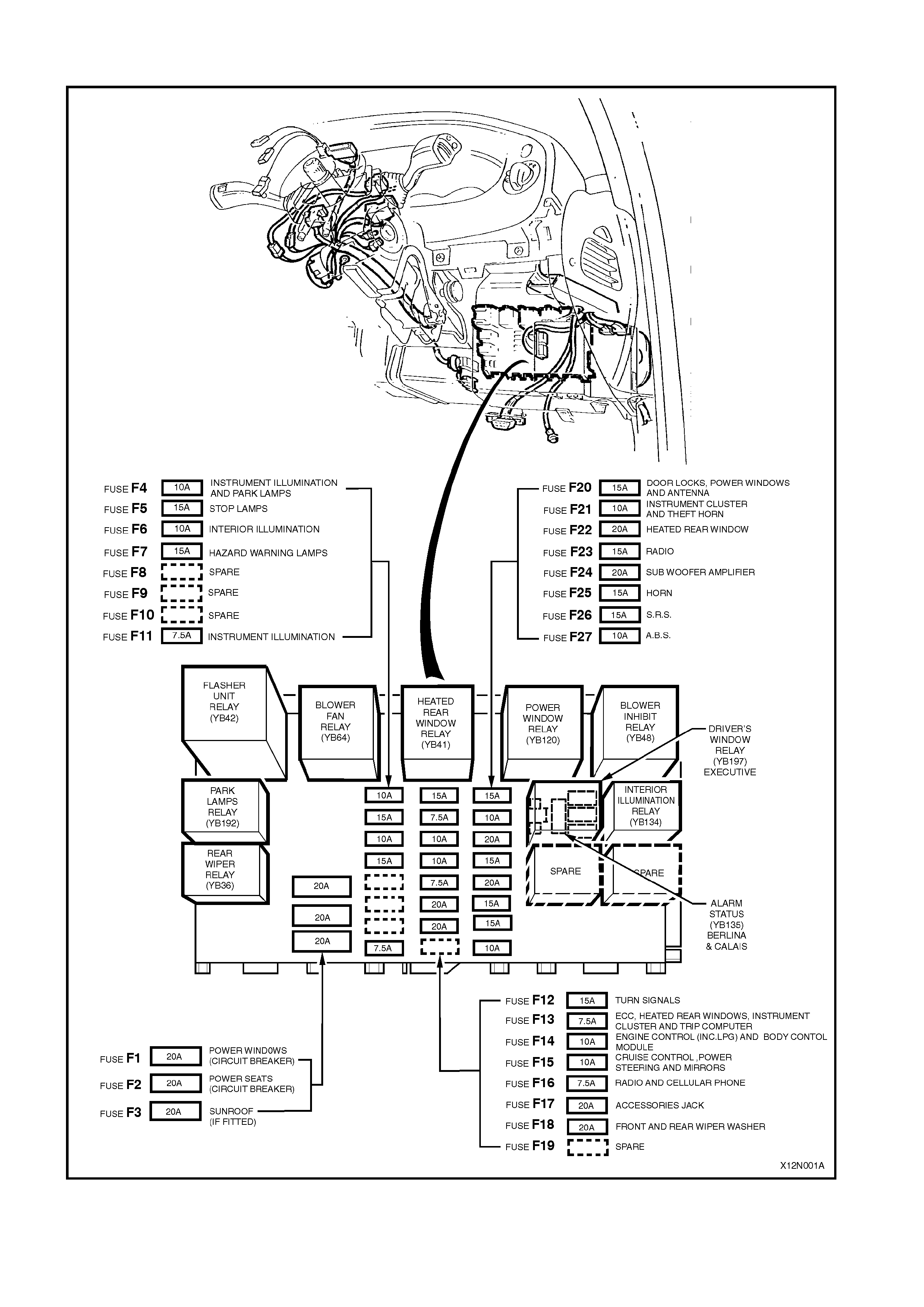
Fig. 12N-1 illustrates the passenger compartment fuse and relay panel assembly for VX Series models.
Figure 12N-1

3. WIRING INSTALLATION DIAGRAMS
The following wiring installation diagrams are applicable to VX Series models.
For all other wiring installation diagrams, refer to Section 12N FUSES, RELAYS & WIRING HARNESSES in the
VT Series I Service Information and the VT Series II Service Information.
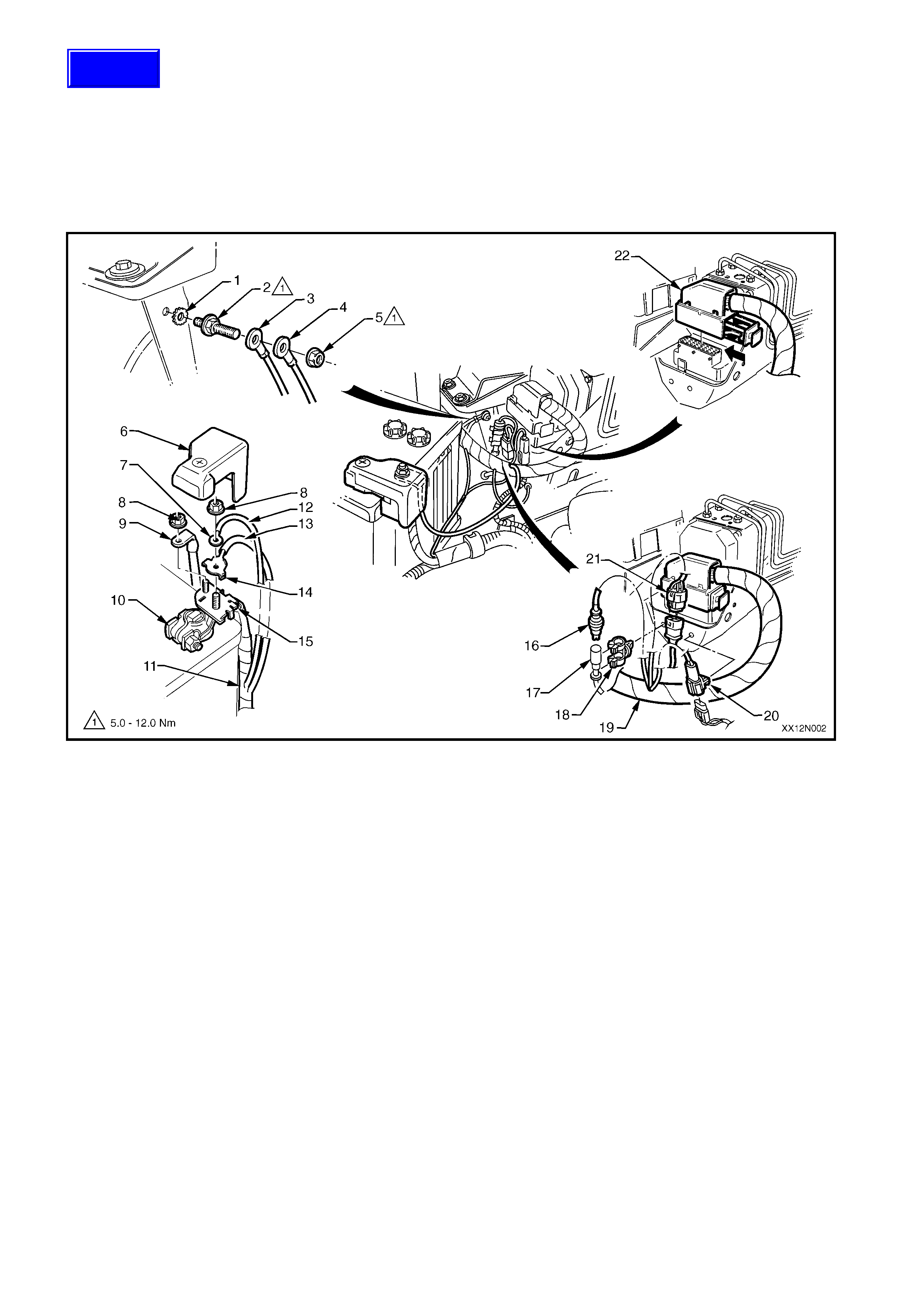
BATTERY WIRING HARNESS — 1
BATTERY AND ABS
Figure 12N-2
1. Washer
2. Stud
3. Body Earth Terminal
4. Battery Earth Term i nal
5. Nut
6. Positive Battery Terminal Cover
7. Voltage Sense Terminal
8. Nut
9. Fuse Panel S uppl y Terminal
10. Positive Batt ery Terminal
11. Battery Harness to S tarter Motor and Generator
12. Brown Fusible Link Wire
13. Blue Fusibl e Li nk Wire
14. Engine Cooling/ Condenser Fans Term i nal
15. Battery Positive Post Assembly
16. ABS Connector to Main Wi ri ng Harness
17. ABS Connec tor to Front Lef t Wheel
18. ABS Connector Retainer
19. Main Wiring Harness
20. Main Wiring Harness to Power Steeri ng P atch Harness Connector
21. Main Wiring Harnes s to Bat tery Harness Connec tor
22. ABS Harness Connect or to ABS ECU Modulator
Techline
BATTERY WIRING HARNESS — 2
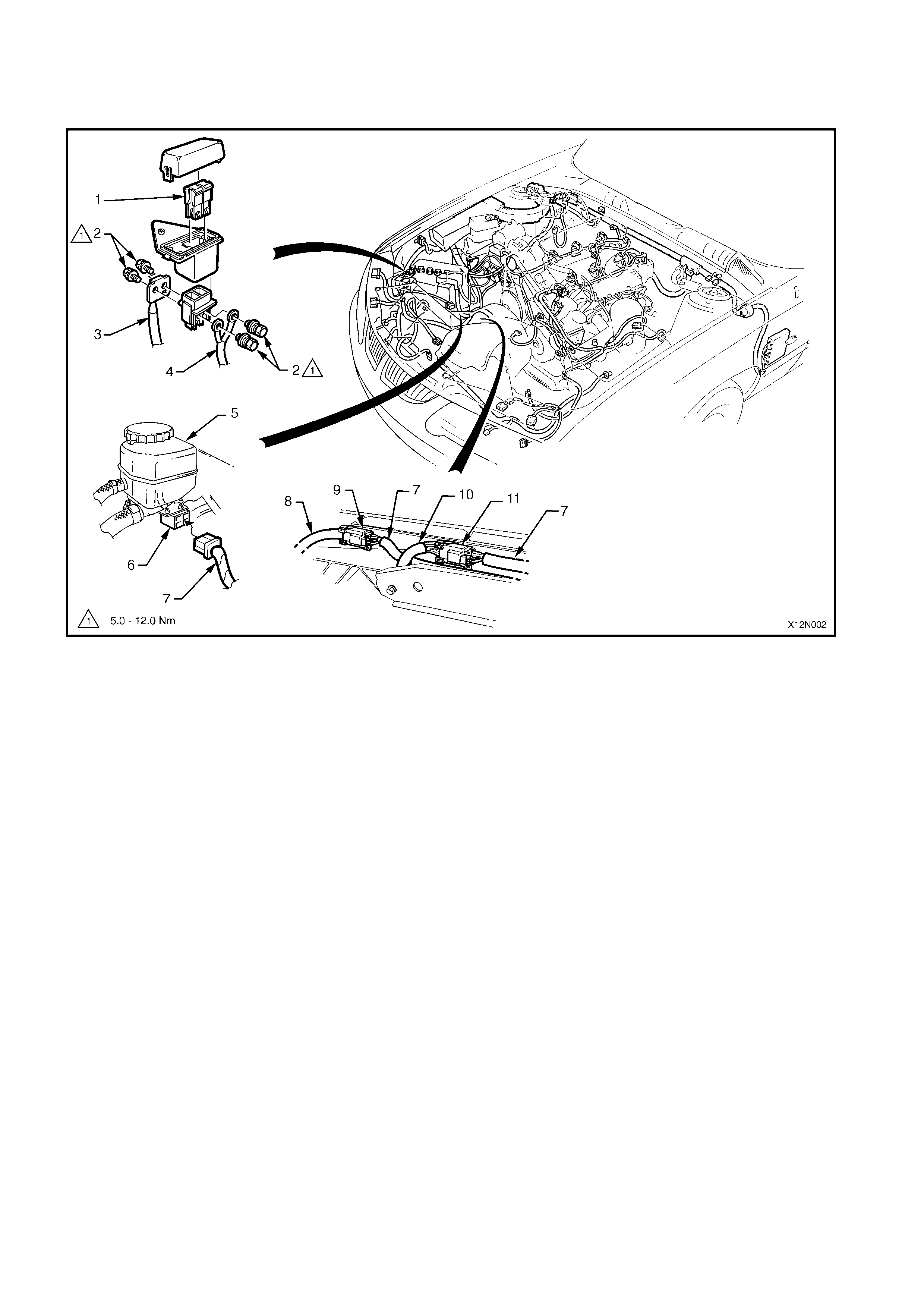
ENGINE COOLING/CONDENSER FAN HARNESS — MODELS WITH V6 ENGINE
Figure 12N-3
1. Engine Cooling Fan Fus i bl e Li nks
2. Screw
3. Battery Harness
4. Power Wires to E ngi ne Cool i ng/Condenser Fans
5. Power Steering Reservoir
6. Connector — Fus ibl e Li nks and Fan Relays t o Engine Cooling Fans
7. Engine Cooling Fans Harness
8. Low Speed Engine Cooling Fan Harness
9. Low Speed Engine Cooling Fan Harness Connector
10. High Speed Engine Cool i ng Fan Harness
11. High Speed Engine Cool i ng Fan Harness Connect or
BATTERY WIRING HARNESS — 3
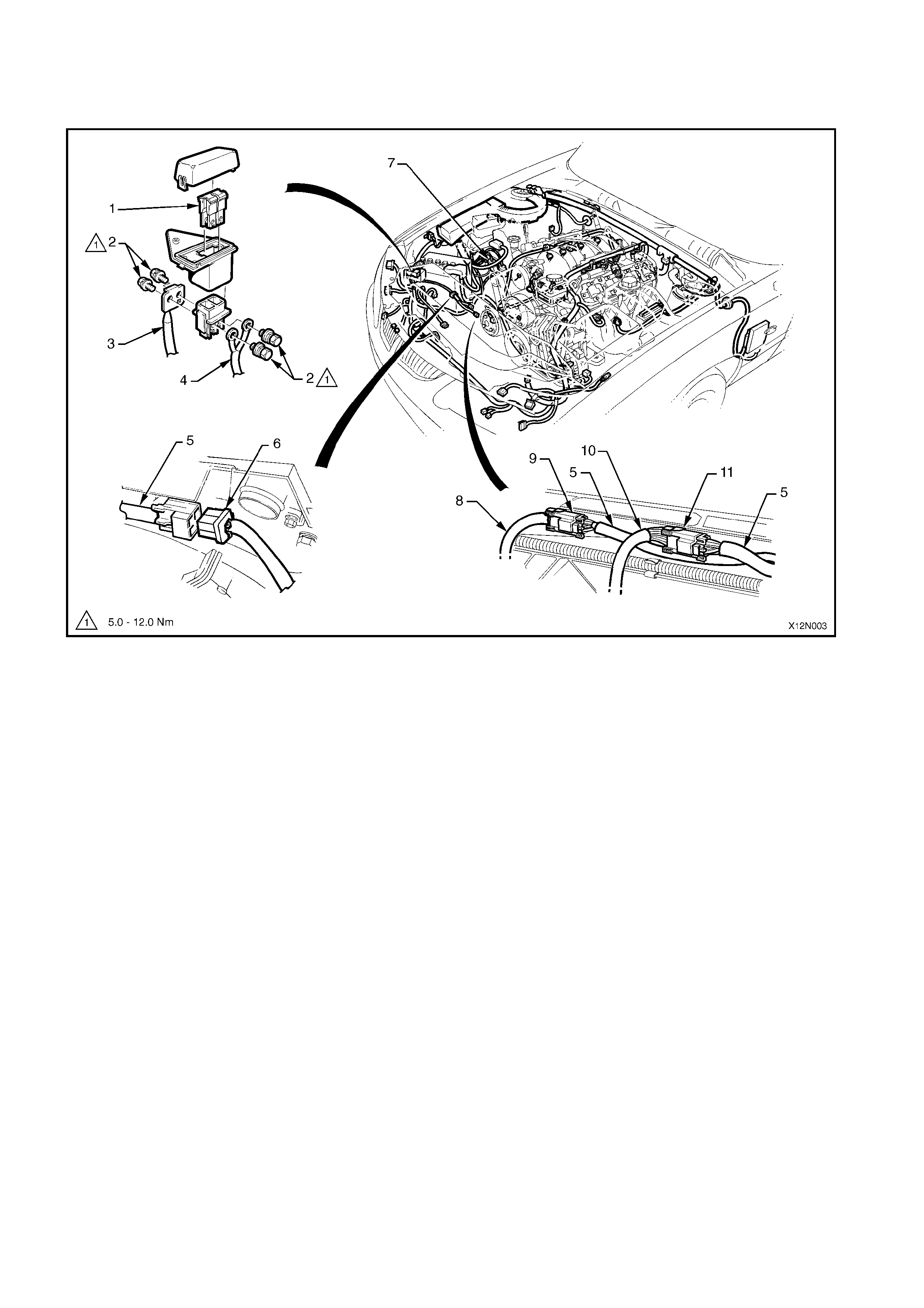
ENGINE COOLING/CONDENSER FAN HARNESS — MODELS WITH GEN III V8 ENGINE
Figure 12N-4
1. Engine Cooling Fan Fus i bl e Li nks
2. Screw
3. Battery Harness
4. Power Wires to E ngi ne Cool i ng/Condenser Fans
5. Engine Cooling Fans Harness
6. Connector — Fus ibl e Li nks and Fan Relays t o Engine Cooling Fans
7. Engine Cooling Fans to Fan Relays Connector
8. Low Speed Engine Cooling Fan Harness
9. Low Speed Engine Cooling Fan Harness Connector
10. High Speed Engine Cool i ng Fan Harness
11. High Speed Engine Cool i ng Fan Harness Connect or
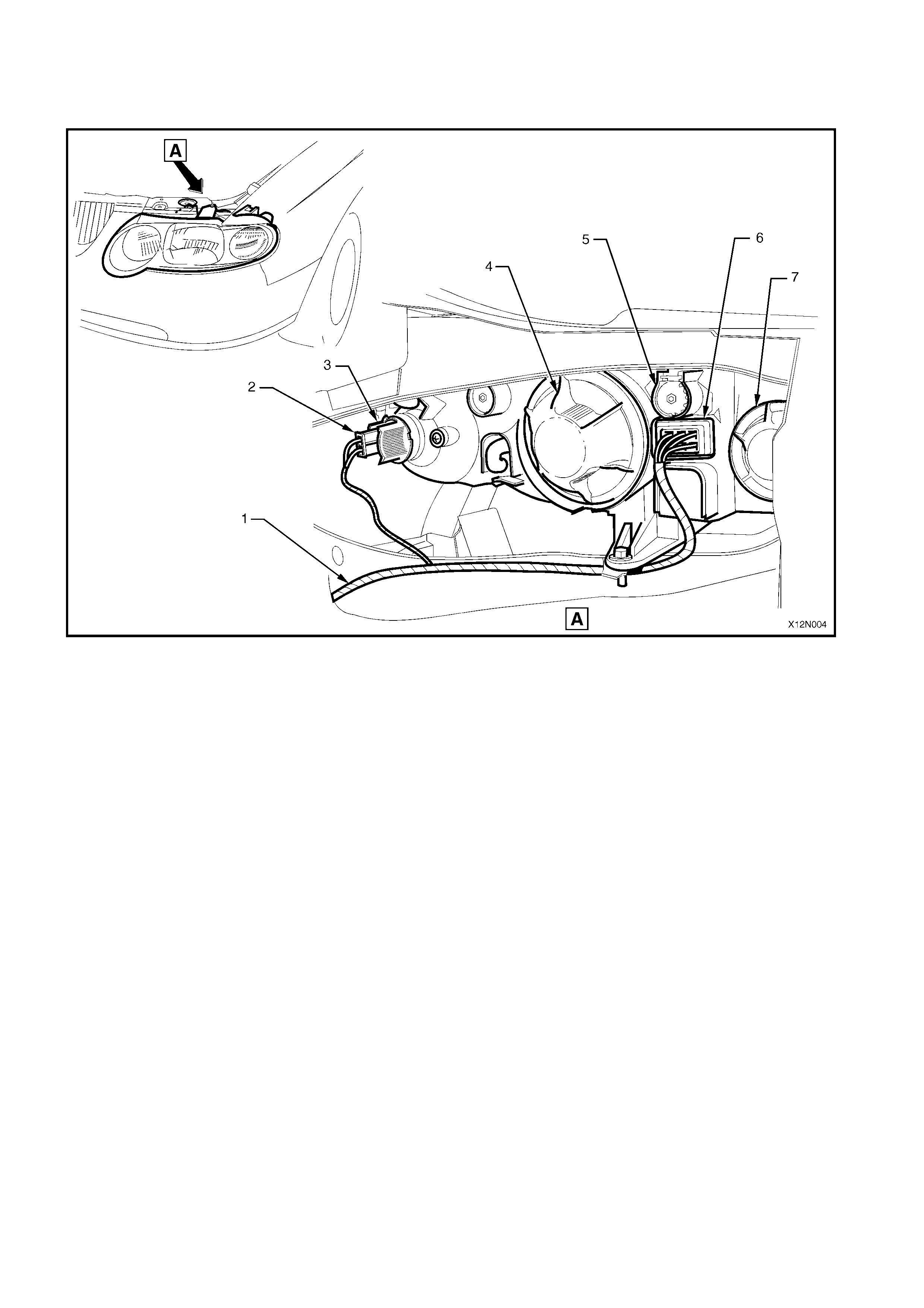
MAIN WIRING HARNESS — 1
HEADLAMP, PARK LAMP AND TURN INDICATOR WIRING HARNESS
Figure 12N-5
1. Main Wiring Harnes s
2. Turn Indicator Connector
3. Turn Indicator Socket
4. Headlamp Low Beam Dust Cover
5. Headlamp Adjuster
6. Headlamp Main Wiring Harness Connec tor
7. Headlamp Hi gh Beam Dus t Cover
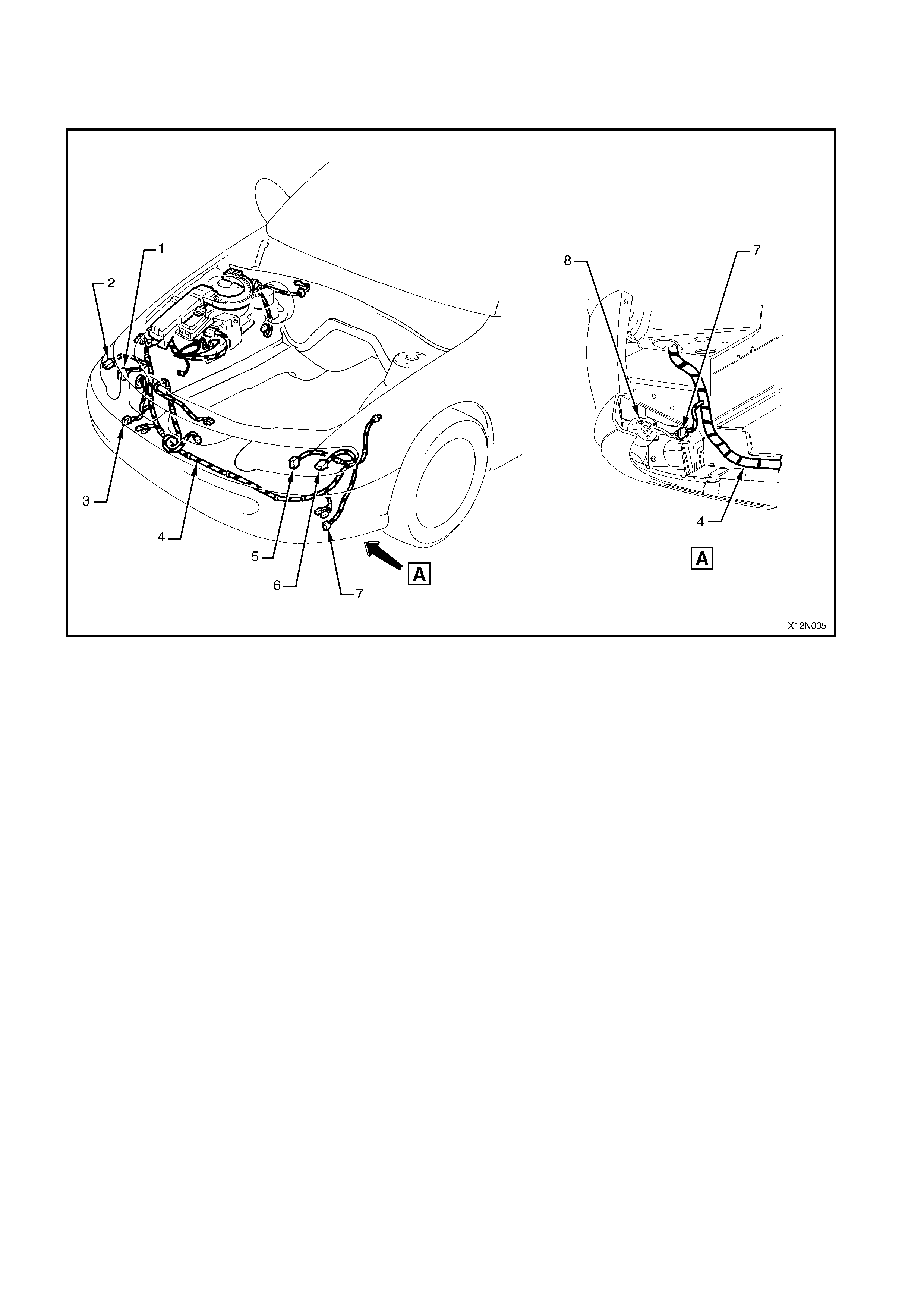
MAIN WIRING HARNESS — 2
FOG LAMP HARNESS, HEADLAMP, PARK LAMP AND TURN INDICATOR WIRING HA RNESS
Figure 12N-6
1. Right-hand Headlamp Connector
2. Right-hand Turn Indi cator Connect or
3. Right-hand Fob Lamp Connector
4. Main Wiring Harnes s
5. Left-hand Headlamp Connector
6. Left-hand Turn Indi cator Connect or
7. Left-hand Fob Lamp Connector
8. Left-hand Fog Lamp Assembly — SS type
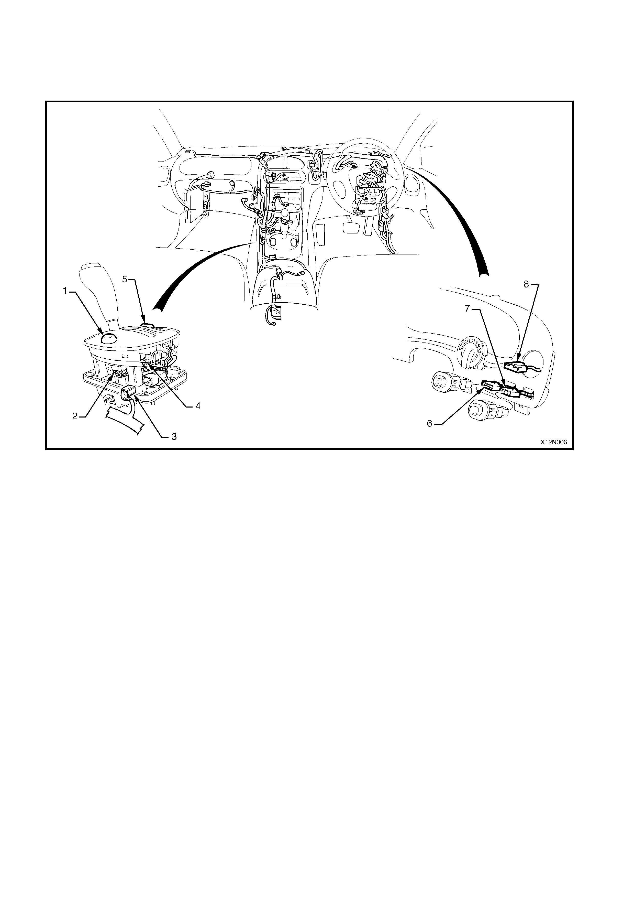
MAIN WIRING HARNESS — 3
LIGHTING, FUEL MODE (LPG), TRACTION CONTROL (TCS) AND POWER/ECONOMY SWITCH
CONNECTORS
Figure 12N-7
1. Traction Cont rol Switch (TCS) Switc h Illum i nation or Fuel Mode Switch (LPG )
2. Traction Cont rol Switch (TCS) Switch Illumination or Fuel Mode Switch (LPG) Connect or
3. Automatic Transmi ssion Sel ector Harness Connector
4. Power/Economy Switc h Connector
5. Power/Economy Switch
6. Traction Cont rol Switch (TCS) Switc h Illum i nat i on Connector — Manual Transmiss i on, or
Fuel Mode Switch (LPG) — Aut omatic Transmission
7. Fog Light Switc h Connector — Calais and SS only
8. Light Switch Connector
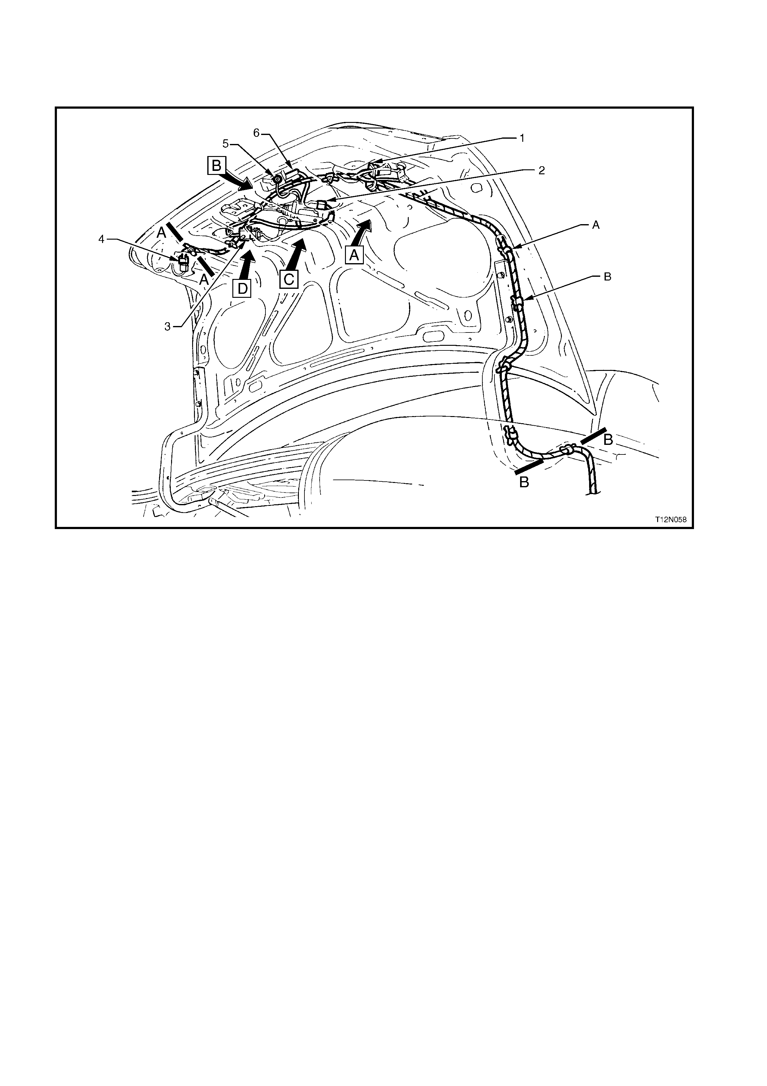
BODY WIRING HARNESS — 1
DECKLID WIRING
Figure 12N-8
1. Stop/Tai l Lamp Harness Connector — Right-hand S i de
(Berlina and Calai s only)
2. Rear Compart ment Actuator Connector
3. Licence Plate Lam p Connector — Right and Left-hand Side
4. Stop/Tai l Lamp Harness Connector — Left-hand Side (Berlina
and Calais onl y)
5. Body Wiring Harness — Deck l i d Earth Term i nal
6. Rear Compart ment Lamp Switch Connector
A. Body Wiring Harness cli pped to Deckl i d I nner — 4 pl aces
B. Body Wiring Harness cl i pped t o Decklid Hi nge — 4 pl aces
For the following refer t o Fi g. 12N-9:
Sections A-A and B-B
Views A, B, C and D
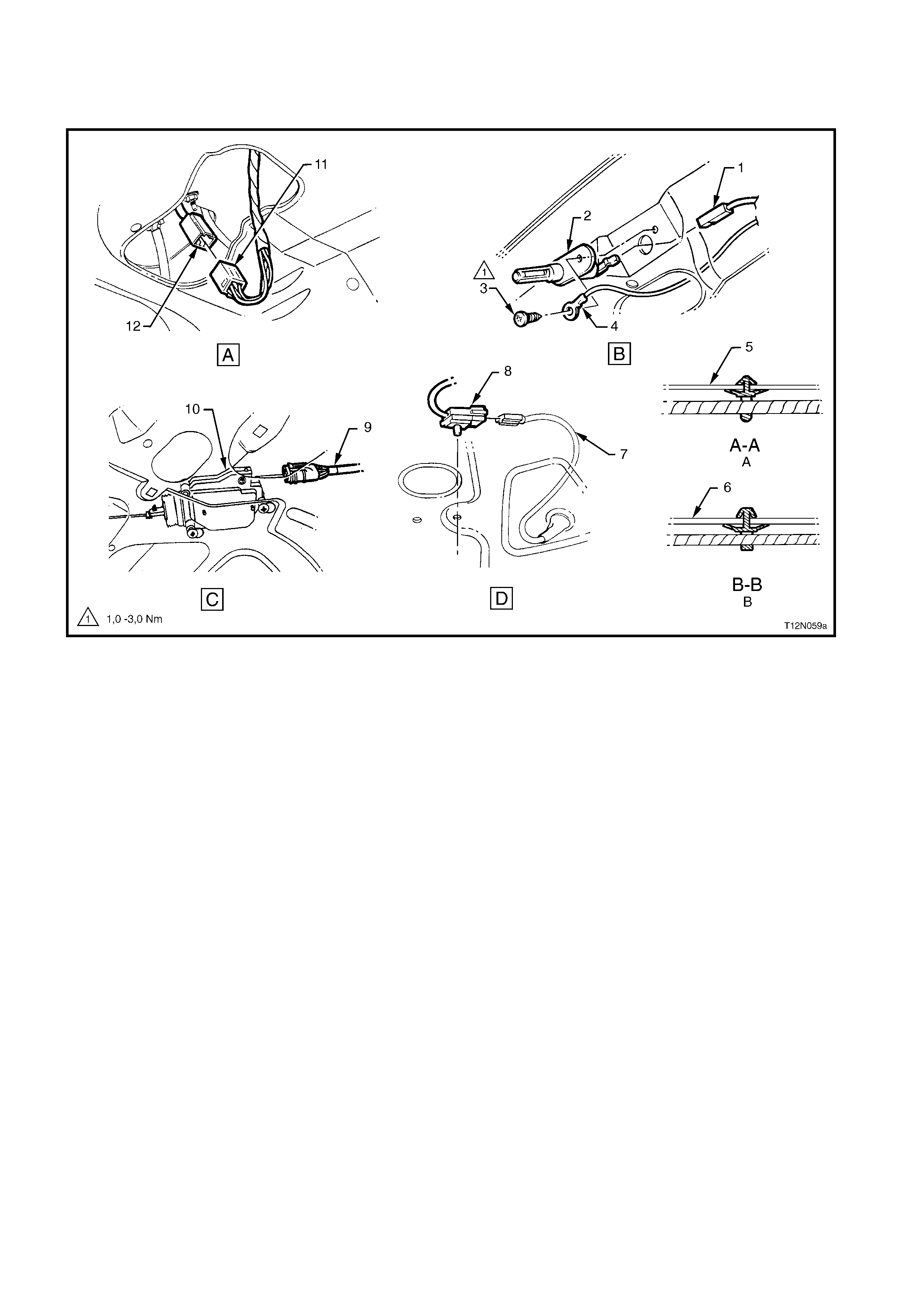
BODY WIRING HARNESS — 2
DECKLID WIRING SECTIONS AND VIEWS
Figure 12N-9
1. Body Wiring Harness Rear Compartm ent Lamp Switch Connector
2. Rear Compart ment Lamp Switch
3. Screw
4. Body Wiring Harness — Deck l i d Earth Term i nal
5. Deckli d Inner Panel
6. Decklid Hinge
7. Licence Plate Harness
8. Right and Left -hand Li cence Plate Lamp Connec tor
9. Body Wiring Harness Rear Compartm ent Lock A ctuator Connec tor
10. Rear Compart ment Loc k Act uat or
11. Body Wiring Harness Connect or (2 pl aces — Berlina and Calais only)
12. Stop/Tai l Lamp Connect or (2 pl aces — Berli na and Cal ai s only)
A. Typical 4 places
B. Typical 4 places
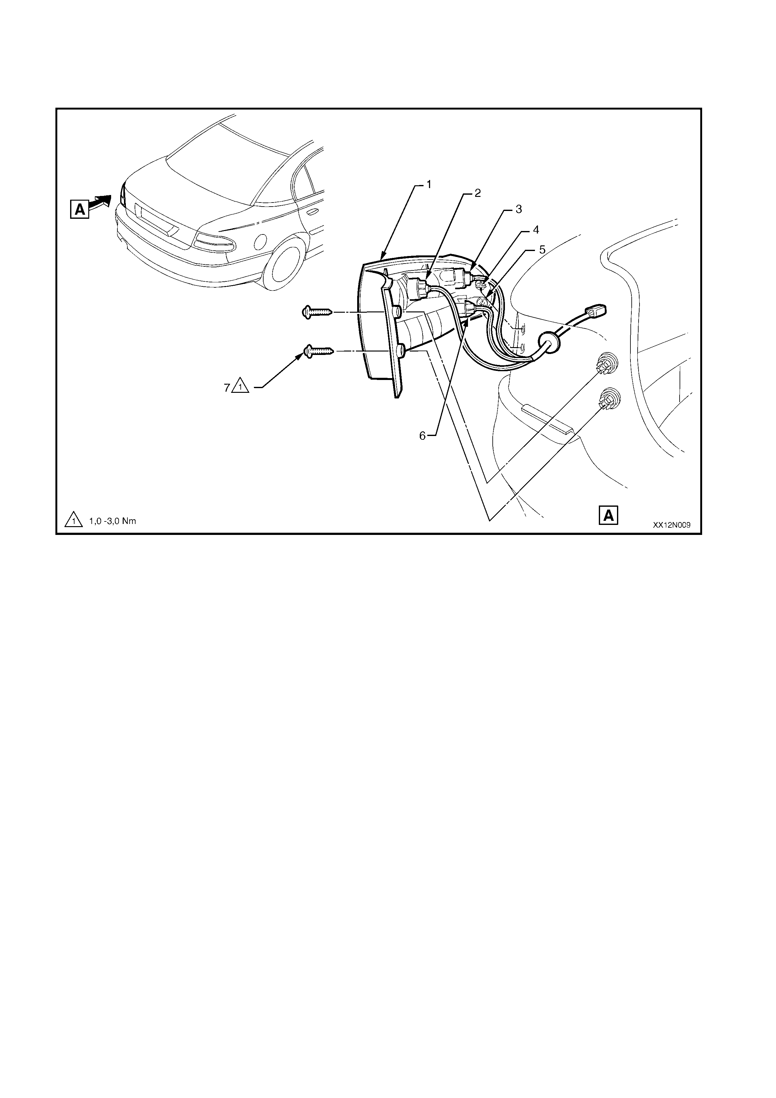
BODY WIRING HARNESS — 3
STOP/TAIL LAMP A ND REAR TURN INDICATOR WIRING HARNESS
Figure 12N-10
1. Tail Lam p Housing
2. Back -up Lamp Socket (blac k – 4 lug)
3. Turn Signal Bul b S ocket (white – 4 lug)
4. Integral P l astic Gui de P eg (1 pl ace each si de)
5. Metal Locati ng Peg (1 place each side)
6. Stop/Tai l Lamp Bulb S ocket (white – 3 lug)
7. Screw (2 places each side)
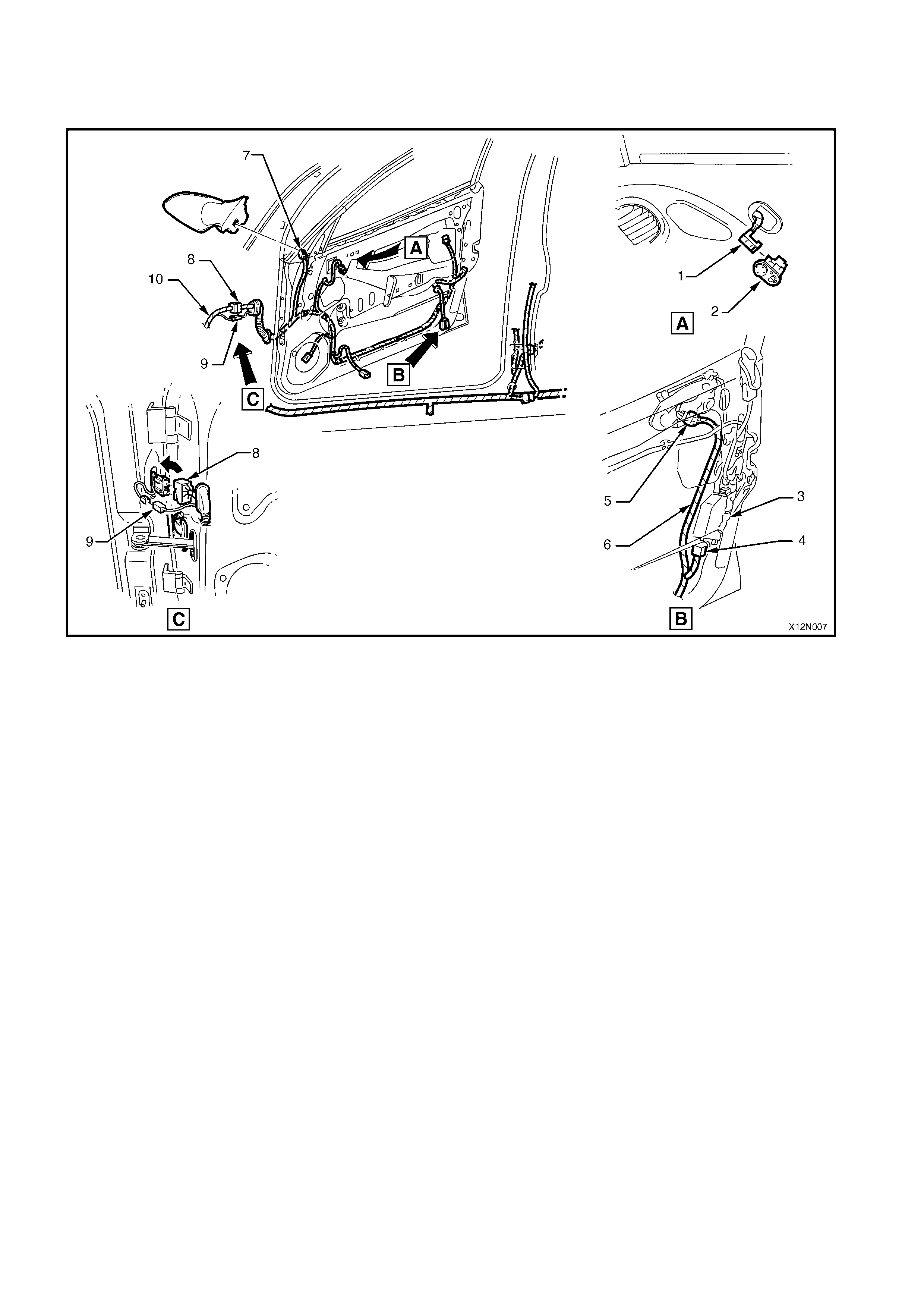
FRONT DOOR WIRING HARNESS
DRIVER’S DOOR WIRING HARNESS
Figure 12N-11
1. Power Mirror Switch Connect or
2. Power Mirror Switch
3. Door Lock A ctuator
4. Door Lock A ctuator Connec tor
5. Door Lock S witch Connector
6. Door Wiring Harnes s
7. Power Mirror Connector
8. Door Harness t o Main Wiring Harness Connec tor
9. Courtesy Lamp Connector t o Main Wiring Harness — Cala i s only
10. Main Wiring Harness