SECTION 12Q - TELEMATICS
IMPORTANT
Before performing any Service Operation or other procedure described in this Section, refer to Section
00 CAUTIONS AND NOTES for correct workshop practices with regard to safety and/or property
damage.
1. GENERAL INFORMA TION
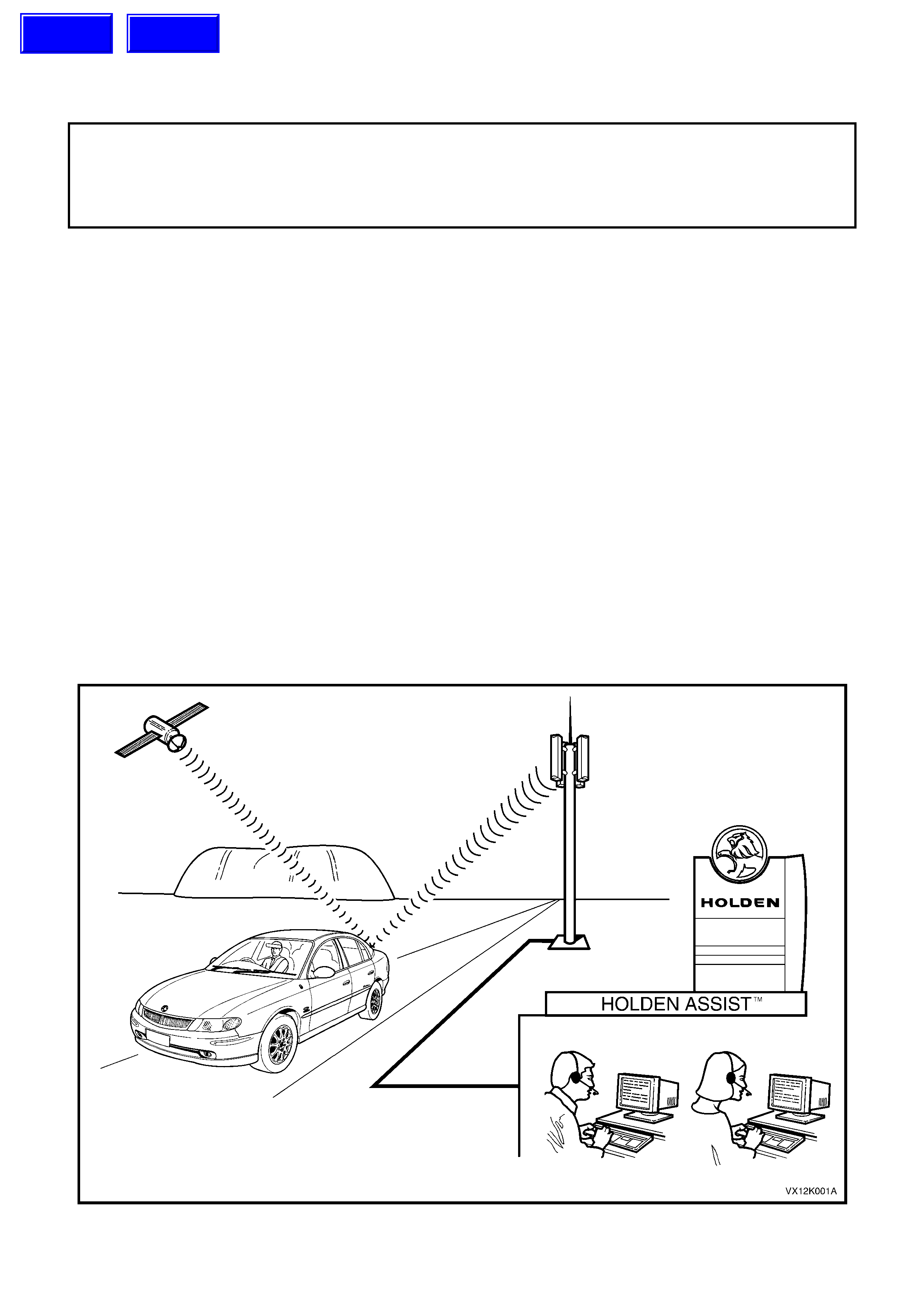
The telem atics system has been de veloped usin g some of the most advanced Global Position System (GPS) and
telecommunications technology, Global System for Mobile (GSM) Communications available. The telematics
system provides in-vehicle safety, security and information services by providing a two way, hands free
communication to either the Holden Assist Centre or, in the case of an emergency, to the National Emergency
Response Centr e (NER C™ ) .
Holden Assist provides several services, some of which include remote door unlocking, connection to Holden
Roadside Assistance, Low Battery Alert and Accident Inquiry. In addition it will know if the theft of the vehicle is
attempted, can then track he vehicle and in certain circumstances, can remotely immobilise the engine. For a full
list of services provided by Holden Assist, refer to the Holden Assist Handbook Supplement.
The link between the vehic l e and the Holden Ass is t Ce ntre or th e Nat ion al Emergency Respons e C entr e use s G PS
for vehic le location a nd tracking an d the Australi an digital m obile phone n etwork to trans mit and recei ve voice and
SMS (S hort Mess age Serv ice) data. If the v ehicle is outside network coverag e, the link to and from the vehic le will
not be available and no services can be provided. Signal strength may be affected in locations like basement car
parks or tunnels. However, in most cases, as the vehicle emerges from the obstruction or re-enters the digital
phone network area the signal will be available again.
A vehic le equippe d with the te lematics s ystem will be de livered to the dealers hip with the te lematics system in the
pre deli very m ode. Dur ing t he pr e de li very of the v eh icl e the te lematic s module pre deli very m ode must be di s able d
and the service mode must be enabled using Tech 2. In service mode, limited service will be provided until the
custom er has signed the terms and conditions d ocument and the custom er has set up the system b y press ing the
Holden Assist button. The Holden Assist operator will then disable service mode and the system will be fully
operational. The set up procedure information is provided in the Holden Assist Handbook Supplement.
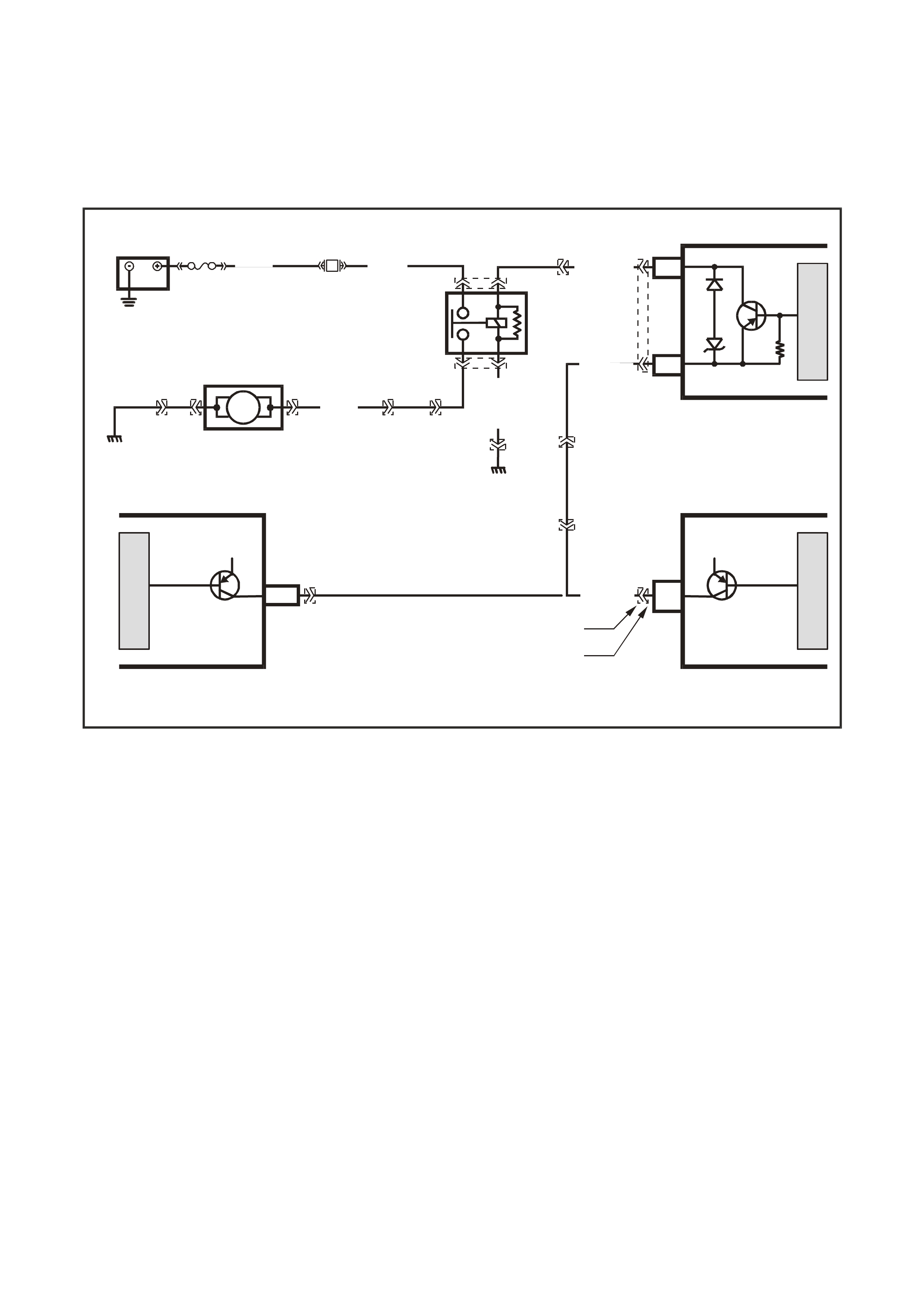
Figure 12Q-1
Techline
Techline
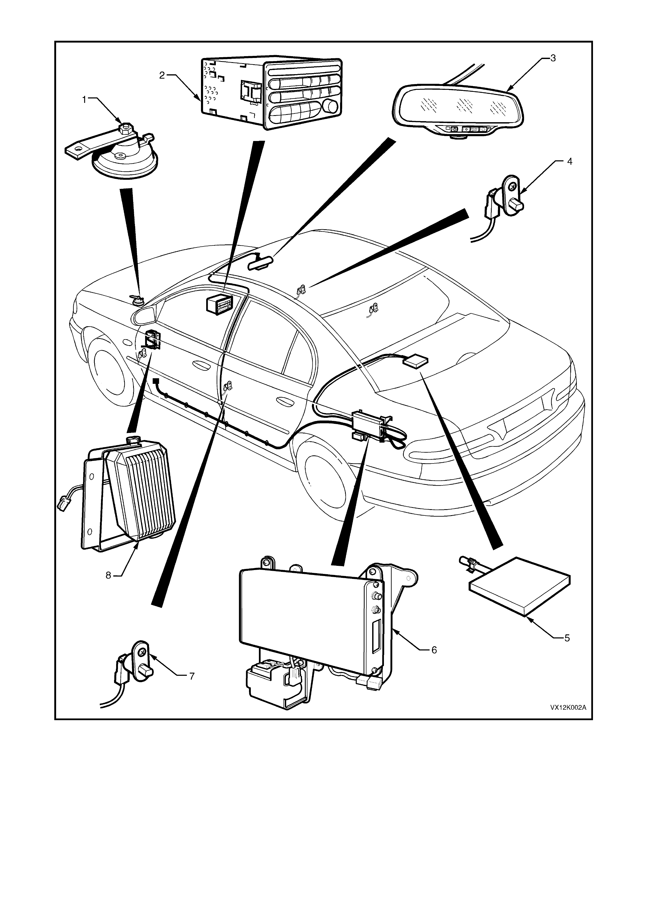
Figure 12Q-2
1. Theft deterrent horn 4. Driver’s door jamb switch 7. Passenger door jamb switches
2. Radio 5. Telematics antenna 8. Telematics speaker
3. Interior rear view mirror 6. Telematics module assembly

2. PRINCIPLES OF OPERATION
2.1 OPERATING MODES
The telematics system has six operating modes, Pre Delivery, Service, Active, Stand-by, Sleep and Battery Saver.
PRE DELIVERY MODE
In the pr e del iver y mode the s ystem is n ot opera tiona l. T he veh icle will b e d eliver ed f rom the ass em bly plant to the
dealer with the telematics system in the pre delivery mode. Before the vehicle is delivered to the customer, the
telematics system must be taken out of the pre delivery mode using Tech 2. Refer to 4.3 TECH 2 TEST MODES
F4: Program, F2: Oper atin g Mode, F 0: Pr e Del i ver y Mo de in t his S ec tio n. When in pr e del ivery mode the t el e matics
module will only communicate with Tech 2 when the driver’s door is open and for 30 minutes after the driver’s
doors is shut or 30 minutes after Tech 2 stops communicating with the telematics module.
SERVICE MODE
When the vehicle is scheduled to be serviced, the telematics system service mode should be activated. The
custom er may request the Holden Assist Centre to rem otely enable or d isable service mode. A service technician
can also activate or inactivate service mode with Tech 2. Refer to 4.3 TECH 2 TEST MODES F4: Program,
F2: Operating Mode, F1: Service Mode in this Section.
When the service mode is activated the telematics module will ignore all button presses except for the Holden
Assist button. In addition, the module will not transmit alert messages for unauthorised entry or low battery.
However the module will transmit an airbag activation alert.
ACTIVE MODE
This is the norm al telem atic s s ystem oper ating m ode. In this m ode the telem atic s system is fully function al a nd can
mak e and receive cal ls, and transm it data via the GSM net work. The c urrent draw of the telem atics module is this
mode will be approximately 330 mA.
STAND-BY MODE
Two m inutes after the ign ition has be en turned of f, or two m inutes after the conclusion of a call while t he ignition is
off , the telem atics module will enter s tand-b y mode. In s tand-b y mode the G PS, Aud io and th e ke ypad buttons ar e
turned off to reduce the standing current of the telematics module. The current draw of the telematics module is this
mode will be approximately 120 mA.
The telematics module will be “woken” from the stand-by mode by any of the following:
An incoming message / call
The ignition is turned on.
Any door is opened.
The alarm is triggered.
The vehicle batt ery is disconnec te d.
A Tech 2 diagnostic request.
SLEEP MODE
The telematics module will enter the sleep mode on request from the Holden Assist Centre or 30 minutes after a
low battery alert has been sent to Holden Assist Centre, or after five days of uninterrupted ignition off. In sleep
mode the telematics module only monitors the inputs required for it to be “woken” from sleep mode.
The system may be “woken” from sleep mode by any of the following:
Any door is opened.
The alarm is triggered.
A battery removal alert.
BATTERY SAVER MODE
The purpos e of the battery saver mode is to lim it the standing curr ent of the telem atics module while s till providi ng
the abilit y to rem otel y unlock the vehicle. After two days of no activit y (igniti on on, an y door opene d, SMS r eceived,
unauthorised entry alert, low battery alert) the telematics module will enter battery saver mode. In this mode, the
telematics module will switch between sleep mode and active mode. The telematics module will operate in sleep
mode for 15 minutes then switch to active mode for two minutes. During these two minutes of active mode
operation the telematics module will log onto the GSM network and any pending remote unlock SMS messages
stored in the network will be received by the telematics module, and the doors will be unlocked. If no SMS
messages are received, the telematics module will return to sleep mode for another 15 minutes. After five days of
intermittent mode operation and no activity, the telematics module will remain in sleep mode.

2.2 ALERTS
AI R BAG AC TI VAT I O N ALE R T
If the vehicle is involved in an accident where the air bags and/or the seat belt pre-tensioners are activated, an
“Airbag Activation Alert” message will be transmitted to the Holden Assist Centre. If the Holden Assist Centre
operator is unable to contact the driver via two-way voice communication in the vehicle, or if the driver cannot
respond, the operator will hand the call over to the National Emergency Response Centre, who will then contact the
Police. T he Police m ay the n contact the am bulance service. F or further information r egarding the air bag activati on
alert, refer to the Holden Assist Handbook Supplement.
LOW BATTERY VOLTAGE ALERT
If the vehicle battery voltage fails below a preset voltage for longer than 30 minutes, the telematics module will
transmit a “Low Battery Alert” message to the Holden Assist Centre. The low battery alert voltage is displayed in
the Tech 2 data list. For further information regarding the low battery alert refer to the Holden Assist Handbook
Supplement.
BATTERY REMOVAL ALERT
If the vehicle battery is disconnected, (battery voltage less than one volt), the telematics module will transmit a
“Batter y Rem oval A ler t” message to the Hol den As sis t Centre. F or f urther inf ormation regar din g the batter y removal
alert refer to the Holden Assist Handbook Supplement.
UNAUTHORISED ENTRY ALERT
If the veh icle entr y deterren t system is trigger ed for lon ger than 20 seconds , the telem atics module will trans mit an
“Unauthorised Entry Alert” message to the Holden Assist Centre. For further information regarding the unauthorised
entry alert refer to the Holden Assist Handbook Supplement.

2.3 HOLDEN ASSIST REMOTE REQUESTS
ENGINE IMMOBILISATION
In the event of the vehicle being stolen, it will be possible for the NERC™ to remotely immobilise the engine by
sending an “immobilise” message to the telematics module. This function can only be activated by the NERC™
under instruction from the Police. On receiving the “immobilise” message, the telematics module will then turn off
the fuel p ump rela y, cutting off the suppl y of f uel to the engi ne a nd c om mand the BCM (v ia t he s eria l da ta c ir c uit) to
flash the indicators. The engin e will remain imm obilised until the “re-mobilise” m essage is rece ived from NERC™.
There are two types of remote immobilisation:
Immediate Engine immobilisation
On receiving an “Immediate Engine Immobilisation” message from the NERC™, the telematics module will
imm ediatel y turn off the fuel pum p rela y, cutting of f the supply of f uel to the engin e and com m and the BCM ( via the
serial data circuit) to flash the indicators.
Under 10 kph Engine Immobilisation
On recei ving an “Under 10 k ph Engine Im mobilisat ion” m essage f rom the NERC™, the t elematic s m odule will wai t
until the ve hicle s peed is les s than 10 k ph befor e turning of f the f uel pum p rela y, cutting of f the s upply of f uel to the
engine and command the BCM (via the serial data circuit) to begin flashing the indicators.
REMOTE UNLOCKING
On recei ving a “Rem ote Un lock” m essage from the Holde n Assist C entre, the tel em atics m odule will comm and the
BCM (via th e seria l data circ uit) to un lock the doors. W hen an y door is ope ned aft er a r emote unloc k , the alarm will
be activated . To tur n the alar m off, loc ate the k eys and either press th e unlock button, or turn the ignit ion on. If the
telematics module is operating in Battery Saver Mode the remote unlock may be delayed as much as 15 minutes.
NOTE: A Remot e Unlock from the Holden Assist Centre w ill not function while the Tech 2 is accessing an y
telematics module diagnostic information.
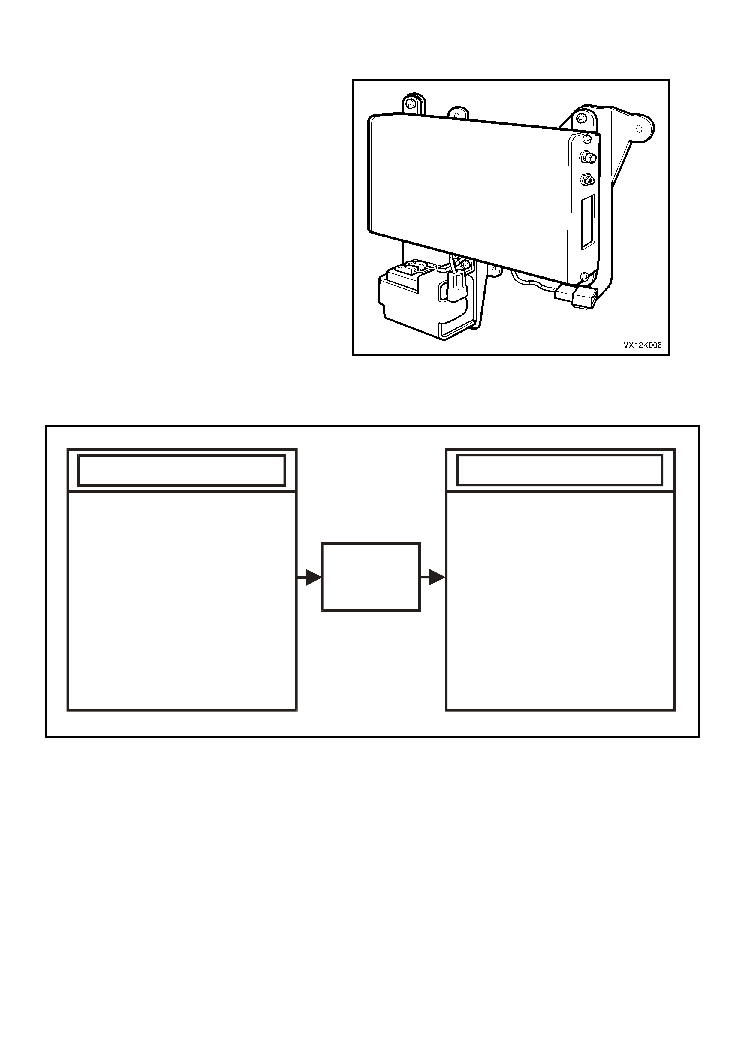
2.4 TELEMATICS MODULE
The telematics module, located in the left hand
side of the rear compartment, controls the
operation of the telematics system. The telematics
module consists of a GPS and GSM engine and a
Serial Data Interface. The telematics module
interfac es with oth er contro l modules in the ve hicle
via the auxiliary serial data circuit normal mode
message. For further information regarding the
serial data bus and normal mode message refer
Section 1.1 SERIAL DATA COMMUNICATION in
Section 12J-1 Low Series Body Control Module
or 12J-2 High Series Body Control Module in
this Service Information.
Tech 2 is also capable of communicating with the
telematics module via the serial data circuit.
Note:
If at any time a new telematics module is installed
into the vehicle, then this new module must be
register with Holden Assist, to register this new
module with Holden Assist refer to the
Telematics Module Changeover Process in this
Section.
Figure 12Q-3
- BATTERY VO LTAGE
- BACKUP BATTERY VOLTAGE
- DRIVER’S DOOR JAMB SWITCH
- PASSENGERS DOOR JAMB SWITCHES
- SERIAL DATA
IGNITION ON
SRS DEPLOYED
VEHICLE SPEED
- EMERGENCY BUTTON
- HOLDEN ASSIST BUTTON
- END CALL / INFORMATION BUTTON
- MICROPHONE
- GSM ANTENNA
- GPS A NTENNA
SYSTEM INPUTS
- AUDI O SPEAKER
- RADI O MUTE
- GREEN STATUS INDI CATOR LED
- RED STATUS INDI CATOR LED
- KEY PAD VOLTAGE
- FUEL PUMP RELAY
- BACKUP BATTERY CHARGER
- GSM
SMS AND VOICE TRANSMISSION
- SERIAL DATA
DIAGNOSTIC S
REMOTE DOOR UNLOCK
INDICATORS
SYSTEM OUTPUTS
TELEMATICS
MODULE
VX12K114
Figure 12Q-4

2.5 INTERIOR RE AR VIEW MIRROR
The interior rear vie w mir ror assembl y contains th e
telematics button pad, microphone and the status
LEDs.
1. End Call / Inform ation Button
2. Holden Assist Button
3. Microphone
4. Emergency Button
5. Status Indicator LEDs
VX12K008
HOLDEN
ASSIST
124
35
Figure 12Q-5
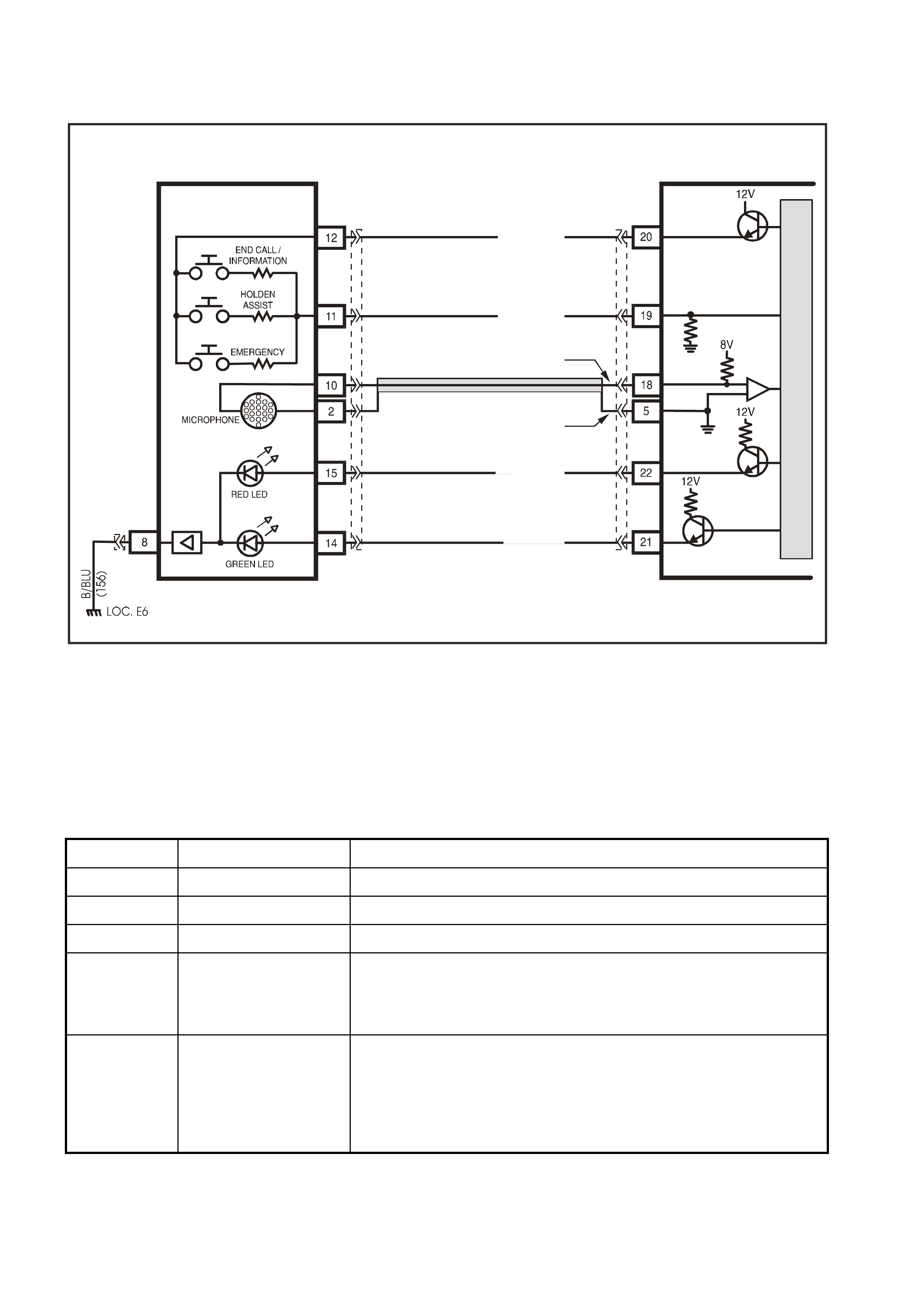
TELEMATICS BUTTON PAD
The telem atic s button pad is a resistor encod ed switch , which m eans that each b utton has a sep arate and diff erent
value resistor connected to it. The telematics module uses a voltage divider circuit to determ ine which button has
been pressed. The telematics module (refer Figure 12Q-6) supplies a 12 volt signal voltage to terminal 12 of the
rear view mirror connector (Light Green/Black wire). Whenever a button is pressed the corresponding switch is
closed and circuit 2514 (Green/White wire) is connected to ground through a resistor, each switch having a
different value resistor. The telematics module m onitors the voltage on circuit 2514 (Green/W hite wire) at terminal
19 of the rear vie w mirr or connector , which will chang e when a ny of the butt ons ar e pressed. Each but ton m ust be
pressed until two beeps are heard from the telematics speaker. If a button is not pressed for long enough, three
beeps will be heard from the telematics speaker. In the event of multiple button presses at the same time, the
telematics module will ignore the button press until all buttons are released.
Emergency Button
When the emergency button is pressed, the voltage at terminal 19 of the telematics module will be approximately
3.8 Volts, the telematics module sees this voltage at terminal 19 as an emergency button press. The emergency
button must be pressed until two beeps are heard. You will then be connected to an operator at the National
Emergency Response Centre. If the button is not pressed for long enough three beeps will be heard. For safety
reasons (in case of the presence of an intruder), if a call has been made to the National Emergency Response
Centre b y pressi ng the emer genc y button, you c annot end th is cal l, you will have to re quest them to e nd the call . If
the vehic le is not with in G SM ne twork range the te lem atics m odule will m ake the em ergenc y call as s oon the G SM
network is available.
Holden Assist Button
When the Holden Assist button is pressed, the voltage at terminal 19 of the telematics module will be approximately
2.3 Volts, the telematics module sees this voltage at terminal 19 as an Holden Assist Button press. The Holden
Assist button must be pressed until two beeps are heard. You will then be connected to the Holden Assist Centre. If
the vehicle is not within GSM network range an additional 12 beeps will be heard. If the button is not pressed for
long enough three beeps will be heard.
End Call / Information Button
When the end call / information button is pressed, the voltage at terminal 19 of the telematics module will be
approxim ately 0.7 Volts, the telem atics module sees this voltage at terminal 19 a s an end call / information button
press. T o end a call m ade to the Holden Assist Centre, the end call / inf ormation butto n must be pres sed until two
beeps are heard. If the button is not pressed for long enough three beeps will be heard.
If end call / information button is pressed to make a call, you will be connected to Holden Assist information
services. The end call / information button must be pressed until two beeps are heard. If the vehicle is not within
GSM net work r ange an ad ditional 12 beeps will be heard. If the butto n is not press ed for lon g enough three bee ps
will be heard.
MICROPHONE
The active microphone in the interior rear view mirror provides a means for voice communication to the vehicle
occupants and Holden Assist Centre.
VX12K103
G (1488)
BR (814 )
BR / W (2517)
Y/B (2516)
MIC (+)
MIC (-)
TELEMATICS MODULE
REAR VIEW MIRROR,
KEY PAD & INDICATOR ASSEMBLY
YB186
G/W (2514)
PUSH
BUTTON
SUPPLY
VOLTAGE
PUSH BUTTON
SIG N AL VO LTAGE
LG/B (2515)
YR55
YB186
M
I
C
R
O
Ω
Ω
Ω
13K
3K
1.5K
Figure 12Q-6
STATUS INDICATOR LEDS
The red a nd green s tatus indicat or L EDs in t he interio r rear view m irror indic ate the c urrent stat us of the te lem atic s
system. The telematics module activates the LEDs by switching a 12 power supply to each LED on or off. The
brightnes s of the LEDs is control led b y the int erior rea r vie w mir ror elec tronic s, which will vary the brig htnes s of the
LEDs depending on the ambient light and the ignition switch position. If the ambient light is low the brightness of
the LEDs will be decreased when the ignition is on. If the ambient light is high there will be no change to the
brightness of the LEDs when the ignition is turned on.
LED Condition Current Status
Green Continuous Call is connected.
Green Flashing Call is being connected.
Red Continuous Vehicle is not within GSM network range.
Red/Green Solid Red and
Flashing Green
(Will appear to be
flashing Red/Or a nge)
Attempting to make an emergency call while outside GSM network
range (“Em er genc y Call Mo de” )
Red/Green Alternate Flashing
(only active for 25
seconds after the
ignition is turned on)
Alert that Service Mode is active or a system malfunction has been
detected.
Potential malfunctions:
Backup battery is not charged or disconnected.
GSM Module not ac tive.
GPS Module not active.
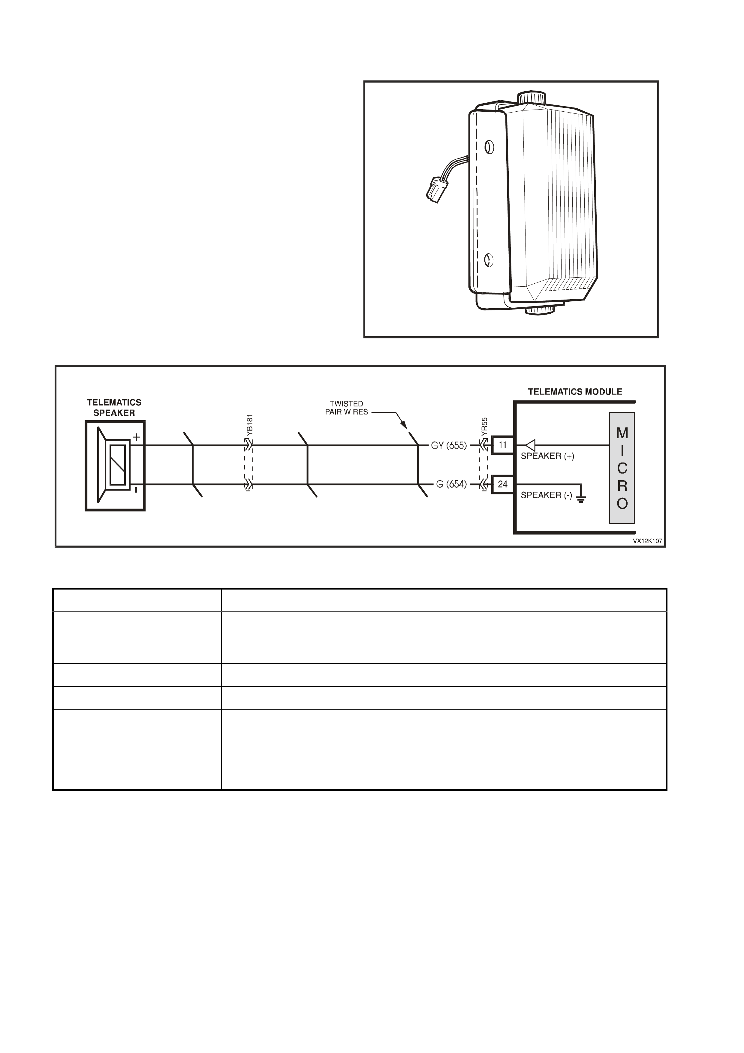
2.6 SPEAKER
The telematics speaker, located behind the glove
compartment, is connected to the vehicle wiring
harness using a two-way connector YB181.
The speaker provides a means for voice
communication, from the call centre and audible
tones are also provided to indicate the system
status and are broadcast via the speaker to alert
the customer to certain operating conditions.
The speaker volume can be programmed using
Tech 2, from 1 being the quietest, to 8 being the
loudest.
VX12K015C
Figure 12Q-7
Figure 12Q-8
Tone Operating Condition
Twelve Tones Attempting to make call when vehicle is not within GSM network range, or if
the twelve tones occur after the ignition is turned off, the vehicle is not within
GSM network range.
Two Tones If button is held down for more than one second.
Three tones If button is held down for less than one second.
Five Tones
(After the ignition is turned
on)
Warning that Service Mode is active or a system malfunction has been
detected.
Potential malfunctions:
GSM Module not active. GPS Module not active.
Backup battery is not charged or disconnected.
2.7 RADIO MUTE
Whenever the telematics speaker is activated the radio mute signal is also activated and the telematics module
grounds the radio mute circuit 656 (Yellow/Black wire) causing the circuit voltage to be pulled low, less than 0.2
volts. This low voltage is seen by the radio as a radio mute request, when received, the radio will mute.
F16
O/B
(45) R
(2H)
Y
(43)
VX12K111
TELEMATICS MODULE
GROUND
RADI O MUTE
BATTERY
IG NITION SWITC H
15a 15 50
30 ACC
IGN
START
F31
YB178
YB23
YB44
YB44
YR55
FS
M
I
C
R
O
YB178
RADIO
MUTE
BATT
BATT
RADIO
F23
BATTERY
LOC. E1
FJ
R (2H)
YB72 YB73
M
I
C
R
O
CELLUAR
TELEPHONE
CONNECTOR
YB178
Figure 12Q-9
2.8 BACKUP BATTERY
The backup battery (1) is located in the left hand
side of the rear compartment and is housed a
bracket attached to the telematics module bracket.
The backup battery will provide power to the
telematics module for approximately 30 minutes in
the event of the ve hic l e bat tery being d isc harge d or
disconn ected. The telematics m odule has a bac k up
battery charging circuit that maintains the backup
battery state of charge. A 3A fuse (2) is used to
protect the backup battery circuitry.
Figure 12Q-10

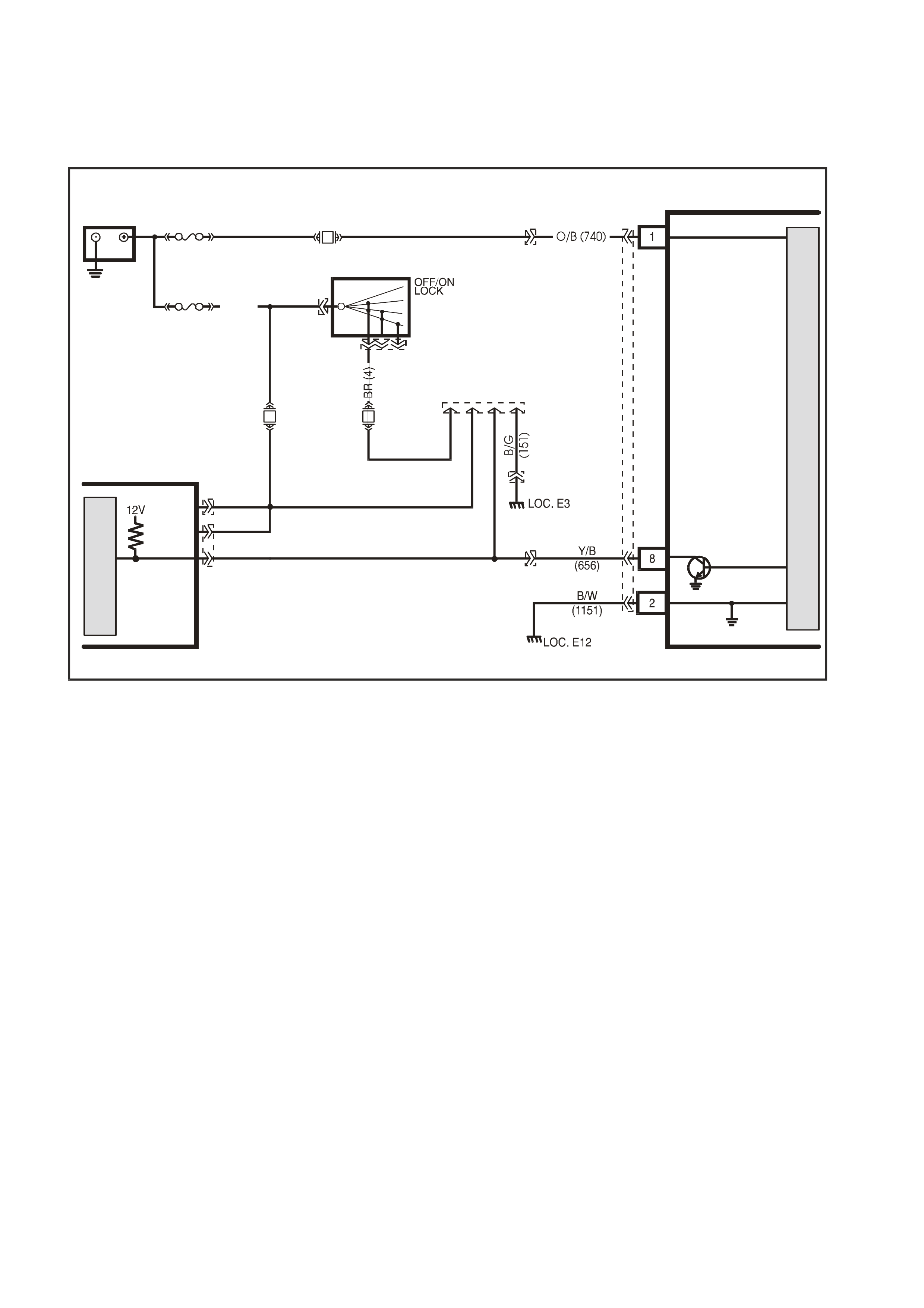
2.9 BATTERY VOLTAGE
Battery voltage is applied to the telematics module terminal 1 at all tim es via circuit 740 (Orange/Black wire), fuse
F31 and fusible link FS (refer Figure 12Q-11). If the battery voltage f ails below a preset volt age for longer than 30
minutes, the telematics module will transmit a Low Battery Alert to the Holden Assist Centre. Refer 2.2 ALERTS,
Low Batt ery Vo ltage Aler t in th is Sect ion f or f urther inform ation. If the batter y is r em oved th e telem atic s m odule will
transmit a Battery Removal Alert to the Holden Assist Centre. Refer 2.2 ALERTS, Battery Removal Alert in this
Section for further information.
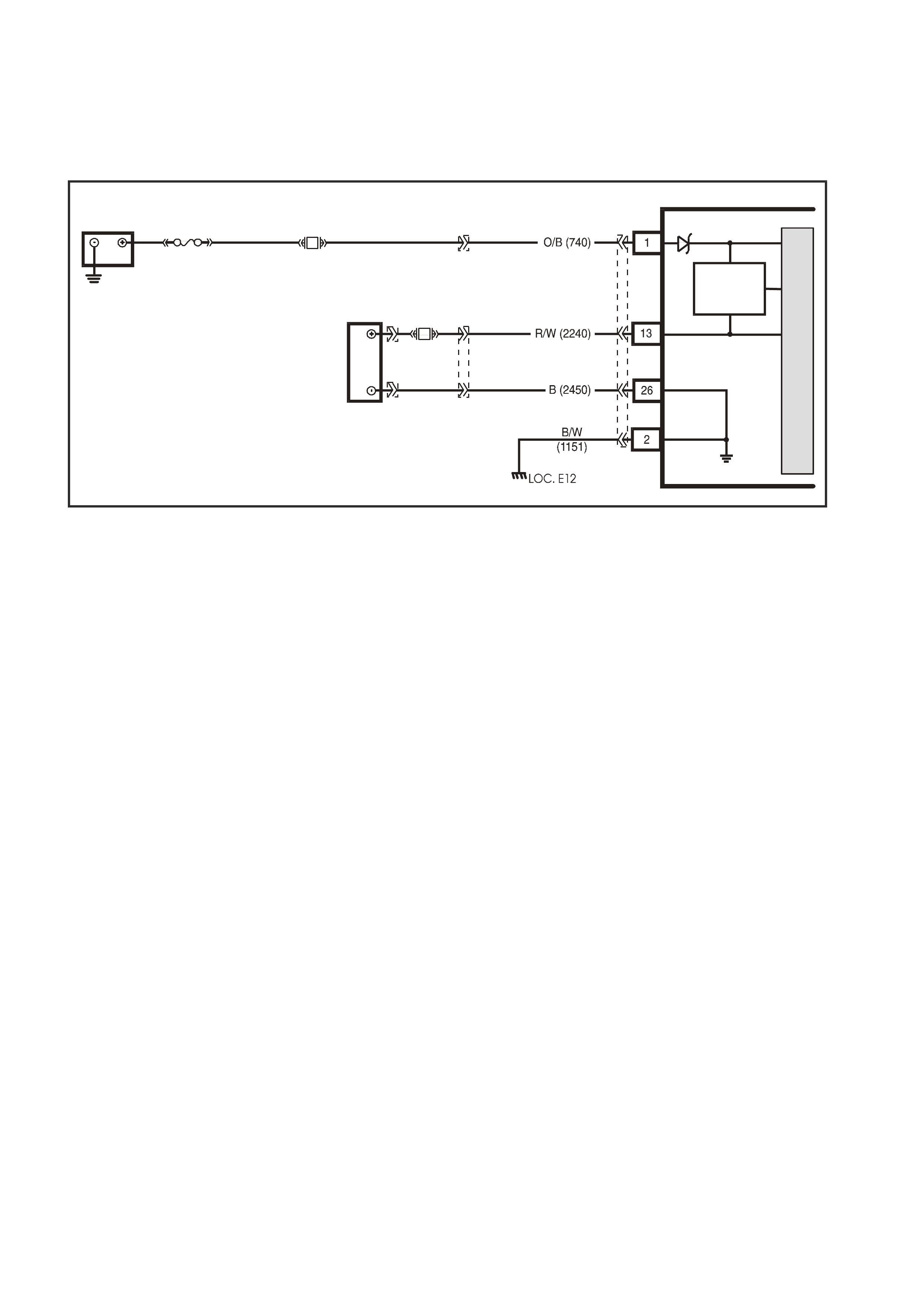
2.10 BACKUP B ATTERY CHARGER
The telematics module constantly monitors both vehicle battery voltage and backup battery voltage. The charging
circuit al lows the back up battery to dra w current of up to 300m A maximum fr om the vehic le batter y. As the batter y
voltages equalise the current drawn will decrease. The charging circuit is only active when the ignition is on, and
can only charge the backup battery to equal the voltage of the vehicle battery.
VX12K106
TELEMATICS MODULE
BATTERY
LOC. E1
GROUND
BACKUP
BATTERY
GROUND
BATTERY
BACKUP
BATTERY
BATTERY
CHARGER
F31
YB178
FS
BACKUP
BATTERY
YR56
YR60YR61
M
I
C
R
O
YR55
Figure 12Q-11
2.11 SERIAL DATA
The telem atic s m odule m onitors the auxi liar y seria l dat a circuit 1 220 (G reen/W hite wire) norm al m ode m essage f or
the following information: Ignition Status from the BCM, Airbag Deployed this Ignition Cycle from the SRS SDM
and Vehicle Speed from the PCM. For further information regarding the serial data bus and normal
mode message, refer 1.1 Serial Data Communication in Section 12J-1 Low Series Body Control Module or
Section 12J-2 High Series Body Control Module in this Service Information.
If the telematics module receives a “Remote Unlock” message from the Holden Assist Centre, the telematics
module will request the BCM (via the serial data circuit) to unlock the doors. For further information regarding the
BCM door lock operation, refer Section 12J-1 Low Series Body Control Module or Section 12J-2 High Series
Body Control Module, 1.3 Central Door Locking Systems in this Service Information.
If the telematics module receives a “Immobilise” message from NERCTM, the telematics module will then turn off the
fuel pump relay (refer 2.16 Fuel Pump Relay Drive Circuit in this Section) cutting off the supply of fuel to the
engine and reques t th e BCM ( via the s eri al dat a c irc u it ) to f las h th e ind ic ators . For f urther i nf ormation r egard i ng t he
BCM indicator operation, refer Section 12J-2 HIGH SERIES BODY CONTROL MODULE, 1.4 Theft Deterrent
System in this Service Information.
TELEMATICS MODULE
LOC. E1
BATTERY
YB178
BATTERY
F31
YR55
FS
YB178
M
I
C
R
O
P
R
O
C
E
S
S
O
R
BODY
CONTROL MODULE
R/B (1221) TO PCM
TO SRS
TO INSTRUMENTS
ECC, ABS/ETC &
G/W (1220)
W/G (1220)
E2
E9
E3
SERIAL
DATA
MAIN
SERIAL
DAT A AUX.
5V
GROUND
9
SERIAL
DATA
5V
G/W (1220)
VX12K115
YB174
YB163
YB175
YB164
Figure 12Q-12

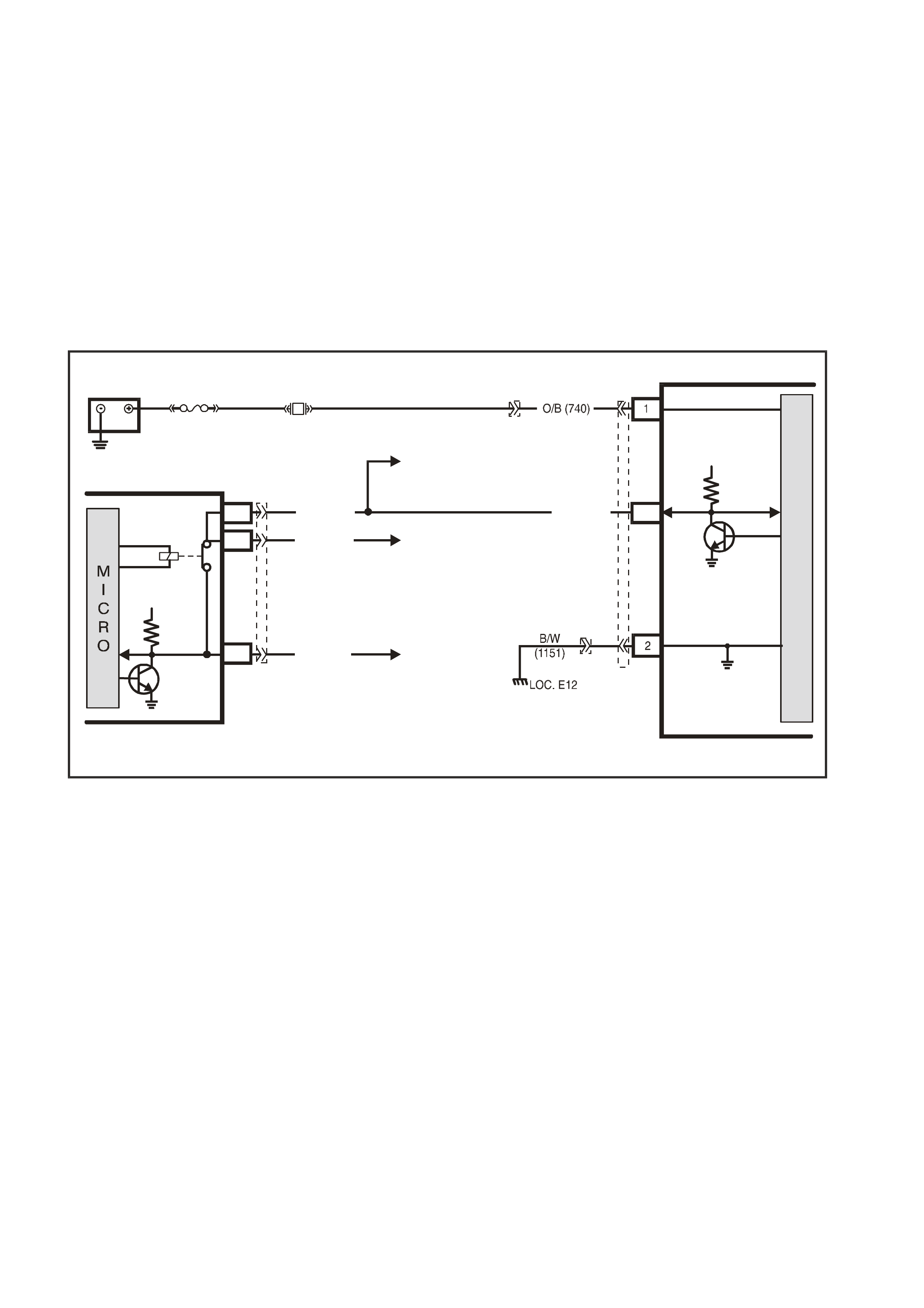
2.12 DRIVER’S DOOR JAMB SWITCH
The telematics module uses this input signal to determine if the driver's front door is opened or closed. W hen the
door is opened, the jamb switch earth’s terminal 23 via circuit 126 (Grey/White wire). This causes the voltage at
term inal 23 to be pul led lo w, less tha n 0.2 volts (dr ive r's door o pen). T his lo w volt age at term inal 23 is se en by the
telematics module as the driver's door open input signal. When a driver's door open input signal is received, the
telematics module will switch from its current operating mode to active mode. This signal is also used to initiate
communication with Tech 2 when the telematics module is in pre delivery mode. Refer 2.1 OPERATING MODES in
this Section
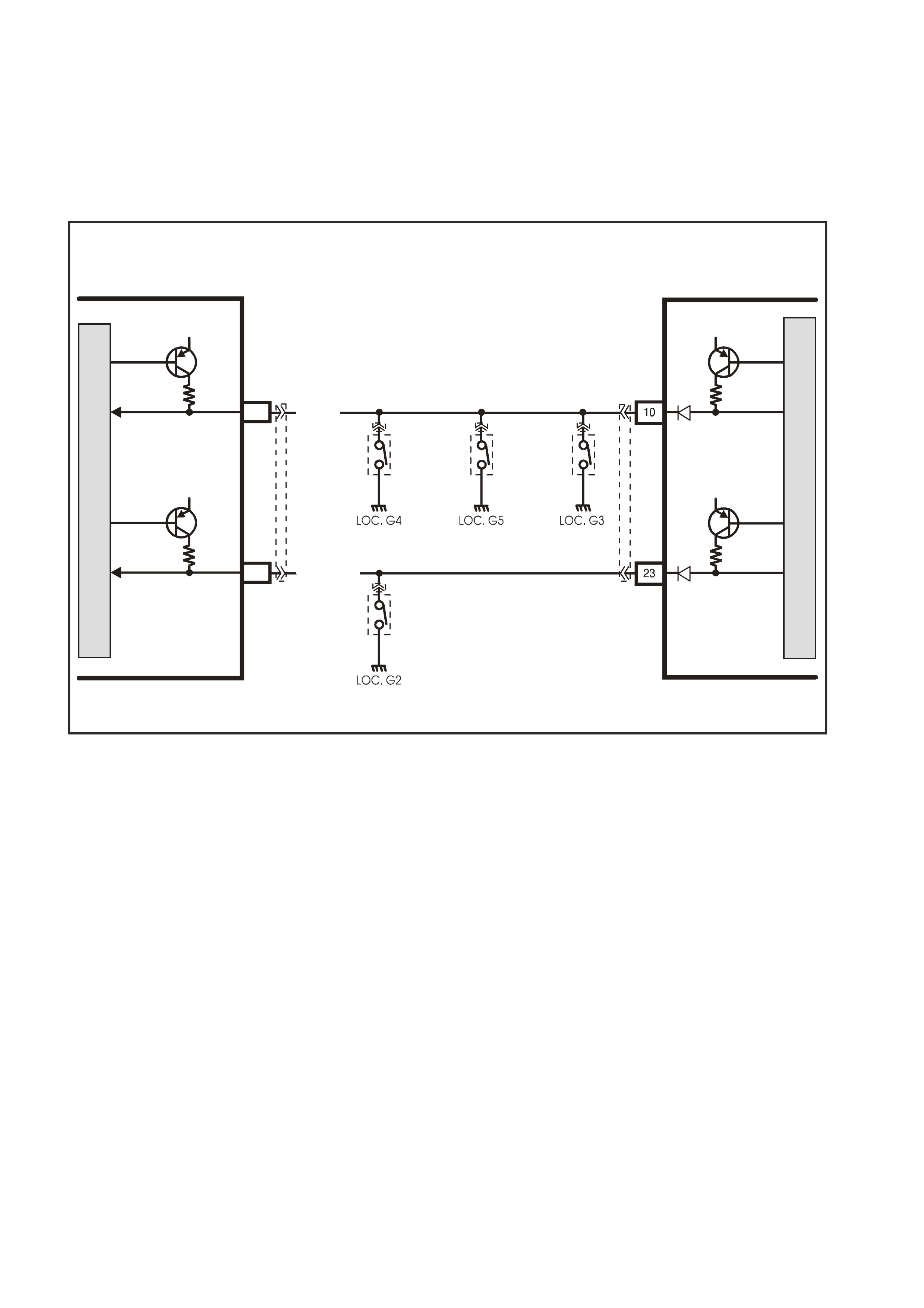
2.13 PASSENGER DOOR JAMB SWITCHES
The telematics module uses this input signal to determine if any of the passenger doors are opened or if all
passenger doors are closed. If the right hand rear, left hand front or left hand rear door is open, terminal 10 is
earthed thr ough cir cuit 125 (White wire). This causes the voltage at ter m inal 10 to be pul led lo w, less than 0. 2 volt s
(if any one of the passenger doors is opened). The telematics module sees this low voltage at terminal 10 as the
passengers door op en input sig nal. W hen a passenge rs door ope n input sign al is rec eived, the telematic s module
will switch from its current operating mode to active mode, refer 2.1 OPERATING MODES in this Section.
VX12K105
PASSENGER DOOR
OPEN
DRIVER’S DOOR
OPEN
PASSENGER DOOR
OPEN
12V 12V
12V
12V
LHF
DOOR
JAMB
SWITCH
LHR
DOOR
JAMB
SWITCH
RHR
DOOR
JAMB
SWITCH
C7
DRIVER'S DOOR
OPEN
RHF DOOR
JAMB SWIT CH
GY/W (126)
C8
M
I
C
R
O
TELEMATICS MODULE
BODY
CONTROL MODULE
YR55
YB173
YB1
YB1
YB1 YB1
M
I
C
R
O
W (125)
Figure 12Q-13
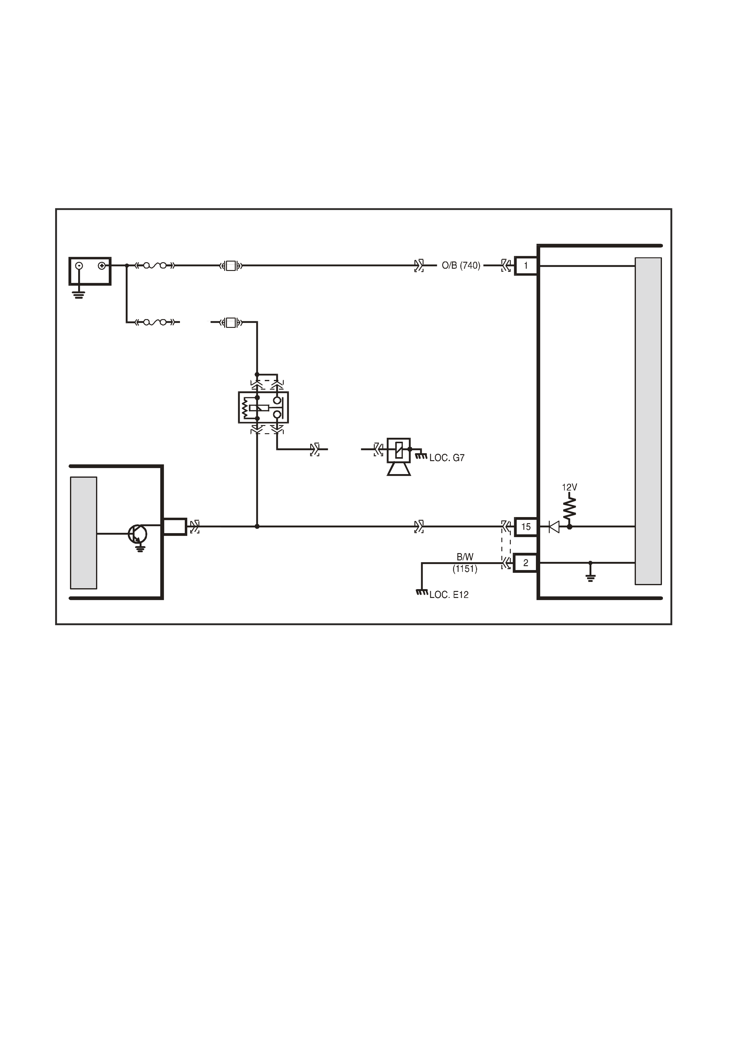
2.14 THEFT DETERRENT HORN
The telematics module monitors the theft deterrent horn to determine if the entry deterrent system has been
triggered. If the entry deterrent system has bee n tri gge r ed, th e BCM pu ls es th e ve hic les horns at a r ate of on c e per
second. To pulse the theft deterrent horn the BCM grounds the theft deterrent horn relay drive circuit 1128
(Black/White wire). When the theft deterrent horn relay drive circuit is grounded, the voltage at terminal 15 of the
telema tics module is pulled lo w, less than 0.2 vol ts. The telem atics m odule sees this l ow voltage at terminal 15 as
the entry deterrent system triggered input. If the vehicle entry deterrent system is triggered for longer than 20
seconds, the telematics module will transmit an “Unauthorised Entry Alert” message to the Holden Assist Centre.
For further information regarding the unauthorised entry alert, refer to the Holden Assist Handbook Supplement.
BODY
CONTROL MODULE
B/W
(1128)
THEFT DETERRENT
HORN RE LAY
THEFT
DETERRENT
HORN
O/Y
(1340)
G (129)
VX12K110
TELEMATICS MODULE
BATTERY
LOC. E1
GROUND
THE FT D E TERR ENT
HORN
BATTERY
F31
F21
YB178
YE107
YE107
YE2
YE111
THEFT
DETERRENT
HORN A3
YB176
YR55YR55
FJ
R (2H)
FS
M
I
C
R
O
YB178
M
I
C
R
O
Figure 12Q-14
2.15 TELEMATICS ANTENNA
The telematics antenna (1) contains both the GPS
and GSM antennas in one unit, and is located on
the rear parcel shelf, under the rear parcel shelf
trim. The antenna has two leads, one for the GPS
antenna and the other for the GSM antenna.
NOTE: The area directly above the telematics
antenna should be free from obstructions as they
may adversely affect antenna operation and the
system may not have full functionality. Aftermarket
window tinting may also affect the antenna
operation.
GSM ANTENN A
The GSM antenna is capable of transmitting and
receiving both voice and data signals via the GSM
network. The telematics module uses the GSM
network to transmit and receive voice and data.
Signal strength may be affected in locations like
basement car parks or tunnels. However, in most
cases, as the vehicle em erges fr om the obstruction
or re-enters the digital phone network area the
signal will be available again and any stored data
will be trans m itted. T he GSM antenn a is c onnected
to the telematics module by a screw-on type
connector (larger of the two antenna connectors).
VX12K011
1
Figure 12Q-15
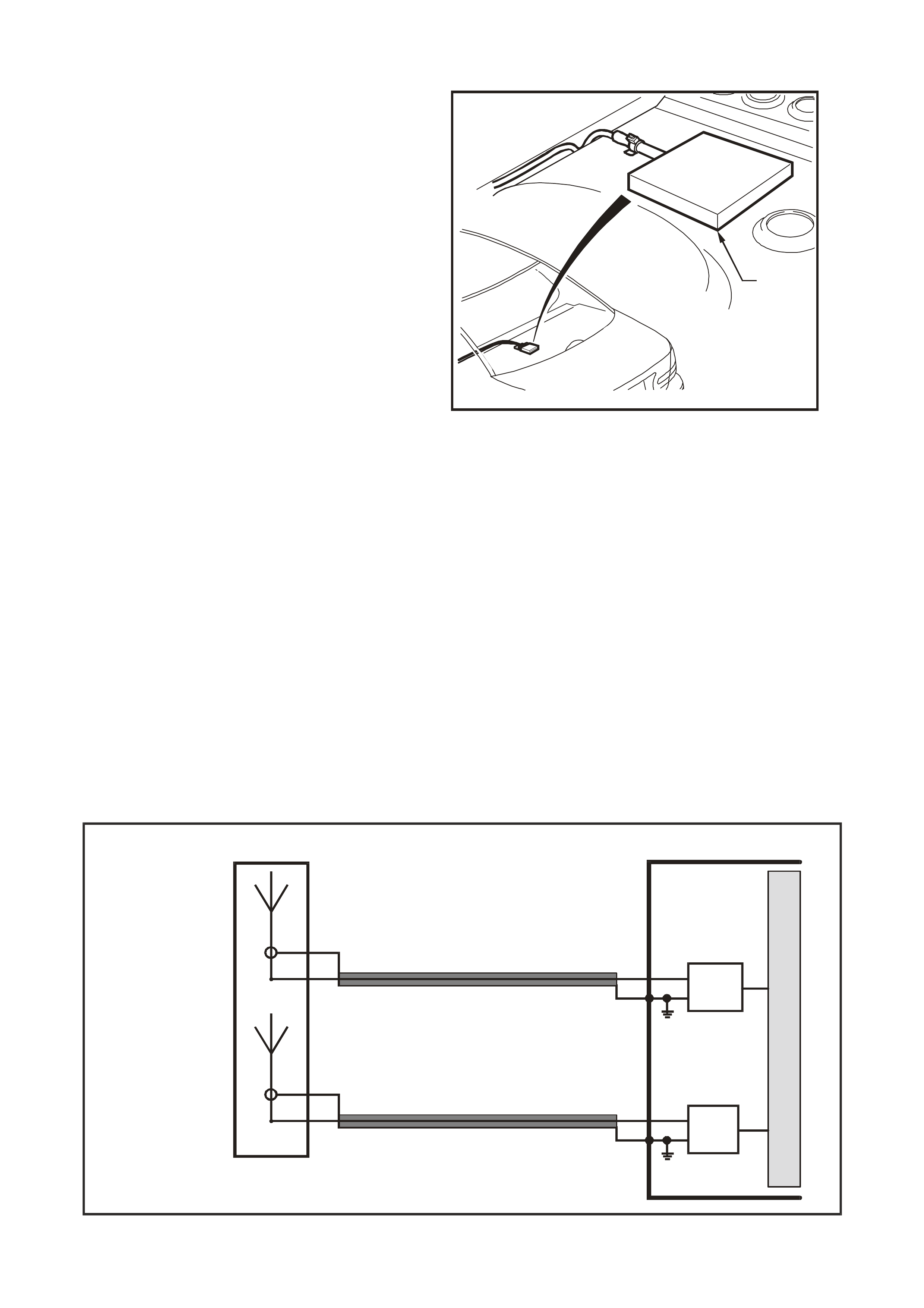
G PS AN TEN NA
The G PS ant enn a re cei ves signa ls f r om s atellit es or bit ing t he e art h a nd tra ns mits these to the t e lematic s module to
determine the vehicles position. Signals from at least three GPS satellites must be received to accurately determine
the vehic le ’s two dimens ion al (2D) pos it io n. S ign als f rom at least f our G PS s atel lit es m us t be rec eive d to ac c ur ately
determine the vehicle’s three dimensional (3D) position. If signals from only three satellites are received, the
telematic s module c annot determ ine the veh icles altit ude. The G PS antenna m ust not be obs cured by an y ob jects,
such as underground car parks, tunnels, bridges or buildings any of these may affect GPS reception. The GPS
antenna is connected to the telematics module by a screw-on type connector (smaller of the two antenna
connectors).
The telematics module uses a principle called triangulation to determine the location of the vehicle, this principle
states that you can determine the location of an object if you know its distance from three known locations. GPS
uses 24 satellites orbiting the earth, the location of each satellite is known at any given time. The satellites
constant l y broadc ast r ad io s ignals , the te lematic s G PS m odule compar es the amount of time it tak es for the s igna ls
from at least three different satellites to reach the GPS module. By converting time into distance, it can calculate
the modules location on earth. The telematics module receives GPS data, decodes it, and transmits the vehicles
location v ia SMS wh en req ues ted b y Holde n Assis t or NERCTM.
GSM
ANTENNA (-)
GSM
ANTENNA (+)
M
I
C
R
O
TELEMATICS MODULE
GSM ANTENNA
GSM
MODULE
VX12K119A
GPS ANTENNA
GPS
ANTENNA (-)
GPS
ANTENNA (+)
GPS
MODULE
Figure 12Q-16
2.16 FUEL PUMP RELAY DRIVE CIRCUIT
The PCM energises the fuel pump relay drive circuit via circuit 465 (Green/White wire), the telematics module
term inals 12 and 2 5, c irc uit 497 (Li ght/G re en wire). T he f uel pump relay drive circui t is ground ed thr o ugh c irc uit 152
(Black/White wire) at ground location E3. The telematics module can immobilise the vehicle by opening the fuel
pump relay drive circuit, causing the fuel pump to stop operating. This function can only be activated by the
National Emergency Response Centre (NERC™) under instruction from the Police. For further information refer
2.3 HOLDEN ASSIST REMOTE REQUESTS, Engine Immobilisation in this Section.
25
12
E10
A6
J2-09 FUEL PUMP RELAY
CONTROL
FUEL PUMP RELAY
CONTROL
B/BLU
(156)
LOC. E7
LOC. E3
IN - TANK
FU EL PUMP
FU EL PUMP
RELAY
L/G (497)
G/W (465)
G/W (465)
TELEMATICS MODULE
V6 POWERTRAIN
CONTROL MODULE
V8 POWERTRAIN
CONTROL MODULE
12V12V
M
I
C
R
O
M
I
C
R
O
M
I
C
R
O
BATTERY
FS
LOC E1
F28
(1040) O (240)
V (120)
B/W(152)
32
51
VX12K102
YB199
YB188
YB199, E10
NON S/C V6 ENGINE
YB188, A6
S/C V6 ENG INE
YR55
YE96
YE114
YE110
YB178
YB178
YR44
YR32
YB39
YR44
YR32
YE96
YE123
Figure 12Q-17
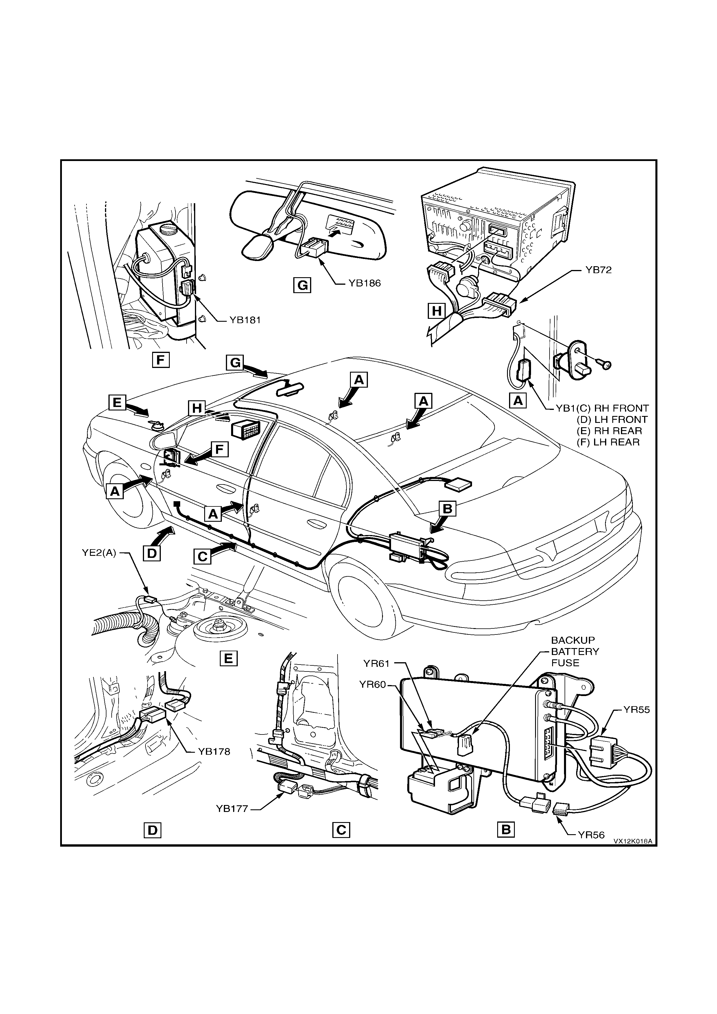
2.17 WIRING HARNESSES
VX Seri es vehicles equipped with th e telematic s system have specific m ain and bod y harnes ses, and a tele matics
patch harn ess . The telem atic s patch har nes s c onnec t o r 2 (YB178) plugs into th e main harnes s behin d the le f t hand
kick panel trim (view D) and the telem atics patch harness connector 1 (YB177) plugs into the bod y harness at the
bottom of the B pillar (view C). The telematics patch harness is also connected to the telematics module (YR55)
(view B), t he interior rear view mirror (YB186) (view G). T he telematics speaker (view F) is connected to the main
harness connector (YB181).
Figure 12Q-18
3. SERVICE OPERATIONS
When carrying out any service procedure on the v ehicle that involves disconnecting the batter y cables o r
any procedure that may cause the battery voltage to fall below 12 Volts, the telematics module Service
Mode MUST BE EN ABLED. Refer to 4.3 T ECH 2 TEST MODES F4: Program, F2 Operating Mode, F1: Service
Mode in this Section.
If the telematics module service mode is not enabled, a “Battery Removal Alert” will be t ransmitted to the
Holden Assist Centre whenever the battery is disconnected, or a “Low Battery Voltage Alert” when the
battery voltage is low.
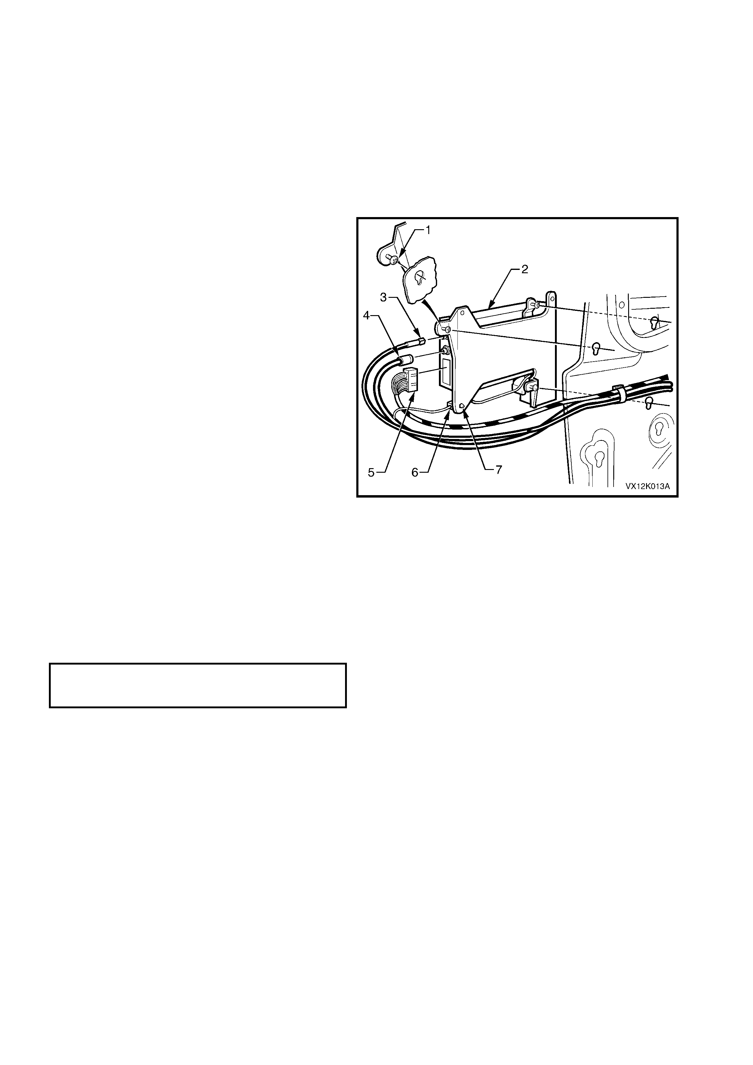
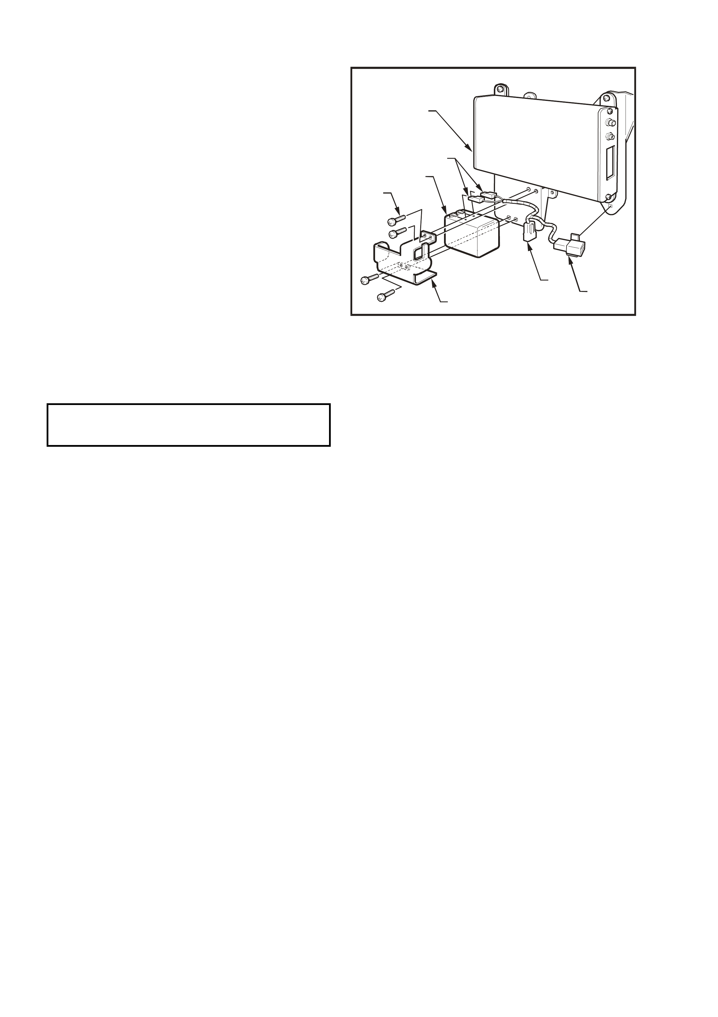
3.1 TELEMATICS MODULE ASSEMBLY
REMOVE
1. Using Tech 2, enable the telematics module
service mode. Refer to 4.3 TECH 2 TEST
MODES F4: Program, F2: Operating Mode,
F1: Service Mode in this Section.
2. Disconnect the negative battery cable from the
battery.
3. Remove the left side rear
compartment wheelhouse carpet, refer to
Section 1A1 BODY in this Service Information.
4. Disconnect telematics module harness
connector (5), GPS antenna connector (3),
GSM antenna connector (4), and the backup
battery harness connector (6).
5. Remove the backup battery harness retaining
clip (7) from the mounting bracket.
6. Loosen the four telematics module assembly
retaining screws (1).
7. Sl ide the contr ol module upward to re lease the
screw heads from the slots in the side inner
panel and remove telematics module
assembly.
Figure 12Q-19
REINST ALL
1. Reverse of the removal, noting the following.
2. Tighten the telematics module assembly
retaining screws to the correct torque
specification.
TELEMATICS MODULE ASSEMBLY
RETAINING SCREWS
TORQUE SPECIFICATION 3 – 3.5 Nm
3. Use Tech 2 to disable the telematics module
Service Mode. Refer to 4.3 TECH 2 TEST
MODES F4: Program, F2: Operating Mode,
F1: Service Mode in this Section.
NOTE: If the telematics module service mode is
not disabled, the system will not have full
functionality.
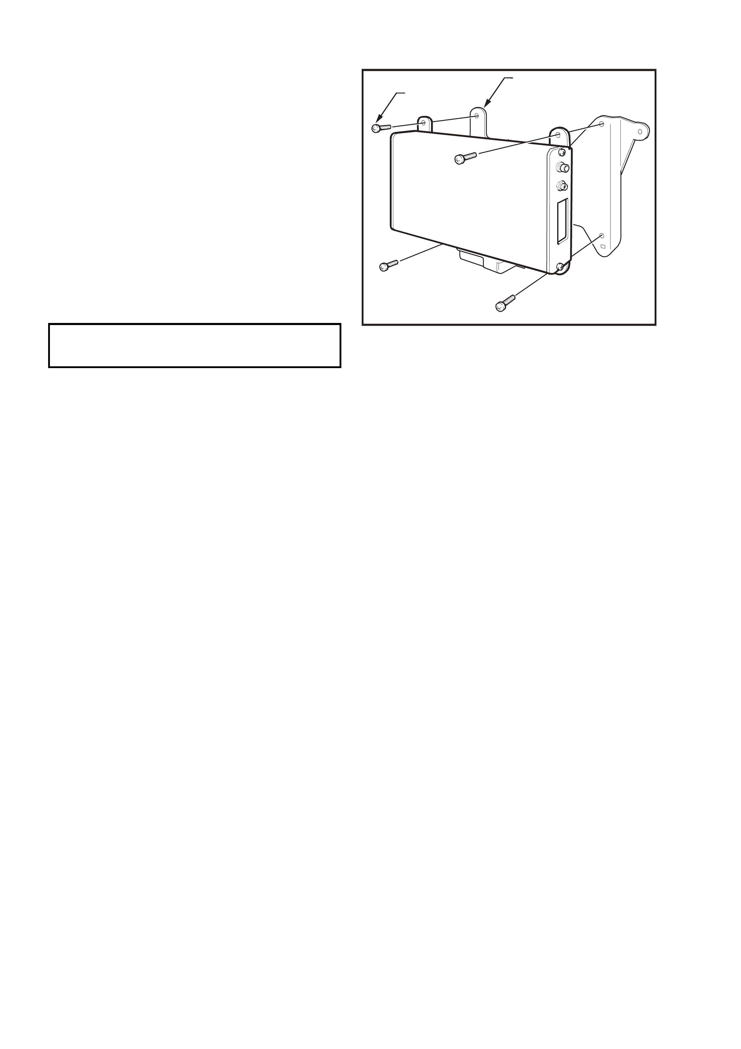
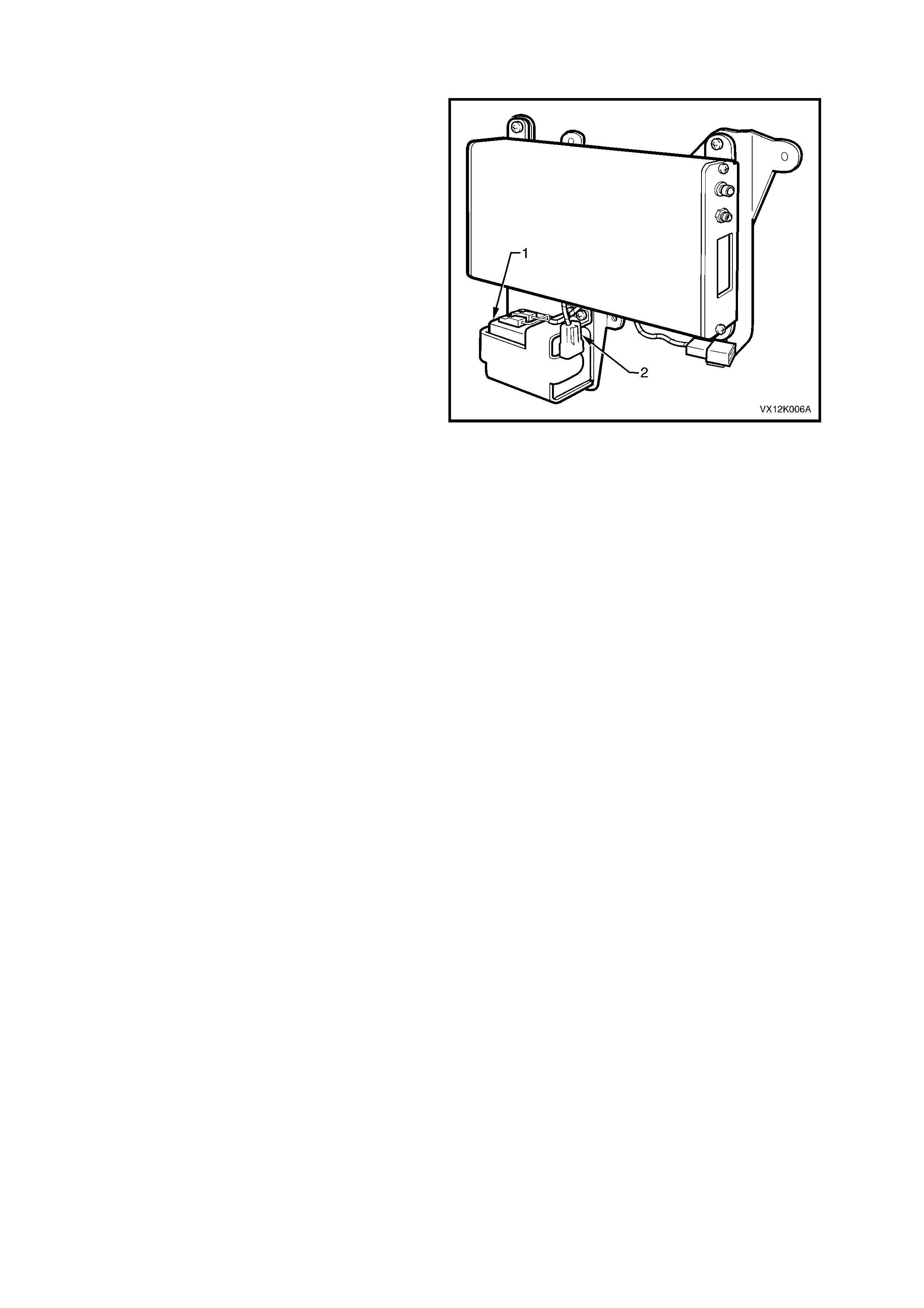
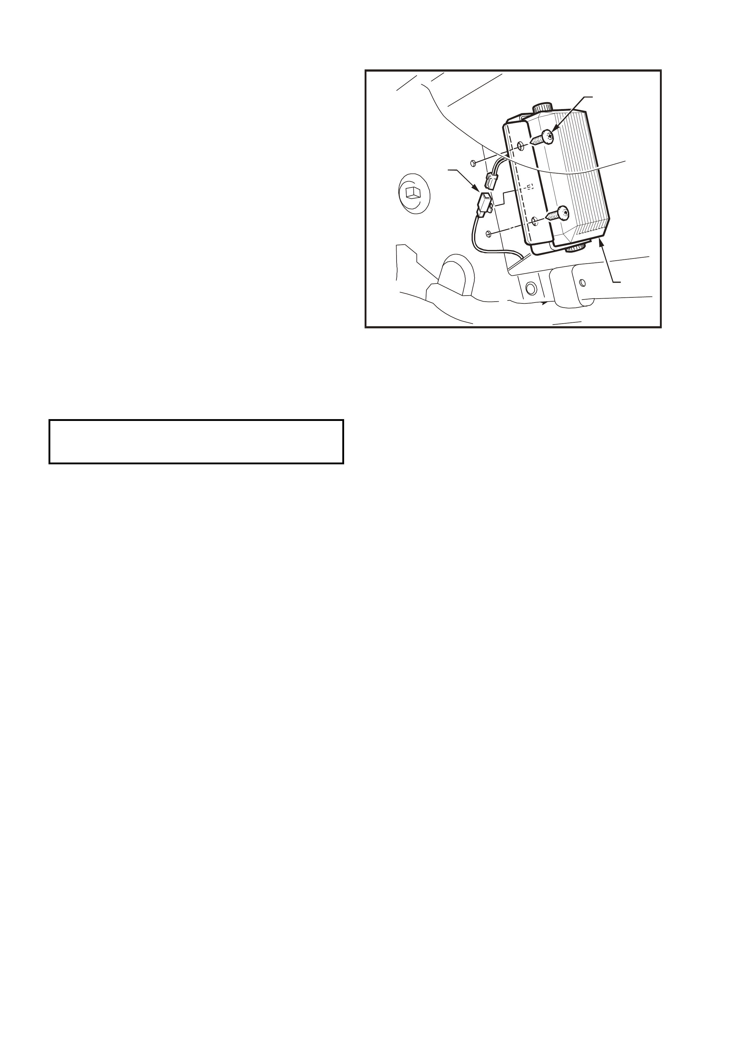
3.2 TELEMATICS MODULE
REMOVE
1. Using Tech 2, enable the telematics module
service mode. Refer to 4.3 TECH 2 TEST
MODES F4: Program, F2: Operating Mode,
F1: Service Mode in this Section.
2. Remove the telematics module assembly.
Refer 3.1 TELEMATICS MODULE
ASSEMBLY in this Section
3. Remove the four telematics module to
mounting bracket retaining screws (1) and
remove the telematics module from the
mounting plate (2).
REINST ALL
1. Reverse of the removal, noting the following.
2. Tighten the t elem atics module r eta ining sc re ws
to the correct torque specification.
TELEMATICS MODULE TO MOUNTING
BRACKET RETAINING SCREWS
TORQUE SPECIFICATION 3 – 3.5 Nm
3. Use Tech 2 to disable the telematics module
service mode. Refer to 4.3 TECH 2 TEST
MODES F4: Program, F2: Operating Mode,
F1: Service Mode in this Section.
NOTE: If the telematics module service mode is
not disabled, the system will not have full
functionality.
TELEMATICS MODULE CHANGEOVER
PROCESS
If a new telematics Module has been installed into
the vehicle, then this new module must be
registered with Holden Assist, to register this new
module with Holden Assist the following procedure
must be performed.
1. Once the new module has been installed into
the vehic le turn the ignition on and mak e a call
to Holden Ass ist by pressin g the Holden Assist
button until two beeps are heard.
2. When the Holden Assist operator answers
inform the operator who you are and what
dealer you are from, and that you have just
installed a new telematics module into the
vehicle . You will a ls o be require d to pro vi de th e
operator with the complete Vehicle
Identif ication Num ber (VIN) and if the vehic le is
registered, the registration number of the
vehicle.
The new telematics module is now registered to
this vehic le.
VX12K014A
12
Figure 12Q-20
3.3 BACKUP BATTERY
REMOVE
1. Using Tech 2, enable the telematics module
service mode. Refer to 4.3 TECH 2 TEST
MODES F4: Program, F2: Operating Mode,
F1: Service Mode in this Section.
2. Remove the telematics module assembly.
Refer 3.1 TELEMATICS MODULE
ASSEMBLY in this Section
3. Disconnect the two backup battery terminals
(4) from the backup battery (5).
4. Remove the six backup battery bracket (6)
retaining screws (7) and remove the backup
battery.
VX12K010
1
2
3
54
7
6
Figure 12Q-21
REINST ALL
1. Reverse of the removal noting the following.
2. Tighten backup battery retaining screws to the
correct torque specification.
TELEMATICS BACKUP BATTERY
RETAINING SCREWS
TORQUE SPECIFICATION 3 – 3.5 Nm
3. Use Tech 2 to disable the telematics module
Service Mode. Refer to 4.3 TECH 2 TEST
MODES F4: Program, F2: Operating Mode,
F1: Service Mode in this Section.
NOTE: If the telematics module service mode is
not disabled, the system will not have full
functionality.
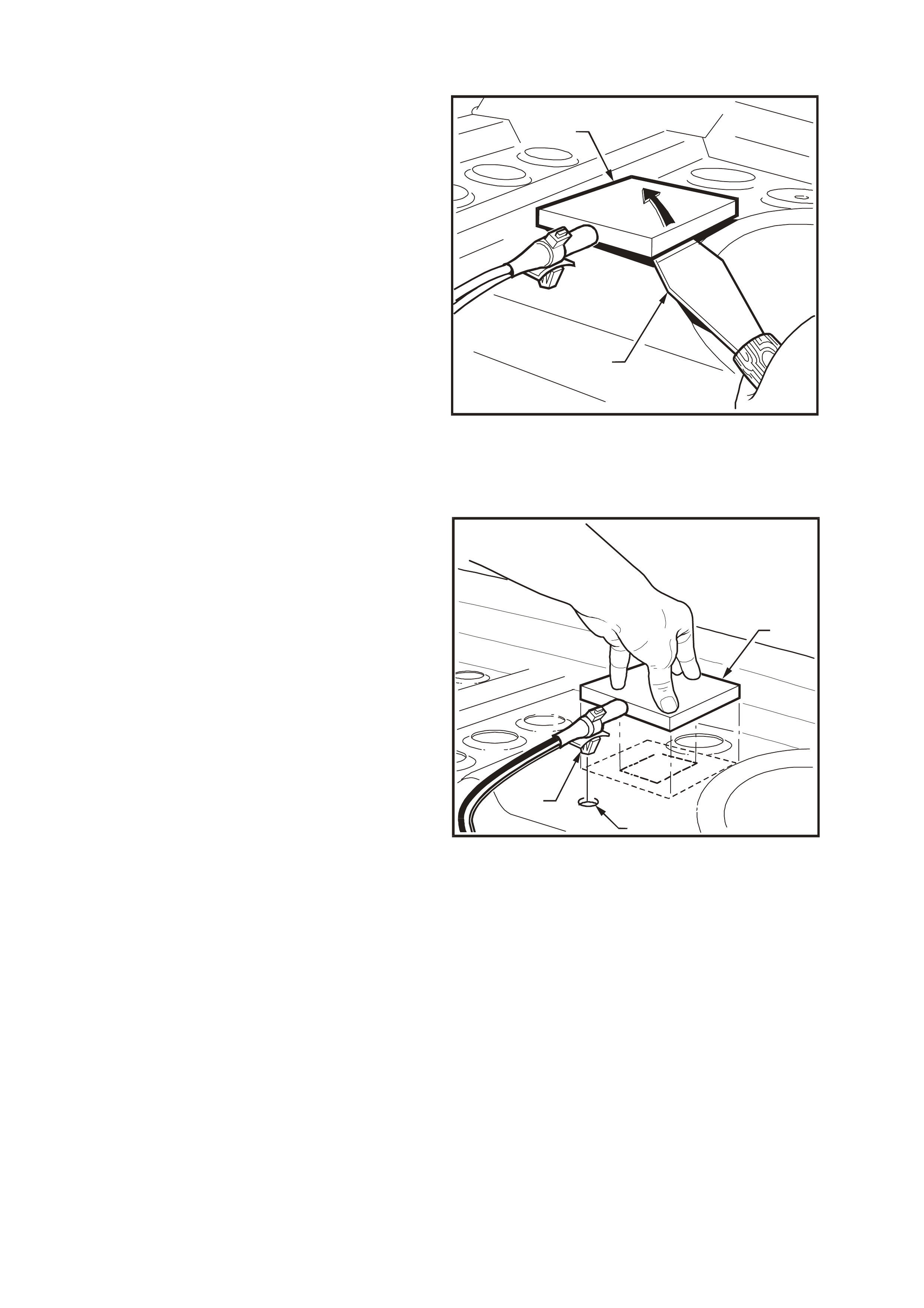
3.4 TELEMATICS ANTENNA
REMOVE
1. Using Tech 2, enable the telematics module
service mode. Refer to 4.3 TECH 2 TEST
MODES F4: Program, F2: Operating Mode,
F1: Service Mode in this Section.
2. Disconnect the negative battery cable from the
battery.
3. Remove the rear parcel shelf trim, refer to
1A8 HEADLINING AND REAR END TRIM in
this Service Information.
4. Remove the left side rear
compartment wheelhouse carpet, refer to
Section 1A1 BODY in this Service Information.
5. Loosen and remove the GSM and GPS
antenna connectors from the telematics
module.
6. Remove the telematics antenna lead retaining
clips.
7. Using a commercial available paint scraper
prise the antenna from the rear parcel shelf.
VX12K009
1
2
Figure 12Q-22
REINST ALL
1. Ensure the rear parcel shelf to telematics
antenna mating surface is clean.
2. If you are reinstalling the original antenna
remove the used double sided tape, and apply
new double sided tape (3M 4428 or
equivalent), meeting Holden Standar d HN2021
Type 6 to the antenna mating surface.
3. Remove the backing from the double sided
tape.
4. Reinstall the antenna to the rear parcel shelf by
aligning the lead retaining clip (3) into the
retaining clip hole (2), then press down firmly
on the antenna.
5. Reinstall the telematics antenna lead retaining
clips.
6. Reinstall the GSM and GPS antenna
connectors to the telematics module.
7. Reinstall the rear parcel shelf trim, refer to
1A8 HEADLINING AND REAR END TRIM in
this Service Information.
8. Reinstall the left side rear compartment
wheelhouse carpet, refer to Section 1A1
BODY in this Service Information.
9. Reconnect the negative battery cable to the
battery.
10. Use Tech 2 to disable the telematics module
Service Mode. Refer to 4.3 TECH 2 TEST
MODES F4: Program, F2: Operating Mode,
F1: Service Mode in this Section.
NOTE: If the telematics module service mode is
not disabled, the system will not operate.
VX12K012
1
2
3
Figure 12Q-23
3.5 TELEMATICS SPEAKER
REMOVE
1. Using Tech 2, enable the telematics module
service mode. Refer to 4.3 TECH 2 TEST
MODES F4: Program, F2: Operating Mode,
F1: Service Mode in this Section.
2. Disconnect the negative battery cable from the
battery.
3. Remove the instrument panel compartment,
refer to Section 1A3 INSTRUMENT PANEL
A ND CONSOLE in this Service Information.
4. Disconnect the speaker wiring harness
connector (3), and remove the connector from
the speaker bracket.
5. Loosen and remove the telematics speaker
bracket retaining screws (1) and remove the
speaker assembly (2).
VX12K015
1
2
3
Figure 12Q-24
REINST ALL
1. Reverse of the removal noting the following.
2. Tighten speaker bracket retaining screws to
the correct torque specification.
TELEMATICS SPEAKER BRACKET
RETAINING SCREWS
TORQUE SPECIFICATION 3 – 3.5 Nm
3. Use Tech 2 to disable the telematics module
Service Mode. Refer to 4.3 TECH 2 TEST
MODES F4: Program, F2: Operating Mode,
F1: Service Mode in this Section.
NOTE: If the telematics module Service Mode is
not disabled, the system will not operate.
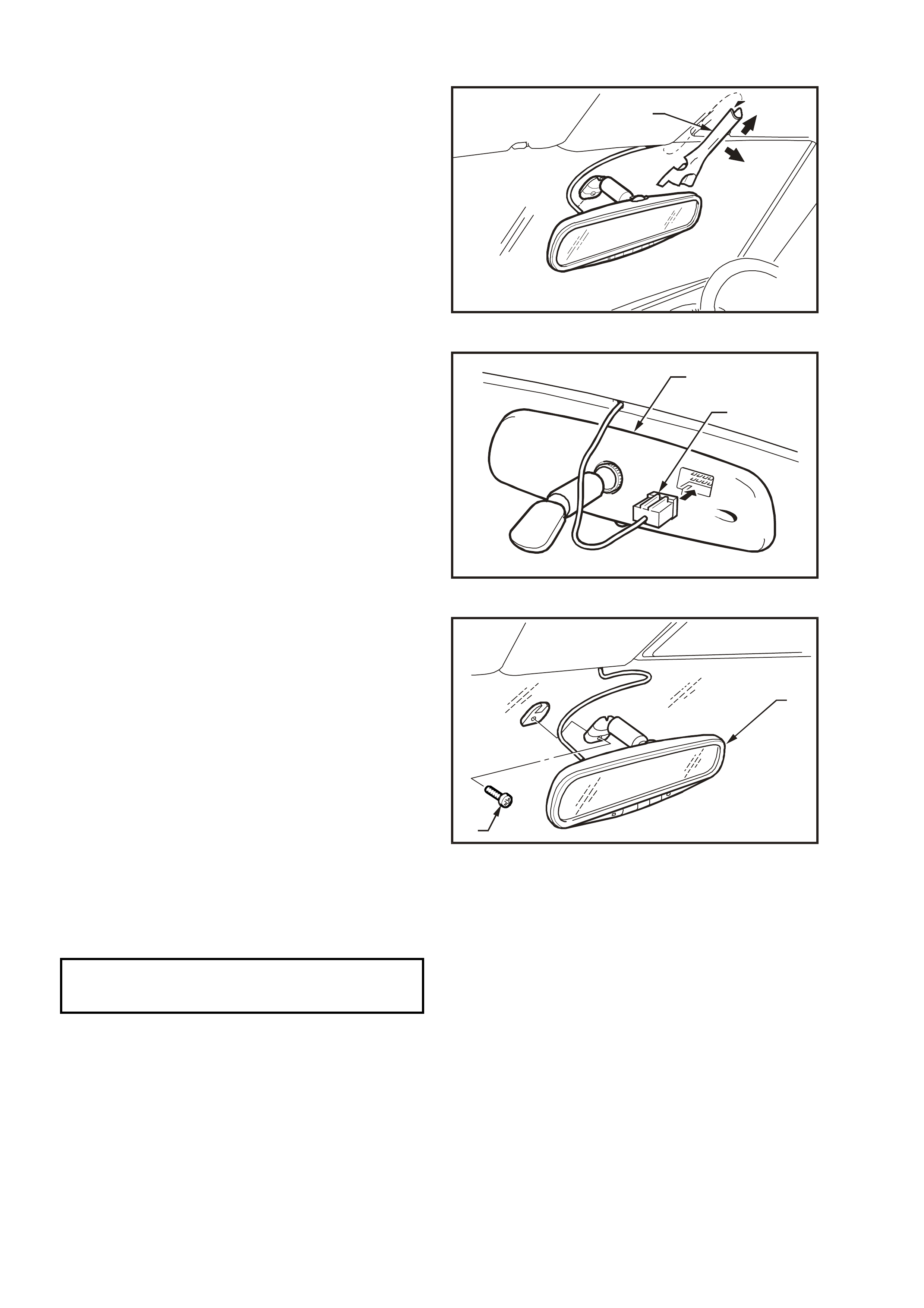
3.6 INTERIOR RE AR VIEW MIRROR
REMOVE
1. Remove mirror wiring harness cover (1) by
sliding cover upwards slightly (direction A) and
pull cover outwards (direction B).
VX12K022
B
1A
Figure 12Q-25
2. Disconnect the interior rear view mirror wiring
harness connector.
VX12K024
1
2
Figure 12Q-26
3. Remove the interior rear view mirror retaining
screw and disengage the interior mirror from
the boss on the windscreen by sliding the
mirror (2) upwards.
VX12K023
2
1
Figure 12Q-27
REINST ALL
Reinstallation of the interior rear view mirror is the reverse of the removal procedure, noting the following:
Tighten the interior rear view mirror retaining screw to the correct torque specification.
INTERIOR REAR VIEW
MIRROR RETAINING SCREW
TORQUE SPECIFICATION 2.5 – 4.5 Nm


4. TECH 2 DI AGNOSIS FOR TELEMATICS
4.1 BASIC KNOWLEDGE REQUIRED
Before attempting to diagnose the telematics system, you must have a good understanding of electrical system
basics and the use of circuit testing tools. Without this basic knowledge it will be difficult to use the diagnostic
procedures detailed in this Section.
Some elec trical basics, tr oubl eshootin g procedures and h ints as well as the use of circuit testing tools are covered
in Section 12P WIRING DIAGRAMS in the VT Series I Service Information.
Basic Electrical Circuits - You should understand the basic theory of electricity, series and parallel circuits, and
voltage drops across series resistors. You should know the meaning of voltage (Volts), current (Amps), and
resistance (Ohms). You should understand what happens in a circuit with an open or shorted wire (shorted either to
voltage or earth). You should also be able to read and understand a wiring diagram.
Use of Circuit Testing Tools - You should know how to use a jumper lead to test circuits. You should be familiar
with the use of a high in put impedance ( 10 Meg O hm) digita l type multimeter s uc h as tool No. J39200 or e qu ivalent
and be able to measure voltage, current, and resistance. You should be familiar with the proper use of the Tech 2.
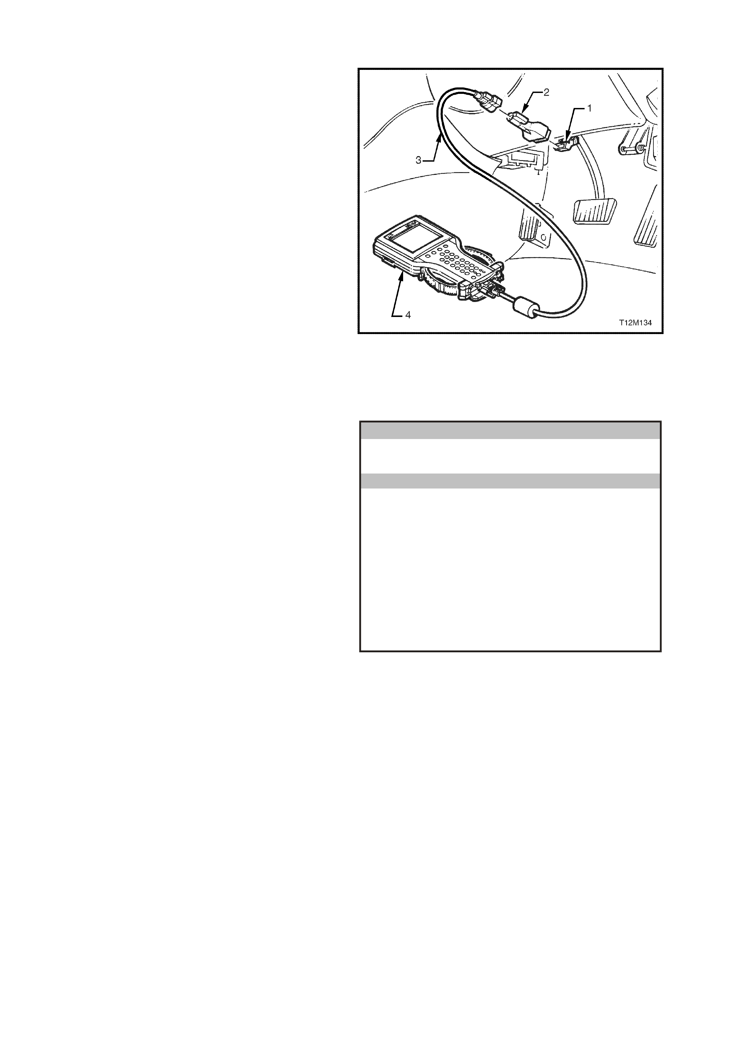
4.2 CONNECTING TECH 2
Tech 2, with the appropriate software, cables and
adaptors, when connected to the Data Link
Connector (DLC) is capable of reading telematics
module serial data. The DLC is connected to the
instrument panel lower right hand trim, to the right
of the steering column.
For additional general information on connecting
and operating Tech 2, refer to Section 0C Tech 2
in this Service Information.
1. DLC
2. DLC Adaptor
3. DLC Cable
4. Tech 2
Tech 2 has five test modes for diagnosing the
telematics module. The five test modes are as
follows:
Figure 12H-28
Mode F0: Data Display
In this test mode, Tech 2 displays the status of
inputs and outputs of the telematics module.
Mode F1: Snapshot
In this test mode, Tech 2 captures telematics
module data before and after a forced manual
trigger.
Mode F2: Miscellaneous Tests
In this test mode, Tech 2 performs various tests to
assist in problem isolation during troubleshooting.
Mode F3: Additional Functions
In this test mode, Tech 2 performs a system
function tes t, of the Microp hone, Speak er, End Call
/ Information Button, Holden Assist Button and the
Emergency Button.
Mode F4: Program
In this test mode, Tech 2 allows the programming
of various features by enabling or disabling the
feature or adjusting settings (ie. Speaker Volume).
Body
VX12K120
F0 : Data Display
F1 : Snapshot
F2 : Miscellaneous Tes ts
F3: Additional Functions
F4 : Program
Figure 12Q-29

4.3 TECH 2 TEST MODES
As a prerequisite to this diagnostic section the user must be familiar with the proper use of Tech 2. The following
information illustrates only the telematics module Tech 2 screen displays and provides an explanation of their
function for diagnosing the telematics module. If additional information is required on the operation of Tech 2,
reference should be made to either Section 0C Tech 2 in this Service Information, or the Tech 2 Operators
Manual.
SYSTEM SELECT MENU
With Tech 2 connected to the DLC and turned on,
and the F0: Diagnostics selected from the Main
Menu, the appropriate Model Year and Vehicle
Type must be selected for access to the System
Select Menu. From the System Select Menu,
Select F3: BODY.
This mode contains all functions to test, diagnose,
monitor and program the vehicles body systems
including the telematics module as well as
providing the opportunity to check all DTCs that
may be set in the vehicle.
VX12K121
System S elect Menu
(1) 2001 VX Comm odore
F0: Engine
F1 : Transmission
F2 : Ch assis
F3 : Body
Figure 12Q-30
Body Application Menu
Once F3: BODY has been selected from the
System Select Menu, the Telematics Module can
be selected from the body application menu.
Select Telematics Module and press enter to
continue.
Once the Telematics Module has been selected
and entered, the following Telematics Module
System Identification screen will be displayed,
once the ignition has been turned on (as
requested).
NOTE: If the telematics module pre delivery
mode is enabled, the telematics module will
only communicate with Tech 2 when the
driver’s is open and for 30 minutes after the
driver’s doors has been closed or Tech 2 stops
communicating with the module.
Vehicle Ide ntification
Select one of the following
Body
Body Con trol Mo dule
P ow e rtrai n Inte rfac e M o du le
SRS
Instrument
Electron ic Climate C ontr ol
Tele matic s Mo dule
DTC Check
Other
Tele matic s Mo dule
VX0C056
6 / 8
Figure 12Q-31

System Identification
The Telematics Module System Identification
screen will then display the following information:
Identifier
(Diagnostic Data Identifier)
Partnumber
(telematics module part number)
Production Date
(telematics module production date)
(DD/MM/YY)
BIM Software Version Number
(telematics module Body Interface Module
software version number)
IVU Software Version Number
(telematics module In Vehicle Unit software
version number)
VAP Process Number
(vehicle ass embly plant proc es s num ber)
Code Version
(sof tware vers io n num ber )
Code Index
(software index number)
Barcode
(telematics module barcode number)
TIS Hardware Key Number
(TIS 2000 Hardware Key Number)
VIN Digit 1-10
(Vehicle Identification Number digits 1-10)
VIN Digit 11-17
(Vehicle Identification Number digits 11-17)
Press the Confirm soft k ey, the telematics m odule
application menu will then be displayed.
Body
(1) 2001 V X Commodore
Tele matic s Modu le
Identifier
Partnumber
Production Date
BIM Software Versio n Number
IVU Software Ve rsion Nu m ber
VA P Pr oce ss N umb er
Identifier
101
92102690
200200
22
140000
12
VX0C062
Confirm
1 / 8
Figure 12Q-32
Application Menu
The following functions will now be available:
F0: Data Display
F1: Snapshot
F2: Miscella neous Tests
F3: Additional Functions
F4: Program
Body
VX12K120
F0 : Data Display
F1 : Snapshot
F2 : Miscellaneous Tes ts
F3: Additional Functions
F4 : Program
Figure 12Q-33

F0: DATA DISPLAY
F0: Data List
In this test mode, Tech 2 checks if the telematics module is actually receiving an input or inputs from the
appropriate sensor/s or antenna/s. If the sensor/s or antenna/s input/s are not being received, then carry out the
relevant system diagnosis as defined in the following chart.
Typical data list parameter nominal values, relevant telematics module pin number and specific diagnostic charts
are detailed in the following chart. If the actual data does not match the nominal value, then refer to the specific
diagnostic chart for that data parameter.
Data Parameter Display Pin No Nominal Values Diagnostic
Chart
Battery Voltage VOLTS 1 Should be within 0.5 volts of actual
vehicle battery voltage. Refer
Vehicle Battery Voltage
Diagnostic Chart in this
Section.
Backup Battery
Voltage Volts 13, 26 Backup Battery Voltage, should be
greater than 11.5 volts. Refer Backup Battery
Diagnostic Chart, in this
Section.
Backup Battery
Charger Active / Inactive 13, 26 Backup Battery Charger, will display
Active when the telematics backup
battery is being charged via the
telematics backup battery charging
circuit.
Refer Backup Battery
Diagnostic Chart in this
Section.
Ignition Switch On / Off SD Ignition Switch status, as read from
the serial data circuit normal mode
message. Should display On when
the ignition switch is on.
Refer No Serial Data
Diagnostic Chart in this
Section.
Operating Mode Pre-Delivery
Active
Service
Int Telematics module Operating Mode.
When the system is operating, should
display Active.
Refer 2.15 OPERATING MODES in
this Section for further information.
Refer
4.3 TECH 2 TEST MODES
F4: Program, F2: Operating
Mode, in this Section.
GPS Module Inactive / Active Int GPS Module status, should di splay
Active when the GPS engine is
operational.
Refer No GPS Signal
Diagnostic Chart in this
Section.
GPS Antenna Status Okay
Open Circuit
Short Circuit
Int Displays GPS antenna circ uit status,
should display Okay.
If Open Circ uit or Short Circuit is
displayed refer to diagnostic chart.
Refer No GPS Signal
Diagnostic Chart in this
Section.
2D or 3D GPS
Position Fix No / Yes Int Will display YES in the GPS has a 2D
or 3D satellite position fix. Will vary
depending upon vehicle and satellite
locations and time of day.
Refer No GPS Signal
Diagnostic Chart in this
Section.
GPS Satellites Not Visible /
Visible Int Should displa y Visible when at least
one GPS satellite has been detected.
Will vary depending upon vehicle and
satellite locations and time of day.
Refer No GPS Signal
Diagnostic Chart in this
Section.
GSM Module Active / Inactive Int Should display Active if GSM Module
is active and registered on the mobile
phone network.
Refer No GSM Signal
Diagnostic Chart in this
Section.
GSM Signal Strength NO SIGNAL OR 1 -
32 Int GSM Signal Strength, will vary from
1 – 32 depending on vehicle position
and GSM coverage. If No Signal is
displayed refer to diagnostic chart.
Refer No GSM Signal
Diagnostic Chart in this
Section.
SPEAKER VOLUME 1 - 8 11, 24 The speaker volume can be
programmed using Tech 2, 1 being
the quietest, to 8 being the loudest.
This displays the current speaker
volume setting.
Refer
4.3 TECH 2 TEST MODES
F4: Program, F1: Speaker
Volume Adjustment in this
Section.
SD = Serial Data, Int = Internal Telematics Module Value

Data Parameter Display Pin No Nominal Values Diagnostic
Chart
Fuel Pump Relay
Drive Circuit Active / Inactive 12, 25 Fuel pump relay drive circuit, should
be active at all times. Should only
display Inactive if remote
immobilisation has been requested.
Refer Fuel Pump Relay
Drive Circuit Diagnostic
Chart in this Section.
FUEL PUMP RELAY
DRIVE CIRCUIT
VOLTAGE
Volts 12
Voltage at terminal 12 of the
telematics module, should be at least
12 volts for three seconds when the
ignition is first turned on, t he engine
is cranking or when the engine is
running.
Refer Fuel Pump Relay
Drive Circuit Diagnostic
Chart in this Section.
Ke ypad Supply
Voltage On / Off 20 Displays the commanded state of the
interior rear view mirror key pad
supply voltage. Should be On
whenever this system is in active or
service mode.
Refer
4.3 TECH 2 TEST MODES
F3: Additional Functions, F1:
Function Test in this
Section.
Ke ypad Signal
Voltage Volts 19
Signal voltage from the resistor
encoded keypa d in the inter ior rear
view mirror. Will vary depending upon
which button is depressed.
Emergency Button 3.8 Volts.
Holden Assist Button 2.3 Volts.
End Call / Info Button 0.7 Volts.
Note: This will make a call to the
Holden Assist Centre.
The operation of this button
should only be tested using the
F1: Function Test.
Refer
4.3 TECH 2 TEST MODES
F3: Additional Functions, F1:
Function Test in this
Section.
End Call / Information
Button On / Off 19 End Call / Information Button status,
should display On when button is
depressed.
Note: This will make a call to the
Holden Assist Centre.
The operation of this button
should only be tested using the
F1: Function Test.
Refer
4.3 TECH 2 TEST MODES
F3: Additional Functions, F1:
Function Test in this
Section.
Holden Assist Button On / Off 19 Holden Assist Button status, should
display On when button is
depressed.
Note: This will make a call to the
Holden Assist Centre.
The operation of this button
should only be tested using the
F1: Function Test.
Refer
4.3 TECH 2 TEST MODES
F3: Additional Functions, F1:
Function Test in this
Section.
Emergency Button On / Off 19 Emergency Button stat us, sho uld
display On when button is
depressed.
Note: This will make a call to the
National Emergency Response
Centre.
The operation of this button
should only be tested using the
F1: Function Test.
Refer
4.3 TECH 2 TEST MODES
F3: Additional Functions, F1:
Function Test in this
Section.
Red Status LED On / Off 22 Displays the commanded state of the
interior rear view mirror red status
LED.
Refer Status Indicators Do
Not Illuminate Diagnostic
Chart in this Section.
Green Status LED On / Off 21 Displays the commanded state of the
interior rear view mirror green status
LED.
Refer Status Indicators Do
Not Illuminate Diagnostic
Chart in this Section.
SD = Serial Data, Int = Internal Telematics Module Value

Data Parameter Display Pin No Nominal Values Diagnostic
Chart
Indicator Drive On / Off SD Display should change from Off to
On when the telematics module is
commanding the indicators On.
Refer 4.3 TECH 2 TEST
MODES F2:
MISCELLANEOUS TESTS
F7: indicators in this Section.
Theft Deterrent Horn On / Off 15 Displays the commanded state of
the theft deterrent horn. Refer Theft Deterrent Horn
Circuit Diagnostic Chart in
this Section.
Driver’s Door DOOR CLOSED /
DOOR OPEN 23 Driver’s door jamb switch status,
should display Door Open when
the driver’s door is open.
Refer Driver’s Door Jamb
Switch Circuit Diagnostic
Chart in this Section.
Passenger Doors Door Closed /
Door Open 10 Passenger door jamb switch status,
should display Door Open when
any passenger door is open.
Refer Passenger Door Jamb
Switch Circuit Diagnostic
Chart in this Section.
Radio Mute Active / Inactive 8 When Active, radio mute is
required by the telematics module. Refer Radio Mute Diagnostic
Chart in this Section.
Entry Alert Delay Seconds Int Displays the amount of time in
seconds after the theft deterrent
system is activated that an
Unauthorised Entry Alert (UEA) is
sent to Holden Assist.
N/A
Low Battery Alert
Delay Seconds Int
Displays the amount of time in
seconds after the battery voltage
has reached the Low Battery Alert
(LBA) threshold that a LBA is sent
to Holden Assist.
N/A
Low Battery Alert
Threshold Volts Int
Displays the battery voltage at
which a Low Battery Alert (LBA) will
be sent to the Holden Assist centre.
N/A
SD = Serial Data, Int = Internal Telematics Module Value
F1: SNAPSHOT
In this mode, TECH 2 captures data before and
after a forced manual trigger.
The purpose of the SNAPSHOT test mode is to
help isolate an intermittent or transient problem by
storing telematics module data parameters just
before and just after a problem occurs.
VX12K123
Sna psh ot O ptions
Trigg er Ty pe : M an ual Trigge r
Trigg er Point : Ce nter
F0 : Manual Trigger
F4 : Beginning
F5 : Center
F6 : End
Record
Snapshot Review
Data
Figure 12Q-34
F2: MISCELLANEOUS TESTS
Miscel laneous tes ts al lo ws f or the tes ting of var ious
components of the telematics system, such as the
status LEDs, radio mute or fuel pump circuit to
assist in problem isolation during troubleshooting.
On entry to each miscellaneous test all other
outputs are turned off. Each test will run for four
seconds. Further activation of the soft key will run
the test for another four seconds. Once
miscellaneous tests has been selected, the
follo wing tes ts will be av ailable.
VX12K122
M isc ellane ous Tests
F0: Fuel Pump Circuit
F1: Red Status LED
F2 : G reen Status LED
F3 : Keypad Supply Voltage
F4: Radio Mute
F5: Backup Battery Charger
F6 : Un lock Doors
F7 : Indicators
Figure 12Q-35
F0: Fuel Pump Circuit
Provides a means of activating and deactivating
the fuel pump relay drive circuit by pressing the
Inactive or Active soft keys. By scrolling to the
screen opposite you can observe the fuel pump
relay circuit status and voltage.
When inactive the telematics module opens the
fuel pump relay drive ground circuit and the fuel
pump will stop. The fuel pump relay drive circuit will
change form approximately 12 Volts engine
running to 1.4 Volts when the engine is not
running.
Pressing the Quit soft key will exit the test.
Precondition: System not in pre delivery mode.
If this miscellaneous test is unsuccessful
replace the telematics module refer
3.2 Telematics Module in this Section.
Fu el Pump Circuit
(1) 2001 V X Commodore
Electronic Syste m : Telem atics Modu le
Fuel Pu m p Relay Drive C
Fuel Pu m p Relay Drive C
Key Pad Supply Voltage
Keypad s ignal Vo ltage
End Call/I nforma tion Bu
Ho lden Assist Button
Em erg ency Button
Fuel Pu m p Relay Drive C
Active
0.7 V
On
13.8 V
Off
Off
Off
Active
VX12K124
Quit
17 / 29
Inactive Active
Figure 12Q-36
F1: Red Status LED
Provid es a means of turnin g the red status LED on
and off using the On and Off soft keys.
Pressing the Quit soft key will exit the test.
Precondition: System not in pre delivery mode.
If this miscellaneous test is unsuccessful refer
Status Indicator LEDs Do Not Illuminate
diagnostic chart in this Section.
Red Status LED
(1) 2001 V X Commodore
Electronic Syste m : Telem atics Modu le
Battery Voltage
Backup Battery Voltage
Backup Battery Charger
Ign itio n Sw itch
Operating Mode
GPS Module
GPS Antenna Status
Red Status LED
13.8 V
13.8 V
Active
On
Active
Okay
Active
Off
VX12K125
Quit
1 / 29
Off On
Figure 12Q-37
F2: Green Status LED
Provides a means of turning the green status LED
on and off using the On and Off soft keys.
Pressing the Quit soft key will exit the test.
Precondition: System not in pre delivery mode.
If this miscellaneous test is unsuccessful refer
Status Indicator LEDs Do Not Illuminate
diagnostic chart in this Section.
Gr een Status LED
(1) 2001 V X Commodore
Electronic Syste m : Telem atics Modu le
Battery Voltage
Backup Battery Voltage
Backup Battery Charger
Ign itio n Sw itch
Operating Mode
GPS Module
GPS Antenna Status
Gr een Status L ED
13.8 V
13.8 V
Active
On
Active
Okay
Active
Off
VX12K126
Quit
1 / 29
Off On
Figure 12Q-38
F3: Keypad Supply Voltage
This test provides the means of turning the supply
voltage from the telematics module to the keypad
on and off using the On and Off soft keys. When
the keypad supply voltage is turned off the keypad
illumination will go out and the keypad buttons will
not function.
Pressing the Quit soft key will exit the test.
Precondition: System not in pre delivery mode.
If this miscellaneous test is unsuccessful refer
Status Indicator LEDs Do Not Illuminate
diagnostic chart in this Section.
Keypad S upply Voltage
(1) 2001 V X Commodore
Electronic Syste m : Telem atics Modu le
Battery Voltage
Backup Battery Voltage
Backup Battery Charger
Ign itio n Sw itch
Operating Mode
GPS Module
GPS Antenna Status
Keypad S upp ly Voltage
13.8 V
13.8 V
Active
On
Active
Okay
Active
On
VX12K127
Quit
1 / 29
Off On
Figure 12Q-39
F4: Radio Mute
Provides a means of activating and deactivating
the telematics radio mute circuit. To activate the
radio mute press the Active soft key, to deactivate
the radio mute press the Inactive soft key.
Precondition: System not in pre delivery mode.
If this miscellaneous test is unsuccessful refer
Radio Mute Circuit diagnostic chart in this
Section.
Radio Mute
(1) 2001 V X Commodore
Electronic Syste m : Telem atics Modu le
Battery Voltage
Backup Battery Voltage
Backup Battery Charger
Ign itio n Sw itch
Operating Mode
GPS Module
GPS Antenna Status
Radio Mute
13.8 V
13.8 V
Active
On
Active
Okay
Active
Inactive
VX12K128
Quit
1 / 29
Inactive Active
Figure 12Q-40

F5: Backup Battery Char ger
Provides a means of activating and deactivating
the telematics backup battery charging circuit. To
activate the backup battery charger press the
Active soft key, to inactivate the backup battery
charger press the Inactive soft key.
Precondition: System not in pre delivery mode.
If this miscellaneous test is unsuccessful refer
Backup Battery diagnostic chart in this Section.
Backup Battery Charger
(1) 2001 V X Commodore
Electronic Syste m : Telem atics Modu le
Battery Voltage
Backup Battery Voltage
Backup Battery Charger
Ign itio n Sw itch
Operating Mode
GPS Module
GPS Antenna Status
Backup Battery Charger
13.8 V
13.8 V
Active
On
Active
Okay
Active
Active
VX12K129
Quit
1 / 29
Inactive Active
Figure 12Q-41
F6: Unlock Doors
Provides a means of locking and unlocking the
doors.
Precondition: System not in pre delivery mode.
When the Lock soft key is pressed, Tech 2 will
send a lock command to the BCM via the serial
data bus. On receiving this request the BCM will
then lock all doors.
NOTE: It is not possible for the telematics
module to lock the doors. To lock the doors,
Tech 2 sends the lock command to the BCM,
the BCM will then lock the doors.
W hen the Unlock soft k e y is depres sed T ech 2 will
request the telematics module to send an unlock
request to the BCM via the serial data bus. On
receiving this request from the telematics module
the BCM will then unlock all doors.
If this miscellaneous test is unsuccessful refer 2
Diagnosis in Section 12J-1 Low Series Body
Control Module or Section 12J-2 High Series
Body Control Module in this Service Information.
Unlock Doo rs
(1) 2001 V X Commodore
Electronic Syste m : Telem atics Modu le
Press L ock or Unlock!
VX12K130
Quit UnlockLock
Figure 12Q-42
F7: Indicators:
Provid es a m eans of caus ing the i ndic ators to flas h
On and Off.
Precondition: System not in pre delivery mode.
When the On soft key is depressed Tech 2 will
request the telematics module to send an
indicators on off request to the BCM via the serial
data bus. On receiving this request the BCM will
then flash the indicators on and off.
When the OFF soft key is depressed Tech 2 will
request the telematics module to stop sending
indicators on off request to the BCM.
If this miscellaneous test is unsuccessful refer 2
Diagnosis in Section 12J-1 Low Series Body
Control Module or Section 12J-2 High Series
Body Control Module in this Service Information.
Indicators
(1) 2001 V X Commodore
Electronic Syste m : Telem atics Modu le
Press O n to Flash Indicators!
VX12K155
Quit OnOff
Figure 12Q-43

F 3: ADDITIONAL F UNCTIONS
In this test mode the following function test is
available:
F1: Function Test
When this test is initiated the telematics module
checks the functionality of the following:
microphone circuit, speaker circuit and the keypad
buttons. During this test you will be requested to
press each of the keypad buttons. Each button
must be pressed before the function test is
completed, with the function test taking 45
seconds.
NOTE: When the keypad buttons are pressed
during the function test, the telematics will not
make any calls, this allows you to test the keypad
buttons without making a call to the Holden Assist
Centre or NERCTM.
If any of the components fail during the function
test, you should refer to the specific diagnostic
chart for each component as detailed in the table at
the end of this test.
Additional Functions
VX12K138
F0: Function Test
Figure 12Q-44
Once F1: Function Test has been selected the
screen opposite will be displayed. Once you have
read the information on the screen press the
Confirm soft key to continue. You will be required
to press al l t hr ee keypad b uttons ind i vid ua lly durin g
this test.
Confirm
(1) 2001 V X Commodore
Electronic Syste m : Telem atics Modu le
VX12K140
Du ring the Fu nction Test You M ust Press
All Th ree Keypad Bu ttons
Func tion Test
Figure 12Q-45
Tech 2 will then request that you press the End
Call / Information Button. You will be given five
seconds to press the button and Tech 2 will then
display Please Wait before automatically moving
on to the next screen.
Confirm
(1) 2001 V X Commodore
Electronic Syste m : Telem atics Modu le
VX12K140
Pres s En d C all / Inform a tion Button
Func tion Test
Figure 12Q-46

Tech 2 will then request that you press th e Holden
Assist Button. You will be given five seconds to
press the button and Tech 2 will then display
Please W ait before automatically moving on to the
next screen.
Confirm
(1) 2001 V X Commodore
Electronic Syste m : Telem atics Modu le
VX12K141
Press Ho lden A ssist Button
Func tion Test
Figure 12Q-47
Tech 2 will then request that you press the
Emergency Button. You will be given five seconds
to press the button and Tech 2 will then display
Please W ait before automatically moving on to the
next screen.
Confirm
(1) 2001 V X Commodore
Electronic Syste m : Telem atics Modu le
VX12K142
Press E mergen cy Button
Func tion Test
Figure 12Q-48
Tech 2 will then display the results of the function
test.
If any of the components fail the function test you
should refer to the specific diagnostic chart for
each component as detailed in the following table.
Confirm
(1) 2001 V X Commodore
Electronic Syste m : Telem atics Modu le
VX12K143
Func tion Test
Microphone
Speaker
End Call / In form ation But
Ho lden Assist Button
Em erg ency Button
Short Circuit
Open Cir cuit
Not Okay
Okay
Okay
Figure 12Q-49

Function Test Failure Diagnostic Charts
Failure Description Function Test Failure
Diagnostic Chart
Microphone Open or Short
Circuit The telematics m odule has detecte d that
there was and open or short in the
telematics microphone circuit during the
function test.
Refer to Microphone Open or
Short Circuit Diagnostic Chart in
this Section.
Speaker Open or Short Circuit The telematics module has detected that
there was and open or short in the
telematics speaker circuit during the
function test.
Refer to the Speaker Open or
Short Circuit Diagnostic Chart in
this Section.
Emergency Button Not Okay The telematics module has detected that
the Emergency Button was not pressed
during the function test.
Refer to the Emergency Button
Not Okay diagnostic Chart in this
Section.
Holden Ass ist Butto n Not Okay T he telematics m odule has detec te d that
the Holden Assist Button was not
pressed during the function test.
Refer to the Holden Assist Button
Not Okay Diagnostic Chart in this
Section.
End Call / Information Button
Not Okay The telematics m odule has detecte d that
the End Call / Information Button was
not pressed during the function test.
Refer to the End Call / Information
Button Not Okay Diagnostic Chart
in this Section.

F4: PROGRAM
In this mode, Tech 2 allows the programming of the
telematics module. When the Program option is
selected, the following three choices will be
available:
F0: Program Code Index
F1: Speaker Volume Adjustment
F2: Operating Mode
VX12K132
Program
F0 : Progra m C ode Index
F1 : Spe aker Volume Ad justment
F2 : Operating Mode
Figure 12Q-50
F0: Program Code Index
In this mode, the code index and programmed
code version are displayed, as well as providing
the operator the option of reprogramming the code
version.
Code Index: The code index identifies the
telematics software level. A higher number
indicates the latest ver s i on of sof tware.
Code Version: The code version identifies the
calibration level. Each software level may have
different code versions, a higher number indicates
the latest versi on of calibr at ion.
Precondition: System not in Pre Delivery Mode.
Once F0: Program Code Index has been sel ected
the screen opposite showing the current code
index and code version numbers will be displayed.
If you wish to change the software level, press the
Modify soft key.
Modify Okay
Co de Inde x
Co de Ve rsion 1
1
Co de Inde x
(1) 2001 V X Commodore
Electronic Syste m : Telem atics Modu le
VX12K153
Figure 12Q-51
You will then be r equested to enter the c ode i ndex.
Once the code index has been entered using the
numerical keypad, press the Enter key to program.
NOTE: Leading zeros will have to be entered.
Code Index
Enter Ecu Code Index
001
Co de Inde x
(1) 2001 V X Commodore
Electronic Syste m : Telem atics Modu le
VX12K161
Figure 12Q-52
Model Code Index
VX 1
WH 1

F1: Speaker Volume Adjustment
This programm ing mode allows you to program the
speaker volume from one to eight, one being the
quietest and eight being the loudest.
Precondition: System not in Pre Delivery Mode.
Once F1: Sp eaker Volume Adjustment has been
selected the s creen oppos it e wil l be displayed. T he
default audio level is f ive. If you wish to chan ge the
audio level, press the Modify soft key.
VX12K152
Program
F0 : Progra m C ode Index
F1 : Spe aker Volume Ad justment
F2 : Operating Mode
Figure 12Q-53
When the screen opposite is displayed enter the
audio level required from 1 – 8 and the press
ENTER to continue.
Spe aker Volum e Ad justm en t
(1) 2001 V X Commodore
Electronic Syste m : Telem atics Modu le
Enter Audio Level (1-8)
Press ENTER key to con tinue
0
VX12K134
Figure 12Q-54
To progr am the audio l evel you have ent ered pres s
the Okay soft key. Tech 2 will then display
Programming Active please wait, before returning
to the Program Menu. If you have entered an
incorrect value press the Not Okay soft key to
return to the previous screen.
Not Okay Okay
Spe aker Volum e Ad justm en t
(1) 2001 V X Commodore
Electronic Syste m : Telem atics Modu le
Pro gram Au dio Lev el ?
5
VX12K135
Figure 12Q-55

F2: Operating Mode
This programm ing mode allows you to program the
system operating mode. There are two
programming options are available.
F0: Pre Delivery Mode
F1: Service Mode
Operating Mo de
VX12K136
F0 : Pre D elivery Mod e
F1 : Service Mode
Figure 12Q-56
F0: Pre Delivery Mode
In this mode, the telematics module pre delivery
mode can be enabled or disabled. Vehicles will be
delivered to the dealer with the pre delivery mode
enabled. With the pre delivery mode enabled the
telematics system is turned off. The pre delivery
mode must be disabled using this programming
function during the pre delivery inspection.
NOTE: When in pre delivery mode the
telematics module will only communicate with
Tech 2 when the driver’s is open and for 30
minutes after the driver’s doors has been
closed or T ech 2 stops commun icating w ith the
module.
Once F0: Pre Delivery has been selected, Tech 2
will request that you “Please get programming
approval from TIS”. Refer Section 0C TECH 2,
ENABLING PROGRAMMING in this Service
Information.
Once enable programming has been successful,
return to and select F0: Pre Delivery Mode and
Tech 2 will continue to the following screen.
Confirm
Pre D eliv ery Mode
(1) 2001 V X Commodore
Electronic Syste m : Telem atics Modu le
VX12K148
Please ge t prog ram m ing appr oval from
TIS!
Figure 12Q-57
The current telematics module operating mode will
be displayed. If you wish to enable or disable the
pre deliver y mode pres s the Modify soft key, if you
do not wish t o modify the operating mode pres s the
Abort soft key.
Abort Modify
Operating Mode Pre Delivery
Pre D eliv ery Mode
(1) 2001 V X Commodore
Electronic Syste m : Telem atics Modu le
VX12K149
Figure 12Q-58

To disable the pre delivery mode press the Disable
soft key. The pre delivery mode will be disabled
and the telematics module will be fully functional.
NOTE: When pre delivery mode is disabled
service mode will be automatically enabled.
To enable the pre delivery mode press the Enable
soft key. The pre delivery mode will be enabled
and the telematics module will not be functional.
Tech 2 will then display programming in progress,
once program m ing has be en completed T ech 2 wil l
return to the Operating Mode menu.
Disable Enable
Pres s En able Or Disable S oft Ke y To
Program!
Pre D eliv ery Mode
(1) 2001 V X Commodore
Electronic Syste m : Telem atics Modu le
VX12K150
Figure 12Q-59
F1: Service Mode
In this mode, the telematics module service mode
can be enabled and disabled.
Precondition: System not in pre delivery mode.
Once F1: Service Mode is selected the current
operating mode will then be displayed.
Operating Mo de
VX12K151
F0 : Pre D elivery Mod e
F1 : Service Mode
Figure 12Q-60
If you wish to enable or disable the service mode
press the Modify soft key. If you do not wish to
modify the operating mode press the Abort soft
key.
Abort Modify
Service Mode
(1) 2001 V X Commodore
Electronic Syste m : Telem atics Modu le
VX12K137
Operating Mode Active
Figure 12Q-61

To dis able the ser vice m ode pres s the Disable soft
ke y. T o enable the ser vice m ode press the Enable
soft key. Tech 2 will then display programming in
progress. Once programming has been completed
Tech 2 will return to the Operating Mode menu.
Disable Enable
Service Mode
(1) 2001 V X Commodore
Electronic Syste m : Telem atics Modu le
VX12K138
Pres s En able or Disab le Soft K ey To
Program
Figure 12Q-62

5. DIAGNOSIS
The General Information contained in this Section is where to start all system diagnosis. Once you have read
and understood the General Information Section, which contains reference material: wiring diagrams,
control module terminal end views and nominal voltages, and component locations. (Remember, this
information is for reference; do not start diagnosis using these pages). Always start diagnosis on the page titled
On-Board Diagnostic System Check. This check first verifies that the diagnostic circuits are operating properly
and then sends you to the correct chart for diagnosis.
If the initial steps in the On-Board Diagnostic System Check reveal a problem, it will direct you to the appropriate
diagnostic chart.
5.1 BASIC KNOWLEDGE AND TOOLS REQUIRED
To us e the Servic e Inf orm ation eff ective ly, you sho uld unders tand the basic theor y of electr ic ity, s eries and par allel
circuits, and voltage drops. You should know the meaning of voltage (Volts), current (Amps), and resistance
(Ohms). You should understand what happens in a circuit with an open or shorted wire (shorted either to
voltage or ground). You should also be able to read and understand a wiring diagram, refer to
Section 12P WIRING DIAGRAMS in the VT Seri es 1 Servic e Inf ormation.
To per f orm s ystem diagnos is , th e us e of a Tech 2 is re quir e d. Tech 31 or a dig ita l vo lt-ohmm eter with 10 megohms
impedanc e, a t es t l ig ht, an d j umper wir es ar e a ls o re q uir ed. Ple as e bec ome acqu aint ed with the too ls a nd th eir use
before attempting to diagnose a vehicle.
Exercise care when taking readings from wiring harness connectors. It is preferred that the back probing method
with individual connectors is employed wherever possible, to avoid terminal damage and subsequent connection
failure. When carrying out wiring checks as directed to by the diagnostic charts, rather than probe terminals and
connectors with incorrect sized multimeter connections, use the adaptors contained in connector test adaptor kit
KM-609. T his will pre ven t an y possib ilit y of spread ing or dam aging wir ing har ness term inals .
Testing of the various systems will also involve gaining access to specific wiring harness connectors. For the
location of these connectors, refer to Section 12P WIRING DIAGRAMS in this Ser vice Information.

5.2 DIAGNOSTIC PRECAUTIONS
The following requirements must be observed when working on vehicles:
1. Before performing any Service Operation or other procedure described in this Section, refer to
Section 00 CAUTIONS AND NOTES for correct workshop practices with regard to safety and/or property
damage.
2. Disconnect the negative battery cable before removing any system component.
3. Never start the engine without the battery being connected correctly.
4. Never separate the battery from the on board electrical system while the engine is running.
5. When charging the battery, disconnect it from the vehicle's electrical system.
6. Nev er subject t he any tele matics module to temperat ures above 8 0 degrees C i.e. paint o ven. Alwa ys remove
the telematics module first, if this temperature is to be exceeded.
7. Ensure that all cable harness plugs are connected solidly and that battery terminals are thoroughly clean.
8. The harness con nectors are des igned to f it in onl y one wa y, forc ing connect ors into place is not n ecessar y if it
is being ins ta lled with t he proper or ienta t io n. Fa il ur e to tak e c ar e to match the ind ex ing t abs a nd s lo ts to e ns ur e
the connector is being installed correctly can cause dam age to the connector, the telematics module, or other
vehicle components or systems.
9. Never connect or disconnect telematics module cable harness connectors when the ignition is switched on.
10. Before attempting any electric arc welding on the vehicle, disconnect the battery leads and the telematics
module connectors.
11. W hen steam c leaning en gines, do no t direc t the s team cleaning no zzle a t s ystem components . If this happens ,
corrosion of the terminals can take place.
12. Use only the test equipment specified in the diagnostic charts, since other test equipment may either give
incorrect results or damage good components.
13. All v olt ag e measur em ents us ing a vol tmeter m us t us e a d igital v oltmeter with a n i nter na l impedanc e r at ing of at
least 10 million ohms per volt (10 meg ohms).
14. W hen a test light is spec ifie d, a lo w-power tes t lig ht must be us ed. Do not use a hig h - watta ge tes t light. W hile
a particu lar brand of tes t light is not sugges ted, a sim ple test on an y test li ght will ensure it to be OK for circ uit
testing. Connect an accurate ammeter (such as the high-impedance digital multimeter) in series with the test
light being tested, and power the test light-ammeter circuit with the vehicle battery.
If the ammeter indicates less than 3/10 amp current flow (0.3 A or 300 mA), the test light is OK to use.
If the ammeter indicates more than 3/10 amp current flow (0.3 A or 300 mA), the test light is NOT OK to use.
Blocking Drive Wheels
The vehicle drive wheels should always be blocked and the parking brake firmly applied while checking the system.
Visual/Physical Inspection
A careful visual and physical inspection must be performed as part of any diagnostic procedure. This can
often lead to fixing a problem without further steps. Inspect all electrical wires f or correct routing, pinches, cuts, or
disconnections. Be sure to inspect wires that are difficult to see. Inspect all the wires for proper connections,
burned or chafed spots, or contact with sharp edges or hot exhaust manifolds. This visual/physical inspection is
very important. It must be done carefully and thoroughly.
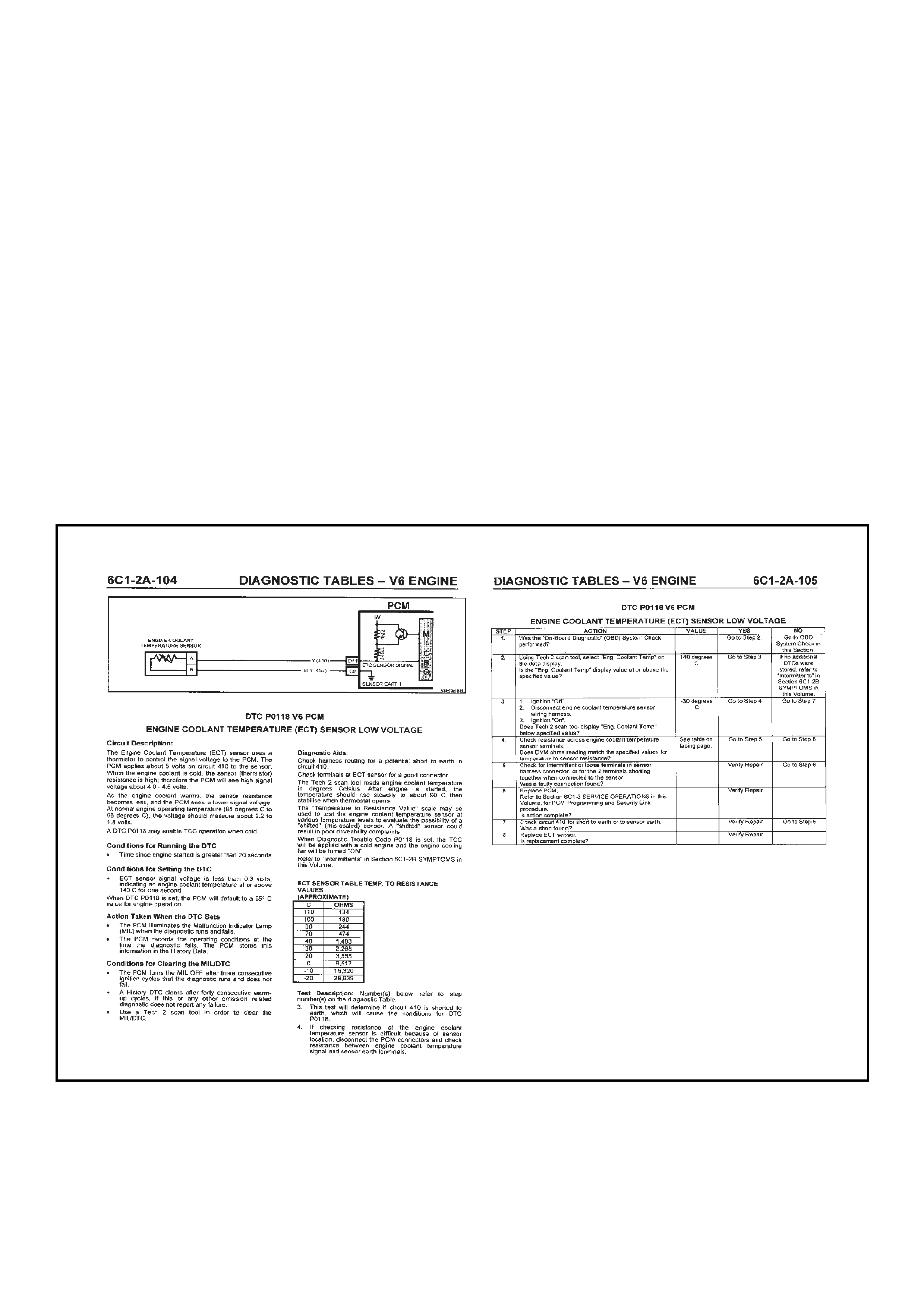
5.3 DIAGNOSTIC CHART
The diagnostic charts are design ed to provide fast and efficient m eans of fault location f or all functions associated
with the te lematics m odule. Each diagnos tic chart use s 2 pages; a chart on th e right side pag e, and a facing pag e
on the left side page. The left side "facing page" contains pertinent information, and circuit diagrams. The chart
steps are explained by the corresponding numbered paragraph on the left side facing page.
When diagnosing any problem, always begin with the On-Board Diagnostic System Check. The On-Board
Diagnostic System Check will lead you to the other charts. DO NOT GO DIRECTLY TO A SPECIFIC CHART or
false dia gn os is an d rep lac e ment of ser viceabl e p ar ts coul d r es ult. After a f ault is cor rec ted a nd al l DTCs hav e bee n
cleared, repeat the On-Board Diagnostic System Check to assure that the proper repairs have been made.
The box at the top of the left page contains a circuit diagram showing the components involved in each circuit.
Immediately below the box is a brief circuit description. On the facing right hand page a troubleshooting chart for
diagnosing conditions. Step numbers on the right-hand page next to the action boxes in the chart relate to the
items in the Test Description on the left-hand page. These items provide an explanation of each test in the chart.
The facing right hand page also contains a three quarter view of the connectors that are listed in the diagnostic
charts.
The appropriate step in any of the trouble shooting chart will instruct you either to make a specific repair or to
continue diagnosis. If further diagnosis is needed, the step will specify where to continue.
The Yes or No column in any diagnostic chart will instruct you either to make a specific repair or to continue
diagnosis. If further diagnosis is needed, the Yes or No column will specify where to continue.
If the condition is intermittent, the trouble shooting chart will direct you to the diagnostic aids on the facing page.
This Section gives suggestions for diagnosing intermittent conditions and explains how some faults can occur.
Remember, charts are for solving active conditions, not intermittent conditions.
Figure 12Q-63

5.4 STRATEGY BASED DIAGNOSTICS
The s trategy based d iagnos tic is a un iform appr oach to r epair all E lectrica l/Electr onic s ystem s. The dia gnostic flow
can always be used to resolve an Electrical/Electronic system problem and is a starting point when repairs are
necessar y. The steps below ar e defined to instruc t the techn ician ho w to proceed with a diagn ostic proc ess. Ste ps
below also refer to step numbers found on the Strategy Based Diagnostic chart.
1. Verify the Driver Concern: To verify the driver concern, the technician should know the normal operation of
the system.
2. Preliminary Check: Conduct a thorough visual and operational inspection, review the service history, detect
unusual sounds or odours, and gather diagnostic trouble code information to achieve effective repair.
3. Service information (Manual) System Check(s): System checks verif y proper operation of the system. This
will lead the technician in an organised approach to diagnostics.
4. Check Bulletins and Other Service Information: This should include, Service Techlines, All Dealer letters,
and Service T r ain ing Pu bl icatio ns .
5. Service Diagnostics (Paper/Electronic)
5.1 DTC Stored: Follow the designed DTC chart exactly to make an effective repair.
NOTE: The telematics module does not have any Diagnostic Trouble Codes.
5.2 Symptom, No DTC: Select the symptom from the symptom charts and follow the diagnostic paths or
suggestions to complete the repair, or refer to the applicable component/system checks in Section 6C3-2C
in the Service Information.
5.3 No Published Diagnostics: Analyse the complaint and develop a plan for diagnostics. Utilise the wiring
diagrams and theory of operation.
Call Technical Assistance for similar cases where repair history may be available. Combine technician
knowledge with efficient use of the available service information.
5.4 Intermittent faults: Conditions that are not always present are intermittent. To resolve intermittence,
perform the following steps:
5.4.1 Observe history DTCs, DTC modes and Freeze Frame data if available.
5.4.2 Evaluate the symptoms and conditions described by the driver.
5.4.3 Use a check sheet or other method to identify the circuit or electrical system component.
5.4.4 Follow the suggestions for intermittent diagnosis found in the service documentation.
The Tech 2, Tech 31 and MM have data capturing capabilities that can assist in detection of intermittents.
5.5 Vehicle Operates As Designed/No Trouble Found: This conditi on exists when the veh icle is f ound to be
operating normally. The condition described by the driver may be normal. Verify against another vehicle
that is operating normally. The condition may be intermittent. Contact Technical Assistance if the concern
is common. Verify the complaint under the conditions described by the driver before releasing the vehicle.
6. Re-examine the Concern: When the complaint cannot be successfully found or isolated, a re-evaluation is
necessary. The complaint should be re-verified and could be intermittent or normal as per step 5.3 or 5.5.
7. Repair and Verific ation Test s: After is olating th e cause, the r epair sho uld be m ade. Then v alidate for pr oper
operation and verify that the symptom has been corrected. This may involve road testing or other methods to
verify the complaint has been resolved under the following conditions:
• Conditions noted by the driver.
• If a DTC was diagnosed, verify a repair by duplicating conditions present when a DTC was set.

5.5 ON-BOARD DIAGNOSTIC SYSTEM CHECK
After the visual/physical vehicle inspection, the On-Board Diagnostic System Check is the starting point
for all diagnostic procedures or finding the cause of a system malfunction or failure.
All Diagnostic procedures must always begin with the On-board Diagnostic System Check.
Diagnostic procedures must begin with the On-Board Diagnostic System Check, which represents an organised
approach for identifying system problems.
The ON-BOARD DIAGNOSTIC SYSTEM CHECK makes an initial check of the system, then will direct the
technician to other charts in the Service Information. It must be used as a starting point for all procedures. The
entire diagnostic section in the Service Information is set up in a specific order, that is, the ON-BOARD
DIAGNOSTIC SYSTEM CHECK will lead the technician to other charts, and those charts may lead to still other
charts. THE SEQUENCE MUST BE FOLLOWED. The telematics module uses many input signals and controls
many output functions. If the correct diagnostic sequence is not followed, incorrect diagnosis and replacement of
good parts may happen.
Diagnostic charts incorporate diagnosis procedures using a Tech 2 where possible. Tech 2 is a small hand-held
computer in itself. Its job is to give information to a technician about what is happening in the system.
The Data Link Connector (DLC) is used by the as sembl y plant to perf orm end of line tests. T his c onnector c an also
be used b y technicians to monitor c ertain inputs an d outputs as s een by the tel ematics module. T he Tech 2 r eads
and displays the information (serial data) supplied to the data link connector from the telematics module.
The correct procedure to diagnose a problem is to follow three basic steps.
1. Are the On-Board Diagnostics working? This is determined by performing the On-Board Diagnostic System
Check. Since this is the starting point for the diagnostic procedures or finding the cause of a failure, always
begin here.
If the On-Board Diagnostics are not working, the On-Board Diagnostic System Check will lead to a diagnostic
chart to correct the problem. If the On-Board Diagnostics are working correctly, the next step is:
2. Is there a Diagnostic Trouble Code stored? If a diagnostic trouble code is stored, go directly to the numbered
diagnostic trouble code chart. This will determine if the fault is still present. If no diagnostic trouble code is
stored, then:
NOTE: The telematics module does not use Diagnostic Trouble Codes, Go to Step 3.
3. Obs erve Serial Data transm itted by the telem atics module: T his invol ves readin g the Tech 2 inf ormation. T ech
2 Information and the meaning of the various displays can be found in the Service Information. Typical data
readings un der a particu lar operatin g condition ca n be found on t he Tech 2 Data page. If the actu al data does
not match the typical data, then refer to the specific diagnostics for that data parameter.
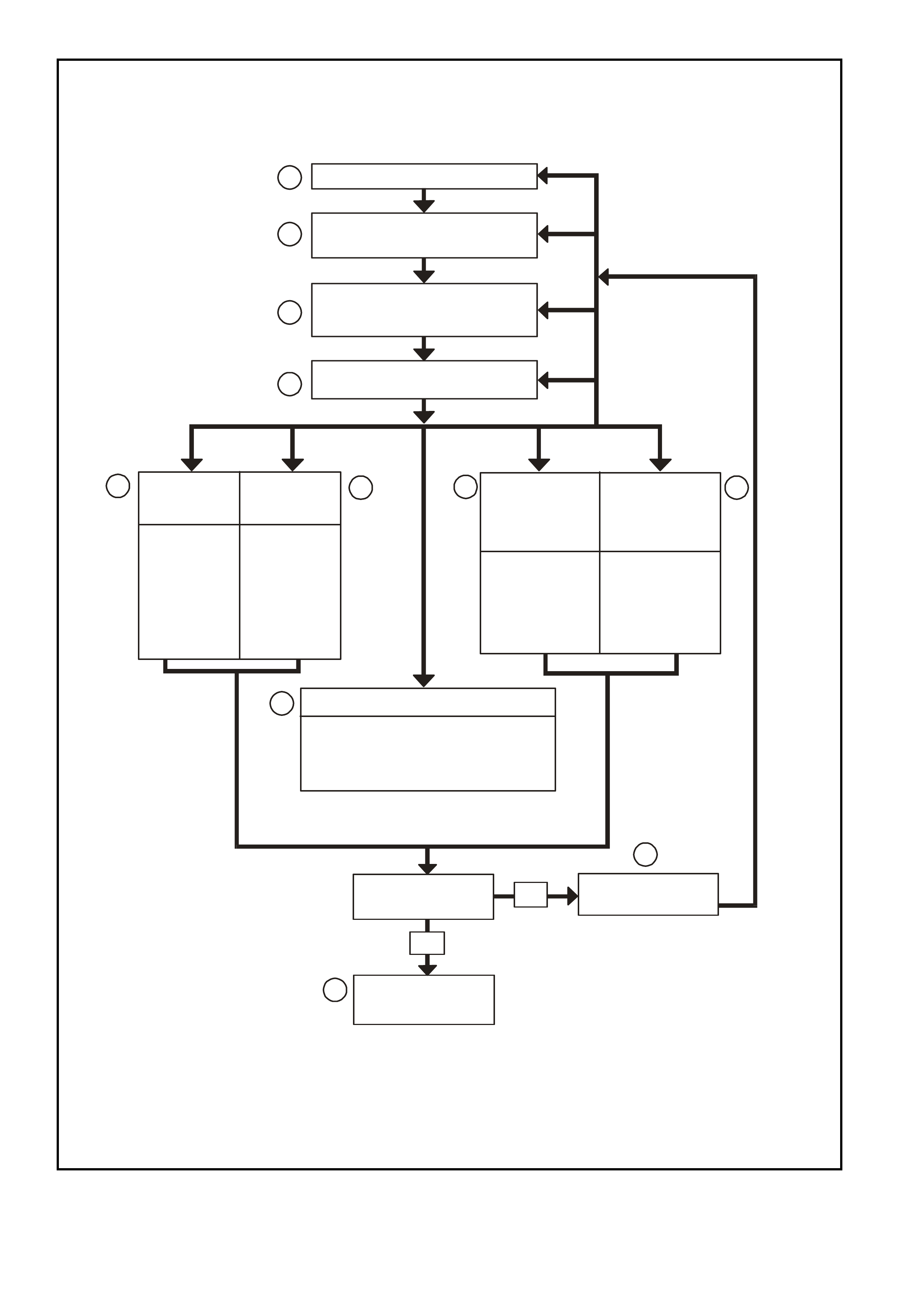
12K DIAGNO ST IC CHAR T
VERIFY DRIVER CONCERN
PRELIMINARY CHECKS
(VISUAL AND OPERATIONAL)
PERFORM
TELEMATICS SYSTEM
OBD SYSTEM CHECK
CHEC K FOR
BULLENTINS
1
2
3
4
STORED
DTC(S)
FOLLOW
PUBLISHED
DTC
DIAGNOSTICS
FOLLOW
PUBLISHED
SYMPTOM
DIAGNOSTICS
ANALYSE &
DEVELOP
DIAGNOSTICS
FROM WIRING
DIAGRAMS
& THEORY
REFER TO
INTERMITTENT
DIAGNOSTIC
DETAILS
Ex p lain Operat ion to Driv er
Call Technical Assistance
DRIVER MISUNDERSTANDING OF SYSTEM
PRODUCT PROBLEM
ISOLATE
THE PROBLEM RE-EXAMINE
THE CONCERN
NO
YES
7
REPAIR/RESOLVE
& VERIFY
SYMPTOM
NO DTC(S)
NO
PUBLISHED
DIAGNOSTICS
OPERATING AS DESIGNE D
INTERMITTENT
5.1 5.2
6
5.3 5.4
5.5
Figure 12Q-64 Strategy Based Diagnostic
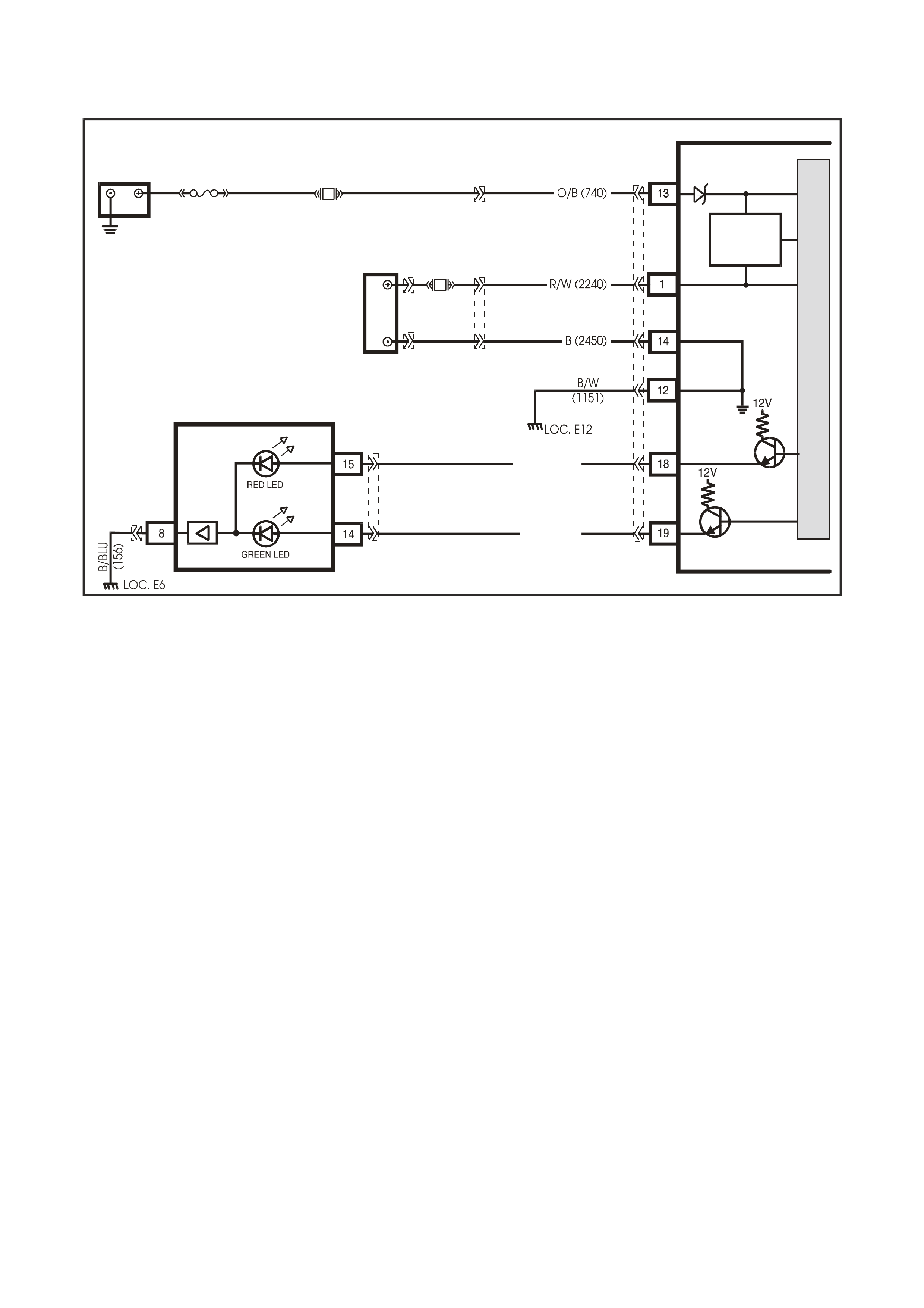
5.6 DIAGNOSTIC CHARTS
ON-BOARD DIAGNOSTIC SYSTEM CHECK
VX12K113
TELEMATICS MODULE
BATTERY
LOC. E1
GROUND
BACK UP
BATTERY
GROUND
BATTERY
BACK UP
BATTERY
BATTERY
CHARGER
F31
YB178
YR55
FS
BACK UP
BATTERY
YR55
YR60YR61
M
I
C
R
O
BR / W (2517)
Y/B (2516)
REAR VIEW MIRROR
TELEMATICS
STATUS LE DS
YB186
YB186
Figure 12Q-65
Circuit Description
The On-Board Diagnostic System Check is an organised approach in identifying a telematics system problem. It
must be the s tarting p oint for an y system diag nostics, as it directs the s ervice tec hnician to th e next logic al step in
diagnosing a complaint. Understanding the diagnostic chart and using it correctly will reduce diagnostic time and
prevent the replacement of good parts.
Test Description
1. The telematics Module Service Mode must be disabled and the Telematics Module operating in Active Mode
for this diagnostic chart to function correctly.
2. Confirms if the telematics module has detected a system fault or if the module is in Service Mode. In Service
Mode only the Holden Assist button is operational. This prevents unnecessary calls and alerts being made to
Holden Ass ist while the vehic le is being ser viced. All s ervice procedur es should be car ried out with th e Servic e
Mode enabled, unless otherwise specified.
3. Confirms Tech 2 operation.
4. Confirms that Tech 2 can communicate with the telematics module. If the telematics module is in the Pre
delivery mode the driver’s door must be open before the telematics module will communicate with Tech 2.
5. The VIN in the telematics module should always match the actual vehicle VIN. The correct VIN is critical for
proper telematics system operation.
6. If the engine starts and runs then the fuel pump relay drive circuit if OK.
7. This test determines if the telematics module is in pre delivery mode. In pre delivery mode the telematics
module is turned off. If the pre delivery mode is enabled it should be disabled and the On-Board Diagnostic
System Check should be performed again.
8. During the function test the telematics module checks the following components for correct operation:
Microphone, Speaker and the Key Pad Buttons. If any of these components fail the function test, you should
refer to the applicable diagnostic chart.
9. In this test you should refer to the telematics data list nom inal values. If the values in the Tech 2 Data List do
not meet the nominal values listed, refer to the applicable diagnostic chart.
10. In this test step all of the Tech 2: Miscellaneous Tests should be conducted and should pass the test
successfully, if any test fails you should refer to the applicable diagnostic chart for that miscellaneous test.
11. The vehicle must be positioned where the GSM signal strength is at least 20 and the GPS has a 2 or
3D fix. You can then begin the Holden Assist Telematics System Test. You must refer to the
Holden Assist Telematics System Test in this Section.

12. This test step confirms that the connector terminal retention is OK, Terminal retention should always be
checked before any component is replaced.
13. T he telematic s system is operati ng as desi gned and h as passed t he On-Board Diagnost ic System Check . You
should discuss the system complaint with the driver (System Subscriber) of the vehicle to ensure that they
understand the correct operation of the system, have them demonstrate the problem, discuss the complaint
with the driver (System Subscriber), and have them demonstrate the problem.
STEP ACTION YES NO
1. Disable Telematics Module Service Mode.
Has Service Mode been disabled? Go to Step 2. Disable Service Mode.
Refer F4: Program /
Operating Mode /
Service Mode
in this Section.
2. 1. Turn ignition on, engine off.
Did you hear five beeps and/or did the Holden Assist
Status LEDs flash Red and Green for 25 seconds?
Go to Status LEDs Indicate a
System Malfunction Chart in
this Section.
Go to Step 3.
3. 1. Turn ignition off, install Tech 2 to DLC, turn ignition
on and turn on Tech 2.
Does Tech 2 power up and display the title display
screen?
Go to Step 4. Refer Tech 2 Diagnosis,
Section 0C Tech 2 in
this Service Information.
4. 1. Open the driver’s door.
2. With Tech 2 still connected and ignition on, press
the ENTER key, then select Diagnostics / (1) 2001 /
VX Commodore / F4: Body / Telematics Module and
then follow the screen instructions.
Does Tech 2 display telematics system identification
information?
Go to Step 5. Refer No Telematics
Serial Data Diagnostic
Chart, in this Section.
5. Did the VIN displayed in the step 4 match the actual VIN
of the vehicle? Go to Step 6. Go to Step 12.
6. Does the engine start and run. Go to Step 7. Refer Fuel Pump Relay
Drive Circuit Diagnostic
Chart in this Section.
7. 1. From the Telematics Application Menu,
Select F0: Data List.
2. Scroll to Operating Mode.
Does Tech 2 display “Pre Delivery”?
Disable Pre Delivery Mode.
Refer F4: Program /
Operating Mode / Pre
Delivery Mode
in this Section.
Go to Step 8.
8. 1. From the Telematics Application Menu,
Select F3: Additional Functions / F0: Function Test.
(Refer, F0: Function Test in th is Section).
Did the Telematics System pass the Function Test?
Go to Step 9. Refer Function Test
Failure Diagnostic
Charts in this Section.
9. 1. From the Tech 2 Telematics application menu
Select / F0: Data Display
(Refer Telematics Data List in this Section).
Do the Telematics Data List parameters match the
Nominal Values?
Go to Step 10. Refer 4.3 TECH 2 TEST
MODES, F0: Data
Display in this Section.
10. 1. From the Tech 2 Telematics application menu
Select / F2: Miscellaneous Tests
(Refer F2: Miscellaneous Tests in this Section).
2. Perform all the Miscellaneous Tests.
Where all the Miscellaneous Tests successful?
Go to Step 11. Refer to the Applicable
Miscellaneous Test
Failure Diagnostic Chart
in this Section.
11. 1. Ignition on.
2. Position the vehicle where the GSM Signal strength
is at least 20 and the GPS has a 2 or 3D Fix.
3. Perform a Holden Assist Telematics System Test.
(Refer Holden Assist Telematics System Test in this
Section).
Was the Telematics System Test successful?
Go to Step 13. Go to Step 12.

STEP ACTION YES NO
12. 1. Check telematics module connector YR55 terminal
retention.
Is the terminal retention OK?
Replace tele mati cs mo dule . Repair connec tor
terminal retention.
13. Telematics system is operating correctly.
If the owner (System Subscriber) was complaining about a system fault, discuss the complaint with the owner, and
have them demonstrate the problem.
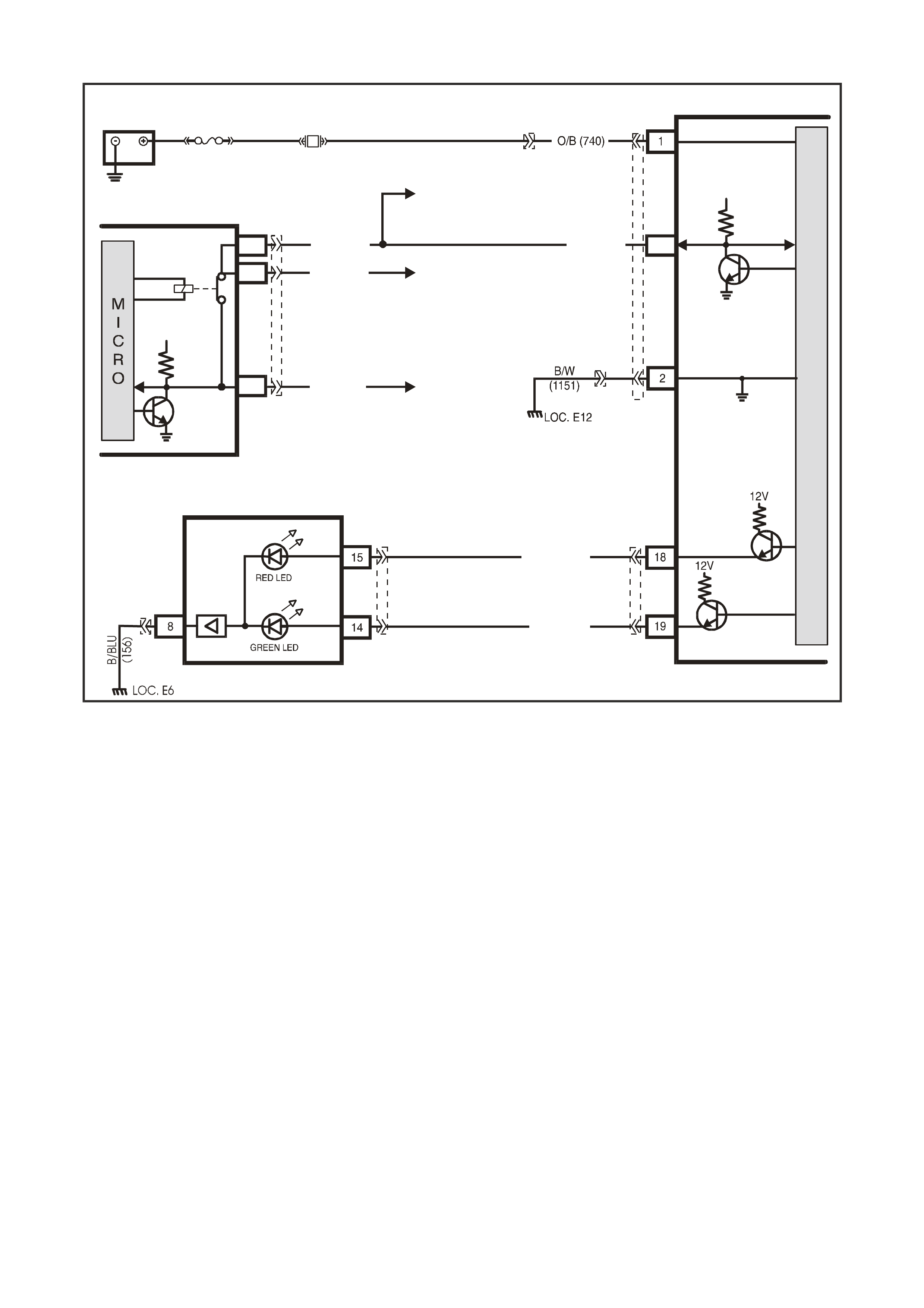
STATUS LEDS INDICATE A SYSTEM MALFUNCTION
TELEMATICS MODULE
LOC. E1
BATTERY
YB178
BATTERY
F31
YR55
FS
YB178
M
I
C
R
O
P
R
O
C
E
S
S
O
R
BODY
CONTROL MODULE
R/B (1221) TO PCM
TO SRS
TO INSTRUMENTS
ECC, ABS/ETC &
G/W (1220)
W/G (1220)
E2
E9
E3
SERIAL
DATA
MAIN
SERIAL
DAT A AUX.
5V
GROUND
9
SERIAL
DATA
5V
G/W (1220)
VX12K157
YB174
YB163
YB175
YB164
BR / W (2517)
Y/B (2516)
REAR VIEW MIRROR
TELEMATICS STATUS LEDS
YB186
YB186
Figure 12Q-66
Circuit Description
W hen the ser vic e a lert is a ctiva ted the sta tus i ndica tor LEDs wil l f lash r ed an d gr e en f or 25 sec on ds and f ive beeps
will be heard when the ign ition is turned from off to on. The service alert will be activated if the telematics module
service m ode is active or the telem atics module has detected that the G SM module is not active, the G PS module
is not active, or the backup battery is not charged or disconnected.
Test Description
1. Confirmation that the Telematics On-Board Diagnostic System Check has been performed.
2. Confirms that Tech 2 is being powered and is operational.
3. Confirms that Tech 2 can communicate with the telematics module.
4. When the telematics module is in service mode the telematics module service alert will be activated i.e. the
status in dicator LEDs will flash r ed and green f or 25 seconds an d five beeps will be hear d when the ign ition is
turned on.
5. Low backup battery voltage will also cause the service alert to be activated i.e. the status indicator LEDs will
flash red and green for 25 seconds and five beeps will be heard when the ignition is turned on.
6. The GPS Module should always be active, unless the telematics module is in pre delivery mode.
7. The GSM Module should always be active, unless the telematics module is in pre delivery mode.
8. The Tech 2 F0: Function Test when in itiated checks the functionalit y of the microphone circuit, speaker circuit
and the keypad buttons. If any components fail the function test, you should refer to the specific diagnostic
chart.
9. The Tech 2 F0: Data L ist should be ch eck to determine if the ac tual data val ues m atch the typical dat a valu es.
If they do not match then you should refer to the specific data list diagnostic chart.
10. This test step confirms that the connector terminal retention is OK. Terminal retention should always be
checked before any component is replaced.

STEP ACTION VALUE YES NO
1. 1. Has a Telematics On-Board Diagnosis System
Check been performed? Go to Step 2. Refer Telematics
On-Board
Diagnostic
System Check in
this Section.
2. 1. Turn ignition off, connect Tech 2 to DLC, turn
ignition on and turn on Tech 2.
Does Tech 2 power up and display the title display
screen?
Go to Step 3. Refer, Tech 2
Diagnosis
Section 0C Tech
2 in this Service
Information.
3. 1. From the Tech 2 title display screen press Enter,
then select the appropria te M odel Y ear (2001)/
VX Commodore/Body/Telematics Module.
Does the Tech 2 display Telematics Identification Data?
Go to Step 4. Refer No Serial
Data Diagnostic
Chart in this
Section.
4. 1. From the Telematics Application Menu,
Select F0: Data List.
2. Scroll to Operating Mode.
Does Tech 2 display Operating Mode “Service”?
Disable Service
Mode.
Refer F4:
Program /
Operating Mode /
Service Mode
in this Section.
Go to Step 5.
5. 1. Scroll to Backup Battery Voltage.
2. Turn the ignition off.
Is the backup battery voltage greater than the specified
value?
11.5 Volts? Go to step 6. Refer Backup
Battery
Diagnostic Chart
in this Section.
6. 1. Scroll to GPS Module.
Does the Tech 2 display GPS Module “Active”?
Go to step 7. Go to step 10.
7. 1. Scroll to GSM Module.
Does the Tech 2 display GSM Module “Active”?
Go to step 8. Go to step 10.
8. 1. From the Telematics Application Menu,
Select F3: Additional Functions / F0: Function Test.
(Refer, F0: Function Test in th is Section).
Did the Telematics System pass the Function Test?
Go to step 9. Refer Function
Test Failure
Diagnostic Chart
in this Section.
9. 1. From the Tech 2 Telematics Application Menu
Select / F0: Data Display
(Refer Telematics Data Display in this Section).
Do the Telematics Data Display parameters match the
Nominal Values?.
Go to step 10. Refer 4.3 TECH
2 TEST MODES,
F0: Data Display
in this Section.
10. 2. Check telematics module connector YR55 terminal
retention.
Is the terminal retention OK?
Replace
telematics
module.
Repair connector
terminal
retention.
WHEN ALL DIAGNOSIS AND REPAIRS ARE COMPLETED, VERIFY CORRECT OPERATION
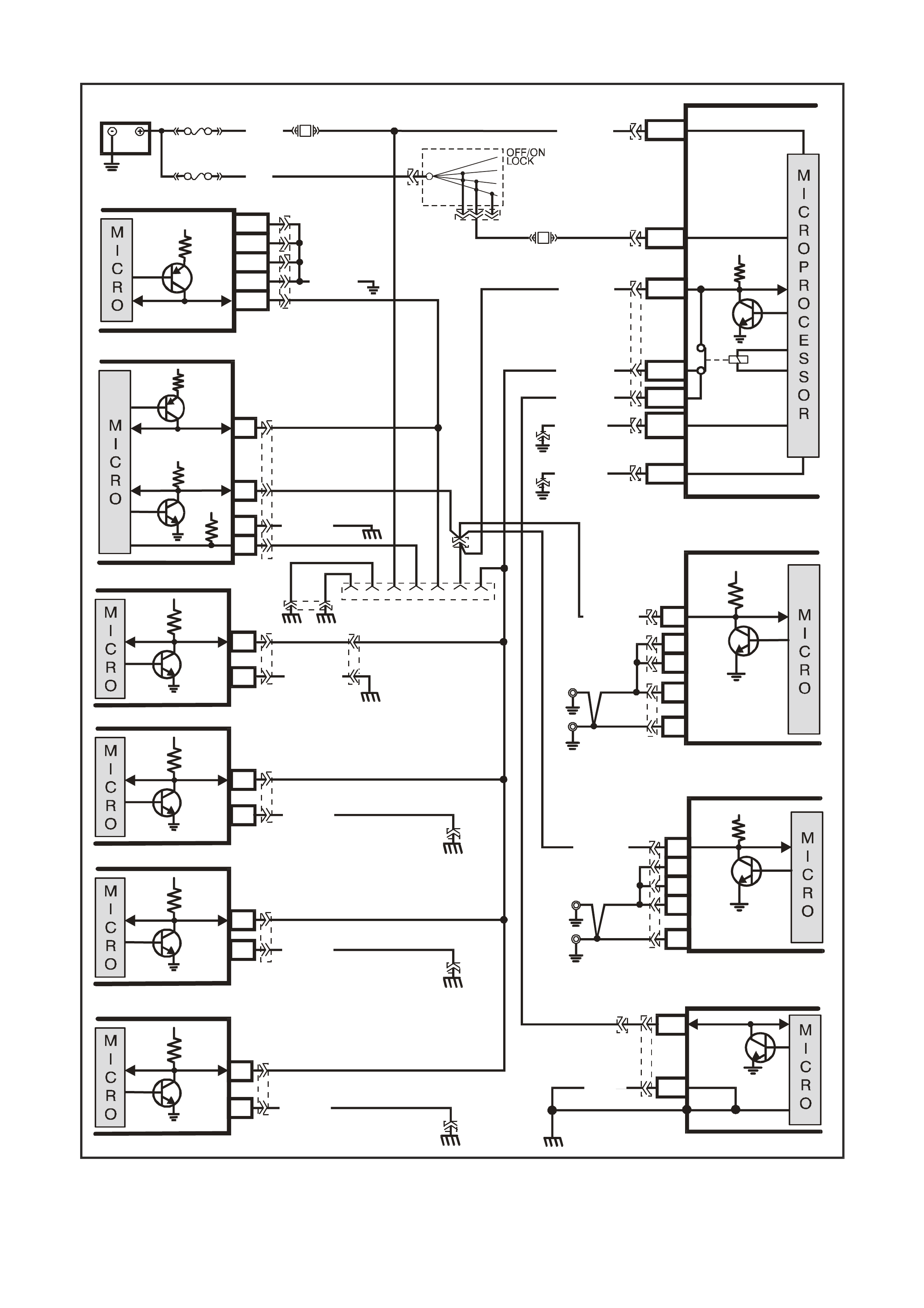
NO SERIAL DATA
GEN III V8
VX12K112
BODY CONTROL MODULE
BATTERY
FS
F31
A
5/A6
O/B (740)
(1040)
BATTERY MAIN POWER
FJ
R (2)
F14
E20/D6
P/B
(39) IGNITION ON
15a 15 50
30
A
CC
IGN
START
IGNITION SWITCH
P
(3)
YB165
YB176
HIG H SERIES
BCM TERMINALS
NO MINATED FIRST
YB44
YB44
YB164
YB175
YE112
B/Y (155)
B/G (151)
LOC. E3
LOC. E3
R/B (1221)
G/W (1220)
W/G (1220)
YE114
YE114
7V
YE114
ELECTRONIC
CLIMATE CONTRO L
6
YE87
LOC.E3
2B/Y (155)
SERIAL
DATA
5V
YE114
YE114
ABS/ETC
11
YE98
LOC.E3
LOC.E3
19 B (150)
SERIAL
DATA
5V
INSTRUMENTS
12
6
YB66
B/Y(155)
SERIAL
DATA
5V
ELECTRONIC EARTH
HIGH CURRENT
EARTH
A1/A5
B10/
B11
YB176
YB165
YB174
YB163
YB164
YB175
E2/D2
E9/D3
E3/D13
SERIAL
DATA
MAIN
SERIAL
DATA AUX.
5V
LOC. E5/E15
GEN III V8 POWERTRAIN
CONTROL MODULE
J1-58
J2-01
J2-40
J1-40
J1-01
CLASS II
SERIAL DATA
YE122
B/R (750)
16
YB215
B/R (750)
POWERTRAIN
INTERFACE MODULE
SERIAL
DATA
7V
12V
5V
6
11
7
DIAG . ENA BLE
CLASS 2
SER IAL DATA
LOC.
E5/E15
SUPPLEMENTAL
RESTRAINT SYSTEM
9
8
YB190
YB189
LOC.G11
EARTH
SERIAL
DATA
B (3 05)
YB191
V
6 POWERTRAIN
CONTROL MODULE
F7
E7
SERIAL
DATA
5V
R/B (1221) C13
YB198
YB199
YB187
LOC. E 15
LOC. E 5
B5
A5
B/R
(750)
B/R
(750)
R/B (1221)
LOC. E5
SUPERCHARGED V6
POWERTRAIN
CONTROL MODULE
A
3
B2
B1
SERIAL
DATA
5V
Y
B188
LOC. E 15
A2
A1
B/R
(750)
B/R
(750)
LOC.E12
B/W(1151)
B/Y
(155)
B
(150)
LO C. E3 YB128
642516 91
DATA LINK
CONNECTOR
TELEMATICS
9
2
YB178
YR55
SERIAL
DATA
5V
Figure 12Q-67
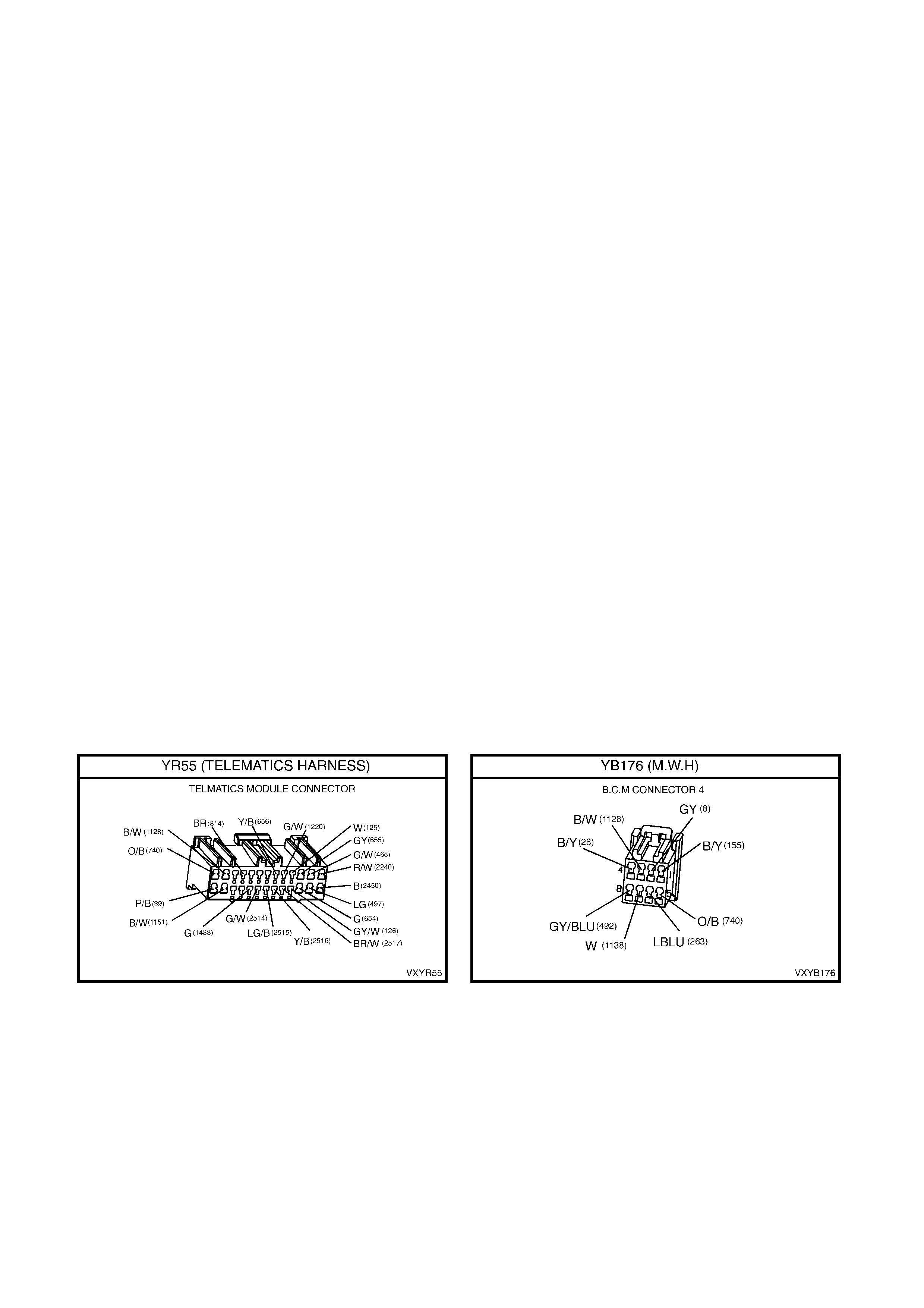
Circuit Description
The telem atic s m odule m onitors the auxi liar y seria l dat a circuit 1 220 (G reen/W hite wire) norm al m ode m essage f or
the follo wing information: Ignit ion Stat us f r om the BCM, Air ba g Dep loyed this Ign it i on C ycle f r om the SRS SD M and
Vehicle Speed from the PCM. For further information regarding the serial data bus and normal mode
message, refer 1.1 Serial Data Communication in Section 12J-1 Low Series Body Control Module or
Section 12J-2 High Series Body Control Module in this Service Information.
If the telematics module receives a “Remote Unlock” message from the Holden Assist Centre, the
telematics module will request the BCM (via the serial data circuit) to unlock the doors. For further
information regarding the BCM door lock operation, refer Section 12J-1 Low Series Body Control Module or
Section 12J-2 High Series Body Control Module, 1.3 Central Door Locking Systems in this Service Information.
If the telematics module receives a “Immobilise” message from the Holden Assist Centre, the telematics module will
then turn of f the fuel pum p r elay cutting off the supp ly of f uel to the e ngine and re ques t th e BC M ( v ia t he s eri al d at a
circuit) to flash the indicators. For further information regarding the BCM indicator operation, refer Section 12J-2
HIGH SERIES BODY CONTROL MODULE 1.4 Theft Deterrent System in this S ervic e Inf or mation.
Test Description
1. Confirmation that the Telematics On-Board Diagnostic System Check has been performed.
2. This test step determines if Tech 2 is able communicate with the BCM.
3. This test step determines if Tech 2 is able to communicate with other control modules on the auxiliary serial
data circuit.
4. This test step checks for an open circuit in the BCM data bus isolator.
5. This test step determ ines if the te lem atics module is r ec eiving a driver’s door input signal. When in pre delivery
mode, the telematics module must see a driver’s door input signal before it will communicate with Tech 2.
6. This test step checks the voltage at the on the auxiliary data circuit at the telematics module connector. The
voltage should be vary between three to five volts.
7. If the auxiliary data circuit is steady or greater that five volts then there is a short to voltage on this circuit.
8. Eac h control m odule on the serial d ata circuit shoul d be disconnected t o determ ine if that m odule is the caus e
of the short to voltage.
9. Eac h control m odule on the serial d ata circuit shoul d be disconnected t o determ ine if that m odule is the caus e
of the short to ground.
10. This test step checks that battery voltage is being applied to terminal 13 of the telematics module.
11. This test step checks the telematics module ground circuit.
12. This test step confirms that the connector terminal retention is OK. Terminal retention should always be
checked before any component is replaced.

STEP ACTION VALUE YES NO
1. 1. Has a Telematics On-Board Diagnosis System
Check been performed? Go to Step 2. Refer, Telematics
On-Board
Diagnostic System
Check, in this
Section.
2. 1. From the Tech 2 Body Application Menu select
DTC Check / F0: DTC Check and follow screen
instructions, Ignition On.
Does Tech 2 Display “BCM DTC Status, No Data”?
NOTE: If “No Data” is displayed next to BCM DTC
Status, then there is no communication between Tech
2 and the BCM.
Refer BCM Serial
Data
Communication
diagnostics in
Section 12J-1 LOW
SERIES BCM or
12J-2 HIGH
SERIES BCM in this
Service Information.
Go to Step 3.
3. In step 2 did Tech 2 display “No Data” for the all of the
following con trol mod ules?
INS DTC Status No Data.
ABS DTC Status No Data.
ECC DTC Status No Data.
Go to Step 4. Go to Step 5.
4. 1. Ignition on.
2. Disconnect telematics module connector YR55.
3. Using a DVM, check the voltage at terminal 9
circuit 1220 (Green/White wire) of the telematics
module connector YR55.
Is the voltage varying between specified value?
3 – 5
Volts Go to step 9. Go to step 5.
5. In step 4 is voltage steady or above specified value? Go to step 6. Go to step 7.
6. 1. Repair for short to voltage in circuit 1220.
NOTE: Disconnect each control module in circuit
1220 one at a time to isolate the fault in the circuit
or to identify the control module causing the fault.
Is action complete.
Verify Repair. Complete Action.
7. 1. Using a DVM, check continuity of circuit 1220
(Green/White wi re) between terminal 9 of the
telematics module connector YR55 and terminal
D3 (Low Series BCM) or terminal E2 (High Se ries
BCM).
Does continu ity ex ist?
Go to Step 8. Repair open in
circuit 1220.
8. 1. Using a DVM, check continuity of circuits 1220
(Green/White wire) and 1221 (Red/Black wire)
between BCM connector YB164, terminals D2 and
D3 (Low Series BCM) or YB175, terminals E2 and
E9 (High Series BCM).
Does continu ity ex ist?
Check for
intermittent open in
circuit 1220.
Refer BCM
diagnostics in
Section 12J-1 Low
Series BCM 12J-2
High Series BCM in
this Service
Information.
9. 1. Ignition on.
2. Open the driver’s door.
3. Using a DVM, check the voltage at terminal 23
circuit 126 (Grey/White wire) of the telematics
module connector YR55.
Is the voltage at the specified value?
Less than
0.2 Volts. Go to Step 10. Refer Driver’s Door
Jamb Switch Circuit
Diagnostic Chart in
this Section.
10. 1. Using a DVM, check the voltage at terminal 13
circuit 740 (Orange/Black wire) of the telematics
module connector YR55.
Is the voltage at the specified value?
B+ Go to Step 11. Repair open in
circuit 740.

STEP ACTION VALUE YES NO
11. 1. Check the integrity of the telematics module earth
circuit, by performing a voltage drop on circuit
1151 (Black/White wire) between telematics
module connector YR55, terminal 2 and a known
good ground.
With connector YR55 connected to the telematics
module and the ignition on, is voltage less than the
specified value?
0.15 Volts Go to Step 12. Repair earth circuit
as necessary.
12. 1. Check telematics module connector YR55 terminal
retention.
Is the terminal retention OK?
Replace telematics
module. Repair con nec tor
terminal retention.
WHEN ALL DIAGNOSIS AND REPAIRS ARE COMPLETED, VERIFY CORRECT OPERATION
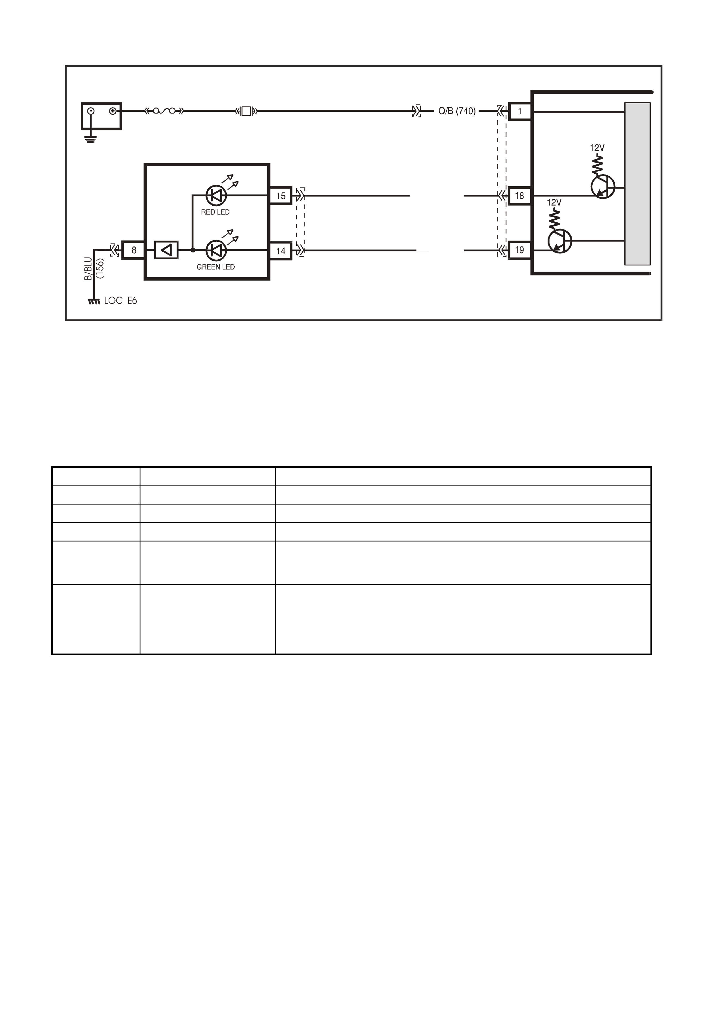
STATUS INDICATOR LEDS DO NOT ILLUMINATE
TELEMATICS MODULE
LOC. E1
BATTERY
BATTERY
F31
YR55
FS
YB178
VX12K161
BR / W (2517)
Y/B (2516)
REAR VIEW MIRROR
TELEMATICS STATUS LEDS
YB186
YB186
M
I
C
R
O
Figure 12Q-68
Circuit Description
The red a nd green s tatus indicat or L EDs in t he interio r rear view m irror indic ate the c urrent stat us of the te lem atic s
system. The telematics module activates the LEDs by switching a 12 power supply to each LED on or off. The
brightnes s of the LEDs is control led b y the int erior rea r vie w mir ror elec tronic s, which will vary the brig htnes s of the
LEDs depending on the ambient light and the ignition switch position. If the ambient light is low the brightness of
the LEDs will be decreased when the ignition is on. If the ambient light is high there will be no change to the
brightness of the LEDs when the ignition is turned on.
LED Condition Current Status
Green Continuous Call is connected.
Green Flashing Call is being connected.
Red Continuous Vehicle is not within GSM network range.
Red/Green Alternate Flashing
(Will appear to be
flashing Red/Orange)
Attempting to make an emergency call while outside GSM network range
(“Emergency Call Mode”)
Red/Green Alternate Flashing
(only active for 25
seconds afte r the
ignition is turned on)
Alert that Service Mode is active or a system malfunction has been
detected.
Potential malfunctions:
GSM Module not active. GPS Module not active.
Backup battery is not charged or disconnected.
Test Description
1. Confirmation that the Telematics On-Board Diagnostic System Check has been performed.
2. If Tech 2 is capable of commanding the red status LED on and off the LED and circuit are OK.
3. Checks red status LED supply voltage on circuit 2517 (Brown/White wire).
4. Checks that the telematics module can command the red status LED supply on and off.
5. If Tech 2 is capable of commanding the green status LED on and off the LED and circuit are OK.
6. Checks green status LED supply voltage on circuit 2516 (Yellow/Black).
7. Checks that the telematics module can command the green status LED supply on and off.
8. Checks integrity of the Rear View Mirror ground circuit 156.
9. This test step confirms that the connector terminal retention is OK. Terminal retention should always be
checked before any component is replaced.

STEP ACTION VALUE YES NO
1. 1. Has a Telematics On-Board Diagnosis System
Check been performed? Go to Step 2. Refer, Telematics
On-Board
Diagnostic System
Check, in this
Section.
2. 1. From the Telematics Application Menu,
Select F2: Miscellaneous Tests / F1: Red Status
LED.
2. Command the LED on and off.
Did the Red Status LED turn on?
Red status LED is
OK.
Go to Step 5.
Go to Step 3.
3. 1. Using a DVM, check the voltage at the rear view
mirror connector YB186 circuit 2517 (Brown/White
wire).
2. Command the LED on, as in step 2.
Is voltage as specified?
12 volts Go to Step 8. Go to Step 4.
4. 1. Using a DVM, check the voltage at the telematics
module connector YR55 circuit 2517 (Brown/White
wire).
2. Command the LED on, as in step 2.
Is voltage as specified?
12 volts Repair open circ uit
2517.
Go to Step 9.
5. 1. From the Telematics Application Menu,
Select F2: Miscellaneous Tests / F2: Green Status
LED.
2. Command the LED on and off.
Did the Green Status LED turn off and on?
Green status LED is
OK. Go to Step 6.
6. 1. Using a DVM, check the voltage at the rear view
mirror connector YB186 circuit 2516 (Yellow/Black
wire).
2. Command the LED on, as in step 5.
Is voltage as specified?
12 volts Go to Step 8 Go to Step 7.
7. 1. Using a DVM, check the voltage at the telematics
module connector YR55 circuit 2516 (Yellow/Black
wire).
2. Command the LED on, as in step 5.
Is voltage as specified?
12 volts Repair open circ uit
2516.
Go to Step 9.
8. 1. Using a DVM, measure the continuity of circuit 156
(Black/Blue wire) between and terminal 8 of the
rear view mirror connector YB186 and a known
good ground.
Is there continuity?
Less than
1 Ohm. Replace rear view
Mirror. Repair open circuit
156 between the
rear view mirror and
ground LOC. E6.

STEP ACTION VALUE YES NO
9. 1. Check telematics module connector YR55 terminal
retention.
Is the terminal retention OK?
Replace telematics
module. Repair con nec tor
terminal retention.
WHEN ALL DIAGNOSIS AND REPAIRS ARE COMPLETED, VERIFY CORRECT OPERATION
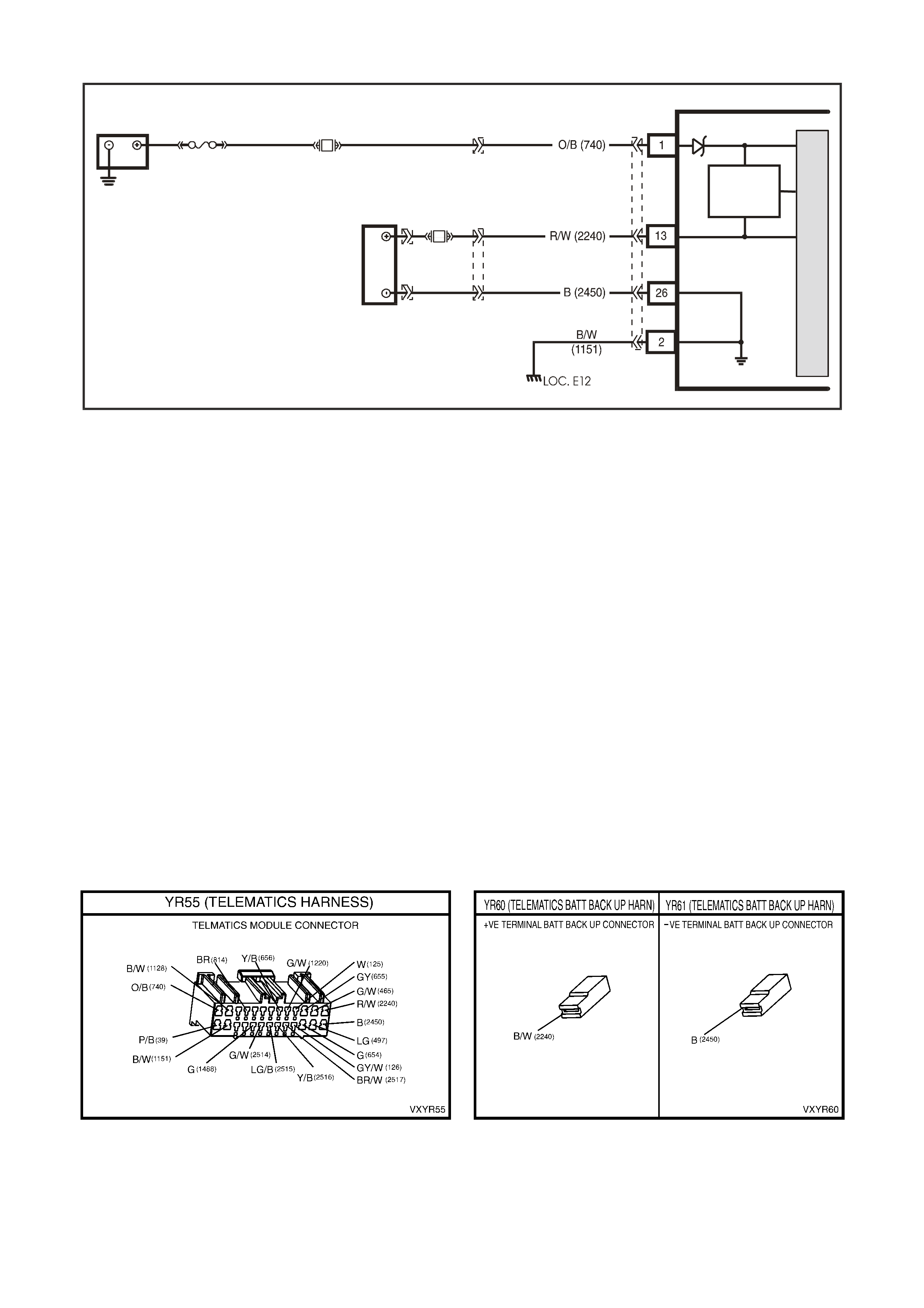
VEHICLE BATTERY VOL TAGE
VX12K106
TELEMATICS MODULE
BATTERY
LOC. E1
GROUND
BACKUP
BATTERY
GROUND
BATTERY
BACKUP
BATTERY
BATTERY
CHARGER
F31
YB178
FS
BACKUP
BATTERY
YR56
YR60YR61
M
I
C
R
O
YR55
Figure 12Q-69
Circuit Description
Battery voltage is applied to the telematics module terminal 1 at all tim es via circuit 740 (Orange/Black wire), fuse
F31 and f us ib le l ink FS. If the battery vo lta ge f ai ls be low a pres et vo lta ge for long er tha n 3 0 minutes, t he tel e matics
module will transmit a Low Battery Alert to the Holden Assist Centre. If the battery is removed the telematics
module will transmit a Battery Removal Alert to the Holden Assist Centre.
The backup battery will provide power to the telematics module for approximately 30 minutes in the event of the
vehicle b attery being dis c h arged or d isc onn ec ted. The telematics m odule has a b ac k up battery charg in g c ircuit that
maintains the backup battery state of charge. A 3A fuse is used to protect the backup battery circuitry.
The telematics module constantly monitors both vehicle battery voltage and backup battery voltage. The charging
circuit al lows the back up battery to dra w current of up to 300m A maximum fr om the vehic le batter y. As the batter y
voltages equalise the current drawn will decrease. The charging circuit is only active when the ignition is on, and
can only charge the backup battery to equal the voltage of the vehicle battery.
Test Description
1. Confirmation that the Telematics On-Board Diagnostic System Check has been performed.
2. Checks the open circuit voltage of the vehicle battery.
3. The displayed battery voltage should be within 0.5 volts of the battery open circuit voltage in step 2.
4. This test step measures that actual voltage at the telematics module connector YR55.
5. This test step checks the continuity of circuit 740.
6. This test step checks the continuity of circuit 1151.
7. This test step confirms that the connector terminal retention is OK. Terminal retention should always be
checked before any component is replaced.

STEP ACTION VALUE YES NO
1. Has a Telematics On-Board Diagnosis System Check
been performed? Go to Step 2 Refer Telematics
On-Board
Diagnostic
System Check in
this Section.
2. 1. Using a DVM measure the vehicle battery open
circuit voltage.
Refer SECTION 12A BATTERY AND CABLES,
3. DIAGNOSIS in this Service Information.
Is the vehicle battery open circuit voltage as specified?
Greater than
12.4 Volts. Go to Step 3. Refer SECTION
12A BATTERY
AND CABLES,
3. DIAGNOSIS in
this Service
Information.
3. 1. From the Telematics Application Menu,
Select F0: Data List.
2. Scroll to Battery Voltage.
Is the voltage as specified?
B+ Vehicle battery
voltage OK. Go to Step 4.
4. 1. Using a DVM measure the voltage at the telematics
module connector YB55 terminal 1 circuit 740
(Orange/Black wire) and a known good ground.
Is the voltage as specified?
B+ Go to Step 6. Go to Step 5.
5. 1. Using a DVM measure the resistance of circuit 740
(Orange/Black wire) between fuse F31 and
terminal 1 of the telematics module connector
YR55.
Is resistance as specified?
Less than
1 Ohm. Go to Step 6. Repair open in
circuit 740.
6. 1. Using a DVM measure the resistance of circuit
1151 (Black/white wire) between term inal 2 of the
telematics module connector YR55 and a know
good ground.
Is resistance as specified?
Less than
1 Ohm. Go to Step 7. Repair open in
circuit 1151.
7. 1. Check telematics module connector YR55 terminal
retention.
Is the terminal retention OK?
Replace
telematics
module.
Repair connector
terminal
retention.
WHEN ALL DIAGNOSIS AND REPAIRS ARE COMPLETED, VERIFY CORRECT OPERATION
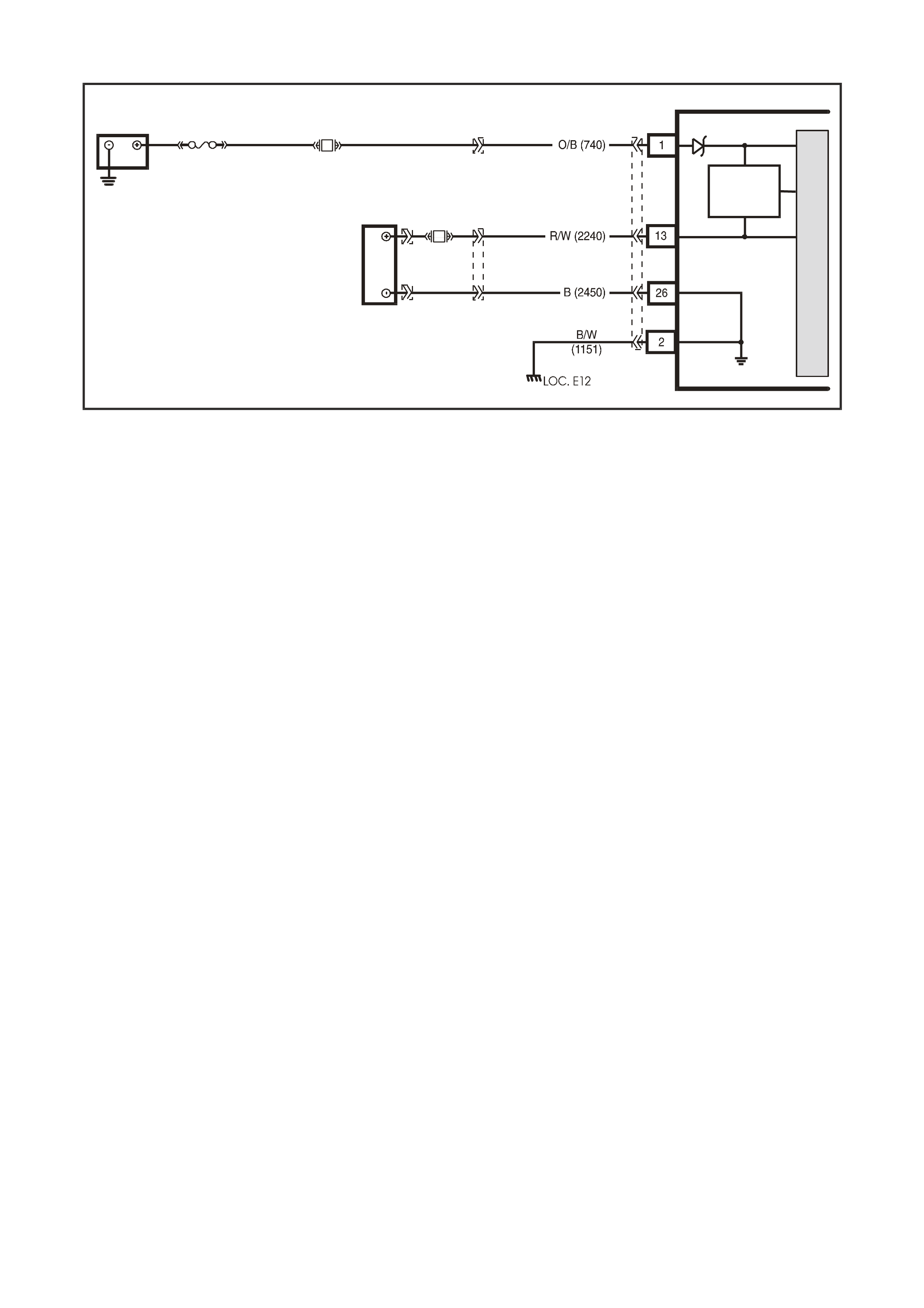
BACKUP BATTERY
VX12K106
TELEMATICS MODULE
BATTERY
LOC. E1
GROUND
BACKUP
BATTERY
GROUND
BATTERY
BACKUP
BATTERY
BATTERY
CHARGER
F31
YB178
FS
BACKUP
BATTERY
YR56
YR60YR61
M
I
C
R
O
YR55
Figure 12Q-70
Circuit Description
The backup battery will provide power to the telematics module for approximately 30 minutes in the event of the
vehicle b attery being dis c h arged or d isc onn ec ted. The telematics m odule has a b ac k up battery charg in g c ircuit that
maintains the backup battery state of charge. A 3A fuse is used to protect the backup battery circuitry.
Battery voltage is applied to the telematics module at all times via circuit 740 (Orange/Black wire), fuse F31 and
fusible link FS. If the batter y voltag e fails b elow a pres et voltage f or longer than 30 m inutes, the telem atics m odule
will transmit a Low Battery Alert to the Holden Assist Centre. If the battery is removed the telematics module will
transmit a Battery Removal Alert to the Holden Assist Centre.
The telematics module constantly monitors both vehicle battery voltage and backup battery voltage. The charging
circuit al lows the back up battery to dra w current of up to 300m A maximum fr om the vehic le batter y. As the batter y
voltages equalise the current drawn will decrease. The charging circuit is only active when the ignition is on, and
can only charge the backup battery to equal the voltage of the vehicle battery.
Test Description
1. Confirmation that the Telematics On-Board Diagnostic System Check has been performed.
2. Checks backup battery fuse.
3. Check vehicle battery voltage. If the vehicle battery voltage the actual vehicle battery voltage should be
checked.
4. Checks backup battery voltage via Tech 2.
5. Checks battery charger status via Tech 2. The backup battery charger should be able to be switched from
“Active” to “Inactive”.
6. Checks that the backup battery charger is functioning, the backup battery should display active when the
ignition is on an d the backup battery voltage is les s tha n veh icle b attery volta ge. When the engine is started the
alternator should cause the vehicle battery voltage to increase, this increase in vehicle battery voltage should
cause the backup battery charger to display active.
7. Checks backup battery voltage using Tech 2
8. Checks the actual backup battery terminal voltage using a DVM.
9. Checks integrity of circuit 2240 (Red/White wire).
10. Checks integrity of circuit 2450 (Black wire).
11. This test step confirms that the connector terminal retention is OK. Terminal retention should always be
checked before any component is replaced.
12. This test step confirms that the connector terminal retention is OK. Terminal retention should always be
checked before any component is replaced.

STEP ACTION VALUE YES NO
1. Has a Telematics On-Board Diagnosis System Check
been performed? – Go to Step 2. Refer, Telematics
On-Board
Diagnostic System
Check, in this
Section.
2. 1. Check backup battery in line fuse.
Is fuse OK? – Go to Step 3. Check for cause of
fuse failure.
Replace Fuse.
3. 1. From the Telematics Application Menu,
Select F0: Data List.
2. Scroll to Battery Voltage.
Is the Battery Voltage as specified?
Greater
than 12.4
Volts.
Go to Step 4. Refer to Vehicle
Battery Voltage
Diagnostic chart in
this Section.
4. 1. From the Telematics Application Menu,
Select F0: Data List.
2. Scroll to Backup Battery Voltage.
Is the Battery Voltage as specified?
Greater
than 11.5
Volts.
Go to Step 5. Go to Step 8.
5. 1. From the Telematics Application Menu,
Select F2: Miscellaneous Tests \ F5: Backup
Battery Charger.
2. Carry out a Backup Battery Charger test.
Does Backup Battery Charger switch from “Active” to
“Inactive” when commanded?
– Go to Step 7. Go to Step 6.
6. 1. Start engine and increase the engine speed to 2000
RPM.
Does Backup Battery Charger display “Active”?
– Go to Step 7. Go to Step 9.
7. 1. Scroll to Backup Battery Voltage.
2. Turn ignition off.
Is backup battery voltage within specified limits?
11.5 to
14.2 volts. Backup battery and
charging cir cui t OK. Go to Step 8.
8. 1. Disconnect Telematics module connector YR55.
2. Using a DMM measure the backup battery voltage
at the Telematics module connector YR55 between
circuit 2240 (Red/White wire +ve) terminal 13 and
circuit 2450 (Black wire –ve) terminal 26.
Is the voltage as specified?
11.5 to
14.2 volts. Go to Step 12. Go to Step 9.
9. 1. Using a DMM, measure resistance between
terminal 13 of the Telematics module connector
YR55 on circuit 2240 (Red/White wire), and backup
battery +ve terminal.
Is the value as specified?
Below 1
Ohm Go to Step 10. Repair open on
circuit 2240.

STEP ACTION VALUE YES NO
10. 1. Using a DMM, measure resistance between
terminal 26 of the Telematics module connector
YR55 circuit 2450 (Black wire), and backup battery
–ve terminal.
Is the value as specified?
Below 1
Ohm Go to Step 12. Repair open on
circuit 2450.
11. 1. Check backup battery connectors YR56, YR60 &
YR61 for terminal retention.
Is the terminal retention OK?
– Replace Backup
Battery. Repair con nec tor
terminal retention.
12. 1. Check Telematics module connector YR55 terminal
retention.
Is the terminal retention OK?
– Replace Telematics
module. Repair connector
terminal retention.
WHEN ALL DIAGNOSIS AND REPAIRS ARE COMPLETED, VERIFY CORRECT OPERATION

NO GPS SIGNAL
GSM
ANTENNA (-)
GSM
ANTENNA (+)
M
I
C
R
O
TELEMATICS MODULE
GSM ANTENNA
GSM
MODULE
VX12K119A
GPS ANTENNA
GPS
ANTENNA (-)
GPS
ANTENNA (+)
GPS
MODULE
Figure 12Q-71
Circuit Description
The telematics antenna contains both the GPS and GSM antennas in one unit, and is located on the rear parcel
shelf, under the rear parcel shelf trim. The antenna has two leads, one for the GPS antenna and the other for the
GSM antenna. The GPS antenna receives signals from satellites orbiting the earth and transmits these to the
telematic s m odule to determ ine the veh ic les position. Sig na ls f r om at least thr ee G PS sa te llites must be recei ved to
accuratel y determ ine the v ehicle’s t wo dim ensional ( 2D) posit ion. Sign als from at least f our GPS sat ellit es must be
received to accurately determine the vehicle’s three dimensional (3D) position. If signals from only three satellites
are received, the telematics module cannot determine the vehicles altitude. The GPS antenna must not be
obscured by any objects, such as underground car parks, tunnels, bridges or buildings any of these may affect
GPS r eception. The GP S anten na is con nected t o the telematics module by a s crew-on type co nnector ( smaller of
the two a nte nna c onn ec tor s ) . To determine the ve hic l es pos it io n th is G P S inf or m atio n is trans mitted via SM S to the
Holden As sist Centre whenever a call is made to the Holden As sist Centre. The Hold en Assist C entre is a lso able
to track the vehicle using this GPS information.
Test Description
1. Confirmation that the Telematics On-Board Diagnostic System Check has been performed.
2. The GPS module should be active at all times.
3. The GPS antenna should display Okay.
4. The position of the veh icle wil l aff ect the GP S signa l. T he veh icle sh ould b e m oved to a locat ion where ther e is
an unobstructed view of the sky. There may be times during the day that there are actually no satellites visible.
5. The telematics m odule has the abilit y to check the GPS ante nna and will displa y either Okay, Open Circuit or
Short Circuit .
6. If the T ech 2 displays GPS Antenna “Short Circuit” th e you should go to step 7. In step 7 you will determ ine if
the antenna or the telematics module is causing the problem.
7. Once the tel em atics anten na G PS c onnector is discon nected, then T ech 2 s houl d dis pla y GPS Antenna “Op en
Circuit”. If this is not displayed then the telematics module is faulty.
8. This test step confirms that the GPS connector is tight.
9. This test step confirms that the connector terminal retention is OK. Terminal retention should always be
checked before any component is replaced.

STEP ACTION VALUE YES NO
1. Has a Telematics On-Board Diagnosis System Check
been performed? Go to Step 2. Refer,
Telematics On-
Board Diagnostic
System Check, in
this Section.
2. 1. From the Telematics Application Menu,
Select F0: Data List.
2. Scroll to GPS Module.
Does Tech 2 display GPS Module “Active”?
Go to Step 3. Go to Step 9.
3. 1. Scroll to GPS Antenna Status.
Does Tech 2 display GPS Antenna “Okay”?
Go to step 4. Go to Step 5.
4. 1. Scroll to GPS Satellites.
Does Tech 2 display Satellites “Visible“?
GPS Antenna
OK. Go to Step 5.
5. In test step 3 did Tech 2 display GPS Antenna “Open
Circuit”? Go to Step 8. Go to Step 6.
6. In test step 3 did Tech 2 display GPS Antenna “Short
Circuit”? Go to Step 7. Go to Step 8.
7. 1. Disconnect telematics antenna GPS connector.
Does Tech 2 display GPS Antenna “Open Circuit”?
Go to Step 8. Go to Step 9.
8. Is the GPS antenna connector loose? Tighten
connector. Replace
telematics
antenna.
9. 1. Check telematics module connector YR55 terminal
retention.
Is the terminal retention OK?
Replace
telematics
module.
Repair connector
terminal
retention.
WHEN ALL DIAGNOSIS AND REPAIRS ARE COMPLETED, VERIFY CORRECT OPERATION
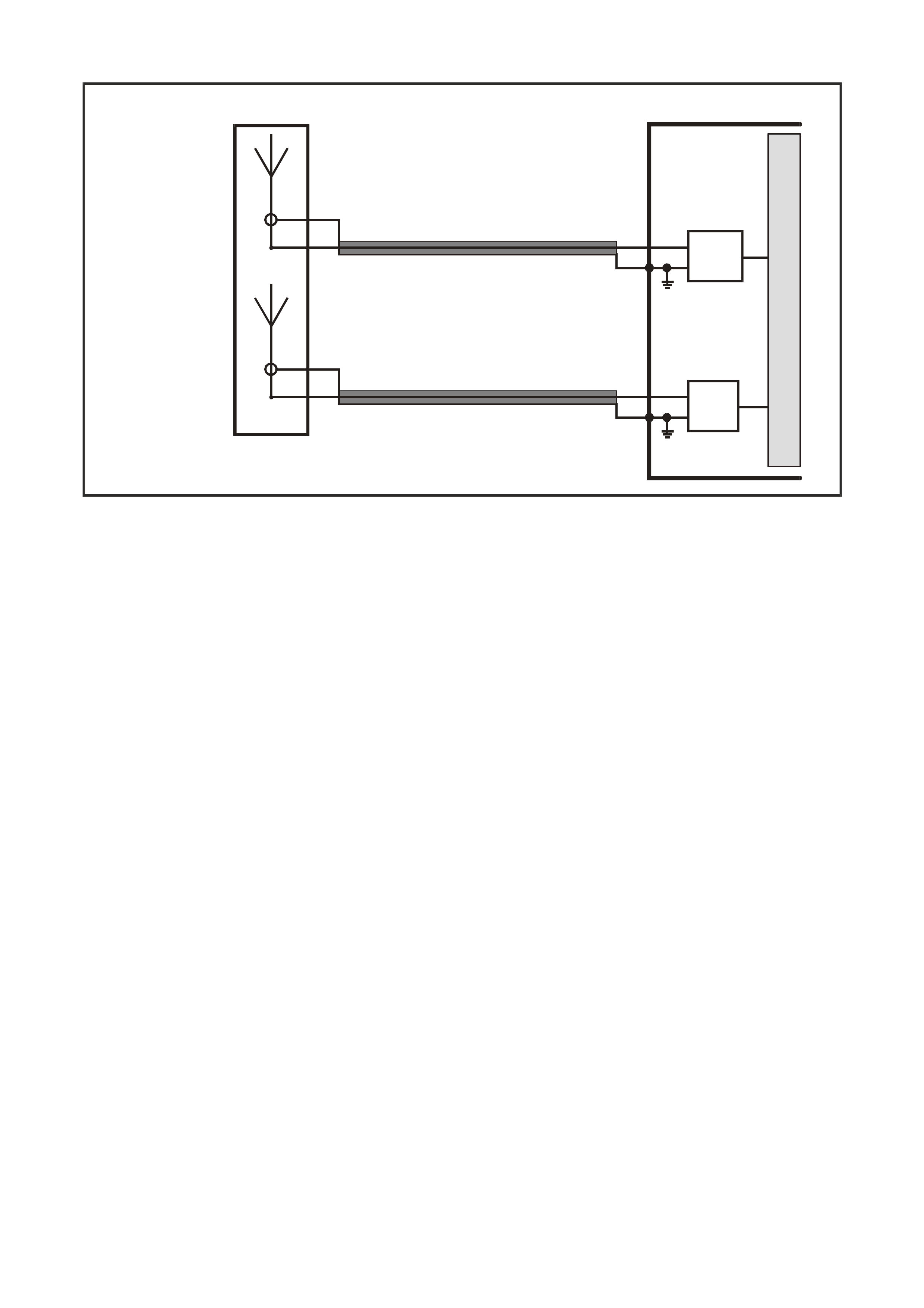
NO GSM SIGNAL
GSM
ANTENNA (-)
GSM
ANTENNA (+)
M
I
C
R
O
TELEMATICS MODULE
GSM ANTENNA
GSM
MODULE
VX12K119A
GPS ANTENNA
GPS
ANTENNA (-)
GPS
ANTENNA (+)
GPS
MODULE
Figure 12Q-72
Circuit Description
The telematics antenna contains both the GPS and GSM antennas in one unit, and is located on the rear parcel
shelf, under the rear parcel shelf trim. The antenna has two leads, one for the GPS antenna and the other for the
GSM anten na. The G SM a ntenna is capab le of tr ans m itting and rec eiving b oth v oice and d ata si gnals via the G SM
network. The telematics module uses the GSM network to transmit and receive voice and data. Signal strength
may be affected in locations lik e basement car park s or tunnels. However, in m ost cases, as the vehicle emerges
from the obstruction or re-enters the digital phone network area the signal will be available again and any stored
data will be transmitted. The GSM antenna is connected to the telematics module by a screw-on type
connector(larger of the two antenna connectors).
Test Description
1. Confirmation that the Telematics On-Board Diagnostic System Check has been performed.
2. The GSM module should be active at all times.
3. If there is no GSM signal then either the telematics antenna or telematics module are faulty. The GSM signal
strength can vary from 1 to 32, less than 15 could cause call dropout. The vehicle should be moved to a
location that has a better GSM signal and the signal strength checked again.
4. The GSM antenna connector should be checked to ensure the connector is tight.
5. Once the antenna is replaced and the signal strength still displays “No Signal” the telematics module is faulty.
6. This test step confirms that the connector terminal retention is OK. Terminal retention should always be
checked before any component is replaced.

STEP ACTION VALUE YES NO
1. Has a Telematics On-Board Diagnosis System Check
been performed? Go to Step 2. Refer Telematics
On-Board
Diagnostic
System Check in
this Section.
2. 1. From the Telematics Application Menu,
Select F0: Data List.
2. Scroll to GSM Module.
Does Tech 2 display GSM Module “Active”?
Go to Step 3. Go to Step 6.
3. 1. Scroll to GSM Signal Strength.
Does Tech 2 display GSM Signal Strength “No Signal”?
Go to Step 4. GSM Antenna
OK.
4. Is the GSM antenna connector loose? Tighten
connector. Go to Step 5.
5. 1. Replace Telematics Antenna.
Does Tech 2 display GSM Signal Strength “No Signal”?
Go to Step 6. GSM Antenna
OK.
6. 1. Check telematics module connector YR55 terminal
retention.
Is the terminal retention OK?
Replace
telematics
module.
Repair connector
terminal
retention.
WHEN ALL DIAGNOSIS AND REPAIRS ARE COMPLETED, VERIFY CORRECT OPERATION
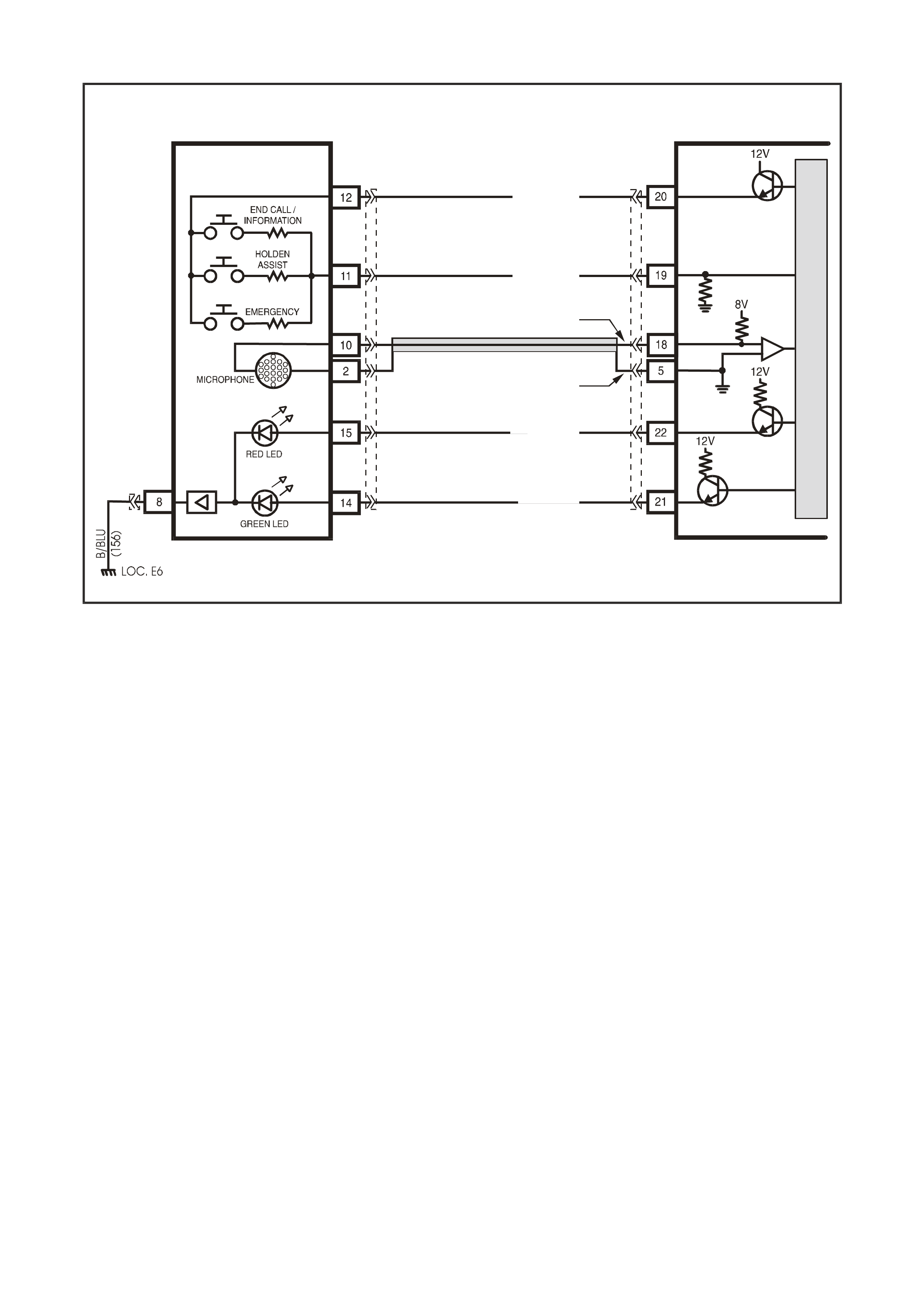
EMERGENCY BUTTON NOT OKAY
VX12K103
G (1488)
BR (814 )
BR / W (2517)
Y/B (2516)
MIC ( + )
MIC ( -)
TELEMATICS MODULE
REAR VIEW MIRROR,
KEY PAD & INDICATOR ASSEMBLY
YB186
G/W (2514)
PUSH
BUTTON
SUPPLY
VOLTAGE
PUSH BUTTON
SIG N AL VO LTAGE
LG/B (2515)
YR55
YB186
M
I
C
R
O
Ω
Ω
Ω
13K
3K
1.5K
Figure 12Q-73
Circuit Description
The telem atic s button pad is a resistor encod ed switch , which m eans that each b utton has a sep arate and diff erent
value resistor connected to it. The telematics module uses a voltage divider circuit to determ ine which button has
been pres sed. The telematic s m odule s upp li es a 12 vo lt s ign al vo lta ge to t er minal 12 of the bu tton pad switch es via
circuit 25 15 (Light Gre en/Black wire). W henever a butt on is pressed the c orrespondi ng switch is c losed and circ uit
2514 (Green/White wire) is connected to ground through a resistor, each switch having a different value resistor.
The telematics module monitors the voltage on circuit 2514 (Green/White wire) at terminal 19 which will change
when any of the buttons are pressed. Each button m ust be pressed until two beeps are heard from the telematics
speaker. If a button is not pressed for long enough, three beeps will be heard from the telematics speaker. In the
event of multiple button presses at the same time, the telematics module will ignore the button press until all
buttons are released.
When the emergency button is pressed, the voltage at terminal 19 of the telematics module will be approximately
3.8 Volts, the telematics module sees this voltage at terminal 19 as an emergency button press. The emergency
button must be pressed until two beeps are heard. You will then be connected to an operator at NERCTM. If the
button is not pressed for long e nough three be eps will be heard. For saf ety reasons (in case of the presence of an
intruder), if a call has been made to NERCTM by pressing the em ergency button, you cannot end this call, you will
have to request them to end the call. If the vehicle is not within GSM network range the telematics module will
make the emergency call as soon the GSM network is available.
Test Description
1. Confirmation that the Telematics On-Board Diagnostic System Check has been performed.
2. Confirms that the telematics module is powering up the keypad.
3. Confirms that the telematics module has commanded the keypad supply voltage on.
4. The keypad signal should display on whenever the telematics module is in active mode.
5. Service mode should be enabled so that the telematics module does not call NERCTM when the emergency
button is pressed. The service mode should be enable until this diagnostic chart is completed.
6. When circuits 2414 and 2415 are jumped together Tech 2 should display a keypad signal voltage of 5.0 volts.
7. T his test step confirm s that the te lematics m odule is s upplying batter y voltag e to circ uit 2515 at th e telemati cs
module connector YR55.
8. T his test step confirm s that the te lematics m odule is s upplying batter y voltag e to circ uit 2515 at th e telemati cs
rear view mirror connector YB186.
9. This test step check that the rear view mirror ground is OK
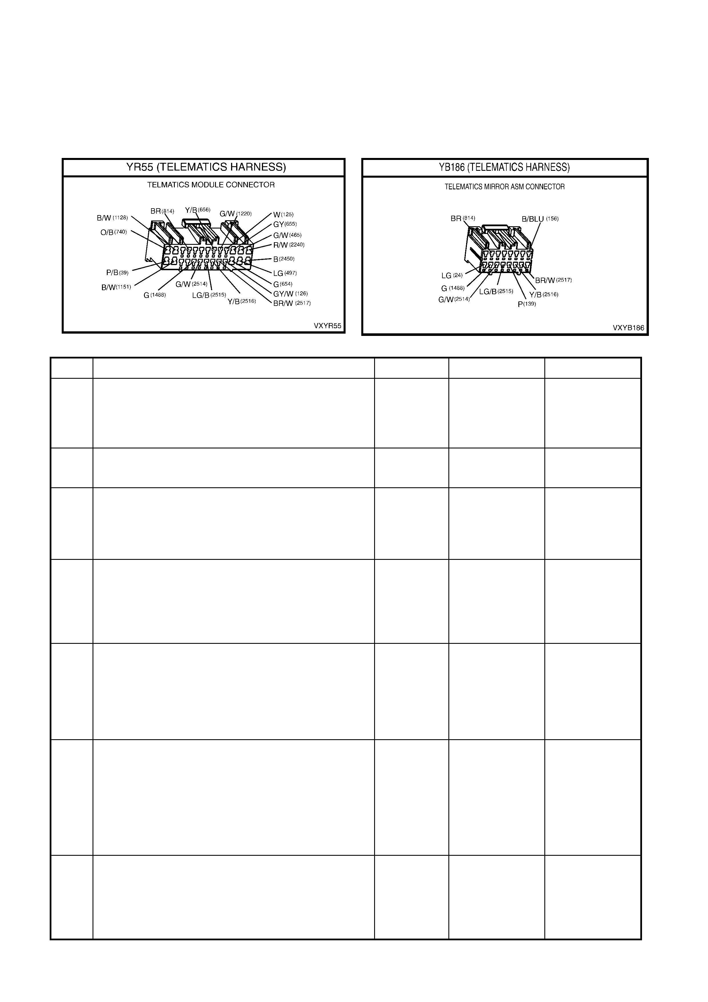
10. This test step check the complete emergency button and circuits.
11. This test step check the resistance of the rear view mirror emergency button.
12. This test step confirms that the rear view mirror connector YB186 terminal retention is OK. Terminal retention
should always be checked before any component is replaced.
13. T his test st ep confirm s that the telem atics m odule connec tor YR55 term inal ret ention is OK. Term inal rete ntion
should always be checked before any component is replaced.
STEP ACTION VALUE YES NO
1. Has a Telematics On-Board Diagnosis System Check
been performed? Go to Step 2. Refer,
Telematics On-
Board Diagnostic
System Check, in
this Section.
2. 1. Ignition On.
Does the keypad back lighting illuminate.
Go to Step 5. Go to Step 3.
3. 1. From the Telematics Application Menu,
Select F0: Data List.
2. Scroll to Keypad Supply Voltage.
Does Tech 2 display Keypad Supply voltage “On”?
Go to Step 4. Go to Step 13.
4. 1. From the Telematics Application Menu,
Select F0: Data List.
2. Scroll to Keypad Signal Voltage.
Does Tech 2 display the specified Keypad Signal
voltage?
0.0 Volts. Go to step 5. Go to step 6.
5. 1. Enable the telematics module service mode.
(Service mode should be enabled until this
diagnostics chart is complete d).
2. Press the emergency button.
Does Tech 2 display the specified Keypad Signal
voltage?
3.8 Volts. Emergency
Button OK.
Check for
intermittent in
circuit 2514.
Go to step 6.
6. 1. Disconnect the rear view mirror connector YB186.
2. Ignition on.
3. Jumper terminal 11 (Green/White wire) circuit 2514
and terminal 12 (Light Green/Black wire) circuit
2515 of connector YB 186.
Does Tech 2 display the specified Keypad Signal
voltage?
5.0 Volts. Go to Step 11.
Go to Step 7.
7. 1. Ignition on.
2. Using a DVM measure the voltage at the telematics
module connector YR55 terminal 20 circuit 2515
(Light Green/Black wire) and a known good ground.
Is the voltage as specified?
B+ Go to Step 8. Go to Step 13.

STEP ACTION VALUE YES NO
8. 1. Disconnect the rear view mirror connector YB186.
2. Ignition on.
3. Using a DVM measure the voltage between circuit
2515 (Light Green/Black wire) of the rear view
mirror connector YB186 and a known good ground.
Is the voltage as specified?
B+ Go to Step 9. Repair open in
circuit 2515.
9. 1. Disconnect the battery negative terminal.
2. Disconnect the rear view mirror connector YB186.
3. Using a DVM measure the resistance of circuit 156
(Black/Blue wire) between the rear view mirror
connector YB186 and a known good ground.
Is the resistance as specified?
Less than 1
Ohm. Go to Step 10. Repair open in
circuit 156.
10. 1. Reconnect the rear view mirror connector YB186
and disconnect the telema tic s modu le connector
YR55.
2. Using a DVM measure the resistance between
terminal 20 circuit 251 5 (Light G reen/Bla ck w ire)
and terminal 19 circuit 2414 (Green/White wire) of
the telematics module connector YR55.
Is the resistance as specified when the Emergency
Button is pressed?
1.5 K Ohms. Go to Step 13. Go to Step 11.
11. 1. Disconnect the interior rear view mirror connector
YB186.
2. Using a DVM measure the resistance between
terminal 12 and terminal 11 of the rear view mirror.
Is the resistance as specified when the Emergency
Button is pressed?
1.5 K Ohms. Repair open in
circuit 2514. Go to Step 12.
12. 1. Check interior rear view mirror connector YB186
terminal retention.
Is the terminal retention OK?
Replace interior
rear view mirror. Repair connector
terminal
retention.
13. 1. Check telematics module connector YR55 terminal
retention.
Is the terminal retention OK?
Replace
telematics
module.
Repair connector
terminal
retention.
WHEN ALL DIAGNOSIS AND REPAIRS ARE COMPLETED, VERIFY CORRECT OPERATION
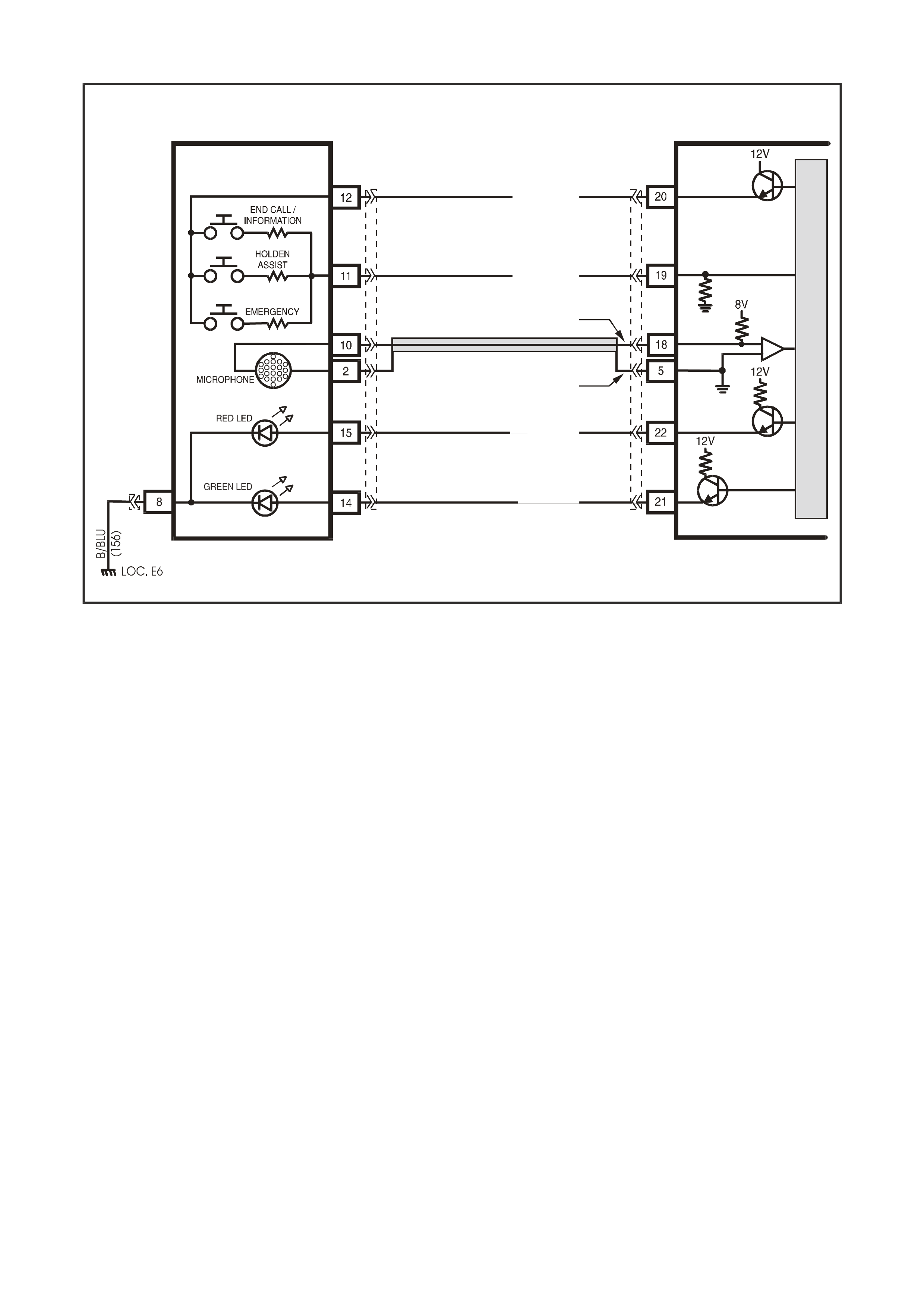
HOLDEN ASSIST BUTTON NOT OKAY
VX12K103
G (1488)
BR (814 )
BR / W (2517)
Y/B (2516)
MIC ( + )
MIC ( -)
TELEMATICS MODULE
REAR VIEW MIRROR,
KEY PAD & INDICATOR ASSEMBLY
YB185
G/W (2514)
PUSH
BUTTON
SUPPLY
VOLTAGE
PUSH BUTTON
SIG N AL VO LTAGE
LG/B (2515)
YR55
YB186
M
I
C
R
O
Ω
Ω
Ω
13K
3K
1.5K
Figure 12Q-74
Circuit Description
The telem atic s button pad is a resistor encod ed switch , which m eans that each b utton has a sep arate and diff erent
value resistor connected to it. The telematics module uses a voltage divider circuit to determ ine which button has
been pres sed. The telematic s m odule s upp li es a 12 vo lt s ign al vo lta ge to t er minal 12 of the bu tton pad switch es via
circuit 25 15 (Light Gre en/Black wire). W henever a butt on is pressed the c orrespondi ng switch is c losed and circ uit
2514 (Green/White wire) is connected to ground through a resistor, each switch having a different value resistor.
The telematics module monitors the voltage on circuit 2514 (Green/White wire) at terminal 19 which will change
when any of the buttons are pressed. Each button m ust be pressed until two beeps are heard from the telematics
speaker. If a button is not pressed for long enough, three beeps will be heard from the telematics speaker. In the
event of multiple button presses at the same time, the telematics module will ignore the button press until all
buttons are released.
When the Holden Assist button is pressed, the voltage at terminal 19 of the telematics module will be approximately
2.3 Volts, the telematics module sees this voltage at terminal 19 as an Holden Assist Button press. The Holden
Assist button must be pressed until two beeps are heard. You will then be connected to the Holden Assist Centre. If
the vehicle is not within GSM network range an additional 12 beeps will be heard. If the button is not pressed for
long enough three beeps will be heard.
Test Description
1. Confirmation that the Telematics On-Board Diagnostic System Check has been performed.
2. Confirms that the telematics module is powering up the keypad.
3. Confirms that the telematics module has commanded the keypad supply voltage on.
4. The keypad signal should display on whenever the telematics module is in active mode.
5. The G SM antenna s hou ld be e nab le d d ur in g t his t es t s o that th e te lematic s module do es not c all Holden Assist
when the Ho ld en Ass ist button is pres sed . The G SM antenna shou ld rem ain d isc onnected u ntil t his diagn os tic
chart is completed.
6. W hen circuits 2414 and 2415 are jumped together T ech 2 should display a ke ypad signal voltage of 5.0 volts.
The internal circuitry limits this value to five volts.
7. T his test step confirm s that the te lematics m odule is s upplying batter y voltag e to circ uit 2515 at th e telemati cs
module connector YR55.
8. T his test step confirm s that the te lematics m odule is s upplying batter y voltag e to circ uit 2515 at th e telemati cs
rear view mirror connector YB186.

9. This test step check that the rear view mirror ground is OK
10. This test step check the complete Holden Assist button and circuits.
11. This test step check the resistance of the rear view mirror Holden Assist button.
12. This test step confirms that the rear view mirror connector YB186 terminal retention is OK. Terminal retention
should always be checked before any component is replaced.
13. T his test st ep confirm s that the telem atics m odule connec tor YR55 term inal ret ention is OK. Term inal rete ntion
should always be checked before any component is replaced.
STEP ACTION VALUE YES NO
1. Has a Telematics On-Board Diagnosis System Check
been performed? Go to Step 2. Refer Telematics
On-Board
Diagnostic
System Check in
this Section.
2. 1. Ignition On.
Does the keypad back lighting illuminate. Go to Step 5. Go to Step 3.
3. 1. From the Telematics Application Menu,
Select F0: Data List.
2. Scroll to Keypad Supply Voltage.
Does Tech 2 display Keypad Supply voltage “On”?
Go to Step 4. Go to Step 13.
4. 1. From the Telematics Application Menu,
Select F0: Data List.
2. Scroll to Keypad Signal Voltage.
Does Tech 2 display the specified Keypad Signal
voltage?
0.0 Volts. Go to step 5. Go to step 6.
5. 1. Disconnect the GSM Antenna.
(The GSM Antenna should remain disconnected
until this diagnostics chart is completed).
2. Press the Holden Assist button.
Does Tech 2 display the specified Keypad Signal
voltage?
2.3 Volts. Holden Assist
Button OK.
Check for
intermittent in
circuit 2514.
Go to step 6.
6. 1. Disconnect the rear view mirror connector YB186.
2. Ignition on.
3. Jumper terminal 11 (Green/White wire) circuit 2514
and terminal 12 (Light Green/Black wire) circuit
2515 of connector YB 186.
Does Tech 2 display the specified Keypad Signal
voltage?
5.0 Volts. Go to Step 11.
Go to Step 7.
7. 1. Ignition on.
2. Using a DVM measure the voltage at the telematics
module connector YR55 terminal 20 circuit 2515
(Light Green/Black wire) and a known good ground.
Is the voltage as specified?
B+ Go to Step 8. Go to Step 13.

STEP ACTION VALUE YES NO
8. 1. Disconnect the rear view mirror connector YB186.
2. Ignition on.
3. Using a DVM measure the voltage between circuit
2515 (Light Green/Black wire) of the rear view
mirror connector YB186 and a known good ground.
Is the voltage as specified?
B+ Go to Step 9. Repair open in
circuit 2515.
9. 1. Disconnect the battery negative terminal.
2. Disconnect the rear view mirror connector YB186.
3. Using a DVM measure the resistance of circuit 156
(Black/Blue wire) between the rear view mirror
connector YB186 and a known good ground.
Is the resistance as specified?
Less than 1
Ohm. Go to Step 10. Repair open in
circuit 156.
10. 1. Reconnect the rear view mirror connector YB186
and disconnect the telema tic s modu le connector
YR55.
2. Using a DVM measure the resistance between
terminal 20 circuit 251 5 (Light G reen/Bla ck w ire)
and terminal 19 circuit 2414 (Green/White wire) of
the telematics module connector YR55.
Is the resistance as specified when the Holden Assist
Button is pressed?
3 K Ohms. Go to Step 13. Go to Step 11.
11. 1. Disconnect the interior rear view mirror connector
YB186.
2. Using a DVM measure the resistance between
terminal 12 and terminal 11 of the rear view mirror.
Is the resistance as specified when the Holden Assist
Button is pressed?
3 K Ohms. Repair open in
circuit 2514. Go to Step 12.
12. 1. Check interior rear view mirror connector YB186
terminal retention.
Is the terminal retention OK?
Replace interior
rear view mirror. Repair connector
terminal
retention.
13. 1. Check telematics module connector YR55 terminal
retention.
Is the terminal retention OK?
Replace
telematics
module.
Repair connector
terminal
retention.
WHEN ALL DIAGNOSIS AND REPAIRS ARE COMPLETED, VERIFY CORRECT OPERATION

END CALL / INFORMATION BUTTON NOT OKAY
VX12K103
G (1488)
BR (814 )
BR / W (2517)
Y/B (2516)
MIC ( + )
MIC ( -)
TELEMATICS MODULE
REAR VIEW MIRROR,
KEY PAD & INDICATOR ASSEMBLY
YB185
G/W (2514)
PUSH
BUTTON
SUPPLY
VOLTAGE
PUSH BUTTON
SIG N AL VO LTAGE
LG/B (2515)
YR55
YB186
M
I
C
R
O
Ω
Ω
Ω
13K
3K
1.5K
Figure 12Q-75
Circuit Description
The telem atic s button pad is a resistor encod ed switch , which m eans that each b utton has a sep arate and diff erent
value resistor connected to it. The telematics module uses a voltage divider circuit to determ ine which button has
been pres sed. The telematic s m odule s upp li es a 12 vo lt s ign al vo lta ge to t er minal 12 of the bu tton pad switch es via
circuit 25 15 (Light Gre en/Black wire). W henever a butt on is pressed the c orrespondi ng switch is c losed and circ uit
2514 (Green/White wire) is connected to ground through a resistor, each switch having a different value resistor.
The telematics module monitors the voltage on circuit 2514 (Green/White wire) at terminal 19 which will change
when any of the buttons are pressed. Each button m ust be pressed until two beeps are heard from the telematics
speaker. If a button is not pressed for long enough, three beeps will be heard from the telematics speaker. In the
event of multiple button presses at the same time, the telematics module will ignore the button press until all
buttons are released.
When the end call / information button is pressed, the voltage at terminal 19 of the telematics module will be
approxim ately 0.7 Volts, the telem atics module sees this voltage at terminal 19 a s an end call / information button
press. T o end a call made to the Holden Assist Centre the end call / inform ation button must be pressed until t wo
beeps are heard. If the button is not pressed for long enough three beeps will be heard.
If end call / information button is pressed to make a call, you will be connected to Holden Assist information
services. The end call / information button must be pressed until two beeps are heard. If the vehicle is not within
GSM net work r ange an ad ditional 12 beeps will be heard. If the butto n is not press ed for lon g enough three bee ps
will be heard.
Test Description
1. Confirmation that the Telematics On-Board Diagnostic System Check has been performed.
2. Confirms that the telematics module is powering up the keypad.
3. Confirms that the telematics module has commanded the keypad supply voltage on.
4. The keypad signal should display on whenever the telematics module is in active mode.
5. Service mode should be enabled so that the telematics module does not call NERCTM when the emergency
button is pressed. The service mode should be enable until this diagnostic chart is completed.
6. When circuits 2414 and 2415 are jumped together Tech 2 should display a keypad signal voltage of 5.0 volts.
7. T his test step confirm s that the te lematics m odule is s upplying batter y voltag e to circ uit 2515 at th e telemati cs
module connector YR55.
8. T his test step confirm s that the te lematics m odule is s upplying batter y voltag e to circ uit 2515 at th e telemati cs
rear view mirror connector YB186.
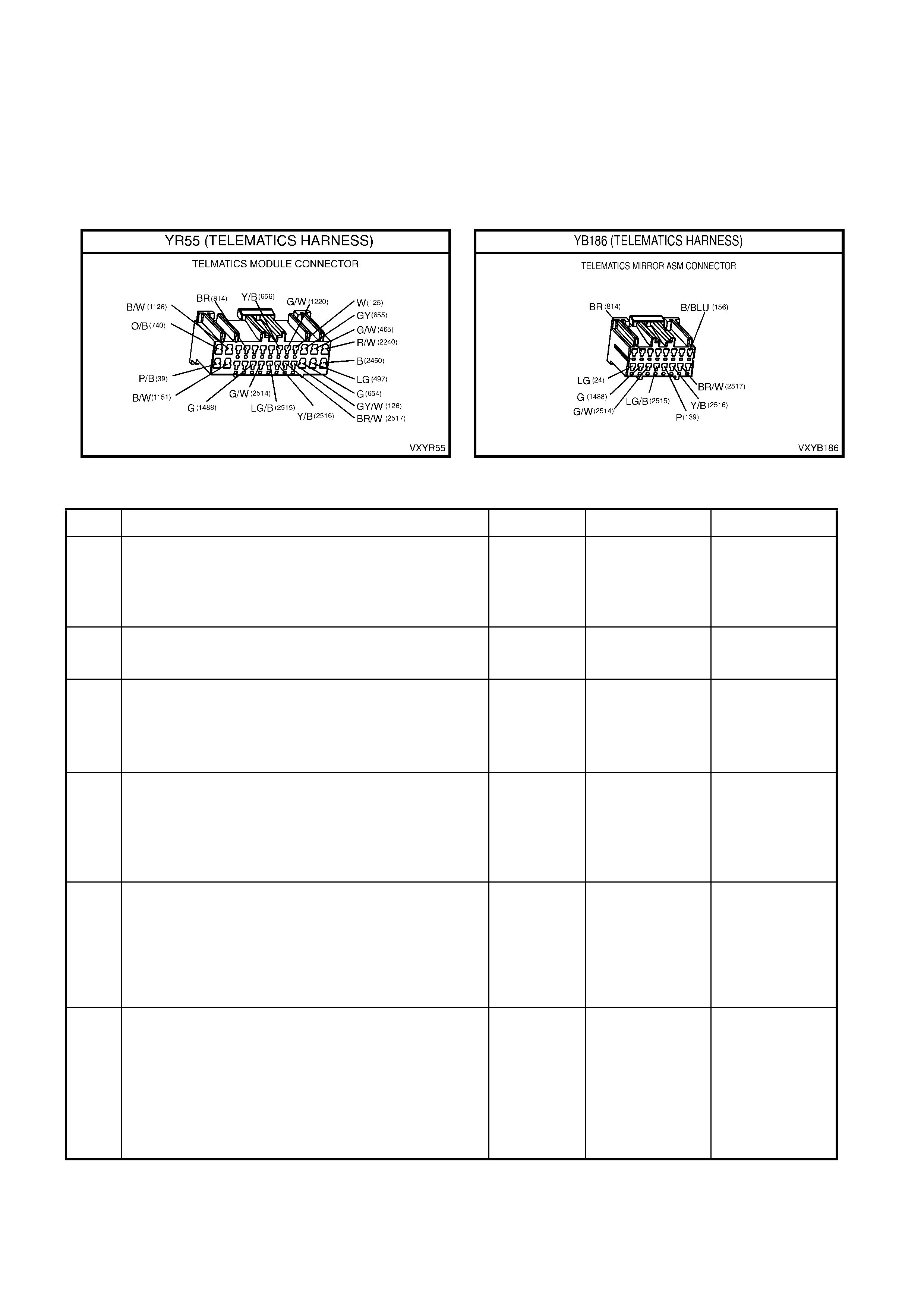
9. This test step check that the rear view mirror ground is OK
10. This test step checks the complete emergency button and circuits.
11. This test step checks the resistance of the rear view mirror end call / information button.
12. This test step confirms that the rear view mirror connector YB186 terminal retention is OK. Terminal retention
should always be checked before any component is replaced.
13. T his test st ep confirm s that the telem atics m odule connec tor YR55 term inal ret ention is OK. Term inal rete ntion
should always be checked before any component is replaced.
STEP ACTION VALUE YES NO
1. Has a Telematics On-Board Diagnosis System Check
been performed? Go to Step 2. Refer Telematics
On-Board
Diagnostic
System Check in
this Section.
2. 1. Ignition On.
Does the keypad back lighting illuminate.
Go to Step 5. Go to Step 3.
3. 1. From the Telematics Application Menu,
Select F0: Data List.
2. Scroll to Keypad Supply Voltage.
Does Tech 2 display Keypad Supply voltage “On”?
Go to Step 4. Go to Step 13.
4. 1. From the Telematics Application Menu,
Select F0: Data List.
2. Scroll to Keypad Signal Voltage.
Does Tech 2 display the specified Keypad Signal
voltage?
0.0 Volts. Go to step 5. Go to step 6.
5. 1. Enable the telematics module service mode.
(Service mode should be enabled until this
diagnostics chart is complete d).
2. Press the end call / informat io n button.
Does Tech 2 display the specified Keypad Signal
voltage?
0.7 Volts. End Call /
Information
Button OK.
Check for
intermittent in
circuit 2514.
Go to step 6.
6. 1. Disconnect the rear view mirror connector YB186.
2. Ignition on.
3. Jumper terminal 11 (Green/White wire) circuit 2514
and terminal 12 (Light Green/Black wire) circuit
2515 of connector YB 186.
Does Tech 2 display the specified Keypad Signal
voltage?
5.0 Volts. Go to Step 11.
Go to Step 7.

STEP ACTION VALUE YES NO
7. 1. Ignition on.
2. Using a DVM measure the voltage at the telematics
module connector YR55 terminal 20 circuit 2515
(Light Green/Black wire) and a known good ground.
Is the voltage as specified?
B+ Go to Step 8. Go to Step 13.
8. 1. Disconnect the rear view mirror connector YB186.
2. Ignition on.
3. Using a DVM measure the voltage between circuit
2515 (Light Green/Black wire) of the rear view
mirror connector YB186 and a known good ground.
Is the voltage as specified?
B+ Go to Step 9. Repair open in
circuit 2515.
9. 1. Disconnect the battery negative terminal.
2. Disconnect the rear view mirror connector YB186.
3. Using a DVM measure the resistance of circuit 156
(Black/Blue wire) between the rear view mirror
connector YB186 and a known good ground.
Is the resistance as specified?
Less than 1
Ohm. Go to Step 10. Repair open in
circuit 156.
10. 1. Reconnect the rear view mirror connector YB186
and disconnect the telema tic s modu le connector
YR55.
2. Using a DVM measure the resistance between
terminal 20 circuit 251 5 (Light G reen/Bla ck w ire)
and terminal 19 circuit 2414 (Green/White wire) of
the telematics module connector YR55.
Is the resistance as specified when the End Call /
Information Button is pres sed ?
13 K Ohms. Go to Step 13. Go to Step 11.
11. 1. Disconnect the interior rear view mirror connector
YB186.
2. Using a DVM measure the resistance between
terminal 12 and terminal 11 of the rear view mirror.
Is the resistance as specified when the End Call /
Information Button is pres sed ?
13 K Ohms. Repair open in
circuit 2514. Go to Step 12.
12. 1. Check interior rear view mirror connector YB186
terminal retention.
Is the terminal retention OK?
Replace interior
rear view mirror. Repair connector
terminal
retention.
13. 1. Check telematics module connector YR55 terminal
retention.
Is the terminal retention OK?
Replace
telematics
module.
Repair connector
terminal
retention.
WHEN ALL DIAGNOSIS AND REPAIRS ARE COMPLETED, VERIFY CORRECT OPERATION
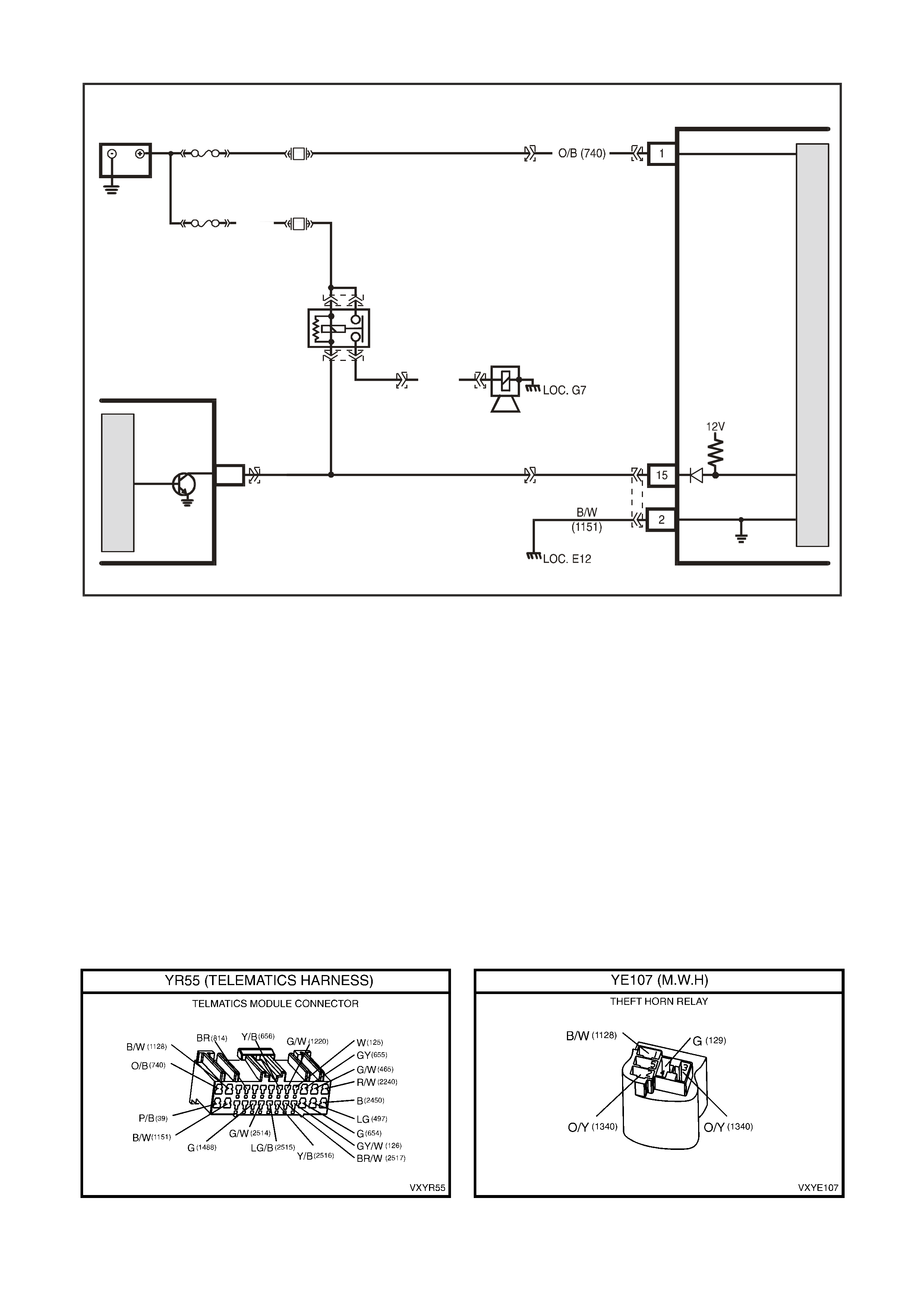
THEFT DETERRENT HORN CIRCUIT
BODY
CONTROL MODULE
B/W
(1128)
THEFT DETERRENT
HORN RE LAY
THEFT
DETERRENT
HORN
O/Y
(1340)
G (129)
VX12K110
TELEMATICS MODULE
BATTERY
LOC. E1
GROUND
THE FT D E TERR ENT
HORN
BATTERY
F31
F21
YB178
YE107
YE107
YE2
YE111
THEFT
DETERRENT
HORN A3
YB176
YR55YR55
FJ
R (2H)
FS
M
I
C
R
O
YB178
M
I
C
R
O
Figure 12Q-76
Circuit Description
The telematics module monitors the theft deterrent horn to determine if the entry deterrent system has been
triggered. If the entry deterrent system has bee n tri gge r ed, th e BCM pu ls es th e ve hic les horns at a r ate of on c e per
second. To pulse the theft deterrent horn the BCM grounds the theft deterrent horn relay drive circuit 1128
(Black/White wire). When the theft deterrent horn relay drive circuit is grounded the voltage at terminal 15 of the
telema tics module is pulled lo w, less than 0.2 vol ts. The telem atics m odule sees this l ow voltage at terminal 15 as
the entry deterrent system triggered input. If the vehicle entry deterrent system is triggered for longer than 20
seconds, the telematics module will transmit an “Unauthorised Entry Alert” message to the Holden Assist Centre.
Test Description
1. Confirmation that the Telematics On-Board Diagnostic System Check has been performed.
2. This test confirms that the telematics module is receiving a theft deterrent horn signal. If the alarm does not
trigger in this step refer Section 12 BCM in this service information.
3. The test step confirms that the telematics module is applying 12 volts to circuit 1128.
4. The test step confirms that circuit 1128 is OK.
5. This test step c onfirm s that the telem atics m odule connec tor YR55 term inal ret ention is OK. Term inal retenti on
should always be checked before any component is replaced.

STEP ACTION VALUE YES NO
1. Has a Telematics On-Board Diagnosis System Check
been performed? Go to Step 2. Refer Telematics
On-Board
Diagnostic
System Check in
this Section.
2. 1. Enable the telematics module service mode.
(Service mode should be enabled until this
diagnostic chart is completed).
2. Open the driver’s Window.
3. Shut all doors.
4. Enable the Theft Deterrent System by pressing the
lock button the remote key once.
3. From the Telematics Application Menu,
Select F0: Data List.
4. Scroll to Theft Deterrent Horn.
5. Trigger the theft deterrent system by lifting the
driver’s door snip and opening the driver’s door.
Does Tech 2 display the Theft Deterrent Horn on and off
in time with theft deterrent horn?
Disarm theft
deterrent system
by pressing the
unlock butt on on
the remote key.
Theft deterrent
horn circuit is
OK.
Check for
intermittent in
circuit 1128.
Disarm theft
deterrent system
by pressing the
unlock butt on on
the remote key.
Go to Step 3.
3. 1. Remove the theft deterrent horn relay.
2. Using a DVM measure the voltage at the telematics
module connector YB55 circuit 1128 (Black/White
wire).
Is the voltage as specified?
B+ Go to step 4. Go to step 5.
4. 1. Reinstall the theft deterrent horn relay.
2. Disconnect the telematics module connector YB55.
3. Using a DVM measure the voltage at the telematics
module connector YB55 circuit 1128 (Black/White
wire).
Is the voltage as specified?
B+ Go to step 5. Repair open in
circuit 1128.
5. 1. Check telematics module connector YR55 terminal
retention.
Is the terminal retention OK?
Replace
telematics
module.
Repair connector
terminal
retention.
WHEN ALL DIAGNOSIS AND REPAIRS ARE COMPLETED, VERIFY CORRECT OPERATION
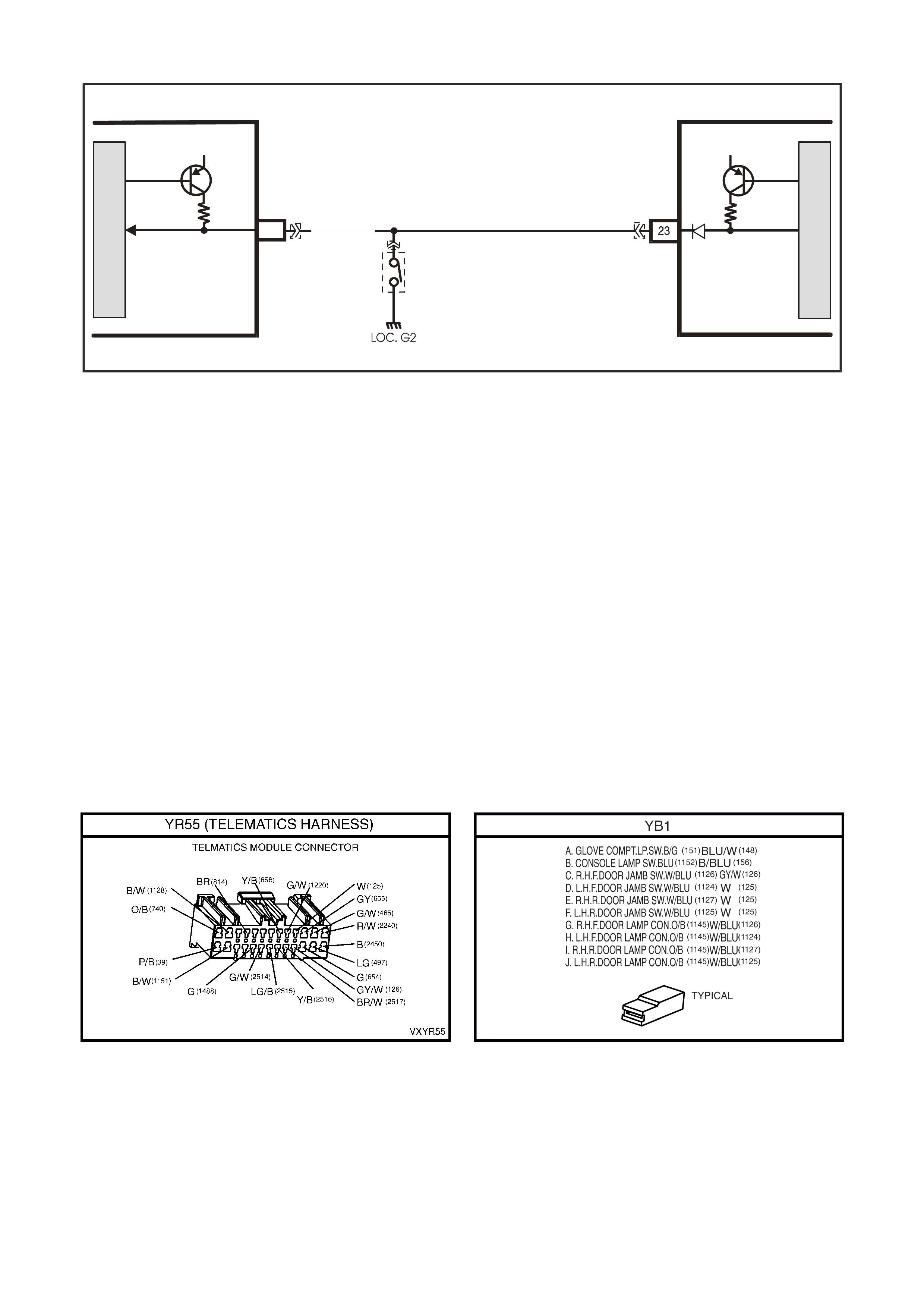
DRIVER’S DOOR JAMB SWITCH CIRCUIT
VX12K160
DRIVER’S DOOR
OPEN
12V
12V
DRIVER'S DOOR
OPEN
RHF DOOR
JAMB SWIT CH
GY/W (126)
C8
M
I
C
R
O
TELEMATICS MODULE
BODY
CONTROL MODULE
YB1
M
I
C
R
O
Figure 12Q-77
Circuit Description
The telematics module uses this input signal to determine if the driver's front door is opened or closed. W hen the
door is opened, the jamb switch earth’s terminal 23 via circuit 126 (Grey/White wire). This causes the voltage at
term inal 23 to b e pu lle d low, les s than 0. 2 v olts (dr i ver's door open). The telematics m odule s ees this l o w voltage at
term inal 23 as the dri ver's door open input s ignal. When a driver's door op en i np ut s ignal is r ecei ved , the te l ematics
module will switch from its current operating mode to active mode. This signal is also used to initiate
communication with Tech 2 when the telematics module is in pre delivery mode.
Test Description
1. Confirmation that the Telematics On-Board Diagnostic System Check has been performed.
2. This test uses Tech 2 determine that the driver’s door jamb switch is operating correctly.
3. This test uses Tech 2 to determine if the BCM is receiving the correct drivers door jamb switch information. If
the BCM is not receiving the correct information refer to the appropriate BCM diagnostics chart.
4. If Tech 2 displays “Driver’s Door Closed” when the door is open then circuit 126 may be shorted to ground.
5. If Tech 2 displays “Driver’s Door Open” when the door is closed then circuit 126 may be open or shorted to
voltage.
6. This test step checks if circuit 126 is shorted to ground.
7. This test step checks if circuit 126 is open or shorted to voltage.
8. This test step determines if the pulsed pull up in the telematics module is OK.
9. This test step c onfirm s that the telem atics m odule connec tor YR55 term inal ret ention is OK. Term inal retenti on
should always be checked before any component is replaced.

STEP ACTION VALUE YES NO
1. Has a Telematics On-Board Diagnosis System Check
been performed? Go to Step 2. Refer Telematics
On-Board
Diagnostic
System Check in
this Section.
2. 1. From the Telematics Application Menu,
Select F0: Data List.
2. Scroll to Driver’s Door.
Does Tech 2 display the “Driver’s Door” Open when the
driver’s door is open.
Does Tech 2 display the “Driver’s Door” Closed when
the driver’s door is close d.
Driver’s door
jamb switch and
circuit is
operating
correctly.
Go to step 3.
3. 1. From the Body Application Menu select Body
Control Module then select F0: Data List.
2. Scroll to Driver’s Door.
Does Tech 2 display the “Driver’s Door” Open when the
driver’s door is open.
Does Tech 2 display the “Driver’s Door” Closed when
the driver’s door is close d.
Go to step 4. Refer 12J1-2 for
Low Series BCM
Diagnosti cs or
12J2-2 for High
Series BCM
Diagnostics
4. In test step 2 did Tech 2 display “Driver’s Door” Open
when the driver’s door is closed. Go to step 6. Go to step 5.
5. In test step 2 did Tech 2 display “Driver’s Door” closed
when the driver’s door is open. Go to step 7. Go to step 8.
6. 1. Check for short to ground in circuit 126.
Is circuit 126 shorted to ground?
Repair short to
ground in circuit
126.
Go to step 8.
7. 1. Check for open or short to voltage in circuit 126.
Is circuit 126 open or shorted to voltage?
Repair open or
short to voltage
in circuit 126.
Go to step 8.
8. 1. Disconnect the BCM connectors.
2. Ignition on driver’s door close d .
3. Using a DVM measure the voltage at the telematics
module connector YB55 terminal 23, circuit 126
(Grey/White wire).
Is the voltage as specified?
Greater than
5 volts. Check for an
intermittent on
circuit 126.
Go to step 9.
9. 1. Check telematics module connector YR55 terminal
retention.
Is the terminal retention OK?
Replace
telematics
module.
Repair connector
terminal
retention.
WHEN ALL DIAGNOSIS AND REPAIRS ARE COMPLETED, VERIFY CORRECT OPERATION
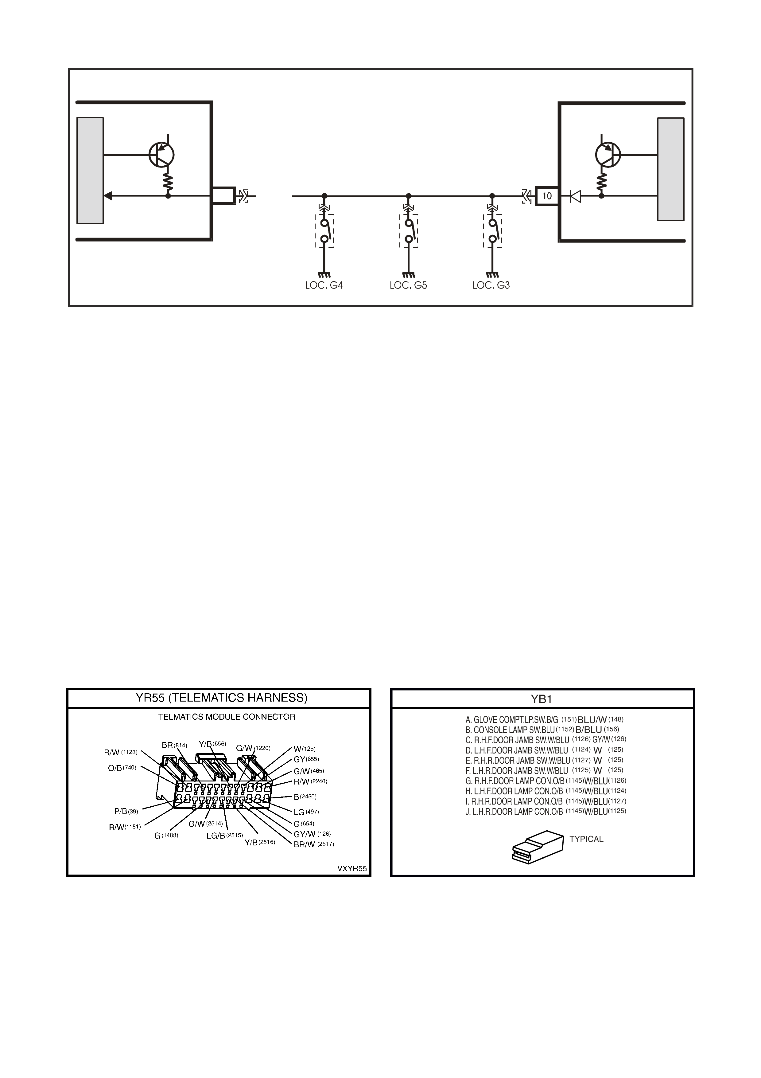
PASSENGERS DOOR JAMB SWITCH CIRCUIT
VX12K159
PASSENGER DOOR
OPEN PASSENGER DOOR
OPEN
12V 12V
LHF
DOOR
JAMB
SWITCH
LHR
DOOR
JAMB
SWITCH
RHR
DOOR
JAMB
SWITCH
C7
M
I
C
R
O
TELEMATICS MODULE
BODY
CONTROL MODULE
YR55
YB173
YB1 YB1 YB1
M
I
C
R
O
W (125)
Figure 12Q-78
Circuit Description
The telematics module uses this input signal to determine if any of the passenger doors are opened or if all
passenger doors are closed. If the right hand rear, left hand front or left hand rear door is open, terminal 10 is
earthed thr ough cir cuit 125 (White wire). This causes the voltage at ter m inal 10 to be pul led lo w, less than 0. 2 volt s
(if any one of the passenger doors is opened). The telematics module sees this low voltage at terminal 10 as the
passengers door op en input sig nal. W hen a passenge rs door ope n input sign al is rec eived, the telematic s module
will switch from its current operating mode to active mode.
Test Description
1. Confirmation that the Telematics On-Board Diagnostic System Check has been performed.
2. This test uses Tech 2 determine that the Passengers door jamb switch is operating correctly.
3. This test uses Tech 2 to determine if the BCM is receiving the correct drivers door jamb switch information. If
the BCM is not receiving the correct information refer to the appropriate BCM diagnostics chart.
4. If Tech 2 displays “Passengers Door Closed” when the door is open then circuit 125 may be shorted to ground.
5. If Tec h 2 d isplays “Pas sengers Door Op en” when the door is c losed then c irc u it 125 ma y be open or shor ted to
voltage.
6. This test step checks if circuit 125 is shorted to ground.
7. This test step checks if circuit 125 is open or shorted to voltage.
8. This test step determines if the pulsed pull up in the telematics module is OK.
9. This test step c onfirm s that the telem atics m odule connec tor YR55 term inal ret ention is OK. Term inal retenti on
should always be checked before any component is replaced.

STEP ACTION VALUE YES NO
1. Has a Telematics On-Board Diagnosis System Check
been performed? Go to Step 2. Refer,
Telematics On-
Board Diagnostic
System Check, in
this Section.
2. 1. From the Telematics Application Menu,
Select F0: Data List.
2. Scroll to Passenger Door.
Does Tech 2 display the “Passenger Door Open” when
any passenger door is open?
Does Tech 2 display the “Passenger Door Closed” when
the all the passenger doors are closed?
Passenger door
jamb switches
are operating
correctly.
Go to step 3.
3. 1. From the Body Application Menu select Body
Control Module then select F0: Data List.
2. Scroll to Passenger Door.
Does Tech 2 display the “Passenger Door Open” when
any passenger door is open?
Does Tech 2 display “Passenger Door Closed” when all
the passenger doors are closed?
Go to step 4. Refer 12J1-2 for
Low Series BCM
Diagnosti cs or
12J2-2 for High
Series BCM
Diagnostics
4. In test step 2 did Tech 2 display “Passenger Door Open”
when the passenger door is closed? Go to step 6. Go to step 5.
5. In test step 2 did Tech 2 display “Passenger Door
closed” when the passenger door is open. Go to step 7. Go to step 8.
6. 1. Check for short to ground in circuit 125.
Is circuit 125 shorted to ground?
Repair short to
ground in circuit
125.
Go to step 8.
7. 1. Check for open or short to voltage in circuit 125.
Is circuit 125 open or shorted to voltage?
Repair open or
short to voltage
in circuit 125.
Go to step 8.
8. 1. Disconnect the BCM connectors.
2. Ignition on all doors door closed.
3. Using a DVM measure the voltage at the telematics
module connector YB55 terminal 10, circuit 125
(White wire).
Is the voltage as specified?
Greater than
5 volts. Check for an
intermittent on
circuit 125.
Go to step 9.
9. 1. Check telematics module connector YR55 terminal
retention.
Is the terminal retention OK?
Replace
telematics
module.
Repair connector
terminal
retention.
WHEN ALL DIAGNOSIS AND REPAIRS ARE COMPLETED, VERIFY CORRECT OPERATION
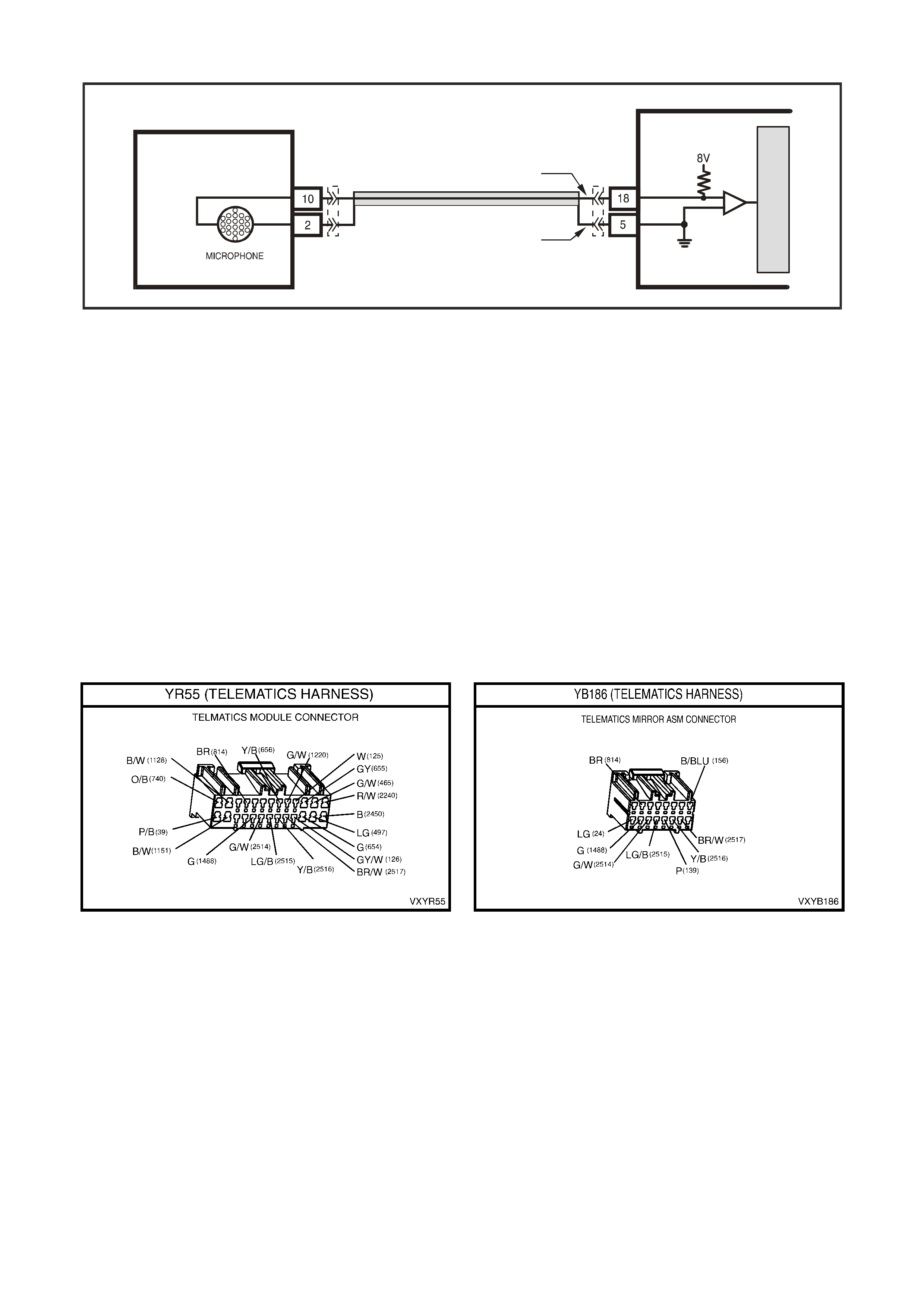
MICROPHONE OPEN OR SHORT CIRCUIT
VX12K158
G (1488)
BR (814 )
MIC ( + )
MIC ( -)
REAR VIEW MIRROR,
MICROPHONE
M
I
C
R
O
YR55
YB186
Figure 12Q-79
Circuit Description
The ac tive m icrophon e in t he inter ior r ear v iew m ir ror prov ides a m eans f or two way voic e c omm unication bet ween
the vehic le occupants a nd Holden Ass ist Centre. During th e function tes t the micropho ne and circuit are tested for
an open or short circuit.
Test Description
1. Confirmation that the Telematics On-Board Diagnostic System Check has been performed.
2. Confirmation that the telematics function test has been completed.
3. Checks that the telematics module is supplying 8 Volts to the microphone.
4. If the voltage is greater than eight Volts then circuit 1488 is shorted to voltage.
5. If the voltage is less than eight Volts then circuit 1488 is shorted to ground or open.
6. Checks if the telematics module is supplying eight Volts to circuit 1488.
7. This test determines if circuit 814 has continuity.
8. Before the mirror is replaced the retention of the mirror connector YB186 should be checked.
9. Before the telematics module is replaced the retention of the telematics module connector YR55 should be
checked.

STEP ACTION VALUE YES NO
1. Has a Telematics On-Board Diagnosis System Check
been performed? Go to Step 2 Refer Telematics
On-Board
Diagnostic
System Check in
this Section.
2. Has a Telematics Function Test been performed?
Go to Step 3. Refer 4.3 TECH
2 TEST MODES
F3: Additional
Functions
F1: Function Test
in this Section.
3. 1. Disconnect the Rear View Mirror connector YB186.
2. Ignition on.
3. Using a DVM, check the voltage at the rear view
mirror connector YB186 circuit 1488 (Green wire).
Is the voltage as specified?
7 - 8 volts. Go to Step 5. Go to Step 4.
4. In step 3 was the voltage greater than specified? 7 – 8 volts. Repair short to
voltage in circuit
1488.
Go to Step 5.
5. In step 3 was the voltage less than specified? 7 - 8 volts. Go to Step 6. Go to Step 7.
6. 1. Ignition on.
2. Rear View Mirror connector YB186 still
disconnected.
3. Using a DVM, check the voltage at the telematics
module connector YB55 circuit 1488 (Green wire).
Is voltage as specified?
7 - 8 volts. Repair open or
short to ground in
circuit 1488.
Go to Step 9.
7. 1. Using a DVM, measure continuity of circuit 814
(Brown wire) between the telematics module
connector YR55 terminal 5 the rear view mirror
connector YB186 terminal 2.
Is circuit resistance specified?
Less than 1
Ohm. Go to Step 8. Repair open
circuit 814.
8. 1. Check rear view mirror connector YB186 terminal
retention.
Is the terminal retention OK?
Replace Rear
view Mirror. Repair connector
terminal
retention.
9. 1. Check telematics module connector YR55 terminal
retention.
Is the terminal retention OK?
Replace
telematics
module.
Repair connector
terminal
retention.
WHEN ALL DIAGNOSIS AND REPAIRS ARE COMPLETED, VERIFY CORRECT OPERATION
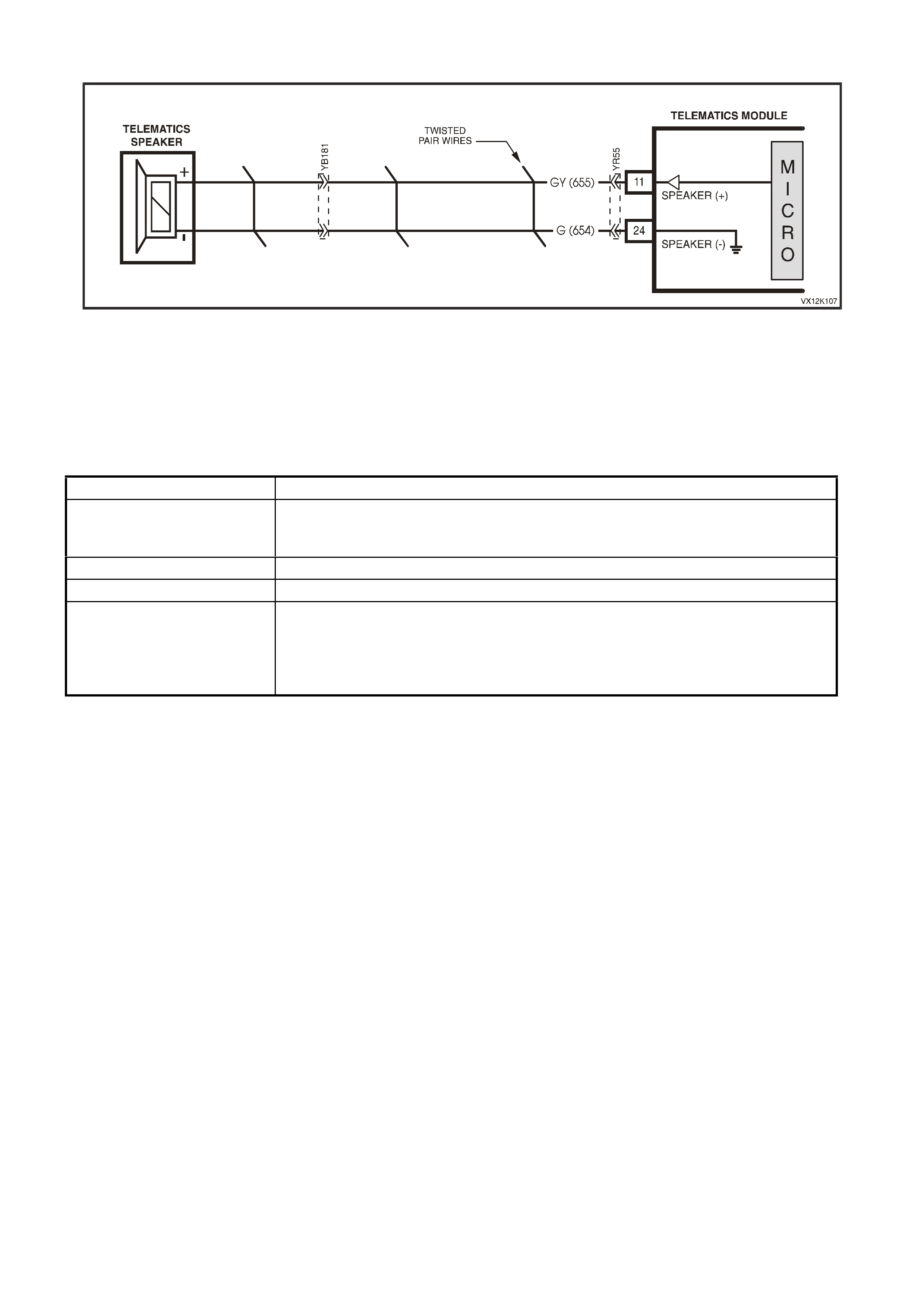
SPEAKER OPEN OR SHORT CIRCUIT
Figure 12Q-80
Circuit Description
The telem atics speaker located behind the glove compartm ent, is connected to the vehic le wiring harness using a
2-way conn ec tor YB1 81. The spe aker provi des a means f or two way voice c om m unic at io ns , an d a udible t on es ar e
also provided to indicate the system status and are broadcast via the speaker to alert the customer to certain
operatin g condit ions. T he speak er vo lume c an be prog ramm ed using T ech 2, f rom 1 being t he quiet est, to 8 being
the loudest. During the function test the speaker and circuit are tested for an open or short circuit.
Tone Operating Condition
Twelve Tones Attempting to make call when vehicle is not within GSM network range, or if the
twelve tones occur after the ignition is turned off, the vehicle is not within GSM
network range.
Two Tones If button is held down for more than one second.
Three tones If button is held down for less than one second.
Five Tones
(After the ignition is turned
on)
Warning that Service Mode is active or a system malfunction has been
detected.
Potential malfunctions:
GSM Module not active. GPS Module not active.
Backup battery is not charged or disconnected.
Test Description
1. Confirmation that the Telematics On-Board Diagnostic System Check has been performed.
2. Confirmation that the telematics function test has been completed.
3. Tests the resistance of the telematics speaker and circuit.
4. Tests the resistance of the telematics speaker.
5. Tests the continuity of circuit 655 (Grey wire) between the telematics module connector YR55 and the
telematics speaker connector YB181.
6. Tests the continuity of circuit 654 (Green wire) between the telematics module connector YR55 and the
telematics speaker connector YB181.
7. This test step determines if circuit 655 (Grey wire) is shorted to ground.
8. This test step determines if circuit 654 (Green wire) is shorted to ground.
9. This test step determines if circuit 655 (Grey wire) is shorted to voltage.
10. This test step determines if circuit 654 (Green wire) is shorted to voltage.
11. Before the telematics module is replaced the retention of the telematics module connector YR55 should be
checked.

STEP ACTION VALUE YES NO
1. Has a Telematics On-Board Diagnosis System Check
been performed? Go to Step 2 Refer Telematics
On-Board
Diagnostic
System Check in
this Section.
2. Has a Telematics Function Test been performed?
Go to Step 3. Refer 4.3 TECH
2 TEST MODES
F3: Additional
Functions
F1: Function Test
in this Section.
3. 1. Disconnect the telematics module connector YR55.
2. Using a DVM measure the resistance of the speaker
circuits from terminal 11 circuit 655 (Gray wi re) to
terminal 24 circuit 654 (Gre en w ire) of the telematic s
module connector YR55.
Is the resistance as specified?
4 – 5 Ohms. Go to Step 7. Go to Step 4.
4. 1. Disconnect the telematics speaker connector
YB181.
2. Using a DVM measure the resistance of the
speaker.
Is the resistance as specified?
4 – 5 Ohms. Go to Step 5. Replace
Speaker.
5. 1. Disconnect the telematics module connector YR55
and the speaker connector YB181.
2. Using a DVM measure the resistance of the speaker
circuit 655 (Grey wire) between the telematics
module connector YR 55 and the speaker connector
YB181.
Is the resistance as specified?
Less than 1
Ohm. Go to Step 6. Repair open in
circuit 655.
6. 1. Disconnect the telematics module connector YR55
and the speaker connector YB181.
2. Using a DVM measure the resistance of the speaker
circuit 654 (Green wire) between the telematics
module connector YR 55 and the speaker connector
YB181.
Is the resistance as specified?
Less than 1
Ohm. Go to Step 9. Repair open in
circuit 654.
7. 1. Disconnect the telematics module connector YR55
and the speaker connector YB181.
2. Using a DVM measure the resistance of the speaker
circuit 655 (Grey wire) between the telematics
module connector YR 55 and a known good ground.
Is the resistance as specified?
Less than 1
Ohm. Repair short to
ground in circuit
655.
Go to Step 8.

STEP ACTION VALUE YES NO
8. 1. Disconnect the telematics module connector YR55
and the speaker connector YB181.
2. Using a DVM measure the resistance of the speaker
circuit 654 (Green wire) between the telematics
module connector YR 55 and a known good ground.
Is the resistance as specified?
Less than 1
Ohm. Repair short to
ground in circuit
654.
Go to Step 9.
9. 1. With the telematics module connector YR55 and the
speaker connec tor Y B181 stil l dis conn ect ed.
2. Using a DVM measure the voltage on the speaker
circuit 655 (Grey wire) between the telematics
module connector YR 55 and a known good ground.
Is the voltage as specified?
Greater than
0.1 Volts. Repair short to
voltage in circuit
655.
Go to Step 10.
10. 1. With the telematics module connector YR55 and the
speaker connec tor Y B181 stil l dis conn ect ed.
2. Using a DVM measure the voltage of the speaker
circuit 654 (Green wire) between the telematics
module connector YR 55 and a known good ground.
Is the voltage as specified?
Less than 0.1
Volts. Repair short to
voltage in circuit
654.
Go to Step 11.
11. 1. Check telematics module connector YR55 terminal
retention.
Is the terminal retention OK?
Replace
telematics
module.
Repair connector
terminal
retention.
WHEN ALL DIAGNOSIS AND REPAIRS ARE COMPLETED, VERIFY CORRECT OPERATION
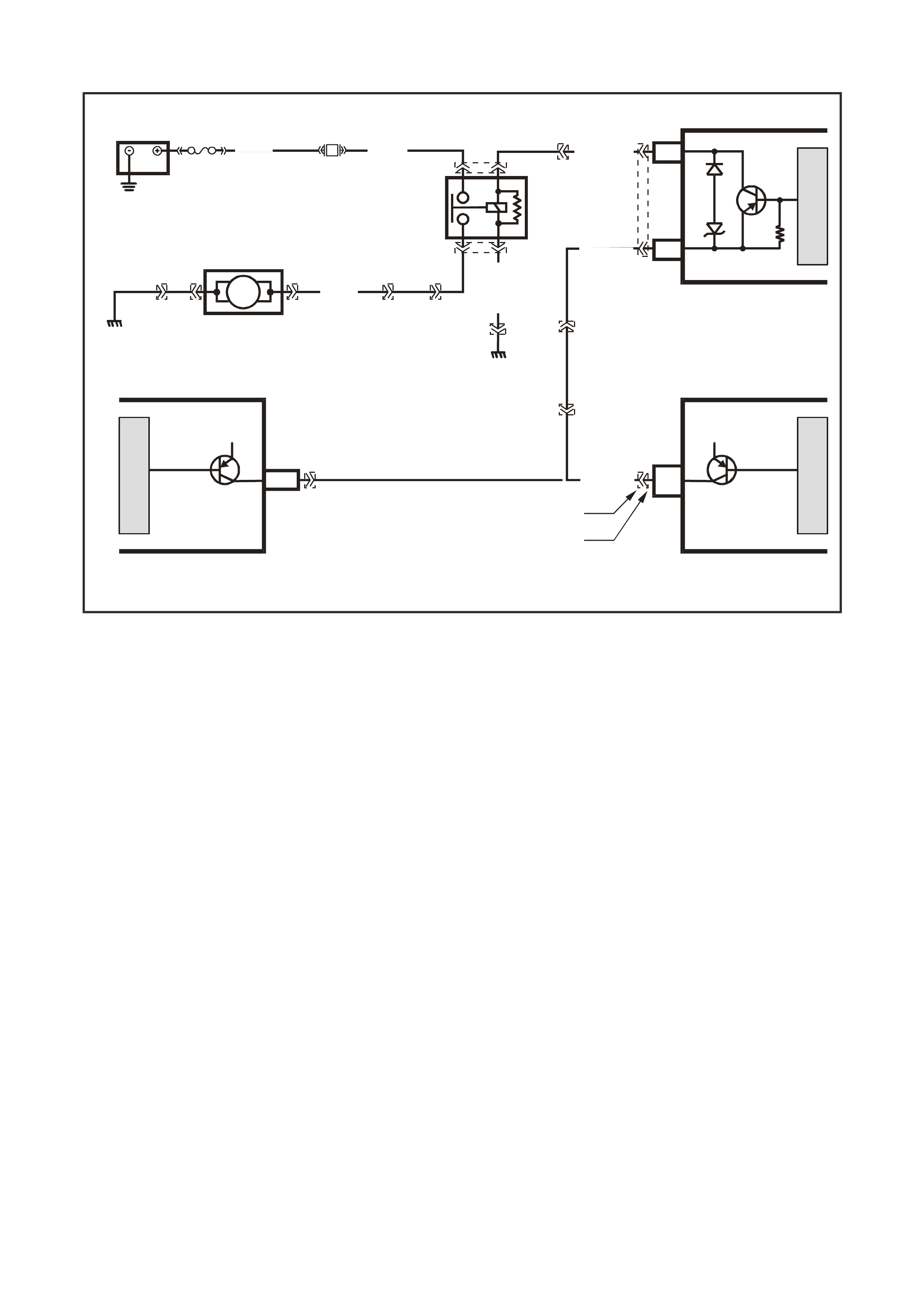
FUEL PUMP RELAY DRIVE CIRCUIT
25
12
E10
A6
J2-09 FUEL PUMP RELAY
CONTROL
FUEL PUMP RELAY
CONTROL
B/BLU
(156)
LOC. E7
LOC. E3
IN - TANK
FU EL PUMP
FU EL PUMP
RELAY
L/G (497)
G/W (465)
G/W (465)
TELEMATICS MODULE
V6 POWERTRAIN
CONTROL MODULE
V8 POWERTRAIN
CONTROL MODULE
12V12V
M
I
C
R
O
M
I
C
R
O
M
I
C
R
O
BATTERY
FS
LOC E1
F28
(1040) O (240)
V (120)
B/W(152)
32
51
VX12K102
YB199
YB188
YB199, E10
NON S/C V6 ENGINE
YB188, A6
S/C V6 ENG INE
YR55
YE96
YE114
YE110
YB178
YB178
YR44
YR32
YB39
YR44
YR32
YE96
YE123
Figure 12Q-81
Circuit Description
The PCM energises the fuel pump relay drive circuit via circuit 465 (Green/White wire) the telematics module
term inals 12 and 2 5, c irc uit 497 (Li ght/G re en wire). T he f uel pump relay drive circui t is ground ed thr o ugh c irc uit 152
(Black/White wire) at ground location E3. The telematics module can immobilise the vehicle by opening the fuel
pump relay drive circuit, causing the fuel pump to stop operating. This function can only be activated by the
National Emergency Response Centre (NERC™)under instruction from the Police.
Test Description
1. Confirmation that the Telematics On-Board Diagnostic System Check has been performed.
2. This steps confirms that the fuel pump relay drive circuit within the telematics module is active.
3. This step confirms that battery voltage is being applied to the telematics module fuel pump relay drive
circuit from the PCM. If the PCM is not applying voltage to this circuit you should refer to the
On-Board Diagnostic System Check in Section 6C1 V6 Engine, Section 6C1 V6 Supercharged Engine and
Section 6C3 V8 GEN III Engine.
4. This step conf irms that the f uel pump r elay dri ve circui t in the te lematic s module is OK an d appl ying voltage to
circuit 497. If the telematics module is applying voltage to this circuit then you should refer to the On-Board
Diagnostic System Check in Section 6C1 V6 Engine, Section 6C1 V6 Supercharged Engine and
Section 6C3 V8 GEN III E ngine. If the telematic s module is not ap plying vo lta ge to c irc u it 4 97 the n you sho uld
replace the telematics module, refer step 5 in this diagnostic chart.
5. Before the telematics module is replaced the retention of the telematics module connector YR55 should be
checked.

STEP ACTION VALUE YES NO
1. Has a Telematics On-Board Diagnosis System Check
been performed? Go to Step 2. Refer, Telematics
On-Board
Diagnostic
System Check, in
this Section.
2. 1. From the Telematics Application Menu,
Select F0: Data List.
2. Scroll to Fuel Pump Relay Drive Circuit.
Does Tech 2 display the “Fuel Pump Relay Drive Circuit
Active”?
Go to Step 3. Go to Step 5.
3. 1. Using a DVM, check the voltage at the telematics
module connector YR55 terminal 12 circuit 465
(Green/White wire).
2. Ignition off for at lease 20 seconds.
Is the voltage as specified for at least 2 seconds when
the ignition is turned from off to on?
B+ Go to step 4. Refer to PCM
On-Board
Diagnostic
System Check is
this Service
Information.
4. 1. Using a DVM, check the voltage at the telematics
module connector YR55 terminal 25 circuit 497
(Light Green wire).
2. Ignition off for at lease 20 seconds.
Is the voltage as specified for at least 2 seconds when
the ignition is turned from off to on?
B+ Refer to PCM
On-Board
Diagnostic
System Check is
this Service
Information.
Go to Step 5.
5. 1. Check telematics module connector YR55 term inal
retention.
Is the terminal retention OK?
Replace
telematics
module.
Repair connector
terminal
retention.
WHEN ALL DIAGNOSIS AND REPAIRS ARE COMPLETED, VERIFY CORRECT OPERATION
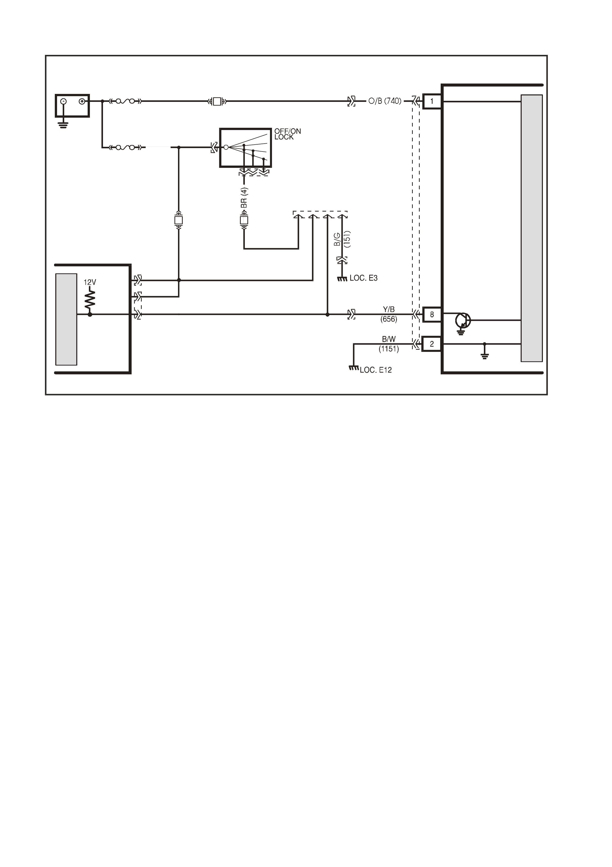
RADIO MUTE CIRCUIT
F16
O/B
(45) R
(2H)
Y
(43)
VX12K111
TELEMATICS MODULE
GROUND
RADI O MUTE
BATTERY
IG NITION SWITC H
15a 15 50
30 ACC
IGN
START
F31
YB178
YB23
YB44
YB44
YR55
FS
M
I
C
R
O
YB178
RADIO
MUTE
BATT
BATT
RADIO
F23
BATTERY
LOC. E1
FJ
R (2H)
YB72 YB73
M
I
C
R
O
CELLUAR
TELEPHONE
CONNECTOR
YB178
Figure 12Q-82
Circuit Description
Whenever the telematics speaker is activated the radio mute signal is also activated and the telematics module
grounds the radio mute circuit 656 (Yellow/Black wire) causing the circuit voltage to be pulled low, less than 0.2
volts. This low voltage is seen by the radio as a radio mute request, when received, the radio will mute.
Test Description
1. Confirmation that the Telematics On-Board Diagnostic System Check has been performed.
2. Radio mute should only display active when the telematics speaker is active.
3. This test step determines if the telematics module can command the radio to mute.
4. If the radio mutes when commanded the radio mute is working correctly.
5. This test step confirms that the radio is applying 12 volts to circuit 656.
6. If the radio mutes when circuit 656 is grounded then the circuit 656 and the radio are OK.
7. This test step checks for an open in circuit 656.
8. Before the telematics module is replaced the retention of the telematics module connector YR55 should be
checked.

STEP ACTION VALUE YES NO
1. Has a Telematics On-Board Diagnosis System Check
been performed? Go to Step 2. Refer, Telematics
On-Board
Diagnostic
System Check, in
this Section.
2. 1. From the Telematics Application Menu,
Select F0: Data List.
2. Scroll to Radio Mute.
Does Tech 2 display the “Radio Mute Active”?
Go to Step 8. Go to Step 3.
3. 1. Turn the radio on.
2. From the Telematics Application Menu,
Select F2: Miscellaneous List, F4: Radio Mute.
Does Tech 2 display “Radio Mute Active” and “Radio
Mute Inactive” when commanded?
Go to step 4. Go to Step 8.
4. In test step 3 did the radio mute when the Tech 2
displayed “Radio Mute Active? Radio Mute OK. Go to Step 5.
5. 1. Radio on, disconnect the telematics module
connector YR55.
2. Using a DVM, check the voltage at the telematics
module connector YR55 terminal 8 circuit 656
(Yellow/Black wire).
Is the voltage as specified?
B+ Go to Step 6. Go to Step 7.
6. 1. Radio on.
2. Using a fused jumper wire, jumper circuit 656
(Yellow/Black) to ground.
Did the radio mute?
Go to Step 8. Replace radio
refer 12D Audio
Systems in this
Service
Information.
7. 1. Check for open or short to ground in circuit 656
(Yellow/Black wire).
Is circuit 656 (Yellow/Black) open or shorted to ground?
Repair open or
short to Ground
in circ uit 656.
Go to Step 8.
8. 1. Check telematics module connector YR55 term inal
retention.
Is the terminal retention OK?
Replace
telematics
module.
Repair connector
terminal
retention.
WHEN ALL DIAGNOSIS AND REPAIRS ARE COMPLETED, VERIFY CORRECT OPERATION
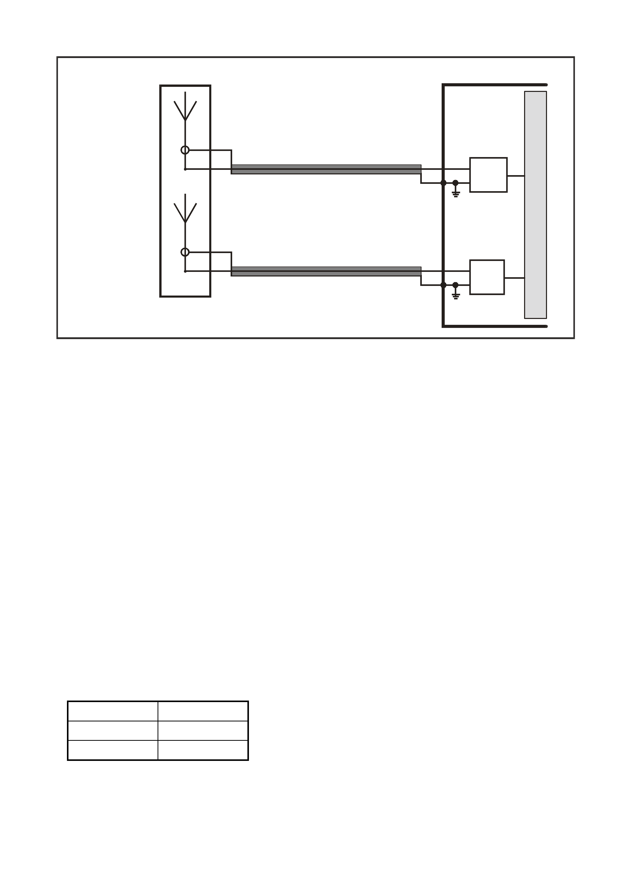
UNABLE TO MAKE OR RECEIVE A CALL
GSM
ANTENNA (-)
GSM
ANTENNA (+)
M
I
C
R
O
TELEMATICS MODULE
GSM ANTENNA
GSM
MODULE
VX12K119A
GPS ANTENNA
GPS
ANTENNA (-)
GPS
ANTENNA (+)
GPS
MODULE
Figure 12Q-83
Circuit Description
The link between the vehicle and the Holden Assist Centre or NERCTM uses G PS for veh icle locatio n and track ing
and the Australian digital mobile phone network to transmit and receive voice and SMS (Short Message Service)
data. If the vehicle is outside network coverage, the link to and from the vehicle will not be available and no
services can be provided. Signal strength may be affected in locations like basement car parks or tunnels.
However, in most cases, as the vehicle emerges from the obstruction or re-enters the digital phone network area
the signal will be available again.
Test Description
1. Confirmation that the Telematics On-Board Diagnostic System Check has been performed.
2. For the telematics system to operate correctly the VIN displayed by Tech 2 must match the actual VIN.
3. For the telematics module to make or receive any calls the GSM must be active.
4. During this test step the telematics module must be reprogrammed with the correct code index, by
reprogram m ing the m odule this will ens ure that the c orrec t phone num ber s are reprogram m ed into the m odule .
Refer Code Index Programming in this Section.
5. 12 beeps when the ignitio n is turned off , or when att empting a mak e call is a n i nd i c ation of no GSM si gna l. Y ou
should refer to the NO GSM Signal diagnostic chart in this Section.
6. If the telematics module makes a call but is continually connected to a recorded message, means that the
module can make a call, but the number being called is not allowed. The module was reprogrammed during
test step 4, which should have reprogrammed the module with the correct phone numbers, therefore the
module should be replaced.
7. Before the telematics module is replaced the retention of the telematics module connector YR55 should be
checked.
Code Index
Model Code Index
VX 1
WH 1

STEP ACTION VALUE YES NO
1. Has a Telematics On-Board Diagnosis System Check
been performed? Go to Step 2 Refer Telematics
On-Board
Diagnostic
System Check in
this Section.
2. 1. From the Tech 2 Body Application Menu select
Telematics Module and follow screen instructions.
At the System Identification screen does the VIN
displayed match the actual vehicle VIN?
Go to Step 3. Go to Step 7.
3. 1. From the Telematics Application Menu,
Select F0: Data List.
2. Scroll to GSM Module.
Does Tech 2 display the “GSM Module Active”?
Go to Step 4. Go to Step 7.
4. 1. From the Tech 2 Telematics Module Application
Menu select F4: Program / F0: Program Code
Index.
2. Reprogram the Code Index to the correct code
index number.
(Refer F0: Program Code Index in this Section).
Has problem been rectified?
Complete On-
Board Diagnostic
System Check.
Go to Step 5.
5. Did you hear 12 beeps when the ignition is turned on?
Did you hear 12 beeps when a keypad button is
pressed?
Is the red status LED on all the time when the ignition is
on?
Refer No GSM
Signal Diagnostic
Chart in this
Section.
Go to Step 6.
6. W hen making a call does the telematics module connect
to the network but only to recorded message saying that
the number is not available from this service?
Go to step 7. Complete On-
Board Diagnostic
System Check.
7. 1. Check telematics module connector YR55 term inal
retention.
Is the terminal retention OK?
Replace
telematics
module.
Repair connector
terminal
retention.
WHEN ALL DIAGNOSIS AND REPAIRS ARE COMPLETED, VERIFY CORRECT OPERATION

HOLDEN ASSIST TELEM ATICS SYST EM TEST
This Holden Assist Telematics System Test should only be carried out as the final steps in the Telematics On-
Board Diagnostic System Check. All other steps in the On-Board Diagnostic System Check must be completed
and have been successful before performing this Holden Assist Telematics System Test.
1. Ignition on.
2. From the Tech 2 Telematics Application Menu, Select F0: Data List, Scroll to GSM Signal Strength and GPS
2D or 3D Fix. Position the vehicle where the GSM Signal strength is at least 20 and the GPS has a 2 or 3D Fix.
3. Disable Service Mode (refer F4: Program / Operating Mode / Service Mode in this Section). Disconnect the
Tech 2 from the vehicle.
4. Press the Holden Assist Button until two beeps are heard.
5. When the call is answered, identify yourself and your dealership and request a Holden Assist Telematics
System Test.
(i.e "Hello, this is Robert Smith from Jonestown Holden, could you please carry out a Holden Telematics
System Test").
6. The Holden Assist operator will then carry out a Holden Telematics System Test. During the test the operator
will inform you that you pressed the Holden Assist button and they have received a vehicle location.
7. Depending on the current Holden Assist telematics system status the operator will be able to either remotely
unlock the doors or enable the telematics module service mode. The operator will inform which function they
are going to perform. If they are going to perform a Remote unlock go to step 8A, if the are going to enable
service mode go to step 8B.
8A. Lower the driver’s window.
Shut and lock all doors.
The operat or wil l t hen s end a remote u nl oc k r eques t, t he d oors s ho ul d t hen un lock within 30 s econds (this ti me
to unlock will vary depending on SMS traffic).
O n receiving a ver ification mess age that the doors ha ve unlock ed, the o perator will inf orm you that the system
has passed the Holden Assist Telematics Test.
Thank the Holden Assist operator.
Press the End Call / Information button to end the call.
8B. The operator will send a remote request to enable service mode.
On rec eiving a ver ification m essage that the s ervice m ode has been e nabled, the o perator will inform you that
that the system has passed the Holden Assist Telematics Test.
Thank the Holden Assist operator.
Press the End Call / Information button to end the call.
From the Telematics Application Menu, Select F0: Data List, Scroll to Operating mode. The operating mode
should display Service.
Disable Service Mode (refer F4: Program / Operating Mode / Service Mode in this Section).
9. Press the Emergency Button until two beeps are heard.
10. When the call is answered, identify yourself and your dealership and request a Holden Telematics System
Test.
(i.e "Hello, this is Robert Smith from Jonestown Holden, could you please carry out a Holden Telematics
System Test").
8. The NERCTM will th en carry out a Hold en Telem atics System T est. During the tes t the operator wil l inform you
that you pressed the em ergency button and they have received a vehicle location. The operator will then end
the call.
11. If all the above steps have been completed successfully the system has passed the Holden Telematics System
Test.

6. TORQUE WRENCH SPECIFIC ATIONS
Nm
Telematics module assembly retaining screws............................... 3 – 3.5
Telematics module to mounting bracket retaining screws .............. 3 – 3.5
Telematics backup battery retaining screws................................... 3 – 3.5
Telematics speaker bracket retaining screws................................. 3 – 3.5
Interior rear view mirror retaining screw ......................................... 2.5 – 4.5