
SECTION 4B - FINAL DRIVE AND DRIVESHAFTS
IMPORTANT
Before performing any Service Operation or other procedure described in this Section, refer to Section
00 CAUTIONS AND NOTES for correct workshop practices with regard to safety and/or property
damage.
1. GENERAL INFORMAT ION
The final drive assembly and driveshafts for VX Series vehicles, carries over from VT Series II, except for the
following:
1. The final drive pinion flange design has changed to suit the new propeller shaft design (refer
4C PROPELL ER SHAFT AND UNIVERSAL JOINTS of the VX Series Service Information).
The service procedure required to replace the pinion oil seal and/or the pinion flange are detailed in this
Section, to il lus trate t he method of r emoval/ reins t al lat i on of the ne w f lang e an d replac ement proc edur es for the
pinion oil seal.
Apart from this procedure, the disassembly/ reassembly procedures detailed in
4B FINAL DRIVE AND DRIVESHAFTS, in the VT Series I Service Information are still valid, despite some
illustrations showing the earlier pinion flange and the former special tools.
In these instances, use the special tools shown in this Section.
2. With the pinion flange change, the part numbers and broadcast codes have also changed. These changed
codes listed in this Section.
3. The oil manufacturer, Mobil has advised that one of their products (recommended for fitment to some of the
final dr ive assem blies fitted to Holden produc t) has ch anged it’s i dentification. An update t o reflect t his change
and all recommended final drive lubricants, is provided in this Section.
4. The source for the tapered roller bearings used in the final drive assembly is now optional. Details of this
change and the service implications that result, are detailed in this Section.
5. The final drive ratio for those VX vehicles with either of the two available manual transmissions, is 3.46:1.
Service procedures however, remain unchanged.
Apart from the service operations described here, all remaining service procedures relating to the final drive and
driveshafts remain as described Section 4B FINAL DRIVE AND DRIVESHAFTS, published for VT Series I
and Section 4B - FINAL DRIVE AND DRIVE SHAFTS - Early Production Traction Arms or
Section 4B - FINAL DRIVE AND DRIVE SHAFTS - Local Production Traction Arms in VT Series II vehicles.
Techline
Techline
Techline
Techline
Techline
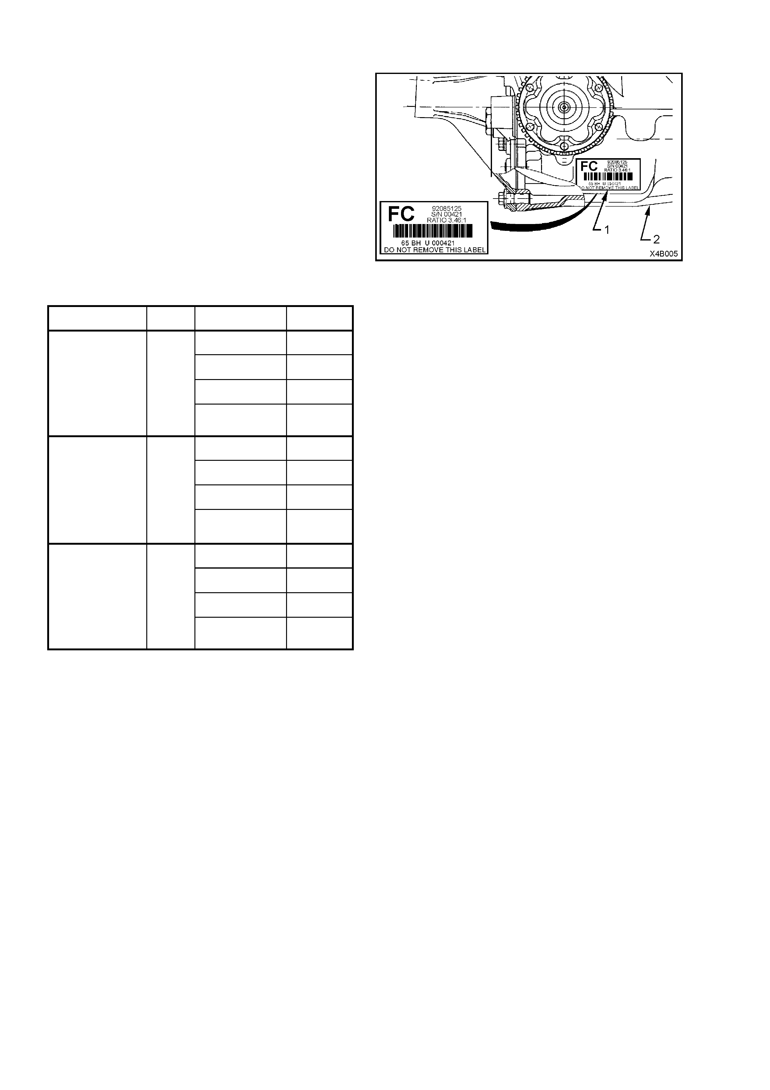
1.1 FINAL DRIVE ASSEMBLY IDENTIFICATION
Variations in the f inal dr ive as sem bly, depend u pon
the final drive ratio, whether the optional Limited
Slip Differential (LSD) and ABS is fitted or not.
NOTE: The optional LSD is also known as Slip
Resistant Differential (SRD).
A specific variant can be identified by referring to
the identification label (1) attached to the right hand
side of the carrier housing (2).
The identification code and bar code are used for
production identification of the final drive assembly.
Figure 4B-1
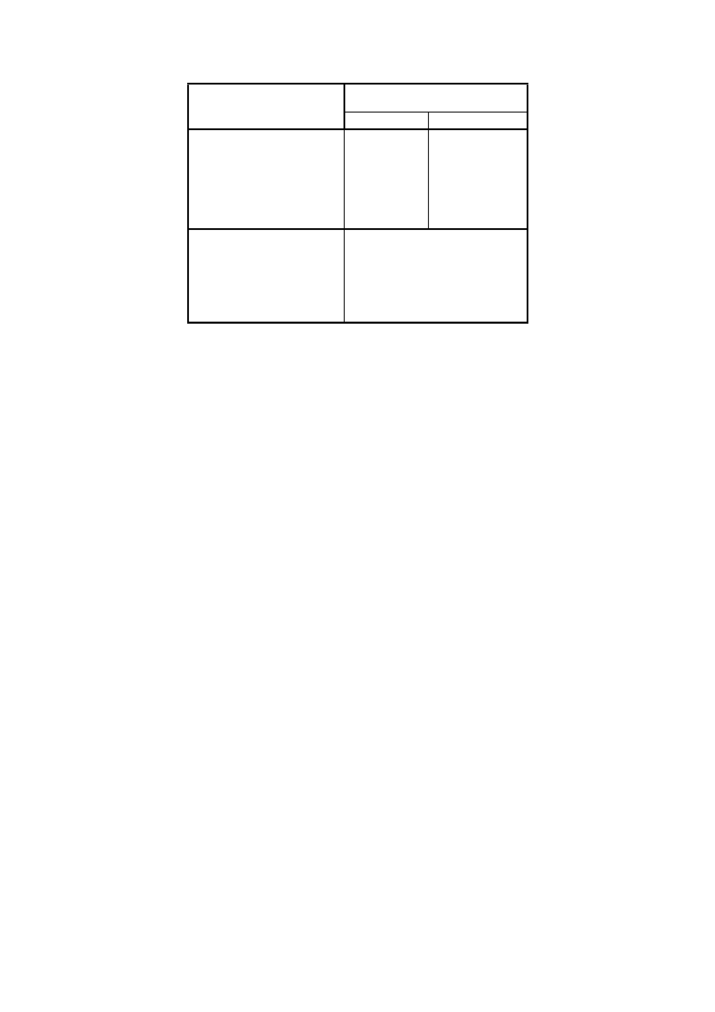
Usage Ratio Type ID Code
Standard FB
LSD FA
ABS FT
GEN II I V8 with
Manual
Transmission 3.46
LSD and
ABS FC
Standard FD
LSD FE
ABS FF
GEN II I V8
Automatic
V6 Supercharged
V6 Station Wagon
with Manual
Transmission
3.07
LSD and
ABS FH
Standard FJ
LSD FK
ABS FL
V6 Station Wagon
with Automatic
Transmission
All V6 Natu ra lly
Aspirat ed Sedans
3.08
LSD and
ABS FM
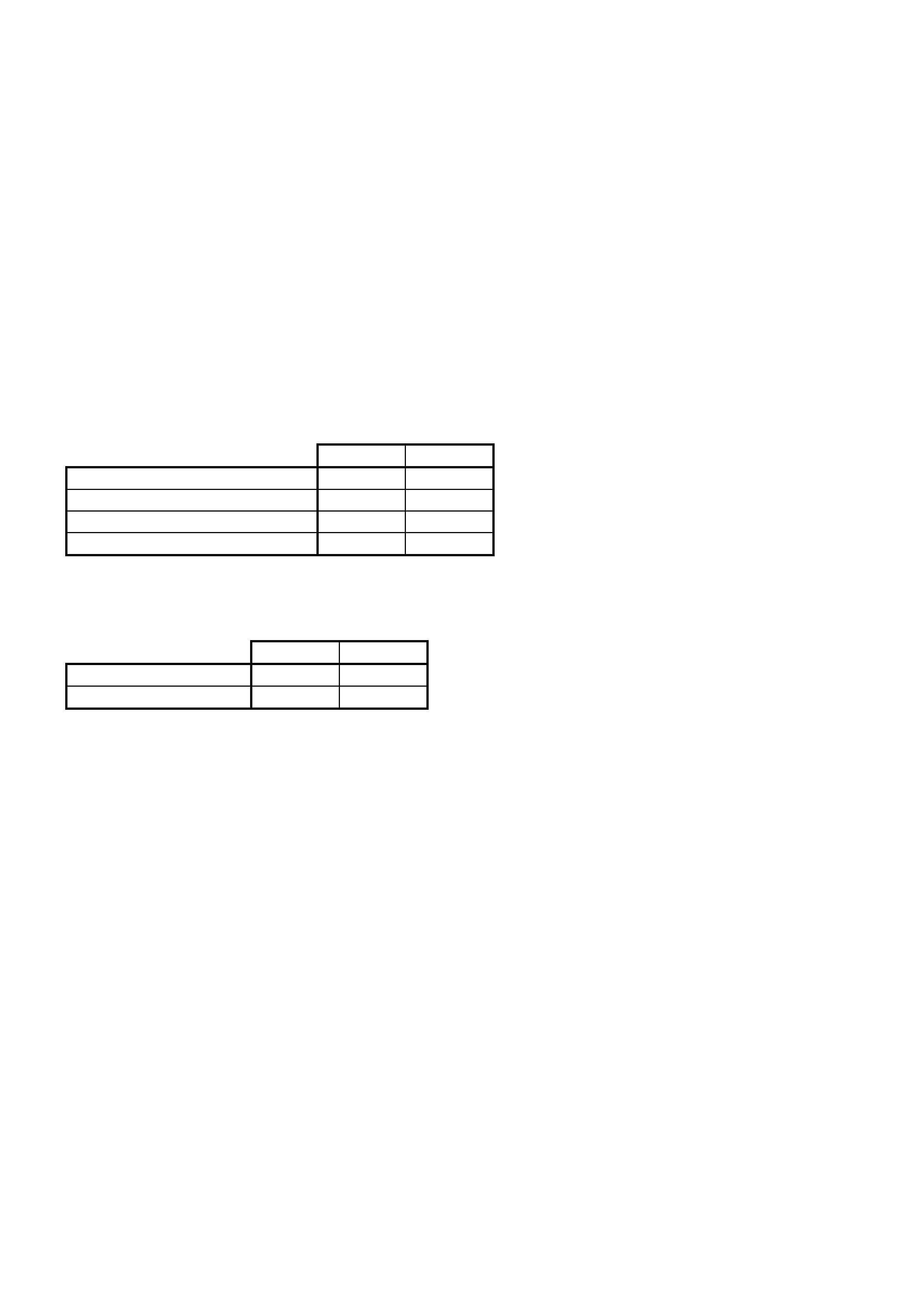
1.2 FINAL DRIVE LUBRICANT RECOMMENDATIONS
Engine & Recommended
Lubricant
Transmission Type Exc G80 LSD (G80)
All Naturally As pi rat ed V6 Sedan,
Manual Or Automatic
Transmission
V6 Station Wagon With
Automatic Transm issi on
Mineral Hypoid
Gear Oil
SAE 90
Mineral Hypoid
Gear Oil
SAE 90 LSD
Such As;
BP Limslip 90,
Castrol LSX90,
Mobil Lubrite LS90,
Shell XD90LS
All Gen III V8 W i th Manual Or
Automatic Transm iss i ons,
V6 Supercharged
V6 Station Wagon With Manual
Transmission
Synthetic Hypoi d Gear Oil
SAE 80W-140
Castrol SAF-XA
Mobil Mobilube SHC ID.
2. SERVICE OPERATION
2.1 SERVICE INFORMATION
REMOVED FINAL DRIVE ASSEMBLY
UNIT REPAIR
W ith the recent optiona l use of two sources of tapered r oller bearing m anuf acture in the as sembl y of the fin al drive
assembly, different pre-load specifications apply to each.
Apart from this change in source and that fact that some illustrations do not reflect the VX Series pinion flange
design, all remaining procedures for the repair of the removed final drive assembly, remain as detailed in
Section 4B - FINAL DRIVE AND DRIVESHAFTS VT Series I and
Section 4B - FINAL DRIVE AND DRIVE SHAFTS - Early Production Traction Arms or
Section 4B - FINAL DRIVE AND DRIVE SHAFTS - Local Production Traction Arms in VT Series II vehicles.
Pinion and Differential Bearings
Introduced as a running change (no breakpoint was recorded), the use of an alternative bearing supplier means
that either Timken or Koyo bearings may be used for the pinion and/or differential side applications.
Removal and fitment procedures are unchanged but the baring pre-loads differ as detailed in the following table.
1. Pinion Bear i ng Pre- l oad Sp ec ific at io ns
Timken Koyo
New bearings with pinion oil seal fitted 1.4 – 2.4 Nm 1.5 – 2.1 Nm
New bearings without pinion oil seal fitt ed 1.4 – 2.0 Nm 1.5 – 1.9 Nm
Used bearings with pinion oi l seal fitted 0.7 – 1.2 Nm 0.7 – 1.2 Nm
Used bearings without pi ni on oil seal fitt ed 0.7 – 1.2 Nm 0.7 – 1.2 Nm
NOTE: Pinion bearing pre-load is to be measured from the companion flange, without the differential assembly
installed. See Pinion Installation, in 3.3 REMOVED FINAL DRIVE ASSEMBLY, in 4B FINAL DRIVE AND
DRIVESHAFTS, in the VT Series I Service Information for the procedure.
1. Differential Bearing Preload Specifications
Timken Koyo
New bearings 15 – 35 N 8 – 24 Nm
Used bearings 8 – 18 N 5 – 13 Nm
NOTE: Preload is to be measured from the differential case flange diameter without axle shafts or the final drive
pinion installed. Refer Differential Case Side Bearing Pre-Load Setting, in 4B REAR AXLE AND DRIVESHAFTS,
in the VT Series I Service Information for the procedure.
SERVICE IMPLICATIONS
1. The front and rear pinion bearings must be a pair from the same manufacturer (i.e. both Koyo or both Timken).
2. Differential bearings must be a pair from the same manufacturer (i.e. both Koyo or both Timken).
3. The differential bearing pair may be from a different manufacturer to the pinion bearing pair.
2.2 PINION OIL SEAL
REPLACE
1. Using a floor jack under centre of differential
carrier, jack up rear of vehicle then place safety
stands under trailing arms.
2. Remove propeller shaft, refer to
Section 4C PROPELLER SHAFT AND
UNIVERSAL JOINTS in the VX Series Service
Information. This operation may require partial
exhaust system removal.
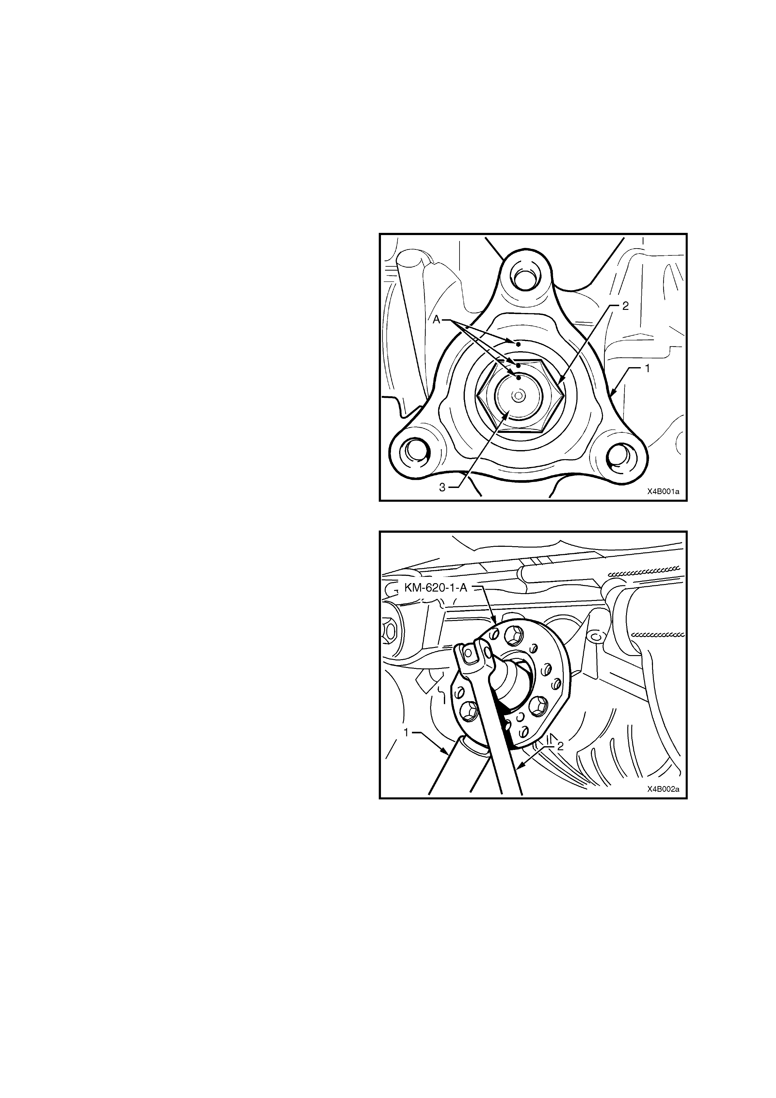
3. Lightly centre-punch alignment marks (A) on
the pinion flange (1), pinion flange nut (2) and
pinion end (3) as an aid for reassembly.
By reassembling to the original position, the
flange run-out will be m inim ised and the pinion
bearing prelo ad wi ll be m aintai ned .
Figure 4B-2
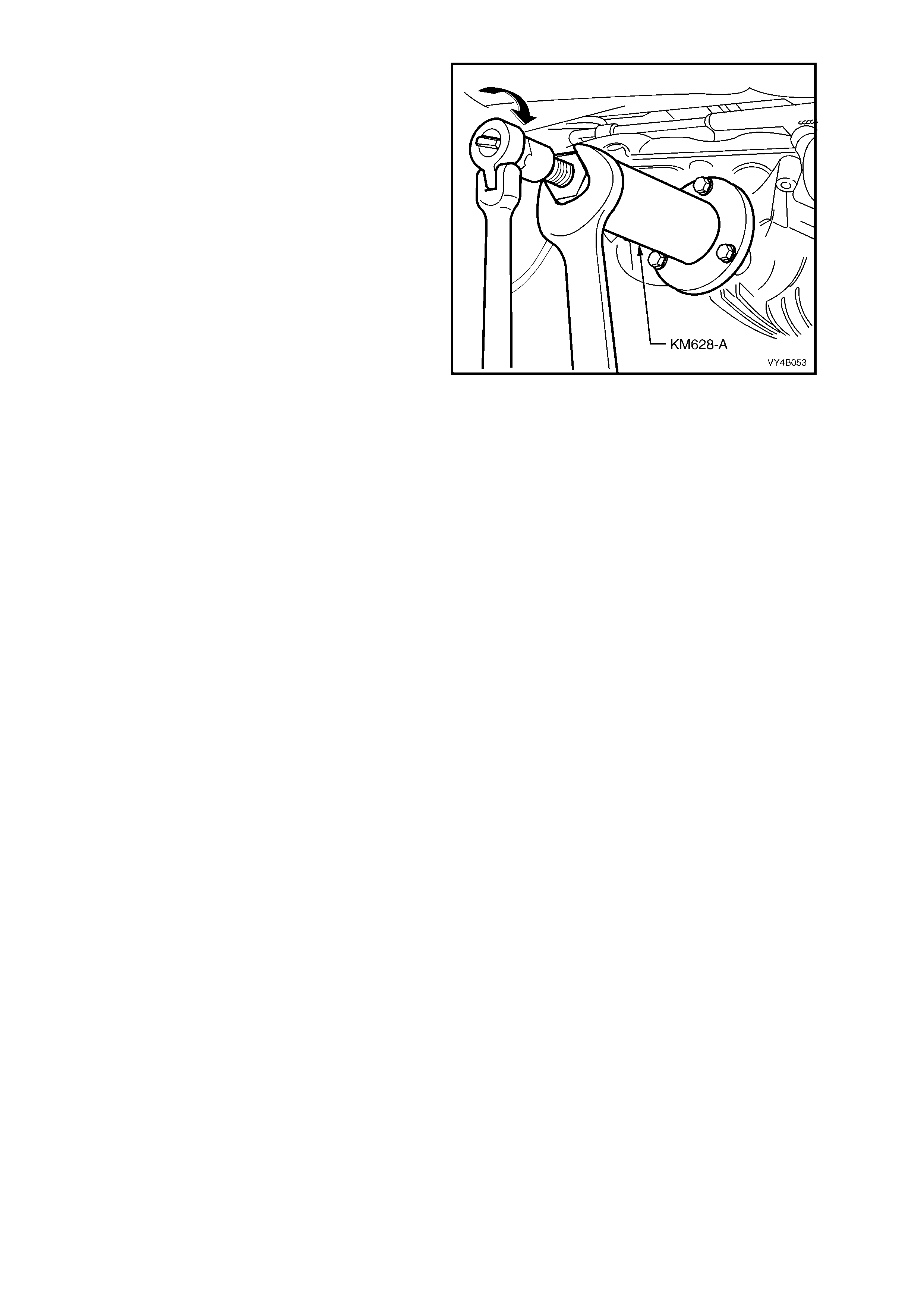
4. Attach Tool No. KM 620-1-A to the pinion
flange, using three suitable bolts and nuts to
hold pinion flange.
NOTE 1: If not previously done so, drill out holes
stamped ‘B’ on Tool No. KM620-1A to 12.5 mm.
NOTE 2: Use either the rear coupling to pinion
flange r eta in ing bo lts with a 25 m m s pac er ( e.g. f lat
washers) insta lled firs t or u se three b olts M 12 x 1.5
x 40, with the thread extending to within 12 mm of
the head.
5. Insert a suitable length of pipe (1) over the tang
of the installed tool for leverage, then remove
the pinion flange retaining nut, using a
comm erc ially ava ilabl e dee p soc ket and soc k et
bar (2).
6. Remove Tool No. KM 620-1-A.
Figure 4B-3

7. Place drain tray beneath differential carrier.
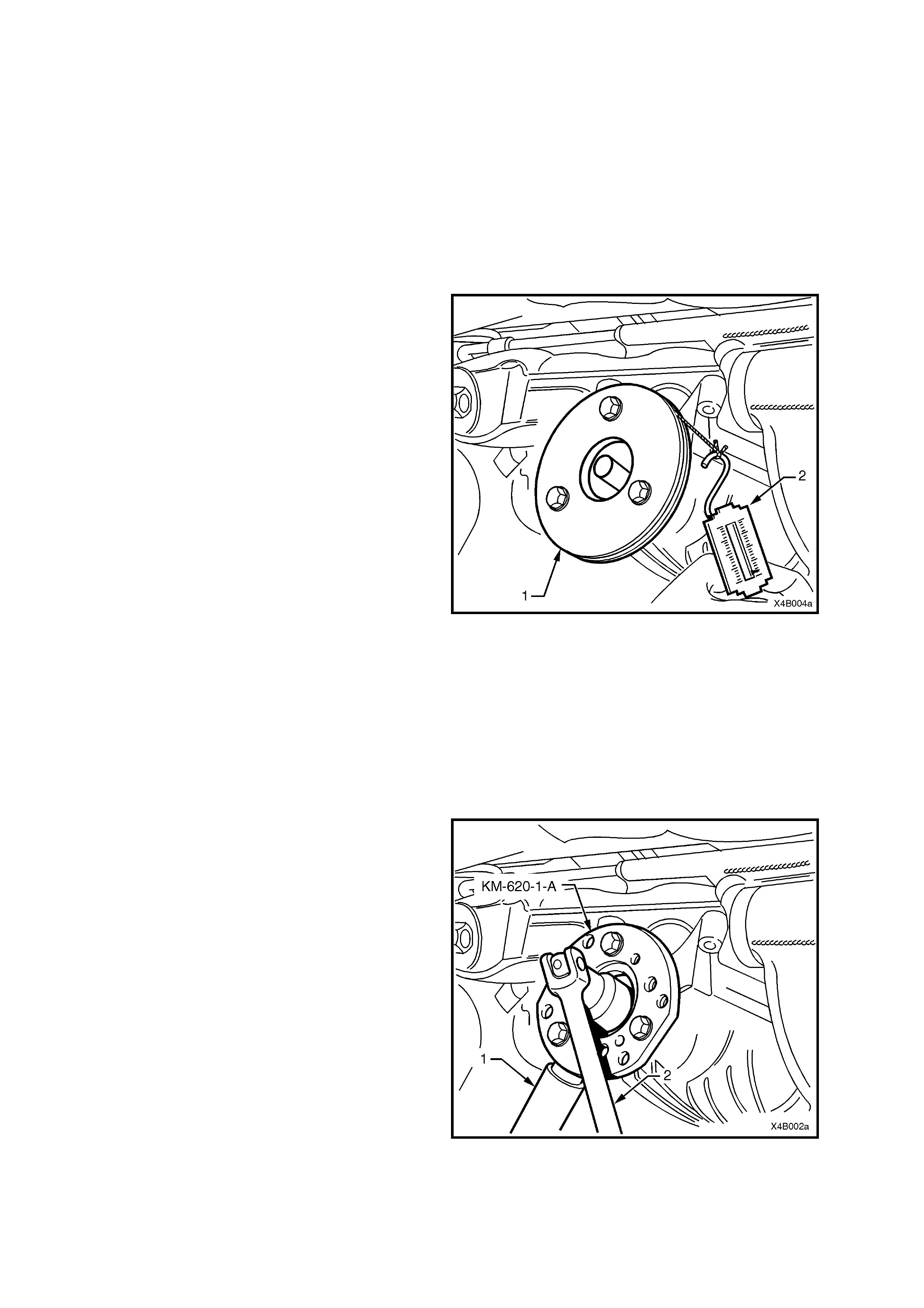
8. Install extractor, Tool No. AKM-628-A to the
pinion flange using the same three bolts and
nuts used to secure the flange holding tool,
KM-620-1-A (refer Fig. 4B-3).
NOTE: If not previo us l y done s o, dr i ll out t he f lan ge
holes on Tool No. KM628-A to 12.5 mm.
IMPORTANT: If using the original propeller shaft
coupling bolts, they must have a 25 mm spacer
fitted to each, so the tool is clamped to the pinion
flange. If this is not done, the screw thread on the
extractor Tool No. KM628-A will not be long
enough to fully remove the pinion flange.
9. While holding the extractor tool with a suitable
spanner, withdraw pinion flange by tightening
the forcing screw in the direction indicated.
Figure 4B-4
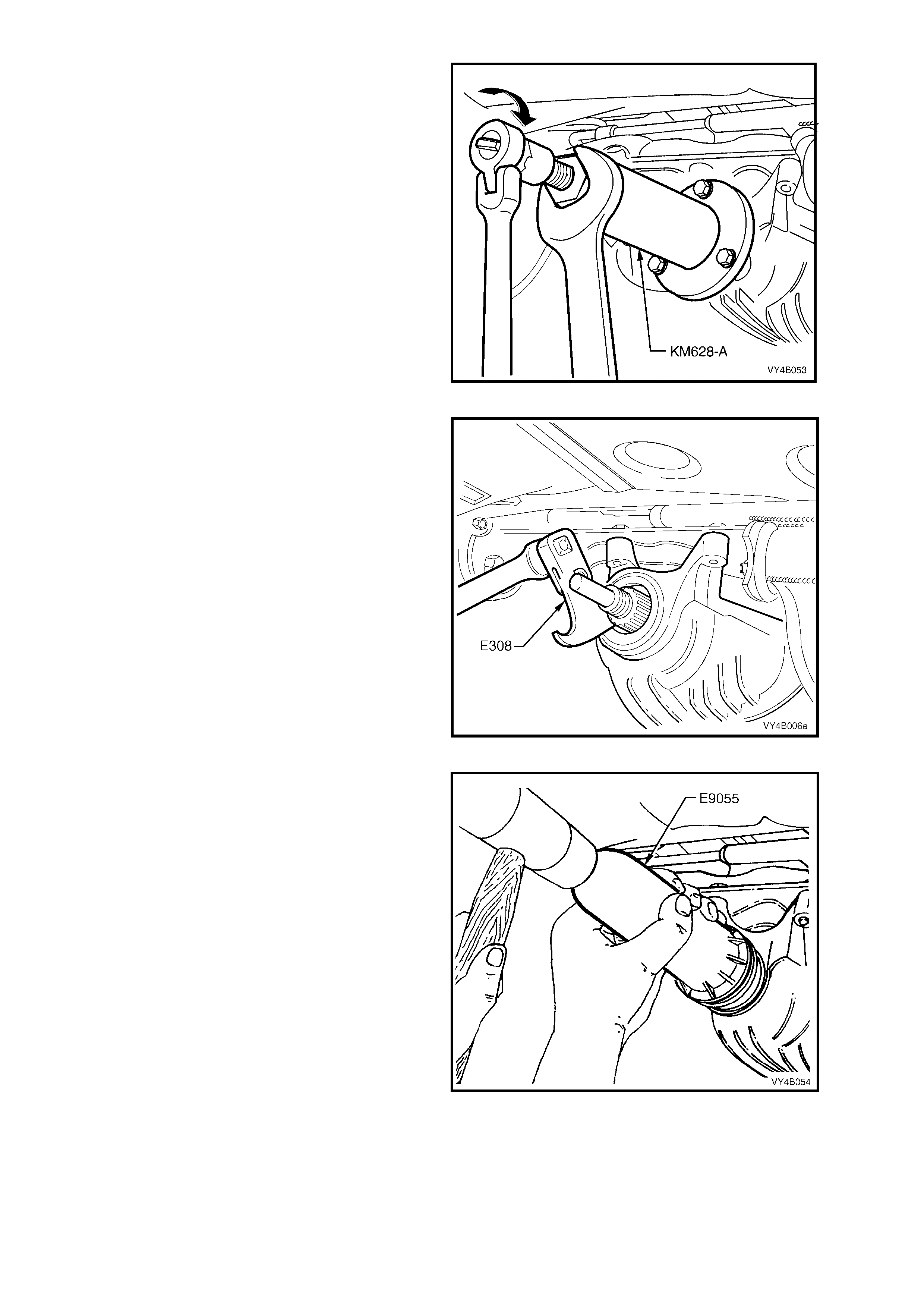
10. Prise pinion oil seal from carrier bore using
Tool No. E308 or a universal seal removing
tool.
Figure 4B-5
11. Lubricate new pinion oil seal lips a nd the outer
diameter with the recommended rear axle
lubricant.
12. Start oil seal into differential carrier housing
and dri ve seal squ arel y into pos iti on usin g T ool
No. E9055. Seal fits flush to 0.25 mm below
carrier housing surface.
13. Ensure that pinion shaft is free from burrs and
that flange oil seal surface is free from
damage.
14. Clean the threads of the pinion shaft and the
flange retaining nut, removing any oil, dirt or
grease.
Figure 4B-6

15. Coat spl ines and seal s urface of pinion f lan ge with dif ferenti al g ear lu bric ant , and ins ta ll f lang e onto pinio n s haf t
splines. Ensure that centre-punch marks are aligned.
16. Reinstall holding tool KM620-1-A to the pinion flange.
17. Apply a thread locking compound such as Loctite 243 or equivalent, to the threads of the pinion flange retaining
nut, then reinstall the nut.
18. Tighten the flange retaining nut until all centre-punch marks align. Then carefully tighten the nut to a position
not more than 5° past the aligned setting.
NOTE: The pinion flange is an interference fit on pinion shaft splines and should only be pulled into place by
tightening the retaining nut. DO NOT, UNDER ANY CIRCUMSTANCES, USE FORCE OR HAMMER FLANGE
DURING INSTALLATION ONTO PINION FLANGE.
CAUTION: Should the retaining nut be ov ertightened and pre-lo ad ex ce ede d, it w ill be nece ssa ry to r emove
the pinio n f rom th e ca rri e r and inst al l a new collap sib le sp acer. Unde r n o ci r cu mstan ce s must t he retaining
nut be backed off to decrease the pre-load reading.
19. Reinstall propeller shaft rear coupling to the pinion flange, refer Section 4C PROPELLER SHAFT AND
UNIVERSAL JOINTS in the VX Series Service Information.
20. If removed previously, reconnect exhaust system, in the reverse to the removal procedure. Refer to
3.2 FINAL DRIVE ASSEMBLY, in the VT Series II Service Information, for details.
21. Remove safety stands and lower vehicle.
22. Check lubricant level and t op up as necessar y. Refer 2.1 CHECKING DIFFER ENTIAL CARRIER LUBRIC ANT
LEVEL in the VT Series I Service Information.
23. Start vehicle and check for exhaust leaks.
2.3 PINION FLANGE
REPLACE (USING OLD OIL SEAL)
NOTE: Due to production tolerances in the length of the pinion flange, it is essential that the following method be
used when installing a new pinion flange. A new retaining nut must always be used when a pinion flange is
replaced.
1. Using a floor jack under centre of differential carrier, jack up rear of vehicle then place safety stands under
trailing arms.
2. Remove prope ller shaf t, ref er 2.1 PROP ELLE R SH AFT in Sec tion 4C PRO PELL ER SHAFT AND UNIVE RSAL
JOINTS in the VX Series Service Information.
3. Remove both dr ive shaf ts, refer 2.6 DRI VE SH AFTS in S ECTION 4B - FINAL DRIVE AN D DRIVE SHAFT S of
the VT Series I Servic e Inf ormation.
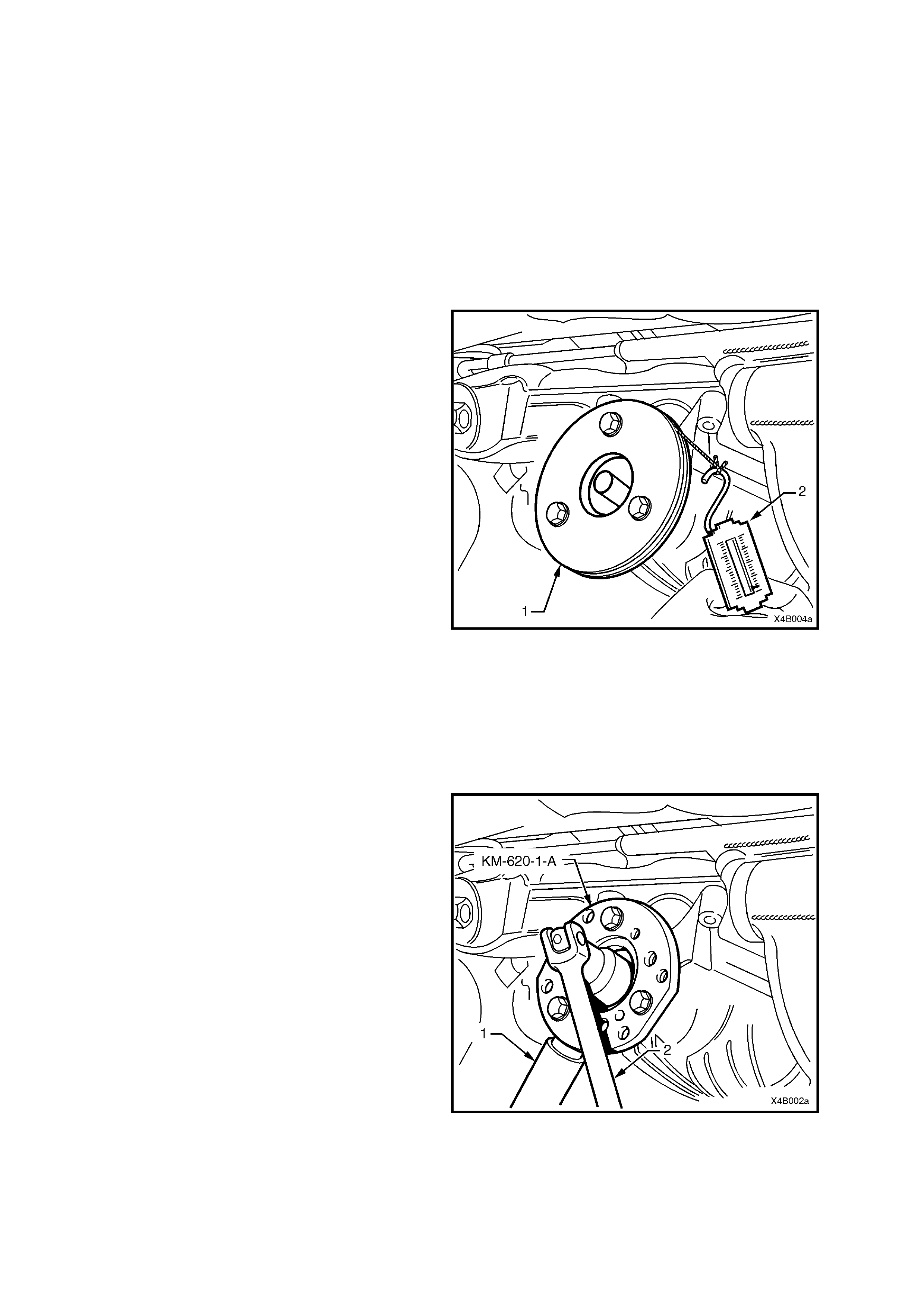
4. Check and record pre-load at pinion flange as follows:
a. Fit a pulley (1) to pinion flange and attach
a cord around pulley and to a spring scale
(2).
NOTE 1: Use either the rear coupling to
pinion flange retaining bolts with a 25 mm
spacer (e.g. flat washers) installed first or
use three bolts M12 x 1.5 x 40,with the
thread extending to within 12 mm of the
head.
NOTE 2: For details of the fabricated
pulley , refer 3. SPECIAL TOOLS at end of
this Section.
b. Start rotation of pulley and whilst in m otion
(approxim atel y 50-60 rpm ) note and r ecord
reading of spring balance.
This pre-load reading includes pinion
bearings, side bearings, meshing effect of
gear set and pinion oil seal.
To determine pre-load, multiply reading on
spring balance by radius of pulley.
EXAMPLE: W ith a pulley diam eter of 152 mm, the
radius is 76 mm, which equals 0.076 m. With a
spring balance reading of 25 N, the pre-load equals
0.076 m x 25 N = 1.9 Nm.
5. Remove pulley from pinion flange.
Figure 4B-7
6. Attach Tool No. KM 620-1-A to the pinion
flange, using three suitable bolts and nuts to
hold pinion flange.
NOTE 1: If not previously done so, drill out
holes stamped ‘B’ on Tool No. KM620-1A to
12.5 mm.
NOTE 2: Use either the r ear coup ling to pini on
flange retaining bolts with a 25 mm spacer
(e.g. flat washers) installed first or use three
bolts M12 x 1.5 x 40,with the thread extending
to within 12 mm of the head.
7. Insert a suitable length of pipe (1) over the tang
of the installed tool for leverage, then remove
the pinion flange retaining nut, using a
comm erc ially ava ilabl e dee p soc ket and soc k et
bar (2).
8. Remove Tool No. KM 620-1-A from the pinion
flange.
Figure 4B-8
9. Place drain tray beneath differential carrier.
10. Install extractor, Tool No. AKM-628-A to the
pinion flange using the same three bolts and
nuts used in step 6.
NOTE: If not previo us l y done s o, dr i ll out t he f lan ge
holes on Tool No. KM628-A to 12.5 mm.
IMPORTANT: If using the original bolts, they must
have the 25 mm spacers fitted so the tool is
clam ped to the pinion f lang e. If this is not don e, the
screw thread on the extractor Tool No. KM628-A
will not be long enough to fully remove the pinion
flange.
11. While holding the extractor tool with a suitable
spanner, withdraw pinion flange by tightening
the forcing screw in the direction shown.
Figure 4B-9
12. Ensure that pinion shaft thread is free from burrs, then coat splines and seal surface of pinion flange with the
recom m ended rear ax le lub r icant.
13. Reinstall the new pinion flange and retaining nut.
NOTE: The new flange will be an interference fit on pinion shaft splines and should only be pulled into place by
tightening retaining nut. DO NOT, UNDER ANY CIRCUMSTANCES, USE FORCE OR HAMMER FLANGE
DURING INSTALLATION ONTO PINION FLANGE.
14. Tighten flange retaining nut gradually until pinion shaft end play is reduced to approximately 0.50 mm.
15. Attach pulley to pinion flange and using spring balance, check pre-load. Continue tightening nut while
alternatively turning pinion to seat bearings, until the pre-load figure recorded previously (Step 4b) is reached.
Further increase this original pre-load reading by 0.5 Nm.
ROTATE PINION AN EXTRA 30-40 TURNS AND RE-CHECK THE PRE-LOAD TO ENSURE THAT NO
CHANGE HAS OCCURRED.
CAUTION: Should the retaining nut be overtightened and the pre-load exceeded, it will be necessary to
remove the differential carrier assembly and install a new collapsible spacer. Under no circumstances
must the retaining nut be backed off to decrease the pre-load setting.
16. Reinstall drive shafts, refer to 2.6 DRIVE SHAFTS in SECTION 4B - FINAL DRIVE AND DRIVE SHAFTS of
the VT Series I Servic e Inf ormation.
17. Reinstall propeller shaft, refer to Section 4C PROPELLER SHAFT AND UNIVERSAL JOINTS in the VX
Series Service Information.
18. If removed previously, reconnect exhaust system, in reverse to the removal procedure. Refer to 3.2 FINAL
DRIVE ASSEMBLY in SECTION 4B – FINAL DRIVE AND DRIVE SHAFTS - Local Trailing Arms of the VT
Series II Service Information, for details.
19. Remove safety stands and lower vehicle.
20. Check lubricant level and top up as necessary with the recommended lubricant, refer to
2.1 CHECKING DIFFERE NTI AL CARRIER LUBRIC ANT LEVEL in SECTION 4B - FINAL DRI VE AND DRI VE
SHAFTS of the VT Series I Service Information.
21. Start vehicle and check for exhaust leaks.
REPLACE (USING NEW OIL SEAL)
1. Using a floor jack under centre of differential
carrier, j ack up r ear of vehic le then place s afety
stands under trailing arms.
2. Remove propeller shaft, refer to
Section 4C PROPELLER SHAFT AND
UNIVERSAL JOINTS in the VX Series Service
Information.
3. Remove both drive shafts, refer to
2.6 DRIVE SHAFTS in SECTION 4B - FINAL
DRIVE AND DRIVE SH AF TS of the VT Series I
Service Information.
4. Check and record pre-load at pinion flange as
follows:
a. Fit a pulley (1) to pinion flange and attach
a cord around pulley and to a spring
balance (2).
NOTE 1: Use either the rear coupling to
pinion flange retaining bolts with a 25 mm
spacer (e.g. flat washers) installed first or
use three bolts M12 x 1.5 x 40,with the
thread extending to within 12 mm of the
head.
NOTE 2: For fabr icated pul le y details, r efer
to 3. SPECIAL TOOLS at end of this
Section.
b. Star t rotation of pulle y and whilst in m otion
(approximately 50-60 rpm), note and
record the spring balance reading.
This pre-load reading includes pinion
bearings, side bearings, meshing effect of
gear set and pinion oil seal.
To determine pre-load, multiply reading on
spring balance by radius of pulley.
EXAMPLE: W ith a pulley diam eter of 152 mm, the
radius is 76 mm which equals 0.076 m. With a
spring balance reading of 25 N, the pre-load equals
0.076 m x 26 N = 1.9 Nm.
5. Remove pulley from pinion flange.
Figure 4B-10
6. Attach Tool No. KM 620-1-A to the pinion
flange, using three suitable bolts and nuts to
hold pinion flange.
NOTE 1: If not previously done so, drill out holes
stamped ‘B’ on Tool No. KM620-1A to 12.5 mm.
NOTE 2: Use either the rear coupling to pinion
flange r eta in ing bo lts with a 25 m m s pac er ( e.g. f lat
washers) insta lled firs t or u se three b olts M 12 x 1.5
x 40,with the thread extending to within 12 mm of
the head.
7. Insert a suitable length of pipe (1) over the tang
of the installed tool for leverage, then loosen
the pinion flange retaining nut, using a
comm erc ially ava ilabl e dee p soc ket and soc k et
bar (2) until end play can be felt in the pinion
shaft.
8. Check the oil seal and differential side bearing
pre-load using the spring scale and pulley, as
detailed in steps 4a and 4b, Record oil seal
and side bearing pre-load for later use.
9. Remove Tool No. KM 620-1-A from the pinion
flange.
Figure 4B-11
10. Place drain tray beneath differential carrier.
11. Install extractor, Tool No. AKM-628-A to the
pinion flange using the same three bolts and
nuts used previously.
NOTE: If not previo us l y done s o, dr i ll out t he f lan ge
holes on Tool No. KM628-A to 12.5 mm.
IMPORTANT: If using the original bolts, they must
have the 25 mm spacers fitted so the tool is
clam ped to the pinion f lang e. If this is not don e, the
screw thread on the extractor Tool No. KM628-A
will not be long enough to fully remove the pinion
flange.
12. While holding the extractor tool with a suitable
spanner, withdraw pinion flange by tightening
the forcing screw in the direction shown.
Figure 4B-12
13. Prise pinion oil seal from carrier bore using
Tool No. E308 or a universal seal removing
tool.
Figure 4B-13
14. Examine carrier seal bore and remove any
nicks or burrs.
15. Lubricate new pinion oil seal lips with the
recommended rear axle lubricant. Lightly coat
outside of seal shell with a non-hardening
gasket cement.
16. Start oil seal in differential carrier and drive
seal squarely into position using Tool No.
E9055. Se al fits flush to 0. 25 mm below carr ier
seal bore leading surface.
17. Ensure that pinion shaft threads are free from
burrs, then coat splines and seal surface of
pinion flange with differential gear lubricant.
18. Reinstall flange on pinion shaft splines.
NOTE: The ne w flang e will be an int e rf er enc e f it on
pinion shaft splines and should only be pulled into
place by tightening the retaining nut. DO NOT,
UNDER ANY CIRCUMSTANCES, USE FORCE
OR HAMMER FLANGE DURING INSTALLATION
ONTO PINION FLANGE.
19. Tighten flange retaining nut gradually until
pinion shaft end play is reduced to
approximately 0.5 mm.
Figure 4B-14
20. Check new oil seal and differential assembly pre-load using spring balance as previously outlined in steps 4a
and 4b. Record pre-load for reassembly reference.
21. T he pre-load re ading for differential assembl y obtain ed in step 8, is su btracted f rom pre- load reading obt ained
in step 20. The difference between these figures represents extra lip tension of new seal expressed as a Nm
pre-load figure. The difference between the pre-load readings obtained in steps 8 and 20 must be added to
pre-load reading obtained in step 4b to obtain a total pre-load reading.
THEOR ETICAL EXAMPLE
STEP 20 NEW OIL SEA L AND SIDE
BEARIN G PR E- L OAD
SETTING
1.47 Nm
STEP 8 OLD OIL SEAL AND SIDE
BEARING
PRE-LOAD READING
1.02 Nm
SUBTRACT STEP 8
FROM STEP 20
0.45 Nm
STEP 4b COMPLETE
DIFFEREN TI AL AS SEM BLY
PRE-LOAD READING
1.47 Nm
THE PRE-LOAD READING
COMBINATION WILL BE
THE SUM OF:-
.47 Nm plus
0.45 Nm
WHICH GI VE S A T O TAL
PRE-LOAD READING OF:-
1.92 Nm
CAUTION: Should the retaining nut be overtightened and the pre-load exceeded, it will be necessary to
remove the differential carrier assembly and install a new collapsible spacer. Under no circumstances
must the retaining nut be backed off to decrease the pre-load setting.
22. Continue tightening retaining nut while alternately turning pinion to seat bearings until total pre-load figure
obtained in step 21 is achieved, then increase this pre-load reading by 0.11 to 0.34 Nm. Further rotate pinion
an extra 30-40 turns and recheck pre-load to ensure that no change has occurred.
NOTE: It must be realised that the pre-load readings in the example are only theoretical. In practice, the figures
could differ greatly, so the readings obtained when performing the actual operations, are the ones to use.
23. Reinstall drive shafts, refer to 2.6 DRIVE SHAFTS in SECTION 4B - FINAL DRIVE AND DRIVE SHAFTS of
the VT Series I Servic e Inf ormation.
24. Reinstall propeller shaft, refer to Section 4C PROPELLER SHAFT AND UNIVERSAL JOINTS in the VX
Series Service Information.
25. If removed previously, reconnect exhaust system, in the reverse to the removal procedure. Refer to
3.2 FINAL DRIVE ASSEMBLY in S ECTIO N 4B – FI NAL DR IVE AND DRI VE S HAFT S - Loc al Tr ailing Ar m s of
the VT Series II Service Information, for details.
26. Remove safety stands and lower vehicle.
27. Check lubricant level and top up as necessary, refer to 2.1 CHECKING DIFFERENTIAL CARRIER
LUBRICANT LEVEL in SECTION 4B - FINAL DRIVE AND DRIVE SHAFTS of the VT Series I Service
Information.
28. Start vehicle and check for exhaust leaks.
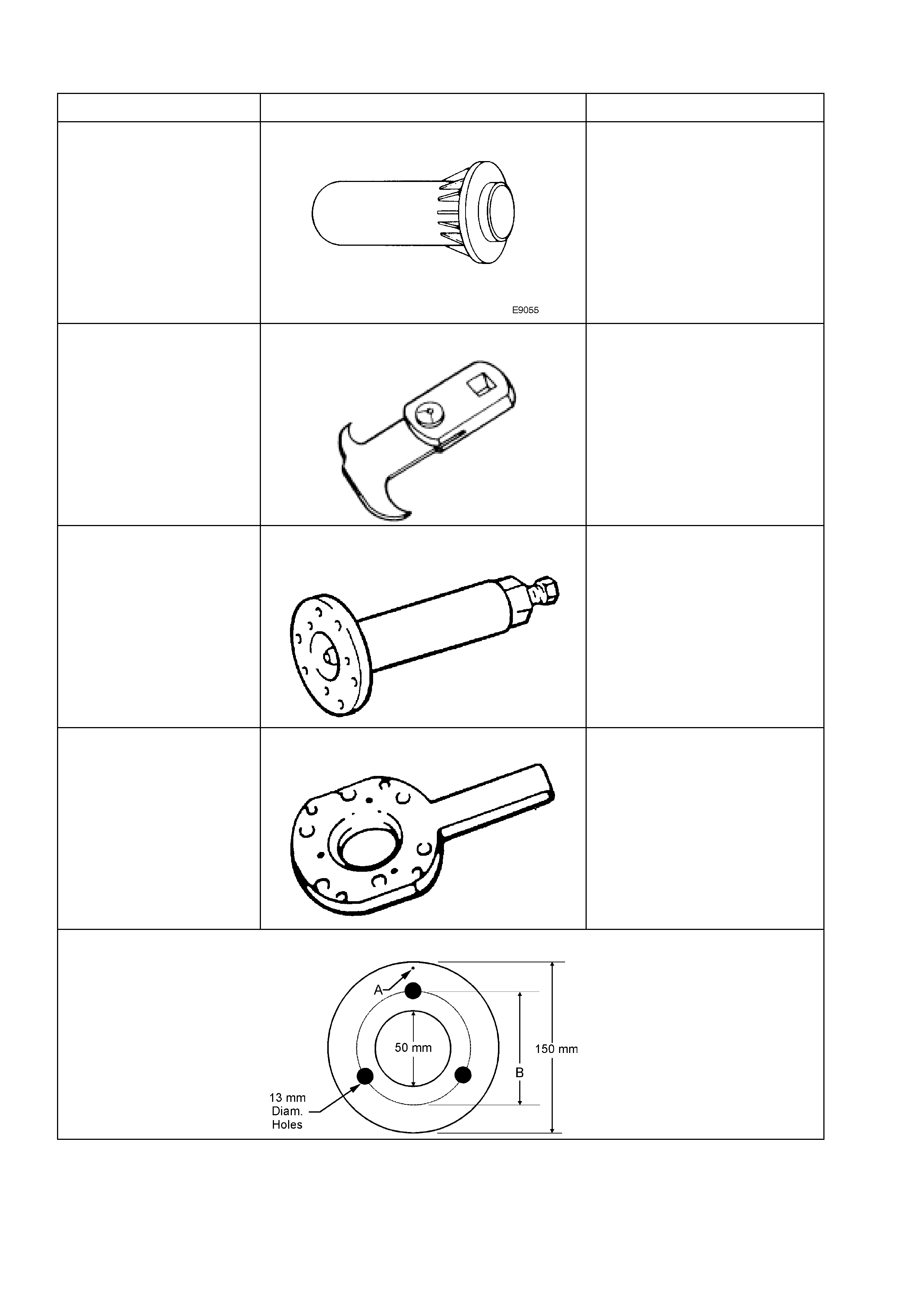
3. SPECIAL TOOLS
TOOL No. REF. IN TEXT TOOL DESCRIPTION COMMENTS
E9055 PINION OIL SEAL INSTALLER
Also released as 17-010A.
E308 SEAL REMOVER Also released as 56750.
KM 628-A EXT RACTOR TOO L Previously released for the VT,
V6 Manual T ransmis sion.
KM 620-1-A FLANGE HOLDING TOOL
Previously released for the VT,
V6 Manual T ransmis sion.
If not modified, drill out the
holes stamped ‘B’ on the tool,
to 12.5 mm
PINION FLANGE PULLEY DETAILS Fabricated:
1. From a 13 mm thick piec e of
wood.
2. Drill a small hole at ‘A” an
attach a one metre length of
string at this point.
3. Drill t hr ee 13 m m holes , on a
pitch circle diameter (B) of
96 mm, 120° apart, as
shown.