
SECTION 4C - PROPELLER SHAFT AND
UNIVERSAL JOINTS
IMPORTANT:
Before p erforming any Serv ice Operation or o ther procedure described in this Section, ref er to Section
00 CAUTIONS AND NOTES for correct workshop practices with regard to safety and/or property
damage.
1. GENERAL DESCRI PTI O N
The propeller shaft assembly fitted to the VX range of vehicles is a new, two piece tubular design (refer Fig. 4C-1).
The new design features a rubber coupling at the front, connected to a slip yoke at the transmission end (V6 and
automatic transmission and GEN III V8 with manual and automatic transmission) and a second coupling bolted to
the pinion f lange at the f inal drive end. The pr opeller shaft ass embly fitted to those VX vehicles with the V6 engine
and manual transmission, continues to have a rubber coupling bolted to a flange splined to the transmission
mainshaft.
Drive is transmitted between the two halves of the propeller shaft through a centre universal joint, that is of the
conventional cross design (Hooke’s joint), located and secured in each of the two propeller shaft yolks by peening.
A fully sealed ball bearing, m ounted in a reinforced rubber cup, supports the propeller shaft assem bly in the centre
location. This centre bearing rubber cup is supported in a cup guide and attached to a carrier, which in turn, is
bolted to the vehicle underbody brace.
The centre universal joint and centre bearing are lubricated for life and do not require any periodic lubrication.
Techline
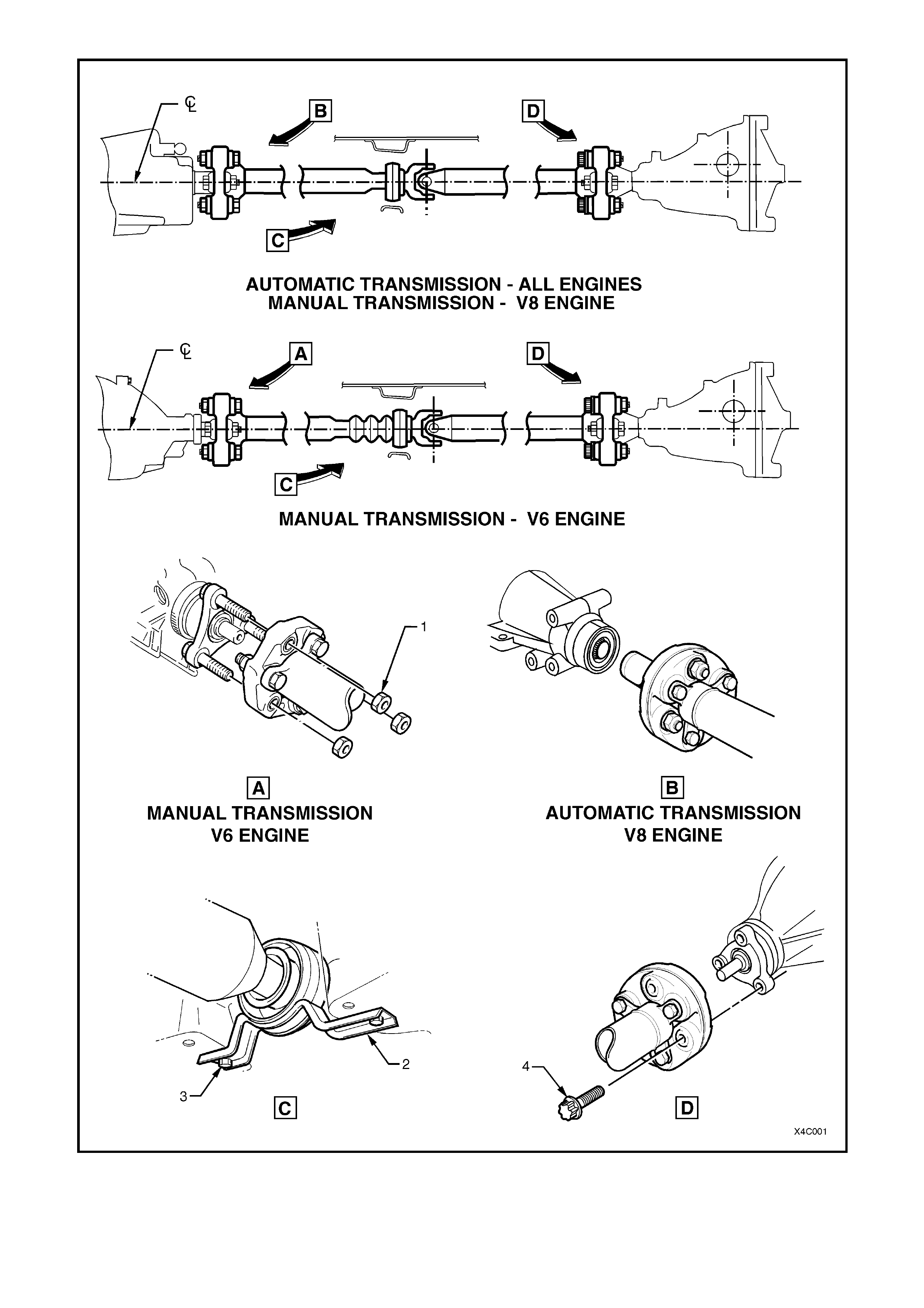
Figure 4C-1
1. Nut – Front Coupling to Transmission Flange Stud – 3 pl aces 3. Bolt – Cent re B eari ng Cup Gui de to Underfloor Brace
2. Guide – Centre Bearing Cup 4. Torx Bolt – Rear Coupling to P i ni on Fl ange – 3 pl aces

1.1 SERVICE INFORMATION
The only serviceable components in the propeller shaft assembly are the two rubber couplings and the centre
bearing assembly in the unit fitted to V6 engined, manual transmission models. The reasons for this situation can
be summarised as:
a. The centre univer sal joint bearing c ups are set and retained by stak ing which requires sophis ticated equipm ent
to ensure concentric reassembly of the universal joint. Should the centre universal joint require servicing, then
the propeller shaft assembly must be replaced.
b. In order to separ ate the two propeller shaft halves, the interference f it of the splined j oint requires the use of an
hydr aulic pr ess and ex pensive tools. As this oper ation would also require the r e-balancing of the propeller s haft
assembly, the centre bearing assembly and/or slinger are also non-serviceable.
c. By using two rubber couplings and having an interfer ence f it between the two propeller shaft halves , m easuring
the driveline angles and propeller shaft phasing is no longer required.
2. SERVICE OPERATIONS
2.1 PROPELLER SHAFT
REMOVE
CAUTION: Whenever any component that forms part of the ABS is disturbed during Service Operations, it
is vital that the complete ABS system be checked, using the procedure as detailed in DIAGNOSIS, ABS
FUNCTION CHECK, in Section 12L ABS & ABS/ETC.
1. Using a floor jack under the centre of the final drive housing, jack up rear of vehicle and place safety stands
under body rear jacking points. Refer to Section 0A GENERAL INFORMATION for location of jacking points.
CAUTION: After raising the rear of the vehicle, release the park brake (if applied) to relax any ‘wind-up’ in
the flexible rubber couplings. Otherwise, when the propeller shaft bolts are released from the final drive
pinion flange, personal injury may r esult!
FOR VX MODELS WITH THE V6 ENGINE AND MANUAL TRANSMISSION.
NOTE: To provide access to the f ront of the propeller shaft, it is recom mended that the twin exhaust pipe/catalytic
converter assembly be removed.
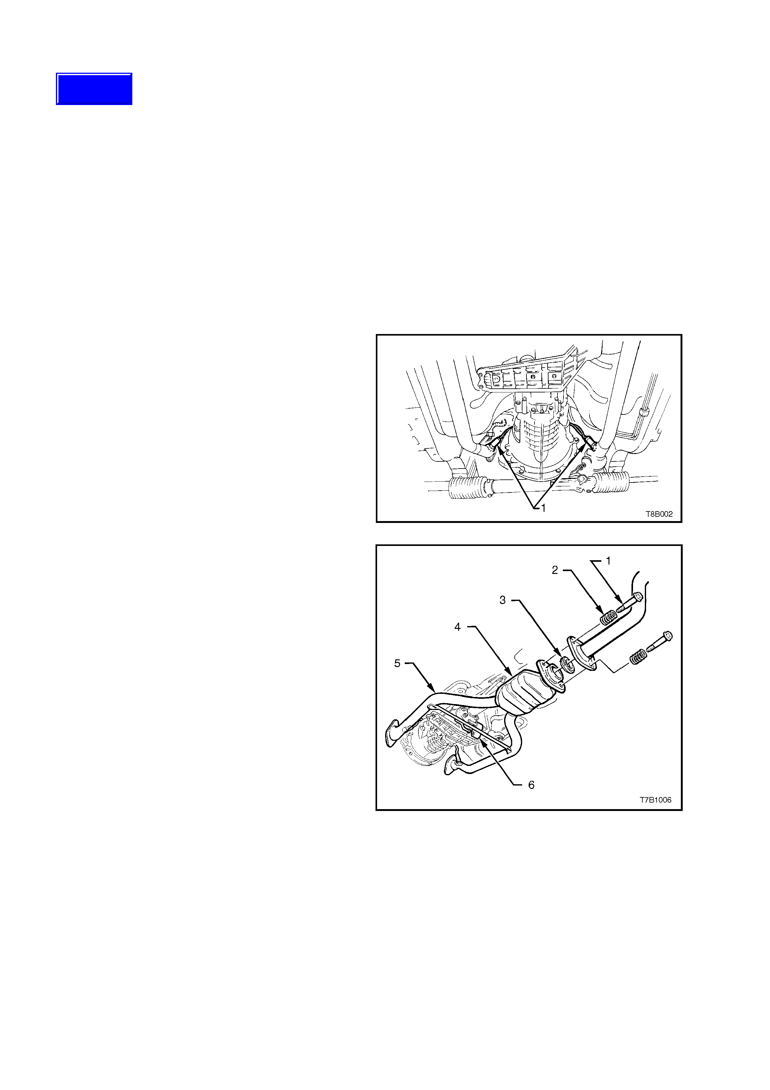
2. Disconnect the wiring harness connector s from
each of the two oxygen sensors (1).
Figure 4C-1
3. Remove the intermediate pipe to catalytic
converter bolts (1), springs (2) and sealing ring
(3). Set the removed components to one side.
4. Remove the exhaust pipe flange to exhaust
manifold nuts fr om each side (not s hown in Fig.
4C-3).
5. W hile supporting the twin exhaust pipe (5) and
catalytic converter assembly (4), remove the
support rubber (6) from the rear of the
transmission.
6. Carefully lower and remove the exhaust pipes
from the vehic le, taking c are not to dam age the
exhaust gas oxygen sensors, in the process.
Figure 4C-2
Techline
FOR VX MODELS WITH THE V6 SUPERCHARGED OR GEN III V8 ENGINE.
NOTE: To gain access to the propeller shaft
fasteners, it will be necessary to remove the
intermediate and rear sections of the exhaust
system.
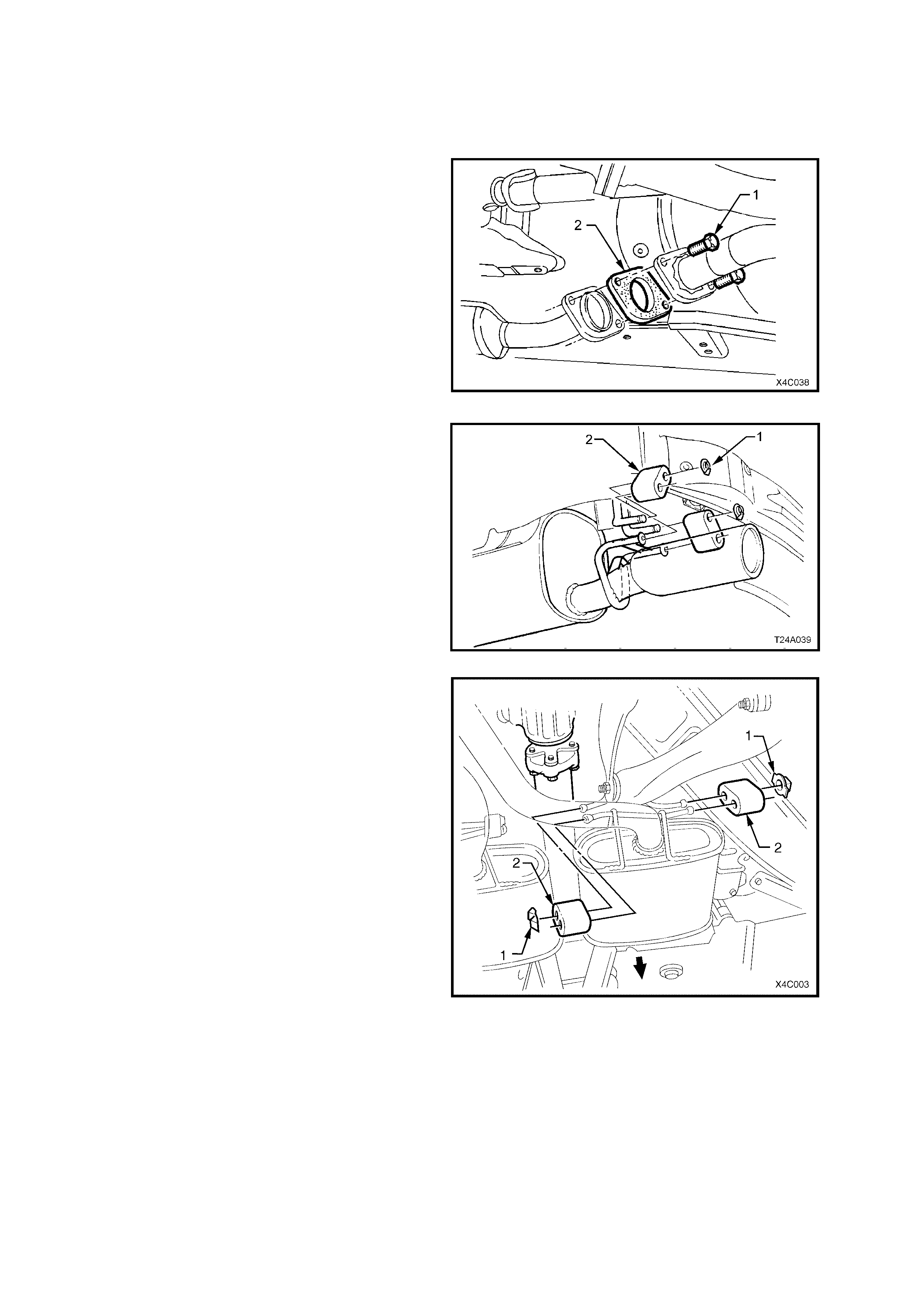
7. Disconnect the intermediate exhaust pipe to
catalytic converter bolts (1) from the rear of
each catalytic converter. Discard the flange
gaskets (2).
NOTE: Only one side of the V6 Supercharged and
GEN III V8 exhaust system is shown in Fig. 4C-4.
Figure 4C-3
8. Remove the two retainers (1) from the top
support posts and discard.
9. Disconnect exhaust system support rings (2)
from rear hanger of the rear muffler.
Figure 4C-4
10. Remove the four muffler support to rear
crossmember retainers (1).
11. While supporting the intermediate section of
the exhaust system, remove the four
intermediate muffler support rubbers (2).
12. Remove the intermediate and rear sections of
the exhaust system from the vehicle.
Figure 4C-5

FOR VX MODELS WITH THE V6 ENGINE AND MANUAL TRANSMISSION
13. Remove propeller shaft rubber coupling (4) to
transmission output flange (1) attaching nuts
(3). Discard removed nuts (3).
Figure 4C-6
ALL VX MODELS
14. With the transmission in the ‘Park’ position
(automatic transmission) or in first gear
(m anual transm ission and the park brak e firm ly
applied, use Torx socket K04425E20 or a
commercially available E20 Torx socket to
loosen the three T or x headed bolts (1) secur ing
the propeller shaft rear rubber coupling (2) to
the pinion flange (3).
15. Release the park brake to relieve any torque
loading on the rubber coupling, then remove
the three Torx headed bolts (1)
NOTE: To enable the pr opeller shaft to be ins talled
in the original position relative to the pinion flange,
use a felt tipped pen or similar to identify the
relationship (‘A’) of the two com ponents before bolt
removal.
Figure 4C-7
16. Remove the two centre bearing carrier (1) to
underbody reinforcement bolts (2).
17. While supporting the centre bearing section,
slide the propeller shaft assembly forward to
disengage from the final drive pinion support
pin, then lower the ass em bly at the rear, sliding
rearward to remove from the vehicle.
FOR VX MODELS WITH A SLIDING FRONT
YOKE
NOTE 1: Take car e to protec t the outer diameter of
the front yoke. Nicks or abrasions will damage the
transm ission extens ion seal during reas sembly and
result in subsequent lubricant leakage from this
area.
NOTE 2: Insert a suitable plug in the end of the
transmission rear extension to prevent loss of
transmission lubricant.
Figure 4C-8
REINSTALL
Reinstallation is the r everse of rem oval proc edures
noting the following:
GENERAL PROCEDURE:
1. Lubricate both the trans m ission output shaf t (V6 engine and m anual tr ansm ission) and final drive pinion spigots
with molybdenum disulphide grease to Holden Specification HN1271.
2. For those VX models with a sliding front yoke, remove any foreign matter that may have adhered to the front
universal joint yok e and lubricate with tr ans mission lubricant. Ins er t yoke on to trans mission m ains haf t, index ing
the splines.
3. Clean threads of centre bearing carrier to underbody reinforcement bolts and underbody weld nuts.
4. Reinstall the front of the propeller shaft assembly first, supporting the centre and rear sections.
5. While still supporting the centre bearing area, slide the propeller shaft assembly forward to allow engagement of
the rear spigot, then slide rearward to fully engage.
6. Raise the centre bearing assembly and reinstall the bolts and washers to secure to the underbody
reinforcement. Tighten both bolts to the correct torque specification.
CENTRE BEARING CARRIER TO
UNDERBODY REINFORCEMENT 20 – 35 Nm
BOLT TORQUE SPECIFICATION
7. Before reinstalling the attaching bolts and washers to the propeller shaft rear coupling and pinion flange, align
marks on pinion flange and rear coupling (or marks made on removal), refer to Fig. 4C-8.
8. Provided no thread damage is evident, reinstall the original rear propeller shaft coupling to final drive pinion
flange bolts and washers, tightening to the correct torque specification.
PROPELLER SHAFT REAR
COUPLING TO PINION FLANGE 105 – 125 Nm
BOLT TORQUE SPECIFICATION
VX MODELS WITH V6 ENGINE AND MANUAL TRANSMISSION
9. Install NEW r ubber coupling to transm ission output flange retaining nuts bef ore tightening to the correct tor que
specification.
RUBBER COUPLING TO TRANSMISSION
OUTPUT SHAFT FLANGE RETAINING 50 – 85 Nm
NUT TORQUE SPECIFICATION
10. Reinstall the exhaust system as follows;
V6 ENGINED MODELS (MANUAL TRANSMISSION ONLY)
a. Reinstall the twin exhaust pipes to the exhaust manifolds, then reinstall the retaining nuts and tighten the
nuts to the specified torque.
EXHAUST PIPE FLANGE TO
EXHAUST MANIFOLD NUT 18 – 35 Nm
TORQUE SPECIFICATION
b. Reinstall the support rubber to the transmission mount bracket post.
c. Reconnect both wiring harness connectors to the oxygen sensors.
d. Check that the catalytic converter to intermediate exhaust pipe bolts, springs and sealing ring are all in a
serviceable c ondition. Reinstall the sealing ring, springs and bolts , tightening the bolts to the cor rect torque
specification.
INTERMEDIATE EXHAUST PIPE
TO CATALYTIC CONVERTER 40 – 50 Nm
BOLT TORQUE SPECIFICATION

V6 SUPERCHARGED AND GEN III V8 ENGINED MODELS
e. Ensure the catalytic converter flange is clean and free from any gasket material.
f. Reinstall exhaust system, using a new gasket at the catalytic converter and new hanger retainers for the
muffler supports to rear crossmember.
g. Reinstall the catalytic converter to intermediate exhaust pipe bolts and tighten to the correct torque
specification.
INTERMEDIATE EXHAUST PIPE
TO CATALYTIC CONVERTER 40 – 50 Nm
BOLT TORQUE SPECIFICATION
All VX Models
h. Check exhaust clearances as detailed in Section 8B EXHAUST SYSTEM in the VT Series I and
VT Series II Service Information.
ALL VT MODELS WITH A SLIDING YOKE
11. If transm ission lubricant leak ed from the rear of the transm ission when the propeller shaf t was rem oved, check
transm iss ion lubricant level and top up as nec essar y. Refer to Section 0B LUBRICATION AND SERVICE in the
VT Series I and VT Series II Service Information for lubricant specifications and procedure.
2.2 RUBBER COUP LING
REPLACE
NOTE: While the front coupling is shown for this
operation, the replacement of either coupling is
similar.
1. Remove propeller shaft. Refer to
2.1 PROPELLER SHAFT, in this Section.
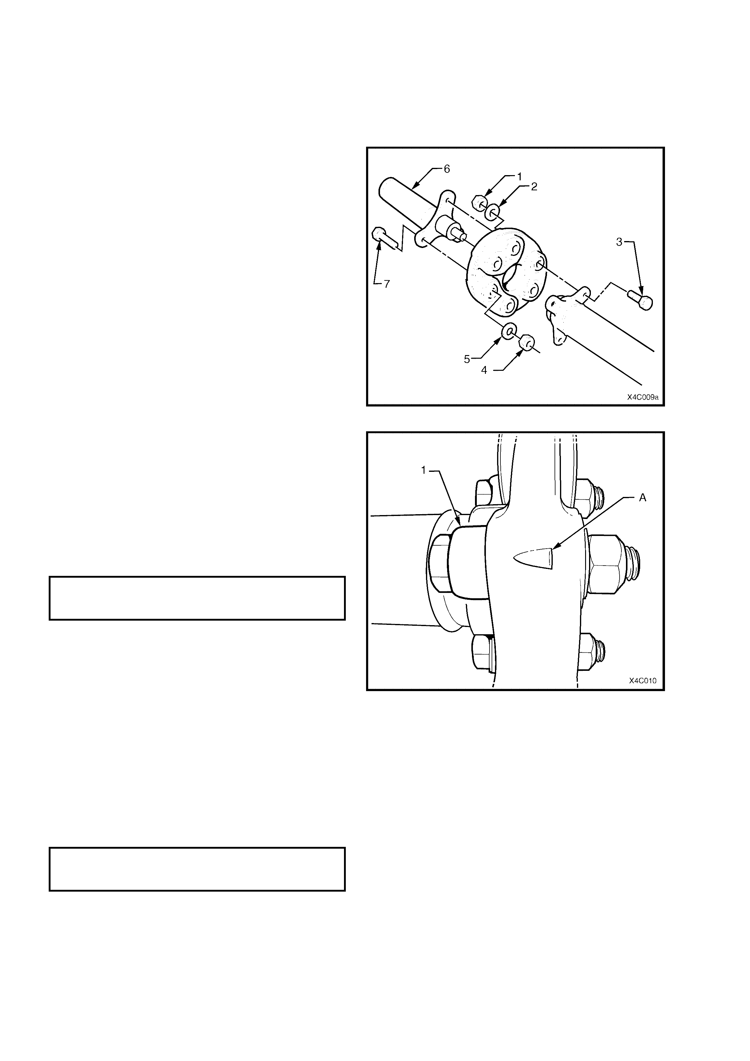
2. Using a back-up spanner on each of the three
propeller shaft sliding yoke bolts (7), loosen
then remove the nuts (4) and washers (5).
Discard the removed bolts and nuts. Remove
the sliding yoke from the coupling.
3. Using a back-up spanner on each of the three
propeller shaft to coupling bolts (3), loosen then
remove the nuts (1) and washers (2). Discard
the removed bolts and washers. Remove the
coupling from the front of the propeller shaft.
Figure 4C-9
4. Reinstall a replacement rubber coupling to the
end of the propeller shaft, aligning the holes in
such a way that the triangular shape (‘A’) on
the coupling ‘points’ to the propeller shaft
flange (1), as shown.
5. Install NEW bolts, washers and nuts to secure
the coupling to the propeller shaft flange and
tighten to the correc t torque specif ication, using
a back-up spanner on the bolt head.
PROPELLER SHAFT TO
RUBBER COUPLING NUT 74 – 80 Nm
TORQUE SPECIFICATION
6. Install 0.5 gm of molybdenum disulphide
grease (to Holden Spec ific ation HN1271) to the
spigot bush in the propeller shaft end of the
sliding yoke.
7. Reinstall the sliding yoke spigot to the bush on
the f ront end of the propeller s haft, aligning the
bolt holes. If the rear bolts were placed
correctly (refer step 4), then the triangular
shape will ‘point’ to the sliding yoke flange bolt
holes.
8. Install new bolts, washers and nuts to secure
the coupling to the sliding yoke flange and
tighten to the correc t torque specif ication, using
a back-up spanner on the bolt head.
PROPELLER SHAFT TO
SLIDING YOKE NUT 74 – 80 Nm
TORQUE SPECIFICATION
9. Reinstall the propeller shaft, as detailed in
2.1 PROPELLER SHAFT Reinstall, in this
Section.
Figure 4C-10
2.3 CENTRE BEARING ASSEMBLY
NOTE 1: T his oper ation is only to be carried out on
propeller shafts fitted to those VX models fitted w ith
the V6 engine and manual transmission.
The reasons for this are detailed in
1.1 SERVICE INFORMATION, in this Section.
NOTE 2: The centre bearing and housing are an
integral part and are not serviced separately
NOTE 3: During the removal process described,
the rubber bearing support will be damaged,
requiring the complete centre bearing assembly to
be replaced.
REMOVE
1. Remove propeller shaft. Refer to
2.1 PROPELLER SHAFT in this Section.
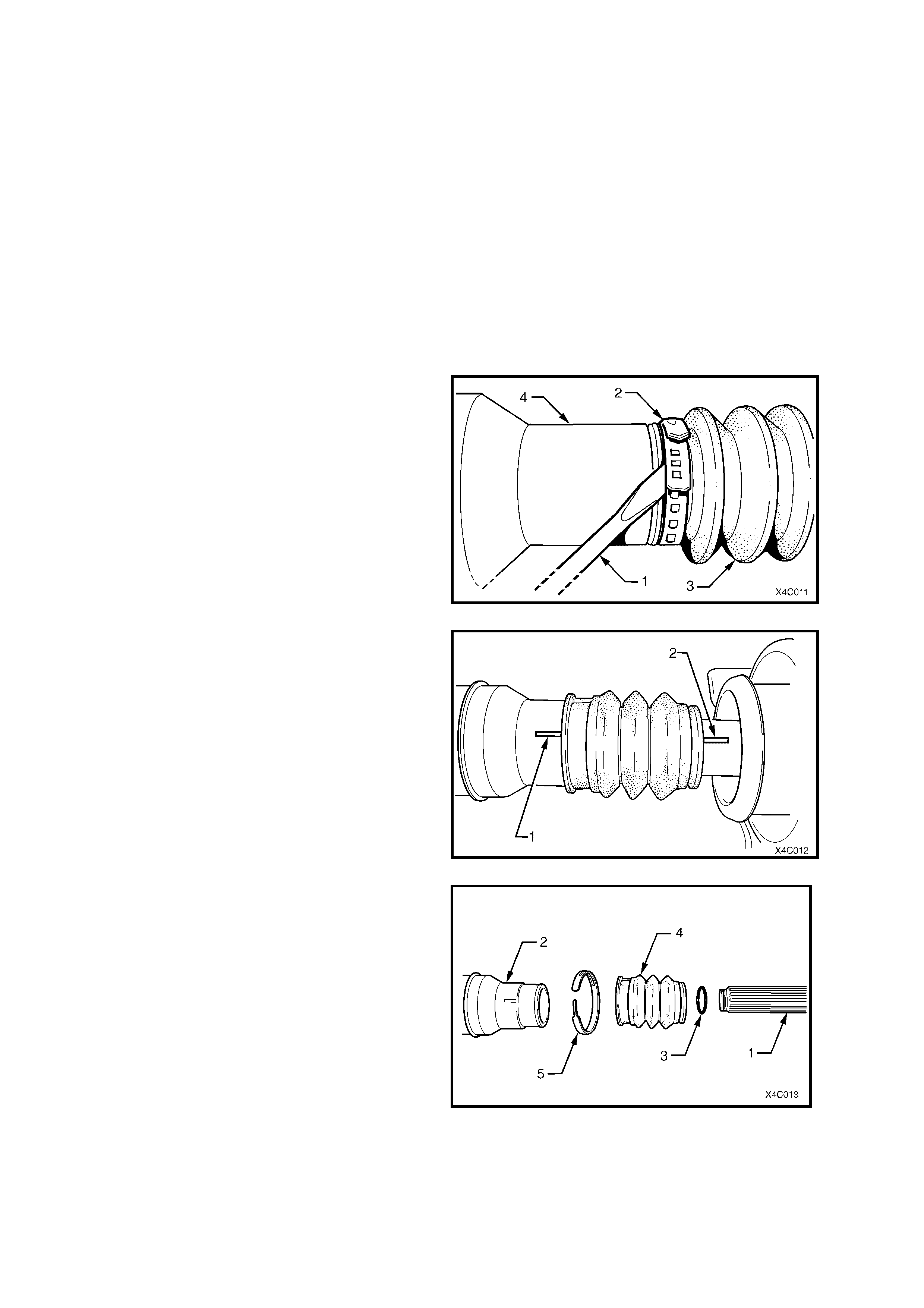
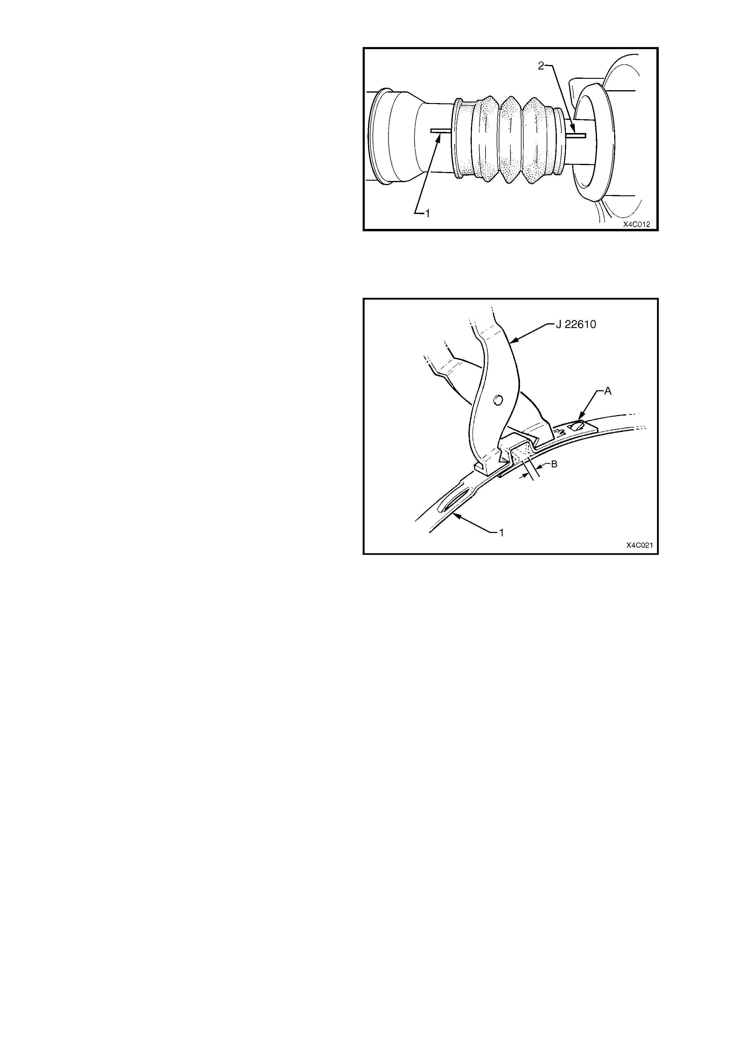
2. W ith the propeller shaft assembly (4) laying on
a bench, use a screwdriver (1) or similar and
lever up on the boot clamp (2) releasing the
tension.
Figure 4C-11
3. Extend the sliding joint until resistance is felt,
then use a felt tipped pen or similar to mark
alignment marks on the front propeller shaft
section (1) and the rear (2)
Important: This is a critical operation, as propeller
shaft phasing and balance will be affected if the two
propeller shaft halves are not aligned correctly on
reassembly.
Figure 4C-12
4. W ith the two propeller s haft halves extended, a
snap action is required to separate them,
because of the O-ring seal (3) mounted on the
end of the rear shaft (1).
5. Once separated, the ribbed boot (4) and O- ring
seal (3) are released.
NOTE: Once s eparated, the O- ring seal (3) may be
retained in the fr ont half (2). Retrieve by inserting a
hooked piece of wire.
Figure 4C-13
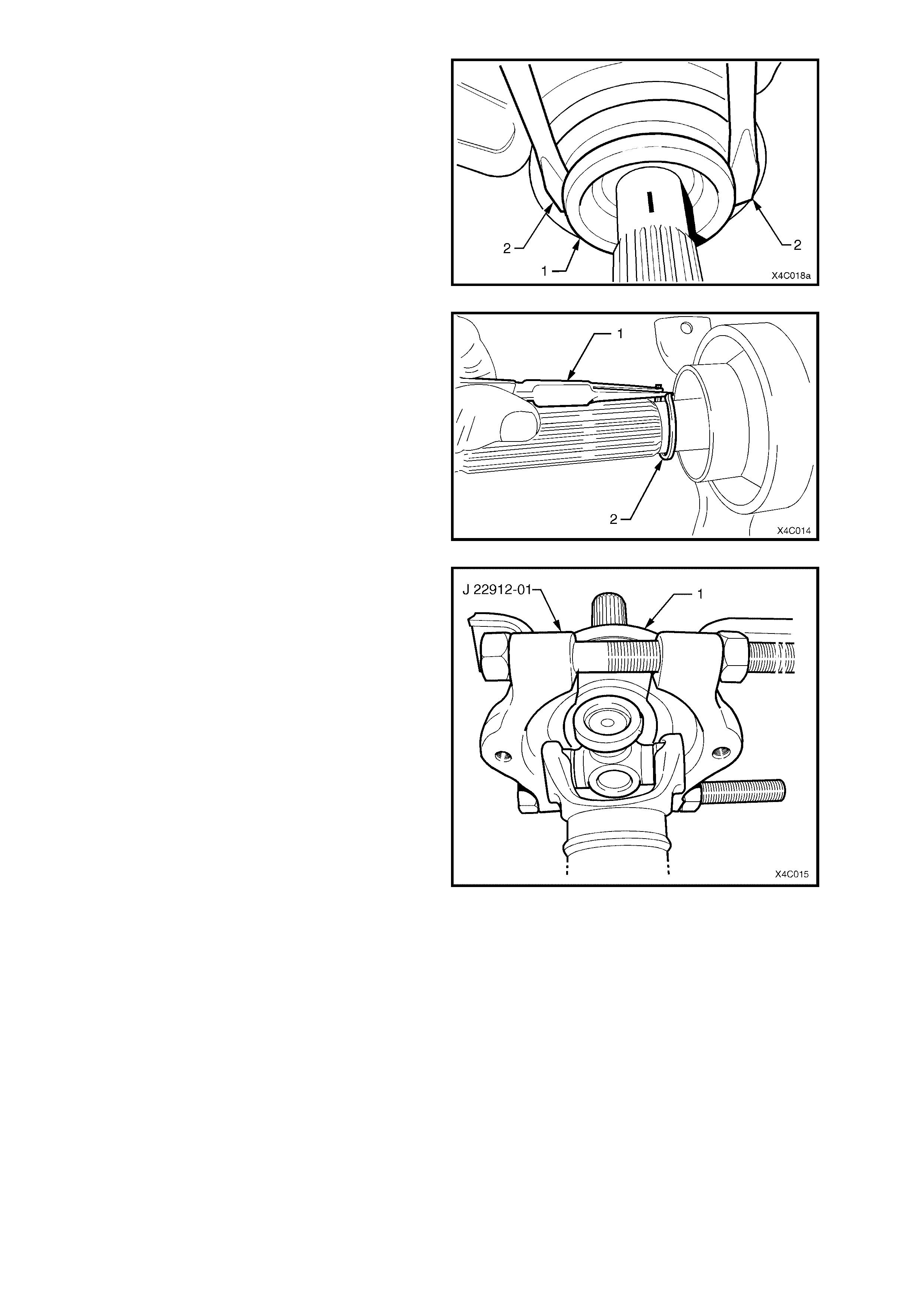
6. Remove the slinger (1), by levering off, using
two similar sized screwdrivers (2) or similar, as
shown.
NOTE: Removal of the slinger is required to gain
access to a circlip underneath.
Figure 4C-14
7. Using suitable, commercially available circlip
pliers (1), remove the circlip (2) securing the
centre bearing.
Figure 4C-15
8. Install s uitable pr ess plates s uch as J 22919-01
under the centre bear ing, carrier (1) and rubber
support, with the flat face towards the bearing
and carrier (1).
9. T ighten the clamp nuts on the pres s plates until
the two halves are firmly secure around the
bearing.
10. Support the press plates on the bed of an
hydraulic press and press the rear propeller
shaft, splined shaft from the centre bearing.
NOTE: This operation will damage the rubber
bearing support, requiring the centre bearing,
rubber and carrier assembly to be replaced.
Figure 4C-16
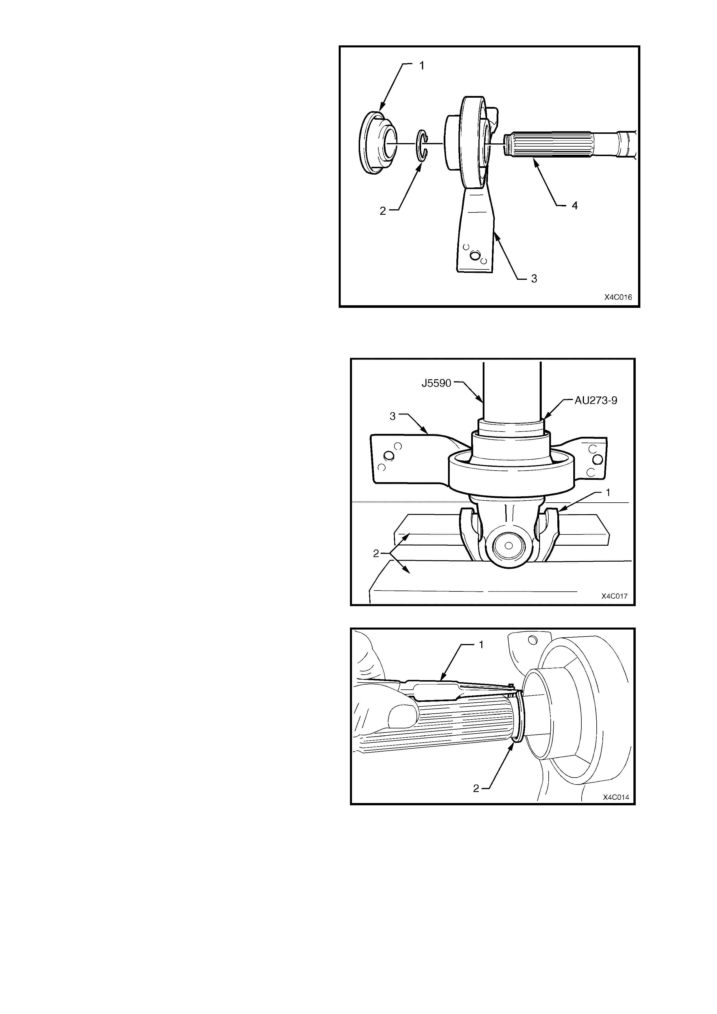
11. Fig. 4C-18 shows the relationship of the centre
bearing as semb ly ( 3) to the rear pr opeller shaft
(4), together with the slinger (1) and the
retaining circlip (2).
Figure 4C-17
REINSTALL
1. With the front universal joint ‘ears’ (1)
supported on press plates (2), press a NEW
centre bearing assembly (3) onto the front
section of the rear propeller shaft, using press
tube J5590 and adaptor AU273-9.
NOTE: If these tools are not available, then a 150
mm length of pipe with an ID of 30 mm (wall
thickness 5 mm), can be used as a substitute.
Figure 4C-18
2. Install a NEW centre bearing retaining circlip
(2), using commercially available circlip pliers
(1), taking care not to over-stretch the circlip.
3. Install a NEW slinger, using press tool J5590.
Figure 4C-19
4. Install a NEW boot and ring assembly over the
splines of the rear propeller shaft.
5. Lubricate the splines of the rear propeller shaf t
with approximately 1 – 2 gm of molybdenum
disulphide grease (to Holden Specification
HN1271).
6. Install a NEW O-ring seal to the nose of the
rear propeller shaft.
7. Taking care to align the two propeller shaft
halves with the marks made before
disassembly (1 and 2), push the two halves
together until the O-ring seal clears the inner
splines of the front half.
NOTE: At this time it should be poss ible to slide the
two halves back and forth with little resistance.
Figure 4C-20
8. With the boot and ring assembly located
correctly in the grooved section of the front
propeller shaft, install a NEW retaining clamp
to secure.
9. After installing a NEW clamp around the boot
and ring assem bly bend the tab over as shown
by ‘A’ in Fig. 4C-22.
10. Using keystone clamp pliers such as J 22610
(Also released as E1896 and 3A13) or
commercial equivalent, tighten the clamp (1)
until the gap ‘B’ is from 1 – 2 mm.
11. Reinstall propeller shaft assembly. Refer
2.1 PROPELLER SHAFT, in this Section.
Figure 4C-21
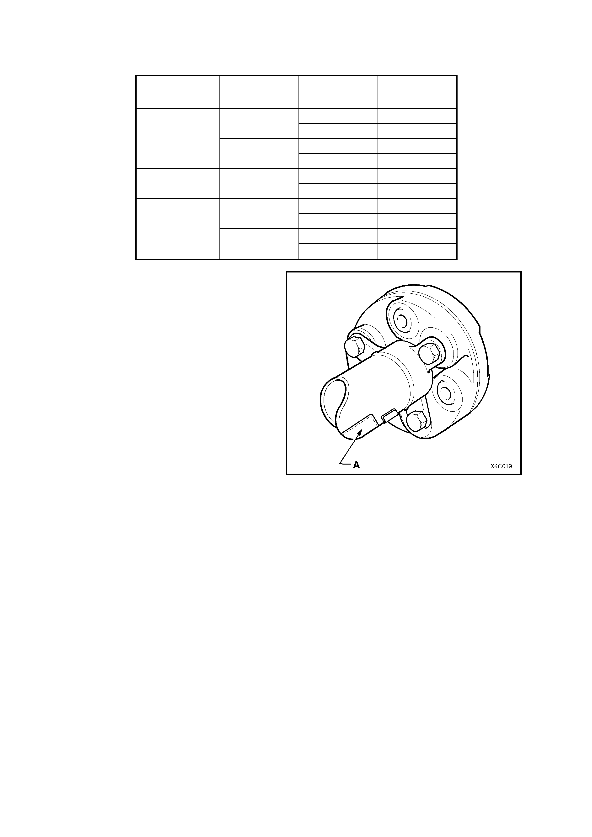
3. SPECIFICATIONS
PROPELLER SHAFT IDENTIFICATION
ENGINE TYPE TRANSMISSION
TYPE BODY STYLE PROPELLER
SHAFT
PRODUCTION I.D.
AUTOMATIC SEDAN NA
STATION WAGON NB
V6 MANUAL SEDAN NC
STATION WAGON ND
AUTOMATIC SEDAN NK
V6
Supercharged STATION WAGON
NL
AUTOMATIC SEDAN NE
STATION WAGON NF
GEN III V8 MANUAL SEDAN NE
STATION WAGON
NF
Legend:
‘A’ Location of Production Identification Label at
Rear of Propeller Shaft assembly.
Figure 4C-22
PROPELLER SHAFT:
Balance Specification.............................................. 8 g cm @ 3,500 rpm, on turn over.
Maximum permissible imbalance 12 g cm @ 5,000 rpm.
LUBRICANT:
At specified locations as detailed in text..................... Molybdenum Disulphide grease to Holden's
Specification HN1271.

4. TORQUE WRENCH SPECIFICATIONS Nm
Centre bearing carrier to underbody reinforcement bolt............................ 20 - 35
Exhaust pipe to engine manifold (V6 engine)............................................ 18 - 35
Intermediate exhaust pipe to catalytic converter attaching bolt (All) ......... 40 - 50
Propeller shaft rear coupling to pinion flange bolt ..................................... 105 - 125
Propeller shaft/sliding yoke to rubber coupling nut.................................... 74 - 80
Rubber coupling bolt to V6 manual transmission output flange nut .......... 50 - 85
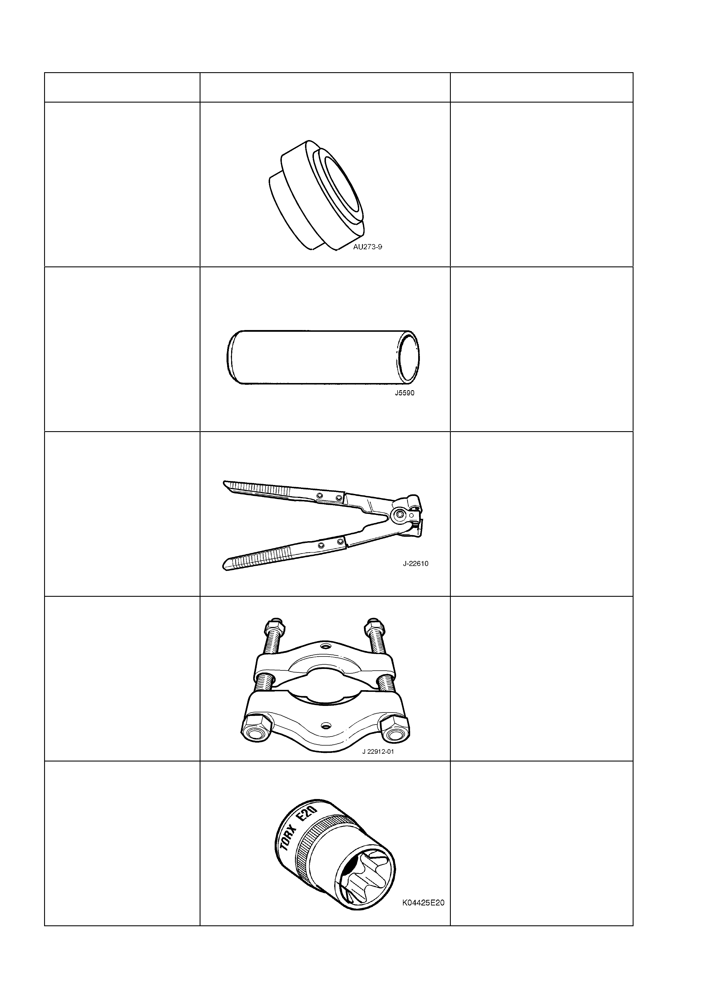
5. SPECIAL TOOLS
TOOL No. REF. IN TEXT TOOL DESCRIPTION COMMENTS
AU273-9 ADAPTOR
Previously released.
J 5590 PRESS TUBE
Previously released.
J 22610 KEYSTONE CLAMP PLIERS
Previously released.
Used to tighten the sliding joint
boot clamp.
Also released as E 1896 and
3A13.
J 22912-01 PRESS PLATES
Previously released.
K04425E20 E 20 TORX SOCKET
New release or use
commercially available
equivalent.