
SECTION 6C1-1 - GENERAL INFORMATION -
V6 SUPERCHARGED ENGINE
IMPORTANT:
Before performing any Service Operation or other procedure described in this Section, refer to Section 00
CAUTIONS AND NOTES in VX Service Information for correct workshop practices with regards to safety
and/or property damage.
1. GENERAL DESCRI PTION
The engines used in this vehicle uses a Powertrain Control Module (PCM) with both an automatic transm iss ion and
a manual transm ission to control exhaust emissions while maintaining excellent driveability and fuel economy. The
PCM maintains a desired air/fuel ratio of precisely 14.7 to 1 by monitoring electrical signals from dual oxygen
sensors mounted in the exhaust stream and optimising the amount of fuel flow from the injectors. This method of
"feed back" fuel control is called CLOSED LOOP.
In addition to fuel contr ol, the PCM als o controls ignition dwell and timing, idle s peed, EGR, electric engine cooling
fan, electric fuel pump, instrument panel "Check Powertrain" lamp and on vehicles so equipped, the A/C
com pressor clutch. The PCM also controls the automatic trans mission f unctions. The PCM also inter faces through
the serial data line with other vehicle control or information modules, such as the trip computer, Body Control
Module (BCM), ABS/ETC module, ECC module, SRS module, and theft deterrent system.
Figures 6C1-1-1 through 6C1-1-2 contain a list of the various operating conditions sensed by the PCM on the left,
and the various systems controlled on the right. Details of basic operation, diagnosis, and service are covered in
this Section.
The PCM has a built-in diagnostic system that recognises and identifies possible operational problems and alerts
the driver by illum inating the "Check Powertrain" lamp/Malf unction Indicator Lam p (MIL) on the instrum ent panel. If
the lam p com es "ON" while driving, it does not m ean that the engine should be s topped im m ediately, but the cause
of the lamp coming "ON" should be checked as soon as is reasonably possible. The PCM has built-in backup
systems that in all but the most severe failures will allow the vehicle to operate in a near normal manner until
repairs can be made.
Below the instrument panel to the left of the steering column is a Data Link Connector (DLC) which is used by the
assembly plant for a computer "c heck-out" of the s ystem . T his c onnec tor is us ed in s ervic e along with a scan tool to
help diagnose the system. Refer to Section 6C1-2, DIAGNOSIS of the VX Series Service Information for further
details.
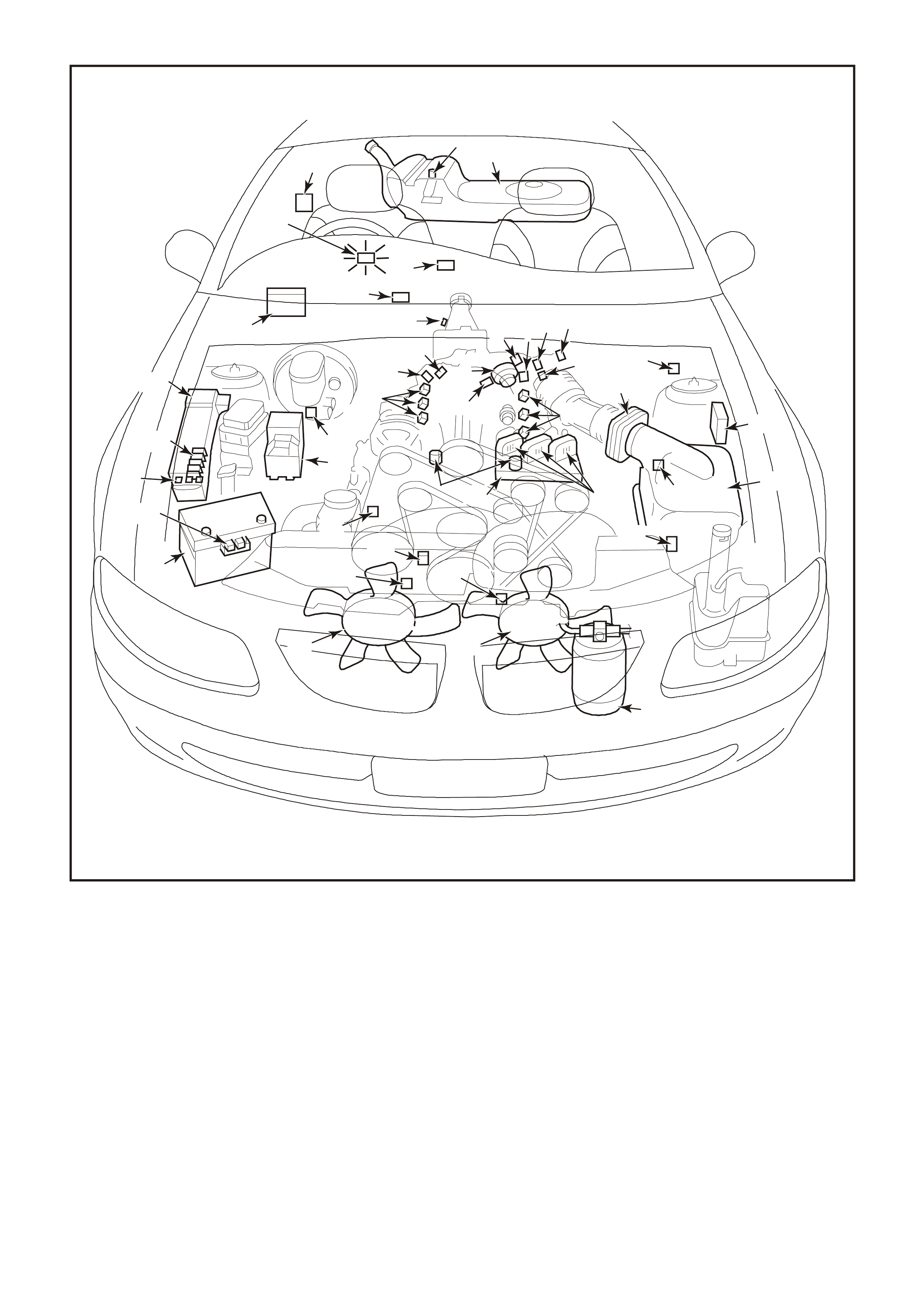
The locations of the Engine Management System (EMS) components of the system are shown in the following
Figures 6C1-1-3 through 6C1-1-7.
For the transmission Management System components and their locations, refer to Figure 6C1-1-8 in this Section.
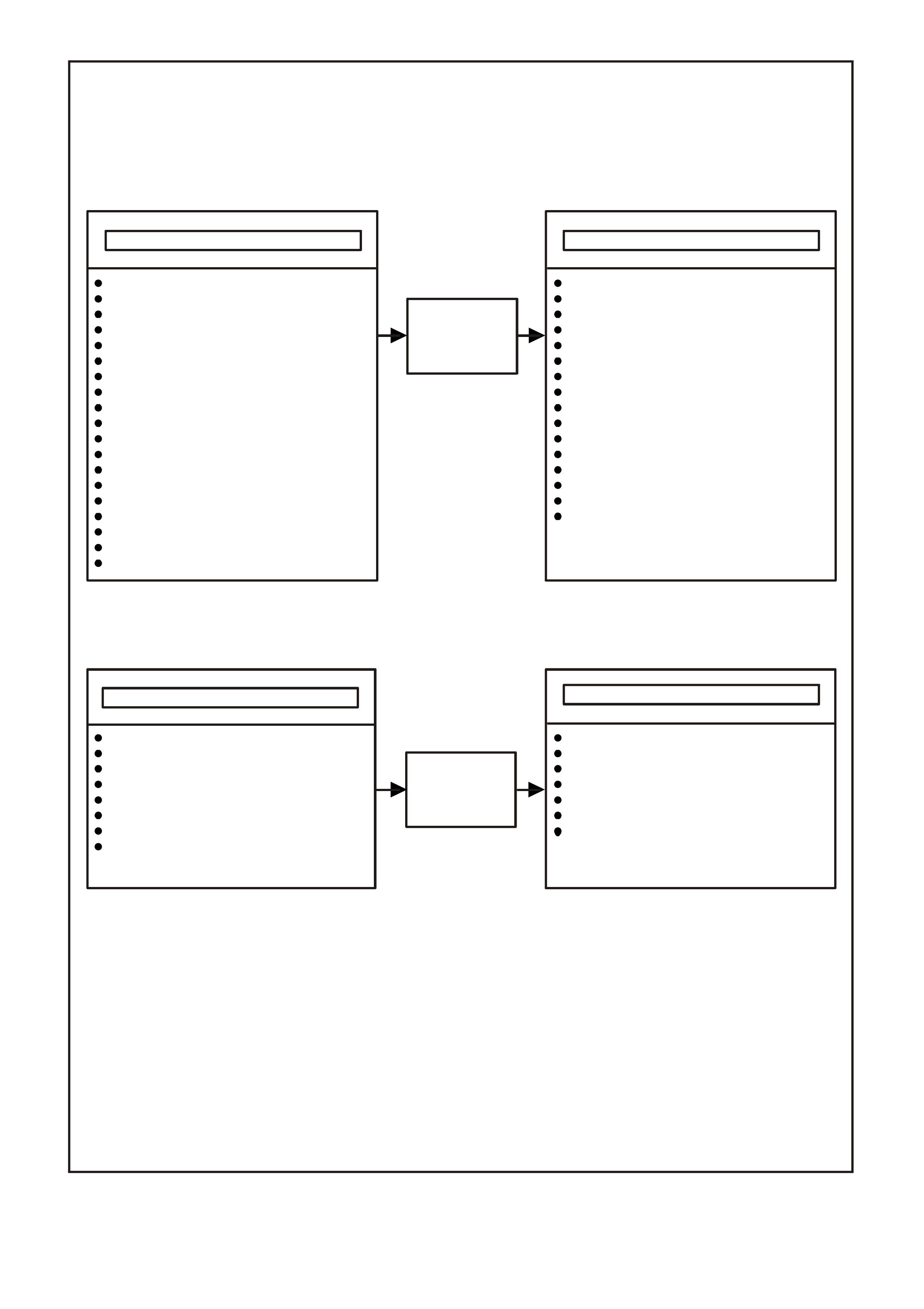
Figure 6C1-1-1 V6 Supercharge Engine Powertrain Control Module Systems
A/C R equest "O N or "OFF"
A/C Pressur e Transducer
Battery Voltage
Camshaft Position Sensor (CMP)
Crankshaf t Position Sensor (CKP )
Di agnostic "Test" Ter m in al
DLC Data Stream Input
Engine Coolant Temperature (ECT)
Engine Cooling Fan Response
Engine Knock (ESC)
Engine Speed (RPM)
Heated Oxygen Sensor Content (HO2S)
Inje ct or Volta ge
Intake Air Temperature (IAT)
Mass Air Flow (MAF) Sensor
Throttle Position (TP) Sensor
Tran smission G e ar Position
Theft Det er r ent Si gnal
Vehicle Speed Sensor (VSS)
Air Conditi on in g Comp ress or Clu tc h
Canister Purge Solenoid
Diagnostics
- "Check Powertrain" Lamp
- Data Link Connector (DLC)
- DLC Data Stream Output
- Field Service Mode
Electric Engine Cooling Fan
Electronic Spark Control (ESC)
Electronic Spark Timing (EST)
Fuel Control
- Fuel Injectors
- El ec t ric Fue l Pump
Idle Air Control
Boost Control Solenoid
Fuel Control Module
Battery Voltage
Engine S peed (E ngine R PM)
Engine Coolant Temperature (ECT)
Throttle Position (TP Sensor)
Power/Economy Switch
Tran sm i ssion Fl u i d Temperatu re ( TFT)
Tran smission G e ar Position
Vehicle Speed Sensor (VSS)
Tran sm i ssion Fl ui d Pres sur e (TF P)
Sw itch Assembly
TCC Enable Solenoid
TC C "PWM" Solenoid
3-2 Shif t Solenoid
1-2 Shif t Solenoid
2-3 Shif t Solenoid
OPERATING P ARAMETERS SENSED
OPERATING CONDITIONS SENSED
POWERTRAIN
CONTROL
MODULE
(PCM)
ENGINE CONTROLS
TRANSMISSION CONTROLS
V6 Supercharge Engine
NOTE: NOT ALL VEHICLES WILL CONTAIN ALL OF THE ABOVE SYSTEMS OR COMPONENTS
POWERTRAIN
CONTROL
MODULE
(PCM)
4345
SYSTEMS CONTROLLED
SYSTEMS CONTROLLED
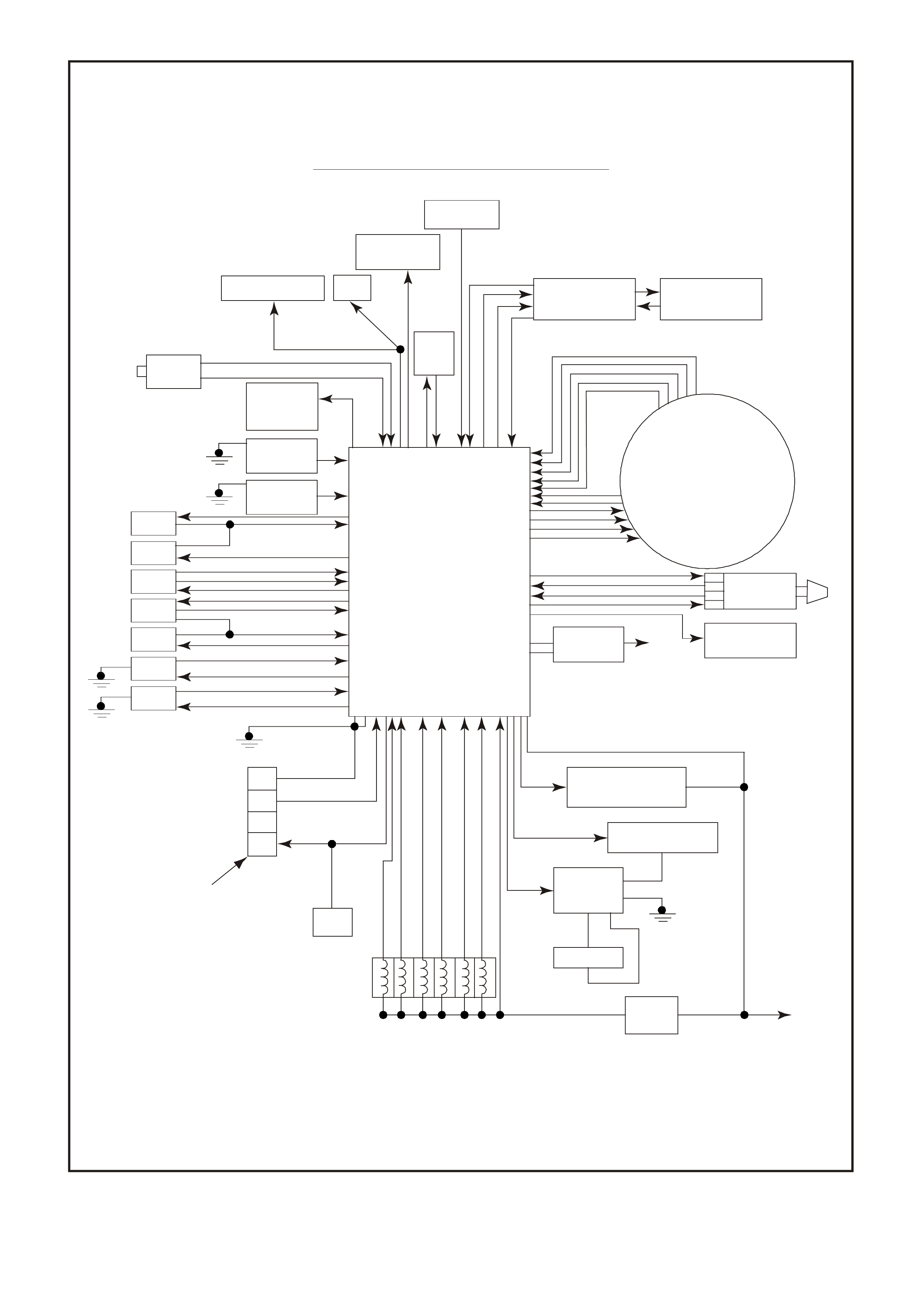
Figure 6C1-1-2 V6 Supercharge Engine Powertrain Control Module
Systems
Starter
Powertrain Control Module Systems
Trip
Computer
Transmission
Connector
(Solenoids)
System
Voltage B +
Canister Purge
Solenoid
Fuel Pump Relay
Fuel Pump
Fuel Pump
Control
Module
EFI
Relay
Injectors
BCM
9
16
6
5
H02S
H02S
ECT
TP
MAF
IAT
TFT
Da t a Link Conn ect o r
(DLC)
Earth
Engine
Earth
Di agnostic Test
Power Supply
Seria l Data
Injector Voltage Monitor
Fusible
Link
4346
Idle Air
Control
Boost Control
Solenoid
Hi gh Speed
Cooling Fan
Knock
Sensor
Knock
Sensor
BCM
A/C
PCM
Co nt rol M odule
V6 Supercharge
Ignition
System Ignition
Control
VSS
Speedometer
37
38
33
16
32
20
27
36
35
434
39
36
25
9
3
28
31
30
29
21 21
23
24
22
19
13
17
15
12
11
5
789
10
6
11
12 18
26
4195
Figure 6C1-1-3 V6 Engine Compartment Component Locations
1. Fuel Pump (Inside Fuel Tank)
2. Fuel Tank
3. ECC In –Car Air Temperature Sensor
4. Fuel Pressure Regulator
5. Exhaust Gas Oxygen (O2S) Sensor (Two)
6. Engine Harness (PCM) Earth (Two
Terminals)
7. Idle Air Control (IAC) Valve
8. Throttle Position (TP) Sensor
9. Mass Air Flow (MAF) Sensor
10. Tachometer Lead
11. Powertrain Control Module (PCM) (Inside
Vehicle)
12. Intake Air Temperature (IAT) Sensor
13. Fuel Injectors
14. Ignition Coils
15. Engine Coolant Temperature (ECT) Sensor
16. DIS Module
17. Air Cleaner
18. Crankshaft Position (CKP) Sensor
19. A/C Refrigerant Pressure Sensor
20. A/C Accumulator
21. Engine Cooling Fans (Two)
22. Crankshaft Position (CKP) Sensor
23. Oil Pressure Switch
24. Camshaft Position (CMP) Sensor
25. Detonation Knock Sensors (KS) (Two)
26. Engine Harness (PCM) Earth (Two Terminals)
27. Battery
28. Battery Harness Fusible Link Housing
29. Engine Compartment Relay Housing
30. Engine Compartment Fusible Link Housing
31. Engine Compartment Fuse/Relay Center
32. ABS
33. Brake Hydraulic Failure Switch
34. EVAP Canister Purge Solenoid
35. Diagnostic Link Connector (DLC)
36. BCM
37. Check Powertrain Malfunction Indicator Lamp(MIL)
38. Fuel Pump Control Module (Rear Compartment)
39. Vehicle Speed Sensor (VSS)
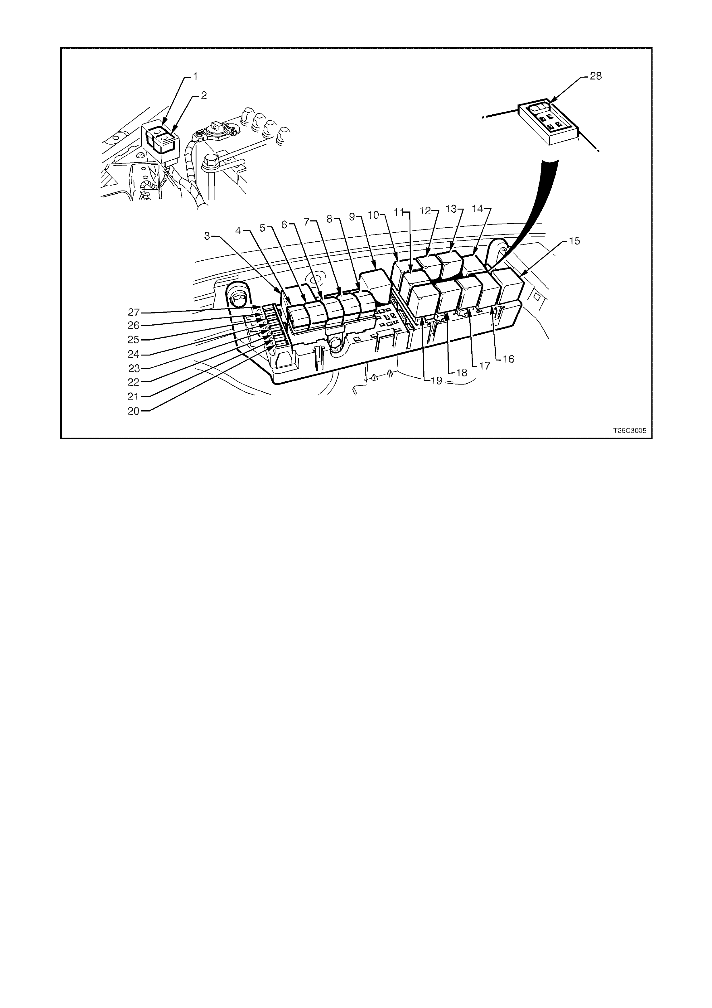
Figure 6C1-1-4 Engine Compartment Fuse/Relay Locations
1. Fan 1 Fusible Link FU 15. Start Relay
2. Fan 2 Fusible Link FT 16. Headlamp High Beam Relay
3. Engine Fan Relay (Low Speed) 17. Fuel Pump Relay
4. Lighting Fusible Link FQ 18. Front Wiper Relay
5. ABS Fusible Link FR 19. Headlamp Low Beam Relay
6. Engine Fusible Link FS 20. Injectors / Ignition Fuse F35
7. Main Fusible Link FJ 21. Injectors / Ignition Fuse F34
8. Blower Fusible Link FY 22. Engine Sensors Fuse F33
9. Engine Cont. (EFI) Relay 23. Automatic Transmission Fuse F32
10. Horn Relay 24. Engine Control / BCM Fuse F31
11. A/C Relay 25. LH Headlamp Fuse F30
12. Theft Horn Relay 26. RH Headlamp Fuse F29
13. Fog Lamp Relay 27. Fuel Pump Fuse F28
14. Engine Fan Relay (High Speed) 28. Throttle Relaxer Control Module Fuse F36
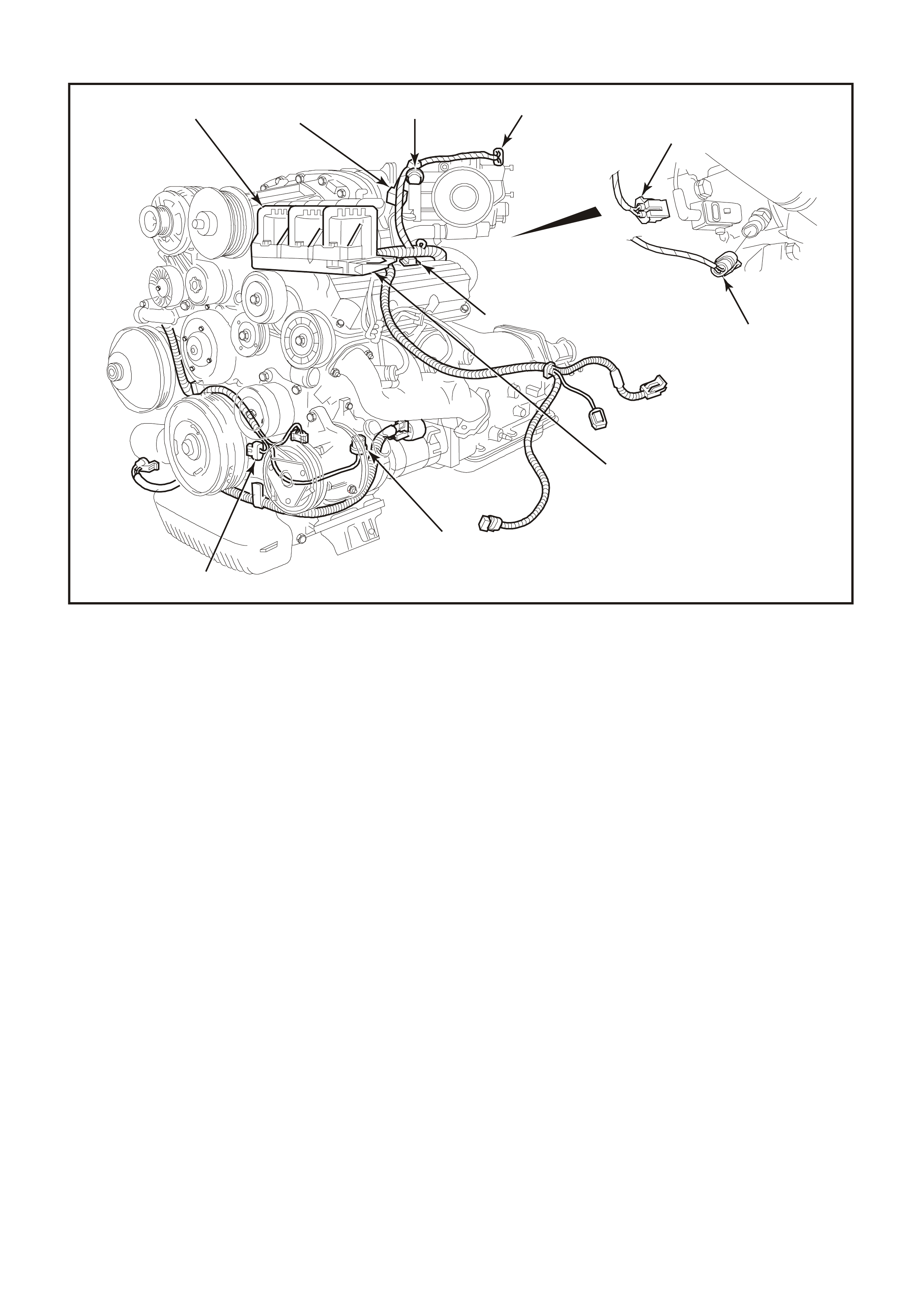
Figure 6C1-1-5 V6 Supercharge Engine Component Locations
1. Throttle Position (TP) Sensor 2. Idle Air Control Valve (IAC)
3. Anti-Boost Solenoid Valve 4. Engine Coolant Temperature (ECT) Sensor
5. Injectors 6. Direct Ignition System Module
7. L.H. Knock Sensor (KS) 8. Crankshaft Position (CKP) Sensor
9. Ignition Coils (3 places) 10. Bypass Valve Actuator
910
5
8
7
4197
6
12
3
4
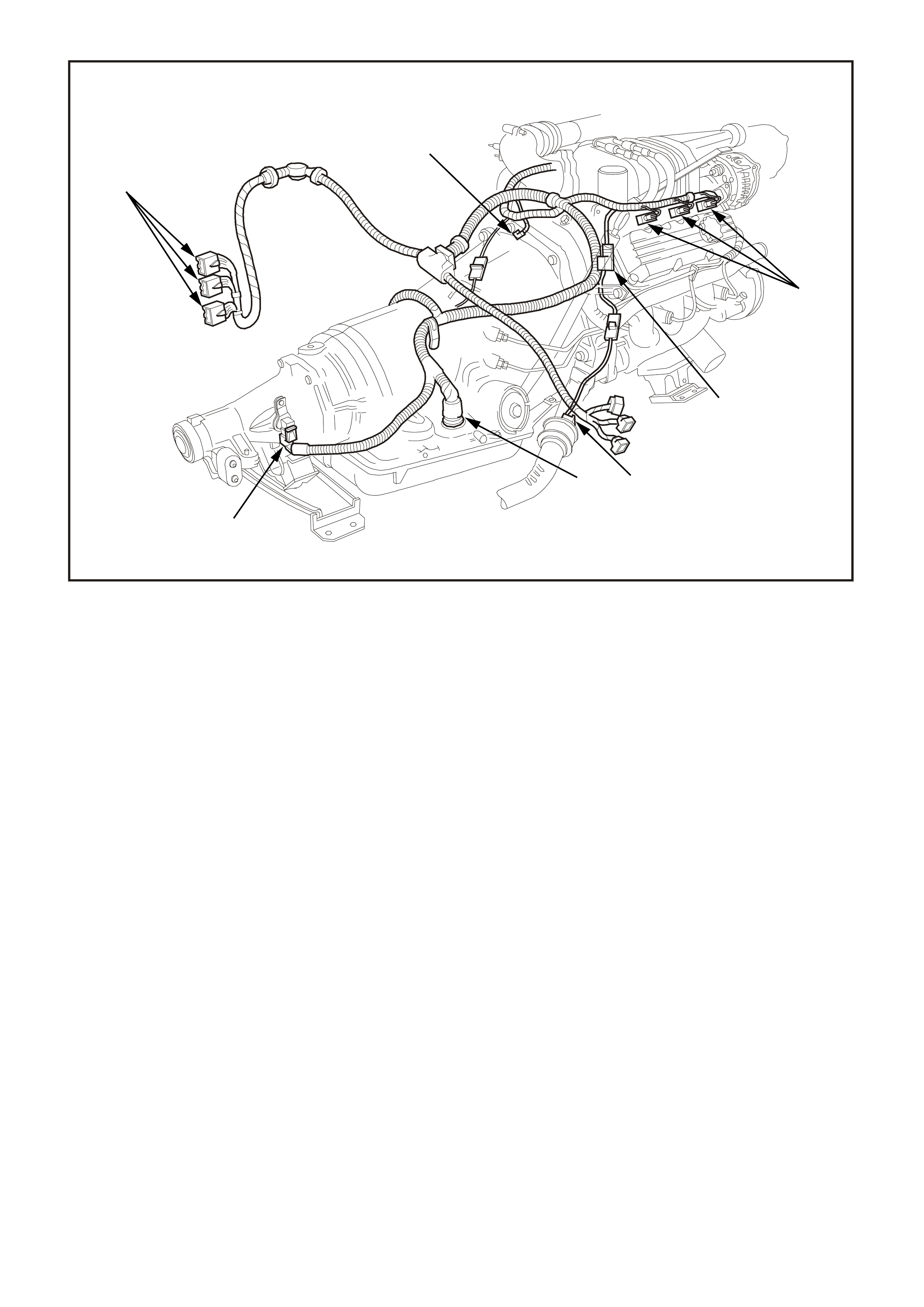
Figure 6C1-1-6 V6 Supercharge Engine Component Locations
1. Injectors
2. Canister Purge Solenoid
3. R.H. Exhaust Gas Oxygen (O2S) Sensor
4. Transmission Pass-Through Connector
5. Vehicle Speed Sensor (VSS) (Automatic Trans)
6. PCM Connectors
7. Engine Harness Earth
6
7
4199
1
2
3
4
5
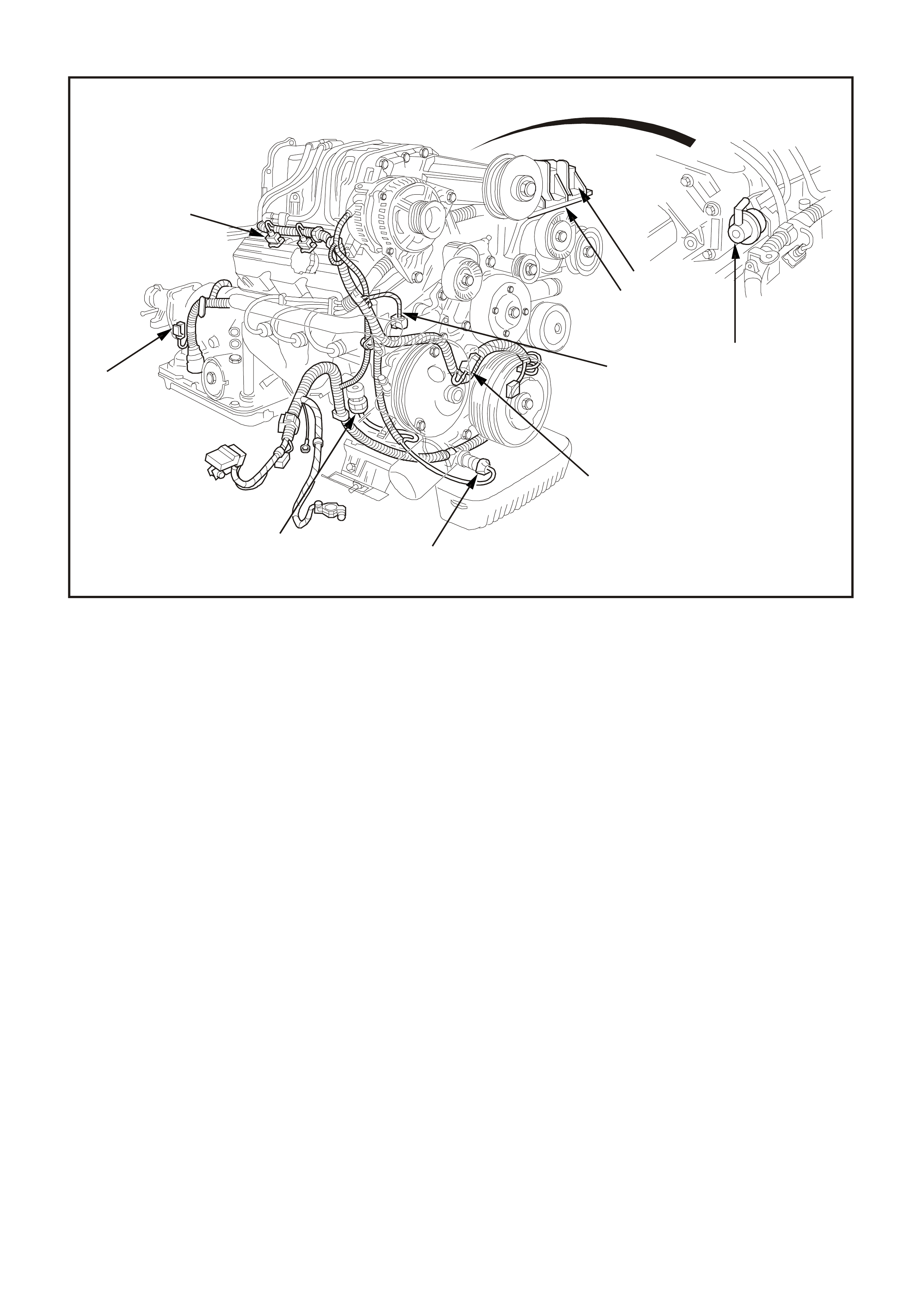
Figure 6C1-1-7 V6 Supercharge Engine Component Locations
1. Ignition Coils (3 places)
2. Fuel Pressure Regulator
3. Direct Ignition System Module
4. Engine Harness Earth
5. Camshaft Position (CMP) Sensor
6. Oil Pressure Switch
7. R.H. Knock Sensor (KS)
8. Vehicle Speed Sensor (VSS) Automatic Trans)
9. Injectors (3 places)
9
8
76
4201
5
4
31
2
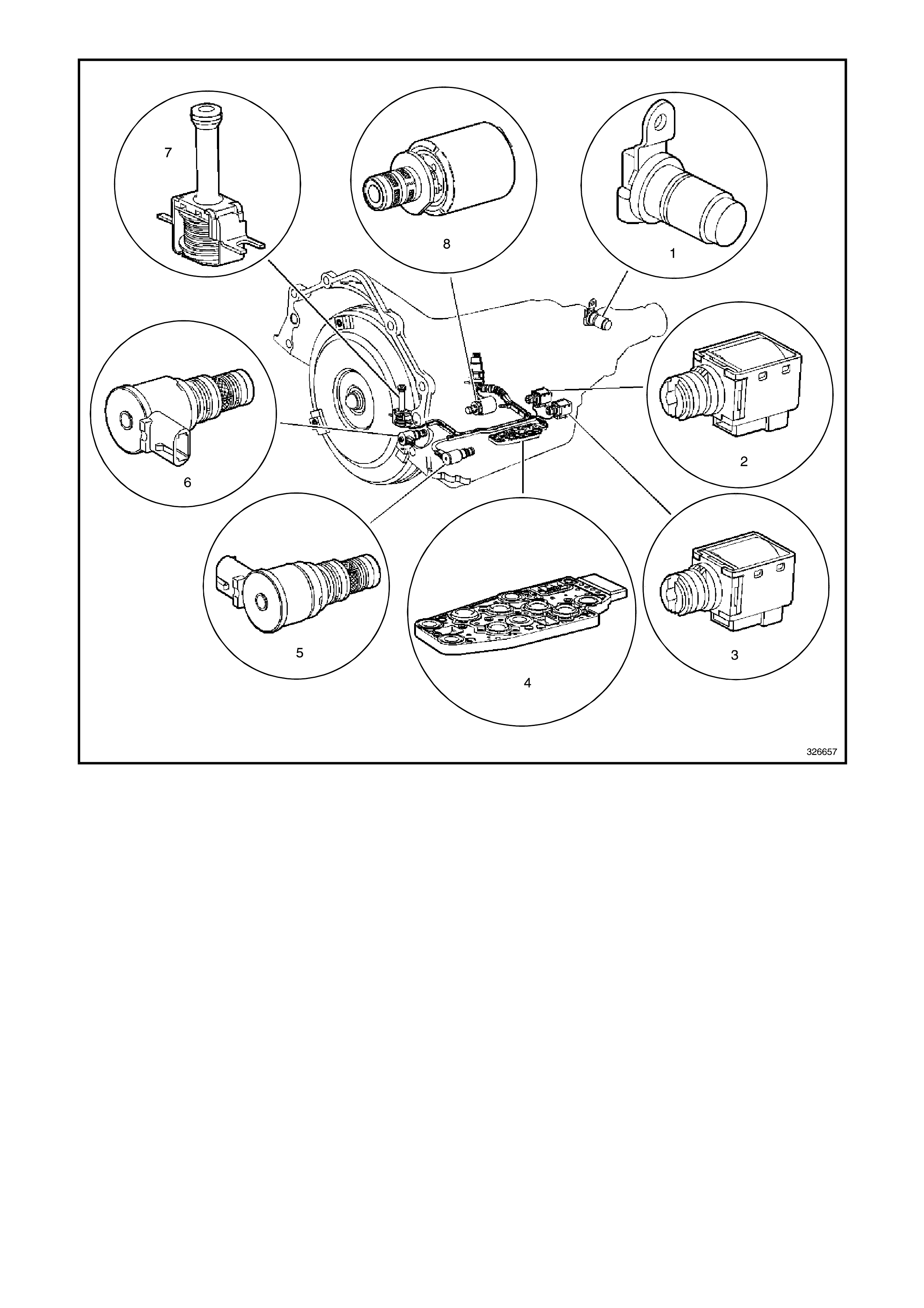
Figure 6C1-1-8 V6 Automatic Transmission Internal Electronic Component Locations
1. Vehicle Speed Sensor
2. Shift Solenoid B (SS) Valve
3. Shift Solenoid A (SS) Valve
4. Automatic Transmission Fluid Pressure (TFP) Manual Valve Position Switch
5. Shift Solenoid (SS) Valve Assembly
6. Torque Converter Clutch Pulse Width Modulation (TCC PWM) Solenoid Valve
7. Torque Converter Clutch (TCC) Solenoid Valve
8. Pressure Control Solenoid (PCS) Valve
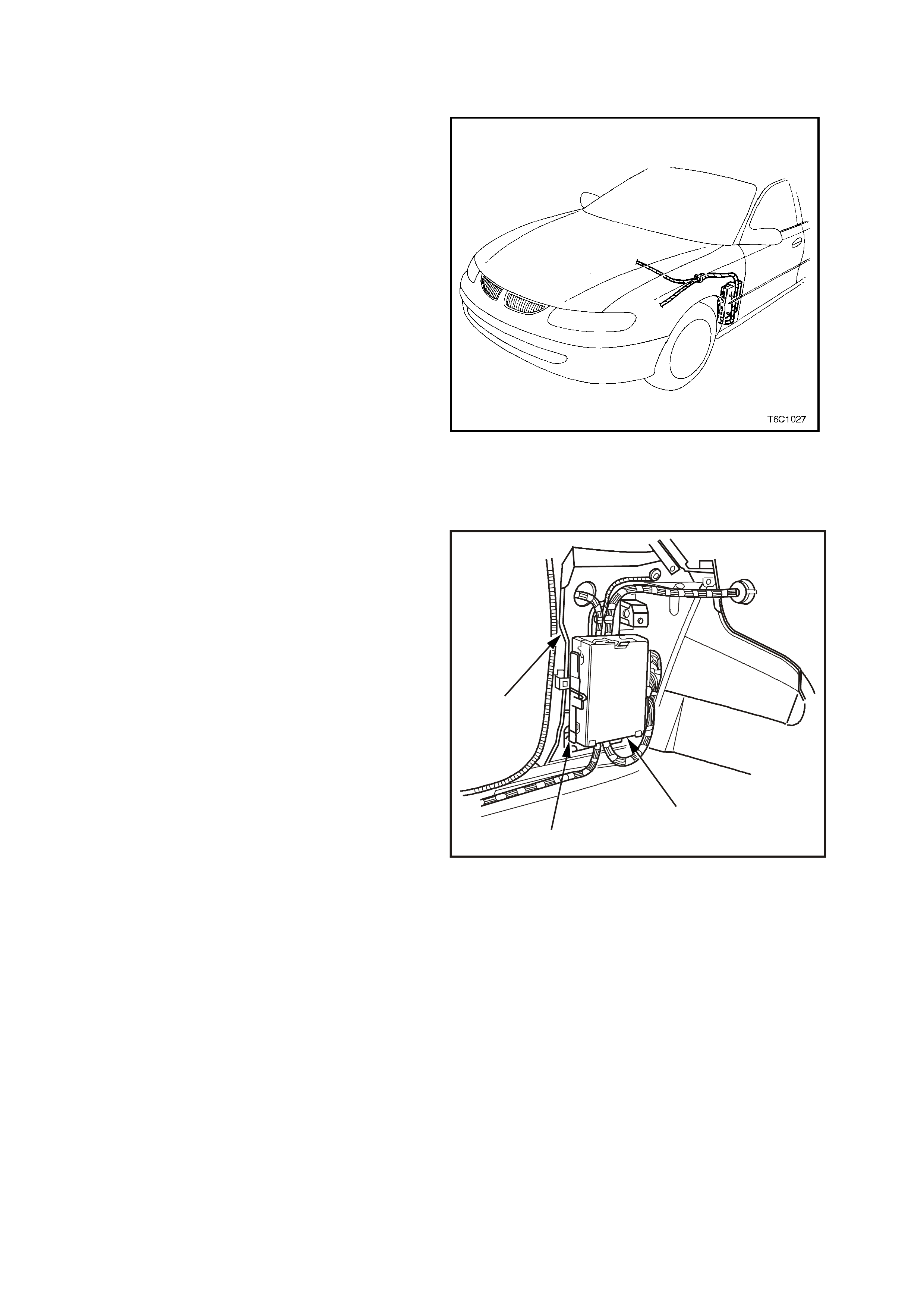
1.1 POWERTRAIN CONTROL MODULE
The Powertrain Control Module (PCM), located
behind the front left hand cowl trim panel, and is
the control center of the fuel injection and
transmission management systems. It constantly
monitors information from various sensors, and
controls the systems that affect exhaust emissions
and vehicle performance. The PCM performs the
diagnostic function of the system. It can recognise
operational problems, alert the driver through a
Malfunction Indicator Lamp (MIL) "Check
Powertrain" lamp and store a diagnostic code(s)
that will identify problem areas to aid the
technician in making repairs. Refer to
Section 6C1-2 DIAGNOSIS of the VX Series
Service Information for more information on using
the diagnostic functions of the PCM.
The PCM s upplies either a buff ered 5 or 12 volts to
power various sensors or switches. This is done
through resistances in the PCM which are so high
in value that a test light will not light when
connected to the circuit. In some cases, even an
ordinary voltmeter will not give an accura te reading
because the meter's internal resistance is too low.
Figure 6C1-1-9 Powertrain Control Module Location
A 10 Megaohm input impedance digital voltmeter is
required to assure accurate voltage readings.
The PCM controls output circuits such as the
injectors, IAC, and various relays, etc. by
controlling the earth circuit through transistors or a
device c alled a "Quad-Dr iver" m odule (QDM) in the
PCM. T he two exceptions to this are the f uel pump
relay control circuit and the automatic transmission
Pressure Control Solenoid (PCS). The fuel pump
relay is the only PCM controlled circuit where the
PCM controls the +12 volts sent to the coil of the
relay. The earth side of the fuel pump relay coil is
connected to engine earth. The PCM supplies
current to the PCS and m onitors how m uch cur rent
returns to the PCM on a separate terminal.
PCM SECURITY LINK
Once the PCM and or BCM have been replaced,
the new PCM and or BCM must be security linked
to each other. If this procedure is not performed,
the vehicle will not crank.
There are two different types of procedures that
may be per form ed to acc om plish this tas k . Refer to
Section 6C1-3 of the VX Series Service
Information for this procedure.
3
2
1
4202
Figure 6C1-1-10 PCM Mounting
1. PCM
2. Mounting Bracket
3. Left Hand Cowl Panel
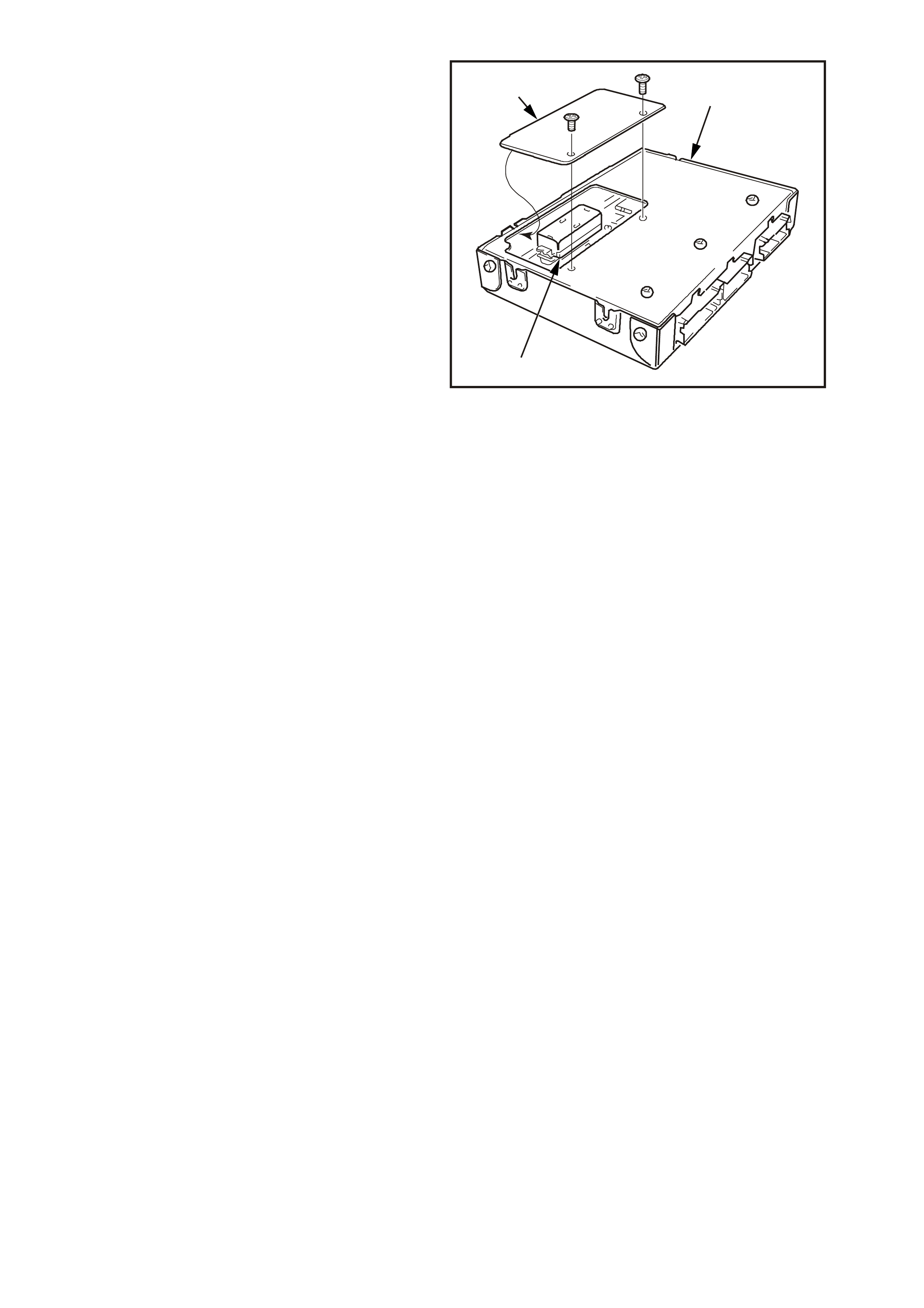
PROM
To allow one model of PCM to be used for many
diff erent vehicles, a device called a PRO M is used.
The PROM is located inside the PCM and has
information on the vehicle's weight, engine,
transmission, axle ratio and several other factors.
While one PCM part number m ay be used by many
different vehicles, a PROM is specific. For this
reason, it is ver y im portant to chec k the latest parts
catalogue and Technical Information Bulletins for
the correct part number when replacing a PROM.
A replacem ent PCM (c alled a contr oller) is supplied
without a PROM. The PROM from the old PCM
must be carefully removed and installed in
the new PCM. For details refer
Section 6C1-3 SERVICE OPERATIONS.
3
4204
2
1
Figure 6C1-1-11 PROM Location
1. Powertrain Control Module (PCM)
2. PROM
3. PROM Access Cover
PCM MEMORY FUNCTIONS
There are three types of memory storage within the PCM: RAM, EPROM and EEPROM.
RAM
Random Ac cess Mem ory (RAM) is the m icroproc essor "s cratch pad." T he processor can write into, or r ead from
this memory as needed. This memory is volatile and needs a constant supply of voltage to be retained. If the
voltage is lost, the memory is lost.
EPROM
Erasable Progr amm able Read Only Mem ory (EPRO M) is the portion of the PCM which means that the program
can be erased. This is also the portion of the PCM that contains software and the different engine and
transmission calibration information that is specific to year, model and emissions. This memory is erased by
exposing it to high intensity ultra violet radiation for several minutes.
The service Programmable Read Only Memory (PROM) which is used by technicians in the field to update
calibrations in the PCM is actually an EPROM. The service PROM is removable from the PCM. The PROM
should be retained with the vehicle following PCM replacement.
EEPROM
Electronically Erasable Program mable Read Only Mem ory (EEPRO M) is the portion of the PCM that m eans the
program can only be erased electronically. This type of m emor y cannot be eras ed by disconnecting the vehicle's
battery. The only way to erase this type of m emory is by a s pecial electronic tool, suc h as the Tech 2 s can tool.
This type of memory is used to store the Diagnostic Trouble Codes (DTC). DTC history data is stored in
EEPROM and will be saved even after the vehicle's battery has been disconnected. For this reason, the only
way that the DTC history data can be cleared is with the Tech 2 scan tool.
1.2 ENGINE INFORMATION SENSORS AND SIGNALS
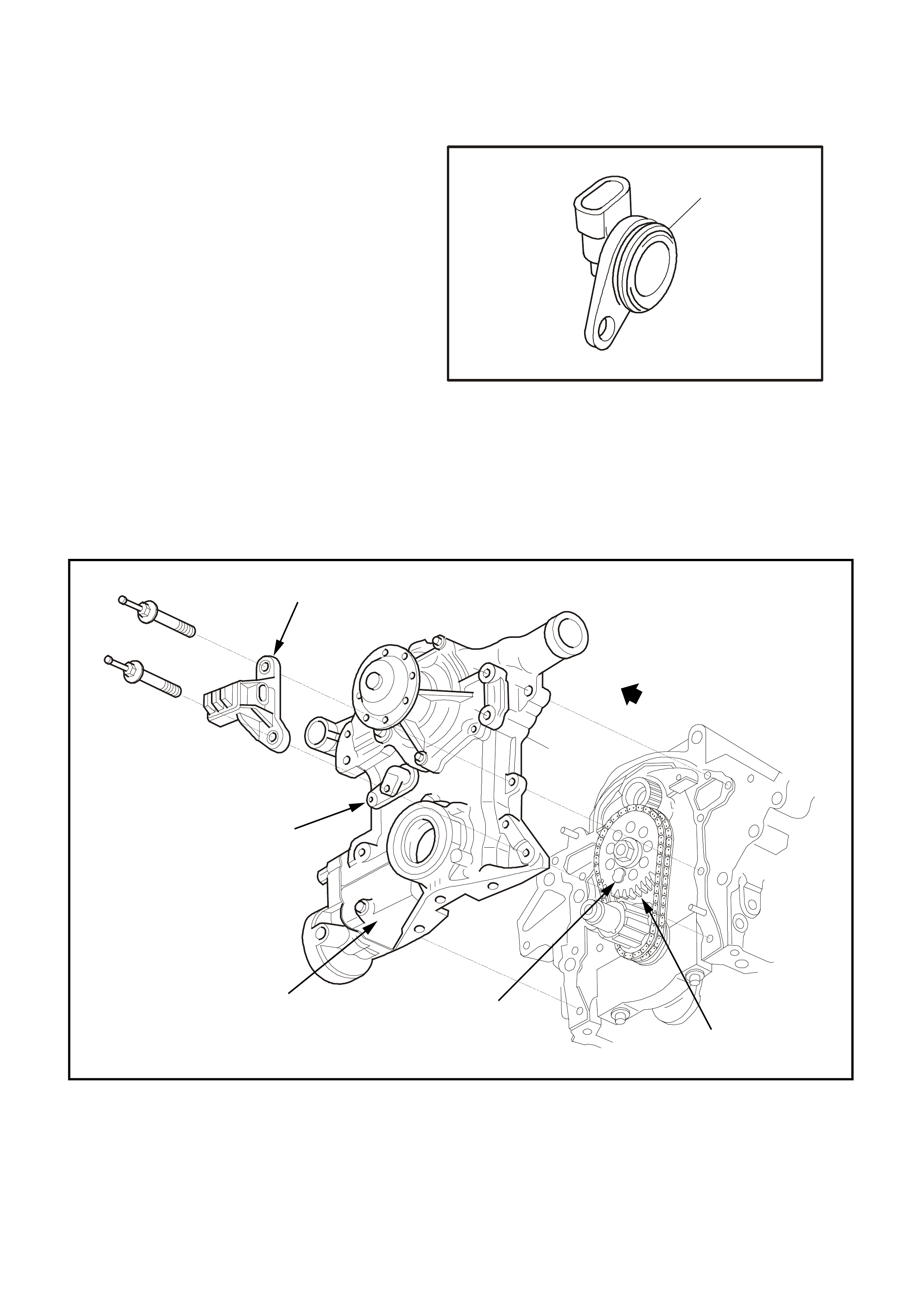
CAMSHAFT POSITION SENSOR
The camshaft position sensor is located in the
engine front cover, behind and below the water
pump, near the camshaft sprocket.
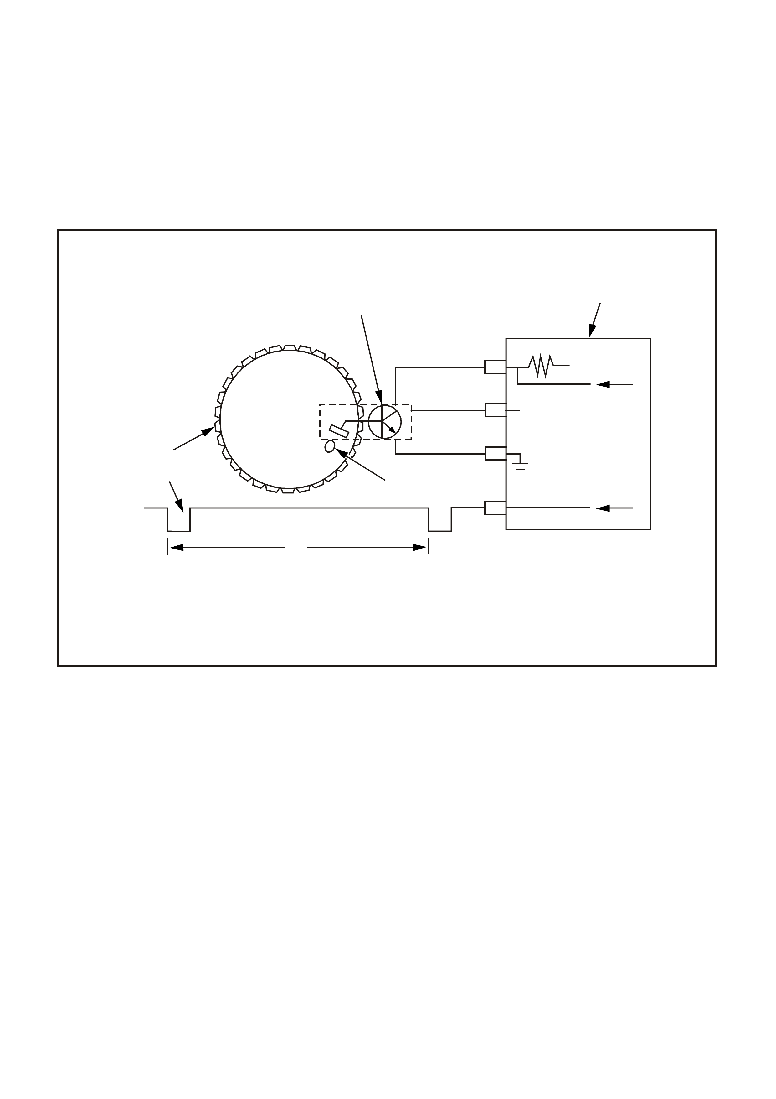
As the cam shaf t spr ock et turns, a m agnet mounted
on it activates the Hall Ef f ec t s witch in the c amshaf t
position sensor. When the Hall Effect switch is
activated, it earth's the signal line to the DIS
module, pulling the camshaft position signal line's
applied voltage low. This is interpreted as a
camshaft position signal (Synchronisation Pulse).
Because of the way the signal is created by the
camshaft position sensor, the signal circuit is
always either at a high or low voltage (square wave
signal).
While the camshaft sprocket continues to turn, the
Hall Eff ect switch turns "OFF" as the m agnetic f ield
passes the camshaft position sensor, resulting in
one signal each time the camshaft makes one
revolution.
The camshaft position signal, which actually
represents camshaft position due to the sensor's
mounting location, is used by the PCM to properly
time its sequential fuel injection operation.
1
4205
Figure 6C1-1-12 Camshaft Position Sensor
1. Crankshaft Position (CKP) Sensor
Figure 6C1-1-13 Camshaft and Crankshaft Position Sensor Locations
1. Camshaft Sprocket
2. Magnetic Interrupter
3. Front Cover
4. Camshaft Position (CKP) Sensor
5. Crankshaft Position (CKP) Sensor
5
4206
4
32
1
CAMSHAFT POSITION SIGNAL
The PCM uses the camshaft position signal to determine the position of the No. 1 piston on its power stroke.
This signal is used by the PCM to c alculate sequential fuel inje ction operation. If the cam shaft pos ition signal is
lost while the engine is running, the fuel injection mode will be based on the last fuel injection pulse, and the
engine will continue to run. The engine c an be res tarted and will run in the synchronous (all s ix injec tors injec t at
once) mode as long as the fault is present.
When the camshaft position signal is not received by the PCM, DTC 48 will be set.
If the PCM sees an incorrect number of pulses on the Camshaft Position PCM input circuit, DTC 49 will set.
If either of these DTC's are set, the fuel system will not be in sequential fuel injection mode.
Figure 6C1-1-14 Camshaft Position Signal
1. DIS Module 2. Camshaft Position Signal In
3. Camshaft Position Signal Out 4. Magnetic Interrupter
5. One Camshaft Rotation 6. Camshaft Signal
7. Camshaft Gear 8. Camshaft Position (CMP) Sensor
The Camshaft signal is norm ally high signal that will go low for 60° once every 720° of crank shaft rotation. The
timing of the camshaft signal is not critical since it only provides information to the PCM for sequential fueling.
DTC 48 (Camshaft Position Sensor Circuit Low Voltage) will set if:
• The engine is running.
• The PCM detects the Camshaft Position sensor signal is low when the signal should be high for 5.0
seconds.
• The PCM will not illuminate the Malfunction Indicator Lamp (MIL).
DTC 49 (Camshaft Position Sensor Circuit Performance) will set if:
• The engine is running.
• The incorrect number of crankshaft reference pulses have been received since the previous camshaft
position signal.
• The PCM will not illuminate the Malfunction Indicator Lamp (MIL).
M
F
N
J
12V
3
2
4
81
5
6
7
12V
OV
#1
5V
4207
DEFAULT VALUE
If either DTC is set, the PCM will determine the fuel injection sequence based on the last fuel injection pulse
received. In the calculated SFI mode, the engine continues to start and run. However, with the fault present,
only a 1 in 6 chance of the correct injection sequence exists.
RECOVERY
Recovery will occur on the next ignition cycle.
DTC 48 AND 49 HISTORY DATA
PARAMETER PARAMETER
ENGINE SPEED BATTERY VOLTAGE
TIME FROM START REFERENCE VOLTAGE
TIMES OCCURRED VEHICLE SPEED
IGNITION CYCLES INJECTOR VOLTAGE
COOLANT TEMPERATURE
Figure 6C1-1-15 Camshaft Position Signal
VXSC009
PCM
D11
D3
D4
D12
D9
D10
CRANKSHAFT
REFERENCE LO
CAM
SENSOR
CONNECTOR
CAMSHAFT
POSITION
SENSOR
SIGNAL
CRANKSHAFT
REFERENCE HI
CRANKSHAFT
18X SIGNAL
BYPASS CONTROL
EST OUTPUT
module power supply - in
sensor power supply - out
cam signal - in
3x crank sensor - in
18x crank sensor - in
cam signal - out
tacho signal - out
crankshaft reference - out
18X cranksignal - out
bypass control
EST signal -in
P
N
M
L
K
J
H
G
F
E
D
C
B
A
DIS
MODULE
ABCD CBA
W/B (644)
GY/R (645)
B/R (453)
CRANK
SENSOR
CONN
L BLU/W
(646) BR (633)
BLU/Y (643)
BR (121)
B (63 0)
V (43 0)
L BLU/B (647)
T/B (4 24)
IGN SW
EFI RELAY
O/Y
(479)
LG
(482)
B/W
(152)P/B
(39)
IC
IC
IC
M
I
C
R
O
W (423)
F35
+
-
BATTERY
FS
LOC. E1
FJ
(1040)
LOC. E3
P (3)
R(2H)
F14
TO INSTRUMENT CLUSTER
(TERMINAL 18)
ABS/ETC (TERMINAL 30)
YB39
YB39
YE111
YE34
YB193
YB193
YE63
YE57
ENGINE COOLANT TEMPERATURE (ECT) SENSOR
The Engine Coolant Temperature (ECT) sensor is a
thermistor (a resistor that changes value based on
temperature) mounted in the engine coolant stream
and is specifically for the PCM. A different sensor is
used for instrument panel functions. Low coolant
engine temperature produces a high sensor
resistanc e (28,939 ohm s at -20 degr ees C) while high
engine coolant temperature causes low sensor
resistance (180 ohms at 100 degrees C).
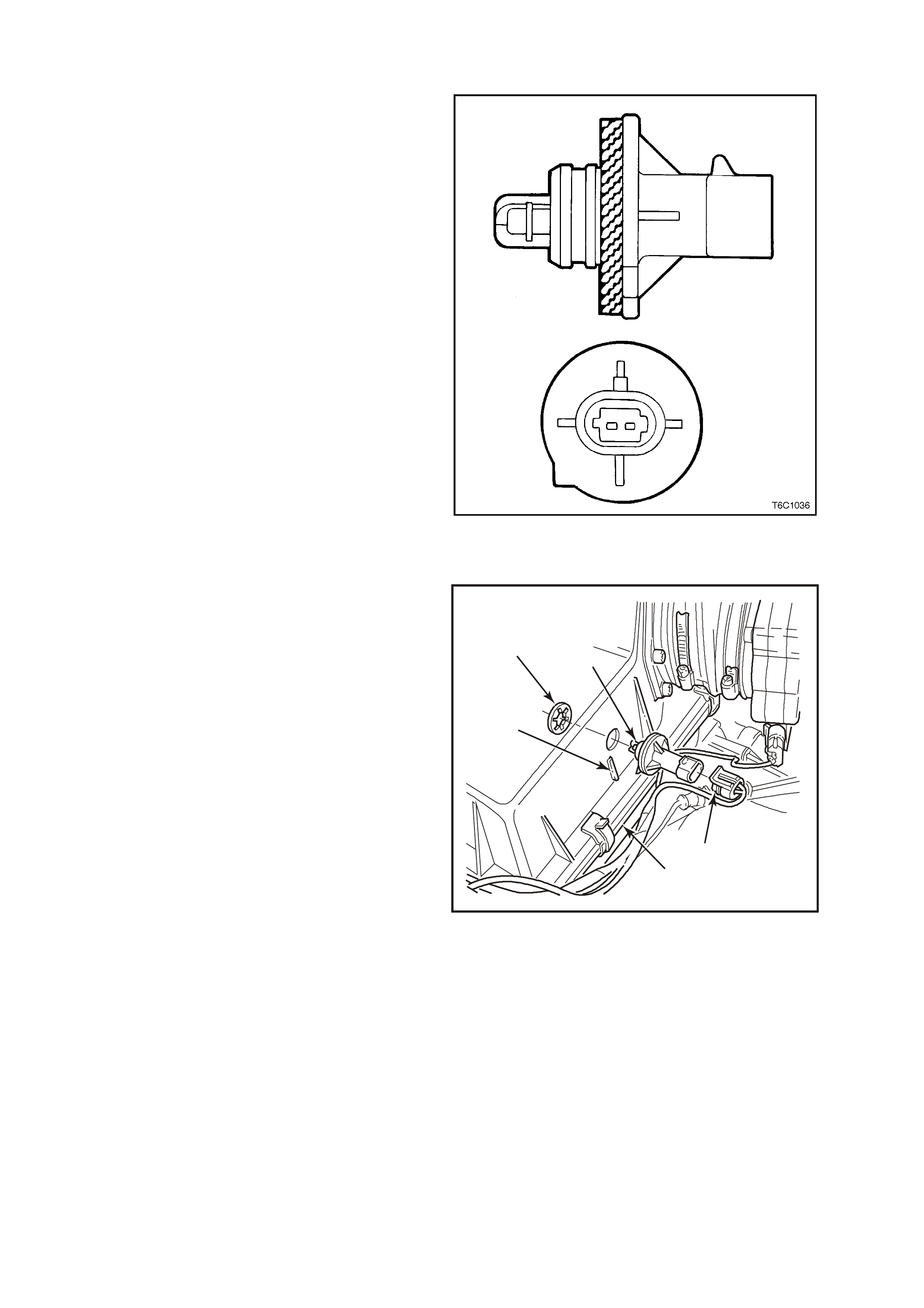
Figure 6C1-1-16 ECT Sensor
The Engine Coolant Temperature location on the V6
engine application is at the front of the engine
5
4
3
4208
2
1
Figure 6C1-1-17 ECT Sensor Location
1. Engine Coolant Temperature (ECT) Sensor
2. Tang
3. Wiring Harness Connector
4. Rear View Of Engine
5. Temperature Gauge Coolant Temperature Sensor

The PCM:
1. Supplies a 5 volt signal voltage to the sensor
through a resistor in the PCM, and
2. Monitors the circuit voltage, which will change
when connected to the sensor.
The circuit voltage will vary depending on the
resistance of the engine coolant temperature sensor.
The circuit voltage will be close to the 5 volt level
when the sensor is cold, and will decrease as the
sensor warms. Engine coolant temperature affects
most systems controlled by the PCM.
A failure in the engine coolant temperature sensor
circuit should set either DTC 14 or DTC 15.
An interm ittent open or a short f ailure should s et DTC
16.
The PCM supplies a 5 volt signal to the engine
coolant temperature sensor through one of two
resistor s in the PCM. When the engine coolant is c old
the PCM will operate on one resistor then switch over
to another resistor at approximately 50 degrees C.
The circuit voltage will change at this time but the
Tec h 2 scan tool will still r ead the correct tem perature
value and will not suddenly jump. A failure in one of
these two resistors should set DTC 17.
5.72
4.90
4.48
4.16
3.84
3.52
3.20
2.58
2.88
2.24
1.92
1.60
1.28
0.96
0.64
0.32
0.00 -28 -16 -4 7 19 31 49 55 79 91 115 127 139103 15167-40
3
1
2
4
5
4210
Figure 6C1-1-18 ECT Temperature vs Voltage
1. Engine Coolant Temperature Vs. Voltage Table
2. Sensor Voltage Above 50°C
3. Temperature °C
4. Sensor Voltage Below 50°C
5. Volts
DTC 14 (Engine Coolant Temperature (ECT) Sensor Low Voltage) will set if:
• Engine run time is longer than 10 seconds.
• The ECT sensor signal indicates an engine coolant temperature greater than 134°C (274°F).
• Above conditions present for at least 10 seconds.
• The PCM will illuminate the Malfunction Indicator Lamp (MIL).
DTC 15 (Engine Coolant Temperature (ECT) Sensor High Voltage) will set if:
• Engine run time is longer than 10 seconds.
• The ECT sensor signal indicates an engine coolant temperature less than -30°C (9°F).
• Above conditions present for at least 10 seconds.
• The PCM will illuminate the Malfunction Indicator Lamp (MIL).
DTC 16 (Engine Coolant Temperature (ECT) Signal Voltage Unstable) will set if:
• Engine run time is longer than 10 seconds.
• The ECT sensor reading changes more than 400 mV in 200 milliseconds.
• Above conditions present for at least 10 seconds.
• The PCM will illuminate the Malfunction Indicator Lamp (MIL).
DTC 17 (Engine Coolant Temperature (ECT) pull-up Resistor Failure) will set if:
• Engine run time is longer than 10 seconds.
• The pull-up resistor inside the PCM switches and there is less than a 60mV change in the engine coolant
temperature signal.
• The PCM will illuminate the Malfunction Indicator Lamp (MIL).
DEFAULT VALUE
When an ECT s ensor circ uit f ault is detected, and cur rent, the PCM will substitute a c oolant tem perature def ault
value. The PCM arrives at this default, or substitute value, by switching to a starting point, then counting
upwards to 95°C at a rate of 11 degrees per minute.
The starting point is the present temperature indication from the intake air temperature (IAT) Sensor.
NOTE: When a DTC 14, 15, 16 and 17 is c urrent, the PCM will turn on the elec tric engine c ooling fan(s ). T his is
a FAIL-SAFE action by the PCM to prevent a possible engine overheat c ondition, since these DTC’s indicate an
unknown actual engine coolant temperature.
If the ECT s ensor circ uit opens with the ignition off, the PCM will interpret - 30°C and deliver enough fuel to start
the engine at room temperature. If the actual ambient temperature is above 0°C, the engine may flood and not
start unless CLEAR FLOOD MODE is used by fully depressing the accelerator while cranking. In the CLEAR
FLOOD MODE the injectors pulse width is set to zero milliseconds.
RECOVERY
Recovery will occur when the PCM sees a valid condition.
DTC 14, 15, 16 AND 17 HISTORY DATA
PARAMETER PARAMETER
ENGINE SPEED ECT SENSOR
TIME FROM START IAT SENSOR
TIMES OCCURRED INTAKE AIR TEMPERATURE
IGNITION CYCLES BATTERY VOLTAGE
COOLANT TEMPERATURE REFERENCE VOLTS
Figure 6C1-1-19 ECT Sensor Circui
SUPERVX004
E16
B5
B
A
ENGINE COOLANT
TEMPERATURE SENSOR
SENSOR EARTH
ETC SENSOR SIGNAL
5V
4k
348
Ω
Ω
Y (41 0)
B/Y (452)
TO
THROTTLE POSITION
SENSOR
M
I
C
R
O
YB194
YE106 YB188
EXHAUST GAS OXYGEN SENSOR
The exhaust gas oxygen sensors are the key to
fuel control. The PCM uses information from the
oxygen sensors to precisely fine-tune its fuel
injector pulse width calculations, based on the
unused, "left-over" oxygen content in the exhaust.
The V6 Supercharge engine use two heated
oxygen sensors, one oxygen sensor is located in
each exhaust pipe. This is done so that the PCM
can better control the engine's fuelling
requirements. These heated oxygen sensors have
a internal heater element that is used to heat the
Zirconia element faster inside the sensors, thereby
decreasing the amount of time the fuel control
system can begin running in closed loop fuel
control.
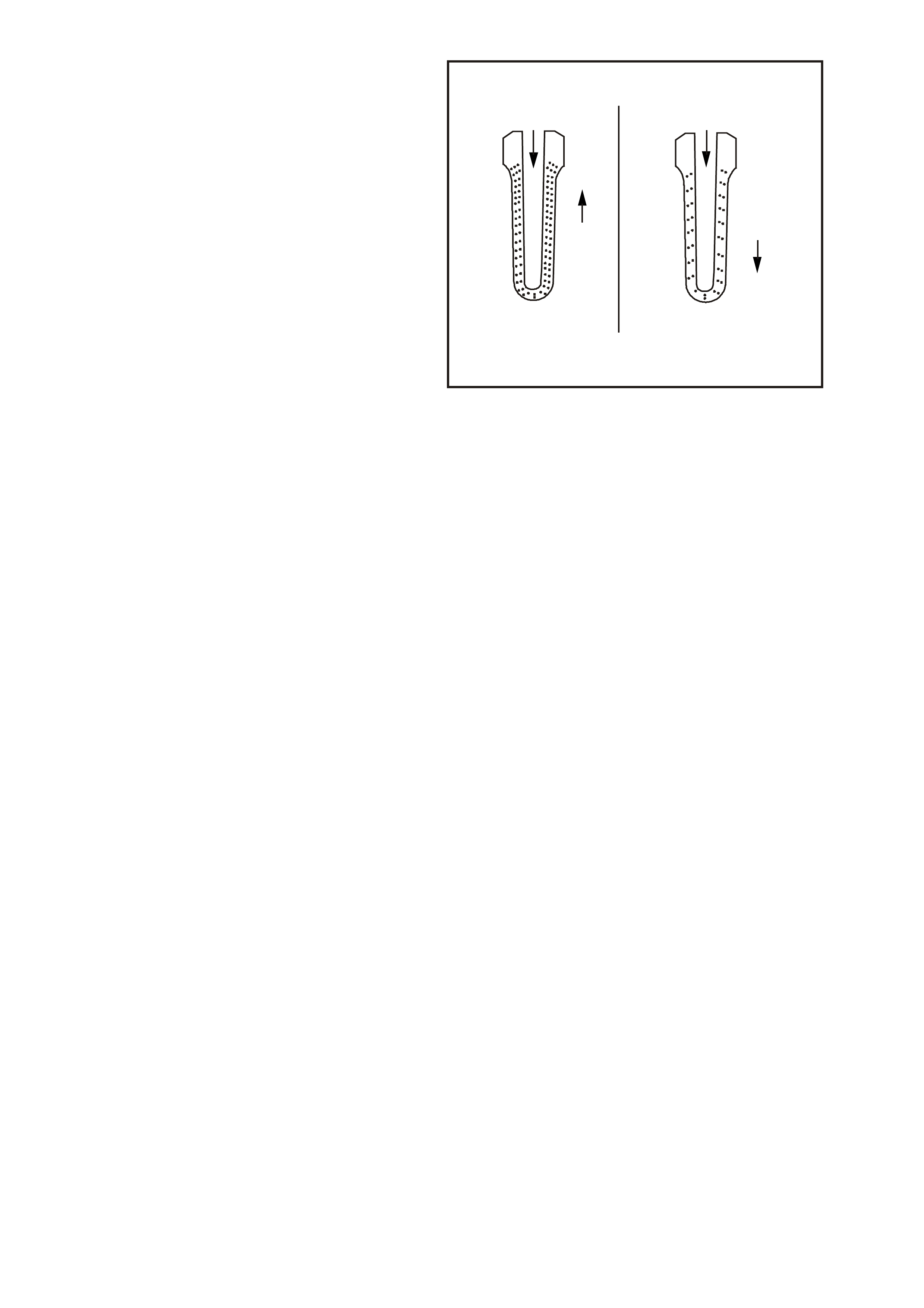
These oxygen sensors have a zirconia element
that, when heated to temperatures above 360
degrees C, produce voltages based on the amount
of oxygen content surrounding the tip, as
compared to oxygen in the atmosphere.
The s ensor is m ounted in the exhaust pipe with the
sensing portion exposed to the exhaust gas
stream. When the sensor has reached an
operating temperature of more than 360 degrees
C, it acts as a voltage generator, producing a
rapidly changing voltage of between 10 - 1000
millivolts. This voltage output is dependent upon
the oxygen content in the exhaust gas, as
compared to the sensor's atmospheric oxygen
reference cavity. This reference cavity is exposed
to the atmosphere through the air that passes
between the wire strands and insulation.
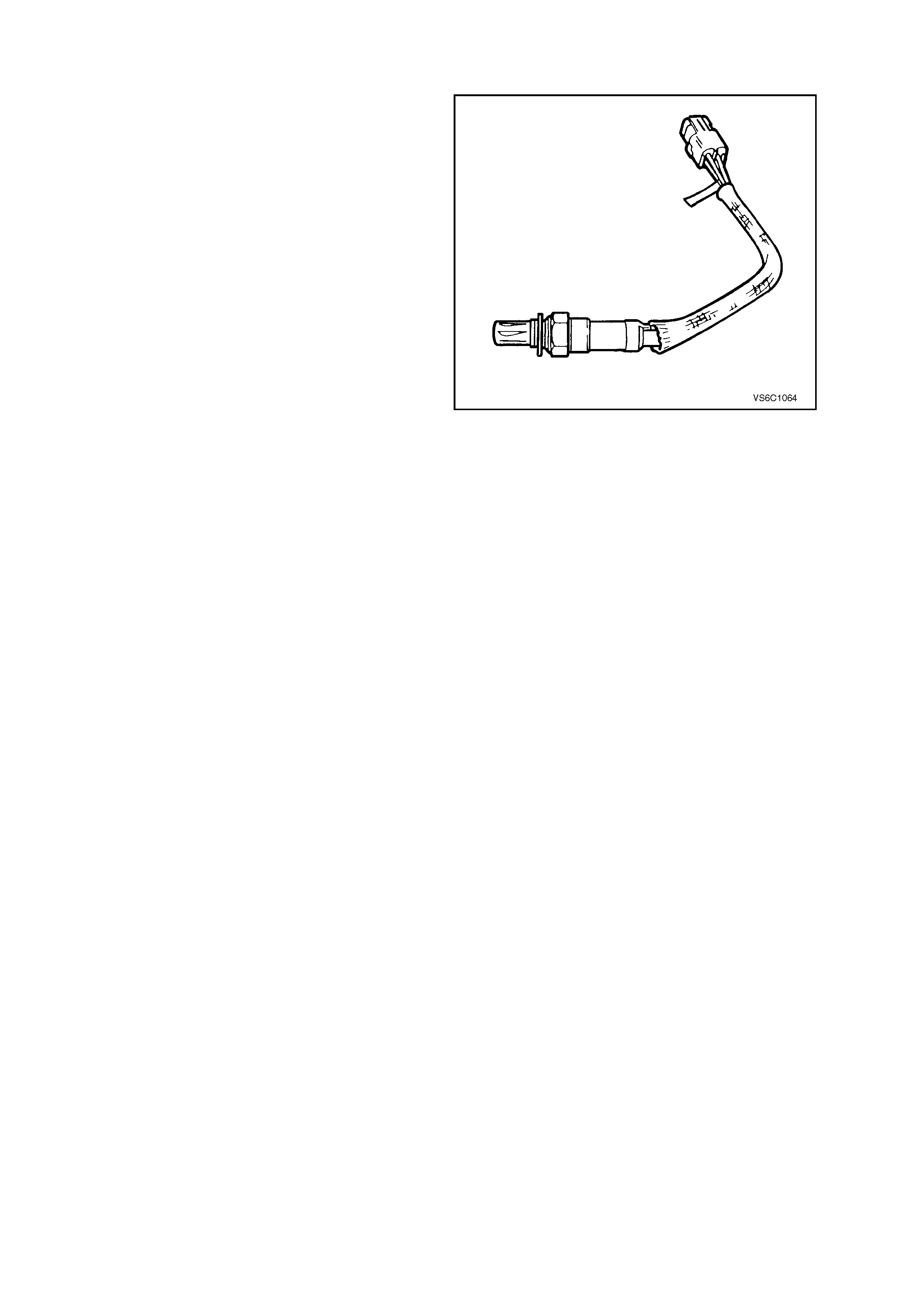
Figure 6C1-1-20 Four Wire Heated Oxygen Sensor
When the sensor is cold, it produces either no
voltage, or an unusable, slowly changing one. Also
when cold, its internal electrical resistance is
extremely high - many million ohms. The PCM
always supplies a steady 450 millivolt, very low
current called "bias" voltage to the oxygen sensor
circuit. W hen the sensor is cold and not producing
any voltage, the PCM "detects" only this steady
bias voltage. As the sensor begins heating, its
internal resistance decreases and it begins
producing a rapidly changing voltage that will
overshadow the PCM's supplied steady bias
voltage.
When the PCM "detects" the changing voltage, it
knows the oxygen sensor is hot and its output
voltage can be used for the "fine-tuning" the fuel
injector puls e width. T he PCM monitors the ox ygen
sensor's "changing voltage" for going above and
below a mid-range voltage band (approximately
300 - 600 millivolts), to help decide when to
operate in the closed-loop mode. (refer "READY
TEST," Figure 6C1-1-23.)
When the fuel system is correctly operating in the
closed-loop mode, the oxygen sensor voltage
output is rapidly changing several times per
second, going above and below a rich/lean band.
The PCM monitors the changing voltage, and
decides the needed fuel mixture correction. (refer
"NORMAL, CLOSED-LOOP OPERATION,"
Figure 6C1-23).
An open sensor signal circuit or earth circuit, or a
defective, contaminated, or cold sensor could
cause the voltage to stay within a 350-550 millivolt
band too long, keeping the fuel control system in
open-loop and setting either DTC 13 or DTC 63.
2
1
2
6
5
4212
4
3
0.6 V 0.3 V
Figure 6C1-1-21 Oxygen Sensor Zirconia Element
1. Oxygen Sensor Element
2. 21% Oxygen
3. Less Conduction
4. Exhaust Gas With 2% Oxygen
5. More Conduction
6. Exhaust Gas With 0% Oxygen
If the PCM monitors a low voltage for too long (indicating a "lean" exhaust), either DTC 44 or DTC 64 will set.
If the PCM m onitors a high oxygen sensor circ uit voltage for too long ( indicating a "ric h" exhaust), either DTC 45
or DTC 65 will set.
RESPONSE TIME
Not only is it necessary for the oxygen sensor to produce a voltage signal for rich or lean exhaust, it is also
important to respond quickly to changes. T he PCM senses the response times and displays this on the Tech 2
scan tool as the "rich-lean status" and as "cross counts" If the oxygen sensor responds slowly, the customer
may complain of poor fuel economy, rough idle or lack of performance. It may also set false PCM DTCs
because the PCM uses oxygen sensor voltages for system checks.
OXYGEN SENSOR CONTAMINANTS
Carbon
Black carbon or soot deposits result f rom over-rich air/fuel m ixtures. However, carbon does not harm an oxygen
sensor. Deposits can be burned off in the vehicle by running it at least part throttle for two minutes.
Silica
Certain RTV silicone gasket materials give off vapour as they cure that may contaminate the oxygen sensor.
This contamination is usually caused by the vapours being pulled from the PCV system, into the combustion
chamber and passed on to the exhaust system. The sand like particles from the RTV silica embed in the
molecules of the oxygen sensor element and plug up the surface. With the outside of the oxygen sensor
element not able to sense all of the oxygen in the exhaust system it results in "lazy" oxygen sensor response
and engine control. The oxygen sensor will have a whitish appearance on the outside if it has been
contaminated.
There is also a possibility of silica contamination caused by silicone in the fuel. Som e oil companies have used
silicone to raise the octane rating of their fuel. Careless fuel handling practices with transport containers can
result in unacceptable concentrations of silicone in the fuel at the pump.
Ther e is also a poss ibility of s ilica contam ination caused by silicon in lubric ants used to install vacuum hoses on
fittings. Do not use silicone sealers on gaskets or exhaust joints.
Lead
Lead glazing of the sensors can be introduced when regular, or leaded fuel is burned. Fuel containing large
amounts of methanol will also result in lead contamination.
The methanol dissolves the terne coating of the fuel tank, which introduces lead into the fuel system, and into
the exhaust after combustion. It is difficult to detect lead contamination by visual inspection.

Other Substances
Oil deposits will ultimately prevent oxygen sensor operation. The sensor will have a dark brown appearance.
Causes of high oil consumption should be checked.
The additives in ethylene glycol can also affect oxygen sensor performance. This produces a whitish
appearance. If antifreeze enters the exhaus t sys tem, you will likely encounter other, m ore obvious, sym ptom s of
cooling system trouble. If for example the engine had a head gasket failure where coolant did enter the
combustion chamber it would be a good idea to check the oxygen sensor operation after the head gasket was
repaired.
Multiple Failures
Leaded fuel, silic a contamination f rom uncur ed, low- grade (unapproved) RTV s ealant, and high oil consumption
are possible.
Figure 6C1-22 Oxygen Sensor Voltage Curves
1. Rich 800 mV
2. PCM O2 Reference Signal 450 mV
3. Lean 200 mV
4. Above 780 mV Too Long. Rich Too Long in Closed Loop. DTC 45 or 65 will set.
5. Between 410-477 mV Too Long. DTC 13 or 63 Will Set.
6. Between 200 mV Too Long. Lean Too Long in Closed Loop. DTC 44 or 64 will set.
7. Normal, Closed Loop Operation
1
7
65
4
2
3
1
2
3
1
2
3
1
2
3
4213
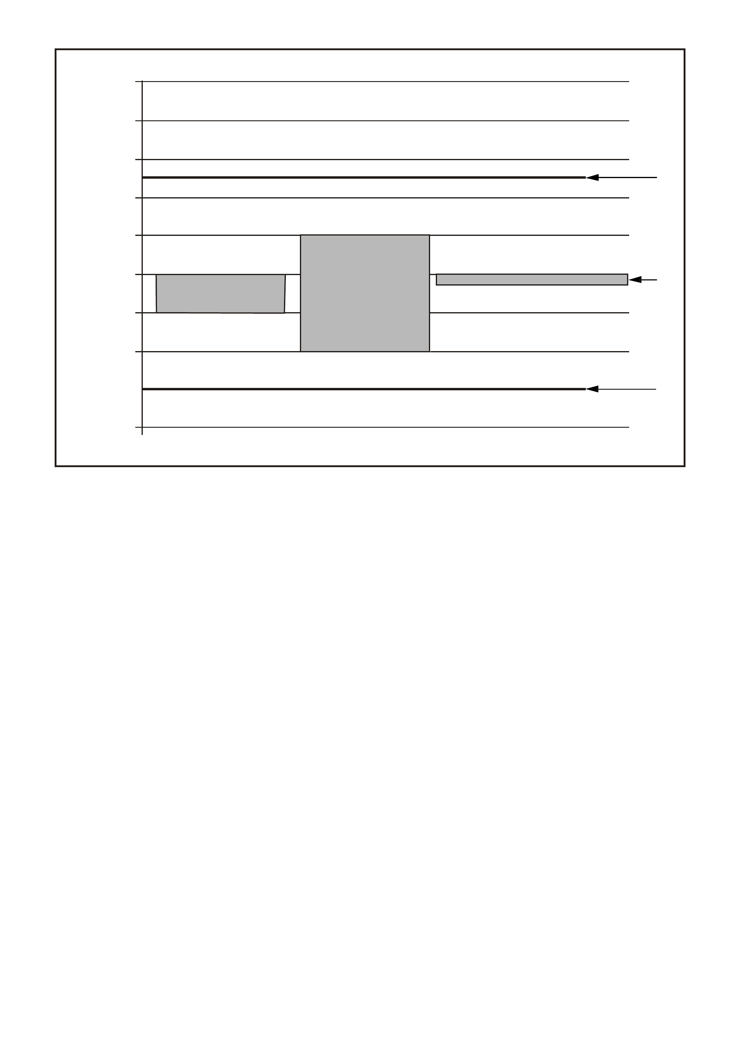
Figure 6C1-1-23 Normal Oxygen Sensor Voltages, and Abnormal Trends
1. More Than 780 mV For Too Long (Plus Other Parameters), DTC 45 or 65 Will Set.
2. Rich-Lean Band at a Hot Idle.
3. Less Than 200 mV For Too Long (Plus Other Parameters), DTC 44 or 64 Will Set.
4. “Ready “ Test.
5. Code 13.
6. Millivolts.
DTC 13 (RH Oxygen Sensor Insufficient Activity) will set if:
• No TP Sensor DTC’s are set.
• The ECT sensor is more than 85°C.
• TP Sensor voltage indicates the throttle is open more than 15%.
• RH 02S voltage stays between 410-477 millivolts.
• The PCM will illuminate the Malfunction Indicator Lamp (MIL).
DTC 44 (RH Oxygen Sensor Lean Exhaust Indicated) will set if:
• No IAT Sensor DTC’s are set.
• The RH 02S signal voltage remains below 200 millivolts for 46 seconds.
• The system is in "Closed Loop”.
• IAT Sensor is below 75°C.
• The PCM will illuminate the Malfunction Indicator Lamp (MIL).
5
600mV
477 mV
410 mV
300 mV
500 mV
490 mV
3
2
1
6
1000
900
800
700
600
500
400
300
200
100
6
6
6
6
6
6
6
6
6
4
4214

DTC 45 (RH Oxygen Sensor Rich Exhaust Indicated) will set if:
• No TP Sensor DTC’s are set.
• The RH 02S signal voltage remains above 780 millivolts for 40 seconds.
• The system is in "Closed Loop”.
• Throttle angle is between 9% and 30%.
• The PCM will illuminate the Malfunction Indicator Lamp (MIL).
DEFAULT VALUE
Once a 02S DTC is set, and current, the PCM will operate the fuel system in the “Open Loop” mode.
RECOVERY
Recovery will occur when the PCM sees a valid condition.
DTC 13, 44, AND 45 HISTORY DATA
PARAMETER PARAMETER
ENGINE SPEED R.H O2 SENSOR
TIME FROM START MASS AIR FLOW
TIMES OCCURRED R.H STFT
IGNITION CYCLES R.H LTFT
COOLANT TEMPERATURE THROTTLE ANGLE
DTC 63 (LH Oxygen Sensor Insufficient Activity) will set if:
• No TP Sensor DTC’s are set.
• The ECT sensor is more than 85°C.
• TP Sensor voltage indicates the throttle is open more than 15%.
• RH 02S voltage stays between 410-477 millivolts.
• The PCM will illuminate the Malfunction Indicator Lamp (MIL).
DTC 64 (LH Oxygen Sensor Lean Exhaust Indicated) will set if:
• No IAT Sensor DTC’s are set.
• The LH 02S signal voltage remains below 200 millivolts for 46 seconds.
• The system is in "Closed Loop”.
• IAT Sensor is below 75°C.
• The PCM will illuminate the Malfunction Indicator Lamp (MIL).
DTC 65 (LH Oxygen Sensor Rich Exhaust Indicated) will set if:
• No TP Sensor DTC’s are set.
• The LH 02S signal voltage remains above 780 millivolts for 40 seconds.
• The system is in "Closed Loop”.
• Throttle angle is between 9% and 30%.
• The PCM will illuminate the Malfunction Indicator Lamp (MIL).
DEFAULT VALUE
Once a 02S DTC is set, and current, the PCM will operate the fuel system in the “Open Loop” mode.
RECOVERY
Recovery will occur when the PCM sees a valid condition.
DTC 63, 64, AND 65 HISTORY DATA
PARAMETER PARAMETER
ENGINE SPEED L.H O2 SENSOR
TIME FROM START MASS AIR FLOW
TIMES OCCURRED L.H STFT
IGNITION CYCLES L.H LTFT
COOLANT TEMPERATURE THROTTLE ANGLE
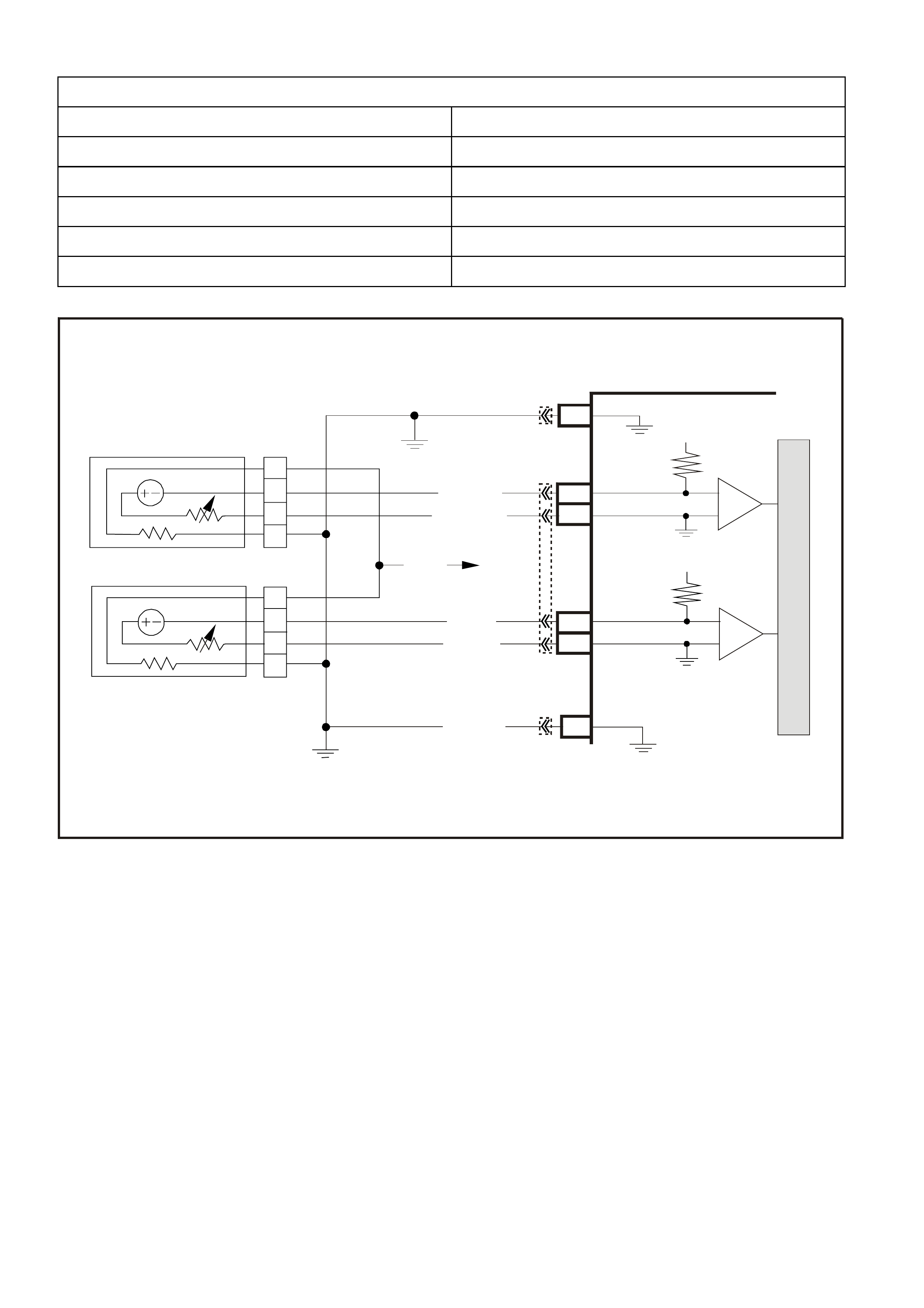
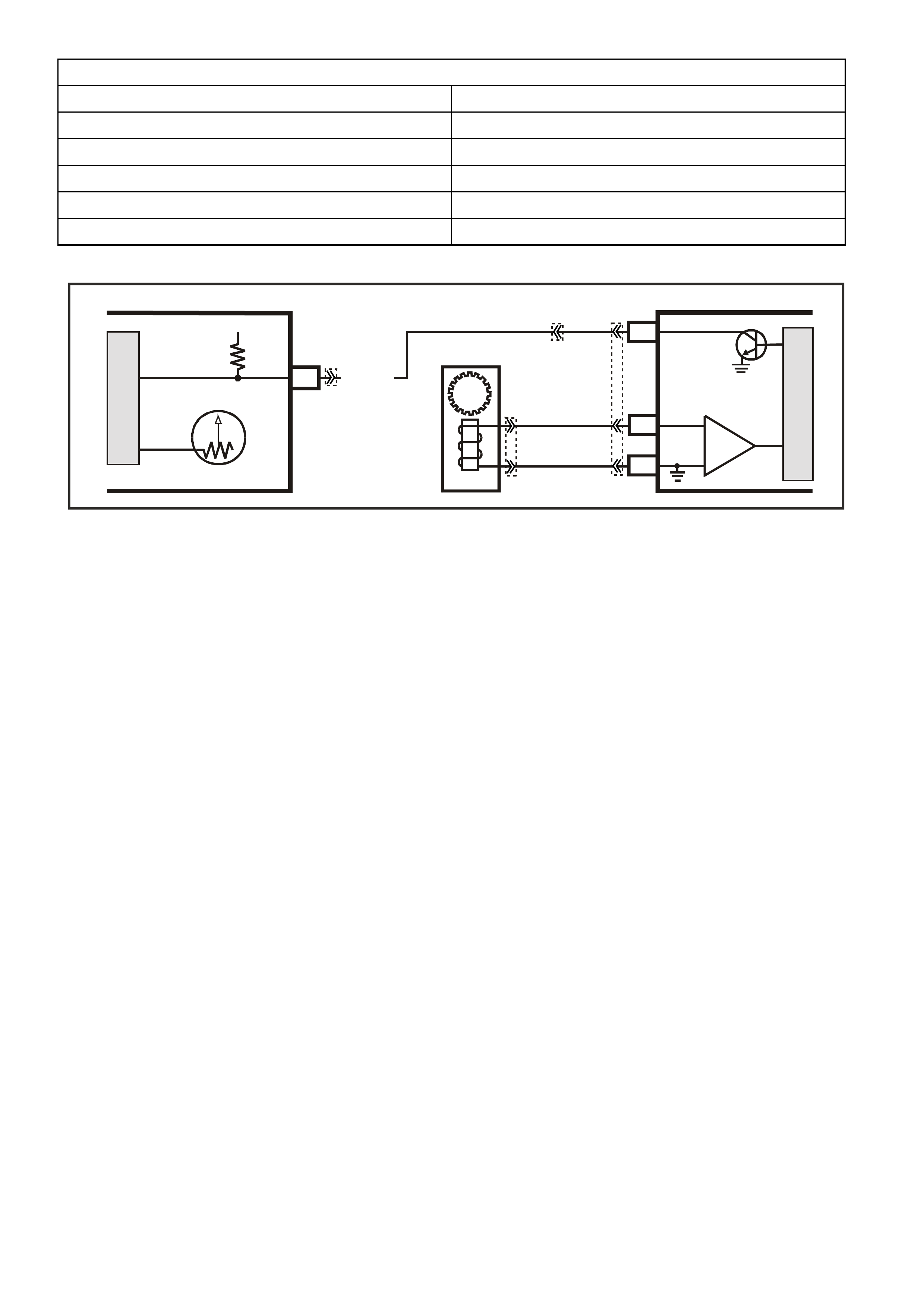
Figure 6C1-1-24 V6 Supercharge Engine Four Wire Oxygen Sensor Circuit
M
I
C
R
O
P (439)
YE95
D
D
B
B
A
A
C
C
YE95
GY (1412)
B/R (750)
Engine
Earth
To Fuse
F33
GY/B (1413)
V (412)
V/B (413)
B/R (750)
4269
A2
D16
D15
D14
D13
A1 450 m V
Right
Oxygen
Sensor
Signal HI
Right
Oxygen
Sensor
Signal LO
Left
Oxygen
Sensor
Signal HI
Left
Oxygen
Sensor
Signal LO
Earth
Earth
Ri ght O x ygen Sensor
Left Oxygen Sensor 450 m V
IC
IC
Engine
Earth
PCM
YB193
YB188
YB188
INTAKE AIR TEMPERATURE (IAT) SENSOR
The Intake Air Temperature (IAT) sensor is a
thermistor (a resistor that changes resistance with
changes in tem perature) mounted in an air cleaner
housing of the intake system. Low intake air
temperature produces high resistance in the
sensor (100,866 ohms at -40 degrees C), while
high intake air temperature causes low sensor
resistance (78 ohms at 130 degrees C).
The PCM:
1. Supplies a 5 volt signal voltage to the sensor
through a resistor in the PCM, and
2. Monitors the intake air temperature circuit
voltage, which will change when connected to
the intake air temperature sensor.
The circuit voltage will vary depending on the
resistance of the IAT sensor. The voltage will be
close to the 5 volt level when the sensor is cold,
and will decrease as the sensor warms.
The input intake air temperature signal voltage is
used by the PCM to assist in calculating the fuel
injector pulse width.
A failure in the IAT sensor circuit should set either
DTC 23 or 25.
An intermittent or unstable voltage in the IAT
sensor circuit should set DTC 26.
Figure 6C1-1-25 IAT Sensor
4215
1
2
5
4
3
Figure 6C1-1-26 IAT Sensor Location
1. Wiring Harness Connector
2. Air Cleaner Upper Housing
3. Mating Tang
4. Retainer
5. IAT Sensor
DTC 23 (Intake Air Temperature Sensor Signal Voltage High) will set if:
• IAT Sensor signal voltage is m ore than 4.9 volts, indicating an intake air temperature below -36°C f or more
than one second.
• The PCM will not illuminate the Malfunction Indicator Lamp (MIL).
DTC 25 (Intake Air Temperature Sensor Signal Voltage low) will set if:
• IAT Sensor signal voltage is m ore less than 0.3 volts, indicating an intak e air temperature above 147°C for
more than one second.
• The PCM will not illuminate the Malfunction Indicator Lamp (MIL).
DTC 26 (Intake Air Temperature Sensor Unstable Voltage) will set if:
• Engine run time is longer than 10 seconds.
• IAT Sensor reading changes more than 140 millivolts in 100 milliseconds
The PCM will not illuminate the Malfunction Indicator Lamp (MIL).
DEFAULT VALUE
One an IAT DTC is set, and current, the PCM will substitute an IAT value of 25°C.
RECOVERY
Recovery will occur when the PCM sees a valid condition.
IF ANY OF THESE DTC(S) SET, THE PCM WILL DEFAULT TO A CALCULATED COOLANT TEMPERATURE
VALUE, ALLOWING THE VEHICLE TO OPERATE.
DTC 23, 25 AND 26 HISTORY DATA
PARAMETER PARAMETER
ENGINE SPEED ECT SENSOR
TIME FROM START IAT SENSOR
TIMES OCCURRED BATTERY VOLTAGE
IGNITION CYCLES REFERENCE VOLTS
COOLANT TEMPERATURE
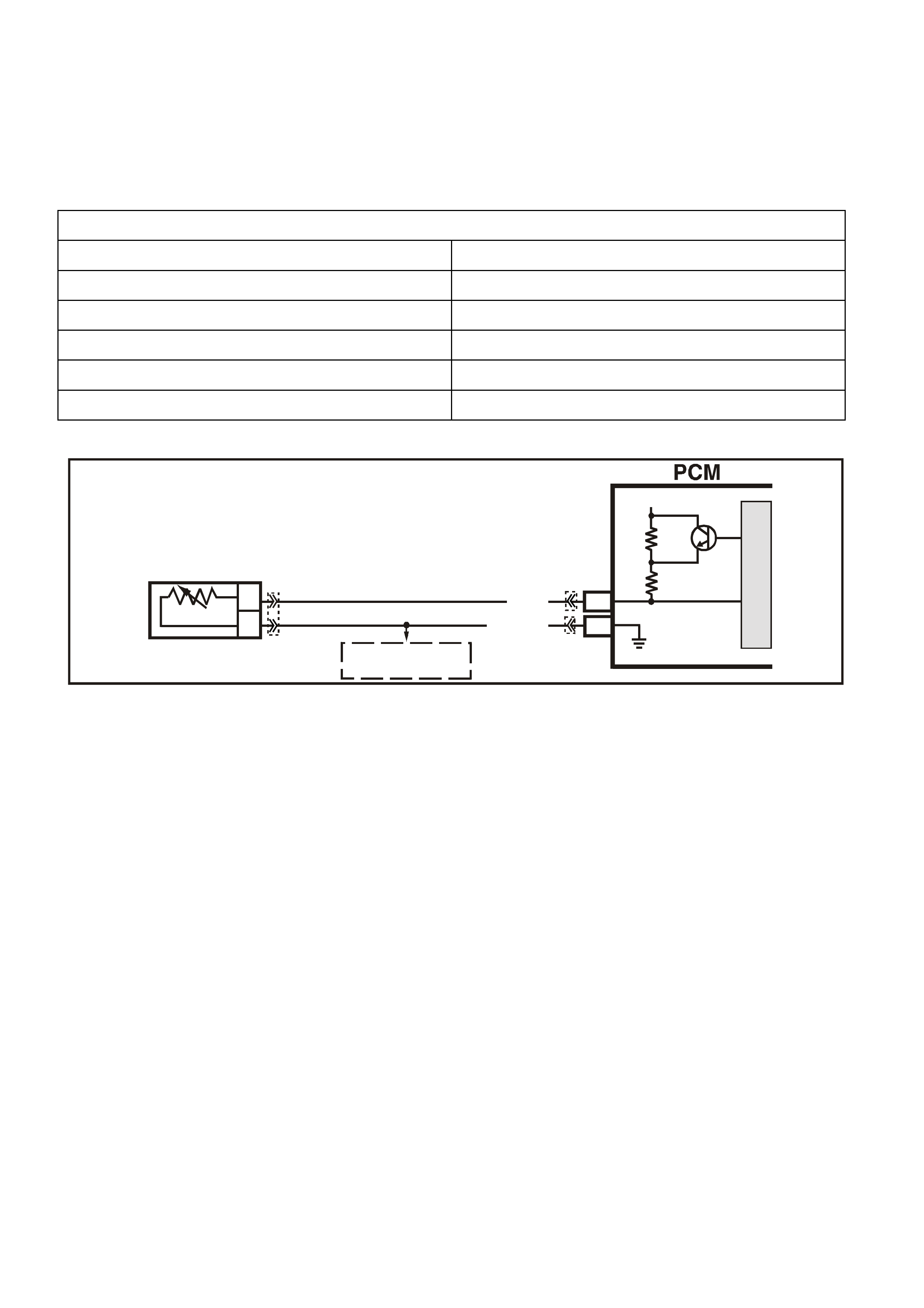
Figure 6C1-1-27 IAT Sensor Circui
SUPERVX002
F16
B4
B
A
INTAKE AIR
TEMPERATURE SENSOR
SENSOR EARTH
IAT SEN SOR SIGNA L
PCM
5V
BR (472)
B (46 9)
M
I
C
R
O
TO
A/C PRESSURE
SENSOR AND
TFT SENSOR
YE23 YB188
YB194
MASS AIR FLOW (MA F) SENSOR
The Mass Air Flow (MAF) sensor used on these
engines utilises a heated element type of operation.
A heated element in the MAF is placed in the air
flow stream of the engine intake system. The
heating element is maintained at a constant
temperature differential above the air temperature.
The am ount of electric al power required to m aintain
the heated element at the proper temperature is a
direct function of the mass flow rate of the air past
the heated element.
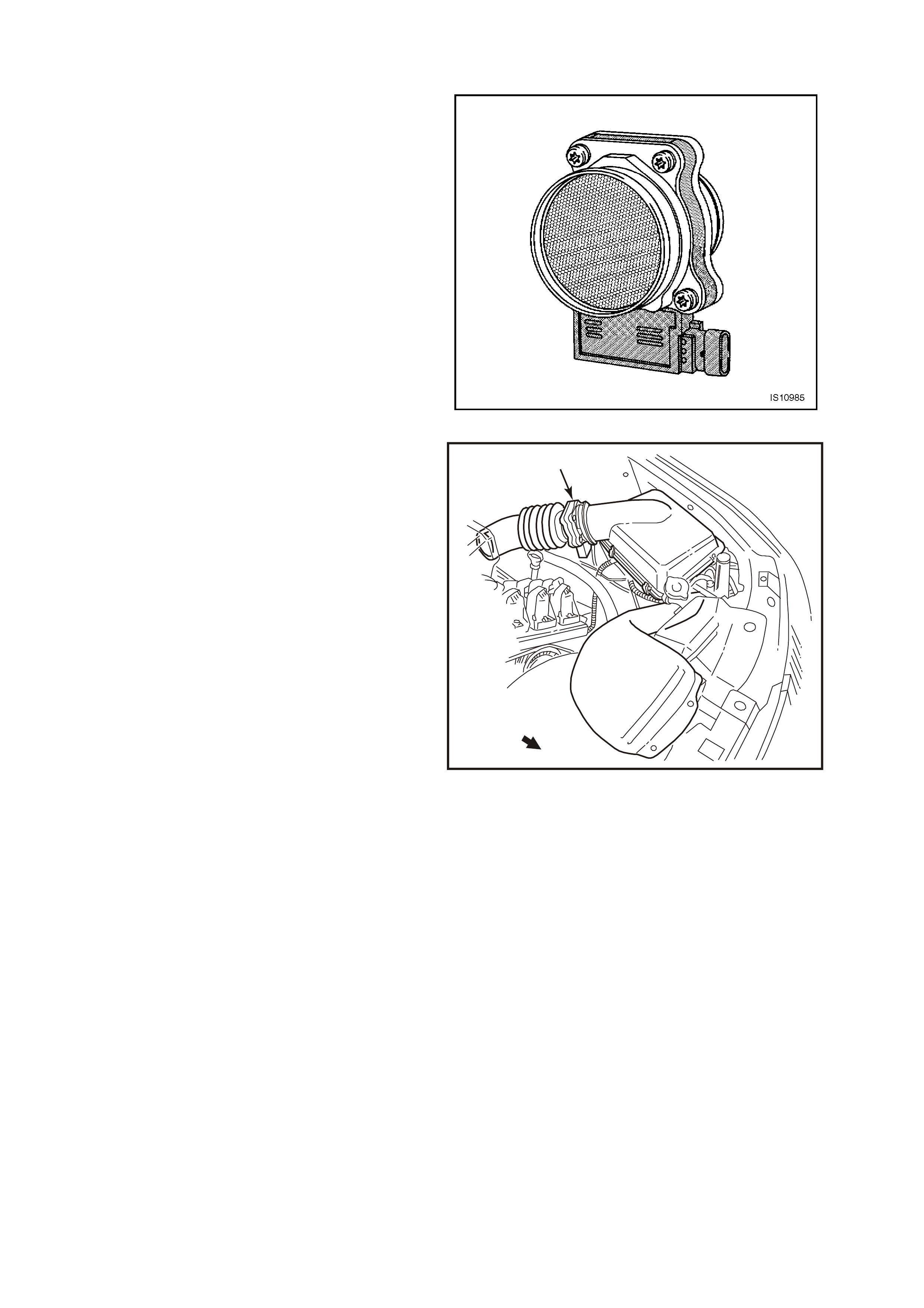
Figure 6C1-1-28 Mass Air Flow Sensor
1
4216
Figure 6C1-1-29 MAF Sensor Location
1. MAF Sensor
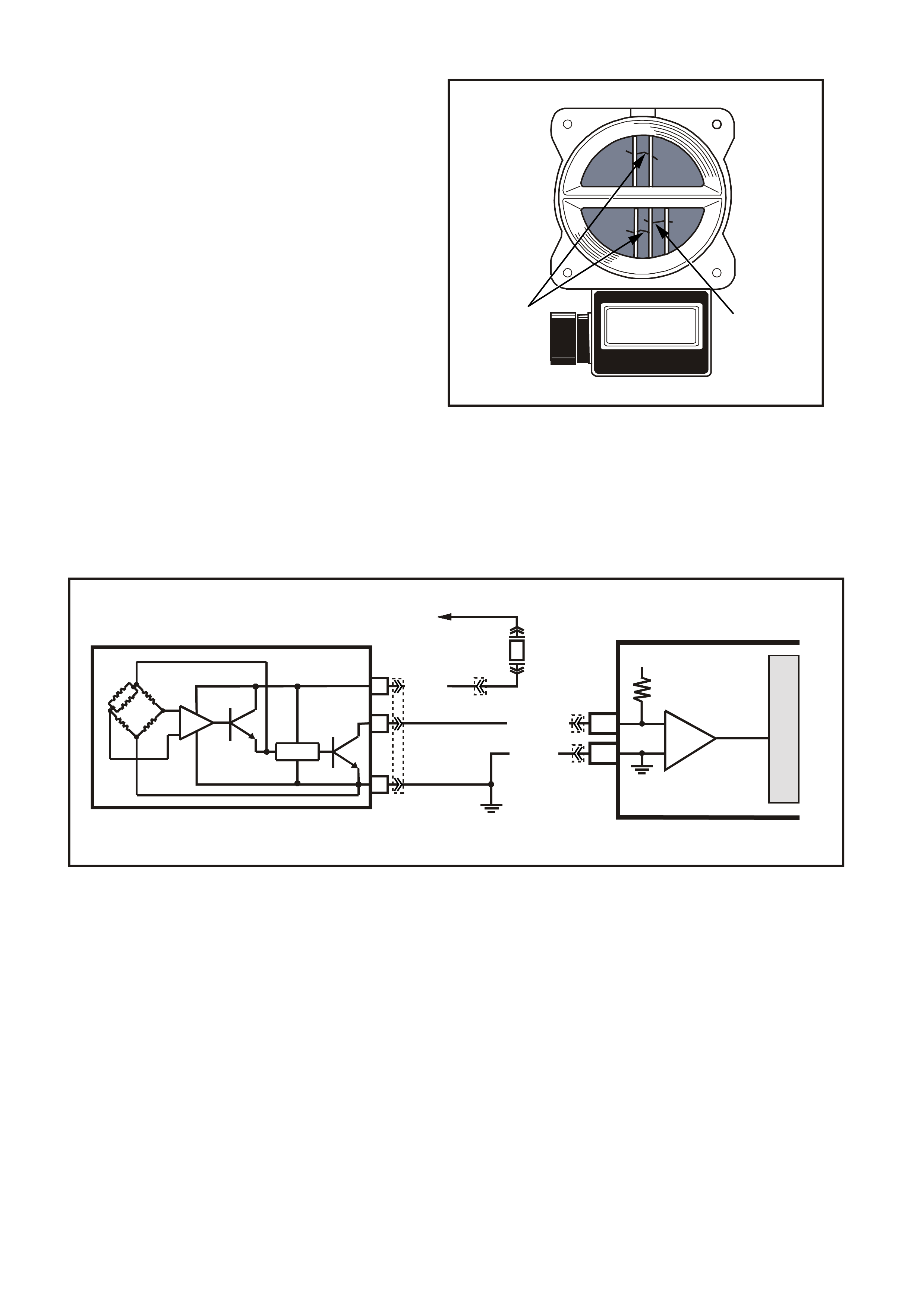
Three sensing elements are used in this system.
One senses am bient air temperature and uses two
calibratable resistors to establish a voltage that is
always a function of ambient temperature. This
ambient sensor is mounted in the lower half of the
sensor housing. The other two sensing elements
are heated to a predetermined temperature that is
significantly above ambient air temperature. The
two heated elements are connected electrically in
parallel and mounted directly in the air flow stream
of the sens or housing. One sens or is in the top and
one sensor is in the bottom of the sensor housing.
This is done so that the air meter is less sensitive
to upstream ducting configurations that could skew
the flow of air through the housing.
As air passes over the heated elements during
engine operation they begin to cool. By measuring
the amount of electrical power required to maintain
the heated elements at the predetermined
temperature above ambient temperature the mass
air flow rate can be determined.
Once the mass air flow sensor has developed an
internal signal related to the mass air flow rate, it
must send this information to the PCM. In order to
preserve the accuracy and resolution of the small
voltage signal in the mass air flow sensor, it is
converted to a frequency signal by a voltage
oscillator and sent to the PCM.
1
2
4217
Figure 6C1-1-30 Sensing Elements
1. Ambient Temperature Sensor
2. Heater Sensing Elements
Figure 6C1-1-31 MAF Sensor Simplified Schematic
VXSC006A
D1A
B
C
A1
PCM
EFI
RELAY
F33
BR/W (792)
MASS AIR FLOW
INP U T SIG NAL
EARTH
5 V
M
I
C
R
O
IC
B/R (750)
LOC. E5/E15
MASS AIR F LOW SENSOR
+
-
P (43 9)
YB193
YB188
YE100
YE111
The signal that is sent from the mass air flow
sensor is sent in the form of a frequency output. A
large quantity of air passing through the sensor
(such as when accelerating) will be indicated as a
high frequency output. A small quantity of air
passing through the sensor will be indicated as a
low frequency output (such as when decelerating
or at idle). The Tech 2 scan tool displays MAF
sensor information in frequency, and in grams per
second and calculated in mg per cylinder. At idle
the readings should be low and increase with
engine RPM.
As the PCM receives this f requency signal from the
Mass Air Flow sensor, it searches its pre-
program med tables of inf ormation to determine the
pulse width of the fuel injectors required to match
the Mass Air Flow signal.
If a problem occurs in the Mass Air Flow sensor
circuit, after a period of time, the PCM will store a
DTC in its memory. The PCM will turn "ON" the
"Check Powertrain" lamp Malfunction indicator
Lamp (MIL) indicating there is a problem. If this
occurs, the PCM will calculate a "substitute" Mass
Air Flow signal based on engine speed and
Throttle Position (TP) sensor signal.
No field service adjustment is necessary or
possible with this Mass Air Flow sensor.
A failure in the Mass Air Flow sensor circuit should
set DTC 32 will set.
Remember, this DTC indicates a failure in the
circuit, so proper use of the diagnostic Table will
lead to either repairing a wiring problem or
replacing the MAF Sensor, to properly repair a
problem.
32 1
4219
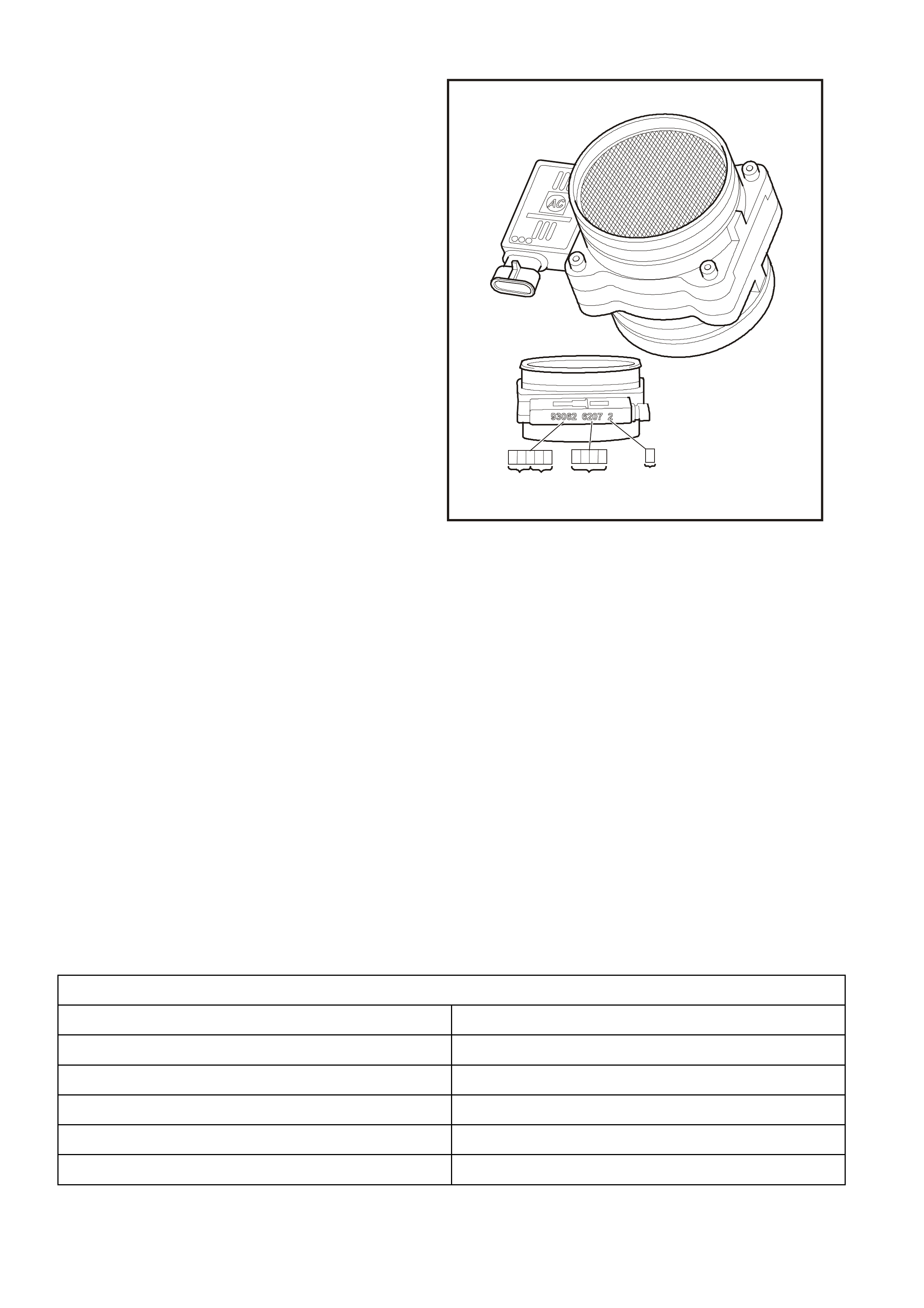
Figure 6C1-1-32 Mass Air Flow Sensor Identification
1. Flow Stand Number
2. Last Four Digits Of Part Number
3. Year Julian Date
DTC 32 (Mass Air Flow System Performance) will set if:
• The engine is running.
• No MAF Signal for over two seconds.
• Above conditions present for at least 10 seconds.
• The PCM will illuminate the Malfunction Indicator Lamp (MIL).
DEFAULT VALUE
W hen a MAF sens or or circuit f ault is detected, and current, the PCM will subs titute a MAF sensor value based
on RPM, throttle angle and IAC position.
RECOVERY
Recovery will occur when the PCM sees a valid condition.
DTC 32 HISTORY DATA
PARAMETER PARAMETER
ENGINE SPEED R.H O2 SENSOR
TIME FROM START MASS AIR FLOW
TIMES OCCURRED R.H STFT
IGNITION CYCLES R.H LTFT
COOLANT TEMPERATURE THROTTLE ANGLE
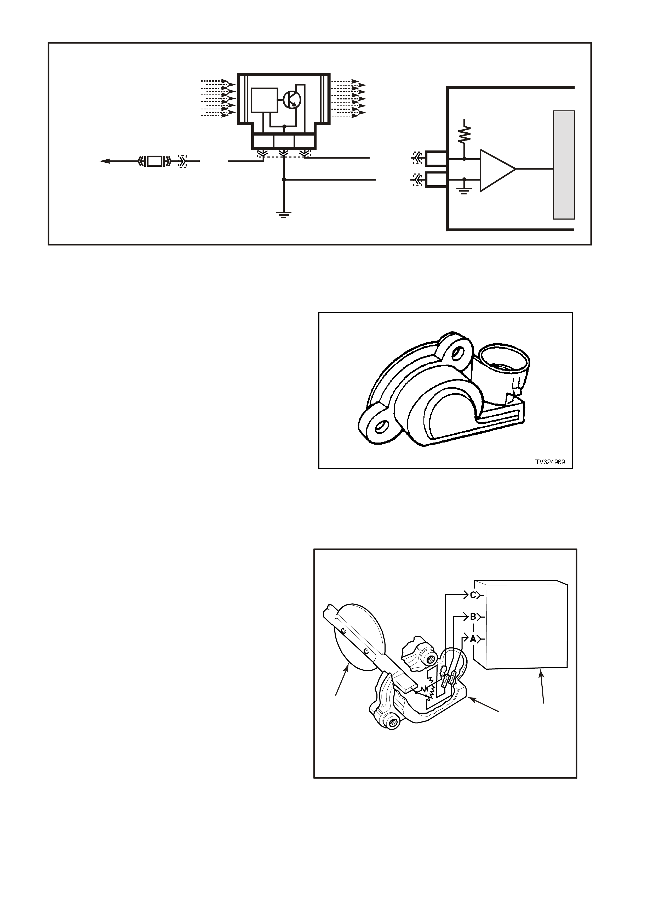
Figure 6C1-1-33 MAF Sensor Circuit
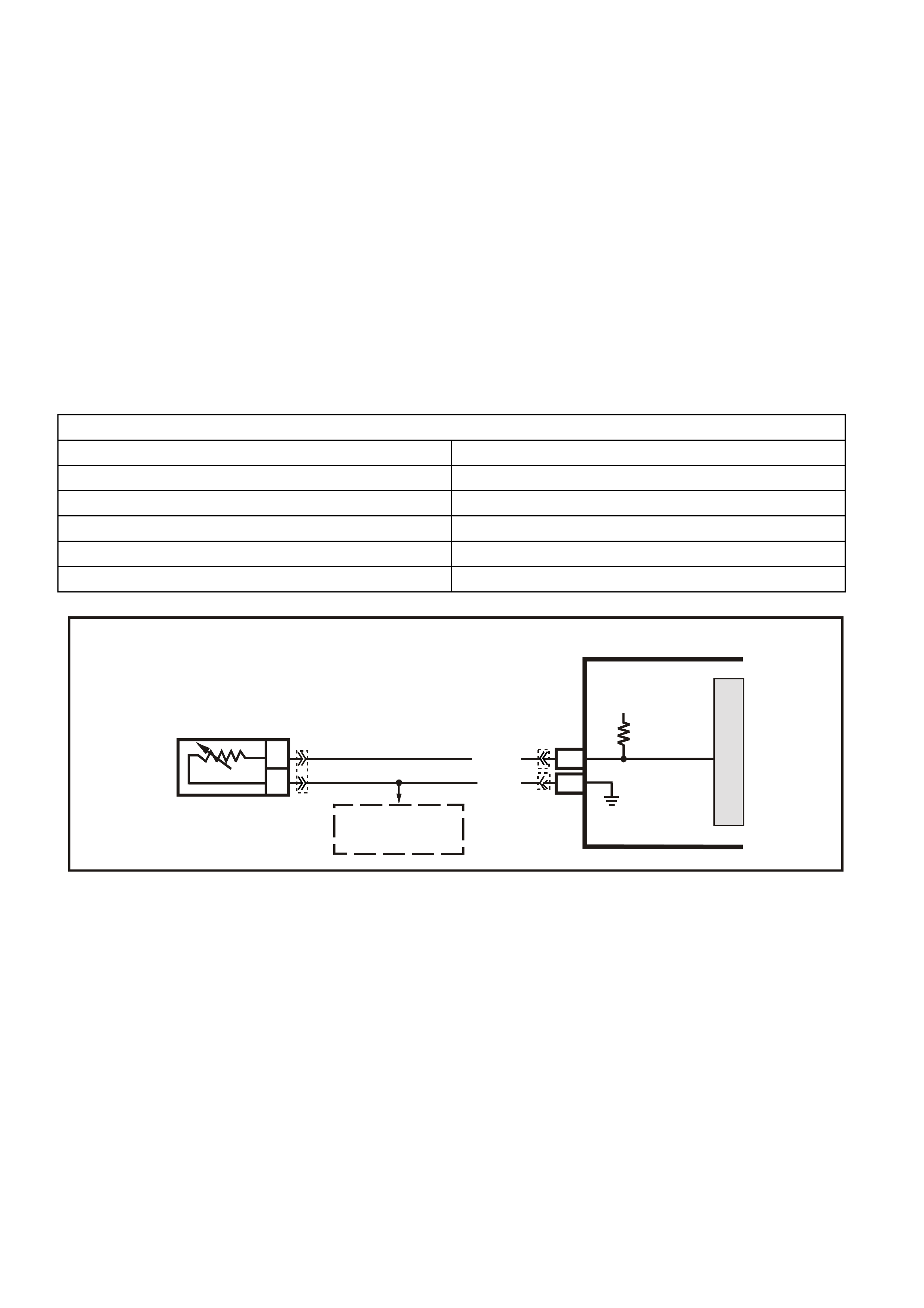
THROTTLE POSITION (TP) SENSOR
The Throttle Position (TP) sensor is connected to
the throttle shaft on the throttle body unit. It is a
potentiometer with one end connected to 5 volts
from the PCM and the other end to PCM earth. A
third wire connects from a sliding contact in the T P
sensor to the PCM allowing the PCM to measure
the voltage from the TP sensor. As the throttle is
moved ( acceler ator pedal m oved), the output of the
TP sensor changes. At a closed throttle position,
the output of the TP sensor is below 1.25V. As the
throttle valve opens, the output increases so that,
at wide-open throttle (WOT), the output voltage
should be about 4 volts.
By monitoring the output voltage from the TP
sensor, the PCM c an determ ine fuel delivery based
on throttle valve angle (driver demand). A broken
or loose T P sensor c an cause intermittent bursts of
fuel from the injectors, and an unstable idle,
because the PCM interprets the throttle is moving.
Figure 6C1-1-34 TP Sensor
The TP sensor is not adjustable and there is not a
set value for voltage at closed throttle because the
actual voltage at closed throttle can vary from
vehicle to vehicle due to tolerances. The PCM has
a special progr am built into it that can adjus t for the
tolerances in the T P sensor voltage reading at idle.
The PCM uses the reading at closed throttle idle
for the zero reading (0% throttle) so no adjustment
is necessary. Even if the TP sensor voltage
reading was to be change by: tampering, throttle
body coking, sticking cable or any other reason,
the TP sensor will still be 0%. The PCM will learn
what the closed throttle value is every time the
throttle comes back to closed throttle. The new
closed throttle value will be used by the PCM and
no driveability complaint will be present because
the PCM learned a new setting.
A failure in the TP sensor circuit should set either
DTC 21 or 22.
If the internal spring in the TP sensor should fail,
the TP sensor will be stuck high. A sticking TP
sensor should set DTC 19.
4220
321
Figure 6C1-1-35 TP Sensor – Typical
1. Control Module
2. Throttle Position (TP) Sensor
3. Throttle Valve
VXSC006
MASS AIR FLOW SENSOR
D1
A1
PCM
CBA
AIR FLOW
FROM
AIR FILTER
AIR FLOW
TO
THROTTLE BODY
TO
EFI
RELAY
P (43 9)
LOC. E5/E15
BR/W (792)
MASS AIR FLOW
INPUT SIGNAL
EARTH
5 V
M
I
C
R
O
IC
B/R (750)
F33
IC
CIRCUIT
YB188
YE100
YE111 YB193
31
2
4221
Figure 6C1-1-36 TP Sensor Location
1. Idle Air Control (IAC) Valve
2. Throttle Position (TP) Sensor
3. Throttle Body
DTC 19 (Throttle Position Sensor Stuck) Sensor Low Voltage) will set if:
• The TP Sensor indicated percentage of opening is greater than the RPM that can be reached with a Mass
Air Flow of less than 301 mg/cyl.
• The PCM will illuminate the Malfunction Indicator Lamp (MIL).
DTC 21 (Throttle Position Sensor Signal Voltage High) will set if:
• The TP Sensor voltage between the PCM TP Sensor signal terminal and the TP Sensor earth terminal is
greater than 4.9 volts for more than two seconds.
• The PCM will illuminate the Malfunction Indicator Lamp (MIL).
DTC 22 (Throttle Position Sensor Signal Voltage Low) will set if:
• The TP Sensor voltage between the PCM TP Sensor signal terminal and the TP Sensor earth terminal is
less than 0.2 volts for more than two seconds.
• The PCM will illuminate the Malfunction Indicator Lamp (MIL).
DEFAULT VALUE
Once a T P Sens or DT C is set, and cur rent, the PCM will subs titute a T P Sensor value based on Idle Air Control
Valve position and Mass Air Flow.
RECOVERY
Recovery will occur when the PCM sees a valid condition.
DTC 19, 21, AND 22 HISTORY DATA
PARAMETER PARAMETER
ENGINE SPEED TP SIGNAL
TIME FROM START MASS AIR FLOW
TIMES OCCURRED R.H LTFT
IGNITION CYCLES BATTERY VOLTAGE
COOLANT TEMPERATURE REFERENCE VOLTS
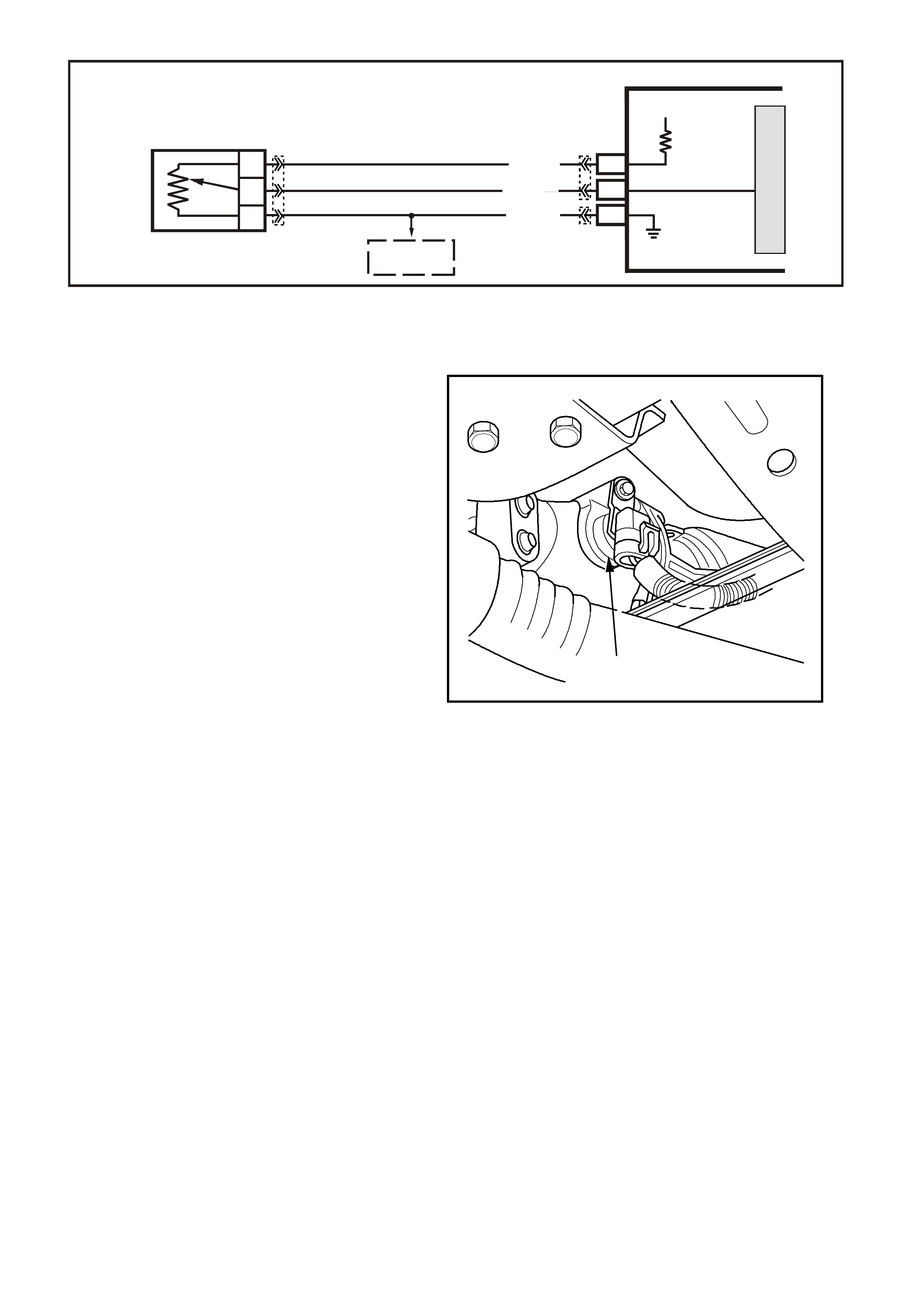
Figure 6C1-1-37 TP Sensor Circuit
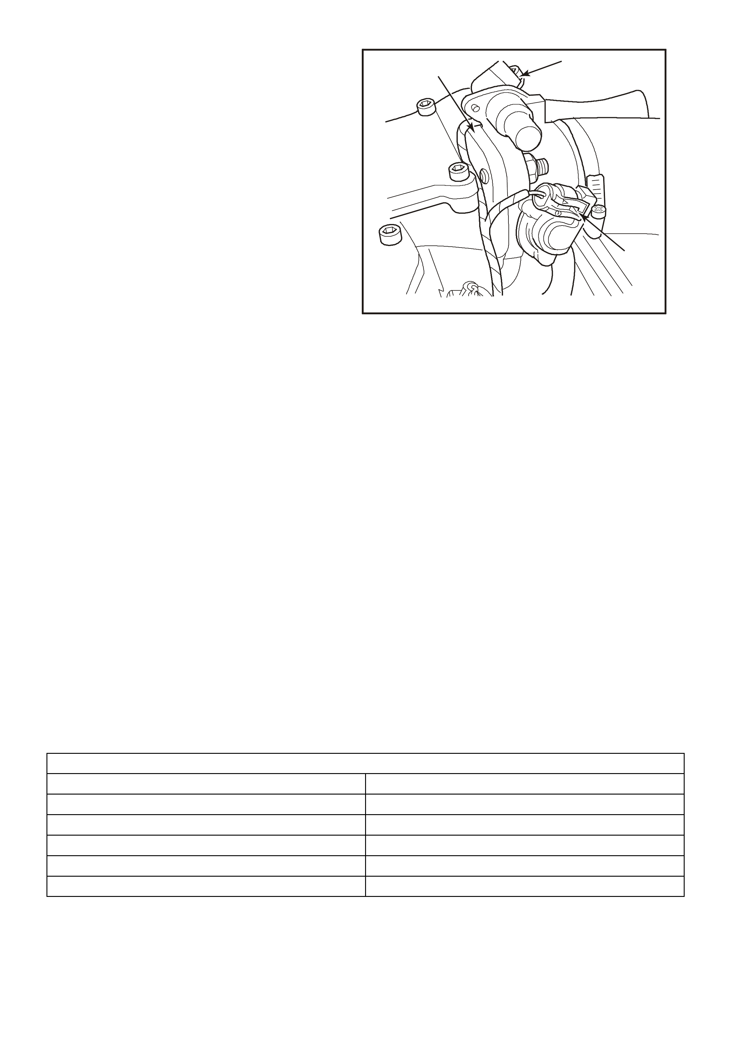
VEHICLE SPEED SENSOR (VSS)
The Vehicle Speed Sensor (VSS) is located on the
transm iss ion. Refer to F igure 6C1-1-38 f or the VSS
Location - Automatic Transmission and 6C1-1-39
for the VSS Location - Manual Transmission.
The VSS provides an indication of road speed to
the PCM. The sensor is mounted to the
transmission where it is gear driven by the
transmission output shaft. The sensor is an
electronic Hall effect switch that pulses to earth a
voltage signal c oming f rom the PCM. T hese pulses
occur 10 tim es per sens or revolution, and are used
by the speedometer for driver information.
The PCM also uses information from the VSS for
IAC valve operation and some of the engine
fuelling modes. If the PCM receives no pulses on
the vehicle speed sensor input while certain
conditions exist, DTC 24 (Automatic Transmission)
or DTC 94 (Manual Transmission) will be set.
DTC 24 or 94 will set if a fault exists in the vehicle
speed sensor circuit when the vehicle is
decelerated, and the VSS signal is constant, or not
pulsing. The DTC will set and a default value will
be substituted by the PCM. As long as the fault
remains and the diagnostic trouble code is set. If
the fault is removed, normal operation will resume
after the next ignition cycle
1
4222
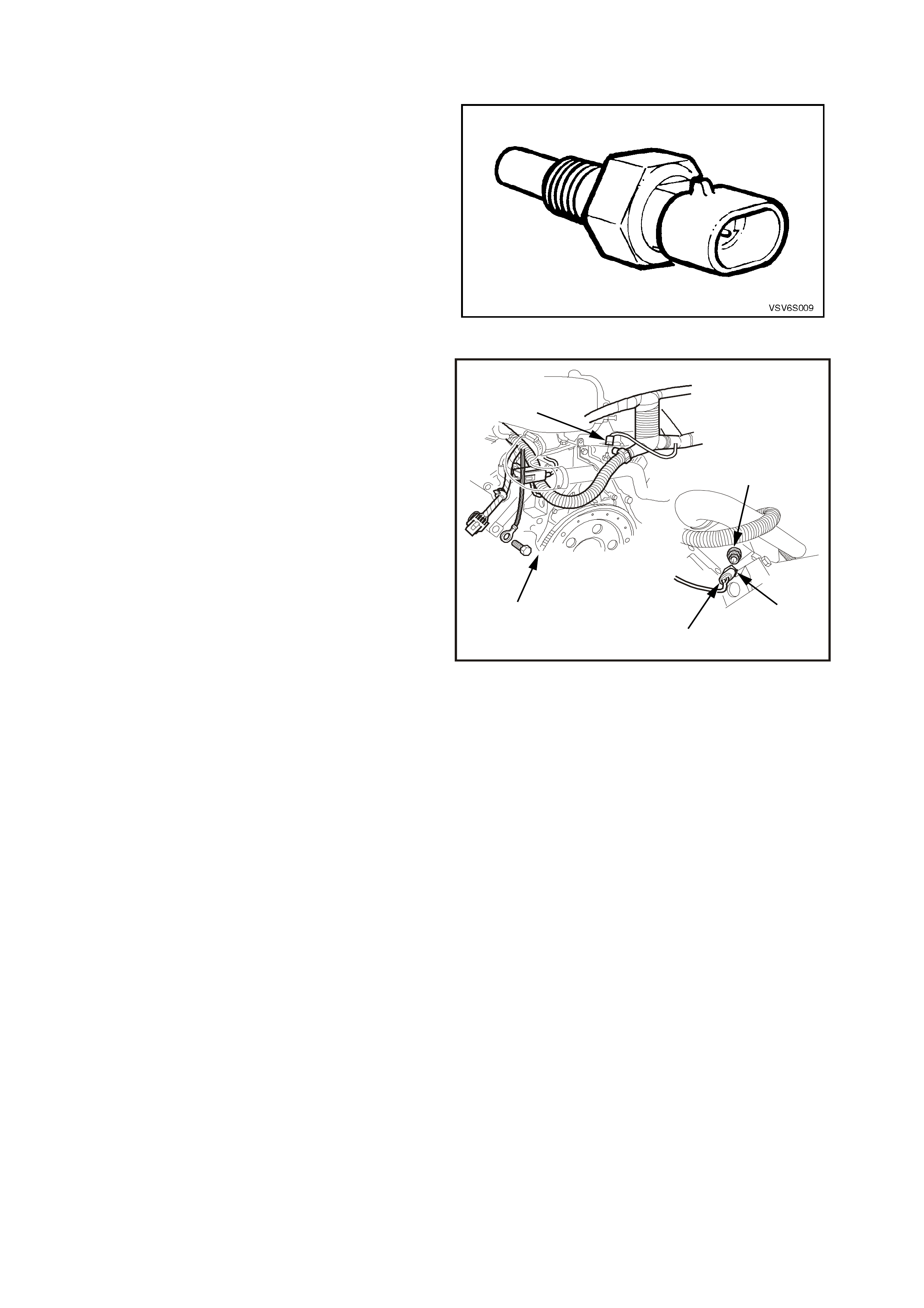
Figure 6C1-1-38 VSS Location - Automatic Transmission
1. Vehicle Speed Sensor (VSS)
VXSC005
SENSOR EARTH
TP SENSOR SIGNAL
TP SENSOR
REFERENCE
VOLTAGE
PCM
5V
M
I
C
R
O
A
C
B
THROTTLE
POSITION SENSOR
A7
B11
E16
BLU (417)
B/Y (452)
GY (416)
TO
ECT SENSOR
YB188
YB194
YE30
1
2
4223
Figure 6C1-1-39 VSS Location - Manual Transmission
1. Bolt
2. Sensor To Bracket Screw
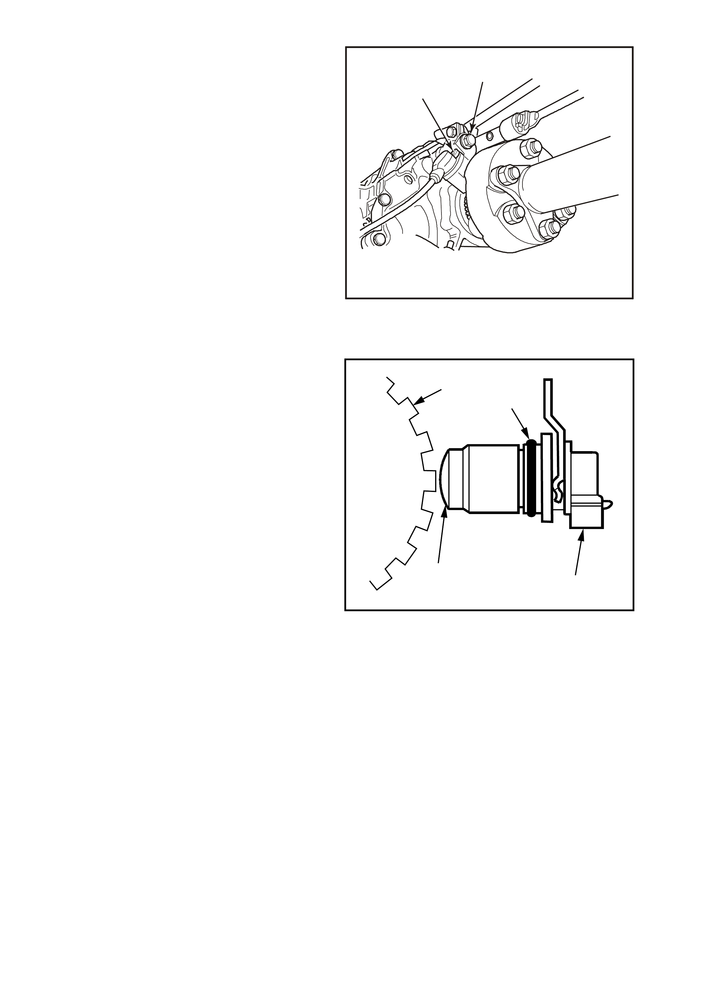
The vehicle speed sensor contains a coil that has
continuous magnetic field. A voltage signal is
induced in the vehicle speed sensor by teeth on
the output shaft that rotate past the sensor and
break the magnetic field. Each break in the field
sends an electrical pulse to the PCM. This voltage
output will vary with transmission output shaft
speed f rom a m inim um of 0.5 volts AC at 100 RPM
to more than 100 volts AC at 8000 RPM with no
load on the c ircuit on the vehic le, with the engine at
4,000 RPM in fourth gear the voltage will be
approximately 10-12 Volts AC.
The PCM uses speed information from this sensor
to determine the following:
• Vehicle speed.
• Control shift points (Auto Trans).
• Calculate transmission slip (Auto Trans).
• Engine fuelling modes.
DTC 24 or 94 will set if a fault exists in the vehicle
speed sensor circuit indicating the vehicle is not
moving. For the automatic transmission, as the
vehicle is accelerated the PCM shifts the
transmission to second gear at approximately 50
km/h. If the vehicle speed signal is still not present
while in second gear, the DTC is set, the
transmission will have maximum line pressure, 2
ND gear only and have no TCC and a default value
will be substituted by the PCM.
DTC 72 will set if there is an intermittent failure in
the VSS c ircuit while the vehic le is moving. As long
as the fault remains and the DTC 72 is set, the
PCM will have max imum line press ure and 3rd gear
only for the automatic transmission. If the fault is
removed, normal operation will resume after the
next ignition cycle.
2
3
41
4224
Figure 6C1-1-40 VSS
1. “O” Ring
2. Electrical Connector
3. Magnetic Pickup
4. Rotor

DTC 24 (Vehicle Speed Sensor Circuit Low Voltage) will set if:
Automatic Transmission
• The transmission is not in Park or Neutral.
• The engine speed is greater than 3000 RPM.
• The TP Sensor angle is between 10% and 99%.
• The VSS indicates an output shaft speed of less than 3 km/h for 3 seconds.
• The PCM will illuminate the Malfunction Indicator Lamp (MIL).
DTC 94 (Vehicle Speed Sensor Circuit Low Voltage) will set if:
Manual Transmission
• The engine speed is between 1400 and 3000 RPM.
• The throttle is closed (throttle angle less than 1%).
• Engine load very low, MAF less than 95 mg/cyl.
• The VSS indicates no output shaft speed for more than 4 seconds.
• Vehicle in gear.
• Vehicle is decelerating from road speed.
DEFAULT VALUE
For the automatic transmission, when this DTC sets, the PCM will command second gear only, The PCM will
command maximum line pressure, The PCM will freeze shift adapts from being updated, The PCM will inhibit
TCC engagement.
RECOVERY
Recovery will occur when the PCM sees a valid condition.
DTC 24, 94 HISTORY DATA
PARAMETER PARAMETER
ENGINE SPEED THROTTL ANGLE
TIME FROM START TFT
TIMES OCCURRED MASS AIR FLOW
IGNITION CYCLES COMMANDED GEAR (AUTO)
COOLANT TEMPERATURE VEHICLE SPEED
DTC 72 (Output Speed Loss) will set if:
Automatic Transmission
• The transmission is not in Park or Neutral.
• Two successive speed readings have a difference of more than 1000 RPM in any drive range (difference
must be more than 2048 RPM in park or neutral). This test checks the vehicle speed sensor signal to the
PCM.
• The PCM will not illuminate the Malfunction Indicator Lamp (MIL).
DEFAULT VALUE
W hen Diagnostic Trouble Code 72 is set, the transm ission will have maxim um line pressure and comm and 3rd
gear only. If DTC 72 is set while in 4th gear, the vehicle will stay in 4th gear. However, as the vehicle is c oasting
to stop the transm ission will downshif t normally from 4 to 3. Once the downshift into 3rd gear has occurred, the
vehicle will stay in 3rd gear.
RECOVERY
Recovery will occur when the PCM sees a valid condition.
DTC 72 HISTORY DATA
PARAMETER PARAMETER
ENGINE SPEED TRANSMISSION SLIP SPEED
TIME FROM START TFT
TIMES OCCURRED THROTTLE ANGLE
IGNITION CYCLES VEHICLE SPEED
COOLANT TEMPERATURE COMMANDED GEAR
Figure 6C1-1-41 VSS Circuit
17
V/W (123)
12V IGN
VEHICLE SPEED
M
I
C
R
O
SUPERVX016
INSTRUMENT
M
I
C
R
O
VEHICLE SPEED
PCM
C5
C6
D5
V
EHICLE SPEED
SENSOR
IC
BLU/W
(831)
(AUTO)
BLU
(831)
(MAN)
T
(832)
(AUTO)
BR
(832)
(MAN)
SPEEDOMETER
YB193
YB195 (AUTO)
YB132 (MANUAL)
YE110
YB66
A/C REQUEST SIGNAL
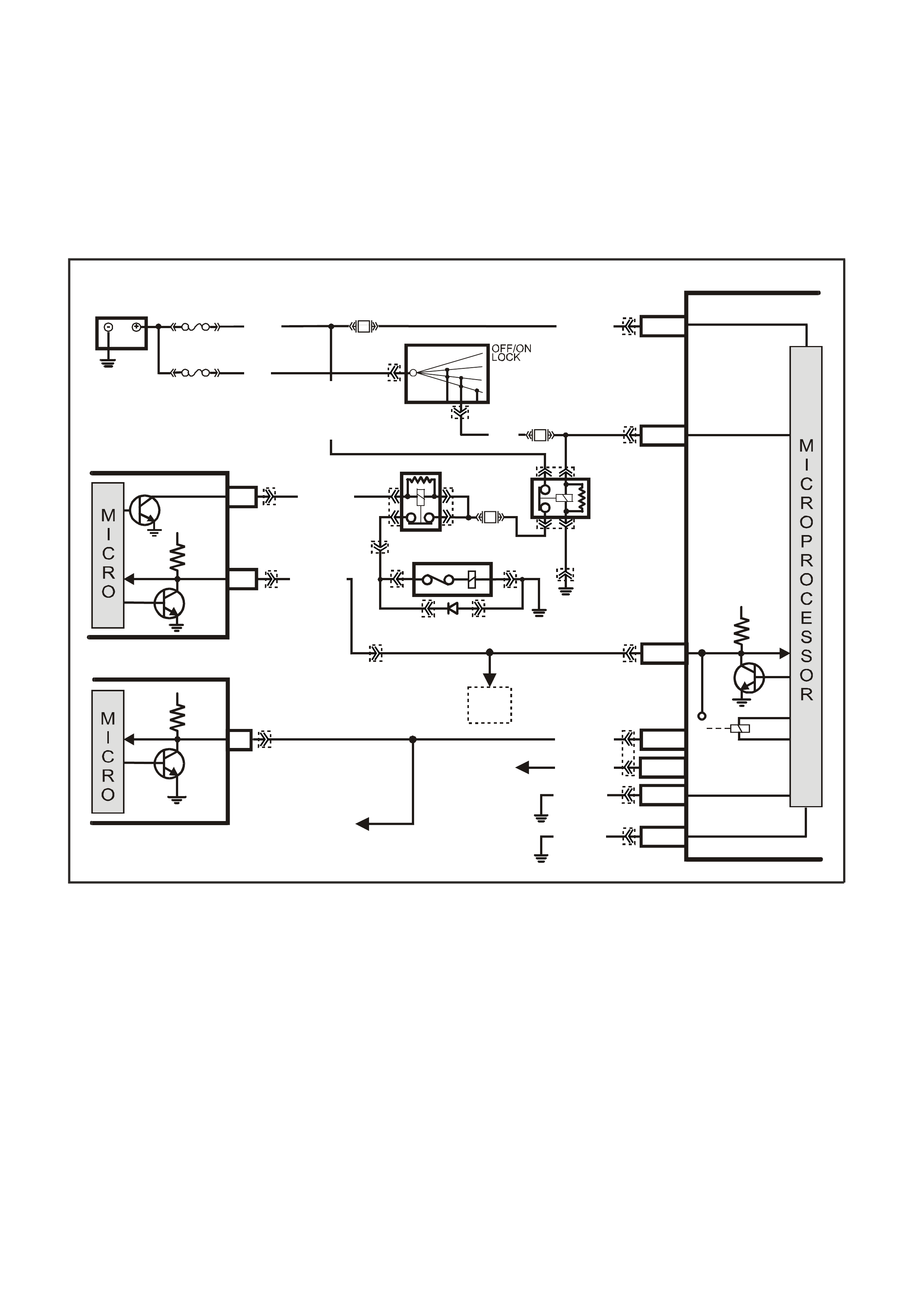
W hen A/C is requested from the dash m aster A/C switch, the A/C request signal is sent to the BCM. The BCM
will then send a command via the serial data line to the PCM. The PCM will then supply a earth signal to the
A/C compressor relay, to energise the A/C compressor. There are no PCM DTC(s) associated with this A/C
Request Signal. Refer to Section 6C1-2A table A-11.1 or A 11.3 for A/C system diagnosis.
The PCM uses this BCM serial data command to:
1. Adjust the Idle Air Control (IAC) position to compensate for the additional load placed on the engine by the
air conditioning compressor, and then
2. Energises the A/C compressor relay, to operate the A/C compressor.
Figure 6C1-1-42 A/C Request Signal Circuit With ECC
B/Y (155)
B/G (151)
ELECTRONIC EARTH
HIGH CURRENT
EARTH
A1/A5
B10/B11
E3/D13
E9/D3
E2/D2
E20/D6
A5/A6
LOC. E3
LOC. E5/E15
LOC. E3
LOC. E3
PCM
ECC
BCM
TO ABS/ETC
CONTROL MODULE
AND INSTRUMENTS
TO SRS
CONTROL
MODULE
TO
DLC
A3
6
SERIAL
DATA
A/C
ENABLE
SERIAL
DATA
SUPERVX018
5V
5V
SERIAL
DATA AUX .
R/B (1221)
G/W (1220)
G/W (1220)
SERIAL
DATA
MAIN
5V
BATTERY
FS
O/B (740)
(1040)
O/Y (479)
BATTERY MAIN POWER
FJ
R (2)
F14
F33
P/B
(39)
B/W
(152)
IGNITION ON
15a 15 50
30 ACC
IGN
START
IGNITION SWITCH
HIGH SERIES
BCM TERMINALS
NOM IN ATE D FIRS T
P (3)
A/C
COMPRESSOR
A/C RELAY
EFI
RELAY
F4
F31
LG/B (366)
YB176
YB165
YB174
YB163
YB175
YB164
YB175
YB164
YB44
YB194
YB188
YB87
YE112
YE105 YE114
YE105
YE120 YE120
YB44
YE101
YE39
YE39
YE101
YB176
YB165
YB175
YB164
YE101YE101YE101
YE101
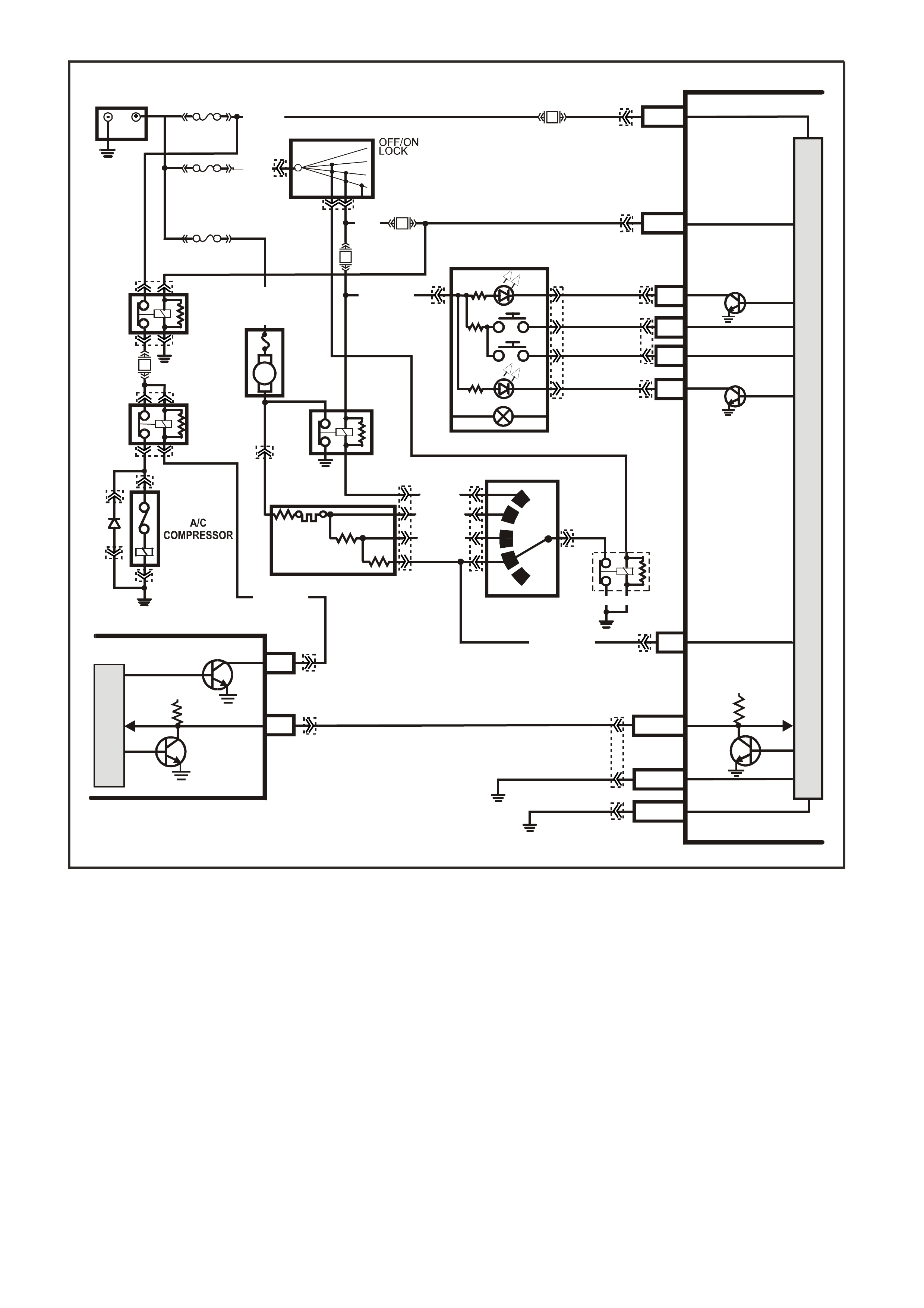
Figure 6C1-1-43 A/C Request Signal Circuit Without ECC
BATTERY VOLTAGE
The PCM continually monitors battery voltage. When the battery voltage is low, the ignition system may deliver
a weak spark and the injector mechanical m ovement takes longer to open the injector. The Powertrain Control
Module will compensate by:
1. Increasing the ignition coil dwell time if the battery voltage is less than 12 volts.
2. Increasing the engine idle RPM if battery voltage drops below 10 volts.
3. Increasing the injector pulse width if the battery voltage drops below 10 volts.
On vehicles equipped with automatic transmissions, Diagnostic Trouble Code 52 will set when the engine is
running and the voltage at PCM ter minal “ A4” is above 16 volts for 109 minutes. Diagnostic Trouble Code (DTC)
53 will set when the ignition is "ON'' and PCM terminal "A4'' voltage is more than 19.5 volts for about 2 seconds.
Diagnostic Trouble Code (DTC) 54 will set when the ignition is "ON'' and PCM terminal "A4'' voltage changed
more than 2.5 volts in 100 milliseconds.
Diagnostic T rouble Code (DT C) 75 will set when the ignition is "ON'' and PCM terminal "A4'' voltage is less than
8.6 volts for about 4 seconds . Minim um voltage allowed for Diagnos tic T rouble Code 75 to set is on a graduated
scale and will change with the tem perature. Minimum voltage at -40 degrees C is 7.3 volts, minim um voltage at
90 degrees C is 8.6 volts., minimum voltage at 152 degrees C is 11.4 volts.
SUPERVX019
D20
A1
D9
B8
A
/C MASTER
SWITCH
HIGH SERIES
BCM TERMINALS
NOM IN ATE D FIRST
O
(291)
B/R
(292)
R/W
(248)
R/BR
(962)
BR
(4)
Y
(51)
B3
BLOWER
MOTOR
RESISTORS
A/C
RELAY
EFI
RELAY
BLOWER
MOTOR
HEATER AND A/C
CONTROLS
BLOWER
INHIBIT
RELAY
DKG/Y (359)
LOC.E3
LOC.E3
Y/B (52)
R/G (245)
LG/B (366)
4
3
2
1
R/Y (244) O/G
(251)
DKG/Y
(359)
BATTERY MAIN POWER
BATTERY
IGNITION SWITCH
FY
F31
O/B
(740)
FS
(1040)
BCM
B/G
(151) HIGH CURRENT
EARTH
IGNITION
DEMIST OUTPUT
DEMIST INPUT
A/C SWITCH INPUT
A/C LED OUTPUT
A/C BLOWER
INPUT
F14
F13
F33
E20/D6
A5/A6
E2/D2
B10/B11
A1/A5
P/B
(39)
15a 15 50
30 ACC
IGN
START
P (3)
R/B
(1221)
SERIAL DATA
A/C ENABLE
5V
SERIAL
DATA
5V
M
I
C
R
O
PCM
A3
F4
B/Y
(155) ELECTRONIC EARTH
FJ
R (2H)
R (2A)
P/BLU (44)
M
I
C
R
O
P
R
O
C
E
S
S
O
R
B (1 50)
YE120
YB188
YB194
YE105
YE105
YB2
YB2 YB50
YB50
YB163
YB176
YB165
YB175
YB164
YE101
YE39
YE39
YB44
YE101
YE120
YB44
YB54
YB54 YB165
YB175
YB164
YB176
YB165
YB164
YB163

DTC 52 (System Voltage Too High – Long Time) will set if:
• The engine is running and the PCM ignition voltage is greater than 16 volts for more than 109 minutes.
• The ECT sensor reading changes more than 400 mV in 200 milliseconds.
• Above conditions present for at least 10 seconds.
• The PCM will illuminate the Malfunction Indicator Lamp (MIL).
DEFAULT VALUE
During the time fault is present, the pressure control solenoid is turned "OFF", the transmission shifts
immediately to 3rd gear and TCC operation is inhibited.
RECOVERY
Recovery will occur when the PCM sees a valid condition.
DTC 53 (System Voltage High) will set if:
• Ignition is on.
• Voltage at PCM ignition feed terminal is more than 19.5 volts for more than 2 seconds.
• The PCM will illuminate the Malfunction Indicator Lamp (MIL).
DEFAULT VALUE
During the time fault is present, the PCM will turn all transmission output devices off and freeze shift adapts
from being updated.
RECOVERY
Recovery will occur when the PCM sees a valid condition.
DTC 54 (System Voltage Unstable) will set if:
• Ignition is on.
• System voltage changes more than 2.5 volts in 100 millivolts.
• Above conditions present for at least 10 seconds.
• The PCM will illuminate the Malfunction Indicator Lamp (MIL).
DEFAULT VALUE
There are no default values.
RECOVERY
Recovery will occur when the PCM sees a valid condition.
DTC 75 (System Voltage Low) will set if:
• The system voltage is less than 7.3 volts with the TFT at or above -40°C.
Or
• The system voltage is less than 10 volts with the TFT at or below 151°C.
• The PCM will illuminate the Malfunction Indicator Lamp (MIL).
DEFAULT VALUE
When DTC 75 sets, the PCM will turn off all transmission output devices and freezes shift adapts from being
updated. The PCM will also adjust ignition timing and adjust injector pulse width to compensate for the low
voltage condition.
RECOVERY
Recovery will occur when the PCM sees a valid condition.
DTC 52, 53, 54 AND 75 HISTORY DATA
PARAMETER PARAMETER
ENGINE SPEED ECT SENSOR
TIME FROM START IAT SENSOR
TIMES OCCURRED BATTERY VOLTAGE
IGNITION CYCLES REFERENCE VOLTS
COOLANT TEMPERATURE
Figure 6C1-1-44 PCM Battery Feed
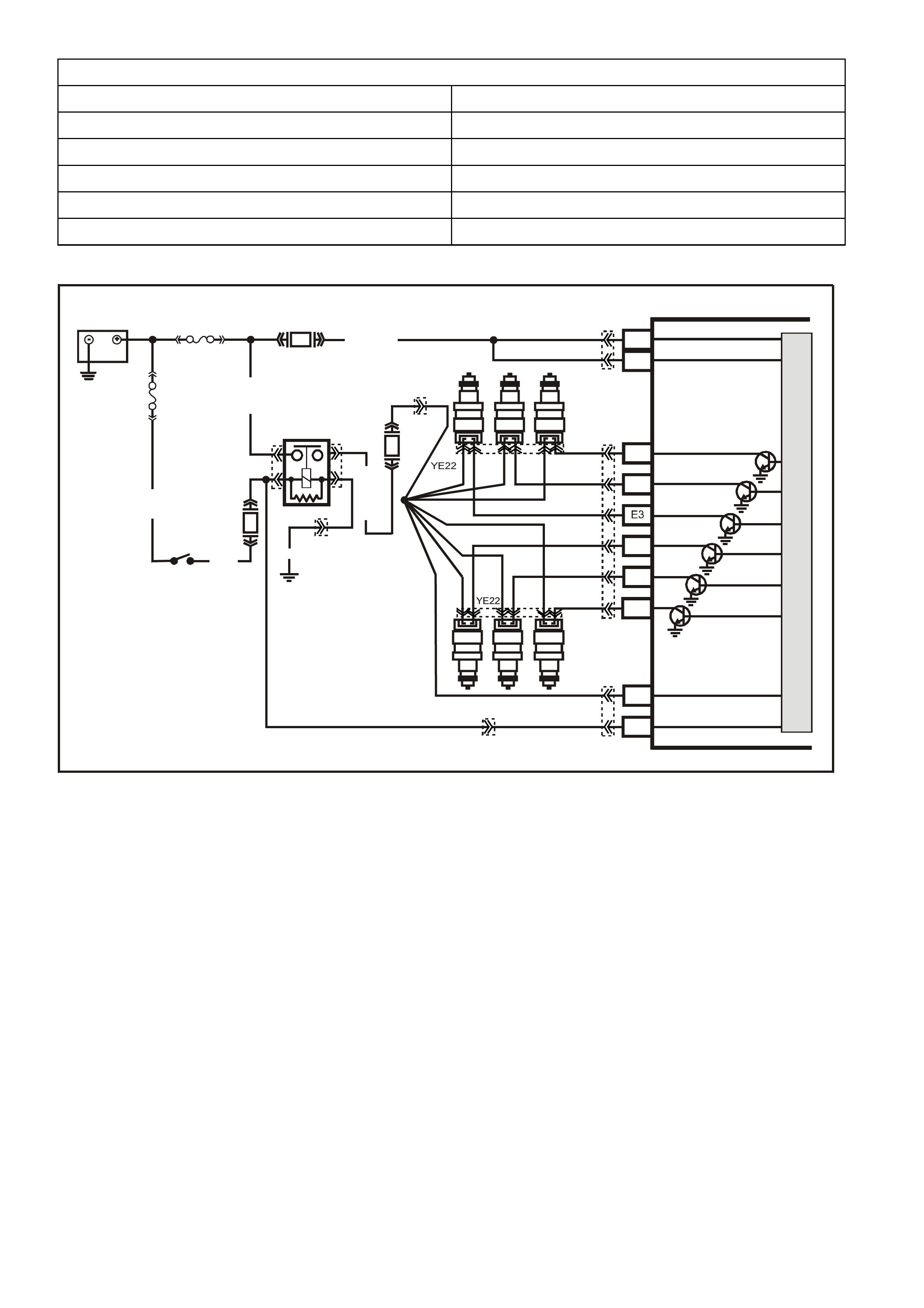
CRANKSHAFT REFERENCE SIGNAL
The Direct Ignition System (DIS) sends this signal to the PCM to tell it engine RPM and crankshaft position. This
signal is a repeating series of low voltage electrical pulses generated by the ignition module. The PCM initiates
fuel injector pulses based upon receiving these crankshaft reference signal pulses. If the PCM's MAF sensor
input detects manifold vacuum and the ignition voltage input detects less than 11 volts and there are no
distributor reference input pulses, a DTC 46 will set.
This engine also uses the c amshaf t position sensor signal to synchronise the f uel injector circ uits for sequential
fuel injection. The PCM also uses these reference pulses for Electronic Spark Timing (EST) operation.
For a full description of the ignition system operation Refer to 1.6 DIRECT IGNITION SYSTEM (DIS) of the VX
Series Service Information.
DTC 46 (No Reference Pulses While Cranking) will set if:
• MAF DTC is not set.
• Battery voltage is at or below 11 volts.
• MAF sensor input is above 2048 Hz.
• No DIS reference input pulses at PCM.
• Conditions exist for more than 2 seconds.
• The PCM will illuminate the Malfunction Indicator Lamp (MIL).
SUPERVX017
# 2
# 4 # 6
# 1 # 3 # 5
PCM
A8
B8
F3
F1
F2
E2
E4
B12
A4
BATTERY FEED
BATTERY FEED
O
(740)
O
(740)
BLU
(841)
V
(843)
GY
(845)
INJECTOR CONTROL
IN JECTOR VOLTAGE
MONITOR LINE
IGNITION FEED
O/Y (479)
EFI R EL AY
B/W (152)
LOC. E4
P (3 )
O/B (740)
IGN SW
M
I
C
R
O
R
(481)
P
(39)
Y
(846)
BR/Y
(844)
G
(842)
F31
F14
F34
BATTERY
FS
FJ
R (2)
(1040)
YE112
YE114
YE111
YB194
YB188
YE39 YE39
YB188
DEFAULT VALUE
There are no default values for the Crankshaft Reference Signal. This DTC is intended to help in diagnosing a
no-start condition.
RECOVERY
Recovery will occur when the PCM sees a valid condition.
DTC 46 HISTORY DATA
PARAMETER PARAMETER
ENGINE SPEED REFERENCE VOLTS
TIME FROM START MASS AIR FLOW
TIMES OCCURRED CAM SIGNAL
IGNITION CYCLES FUELING MODE
COOLANT TEMPERATURE FUEL PUMP RELAY
BATTERY VOLTAGE
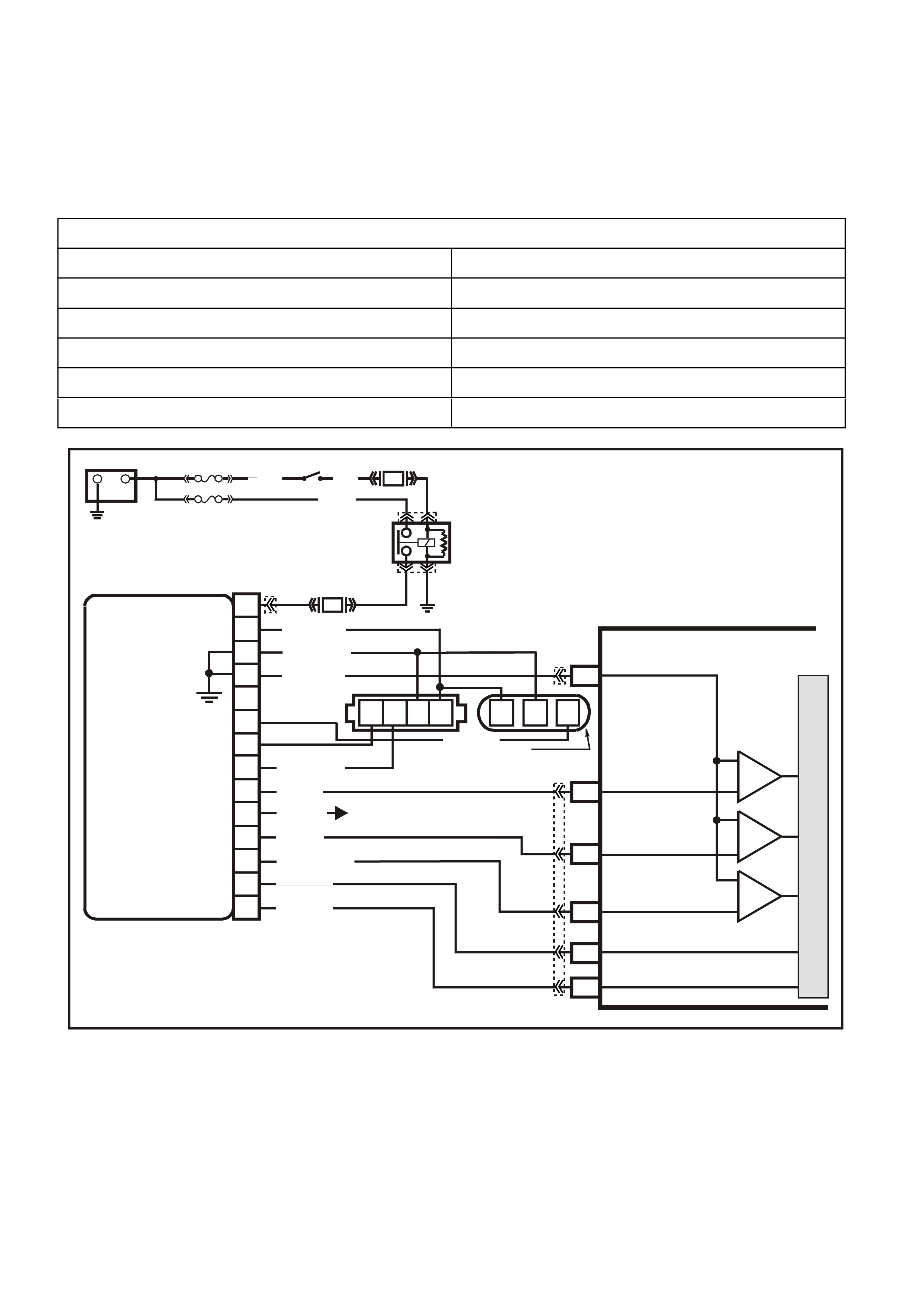
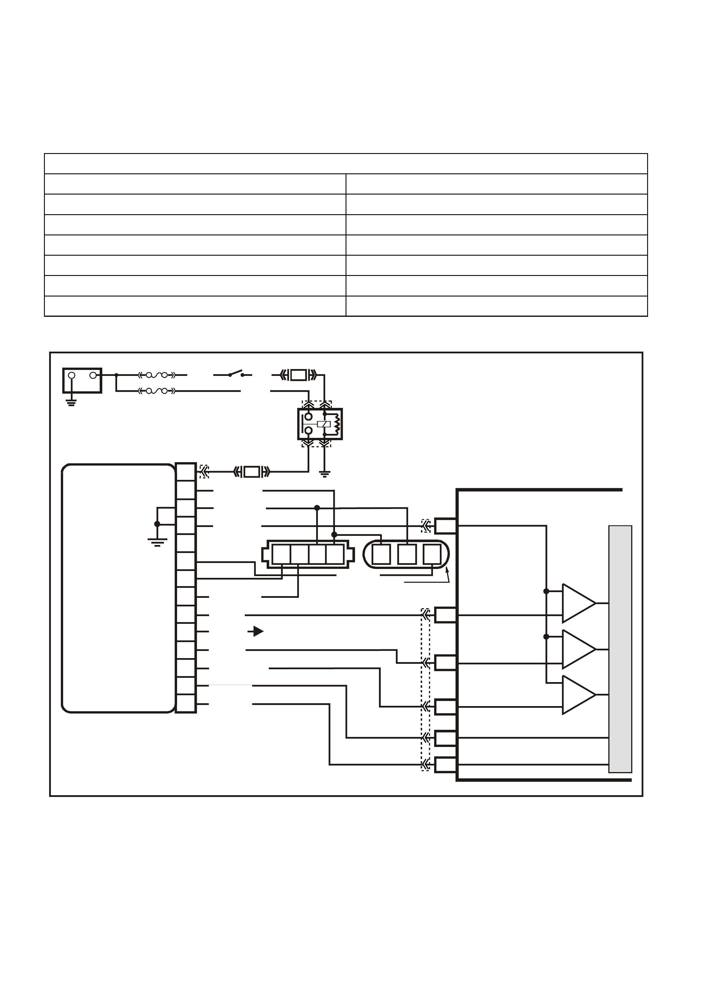
Figure 6C1-1-45 Crankshaft Reference Signal
VXSC009
PCM
D11
D3
D4
D12
D9
D10
CRANKSHAFT
REFERENCE LO
CAM
SENSOR
CONNECTOR
CAMSHAFT
POSITION
SENSOR
SIGNAL
CRANKSHAFT
REFERENCE HI
CRANKSHAFT
18X SIGNAL
BYPASS CONTROL
EST OUTPUT
module power supply - in
sensor power supply - out
cam signa l - in
3x crank sensor - in
18x crank sensor - in
cam signal - out
tacho signal - out
crankshaft reference - out
18X cranksignal - out
bypass control
EST signal -in
P
N
M
L
K
J
H
G
F
E
D
C
B
A
DIS
MODULE
ABCD CBA
W/B (644)
GY/R (645)
B/R (453)
CRANK
SENSOR
CONN
L BLU/W
(646) BR (633)
BLU/Y (643)
BR (121)
B (63 0)
V (43 0)
L BLU/B (647)
T/B (4 24)
IGN SW
EFI RELAY
O/Y
(479)
LG
(482)
B/W
(152)P/B
(39)
IC
IC
IC
M
I
C
R
O
W (423)
F35
+
-
BATTERY
FS
LOC. E1
FJ
(1040)
LOC. E3
P (3)
R(2H)
F14
TO INSTRUMENT CLUSTER
(TERMINAL 18)
ABS/ETC (TERMINAL 30)
YB39
YB39
YE111
YE34
YB193
YB193
YE63
YE57

ENGINE COOLI NG FAN SIGNAL
(LOW SPEED RESPONSE)
The engine c ooling low s peed fans are enabled when the low speed r elay is energized by the BCM. The PCCM
will request the BCM to turn the low speed engine cooling fan relay on or off, via the serial data bus normal
mode m essage. Af ter the PCM requests a change in the engine c ooling f an low speed relay, the BCM will send
a res ponse me ssage back to the PCM via the s erial data bus norm al mode m essage confir ming it received the
request. A failure in the response communication will set a DTC 92.
There are also four (4) suppression capacitors incorporated into the fan motor wiring circuits. These
suppress ion capacitor s help elim inate f an motor nois e through the radio speak ers. If these capacitors are open,
then noise will be present through the r adio speaker s. If shor ted to earth, the fan motor s could continuously run,
or the fuse or fusible link could fail.
DTC 92 (Low Speed Fan No BCM Response) will set if:
• Engine is idling.
• The PCM sends a request to the BCM to turn on the engine cooling fan low speed relay via the serial data
normal mode message and the BCM does not send a message back to the PCM.
• The PCM will not illuminate the Malfunction Indicator Lamp (MIL).
DEFAULT VALUE
Once DTC 92 is set, the PCM will energize the engine cooling fan high speed relay.
RECOVERY
Recovery will occur on the next ignition cycle.
DTC 92 HISTORY DATA
PARAMETER PARAMETER
ENGINE SPEED REFERENCE VOLTS
TIME FROM START MASS AIR FLOW
TIMES OCCURRED CAM SIGNAL
IGNITION CYCLES FUELING MODE
COOLANT TEMPERATURE FUEL PUMP RELAY
BATTERY VOLTAGE

Figure 6C1-1-46 Engine Cooling Fan Signal
VXSC032
5V
5V
BLU
(831)
T
(832)
IC
C6
D5
VEHICLE SPEED
SENSOR
B/Y (452 )
B (469)
D11
C16
D10
C6
D6
Y (41O)
V/W (415)
G/B (259)
COOLANT TE MP
SENSOR
A
/C PRESSURE
SENSOR
A
C
B
M
I
C
R
O
P
R
O
C
E
S
S
O
R
M
I
C
R
O
P
R
O
C
E
S
S
O
R
BATTERY MAIN POWER
HIGH SERIES
BCM TERMINALS
NOMINATED FIRST
BCM
PCM
F6
A3
HIGH
SPEED
FAN
SERIAL DA TA
BLU/W (304)
IGNITION
15a 15 50
30 OFF/ON
LOCK
ACC
IGN
START
E20/D6
P/B
(39)
IGNITION SWITCH
87A
30
87
85
86
87
30
85
86
ENGINE
COOLING
FAN 1
ENGINE
COOLING
FAN RELAY
(LOW SPEED)
ENGINE
COOLING
FAN RELAY
(HIGH SPEED)
P/B (39)
F14
BLUE
FUSIBLE
LINK
LOC.
E1
F31
A5/A6
O/B
(740)
ENGINE
COOLING
FAN 2
+-
BATTERY
FS
FT FAN 2
FU FAN 1
(1040)
(1040)
O/B (740)
O/B
(208)
O/BLU
YE119
YE119
YB44
YE103
YE103
YE43
YB175
YB164
YB174
YB163
YB174
YB163
YE114
YE106
YE113
YE106
YB195
YB193
YB188
YB194
YB132
YB164
YB175
YB165
YB176
YB176
YB165
YE43
YB44
(204)
R
(203)
FJ
R
(2H)
LOW
SPEED FAN
B7/B7
R/B (1221) R/B
(1221) E2/D2 SERIAL DATA
HIGH
CURRENT EARTH
B/Y
(155) A1/A5 ELECTRONIC EARTH
B/G
(151)
LOC.
E2 LOC.
E3
B10/B11
B/P (157)
O/B
(473)

ENGINE COOLI NG FAN
HIGH SPEED
The engine cooling fan high speed is controlled by the PCM based on input from the Engine Coolant
Tem per ature Sensor ( ECT) . T he PCM will only turn "O N" the engine cooling fan high speed if the engine cooling
low speed fans have been "ON" for 2 seconds and the following conditions are satisfied.
• There is a BCM message response fault which will cause a DTC 92.
• An engine coolant temperature sensor failure is detected, such as DTC 14, 15, 16, 17 or 91.
• Coolant temperature greater than 107 degrees C.
• If the fan low speed was "OFF" when the criteria was met to turn the fan high speed "ON", the fan high
speed will come "ON" 5 seconds after the fan low speed is turned "ON".
• The high speed engine cooling fan relay can also be enable by the A/C Refrigerant Pressure Sensor. The
A/C Ref rigerant Press ure Sens or will enable high speed cooling f an, if the A/C system pres sur e becom es to
high.
There are also four (4) suppression capacitors incorporated into the fan motor wiring circuits. These
suppress ion capacitor s help elim inate f an motor nois e through the radio speak ers. If these capacitors are open,
then noise will be present through the r adio speak ers. Is shorted to earth, the fan motors could continuously run,
or the fuse or fusible link could fail.
DTC 91(QDSM Quad Driver Module) will set if:
• Engine run time is longer than 10 seconds.
• The ECT sensor reading changes more than 400 mV in 200 milliseconds.
• Above conditions present for at least 10 seconds.
• The PCM will illuminate the Malfunction Indicator Lamp (MIL).
DTC 91 HISTORY DATA
PARAMETER PARAMETER
ENGINE SPEED REFERENCE VOLTS
TIME FROM START A/C RELAY
TIMES OCCURRED STARTER RELAY
IGNITION CYCLES PURGE PWM
COOLANT TEMPERATURE HIGH SPEED FAN
BATTERY VOLTAGE ACTUAL TORQUE

Figure 6C1-1-47 Engine Cooling Fan Signal
VXSC032
5V
5V
BLU
(831)
T
(832)
IC
C6
D5
VEHICLE SPEED
SENSOR
B/Y (452 )
B (469)
D11
C16
D10
C6
D6
Y (41O)
V/W (415)
G/B (259)
COOLANT TE MP
SENSOR
A
/C PRESSURE
SENSOR
A
C
B
M
I
C
R
O
P
R
O
C
E
S
S
O
R
M
I
C
R
O
P
R
O
C
E
S
S
O
R
BATTERY MAIN POWER
HIGH SERIES
BCM TERMINALS
NOMINATED FIRST
BCM
PCM
F6
A3
HIGH
SPEED
FAN
SERIAL DA TA
BLU/W (304)
IGNITION
15a 15 50
30 OFF/ON
LOCK
ACC
IGN
START
E20/D6
P/B
(39)
IGNITION SWITCH
87A
30
87
85
86
87
30
85
86
ENGINE
COOLING
FAN 1
ENGINE
COOLING
FAN RELAY
(LOW SPEED)
ENGINE
COOLING
FAN RELAY
(HIGH SPEED)
P/B (39)
F14
BLUE
FUSIBLE
LINK
LOC.
E1
F31
A5/A6
O/B
(740)
ENGINE
COOLING
FAN 2
+-
BATTERY
FS
FT FAN 2
FU FAN 1
(1040)
(1040)
O/B (740)
O/B
(208)
O/BLU
YE119
YE119
YB44
YE103
YE103
YE43
YB175
YB164
YB174
YB163
YB174
YB163
YE114
YE106
YE113
YE106
YB195
YB193
YB188
YB194
YB132
YB164
YB175
YB165
YB176
YB176
YB165
YE43
YB44
(204)
R
(203)
FJ
R
(2H)
LOW
SPEED FAN
B7/B7
R/B (1221) R/B
(1221) E2/D2 SERIAL DATA
HIGH
CURRENT EARTH
B/Y
(155) A1/A5 ELECTRONIC EARTH
B/G
(151)
LOC.
E2 LOC.
E3
B10/B11
B/P (157)
O/B
(473)

TRANSMISSION POWER/ECONOMY SWITCH
The Power/Economy switch is used to modify
upshifts and shift times. The driver can select
either Economy or Power mode with the switch (1)
located on the centre console. A third mode,
Cruise, is available via a switch located on the top
of the steering column.
Two green indicator lamps of 1.2 watts at 12 volts
are located in the instrument cluster and display
POWER or CRUISE when illuminated to inf orm the
driver of the mode that is enabled.
The PCM provides a voltage signal of about 12
volts, and monitors the status of this circuit. In the
Econom y pos ition, the switch is open and the PCM
voltage status signal remains high, about 12 volts.
The PCM does not allow shift point changes in the
economy mode. When the transmission switch is
pressed to the Power position the switch is
momentarily closed and the PCM voltage status
signal is mom entarily pulled low, to about 0.5 volts.
The PCM senses this voltage momentary voltage
drop and enables Power mode (alternate shift
pattern tables to be utilised).
In the Power mode, the TCC can be applied in 3rd
and 4th gears. When the TCC is applied in 3rd
gear it will stay applied until the normal 4th gear
upshift criteria is m et. W hen the 3-4 ups hift occ urs,
the TCC will be released momentarily. Also, in the
Power mode while in D gear select position, the
PCM will delay the 1-2 and 2-3 shift while under
light throttle. The shift patterns will be the same in
the Econom y and Power m odes if the TP sensor is
between 80% - 100%. The power mode should be
used when towing, as applying the TCC in 3rd and
4th gear reduces slippage in the TCC and thus
reduces heat build up.
In cr uise mode oper ation, when the driver activates
the cr uise c ontr ol, the power lamp and power m ode
will turn OFF (if vehicle was in power mode) and a
CRUISE lamp will illuminate on the instrument
panel. The transmission shift pattern will switch to
cruise shift pattern. W hen in cruise mode the PCM
will modify the transmission calibration so that
transmission shift activity is reduced.
W hen the k ey is turned O N, the PCM shift m ode is
set to the last mode that was previously selected
(Power/Econom y). The cruise control is set to OFF
at every key ON cycle.
For replacement of the Power/Economy switch,
Refer to Section 7C4 AUTOMATIC
TRANSMISSION - ON VEHICLE SERVICE in VX
Service Information..
GE N 3 0154
1
Figure 6C1-1-48 Transmission Power/Economy Switch
1. Automatic Transmission Power/Economy Switch
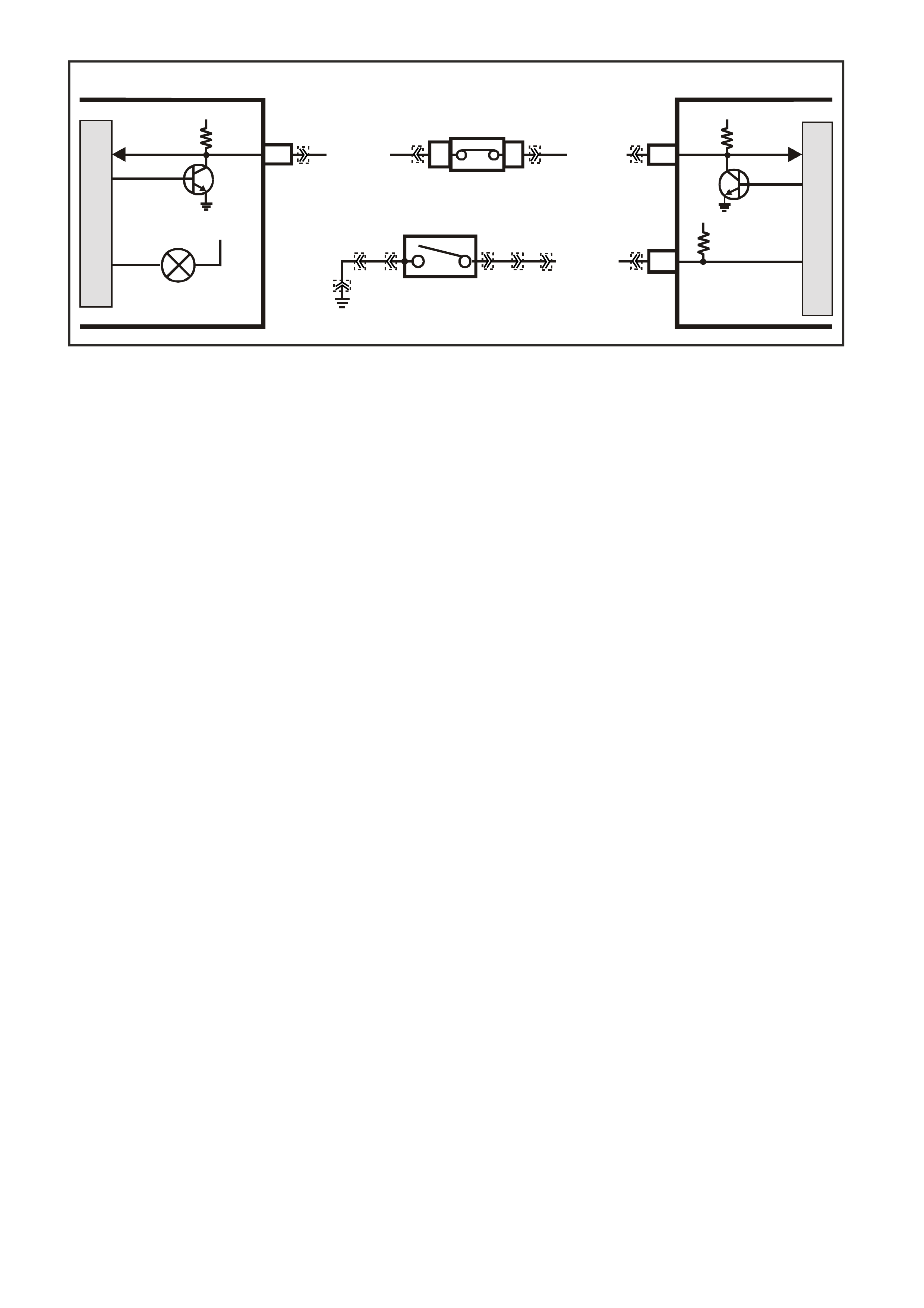
Figure 6C1-1-49 Transmission Power/Economy Switch Wiring
THEFT DETERRENT INPUT SIGNAL
When the ignition switch is turned to the “ON” position, the BCM polls the PCM and sends an encrypted
BCM / key security code. The security code is received by the BCM, via the remote k ey reader (slip ring) or via
the remote receiver in the event of no slip ring communication.
The PCM compares the received security code with its stored security code and if matched, the PCM will
continue to enable injector fuelling and engine crank.
The PCM will return a Valid Code message (OK TO START), which tells the BCM to jump to the short loop
mode to the long loop mode.
W hen the ignition s witch is turned fr om the O FF position to the ON pos ition, the BCM will com munic ate with the
PCM for antitheft purposes. If the BCM does not receive the message OK TO START from the PCM within 0.5
seconds of the ignition being switched on, the auxiliary bus is isolated via switching within the BCM.
The isolation of the auxiliary data bus during this period eliminates the possibility of a device failure other than
the BCM or PCM causing a problem on the bus and inhibiting antitheft communications.
This period is k nown as “Short Loop T im e”, and continues until the PCM responds with an ack nowledgm ent or a
maximum of 5 seconds, after which the BCM will switch to the standard poling sequence.
Following successful antitheft communications, the BCM begins sequential poling of devices on the bus and
normal system operation is established.
DTC 31 will set when the PCM at ignition ON sends 20 m essages to the BCM and does not receive a m essage
back saying it is OK to start.
M
I
C
R
O
SUPERVX006A1
INSTRUMENT
M
I
C
R
O
PCM
12
SERIAL
DATA
5V
12V IGN
G/W (1 220) R/B (1221)
POWER
POWER/ECONOMY
SWITCH
12V
F12
A3 SERIAL
DATA
5V
BLU (774)
BCM
E2
D2 E9
D3
YB188
YB194YE112
YE30
YB34
YB175
YB164 YB175
YB164
YB34
YB66
YB30
YE114
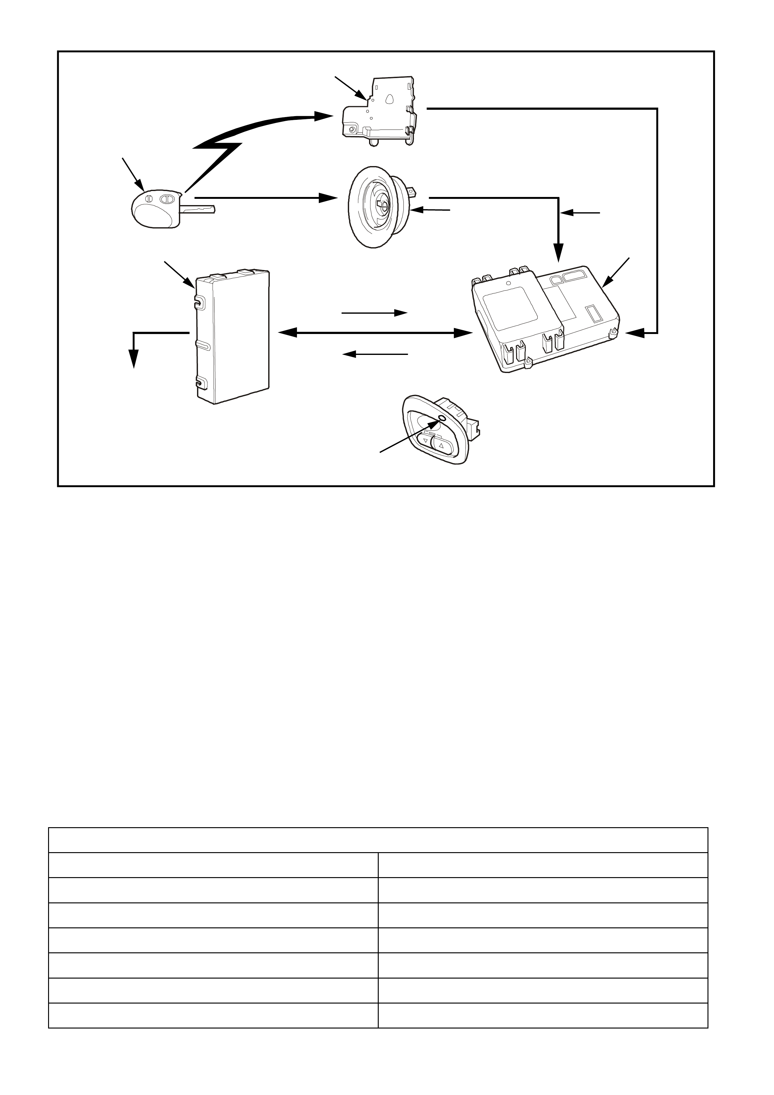
Figure 6C1-1-50 Theft Deterrent System
1. Remote Receiver Module
2. Remote Coded Key Reader Assembly
3. Code From Remote Coded Key
4. BCM
5. Is It OK To Start
6. OK To Start, Don’t Start
7. Theft Deterrent Alert Indicator LED
8. Enable Or Disable Fuel System Control And Starter Motor
9. Powertrain Control Module (PCM)
10. Remote Coded Key
DTC 31 (Theft Deterrent Signal Missing) will set if:
• The ignition is on.
• The PCM sends 20 messages to the BCM and does not receive a message back saying its OK to start.
• Conditions present for at least 10 seconds.
• The PCM will illuminate the Malfunction Indicator Lamp (MIL).
DEFAULT VALUES
There are no default value for DTC 31, the engine will not start if DTC 31 is current.
RECOVERY
Recovery will occur when the PCM sees a valid condition.
DTC 31 HISTORY DATA
PARAMETER PARAMETER
ENGINE SPEED REFERENCE VOLTS
TIME FROM START MASS AIR FLOW
TIMES OCCURRED CAM SIGNAL
IGNITION CYCLES FUELING MODE
COOLANT TEMPERATURE FUEL PUMP RELAY
BATTERY VOLTAGE
10
9
8
4225
5
2
1
6
4
3
7
CODE
SECURITY
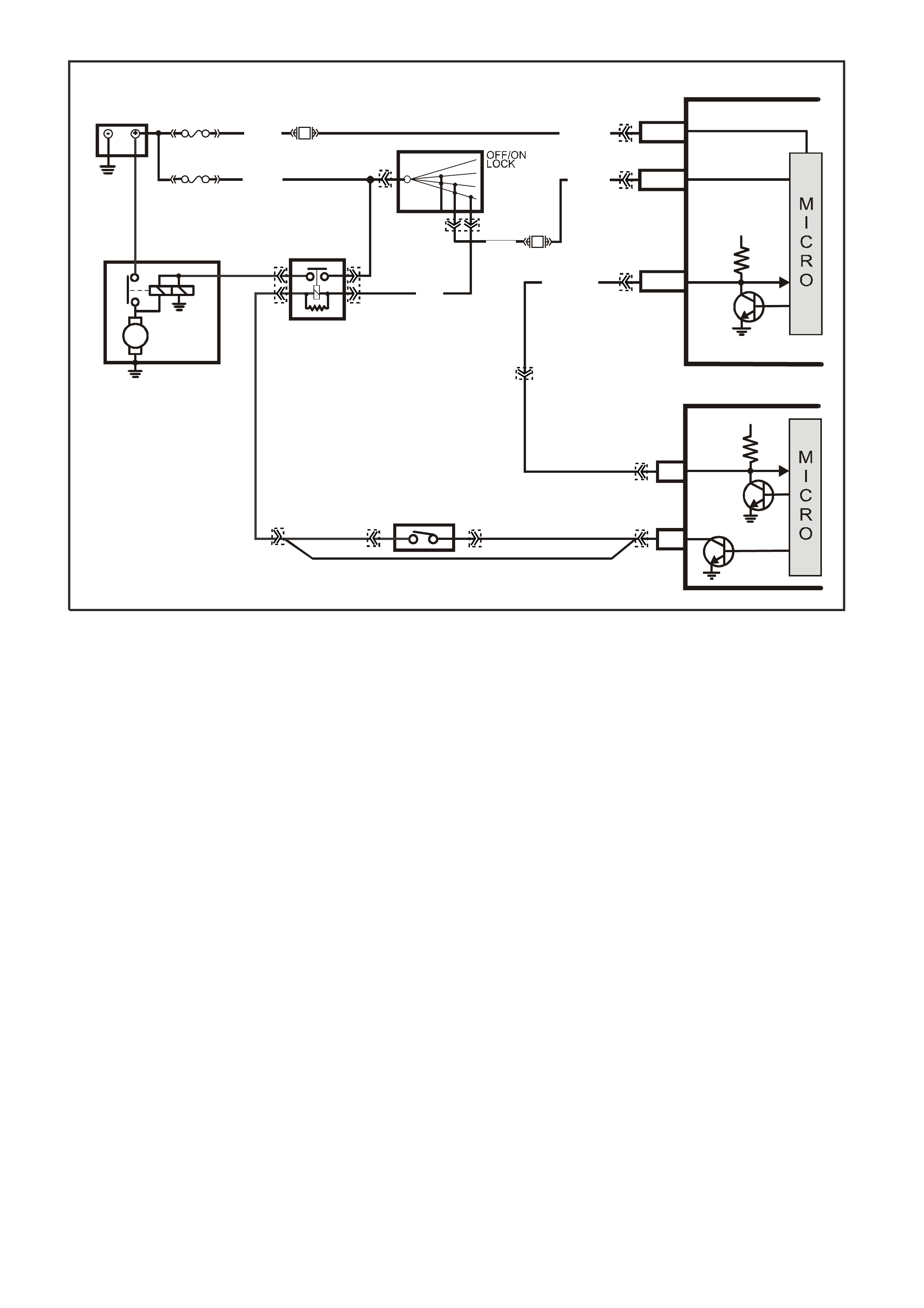
Figure 6C1-1-51 Theft Deterrent Serial Data Circuit
VXSC033
PCM
BCM
A3
SERIAL
DATA
STARTER
ENABLE
5V
SERIAL
DATA
MAIN
5V
BATTERY
FS
LOC.
E1
F31
A5/A6O/B (740)
(1040)
BATTERY MAIN POWER
FJ
R (2H)
F14
E20/D6P/B (39) IGNITION ON
15a 15 50
30 ACC
IGN
START
IGNITION SWI TCH
P (3)
LOC. G1
E2/D2
R/B (1221)
GY/BLU
(1434)
GY
(434)
EG
NEUTRAL START
BACK-UP SW.
( MANUAL
TRANS)
STARTER
MOTOR
M
START
RELAY
V (5)
F5
V/W
(6)
87
36 85
30
HIGH SERIES
BCM TERMINALS
NOMINA TED FIRST
YE111 YB194
YB188
YB175
YB164
YB175
YB164
YB176
YB165
YE112
YB44
YB44
YE49
YE49
YB35 YB35
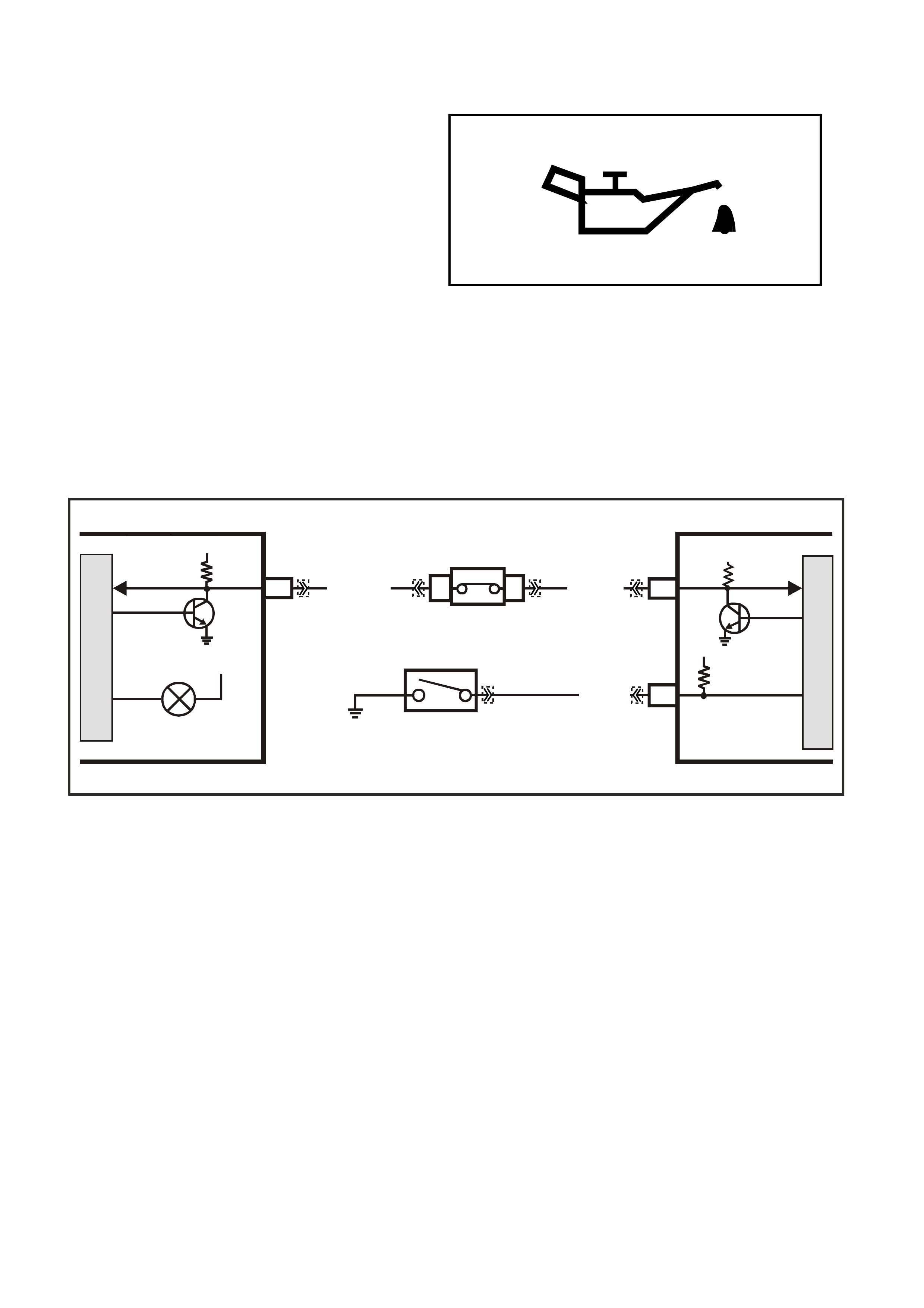
OIL PRESSURE SWITCH
The instruments receive oil pressure switch status
information from the PCM via the serial data bus
normal mode message. The PCM monitors the
voltage at terminal E12 to determine the status of
the oil pressure switch. When the oil pressure
switch is open the voltage at E12 will be 12 volts,
when the switch closes the voltage at term inal E12
will be pulled low, le3ss than 0.2 volts via circuit 31
(Blue wire) and the oil pressure switch.
This low voltage is seen by the PCM as an oil
pressure switch closed input signal. When the
PCM sees this low voltage at terminal E12 the
PCM will command the instruments to turn the oil
pressure warning lamp on, when the PCM sees a
high voltage at terminal E12 the PCM will
command the instruments to turn the oil pressure
warning lamp off, via the serial data bus normal
mode message.
There are no PCM trouble codes for this oil
pressure switch .
Figure 6C1-1-52 Oil Pressure Warning Lamp
Figure 6C1-1-53 Oil Pressure Warning Lamp
VXSC008
M
I
C
R
O
INSTRUMENT
M
I
C
R
O
PCM
12
SERIAL
DATA
5V
12V IGN
G/W (1220) R/B (1221)
OIL PRESSURE
OIL PRESSURE
SWITCH
12V
E12
A3 SERIAL
DATA
5V
BLU (31)
BCM
E2
D2
E9
D3
YB66
YE33
YB175
YB164 YB175
YB164 YB188
YB194
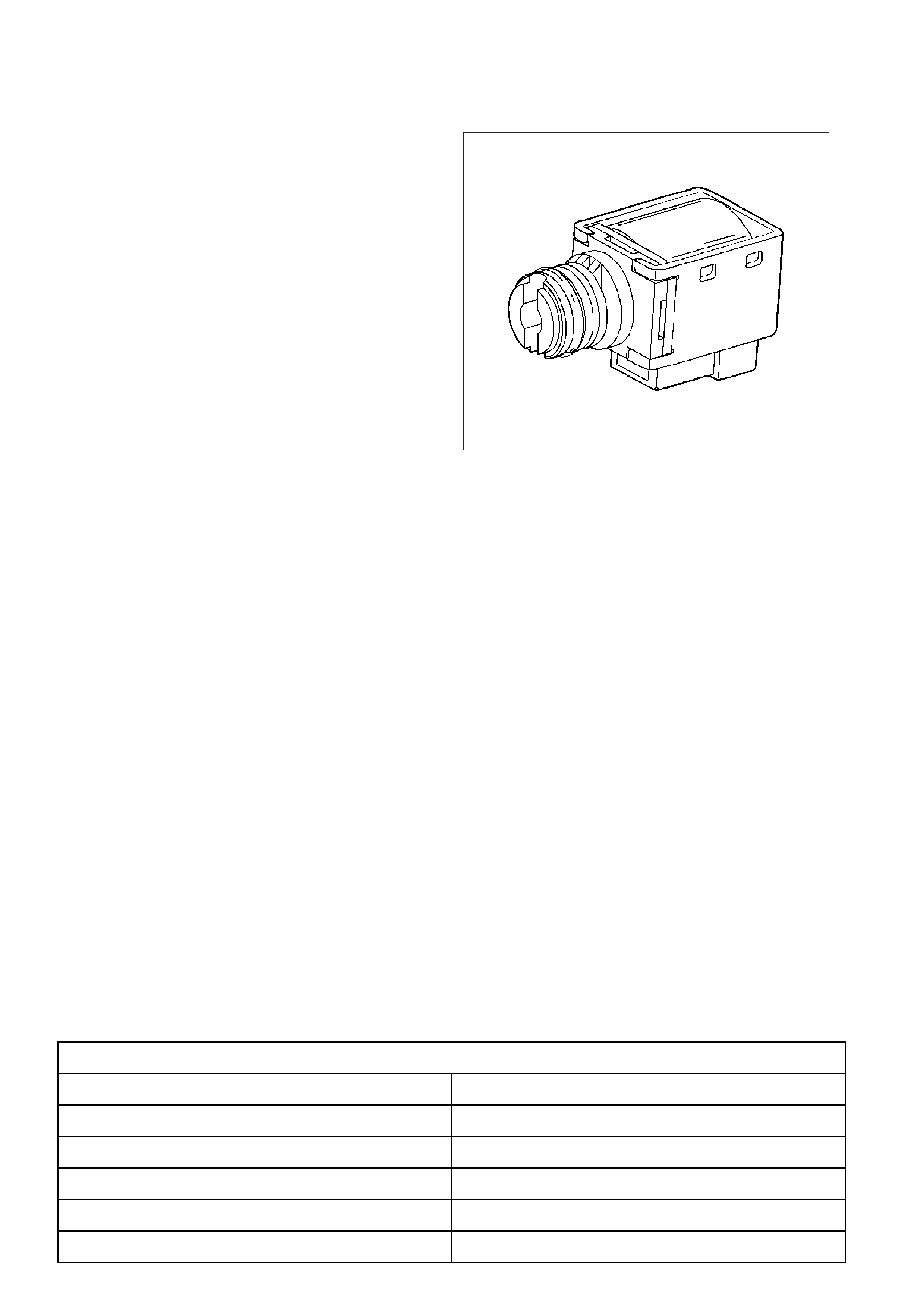
1.3 AUTOMATIC TRANSMISSION INFORMATION SENSORS & SIGNALS
1-2 (A) AND 2-3 (B) SHIFT SOLENOID VALVES
IMPORTANT:
The shift solenoid valve resistance should measure
19-24 ohm s minim um when m easured at 20°C (68°F ).
The shift solenoid current flow should not exceed 0.75
amps. The shift solenoid should energise at a voltage
of 7.5 volts or more (measured across the terminals).
The shift solenoid should de-energise when the
voltage is one volt or less.
If both solenoids lose power, third gear only results.
The 1-2 and 2-3 shift solenoid valves (also called A
and B solenoids) are identical devices that control the
mo vement of the 1-2 and 2- 3 shift valves (the 3-4 shift
valve is not directly controlled by a shif t solenoid). The
solenoids are normally open exhaust valves that work
in four combinations to shift the transmission into
different gears.
The PCM energises each solenoid by grounding the
solenoid through an internal quad driver. This sends
current through the coil winding in the solenoid and
moves the internal plunger out of the exhaus t position.
When ON, the solenoid redirects fluid to move a shift
valve.
IMPORTANT:
The manual valve hydraulically can override the shift
solenoids. Only in D4 do the shift solenoid states
totally determine what gear the transmission is in. In
the other manual valve positions, the transmission
shifts hydraulically and the shift solenoid states
CATCH UP when the throttle position and the vehicle
speed fall into the correct ranges. Diagnostic trouble
codes 81 and 82 indicate shift solenoid circuit voltage
faults.
The PCM-controlled shift solenoids eliminate the need
for TV and governor pressures to control shift valve
operation.
8885
Figure 6C1-1-54
DTC 81 (2-3 Shift Solenoid Circuit Electrical) will set if:
• The PCM commands the solenoid ON and the voltage input remains high (B+).
• The PCM commands the solenoid OFF and the voltage input remains low (0volts)
• The PCM will illuminate the Malfunction Indicator Lamp (MIL).
DEFAULT VALUES
When this DTC sets, the PCM will command D2 line pressure, The PCM inhibits 3-2 downshift if the vehicle
speed is greater than 48 km/h, The PCM will freeze shift adapts from being updated.
RECOVERY
Recovery will occur when the PCM sees a valid condition.
DTC 81 HISTORY DATA
PARAMETER PARAMETER
ENGINE SPEED TCC SOLENOID
TIME FROM START THROTTLE ANGLE
TIMES OCCURRED VEHICLE SPEED
IGNITION CYCLES COMMANDED GEAR
COOLANT TEMPERATURE
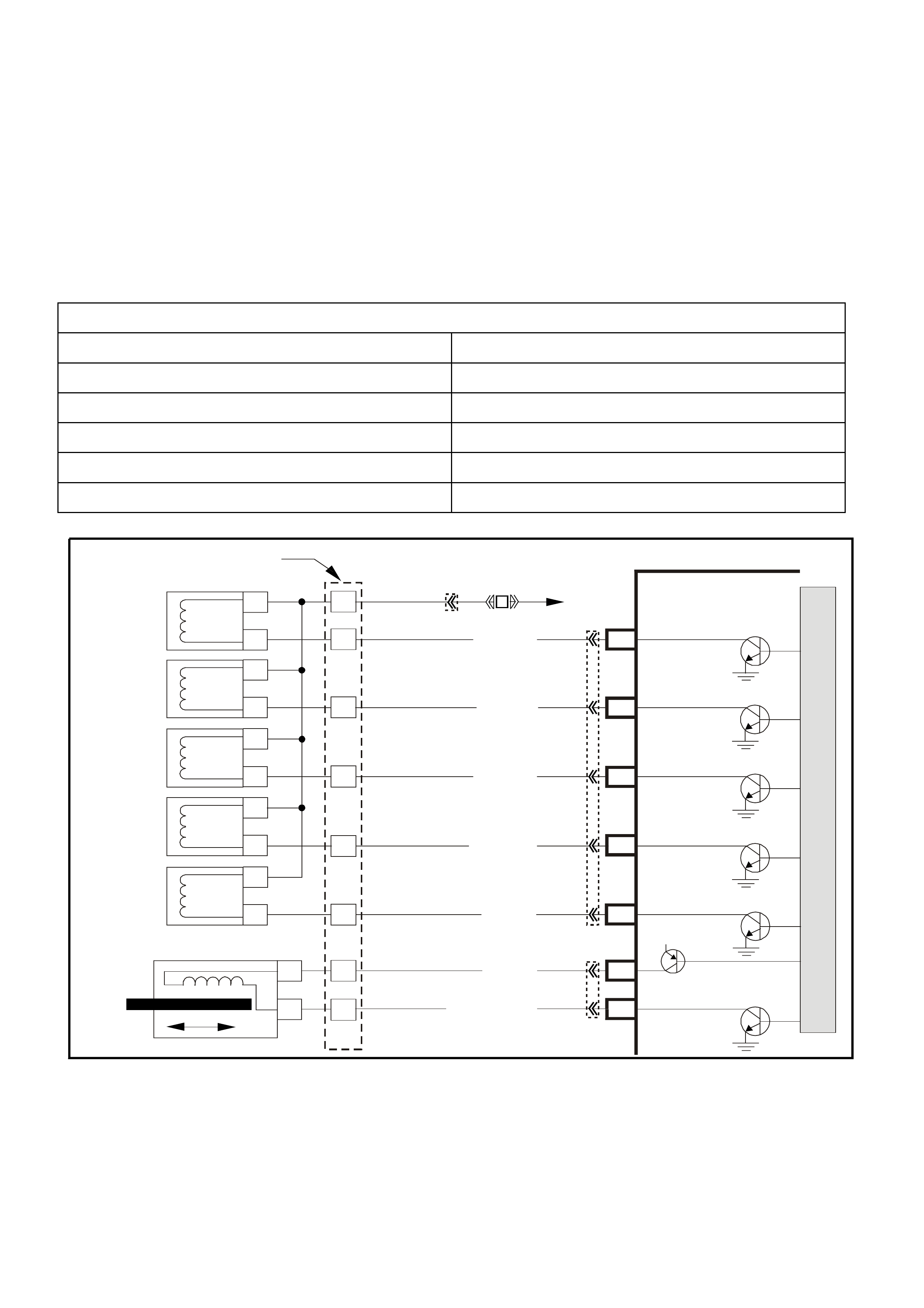
DTC 82 (1-2 Shift Solenoid Circuit Electrical) will set if:
• The PCM commands the solenoid ON and the voltage input remains high (B+).
• The PCM commands the solenoid OFF and the voltage input remains low (0volts)
• The PCM will illuminate the Malfunction Indicator Lamp (MIL).
DEFAULT VALUES
When this DTC sets, the PCM will command 3rd gear only, The PCM commands maximum line pressure, The
PCM will inhibit TCC engagement, The PCM will freeze shift adapts from being updated.
RECOVERY
Recovery will occur when the PCM sees a valid condition.
DTC 82 HISTORY DATA
PARAMETER PARAMETER
ENGINE SPEED 2-3 SHIFT SOLENOID
TIME FROM START THROTTLE ANGLE
TIMES OCCURRED VEHICLE SPEED
IGNITION CYCLES COMMANDED GEAR
COOLANT TEMPERATURE
Figure 6C1-1-55 Transmission Solenoid Circuits
3–2 Down shift
Control
Solenoid
1–2 Shift
Solenoid A
2–3 Shift
Solenoid B
YB 12 9 Tran s mis sion
Pass-Thru Connector
Torque
Converter
Clutch (TCC)
(PWM)
Solenoid
Torque
Converter
Clutch (TCC)
Enable
Solenoid
Pressure
Control
Solenoid A
B
A
B
SUPER4284-1
A
B
A
B
EF32 EFI
Relay
P/BLU
(339)
G/W (897)
LG (1222)
Y/B (1223)
GY/R (422)
BR (418)
R (1228)
GY/BLU (1229)
C13 3–2 Control
Solenoid
1–2 Shift
Solenoid
2–3 Shift
Solenoid
TCC Enable
Solenoid
TCC PWM
Solenoid
Pressure Control
Solenoid High
Pressure Control
Solenoid Low
C2
C3
C1
C15
E15
E14
S
A
B
T
U
C
D
A
B
A
B
PCM
M
I
C
R
O
P
R
O
C
E
S
S
O
R
12V
YB194
YB110
YB193
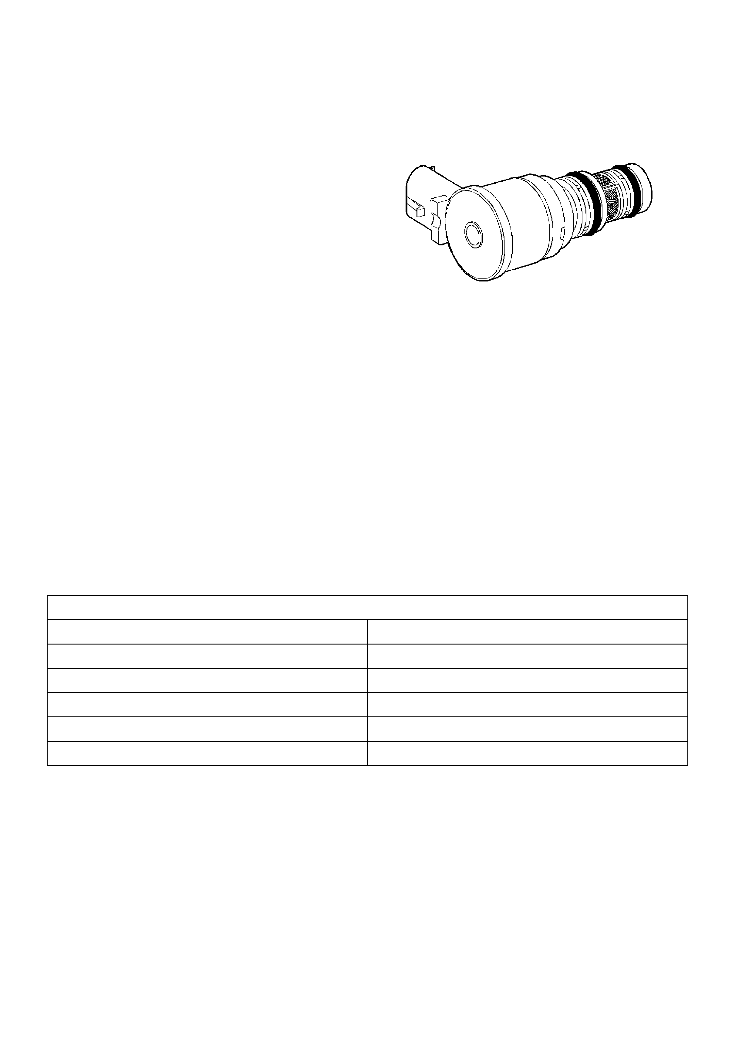
3-2 SHIFT SOLENOID VALVE ASSEMBLY
IMPORTANT:
The 3-2 shift solenoid valve assembly resistance
should be a minimum of 20-24 ohms at 20°C (68°F).
The 3-2 shift solenoid valve assembly is an ON/OFF
solenoid that is used in order to improve the 3-2
downshift. T he s olenoid regulates the release of the 3-
4 clutch and the 2-4 band apply.
If a voltage fault is detected in the 3-2 shift solenoid
circuit, diagnostic trouble code 66 will set.
325350
Figure 6C1-1-56
DTC 66 (3-2 Shift Solenoid Circuit Electrical) will set if:
• The PCM commands the solenoid ON and the voltage input remains high (B+).
• The PCM commands the solenoid OFF and the voltage input remains low (0volts)
• The PCM will illuminate the Malfunction Indicator Lamp (MIL).
DEFAULT VALUES
W hen this DTC sets, the PCM will comm and a soft landing to 3rd gear, The PCM will inhibit TCC engagement,
The PCM c omm ands maxim um line pr essure, The PCM inhibits 4th gear if the transm iss ion is in hot mode, T he
PCM will freeze shift adapts from being updated.
RECOVERY
Recovery will occur when the PCM sees a valid condition.
DTC 66 HISTORY DATA
PARAMETER PARAMETER
ENGINE SPEED TFT
TIME FROM START THROTTLE ANGLE
TIMES OCCURRED VEHICLE SPEED
IGNITION CYCLES COMMANDED GEAR
COOLANT TEMPERATURE
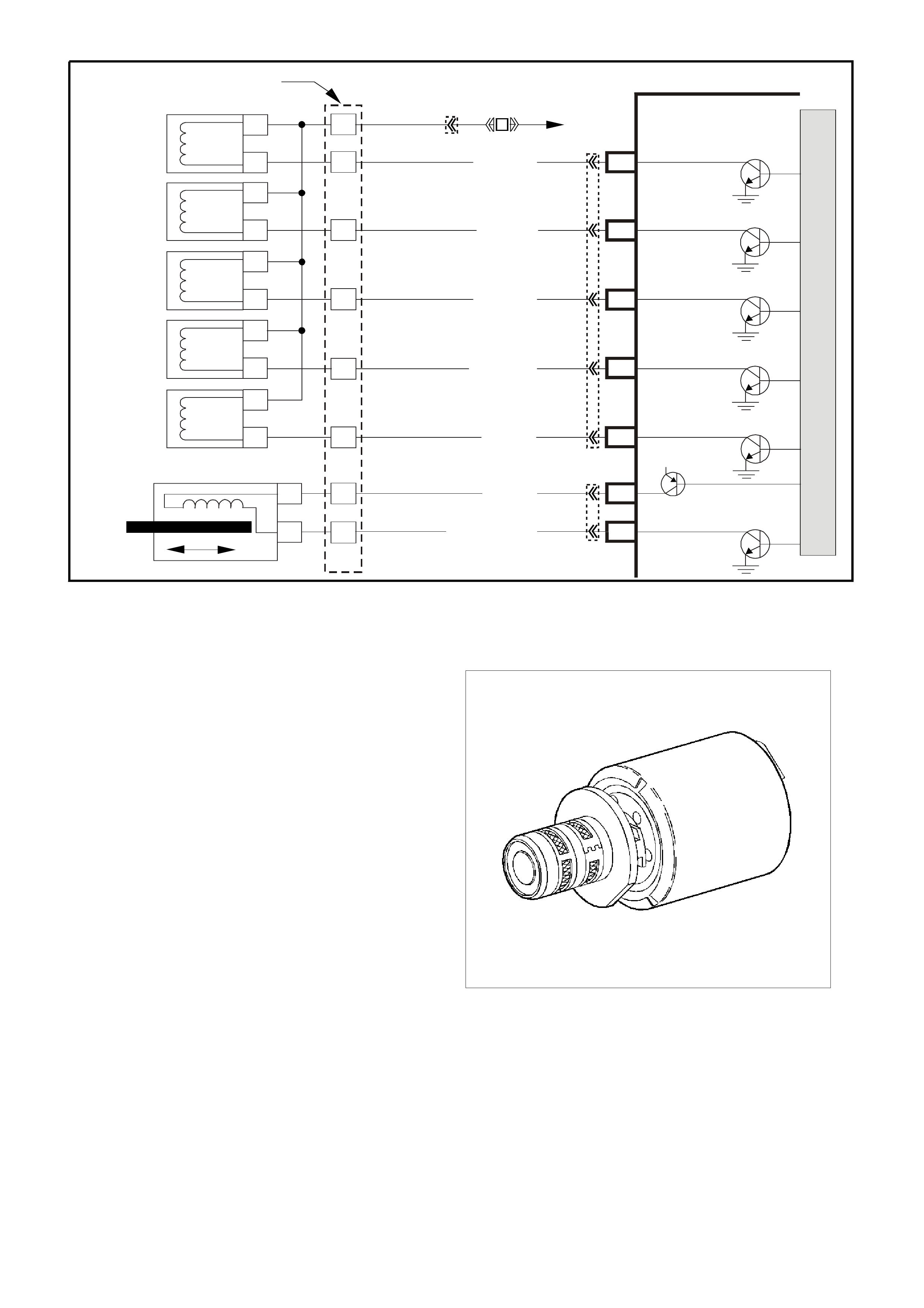
Figure 6C1-1-57 Transmission Solenoid Circuits
TRANSMISSION PRESSURE CONTROL SOLENOID
IMPORTANT:
Transmission pressure control solenoid resistance
should measure 3-5 ohms when measured at 20°C
(68°F).
The transmission pressure control solenoid is an
electronic pressure regulator that controls pressure
based on the current flow through its coil winding. The
magnetic field produced by the coil moves the
solenoid's internal valve, which varies pressure to the
pressure regulator valve.
The PCM controls the pressure control solenoid by
commanding current between 100 and 1100
milliam ps. This c hanges the duty c ycle of the solenoid,
which can range between 5 percent and 95 percent
(typically less than 60 percent). 1100 milliamps
corresponds to minimum line pressure, and 100
milliamps corresponds to maximum line pressure (if
the solenoid loses power, the transmission defaults to
maximum line pressure).
The PCM commands the line pressure values, using
inputs such as the throttle position sensor. The
pressure control solenoid takes the place of the
throttle valve or the vacuum modulator that was used
on the past model transmissions.
If the duty cycle drops below 5 percent or rises above
95 percent, DTC 73 will set.
325352
Figure 6C1-1-58
3–2 Down shift
Control
Solenoid
1–2 Shift
Solenoid A
2–3 Shift
Solenoid B
YB 12 9 Tran s mis sion
Pass-Thru Connector
Torque
Converter
Clutch (TCC)
(PWM)
Solenoid
Torque
Converter
Clutch (TCC)
Enable
Solenoid
Pressure
Control
Solenoid A
B
A
B
SUPER4284-1
A
B
A
B
EF32 EFI
Relay
P/BLU
(339)
G/W (897)
LG (1222)
Y/B (1223)
GY/R (422)
BR (418)
R (1228)
GY/BLU (1229)
C13 3–2 Control
Solenoid
1–2 Shift
Solenoid
2–3 Shift
Solenoid
TCC Enable
Solenoid
TCC PWM
Solenoid
Pressure Control
Solenoid High
Pressure Control
Solenoid Low
C2
C3
C1
C15
E15
E14
S
A
B
T
U
C
D
A
B
A
B
PCM
M
I
C
R
O
P
R
O
C
E
S
S
O
R
12V
YB194
YB110
YB193
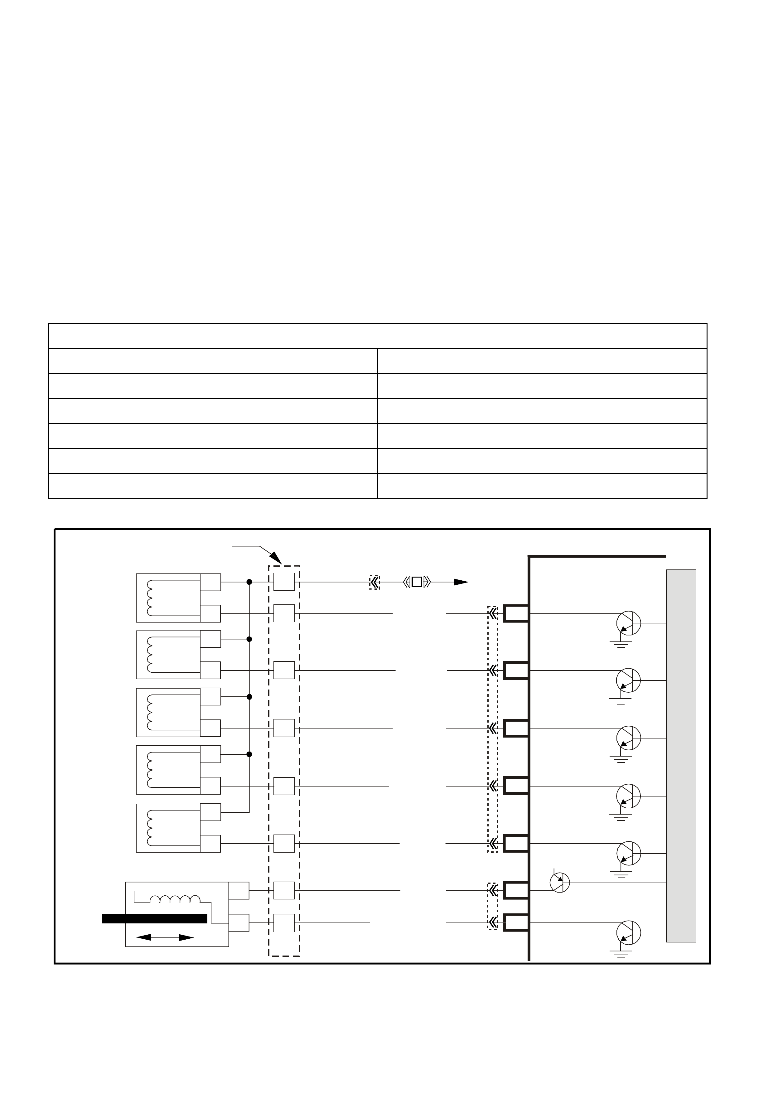
DTC 73 (PC Solenoid Circuit Electrical) will set if:
• No DTC 75 is set.
• The system voltage is between 10 and 16 volts.
• The engine is running.
• The PC s olenoid valve duty cycle reaches its high lim it (approxim ately 95%) or low lim it (appr oximately 0%)
for 200 milliseconds.
• The PCM will not illuminate the Malfunction Indicator Lamp (MIL).
DEFAULT VALUES
W hen this DTC sets , the PCM will comm and the PC solenoid valve O FF, The PCM will f reeze shift adapts f rom
being updated.
RECOVERY
Recovery will occur when the PCM sees a valid condition.
DTC 73 HISTORY DATA
PARAMETER PARAMETER
ENGINE SPEED COMMANDED PCS
TIME FROM START ACTUAL PCS
TIMES OCCURRED THROTTLE ANGLE
IGNITION CYCLES VEHICLE SPEED
COOLANT TEMPERATURE COMMANDED GEAR
Figure 6C1-1-59 Transmission Solenoid Circuits
3–2 Down shift
Control
Solenoid
1–2 Shift
Solenoid A
2–3 Shift
Solenoid B
YB 12 9 Trans mis sion
Pass-Thru Connector
Torque
Converter
Clutch (TCC)
(PWM)
Solenoid
Torque
Converter
Clutch (TCC)
Enable
Solenoid
Pressure
Control
Solenoid A
B
A
B
SUPER4284-1
A
B
A
B
EF32 EFI
Relay
P/BLU
(339)
G/W (897)
LG (1222)
Y/B (1223)
GY/R (422)
BR (418)
R (1228)
GY/BLU (1229)
C13 3–2 C ontrol
Solenoid
1– 2 Shift
Solenoid
2– 3 Shift
Solenoid
TCC Enable
Solenoid
TCC PWM
Solenoid
Pressure Control
Solenoid High
Pressure Control
Solenoid Low
C2
C3
C1
C15
E15
E14
S
A
B
T
U
C
D
A
B
A
B
PCM
M
I
C
R
O
P
R
O
C
E
S
S
O
R
12V
YB194
YB110
YB193
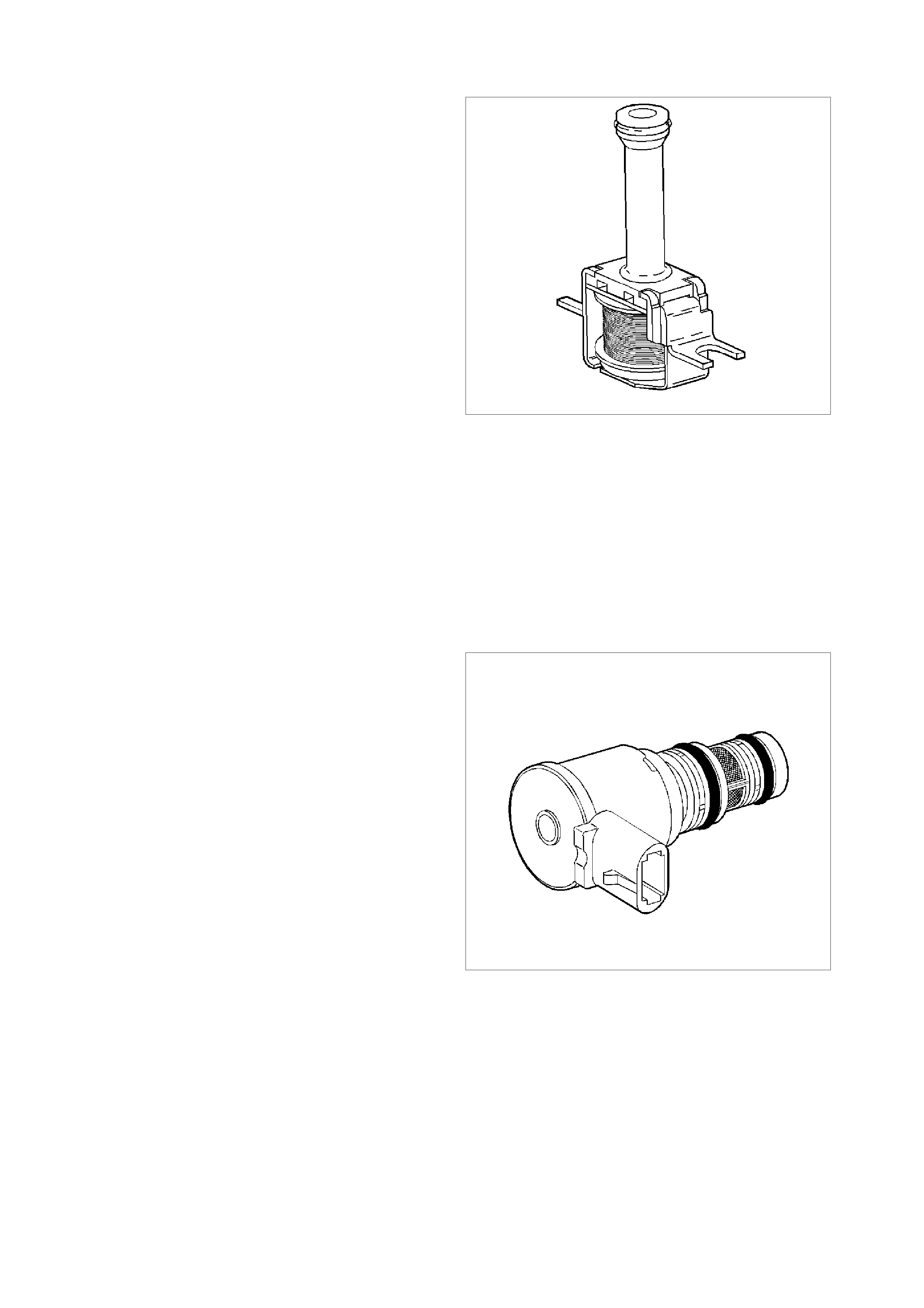
TORQUE CONVERTER CLUTCH SOLENOID VALVE
IMPORTANT:
The TCC solenoid resistance should be 21-26 ohms
minimum when measured at 20°C (68°F).
There are two DTCs associated with the TCC
solenoid. The first DTC is 67, TCC enable solenoid.
DTC 67 is designed to detec t a f ault in the TCC enable
solenoid electrical circuit. While DTC 67 is set, the
PCM will inhibit 4th gear if the transmission is in hot
mode, and no TCC operation. The second DTC
associated with the TCC enable solenoid is DTC 69,
TCC stuck on. DTC 69 is designed to detect TCC
enable solenoid that does not disengage. It does this
by m onitor ing engine RPM when the TCC comm anded
on. If the engine speed does not rise when the TCC
solenoid is dis engaged the DT C 69 will set. While DT C
69 is s et, the TCC will be on in all gears or 2 nd, 3rd, and
4th depending upon the failure, and the transmission
will have an early shift pattern.
The torque converter clutch solenoid valve is a
normally open exhaust valve that is used to control
torque converter clutch apply and release. When
grounded (energised) by the PCM, the TCC solenoid
valve stops converter signal oil from exhausting. This
causes converter signal oil pressure to increase and
shifts the TCC solenoid valve into the apply position.
The brak e s witch is an input to the PCM, and the PCM
directly controls the TCC apply based on the brake
switch status.
8882
Figure 6C1-1-60
TORQUE CONVERTER CLUTCH PWM SOLENOID VALVE
IMPORTANT:
TCC PW M solenoid valve resistance should be 10-11
ohms when measured at 20°C (68°F), and 13-15
ohms when measured at 100°C (212°F).
The torque converter clutch PWM solenoid valve
controls the fluid acting on the converter clutch valve,
which then controls the TCC apply and release. This
solenoid is attached to the control valve body
assembly within the transmission.
The TCC PWM solenoid valve provides smooth
engagement of the torque converter clutch by
operating on a negative duty cycle a variable percent
of ON time.
If a fault is detected in the TCC PW M circuit, code 83
will set
325355
Figure 6C1-1-61
DTC 67 (TCC Enable Solenoid Circuit Electrical) will set if:
• The engine is running.
• Battery voltage is between 10 and 16 volts.
• The PCM commands the solenoid ON and the voltage input remains high (B+).
• The PCM commands the solenoid OFF and the voltage input remains low (0volts).
• Conditions are met for 5 seconds.
• The PCM will illuminate the Malfunction Indicator Lamp (MIL).

DEFAULT VALUES
When this DTC s ets, the PCM will inhibit TCC engagem ent, T he PCM will inhibit 4th gear if the tr ans mission is in
hot mode, The PCM will freeze shift adapts from being updated.
RECOVERY
Recovery will occur when the PCM sees a valid condition.
DTC 69 (TCC System Stuck ON) will set if:
• No TP DTCs set.
• No VSS DTCs set.
• No TFP Valve Position Switch DTC 28 is set.
• No TCC Solenoid Valve DTC 67 is set.
• No TCC PWM Solenoid Valve DTC 83 is set.
• The TP angle is greater than 25%.
• The engine RPM is greater than 450 for 8 seconds.
• The commanded gear is not 1st.
• The gear range is D4 or D3.
• The PCM commands TCC OFF.
• The Trans slip speed is –20 to +20 RPM.
• All conditions are met for 4 seconds.
• The PCM will not illuminate the Malfunction Indicator Lamp (MIL).
DEFAULT VALUES
When this DTC sets, the PCM will freeze shift adapts from being updated.
RECOVERY
Recovery will occur when the PCM sees a valid condition.
DTC 83 (TCC PWM Solenoid Circuit ) will set if:
• The system voltage is 8-18 volts.
• The engine speed is greater than 300 RPM for 5 seconds.
• The engine is not in fuel cutoff.
• The PCM commands first gear.
• The TCC duty cycle is less than 10% or greater than 90%.
• The PCM commands the solenoid ON and the voltage input remains high (B+).
• The PCM commands the solenoid OFF and the voltage input remains low (0volts).
• The PCM will not illuminate the Malfunction Indicator Lamp (MIL).
DEFAULT VALUES
When this DTC s ets, the PCM will inhibit TCC engagem ent, T he PCM will inhibit 4th gear if the tr ans mission is in
hot mode, The PCM will freeze shift adapts from being updated.
RECOVERY
Recovery will occur when the PCM sees a valid condition.
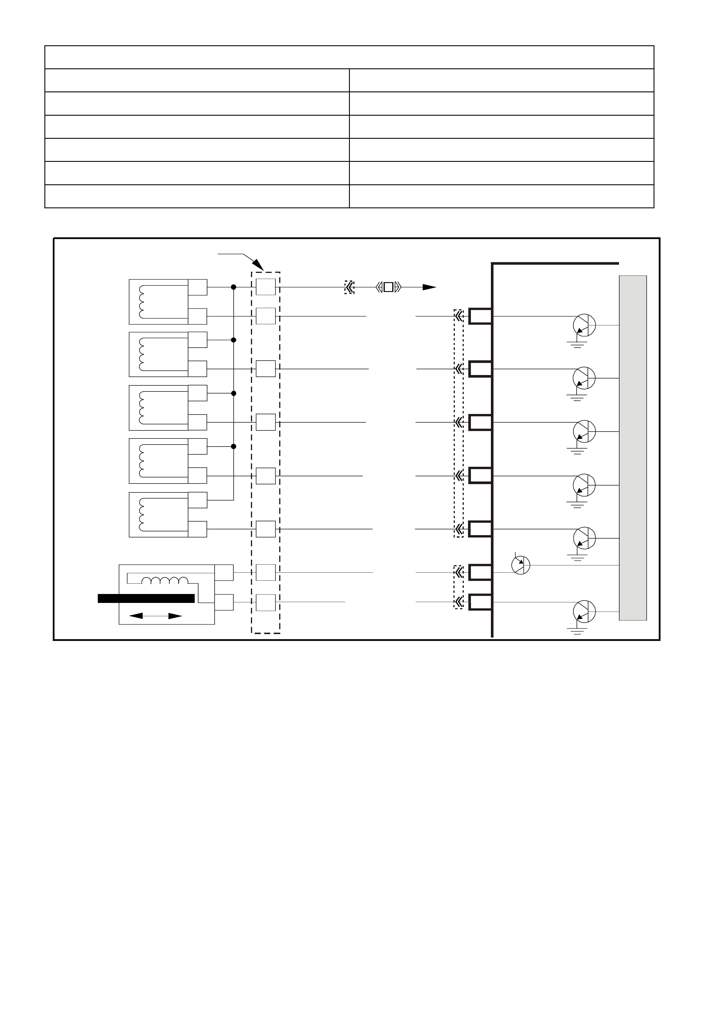
DTC 67 , 69 AND 83 HISTORY DATA
PARAMETER PARAMETER
ENGINE SPEED TCC SOLENOID
TIME FROM START THROTTLE ANGLE
TIMES OCCURRED VEHICLE SPEED
IGNITION CYCLES COMMANDED GEAR
COOLANT TEMPERATURTE
Figure 6C1-1-62 Transmission Solenoid Circuits
3–2 Down shift
Control
Solenoid
1–2 Shift
Solenoid A
2–3 Shift
Solenoid B
YB 12 9 Tran s mission
Pass-Thru Connector
Torque
Converter
Clutch (TCC)
(PWM)
Solenoid
Torque
Converter
Clutch (TCC)
Enable
Solenoid
Pressure
Control
Solenoid A
B
A
B
SUPER4284-1
A
B
A
B
EF32 EFI
Relay
P/BLU
(339)
G/W (897)
LG (1222)
Y/B (1223)
GY/R (422)
BR (418)
R (1228)
GY/BLU (1229)
C13 3–2 Control
Solenoid
1–2 Shift
Solenoid
2–3 Shift
Solenoid
TCC Enable
Solenoid
TCC PWM
Solenoid
Pressure Control
Solenoid High
Pressure Control
Solenoid Low
C2
C3
C1
C15
E15
E14
S
A
B
T
U
C
D
A
B
A
B
PCM
M
I
C
R
O
P
R
O
C
E
S
S
O
R
12V
YB194
YB110
YB193
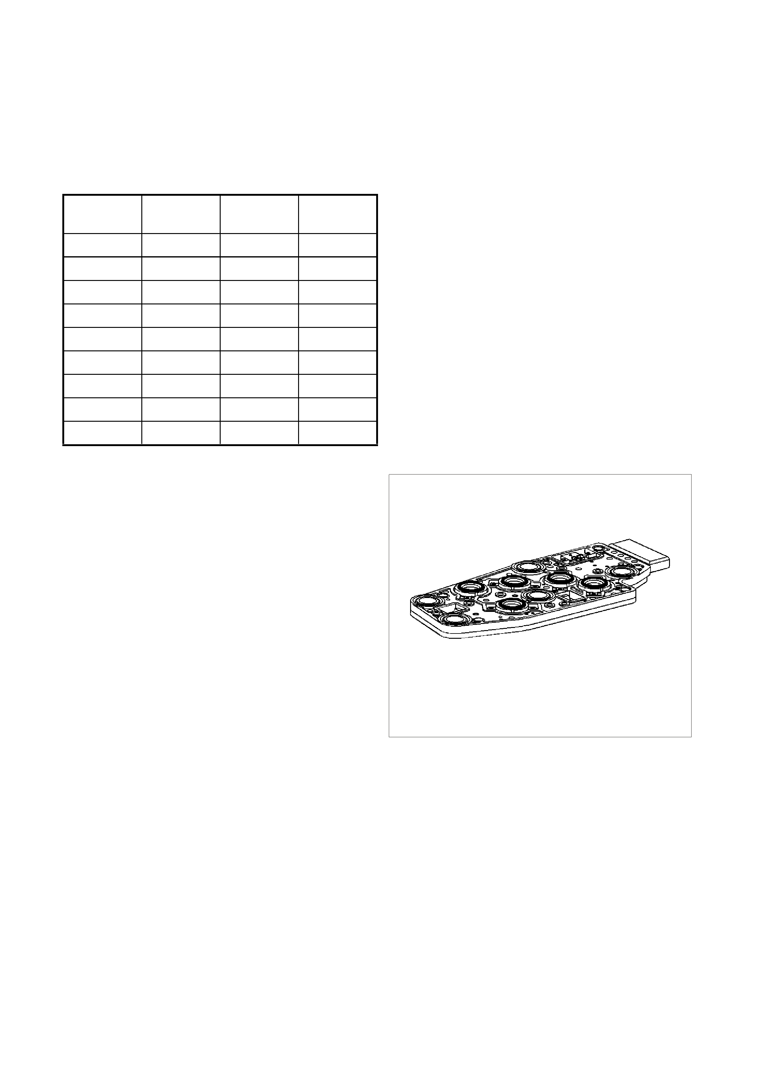
TRANSMISSION FLUID PRESSURE (TFP) MANUAL VALVE POSITION SWITCH
IMPORTANT:
Seven valid combinations and two invalid
combinations are available from the TFP manual
valve position switch. Refer to the T FP Manual Valve
Position Switch Logic table below for valid/invalid
combinations for range signal circuits A, B and C.
Gear
Position Range
Signal A Range
Signal B Range
Signal C
Park Open 12 V Closed 0 V Open 12 V
Reverse Closed 0 V Closed 0 V Open 12 V
Neutral Open 12 V Closed 0 V Open 12 V
D Open 12 V Closed 0 V Closed 0 V
3 Open 12 V Open 12 V Closed 0 V
2 Open 12 V Open 12 V Open 12 V
1 Closed 0 V Open 12 V Open 12 V
Invalid Closed 0 V Open 12 V Closed 0 V
Invalid Closed 0 V Closed 0 V Closed 0 V
The transmission fluid pressure (TFP) manual valve
position switch is a set of five pressure switches on the
control valve body that sense whether fluid pressure is
present in five different valve body passages. The
combination of which switches are open and closed is
used by the PCM in order to determine actual manual
valve position. The TFP manual valve position switch,
however, cannot distinguish between PARK and
NEUTRAL because the monitored valve body
pressures are identical in both cases.
The s witches are wired to provide three signal lines that
are monitored by the PCM. These inputs are used to
help control line pressure, torque converter clutch apply
and shift solenoid valve operation. Voltage at each of
the signal lines is either zero or twelve volts.
In order to monitor the TFP manual valve position
switch operation, the PCM compares the actual voltage
com bination of the switches to a T FP com bination table
stored in its m em ory. If the PCM s ees one of two illegal
voltage combinations, a DTC 28 will result. A DTC 28
indicates a short circuit condition in either the range
signal A or the range signal C circuits.
The TFP manual valve position switch signal voltage
can be measured from each pin-to-ground and
compared to the combination table. On the automatic
transmission (A/T) wiring harness assembly, pin N is
range signal A, pin R is range signal B, and pin P is
range signal C. With the A/T wiring harness assembly
connected and the engine running, a voltage
measurement of these three lines will indicate a high
reading (near 12 volts ) when a circuit is open, and a low
reading (zero volts) when the circuit is switched to
ground.
8889
Figure 6C1-1-63
The transmission fluid temperature (TFT) sensor is
part of the TFP manual valve position switch assembly.

DTC 28 (TFP Valve Position Switch Circuit ) will set if:
Condition 1
• The PCM detects an illegal TFP manual valve position switch state for 60 seconds.
Condition 2
• The engine speed is less than 80 RPM for 0.1 second; then the engine speed is 80-550 RPM for 0.07
seconds; then the engine speed is greater than 500 RPM.
• The vehicle speed is less than 3 km/h.
• The PCM detects a gear range of D2, D4, or Reverse during an engine start.
• All conditions are met for 5 seconds.
Condition 3
• The TP angle is 8-45%.
• The PCM commands 4th gear.
• The TCC is locked ON.
• The speed ratio is 0.65-0.8 (speed ratio is engine speed divided by transmission output speed).
• The PCM detects a gear range of Park or Neutral when operating in D4.
• All conditions are met for 10 seconds.
• The PCM will illuminate the Malfunction Indicator Lamp (MIL).
DEFAULT VALUES
W hen this DTC sets, the PCM will comm and D2 line pressure, T he PCM will com mand a D4 shift pattern, The
PCM will freeze shift adapts from being updated.
RECOVERY
Recovery will occur when the PCM sees a valid condition.
DTC 28 HISTORY DATA
PARAMETER PARAMETER
ENGINE SPEED PRNDL SWITCH
TIME FROM START TFT
TIMES OCCURRED VEHICLE SPEED
IGNITION CYCLES COMMANDED GEAR
COOLANT TEMPERATURE
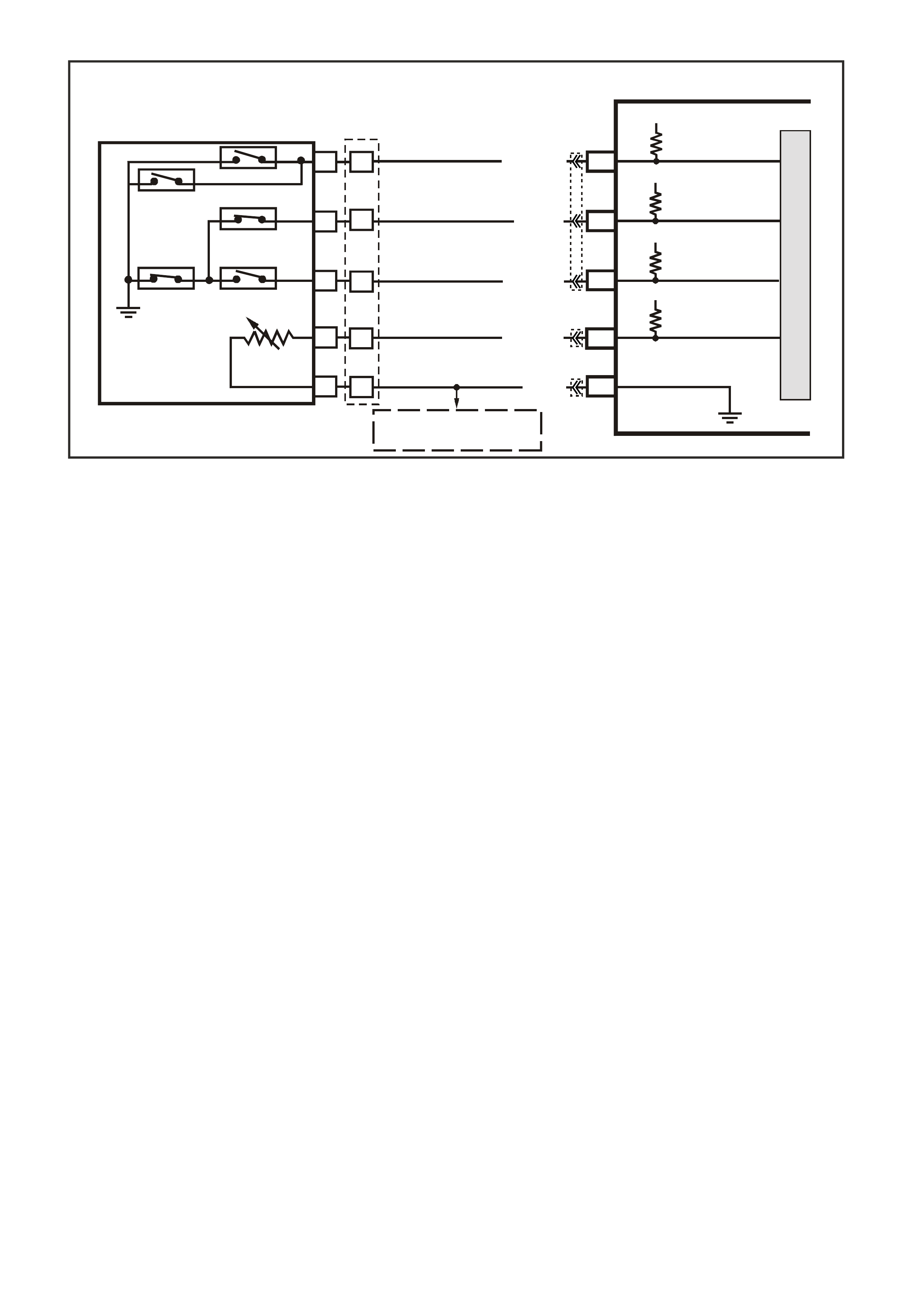
Figure 6C1-1 64 TFP Switch Assembly
SUPERVX034
PCM
F9
F10
B6
F16
TFP SIGNAL A
TFP SIGNAL B
TRANSMISSION FLUID
TEMPERATURE (TFT)
SENSOR SIGNAL
SENSOR EARTH
N
C
R
E
D
A
B
P
L
M
TRANSMISSION FLUID
TEMPERATURE
(TF T ) SENSOR
AUTOMATIC TRANSMISSION FLUID
PRESSURE SWITCH ASSEMBLY
BR/Y (1224)
Y (1225)
GY (1226)
B/Y (1227)
B (46 9)
12V
12V
5V
F11 TFP SIGNAL C
12V
M
I
C
R
O
TO
A
/C PRESSURE SENSOR
AND IAT SENSOR
YB194
YB129
YB188
YB194

VEHICLE SPEED SENSOR
IMPORTANT:
The sensor resistance is model dependent and varies
with speed from a minimum of 0.5 volts AC at 100
RPM to more than 100 volts AC at 8000 RPM.
The vehicle speed sensor (or transmission output
speed sensor) controls shift points and calculates the
TCC slip. The speed sensor contains a coil that gives
off a continuous magnetic f ield. A r otor r otates past the
sensor and the rotor teeth break the magnetic field.
Each break in the field sends a pulse to the VSSB
(Vehicle Speed Sensor Buffer). The VSSB sends two
signals to the PCM. The first is a 2002 pulse per mile
(PPM) signal that is used by the engine. The second is
the transmission/transfer case 40 pulse per revolution
(PPR) signal that is used in order to control the
transmission.
The vehicle speed sensor is located on the
transmission extension housing. Trans Output Speed
= Transfer Case Speed.
DTC 24 will set if a fault exists in the vehicle speed
sensor circuit 40 PPR line. DTC 94 will set for the
manual transmission Vehicle Speed Sensor.
62801
Figure 6C1-1-65
DTC 24 (Vehicle Speed Sensor Circuit Low Voltage) will set if:
Automatic Transmission
• The transmission is not in Park or Neutral.
• The engine speed is greater than 3000 RPM.
• The TP Sensor angle is between 10% and 99%.
• The VSS indicates an output shaft speed of less than 3 km/h for 3 seconds.
• The PCM will illuminate the Malfunction Indicator Lamp (MIL).
DTC 94 (Vehicle Speed Sensor Circuit Low Voltage) will set if:
Manual Transmission
• The engine speed is between 1400 and 3000 RPM.
• The throttle is closed (throttle angle less than 1%).
• Engine load very low, MAF less than 95 mg/cyl.
• The VSS indicates no output shaft speed for more than 4 seconds.
• Vehicle in gear.
• Vehicle is decelerating from road speed.
DEFAULT VALUE
For the automatic transmission, when this DTC sets, the PCM will command second gear only, The PCM will
command maximum line pressure, The PCM will freeze shift adapts from being updated, The PCM will inhibit
TCC engagement.
RECOVERY
Recovery will occur when the PCM sees a valid condition.
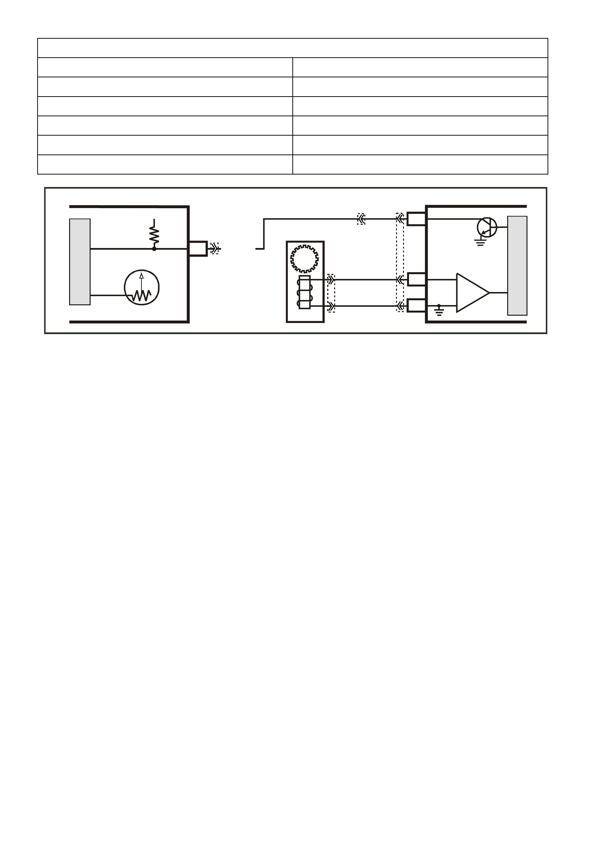
DTC 24 AND DTC 94 HISTORY DATA
PARAMETER PARAMETER
ENGINE SPEED THROTTLE ANGLE
TIME FROM START TFT
TIMES OCCURRED MASS AIR FLOW
IGNITION CYCLES COMMANDED GEAR (AUTO)
COOLANT TEMPERATURE VEHICLE SPEED
Figure 6C1-1-65 VSS Circuit
17
V/W (123)
12V IGN
VEHICLE SPEED
M
I
C
R
O
SUPERVX016
INSTRUMENT
M
I
C
R
O
VEHICLE SPEED
PCM
C5
C6
D5
V
EHICLE SPEED
SENSOR
IC
BLU/W
(831)
(AUTO)
BLU
(831)
(MAN)
T
(832)
(AUTO)
BR
(832)
(MAN)
SPEEDOMETER
YB193
YB195 (AUTO)
YB132 (MANUAL)
YE110
YB66

AUTOMATIC TRANSMISSION FLUID TEMPERA TURE SENSOR
The automatic transm ission fluid tem perature (TFT ) sens or is part of the automatic transm ission fluid pres sure
(T FP) m anual valve position switch as sem bly. T his sensor helps control tor que converter clutc h apply and shif t
quality. The TFT sensor is a resistor, or thermistor, which changes value based on temperature. At low
temperatures the resistance is high, and at high temperatures the resistance is low.
The PCM sends a 5 volt signal to the TFT sensor and the PCM measures the voltage drop in the circuit. You
will measure a high voltage when the transmission is cold and a low voltage when the transmission is hot.
Refer to the Temperature Vs Resistance table in Section 6C1-4.
If the TFT sensor circuit has a fault, DTC 58 or 59 is set. A DT C 58 indicates a short circuit condition, while a
DTC 59 indic ates an open circ uit condition. DT C 79 is set if the trans m ission is oper ating at a high temperatur e
for a period of time.
DTC 58 (TFT Sensor Circuit Low) will set if:
• The TFT sensor indicates a signal voltage less than 0.2 volts for 10 seconds.
• The PCM will not illuminate the Malfunction Indicator Lamp (MIL).
DEFAULT VALUE
When this DT C s ets , the PCM uses a tr ansmiss ion f luid temperature def ault value bas ed on engine c oolant, engine
run time and IAT at startup, the PCM will freeze shift adapts from being updated.
RECOVERY
Recovery will occur when the PCM sees a valid condition.
DTC 59 (TFT Sensor Circuit High) will set if:
• The TFT sensor indicates a signal voltage greater than 4.92 volts for 6.8 minutes (409 seconds).
• The PCM will not illuminate the Malfunction Indicator Lamp (MIL).
DEFAULT VALUE
When this DT C s ets , the PCM uses a tr ansmiss ion f luid temperature def ault value bas ed on engine c oolant, engine
run time and IAT at startup, the PCM will freeze shift adapts from being updated.
RECOVERY
Recovery will occur when the PCM sees a valid condition.
DTC 58 AND 59 HISTORY DATA
PARAMETER PARAMETER
ENGINE SPEED TFT
TIME FROM START THROTTLE ANGLE
TIMES OCCURRED VEHICLE SPEED
IGNITION CYCLES COMMANDED GEAR
COOLANT TEMPERATURE
DTC 79 (Transmission Fluid Overtemperature) will set if:
• The TFT is greater than 130° C for 10 minutes (600 seconds).
• The PCM will not illuminate the Malfunction Indicator Lamp (MIL).
DEFAULT VALUE
When this DTC sets, the PCM will freeze shift adapts from being updated.
RECOVERY
Recovery will occur when the PCM sees a valid condition.

DTC 79 HISTORY DATA
PARAMETER PARAMETER
ENGINE SPEED TFT SENSOR
TIME FROM START TFT
TIMES OCCURRED THROTTLE ANGLE
IGNITION CYCLES COMMANDED GEAR
COOLANT TEMPERATURE
Figure 6C1-1-66 TFT Sensor
DTC 85 (Transmission Slipping) will set if:
• No Throttle Position DTCs 21 or 22.
• No VSS assembly DTCs 24 or 72.
• No TCC solenoid valve DTC 67.
• No 1-2 SS valve DTC 81.
• No 2-3 SS valve DTC 83.
• No 3-2 SS valve assembly DTC 66.
• No TCC PWM solenoid valve DTC 83.
• The engine speed is greater than 300 RPM for 5 seconds.
• The engine is not in fuel cutoff.
• The vehicle speed is 56-105 km/h.
• The speed ratio is 0.67-0.90 (the speed ratio is the engine speed divided by the transmission output speed).
• The engine speed is 1200-3500 RPM.
• The engine torque is 54-542 N.m.
• The gear range is D4.
• The commanded gear is not 1st gear.
• The Throttle Position angle is 10-50%.
• The TFT is between 20-130°C.
• DTC P1870 sets if the following conditions occur for three TCC cycles.
- The TCC is commanded ON for 5 seconds.
- The TCC is at maximum duty cycle for 1 second.
- The TCC slip speed is 80-800 RPM for 7 seconds.
SUPERVX034
PCM
F9
F10
B6
F16
TFP SIGNAL A
TFP SIGNAL B
TRANSMISSION FLUID
TEMPERATURE (TFT)
SENSOR SIGNAL
SENSOR EARTH
N
C
R
E
D
A
B
P
L
M
TRANSMISSION FLUID
TEMPERATURE
(TF T ) SENSOR
AUTOMATIC TRANSMISSION FLUID
PRESSURE SWITCH ASSEMBLY
BR/Y (1224)
Y (1225)
GY (1226)
B/Y (1227)
B (46 9)
12V
12V
5V
F11 TFP SIGNAL C
12V
M
I
C
R
O
TO
A
/C PRESSURE SENSOR
AND IAT SENSOR
YB194
YB129
YB188
YB194

IMPORTANT:
The following actions may occur before the DTC sets:
• If the TCC is commanded ON and at maximum duty cycles for 5 seconds, the TP angle is 10-40%, and the
transm ission slip counter has incremented to either 1 or 2 (out of 3 to increm ent the fail counter for the current
ignition cycle), then the following slip conditions and actions may increment the fail counter for the current
ignition cycle:
- Condition 1: If the TCC slip speed is 80-800 RPM for 7 seconds, then the PCM will comm and maximum
line pressure and freeze shift adapts from being updated.
- Condition 2: If condition 1 is met and the T CC slip speed is 80- 800 RPM f or 7 seconds, then the PCM will
command the TCC OFF for 1.5 seconds.
- Condition 3: If condition 2 is met and the TCC slip speed is 80-800 RPM for 7 seconds, then the fail
counter on the current ignition cycle is incremented.
The above s lip conditions and ac tions m ay be disregarded if the T CC is c om m anded OF F at any time as a result of
a driving maneuver (sudden acceleration or deceleration).
• The PCM will not illuminate the Malfunction Indicator Lamp (MIL).
DEFAULT VALUE
W hen this DTC sets, the PCM inhibits TCC engagement, the PCM com mands maximum line pressure, The PCM
inhibits 4th gear if the transmission is in hot mode, the PCM will freeze shift adapts from being updated.
RECOVERY
Recovery will occur when the PCM sees a valid condition.
DTC 85 HISTORY DATA
PARAMETER PARAMETER
ENGINE SPEED TRANSMISSION SLIP SPEED
TIME FROM START TFT
TIMES OCCURRED THROTTLE ANGLE
IGNITION CYCLES VEHICLE SPEED
COOLANT TEMPERATURE COMMANDED GEAR
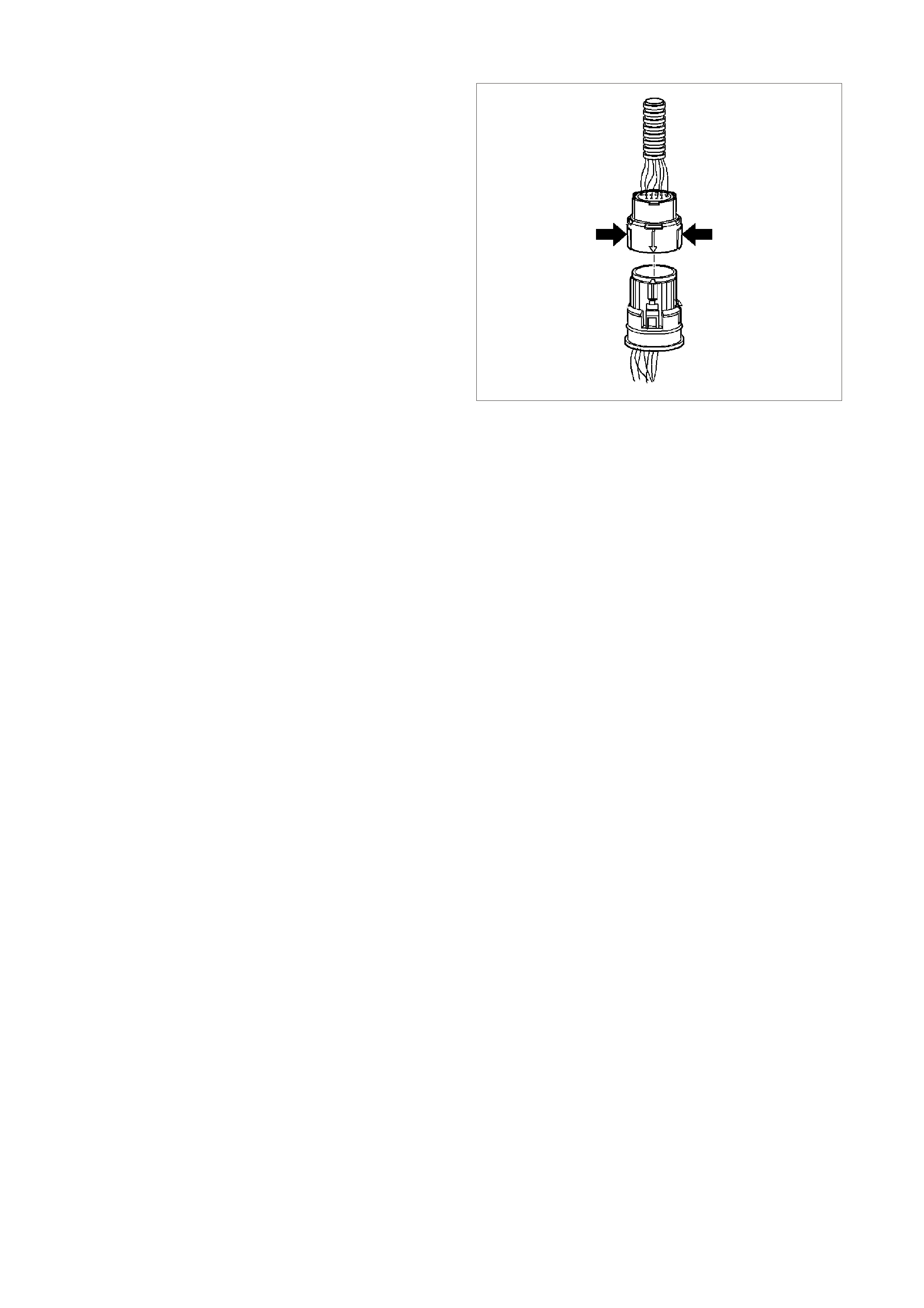
TRANSMISSION PASS-THRU CONNECTOR
The transmission electrical connector is an important
part of the transmission operating system. Any
interference with the electrical connection can cause
the transmission to set Diagnostic Trouble Codes
(DTCs) or affect proper operation.
The following items can affect the electrical
connection:
• Bent pins in the connector from rough handling
during connection and disconnection
• Wires backing away from the pins or coming
uncrimped (in either the internal or the external
wiring harness)
• Dirt contamination entering the connector when
disconnected
• Pins in the inter nal wiring connector back ing out of
the connector or pushed out of the connector
during reconnection
• Excessive transmission fluid leaking into the
connector, wicking up into the external wiring
harness and degrading the wire insulation
• Moisture intrusion in the connector
• Low pin retention in the external connector from
excessive connection and disconnection of the
wiring connector assembly
• Pin corrosion from contamination
• Damaged connector assembly
13265
Figure 6C1-1-67
Remember the following points:
• In order to rem ove the connector, squeeze the two
tabs toward each other and pull s traight up without
pulling by the wires.
• Limit twisting or wiggling the connector during
removal. Bent pins can occur.
• Do not pry the connector off with a screwdriver or
other tool.
• Visually inspect the seals to ensure that they are
not damaged during handling.
• In order to reinstall the external wiring connector,
first align the pins by lining up the arrows on each
half of the connector. Push the connector straight
down into the transmission without twisting or
angling the mating parts.
• The connector should click into place with a
positive feel and/or noise.
IMPORTANT:
Whenever the transmission external wiring connector
is disconnected from the internal harness and the
engine is operating, DTCs will set. Clear these DTCs
after reconnecting the external connector.

1.4 FUEL CONTROL SYSTEM
PURPOSE
The purpose of closed loop fuel control is to control tailpipe emissions consisting of hydrocarbons (HC), Carbon
Monoxide (CO), and Oxides of Nitrogen (NOx). At the same time, the system must achieve good engine
performance and good fuel economy.
The closed loop system regulates exhaust emissions by controlling the air/fuel ratio at an optimum level during
various driving c onditions. The most ef f ic ient air/f uel r atio to minimise exhaus t emiss ions is 14.7 to 1, this allows the
3-way catalytic converter to operate at maximum efficiency to control exhaust pollutants. Because of the constant
measuring of the exhaust gases by the oxygen sensors, and adjusting of the fuel injector pulse width by the PCM,
the fuel injection system is called a "closed-loop" control system.
FUNCTION
The fuel supply system delivers fuel at a regulated pressure to the fuel rail. The fuel injectors, located directly
ahead of each inlet port of the cylinder head, act as fuel flow control valves, "spraying" atomised fuel into the inlet
ports when they are electrically "pulsed" by the PCM. On this engine, all injectors ar e wired individually so they are
pulsed individually. This type of fuel injec tion is ref erred to as sequential injection because pulsation of the injector s
are individually controlled and in a specific order.
The PCM controls the am ount of fuel inj ected into the engine by controlling the length of tim e the injectors are held
open. This "length-of-time" is called PULSE WIDTH. To increase the amount of fuel injected, the pulse width is
lengthened, and vic e versa. T he pulse width is calibratable and varies between 0 - 11 m illiseconds with the engine
running at idle, and injection pulses normally occur once every crankshaft revolution.
MASS AIR FLOW SYSTEM
The Holden/Delco Fuel Injection system is a Mass Air Flow system. The system is based upon an Air Meter that
measures the mass air flow rate of the engine directly.
Advantages of Mass Air Flow:
• Base engine components can be changed.
• Automatically compensates for engine aging.
• No air measurement lag time.
• Excellent idle stability.
Two specific data sensors provide the PCM with the basic information for the fuel management portion of its
operation. That is , two specific signals; crank shaf t referenc e signal from the ignition system , and the Mass Air Flow
(MAF) s ensor signal. Both of these s ignals to the PCM establish the engine speed and mass of air ingested by the
engine. Due to the additional temper ature compens ation sensor in the MAF sens or, this sys tem does not require a
manifold absolute pressure sensor.
The engine speed signal comes from the ignition module to the PCM on the crankshaft reference signal input
circuit. The PCM uses RPM information to calculate the best fuel injector pulse width and spark timing for a given
operating RPM band.
The mass of air ingested by the engine is sent as a signal from the mass air flow sensor to the PCM.
When the engine is started, the PCM will im m ediately look at the Engine Coolant Tem per ature sens or to determ ine
how much fuel is required to start the engine. After the engine is started, the PCM will constantly monitor the MAF
sensor values to determine both the spark advance and engine fuelling requirements. The Mass Air Flow sensor
measures the mass of air ingested
into the engine. The PCM then calculates how much fuel that must be injected to maintain an air/fuel ratio of
14.7 to 1. An engine started in cold weather will require more fuel and spark advance than an engine started hot,
which requires less fuel and less spark advance.
One sensor is used to m eas ure the density factor, the Mas s Air F low (MAF) sens or. T he m ass air flow sensor used
on this engine utilises a heated element type of operation. Three sensing elements are used in this system.
As air passes over the heated elements during engine operation they begin to cool. By measuring the amount of
electrical power required to maintain the heated elements at the predetermined temperature above ambient
temperature mass air flow rate can be determined.
As the PCM receives this frequenc y s ignal from the mas s air flow sens or, it searches its pre-progr amm ed tables of
information to determine the pulse width of the fuel injectors required to match the mass air flow signals.
The s ignal that is s ent f r om the m as s air flow sensor is sent in the form of a f r equenc y output. A large quantity of air
passing through the sensor (such as when accelerating) will be indicated as a high frequency output. A small
quantity of air passing through the sensor will be indicated as a low frequency output (such as deceleration or at
idle. The T ech 2 scan tool disp lays MAF sens or inform ation in frequency, grams per second. A "norm al" reading is
approximately 4 - 9 grams per second at idle and increases with engine RPM.

The remaining sensors and switches provide electrical inputs to the PCM which are used for modification of the
air/fuel mixture as well as for other PCM control functions, such as Idle Air Control (IAC).
MODES OF OPERATION
The PCM looks at voltage signals from several sensors to determ ine how m uch fuel to give the engine, and when
to operate in the open- loop or closed-loop m odes. The fuel deliver y is contr olled in one of several possible m odes.
All the modes are controlled by the PCM, and are described in the following paragraphs.
STARTING MODE
W hen the ignition key is first turned "ON," the PCM will energise the fuel pump relay, and the fuel pump will build
up pressure to the fuel rail. The PCM then checks the engine coolant temperature sensor and determines the
proper injector pulse width for starting the engine.
When cranking begins, the PCM will operate in the Starting Mode until engine RPM is more than about 400, -or-
the "Clear Flood" mode is enabled. After the ignition is turned "ON" and the first reference signal is received, the
PCM will pulse all of the fuel inj ectors . After the firs t prim e puls e has been injec ted, the PCM will wait until the PCM
receives a good camshaft position signal. When the PCM receives a good camshaft position signal, the PCM
operates the fuel injectors in Sequential mode. Pulse width during the Starting Mode is between approxim ately 4 -
26 milliseconds, depending upon engine coolant temperature.
CLEAR FLOOD MODE
If the engine floods, it can be started by pushing the accelerator pedal down all the way to the floor while cranking
the engine. The PCM then pulses the injectors with zero millisecond pulse width, which should "clear" a flooded
engine. The PCM holds this pulse width as long as the throttle position sensor input indicates the throttle is above
80% and RPM is below 400.
If the throttle is held wide-open while attempting to make a normal start with a non-flooded engine, the
engine will not start.
NORMAL OPEN LOOP MODE
After the engine is running (RPM more than 400), the PCM will operate the fuel control system in the Open Loop
mode. In open loop, the PCM ignores the signal from the Oxygen Sensor (O2S), and calculates the air/fuel ratio
injector pulse width based on inputs from the crankshaft reference signal (RPM input) and these sensors: MAF,
IAT, ECT, and TP sensor.
The system will stay in the Open Loop m ode until all the Closed Loop mode criteria have been m et, or not at idle,
refer Open Loop Idle Mode description.
In open loop, the calculated puls e width may give an air/fuel ratio other than 14.7 to 1. An example of this would be
when the engine is cold, because a richer mixture is needed to ensure good driveability.
The normal open loop mode is not active when adverse or abnormal vehicle operating conditions are occurring
adverse conditions include engine overheating due to high vehicle speed or high ambient temperature.
OPEN LOOP IDLE MODE
The reas on for the Idle Mode is to allow a slightly richer mix ture at idle for better idle quality. Idle Mode air/fuel ratio
is about 14.0 to 1. This is an open loop mode, meaning the O2 sensor signal is ignored.
The Open Loop Idle Mode is in effect when the throttle is closed (TP Sensor), and vehicle speed is below 5 km/h
(VSS).
In the c ase where the vehicle r olls to a st op while operating in the Closed Loop m ode, Idle Mode will be delayed f or
about 20-30 seconds. During this time, the PCM will "learn" a fuel correction factor for a 14.7 to 1 air/fuel ratio
before switching to the Idle Mode.
CLOSED LOOP MODE
In Closed Loop mode, the PCM initially calculates injector pulse width based on the same sensors used in open
loop. The difference is that in closed loop, the PCM uses the Exhaust Gas Oxygen Sensor (O2S) signal to modif y
and precisely fine tune the fuel puls e width calculations in order to pr ecisely maintain the 14.7 to 1 air/fuel ratio that
allows the catalytic converter to operate at it's maximum conversion efficiency.
DELTA TPS ACCELERATION MODE
The PCM look s at rapid changes in throttle position (TP sensor) to increase engine power, and provides extra fuel
by inc reasing the injector pulse width. If the increas ed fuel requirem ents are gr eat enough, the PCM may add extra
fuel injection pulses between the injector pulses that normally occur once per crankshaft revolution.

LEAN CRUISE AIR/FUEL MODE
During steady state cruising, the air/fuel ratio is made lower in order to increase fuel economy .
The engine will operate in Lean Cruise when:
• ECT is greater than 80 degrees C.
• VSS is greater than 70 km/h.
• Engine has been running longer than 2 minutes and 30 seconds.
• Calculated A/F ratio is 14.8 to 1
• Engine is not in power enrichment mode.
If all the criteria are met, the PCM will lean out the A/F ratio by 0.1 ratio every 0.2 second until it reaches its
maximum total enleanment.
DECELERATION MODE
W hen deceleration occurs, the fuel remaining in the intake manifold can cause excessive emissions and possibly
backfiring. Again, the PCM looks at changes in throttle position (TP sensor) and engine RPM and reduces the
amount of fuel by decreasing the pulse width, but does not completely shut off the fuel.
DECEL FUEL CUTOFF MODE
Decel fuel cutoff disables fuel delivery during a deceleration to reduce emissions and to improve fuel economy.
When deceleration from road speed occurs, the PCM can cut off fuel pulses completely for short periods. The
decel fuel cutoff mode occurs when all these conditions are met:
1. Coolant temperature above 63 degrees C.
2. Engine RPM has dropped more than 200 RPM.
3. Vehicle speed above 42 km/h.
4. Throttle is less than 2 %.
When the decel fuel cutoff is in effect, any one of these can cause the injection pulses to restart.
1. Engine RPM has not dropped more than 200 RPM.
2. Vehicle speed is less than 42 km/h.
3. Throttle is open at least 2%.
PARK/NEUTRAL TO DRIVE ACCELERATION ENRICHMENT MODE
The PCM will deliver additional fuel to the engine to reduce the RPM droop associated with a transmission shift
from park/neutral to a drive shift. This mode will only add fuel based on the first 32 reference pulses after a shift
has been detected.
POWER ENRICHMENT (PE) MODE
The Power Enrichment (PE) mode delivers a rich mixture to the cylinders during a large throttle position change
command from the driver. During PE, the PCM will not make fuelling changes based on the oxygen sensor signal.
BATTERY VOLTAGE CORRECTION MODE
At low battery voltages, the ignition system m ay deliver a weak spar k, and the injector m echanical movem ent tak es
longer to "open." The PCM will compensate by:
• Increasing ignition coil dwell time if voltage is less than 12 volts.
• Increasing idle RPM if voltage drops below 10 volts.
• Increasing injector pulse width if voltage drops below 10 volts.
FUEL CUTOFF MODE
No fuel is delivered by the injectors when the ignition is (OFF). This prevents dieseling. Also, fuel pulses are not
delivered if the PCM receives no distributor reference pulses from the ignition module, which means the engine is
not running.
The Fuel Cutoff Mode is also enabled at:
• High engine RPM, as an overspeed protection for the engine. When cutoff is in effect due to high RPM,
injection pulses will resume after engine RPM drops slightly.
• High vehic le speed. When the vehic le speed ex c eeds a calibr atable value the f uel bas e puls e width is set equal
to zero. Normal fuel operation will return when the vehicle speed falls below a calibratable value.
SEQUENTIAL FUEL INJECTION MODE
When the engine is first cranked over, all injectors will be energised simultaneously. After the engine has been
started and a good camshaft signal has been processed, the PCM will energise each individual injector in the
normal firing order. This mode of operation helps to stabilize idle, reduce em issions and reduce fluctuations in fuel
pressure.

CAMSHAFT POSITION SENSOR
The Camshaft Position Sensor is located in the
engine front cover, behind and below the water
pump, near the camshaft sprocket.
As the cam shaf t spr ock et turns, a m agnet mounted
on it activates the Hall Ef f ec t s witch in the c amshaf t
position sensor. When the Hall Effect switch is
activated, it earth's the signal line to the DIS
module, pulling the camshaft position signal line's
applied voltage low. This is interpreted as a
camshaft position signal (Synchronisation Pulse).
Because of the way the signal is created by the
camshaft position sensor, the signal circuit is
always either at a high or low voltage (square wave
signal).
While the camshaft sprocket continues to turn, the
Hall Eff ect switch turns "OFF" as the m agnetic f ield
passes the camshaft position sensor, resulting in
one signal each time the camshaft makes one
revolution.
The camshaft position signal, which actually
represents camshaft position due to the sensor's
mounting location, is used by the PCM to properly
time its sequential fuel injection operation.
Refer to Figs. 6C-1-1-13 and 6C1-1-14 in this
Section for camshaft position sensor location and
camshaft position signal details.
When the camshaft position signal is not received
by the PCM, a DTC 48 will be set. An intermittent
cam shaft pos ition signal will set a DTC 49. If either
of these DTC's are set, the fuel system will not be
in sequential fuel injection mode.
1
4205
Figure 6C1-1-68 Camshaft Position Sensor
1. Camshaft Position (CMP) Sensor
ADAPTIVE LEARNING
Adaptive learning is the ability of the on-board computer to determine and remember its most recent operating
experience. The PCM uses this rem em bered inform ation to "learn from experience" and to m ake adjustm ents with
respect to what it learnt. If the engine were to develop a restricted fuel filter, the PCM will change the fuel injector
pulse width richer to compensate for this condition and will remember to keep this fuel injector pulse in memory
until the restriction is corrected. After the restriction has been fixed, the PCM will eventually go back to the original
pre-programmed fuel injector pulse.
Adaptive learning is an on-going process that continues throughout the life of the engine. A new engine with good
com pres sion will have good vacuum . As the engine wears and c om press ion decreas es, a slight decrease in engine
vacuum will be noticed, which translates into a slightly lower MAF grams per second at idle, which will decrease
injector pulse width to compensate for this condition.
SHORT TERM FUEL TRIM
Short T erm Fuel Trim (STFT) represents short term corrections to the fuel injector pulse width calculations, based
on the oxygen sensor input signal to the PCM.
When the engine is started cold, in "Open Loop," the PCM will control the fuel injection pulse width based upon
various sensor inputs such as RPM, ECT, MAF and TP sensor until the oxygen sensors become hot enough
(approximately 315 degrees C) to operate properly. During this "Open Loop" period, both Short Term Fuel Trim
(STFT) and Long Term Fuel Trim (LTFT) are disabled and will read 0% on a Tech 2 scan tool.
When the oxygen sensor has come up to its normal operating temperature (approximately 600 degrees C or
above), it will produce a varying voltage to the PCM and provide a good indication of what has happened in the
combustion chambers.
At this time the PCM will switch from "Open Loop" to "Closed Loop" and the STFT will start to constantly monitor
the oxygen sensor signal, so that the PCM can m odif y fuel inj ector pulse width with greater acc uracy than in "Open
Loop".
STFT monitors the oxygen sensor signal so that it can adjust the fuel injector pulse width to maintain an air/fuel
ratio of 14.7 to 1 f or maximum catalytic converter efficiency. An ST FT value of 0% is equivalent to an air/fuel ratio
of 14.7 to 1 and an average oxygen sensor signal voltage of 450 mV.

The normal pos ition f or Short Term Fuel Trim is 0%, any change from this value indic ates the Short T er m Fuel Trim
is c hanging the f uel injec tor pulse width. The am ount of pulse width change depends upon how far the ST FT value
is f r om 0%. If the STFT value is above 0%, the f uel inj ec tor puls e width is being inc reas ed, thus adding more f uel. If
the STFT value is below 0%, the fuel injector pulse width is being decreased, thus removing fuel. The normal
operating range of STFT is considered to be between -22% and +25% ; any value out of this range is usually
caused by a malfunction.
If an engine has a r est ric ted f uel f ilter , the low fuel pr es s ure will res ult in les s f uel being inj ect ed and allows more air
into the air c harge than is needed to ignite the am ount of f uel the f uel injector has injec ted, theref ore, a lean air/f uel
ratio exists in the combustion chamber. After combustion has taken place, the exhaust gases still contain more
oxygen content than nor mal and the oxygen sensor reads this as low voltage, say 200 m V. The STF T detects that
the oxygen sensor s ignal is low and will increas e the value to ric hen up the air /f uel mixtur e. On a Tech 2 s c an tool it
will display STFT as a value above 0%. This STFT change will increase the injector pulse width allowing the fuel
injectors to stay open longer and inject more fuel.
If the additional fuel was injected and the oxygen sensor signal voltage is still low, the STFT will continue to
increase its value until the oxygen sensor signal voltage goes above 450 m V. If the STFT continues to detect a low
oxygen sensor signal voltage it will continue to tr y and compensate f or the lean exhaus t condition until it runs out of
its authority in the particular Long Term Fuel Trim (LTFT) cell it's operating in. At this point, the PCM will reset
STFT to 0% and go through this procedure again until it can control the system.
If after a specif ied am ount of resets have been tr ied and failed, the PCM k nows that it cannot control f or the failure
and the STFT will remain at its maximum value.
STFT values are bas ed on the oxygen s ensor signal voltage reading, ther efore, ST FT is used by the PCM to m ake
quick changes to the fuel injector pulse width over a short period of time.
LONG TERM FUEL TRIM
Long Term Fuel Trim is used to adjust for engine to engine variation and to adjust for engine aging. LTFT is a
portion of the PCM memory used to adjust fuel delivery across all operating conditions of the engine. The PCM
monitors the STFT and will adjust the long term trend of the fuel injector pulse width if the STFT has been at a
value for a certain period of time. LTFT is used to change the long term fuel injector pulse width and is only
operational when the fuel control system is in "Closed Loop." A normal LTFT value is 0% and should follow the
STFT value.
If an engine has a restricted f uel filter, the low fuel pres sure will result in less f uel being injected and will cause the
STFT value to go higher than 0%, say 2%. If this STFT value change does not compensate for the restricted fuel
filter, the PCM will continue to increase the STFT value. The STFT may climb as high as its maximum calibrated
value if there is a severe restriction. The PCM will continue to monitor STFT as it climbs, but it will not make any
changes to the f uel injector puls e width for a specif ic period of time. Af ter a specific period of time has elapsed and
the STFT value has remained above say +8%, the LTFT will move up to say 4% and wait again to detect if the
STFT has dr opped bac k down to 0%. If not, the ST F T will gradually move toward its m a ximum calibr ated value limit
until it gains control of the fuel injection system. If STFT and LTFT are both set at their maximum value limit, the
fuel control system is "out of the limits of control" and will set either a Diagnostic Trouble Code (DTC) 44, or DTC
64 (lean exhaust) or DT C 45, or DTC 65 (rich exhaust) and go into "open loop" operation. Under the conditions of
power enrichment, (Wide Open Throttle, WOT), the PCM sets the STFT to 0% and freezes it there until power
enrichment is no longer in effect. This is done so that LTFT will not try to correct for the commanded richness of
power enrichment.
The PCM will keep the latest LT FT values stored in its LT FT mem ory cells. MAF sens or readings and engine RPM
are used by the LTFT to determ ine what cell to read. LTFT values are stored in the PCM's long term m emory, for
use each time the engine's RPM and load matches one of the LTFT cells. All LTFT values are reset to 0% when
the PCM's "long term memory power supply" is disconnected, as when diagnostic trouble codes are cleared. The
Tech 2 scan tool also has the ability to reset LTFT to 0% with a special command.
0%
+ 1% 0%
0%
0%
–
-2%
–
-1%
+ 2%
+ 2%
0%
–
1%
–
-1%
0%
+ 1%
+ 1%
+ 2%
–
-1%
–
-2%
0%
+ 1%
+ 1%
+ 1%
0%
11
12
1314
16
17
5
15
88
9
5
2
1
3
10
9
7
8
22 23
18
3
3
15
20
19
21
5
5
4
3
2
1
+ 1%
0%
6
4227
Figure 6C1-1-69 Long Term Fuel Trim Values
1. Light % Canister Purge
2. Heavy % Canister Purge
3. Hysteresis
4. 4 km/h
5. High
6. 1000 RPM
7. Vehicle Speed
8. Low
9. RPM
10. 0 RPM
11. 4000 RPM
12. 2000 RPM
13. 975 RPM
14. 17 G/S
15. AirFlow
16. 25 G/S
17. 45 G/S
18. 0G/S
19. Throttle Position
20. 9 G/S
21. 0%
22. 0 km/h

LONG TERM FUEL TRIM CELLS
The Long Term Fuel Trim function of the PCM is divided up into cells arranged by a Mass Air Flow (MAF) and
Engine Speed (RPM). Each cell corresponds to a region on a MAF vs RPM table. Each region is calibrated to a
LTFT value of 0%. A value of 0% in a given block indicates no fuel adjustment is needed for that engine load
condition. A higher number, say + 4%, indicates that the PCM has detected a lean exhaust indication under those
conditions, and is adding fuel (increasing fuel injector pulse width) to compensate. Conversely, a lower number,
say -6%, indicates that the PCM has detected a rich exhaust indication under those load conditions, and is
subtracting fuel (decreasing fuel injector pulse width) to compensate.
As the vehicle is driven from a standing start and accelerated or decelerated from various engine speeds, the
engine's LTFT calibration will change from one cell to another cell. As the LTFT changes cell so does STFT,
however, STFT will only make short term corrections in whatever LTFT cell the engine is operating in. When the
engine is idling, it can be in one of two cells. On a vehicle with automatic transmission, depending upon canister
purge, the engine will idle in cell 0 or 17. If the engine was running at idle and the canister purge was "ON", we
would be in cell number 0 on an automatic transmission equipped vehicle. Cells 16 and 33 are used for idle on
vehicles with manual transmission only. Whatever cell the engine is operating in, the PCM will read that cell's
particular LTFT value and electronically adjust the fuel injector base pulse width to compensate for a rich or lean
condition in the engine. If an engine has a restricted fuel f ilter and the customer has driven the vehicle like this f or
quite some time, the STFT value would be high, and the PCM would be compensating for this condition by adding
more fuel. Because the STFT value is above 0%, LTFT will also be greater than 0% in most of the cells to
compensate for the lean exhaust. If you suspect a driveability problem associated with an over rich or over lean
condition, then use the STFT value to detect what the fuel control system is doing at the present time. Use the
LTFT to identify what the system has "learned" over a greater period of time to compensate for the condition.
Use the LTFT cells to determine if the fuel control system is commanding rich or lean throughout the operating
range. If it is only rich or lean at idle or part throttle, look for components that would cause problems in these areas.
All LT FT c ell values are rese t to 0% when long term mem or y power to the PCM is rem oved, s uch as when clearing
DTC's.
The Tech 2 scan tool has the ability to reset all LTFT cells to 0% with a special command.
A system malf unction that causes too great a dif ference between the right and lef t Short Term Fuel Trim values or
too great a difference between the right and left Long Term Fuel Trim values will set either a DTC 78 or DTC 76.

CELL
15 CELL
11
CELL
7
CELL
10
CELL
6
CELL
14
CELL
13
CELL
9
CELL
8
CELL
12
CELL
4
CELL
1
CELL
2
CELL
3
CELL
5
CELL
0
CELL
CELL
CELL
CELL
17
CELL
CELL
CELL
11
12
1314
16
17
5
15
88
9
5
2
1
3
10
9
7
8
22 23
18
3
3
15
20
19
21
55
4
3
2
1
CELL
16
CELL
33
6
4228
29
25
21 18
20
19
Figure 6C1-1-70 Long Term Fuel Trim Cell Matrix
1. Light % Canister Purge
2. Heavy % Canister Purge
3. Hysteresis
4. 4 km/h
5. High
6. 1000 RPM
7. Vehicle Speed
8. Low
9. RPM
10. 0 RPM
11. 4000 RPM
12. 2000 RPM
13. 975 RPM
14. 17 G/S
15. AirFlow
16. 25 G/S
17. 45 G/S
18. 0G/S
19. Throttle Position
20. 9 G/S
21. 0%
22. 0 km/h

DTC 76 (Short Term Fuel Trim (STFT) Delta High) will set if:
• The lef t hand short term fuel trim value varies from the right hand short term fuel trim value by m ore than 63%
for more than 32 seconds
• The PCM will not illuminate the Malfunction Indicator Lamp (MIL).
DTC 78 (Long Term Fuel Trim (LTFT) Delta High) will set if:
• The lef t hand long ter m f uel trim value varies f rom the r ight hand long term f uel trim value by mo re than 59% for
more than 32 seconds
• The PCM will not illuminate the Malfunction Indicator Lamp (MIL).
DEFAULT VALUES
Once DTC 76 or 78 are set, and current, the PCM will operate the fuel system in the open loop mode.
RECOVERY
Recovery will occur when the PCM sees a valid condition.
DTC 76 AND 78 HISTORY DATA
PARAMETER PARAMETER
ENGINE SPEED L.H STFT
TIME FROM START R.H LTFT
TIMES OCCURRED L.H LTFT
IGNITION CYCLES R.H O2 SENSOR
R.H STFT L.H O2 SENSOR
BASIC FUEL SYSTEM OPERATION
The f uel control system starts with the fuel in the f uel tank. A single in- tank high pressure fuel pum p (located inside
a m odular s ender unit) is used. From the high pressur e pump, f uel flows through a f uel filter, then on to the engine
fuel rail through the fuel pressure supply line.
The high pressure in-tank single pump is capable of providing fuel at more than 414 kPa. A pressure regulator
connects between the fuel rail and the return fuel line, and keeps fuel available to the injectors at a regulated
pressur e between 270 and 350 k Pa. The regulated pres sure will vary, depending on intake manif old pres sure. The
pressur e regulator senses manif old pressur e through a sm all hose connecting it to the thr ottle body adapter. When
throttle body adapter pressure is low (closed-throttle), the regulated pressure is at its lowest. W hen the throttle is
wide open, intake manifold pressure is high and the fuel pressure also is at its highest.
Fuel in ex ces s of inj ec tor needs is r eturned to the f uel tank by the separate return line connec ted to the outlet of the
pressure regulator.
The injectors, located in each runner of the intake manifold just ahead of the inlet ports to the cylinder head, are
controlled by the PCM. They deliver fuel in one of several modes, as described previously.
The fuel pum p is energised by the PCM via the fuel pum p relay. Refer to Diagnosis TABLE A 4.1 of the VX Ser ies
Service Information for further diagnosis of the fuel pump electrical system.
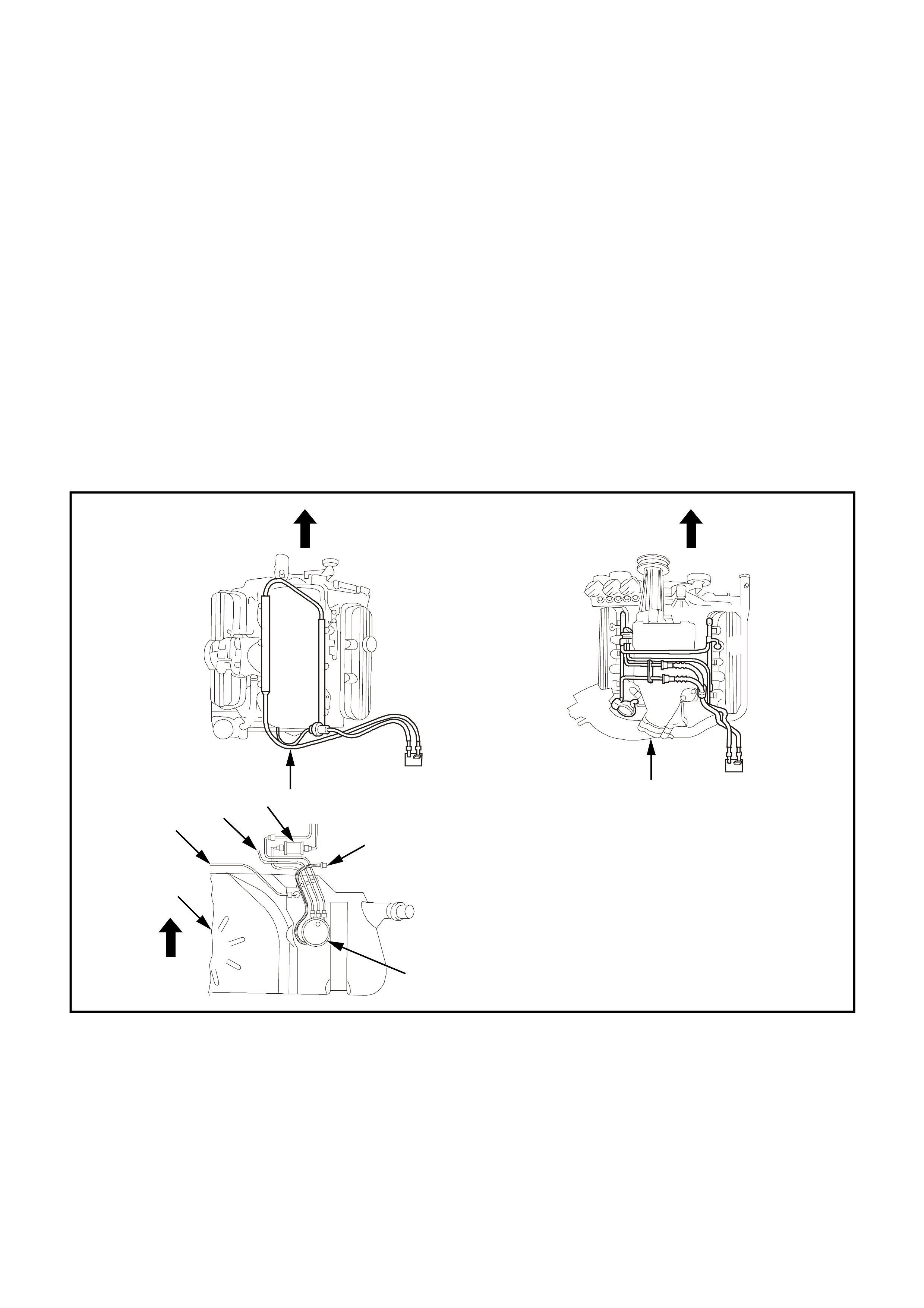
SYSTEM COMPONENTS
The Fuel Control System is made up of the following components:
• PCM
• Fuel pressure supply line
• Fuel pump relay
• Fuel rail
• Injectors
• Modular Fuel Sender Assembly
• Fuel Pump
• Fuel pressure regulator
• Fuel filter
• Fuel return line
• Swirl pot
Prior To Starting Engine, Check Fuel System For Leaks As Follows:
1. Turn Ignition “ON”.
2. Check Fuel System For Leaks, Particularly At Points Marked In Figure 6C1-1-71, With Fuel Pump Running.
3. Repair Leaks If Present.
1
4
8
7
3
4229
2
6
5
Figure 6C1-1-71 Fuel Delivery System
1. V6 Supercharge Engine
2. Fuel Pump
3. Fuel Pump Harness Connector
4. V6 Non-Supercharge Engine
5. Fuel Tank
6. Vent Tube
7. Vapour Tube
8. Fuel Filter
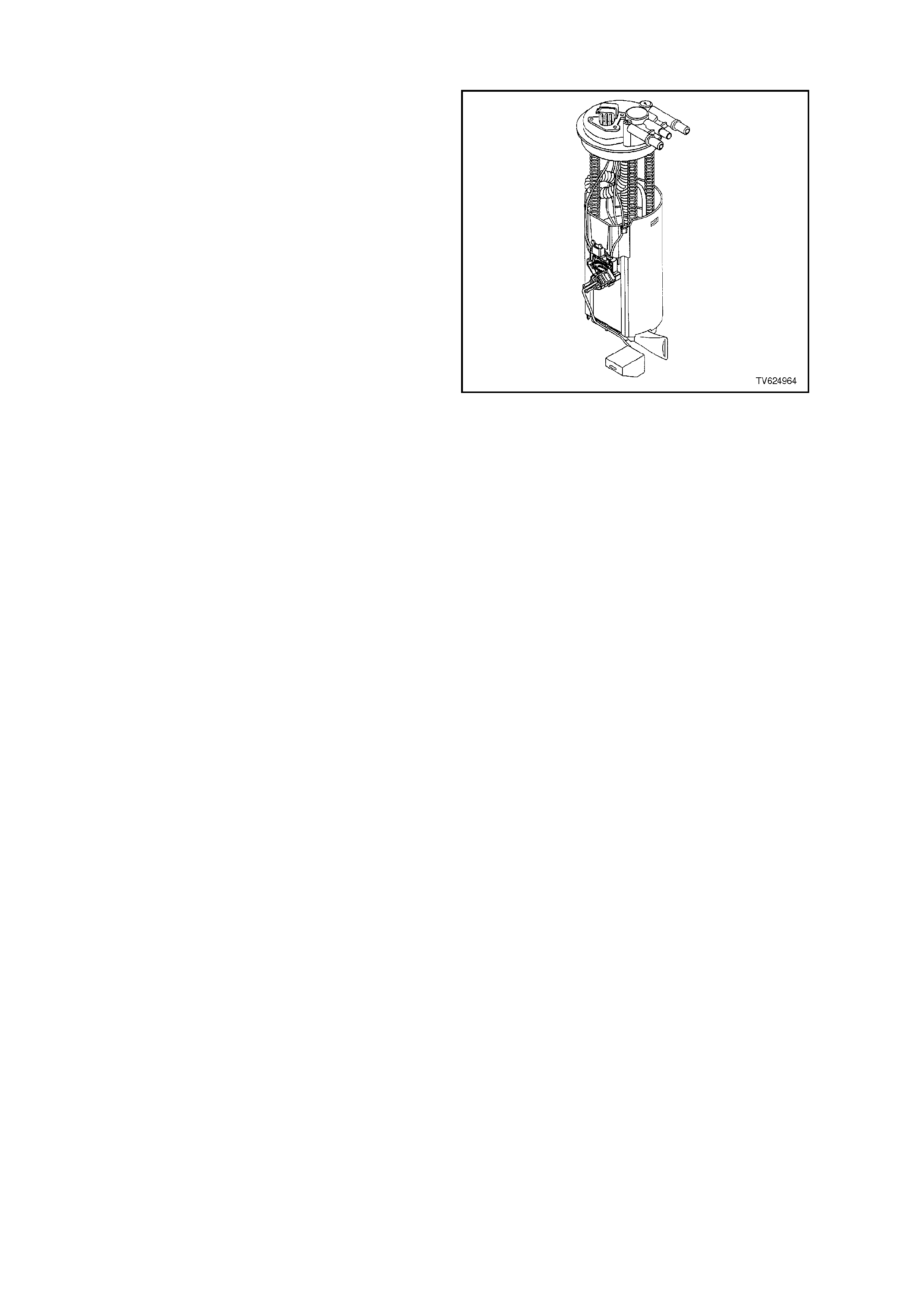
MODULAR FUEL SENDER ASSEMBLY
The modular fuel sender assembly is attached to
the top of the f uel tank, and extends f rom the top of
the fuel tank to the bottom.
The modular fuel sender assembly consists of the
following major components:
• A Fuel Sender Cover
• Fuel Pipes (above cover)
• A Fuel Pump
• A Fuel Pump Strainer
• A Fuel Pump Reservoir
• A Fuel Sender Strainer
• A Ceramic Fuel Level Sensor Assembly
The fuel level sender assembly consists of the
following:
• A Float
• The Wire Float Arm
• A Rheostat
The fuel level is sensed by the position of the float
and float arm, position changes, the amount of
current passing through the rheostat varies, thus
changing the fuel gauge reading on the instrument
panel.
The V6 Supercharged Engine application uses a
ROLLERVANE f uel pump. T his fuel pum p can only
be serviced as a complete unit with the sender unit
assembly.
Figure 6C1-1-72 Modular Sender Assembly
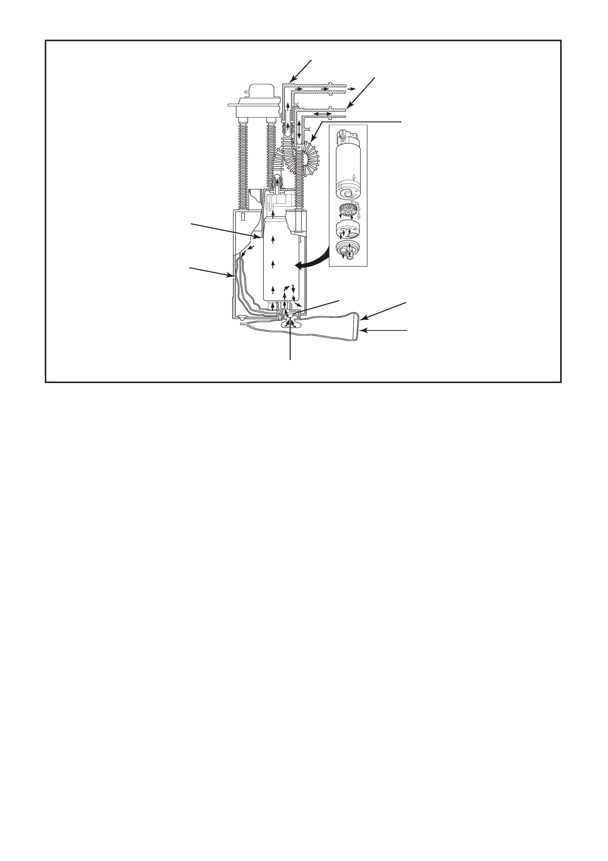
Figure 6C1-1-73 Fuel Pump/Sender Assembly
1. Fuel Feed 2. Fuel Return
3. Flex Pipe (Convoluted Fuel Tube) 4. External Strainer
5. External Filter 6. Umbrella Valve
7. Fuel Entering Umbrella Valve 8. Fuel Pump Strainer
9. Fuel Pump
9
8
7
6
5
4230
4
3
2
1
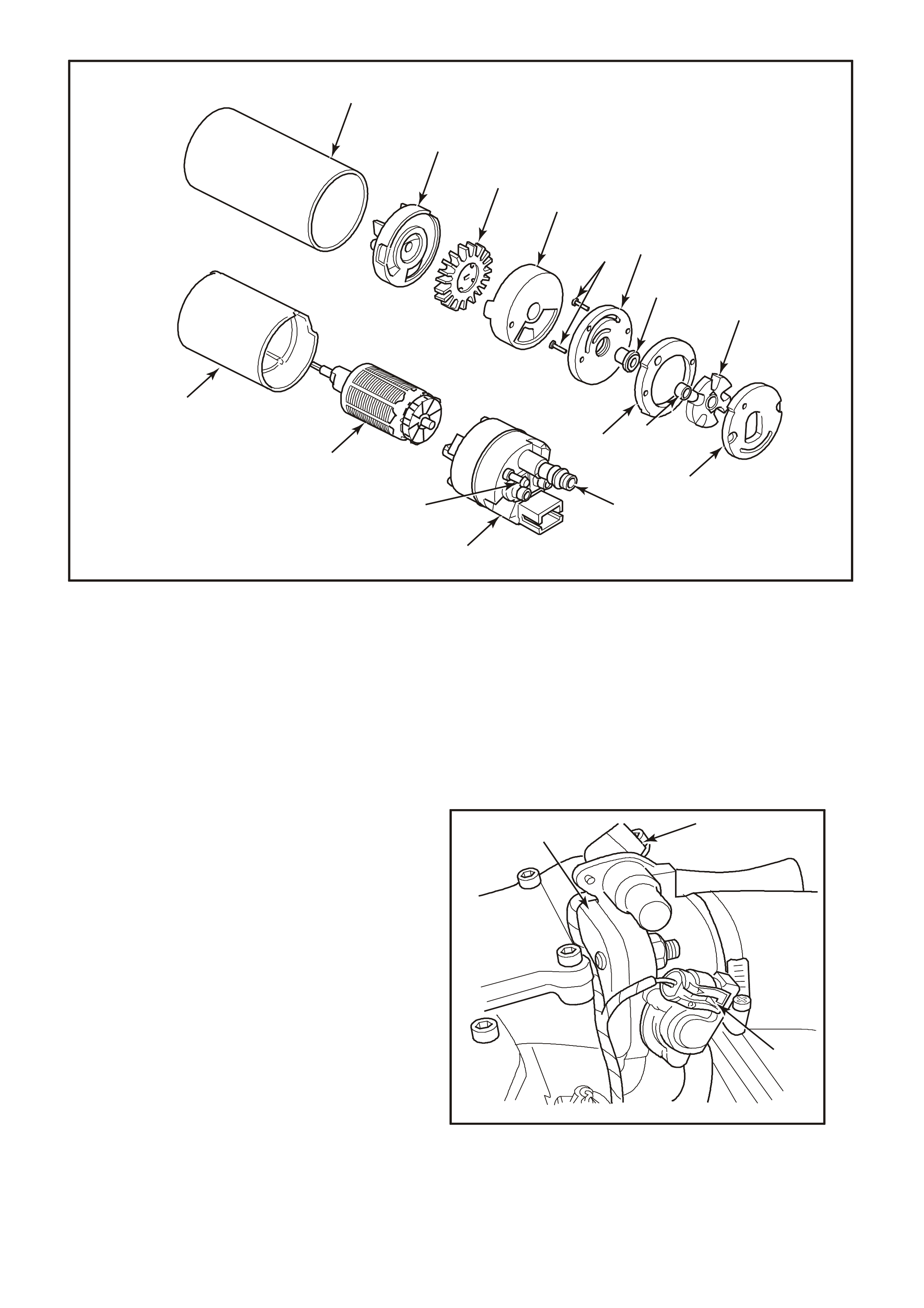
Figure 6C1-1-74 V6 Supercharge Engine Rollervane Fuel Pump Assembly
1. Aluminum Shell 2. Inlet
3. Impeller 4. Pump Housing
5. Rivets 6. Plate Face
7. Bearing 8. Rotor & Sleeve
9. Outlet Plate 10. Roller
11. Ring (Eccentric) 12. Fuel Pump Flex Pipe Attaches Here
13. End Cap Assembly 14. Crossover Pipe Attached Here
15. Armature 16. Flux Carrier & Magnets
THROTTLE BODY UNIT
The throttle body unit is made up of one casting
assembly, with two electrical components
connected to it. They are:
1. An Idle Air Control ( IAC) valve to control air flow
bypassing around the throttle blade. This
"bypass" airflow provides the air requirements
for the engine when the throttle is closed. More
"bypass" air gives the engine the ability of a
higher idle speed, while lower flow rates of this
"bypass" air give lower idle speeds. The IAC
acts as an PCM-controlled bypass air valve,
allowing the PCM to control idle speed.
2. A Throttle Position Sensor, which gives the
PCM information about current throttle position,
and if the throttle is m oving (opening or closing) .
The PCM can also determine how quickly the
throttle is opening or closing with this signal.
The throttle body contains 2 vacuum ports. The
small port provides manifold vacuum to the
evaporative em ission's canister purge solenoid. T he
larger port is for the positive crankcase ventilation
system.
31
2
4221
Figure 6C1-1-75 Throttle Body with TPS and IAC
1. Idle Air Control (IAC) Valve
2. Throttle Position (TP) Sensor
3. Throttle Body
4231
8
9
7
6
5
4
3
2
1
14
10
11
13
12
15
16
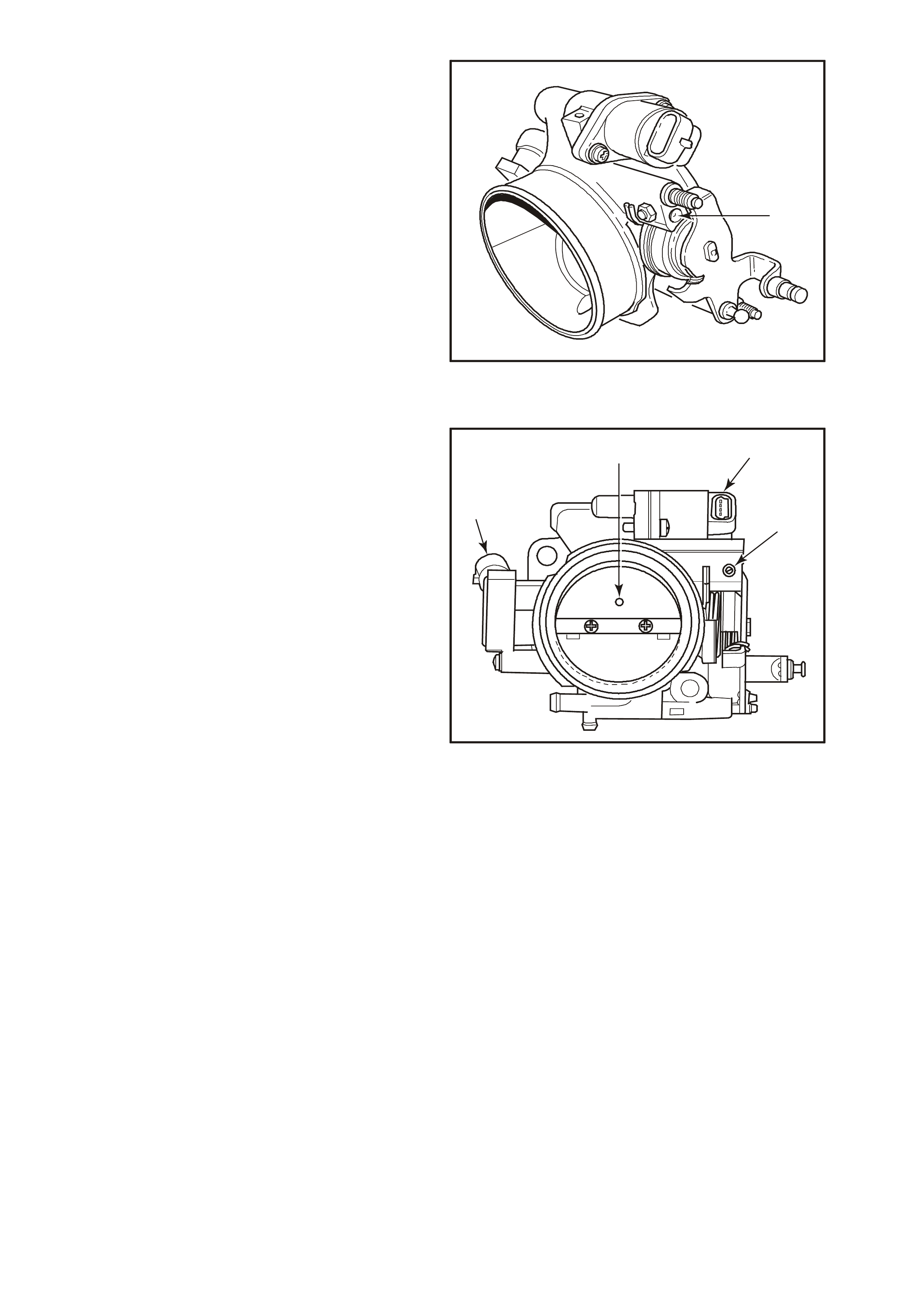
There are specific throttle body assemblies for
vehicles with automatic and manual transmission.
Identification is by a drill point marking on the
throttle used for vehicles with manual transmission.
1
4233
Figure 6C1-1-76 Throttle Body Identification
1. Drill Point
IDLE INSPECTION
For this V6 application, the engine idle must be
checked every 80,000km. If the Idle Air Control
(IAC) Valve steps displayed on the Tech 2 are
greater than 25 at idle, the throttle body will need to
be removed and cleaned. For throttle
body cleaning procedure, Refer to
Section 6C1-3 SERVICE OPERATIONS of the VX
Series Service Information.
Ther e is a specific thro ttle body assem bly for this V6
application. Although the throttle body for this
application looks very similar to previous V6
application, the main distinctive difference is the
addition of a small air flow hole in the throttle blade
above the throttle blade shaft. Also, the Idle Air
Control (IAC) valve air passage has been
redesigned to allow more air flow. The redesign of
this throttle body assembly is to help improve idle
quality and help prevent engine stalling.
2
1
43
4348
Figure 6C1-1-77 Throttle Body Identification
1. Air Flow Hole
2. IAC valve
3. Throttle Stop Screw
4. TP Sensor
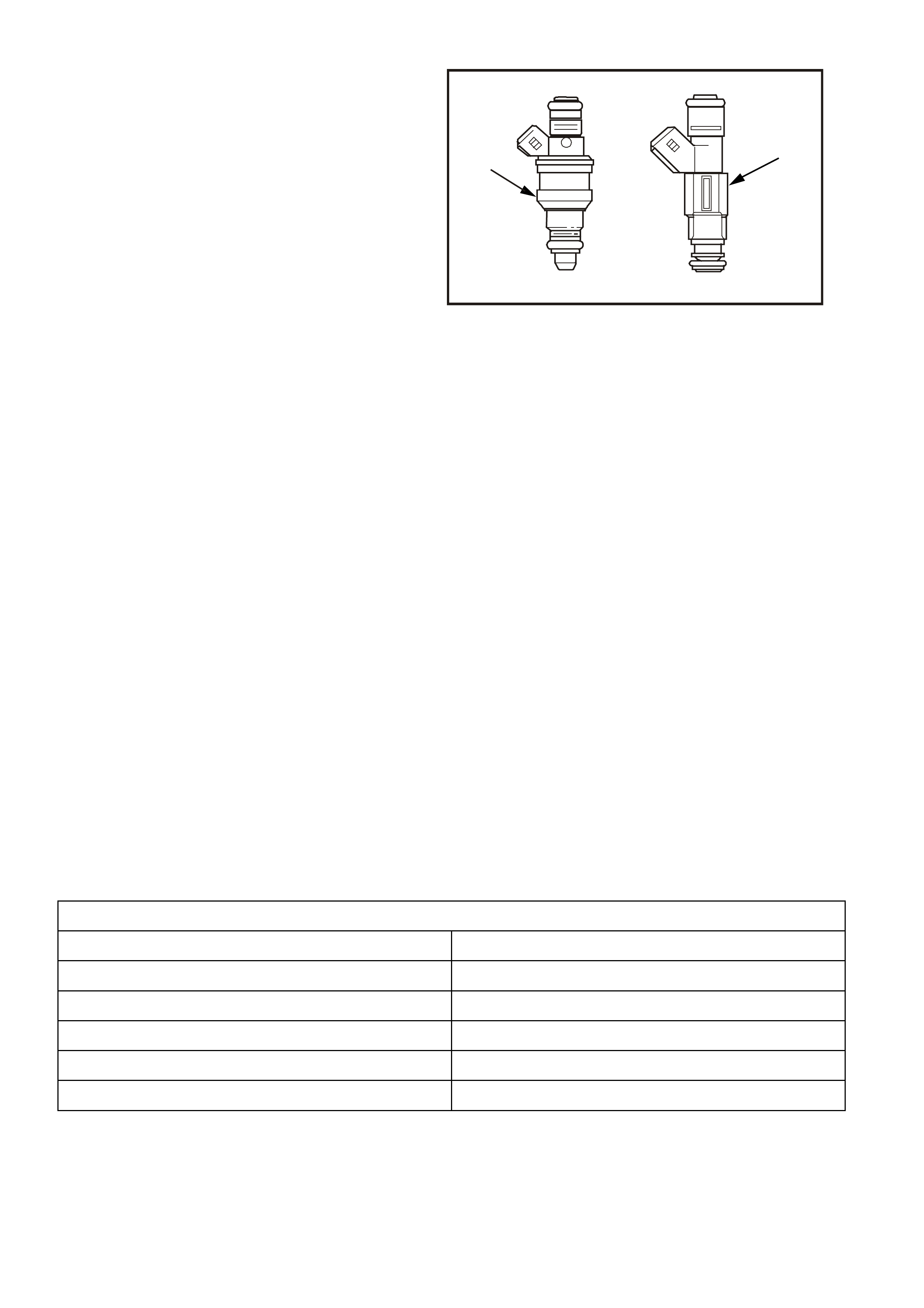
FUEL INJECTORS
The fuel injectors are electrically operated fuel flow
control valves. They are supplied with +12 volts
through a Fuse and EFI relay, both located in the
engine compartment fuse and relay housing. The
injectors are controlled by the PCM providing the
earth circuit. The PCM energises the injectors to
"open" the flow of f uel. The injector s are never f ully
energised "ON," as that would flood the engine
with too much fuel. The PCM supplies the earth
circuit in short pulses. The longer the duration of
the pulse (pulse width), the more fuel is injected
into the engine. Inside, the injectors have a coil of
electrical wire that becomes an electromagnet
when energised. The resistance of these windings
is important for the PCM to operate correctly.
The injector electrical resistance is
approximately 12.2 ohms at 20 C. If
measurement with an accurate ohmmeter
shows less than 11.8 ohms or more than 12.8
ohms, replace the injector.
(Acceptable: 11.8-12.8 ohms)
A fuel injector that does not open causes a misfire
condition. An injector which is stuck partly open
could c ause dieseling becaus e some f uel would be
delivered to the engine after the ignition key is
turned "OFF." If there is an electrical fault with any
of the injector circuits, DTC 57 will set.
1
2
4234
Figure 6C1-1-78 Fuel Injector
1. Supercharge Injector
2. Non-Supercharge Injector
DTC 57 (Injector Voltage Monitor Fault) will set if:
• The engine is running.
• DTC 54 is not set.
• Injector voltage monitor line voltage is 2.2 volts different than system voltage for 3 seconds.
• The PCM will not illuminate the Malfunction Indicator Lamp (MIL).
DEFAULT VALUES
There are no default values.
RECOVERY
Recovery will occur when the PCM sees a valid condition.
DTC 57 HISTORY DATA
PARAMETER PARAMETER
ENGINE SPEED BATTERY VOLTAGE
TIME FROM START REFERENCE VOLTS
TIMES OCCURRED VEHICLE SPEED
IGNITION CYCLES INJECTOR VOLTAGE
COOLANT TEMPERATURE
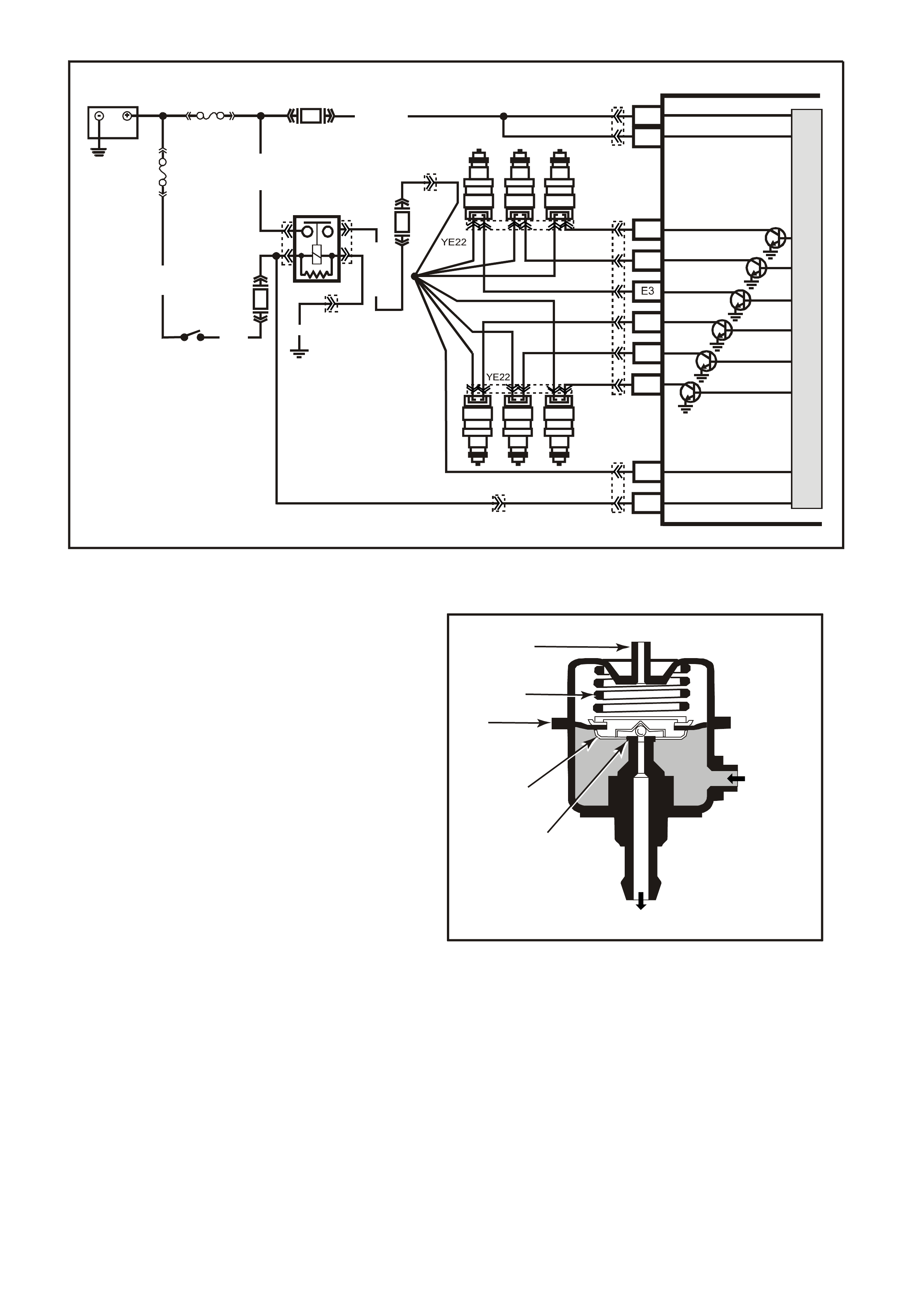
Figure 6C1-1-79 Injector Circuit
FUEL PRESSURE REGULATOR
The fuel pressure regulator is a diaphragm-
operated relief valve with fuel pump pressure on
one side and intake manifold pressure (engine
vacuum) combined with mechanical spring
pressur e on the other. The f unction of the regulator
is to maintain a regulated pressure at the injectors
at all times by controlling the flow into the return
line.
The fuel pressure regulator is mounted on the fuel
rail and may be serviced separately.
If the fuel pressure is too low, poor performance
and a DTC 44, or 64 could set. If the pressure is
too high, excessive odour and a DTC 45, or 65
may result. Refer to Table A-4.1-1 for information
on diagnosing fuel pressure conditions.
4235
2
1
7
6
5
4
3
Figure 6C1-1-80 Typical Fuel Pressure Regulator
1. Fuel Inlet
2. Fuel Return Outlet
3. Valve
4. Valve Holder
5. Diaphragm
6. Compression Spring
7. Vacuum Connection
SUPERVX017
# 2
# 4 # 6
# 1 # 3 # 5
PCM
A8
B8
F3
F1
F2
E2
E4
B12
A4
BATTERY FEED
BATTERY FEED
O
(740)
O
(740)
BLU
(841)
V
(843)
GY
(845)
INJECTOR CONTROL
IN JE C TOR VOLTAGE
MONITOR LINE
IGNITION FEED
O/Y (479)
EFI R EL AY
B/W (152)
LOC. E4
P (3 )
O/B (740)
IGN SW
M
I
C
R
O
R
(481)
P
(39)
Y
(846)
BR/Y
(844)
G
(842)
F31
F14
F34
BATTERY
FS
FJ
R (2)
(1040)
YE112
YE114
YE111
YB194
YB188
YE39 YE39
YB188
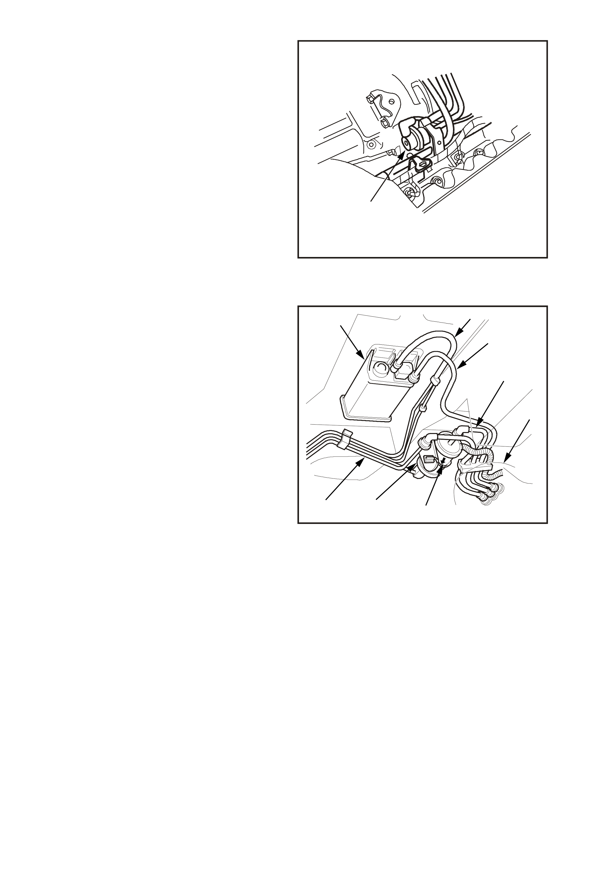
4236
1
Figure 6C1-1-81 Fuel Pressure Regulator Location
V6 Supercharge Engine
1. Fuel Pressure Regulator
FUEL FILTER
The fuel filter is located under the vehicle by the
left hand rear side frame, forward of the fuel tank.
The fuel filter is mounted in place by a plastic
retaining s trap attac hed to the r ear fr am e. Both fuel
pressure hoses at the filter are quick connects to
the filter. T hese quick connections can be rem oved
by squeezing the oval shaped connections at the
filter.
For removal of the fuel filter, Refer to
Section 6C1-3 SERVICE OPERATIONS of the VX
Series Service Information.
765
4
3
2
1
8
4238
Figure 6C1-1-82 Fuel Filter Location
1. Fuel Vapour Canister To Engine
2. Fuel Vapour Line
3. Fuel Feed Line
4. Fuel Tank
5. Flow Arrow
6. Fuel Filter
7. Fuel Return Line
8. EVAP Canister
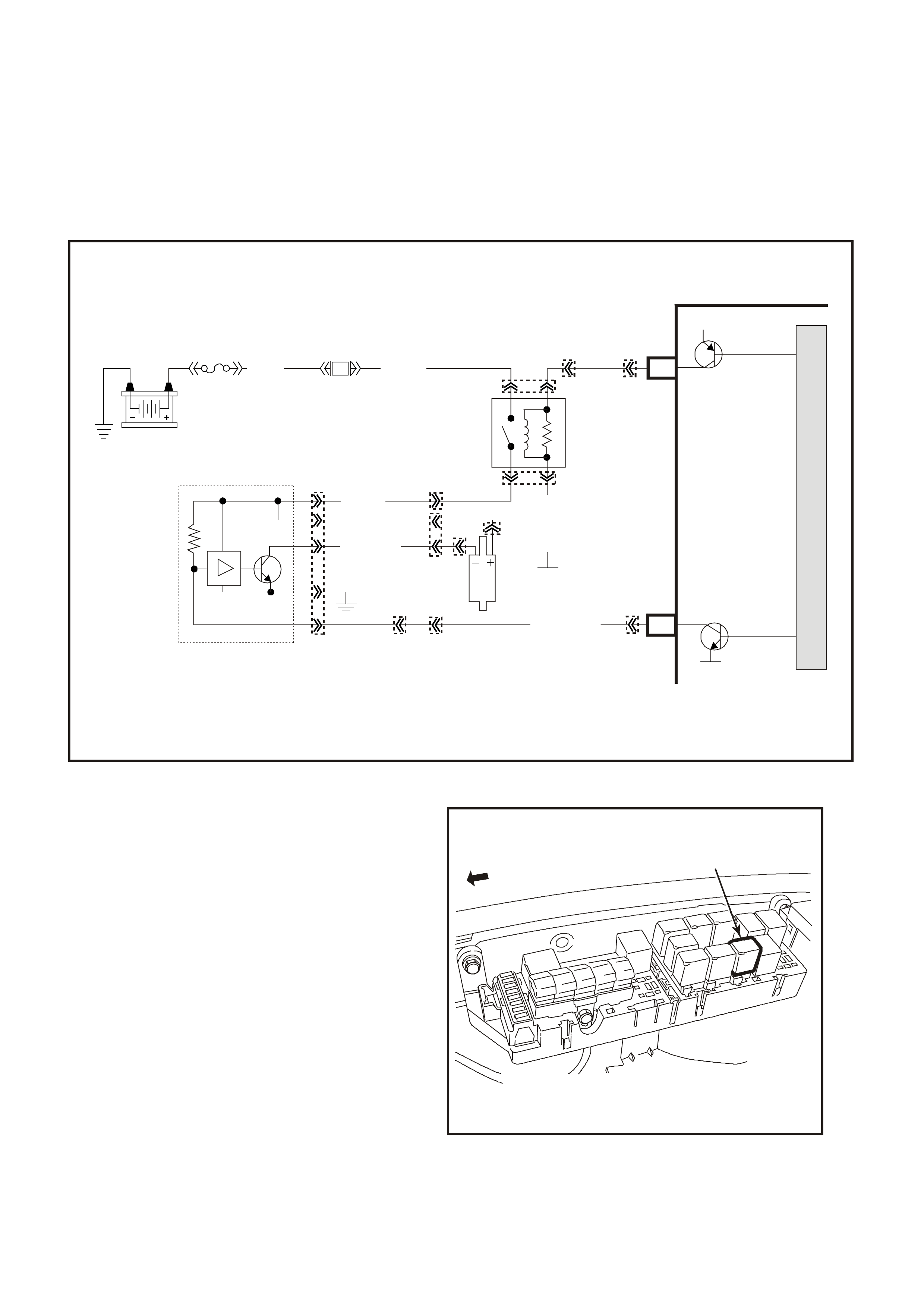
FUEL PUMP ELECTRICAL CIRCUITS SUPERCHARGED ENGINE
When the ignition switch is turned to "ON" or 'crank' after
having been "O FF" for at least 10 s econds, the PCM will imm ediately energis e the fuel pump r elay, which will then
activate the Fuel Pum p Control Module (f igure 6C1-1-85) to operate the f uel pum p. T his builds up the f uel pres sure
quick ly. If the engine is not c ranked within two seconds, the PCM will shut the f uel pum p relay "OFF" and wait until
the engine is cranked. As soon as the engine begins cranking, the PCM will sense the engine turning from the
crankshaft reference input, and turn the relay "ON" again to run the fuel pump.
A failed fuel pump relay circuit will cause a no start condition. Refer to Figure 6C1-1-84 for fuel pump relay location.
Figure 6C1-1-83 Fuel Pump Electrical Circuits V6 Supercharge Engine
1
4239
Figure 6C1-1-84 Fuel Pump Relay Location
1. Fuel Pump Relay
Battery
Fuel Pump
Relay
PCM
M
I
C
R
O
12V
8V (120)
V/W ( 1120)
B/W (489)
LOC.E7
G/W
(465)
LBLU (411)
O (240)
F28
(1040)
B/W (152)
3
15
2
6
5
4
7
4268
A6
E5
Fuel Pump
Rela y Control
In-Tank
Fuel Pump Fuel Pump
Co nt rol Module
Fuel Pump
Co ntrol M odule
YB96
YB96
YB39
YR44
YE112YB74
YR45
YR44
YR32
YB110 YB188
YB194
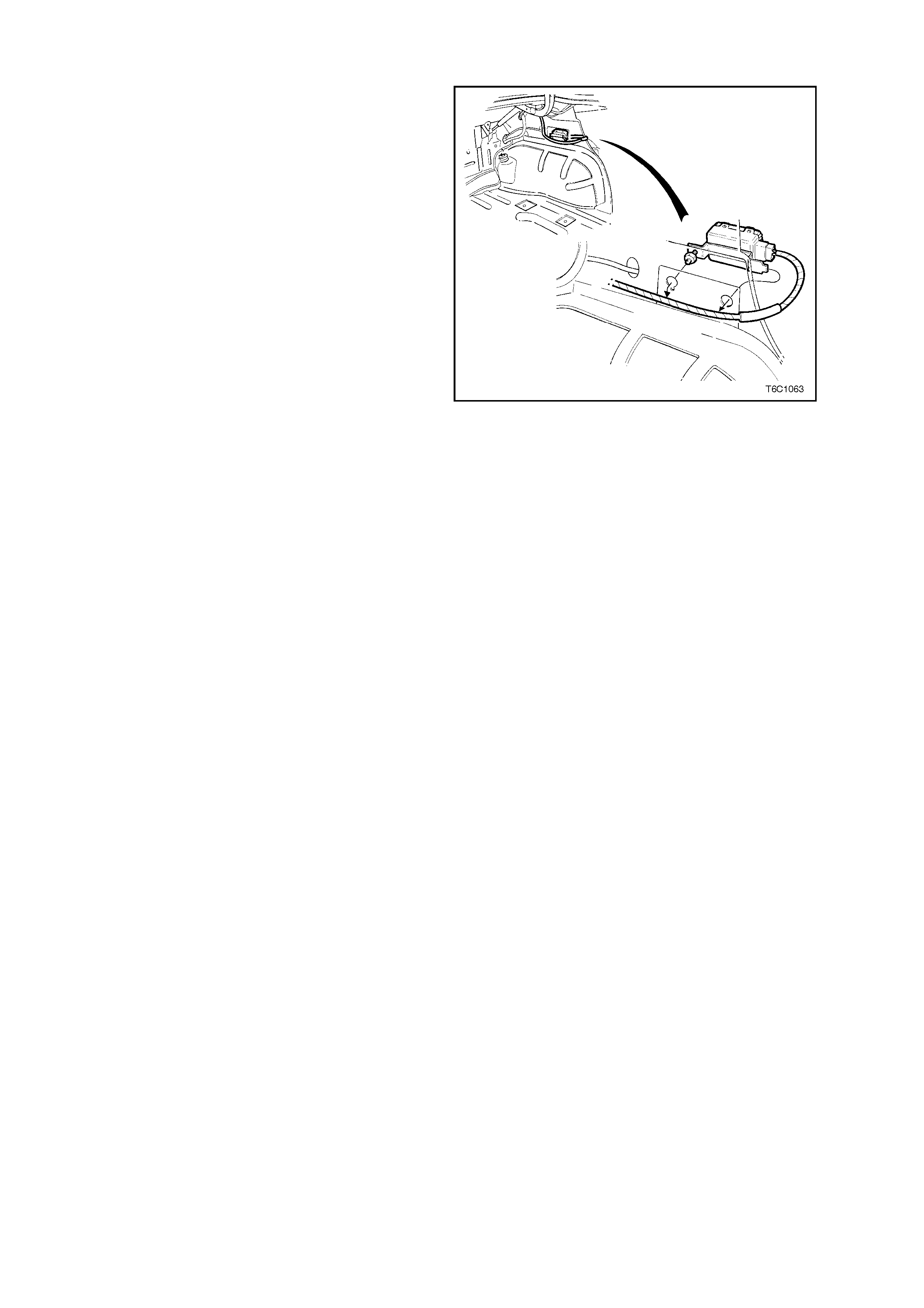
FUEL PUMP CONTROL MODULE
The V6 Supercharged engine utilises a two speed
Fuel Pump and a Fuel Pump Control module. The
Fuel Pump Control Module is located in the boot.
The Fuel Pump Control Module can vary the fuel
pump output depending on the required engine
load. When the ignition is first turned "ON", the
PCM energises the fuel pump relay, which applies
power to the Fuel Pump Control Module. The fuel
pump will then pressurise the fuel system.
The purpose for the Fuel Pump Control Module is
that this Supercharged system requires more fuel
volume under heavy engine load conditions then
the non-superc harged system. T he fuel pum p used
in the non-superc harged system m ay be capable of
supplying the required fuel volume for the
supercharged system, but with the increased fuel
volume required, the non-supercharged fuel pump
would eventually f ail from running at the higher f uel
volume.
The PCM controls the current flow through the fuel
pump with a Pulsed Width Modulation (PWM)
signal at 128 Hertz (Hz) to the fuel pump control
module. T he fuel pum p control module controls the
current flow through the fuel pump depending on
the PWM signal received from the PCM.
Under normal driving conditions the required fuel
volume is less, s o the fuel pum p operates at a duty
cycle of 67% "ON", that is the PCM controls the
fuel pump circuit, via the fuel pump control module
at 67% "ON" and 33% "OFF", at a frequency of
128 Hz.
When the engine load is increased, as measured
by the Mas s Air Flow sensor, the f uel pump control
module will switch from the normal duty cycle
(67%) to a higher duty cycle (100%) based on the
com m and f rom the PCM. T his higher duty cycle will
increase the current supply through the fuel pump,
increasing the fuel volume delivered by the fuel
pump.
Another feature of this Fuel Pump Control Module
is that when the fuel pump is running at the lower
duty cycle, (normal driving conditions), and the
returned fuel to the fuel tank (from the fuel
pressure regulator) is less. This lower volume of
returned fuel to the fuel tank will result in lower
emissions (fuel tank vapours).
Also with the fuel pump running at a lower duty
cycle (normal driving conditions), the voltage
output required to run the pump is lower. This will
require less generator output and will decrease
overall vehicle fuel usage.
Refer to Table A-4.1-1 for diagnosis of the fuel
pump electrical circuit.
Figure 6C1-1-85 Fuel Pump Control Module Location
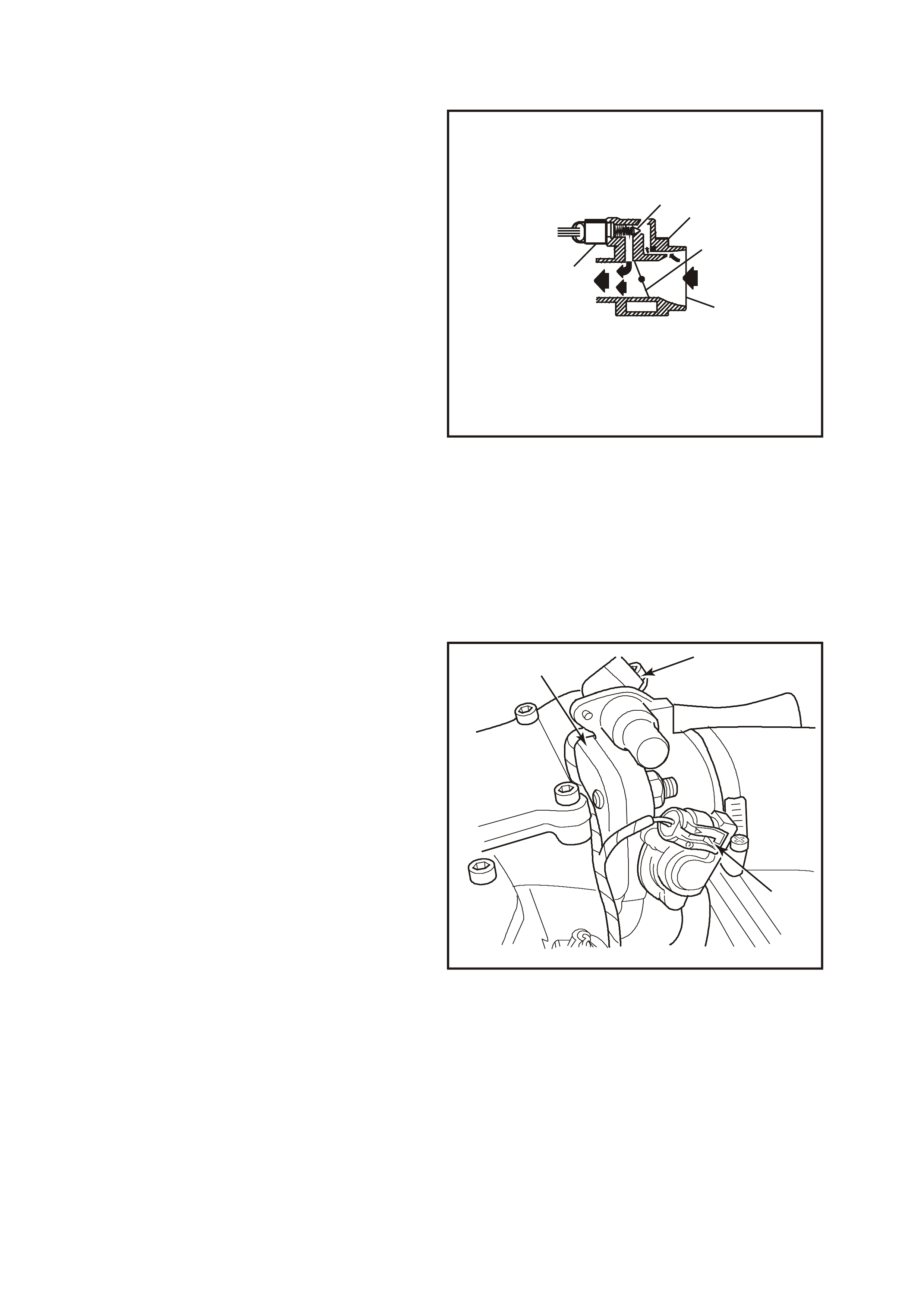
1.5 IDLE AIR CONTROL (IAC) VALVE
The purpose of the Idle Air Control (IAC) valve is to
control engine idle speed, and pr event s talls due to
changes in engine load at idle.
The IAC valve, mounted in the throttle body,
controls bypass air around the throttle valve. By
extending the pintle (to decrease airflow) or
retracting the pintle (to increase airflow), a
controlled amount of air can move around the
throttle valve. If RPM is too low, more air is
bypassed around the throttle valve to increase
RPM. If RPM is too high, less air is bypassed
around the throttle valve to decrease RPM.
The IAC valve moves in small steps numbered
from 0 (extended pintle, bypass air passage fully
shut) to 255 (retracted pintle, maximum bypass
airflow) as commanded by the PCM.
At idle, the desired position of the IAC valve is
calculated by the PCM based on coolant
temperature, actual engine RPM, engine load, and
battery voltage.
If the IAC valve is disconnected or reconnected
with the engine running, the PCM can "lose track"
of the actual pos ition of the IAC. T his also happens
when PCM's keep alive memory voltage, i.e., PCM
connectors, ENGINE fuse F31, or battery cables,
are disconnected. If this happens, the PCM will
"reset" the IAC. After the engine has been run for
at least 5 seconds, then upon ignition "OFF" the
IAC will be reset.
12
3
4
5
6
4240
7
{
Figure 6C1-1-86 IAC Valve
1. IAC Valve Pintle
2. Idle Air Housing
3. Throttle Valve
4. Air Inlet
5. Throttle Body Assembly
6. Idle Air Control (IAC) Valve Assembly
7. Electrical Input Signal
The "reset" procedure is as follows:
The PCM commands the IAC to shut the idle air
passageway in the throttle body. It does so by
issuing enough "extend" pulses to move the IAC
pintle fully shut in the bore, regardless of where the
actual position was. Then, the PCM calculates the
IAC is at a fully shut position, and calls that position
"0 steps." Next, the PCM issues "retract" steps to
properly position the pintle.
The IAC can also be reset with the engine running
by a special command on the Tech 2 scan tool.
The IAC valve affects only the idle RPM of the
engine. If it is open fully, too much air will be
allowed into the manif old and idle speed will be too
high. If it is s tuck clos ed, too little air will be allowed
into the intake manifold, and idle speed will be too
low.
A system malfunction that causes too great a
difference between desired idle and the actual idle
speed will set a DTC 35 or DTC 36.
31
2
4221
Figure 6C1-1-87 IAC Valve Location
1. Idle Air Control (IAC) Valve
2. Throttle Position (TP) Sensor
3. Throttle Body

DTC 35 (Idle Speed Low)
Or
DTC 36 (Vacuum Leak/ Idle Speed High) Either DTC will set if:
• No TP Sensor, IAT Sensor or VSS DTCs are set.
• The engine has been running for at least 15 seconds.
• The IAT is less than 73°C.
• The engine speed is 200 RPM below the desir ed idle s peed for 5 sec onds and the IAC has been opened to its
maximum position (255 steps), then a DTC P0506 will set. If the PCM detects a condition where a high idle
speed is present and the IAC has been closed (0 steps); the PCM will command the IAC motor to open 50
steps. If the RPM increase more than 50 RPM it is accepted that the IAC motor is moving and therefore the
fault is a vac uum leak, and DTC 35 will set. If the RPM does not c hange when the PCM comm ands the IAC to
open, the PCM will set DTC 36.
• The PCM will not illuminate the Malfunction Indicator Lamp (MIL).
DEFAULT VALUE
There ARE no default values.
RECOVERY
Recovery will occur when the PCM sees a valid condition.
DTC 35 AND 36 HISTORY DATA
PARAMETER PARAMETER
ENGINE SPEED BATTERY VOLTAGE
TIME FROM START REFERENCE VOLTS
TIMES OCCURRED MASS AIR FLOW
IGNITION CYCLES CAM SIGNAL
COOLANT TEMPERATURE FUEL PUMP RELAY
STALL DATA
If an engine stall occurs the PCM will capture nine data values. The PCM will store the first stall condition data
values, then count the number of stalls after the first.
Note: Stall data will be erased from the PCM memory whenever DTC HISTORY DATA is cleared.
STALL DATE
PARAMETER PARAMETER
ENGINE SPEED VEHICLE SPEED
TIME FROM START BATTERY VOLTAGE
TIMES OCCURRED THROTTLE ANGLE
IGNITION CYCLES A/C REQUEST
IDLE AIR CONTROL
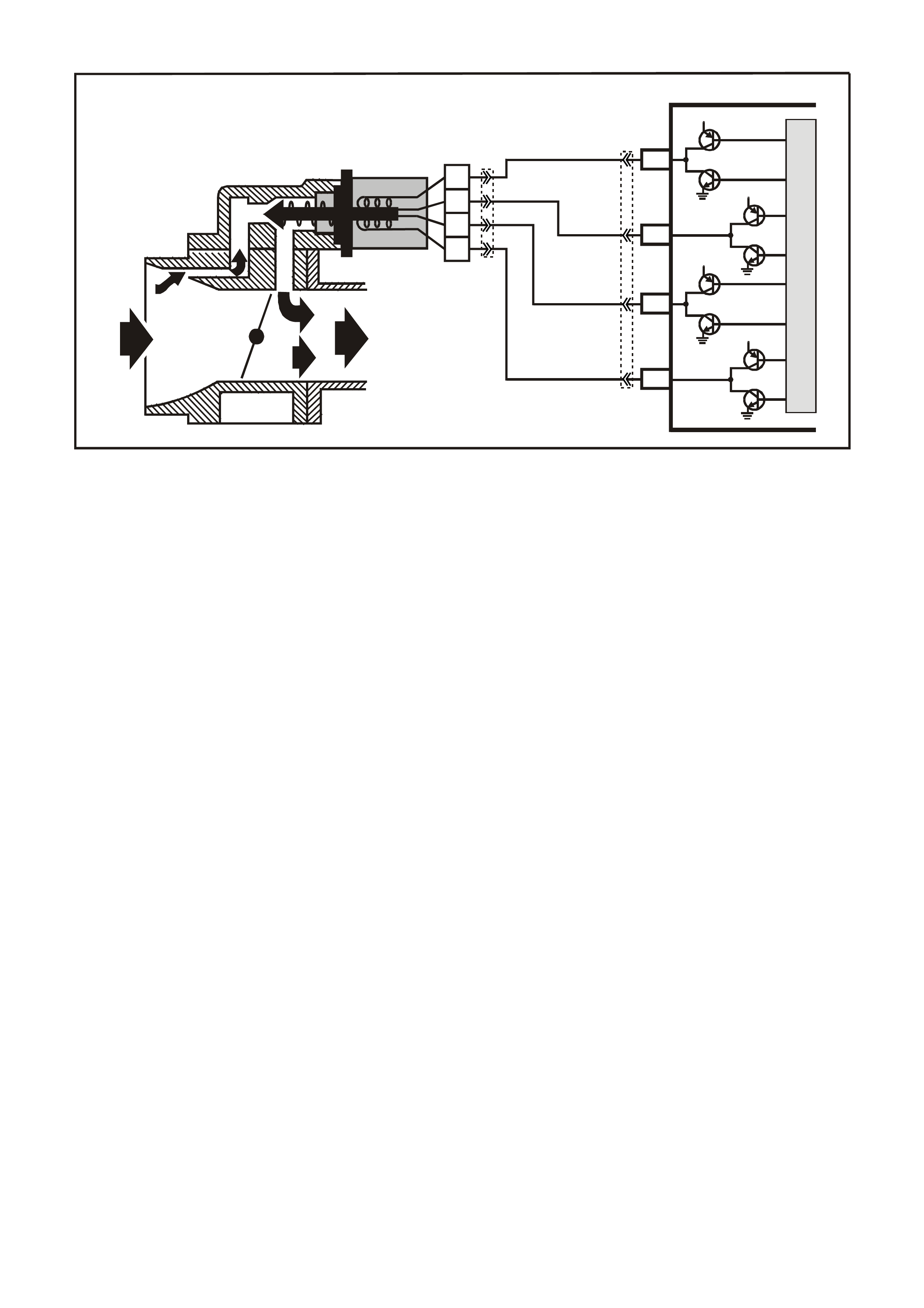
Figure 6C1-1-88 IAC Valve Circuit
SUPERVX025
PCM
C10
C7
C8
C9
LG/W
(443)
A
B
C
D
IAC VALVE
IAC
COIL B LO
IAC
COIL A LO
IAC
COIL B HI
IAC
COIL A HI
12V
12V
12V
12V
M
I
C
R
O
LG/B
(444)
LBLU
(441)
LBLU/B
(442)
YE36
YB193
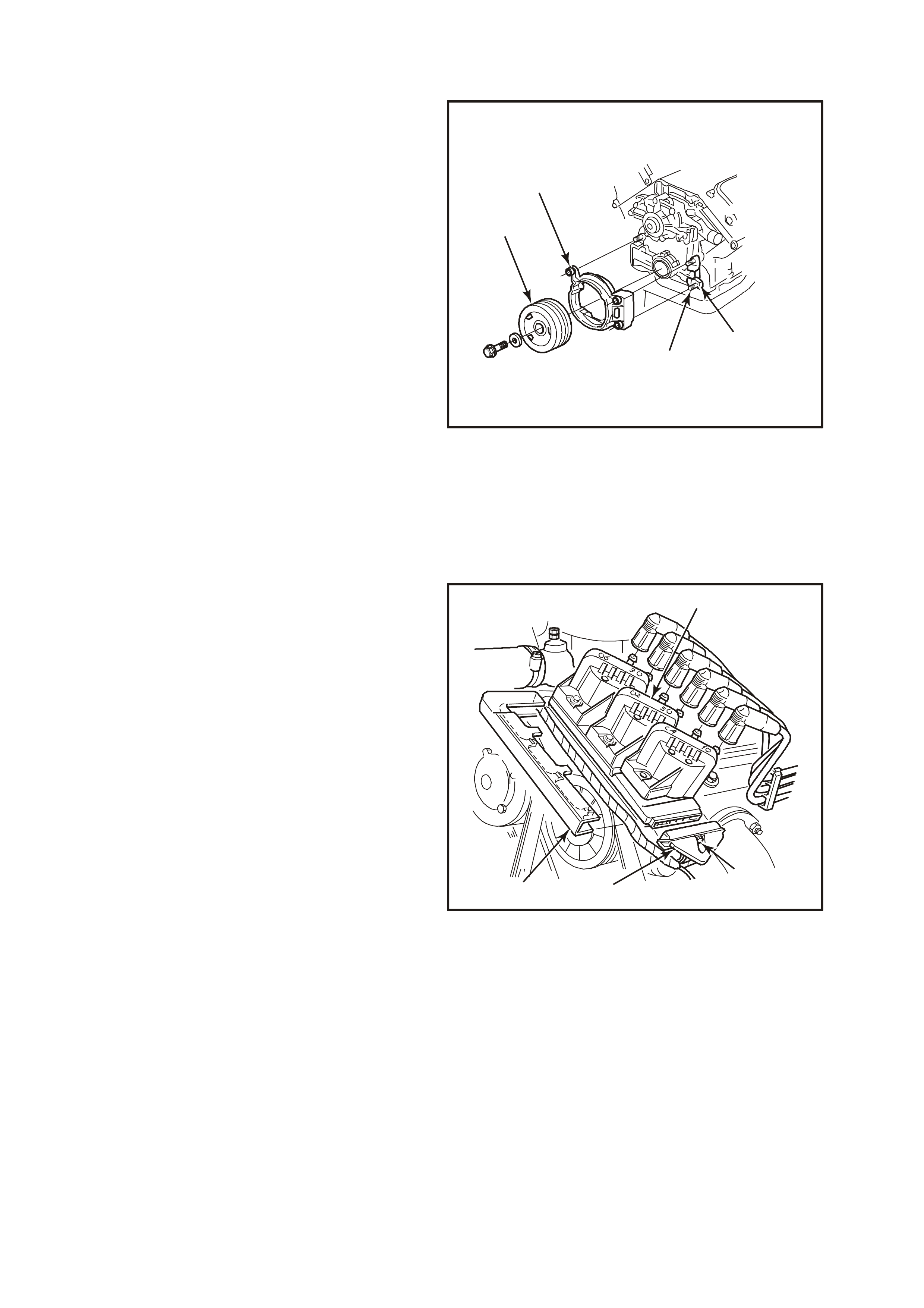
1.6 DIRECT IGNITION SYSTEM (DIS)
PURPOSE
The Direct Ignition System (DIS) system controls
fuel combustion by providing a spark to ignite the
compressed air/fuel mixture at the correct time. To
provide optimum engine performance, fuel
economy, and control of exhaust emissions, the
PCM controls spark advance with the DIS system.
DIS has several advantages over a mechanical
distributor system:
• No moving parts
• Less maintenance
• Remote mounting capability
• No mechanical load on the engine
• More coil cool down time between firing events
• Elimination of mechanical timing adjustments
• Increased available ignition coil saturation time
4241
1
2
3
4
Figure 6C1-1-89 Crankshaft Sensor & Crankshaft Balancer
1. Crankshaft Position (CKP) Sensor
2. Front Cover Stud (Three Places)
3. Crankshaft Balancer Assembly
4. Crankshaft Position Sensor Shield
OPERATION
The Direct Ignition System (DIS) is an ignition
system that does not use a conventional distributor
and ignition coil. The DIS ignition system consists
of; 3 ignition coils, a DIS module, a dual Hall-effect
crankshaft position sensor, an engine crankshaft
balancer with crankshaft sensor interrupter rings
attached to the rear, related connecting wires, and
the EST (electronic spark timing) portion of the
PCM. The PCM controls only the ignition timing
and dwell only. The DIS coils do the actual fir ing of
the spark plugs.
Conventional ignition coils have one end of the
secondary winding connected to earth. In the
Direct Ignition System, neither end of the
secondary winding is earthed. Instead, eac h end of
a coil's secondary winding is attached to a spark
plug. These two plugs are on "companion"
cylinders, i.e., on top dead centre at the same time.
When the coil discharges, both plugs fire at the
same time to complete the series circuit. The
cylinder on compression is said to be the `event'
cylinder and the one on exhaust is the `waste'
cylinder. The cylinder on the exhaust stroke
requires very little of the available energy to fire the
spark plug at idle. The remaining energy will be
used as required by the cylinder on the
compression stroke. This method of ignition is
called "waste spark" ignition.
Since the polarity of the ignition coil primary and
secondary windings is fixed, one s park plug always
fires with a forward current flow and it's
`companion' plug fires with a reverse current flow.
This is dif fer ent fr om a conventional ignition system
that fires all the plugs with the same direction of
current flow.
4242
2
3
4
1
Figure 6C1-1-90 DIS Module And Coils
1. Direct Ignition System Coil And Module Assembly
2. Bolt
3. Wiring
4. Powertrain Harness Retainer
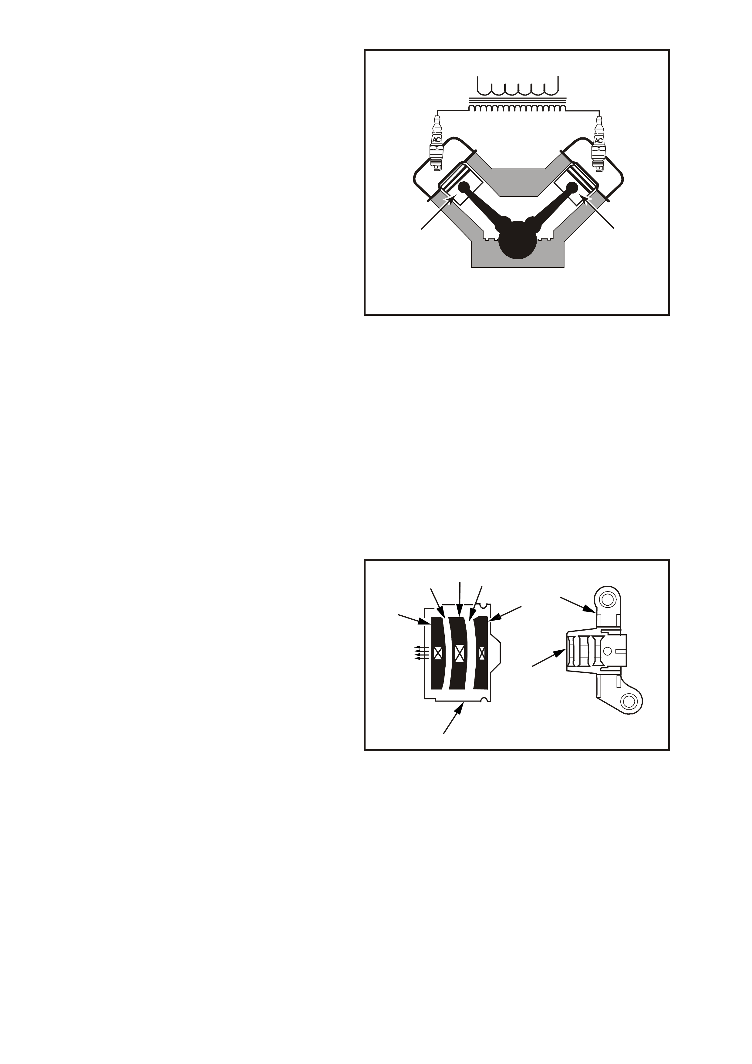
Since it requires approximately 30% more voltage
to fire a spark plug with reverse current flow, the
ignition coil design is im proved, with saturation tim e
and primary current flow increased. This redesign
of the system allows higher secondary voltage to
be available from the ignition c oils - gr eater than 40
kilovolts (40,000 volts) at any engine RPM. The
voltage required by each spark plug is determined
by the polarity and the cylinder pressure. The
cylinder on compression requires more voltage to
fire the spark plug (approximately 8 kilovolts) than
the one on exhaust (approximately 3 kilovolts).
It is possible for one spark plug to f ire even though
a plug wire fed by the same coil may be
disconnected from its 'companion' spark plug. The
disconnected plug wire acts as one plate of a
capacitor, with the engine being the other plate.
These two 'capacitor plates' are charged as a
spark jumps across the gap of the still-connected
spark plug. The `plates' ar e then discharged as the
secondary energy is dissipated in an oscillating
current across the gap of the still-connected spark
plug. Secondary voltage requirements are very
high with an 'open' spark plug or wire. The ignition
coil has enough reserve energy to fire the still-
connected plug at idle, but possibly not under high
engine load. A more noticeable misfire may be
evident under load; both spark plugs may be
misfiring.
4243
5
3
2
1
7
64
Figure 6C1-1-91 Waste Spark Ignition, Companion
Cylinders
1. Primary Coil
2. Secondary Coil
3. Companion Cylinders: 1&4, 5&2, 3&6
4. Compression Stroke, TDC
5. Companion Cylinders Have Pistons At TDC At The
Same Time
6. Exhaust Stroke TDC
7. Ignition Coil (One Of Three)
SYSTEM COMPONENTS
CRANKSHAFT SENSOR CRANKSHAFT BALANCER INTERRUPTER RINGS
The dual crankshaft sensor, secured in aluminum
mounting br acket and bolted to the f ront left s ide of
the engine timing chain cover, is partially behind
the cr anks haft balancer . A 4-wire electric al harness
connector plugs into the sensor, connecting it to
the DIS module.
The DIS dual crankshaft sensor contains two Hall-
effect switches with one shared magnet mounted
between them. The magnet and each Hall switch
are separated by an air gap.
A Hall switch reacts like a solid-state switch,
earthing a low-current signal voltage when a
magnetic field is present. When the magnetic field
is shielded from the switch by a piece of steel
placed in the air gap between the magnet and the
switch, the signal voltage is not earthed. If the
piece of steel (called an interrupter) is repeatedly
moved in and out of the air gap, the signal voltage
will appear to go "ON-OFF-ON-OFF-ON-OFF."
Compared to a conventional mechanical
distributor, this "ON-OFF" signal is similar to the
signal that a set of breaker points in the distributor
would generate as the distributor shaft turned and
the points opened & closed.
4
3
1
2
2
567
8
4244
Figure 6C1-1-92 Crankshaft Sensor
1. Aluminum Mounting Bracket
2. CKP Sensor
3. Towards Crankshaft
4. 3X Sensor
5. 3X Air Gap
6. Magnet
7. 18X Air Gap
8. 18X Sensor
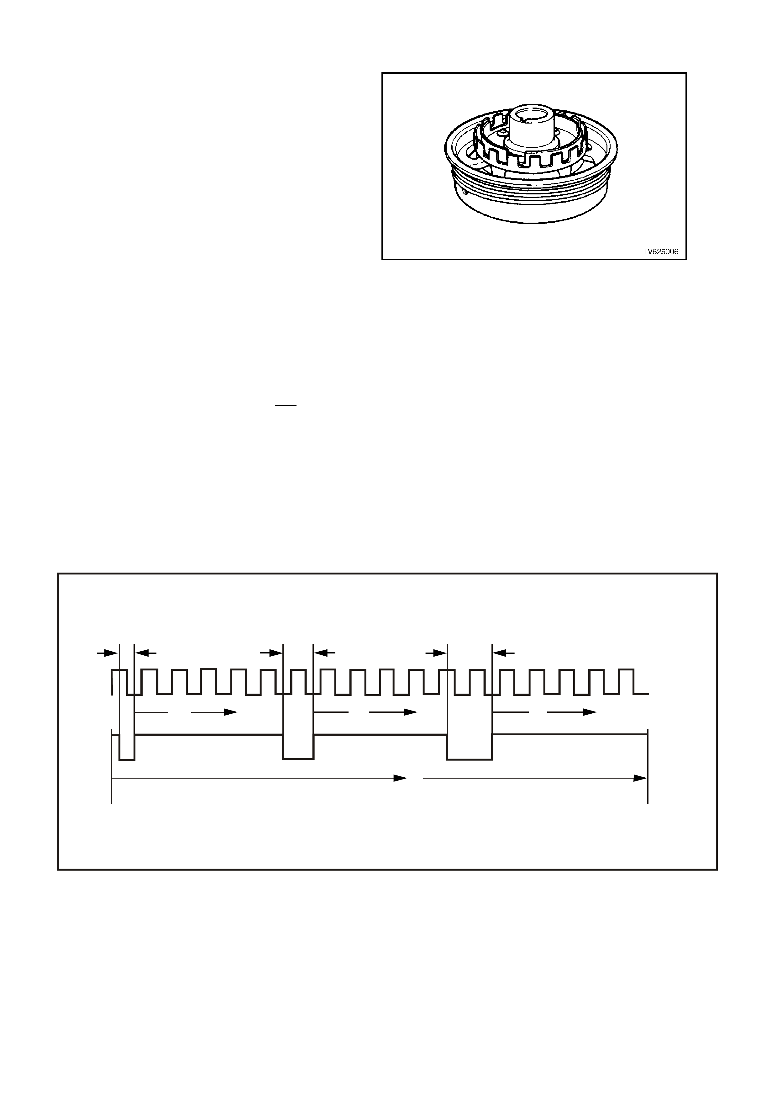
In the case of the DIS system, the piece of steel is
two concentric interrupter r ings m ounted to the rear
of the crankshaft balancer. Each interrupter ring
has blades and windows that, with crankshaft
rotation, either block the magnetic f ield or allow it to
reach one of the Hall switches. The outer Hall
switch is called the 18X-crankshaft sensor,
because the outer interrupter ring has 18 evenly
spaced same-width blades and windows. The 18X -
crankshaft sensor produces 18 "ON-OFF" earth
pulses per crankshaft revolution. The Hall switch
closest to the crankshaft, the 3X-crankshaft
sensor, is so called because the inside interrupter
ring has 3 unevenly spaced, different-width blades
and windows. The 3X-crankshaft sensor produces
3 different length "ON-OFF" earth pulses per
crankshaft revolution.
W hen a 3X interrupter ring 'window' is between the
magnet and inner switch, the magnetic field will
cause the 3X Hall switch to earth the 3X c rank shaf t
signal voltage supplied from the DIS module. The
18X-interrupter ring and Hall switch react similarly.
The DIS module interprets the 18X and 3X "ON-
OFF" signals as an indication of crankshaft
position, and must have both signals to "fire" the
correct ignition coil. The DIS module determines
crankshaft position for correct ignition coil
sequencing by counting how many 18X-signal
transitions occur, i.e. "ON-OFF" or "OFF-ON,"
during a 3X pulse.
A failure in the crankshaft reference signal input
circuit will set a DTC 46. A failure in the 18X
reference signal circuit will set DTC 47.
Figure 6C1-1-93 Crankshaft Balancer with Interrupter Rings
Figure 6C1-1-94 18X and 3X Crankshaft Sensor Pulses for One Crankshaft Revolution
1. One 18 X Transition
2. Two 18 X Transition
3. Three 18 X Transition
4. 18 X Crankshaft Sensor
5. 3 X Crankshaft Sensor
6. One Crankshaft Rotation - 360°
1
10
23
4
5
6
6
º10
75 TDC
1 & 4
10 20
75 TDC
6 & 3
30
75 5 & 2
TDC
º
º
ºº
º
º
º
4245
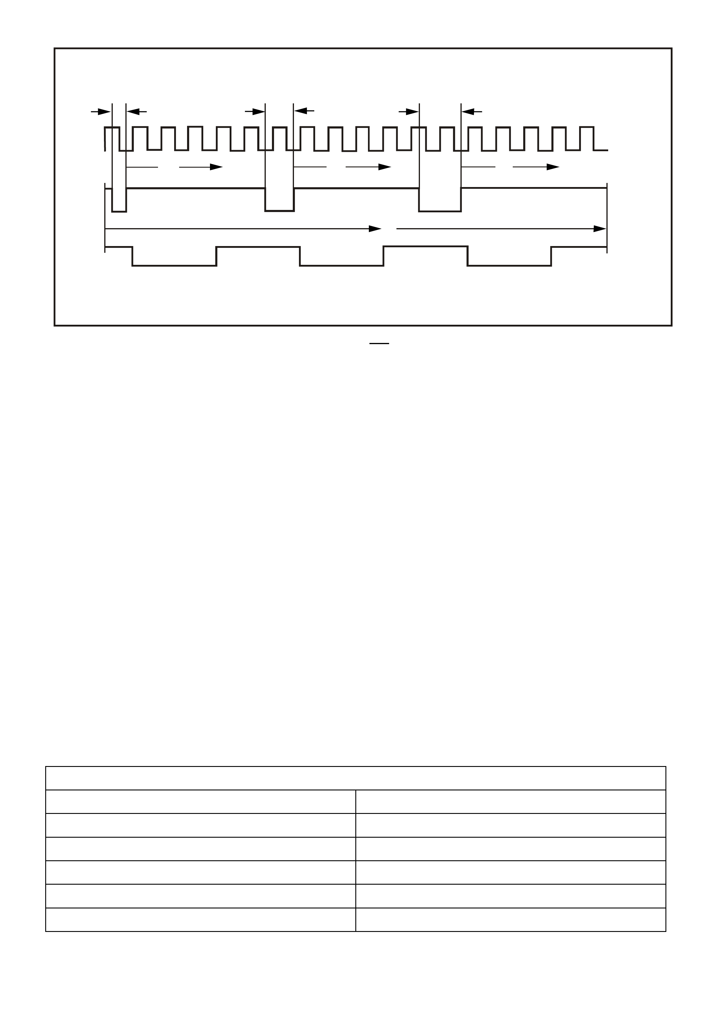
Figure 6C1-1-95 18X & 3X Crankshaft Sensor Pulses and - Crankshaft Reference Signal sent to the PCM
1. One 18X Transition
2. Two 18 X Transition
3. Three 18 X Transition
4. 18 X Crankshaft Sensor
5. 3 X Crankshaft Sensor
6. Crankshaft Reference Signal (Sent to PCM)
7. One Crankshaft Rotation - 360°
DTC 46 (No Reference Pulses While Cranking) DTC will set if:
• No MAF sensor DTC is set.
• Battery voltage is at or below 11 volts.
• The MAF sensor input signal is greater than 2048 Hz.
• No crank shaft r eference input puls es are received at the PCM c ranks haft refe rence input term inal for at least 2
seconds.
• The PCM will illuminate the Malfunction Indicator Lamp (MIL).
DEFAULT VALUE
There are no default values for the crankshaft reference signal as the PCM uses this signal to determine if the
engine is running and initiate injection pulses. The engine will not run if the PCM does not receive a crankshaft
reference signal. With no crankshaft reference signal the PCM will not issue any injection pulses.
RECOVERY
Recovery will occur when the PCM sees a valid condition.
DTC 46 HISTORY DATA
PARAMETER PARAMETER
ENGINE SPEED BATTERY VOLTAGE
TIME FROM START REFERENCE VOLTS
TIMES OCCURRED MASS AIR FLOW
IGNITION CYCLES CAM SIGNAL
COOLANT TEMPERATURE FUEL PUMP RELAY
1
10
23
4
5
6
7
º10
75 TDC
1 & 4
10
100 20
75 TDC
6 & 3
90 30
75
110
60
60
5 & 2
TDC
º
º
º
ºº
º
ºº
º
º
º
º
60
º
60
º
60
º
60
º
4246
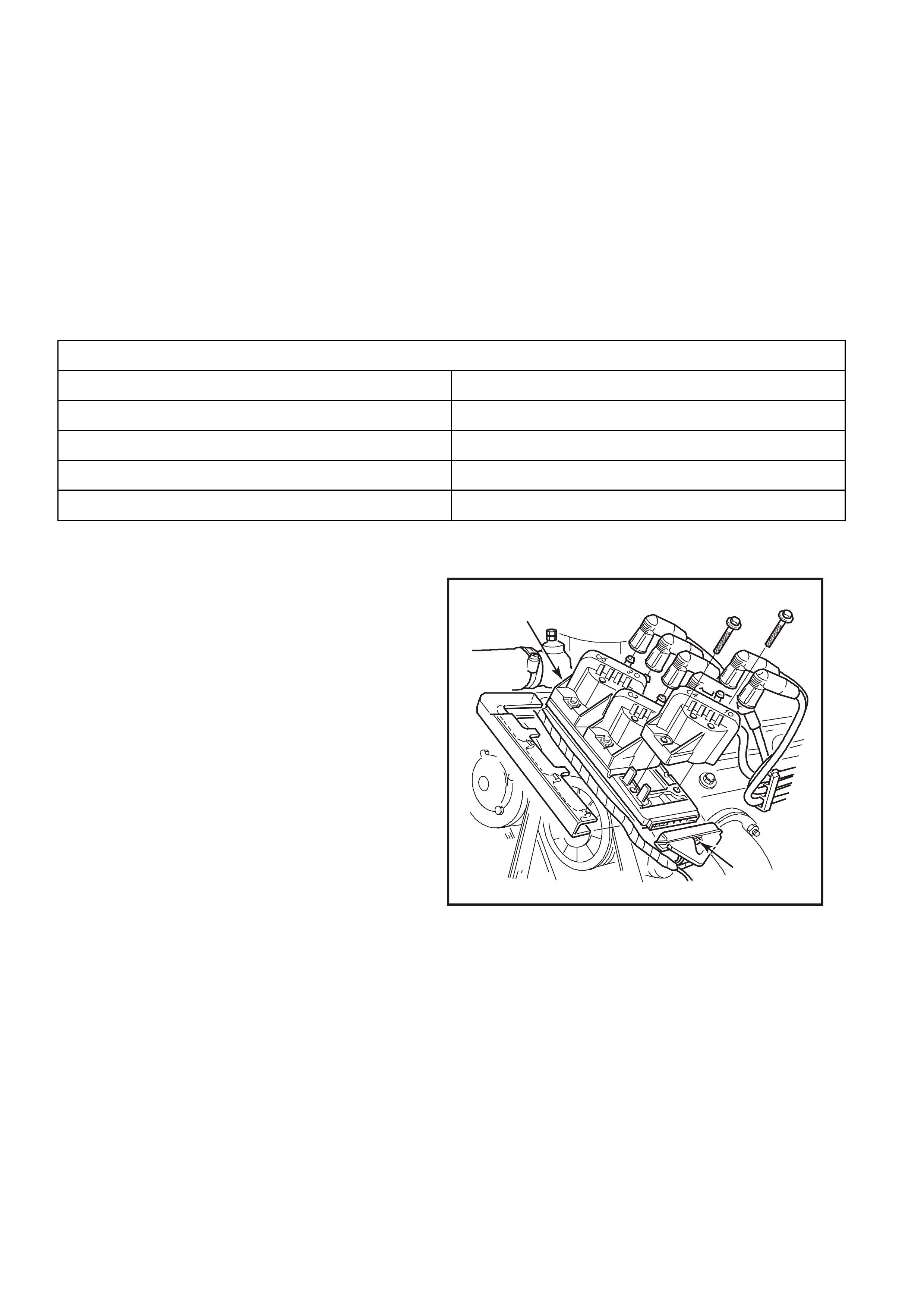
DTC 47 (18X Reference Signal Missing) DTC will set if:
• The engine is running.
• The MAF sensor input signal is greater than 2048 Hz.
• The PCMM detects 253 crankshaft reference pulses and no 18X pulses.
• The PCM will not illuminate the Malfunction Indicator Lamp (MIL).
DEFAULT VALUE
When DTC 47 is set and current (no 18X reference signal), the PCM uses the crankshaft reference signal to
determine engine speed. This condition will cause the EST to be degraded; no high resolution spark.
RECOVERY
Recovery will occur when the PCM sees a valid condition.
DTC 47 HISTORY DATA
PARAMETER PARAMETER
ENGINE SPEED COOLANT TEMPERATURE
TIME FROM START BATTERY VOLTAGE
TIMES OCCURRED REFERENCE VOLTS
IGNITION CYCLES INJECTOR VOLTAGE
IGNITION COILS
Three twin-tower ignition coils are individually
mounted to the DIS module, with six screw type
fasteners. Each coil provides the spark for two
spark plugs simultaneously (waste spark
distribution), and all three coils can be replaced
individually. Spade type electrical terminals
connect each coil to the DIS module. Three of the
six terminals are connected together by a circuit in
the DIS module, supplying +12 volts to the primary
windings of all three coils. The other three
terminals are individually connected to the DIS
module, so that the DIS module can control only
one coil firing at a time, in the correct order, by
removing the primary circuit earth path at the
proper time.
4247
2
1
Figure 6C1-1-96 Ignition Coils & Ignition Module
1. Bolt
2. Direct Ignition System Coil and Module Assembly.

DIS IGNITION MODULE
The DIS module serves several functions:
• It powers the dual crankshaft sensor internal circuits.
• It supplies the 3X and 18X voltage signals that each respective Hall switch pulses to earth to generate the 3X
and 18X crankshaft sensor pulses.
• It determines the correct ignition coil firing sequence, based on how many 18X transitions occur during a 3X
pulse. This coil sequencing occurs at start-up. After the engine is running, the module remembers the
sequence, and triggers the proper ignition coil.
• It s ends a "crank shaft r eference" s ignal to the PCM. The PCM interprets engine RPM from this signal. It is also
used by the PCM to determine crankshaft position for EST spark advance calculations. (The falling edge of
each crankshaft reference signal pulse occurs 75 degrees before TDC of any cylinder.) The crankshaft
reference signal sent to the PCM by the DIS module is an "on-off" pulse occurring 3 times per crankshaft
revolution. This is neither the 3X nor the 18X -c r ank s haf t s ens or puls e, but both of thes e are r equir ed by the DIS
module to generate the crankshaft reference signal.
The DIS module generates the crankshaft reference signal by an internal "divide-by-6" circuit. This divider
circuit divides the 18X crank shaft sensor pulses by 6. The divider circuit is enabled, or ready to begin dividing,
only after it receives 3X crankshaft sensor pulses. After it receives the first 3X-crankshaft sensor signal, the
divider c irc uit does not need the 3X pulses to c ontinue operating. If either the 18X or 3X puls es ar e miss ing, the
divider cannot generate any crankshaft reference signal pulses (sent to the PCM), and no fuel injector pulses
will occur.
• Below 450 engine RPM (or anytime the PCM does not apply 5 volts to the DIS module 'bypass' cir cuit), the DIS
module controls ignition by triggering each of the three coils in the proper sequence at a predetermined dwell,
with spark advance fixed at 10 degrees BTDC. This is called bypass mode ignition. The DIS module provides
proper ignition coil sequencing during both the module and EST modes.
• Above 450 RPM, the PCM applies 5 volts to the DIS module 'bypass' circ uit, signalling the module to allow the
PCM to control the dwell and spark timing. This is EST mode ignition. During EST mode, the PCM adjusts
spark dwell and timing advance for all driving conditions. Again, the DIS module is responsible for proper
ignition coil sequencing during both the module and EST modes.
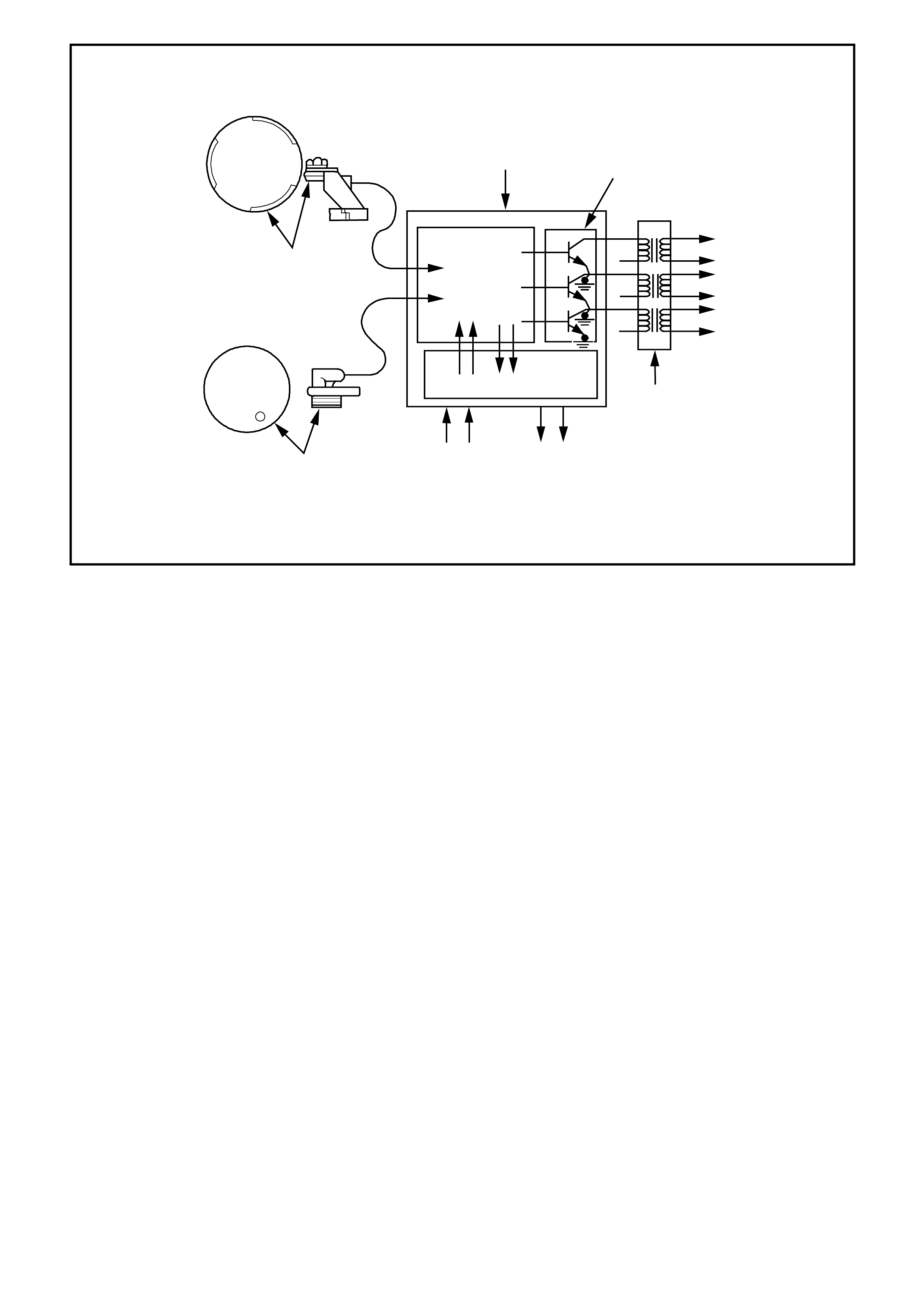
Figure 6C1-1-97 Computer Controlled Coil Ignition
1. Powertrain Control Module (PCM)
2. Coil Options
3. 1st Spark Plug Pair Firing
4. 2nd Spark Plug Pair Firing
5. 3rd Spark Plug Pair Firing
6. Ignition Coil
7. Camshaft Reference
8. Reference Crank Signal
9. EST
10. Bypass
11. Input/Output Buffers
12. Camshaft Sensor
13. Control Logic
14. Crankshaft Sensor
+
+
+
12
14
1
2
3
4
5
6
4248
6
78
11
13
12
10 9
3
4
5

DIRECT IGNITION SYSTEM (DIS) NOTEWORTHY INFORMATION
There are important considerations to point out when servicing the Direct Ignition System. This "Noteworthy
Information" will list some of these, to help the technician in servicing the DIS system.
A. The ignition coils secondary voltage output capabilities are very high - more than 40,000 volts. Avoid body
contact with DIS high voltage secondary components when the engine is running, or personal injury
may result!
B. T he dual Hall-effect 18X - 3X crank shaft sens or is the mos t c ritical part of the DIS system. If the crank shaft
sensor is damaged so that the 18X or 3X crankshaft sensor pulses are not generated, the engine will not
start!
C. There are 4 c ircuit wires connec ting the dual crank s haft sens or to the DIS m odule. If there is a pr oblem with
any of the four, the engine will not start (No spark and no injector pulses). The circuits are:
• +10-to-12 volt operating power supply for the Hall switches from the DIS module.
• 18X sensor pulse signal to the DIS module.
• 3X sensor pulse signal to the DIS module.
• Earth circuit for both Hall switches.
• Equally important (for the engine to run) is the crankshaft reference signal generated by the DIS
module, sent to the PCM. If the PCM does not receive this signal, it will not pulse the fuel injectors.
D. If the 3X crankshaft sensor pulses cease while the engine is running; the engine will stop running and will
not restart.
E. If the 18X crank shaft sensor pulses cease while the engine is running; the engine will stop running and will
not restart.
F. The crankshaft sensor is not adjustable in its aluminium mounting bracket.
G. Ignition timing is not adjustable. Clearance of the crankshaft sensor is only for proper clearance of the
rotating interrupter rings in the sens or air gap, and does not aff ect ignition timing. Ther e are no tim ing m ark s
on the crankshaft balancer or timing chain cover.
H If crankshaft sensor replacement is necessary, the crankshaft balancer must be removed first. The
balancer is a pr ess f it onto the crank s haft and m us t be rem oved with a special tool; r em oving the serpentine
accessory drive belt, balancer and crankshaft sensor shield will allow access to replacing the crankshaft
sensor. When reinstalled, the proper torquing of the balancer attachment bolt is critical to ensure the
balancer stays attached to the crankshaft.
I If a crankshaft sensor assembly is replaced, 2 items are very important:
1. Check the crankshaft balancer interrupter rings for any blades being bent (runout and concentricity). If
this is not checked closely and a bent blade exists, a new crankshaft sensor can be destroyed by the
bent blade with only one revolution of the crankshaft!
2. The proper crankshaft sensor replacement procedure must be followed. Refer to
Section 6C1-3 SERVICE OPERATIONS of the VX Series Service Information for proper replacement
procedure. This procedure will position the interrupter rings in the centre of the sensor air gaps.
J. Neither side of the ignition coil primary or secondary windings is connected to engine earth.
K. Be careful not to damage the high tension leads or boots (dust caps) when servicing the ignition system.
Rotate each boot to dislodge it from the plug or coil tower before pulling it from either a spark plug or the
ignition coil. Never pierce a high tension lead or boot for any testing purposes! Future problems are
guaranteed if pinpoints or test lights are pushed through the insulation for testing.
L The DIS module is earthed to the engine block through 2 mounting studs used to secure the module to it's
mounting bracket. If servicing is required, ensure that good electrical contact is made between the module
and its mounting bracket, including proper hardware & torque.
M A conventional tachometer used to check RPM on a primary ignition 'tacho lead' will not work on DIS. To
check RPM, use one of the following methods:
• A tachometer designed with an inductive pickup, used on the secondary side of an ignition system.
• These tachometers are identified by a 'clamp' that goes around a spark plug wire. Set the tacho to '2-
cycle' operation. The reason f or 2- cycle? Spark plugs on this engine fire every time the piston is at the
top of its stroke. If a '2 cycle' selection is not available, divide the indicated 4 cycle reading by 2.
• Tech 2 scan tool. Use "Engine Speed" display to read actual RPM.

1.7 ELECTRONIC SPARK TIMING (EST)
The V6 Direc t Ignition System uses the sam e four ignition m odule to PCM circuits, as do all other Delco engine
management systems. They are:
• Crankshaft Reference PCM Input
• Crankshaft Reference Earth
• Bypass Control
• EST Output
Electronic Spark Tim ing is the PCM's m ethod of c ontrolling spark advance and ignitions dwell, when the ignition
system is operating in the EST mode.
There are two "modes" of ignition system operation:
• Bypass mode
• EST mode
In the bypass mode, the ignition system operates independently of the PCM, with bypass mode spark advance
always at 10 degrees BTDC. T he bypass m ode is in effect when cranking the engine. T he PCM has no control
of the ignition system when in this m ode. In fac t, the PCM could be disc onnected and rem oved f rom the car and
the ignition system would still fire the spark plugs while cranking, as long as the other ignition system
components were functioning! (This would provide spark but no fuel injector pulses, and a no-start.)
After the engine starts (RPM greater than 450), the PCM will cause the ignition system to change over to the
EST mode. Once the change is made to EST mode, it will stay in effect until either:
1. The ignition key is turned "OFF,"
2. The engine quits running, or
3. An EST fault is detected.
If an EST fault is detected while the engine is running, the ignition system will switch back to the bypass mode.
The engine may quit running, but will restart and stay in the bypass mode.

Figure 6C1-1-98 Cranking Below 450 RPM
1. Engine Cranking Below 450 RPM 2. DIS Module
3. Coil Sequencing Control Logic 4. Spark Plugs
5. Ignition Coils 6. Signal Converter
7. 0 Volts 8. Crankshaft Reference Earth Low
9. Bypass Control 10. 0.1 0.2 Volts
11. EST Output 12. Crankshaft Reference Input
13. 2-3 Volts 14. Powertrain Control Module
15. From EFI Relay 12+ Volts 16. Sensor Power Supply
17. Sensor Earth 18. 18 X Crankshaft Sensor
19. 3 X Crankshaft Signal 20. Crankshaft Position Sensor (CKP)
20
AH
G
M
N
P
D
A
B
L
B
C
D
14
1
3X
18X
19
18
17
2
16
15 6
3
5
1
4
3
6
2
5
4
13
10
10
7
9
8
11
12
4249
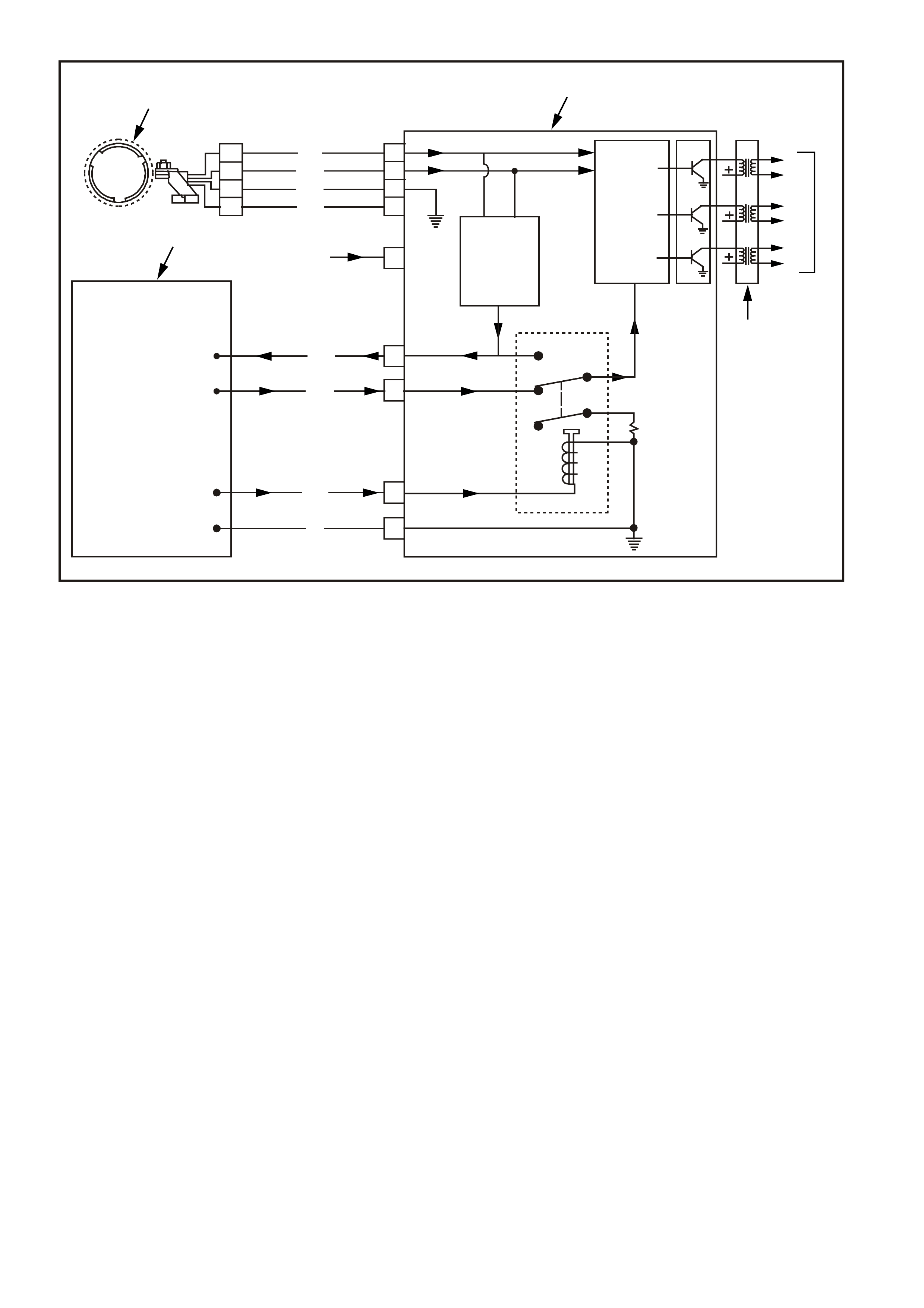
Figure 6C1-1-99 Engine Running Above 450 RPM
1. Engine Running Above 450 RPM
2. DIS Module
3. Coil Sequencing Control Logic
4. Spark Plugs
5. Ignition Coils
6. Signal Converter
7. 0 Volts
8. Crankshaft Reference Earth Low
9. Bypass Control
10. 4-5 Volts
11. EST Output
12. 1-4 Volts RPM Variable
13. Crankshaft Reference Input
14. 2-3 Volts Steady
15. Powertrain Control Module
16. From EFI Relay 12+ Volts
17. Sensor Power Supply
18. Sensor Earth
19. 18 X Crankshaft Sensor
20. 3 X Crankshaft Signal
21. Crankshaft Position Sensor (CKP)
In the EST mode, the ignition spark timing and ignition dwell time is fully controlled by the PCM. EST spark
advance and ignition dwell is calculated by the PCM using the following inputs:
• Engine speed (crankshaft reference)
• Crankshaft position (crankshaft reference)
• Engine load (MAF)
• Engine coolant temperature (ECT)
• Throttle position (TP sensor)
• Park/neutral (TFP)
• Detonation (Knock sensor)
• Vehicle speed (VSS)
• Diagnostic request input - (DLC diagnostic test" terminal)
• PCM supply voltage
The following describes the four PCM-to-ignition module circuits.
21
AH
G
M
N
P
D
A
B
L
B
C
D
15
1
3X
18X
20
19
18
2
17
16 6
3
5
1
4
3
6
2
5
4
14
12
10
7
9
8
11
13
4250
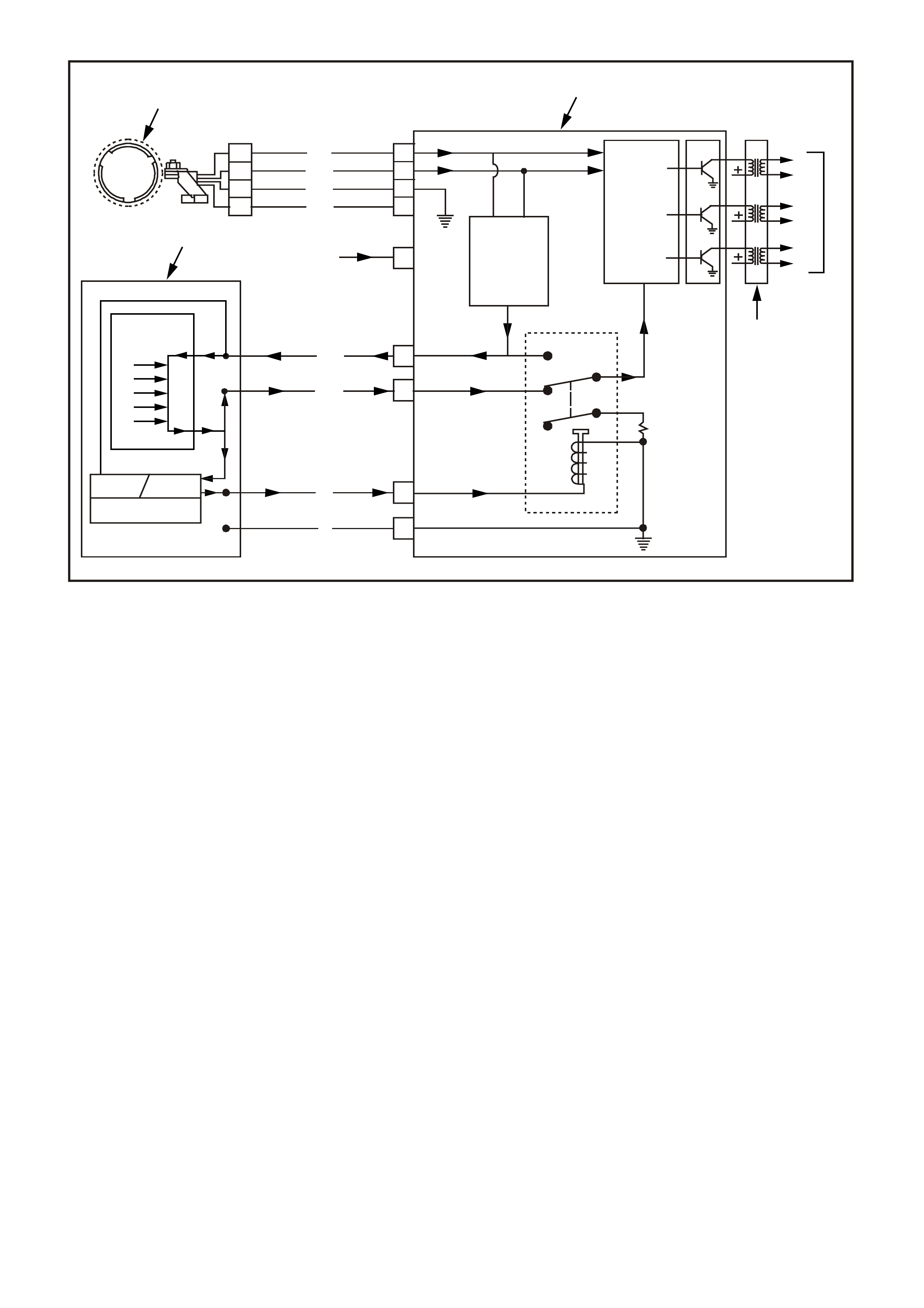
Figure 6C1-1-100 Engine Running with EST Inputs
1. Engine Running With EST Inputs
2. DIS Module
3. Coil Sequencing Control Logic
4. Spark Plugs
5. Ignition Coils
6. Signal Converter
7. 0 Volts
8. 4-5 Volts
9. DTC Monitor
10. RPM Counter
11. Bypass Control
12. Knock
13. ECT
14. BARO
15. MAF
16. RPM
17. 1-4 Volts
18. 2-3 Volts
19. EST Modifier
20. Powertrain Control Module
21. From EFI Relay 12+ Volts
22. Sensor Power Supply
23. Sensor Earth
24. 18 X Crankshaft Sensor
25. 3 X Crankshaft Signal
26. Crankshaft Position Sensor (CKP)
26
AH
G
M
N
P
D
A
B
L
B
C
D
20
1
3X
18X
25
24
23
2
22
21 6
3
5
1
4
3
6
2
5
4
18
17
8
7
16
15
14
13
12
19
10 11
9
4251

CRANKSHAFT REFERENCE PCM INPUT.
From the ignition module, the PCM uses this signal to calculate engine RPM and crankshaft position. The PCM
compares pulses on this circuit to any that are on earth crankshaft reference low circuit. The PCM also uses the
pulses on this circuit to initiate injec tor pulses. If the PCM receives no pulses on this c ircuit, no fuel inj ection pulses
will occur, the engine will not run, and DTC 46 will set when attempting to start the engine.
CRANKSHAFT REFERENCE EARTH.
This is an earth circuit for the digital RPM counter inside the PCM, but the wire is connected to engine earth only
through the ignition m odule. Although this c ircuit is elec trically connected to the PCM, it is not connec ted to earth at
or through the PCM. The PCM compares voltage pulses on the reference input circuit to any on this circuit. If the
circuit is open, or connected to earth at the PCM, it may cause poor engine performance and possibly a "Check
Powertrain" Lamp with no DTC.
BYPASS CONTROL.
The PCM either allows the ignition m odule to keep the spark advance at "bypass mode" 10 degrees BTDC, or the
PCM signals the ignition module that the PCM is going to control the spark advance (EST mode). The ignition
module switches between the two m odes by the level of voltage that the PCM sends to the ignition m odule on the
bypass control circuit. The PCM provides 5 volts to the ignition module if the PCM is going to control spark timing
(EST m ode). If the PCM does not turn "ON" the 5 volts , or if the ignition m odule doesn't rec eive it, then the module
will keep c ontr ol of s park timing (bypass mode). An open or ear thed bypass control c irc uit will set a DT C 42 and the
ignition system will stay in 'bypass mode'. If the bypass control circuit is shorted to voltage then DTC 41 will set.
EST OUTPUT
The EST output circuitry of the PCM sends out timing pulses to the ignition module on this circuit. When in the
"bypass mode," the ignition module earths these pulses. When in the EST mode, these pulses are the ignition
timing pulses used by the ignition module to energise the ignition coil. If the EST output circuit is open when the
engine is started, a DTC 41 will set and the ignition system will stay in the bypass mode. If this circuit becomes
shorted to voltage or earthed during EST mode operation above 1600 RPM, then DTC 42 will set.
HOW DTC 41 AND DTC 42 ARE DETERMINED
The EST output circ uitry in the PCM issues EST output pulses anytime cr ankshaf t reference s ignal input pulses ar e
being received. When the ignition system is operating in the bypass mode (no voltage on the bypass control
circuit), the ignition module earths the EST pulses sent from the PCM. The ignition module will remove the earth
path for the EST pulses only after switching to the EST m ode. (T he PCM com m ands the s witching between bypass
& EST modes, via applying 5 volts on the bypass control circuit to the ignition module.)
The PCM has voltage monitors on the EST output line and the bypass control line. The PCM monitors it's EST
output, and expects to detect no EST pulses on the EST circuit when it has not supplied the 5 volts on the bypass
control circuit. W hen the RPM for EST operation is reached (approxim ately 450 RPM), the PCM applies 5 volts to
the bypass control circuit, and the EST pulses should no longer be earthed by the ignition module. The PCM
constantly monitors it's EST output, and should 'detect' the high EST pulses only when in the 'EST mode.'
If EST output circuit is open, the PCM will detect EST output pulses while attempting to start the engine (in the
bypass mode) due to the ignition module not being able to earth the EST pulses. The PCM will check for this
condition during engine cr anking. Thr ee things will occur: 1. A DT C 41 will s et, 2. The PCM will not apply 5 volts to
the bypass control circuit, and 3. The engine will start and run in the bypass mode.
If EST output circuit is earthed or shorted to voltage, the PCM would not detect a problem until the change to
EST mode happens. W hen the PCM applies 5 volts to the bypass control circuit, the ignition module will switch to
the EST mode. With EST circuit earthed or shorted to voltage, there would be no EST pulses for the ignition
module to trigger the ignition coil with, and the engine may falter. The PCM will quickly revert back to the bypass
mode (turn "OFF" the 5 volts on the bypass control circuit), DTC 42 will set, after the engine speed exceeds 1600
RPM. The ignition s ystem will operate in the bypass mode until the fault is corr ected and the engine is stopped and
restarted.
If bypass control circuit is open OR earthed, the ignition module can not switch to the EST mode. In this case,
the EST pulses will stay earthed by the ignition module, and DTC 42 will be set after the
engine speed exceeds 1600 RPM. The engine will start and run in the bypass mode.
If bypass contro l circuit is shorted t o voltag e, the ignition m odule will be switched to the EST m ode all the tim e.
In this c as e, the PCM would detec t voltage on the bypass circuit only with the engine cranking and set DTC 41. T he
engine would start and run in the EST mode.

RESULTS OF INCORRECT OPERATION
An open or ear th in the EST or bypass c irc uit will set a DT C 41 or DT C 42. If a fault oc cur s in the EST output c irc uit
when the engine is running, the engine m ay falter or quit running but will restart and run in the bypass mode. A fault
in either circ uit will force the ignition s ystem to operate on bypass m ode tim ing (10 degrees BTDC), which will res ult
in reduced performance and fuel economy.
The PCM us es information fr om the MAF and c oolant temperature s ens ors in addition to RPM to c alc ulate the main
spark advance values as follows:
High RPM = more advance
Low MAF frequency
(Low engine load) = more advance
Cold engine = more advance
Low RPM = less advance
High MAF frequency
(High engine load) = less advance
Hot engine = less advance
Therefore, detonation could be caused by incorrect low MAF output frequency or incorrect high resistance in the
coolant temperature sensor circuit. Poor performance could be caused by incorrect high MAF output frequency or
incorrect low resistance in the coolant temperature sensor circuit.
DTC 41 (Ignition Electronic Spark Timing Output Circuit Fault) will set if:
• The ignition is ON.
• The PCM has detected at least 2 EST output pulses during the first 3 crankshaft reference pulses received
from the ignition module.
• The PCM will illuminate the Malfunction Indicator Lamp (MIL).
DTC 42 (Ignition Bypass Circuit Fault) will set if:
• The engine is cranking or running.
• The PCM has commanded EST.
• The PCM has detected no EST output pulses for 400 ms.
• The engine RPM is greater than 1600 RPM.
• The PCM will illuminate the Malfunction Indicator Lamp (MIL).
DEFAULT VALUES
When either DTC 41 or 42 are set, the PCM will operate in the Bypass spark mode.
RECOVERY
Recovery will occur on the next ignition cycle.
DTC 41 AND 42 HISTORY DATA
PARAMETER PARAMETER
ENGINE SPEED COOLANT TEMPERATURE
TIME FROM START REFERENCE VOLTS
TIMES OCCURRED VEHICLE SPEED
IGNITION CYCLES SPARK MODE
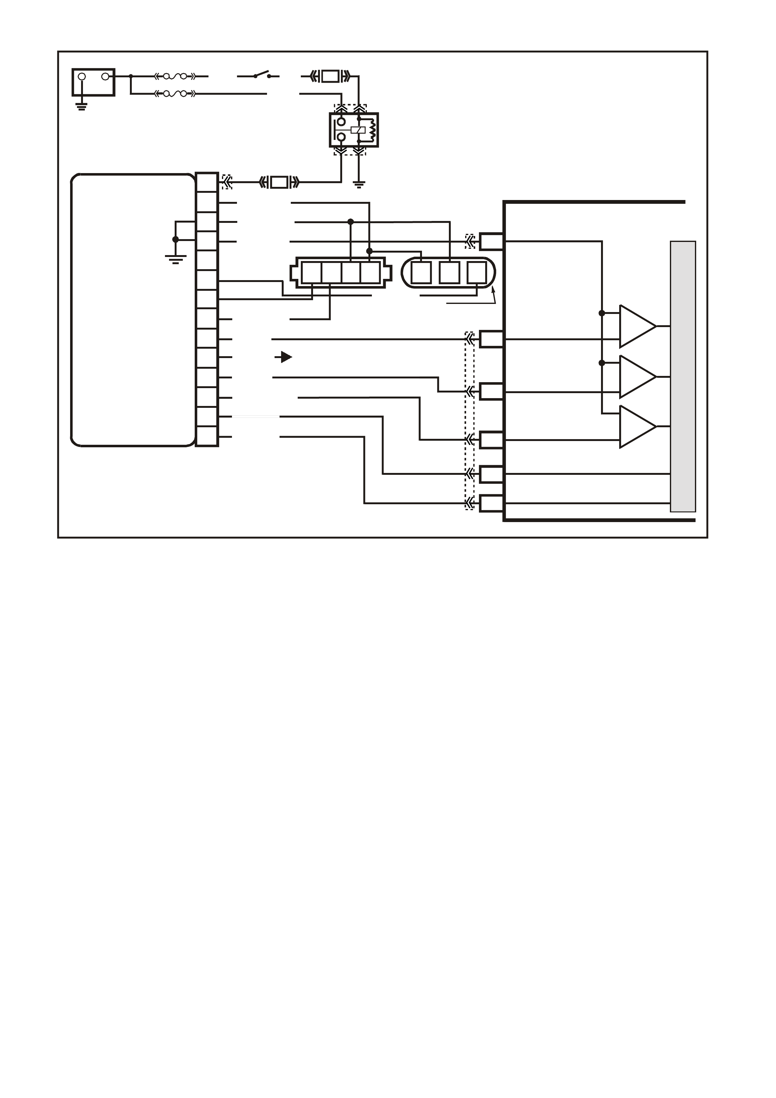
Figure 6C1-1-101 Ignition System
VXSC009
PCM
D11
D3
D4
D12
D9
D10
CRANKSHAFT
REFERENCE LO
CAM
SENSOR
CONNECTOR
CAMSHAFT
POSITION
SENSOR
SIGNAL
CRANKSHAFT
REFERENCE HI
CRANKSHAFT
18X SIGNAL
BYPASS CONTROL
EST OUTPUT
module power supply - in
sensor power supply - out
cam signal - in
3x crank sensor - in
18x crank sensor - in
cam signal - out
tacho signal - out
crankshaft reference - out
18X cranksignal - out
bypass control
EST signal -in
P
N
M
L
K
J
H
G
F
E
D
C
B
A
DIS
MODULE
ABCD CBA
W/B (644)
GY/R (645)
B/R (453)
CRANK
SENSOR
CONN
L BLU/W
(646) BR (633)
BLU/Y (643)
BR (121)
B (63 0)
V (43 0)
L BLU/B (647)
T/B (4 24)
IGN SW
EFI RELAY
O/Y
(479)
LG
(482)
B/W
(152)P/B
(39)
IC
IC
IC
M
I
C
R
O
W (423)
F35
+
-
BATTERY
FS
LOC. E1
FJ
(1040)
LOC. E3
P (3)
R(2H)
F14
TO INSTRUMENT CLUSTER
(TERMINAL 18)
ABS/ETC (TERMINAL 30)
YB39
YB39
YE111
YE34
YB193
YB193
YE63
YE57
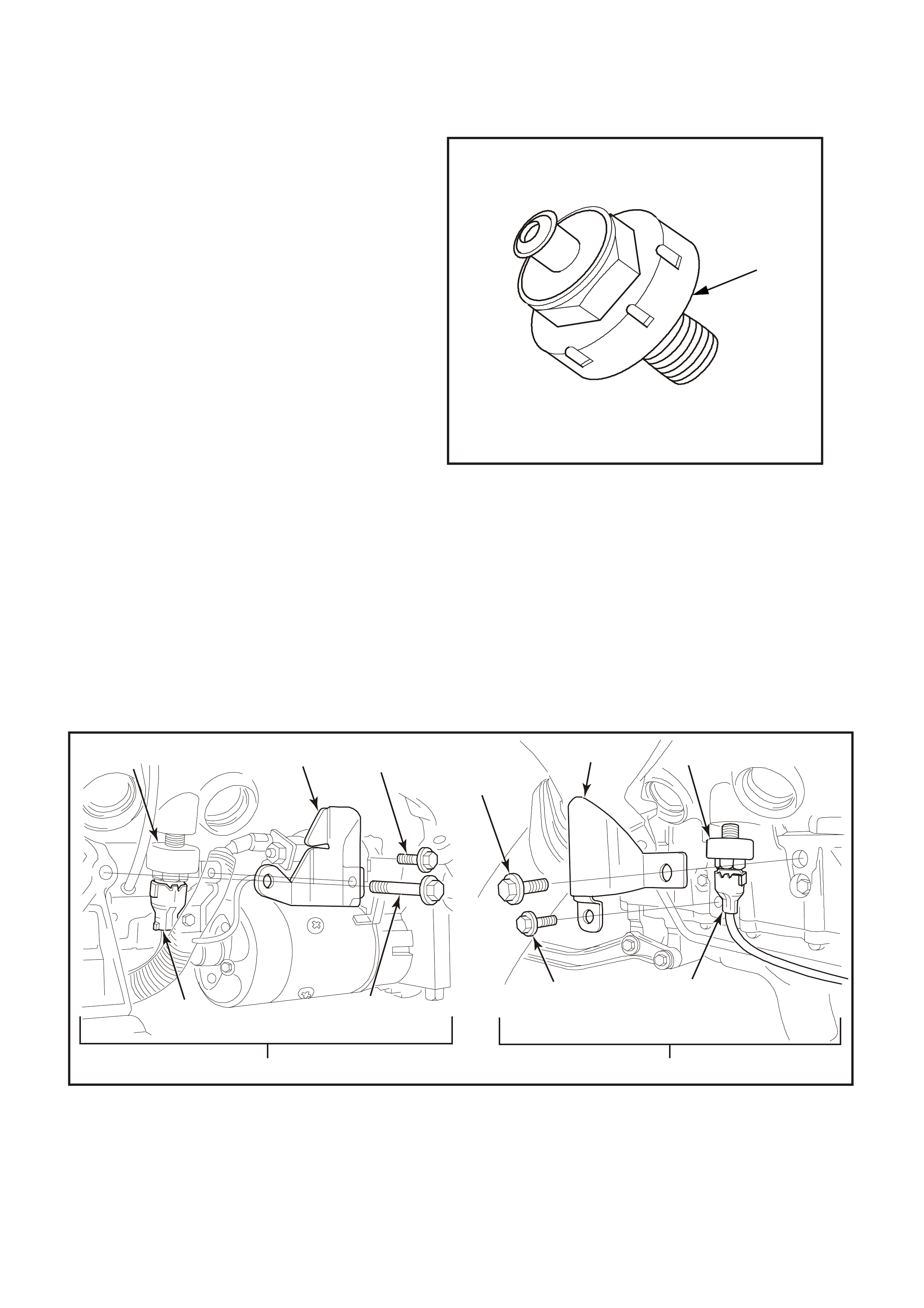
1.8 ELECTRONIC SPARK CONTROL (ESC) SYSTEM
PURPOSE
Varying octane levels in today's petrol may cause
detonation in some engines. Detonation is caused
by an uncontrolled pressure in the combustion
chamber. This uncontrolled pressure could
produce a flame front opposite that of the normal
flame front produced by the spark plug.
The "rattling" sound normally associated with
detonation is the result of two or more opposing
pressures (flame fronts) colliding within the
combustion chamber. Though "light" detonation is
sometimes considered normal, "heavy" detonation
could result in engine damage. Light detonation
occurs when the point of maximum pressure has
been exceeded.
To control spark knock, a Knock Sensor (KS) is
used. This system is designed to retard spark
timing up to 15 degrees to reduce spark knock in
the engine. T his allows the engine to use max imum
spark advance to improve driveability and fuel
economy .
1
4252
Figure 6C1-1-102 Knock Sensor
1. Knock Sensor (KS)
OPERATION
The ESC system has two major components:
• Knock Sensor Module (part of PCM)
• Knock Sensors (2)
The knock sensor detects abnormal mechanical vibration (spark knocking) in the engine. There are several
calibrations of k nock sensor s bec ause each engine produc es a dif ferent f requenc y of mechanic al noise. T he k nock
sensor is specifically chosen for this engine to best detect engine knock, over all the other noises in the engine.
This engine has two knock sensors. Each sensor is mounted in the engine block near each bank of cylinders to
better detect detonation.
Figure 6C1-1-103 Knock Sensor Locations
1. Attaching Bolt. 7. Attaching Bolt.
2. Knock Sensor Shield. 8. Wiring Harness Connector.
3. R.H Knock Sensor. 9. L.H Side of Engine View.
4. Wiring Harness Connector. 10. L.H Knock Sensor.
5. Attaching Bolt. 11. Knock Sensor Shield.
6. R.H Side of Engine View. 12. Attaching Bolt.
10 11
1
4
5
7
8
9
12 23
6
4253

Under a no knock condition, each circuit should
measure about 32 mV AC. The knock sensors
produce an AC output voltage that increases with
the sever ity of the knoc k. T his signal voltage inputs
to the PCM. This AC signal voltage to the PCM is
processed by an analog signal to a Signal Noise
Enhancement Filter (SNEF) module. This SNEF
module is used to determine if the AC signal
com ing in is noise or actual detonation. T his SNEF
module is part of the PCM and cannot be replaced.
The processed knock sensor signal is then
supplied to the PCM. The PCM then adjusts the
ignition control system to reduce the spark
advance. How muc h the tim ing is retar ded is based
upon the amount of time knock is detected and is
limited to a maximum value of 15 degrees. After
the detonation stops, the timing will gradually
return to it's calibrated value of spar k advance. T he
Knock Sensor system will only retard timing after
the following conditions are met:
• Engine running longer than 5 seconds
• Battery voltage higher than 9.3 volts
• Engine speed above 550 RPM
• ECT greater than 45 degrees C
1
2
4254
Figure 6C1-1-104 Knock Sensor Sectioned View
1. Piezo Crystal
2. Shunt Resistor
The T ech 2 scan tool has two data displays to check for diagnosing this k nock sensor circ uit. "KNOCK SIGNAL" is
used to monitor the input signal from the knock sensors. This position will display "YES" when knock is being
detected. "KNOCK RETARD" is the indication of how much the PCM is retarding the spark advance.
The T ech 2 scan tool has two data displays to check for diagnosing this k nock sensor circ uit. "KNOCK SIGNAL" is
used to monitor the input signal from the knock sensor. This position will display "YES" when knock is being
detected. "KNOCK RETARD" is the indication of how much the PCM is retarding the spark advance.
The Knock Sensor System has two DTC's to detect a failure in its system. DTC 43 is designed to diagnose the
knock sensor and wiring, so that problems encountered with this circuit should set the DTC. The PCM learns a
minimum noise level from the knock sensors.
• The actual noise level is determined as: Noise level = Filtered noise - minimum noise
If the noise level is too low or too high then DTC 43 will be set.
The second DTC associated with the Knock Sensor is DTC 93. DTC 93 indicates that the engine has been
detonating longer than norm al. The PCM monitors the output of the SNEF circuit. W hen the SNEF output signal is
significantly longer than the longest expected "norm al": output it is assum ed that the SNEF circuitry has failed and
DTC 93 is set.
DTC 43 (Knock Sensor Circuit) will set if:
• No DTC 14,15,16,17,19 ,21, 22, or 93 are set.
• Engine has been running longer than 10 seconds.
• Engine Coolant Temperature is greater than 65
degrees C.
• TP sensor signal is greater than 22%.
• Engine RPM is between 2000 and 6375 RPM.
• There is no knock sensor signal or too high a knock sensor signal detected by the PCM for 3 seconds
• The PCM will not illuminate the Malfunction Indicator Lamp (MIL).
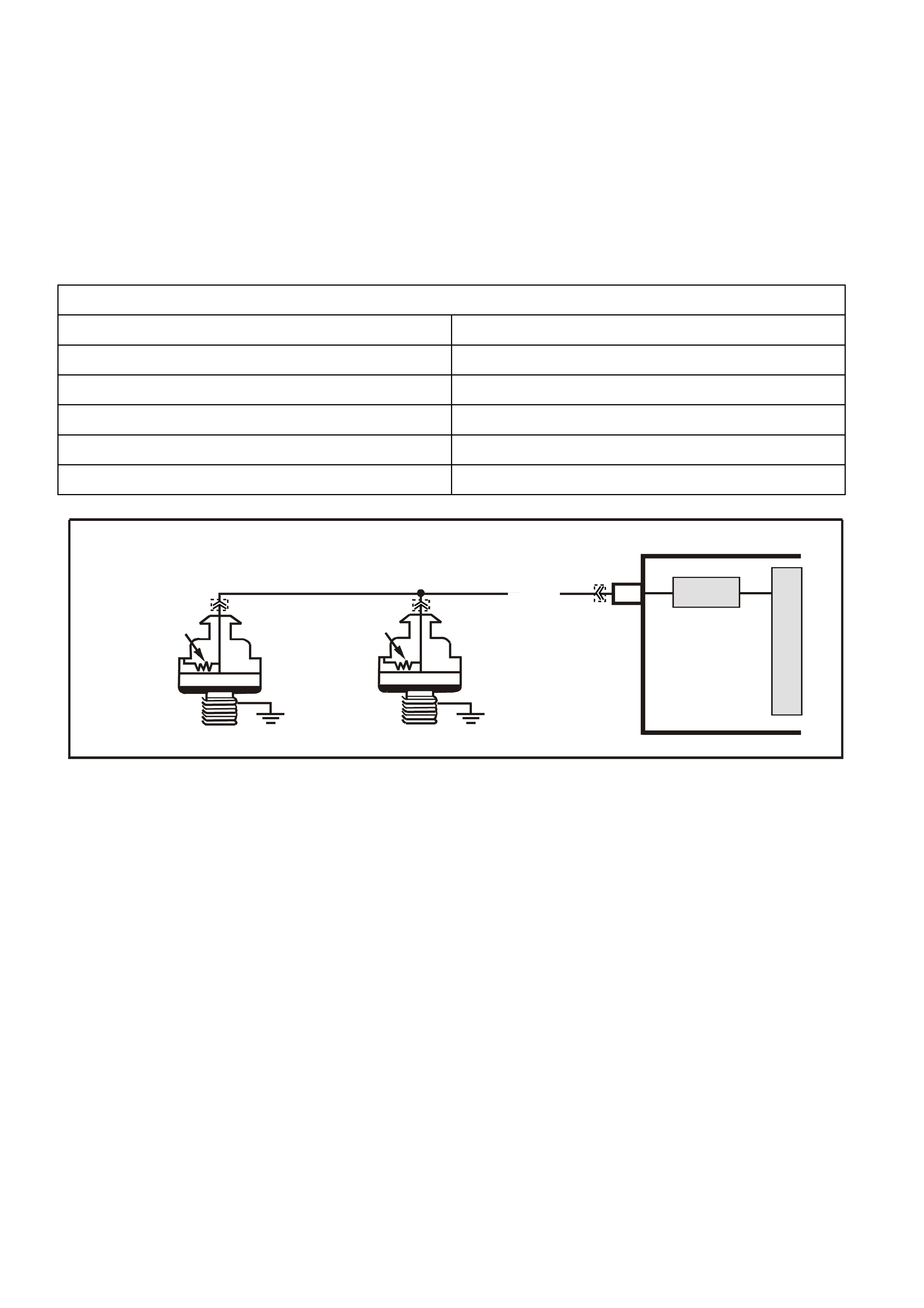
DTC 93 (Knock Sensor System) will set if:
• The engine has been running for more than 10 seconds
• The PCM’s SNEF circuit indicates knocking for more than 10 seconds
• The PCM will not illuminate the Malfunction Indicator Lamp (MIL).
DEFAULT VALUES
Once DTC 43 OR 93 is set, and current, the PCM uses a default spark advance table.
RECOVERY
Recovery will occur when the PCM sees a valid condition.
DTC 43 AND 93 HISTORY DATA
PARAMETER PARAMETER
ENGINE SPEED MASS AIR FLOW
TIME FROM START KNOCK DETECTION
TIMES OCCURRED INTAKE AIR TEMPERATURE
IGNITION CYCLES SPARK ADVANCE
COOLANT TEMPERATURE THROTTLE ANGLE
Figure 6C1-1-105 Knock Sensor Wiring
VXSC007
PCM
M
I
C
R
O
SNEF
KNOCK SENSOR
SIGNAL INPUT
C12
RH KNOCK
SENSOR
LH KNOCK
SENSOR
PIEZO CRYSTAL
SHUNT
RESISTOR
PIEZO CRYSTAL
SHUNT
RESISTOR
W/R (815)
YE3 YE3
YB193
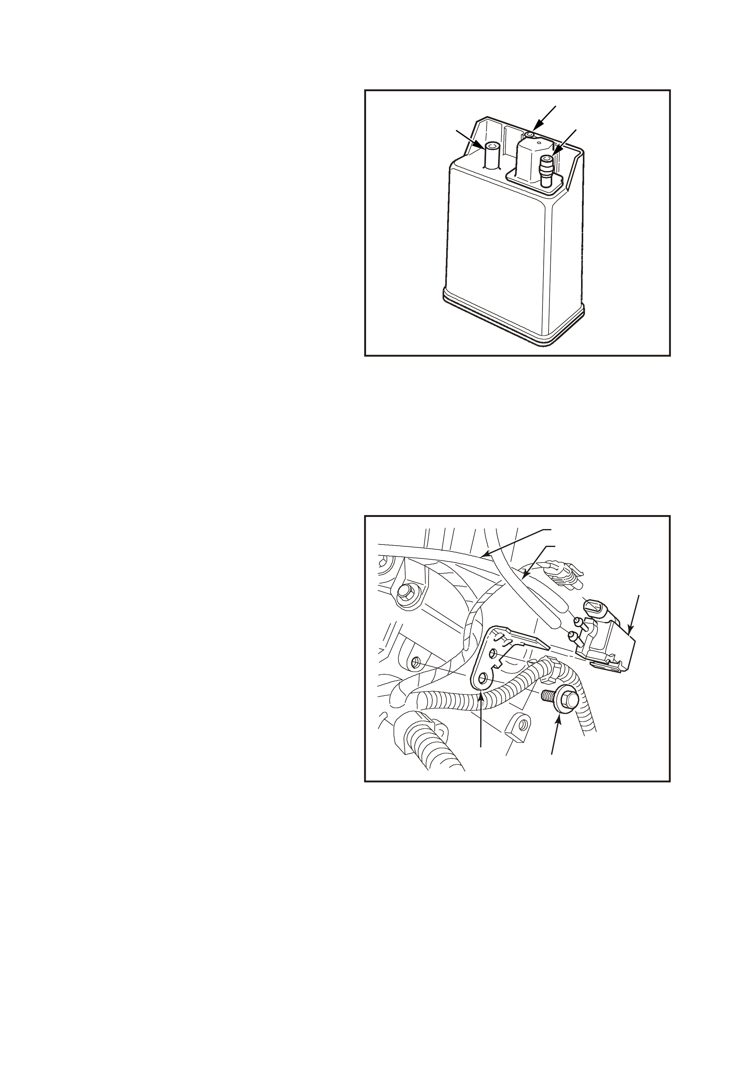
1.9 EVAPORATIVE EMISSION
The Evaporative Emission Control System (EECS)
used on this vehicle is the charcoal canister
storage method. This method transfers fuel vapour
from the fuel tank to an activated carbon (charcoal)
storage device (canister located under the rear of
the vehicle) to hold the vapours when the vehicle is
not operating. W hen the engine is running, the fuel
vapour is purged from the carbon element by
intake air flow and consumed in the normal
combustion process.
The EECS purge solenoid valve allows manifold
vacuum to purge the canister. The Powertrain
Control Module (PCM) supplies an earth signal to
energise the EECS purge solenoid valve (purge
“ON”). The EECS purge solenoid control is Pulse
W idth Modulated (PWM) or turned “ON” and “OFF ”
several times a second. The PCM controlled PW M
output is commanded when the appropriate
conditions have been met:
• Engine coolant temperature above 80°C.
• Engine has been running longer than 3
minutes.
• Engine is not in Decel Fuel Cutoff Mode.
• Throttle opening is less than 92%.
• Engine is in Closed Loop mode.
3
1
2
4255
Figure 6C1-1-106 Fuel Vapour Canister
1. Canister Purge Port
2. Vapour From Fuel Tank Port
3. Air Vent Port
EECS purge PWM duty cycle varies according to
operating conditions determined by mass air flow,
fuel trim and intake air temperature. The EECS
purge will be re-enabled when TP angle decreases
below 92%.
The canister (located under the rear of the vehicle)
cannot be repaired, and is serviced only as an
assembly. Periodically check the canister at the
time or distance intervals specified in the vehicle
Series Owners Handbook. If there is a fault with
the Canister Purge Solenoid elec trical c ircuits , DTC
97 will set.
4256
12
54
3
Figure 6C1-1-107 Canister Purge Solenoid Location
1. To Throttle Body
2. To Canister
3. Solenoid Valve
4. Solenoid Mounting Bracket Screw
5. Solenoid Mounting Bracket
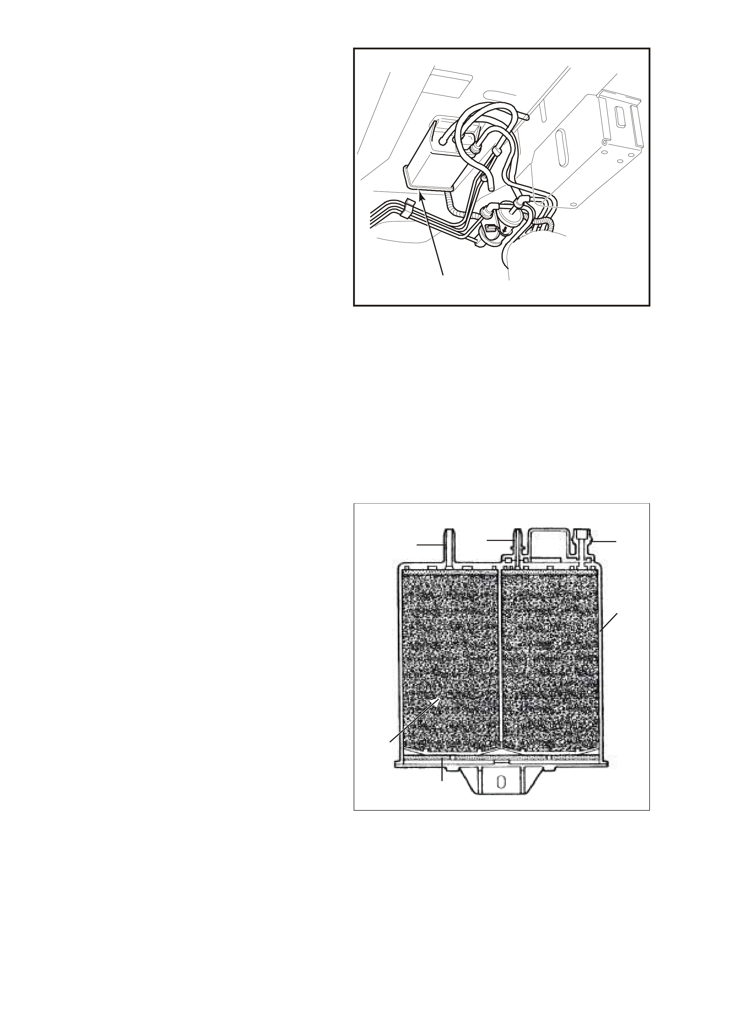
The fuel vapour canister is mounted in a bracket
underneath the vehicle, located by the fuel filter.
This canister is a three port design. The fuel
vapour is absorbed by the charcoal within the
canister. When the engine is running at idle speed
and above idle, air is drawn into the canister
through the atmospheric port at the top of the
canister assembly. The air mixes with the fuel
vapour and the mixture is drawn into the intake
manifold via the canister purge line. Uppermost
port on the canister is controlled by a PCM
controlled canister purge solenoid. The canister
purge solenoid contr ols the m anif old vacuum signal
from the throttle body. The port below the canister
purge port is the vapour inlet from the fuel tank.
The single off centre port is open to the
atmosphere.
RESULTS OF INCORRECT OPERATION
• Poor idle, stalling and poor driveability can be
caused by:
-Inoperative canister purge solenoid
-Damaged canister.
-Hoses split, cracked and/or not connected to
the proper tubes.
• Evidence of fuel loss or fuel vapour odour can
be caused by:
1
4257
Figure 6C1-1-108 Canister Location
1. Canister
-Liquid fuel leaking from fuel lines.
-Cracked or damaged canister.
-Disconnected, misrouted, kinked, deteriorated
or damaged vapour hoses, or control hoses.
If the solenoid is stuc k open, or the control c ircuit is
shorted to earth the c anister will purge to the intak e
manifold all the time. This can allow extra fuel at
idle or during warm-up, which can cause rough or
unstable idle or a rich fuel operation.
If the canister purge solenoid is always closed, the
canister can become over loaded, with fuel
resulting in fuel odour.
A failure in the canister purge solenoid or circuit
may result in DTC 97.
GEN 03 0042
123
4
6
5
Figure 6C1-1-109 Sectioned View of Canister
1. Air Vent Port
2. Canister Purge Port
3. Vapour From Fuel Tank Port
4. Evaporative Canister
5. Volume Compensator
6. Charcoal Bed
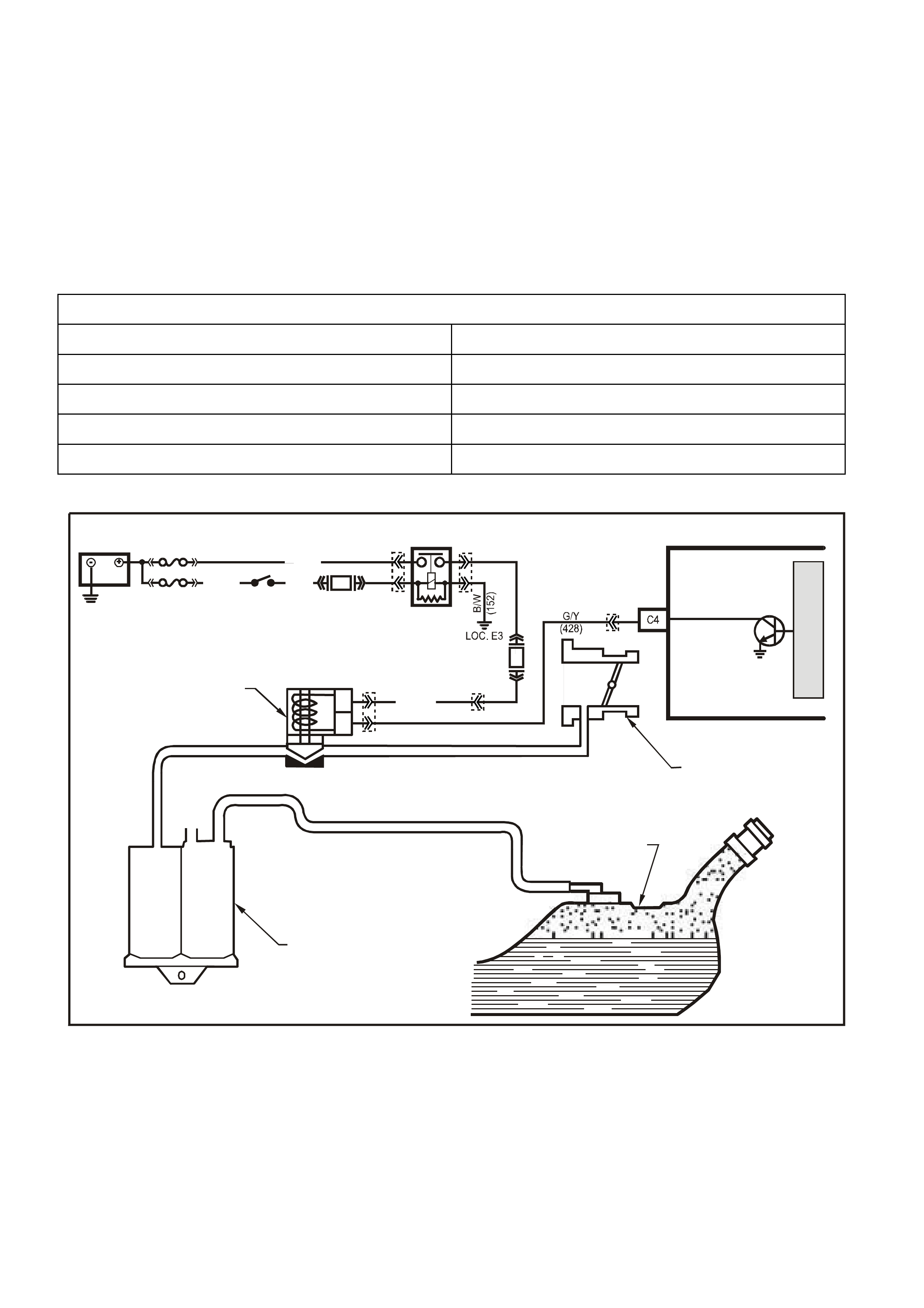
DTC 97 (Canister Purge Circuit Fault) will set if:
• The ignition is ON
• The PCM detects the incorrect voltage on the canister purge solenoid driver
• The PCM will not illuminate the Malfunction Indicator Lamp (MIL).
DEFAULT VALUES
There are no default values for DTC 97.
RECOVERY
Recovery will occur when the PCM sees a valid condition.
DTC 97 HISTORY DATA
PARAMETER PARAMETER
ENGINE SPEED COOLANT TEMPERATURE
TIME FROM START PURGE PWM
TIMES OCCURRED MASS AIR FLOW
IGNITION CYCLES
Figure 6C1-1-110 Typical Evaporative Emission Control Schematic
SUPERVX026
A
B
THROTTLE BODY
CANISTER PURGE
SOL EN OID VALVE
CARBON CANISTER
FUEL TANK
PCM
CANISTER PURGE
M
I
C
R
O
F33
F14
IGN SW
EFI
RELAY
BATTERY
FS
FJ
P (3 ) P/B
(39)
R (2H)
(1040)
P (439)
O/Y
(479)
YE99
YE39
YE39
YB111
YB193
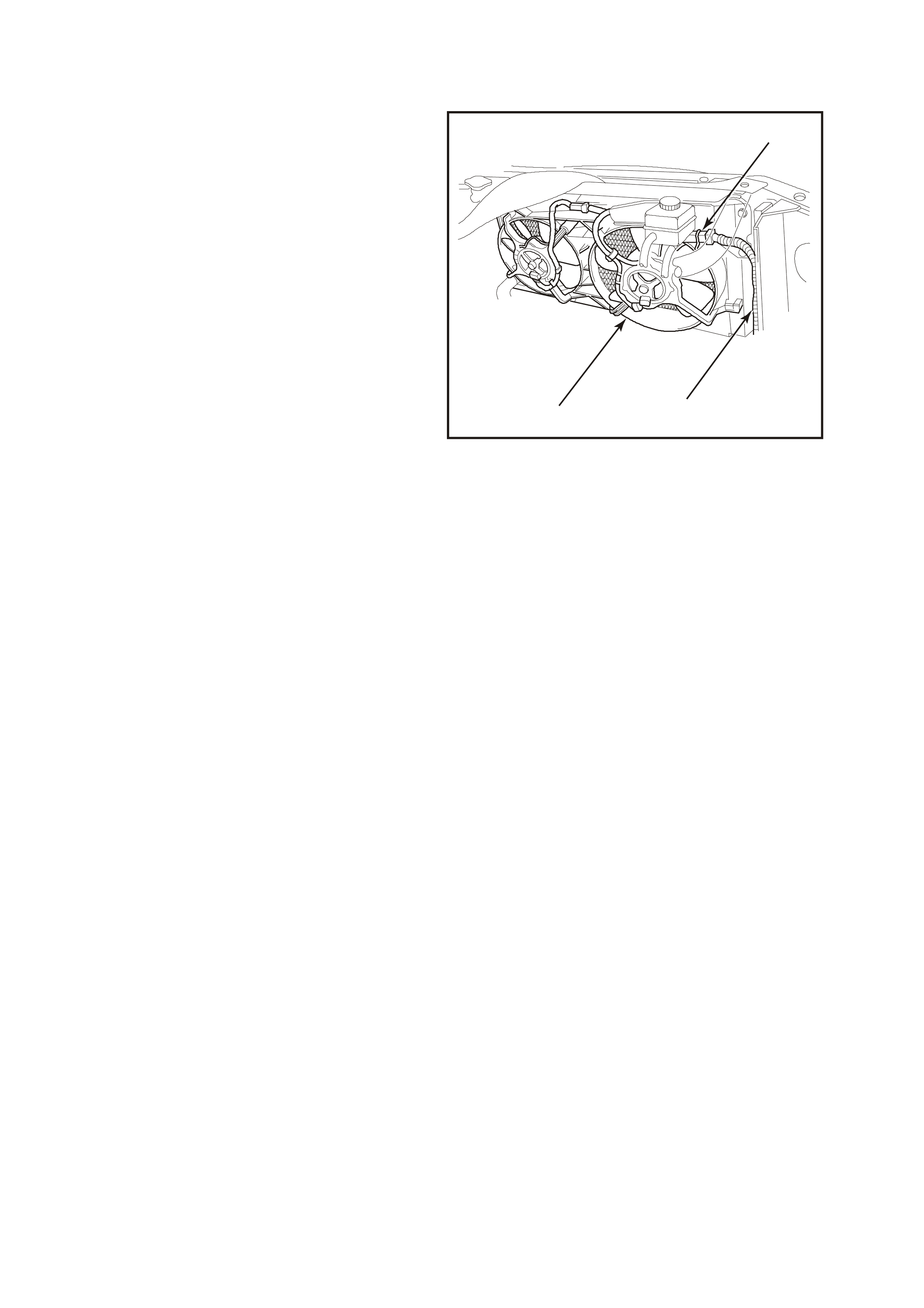
1.10 ELECTRIC COOLING FAN
This V6 engine has two, two speed electric engine
cooling fan assembly that provides the primary
means of moving air through the engine radiator.
The two, two speed elec tric cooling f an are used to
cool engine coolant flowing through the radiator.
The two, two speed electric cooling fans are also
used to cool the ref rigerant f lowing through the A/C
condenser (if fitted).
Each engine cooling fan motor has four terminals,
two negative and two positive terminals. The two
negative terminals are the relay controlled circuits
for fan operation. The two positive terminals are
the direct power feed from a fusible link to the fan
motors. When a earth signal is applied to one of
the negative term inals , the fan m otor will operate at
low speed. When a earth signal is applied to both
negative terminals, both fan will operate at high
speed.
The engine cooling fan high speed relay is
controlled by the PCM. The PCM controls the earth
path for the engine cooling fan high speed relay.
The low speed of the electric fan is controlled by
the PCM through a s pecial Data Comm unication to
the BCM. The BCM controls the earth path for the
engine cooling fan low speed relay. The engine
cooling fan high speed relay and the engine
cooling fan low speed relay are used to control the
earth s ignal to the elec tric motor that drives the f ive
bladed fan.
The PCM determines operation of the two, two
speed engine cooling fan based on A/C request,
engine coolant temperature, A/C Refrigerant
Pressure Sensor, and vehicle speed signal inputs.
There are also four (4) suppression capacitors
incorporated into the fan motor wiring circuits.
These suppression capacitors help eliminate fan
motor noise through the radio speakers. If these
capacitors are open, then noise will be present
through the radio s peakers. Is shorted to earth, the
fan motors could continuously run, or the fuse or
fusible link could fail.
3
1
2
4259
Figure 6C1-1-111 Engine Cooling Fan Assembly
1. Engine Cooling Fan Motor Connector
2. Main Wiring Harness
3. Engine Cooling Fan Assembly
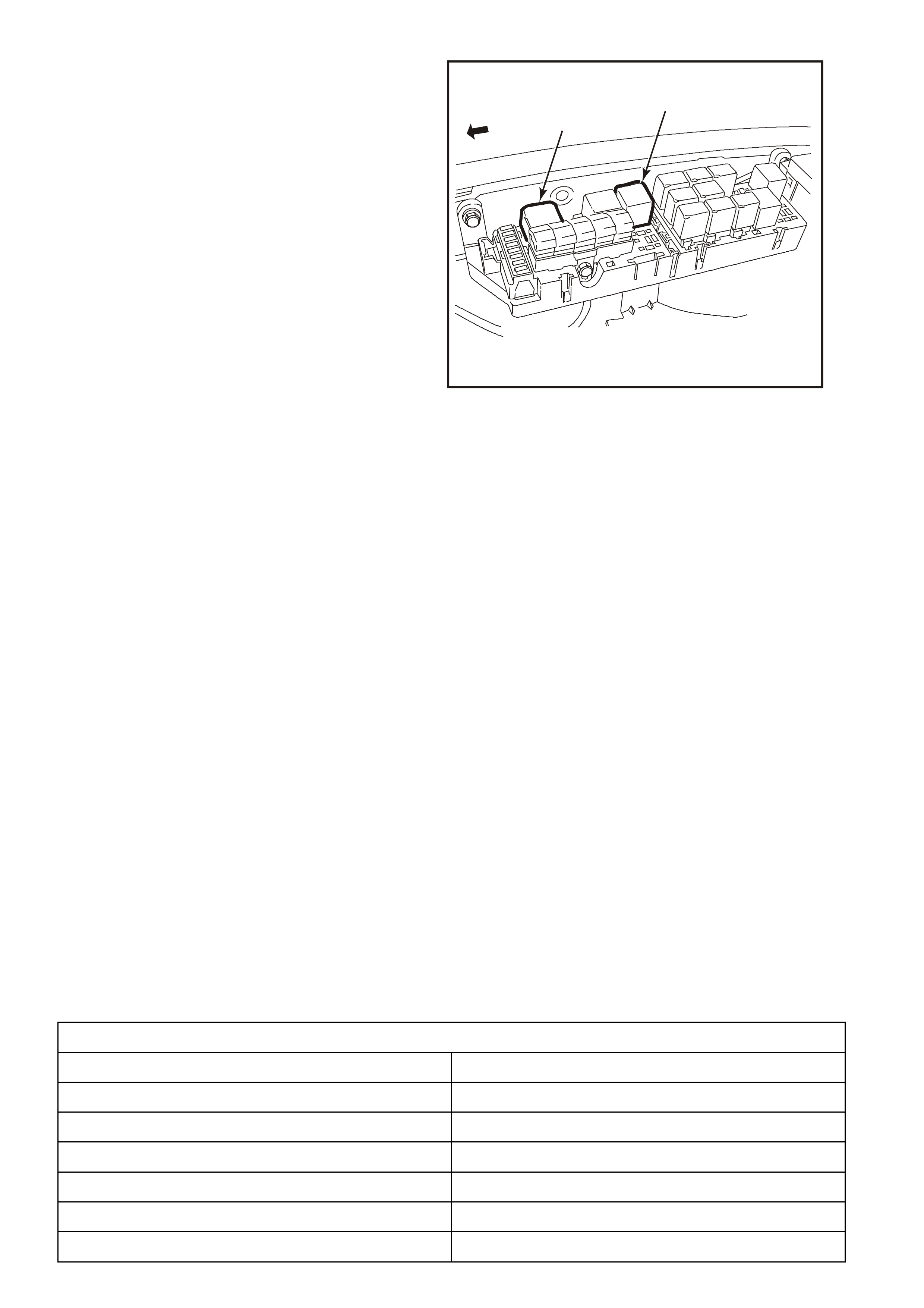
ENGINE COOLING FA N LOW SPEED
The engine cooling fan low speed relay is
energised by the BCM. The PCM determ ines when
to enable the low speed fan based on inputs from
the BCM serial data, Engine Coolant Temperature
(ECT) sensor and the Vehicle Speed Sensor
(VSS). The cooling fan low speed relay will be
turned "ON'' when:
• The A/C request indicated (YES) and either
• the vehicle speed is less than 30 km/h.
or
• A/C pressure is greater than 1500 kPa
or
• The coolant temperature is greater than 104
degrees C.
• If the coolant temperature is greater than 117
degrees C when the ignition is switched off , the
relay is energised for up to approximately 4
minutes.
12
4260
Figure 6C1-1-112 Cooling Fan Low Speed Relay Location
1. Radiator Fan Low Speed Relay
2. Radiator Fan High Speed Relay
• If an engine coolant tem per ature sens or f ault is
detected, such as DTC 14, 15, 16, or 17.
The cooling fan low speed relay will be turned
"OFF'' when any of the following conditions have
been met :
• The A/C request is not indicated (NO)
• Engine coolant temperature is less than 99
degrees C.
• The A/C request is indicated (YES) and the
vehicle speed is greater than 50 km /h and A/C
pressure is less than 1170 kPa.
LOW SPEED RESPONSE
The engine cooling low speed fans are enabled when the low speed relay is energized by the BCM. The PCM will
request the BCM to turn the low speed engine cooling fan relay on or off, via the serial data bus normal mode
message. After the PCM requests a change in the engine cooling fan low speed relay, the BCM will send a
response message back to the PCM via the serial data bus normal mode message confirming it received the
request. A failure in the response communication will set a DTC 92.
DTC 92 (Low Speed Fan – No BCM Response) will set if:
• Engine is idling
• The PCM sends a request to the BCM to turn ON the engine cooling fan low speed relay via the serial data
normal mode message and the BCM does not send a message back to the PCM.
• The PCM will not illuminate the Malfunction Indicator Lamp (MIL).
DEFAULT VALUES
Once DTC 92 is set, the PCM will energise the engine cooling fan high-speed relay
RECOVERY
Recovery will occur on the next ignition cycle.
DTC 92 HISTORY DATA
PARAMETER PARAMETER
ENGINE SPEED REFERENCE VOLTS
TIME FROM START MASS AIR FLOW
TIMES OCCURRED CAM SIGNAL
IGNITION CYCLES FUELING MODE
COOLANT TEMPERATURE FUEL PUMP RELAY
BATTERY VOLTAGE
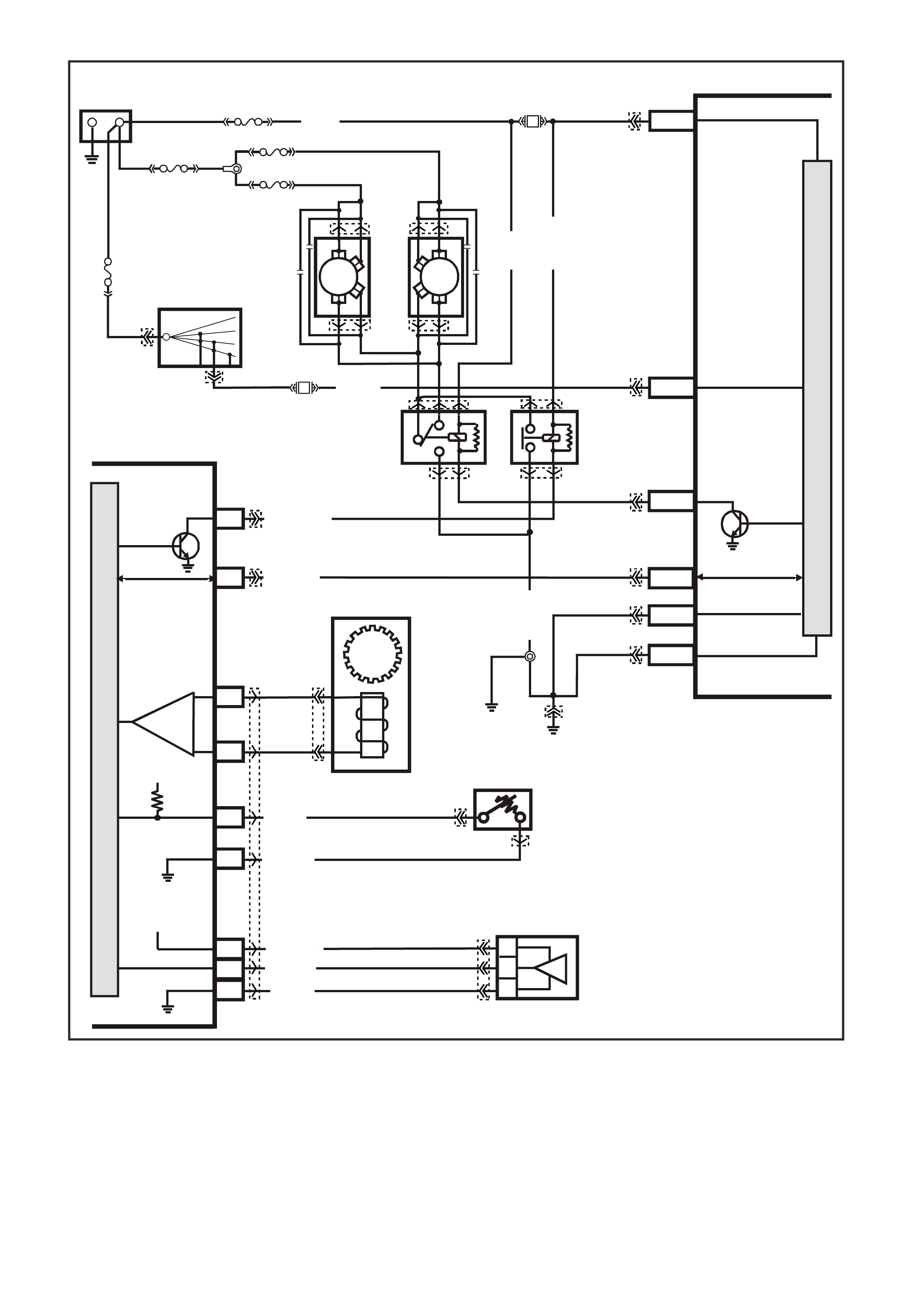
Figure 6C1-1-113 Engine Cooling Fan Circuit
VXSC032
5V
5V
BLU
(831)
T
(832)
IC
C6
D5
VEHICLE SPEED
SENSOR
B/Y (452 )
B (469)
D11
C16
D10
C6
D6
Y (41O)
V/W (415)
G/B (259)
COOLANT TE MP
SENSOR
A
/C PRESSURE
SENSOR
A
C
B
M
I
C
R
O
P
R
O
C
E
S
S
O
R
M
I
C
R
O
P
R
O
C
E
S
S
O
R
BATTERY MAIN POWER
HIGH SERIES
BCM TERMINALS
NOMINATED FIRST
BCM
PCM
F6
A3
HIGH
SPEED
FAN
SERIAL DA TA
BLU/W (304)
IGNITION
15a 15 50
30 OFF/ON
LOCK
ACC
IGN
START
E20/D6
P/B
(39)
IGNITION SWITCH
87A
30
87
85
86
87
30
85
86
ENGINE
COOLING
FAN 1
ENGINE
COOLING
FAN RELAY
(LOW SPEED)
ENGINE
COOLING
FAN RELAY
(HIGH SPEED)
P/B (39)
F14
BLUE
FUSIBLE
LINK
LOC.
E1
F31
A5/A6
O/B
(740)
ENGINE
COOLING
FAN 2
+-
BATTERY
FS
FT FAN 2
FU FAN 1
(1040)
(1040)
O/B (740)
O/B
(208)
O/BLU
YE119
YE119
YB44
YE103
YE103
YE43
YB175
YB164
YB174
YB163
YB174
YB163
YE114
YE106
YE113
YE106
YB195
YB193
YB188
YB194
YB132
YB164
YB175
YB165
YB176
YB176
YB165
YE43
YB44
(204)
R
(203)
FJ
R
(2H)
LOW
SPEED FAN
B7/B7
R/B (1221) R/B
(1221) E2/D2 SERIAL DATA
HIGH
CURRENT EARTH
B/Y
(155) A1/A5 ELECTRONIC EARTH
B/G
(151)
LOC.
E2 LOC.
E3
B10/B11
B/P (157)
O/B
(473)
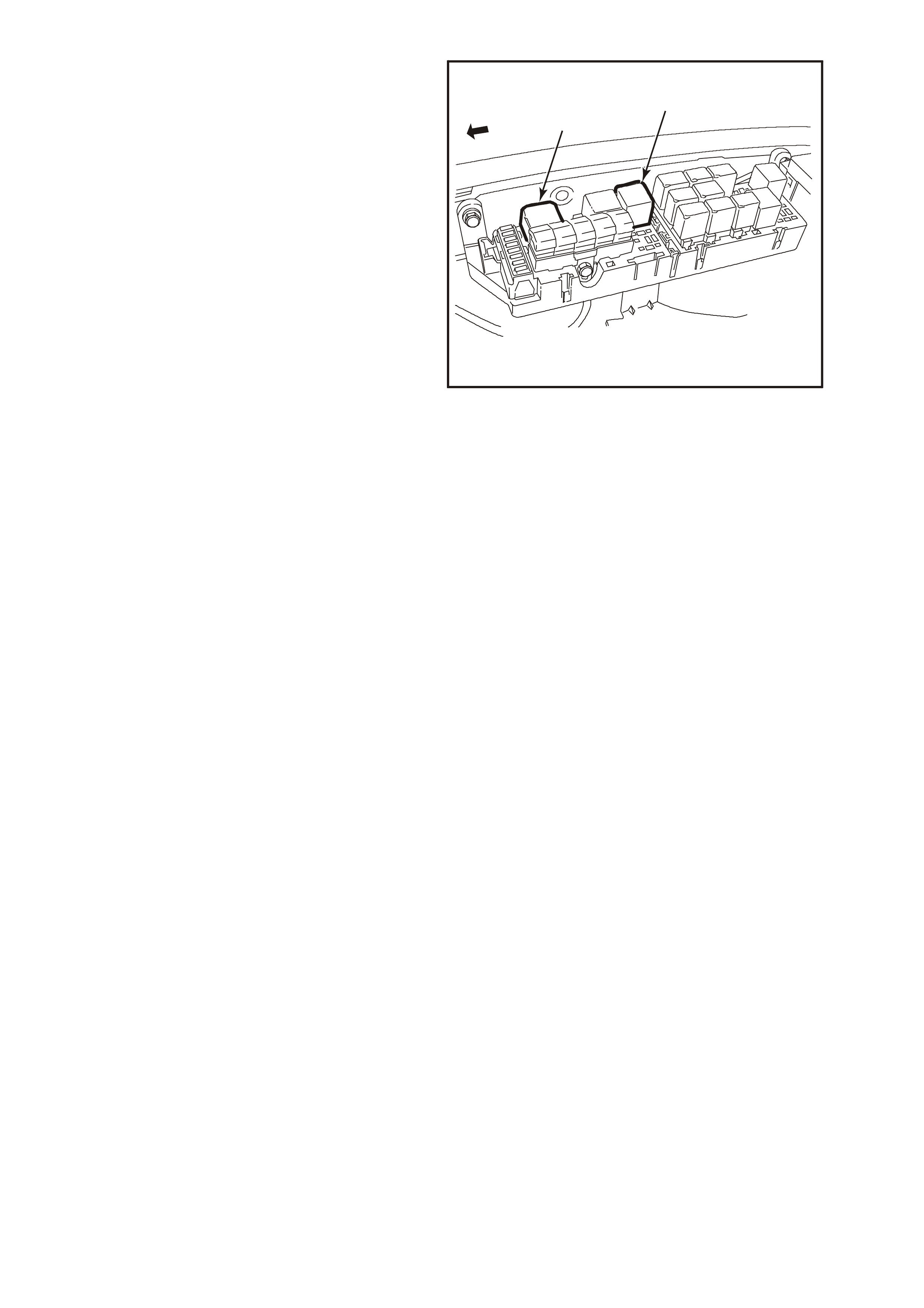
ENGINE COOLING FAN HIGH SPEED
The engine cooling fan high speed relay is
controlled by the PCM based on input from the
Engine Coolant Temperature (ECT) sensor. The
PCM will only turn “ON’’ the engine cooling fan
high speed relay fan if the engine cooling fan low
speed relay has been “ON” for 2 seconds and the
following conditions are satisfied.
• There is a BCM mess age r es ponse fault, which
will cause a DTC 92.
• An engine coolant temperature sensor fault is
detected such as DTC 14, 15, 16, or 17.
• Coolant temperature greater than 104
degrees C.
• The engine cooling fan high speed relay can
also be enabled by the A/C Refrigerant
Pressure Sensor. When the A/C Refrigerant
Pressure Sensor determines the A/C system
pressur e is to high, greater than 2600 kPa, and
this will instruct the PCM to enable the high
speed fan.
Notice:If the low speed fan was "OFF" when the
criteria was met to turn the high speed fan "ON",
the high speed fan will com e "ON" 5 seconds after
the low speed fan is turned "ON". "
If both the engine cooling fan relays are "ON", the
PCM will turn "OFF" the high speed relay when:
• The engine coolant temperature is less than
103 degrees C.
• A/C request not indicated (NO)
• A/C request indicated (YES) and A/C pressure
is less than 1500 kPa.
There are no DTC’s associated with the high speed
cooling fan relay.
12
4260
Figure 6C1-1-114 Cooling Fan High Speed Relay Location
1. Radiator Fan Low Speed Relay
2. Radiator Fan High Speed Relay
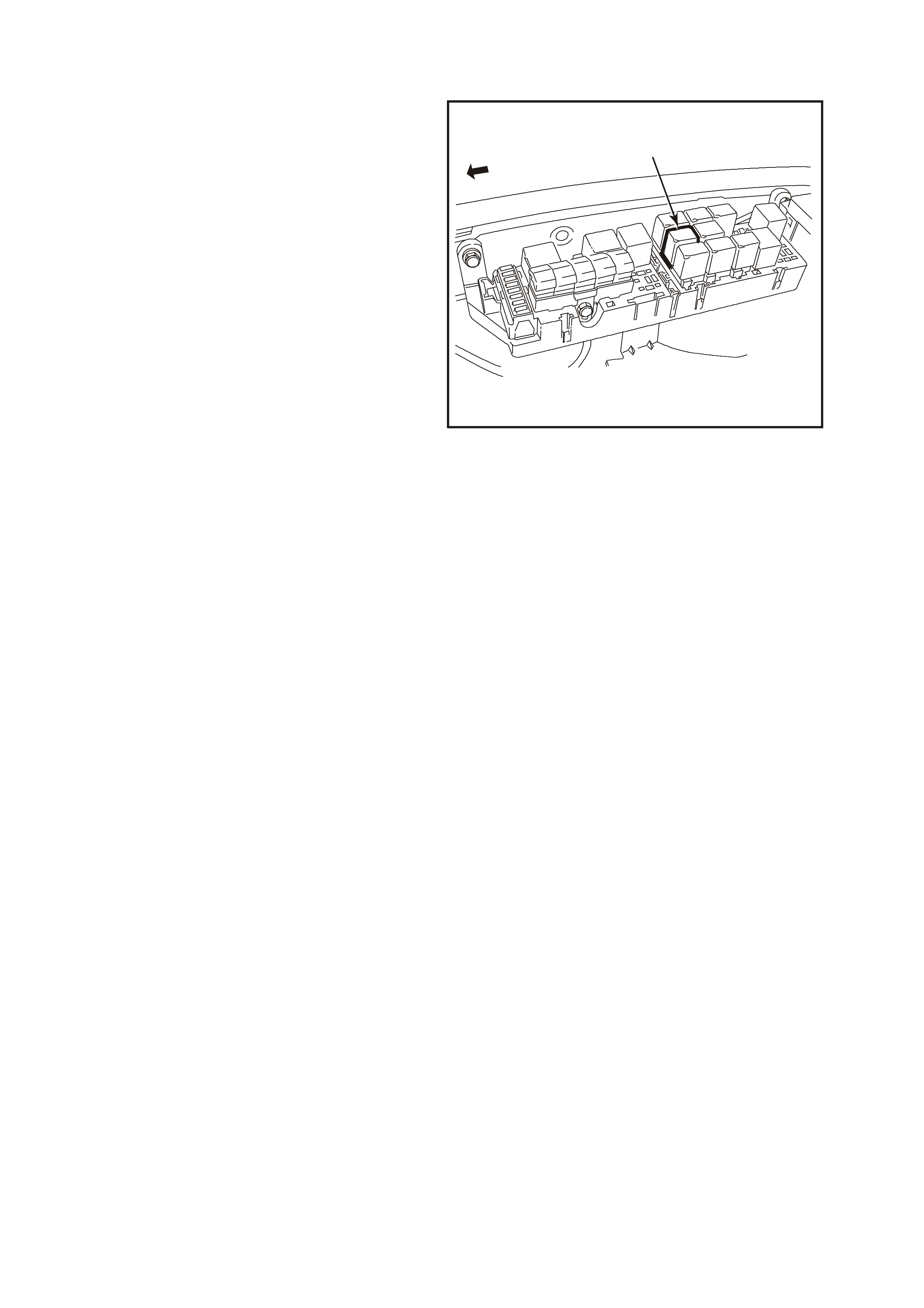
1.11 A/C CLUTCH CONTROL
This vehicle uses two types of A/C clutch controls.
One type is standard A/C (Figure 6C1-1-117) and
the other uses an Elec tronic Clim ate Control (ECC)
module (Figure 6C1- 1-118).
With the ECC system, when the A/C is requested,
the Electronic Clim ate Control Module will supply a
signal to the BCM. T he BCM will then send a serial
data request to the PCM. W hen the PCM receives
the serial data request on PCM terminal B12, it
indicates that air conditioning has been requested
and approximately 1/2 second after the PCM
receives this signal, it will energise the A/C control
relay. This serial data signal to the PCM is also
used to adjust the idle speed before turning "ON"
the A/C compressor relay. If this signal is not
available to the PCM, the A/C compressor will be
inoperative.
The BCM also supplies the earth signal from BCM
terminal "7" to the low speed cooling fan relay.
This A/C system also incorporates an A/C
Refrigerant Pressure Sensor. The A/C Refrigerant
Pressure Sensor signal indicates high side
refrigerant pressure to the PCM. The PCM uses
this inf or mation to adj ust the idle air c ontrol valve to
compensate for the higher engine loads present
with high A/C refrigerant pressures. A fault in the
A/C Refrigerant Pressure Sensor signal will cause
DTC 96 to set.
1
4262
Figure 6C1-1-115 A/C Relay Location Location
1. A/C Relay

The PCM will NOT energise the A/C control
relay if any of the following conditions are
present:
• Coolant temperature is above 119°C. Once
coolant temperature is below 116°C, A/C is
reactivated.
• RPM more than 5,800. If de-energised
because of RPM, it can re-energised when
RPM falls below 5,400.
• Throttle is more than 96% open. When de-
energised during wide-open throttle, it will be
re-energis ed when the throttle is less than 92%
open.
On vehicles equipped with non-ECC systems the
power flow is different. With the blower fan
switched "ON", and the air conditioning switched
"ON," switched ignition voltage is supplied from
fuse F13 through the A/C master switch, and then
to the BCM. T he BCM will then supply a serial data
signal to the PCM requesting A/C. If the BCM does
not rec eive a earth signal from the blower switch to
BCM terminal "3", the BCM will not supply the
serial data r eques t f or A/C. O nc e the PCM rec eives
this serial data signal, the PCM will energise the
A/C compressor relay. The BCM also supplies the
earth signal from BCM terminal "7" to the low
speed cooling fan relay.
This serial data signal to the PCM is also used to
adjust the idle speed before turning "ON" the A/C
compressor relay. If this signal is not available to
the PCM, the A/C compressor will be inoperative.
This system like on the ECC system also
incorporates a A/C Refrigerant Pressure Sensor.
The A/C Refrigerant Pressure Sensor signal
indicates high side refrigerant pressure to the
PCM. The PCM uses this information to adjust the
idle air control valve to compensate for the higher
engine loads present with high A/C refrigerant
pressures. A fault in the A/C Refrigerant Pressure
Sensor signal will cause DTC P0530 to set.
There are no DTC’s associated with A/C system
except for the A/C Refrigerant Pressure Sensor
DTC 96.
1
4261
Figure 6C1-1-116 A/C Refrigerant Pressure Sensor Location
1. A/C Refrigerant Pressure Sensor Connector

Figure 6C1-1-117 A/C Clutch Control Without ECC
SUPERVX019
D20
A1
D9
B8
A
/C MASTER
SWITCH
HIGH SERIES
BCM TERMINALS
NOM IN ATE D FIRST
O
(291)
B/R
(292)
R/W
(248)
R/BR
(962)
BR
(4)
Y
(51)
B3
BLOWER
MOTOR
RESISTORS
A/C
RELAY
EFI
RELAY
BLOWER
MOTOR
HEATER AND A/C
CONTROLS
BLOWER
INHIBIT
RELAY
DKG/Y (359)
LOC.E3
LOC.E3
Y/B (52)
R/G (245)
LG/B (366)
4
3
2
1
R/Y (244) O/G
(251)
DKG/Y
(359)
BATTERY MAIN POWER
BATTERY
IGNITION SWITCH
FY
F31
O/B
(740)
FS
(1040)
BCM
B/G
(151) HIGH CURRENT
EARTH
IGNITION
DEMIST OUTPUT
DEMIST INPUT
A/C SWITCH INPUT
A/C LED OUTPUT
A/C BLOWER
INPUT
F14
F13
F33
E20/D6
A5/A6
E2/D2
B10/B11
A1/A5
P/B
(39)
15a 15 50
30 ACC
IGN
START
P (3)
R/B
(1221)
SERIAL DATA
A/C ENABLE
5V
SERIAL
DATA
5V
M
I
C
R
O
PCM
A3
F4
B/Y
(155) ELECTRONIC EARTH
FJ
R (2H)
R (2A)
P/BLU (44)
M
I
C
R
O
P
R
O
C
E
S
S
O
R
B (1 50)
YE120
YB188
YB194
YE105
YE105
YB2
YB2 YB50
YB50
YB163
YB176
YB165
YB175
YB164
YE101
YE39
YE39
YB44
YE101
YE120
YB44
YB54
YB54 YB165
YB175
YB164
YB176
YB165
YB164
YB163
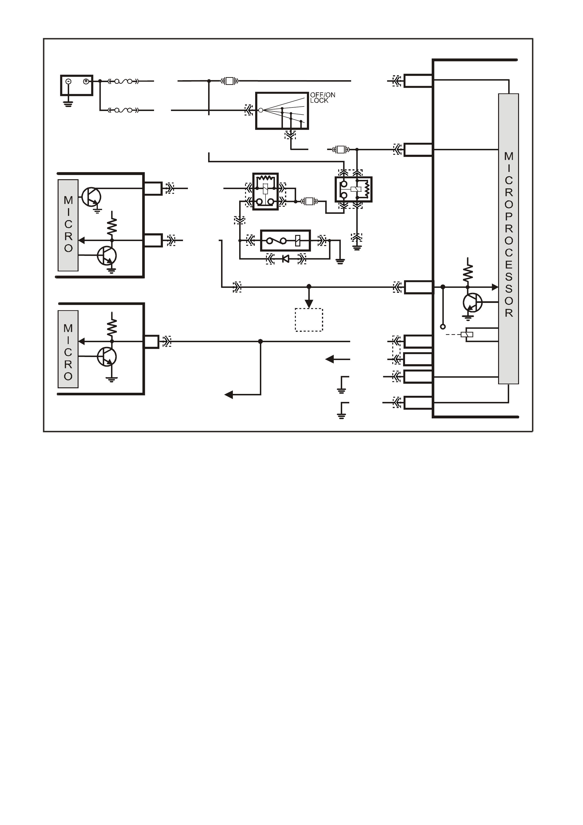
Figure 6C1-1-118 A/C Clutch Control With ECC
B/Y (155)
B/G (151)
ELECTRONIC EARTH
HIGH CURRENT
EARTH
A1/A5
B10/B11
E3/D13
E9/D3
E2/D2
E20/D6
A5/A6
LOC. E3
LOC. E5/E15
LOC. E3
LOC. E3
PCM
ECC
BCM
TO ABS/ETC
CONTROL MODULE
AND INSTRUMENTS
TO SRS
CONTROL
MODULE
TO
DLC
A3
6
SERIAL
DATA
A/C
ENABLE
SERIAL
DATA
SUPERVX018
5V
5V
SERIAL
DATA AUX .
R/B (1221)
G/W (1220)
G/W (1220)
SERIAL
DATA
MAIN
5V
BATTERY
FS
O/B (740)
(1040)
O/Y (479)
BATTERY MAIN POWER
FJ
R (2)
F14
F33
P/B
(39)
B/W
(152)
IGNITION ON
15a 15 50
30 ACC
IGN
START
IGNITION SWITCH
HIGH SERIES
BCM TERMINALS
NOM IN ATE D FIRS T
P (3)
A/C
COMPRESSOR
A/C RELAY
EFI
RELAY
F4
F31
LG/B (366)
YB176
YB165
YB174
YB163
YB175
YB164
YB175
YB164
YB44
YB194
YB188
YB87
YE112
YE105 YE114
YE105
YE120 YE120
YB44
YE101
YE39
YE39
YE101
YB176
YB165
YB175
YB164
YE101YE101YE101
YE101
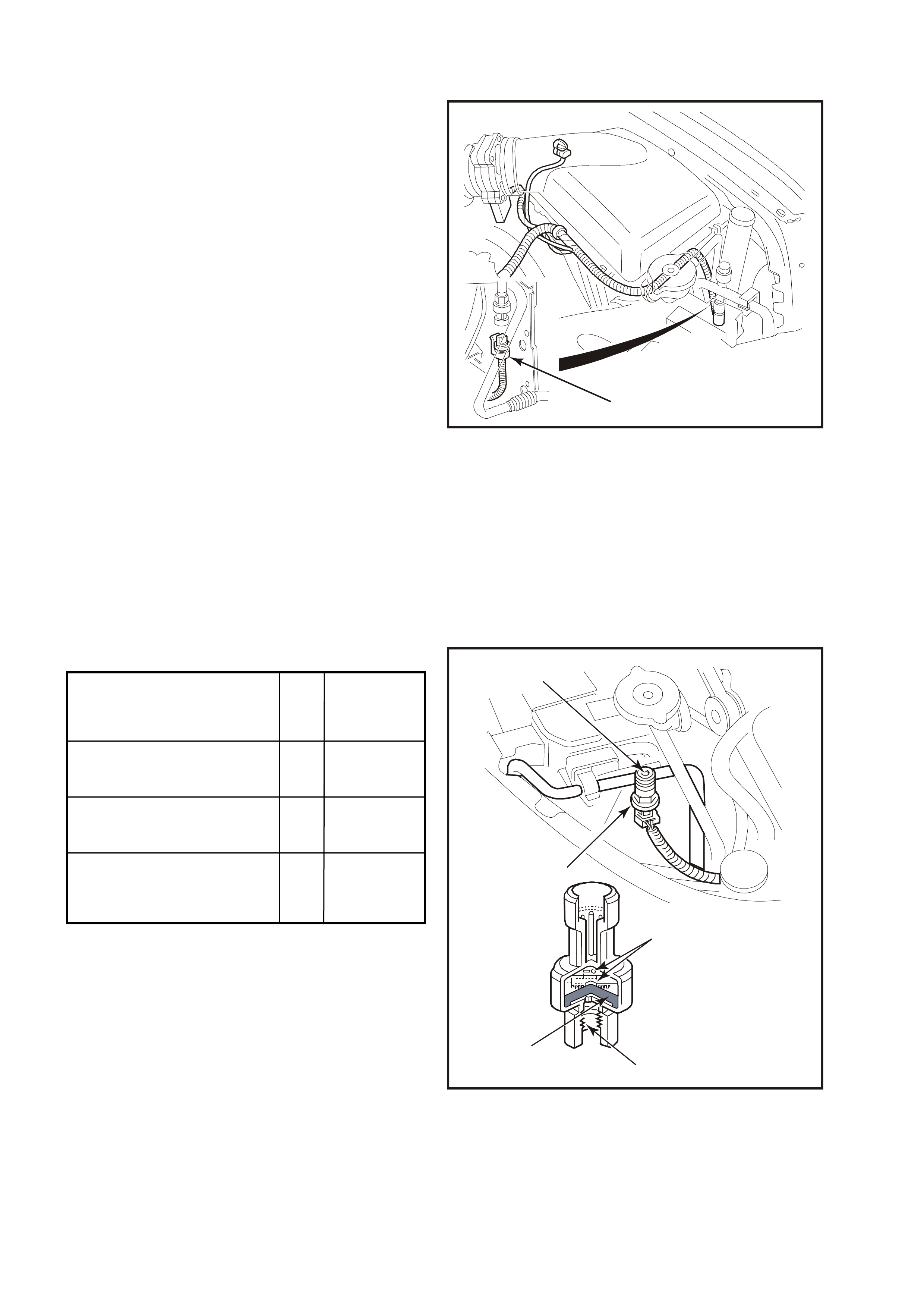
1.12 A/C REFRIGERANT PRESSURE SENSOR
The A/C Refrigerant Pressure Sensor is a sealed
gauge reference capacitive pressure sensor with
on board signal conditioning. It provides a 0 to five
volt output and requires a five volt regulated power
supply.
In operation the Sensor senses applied pressure
via the deflection of a two piece ceramic diaphragm
with one half being a parrel plate capacitor.
Changes in capacitance influenced by the
refrigerant pressure under the ceramic diaphragm
are converted to an analogue output by the
Sensors integral signal electronics.
The pressure Sensor’s electronics are on a flexible
circuit board contained in the upper section of the
Sensor. They provide linear calibration of the
capacitance signal from the ceramic sensing
diaphragm.
Benefits of using the pressure Sensor over a
normal type pressure switch is that the Sensor is
constantly monitoring pressures and sending
signals to the Powertrain Control Module (PCM).
The normal type pressure switch only has an upper
and lower cut-out point. The PCM will disengage
the A/C compressor at Low or High refrigerant
pressures and control the operation of the engine
cooling fans.
If there is a failure in the A/C Pressure Sensor
circuit DTC 96 will set.
1
4261
Figure 6C1-1-119 A/C Refrigerant Pressure Sensor Location
1. A/C Refrigerant Pressure Sensor Connector
32
1
4347
4
5
Figure 6C1-1-120 A/C Refrigerant Pressure Sensor
Cut-Away View
1. Signal Electronics.
2. Pressure Port.
3. Ceramic Diaphragm.
4. Pressure Sensor.
5. High Side Charge Port.
Low Pressure Compressor Cut OFF at 180kPa
ON at 240 kPa
High Pressure Compressor Cut OFF at 2900 kPa
ON at 2400 kPa
Engine Cooling Fan Low ON at 1500 kPa
Speed OFF at 1250 kPa
Engine Cooling Fan High ON at 2600 kPa
Speed OFF at 2300 kPa
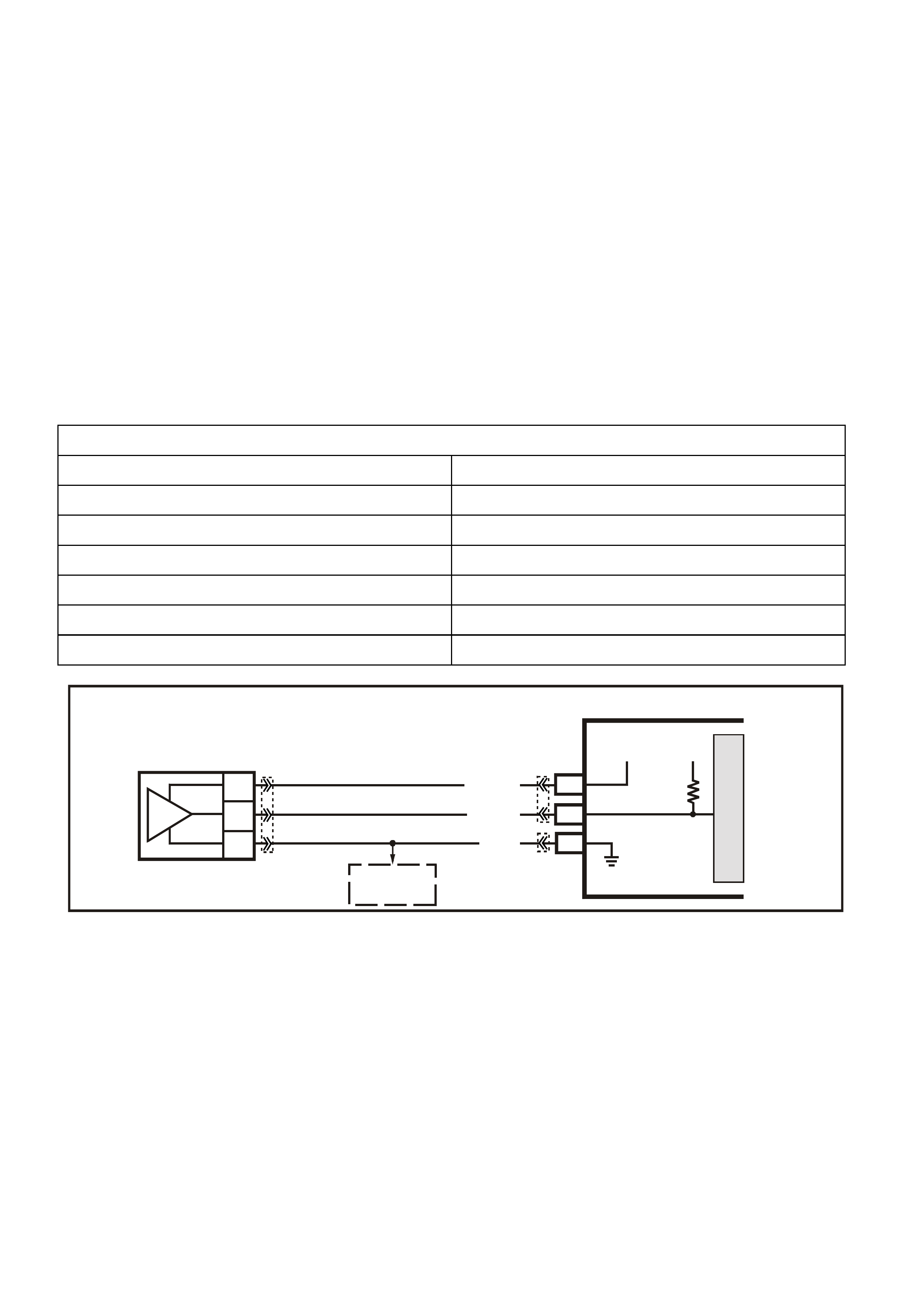
DTC 96 (A/C Pressure Sensor Circuit) will set if:
• Engine Coolant Temperature is below 119°C
• Intake Air Temperature is below 90°C
• Engine RPM is below 2000
• Engine has been running for less than 10 minutes
• A/C Refrigerant Pressure Sensor signal voltage is greater than 4.9 volts
• All of the above conditions are present for longer than 10 seconds.
• The PCM will not illuminate the Malfunction Indicator Lamp (MIL).
DEFAULT VALUES
W hen DTC 96 is set, the low speed cooling fan will operate for five seconds, then the high speed fan will turn ON
and remain on until the fault is removed.
RECOVERY
Recovery will occur on the next ignition cycle.
DTC 96 HISTORY DATA
PARAMETER PARAMETER
ENGINE SPEED ECT SENSOR
TIME FROM START IAT SENSOR
TIMES OCCURRED INTAKE AIR TEMPERATURE
IGNITION CYCLES BATTERY VOLTAGE
COOLANT TEMPERATURE REFERENCE VOLTS
REFERENCE VOLTS
Figure 6C1-1-121 A/C Refrigerant Pressure Sensor Circuit
SUPERVX001
PCM
M
I
C
R
O
B3
F16
C
B
A
A/C
PRESSURE
SENSOR
B7
SENSOR EARTH
A/C PRESSURE
SENSOR SIGNAL
REFERENCE
VOLTAGE
5V 5V
V/W (415)
B (46 9)
G/B (259)
TO
TFT AND
IAT SENSORS
YB188
YB194
YE113
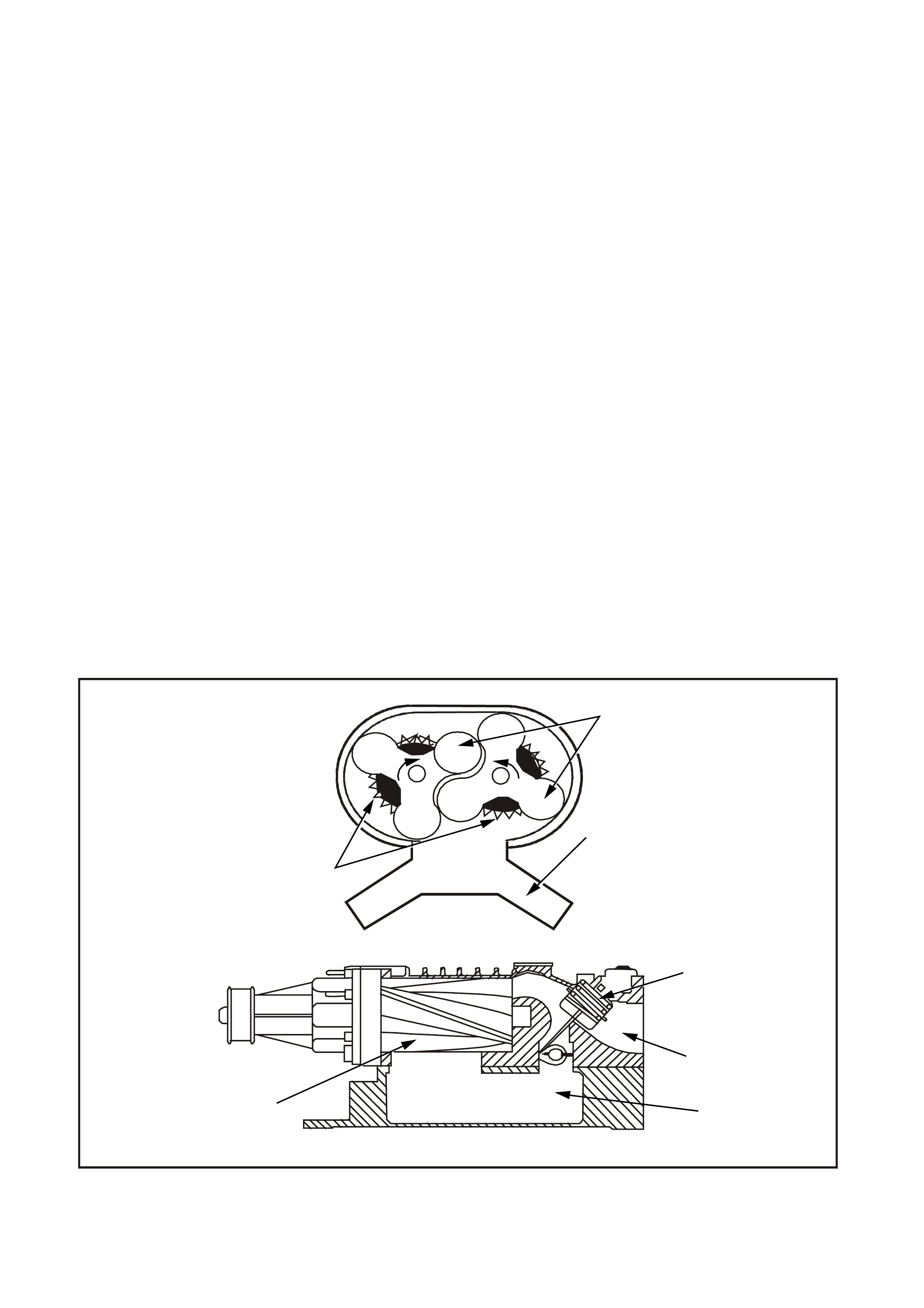
1.13 S UP ERCHARGER SYSTEM
DESCRIPTION
The supercharger is a positive displacement pump that consists of two counter-rotating rotors in housing with an
inlet port and an outlet port. The rotors are designed with three lobes and a helical twist. An air bypass circuit is
built into the housing. T he rotors in the s uperchar ger are des igned to run at a m inim al clearance, not in contact with
each other or the hous ing. The r otors ate tim ed to eac h other by a pair of precision spur gears , which are pressed
onto the r otor shafts . T he forward end of the rotors are held in position by deep groove ball bearings. T he back end
of the rotors are supported by sealed roller bearings.
The gears and ball bearings are lubricated by synthetic oil. The oil reservoir is self-contained in the supercharger
and does not rely on engine oil for lubrication.
The c over on the superc harger c ontains the input shaf t, which is s upported by two deep groove ball bear ings and is
coupled to the rotor drive gears. The pulley is pressed and keyed onto the input shaft. These bearings are
lubricated by the synthetic oil contained in the same reservoir as the gears and rotor bearings.
SUPERCHARGER OPERATION
The supercharger is designed to pump more air than the engine would normally use. This excess air creates a
boost pressure in the intake manifold. Maximum boost can range from 50 to 80 kPa (7 to 11 P.S.I.). Since the
superchar ger is a positive displacem ent pum p and is directly driven from the engine access ory drive system , boost
pressure is available at all driving conditions.
When boost is not desired, such as during idle and light throttle cruising, the excess air that the supercharger is
producing is routed through the bypass passage between the intake manifold and the supercharger inlet. This
bypass circuits regulated by a bypass valve which is similar to a throttle plate. The bypass valve is controlled by a
vacuum actuator, which is connected to the vacuum signal between the throttle and the supercharger inlet. Spring
force from the actuator holds the valve closed to create boost and vacuum pulls the valve open when the throttle
closes to decrease boost. The open bypass valve reduces pumping loss thereby increasing fuel efficiency.
The Boost Control Solenoid valve is an electronically controlled valve. This valve, controlled by the PCM,
determines whether pressure from the manifold is routed to the bypass actuator or closed off. The solenoid allows
pressure from the manifold to open the bypass valve and regulate boost pressure during specific driving conditions.
BOOST CONTROL
The boost control system regulates induction boost pr essur e during rapid deceler ation, under very high engine load
situations and anytime reverse gear is selected.
Figure 6C1-1-122 Supercharger Components
1. Lobes 2. Inlet Manifold
3. Boost Control Actuator and Valve 4. Throttle
5. Rotors 6. Timing Gears
4263
6
1
2
3
4
2
5
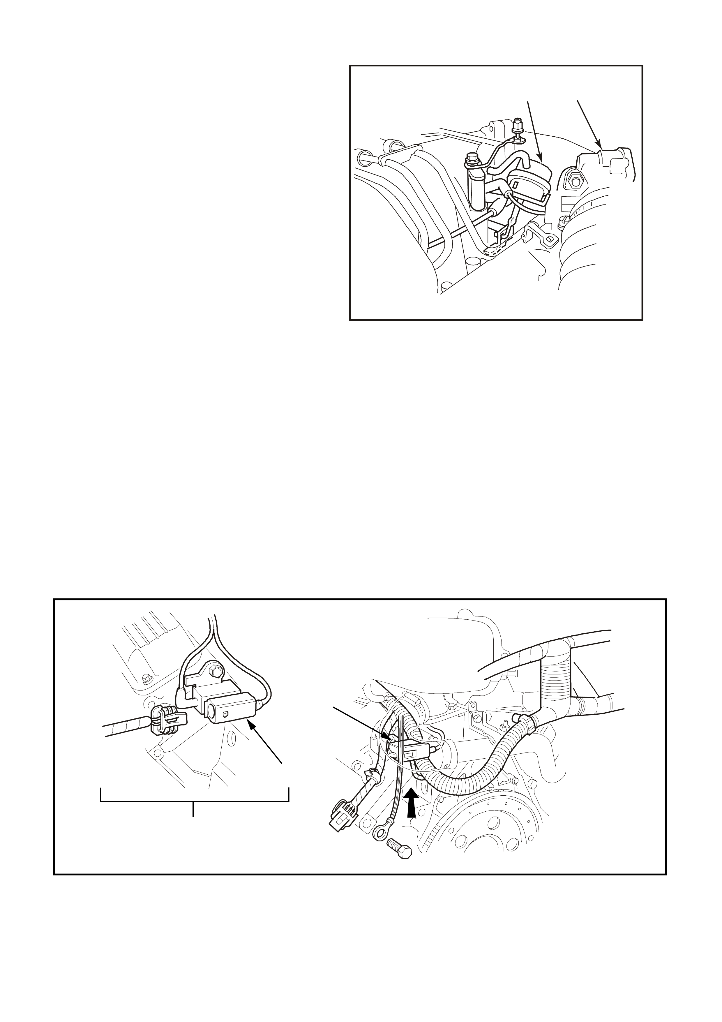
OPERATION
Under most conditions, the PCM commands the
Boost Control Solenoid to operate at 100% duty
cycle ("ON"), keeping the solenoid valve closed
and allowing only inlet vacuum to control the
position of the Bypass valve. At idle, full inlet
vacuum is applied to one side of the Bypass Valve
Actuator diaphragm counteracts spring tension to
hold the bypass valve open. As the engine load
increases, reduced vacuum acts upon the spring
tension in the Bypass Valve Actuator, causing the
bypass valve to close and increasing boost
pressur e. When reduced boost press ure is desired,
the PCM commands the Boost Control Solenoid to
operate at 0% duty cycle ("OFF"). This opens the
solenoid valve and allows boost pressure from the
intake manifold to counteract the spring tension in
the Bypass Valve Actuator, opening the bypass
valve and recirc ulation excess boost pressur e back
into the supercharger inlet. With reverse gear
selected, the PCM commands the Boost Control
Solenoid to operate at 0% duty cycle ("OFF") at all
times.
4264
12
Figure 6C1-1-123 Bypass Valve Actuator
1. Bypass Valve Actuator
2. Throttle Body
RESULTS OF INCORRECT OPERATION
An open Boost Control Solenoid driver circuit, ignition feed circuit, or Boost Control Solenoid valve stuck open
will cause reduced engine power, especially during wide open throttle operation.
The Boost Control Solenoid driver circuit shorted to earth, Boost Control Solenoid valve stuck closed or a
restric tion in the boost s ource or signal hoses will caus e full boost to be c omm anded at all tim es and a possible
overboost condition during high engine load situations.
A res triction in the vacuum signal hoses to the Bypass Valve Actuator or a stuck closed bypass valve will cause
a rough idle and reduced fuel economy.
DIAGNOSIS
The boost control system diagnosis is covered in Table 2-6. For further information on the Supercharger and
boost control system, and on vehicle service, refer to Supercharger Service Operation 3.24 of the VX Series
Service Information.
Figure 6C1-1-124 Boost Control Solenoid Location
1. Boost Control Solenoid 2. Rear View of Engine Assembly
3. Expanded ViewFigure 6C1-1-125 Boost Control
System (Bypass Closed)
1
1
3
4265
3
2
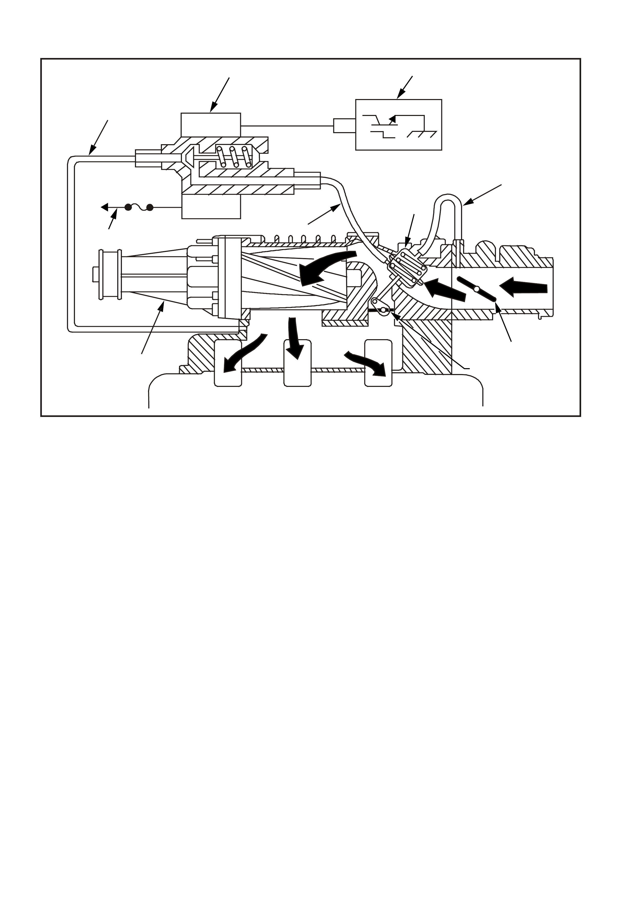
Figure 6C1-1-125 Boost Control System (Bypass Closed)
1. Boost Control Solenoid ON With Full Boost Commanded 2. PCM
3. Bypass Closed For Full Boost Condition 4. Bypass Valve Actuator
5. Boost Source Hose 6. Throttle Butterfly
7. Bypass Valve (Closed) 8. Intake Manifold
9. Boost Signal Hose 10. Supercharger
11. B+ Power Supply 12. Inlet Vacuum Signal
12
12
4
9
11
10
8
7
6
5
3
4266
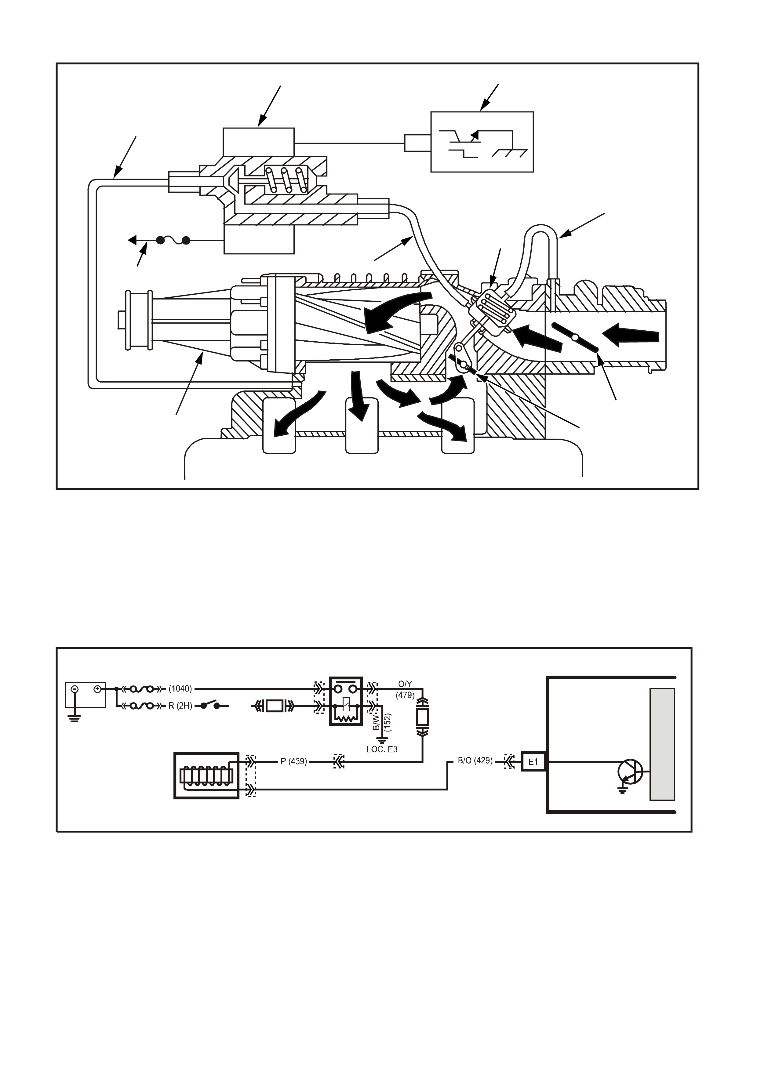
Figure 6C1-1-126 Boost Control System (Bypass Open)
1. Boost Control Solenoid OFF (Open) With Reduced Boost
Commanded, ON (Closed) At Idle 2. PCM
3. Bypass Open For Reduced Boost Condition 4. Bypass Valve Actuator
5. Boost Source Hose 6. Throttle Butterfly
7. Bypass Valve (Open) 8. Intake Manifold
9. Boost Signal Hose 10. Supercharger
11. B+ Power Supply 12. Inlet Vacuum Signal
Figure 6C1-1-127 Boost Control Solenoid Circuit
12
12
4
9
11
10
8
7
6
5
3
4267
BOOST CONTROL
SOLENOID
PCM
BOOST CONTROL
SOLENOID DRIVE
VXSC036
M
I
C
R
O
F33
F14
IGN SW
EFI
RELAY
BATTERY
FS
FJ
LOC. E1
P (3 ) P/B
(39)
YE111
YB194
YE115
YE39
YE39
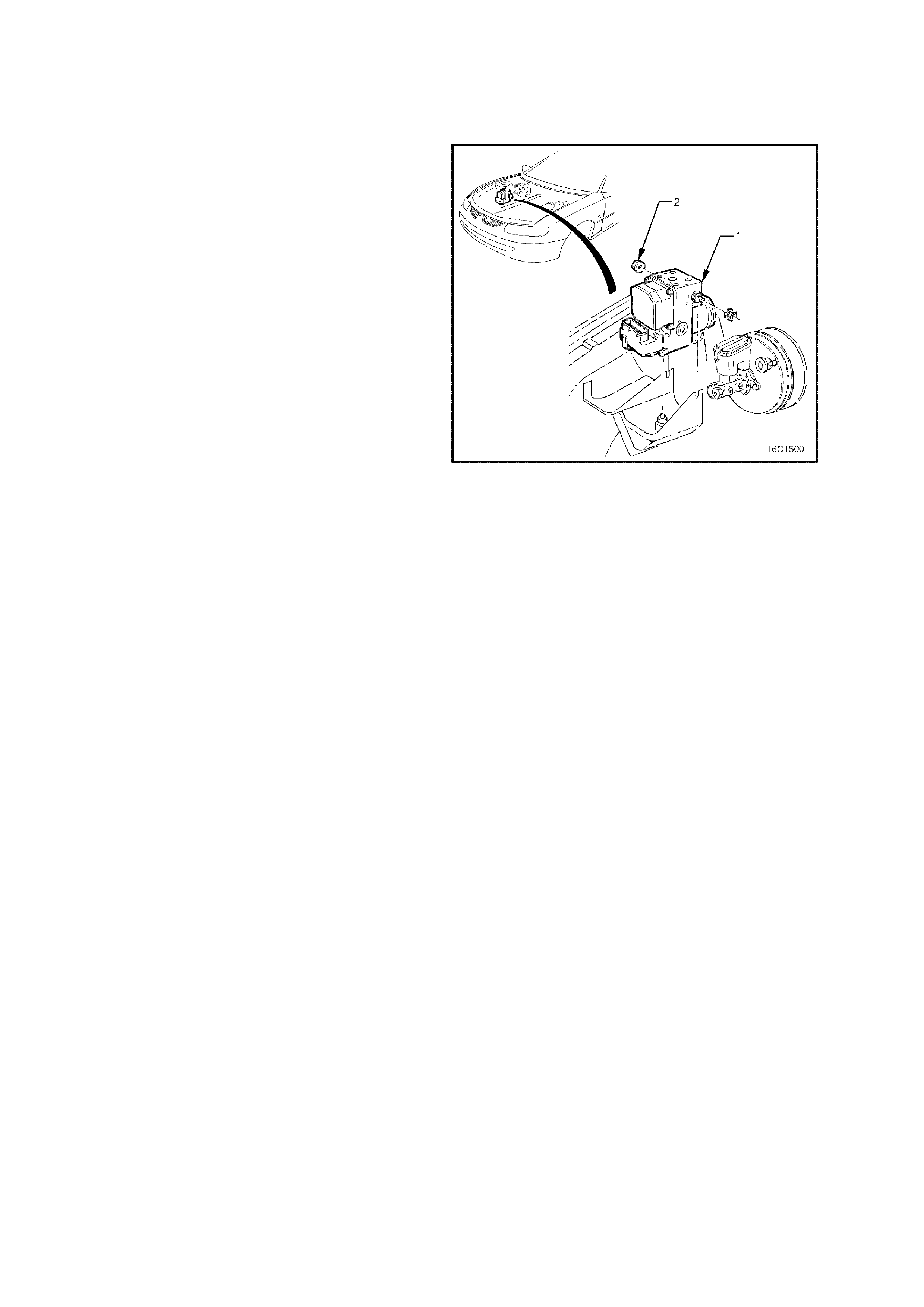
1.14 ELECTRONIC TRACTION CONTROL
PURPOSE
The Electronic Traction Control (ETC) system is
designed to maintain traction and reduce wheel
over spin at the drive wheels on slippery surfaces
during acceleration. This system is designed to
operate at all vehicle speeds and reduces wheel
slip by use of the engine torque management
system and Anti-Lock Brake (ABS) system.
The ABS/ETC m odule monitors both front and rear
wheel speeds through the wheel speed sensors. If
at any time during acceleration the ABS/ETC
module detects drive wheel slip, it will request (on
the Torque Request circuit) the Powertrain Control
Module (PCM) to bring ex cess engine torque into a
specific range. This is accomplished via two high
speed Pulse Width Modulated (PWM) circuits
between the ABS/ETC module and the PCM. This
is displayed on the scan tool as a N.m number.
The PCM will then adjust spark firing and air/fuel
ratio, and shutting "OFF" up to five (5) injectors (if
necessary), and report the modified torque value
(on the Torque Achieved circuit) back to the
ABS/ETC module in the form of a N.m number.
These N.m numbers should match closely when
traction control is being requested. Simultaneous
with engine torque management, the ABS/ETC
module will activate the ABS isolation valves, turn
on the ABS pump motor and s upply brake pres s ure
to the over spinning wheel(s).
The isolation valves isolate the front brake
hydraulic circuits from the master cylinder and rear
brake hydraulic circuits. Once the rear brake
hydraulic circuits are isolated, pressure can be
applied to the rear wheels without affecting any
other brake hydraulic circuits. The ABS/ETC
module turns on the ABS pump motor to apply
pressure, and begins cycling the ABS assembly's
inlet and outlet valves.
The inlet and outlet valve cycling aids in obtaining
maximum road surface traction in the same
manner as the Anti-Lock Brake mode. The
difference between Electronic Traction Control and
Anti-Lock Brake mode is that brake fluid pressure
is increased to lesson wheel spin (Traction Control
mode), rather then reduced to allow greater wheel
spin (Anti-Lock Brake mode).
If at any time during Traction Control mode, the
brakes are manually applied, the brake switch
signals the ABS/ETC module to disable Traction
Control mode and allow manual braking.
If there is a malfunction with the Torque Request
PWM circuit between the ABS/ETC module and
the PCM, DTC 95 will set. If there is a malfunction
with the Torque Achieved circuit between the
ABS/ETC module and the PCM, a ABS/ECT DTC
will set.
For further description on the Anti-Lock Brake
(ABS) system, and Electronic Traction
Control (ETC) system, Refer to
Section 12L ABS & ABS/ETC in VX Service
Information for information on ABS/ETC operation
and DTC diagnosis.
Figure 6C1-1-128 ABS/ETC Module Location
1. ABS/ETC Hydraulic Modulator
2. Nut (2 Places) 5.0 - 12.0 N.m
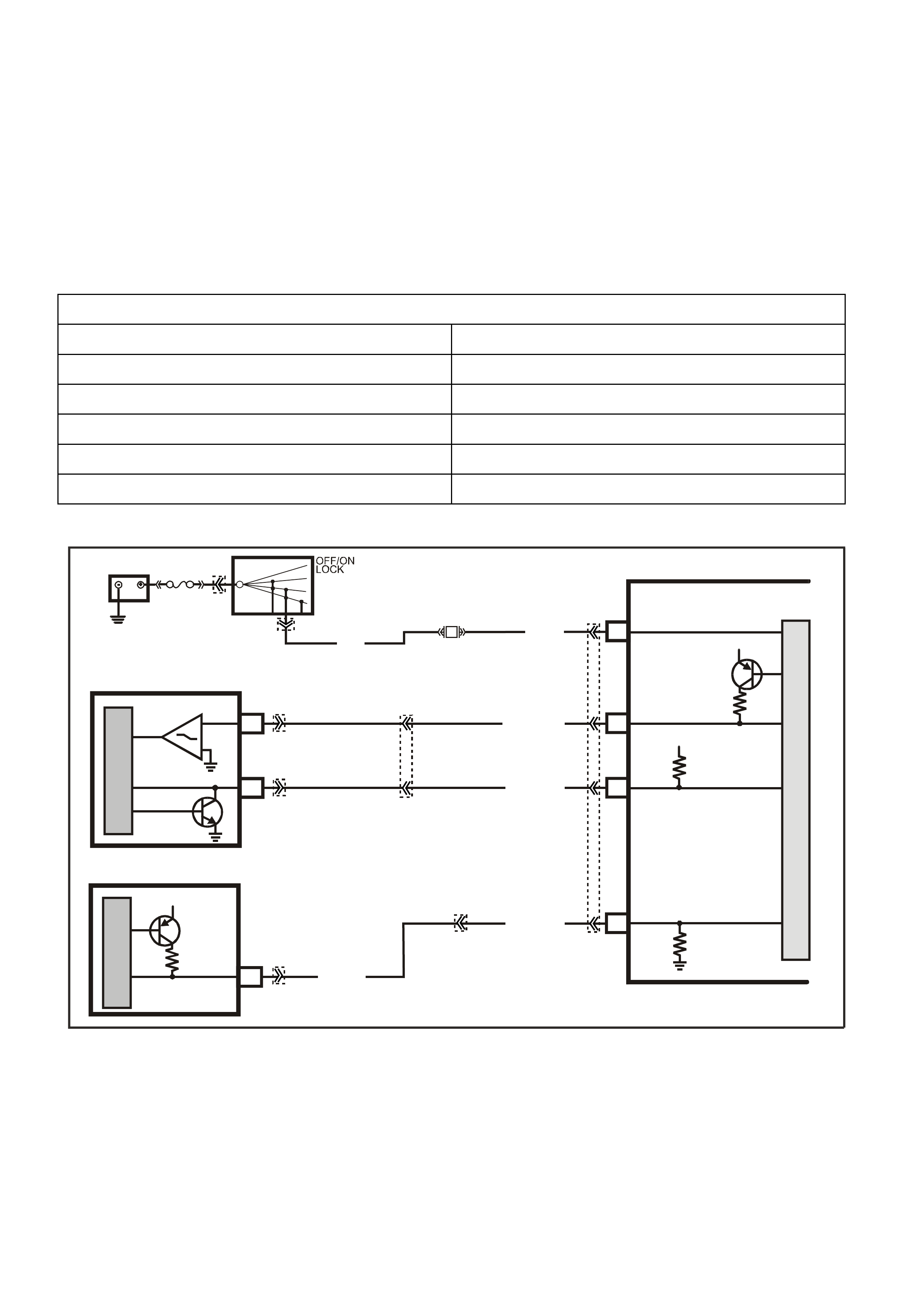
DTC 95 (Request Torque Out of Range) will set if:
• The engine is running.
• The PCM detects the incorrect voltage on the Requested Torque circuit.
• The PCM will not illuminate the Malfunction Indicator Lamp (MIL).
DEFAULT VALUES
When DTC 95 is set, traction control will be disabled and a corresponding DTC will be set in the ABS/ETS module.
RECOVERY
Recovery will occur when the DTC has been cleared and the ignition cycled OFF and ON.
DTC 95 HISTORY DATA
PARAMETER PARAMETER
ENGINE SPEED TFT
TIME FROM START THROTTLE ANGLE
TIMES OCCURRED VEHICLE SPEED
IGNITION CYCLES COMMANDED GEAR
COOLANT TEMPERATURE
Figure 6C1-1-129 Traction Control Circuit
12V
E
30
M
I
C
R
O
BR/R(121)
BR (121)
ENGINE SPEED
DIS
12V
12V
F7
C11
27
13
REQUESTED
TORQUE (M MR)
MMI ACTUAL
TORQUE (M MI)
O/W (1426)
M
I
C
R
O
B/W (1247)
M
I
C
R
O
BATTERY POWER
15
BATTERY
FJ
ABS/ETC
IGNITION
SWITCH
15a 15 50
30 ACC
IGN
START
F27
P (3)
SUPERVX024
PCM
R (855)
MMR
YE57
YB194
YB193
YB44
YB44
YB98
YE110
YE112

1.15 ABBREVIATIONS AND GLOSSARY OF TERMS
Abbreviations used in this Service Information are listed below in alphabetical order with an explanation of the
abbreviation.
AC - A LTERNATING CURRENT - A current with varying magnitude.
A/C - AIR CONDITIONING
A/F - AIR/FUEL (A/F RATIO)
ANALOG SIGNAL - An electrical signal that varies in voltage within a given parameter.
BAROMETRIC PRESSURE- Atmospheric pressure. May be called BARO, or barometric absolute pressure.
BATTERY - Stores chemical energy and converts it into electrical energy. Provide DC current for the vehicles
electrical systems.
CAMSHAFT POSITION SENSOR - The PCM uses this signal to determine the position of the No.1 piston in its
power stroke. This signal is used by the PCM to calculate sequential fuel injection mode of operation.
CAT. CONV. - CATALYTIC CONVERTER - A muffler-shaped device fitted in the exhaust system, between the
engine and the muffler. It is the primary "workhorse" of the emission control system, and the PCM's control of the
air/fuel ratio allows it to operate efficiently. It contains platinum, palladium and rhodium. It receives pollutants (HC,
CO, and NOx) emitted by the engine, and through a chemical reaction, converts these harmful pollutants into
harmless water vapour, carbon dioxide, and nitrogen. Maximum conversion efficiency of exhaust emissions is
achieved with precise control of the air/fuel ratio at 14.7-to-1.
CCP - CONVERTER CANISTER PURGE - A PCM controlled solenoid to purge the charcoal canister.
"CHECK POWERTRAIN" LAMP - W arning indicator with the outline of an engine. The "check powertrain lamp" is
located on the instrument panel, and is controlled by the PCM. "Check powertrain lam p" is illuminated by the PCM
when it detects a malfunction in the engine or transmission management system. "Check powertrain lamp" is on
and when the ignition is "ON" with the engine not running (bulb check).
CKT - CIRCUIT
CLOSED LOOP - A fuel contr ol sys tem m ode of oper ation that uses the signal f rom the ex haust oxygen sensor, in
order to control the air/fuel ratio precisely at a 14.7 to 1 ratio, allowing maximum efficiency of the catalytic
converter.
CO - CARBON MONOXIDE - One of the pollutants found in engine exhaust.
DC - DIRECT CURRENT - A current with a constant direction.
DTC - DIAGNOSTIC TROUBLE CODE - The PCM can detect malfunctions in the engine or transmission
management system. If a malfunction occurs, the PCM may turn on the "Check Powertrain" lamp, and a two-digit
code number will set in the PCM's memory. A diagnostic trouble code can be obtained from the PCM through the
"Check Powertrain" lamp, or with the Tech 2 scan tool. This DTC will indicate the area of the malfunction, and
properly following the service manual diagnostic procedures for the engine management system will locate the
source of the problem. NOTE: DTC 12 is used to verify that the PCM's diagnostic ability is operational.
DIAGNOSTIC "TEST" ENABLE TERMINAL - A terminal of the Data Link Connector (DLC) earthed to obtain a
Diagnostic Trouble Code by flashing out the MIL "Check Powertrain Lamp".
DIGITAL SIGNAL - An electrical signal that is either one of two states, "ON" or "OFF" with no in between.
DLC - DATA LINK CONNECTOR - The 16 pin connector used at the assembly plant to evaluate the control
module sy stem.
The c onnector is also us ed in service to f lash the Malfunction Indic ator Lam p (MIL) "Check Powertrain Lamp". T his
connector is also used by the Tech 2 scan tool to make system checks.
DLC DATA STREAM - An output of the PCM, initiated by the Tech 2 scan tool sending a command to the PCM.
This output is a digital c om puter language s ignal, used by assembly plant test equipm ent and the Te ch 2 sc an tool.
This signal is transmitted to the data link connector.
DRIVER - An electronic device, usually a power transistor, that operates like a switch; that is, it turns something
"ON" or "OFF."
DUTY CYCLE - The measurement of the length of time, in percentage, that a circuit is "ON" versus "OFF" when
compared with a 100% full ON/OFF time factor.
DVM (10 Meg.) - Digital voltmeter with 10 million ohms per volt impedance - used for voltage and resistance
measurement in electrical/electronic systems.
EECS - EVAPORATIVE EMISSIONS CONTROL SYSTEM - Used to prevent petrol vapours in the fuel tank from
entering the atmosphere. Stores the vapours in a storage canister, located in the engine compartment. Canister
contains activated charcoal, and the vapours are "purged" by engine vacuum during certain operating conditions.
EEPROM - ELECTRICALLY ERASABLE PROGRAMMABLE READ ONLY MEMORY - Type of read only
memory (ROM) that can be electrically programmed, erased and reprogrammed.
EMI OR ELECTRICAL NOISE - An unwanted signal interfering with another needed signal; like an electric razor
upsets a television picture, or driving under high voltage power lines upsets the AM radio in a vehicle.

EGR - EXHAUST GAS RECIRCULATION VALVE - A device that is used to lower Oxides of Nitrogen (NOx)
emission levels by recalculating exhaust gases back into the combustion chamber.
ENGINE COOLANT TEMPERATURE (ECT) SENSOR - Device that senses the engine coolant temperature, and
passes that information to the powertrain control module.
EPROM - ERASABLE PROGRAMMABLE READ ONLY MEMORY - Type of read only memory (ROM) that can
be erased with ultraviolet light and reprogrammed.
ESD - ELECTROSTATIC DISCHARGE - The discharge of static electricity, which has built up on an insulative
material.
FIELD SERVICE MODE - A PCM mode of operation that is used during service. It is operational when the engine
is running and the DLC diagnostic "test" enable terminal is earthed.
FUSE - A thin m etal strip that m elts through when excessive c urrent flows through it, thereby stopping current f low
and protecting a circuit from damage.
HC - HYDROCARBONS - One of the pollutants found in engine exhaust.
HIGH - A voltage more than a specific threshold such as earth or 0. In digital signals, high is "ON" and low is
"OFF".
HYSTERESIS - Movement that does not follow the same path as it entered an area as it exits.
IAC - IDLE AIR CONTROL - Installed in the throttle body unit and controlled by the PCM to regulate idle air flow,
and thus idle RPM.
IAT - INTAKE AIR TEM PERAT URE SENSOR - Senses intake m anifold inc oming air temper ature, and pas ses that
information to the PCM.
IDEAL M IXT URE - The air/f uel ratio that provides the bes t perfor mance, while m aintaining max imum conversion of
exhaust emissions, typically 14.7 to 1 on petrol engines.
IGN - IGNITION
INPUTS - Information from sensors (MAF, TPS, etc.) and switches (A/C request, etc.) used by the PCM to
determine how to control it's outputs.
INTERMITTENT - Oc curs now and then; not continuously. In electrical circuits , refers to oc casional open, short, or
earth.
I.C. - INSTRUMENT CLUSTER
LOW - A voltage less than a specif ic thres hold. Operates the sam e as an earth and m ay, or may not, be connected
to chassis earth.
M AF - M ASS AIR FLO W SENSOR - A devic e that monitors the amount of air f low coming in the engine intak e. The
MAF sensor sends a signal to the PCM.
MODE - A particular state of operation.
N.C. - NORMALLY CLOSED - Switch contacts that are connected, or together, when no outside forces
(temperature, pressure, position) are applied.
N.O. - NORMALLY OPEN - Switch contacts that are not connected, or not together, when no outside forces
(temperature, pressure, position) are applied.
NOx - NITROGEN OXIDES - One of the pollutants found in engine exhaust.
O2 - OXYGEN
OXYGEN SENSOR - Exhaust gas oxygen sensor, fitted in the exhaust manifold. Senses leftover oxygen after the
combustion process, and produces a very small electrical signal based on the amount of oxygen in the exhaust
gas, as compared to oxygen in the atmosphere.
OPEN LOOP - Describes PCM control of the fuel control system without use of oxygen sensor information.
OUTPUT - Functions, typically solenoids and relays that are controlled by the PCM.
PCM - POWERTRAIN CONTROL MODULE. A metal cased box (located in passenger compartment) containing
electronic circuitry that electrically monitors and controls the transmission system and emission systems of the
engine management system. It also turns "ON" the "Check Powertrain" lamp when a malfunction occurs in the
system.
PCV - POSITIVE CRANKCASE VENT ILAT ION - Method of reburning crankcase fumes, rather than passing them
directly into the atmosphere.
PFI - PORT FUEL INJECTIO N - Method of injecting f uel into the engine. Places a fuel inj ector at eac h inlet port of
a cylinder head, directly in front of the intake valve, mounted in the intake manifold.
PROM - PROGRAMMABLE READ ONLY MEMORY - an electronic term used to describe the engine calibration
unit. A plug-in memory unit that instructs the PCM how to operate for a particular vehicle.
PULSE WIDTH MODULATED (PWM)- a digital signal turned "ON" and "OFF'" for a percentage of available on-
plus-off cycle time, such as 30% "on" and 70% "off" would be called a 30% "ON" PWM signal.

QUAD DRIVER - A "chip" device in the PCM, capable of operating four separate outputs. Outputs can be either
"ON-OFF" or pulse width modulated.
RAM - RANDOM ACCESS MEMORY - Is the m ic roproces sors "scr atch pad". T he proces sor c an write into, or read
from this mem ory as needed. T his mem ory is volatile and needs a constant supply of voltage to be retained. If the
voltage is lost or removed, this memory is lost.
SERIAL DATA - Serial date is a series of rapidly changing voltage signals pulsed from high to low voltage. These
voltage signals are typically 5 volts (high) and 0 volts (low) and are transmitted through a wire often referred to as
the serial data line.
SEQUENTIAL FUEL INJECTION - A mode of injecting fuel into the engine on the intake stroke of each cylinder.
SOLENOID - An electromagnetic coil that creates a magnetic field when current flows through it and causes a
plunger or ball to move.
SUPPRESSION CAPACITORS - These capacitors are connected between the power and earth circuits of the
cooling fan motors. These capacitors are for controlling fan motor noise in the radio.
SWITCH - Opens and closes circuits, thereby stopping or allowing current flow.
TCC - TORQUE CONVERTER CLUTCH - PCM controlled solenoid in automatic transmission that positively
couples the transmission input shaft to the engine.
TECH 2 SCAN TOOL - A hand-held diagnostic tool, containing a microprocessor to interpret the PCM's DLC data
stream. A display panel displays the PCM input signals and output commands.
TP SENSOR - T HROT TL E POSIT ION SENSO R - Device that tells the PCM the c urr ent thr ottle position, and, when
it is moving, the rate of throttle opening / closing.
VACUUM, MANIFOLD - Vacuum source in the engine.
VACUUM , PORTED - Vac uum soured f rom a sm all "port" in the throttle body. W ith the throttle closed, there would
be no vacuum meas ured, because the port is on the air cleaner side of the throttle blade, and is exposed to engine
vacuum only after the throttle is open.
VSS - VEHICLE SPEED SENDER (Vehicles with Manual Transmission) - Pulse generator mounted in the
transm ission. T he speedom eter circuitr y contains an electronic divider c ircuit that sends a s ignal to the PCM and, if
so equipped, the body control module or trip computer.
VSS - VEHICLE SPEED SENSOR (Vehicles with Automatic Transmission) - A permanent magnet type sensor
which produces AC voltage which is sent to the PCM to determine vehicle speed.
UART - UNIVERSAL ASYNCHRONOUS RECEIVE AND TRANSMIT - A method of communicating between two
electronic devices.
WOT - WIDE OPEN TH ROTTLE