
SECTION 6C1-2A - DIAGNOSTIC TABLES -
V6 SUPERCHARGED ENGINE
IMPORTANT:
Before performing any Service Operation or other procedure described in this Section, refer to Section 00
CAUTIONS AND NOTES in VX Service Information for correct workshop practices with regards to safety
and/or property damage.
SYSTEM COMPONENT LOCATIONS
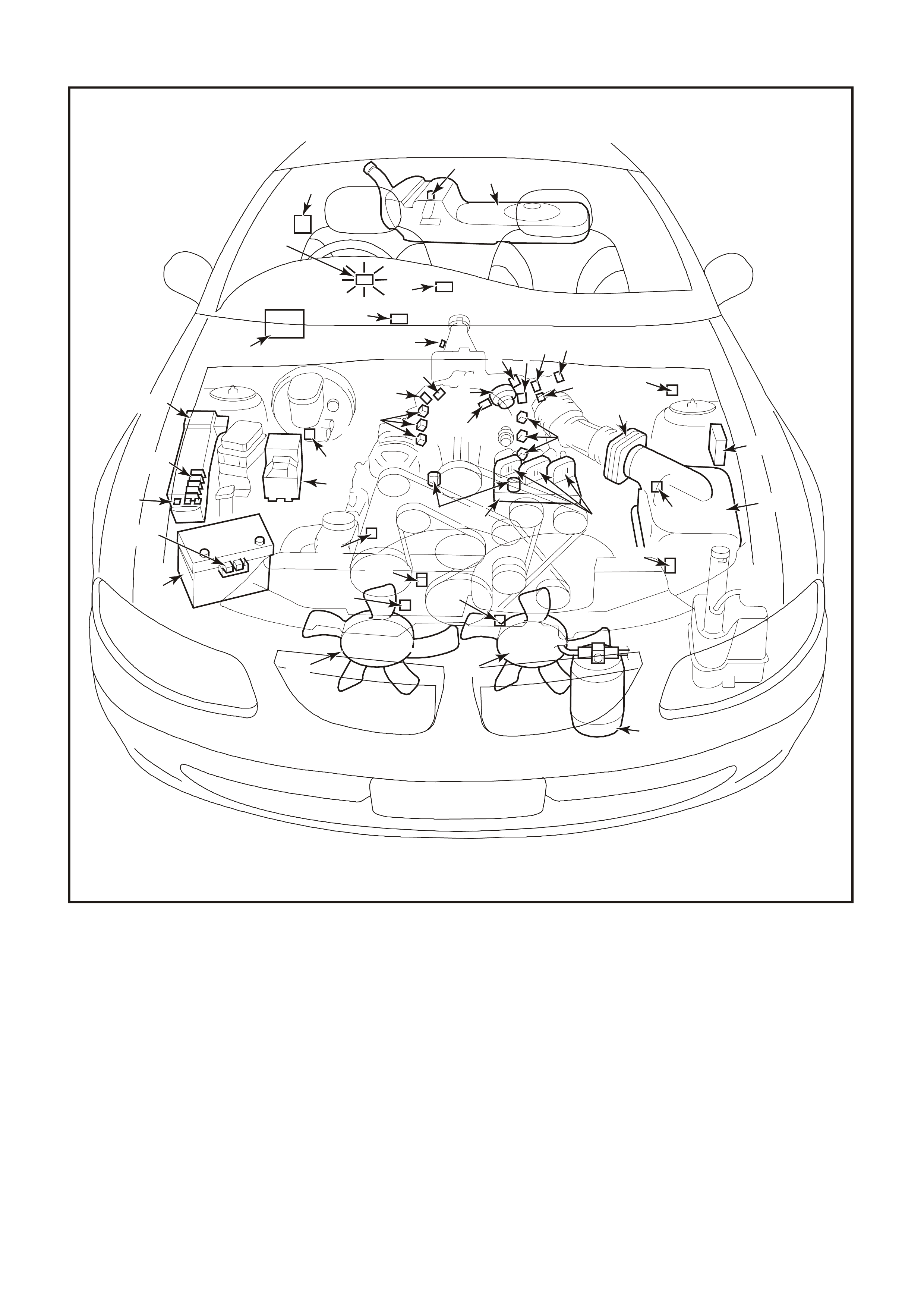
Figure 6C1-2A-1 Engine Compartment Component Locations Supercharged Engine
1. Fuel Pump (Inside Fuel Tank)
2. Fuel Tank
3. ECC In –Car Air Temperature Sensor
4. Fuel Pressure Regulator
5. Exhaust Gas Oxygen (O2S) Sensor (Two)
6. Engine Harness (PCM) Earth (Two Terminals)
7. Idle Air Control (IAC) Valve
8. Throttle Position (TP) Sensor
9. Mass Air Flow (MAF) Sensor
10. Tachometer Lead
11. Powertrain Control Module (PCM) (Inside
Vehicle)
12. Intake Air Temperature (IAT) Sensor
13. Fuel Injectors
14. Ignition Coils
15. Engine Coolant Temperature (ECT) Sensor
16. DIS Module
17. Air Cleaner
18. Crankshaft Position (CKP) Sensor
19. A/C Refrigerant Pressure Sensor
20. A/C Accumulator
21. Engine Cooling Fans (Two)
22. Crankshaft Position (CKP) Sensor
23. Oil Pressure Switch
24. Camshaft Position (CMP) Sensor
25. Detonation Knock Sensors (KS) (Two)
26. Engine Harness (PCM) Earth (Two Terminals)
27. Battery
28. Battery Harness Fusible Link Housing
29. Engine Compartment Relay Housing
30. Engine Compartment Fusible Link Housing
31. Engine Compartment Fuse/Relay Center
32. ABS
33. Brake Hydraulic Failure Switch
34. EVAP Canister Purge Solenoid
35. Diagnostic Link Connector (DLC)
36. BCM
37. Check Powertrain Malfunction Indicator Lamp(MIL)
38. Fuel Pump Control Module (Rear Compartment)
39. Vehicle Speed Sensor (VSS)
37
38
33
16
32
20
27
36
35
434
39
36
25
9
3
28
31
30
29
21 21
23
24
22
19
13
17
15
12
11
5
789
10
6
11
12 18
26
4195
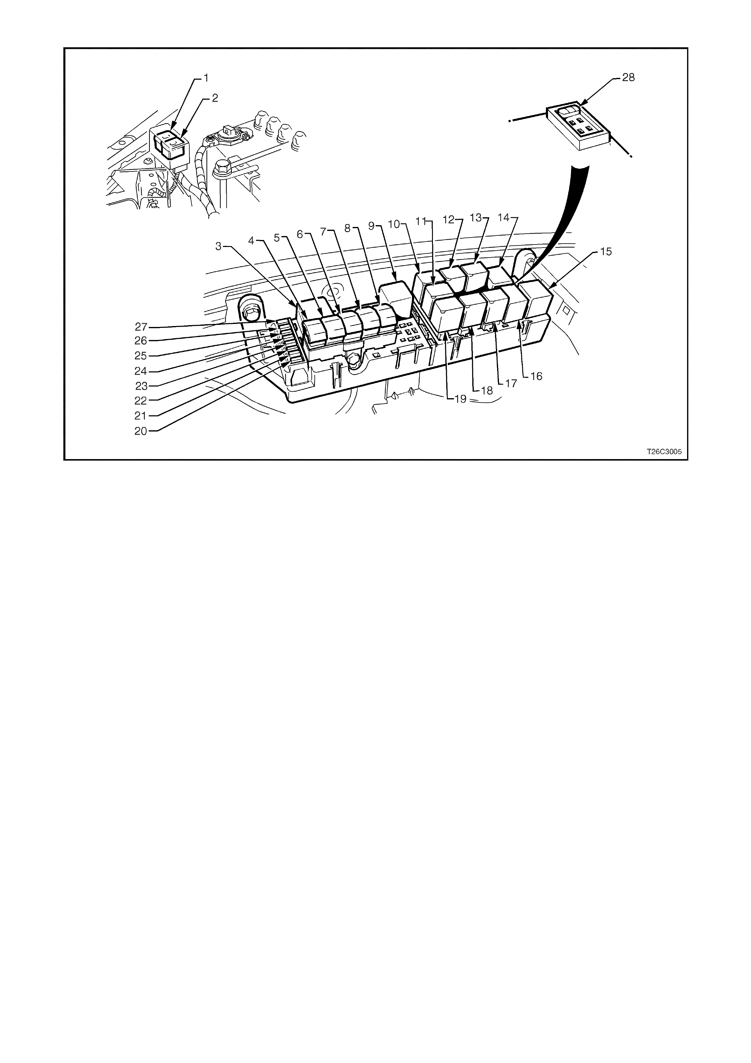
Figure 6C1-2A-2 Engine Compartment Relay Locations
1. Fan 1 Fusible Link FU 15. Start Relay
2. Fan 2 Fusible Link FT 16. Headlamp High Beam Relay
3. Engine Fan Relay (Low Speed) 17. Fuel Pump Relay
4. Lighting Fusible Link FQ 18. Front Wiper Relay
5. ABS Fusible Link FR 19. Headlamp Low Beam Relay
6. Engine Fusible Link FS 20. Injectors / Ignition Fuse F35
7. Main Fusible Link FJ 21. Injectors / Ignition Fuse F34
8. Blower Fusible Link FY 22. Engine Sensors Fuse F33
9. Engine Cont. (EFI) Relay 23. Automatic Transmission Fuse F32
10. Horn Relay 24. Engine Control / BCM Fuse F31
11. A/C Relay 25. LH Headlamp Fuse F30
12. Theft Horn Relay 26. RH Headlamp Fuse F29
13. Fog Lamp Relay 27. Fuel Pump Fuse F28
14. Engine Fan Relay (High Speed) 28. Throttle Relaxer Control Module Fuse F36
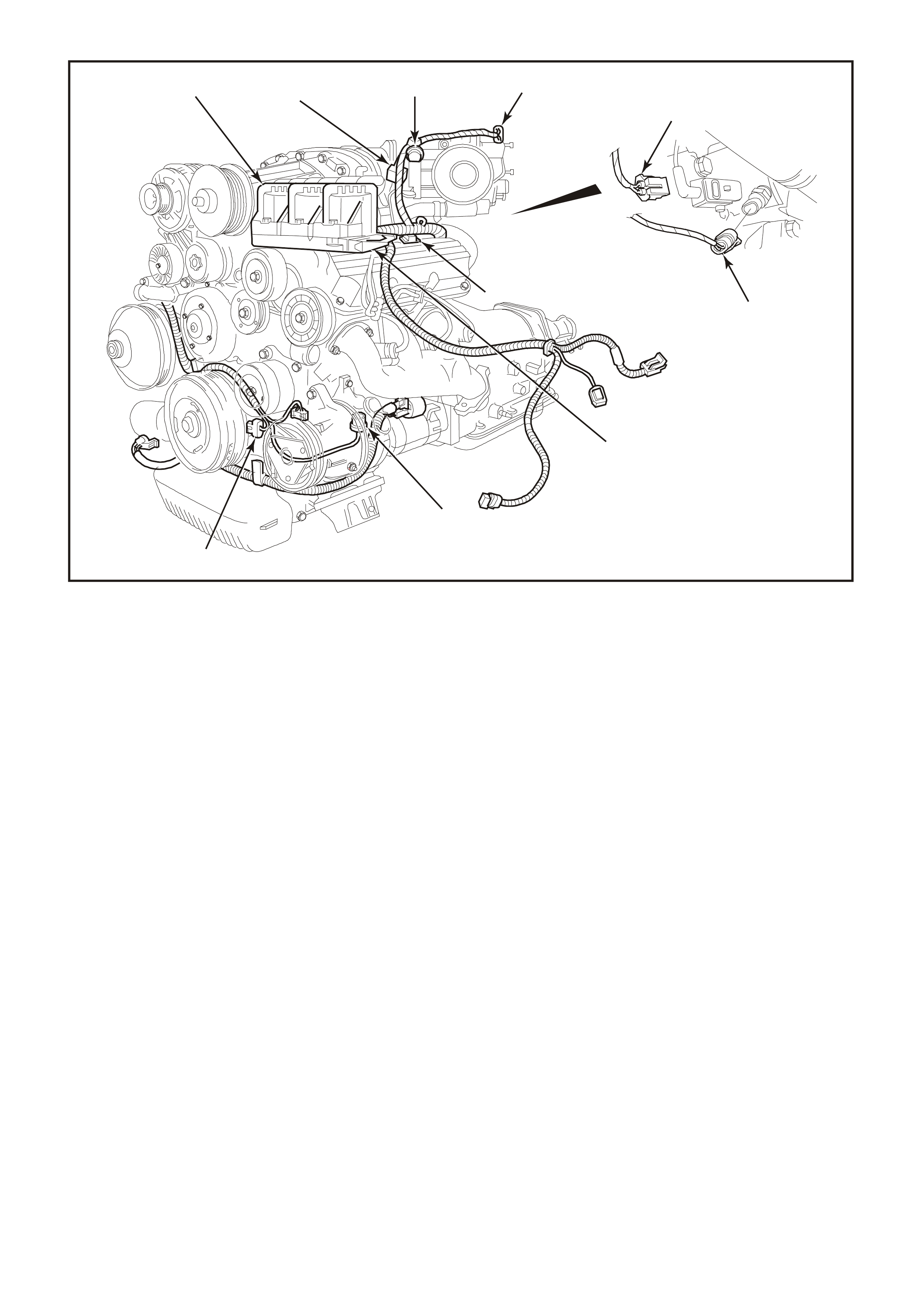
Figure 6C1-2A-3 Compartment Locations Supercharged Engine
1. Throttle Position (TP) Sensor
2. Idle Air Control Valve (IAC)
3. Anti-Boost Solenoid Valve
4. Engine Coolant Temperature (ECT) Sensor
5. Injectors
6. Direct Ignition System Module
7. L.H. Knock Sensor (KS)
8. Crankshaft Position (CKP) Sensor
9. Ignition Coils (3 places)
10. Bypass Valve Actuator
910
5
8
7
4197
6
12
3
4
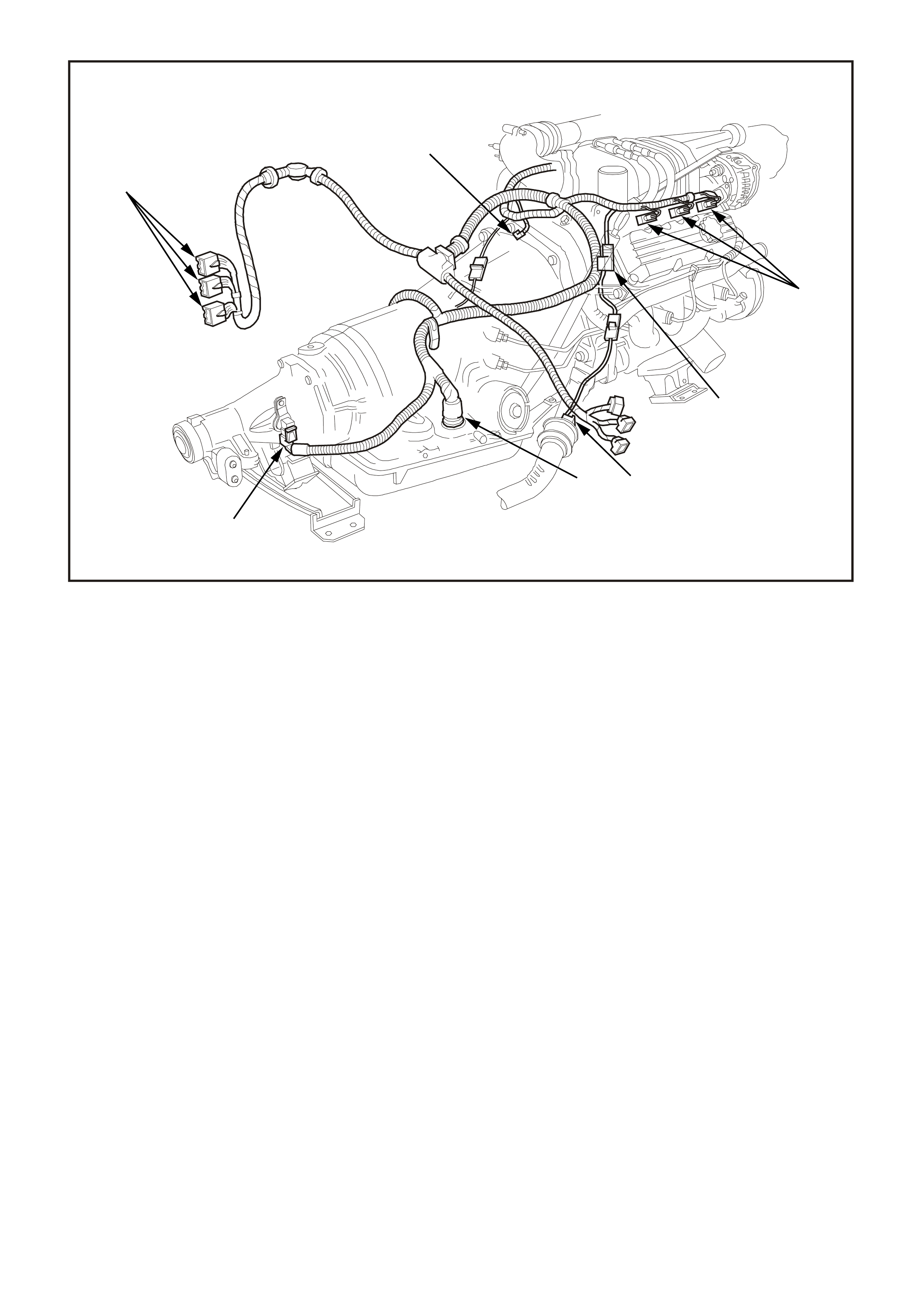
Figure 6C1-2A-4 Compartment Locations Supercharged Engine
1. Injectors
2. Canister Purge Solenoid
3. R.H. Exhaust Gas Oxygen (O2S) Sensor
4. Transmission Pass-Through Connector
5. Vehicle Speed Sensor (VSS) (Automatic Trans)
6. PCM Connectors
7. Engine Harness Earth
6
7
4199
1
2
3
4
5
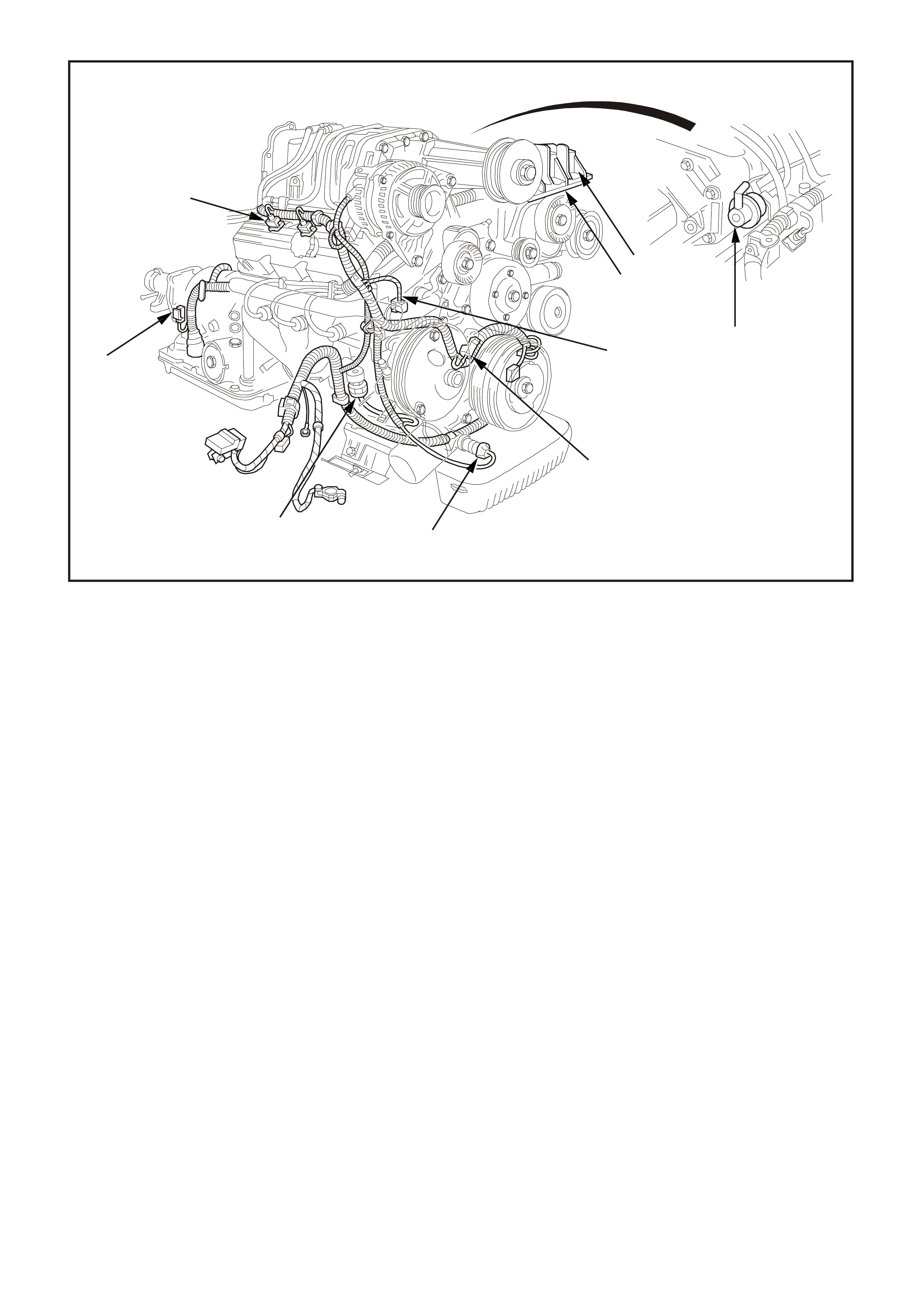
Figure 6C1-2A-5 Component Locations Supercharged Engine
1. Ignition Coils (3 places)
2. Fuel Pressure Regulator
3. Direct Ignition System Module
4. Engine Harness Earth
5. Camshaft Position (CMP) Sensor
6. Oil Pressure Switch
7. R.H. Knock Sensor (KS)
8. Vehicle Speed Sensor (VSS) Automatic Trans)
9. Injectors (3 places)
9
8
76
4201
5
4
31
2
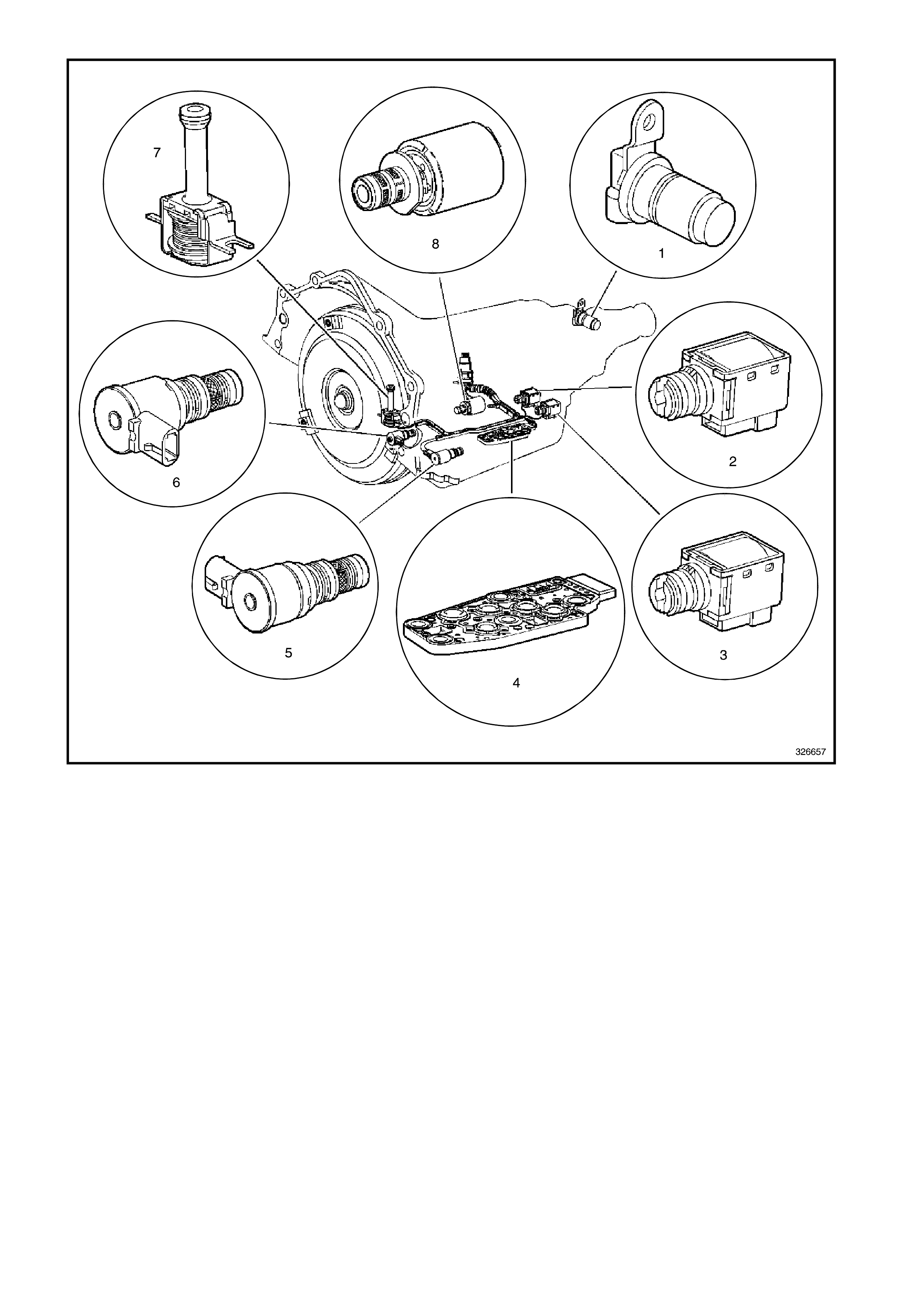
Figure 6C1-2A-6 Compartment Locations Supercharged Engine
1. Vehicle Speed Sensor
2. Shift Solenoid B (SS) Valve
3. Shift Solenoid A (SS) Valve
4. Automatic Transmission Fluid Pressure (TFP) Manual Valve Position Switch
5. Shift Solenoid (SS) Valve Assembly
6. Torque Converter Clutch Pulse Width Modulation (TCC PWM) Solenoid Valve
7. Torque Converter Clutch (TCC) Solenoid Valve
8. Pressure Control Solenoid (PCS) Valve
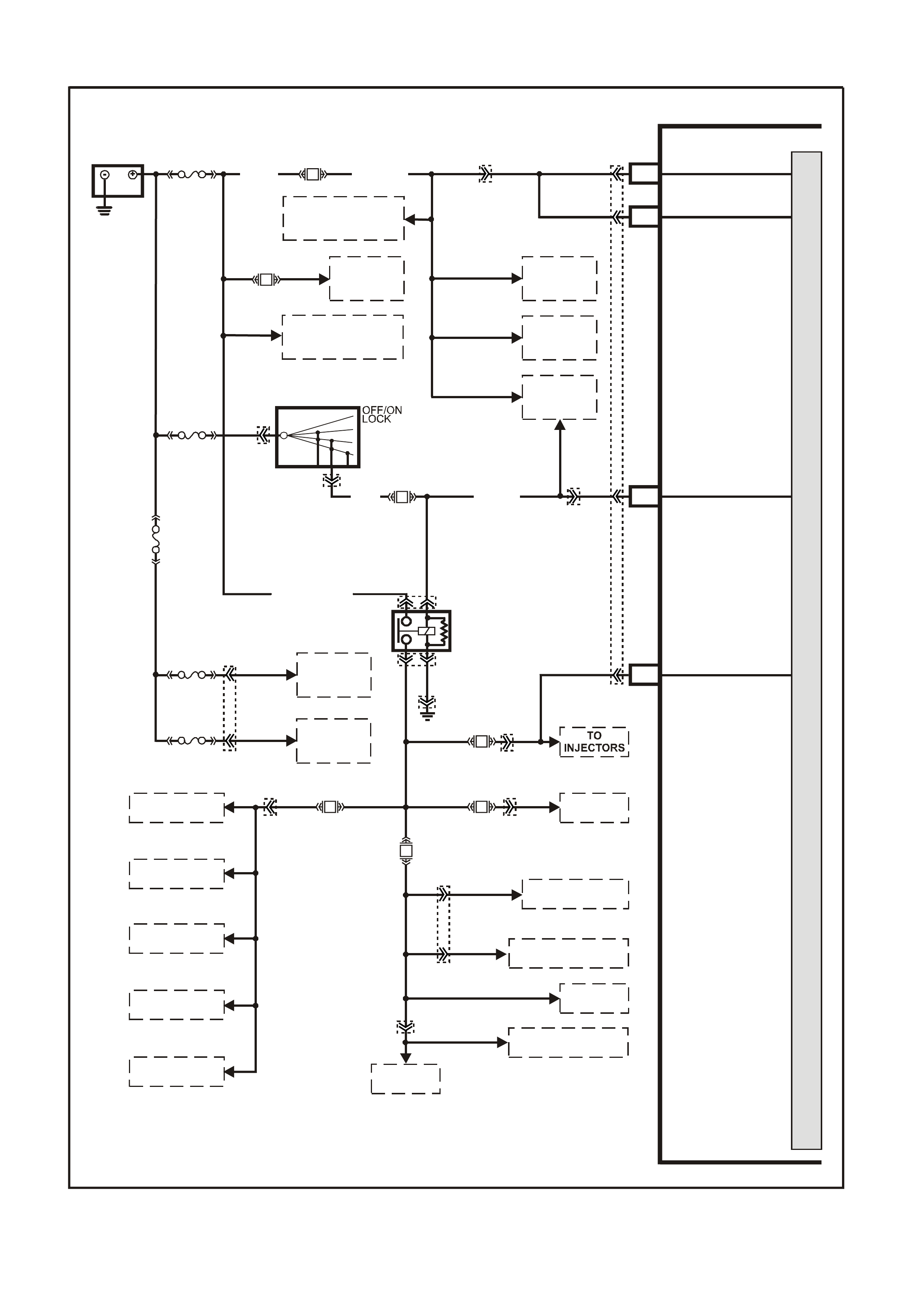
PCM WIRING DIAGRAMS
Figure 6C1-2A-7 V6 PCM Wiring Diagram (1 of 8) Fuse Power Circuits
VXSC054
PCM
M
I
C
R
O
P
R
O
C
E
S
S
O
R
BATTERY
LOC . E1
FS
(1040)
O
(740)
O
(740)
O/B (740) B8
A8
BATTERY
BATTERY
F31
A4
B12
IGNITION
IN JE C TOR VOLTAG E
MONITOR LINE
FJ
BLUE
FUSIBLE
LINK
FU
FT
R
(2H)
15a 15 50
30 ACC
IGN
START
IGNITION SWITCH
P (3) F14
P
(39)
P/B (39)
EFI REL AY
O/Y
(479)
LOC. E3
R
(481)
LG
(482)
P
(439)
P/BLU
(339)
O/BLU
(204)
12V BUS (1040)
R
(203)
O/B
(208)
B/W
(152)
F34
F35
F33
F32
TO DIS
MODULE
TO A/C
RELAY
TO MAF
SENSOR
TO CANISTER
PURGE SOLENOID
TO BOOST CONTROL
SOLENOID
TO HEATED
OXYGEN SENSORS
TO 3-2
SOLENOID
TO 1-2 SHIFT
SOL ENOID A
TO 2-3 SHIFT
SOL ENOID B
TO TCC ENABLE
SOLENOID
TO TCC PWM
SOLENOID
F28
TO
FUEL PUMP
RELAY
TO
HIGH SPEED
COOLING FAN RELAY
TO
LOW SPEED
COOLING FAN RELAY
TO
DLC
TO REMOTE
RECEIVER
MODULE
TO BODY
CONTROL
MODULE
ENGINE
COOLING
FAN 2
ENGINE
COOLING
FAN 1
YE112
YE110
YE111
YE111
YE111
YE114
YE39
YE39
YE112
YB44
YB44
YB188
YB188
YE111
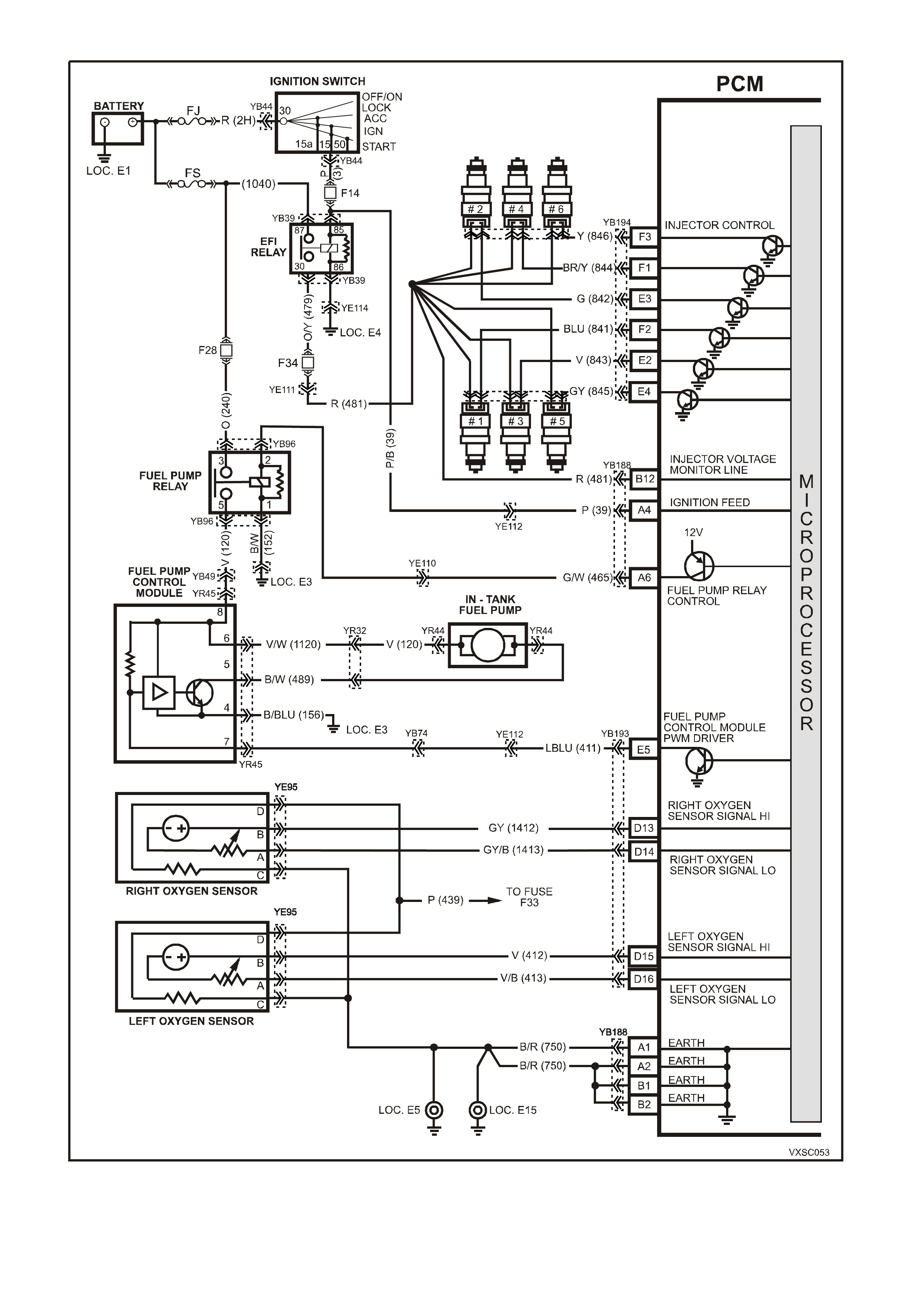
Figure 6C1-2A-8 V6 PCM Wiring Diagram (2 of 8) Supercharged Engine Application
YE22
YE22
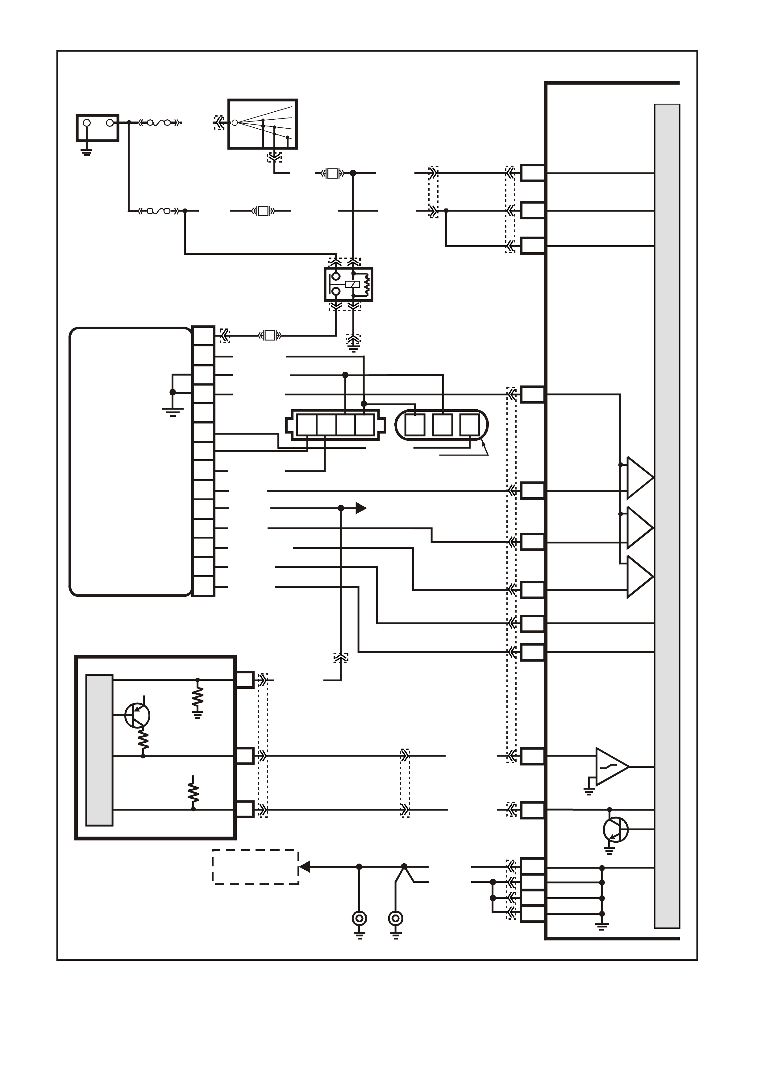
Figure 6C1-2A-9 V6 PCM Wiring Diagram (3 of 8 ) Supercharged Engine Application
VXSC051
+-
BATTERY
LOC . E 1
FS
(1040)
12V BUS (1040)
O (740)O/B (740)
B8
A8
BATTERY
BATTERY
F31
A1
B2
A2
B1
LOC. E15LOC. E5
EARTH
EARTH
EARTH
EARTH
B/R (750)
B/R (750)
PCM
A4 IGNITION
FJ
R (2H)
15a 15 50
30 OFF/ON
LOCK
ACC
IGN
START
IGNITION SWITCH
P (3)
F14 P/ B (39) P
O
(39)
(740)
O
(740)
D11
D3
D4
D12
D9
D10
CAM
SENSOR
CONNECTOR
module power supply - in
sensor power supply - out
cam signal - in
3x crank sensor - in
18x crank sensor - in
cam signal - out
tacho signal - out
crankshaft reference - out
18X cranksignal - out
bypass control
EST signal -in
P
N
M
L
K
J
H
G
F
E
D
C
B
A
DIS
MODULE
ABCD CBA
W/B (644)
GY/R (645)
B/R (453)
CRANK
SENSOR
CONN
L BLU/W
(646) BR (633)
BLU/Y (643)
BR (121)
TO INSTRUMENT CLUSTER
TO
HEATED OXYGEN
SENSORS
TERMINAL 18 (TACHOMETER)
B (63 0)
V (43 0)
L BLU/B (647)
T/B (4 24)
EFI RELAY
O/Y
(479) LOC. E3
LG
(482)
B/W
(152)
W (423)
CRANKSHAFT
REFERENCE LO
CAMSHAFT
POSITION
SENSOR
SIGNAL
CRANKSHAFT
REFERENCE HI
CRANKSHAFT
18X SIGNAL
BYPASS CONTROL
EST OUTPUT
IC
IC
IC
F7
C11
A
CT UA L TO RQ UE
O/W (1426)
B/W (14 27)
30
ENGINE SPEED
12V
12V
27
13
REQUESTED
TORQUE (M MR)
ACTUAL
TORQUE (M MI)
M
I
C
R
O
ABS/ETC
CONTROL MODULE
DIS
CONTROL MODULE
REQUESTED
TORQUE
BR/R(121)
M
I
C
R
O
P
R
O
C
E
S
S
O
R
F35
YB188YE112
YE39
YE39
YE114
YE111
YB44
YE34 YE63
YE110
YB98 YE112
YE57
YB194
YB188
YB193
YB44
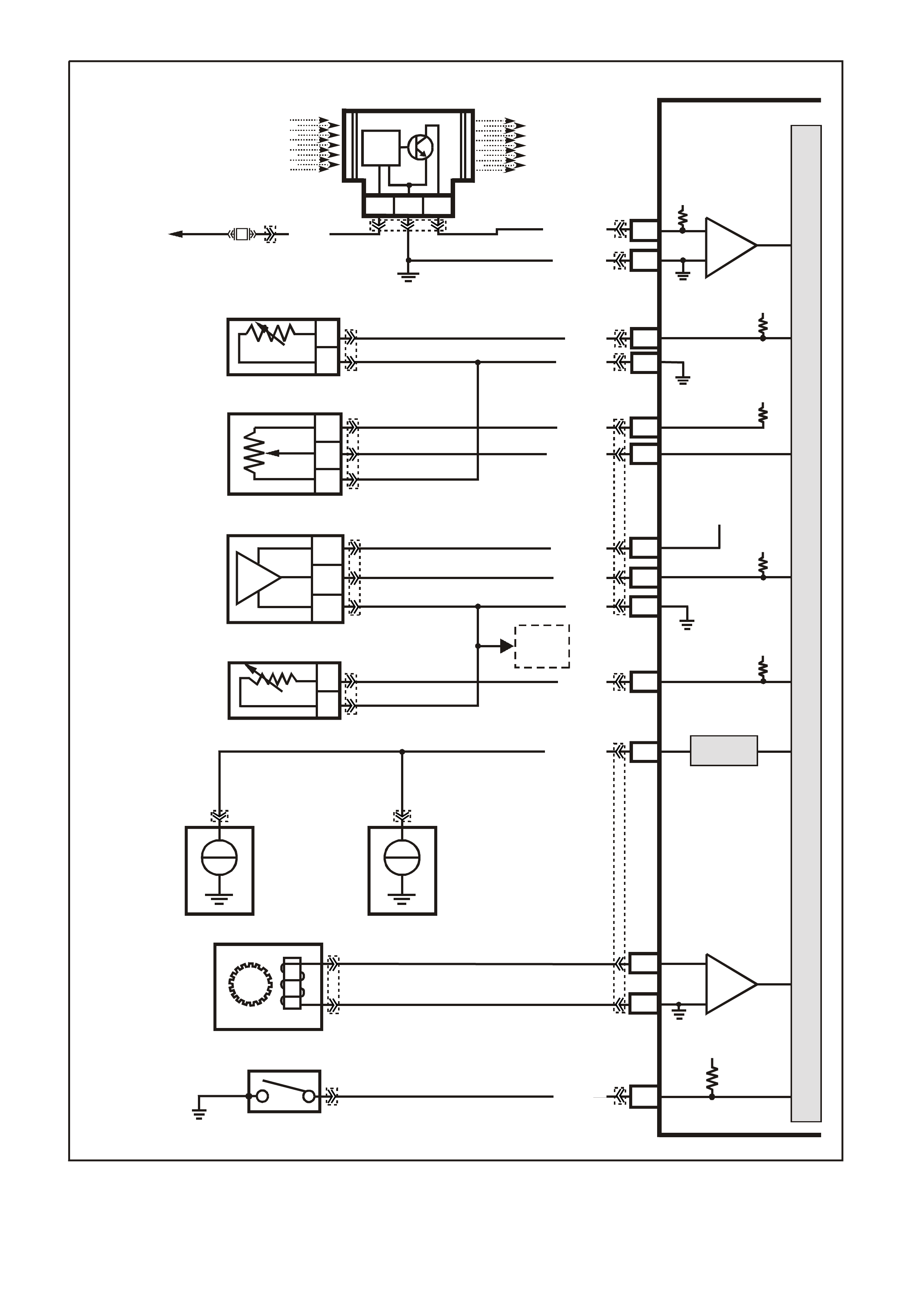
Figure 6C1-2A-10 V6 PCM Wiring Diagram (4 of 8) Supercharged Engine Application
VXSC052
PCM
IC
CIRCUIT
MASS AIR FLOW SENSOR
D1
A1
CBA
AIR FLOW
FROM
AIR FILTER
AIR FLOW
TO
THROTTLE BODY
EFI
RELAY
P (43 9)
ENGINE EARTH
MASS AIR FLOW
INP U T SIG NAL
EARTH
SENSOR EARTH
ECT SENSOR
SIGNAL
IC
B/R (750)
LOC. E5/E15
BR/W (792)
E16
B5
B
A
ENGINE COOLANT
TEMPERATURE SENSOR
Y (41 0)
B/Y (452)
5V
5V
TP SENSOR SIGNAL
TP SENSO R
REFERENCE
VOLTAGE
5V
A7
B11
A
C
B
THROTTLE
POSITION SENSOR
GY (416)
BLU (417)
C
B
A
A/C PRESSURE
SENSOR
F16
SENSOR
EARTH
5V
B3
B7 A/C PRESSURE
SENSOR SIGNAL
5V REFERENCE
VOLTAGE
V/W (415)
B (46 9)
G/B (259)
5V
B4
B
A
INTAKE AIR
TEMPERATURE SENSOR
TO
TFT
SENSOR
IAT SENSOR SIGNAL
BR (47 2 )
SNEF
KNOCK SENSOR
SIGNAL
C12
RIGHT
HAND
KNOCK
SENSOR
LEFT
HAND
KNOCK
SENSOR
+
-
+
-
W/R (815)
OIL PRESSURE
SWITCH
OIL PRESSURE
SWITCH
12V
E12
BLU (31)
F33
C6
D5
VEHICLE SPEED
SENSOR
IC
M
I
C
R
O
P
R
O
C
E
S
S
O
R
BR
(832)
(MAN)
T
(832)
(AUTO)
BLU/W
(831)
(AUTO)
BLU
(831)
(MAN)
YB193
YB188
YB188
YB188
YB188
YB194
YB193
YB194
YB132 (AUTO)
YB195 (MAN)
YE33
YE3YE3
YE23
YE113
YE30
YE106
YE111 YE100
YB194
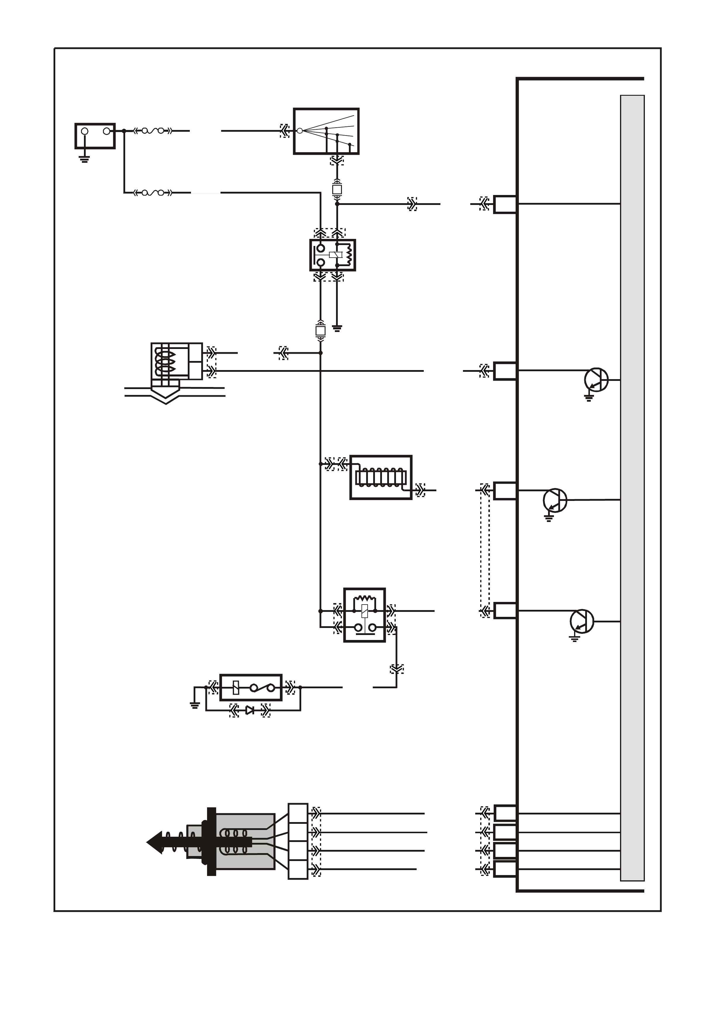
Figure 6C1-2A-11 V6 PCM Wiring Diagram (5 of 8) Supercharged Engine Application
VXSC055
PCM
A
B
CANISTER PURGE
SOLENOID V ALVE
CANISTER PURGE
IGNITION
C4
E1
A4
G/Y (428)
P (39 )
C10
C7
C8
C9
LG/W (443)
A
B
C
D
IAC VALVE
LG/B (444)
LBLU (441)
LBLU/B (442)
IAC COIL B HI
IAC COIL B LO
IAC COIL A HI
IAC COIL A LO
M
I
C
R
O
P
R
O
C
E
S
S
O
R
+-
BATTERY
FS (1040)
FJ R (2H)
F14
LOC. E3
F33
P/B
(39)
15a 15 50
30 OFF/ON
LOCK
ACC
IGN
START
IGNITION SWITCH
P
(3)
O/Y
(479)
B/W
(152)
LOC. E5/E15
A/C
COMPRESSOR
A/C RELAY
F4
LG/B (366)
1
2
35
G (59)
A/C CLUTCH ENABLE
EFI
RELAY
LOC. E1
P (43 9)
BOOST CONTROL
SOLENOID DRIVE
BOOST
CONTROL
SOLENOID
B/O (429)
YB193YE36
YE120 YE120
YE105
YE101
YE111
YE101
YE115
YE115
YE111
YE111YE99
YE39
YE39
YE112 YB188
YB44
YB44
YB194
YB193
YE105
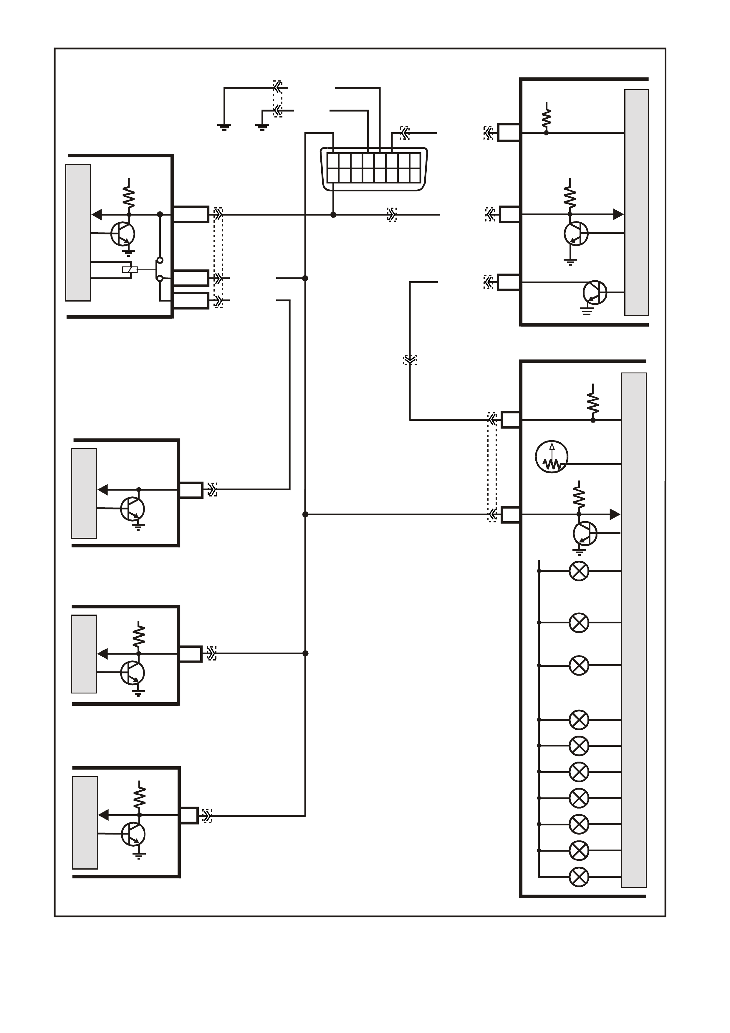
Figure 6C1-2A-12 V6 PCM Wiring Diagram (6 of 8) Supercharged Engine Application
VXSC057
PCM
A3 SERIAL
DATA
MAIN
5V
LOC. E3
BCM
E2/D2
E9/D3
E3/D13
M
I
C
R
O
SERIAL
DATA
MAIN
SERIAL
DATA AUX.
5V
G/W (1220)
W/G (1220)
HIGH SERIES
BCM TERMINALS
NOMINATED FIRST
DATA
LINK
CONNECTOR
12345678
910111213141516
5V
F14
DIAGNOSTIC
ENABLE
W/B (451)
B/Y (155)
B (150)
R/B (1221)
INSTRUMENTS
ABS/ETC
11
SERIAL
DATA
5V
12
17
SERIAL
DATA
5V
M
I
C
R
O
CHECK
POWERTRAIN
LAMP
OIL PRESSURE
WARNING LAMP
POWER
EC ONOMY LAMP
R
12V
P
N
D
3
1
2
SRS
ECC
9
6
M
I
C
R
O
M
I
C
R
O
SERIAL
DATA
SERIAL
DATA
5V
12V IGN
VEHICLE
SPEED
SPEEDOMETER
VEHICLE SPEED
C5
V/W (123)
M
I
C
R
O
M
I
C
R
O
P
R
O
C
E
S
S
O
R
YE130
YB87
YB190
YB175
YE114
YE111 YB194
YB188
YB193
YE110
YB66
YB128
YE112
YB164
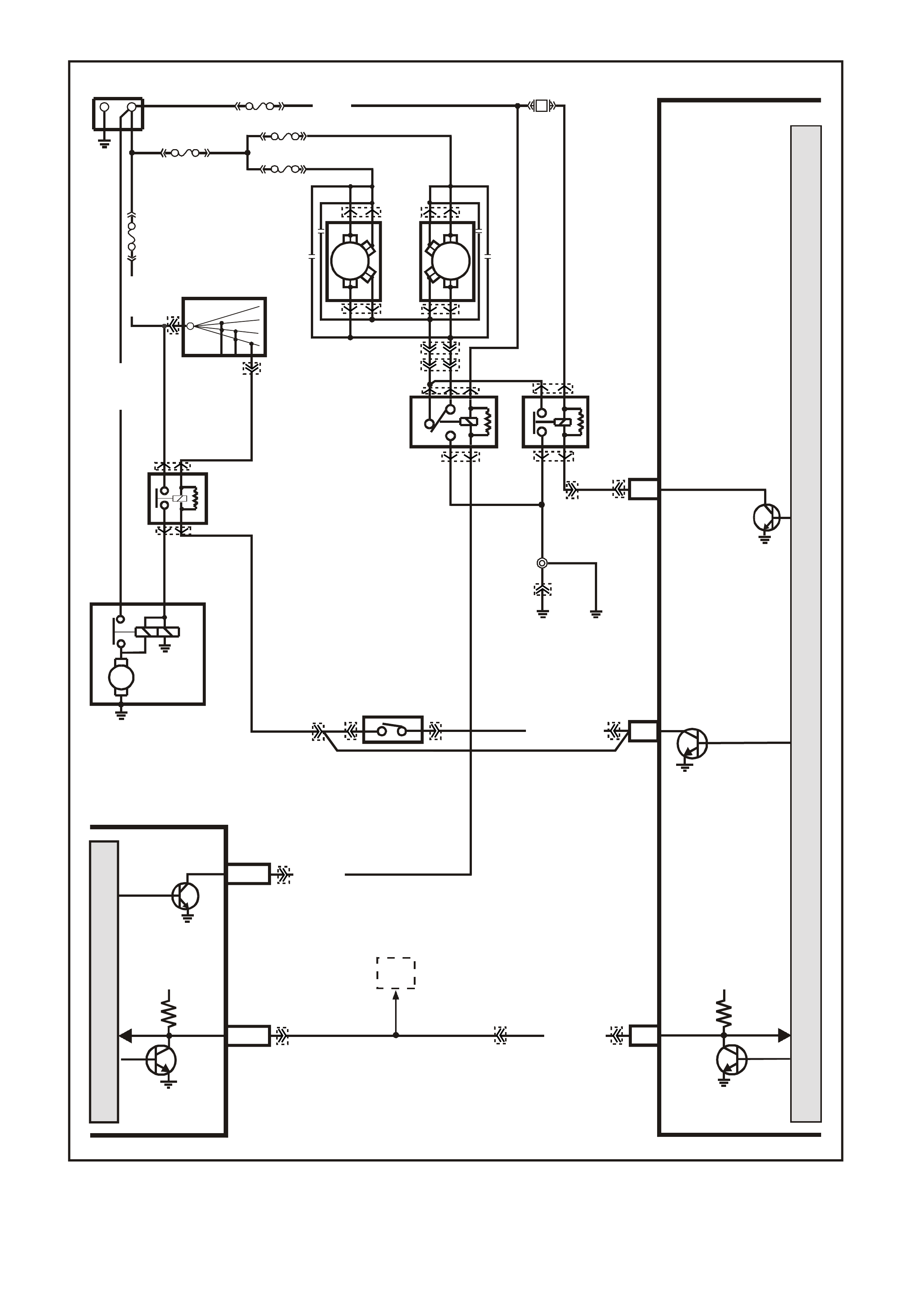
Figure 6C1-2A-13 V6 PCM Wiring Diagram (7 of 8) Supercharged Engine Application
VXSC056
PCM
M
I
C
R
O
P
R
O
C
E
S
S
O
R
LOW SPEED FAN
M
I
C
R
O
BCM
O/B (473)
+-
BATTERY
LOC.
E1
15a 15 50
30 OFF/ON
LOCK
ACC
IGN
START
IGNITION SWITCH
FJ
R (2H)
R (001)
B7/B7
HIGH SERIES
BCM TERMINALS
NOMINATED FIRST
TO
DLC
YB175
YB164
YB174
YB163
YE112
YB188
YB194YB35
YE114
YE110
YB194
YE43
YE43
YE103
YE103
YB44
YE49
YE49
YB44
YE104
YE118
YE119
YE119
YB35YE111
A3
MAIN
SERIAL
DATA
START ER ENABLE
5V
SERIAL
DATA
MAIN
5V
E2/D2
GY
(434)
EG
NEUTRAL START
BACK-UP SW.
( MANUAL
TRANS)
F5
START
RELAY
LOC. G1
STARTER
MOTOR
M
V/W
(6)
30
87 86
85
GY/BLU (1434)
R/B (1221)
87A
30
87
85
86
87
30
85
86
ENGINE
COOLING
FAN 1
ENGINE
COOLING
FAN RELAY
(LOW SPEED)
ENGINE
COOLING
FAN RELAY
(HIGH SPEED)
R
YB
G
BLUE
FUSIBLE
LINK
F31
ENGINE
COOLING
FAN 2
FS
FT FAN 2
FU FAN 1
(1040)
R
(203)
R
(001)
R
(001)
O/B
(208)
O/BLU
(204)
BLU/W
(304)
F6
HIGH
SPEED FAN
LOC.
E2
LOC.
E3
B/P
(157)
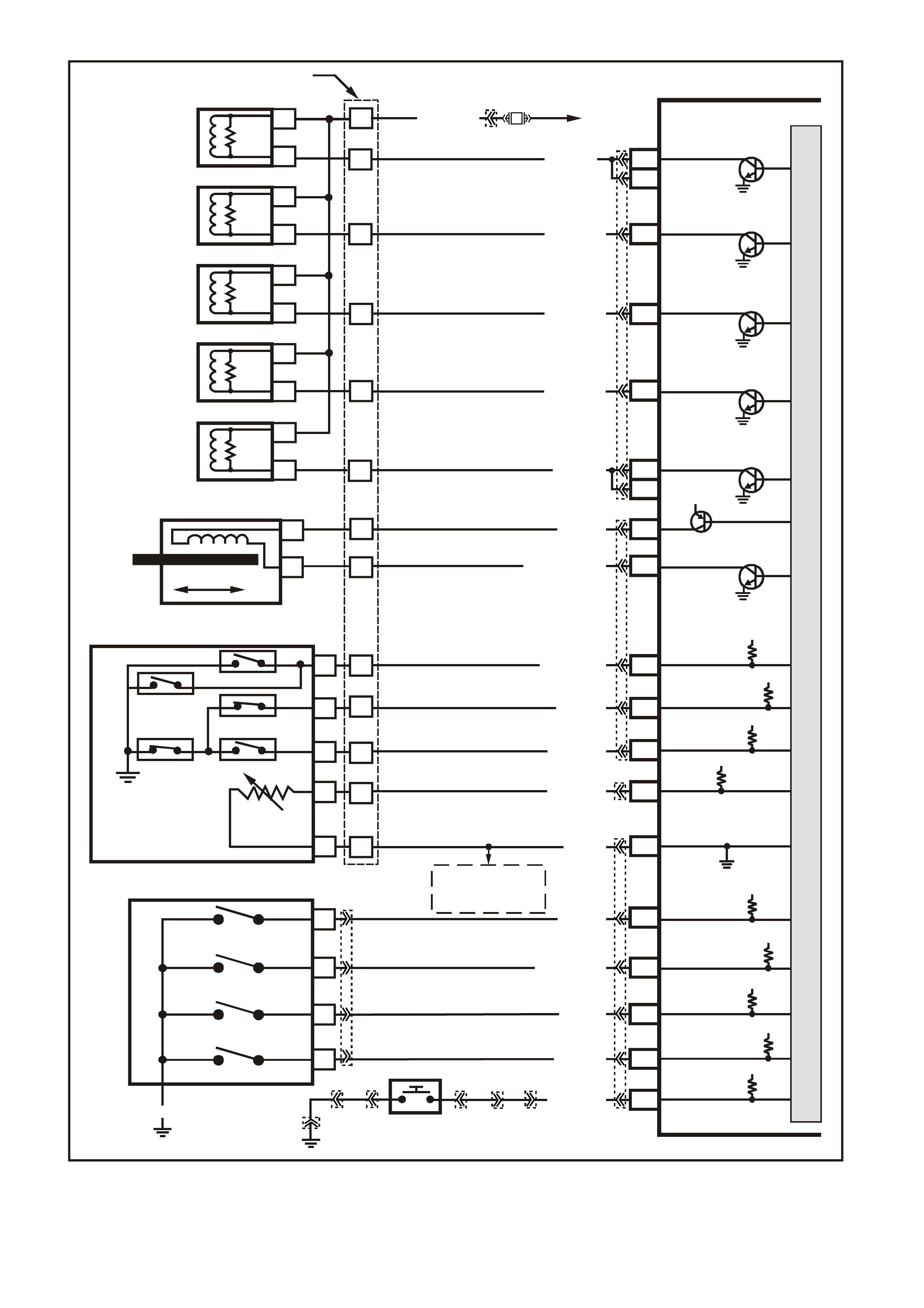
Figure 6C1-2A-14 V6 PCM Wiring Diagram (8 of 8) Supercharged Engine Application
VXSC050
PCM
C15
C16
C1
C13
C14
C2
C3
E14
E15
TCC PWM
SOLENOID
3-2 CONTROL
SOLENOID
1-2 SHIFT
SOLENOID
2-3 SHIFT
SOLENOID
PRESSURE
CONTROL
SOLENOID
LOW
PRESSURE CONTROL
SOLENOID HIGH
B
A
A
B
B
B
A
A
B
A
YB 129 T RANSMIS SION
PASS-THRU CONNECTOR
TORQUE
CONVERTER
CLUTCH (TCC)
(PWM)
SOLENOID
TORQUE
CONVERTER
CLUTCH (TCC)
ENABLE
SOLENOID
3-2 DOWNSHIFT
CONTROL
SOLENOID
1-2 SHIFT
SOLENOID A
2-3 SHIFT
SOLENOID B
PRESSURE
CONTROL
SOLENOID
C
D
B
S
A
E
T
U
P/BLU (339)
F9
F10
F11
F16
TFP SIGNAL A
TFP SIGNAL B
TFP SIGNAL C
TRANSMISSION FLUID
TEMPERATURE (TFT)
SENSOR SIGNAL
SENSOR
EARTH
N
C
R
E
DP
TRANSMISSION FLUID
TEMPERATURE
TO
A/C PRESSURE
SENSOR AND
IAT SENSOR
(TF T ) SENSOR
AUTOMATIC TRANSMISSION FLUID PRESSURE
MANUAL VALVE POSITION SWITCH (TFP)
F12 POWER/ECONOMY
SWITCH
POWER/ECONOMY
SWITCH
TCC ENABLE
SOLENOID
B
A
EFI
RELAY
F32
BR (418)
GY/R (422)
G/W (897)
LG (1222)
Y/B (1223)
GY/BLU (1229)
R (1228)
BR/Y (1224)
Y (1225)
GY (1226)
B6
A
B
L
M
B/Y (1227)
B (46 9)
12V
12V
12V
12V
12V
12V
12V
12V
12V
5V
M
I
C
R
O
P
R
O
C
E
S
S
O
R
E6
E7
A
SWITCH P
SWITCH A
SWITCH B
SWITCH C
LOC. E5/E15 LOC. E3
D
B
C
P R N D L SWITCH
E8
F15
BLU/W (771)
Y (77 2)
GY (773)
W (776)
B/R (750)
RANGE
SIGNAL P
RANGE
SIGNAL A
RANGE
SIGNAL B
RANGE
SIGNAL C
BLU (774)
YB193
YE110
YB194
YB188
YB194
YE112YE30
YB34
YB30
YB20
YE114 YB34

POWERTRAIN CONTROL MODULE CONNECTOR IDENTIFICATION
This powertrain control module voltage Table is for use with a digital voltmeter to further aid in diagnosis.
Connect the Black (-) probe to a good chassis earth, and back probe the powertrain control module terminal with
the Red (+) probe. These voltages were derived from a known good vehicle. The voltages you get may vary
due to low battery charge or other reasons, but they should be very close.
THE FOLLOWING CONDITIONS MUST BE MET BEFORE TESTING:
• Engine and Transmission at operating temperature
• Closed Loop
• Engine idling ( for "Engine Run" column)
• Diagnostic "Test" terminal not earthed
• Tech 2 scan tool not installed
• Accessories "OFF"
BACKPROBING VIEW OF PINK PCM CONNECTOR
Figure 6C1-2A 15 PCM Connector Terminal End View (1 of 3)
Pin
Pin Funct i on
CKT
#
Wire
Colour
Ign
"ON"
Eng
Run
Pin
Pin Funct i on
CKT
#
Wire
Colour
Ign
"ON"
Eng
Run
A1 SYSTEM EARTH 750 B/R * * B1 SYSTEM EARTH 750 B/R * *
A2 SYSTEM EARTH 750 B/R * * B2 SYSTEM EARTH 750 B/R * *
A3 PRIMARY SERIAL
DATA 1221 R/B 3-5 3-5
B3 A/C PRESSURE
SENSOR SIGNAL 259 G/B 1-2 1-2
A4 FUSED IGNITION
FEED 39 P/B 12 13
B4 INTAKE AIR
TEMPERATURE
(IAT) SENSOR
SIGNAL
472 BR 1.0
(3) 1.0
(3)
A5 NOT USED - - - -
B5 ENGINE COOLANT
TEMPERATURE
(ECT) SE NSOR
SIGNAL
410 Y 1.9
(3) 1.9
(3)
A6 FUEL PUMP
RELAY CONT ROL 465 G/W (1) 13
B6 TRANSMISSION
FLUID
TEMPERATURE
(TFT) SENSOR
SIGNAL
1227 B/Y 1.8
(3) 1.8
(3)
A7 TP SENSOR
5 VOLT
REFERENCE
416 GY 5 5
B7 A/C
REFRIGERANT
PRESSURE
SENSOR 5 VOLT
REFERENCE
415 V/W 5 5
A8 BATTERY
VOLTAGE FEED 740 O/B 12 13
B8 BATTERY
VOLTAGE FEED 740 O/B 12 12
A9 NOT USED - - - -
B9 NOT USED - - - -
A10 NOT USED - - -
B10 NOT USED - - - -
A11 NOT USED - - - -
B11 TP SENSOR
SIGNAL 417 BLU (5) (5)
A12 NOT USED - - - -
B12 INJECTOR
VOLTAGE
MONITOR LINE
481 R 12 12
(1) Battery voltage first 2 seconds.
(3) Varies with temperature.
(5) 0.l25 - 1.25 volts measured between terminals "B11" and "B1" or about 4.0 volts at wide open throttle.
(6) Varies with altitude.
* Less than 0.50 volts
Normal
Volta
g
es Normal
Volta
g
es

POWERTRAIN CONTROL MODULE CONNECTOR IDENTIFICATION
This powertrain control module voltage Table is for use with a digital voltmeter to further aid in diagnosis.
Connect the Black (-) probe to a good chassis earth, and back probe the powertrain control module terminal with
the Red (+) probe. These voltages were derived from a known good vehicle. The voltages you get may vary
due to low battery charge or other reasons, but they should be very close.
THE FOLLOWING CONDITIONS MUST BE MET BEFORE TESTING:
• Engine and Transmission at operating temperature
• Closed Loop
• Engine idling ( for "Engine Run" column)
• Diagnostic "Test" terminal not earthed
• Tech 2 scan tool not installed
• Accessories "OFF" BACKPROBING VIEW OF PINK PCM CONNECTOR
Figure 6C1-2A-16 PCM Connector Terminal End View (2 of 3)
Pin
Pin Funct i on
CKT
#
Wire
Colour
Ign
"ON"
Eng
Run
Pin
Pin Funct i on
CKT
#
Wire
Colour
Ign
"ON"
Eng
Run
C1 TCC "ON-OFF"
SOLENOID
CONTROL
422 GY/R 12 13
D1 MASS AIR FLOW
(MAF) SENS OR
INPUT SIGNAL
792 BR/W 4.8 4.2
C2 1-2 SHIFT
SOLENOID
CONTROL
1222 LG 12 *
D2 NOT USED - - - -
C3 2-3 SHIFT
SOLENOID
CONTROL
1223 Y/B 12 *
D3 CAMSHAFT
POSITION (CMP)
SENSOR INPUT
630 B 4.8 4.4
C4 CANISTER PURGE
SOLENOID 428 G/Y 12 13
D4 CRANKSHAFT 18X
SIGNAL 647 LBLU/B 5
OR
0
2.7
OR
3.0
C5 VEHICLE SPEED
OUTPUT TO
SPEEDOMETER
123 V/W 0.1
OR
12
0.1
OR
13
D5 VEHICLE SPEED
SENSOR SIGNAL
LOW
832 T * *
C6 VEHICLE SPEED
SIGNAL HIGH 831 BLU/W * *
D6 NOT USED - - - -
C7 IAC COIL "A" HI GH 441 LBLU NOT USE-
ABLE D7 NOT USED - - - -
C8 IAC COI L "A" LOW 442 LBLU/B NOT USE-
ABLE D8 NOT USED - - - -
C9 IAC COI L " B" LOW 444 LG/B NOT USE-
ABLE D9 BYPASS
CONTROL 424 T/B 0 4.7
C10 IAC COIL "B" HIGH 443 LG/W NOT USE-
ABLE D10 EST OUTPUT 423 W 0 2.0
C11 TORQUE
REQUEST 1426 O/W 4-5 4-5
D11 CRANKSHAFT
REFERE NCE LOW 453 B/R * *
C12 KNOCK SENSOR
(ESC) SIGNAL
INPUT
815 W/R 1.3
mV
AC
19
mV
AC
D12 CRANKSHAFT
REFERE NCE HIGH 430 V 4.8 2.3
C13 3-2 CONTROL
SOLENOID 897 G/W 12 *
D13 RH OXYGEN
SENSOR SIGNAL 1412 GY 450
mV (4)
C14 3-2 CONTROL
FEEDBACK 897 G/W 12 *
D14 RH OXYGEN
SENSOR EARTH 1413 GY/B * *
C15 TCC PWM
FEEDBACK 418 BR 12 13
D15 LH OXYGEN
SENSOR SIGNAL 412 V 450
mV (4)
C16 TCC
SOLENOID
PWM
CONTROL
418 BR 12 13 D16 LH OXYGEN
SENSOR EARTH 413 VB * *
(4) The voltage should vary between 100 mV - 1000 mV.
* Less than 0.50 volts
Normal
Volta
g
es Normal
Volta
g
es
POWERTRAIN CONTROL MODULE CONNECTOR IDENTIFICATION
This powertrain control module voltage Table is for use with a digital voltmeter to further aid in diagnosis.
Connect the Black (-) probe to a good chassis earth, and back probe the powertrain control module terminal with
the Red (+) probe. These voltages were derived from a known good vehicle. The voltages you get may vary
due to low battery charge or other reasons, but they should be very close.
THE FOLLOWING CONDITIONS MUST BE MET BEFORE TESTING:
• Engine and Transmission at operating temperature
• Closed Loop
• Engine idling ( for "Engine Run" column)
• Diagnostic "Test" terminal not earthed
• Tech 2 scan tool not installed
• Accessories "OFF" BACKPROBING VIEW OF BLUE PCM CONNECTOR
Figure 6C1-2A 17 PCM Connector Terminal End View (3 of 3)
Pin
Pin Funct i on
CKT
#
Wire
Colour
Ign
"ON"
Eng
Run
Pin
Pin Funct i on
CKT
#
Wire
Colour
Ign
"ON"
Eng
Run
E1 BOOST CONTROL
SOLENOID 429 B/O 12 13 F1 FUEL INJECTOR #
4 CONTROL 844 BR/Y 12 13
E2 FUEL INJECTOR #
3 CONTROL 843 V 12 13 F2 FUEL INJECTOR #
1 CONTROL 841 BLU 12 12
E3 FUEL INJECTOR #
2 CONTROL 842 G 12 13 F3 FUEL INJECTOR #
6 CONTROL 846 Y 12 13
E4 FUEL INJECTOR #
5 CONTROL 845 GY 12 13 F4 AIR
CONDITIONING
RELAY CONT ROL
366 LG/B 12 (2)
E5 FUEL PUMP
CONTROL
MOLDULE (PWM)
DRIVER
411 LT BLU * 3.0
TO
3.4 v
F5 START RELAY
CONTROL 1434 GY/BLU * *
E6 PRNDLE "A" 771 BLU/W * * F6 ENGINE COOLING
FAN RELA Y HIGH
SPEED CONTROL
304 BLU/W 12 (7)
E7 PRNDL "B" 772 Y 12 13 F7 TORQUE
ACHIEVED 1427 B/W .9 3-6
E8 PRNDL " C" 773 GY 12 13 F8 NOT USED - - - -
E9 NOT USED - - - - F9 RANGE SIGNAL
"A" 1224 BR/Y 12 13
E10 NOT USED - - - - F10 RANGE SIGNAL
"B" 1225 Y 0 0
E11 NOT USED - - - - F11 RANGE SIGNAL
"C" 1226 GY 12 13
E12 OIL PRESSURE
INPUT SIGNAL 31 BLU * 13 F12
POWER/ECONOMY
SWITCH INPUT 774 BLU (6) (6)
E13 NOT USED - - - - F13 NOT USED - - - -
E14 PRESSURE
CONTROL
SOLENOID LOW
1229 GY/BLU * 6.8 F14 DIAGNOSTIC
TEST ENABLE 451 W/B 5 5
E15 PRESSURE
CONTROL
SOLENOID HIGH
1228 R * 1.3 F15 PRNDL "P" 776 W * *
E16 ECT/TP
SENSOR
SENSOR
EARTH
452 B/Y * * F16 IAT, TFT, A/C
REFRIGERANT
PRESSURE
SENSOR
EARTH
469 B * *
(2) With air conditioning "ON" 0 volts, with air conditioning "OFF" 13 volts.
(3) 12 volts while engine is cranking.
(6) When Power/Economy switch is depresses, voltage will momentarily change from 12 volts to 0 volts
then back to 12V.
(7) With engine cooling fan "ON" 0 volts, with engine cooling fan "OFF" 13 volts.
* Less than 0.50 volts.
Normal
Volta
g
es Normal
Volta
g
es

PCM CONNECTOR TERMINAL VOLTAGES WITH EXPLANATIONS
A1 - SYSTEM EARTH
A2 - SYSTEM EARTH
These terminals should have zero volts. They are connected directly to the engine earth.
A3 - PRIMARY SERIAL DATA
This is a dedic ated line for the T ech 2 sc an tool comm unication. T he circuit c onnects the PCM, ABS, and BCM.
The T ech 2 sc an tool can "talk" to each of these m odules by sending a mess age to a controller and ask ing only
it to respond. The communication rate is at 8192 baud. The normal voltage on this circuit is about 5 volts, but
when the Tech 2 scan tool is com municating with a controller, the voltage will vary and if read with a DVM may
read about 2.5 volts
A4 - IGNITION SWITCH INPUT SIGNAL
This is the "turn on" signal to the PCM from the ignition switch circuit. It is not the "power supply" to the PCM, it
only tells the PCM that the ignition switch is "ON." T he voltage should equal the battery voltage when the k ey is
in either the `run' or `crank' position.
A5 - NOT USED
A6 - FUEL PUMP (FP) RELAY CONTROL
Turning the ignition "ON" causes the PCM to energise (+12V) the Fuel Pump Relay. If no crankshaft reference
input pulses are received, the PCM turns "OFF" the relay. As soon as the PCM receives crankshaft reference
input pulses, the PCM will turn the Fuel Pump Relay on again.
A7 - THROTTLE POSITION (TP) SENSOR
REFERENCE VOLTAGE
This voltage should always be 5 volts anytim e the ignition is "ON." It is a regulated voltage output f rom the PCM,
and supplies 5 volts to the TP sensor.
A8 - BATTERY VOLTAGE FEED
- HOT AT ALL TIMES -
This supplies the PCM with full-time +12 volts. It stays hot even when the ignition is turned off. It receives its
voltage through the "ENGINE" fuse F31. This PCM terminal could be called the power supply and "MEMORY"
terminal.
A9 - NOT USED
A10 - NOT USED
A11 - NOT USED
A12 - NOT USED
B1 - SYSTEM EARTH
B2 - SYSTEM EARTH
These terminals should have zero volts. They are connected directly to the engine earth.
B3 - A/C REFRIGERANT PRESSURE SENSOR INPUT
SIGNAL
The signal that is sent from the pressure Sensor to the PCM indicates to the PCM what the A/C pressure is at.
Depending on the A/C pressure, this signal will indicate to the PCM if A/C pressure is to low or to high.
B4 - INTAKE AIR TEMPERATURE (IAT) INPUT SIGNAL
The PCM sends a 5 volt signal voltage to the IAT sensor, which is a temperature - variable-resistor called a
thermistor. The sensor is also connected to earth, and will alter the signal voltage according to incoming air
temper ature. As the air tem perature inc reases, the voltage s een on this term inal dec reases . At 0 degrees C, the
voltage will be above 4 volts. At normal operating temperature (10 degrees C to 80 degrees C) the voltage will
be less than 4 volts.
B5 - ENGINE COOLANT TEMPERATURE (ECT)INPUT SIGNAL
The PCM sends a 5 volt signal voltage out to the engine coolant temperature sensor, which is a temperature-
variable-resistor called therm istor. The sensor, being also connected to earth, will alter the voltage according to
engine coolant temperature. As the engine coolant temperature increases, the voltage seen on terminal B5
decreases. At 0 degrees C engine coolant temperature the voltage will be above 4 volts. At normal operating
temperature (85 degrees C to 100 degrees C) the voltage will be less than 2 volts.
B6 - TRANSMISSION FLUID TEMPERATURE (TFT) INPUT SIGNAL
- AUTO TRANS ONLY
The PCM s ends a 5 volt signal voltage out to the trans m ission f luid tem perature s ensor, which is a temperatur e-
variable-resistor called therm istor. The sensor, being also connected to earth, will alter the voltage according to
transmission fluid temperature. As the fluid temperature increases, the voltage seen on terminal B6 will
decrease.

B7 - A/C PRESSURE SENSOR REFERENCE VOLTAGE
This voltage should always be 5 volts anytim e the ignition is "ON." It is a regulated voltage output f rom the PCM,
and supplies 5 volts to the A/C Pressure Sensor.
B8 - BATTERY VOLTAGE FEED
- HOT AT ALL TIMES -
This supplies the PCM with full-time +12 volts. It stays hot even when the ignition is turned off. It receives its
voltage through the "ENGINE" fuse F31. This PCM terminal could be called the power supply and "MEMORY"
terminal.
B9 - NOT USED
B10 - NOT USED
B11 - THROTTLE POSITION (TP) SENSOR
The TP sensor input voltage, which follows actual throttle changes, is variable from 0 to 5 volts. Typically the
voltage is less than 1 volt at idle, and 4 to 5 volts at wide-open throttle.
B12 - INJECTOR CIRCUIT VOLTAGE MONITOR INPUT SIGNAL
The injector voltage monitor line is used so that the PCM will know the exact voltage the fuel injectors are
operating at. This voltage signal is used to modify the fuel injector pulse width calculation.
C1 - TORQUE CONVERTER CLUTCH ENABLE SOLENOID CONTROL
- AUTO TRANS ONLY
The PCM is used to either open or provide a path to earth for the torque converter solenoid. When the PCM
provides a path to earth, the T CC solenoid is cons idered ON and voltage s hould be near 0 volts. T he PCM uses
both the TCC enable solenoid and the TCC "PWM" solenoid to control the torque converter clutch. (See TCC
PWM solenoid terminal E1)
C2 - 1 - 2 SHIFT SOLENOID CONTROL
- AUTO TRANS ONLY -
The PCM is used to either open or pr ovide a path to earth for the 1-2 shif t solenoid. W hen the PCM provides a
path to earth, the 1-2 shift solenoid is considered "ON" and the voltage should read 0 volts.
C3 - 2 - 3 SHIFT SOLENOID CONTROL
- AUTO TRANS ONLY
The PCM is used to either open or pr ovide a path to earth for the 2-3 shif t solenoid. W hen the PCM provides a
path to earth, the 2-3 shift solenoid is considered "ON" and the voltage should read 0 volts.
C4 - CANISTER PURGE SOLENOID CONTROL
The PCM operates a norm ally closed solenoid valve, which contr ols vacuum to pur ge the evaporative emis sions
storage canister of stored gasoline vapours. The PCM turns "ON" the pulse width modulated control of the
purge solenoid, to control purging of the stored vapours. If the PCM is not energising the purge solenoid, the
voltage measured at this terminal should equal battery voltage. If the PCM is controlling the solenoid, the
measured voltage will be between battery voltage and 0.50 volts.
C5 - VEHICLE SPEED OUTPUT TO SPEEDOMETER
The PCM alternately earths this s ignal, in pulses, when it rec eives a vehicle speed signal f rom the vehicle speed
sensor in the transmission. This pulsing action takes place about 6250 times per kilometer. The speedometer
calculates vehicle speed based on the time between pulses.
C6 - VEHICLE SPEED SENSOR - OUTPUT SHAFT SPEED INPUT SIGNAL HIGH
The transmission has an output shaft speed sensor used by the PCM to calculate vehicle speed, and to help
determ ine various autom atic trans mission shifting f unctions. It is a m agnetic inductive sens or that generates an
AC voltage signal sent to the PCM. If measured with the digital AC voltmeter, no voltage will appear until the
output shaft begins turning.
C7 - IDLE AIR CONTROL (IAC)
C8 - IDLE AIR CONTROL (IAC)
C9 - IDLE AIR CONTROL (IAC)
C10 - IDLE AIR CONTROL (IAC)
These terminals connect the Idle Air Control valve, located on the throttle body, to the PCM. It is difficult to
predict what the voltage will be, and the measurement is unusable for any service procedures.
C11 - TRACTION CONTROL (TORQUE REQUESTED)
The ABS/ET C m odule will send a N.m signal to the PCM when torque reduction is requested fr om the ABS/ETC
module for traction control. This N.m signal should match closely with Torque Achieved N.m signal, when
traction control is being requested.

C12 - ELECTRONIC SPARK CONTROL (ESC) "KNOCK" INPUT SIGNAL
The Electronic Spark Control "k nock " sensor detects when detonation is occurr ing in the combus tion cham bers.
W hen detected, the PCM will reduce the am ount of spark advance being delivered on the EST output circuit to
the ignition module.
C13 - 3 - 2 DOWNSHIFT CONTROL SOLENOID
CONTROL
- AUTO TRANS ONLY -
The 3-2 c ontrol solenoid is a nor mally closed, pulse width m odulated solenoid used to control the 3-2 downshift.
The PCM operates the 3-2 control solenoid at
a frequency of 50 Hz (cycles per second). The solenoid is constantly fed 12 volts and PCM controls the length
of time the path to earth for the electrical circuit is closed.
C14 - 3 - 2 SHIFT SOLENOID FEEDBACK
- AUTO TRANS ONLY -
The 3-2 Shif t solenoid is a norm ally closed solenoid used to control the 3-2 downshift. The solenoid is constantly
fed 12 volts and PCM controls the length of time the path to earth for the electrical circuit is closed. The PCM
does this to provide a smooth 3-2 downshift. If the PCM senses an incorrect voltage on this circuit when
controlling the 3-2 downshift solenoid (i.e. - O volts with the solenoid OFF, or 12 volts with the solenoid ON) a
DTC code 66 will set.
C15 - TORQUE CONVERTER CLUTCH - PULSE WIDTH MODULATED APPLY SOLENOID FEEDBACK
- AUTO TRANS ONLY -
The PCM uses the pulse width modulated T CC apply solenoid to sm oothly engage the torque converter clutch,
after the TCC "ON-OFF" solenoid is energised. By varying the duty cycle pulse width modulation, the PCM can
slowly engage the torque converter clutch, allowing very smooth TCC engagement. If the PCM senses an
incorrec t voltage on this c ircuit when c ontrolling the T CC PW M s olenoid (i.e. - O volts with the solenoid OF F, or
12 volts with the solenoid ON ) a DTC code 83 will set.
C16 - TORQUE CONVERTER CLUTCH - PULSE WIDTH MODULATED APPLY SOLENOID CONTROL
- AUTO TRANS ONLY -
The PCM uses the pulse width modulated TCC apply solenoid to smoothly engage the torque converter clutch,
after the TCC "ON-OFF" solenoid is energised. By varying the duty cycle pulse width modulation, the PCM can
slowly engage the torque converter clutch, allowing very smooth TCC engagement.
D1 - MASS AIR FLOW (MAF) INPUT SIGNAL
The PCM supplies a 5-volt signal voltage to the mass air flow sensor on this circuit. The mass air flow sensor
pulses the 5-volt signal to earth. These earth pulses occur at a very fast rate - from less than 500 per second
(500 Hz) with no airflow through the sensor, to upwards of many thousands of pulses per second at high air flow
rates such as during acceleration. If measured, the voltage seen will be between 0.5 and 4.5 volts, depending
on air flow through the sensor.
D2 - NOT USED
D3 - CAMSHAFT POSITION INPUT SIGNAL
This signal is used by the PCM to "sequence" the energising of the fuel injector s, similar to the firing order of an
engine. This allows the PCM to operate the fuel injectors in a "sequential fuel injection" mode. The camshaft
position sensor is actually wired to the ignition module. The ignition module sends one pulse per every two
crankshaft revolutions to the PCM to determine actual camshaft position, and thus, engine cycle sequence.
D4 - CRANKSHAFT 18X INPUT SIGNAL
The 18X crankshaft reference input signal is used to very accurately control EST spark timing at low engine
speeds - below 1200 RPM. Below 1200 RPM, the PCM monitors the 18X signal to control spark timing. At
engine speeds above 1200 RPM, the PCM uses the 3X c rankshaf t r ef er ence input s ignal to c ontrol s park timing.
(See 3X crankshaft reference terminal D12)
D5 - VEHICLE SPEED SENSOR - OUTPUT SHAFT SPEED INPUT SIGNA L LOW
The transmission has an output shaft speed sensor used by the PCM to calculate vehicle speed, and to help
determ ine various autom atic trans mission shifting f unctions. It is a m agnetic inductive sens or that generates an
AC voltage signal sent to the PCM. If measured with the digital AC voltmeter, no voltage will appear until the
output shaft begins turning.
D6 - NOT USED
D7 - NOT USED
D8 - NOT USED
D9 - IGNITION MODULE BYPASS CONTROL
- IGNITION SYSTEM MODE CONTROL -
With ignition "ON" and engine not running this terminal will have very low voltage. As soon as the PCM sees
engine RPM of m ore than 1600 RPM (Electronic Spark Timing "run" threshold) the PCM turns on 5 volts to the

Ignition Module Bypass Control circuit, causing the ignition module to allow the PCM to operate the ignition
system.
D10 - ELECTRONIC SPARK TIMING (EST) OUTPUT
This terminal will have very low voltage with the ignition "O N" but engine not running. W ith the engine r unning at
idle, the voltage should be slightly more than 1 volt. As the engine RPM goes up, this voltage will increases.
D11 - CRANKSHAFT REFERENCE INPUT SIGNAL LOW
This terminal should always be zero volts. It is connected through the ignition module to engine earth.
D12 - 3X CRANKSHAFT REFERENCE INPUT SIGNAL HIGH
This terminal could be called the "tach" input. It provides the PCM with RPM and crankshaft position
information. With ignition "ON" but engine not running, the voltage will be either high or low, depending on
crank shaft position. As the crankshaft turns, the voltage will be an average of the two readings. The PCM uses
the 3X signal to control fuel injection, and spark timing with engine speeds above 1200 RPM. (See 18X
crankshaft reference terminal D4)
D13 - OXYGEN SENSOR INPUT SIGNAL
- RIGHT BANK -
W ith ignition "ON" and engine not running, the voltage should be 350 - 450 millivolts (0.350 - 0.450 volts). This
is the PCM-supplied 02 c ircuit "bias" voltage. With the engine running and after the 02 s ensor is hot, the voltage
should be rapidly changing, somewhere between 10 - 1000 millivolts (0.010 - 1.000 volt).
D14 - OXYGEN SENSOR EARTH
- RIGHT BANK -
This terminal should have zero volts. It is connected directly to the engine earth. This terminal earths the PCM
circuitry for the O2 voltage monitor inside the PCM.
D15 - OXYGEN SENSOR INPUT SIGNAL
- LEFT BANK -
W ith ignition "ON" and engine not running, the voltage should be 350 - 450 millivolts (0.350 - 0.450 volts). This
is the PCM-supplied 02 c ircuit "bias" voltage. With the engine running and after the 02 s ensor is hot, the voltage
should be rapidly changing, somewhere between 10 - 1000 millivolts (0.010 - 1.000 volt).
D16 - OXYGEN SENSOR EARTH
- LEFT BANK -
This terminal should have zero volts. It is connected directly to the engine earth. This terminal earths the PCM
circuitry for the O2 voltage monitor inside the PCM.
E1 - BOOST CONTROL SOLENOID
The PCM oper ates a norm ally closed solenoid valve, which contr ols vac uum to the By-Pass Valve Actuator. The
PCM turns "ON" the solenoid , to allow vacuum to the By-Pass Valve Actuator, to close the By-Pass valve and
allow full boost. If the PCM is not energising the boost solenoid, the voltage measured at this terminal should
equal battery voltage. If the PCM is controlling the solenoid, the measured voltage will be between battery
voltage and 0.50 volts.
E2 - FUEL INJECTOR 3 - CONTROL
E3 - FUEL INJECTOR 2 - CONTROL
E4 - FUEL INJECTOR 5 - CONTROL
The voltage seen at these terminals actually comes through the injectors, which are connected to +12 volts.
With the engine not running, the voltage seen would be battery voltage. With the engine running at idle, the
charging system increases the voltage slightly, so this voltage will increase. With higher engine RPM or more
engine load, the resulting increase in injector pulse frequency or injector pulse width will cause this voltage to
appear slightly less.
E5 - FUEL PUMP CONTROL MODULE
A duty cycle earth signal on this circuit varies depending on engine load. Under normal driving conditions, the
duty cycle earth signal supplied from the PCM to the Fuel Pump Control Module (terminal 7 of the Fuel Pump
Control Module) is at 33% duty cycle. This 33% duty cycle runs the Fuel Pump at a lower fuel flow rate. When
the vehicle is in a heavy engine load condition, the PCM will switch from 33% duty cycle to 100% duty cycle.
This will cause the Fuel Pump to operate at a high fuel flow rate to compensate for the higher engine load
condition. T his change in duty cycles does not change the f uel sys tem operating fuel pressur e, but changes the
fuel flow rate.
E6 - PRNDL A
E7 - PRNDL B
E8 - PRNDL C
These circuits along with PCM circuit F15 indicate to the PCM what transmission gear the driver has selected.
The PCM will then send a command via the serial data line to the instrument panel cluster (smart cluster) to
indicate to the driver what gear has been selected.

E9 - EGR IGNITION
This is a ignition voltage input that runs between the EGR valve and the PCM. The PCM uses this input to
determine actual voltage supplied to the EGR valve.
E10 - NOT USED
E11 - NOT USED
E12 - OIL PRESSURE SWITCH
This is a earth input to the PCM from the Oil Pressure Switch indicating proper oil pressure when the engine is
running. If oil pressure is lost while the engine is running, the oil switch will open its contacts and the earth
signal to the PCM will be rem oved. When the PCM sees this los s of ear th signal, the PCM will comm and the oil
lamp ON.
E13 - NOT USED
E14 - TRANSMISSION PRESSURE CONTROL
SOLENOID (PCS) - LOW
- AUTO TRANS ONLY -
The 4L60-E automatic transmission uses an electrical solenoid to control hydraulic pressure inside the
transmission. This electrical solenoid allows the PCM to control "line pressure", similar to other automatic
transm issions that use a "throttle valve" cable or vacuum modulator. T he duty cycle, and am ount of cur rent flow
to the PCS, are both controlled by the PCM. By m onitoring this line, the PCM can determine if the comm anded
amperage has gone to the PCS and returned to the PCM.
E15 - TRANSMISSION FLUID PRESSURE CONTROL
SOLENOID (TFP) - HIGH
- AUTO TRANS ONLY -
The duty cycle, and am ount of current f low to the TFP, are controlled by the PCM. T his circuit is the B+ supply
line from the PCM to the TFP. The duty cycle and amperage are controlled by the PCM.
E16 - ENGINE COOLANT TEMPERATURE and THROTTLE POSITION SENSOR EARTH
This terminal should be zero volts. It is connected through the PCM circuitry to engine earth.
F1 - FUEL INJECTOR 4 - CONTROL
F2 - FUEL INJECTOR 1 - CONTROL
F3 - FUEL INJECTOR 6 - CONTROL
The voltage seen at these terminals actually comes through the injectors, which are connected to +12 volts.
With the engine not running, the voltage seen would be battery voltage. With the engine running at idle, the
charging system increases the voltage slightly, so this voltage will increase. With higher engine RPM or more
engine load, the resulting increase in injector pulse frequency or injector pulse width will cause this voltage to
appear slightly less.
F4 -AIR CONDITIONING RELAY CONTROL
W hen the A/C is r equested, the BCM will comm unicate to the PCM via the serial data line, requesting A/C. T he
PCM supplies the earth path on this terminal to energise the A/C control relay. The voltage will be less than 1
volt when the PCM energises the relay. W hen the PCM does energise the A/C control relay, the voltage will be
more than 0.1, but less than 1 volt.
F5 - START RELAY CONTROL
When the PCM receives the proper Theft Deterrent signal, the PCM will supply a earth signal to Start Relay.
This will allow the vehicle to star t. If a impr oper Theft Deter rent signal is sensed by the PCM, then the PCM will
not supply a earth signal to the Start Relay. This will prevent the starter motor from operating.
F6 - ENGINE COOLING FAN - HIGH SPEED RELAY CONTROL
This terminal will have battery voltage until the PCM energises the high s peed cooling fan relay by supplying the
earth; then it will be close to zero. The input that causes the PCM to energise the high speed fan relay is the
engine coolant tem perature s ensor. T he PCM will also energis e the high speed f an relay in the Diagnos tic Mode
- i.e., ignition "ON," engine stopped, and DLC
diagnostic "test" enable terminal earthed. Refer engine fan TABLE A-12 in this Section for further explanation.
(The Body Control Module operates the cooling fan low speed relay)
F7 - TRACTION CONTROL (TORQUE ACHIEVED)
The PCM sends a N.m signal to the ABS/ETC module on the delivered torque circuit informing the ABS/ETC
module of response made to the desired torque N.m signal. This N.m signal should match closely with the
Requested Torque N.m signal. A problem with the
delivered torque circuit should cause a ABS/ETC DTC to set, and traction control to be disabled.

F8 - CRANKING SIGNAL INPUT
This cranking signal circuit provides an input for enabling fuel cutoff during a possible back fire situation. During
an engine start, when the k ey switch is released fr om the crank position before the engine is running, the engine
may backfire. The PCM stops all injector pulses when the engine speed is less than 450 RPM, coolant
temper ature is gr eater than -4 degr ees C, a cr anking s ignal is not received, but was received within the previous
12.5 milliseconds
F9 - RANGE SIGNAL A INPUT SIGNAL
F10 - RANGE SIGNAL B INPUT SIGNAL
F11 - RANGE SIGNAL C INPUT SIGNAL
- AUTO TRANS ONLY -
Range signal "A", "B" and "C". The PCM sends out a buffered 12 volt signal to the pressure switch assembly,
located in the automatic transmission valve body. The 12 volt signal must pass through either a normally open
or norm ally closed s witc h to reach earth. W hen the switches ) are closed, the signal should be near 0 volts. The
PCM monitors the status of these signals to determine which gear servo is actually receiving hydraulic apply
pressure.
F12 -POWER / ECONOMY INPUT SIGNAL
- AUTO TRANS ONLY -
The PCM s ends a signal of about 12 volts, and monitors the status of this circuit. In the ECON OMY pos ition the
switch is open, the PCM voltage status signal remains high – about 12 volts, and the PCM does not allow shift
point changes. When the transmission switch is pressed to the POWER position the switch is momentarily
closed and the PCM voltage status signal is momentarily pulled low. The PCM senses the momentary voltage
signal drop and enables power m ode shif ting only if other criteria are met. Thes e criteria include throttle position
and engine speed.
F13 - NOT USED
F14 - DIAGNOSTIC TEST ENABLE INPUT SIGNAL
This terminal is connected to the DLC diagnostic test enable terminal. W hen the diagnostic test term inal is not
earthed, this terminal will have 5 volts on it. When the DLC diagnostic test enable terminal is earthed, the
resulting zero voltage at the PCM will cause it to operate in Diagnostic Mode.
F15 - PRNDL P
This circuit along with PCM circuits E6, E7, E8 indicate to the PCM what transmission gear the driver has
selected. The PCM will then send a command via the serial data line to the instrument panel cluster (smart
cluster) to indicate to the driver what gear has been selected.
F16 - INTAKE AIR TEMPERATURE / TRANSMISSION FLUID TEMPERATURE / A/C PRESSURE SENSOR
EARTH CIRCUIT
This terminal should be zero volts. It is connected through the PCM circuitry to engine earth.

PCM V6 SUPERCHARGE ENGINE AND TRANSMISSION DIAGNOSTIC
TROUBLE CODES (DTC)
DTC
DESCRIPTION ILLUMINATE
"CHECK
POWERTRAIN"
LAMP
12 No revolutions per minute signal - normal when engine is not running No
13 Right Hand Oxygen Sensor (HO2S) Insufficient Activity Yes
14 Engine Coolant Temperature ECT - Signal Voltage Low Yes
15 Engine Coolant Temperature ECT - Signal Voltage High Yes
16 Engine Coolant Temperature ECT – Sensor Unstable No
17 PCM Error - ECT Circuit No
19 Throttle Position (TP) Sensor Circuit Insufficient Activity Yes
21 Throttle Position (TP) Sensor Circuit High Voltage Yes
22 Throttle Position (TP) Sensor Circuit Low Voltage Yes
23 Intake Air Temperature (IAT) Sensor Circuit High Voltage No
24 Vehicle Speed Sensor (VSS) Circuit Low Voltage Yes
25 Intake Air Temperature (IAT) Sensor Circuit Low Voltage No
26 Intake Air Temperature (IAT) Sensor Unstable No
28 Transmission Fluid Pressure (TFP) Valve Position Switch Circuit Yes
31 Theft Deterrent Signal Missing Yes
32 Mass Air Flow (MAF) Out Of Range Yes
35 Idle Speed Low No
36 Idle Speed High No
41 Ignition Electronic Spark Timing (EST) Output Circuit Fault Yes
42 Ignition Bypass Circuit Fault Yes
43 Knock Sensor Circuit Fault No
44 Right Hand Heated Oxygen Sensor (HO2S) Low Voltage Yes
45 Right Hand Heated Oxygen Sensor (HO2S) High Voltage Yes
46 No Reference Pulses While Cranking Yes
47 18X Reference Signal Missing No
48 Camshaft Position Sensor Circuit Low Voltage No
49 Camshaft Position Sensor Circuit Performance No
51 PROM Error Yes
52 System Voltage Too High (Long Time) Yes
53 System Voltage Too High Yes
54 System Voltage Unstable Yes
55 PCM - Analog - Digital (A/D) Conversion Error Yes
56 Lean Condition Under Load (Supercharged Engine Only) Yes
57 Injector Voltage Monitor Fault No
58 Transmission Fluid Temperature (TFT) Sensor Circuit - Low Input No
59 Transmission Fluid Temperature (TFT) Sensor Circuit - High Input No
63 Left Hand Oxygen Sensor (HO2S) Insufficient Activity Yes
64 Left Hand Heated Oxygen Sensor (HO2S) Low Voltage Yes
65 Left Hand Heated Oxygen Sensor (HO2S) High Voltage Yes
66 3-2 Shift Solenoid Circuit Electrical Yes
67 Torque Converter Clutch (TCC) Enable Solenoid Circuit Electrical Yes
69 Torque Converter Clutch (TCC) System Stuck On No
72 Transmission Output Speed Loss No
73 Pressure Control (PC) Solenoid Circuit Electrical No
75 System Voltage Low Yes
76 Short Term Fuel Trim (STFT) Delta High No
78 Long Term Fuel Trim (LTFT) Delta High No
79 Transmission Fluid Overtemperature Yes
81 2-3 Shift Solenoid Circuit - Fault Yes
82 1-2 Shift Solenoid Circuit - Fault Yes
83 Torque Converter Clutch Pulse Width Modulation Solenoid Circuit - Fault No

PCM V6 SUPERCHARGE ENGINE AND TRANSMISSION DIAGNOSTIC TROUBLE CODES (DTC)
(CONTINUED)
DTC
DESCRIPTION ILLUMINATE
"CHECK
POWERTRAIN"
LAMP
85 Transmission Slipping No
91 QDSM (Quad Driver Surface Module) Circuit No
92 Low Speed Fan No BCM Response No
93 SNEF Circuit Fault No
94 No Vehicle Speed Sensor - Manual Transmission Yes
95 Requested Torque Out Of Range Yes
96 A/C Pressure Sensor Fault No
97 Canister Purge Circuit Fault No

4L60 E TRANSMISSION FLUID CHECKING PROCEDURE
GENERAL INFORMATION
W hen adding or changing the tr ansmiss ion fluid, use only Dexr on III. Ref er to the Series Owner's Handbook for
the recommended servicing intervals.
Because this transmission fluid changes colour and smell very easily in its life, these indicators should not
necessarily be relied upon to diagnose either transmission internal condition or fluid deterioration.
The Fluid Checking Procedure shows that a dark brown fluid colour, coupled with a delayed shift pattern, may
only indic ate that the fluid requires replacem ent and alone, is not a definite indic ation of a potential transm ission
failure.
NOTE: Do not overfill the transmission. Overfilling will cause foaming of the fluid, loss of fluid, shift complaints
and possible damage to the transmission.
TRANSMISSION FLUID COLOUR
Trans mission f luid colour when new and unused, is red. A red dye is added so that it can be distinguished from
other oils and lubricants. The red dye is not an indicator of fluid quality and is not permanent. As the vehicle is
driven, the transm ission fluid will quickly begin to look darker in colour. The colour will then appear light brown.
A DARK brown colour with a distinctively burnt odour MAY indicate fluid deterior ation and a need for the fluid to
be changed.
TRANSMISSION FLUID CHECKING PROCEDURE
1. Start the engine and drive vehicle for a maximum of 24 km, or until the transmission normal operating
temperature is reached.
NOTE: As tem peratur e greatly affects transm is sion fluid levels , this operation m ust only be carr ied out when
the transmission is at normal operating temperature (82 - 94 degrees C). If the vehicle is not at normal
operating temperature, and the proper checking procedures are not followed, the result could be a false
reading of the fluid level on the dipstick.
2. Park vehicle on level earth.
3. Move gear selector to 'PARK' position.
4. Apply park brake.
5. Let engine idle for 3 minutes with accessories turned off.
6. Locate r ed coloured dips tick in the engine com partment, lif t the lock ing lever, rem ove the dipstick and check
fluid colour, condition and level.
7. If the fluid level is low, add only enough DEXRONâ III to bring the level into the "HOT" area.
Inaccurate fluid level readings will result if checked immediately after the vehicle has been operated under
any or all of the following conditions:
a. In high ambient temperatures above 32 degrees C.
b. At sustained high speeds.
c. In heavy city traffic during hot weather.
d. Towing
e. In commercial use (e.g. taxi).
If the vehicle has been operated under these conditions, switch the engine off and allow the vehicle to 'cool' for
approximately thirty minutes. After cool-down period, re-start the vehicle and continue from step 2.

4L60-E AUTOMATIC TRANSMISSION FLUID CHECKING PROCEDURE
STEP ACTION VALUE YES NO
1. Check the fluid colour.
Is the fluid colour red? Go to Step 2 Go to Step 11
2. Is the fluid level satisfactory? Go to Step 20 Go to Step 3
3. Check the fluid.
Is the fluid foamy? Go to Step 8 Go to Step 4
4. Check the fluid level. The proper fluid level should be In
the middle of the X-hatch.
Is the level high?
Go to Step 9 Go to Step 5
5. Fluid will be low.
Add fluid to the proper fluid level.
Is the fluid level satisfactory?
Go to Step 6 Go to Step 1
6. Check for external leaks.
Were any leaks present? Go to Step 7 Go to Step 20
7. Correct the fluid leak condition.
Is action complete? Go to Step 20
8. Is the fluid level too high? Go to Step 9 Go to Step 10
9. Remove excess fluid to adjust to the proper fluid level.
Is action complete? Go to Step 20
10. 1. Check for contaminants in the fluid.
2. Drain the fluid to determine the source of the
contamination.
Is action complete?
Go to Step 15
11. Is the fluid colour non-transparent pink? Go to Step 12 Go to Step 13
12. Replace the cooler.
Is action complete? Go to Step 15
13. The fluid colour should be light brown. Transmission fluid
may turn dark with normal use. This does not always
indicate oxidation or contamination.
Is the fluid colour light brown?
Go to Step 14 Go to Step 1
14. Drain the fluid to determine if the fluid is contaminated.
A very small amount of material in the bottom of the pan
is a normal condition, but large pieces of metal or other
material in the bottom of the pan requires a transmission
overhaul.
Was the fluid contaminated?
Go to Step 15 Go to Step 18
15. Overhaul the transmission. Refer to Section 7C5, unit
repair in VX Service Information.
Is action complete?
Go to Step 16
16. Flush the cooler.
Is action complete? Go to Step 17
17. Add new fluid.
Is action complete? Go to Step 19
18. Change the fluid and filter.
Is action complete? Go to Step 19
19. Is the fluid level satisfactory, If not, correct as necessary.
Is action complete? Go to Step 20
20. Refer to 4L60-E Transmission Functional Test Procedure,
in Section 7C3, Diagnosis, in VX Service Information.
Is action complete?
Fluid Checking
Procedure
Completed
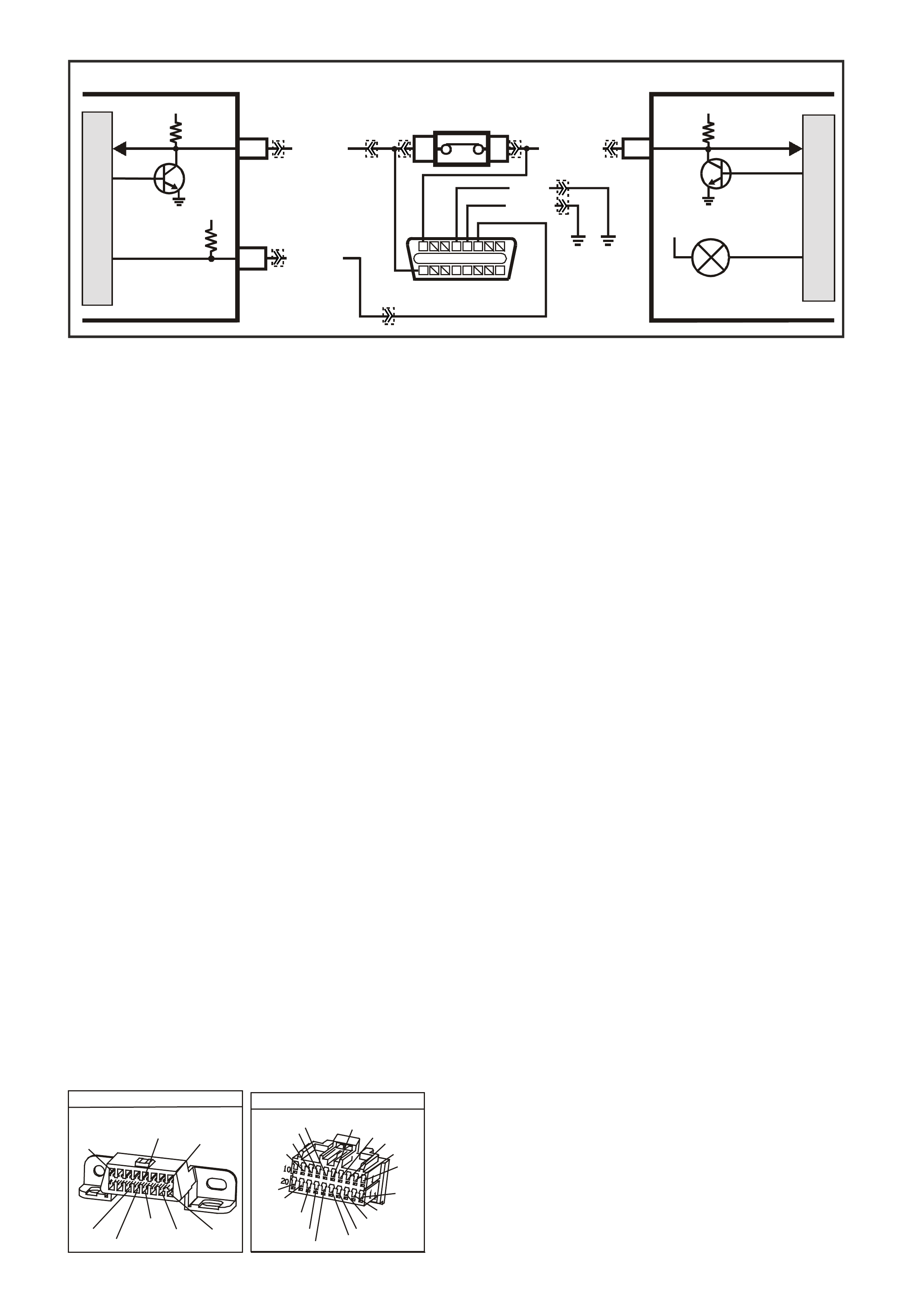
TABLE A V6 PCM -
ON-BOARD DIAGNOSTIC (OBD) SYSTEM CHECK
CIRCUIT DESCRIPTION:
The On-Board Diagnostic System Check is an organised approach in identifying a problem created by a
powertrain control system malfunction. It must be the starting point for any driveability complaint diagnosis,
because it directs the service technician to the next logic al step in diagnosing the com plaint. Understanding the
Table and using it correctly will reduce diagnostic time and prevent the unnecessary replacement of good parts.
TEST DESCRIPTION: Number(s) below refer to step number(s) on the diagnostic Table.
1. This s tep is a chec k for the pr oper oper ation of the "Chec k Powertrain" lamp (MIL). The PCM should provide
serial data communication path for the "Check Powertrain" lamp, this is a bulb check. The "Check
Powertrain" lam p should be "ON." If it can do this, it conf irm s that the PCM has power, earth and is capable
of some functions.
If the "Check Powertrain" lamp is "OFF," this indicates a problem in the "Check Powertrain" lamp fuse
circuits or the PCM earth circuits or the PCM's serial data communication circuit or a problem with the
instrument cluster. Table A-1 will check for both ignition feed and constant battery power to the PCM and
the PCM earth.
2. This check is done to see if the PCM has the capability of performing internal diagnostics. With the
diagnostic "test" terminal earthed, the "Check Powertrain" lamp, should flash a DTC 12 or flash any other
DTC(s ) stor ed in memory. DTC 12 means ther e is no c rankshaf t r ef er ence s ignal coming to the PCM, this is
normal because the engine is not running.
3. This c heck is us ed to s ee if the PCM c an supply serial data f or Tech 2 s can tool us e. If an EEPRO M er ror is
present, the PCM may have been able to flash DTC 12 but not enable serial data.
4. This check is to see there are any Theft Deterrent DTC stored. If Theft Deterrent system is enabled, this
may be the cause of the no crank condition.
5. This test determines if the vehicle is able to crank. If the vehicle will not crank, refer to Table A-4.0 to
diagnosis starter cranking circuit.
7. T his test is us ed to determ ine the caus e of a "Crank s But Will Not Run," although the PCM is powered up, a
"Cranks But Will Not Run" symptom could exist because of a PCM problem or the vehicle electrical system.
8. Look at all the param eters to determ ine if one is not in a normal s tate with just the ignition "ON" and engine
stopped. Look at the ECT value to see if the value is shifted above or below where it should be. If so, refer
"Diagnostic Aid Table" on DTC 14.
9. Look at all the parameters to determine that all values are within typical ranges for normal operating
temperatures at idle. Keep in mind that a basic engine problem may alter sensor value.
DIAGNOSTIC AIDS:
If the Serial Data circuit is shorted to voltage or earth or open, the vehicle will not crank. Check Serial Data
circuit from PCM to BCM, and from BCM to all other controllers.
DATA LINK CO NNECTO R
YB128
(863)
O/B BLU/B R/B
(1221)
(740)
16 9
(1220)
(155)
B/Y G/W
W/B
(451)
B
(150)
Y
(1049)
1
8
YB 66
INSTRUMENTS
T
BLU/B
BR/W
(234)
(25)
(14)
(10)
(875)
(155)
(1340)
G/W
(44)
(121)
(8)
(30)
BLU/Y
G
O/Y
P/BLU
BR/R
V/W
(33)
(946)
(1220)
(88)
(15)
(123)
(85)
(19)
GY
W
V/R
BR
BR/O
Y/R
B/Y
LBLU
BLU
M
I
C
R
O
SUPERVX30
INSTRUMENTPCM
12 SERIAL
DATA
5V
G/W (1220)
LOC. E3
R/B (1221)
CHECK
POWERTRAIN
LAMP
12V
5V
5V
F14
A3
SERIAL
DATA
DIAGNOSTIC
ENABLE
W/B (451)
BCM
E2
D2 E9
D3
DATA LINK
CONNECTOR
1546
1613129
B (150)
B/Y (155 )
M
I
C
R
O
YB66
YE114
YE111
YE112
YB175
YB188
YB194
YB164 YB175
YB164
YB128

TABLE A V6 PCM ON-BOARD DIAGNOSTIC (OBD) SYSTEM CHECK
STEP ACTION VALUE YES NO
1.
1. Ignition "ON" engine "STOPPED".
2. Observe the "CHECK POWERTRAIN" la mp (MIL).
Is the "CHECK POWERTRAIN" lamp (MIL) "ON" steady?
Go to Step 2 If
No, "CHECK
POWERTRAIN"
lamp, Go to
Table A-1 in this
Section
----------------------
If "CHECK
POWERTRAIN"
lamp is flashing
DTC 12, or any
other DTC Go to
Step 10
2. Jumper Data Link Connector (DLC) terminal "6" To "5".
Does "CHECK POWERTRAIN" lamp flash DTC 12, or
any other DTC?
Go to Step 3 Go to Table A-1
in this Section
3. 1. Disconnect Data Link Connector jumper.
2. Install scan tool to Data Link Connector.
Does scan tool display PCM serial data.?
Go to Step 4 Go to Table A-2
in this Section
4. 1. Ignition "ON".
2. Using Tech 2 scan tool, check for DTC 31.
Is DTC 31 set?
Go to DTC 31
Table Go to Step 5
5. Does engine crank? Go to Step 6 Go to
Table A-4.0
6. 1. With Tech 2 scan tool, display DTC(s).
Are any Diagnostic Trouble Codes displayed?
NOTE: Check both Current and History codes.
Refer To
Applicable DTC
Table.
Start with lowest
DTC
Go to Step 7
7. Does engine start? Go to Step 8 Go to
Table A-3.1-1
8. 1. Ignition "ON", engine "STOPPED".
2. Compare Tech 2 scan tool data with typical values
shown on scan data page.
Are values normal or within typical ranges?
Go to Step 9 Refer to
indicated
"Component(s)-
System" checks
in this Section.
9. 1. Run engine until normal operating temperature is
reached.
2. Run engine at 1500 revolutions per minute for 2
minutes, then idle engine.
3. Compare Tech 2 scan data with typical values
shown on "scan data" page.
Are values normal or within typical ranges?
Refer to
"Symptom"
Diagnosis
Tables" in
Section 6C1-2B
of the VX Series
Service
Information
Refer to
indicated
"Component(s)-
System "checks
in this Section
10. Check for earthed diagnostic "TEST" terminal circuit.
Was a problem found? Verify Repair Go to Step 11
11. Replace PCM.
Refer to Section 6C1-3 Service Operations of the VX
Series Service Information, for PCM Security Link
procedure.
Is action complete?
Verify Repair
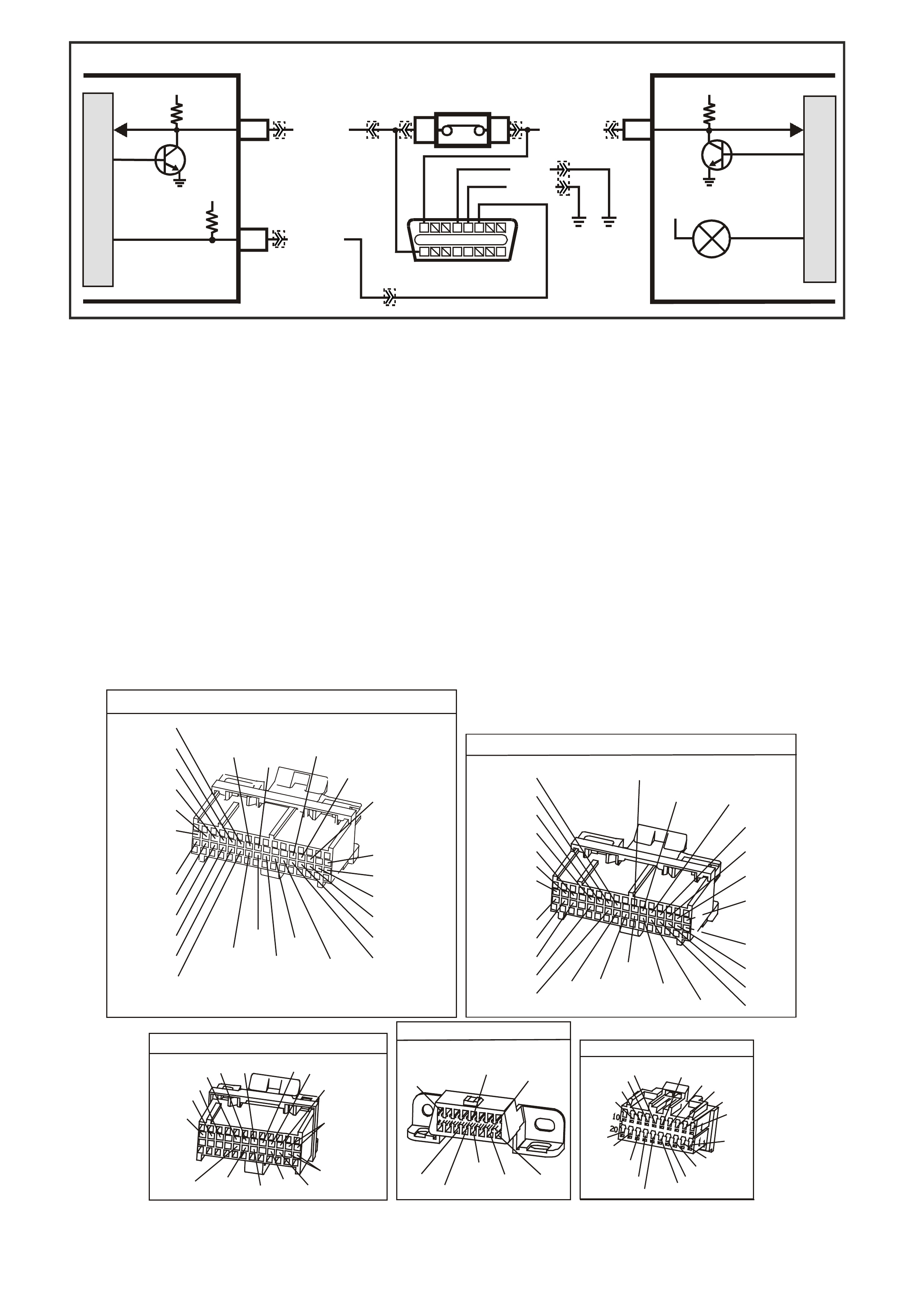
TABLE A-1 V6 PCM -
NO "CHECK POWERTRAIN" MALFUNCTION INDICATOR LAMP (MIL)
CIRCUIT DESCRIPTION:
There should always be a steady "Check Powertrain" (MIL) lamp with the ignition "ON" and engine stopped.
Battery voltage is supplied directly to the "Check Powertrain" (MIL) lamp bulb through a fused circuit. The
Powertrain Control Module (PCM) will control the lamp via serial data communication to the Body Control
Module (BCM) on the ser ial data circuit. When the PCM determ ines that the "Chec k Powertrain" lam p should be
"ON", the PCM will send a message on the serial data circuit to the BCM requesting the (MIL) "ON". The BCM
will then send a serial data communication message to the instrument panel (IP) Cluster. The IP Cluster will
then determine what message the BCM is sending, and will then turn "ON" the "Check Powertrain" lamp.
TEST DESCRIPTION: Number(s) below refer to step number(s) on the diagnostic Table.
2. Fuse F13 supplies power to the instrument panel cluster. If this fuse is blown, the cluster lamps will not light.
5. If the T ech 2 sc an tool will not comm unicate with the vehicle, there m ay be a problem in the serial data line.
Table A-2 will check this serial data line.
6. If the Tech 2 scan tool is capable of commanding the MIL "ON" and "OFF", the PCM may be at fault.
7. This step checks for proper serial data voltage to the instrument panel (IP) cluster.
YB1 93
(413)
(412)
(1413)
(1412)
(430)
(453)
(815)
V/B
GY/B
V
GY
V
B/R
W/R
(897)
(897)
G/W
G/W
(418)
(418)
BR
BR
(1426)
O/W
C16
D16
WT/B
(832)AUTO
(647)
(630)
BR
T
(832) MAN
LBLU/B
B
(424)
(423)
C1
D1
(792)
(422)
(1222)
(1223)
(428)
(123)
BR/W
GY/R
LG
Y/B
G/Y
V/W
BLU/W
BLU
(831) Man
(443)
LG/W
(442) (831)AUTO
(441)
LBLU
LBLU/B
(444)
LG/B
P.C.M. CONNECTOR 1
YE194
P.C.M. CONNECTOR 3
LG/B
(366)
G
(843)
B/W
F16
B/Y
BR/Y
(1228)
(469)
Y
(451)
F1
P
(841)
BLU
V
E1
LBLU
(845)
BLU
B
(1226)
W/B
BLU/W
V
R
(435)
(31)
(1229)
GY
(1224)
Y
(846)
GY
(842)
(452)
(774)
(304)
BR/Y
(411)
(439)
GY/BLU
BLU
(1225)
E16
(1427)
(429)
(844)
B/O
(434)
OR AUTO
GY/BLU
GY
(1434)
MAN
(776)
W
BLU/W
Y
GY
(771)
(772)
(773)
YB 188
P.C.M CONNECTOR 2
(481)
(417)
(740)
R
BLU
O
(1456)
LG
V/W
(415)
Y
(1227)
B/Y
(410)
BR
(472)
(259)
(750)
(750)
(1221)
B/R
B/R
R/B
G/B
(39)
P
(465)
G/W
(416)
GY
(740)
O
A1
B1
B12
A12
DATA LINK CO NNECTO R
YB128
(863)
O/B BLU/B R/B
(1221)
(740)
16 9
(1220)
(155)
B/Y G/W
W/B
(451)
B
(150)
Y
(1049)
1
8
YB66
INSTRUMENTS
T
BLU/B
BR/W
(234)
(25)
(14)
(10)
(875)
(155)
(1340)
G/W
(44)
(121)
(8)
(30)
BLU/Y
G
O/Y
P/BLU
BR/R
V/W
(33)
(946)
(1220)
(88)
(15)
(123)
(85)
(19)
GY
W
V/R
BR
BR/O
Y/R
B/Y
LBLU
BLU
M
I
C
R
O
SUPERVX30
INSTRUMENTPCM
12 SERIAL
DATA
5V
G/W (1220)
LOC. E3
R/B (1221)
CHECK
POWERTRAIN
LAMP
12V
5V
5V
F14
A3
SERIAL
DATA
DIAGNOSTIC
ENABLE
W/B (451)
BCM
E2
D2 E9
D3
DATA LINK
CONNECTOR
1546
1613129
B (150)
B/Y (155 )
M
I
C
R
O
YB66
YE114
YE111
YE112
YB175
YB188
YB194
YB164 YB175
YB164
YB128

TABLE A-1 V6 PCM NO "CHECK POWERTRAIN" MALFUNCTION INDICATOR LAMP (MIL)
STEP ACTION VALUE YES NO
1. Was the "On-Board Diagnostic" (OBD) System Check
performed? Go to Step 2. Go to OBD
System Check in
this Section
2. Check IP cluster fuse F13.
Is fuse OK? Go to Step 3 Go to Step 9
3. 1. Ignition "OFF".
2. Disconnect PCM connectors.
3. Ignition "ON".
4. Probe PCM battery feed circuits and ignition feed
circuit with a test light connected to earth.
Is the test light "ON" for all circuits?
Go to Step 4 Go to Step 15
4. 1. Ignition "OFF".
2. Disconnect PCM connectors.
3. Probe PCM earth circuits with a test light connected
to B+.
Is the test light "ON" for both circuits?
Go to Step 5 Go to Step 16
5. 1. Ignition "OFF".
2. Reconnect PCM connectors.
3. Connect Tech 2 scan tool to DLC.
4. Ignition "ON", engine stopped.
Does Tech 2 scan tool display PCM serial data?
Go to Step 6 Go to Table A-2
6. With scan tool still connected to DLC, command the MIL
"ON" using the scan tool.
Does the MIL turn "ON" when commanded "ON" using
the scan tool?
Go to Step 14 Go to Step 7
7. 1. Ignition "OFF".
2. Remove IP Cluster from dash panel.
3. Ignition "ON".
4. Using DVM, probe IP Cluster connector
terminal
12 with the DVM connected to earth.
Does the DVM display a varying voltage between
the specified value?
3-5 volts Go to Step 8 Go to Step 10
8. Check for poor connection between the IP Cluster
and cluster connector.
Was a problem found?
Verify Repair Go to Step 11
9. Repair short to earth in IP cluster fuse circuit.
Is action complete ? Verify Repair
10. Repair open in the serial data circuit from the BCM
to IP Cluster.
Is action complete?
Verify Repair
11. Check "Check Powertrain " (MIL) bulb for open.
Was a problem found? Go to Step 12 Go to Step 13
12. Replace "Check Powertrain " (MIL) bulb.
Is action complete? Verify Repair
13. Replace IP cluster.
Is action complete? Verify Repair
14. Replace PCM.
Refer to Section 6C1-3 Service Operations of the
VX Series Service Information, for PCM Security
Link procedure.
Is action complete?
Verify Repair
15. Check for short to earth, and repair open in power
circuit that did not light test light.
Is action complete?
Verify Repair
16. Repair open in earth circuit that did not light test
light.
Is action complete?
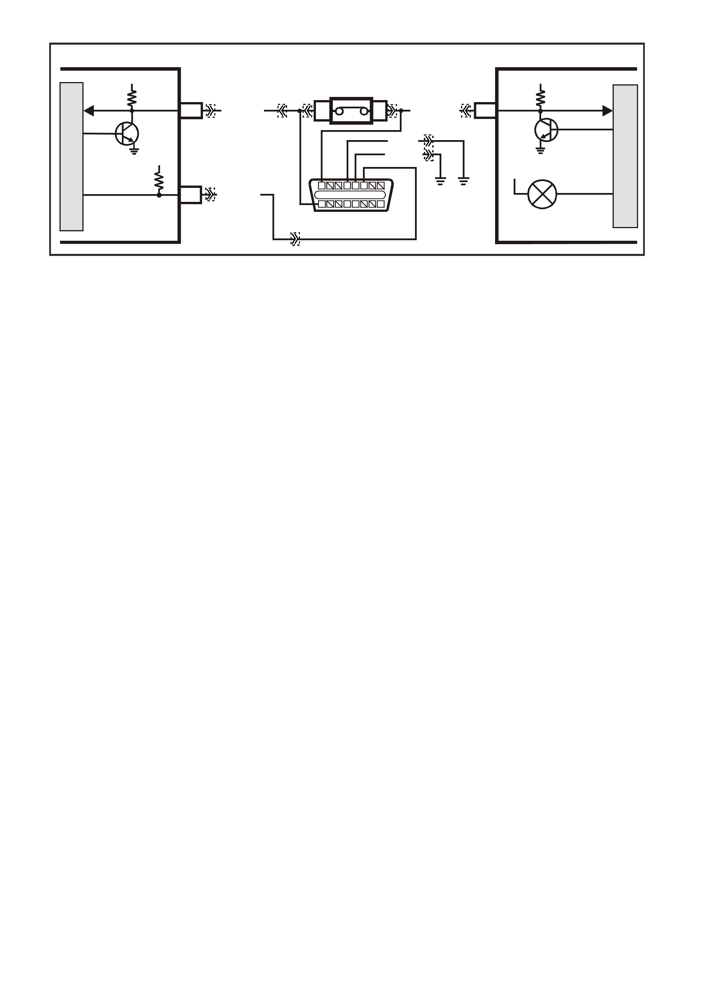
TABLE A-2 V6 PCM -
NO SERIAL DATA, WILL NOT FLASH DTC 12, MALFUNCTION INDICATOR LAMP (MIL)
"CHECK POW ERTRAIN" LAMP "ON" STEADY
CIRCUIT DESCRIPTION:
There s hould always be a steady (MIL) "Check Powertrain" lamp when the ignition is "O N" and engine stopped.
Battery voltage is supplied directly to the (MIL) "Check Powertrain" lamp bulb. The Powertrain Control Module
(PCM) will control the "Check Powertrain" lamp and turn it "ON" via the serial data communication circuit..
With the ignition "ON", engine stopped and diagnostic "test" terminal earthed, the "Check Powertrain" lamp
should flash a DTC 12, followed by any diagnostic trouble code(s) stored in memory.
A steady lamp suggests a fault in the IP cluster.
With the Tech 2 scan tool connected to the DLC and the ignition switch on, the scan tool should display serial
data communication. If the scan tool does not display serial data, the serial data circuit may be open or shorted.
There are several other control modules that are connected to the serial data line (PCM, BCM, ABS/ETC
module, ECC module, SRS module and IP cluster). Any one of these controllers could cause a fault on the
serial data line. This fault could result in the scan tool not being able to display serial data.
TEST DESCRIPTION: Number(s) below refer to step number(s) on the diagnostic Table.
2. This step checks to see if the PCM will flash DTC 12 or any other DTC.
3. This step checks to see if the Tech 2 scan tool will
communicate with the PCM.
4. Using a Digital Volt\Ohm meter (DVM), there should be 3 to 5 volts at the DLC terminal 9. If the voltage is
higher or lower, serial communication will be effected. This serial data circuit is also connected to several
other controllers. A problem with any one of
these other controllers, may cause serial data communication malfunction.
13. This step c hec ks to see if the Serial Data circ uit is shor ted to voltage or ear th. Chec k Serial Data circuit fr om
PCM, to BCM, and from BCM to all other controllers.
DIAGNOSTIC AIDS:
If there is a fault with the serial data circuit, it could be caused by one or more of the several controllers
connected to this serial data circuit. Isolate the fault by disconnection one at a time each controller until the
serial data communication is restored.
M
I
C
R
O
SUPERVX30
INSTRUMENTPCM
12 SERIAL
DATA
5V
G/W (1220)
LOC. E3
R/B (1221)
CHECK
POWERTRAIN
LAMP
12V
5V
5V
F14
A3
SERIAL
DATA
DIAGNOSTIC
ENABLE
W/B (451)
BCM
E2
D2 E9
D3
DATA LINK
CONNECTOR
1546
1613129
B (150)
B/Y (155 )
M
I
C
R
O
YB66
YE114
YE111
YE112
YB175
YB188
YB194
YB164 YB175
YB164
YB128
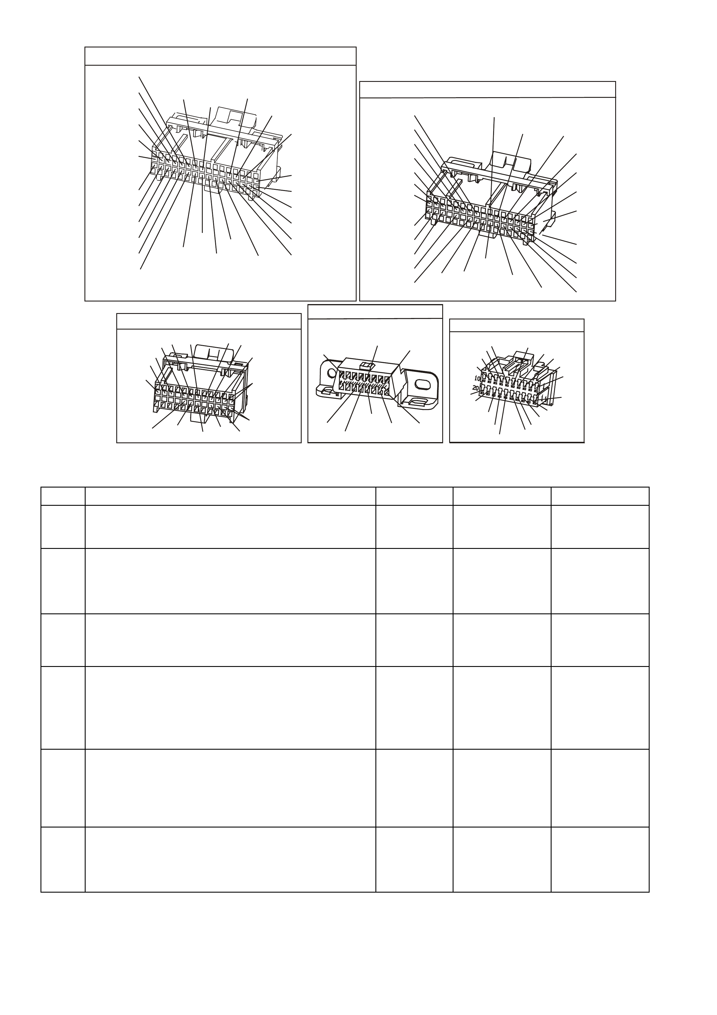
YB1 93
(413)
(412)
(1413)
(1412)
(430)
(453)
(815)
V/B
GY/B
V
GY
V
B/R
W/R
(897)
(897)
G/W
G/W
(418)
(418)
BR
BR
(1426)
O/W
C16
D16
WT/B
(832)AUTO
(647)
(630)
BR
T
(832) MAN
LBLU/B
B
(424)
(423)
C1
D1
(792)
(422)
(1222)
(1223)
(428)
(123)
BR/W
GY/R
LG
Y/B
G/Y
V/W
BLU/W
BLU
(831) Man
(443)
LG/W
(442) (831)AUTO
(441)
LBLU
LBLU/B
(444)
LG/B
P.C.M. CONNECTOR 1
YE194
P.C.M. CONNECTOR 3
LG/B
(366)
G
(843)
B/W
F16
B/Y
BR/Y
(1228)
(469)
Y
(451)
F1
P
(841)
BLU
V
E1
LBLU
(845)
BLU
B
(1226)
W/B
BLU/W
V
R
(435)
(31)
(1229)
GY
(1224)
Y
(846)
GY
(842)
(452)
(774)
(304)
BR/Y
(411)
(439)
GY/BLU
BLU
(1225)
E16
(1427)
(429)
(844)
B/O
(434)
OR AUTO
GY/BLU
GY
(1434)
MAN
(776)
W
BLU/W
Y
GY
(771)
(772)
(773)
YB 188
P.C.M CONNECTOR 2
(481)
(417)
(740)
R
BLU
O
(1456)
LG
V/W
(415)
Y
(1227)
B/Y
(410)
BR
(472)
(259)
(750)
(750)
(1221)
B/R
B/R
R/B
G/B
(39)
P
(465)
G/W
(416)
GY
(740)
O
A1
B1
B12
A12
DATA LINK CO NNECTO R
YB128
(863)
O/B BLU/B R/B
(1221)
(740)
16 9
(1220)
(155)
B/Y G/W
W/B
(451)
B
(150)
Y
(1049)
1
8
YB66
INSTRUMENTS
T
BLU/B
BR/W
(234)
(25)
(14)
(10)
(875)
(155)
(1340)
G/W
(44)
(121)
(8)
(30)
BLU/Y
G
O/Y
P/BLU
BR/R
V/W
(33)
(946)
(1220)
(88)
(15)
(123)
(85)
(19)
GY
W
V/R
BR
BR/O
Y/R
B/Y
LBLU
BLU
TABLE A-2 V6 PCM - NO SERIAL DATA, WILL NOT FLASH DTC 12, MALFUNCTION INDICATOR LAMP
(MIL) "CHECK POWERTRAIN" LAMP "ON" STEADY
STEP ACTION VALUE YES NO
1. Was the "On-Board Diagnostic" (OBD) System Check
performed? Go to Step 2 Go to OBD
System Check in
this Section.
2. 1. Ignition" ON" engine stopped.
2. Earth diagnostic "TEST" terminal No. 6.
Does "CHECK POWERTRAIN" lamp flash DTC 12 or any
other DTC?
Go to Step 3 Go to Step 6
3. 1. Connect Tech 2 scan tool to DLC.
2. Ignition "ON", engine stopped.
Does Tech 2 scan tool display PCM serial data?
No trouble found Go to Step 4
4. 1. Ignition "ON" engine stopped.
2. Using DVM, probe DLC terminal 9 with DVM
connected to earth.
Does DVM display voltage varying between the specified
value?
3-5 volts Go to Step 5 Go to Step 8
5. Check connections between the DLC and the PCM. If not
OK repair, if connection are OK, Replace PCM,
Refer to Section 6C1-3 Service Operations in this Section
for PCM Security link procedure.
Is action complete?
Verify Repair
6. 1. Ignition "ON" engine stopped.
2. Using DVM, probe DLC terminal 6 with DVM
connected to earth.
Does DVM display voltage at specified value?
5 volts Go to Step 13 Go to Step 12

TABLE A-2 V6 PCM - NO SERIAL DATA, WILL NOT FLASH DTC 12, MALFUNCTION INDICATOR LAMP
(MIL) "CHECK POWERTRAIN" LAMP "ON" STEADY
STEP ACTION VALUE YES NO
7. Replace IP cluster.
Is action complete? Verify Repair
8. Is voltage steady at or above the specified value? 5 volts Go to Step 11 Go to Step 9
9. 1. Connect Tech 2 scan tool to DLC.
2. Ignition "ON", engine stopped.
Does Tech 2 scan tool display BCM serial data?
Go to Step 10 Go to Step 13
10. Repair open or short to earth in the serial data circuit
between the PCM and the DLC.
Is action complete?
Verify Repair
11. Repair short to voltage on the serial data circuit.
NOTE: Insure that none of the other controllers on the
serial data circuit are causing this voltage
problem. Unplug each controller one at a time
to isolate short to voltage.
Is action complete?
Verify Repair
12. Check for an open in the Diagnostic Test circuit from the
PCM to the DLC.
Was a problem found?
Verify Repair Go to Step 5
13. Check for short to earth or short to voltage or open in the
serial data line.
Refer to Diagnostic Aids.
Was a problem found?
Verify Repair Go to Step 7

TABLE A-3.1-1 V6 PCM -
ENGINE CRANKS BUT WILL NOT RUN
CIRCUIT DESCRIPTION:
This is the first of several diagnostic T ables that must be followed in an orderly, progressive fashion in order to
find the cause of a no-start. These Tables assume an adequate supply of good quality fuel is in the fuel tank,
that the cranking motor circuit is in good working order, and that the engine will crank with adequate RPM.
These Tables also assume that no Diagnostic Trouble Code (DTC) 31 or 46 is set in the PCM memory, as
determined by the On-Board Diagnostic Circuit Check. The On-Board Diagnostic System Check is always the
beginning point for all diagnostic procedures.
TEST DESCRIPTION: Number(s) below refer to step number(s) on the diagnostic Table.
1. The PCM must be operable. The On-Board Diagnostic System Check will prove that. There are few
chances that the PCM itself would cause a no-start, but the On-Board Diagnostic System Check will
uncover any problems in the PCM power and earth circuitry.
4. This checks for a short to earth on the injector control circuit. If this were to occur, the engine would be
extremely flooded, since the injectors would be "ON" continuously, and would inject fuel any time there is
fuel pressure.
5. Any time the PCM has been "OFF" for at least 10 seconds, it should energise the Fuel Pump Relay for 2
seconds after the ignition is turned "ON." If the engine is not cranked, the PCM should turn the relay "OFF"
after 2 seconds. Proper operation of the Fuel Pump electrical circuit would be noted here by the test light
being "ON" for 2 seconds after the ignition switch is turned to the "ON" position. After 2 seconds, the test
light should go "OFF."
6. Note that this check is for sufficient voltage at the spark plug wire. If, for some reason, the spark plug
electrodes were wet with fuel (engine f looded), this could c ause a no-start. However, a "flooded" engine is a
symptom of some other problem. There is no normal condition that should ever be able to "flood" the
engine.
7. This is a quick check of the fuel system. The easiest place to install the pressure gauge is where the fuel
pipes come up into the engine compartment. There are 2 hoses, and the gauge must be connected to the
hose or pipe leading directly to the fuel rail. This connection is on the left (passenger) side of the fuel rail
(refer Service Operation 3.11 FUEL CONTROL SYSTEM; Fuel System Pressure Test). The other hose or
pipe leads to the pressure regulator, and no pressure testing is done there. If the pressure is not as
specified, or continues to drop after the pump stops running, the Fuel System Diagnostic Table A-4.3 in this
Section must be used.
SUPERVX017
# 2
# 4 # 6
# 1 # 3 # 5
PCM
A8
B8
F3
F1
F2
E2
E4
B12
A4
BATTERY FEED
BATTERY FEED
O
(740)
O
(740)
BLU
(841)
V
(843)
GY
(845)
INJECTOR CONTROL
IN JECTOR VOLTAGE
MONITOR LINE
IGNITION FEED
O/Y (479)
EFI R EL AY
B/W (152)
LOC. E4
P (3 )
O/B (740)
IGN SW
M
I
C
R
O
R
(481)
P
(39)
Y
(846)
BR/Y
(844)
G
(842)
F31
F14
F34
BATTERY
FS
FJ
R (2)
(1040)
YE112
YE114
YE111
YB194
YB188
YE39 YE39
YB188
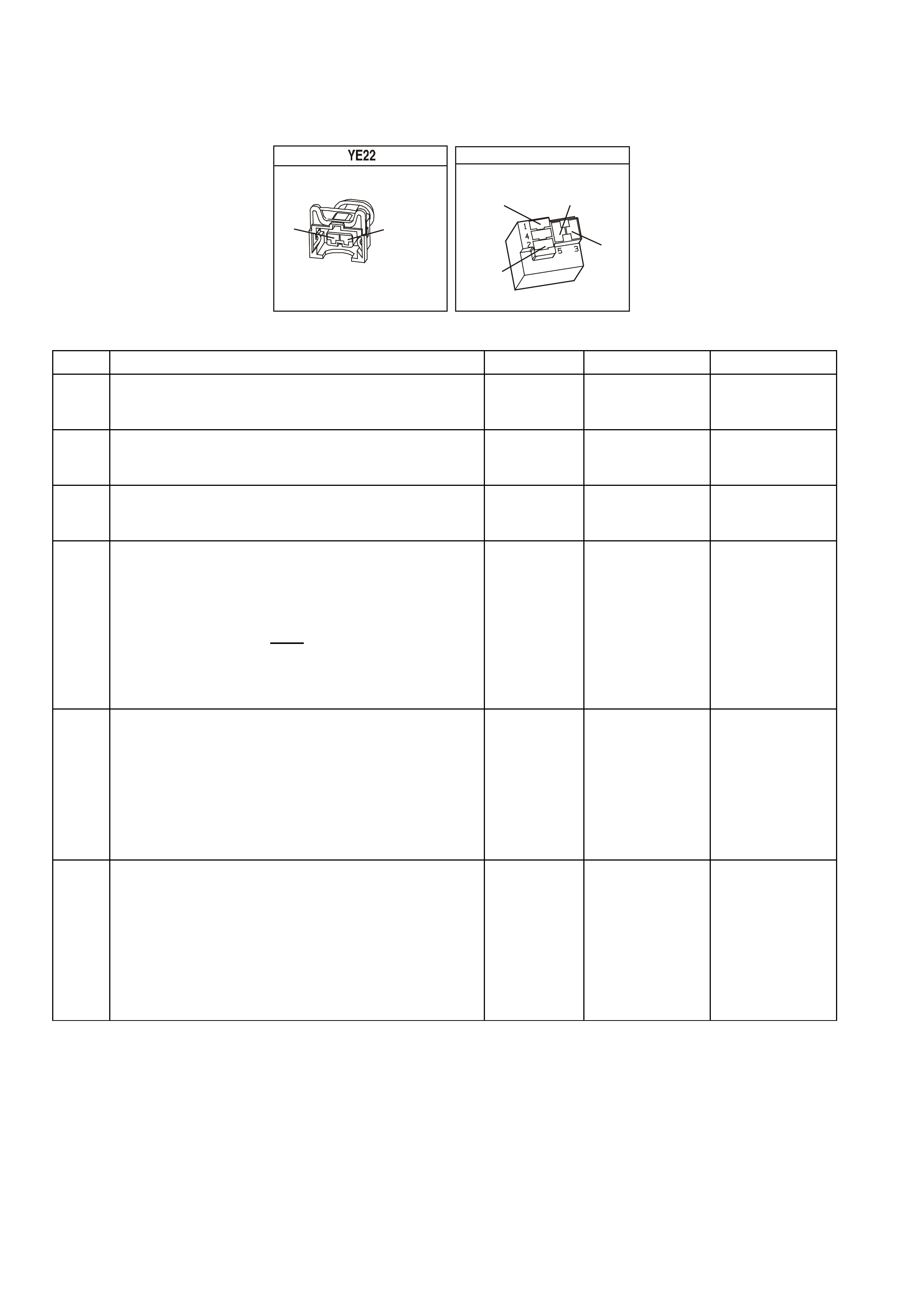
NOTE: Use ST 125 spark checker or equivalent. An ST 125 requires about 25,000 volts (25 k ilovolts, or 25 k V)
to "spar k ". Do not us e a s par k plug in open air ear thed to the engine as an indic ation of s uf f ic ient "spar k". Only a
few kilovolts are required to jump the gap of a spark plug outside of the engine, and that would be an
inadequate test of the ignition coil output ability.
INJECTORS
GY
(1)
(842)
(481)
Y
V
BLU
(6)
(4)
(2)
(846)
(843)
G
R
(845)
(841)
(5)
(844)
BR/Y
(3)
FUEL PUMP RELAY
YE 96
(465)
G/W
(152)
B/W V
(120)
O
(240)
TABLE A-3.1-1 V6 PCM - ENGINE CRANKS BUT WILL NOT RUN
STEP ACTION VALUE YES NO
1. Was the "On-Board Diagnostic" (OBD) System Check
performed? Go to Step 2. Go to OBD
System Check in
this Section.
2. Is DTC 31 present ? Go to DTC 31
Table in this
Section
Go to Step 3
3. Is DTC 46 present ? Go to DTC 46
Table in this
Section
Go to Step 4
4. 1. Check fuel tank quantity .
2. Disconnect ALL injector electrical connectors.
3. Connect test light between the terminals of each
injector harness connector.
• Be very careful to NOT short across the terminals,
or to engine earth.
4. Ignition "ON", note test light.
Is light "OFF" ?
Go to Step 5 Go to Step 8
5. 1. Ignition "OFF".
2. Backprobe Fuel Pump Control Module "6" circuit with
a test light connected to earth.
3. Ignition "ON".
4. Using TECH 2 scan tool, Select Fuel Pump.
5. Activate Fuel Pump
Is test light "ON"?
Go to Step 6 Go to
Table A-4.1-1
in this Section
6. 1. Ignition "OFF".
2. Remove the spark plug leads from 2 spark plugs.
3. Connect ST 125 spark checker (refer note above) to
each individually, and check for spark
while cranking the engine.
4. Check both wires. A few sparks and then nothing
is considered no spark.
Was there spark on both wires ?
Go to Step 7 Go to
Table A-8.1 in
this Section

TABLE A-3.1-1 V6 PCM - ENGINE CRANKS BUT WILL NOT RUN
STEP ACTION VALUE YES NO
7. 1. Ignition "OFF".
2. Reconnect both spark plug leads to spark plugs.
3. Reconnect all injector electrical connectors.
4. Remove Fuel Pump Relay from engine compartment
"FUSE AND RELAY CENTRE," and crank engine
for 15 seconds to relieve any residual fuel pressure.
5. Ignition "OFF," connect Fuel Pressure Gauge
6. Reinstall Fuel Pump Relay
7. Observe fuel pressure when ignition is turned "ON."
8. Pressure should be within the value, and not
continue to drop after pump stops running.
Is fuel pressure at or between the value, and holding
steady?
290 to 410
kPa Go to
Table A-3.2 in
this Section
Go to
Table A-4.3 in
this Section
8. Repair short to earth on Injector Circuit.
Was Injector Circuit shorted to earth ? Verify Repair Go to Step 9
9. Replace PCM.
Refer to Section 6C1-3 Service Operations of the VX
Series Service Information, for PCM Security Link
procedure.
Is action complete?
Verify Repair
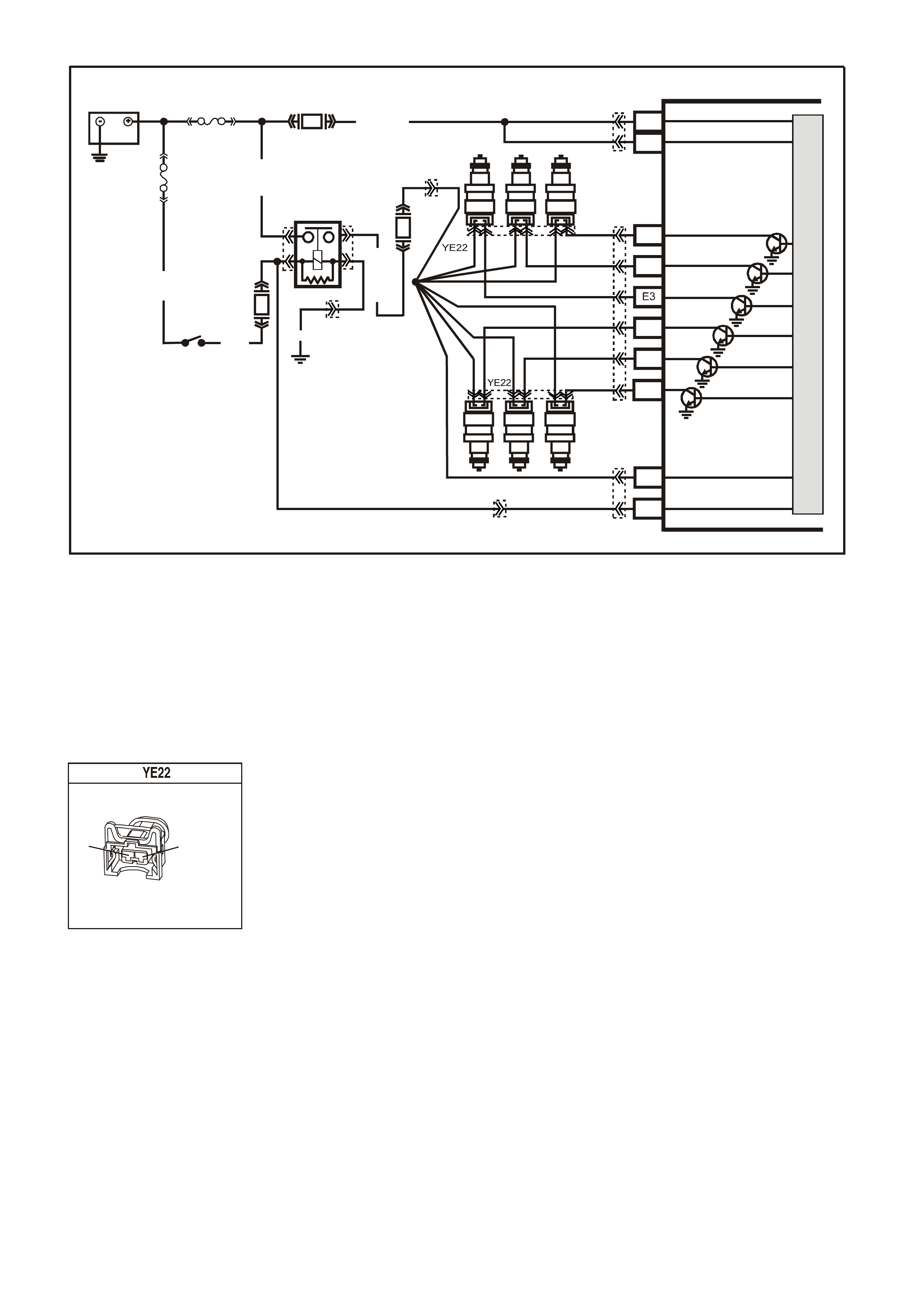
TABLE A-3.2 V6 PCM -
ENGINE CRANKS BUT WILL NOT RUN
TEST DESCRIPTION: Number(s) below refer to step number(s) on the diagnostic Table.
6. "ST EADY LIGHT" indicates the PCM is continuously s upplying the earth path on the injector circuit. It is not
a harness problem at this point; That would have been in Table A-3.1-1. This may destroy an injector, as
they are designed to be energised in short pulses and may not withstand 100% "ON" time. If any injector
check s les s than 11.4 ohm s, it c ould be the cause of the def ective PCM. T he PCM can be damaged when it
attempts to energise the injector circuit with a very-low-resistance load. Normal injector resistance is
approximately 12.2 ohms at 20 degrees C per individual injector.
INJECTORS
GY
(1)
(842)
(481)
Y
V
BLU
(6)
(4)
(2)
(846)
(843)
G
R
(845)
(841)
(5)
(844)
BR/Y
(3)
SUPERVX017
# 2
# 4 # 6
# 1 # 3 # 5
PCM
A8
B8
F3
F1
F2
E2
E4
B12
A4
BATTERY FEED
BATTERY FEED
O
(740)
O
(740)
BLU
(841)
V
(843)
GY
(845)
INJECTOR CONTROL
IN JECTOR VOLTAGE
MONITOR LINE
IGNITION FEED
O/Y (479)
EFI R EL AY
B/W (152)
LOC. E4
P (3 )
O/B (740)
IGN SW
M
I
C
R
O
R
(481)
P
(39)
Y
(846)
BR/Y
(844)
G
(842)
F31
F14
F34
BATTERY
FS
FJ
R (2)
(1040)
YE112
YE114
YE111
YB194
YB188
YE39 YE39
YB188

TABLE A-3.2 V6 PCM - ENGINE CRANKS BUT WILL NOT RUN
STEP ACTION VALUE YES NO
1. Was the "On-Board Diagnostic" (OBD) System Check
performed? Go to Step 2. Go to OBD
System Check in
this Section.
2. • From Table A-3.1-1.
1. Ignition "OFF".
2. With all injectors disconnected, connect test light
across both harness terminals of one injector
connector.
• Be very careful to not short across the terminals, or
to engine earth.
3. Have a helper crank the engine while you closely
observe the test light.
4. Test light should blink while cranking, indicating
electrical injector pulses are present, do this test for
all injectors
Did test light blink while cranking ?
Go to Step 3 If
there was no
blinking light, Go
to Table 3.3 in
this Section
----------------------
If the test light
was on steady
(no blinking light)
Go to Step 6
3. Check the remaining 5 injector connectors for
blinking test light, as described in step 2.
Did all the remaining injector connectors blink the
test light ?
Go to Step 4 Go to Step 5
4. • At this point, the fuel control system, fuel delivery
system, and ignition system are OK.
Check For:
• Fouled spark plugs.
• Proper MAF sensor operation. If engine
will start with MAF sensor electrical
connector disconnected, refer Table
A-6.1 in this Section.
• Proper TP sensor circuit operation. Use
Tech 2 scan tool to monitor TP sensor
signal. If voltage is over 1.25 volts with
throttle closed, refer Table A-6.2 in this
Section.
• Restricted exhaust system. Loosen
front pipe from exhaust manifold(s). If
the engine will start, refer Table A-13 in
this Section.
• Improper engine coolant temperature
(ECT) sensor resistance. Refer DTC 14
Diagnostic Aids in this Section to check
resistance of ECT sensor.
• Water or foreign material in fuel, or
incorrect fuel.
• Spark plug wires crossed.
• Camshaft timing chain.
• Inadequate engine compression.
Is action complete?
Verify Repair
5. Repair open in injector power circuit and injector circuit to
connector that did not blink the test light.
Is action complete ?
Verify Repair

TABLE A-3.2 V6 PCM - ENGINE CRANKS BUT WILL NOT RUN
STEP ACTION VALUE YES NO
6. Check for a short to earth in injector circuit that caused
test light to stay "ON" steady.
Was a problem found?
Verify Repair Go to Step 7
7. Check resistance across each injector. Each injector
should be between the specified value.
Is each injector at the value ?
11.4 - 12.6
ohms Go to step 8 Go to step 9
8. Replace PCM.
Refer to Section 6C1-3 Service Operations of the VX
Series Service Information, for PCM Security Link
procedure.
Is action complete?
Verify Repair
9. 1. Replace any injector that did not measure within
the specified value.
2. Retest beginning at Step 2.
Is action complete?
11.4 - 12.6
ohms Verify Repair

TABLE A-3.3 V6 PCM -
ENGINE CRANKS BUT WILL NOT RUN
TEST DESCRIPTION: Number(s) below refer to step number(s) on the diagnostic Table.
2 "NO LIGHT" indicates no PCM control of the injector. Fuse F34 supplies +12 volts to the injectors. Probe
both terminals of one injector connector with a test light to earth. There should be a light on only one
terminal, confirming ignition voltage to one terminal, but not both.
3. The PCM inj ec tor contr ol c irc uit may be open. Rec onnect the inj ec tors . Us ing a tes t light connec ted to ear th,
check for a light at the PCM connector terminals. A light at this point indicates that injector control circuit is
not "open." The voltage to light that test light comes from circuit 481, through the injector windings, and
continues through the injector control circuit to PCM connector terminals.
7. There is no terminal identification on the relay connector socket, but the relay itself has terminal numbers.
Make certain the correct relay connector socket terminal (NOT the relay) is being probed.
SUPERVX017
# 2
# 4 # 6
# 1 # 3 # 5
PCM
A8
B8
F3
F1
F2
E2
E4
B12
A4
BATTERY F EED
BATTERY F EED
O
(740)
O
(740)
BLU
(841)
V
(843)
GY
(845)
INJECTOR CONTROL
IN JE C TOR VOLTAG E
MONITOR LINE
IGNITION FEED
O/Y (479)
EFI R EL AY
B/W (152)
LOC. E4
P (3 )
O/B (740)
IGN SW
M
I
C
R
O
R
(481)
P
(39)
Y
(846)
BR/Y
(844)
G
(842)
F31
F14
F34
BATTERY
FS
FJ
R (2)
(1040)
YE112
YE114
YE111
YB194
YB188
YE39 YE39
YB188
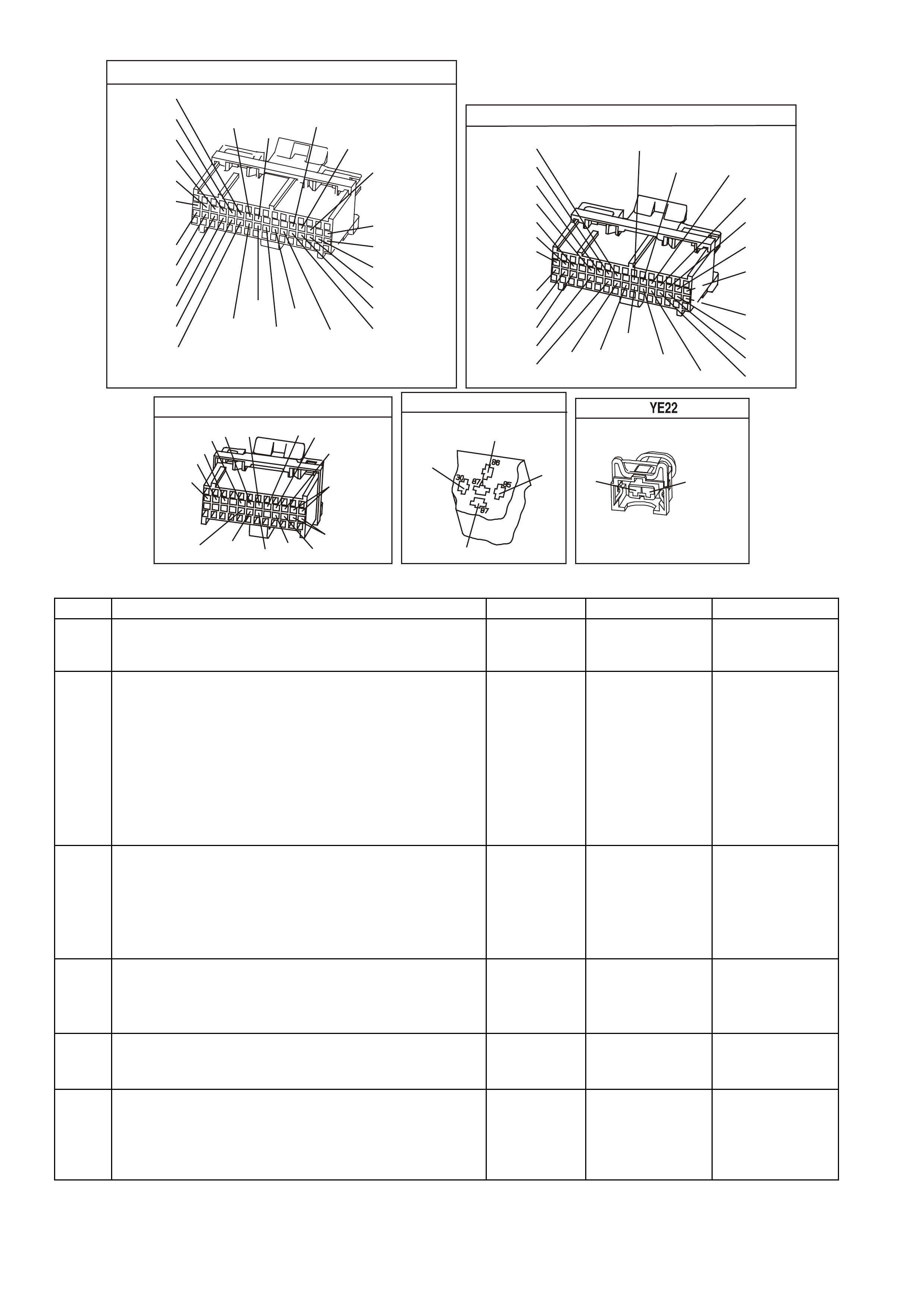
YB1 93
(413)
(412)
(1413)
(1412)
(430)
(453)
(815)
V/B
GY/B
V
GY
V
B/R
W/R
(897)
(897)
G/W
G/W
(418)
(418)
BR
BR
(1426)
O/W
C16
D16
WT/B
(832)AUTO
(647)
(630)
BR
T
(832) MAN
LBLU/B
B
(424)
(423)
C1
D1
(792)
(422)
(1222)
(1223)
(428)
(123)
BR/W
GY/R
LG
Y/B
G/Y
V/W
BLU/W
BLU
(831) Man
(443)
LG/W
(442) (831)AUTO
(441)
LBLU
LBLU/B
(444)
LG/B
P.C.M. CONNECTOR 1
YE194
P.C.M. CONNECTOR 3
LG/B
(366)
G
(843)
B/W
F16
B/Y
BR/Y
(1228)
(469)
Y
(451)
F1
P
(841)
BLU
V
E1
LBLU
(845)
BLU
B
(1226)
W/B
BLU/W
V
R
(435)
(31)
(1229)
GY
(1224)
Y
(846)
GY
(842)
(452)
(774)
(304)
BR/Y
(411)
(439)
GY/BLU
BLU
(1225)
E16
(1427)
(429)
(844)
B/O
(434)
OR AUTO
GY/BLU
GY
(1434)
MAN
(776)
W
BLU/W
Y
GY
(771)
(772)
(773)
YB 188
P.C.M CONNECTOR 2
(481)
(417)
(740)
R
BLU
O
(1456)
LG
V/W
(415)
Y
(1227)
B/Y
(410)
BR
(472)
(259)
(750)
(750)
(1221)
B/R
B/R
R/B
G/B
(39)
P
(465)
G/W
(416)
GY
(740)
O
A1
B1
B12
A12
E.F.I RELAY
YE 39
B/W
P/B
O/Y
(152)
(39)
(479)
(1040)
ENGINE 12V BUS
INJECTORS
GY
(1)
(842)
(481)
Y
V
BLU
(6)
(4)
(2)
(846)
(843)
G
R
(845)
(841)
(5)
(844)
BR/Y
(3)
TABLE A-3.3 V6 PCM - ENGINE CRANKS BUT WILL NOT RUN
STEP ACTION VALUE YES NO
1. Was the "On-Board Diagnostic" (OBD) System Check
performed? Go to Step 2. Go to OBD
System Check in
this Section.
2. 1. Ignition "OFF"
2. Disconnect injector connectors. From Table A-3.2
No Light
3. Ignition "ON," engine stopped.
4. Probe each terminal of each injector harness
connector with a test light to earth.
Is the test light "ON" at each terminal?
Go to Step 3 If
the test light was"
ON" at both
terminals, repair
short to voltage
on injector circuit.
----------------------
If there was no
light "ON",
Go to Step 7
3. 1. Ignition "OFF".
2. Reconnect injectors.
3. Ignition "ON".
4. Backprobe PCM injector control terminals with a
test light connected to earth.
Is test light "ON" at each terminal?
Go to Step 4 Go to Step 12
4. 1. Ignition "ON".
2. With a Tech 2 scan tool, monitor TP sensor
signal voltage.
Is voltage less than value?
1.25 volts Go to Step 5 Go to
Table A-6.2
in this Section
5. Check for faulty crankshaft reference High signal input to
PCM connector terminal.
Was a problem found?
Verify Repair Go to Step 6
6. Replace PCM.
Refer to Section 6C1-3 SERVICE OPERATIONS of the
VX Series Service Information, for PCM Security Link
procedure.
Is action complete?
Verify Repair

TABLE A-3.3 V6 PCM - ENGINE CRANKS BUT WILL NOT RUN
STEP ACTION VALUE YES NO
7. 1. Ignition "OFF".
2. Disconnect EFI relay.
3. Ignition "ON".
4. Probe EFI relay harness connector terminal "30" and
terminal "85" with a test light connected to earth.
Is the test light "ON" at both circuits?
Go to Step 8 Go to Step 13
8. 1. Ignition "OFF".
2. Disconnect EFI relay.
3. With test light connected to 12 volts, probe relay
harness terminal earth circuit of EFI relay.
Is test light "ON", is it?
Go to Step 9 Go to Step 14
9. Check injector fuse F34 for an open.
Was a problem found? Go to step 15 Go to Step 10
10. Check for an open in injector power circuit from fuse F34
to injector splice.
Was a problem found?
Verify Repair Go to Step 11
11. Replace EFI relay.
Is action complete? Verify Repair
12. Repair open injector control circuit that did not light test
light.
Is action complete?
Verify Repair
13. Check fuses and repair circuit that did not turn
"ON" test light.
Is action complete?
Verify Repair
14. Repair earth circuit to EFI relay.
Is action complete? Verify Repair
15. Repair short to earth in fuse circuit.
Replace fuse.
Is action complete?
Verify Repair
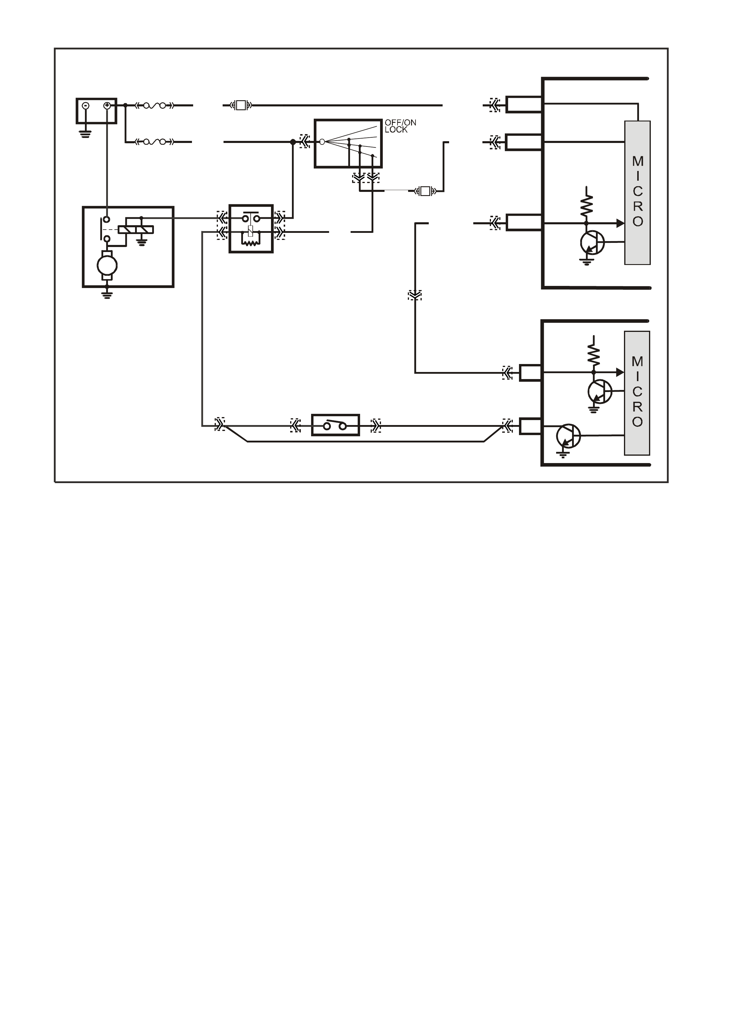
TABLE A- 4.0 V6 PCM -
STARTER CRANKING CIRCUIT
CIRCUIT DESCRIPTION:
W hen the ignition is turned to the "ON" position, battery power is supplied from a fusible link to the Start Relay
terminal "30". As the ignition switch is turned to the START position, power is supplied to the Start Relay
terminal 85. The PCM supplies the earth signal needed to energise the Start Relay and allows power to the
starter motor.
When the ignition is turned “ON”, the PCM will then look for the proper Theft Deterrent signal sent from the
BCM. If the PCM has determined that the proper Theft Deterrent signal is present, the PCM will allow the
vehicle to crank. If the PCM determines that a improper Theft Deterrent signal was sent from the BCM, or no
Thef t Deter rent s ignal was s ent, the PCM will not supply a earth signal from the PCM ter m inal to the Start Relay
terminal "86". When the Start Relay receives this earth signal from the PCM, the relay will be energised,
allowing the starter motor to operate. This removed earth signal to the Start Relay will cause the vehicle not to
crank.
If there is a problem with the Theft Deterrent signal from the BCM to the PCM, DTC 31 will set.
TEST DESCRIPTION: Number(s) below refer to step number(s) on the diagnostic Table.
2. This step checks to see if DT C 31 is set. This DT C could prevent the vehicle from cranking. This step also
verifies that if a PCM was replaced, that the Security Link procedure was performed.
3. This step checks to see if power is being applied to the starter motor. If test light lights, the problem is with
the starter motor.
12. This step checks the adjustment of the Neutral start switch.
VXSC033
PCM
BCM
A3
SERIAL
DATA
STARTER
ENABLE
5V
SERIAL
DATA
MAIN
5V
BATTERY
FS
LOC.
E1
F31
A5/A6O/B (740)
(1040)
BATTERY M AIN POWER
FJ
R (2H)
F14
E20/D6P/B (39) IGNITION ON
15a 15 50
30 ACC
IGN
START
IGNITION SWI TCH
P (3)
LOC. G1
E2/D2
R/B (1221)
GY/BLU
(1434)
GY
(434)
EG
NEUTRAL START
BACK-UP SW.
( MANUAL
TRANS)
STARTER
MOTOR
M
START
RELAY
V (5)
F5
V/W
(6)
87
36 85
30
HIGH SERIES
BCM TERMINALS
NOMINA TED FIRST
YE111 YB194
YB188
YB175
YB164
YB175
YB164
YB176
YB165
YE112
YB44
YB44
YE49
YE49
YB35 YB35
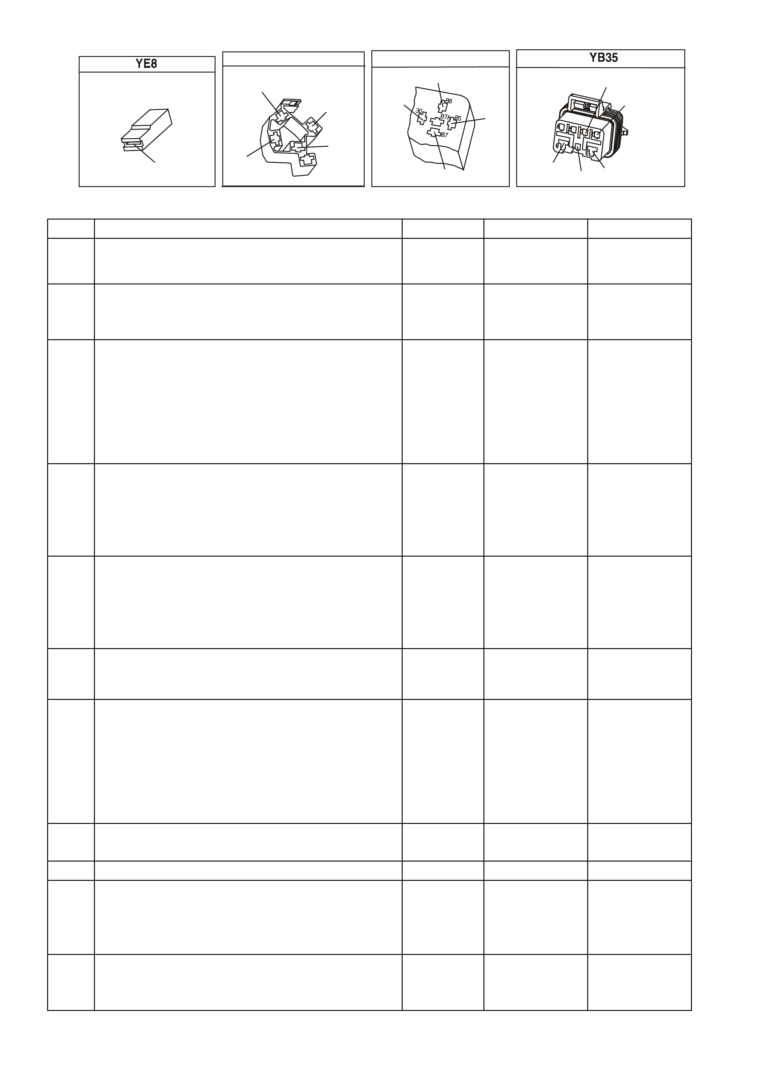
STARTER MOTOR SOLENOID
V
(6)
IGNITION SWITCH
YB 44
BR
(4)
V
(5)
(2)
R
(3)
P
Y E 49
START RELAY
V
(5)
(2)
GY
V/W
R
(434)
(6)
NEUTRAL START & BACK-UP SWITCH
(1434)
GY/BLU
(24)
LG GY
(434)
(750)
B/R
(42)
BR/BLU
TABLE A-4.0 V6 PCM - STARTER CRANKING CIRCUIT
STEP ACTION VALUE YES NO
1 Was the "On-Board Diagnostic" (OBD) System Check
performed? Go to Step 2 Go to OBD
System Check in
this Section
2 1. Install a Tech 2 scan tool.
2. Using the scan tool, check for a DTC 31.
Is DTC 31 set?
Go to the
appropriate DTC
Table
Go to Step 3
3 1. Ignition OFF.
2. Using a test light, probe the starter solenoid terminal
"S" with test light connected to earth.
3. Have a helper turn the ignition switch to the START
position, note the test light.
Does the test light illuminate when the ignition switch is
turned to the START position?
Refer to Section
6D1-2 Starting
System - V6 in
Section 2 of this
Service
Information
Go to Step 4
4 1. Remove the start relay.
2. With a test light connected to earth probe the start
relay harness terminal 30.
3. Turn the ignition ON.
Does the test light illuminate?
Go to Step 5 Go to Step 15
5 1. With the start relay still removed and the test light
connected to earth probe the start relay harness
terminal 85.
2. Turn the ignition to the start position.
Did the test light illuminate?
Go to Step 7 Go to Step 14
6 Check for an open circuit between the starter solenoid
and the Start Relay.
Was a problem found?
Verify Repair Go to Step 8
7 1. Ignition OFF.
2. Remove the Start Relay.
3. Connect a test light between the relay harness
terminal 85 and terminal 86.
4. Turn the ignition switch to the START position.
Does the test light illuminate when the ignition switch is
turned to the START position?
Go to Step 6 Go to Step 9
8 Replace the Start Relay.
Is the action complete? Verify Repair
9 Is the vehicle equipped with a manual transmission? Go to Step 10 Go to Step 12
10 1. Ignition ON engine OFF.
2. With a test light connected to B+, probe both of the
circuits at the neutral start switch.
Did the test light illuminate at both terminals?
Go to Step 16 Go to Step 11
11 Check the adjustment of the neutral start switch. If the
Adjustment is OK, replace the neutral start switch.
Is the action complete?
Verify Repair

TABLE A-4.0 V6 PCM - STARTER CRANKING CIRCUIT (CONT)
STEP ACTION VALUE YES NO
12 Check for open circuit from the neutral start switch to the
Start Relay.
Was a problem found?
Verify Repair Go to Step 17
13 Repair the short to earth in the faulty circuit.
Replace the fusible link or the fuse as necessary.
Is the action complete?
Verify Repair
14 Repair the open in the ignition circuit.
Is the action complete? Verify Repair
15 Check for an open circuit 2 including the fusible link.
Is the action complete? Verify Repair
16 Repair the open in circuit 434.
Is the action complete? Verify Repair
17 Replace PCM.
Refer to Section 6C1-3 Service Operations of the VX
Series Service Information for PCM Security Link
procedure.
Is action complete?
Verify Repair
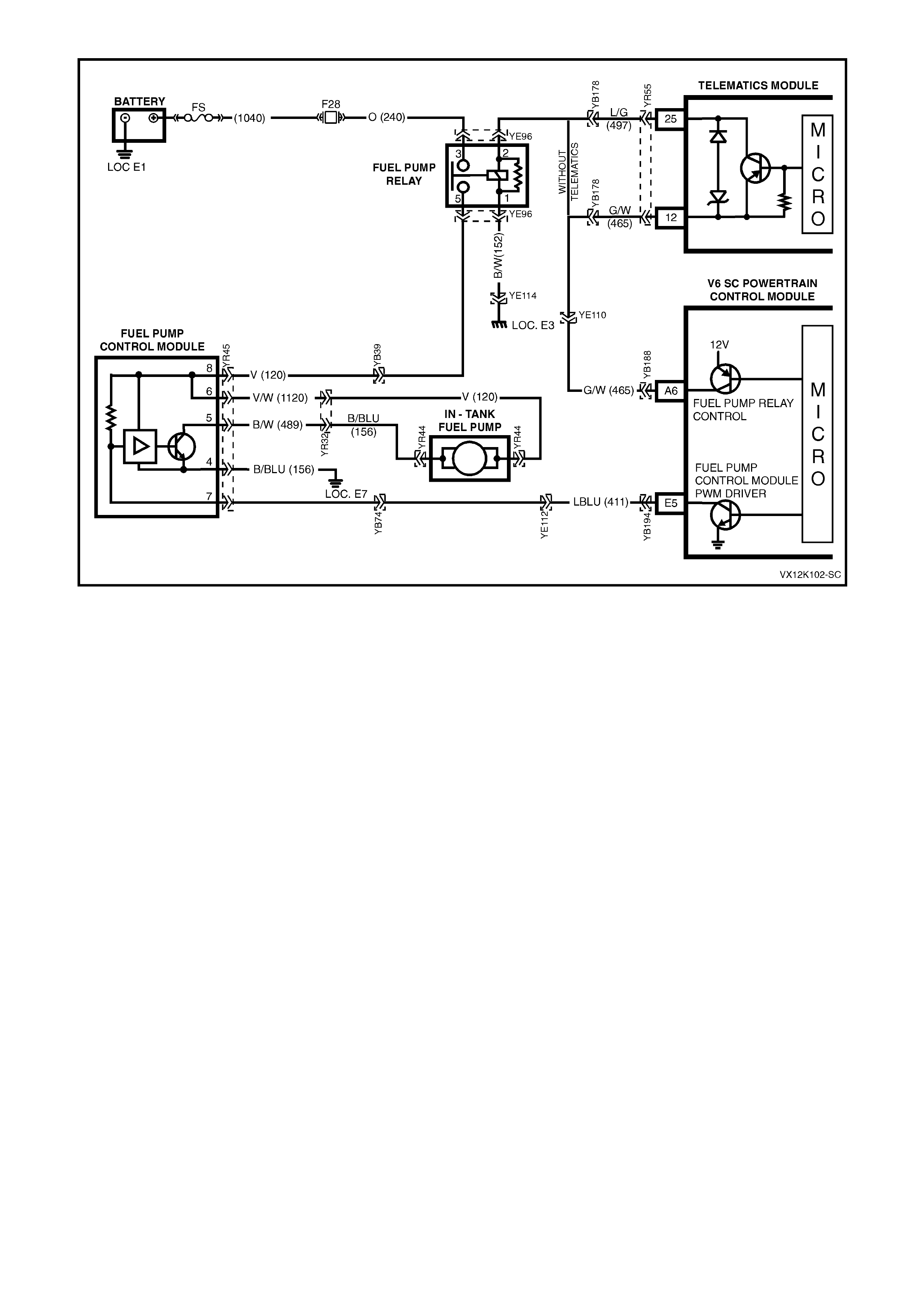
TABLE A-4.1-1 V6 PCM -
FUEL PUMP ELECTRICAL CIRCUIT
Circuit Description:
W hen the ignition switch is first turned "ON", the P CM energises the Fuel Pum p Rela y which applies power to the
Fuel Pump Control Module. The Fuel Pump Relay will remain "ON" as long as the engine is cranking or running
and the PCM is receiving reference pulses. If no reference pulses are present, the PCM de-energises the Fuel
Pump Relay within 2 seconds after the ignition is turned "ON" or the engine is stopped. The Fuel Pump delivers
fuel to the fuel rail injectors, then to the fuel pressure regulator. The pressure regulator control fuel pressure by
allowing ex ces s f uel to be returne d to th e f uel ta nk. W ith the engi ne st op ped , the F uel Pump c an be turne d "ON" b y
using the Tech 2 scan tool output controls function.
The PCM alters Fuel Pump speed by applying or remov ing a dut y c yc le on the F uel Pump PW M driver c ircuit 411
to the Fuel Pum p Control Modu le. Under nor mal driv ing conditio ns, the PCM will appl y a 33% PW M earth signal to
the Fuel P ump Control M od ule c irc u it 41 1. T his 33% d ut y c ycle wil l com mand the Fuel Pump Control Module to r un
the fuel pump at a lower s peed, (lo wer f uel vo lume, low volt age s up pl ied t o f uel pump, between 7 to 9 vo lts.). When
higher fuel volume is required due to increased engine load, the PCM will remove the supplied 33% PWM earth
signal f rom c ircuit 411. T his will c ause the Fu el Pum p Control M odule to s witch i nternall y and allo w the Fue l Pum p
to run at a hi gher sp eed ( hi gher fuel volu me, s ystem volta ge appli ed to f ue l p ump). The PCM a ls o compens a tes f or
low system voltage by commanding the Fuel Pump Control Module to switch to high speed Fuel Pump , when
system voltage is low.
TEST DESCRIPTION: Number(s) below refer to step number(s) on the diagnostic Table.
3. Checks that fuel pressure is sufficient for the vehicle to start.
4. Ensures that the Fuel Pump PWM driver circuit and the PCM are capable of controlling Fuel Pump speed.
5. Verifies that the Fuel Pump feed and earth circuits are OK between the Fuel Pump Control Module and the
Fuel Pump , and that the Fuel Pump can deliver adequate pressure to the fuel rail.
6. Checks the feed circuit to the Fuel Pump Control Module.
8. Ensures that the Fuel Pump PWM driver circuit is not shorted to earth.
13. Checks the ignition feed circuit to the Fuel Pump Relay contacts.
14. Checks the earth circuit for the Fuel Pump Relay coil.
15. Ensures that the Fuel Pump Relay driver circuit is OK and that the PCM is capable of controlling the Fuel Pump
Relay. Using the Tech 2 scan tool to command the Fuel Pump Relay allows only a 2 second "ON" time.
21. Checks the Fuel Pump Relay driver circuit for a short to earth.
26. If the Fuel Pump is operating but incorrect pressure is noted, the Fuel Pump wiring is OK. Go to Table A-4.3.
28. Determines weather the problem is being caused by an open in the Fuel Pum p feed circuit or the Fuel Pump
earth circuit.
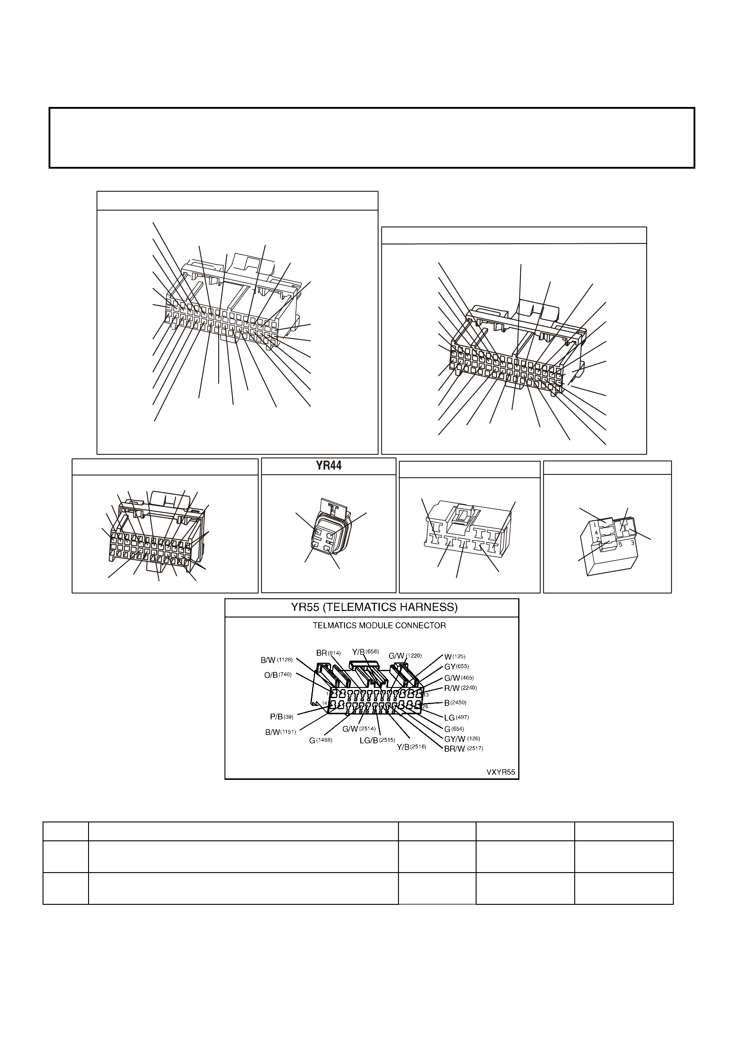
31. Ensures that the Fuel Pump speed control PWM circuit is OK and that the PCM can control the Fuel Pump
speed control PWM driver.
37. The fuel pump on this Supercharged Engine application is serviceable from the Modular Sender Assembly.
Refer to Section 6C1-3 Service Operations in the VX Series Service Information for replacement procedures.
NOTICE:
When performing this diagnostic Table, make certain that the drive wheels are blocked and the parking
brake is firmly set.
YB1 93
(413)
(412)
(1413)
(1412)
(430)
(453)
(815)
V/B
GY/B
V
GY
V
B/R
W/R
(897)
(897)
G/W
G/W
(418)
(418)
BR
BR
(1426)
O/W
C16
D16
WT/B
(832)AUTO
(647)
(630)
BR
T
(832) MAN
LBLU/B
B
(424)
(423)
C1
D1
(792)
(422)
(1222)
(1223)
(428)
(123)
BR/W
GY/R
LG
Y/B
G/Y
V/W
BLU/W
BLU
(831) Man
(443)
LG/W
(442) (831)AUTO
(441)
LBLU
LBLU/B
(444)
LG/B
P.C.M. CONNECTOR 1
YE194
P.C.M. CONNECTOR 3
LG/B
(366)
G
(843)
B/W
F16
B/Y
BR/Y
(1228)
(469)
Y
(451)
F1
P
(841)
BLU
V
E1
LBLU
(845)
BLU
B
(1226)
W/B
BLU/W
V
R
(435)
(31)
(1229)
GY
(1224)
Y
(846)
GY
(842)
(452)
(774)
(304)
BR/Y
(411)
(439)
GY/BLU
BLU
(1225)
E16
(1427)
(429)
(844)
B/O
(434)
OR AUTO
GY/BLU
GY
(1434)
MAN
(776)
W
BLU/W
Y
GY
(771)
(772)
(773)
YB 188
P.C.M CONNECTOR 2
(481)
(417)
(740)
R
BLU
O
(1456)
LG
V/W
(415)
Y
(1227)
B/Y
(410)
BR
(472)
(259)
(750)
(750)
(1221)
B/R
B/R
R/B
G/B
(39)
P
(465)
G/W
(416)
GY
(740)
O
A1
B1
B12
A12
FUEL TANK
(156)
(155)
B/BLU
B/Y
(30)
(120)
T
V
YR45
FUEL CONTRO L MODULE
V
LBLU
V/W
(120)
(411)
(1120)
(489)
(156)
B/W
B/BLU
FUE L PUMP RELAY
YE96
(465)
G/W
(152)
B/W V
(120)
O
(240)
TABLE A-4.1-1 V6 PCM - FUEL PUMP ELECTRICAL CIRCUIT
STEP ACTION VALUE YES NO
1. Was the "On-Board Diagnostic" (OBD) System Check
performed? Go to Step 2. Go to OBD
System Check.
2. Are any DTC’s set? Go to DTC Table
first Go to step 3

STEP ACTION VALUE YES NO
3. 1. Connect Fuel Pressure Gauge to fuel pressure tap
fitting.
2. Ignition "ON".
3. Select Fuel Pump Relay output control with the Tech
2 scan tool.
4. Observe the pressure gauge while turning the fuel
pump "ON" with the Tech 2.
5. Note fuel pressure on Fuel Pressure Gauge.
Is proper fuel pressure indicated?
290 to 410
kPa Go to Step 4 Go to Step 5
4. 1. Engine idling.
2. Remove vacuum hose from fuel pressure regulator,
and plug hose.
3. Observe the Fuel Pressure Gauge at idle.
4. Using scan tool, select Fuel Pump Speed , and select
High Speed.
Does the fuel pressure increase slightly from the idle
Position when the fuel pump High Speed is turned "ON"
Then turned "OFF"?
No problem
found Go to Step 31
5. 1. Ignition "OFF".
2. Disconnect Fuel Pump Control Module.
3. Connect a fused jumper wire between Fuel Pump
Control Module harness connector terminal 6 (Fuel
Pump power feed circuit) and +12. volts.
4. Connect a second jumper between the Fuel Pump
Control Module harness connector terminal 5 (Fuel
Pump earth circuit) and chassis earth.
5. Note the fuel pressure on the Fuel Pressure Gauge
Is proper fuel pressure indicated?
290 to 410
kPa Go to Step 6 Go to Step 26
6. 1. Ignition "OFF".
2. Disconnect the jumpers from the Fuel Pump Control
Module connector.
3. Connect a test light between the Fuel Pump Control
Module harness connector terminal 8 (Fuel Pump
Control Module relay feed circuit) and earth.
4. Ignition "ON".
5. Using the Tech 2 scan tool output control functions,
command the Fuel Pump Relay "ON".
6. Observe the test light.
Did the test light turn "ON"?
Go to Step 7 Go to Step 13
7. Probe terminal 4 (Fuel Pump Control Module earth circuit)
with a test light to +12 volts.
Is the test light "ON"?
Go to Step 8 Go to Step 25
8. 1. Ignition "OFF".
2. Disconnect the PCM connectors.
3. Probe the Fuel Pump Control Module PWM driver
circuit at the PCM connector with a test light
connected to +12 volts.
Is the test light "ON"?
Go to Step 9 Go to Step 10
9. Locate and repair short to earth in the Fuel Pump Control
Module PWM driver circuit .
Is action complete?
Go to Step 39

STEP ACTION VALUE YES NO
10. 1. Ignition "OFF".
2. Reconnect PCM connectors.
3. Ignition "ON".
4. Install a volt/ohmmeter to measure voltage between
the Fuel Pump Control Module connector terminal 7
(Fuel Pump Control Module PWM driver circuit )
and terminal 4 (earth circuit ).
5. Using the Tech 2 scan tool relay output test function,
command the Fuel Pump Relay "ON" and "OFF".
Does the voltage measure at or above the specified value
while the Fuel Pump Relay is commanded "ON"?
8 volts Go to Step 11 Go to Step 38
11. 1. Ignition "OFF".
2. Reconnect the Fuel Pump Control Module electrical
connector.
3. Ignition "ON".
4. Using a test light, backprobe between the Fuel Pump
Control Module connector terminal 6 (Fuel Pump
power feed circuit ) and terminal 5 (Fuel Pump
earth circuit ).
5. Using the Tech 2 scan tool relay output test functions,
command the Fuel Pump Relay "ON" and "OFF".
6. Observe the test light.
Is the test light "ON" while the Fuel Pump Relay is
commanded "O N"?
Go to Step 12 Go to Step 34
12. 1. Check for a poor connections at the Fuel Pump
Control Module.
2. If a problem is found, replace faulty terminals as
necessary.
Was a problem found?
Go to Step 39 Refer to
Diagnostic Aids
13. 1. Ignition "OFF".
2. Disconnect the Fuel Pump Relay.
3. Ignition "ON".
4. Probe the Fuel Pump Relay fused power feed circuit
with a test light to earth.
Is the test light "ON"?
Go to Step 14 Go to Step 19
14. Connect test light between the Fuel Pump Relay power
feed circuit and the Fuel Pump Relay earth circuit .
Is the test light "ON"?
Go to Step 15 Go to Step 20
15. 1. Connect the test light between the Fuel Pump Relay
control circuit, and the Fuel Pump Relay earth
circuit .
2. Using the Tech 2 scan tool output control function,
command the Fuel Pump Relay "ON".
Is the test light "ON" when the Fuel Pump Relay is
commanded "O N"?
Go to Step 16 Go to Step 21
16. 1. Connect a fused jumper wire between Fuel Pump
Relay connector power feed circuit ( terminal 3)
and output power feed circuit ( terminal 5).
2. Probe the Fuel Pump Control Module Fuel Pump
power feed circuit at the Fuel Pump Control
Module harness connector (terminal 6) with a test
light to earth.
Is the test light "ON"?
Go to Step 17 Go to Step 24
17. 1. Check for a faulty terminal connection at the Fuel
Pump Relay.
2. If a problem is found, repair terminals as necessary.
Was a problem found?
Go to Step 39 Go to Step 18

STEP ACTION VALUE YES NO
18. Replace the Fuel Pump Relay.
Is action complete? Go to Step 39
19. Locate and repair open in Fuel Pump Relay fused power
feed circuit .
Is action complete?
Go to Step 39
20. Locate and repair open in Fuel Pump Relay earth circuit.
Is action complete? Go to Step 39
21. 1. Ignition "OFF".
2. Disconnect the PCM connectors.
3. Probe the Fuel Pump Relay control circuit at the PCM
connector with a test light to +12 volts.
Is test light "ON"?
Go to Step 22 Go to Step 23
22. Locate and repair short to earth in the Fuel Pump Relay
control circuit .
Is action complete?
Go to Step 39
23. 1. Check for the following conditions:
• Fuel Pump Relay control circuit for an open between
the Fuel Pump Relay and the PCM.
• Fuel Pump Relay control circuit for a poor terminal
connection at the PCM.
2. If a problem is found, repair as necessary.
Was a problem found?
Go to Step 39 Go to Step 38
24. Check for a open or poor connection in the Fuel Pump
Control Module Fuel Pump power feed circuit .
Was a problem found?
Go to Step 39 Go to Step 35
25. Locate and repair open in Fuel Pump Control Module earth
circuit .
Is action complete?
Go to Step 39
26. Remove the fuel tank filler cap and listen for the Fuel Pump
running.
Is the Fuel Pump running?
Go to
Table A-4.3 Go to Step 27
27. 1. Using fused jumper wires, jumper Fuel Pump control
module terminal 6 circuit to +12 volts, and
jumper terminal 5 circuit to earth.
2. Raise the vehicle.
3. Disconnect the Fuel Pump electrical connector at
fuel tank.
4. Connect a test light between the Fuel Pump
electrical connector power feed circuit , and fuel
pump earth circuit at PCM side of connector.
Is the test light "ON"?
Go to Step 39 Go to Step 28
28. Probe the Fuel Pump power feed circuit at the Fuel Pump
electrical connector with a test light connected to chassis
earth.
Is the test light "ON"?
Go to Step 30 Go to Step 29
29. Locate and repair open in the Fuel Pump power feed circuit
.
Is action complete?
Go to Step 39
30. Locate and repair open in the Fuel Pump earth circuit .
Is action complete? Go to Step 39

STEP ACTION VALUE YES NO
31. 1. Ignition "OFF"
2. Reconnect fuel pressure regulator vacuum hose.
3. Using a test light, backprobe between the Fuel Pump
control module terminal 7 (Fuel Pump Control
Module PWM circuit ) and terminal 8 (Fuel Pump
Control Module Fuel Pump Relay circuit ).
4. Ignition "ON", engine idlin g.
5. Observe the test light while the engine is idling.
6. Using scan tool, select Fuel Pump Speed , and select
High Speed.
Is the test light "ON" when the engine is idling, and "OFF"
when the fuel pump High Speed is turned "ON" ?
Go to Step 32 Go to Step 33
32. 1. Using a volt/ohmmeter, backprobe between Fuel
Pump control mod ule terminal 5 (Fuel Pump earth
circuit ) and terminal 6 (Fuel Pump power supply
circuit ).
2. Engine idling for longer than 15 seconds.
3. Observe the voltage on the volt/ohmmeter while the
engine is idling.
4. Using scan tool, select Fuel Pump Speed , and select
High Speed.
• Idle speed voltage is the first value shown.
• Fuel Pump High Speed voltage is the second value
shown.
Does the voltage measure near the specified values?
8-9 volts
at idle
+12 volts
Fuel Pump
High Speed
Go to Step 36 Go to Step 34
33. 1. Check for the following conditions:
• Fuel Pump PWM driver circuit for an open or short to
voltage between the Fuel Pump Control Module and
the PCM.
• Fuel Pump PWM driver circuit for a poor terminal
connection at the PCM.
2. If a problem is found, repair as necessary.
Was a problem found?
Go to Step 39 Go to Step 38
34. 1. Check terminal connections at the Fuel Pump Control
Module.
2. If a problem is found, repair faulty terminal(s) as
necessary.
Was a problem found?
Go to Step 39 Go to Step 35
35. Replace the Fuel Pump Control Module.
Is action complete? Go to Step 39
36. 1. Check terminal connections at the Fuel Pump.
2. If a problem is found, repair faulty terminal as
necessary
Was a problem found?
Go to Step 39 Go to Step 37
37. Replace the Fuel Pump.
Is action complete? Go to Step 39
38. Replace PCM.
Refer to Section 6C1-3 Service Operations in this Volume,
for PCM Securit y Link procedure.
Is action complete?
Go to Step 39
39. 1. Ignition "ON", select Fuel Pump Relay output control
with the Tech 2 scan tool.
2. Observe the Fuel Pressure Gauge while turning the
fuel pump "ON" with the Tech 2 scan tool.
3. Note the fuel pressure on the Fuel Pressure Gauge.
Is proper fuel pressure indicated?
290 to 410
kPa Go to Step 40 Go to Step 5

STEP ACTION VALUE YES NO
40. 1. Ignition "OFF".
2. Fuel Pressure Gauge still installed.
3. Remove vacuum hose from fuel pressure regulator, and
plug hose.
4. Ignition "ON", engine idling.
5. Observe the Fuel Pressure Gauge at idle.
6. Using scan tool, select Fuel Pump Speed , and select
High Speed.
Does the fuel pressure increase slightly from the idle
Position when the fuel pump High Speed is turned "ON"?
Repair complete.
If a driveability
symptom exists,
Refer to Section
6C1-2B
Symptoms.
Go to Step 31

1. Fuel Pressure Too LOW or Too HIGH or
Pressure That Continues to Drop After The
Ignition is Turned OFF Can Cause The
Following Driveability Complaints:
• Poor Idle Quality
• Excessive Exhaust Odor
• Poor Fuel Economy
• Excessive Cranking Time
• Detonation
• Loss of Power
• DTC 44 or 64
• DTC 45 or 65
2. Fuel Rail
3. Fuel Injectors
4. Vacuum Hose Fitting
5. Fuel Pressure Regulator
6. Fuel Return Line
7. Fuel Pressure Gauge Connects Into This Line For
Testing
8. Fuel Feed (Pressure) Line
9. Fuel Filter
10. Fuel Tank
TABLE A-4.3 V6 PCM -
FUEL DELIVERY SYSTEM
CIRCUIT DESCRIPTION:
Fuel is drawn from the tank by the electric fuel pump and is fed under pressure through a fuel filter and continues
on into the fuel rail and then is injected into the ports through the fuel injectors.
Fuel pressure in the system is governed by the fuel pressure regulator, in such a manner that a certain pressure
difference between fuel pressure and inlet manifold pressure is maintained. Excess fuel above the regulated
pressure is returned to the fuel tank by the pressure regulator and the fuel return line.
The fuel pump has a check valve to maintain pressure at the fuel rail after the pump stops running. The check
valve plays an important part in the fuel delivery system: to keep the fuel rail "charged" with fuel after the pumps
shuts of f . When the engine begins c r ank ing to s tar t, there is no delay before f uel injec tion begins , and quic k starting
is ensured. The check valve is inside the fuel pump, and is not serviceable.
TEST DESCRIPTION: Number(s) below refer to step number(s) on the diagnostic Table.
2. T hese are elec trical system chec k s, which m ust both be O K befor e any f urther fuel delivery system chec k s can
be made. If either do not "pass," refer Table A-4.1-1, Fuel Pump Electrical Circuit in this Section.
3. This has eleven sequenced segments to follow in order. "1" and "2" is to reduce the residual pressure in the
lines before opening the lines. "6" is to purge any air from the lines after installing the gauge. It also serves to
cool the fuel rail for more accurate pressure testing if the engine is hot. "8" is to allow the PCM to "power
9
8
7
2
3
5
6
4
1
4280
10

down," so the next time the ignition is turned "ON," the PCM will energise its Fuel Pump Relay control for 2
seconds. "9" and "10" indicate what the pressure should do when the ignition is turned "ON". There are two
things to note: (A) - pressure reading, and (B) - that the pressure does not continue to drop after the pump
stops running.
4. At this point, the regulated pressure should be within specification, and the pressure does not drop when the
pump stops running. This check is to see if the pressure regulator will modulate the regulated fuel pressure
when the vacuum signal to it changes. During normal engine operation, the regulated pressure can change,
based on inlet manifold pr essure. W hen the m anifold pres sure is at its lowest (engine idling) , fuel pressur e will
be at its lowest r egulated pr ess ur e. When inlet m anif old pr es sur e is at its highes t ( wide open throttle), r egulated
fuel pressure will be at its highest regulated pressure.
FUEL PUMP RELAY
YE 96
(465)
G/W
(152)
B/W V
(120)
O
(240)
TABLE A-4.3 V6 PCM - FUEL DELIVERY SYSTEM
STEP ACTION VALUE YES NO
1. Was the "On-Board Diagnostic" (OBD) System Check
performed? Go to Step 2. Go to OBD
System Check in
this Section.
2. 1. Ignition "ON".
2. Using TECH 2 scan tool, Select FUEL PUMP .
3. Turn Fuel Pump "On" and "OFF"
4. Listen for Fuel Pump in fuel tank.
Does fuel pump run when turned "ON" with TECH
2 scan tool?
Go to Step 3 Go to
Table A-4.1-1
in this Section
3. 1. Disable output test for Fuel Pump .
2. Turn ignition "OFF".
3. Remove Fuel Pump Relay from engine compartment
fuse and relay centre, then crank engine for 15
seconds to relieve any residual fuel pressure.
4. Connect Fuel Pressure Gauge, then reinstall fuel
pump relay.
5. Remove vacuum hose from fuel pressure
regulator.
6. Ignition "ON",
7. Enable output test with Tech 2 scan tool for Fuel
Pump and allow pump to run for 15 seconds. This is
to purge the lines of any air before pressure testing.
8. Disable output test for Fuel Pump .
9. Ignition "OFF" for 10 seconds.
10. Observe fuel pressure when ignition is turned "ON".
11. Pressure should be within specified value and not
continue to drop (after a small amount) after pump
stops running.
Is fuel pressure at or between the specified value and
holding?
290 to 410
kPa
Go to Step 4 Go to Table
A-4.4 in this
Section

TABLE A-4.3 V6 PCM - FUEL DELIVERY SYSTEM
STEP ACTION VALUE YES NO
4. 1. Ignition "ON".
2. Enable output test with Tech 2 scan tool for fuel
pump and note fuel pressure.
3. Connect a hand vacuum pump to the fuel pressure
regulator vacuum fitting, and apply 38 cm Hg
of vacuum to the fuel pressure regulator.
4. Note fuel pressure with vacuum applied to
regulator.
When vacuum is applied, is fuel pressure at least specified
value difference then when no vacuum applied?
15 kPa Fuel supply
system OK.
Refit regulator
vacuum hose.
Go to Step 5
5. Replace fuel pressure regulator
Is repair complete ? Verify Repair
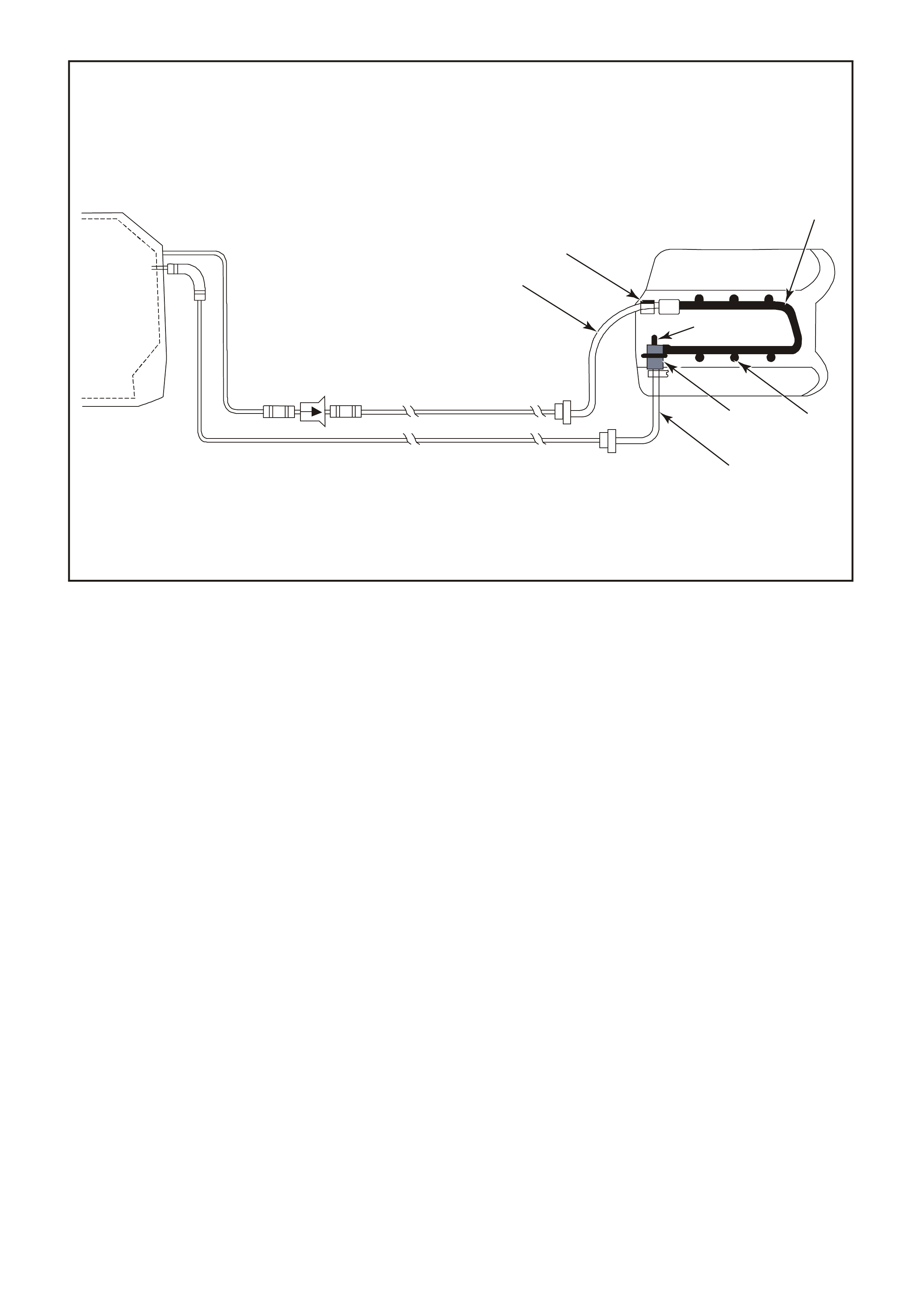
1. Fuel Pressure Too LOW or Too HIGH or
Pressure That Continues to Drop After The
Ignition is Turned OFF Can Cause The
Following Driveability Complaints:
• Poor Idle Quality
• Excessive Exhaust Odor
• Poor Fuel Economy
• Excessive Cranking Time
• Detonation
• Loss of Power
• DTC 44 or 64
• DTC 45 or 65
2. Fuel Rail
3. Fuel Injectors
4. Vacuum Hose Fitting
5. Fuel Pressure Regulator
6. Fuel Return Line
7. Fuel Pressure Gauge Connects Into This Line For
Testing
8. Fuel Feed (Pressure) Line
9. Fuel Filter
10. Fuel Tank
TABLE A-4.4 V6 PCM -
FUEL DELIVERY SYSTEM
CIRCUIT DESCRIPTION:
Fuel is drawn from the tank by the electric fuel pump and is fed under pressure through a fuel filter and continues
on into the fuel rail and then is injected into the ports through the fuel injectors.
Fuel pressure in the system is governed by the fuel pressure regulator, in such a manner that a certain pressure
difference between fuel pressure and inlet manifold pressure is maintained. Excess fuel above the regulated
pressure is returned to the fuel tank by the pressure regulator and the fuel return line.
The fuel pump has a check valve to maintain pressure at the fuel rail after the pump stops running. The check
valve plays an important part in the fuel delivery system: to keep the fuel rail "charged" with fuel after the pumps
shuts of f . When the engine begins c r ank ing to s tar t, there is no delay before f uel injec tion begins , and quic k starting
is ensured. The check valve is inside the fuel pump, and is not serviceable.
TEST DESCRIPTION: Number(s) below refer to step number(s) on the diagnostic Table.
2. If the pressure continues to drop after the pump stops running, there is a leak somewhere. Either the Fuel
Pump check valve is leak ing f uel back into the tank , the regulator has an internal leak allowing fuel to leak from
the pressure to the return side, or an injector is leaking (dripping).
9
8
7
2
3
5
6
4
1
4280
10

TABLE A-4.4 V6 PCM - FUEL DELIVERY SYSTEM
STEP ACTION VALUE YES NO
1. Was the "On-Board Diagnostic" (OBD) System Check
performed? Go to Step 2. Go to OBD
System Check in
this Section.
2. • From Table A-4.3
• Fuel pressure not OK.
Does fuel pressure continue to drop after pump stops?
Go to Step 3 Go to Step 10
3. 1. Ignition "OFF" for 10 seconds.
2. While you observe the pressure gauge, have an
assistant turn the ignition "ON".
3. When the pump stops running, pinch shut the
rubber section of the pressure (supply) hose.
connection.
Fuel pressure should now hold, does it?
Go to Step 4 Go to step 7
4. Check for leaks in the "pressure-side" of the fuel
System.
Were any leaks found ?
Go to Step 11 Go to step 5
5. Replace fuel pump.
Is action complete? Go to Step 11
6. Check For:
• Fuel pressure line restricted between pump and
fuel rail.
• Fuel supply line between tank and pump either
restricted or leaking.
• Restricted fuel filter.
• Restricted in-tank fuel strainer.
• Defective Fuel Pump .
Was a problem found?
Go to Step 11 Go to Service
Operation 3.11
FUEL
CONTROL
SYSTEM in this
Section for Fuel
Pump pressure
test procedures
7. 1. Ignition "OFF" for 10 seconds.
2. Release pinched off pressure (supply) hose.
3. While you observe the pressure gauge, have an
assistant turn the ignition "ON".
4. When the pump stops running, pinch shut the
rubber section of the fuel return hose.
DO NOT PINCH OFF THE FUEL RETURN HOSE AT
THE FUEL PRESSURE REGULATOR.
Fuel pressure should now hold, does it?
Go to Step 8 Go to Step 9
8. Replace fuel pressure regulator.
Is action complete ? Go to Step 11
9. Locate and replace leaking injectors.
Is action complete ? Go to Step 11
10. Is there fuel pressure? Go to Step 11 Go to Step 6
11. Retest fuel pressure system.
Is Pressure between specified values? 290 to 410
kPa
Fuel Delivery
System OK Go to
Table
A-4.5 in this
Section

1. Fuel Pressure Too LOW or Too HIGH or
Pressure That Continues to Drop After The
Ignition is Turned OFF Can Cause The
Following Driveability Complaints:
• Poor Idle Quality
• Excessive Exhaust Odor
• Poor Fuel Economy
• Excessive Cranking Time
• Detonation
• Loss of Power
• DTC 44 or 64
• DTC 45 or 65
2. Fuel Rail
3. Fuel Injectors
4. Vacuum Hose Fitting
5. Fuel Pressure Regulator
6. Fuel Return Line
7. Fuel Pressure Gauge Connects Into This Line For
Testing
8. Fuel Feed (Pressure) Line
9. Fuel Filter
10. Fuel Tank
TABLE A-4.5 V6 PCM -
FUEL DELIVERY SYSTEM
CIRCUIT DESCRIPTION:
Fuel is drawn from the tank by the electric fuel pump and is fed under pressure through a fuel filter and
continues on into the fuel rail and then is injected into the ports through the fuel injectors.
Fuel press ure in the system is governed by the fuel press ure regulator, in suc h a manner that a certain pressure
difference between fuel pressure and inlet manifold pressure is maintained. Excess fuel above the regulated
pressure is returned to the fuel tank by the pressure regulator and the fuel return line.
The ex ternal fuel pum p has a chec k valve to m aintain pr essur e at the fuel rail after the pum p stops running. The
check valve plays an im portant part in the fuel deliver y system: to k eep the fuel rail "char ged" with f uel after the
pumps shuts off. W hen the engine begins cranking to start, there is no delay before fuel injection begins, and
quick starting is ensured. The check valve is inside the fuel pump , and is not serviceable.
TEST DESCRIPTION: Number(s) below refer to step number(s) on the diagnostic Table.
3. If any fuel lines, fittings, filter, or components are restricted, correct pressure cannot be attained.
6. W hen the fuel return hose is pinched shut, there is no pressure regulator control to limit the pressure. The
pressure reading will be whatever the Fuel Pump is capable of producing. This is the same as attaching a
pressure gauge directly to the output of the Fuel Pump . The pressure reading would be a "maximum
pressure - no flow" reading, and should be well over 320 kPa. Do not allow the pressure to exceed 414 kPa.
9
8
7
2
3
5
6
4
1
4280
10

10. At this point, the pressure checks are OK, but a complete test has not been performed. Return to
Table A-4.3 in this Section to complete the testing.
11. This is to determ ine if the cause of the high pressure is a restricted fuel return line, or a defective pressure
regulator. If the pressure is normal when the regulator outlet (hose or fuel pipe attached to regulator) is
connected only to an open hose, then the problem is a restricted return line between the regulator and the
tank.
12. The fuel pressure regulator on the Non-Supercharged Engine application is serviceable separate from the
fuel rail. The pressure regulator on the Supercharged Engine application is part of the fuel rail, and the
complete fuel rail must be replaced. Refer to Section 6C1-3 of the VX Series Service Information for fuel
pressure regulator replacement service procedures.
TABLE A-4.5 V6 PCM - FUEL DELIVERY SYSTEM
STEP ACTION VALUE YES NO
1. Was the "On-Board Diagnostic" (OBD) System Check
performed? Go to Step 2. Go to OBD
System Check in
this Section.
2. Is fuel pressure less than values? Go to Step 3 Go to Step 11
3. • There is low fuel pressure
1. Make close inspection of all fuel lines between fuel
tank and fuel rail for restrictions.
• This includes these lines:
- Tank to filter.
- Filter to fuel rail.
Were any restrictions found ?
Go to Step 4 Go to Step 5
4. Repair any restrictions, then recheck pressure.
Is action complete ? Verify Repair
5. Replace fuel filter, then recheck fuel pressure.
Is fuel pressure still less then value ? Less then 290
kPa Go to Step 6 Go to Step 10
6. 1. Ignition "OFF".
2. Pinch shut the fuel return hose at the
fuel gauge sender unit (this fuel return hose is the
lower hose). DO NOT PINCH OFF THE FUEL
RETURN HOSE AT THE FUEL PRESSURE
REGULATOR.
3. Ignition "ON"
4. Enable output test with Tech 2 scan tool for fuel
pump.
Is fuel pressure at or above the specified value?
410 kPa Go to Step 7 Go to Step 9
7. Replace pressure regulator and recheck pressure.
Is pressure now between value ? 290 to 410
kPa Verify Repair Go to Step 8
8. Replace in-tank fuel strainer.
Is action complete ? Verify Repair
9. • Pressure less than 320 kPa
Replace fuel pump
Is action complete ?
Verify Repair
10. Is pressure between value, and does not continue
dropping when pump stops ? 290 to 410
kPa Verify Repair Go to
Table
A-4.1-1
11. 1. Disconnect fuel return line flexible hose from fuel
pipe that leads to the pressure regulator.
2. Attach a long length of hose to the fuel pipe leading
to the pressure regulator.
3. Insert other end of hose into an approved fuel
container.
4. Enable output test with Tech 2 scan tool for fuel
pump.
Is fuel pressure still more than value ?
410 kPa Go to Step 12 Go to Step 13
12. Replace pressure regulator
Is action complete ? Verify Repair
13. Locate and correct restricted fuel return line to
tank, or blocked return line screen filter in fuel tank
return connector, or screen in fuel pressure
regulator.
Is action complete ?
Verify Repair
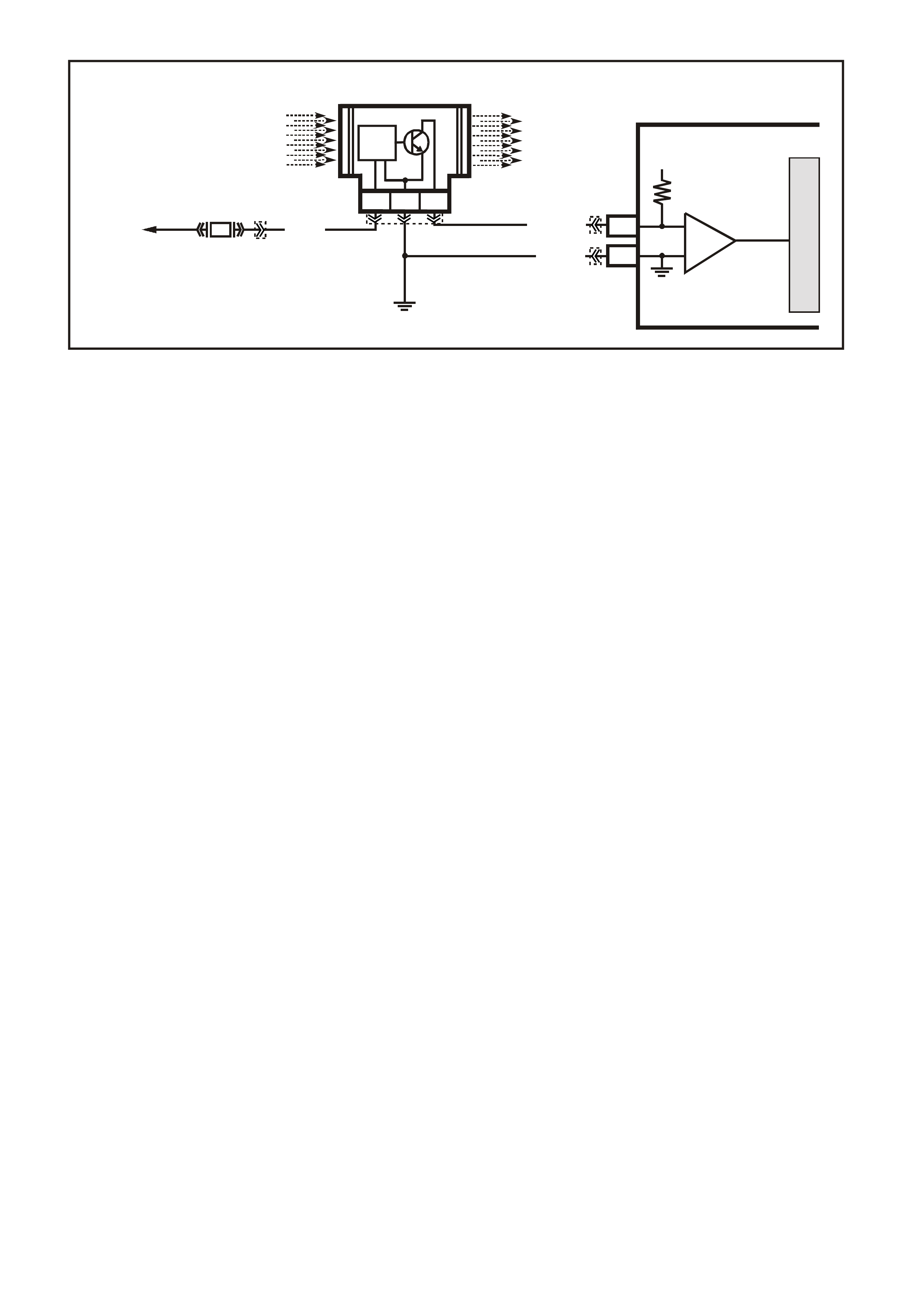
TABLE A-6.1 V6 PCM -
MAF SENS OR OUTPUT CHECK
CIRCUIT DESCRIPTION:
The signal that is sent from the Mass Air Flow (MAF) sensor is sent in the form of a frequency output. A large
quantity of air passing through the MAF sensor will be indicated as a high frequency output (such as when
under acceleration). A small quantity of air passing through the sensor will be indicated as a low frequency
output (such as when decelerating or at idle). T he Tech 2 scan tool displays this inform ation both as air flow in
grams per second, grams per cylinder and frequency. A "normal" reading is approximately 4-9 grams per
second at idle and increases with RPM.
TEST DESCRIPTION: Number(s) below refer to Step number(s) on the diagnostic Table.
3. This step checks for the proper Mass Air Flow grams per second at idle.
4. This step checks for the proper Mass Air Flow grams per second at 2500 RPM.
5. This s tep c hecks the Mas s Air F low sensor f or a s teady decrease in grams per s econd as the RPM c hanges
from 2500 to idle.
DIAGNOSTIC AIDS:
Check air filter for being plugged
Check for air intake ducts for restrictions
Check air intake ducts for leaks after the MAF sensor
Check for partly restricted exhaust system
Check for any other source that would allow air into the engine after the MAF sensor.
This would include:
• inlet manifold gasket
• inlet manifold
• throttle body and or gasket
• PCV system, this includes the oil dipstick for proper seating
• injector o-rings
VXSC006
MASS AIR FLOW SENSOR
D1
A1
PCM
CBA
AIR FLOW
FROM
AIR FILTER
AIR FLOW
TO
THROTTLE BODY
TO
EFI
RELAY
P (43 9)
LOC. E5/E15
BR/W (792)
MASS AIR FLOW
INPUT SIGNAL
EARTH
5 V
M
I
C
R
O
IC
B/R (750)
F33
IC
CIRCUIT
YB188
YE100
YE111 YB193

TABLE A-6.1 V6 PCM - MAF SENSOR OUTPUT CHECK
STEP ACTION VALUE YES NO
1. Was the "On-Board Diagnostic" (OBD) System Check
performed? Go to Step 2. Go to OBD
System Check in
this Section.
2. Is DTC 32 present? Go to DTC 32 Go to Step 3
3. 1. Ignition "ON", engine running at normal operating
temperature.
2. Using Tech 2 scan tool; select Data List, then select
"Mass Air Flow G/S".
3. With engine at idle, the Tech 2 scan tool should
indicate a MAF sensor reading between the
specified value.
Is the reading between the specified value ?
4-9 Grams
Per Second
(G/S)
at Idle
Go to Step 4 Go to Step 6
4. Increase engine RPM to 2500 and hold steady. The
Tech 2 should now indicate a MAF sensor reading
at the specified value.
Is the reading at the specified value ?
17-20 Grams
Per Second
(G/S)
at
2500 RPM
Go to Step 5 Go to Step 6
5. Release the throttle, and watch the MAF sensor
readings on the Tech 2. The Mass Air Flow G/S
should decrease at a steady rate down to the reading
determined at idle, did it ?
No trouble found
with Mass Air
Flow sensor
Go to Step 6
6. Check for restrictions in the Mass Air Flow induction
system. Also check for air leaks after the MAF
sensor or a possible restricted exhaust system.
Refer to Diagnostic Aids above.
If all checks OK, replace the Mass Air Flow sensor.
Is action complete ?
Verify Repair
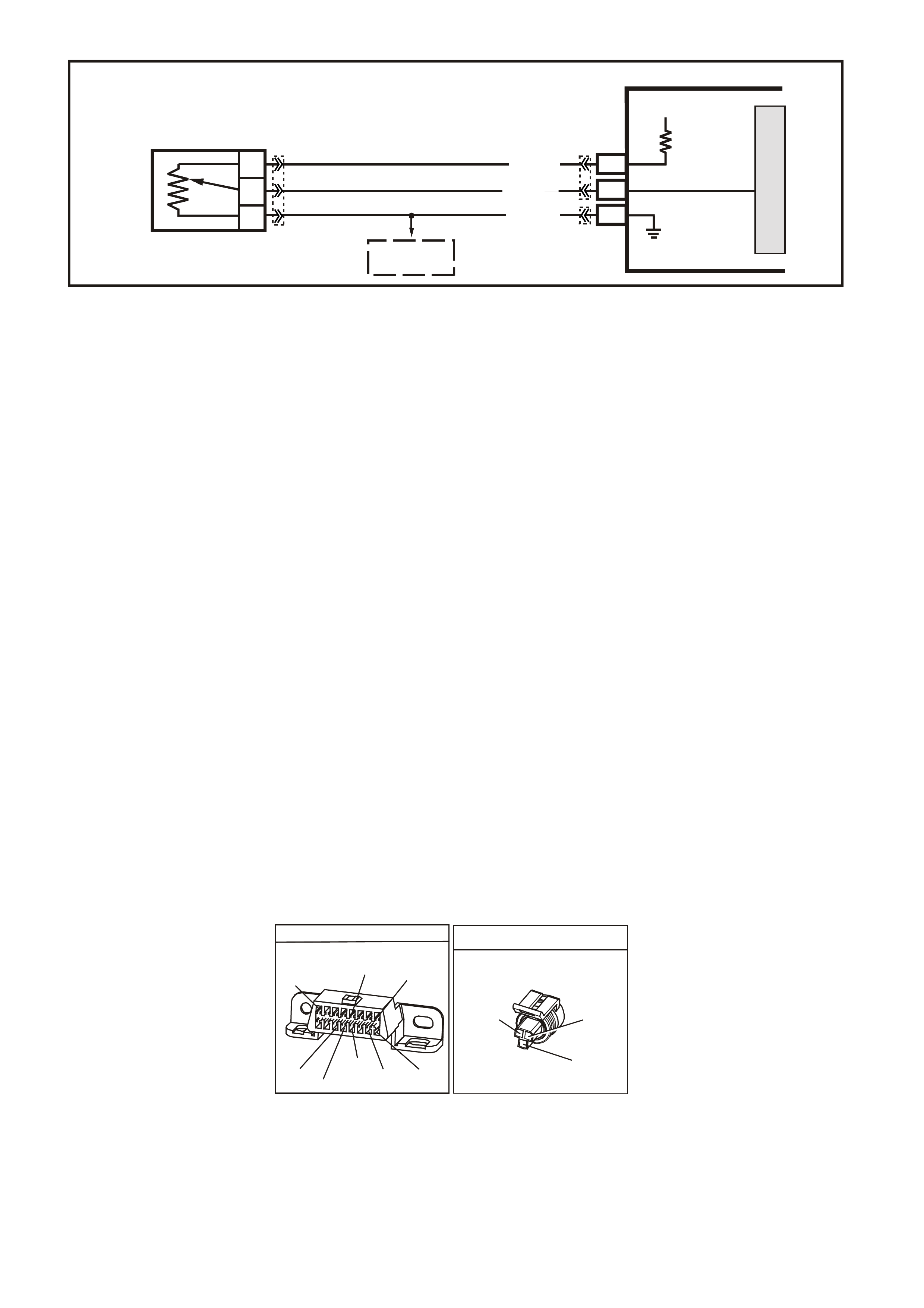
TABLE A-6.2 V6 PCM -
TP SENSOR OUTP UT CHECK
CIRCUIT DESCRIPTION:
The Throttle Position (TP) sensor is attached to the throttle body, and is internally rotated by the throttle body
shaft. It is a potentiometer with one end connected to 5 volts f rom the PCM and the other to PCM earth. A thir d
wire is connected to the PCM, allowing it to measure the variable output voltage from the TP sensor.
As the throttle valve angle is changed ( accelerator pedal m oved), the T P Sensor output voltage also changes in
proportion. At a closed throttle position, the output voltage is usually below 1.0 volt. As the throttle valve opens,
the output increases so that, at wide-open throttle, the output should be above 4.0 volts. By monitoring the
output voltage from the TP sensor, the PCM can determine fuel needs based on throttle opening (driver
demand).
A brok en or loose TP Sensor, or one that has an unstable output, c an c ause inter mittent bursts of fuel because
the PCM thinks the throttle is moving. Results could include engine surge or poor idle quality. If the PCM
interprets a high voltage when engine RPM is less than 400, har d st arting c ould be the res ult ( clear - f lood mode).
A problem in any of the TP sensor circ uits will set either a DT C 21 or DTC 22 after the engine is started. Once a
Diagnostic Trouble Code is set, the PCM will use an ar tificial def ault value for T P sensor based on engine RPM
to enable the vehicle to be driven, although performance could be less than normal.
The TP sensor is not adjustable. The PCM uses the reading at idle as "0% throttle," so no adjustment is
necessary.
TEST DESCRIPTION: Number( s ) below ref er to s tep number( s) on the diagnos tic Table. If a DTC 21 or DTC 22
is present, follow that Table first,
2. This is a check of the voltage at the idle position. It is usually less than 1.0 volt.
3. The voltage should increase at the same steady rate at which the throttle is opened with the throttle valve.
6. With the throttle valve wide open, the TP sensor output needs to be above 4 volts, allowing the PCM to
interpret a wide open throttle position.
7. If the throttle s top screw has been inadvertently reset, the T P sensor output at idle could be out of allowable
limits.
9. If the closed-throttle voltage is over 2.5 volts, hard starting may be encountered (worse cold) due to "clear-
flood" mode. This mode occurs when engine RPM is less than 400, and TP sensor input indicates the
throttle is m ore than 80% open. Possible caus es: short to voltage on input signal circuit, open ear th circuit ,
or a faulty sensor.
DATA LINK CONNECTO R
YB128
(863)
O/B BLU/B R/B
(1221)
(740)
16 9
(1220)
(155)
B/Y G/W
W/B
(451)
B
(150)
Y
(1049)
1
8
THROTTLE POSITION SENS OR
YE 30
(452) (416)
(417)
GY
B/Y
BLU
VXSC005
SENSOR EARTH
TP SENSOR SIGNAL
TP SEN S OR
REFERENCE
VOLTAGE
PCM
5V
M
I
C
R
O
A
C
B
THROTTLE
POSITION SENSOR
A7
B11
E16
BLU (417)
B/Y (452)
GY (416)
TO
ECT SENSOR
YB188
YB194
YE30

TABLE A-6.2 V6 PCM - TP SENSOR OUTPUT CHECK
STEP ACTION VALUE YES NO
1. Was the "On-Board Diagnostic" (OBD) System Check
performed? Go to Step 2. Go to OBD
System Check.
2. 1. Ignition "ON", engine stopped, throttle plate closed.
2. Tech 2 scan tool set to TP sensor voltage.
Is voltage on Tech 2 scan tool within value shown?
0.25 to 1.25
volts Go to Step 3 Go to Step 4
3. 1. Ignition "ON".
2. With Tech 2 scan tool still connected, monitor the
voltage as the throttle is slowly and steadily
opened to a wide-open-position.
3. Voltage should increase at a steady rate, with no
sudden changes.
Did voltage increase at a steady rate with throttle
movement ?
Go to Step 6 Go to Step 8
4. 1. Ignition "ON", engine stopped.
2. Tech 2 'Scan" tool set to TP sensor voltage.
Is voltage on Tech 2 scan tool within value shown?
1.26 to 2.5
volts Go to Step 7 Go to Step 5
5. 1. Ignition "ON", engine stopped.
2. Tech 2 scan tool set to TP sensor voltage.
Is voltage on Tech 2 scan tool over value shown?
2.5 volts Go to Step 9 Go to Step 12
6. 1. Ignition "ON".
2. With the Tech 2 scan tool still connected, monitor the
voltage as the throttle valve is opened to the wide
open position.
• Have a helper ensure that the throttle valve is fully
open when accelerator pedal is fully depressed.
• If throttle valve does not fully open when pedal is
depressed, check for extra floor mats or carpet under
accelerator pedal. Then refer to SERVICE
OPERATIONS, 3.11 FUEL CONTROL SYSTEM –
Throttle Cable - "Adjust" of this Service Information.
Is the TPS voltage above the specified value?
4 volts TP sensor is
working properly
Go to OBD
System Check in
this Section
Go to Step 6
7. 1. Check throttle stop screw. refer to SERVICE
OPERATIONS, 3.11 FUEL CONTROL SYSTEM -
Throttle Stop Screw - "Reset Procedure"of this
Service Information.
Reset only if incorrect.
2. Ignition "ON".
3. Tech 2 scan tool connected to data link connector.
4. Recheck TPS voltage.
Is voltage now within the specified value ?
0.25 to 1.25
volts Go to Step 6 Go to Step 8
8. Replace TP sensor.
Is action complete ?
Verify Repair
9. 1. Ignition "OFF".
2. Disconnect TPS.
3. Connect Tech 2 scan tool to data link connector,
set to TPS voltage.
4. Ignition "ON"
Is voltage on Tech 2 scan tool at or below specified
value?
1.25 volt Go to Step 10 Go to Step 11

TABLE A-6.2 V6 PCM - TP SENSOR OUTPUT CHECK (CONTINUED)
STEP ACTION VALUE YES NO
10. Check for open in TP sensor earth circuit..
Was a problem found?
Verify Repair Go to Step 8
11. Repair short to voltage on TP sensor signal circuit.
Is action complete ?
Verify Repair
12. Repair short to earth on TP sensor signal circuit.
Is repair complete ?
Verify Repair
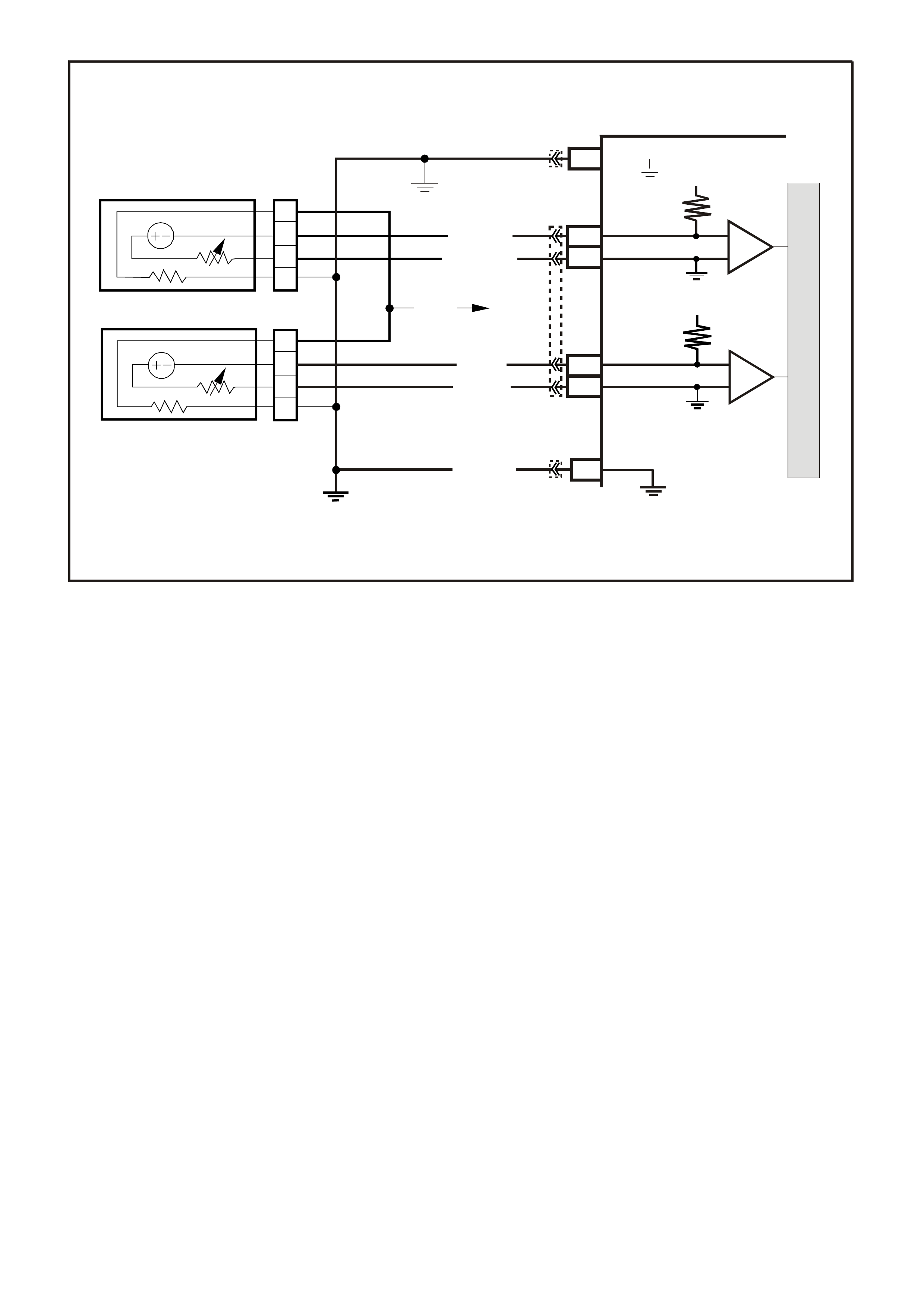
TABLE A-6.3 V6 PCM -
OXYGEN SENSO R CHECK
CIRCUIT DESCRIPTION:
The ox8ygen sensors are mounted in the exhaust pipes near the cylinders. At operating temperature, the
oxygen sensors are required to respond quickly to changes to oxygen content in the exhaust. If the oxygen
sensors becom e contam inated or faulty, a sluggish driveability or a complaint of poor idle condition m ay exis t. A
proper oxygen sensor response should be almost instantaneous to the fuelling mode command.
TEST DESCRIPTION: Number(s) below refer to step number(s) on the diagnostic Table.
2. Never perform this tes t on a cold engine. The oxygen sensor must be near nor mal operating temper ature for
this T able to work. It is im portant to see a low voltage and a high voltage res ponse very quic kly because this
means the oxygen sensor is not contaminated or faulty.
.
M
I
C
R
O
P (439)
YE95
D
D
B
B
A
A
C
C
YE95
GY (1412)
B/R (750)
Engine
Earth
To Fuse
F33
GY/B (1413)
V (412)
V/B (413)
B/R (750)
4269
A2
D16
D15
D14
D13
A1 450 m V
Right
Oxygen
Sensor
Signal HI
Right
Oxygen
Sensor
Signal LO
Left
Oxygen
Sensor
Signal HI
Left
Oxygen
Sensor
Signal LO
Earth
Earth
Ri ght Oxygen Sensor
Left Oxygen Sensor 450 m V
IC
IC
Engine
Earth
PCM
YB193
YB188
YB188

TABLE A-6.3 V6 PCM - OXYGEN SENSOR CHECK
STEP ACTION VALUE YES NO
1. Was the "On-Board Diagnostic" (OBD) System Check
performed? Go to Step 2. Go to OBD
System Check in
this Section.
2. 1. Ignition "ON", engine Running.
2. Run engine at 1600 to 1800 RPM for 2 minutes, or
until engine temperature is above 85 degrees C,
then let engine idle.
3. Using Tech 2 scan tool, select Misc. Test, then A/F
Ratio, then display "RH O2 Sensor and LH O2
Sensor.
4. With engine idling, Press the Down select button on
Tech 2 scan tool until 11.7 A/F Ratio is displayed,
at the same time note the response of both O2
Sensors.
5. Both O2 Sensors should display above specified
value.
6. Then press the Up select button on Tech 2 scan
tool until 17.7 A/F Ratio is displayed, at the same
time note the response of both O2 Sensors.
7. Both O2 Sensors should display below specified
value.
Did both O2 Sensors display above and below the
specified value ?
Above 700
mV
or
Below 100
mV
No trouble
found
Go to Step 3
3. Replace the O2 Sensor that did not perform as specified
in Step 2.
Is action complete ?
Verify Repair
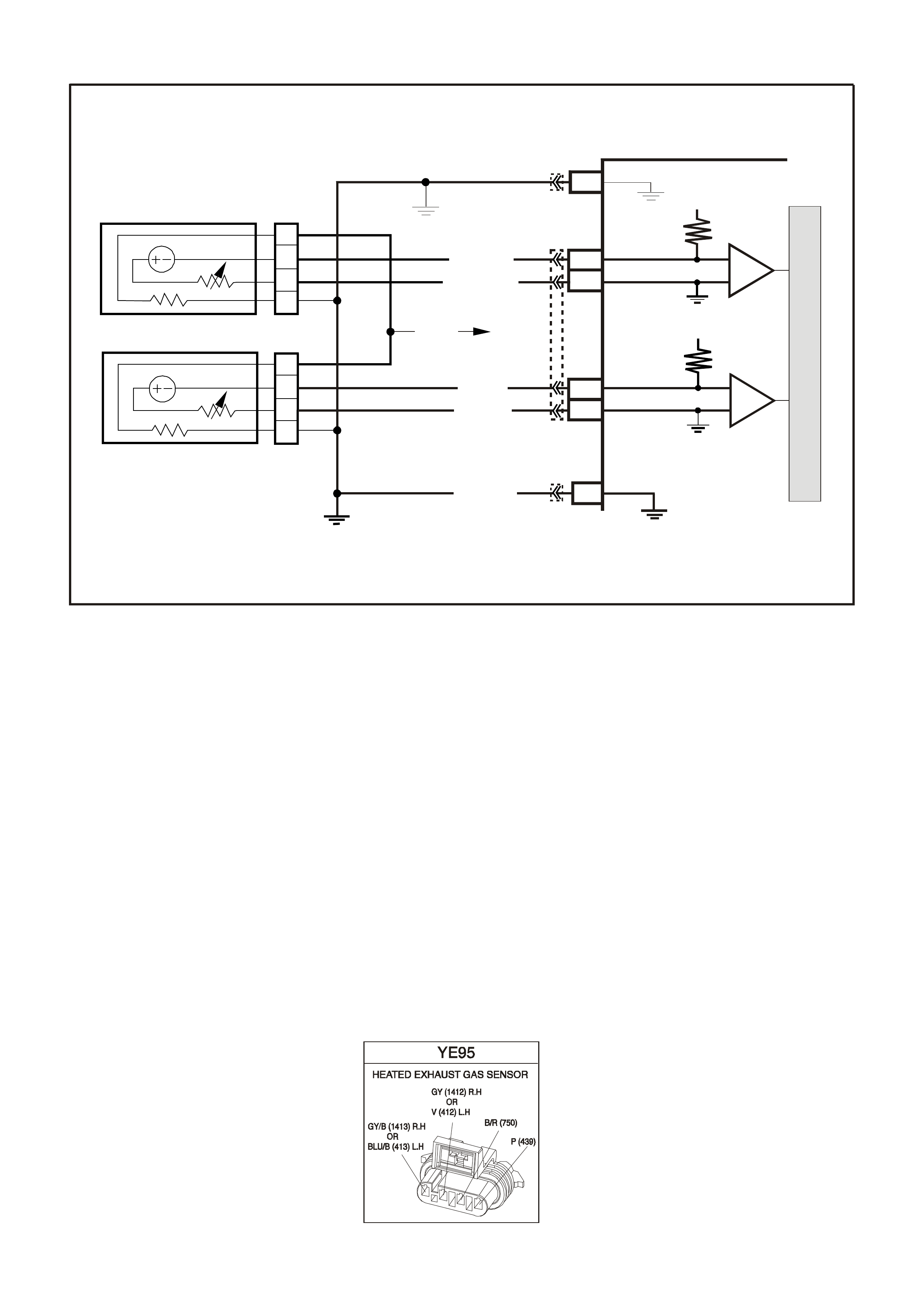
TABLE A-6.3A V6 PCM -
ENGINE OXYGEN SENSOR HEATER CHECK
CIRCUIT DESCRIPTION
On the Superchar ged V6 engine, two heated ox ygen sensors are used to minim ise the am ount of time required
for closed loop fuel control operation and to allow accurate exhaust converter operation. The oxygen sensor
heater greatly decreases the amount of time required for the oxygen sensor signal to become active, and the
PCM to use this signal for efficient emissions control.
Because the sens or must be at least 360°C to operate eff ectively, it is equipped with an internal electric heating
element to quickly heat the sensor after key "ON", or start up. This heating element is powered from the
vehicles electrical system, any time the ignition is "ON".
The heater is used to maintain the oxygen sensor at a sufficiently high temperature. This allows accurate
exhaust oxygen content readings f urther f rom the engine, and m aintains the sensors temper ature at long engine
idle intervals.
TEST DESCRIPTION: Number(s) below refer to step number(s) on the diagnostic Table.
2. Never perform this tes t on a cold engine. The oxygen sensor must be near nor mal operating temper ature for
this Table to work. You may not see the voltage at 450 mV when the ignition is cycled "ON", because the
Tech 2 scan tool menus take som e time, however, it is important to see a low voltage because this means
the oxygen sensor is only monitoring oxygen in the exhaust pipe.
M
I
C
R
O
P (439)
YE95
D
D
B
B
A
A
C
C
YE95
GY (1 412)
B/R (750)
Engine
Earth
To Fuse
F33
GY/B (1413)
V (412)
V/B (413)
B/R (750)
4269
A2
D16
D15
D14
D13
A1 450 m V
Right
Oxygen
Sensor
Signal HI
Right
Oxygen
Sensor
Signal LO
Left
Oxygen
Sensor
Signal HI
Left
Oxygen
Sensor
Signal LO
Earth
Earth
Ri ght Oxygen Sens or
Left Oxygen Sensor 450 m V
IC
IC
Engine
Earth
PCM
YB193
YB188
YB188

TABLE A-6.3A V6 PCM - ENGINE OXYGEN SENSOR HEATER CHECK
STEP ACTION VALUE YES NO
1. Was the "On-Board Diagnostic" (OBD) System Check
performed? Go to Step 2. Go to OBD
System Check.
2. 1. Ignition "ON".
2. Using Tech 2 scan tool display LH and RH O2
Sensors.
3. Ignition "ON", engine "OFF".
4. Did LH and RH O2 Sensor voltages drop to specified
value within 60 seconds ?
450 mV to
less than
100 mV
No problem
found.
Oxygen Sensor
Heater is OK
If both did not
drop to specified
value,
Go to Step 8
-----------------------
If only one
dropped to
specified value,
Go to Step 3
3. 1. Ignition "OFF".
2. Disconnect the oxygen sensor harness connector
from the sensor that did not drop.
3. Connect test light between oxygen sensor connector
on powertrain harness, circuit 439 and earth, circuit
750.
4. Ignition "ON".
Is the test light "ON"?
Go to Step 4 Go to Step 7
4. 1. Ignition "OFF".
2. Measure resistance of oxygen sensor heater with
ohmmeter between circuits 439 and circuit 750.
Is measured resistance within the specified value ?
3.5 - 13.2
ohms Go to Step 6 Go to Step 5
5. Replace heated oxygen sensor.
Is action complete ? Verify Repair
6. Repair poor connection at oxygen sensor.
Is action complete ? Verify Repair
7. 1. Ignition "OFF".
2. Connect test light to battery positive.
3. Probe oxygen sensor connector on powertrain
harness connector, circuit 750.
Is test light "ON" ?
Go to Step 8 Go to Step 9
8. Repair open or short to earth in circuit 439 between fuse
F33 and oxygen sensor. Replace fuse if blown.
Is action complete ?
Verify Repair
9. Repair open in circuit 750.
Is action complete ? Verify Repair
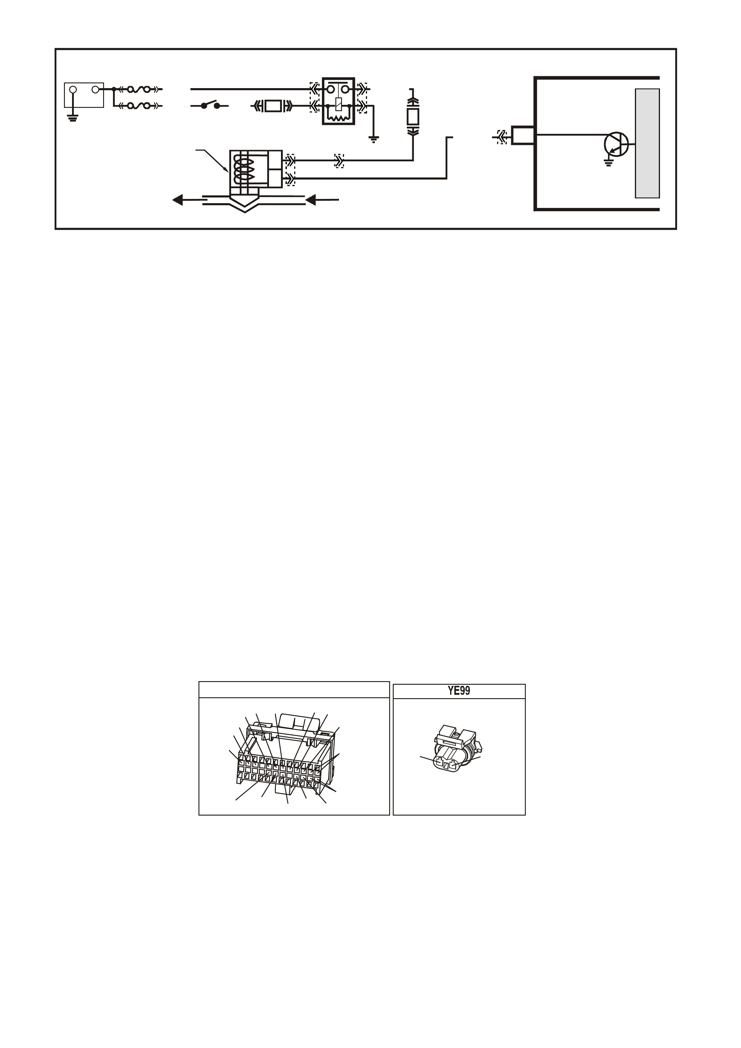
TABLE A-6.4 V6 PCM -
CANISTER PURGE SOLENOID CHECK
CIRCUIT DESCRIPTION:
The canister purge is controlled by a solenoid that allows manifold vacuum to purge the fuel vapour canister
when energised. The PCM supplies a earth to energise the solenoid (purge "ON").
If the following conditions are met with the engine running, the canister purge solenoid is energised.
• Engine run time after start more than 3 minutes and 15 seconds if coolant is less than 80 degrees C or
• Engine run time after start is more than 15 seconds if coolant is above 80 degrees C.
• Coolant temperature above 60 degrees C
• Engine not in Decel fuel cutoff mode.
• Throttle is less than 92%.
• Engine is in closed loop fuel mode or open loop fuel mode.
TEST DESCRIPTION: Number(s) below refer to Step number(s) on the diagnostic Table.
2. Checks to see if the solenoid is opened or closed. The solenoid is normally energised in this step, so it
should be open.
3. This checks to see if the Canister Purge Solenoid mechanical function is functioning properly by earthing
Canister Purge Solenoid several times with the Tech 2 scan tool.
4. This checks to see if +B volts is supplied to the Canister Purge Solenoid.
5. This checks to see if the PCM is supplying the earth signal for the Canister Purge Solenoid.
DIAGNOSTIC AIDS:
Normal operation of the Canister Purge Solenoid is described as follows:
W ith the ignition "ON", engine "OFF", diagnostic "Test" terminal unearthed, the Canister Purge Solenoid will be
de-energised.
YB 188
P.C.M CONNECTOR 2
(481)
(417)
(740)
R
BLU
O
(1456)
LG
V/W
(415)
Y
(1227)
B/Y
(410)
BR
(472)
(259)
(750)
(750)
(1221)
B/R
B/R
R/B
G/B
(39)
P
(465)
G/W
(416)
GY
(740)
O
A1
B1
B12
A12
CANNISTER P URGE
(439) (428)
PG/Y
B
A
A
B
CANISTER PURGE
SOLENOID V ALVE
PCM
CANISTER PURGE
SUPERVX027
C4
G/Y (428)
MANIFOLD
VACUUM
TO CARBON
CANISTER
B/W
(152)
LOC. E3
M
I
C
R
O
F33
F14
IGN SW
EFI
RELAY
+
-
BATTERY
FS
FJ
P (3) P/B
(39)
(1040) O/Y (479)
R (2H)
YE39
YB193
YE111
YE99
YE39

TABLE A-6.4 V6 PCM - CANISTER PURGE SOLENOID CHECK
STEP ACTION VALUE YES NO
1. Was the "On-Board Diagnostic" (OBD) System Check
performed? Go to Step 2. Go to OBD
System Check in
this Section.
2. Note: This Table only covers the solenoid portion of the
Canister Purge system.
1. Ignition OFF.
2. Disconnect purge vacuum hose from top of canister,
and place a vacuum gauge in hose.
3. Ignition "ON", engine Running.
4. With Tech 2 scan tool enable Canister Purge
Solenoid "ON" with Up and Down buttons on Tech 2
scan tool.
Does vacuum gauge read manifold vacuum with canister
purge solenoid display "ON"?
No trouble found.
Canister Purge
Solenoid is OK.
Go to Step 3
3. 1. Ignition "ON", engine "OFF".
2. Place index finger on top of Canister Purge
Solenoid.
3. Enable Canister Purge Solenoid "ON" and "OFF"
several times with the Tech 2 scan tool.
Does the solenoid click while enabling and disabling ?
Canister Purge
Solenoid
electrical is OK.
Go to Step 10 for
vacuum check
Go to Step 4
4. 1. Ignition "ON", engine "OFF".
2. Disconnect Canister Purge Solenoid electrical
connector.
3. With a test light connected to earth, probe Canister
Purge Solenoid electrical connector power feed
circuit.
Is test light "ON" ?
Go to Step 5 Go to Step 6
5. 1. Ignition "ON", engine "OFF".
2. Disconnect Canister Purge Solenoid electrical
connector.
3. With a test light connected to +B volts, probe
Canister purge Solenoid electrical connector Purge
Solenoid control circuit.
4. With Tech 2" Scan" tool, enable Canister Purge
Solenoid "ON" with up and down buttons on the
Tech 2 scan tool.
Is test light "ON" when Canister Purge Solenoid is
commanded "ON" ?
Go to Step 7 Go to Step 8
6. Check for open in power feed circuit.
Is action complete ? Verify Repair
7. Replace Canister Purge Solenoid.
Is action complete ? Verify Repair
8. Check for open in Purge Solenoid control circuit from
PCM to Canister Purge Solenoid.
Was a open found ?
Verify Repair Go to Step 9
9. Check for poor connection at PCM. If connection is OK,
replace PCM. Refer to Section 6C1-3 Service Operations
of the VX Series Service Information, for the Security Link
procedure.
Is the action complete?
Verify Repair
10. Check manifold vacuum hose from manifold to Canister
Purge Solenoid for kinks, pinched, cracked, or plugged.
Repair as necessary.
Is action complete?
Verify Repair
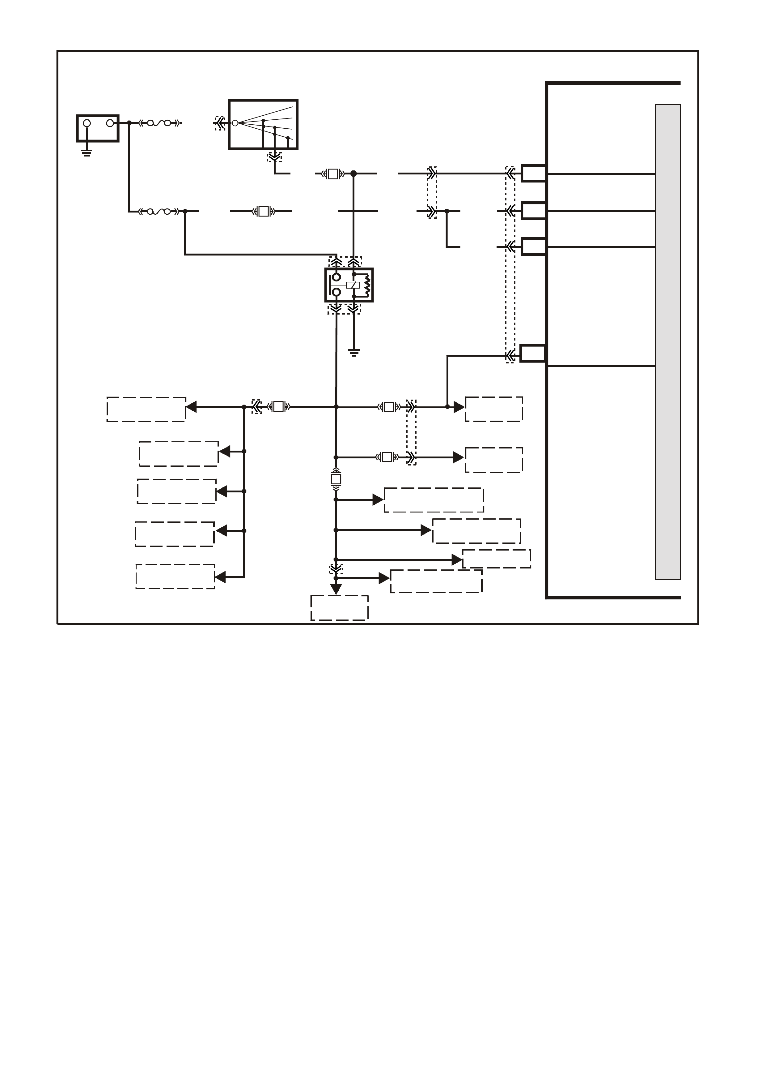
TABLE A-6.5 V6 PCM
EFI RELAY DIAGNOSIS
CIRCUIT DESCRIPTION
The EFI relay protects the battery from a parasitic draw. The following components are powered by the EFI
relay:
• Injectors
• DIS Module
• Transmission
• A/C System
• EVAP Solenoid
• MAF Sensor
• Oxygen Sensors
DIAGNOSTIC AIDS
• The following may cause an intermittent:
- Poor connections. Check for adequate terminal tension.
- Corrosion.
- Incorrectly routed harness.
- Rubbed through wire insulation.
- Broken wire inside the insulation.
SUPERVX4350
+-
BATTERY
LOC . E 1
FS
12V BU S (10 40)
(1040) O (7 40 )O/B (740)
B8
A8
O (740)
O (740)
BATTERY
BATTERY
F31
PCM
A4 IGNITION
FJ
R (2H)
15a 15 50
30 OFF/ON
LOCK
ACC
IGN
START
IGNITION SWITCH
P (3)
F14 P
(39)
P/B
EFI RELAY
LOC. E3
B/W
(152)
M
I
C
R
O
P
R
O
C
E
S
S
O
R
B12 IN JECTOR VOLTAGE
MONITOR LINE
F34
R
(481)
TO
INJECTORS
F35
F33
LG
(482)
TO DIS
MODULE
F32
P/BLU
(339)
TO 3-2
SOLENOID
TO 1-2 SHIFT
SOLENOID A
TO 2-3 SHIFT
SOLENOID B
TO TCC ENABLE
SOLENOID
TO TCC PWM
SOLENOID
TO MAF
SENSOR
P
(439)
TO CANISTER
TO BOOST CONTROL
SOLENOID
TO HEATED
OXYGEN SENSORS
PURGE SOLENOID
TO A/C RELAY
YE111
YE111
YE39
YE39
YE112
YB44
YB44
YE110
YB188

TEST DESCRIPTION
The numbers below refer to the step numbers on the diagnostic table.
NOTE: For any test that requires probing the PCM or a com ponent harness c onnector, use the Connector T est
Adapter Kit J35616-A. Using this kit prevents damage to the harness connector terminals.
2. This test checks the fusible link FS power feed to the EFI relay.
3. This test checks the fused power feed ignition circuit.
4. This test is checking the earth circuit of the EFI relay.
5. This step isolates the circuit from the EFI relay. All of the circuits at the relay are good if the test lamp
illuminates.
E.F.I RELAY
YE 39
B/W
P/B
O/Y
(152)
(39)
(479)
(1040)
ENGINE 12V BUS
TABLE A-6.5 V6 PCM - EFI RELAY DIAGNOSIS
Step Action Value(s) Yes No
1 Did you perform the Powertrain On-Board Diagnostic
(OBD) System Check? Go to Step 2 Go to Powertrain
OBD System
Check Table
2 1. Turn OFF the ignition.
2. Remove the engine compartment Fuse/Relay panel
cover.
3. Remove the EFI relay.
4. Probe the fusible link FS power feed circuit to the EFI
relay harness terminal 87 with a test lamp J34142-B
connected to earth.
Does the test lamp illuminate?
Go to Step 3 Go to Step 8
3 1. Turn ON the ignition leaving the engine OFF.
2. Probe the fused ignition feed circuit to the EFI relay
harness terminal 85 with the test lamp J34142-B
connected to a earth.
Does the test lamp illuminate?
Go to Step 4 Go to Step 9
4 1. Turn OFF the ignition.
2. Probe the earth circuit to the EFI relay harness
terminal 86 with the test lamp J34142-B connected to
B+.
Does the test lamp illuminate?
Go to Step 5 Go to Step 10
5 1. Turn OFF the ignition
2. Jump the EFI relay B+ feed circuit terminal 87 and the
EFI relay load circuit terminal 30 together using a
fused jumper wire.
3. Probe the following fuses with a test lamp J34142-B
connected to earth:
- F32
- F33
- F34
- F35
Does the test lamp illuminate for all fuses?
Go to Step 6 Go to Step 11
6 Check for poor terminal contact at the EFI relay harness
connector.
Did you find and correct the condition?
System OK Go to Step 7

TABLE A-6.5 V6 PCM - EFI RELAY DIAGNOSIS (CONT)
Step Action Value(s) Yes No
7 Replace the EFI relay.
Is the action complete? System OK
8 Repair the open in fusible link FS circuit to the EFI relay.
Is the action complete? System OK
9 Repair the fused ignition feed circuit to the EFI relay.
Replace fuse if open.
Is the action complete?
System OK
10 Repair the open in the earth circuit for the EFI relay.
Is the action complete? System OK
11 Repair open in the EFI relay load circuit, or open in
fuse(s) circuit that did not illuminate the test light.
Is the action complete?

TABLE A-7.1 V6 PCM -
IDLE AIR CONTROL (IAC) SYSTEM
CIRCUIT DESCRIPTION:
The PCM controls engine idle speed by moving the IAC valve to control closed-throttle air flow around the
throttle plate. It does this by sending voltage pulses (called "counts" or "steps") to the IAC motor windings. The
motor shaft and conical valve move a given distance for each pulse received.
• TO INCREASE IDLE SPEED: The PCM sends enough puls es to retrac t the IAC valve and allow m ore air to
bypass the throttle plate through the idle air passage, until idle speed reaches the PCM-desired idle RPM.
• TO DECREASE IDLE SPEED: The PCM sends enough pulses to extend the IAC valve and reduce the
airflow bypassing the throttle plate through the idle air passage, until idle speed reaches the PCM-desired
RPM.
The PCM desired idle RPM, and the commanded IAC position, is based on:
• Engine Coolant Temperature
• Actual engine RPM (crankshaft reference input)
• Engine load (A/C request input, engine fan command)
• Battery voltage
• Vehicle speed (VSS)
• Throttle position (TP)
TEST DESCRIPTION:
Number(s) below refer to step number(s) on the diagnostic Table.
2. This tests the PCM's ability to control IAC valve.
DIAGNOSTIC AIDS:
Remove IAC and check for frozen or sticking IAC. Check that TP sensor is within acceptable range.
SUPERVX025
PCM
C10
C7
C8
C9
LG/W
(443)
A
B
C
D
IAC VALVE
IAC
COIL B LO
IAC
COIL A LO
IAC
COIL B HI
IAC
COIL A HI
12V
12V
12V
12V
M
I
C
R
O
LG/B
(444)
LBLU
(441)
LBLU/B
(442)
YE36
YB193

TABLE A-7.1 V6 PCM - IDLE AIR CONTROL (IAC) SYSTEM
STEP ACTION VALUE YES NO
1. Was the "On-Board Diagnostic" (OBD) System Check
performed? Go to Step 2. Go to OBD
System Check .
2. 1. Using TECH 2 scan tool, Select RPM CONTROL.
2. With the up/down arrows, vary RPM from 600 to 1675
RPMs.
Does engine speed rise and fall?
Go to Step 3 Go to Table
A-7.2 in this
Section
3. No trouble found with IAC system.
Check For:
• Vacuum leaks (Causes Fast Idle Speeds).
• Sticking or binding throttle shaft, cables, or linkages.
• Engine Coolant Temperature sensor resistance.
Refer DTC 14 in this Section.
• TP Sensor Operation. Refer Table A-6.2 in this Section
• Dirty or loose battery cables or earth straps.
• System earth circuit terminals at the engine for being
clean and tight.
• Inspect all accessory drive pulleys. They should all spin
freely.
• Spark plugs that are excessively worn, mis-gapped or
cracked.
• For high or low fuel pressure, or leaking injectors - refer
Table A-4.3 in this Section.
• A/C Clutch Control circuit failure.
refer Table A 11.1 or Table A 11.3 in this Section.
• Generator Output - if under 9 volts or over 16 volts,
PCM will not command the IAC to move.
• Throttle Body - remove IAC and inspect bore for foreign
material or evidence of IAC valve "Dragging" in the bore.
• Throttle Stop Screw, refer SERVICE OPERATIONS, 3.11
FUEL CONTROL SYSTEM - Throttle Stop Screw - Reset
Procedure of this Service Information.
Refer To "Rough, Unstable, Or Incorrect Idle" In Section
6C1-2B SYMPTOMS of this Service Information.
Verify Repair
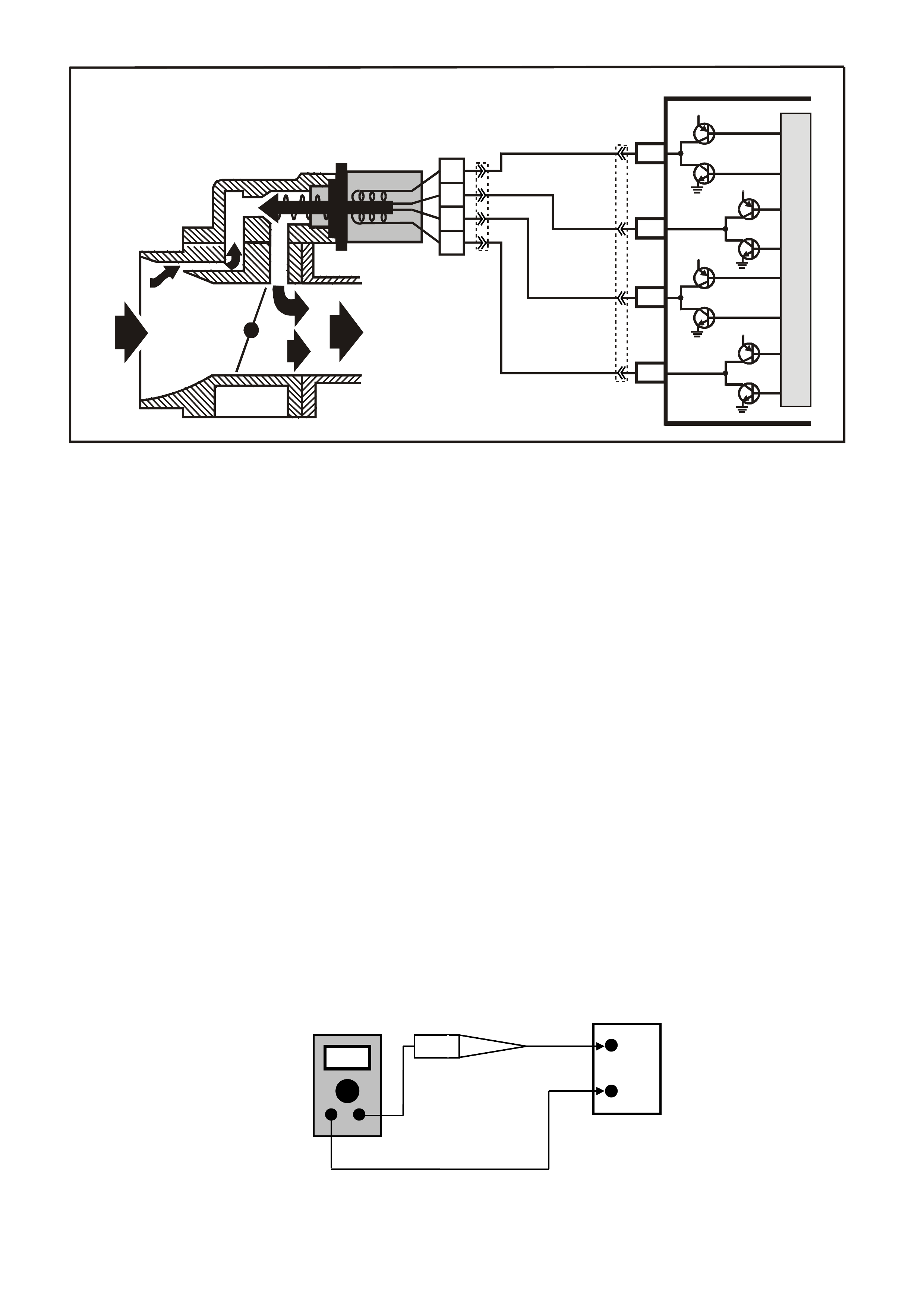
TABLE A-7.2 V6 PCM -
IDLE AIR CONTROL (IAC) SYSTEM
CIRCUIT DESCRIPTION:
The PCM controls engine idle speed by moving the IAC valve to control closed-throttle air flow around the
throttle plate. It does this8 by sending voltage pulses ( called "counts" or "s teps") to the IAC m otor windings. The
motor shaft and conical valve move a given distance for each pulse received.
• T O INCREASE IDLE SPEED: The PCM s ends enough pulses to r etract the IAC valve and allow more air to
bypass the throttle plate through the idle air passage, until idle speed reaches the PCM - desired idle RPM.
• TO DECREASE IDLE SPEED: The PCM sends enough pulses to extend the IAC valve and reduce the air
flow bypassing the throttle plate through the idle air passage, until idle speed reaches the PCM-desired
RPM.
The PCM desired idle RPM, and the commanded IAC position, is based on:
• Engine Coolant Temperature (ECT)
• Actual engine RPM (crankshaft reference input)
• Engine load (A/C request input, engine fan command)
• Battery voltage
• Vehicle Speed (VSS)
• Throttle Position (TPS)
TEST DESCRIPTION: Number(s) below refer to step number(s) on the diagnostic Table.
2. With the ignition "ON," engine stopped, and Tech 2: IAC reset, the PCM should issue electrical
"extend/retrac t" pulses to the IAC valve. With the IAC disc onnected, each connec tor term inal should have a
"pulsing" voltage, noted by a flashing or flickering test light. The rate of flashing or flickering is not important.
8. There are 2 separate windings in the IAC motor. Each winding (A - to - B, and C - to- D) should have
between 40 and 80 ohms resistance. Also, there should be no continuity between the two windings.
+
BATTERY
-
DC Amps
Test Light
SUPERVX025
PCM
C10
C7
C8
C9
LG/W
(443)
A
B
C
D
IAC VALVE
IAC
COIL B LO
IAC
COIL A LO
IAC
COIL B HI
IAC
COIL A HI
12V
12V
12V
12V
M
I
C
R
O
LG/B
(444)
LBLU
(441)
LBLU/B
(442)
YE36
YB193
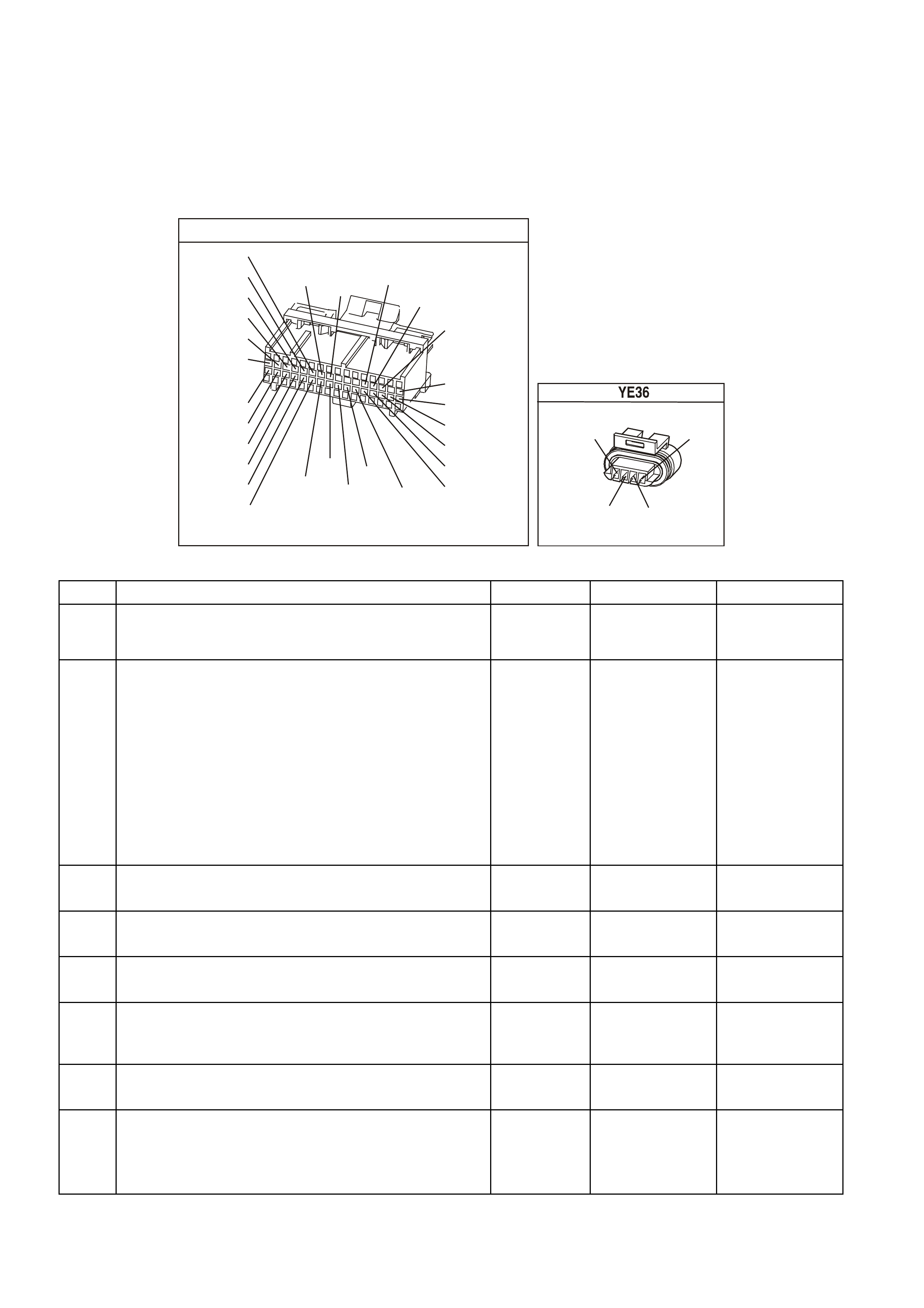
NOTE: When performing this test, ensure that a standard low power test light is used.
Do not use a "High-W attage" test light, as the PCM could be dam aged. A high wattage test light will either give
inaccurate test results, or damage the PCM, or both.
• A low-power test light must be used for any circuit testing. While a particular brand of test light is not
suggested, a simple test on any test light will ensure it to be OK for PCM circuit testing. Connect an
accurate ammeter (such as the digital multimeter) in series with the test light being tested, and power the
test light- amm eter c ircuit with the vehicle battery (See above). If the am m eter indicates less than 3/10 amp
current flow (0.3 A or 300 ma), the test light is OK to use. If more than 0.3A (300 ma), do not use !
YB1 93
(413)
(412)
(1413)
(1412)
(430)
(453)
(815)
V/B
GY/B
V
GY
V
B/R
W/R
(897)
(897)
G/W
G/W
(418)
(418)
BR
BR
(1426)
O/W
C16
D16
WT/B
(832)AUTO
(647)
(630)
BR
T
(832) MAN
LBLU/B
B
(424)
(423)
C1
D1
(792)
(422)
(1222)
(1223)
(428)
(123)
BR/W
GY/R
LG
Y/B
G/Y
V/W
BLU/W
BLU
(831) Man
(443)
LG/W
(442) (831)AUTO
(441)
LBLU
LBLU/B
(444)
LG/B
P.C.M. CONNECTOR 1
IDLE AIR CO NTROL VALVE
(442)
(441) (444)
(443)
LBLU/B
LBLU LG/B
LG/W
TABLE A-7.2 V6 PCM - IDLE AIR CONTROL (IAC) SYSTEM
STEP ACTION VALUE YES NO
1. Was the "On-Board Diagnostic" (OBD) System Check
performed? Go to Step 2. Go to OBD
System Check in
this Section.
2. • From Table A-7.1
1. Disconnect IAC valve electrical connector.
2. Ignition "ON", engine stopped. Using TECH 2 scan
tool, select RE SET IAC.
3. Probe each IAC harness connector terminal for 5
seconds with test light connected to earth, while
using Tech 2.
• See note above for proper test light usage.
Does test light flash at all terminals while IAC is
Being reset ?
Go to Step 3 If No light one or
more terminals,
Go to Step 6
----------------------
If steady light one
or more
terminals,
Go to Step 13
3. Check for faulty IAC terminals.
Were any faulty terminals found ? Go to Step 4 Go to Step 5
4. Repair faulty terminals
Is action complete? Verify Repair
5. Replace IAC valve.
Is action complete ? Verify Repair
6. Check for open or short to earth in circuit(s) that did not
light the test light.
Were any opens or short's found ?
Go to Step 7 Go to Step 8
7. Repair any opens or short found.
Is action complete? Verify Repair
8. 1. Check resistance across IAC coils.
2. Check all IAC terminals opposite harness
connectors terminals "A" to "B" and "C" to "D".
Are the IAC coils within specified value ?
40 to 80
ohms Go to Step 9 Go to Step 5

TABLE A-7.2 V6 PCM - IDLE AIR CONTROL (IAC) SYSTEM (CONTINUED)
STEP ACTION VALUE YES NO
9. Check for short between windings by measuring for
continuity between IAC terminals "A" to "D".
Ohmmeter should indicate an open circuit, does it?
Go to Step 10 Go to Step 5
10. Check for faulty PCM terminals .
Were any faulty terminals found ? Go to Step 17 Go to Step 11
11. Check for faulty IAC terminals.
Were any faulty terminals found ? Go to Step 14 Go to Step 12
12. Replace PCM.
Refer to Section 6C1-3 Service Operations, for PCM
Security Link procedure.
Is action complete?
Verify Repair
13. 1. Ignition "OFF".
2. Disconnect PCM.
3. Ignition "ON".
4. Check for short to voltage on circuits that steady
light was "ON".
Was a short to voltage found ?
Go to Step 15 Go to Step 14
14. Check for faulty IAC connections.
Were faulty connections found ? Go to Step 16 Go to Step 5
15. Repair short to voltage.
Is action complete? Verify Repair
16. Repair faulty IAC connections.
Is action complete? Verify Repair
17. Repair faulty PCM terminals.
Is action complete? Verify Repair
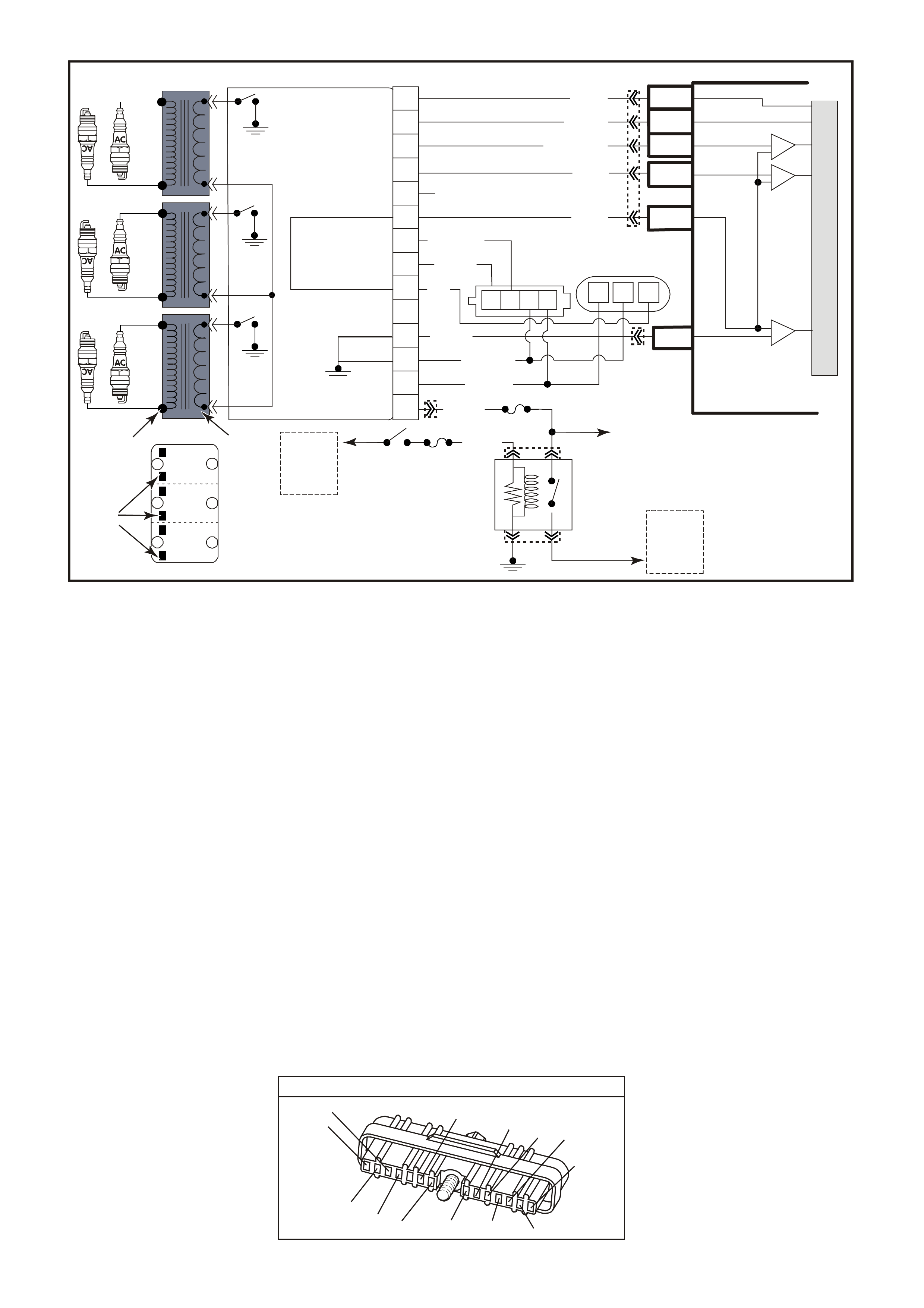
TABLE A-8.1 V6 PCM -
DIRECT IGNITION SYSTEM (DIS) CHECK
CIRCUIT DESCRIPTION:
The DIS ignition system uses a waste spark method of spark distribution. In this type of ignition system the
ignition m odule triggers the correct ignition coil, based on signals from the crankshaft sensor. Each ignition coil
provides the high secondar y voltage required to fire two spar k plugs at the sam e tim e on "c om panion" cylinders,
i.e. cylinders with pistons at the top of the their s trok e (T DC) at the sam e tim e. O ne of thes e pistons would be at
the top of its compression stroke, the other piston would be at the top of its exhaust stroke.
For additional information about the DIS system, Refer to Section 6C1-1 GENERAL DESCRIPTION of this
Service Information.
TEST DESCRIPTION: Number(s) below refer to step number(s) on the diagnostic Table.
5. Terminal "P" to the DIS module is the +12 volt supply to the DIS system.
7. This procedure will check the crankshaft sensor output, through the harness to the DIS module harness
connector. DIS m odule harness connector term inals "N" and "P" are jumper ed together to provide power to
the sensor Hall circuits. Terminal "M" is earthed to provide an earth path for the Hall circuits. As the
crankshaft balancer interrupter rings are related, the test light should blink "ON" and "OFF" as the blades
pass the cr ank shaf t sensor air gap. T he test light should be "O N" when the blade is in the crankshaf t sensor
air gap, indicating the Hall circuits are providing the earth path for the test light connected to +12 volts.
Terminal "H", the 3X signal terminals, should blink "ON" and "OFF" three times per crankshaft revolution.
NOTE: Use ST -125 spark check er or equivalent to chec k f or adequate spark . An ST-125 requires about 25,000
volts (25 kilovolts, or 25 kV) to "Spark". Do not use a spark plug in open air earthed to the engine as an
indication of sufficient "Spark". Only a few kilovolts are required to jump the gap of a spark plug outside of the
engine, and that would be an inadequate test of the ignition system.
DIRECT IGNITION M ODULE
YE 57
(647)
LBLU/B
W/B
(644)
B/R
(453)
LBLU/W
(646)
BLU/Y
(643)
V
(430)
T/B
(424)
(633)
BR
(645)
GY/R
LG
(482)
B
(630)
BR
(121)
W
(423)
PNMLKJHGFED
CBA
M
I
C
R
O
A
FUSE
FUSE
F35
85 30
8786
F14
IGNITION
SWITCH
TO
FUSIBLE
LINK
FJ
TO
INJECTORS
SUPERVX4281
CRANK
SENSOR
CONNECTOR
CAM
SENSOR
CONNECTOR
TO
FUSIBLE
LINK
FS
EFI
RELAY
B/W (152) O/P
(1040)
PRIMARY
WINDINGS
SECO NDARY
WINDINGS
12V
POWER
SUPPLY
TO COILS
TOP OF MODULE
6 – 3
2 – 5
4 – 1
COIL PACK
A
B
C
D
EBR
(121)
D4
D9
D10
PCM
EST OUTPUT
BYPASS CO NT RO L
CRANKSHAFT
18X SIGNAL
CRANKSHAFT
REFERENCE LO
IC
IC
IC
CAMSHAFT
POSITION
SENSOR
SIGNAL
CRANKSHAFT
REFERENCE HI
D12
D3
D11
BLU/Y (643)
W (423)
T/B (4 24)
LBLU/B (647)
V (430)
B (630)
LBLU/W
(646)
BR
(633)
B/R (453)
GY/R (645)
W/B (644)
LG (482)
P/B (39)
F
G
18X CRANK SENSOR – IN
18X CRANK SENSOR – OUT
EST SIGNAL – IN
BYPASS CO NT ROL
CRANKSHAFT REFERENCE – OUT
TACHO SIGNAL – OUT
SENSO R POW ER SUPP LY– OUT
MODULE POWER SUPPLY – IN
CAM SIG NAL OUT
CAM SIG NAL IN
DIS
MODULE
3X CRANK SENSOR – IN
H
J
K
L
N
P
3
6
2
5
1
4
M
BCD CBA
YB193
YE111
YE39
YE39
YE34
YE57
YE63
YB193

TABLE A-8.1 V6 PCM - DIRECT IGNITION SYSTEM (DIS) CHECK
STEP ACTION VALUE YES NO
1. Was the "On-Board Diagnostic" (OBD) System Check
performed? Go to Step 2. Go to OBD
System Check in
this Section.
2. 1. Remove one spark plug lead.
2. Connect ST-125 spark checker (see note above)
to lead and check for spark while cranking
the engine.
3. Check 3 wires on the same side of the engine this
way. A few sparks and then nothing is considered
No Spark.
Is spark present on all spark plug leads ?
Go to Step 3 If Spark on only
1 or 2 leads,
Go to Step 4
_____________
If No Spark,
Go to Step 5
3. No trouble found with ignition system
Is action complete ? Verify Repair
4. Refer to DIS module and coil checking procedure, Table
A-8.2 Step 5 in this Section.
Is action complete ?
Verify Repair
5. 1. Disconnect 14-pin connector from DIS module.
2. Ignition "ON", probe harness connector terminal "P"
with a test light connected to earth.
Is test light "ON" ?
Go to Step 9 Go to Step 6
6. Check ignition module fuse F35.
Is fuse open? Go to Step 7 Go to Step 8
7. Repair short to earth in fuse circuit.
Replace fuse.
Is action complete?
Verify Repair
8. Check for open in power circuit to DIS ignition module
harness connector terminal "P".
Was a problem found?
Verify Repair Go To Table
A-6.5
9. 1. Ignition "OFF".
2. Get three paper clips, and re-form until straight.
3. Bend one of the straightened paper clips into a very
narrow "U", and use it to jumper DIS module
harness connector terminals "N" and "P".
4. Insert a straightened paper clip into terminal "M".
Connect a jumper lead from this paper clip to earth.
• Ensure that the Two paper clips and/or jumper
leads Do Not Touch.
5. Insert a straightened paper clip into harness
connector terminal "H", and connect a test light
between this terminal and +12 volts.
6. Ignition "ON".
7. Using a 28 mm socket and hand tools, slowly rotate
the crankshaft balancer one revolution, while
observing the test light.
The test light should go "ON" and "OFF" as the 3X
interrupter blades pass through the sensor air gap, does
it ?
Go to Table 8.2,
Step 8 in this
Section
Go to Step 10
10. Check for good continuity, and for no Shorts or Opens on
the 4 circuits between the crank sensor and DIS module.
If all are OK, replace crank sensor. Refer DIS SERVICE
OPERATIONS in Section 6C1-3 of the VX Series Service
Information for proper procedure.
It must be followed.
Is action complete ?
Verify Repair
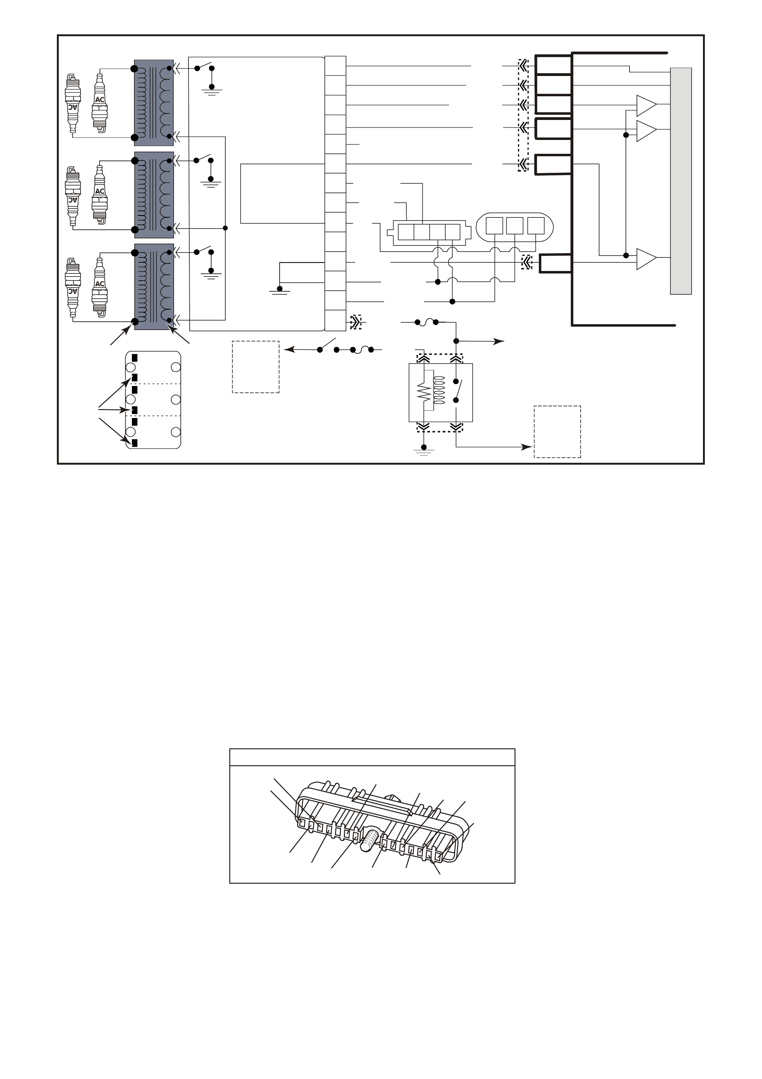
TABLE A-8.2 V6 PCM -
DIRECT IGNITION SYSTEM (DIS) CHECK
CIRCUIT DESCRIPTION:
The DIS ignition system uses a waste spark method of spark distribution. In this type of ignition system the
ignition m odule triggers the correct ignition coil, based on signals from the crankshaft sensor. Each ignition coil
provides the high secondar y voltage required to fire two spar k plugs at the sam e tim e on "c om panion" cylinders,
i.e. cylinders with pistons at the top of the their s trok e (T DC) at the sam e tim e. O ne of thes e pistons would be at
the top of its compression stroke, the other piston would be at the top of its exhaust stroke.
For additional information about the DIS system Refer to Section 6C1-1 GENERAL DESCRIPTION of this
Service Information CD.
TEST DESCRIPTION: Number(s) below refer to Step number(s) on the Diagnostic Table.
3. Terminal "G", the 18x signal terminal, should blink "ON" and "OFF" eighteen times per crankshaft revolution.
5. This procedure will check the modules ability to control the ignition coil primary system.
7. These checks are for the primary and secondary windings of each of the three ignition coils. The resistance
of each of the six checks (3 primary and 3 secondary windings) must be within the specified ranges
DIRECT IGNITION M ODULE
YE 57
(647)
LBLU/B
W/B
(644)
B/R
(453)
LBLU/W
(646)
BLU/Y
(643)
V
(430)
T/B
(424)
(633)
BR
(645)
GY/R
LG
(482)
B
(630)
BR
(121)
W
(423)
PNMLKJHGFED
CBA
M
I
C
R
O
A
FUSE
FUSE
F35
85 30
8786
F14
IGNITION
SWITCH
TO
FUSIBLE
LINK
FJ
TO
INJECTORS
SUPERVX4281
CRANK
SENSOR
CONNECTOR
CAM
SENSOR
CONNECTOR
TO
FUSIBLE
LINK
FS
EFI
RELAY
B/W (152) O/P
(1040)
PRIMARY
WINDINGS
SECO NDARY
WINDINGS
12V
POWER
SUPPLY
TO COILS
TOP OF MODULE
6 – 3
2 – 5
4 – 1
COIL PACK
A
B
C
D
EBR
(121)
D4
D9
D10
PCM
EST OUTPUT
BYPASS CONTROL
CRANKSHAFT
18X SIGNAL
CRANKSHAFT
REFERENCE LO
IC
IC
IC
CAMSHAFT
POSITION
SENSOR
SIGNAL
CRANKSHAFT
REFERENCE HI
D12
D3
D11
BLU/ Y (643)
W (423)
T/B (4 24)
LBL U/B (647)
V (430)
B (630)
LBLU/W
(646)
BR
(633)
B/R (453)
GY/R (645)
W/B (644)
LG (482)
P/B (39)
F
G
18X CRANK SENSOR – IN
18X CRANK SENSOR – OUT
ES T SIG NAL – IN
BYPASS CONTROL
CRANKSHAFT REFERENCE – OUT
TACHO SIGNAL – OUT
SEN SOR POW ER SUPP LY– OUT
MODULE POWER SUPPLY – IN
CAM SIG NAL OUT
CAM SIG NAL IN
DIS
MODULE
3X CRANK SENSOR – IN
H
J
K
L
N
P
3
6
2
5
1
4
M
BCD CBA
YB193
YE111
YE39
YE39
YE34
YE57
YE63
YB193

TABLE A-8.2 V6 PCM - DIRECT IGNITION SYSTEM (DIS) CHECK
STEP ACTION VALUE YES NO
1. Was the "On-Board Diagnostic" (OBD) System Check
performed? Go to Step 2. Go to OBD
System Check in
this Section.
2. 1. Ignition "OFF".
2. Remove the paper clip from terminal "H" and insert
it into terminal "G".
3. Ignition "ON".
Slowly rotate the crankshaft balancer one revolution and
note test light. It should go "ON" and "OFF" as the 18X
interrupter blades pass through the sensor air gap, does
it ?
Go to Step 4 Go to Step 3
3. Check for good continuity, and for no Shorts or Opens on
the 4 circuits between the crank sensor and DIS module.
If all are OK, replace crank sensor. See DIS Service
Operations in Section 6C1-3 in this Section for proper
procedure. It must be followed.
Is action complete ?
Verify Repair
4. 1. Remove test light and all leads from harness
connector terminals. Reconnect 14-pin connector to
DIS module. Torque retaining bolt to specification
value.
2. Disconnect all spark plug leads from the DIS coils.
3. Remove 6 screws that retain the coils to the module.
4. Remove all three coils.
5. Connect the test light clip lead to one of the two coil
terminals on the module.
6. Connect the test light probe to the other coil
terminal on the module.
7. While the engine is cranking, observe test light.
The test light should blink.
8. This test should be performed for each pair of
module terminals that connect to the three (3)
ignition coils.
Is the test light blinking for all three coil pairs ?
0.6 to 1.2
N.m Go to Step 6 Go to Step 5
5. If no blink, or blinks on less than all 3 pairs, replace DIS
module.
Is action complete ?
Verify Repair
6. 1. Ignition "OFF".
2. Using a digital ohmmeter, check resistance across
the ignition coil primary winding (underside)
terminals
3. Correct resistance of the ignition coils primary
winding must be within the specified value.
Are all three coils (6-3, 2-5, 4-1) within this range ?
0.3 ohms
to
1.5 ohms
Go to Step 8 Go to Step 7

TABLE A-8.2 V6 PCM - DIRECT IGNITION SYSTEM (DIS) CHECK (CONTINUED)
STEP ACTION VALUE YES NO
7. Replace coil(s) that had the incorrect ohms reading.
Is action complete ? Verify Repair
8. 1. Check resistance across the ignition coil secondary
tower terminals. Each tower is marked.
2. Correct resistance of the ignition coil secondary
windings must be within the specified value.
Are all three coils (6-3, 2-5, 4-1) within this range ?
5000
(5K ohms)
to
7000
(7K ohms)
Go to Step 10 Go to Step 9
9. Replace coil(s) that had the incorrect ohms reading.
Is action complete ? Verify Repair
10. At this point, all DIS components test indicate the DIS
system should produce spark. If a No Spark condition still
exists, very closely check the metal terminals in the
plastic connectors at the DIS module and crank sensor.
Also check the resistance of the spark plug leads,
ensuring that none are "Open"
Is action complete ?.
Verify Repair
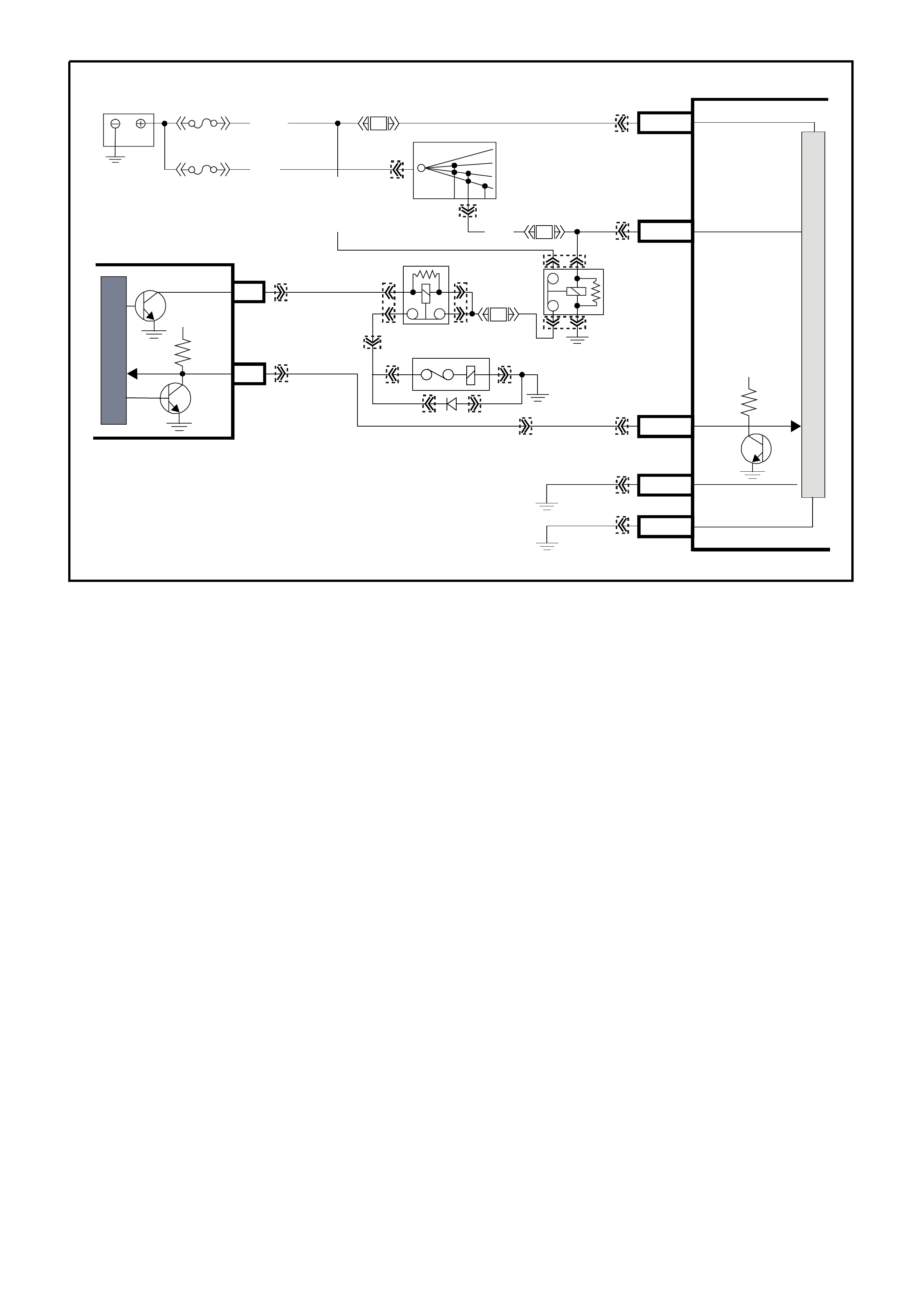
Refer to PCM wiring Mech. for further details of A/C wiring
TABLE A-11.1 V6 PCM -
A/C CLUTCH CONTROL ( NON ECC S YSTEM )
CIRCUIT DESCRIPTION:
W ith the blower fan s witc hed "ON", and the air conditioning switched "ON," s witc hed ignition voltage is supplied
from fuse F13 through the A/C master switch, and then to the BCM. The BCM will then supply a serial data
signal to the PCM requesting A/C. If the BCM does not receive a earth signal from the blower switch to BCM,
the BCM will not supply the serial data request for A/C to the PCM. Once the PCM receives this serial data
signal, the PCM will energise the A/C compressor relay by supplying a earth signal (A/C Relay Control ) from
the PCM. The BCM also supplies a earth signal from BCM terminal "7" to the low speed cooling fan relay.
This serial data signal to the PCM is also us ed to adjust the idle speed bef ore turning "ON" the A/C com press or
relay. If this signal is not available to the PCM, the A/C compressor will be inoperative.
This system also incorporates a A/C Refrigerant Pressure Sensor. The A/C Refrigerant Pressure Sensor signal
indicates Low / High pressure on the A/C high side refrigerant pressure line to the PCM. The PCM uses this
information to adjust the idle air control valve to compensate for the higher engine loads present with high A/C
refrigerant pressures. A fault in the A/C Refrigerant Pressure Sensor signal will cause DTC 96 to set.
The purpose of this A/C Refrigerant Pressure Sensor is to protect the system from danger because of either
refrigerant pressure too low (which could damage the compressor due to insufficient lubrication), or too high
(which could result in a leak in the sealed refrigerant R134a system).
The PCM will NOT energise the A/C control relay if any of the following conditions are present:
• DTC 96 is set.
• RPM more than 4,800. If de-energised because of RPM, it can re-energised when RPM falls below 4,000
for at least 10 seconds.
• Throttle is more than 90% open.
• A/C Refrigerant Pressure Sensor voltage is to Low or to High.
FS (1040)
R (2)
O/Y (479)
FJ 30
15a 15 50
Off/On
Lock
Acc
Ign
Start
M
I
C
R
O
P
R
O
C
E
S
S
O
R
M
I
C
R
O
F31
F33
Loc. E5/E15
A/C
Compressor
A/C Relay
EFI
Relay
F14
SUPERVX4282
P (3) P/B
(39)
O/B
(740)
B/G
(151)
Loc. E3
Loc. E3
B/Y
(155) A1/A5
B10/B11
E2/D2
E20/D6
A3/A6
Battery
Serial
Data
A3
F4 LG/B
(366)
R/B
(1221)
A/C
Enable
5V
5V
Ignition Switch Battery Main Power
Ignition On
El ect ronic Ear t h
Serial
Data
Main
High Current
Earth
BCM
PCM
YE101
YE39
YE39
YE101
YB188
YB194
YE105
YB44
YE105
YE120
YB176
YB165
YB174
YB163
YB175
YB164
YB175
YB164
YB176
YB165
YE120
YE112
YE111
YB44
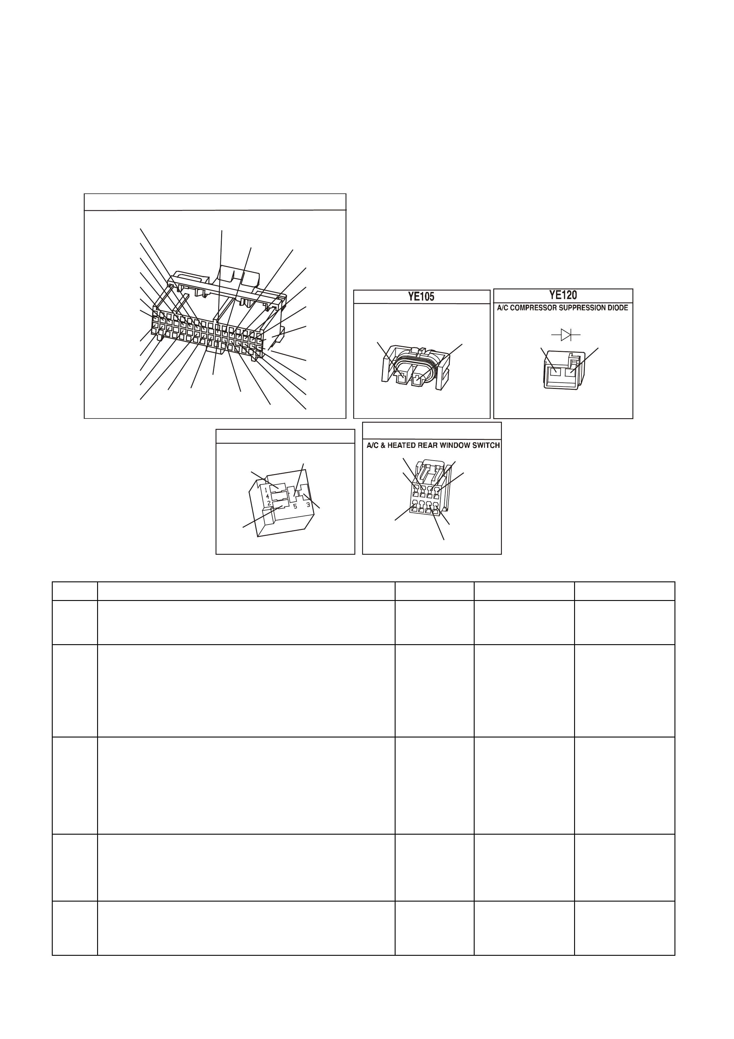
TEST DESCRIPTION: Number(s) below refer to step number(s) on the diagnostic Table.
1. The PCM's diagnostic circuits must be proven before any further testing is performed.
2. The PCM does not normally energise the A/C control relay unless the engine is running.
4. This checks for operation of the condenser fan.
20, 21, 22, 23, 24, 26, 28 There are no terminal identification on the relay connector (although the relay itself
has terminal numbers). Make certain the correct relay connector terminal (not the relay) is being probed.
39. The most likely cause of an automotive air conditioner not working is a discharged refrigerant R134a
system, due to a refrigerant leak.
Check For: If fuse F13 is blown, check for short to earth on all circuit associated with this fuse.
YE194
P.C.M. CONNECTOR 3
LG/B
(366)
G
(843)
B/W
F16
B/Y
BR/Y
(1228)
(469)
Y
(451)
F1
P
(841)
BLU
V
E1
LBLU
(845)
BLU
B
(1226)
W/B
BLU/W
V
R
(435)
(31)
(1229)
GY
(1224)
Y
(846)
GY
(842)
(452)
(774)
(304)
BR/Y
(411)
(439)
GY/BLU
BLU
(1225)
E16
(1427)
(429)
(844)
B/O
(434)
OR AUTO
GY/BLU
GY
(1434)
MAN
(776)
W
BLU/W
Y
GY
(771)
(772)
(773)
A/C COM PRESSOR
(59)
G
(750)
B/R
A
1
2
G
(59)
B/R
(750)
A/C RELAY
Y E 101
(366)
(439)
LG/B
P
G
P
(59)
(439)
YB 5 4
(291)
(248)
(44)
O
R/W
P/BLU
R/BR
GY
BR/W
B/R
(962)
(8)
(19)
(292)
TABLE A-11.1 V6 PCM - A/C CLUTCH CONTROL ( NON-ECC SYSTEM )
STEP ACTION VALUE YES NO
1. Was the "On-Board Diagnostic" (OBD) System Check
performed? Go to Step 2. Go to OBD
System Check in
this Section.
2. 1. Ignition "ON", engine stopped.
2. Disconnect the A/C compressor clutch electrical
connector and reconnect, and note compressor
clutch.
Did compressor clutch cycle "OFF" then "ON" with
electrical connector disconnected and reconnected?
If A/C clutch
cycled "OFF"
then "ON"
or will not
disengage
Go to Step 6
Go to Step 3
3. 1. Ignition "ON", engine idling.
2. Blower Switch turned "ON".
3. Cycle the A/C switch "ON" and "OFF", waiting a
few seconds between positions.
Listen for A/C compressor clutch. Does it cycle "ON" and
"OFF?
Go to Step 4 Go to Step 14
4. 1. Ignition "ON", engine idling.
2. A/C switch in the "ON" position.
Does the A/C condenser fan operate when the A/C
Switch is turned "ON" ?
Go to Step 5 Go to Table
A-12 in this
Section
5. 1. A/C clutch control circuits OK.
2. If complaint is insufficient cooling, review symptoms.
Is action complete ?
Verify Repair

TABLE A-11.1 V6 PCM - A/C CLUTCH CONTROL ( NON-ECC SYSTEM ) (CONTINUED)
STEP ACTION VALUE YES NO
6. 1. Ignition "OFF".
2. Disconnect A/C compressor electrical connector.
2. Observe A/C clutch.
Is A/C clutch staying engaged to compressor?
Go to Step 7 Go to Step 8
7. Replace A/C compressor clutch. Refer to section 2B in
VX Service Information..
Is action complete?
Verify Repair
8. 1. Ignition "ON", engine "OFF".
2. Using test light connected to B+, backprobe PCM
terminal for A/C Relay Control.
Does test light illuminate?
Go to Step 9 Go to Step 11
9. Check for a short to earth in circuit for A/C Relay Control
from the PCM to A/C Compressor Relay.
Was a problem found?
Verify Repair Go to Step 10
10. Replace PCM.
Refer to Section 6C1-3 Service Operations of the VX
Series Service Information, for PCM Security Link
procedure.
Is action complete?
Verify Repair
11. 1. Ignition "ON".
2. Disconnect A/C compressor electrical connector.
3. Using test light connected to earth, probe A/C
compressor electrical connector power circuit.
4. With test light "ON", remove A/C Compressor Relay
and note test light.
Did test light turn "OFF"?
Go to Step 12 Go to Step 13
12. Replace A/C Compressor Relay.
Is action complete? Verify Repair
13. Repair short to voltage on A/C compressor power feed
circuit from A/C Compressor Relay to A/C compressor.
Is action complete?
Verify Repair
14. 1. Ignition "ON", engine idling.
2. Install scan tool.
3. Observe A/C Refrigerant Pressure Sensor voltage
display on the scan tool.
Is indicated A/C Refrigerant Pressure Sensor voltage at
or between the specified value?
0.35V - 4.2V Go to Step 15 Go to Step 39
15. Check power supply fuse to A/C master switch.
Is fuse open? Go to Step 16 Go to Step 17
16. Repair short to earth in fuse circuit, and replace fuse.
Is action complete? Verify Repair
17. 1. Ignition "ON", engine "OFF".
2. Turn A/C Master Switch to "ON" position.
2. Using test light connected to earth, backprobe BCM
terminal for A/C Select Input circuit.
Dose test light illuminate?
Go to Step 20 Go to Step 18
18. Check for open or poor connection in circuit from A/C
Master Switch to BCM A/C Select Input, or open in power
feed circuit to A/C Master Switch.
Was a problem found?
Verify Repair Go to Step 19
19. Replace A/C Master Switch.
Is action complete? Verify Repair

TABLE A-11.1 V6 PCM - A/C CLUTCH CONTROL ( NON-ECC SYSTEM ) (CONTINUED)
STEP ACTION VALUE YES NO
20. 1. Ignition "ON", engine idling.
2. Remove Blower Inhibit Relay from Relay center,
leave harness connector connected to relay.
3. Using test light connected to B+, backprobe relay
harness connector terminal 30.
4. Turn A/C Master Switch to "ON" position.
Does test light illuminate?
Go to Step 21 Go to Step 26
21. 1. Ignition "ON", engine idling.
2. Using test light connected to B+, backprobe BCM
terminal for Blower Switch Input Signal.
3. Turn A/C Master Switch to "ON" position.
4. Turn Blower Switch to "ON" position.
Does test light illuminate?
Go to Step 22 Go to Step 33
22. 1. Ignition "OFF".
2. Remove A/C Compressor Relay fro m Relay center.
3. Ignition "ON", engine idling.
4. Turn A/C Master Switch to "ON" position.
5. Turn Blower Switch to "ON" position.
6. Using test light connected to B+, probe terminal "2"
of A/C Compressor Relay harness connector.
Does test light illuminate?
Go to Step 23 Go to Step 35
23. 1. Ignition "ON", engine "OFF".
2. Using test light connected to earth, probe A/C
Compressor Relay harness terminals 1 and 3.
Does test light illuminate on both circuits?
Go to Step 24 Go to Step 36
24. 1. Ignition "OFF".
2. Reinstall Blower Inhibit Relay and A/C Compressor
Relay.
3. Disconnect electrical connector at A/C compressor.
4. Ignition "ON", engine idling.
5. Turn A/C Master Switch to the "ON" position.
6. Turn Blower Switch to the "ON" position.
7. Using test light connected to earth, probe A/C
compressor harness power feed circuit from A/C
Compressor Relay to compressor.
Dose test light illuminate?
Go to Step 25 Go to Step 37
25. Check A/C compressor earth circuit for an open, if open
repair. If earth circuit is OK, Replace A/C compressor.
Refer to Section 2C of the VX Service Information..
Is action complete?
Verify Repair
26. 1. Ignition "ON", engine idling.
2. Using test light connected to B+, backprobe Blower
Inhibit Relay terminal 85 for Blower Inhibit Relay
Earth Output Signal from BCM.
3. Turn A/C master switch "ON".
Dose test light illuminate?
Go to Step 28 Go to Step 27
27. Check for open in circuit from BCM to Blower Inhibit
Relay or poor connection at BCM. If OK, replace BCM.
Is action complete?
Verify Repair
28. 1. Ignition "ON", engine "OFF".
2. Disconnect Blower Inhibit Relay from harness
connector.
3. Using test light connected to earth, probe relay
harness terminal 86.
Does test light illuminate?
Go to Step 30 Go to Step 29

TABLE A-11.1 V6 PCM - A/C CLUTCH CONTROL ( NON-ECC SYSTEM ) (CONTINUED)
STEP ACTION VALUE YES NO
29. Repair open in circuit from Blower Inhibit Relay terminal
86 to Ignition Switch.
Is action complete?
Verify Repair
30. 1. Ignition "ON", engine "OFF".
2. With Blower Inhibit Relay still disconnected, probe
relay harness terminal 87 with a test light connected
to B+.
Does test light illuminate?
Go to Step 31 Go to Step 32
31. Replace Blower Inhibit Relay.
Is action complete? Verify Repair
32. Repair open in earth circuit to Blower Inhibit Relay.
Is action complete? Verify Repair
33. Check for open circuit from Blower Switch to BCM Blower
Switch Input terminal.
Was a problem found?
Verify Repair Go to Step 34
34. Check for open in circuit from Blower Inhibit Relay
terminal 30 to Blower Switch.
Was a problem found?
Verify Repair Go to Step 38
35. Check for open in circuit from A/C Compressor Relay to
PCM terminal for A/C Relay Control.
Was a problem found?
Verify Repair Go to Step 10
36. Repair open in circuit that did not light.
Is action complete? Verify Repair
37. Check for open in circuit from A/C Compressor to A/C
Compressor Relay.
Was a problem found?
Verify Repair Go to Step 12
38. Replace Blower Switch.
Is action complete? Verify Repair
39. Check A/C Pressure Sensor signal circuit for short to
earth.
Was a problem found?
Verify Repair Go to Step 40
40. Check A/C refrigerant (R-134a) system for being
undercharged, or overcharged.
Is action complete.
Verify Repair
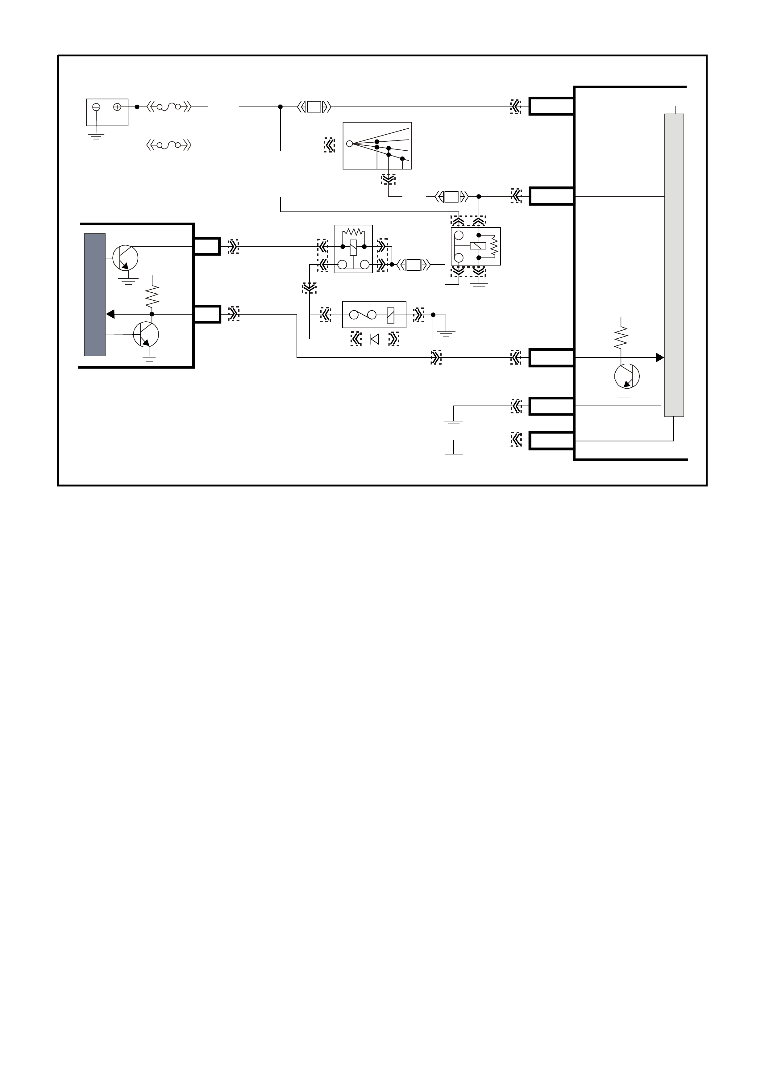
Refer to PCM wiring Mech. for further details on A/C wiring
TABLE A-11.3 V6 PCM -
A/C CLUTCH CONTROL WI TH ELECTRONIC CLIMATE CONTROL (ECC)
CIRCUIT DESCRIPTION:
When the A/C is reques ted, the Elec tronic Climate Control Module will supply a signal to the BCM. The BCM will
then send a s erial data request to the PCM. When the PCM rec eives the ser ial data request on PCM ser ial data
circuit, it indicates that air conditioning has been requested and approximately 1/2 second after the PCM
receives this signal, it will energise the A/C control relay. This serial data signal to the PCM is also used to
adjust the idle speed before turning "ON" the A/C compressor relay. If this signal is not available to the PCM,
the A/C compressor will not operative.
The BCM also supplies the earth signal from BCM to the low speed cooling fan relay.
This A/C system also incorporates a A/C Refrigerant Pressure Sensor. The A/C Refrigerant Pressure Sensor
signal indica tes low and high side r ef riger ant pres s ures to the PCM. The PCM uses this inf or mation to adjus t the
idle air c ontrol valve to compensate f or the higher engine loads pr es ent with high A/C refr igerant pr es s ures ., and
not allow A/C operation if pressure is to low A fault in the A/C Refrigerant Pressure Sensor signal will cause
DTC 96 to set.
The PCM will NOT energise the A/C control relay if any of the following conditions are present:
• DTC 96 is set.
• RPM more than 4,800. If de-energised because of RPM, it can re-energised when RPM falls below 4,000
for at least 10 seconds.
• Throttle is more than 90% open.
• A/C Refrigerant Pressure Sensor voltage is to Low or to High.
TEST DESCRIPTION: Number(s) below refer to step number(s) on the diagnostic Table.
1. The PCM's diagnostic circuits must be proven before any further testing is performed.
3. The PCM does not normally energise the A/C control relay unless the engine is running.
4. W hen the T ech 2 sc an tool is installed, and the A/C switch is turned "ON", the s can tool should display "A/C
Requested".
FS (1040)
R (2)
O/Y (479)
FJ 30
15a 15 50
Off/On
Lock
Acc
Ign
Start
M
I
C
R
O
P
R
O
C
E
S
S
O
R
M
I
C
R
O
F31
F33
Loc. E5/E15
A/C
Compressor
A/C Relay
EFI
Relay
F14
SUPERVX4282
P (3) P/B
(39)
O/B
(740)
B/G
(151)
Loc. E3
Loc. E3
B/Y
(155) A1/A5
B10/B11
E2/D2
E20/D6
A3/A6
Battery
Serial
Data
A3
F4 LG/B
(366)
R/B
(1221)
A/C
Enable
5V
5V
Ignition Switch Battery Main Power
Ignition On
El ect roni c Ear t h
Serial
Data
Main
High Current
Earth
BCM
PCM
YE101
YE39
YE39
YE101
YB188
YB194
YE105
YB44
YE105
YE120
YB176
YB165
YB174
YB163
YB175
YB164
YB175
YB164
YB176
YB165
YE120
YE112
YE111
YB44
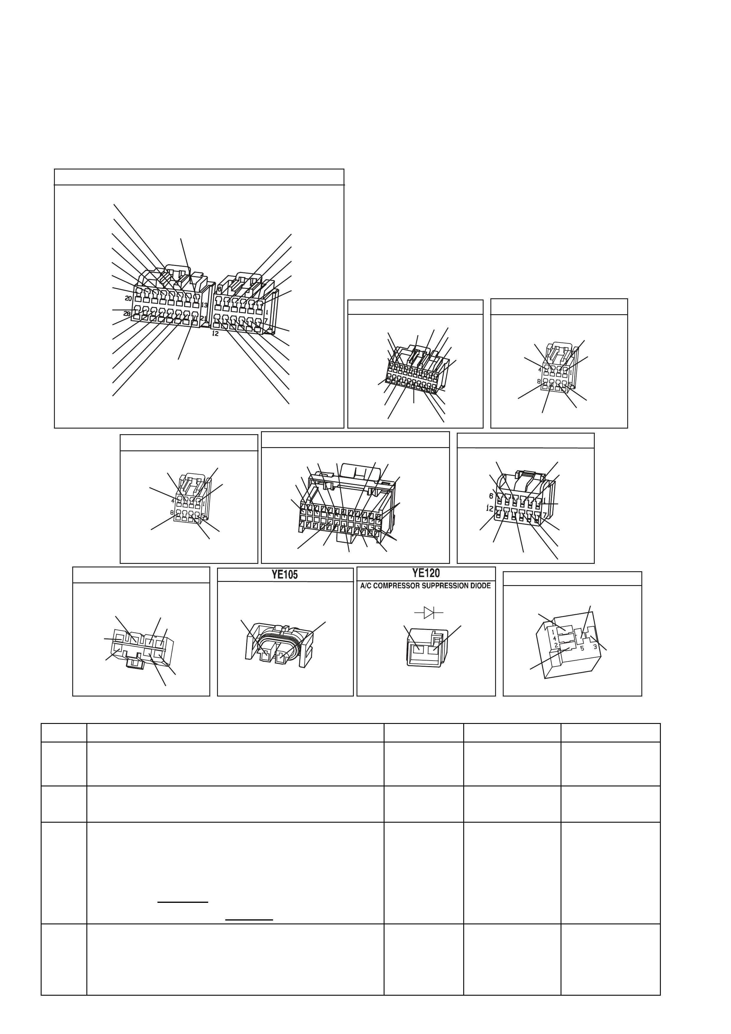
6. This checks for operation of the condenser fan.
7. The most likely cause of an automotive air conditioner not cooling properly is a discharged or overcharged
refrigerant R134a system.
18, 19, 20 There are no terminal identification on the relay connector (although the relay itself has terminal
numbers). Make certain the correct relay connector terminal (not the relay) is being probed.
Check For: If fuse F13 is blown, check for short to earth on all circuit associated with this fuse.
YB 175
B.C.M CO NNECTOR 3
BERLINA & CALAIS
LBLU
Y/R
O/BLU
B
BLU/W
W/BLU
(43)
(39)
(97)
(83)
(94)
O/W
Y/B
B/R
(161)
(143)
(640)
(1150)
(260)
(1144)
(840)
Y
P/B
GY
LBLU
(494)
W
(160)
V/R
R/B
W/G
B/Y
GY/B
(229)
(1221)
(1220)
(556)
(96)
(261)
G/W
Y
Y/B
W
W/R
(266)
(1220)
(272)
(717)
(308)
BR/G
(271)
R/W
GY/R
(1391)
B.C.M CONNECTOR 3
EXECUTIVE
YB164
(83)
(97)
W/G
(229)
B/G
W/BLU
(266)
(1144)
P/BLU
G/W
BLU/W
(1220)
(494)
BR/G
GY
(1220)
B
GY
(1391)
LBLU
(151)
(271)
R/B
R/W
(1150)
(291)
V/R
(8)
O
P/B
B/R
Y
GY/R
(1221)
(94)
(39) (44)
(248)
10
20 1
11
B.C.M CONNECTOR 4
YB1 76
GY
B/Y
O/B
LBLU
(155)
(8)
(740)
(263)
(1128)
(28)
B/Y
B/W
GY/BLU
(492)
W
(1138)
YB 165
B.C.M CONNECTOR 4
(492)
GY/BLU
(173)
Y
B/R
BR
(292)
(90)
(263)
LBLU B/Y
O/B
(155)
(740)
YB 188
P.C.M CONNECTOR 2
(481)
(417)
(740)
R
BLU
O
(1456)
LG
V/W
(415)
Y
(1227)
B/Y
(410)
BR
(472)
(259)
(750)
(750)
(1221)
B/R
B/R
R/B
G/B
(39)
P
(465)
G/W
(416)
GY
(740)
O
A1
B1
B12
A12
A/C CONTR OL (E.C.C)
YB 87
(1220)
(52)
(44)
(735)
(734) (19)
(64)
(51)
(292)
(155)
(8)
P/BLU
Y/B
G/W
LG/B
BLU/B
GY
B/Y
B/R
Y
B/R
BR/W
G
(342)
LIGHT S W ITCH
YB 33
(151)
B/G
GY
(8)
(717)
WW/R
(308)
BR/BLU
(42)
(49)
BLU
W/B
(147)
B
(1150)
OR EXECUTIVE
A/C COM PRESSOR
(59)
G
(750)
B/R
A
1
2
G
(59)
B/R
(750)
A/C RELAY
Y E 101
(366)
(439)
LG/B
P
G
P
(59)
(439)
TABLE A-11.3 V6 PCM - A/C CLUTCH CONTROL WITH ELECTRONIC CLIMATE CONTROL (ECC)
STEP ACTION VALUE YES NO
1. Was the "On-Board Diagnostic" (OBD) System Check
performed? Go to Step 2 Go to OBD
System Check in
this Section.
2. Check fuse for Electronic Climate Control module.
Is fuse OK ? Go to Step 3 Go to Step 16
3. 1. Ignition "ON", engine stopped.
2. Cycle A/C master switch "ON" and "OFF", waiting a
few seconds between positions.
3. Observe the A/C compressor clutch.
4. It should not cycle "ON" and "OFF",
Did the compressor clutch not cycle "ON" and "OFF" ?
Go to Step 4 If either engages
or will not
disengage
Go to Step 13
4. 1. Ignition "ON".
2. Install Tech 2 scan tool.
3. Turn A/C switch "On"
Does Tech 2 scan tool display "A/C Requested" ?
Go to Step 5 Go to Step 8

TABLE A-11.3 V6 PCM - A/C CLUTCH CONTROL WITH ELECTRONIC CLIMATE CONTROL (ECC) (CONT)
STEP ACTION VALUE YES NO
5. 1. Ignition "ON", engine idling.
2. Cycle the A/C switch "ON" and "OFF", waiting a
few seconds between positions.
3. Listen for A/C compressor clutch.
Does A/C compressor clutch cycle "ON" and "OFF"?
Go to Step 6 Go to Step 17
6. Ignition "ON", engine idling.
Does the A/C condenser fan operate when the A/C is
turned "ON"?
Go to Step 7 Go to Table
A-12 in this
Section
7. A/C clutch control circuits OK. If complaint is Insufficient
A/C cooling, review symptoms.
Is action complete ?
Verify Repair
8. Check for poor connection or an open circuit between
BCM and Electronic Climate Control Module.
Was a problem found ?
Verify Repair Go to Step 9
9. 1. Ignition "OFF".
2. Disconnect BCM connectors.
3. Ignition "ON", engine "OFF".
4. Using DVM connected to earth, probe BCM harness
connector terminal for A/C Select Input from
Electronic Climate Control module.
5. Turn "ON" A/C switch.
Does DVM indicate voltage between the specified value?
2 - 4
volts Go to Step 11 Go to Step 10
10. Check for a open or short to earth in A/C Select circuit
between BCM and Electronic Climate Control module.
Was a problem found?
Verify Repair Go to Step 12
11. Replace BCM.
Is action complete ? Verify Repair
12. Check for poor connection at Electronic Climate Control
module, if connection OK, replace faulty Electronic
Climate Control Module.
Is action complete ?
Verify Repair
13. Check for short to earth from PCM circuit A/C Relay
Control to A/C Co mpresso r Relay.
Was a problem found?
Verify Repair Go to Step 14
14. Check for short to voltage on power feed circuit to A/C
compressor.
Was a problem found?
Verify Repair Go to Step 15
15. Replace defective A/C compressor relay.
NOTE: If compressor clutch still will not disengage,
replace A/C compressor clutch. Refer to Section
2B in VX Service Information..
Is action complete ?
Verify Repair
16. Repair short to earth in fuse circuit.
Replace fuse.
Is action complete?
Verify Repair
17. 1. Ignition "ON", engine idling.
2. Install scan tool.
3. Observe A/C Refrigerant Pressure Sensor voltage
display on the scan tool.
Is indicated A/C Refrigerant Pressure Sensor voltage at
or between the specified value?
0.35V - 4.2V Go to Step 18 Go to Step 29

TABLE A-11.3 V6 PCM - A/C CLUTCH CONTROL WITH ELECTRONIC CLIMATE CONTROL (ECC) (CONT)
STEP ACTION VALUE YES NO
18. 1. Ignition "ON", engine idling.
2. Disconnect A/C compressor relay.
3. Probe both relay terminals "3" and "1" of harness
connector, with a test light connected to earth.
Is test light "ON" at both terminals ?
Go to Step 19 Go to Step 25
19. 1. Ignition "ON", engine idling.
2. Probe A/C compressor relay connector circuit for
A/C Relay Control with a test light connected to B+.
3. Turn A/C switch "ON".
Is test light "ON" when the A/C switch is "ON" ?
Go to Step 20 Go to Step 23
20. 1. Ignition "ON", engine idling.
2. Reconnect A/C compressor relay.
3. Backprobe relay harness terminal "5" with a test light
connected to earth.
4. Turn A/C switch "ON".
Is test light "ON" when A/C switch is turned "ON"?
Go to Step 21 Go to Step 15
21. 1. Ignition "OFF".
2. Disconnect A/C compressor electrical connector.
3. Ignition "ON", engine idling.
4. Probe compressor harness connector terminal
power feed circuit with a test light connected to
earth.
5. Turn A/C switch "ON".
Is test light "ON" when the A/C switch is turned "ON"?
Go to Step 22 Go to Step 28
22. Check for a poor earth circuit to A/C compressor.
Was a problem found? Verify Repair Go to Step 27
23. Check for a faulty connection for A/C compressor relay.
Was a problem found ? Verify Repair Go to Step 24
24. Check for a open in the PCM A/C Relay Control circuit,
from the PCM to the A/C compressor relay.
Was a problem found ?
Verify Repair Go to Step 26
25. Repair open in circuit that did not light test light.
Is action complete ? Verify Repair
26. Replace PCM.
Refer to Section 6C1-3 Service Operations of the VX
Series Service Information, for PCM Security Link
procedure.
Is action complete?
Verify Repair
27. Replace A/C compressor.
Is repair complete ? Verify Repair
28. Repair open in circuit 59 to A/C compressor clutch.
Is repair complete ? Verify Repair
29. Check A/C Pressure Sensor signal circuit for short to
earth.
Was a problem found?
Verify Repair Go to Step 30
30. Check A/C refrigerant (R-134a) system for being
undercharged, or overcharged.
Is action complete.
Verify Repair
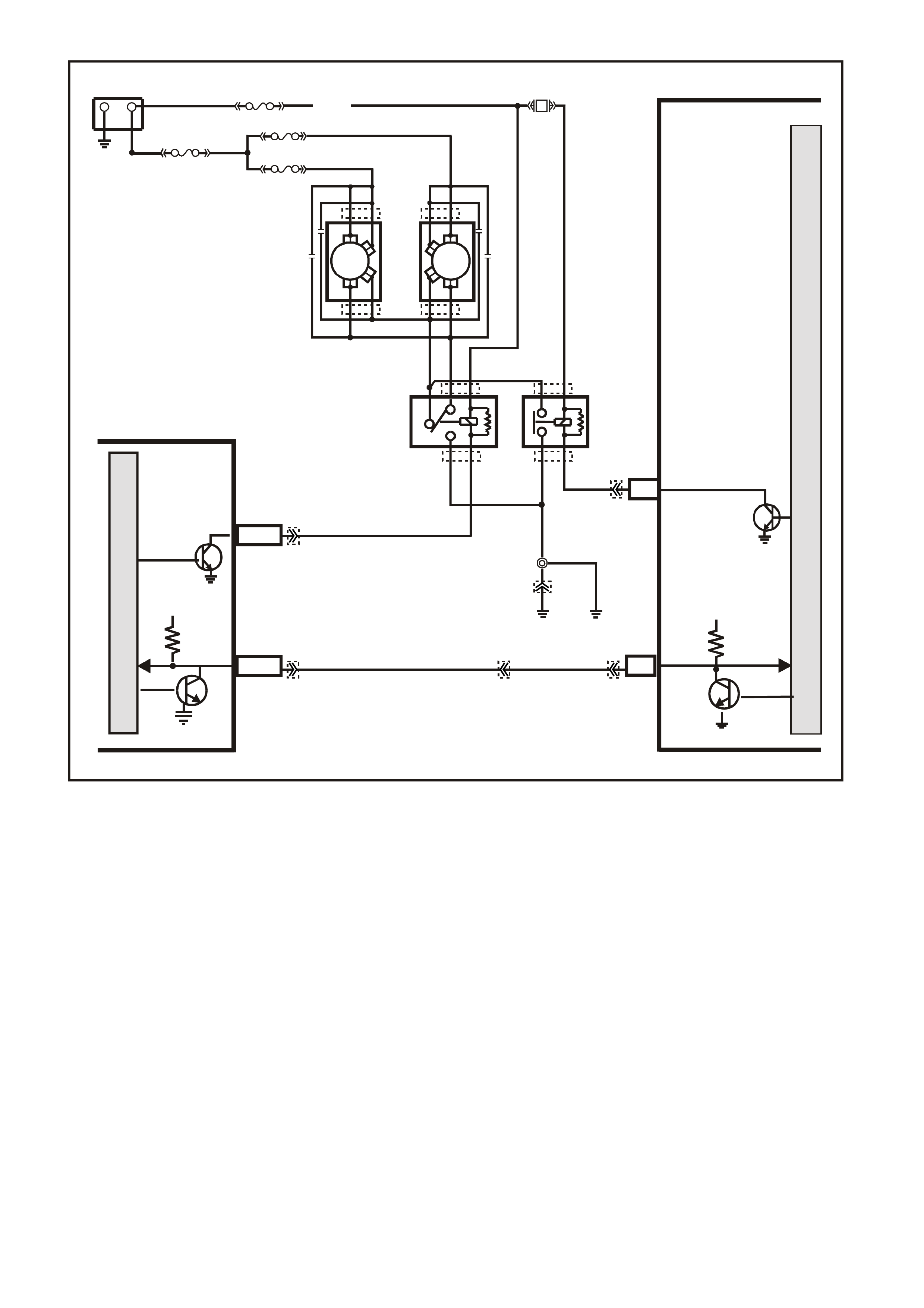
TABLE A-12.1 V6 PCM -
ELECTRIC FAN CONTROL
CIRCUIT DESCRIPTION:
This V6 engine have two (2) two speed electric radiator f an m otors which provides the primar y m eans of m oving
air through the engine radiator. The two (2) two speed electric cooling fan's are used to cool engine coolant
flowing through the radiator. It is also used to cool the refrigerant flowing through the A/C condenser.
The engine cooling fan high speed relay is controlled by the PCM. The PCM controls the earth path for the
engine cooling fan high speed relay.
The low speed of the electric fan is controlled by the PCM through special Data Communication to the BCM.
The BCM controls the earth path for the engine cooling fan low speed relay.
Both relays are used to control the earth paths to the electric motor's that drives both five bladed fan's.
ENGINE COOLING FAN LOW SPEED.
The engine cooling fan low speed relay is energised by the BCM. The PCM determines when to enable the
engine cooling fan low speed based on inputs from the A/C request signal, vehicle speed and engine coolant
temperature. The engine cooling low speed fan will be turned "ON" when:
• A/C request indicated (YES) and
• Vehicle speed less than 54 Km/h
or
• Coolant temper ature is greater than 104 degrees C and will rem ain on until coolant tem perature goes down
below 99 degrees C
SUPERVX056
PCM
M
I
C
R
O
P
R
O
C
E
S
S
O
R
LOW SPE ED FAN
M
I
C
R
O
BCM
O/B (4 73)
+-
BATTERY
LOC.
E1
B7/B7
HIGH SERIES
BCM TERMINALS
NOMINATED FIRST
A3
MAIN
SERIAL
DATA 5V
SERIAL
DATA
MAIN
5V
E2/D2 R/B (1221)
87A
30
87
85
86
87
30
85
86
ENGINE
COOLING
FAN 1
ENGINE
COOLING
FAN RELAY
(LOW SPEED)
ENGINE
COOLING
FAN RELAY
(HIGH SPEED)
R
YB
G
BLUE
FUSIBLE
LINK
F31
ENGINE
COOLING
FAN 2
FS
FT FAN 2
FU FAN 1
(1040)
R
(203)
R
(001)
R
(001)
O/B
(208)
O/BLU
(204)
BLU/W
(304) F6
HIGH
SPEED FAN
LOC.
E2
LOC.
E3
B/P
(157)
YE119
YE119
YE103
YE103
YE43
YE43 YB194
YE114
YE112
YB188
YB174
YB163
YB175
YB164
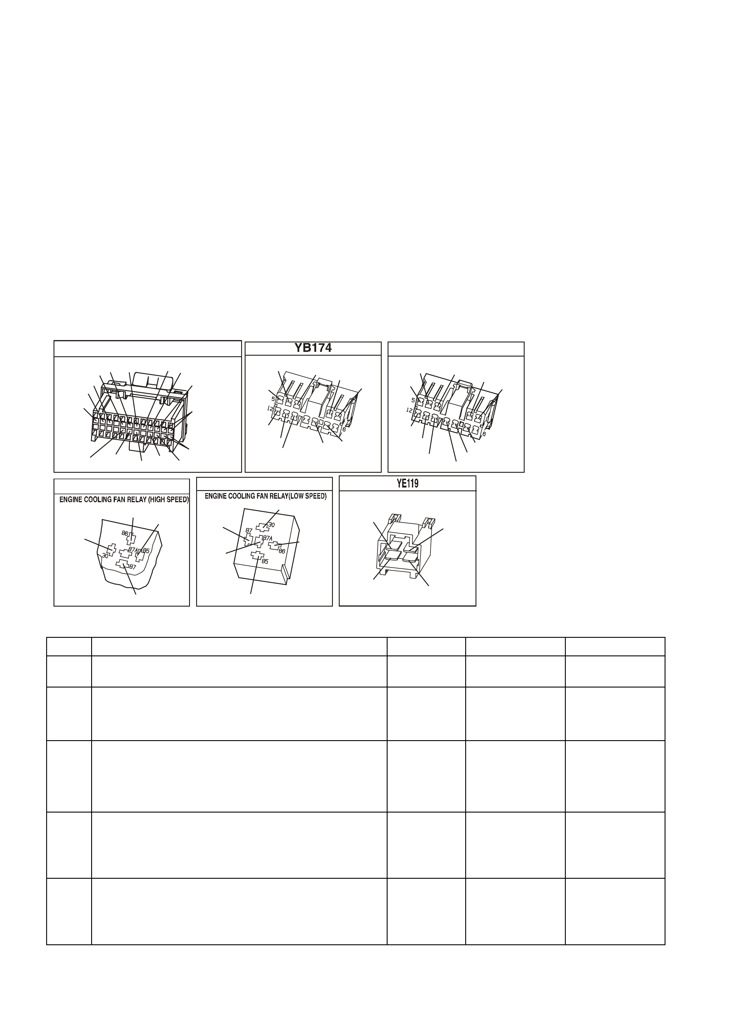
ENGINE COOLING FAN HIGH SPEED
The engine cooling fan high speed is controlled by the PCM based on input from the Engine Coolant
Tem per ature Sensor ( ECT) . T he PCM will only turn "O N" the engine cooling fan high speed if the engine cooling
low speed fan has been "ON" for 2 seconds and the following conditions are satisfied.
• There is a BCM message response fault which will cause a DTC 92.
• An engine coolant temperature sensor failure is detected, such as DTC 14,15,16,17, or 91.
• Coolant temperature greater than 109 degrees C.
If the fan low speed was "OFF" when the criteria was met to turn the fan high speed "ON", the fan high speed
will come "ON" 5 seconds after the fan low speed is turned "ON". The engine cooling fan High speed relay can
also be enable by the A/C Refrigerant Pressure Sensor. The A/C Refrigerant Pressure Sensor will provide a
signal to the PCM when A/C pressure becomes to high approximately 1770 kPa.
TEST DESCRIPTION: Number(s) below refer to step number(s) on the diagnostic Table.
2. T his entire diagnostic pr ocedure mus t begin with a "c old" engine - at ambient air temperature. If the coolant
is hot when diagnosis is performed, replacement of good parts will result. Fan should not be running if
engine coolant temperature is less than 99 degrees C and air conditioning is not "ON".
8. On A/C equipped vehicles, the engine cooling fan High speed relay should energise by the PCM, as soon
as the PCM energises the A/C clutch.
YB 188
P.C.M CONNECTOR 2
(481)
(417)
(740)
R
BLU
O
(1456)
LG
V/W
(415)
Y
(1227)
B/Y
(410)
BR
(472)
(259)
(750)
(750)
(1221)
B/R
B/R
R/B
G/B
(39)
P
(465)
G/W
(416)
GY
(740)
O
A1
B1
B12
A12
BERLINA & CALAIS
B.C.M CONNE CTOR 2
V
LBLU
(14)
(140)
O/R Y
(173)
(782)
BR
(90)
O/B
(151)
(440)
(15)
BLU
O/V
B/G Y
(196) (473)
EXECUTIVE
B.C.M CONNE CTOR 2
Y B 163
DG/YBLU
(140)
(15)
O/R
(674)
G/W
(359)
W
(1138)
(440)
(151)
(14)
O/V
B/G
LBLU
O/B
R/BR
Y
(473)
(962)
(196)
YE 43
B/R
(157)
BLU/W
(304)
O/B
(740)
O/Y
(250)
YE 103
(1040)
O/Y
(250)
ENGINE 12V BUS
BLU/Y
(533)
O/B
(473)
B/R
(157)
ENGINE C OOLING FAN
B
Y
R
G
(533)
(250) (208)
(204)
(208)
G
R
(204)
OR
OR
TABLE A-12.1 V6 PCM - ELECTRIC FAN CONTROL
STEP ACTION VALUE YES NO
1. Was the "On-Board Diagnostic" (OBD) System Check
performed? Go to Step 2. Go to OBD
System Check
2. 1. Ignition "ON", engine stopped.
2. Engine coolant temperature below 99 degrees C.
Are both electric fan motor's running ?
Go to Step 3 Go to Step 9
3. 1. Ignition "OFF".
2. Remove the Radiator Fan High Speed Relay.
3. Ignition "ON".
Does both fan's continue to run ?
Go to Step 4 Go to Step 5
4. 1. Ignition "ON".
2. Remove Radiator Fan Low Speed Relay from relay
housing.
Does both fan's continue to run ?
Go to Step 13 Go to Step 16
5. 1. Ignition "ON".
2. Probe Radiator Fan High Speed Relay harness
connector circuit 304 with a test light to +12 volts.
Is the test light "ON"?
Go to Step 6 Go to Step 8

TABLE A-12.1 V6 PCM - ELECTRIC FAN CONTROL (CONTINUED)
STEP ACTION VALUE YES NO
6. 1. Ignition "OFF".
2. Disconnect PCM connectors.
3. Ignition "ON".
4. Using test light, probe Radiator Fan High Speed
Relay harness connector circuit 304 with a test light
connected to +12 volts.
Is the test light "ON" ?
Go to Step 14 Go to Step 7
7. Replace PCM.
Refer to Section 6C1-3 Service Operations of this Service
Information, for PCM Security Link procedure.
Is action complete?
Verify Repair
8. Replace Radiator Fan High Speed Relay. Verify Repair
9. 1. Ignition "ON".
2. Using the scan tool, Select HIGH FAN relay control.
3. Turn "ON" "HIGH FAN " with up/down arrow keys.
Do both cooling fan's operate in high fan mode?
Go to Step 20 Go to Table
A-12.2 in this
Section
10. Is the vehicle equipped with A/C? Go to Step 11 Go to Step 12
11. 1. Start engine, allow to idle.
2. Turn A/C "ON".
3. Electric fan's should run when the A/C clutch
engages.
NOTE: If A/C clutch will not engage, refer Table A-11.1
or Table A-11.3 in this Section.
Do the fan's run when A/C clutch is engaged?
Go to Step 12 Go to Step 9
12. The electric fan's circuit are OK. Verify Operation
13. 1. Connect a test light to +12 volts.
2. Probe circuit's 533 and 250 of Radiator Fan Low
Speed Relay.
Is the test light "ON" ?
Go to Step 15 Go to Step 18
14. Repair short to earth in circuit 304. Verify Repair
15. Repair short to earth in circuit 533 and/or circuit 250. Verify Repair
16. 1. Ignition "ON".
2. Probe Fan Low Speed Relay harness connector
circuit 473 with a test light connected to +12 volts.
Is the test light "ON"?
Go to Step 17 Go to Step 21
17. 1. Ignition "OFF".
2. Check for short to earth on circuit 473.
Was a short to earth found ?
Verify Repair Go to Step 18
18. Replace the BCM. Verify Repair
19. 1. Reinstall Radiator Fan High Speed Relay.
2. Ignition "ON".
3. Using the scan tool, Select LOW FAN.
4. Turn "ON" "LOW FAN " with up/down arrow keys.
Does the radiator fan motor run?
Go to Step 10 Go to Table
A-12.3 in this
Section
20. 1. Ignition "ON"
2. Using the scan tool; Select HIGH FAN relay control.
3. Turn "ON" "HIGH FAN " with up/down arrow keys.
4. While fan is running, remove Radiator Fan High
Speed Relay.
Did the cooling fan motor reduce to a lower running
speed ?
Go to Step 19 If radiator fan
motor turned
"OFF",
Go to Table
A-12.3 in this
Section

TABLE A-12.1 V6 PCM - ELECTRIC FAN CONTROL (CONTINUED)
STEP ACTION VALUE YES NO
21. Check for short to earth in circuit 250.
Was a problem found? Verify Repair Go to Step 22
22. Replace Radiator Fan Low Speed Relay.
Is action complete? Verify Repair
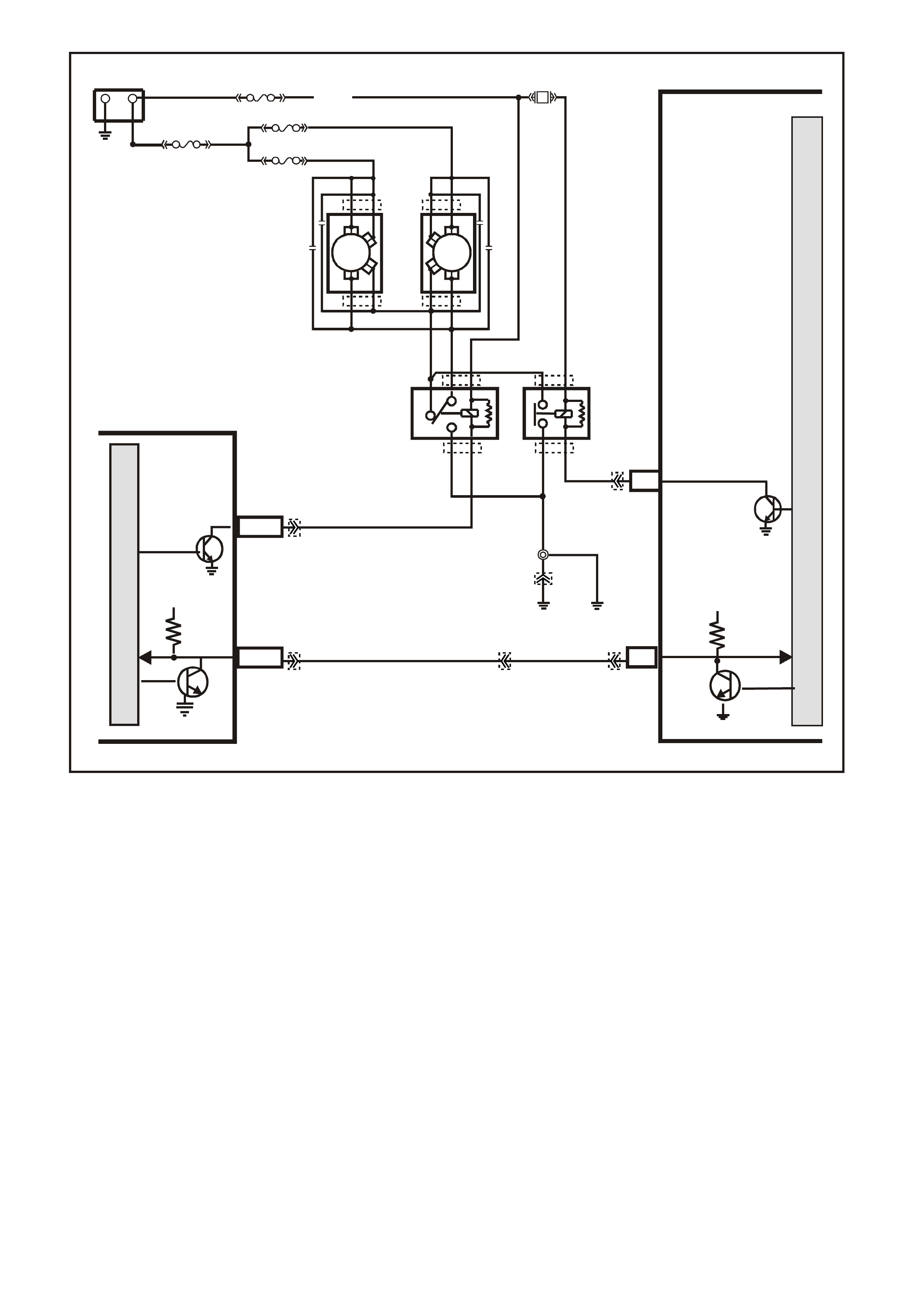
TABLE A-12.2 V6 PCM -
ELECTRIC FAN CONTROL
CIRCUIT DESCRIPTION:
This V6 engine have two (2) two speed electric radiator f an m otors which provides the primar y m eans of m oving
air through the engine radiator. The two (2) two speed electric cooling fan's are used to cool engine coolant
flowing through the radiator. It is also used to cool the refrigerant flowing through the A/C condenser.
The engine cooling fan high speed relay is controlled by the PCM. The PCM controls the earth path for the
engine cooling fan high speed relay.
The low speed of the electric fan is controlled by the PCM through special Data Communication to the BCM.
The BCM controls the earth path for the engine cooling fan low speed relay.
Both relays are used to control the earth paths to the electric motor's that drives both five bladed fan's.
ENGINE COOLING FAN LOW SPEED.
The engine cooling fan low speed relay is energised by the BCM. The PCM determines when to enable the
engine cooling fan low speed based on inputs from the A/C request signal, vehicle speed and engine coolant
temperature. The engine cooling low speed fan will be turned "ON" when:
• A/C request indicated (YES) and
• Vehicle speed less than 54 Km/h
or
• Coolant temper ature is greater than 104 degrees C and will rem ain on until coolant tem perature goes down
below 99 degrees C
SUPERVX056
PCM
M
I
C
R
O
P
R
O
C
E
S
S
O
R
LOW SPEED FAN
M
I
C
R
O
BCM
O/B (473)
+-
BATTERY
LOC.
E1
B7/B7
HIGH SERIES
BCM TERMINALS
NOMINATED FIRST
A3
MAIN
SERIAL
DATA 5V
SERIAL
DATA
MAIN
5V
E2/D2 R/B (1221)
87A
30
87
85
86
87
30
85
86
ENGINE
COOLING
FAN 1
ENGINE
COOLING
FAN RELAY
(LOW SPEED)
ENGINE
COOLING
FAN RELAY
(HIGH SPEED)
R
YB
G
BLUE
FUSIBLE
LINK
F31
ENGINE
COOLING
FAN 2
FS
FT FAN 2
FU FAN 1
(1040)
R
(203)
R
(001)
R
(001)
O/B
(208)
O/BLU
(204)
BLU/W
(304) F6
HIGH
SPEED FAN
LOC.
E2
LOC.
E3
B/P
(157)
YE119
YE119
YE103
YE103
YE43
YE43 YB194
YE114
YE112
YB188
YB174
YB163
YB175
YB164
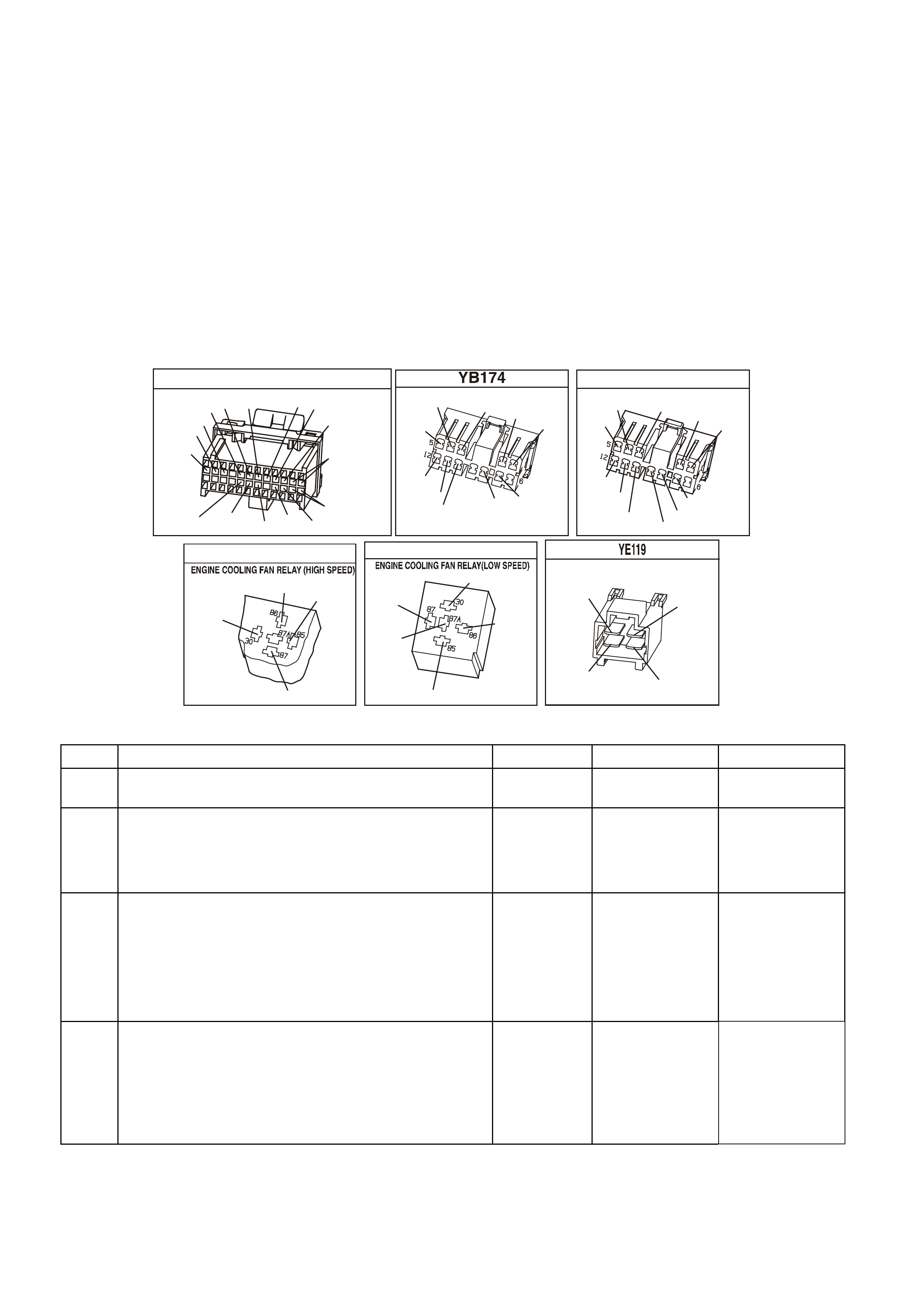
ENGINE COOLING FAN HIGH SPEED
The engine cooling fan high speed is controlled by the PCM based on input from the Engine Coolant
Tem per ature Sensor ( ECT) . T he PCM will only turn "O N" the engine cooling fan high speed if the engine cooling
low speed fan has been "ON" for 2 seconds and the following conditions are satisfied.
• There is a BCM message response fault which will cause a DTC 92.
• An engine coolant temperature sensor failure is detected, such as DTC 14,15,16,17, or 91.
• Coolant temperature greater than 109 C.
If the fan low speed was "OFF" when the criteria was met to turn the fan high speed "ON", the fan high speed
will come "ON" 5 seconds after the fan low speed is turned "ON". The engine cooling fan High speed relay can
also be enable by the A/C Refrigerant Pressure Sensor. The A/C Refrigerant Pressure Sensor will provide a
signal to the PCM when A/C pressure becomes to high approximately 1770 kPa.
TEST DESCRIPTION: Number(s) below refer to step number(s) on the diagnostic Table.
3. This checks the fused power circuit to the Radiator Fan High Speed Relay.
7. This step checks for proper power supply to both circuits of both fan motors.
YB 188
P.C.M CONNECTOR 2
(481)
(417)
(740)
R
BLU
O
(1456)
LG
V/W
(415)
Y
(1227)
B/Y
(410)
BR
(472)
(259)
(750)
(750)
(1221)
B/R
B/R
R/B
G/B
(39)
P
(465)
G/W
(416)
GY
(740)
O
A1
B1
B12
A12
BERLINA & CALAIS
B.C.M CONNE CTOR 2
V
LBLU
(14)
(140)
O/R Y
(173)
(782)
BR
(90)
O/B
(151)
(440)
(15)
BLU
O/V
B/G Y
(196) (473)
EXECUTIVE
B.C.M CONNE CTOR 2
Y B 163
DG/YBLU
(140)
(15)
O/R
(674)
G/W
(359)
W
(1138)
(440)
(151)
(14)
O/V
B/G
LBLU
O/B
R/BR
Y
(473)
(962)
(196)
YE 43
B/R
(157)
BLU/W
(304)
O/B
(740)
O/Y
(250)
YE 103
(1040)
O/Y
(250)
ENGINE 12V BUS
BLU/Y
(533)
O/B
(473)
B/R
(157)
ENGINE C OOLING FAN
B
Y
R
G
(533)
(250) (208)
(204)
(208)
G
R
(204)
OR
OR
TABLE A-12.2 V6 PCM - ELECTRIC FAN CONTROL
STEP ACTION VALUE YES NO
1. Was the "On-Board Diagnostic" (OBD) System Check
performed? Go to Step 2. Go to OBD
System Check.
2. • From Table A-12.1
Check fusible links FS, FT, FU, and White fusible link for
open.
Was a problem found?
Go to Step 8 Go to Step 3
3. 1. Ignition "OFF".
2. Remove Radiator Fan High Speed Relay.
3. Ignition "ON"
4. Probe relay socket, circuit 39 with test light
connected to earth
Is test light "ON" ?
Go to Step 4 Go to Step 10
4. 1. Ignition "ON".
2. Probe Radiator Fan High Speed Relay socket circuit
304 with a test light connected to +12 volts.
3. Using scan tool, Select HIGH FAN, enable fan "ON"
with up/down arrows.
Is test light "ON"?
Go to Step 5 Go to Step 9

TABLE A-12.2 V6 PCM - ELECTRIC FAN CONTROL (CONTINUED)
STEP ACTION VALUE YES NO
5. 1. Ignition "ON".
2. Reinstall Radiator Fan High Speed Relay.
3. Back-probe Radiator Fan High Speed Relay harness
connector circuit 250 with test light connected to
+12 volts.
4. Using scan tool, Select HIGH FAN, enable fan "ON"
with up/down arrow keys.
Is test light "ON"
Go to Step 6 Go to Step 11
6. 1. Ignition "ON".
2. Disconnect both electric cooling fan wiring harness
connector.
3. Probe both fan harness connector, circuits 533 and
250 with a test light to +12 volts.
4. Using scan tool, Select HIGH FAN, enable fan "ON"
by pressing up/down arrow keys.
Is test light "ON" for both circuits ?
Go to Step 7 Go to Step 13
7. Probe both fan harness connector power feed circuits,
with a test light connected to earth.
Is test light "ON" for all circuits ?
Go to Step 12 Go to Step 15
8. 1. Check for short to earth that caused fusible link to
blow.
2. Check that the engine cooling fan motor is not
drawing too much current.
Is action complete ?
Verify Repair
9. 1. Ignition "ON".
2. Using scan tool, Select HIGH FAN, enable
output by pressing up/down arrow keys.
3. Backprobe PCM terminal "F6" with a test light
connected to +12 volts.
Is test light "ON"?
Go to Step 14 Go to Step 16
10. Repair open or short to earth in circuit 39.
Replace fuse if blown. Verify Repair
11. With test light connected to +12 volts, back probe
Radiator Fan High Speed Relay harness connector circuit
157.
Does test light illuminate?
Go to Step 17 Go to Step 18
12. Check for poor connection at both fan motor's. If OK,
replace the electric fan motor that did not operate. Verify Repair
13. Check for open in circuits 533 or 250.
Was a problem found? Verify Repair Go to Step 18
14. Repair open in circuit 304. Verify Repair
15. Repair open circuit in fan motor power circuit that did not
light test light. Verify Repair
16. Check for short to voltage in circuit 304, or faulty
connection at PCM, if OK replace PCM. Verify Repair
17. Replace Radiator Fan High Speed Relay. Verify Repair
18. Check for open in earth circuit 157.
Was a problem found? Verify Repair Go to Step 19
19. Replace Radiator Fan Low Speed Relay. Verify Repair
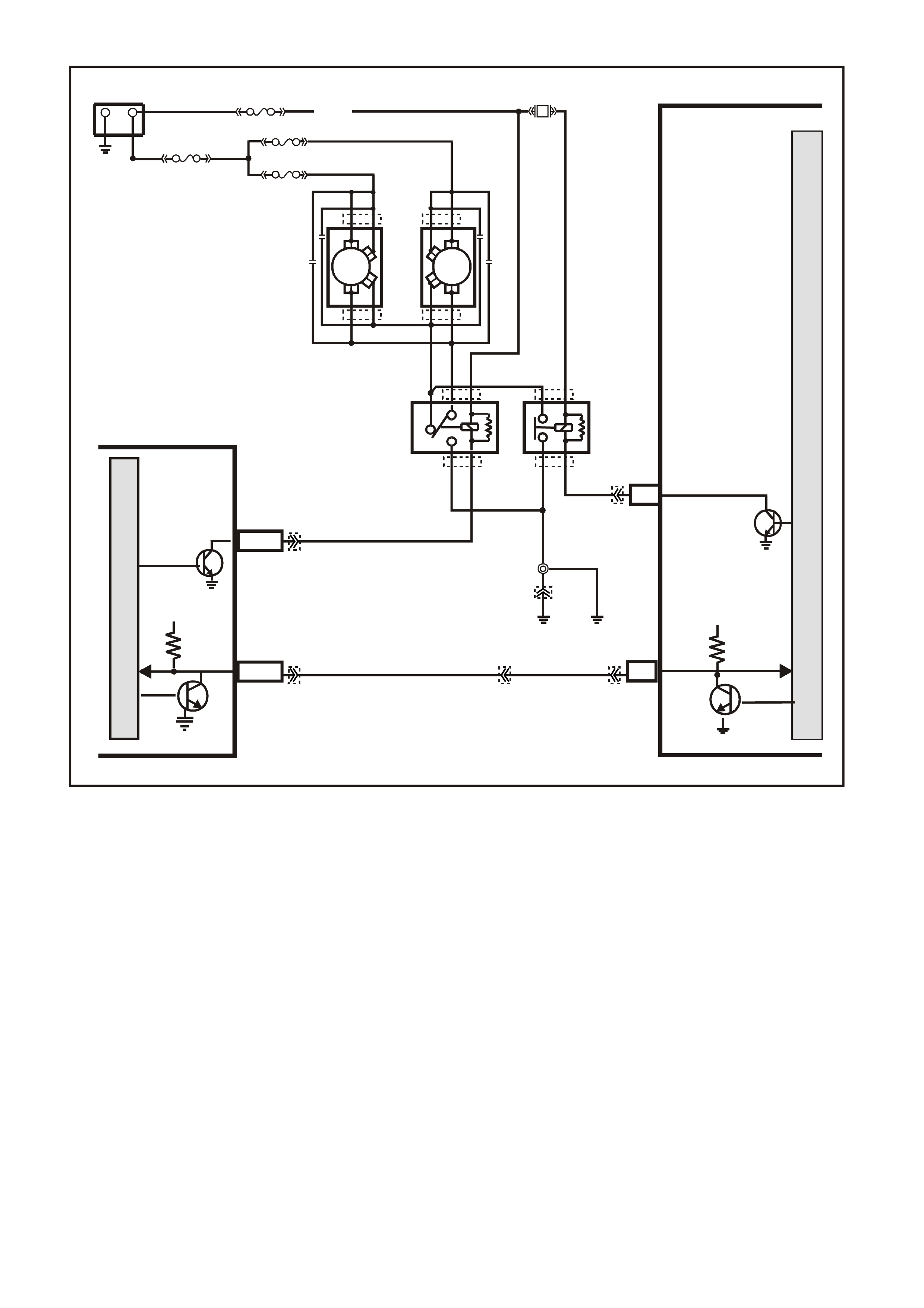
TABLE A-12.3 V6 PCM -
ELECTRIC FAN CONTROL
CIRCUIT DESCRIPTION:
This V6 engine have two (2) two speed electric radiator f an m otors which provides the primar y m eans of m oving
air through the engine radiator. The two (2) two speed electric cooling fan's are used to cool engine coolant
flowing through the radiator. It is also used to cool the refrigerant flowing through the A/C condenser.
The engine cooling fan high speed relay is controlled by the PCM. The PCM controls the earth path for the
engine cooling fan high speed relay.
The low speed of the electric fan is controlled by the PCM through special Data Communication to the BCM.
The BCM controls the earth path for the engine cooling fan low speed relay.
Both relays are used to control the earth paths to the electric motor's that drives both five bladed fan's.
ENGINE COOLING FAN LOW SPEED.
The engine cooling fan low speed relay is energised by the BCM. The PCM determines when to enable the
engine cooling fan low speed based on inputs from the A/C request signal, vehicle speed and engine coolant
temperature. The engine cooling low speed fan will be turned "ON" when:
• A/C request indicated (YES) and
• Vehicle speed less than 54 Km/h
or
• Coolant temper ature is greater than 104 degrees C and will rem ain on until coolant tem perature goes down
below 99 degrees C
SUPERVX056
PCM
M
I
C
R
O
P
R
O
C
E
S
S
O
R
LOW SPEED FAN
M
I
C
R
O
BCM
O/B (473)
+-
BATTERY
LOC.
E1
B7/B7
HIGH SERIES
BCM TERMINALS
NOMINATED FIRST
A3
MAIN
SERIAL
DATA 5V
SERIAL
DATA
MAIN
5V
E2/D2 R/B (1221)
87A
30
87
85
86
87
30
85
86
ENGINE
COOLING
FAN 1
ENGINE
COOLING
FAN RELAY
(LOW SPEED)
ENGINE
COOLING
FAN RELAY
(HIGH SPEED)
R
YB
G
BLUE
FUSIBLE
LINK
F31
ENGINE
COOLING
FAN 2
FS
FT FAN 2
FU FAN 1
(1040)
R
(203)
R
(001)
R
(001)
O/B
(208)
O/BLU
(204)
BLU/W
(304) F6
HIGH
SPEED FAN
LOC.
E2
LOC.
E3
B/P
(157)
YE119
YE119
YE103
YE103
YE43
YE43 YB194
YE114
YE112
YB188
YB174
YB163
YB175
YB164

ENGINE COOLING FAN HIGH SPEED
The engine cooling fan high speed is controlled by the PCM based on input from the Engine Coolant
Tem per ature Sensor ( ECT) . T he PCM will only turn "O N" the engine cooling fan high speed if the engine cooling
low speed fan has been "ON" for 2 seconds and the following conditions are satisfied.
• There is a BCM message response fault which will cause a DTC 92.
• An engine coolant temperature sensor failure is detected, such as DTC 14,15,16,17, or 91.
• Coolant temperature greater than 109 C.
If the fan low speed was "OFF" when the criteria was met to turn the fan high speed "ON", the fan high speed
will come "ON" 5 seconds after the fan low speed is turned "ON". The engine cooling fan High speed relay can
also be enable by the A/C Refrigerant Pressure Sensor. The A/C Refrigerant Pressure Sensor will provide a
signal to the PCM when A/C pressure becomes to high approximately 1770 kPa.
TEST DESCRIPTION: Number(s) below refer to step number(s) on the diagnostic Table.
3. This checks the FS fusible link power supply to the Radiator Fan Low Speed Relay.
4. This step checks for proper BCM operation for the Radiator Fan Low Speed Relay.
YB 188
P.C.M CONNECTOR 2
(481)
(417)
(740)
R
BLU
O
(1456)
LG
V/W
(415)
Y
(1227)
B/Y
(410)
BR
(472)
(259)
(750)
(750)
(1221)
B/R
B/R
R/B
G/B
(39)
P
(465)
G/W
(416)
GY
(740)
O
A1
B1
B12
A12
BERLINA & CALAIS
B.C.M CONNE CTOR 2
V
LBLU
(14)
(140)
O/R Y
(173)
(782)
BR
(90)
O/B
(151)
(440)
(15)
BLU
O/V
B/G Y
(196) (473)
EXECUTIVE
B.C.M CONNE CTOR 2
Y B 163
DG/YBLU
(140)
(15)
O/R
(674)
G/W
(359)
W
(1138)
(440)
(151)
(14)
O/V
B/G
LBLU
O/B
R/BR
Y
(473)
(962)
(196)
YE 43
B/R
(157)
BLU/W
(304)
O/B
(740)
O/Y
(250)
YE 103
(1040)
O/Y
(250)
ENGINE 12V BUS
BLU/Y
(533)
O/B
(473)
B/R
(157)
ENGINE C OOLING FAN
B
Y
R
G
(533)
(250) (208)
(204)
(208)
G
R
(204)
OR
OR
TABLE A-12.3 V6 PCM - ELECTRIC FAN CONTROL
STEP ACTION VALUE YES NO
1. Was the "On-Board Diagnostic" (OBD) System Check
performed? Go to Step 2. Go to OBD
System Check.
2. 1. Ignition "OFF".
2. Remove Radiator Fan Low Speed Relay.
3. Probe relay socket, circuit 250 with a test light
connected to +12 volts.
Is test light "ON" ?
Go to Step 7 Go to Step 3
3. 1. Ignition "OFF".
2. Remove Radiator Fan Low Speed Relay
3. Ignition "ON"
4. Probe relay socket, circuits 1040 with test light
connected to earth
Is test light "ON" ?
Go to Step 4 Go to Step 9
4. 1. Ignition "ON".
2. Probe Radiator Fan Low Speed Relay socket, circuit
473 with a test light connected to +12 volts.
2. Using scan tool, Select LOW FAN, enable fan "ON"
with up/down arrow keys.
Is test light "ON"?
Go to Step 5 Go to Step 8

TABLE A-12.3 V6 PCM - ELECTRIC FAN CONTROL (CONTINUED)
STEP ACTION VALUE YES NO
5. 1. Ignition "ON".
2. Reinstall Radiator Fan Low Speed Relay.
3. Back-probe low speed relay wiring harness
connector, circuit 533 with test light connected to
+12 volts.
4. Using scan tool, Select LOW FAN, enable fan "ON"
with up/down arrow keys.
Is test light "ON"
Go to Step 10 Go to Step 6
6. 1. Ignition "OFF".
2. Disconnect both electric cooling fan wiring harness
connector.
3. Probe both wiring harness connector circuit's 533
with test light connected to +12 volts.
4. Using scan tool, Select LOW FAN, enable fan "ON"
with up/down arrow keys.
Is test light "ON"
Go to Step 14 Go to Step 12
7. Repair short to earth in circuit 250.
Is action complete? Verify Repair
8. 1. Ignition "ON".
2. Using scan tool, Select LOW FAN, enable fan "ON".
3. Backprobe BCM terminal "7" with a test light
connected to +12 volts.
Is test light "ON"?
Go to Step 13 Go to Step 15
9. Repair open in circuit which causes test light not to come
"ON".
Is action complete?
Verify Repair
10. Replace Radiator Fan Low Speed Relay.
Is action complete? Verify Repair
11. Repair short to earth Verify Repair
12. Repair open in circuits 533 or 250.
Is action complete? Verify Repair
13. Repair open in circuit 473 between BCM and Radiator
Fan Low Speed Relay.
Is action complete?
Verify Repair
14. Replace Radiator fan motor that did not operate.
Is action complete? Verify Repair
15. Check for faulty connection at BCM, if OK replace BCM.
Is action complete? Verify Repair
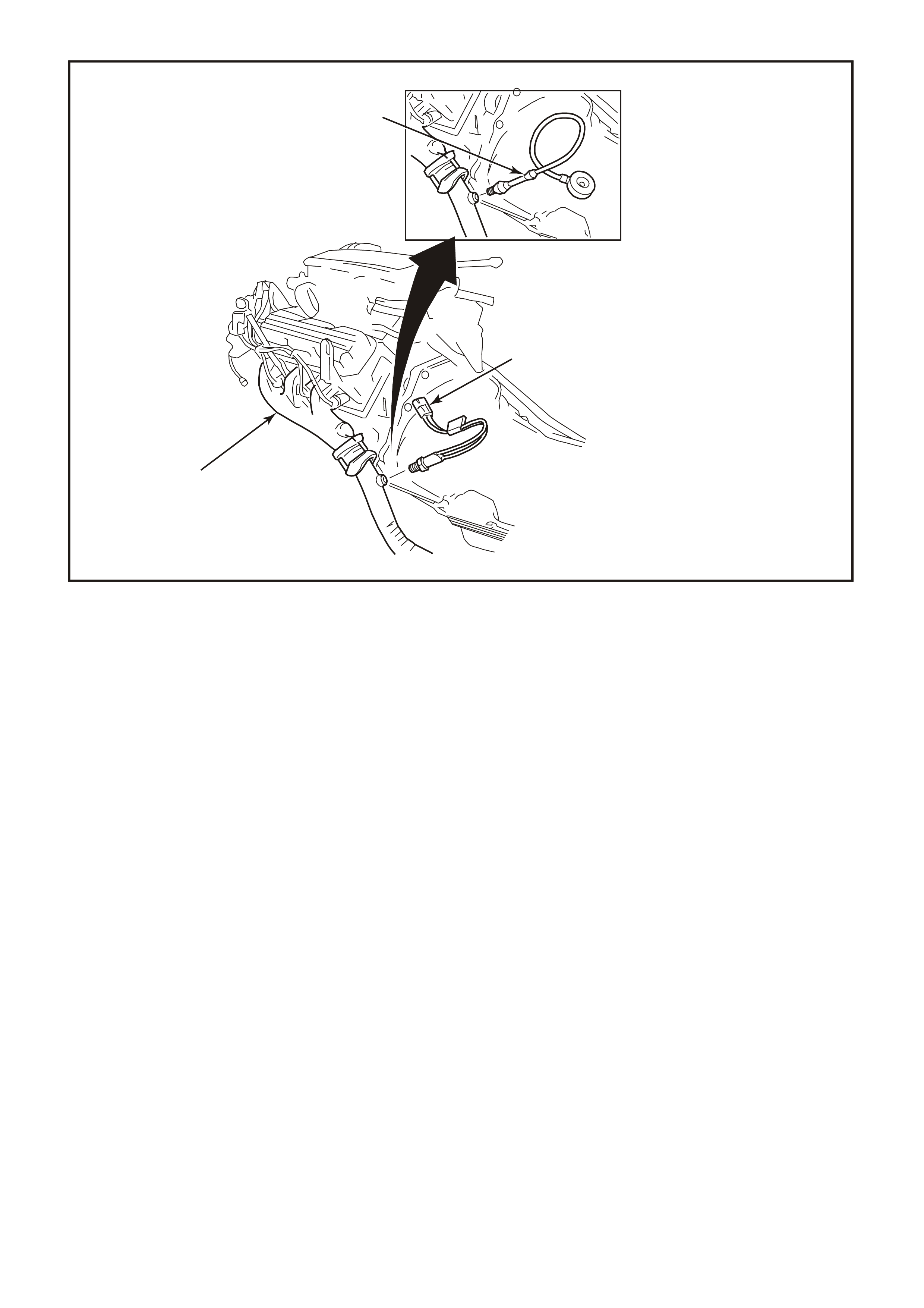
1. Back Pressure Gauge Assembly.
2. Exhaust Gas Heated Oxygen (HO2S) Sensor
3. L.H. Engine Exhaust Pipe.
TABLE A-13 V6 PCM -
RESTRICTED EXHAUST CHECK
There are tim es when a restricted exhaust can cause a variety of owner complaints. Below is a list of some of
these owner complaints.
• No power, sluggish
• Hesitation on acceleration
• Surges while driving
• Poor fuel economy
• Stalling
• Hard starting
Things that could cause a restricted exhaust:
A. Collapsed exhaust pipe.
B. Muffler. Loose baffles may cause internal restriction
C. Catalytic converter. Things that can cause a catalytic converter to become restricted: (1) The use of
LEADED FUEL (2) A very rich-running engine. T his rich-r unning condition could be caused by fuel pres sure
too high, or by a malfunction in the engine control system (3) Engine in a bad state of tune. W orn parts in
the ignition system can cause an engine misfire, which sends unburned fuel into the exhaust system. The
catalytic converter "sees" this unburned fuel as a rich-running condition. (4) Push-starting the engine. This
can send a tremendous amount of unburned fuel into the exhaust system.
4283
1
2
3

TABLE A-13 V6 PCM - RESTRICTED EXHAUST CHECK
STEP ACTION VALUE YES NO
1. Was the "On-Board Diagnostic" (OBD) System Check
performed? Go to Step 2. Go to OBD
System Check in
this Section.
2. Carefully remove O2 sensor.
Did O2 sensor remove from exhaust system ? Go to Step 3 Go to Step 6
3. 1. Install exhaust back pressure gauge in place of
removed O2 sensor.
2. Ignition "ON", engine started.
3. Observe the exhaust system back pressure reading
on the gauge.
Is the reading below the specified value ?
8.6 kPa Go to Step 4 Go to Step 7
4. Accelerate engine to 2000 RPM and observe reading on
gauge.
Is reading on gauge below the specified value ?
20.7 kPa Go to Step 5 Go to Step 7
5. No problem with exhaust system.
NOTE: Make sure to coat threads of O2 sensor with a
specified anti-seize compound prior to
installation.
Is action complete ?
Go to OBD
System Check in
this Section
6. If the O2 sensor will not remove from the exhaust
System, make sure that the exhaust system is Above
60 C. Excessive force may damage threads. If the O2
sensor cannot be removed , the exhaust pipe and O2
sensor may need to be replaced.
Was removal of O2 sensor successful ?
Go to Step 3 Verify Repair
7. NOTE: If there are no obvious reasons for the
excessive back pressure, a restricted catalytic
converter should be suspected and replaced
using current recommended procedures. Refer
above Things that could cause a
restricted exhaust: for possible causes.
NOTE: Make sure to coat threads of O2 sensor with a
specified anti-seize compound prior to
installation.
Is action complete ?
Verify Repair and
Go to OBD
System Check in
this Section

DTC 13 V6 PCM -
RIGHT HAND OXYGEN SENSOR (O2S) INSUFFICIENT ACTIVITY
CIRCUIT DESCRIPTION:
The ex haust oxygen sens or is mounted in the ex haust pipe with the sensing portion exposed to exhaust gases.
After the sensor is hot (360 degrees C), it becomes a voltage generator, producing a "changing" voltage. This
voltage ranges from approximately 100 millivolts with a "lean" exhaust, to 900 millivolts with a "rich" exhaust.
When the sens or is c old (below 360 degrees C) it acts lik e an open c ircuit and produc es alm ost no voltage. T he
PCM supplies a very small "bias" voltage between terminals C9 and D5, normally about 450 millivolts. If
measured with the 10 megaohm digital voltmeter, it may measure as low as 350 millivolts. W hen the sensor is
hot, it's output overshadows this PCM supplied voltage.
When the fuel system is correctly operating in the closed-loop mode, the sensor output is changing several
times per second, going above and below a mid-point range of 490-500 millivolts at a hot idle. The PCM
compares the voltage between the sensor signal and sensor earth terminals and decides the needed fuel
mixture correction. The PCM also monitors the changing voltage, watching for transitions above and below the
mid- point range, to decide when to operate in the closed-loop m ode. An open circ uit, defective, or contaminated
sensor could caus e the voltage to stay within a 410- 477 m illivolt band too long, k eeping the system in open-loop
and setting a DTC 13.
CONDITIONS FOR RUNNING THE DTC
• Engine run time is longer than 4 minutes.
• No TP Sensor DTC’s are set.
• The ECT sensor is more than 85°C.
• Throttle angle is more than 15%.
CONDITIONS FOR SETTING THE DTC
• The RH 02S voltage stays between 410-477 millivolts.
M
I
C
R
O
P (439)
YE95
D
D
B
B
A
A
C
C
YE95
GY (1412)
B/R (750)
Engine
Earth
To Fuse
F33
GY/B (1413)
V (412)
V/B (413)
B/R (750)
4269
A2
D16
D15
D14
D13
A1 450 m V
Right
Oxygen
Sensor
Signal HI
Right
Oxygen
Sensor
Signal LO
Left
Oxygen
Sensor
Signal HI
Left
Oxygen
Sensor
Signal LO
Earth
Earth
Ri ght Oxygen Sensor
Left Oxygen Sensor 450 m V
IC
IC
Engine
Earth
PCM
YB193
YB188
YB188
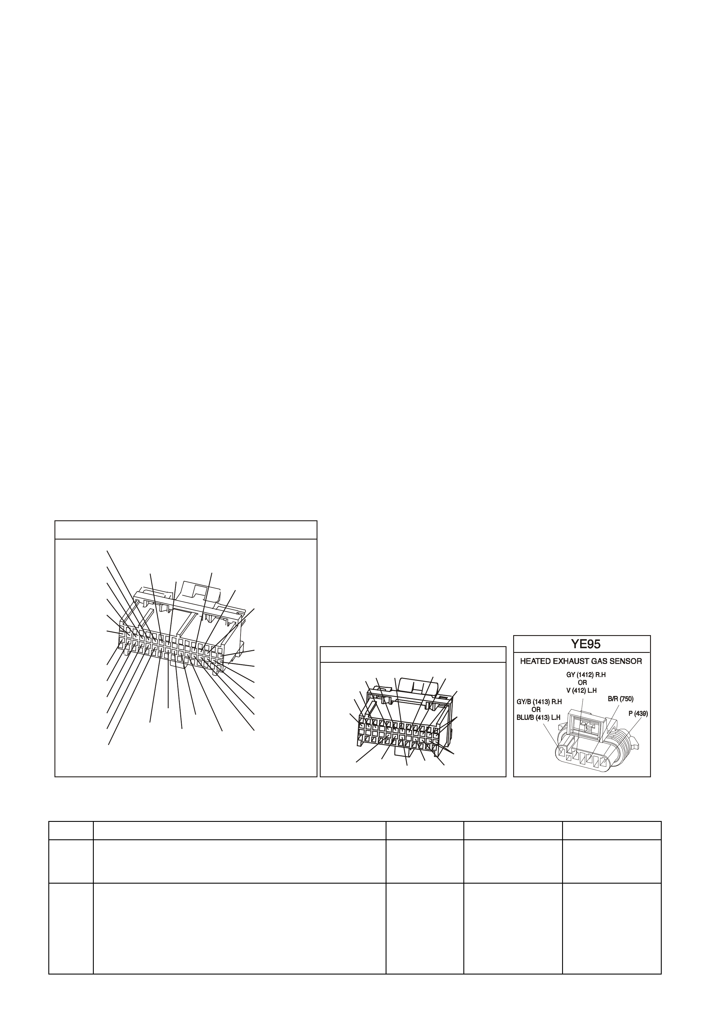
ACTION TAKEN WHEN THE DTC SETS
• The PCM illuminates the Malfunction Indicator Lamp (MIL) when the diagnostic runs and fails.
• The PCM records the operating conditions at the tim e the diagnostic fails. T he PCM stores this information
in the History Data.
• Once a 02S DTC is set, and current, the PCM will operate the fuel system in the “Open Loop” mode.
CONDITIONS FOR CLEARING THE MIL/DTC
• The PCM turns the MIL OFF after the first ignition cycle that the diagnostic runs and does not fail.
• A Histor y DT C clears after f orty c onsecutive warm -up cycles, if this or any other em ission related diagnostic
does not report any failure.
• Use a Tech 2 scan tool in order to clear the MIL/DTC.
DIAGNOSTIC AIDS:
Normal Tech 2 scan tool voltage varies between 100 mV to 999 mV while in "Closed Loop". DTC 13 sets if
voltage remains between 410 and 477 millivolts, but the system will go "Open Loop" before the "Check
Powertrain" lamp is turned "ON".
Refer to "Interm ittents" in Section 6C1-2B SYM PTOMS of the VX Series Service Inform ation. To diagnose the
oxygen sensor, refer Table A-6.3. in this Section
NOTE: Oxygen Sensor Contamination - If fuel containing lead or silicone is used, or engine repairs using
unapproved RTV gasket sealer are performed, the sensor may be contaminated. It may send a "False" rich
exhaust indication to the PCM, and the PCM will attempt to drive the fuel system lean to compensate. Poor
driveability or a Diagnostic Trouble Code 13 could result. If this happens, the sensor will need to be replaced,
but every attempt to locate the source of contamination should be pursued.
TEST DESCRIPTION: Number(s) below refer to step number(s) on the diagnostic Table.
2. The Tech 2 scan tool allows you to read the same oxygen sensor voltage the PCM is using for its
calculations.
3. This step simulates a lean exhaust indication to the PCM. If the PCM and wiring are OK, the PCM will see
the lean indication and the Tech 2 scan tool should display O2 voltage below 200 mV.
YB1 93
(413)
(412)
(1413)
(1412)
(430)
(453)
(815)
V/B
GY/B
V
GY
V
B/R
W/R
(897)
(897)
G/W
G/W
(418)
(418)
BR
BR
(1426)
O/W
C16
D16
WT/B
(832)AUTO
(647)
(630)
BR
T
(832) MAN
LBLU/B
B
(424)
(423)
C1
D1
(792)
(422)
(1222)
(1223)
(428)
(123)
BR/W
GY/R
LG
Y/B
G/Y
V/W
BLU/W
BL U
(831) Man
(443)
LG/W
(442) (831)AUTO
(441)
LBLU
LBLU/B
(444)
LG/B
P.C.M. CONN ECTOR 1
YB 188
P.C.M CONNECTOR 2
(481)
(417)
(740)
R
BLU
O
(1456)
LG
V/W
(415)
Y
(1227)
B/Y
(410)
BR
(472)
(259)
(750)
(750)
(1221)
B/R
B/R
R/B
G/B
(39)
P
(465)
G/W
(416)
GY
(740)
O
A1
B1
B12
A12
DTC 13 V6 PCM - RIGHT HAND OXYGEN SENSOR (O2S) INSUFFICIENT ACTIVITY
STEP ACTION VALUE YES NO
1. Was the "On-Board Diagnostic" (OBD) System Check
performed? Go to Step 2. Go to OBD
System Check in
this Section.
2. 1. Engine at normal operating temperature
(above 85 degrees C).
2. Run engine at approximately 600 to 1800 RPM for
two minutes.
Is Tech 2 scan tool oxygen sensor voltage between
specified values?
410-477 mV
Go to Step 3 If no additional
DTCs were
stored, refer to
“Intermittents” in
Section 6C1-2B.

DTC 13 V6 PCM - RIGHT HAND OXYGEN SENSOR (O2S) INSUFFICIENT ACTIVITY (CONTINUED)
STEP ACTION VALUE YES NO
3. 1. Ignition ON, engine stopped.
2. Disconnect O2 and jumper the O2 signal and low
circuits (PCM side) to earth.
3. Using Tech 2 scan tool, monitor O2 voltage.
Is the O2 voltage less than the specified value?
0.2 Volt
(200 mV) Go to Step 7 Go to Step 4
4. 1. Remove the jumper wire from the O2 signal circuit
(leaving the O2 low circuit jumpered to earth).
2. Using a DVM, measure voltage between the O2
signal circuit (PCM side) and earth.
Does the O2 signal voltage measure near the specified
value?
410-477 mV
Go to Step 5 Go to Step 6
5. 1. Ignition OFF.
2. Disconnect the PCM.
3. Check continuity of the O2 low circuit between the
PCM harness connector and the O2 harness
connector.
4. If the O2 low circuit measures over 5 ohms, repair
open or poor connection as necessary.
Was a problem found?
Verify Repair Go to Step 8
6. 1. Ignition OFF.
2. Disconnect the PCM.
3. Check continuity of the following circuits:
• The O2 signal circuit between the PCM harness
connector and the O2 harness connector.
• The O2 low circuit between the PCM harness
connector and the O2 harness connector.
4. If either circuit measures over 5 ohms, repair open
or poor connection as necessary.
Was a problem found?
Verify Repair Go to Step 9
7. 1. Check the following circuits for a poor terminal
connection at the O2 harness connector.
• O2 signal circuit.
• O2 low circuit.
2. If a problem is found, repair as necessary.
Was a problem found?
Verify Repair Go to Step 10
8. 1. Check for poor O2 low circuit terminal connection at
PCM.
2. If a problem is found, repair as necessary.
Was a problem found?
Verify Repair Go to Step 11
9. 1. Check the O2 signal circuit and the O2 low circuit for
a poor terminal connection at the PCM.
2. If a problem is found, repair as necessary.
Was a problem found?
Verify Repair Go to Step 11
10. Replace the O2 sensor.
Is action complete? Verify Repair
11. Replace PCM.
Refer to Section 6C1-3 Service Operations of the VX
Series Service Information, for PCM Programming and
Security Link procedure.
Is action complete?
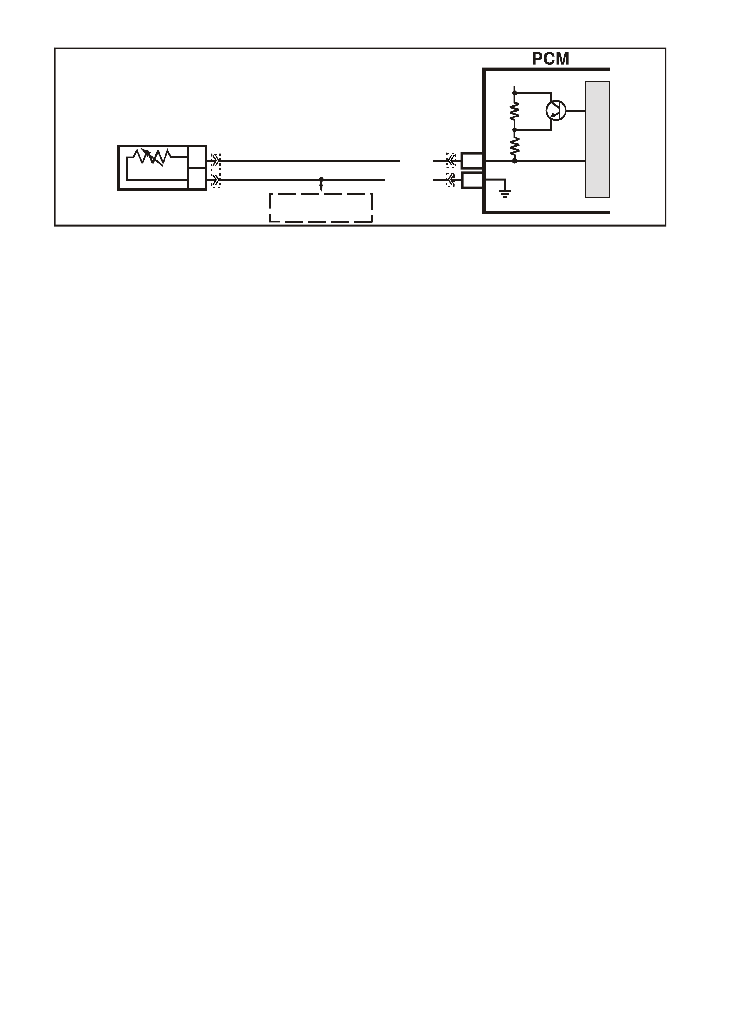
DTC 14 V6 PCM -
ENGINE COOLANT TEMPERATURE (ECT) SENSOR LOW VOLTAGE
CIRCUIT DESCRIPTION:
The Engine Coolant T emperature ( ECT) sensor uses a therm istor to control the signal voltage to the PCM. The
PCM applies about 5 volts on c ircuit 410 to the sens or. When the engine coolant is c old, the sensor (therm ist or)
resistance is high, therefore the PCM will see high signal voltage about 4.0 - 4.5 volts.
As the engine coolant warm s, the s ensor r esistanc e becom es les s, and the PCM s ees a lower s ignal voltage. At
norm al engine oper ating temperatur e (85 degrees C to 95 degrees C), the voltage should m easure about 2.2 to
1.8 volts.
CONDITIONS FOR RUNNING THE DTC
• Time since engine started is greater than 20 seconds
CONDITIONS FOR SETTING THE DTC
• ECT s ens or s ignal voltage is les s than 0.3 volts , indic ating an engine c oolant temperature at or above 140 C
for one second.
ACTION TAKEN WHEN THE DTC SETS
• The PCM illuminates the Malfunction Indicator Lamp (MIL) when the diagnostic runs and fails.
• The PCM records the operating conditions at the tim e the diagnostic fails. T he PCM stores this information
in the History Data.
• The PCM will substitute a coolant temperature default value. The PCM arrives at this default, or substitute
value, by switching to a starting point, then counting upwards to 95°C at a rate of 11 degrees per minute.
• W hen Diagnostic Trouble Code 14 is set, the T CC will be applied with a c old engine and the engine cooling
fan will be turned "ON".
• A DTC 14 may enable TCC operation when cold.
CONDITIONS FOR CLEARING THE MIL/DTC
• The PCM turns the MIL OFF after the first ignition cycle that the diagnostic runs and does not fail.
• A Histor y DT C clears after f orty c onsecutive warm -up cycles, if this or any other em ission related diagnostic
does not report any failure.
• Use a Tech 2 scan tool in order to clear the MIL/DTC.
DIAGNOSTIC AIDS:
Check harness routing for a potential short to earth in circuit 410.
Check terminals at ECT sensor for a good connector.
The Tech 2 scan tool reads engine coolant temperature in degrees Celsius. After engine is started, the
temperature should rise steadily to about 90 C then stabilise when thermostat opens.
The "Temperature to Resistance Value" scale may be used to test the engine coolant temperature sensor at
various tem perature levels to evaluate the poss ibility of a "shif ted" (mis -scaled) s ensor. A "shifted" sensor could
result in poor driveability complaints.
Refer to "Intermittents" in Section 6C1-2B SYMPTOMS of the VX Series Service Information.
SUPERVX004
E16
B5
B
A
ENGINE COOLANT
TEMPERATURE SENSOR
SENSOR EARTH
ETC SENSOR SIGNAL
5V
4k
348
Ω
Ω
Y (41 0)
B/Y (452)
TO
THROTTLE POSI TION
SENSOR
M
I
C
R
O
YB194
YE106 YB188
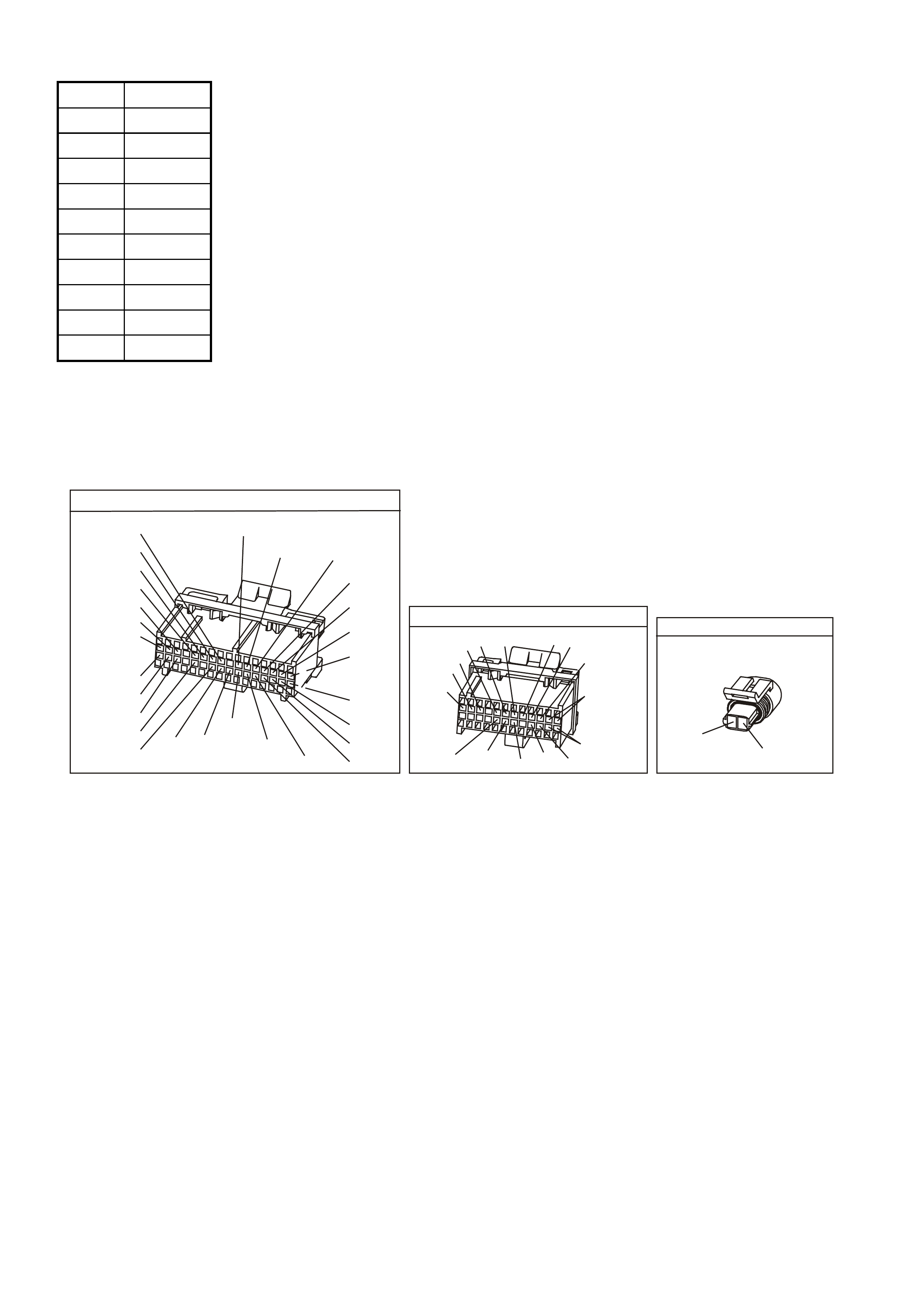
ECT SENSOR TABLE TEMP. TO RESISTANCE VALUES (APPROXIMATE)
C OHMS
110 134
100 180
90 244
70 474
40 1,483
30 2,268
20 3,555
0 9,517
-10 16,320
-20 28,939
TEST DESCRIPTION: Number(s) below refer to step number(s) on the diagnostic Table.
3. This test will determine if circuit 410 is shorted to earth which will cause the conditions for DTC 14.
4. If checking resistance at the engine coolant temperature sensor is difficult because of sensor location,
disconnect the PCM connectors and check resistance between engine coolant temperature signal and
sensor earth terminals.
YE194
P.C.M. CONNECTOR 3
LG/B
(366)
G
(843)
B/W
F16
B/Y
BR/Y
(1228)
(469)
Y
(451)
F1
P
(841)
BLU
V
E1
LBLU
(845)
BLU
B
(1226)
W/B
BLU/W
V
R
(435)
(31)
(1229)
GY
(1224)
Y
(846)
GY
(842)
(452)
(774)
(304)
BR/Y
(411)
(439)
GY/BLU
BLU
(1225)
E16
(1427)
(429)
(844)
B/O
(434)
OR AUTO
GY/BLU
GY
(1434)
MAN
(776)
W
BLU/W
Y
GY
(771)
(772)
(773)
YB 188
P.C.M CONNECTOR 2
(481)
(417)
(740)
R
BLU
O
(1456)
LG
V/W
(415)
Y
(1227)
B/Y
(410)
BR
(472)
(259)
(750)
(750)
(1221)
B/R
B/R
R/B
G/B
(39)
P
(465)
G/W
(416)
GY
(740)
O
A1
B1
B12
A12
COOLANT TEM P SENSO R
YE106
Y
(410)
B/Y
(452)

DTC 14 V6 PCM - ENGINE COOLANT TEMPERATURE (ECT) SENSOR LOW VOLTAGE
STEP ACTION VALUE YES NO
1. Was the "On-Board Diagnostic" (OBD) System Check
performed? Go to Step 2. Go to OBD
System Check in
this Section.
2. Using Tech 2 scan tool, select "Eng. Coolant Temp" on
the data display.
Is the "Eng. Coolant Temp" display value at or above the
specified value?
140 degrees
C Go to Step 3 If no additional
DTCs were
stored, refer to
"Intermittents" in
Section 6C1-2B
SYMPTOMS.
3. 1. Ignition "Off".
2. Disconnect engine coolant temperature sensor
wiring harness.
3. Ignition "On".
Does Tech 2 scan tool display "Eng. Coolant Temp"
below specified value?
-30 degrees
C Go to Step 4 Go to Step 7
4. Check resistance across engine coolant temperature
sensor terminals.
Does DVM ohms reading match the specified values for
temperature to sensor resistance?
See table
above.
Go to Step 5 Go to Step 8
5 Check for intermittent or loose terminals in sensor
harness connector, or for the 2 terminals shorting
together when connected to the sensor.
Was a faulty connection found?
Verify Repair Go to Step 6
6 Replace PCM.
Refer to Section 6C1-3 SERVICE OPERATIONS of the
VX Series Service Information, for PCM Programming
and Security Link procedure.
Is action complete?
Verify Repair
7 Check circuit 410 for short to earth or to sensor earth.
Was a short found? Verify Repair Go to Step 6
8 Replace ECT sensor.
Is replacement complete? Verify Repair
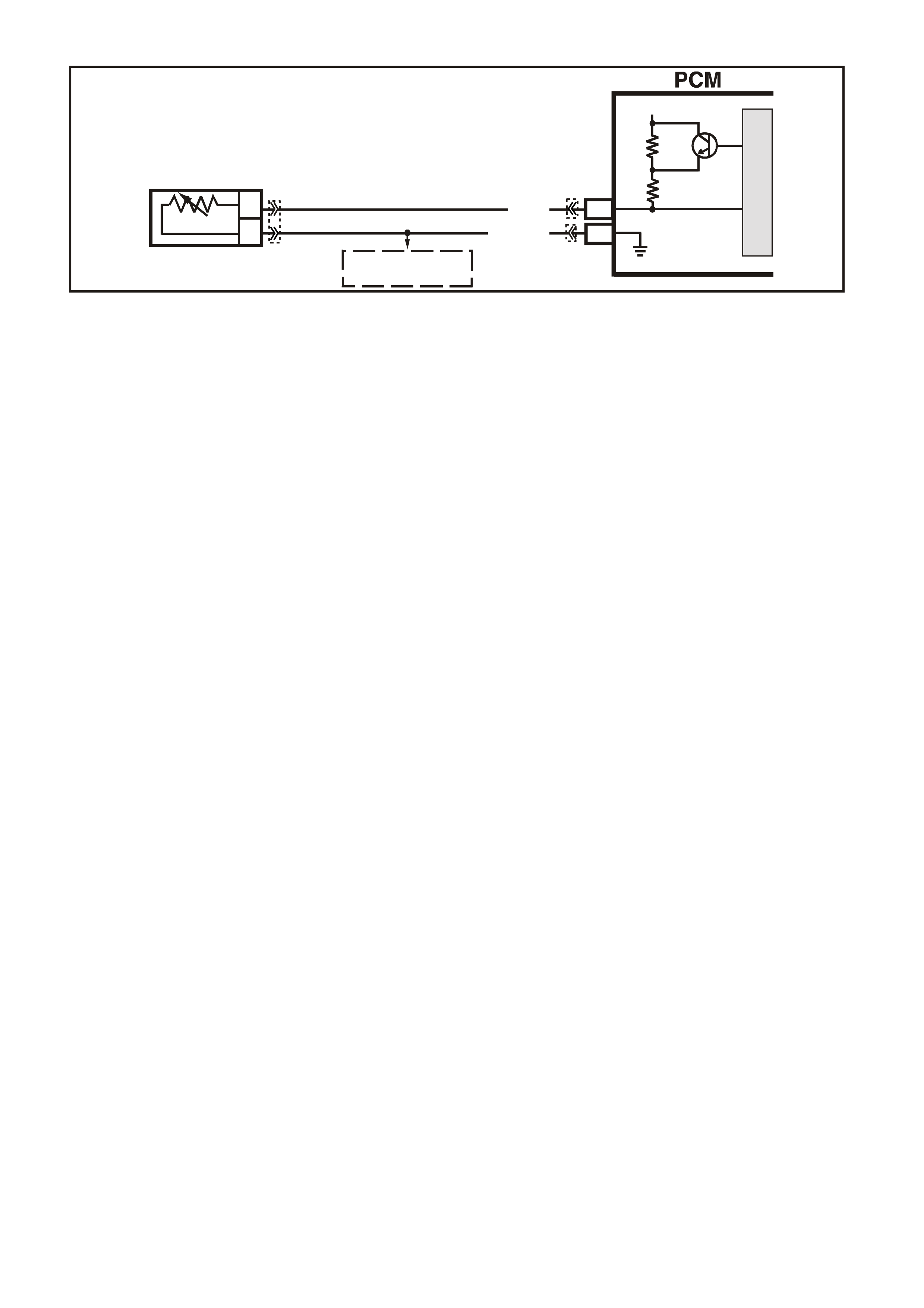
DTC 15 V6 PCM -
ENGINE COOLANT TEMPERATURE (ECT) SENSOR HIGH VOLTAGE
CIRCUIT DESCRIPTION:
The Engine Coolant T emperature ( ECT) sensor uses a therm istor to control the signal voltage to the PCM. The
PCM applies about 5 volts on c ircuit 410 to the sens or. When the engine coolant is c old, the sensor (therm ist or)
resistance is high, therefore the PCM will see high signal voltage, about 4 - 4.5 volts.
As the engine coolant warms, the sensor (thermistor) resistance becomes less, and the PCM sees a lower
signal voltage. At normal engine operating temperature (85 degrees C to 95 degrees C), the voltage will
measure about 2.2 to 1.8 volts.
CONDITIONS FOR RUNNING THE DTC
• Time since engine started is greater than 10 seconds.
CONDITIONS FOR SETTING THE DTC
• ECT input signal voltage is greater than 4.64 volts, indicating an engine coolant temperature at or lower
than -30 degrees C for one second.
• Above conditions present for at least 1 second.
ACTION TAKEN WHEN THE DTC SETS
• The PCM illuminates the Malfunction Indicator Lamp (MIL) when the diagnostic runs and fails.
• The PCM records the operating conditions at the tim e the diagnostic fails. T he PCM stores this information
in the History Data.
• The PCM will substitute a coolant temperature default value. The PCM arrives at this default, or substitute
value, by switching to a starting point, then counting upwards to 95°C at a rate of 11 degrees per minute.
• When the Diagnostic Trouble Code 15 is set, the TCC will be applied with a cold engine and the engine
cooling fan will be forced "ON".
CONDITIONS FOR CLEARING THE MIL/DTC
• The PCM turns the MIL OFF after the first ignition cycle that the diagnostic runs and does not fail.
• A Histor y DT C clears after f orty c onsecutive warm -up cycles, if this or any other em ission related diagnostic
does not report any failure.
• Use a Tech 2 scan tool in order to clear the MIL/DTC.
DIAGNOSTIC AIDS:
A Tech 2 scan tool reads engine coolant temperature in degrees Celsius. After engine is started, the
temperature should rise steadily to about 90 C then stabilise when thermostat opens.
A faulty connection, or an open in circuit 410 or circuit 452 will result in a Diagnostic Trouble Code (DTC) 15.
If DTC 21 is also set, check circuit 452 for faulty wiring or connections. Check terminals at sensor for a good
connection. The "Temperature to Resistance Value" scale may be used to test the engine coolant temperature
sensor at various temperature levels to evaluate the possibility of a "shifted" (mis-scaled) sensor. A "shifted"
sensor could result in poor driveability complaints.
Refer to "Intermittents" in Section 6C1-2B SYMPTOMS of the VX Series Service Information.
SUPERVX004
E16
B5
B
A
ENGINE COOLANT
TEMPERATURE SENSOR
SENSOR EARTH
ETC SENSOR SIGNAL
5V
4k
348
Ω
Ω
Y (41 0)
B/Y (452)
TO
THROTTLE POSITION
SENSOR
M
I
C
R
O
YB194
YE106 YB188
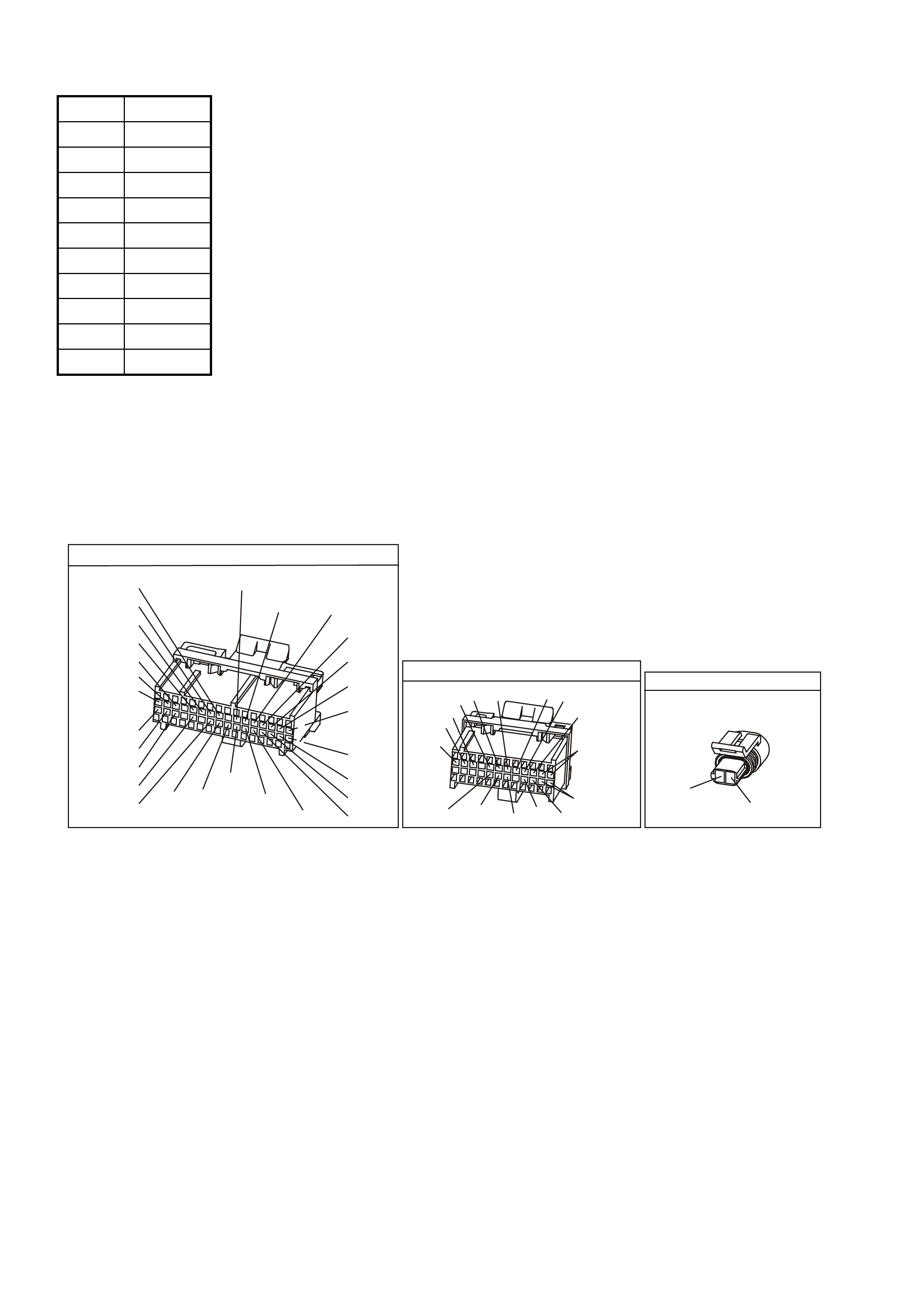
ECT SENSOR TABLE TEMP. TO RESISTANCE VALUES (APPROXIMATE)
C OHMS
110 134
100 180
90 244
70 474
40 1,483
30 2,268
20 3,555
0 9,517
-10 16,320
-20 28,939
TEST DESCRIPTION: Number(s) below refer to step number(s) on the diagnostic Table.
3. This test simulates a Diagnostic Trouble Code 15. If the PCM recognises the low signal voltage, (high
temperature) and the Tech 2 scan tool reads 130 C or above, the PCM and wiring are OK.
4. This test will determine if circuit 410 is open. There should be an open circuit voltage of 5 volts present at
Engine Coolant Temperature (ECT) sensor harness connector if measured with a DVM. By jumpering this
5 volt signal to earth, the PCM should recognise this change.
YE194
P.C.M. CONNECTOR 3
LG/B
(366)
G
(843)
B/W
F16
B/Y
BR/Y
(1228)
(469)
Y
(451)
F1
P
(841)
BLU
V
E1
LBLU
(845)
BLU
B
(1226)
W/B
BLU/W
V
R
(435)
(31)
(1229)
GY
(1224)
Y
(846)
GY
(842)
(452)
(774)
(304)
BR/Y
(411)
(439)
GY/BLU
BLU
(1225)
E16
(1427)
(429)
(844)
B/O
(434)
OR AUTO
GY/BLU
GY
(1434)
MAN
(776)
W
BLU/W
Y
GY
(771)
(772)
(773)
YB 188
P.C.M CONNECTOR 2
(481)
(417)
(740)
R
BLU
O
(1456)
LG
V/W
(415)
Y
(1227)
B/Y
(410)
BR
(472)
(259)
(750)
(750)
(1221)
B/R
B/R
R/B
G/B
(39)
P
(465)
G/W
(416)
GY
(740)
O
A1
B1
B12
A12
COOLANT TEM P SENSO R
YE106
Y
(410)
B/Y
(452)

DTC 15 V6 PCM - ENGINE COOLANT TEMPERA TURE (ECT) SENSOR HIGH VOLTAGE
STEP ACTION VALUE YES NO
1. Was the "On-Board Diagnostic" (OBD) System Check
performed? Go to Step 2. Go to OBD
System Check in
this Section.
2. 1. Using Tech 2 scan tool, select "Eng. Coolant
Temp" on the data display.
Is the "Eng. Coolant Temp" display value at or between
the specified value ?
-30 to -40
degrees C Go to Step 3 If no additional
DTCs were
stored, refer to
"Intermittents" in
Section 6C1-2B
SYMPTOMS.
3. 1. Ignition "OFF".
2. Disconnect engine coolant temperature sensor
powertrain wiring harness.
3. Jumper harness terminals together.
4. Ignition "ON".
Does Tech 2 scan tool display "Eng. Coolant Temp" at or
above specified value?
130
degrees C Go to Step 10 Go to Step 4
4. Jumper circuit 410 to earth.
Does Tech 2 scan tool display "Eng. Coolant Temp" at
or above specified value?
130
degrees C Go to Step 5 Go to Step 8
5. Check resistance across engine coolant temperature
sensor terminals.
Does DVM reading match the specified values for
temperatures to sensor resistance?
See table
above
Go to Step 6 Go to Step 9
6. Check for intermittent or loose terminals in sensor
harness connector. Terminals may not be contacting
the sensor when connected.
Was a problem found?
Verify Repair Go to Step 7
7. Replace PCM.
Refer to Section 6C1-3 SERVICE OPERATIONS of the
VX Series Service Information, for PCM Programming
and Security Link procedure.
Is action complete?
Verify Repair
8. Check circuit 410 for an open, short to voltage or faulty
connection at PCM.
Was a problem found?
Verify Repair Go to Step 7
9. Replace ECT sensor.
Is action complete? Verify Repair
10. Check for faulty connection.
Was a problem found? Verify Repair Go to Step 9

DTC 16 V6 PCM -
ENGINE COOLANT TEMPERATURE (ECT) SENSOR UNSTABLE
CIRCUIT DESCRIPTION:
The Engine Coolant Temperature (ECT) sensor is a thermistor located in a coolant passage on the engine.
When engine coolant temperature is cold, the sensor has a high resistance. As temperature increases, the
resistance of the sensor decreases. The PCM provides a f ive volt signal to the engine coolant sensor, which is
also connected to PCM earth. The PCM reads the voltage drop on the signal line to determine engine coolant
temperature.
CONDITIONS FOR RUNNING THE DTC
• Time since engine started is greater than 10 seconds.
• DTC 14, 15 or 17 are not set.
CONDITIONS FOR SETTING THE DTC
• ECT reading changes more than 400 mV in 200 milliseconds.
• Above conditions present for at least 10 seconds.
ACTION TAKEN WHEN THE DTC SETS
• The PCM stores the DTC information into memory when the diagnostic runs and fails.
• The Malfunction Indicator Lamp (MIL) will not be illuminated.
• The PCM records the operating conditions at the tim e the diagnostic fails. T he PCM stores this information
in the History Data.
• The PCM will substitute a coolant temperature default value. The PCM arrives at this default, or substitute
value, by switching to a starting point, then counting upwards to 95°C at a rate of 11 degrees per minute.
• When DTC 16 is set, the PCM will turn "ON" the engine cooling fan.
CONDITIONS FOR CLEARING THE MIL/DTC
• A History DTC clears after forty consecutive warm-up cycles.
• Use a Tech 2 scan tool in order to clear the MIL/DTC.
DIAGNOSTIC AIDS:
When attempting to diagnose an inter m ittent problem , use the s napshot m ode of the Tech 2 scan tool, to review
diagnostic information.
This DTC is more likely to set on a cold engine than on a hot engine because of the pull up resistors in the
PCM.
If DTC 16, 53 and 57 are set, check for short to voltage on "Diagnostic Test" line. circuit 451.
SUPERVX004
E16
B5
B
A
ENGINE COOLANT
TEMPERATURE SENSOR
SENSOR EARTH
ETC SENSOR SIGNAL
5V
4k
348
Ω
Ω
Y (41 0)
B/Y (452)
TO
THROTTLE POSI TION
SENSOR
M
I
C
R
O
YB194
YE106 YB188
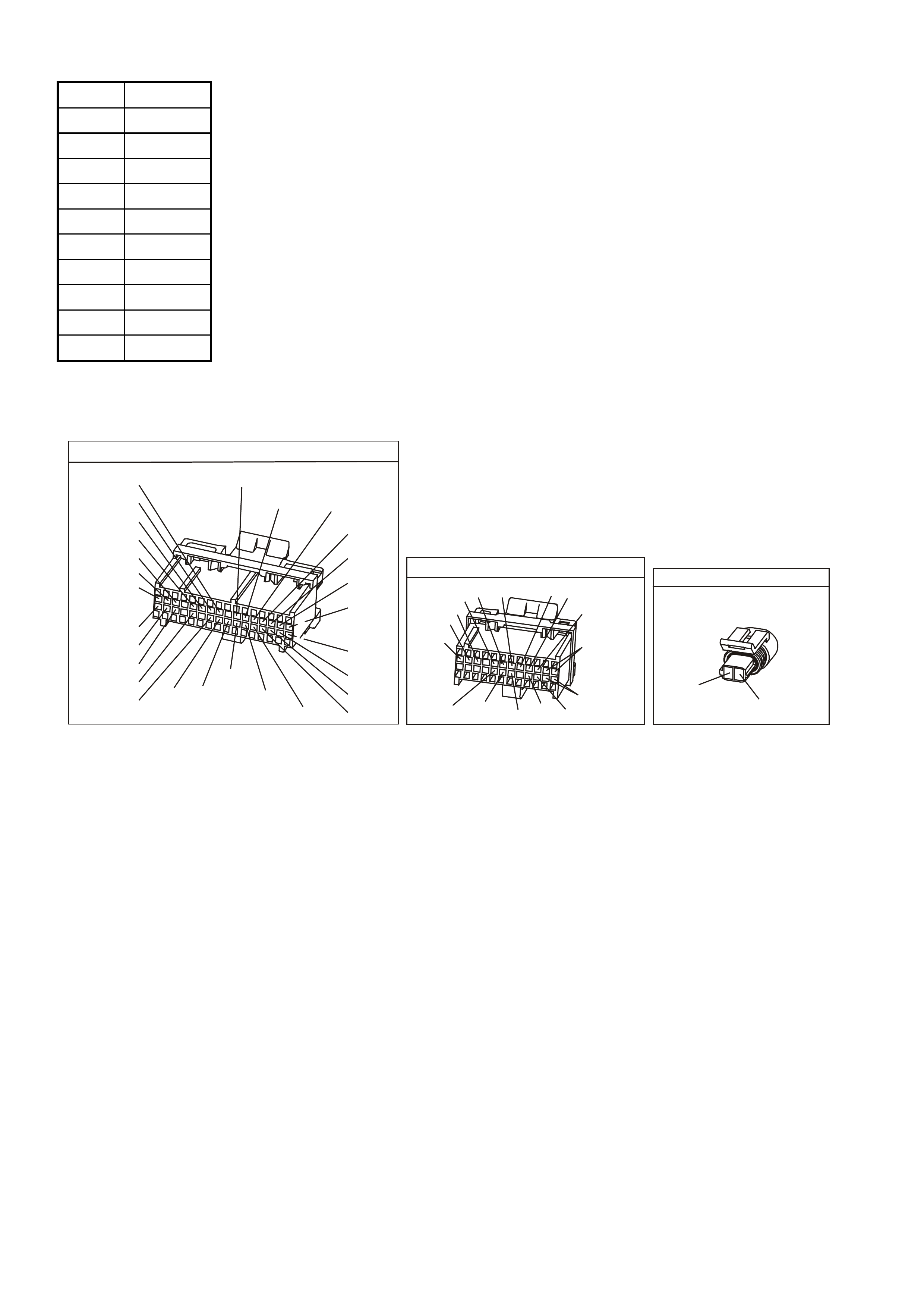
ECT SENSOR TABLE TEMP. TO RESISTANCE VALUES (APPROXIMATE)
C OHMS
110 134
100 180
90 244
70 474
40 1,483
30 2,268
20 3,555
0 9,517
-10 16,320
-20 28,939
TEST DESCRIPTION: Number(s) below refer to step number(s) on the diagnostic Table.
2. This step checks the wiring of the sensor for a intermittent fault.
YE194
P.C.M. CONNECTOR 3
LG/B
(366)
G
(843)
B/W
F16
B/Y
BR/Y
(1228)
(469)
Y
(451)
F1
P
(841)
BLU
V
E1
LBLU
(845)
BLU
B
(1226)
W/B
BLU/W
V
R
(435)
(31)
(1229)
GY
(1224)
Y
(846)
GY
(842)
(452)
(774)
(304)
BR/Y
(411)
(439)
GY/BLU
BLU
(1225)
E16
(1427)
(429)
(844)
B/O
(434)
OR AUTO
GY/BLU
GY
(1434)
MAN
(776)
W
BLU/W
Y
GY
(771)
(772)
(773)
YB 188
P.C.M CONNECTOR 2
(481)
(417)
(740)
R
BLU
O
(1456)
LG
V/W
(415)
Y
(1227)
B/Y
(410)
BR
(472)
(259)
(750)
(750)
(1221)
B/R
B/R
R/B
G/B
(39)
P
(465)
G/W
(416)
GY
(740)
O
A1
B1
B12
A12
COOLANT TEM P SENSO R
YE106
Y
(410)
B/Y
(452)

DTC 16 V6 PCM - ENGINE COOLANT TEMPERATURE (ECT) SENSOR UNSTABLE
STEP ACTION VALUE YES NO
1. Was the "On-Board Diagnostic" (OBD) System Check
performed? Go to Step 2. Go to OBD
System Check in
this Section.
2. 1. Install Tech 2 scan tool and set up snapshot
mode to trigger on DTC 16.
2. Watch the Tech 2 scan tool while wiggling
the ECT sensor connector.
Does the "Eng. Coolant Temp" reading change sharply?
Go to Step 8 Go to Step 3
3. Wiggle and tug the ECT sensor harness.
Does the "Eng. Coolant Temp" reading change sharply? Go to Step 9 Go to Step 4
4. Wiggle and tug the harness at the PCM.
Does the "Eng. Coolant Temp" reading change sharply? Go to Step 10 Go to Step 5
5. Lightly tap on the PCM.
Does the "Eng. Coolant Temp" reading change sharply? Go to Step 6 DTC 16 is
intermittent.
Refer
"Diagnostic
Aids" above.
6. Make sure PCM is mounted securely to vehicle.
Was a problem found? Verify Repair Go to Step 7
7. Replace PCM.
Refer to section 6C1-3 Service Operations of the VX
Series Service Information, for PCM Security Link
procedure.
Is action complete?
Verify Repair
8. 1. Check ECT sensor connector.
2. Check the tightness of the female terminal grip
with a spare male terminal.
3. Inspect connectors for corrosion. If connectors
are corroded, try cleaning with electronic part
cleaner and retest.
4. If these repairs do not resolve the problem,
replace terminals.
Is action complete?
Verify Repairs
9. 1. Check for an open in the ECT harness.
2. Check for broken strands of wire in ECT sensor
harness.
3. Check for cuts or pinches in ECT sensor harness.
4. Make repairs as necessary.
Is action complete?
Verify Repairs
10. 1. Check the ECT sensor connection at the PCM.
2. Check tightness of the female terminal grip with a
spare male terminal.
3. Inspect connectors for corrosion. If connectors
are corroded, try cleaning with electronic parts
cleaner and retest.
4. Remove connector strain relief and remove
terminal from connector to check for broken
locking tang.
Is action complete?
Verify Repairs
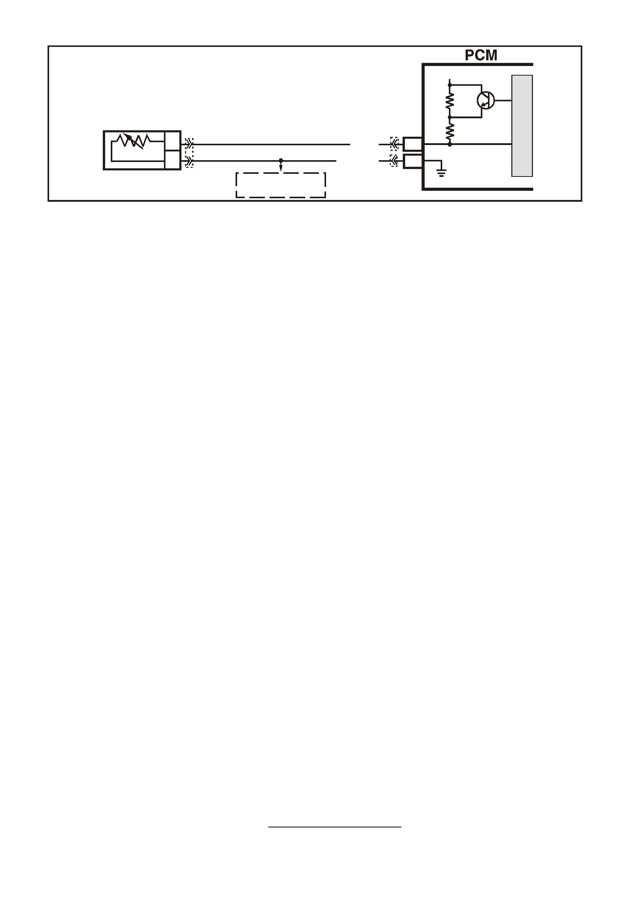
DTC 17 V6 PCM -
PCM ERROR – ECT CIRCUIT
CIRCUIT DESCRIPTION;
The PCM uses two different internal pull-up resistors to increase resolution throughout the entire range of
engine operating temperatures. When the engine coolant temperature is less than 50 degrees C, the 4K ohm
resistor is used. When temperature is above 50 degrees C, the PCM switches to the 348 ohm resistor. If the
pull-up resistor does not switch, DTC 17 will set.
CONDITIONS FOR RUNNING THE DTC
• The engine run time is longer than 10 seconds.
CONDITIONS FOR SETTING THE DTC
• The pull-up resistor inside the PCM switches and there is less than a 60mV change in the engine coolant
temperature signal.
ACTION TAKEN WHEN THE DTC SETS
• The PCM stores the DTC information into memory when the diagnostic runs and fails.
• The Malfunction Indicator Lamp (MIL) will not be illuminated.
• The PCM records the operating conditions at the tim e the diagnostic fails. T he PCM stores this information
in the History Data.
• When an ECT sensor circuit fault is detected, and current, the PCM will substitute a coolant temperature
default value. The PCM arrives at this default, or substitute value, by switching to a starting point, then
counting upwards to 95°C at a rate of 11 degrees per minute.
• When DTC 17 is set, the PCM will turn "ON" the engine cooling fan.
CONDITIONS FOR CLEARING THE MIL/DTC
• A History DTC clears after forty consecutive warm-up cycles.
• Use a Tech 2 scan tool in order to clear the MIL/DTC.
DIAGNOSTIC AIDS
When a DT C 14, 15, 16 and 17 is c urr ent, the PCM will turn on the electr ic engine cooling fan(s) . T his is a FAIL-
SAFE action by the PCM to prevent a possible engine overheat condition, since these DTC’s indicate an
unknown actual engine coolant temperature.
If the ECT s ensor circ uit opens with the ignition off, the PCM will interpret - 30°C and deliver enough fuel to start
the engine at room temperature. If the actual ambient temperature is above 0°C, the engine may flood and not
start unless CLEAR FLOOD MODE is used by fully depressing the accelerator while cranking. In the CLEAR
FLOOD MODE the injectors pulse width is set to zero milliseconds.
TEST DESCRIPTION
The numbers below refer to the step numbers on the diagnostic table.
2. DTC 17 is an internal fault within the PCM. The PCM must be replaced!
SUPERVX004
E16
B5
B
A
ENGINE COOLANT
TEMPERATURE SENSOR
SENSOR EARTH
ETC SENSOR SIGNAL
5V
4k
348
Ω
Ω
Y (41 0)
B/Y (452)
TO
THROTTLE POSI TION
SENSOR
M
I
C
R
O
YB194
YE106 YB188

DTC 17 V6 PCM - PCM ERROR - ECT CIRCUIT
STEP ACTION VALUE YES NO
1. Was the "On-Board Diagnostic" (OBD) System Check
performed? Go to Step 2. Go to OBD
System Check in
this Section.
2. Replace PCM.
Refer to Section 6C1-3 Service Operations, for PCM
Security Link procedure.
Is action complete?
Verify Repair

DTC 19 V6 PCM -
THROTTLE POSITION (TP) SENSOR CIRCUIT INSUFFICIENT ACTIVITY
CIRCUIT DESCRIPTION:
The Throttle Position (TP) sensor provides a voltage signal that changes relative to the throttle blade angle.
Signal voltage will vary from about 0.25 to 1.25 volts at idle to about 4 volts at Wide Open Throttle (WOT).
The TP sensor signal is one of the most important inputs used by the PCM for transient fuelling and
transmission control and for most of the PCM control outputs.
Diagnostic Trouble Code (DTC) 19 is used to detect a stuck open or TP sensor. DTC 19 detects if the TP
sensor does not return with the throttle blade when decelerating.
CONDITIONS FOR RUNNING THE DTC
• Time since engine started is greater than 20 seconds
CONDITIONS FOR SETTING THE DTC
• The Throttle Position (TP) sensor percentage of opening angle indicated is greater than the RPM that can
be reached with a Mass Air Flow reading of less than 301 mg/cyl for 20 seconds.
ACTION TAKEN WHEN THE DTC SETS
• The PCM illuminates the Malfunction Indicator Lamp (MIL) when the diagnostic runs and fails.
• The PCM records the operating conditions at the tim e the diagnostic fails. T he PCM stores this information
in the History Data.
• When DTC 19 is set, the PCM will calculate throttle position based off of IACV and MAF for engine and
transmission operation.
CONDITIONS FOR CLEARING THE MIL/DTC
• The PCM turns the MIL OFF after the first ignition cycle that the diagnostic runs and does not fail.
• A Histor y DT C clears after f orty c onsecutive warm -up cycles, if this or any other em ission related diagnostic
does not report any failure.
• Use a Tech 2 scan tool in order to clear the MIL/DTC.
DIAGNOSTIC AIDS:
A T ech 2 scan tool reads thr ottle position in volts. W ith ignition "ON'' or at idle, T P sensor s ignal voltage should
read about 0.25 to 1.25 volts with the throttle closed and increase at a steady rate as throttle is moved toward
Wide Open Throttle (WOT).
The Tech 2 scan tool will read throttle angle. 0%=closed throttle; 100%=WOT.
If voltage is steady above DTC 22 voltage criteria and below DTC 19 voltage criteria, check for a short to
voltage on the TP Sensor signal circuit.
Refer to "Intermittents" in Section 6C1-2B SYMPTOMS of the VX Series Service Information.
VXSC005
SENSOR EARTH
TP SENSOR SIGNAL
TP SENSOR
REFERENCE
VOLTAGE
PCM
5V
M
I
C
R
O
A
C
B
THROTTLE
POSITION SENSOR
A7
B11
E16
BLU (417)
B/Y (452)
GY (416)
TO
ECT SENSOR
YB188
YB194
YE30

DTC 19 CRITERIA TABLE MAF LESS THAN 301 MG/CYL. (APPROXIMATE)
TPS%
V6 RPM
20 800
22 1,200
27 1,600
29 2,000
33 2,400
37 2,800
39 3,200
40 3,600
41 4,000
44 4,400
TEST DESCRIPTION: Number(s) below refer to step number(s) on the diagnostic Table.
2. This step checks to verify the throttle linkage is moving freely.
DTC 19 V6 PCM - THROTTLE POSITION (TP) SENSOR CIRCUIT INSUFFICIENT ACTIVITY
STEP ACTION VALUE YES NO
1. Was the "On-Board Diagnostic" (OBD) System Check
performed? Go to Step 2. Go to OBD
System Check in
this Section.
2. Inspect throttle cable, linkage, and blade movement.
Are components binding or sticking? Verify Repair Go to Step 3
3 Using Tech 2 scan tool to monitor TP sensor voltage,
inspect TP sensor for binding or sticking during its
movement from closed throttle to wide open throttle and
back to closed throttle position.
Was fault found ?
Go to Step 4 DTC 19
intermittent. If no
additional DTC's
were stored,
refer to
Diagnostic Aids
above.
4. Replace binding Throttle Position (TP) sensor.
Is action complete? Verify Repair
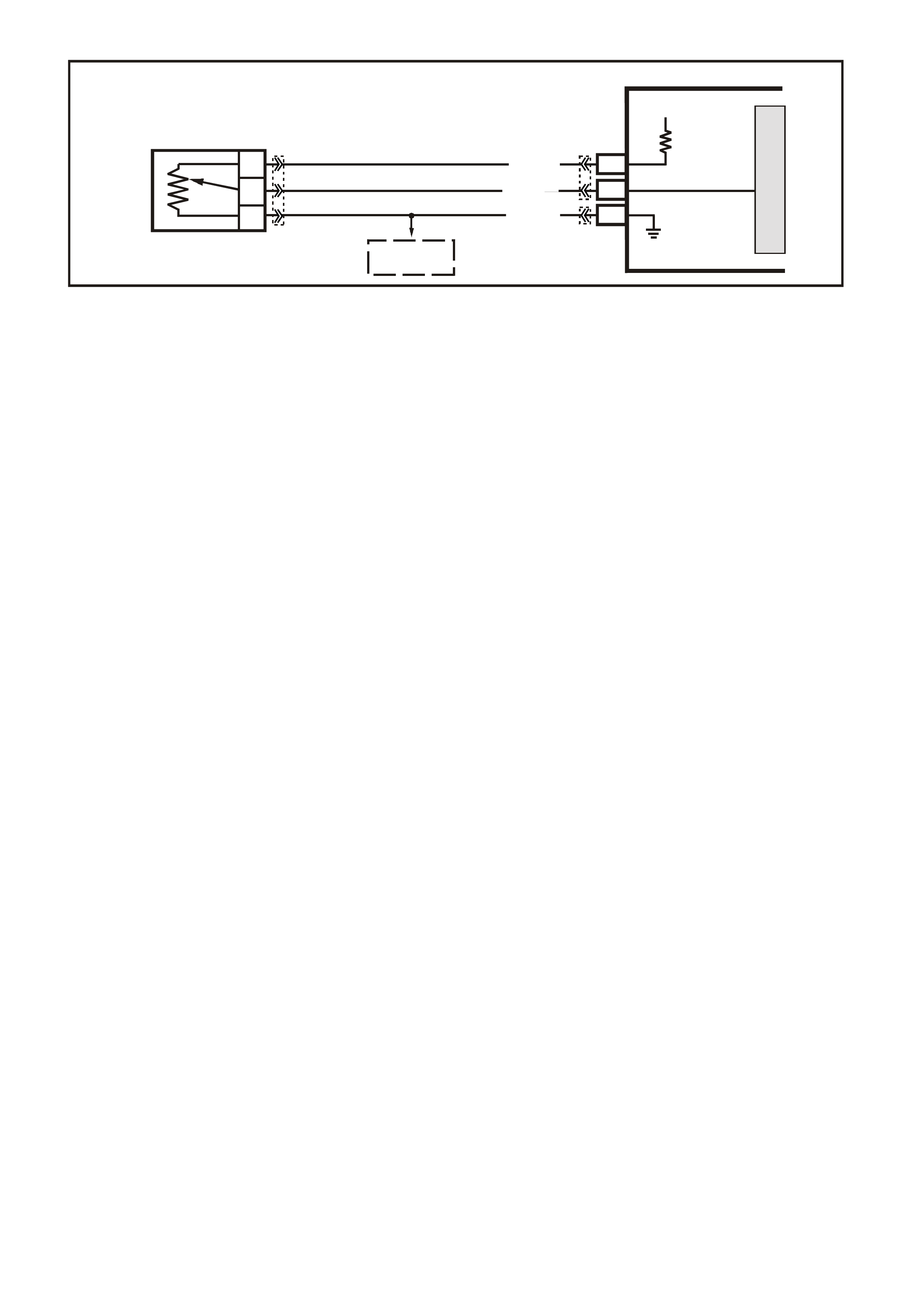
DTC 21 V6 PCM -
THROTTLE POSITION (TP) SENSOR CIRCUIT HIGH VOLTAGE
CIRCUIT DESCRIPTION:
The Throttle Position (TP) sensor provides a voltage signal that changes relative to the throttle blade. Signal
voltage will vary from about 0.25 to 1.25 volts at idle to about 4 volts at Wide Open Throttle (WOT).
The TP sensor signal is one of the most important inputs used by the PCM for transient fuelling and
transmission control and for most of the PCM control. Outputs.
CONDITIONS FOR RUNNING THE DTC
• Time since engine started is greater than 20 seconds
CONDITIONS FOR SETTING THE DTC
• The TP Sensor voltage between the PCM TP Sensor signal terminal and the TP Sensor earth terminal is
greater than 4.9 volts (97%) for more than two seconds.
ACTION TAKEN WHEN THE DTC SETS
• The PCM illuminates the Malfunction Indicator Lamp (MIL) when the diagnostic runs and fails.
• The PCM records the operating conditions at the tim e the diagnostic fails. T he PCM stores this information
in the History Data.
• When a DTC 21 is set, the PCM does not receive the proper signal from the TP sensor, but it can still
determ ine the TP sens or value with a default value based on RPM, Idle Air Control Valve position and Mas s
Air Flow.
• If DTC 21 is set, the transmission will have no TCC.
CONDITIONS FOR CLEARING THE MIL/DTC
• The PCM turns the MIL OFF after the first ignition cycle that the diagnostic runs and does not fail.
• A Histor y DT C clears after f orty c onsecutive warm -up cycles, if this or any other em ission related diagnostic
does not report any failure.
• Use a Tech 2 scan tool in order to clear the MIL/DTC.
DIAGNOSTIC AIDS:
A T ech 2 scan tool reads thr ottle position in volts. W ith ignition "ON'' or at idle, T P sensor s ignal voltage should
read about 0.25 to 1.25 volts with the throttle closed and increase at a steady rate as throttle is moved toward
Wide Open Throttle (WOT).
The Tech 2 scan tool will read throttle angle. 0%=closed throttle; 100%=W OT. An open in circuit 452 will result
in a DTC 21.
Refer to "Intermittents" in Section 6C1-2B SYMPTOMS of the VX Series Service Information.
TEST DESCRIPTION: Number(s) below refer to step number(s) on the diagnostic Table.
3. With the TP sensor disconnected, the TP sensor signal voltage should go low if the PCM and wiring are OK.
4. Probing circuit 452 with a test light connected to 12 volts checks the sensor earth circuit. A faulty sensor
earth will cause a DTC 21.
VXSC005
SENSOR EARTH
TP SENSOR SIGNAL
TP SENSOR
REFERENCE
VOLTAGE
PCM
5V
M
I
C
R
O
A
C
B
THROTTLE
POSITION SENSOR
A7
B11
E16
BLU (417)
B/Y (452)
GY (416)
TO
ECT SENSOR
YB188
YB194
YE30

THROTTLE POSITION SENS OR
YE 30
(452) (416)
(417)
GY
B/Y
BLU
DTC 21 V6 PCM - THROTTLE POSITION (TP) SENSOR CIRCUIT HIGH VOLTAGE
STEP ACTION VALUE YES NO
1. Was the "On-Board Diagnostic" (OBD) System Check
performed? Go to Step 2. Go to OBD
System Check in
this Section.
2. Throttle closed.
Is Tech 2 scan tool display "TPS Voltage" over specified
value?
2.5 volts Go to Step 3 If no additional
DTCs were
stored, refer to
"Intermittents" in
Section 6C1-2B
SYMPTOMS.
3. Disconnect TPS wiring harness.
Does Tech 2 scan tool display "TPS Voltage" below
specified value?
0.2 volts
(200 mV) Go to Step 4 Go to Step 7
4. Probe TP sensor earth circuit with test light connected to
battery voltage.
Is test light "ON"?
Go to Step 5 Go to Step 8
5. Check for a faulty connection.
Was faulty connection found? Verify Repair Go to Step 6
6. Replace Throttle Position Sensor (TPS). Verify Repair
7. Is the TP sensor signal circuit shorted to voltage? Verify Repair Go to Step 9
8. Is the TP sensor earth circuit open? Verify Repair Go to Step 9
9. Replace PCM.
Refer to section 6C1-3 Service Operations of the VX
Series Service Information, for PCM Security Link
procedure.
Is action complete?
Verify Repair
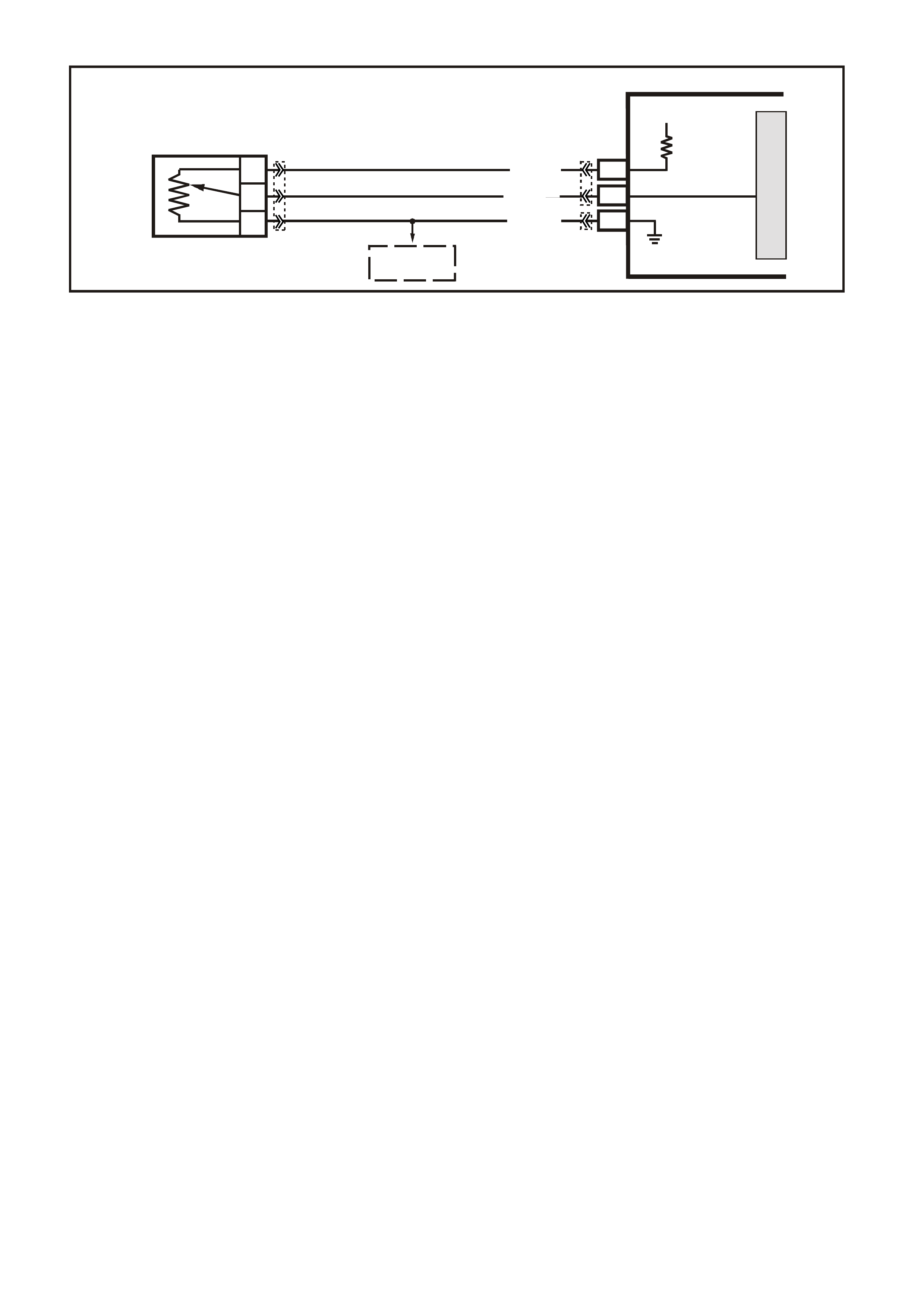
DTC 22 V6 PCM -
THROTTLE POSITION (TP) SENSOR CIRCUIT LOW VOLTAGE
CIRCUIT DESCRIPTION:
The Throttle Position (TP) sensor provides a voltage signal that changes relative to the throttle blade. Signal
voltage will vary from about 0.25 to 1.25 volts at idle to about 4 volts at Wide Open Throttle (WOT).
The TP sensor signal is one of the most important inputs used by the PCM for transient fuelling and
transmission control and for most of the PCM control. Outputs.
CONDITIONS FOR RUNNING THE DTC
• Time since engine started is greater than 20 seconds
CONDITIONS FOR SETTING THE DTC
• The TP Sensor voltage between the PCM TP Sensor signal terminal and the TP Sensor earth terminal is
less than 0.2 volts for more than two seconds.
ACTION TAKEN WHEN THE DTC SETS
• The PCM illuminates the Malfunction Indicator Lamp (MIL) when the diagnostic runs and fails.
• The PCM records the operating conditions at the tim e the diagnostic fails. T he PCM stores this information
in the History Data.
• When a DTC 22 is set, the PCM does not receive the proper signal from the TP sensor, but it can still
determ ine the TP sens or value with a default value based on RPM, Idle Air Control Valve position and Mas s
Air Flow.
• If DTC 22 is set, the transmission will have no TCC.
CONDITIONS FOR CLEARING THE MIL/DTC
• The PCM turns the MIL OFF after the first ignition cycle that the diagnostic runs and does not fail.
• A Histor y DT C clears after f orty c onsecutive warm -up cycles, if this or any other em ission related diagnostic
does not report any failure.
• Use a Tech 2 scan tool in order to clear the MIL/DTC.
DIAGNOSTIC AIDS:
A T ech 2 scan tool reads thr ottle position in volts. W ith ignition "ON'' or at idle, T P sensor s ignal voltage should
read about 0.25 to 1.25 volts with the throttle closed and increase at a steady rate as throttle is moved toward
Wide Open Throttle (WOT).
The Tech 2 scan tool will read throttle angle. 0%=closed throttle; 100%=WOT.
An open or short to earth in circuit 416 or circuit 417 will result in a DTC 22.
Refer to "Intermittents" in Section 6C1-2B SYMPTOMS of the VX Series Service Information.
TEST DESCRIPTION: Number(s) below refer to step number(s) on the diagnostic Table.
3. This test simulates a Diagnostic Trouble Code 21: (high voltage) If the PCM recognises the high signal
voltage and the Tech 2 scan tool reads over 4 volts or above, the PCM and wiring are OK.
4. This simulates a high signal voltage to check for an open in circuit 417. The Tech 2 scan tool will not read
up to 12 volts, but what is important is that the PCM recognises the signal on circuit 417.
VXSC005
SENSOR EARTH
TP SENSOR SIGNAL
TP SENSO R
REFERENCE
VOLTAGE
PCM
5V
M
I
C
R
O
A
C
B
THROTTLE
POSITION SENSOR
A7
B11
E16
BLU (417)
B/Y (452)
GY (416)
TO
ECT SENSOR
YB188
YB194
YE30

THROTTLE POSITION SENS OR
YE 30
(452) (416)
(417)
GY
B/Y
BLU
DTC 22 V6 PCM - THROTTLE POSITION (TP) SENSOR CIRCUIT LOW VOLTAGE
STEP ACTION VALUE YES NO
1. Was the "On-Board Diagnostic" (OBD) System Check
performed? Go to Step 2. Go to OBD
System Check in
this Section.
2. Throttle closed
Is Tech 2 scan tool display "TPS Voltage" at or below
specified value?
0.2 Volt
(200 mV) Go to Step 3 DTC 22 is
intermittent, if no
additional DTCs
were stored, refer
to "Intermittents"
in Section 6C1-
2B S YMPT OMS.
3. 1. Disconnect TPS wiring harness.
2. Jumper circuits 416 & 417 together.
Does Tech 2 scan tool display "TPS Voltage" above
Specified value?
4.0 Volts
(400 mV) Go to Step 6 Go to Step 4
4. Probe circuit 417 with test light connected to 12 volts.
Does Tech 2 scan tool display "TPS Voltage" above
specified value?
4.0 Volts
(400 mV) Go to Step 5 Go to Step 7
5. Check for open or short on circuit 416 or faulty
connection.
Was a short, open or faulty connection found?
Verify Repair Go to Step 8
6. Replace Throttle Position (TP) Sensor.
Is action complete? Verify Repair
7. Check for open or short on circuit 417 or faulty
connection.
Was a short, open or faulty connection found?
Verify Repair Go to Step 8
8. Replace PCM.
Refer to Section 6C1-3 Service Operations of the VX
Series Service Information, for PCM Security Link
procedure.
Is action complete?
Verify Repair
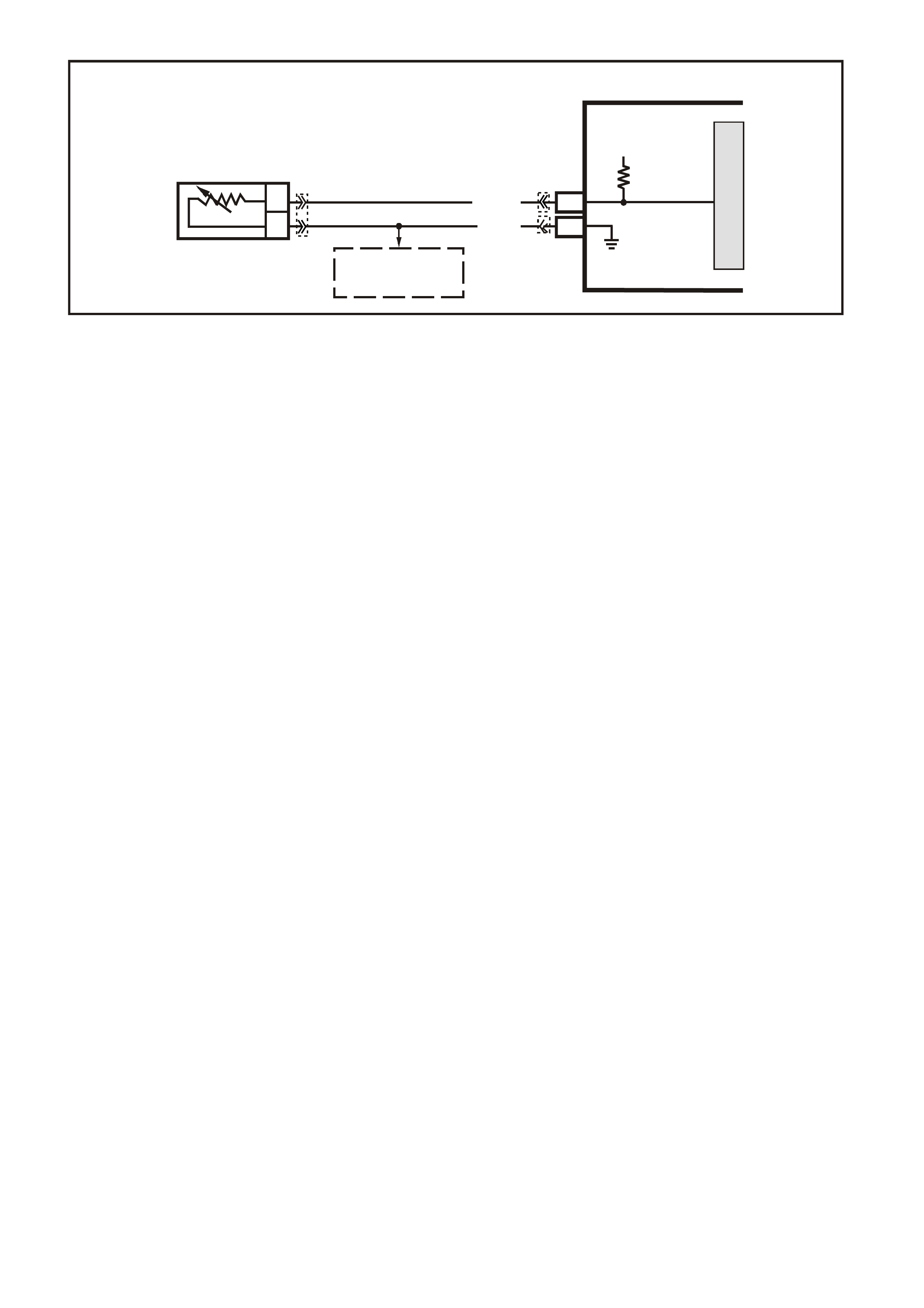
DTC 23 V6 PCM -
INTAKE AIR TEMPERATURE (IAT) SE NS O R CIRCUIT HIGH VOLTAGE
CIRCUIT DESCRIPTION:
The Intake Air Temperature (IAT) sensor uses a thermistor to control the signal voltage to the PCM. The PCM
applies a voltage (about 5 volts) on circ uit 472 to the sensor . When the intake air is cold, the sens or (ther m istor)
resistance is high, therefore, the PCM will sensor a high signal voltage. If the intake air is warm, the sensor
(thermistor) resistance is low, therefore, the PCM will sense a low signal voltage.
CONDITIONS FOR RUNNING THE DTC
• The engine has been operating for more than 10 seconds.
CONDITIONS FOR SETTING THE DTC
• IAT sensor signal voltage is more than 4.9 volts,indicating an intake air temperature is at or below -30°C for
one second.
ACTION TAKEN WHEN THE DTC SETS
• The PCM stores the DTC information into memory when the diagnostic runs and fails.
• The Malfunction Indicator Lamp (MIL) will not be illuminated.
• The PCM records the operating conditions at the tim e the diagnostic fails. T he PCM stores this information
in the History Data.
• When DTC 23 is set, the PCM will default to a 25°C IAT for engine operation.
CONDITIONS FOR CLEARING THE MIL/DTC
• A History DTC clears after forty consecutive warm-up cycles.
• Use a Tech 2 scan tool in order to clear the MIL/DTC.
DIAGNOSTIC AIDS:
A Tech 2 scan tool indicates the temperature of the air in the intake. W hen the PCM detects a fault in the IAT
sensor circuit, a default value of 25 degrees C will be used by the PCM.
Carefully check harness and connections for possible open circuit 472 or circuit 469.
An open circuit 469 will set DT C 23 and DTC 59, if the engine has been allowed to s it overnight, then the intake
air tem perature and engine coolant tem perature values should be within a few degrees of each other. After the
engine is started, the IAT sensor will increase due to engine compartment temperatures.
Refer to "Intermittents" in Section 6C1-2B SYMPTOMS of the VX Series Service Information.
TEST DESCRIPTION: Number(s) below refer to step number(s) on the diagnostic Table.
3. A Diagnostic Tr ouble Code 23 will set, due to an open sensor, wire or c onnection. This test will determ ine if
the wiring and PCM are OK.
6. This will determine if the IAT sensor signal (circuit 472) or the IAT sensor earth (circuit 469) is open.
SUPERVX002
F16
B4
B
A
INTAKE AIR
TEMPERATURE SENSOR
SENSOR EARTH
IAT SENSOR SIGNAL
PCM
5V
BR (472)
B (46 9)
M
I
C
R
O
TO
A/C PRESSURE
SENSOR AND
TFT SENSOR
YE23 YB188
YB194

IAT SENSOR TABLE RESISTANCE-TEMPERATURE CHARACTERISTICS
Temp (C) No Load
Ω
ΩΩ
Ω Temp (C) No Load
Ω
ΩΩ
Ω
-40 102,129 60 679
-35 73,345 65 566
-30 53,253 70 475
-25 39,066 75 400
-20 28,940 80 338
-15 21,638 85 287
-10 16,321 90 245
-5 12,414 95 210
0 9,517 100 180
5 7,355 105 156
10 5,729 110 135
15 4,497 115 117
20 3,555 120 102
25 2,830 125 89
30 2,268 130 79
35 1,829 135 69
40 1,483 140 61
45 1,210 145 54
50 993 150 48
55 819
YE194
P.C.M. CONNECTOR 3
LG/B
(366)
G
(843)
B/W
F16
B/Y
BR/Y
(1228)
(469)
Y
(451)
F1
P
(841)
BLU
V
E1
LBLU
(845)
BLU
B
(1226)
W/B
BLU/W
V
R
(435)
(31)
(1229)
GY
(1224)
Y
(846)
GY
(842)
(452)
(774)
(304)
BR/Y
(411)
(439)
GY/BLU
BLU
(1225)
E16
(1427)
(429)
(844)
B/O
(434)
OR AUTO
GY/BLU
GY
(1434)
MAN
(776)
W
BLU/W
Y
GY
(771)
(772)
(773)
YB 188
P.C.M CONNECTOR 2
(481)
(417)
(740)
R
BLU
O
(1456)
LG
V/W
(415)
Y
(1227)
B/Y
(410)
BR
(472)
(259)
(750)
(750)
(1221)
B/R
B/R
R/B
G/B
(39)
P
(465)
G/W
(416)
GY
(740)
O
A1
B1
B12
A12
AIR TEMP SENS OR
YE 23
B
(469)
BR
(472)

DTC 23 V6 PCM - INTAKE AIR TEMPERATURE (IAT) SENSOR CIRCUIT HIGH VOLTAGE
STEP ACTION VALUE YES NO
1. Was the "On-Board Diagnostic" (OBD) System Check
performed? Go to Step 2. Go to OBD
System Check in
this Section.
2. Does Tech 2 scan tool display "IAT" at or between the
specified value? -30 to -40
degrees C Go to Step 3 DTC 23
intermittent. If no
additional DTCs
were stored, refer
to "Intermittents"
in Section 6C1-
2B S YMPT OMS.
3. 1. Disconnect IAT sensor wiring harness.
2. Jumper harness terminals together.
Does Tech 2 scan tool display "IAT" at specified Value or
higher?
130 °
degrees C Go to Step 4 Go to Step 6
4. Check resistance across "IAT" sensor terminals.
Is value OK? See IAT
table above. Go to Step 5 Go to Step 12
5. Is there an intermittent or loose terminal in sensor
harness connector? Verify Repair Go to Step 11
6. Jumper circuit 472 to earth.
Does Tech 2 scan tool display "IAT" at specified Value or
higher?
130 °
degrees C Go to Step 7 Go to Step 8
7. Check for an open sensor earth circuit or faulty
Connection.
Was an open or faulty connection found?
Verify Repair Go to Step 10
8. Check for an open circuit 472 or faulty connection.
Was an open or faulty connection found? Verify Repair Go to Step 10
9. Replace intake air temperature sensor. Verify Repair
10 Replace PCM.
Refer to Section 6C1-3 Service Operations of the VX
Series Service Information, for PCM Security Link
procedure.
Is action complete?
Verify Repair
11. 1. Ignition "OFF"
2. Disconnect PCM connectors.
3. Remove jumper from IAT sensor harness.
4. Ignition "ON".
5. Check for short to voltage in circuit 472.
Was a short to voltage found?
Verify Repair Go to Step 10
12 Replace IAT sensor.
Is action complete ? Verify Repair

DTC 24 V6 PCM -
VEHICLE SPEED SENSOR (VSS) CIRCUIT LOW VOLTAGE
CIRCUIT DESCRIPTION:
The Vehicle Speed Sensor Assembly (VSS Assy.) provides vehicle speed information to the PCM. The VSS
Assy. is a Permanent Magnet (PM) generator. The PM generator produces a pulsing AC voltage. The AC
voltage level and the number of pulses increase with the speed of the vehicle. The PCM then converts the
pulsing voltage to vehicle speed. The PCM uses this information for calculations. A scan tool can display the
vehicle speed.
W hen the PCM detects a low or no vehicle speed, when there is high engine speed in a drive r ange, then DTC
24 sets.
CONDITIONS FOR RUNNING THE DTC
Automatic Transmission
• The transmission is not in Park or Neutral.
• The engine speed is greater than 3000 RPM.
• The TP Sensor angle is between 10% and 99%.
Manual Transmission
• The engine speed is between 1400 and 3000 RPM.
• The throttle is closed (throttle angle less than 1%).
• Engine load very low, MAF less than 95 mg/cyl.
• Vehicle in gear.
• Vehicle is decelerating from road speed.
CONDITIONS FOR SETTING THE DTC
Automatic Transmission
• The VSS indicates an output shaft speed of less than 3 km/h for 3 seconds.
Manual Transmission
• The VSS indicates no output shaft speed for more than 4 seconds.
ACTION TAKEN WHEN THE DTC SETS
• The PCM illuminates the Malfunction Indicator Lamp (MIL) when the diagnostic runs and fails.
• The PCM records the operating conditions at the tim e the diagnostic fails. T he PCM stores this information
in the History Data.
• For the automatic transmission, when this DTC sets, the PCM will command second gear only, The PCM
will command maxim um line pressure, The PCM will freeze shift adapts from being updated, The PCM will
inhibit TCC engagement.
CONDITIONS FOR CLEARING THE MIL/DTC
• The PCM turns the MIL OFF after the first ignition cycle that the diagnostic runs and does not fail.
• A Histor y DT C clears after f orty c onsecutive warm -up cycles, if this or any other em ission related diagnostic
does not report any failure.
• Use a Tech 2 scan tool in order to clear the MIL/DTC.
17
V/W (123)
12V IGN
VEHICLE SPEED
M
I
C
R
O
SUPERVX016
INSTRUMENT
M
I
C
R
O
VEHICLE SPEED
PCM
C5
C6
D5
V
EHICLE SPEED
SENSOR
IC
BLU/W
(831)
(AUTO)
BLU
(831)
(MAN)
T
(832)
(AUTO)
BR
(832)
(MAN)
SPEEDOMETER
YB193
YB195 (AUTO)
YB132 (MANUAL)
YE110
YB66
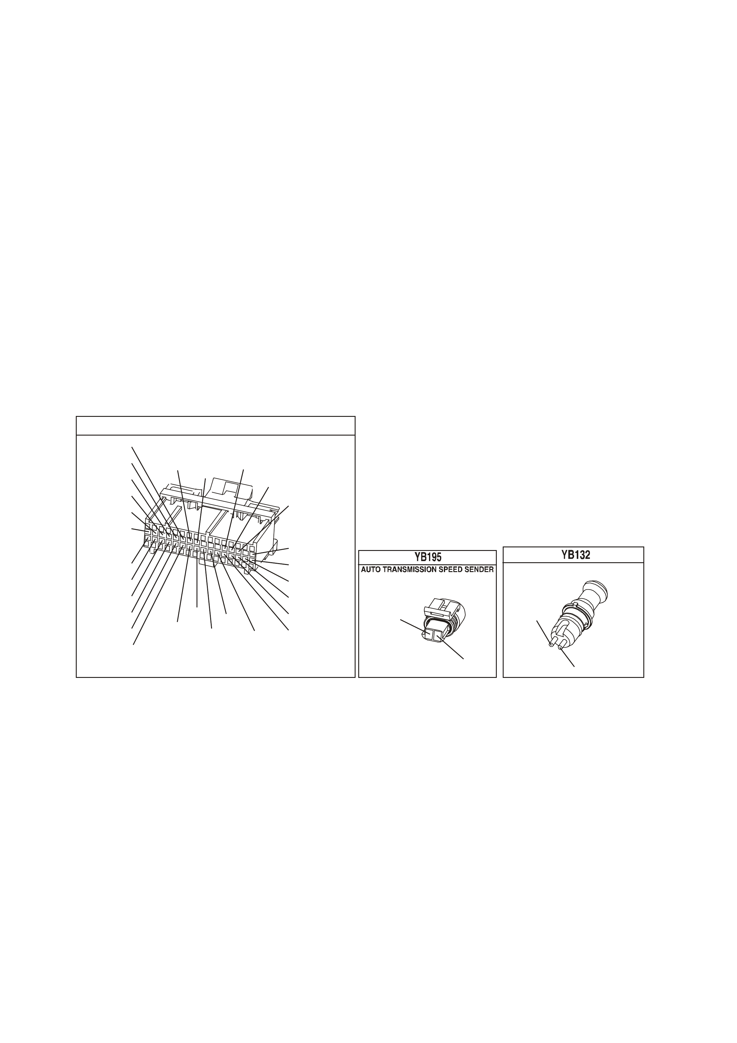
DIAGNOSTIC AIDS:
• Inspect the wiring for poor electrical connections at the PCM. Look for the following conditions:
- A bent terminal
- A backed out terminal
- A damaged terminal
- Poor terminal tension
- A chafed wire
- A broken wire inside the insulation
- Moisture intrusion
- Corrosion
• When diagnosing for an inter m ittent short or open c ondition, m ass age the wiring harness while watc hing the
test equipment for a change.
• Check circuits 831 and 832 f or the proper connections to be sure they are clean and tight and the harness
is routed correctly.
• The scan tool should indicate a vehicle speed whenever the drive wheels are turning greater than 3 km/h.
• The vehicle speed sensor resistance should be between 1470-2140 Ω at 20°C, and 2270-2820 Ω at 100° C.
• Refer to "Intermittents" in Section 6C1-2B Symptoms of the VX Series Service Information.
TEST DESCRIPTION: Number(s) below refer to step number(s) on the diagnostic Table.
3. This step tests the integrity of the VSS Assy.
4. This step tests the VSS Assy. circuit.
YB1 93
(413)
(412)
(1413)
(1412)
(430)
(453)
(815)
V/B
GY/B
V
GY
V
B/R
W/R
(897)
(897)
G/W
G/W
(418)
(418)
BR
BR
(1426)
O/W
C16
D16
WT/B
(832)AUTO
(647)
(630)
BR
T
(832) MAN
LBLU/B
B
(424)
(423)
C1
D1
(792)
(422)
(1222)
(1223)
(428)
(123)
BR/W
GY/R
LG
Y/B
G/Y
V/W
BLU/W
BLU
(831) Man
(443)
LG/W
(442) (831)AUTO
(441)
LBLU
LBLU/B
(444)
LG/B
P.C.M. CONNECTOR 1
(831)
BLU/W
T
(832)
MANUAL TRANS SPEED SENDER
(831)
(832)
BR
BLU

DTC 24 V6 PCM - VEHICLE SPEED SENSOR (VSS) CIRCUIT LOW VOLTAGE
STEP ACTION VALUE YES NO
1 Was the On-Board Diagnostic (OBD) System Check
performed? Go to Step 2 Go to OBD
System Check.
2 1. Install the scan tool.
2. With the engine OFF, turn the ignition switch to the
RUN position.
IMPORTANT: Before clearing the DTCs, use the scan
tool in order to record the DTC history for reference. The
Clear Info function will erase the data.
3. Record the DTC history.
4. Clear the DTC.
5. Raise the drive wheels.
Note: Do not perform this test without supporting the rear
axle assembly or the lower control arms on vehicles with
independent rear suspension so that the drive shafts are
in a normal horizontal position.
6. Start the engine.
7. Place the transmission in any drive gear.
W ith the rear wheels rotating, does the scan tool Vehicle
Speed increase with the drive wheel speed?
Go to
“Diagnostic Aids”
above
Go to Step 3
3 1. Turn the ignition switch to the OFF position.
2. Disconnect the VSS connector from the VSS
assembly.
3. Using the J 35616 Connector Test Adapter Kit,
connect the J 39200 DVM to the VSS terminals.
4. Select AC volts.
5. Place the transmission selector in the neutral
position.
6. Rotate the drive wheels by hand, ensuring that the
driveshaft is turning.
With rear wheels rotating, is the DVM voltage greater
than the specified value?
0.5 volts AC Go to Step 4 Go to Step 11
4 1. Turn the ignition switch to the OFF position.
2. Reconnect the VSS connector to the VSS Assy.
3. Disconnect the PCM connector from the PCM.
4. Connect the DVM test leads to the connector
terminals D5 (T) and C6 (Blu/W).
5. Place the transmission selector in the neutral
position.
6. Rotate the drive wheels by hand, ensuring that the
driveshaft is turning.
With rear wheels rotating, is the DVM voltage greater
than the specified value?
0.5 volts AC Go to Step 13 Go to Step 5
5 1. Select Ω (Ohms), on the DVM.
2. Measure the resistance between the connector
terminals D1 and D2.
Is the circuit resistance within the specified range?
1470-2820 Ω Go to Step 6 Go to Step 8
6 Connect the DVM between the connector terminal D1
and earth.
Is the circuit resistance less than the specified value?
250k Ω Go to Step 7 Go to
Diagnostic Aids
7 1. Check circuit 831 and circuit 832 for a short to earth.
2. Repair the circuit if necessary.
Was the short to earth condition found and corrected?
Go to Step 14 Go to
“Diagnostic Aids”
above
8 Is the resistance reading in step 6 greater than the
specified value? 2820 Ω Go to Step 10 Go to Step 9

DTC 24 V6 PCM - VEHICLE SPEED SENSOR (VSS) CIRCUIT LOW VOLTAGE (CONTINUED)
STEP ACTION VALUE YES NO
9 1. Check circuit 831 and circuit 832 for a shorted
together condition.
2. Repair the circuit if necessary.
Was a shorted together condition found and corrected ?
Go to Step 14 Go to
“Diagnostic Aids”
above
10 1. Check circuit 831 and circuit 832 for an open
condition.
2. Repair the circuit if necessary.
Was an open condition found and corrected ?
Go to Step 14 Go to
“Diagnostic Aids”
above
11 1. Remove the VSS Assembly.
2. Inspect the VSS Output Sensor Rotor for damage or
misalignment.
Did you find a condition?
Refer to Section
7B-1 Manual
Transmission -
V6 or Section
7C-4 Automatic
Transmission in
VX Service
Information.
Go to Step 12
12 Replac e the VSS Assy. Refer to Service Operations.
Is the action complete? Go to Step 14
13 Replace PCM.
Refer to Section 6C1-3 Service Operations of the VX
Series Service Information, for PCM Security Link
procedure.
Is action complete?
Go to Step 14
14 In order to verify your repair, perform the following
procedure:
1. Select DTC.
2. Select Clear Info.
3. Operate the vehicle ensuring that the vehicle speed
is greater than 10 km/h and observe the scan tool
Vehicle Speed.
Is the scan tool Vehicle Speed greater than the specified
value?
10 km/h System OK Go to Step 2
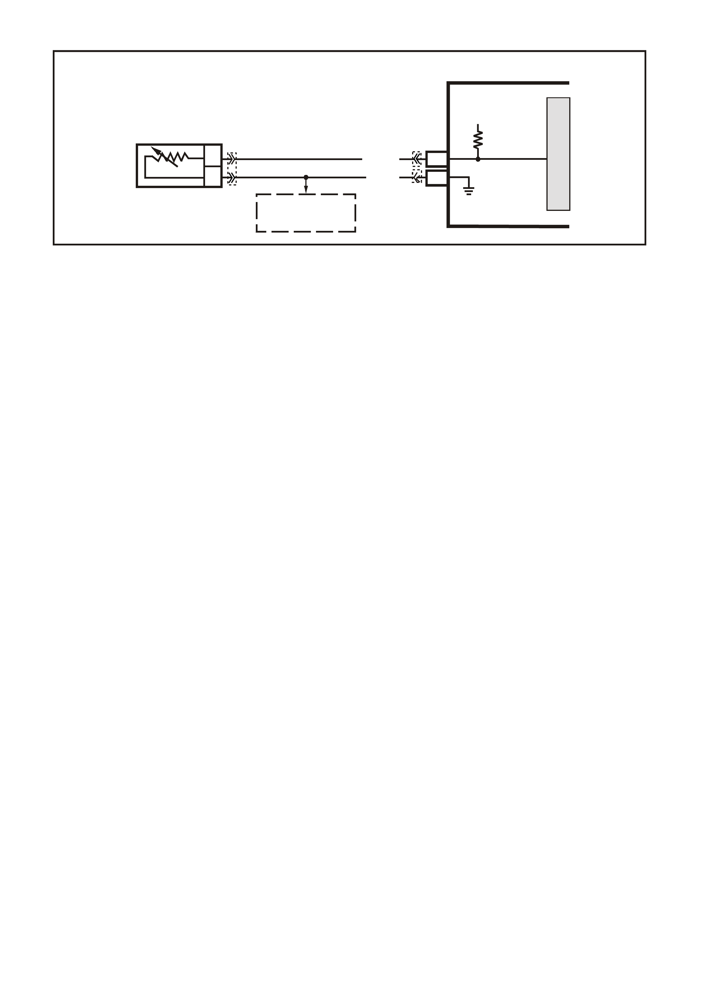
DTC 25 V6 PCM -
INTAKE AIR TEMPERATURE (IAT) SE NS O R CIRCUIT LOW VOLTAGE
CIRCUIT DESCRIPTION:
The Intake Air Temperature (IAT) sensor uses a thermistor to control the signal voltage to the PCM. The PCM
applies a voltage (about 5 volts) on circ uit 472 to the sensor . When the intake air is cold, the sens or (ther m istor)
resistance is high, therefore, the PCM will sensor a high signal voltage. If the intake air is warm, the sensor
(thermistor) resistance is low, therefore, the PCM will sense a low signal voltage.
CONDITIONS FOR RUNNING THE DTC
• The engine has been operating for more than 10 seconds.
CONDITIONS FOR SETTING THE DTC
• IAT Sens or s ignal voltage is more les s than 0.3 volts, indic ating an intake air temperatur e at or above 135°C
for more than one second.
ACTION TAKEN WHEN THE DTC SETS
• The PCM stores the DTC information into memory when the diagnostic runs and fails.
• The Malfunction Indicator Lamp (MIL) will not be illuminated.
• The PCM records the operating conditions at the tim e the diagnostic fails. T he PCM stores this information
in the History Data.
• When DTC 25 is set, the PCM will default to a 25°C IAT for engine operation.
CONDITIONS FOR CLEARING THE MIL/DTC
• A History DTC clears after forty consecutive warm-up cycles.
• Use a Tech 2 scan tool in order to clear the MIL/DTC.
DIAGNOSTIC AIDS:
Intake Air Temper ature (IAT) on a T ech 2 scan tool indicates the temperature of the air in the air cleaner. If the
engine has been allowed to sit overnight, the IAT sensor and engine coolant temperature values should be
within a f ew degrees of each other. Af ter the engine is s tarted, the IAT will increas e due to engine com partment
temperatures, however, IAT will rarely exceed 80 degrees C.
When the PCM detects a fault in the IAT circuit, a default value of 25 degrees C will be used.
Check harness routing for possible short to earth in circuit 469.
Refer to "Intermittents" in Section 6C1-2B SYMPTOMS of the VX Series Service Information.
TEST DESCRIPTION: Number(s) below refer to step number(s) on the diagnostic Table.
SUPERVX002
F16
B4
B
A
INTAKE AIR
TEMPERATURE SENSOR
SENSOR EARTH
IAT SENSOR SIGN AL
PCM
5V
BR (472)
B (46 9)
M
I
C
R
O
TO
A/C PRESSURE
SENSOR AND
TFT SENSOR
YE23 YB188
YB194
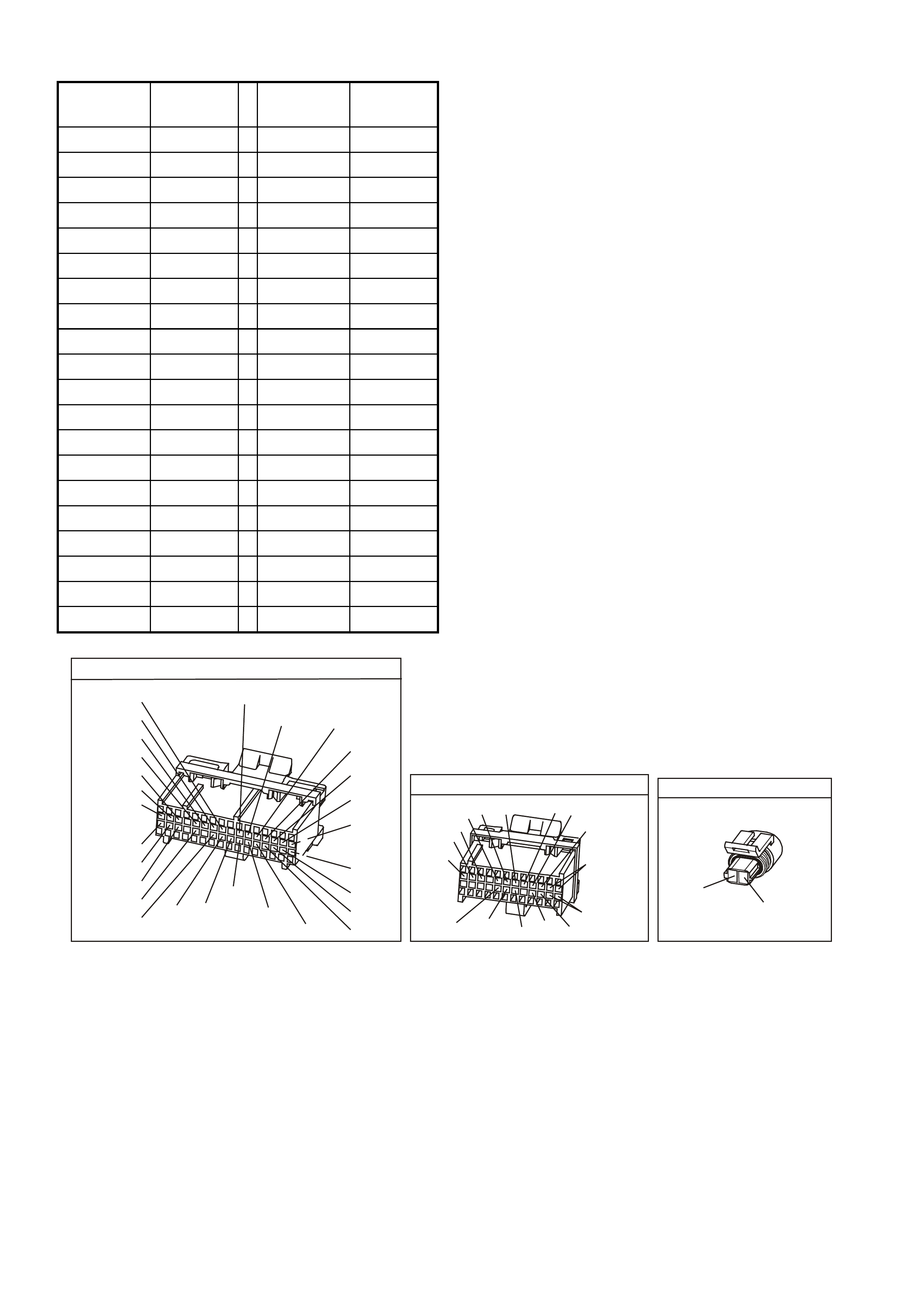
IAT SENSOR TABLE RESISTANCE-TEMPERATURE CHARACTERISTICS
Temp (C) No Load
Ω
ΩΩ
Ω Temp (C) No Load
Ω
ΩΩ
Ω
-40 102,129 60 679
-35 73,345 65 566
-30 53,253 70 475
-25 39,066 75 400
-20 28,940 80 338
-15 21,638 85 287
-10 16,321 90 245
-5 12,414 95 210
0 9,517 100 180
5 7,355 105 156
10 5,729 110 135
15 4,497 115 117
20 3,555 120 102
25 2,830 125 89
30 2,268 130 79
35 1,829 135 69
40 1,483 140 61
45 1,210 145 54
50 993 150 48
55 819
YE194
P.C.M. CONNECTOR 3
LG/B
(366)
G
(843)
B/W
F16
B/Y
BR/Y
(1228)
(469)
Y
(451)
F1
P
(841)
BLU
V
E1
LBLU
(845)
BLU
B
(1226)
W/B
BLU/W
V
R
(435)
(31)
(1229)
GY
(1224)
Y
(846)
GY
(842)
(452)
(774)
(304)
BR/Y
(411)
(439)
GY/BLU
BLU
(1225)
E16
(1427)
(429)
(844)
B/O
(434)
OR AUTO
GY/BLU
GY
(1434)
MAN
(776)
W
BLU/W
Y
GY
(771)
(772)
(773)
YB 188
P.C.M CONNECTOR 2
(481)
(417)
(740)
R
BLU
O
(1456)
LG
V/W
(415)
Y
(1227)
B/Y
(410)
BR
(472)
(259)
(750)
(750)
(1221)
B/R
B/R
R/B
G/B
(39)
P
(465)
G/W
(416)
GY
(740)
O
A1
B1
B12
A12
AIR TEMP SENS OR
YE 23
B
(469)
BR
(472)

DTC 25 V6 PCM - INTAKE AIR TEMPERATURE (IAT) SENSOR CIRCUIT LOW VOLTAGE
STEP ACTION VALUE YES NO
1. Was the "On-Board Diagnostic" (OBD) System Check
performed? Go to Step 2. Go to OBD
System Check in
this Section.
2. Does Tech 2 scan tool display "IAT" equal or greater than
specified value? 135
degrees C Go to Step 3 DTC 25 is
intermittent, if no
additional DTCs
were stored,
refer to
"Diagnostic Aids"
above.
3. Disconnect IAT sensor wiring harness.
Does Tech 2 scan tool display "IAT" below specified
value?
-30
degrees C Go to Step 4 Go to Step 6
4. Measure resistance across IAT sensor.
Does value correspond to specified value? Refer to IAT
table above. Go to Step 5 Go to Step 7
5. Check for intermittent or loose terminals in harness
connector, or terminals shorted together.
Was a problem found?
Verify Repair. Go to Step 8
6. Check for a short in circuit 472 to earth or to IAT sensor
earth.
Was a problem found?
Verify Repair. Go to Step 8
7. Replace IAT sensor.
Is action complete? Verify Repair.
8. Replace PCM.
Refer to Section 6C1-3, for Security Link procedure.
Is action complete?
Verify Repair.
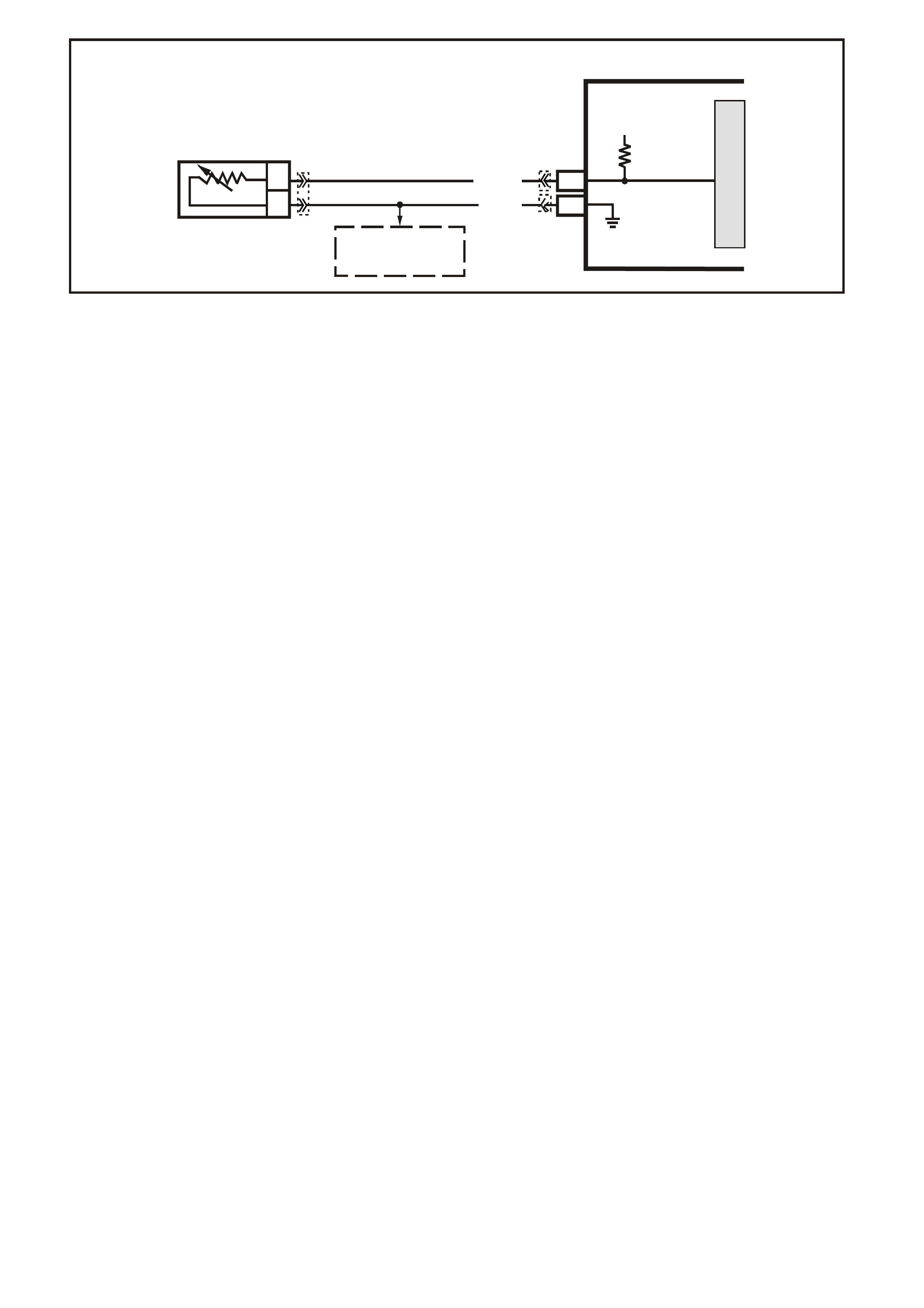
DTC 26 V6 PCM -
INTAKE AIR TEMPERATURE (IAT) SENSOR UNSTABLE
CIRCUIT DESCRIPTION:
The Intake Air Temperature (IAT) sensor uses a thermistor to control the signal voltage to the PCM. The PCM
applies a voltage ( about 5 volts ) on c irc uit 472 to the s ens or. When manifold intake air is c old (s uc h as when the
engine is first s tarted on a cold day), the sens or (therm istor) resistanc e is high, therefore, the PCM will sens e a
high signal voltage. If the manifold intake air is warm, the sensor (thermistor) resistance is low, therefore, the
PCM will sense a low signal voltage.
CONDITIONS FOR RUNNING THE DTC
• The engine has been operating for more than 10 seconds.
CONDITIONS FOR SETTING THE DTC
• IAT sensor reading changes more than 7°C (140 millivolts) in 100 milliseconds.
ACTION TAKEN WHEN THE DTC SETS
• The PCM stores the DTC information into memory when the diagnostic runs and fails.
• The Malfunction Indicator Lamp (MIL) will not be illuminated.
• The PCM records the operating conditions at the tim e the diagnostic fails. T he PCM stores this information
in the History Data.
• When DTC 26 is set, the PCM will default to a 25°C IAT for engine operation.
CONDITIONS FOR CLEARING THE MIL/DTC
• A History DTC clears after forty consecutive warm-up cycles.
• Use a Tech 2 scan tool in order to clear the MIL/DTC.
DIAGNOSTIC AIDS:
W hen attem pting to diagnose an inter mittent problem , use the s napshot mode of the Tec h 2 scan tool to r eview
diagnostic information.
TEST DESCRIPTION: Number(s) below refer to step number(s) on the diagnostic Table.
SUPERVX002
F16
B4
B
A
INTAKE AIR
TEMPERATURE SENSOR
SENSOR EARTH
IAT SENSOR SIGN AL
PCM
5V
BR (472)
B (46 9)
M
I
C
R
O
TO
A/C PRESSURE
SENSOR AND
TFT SENSOR
YE23 YB188
YB194
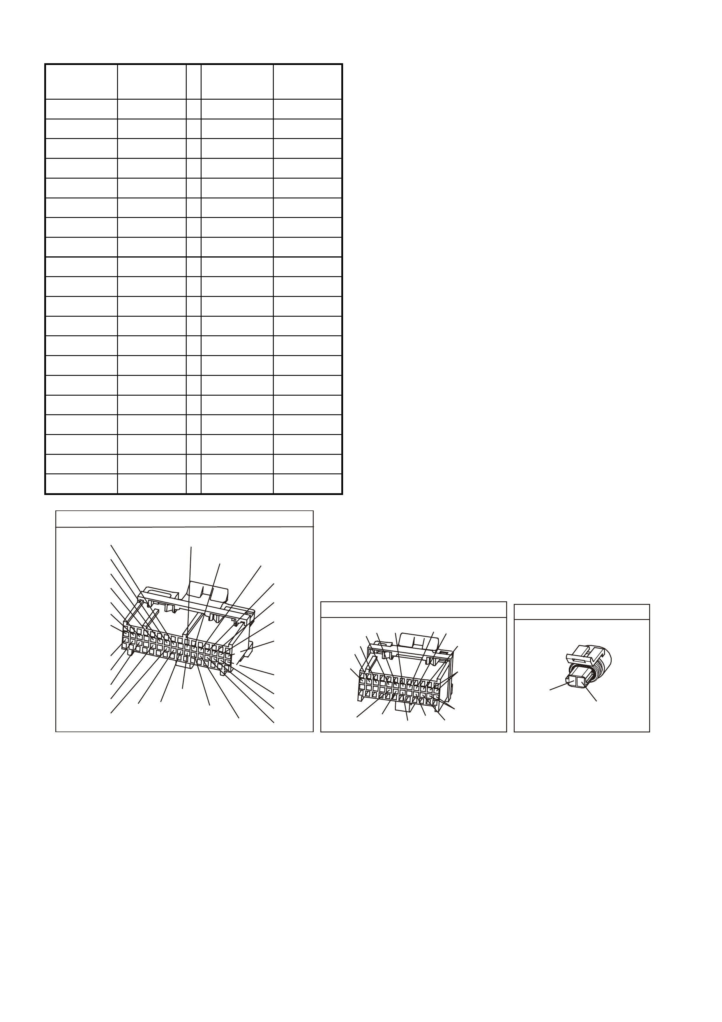
IAT SENSOR TABLE RESISTANCE-TEMPERATURE CHARACTERISTICS
Temp (C) No Load
Ω
ΩΩ
Ω Temp (C) No Load
Ω
ΩΩ
Ω
-40 102,129 60 679
-35 73,345 65 566
-30 53,253 70 475
-25 39,066 75 400
-20 28,940 80 338
-15 21,638 85 287
-10 16,321 90 245
-5 12,414 95 210
0 9,517 100 180
5 7,355 105 156
10 5,729 110 135
15 4,497 115 117
20 3,555 120 102
25 2,830 125 89
30 2,268 130 79
35 1,829 135 69
40 1,483 140 61
45 1,210 145 54
50 993 150 48
55 819
YE194
P.C.M. CONNECTOR 3
LG/B
(366)
G
(843)
B/W
F16
B/Y
BR/Y
(1228)
(469)
Y
(451)
F1
P
(841)
BLU
V
E1
LBLU
(845)
BLU
B
(1226)
W/B
BLU/W
V
R
(435)
(31)
(1229)
GY
(1224)
Y
(846)
GY
(842)
(452)
(774)
(304)
BR/Y
(411)
(439)
GY/BLU
BLU
(1225)
E16
(1427)
(429)
(844)
B/O
(434)
OR AUTO
GY/BLU
GY
(1434)
MAN
(776)
W
BLU/W
Y
GY
(771)
(772)
(773)
YB 188
P.C.M CONNECTOR 2
(481)
(417)
(740)
R
BLU
O
(1456)
LG
V/W
(415)
Y
(1227)
B/Y
(410)
BR
(472)
(259)
(750)
(750)
(1221)
B/R
B/R
R/B
G/B
(39)
P
(465)
G/W
(416)
GY
(740)
O
A1
B1
B12
A12
AIR TEMP SENS OR
YE 23
B
(469)
BR
(472)

DTC 26 V6 PCM - INTAKE AIR TEMPERATURE (IAT) SENSOR UNSTABLE
STEP ACTION VALUE YES NO
1. Was the "On-Board Diagnostic" (OBD) System Check
performed? Go to Step 2. Go to OBD
System Check in
this Section.
2. 1. Install Tech 2 scan tool and set up snapshot
mode to trigger on DTC 26.
2. Watch the Tech 2 scan tool while wiggling
the IAT sensor connector.
Does the "IAT" reading change sharply?
Go to Step 8 Go to Step 3
3. Wiggle and tug the IAT sensor harness.
Does the "IAT" reading change sharply? Go to Step 9 Go to Step 4
4. Wiggle and tug the harness at the PCM.
Does the "IAT" reading change sharply? Go to Step 10 Go to Step 5
5. Lightly tap on the PCM.
Does the "IAT" reading change sharply? Go to Step 6 DTC 26 is
intermittent,
refer to
Diagnostic Aids
above.
6. Make sure PCM is mounted securely to vehicle.
Was a problem found? Verify Repair Go to Step 7
7. Replace PCM.
Refer to Section 6C1-3 SERVICE OPERATIONS of the
VX Series Service Information, for PCM Security Link
procedure.
Is action complete?
Verify Repair
8. 1. Check IAT sensor connector.
2. Check the tightness of the female terminal grip
with a spare male terminal.
3. Inspect connectors for corrosion. If
connectors are corroded, try cleaning with
electronic part cleaner and retest.
4. If these repairs do not resolve the problem,
replace terminals.
Is action complete?
Verify Repairs
9. 1. Check for an open in the IAT harness.
2. Check for broken strands of wire in IAT sensor
harness.
3. Check for cuts or pinches in IAT sensor harness.
4. Make repairs as necessary.
Is action complete?
Verify Repairs
10. 1. Check the IAT sensor connection at the PCM.
2. Check tightness of the female terminal grip with a
spare male terminal.
3. Inspect connectors for corrosion. If connectors
are corroded, try cleaning with electronic parts
cleaner and retest.
4. Remove connector strain relief and remove
terminal from connector to check for broken
locking tang.
Is action complete?
Verify Repairs

DTC 28 V6 PCM –
TRANSMISSION FLUID PRESSURE (TFP) VALVE POSITION SWITCH CIRCUIT
CIRCUIT DESCRIPTION:
The Automatic Transmission Fluid Pressure Manual Valve Position Switch (TFP Val. Position Sw.) consists of
five pressure switches (two normally-closed and three normally-open) and a Transmission Fluid Temperature
(TFT) sensor combined into one unit. The combined unit mounts on the valve body. The PCM supplies the
battery voltage for each range signal. By earthing one or more of the circuits through various combinations of
the pressur e switches, the PCM detects which m anual valve position you select. The PCM compares the actual
voltage combination of the switches to a TFP Val. Position Sw. combination Table stored in memory. The TFP
Val. Position Sw. cannot dis tinguish between Park and Neutral becaus e the m onitored valve body pressures are
identical. W ith the engine OFF and the ignition switch in the RUN position, the TFP Val. Position Sw. indicates
Park/Neutral. Disconnecting the transmission pass-through connector removes the earthing potential for the
three range signals to the PCM. In this case, with the engine OFF, and the ignition switch in the RUN position,
D2 will be indicated.
When the PCM detects an invalid state of the TFP Val. Position Sw. or the TFP Val. Position Sw. circuit by
deciphering the TFP Val. Position Sw. inputs, then DTC 28 set.
CONDITIONS FOR RUNNING THE DTC
• The engine is running.
• The vehicle automatic transmission is in gear.
CONDITIONS FOR SETTING THE DTC
Condition 1
• The PCM detects an illegal TFP manual valve position switch state for 60 seconds.
Condition 2
• The engine speed is less than 80 RPM for 0.1 second; then the engine speed is 80-550 RPM for
0.07 seconds; then the engine speed is greater than 500 RPM.
• The PCM detects a gear range of D2, D4, or Reverse during an engine start.
• All conditions are met for 5 seconds.
Condition 3
• The TP angle is 8-45%.
• The PCM commands 4th gear.
• The TCC is locked ON.
• The speed ratio is 0.65-0.8 (speed ratio is engine speed divided by transmission output speed).
• The PCM detects a gear range of Park or Neutral when operating in D4.
• All conditions are met for 10 seconds.
SUPERVX034
PCM
F9
F10
B6
F16
TFP SIGNAL A
TFP SIGNAL B
TRANSMISSION FLUID
TEMPERATURE (TFT)
SENSOR SIGNAL
SENSOR EARTH
N
C
R
E
D
A
B
P
L
M
TRANSMISSION FLUID
TEMPERATURE
(TF T ) SENSOR
AUTOMATIC TRANSMISSION FLUID
PRESSURE SWITCH ASSEMBLY
BR/Y (1224)
Y (1225)
GY (1226)
B/Y (1227)
B (46 9)
12V
12V
5V
F11 TFP SIGNAL C
12V
M
I
C
R
O
TO
A
/C PRESSURE SENSOR
AND IAT SENSOR
YB194
YB129
YB188
YB194

ACTION TAKEN WHEN THE DTC SETS
• The PCM illuminates the Malfunction Indicator Lamp (MIL) when the diagnostic runs and fails.
• The PCM records the operating conditions at the tim e the diagnostic fails. T he PCM stores this information
in the History Data.
• When DTC 28 is set, the PCM will inhibit TCC engagement, command D2 line pressure, and freeze shift
adapts from being updated.
CONDITIONS FOR CLEARING THE MIL/DTC
• The PCM turns the MIL OFF after the first ignition cycle that the diagnostic runs and does not fail.
• A Histor y DT C clears after f orty c onsecutive warm -up cycles, if this or any other em ission related diagnostic
does not report any failure.
• Use a Tech 2 scan tool in order to clear the MIL/DTC.
DIAGNOSTIC AIDS:
• Refer to the TFP Val. Position Sw. Logic Table for the normal range signals and the illegal combinations.
• Inspect the wiring for poor electrical connections at the PCM. Inspect the wiring for poor electrical
connections at the transmission pass-through connector. Look for the following conditions:
- A bent terminal
- A backed out terminal
- A damaged terminal
- Poor terminal tension
- A chafed wire
- A broken wire inside the insulation
- Moisture intrusion
• When diagnosing for an inter m ittent short or open c ondition, m ass age the wiring harness while watc hing the
test equipm ent for a c hange. Refer to Autom atic Tr ansmis sion Fluid Pressure Manual Valve Pos ition Switc h
Resistance Check or Functional Test Procedure for further information.
TFP VALVE POSITION SWITCH LOGIC
Gear
Position
Range
Signal
Switch A
Range
Signal
Switch B
Range
Signal
Switch C
P Open 12V Closed 0V Open 12V
R Closed 0V Closed 0V Open 12V
N Open 12V Closed 0V Open 12V
D Open 12V Closed 0V Closed 0V
3 Open 12V Open 12V Closed 0V
2 Open 12V Open 12V Open 12V
1 Closed 0V Open 12V Open 12V
Illegal Closed 0V Open 12V Closed 0V
Illegal Closed 0V Closed 0V Closed 0V
TEST DESCRIPTION
The numbers below refer to the step numbers on the diagnostic table.
3. This step compares the indicated range signal to the manual valve position that is actually selected.
4. This step tests for correct voltage from the PCM to the transmission pass-through connector terminals.
TRANSMISSION CONNECTOR
GY/BLU
(1229)
R
(1228)
Y/B
(1223)
LG
(1222)
P/BLU
(339)
(1227)
B/Y
(1230)
B/W
GY/R
(422)
BR
(418)
BR/Y
(1224)
(1226)
GY
Y
(1225)
(897)
G/W
(V8)
B
(469) (V6)
OR

DTC 28 V6 PCM - TRANSMISSION FLUID PRESSURE (TFP) VALVE POSITION SWITCH CIRCUIT
STEP ACTION VALUE YES NO
1 Was the On-Board Diagnostic (OBD) System Check
performed? Go to Step 2 Go to OBD
System Check
2 Perform the following inspections:
1. Ensure that the transmission linkage from the select
lever to the manual valve is adjusted properly.
2. Perform the fluid checking procedure/inspection.
Did you perform the inspections?
Go to Step 3 Perform the
Inspections
3 1. Install the scan tool.
2. With the engine OFF, turn the ignition switch to the
RUN position.
IMPORTANT: Before clearing the DTCs, use the
scan tool in order to record the DTC history for
reference. The Clear Info function will erase the data.
3. Record the DTC history.
4. While the engine is idling at normal operating
temperature, apply the parking brake.
5. Select each transmission range: P, R, N, D4, D3, D2,
and D1.
Does each selected transmission range match the scan
tool TFP Switc h A/B/C display?
• Refer to the TFP Val. Position Sw. Logic Table.
Go to
“Diagnostic Aids”
above
Go to Step 4
4 1. Turn the ignition OFF.
2. Disconnect the transmission pass-through connector
(additional DTCs may set).
3. Install the J 39775 Jumper Harness on the engine
side of the transmission pass-through connector.
4. With the engine OFF, turn the ignition switch to the
RUN position.
5. Using the J 39200 DVM and J 35616 Connector Test
Adapter Kit, check for voltage at connector terminals
N, R, and P.
Is B+ displayed on all three circuits?
Go to Step 6 Go to Step 5
5 1. Check the circuits that did not indicate B+ for an
open or a short to earth.
2. Repair the circuits if necessary.
Did you find and correct the problem?
Go to Step 13 Go to Step 7
6 In order to verify that circuit 1224, circuit 1225, and circuit
1226 are not shorted together, use a fused jumper to
earth, on each circuit while monitoring the scan tool TFP
Switch A/B/C display.
When a range signal circuit is earthed, are any other
range signal circuits affected?
Go to Step 8 Go to Step 9
7 Replace PCM.
Refer to Section 6C1-3 Service Operations, for PCM
Security Link procedure.
Is action complete?
Go to Step 13
8 Repair the affected wiring as necessary.
Is the action complete? Go to Step 13
9 1. Turn the ignition switch to the OFF position.
2. Reconnect the pass-through connector.
3. Select the PARK position.
4. Start the engine.
5. Apply the brakes.
6. Move the shift selector through all gear ranges, while
observing the A and C range signals on the scan
tool.
Does either range signal always indicate 0 volts/ON?
Go to Step 10 Intermittent
Problem Go to
“Diagnostic Aids”
above

DTC 28 V6 PCM - TRANSMISSION FLUID PRESSURE (TFP) VALVE POSITION SWITCH CIRCUIT (CONT)
STEP ACTION VALUE YES NO
10 1. Turn the ignition switch to the OFF position.
2. D isconnect the transmission pass-through connector.
3. Remove the transmission pan.
4. Remove the internal wiring harness connector from
the TFP Valve Position Switch.
5. Check the internal wiring harness circuits 1224 and
1226 for a short to earth.
Did you find a short to earth condition on either circuit?
Go to Step 12 Go to Step 11
11 Replace the TFP Valve Position Switch. Refer to Service
Operations, Section6C2-3, in the VX Series Service
Information.
Is the action complete?
Go to Step 13
12 Replace the internal A/T Wiring Harness Assembly Refer
to Service Operations in Section 7C-5 Automatic
Transmission VX Service Information.
Is the replacement complete?
Go to Step 13
13 In order to verify your repair, perform the following
procedure:
1. Select DTC.
2. Select Clear Info.
3. Operate the vehicle under the following conditions:
• With the engine OFF, turn the ignition switch to
the RUN position for at least 2 seconds.
• Start the vehicle and idle for 5 seconds.
• Select each transmission range: P, R, N, D4,
D3, D2 and D1.
• Compare the scan tool TFP Sw. A/B/C/ display,
to the TFP Valve Position Sw. Logic Table.
Does each shifter position range signal match the scan
tool TFP Sw. A/B/C dis p lay?
System OK Begin the
diagnosis again.
Go to Step 1

DTC 31 V6 PCM -
THEFT DETERRENT SIGNAL MISSING
CIRCUIT DESCRIPTION;
When the ignition is turned "ON", the PCM will send a message on circuit 1221 to the BCM asking for
permission to start. W hen the BCM receives this message, it instantly sends a m essage back to the PCM. The
message says that the proper ignition key has been used to turn the ignition and that it is OK for the PCM to
enable the fuel injectors to start the vehicle. If the BCM does not receive communications from the PCM when
the ignition is switched "ON", then the starter motor will be enabled after a one second delay.
CONDITIONS FOR RUNNING THE DTC
• The ignition is on.
• Conditions present for at least 10 seconds.
CONDITIONS FOR SETTING THE DTC
• The PCM sends 20 messages to the BCM and does not receive a message back saying its OK to start.
ACTION TAKEN WHEN THE DTC SETS
• The PCM illuminates the Malfunction Indicator Lamp (MIL) when the diagnostic runs and fails.
• The PCM records the operating conditions at the tim e the diagnostic fails. T he PCM stores this information
in the History Data.
• When DTC 31 is set and current, the engine will not start.
CONDITIONS FOR CLEARING THE MIL/DTC
• The PCM turns the MIL OFF after the first ignition cycle that the diagnostic runs and does not fail.
• A Histor y DT C clears after f orty c onsecutive warm -up cycles, if this or any other em ission related diagnostic
does not report any failure.
• Use a Tech 2 scan tool in order to clear the MIL/DTC.
DIAGNOSTIC AIDS
The Tech 2 scan tool has a special test to check this signal. To access this special test, select F3: BCM, then
select F1: THEFT STATUS. The Tech 2 scan tool will either display "OK TO START" or "NO START".
• Dirty, Damaged, or Loos e Connections or Dam aged Harness - Check for any damage to the harness which
could cause an intermittent open or short to earth or backed out terminals at the PCM connectors, broken
locks, improperly formed or damaged terminals.
VXSC033
PCM
BCM
A3
SERIAL
DATA
STARTER
ENABLE
5V
SERIAL
DATA
MAIN
5V
BATTERY
FS
LOC.
E1
F31
A5/A6O/B (740)
(1040)
BATTERY M AIN POWER
FJ
R (2H)
F14
E20/D6P/B (39) IGNITION ON
15a 15 50
30 ACC
IGN
START
IGNITION SWI TCH
P (3)
LOC. G1
E2/D2
R/B (1221)
GY/BLU
(1434)
GY
(434)
EG
NEUTRAL START
BACK-UP SW.
( MANUAL
TRANS)
STARTER
MOTOR
M
START
RELAY
V (5)
F5
V/W
(6)
87
36 85
30
HIGH SERIES
BCM TERMINALS
NOMINA TED FIRST
YE111 YB194
YB188
YB175
YB164
YB175
YB164
YB176
YB165
YE112
YB44
YB44
YE49
YE49
YB35 YB35

TEST DESCRIPTION
The numbers below refer to the step numbers on the diagnostic table.
2. If the engine c ranks af ter a one s ec ond delay it m eans the BCM did not s ee a mess age f rom the PCM when
the ignition was turned "ON".
3. An open or short to earth on circuit 1221 will disable any communication of serial data.
DTC 31 V6 PCM - THEFT DETERRENT SIGNAL MISSING
STEP ACTION VALUE YES NO
1. Was the "On-Board Diagnostic" (OBD) System Check
performed? Go to Step 2 Go to OBD
System Check.
2. Attempt to start vehicle.
Does engine crank after a one second delay when
ignition is switched "ON"?
Go to Step 3 DTC 31 is
intermittent, refer
to "Diagnostic
Aids" above.
3. Ignition "ON".
Does voltage between DLC terminal "9" and earth equal
specified value?
3 -5 volts Refer to
Section 12F
"THEFT
DETERRENT" in
VX Service
Information. for
further diagnosis.
Go to Step 4
4. Check for poor connection at PCM terminal and/or
open or shorted circuit 1221.
Was a problem found?
Verify Repair Go to Step 5
5. Replace PCM.
Refer to Section 6C1-3 Service Operations of the VX
Series Service Information, for PCM Security Link
procedure.
Is action complete?
Verify Repair
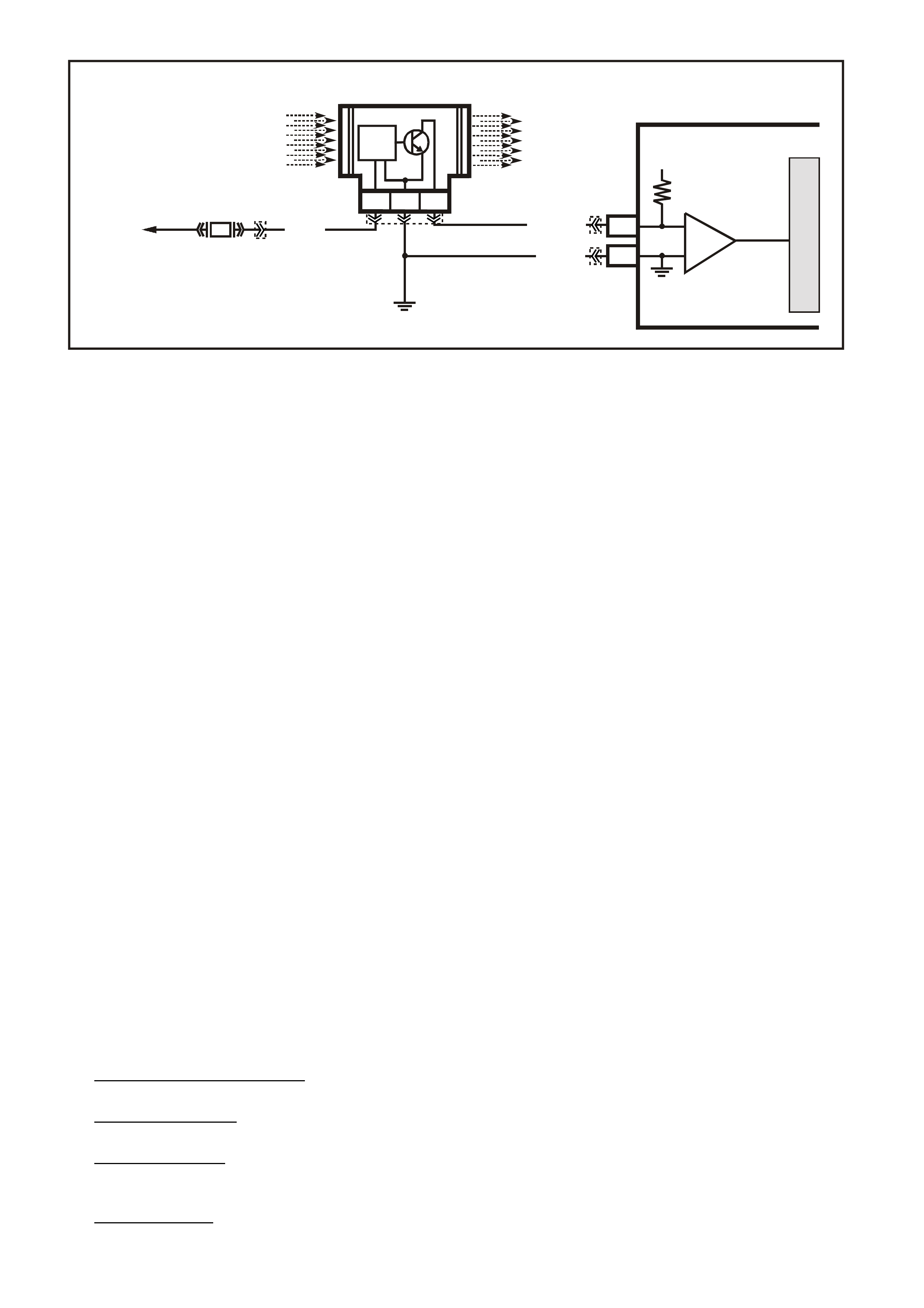
DTC 32 V6 PCM -
MASS AIR FLOW (MAF) OUT OF RANGE
CIRCUIT DESCRIPTION:
The Mass Air Flow (MAF) sensor measures the flow of air which passes through it in a given time. The PCM
uses this information to monitor the operating condition of the engine for fuel delivery calculations. A large
quantity of air movement indicates acceleration, while a small quantity indicates deceleration or idle.
The MAF sensor produces a frequency signal which cannot be easily measured.
The MAF sensor can be diagnosed using the procedures on this Table.
W ith DT C 32 set, the PCM will use a default value for air f low based on throttle position, and engine speed and
some vehicle performance will return. When DTC 32 is set the MIL "Check Powertrain Lamp" will be illuminated.
CONDITIONS FOR RUNNING THE DTC
• The engine is running.
CONDITIONS FOR SETTING THE DTC
• No MAF signal for over 2 seconds.
• Above conditions present for at least 10 seconds.
ACTION TAKEN WHEN THE DTC SETS
• The PCM illuminates the Malfunction Indicator Lamp (MIL) when the diagnostic runs and fails.
• The PCM records the operating conditions at the tim e the diagnostic fails. T he PCM stores this information
in the History Data.
• The PCM will substitute a MAF sensor value based on RPM, throttle angle and IAC position.
CONDITIONS FOR CLEARING THE MIL/DTC
• The PCM turns the MIL OFF after the first ignition cycle that the diagnostic runs and does not fail.
• A Histor y DT C clears after f orty c onsecutive warm -up cycles, if this or any other em ission related diagnostic
does not report any failure.
• Use a Tech 2 scan tool in order to clear the MIL/DTC.
DIAGNOSTIC AIDS:
An intermittent may be caused by a poor connection, mis-routed harness, rubbed through wire insulation, or a
wire broken inside the insulation.
Check for:
• Poor Connection at PCM Pin - Inspect harness connectors for backed out terminals, improper mating,
broken locks, improperly formed or damaged terminals, and poor terminal to wire connection.
• Mis-Routed Harness - Inspect MAF sensor harness to ensure that it is not too close to high voltage wires,
such as spark plug leads.
• Damaged Harness - Inspect harness for damage. If harness appears OK, observe Tech 2 scan tool while
moving related connectors and wiring harness. A change in display would indicate the intermittent fault
location.
• Plugged Air Filter - A wide open throttle ac c eleration from a stop s hould caus e the MAF reading on the Tech
2 sc an tool to range from about 4-7 g/s at idle to 100 or greater at the time of the 1-2 shift on an autom atic
transmission. If not, check for restriction.
VXSC006
MASS AIR FLOW SENSOR
D1
A1
PCM
CBA
AIR FLOW
FROM
AIR FILTER
AIR FLOW
TO
THROTTLE BODY
TO
EFI
RELAY
P (43 9)
LOC. E5/E15
BR/W (792)
MASS AIR FLOW
INPUT SIGNAL
EARTH
5 V
M
I
C
R
O
IC
B/R (750)
F33
IC
CIRCUIT
YB188
YE100
YE111 YB193
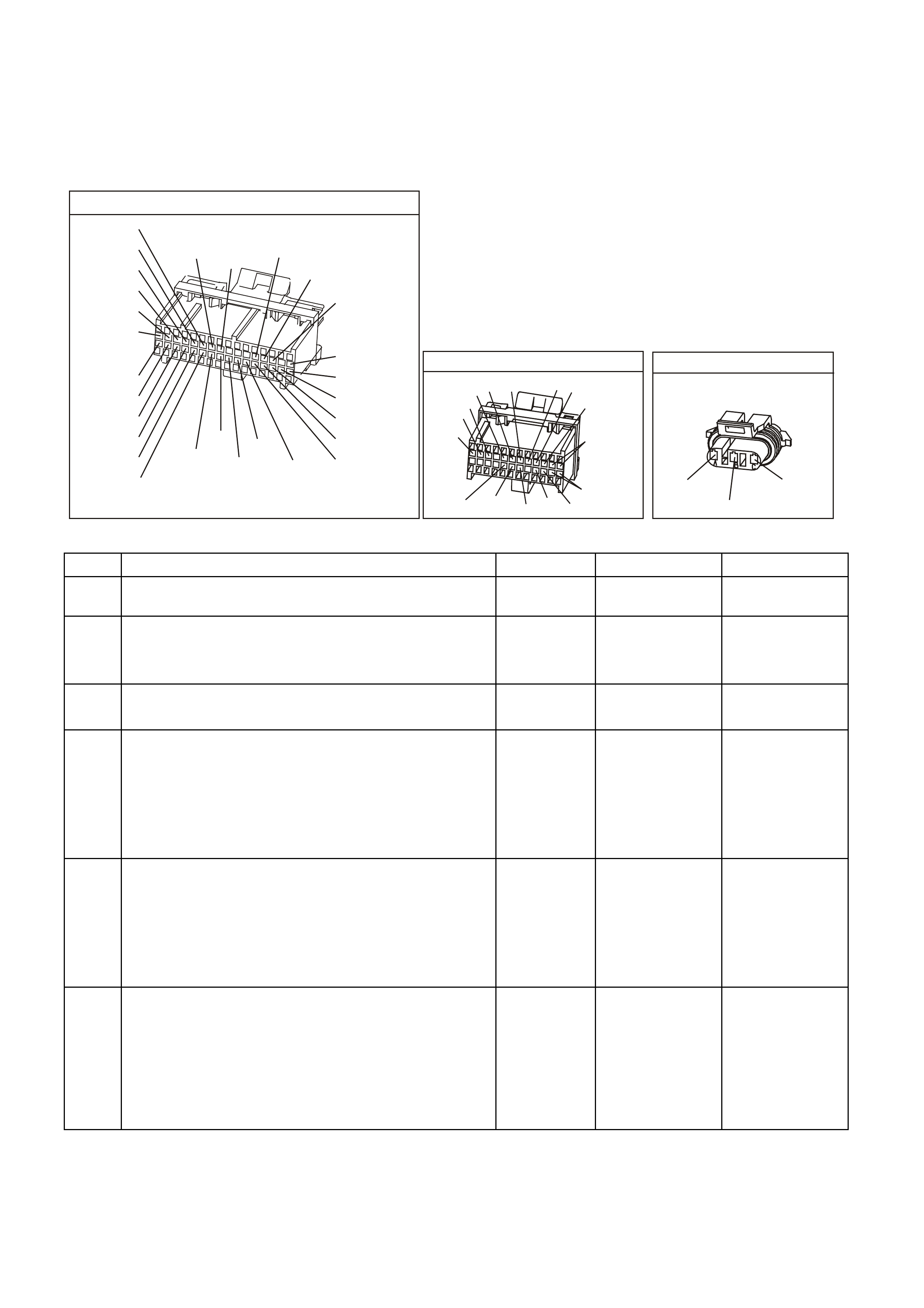
TEST DESCRIPTION: Number(s) below refer to step(s) on the diagnostic Table.
5. Verifies that both ignition feed voltage and a good earth circuit are available.
6. This step checks to see if PCM recognises a problem.
7. A voltage reading at sensor harness connector term inal "A" of les s than 4 or over 6 volts indic ates a fault in
circuit 792 or poor connection.
YB1 93
(413)
(412)
(1413)
(1412)
(430)
(453)
(815)
V/B
GY/B
V
GY
V
B/R
W/R
(897)
(897)
G/W
G/W
(418)
(418)
BR
BR
(1426)
O/W
C16
D16
WT/B
(832)AUTO
(647)
(630)
BR
T
(832) MAN
LBLU/B
B
(424)
(423)
C1
D1
(792)
(422)
(1222)
(1223)
(428)
(123)
BR/W
GY/R
LG
Y/B
G/Y
V/W
BLU/W
BLU
(831) Man
(443)
LG/W
(442) (831)AUTO
(441)
LBLU
LBLU/B
(444)
LG/B
P.C.M. CONNECTOR 1
YB188
P.C.M CO NNECTOR 2
(481)
(417)
(740)
R
BLU
O
(1456)
LG
V/W
(415)
Y
(1227)
B/Y
(410)
BR
(472)
(259)
(750)
(750)
(1221)
B/R
B/R
R/B
G/B
(39)
P
(465)
G/W
(416)
GY
(740)
O
A1
B1
B12
A12
M.A.F SENSOR
YE 100
(439)
(750)
(792)
B/R
PBR/W
DTC 32 V6 PCM - MASS AIR FLOW (MAF) OUT OF RANGE
STEP ACTION VALUE YES NO
1. Was the "On-Board Diagnostic" (OBD) System Check
performed? Go to Step 2. Go to OBD
System Check.
2. 1. Ignition "ON".
2. Using Tech 2 scan tool, select MAF frequency.
Is "MAF frequency" reading at the specified value ?
0 Hz Go to Step 4 Go to Step 3
3. Replace MAF sensor.
Is action complete ? Verify Repair
4. 1. Ignition "OFF".
2. Disconnect MAF sensor.
3. Ignition "ON".
4. Connect a test light to earth, and probe MAF sensor
harness connector terminal "C".
Is test light "ON" ?
Go to Step 5 Go to Step 11
5. 1. Ignition "OFF".
2. Disconnect MAF sensor.
3. Ignition "ON".
4. Measure voltage between MAF sensor harness
connector terminals "B" and "C" .
Is voltage greater then specified value ?
10 volts Go to Step 7 Go to Step 10
6. 1. Ignition "OFF".
2. Reconnect MAF sensor.
3. Ignition "ON" engine idling.
Is MAF sensor "MASS AIR FLOW" reading between
Specified value ?
4 - 9
grams/sec DTC 32 is
intermittent. If no
additional DTC's
were stored,
refer to
"Diagnostic
Aids" above.
Go to Step 3

DTC 32 V6 PCM - MASS AIR FLOW (MAF) OUT OF RANGE (CONTINUED)
STEP ACTION VALUE YES NO
7. 1. Ignition "OFF".
2. Disconnect wiring harness connector from MAF
sensor.
3. Ignition "ON".
4. Measure voltage at MAF sensor harness connector
terminal "A" with a voltmeter to earth.
Is the measured voltage between the specified values ?
4 - 6 volts Go to Step 6 Go to Step 8
8. Is voltage on MAF sensor harness connector
Terminal "A" less than specified value ? 4 volts Go to Step 9 Go to Step 12
9. Check for an open or short to earth on circuit 792.
Is a fault found ? Verify Repair Go to Step 13
10. Repair open in circuit 750.
Is action complete ? Verify Repair
11. Repair open or short to earth in circuit 439 .
Replace fuse F33 if blown.
Is action complete ?
Verify Repair
12. Repair short to voltage on circuit 792.
Is action complete ? Verify Repair
13. Replace PCM.
Refer to Section 6C1-3 Service Operations of the VX
Series Service Information, for PCM Security Link
procedure.
Is action complete?
Verify Repair
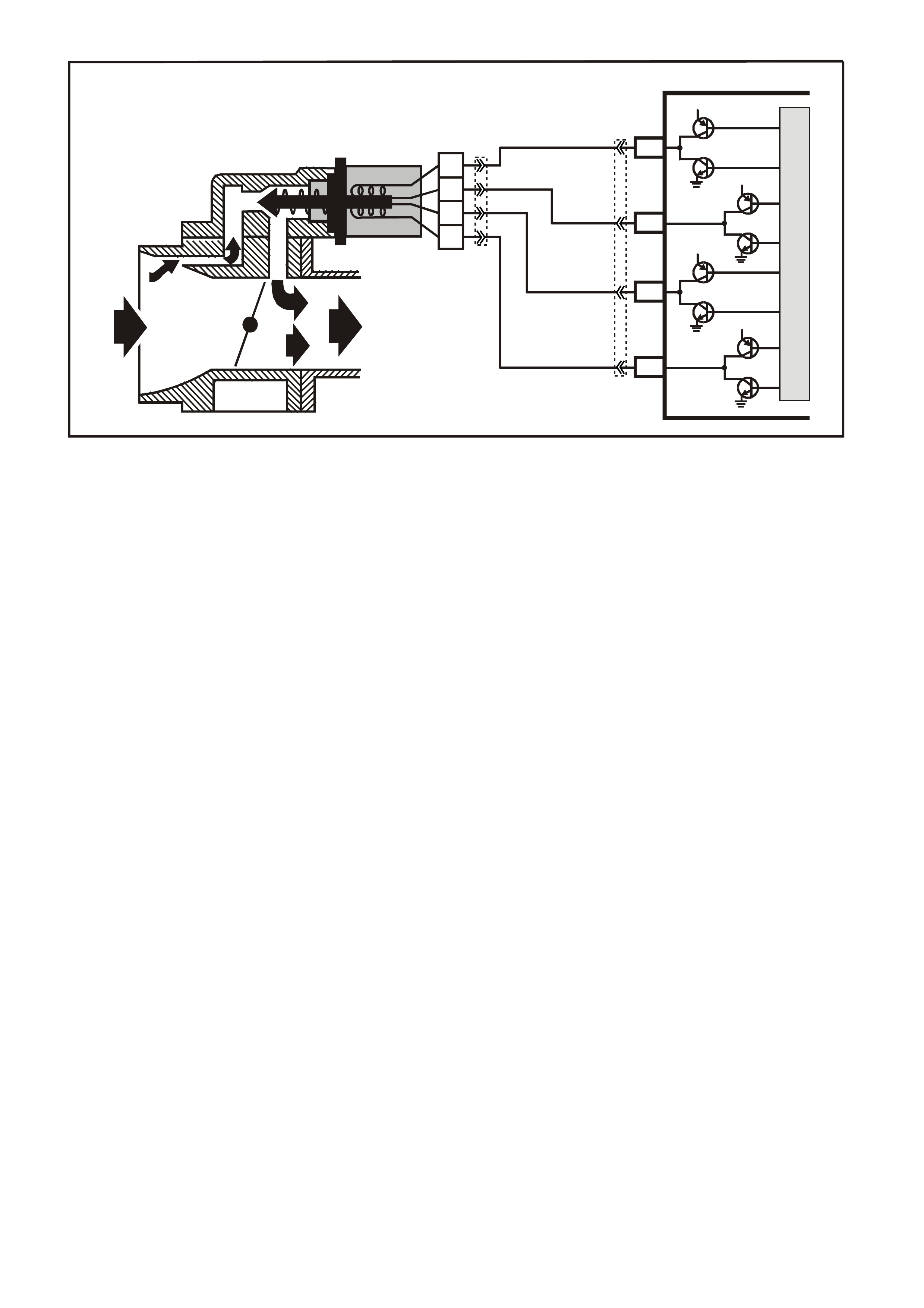
DTC 35 V6 PCM -
IDLE SPEED LOW
CIRCUIT DESCRIPTION:
The IAC valve is a stepper m otor. Stepper m otors have c oils that the PCM turns ON and OFF several tim es per
second. This allows for an incremental clockwise and counter clockwise rotation of a pintle valve. The pintle
valve has a threaded shaf t that either extends or retracts with each puls e of the PCM. The controlled pulses are
called steps or counts. The PCM controls the air entering into the engine at idle through the IAC valve. To
increase the idle speed, the PCM will command the pintle valve away from the throttle body. This allows more
air to bypass the throttle blade and thus increase engine RPM. To decrease the engine RPM at idle, the PCM
will comm and the pintle valve toward the throttle body seat to restrict air from entering into the engine and thus
reduce engine RPM.
CONDITIONS FOR RUNNING THE DTC
• Engine is Idling.
• No TP Sensor, IAT Sensor DTCs are set.
• DTC 36 is not set.
• The IAT is less than 73°C.
• No vehicle speed indicated.
• Conditions present for 5 seconds.
CONDITIONS FOR SETTING THE DTC
• Engine speed is 200 RPM below the desired idle speed for 5 seconds and the IAC has been opened to its
maximum position (255 steps).
ACTION TAKEN WHEN THE DTC SETS
• The PCM stores the DTC information into memory when the diagnostic runs and fails.
• The Malfunction Indicator Lamp (MIL) will not be illuminated.
• The PCM records the operating conditions at the tim e the diagnostic fails. T he PCM stores this information
in the History Data.
CONDITIONS FOR CLEARING THE MIL/DTC
• A Histor y DT C clears after f orty c onsecutive warm -up cycles, if this or any other em ission related diagnostic
does not report any failure.
• Use a Tech 2 scan tool in order to clear the MIL/DTC.
SUPERVX025
PCM
C10
C7
C8
C9
LG/W
(443)
A
B
C
D
IAC VALVE
IAC
COIL B LO
IAC
COIL A LO
IAC
COIL B HI
IAC
COIL A HI
12V
12V
12V
12V
M
I
C
R
O
LG/B
(444)
LBLU
(441)
LBLU/B
(442)
YE36
YB193

DIAGNOSTIC AIDS:
A slow, unstable, or fast idle may be caused by a non-IAC system problem that cannot be compensated by the
IAC valve. Out of c ontrol range IAC T ech 2 scan tool c ounts will be above 60 if idle is too low and zero c ounts if
idle is too high. The following checks should be made to repair a non-IAC system problem:
• Vacuum Leak (High Idle).
If idle is too high, stop the engine. Fully extend (low) IAC with Tech 2 scan tool. Start engine.
If idle speed is above 800 RPM, locate and correct vacuum leak including PCV system. Also, check for
binding of throttle blade or linkage.
• System too lean (High Air/Fuel Ratio).
The idle speed may be too high or too low. Engine speed may be too high or too low. Engine speed may
vary up and down and disc onnecting the IAC valve does not help. DT C 44 may be set. Tec h 2 sc an tool O 2
voltage will be less than 300 mV. Check for low regulated fuel pressure, water in the fuel or a restricted
injector.
• System too rich (Low Air/Fuel Ratio).
The idle speed will be too low. Tech 2 scan tool IAC counts will usually be above 80. System is obviously
rich and may exhibit black smoke in exhaust. Tech 2 scan tool O2 voltage will be fixed above 800 mV.
Check for high fuel pressure, leaking or sticking injector. Silicon contam inated O2 sensor Tech 2 scan tool
voltage will be slow to respond.
• Throttle Body.
Remove the IAC valve and inspect bore for foreign material.
• IAC valve Electrical Connections.
The IAC valve connections should be carefully checked for proper contact tension.
• PCV Valve.
An incorrect or faulty PCV valve may result in an incorrect idle speed.
• Refer to "Rough, Unstable, Incorrect Idle or Stalling" in Section 6C1-2B SYMPTOMS, of the VX Series
Service Information.
• If intermittent poor driveability or idle symptoms are resolved by disconnecting the IAC, carefully recheck
connections, valve terminal resistance, or replace IAC.
TEST DESCRIPTION: Number(s) below refer to step number(s) on the diagnostic Table.
2. The Tech 2 scan tool RPM control mode is used to extend and retract the IAC valve. The valve should
move smoothly within the specified range. If the idle speed is commanded (IAC extended) too low (below
600 RPM), the engine m ay stall. T his may be normal and would not indicate a problem . Retracting the IAC
beyond its controlled range (above 1675 RPM) will cause a delay before the RPM's start dropping, this too
is normal.
3. This test uses the Tech 2 scan to command the IAC controlled idle speed. The PCM issues commands to
obtain com m ended idle s peed. T he test lights each should flash indic ated a good circuit as the PCM is sues
commands. W hile the sequence is not important, if either light is OFF or does not flash, check the circuits
for faults, beginning with poor terminal contacts.
YB1 93
(413)
(412)
(1413)
(1412)
(430)
(453)
(815)
V/B
GY/B
V
GY
V
B/R
W/R
(897)
(897)
G/W
G/W
(418)
(418)
BR
BR
(1426)
O/W
C16
D16
WT/B
(832)AUTO
(647)
(630)
BR
T
(832) MAN
LBLU/B
B
(424)
(423)
C1
D1
(792)
(422)
(1222)
(1223)
(428)
(123)
BR/W
GY/R
LG
Y/B
G/Y
V/W
BLU/W
BLU
(831) Man
(443)
LG/W
(442) (831)AUTO
(441)
LBLU
LBLU/B
(444)
LG/B
P.C.M. CONNECTOR 1
IDLE AIR CO NTROL VALVE
(442)
(441) (444)
(443)
LBLU/B
LBLU LG/B
LG/W

DTC 35 V6 PCM - IDLE SPEED LOW
STEP ACTION VALUE YES NO
1 Was the "On-Board Diagnostic" (OBD) System Check
performed? Go to Step 2 Go to the OBD
System Check
2 1. Install a Tech 2 scan tool.
2. Start the engine and allow the engine to idle until the
specified temperature is reached.
3. Transmission in park or neutral.
4. Set the park brake.
5. Turn the A/C OFF.
6. Using the Tech 2 scan tool cycle the IAC valve from
600 RPM to 1675 RPM.
Does the engine speed change smoothly when
Commanded?
80°C Go to Step 3 Go to Step 5
3 1. Ignition OFF.
2. Disconnect the IAC valve electrical connector.
3. Measure the resistance across the IAC valve
terminals A and B.
4. Measure the resistance across the IAC valve
terminals C and D.
Are the resistance readings across terminals A and B,
and terminals C and D within the specified values?
40-80 ohms Go to Step 4 Go to Step 13
4 1. Measure the resistance across the IAC valve
terminals B and C.
2. Measure the resistance across the IAC valve
terminals A and D.
Are the resistance readings across terminals B and C,
and terminals A and D within the specified values?
Infinite IAC valve control
circuits are OK.
Refer to
Diagnostic Aids
above.
Go to Step 13
5 1. Disconnect the IAC valve electrical connector
2. Ignition ON engine OFF.
3. With a test light connected to earth,. Probe the IAC
valve electrical connectors.
Does the test light illuminate on two terminals?
Go to Step 6 Go to Step 7
6 With a test light connected to B+, probe the IAC valve
electrical connector terminals.
Does the test light illuminate on two terminals?
Go to Step 8 Go to Step 7
7 Check for an open or a short in the IAC valve HI and Lo
circuits.
Was a problem found?
Go to Step 12 Go to Step 14
8 1. Start the engine and allow to idle.
2. With a test light connected to earth, probe the IAC
valve electrical terminals?
Does the test light flash ON and OFF on all the
Terminals?
Go to Step 10 Go to Step 9
9 Did the test light remain ON steady for the terminals that
did not flash? Go to Step 7 Go to Step 11
10 Check the IAC passages for a restriction.
Was a fault found? Go to Step 15 Go to Step 13
11 Check the PCM electrical connector for proper tension at
the terminals.
Was a problem found?
Go to Step 12 Go to Step 14

DTC 35 V6 PCM - IDLE SPEED LOW (CONTINUED)
STEP ACTION VALUE YES NO
12 Repair the circuit or the connector as necessary.
Is the action complete? Verify Repair
13 Replace the IAC valve.
Is the action complete? Verify Repair
14 Replace PCM.
Refer to Section 6C1-3 Service Operations of the VX
Series Service Information, for PCM Security Link
procedure.
Is action complete?
Verify Repair
15 Clean the passages as necessary.
Is the action complete? Verify Repair
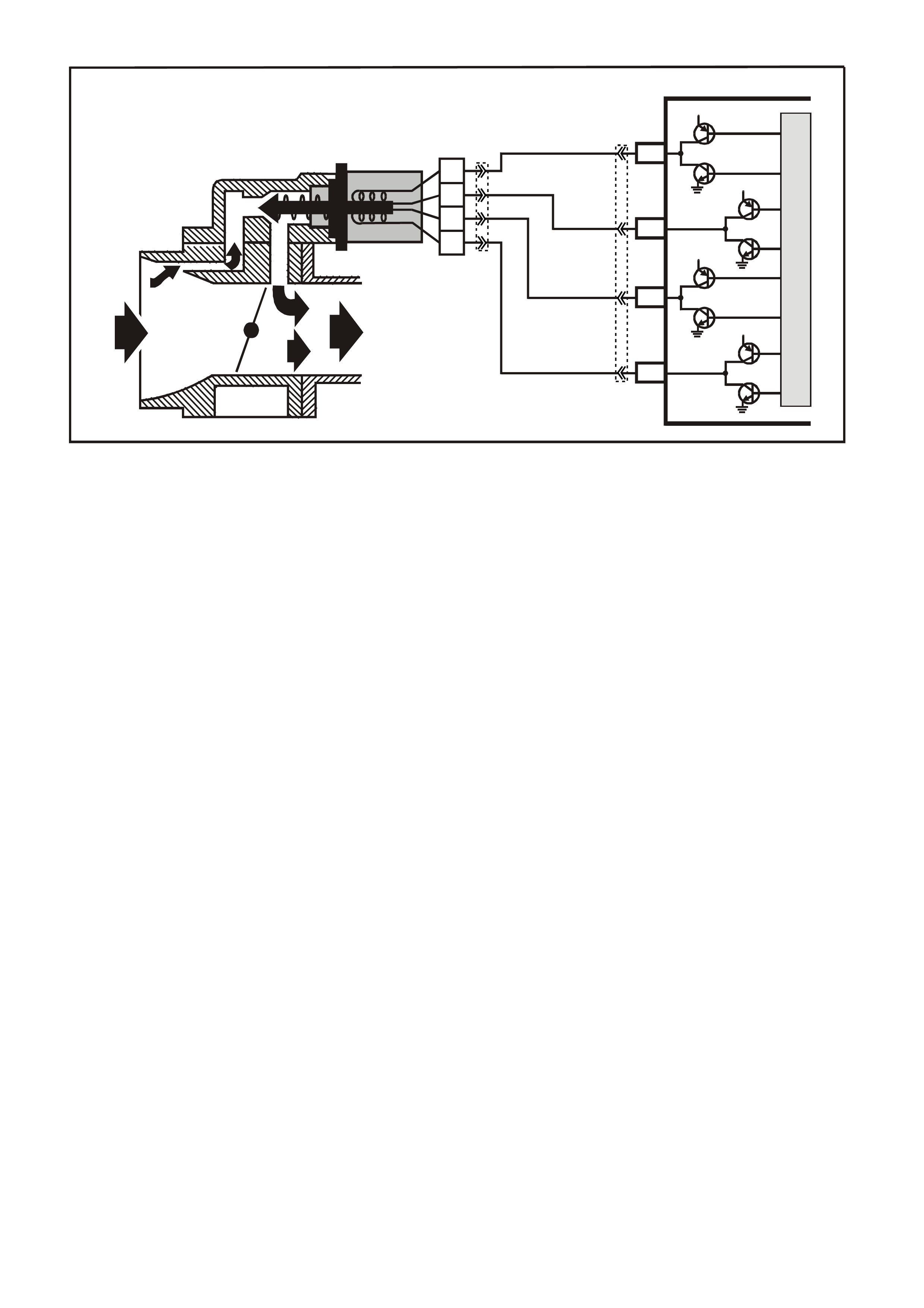
DTC 36 V6 PCM -
IDLE SPEED HIGH
CIRCUIT DESCRIPTION:
The PCM controls engine idle speed by adjusting the position of the Idle Air Control (IAC) m otor pintle. T he IAC
is a bi-directional motor driven by two coils. The PCM sends pulses (steps) to the IAC to extend or retract the
IAC pintle into a passage in the throttle body to decrease or increase air flow. The commanded IAC position
(displayed in counts) can be monitored on the scan tool; a lower number of counts indicates less commanded
airflow (pintle extended). This method allows highly accurate control of idle speed and quick response to
changes in engine load. If the PCM detects a condition where too high of an idle s peed is present, the PCM will
send 50 counts (steps) to the IAC motor. If the RPM increases more than 50 RPM it is accepted that the IAC
motor is moving and therefore the fault is a vacuum leak, and DTC 36 will set. If the RPM does not change
when the PCM commands the IAC to respond to a commanded count (steps), the PCM will set a DTC 35.
CONDITIONS FOR RUNNING THE DTC
• Engine is Idling.
• No TP Sensor, IAT Sensor DTCs are set.
• DTC 35 is not set.
• The IAT is less than 73°C.
• No vehicle speed indicated.
• Conditions present for 5 seconds.
CONDITIONS FOR SETTING THE DTC
• If the PCM detects a condition where a high idle speed is present and the IAC has been closed (0 steps);
the PCM will command the IAC motor to open 50 steps. If the RPM increase more than 50 RPM it is
accepted that the IAC motor is moving and therefore the fault is a vacuum leak.
ACTION TAKEN WHEN THE DTC SETS
• The PCM stores the DTC information into memory when the diagnostic runs and fails.
• The Malfunction Indicator Lamp (MIL) will not be illuminated.
• The PCM records the operating conditions at the tim e the diagnostic fails. T he PCM stores this information
in the History Data.
CONDITIONS FOR CLEARING THE MIL/DTC
• A Histor y DT C clears after f orty c onsecutive warm -up cycles, if this or any other em ission related diagnostic
does not report any failure.
• Use a Tech 2 scan tool in order to clear the MIL/DTC.
SUPERVX025
PCM
C10
C7
C8
C9
LG/W
(443)
A
B
C
D
IAC VALVE
IAC
COIL B LO
IAC
COIL A LO
IAC
COIL B HI
IAC
COIL A HI
12V
12V
12V
12V
M
I
C
R
O
LG/B
(444)
LBLU
(441)
LBLU/B
(442)
YE36
YB193
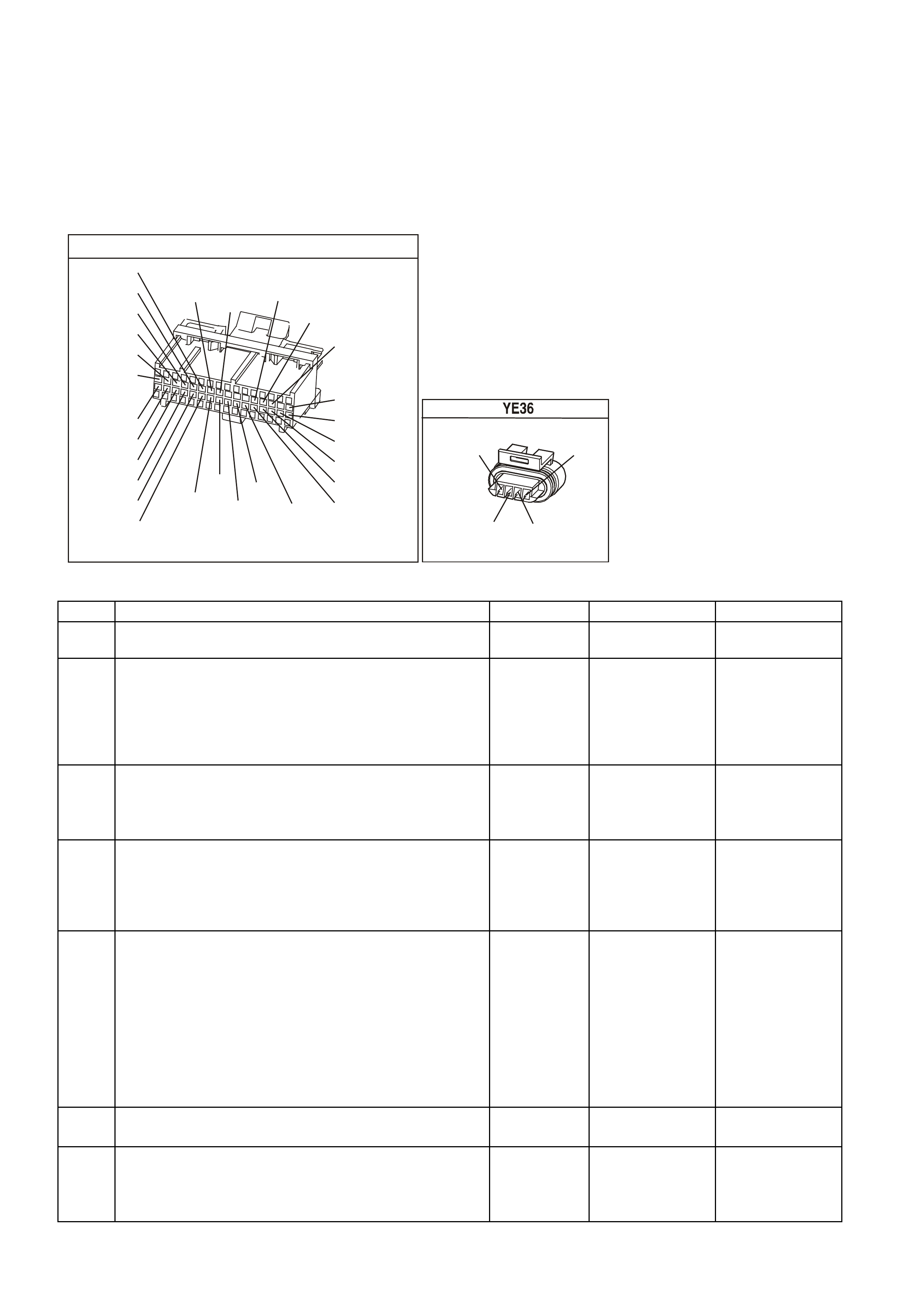
DIAGNOSTIC AIDS:
Check the IAC air passage for possible foreign material.
Code 36 may also be set by other system faults. Refer to 'Symptom Tables" for diagnostic by symptoms.
TEST DESCRIPTION: Number(s) below refer to step number(s) on the diagnostic Table.
2. The importance of this step cannot be stressed too strongly. It can lead to correcting a problem without
further checks and save valuable time.
4. By restricting vacuum supply hoses, you are isolating which vacuum circuit m ay have a vacuum leak. W hen
the leak is stopped, the engine should respond immediately.
YB1 93
(413)
(412)
(1413)
(1412)
(430)
(453)
(815)
V/B
GY/B
V
GY
V
B/R
W/R
(897)
(897)
G/W
G/W
(418)
(418)
BR
BR
(1426)
O/W
C16
D16
WT/B
(832)AUTO
(647)
(630)
BR
T
(832) MAN
LBLU/B
B
(424)
(423)
C1
D1
(792)
(422)
(1222)
(1223)
(428)
(123)
BR/W
GY/R
LG
Y/B
G/Y
V/W
BLU/W
BLU
(831) Man
(443)
LG/W
(442) (831)AUTO
(441)
LBLU
LBLU/B
(444)
LG/B
P.C.M. CONNECTOR 1
IDLE AIR CO NTROL VALVE
(442)
(441) (444)
(443)
LBLU/B
LBLU LG/B
LG/W
DTC 36 V6 PCM - IDLE SPEED HIGH
STEP ACTION VALUE YES NO
1. Was the "On-Board Diagnostic" (OBD) System Check
performed? Go to Step 2 Go to OBD
System Check
2. 1. Ignition Off.
2. Perform a visual/physical check of all the vacuum
hoses and air duct between the Mass Air Flow
Sensor and the throttle body for: Cracks, Splits,
Kinks, Connections and in their proper location.
Was a problem found?
Verify Repair Go to Step 3
3. 1. Ignition "ON", engine running.
2. Listen for a hissing sound as evidence of a vacuum
leak.
Was a problem found?
Verify Repair Go to Step 4
4. 1. Ignition "ON", engine running.
2. Using pliers, restrict each vacuum hose near the
intake manifold and listen for the engine RPM to
change when hoses are restricted.
Did RPM change when with vacuum hoses restricted?
Repair vacuum
leak in hose or
vacuum circuit.
Verify Repair
Go to Step 5
5. Inspect suspect areas of the intake system such as:
• The intake manifold gaskets;
• PCV system;
• Throttle body vacuum hose connections;
• Throttle body gasket;
• Oil dipstick seal and oil fill cap for sources of
unmetered air;
• IACV O-ring;
Was a problem found?
Verify Repair Go to Step 6
6. Clear DTC and drive vehicle.
Does DTC reset? Go to Step 7 Repair Complete
7. Replace PCM.
Refer to Section 6C1-3 Service Operations, VX Series
Service Information, for PCM Security Link procedure.
Is action complete?
Verify Repair
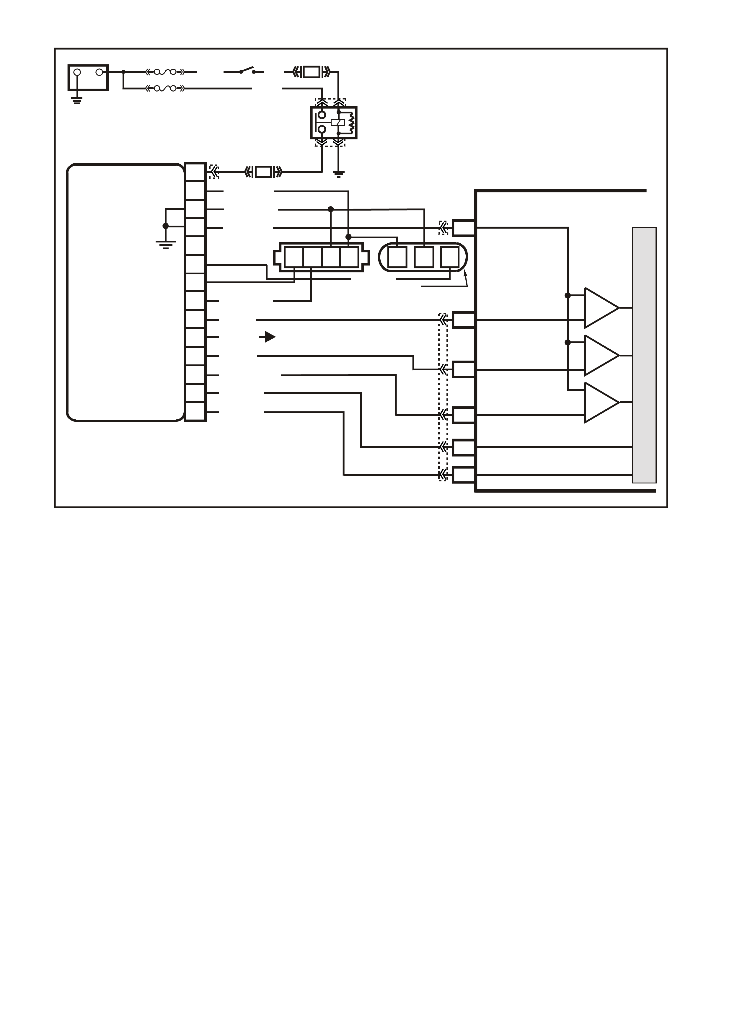
DTC 41 V6 PCM -
IGNITION ELECTRONIC SPARK TIMING (EST) OUTPUT CIRCUIT FAULT
CIRCUIT DESCRIPTION;
There are two modes of ignition system operation: BYPASS mode, and ELECTRONIC SPARK TIMING mode.
The Bypass m ode is norm ally used while s tarting the engine, while the Electronic Spark T iming m ode is used to
allow the PCM to control the ignition system after the engine is running. The PCM controls a "Bypass control
circuit", used to control the ignition module between the two different ignition system modes.
The PCM's Electronic Spark Timing (EST) output circuitry generates EST output pulses anytime crankshaft
reference input pulses are received. The PCM also monitors it's EST output terminal, to monitor if and when
EST pulses are present.
When the ignition system is operating in the Bypass mode (such as when the engine is cranking), the ignition
module earths the EST pulses com ing from the PCM. Because the EST pulses should be earthed through the
ignition module during Bypass mode operation., the PCM should not detect EST pulses on it's EST output
terminal.
If the EST output circuit wire between the PCM and the ignition module has an "open circuit" fault, then the
ignition module c an not ear th the PCM's EST output pulses . If the PCM detec ts two EST puls es during the f ir st 3
crankshaft reference input pulses, indicating the EST circuit is open, the PCM will set a DTC 41.
DTC 41 can also be set if the Bypass control circuit is shorted to voltage. If this where to happen, the PCM's
EST m onitor would not sense the EST signal being earthed in the ignition module while cranking , and DTC 41
would be set.
CONDITIONS FOR RUNNING THE DTC
• The ignition is on.
CONDITIONS FOR SETTING THE DTC
• PCM had detected at least 2 EST output pulses, during the first 3 crankshaft reference signal pulses
received from the ignition module, while cranking to start the engine.
VXSC009
PCM
D11
D3
D4
D12
D9
D10
CRANKSHAFT
REFERENCE LO
CAM
SENSOR
CONNECTOR
CAMSHAFT
POSITION
SENSOR
SIGNAL
CRANKSHAFT
REFERENCE HI
CRANKSHAFT
18X SIGNAL
BYPASS CONTROL
EST OUTPUT
module power supply - in
sensor power supply - out
cam signal - in
3x crank sensor - in
18x crank sensor - in
cam signal - out
tacho signal - out
crankshaft reference - out
18X cranksignal - out
bypass control
EST signal -in
P
N
M
L
K
J
H
G
F
E
D
C
B
A
DIS
MODULE
ABCD CBA
W/B (644)
GY/R (645)
B/R (453)
CRANK
SENSOR
CONN
L BLU/W
(646) BR (633)
BLU/Y (643)
BR (121)
B (63 0)
V (43 0)
L BLU/B (647)
T/B (4 24)
IGN SW
EFI RELAY
O/Y
(479)
LG
(482)
B/W
(152)P/B
(39)
IC
IC
IC
M
I
C
R
O
W (423)
F35
+
-
BATTERY
FS
LOC. E1
FJ
(1040)
LOC. E3
P (3)
R(2H)
F14
TO INSTRUMENT CLUSTER
(TERMINAL 18)
ABS/ETC (TERMINAL 30)
YB39
YB39
YE111
YE34
YB193
YB193
YE63
YE57
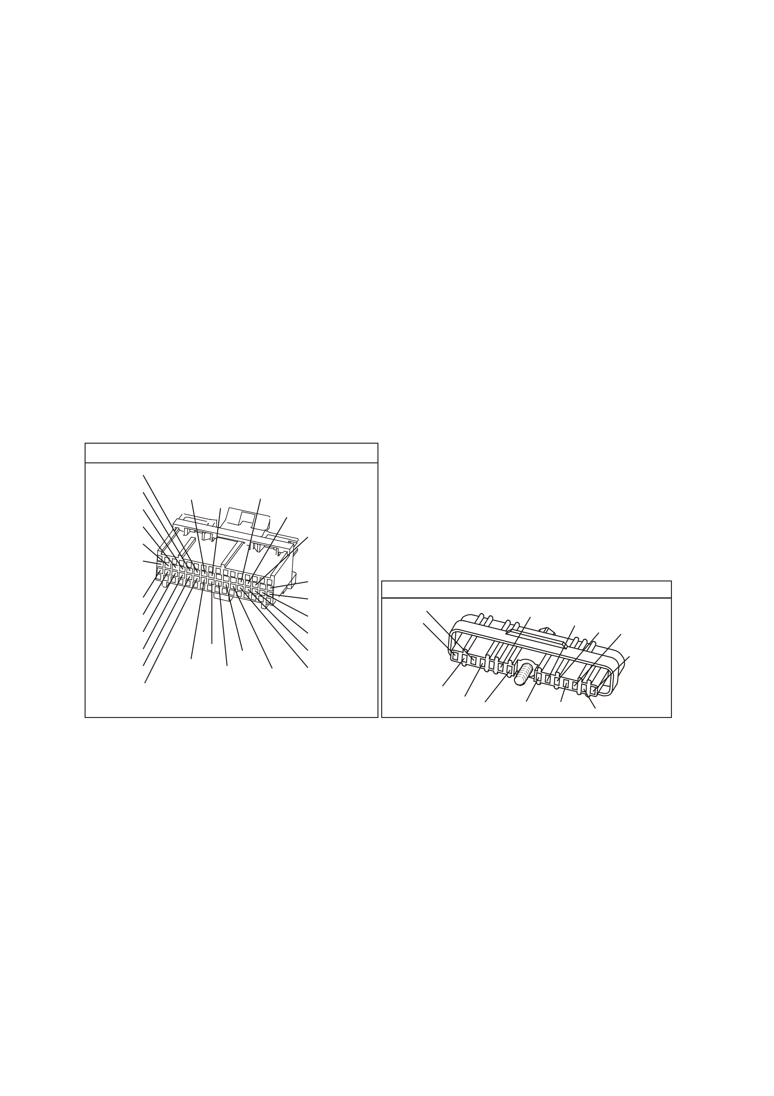
ACTION TAKEN WHEN THE DTC SETS
• The PCM illuminates the Malfunction Indicator Lamp (MIL) when the diagnostic runs and fails.
• The PCM records the operating conditions at the tim e the diagnostic fails. T he PCM stores this information
in the History Data.
• When DTC 41 is set and current, the PCM will operate in the Bypass spark mode.
CONDITIONS FOR CLEARING THE MIL/DTC
• The PCM turns the MIL OFF after the first ignition cycle that the diagnostic runs and does not fail.
• A Histor y DT C clears after f orty c onsecutive warm -up cycles, if this or any other em ission related diagnostic
does not report any failure.
• Use a Tech 2 scan tool in order to clear the MIL/DTC.
DIAGNOSTIC AIDS
• Poor connection at PCM. Inspect harness connectors for backed out terminals, improper mating, broken
locks, improperly formed or damaged terminals, and poor terminal to wire connection.
• Damaged Har ness. Ins pect the wiring harness f or dam age. If the harness appears to be O K, disconnect the
ignition module, turn the ignition "ON". Connect and observe a voltmeter connected between the Bypass
control circuit and +B, while m oving c onnectors and wiring harness related to the ignition m odule. A change
in voltage will indicate the location of the fault.
TEST DESCRIPTION
The numbers below refer to the step numbers on the diagnostic table.
4. This Step checks to see if circuit 424 is shorted to voltage.
8. This Step checks to see if circuit 423 is open.
YB1 93
(413)
(412)
(1413)
(1412)
(430)
(453)
(815)
V/B
GY/B
V
GY
V
B/R
W/R
(897)
(897)
G/W
G/W
(418)
(418)
BR
BR
(1426)
O/W
C16
D16
WT/B
(832)AUTO
(647)
(630)
BR
T
(832) MAN
LBLU/B
B
(424)
(423)
C1
D1
(792)
(422)
(1222)
(1223)
(428)
(123)
BR/W
GY/R
LG
Y/B
G/Y
V/W
BLU/W
BLU
(831) Man
(443)
LG/W
(442) (831)AUTO
(441)
LBLU
LBLU/B
(444)
LG/B
P.C.M. CONNECTOR 1
DIRECT IGNITION MODUL E
YE 57
(647)
LBLU/B
W/B
(644)
B/R
(453)
LBLU/W
(646)
BLU/Y
(643)
V
(430)
T/B
(424)
(633)
BR
(645)
GY/R
LG
(482)
B
(630)
BR
(121)
W
(423)
PNMLKJHGFED
CBA

DTC 41 V6 PCM - IGNITION ELECTRONIC SPARK TIMING (EST) OUTPUT CIRCUIT FAULT
STEP VALUE YES NO
1. Was the "On-Board Diagnostic" (OBD) System Check
performed? Go to Step 2 Go to OBD
System Check in
this Section
2. 1. Clear DTC 41.
2. Start engine and run above 1600 RPM.
3. Observe DTC(s).
Did DTC 41 set?
Go to Step 3 DTC 41 is
intermittent. If no
additional DTC's
were stored, refer
to "Diagnostic
Aids" above.
3. 1. Ignition "OFF".
2. Disconnect ignition module 14 pin connector.
3. Probe ignition module harness connector terminal
"B" with a voltmeter connected to earth.
4. Ignition "ON".
Is voltage greater then the specified value?
0.5 V Go to Step 4 Go to Step 7
4. 1. Ignition "OFF".
2. Disconnect PCM connectors.
3. Ignition "ON".
Is voltage still present at ignition module harness
Connector terminal "B"?
Go to Step 5 Go to Step 10
5. Repair short to voltage in Bypass circuit 424.
Is action complete? Verify Repair
6. Replace ignition module.
Is action complete? Verify Repair
7. 1. Ignition "OFF".
2. Reconnect 14 pin connector to ignition module.
3. Backprobe PCM connector D10 with voltmeter
connected to earth.
4. Ignition "ON", crank engine.
Is voltage approximately at specified value while
cranking or with engine running?
2 volts Go to Step 8 Go to Step 9
8. Check for faulty connection, or an open in the EST circuit
423 between the PCM terminal and the ignition module
harness connector terminal "A"
Was a fault found?
Verify Repair Go to Step 6
9. Check PCM for faulty connection.
Was a faulty connection found ? Verify Repair Go to Step 10
10. Replace PCM.
Refer to Section 6C1-3 Service Operations of the VX
Series Service Information, for PCM Security Link
procedure.
Is action complete?
Verify Repair
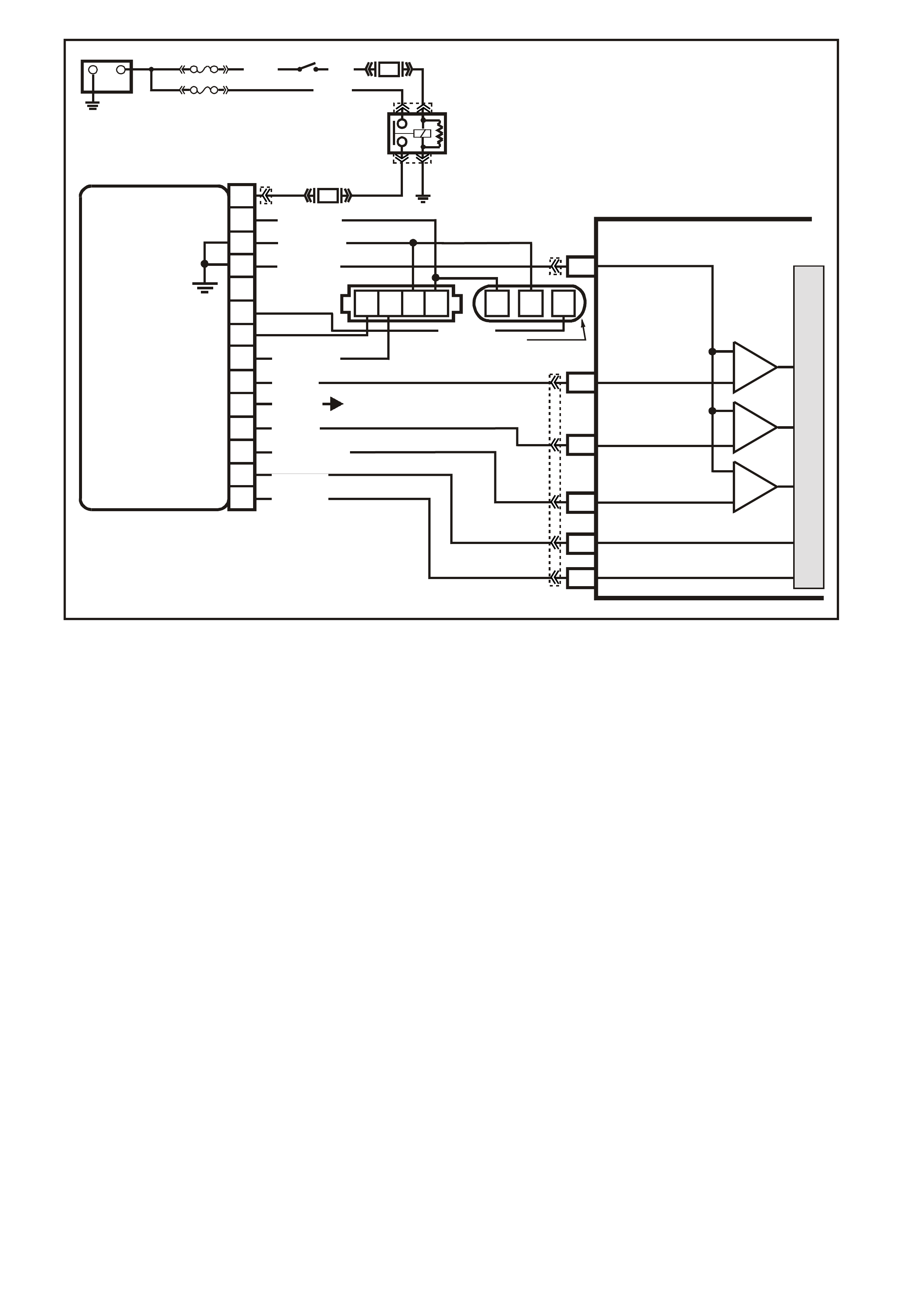
DTC 42 V6 PCM -
IGNITION BYPASS CIRCUIT FAULT
CIRCUIT DESCRIPTION;
There are two modes of ignition system operation: BYPASS mode, and ELECTRONIC SPARK TIMING mode.
The Bypass m ode is norm ally used while s tarting the engine, while the Electronic Spark T iming m ode is used to
allow the PCM to control the ignition system after the engine is running. The PCM controls a "Bypass control
circuit", used to control the ignition module between the two different ignition system modes.
The PCM's Electronic Spark Timing (EST) output circuitry generates EST output pulses anytime crankshaft
reference input pulses are received. The PCM also monitors it's EST output terminal, to monitor if and when
EST pulses are present.
When the ignition system is operating in the Bypass mode (such as when the engine is cranking), the ignition
module earths the EST pulses com ing from the PCM. Because the EST pulses should be earthed through the
ignition module during Bypass mode operation., the PCM should not detect EST pulses on it's EST output
terminal.
W hen the engine is star ted, the PCM applies 5 volts to the Bypass control circ uit. W hen r eceived by the ignition
module, this 5 volts control causes the ignition module to release the earth from the EST pulses coming from
the PCM. The ignition module will then us e the EST pulses to operate the ignition s ystem . When this occ ur s, the
PCM will correctly detect EST pulses at it's EST output terminal.
If the Bypass control cir cuit has as open fault or s hort to earth, or if the EST circuit has a short to earth or short
to voltage, the PCM cannot control the ignition m odule to release the EST pulses from being earthed. Because
the PCM also monitors it's EST output terminal for EST
pulses, if it detects no EST pulses after it has "turned on" the 5 volts to the Bypass control circuit, and the
engine speed goes above 1600 RPM, a DTC 42 will be set.
CONDITIONS FOR RUNNING THE DTC
• The engine is running.
CONDITIONS FOR SETTING THE DTC
• The PCM has commanded EST.
• The PCM has detected no EST output pulses for 1000 m s with the engine RPM below 200, or no EST
pulses received for 200 ms with engine RPM greater than 200.
VXSC009
PCM
D11
D3
D4
D12
D9
D10
CRANKSHAFT
REFERENCE LO
CAM
SENSOR
CONNECTOR
CAMSHAFT
POSITION
SENSOR
SIGNAL
CRANKSHAFT
REFERENCE HI
CRANKSHAFT
18X SIGNAL
BYPASS CONTROL
EST OUTPUT
module power supply - in
sensor power supply - out
cam signa l - in
3x crank sensor - in
18x crank sensor - in
cam signal - out
tacho signal - out
crankshaft reference - out
18X cranksignal - out
bypass control
EST signal -in
P
N
M
L
K
J
H
G
F
E
D
C
B
A
DIS
MODULE
ABCD CBA
W/B (644)
GY/R (645)
B/R (453)
CRANK
SENSOR
CONN
L BLU/W
(646) BR (633)
BLU/Y (643)
BR (121)
B (63 0)
V (43 0)
L BLU/B (647)
T/B (4 24)
IGN SW
EFI RELAY
O/Y
(479)
LG
(482)
B/W
(152)P/B
(39)
IC
IC
IC
M
I
C
R
O
W (423)
F35
+
-
BATTERY
FS
LOC. E1
FJ
(1040)
LOC. E3
P (3)
R(2H)
F14
TO INSTRUMENT CLUSTER
(TERMINAL 18)
ABS/ETC (TERMINAL 30)
YB39
YB39
YE111
YE34
YB193
YB193
YE63
YE57
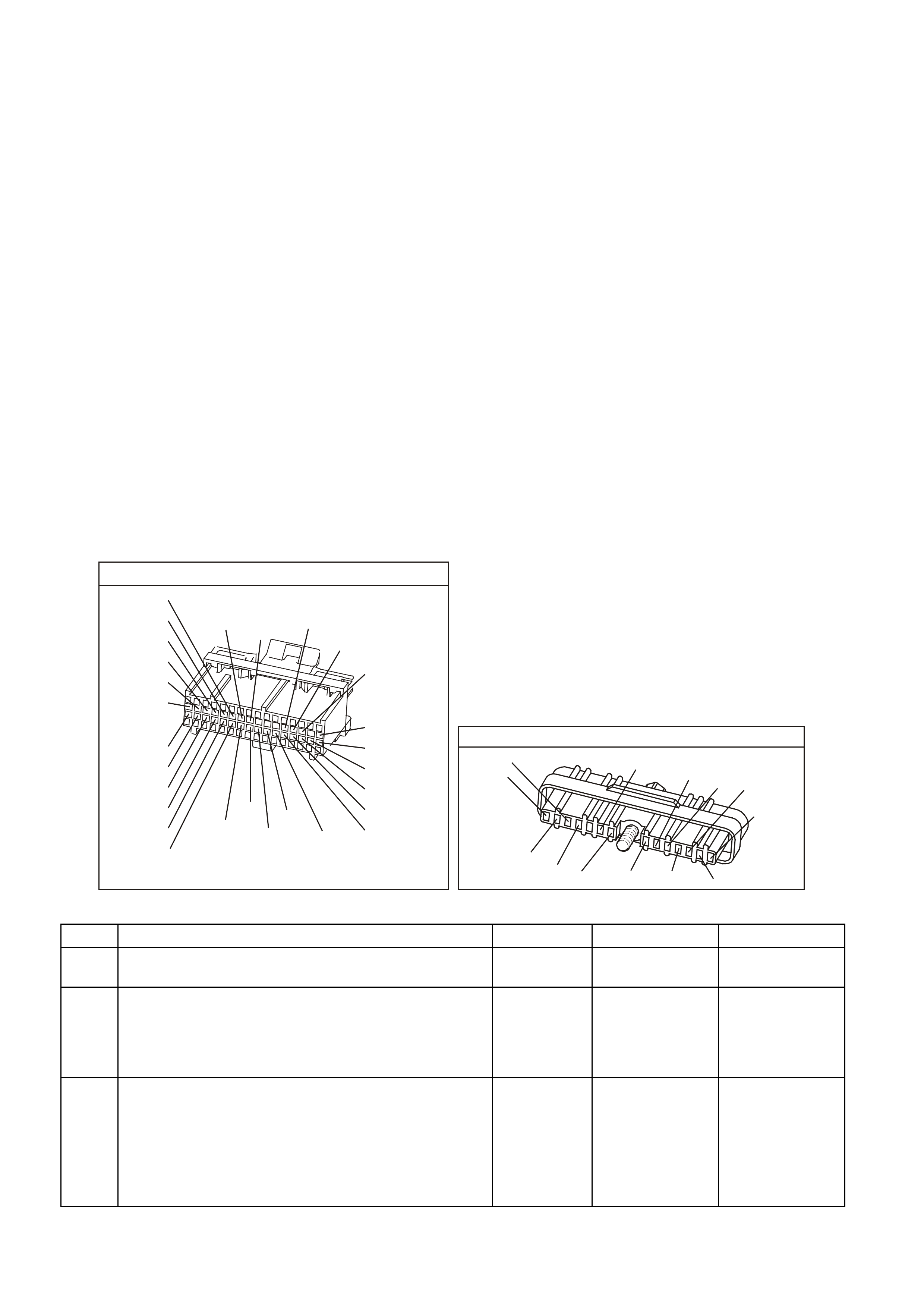
ACTION TAKEN WHEN THE DTC SETS
• The PCM illuminates the Malfunction Indicator Lamp (MIL) when the diagnostic runs and fails.
• The PCM records the operating conditions at the tim e the diagnostic fails. T he PCM stores this information
in the History Data.
• When DTC 42 is set and current, the PCM will operate in the Bypass spark mode.
CONDITIONS FOR CLEARING THE MIL/DTC
• The PCM turns the MIL OFF after the first ignition cycle that the diagnostic runs and does not fail.
• A Histor y DT C clears after f orty c onsecutive warm -up cycles, if this or any other em ission related diagnostic
does not report any failure.
• Use a Tech 2 scan tool in order to clear the MIL/DTC.
DIAGNOSTIC AIDS
• Poor connection at PCM. Inspect harness connectors for backed out terminals, improper mating, broken
locks, improperly formed or damaged terminals, and poor terminal to wire connection.
• Damaged Har ness. Ins pect the wiring harness for dam age. If the harness appears to be O K, disconnec t the
ignition module, turn the ignition "ON". Connect and observe a voltmeter connected between the Bypass
control circuit and B+, while m oving c onnectors and wiring harness related to the ignition m odule. A change
in voltage will indicate the location of the fault.
TEST DESCRIPTION
The numbers below refer to the step numbers on the diagnostic table.
4. This step checks to see if circuit 423 is shorted to voltage.
7. This step checks to see if circuit 423 is shorted to earth.
10. This step checks to see if circuit 424 is shorted to earth.
12. This step checks to see if circuit 424 is open.
13. This step checks to see if the ignition module is capable of switching from Bypass to EST mode.
YB1 93
(413)
(412)
(1413)
(1412)
(430)
(453)
(815)
V/B
GY/B
V
GY
V
B/R
W/R
(897)
(897)
G/W
G/W
(418)
(418)
BR
BR
(1426)
O/W
C16
D16
WT/B
(832)AUTO
(647)
(630)
BR
T
(832) MAN
LBLU/B
B
(424)
(423)
C1
D1
(792)
(422)
(1222)
(1223)
(428)
(123)
BR/W
GY/R
LG
Y/B
G/Y
V/W
BLU/W
BLU
(831) Man
(443)
LG/W
(442) (831)AUTO
(441)
LBLU
LBLU/B
(444)
LG/B
P.C.M. CONNECTOR 1
DIRECT IGNITION MODUL E
YE 57
(647)
LBLU/B
W/B
(644)
B/R
(453)
LBLU/W
(646)
BLU/Y
(643)
V
(430)
T/B
(424)
(633)
BR
(645)
GY/R
LG
(482)
B
(630)
BR
(121)
W
(423)
PNMLKJHGFED
CBA
DTC 42 V6 PCM - IGNITION BYPASS CIRCUIT FAULT
STEP ACTION VALUE YES NO
1. Was the "On-Board Diagnostic" (OBD) System Check
performed? Go to Step 2. Go to OBD
System Check.
2. 1. Clear DTC 42.
2. Start engine, and run above 1600 RPM.
3. Observe DTC(s).
Did DTC 42 set ?
Go to Step 3 DTC 42
is intermittent.
Refer to
"Diagnostic Aids"
above.
3. 1. Ignition "OFF".
2. Disconnect ignition module 14 pin connector.
3. Probe ignition module harness connector terminal
"A" with a voltmeter to earth.
4. Ignition "ON".
Is voltage greater then the specified value?
0.5 V Go to Step 4 Go to Step 6

DTC 42 V6 PCM - IGNITION BYPASS CIRCUIT FAULT (CONTINUED)
STEP ACTION VALUE YES NO
4. 1. Ignition "OFF".
2. Disconnect PCM connectors.
3. Ignition "ON".
Is voltage still present at ignition module harness
Connector terminal "A" ?
Go to Step 5 Go to Step 15
5. Repair short to voltage on circuit 423.
Is action complete ? Verify Repair
6. 1. Ignition "ON".
2. Probe ignition module harness connector circuit
423 with a test light connected to battery voltage.
Is test light "ON" ?
Go to Step 7 Go to Step 9
7. 1. Ignition "OFF
2. Disconnect PCM connectors.
3. Probe ignition module connector circuit 423 with a
test light connected to battery voltage.
Is test light "ON" ?
Go to Step 8 Go to Step 14
8. Repair short to earth in circuit 423.
Is action complete Verify Repair
9. 1. Ignition "ON".
2. Disconnect ignition module 14 pin connector.
3. With test light connected to battery voltage, probe
ignition module harness connector circuit 424.
Is test light "ON" ?
Go to Step 10 Go to Step 12
10. 1. Ignition "OFF".
2. Disconnect PCM connectors.
3. Ignition "ON".
4. Disconnect ignition module 14 pin connector.
5. With test light connected to battery voltage, probe
ignition module harness connector circuit 424.
Is test light "ON" ?
Go to Step 11 Go to Step 14
11. Repair short to earth on circuit 424.
Is action complete ? Verify Repair
12.
1. Ignition "OFF".
2. Disconnect PCM connectors.
3. Check for faulty connection or open circuit 424.
Is fault found ?
Verify Repair Go to Step 13
13. 1. Ignition "OFF".
2. Reconnect ignition module 14 pin connector.
3. Disconnect PCM connectors.
3. Ignition "ON".
4. Probe PCM harness connector circuit 423 with an
ohmmeter connected to earth.
5. Probe PCM harness connector circuit 424 with a
test light connected to battery voltage.
As the test light contacts circuit 424, does resistance
switch from under the specified value to over the
specified value ?
300 ohms
to
6000 ohms
Go to Step 14 Go to Step 15
14. Replace PCM.
Refer to Section 6C1-3 SERVICE OPERATIONS of the
VX Series Service Information, for PCM Security Link
procedure.
Is action complete?
Verify Repair
15. Replace ignition module.
Is action complete ? Verify Repair

DTC 43 V6 PCM -
KNOCK SENSOR CIRCUIT FAULT
CIRCUIT DESCRIPTION:
The knock sensor is used to detect engine detonation, and the PCM will retard the Electronic Spark Timing
(EST) based on the signal being received. The Knock sensor produces an AC signal which the PCM receives,
so that under a no k nock condition circuit 815 would m easure about 29 m illivolts AC when the engine is running
at idle. The amplitude and signal frequency is dependent upon the Knock level.
CONDITIONS FOR RUNNING THE DTC
• No DTC 14,15,16,17,19 ,21, 22, or 93 are set.
• Engine has been running longer than 10 seconds.
• Engine Coolant Temperature is greater than 65
degrees C.
• TP sensor signal is greater than 22%.
• Engine RPM is between 2000 and 6375 RPM.
CONDITIONS FOR SETTING THE DTC
• There is no knock sensor signal or too high a knock sensor signal detected by the PCM for 3 seconds
ACTION TAKEN WHEN THE DTC SETS
• The PCM stores the DTC information into memory when the diagnostic runs and fails.
• The Malfunction Indicator Lamp (MIL) will not be illuminated.
• Once DTC 43 is set and current, the PCM uses a default spark advance table.
CONDITIONS FOR CLEARING THE MIL/DTC
• A Histor y DT C clears after f orty c onsecutive warm -up cycles, if this or any other em ission related diagnostic
does not report any failure.
• Use a Tech 2 scan tool in order to clear the MIL/DTC.
DIAGNOSTIC AIDS:
If circuit 815 is not open or shorted to earth, the most likely cause is an open circuit in the PCM. It is possible
that a faulty PCM could be the cause of the DTC 43, and it should be replaced.
Refer to "Intermittents" in Section 6C1-2B SYMPTOMS of the VX Series Service Information.
TEST DESCRIPTION: Number(s) below refer to step number(s) on the diagnostic Table.
2. This Step determines if conditions for DTC 43 still exist.
6. This Step determines if the knock sensor resistance is between 50,000 ohms and 100,000 ohms.
NOTE: If the resistance is at 50,00 ohms, this means that both knock sensor shunt resistors are OK. If the
resistance is at 100,000 ohm s, this means that one of the knock sensor is open, but the knock sensor system
will still work properly with only one knock sensor functioning.
Check each "knock" sensor for an open circuit 815 between splice and sensor. If wiring is OK, replace "knock"
sensor.
VXSC007
PCM
M
I
C
R
O
SNEF
KNOCK SENSOR
SIGNAL INPUT
C12
RH KNOCK
SENSOR
LH KNOCK
SENSOR
PIEZO CRYSTAL
SHUNT
RESISTOR
PIEZO CRYSTAL
SHUNT
RESISTOR
W/R (815)
YE3 YE3
YB193

YB1 93
(413)
(412)
(1413)
(1412)
(430)
(453)
(815)
V/B
GY/B
V
GY
V
B/R
W/R
(897)
(897)
G/W
G/W
(418)
(418)
BR
BR
(1426)
O/W
C16
D16
WT/B
(832)AUTO
(647)
(630)
BR
T
(832) MAN
LBLU/B
B
(424)
(423)
C1
D1
(792)
(422)
(1222)
(1223)
(428)
(123)
BR/W
GY/R
LG
Y/B
G/Y
V/W
BLU/W
BLU
(831) Man
(443)
LG/W
(442) (831)AUTO
(441)
LBLU
LBLU/B
(444)
LG/B
P.C.M. CONNECTOR 1
YE3
KNOCK S ENSORS
W/R
(815)
DTC 43 V6 PCM - KNOCK SENSOR CIRCUIT FAULT
STEP ACTION VALUE YES NO
1. Was the "On-Board Diagnostic" (OBD) System Check
performed? Go to Step 2 Go to OBD
System Check
2. 1. Install Tech 2 scan tool.
2. Record then clear DTC(s).
3. Ignition "ON", engine idling.
4. Using Tech 2 scan tool, select "Knock Signal"
and "Knock Retard".
Is "Knock Retard" above the specified value?
0° Go to Step 3 Go to Step 4
3. Repair short to voltage on circuit 815.
Is action complete? Verify Repair
4. 1. Ignition "ON", engine Idling.
2. Lightly tap on alternator bracket with hammer.
Is Tech 2 scan tool indicating "Knock Retard" above the
specified value?
0° DTC 43
is intermittent. If
no additional
DTC's were
stored, refer to
"Diagnostic Aids"
above.
Go to Step 5
5. 1. Ignition "ON", engine stopped.
2. Backprobe PCM connector terminal for circuit 815,
with DVM connected to earth.
3. Set DVM to read DC voltage.
Is voltage reading on DVM above the specified value?
0 volts Go to Step 3 Go to Step 6
6. 1. Ignition "OFF".
2. Disconnect PCM connectors.
3. Backprobe PCM connector terminal for circuit 815,
with DVM connected to earth.
4. Set DVM to read resistance.
Is resistance on DVM at either of the specified value?
50 K ohms
(50,000
ohms)
or
100 K ohms
(100,000
ohms)
Go to Step 7 Go to Step 10
7. 1. Ignition "OFF".
2. Reconnect PCM connectors.
3. Backprobe PCM connector terminal for circuit 815,
with DVM connected to earth.
4. Set DVM to read AC voltage.
5. Tap on alternator bracket with hammer.
Is DVM indicating above specified value?
50 mV AC Go to Step 8 Go to Step 11

DTC 43 V6 PCM - KNOCK SENSOR CIRCUIT FAULT (CONTINUED)
STEP ACTION VALUE YES NO
8. Check for poor connection at PCM.
Was a poor connection found? Verify Repair Go to Step 9
9. Replace PCM.
Refer to Section 6C1-3 Service Operations of the VX
Series Service Information, for PCM Security Link
procedure.
Is action complete?
Verify Repair
10. Check for open or short to earth in circuit 815.
Was a fault found? Verify Repair Go to Step 11
11. Replace knock sensor(s)
Is action complete? Verify Repair
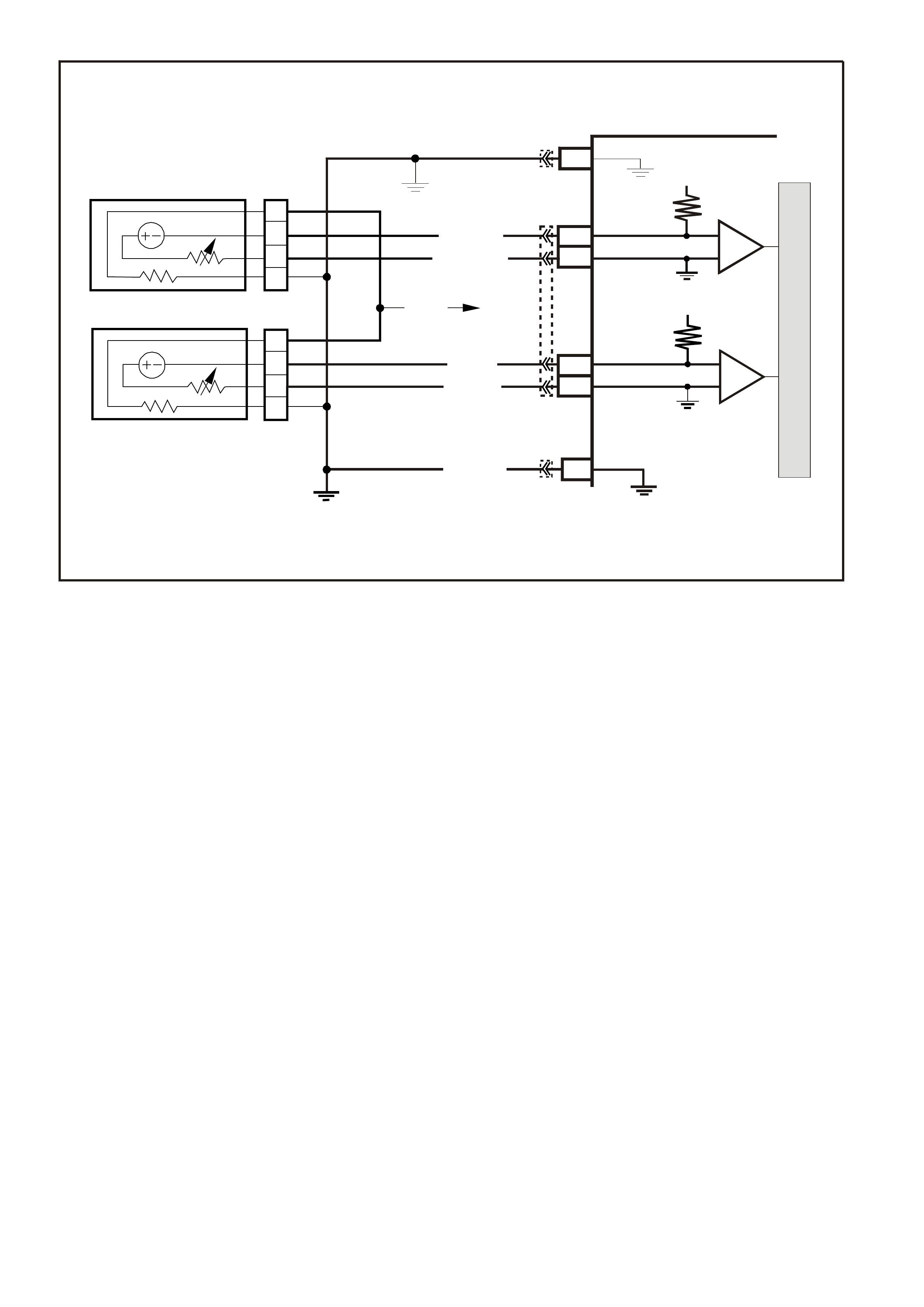
DTC 44 V6 PCM -
RIGHT HAND HEATED OXYGEN SENSOR (HO2S) LOW VOLTAGE
CIRCUIT DESCRIPTION:
The PCM s upplies a voltage of about 450 m illivolts between term inal "D14" and "D13". T he O xygen (O2) sensor
varies the voltage within a range of about 1 volt if the exhaust is rich, down through about 100 millivolts, if
exhaust is lean.
The sensor is like an open circuit and produces no voltage when it is below about 360 degrees C. An open
sensor circuit or cold sensor causes "Open Loop" operation.
CONDITIONS FOR RUNNING THE DTC
• No IAT Sensor DTC’s are set.
• IAT Sensor is below 75°C.
• The system is in "Closed Loop”.
• Throttle angle is between 9% and 30%.
CONDITIONS FOR SETTING THE DTC
• The RH 02S signal voltage remains below 200 millivolts for 46 seconds.
ACTION TAKEN WHEN THE DTC SETS
• The PCM illuminates the Malfunction Indicator Lamp (MIL) when the diagnostic runs and fails.
• The PCM records the operating conditions at the tim e the diagnostic fails. T he PCM stores this information
in the History Data.
• Once a 02S DTC is set, and current, the PCM will operate the fuel system in the “Open Loop” mode.
CONDITIONS FOR CLEARING THE MIL/DTC
• The PCM turns the MIL OFF after the first ignition cycle that the diagnostic runs and does not fail.
• A Histor y DT C clears after f orty c onsecutive warm -up cycles, if this or any other em ission related diagnostic
does not report any failure.
• Use a Tech 2 scan tool in order to clear the MIL/DTC.
M
I
C
R
O
P (439)
YE95
D
D
B
B
A
A
C
C
YE95
GY (1 412)
B/R (750)
Engine
Earth
To Fuse
F33
GY/B (1413)
V (412)
V/B (413)
B/R (750)
4269
A2
D16
D15
D14
D13
A1 450 m V
Right
Oxygen
Sensor
Signal HI
Right
Oxygen
Sensor
Signal LO
Left
Oxygen
Sensor
Signal HI
Left
Oxygen
Sensor
Signal LO
Earth
Earth
Ri ght Oxygen Sens or
Left Oxygen Sensor 450 m V
IC
IC
Engine
Earth
PCM
YB193
YB188
YB188
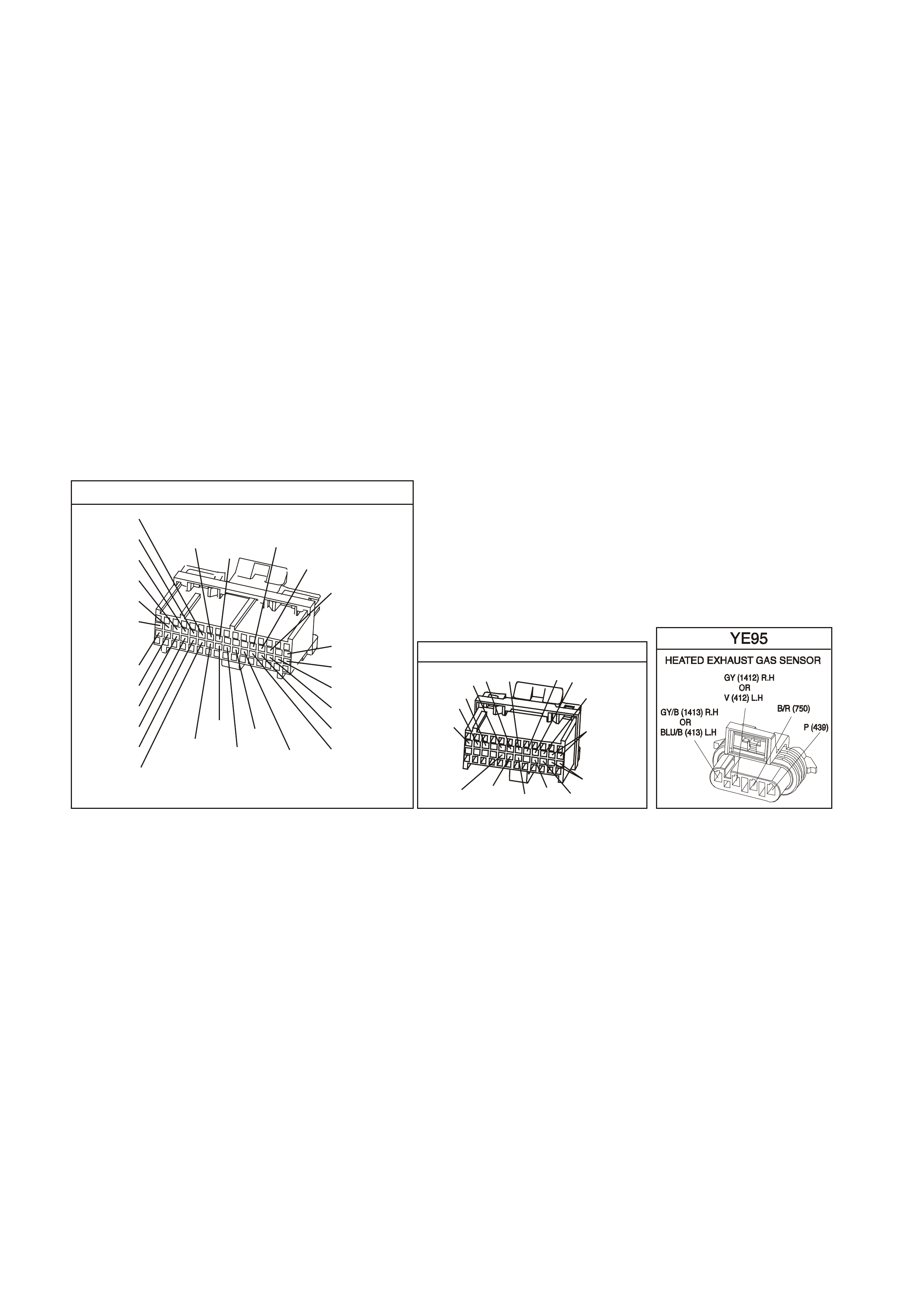
DIAGNOSTIC AIDS:
Using the T ech 2 scan tool, obser ve the Long Term Fuel Trim values at diff erent RPMs and air flow conditions.
The Tech 2 scan tool also displays the Long Term Fuel Trim cells, so the Long Term Fuel Trim values can be
check ed in each of the cells to deter mine when the DTC 44 or DT C 64 may have been s et. If the conditions for
DTC 44 or DTC 64 exists, the Long Term Fuel Trim values will be around +25%.
TEST DESCRIPTION: Number(s) below refer to step number(s) on the diagnostic Table.
4. The DTC 44 or lean exhaust is most likely caused by one of the following:
• O2 Sensor Wire - Sensor pigtail may be mispositioned and contacting the exhaust manifold.
• Check for intermittent earth in wire between connector and sensor.
• MAF Sensor - A shifted MAF sensor could cause the fuel system to go lean. Refer to TABLE A-6.1 of the
VX Series Service Information.
• Lean Injector(s) - Perform power balance test using the Tech 2 scan tool.
• Fuel Contamination - Water, even in small amounts, near the in-tank Fuel Pump inlet can be delivered to
the injectors. The water causes a lean exhaust and can set a DTC 44 and/or DTC 64.
• Fuel Pressure - System will go lean if pressure is too low. It may be necessary to monitor fuel pressure
while driving the vehicle at various road speeds and/or loads to confirm. Refer to TABLE A-4.1 of the VX
Series Service Information.
• Exhaust Leaks - If there is an exhaust leak, the engine can cause outside air to be pulled into the exhaust
and past the sensor. Vacuum or crankcase leaks can cause a lean condition.
YB 1 93
(413)
(412)
(1413)
(1412)
(430)
(453)
(815)
V/B
GY/B
V
GY
V
B/R
W/R
(897)
(897)
G/W
G/W
(418)
(418)
BR
BR
(1426)
O/W
C16
D16
WT/B
(832)AUTO
(647)
(630)
BR
T
(832) MAN
LBLU/B
B
(424)
(423)
C1
D1
(792)
(422)
(1222)
(1223)
(428)
(123)
BR/W
GY/R
LG
Y/B
G/Y
V/W
BLU/W
BLU
(831) Man
(443)
LG/W
(442) (831)AUTO
(441)
LBLU
LBLU/B
(444)
LG/B
P.C.M . CONNECTOR 1
YB188
P.C.M CONN ECTO R 2
(481)
(417)
(740)
R
BLU
O
(1456)
LG
V/W
(415)
Y
(1227)
B/Y
(410)
BR
(472)
(259)
(750)
(750)
(1221)
B/R
B/R
R/B
G/B
(39)
P
(465)
G/W
(416)
GY
(740)
O
A1
B1
B12
A12

DTC 44 V6 PCM - RIGHT HAND HEATED OXYGEN SENSOR (HO2S) LOW VOLTAGE
STEP ACTION VALUE YES NO
1. Was the "On-Board Diagnostic" (OBD) System Check
performed? Go to Step 2 Go to OBD
System Check in
this Section
2. 1. Start engine.
2. Run engine until it reaches normal operating
temperature (Above 80 degrees C).
3. Continue to run at 1600 to 1800 RPM for two
minutes.
Does Tech 2 scan tool indicate O2 sensor voltage fixed
below specified value?
200 mV Go to Step 3
DTC 44 is
intermittent, If no
additional DTCs
were stored, refer
to "Intermittents"
in Section 6C1-
2B S YMPT OMS
of the VX Series
Service
Information.
3. Disconnect O2 sensor connector.
With engine idling, does Tech 2 scan tool display O2
sensor voltage between the specified values?
Between
350 mV and
550 mV
Go to Step 4 Go to Step 6
4. 1. Refer to step 4 Test description, above first.
2. Perform the checks on the items as noted.
• MAF sensor operation
• Low fuel pressure
• Contaminated fuel exhaust manifold leaks ahead of O2
sensor
• Lean injector (possibly restricted)
• O2 sensor earth circuit
Are all items checked found to be OK?
Go to Step 5 Verify Repair
5. Replace Oxygen sensor.
Is action complete?
Verify repair
6. 1. Ignition "OFF".
2. Disconnect PCM connectors.
3. With O2 sensor still disconnected, check O2 signal
circuit 1412 for a short to earth.
Is a short to earth detected?
Go to Step 7 Go to Step 8
7. Repair circuit 1412.
Is action complete? Verify Repair
8. Replace PCM.
Refer to Section 6C1-3 Service Operations of the VX
Series Service Information, for PCM Security Link
procedure.
Is action complete?
Verify Repair
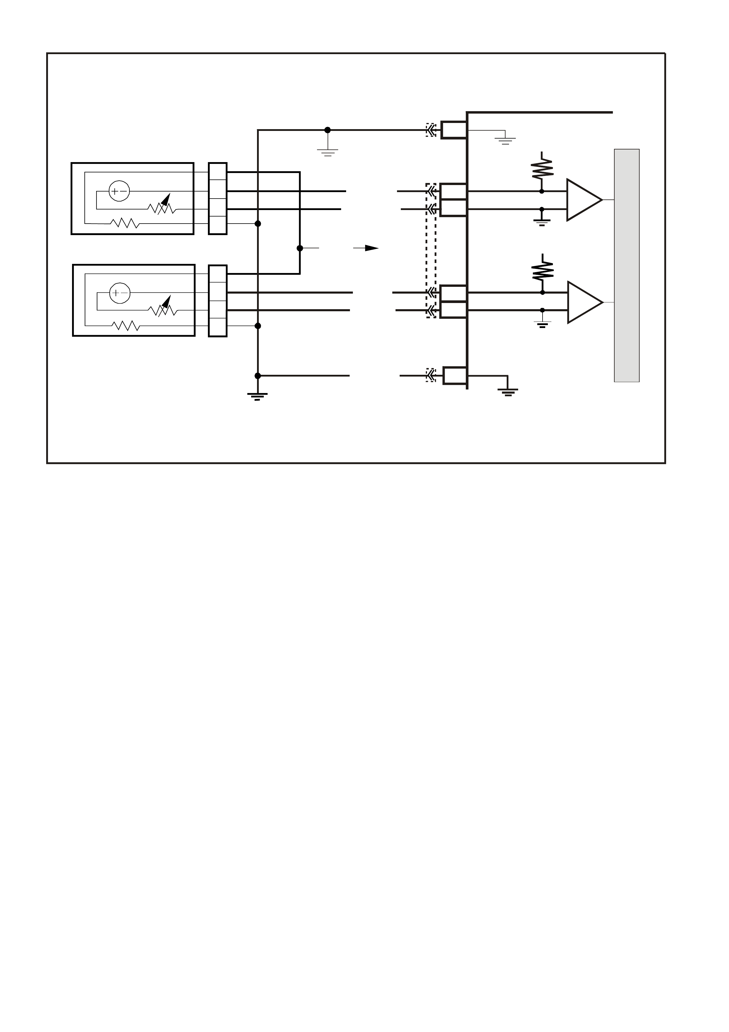
DTC 45 V6 PCM
RIGHT HAND HEATED OXYGEN SENSOR (HO2S) HIGH VOLTAGE
CIRCUIT DESCRIPTION:
The PCM supplies a voltage of about 450 millivolts between terminal "C9" and "D5". The Oxygen (O2) sensor
varies the voltage within a range of about 1 volt, if the exhaust is rich and down through about 100 millivolts if
exhaust is lean.
The sensor produces no voltage when it is below about 360 degrees C. An open sensor circuit or cold sensor
causes "Open Loop" operation.
CONDITIONS FOR RUNNING THE DTC
• No TP Sensor DTC’s are set.
• The system is in "Closed Loop”.
• Throttle angle is between 9% and 30%.
CONDITIONS FOR SETTING THE DTC
• The RH 02S signal voltage remains above 780 millivolts for 40 seconds.
ACTION TAKEN WHEN THE DTC SETS
• The PCM illuminates the Malfunction Indicator Lamp (MIL) when the diagnostic runs and fails.
• The PCM records the operating conditions at the tim e the diagnostic fails. T he PCM stores this information
in the History Data.
• Once a 02S DTC is set, and current, the PCM will operate the fuel system in the “Open Loop” mode.
CONDITIONS FOR CLEARING THE MIL/DTC
• The PCM turns the MIL OFF after the first ignition cycle that the diagnostic runs and does not fail.
• A Histor y DT C clears after f orty c onsecutive warm -up cycles, if this or any other em ission related diagnostic
does not report any failure.
• Use a Tech 2 scan tool in order to clear the MIL/DTC.
DIAGNOSTIC AIDS:
Using the Tech 2 scan tool, observe the Long Term Fuel Trim values at different RPM and air flow conditions.
The Tech 2 scan tool also displays the Long Term Fuel Trim cells, so the Long Term Fuel Trim values can be
checked in each of the cells to determine when the DTC 45 may have been set. If the conditions for DTC 45
exists, the Long Term Fuel Trim values will be around - 22%.
M
I
C
R
O
P (439)
YE95
D
D
B
B
A
A
C
C
YE95
GY (1412)
B/R (750)
Engine
Earth
To Fuse
F33
GY/B (1413)
V (412)
V/B (413)
B/R (750)
4269
A2
D16
D15
D14
D13
A1 450 m V
Right
Oxygen
Sensor
Signal HI
Right
Oxygen
Sensor
Signal LO
Left
Oxygen
Sensor
Signal HI
Left
Oxygen
Sensor
Signal LO
Earth
Earth
Ri ght O x ygen Sensor
Left Oxygen Sensor 450 m V
IC
IC
Engine
Earth
PCM
YB193
YB188
YB188
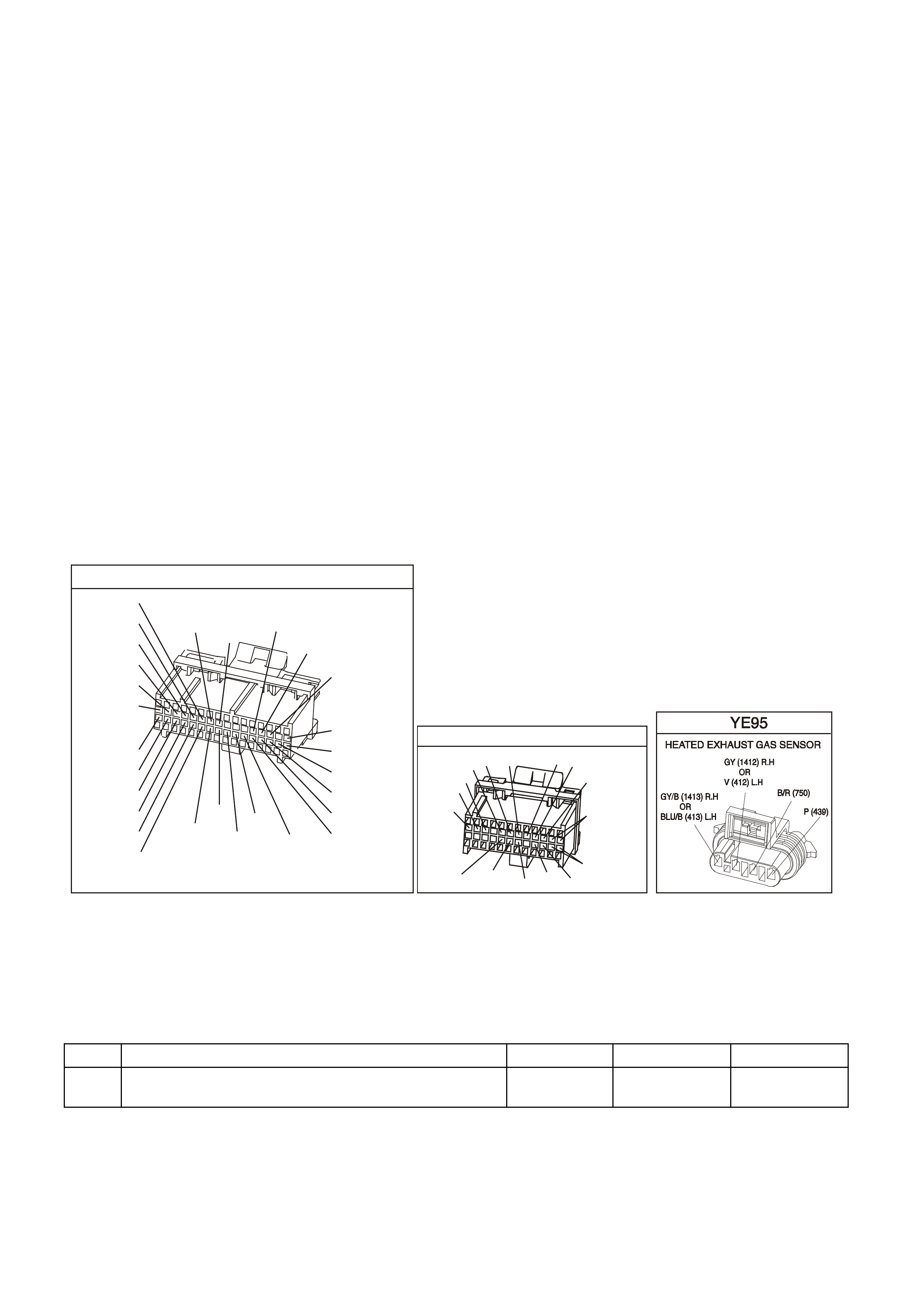
TEST DESCRIPTION: Number(s) below refer to step number(s) on the diagnostic Table.
2. The O2 sensor MUST be at operating temperature before checking operation.
3. This step checks for a short to voltage on the O2 signal line.
7. Earthing circuit 1412 causes a low O2 signal voltage. If the PCM and wiring are OK, the PCM should
recognise the low voltage and confirm the lean signal.
8. A DTC 45 will most likely NOT be caused by a faulty O2 sensor. DTC 45 indicates a rich exhaust and
diagnosis should begin with the items listed:
• Fuel pressure. System will go rich, if pressure is too high. The PCM can compensate for some increase.
However, if it gets too high, a DTC 45 or DTC 65 may be set. Refer to fuel system diagnosis TABLE A-4.3
of the VX Series Service Information.
• Rich injector.
• Leaking injector. Refer to TABLE A-4.3 of the VX Series Service Information.
• Check for fuel contaminated oil.
• Short to voltage on circuit 1412.
• HEI shielding. An open earth circuit 453 (ignition system) may result in EMI, or induced electrical "noise."
The PCM looks at this "noise" as reference pulses. The additional pulses result in a higher than actual
engine speed signal. T he PCM then delivers too much f uel, causing system to go rich. Engine tachometer
will also show higher than actual engine speed, which can help in diagnosing this problem.
• Canister purge. Check for fuel saturation. If full of fuel, check canister control and hoses.
• MAF sensor. A shifted MAF sensor could cause the fuel system to go rich.
• Check for leaking fuel pressure regulator diaphragm by checking vacuum line to regulator for fuel.
• TP Sensor. An intermittent TP sensor output will cause the system to go rich, due to a false indication of
the engine accelerating.
YB 1 93
(413)
(412)
(1413)
(1412)
(430)
(453)
(815)
V/B
GY/B
V
GY
V
B/R
W/R
(897)
(897)
G/W
G/W
(418)
(418)
BR
BR
(1426)
O/W
C16
D16
WT/B
(832)AUTO
(647)
(630)
BR
T
(832) MAN
LBLU/B
B
(424)
(423)
C1
D1
(792)
(422)
(1222)
(1223)
(428)
(123)
BR/W
GY/R
LG
Y/B
G/Y
V/W
BLU/W
BLU
(831) Man
(443)
LG/W
(442) (831)AUTO
(441)
LBLU
LBLU/B
(444)
LG/B
P.C.M . CONNECTOR 1
YB188
P.C.M CONN ECTO R 2
(481)
(417)
(740)
R
BLU
O
(1456)
LG
V/W
(415)
Y
(1227)
B/Y
(410)
BR
(472)
(259)
(750)
(750)
(1221)
B/R
B/R
R/B
G/B
(39)
P
(465)
G/W
(416)
GY
(740)
O
A1
B1
B12
A12
DTC 45 V6 PCM - RIGHT HAND HEATED OXYGEN SENSOR (HO2S) HIGH VOLTAGE
NOTE: Oxygen Sensor Contamination - If fuel containing lead or silicone is used, or engine repairs using
unapproved RTV gasket sealer are performed, the sensor may be contaminated. it may send a "false" rich
exhaust indication to the PCM, and the PCM will attempt to drive the fuel system lean to compensate. Poor
driveability or a Diagnostic Trouble Code 45 could result. if this happens, the sensor will need to be replaced,
but every attempt to locate the source of contamination should be pursued.
STEP ACTION VALUE YES NO
1. Was the "On-Board Diagnostic" (OBD) System Check
performed? Go to Step 2 Go to OBD
System Check

DTC 45 V6 PCM - RIGHT HAND HEATED OXYGEN SENSOR (HO2S) HIGH VOLTAGE (CONTINUED)
STEP ACTION VALUE YES NO
2. 1. Engine at normal operating temperature
(above 80 degrees C).
2. Run engine at approximately 1600 RPM to 1800
RPM for two minutes.
Is Tech 2 scan tool voltage above specified value?
750 mV Go to Step 3 DTC 45 is
intermittent,
If no additional
DTC(s) were
stored, refer to
"Intermittents"
in Section
6C1-2B
SYMPTOMS.
3. 1. Ignition "OFF".
2. Disconnect O2 sensor wiring harness.
3. With ohmmeter connected to earth, probe circuit
1412 at O2 sensor wiring harness connector.
4. Ignition "ON".
Is voltmeter indicating less then specified value?
350 mV Got to Step 7 Go to Step 4
4. 1. Ignition "OFF".
2. Disconnect PCM connectors.
3. Probe circuit 1412 at O2 sensor wiring harness
connector.
5. Ignition "ON".
Is voltmeter indicating voltage below specified value ?
350 mV Go to Step 6 Go to Step 5
5. Repair circuit 1412, shorted to voltage.
Is action complete? Verify Repair
6. Replace PCM.
Refer to Section 6C1-3 Service Operations of the VX
Series Service Information, for PCM Security Link
procedure.
Is action complete?
Verify Repair
7. 1. Disconnect O2 sensor wiring harness connector.
2. Jumper harness connector circuit 1412 to earth.
With engine running, does Tech 2 scan tool display O2
voltage below specified value?
350 mV Go to Step 8 Go to Step 9
8. See step 8 above, to perform additional checks for:
• High Fuel Pressure
• Map Sensor Operation
• Leaking Injectors
• Ignition Earth Circuit
• Canister Purge
• Engine Coolant Temperature Sensor Circuit
• Intake Air Temperature Sensor Circuit
• Throttle Position Sensor Operation
Do all additional checks in step 8 above, test OK.?
Go to Step 8
above Verify Repair
9. 1. Ignition "OFF"
2. Disconnect PCM connectors.
3. Check O2 sensor earth circuit 750 for good
continuity between PCM connector terminal "D5"
and engine earth.
Is an "OPEN" circuit indicated?
Verify Repair Go to Step 10
10. Check PCM earth wire connection at engine. Must be a
clean and tight connection to the engine.
Is connection good?
Go to Step 6 Verify Repair
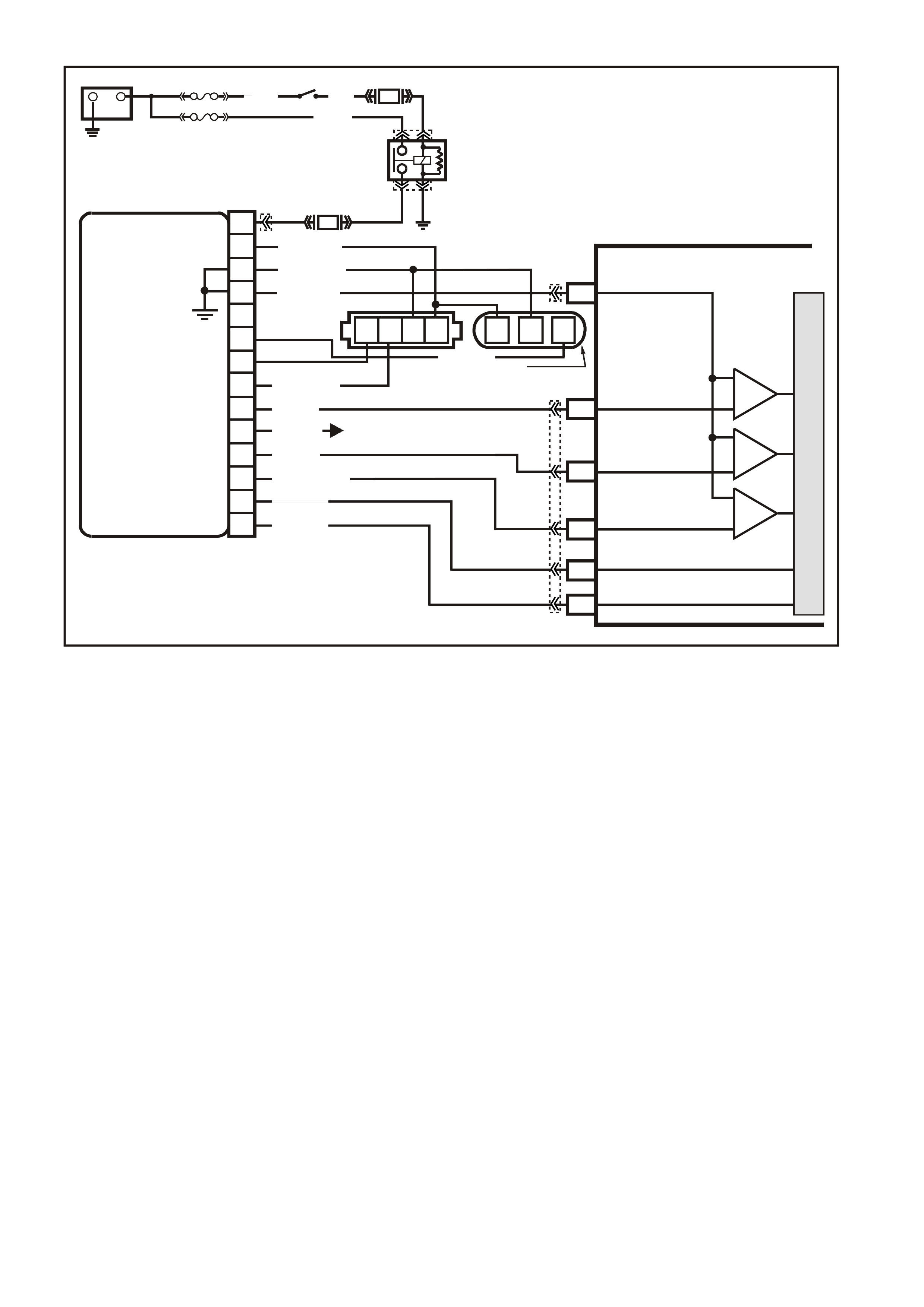
DTC 46 V6 PCM
NO REFERENCE PULSES WHILE CRANKING
CIRCUIT DESCRIPTION;
This DTC is intended to help in diagnosing a no-start condition. Any time the engine is turning, the ignition
module should generate the c r ank s haf t r ef er enc e pulses that the PCM s hould be rec eiving. F uel injec tion puls es
are "tim ed" f rom the c rank shaf t pulses, and without them no injec tion pulses will occur. T he PCM can deter m ine
when these crankshaft pulses should be present, but aren't.
As with any engine while being crank ed, there is a sm all amount of inlet manifold vacuum. Also while cranking,
the battery voltage will be less than 11 volts. If the PCM's MAF sensor input detects manifold vacuum and the
ignition voltage input detects less than 11 volts and there are no reference input pulses, a DTC 46 set.
NOTE: It is possible for the ignition system to provide spark, yet there may not be any reference pulses at the
PCM.
CONDITIONS FOR RUNNING THE DTC
• No MAF sensor DTC is set.
• Battery voltage is at or below 11 volts.
• The MAF sensor input signal is greater than 2048 Hz.
CONDITIONS FOR SETTING THE DTC
• No crankshaft reference input pulses are received at the PCM crankshaft reference input terminal for at
least 2 seconds.
ACTION TAKEN WHEN THE DTC SETS
• The PCM illuminates the Malfunction Indicator Lamp (MIL) when the diagnostic runs and fails.
• The PCM records the operating conditions at the tim e the diagnostic fails. T he PCM stores this information
in the History Data.
VXSC009
PCM
D11
D3
D4
D12
D9
D10
CRANKSHAFT
REFERENCE LO
CAM
SENSOR
CONNECTOR
CAMSHAFT
POSITION
SENSOR
SIGNAL
CRANKSHAFT
REFERENCE HI
CRANKSHAFT
18X SIGNAL
BYPASS CONTROL
EST OUTPUT
module power supply - in
sensor power supply - out
cam signa l - in
3x crank sensor - in
18x crank sensor - in
cam signal - out
tacho signal - out
crankshaft reference - out
18X cranksignal - out
bypass control
EST signal -in
P
N
M
L
K
J
H
G
F
E
D
C
B
A
DIS
MODULE
ABCD CBA
W/B (644)
GY/R (645)
B/R (453)
CRANK
SENSOR
CONN
L BLU/W
(646) BR (633)
BLU/Y (643)
BR (121)
B (63 0)
V (43 0)
L BLU/B (647)
T/B (4 24)
IGN SW
EFI RELAY
O/Y
(479)
LG
(482)
B/W
(152)P/B
(39)
IC
IC
IC
M
I
C
R
O
W (423)
F35
+
-
BATTERY
FS
LOC. E1
FJ
(1040)
LOC. E3
P (3)
R(2H)
F14
TO INSTRUMENT CLUSTER
(TERMINAL 18)
ABS/ETC (TERMINAL 30)
YB39
YB39
YE111
YE34
YB193
YB193
YE63
YE57
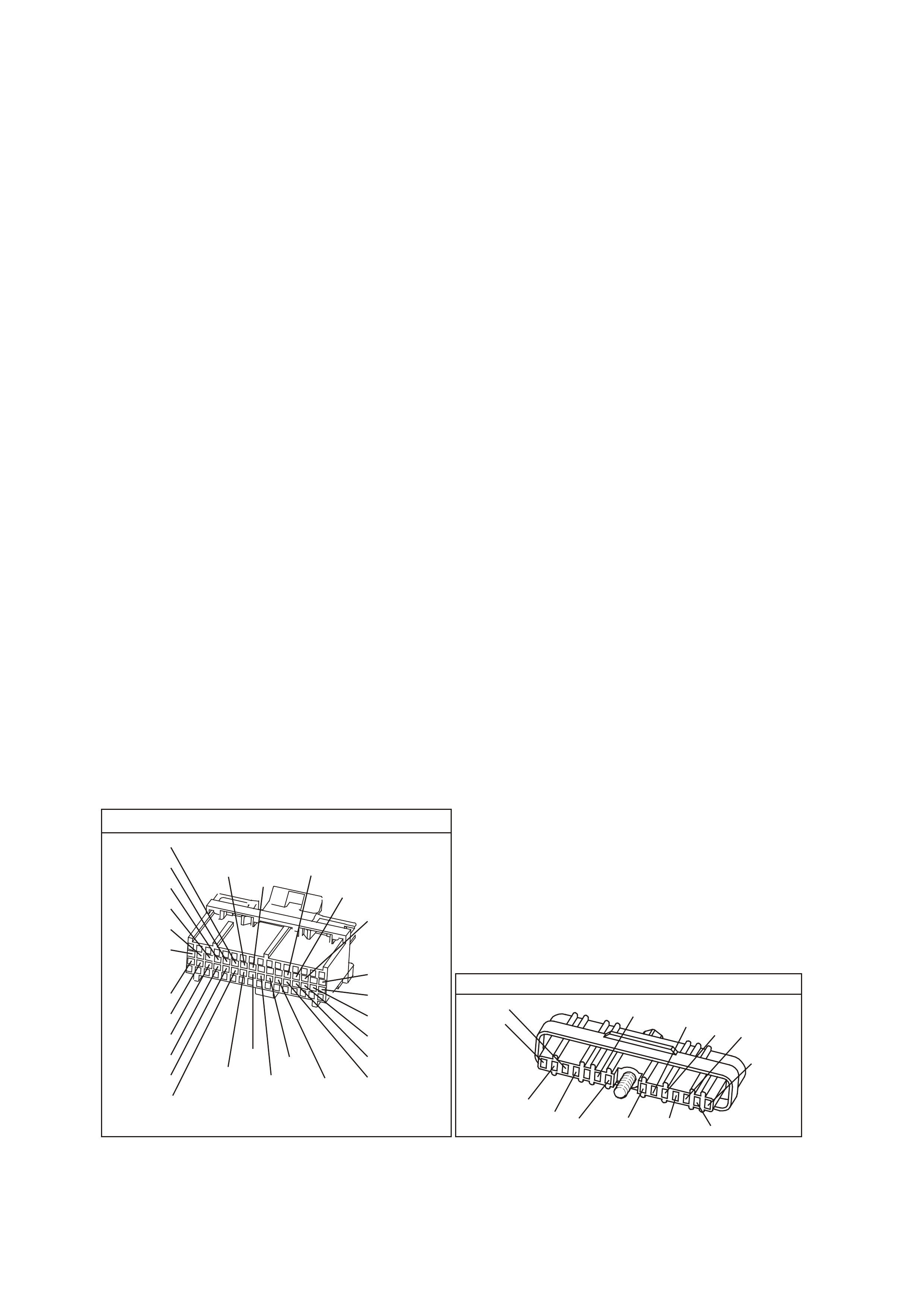
CONDITIONS FOR CLEARING THE MIL/DTC
• The PCM turns the MIL OFF after the first ignition cycle that the diagnostic runs and does not fail.
• A Histor y DT C clears after f orty c onsecutive warm -up cycles, if this or any other em ission related diagnostic
does not report any failure.
• Use a Tech 2 scan tool in order to clear the MIL/DTC.
DIAGNOSTIC AIDS
• Poor connection at PCM. Inspect harness connectors for backed out terminals, improper mating, broken
locks, improperly formed or damaged terminals, and poor terminal to wire connection.
• Damaged Har ness. Ins pect the wiring harness for dam age. If the harness appears to be O K, disconnec t the
ignition module, turn the ignition "ON". Connect and observe a voltmeter connected between the Bypass
control circuit and B+, while m oving c onnectors and wiring harness related to the ignition m odule. A change
in voltage will indicate the location of the fault.
NOTE: Use ST -125 spark check er or equivalent to chec k f or adequate spark . An ST-125 requires about 25,000
volts (25 Kilovolts or 25 kV) to "spark". Do not use a spark plug in open air earthed to the engine as an
indication of sufficient "spark". Only a few kilovolts are required to jump the gap of a spark plug outside of the
engine, and that would be an inadequate test of the ignition system.
TEST DESCRIPTION
The numbers below refer to the step numbers on the diagnostic table.
2. If engine starts, the problem is not present now. While the PCM monitors 3 inputs to determine DTC 46,
only a lack of reference input signal pulses can set the DTC. If a problem occurred on the MAF or ignition
voltage inputs, other problems would be apparent.
NOTE: Even one crankshaft reference pulse while cranking will cause DTC 46 to NOT set.
3. Spark on all three wires on the s am e side of the engine proves the DIS c oil pack to be OK. No spar k on any
lead means the DIS ignition system is suspect of causing the DTC 46. If the DIS ignition system cannot
generate any spark, it cannot generate the crankshaft reference signal either.
Refer to TABLE A-8.1 in this Section to determine the cause. If there is spark on only 1 or 2 spark plug
leads, the crank sensor is probably OK, but there could be a problem with the coil pack or DIS module.
TABLE A-8.1 in this Section should determine the problem.
4. The voltage should be either "OFF" (less than 1 volt) or "ON" (m ore than 3 volts). This is the square-wave,
digital "ON-OFF" reference signal generated by the ignition module. The voltage could be either reading,
depending on where the reluctor wheel stopped turning.
5. This is again the ref erence signal. W hen the reluctor wheel is turning, the signal changes from under 1 volt
to over 3 volts, back and forth, eight times per reluctor wheel revolution. Since it changes quickly, the
voltmeter can indicate only an average voltage. (expected reading - approximately 2 volts.)
6. A loose connection at PCM terminal "D12" could cause an intermittent voltage measurement to be seen.
YB1 93
(413)
(412)
(1413)
(1412)
(430)
(453)
(815)
V/B
GY/B
V
GY
V
B/R
W/R
(897)
(897)
G/W
G/W
(418)
(418)
BR
BR
(1426)
O/W
C16
D16
WT/B
(832)AUTO
(647)
(630)
BR
T
(832) MAN
LBLU/B
B
(424)
(423)
C1
D1
(792)
(422)
(1222)
(1223)
(428)
(123)
BR/W
GY/R
LG
Y/B
G/Y
V/W
BLU/W
BLU
(831) Man
(443)
LG/W
(442) (831)AUTO
(441)
LBLU
LBLU/B
(444)
LG/B
P.C.M. CONNECTOR 1
DIRECT IGNITION MODUL E
YE 57
(647)
LBLU/B
W/B
(644)
B/R
(453)
LBLU/W
(646)
BLU/Y
(643)
V
(430)
T/B
(424)
(633)
BR
(645)
GY/R
LG
(482)
B
(630)
BR
(121)
W
(423)
PNMLKJHGFED
CBA

DTC 46 V6 PCM - NO REFERENCE PULSES WHILE CRANKING
STEP ACTION VALUE YES NO
1. Was the "On-Board Diagnostic" (OBD) System check
performed?
Go to Step 2 Go to OBD
System Check in
this Section
2. Attempt to start engine.
Did engine start and continue to run?
DTC 46 is
intermittent. If no
additional DTC's
were stored, refer
to "Intermittents"
in Section 6C1-
2B SYMPTOMS .
Go to Step 3
3. 1. Remove the spark plug leads from two spark
plugs.
2. Connect ST-125 spark checker (See note above)
to each lead individually, and check for spark while
cranking the engine.
Was spark evident on both leads? (A few sparks and then
nothing is considered no spark.)
Go to Step 4 Go to Table
A-8.1 in this
Section
4. 1. Ignition "OFF".
2. Disconnect PCM.
3. Backprobe PCM harness connector terminal "D12"
to earth with a digital voltmeter set to read "DC
volts".
4. Ignition "ON".
Is the voltage at the specified value?
Approx
5 volts
Go to Step 5 Go to Step 9
5. 1. Ignition "OFF".
2. Disconnect PCM.
3. Backprobe PCM harness connector terminal "D12"
to earth with a digital voltmeter set to read "DC
Volts".
4. Ignition "ON" .
5. While observing digital voltmeter, crank the engine.
Is voltage measured approximately the specified value?
2 - 3 volts Go to Step 6 Go to Step 8
6. Check PCM terminal "D12" for a loose connection.
Was a fault found?
Verify Repair
Go to Step 7
7. Replace PCM.
Refer to Section 6C1-3 Service Operations of the VX
Series Service Information, for PCM Security Link
procedure.
Is action complete?
Verify Repair
8. Check circuit 430 for a faulty connection or an open or
short to earth.
Was a fault found?
Verify Repair Go to Step 9
9. Replace Ignition Module
Is action complete?
Verify Repair
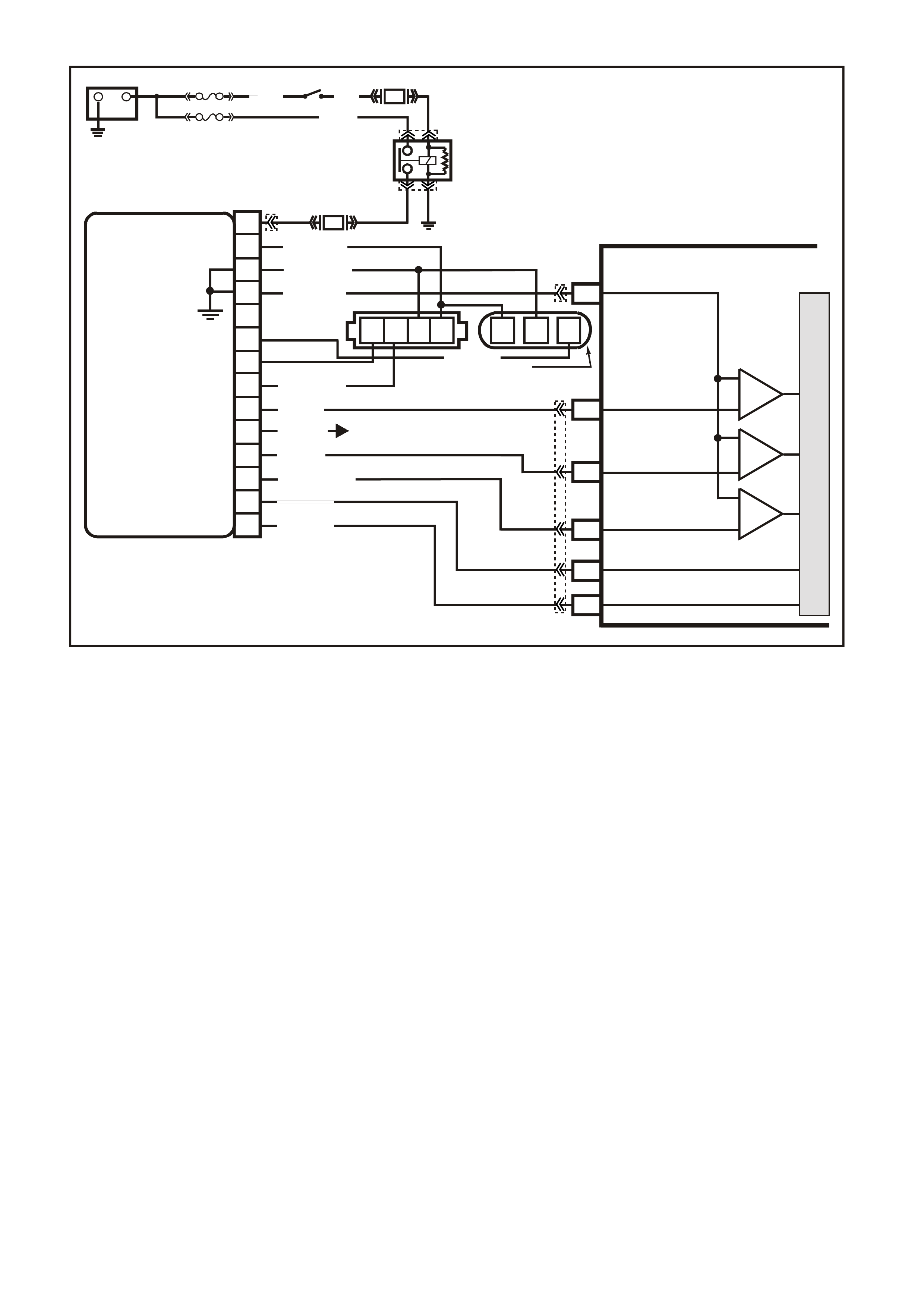
DTC 47 V6 PCM -
18X REFERE NCE SIGNAL MISSING
CIRCUIT DESCRIPTION:
The 18X signal ( circuit 647) is used by the PCM to improve ignition tim ing accuracy during crank and at engine
speeds of up to 2000 RPM. The 18X signal circuit allows the use of EST m ode below 400 RPM, eliminating the
need to utilise bypass mode dur ing startup, and also allows the PCM to calculate tr ue crankshaf t position in 1/6
the time that use of the crankshaft reference signal would permit.
During norm al operation, the PCM uses the 18X signal to contr ol ignition timing until the engine speed exc eeds
2000 RPM, at which time the c rankshaf t reference s ignal (circuit 430) is us ed. When conditions for setting DTC
47 exist, the crankshaft reference signal is used by the PCM to control EST. This condition will cause bypass
mode to be used for ignition timing below 400 RPM and EST ignition timing to be degraded below 2000 RPM.
CONDITIONS FOR RUNNING THE DTC
• The engine is running.
• The MAF sensor input signal is greater than 2048 Hz.
CONDITIONS FOR SETTING THE DTC
• The PCM detects 253 crankshaft reference pulses and no 18X pulses.
ACTION TAKEN WHEN THE DTC SETS
• The PCM stores the DTC information into memory when the diagnostic runs and fails.
• The Malfunction Indicator Lamp (MIL) will not be illuminated.
• The PCM records the operating conditions at the tim e the diagnostic fails. T he PCM stores this information
in the History Data.
• When DTC 47 is set and c ur rent ( no 18X ref er ence s ignal), the PCM uses the c rankshaf t r ef erenc e s ignal to
determine engine speed. This condition will cause the EST to be degraded; no high resolution spark.
VXSC009
PCM
D11
D3
D4
D12
D9
D10
CRANKSHAFT
REFERENCE LO
CAM
SENSOR
CONNECTOR
CAMSHAFT
POSITION
SENSOR
SIGNAL
CRANKSHAFT
REFERENCE HI
CRANKSHAFT
18X SIGNAL
BYPASS CONTROL
EST OUTPUT
module power supply - in
sensor power supply - out
cam signa l - in
3x crank sensor - in
18x crank sensor - in
cam signal - out
tacho signal - out
crankshaft reference - out
18X cranksignal - out
bypass control
EST signal -in
P
N
M
L
K
J
H
G
F
E
D
C
B
A
DIS
MODULE
ABCD CBA
W/B (644)
GY/R (645)
B/R (453)
CRANK
SENSOR
CONN
L BLU/W
(646) BR (633)
BLU/Y (643)
BR (121)
B (63 0)
V (43 0)
L BLU/B (647)
T/B (4 24)
IGN SW
EFI RELAY
O/Y
(479)
LG
(482)
B/W
(152)P/B
(39)
IC
IC
IC
M
I
C
R
O
W (423)
F35
+
-
BATTERY
FS
LOC. E1
FJ
(1040)
LOC. E3
P (3)
R(2H)
F14
TO INSTRUMENT CLUSTER
(TERMINAL 18)
ABS/ETC (TERMINAL 30)
YB39
YB39
YE111
YE34
YB193
YB193
YE63
YE57
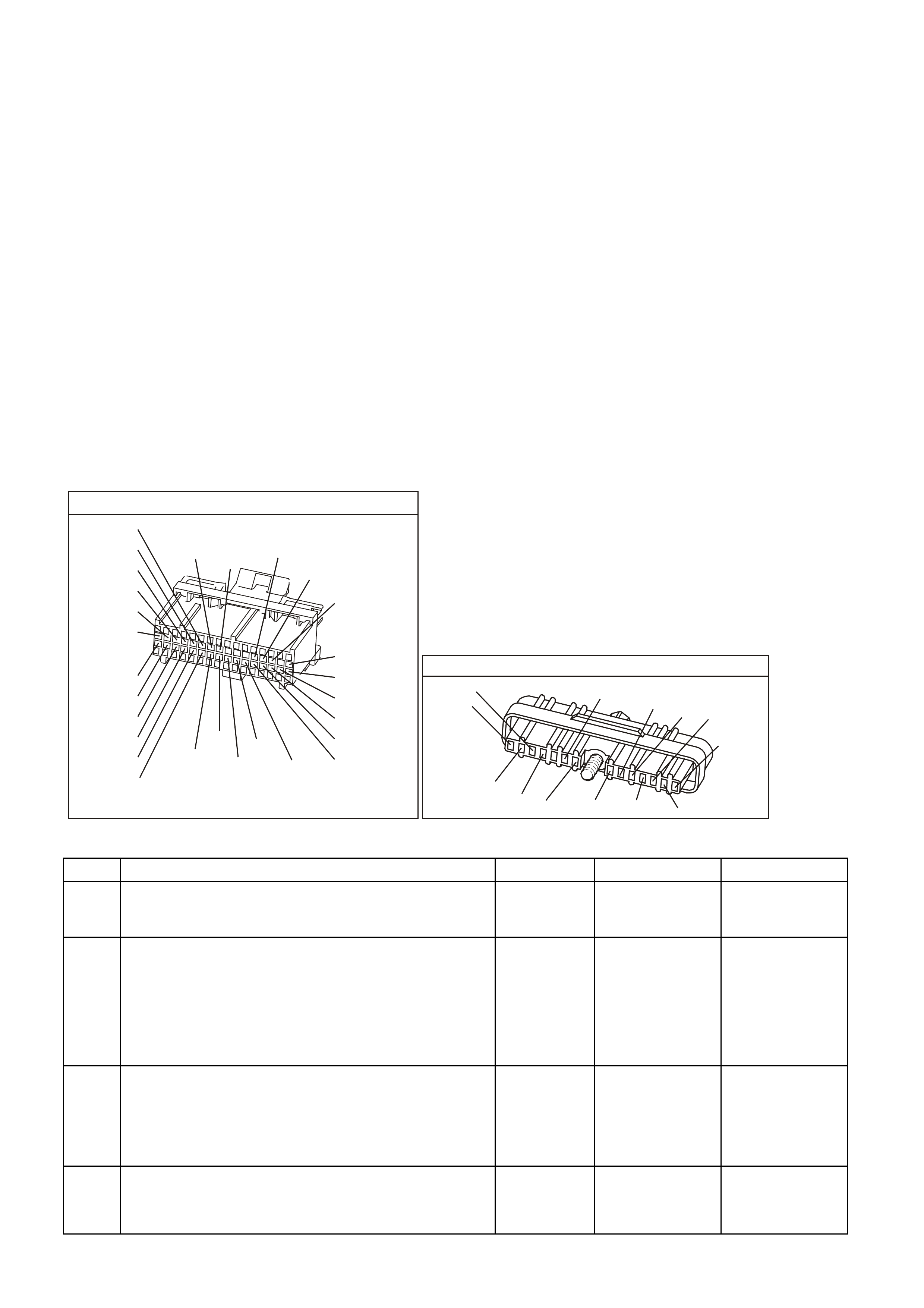
CONDITIONS FOR CLEARING THE MIL/DTC
• A Histor y DT C clears after f orty c onsecutive warm -up cycles, if this or any other em ission related diagnostic
does not report any failure.
• Use a Tech 2 scan tool in order to clear the MIL/DTC.
DIAGNOSTIC AIDS:
An interm ittent may be caused by a poor connection, rubbed through wire insulation, or a wire br oken inside the
insulation.
Check for:
• Backed out connector terminals or broken down insulation in circuit 647.
• If connections and harness check OK, try monitoring voltage on circuit 647 with DVM while moving the
related wiring harness and connectors with the engine idling. This may help to isolate the location of the
malfunction.
TEST DESCRIPTION: Number(s) below refer to step number(s) on the diagnostic Table.
4. If a window on the harmonic balancer is interfering with the 18X Hall-Effect switch, the ignition module will
earth the 18X signal. Starter may have to be bumped several times to obtain a voltage reading.
5. Voltage reading should be lower than that obtained with engine not running, indicating a pulsed reference
signal.
8. Verifies that circuit 647 is not shorted to earth or open in the harness.
YB1 93
(413)
(412)
(1413)
(1412)
(430)
(453)
(815)
V/B
GY/B
V
GY
V
B/R
W/R
(897)
(897)
G/W
G/W
(418)
(418)
BR
BR
(1426)
O/W
C16
D16
WT/B
(832)AUTO
(647)
(630)
BR
T
(832) MAN
LBLU/B
B
(424)
(423)
C1
D1
(792)
(422)
(1222)
(1223)
(428)
(123)
BR/W
GY/R
LG
Y/B
G/Y
V/W
BLU/W
BLU
(831) Man
(443)
LG/W
(442) (831)AUTO
(441)
LBLU
LBLU/B
(444)
LG/B
P.C.M. CONNECTOR 1
DIRECT IGNITION MODUL E
YE 57
(647)
LBLU/B
W/B
(644)
B/R
(453)
LBLU/W
(646)
BLU/Y
(643)
V
(430)
T/B
(424)
(633)
BR
(645)
GY/R
LG
(482)
B
(630)
BR
(121)
W
(423)
PNMLKJHGFED
CBA
DTC 47 V6 PCM - 18X REFERENCE SIGNA L MISSING
STEP ACTION VALUE YES NO
1. Was the "On-Board Diagnostic" (OBD) System Check
performed? Go to Step 2 Go to OBD
System Check in
this Section
2. 1. Ignition "OFF".
2. Install Tech 2 scan tool and clear DTCs.
3. Ignition "ON".
4. Start engine idle for 1 minute or until Diagnostic
Trouble Code 47 sets.
Did Diagnostic Trouble Code 47 set?
Go to Step 3 DTC 47 is
intermittent. If no
additional DTC's
were stored, refer
"Diagnostic Aids"
above.
3 1. Backprobe PCM terminal D4 with a DVM connected
to earth.
2. Ignition "ON", engine "OFF", observe voltage on
PCM terminal D4.
Does voltage measure specified value?
Approx.
5 volts Go to Step 5 Go to Step 4
4. 1. Bump engine with starter.
2. Retest voltage at PCM terminal D4.
Does voltage measure specified value?
Approx.
5 volts Go to Step 5 Go to Step 8

DTC 47 V6 PCM - 18X REFERENCE SIGNAL MISSING (CONTINUED)
STEP ACTION VALUE YES NO
5. 1. Start engine, idle 1 minute to stabilise system.
2. Observe voltage on PCM terminal D4.
Does voltage measure specified value?
Approx.
3 volts Go to Step 7 Go to Step 6
6. Check for poor ignition module connections.
Was a fault found? Verify Repair Go to Step 10
7. Check for poor connection at PCM D4.
Was a fault found? Verify Repair Go to Step 11
8. 1. Ignition "OFF".
2. Disconnect PCM connectors.
3. Ignition "ON".
4. Measure voltage at PCM harness connector
terminal D4.
Does voltage measure specified value?
Approx.
5 volts Go to Step 11 Go to Step 9
9. Check circuit 647 open or shorted to earth.
Was a fault found? Verify Repair Go to Step 10
10. Replace faulty ignition control module.
Is action complete? Verify Repair
11. Replace PCM.
Refer to Section 6C1-3 Service Operations of the VX
Series Service Information, for PCM Security Link
procedure.
Is action complete?
Verify Repair

DTC 48 V6 PCM -
CAMSHAFT POSITION (CKP) SENSOR CIRUCIT LOW V OLTAGE
CIRCUIT DESCRIPTION:
During cranking, the ignition module monitors the dual crank sensor 3X signal. The 3X signal is used to
determ ine the cor rect c ylinder pair to s park f irst. After the 3X signal has been proc essed by the ignition module,
it sends a crankshaft reference pulse to the PCM. When the PCM receives this pulse it will command all six
injectors to open for one priming shot of fuel in all cylinders. After the priming, all six of the injectors are left
"OFF" until the next crankshaft reference pulses from the ignition module (two crankshaft revolutions). This
allows each cylinder a chance to use the f uel from the prim ing shot. During this waiting period, a cam s ignal will
have been received by the PCM. Now the PCM begins to operate the injectors in sequential fuelling mode by
energising each inj ector bas ed on true cam s haft pos ition. However, if the c am shaf t position signal is not present
at startup, a DT C 48 will set and the PCM will energise all six injector s at the sam e tim e and continue to operate
like this until the fault is corrected.
CONDITIONS FOR RUNNING THE DTC
• The engine is cranking.
CONDITIONS FOR SETTING THE DTC
• The PCM detects the Camshaft Position sensor signal is low when the signal should be high for 5.0
seconds.
ACTION TAKEN WHEN THE DTC SETS
• The PCM stores the DTC information into memory when the diagnostic runs and fails.
• The Malfunction Indicator Lamp (MIL) will not be illuminated.
• The PCM records the operating conditions at the tim e the diagnostic fails. T he PCM stores this information
in the History Data.
• Once DTC 48 is set, the PCM will determine the fuel injection sequence based on the last fuel injection
pulse received. In the calculated SFI mode, the engine continues to start and run. However, with the fault
present, only a 1 in 6 chance of the correct injection sequence exists.
VXSC009
PCM
D11
D3
D4
D12
D9
D10
CRANKSHAFT
REFERENCE LO
CAM
SENSOR
CONNECTOR
CAMSHAFT
POSITION
SENSOR
SIGNAL
CRANKSHAFT
REFERENCE HI
CRANKSHAFT
18X SIGNAL
BYPASS CONTROL
EST OUTPUT
module power supply - in
sensor power supply - out
cam signa l - in
3x crank sensor - in
18x crank sensor - in
cam signal - out
tacho signal - out
crankshaft reference - out
18X cranksignal - out
bypass control
EST signal -in
P
N
M
L
K
J
H
G
F
E
D
C
B
A
DIS
MODULE
ABCD CBA
W/B (644)
GY/R (645)
B/R (453)
CRANK
SENSOR
CONN
L BLU/W
(646) BR (633)
BLU/Y (643)
BR (121)
B (63 0)
V (43 0)
L BLU/B (647)
T/B (4 24)
IGN SW
EFI RELAY
O/Y
(479)
LG
(482)
B/W
(152)P/B
(39)
IC
IC
IC
M
I
C
R
O
W (423)
F35
+
-
BATTERY
FS
LOC. E1
FJ
(1040)
LOC. E3
P (3)
R(2H)
F14
TO INSTRUMENT CLUSTER
(TERMINAL 18)
ABS/ETC (TERMINAL 30)
YB39
YB39
YE111
YE34
YB193
YB193
YE63
YE57
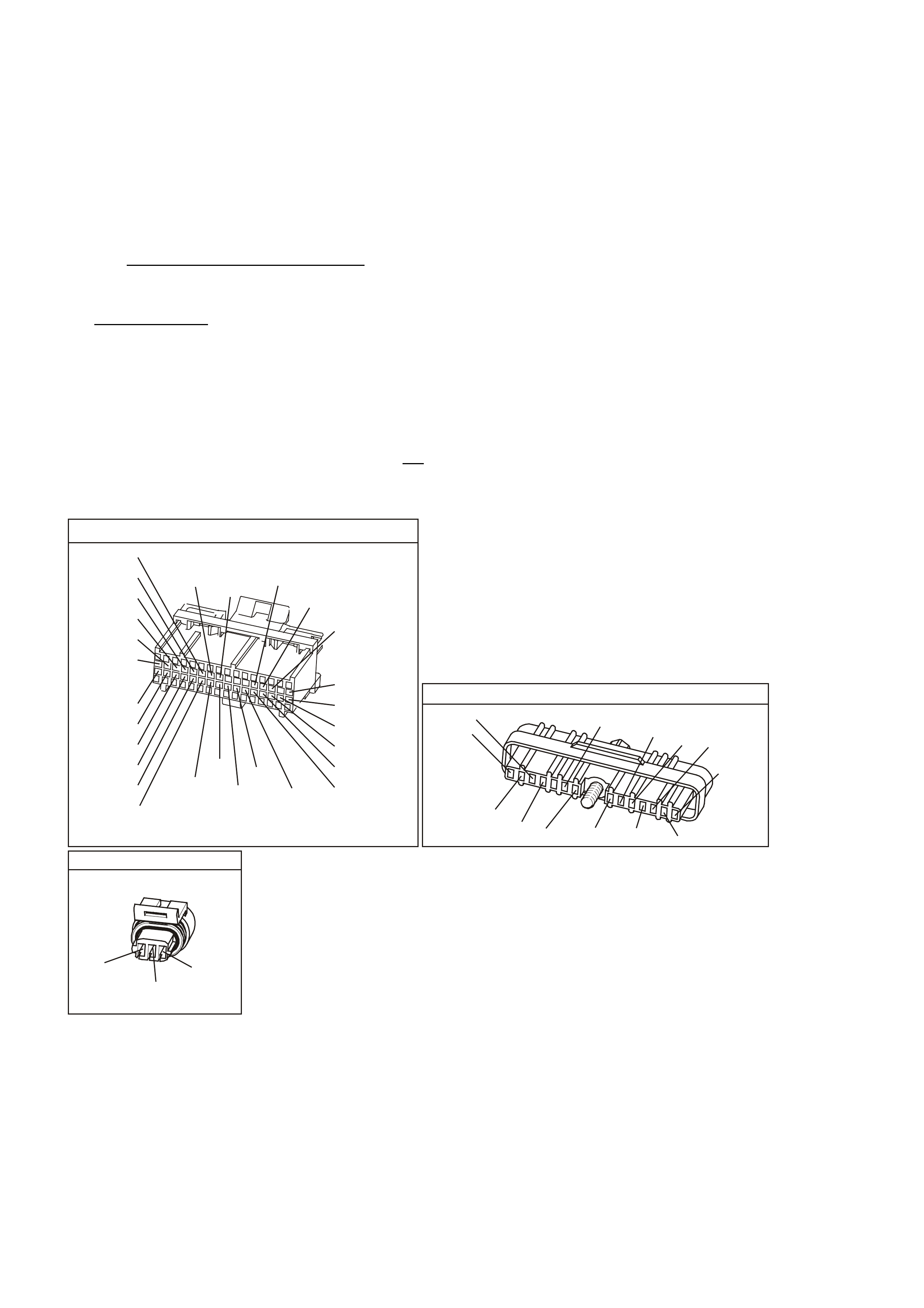
CONDITIONS FOR CLEARING THE MIL/DTC
• A Histor y DT C clears after f orty c onsecutive warm -up cycles, if this or any other em ission related diagnostic
does not report any failure.
• Use a Tech 2 scan tool in order to clear the MIL/DTC.
DIAGNOSTIC AIDS:
An interm ittent may be caused by a poor connection, rubbed through wire insulation, or a wire br oken inside the
insulation.
Check for:
• Poor Connection or Damage Harness - Inspect PCM harness connectors for backed out terminal "B6",
improper mating, broken locks, improperly formed or damaged terminal, poor terminal to wire connection
and damaged harness.
• Intermittent Test - If connections and harness check OK, monitor a digital voltmeter connected from PCM
terminal "D3" to earth while moving related connectors and wiring harness. If the failure is induced, the
voltage reading will change. This may help to isolate the location of the malfunction.
TEST DESCRIPTION: Number(s) below refer to step number(s) on the diagnostic Table.
3. This step verifies proper operation of circuits 633, 644, and 645.
4. This step verifies the integrity of circuit 630 from ignition module to PCM. If the voltage reading of "D3"
drops slightly from 4.7 volts to approximately 4.1 volts, the camshaft sensor is pulling the signal line low,
therefore the connection to the PCM is not good or the PCM is faulty. If the voltage remains at
approximately 4.4 volts and is steady, continue with diagnosis.
YB1 93
(413)
(412)
(1413)
(1412)
(430)
(453)
(815)
V/B
GY/B
V
GY
V
B/R
W/R
(897)
(897)
G/W
G/W
(418)
(418)
BR
BR
(1426)
O/W
C16
D16
WT/B
(832)AUTO
(647)
(630)
BR
T
(832) MAN
LBLU/B
B
(424)
(423)
C1
D1
(792)
(422)
(1222)
(1223)
(428)
(123)
BR/W
GY/R
LG
Y/B
G/Y
V/W
BLU/W
BLU
(831) Man
(443)
LG/W
(442) (831)AUTO
(441)
LBLU
LBLU/B
(444)
LG/B
P.C.M. CONNECTOR 1
DIRECT IGNITION MODUL E
YE 57
(647)
LBLU/B
W/B
(644)
B/R
(453)
LBLU/W
(646)
BLU/Y
(643)
V
(430)
T/B
(424)
(633)
BR
(645)
GY/R
LG
(482)
B
(630)
BR
(121)
W
(423)
PNMLKJHGFED
CBA
YE 63
CAM S EN SOR
(644)
W/B
GY/R
(645)
BR
(633)

DTC 48 V6 PCM - CAMSHAFT POSITION (CKP) SENSOR CIRUCIT LOW VOLTAGE
STEP ACTION VALUE YES NO
1. Was the "On-Board Diagnostic" (OBD) System Check
performed? Go to Step 2. Go to OBD
System Check
in this Section
2. 1. Install Tech 2 scan tool.
2. Ignition "ON", engine "OFF".
3. Record, then clear DTCs.
4. Start engine, idle for 1 minute.
5. Select DATA LIST.
Does Tech 2 scan tool display "Cam Signal" as
"Missing"?
Go to Step 3 DTC 48 is
intermittent. If
no additional
DTCs were
stored, refer to
"Diagnostic
Aids" above.
3 1. Ignition "OFF".
2. Disconnect camshaft position sensor harness
connector from camshaft position sensor.
3. Ignition "ON", engine "OFF".
Using DVM, does voltage between harness connectors
pins "A-B and "B-C" measure between specified values?
"A-B"
5-7 volts
"B-C"
8-11 volts
Go to Step 4 Go to Step 11
4. 1. Ignition "OFF".
2. Reconnect camshaft position sensor harness to
camshaft position sensor.
3. Install DVM to backprobe PCM terminals D3 & A1
to measure voltage at PCM terminal D3.
4. Ignition "ON", engine "OFF".
Is voltage fixed at specified value?
Approximately
4.7 volts Go to Step 5 Go to Step 10
5. Start engine, idle 1 minute to stabilise system.
Is voltage reading of "D3" constantly varying around a
mid-point of specified value?
Approximately
4.1 volts Go to Step 9 Go to Step 6
6. 1. Ignition "OFF".
2. Disconnect camshaft position sensor harness
connector from camshaft position sensor.
3. Ignition "ON", engine "OFF".
4. Touch terminal "A" of camshaft position sensor
harness connector with a test light connected to
earth while observing voltmeter.
Does voltage reading at PCM terminal "D3" drop to
specified value?
0 volts Go to Step 7 Go to Step 8
7. Check the following:
• Poor connection at camshaft position sensor;
• Faulty camshaft position sensor;
• Missing camshaft magnet;
Is action complete?
Verify Repair
8. Replace faulty ignition control module.
Is action complete? Verify Repair
9. Check for poor connection at PCM terminal D3 or faulty
PCM.
Is action complete?
Verity Repair
10 Bump engine with starter.
Retest voltage at terminal "D3".
Is voltage fixed at specified value?
Approximately
4.7 volts Go to Step 5 Go to Step 17
11. Was one voltage reading low? Go to Step 12 Go to Step 16
12. Was the reading between harness connector pin
"A-B low? Go to Step 13 Go to Step 15

DTC 48 V6 PCM - CAMSHAFT POSITION (CKP) SENSOR CIRUCIT LOW VOLTAGE (CONTINUED)
STEP ACTION VALUE YES NO
13. Check for open or short to earth in circuit 633.
Was a fault found? Verify Repair Go to Step 14
14. Check for poor ignition control module connection.
Was a fault found? Verify Repair Go to Step 8
15 Repair circuit 644 between splice and camshaft position
sensor connector.
Is action complete?
Verify Repair
16 Repair circuit 645 between splice and camshaft position
sensor connector.
Is action complete?
Verify Repair
17 Check circuit 630 for open or short to earth.
Was a fault found? Verify Repair Go to Step 18
18 Replace the camshaft position sensor.
Is action complete? Verify Repair
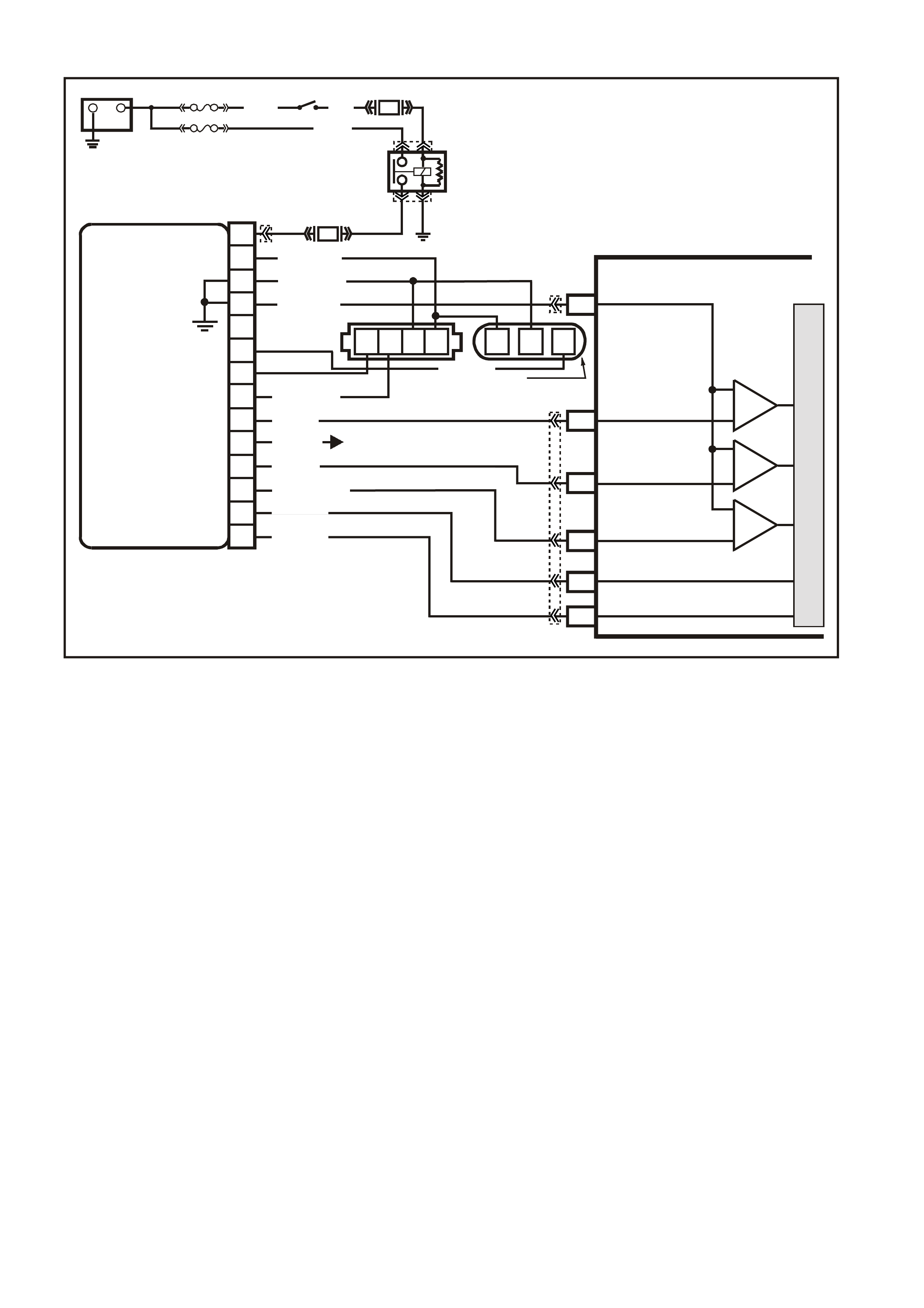
DTC 49 V6 PCM -
CAMSHAFT POSITION (CKP) SENSOR CIRUCIT PERFORMANCE
CIRCUIT DESCRIPTION:
During cranking, the ignition module monitors the dual crank sensor 3X signal. The 3X signal is used to
determ ine the cor rect c ylinder pair to s park f irst. After the 3X signal has been proc essed by the ignition module,
it sends a crankshaft reference pulse to the PCM. When the PCM receives this pulse it will command all six
injector s to open f or one pr im ing shot of fuel in all c ylinders. After the priming, the inj ectors are lef t "OFF " for the
next six crankshaft reference pulses from the ignition module (two crankshaft revolutions). This allows each
cylinder a chance to use the f uel from the priming shot. During this waiting period, a cam signal will have been
received by the PCM. Now the PCM begins to operate the injectors by energising each injector based on true
camshaft position. With the engine running, the PCM monitors the cam and 18X signal pulses it receives and
expects to see 36 18X signal pulses for each cam pulse.
CONDITIONS FOR RUNNING THE DTC
• The engine is cranking.
CONDITIONS FOR SETTING THE DTC
• An incorrect number of crankshaft reference pulses have been received since the previous camshaft
position signal.
ACTION TAKEN WHEN THE DTC SETS
• The PCM stores the DTC information into memory when the diagnostic runs and fails.
• The Malfunction Indicator Lamp (MIL) will not be illuminated.
• The PCM records the operating conditions at the tim e the diagnostic fails. T he PCM stores this information
in the History Data.
• Once DTC 49 is set, the PCM will determine the fuel injection sequence based on the last fuel injection
pulse received. In the calculated SFI mode, the engine continues to start and run. However, with the fault
present, only a 1 in 6 chance of the correct injection sequence exists.
VXSC009
PCM
D11
D3
D4
D12
D9
D10
CRANKSHAFT
REFERENCE LO
CAM
SENSOR
CONNECTOR
CAMSHAFT
POSITION
SENSOR
SIGNAL
CRANKSHAFT
REFERENCE HI
CRANKSHAFT
18X SIGNAL
BYPASS CONTROL
EST OUTPUT
module power supply - in
sensor power supply - out
cam signa l - in
3x crank sensor - in
18x crank sensor - in
cam signal - out
tacho signal - out
crankshaft reference - out
18X cranksignal - out
bypass control
EST signal -in
P
N
M
L
K
J
H
G
F
E
D
C
B
A
DIS
MODULE
ABCD CBA
W/B (644)
GY/R (645)
B/R (453)
CRANK
SENSOR
CONN
L BLU/W
(646) BR (633)
BLU/Y (643)
BR (121)
B (63 0)
V (43 0)
L BLU/B (647)
T/B (4 24)
IGN SW
EFI RELAY
O/Y
(479)
LG
(482)
B/W
(152)P/B
(39)
IC
IC
IC
M
I
C
R
O
W (423)
F35
+
-
BATTERY
FS
LOC. E1
FJ
(1040)
LOC. E3
P (3)
R(2H)
F14
TO INSTRUMENT CLUSTER
(TERMINAL 18)
ABS/ETC (TERMINAL 30)
YB39
YB39
YE111
YE34
YB193
YB193
YE63
YE57
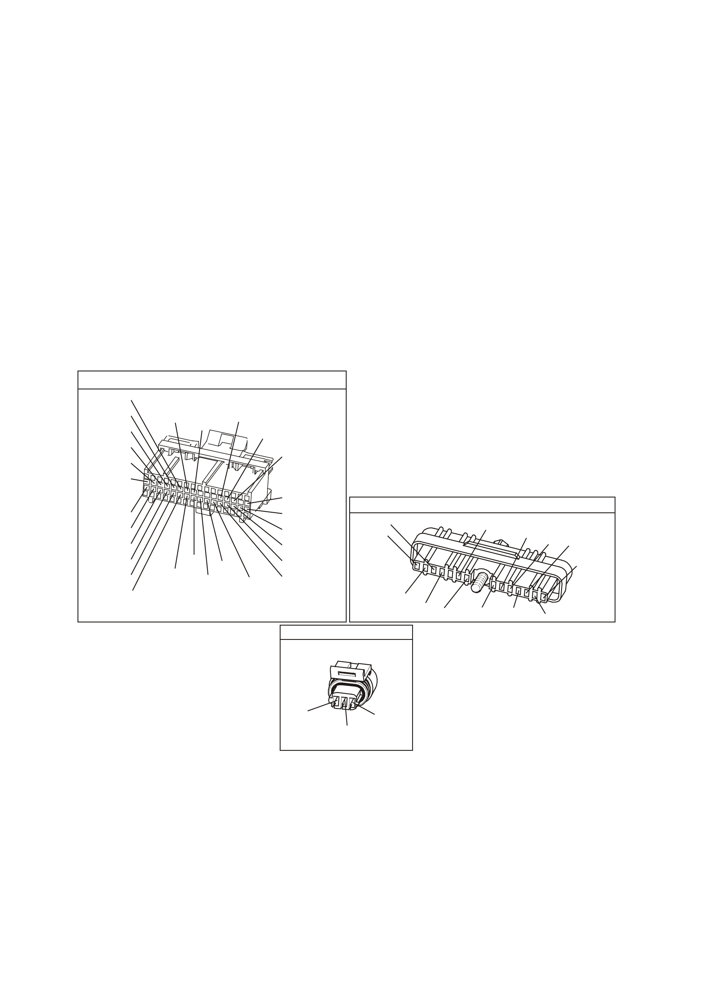
CONDITIONS FOR CLEARING THE MIL/DTC
• A Histor y DT C clears after f orty c onsecutive warm -up cycles, if this or any other em ission related diagnostic
does not report any failure.
• Use a Tech 2 scan tool in order to clear the MIL/DTC.
DIAGNOSTIC AIDS:
DTC 49 indic ates an interm ittent fault and m ay not set im mediately or under all conditions . Customer com m ents
of symptoms experienced may help isolate the cause of the condition. A poor connection or fault in the cam
sensor circuits 630, 633, 644, or 645 or a faulty cam sensor may cause the PCM to re-initialise injector
sequence when the fault occurs, causing a possible stumble or miss. A poor connection or fault in the 18X
signal cir cuit 647, crank sensor c ircuits 643, 644, or 645, the 18X portion of the cr ank sens or or bent or m issing
vanes on the harm onic balancer interrupter rings will caus e the PCM to stop pulsing the injec tors when the fault
occurs, causing an intermittent stumble or stall.
TEST DESCRIPTION: Number(s) below refer to step number(s) on the diagnostic Table.
2. Determines if conditions necessary to set DTC 49 exist on this ignition cycle.
3. If 5 volts are not present at PCM harness connector term inal "D3", the cam sensor m ay be interfacing with
the magnet in the camshaft sprocket. Bumping the starter should correct this condition.
6. If a f ailure is induced in the 18X s ignal circuit, the 5 volts on the circ uit should change when the faulty wiring
or connection is manipulated.
NOTE: If DTC 48 is set along with DTC 49, use DTC 48 table for diagnosis.
YB1 93
(413)
(412)
(1413)
(1412)
(430)
(453)
(815)
V/B
GY/B
V
GY
V
B/R
W/R
(897)
(897)
G/W
G/W
(418)
(418)
BR
BR
(1426)
O/W
C16
D16
WT/B
(832)AUTO
(647)
(630)
BR
T
(832) MAN
LBLU/B
B
(424)
(423)
C1
D1
(792)
(422)
(1222)
(1223)
(428)
(123)
BR/W
GY/R
LG
Y/B
G/Y
V/W
BLU/W
BLU
(831) Man
(443)
LG/W
(442) (831)AUTO
(441)
LBLU
LBLU/B
(444)
LG/B
P.C.M. CONNECTOR 1
DIRECT IGNITION MODUL E
YE 57
(647)
LBLU/B
W/B
(644)
B/R
(453)
LBLU/W
(646)
BLU/Y
(643)
V
(430)
T/B
(424)
(633)
BR
(645)
GY/R
LG
(482)
B
(630)
BR
(121)
W
(423)
PNMLKJHGFED
CBA
YE 63
CAM S EN SOR
(644)
W/B
GY/R
(645)
BR
(633)

DTC 49 V6 PCM - CAMSHAFT POSITION (CKP) SENSOR CIRUCIT PERFORMANCE
STEP ACTION VALUE YES NO
1. Was the "On-Board Diagnostic" (OBD) System Check
performed? Go to Step 2 Go to OBD
System Check in
this Section
2. 1. Install Tech 2 scan tool.
2. Start and idle engine.
3. Using Tech 2 scan tool, look at "IGN Cycles" in
DTC hist ory.
Is DTC 49 current?
Go to Step 3 DTC 49 is
intermittent. If no
additional DTC's
were set, refer to
"Diagnostic Aids"
above.
3 1. Ignition "OFF".
2. Disconnect PCM connectors.
3. Connect a DVM between PCM harness connector
terminal "D3" and earth.
4. Ignition "ON".
Is voltage at "D3” at specified value?
Approximately
5 volts Go to Step 5 Go to Step 4
4. Bump engine with starter.
Is voltage at "D3" at specified value? Approximately
5 volts Go to Step 5 Go to DTC 48 of
this Service
Information
5. Monitor voltage at "D3" while manipulating powertrain
wiring harness to PCM connector.
Does voltage remain steady as wiring is manipulated?
Go to Step 6 Go to Step 10
6. 1. Connect DVM between PCM harness connector
terminal "D4" and earth.
2. Monitor voltage at "D4" while manipulating ignition
harness, engine harness, and dash harness to PCM
connector.
Does voltage remain steady as wiring is manipulated?
Go to Step 7 Go to Step 8
7. Check for:
• Poor connections at PCM;
• Harmonic balancer interrupter ring vanes bent or
• missing;
• Faulty crank sensor (malfunctioning hot/cold).
Are all above OK?
Refer to
"Diagnostic Aids"
above.
Verify Repair
8. Check for poor connection at crankshaft position sensor
or ignition control module.
Was a fault found?
Verify Repair Go to Step 9
9. Repair intermittent open/short to earth in circuit 643, 644,
645 or 647.
Is action complete?
Verity Repair
10 Check for poor connection at camshaft position sensor or
ignition control module.
Was a fault found?
Verify Repair Go to Step 11
11. Repair intermittent open/short to earth in circuit 630, 633,
644 or 645.
Is action complete?
Verify Repair
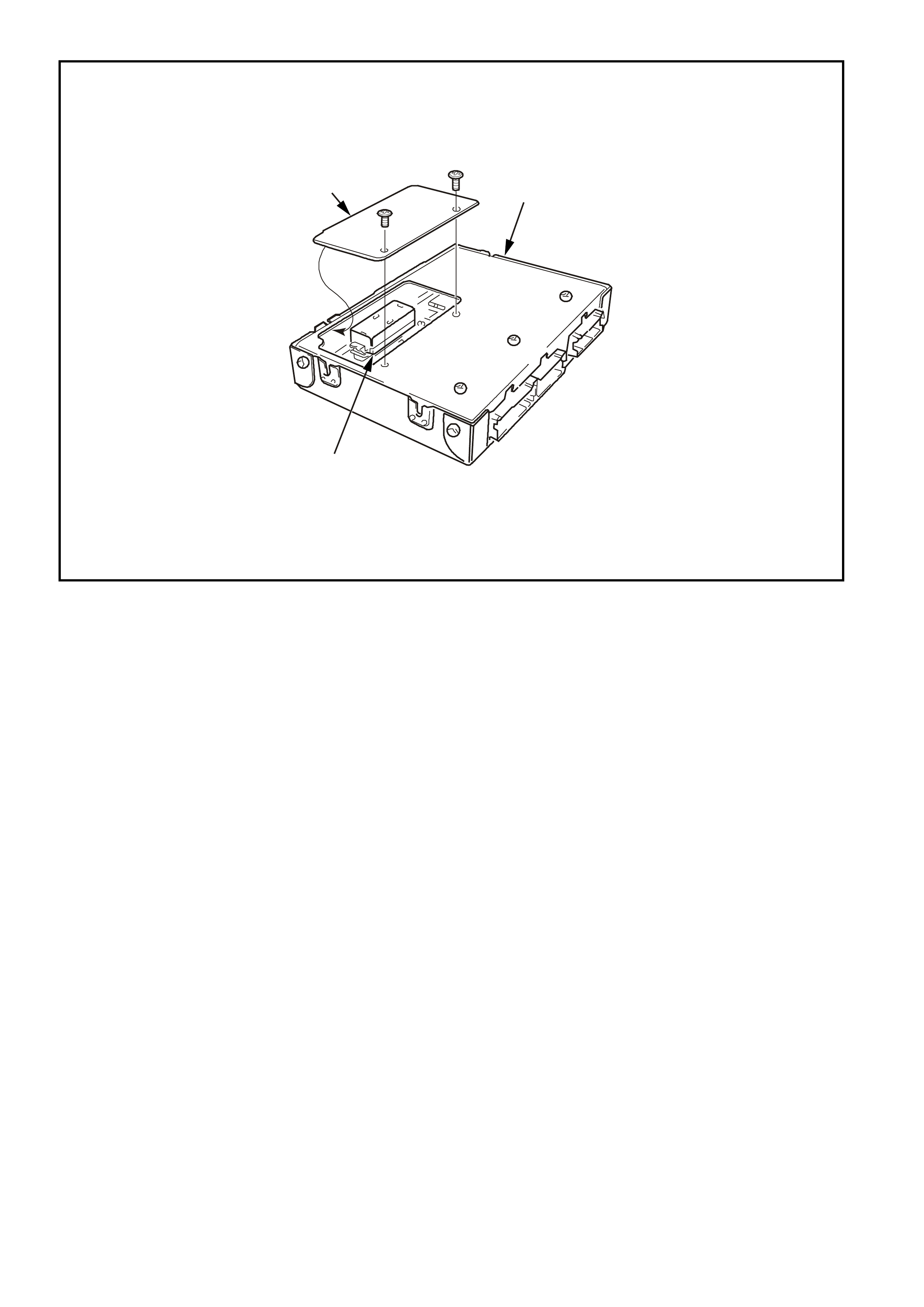
1. Powertrain Control Module (PCM)
2. Prom
3. Prom Access Cover
DTC 51 V6 PCM
POWERTRAIN CONTROL MODULE (PCM) MEMORY
CIRCUIT DESCRIPTION:
The PCM PROM contains data which is essential to running the engine and transmission. The PCM
continuously checks the integrity of this data.
CONDITIONS FOR RUNNING THE DTC
• The ignition switch is in the crank position or the run position.
CONDITIONS FOR SETTING THE DTC
• The PCM is unable to correctly read data from the PROM.
ACTION TAKEN WHEN THE DTC SETS
• The PCM illuminates the Malfunction Indicator Lamp (MIL) when the diagnostic runs and fails.
• The PCM records the operating conditions at the tim e the diagnostic fails. T he PCM stores this information
in the History Data.
CONDITIONS FOR CLEARING THE MIL/DTC
• The PCM turns the MIL OFF after the first ignition cycle that the diagnostic runs and does not fail.
• A Histor y DT C clears after f orty c onsecutive warm -up cycles, if this or any other em ission related diagnostic
does not report any failure.
• Use a Tech 2 scan tool in order to clear the MIL/DTC.
DIAGNOSTIC AIDS
• Replace the PCM Prom even if this DTC exists only in history.
• For an intermittent, Refer to Section 6C1-2B Symptoms of the VX Series Service Information.
TEST DESCRIPTION
The numbers below refer to the step numbers on the diagnostic table.
2. This step verifies that the Prom is inserted properly into the PCM.
3
SUPERVX4376
2
1

DTC 51 V6 PCM - POWERTRAIN CONTROL MODULE (PCM) MEMORY
STEP ACTION VALUE YES NO
1. Was the "On-Board Diagnostic" (OBD) System Check
performed? Go to Step 2 Go to OBD
System Check in
this Section
2. Check that PROM is fully inserted into the PCM.
Is PROM fully inserted? Go to Step 3 Go to Step 5
3. Replace PROM.
Clear DTCs and recheck for DTC 51.
Does DTC 51 reset?
Go to Step 4 Go to Step 6
4. Replace PCM.
Refer to Section 6C1-3 Service Operations of the VX
Series Service Information, for PCM Security Link
procedure.
Is action complete?
Verify Repair
5. Fully insert PROM.
Clear DTCs and recheck for DTC 51.
Does DTC 51 reset?
Go to Step 3 Go to Step 6
6. Clear DTC’s and confirm no "Check Powertrain Lamp".
Is action complete? Verify Repair

DTC 52 V6 PCM
SYSTEM VOLTAGE TOO HIGH (LONG TIME)
CIRCUIT DESCRIPTION
Circuit 39 is the ignition voltage feed circuit to terminal A4 for the PCM. Circuit 740 is the battery voltage feed
circuit to term inals C12 and D12 for the PCM. W hen the PCM detects a high voltage for a long tim e, then DTC
52 sets..
CONDITIONS FOR RUNNING THE DTC
• The ignition is on.
• ECT is at or above 85°C.
CONDITIONS FOR SETTING THE DTC
• The engine is running and the PCM ignition voltage is greater than 16 volts for more than 109 minutes.
ACTION TAKEN WHEN THE DTC SETS
• The PCM illuminates the Malfunction Indicator Lamp (MIL) when the diagnostic runs and fails.
• The PCM records the operating conditions at the tim e the diagnostic fails. T he PCM stores this information
in the History Data.
• During the time fault is present, the pressure control solenoid is turned "OFF", the transmission shifts
immediately to 3rd gear and TCC operation is inhibited.
CONDITIONS FOR CLEARING THE MIL/DTC
• The PCM turns the MIL OFF after the first ignition cycle that the diagnostic runs and does not fail.
• A Histor y DT C clears after f orty c onsecutive warm -up cycles, if this or any other em ission related diagnostic
does not report any failure.
• Use a Tech 2 scan tool in order to clear the MIL/DTC.
SUPERVX017
# 2
# 4 # 6
# 1 # 3 # 5
PCM
A8
B8
F3
F1
F2
E2
E4
B12
A4
BATTERY F EED
BATTERY F EED
O
(740)
O
(740)
BLU
(841)
V
(843)
GY
(845)
INJECTOR CONTROL
IN JE C TOR VOLTAG E
MONITOR LINE
IGNITION FEED
O/Y (479)
EFI R EL AY
B/W (152)
LOC. E4
P (3 )
O/B (740)
IGN SW
M
I
C
R
O
R
(481)
P
(39)
Y
(846)
BR/Y
(844)
G
(842)
F31
F14
F34
BATTERY
FS
FJ
R (2)
(1040)
YE112
YE114
YE111
YB194
YB188
YE39 YE39
YB188

DIAGNOSTIC AIDS
• Inspect the wiring for poor electrical connections at the PCM. Look for the following conditions:
- A bent terminal
- A backed out terminal
- A damaged terminal
- Poor terminal tension
- A chafed wire
- A broken wire inside the insulation
- Moisture intrusion
• When diagnosing for an inter m ittent short or open c ondition, m ass age the wiring harness while watc hing the
test equipment for a change.
• Charging the battery with a battery charger may set DTCs. Jump starting an engine may set DTCs.
• If DT Cs set when you operate an acces sory, inspect the applicable wiring for f aulty connections. Inspect the
wiring for excessive current draw.
• Inspect the following items for faulty connections:
- The starter solenoid
- The fusible link
- The generator terminals
- Battery cables
• Inspect the belts for excessive wear. Inspect the belts for proper tension.
TEST DESCRIPTION
The numbers below refer to the step numbers on the diagnostic table.
4. This step tests the charging system voltage.
5. This step tests PCM battery voltage.

DTC 52 V6 PCM - SYSTEM VOLTAGE TOO HIGH (LONG TIME)
STEP ACTION VALUE YES NO
1 Was the On-Board Diagnostic (OBD) System Check
performed? Go to Step 2 Go to OBD
System Check
2 1. Install the scan tool.
2. With the engine OFF, turn the ignition switch to the
RUN position.
IMPORTANT: Before clearing the DTCs, use the scan
tool in order to record the DTC history. The Clear Info
function will erase the data.
3. Record the DTC history.
4. Using the J 39200 DVM, measure the battery voltage
across the battery terminals. Record the
measurement for future reference.
Is the voltage higher than the specified value?
10 volts Go to Step 3 Go to Battery
Diagnosis
3 1. Start the engine.
2. Warm the engine to the operating temperature.
Is the generator/check engine light ON?
85°C Go to Charging
System
Diagnosis
Go to Step 4
4 1. Increase the engine speed to 2000 RPM for 15
seconds.
2. Observe the DVM battery voltage.
Is the DVM battery voltage greater than the specified
value?
15 volts Go to Charging
System
Diagnosis
Go to Step 5
5 1. Increase the engine speed to 2000 RPM.
2. Observe the scan tool Battery Voltage.
Is the scan tool Battery Voltage greater than the specified
value?
15.5 volts Go to Step 6 System Checks
OK, Go to
“Diagnostic Aids”
above
6 Replace PCM.
Refer to Section 6C1-3 Service Operations of the VX
Series Service Information, for PCM Security Link
procedure.
Is action complete?
Go to Step 7
7 In order to verify your repair, perform the following
procedure:
1. Select DTC.
2. Select Clear Info.
3. Operate the vehicle under the following conditions:
• Start the vehicle.
• Warm the engine to normal operating
temperature.
Is the scan tool Battery Voltage within the specified
range?
13-15.5 volts System OK Go to Step 2

DTC 53 V6 PCM
SYSTEM VOLTAGE TOO HIGH
CIRCUIT DESCRIPTION
Circuit 39 is the ignition voltage feed circuit to terminal A4 for the PCM. Circuit 740 is the battery voltage feed
circuit to terminals C12 and D12 f or the PCM. When the PCM detects a HIG H voltage for a s hort period of tim e,
then DTC 53 sets.
CONDITIONS FOR RUNNING THE DTC
• The ignition is on.
• ECT is at or above 85°C.
• Conditions present for at least 4 seconds.
CONDITIONS FOR SETTING THE DTC
• Voltage at PCM ignition feed terminal is more than 19.5 volts for more than 2 seconds.
ACTION TAKEN WHEN THE DTC SETS
• The PCM illuminates the Malfunction Indicator Lamp (MIL) when the diagnostic runs and fails.
• The PCM records the operating conditions at the tim e the diagnostic fails. T he PCM stores this information
in the History Data.
• W hen DTC 53 sets, the PCM turns off all transmission output devices, and freezes shift adapts from being
updated.
CONDITIONS FOR CLEARING THE MIL/DTC
• The PCM turns the MIL OFF after the first ignition cycle that the diagnostic runs and does not fail.
• A Histor y DT C clears after f orty c onsecutive warm -up cycles, if this or any other em ission related diagnostic
does not report any failure.
• Use a Tech 2 scan tool in order to clear the MIL/DTC.
SUPERVX017
# 2
# 4 # 6
# 1 # 3 # 5
PCM
A8
B8
F3
F1
F2
E2
E4
B12
A4
BATTERY F EED
BATTERY F EED
O
(740)
O
(740)
BLU
(841)
V
(843)
GY
(845)
INJECTOR CONTROL
IN JE C TOR VOLTAG E
MONITOR LINE
IGNITION FEED
O/Y (479)
EFI R EL AY
B/W (152)
LOC. E4
P (3 )
O/B (740)
IGN SW
M
I
C
R
O
R
(481)
P
(39)
Y
(846)
BR/Y
(844)
G
(842)
F31
F14
F34
BATTERY
FS
FJ
R (2)
(1040)
YE112
YE114
YE111
YB194
YB188
YE39 YE39
YB188

DIAGNOSTIC AIDS
• Inspect the wiring for poor electrical connections at the PCM. Look for the following conditions:
- A bent terminal
- A backed out terminal
- A damaged terminal
- Poor terminal tension
- A chafed wire
- A broken wire inside the insulation
- Moisture intrusion
• When diagnosing for an inter m ittent short or open c ondition, m ass age the wiring harness while watc hing the
test equipment for a change.
• Charging the battery with a battery charger may set DTCs. Jump starting an engine may set DTCs.
• If DT Cs set when you operate an acces sory, inspect the applicable wiring for f aulty connections. Inspect the
wiring for excessive current draw.
• Inspect the following items for faulty connections:
- The starter solenoid
- The fusible link
- The generator terminals
- Battery cables
• Inspect the belts for excessive wear. Inspect the belts for proper tension.
TEST DESCRIPTION
The numbers below refer to the step numbers on the diagnostic table.
4. This step tests the charging system voltage.
5. This step checks battery voltage of the PCM, using the scan tool.

DTC 53 V6 PCM - SYSTEM VOLTAGE TOO HIGH
STEP ACTION VALUE YES NO
1 Was the On-Board Diagnostic (OBD) System Check
performed? Go to Step 2 Go to OBD
System Check
2 1. Install the scan tool.
2. With the engine OFF, turn the ignition switch to the
RUN position.
IMPORTANT: Before clearing the DTCs, use the scan
tool in order to record the DTC history. The Clear Info
function will erase the data.
3. Record the DTC history.
4. Using the J 39200 DVM , measure the battery v oltage
across the battery terminals. Record the
measurement for future reference.
Is the voltage higher than the specified value?
10 volts Go to Step 3 Go to Battery
Diagnosis
3 1. Start the engine.
2. Warm the engine to the operating temperature.
Is the generator/check engine light ON?
85°C Go to Charging
System
Diagnosis in
Section 6D1-1in
VX Service
Information
Go to Step 4
4 1. Increase the engine speed to 2000 RPM for 15
seconds.
2. Observe the DVM battery voltage and record your
reading.
Did the DVM battery voltage exceed the specified value?
16.0 volts Go to Charging
System
Diagnosis
Section6D1-1 in
VX Service
Information.
Go to Step 5
5 1. Increase the engine speed to 2000 RPM.
2. Observe the scan tool Battery Voltage.
Is the scan tool Battery Voltage within 0.5 volts of your
recorded voltage in step 4?
System Checks
OK, Go to
“Diagnostic Aids”
above
Go to Step 6
6 Replace PCM.
Refer to Section 6C1-3 SERVICE OPERATIONS of the
VX Series Service Information, for PCM Security Link
procedure.
Is action complete?
Go to Step 7
7 In order to verify your repair, perform the following
procedure:
1. Select DTC.
2. Select Clear Info.
3. Operate the vehicle under the following conditions:
• Start the vehicle.
• Warm the engine to normal operating
temperature.
Is the scan tool Battery Voltage within the specified
range?
13-15.5 volts System OK Begin the
diagnosis again.
Go to Step 1

DTC 54 V6 PCM -
SYSTEM VOLTAGE UNSTABLE
CIRCUIT DESCRIPTION
Diagnostic Trouble Code (DTC) 54 will set when the ignition is "ON" and PCM terminal "A4" voltage changed
more than 2.5 volts in 100 milliseconds..
CONDITIONS FOR RUNNING THE DTC
• The ignition is on.
• Conditions present for at least 10 seconds.
CONDITIONS FOR SETTING THE DTC
• System voltage changes more than 2.5 volts in 100 millivolts.
ACTION TAKEN WHEN THE DTC SETS
• The PCM illuminates the Malfunction Indicator Lamp (MIL) when the diagnostic runs and fails.
• The PCM records the operating conditions at the tim e the diagnostic fails. T he PCM stores this information
in the History Data.
• W hen DTC 54 sets, the PCM turns off all transmission output devices, and freezes shift adapts from being
updated.
CONDITIONS FOR CLEARING THE MIL/DTC
• The PCM turns the MIL OFF after the first ignition cycle that the diagnostic runs and does not fail.
• A Histor y DT C clears after f orty c onsecutive warm -up cycles, if this or any other em ission related diagnostic
does not report any failure.
• Use a Tech 2 scan tool in order to clear the MIL/DTC.
SUPERVX017
# 2
# 4 # 6
# 1 # 3 # 5
PCM
A8
B8
F3
F1
F2
E2
E4
B12
A4
BATTERY FEED
BATTERY FEED
O
(740)
O
(740)
BLU
(841)
V
(843)
GY
(845)
INJECTOR CONTROL
IN JECTOR VOLTAGE
MONITOR LINE
IGNITION FEED
O/Y (479)
EFI R EL AY
B/W (152)
LOC. E4
P (3 )
O/B (740)
IGN SW
M
I
C
R
O
R
(481)
P
(39)
Y
(846)
BR/Y
(844)
G
(842)
F31
F14
F34
BATTERY
FS
FJ
R (2)
(1040)
YE112
YE114
YE111
YB194
YB188
YE39 YE39
YB188

DIAGNOSTIC AIDS
• Inspect the wiring for poor electrical connections at the PCM. Look for the following conditions:
- A bent terminal
- A backed out terminal
- A damaged terminal
- Poor terminal tension
- A chafed wire
- A broken wire inside the insulation
- Moisture intrusion
• When attempting to diagnose an intermittent problem, use the snapshot mode of the Tech 2 scan tool, to
review diagnostic information.
• Charging the battery with a battery charger may set DTCs. Jump starting an engine may set DTCs.
• If DT Cs set when you operate an acces sory, inspect the applicable wiring for f aulty connections. Inspect the
wiring for excessive current draw.
• Inspect the following items for faulty connections:
- The starter solenoid
- The fusible link
- The generator terminals
- Battery cables
• Inspect the belts for excessive wear. Inspect the belts for proper tension.
TEST DESCRIPTION
The numbers below refer to the step numbers on the diagnostic table.
2. Diagnostic Trouble Code 54 will set if: T he last 25% of the sam ples for ignition feed voltage changes more
than 2.5 volts in 100 milliseconds.
YB 188
P.C.M CONNECTOR 2
(481)
(417)
(740)
R
BLU
O
(1456)
LG
V/W
(415)
Y
(1227)
B/Y
(410)
BR
(472)
(259)
(750)
(750)
(1221)
B/R
B/R
R/B
G/B
(39)
P
(465)
G/W
(416)
GY
(740)
O
A1
B1
B12
A12

DTC 54 V6 PCM - SYSTEM VOLTAGE UNSTABLE
STEP ACTION VALUE YES NO
1. Was the "On-Board Diagnostic" (OBD) System Check
performed? Go to Step 2 Go to OBD
System Check in
this Section
2. 1. Install Tech 2 scan tool and set up snapshot
mode to trigger on DTC 54.
2. Ignition "ON".
3. Wiggle the PCM connector.
Does "System Voltage" reading change sharply as
Connector is wiggled?
Go to Step 7
Go to Step 3
3. Wiggle and tug the harness at the PCM.
Does "System Voltage" reading change sharply as
harness is wiggled?
Go to Step 7 Go to Step 4
4. Lightly tap on the PCM.
Does "System Voltage" reading change sharply as PCM
is tapped?
Go to Step 5 DTC 54 is
intermittent. If no
additional DTC's
were stored, refer
to "Diagnostic
Aids" above.
5. Verify that PCM is securely mounted to vehicle
Is PCM securely mounted? Go to Step 6
Verify Repair
6. Replace PCM.
Refer to Section 6C1-3 SERVICE OPERATIONS of the
VX Series Service Information, for PCM Security Link
procedure.
Is action complete?
Verify Repair
7. Check PCM connector for corrosion.
Is corrosion present? Go to Step 8
Go to Step 9
8. Clean corroded terminals with electronic part cleaner.
Is action complete? Verify Repair
9. Check tightness of the female terminal grip with a spare
male terminal.
Are terminals tight?
Go to Step 10 Verify Repair
10. Remove PCM connector strain relief and remove terminal
from connector to check for broken or bent locking tang.
Is locking tang OK?
Find intermittent
open in
powertrain wiring
harness.
Replace terminal
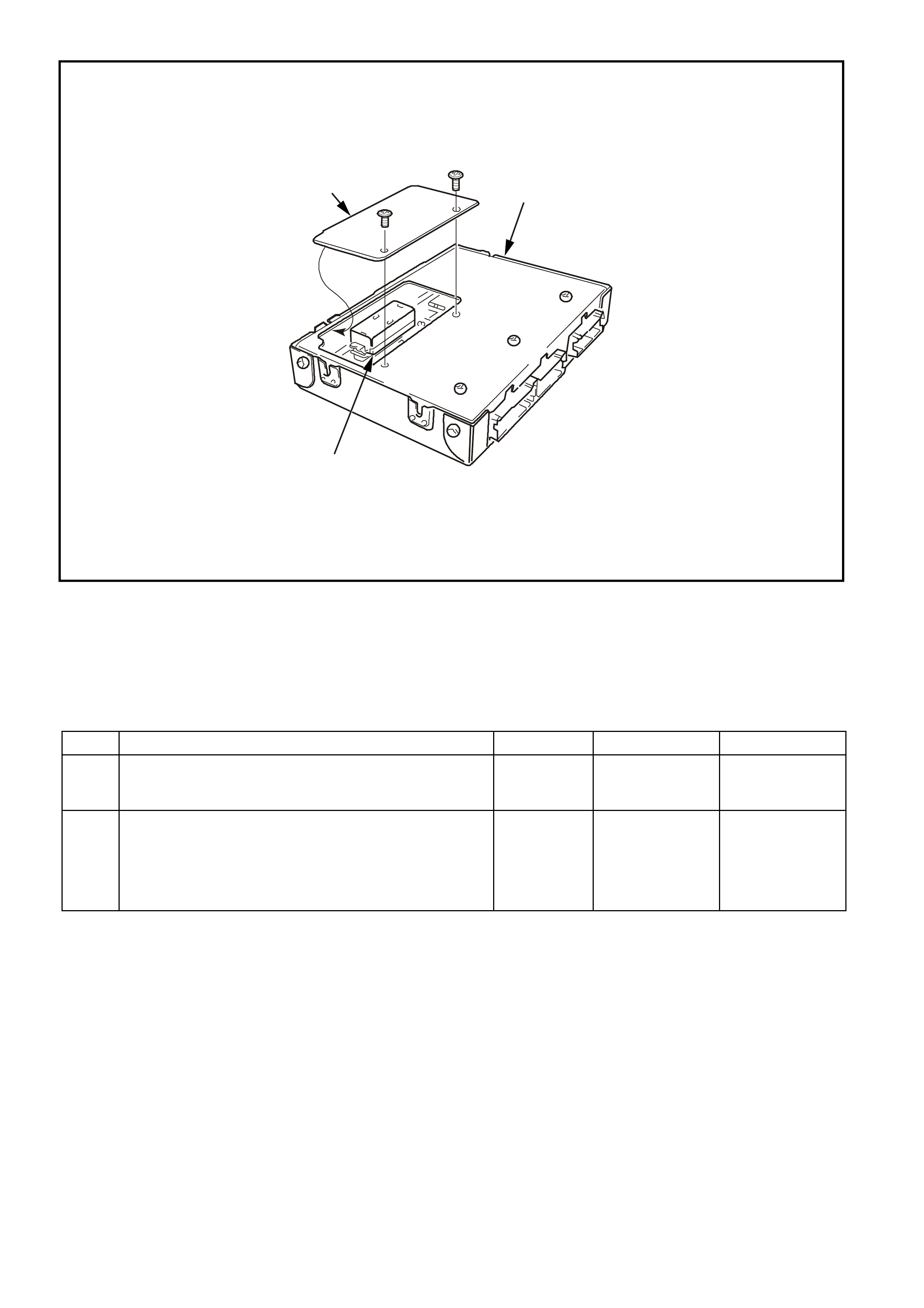
1. Powertrain Control Module (PCM)
2. Prom
3. Prom Access Cover
DTC 55 V6 PCM -
PCM – ANALOG TO DIGITAL (A/D) CONVERSION ERROR
DTC 55 V6 PCM - PCM - ANALOG TO DIGITAL (A/D) CONVERSION ERROR
STEP ACTION VALUE YES NO
1. Was the "On-Board Diagnostic" (OBD) System Check
performed? Go to Step 2 Go to OBD
System Check in
this Section
2. Replace PCM.
Refer to Section 6C1-3 Service Operations of the VX
Series Service Information, for PCM Security Link
procedure.
Is action complete?
Verify repair
3
SUPERVX4376
2
1

DTC 56 V6 PCM -
LEAN CONDITION UNDER LOAD
CIRCUIT DESCRIPTION;
The PCM's internal c ircuitr y c an identify if the vehicle's f uel system is capable of supplying adequate amounts of
fuel during heavy acceleration (power enrichment) by monitoring the voltage of the oxygen sensor. When a
"power enrichment" mode of operation is requested during "Closed Loop" (remember the PCM will go "Open
Loop" not make fueling changes based on oxygen sensor signal under heavy acceleration), the PCM will
provide more fuel to the engine. Under these conditions, the PCM should detect a "rich" condition, high oxygen
sensor voltage. If this "rich" exhaust is NOT detected at this time, a DTC 56 will set. A plugged fuel filter or
restric ted fuel line or a f uel pump that is not s witching to high speed can prevent adequate amounts of fuel from
being supplied during the power enrichment mode but may be fine at idle or light throttle acceleration.
This superc harged engine application has a two speed fuel pum p that s witches fr om low speed (low f uel flow) to
high speed (high fuel flow) when heavy boost is required, and will switch back to low speed (low fuel flow) for
normal vehicle driving conditions.
CONDITIONS FOR RUNNING THE DTC
• The engine has been running for longer than two minutes.
• DTC 13, 44, 45, 63, 64 and 65 are not current.
CONDITIONS FOR SETTING THE DTC
• The PCM detects a low oxygen sensor voltage for 10 seconds during “Power Enrichment” mode of
operation.
ACTION TAKEN WHEN THE DTC SETS
• The PCM stores the DTC information into memory when the diagnostic runs and fails.
• The Malfunction Indicator Lamp (MIL) will not be illuminated.
• The PCM records the operating conditions at the tim e the diagnostic fails. T he PCM stores this information
in the History Data.
M
I
C
R
O
P (439)
YE95
D
D
B
B
A
A
C
C
YE95
GY (1412)
B/R (750)
Engine
Earth
To Fuse
F33
GY/B (1413)
V (412)
V/B (413)
B/R (750)
4269
A2
D16
D15
D14
D13
A1 450 m V
Right
Oxygen
Sensor
Signal HI
Right
Oxygen
Sensor
Signal LO
Left
Oxygen
Sensor
Signal HI
Left
Oxygen
Sensor
Signal LO
Earth
Earth
Ri ght Oxygen Sensor
Left Oxygen Sensor 450 m V
IC
IC
Engine
Earth
PCM
YB193
YB188
YB188

CONDITIONS FOR CLEARING THE MIL/DTC
• A History DTC clears after forty consecutive warm-up cycles.
• Use a Tech 2 scan tool in order to clear the MIL/DTC.
DIAGNOSTIC AIDS
A restricted f ilter can supply adequate amounts of fuel at idle but m ay not be able to supply enough fuel during
heavy acceleration. A vapour lock condition can cause a DTC 56.
Be certain that the proper fuel pump is installed in the vehicle. If the improper fuel pump is installed, this could
cause DTC 56 to set.
Refer to Table A-4.1-1 for checking the operation of the two speed fuel pump.
TEST DESCRIPTION
The numbers below refer to the step numbers on the diagnostic table.
3. Wrap a shop towel around the f uel press ure connec tor to absorb any sm all am ount of f uel leak age that m ay
occur when installing the gauge. Ignition "ON," pump pressure should be 290-410 kPa. This pressure is
controlled by spring pressure within the fuel pressure regular assembly. Pressure below 290 kPa. may
cause a lean condition and may set a DTC 44. It could also cause hard starting cold and poor driveability.
Low enough pressure will cause the engine not to run at all. Restricted flow may allow the engine to run at
idle, or low speeds, but may cause a surge and stall when more fuel is required, as when accelerating or
driving at high speeds. Low fuel pressure under heavy acceleration conditions may set a DTC 56.
5. Restricting the fuel return line allows the fuel pressure to build above regulated pressure. With a Tech 2
scan tool enable the fuel pump, pressure should rise above 410 kPa as the return line is partially closed.
12. A vehicle driven in extrem ely hot temperatur es and a near em pty fuel tank can caus e the temperatur e of the
fuel in the tank to becom e heated. Couple this with the fact fuel is being sent to an even hotter engine and
the fuel becom es even hotter. Not all fuel sent to the engine is injected and this hot fuel is sent back to the
fuel tank, increasing the temperature of the fuel in the tank even more. If temperature becomes great
enough, a possible vapour leak could exist causing a DTC 56. Check that the engine cooling system and
ignition timing are working properly. Adding fuel to the fuel tank could lower fuel tank temperature.
DTC 56 V6 PCM - LEAN CONDITION UNDER LOAD
STEP ACTION VALUE YES NO
1. Was the "On-Board Diagnostic" (OBD) System Check
performed? Go to Step 2 Go to OBD
System Check in
this Section
2. Is any other DTC set? Go to that DTC
first. Go to Step 3
3. 1. Disconnect Fuel Pump Relay and crank engine to
relieve fuel pressure.
2. Install Fuel pressure gauge.
3. Start and idle engine at normal operating
temperature.
4. Disconnect vacuum line going to fuel pressure
regulator.
5. Note fuel pressure with engine running.
Is fuel pressure within specified value?
290-410 kPa No trouble found.
If no additional
DTCs were
stored, refer to
"Diagnostic Aids"
above
Go to Step 4
4. Check for restrictions in the fuel lines or the in-line fuel
filter.
Are restrictions found?
Verify Repair
Go to Step 5
5. 1. Ignition "OFF".
2. Ignition "ON".
3. Using a Tech 2 scan tool, select and enable the
fuel pump.
4. Use a pliers to slowly close the fuel return line at
the fuel gauge sender unit while fuel pump is
operating.
Does pressure rise above value shown?
410 kPa
Do not
exceed 450
kPa
DTC 56 is
intermittent.
Refer to
"Diagnostic Aids"
above.
Go to Step 6
6. Check for faulty fuel pump.
Is faulty fuel pump found? Verify Repair Go to Step 7

DTC 56 V6 PCM - LEAN CONDITION UNDER LOAD (CONTINUED)
STEP ACTION VALUE YES NO
7. Verify that fuel pulse dampener (Pulsator) is properly
connected.
Is the fuel pulse dampener connected correctly?
Go to Step 8 Verify Repair
8. Check for restriction in fuel pump strainer.
Is a restriction found? Verify Repair Go to Step 9
9. Check that the fuel pump being used is the correct part
number for the vehicle.
Is incorrect fuel pump installed in vehicle?
Go to Step 10 Go to Step 11
10. Install the correct fuel pump
Is action complete? Verify Repair
Refer to
"Diagnostic Aids"
above.
11. Check that the fuel sock is not collapsed.
Is the sock collapsed? Verify Repair Go to Step 12
12. Check vehicle fuel for being overheated?
Was a problem found? Repair
overheating
problem
Go to Step 13
13. Clear DTC and drive vehicle under the condition for
setting the DTC on the facing page.
Does DTC 56 reset?
Go to Step 2 Repair complete
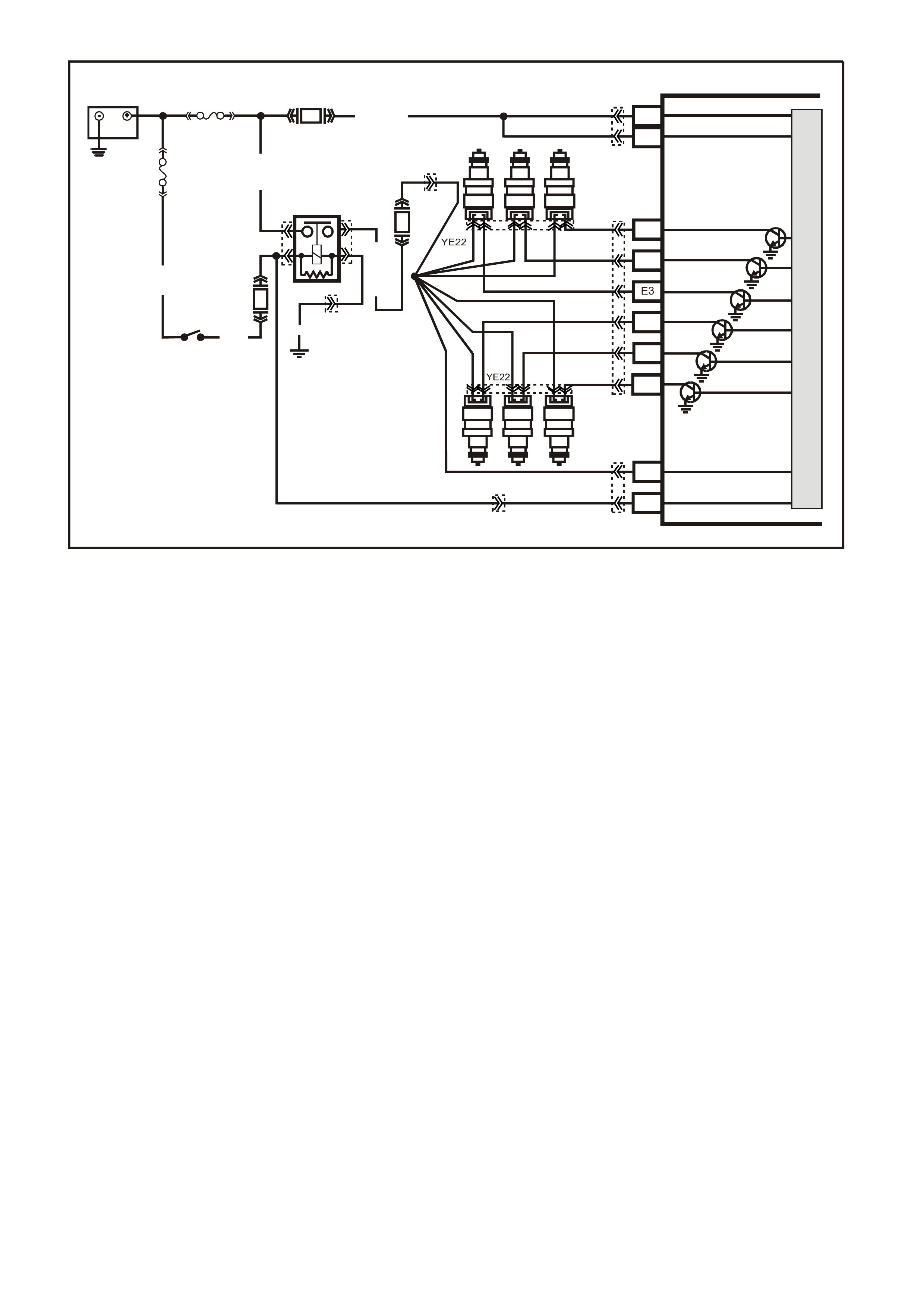
DTC 57 V6 PCM -
INJECTOR VOLTAGE MONITOR FAULT
Circuit Description:T he injec tor voltage monitor line is used so that the PCM will k now the exact voltage the fuel
injectors are operating at. This voltage is used to control the pulse width modulation of the fuel injectors. If the
injector voltage m onitor line drops mor e than 2.2 volts for m ore than 3 sec onds, Diagnos tic T rouble Code (DT C)
57 will set. This DTC will not turn "ON" the "Check Powertrain" lamp, but will have a DTC set in the PCM
memory that can be read with the Tech 2 scan tool and can be displayed by flashing out codes.
CONDITIONS FOR RUNNING THE DTC
• The engine is running.
• DTC 54 is not set.
CONDITIONS FOR SETTING THE DTC
• Injector voltage monitor line voltage is 2.2 volts different than system voltage for 3 seconds.
ACTION TAKEN WHEN THE DTC SETS
• The PCM stores the DTC information into memory when the diagnostic runs and fails.
• The Malfunction Indicator Lamp (MIL) will not be illuminated.
• The PCM records the operating conditions at the tim e the diagnostic fails. T he PCM stores this information
in the History Data.
• The PCM will use the battery feed input signal as the voltage value to control the fuel injectors base pulse
width.
CONDITIONS FOR CLEARING THE MIL/DTC
• The PCM turns the MIL OFF after the first ignition cycle that the diagnostic runs and does not fail.
• A Histor y DT C clears after f orty c onsecutive warm -up cycles, if this or any other em ission related diagnostic
does not report any failure.
• Use a Tech 2 scan tool in order to clear the MIL/DTC.
SUPERVX017
# 2
# 4 # 6
# 1 # 3 # 5
PCM
A8
B8
F3
F1
F2
E2
E4
B12
A4
BATTERY F EED
BATTERY F EED
O
(740)
O
(740)
BLU
(841)
V
(843)
GY
(845)
INJECTOR CONTROL
IN JE C TOR VOLTAG E
MONITOR LINE
IGNITION FEED
O/Y (479)
EFI R EL AY
B/W (152)
LOC. E4
P (3 )
O/B (740)
IGN SW
M
I
C
R
O
R
(481)
P
(39)
Y
(846)
BR/Y
(844)
G
(842)
F31
F14
F34
BATTERY
FS
FJ
R (2)
(1040)
YE112
YE114
YE111
YB194
YB188
YE39 YE39
YB188

DIAGNOSTIC AIDS:
W hen the injector voltage monitor line voltage drops more than 2.2 volts, the PCM will operate on an incorrect
value for 3 seconds until the DTC 57 is set. Check PCM terminal connections for proper mating.
If DTC 16, 53 and 57 are set, check for short to voltage on "Diagnostic Test" line, circuit 451.
Test Description: Number(s) below refer to step number(s) on the diagnostic Table.
2. If the charging voltage is too high, this could set DTC 57. If DTC 53 is set, refer to that DTC first.
YB 188
P.C.M CONNECTOR 2
(481)
(417)
(740)
R
BLU
O
(1456)
LG
V/W
(415)
Y
(1227)
B/Y
(410)
BR
(472)
(259)
(750)
(750)
(1221)
B/R
B/R
R/B
G/B
(39)
P
(465)
G/W
(416)
GY
(740)
O
A1
B1
B12
A12
INJECTORS
GY
(1)
(842)
(481)
Y
V
BLU
(6)
(4)
(2)
(846)
(843)
G
R
(845)
(841)
(5)
(844)
BR/Y
(3)
DTC 57 V6 PCM INJECTOR VOLTAGE MONITOR FAULT
STEP ACTION VALUE YES NO
1. Was the "On-Board Diagnostic" (OBD) System Check
performed? Go to Step 2. Go to OBD
System Check in
this Section
2. 1. This table assumes that no DTC 54 is set and the
battery and charging systems are operating
properly.
2. Using the Tech 2 scan tool, display "Injector
Voltage" and "Battery Voltage".
Are they within the specified value of each other?
2.4 volts DTC 57 is
intermittent, if no
additional DTCs
were stored, refer
to "Diagnostic
Aids" above.
Go to Step 3
3. Using DVM, backprobe PCM terminal "B12" with red lead
and connect black lead to PCM terminal "A1".
Is voltage measured within specified value of "Battery
Voltage" reading on Tech 2 scan tool?
2.4 volts Go to Step 5
Go to Step 4
4. Repair open in circuit 481 between splice and PCM
terminal "A1".
Is action complete?
Verify Repair
5. Replace PCM.
Refer to Section 6C1-3 Service Operations of the VX
Series Service Information, for PCM Security Link
procedure.
Is action complete?
Verify Repair
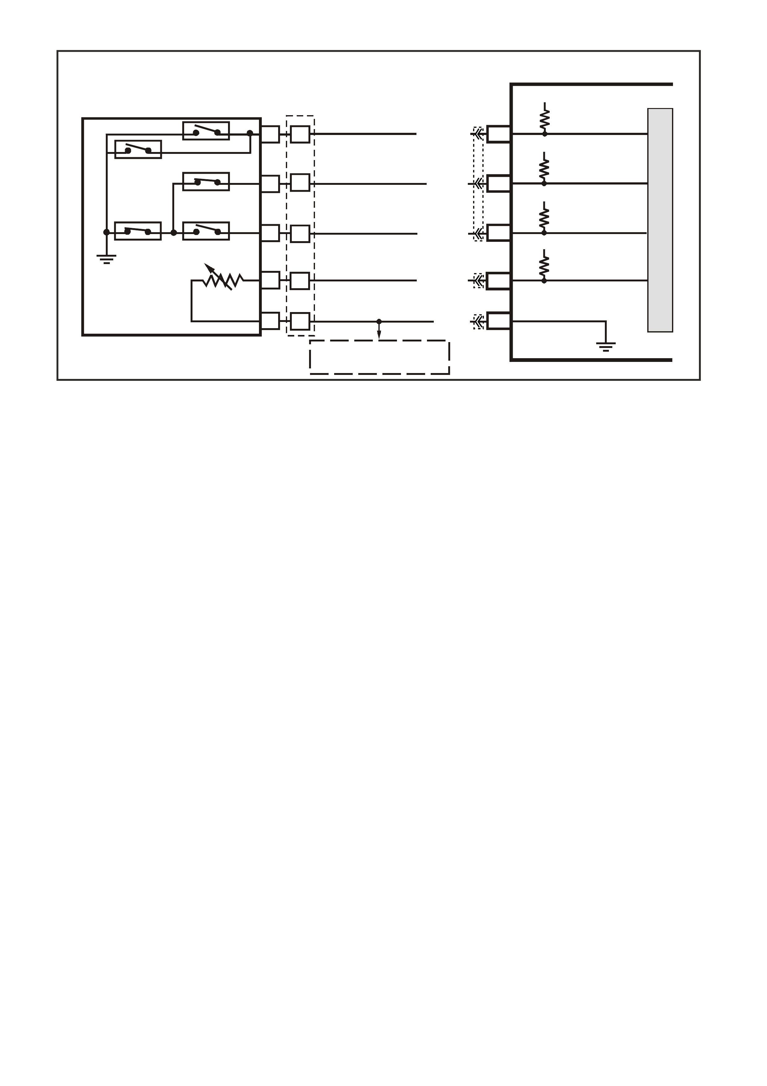
DTC 58 V6 PCM -
TRANSMISSION FLUID TEMPERATURE (TFT) SENSOR LOW INPUT
CIRCUIT DESCRIPTION
The Autom atic T ransm ission Fluid T emper ature (TF T) sens or is a therm istor within the Automatic Transm ission
Fluid Pressure Manual Valve Position Switch (TFP Val. Position Sw.). The TFT sensor controls the signal
voltage to the PCM. The PCM supplies a 5-volt reference signal to the sensor on circuit 1227. When the
transm ission f luid is cold, the sensor resistance will be high. The PCM will then detect a high s ignal voltage. As
the transmission fluid temperature increases to the normal operating temperature, the sensor resistance
becomes less and the voltage decreases.
When the PCM detects a c ontinuous shor t to ear th in the T F T s ignal circ uit or in the T F T s ens or, then a DTC 58
will set.
CONDITIONS FOR RUNNING THE DTC
• The ignition switch is on.
CONDITIONS FOR SETTING THE DTC
• The TFT sensor indicates a signal voltage less than 0.2 volts for 10 seconds.
ACTION TAKEN WHEN THE DTC SETS
• The PCM stores the DTC information into memory when the diagnostic runs and fails.
• The Malfunction Indicator Lamp (MIL) will not be illuminated.
• The PCM records the operating conditions at the tim e the diagnostic fails. T he PCM stores this information
in the History Data.
• When this DTC sets , the PCM uses a transm iss ion fluid tem peratur e default value based on engine coolant,
engine run time and IAT at startup, the PCM will freeze shift adapts from being updated.
CONDITIONS FOR CLEARING THE MIL/DTC
• A History DTC clears after forty consecutive warm-up cycles.
• Use a Tech 2 scan tool in order to clear the MIL/DTC.
SUPERVX034
PCM
F9
F10
B6
F16
TFP SIGNAL A
TFP SIGNAL B
TRANSMISSION FLUID
TEMPERATURE (TFT)
SENSOR SIGNAL
SENSOR EARTH
N
C
R
E
D
A
B
P
L
M
TRANSMISSION FLUID
TEMPERATURE
(TF T ) SENSOR
AUTOMATIC TRANSMISSION FLUID
PRESSURE SWITCH ASSEMBLY
BR/Y (1224)
Y (1225)
GY (1226)
B/Y (1227)
B (46 9)
12V
12V
5V
F11 TFP SIGNAL C
12V
M
I
C
R
O
TO
A
/C PRESSURE SENSOR
AND IAT SENSOR
YB194
YB129
YB188
YB194

DIAGNOSTIC AIDS
• Inspect the wiring for poor electrical connections at the PCM. Inspect the wiring for poor electrical
connections at the transmission pass-through connector. Look for the following conditions:
- A backed out terminal
- A damaged terminal
- Poor terminal tension
- A chafed wire
- A broken wire inside the insulation
- Corrosion
• When diagnosing for an inter m ittent short or open c ondition, m ass age the wiring harness while watc hing the
test equipment for a change.
• Use the Temperature vs Resistance table when testing the T FT sensor at various temperature levels. T est
the TFT sensor in order to evaluate the possibility of a skewed (mis-scaled) sensor. A skewed sensor can
result in delayed garage shifts or TCC complaints.
• The s can tool can display the transm ission fluid tem perature in degrees. After the transm ission is operating,
the fluid temperature should rise steadily to a normal operating temperature, then stabilise.
TEST DESCRIPTION
The numbers below refer to the step numbers on the diagnostic table.
3. This step tests for a short to earth or a skewed sensor.
4. This step creates an open within the transmission in order to test for an internal fault.
Transmission Fluid Temperature (TFT) Sensor Temperature To Resistance Table
Temperature TFT Resistance Signal
Degrees °C Minimum Ω
ΩΩ
Ω Normal Ω
ΩΩ
Ω Maximum Ω
ΩΩ
Ω Volts
-40 90636 100707 110778 5.0
-30 47416 52684 57952 4.78
-20 25809 28677 31545 4.34
-10 14558 16176 17784 3.89
0 8481 9423 10365 3.45
10 5104 5671 6238 3.01
20 3164 3515 3867 2.56
30 2013 2237 2461 1.8
40 1313 1459 1605 1.1
50 876 973 1070 3.25
60 600 667 734 2.88
70 420 467 514 2.56
80 299 332 365 2.24
90 217 241 265 1.7
100 159 177 195 1.42
110 119 132 145 1.15
120 89.9 99.9 109.9 0.87
130 69.1 76.8 84.5 0.6
140 53.8 59.8 65.8 0.32
150 42.5 47.2 51.9 0
A shunt in the PCM becomes active as the transmission temperature increases
beyond 50 °C. As the temperature decreases, the internal shunt deactivates at 40
°C.
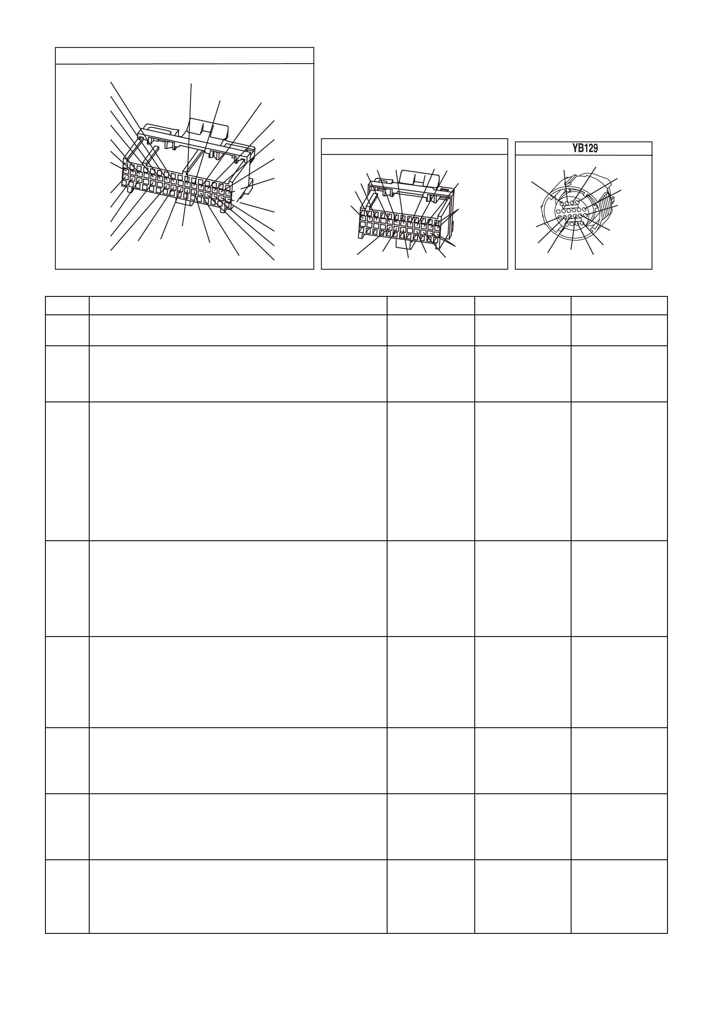
YE194
P.C.M. CONNECTOR 3
LG/B
(366)
G
(843)
B/W
F16
B/Y
BR/Y
(1228)
(469)
Y
(451)
F1
P
(841)
BLU
V
E1
LBLU
(845)
BLU
B
(1226)
W/B
BLU/W
V
R
(435)
(31)
(1229)
GY
(1224)
Y
(846)
GY
(842)
(452)
(774)
(304)
BR/Y
(411)
(439)
GY/BLU
BLU
(1225)
E16
(1427)
(429)
(844)
B/O
(434)
OR AUTO
GY/BLU
GY
(1434)
MAN
(776)
W
BLU/W
Y
GY
(771)
(772)
(773)
YB 188
P.C.M CONNECTOR 2
(481)
(417)
(740)
R
BLU
O
(1456)
LG
V/W
(415)
Y
(1227)
B/Y
(410)
BR
(472)
(259)
(750)
(750)
(1221)
B/R
B/R
R/B
G/B
(39)
P
(465)
G/W
(416)
GY
(740)
O
A1
B1
B12
A12
TRANSMISSION CONNECTOR
GY/BLU
(1229)
R
(1228)
Y/B
(1223)
LG
(1222)
P/BLU
(339)
(1227)
B/Y
(1230)
B/W
GY/R
(422)
BR
(418)
BR/Y
(1224)
(1226)
GY
Y
(1225)
(897)
G/W
(V8)
B
(469) (V6)
OR
DTC 58 V6 PCM - TRANSMISSION FLUID TEMPERATURE (TFT) SENSOR LOW INPUT
STEP ACTION VALUE YES NO
1 Was the On-Board Diagnostic (OBD) System Check
performed? Go to Step 2 Go to OBD
System Check
2 Perform the transmission fluid checking procedure.
Have you performed the fluid checking procedure?
Go to Step 3 Go to
Transmission
Fluid Checking
Procedure
3 1. Install the scan tool.
2. With the engine OFF, turn the ignition switch to the
RUN position.
Important: Before clearing the DTCs use the scan tool in
order to record the DTC history. The Clear Info function
will erase the data.
3. Record the DTC history.
Does the scan tool display a TFT voltage less than the
specified value?
0.33 volts Go to Step 4 Go to
“Diagnostic Aids”
above
4 1. Turn the ignition OFF.
2. Disconnect the transmission pass-through connector.
3. With the engine OFF, turn the ignition switch to the
RUN position.
Does the scan tool display a TFT voltage greater than the
specified value?
4.92 volts Go to Step 5 Go to Step 9
5 1. Install the J 39775 Jumper Harness on the
transmission side of the pass-through connector.
2. Using the J 39200 DVM and J 35616 Connector Test
Adapter Kit, measure the resistance between terminal
L and terminal M.
Is the resistance within specifications?
3088-3942Ω
@ 20° C
159-198Ω
@100° C
Go to
“Diagnostic Aids”
above.
Go to Step 6
6 1. Check the internal Automatic Transmission Wiring
Harness Assembly for a short to earth.
2. Replace the harness if necessary.
Did you find and correct the problem?
Go to Step 11 Go to Step 7
7 1. Disconnect the internal Automatic Transmission
Wiring Harness Assembly at the TFT sensor.
2. Measure the resistance of the TFT sensor.
Is the resistance within specifications?
3088-3942Ω
@ 20° C
159-198 Ω
@ 100° C
Go to
“Diagnostic Aids”
above.
Go to Step 8
8 Replace the TFT Sensor (this is part of the TFP Val.
Position Sw.). Refer to Service Operations in Section 6C1-
3 Service Operations of the VX Series Service
Information.
Is the action complete?
Go to Step 11

DTC 58 V6 PCM - TRANSMISSION FLUID TEMPERATURE (TFT) SENSOR LOW INPUT (CONTINUED)
STEP ACTION VALUE YES NO
9 Check circuit 1227 for a short to earth. Repair the circuit if
necessary.
Did you find a problem?
Go to Step 11 Go to Step 10
10 Replace PCM.
Refer to Section 6C1-3 Service Operations of the VX
Series Service Information, for PCM Security Link
procedure.
Is action complete?
Go to Step 11
11 In order to verify your repair, perform the following
procedure:
1. Select DTC.
2. Select Clear Info.
3. With the engine OFF, turn the ignition switch to the
RUN position.
Does the scan tool indicate a TFT voltage greater than the
specified value?
0.33 volts System OK Begin the
diagnosis again.
Go to Step 1
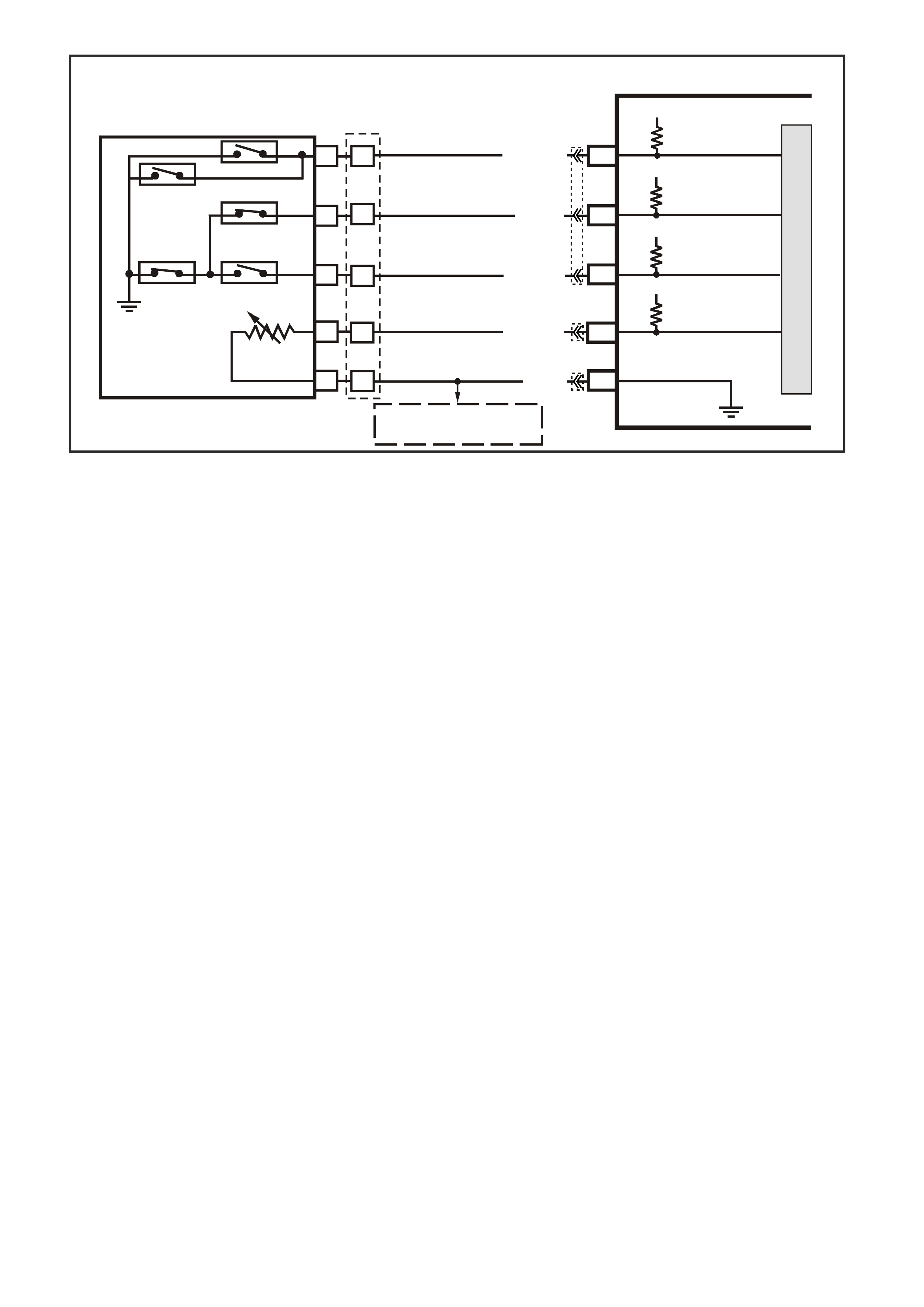
DTC 59 V6 PCM -
TRANSMISSION FLUID TEMPERATURE (TFT) SENSOR HIGH INPUT
CIRCUIT DESCRIPTION
The Autom atic T ransm ission Fluid T emper ature (TF T) sens or is a therm istor within the Automatic Transm ission
Fluid Pressure Manual Valve Position Switch (TFP Val. Position Sw.). The TFT sensor controls the signal
voltage to the PCM. The PCM supplies a 5-volt reference signal to the sensor on circuit 1227. When the
transm ission f luid is cold, the sensor resistance will be high. The PCM will then detect a high s ignal voltage. As
the transmission fluid temperature increases to the normal operating temperature, the sensor resistance
becomes less and the voltage decreases.
When the PCM detects a c ontinuous open or s hor t to voltage in the T F T s ignal c ircuit or in the TFT s ensor , then
a DTC 59 will set.
CONDITIONS FOR RUNNING THE DTC
• The ignition switch is on.
CONDITIONS FOR SETTING THE DTC
• The TFT sensor indicates a signal voltage greater than 4.92 volts for 6.8 minutes (409 seconds).
ACTION TAKEN WHEN THE DTC SETS
• The PCM stores the DTC information into memory when the diagnostic runs and fails.
• The Malfunction Indicator Lamp (MIL) will not be illuminated.
• The PCM records the operating conditions at the tim e the diagnostic fails. T he PCM stores this information
in the History Data.
• When this DTC sets , the PCM uses a transm iss ion fluid tem peratur e default value based on engine coolant,
engine run time and IAT at startup, the PCM will freeze shift adapts from being updated.
CONDITIONS FOR CLEARING THE MIL/DTC
• A History DTC clears after forty consecutive warm-up cycles.
• Use a Tech 2 scan tool in order to clear the MIL/DTC.
SUPERVX034
PCM
F9
F10
B6
F16
TFP SIGNAL A
TFP SIGNAL B
TRANSMISSION FLUID
TEMPERATURE (TFT)
SENSOR SIGNAL
SENSOR EARTH
N
C
R
E
D
A
B
P
L
M
TRANSMISSION FLUID
TEMPERATURE
(TF T ) SENSOR
AUTOMATIC TRANSMISSION FLUID
PRESSURE SWITCH ASSEMBLY
BR/Y (1224)
Y (1225)
GY (1226)
B/Y (1227)
B (46 9)
12V
12V
5V
F11 TFP SIGNAL C
12V
M
I
C
R
O
TO
A
/C PRESSURE SENSOR
AND IAT SENSOR
YB194
YB129
YB188
YB194

DIAGNOSTIC AIDS
• Inspect the wiring for poor electrical connections at the PCM. Inspect the wiring for poor electrical
connections at the transmission pass-through connector. Look for the following conditions:
- A backed out terminal
- A damaged terminal
- Poor terminal tension
- A chafed wire
- A broken wire inside the insulation
- Corrosion
• Corrosion when diagnosing for an intermittent short or open condition, massage the wiring harness while
watching the test equipment for a change.
• Use the Temperature vs Resistance table when testing the T FT sensor at various temperature levels. T est
the TFT sensor in order to evaluate the possibility of a skewed (mis-scaled) sensor. A skewed sensor can
result in delayed garage shifts or TCC complaints.
• The s can tool can display the transm ission fluid tem perature in degrees. After the transm ission is operating,
the fluid temperature should rise steadily to a normal operating temperature, then stabilise.
TEST DESCRIPTION
The numbers below refer to the step numbers on the diagnostic table.
3 This step verifies that a problem exists in the TFT sensor circuit.
4 This s tep s imulates a T F T s ens or DTC 58. If the PCM r ec ognises high temperatur e, the PCM and wiring are
functioning normally.
5 This step tests the TFT sensor and Automatic Transmission Wiring Harness Assembly.
Transmission Fluid Temperature (TFT) Sensor Temperature To Resistance Table
Temperature TFT Resistance Signal
Degrees °C Minimum Ω
ΩΩ
Ω Normal Ω
ΩΩ
Ω Maximum Ω
ΩΩ
Ω Volts
-40 90636 100707 110778 5.0
-30 47416 52684 57952 4.78
-20 25809 28677 31545 4.34
-10 14558 16176 17784 3.89
0 8481 9423 10365 3.45
10 5104 5671 6238 3.01
20 3164 3515 3867 2.56
30 2013 2237 2461 1.8
40 1313 1459 1605 1.1
50 876 973 1070 3.25
60 600 667 734 2.88
70 420 467 514 2.56
80 299 332 365 2.24
90 217 241 265 1.7
100 159 177 195 1.42
110 119 132 145 1.15
120 89.9 99.9 109.9 0.87
130 69.1 76.8 84.5 0.6
140 53.8 59.8 65.8 0.32
150 42.5 47.2 51.9 0
A shunt in the PCM becomes active as the transmission temperature increases beyond
50 °C. As the temperature decreases, the internal shunt deactivates at 40 °C.

YE194
P.C.M. CONNECTOR 3
LG/B
(366)
G
(843)
B/W
F16
B/Y
BR/Y
(1228)
(469)
Y
(451)
F1
P
(841)
BLU
V
E1
LBLU
(845)
BLU
B
(1226)
W/B
BLU/W
V
R
(435)
(31)
(1229)
GY
(1224)
Y
(846)
GY
(842)
(452)
(774)
(304)
BR/Y
(411)
(439)
GY/BLU
BLU
(1225)
E16
(1427)
(429)
(844)
B/O
(434)
OR AUTO
GY/BLU
GY
(1434)
MAN
(776)
W
BLU/W
Y
GY
(771)
(772)
(773)
YB 188
P.C.M CONNECTOR 2
(481)
(417)
(740)
R
BLU
O
(1456)
LG
V/W
(415)
Y
(1227)
B/Y
(410)
BR
(472)
(259)
(750)
(750)
(1221)
B/R
B/R
R/B
G/B
(39)
P
(465)
G/W
(416)
GY
(740)
O
A1
B1
B12
A12
TRANSMISSION CONNECTOR
GY/BLU
(1229)
R
(1228)
Y/B
(1223)
LG
(1222)
P/BLU
(339)
(1227)
B/Y
(1230)
B/W
GY/R
(422)
BR
(418)
BR/Y
(1224)
(1226)
GY
Y
(1225)
(897)
G/W
(V8)
B
(469) (V6)
OR
DTC 59 V6 PCM - TRANSMISSION FLUID TEMPERATURE (TFT) SENSOR HIGH INPUT
STEP ACTION VALUE YES NO
1 Was the On-Board Diagnostic (OBD) System Check
performed? Go to Step 2 Go to OBD
System Check
2 Perform the transmission fluid checking procedure.
Have you performed the fluid checking procedure?
Go to Step 3 Go to
Transmission
Fluid Checking
Procedure
3 1. Install the scan tool.
2. With the engine OFF, turn the ignition switch to the
RUN position.
Important: Before clearing the DTCs, use the scan tool
in order to record the DTC history for reference. The
Clear Info function will erase the data.
3. Record the DTC history.
Does the scan tool display a TFT Sensor voltage greater
than the specified value?
4.92 volts Go to Step 4 Go to “Diagnostic
Aids” above
4 1. Turn the ignition OFF. 0.2 volts Go to Step 5 Go to Step 9
5 1. Turn the ignition OFF.
2. Install the J 39775 Jumper Harness on the
transmission side of the pass-through connector.
3. Using the J 39200 DVM and J 35616 Connector Test
Adapter Kit, measure the resistance between
terminal L and terminal M.
Is the resistance within specification?
3088-3942 Ω
at 20° C
159-198 Ω
at 100° C
Go to “Diagnostic
Aids” above
Go to Step 6
6 1. Check the internal Automatic Transmission Wiring
Harness Assembly for a open condition.
2. Replace the harness if necessary.
Did you find and correct the problem?
Go to Step 12 Go to Step 7
7 1. Disconnect the internal Automatic Transmission
Wiring Harness Assembly at the TFT sensor.
2. Measure the resistance of the TFT sensor.
Is the resistance within specifications?
3088-3942 Ω
at 20° C
159-198 Ω at
100° C
Go to “Diagnostic
Aids” above
Go to Step 8

DTC 59 V6 PCM - TRANSMISSION FLUID TEMPERATURE (TFT) SENSOR HIGH INPUT (CONTINUED)
STEP ACTION VALUE YES NO
8 Replace the TFT Sensor (this is part of the TFP Val.
Position Sw.). Refer to Service Operations in
Section 6C1-3 Service Operations of the VX Series
Service Information.
Is the replacement complete?
Go to Step 12
9 Check circuit 1227 for an open or short to B+. Repair the
circuit if necessary.
Did you find a problem?
Go to Step 12 Go to Step 10
10 Check circuit 469 for an open. Repair the circuit if
necessary.
Did you find a problem?
Go to Step 12 Go to Step 11
11 Replace PCM.
Refer to Section 6C1-3 Service Operations of the VX
Series Service Information, for PCM Programming and
Security Link procedure.
Is action complete?
Go to Step 12
12 In order to verify your repair, perform the following
procedure:
1. Select DTC.
2. Select Clear Info.
3. With the engine OFF, turn the ignition switch to the
RUN position.
Does the scan tool indicate a TFT voltage less than the
specified value?
4.92 volts System OK Begin the
diagnosis again.
Go to Step 1

DTC 63 V6 PCM -
LEFT HAND OXYGEN SENSOR (O2S) INSUFFICIENT ACTIVITY
Circuit Desc ription:The ex haust oxygen sensor is m ounted in the exhaust pipe with the sensing portion exposed
to exhaust gases. After the sensor is hot (360 degrees C), it becomes a voltage generator, producing a
"changing" voltage. T his voltage ranges fr om approxim ately 100 m illivolts with a "lean" exhaust, to 900 m illivolts
with a "rich" exhaust. W hen the sensor is cold (below 360 degrees C) it acts like an open circuit and produces
almost no voltage. The PCM supplies a very small "bias" voltage between terminals D15 and D16, normally
about 450 millivolts . If measur ed with the 10 m egaohm digital voltmeter, it may measur e as low as 350 millivolts .
When the sensor is hot, it's output overshadows this PCM supplied voltage.
When the fuel system is correctly operating in the closed-loop mode, the sensor output is changing several
times per second, going above and below a mid-point range of 490-500 millivolts at a hot idle. The PCM
compares the voltage between the sensor signal and sensor earth terminals and decides the needed fuel
mixture correction. The PCM also monitors the changing voltage, watching for transitions above and below the
mid- point range, to decide when to operate in the closed-loop m ode. An open circ uit, defective, or contaminated
sensor could caus e the voltage to stay within a 410- 477 m illivolt band too long, k eeping the system in open-loop
and setting a DTC 63.
CONDITIONS FOR RUNNING THE DTC
• Engine run time is longer than 4 minutes.
• No TP Sensor DTC’s are set.
• The ECT sensor is more than 85°C.
• Throttle angle is more than 15%.
CONDITIONS FOR SETTING THE DTC
• The LH 02S voltage stays between 410-477 millivolts.
ACTION TAKEN WHEN THE DTC SETS
• The PCM illuminates the Malfunction Indicator Lamp (MIL) when the diagnostic runs and fails.
• The PCM records the operating conditions at the tim e the diagnostic fails. T he PCM stores this information
in the History Data.
• Once a 02S DTC is set, and current, the PCM will operate the fuel system in the “Open Loop” mode.
M
I
C
R
O
P (439)
YE95
D
D
B
B
A
A
C
C
YE95
GY (1 412)
B/R (750)
Engine
Earth
To Fuse
F33
GY/B (1413)
V (412)
V/B (413)
B/R (750)
4269
A2
D16
D15
D14
D13
A1 450 m V
Right
Oxygen
Sensor
Signal HI
Right
Oxygen
Sensor
Signal LO
Left
Oxygen
Sensor
Signal HI
Left
Oxygen
Sensor
Signal LO
Earth
Earth
Ri ght O x ygen Sensor
Left Oxygen Sensor 45 0 m V
IC
IC
Engine
Earth
PCM
YB193
YB188
YB188
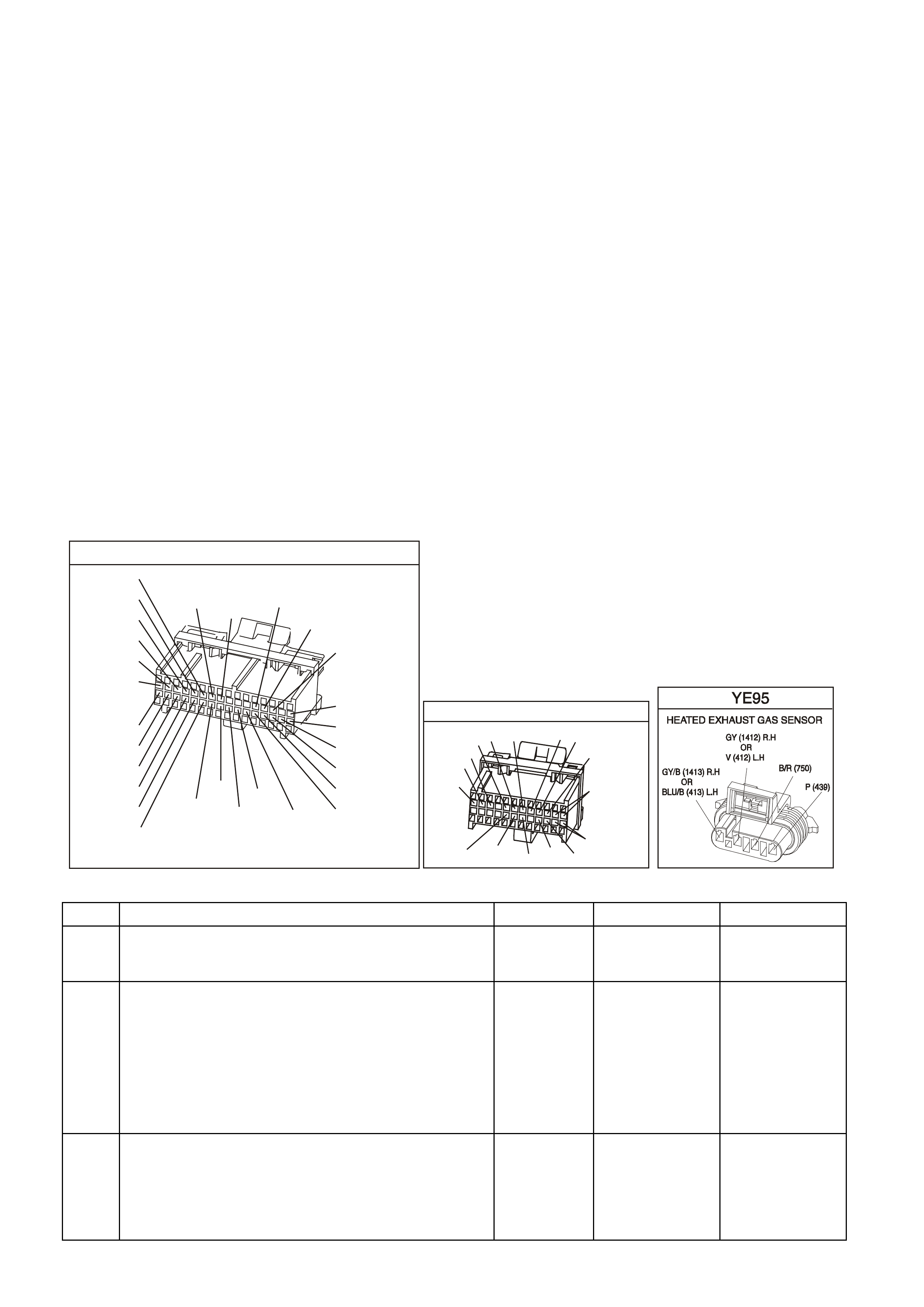
CONDITIONS FOR CLEARING THE MIL/DTC
• The PCM turns the MIL OFF after the first ignition cycle that the diagnostic runs and does not fail.
• A Histor y DT C clears after f orty c onsecutive warm -up cycles, if this or any other em ission related diagnostic
does not report any failure.
• Use a Tech 2 scan tool in order to clear the MIL/DTC.
DIAGNOSTIC AIDS:
Normal Tech 2 scan tool voltage varies between 100 mV to 999 mV while in "Closed Loop". DTC 63 sets if
voltage remains between 410 and 477 millivolts, but the system will go "Open Loop" before the "Check
Powertrain" lamp is turned "ON".
Refer to "Intermittents" in Section6C1-2B SYMPTOMS of the VX Series Service Information. To diagnose the
oxygen sensor, refer TABLE A-6.3. in this Section.
NOTE: Oxygen Sensor Contamination - If fuel containing lead or silicone is used, or engine repairs using
unapproved RTV gasket sealer are performed, the sensor may be contaminated. It may send a "False" rich
exhaust indication to the PCM, and the PCM will attempt to drive the fuel system lean to compensate. Poor
driveability or a Diagnostic Trouble Code 13 could result. If this happens, the sensor will need to be replaced,
but every attempt to locate the source of contamination should be pursued.
TEST DESCRIPTION: Number(s) below refer to step number(s) on the diagnostic Table.
2. The Tech 2 scan tool allows you to read the same oxygen sensor voltage the PCM is using for its
calculations.
3. This step simulates a lean exhaust indication to the PCM. If the PCM and wiring are OK, the PCM will see
the lean indication and the Tech 2 scan tool should display O2 voltage below 200 mV.
YB1 93
(413)
(412)
(1413)
(1412)
(430)
(453)
(815)
V/B
GY/B
V
GY
V
B/R
W/R
(897)
(897)
G/W
G/W
(418)
(418)
BR
BR
(1426)
O/W
C16
D16
WT/B
(832)AUTO
(647)
(630)
BR
T
(832) MAN
LBLU/B
B
(424)
(423)
C1
D1
(792)
(422)
(1222)
(1223)
(428)
(123)
BR/W
GY/R
LG
Y/B
G/Y
V/W
BLU/W
BLU
(831) Man
(443)
LG/W
(442) (831)AUTO
(441)
LBLU
LBLU/B
(444)
LG/B
P.C.M. CONNECTOR 1
YB188
P.C.M CONNECTOR 2
(481)
(417)
(740)
R
BLU
O
(1456)
LG
V/W
(415)
Y
(1227)
B/Y
(410)
BR
(472)
(259)
(750)
(750)
(1221)
B/R
B/R
R/B
G/B
(39)
P
(465)
G/W
(416)
GY
(740)
O
A1
B1
B12
A12
DTC 63 V6 PCM - LEFT HAND OXYGEN SENSOR (O2S) INSUFFICIENT ACTIVITY
STEP ACTION VALUE YES NO
1. Was the "On-Board Diagnostic" (OBD) System Check
performed? Go to Step 2. Go to OBD
System Check in
this Section.
2. 1. Engine at normal operating temperature
(above 85 degrees C).
2. Run engine at approximately 600 to 1800 RPM for
two minutes.
Is Tech 2 scan tool oxygen sensor voltage between
specified values?
410-477 mV
Go to Step 3 If no additional
DTCs were
stored, refer to
“Intermittents” in
Section 6C1-2B
SYMPTOMS
of the VX Series
Service
Information.
3. 1. Ignition ON, engine stopped.
2. Disconnect O2 and jumper the O2 signal and low
circuits (PCM side) to earth.
3. Using Tech 2 scan tool, monitor O2 voltage.
Is the O2 voltage less than the specified value?
0.2 Volt
(200 mV) Go to Step 7 Go to Step 4

DTC 63 V6 PCM - LEFT HAND OXYGEN SENSOR (O2S) INSUFFICIENT ACTIVITY (CONTINUED)
STEP ACTION VALUE YES NO
4. 1. Remove the jumper wire from the O2 signal circuit
(leaving the O2 low circuit jumpered to earth).
2. Using a DVM, measure voltage between the O2
signal circuit (PCM side) and earth.
Does the O2 signal voltage measure near the specified
value?
410-477 mV
Go to Step 5 Go to Step 6
5. 1. Ignition OFF.
2. Disconnect the PCM.
3. Check continuity of the O2 low circuit between the
PCM harness connector and the O2 harness
connector.
4. If the O2 low circuit measures over 5 ohms, repair
open or poor connection as necessary.
Was a problem found?
Verify Repair Go to Step 8
6. 1. Ignition OFF.
2. Disconnect the PCM.
3. Check continuity of the following circuits:
• The O2 signal circuit between the PCM harness
connector and the O2 harness connector.
• The O2 low circuit between the PCM harness
connector and the O2 harness connector.
4. If either circuit measures over 5 ohms, repair open
or poor connection as necessary.
Was a problem found?
Verify Repair Go to Step 9
7. 1. Check the following circuits for a poor terminal
connection at the O2 harness connector.
• O2 signal circuit.
• O2 low circuit.
2. If a problem is found, repair as necessary.
Was a problem found?
Verify Repair Go to Step 10
8. 1. Check for poor O2 low circuit terminal connection at
PCM.
2. If a problem is found, repair as necessary.
Was a problem found?
Verify Repair Go to Step 11
9. 1. Check the O2 signal circuit and the O2 low circuit for
a poor terminal connection at the PCM.
2. If a problem is found, repair as necessary.
Was a problem found?
Verify Repair Go to Step 11
10. Replace the O2 sensor.
Is action complete? Verify Repair
11. Replace PCM.
Refer to Section 6C1-3 Service Operations of the VX
Series Service Information, for PCM Security Link
procedure.
Is action complete?
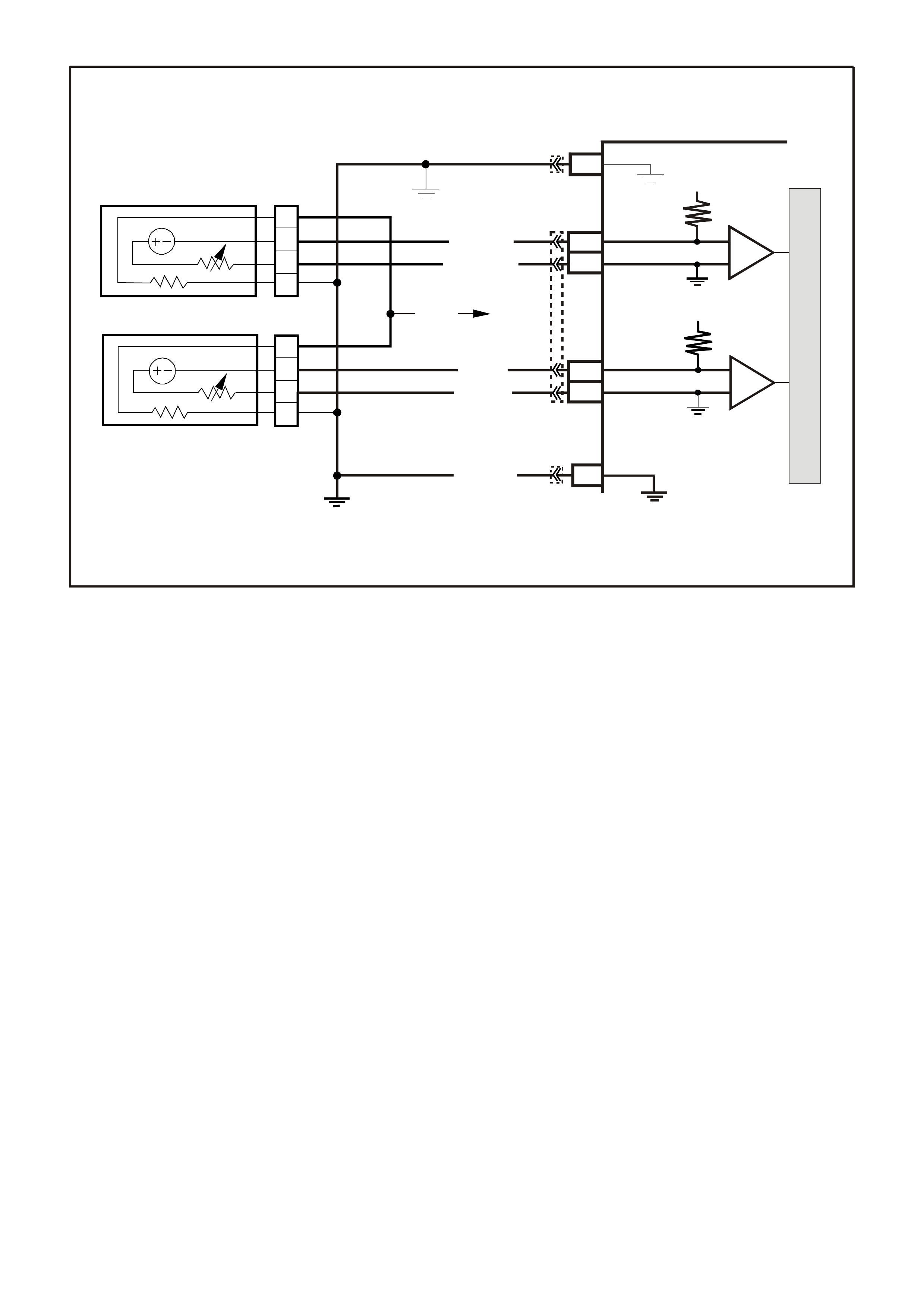
DTC 64 V6 PCM -
LEFT HAND OXYGEN SENSOR (O2S) LOW VOLTAGE
Circuit Description:The PCM supplies a voltage of about 450 millivolts between terminal "D15" and "D16". The
Oxygen (O2) sensor varies the voltage within a range of about 1 volt if the exhaust is rich, down through about
100 millivolts, if exhaust is lean.
The sensor is like an open circuit and produces no voltage when it is below about 360 degrees C. An open
sensor circuit or cold sensor causes "Open Loop" operation.
CONDITIONS FOR RUNNING THE DTC
• No IAT Sensor DTC’s are set.
• IAT Sensor is below 75°C.
• The system is in "Closed Loop”.
• Throttle angle is between 9% and 30%.
CONDITIONS FOR SETTING THE DTC
• The RH 02S signal voltage remains below 200 millivolts for 46 seconds.
ACTION TAKEN WHEN THE DTC SETS
• The PCM illuminates the Malfunction Indicator Lamp (MIL) when the diagnostic runs and fails.
• The PCM records the operating conditions at the tim e the diagnostic fails. T he PCM stores this information
in the History Data.
• Once a 02S DTC is set, and current, the PCM will operate the fuel system in the “Open Loop” mode.
CONDITIONS FOR CLEARING THE MIL/DTC
• The PCM turns the MIL OFF after the first ignition cycle that the diagnostic runs and does not fail.
• A Histor y DT C clears after f orty c onsecutive warm -up cycles, if this or any other em ission related diagnostic
does not report any failure.
• Use a Tech 2 scan tool in order to clear the MIL/DTC.
DIAGNOSTIC AIDS:
Using the T ech 2 scan tool, obser ve the Long Term Fuel Trim values at diff erent RPMs and air flow conditions.
The Tech 2 scan tool also displays the Long Term Fuel Trim cells, so the Long Term Fuel Trim values can be
check ed in each of the cells to deter mine when the DTC 44 or DT C 64 may have been s et. If the conditions for
DTC 44 or DTC 64 exists, the Long Term Fuel Trim values will be around +25%.
M
I
C
R
O
P (439)
YE95
D
D
B
B
A
A
C
C
YE95
GY (1 412)
B/R (750)
Engine
Earth
To Fuse
F33
GY/B (1413)
V (412)
V/B (413)
B/R (750)
4269
A2
D16
D15
D14
D13
A1 450 m V
Right
Oxygen
Sensor
Signal HI
Right
Oxygen
Sensor
Signal LO
Left
Oxygen
Sensor
Signal HI
Left
Oxygen
Sensor
Signal LO
Earth
Earth
Ri ght O x ygen Sensor
Left Oxygen Sensor 45 0 m V
IC
IC
Engine
Earth
PCM
YB193
YB188
YB188
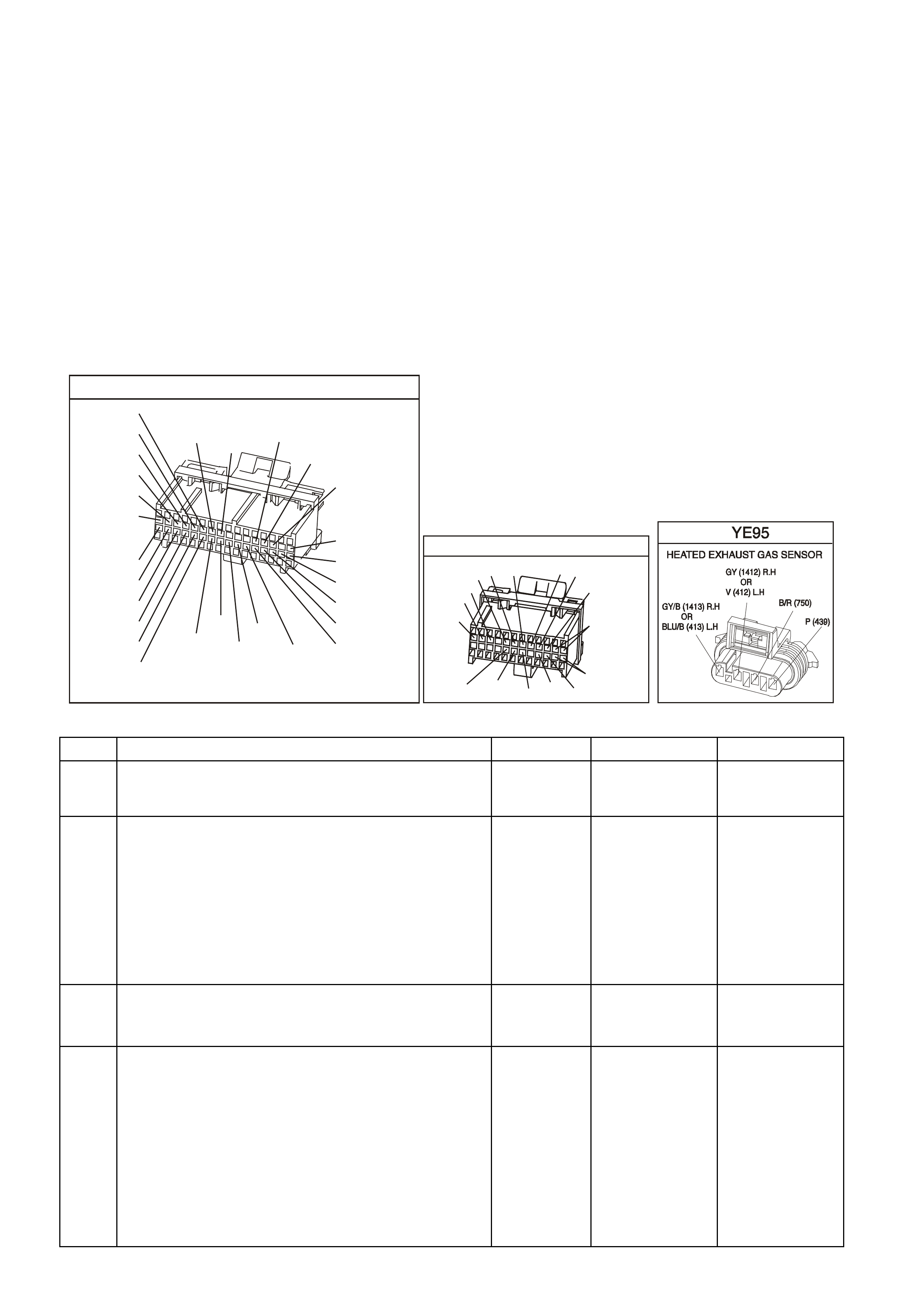
TEST DESCRIPTION: Number(s) below refer to step number(s) on the diagnostic Table.
4. The DTC 64 or lean exhaust is most likely caused by one of the following:
• O2 Sensor Wire - Sensor pigtail may be mispositioned and contacting the exhaust manifold.
• Check for intermittent earth in wire between connector and sensor.
• MAF Sensor - A shifted MAF sensor could cause the fuel system to go lean. Refer to TABLE A-6.1 of the
VX Series Service Information.
• Lean Injector(s) - Perform power balance test using the Tech 2 scan tool.
• Fuel Contamination - W ater, even in small amounts, near the in-tank Fuel Pump inlet can be delivered to
the injectors. The water causes a lean exhaust and can set a DTC 44 and/or DTC 64.
• Fuel Pressure - System will go lean if pressure is too low. It may be necessary to monitor fuel pressure
while driving the vehicle at various road speeds and/or loads to confirm. Refer to TABLE A-4.1 in this
Section.
• Exhaust Leaks - If there is an exhaust leak, the engine can cause outside air to be pulled into the exhaust
and past the sensor. Vacuum or crankcase leaks can cause a lean condition.
YB1 93
(413)
(412)
(1413)
(1412)
(430)
(453)
(815)
V/B
GY/B
V
GY
V
B/R
W/R
(897)
(897)
G/W
G/W
(418)
(418)
BR
BR
(1426)
O/W
C16
D16
WT/B
(832)AUTO
(647)
(630)
BR
T
(832) MAN
LBLU/B
B
(424)
(423)
C1
D1
(792)
(422)
(1222)
(1223)
(428)
(123)
BR/W
GY/R
LG
Y/B
G/Y
V/W
BLU/W
BLU
(831) Man
(443)
LG/W
(442) (831)AUTO
(441)
LBLU
LBLU/B
(444)
LG/B
P.C.M. CONNECTOR 1
YB188
P.C.M CONNECTOR 2
(481)
(417)
(740)
R
BLU
O
(1456)
LG
V/W
(415)
Y
(1227)
B/Y
(410)
BR
(472)
(259)
(750)
(750)
(1221)
B/R
B/R
R/B
G/B
(39)
P
(465)
G/W
(416)
GY
(740)
O
A1
B1
B12
A12
DTC 63 V6 PCM - LEFT HAND OXYGEN SENSOR (02S) LOW VOLTA GE
STEP ACTION VALUE YES NO
1. Was the "On-Board Diagnostic" (OBD) System Check
performed? Go to Step 2 Go to OBD
System Check in
this Section
2. 1. Start engine.
2. Run engine until it reaches normal operating
temperature (Above 80 degrees C).
3. Continue to run at 1600 to 1800 RPM for two
minutes.
Does Tech 2 scan tool indicate O2 sensor voltage fixed
below specified value?
200 mV Go to Step 3
DTC 63 is
intermittent, If no
additional DTCs
were stored, refer
"Intermittents" in
Section 6C1-2B
SYMPTOMS
of the VX
Series Service
Information.
3. Disconnect O2 sensor connector.
With engine idling, does Tech 2 scan tool display O2
sensor voltage between the specified values?
Between
350 mV and
550 mV
Go to Step 4 Go to Step 6
4. 1. Refer to Test description, step 4 above first.
2. Perform the checks on the items as noted.
• MAF sensor operation
• Low fuel pressure
• Contaminated fuel exhaust manifold leaks ahead of
O2 sensor
• Lean injector (possibly restricted)
• O2 sensor earth circuit
Are all items checked found to be OK?
Go to Step 5 Verify Repair

DTC 63 V6 PCM - LEFT HAND OXYGEN SENSOR (02S) LOW VOLTAGE (CONTINUED)
STEP ACTION VALUE YES NO
5. Replace Oxygen sensor.
Is action complete?
Verify repair
6. 1. Ignition "OFF".
2. Disconnect PCM connectors.
3. With O2 sensor still disconnected, check O2 signal
circuit 412 for a short to earth.
Is a short to earth detected?
Go to Step 7 Go to Step 8
7. Repair circuit 412.
Is action complete? Verify Repair
8. Replace PCM.
Refer to Section 6C1-3 Service Operations of the VX
Series Service Information, for PCM Security Link
procedure.
Is action complete?
Verify Repair
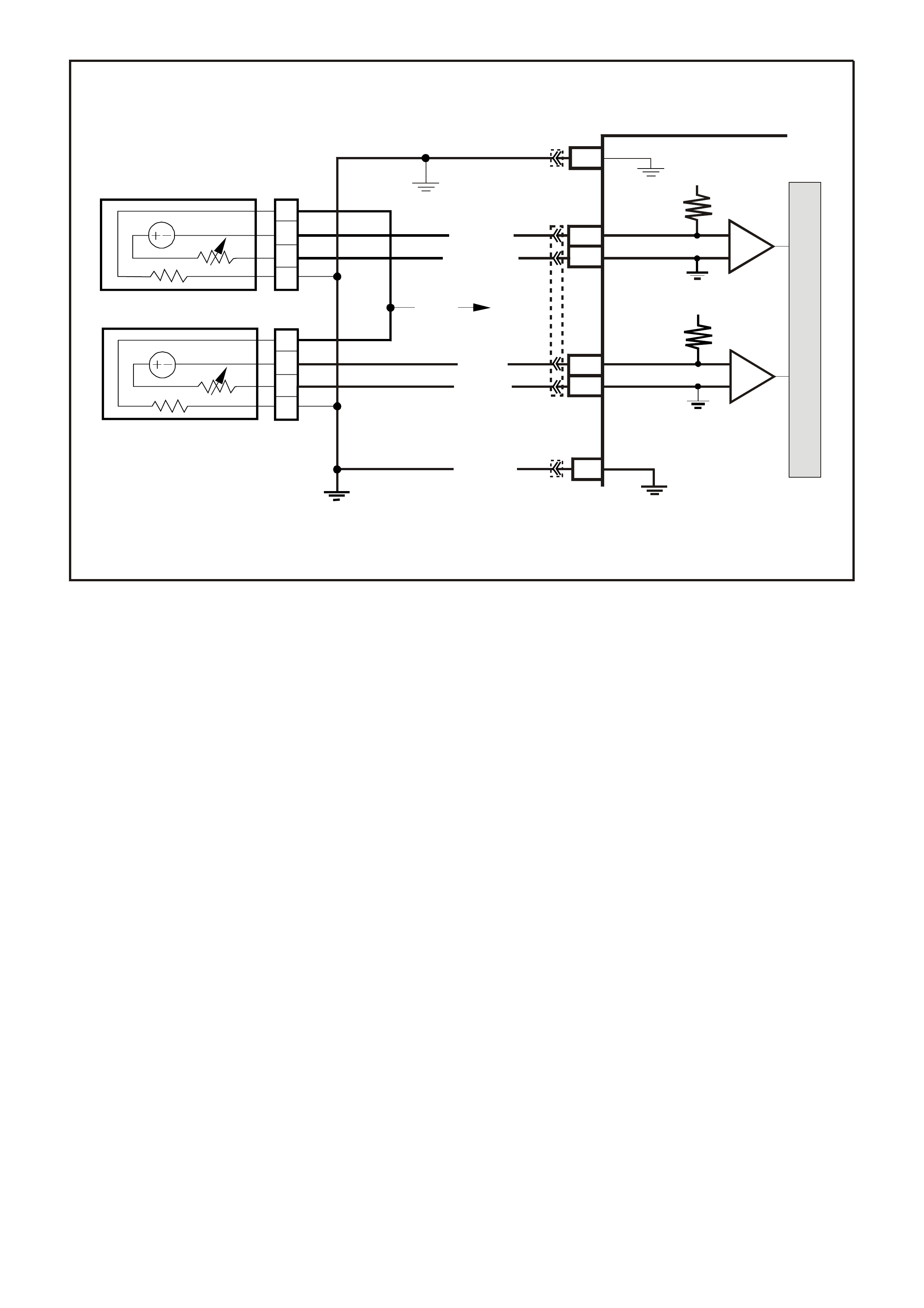
DTC 65 V6 PCM -
LEFT HAND OXYGEN SENSOR (O2S) HIGH VOLTAGE
Circuit Description:The PCM supplies a voltage of about 450 millivolts between terminal "D15" and "D16". The
Oxygen (O2) sensor varies the voltage within a range of about 1 volt, if the exhaust is rich and down through
about 100 millivolts if exhaust is lean.
The sensor produces no voltage when it is below about 360 degrees C. An open sensor circuit or cold sensor
causes "Open Loop" operation.
CONDITIONS FOR RUNNING THE DTC
• No TP Sensor DTC’s are set.
• The system is in "Closed Loop”.
• Throttle angle is between 9% and 30%.
CONDITIONS FOR SETTING THE DTC
• The RH 02S signal voltage remains above 780 millivolts for 40 seconds.
ACTION TAKEN WHEN THE DTC SETS
• The PCM illuminates the Malfunction Indicator Lamp (MIL) when the diagnostic runs and fails.
• The PCM records the operating conditions at the tim e the diagnostic fails. T he PCM stores this information
in the History Data.
• Once a 02S DTC is set, and current, the PCM will operate the fuel system in the “Open Loop” mode.
CONDITIONS FOR CLEARING THE MIL/DTC
• The PCM turns the MIL OFF after the first ignition cycle that the diagnostic runs and does not fail.
• A Histor y DT C clears after f orty c onsecutive warm -up cycles, if this or any other em ission related diagnostic
does not report any failure.
• Use a Tech 2 scan tool in order to clear the MIL/DTC.
M
I
C
R
O
P (439)
YE95
D
D
B
B
A
A
C
C
YE95
GY (1 412)
B/R (750)
Engine
Earth
To Fuse
F33
GY/B (1413)
V (412)
V/B (413)
B/R (750)
4269
A2
D16
D15
D14
D13
A1 450 m V
Right
Oxygen
Sensor
Signal HI
Right
Oxygen
Sensor
Signal LO
Left
Oxygen
Sensor
Signal HI
Left
Oxygen
Sensor
Signal LO
Earth
Earth
Ri ght O x ygen Sensor
Left Oxygen Sensor 45 0 m V
IC
IC
Engine
Earth
PCM
YB193
YB188
YB188
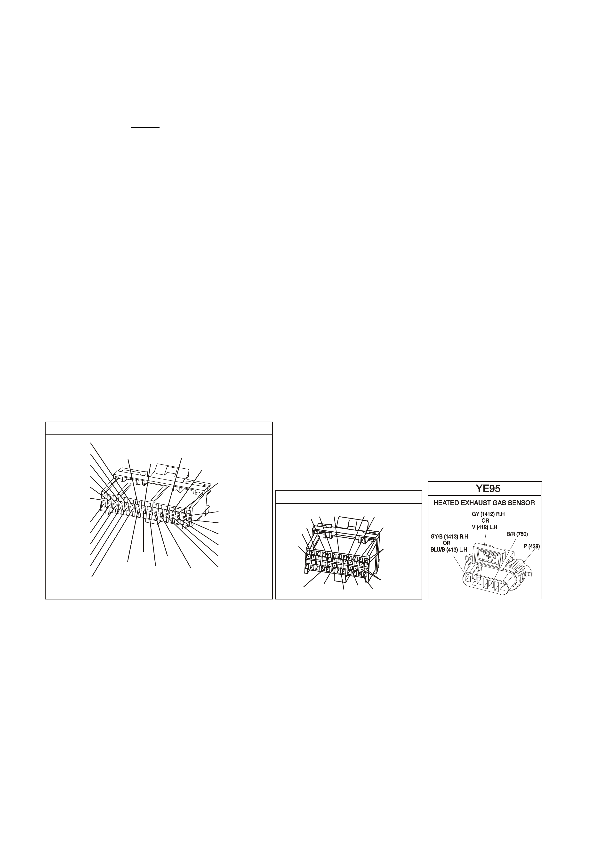
DIAGNOSTIC AIDS:
Using the Tech 2 scan tool, observe the Long Term Fuel Trim values at different RPM and air flow conditions.
The Tech 2 scan tool also displays the Long Term Fuel Trim cells, so the Long Term Fuel Trim values can be
checked in each of the cells to determine when the DTC 45 may have been set. If the conditions for DTC 65
exists, the Long Term Fuel Trim values will be around - 22%.
TEST DESCRIPTION: Number(s) below refer to step number(s) on the diagnostic Table.
2. The O2 sensor MUST be at operating temperature before checking operation.
3. This step checks for a short to voltage on the O2 signal line.
7. Earthing circuit 412 causes a low O2 signal voltage. If the PCM and wiring are OK, the PCM should
recognise the low voltage and confirm the lean signal.
8. A DTC 65 will most likely NOT be caused by a faulty O2 sensor. DTC 65 indicates a rich exhaust and
diagnosis should begin with the items listed:
• Fuel pressure. System will go rich, if pressure is too high. The PCM can compensate for some increase.
However, if it gets too high, a DTC 45 or DTC 65 m ay be s et. Refer to fuel system diagnosis TABLE A-4.3
of the VX Series Service Information.
• Rich injector.
• Leaking injector. Refer to TABLE A-4.3 of the VX Series Service Information.
• Check for fuel contaminated oil.
• Short to voltage on circuit 412.
• HEI shielding. An open earth circuit 453 (ignition system) may result in EMI, or induced electrical "noise."
The PCM looks at this "noise" as reference pulses. The additional pulses result in a higher than actual
engine speed signal. The PCM then delivers too much fuel, causing system to go rich. Engine tachometer
will also show higher than actual engine speed, which can help in diagnosing this problem.
• Canister purge. Check for fuel saturation. If full of fuel, check canister control and hoses.
• MAF sensor. A shifted MAF sensor could cause the fuel system to go rich.
• Check for leaking fuel pressure regulator diaphragm by checking vacuum line to regulator for fuel.
• TP Sensor . An interm ittent T P sensor output will cause the system to go rich, due to a f alse indication of the
engine accelerating.
YB1 93
(413)
(412)
(1413)
(1412)
(430)
(453)
(815)
V/B
GY/B
V
GY
V
B/R
W/R
(897)
(897)
G/W
G/W
(418)
(418)
BR
BR
(1426)
O/W
C16
D16
WT/B
(832)AUTO
(647)
(630)
BR
T
(832) MAN
LBLU/B
B
(424)
(423)
C1
D1
(792)
(422)
(1222)
(1223)
(428)
(123)
BR/W
GY/R
LG
Y/B
G/Y
V/W
BLU/W
BLU
(831) Man
(443)
LG/W
(442) (831)AUTO
(441)
LBLU
LBLU/B
(444)
LG/B
P.C.M. CO NNE CTOR 1
YB188
P.C.M CONNECTOR 2
(481)
(417)
(740)
R
BLU
O
(1456)
LG
V/W
(415)
Y
(1227)
B/Y
(410)
BR
(472)
(259)
(750)
(750)
(1221)
B/R
B/R
R/B
G/B
(39)
P
(465)
G/W
(416)
GY
(740)
O
A1
B1
B12
A12
DTC 65 V6 PCM - LEFT HAND OXYGEN SENSOR (O2S) HIGH VOLTAGE
NOTE: Oxygen Sensor Contamination - If fuel containing lead or silicone is used, or engine repairs using
unapproved RTV gasket sealer are performed, the sensor may be contaminated. it may send a "false" rich
exhaust indication to the PCM, and the PCM will attempt to drive the fuel system lean to compensate. Poor
driveability or a Diagnostic Trouble Code 45 could result. if this happens, the sensor will need to be replaced,
but every attempt to locate the source of contamination should be pursued.

STEP ACTION VALUE YES NO
1. Was the "On-Board Diagnostic" (OBD) System Check
performed? Go to Step 2 Go to OBD
System Check
2. 1. Engine at normal operating temperature
(above 80 degrees C).
2. Run engine at approximately 1600 RPM to 1800
RPM for two minutes.
Is Tech 2 scan tool voltage above specified value?
750 mV Go to Step 3 DTC 65 is
intermittent,
If no additional
DTC(s) were
stored, refer
"Intermittents",
Section 6C1-2B
SYMPTOMS
of the VX
Series Service
Information.
3. 1. Ignition "OFF".
2. Disconnect O2 sensor wiring harness.
3. With ohmmeter connected to earth, probe circuit
412 at O2 sensor wiring harness connector.
4. Ignition "ON".
Is voltmeter indicating less then specified value?
350 mV Got to Step 7 Go to Step 4
4. 1. Ignition "OFF".
2. Disconnect PCM connectors.
3. Probe circuit 412 at O2 sensor wiring harness
connector.
5. Ignition "ON".
Is voltmeter indicating voltage below specified value ?
350 mV Go to Step 6 Go to Step 5
5. Repair circuit 412, shorted to voltage.
Is action complete? Verify Repair
6. Replace PCM.
Refer to Section 6C1-3 Service Operations of the VX
Series Service Information, for PCM Programming and
Security Link procedure.
Is action complete?
Verify Repair
7. 1. Disconnect O2 sensor wiring harness connector.
2. Jumper harness connector circuit 412 to earth.
With engine running, does Tech 2 scan tool display O2
voltage below specified value?
350 mV Go to Step 8 Go to Step 9
8. See Facing page step 8 to perform additional checks for:
• High Fuel Pressure
• Map Sensor Operation
• Leaking Injectors
• Ignition Earth Circuit
• Canister Purge
• Engine Coolant Temperature Sensor Circuit
• Intake Air Temperature Sensor Circuit
• Throttle Position Sensor Operation
Do all additional checks from facing page step 8 test OK.?
Go to Facing
Page Step 8 Verify Repair
9. 1. Ignition "OFF"
2. Disconnect PCM connectors.
3. Check O2 sensor earth circuit 750 for good
continuity between PCM connector terminal "D3"
and engine earth.
Is an "OPEN" circuit indicated?
Verify Repair Go to Step 10
10. Check PCM earth wire connection at engine. Must be
a clean and tight connection to the engine.
Is connection good?
Go to Step 6 Verify Repair

DTC 66 V6 PCM -
3-2 SHIFT SOLENOID CIRCUIT ELECTRICAL
CIRCUIT DESCRIPTION:
The 3-2 Shift Solenoid (SS) valve is a normally-closed, 3-port, on/off device that controls the 3-2 downshift. The
solenoid attaches to the control valve body within the transmission. The solenoid receives ignition voltage through
circuit 339. The Powertrain Control Module (PCM) controls the solenoid by providing an earth path on circuit 897.
During a 3-2 downshift, the 2-4 band applies as the 3- 4 clutch releases . The PCM varies the tim ing between the 3-
4 clutch release and the 2-4 band apply depending on the vehicle speed and the throttle position.
When the PCM detec ts a c ontinuous open or shor t to ear th in the 3-2 SS valve as s embly circuit or the 3-2 SS valve
assembly, then DTC 66 sets.
CONDITIONS FOR RUNNING THE DTC
• The engine is running.
CONDITIONS FOR SETTING THE DTC
DTC 66 sets if either of the following conditions occur for 5 seconds:
• The PCM commands the solenoid ON and the voltage input remains high (B+).
or
• The PCM commands the solenoid OFF and the voltage input remains low (0volts)
ACTION TAKEN WHEN THE DTC SETS
• The PCM illuminates the Malfunction Indicator Lamp (MIL) when the diagnostic runs and fails.
• The PCM records the operating conditions at the time the diagnostic fails. The PCM stores this information in
the History Data.
• When this DTC sets, the PCM will command maximum line pressure, and inhibits TCC engagement.
CONDITIONS FOR CLEARING THE MIL/DTC
• The PCM turns the MIL OFF after the first ignition cycle that the diagnostic runs and does not fail.
• A History DTC clears after forty consecutive warm-up cycles, if this or any other emission related diagnostic
does not report any failure.
• Use a Tech 2 scan tool in order to clear the MIL/DTC.
3–2 Down shift
Control
Solenoid
1–2 Shift
Solenoid A
2–3 Shift
Solenoid B
YB 12 9 Tran s mission
Pass-Thru Connector
Torque
Converter
Clutch (TCC)
(PWM)
Solenoid
Torque
Converter
Clutch (TCC)
Enable
Solenoid
Pressure
Control
Solenoid A
B
A
B
SUPER4284-1
A
B
A
B
EF32 EFI
Relay
P/BLU
(339)
G/W (897)
LG (1222)
Y/B (1223)
GY/R (422)
BR (418)
R (1228)
GY/BLU (1229)
C13 3–2 Control
Solenoid
1–2 Shift
Solenoid
2–3 Shift
Solenoid
TCC Enable
Solenoid
TCC PWM
Solenoid
Pressure Control
Solenoid High
Pressure Control
Solenoid Low
C2
C3
C1
C15
E15
E14
S
A
B
T
U
C
D
A
B
A
B
PCM
M
I
C
R
O
P
R
O
C
E
S
S
O
R
12V
YB194
YB110
YB193
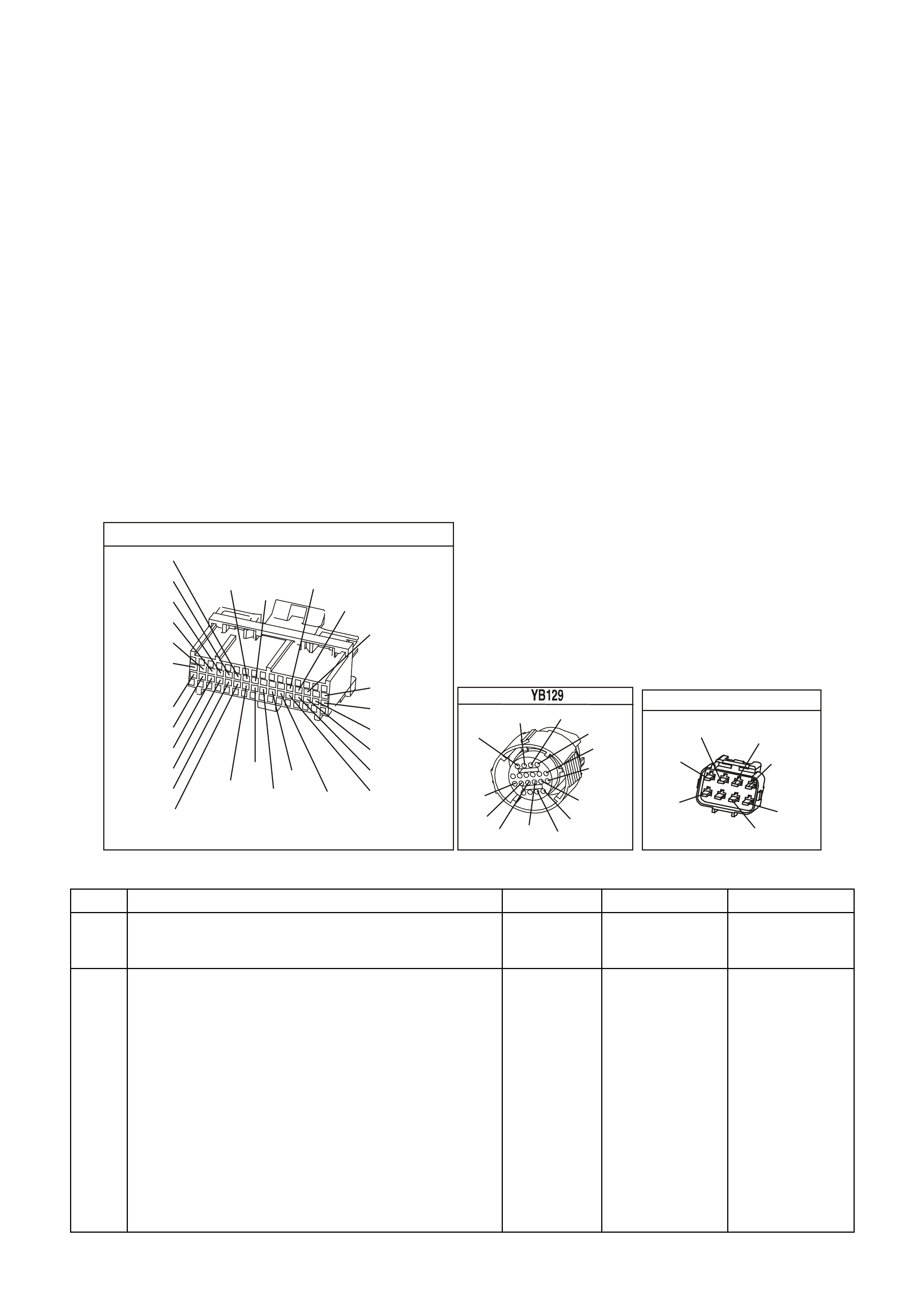
DIAGNOSTIC AIDS
• Inspect the wiring at the PCM, the transmission connector and all other circuit connecting points for the
following conditions:
- A backed out terminal
- A damaged terminal
- Reduced terminal tension
- A chafed wire
- A broken wire inside the insulation
- Moisture intrusion
- Corrosion
• When diagnosing for an intermittent short or open condition, massage the wiring harness while watching the
test equipment for a change.
TEST DESCRIPTION
The numbers below refer to the step numbers on the diagnostic table.
4. This step tests the ability of the PCM to control the solenoid.
5. This step tests for power to the 3-2 SS valve assembly.
7. This step tests the ability of the PCM and the wiring to control the earth circuit.
10. This step measures the resistance of the A/T wiring harness assembly and the 3-2 SS valve assembly.
YB1 93
(413)
(412)
(1413)
(1412)
(430)
(453)
(815)
V/B
GY/B
V
GY
V
B/R
W/R
(897)
(897)
G/W
G/W
(418)
(418)
BR
BR
(1426)
O/W
C16
D16
WT/B
(832)AUTO
(647)
(630)
BR
T
(832) MAN
LBLU/B
B
(424)
(423)
C1
D1
(792)
(422)
(1222)
(1223)
(428)
(123)
BR/W
GY/R
LG
Y/B
G/Y
V/W
BLU/W
BLU
(831) Man
(443)
LG/W
(442) (831)AUTO
(441)
LBLU
LBLU/B
(444)
LG/B
P.C.M. CONNECTOR 1
TRANSMISSION CONNECTOR
GY/BLU
(1229)
R
(1228)
Y/B
(1223)
LG
(1222)
P/BLU
(339)
(1227)
B/Y
(1230)
B/W
GY/R
(422)
BR
(418)
BR/Y
(1224)
(1226)
GY
Y
(1225)
(897)
G/W
(V8)
B
(469) (V6)
OR
ENGINE CONNECTOR 1
YE110
O/W
(304)
(1426)
BLU/W
G/W
(339)
P/BLU
(465)
(123)
V/W
(1427)
B/W
Y
(1049)
DTC 66 V6 PCM - 3-2 SHIFT SOLENOID CIRCUIT ELECTRICAL
Step Action Value(s) Yes No
1 W as the Powertrain On-Board Diagnostic (OBD) System
Check performed? Go to Step 2 Go to Powertrain
OBD System
Check Table.
2 1. Install the Tech 2 Scan Tool.
2. With the engine OFF, turn the ignition switch to the
RUN position.
Important: Before clearing the DTC, use the Scan Tool
in order to record the History Data. Using the scan tool,
clear the History Data.
3. Record the DTC History Data.
4. Clear the DTC.
Are any of the following DTCs also set?
• 67
• 81
• 82
• 83
Go to Step 3 Go to Step 4

DTC 66 V6 PCM - 3-2 SHIFT SOLENOID CIRCUIT ELECTRICAL (CONTINUED)
Step Action Value(s) Yes No
3 1. Inspect fuse F32.
2. If the fuse is open, inspect the following components
for a short to earth condition:
- Circuit 339
- The solenoids
- The A/T wiring harness assembly
3. Repair the circuit, the solenoids, and the harness if
necessary.
Did you find a short to earth condition?
Go to Step 16 Go to Step 5
4 Important: the 3-2 shift solenoid valve will rapidly apply
when commanded ON by the Scan Tool.
Using the transmission Miscellaneous Tests function on
the Scan Tool, command the 3-2 SS valve ON and OFF
three times while listening to the bottom of the
transmission pan (a stethoscope may be necessary).
Did the solenoid click when commanded?
Go to Diagnostic
Aids Go to Step 5
5 1. Turn the ignition OFF.
2. Disconnect the transmission 20-way (YB 129)
connector (additional DTCs may set).
3. Install the J 39775 jumper harness on the engine side
of the 20-way (YB 129) connector.
4. With the engine OFF, turn the ignition switch to the
RUN position.
5. Connect a test lamp from J 39775 jumper harness
cavity E to earth.
Is the test lamp ON?
Go to Step 7 Go to Step 6
6 Repair the open or short to earth in ignition feed circuit
339 to the 3-2 SS valve assembly.
Is the repair complete?
Go to Step 16
7 1. Install a test lamp from J 39775 jumper harness cavity
E to cavity S.
Important: The 3-2 shift solenoid will rapidly apply when
commanded ON by the Scan Tool.
2. Using the transmission Miscellaneous Tests function
on the Scan Tool, command the 3-2 SS valve ON and
OFF three times.
Is the test lamp ON when the solenoid is commanded ON
and OFF, when the solenoid is commanded OFF?
Go to Step 10 Go to Step 8
8 1. Inspect circuit 897 of the powertrain wiring harness for
an open, short to earth or short to power condition.
2. Repair the circuit if necessary.
Did you find an open, short to earth or short to power
condition?
Go to Step 16 Go to Step 9
9 Replace PCM.
Refer to Section 6C1-3 Service Operations of the VX
Series Service Information, for PCM Security Link
procedure.
Is action complete?
Go to Step16
10 1. Install the J 39775 jumper harness on the
transmission side of the 20-way (YB 129) connector.
2. With the J 39200 digital multimeter (DMM) and the
J 35616 connector test adapter kit, measure the
resistance between terminals S and E.
Is the resistance within the range indicated?
20-32 Ω Go to Step 12 Go to Step 11

DTC 66 V6 PCM - 3-2 SHIFT SOLENOID CIRCUIT ELECTRICAL (CONTINUED)
Step Action Value(s) Yes No
11 1. Disconnect the A/T wiring harness assembly from the
3-2 SS valve assembly.
2. Measure the resistance of the 3-2 SS valve assembly.
Is the resistance within the range indicated?
20-32 Ω Go to Step 14 Go to Step 15
12 Measure the resistance between terminal S and earth,
and between terminal E and earth.
Are both readings greater than the specified value?
250 K Ω Go to Diagnostic
Aids Go to Step 13
13 1. Disconnect the A/T wiring harness assembly from the
3-2 SS valve assembly.
2. Measure the resistance from the component’s
terminals to earth.
Are both measurements greater than the specified value?
250 K Ω Go to Step 14 Go to Step 15
14 Replace the automatic transmission wiring harness
assembly.
Refer to Control Valve Body and Wiring Harness
replacement in Section7C5-5 in VX Service Information.
Is the replacement complete?
Go to Step 16
15 Replace the 3-2 SS valve. Refer to Service Operations in
this Section 6C1-3 Service Operations of the VX Series
Service Information.
Is the replacement complete?
Go to Step 16
16 Perform the following procedure in order to verify the
repair:
Drive the vehicle in 3 or D and perform a 3-2 downshift.
Ensure the following conditions are met:
- The PCM commands the 3-2 SS valve ON and the
voltage input drops to zero.
- The PCM commands the 3-2 SS valve OFF and the
voltage input increases to B+.
- All conditions are met for 5 seconds.
Were the above conditions verified?
System OK Go to Step 1
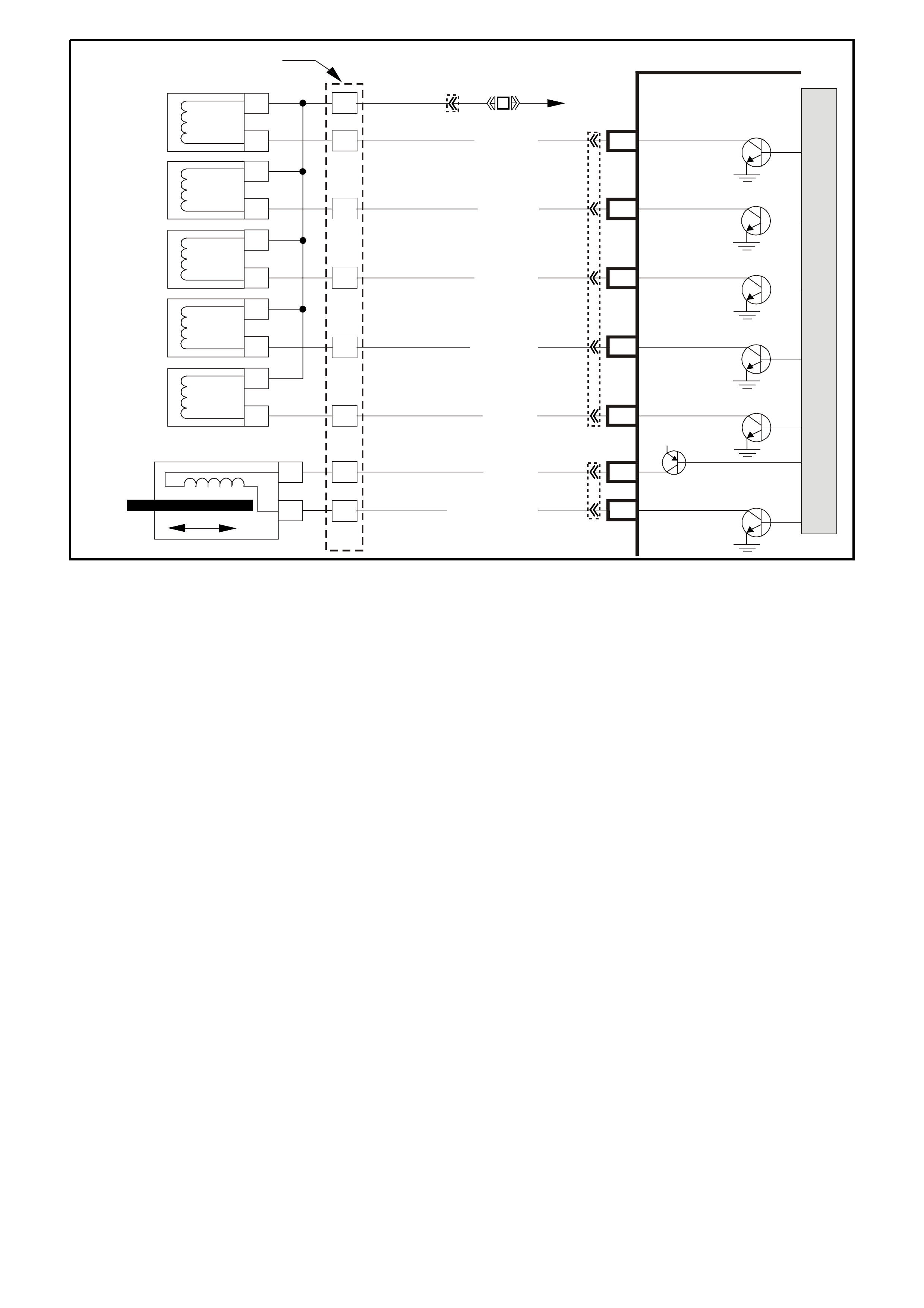
DTC 67 V6 PCM -
TORQUE CONVERTER CLUTCH (TCC) ENABLE SOLENOID CIRCUIT ELECTRICAL
CIRCUIT DESCRIPTION
The torque converter clutch (TCC) solenoid valve is an electrical device that is used with the torque converter
clutch pulse width modulation (TCC PWM) solenoid valve in order to control TCC apply and release. The TCC
solenoid valve attaches to the transm iss ion case as sem bly extending into the pump c over. T he T CC solenoid valve
receives ignition voltage through circuit 339. The powertrain control module (PCM) controls the solenoid by
providing the earth path on circuit 422. T he PCM monitors the throttle position (TP) voltage, the vehicle speed and
other inputs in order to determine when to energise the TCC solenoid valve.
When the PCM detects a continuous open or a short to earth in the TCC solenoid valve circuit or in the TCC
solenoid valve, then DTC 67 sets.
CONDITIONS FOR RUNNING THE DTC
• The system voltage is 8-18 volts.
• The engine speed is greater than 300 RPM for 5 seconds.
• The engine is not in fuel cutoff.
CONDITIONS FOR SETTING THE DTC
• DTC P0740 sets if either of the following conditions occurs for 5 seconds:
- The PCM commands the solenoid ON and the voltage input remains high (B+).
- The PCM commands the solenoid OFF and the voltage input remains low (0 volt).
ACTION TAKEN WHEN THE DTC SETS
• The PCM does not illuminate the check powertrain lamp (MIL).
• The PCM inhibits TCC engagement.
• The PCM inhibits 4th gear if the transmission is in hot mode.
• The PCM freezes shift adapts from being updated.
• The PCM stores DTC 67 in PCM history during the second consecutive trip in which the conditions for setting
the DTC are met.
3–2 Down shift
Control
Solenoid
1–2 Shift
Solenoid A
2–3 Shift
Solenoid B
YB 12 9 Trans mis sion
Pass-Thru Connector
Torque
Converter
Clutch (TCC)
(PWM)
Solenoid
Torque
Converter
Clutch (TCC)
Enable
Solenoid
Pressure
Control
Solenoid A
B
A
B
SUPER4284-1
A
B
A
B
EF32 EFI
Relay
P/BLU
(339)
G/W (897)
LG (1222)
Y/B (1223)
GY/R (422)
BR (418)
R (1228)
GY/BLU (1229)
C13 3–2 C ontrol
Solenoid
1– 2 Shift
Solenoid
2– 3 Shift
Solenoid
TCC Enable
Solenoid
TCC PWM
Solenoid
Pressure Control
Solenoid High
Pressure Control
Solenoid Low
C2
C3
C1
C15
E15
E14
S
A
B
T
U
C
D
A
B
A
B
PCM
M
I
C
R
O
P
R
O
C
E
S
S
O
R
12V
YB194
YB110
YB193
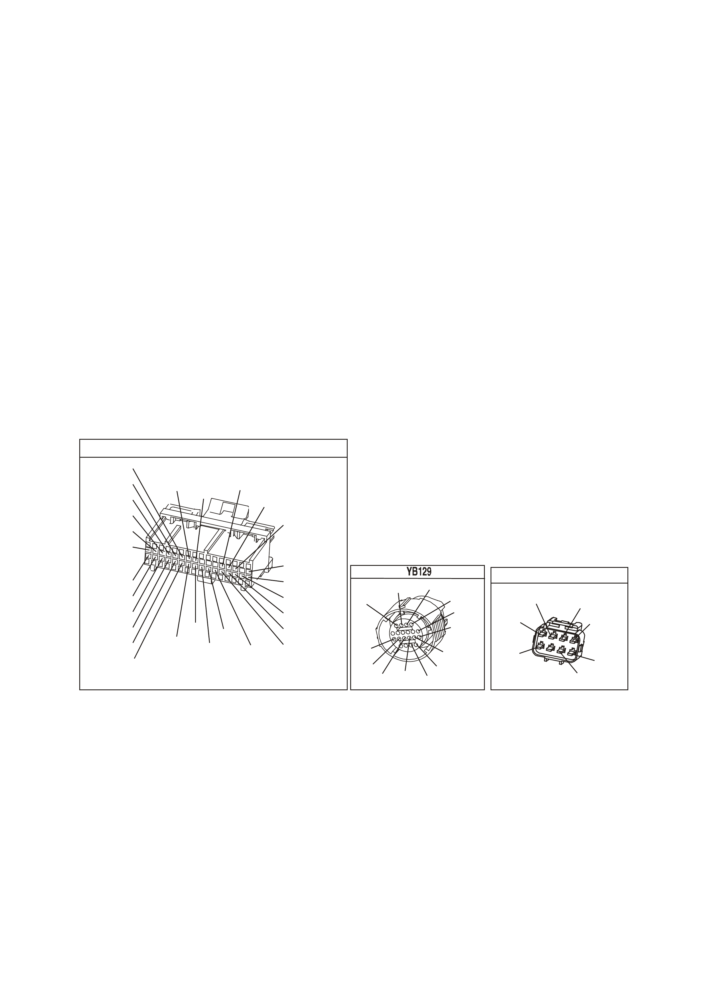
CONDITIONS FOR CLEARING THE DTC
• A scan tool clears the DTC from the PCM history.
• The PCM clears the DTC from the PCM history if the vehicle completes 40 warm-up cycles without an
emission-related diagnostic fault occurring.
• The PCM cancels the DTC default actions when the fault no longer exists and the ignition switch is OFF long
enough in order to power down the PCM.
DIAGNOSTIC AIDS
• Inspect the wiring at the PCM, the transmission connector and all other circuit connecting points for the
following conditions:
- A backed out terminal
- A damaged terminal
- Reduced terminal tension
- A chafed wire
- A broken wire inside the insulation
- Moisture intrusion
- Corrosion
• When diagnosing for an intermittent short or open condition, massage the wiring harness while watching the
test equipment for a change.
• With the TCC engaged, the TCC slip speed should be -20 to +40 RPM.
TEST DESCRIPTION
The numbers below refer to the step numbers on the diagnostic table.
2. This step tests for voltage to the solenoid.
4. This step tests the ability of the PCM and wiring to control the earth circuit.
6. This step tests the resistance of the TCC solenoid valve and the automatic transmission (A/T) wiring harness
assembly.
YB1 93
(413)
(412)
(1413)
(1412)
(430)
(453)
(815)
V/B
GY/B
V
GY
V
B/R
W/R
(897)
(897)
G/W
G/W
(418)
(418)
BR
BR
(1426)
O/W
C16
D16
WT/B
(832)AUTO
(647)
(630)
BR
T
(832) MAN
LBLU/B
B
(424)
(423)
C1
D1
(792)
(422)
(1222)
(1223)
(428)
(123)
BR/W
GY/R
LG
Y/B
G/Y
V/W
BLU/W
BLU
(831) Man
(443)
LG/W
(442) (831)AUTO
(441)
LBLU
LBLU/B
(444)
LG/B
P.C.M. CONNECTOR 1
TRANSMISSION CONNECTOR
GY/BLU
(1229)
R
(1228)
Y/B
(1223)
LG
(1222)
P/BLU
(339)
(1227)
B/Y
(1230)
B/W
GY/R
(422)
BR
(418)
BR/Y
(1224)
(1226)
GY
Y
(1225)
(897)
G/W
(V8)
B
(469) (V6)
OR
ENGINE CONNECTOR 1
YE110
O/W
(304)
(1426)
BLU/W
G/W
(339)
P/BLU
(465)
(123)
V/W
(1427)
B/W
Y
(1049)

DTC 67 V6 PCM - TORQUE CONVERTER CLUTCH (TCC) ENA BLE SOLENOID CIRCUIT ELECTRICAL
Step Action Value(s) Yes No
1 W as the Powertrain On-Board Diagnostic (OBD) System
Check performed? Go to Step 2 Go to Powertrain
OBD System
Check Table.
2
3. Install the Tech 2 Scan Tool.
4. With the engine OFF, turn the ignition switch to the
RUN position.
IMPORTANT: Before clearing the DTC, use the Scan
Tool in order to record the History Data. Using the scan
tool, clear the History Data.
5. Record the DTC History Data.
6. Clear the DTC.
Are any of the following DTCs also set?
• P0753
• P0730
• P0785
• P1860
Go to Step 3
Go to Step 4
3
1. Inspect fuse F32.
2. If the fuse is open, inspect the following components
for a short to earth condition:
- Circuit 339 (P/BLU)
- The solenoids
- The A/T wiring harness assembly
3. Repair the circuit, the solenoids, and the harness if
necessary.
Did you find a short to earth condition?
Go to Step 12
Go to Step 4
4
1. Turn the ignition switch OFF.
2. Disconnect the transmission 20-way connector
(additional DTCs may set).
3. Install the J 39775 jumper harness on the engine side
of the 20-way connector.
4. With the engine OFF, turn the ignition switch to the
RUN position.
5. Connect a test lamp from cavity E of the J 39775
jumper harness to earth.
6. Refer to AT Inline Harness Connector End View of the
VX Series Service Information.
Is the test lamp ON?
Go to Step 6
Go to Step 5
5
IMPORTANT: The condition that affects this circuit may
exist in other connecting branches of the circuit. Refer to
Power Distribution Diagrams in VX Service Information,
Section 12P for complete circuit distribution.
Repair the open or short to earth in ignition feed circuit
339 (P/BLU) to the TCC solenoid valve.
Is the repair complete?
Go to Step 12
6
1. Install the test lamp from cavities E to T of the
J 39775 jumper harness.
2. Using the transmission Miscellaneous Tests function
on the Scan Tool, command the TCC solenoid valve
ON and OFF three times.
Does the test lamp turn ON when the TCC solenoid valve
is commanded ON, and OFF when commanded OFF?
Go to Step 8
Go to Step 7
7
1. Inspect circuit 422 (GY/R) of the engine wiring
harness for an open, short to earth or short to power
condition.
2. Repair the circuit if necessary.
Did you find an open, short to earth or short to power
condition?
Go to Step 12
Go to Step 9

DTC 67 V6 PCM - TORQUE CONVERTER CLUTCH (TCC) ENA BLE SOLENOID CIRCUIT ELECTRICAL
(CONTINUED)
Step Action Value(s) Yes No
8
1. Install the J 39775 jumper harness on the
transmission side of the 20-way connector.
2. Using the J 39200 digital multimeter (DMM) and the
J 35616 connector test adapter kit, measure the
resistance between terminals T and E.
Is the resistance within the specified range?
21-33 Ω
Go to Step 10
Go to Step 11
9
Replace PCM.
Refer to Section 6C1-3 Service Operations of the VX
Series Service Information, for PCM Programming and
Security Link procedure.
Is action complete?
Go to Step
12
10
Measure the resistance between terminal E and earth,
and between terminal T and earth.
Are both readings greater than the specified value?
250 K Ω
Go to
Diagnostic Aids
Go to Step 11
11
Replace the automatic transmission wiring harness
assembly (this includes the TCC solenoid valve).
Refer to Control Valve Body and Wiring Harness
replacement in Section 7C4, in VX Service Information.
Is the replacement complete?
Go to Step 12
12
Perform the following procedure in order to verify the
repair:
1. Select DTC.
2. Select Clear Info.
3. Drive the vehicle in D with the TCC ON and OFF.
Ensure the following conditions are met:
- The PCM commands the TCC solenoid valve ON,
and the voltage input drops to zero.
- The PCM commands the TCC solenoid valve OFF,
and the voltage input increases to B+.
- All conditions are met for 5 seconds.
Were the above conditions verified?
System OK
Go to Step 1

DTC 69 V6 PCM -
TORQUE CONVERTER CLUTCH (TCC) SYSTE M S TUCK ON
CIRCUIT DESCRIPTION
The PCM energises the Torque Converter Clutch Solenoid Valve (TCC Solenoid Valve) by creating an earth path
on circuit 422. When circ uit 422 is earthed (energis ed) by the PCM, the TCC Solenoid Valve stops conver ter signal
oil from exhausting. This causes converter signal oil pressure to increase and move the TCC valve. The TCC
Solenoid Valve de- energises when the PCM no longer provides a path to earth. When the TCC Solenoid Valve de-
energises, the valve exhausts fluid and releases the TCC.
Diagnostic Trouble Code 69 is f or determining a m echanical fault which will cause the T orque Converter Clutch to
be stuck "ON." An electrical fault in the torque converter clutch solenoid circuit which could cause the torque
converter clutch to be "Stuck ON" is diagnosed in DTC 67.
When the PCM detects low torque converter slip when the PCM commands the TCC OFF, then DTC 69 sets.
CONDITIONS FOR RUNNING THE DTC
• No TP DTCs set.
• No VSS DTCs set.
• No TFP Valve Position Switch DTC 28 is set.
• No TCC Solenoid Valve DTC 67 is set.
• No TCC PWM Solenoid Valve DTC 83 is set.
• The TP angle is greater than 25%.
• The engine RPM is greater than 450 for 8 seconds.
• The commanded gear is not 1st.
• The gear range is D4 or D3.
• The PCM commands TCC OFF.
CONDITIONS FOR SETTING THE DTC
• DTC 69 sets if the following conditions occur three times:
- The TCC slip speed is –20 to +30 RPM for 4 seconds.
3–2 Down shift
Control
Solenoid
1–2 Shift
Solenoid A
2–3 Shift
Solenoid B
YB 12 9 Trans mis sion
Pass-Thru Connector
Torque
Converter
Clutch (TCC)
(PWM)
Solenoid
Torque
Converter
Clutch (TCC)
Enable
Solenoid
Pressure
Control
Solenoid A
B
A
B
SUPER4284-1
A
B
A
B
EF32 EFI
Relay
P/BLU
(339)
G/W (897)
LG (1222)
Y/B (1223)
GY/R (422)
BR (418)
R (1228)
GY/BLU (1229)
C13 3–2 C ontrol
Solenoid
1– 2 Shift
Solenoid
2– 3 Shift
Solenoid
TCC Enable
Solenoid
TCC PWM
Solenoid
Pressure Control
Solenoid High
Pressure Control
Solenoid Low
C2
C3
C1
C15
E15
E14
S
A
B
T
U
C
D
A
B
A
B
PCM
M
I
C
R
O
P
R
O
C
E
S
S
O
R
12V
YB194
YB110
YB193
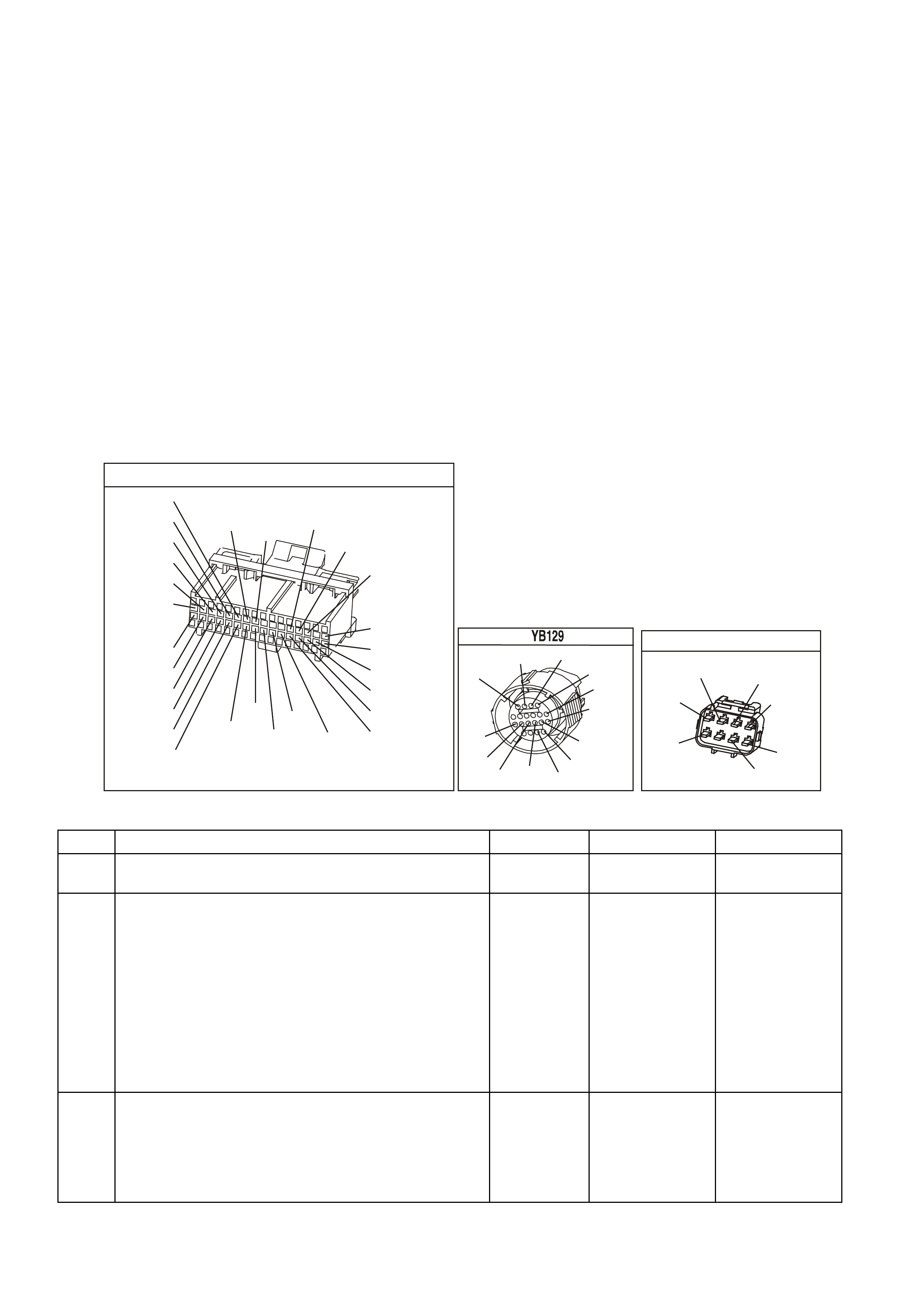
ACTION TAKEN WHEN THE DTC SETS
• The PCM stores the DTC information into memory when the diagnostic runs and fails.
• The Malfunction Indicator Lamp (MIL) will not be illuminated.
• The PCM records the operating conditions at the time the diagnostic fails. The PCM stores this information in
the History Data.
• When this DTC sets, the PCM will freeze shift adapts from being updated.
CONDITIONS FOR CLEARING THE MIL/DTC
• A History DTC clears after forty consecutive warm-up cycles.
• Use a Tech 2 scan tool in order to clear the MIL/DTC.
DIAGNOSTIC AIDS
• The TCC fluid will mechanically apply the TCC, possibly causing an engine stall, under the following conditions:
- The TCC is mechanically stuck ON
- The parking brake is applied
- Any gear range is selected
- A stuck TP sensor may set DTC 69.
TEST DESCRIPTION
The numbers below refer to the step numbers on the diagnostic table.
3. This step inspects the m echanical state of the TCC. W hen the PCM comm ands the TCC Solenoid Valve OFF ,
the slip speed should increase to greater than +50 RPM.
YB1 93
(413)
(412)
(1413)
(1412)
(430)
(453)
(815)
V/B
GY/B
V
GY
V
B/R
W/R
(897)
(897)
G/W
G/W
(418)
(418)
BR
BR
(1426)
O/W
C16
D16
WT/B
(832)AUTO
(647)
(630)
BR
T
(832) MAN
LBLU/B
B
(424)
(423)
C1
D1
(792)
(422)
(1222)
(1223)
(428)
(123)
BR/W
GY/R
LG
Y/B
G/Y
V/W
BLU/W
BLU
(831) Man
(443)
LG/W
(442) (831)AUTO
(441)
LBLU
LBLU/B
(444)
LG/B
P.C.M. CONNECTOR 1
TRANSMISSION CONNECTOR
GY/BLU
(1229)
R
(1228)
Y/B
(1223)
LG
(1222)
P/BLU
(339)
(1227)
B/Y
(1230)
B/W
GY/R
(422)
BR
(418)
BR/Y
(1224)
(1226)
GY
Y
(1225)
(897)
G/W
(V8)
B
(469) (V6)
OR
ENGINE CONNECTOR 1
YE110
O/W
(304)
(1426)
BLU/W
G/W
(339)
P/BLU
(465)
(123)
V/W
(1427)
B/W
Y
(1049)
DTC 69 V6 PCM - TORQUE CONVERTER CLUTCH (TCC) SYSTEM STUCK ON
STEP ACTION VALUE YES NO
1 Was the On-Board Diagnostic (OBD) System Check
performed? Go to Step 2 Go to OBD
System Check
2 1. Install the scan tool.
2. With the engine OFF, turn the ignition switch to the
RUN position.
Important: Before clearing the DTCs, use the scan
tool in order to record the DTC history for reference.
The Clear Info function will erase the data.
3. Record the DTC history.
4. Using the scan tool, verify the TP Sensor operation.
Are the TP Sensor values within the normal range (shown
in the value column)?
0.6–5.0 volts Go to Step 3 Go to “Diagnostic
Aids” above
3 Drive the vehicle in the D4 drive range in fourth gear
under steady acceleration, with a TP angle greater than
25%.
While the displayed TCC Solenoid status is No, does the
scan tool display a Trans Slip Speed within the specified
range?
-20 to +30
RPM Go to Step 4 Go to “Diagnostic
Aids” above

DTC 69 V6 PCM - TORQUE CONVERTER CLUTCH (TCC) SYSTEM STUCK ON (CONTINUED)
STEP ACTION VALUE YES NO
4 The TCC is mechanically stuck ON. Inspect for the
following conditions:
• A clogged exhaust orifice in the TCC Solenoid
Valve.
• The converter clutch apply valve is stuck in the
apply position.
• A misaligned or damaged valve body gasket.
• A restricted release passage.
• A restricted transmission cooler line.
Did you find and correct a problem?
Go to Step 5 Go to Symptoms-
No TCC Release
5 In order to verify your repair, perform the following
procedure:
Operate the vehicle under the following conditions:
• Hold the throttle at 25% and accelerate to 88
km/h.
• Ensure that the Trans Slip Speed is -50 to
+2500 RPM for 4 seconds, with the TCC
commanded OFF.
Was the slip speed greater than 50 RPM in 2nd, 3rd and
4th gears when the TCC was commanded OFF?
System OK Begin the
diagnosis again.
Go to Step 1

DTC 72 V6 PCM -
TRANSMISSION OUTPUT SPEED LOSS
CIRCUIT DESCRIPTION:
The Vehicle Speed Sensor (VSS) circuit consists of a magnetic induction type sensor and vehicle speed sensor
wiring. Gear teeth pressed on the output shaft of the transmission induce an alternating current in the vehicle
speed sensor. This alternating current is transmitted to the PCM.
CONDITIONS FOR RUNNING THE DTC
• The engine is running.
CONDITIONS FOR SETTING THE DTC
• T wo successive speed r eadings have a differ ence of m ore than 1000 RPM in any drive range (diff erence must
be more than 2048 RPM in park or neutral). This test checks the vehicle speed sensor signal to the PCM.
ACTION TAKEN WHEN THE DTC SETS
• The PCM stores the DTC information into memory when the diagnostic runs and fails.
• The Malfunction Indicator Lamp (MIL) will not be illuminated.
• The PCM records the operating conditions at the time the diagnostic fails. The PCM stores this information in
the History Data.
• W hen Diagnos tic Tr ouble Code 72 is set, the trans miss ion will have m axim um line pres sure and comm and 3rd
gear only. If DTC 72 is set while in 4th gear, the vehicle will stay in 4th gear. However, as the vehicle is
coasting to stop the transmission will downshift normally from 4 to 3. Once the downshift into 3rd gear has
occurred, the vehicle will stay in 3rd gear.
CONDITIONS FOR CLEARING THE MIL/DTC
• A History DTC clears after forty consecutive warm-up cycles.
• Use a Tech 2 scan tool in order to clear the MIL/DTC.
DIAGNOSTIC AIDS:
DTC 72 is used to detect an intermittent failure. If a hard VSS fault exists, it will set DTC 24.
DTC 72 will set if the vehicle is operating at a road speed and something happens to the VSS signal.
Check all connections for proper retention. Check that wiring harness for VSS are not routed near high voltage
sources such as spark plug cables which could induce a false signal onto the VSS signal.
DTC 72 c ould possibly be set by rapidly accelerating the vehicle in a loose m aterial (s uch as sand or gravel) where
the wheels c an be s pinning fas ter than actual vehicle speed then having the s pinning wheel rapidly decr ease when
it contacts a hard surface. Review DTC history to identify when DTC 72 was set.
TEST DESCRIPTION
The numbers below refer to the step numbers on the diagnostic table.
3. This test checks the vehicle speed sensor signal to the powertrain control module.
17
V/W (123)
12V IGN
VEHICLE SPEED
M
I
C
R
O
SUPERVX016
INSTRUMENT
M
I
C
R
O
VEHICLE SPEED
PCM
C5
C6
D5
V
EHICLE SPEED
SENSOR
IC
BLU/W
(831)
(AUTO)
BLU
(831)
(MAN)
T
(832)
(AUTO)
BR
(832)
(MAN)
SPEEDOMETER
YB193
YB195 (AUTO)
YB132 (MANUAL)
YE110
YB66
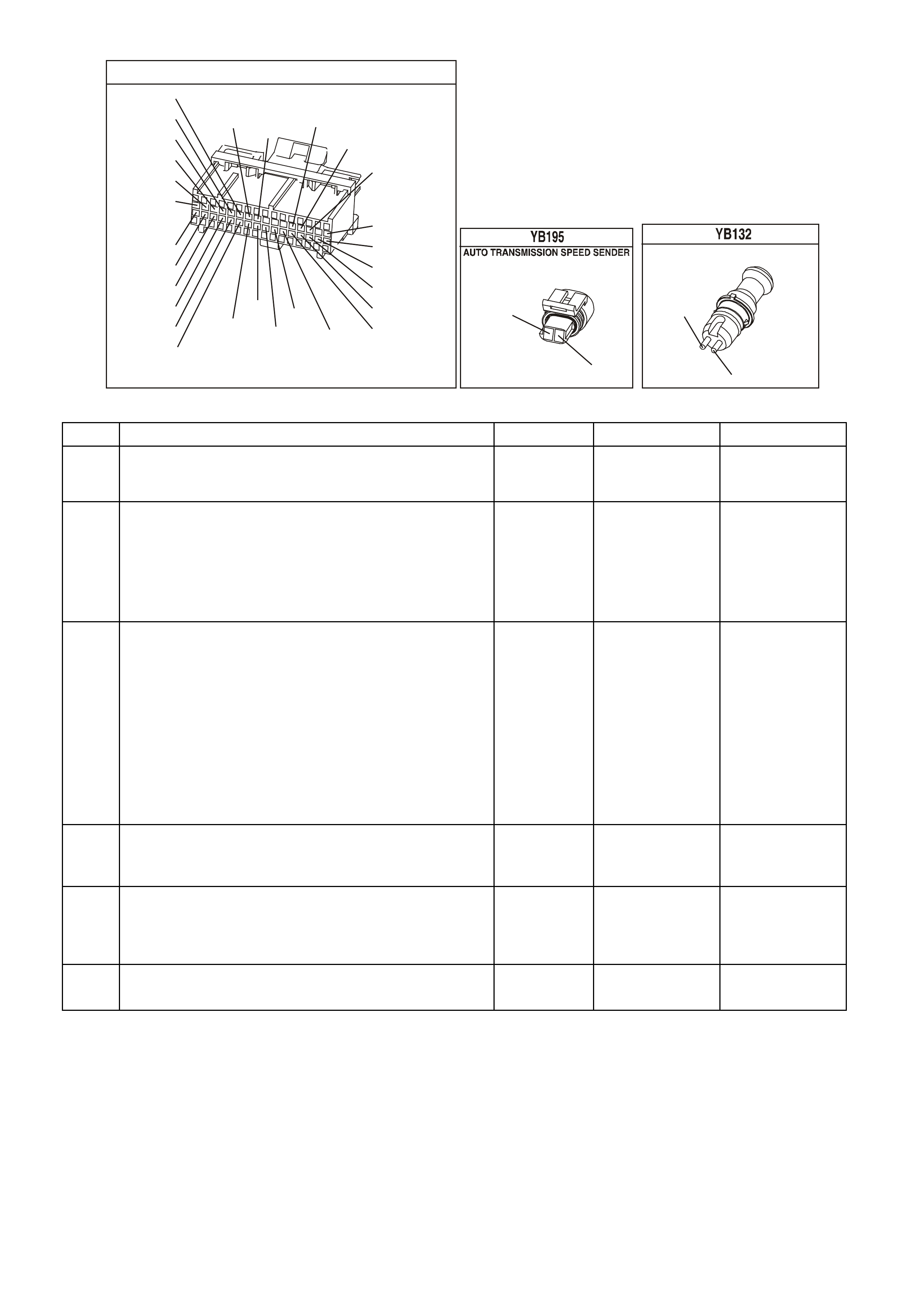
YB1 93
(413)
(412)
(1413)
(1412)
(430)
(453)
(815)
V/B
GY/B
V
GY
V
B/R
W/R
(897)
(897)
G/W
G/W
(418)
(418)
BR
BR
(1426)
O/W
C16
D16
WT/B
(832)AUTO
(647)
(630)
BR
T
(832) MAN
LBLU/B
B
(424)
(423)
C1
D1
(792)
(422)
(1222)
(1223)
(428)
(123)
BR/W
GY/R
LG
Y/B
G/Y
V/W
BLU/W
BLU
(831) Man
(443)
LG/W
(442) (831)AUTO
(441)
LBLU
LBLU/B
(444)
LG/B
P.C.M. CONNECTOR 1
(831)
BLU/W
T
(832)
MANUAL TRANS SPEED SENDER
(831)
(832)
BR
BLU
DTC 72 V6 PCM - TRANSMISSION OUTPUT SPEED LOSS
STEP ACTION VALUE YES NO
1. Was the "On-Board Diagnostic" (OBD) System Check
performed? Go to Step 2 Go to OBD
System Check
in this Section
2. 1. Clear DTC, set Tech 2 scan tool to display "Vehicle
Speed" in the snapshot mode and set to trigger on
DTC 72.
2. Drive vehicle at different speeds and road conditions.
Is DTC 72 set again?
Go to Step 3 DTC 72 Is
intermittent. If
no additional
DTC's were
stored, refer to
"Diagnostic
Aids" above.
3. 1. Raise drive wheels.
NOTE: Do not perform this test without supporting
the rear axle assembly (five link suspension) or lower
control arms on vehicles with independent rear
suspension so that the drive shafts are in a normal
horizontal position. on vehicles with IRS, running the
vehicle in gear with the wheels hanging down at full
travel may damage the drive shaft.
3. Engine idling in gear.
Does Tech 2 scan tool display "Vehicle Speed" above
specified value?
0 km/h Go to Step 4 Go to DTC 24 in
this Section
4. Wiggle and tug on connector at vehicle speed sensor.
Does Tech 2 scan tool display "Vehicle Speed" drop to
specified value?
0 km/h Go to step 6 Go to step 5
5. Wiggle and tug on connectors at Powertrain Control
Module.
Does Tech 2 scan tool display "Vehicle Speed" above
specified value?
0 km/h Go to step 6 Refer to
"Diagnostic
Aids" above
6. Repair connector terminals.
Is action complete? Verify Repair
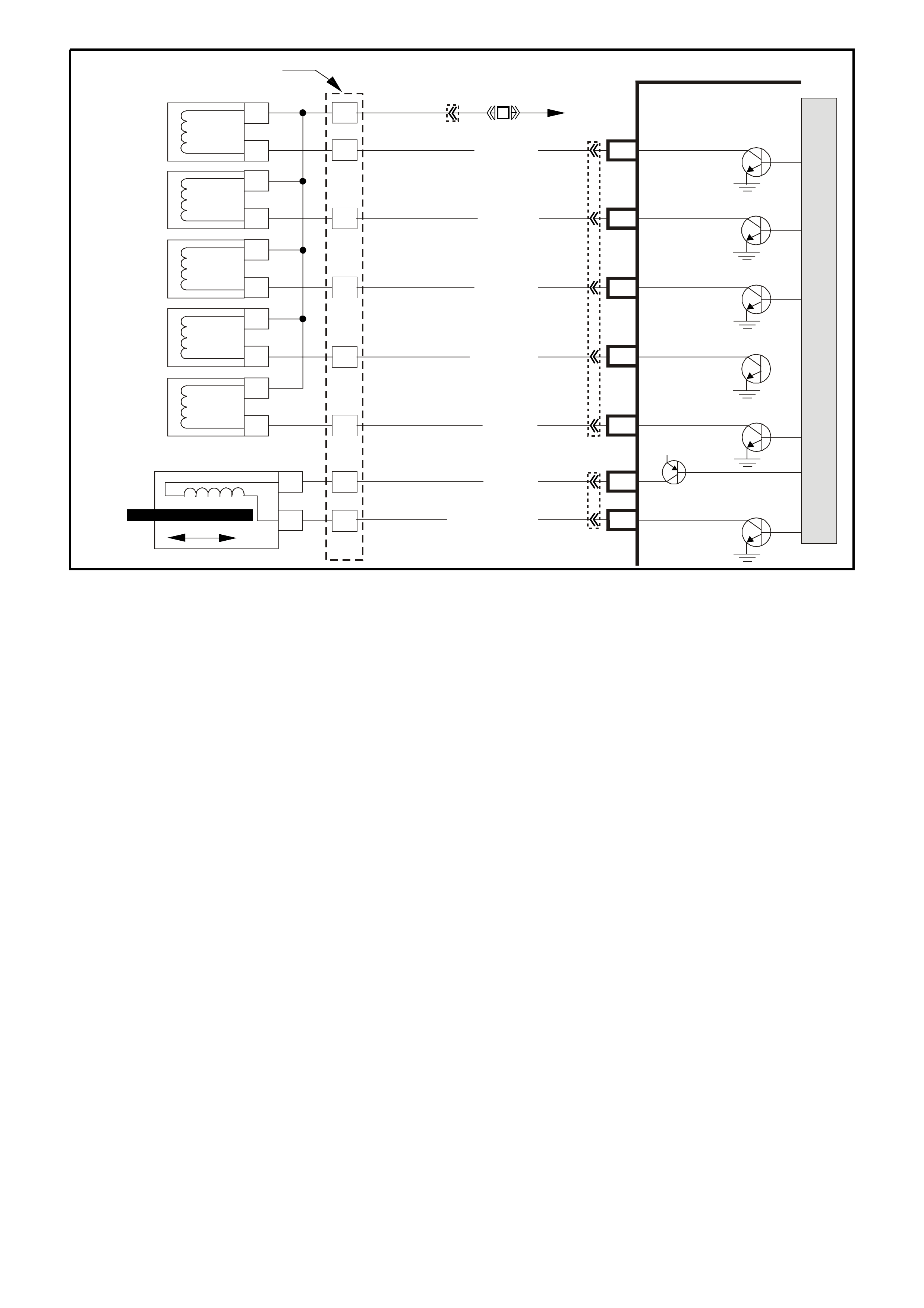
DTC 73 V6 PCM -
PRESSURE CONTROL (PC) SOLENOID CIRCUIT ELECTRICAL
CIRCUIT DESCRIPTION:
The Pressure Control Solenoid Valve (PC Solenoid Valve) is a PCM controlled device which regulates the
transmission line pressure. The PCM compares the TP voltage, the engine speed and other inputs in order to
determ ine the appropriate line pressure f or a given load. The PCM applies a var ying amperage to the PC Solenoid
Valve in order to regulate the pressure. The applied am perage can vary from 0.1 to 1.1 amps. The PCM m onitors
the amperage.
When the PCM detects a continuous open or short to earth in the PC Solenoid Valve circuit or the PC Solenoid
Valve, then a DTC 73 sets.
Once a DTC 73 is set, the pressure control solenoid is disabled and full line pressure will be applied until the next
time the ignition k ey is cycled. If upon restart, the current error does not exist, a DTC 73 will rem ain stored but the
pressure control solenoid will resume normal function.
CONDITIONS FOR RUNNING THE DTC
• No DTC 75 is set.
• The system voltage is between 10 and 16 volts.
• The engine is running.
CONDITIONS FOR SETTING THE DTC
• The PC solenoid valve duty cyc le reaches its high limit ( approxim ately 95%) or low limit (appr oxim ately 0%) f or
200 milliseconds.
ACTION TAKEN WHEN THE DTC SETS
• The PCM stores the DTC information into memory when the diagnostic runs and fails.
• The Malfunction Indicator Lamp (MIL) will not be illuminated.
• The PCM records the operating conditions at the time the diagnostic fails. The PCM stores this information in
the History Data.
• When this DTC s ets , the PCM will command the PC solenoid valve O FF , The PCM will freeze shif t adapts f r om
being updated.
CONDITIONS FOR CLEARING THE MIL/DTC
• A History DTC clears after forty consecutive warm-up cycles.
• Use a Tech 2 scan tool in order to clear the MIL/DTC.
3–2 Down shift
Control
Solenoid
1–2 Shift
Solenoid A
2–3 Shift
Solenoid B
YB 12 9 Trans mis sion
Pass-Thru Connector
Torque
Converter
Clutch (TCC)
(PWM)
Solenoid
Torque
Converter
Clutch (TCC)
Enable
Solenoid
Pressure
Control
Solenoid A
B
A
B
SUPER4284-1
A
B
A
B
EF32 EFI
Relay
P/BLU
(339)
G/W (897)
LG (1222)
Y/B (1223)
GY/R (422)
BR (418)
R (1228)
GY/BLU (1229)
C13 3–2 C ontrol
Solenoid
1– 2 Shift
Solenoid
2– 3 Shift
Solenoid
TCC Enable
Solenoid
TCC PWM
Solenoid
Pressure Control
Solenoid High
Pressure Control
Solenoid Low
C2
C3
C1
C15
E15
E14
S
A
B
T
U
C
D
A
B
A
B
PCM
M
I
C
R
O
P
R
O
C
E
S
S
O
R
12V
YB194
YB110
YB193
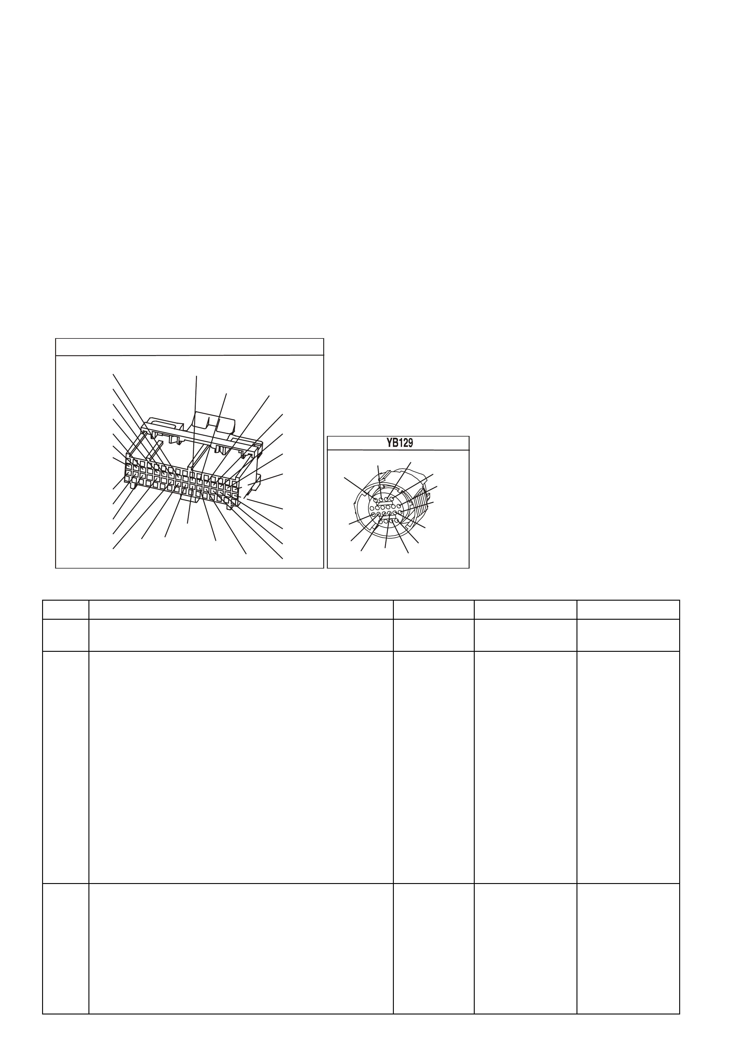
DIAGNOSTIC AIDS
• Inspect the wiring for poor electrical connections at the PCM. Inspect the wiring for poor electrical connections
at the transmission pass-through connector. Look for the following conditions:
- A bent terminal
- A backed out terminal
- A damaged terminal
- Poor terminal tension
- A chafed wire
- A broken wire inside the insulation
- Moisture intrusion
- Corrosion
• When diagnosing for an intermittent short or open condition, massage the wiring harness while watching the
test equipment for a change.
TEST DESCRIPTION
The numbers below refer to the step numbers on the diagnostic table.
2. This step tests the ability of the PCM to command the PC Solenoid Valve.
4. This step tests the PC Solenoid Valve and Automatic Transmission Wiring Harness Assembly for correct
resistance.
YE194
P.C.M. CONNECTOR 3
LG/B
(366)
G
(843)
B/W
F16
B/Y
BR/Y
(1228)
(469)
Y
(451)
F1
P
(841)
BLU
V
E1
LBLU
(845)
BLU
B
(1226)
W/B
BLU/W
V
R
(435)
(31)
(1229)
GY
(1224)
Y
(846)
GY
(842)
(452)
(774)
(304)
BR/Y
(411)
(439)
GY/BLU
BLU
(1225)
E16
(1427)
(429)
(844)
B/O
(434)
OR AUTO
GY/BLU
GY
(1434)
MAN
(776)
W
BLU/W
Y
GY
(771)
(772)
(773)
TRANSMISSION CONNECTOR
GY/BLU
(1229)
R
(1228)
Y/B
(1223)
LG
(1222)
P/BLU
(339)
(1227)
B/Y
(1230)
B/W
GY/R
(422)
BR
(418)
BR/Y
(1224)
(1226)
GY
Y
(1225)
(897)
G/W
(V8)
B
(469) (V6)
OR
DTC 73 V6 PCM - PRESSURE CONTROL (PC) SOLENOID CIRCUIT ELECTRICAL
STEP ACTION VALUE YES NO
1 Was the On-Board Diagnostic (OBD) System Check
performed? Go to Step 2 Go to OBD
System Check
2 1. Install the scan tool.
2. With the engine OFF, turn the ignition switch to the
RUN position.
Important: Before clearing the DTCs, use the scan tool
in order to record the DTC history for reference. The
Clear Info function will erase the data.
3. Record the DTC history.
4. While the engine is operating, put the transmission in
Park position.
5. Using the transmission output control function on the
scan tool, apply 0.1 amp through 1.0 amp while
observing Commanded PCS and Actual PCS
amperage.
Is the Actual PCS amperage always within the specified
value of the Commanded PCS amperage?
0.16 amp Go to
“Diagnostic Aids”
above
Go to Step 3
3 1. Turn the ignition OFF.
2. D isconnect the transmission pass-through connector.
3. Install the J 39775 Jumper Harness on the
transmission side of the pass-through connector.
4. Using the J 39200 DVM and J 35616 Connector Test
Adapter Kit, measure the resistance between
terminal C and terminal D.
Is the resistance within the specified range?
3-7 Ω Go to Step 8 Go to Step 4

DTC 73 V6 PCM - PRESSURE CONTROL (PC) SOLENOID CIRCUIT ELECTRICAL (CONTINUED)
STEP ACTION VALUE YES NO
4 Is the resistance greater than the specified value? 7 Ω Go to Step 5 Go to Step 6
5 1. Check the Automatic Transmission Wiring Harness
Assembly for an open.
2. Replace the harness if necessary. Refer to Service
Operations.
Did you find and correct the problem?
Go to Step 15 Go to Step 10
6 Is the resistance less than the specified value? 3 Ω Go to Step 7 Go to Step 10
7 1. Check the Automatic Transmission Wiring Harness
Assembly for a shorted together condition.
2. Replace the harness if necessary. Refer to Service
Operations in Section 7C-5 of the VX Service
Information.
Did you find and correct the problem?
Go to Step 15 Go to Step 10
8 Using the J 39200 DVM and J 35616 Connector Test
Adapter Kit, measure the resistance from terminal C to
the transmission case.
Is the resistance less than the specified value?
9 Ω Go to Step 9 Go to Step 11
9 1. Check the Automatic Transmission Wiring Harness
Assembly for a short to earth.
2. Replace the harness if necessary. Refer to Service
Operations.
Did you find and correct the problem?
Go to Step 15 Go to Step 10
10 Replace the PC Solenoid Valve. Refer to Service
Operations in this Section6C1-3 Service Operations of
the VX Series Service Information.
Is the action complete?
Go to Step 15
11 1. Disconnect the J 39775 Jumper Harness from the
transmission side of the pass-through connector.
2. Reconnect the transmission pass-through connector.
3. Disconnect the PCM connector 3 (BLUE 32 pin).
4. Using the J 39200 DVM and the J 35616 Connector
Test Adapter Kit, measure the resistance from
terminal E15 to earth.
Is the resistance greater than the specified value?
9 Ω Go to Step 12 Go to Step 13
12 1. Check circuit 1228 and circuit 1229 for an open.
2. Repair the circuits if necessary.
Did you find and correct the problem?
Go to Step 15 Go to Step 14
13 1. Check circuit 1228 and circuit 1229 for a short to
earth.
2. Repair the circuits if necessary.
Did you find and correct the problem?
Go to Step 15
14 Replace PCM.
Refer to Section 6C1-3 Service Operations of the VX
Series Service Information, for PCM Security Link
procedure.
Is action complete?
Go to Step 15
15 In order to verify your repair, perform the following
procedure:
Operate the vehicle under the following conditions:
• The engine is running.
• Observe the Actual PCS amperage and the
Commanded PCS amperage.
Is the difference between the Actual PCS amperage and
the Commanded PCS amperage less than the specified
value?
0.16 amp System OK Begin the
diagnosis again.
Go to Step 1

DTC 75 V6 PCM -
SYSTEM VOLTAGE LOW
CIRCUIT DESCRIPTION:
Circuit 39 is the ignition voltage feed circuit to terminal D16 for the PCM. Circuit 740 is the battery voltage feed
circuit to terminals A8 and B8 for the PCM. W hen the PCM detects a low voltage for a short period of time, then
DTC 75 sets.
CONDITIONS FOR RUNNING THE DTC
• The ignition is on.
• Conditions present for at least 4 seconds.
CONDITIONS FOR SETTING THE DTC
• The system voltage is less than 7.3 volts with the TFT at or above -40°C.
Or
• The system voltage is less than 10 volts with the TFT at or below 151°C.
ACTION TAKEN WHEN THE DTC SETS
• The PCM illuminates the Malfunction Indicator Lamp (MIL) when the diagnostic runs and fails.
• The PCM records the operating conditions at the time the diagnostic fails. The PCM stores this information in
the History Data.
• When DTC 75 sets, the PCM turns off all transmission output devices, and freezes shift adapts from being
updated.
CONDITIONS FOR CLEARING THE MIL/DTC
• The PCM turns the MIL OFF after the first ignition cycle that the diagnostic runs and does not fail.
• A History DTC clears after forty consecutive warm-up cycles, if this or any other emission related diagnostic
does not report any failure.
• Use a Tech 2 scan tool in order to clear the MIL/DTC.
SUPERVX017
# 2
# 4 # 6
# 1 # 3 # 5
PCM
A8
B8
F3
F1
F2
E2
E4
B12
A4
BATTERY F EED
BATTERY F EED
O
(740)
O
(740)
BLU
(841)
V
(843)
GY
(845)
INJECTOR CONTROL
IN JE C TOR VOLTAG E
MONITOR LINE
IGNITION FEED
O/Y (479)
EFI R EL AY
B/W (152)
LOC. E4
P (3 )
O/B (740)
IGN SW
M
I
C
R
O
R
(481)
P
(39)
Y
(846)
BR/Y
(844)
G
(842)
F31
F14
F34
BATTERY
FS
FJ
R (2)
(1040)
YE112
YE114
YE111
YB194
YB188
YE39 YE39
YB188
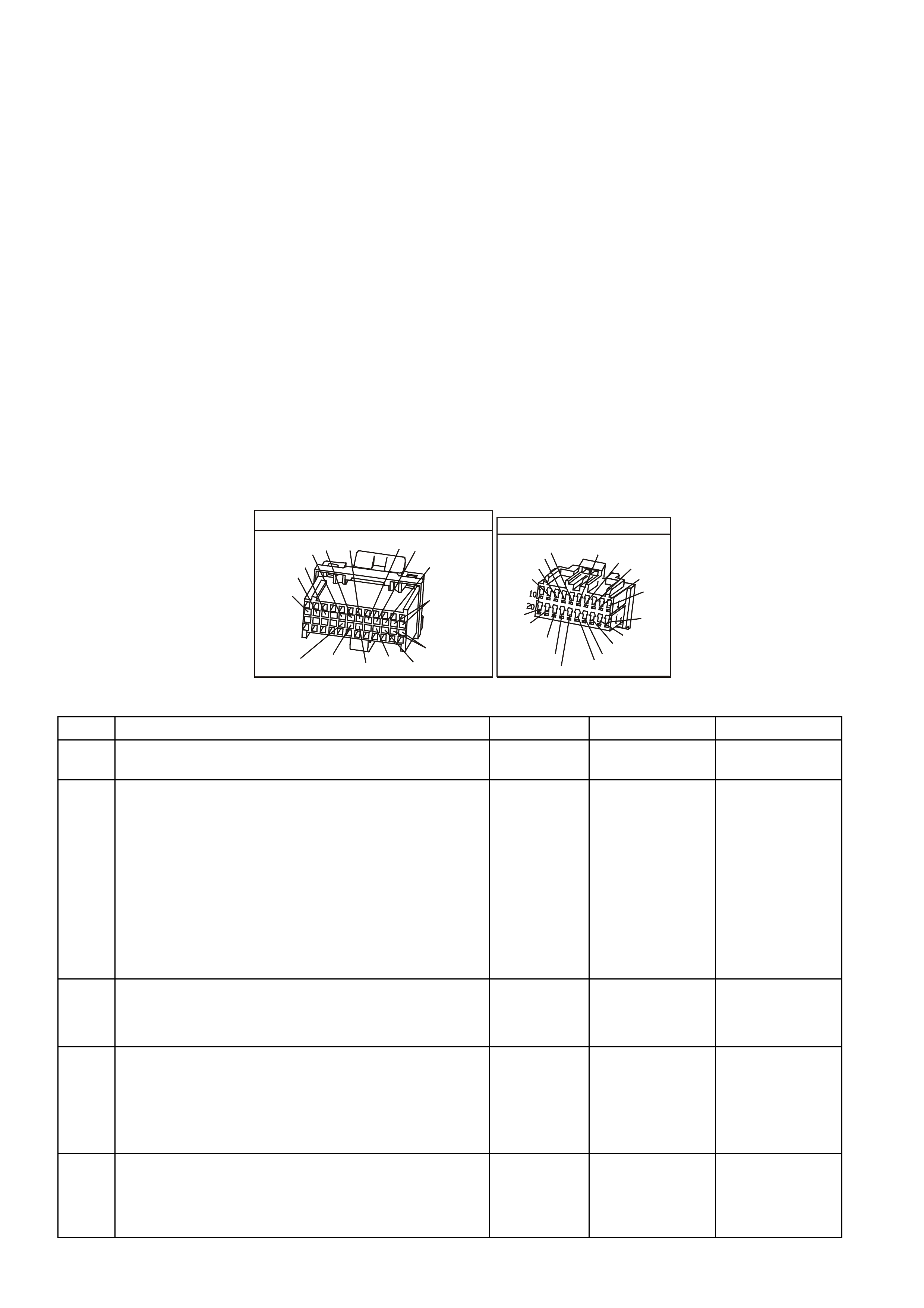
DIAGNOSTIC AIDS:
• Inspect the wiring for poor electrical connections at the PCM. Look for the following conditions:
- A bent terminal
- A backed out terminal
- A damaged terminal
- Poor terminal tension
- A chafed wire
- A broken wire inside the insulation
- Moisture intrusion
• When attempting to diagnose an intermittent problem, use the snapshot mode of the Tech 2 scan tool, to
review diagnostic information.
• Inspect the belts for excessive wear. Inspect the belts for proper tension.
• Minimum voltage allowed for Diagnostic Trouble Code 75 to set is on a graduated scale and will change with
temper ature. Minim um voltage at - 40 degr ees C is 7.3 volts, m inimum voltage at 151 degrees C is 10.0 volts ,
8.6 volts is the minimum voltage at 90 degrees C.
TEST DESCRIPTION:
The numbers below refer to the step numbers on the diagnostic Table.
4. This step tests the charging system voltage.
6. This step tests for proper voltage to the PCM on circuits 39 and 740.
YB 188
P.C.M CONNECTOR 2
(481)
(417)
(740)
R
BLU
O
(1456)
LG
V/W
(415)
Y
(1227)
B/Y
(410)
BR
(472)
(259)
(750)
(750)
(1221)
B/R
B/R
R/B
G/B
(39)
P
(465)
G/W
(416)
GY
(740)
O
A1
B1
B12
A12
YB66
INSTRUMENTS
T
BLU/B
BR/W
(234)
(25)
(14)
(10)
(875)
(155)
(1340)
G/W
(44)
(121)
(8)
(30)
BLU/Y
G
O/Y
P/BLU
BR/R
V/W
(33)
(946)
(1220)
(88)
(15)
(123)
(85)
(19)
GY
W
V/R
BR
BR/O
Y/R
B/Y
LBLU
BLU
DTC 75 V6 PCM - SYSTEM VOLTAGE LOW
STEP ACTION VALUE YES NO
1. Was the On-Board Diagnostic (OBD) System Check
performed? Go to Step 2 Go to OBD
System Check
2. 1. Install the scan tool.
2. With the engine OFF, turn the ignition switch to the
RUN position.
Important: Before clearing the DTCs, use the scan tool
in order to record the DTC history for reference. The
Clear Info function will erase the data.
3. Record the DTC history.
4. Using the J 39200 DVM, measure the battery voltage
across the battery terminals.
Is the voltage higher than the specified value?
10 volts Go to Step 3 Go to Battery
Diagnosis,
3. 1. Start the engine.
2. Warm the engine to normal operating temperature.
Is the generator/check engine light ON?
Go to Charging
System
Diagnosis
Go to Step 4
4. 1. Turn on the headlights and the heater blower motor.
2. Increase the engine speed to 1500 RPM.
3. Observe the DVM battery voltage and record your
reading for reference.
Is the DVM voltage within the specified range?
13-15 volts Go to Step 5 Go to Charging
System
Diagnosis
5. 1. Increase the engine speed to 1500 RPM.
2. Observe the scan tool battery voltage.
Is the scan tool Battery Voltage within the specified
range?
13-15 volts System Checks
OK, Go to
“Diagnostic Aids”
above
Go to Step 6

DTC 75 V6 PCM - SYSTEM VOLTAGE LOW (CONTINUED)
STEP ACTION VALUE YES NO
6. 1. Turn the ignition switch to OFF position.
2. Locate terminals A4, A8 and B8 in the PCM
connector (24 pin). Do not disconnect the PCM
connector.
3. Connect the DVM black lead to earth.
4. Start the engine.
5. Run the engine at 1500 RPM with the headlights and
the blower motor on.
6. Using the J 39200 DVM and J 35616 Connector Test
Adapter Kit, backprobe terminals A4, A8 and B8 to
measure the battery voltage input at the PCM
connector.
Is there a voltage variance between the voltage
measured at the battery (taken in Step 4) and at terminals
A4, A8 and B8 that is greater than the specified value?
0.5 volts Go to Step 7 Go to Step 10
7. Does terminal A4 (circuit 39) have the voltage variance? Go to Step 8 Go to Step 9
8. Repair the high resistance condition in circuit 39.
Is the action complete? Go to Step 11
9. Repair the high resistance condition in circuit 740.
Is the action complete? Go to Step 11
10. Replace PCM.
Refer to Section 6C1-3 SERVICE OPERATIONS of the
VX Series Service Information, for PCM Security Link
procedure.
Is action complete?
Go to Step 11
11. In order to verify your repair, perform the following
procedure:
Operate the vehicle under the following conditions:
• Start the vehicle.
• Warm the engine to normal operating
temperature.
Is the scan tool Battery Voltage within the specified
range?
13-15.5 volts System OK Begin the
diagnosis again.
Go to Step 1

DTC 76 V6 PCM -
SHORT TERM FUEL TRIM (STFT) DELTA HIGH
Circuit Description:The PCM controls left to right cylinder bank fuel delivery separately based on their respective
oxygen sensor signals. If the PCM detec ts too great a diff erence between the left to right c ylinder bank Short Ter m
(ST) Fuel Trim values, it will set DTC 76.
CONDITIONS FOR RUNNING THE DTC
• Engine is idling.
CONDITIONS FOR SETTING THE DTC
• The lef t hand short term fuel trim value varies from the right hand short term fuel trim value by m ore than 63%
for more than 32 seconds.
ACTION TAKEN WHEN THE DTC SETS
• The PCM stores the DTC information into memory when the diagnostic runs and fails.
• The Malfunction Indicator Lamp (MIL) will not be illuminated.
• The PCM records the operating conditions at the time the diagnostic fails. The PCM stores this information in
the History Data.
• W ith a current DT C 76 is set, the PCM will not illuminate the MIL (Check Powertrain Lamp). DTC 76 will clear
when the fault no longer exists and the ignition switch is cycled "OFF" and "ON".
CONDITIONS FOR CLEARING THE MIL/DTC
• The PCM turns the MIL OFF after the first ignition cycle that the diagnostic runs and does not fail.
• A History DTC clears after forty consecutive warm-up cycles, if this or any other emission related diagnostic
does not report any failure.
• Use a Tech 2 scan tool in order to clear the MIL/DTC.
M
I
C
R
O
P (439)
YE95
D
D
B
B
A
A
C
C
YE95
GY (1412)
B/R (750)
Engine
Earth
To Fuse
F33
GY/B (1413)
V (412)
V/B (413)
B/R (750)
4269
A2
D16
D15
D14
D13
A1 450 m V
Right
Oxygen
Sensor
Signal HI
Right
Oxygen
Sensor
Signal LO
Left
Oxygen
Sensor
Signal HI
Left
Oxygen
Sensor
Signal LO
Earth
Earth
Ri ght O x ygen Sensor
Left Oxygen Sensor 450 mV
IC
IC
Engine
Earth
PCM
YB193
YB188
YB188

DIAGNOSTIC AIDS:
• Lean or faulty injector(s) on one side of the engine.
• Cracked or fouled spark plug(s).
• Exhaust or inlet manifold leak.
• Make sure oxygen sensor leads are not swapped.
TEST DESCRIPTION: Number(s) below refer to step number(s) on the diagnostic Table.
2. Check and repair other DTC(s) first.
3. Check for other mechanical problems causing DTC to set.
4. The bank that is the farthest from the neutral value of 0% is the bank which is out of fuel control.
DTC 76 V6 PCM - SHORT TERM FUEL TRIM (STFT) DELTA HIGH
STEP ACTION VALUE YES NO
1. Was the "On-Board Diagnostic" (OBD) System Check
performed? Go to Step 2 Go to OBD
System Check in
this Section
2. Are any other PCM DTC(s) set? Diagnose other
DTC(s) first Go to Step 3
3. Is there a Driveability complaint associated with this DTC
such as an Engine Miss, Lack of Power, or Poor Fuel
Economy?
Go to Step 7 Go to Step 4
4. 1. Start Engine and allow to warm up (Coolant
Temperature above 85 degrees C).
2. Install Tech 2 scan tool and note left and right bank
Short Term Fuel Trim values.
Is the left bank Short Term Fuel Trim values further From
0% then the right bank?
Go to Step 5 Go to Step 6
5. Perform Oxygen Sensor (O2S) Diagnosis, Table A-6.3 in
this Section.
Is action complete?
Verify Repair
6. 1. Start Engine and allow to warm up (Coolant
Temperature above 85 degrees C).
2. Install Tech 2 scan tool and note left and right bank
Short Term Fuel Trim values.
Is the right bank Short Term Fuel Trim values further from
0% then the left bank?
Go to Step 5 DTC 76 is
intermittent.
Refer "Diagnostic
Aids" above.
7. Perform the following tests in the order given until the
problem is corrected :
• Fuel system check, (refer to Table A- 4.3 in this
Section).
• Oscilloscope Engine, note and repair any Ignition
System problem found.
• Compression test each cylinder.
Is action complete ?
Verify Repair

DTC 78 V6 PCM -
LONG TERM FUEL TRIM (LTFT) DELTA HIGH
Circuit Description:The PCM controls left to right cylinder bank fuel delivery separately based on their respective
oxygen sensor signals. If the PCM detects too great a diff erence between the left to right cylinder bank Long T erm
Fuel Trim values, it will set DTC 78.
CONDITIONS FOR RUNNING THE DTC
• Engine is idling.
CONDITIONS FOR SETTING THE DTC
• The lef t hand long ter m f uel trim value varies f rom the r ight hand long term f uel trim value by mo re than 59% for
more than 32 seconds.
ACTION TAKEN WHEN THE DTC SETS
• The PCM stores the DTC information into memory when the diagnostic runs and fails.
• The Malfunction Indicator Lamp (MIL) will not be illuminated.
• The PCM records the operating conditions at the time the diagnostic fails. The PCM stores this information in
the History Data.
• With a current DT C 78 set, the PCM will not illum inate the MIL (Check Powertrain Lam p) . DTC P0170 will clear
when the fault no longer exists and the ignition switch is cycled "OFF" and "ON".
CONDITIONS FOR CLEARING THE MIL/DTC
• The PCM turns the MIL OFF after the first ignition cycle that the diagnostic runs and does not fail.
• A History DTC clears after forty consecutive warm-up cycles, if this or any other emission related diagnostic
does not report any failure.
• Use a Tech 2 scan tool in order to clear the MIL/DTC.
M
I
C
R
O
P (439)
YE95
D
D
B
B
A
A
C
C
YE95
GY (1412)
B/R (750)
Engine
Earth
To Fuse
F33
GY/B (1413)
V (412)
V/B (413)
B/R (750)
4269
A2
D16
D15
D14
D13
A1 450 m V
Right
Oxygen
Sensor
Signal HI
Right
Oxygen
Sensor
Signal LO
Left
Oxygen
Sensor
Signal HI
Left
Oxygen
Sensor
Signal LO
Earth
Earth
Ri ght O x ygen Sensor
Left Oxygen Sensor 450 mV
IC
IC
Engine
Earth
PCM
YB193
YB188
YB188

DIAGNOSTIC AIDS:
• Lean or faulty injector(s) on one side of the engine.
• Cracked or fouled spark plug(s).
• Exhaust or inlet manifold leak.
• Make sure oxygen sensor leads are not swapped.
TEST DESCRIPTION: Number(s) below refer to step number(s) on the diagnostic Table.
2. Check and repair other DTC(s) first.
3. Check for other mechanical problems causing DTC to set.
4. The bank that is the farthest from the neutral value of 0% is the bank which is out of fuel control.
DTC 78 V6 PCM - LONG TERM FUEL TRIM (LTFT) DELTA HIGH
STEP ACTION VALUE YES NO
1. Was the "On-Board Diagnostic" (OBD) System Check
performed? Go to Step 2 Go to OBD
System Check in
this Section
2. Are any other PCM DTC(s) set? Diagnose other
DTC(s) first Go to Step 3
3. Is there a Driveability complaint associated with this DTC
such as an Engine Miss, Lack of Power, or Poor Fuel
Economy?
Go to Step 7 Go to Step 4
4. 1. Start Engine and allow to warm up (Coolant
Temperature above 85 degrees C).
2. Install Tech 2 scan tool and note left and right bank
Long Term Fuel Trim values.
Is the left bank Long Term Fuel Trim values further From
0% then the right bank?
Go to Step 5 Go to Step 6
5. Perform Oxygen Sensor (O2S) Diagnosis, Table A-6.3 in
this Section.
Is action complete?
Verify Repair
6. 1. Start Engine and allow to warm up (Coolant
Temperature above 85 degrees C).
2. Install Tech 2 scan tool and note left and right bank
Long Term Fuel Trim values.
Is the right bank Long Term Fuel Trim values further from
0% then the left bank?
Go to Step 5 DTC 78 is
intermittent.
Refer "Diagnostic
Aids" above.
7. Perform the following tests in the order given until
the problem is corrected :
• Fuel System check, (refer TableA-4.3 in this
Section).
• Oscilloscope Engine, note and repair any Ignition
System problem found.
• Compression test each cylinder.
Is action complete?
Verify Repair
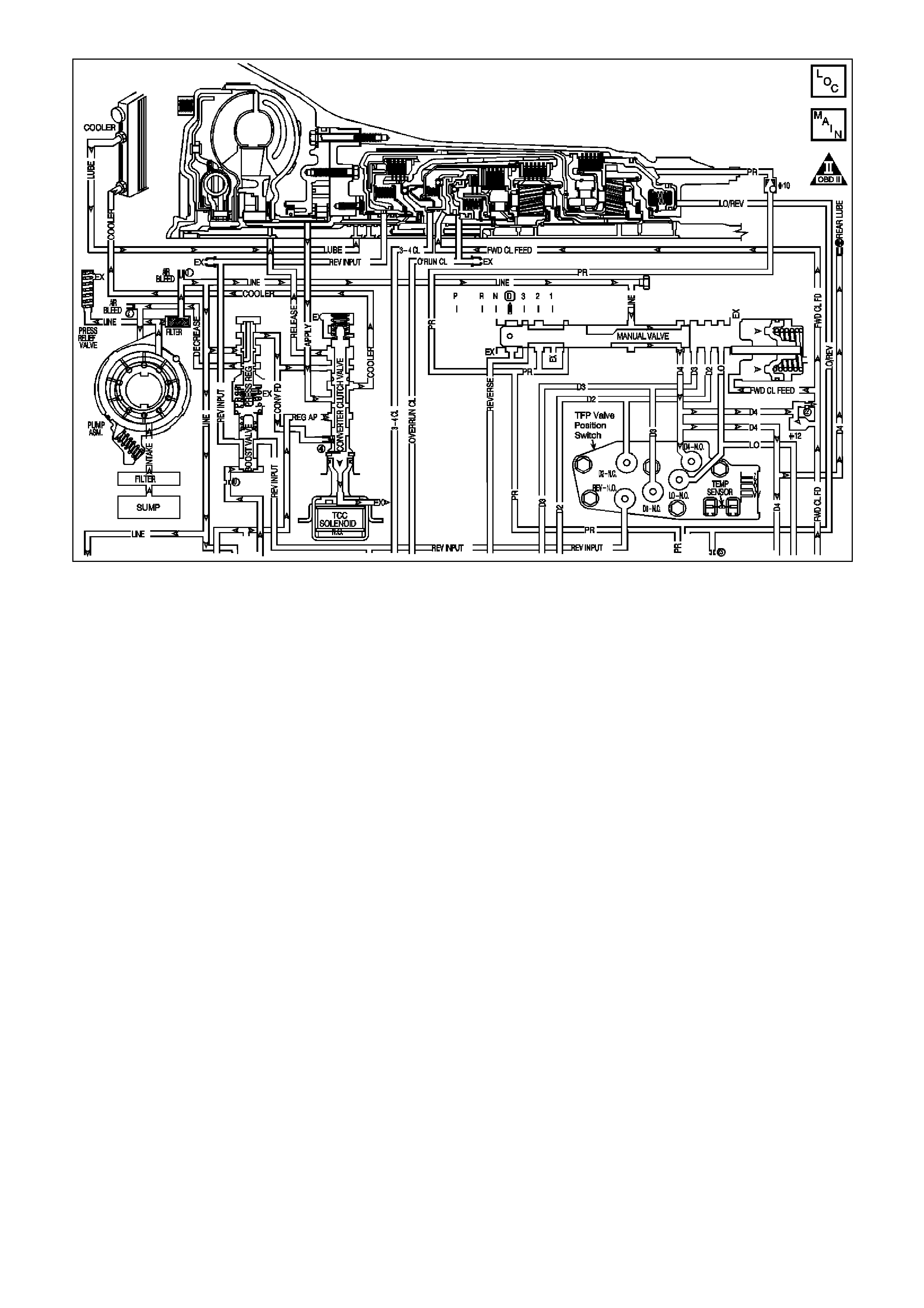
DTC 79 V6 PCM -
TRANSMISSION FLUID OVERTEMPERATURE
CIRCUIT DESCRIPTION:
The flow of transmission fluid starts in the bottom of the pan and is drawn through the filter, control valve body
assembly, transmission case and into the oil pump assembly. The oil pump assembly pressurises the fluid and
directs it to the pressure regulator valve where it becomes the main supply of fluid to the various components and
hydr aulic circuits in the transm ission. Hot fluid exiting the tor que converter flows through the c onverter clutch apply
valve and into the transmission cooler lines to the oil cooler located in the radiator (and auxiliary cooler if
equipped). Fr om the cooler, fluid returns to cool and lubricate the f ront of the transm iss ion. In for ward drive ranges,
D4 fluid fr om the m anual valve is routed thr ough an orifice c up plug in the r ear of the transmiss ion case to f eed the
rear lube fluid circuit.
When the PCM detects a high transmission fluid temperature (TFT) for a long period of time, then DTC 79 sets.
As the transmission fluid temperature warms (normal transmission operating temperature 82 degrees C - 94
degrees C), the s ensor (therm istor) resist ance becomes less and the voltage will measure about 1.5 to 2.0 volts. If
the fluid temperatur e becomes greater than 146 degrees C and does not drop below 137 degrees C for 30 minutes,
a DTC 79 will set.
When DTC 79 sets the transmission fluid may be severely degraded.
CONDITIONS FOR RUNNING THE DTC
• DTC 58 is not set.
CONDITIONS FOR SETTING THE DTC
• The TFT is at or greater than 137° C for 10 minutes (600 seconds).
ACTION TAKEN WHEN THE DTC SETS
• The PCM illuminates the Malfunction Indicator Lamp (MIL) when the diagnostic runs and fails.
• The PCM records the operating conditions at the time the diagnostic fails. The PCM stores this information in
the History Data.
• When a DTC 79 sets, the PCM freezes shift adapts from being updated.
CONDITIONS FOR CLEARING THE MIL/DTC
• The PCM turns the MIL OFF after the first ignition cycle that the diagnostic runs and does not fail.
• A History DTC clears after forty consecutive warm-up cycles, if this or any other emission related diagnostic
does not report any failure.
• Use a Tech 2 scan tool in order to clear the MIL/DTC.

DIAGNOSTIC AIDS:
• Inspect the cooling system fluid level and condition.
• DTC 79 may set approximately 30 minutes after DTC 58 has set. Follow the diagnostic table for DTC 58
before proceeding to the diagnostic table for DTC 79. Repairing the condition that set DTC 58 will likely
eliminate DTC 79.
• The TFT temperature displayed on the scan tool should rise steadily to a normal operating temperature, then
stabilise.
• Inspect the torque converter stator for a possible problem.
• Ask about the customer's driving habits, trailer towing, etc.
Test DESCRIPTION: Number(s) below refer to step number(s) on the diagnostic Table.
3. DTC 58 may also set a DTC 79. Go to the DTC 58 table for diagnosis.
4. This step inspects for air restrictions and loss of transmission fluid flow, causing an extremely high TFT.
DTC 58 V6 PCM - TRANSMISSION FLUID OVERTEMPERATURE
STEP ACTION VALUE YES NO
1 Was the On-Board Diagnostic (OBD) System Check
performed? Go to Step 2 Go to OBD
System Check
2 1. Install the scan tool.
2. With the engine OFF, turn the ignition switch to the
RUN position.
Important: Before clearing the DTCs, use the scan tool in
order to record the DTC history for reference. The Clear
Info function will erase the data.
3. Record the DTC history.
4. Perform the transmission fluid checking procedure.
Refer to Transmission Fluid Checking Procedure.
Was the fluid checking procedure performed?
Go to Step 3 Go to
Transmission
Fluid Checking
Procedure
3 Is DTC 58 also set? Go to “Diagnostic
Aids” above Go to Step 4
4 1. Inspect the cooling system for the following
conditions:
• Air flow restrictions
• Air flow blockage
• Debris
2. Inspect the transmission cooling system for the
following conditions:
• Air flow restrictions
• Air flow blockage
• Debris
• Damaged cooler lines
3. Repair restrictions if necessary.
Was a problem found?
Go to Step 7 Go to Step 5
5 1. Drive the vehicle in D4 with the TCC commanded
On.
2. Observer the TCC slip speed on the scan tool.
Is the TCC slip speed within the specified value?
-20 to +20
RPM Go to Step 6 Refer to Torque
Converter Clutch
Diagnosis
Symptoms
6 Perform the Line Pressure Check Procedure. Refer to
Section 7C-3 in VX Service Information.
Was a problem found?
Go to Step 7 Go to “Diagnostic
Aids” above
7 In order to verify your repair, perform the following
procedure:
1. Drive the vehicle to normal operating engine and
transmission temperature.
2. Observe the TFT during the entire drive.
Is the TFT less than the specified value during the entire
drive?
137°C System OK Begin the
diagnosis again.
Go to Step 1
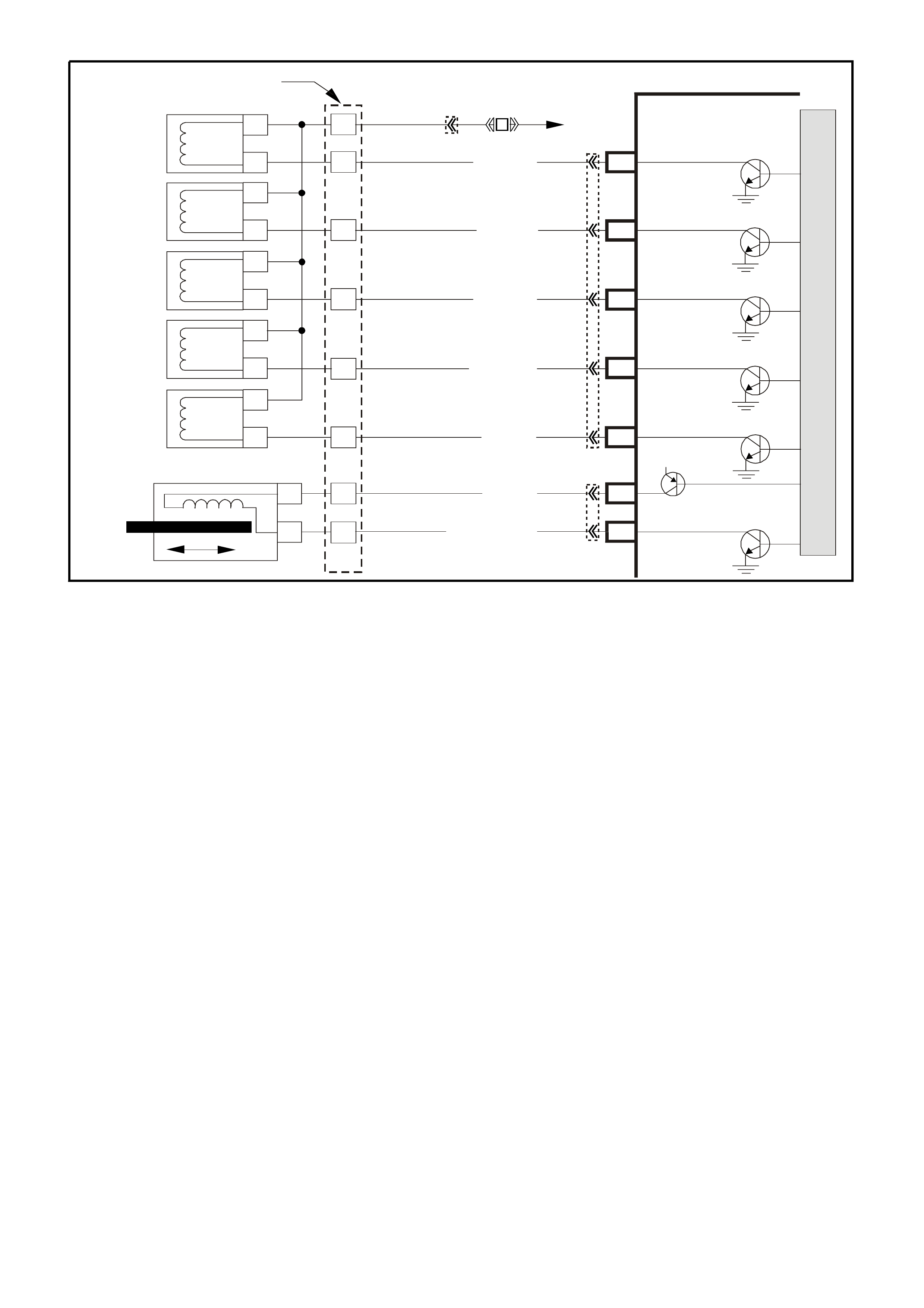
DTC 81 V6 PCM -
2-3 SHIFT SOLENOID CIRCUIT ELECTRICAL
CIRCUIT DESCRIPTION
The 2- 3 Shift Solenoid Valve (2-3 SS Valve) contr ols the fluid flow acting on the 2-3 shift valves. The 2-3 SS Valve
is a normally-open exhaust valve that is used with the 1-2 Shift Solenoid Valve in order to allow four different
shifting combinations. The solenoid attaches to the control valve body within the transmission. The 2-3 SS Valve
receives ignition voltage through circuit 339. The PCM controls the solenoid by providing a path to earth on circuit
1223.
When the PCM detects a continuous open or short to earth in the 2-3 SS Valve circuit or the 2-3 SS Valve, then
DTC 81 sets.
CONDITIONS FOR RUNNING THE DTC
• The engine is running.
CONDITIONS FOR SETTING THE DTC
• The PCM commands the solenoid ON and the voltage input remains high (B+).
or
• The PCM commands the solenoid OFF and the voltage input remains low (0volts).
ACTION TAKEN WHEN THE DTC SETS
• The PCM illuminates the Malfunction Indicator Lamp (MIL) when the diagnostic runs and fails.
• The PCM records the operating conditions at the time the diagnostic fails. The PCM stores this information in
the History Data.
• When this DTC sets, the PCM will command D2 line pressure, The PCM inhibits 3-2 downshift if the vehicle
speed is greater than 48 km/h, The PCM will freeze shift adapts from being updated.
CONDITIONS FOR CLEARING THE MIL/DTC
• The PCM turns the MIL OFF after the first ignition cycle that the diagnostic runs and does not fail.
• A History DTC clears after forty consecutive warm-up cycles, if this or any other emission related diagnostic
does not report any failure.
• Use a Tech 2 scan tool in order to clear the MIL/DTC.
3–2 Down shift
Control
Solenoid
1–2 Shift
Solenoid A
2–3 Shift
Solenoid B
YB 12 9 Tran s mission
Pass-Thru Connector
Torque
Converter
Clutch (TCC)
(PWM)
Solenoid
Torque
Converter
Clutch (TCC)
Enable
Solenoid
Pressure
Control
Solenoid A
B
A
B
SUPER4284-1
A
B
A
B
EF32 EFI
Relay
P/BLU
(339)
G/W (897)
LG (1222)
Y/B (1223)
GY/R (422)
BR (418)
R (1228)
GY/BLU (1229)
C13 3–2 Control
Solenoid
1–2 Shift
Solenoid
2–3 Shift
Solenoid
TCC Enable
Solenoid
TCC PWM
Solenoid
Pressure Control
Solenoid High
Pressure Control
Solenoid Low
C2
C3
C1
C15
E15
E14
S
A
B
T
U
C
D
A
B
A
B
PCM
M
I
C
R
O
P
R
O
C
E
S
S
O
R
12V
YB194
YB110
YB193
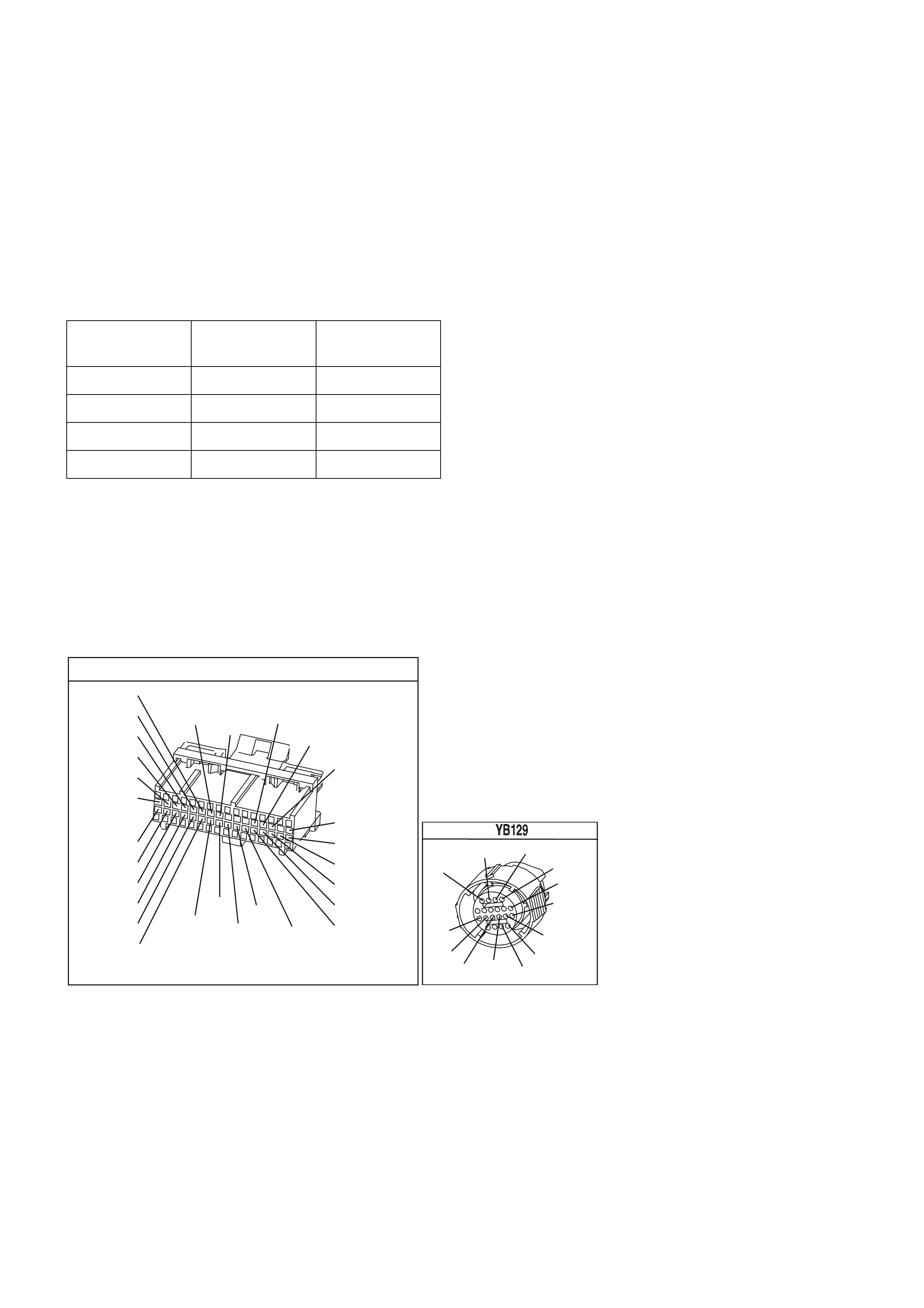
DIAGNOSTIC AIDS
Inspect the wiring for poor electrical connections at the PCM. Inspect the wiring for poor electrical connections at
the transmission pass-through connector. Look for the following conditions:
- A bent terminal
- A backed out terminal
- A damaged terminal
- Poor terminal tension
- A chafed wire
- A broken wire inside the insulation
• Moisture intrusion when diagnosing for an intermittent short or open condition, massage the wiring harness
while watching the test equipment for a change.
• Refer to the following Table for the correct On and Off states of the shift solenoids.
GEAR 1-2-SHIFT
SOLENOID 2-3 SHIFT
SOLENOID
1 ON ON
2 OFF ON
3 OFF OFF
4 ON OFF
TEST DESCRIPTION
The numbers below refer to the step numbers on the diagnostic table.
4. This step tests the function of the 2-3 SS valve and the automatic transmission wiring harness assembly.
5. This step tests for power to the 2-3 SS valve from the ignition through the fuse.
7. This step tests the ability of the PCM and the wiring to control the earth circuit.
10. This step measures the resistance of the A/T wiring harness assembly and the 2-3 SS valve.
YB1 93
(413)
(412)
(1413)
(1412)
(430)
(453)
(815)
V/B
GY/B
V
GY
V
B/R
W/R
(897)
(897)
G/W
G/W
(418)
(418)
BR
BR
(1426)
O/W
C16
D16
WT/B
(832)AUTO
(647)
(630)
BR
T
(832) MAN
LBLU/B
B
(424)
(423)
C1
D1
(792)
(422)
(1222)
(1223)
(428)
(123)
BR/W
GY/R
LG
Y/B
G/Y
V/W
BLU/W
BLU
(831) Man
(443)
LG/W
(442) (831)AUTO
(441)
LBLU
LBLU/B
(444)
LG/B
P.C.M. CONNECTOR 1
TRANSMISSION CONNECTOR
GY/BLU
(1229)
R
(1228)
Y/B
(1223)
LG
(1222)
P/BLU
(339)
(1227)
B/Y
(1230)
B/W
GY/R
(422)
BR
(418)
BR/Y
(1224)
(1226)
GY
Y
(1225)
(897)
G/W
(V8)
B
(469) (V6)
OR

DTC 81 V6 PCM - 2-3 SHIFT SOLENOID CIRCUIT ELECTRICAL
Step Action Value(s) Yes No
1 W as the Powertrain On-Board Diagnostic (OBD) System
Check performed? Go to Step 2 Go to Powertrain
OBD System
Check Table.
2 1. Install the Tech 2 Scan Tool.
2. With the engine OFF, turn the ignition switch to the
RUN position.
Important: Before clearing the DTC, use the Scan Tool
in order to record the History Data. Using the scan tool ,
clear the History Data.
3. Record the DTC History Data.
4. Clear the DTC.
Are any of the following DTCs also set?
• 66
• 67
• 81
• 83
Go to Step 3 Go to Step 4
3 1. Inspect fuse F32.
2. If the fuse is open, inspect the following components
for a short to earth condition:
- Circuit 339 (P/BLU)
- The solenoids
- The A/T wiring harness assembly
3. Repair the circuit, the solenoids, and the harness if
necessary.
Did you find a short to earth condition?
Go to Step 16 Go to Step 5
4 Using the transmission Miscellaneous Tests function on
the Scan Tool, command the 2-3 SS valve ON and OFF
three times while listening to the bottom of the
transmission pan (a stethoscope may be necessary).
Did the solenoid click when commanded?
Go to Diagnostic
Aids Go to Step 5
5 1. Turn the ignition OFF.
2. Disconnect the transmission 20-way (YB 129)
connector (additional DTCs may set).
3. Install the J 39775 jumper harness on the engine side
of the 20-way (YB 129) connector.
4. With the engine OFF, turn the ignition switch to the
RUN position.
5. Connect a test lamp from J 39775 jumper harness
cavity E to earth.
Is the test lamp ON?
Go to Step 7 Go to Step 6
6 Repair the open or short to earth in ignition feed circuit
339 to the 2-3 SS valve.
Is the repair complete?
Go to Step 16
7 1. Install a test lamp from J 39775 jumper harness cavity
E to cavity B.
2. Using the transmission Miscellaneous Tests function
on the Scan Tool, command the 2-3 SS valve ON and
OFF three times.
Is the test lamp ON when the 1-2 SS valve is
commanded ON, and OFF when commanded OFF?
Go to Step 10 Go to Step 8
8 1. Inspect circuit 1223 (Y/B) of the powertrain wiring
harness for an open, short to earth or short to power
condition.
2. Repair the circuit if necessary.
Did you find an open, short to earth or short to power
condition?
Go to Step 16 Go to Step 9

DTC 81 V6 PCM - 2-3 SHIFT SOLENOID CIRCUIT ELECTRICAL (CONTINUED)
Step Action Value(s) Yes No
9 Replace PCM.
Refer to Section 6C1-3 Service Operations of the VX
Series Service Information, for PCM Security Link
procedure.
Is action complete?
Go to Step16
10 1. Install the J 39775 jumper harness on the
transmission side of the 20-way (YB 129) connector.
2. With the J 39200 digital multimeter (DMM) and the
J 35616 connector test adapter kit, measure the
resistance between terminals B and E.
Is the resistance within the range indicated?
19-31 Ω Go to Step 12 Go to Step 11
11 1. Disconnect the A/T wiring harness assembly from the
2-3 SS valve.
2. Measure the resistance of the 2-3 SS valve.
Is the resistance within the range indicated?
19-31 Ω Go to Step 14 Go to Step 15
12 Using the J 39200 DMM, measure the resistance
between terminal B and earth, and between terminal E
and earth.
Are both readings greater than the specified value?
250 K Ω Go to Diagnostic
Aids Go to Step 13
13 1. Disconnect the A/T wiring harness assembly from the
2-3 SS valve.
2. Using the J 39200 DMM, measure the resistance from
the component's terminals to earth.
Are both readings greater than the specified value?
250 K Ω Go to Step 14 Go to Step 15
14 Replace the automatic transmission wiring harness
assembly.
Refer to Control Valve Body and Wiring Harness
replacement in Section 7C5-5 in VX Service Information.
Is the replacement complete?
Go to Step 16
15 Replace the 2-3 SS valve. Refer to Service Operations in
this Section 6C1-3 Service Operations of the VX Series
Service Information.
Is the replacement complete?
Go to Step 16
16 Perform the following procedure in order to verify the
repair:
Drive the vehicle in D and ensure the following conditions
are met:
- The PCM commands the 2-3 SS valve ON and the
voltage input drops to zero.
- The PCM commands the 1-2 SS valve OFF and the
voltage input increases to B+.
- All conditions are met for 5 seconds.
Were the above conditions verified?
System OK Go to Step 1

DTC 82 V6 PCM -
1-2 SHIFT SOLENOID CIRCUIT ELECTRICAL
CIRCUIT DESCRIPTION
The 1-2 Shift Solenoid Valve (1-2 SS Valve) controls the fluid flow acting on the 1-2 and 3-4 shift valves. The 1-2
SS Valve is a normally-open exhaust valve that is used with the 2-3 Shift Solenoid Valve in order to allow four
diff erent shif ting com binations. The s olenoid attaches to the contr ol valve body within the transm ission. T he 1-2 SS
Valve receives voltage through circuit 339. The PCM controls the solenoid by providing the ground path on circuit
1222.
When the PCM detects a continuous open or short to earth in the 1-2 SS Valve circuit or the 1-2 SS Valve, then
DTC 82 sets.
CONDITIONS FOR RUNNING THE DTC
• The engine is running.
CONDITIONS FOR SETTING THE DTC
• The PCM commands the solenoid ON and the voltage input remains high (B+).
or
• The PCM commands the solenoid OFF and the voltage input remains low (0volts)
ACTION TAKEN WHEN THE DTC SETS
• The PCM illuminates the Malfunction Indicator Lamp (MIL) when the diagnostic runs and fails.
• The PCM records the operating conditions at the time the diagnostic fails. The PCM stores this information in
the History Data.
• When this DTC sets, the PCM will command D2 line pressure, The PCM inhibits 3-2 downshift if the vehicle
speed is greater than 48 km/h, The PCM will freeze shift adapts from being updated.
CONDITIONS FOR CLEARING THE MIL/DTC
• The PCM turns the MIL OFF after the first ignition cycle that the diagnostic runs and does not fail.
• A History DTC clears after forty consecutive warm-up cycles, if this or any other emission related diagnostic
does not report any failure.
• Use a Tech 2 scan tool in order to clear the MIL/DTC.
3–2 Down shift
Control
Solenoid
1–2 Shift
Solenoid A
2–3 Shift
Solenoid B
YB 12 9 Trans mis sion
Pass-Thru Connector
Torque
Converter
Clutch (TCC)
(PWM)
Solenoid
Torque
Converter
Clutch (TCC)
Enable
Solenoid
Pressure
Control
Solenoid A
B
A
B
SUPER4284-1
A
B
A
B
EF32 EFI
Relay
P/BLU
(339)
G/W (897)
LG (1222)
Y/B (1223)
GY/R (422)
BR (418)
R (1228)
GY/BLU (1229)
C13 3–2 C ontrol
Solenoid
1– 2 Shift
Solenoid
2– 3 Shift
Solenoid
TCC Enable
Solenoid
TCC PWM
Solenoid
Pressure Control
Solenoid High
Pressure Control
Solenoid Low
C2
C3
C1
C15
E15
E14
S
A
B
T
U
C
D
A
B
A
B
PCM
M
I
C
R
O
P
R
O
C
E
S
S
O
R
12V
YB194
YB110
YB193
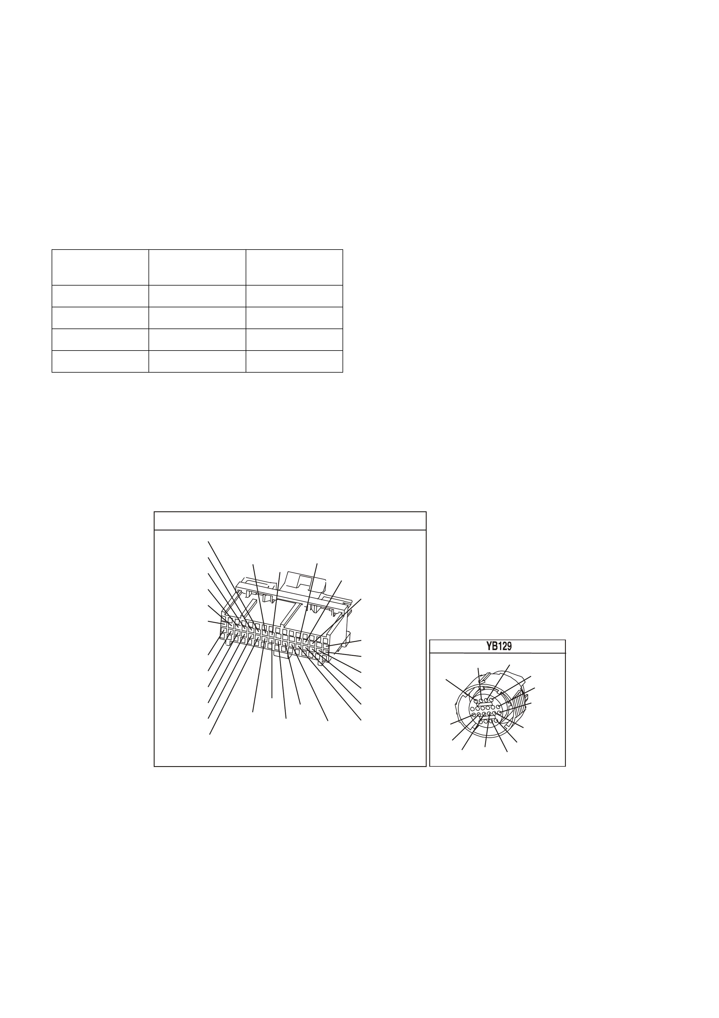
DIAGNOSTIC AIDS
Inspect the wiring for poor electrical connections at the PCM. Inspect the wiring for poor electrical connections at
the transmission pass-through connector. Look for the following conditions:
- A bent terminal
- A backed out terminal
- A damaged terminal
- Poor terminal tension
- A chafed wire
- A broken wire inside the insulation
• Moisture intrusion when diagnosing for an intermittent short or open condition, massage the wiring harness
while watching the test equipment for a change.
• Refer to the following Table for the correct On and Off states of the shift solenoids.
GEAR 1-2-SHIFT
SOLENOID 2-3 SHIFT
SOLENOID
1 ON ON
2 OFF ON
3 OFF OFF
4 ON OFF
TEST DESCRIPTION
The numbers below refer to the step numbers on the diagnostic table.
4. This step tests the function of the 1-2 SS valve and the automatic transmission wiring harness assembly.
5. This step tests for power to the 1-2 SS valve from the ignition through the fuse.
7. This step tests the ability of the PCM and the wiring to control the earth circuit.
10. This step measures the resistance of the A/T wiring harness assembly and the 1-2 SS valve.
YB1 93
(413)
(412)
(1413)
(1412)
(430)
(453)
(815)
V/B
GY/B
V
GY
V
B/R
W/R
(897)
(897)
G/W
G/W
(418)
(418)
BR
BR
(1426)
O/W
C16
D16
WT/B
(832)AUTO
(647)
(630)
BR
T
(832) MAN
LBLU/B
B
(424)
(423)
C1
D1
(792)
(422)
(1222)
(1223)
(428)
(123)
BR/W
GY/R
LG
Y/B
G/Y
V/W
BLU/W
BLU
(831) Man
(443)
LG/W
(442) (831)AUTO
(441)
LBLU
LBLU/B
(444)
LG/B
P.C.M. CONNECTOR 1
TRANSMISSION CONNECTOR
GY/BLU
(1229)
R
(1228)
Y/B
(1223)
LG
(1222)
P/BLU
(339)
(1227)
B/Y
(1230)
B/W
GY/R
(422)
BR
(418)
BR/Y
(1224)
(1226)
GY
Y
(1225)
(897)
G/W
(V8)
B
(469) (V6)
OR

DTC 82 V6 PCM - 1-2 SHIFT SOLENOID CIRCUIT ELECTRICAL
Step Action Value(s) Yes No
1 W as the Powertrain On-Board Diagnostic (OBD) System
Check performed? Go to Step 2 Go to Powertrain
OBD System
Check Table.
2 1. Install the Tech 2 Scan Tool.
2. With the engine OFF, turn the ignition switch to the
RUN position.
Important: Before clearing the DTC, use the Scan Tool
in order to record the History Data. Using the scan tool ,
clear the History Data.
3. Record the DTC History Data.
4. Clear the DTC.
Are any of the following DTCs also set?
• 66
• 67
• 81
• 83
Go to Step 3 Go to Step 4
3 1. Inspect fuse F32.
2. If the fuse is open, inspect the following components
for a short to earth condition:
- Circuit 339 (P/BLU)
- The solenoids
- The A/T wiring harness assembly
3. Repair the circuit, the solenoids, and the harness if
necessary.
Did you find a short to earth condition?
Go to Step 16 Go to Step 5
4 Using the transmission Miscellaneous Tests function on
the Scan Tool, command the 1-2 SS valve ON and OFF
three times while listening to the bottom of the
transmission pan (a stethoscope may be necessary).
Did the solenoid click when commanded?
Go to Diagnostic
Aids Go to Step 5
5 1. Turn the ignition OFF.
2. Disconnect the transmission 20-way (YB 129)
connector (additional DTCs may set).
3. Install the J 39775 jumper harness on the engine
side of the 20-way (YB 129) connector.
4. With the engine OFF, turn the ignition switch to the
RUN position.
5. Connect a test lamp from J 39775 jumper harness
cavity E to earth.
Is the test lamp ON?
Go to Step 7 Go to Step 6
6 Repair the open or short to earth in ignition feed circuit
339 to the 1-2 SS valve.
Is the repair complete?
Go to Step 16
7 1. Install a test lamp from J 39775 jumper harness
cavity E to cavity B.
2. Using the transmission Miscellaneous Tests function
on the Scan Tool, command the 2-3 SS valve ON
and OFF three times.
Is the test lamp ON when the 1-2 SS valve is
commanded ON, and OFF when commanded OFF?
Go to Step 10 Go to Step 8
8 1. Inspect circuit 1223 (Y/B) of the powertrain wiring
harness for an open, short to earth or short to power
condition.
2. Repair the circuit if necessary.
Did you find an open, short to earth or short to power
condition?
Go to Step 16 Go to Step 9

DTC 82 V6 PCM - 1-2 SHIFT SOLENOID CIRCUIT ELECTRICAL (CONTINUED)
Step Action Value(s) Yes No
9 Replace PCM.
Refer to Section 6C1-3 Service Operations of the VX
Series Service Information, for PCM Security Link
procedure.
Is action complete?
Go to Step16
10 1. Install the J 39775 jumper harness on the
transmission side of the 20-way (YB 129) connector.
2. With the J 39200 digital multimeter (DMM) and the
J 35616 connector test adapter kit, measure the
resistance between terminals B and E.
Is the resistance within the range indicated?
19-31 Ω Go to Step 12 Go to Step 11
11 1. Disconnect the A/T wiring harness assembly from
the 1-2 SS valve.
2. Measure the resistance of the 1-2 SS valve.
Is the resistance within the range indicated?
19-31 Ω Go to Step 14 Go to Step 15
12 Using the J 39200 DMM, measure the resistance
between terminal B and earth, and between terminal E
and earth.
Are both readings greater than the specified value?
250 K Ω Go to Diagnostic
Aids Go to Step 13
13 1. Disconnect the A/T wiring harness assembly from
the 1-2 SS valve.
2. Using the J 39200 DMM, measure the resistance
from the component's terminals to earth.
Are both readings greater than the specified value?
250 K Ω Go to Step 14 Go to Step 15
14 Replace the automatic transmission wiring harness
assembly.
Refer to Control Valve Body and Wiring Harness
replacement in Section 7C5-5 in VX Service Information.
Is the replacement complete?
Go to Step 16
15 Replace the 1-2 SS valve. Refer to Service Operations in
this Section 6C1-3 Service Operations of the VX Series
Service Information.
Is the replacement complete?
Go to Step 16
16 Perform the following procedure in order to verify the
repair:
Drive the vehicle in D and ensure the following conditions
are met:
- The PCM commands the 1-2 SS valve ON and the
voltage input drops to zero.
- The PCM commands the 1-2 SS valve OFF and the
voltage input increases to B+.
- All conditions are met for 5 seconds.
Were the above conditions verified?
System OK Go to Step 1
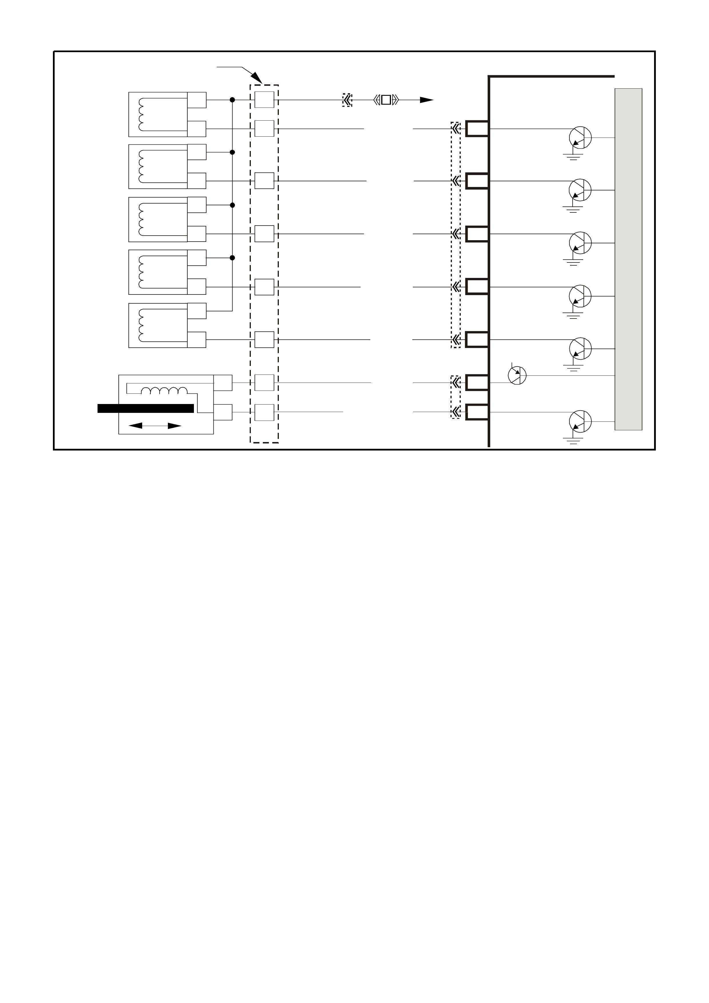
DTC 83 V6 PCM -
TORQUE CONVERTER CLUTCH (TCC)
PULSE WIDTH MODULATION (PWM) SOLENOID CIRCUIT
CIRCUIT DESCRIPTION:
The T orque Conver ter Clutch Puls e Width Modulation Solenoid Valve (TCC PWM Solenoid Valve) controls the fluid
acting on the converter clutch valve. The converter clutch valve controls the TCC application and release. The
solenoid attaches to the control valve body within the transmission. The solenoid receives ignition voltage through
circuit 339. The PCM controls the solenoid by providing a earth path on circuit 418. Current flows through the
solenoid coil according to the duty cycle (percentage of ON and OFF time). The TCC PWM Solenoid Valve
provides a smooth engagement of the torque converter clutch by operating during a duty cycle percent of ON time.
The TCC" PWM" solenoid is used in combination with the TCC Enable solenoid to regulate fluid to the torque
converter, and is attached to the control valve body within the transmission. The use of the Torque Converter
Clutch Pulse Width Modulated, (TCC PWM) solenoid provides the ability of being able to control more precisely,
the rate of Torque Converter Clutch (TCC) apply and release.
When the PCM detects a continuous open or short to earth in the TCC PWM Solenoid Valve circuit or the TCC
PWM Solenoid Valve, then DTC 83 sets.
CONDITIONS FOR RUNNING THE DTC
• The system voltage is 8-18 volts.
• The engine speed is greater than 300 RPM for 5 seconds.
• The engine is not in fuel cutoff.
• The PCM commands first gear.
• The TCC duty cycle is less than 10% or greater than 90%.
CONDITIONS FOR SETTING THE DTC
• The PCM commands the solenoid ON and the voltage input remains high (B+)
or
• The PCM commands the solenoid OFF and the voltage input remains low (0volts).
• Either condition for 5 seconds.
3–2 Down shift
Control
Solenoid
1–2 Shift
Solenoid A
2–3 Shift
Solenoid B
YB 12 9 Trans mis sion
Pass-Thru Connector
Torque
Converter
Clutch (TCC)
(PWM)
Solenoid
Torque
Converter
Clutch (TCC)
Enable
Solenoid
Pressure
Control
Solenoid A
B
A
B
SUPER4284-1
A
B
A
B
EF32 EFI
Relay
P/BLU
(339)
G/W (897)
LG (1222)
Y/B (1223)
GY/R (422)
BR (418)
R (1228)
GY/BLU (1229)
C13 3–2 C ontrol
Solenoid
1– 2 Shift
Solenoid
2– 3 Shift
Solenoid
TCC Enable
Solenoid
TCC PWM
Solenoid
Pressure Control
Solenoid High
Pressure Control
Solenoid Low
C2
C3
C1
C15
E15
E14
S
A
B
T
U
C
D
A
B
A
B
PCM
M
I
C
R
O
P
R
O
C
E
S
S
O
R
12V
YB194
YB110
YB193
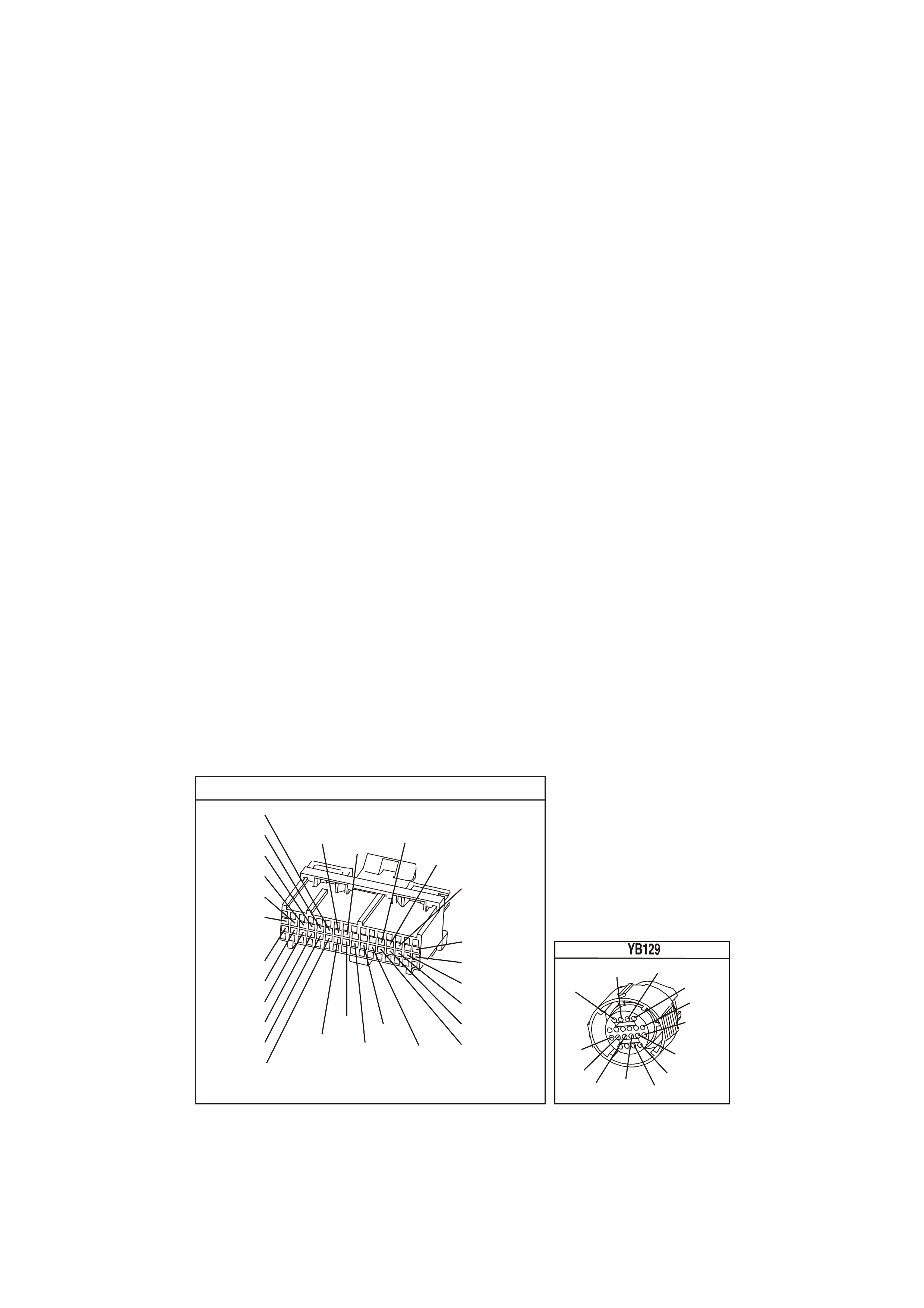
ACTION TAKEN WHEN THE DTC SETS
• The PCM stores the DTC information into memory when the diagnostic runs and fails.
• The Malfunction Indicator Lamp (MIL) will not be illuminated.
• The PCM records the operating conditions at the time the diagnostic fails. The PCM stores this information in
the History Data.
• When this DTC sets, the PCM will freeze shift adapts from being updated.
CONDITIONS FOR CLEARING THE MIL/DTC
• A History DTC clears after forty consecutive warm-up cycles.
• Use a Tech 2 scan tool in order to clear the MIL/DTC.
DIAGNOSTIC AIDS:
• Inspect the wiring for poor electrical connections at the PCM. Inspect the wiring for poor electrical connections
at the transmission pass-through connector.
Look for the following conditions:
- A bent terminal
- A backed out terminal
- A damaged terminal
- Poor terminal tension
- A chafed wire
- A broken wire inside the insulation
- Moisture intrusion
• When diagnosing for an intermittent short or open condition, massage the wiring harness while watching the
test equipment for a change.
TEST DESCRIPTION
The numbers below refer to the step numbers on the diagnostic table.
3. An open fuse indicates a short circuit in circuit 339. A short in any of the five solenoids fed by circuit 339 may
cause an open fuse.
4. This step tests for voltage to the solenoid.
6. This step tests the ability of the PCM and wiring to control the earth circuit.
7. This step tests the resistance of the TCC PWM Solenoid Valve and the Automatic Transmission Wiring
Harness Assembly.
YB1 93
(413)
(412)
(1413)
(1412)
(430)
(453)
(815)
V/B
GY/B
V
GY
V
B/R
W/R
(897)
(897)
G/W
G/W
(418)
(418)
BR
BR
(1426)
O/W
C16
D16
WT/B
(832)AUTO
(647)
(630)
BR
T
(832) MAN
LBLU/B
B
(424)
(423)
C1
D1
(792)
(422)
(1222)
(1223)
(428)
(123)
BR/W
GY/R
LG
Y/B
G/Y
V/W
BLU/W
BLU
(831) Man
(443)
LG/W
(442) (831)AUTO
(441)
LBLU
LBLU/B
(444)
LG/B
P.C.M. CONNECTOR 1
TRANSMISSION CONNECTOR
GY/BLU
(1229)
R
(1228)
Y/B
(1223)
LG
(1222)
P/BLU
(339)
(1227)
B/Y
(1230)
B/W
GY/R
(422)
BR
(418)
BR/Y
(1224)
(1226)
GY
Y
(1225)
(897)
G/W
(V8)
B
(469) (V6)
OR

DTC 83 V6 PCM - TORQUE CONVERTER CLUTCH (TCC) PULSE WIDTH MODULATION (PWM) SOLENOID
CIRCUIT
STEP ACTION VALUE YES NO
1 Was the On-Board Diagnostic (OBD) System Check
performed? Go to Step 2 Go to OBD
System Check
2 1. Install the scan tool.
2. With the engine OFF, turn the ignition switch to the
RUN position.
Important: Before clearing the DTCs, use the scan tool
in order to record the DTC history for reference. The
Clear Info function will erase the data.
3. Record the DTC history.
4. If DTCs 66, 67, 81, or 82 are also set, inspect the
F32 fuse for an open.
Is the fuse open?
Go to Step 3 Go to Step 4
3 1. Check circuit 339 for a short to earth.
2. Check each of the five solenoids for being internally
shorted or shorted to earth.
3. Check the A/T Wiring Harness Assembly for a short
to earth on each of the five solenoid circuits.
4. Make the repair/replacement if necessary.
Did you find and correct a problem?
Go to Step 15 Go to “Diagnostic
Aids” on facing
page
4 1. Turn the ignition OFF.
2. Disconnect the transmission pass-through connector
(additional DTCs may set).
3. Install J 39775 Jumper Harness on the engine
harness connector.
4. With the engine OFF, turn the ignition switch to the
RUN position.
5. Connect a lest lamp from J 39775 Jumper Harness
cavity E to earth.
Is the test lamp on?
Go to Step 6 Go to Step 5
5 Repair the open in the ignition feed circuit 339 to the TCC
PWM Solenoid Valve.
Is the repair complete?
Go to Step 15
6 1. Install the test lamp from cavity E to cavity U of the J
39775 Jumper Harness.
2. Command the TCC PWM Solenoid Valve ON and
OFF three times.
Does the test lamp turn ON when the TCC PWM
Solenoid Valve is commanded ON, and OFF when
commanded OFF?
Go to Step 8 Go to Step 7
7 Check circuit 418 for an open, short to B+, or a short to
earth. Repair the circuit if necessary.
Did you find and correct the problem?
Go to Step 15 Go to Step 9
8 1. Install J 39775 Jumper Harness on the transmission
pass-through connector.
2. Using the J 39200 DVM and the J 35616 Connector
Test Adapter Kit, measure the resistance between
terminals E and U.
Is the resistance within the specified range?
10-15 Ω Go to Step 11 Go to Step 10
9 Replace PCM.
Refer to Section 6C1-3 Service Operations of the VX
Series Service Information, for PCM Security Link
procedure.
Is action complete?
Go to Step 15

DTC 83 V6 PCM - TORQUE CONVERTER CLUTCH (TCC) PULSE WIDTH MODULATION (PWM) SOLENOID
CIRCUIT (CONTINUED)
STEP ACTION VALUE YES NO
10 1. Disconnect the Automatic Transmission Wiring
harness Assembly at the TCC PWM Solenoid Valve.
2. Measure the resistance of the TCC PWM Solenoid
Valve.
Is the resistance within the specified range?
10-15 Ω Go to Step 13 Go to Step 14
11 Measure the resistance between terminal E and earth,
and between terminal U and earth.
Are both readings greater than the specified value?
250 K Ω Go to “Diagnostic
Aids” on facing
page
Go to Step 12
12 1. Disconnect the Automatic Transmission Wiring
Harness Assembly at the TCC PWM Solenoid Valve.
2. Measure the resistance between each of the
component terminals and a known good earth.
Are both readings greater than the specified value?
250 K Ω Go to Step 13 Go to Step 14
13 Replace the Automatic Transmission Wiring Harness
Assembly. Refer to Service Operations in Section 7C-5 in
VX Service Information.
Is the action complete?
Go to Step 15
14 Replace the TCC PWM Solenoid Valve. Refer to Section
6C1-3 Service Operations of the VX Series Service
Information.
Is the action complete?
Go to Step 15
15 In order to verify your repair, perform the following
procedure:
Operate the vehicle under the following conditions while
observing the TCC PWM Solenoid and TCC Slip Speed:
• The PCM commands the TCC PWM Solenoid
Valve ON, and the TCC Slip Speed is -20 to +20
rpm.
• The PCM commands the TCC PWM Solenoid
Valve OFF, and the TCC Slip Speed is greater
than rpm 50.
Are both of the TCC Slip conditions met for at least 4
seconds?
System OK Begin the
diagnosis again
Go to Step 1
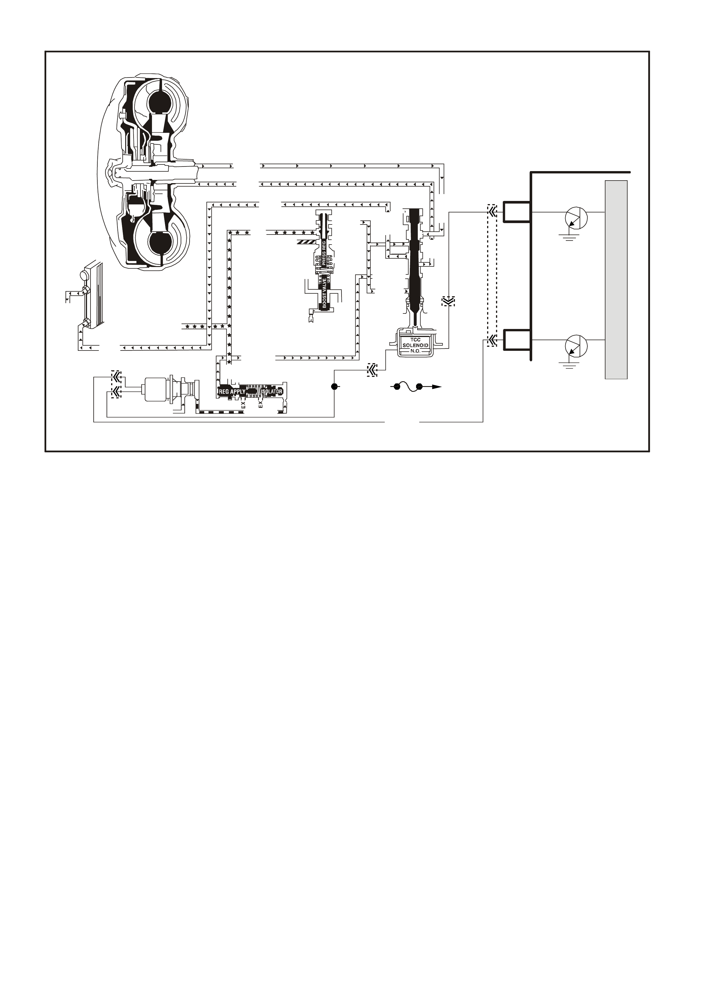
DTC 85 V6 PCM -
TRANSMISSION SLIPPING
CIRCUIT DESCRIPTION:
The PCM m onitors the diff erence between the engine speed and the transm ission output speed. In D3 drive range
with the TCC engaged, the engine speed should closely match the transmission output speed. In D4 drive range,
with the TCC engaged, the Trans Slip Speed should be -20 to +20 RPM.
W hen the PCM detects an excessive transm ission slip speed when the T CC should be engaged, then DTC 85 will
set.
CONDITIONS FOR RUNNING THE DTC
• No Throttle Position DTCs 21 or 22.
• No VSS assembly DTCs 24 or 72.
• No TCC solenoid valve DTC 67.
• No 1-2 SS valve DTC 81.
• No 2-3 SS valve DTC 82.
• No 3-2 SS valve assembly DTC 66.
• No TCC PWM solenoid valve DTC 83.
• The engine speed is greater than 300 RPM for 5 seconds.
• The engine is not in fuel cutoff.
• The vehicle speed is 56-105 km/h.
• The speed ratio is 0.67-0.90 (the speed ratio is the engine speed divided by the transmission output speed).
• The engine speed is 1200-3500 RPM.
• The engine torque is 54-542 N.m.
• The gear range is D4.
• The commanded gear is not 1st gear.
• The Throttle Position angle is 10-50%.
• The TFT is between 20-130°C.
M
I
C
R
O
PCM
Torque
Converter
Assembly
TCC Enable
Solenoid
SUPPERVX4285-1
C1
GY/R
(422)
Ignition
Switch
Fuse
F32
BR 418
P/BLU(339)
TCC
Pwm
Sol
(N.C.)
Cooler
Cooler
Cooler
Release
Apply
Cooler
Conv FD
Conv FD
Reg Apply
EX
EX
EX
Apply
Release
Decrease
Line
Line
Reg Ap
CC Signal
Reg Apply
Reg Apply Isolator
Torque Sig
Rev Input
Rev Input
AFL (From Press Cont Sol)
Lube
Line (From Pump)
C15
TCC PWM
Solenoid
CONVERTER CLUTCH VALVE
YB193
YB129
YB129
YB129

CONDITIONS FOR SETTING THE DTC
• DTC 85 sets if the following conditions occur for three TCC cycles.
- The TCC is commanded ON for 5 seconds.
- The TCC is at maximum duty cycle for 1 second.
- The TCC slip speed is 80-800 RPM for 7 seconds.
Important: The following actions may occur before the DTC sets.
• If the T CC is com m anded O N and at m axim um duty cyc le for 5 s econds, the T hrottle Position angle is 10-40%,
and the transm ission slip c ounter has increm ented to either 1 or 2 ( out of 3 to increm ent the fail counter for the
current ignition cycle), then the following slip conditions and actions may increment the fail counter for the
current ignition cycle:
These conditions must occur sequentially.
- Condition 1: If the TCC s lip speed is 80-800 RPM for 7 seconds , then the PCM will comm and m axim um line
pressure and freeze shift adapts from being updated.
- Condition 2: If Condition 1 is met and the TCC slip speed is 80-800 RPM for 7 seconds, then the PCM will
command the TCC OFF for 1.5 seconds.
- Condition 3: If Condition 2 is met and the TCC s lip s peed is 80- 800 RPM f or 7 s econds , then the f ail c ounter
on the current ignition cycle is incremented.
• The above slip conditions and actions may be disregarded if the TCC is commanded OFF at any time as a
result of a driving manoeuvre (sudden acceleration or deceleration).
ACTION TAKEN WHEN THE DTC SETS
• The PCM stores the DTC information into memory when the diagnostic runs and fails.
• The Malfunction Indicator Lamp (MIL) will not be illuminated.
• The PCM records the operating conditions at the time the diagnostic fails. The PCM stores this information in
the History Data.
• When this DTC s ets, the PCM will freeze shif t adapts fr om being updated, inhibits 4th gear if the trans mission is
in hot mode, and command maximum line pressure.
CONDITIONS FOR CLEARING THE MIL/DTC
• A History DTC clears after forty consecutive warm-up cycles.
• Use a Tech 2 scan tool in order to clear the MIL/DTC.
DIAGNOSTIC AIDS
• Internal transmission failures may set DTC 85.
TEST DESCRIPTION
The numbers below refer to the step numbers on the diagnostic table.
3. This step tests the torque converter for slippage while in a commanded lock-up state.
DTC 85 V6 PCM - TRANSMISSION SLIPPING
STEP ACTION VALUE YES NO
1 Was the On-Board Diagnostic (OBD) System Check
performed? Go to Step 2 Go to OBD
System Check
2 Perform the transmission fluid checking procedure.
Have you performed the transmission fluid checking
procedure?
Go to Step 3 Go to
Transmission
Fluid Checking
Procedure
3 1. Install the scan tool.
2. With the engine OFF, turn the ignition switch to the
RUN position.
3. Drive the vehicle in 4th gear with the TCC engaged.
Is the TCC Slip Speed between the specified values for 7
seconds?
300-1000
RPM Go to Step 4 Go to “Diagnostic
Aids” above

DTC 85 V6 PCM - TRANSMISSION SLIPPING (CONTINUED)
STEP ACTION VALUE YES NO
4 Inspect the Torque Converter Clutch Solenoid Valve
(TCC Solenoid Valve) for the following conditions:
• Internal malfunction (such as sediment or damage)
• Damaged seals
Inspect the Torque Converter Clutch Pulse Width
Modulation Solenoid Valve (TCC PWM Solenoid Valve)
for the following conditions:
• Internal malfunction (such as sediment or damage)
• Damaged seals
Did you find and correct the problem?
Go to Step 13 Go to Step 5
5 Inspect the 1-2 Shift Solenoid Valve (1-2 SS Valve) for
the following conditions:
• Internal malfunction (such as sediment or damage)
• Damaged seals
Inspect the 2-3 Shift Solenoid Valve (2-3 SS Valve) for
the following conditions:
• Internal malfunction (such as sediment or damage)
• Damaged seals
Did you find and correct the problem?
Go to Step 13 Go to Step 6
6 Inspect the valve body assembly for a stuck TCC signal
valve. Refer to Unit Repair.
Did you find and correct the problem?
Go to Step 13 Go to Step 7
7 Inspect the torque converter assembly for the following
conditions:
• Stator roller clutch not holding
• Internal damage
Did you find and correct the problem?
Go to Step 13 Go to Step 8
8 Inspect the oil pump assembly for the following
conditions:
• Stuck converter clutch valve
• Converter clutch valve assembled backward
• Mispositioned converter clutch valve retaining ring
• Mispositioned pump to case gasket
• Restricted orifice cup plugs
• Damaged orifice cup plugs
• Over-tightened, or unevenly tightened pump body to
cover bolts
Did you find and correct the problem?
Go to Step 13 Go to Step 9
9 Inspect the input housing and shaft assembly for the
following conditions:
• Cut turbine shaft o-ring seal
• Damaged turbine shaft o-ring seal
• Restricted turbine shaft retainer and ball assembly
• Damaged turbine shaft retainer and ball assembly
Did you find and correct the problem?
Go to Step 13 Go to Step 10

DTC 85 V6 PCM - TRANSMISSION SLIPPING (CONTINUED)
STEP ACTION VALUE YES NO
10 Inspect the 2-4 band assembly for the following
conditions:
• Worn 2-4 band
• Damaged 2-4 band
• Mispositioned 2-4 band
• Misassembled 2-4 band
• The band anchor pin is not engaged
• Restricted apply passages in the 2-4 servo assembly
• Blocked apply passages in the 2-4 servo assembly
• Nicks or burrs on the servo pin
• Nicks or burrs on the pin bore in the case
• Damaged fourth servo piston
• Misassembled fourth servo piston
• Damaged band apply pin
• Incorrect band apply pin
• Damaged servo bore in the case
• Missing piston seals
• Cut piston seals
• Damaged piston seals
• Porosity in the pistons
• Porosity in the cover
• Porosity in the case
• Damaged piston seal grooves
• Plugged orifice cup plug
• Missing orifice cup plug
Did you find and correct the problem?
Go to Step 13 Go to Step 11
11 Inspect the forward clutch assembly for the following
conditions:
• Worn clutch plates
• Porosity in the forward clutch piston
• Damaged forward clutch piston
• Missing forward clutch piston inner and outer seals
• Cut forward clutch piston inner and outer seals
• Damaged forward clutch piston inner and outer seals
• Missing input housing to forward clutch housing O-
ring seal
• Cut input housing to forward clutch housing O-ring
seal
• Damaged input housing to forward clutch housing
O-ring seal
• Damaged forward clutch housing
• Damaged forward clutch housing retainer and ball
assembly
• Forward clutch housing retainer and ball assembly is
not sealing
Did you find and correct problem?
Go to Step 13 Go to Step 12

DTC 85 V6 PCM - TRANSMISSION SLIPPING (CONTINUED)
STEP ACTION VALUE YES NO
12 Inspect the 3-4 clutch assembly for the following
conditions:
• Worn clutch plates
• Porosity in the 3-4 clutch piston
• Damaged 3-4 clutch piston
• Missing 3-4 clutch inner and outer seals
• Cut 3-4 clutch inner and outer seals
• Damaged 3-4 clutch inner and outer seals
• Damaged 3-4 clutch spring assembly
• Damaged 3-4 clutch apply ring
• Damaged piston seal grooves
• Plugged orifice cup plug
• Missing orifice cup plug
Did you find and correct the problem?
Go to Step 13 Go to “Diagnostic
Aids” above
13 In order to verify your repair, operate the vehicle under
the following conditions:
• Drive the vehicle in D4 with the TCC ON and a
throttle position of 16-50%.
Did the vehicle obtain a Trans Slip Speed of -20 to +40
RPM?
System OK Begin the
diagnosis again.
Go to Step 1
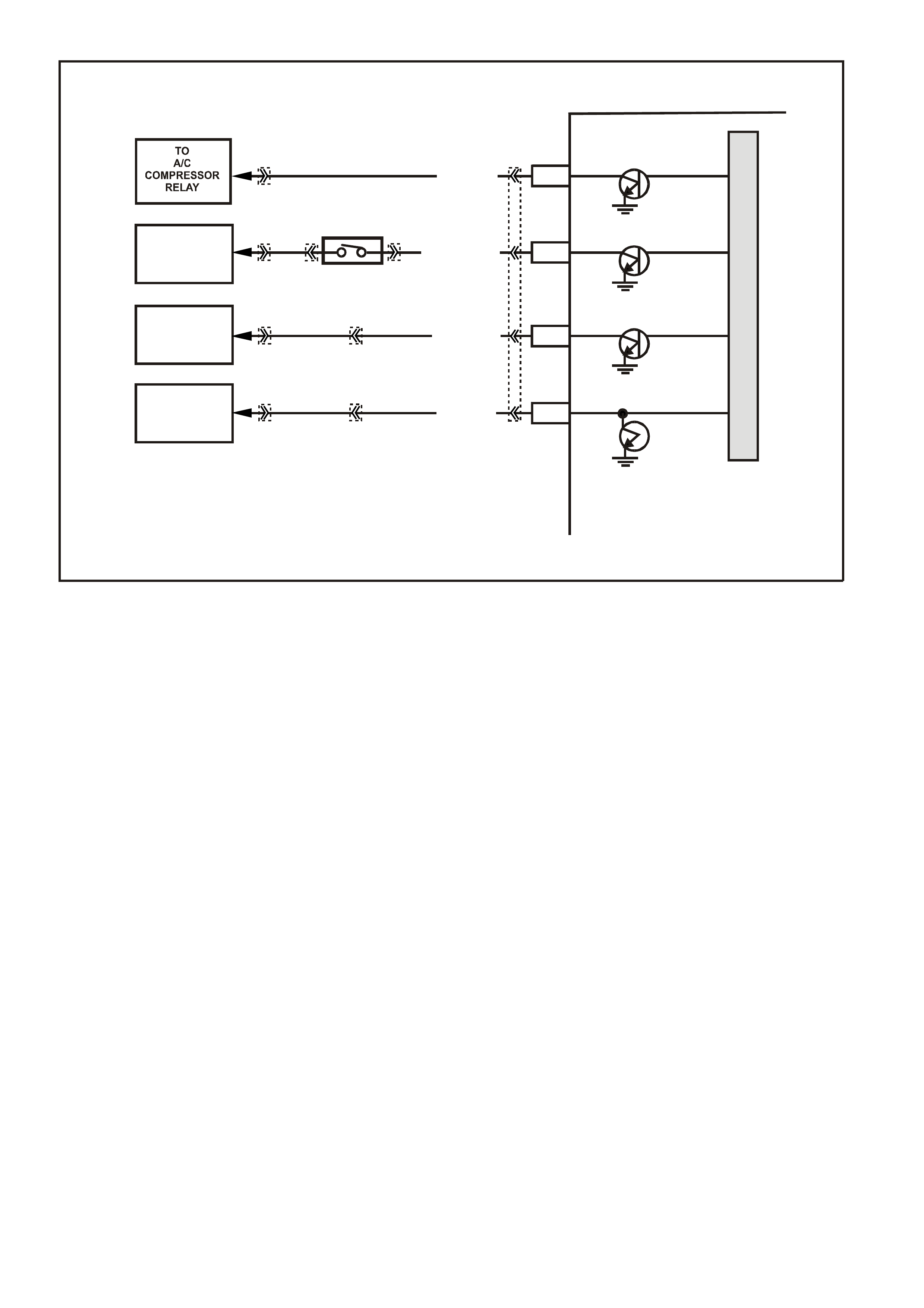
DTC 91 V6 PCM -
QDSM (QUAD DRIVER SURFACE MODULE) CIRCUIT
CIRCUIT DESCRIPTION:
Quad Driver Surface Modules (QDSM) is used by the PCM to turn "on" many of the current-driven devices that
are needed to control various engine functions. A QDSM is capable of controlling up to 4 separate outputs by
applying earth or voltage to the device which the PCM is commanding "ON."
QDSM do not have the capability of diagnosing each output c ircuit individually. A DTC 91 that is s et indicates an
impr oper voltage level has been detected on one of the QDSM c irc uits. The QDSM c ontr ols the A/C c ompres s or
relay, the Start Relay, High Speed fan relay, and the Torque Achieved circuit to the ABS/ETC module.
CONDITIONS FOR RUNNING THE DTC
• The engine has been running for longer than 5 seconds.
CONDITIONS FOR SETTING THE DTC
• An improper voltage level has been detected on a QDSM circuit.
ACTION TAKEN WHEN THE DTC SETS
• The PCM stores the DTC information into memory when the diagnostic runs and fails.
• The Malfunction Indicator Lamp (MIL) will not be illuminated.
• The PCM records the operating conditions at the tim e the diagnostic fails. T he PCM stores this information
in the History Data.
• When DTC 91 is set, the low speed fan will be turned "ON" and will remain "ON" until DTC 91 has been
cleared.
CONDITIONS FOR CLEARING THE MIL/DTC
• The PCM turns the MIL OFF after the first ignition cycle that the diagnostic runs and does not fail.
• A Histor y DT C clears after f orty c onsecutive warm -up cycles, if this or any other em ission related diagnostic
does not report any failure.
• Use a Tech 2 scan tool in order to clear the MIL/DTC.
TO
HIGH SPEED
FAN RELAY
TO
START
RELAY
TO
ABS/ETC
MODULE
M
I
C
R
O
PCM
4286
LG/B (366)
B/W (1427)
BL U/ W (304 )
GY/BLU (1434)
A/C RELAY CONTROL
START RELAY CONTROL
ENGINE COOLING RAN
RELAY HIGH SPEED
CONTROL
F5
F4
F7
F6
TORQUE ACHIEVED
YE98 YE110
YE43
YB35
YE110
YB35
YE49
YE101
YB194
EG
NEUTRAL START
BACK-UP SW.
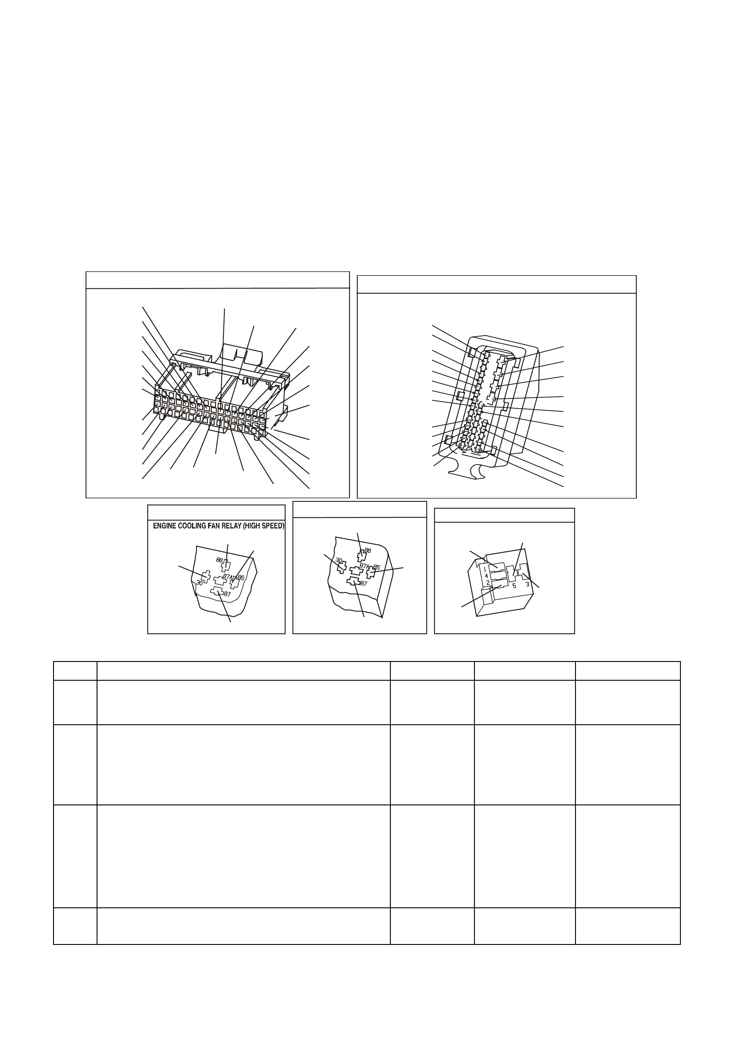
DIAGNOSTIC AIDS:
A ABS/ETC DTC may also be set, if the Torque Achieved circuit is causing the fault.
Check the connector harnesses for:
• Dirty, Damaged, or Loos e Connections or Dam aged Harness - Check for any damage to the harness which
could cause an intermittent open or short to earth or backed out terminals at the PCM and BCM module
connectors, broken locks, improperly formed or damaged terminals.
TEST DESCRIPTION: Number(s) below refer to step number(s) on the diagnostic Table.
2. T his step c heck s to s ee if the A/C c om press or relay can be controlled using a s can tool. If the scan tool c an
control the A/C relay, the A/C circuit is not causing DTC 91 to set.
8. T his step c heck s to s ee if the Star t relay can be controlled using a sc an tool. If the s can tool can control the
Start relay, the Start relay circuit is not causing DTC 91 to set.
13. This step checks to see if the High Speed relay can be controlled using a scan tool. If the scan tool can
control the High Speed relay, the High Speed Relay circuit is not causing DTC 91 to set.
YE194
P.C.M. CONNECTOR 3
LG/B
(366)
G
(843)
B/W
F16
B/Y
BR/Y
(1228)
(469)
Y
(451)
F1
P
(841)
BLU
V
E1
LBLU
(845)
BLU
B
(1226)
W/B
BLU/W
V
R
(435)
(31)
(1229)
GY
(1224)
Y
(846)
GY
(842)
(452)
(774)
(304)
BR/Y
(411)
(439)
GY/BLU
BLU
(1225)
E16
(1427)
(429)
(844)
B/O
(434)
OR AUTO
GY/BLU
GY
(1434)
MAN
(776)
W
BLU/W
Y
GY
(771)
(772)
(773)
A.B.S & T.C.S M ODUL ATOR AND CONT ROL MODULE
YE98
1
15
16
27
31
26
19
20
(885)
(884)
(833)
(830)
(873)
(872)
(883)
(882)
B
BLU
W
R
BR
GY
Y
(855)
(20)
(1426)
(863)
(1220)
BLU/B
G/W
O/W
BLU/R
R
V
R/W
BR/R
B/W
G
Y/R
B
R
R
B/O
(1429)
(121)
(1427)
(875)
(88)
(150)
(2R)
(2R)
(154)
GY/B
(1687)
YE 43
B/R
(157)
BLU/W
(304)
O/B
(740)
O/Y
(250)
Y E 49
START RELAY
V
(5)
(2)
GY
V/W
R
(434)
(6)
A/C RELAY
YE101
(366)
(439)
LG/B
P
G
P
(59)
(439)
DTC 91 V6 PCM - QDSM (QUAD DRIVER SURFACE MODULE) CIRCUIT
STEP ACTION VALUE YES NO
1. Was the "On-Board Diagnostic" (OBD) System Check
performed? Go to Step 2 Go to OBD
System Check in
this Section
2. 1. Ignition "ON", engine "OFF".
2. Using scan tool, command A/C compressor relay
"ON" and "OFF" while listening to relay.
Did the A/C compressor relay click "ON" and "OFF"
when commanded?
Go to Step 8 Go to Step 3
3. 1. Ignition "OFF".
2. Disconnect the PCM connectors.
3. Ignition "ON".
4. Using DVM, probe PCM harness connector
terminal "F4" with negative lead to earth.
Is the voltage at the specified value?
B+ Go to Step 4 Go to Step 6
4. Check for poor connection at PCM harness connectors.
Was a problem found? Verify Repair Replace the PCM
and Verify Repair

DTC 91 V6 PCM - QDSM (QUAD DRIVER SURFACE MODULE) CIRCUIT (CONTINUED)
STEP ACTION VALUE YES NO
5. Check for an open or a short to earth between the PCM
harness connector terminal "F4", and the A/C
compressor relay terminal "1".
Was a problem found?
Verify Repair Go to Step 7
6. Replace A/C Compressor Relay.
Is action complete? Verify Repair
7. 1. Ignition "ON", engine "OFF".
2. Using scan tool, command Start relay "ON",
and "OFF" while listening to relay.
Did the Start relay click "ON", and "OFF"?
Go to Step 13 Go to Step 9
8. 1. Ignition "OFF".
2. Disconnect PCM connectors.
3. Ignition "ON".
4. Using DVM, probe PCM harness connector
terminal "F5" with negative lead to earth.
Is the voltage at the specified value?
B+ Go to Step 10 Go to Step 11
9. Check for poor connection at PCM harness connectors.
Was a problem found? Verify Repair Go to Step 5
10. Check for an open or short to earth between the PCM
harness connector terminal "F5", and the Start relay
terminal "86".
Was a problem found?
Verify Repair Go to Step 12
11. Replace Start Relay.
Is action complete? Verify Repair
12. 1. Ignition "ON", engine "OFF".
2. Using scan tool, command High Speed fan relay
"ON", and "OFF" while listening to relay.
Did the High Speed relay click "ON" and "OFF" when
commanded?
Go to Step 17 Go to Step 14
13. 1. Ignition "OFF".
2. Disconnect PCM harness connectors.
3. Ignition "ON".
4. Using DVM, probe PCM harness connector
terminal "F6", with negative lead to earth.
Is the voltage at the specified value?
B+ Go to Step 15 Go to Step 16
14. Check for poor connection at PCM harness connectors.
Was a problem found? Verify Repair Go to Step 5
15. Check for an open or a short to earth between the PCM
harness connector terminal "F6", and the High Speed
fan relay terminal "86".
Was a problem found?
Verify Repair Refer to Table
A-12.2 for testing
of the High Speed
Fan Relay
16. Check for open or short to earth in Torque Achieved
circuit between the PCM and BCM. If OK, check for poor
connection at PCM, and BCM.
Was a problem found?
Verify Repair Go to Step 5
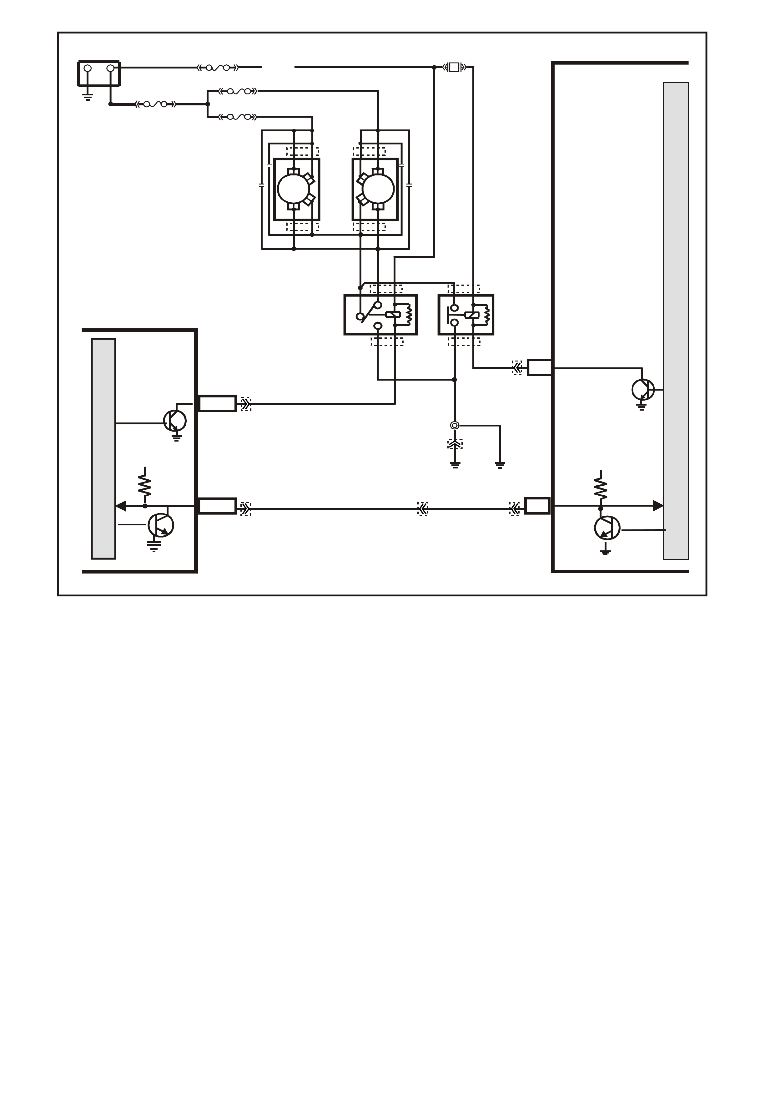
DTC 92 V6 PCM -
LOW SPEED FAN – NO BCM RESPONSE
CIRCUIT DESCRIPTION;
The PCM determ ines operation of the two speed engine cooling fan based on A/C request signal input, engine
coolant temperature and vehicle speed.
The engine cooling fan low speed relay (labeled LO FAN in relay housing) is energised by the BCM. W hen the
PCM determines that the engine cooling fan low speed relay should be turned "ON", the PCM will send a
message on circuit 1221 to the BCM. This message will ask the BCM to earth circuit 473 and energise the
engine cooling fan low speed relay. After the BCM provides the earth for circuit 473, the BCM will send a
message back to the PCM saying that the earth circuit was commanded.
When the BCM does not receive communications from the PCM when the ignition is switched "ON", then the
starter motor will be enabled after a one second delay.
CONDITIONS FOR RUNNING THE DTC
• Engine is idling.
• PCM supplies a signal to the BCM.
CONDITIONS FOR SETTING THE DTC
• The PCM sends a request to the BCM to turn on the engine cooling fan low speed relay via the serial data
normal mode message and the BCM does not send a message back to the PCM.
SUPERVX056
PCM
M
I
C
R
O
P
R
O
C
E
S
S
O
R
LOW S PEED FAN
M
I
C
R
O
BCM
O/B (4 73)
+-
BATTERY
LOC.
E1
B7/B7
HIGH SERIES
BCM TERMINALS
NOMINATED FIRST
A3
MAIN
SERIAL
DATA 5V
SERIAL
DATA
MAIN
5V
E2/D2 R/B (1221)
87A
30
87
85
86
87
30
85
86
ENGINE
COOLING
FAN 1
ENGINE
COOLING
FAN RELAY
(LOW SPEED)
ENGINE
COOLING
FAN RELAY
(HIGH SPEED)
R
YB
G
BLUE
FUSIBLE
LINK
F31
ENGINE
COOLING
FAN 2
FS
FT FAN 2
FU F AN 1
(1040)
R
(203)
R
(001)
R
(001)
O/B
(208)
O/BLU
(204)
BLU/W
(304) F6
HIGH
SPEED FAN
LOC.
E2
LOC.
E3
B/P
(157)
YE119
YE119
YE103
YE103
YE43
YE43 YB194
YE114
YE112
YB188
YB174
YB163
YB175
YB164

ACTION TAKEN WHEN THE DTC SETS
• The PCM stores the DTC information into memory when the diagnostic runs and fails.
• The Malfunction Indicator Lamp (MIL) will not be illuminated.
• The PCM records the operating conditions at the tim e the diagnostic fails. T he PCM stores this information
in the History Data.
• When DTC 31 is set, the engine will not start if DTC 31 is current.
CONDITIONS FOR CLEARING THE MIL/DTC
• A History DTC clears after forty consecutive warm-up cycles.
• Use a Tech 2 scan tool in order to clear the MIL/DTC.
DIAGNOSTIC AIDS
The Tech 2 scan tool has a special test to check this signal. To access this special test, select F3: BCM, then
select F1: THEFT STATUS. The Tech 2 scan tool will either display "OK TO START" or "NO START".
• Dirty, Damaged, or Loos e Connections or Dam aged Harness - Check for any damage to the harness which
could cause an intermittent open or short to earth or backed out terminals at the PCM connectors, broken
locks, improperly formed or damaged terminals.
TEST DESCRIPTION
The numbers below refer to the step numbers on the diagnostic table.
2. If the engine c ranks af ter a one s ec ond delay it m eans the BCM did not s ee a mess age f rom the PCM when
the ignition was turned "ON".
3. An open or short to earth on circuit 1221 will disable any communication of serial data.
DTC 92 V6 PCM - LOW SPEED FAN – NO BCM RESPONSE
STEP ACTION VALUE YES NO
1. Was the "On-Board Diagnostic" (OBD) System Check
performed? Go to Step 2 Go to OBD
System Check in
this Section
2. Is DTC 31 set? Go to DTC 31
Diagnostic Table
in this Section
Go to Step 3
3. 1. Engine at idle speed.
2. Using Tech 2 scan tool, select "LOW FAN".
Does Tech 2 scan tool "BCM Response" display change
from "FAN OFF" to "FAN ON" when test is enabled?
Go to Step 4
Go to
Table A-12.1 in
this Section
4. Does Tech 2 scan tool "BCM Response" display change
from "FAN OFF" to "FAN ON" when test is enabled? DTC 92 is
intermittent.
Refer to
"Diagnostic Aids"
above.
Refer
Section 12J-1
LOW SERIES
BCM or
Section 12J-2
HIGH SERIES
BCM in VX
Service
Information for
additional
diagnosis.
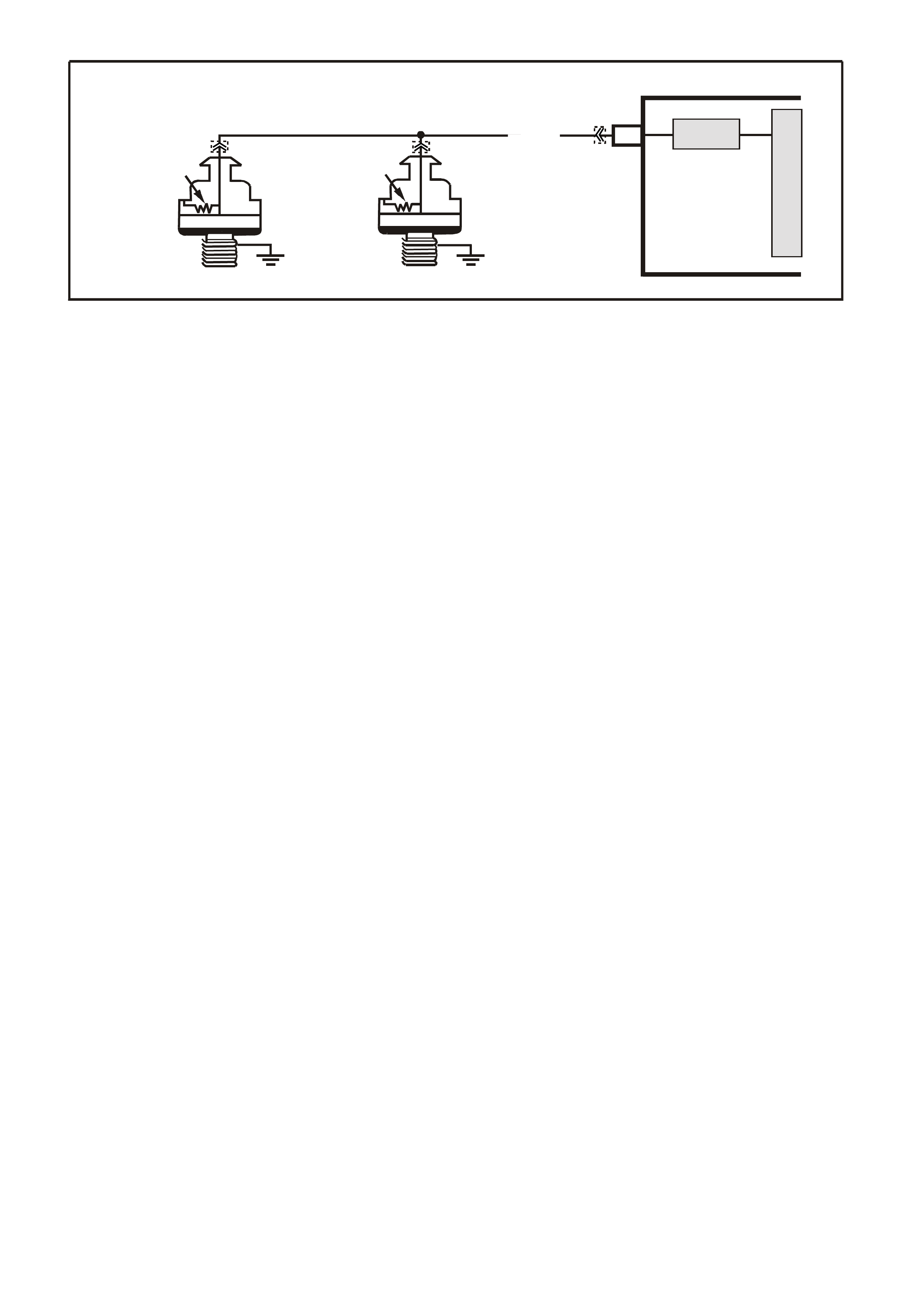
DTC 93 V6 PCM
KNOCK SENSOR SYSTEM
CIRCUIT DESCRIPTION:
The Knock sensor is used to detect engine detonation, and the PCM will retard the Electronic Spark Timing
(EST) based on the signal being received The Knock sensor produces an AC signal which varies in signal
amplitude and frequency depending upon the amount of Knock being experienced.
The PCM monitors the output of the SNEF (Signal To Noise Enhancem ent Filter) circuit. The PCM determines
weather Knock is occurring by comparing the Knock sensor signal level with the voltage level on the SNEF
circuit. The SNEF circuit allows the PCM to reject only false Knock signals by indicating the amount of normal
engine mechanical noise present. Normal engine noise varies depending on engine speed and load. A normal
Knock condition could result in a Knock sensor signal from a few milliseconds to possibly as high as 100
milliseconds in length.
When the SNEF circuit output is signific antly longer than the longest expected "Norm al" output it is assum ed the
SNEF circuitry has failed and DTC 93 will set.
CONDITIONS FOR RUNNING THE DTC
• DTC The engine has been running for more than 10 seconds.
• DTC 43 is not set.
• Engine RPM is greater than 1000.
CONDITIONS FOR SETTING THE DTC
• The PCM’s SNEF circuit indicates knocking for more than 10 seconds.
ACTION TAKEN WHEN THE DTC SETS
• The PCM illuminates the Malfunction Indicator Lamp (MIL) when the diagnostic runs and fails.
• The PCM records the operating conditions at the tim e the diagnostic fails. T he PCM stores this information
in the History Data.
• When DTC 93 is set, and current, the PCM uses a default spark advance table.
CONDITIONS FOR CLEARING THE MIL/DTC
• The PCM turns the MIL OFF after the first ignition cycle that the diagnostic runs and does not fail.
• A Histor y DT C clears after f orty c onsecutive warm -up cycles, if this or any other em ission related diagnostic
does not report any failure.
• Use a Tech 2 scan tool in order to clear the MIL/DTC.
DIAGNOSTIC AIDS:
Refer to "Intermittents" in Section6C1-2B SYMPTOMS of the VX Series Service Information.
TEST DESCRIPTION: Number(s) below refer to step number(s) on the diagnostic Table.
2. This step checks to see if the Tech 2 scan tool is displaying Knock signal at all times.
3. This step checks to see if a audible Knock is being caused by the engine or transmission.
VXSC007
PCM
M
I
C
R
O
SNEF
KNOCK SENSOR
SIGNAL INPUT
C12
RH KNOCK
SENSOR
LH KNOCK
SENSOR
PIEZO CRYSTAL
SHUNT
RESISTOR
PIEZO CRYSTAL
SHUNT
RESISTOR
W/R (815)
YE3 YE3
YB193

YB1 93
(413)
(412)
(1413)
(1412)
(430)
(453)
(815)
V/B
GY/B
V
GY
V
B/R
W/R
(897)
(897)
G/W
G/W
(418)
(418)
BR
BR
(1426)
O/W
C16
D16
WT/B
(832)AUTO
(647)
(630)
BR
T
(832) MAN
LBLU/B
B
(424)
(423)
C1
D1
(792)
(422)
(1222)
(1223)
(428)
(123)
BR/W
GY/R
LG
Y/B
G/Y
V/W
BLU/W
BLU
(831) Man
(443)
LG/W
(442) (831)AUTO
(441)
LBLU
LBLU/B
(444)
LG/B
P.C.M. CONNECTOR 1
YE3
KNOCK S ENSORS
W/R
(815)
DTC 93 V6 PCM - KNOCK SENSOR SYSTEM
STEP ACTION VALUE YES NO
1. Was the "On-Board Diagnostic" (OBD) System Check
performed? Go to Step 2 Go to OBD
System Check in
this Section
2. 1. Install Tech 2 "Scan " tool.
2. Ignition "ON", engine Idling.
3. Using Tech 2 scan tool, select "Knock Signal"
and "Knock Retard".
Is "Knock Signal" indication "Knock"?
Go to Step 3 Go to Step 4
3. With engine running, is a audible "Knock" condition
heard? Refer to Engine
Mechanical or
Transmission
Section of VX
Service
Information to
repair audible
Knock
Go to Step 4
4. Replace PCM.
Refer to Section 6C1-3 Service Operations of the VX
Series Service Information, for PCM Security Link
procedure.
Is action complete?
Verify Repair
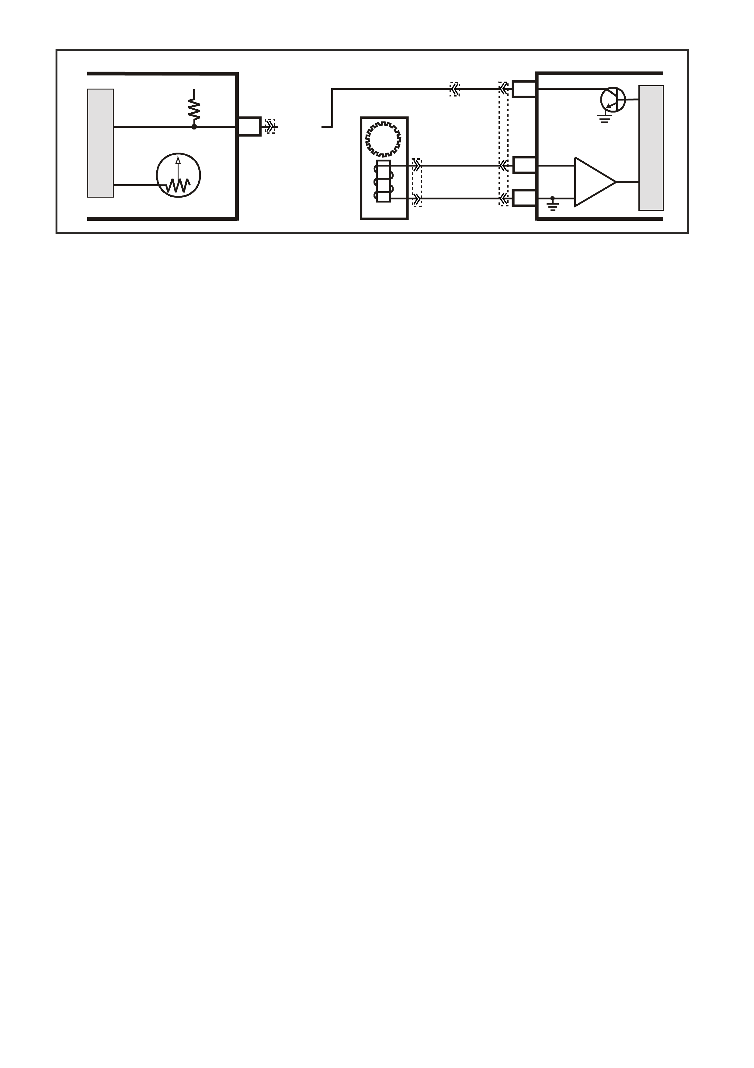
DTC 94 V6 PCM -
NO VEHICLE SPEED SIGNAL (MANUAL TRANSMISSION)
CIRCUIT DESCRIPTION:
The Vehic le Speed Sensor As sem bly (VSS Assem bly) provides vehicle s peed infor m ation to the PCM. The VSS
Assembly is a Permanent Magnet (PM) generator. The PM generator produces a pulsing AC voltage. The AC
voltage level and the number of pulses increase with the speed of the vehicle. The PCM then converts the
pulsing voltage to vehicle speed. The PCM uses this information for calculations. A scan tool can display the
vehicle speed.
When the PCM detects a low or no vehicle speed, when there is high engine speed and low Throttle Position
(TP) %, then DTC 94 sets.
CONDITIONS FOR RUNNING THE DTC
• No DTC 19, 21, 22, or 32 is active, and all following conditions are met for at least 4 seconds:
• Engine RPM between 1400 and 3000 RPM.
• Throttle is closed < 1% (TP sensor).
• Engine load very low (MAF sensor) 95 mg/cyl .
• For these conditions to happen during the 4 second period of time, the vehicle must be in-gear, closed-
throttle, and deceleration from road speed must occur
CONDITIONS FOR SETTING THE DTC
• Circuit 123 voltage is constant - that is, NOT pulsing.
ACTION TAKEN WHEN THE DTC SETS
• The PCM illuminates the Malfunction Indicator Lamp (MIL) when the diagnostic runs and fails.
• The PCM records the operating conditions at the tim e the diagnostic fails. T he PCM stores this information
in the History Data.
CONDITIONS FOR CLEARING THE MIL/DTC
• The PCM turns the MIL OFF after the first ignition cycle that the diagnostic runs and does not fail.
• A Histor y DT C clears after f orty c onsecutive warm -up cycles, if this or any other em ission related diagnostic
does not report any failure.
• Use a Tech 2 scan tool in order to clear the MIL/DTC.
DIAGNOSTIC AIDS:
• Inspect the wiring for poor electrical connections at the PCM. Look for the following conditions:
- A bent terminal
- A backed out terminal
- A damaged terminal
- Poor terminal tension
- A chafed wire
- A broken wire inside the insulation
- Moisture intrusion
- Corrosion
• When diagnosing for an inter m ittent short or open c ondition, m ass age the wiring harness while watc hing the
test equipment for a change.
17
V/W (123)
12V IGN
VEHICLE SPEED
M
I
C
R
O
SUPERVX016
INSTRUMENT
M
I
C
R
O
VEHICLE SPEED
PCM
C5
C6
D5
V
EHICLE SPEED
SENSOR
IC
BLU/W
(831)
(AUTO)
BLU
(831)
(MAN)
T
(832)
(AUTO)
BR
(832)
(MAN)
SPEEDOMETER
YB193
YB195 (AUTO)
YB132 (MANUAL)
YE110
YB66
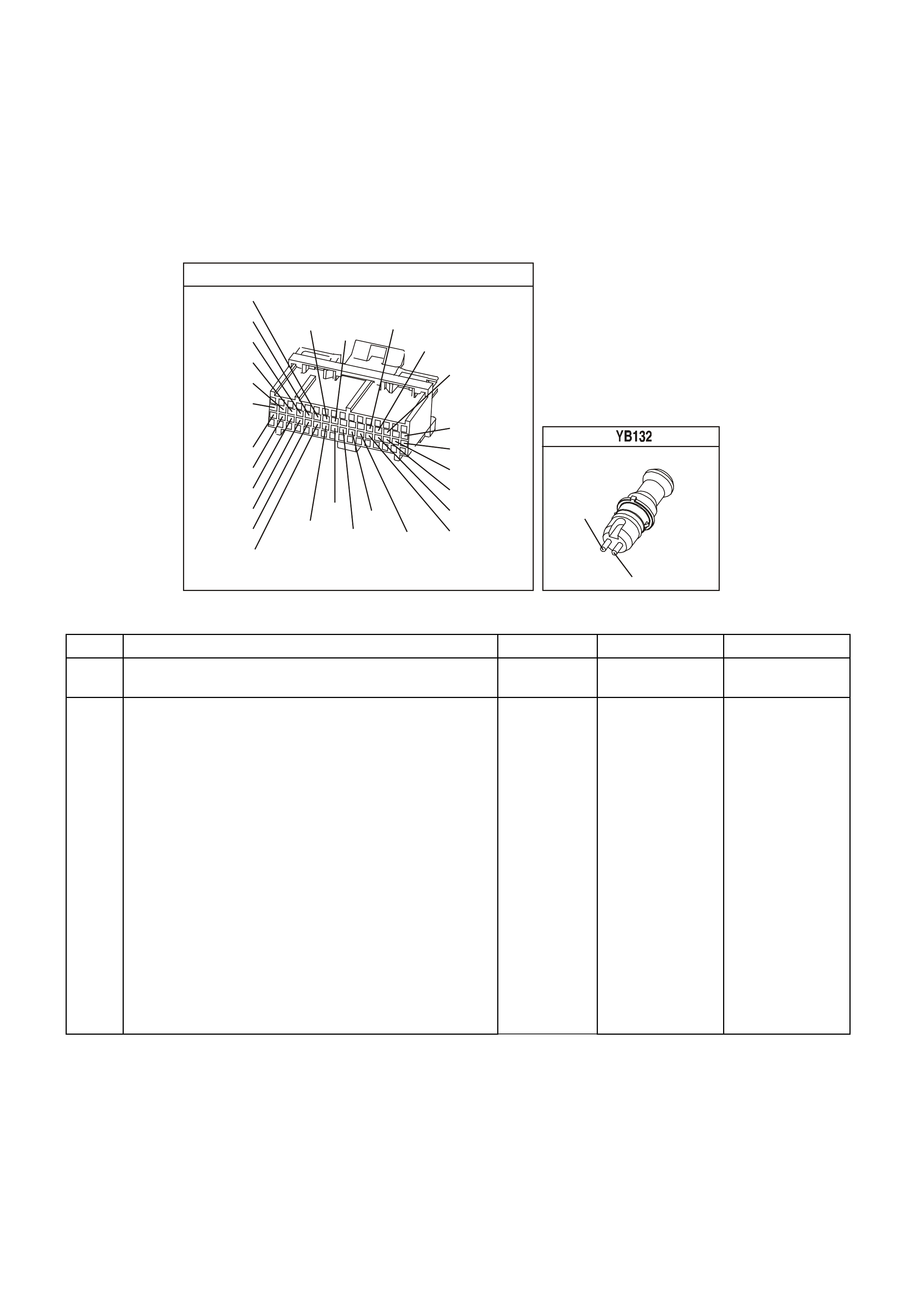
• Check circuits 831 and 832 f or the proper connections to be sure they are clean and tight and the harness
is routed correctly.
• The scan tool should indicate a vehicle speed whenever the drive wheels are turning greater than 3 km/h.
• The vehicle speed sensor resistance should be between 1470-2140 Ω at 20°C, and 2270-2820 Ω at 100° C.
• Refer to "Intermittents" in Section 6C-2B Symptoms of the VX Series Service Information.
TEST DESCRIPTION: Number(s) below refer to step number(s) on the diagnostic Table.
3. This step tests the integrity of the VSS Assembly
4. This step tests the VSS Assembly circuit.
YB1 93
(413)
(412)
(1413)
(1412)
(430)
(453)
(815)
V/B
GY/B
V
GY
V
B/R
W/R
(897)
(897)
G/W
G/W
(418)
(418)
BR
BR
(1426)
O/W
C16
D16
WT/B
(832)AUTO
(647)
(630)
BR
T
(832) MAN
LBLU/B
B
(424)
(423)
C1
D1
(792)
(422)
(1222)
(1223)
(428)
(123)
BR/W
GY/R
LG
Y/B
G/Y
V/W
BLU/W
BLU
(831) Man
(443)
LG/W
(442) (831)AUTO
(441)
LBLU
LBLU/B
(444)
LG/B
P.C.M. CONNECTOR 1
MANUAL TRANS SPEED SENDER
(831)
(832)
BR
BLU
DTC 94 V6 PCM - NO VEHICLE SPEED SIGNAL (MANUAL TRANSMISSION)
STEP ACTION VALUE YES NO
1 Was the On-Board Diagnostic (OBD) System Check
performed? Go to Step 2 Go to OBD
System Check.
2 1. Install the scan tool.
2. With the engine OFF, turn the ignition switch to the
RUN position.
IMPORTANT: Before clearing the DTCs, use the scan
tool in order to record the DTC history for reference. The
Clear Info function will erase the data.
3. Record the DTC history.
4. Clear the DTC.
5. Raise the drive wheels.
NOTE: Do not perform this test without supporting the
rear axle assembly or the lower control arms on vehicles
with independent rear suspension so that the drive shafts
are in a normal horizontal position.
6. Start the engine.
7. Place the transmission in any drive gear.
With the rear wheels rotating, does the scan tool Vehicle
Speed increase with the drive wheel speed?
Go to “Diagnostic
Aids” above Go to Step 3

DTC 94 V6 PCM - NO VEHICLE SPEED SIGNAL (MANUAL TRANSMISSION) (CONTINUED)
STEP ACTION VALUE YES NO
3 1. Turn the ignition switch to the OFF position.
2. Disconnect the VSS connector from the VSS
assembly.
3. Using the J 35616 Connector Test Adapter Kit,
connect the J 39200 DVM to the VSS terminals.
4. Select AC volts.
5. Place the transmission in the neutral position.
6. Rotate the drive wheels by hand, ensuring that the
driveshaft is turning.
With rear wheels rotating, is the DVM voltage greater
than the specified value?
0.5 volts AC Go to Step 4 Go to Step 11
4 1. Turn the ignition switch to the OFF position.
2. Reconnect the VSS connector to the VSS Assembly
3. Disconnect the PCM connector from the PCM.
4. Connect the DVM test leads to the connector
terminals D5 (BR) and C6 (Blu).
5. Place the transmission in the neutral position.
6. Rotate the drive wheels by hand, ensuring that the
driveshaft is turning.
With rear wheels rotating, is the DVM voltage greater
than the specified value?
0.5 volts AC Go to Step 13 Go to Step 5
5 1. Select Ω (Ohms), on the DVM.
2. Measure the resistance between the connector
terminals D5 (BR) and C6 (Blu).
Is the circuit resistance within the specified range?
1470-2820 Ω Go to Step 6 Go to Step 8
6 Connect the DVM between the connector terminal C-6
and earth.
Is the circuit resistance less than the specified value?
250k Ω Go to Step 7 Go to Diagnostic
Aids above
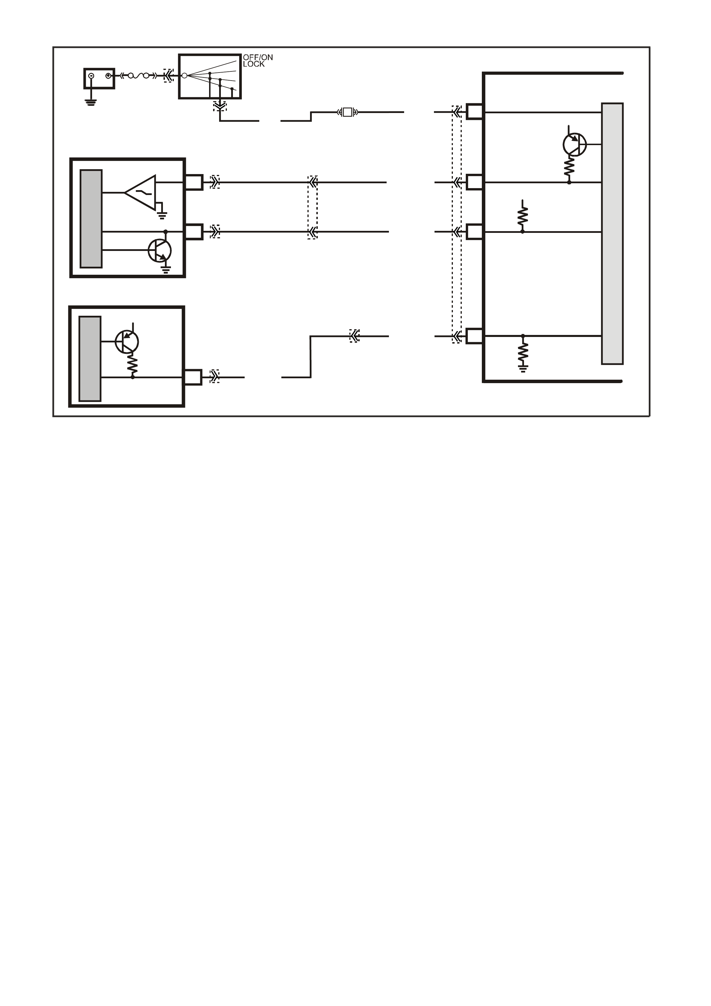
DTC 95 V6 PCM -
REQUESTED TORQUE OUT OF RANGE
CIRCUIT DESCRIPTION;
The Anti-Lock Brake System/Electronic Traction Control (ABS/ETC) Module (Traction Control) controls the
PWM signal on the torque request circuit while monitoring the wheel speed sensors to detect slippage. The
PCM monitors the PWM signal and reduces engine torque as needed by retarding ignition timing, decreasing
boost duty cycle, increasing air/fuel ratio, or in severe cases, shutting OFF up to five (5) injectors. The PCM
sends a PW M signal to the ABS/ETC module on the torque achieved circuit informing the ABS/ETC module of
response made to the torque request signal. A problem with the torque Request circuit should cause DTC 95
and a ABS/ETC DTC to set and traction control to be disabled. Refer to Section 12L ABS & ABS/ETC in VX
Service Information for information on ABS/ETC operation and DTC diagnosis.
CONDITIONS FOR RUNNING THE DTC
• The engine is running.
CONDITIONS FOR SETTING THE DTC
• The PCM detects the incorrect voltage on the Requested Torque circuit.
ACTION TAKEN WHEN THE DTC SETS
• The PCM illuminates the Malfunction Indicator Lamp (MIL) when the diagnostic runs and fails.
• The PCM records the operating conditions at the tim e the diagnostic fails. T he PCM stores this information
in the History Data.
• W hen DTC 95 is set, traction control will be disabled and a corresponding DTC will be set in the ABS/ETS
module.
CONDITIONS FOR CLEARING THE MIL/DTC
• The PCM turns the MIL OFF after the first ignition cycle that the diagnostic runs and does not fail.
• A Histor y DT C clears after f orty c onsecutive warm -up cycles, if this or any other em ission related diagnostic
does not report any failure.
• Use a Tech 2 scan tool in order to clear the MIL/DTC.
12V
E
30
M
I
C
R
O
BR/R(121)
BR (121)
ENGINE SPEED
DIS
12V
12V
F7
C11
27
13
REQUESTED
TORQUE (M MR)
MMI ACTUAL
TORQUE (M MI)
O/W (1426)
M
I
C
R
O
B/W (1247)
M
I
C
R
O
BATTERY POWER
15
BATTERY
FJ
ABS/ETC
IGNITION
SWITCH
15a 15 50
30 ACC
IGN
START
F27
P (3)
SUPERVX024
PCM
R (855)
MMR
YE57
YB194
YB193
YB44
YB44
YE98
YE110
YE112
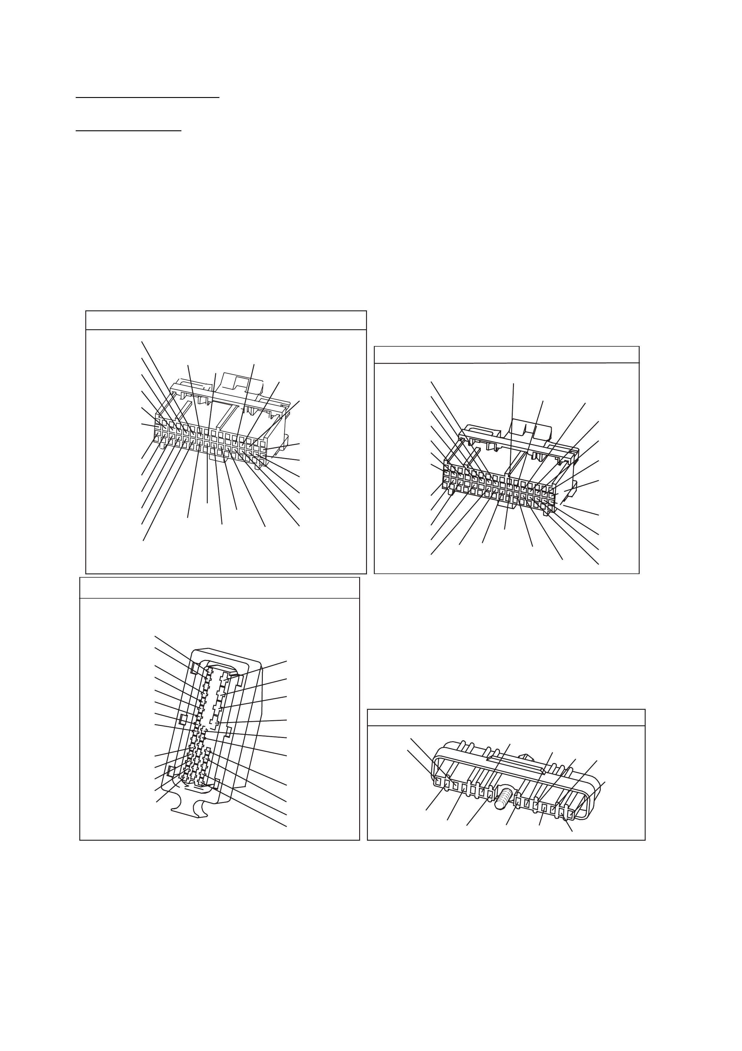
DIAGNOSTIC AIDS
Check for the following conditions:
• Poor connection at PCM. Inspect harness connectors for backed out terminals, improper mating, broken
locks, improper formed or damaged terminals, and poor terminal to wire connection.
• Damaged har ness. Inspec t the wiring harness for dam age. If the har ness appears to be O K, disconnect the
PCM, turn the ignition ON and observe a voltmeter connected to the Torque Request circuit at the PCM
harness connector while moving connectors and wiring harnesses related to the ABS/ETC module. If a
voltage is indicated the fault is in the harness.
TEST DESCRIPTION
The numbers below refer to the step numbers on the diagnostic table.
2. The PCM supplies 4 to 5 volts on the T orque Request circuit. W ith the PCM disconnected, there should be
no voltage on the circuit.
6. This step checks to see if the Torque Request circuit is shorted to voltage.
11. This step checks to see if the ABS/ECT system is functioning properly.
YB1 93
(413)
(412)
(1413)
(1412)
(430)
(453)
(815)
V/B
GY/B
V
GY
V
B/R
W/R
(897)
(897)
G/W
G/W
(418)
(418)
BR
BR
(1426)
O/W
C16
D16
WT/B
(832)AUTO
(647)
(630)
BR
T
(832) MAN
LBLU/B
B
(424)
(423)
C1
D1
(792)
(422)
(1222)
(1223)
(428)
(123)
BR/W
GY/R
LG
Y/B
G/Y
V/W
BLU/W
BLU
(831) Man
(443)
LG/W
(442) (831)AUTO
(441)
LBLU
LBLU/B
(444)
LG/B
P.C.M. CONNECTOR 1
YE194
P.C.M. CONNECTOR 3
LG/B
(366)
G
(843)
B/W
F16
B/Y
BR/Y
(1228)
(469)
Y
(451)
F1
P
(841)
BLU
V
E1
LBLU
(845)
BLU
B
(1226)
W/B
BLU/W
V
R
(435)
(31)
(1229)
GY
(1224)
Y
(846)
GY
(842)
(452)
(774)
(304)
BR/Y
(411)
(439)
GY/BLU
BLU
(1225)
E16
(1427)
(429)
(844)
B/O
(434)
OR AUTO
GY/BLU
GY
(1434)
MAN
(776)
W
BLU/W
Y
GY
(771)
(772)
(773)
A.B.S & T.C.S MODULATOR AND CONTROL MO DULE
YE 98
1
15
16
27
31
26
19
20
(885)
(884)
(833)
(830)
(873)
(872)
(883)
(882)
B
BLU
W
R
BR
GY
Y
(855)
(20)
(1426)
(863)
(1220)
BLU/B
G/W
O/W
BLU/R
R
V
R/W
BR/R
B/W
G
Y/R
B
R
R
B/O
(1429)
(121)
(1427)
(875)
(88)
(150)
(2R)
(2R)
(154)
GY/B
(1687)
DIRECT IGNITION M ODULE
YE 57
(647)
LBLU/B
W/B
(644)
B/R
(453)
LBLU/W
(646)
BLU/Y
(643)
V
(430)
T/B
(424)
(633)
BR
(645)
GY/R
LG
(482)
B
(630)
BR
(121)
W
(423)
PNMLKJHGFED
CBA

DTC 95 V6 PCM - REQUESTED TORQUE OUT OF RANGE
STEP ACTION VALUE YES NO
1. Was the "On-Board Diagnostic" (OBD) System Check
performed? Go to Step 2 Go to OBD
System Check in
this Section
2. 1. Ignition "OFF".
2. Disconnect the PCM connectors.
3. Ignition "ON".
4. Using volt/ohmmeter, measure voltage between the
torque Request circuit at the PCM harness
connector and earth.
Is voltage at the specified value?
0 V Go to Step 3 Go to Step 6
3. 1. Ignition "OFF".
2. Reconnect the PCM connectors.
3. Disconnect the ABS/ECT connector.
4. Ignition "ON".
5. Using volt/ohmmeter, measure voltage between the
torque Request circuit at the ABS/ECT harness
connector and earth.
Is voltage at the specified value?
4-5 V Go to Step 4 Go to Step 8
4. Check for poor connection at ABS/ECT module.
Was a problem found? Verify Repair Go to Step 5
5. Replace ABS/ECT module.
Is action complete? Verify Repair
6. 1. Ignition "OFF".
2. Disconnect the ABS/ECT module connector.
3. Ignition "ON".
4. Using volt/ohmmeter, measure voltage between the
torque Request circuit at the PCM harness
connector and earth.
Is voltage at the specified value?
0 V Go to Step 5 Go to Step 7
7. Locate and repair short to voltage in Torque Request
circuit.
Is action complete?
8. Check for an open or short to earth in the Torque
Request circuit between the PCM and the ABS/ECT
module.
Was a problem found?
Verify Repair Go to Step 9
9. Check for poor connection at PCM harness connectors.
Was a problem found? Verify Repair Go to Step 10
10. Replace PCM.
Refer to Section 6C1-3 Service Operations of the VX
Series Service Information, for PCM Security Link
procedure.
Is action complete?
Go to Step 12

DTC 95 V6 PCM - REQUESTED TORQUE OUT OF RANGE (CONTINUED)
STEP ACTION VALUE YES NO
11. 1. Ignition "OFF".
2. Reconnect the ABS/ECT connector, and the PCM
connectors.
3. Raise the rear of the vehicle, and support the rear
wheel trailing arms.
4. Backprobe PCM harness connector for the Torque
Request circuit with a volt/ohmmeter connected to
earth.
5. Ignition "ON", and the engine running in park.
Is the voltage near the specified value?
4-5 V Go to Step 12 Go to Step 2
12. W i th the engine still running in park, and the
volt/ohmmeter still connected to the Torque Request
circuit, shift the transmission into D range and let the
rear wheels turn. Snap the throttle and note the voltage
on the volt/ohmmeter.
Does the volt/ohmmeter switch from the First specified
value to the Second specified value ( and stay at the
second value) when traction control is activated?
First
4-5 V
Second
1-2 V
ABS/ECT
System is
working properly
Go to Step 2
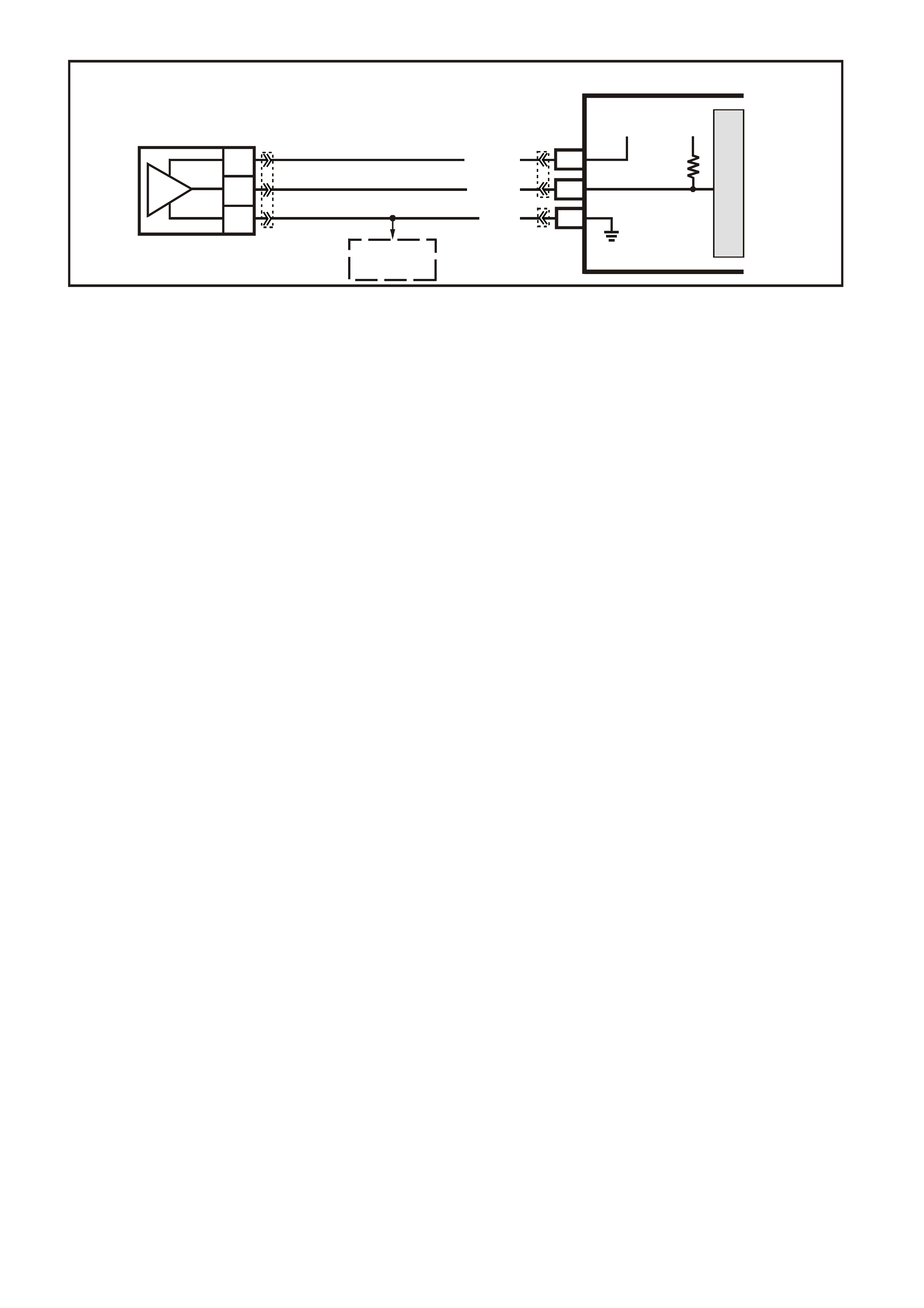
DTC 96 V6 PCM -
A/C REFRIGERANT PRESSURE SENSOR CIRCUIT
CIRCUIT DESCRIPTION:
The A/C refrigerant pressure Sensor responds to changes in the A/C refrigerant high side pressure. This input
to the PCM indicates how m uch load the A/C compr essor is putting on the engine and is one of the factors used
by the PCM to determ ine the Idle Air Control (IAC) valve position for idle speed. The circuits consist of a 5 volt
reference and a earth circuit, both provided by the PCM, and a signal circuit from the Sensor to the PCM. The
signal is a voltage which is proportional to A/C pressure. The Sensors operating range is between 0 and 3160
kPa ( 0-468 psi). At 0 kpa, the signal voltage will be about 0.1 volts, varying to about 4.9 volts at 3160 kPa.
CONDITIONS FOR RUNNING THE DTC
• Engine Coolant Temperature is below 119°C.
• Intake Air Temperature is below 90°C.
• Engine RPM is below 2000.
• Engine has been running for less than 10 seconds.
CONDITIONS FOR SETTING THE DTC
• A/C Refrigerant Pressure Sensor signal voltage is greater than 4.9 volts, or less than 0.2 volts.
ACTION TAKEN WHEN THE DTC SETS
• The PCM stores the DTC information into memory when the diagnostic runs and fails.
• The Malfunction Indicator Lamp (MIL) will not be illuminated.
• The PCM records the operating conditions at the tim e the diagnostic fails. T he PCM stores this information
in the History Data.
• W hen DT C 96 is set, the low speed cooling fan will operate f or 5 seconds, then the high speed fan will turn
"ON, and remain "ON" until the fault is removed.
CONDITIONS FOR CLEARING THE MIL/DTC
• A Histor y DT C clears after f orty c onsecutive warm -up cycles, if this or any other em ission related diagnostic
does not report any failure.
• Use a Tech 2 scan tool in order to clear the MIL/DTC
DIAGNOSTIC AIDS:
• DTC 96 will only set with a short to voltage or a open circuit. A short to earth will not set the DTC, but the
A/C system will be inoperative.
• DTC 96 sets when the signal voltage falls outside the normal possible range of the sensor. Repair any A/C
pressure problems before using this table.
• Any c ircuitry, that is suspec ted as caus ing the interm ittent com plaint, s hould be thoroughly check f or bac k ed
out terminals, improper mating, broken locks, improperly formed or damaged terminals, poor terminal to
wiring connections or physical damage to the wiring harness.
SUPERVX001
PCM
M
I
C
R
O
B3
F16
C
B
A
A/C
PRESSURE
SENSOR
B7
SENSOR EARTH
A/C PRESSURE
SENSOR SIGNAL
REFERENCE
VOLTAGE
5V 5V
V/W (415)
B (46 9)
G/B (259)
TO
TFT AND
IAT SENSORS
YB188
YB194
YE113
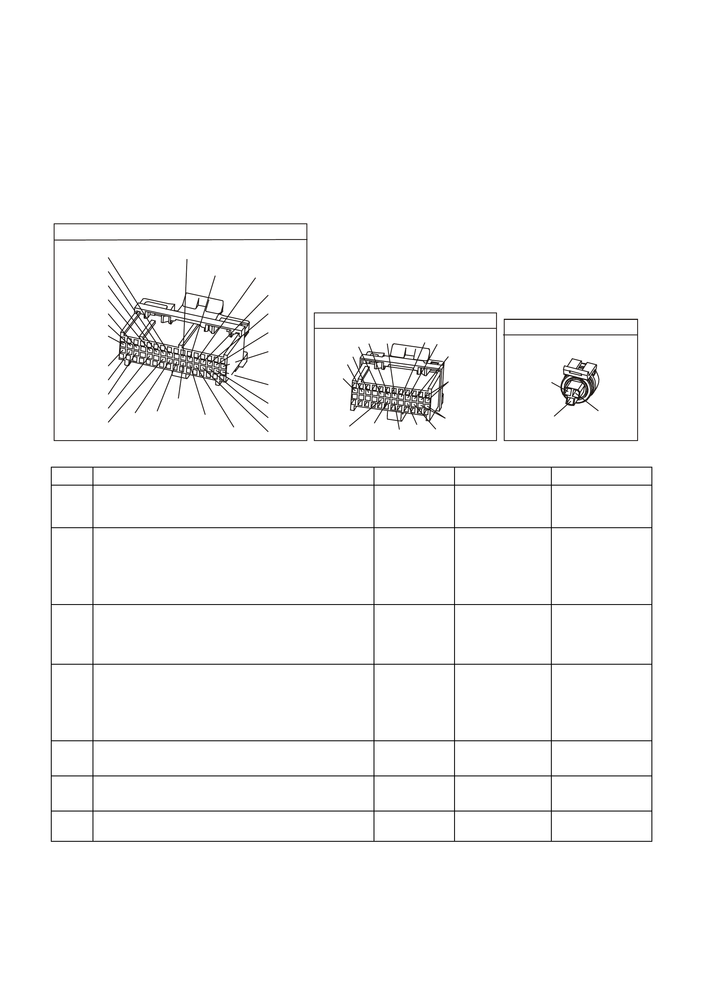
TEST DESCRIPTION: Number(s) below refer to step number(s) on the diagnostic Table.
3. This s tep c hecks to s ee if the low voltage s ignal was due to an open in the signal c irc uit, the 5 volt re f erenc e
circuit or if the PCM is faulty.
4. An open in a shared earth circuit can cause other DTC's to be set. If no other DTC's were set, the circuit
must be open between the sensor and the circuit splice.
8. Determines if the low voltage signal was from the sens or or the signal circ uit. Jum pering the s ignal circuit to
the 5 volt reference checks the circuits, connections and the PCM.
9. An open in a shar ed 5 volt r ef erenc e c irc uit can c aus e other DTC's to be set. If no other DTC's were set, the
circuit must have an open between the sensor and the circuits wiring harness splice.
YE194
P.C.M. CONNECTOR 3
LG/B
(366)
G
(843)
B/W
F16
B/Y
BR/Y
(1228)
(469)
Y
(451)
F1
P
(841)
BLU
V
E1
LBLU
(845)
BLU
B
(1226)
W/B
BLU/W
V
R
(435)
(31)
(1229)
GY
(1224)
Y
(846)
GY
(842)
(452)
(774)
(304)
BR/Y
(411)
(439)
GY/BLU
BLU
(1225)
E16
(1427)
(429)
(844)
B/O
(434)
OR AUTO
GY/BLU
GY
(1434)
MAN
(776)
W
BLU/W
Y
GY
(771)
(772)
(773)
YB 188
P.C.M CONNECTOR 2
(481)
(417)
(740)
R
BLU
O
(1456)
LG
V/W
(415)
Y
(1227)
B/Y
(410)
BR
(472)
(259)
(750)
(750)
(1221)
B/R
B/R
R/B
G/B
(39)
P
(465)
G/W
(416)
GY
(740)
O
A1
B1
B12
A12
A/C PRESSURE SENSOR
YE113
(469)
(415)
(259)
G/B B
V/W
DTC 96 V6 PCM - A /C REFRIGERANT PRESSURE SENSOR CIRCUIT
STEP ACTION VALUE YES NO
1. Was the "On-Board Diagnostic" (OBD) System Check
performed? Go to Step 2 Go to OBD
System Check in
this Section
2. 1. Ignition ON, engine OFF.
2. Install scan tool, and display A/C pressure
Sensor voltage.
Is the A/C pressure Sensor voltage at or above the
specified value?
4.0V Go to Step 3 Go to Step 7
3. Disconnect the A/C pressure Sensor electrical
connector.
Does scan tool display A/C pressure Sensor voltage at
or below the specified value?
0.2 V Go to Step 4 Go to Step 11
4. 1. Ignition "OFF".
2. Using test light connected to B+, probe A/C
pressure Sensor earth circuit at harness
electrical connector.
Does test light illuminate?
Go to Step 5 Go to Step 12
5. Check for a poor connection at A/C pressure Sensor.
Was a problem found? Verify Repair Go to Step 6
6. Replace A/C pressure Sensor.
Is action complete? Verify Repair
7. Is the A/C pressure Sensor voltage at or below the
specified value? 0.2 V Go to Step 8 Go to Step 15

DTC 96 V6 PCM - A/C REFRIGERANT PRESSURE SENSOR CIRCUIT (CONTINUED)
STEP ACTION VALUE YES NO
8. 1. Disconnect A/C pressure Sensor electrical
connector.
2. Using fused jumper wire, jumper the A/C pressure
Sensor 5 volt reference circuit and signal
circuits together at harness connector.
Does scan tool indicate A/C pressure Sensor voltage at
or above the specified value?
4.0 V Go to Step 6 Go to Step 9
9. 1. Remove the jumper wire.
2. Connect a DVM between the A/C pressure
Sensor 5 volt reference circuit and earth circuit
at the harness connector.
Does the DVM read at or between the specified value?
4.0 - 5.0 V Go to Step 10 Go to Step 13
10. Repair open or short to earth in A/C pressure Sensor
signal circuit.
Is action complete?
Verify Repair
11. Check A/C pressure Sensor signal circuit for short to
voltage.
Was a problem found?
Verify Repair Go to Step 14
12. Repair open in earth circuit to A/C pressure Sensor.
Is action complete? Verify Repair
13. Repair open in 5 volt reference circuit.
Is action complete? Verify Repair
14. Replace PCM.
Refer to Section 6C1-3 Service Operations of the VX
Series Service Information, for PCM Security Link
procedure.
Is action complete?
Verify Repair
15. 1. Using a scan tool, clear DTC.
2. Start engine and idle at normal operating
temperature.
3. Operate vehicle A/C system and note A/C pressure
Sensor voltage on scan tool.
Is voltage displayed at or between the specified value?
0.2 - 4.6 V System OK,
refer to
Diagnostic Aids
Go to Step 2
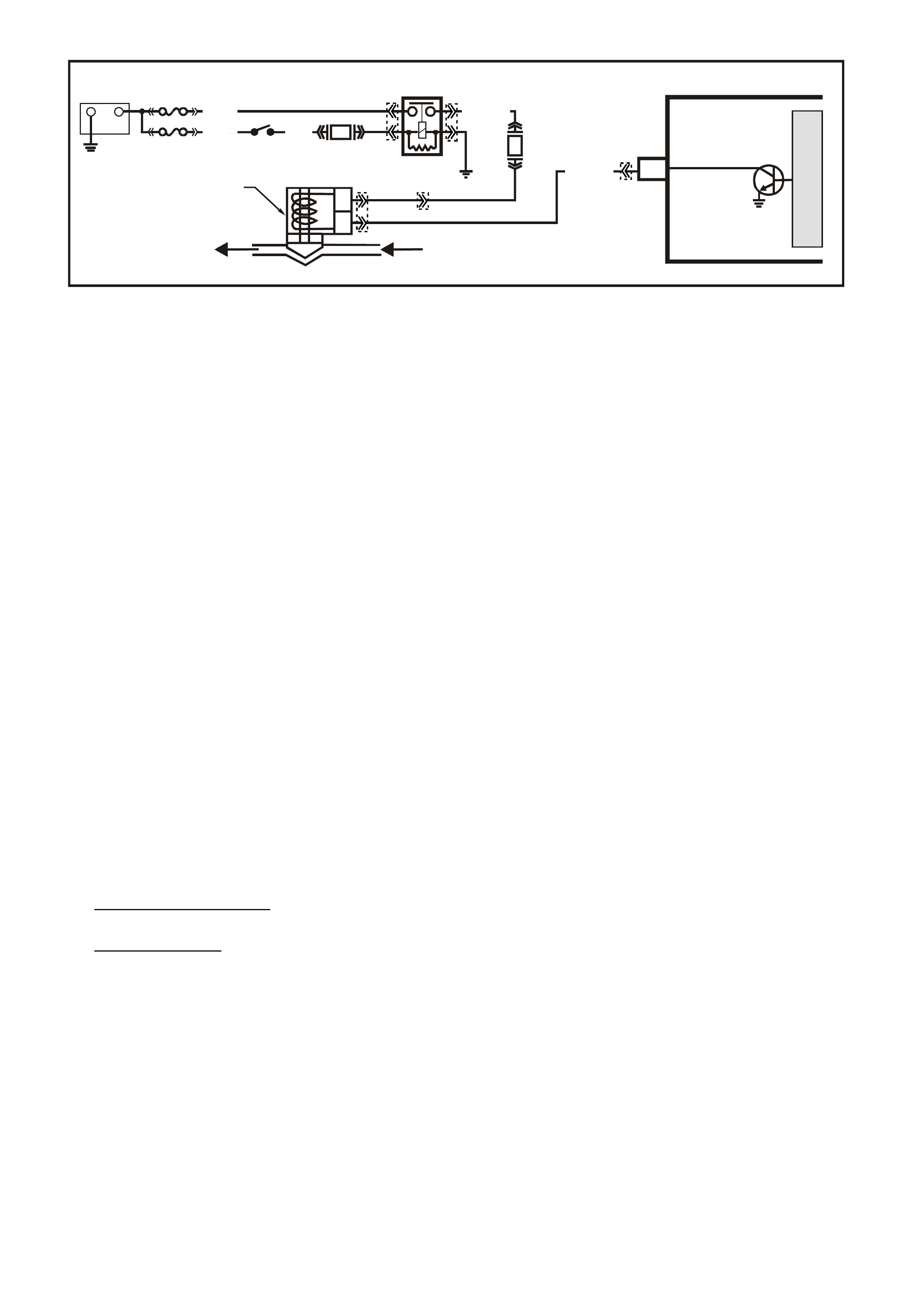
DTC 97 V6 PCM -
EVAP P URGE SOLENOID CONTROL CIRCUIT
CIRCUIT DESCRIPTION:
Quad Driver Modules (QDMs) are used by the PCM to turn "ON" many of the current-driven devices that are
needed to control various engine and transmission functions. Each QDM is capable of controlling up to 4
separate outputs by applying earth to the device which the PCM is commanding "ON".
The Quad Driver Modules (QDMs) used has the capability of diagnosing each output circuit individually. If DTC
97 is set, this indicates an improper voltage level has been detected on the QDM fault line which controls the
Canister Purge Solenoid.
CONDITIONS FOR RUNNING THE DTC
• The ignition is on.
CONDITIONS FOR SETTING THE DTC
• The PCM detects an incorrect voltage on the EVAP purge solenoid driver circuit for 5 seconds.
ACTION TAKEN WHEN THE DTC SETS
• The PCM illuminates the Malfunction Indicator Lamp (MIL) when the diagnostic runs and fails.
• The PCM records the operating conditions at the tim e the diagnostic fails. T he PCM stores this information
in the History Data.
CONDITIONS FOR CLEARING THE MIL/DTC
• The PCM turns the MIL OFF after the first ignition cycle that the diagnostic runs and does not fail.
• A Histor y DT C clears after f orty c onsecutive warm -up cycles, if this or any other em ission related diagnostic
does not report any failure.
• Use a Tech 2 scan tool in order to clear the MIL/DTC.
DIAGNOSTIC AIDS:
Check for the following conditions:
• Poor connection at PCM. Inspect harness connections for backed out terminals, improper mating , broken
locks, improper formed or damaged terminals, and poor terminal to wire connection.
• Damaged har ness. Inspec t the wiring harness for dam age. If the har ness appears to be O K, disconnect the
PCM, turn the ignition "ON" and obser ve a voltmeter connected to the Canister Purge Solenoid driver circuit
at the PCM harness connector while moving connectors and wiring harness related to the Canister Purge
Solenoid. A change in voltage will indicate the location of the fault.
If DTC 97 cannot be duplicated, the information included in the DTC History can be useful in determining how
many ignition cycles have passed since the DTC was last set.
TEST DESCRIPTION: Number(s) below refer to step number(s) on the diagnostic Table.
2. Normally, ignition feed voltage present on the output driver circuit with the PCM disconnected and the
ignition "ON".
3. Chec ks f or a s horted c omponent or a s hort to B+ or the Q uad driver cir cuit. Either c ondition would result in a
measured current of over 1.5 amps. Also checks for a component that is going open while being operated,
resulting in a measured current of 0 amps.
4. Checks for a faulty Canister Purge Solenoid.
A
B
CANISTER PURGE
SOLENOID V ALVE
PCM
CANISTER PURGE
SUPERVX027
C4
G/Y (428)
MANIFOLD
VACUUM
TO CARBON
CANISTER
B/W
(152)
LOC. E3
M
I
C
R
O
F33
F14
IGN SW
EFI
RELAY
+
-
BATTERY
FS
FJ
P (3) P/B
(39)
(1040) O/Y (479)
R (2H)
YE39
YB193
YE111
YE99
YE39

YB1 93
(413)
(412)
(1413)
(1412)
(430)
(453)
(815)
V/B
GY/B
V
GY
V
B/R
W/R
(897)
(897)
G/W
G/W
(418)
(418)
BR
BR
(1426)
O/W
C16
D16
WT/B
(832)AUTO
(647)
(630)
BR
T
(832) MAN
LBLU/B
B
(424)
(423)
C1
D1
(792)
(422)
(1222)
(1223)
(428)
(123)
BR/W
GY/R
LG
Y/B
G/Y
V/W
BLU/W
BLU
(831) Man
(443)
LG/W
(442) (831)AUTO
(441)
LBLU
LBLU/B
(444)
LG/B
P.C.M. CONNECTOR 1
CANNISTER P URGE
(439) (428)
PG/Y
B
A
YE111
ENGINE CONNECTOR 2
(482)
(481)
R
LG
GY
G
(434)
(129)
P
(439)
(59)
(366)
LG/B
GW/B
(451)
DTC 97 V6 PCM - EVAP PURGE SOLENOID CONTROL CIRCUIT
STEP ACTION VALUE YES NO
1. Was the "On-Board Diagnostic" (OBD) System Check
performed? Go to Step 2 Go to OBD
System Check
2. 1. Ignition "OFF"., disconnect the PCM.
2. Ignition "ON".
3. Using voltmeter, measure voltage between the
Canister Purge Solenoid driver circuit at the PCM
harness connector and earth.
Is voltage near the specified value?
B+ Go to Step 3 Go to Step 6
3. 1. Digital volt/ohmmeter set to 10 amp scale, install
digital volt/ohmmeter to measure current between
the Canister Purge Solenoid driver and earth.
2. Monitor the current reading on the digital
volt/ohmmeter for at least 2 minutes.
Does the current reading remain between the specified
values?
0.1 amp
To
1.5 amps
Go to Step 11 Go to Step 4
4. 1. Disconnect the Canister Purge Solenoid (leave the
PCM disconnected).
2. Using digital volt/ohmmeter, measure voltage
between the Canister Purge Solenoid driver circuit
and earth.
Is voltage at specified value?
0 volts Go to Step 14 Go to Step 5
5. Locate and repair short to voltage in the Canister
Purge Solenoid driver circuit.
Is action complete?
Verify Repair
6. Check the ignition feed fuse for the Canister Purge
Solenoid.
Is the fuse blown?
Go to Step 7 Go to Step 8
7. 1. Locate and repair short to earth in ignition feed
circuit for the Canister Purge Solenoid.
2. Replace fuse.
Is action complete?
Verify Repair
8. 1. Disconnect the Canister Purge Solenoid.
2. Ignition "ON".
3. Measure voltage between the ignition feed circuit for
the Canister Purge Solenoid and earth.
Is voltage near the specified value?
B+ Go to Step 9 Go to Step 13

DTC 97 V6 PCM - EVAP PURGE SOLENOID CONTROL CIRCUIT (CONTINUED)
STEP ACTION VALUE YES NO
9. Check the Canister Purge Solenoid driver circuit for an
open or a short to earth.
Was a problem found?
Verify Repair Go to Step 10
10. Check the Canister Purge Solenoid driver circuit and the
ignition feed circuit for a poor connection at the Canister
Purge Solenoid and the PCM.
Was a problem found?
Verify Repair Replace
Canister Purge
Solenoid and
Verify Repair.
11. 1. Ignition "OFF", reconnect the PCM and disconnect
the Canister Purge Solenoid.
2. Ignition "ON, connect a test light between the
Canister Purge Solenoid driver circuit and the
ignition feed circuit at the Canister Purge Solenoid
connector.
3. Using the Tech 2 scan tool, select, PURGE.
4. Cycle the Canister Purge Solenoid "ON" and "OFF".
Does the test light flash "ON" and "OFF"?
Refer to
"Diagnostic Aids"
above.
Go to Step 12
12. Check the Canister Purge Solenoid driver for a poor
connection at the PCM.
Was a problem found?
Verify Repair Go to Step 15
13. Locate and repair open ignition feed circuit to the
Canister Purge Solenoid.
Is action complete?
Verify Repair
15. Replace PCM.
Refer to Section 6C1-3 Service Operations of the VX
Series Service Information, for PCM Security Link
procedure.
Is action complete?
Verify Repair