
SECTION 6C1-3 - SERVICE OPERATIONS
V6 ENGINE
IMPORTANT:
Before performing any Service Operation or other procedure described in this Section, refer to Section 00
CAUTIONS AND NOTES in this VX Service Information for correct workshop practices with regards to
safety and/or property damage.
NOTE: When fastener s are rem oved, always reinstall them at the sam e location from which they were rem oved. If
a fastener needs to be replaced, use the correct part number fastener for that application. If the correct part
number fastener is not available, a fastener of equal size and strength (or stronger) may be used. Fasteners that
are not to be reused, or those requiring thread locking compound will be identified. The correct torque value must
be used when installing fasteners that require it. If the above conditions are not followed, parts or system damage
could result.
WHAT THIS SECTION CONTAINS
This Section describes the proper service procedures to repair components of the Powertrain Management
Systems. Emphasis is placed on the proper procedures and repair of components related to the systems.
Techline
Techline
3.1 SERVICE PRECAUTIONS
The following requirements must be observed when working on vehicles:
1. Before removing any PCM system component, disconnect the battery earth lead.
2. Never start the engine without the battery being solidly connected.
3. Never disconnect the battery from the on board electrical system while the engine is running.
4. When charging the battery, disconnect it from the vehicle's electrical system.
5. Never subject the PCM to temperatures above 80 degrees C i.e. paint oven. Always remove PCM first if this
temperature is to be exceeded.
6. Ensure that all cable harness plugs are connected solidly and that battery terminals are thoroughly clean.
7. The engine management system harness connectors are designed to fit in only one way; there are indexing
tabs and slots on both halves of the connector. Forcing the connector into place is not necessary if it is being
installed with the proper orientation. Failure to take care to match the indexing tabs and slots to ensure the
connector is being installed correctly can cause damage to the connector, the module, or other vehicle
components or systems.
8. Never connect or disconnect cable harness plug at the PCM when the ignition is switched "ON."
9. Before attempting any electric arc welding on the vehicle, disconnect the battery leads and the PCM
connectors.
10. When steam cleaning engines, do not direct the steam cleaning nozzle at PCM system components. If this
happens, corrosion of the terminals can take place.
11. Use only the test equipment specified in the diagnostic Tables, since other test equipment may either give
incorrect results or damage good components.
12. All voltage m easurements using a voltmeter must use a digital voltmeter with an internal impedance rating of
at least 10 million ohms per volt (10 megohm/volt).
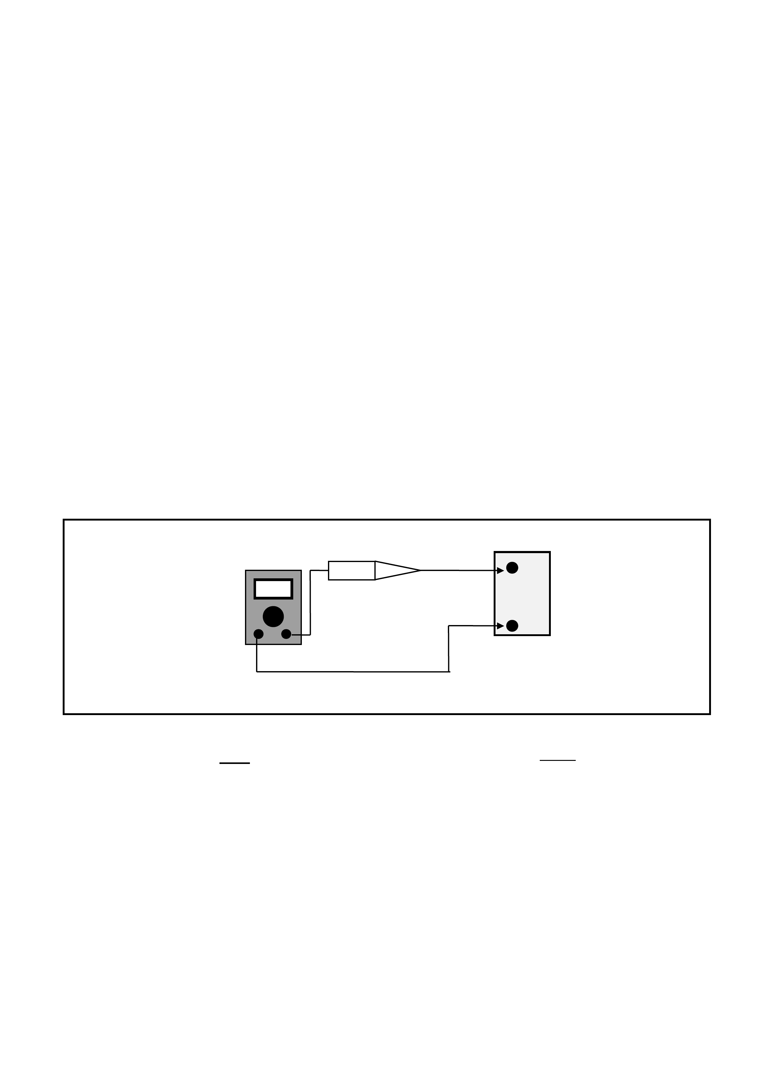
13. When a test light is specified, a "low-power" test light must be used. Do not use a high - wattage test light.
W hile a partic ular brand of test light is not suggested, a simp le test on any test light will ensure it to be OK f or
PCM circuit testing. Connect an accurate ammeter (such as the high-impedance digital multimeter) in series
with the test light being tested, and power the test light-ammeter circuit with the vehicle battery.
Figure 6C1-3-1 Test Light Check
If the ammeter indicates less than 3/10 amp current
flow (0.3 A or 300 mA), the test light is OK to use.
I
f
the ammeter indicates more than 3
/
10 amp current
flow (0.3 A or 300 mA), the test light is NOT OK to
use.
+
BATTERY
-
DC AMPS
Test Light
3.2 POWERTRAIN CONTROL MODULE
PCM REPLACEMENT/ PROGRAMMING
Service of the PCM should normally consist of
either replacement of the PCM or EEPROM (flash
memory) programming. If the diagnostic
procedures call for the PCM to be replaced, the
PCM should be first checked to ensure it is the
correct part. If it is, remove the faulty PCM and
install the new PCM.
IMPORTANT:
• The replacement PCM EEPROM will not be
programmed.
• DTC P0601 indicates the EEPROM is not
programmed or has malfunctioned. Refer to
Service Programming in this section for
programming procedures.
IMPORTANT:
The following must be performed anytime the PCM
is replaced:
1. Programming of the EEPROM
2. The Functional Check
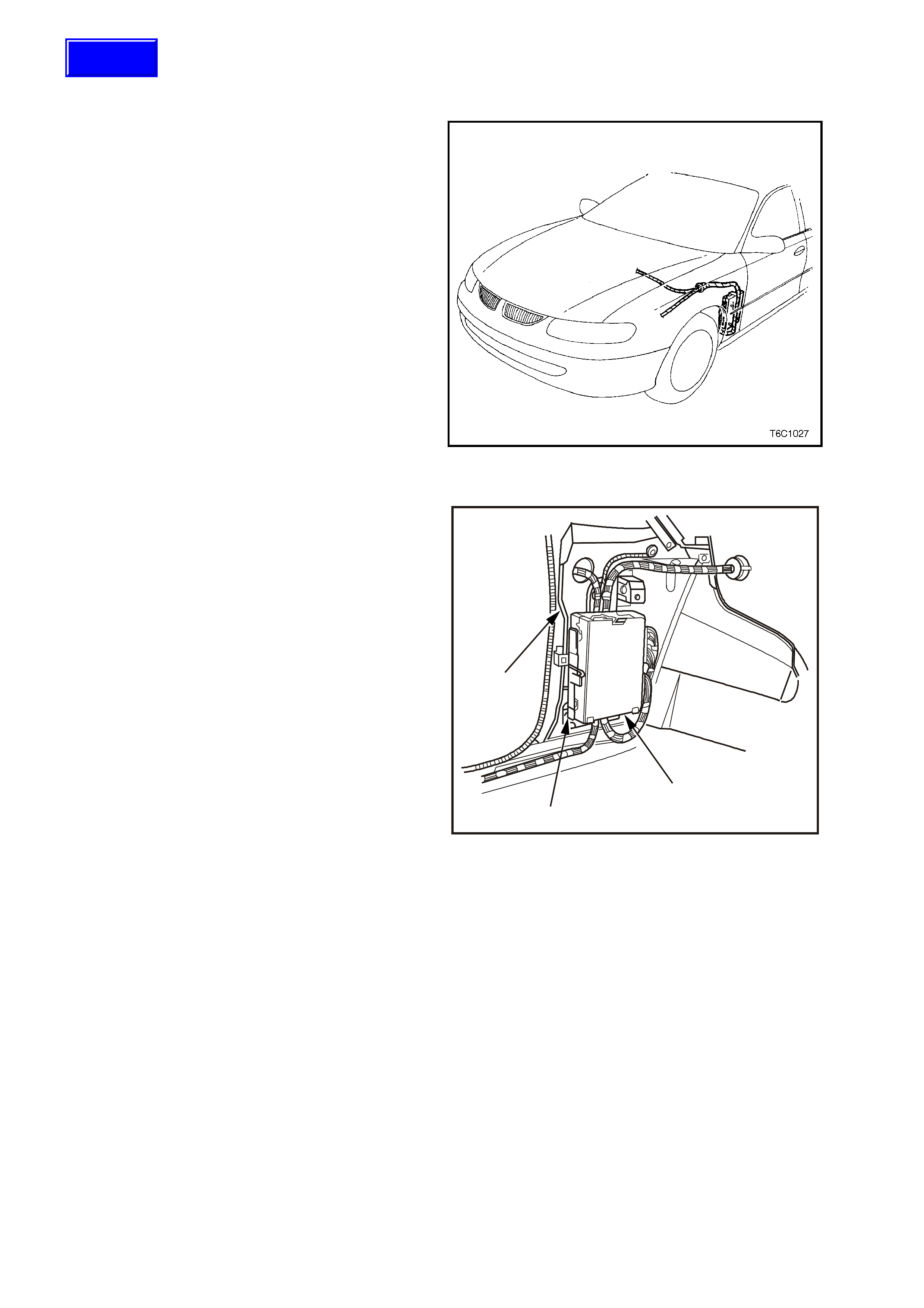
Figure 6C1-3-2 PCM Location
The f ollowing m ust be perf ormed anytime the PCM
(1) is disconnected or loses power.
1. The Functional Check.
This is described later in this section.
NOTE:
• To prevent internal PCM damage, the ignition
must be OFF when disconnecting or
reconnecting power to the PCM.
• The location of the PCM is behind the front left
hand cowl trim panel. The PCM and mounting
brackets (2) is attached to the left hand cowl
panel (3).
REMOVE
IMPORTANT:
Remove any debris from the PCM connector
surfaces before servicing the PCM.
NOTE:
Do not touch the connector pins or soldered
components on the circuit board in order to prevent
possible electrostatic discharge damage to the
PCM.
1. Disconnect battery earth lead.
2. Remove left hand front shroud panel lower
trim assembly (cowl panel trim), refer
Section 1A1, BODY in the VT Series I
Service Information.
3
2
1
4202
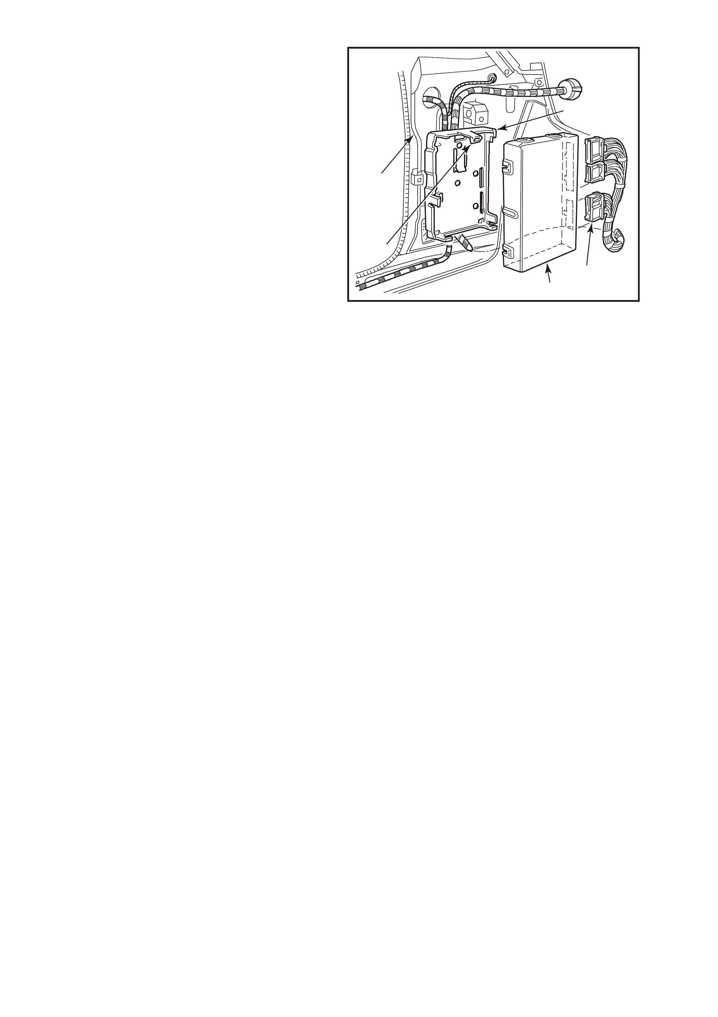
Figure 6C1-3-3 PCM Mounting
Techline
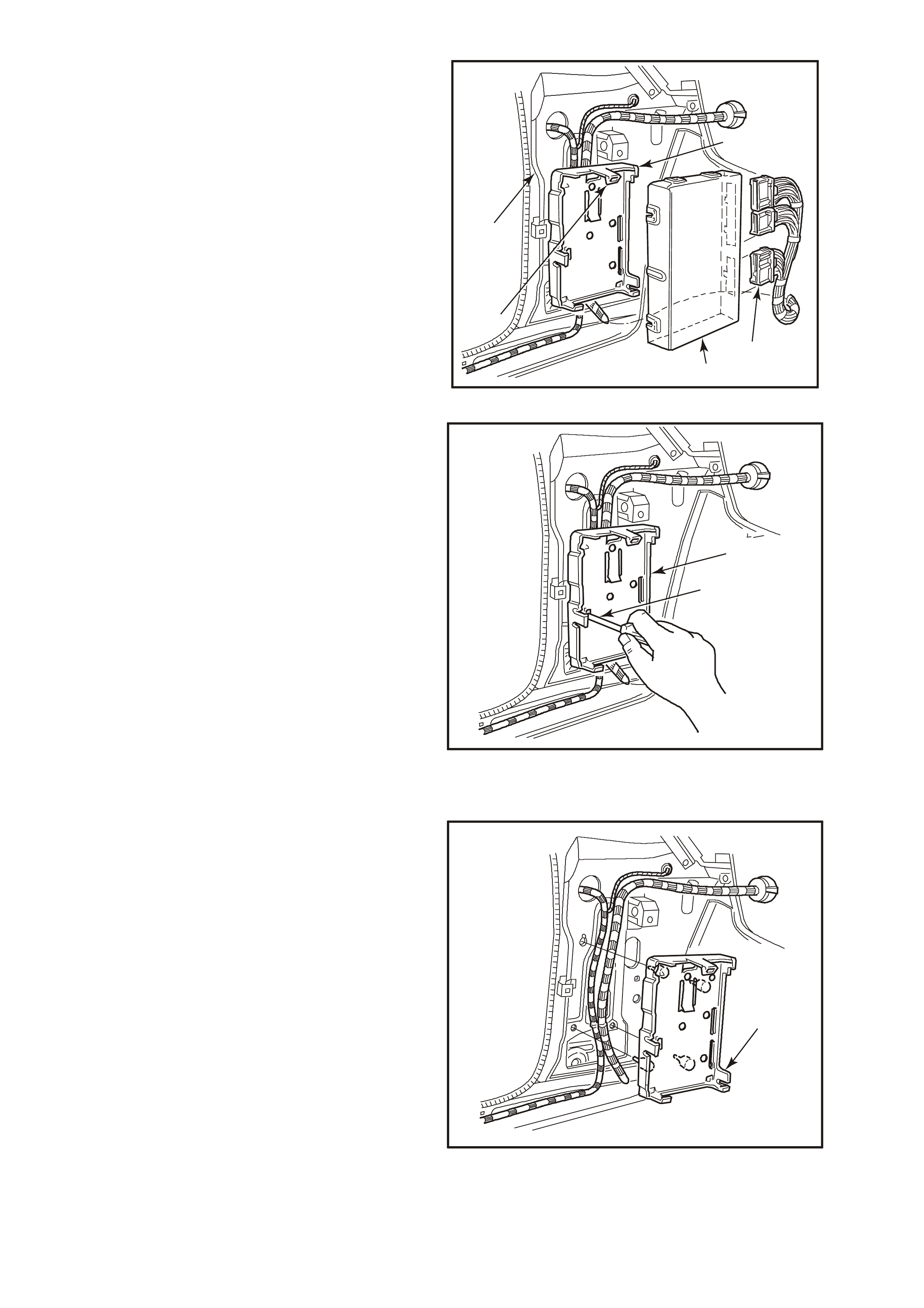
3. Lift up mounting bracket to PCM upper
retaining tang (4), pull PCM (3) out then up to
remove it from the mounting bracket (1).
4. Remove wiring harness connectors (2) from
PCM, remove PCM from vehicle.
IMPORTANT:
The replacement PCM EEPROM will not be
programmed.
1
2
4294
3
4
5
Figure 6C1-3-4 PCM Removal
5. If required, remove PCM mounting bracket (1)
by inserting a screwdriver into the retaining
tang slot (2), lever screwdriver to release tang.
Pull bracket out then down to release from the
cowl panel.
2
4295
1
Figure 6C1-3-5 PCM Mounting Bracket Removal
REINSTALL
1. If rem oved, r eins tall PCM mounting brac k et (1) ,
engaging bracket leg into slotted hole in cowl
panel. Lift up bracket and engage bracket
lower retainers and retaining tang into cowl
panel.
1
4296
Figure 6C1-3-6 PCM Mounting Bracket Reinstallation
2. Reconnect wiring harness connectors (2) to
PCM.
3. Assemble PCM into mounting bracket (1),
ensuring wiring harness is routed in fr ont of the
mounting bracket.
4. Reinstall cowl panel trim, Refer to
Section 1A1, BODY in the VT Series I
Service Information.
5. Reconnect battery earth lead. Perform Service
Programming if PCM was replaced with new,
refer to Service Programming in this Section
otherwise star t vehicle and allow to idle. Check
vehicle for correct operation.
1
2
4294
3
4
5
Figure 6C1-3-7 PCM Mounting Bracket Reinstallation
SERVICE PROGRAMMING
NOTE:
Follow the programming instructions completely and do not key OFF during programming unless instructed. If the
key is turned OFF during programming, possible PCM damage may occur.
IMPORTANT:
Do not disconnect tech 2 during each programming step.
1. Setup - Ensure that the following conditions have been met:
- The battery is fully charged, but not charging during programming.
- The ignition is ON.
- Ensure that all PCM connections are OK.
2. Connect TECH 2 to the vehicle and select Service Programming System (SPS) / Request Info.
3. Connect TECH 2 to a TIS terminal and download latest software matching the vehicle. Refer to TIS
terminal/equipment users instructions.
4. Connect TECH 2 to the vehicle again and select Service Programming System (SPS) / Program ECU.
5. If the PCM fails to program, proceed as follows:
- Ensure that all PCM connections are OK.
- Attempt to re-program the PCM. If the PCM still cannot be programmed correctly, replace the PCM and
program it according to this procedure.
IMPORTANT:
Once new PCM has been programmed, it must be Security Linked. Refer to PCM Security Link below for
linking procedure. If updating calibrations to the vehicle’s existing PCM hardware, no linking procedure is necessary.
PCM SECURITY LINK
Once the PCM and or BCM have been replaced, the new PCM and or BCM mus t be security link ed to each other.
If this procedure is not performed, the vehicle will not crank.
The PCM to BCM linking procedure is as follows:
Connect TECH 2 to DLC and select:
Diagnostic / (V) 20XX / VX Commodore / Body / Body Control Module / Security / BCM Link to PCM and follow
TECH 2 instructions.
For additional information regarding TECH 2 and TECH 2 test modes (including this linking procedure), refer to
TECH 2 DIAGNOSIS FOR BCM in Section 12J-1 LOW SERIES BCM or Section 12J-2 HIGH SERIES BCM in
the VX Service Information.
NOTE:
If this vehicle is also fitted with LPG, refer to Section 8A - LPG SYSTEM of the VX Service Information after the
PCM replacement and/or reprogrammed for LPG setup procedure. This must be performed whenever the PCM is
replaces or reprogrammed.
FUNCTIONAL CHECK
1. Clear the Diagnostic Trouble Codes (DTCs).
2. Perform the Powertrain OBD System Check.
3. Start the engine and idle for one minute.
4. Use the Tech 2 scan tool to check for DTCs.
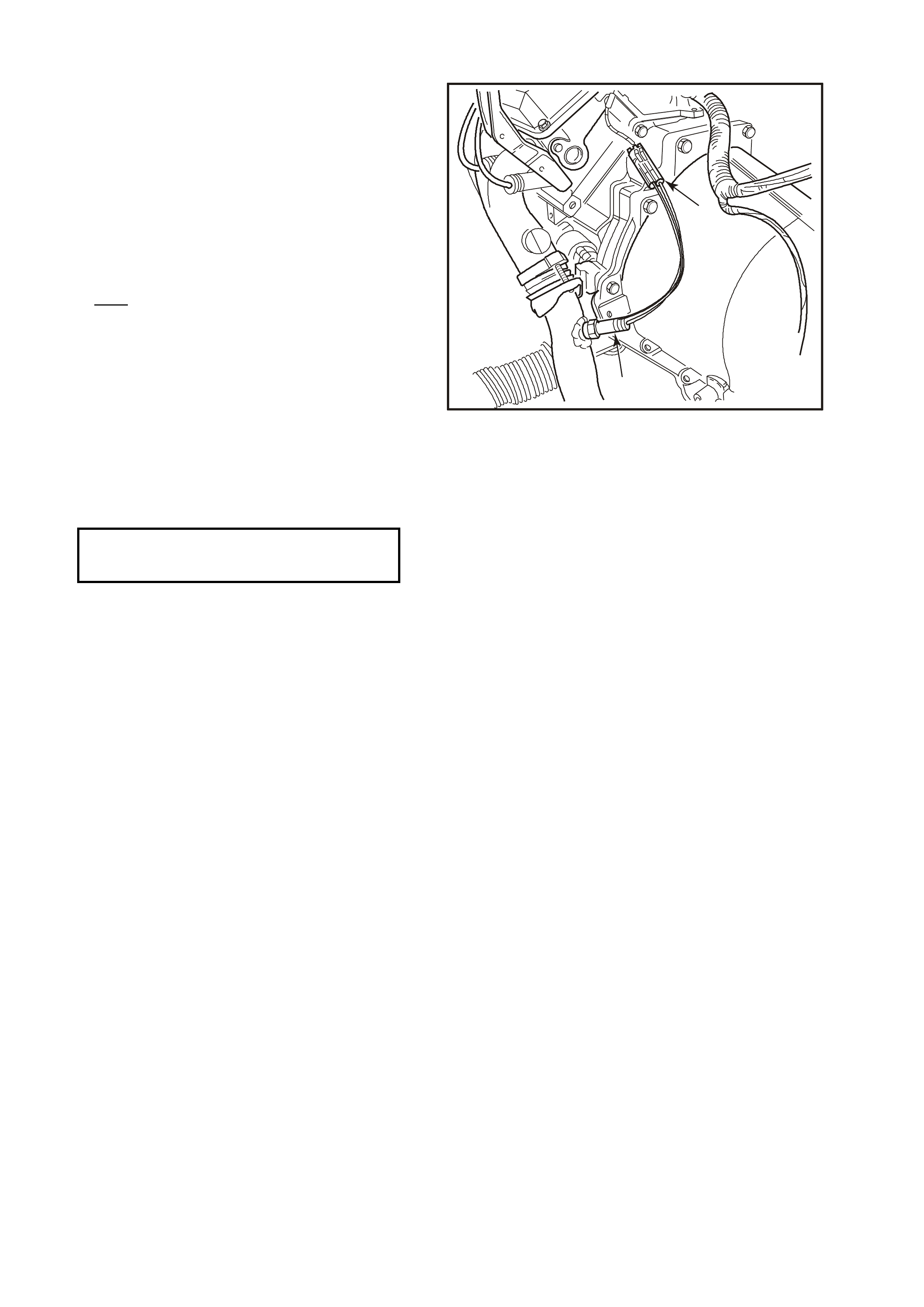
3.3 CAMSHAFT POSITION SENSOR
Figure 6C1-3-8 Camshaft/Crankshaft Position Sensors
REMOVE
1. Disconnect battery earth lead.
2. Lift up retaining tang and disconnect wiring harness connector from camshaft position sensor (6).
3. Remove camshaft position sensor to front cover retaining bolt (3).
4. Remove camshaft position sensor and O-ring (4) from front cover.
REINSTALL
1. Apply light engine oil to O-ring (4) on new camshaft position sensor (6).
2. Assemble camshaft position sensor (6) into front cover hole.
3. Install camshaft position sensor (6) to front cover retaining bolt (3) and tighten to the correct torque
specification.
Camshaft Position Sensor
Retaining Bolt
Torque Specification
11 N.m
4. Reconnect wiring harness connector to camshaft position sensor (6).
5. Reconnect battery earth lead.
2
3
4300
45
1
8
7
6

3.4 ENGINE COOLANT TEMPERATURE (ECT) SENSOR
IMPORTANT:
• Care must be taken when handling PCM
engine coolant sensor. Damage to sensor
will affect the operation of the engine
management system. Ensure that the
correct sensor is located before service is
attempted. There are different engine
coolant temperature sensors: for the PCM,
the instrument panel gauge, and/or warning
lights. Sensors are located in the front of
the inlet manifold below the engine
thermostat housing.
CAUTION: The Engine Coolant Temperature
(ECT) sensor (2) is installed into a "wet" engine
coolant passage (in the inlet manifold, below the
thermostat housing). Drain the engine coolant
before removing the ECT sensor from the engine.
Position a coolant drain pan appropriately, then
loosen lower radiator hose at the radiator to drain
the coolant.
REMOVE
1. Disconnect battery earth lead.
2. Depressurize engine cooling system by
removing radiator cap in two stages.
CAUTION: DO NOT REMOVE RADIATOR CAP
WHILE T HE ENGINE COOLANT TEM PERAT URE
IS ABOVE 50 DEGREES C.
4209
3
21
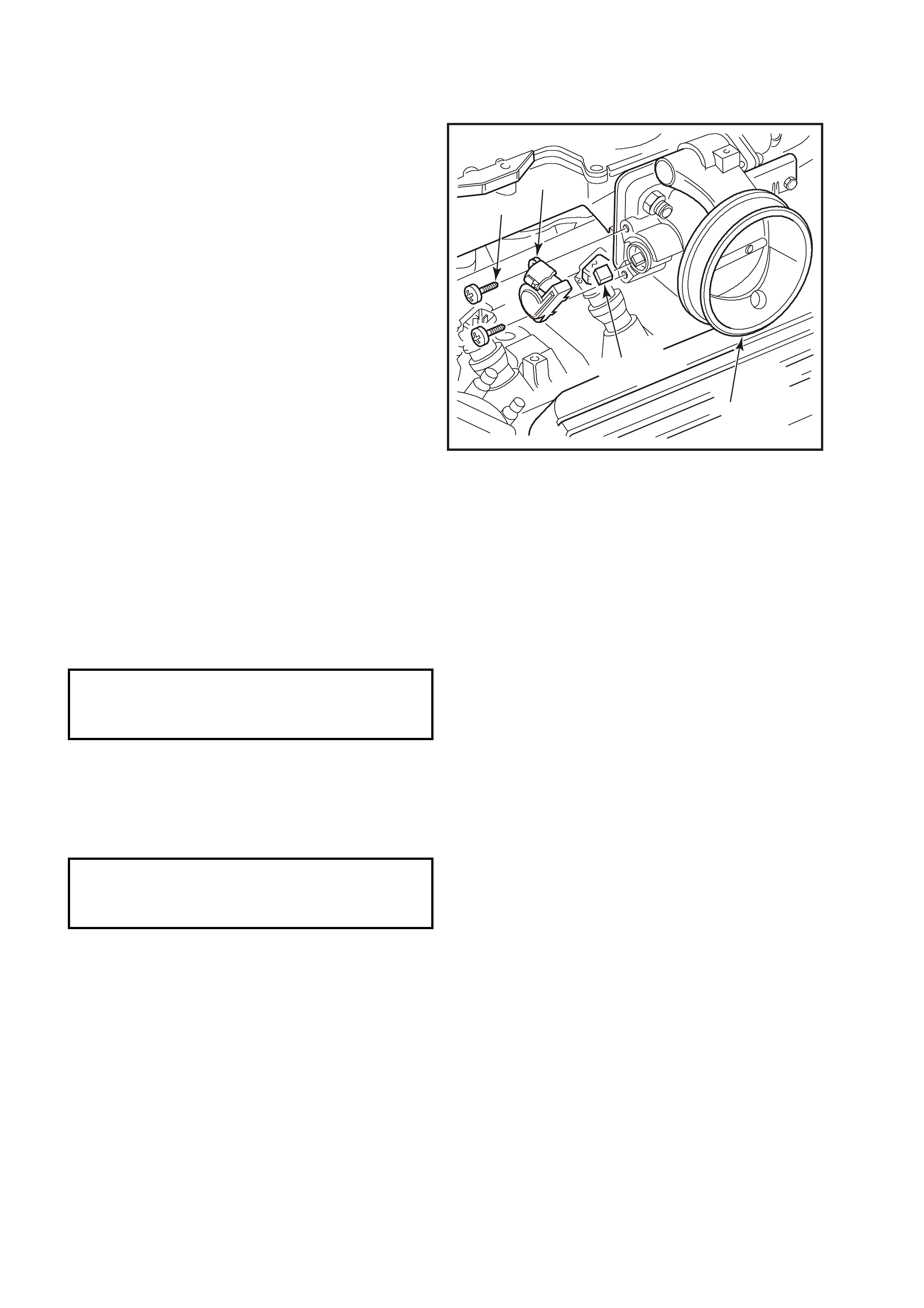
Figure 6C1-3-9 ECT Sensor Location
3. Remove four dome nuts (1) securing the
engine dress cover assembly (2) to the inlet
manifold studs, lift off and remove the cover
assembly.
4. Position a coolant drain pan appropriately
beneath the vehicle, then loosen lower radiator
hose at the radiator to drain the engine coolant.
5. Lift up retaining tang and disconnect wiring
harness connector from PCM ECT sensor. Lift
connector up away from sensor.
6. Carefully move powertrain wiring harness
down under the ECT sens or so as to allow tool
access to the sensor.
7. Using a 19 mm ring spanner, carefully loosen
and remove PCM engine coolant temperature
sensor.
2
1
4302
Figure 6C1-3-10 Engine Dress Cover V6 Engine

REINSTALL
1. Apply Loctite 242 (Holden's Specification HN1256 Class 2, Type 2) sealant to sensor threads.
2. Install ECT sensor into inlet manifold and tighten to the correct torque specification.
3. Reconnect wiring harness connector onto ECT
sensor,
NOTE:
Recheck that wiring harness connector and harness are corr ectly positioned. T he accessory drive belt passe s ver y
close to the temperature sensor connectors. Future damage to the harness could occur if not correctly positioned
now.
4. Reconnect battery earth lead.
5. Refill the engine coolant system, Ref er to Section 6B1-1, ENGINE COO LING - V6 ENGINE in the VX Ser vice
Information.
6. Reinstall engine dress cover to the inlet manifold, ens uring that stud grom mets in dres s cover rem ain in place.
Tighten securing dome nuts to the correct torque specification.
ECT Sensor To Inlet Manifold
Torque Specification 15 – 20
N.m
Engine Dress Cover Securing
Dome Nut To Inlet Manifold
Torque Specification
4 – 6 N.m
3.5 INTAKE AIR TEMPERATURE (IAT) SENSOR
IMPORTANT:
• Care must be taken when handling IAT
Sensor. Damage to IAT sensor will affect
proper operation of the fuel control system.
REMOVE
1. Disconnect battery earth lead.
2. Lift up tang on IAT sensor wiring harness
connector (1) and pull connector from sensor
(5).
3. Loosen intake air duct adapter clamp that is
located closest to air cleaner assembly.
4. Disconnect air duct, with mass air flow sensor
attached, from air cleaner upper housing.
5. Unclip 5 retaining clips holding the air cleaner
upper housing (2) in place.
6. Separate the upper and lower air cleaner
housings.
IMPORTANT:
Air filter should remain in the lower housing.
7. Remove air cleaner upper housing and place
on bench.
8. Using a pair of side cutters, cut across the IAT
sensor retainer (4) to remove it. Once
removed, discard retainer.
9. Pull out IAT sensor (5) from air cleaner upper
housing.
4215
1
2
5
4
3
Figure 6C1-3-11 IAT Sensor Removal
REINSTALL
1. Push new IAT sensor (5) into air cleaner upper housing (2), with triangular tang on the mounting flange
locating on the mating rib of the air cleaner upper housing.
2. Position the upper air cleaner housing assembly, with the IAT sensor on the work bench, pushing up into the
air cleaner upper housing.
Position new retainer (4) onto IAT sensor and then using a 20 m m sock et, push the retainer fully onto the IAT
sensor.
3. Assemble the air filter element into the air cleaner upper housing and place the upper housing onto the air
cleaner lower air cleaner housing, ensuring that air filter element remains in position.
4. Snap 5 retainer clips up into place over the top of the air cleaner upper housing.
5. Reconnect wiring harness connector (1) to IAT sensor (5).
6. Carefully assemble intake air duct and mass air flow sensor onto air cleaner upper housing.
IMPORTANT:
Align notch on air cleaner housing adapter with notch in air duct adapter and notch in clamp.
7. Tighten air duct clamp securely.
8. Check that mass air flow sensor wiring harness connector has remained firmly in place.
9. Reconnect battery earth lead.
3.6 MASS AIR FLOW (MAF) SENSOR
IMPORTANT:
Care must be taken when handling MAF sensor.
Damage to MAF sensor will aff ect proper operation
of PCM control.
REMOVE
1. Disconnect battery earth lead.
2. Lift up tang on MAF sensor wiring harness
connector (3) and pull connector from
sensor (1).
3. Loosen clamp on air duct adapter, closest to
MAF sensor (1).
4. Loosen clamp ( 4) on air duc t (5) at MAF sensor
(1) and pull back air duct (5) from sensor.
IMPORTANT:
Air duct adapter (between air cleaner and MAF
sensor), both clamps, air duct and MAF sensor
itself have locating notches.
5. Remove MAF sensor (1) from air duct
adapter (5).
REINSTALL
1. Install MAF sensor (1) into air duct adapter (5)
and air duct, aligning all notches. Install
clamps, aligning notches, tighten clamps
securely.
2. Reconnect MAF sensor wiring harness
connector (3).
3. Reconnect battery earth lead.
4. Start vehicle and check for air leaks.
5
4
1
3
4303
2
Figure 6C1-3-12 MAF Sensor Removal
3.7 OXYGEN SENSOR
IMPORTANT:
• The oxygen sensor uses a permanently
attached pigtail and connector. This pigtail
should not be removed from the oxygen
sensor. Damage or removal of the pigtail or
connector will affect proper operation of the
oxygen sensor.
• Take care when handling the oxygen sensor.
The in-line electrical connector and louvered
end must be kept free of grease, dirt or other
contaminants. Avoid using any cleaning
solvents. Do not drop or roughly handle the
oxygen sensor.
IMPORTANT:
The oxygen sensor may be difficult to remove
when engine temperature is below 60 degrees
Celsius. Excessive force may damage threads in
exhaust pipe, or on the sensor.
REMOVE
1. Disconnect battery earth lead.
2. Lift up retaining tang on oxygen sensor wiring
harness connector (1) and pull connector from
sensor pigtail connector.
For R.H s ensor, the connector is located at the
rear of the R.H cylinder head and is accessed
from the rear of the engine compartment. The
sensor pigtail leads are further retained by a
clip attached to the torque converter housing.
For L.H sensor, the connector is located at the
rear of the L.H cylinder head and is accessed
from the rear of the engine compartment.
3. Raise vehicle and place on suitable safety
stands. Refer to Section 3, FRONT
SUSPENSION, in the VT I Service Information.
4. Carefully unscrew oxygen sensor (2) from
exhaust pipe referring to previous NOTE.
2
1
4304
Figure 6C1-3-13 R.H. Sensor Location (Two wire sensor)
REINSTALL
IMPORTANT:
• A special anti-seize compound is used on the
oxygen sensor threads. The compound
consists of a liquid graphite and very small
glass beads. The graphite will burn away, but
the glass beads will rem ain, mak ing the sens or
easier to remove.
• Genuine replacement sensors will already
have the compound applied to the threads. If a
sensor is removed from an engine, and, if for
any reason it is to be reinstalled, the threads
must have the specified anti-seize compound
applied before reinstallation.
NOTE:
Specified anti-seize compound is available from
authorized Holden Parts Outlets as part number
5613695.
1. If necessary, coat threads of oxygen sensor
with
specified anti-seize compound.
2. Ins tall oxygen sensor (2) into exhaust pipe and
tighten to the correct torque specification.
3. Remove safety stands and lower the vehicle.
4. Reconnect oxygen sensor wiring harness
connector (1).
IMPORTANT:
Ensure that the R.H sensor pigtail leads are
retained by a clip attached to the torque converter
housing
5. Reconnect battery earth lead.
2
4305
1
Figure 6C1-3-14 L.H Sensor Location (Two wire sensor)
Oxygen Sensor To Exhaust
Manifold Torque Specification 40-50
N.m
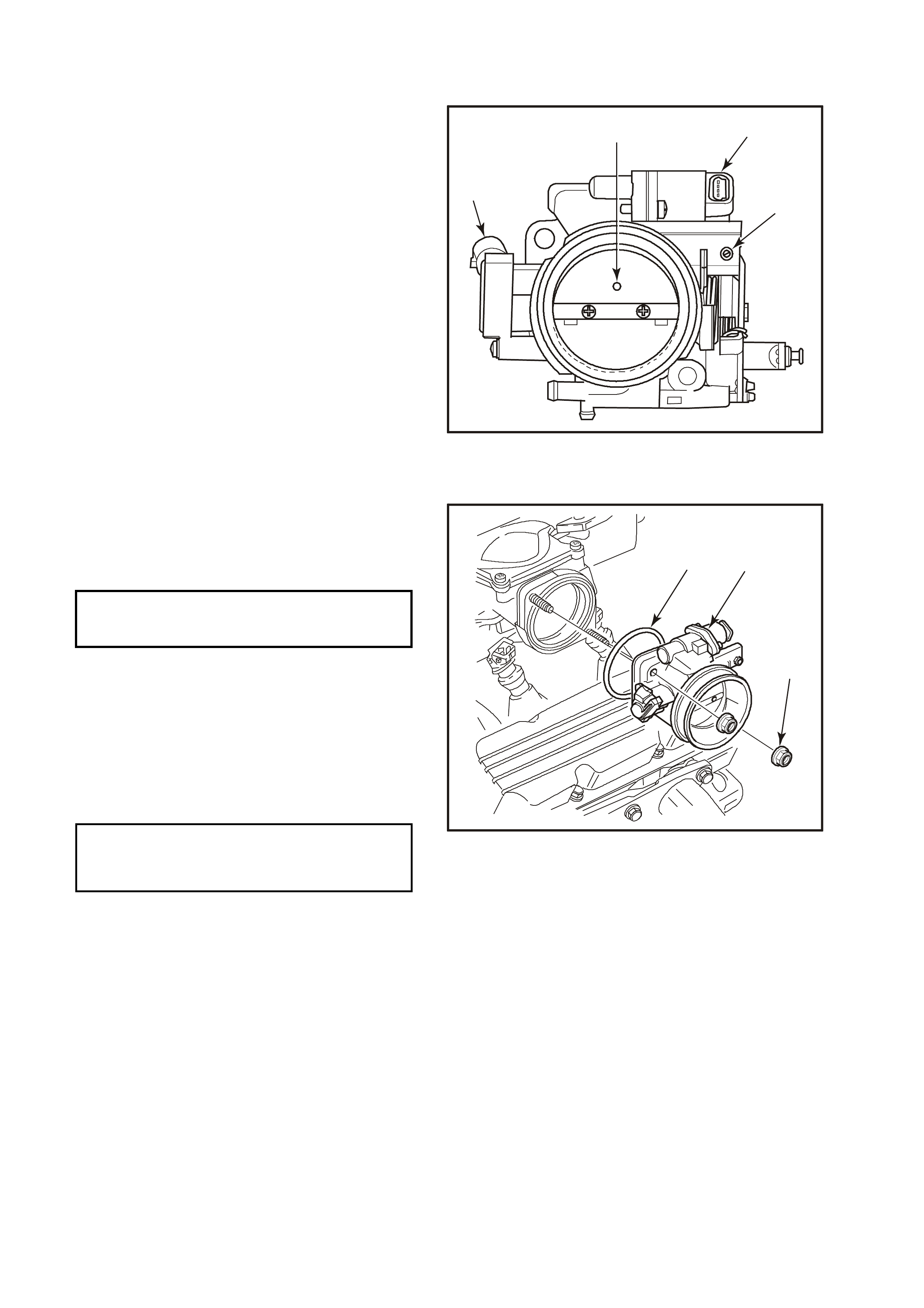
3.8 THROTTLE POSITION (TP) SENSOR
REMOVE
1. Disconnect battery earth lead.
2. Remove four dome nuts securing the engine
dress cover assembly to the inlet manifold
studs, lift off and remove the cover assembly .
Refer to Figure 6C1-3-10.
3. Lift up retaining tang on TP sensor wiring
harness connector and pull connector from
sensor (1).
4. Remove the two TP sensor to throttle body
attaching screws (4).
5. Remove sensor (1) from throttle body (2)
taking care not to lose the drive adapter (3).
NOTE:
The "drive adapter" (3) is a plastic cover that
loosely slides over the end of the throttle shaft, on
the TP sensor side of the throttle body. It is
captured in place when the T P sensor is in position
on the throttle body. The drive adapter could fall
from the throttle shaft after the TP sensor is
removed. Ensure that the drive adapter is not lost.
2
4309
3
4
1
Figure 6C1-3-15 TP Sensor Removal
REINSTALL
1. Check that the drive adapter (3) is in place on the throttle valve shaft, refer to previous NOTE.
2. With throttle valve in the norm ally closed idle position, inst all TP s ensor ( 1) on to throttle valve s haft and throttle
body at a position 30 degrees clockwise past throttle body attaching screw holes.
3. Rotate TP sensor anti-clockwise on throttle body, and install TP sensor attaching screws and tighten to the
correct torque specification.
TP Sensor To Throttle Body
Attaching Screw
Torque Specification
1 - 1.5 N.m
4. Reconnect TP sensor wiring harness connector.
5. Reinstall engine dress cover to the inlet manifold, ensuring that stud grommets in the dress cover remain in
place . Tighten securing dome nuts to the correct torque specification.
Engine Dress Cover Securing
Dome Nut To Inlet Manifold
Torque Specification
4 - 6 N.m
6. Reconnect battery earth lead.
3.9 VEHICLE SPEED SENSOR
AUTOMATIC TRANSMISSIO N
REMOVE
1. Jack up rear of vehicle and support on safety
stands, Refer to Section OA, GENERAL
INFORMATION in the VT I Service Information.
2. Lift up tang on VSS wiring harness connector
(2) and pull connector from VSS (3).
3. Remove VSS to transmission extension
housing bolt (1).
4. Remove VSS and O-ring seal from extension
housing by slowly prying out sensor with a flat
screwdriver.
REINSTALL
1. Coat the VSS O-ring seal with a thin film of
transmission fluid.
2. Install new VSS and O-ring into transmission
extension housing.
3. Install retaining bolt (1) and tighten to the
correct torque specification.
4. Reconnect wiring harness connector (2) to
VSS (3).
5. Remove safety stands and lower vehicle.
1
2
4310
3
Figure 6C1-3-16 VSS Location Automatic Transmission
MANUAL TRANSMISSION
For vehicle speed sensor removal and
reinstallation, Refer to Section 7B-1 MANUAL
TRANSMISSION - V6 in the VX Service
Information.
1
2
4223
Figure 6C1-3-17 VSS Location Manual Transmission
VSS Retaining Bolt 11
Torque Specification N.m
3.10 FUEL CONTROL SYSTEM
FUEL PUMP RELAY
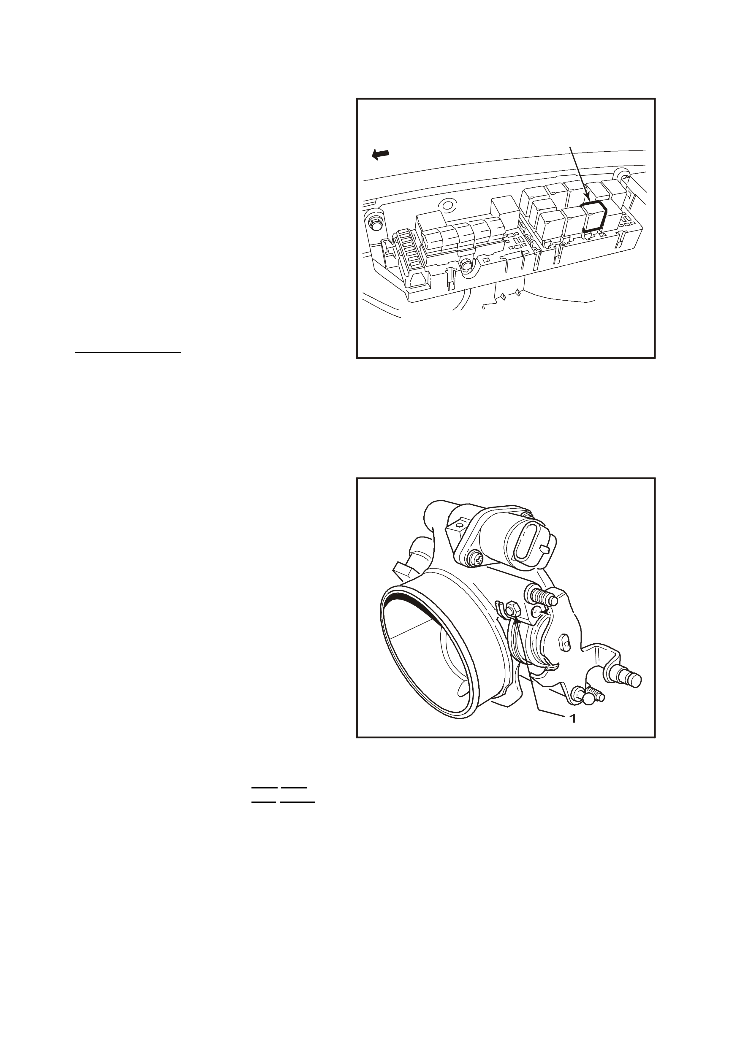
The fuel pump relay (1) is located in a relay
housing, in the engine compartment. The relay
housing is positioned forward of the right side
(driver's side) strut tower, in front of the cooling
system coolant recovery reservoir. Other than
checking for loose connectors, the only service
possible is replacement.
FUEL PRESSURE RELIEF PROCEDURE
IMPORTANT:
UNLESS THIS PROCEDURE IS FOLLOWED
BEFORE SERVICING FUEL LINES OR
CONNECTIONS, FUEL SPRAY INTO THE
ENGINE COMPARTMENT COULD OCCUR!
1. Remove "Fuel Pump Relay" from engine
compartment relay housing.
2. With throttle closed, crank engine - engine m ay
start and idle until fuel supply remaining in fuel
line is exhausted. W hen engine stops, engage
starter again for 10 seconds to ensure
dissipation of any remaining pressure.
3. Refit fuel pump relay (1).
1
4239
Figure 6C1-3-18 Fuel Pump Relay Location
THROTTLE STOP SCREW - RESET PROCEDURE
IMPORTANT:
Engine idle for this V6 application must be check ed
every 80,000KM. If the IAC valve counts are
greater than 25 at idle, the throttle body must be
removed and cleaned. Refer to
Throttle Body Cleaning Procedure in this
Section.
The T hrottle Stop Screw (1) controls the minimum
throttle opening (nominal "Closed throttle"
position). It is preset at the factory and must not
be reset unless:
I. The s crew is known to have been inadvertently
reset,
-OR-
II. Clearly instructed to do so by a diagnostic
Table.
Engine idle speed, which will vary with engine
temperature, is PCM - controlled and is not
adjustable.
PCM - Controlled idle speed (IAC) and
Throttle stop screw setting (RPM) ARE NOT
THE SAME!
4346
Figure 6C1-3-19 Throttle Stop Screw Location
Thro ttle stop screw setting (RPM) must always be less than the PCM controlled idle s peed, and is chec ked only
after temporarily disabling the PCM's method of controlling idle speed, the Idle Air Control system. The throttle
stop screw setting is the least likely cause of an abnormal idle condition, therefore resetting the screw should
only be considered as a last resort. An incorrect setting is likely to cause a deterioration in idle stability.
IMPORTANT: - Inspect
• Before any adjustments are made, ensure that no vacuum leaks exist. Check all vacuum hoses, MAF air
ducts, inlet manifold gasket, throttle body-to-manifold attachment, and any vacuum-operated devices. The
engine must be at normal operating temperature before any checking or resetting is attempted.
WITH THIS ENGINE CONTROL SYSTEM, ANY VACUUM LEAK WILL RESULT IN A LOW/ROUGH IDLE
SPEED.
CHECK OR RESET
1. Before performing this procedure, perform the
On-Board Diagnostic System Check. Refer to
Section 6C1-2A In VX Service Information.
2. Bef ore perf orming s teps 3 - 10, ensure that the
IAC system is functioning properly. Refer
Diagnostic T ABLE A-7.1 (IAC system chec k) in
Section 6C1-2A, DIAGNOSTIC TABLES - V6
ENGINE in VX Service Information, and follow
it to the "NO TROUBLE FOUND - IAC OK"
step before proceeding.
3. Engine must be at normal operating
temperature (above 90 degrees C), preferable
achieved by driving for at least 15 minutes,
before continuing.
4. Set parking brake and block drive wheels.
Ensure transmission is in `Park' (auto) or
neutral (manual).
5. Remove four dome nuts securing the engine
dress cover assembly to the inlet manifold
studs, lift off and remove the cover assembly.
1
2
4311
Figure 6C1-3-20 IAC Valve Harness Removed
6. Verify that the throttle cable and throttle
linkage are not binding. The throttle lever
attached to the throttle butterfly shaft must be
able to open fully, and shut fully and freely
every time the accelerator pedal is fully
depressed and slowly released.
Refer "Throttle cable - adjust" in this Section if
throttle cable adjustment is required.
7. Install Tech-2 scan tool, and select
Miscellaneous tests, IAC System, Base Idle.
8. Ignition “ON”, engine running.
NOTE:
If the engine has completed less than 3,000
km, do not reset the throttle stop screw unless
the RPM is above 600. Otherwise, RPM
should be 500 - 600. If reset is necessary,
adjust throttle stop screw to obtain engine
speed of 450 - 550 RPM.
9. Using the Tech-2 scan tool, activate the Base
Idle test and follow the instructions on the
Tech-2 scan tool.
10. Adjust the base idle scr ew to obtain engine idle
speed of 450-550 RPMs.
11. Reinstall engine dress cover to the inlet
manifold, ensuring that stud grommets in the
dress cover remain in place. Tighten securing
dome nuts to the correct torque.
Engine Dress Cover Securing
Dome Nut To Inlet Manifold
Torque Specification
4 - 6 N.m
MODULAR FUEL SENDER ASSEMBLY
REMOVE
TOOL REQUIRED
J 39765, FUEL SENDER LOCKNUT WRENCH
IMPORTANT:
Do not handle the modular fuel sender assembly
by the fuel pipes.
1. Relieve the fuel system pressure. Refer to the
Fuel Pressure Relief Procedure in this
Section.
2. Disconnect battery earth lead.
3. Remove fuel tank, Refer to Section 8A, FUEL
TANK, in VX Service Information.
4. Remove the modular fuel sender retaining ring
using the J 39765 Fuel Sender Locknut
Wrench.
NOTE:
W hen removing the modular fuel sender assembly
from the fuel tank, the reservoir bucket on the fuel
sender assembly is full of fuel. The modular fuel
sender assembly must be tipped slightly during
removal in order to avoid damage to the float.
Place any remaining fuel into an approved
container once the modular fuel sender assembly
is removed from the fuel tank.
IMPORTANT:
The modular fuel sender assembly will spring-up
when the locking ring is removed.
5. Pull the modular fuel sender straight up while
draining the fuel from the reservoir.
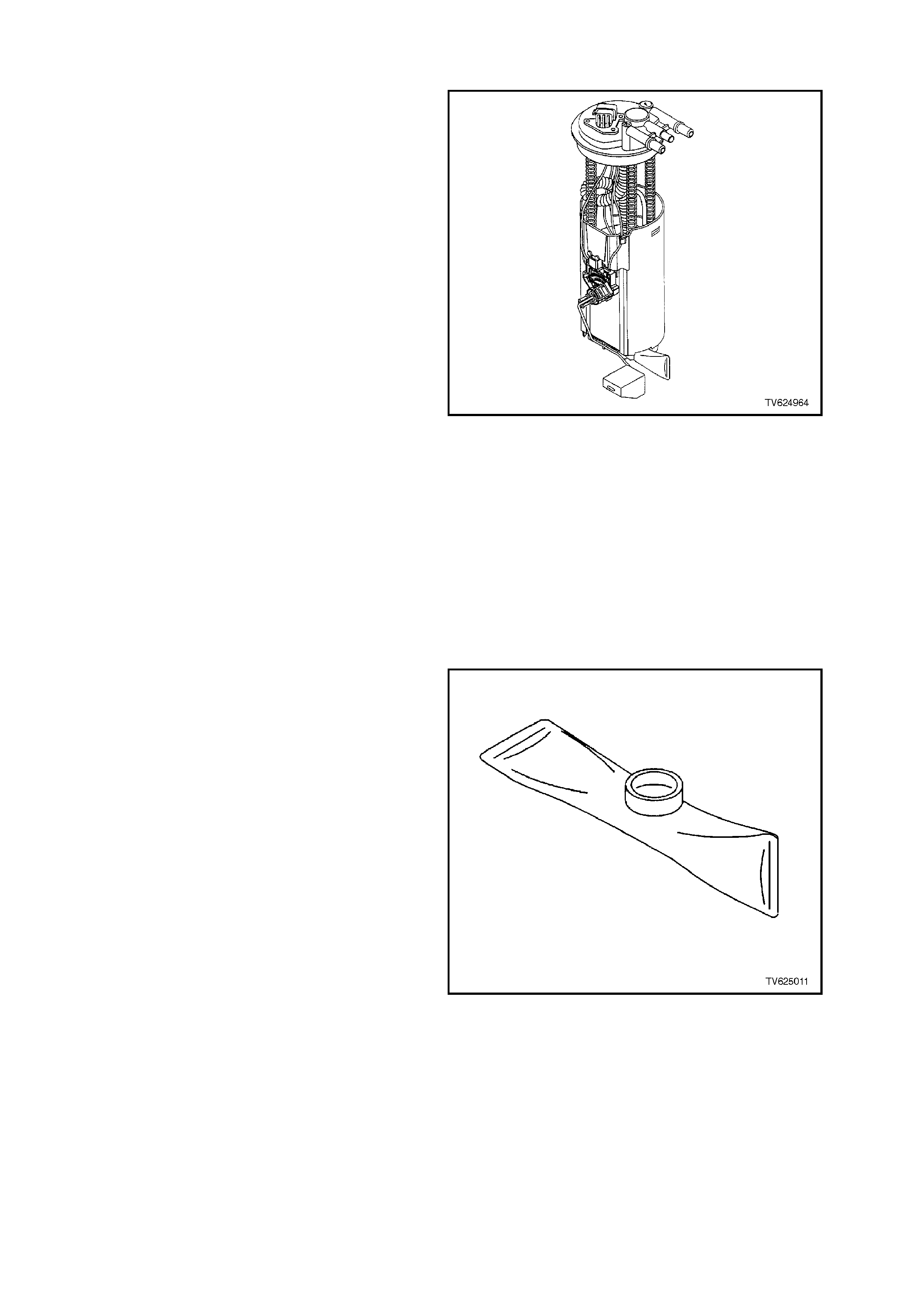
Figure 6C1-3-21 Modular Sender Assembly
6. Clean the fuel sender assembly O-ring sealing
surface.
7. Inspect the fuel sender assembly O-ring
sealing surface.
REINSTALL
IMPORTANT:
Always replace the fuel sender O-ring when
reinstalling the fuel sender assembly.
1. Position the new fuel sender assembly O-ring
on the fuel tank.
IMPORTANT:
Care should be taken not to fold over or twist the
fuel pump strainer when installing the fuel sender
assem bly, as this will restrict fuel flow. Also, assure
that the fuel pump strainer does not interfere with
full travel of float arm.
2. Install the fuel sender assembly and the fuel
sender assembly retainer ring using the J
39765 Fuel Sender Locknut Wrench.
3. Reinstall fuel tank, Refer to Section 8A FUEL
TANK, in VX Service Information.
4. Reconnect battery earth lead.
5. Inspect system for leaks.
Figure 6C1-3-22 Fuel Strainer
MODULAR FUEL SENDER ASSEMBLY (SERVICEABLE FUEL STRAINER AND FUEL LEVEL SENSOR)
REMOVE
NOTE:
Do not handle the modular fuel sender assembly
by the fuel pipes.
1. Relieve the fuel system pressure. Refer to
3.10, Fuel Control System (FUEL
PRESSURE RELIEF PROCEDURE) in this
Section.
2. Disconnect battery earth lead.
3. Remove fuel tank, Refer to
Section 8A, FUEL TANK, in VX Service
Information.
4. Remove MODULAR FUEL SENDER
ASSEMBLY. Refer to removal procedure in
this Section.
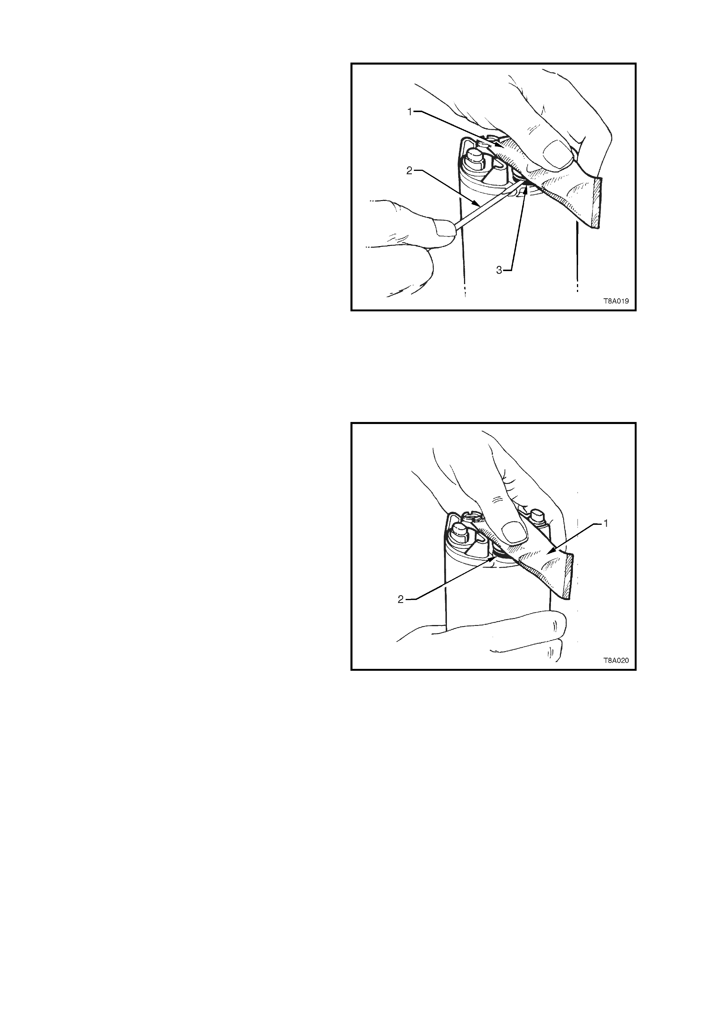
DISASSEMBLE
1. Note the position of the f uel sender strainer for
installation.
2. Support the reservoir with one hand and grasp
the fuel sender (1) strainer with the other hand.
3. Using a screwdriver (2) , pry the fuel strainer
off of the fuel sender assembly (3).
Figure 6C1-3-23 Removing Strainer
4. Inspect the fuel sender strainer. If the fuel
sender strainer is contaminated, the fuel tank
should be cleaned.
NOTE:
The Fuel Pump Strainer is NOT serviced
separately. It can only be purchased as a
pump and strainer assembly.
5. Discard the fuel sender strainer after
inspection.
6. Disassem ble the electrical connectors from the
fuel level sensor assembly of the fuel pump
and the cover assembly.
7. Disassembly the fuel level sensor assembly.
ASSEMBLE
1. Assemble the fuel level sensor assembly.
2. Assemble the electrical connectors to the fuel
pump and cover assembly.
3. Assemble the rubber pad on the bottom of the
modular fuel sender assembly.
4. Pos ition the new fuel sender s trainer and o-ring
on the modular fuel sender and push on the
outer edge of the fuel sender strainer until the
fuel sender strainer is fully seated.
Figure 6C1-3-24 Installing Strainer

REINSTALL
1. Install the fuel sender assembly. Refer to
MODULAR FUEL SENDER ASSEMBLY in
this Section for reinstallation of sender
assembly to fuel tank.
2. Reinstall fuel tank Refer to
Section 8A, FUEL TANK, in VX Service
Information.
3. Reconnect battery earth lead.
4. Inspect system for leaks.
Figure 6C1-3-25 Fuel Level Sensor Assembly
MODULAR FUEL SENDER ASSEMBLY
REMOVE
1. Relieve the fuel system pressure. Refer to the
Fuel Pressure Relief Procedure in this
Section.
2. Disconnect battery earth lead.
3. Remove fuel tank, Refer to Section 8A, FUEL
TANK, in VX Service Information.
4. Remove MODULAR FUEL SENDER
ASSEMBLY. Refer to removal procedure in
this Section.
5. Remove the fuel pump/sender patch harness
connector as follows;
1. Using a small screwdriver, first rem ove the
red Connector Position Assurance (CPA)
locking tab (1), then the gray tap (2).
Depress the connector lock and remove
from the top cover.
Figure 6C1-3-26 Removing CPA Connector
2. Release the locking tabs on the fuel pump
harness connector and remove the
connector from the fuel pump.
Figure 6C1-3-27 Removing Connector from Fuel Pump
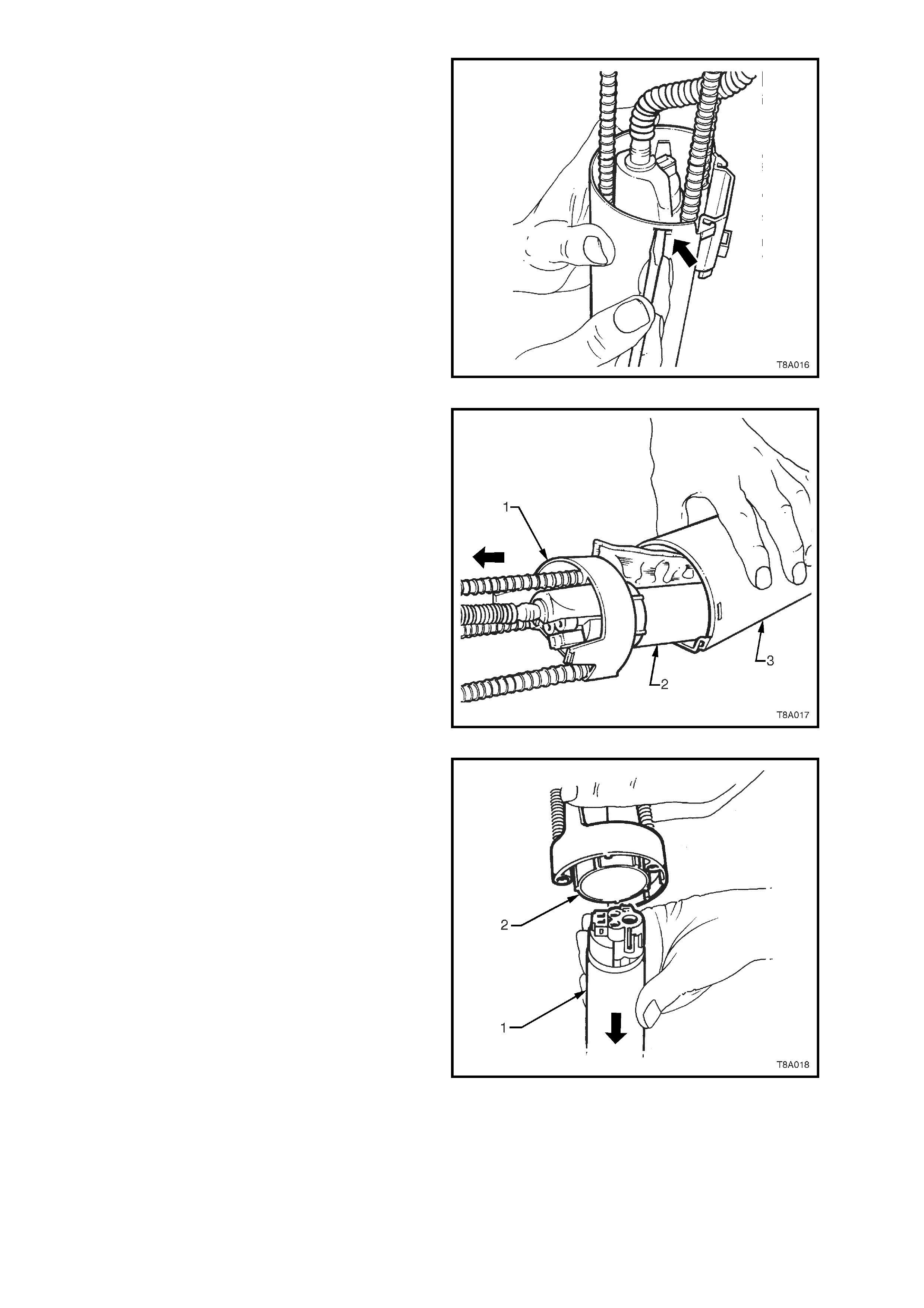
6. Separate the inner member from the outer
reservoir, by releasing the two tangs with a
small screwdriver as shown.
Figure 6C1-3-28 Release Tangs
7. Slide the inner member cover assembly and
fuel pump from the outer reservoir shell.
Figure 6C1-3-29 Separating pump from reservoir
8. Us ing a twisting/pulling motion, rem ove the fuel
pump and integral strainer from the inner
membe r assembly.
REINSTALL
1. Installation is the reverse of the removal
process, noting the following points:
1. Ensure that the fuel pump inlet sealing
grommet is installed in the base of the
outer reservoir shell before the pump is
installed.
2. After the fuel tank has been installed into
the vehicle, check for fuel leaks. Refer to
3.10, FUEL CONTROL SYSTEM – LEAK
TESTING, in this section.
Figure 6C1-3-30
FUEL SYSTEM PRESSURE TEST
A Fuel System Pressure Test is part of several of
the Diagnostic Tables and Symptom checks. To
perform this test, follow this procedure:
IMPORTANT:
To reduce the risk of fire or personal injury, it
is necessary to relieve fuel system
pressure before performing this test. See
"Fuel Pressure Relief Procedure" in this Section.
IMPORTANT:
At no time must the fuel inlet hose or return line
hose be clamped or bent over as this will cause a
permanent kinking of the inner section of the hose
assembly and will result in restricted fuel flow.
1. Relieve fuel pressure as described in
3.10, FUEL CONTROL SYSTEM - FUEL
PRESSURE RELIEF PROCEDURE, in this
Section. Turn ignition "OFF."
2. Remove four dome nuts securing the engine
dress c over ass em bly to the mounting brack ets
studs, lift off and remove the cover assembly.
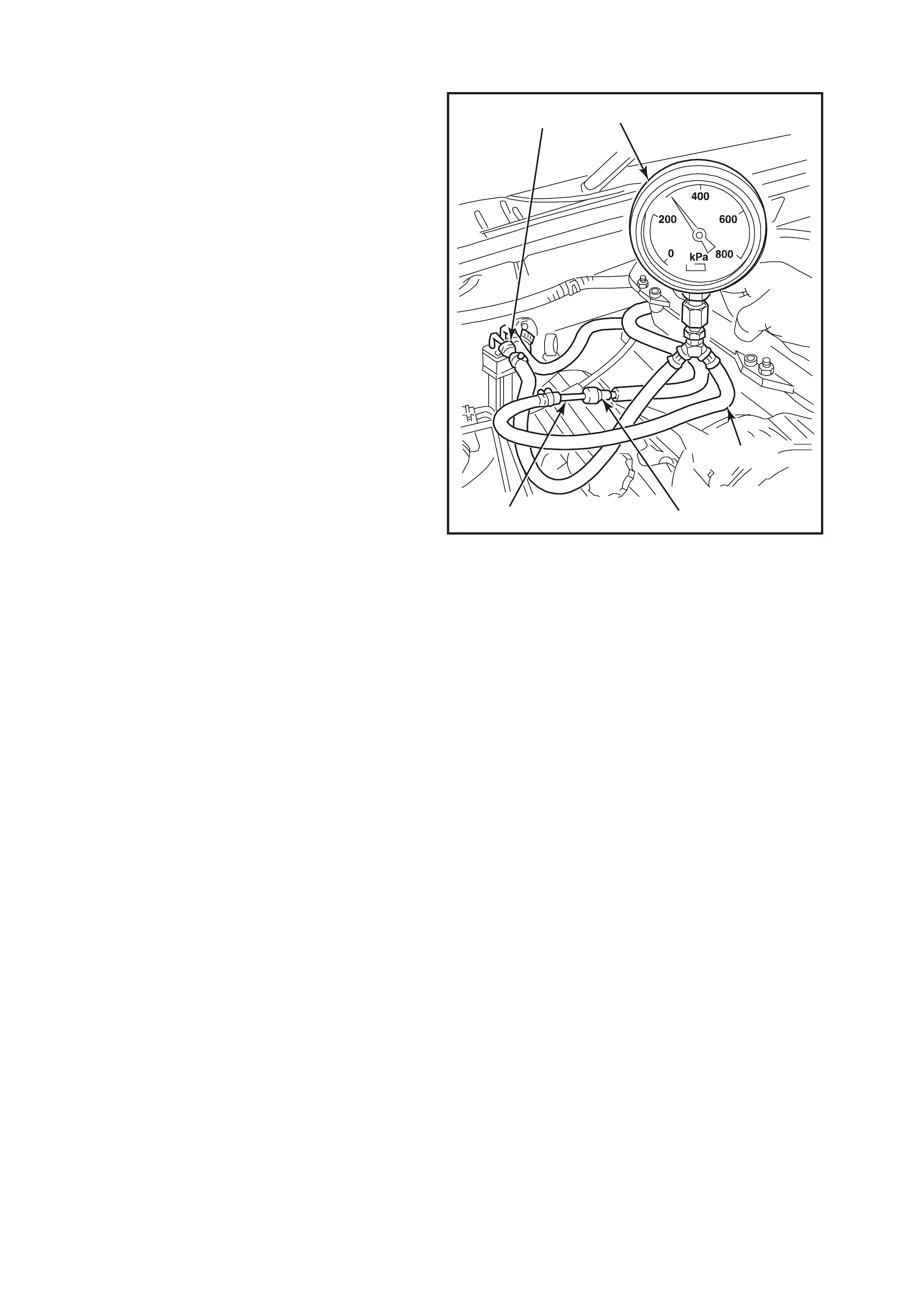
3. Open Tool No. 7370 and install over fuel inlet
line.
4. Close 7370 and pull into f uel line quic k connect
to release it f rom the f uel inlet line, pull back on
quick connect.
IMPORTANT:
Before conducting the next step, inspect tube
adapter (P/N 216812) on f uel pres sure gauge hos e
to ensure that it is free from any damage or burrs.
This is necessary so as to ensure that the tube
does not damage the sealing ring in the quick
connect. If the s ealing ring becom es dam aged, f uel
leakage will occur.
4278
1
5
43
2
Figure 6C1-3-31
5. Install fuel pressure gauge AU338 or SD28018
(1) & hose SD28057 (2) fitted with Coupler
7434 (5) and tube 216812 (4) in the pressure
line, between the fuel inlet line and the fuel
inlet hose quick connect (3).
Measure
6. Use scan tool , enable fuel pump so that the
"fuel pump" can pressurize the system.
7. Fuel gauge reading should be 270 - 350 k Pa. If
not, refer to Diagnostic TABLE A-4.1 in
Section 6C1-2A, DIAGNOSTIC TABLES - in
this Section.
8. Relieve fuel pressure as described in
3.10, FUEL CONTROL SYSTEM - FUEL
PRESSURE RELIEF PROCEDURE, in this
Section.
9. Remove fuel pressure gauge and adapter.
10. Reinstall fuel line.
11. Check for fuel leaks as described in
3.10, FUEL CONTROL SYSTEM - LEAK
TESTING, in this Section.
FUEL FILTER
REMOVE
IMPORTANT Relieve the fuel system pressure
before servicing any fuel system connection. Refer
to the Fuel Pressure Relief Procedure in
3.10, FUEL CONTROL SYSTEM in this Section.
1. Relieve fuel pressure as described in
3.10, FUEL CONTROL SYSTEM - Fuel
Pressure Relief Procedure in this Section.
2. Disconnect batter y earth lead.
3. Raise rear of vehicle and support on safety
stands, refer to Section OA, GENERAL
INFORMATION in the VT Service Information.
4. Place a drain tray beneath fuel filter.
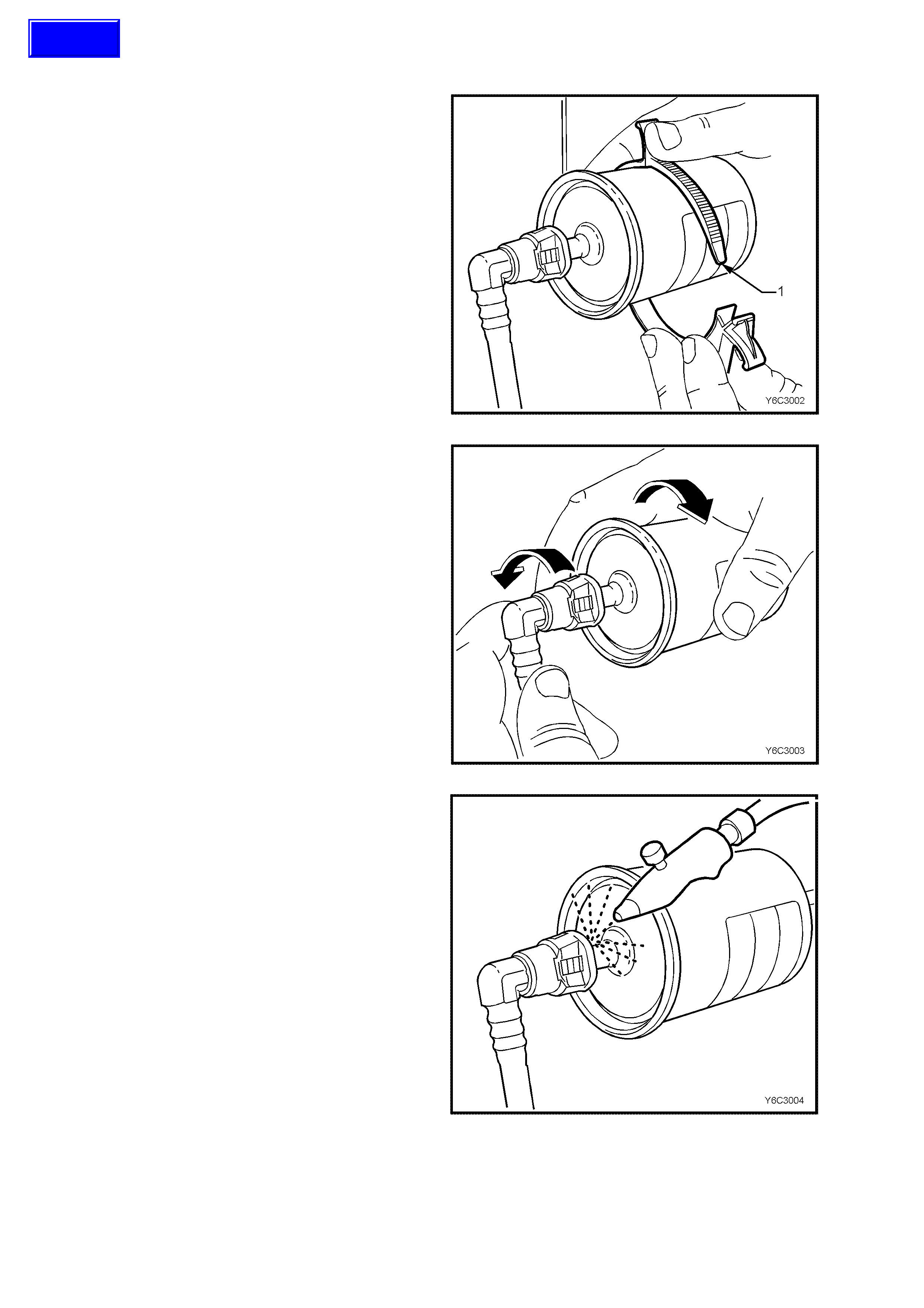
5. Remove the fuel filter from the retaining
brack et (1) with the fuel lines still connected to
the fuel filter to allow easier access.
Figure 6C1-3-32
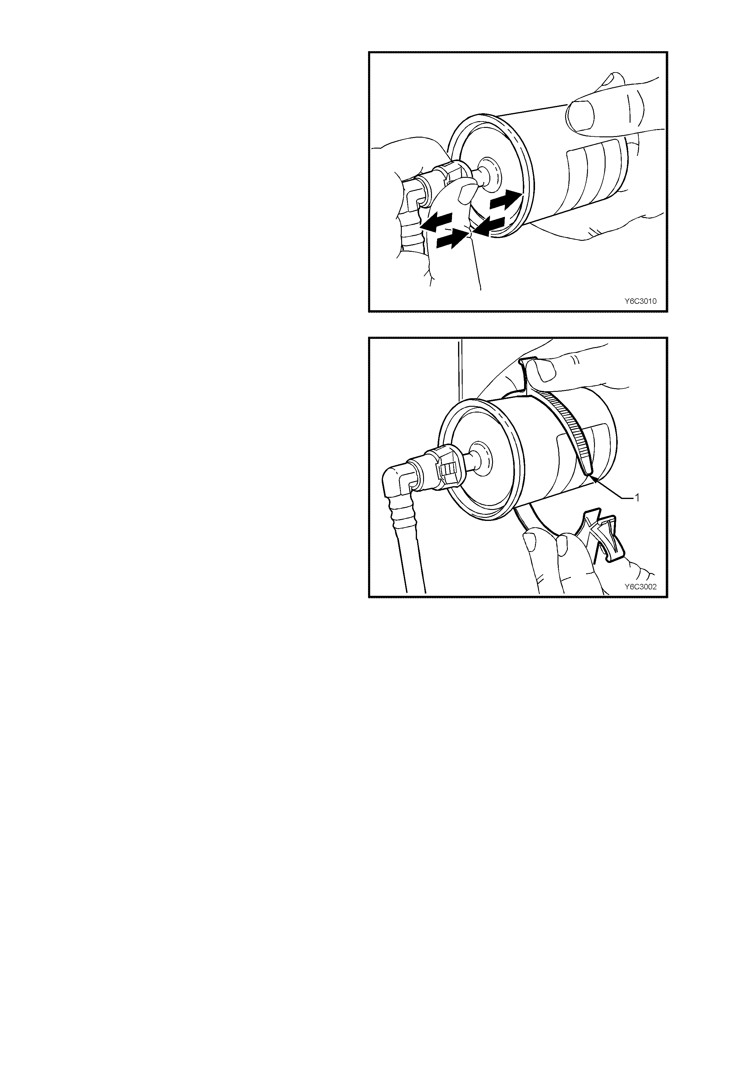
QUICK CONNECT FITTINGS
(PLAST IC COLL AR)
6. Grasp the quick-connect fittings both sides of
the fuel filter. Twist the female connectors 1/4
turn in each direction in order to loosen any dirt
within the quick-connect fitting.
Figure 6C1-3-33
7. Using compressed air, blow any dirt out of the
quick-connect fitting to aid the release of any
tension or binding on the release tabs .
IMPORTANT:
W ear safety glas ses whe n using com pres sed air in
order to prevent eye injury.
Figure 6C1-3-34
Techline
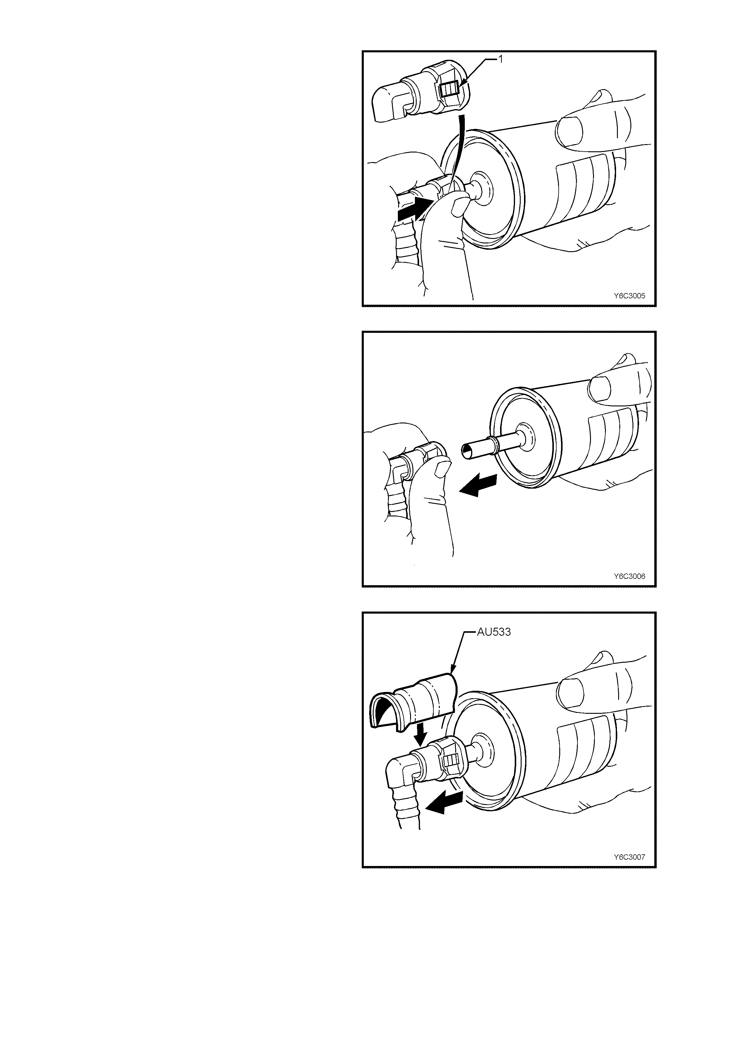
8. Hold t he fuel f ilter f irmly in one h and to support
the filter.
9. Using your other h and, grasp one of the quic k-
connect fittings.
10. Squeeze the plastic retainer release tabs (1)
on each side of the fitting while pushing the
fitting fir mly toward the fue l filter to rele ase any
tension on the release tabs.
Figure 6C1-3-35
11. With the tension release tabs still held in the
squezed position, move the complete quick-
connect fitting away from the fuel filter to
separate the connector fitting from the fuel
filter.
12. Apply the same method from step 8 to 11 for
the remaining quick-connect fitting.
Figure 6C1-3-36
13. Alternatel y for steps 8 to 11, us e tool AU533 t o
squeeze the release tabs, release the quick
connect fittings and remove both fuel pressure
hoses from the fuel filter.
14. Remove fuel filter from vehicle and disguard
safely remembering that some fuel will still
remain in the filter.
Figure 6C1-3-37
REINST ALL
IMPORTANT The fuel filter must be installed with
the flow arrow (6) on its body pointing in the same
direction as the fuel flow to the front of the vehicle.
Figure 6C1-3-38 Fuel Filter Installation
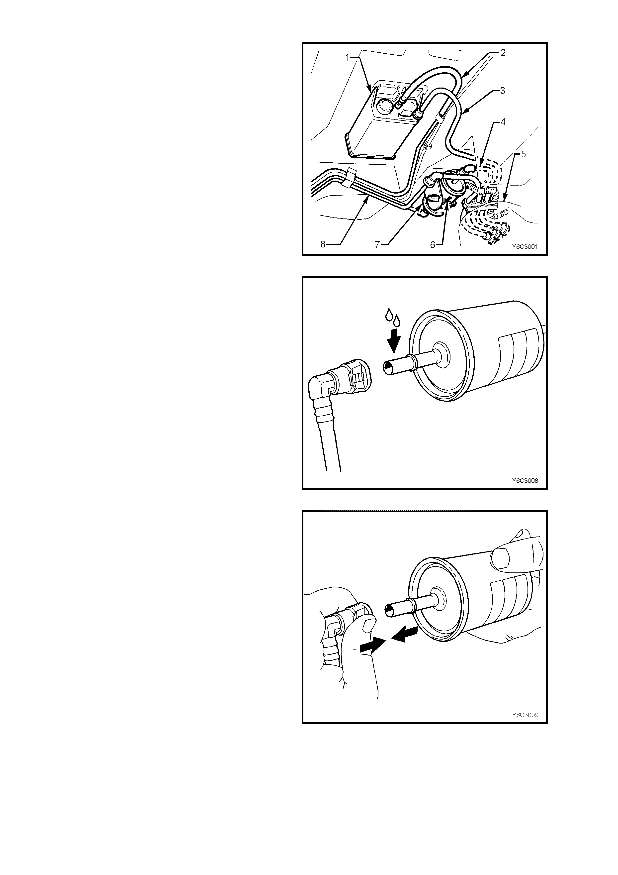
IMPORTANT Before connecting fuel filter quick-
connect fittings, always apply a few drops of clean
engine oil to the male ends of the fuel filter.
This will e nsure proper r econnection and pr event a
possible fuel leak.
During normal operation, the O-ring located in the
fem ale connec tor will s wel l and may prevent pr oper
reconnection if not lubr icate d.
1. Apply a few drops of clean engine oil to each
male fuel filter end.
Figure 6C1-3-39
2. Push both the quick-connect fitting and the fuel
filter together in order to cause the retaining
tabs to snap into place. Apply this method to
both ends of the fuel filter and the respective
quick-connect fittings.
Figure 6C1-3-40
3. Once ins talled, pul l and pu sh on both t he quick -
connect fitting and the fuel filter in order to
make sure the connection is secure. Apply
method this to both ends of the fuel filter and
the respective quick-connect fittings.
Figure 6C1-3-41
4. Install a new fuel filter to a new retaining bracket
(1).
5. Connect battery earth lead.
6. Check for fuel leaks, refer to
3.10, FUEL CONTROL SYSTEM – Leak
Testing in this Section of the VT Service
Information.
7. Remove safety stands and lower vehicle.
Figure 6C1-3-42
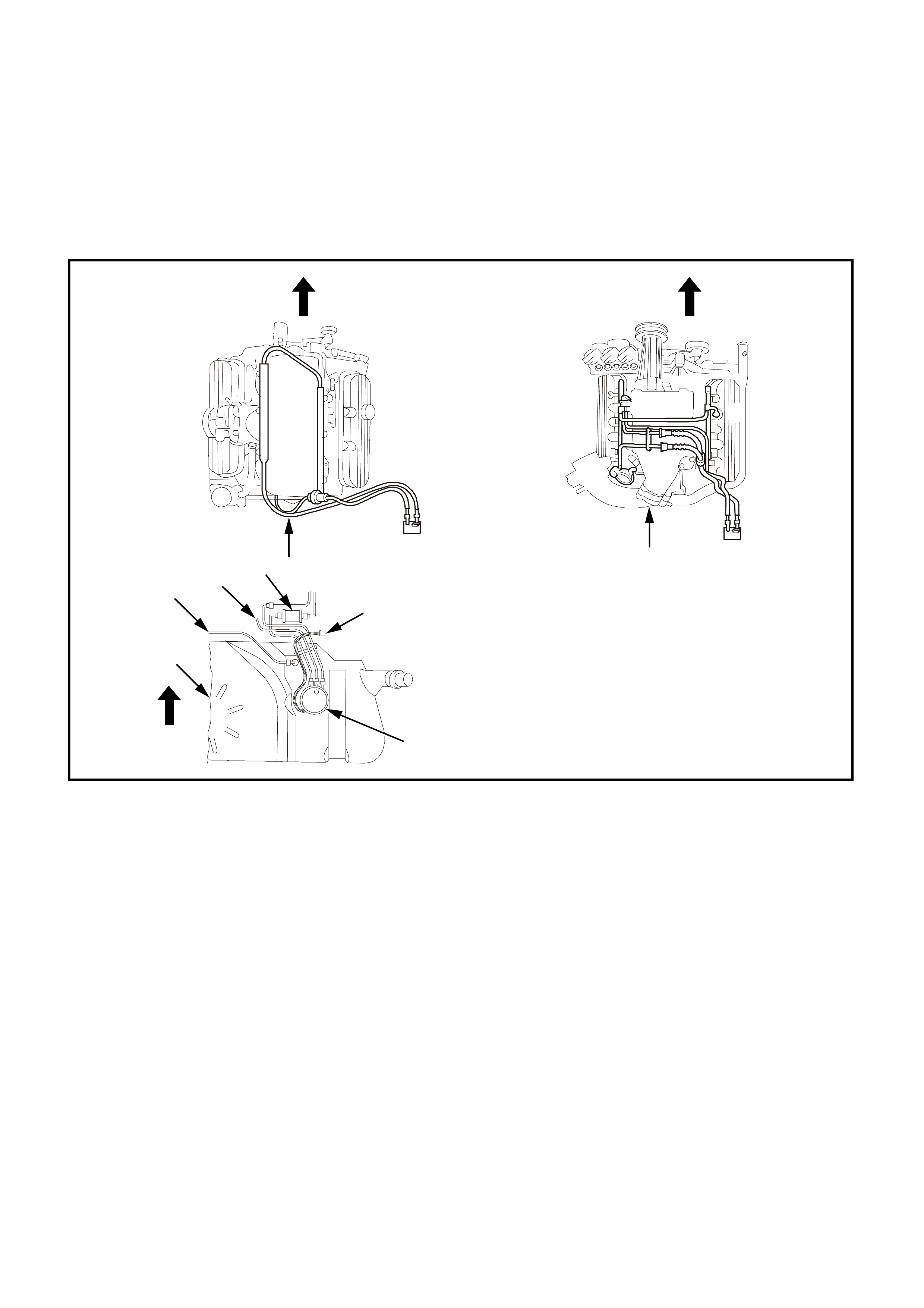
LEAK TESTING
Prior to star ting the engine, following the installation of any fuel system c omponent, c heck the f uel system f or leaks
using the following procedure:
1. Check to ensure that there is a sufficient level of fuel in the fuel tank.
2. Use sc an tool "Output Test" f or "Fuel Pump." Enabling the output tes t will activate the fuel pum p to pres surize
the fuel system.
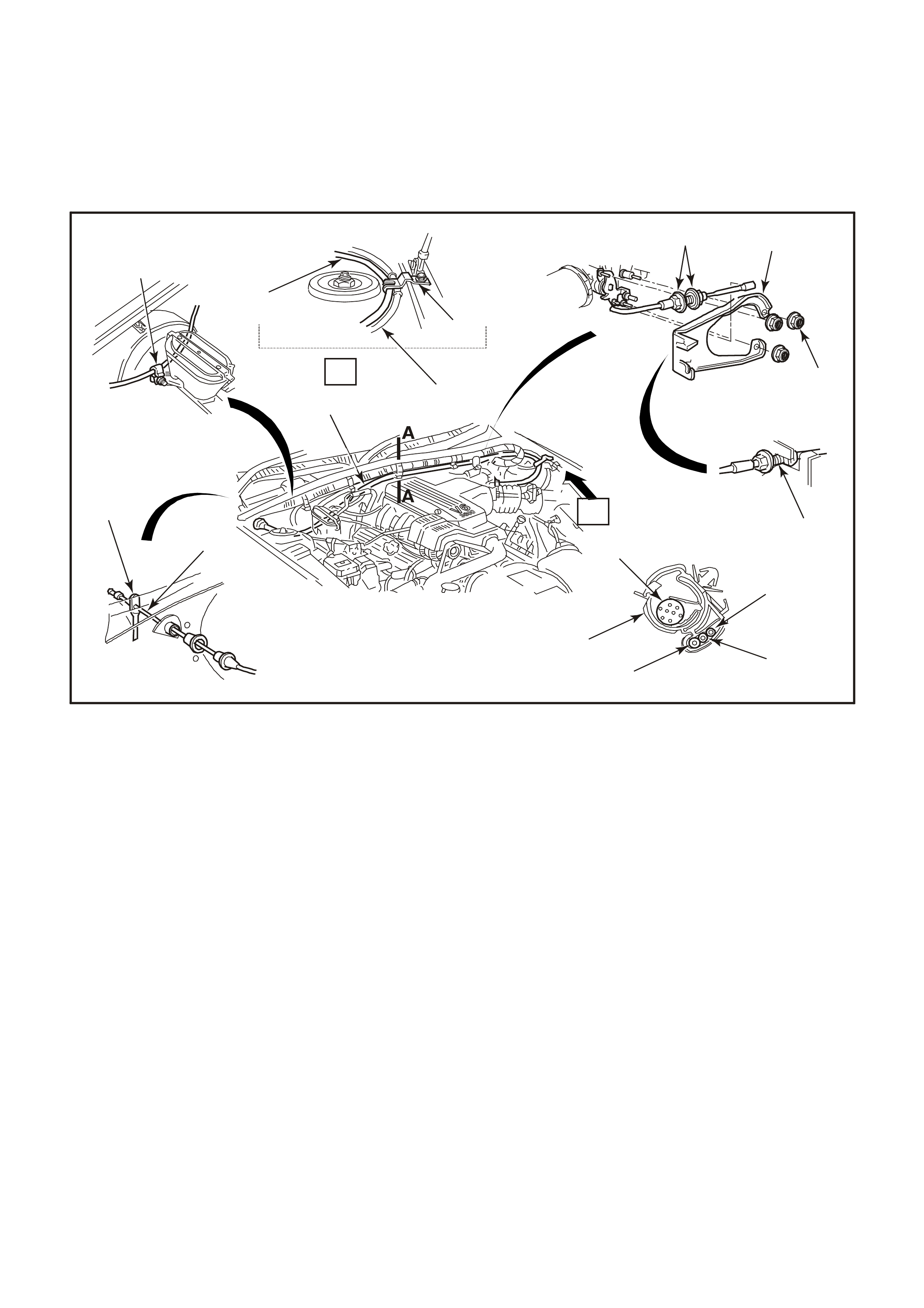
3. Check fuel system for leaks, particularly at points marked in figure 6C1-3-43.
Figure 6C1-3-43 Leak Testing V6 Engine
1. V6 Supercharged Engine.
2. Fuel Pump.
3. Fuel Pump Harness Connector.
4. V6 Non-Supercharged Engine.
5. Fuel Tank.
6. Vent Tube
7. Vapour Tube.
8. Fuel Filter.
1
4
8
7
3
4229
2
6
5
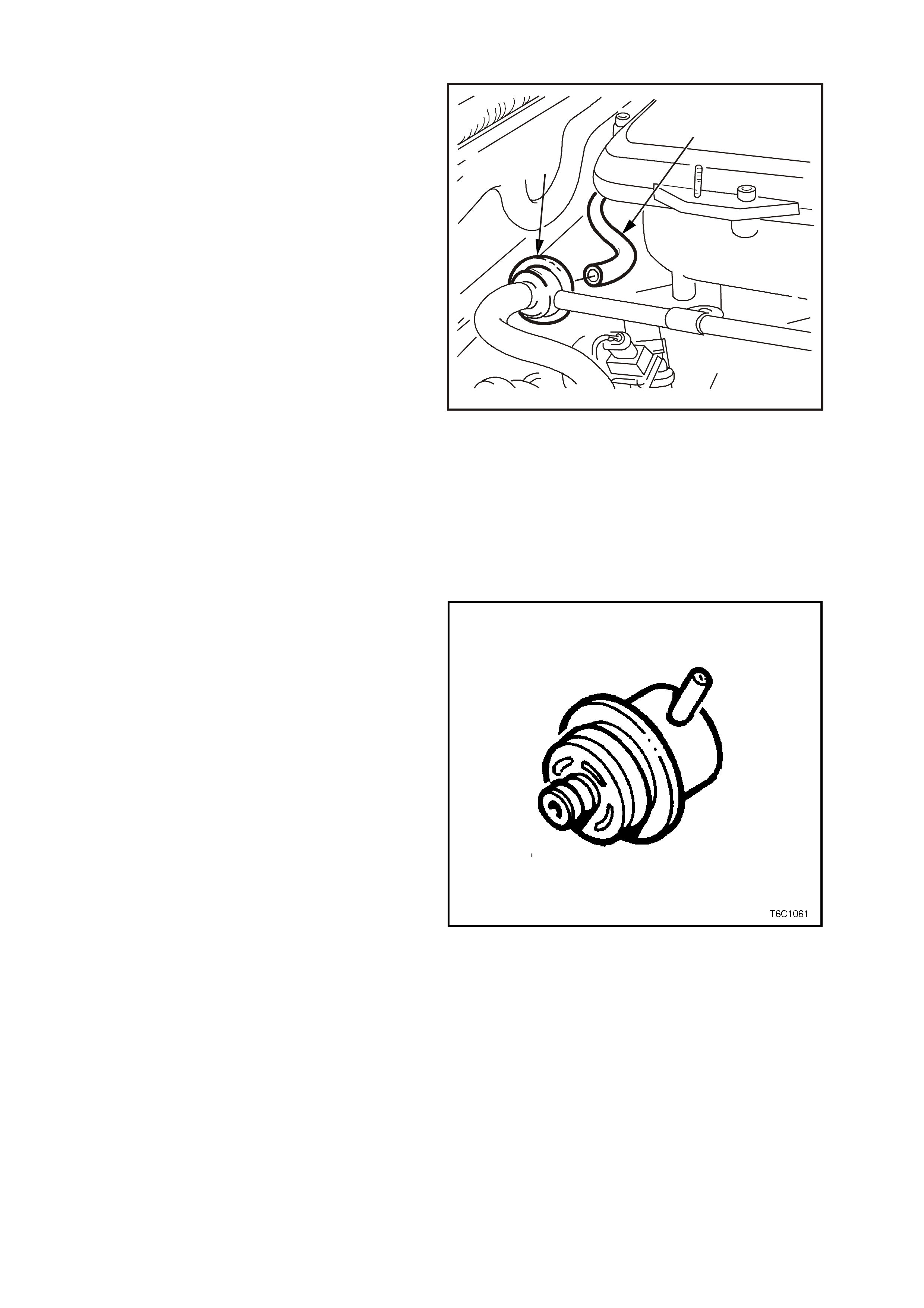
FUEL PRESSURE REGULATOR
REMOVE
1. Relieve fuel pressure as described in
3.10, FUEL CONTROL SYSTEM – (FUEL
PRESSURE RELIEF PROCEDURE) in this
Section.
2. Disconnect battery earth lead.
3. Remove four dome nuts securing the engine
dress cover assembly to the inlet manifold
studs, lift off and remove cover assembly.
Refer to Figure 6C1-3-10.
4. Remove fuel rail assembly, refer to
3.10, FUEL CONTROL SYSYTEM - FUEL
RAIL AND INJECTORS, in this Section.
5. Disconnect vacuum hose (1) from fuel
pressure regulator (2).
6. Clean any dirt from the fuel pressure regulator
retaining ring.
7. Using snap ring tool, remove snap ring from
fuel pressure regulator.
8. Us ing a shop towel to catch any spilled fuel, lift
and twist the fuel pr essure regulator in or der to
remove the fuel pressure regulator from the
fuel pressure regulator housing.
9. Cover the fuel pressure regulator housing to
prevent contamination from entering the fuel
system.
1
2
4237
Figure 6C1-3-44 V6 Engine Fuel Pressure
Regulator Location
REINSTALL
1. Install new O-rings on the fuel pressure
regulator, if a new fuel press ure regulator is not
being installed. lubricate the O-rings lightly
with clean engine oil.
2. Install the fuel pressure regulator in the fuel
pressure regulator housing.
3. Install the retaining snap ring to the fuel
pressure regulator using the snap ring tool.
4. Install the fuel rail. refer to
3.10, FUEL CONTROL SYSTEM - FUEL
RAIL AND INJECTORS, in this Section.
5. Install the vacuum hose to the fuel pressure
regulator.
7. Reconnect battery earth lead.
Figure 6C1-3-45 Fuel Pressure Regulator
8. Check for fuel leaks as described in
3.10, FUEL CONTROL SYSTEM - LEAK
TESTING in this Section.
9. Reinstall engine dress cover to the inlet
manif old, ensuring that s tud gromm ets in dr ess
cover remain in place. Tighten securing dome
nuts to the correct torque specification.
IMPORTANT:
• Compressed air must never be used to test or
clean a fuel pressure regulator, as damage to
the fuel pressure regulator may result.
• In order to prevent damage to the fuel pressure
regulator, do not immerse in solvent.
Figure 6C1-3-46 V6 Engine Fuel Pressure Regulator
Removal From Fuel Rail
FUEL RAIL
IMPORTANT:
The fuel inlet hose and return hose is an assem bly
with the fuel rail. Both components are NOT
serviced separately. For removal or replacement
of the fuel inlet hose, Refer to
3.10, FUEL CONTROL SYSTEM - FUEL RAIL
AND INJECTORS, in this Section.
1
2
3
4317
4
Figure 6C1-3-47 V6 Engine
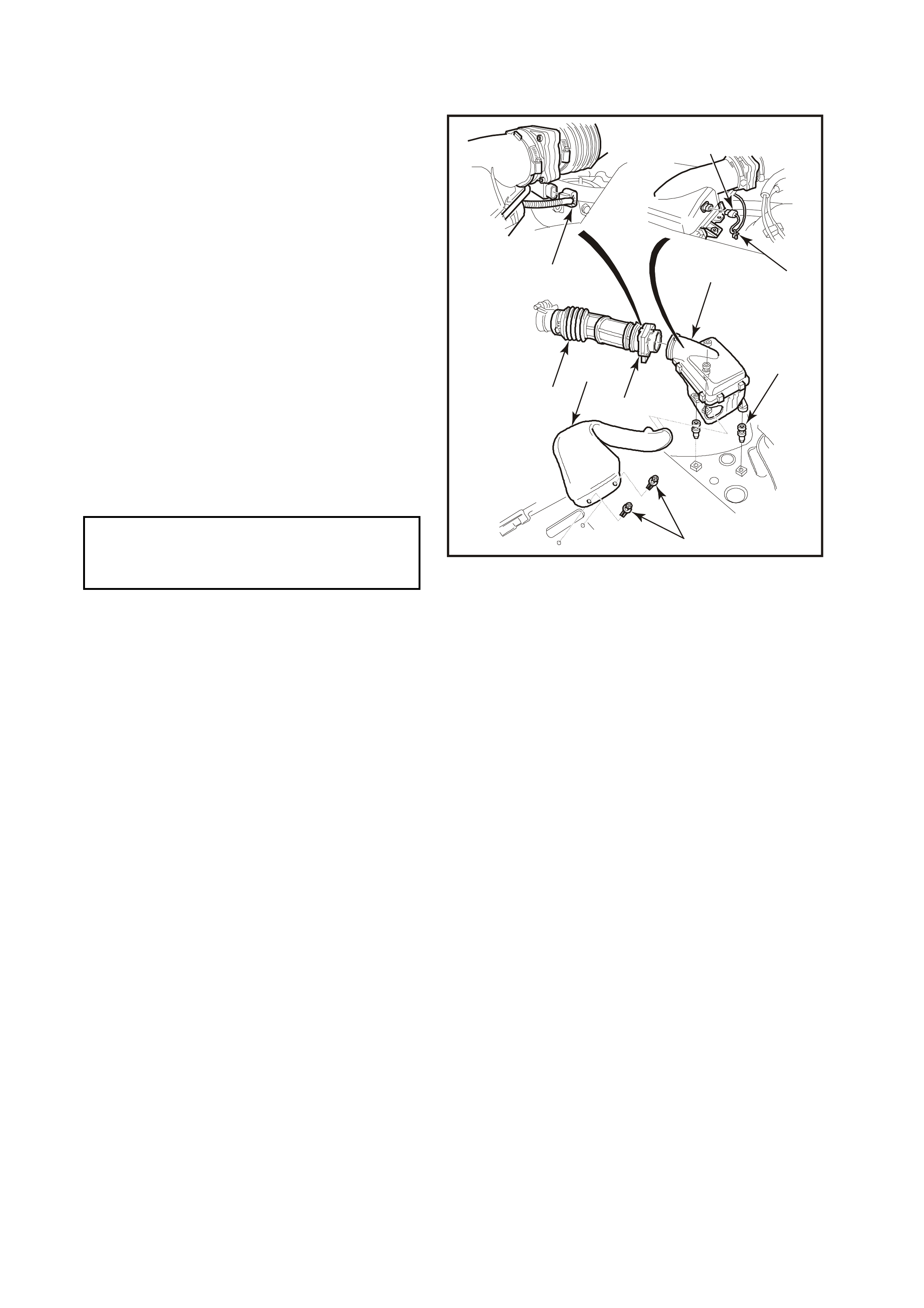
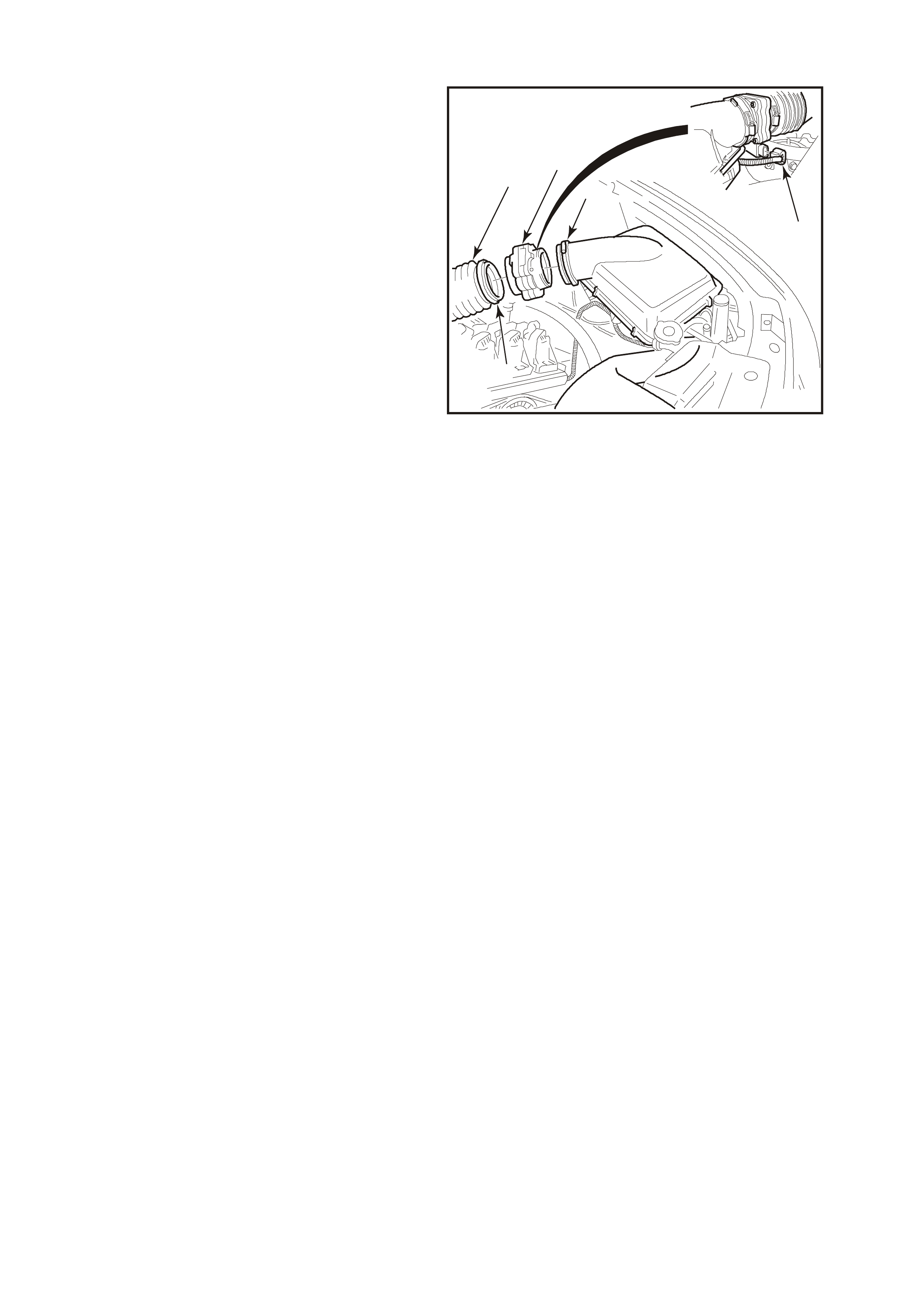
AIR CLEANER ASSEMBLY
REMOVE
1. Loosen air duct adapter located closest to air
cleaner assembly.
2. Disconnect air duct (8) from air cleaner
assembly.
3. Pull up retaining tang on IAT sensor wiring
harness connector and pull connector from
sensor (1).
4. Unclip 5 clips holding the air cleaner upper
housing in place (3).
5. Remove air cleaner upper housing and air
cleaner element assembly.
6. Remove three studs (4) securing air cleaner
lower housing to fender inner panel insulators.
7. Disengage air cleaner lower inlet assembly (7)
from lower housing. Remove air cleaner lower
housing.
REINSTALL
1. Assemble air cleaner lower housing on to
mounting insulators.
2. Install securing studs (4) and tighten to the
correct torque specification.
5
4318
86
32
1
9
4
7
Figure 6C1-3-48 Air Cleaner Housing Removal
3. Assemble the air cleaner element into the air
cleaner upper housing and place the upper
housing onto the air cleaner lower air cleaner
housing, ensuring that air filter element
remains in position.
4. Snap 5 retainer clips up into place over the top
of the air cleaner upper housing (3).
5. Reconnect wiring harness connector to IAT
sensor (1).
6. Carefully assemble air duct adapter onto air
cleaner upper housing (8).
IMPORTANT:
Align notch on air cleaner housing adapter with
notch in air duct adapter and notch in clamp.
7. Tighten air duct clamp securely.
8. Check that mass air f low sens or wiring harnes s
connector (9) has remained firmly in place.
9. Reconnect battery earth lead.
THROTTLE CABLE
REMOVE
1. Remove four dome nuts securing the engine dress cover assembly to the inlet manifold studs, lift off and
remove the cover assembly.
2. Loosen outer cable lock nuts at throttle body mounting bracket.
NOTE:
Do not detach adjusting nuts from cable.
3. Remove inner cable from throttle body linkage.
4. Disconnect outer cable from mounting bracket.
5. Remove instrument panel lower right side trim assembly retainers and lower trim, Refer to
Section 1A3, INSTRUMENT PANEL, in the VT Series I Service Information.
6. Disconnect inner cable plastic spacer from throttle pedal lever.
7. Withdraw cable assembly from engine compartment.
Air Cleaner Lower
Housing Securing Nut 5 - 7 N.m
Torque Specification
REINSTALL
1. Assemble outer cable into dash panel.
2. Attach inner cable to throttle pedal lever.
3. Install outer cable to mounting bracket.
4. Attach inner cable to throttle body linkage.
5. Adjust cable as in following instructions.
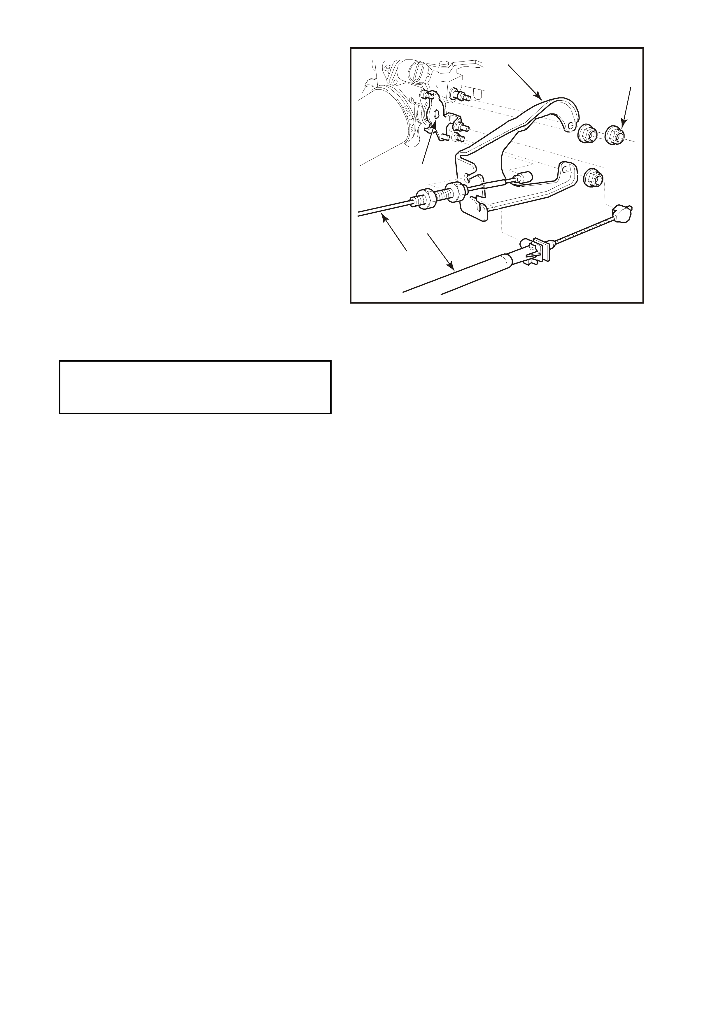
Figure 6C1-3-49 Throttle Cable V6 Engine
1. NOTE: do not detach adjusting nuts from cable. 11. Inner cable.
2. Mounting bracket. 12. Throttle pedal lever.
3. Mounting bracket nuts (3 places). 13. Throttle cable.
4. Position throttle cable in circular hole before 14. Clip.
Tightening adjustment nuts. 15. Throttle cable.
5. Rear washer hose (wagon). 16. Cruise control cable.
6. Cruise control cable. 17. Clip.
7. Throttle cable.
8. Wiring Harness Retention Clip
9. Powertrain Wiring Harness.
10. View A
16
17
15
14
13
12
11
10 4
3
2
1
9
8
5
76
4320
10
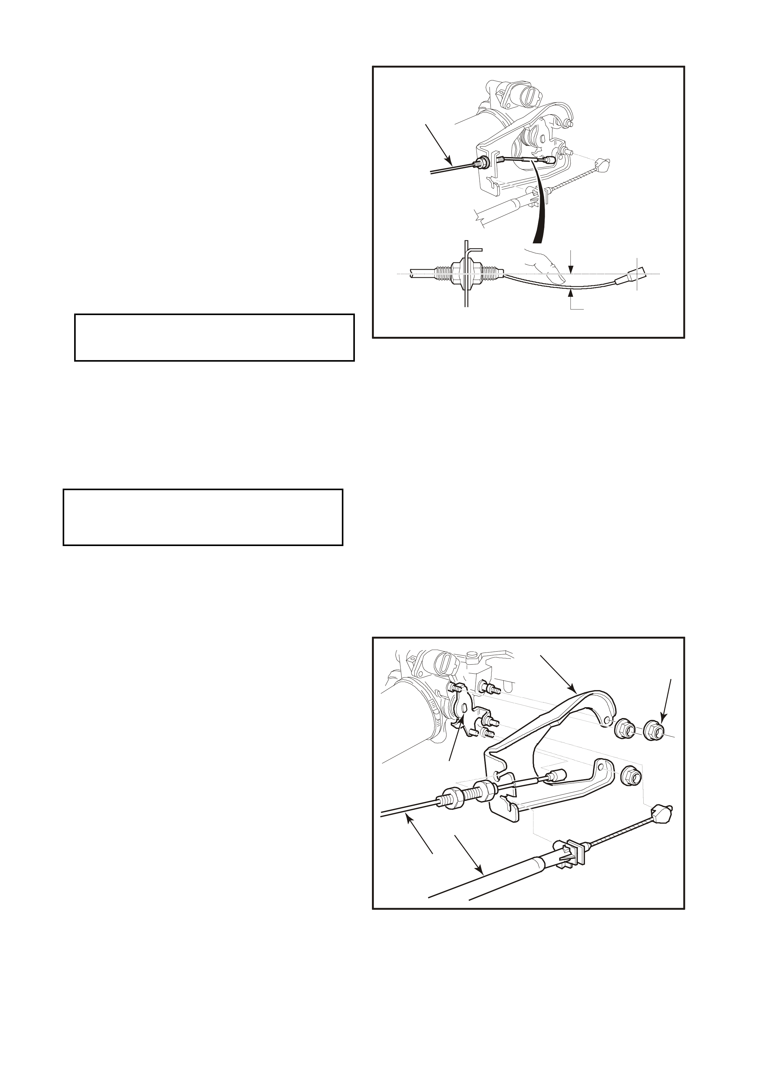
ADJUST
1. Remove instrument panel lower right side trim
(if not already removed, Refer to
Section 1A3, INSTRUMENT PANEL, of the
VT Series I Service Information.
2. Ensure throttle pedal is free to move from
closed to f ully open position. Check that throttle
pedal comes to rest at the correct closed
throttle position (against pedal stop).
3. Adjust outer cable lock nuts s o that inner cable
is tensioned with a deflection of 10 to 15 mm
(2) without moving throttle linkage from idle
stop.
4. Tighten cable lock nuts to the correct torque
specification.
5. Check for Wide Open Throttle and smooth
operation of throttle pedal.
6. Reinstall engine dress cover to the inlet
manif old, ensuring that s tud gromm ets in dress
cover remain in place. Tighten securing dome
nuts to the correct torque specification.
7. Refit instrument panel lower right side trim,
Refer to Section 1A3, INSTRUMENT PANEL
& CONSOLE, of the VT I Service Information.
1
2
4322
Figure 6C1-3-50 Throttle cable adjustment
THROTTLE BODY REMOVE
1. Disconnect battery earth lead.
2. Remove four dome nuts securing the engine
dress cover assembly to the inlet manifold
studs, lift off and remove the cover assembly.
3. Disconnect wiring harness connectors from
IAC valve and TP sensor.
4. Loosen air duct clamp at throttle body.
5. Remove air flow duct from throttle body.
6. Remove engine positive crankcase ventilation
hose from throttle body union.
7. Remove canister purge hose from throttle
body.
8. Disconnect throttle cable from throttle body
linkage (5).
9. If vehicle is fitted with cruise control, remove
cruise control cable (3) from throttle body
linkage.
10. Remove throttle cable mounting bracket
attaching nut(s) (2).
1
5
4
3
2
4325
Figure 6C1-3-51
Throttle Outer Cable Lock Nut 2 – 5
Torque Specification N.m
Engine Dress Cover Securing
Dome Nut To Inlet Manifold 2 – 4 N.m
Torque Specification
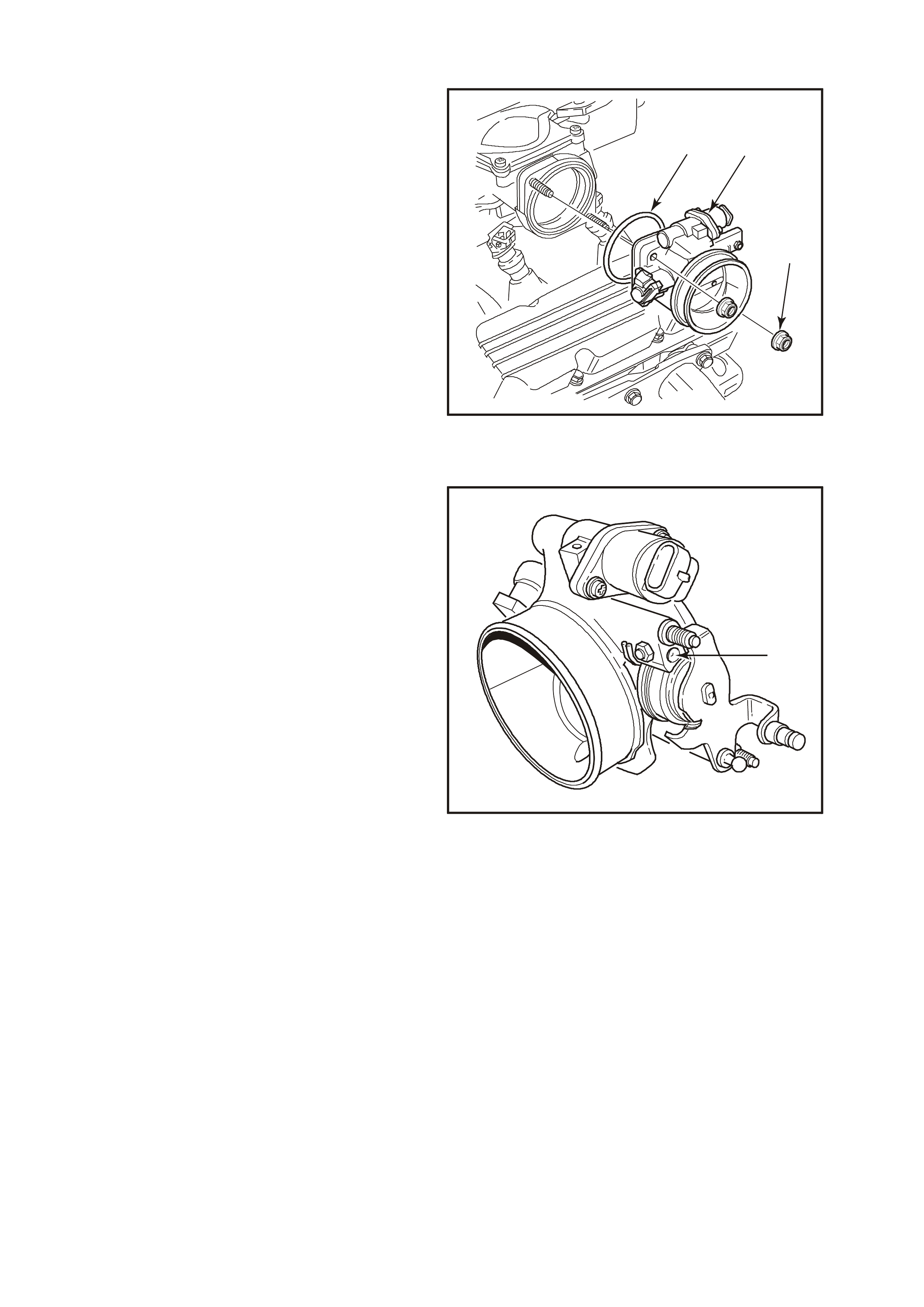
11. Remove throttle body to inlet manifold
attaching nuts (3).
12. Remove throttle body (2)and gasket (1) from
manifold.
CLEAN
Gasket surfaces on throttle body and manifold.
IMPORTANT:
If reusing the old throttle body, you must perform
the throttle body Cleaning Procedure before
reinstalling.
INSPECT
There is a specific throttle body assembly for the
V6 application only. Although the throttle body for
this application looks very similar to previous V6
application, the main distinctive difference is the
addition of a sm all air flow hole in the throttle blade
above the throttle blade shaft. Also, the Idle Air
Control (IAC) valve air passage has been
redesigned to allow more air flow. Refer to
Fig. 6C1-3-44.
12
3
4326
Figure 6C1-3-52
NOTE:
There are specific throttle body assemblies for
vehicles with automatic and manual transmissions.
If replacing a throttle body, ensure that the correct
type is fitted. Identification is by a drill point
marking on the throttle body used for vehicles with
manual transmission.
1
4233
Figure 6C1-3-53
THROTTLE BODY CLEANING PROCEDURE
1. Remove throttle body from vehicle.
2. Remove the TP sensor (4) and IAC valve (2)
from the throttle body.
3. Using an approved injector cleaner, clean the
carbon build up around the pintle of the IAC
valve(2).
4. On the throttle body, clean the carbon build up
around the IAC air port, throttle body bore and
Throttle Blade.
5. Reinstall TP sensor to throttle body.
6. Reinstall IAC valve to throttle body.
Continue with the reinstallation of the throttle body
to the engine.
2
1
43
4348
Figure 6C1-3-54 Throttle Body Identification and Cleaning
THROTTLE BODY REINSTALL
1. Install throttle body gasket (1) and throttle body
(2) to inlet manifold.
2. Install throttle body attaching nuts (3) and
tighten to the correct torque specification.
3. Reinstall canister purge control hose to throttle
body.
4. Reinstall engine positive crankcase ventilation
hose to throttle body union.
5. Reinstall wiring harness connectors to IAC
valve and TP Sensor.
6. Reinstall throttle cable mounting bracket
attaching nut (2).
12
3
4326
Figure 6C1-3-55
Throttle Body Attaching Nuts 15 – 20
Torque Specification N.m
Throttle Cable Mounting
Bracket Attaching Nut 2 – 4 N.m
Torque Specification
7. Reconnect throttle cable (4) to throttle body
linkage (5).
8. If vehicle is fitted with cruise control, reinstall
cruise control cable (3) to throttle body
linkage.
9. Install air duct onto throttle body, align clamp
and air duct locating notches. Tighten air duct
clamp at throttle body securely
10. Reconnect battery earth lead.
11. Start engine then look and listen for air leaks.
12. Check throttle cable adjustment, refer
3.10, FUEL CONTROL SYSTEM – Throttle
Cable Adjust in this Section.
13. Check cruise control cable adjustment, Refer
to Section 12E, CRUISE CONTROL in VX
Service Information.
14. Reinstall engine dress cover to the inlet
manifold, ensuring that stud grommets in the
dress cover remain in place. Tighten securing
dome nuts to the correct torque specification.
1
5
4
3
2
4325
Figure 6C1-3-56
THROTTLE BODY IAC VALVE COUNT CHECKING PROCEDURE
1. Start engine and run to operation temperature
85°C.
2. Transmission in Park or Neutral.
3. Turn Off all accessories (A/C, radio etc.)
4. Install Tech 2 scan tool and display Engine
Data.
5. Confirm the IAC valve counts are at 15 counts
or less at idle.
If the counts are not at 15 or less, perform the
Throttle Stop Screw Reset Procedure if the screw
has been tam pered with. If the Throttle Stop Screw
has not been tampered with, replace the throttle
body.
Engine Dress Cover Securing
Dome Nut To Inlet Manifold 4 – 6 N.m
Torque Specification
FUEL RAIL AND INJECTORS
NOTE:
The f uel inlet and return hos e are an ass em bly with
the fuel rail. Both components are NOT serviced
separately.
REMOVE
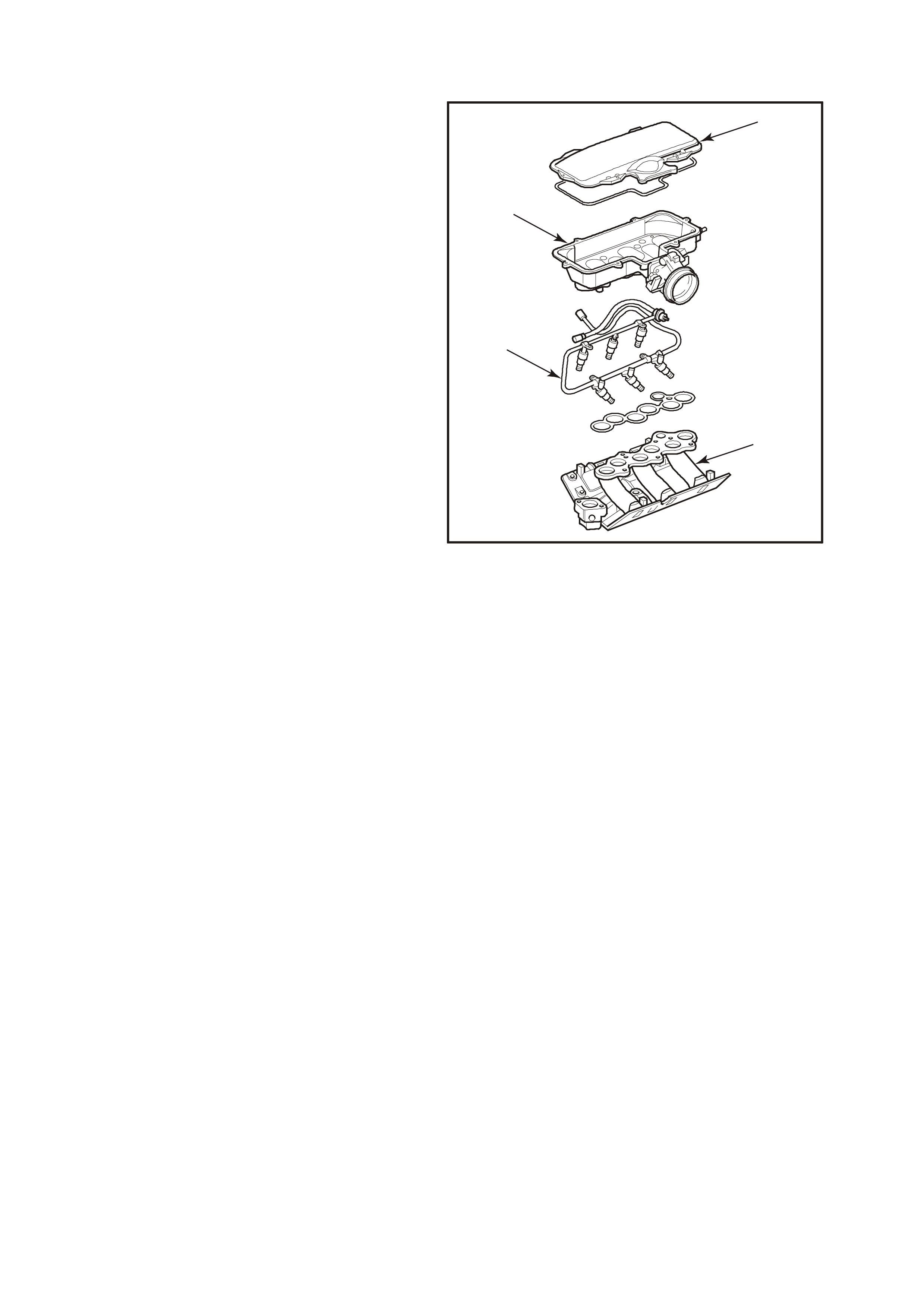
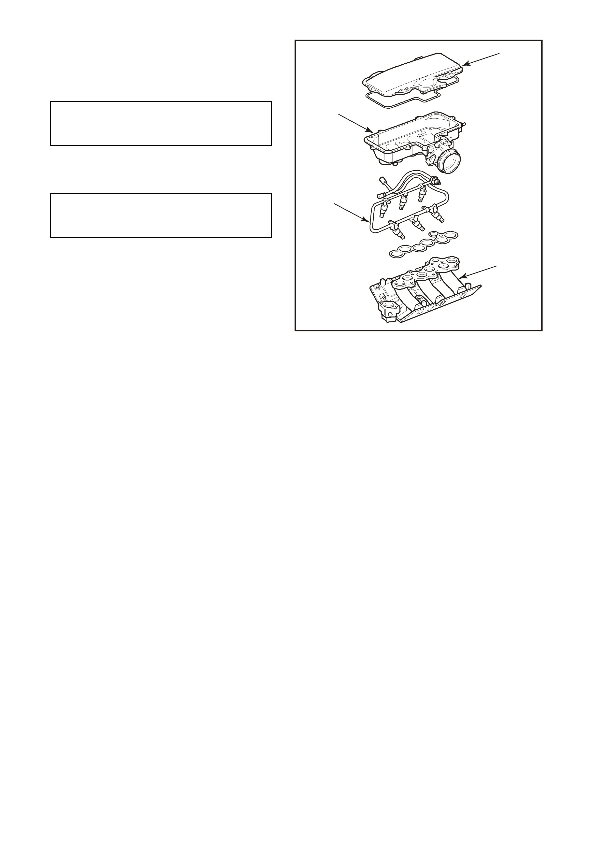
IMPORTANT:
The fuel rail and injectors are attached to the
bottom of the two-piece air inlet plenum. T he top of
the air inlet plenum (1) must be removed to gain
access to the bolts that secure the inlet plenum (4)
to the inlet manifold (2). The inlet plenum is then
removed, bringing with it the attached fuel rail and
injectors.
1. Relieve fuel pressure as described in
3.10 FUEL CONTROL SYSTEM (FUEL
PRESSURE RELIEF PROCEDURE) in this
Section.
2. Disconnect battery earth lead.
3. Remove four dome nuts securing the engine
dress cover assembly to the inlet manifold
studs, lift off and remove the cover assembly.
IMPORTANT:
Thoroughly clean around injector to inlet manifold
ports.
4. Remove the intake air duct from the throttle
body.
5. Remove the purge hose and crankcase vent
hose from the throttle body.
6. Remove the brake booster vacuum hose, and
two small vacuum hoses, from the air inlet
plenum.
7. Disconnect electrical c onnectors fr om injector s,
TP sensor, and Idle Air Control valve.
8. Remove eight hex - head bolts securing
plenum cover (1) to air inlet plenum. Lift and
remove cover.
4
1
2
4328
3
Figure 6C1-3-57
NOTE:
Plenum cover uses a soft o-ring - style gasket
between the cover and the air inlet plenum . Gask et
should remain attached in the cover.
IMPORTANT:
After r emoving plenum cover, BE VERY CAREFUL
TO NOT DROP ANYTHING INTO THE EXPOSED
INLET MANIFOLD PORTS !!
NOTE:
Anything dropped into these ports can, and most
likely will, cause serious engine damage due to
foreign objects being ingested into the engine
combustion chambers through the intake valves.
9. Remove vacuum hose from fuel pressure
regulator.
10. Using Tool No. 7370 (3), disconnect fuel inlet
hose quick connect at dash panel
connection (4).
11. Disconnect fuel pressure regulator from fuel
rail. Refer to Fuel Pressure Regulator in this
Section.
12. Using T ool No. 7370 (3), disconnect f uel return
hose quick connect at dash panel
connection (4).
13. Fully loosen (but do not remove) five bolts
securing inlet plenum to inlet manifold.
14. Carefully lift air plenum (and attached fuel rail
with injectors) from inlet manifold. Carefully
rotate the front of the inlet plenum up and
towards the windscreen. Gently lower the
plenum assembly to rest on the inlet manifold,
with the fuel rail and injectors facing forward
and tilted slightly up.
IMPORTANT:
Place a clean piece of cardboard between the inlet
manifold and plenum assembly, to prevent foreign
objects from entering inlet manifold ports.
1
2
3
4317
4
Figure 6C1-3-58
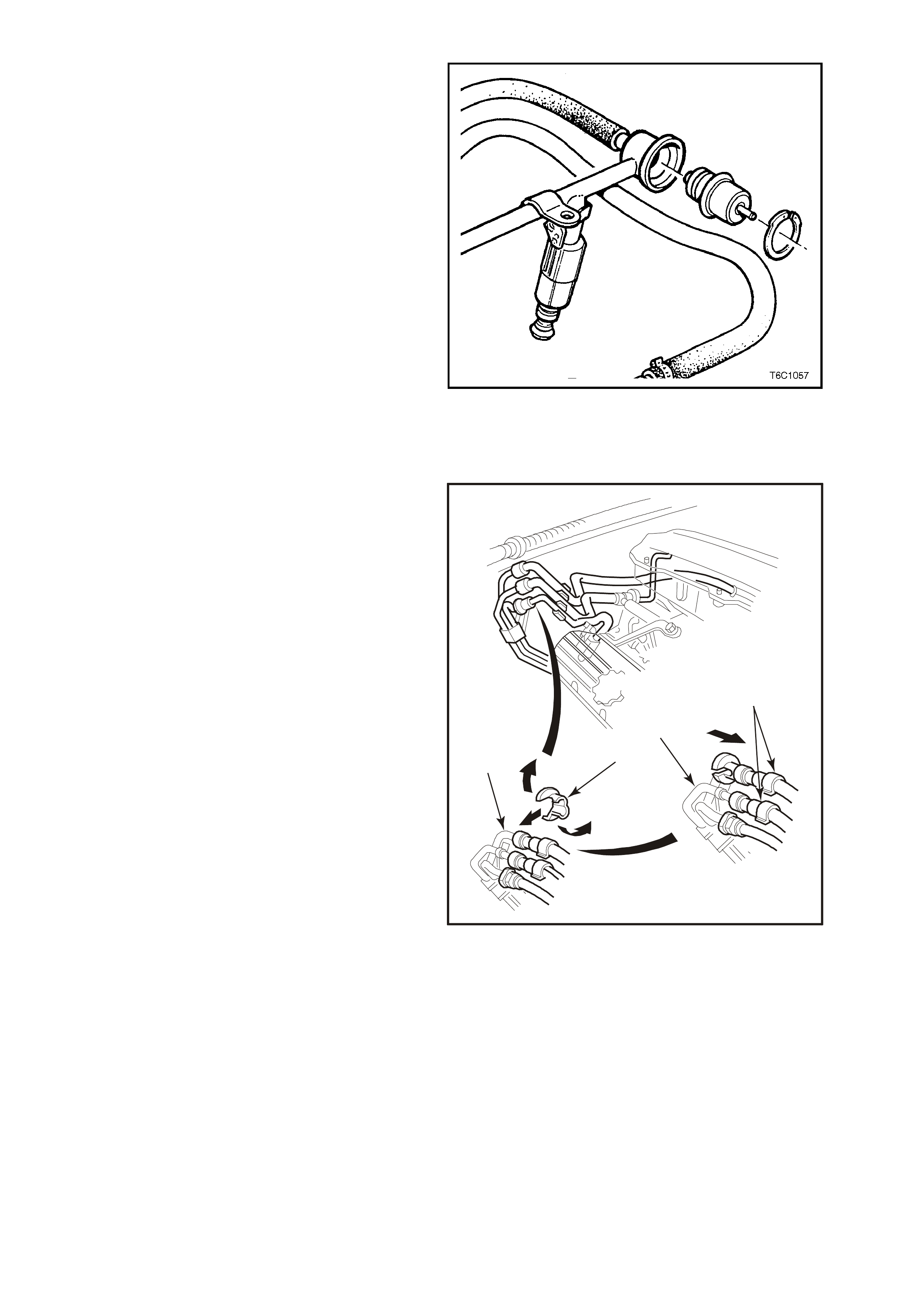
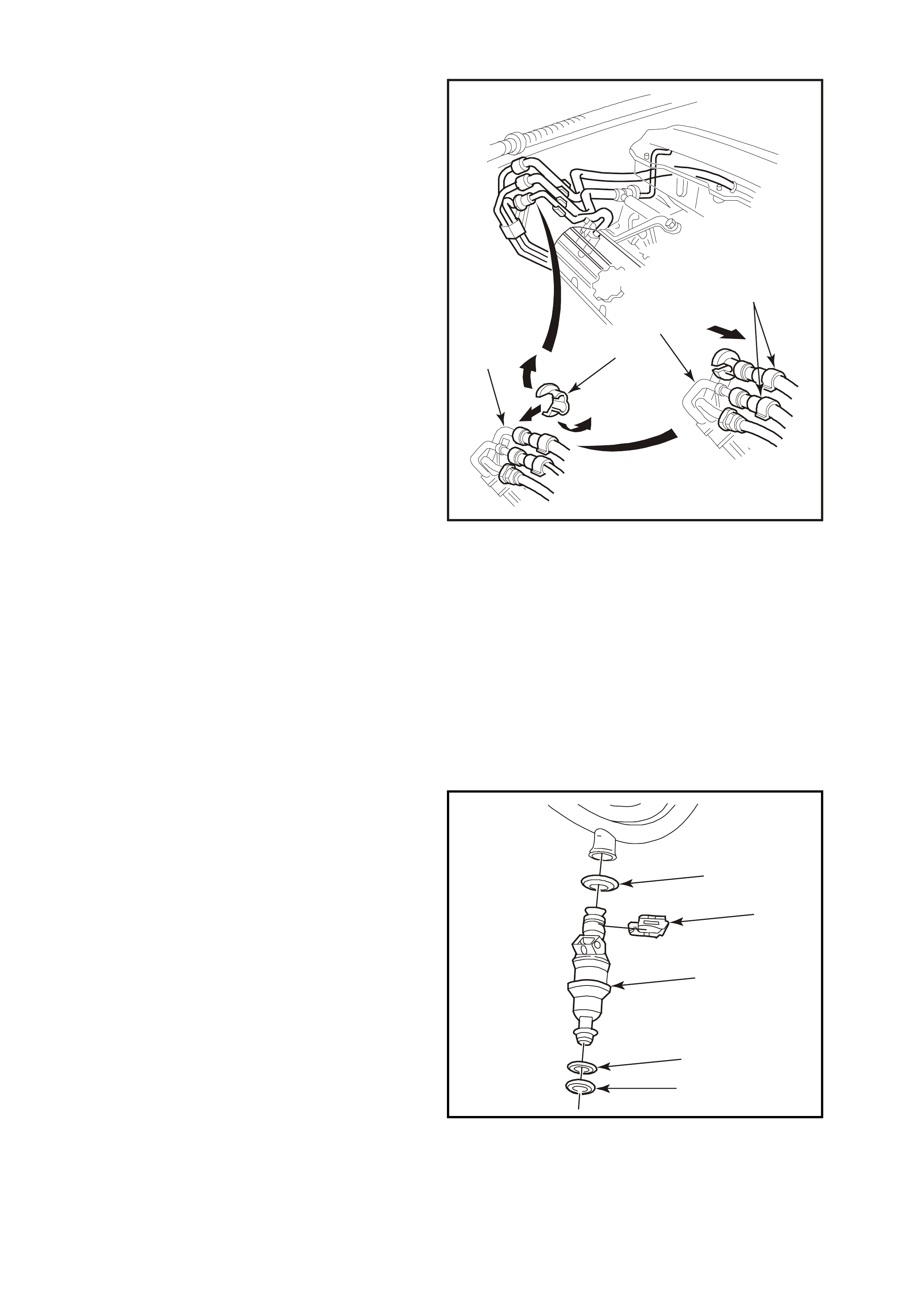
15. Remove injector retaining clips (2). Withdraw
injectors (3) from fuel rail. Remove fuel rail
from air inlet plenum ONLY if replacement of
fuel rail is needed.
IMPORTANT:
When servicing the fuel rail assembly, precautions
must be taken to prevent dirt and other
contaminants from entering the fuel passages. It is
recommended that fittings be capped, and holes
plugged, during servicing.
IMPORTANT:
Any tim e the fuel system is opened f or service, the
O-ring seals used with related component(s)
should be replaced, including those used between
the air inlet plenum and inlet manifold, and
between the plenum and it's cover.
REINSTALL
1. Injec tors using new O-r ings (1&5), coat O-r ings
with engine oil.
2. Injector retaining clips (2).
3
2
1
4329
4
5
Figure 6C1-3-59
3. Air inlet plenum assembly (containing fuel rail
assembly and throttle body) (4) onto intake
manifold (2), carefully placing injectors into
intake manifold ports. Tighten five bolts to the
correct torque specification.
4. Air inlet plenum cover (1) to inlet plenum.
Tighten bolts to the correct torque
specification.
5. Vacuum hoses:
- Brake booster vacuum hose to inlet plenum.
- Crankcase vent hose to throttle body.
- Purge vacuum supply hose to bottom of
throttle body.
- HVAC vacuum hose (small hose) to back of
inlet plenum.
6. Pressure regulator to fuel rail.
7. Fuel return hose to dash quick connector.
8. Fuel inlet hose to dash quick connector.
9. Electrical connectors to fuel injectors, TP
sensor, and Idle Air Control valve.
10. Reinstall engine dress cover to the inlet
manifold, ensuring that stud grommets in the
dress cover remain in place. Tighten securing
dome nuts to the correct torque specification.
11. Negative battery cable.
12. Check for fuel leaks as described in
3.10, FUEL CONTROL SYSTEM (LEAK
TESTING) in this Section.
4
1
2
4328
3
Figure 6C1-3-60
Air Inlet Plenum Assembly
To Inlet Manifold Attaching Bolt 15 N.m
Torque Specification
Air Inlet Plenum Cover To Air Inlet
Plenum Assembly Attaching Bolt 10 N.m
Torque Specification
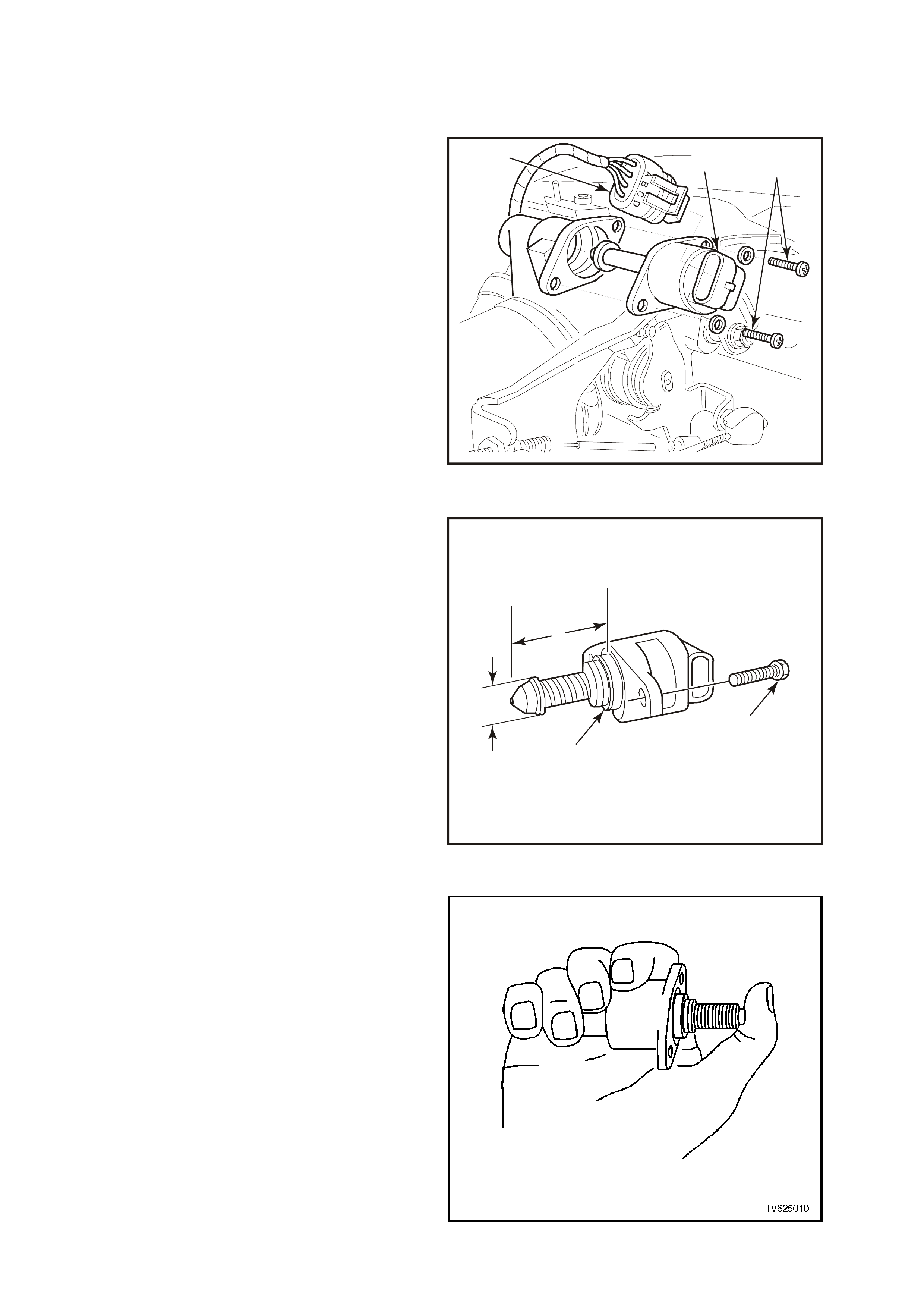
3.11 IDLE AIR CONTROL VALVE
REMOVE
1. Disconnect battery earth lead.
2. Remove four dome nuts securing the engine
dress cover assembly to the inlet manifold
studs, lift off and remove the cover assembly.
3. Lift up retaining tang on IAC valve wiring
harness connector (3) and pull connector from
valve.
4. Remove IAC valve to throttle body attaching
screws (2).
5. Remove IAC valve (1) from throttle body.
CLEAN
IAC valve sealing surfaces on throttle body, to
assure proper seal of O-ring and contact of IAC
valve flange.
IMPORTANT:
W hen installing a new IAC valve, be sure it has the
correct part number.
2
4330
1
3
Figure 6C1-3-61 IAC Valve Removal
IMPORTANT:
Before installing a new IAC valve, measure
distance "1" between tip of valve pintle and the
flange mounting surface. If it is greater than 28
mm, it must be reduced to prevent damage to the
valve when it is installed.
3
4312
2
1
4
Figure 6C1-3-62 IAC Measured Distance
Exert firm pressure on valve pintle to retract it. (A
slight side-to-side movement may be helpful).
Figure 6C1-3-63 IAC Retraction Method
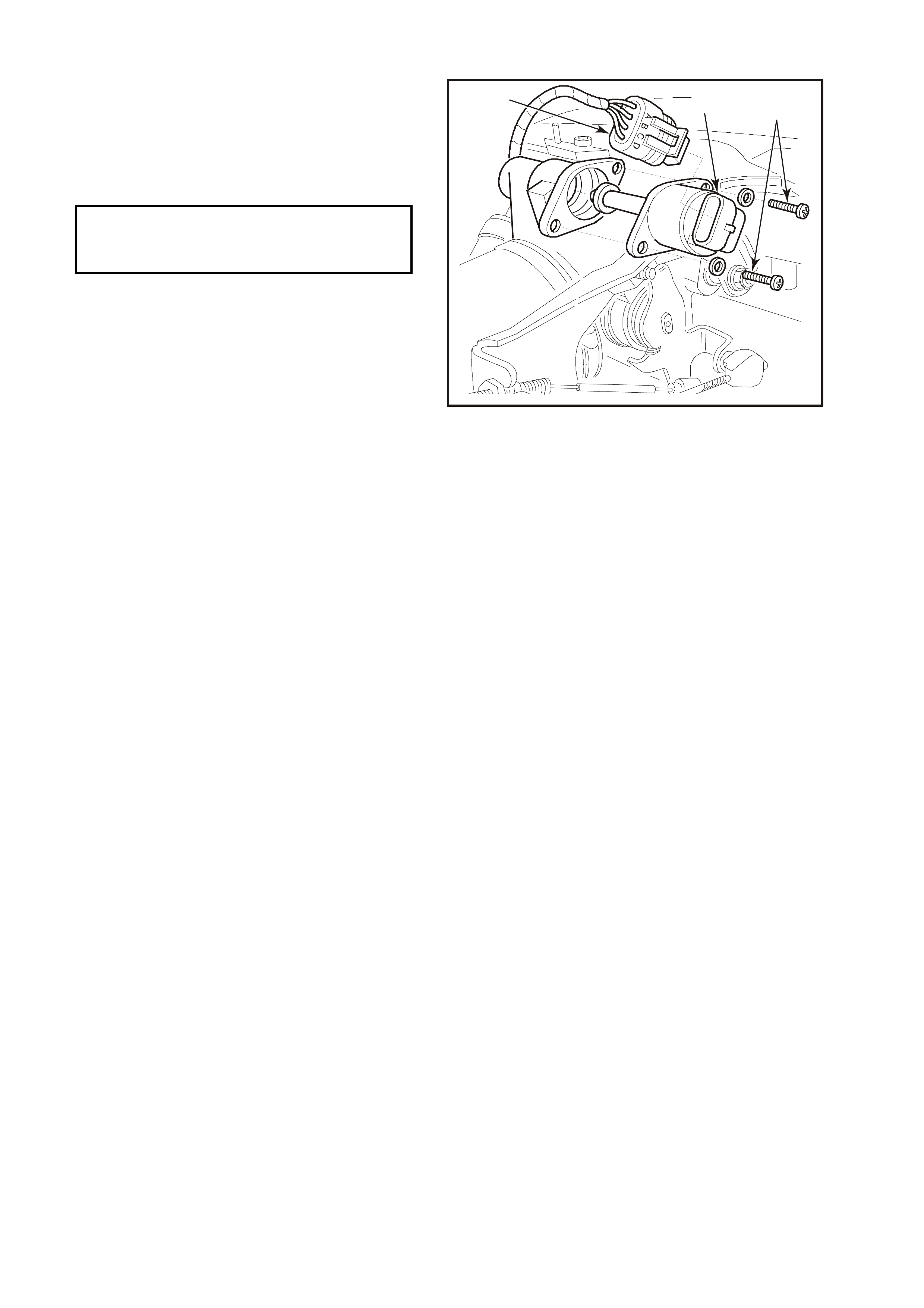
REINSTALL
1. Lubricate IAC valve O-ring with light engine oil.
If necessary, install on to valve assembly.
2. Reinstall IAC valve (1) into throttle body with
wiring harness connector (3) facing up.
3. Install IAC valve attaching screws (2) and
tighten to the correct torque specification.
4. Reconnect IAC valve wiring harness
connector (3).
5. Reconnect battery earth lead.
6. If required, clear any DTCs using scan tool.
7. Start engine, and allow engine to run for 5
seconds then turn engine "OFF" to "Reset" the
IAC valve
or
Use the Scan Tool, selec t IAC RESET to r eset
the IAC valve.
8. Reinstall engine dress cover to the inlet
manifold, ensuring that stud grommets in the
dress cover remain in place. Tighten securing
dome nuts to the correct torque specification.
2
4330
1
3
Figure 6C1-3-64
IAC Valve To Throttle
Body Attaching Screws 1-1.5 N.m
Torque Specification
3.12 DIRECT IGNITION SYSTEM (DIS)
TIMING ADJUSTMENT
The Dire ct Ignition System (DIS) system fully contr ols the spark timing. No adjustment for spar k timing is provided.
There are no timing marks on the crankshaft balancer or engine.
CHECKING EST SPARK TIMING OPERATION
The PCM will force the Electronic Spark Timing (EST) spark advance to 10 degrees BTDC when the Tech-2 is
used, and By-Pas s m ode is selected. To c heck for EST operation, run the engine with the throttle fix ed at a steady
1600-1800 RPM, then enter the "By-Pass" mode of operation with the Scan Tool. If the RPM changes (drops),
EST spark timing is operating. An EST system fault will set a DTC. Use proper DTC Table in Section 6C1-2A in VX
Service Information to correctly diagnosis the system.
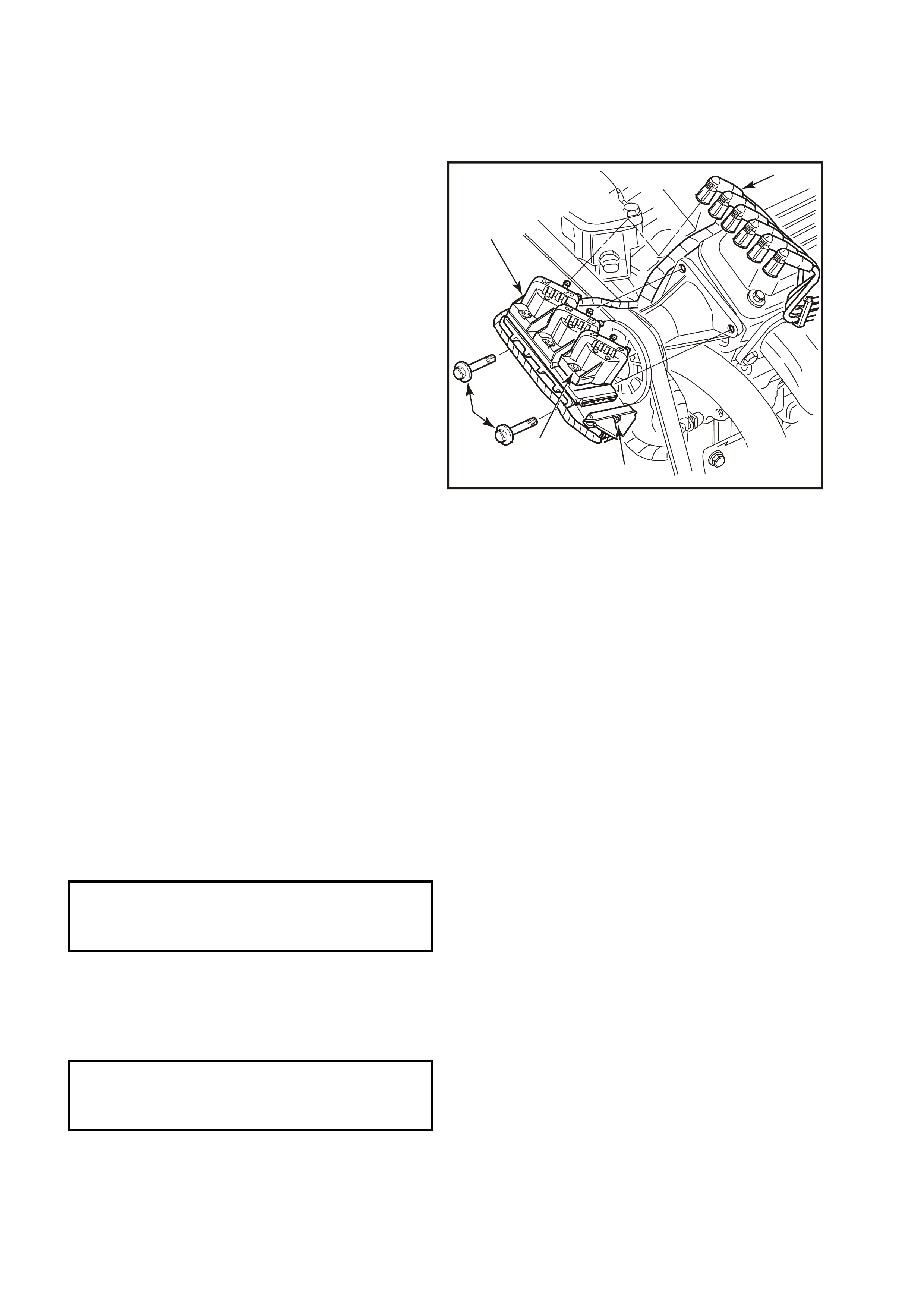
IGNITION COIL (S)
REMOVE
1. Disconnect battery earth lead.
2. Remove spark plug leads (3) from coil towers,
noting lead numbering with reference to coil
tower numbers.
IMPORTANT: 1.
Slightly twist spark plug leads before removing
from coil towers
IMPORTANT: 2.
All spark plug leads and coil terminals are
number ed to correspond to the cylinder numbering.
On service replacement coils the cylinder
numbering does not appear on top of any coil
assembly, refer to cylinder numbering on the
module.
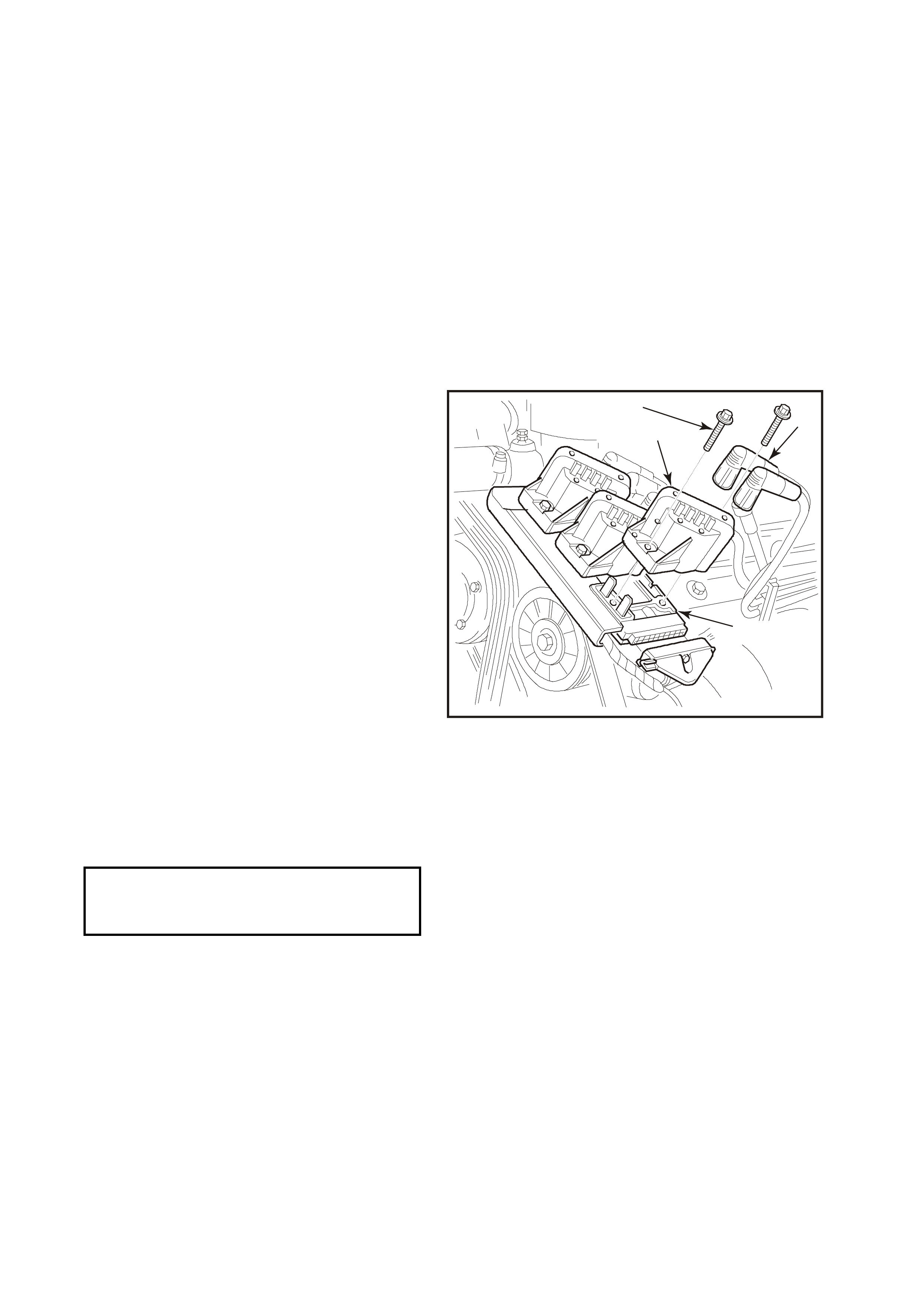
3. Remove screws (1) securing coil(s) to module
and mounting plate.
4. Pull coil(s) (2) from m odule (4), taking care not
to bend module terminals.
REINSTALL
1. Install coil(s) (2) onto module (4), aligning
module terminals with mating slots on
underside of coil.
2. Install coil securing screws (1) and tighten to
the correct torque specification.
3. Reconnect spark plug leads (3) to coil
terminals, ensuring correct lead to coil terminal
relationship.
4. Reconnect battery earth lead, start engine and
ensure engine operates correctly.
4
4331
23
1
Figure 6C1-3-65 Ignition Coils To Module
DIS Coil To Mounting
Plate Securing Screw 4 – 5 N.m
Torque Specification
DIS MODULE
REMOVE
1. Disconnect battery earth lead.
2. Remove all spark plug leads (1) from coil
towers, noting lead numbering with reference
to coil towers numbers.
3. From beneath powertrain harness retainer at
front of coil and module assembly (5), gently
pull down on the retainer lower locating tangs
and pull retainer from coil and module
assembly.
IMPORTANT: 1.
Slightly twist spark plug leads before removing
from coil towers
IMPORTANT: 2.
All spark plug leads and coil terminals are
number ed to correspond to the cylinder numbering.
On service replacement coils the cylinder
numbering does not appear on top of any coil
assembly, refer to cylinder numbering on the
module.
4. Loosen bolt (2) attaching 14-pin wiring
harness connector to module (5) until you can
pull connector from module.
5. Remove screws securing coils (3).
6. Remove coils from module, taking care not to
bend module terminals.
7. Remove ignition module assembly (5).
1
4332
5
3
2
4
Figure 6C1-3-66 Ignition Module Removed
REINSTALL
1. When replacing module assembly, remove module to coil terminal and 14 pin wiring harness connector
terminal seals from original module. Install seals onto new module, taking care not to damage seals. If any
seal(s) is damaged in any way, install new seal(s).
2. Place coils onto module, aligning module terminals with mating slots on underside of coil.
3. Reinstall ignition module assembly (5) to mounting plate, locating raised lugs (2) on both module and plate
together.
IMPORTANT:
The lugs on the underside of the module will m ate with the mounting plate holes in one way only to ensure cor rect
assembly relationship.
4. Reinstall screws (3) securing coils and module to mounting plate and tighten to the correct torque specification.
DIS Coil To Mounting
Plate Securing Screw
Torque Specification
4 - 5 N.m
5. Reconnect spark plug leads (1) to coil terminals, ensuring correct lead to coil terminal relationship.
6. Reconnect 14-pin wiring harness connector to module assembly and tighten attaching bolt (2) to the correct
torque specification.
Wiring Harness Connector To
DIS Module Attaching Bolt
Torque Specification
0.6 - 1.2 N.m
7. Snap powertrain wiring harness retainer onto coil and module assembly and it's mounting plate.
8. Reconnect battery earth lead.
9. Start engine and ensure engine operates correctly.
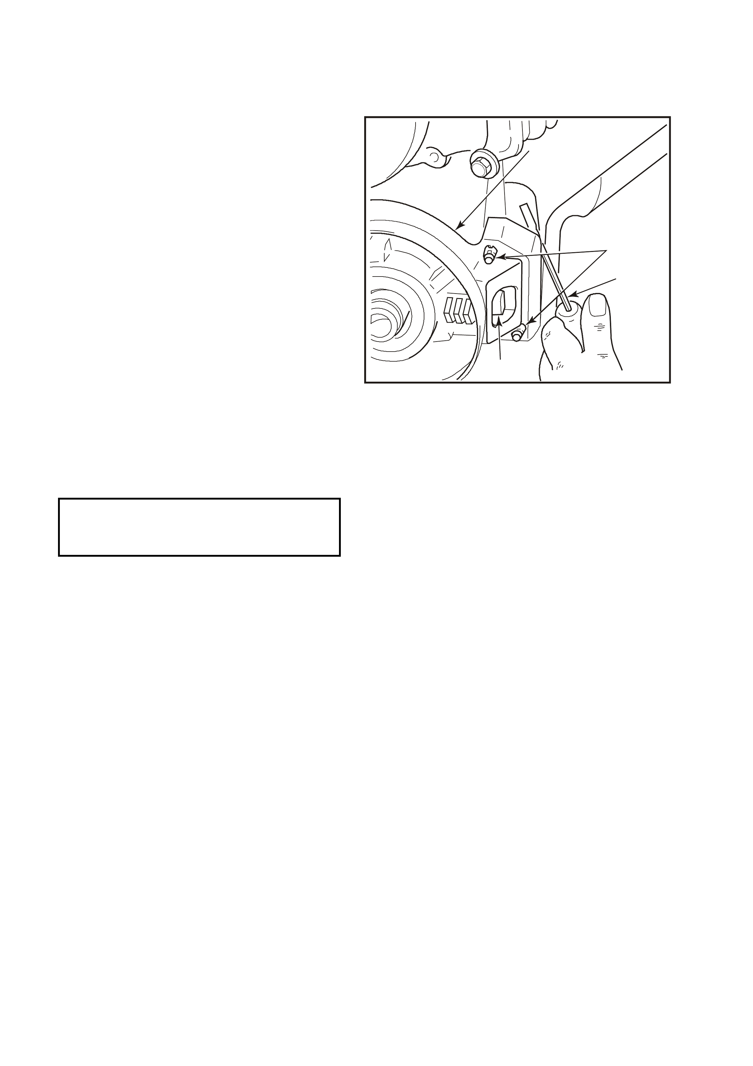
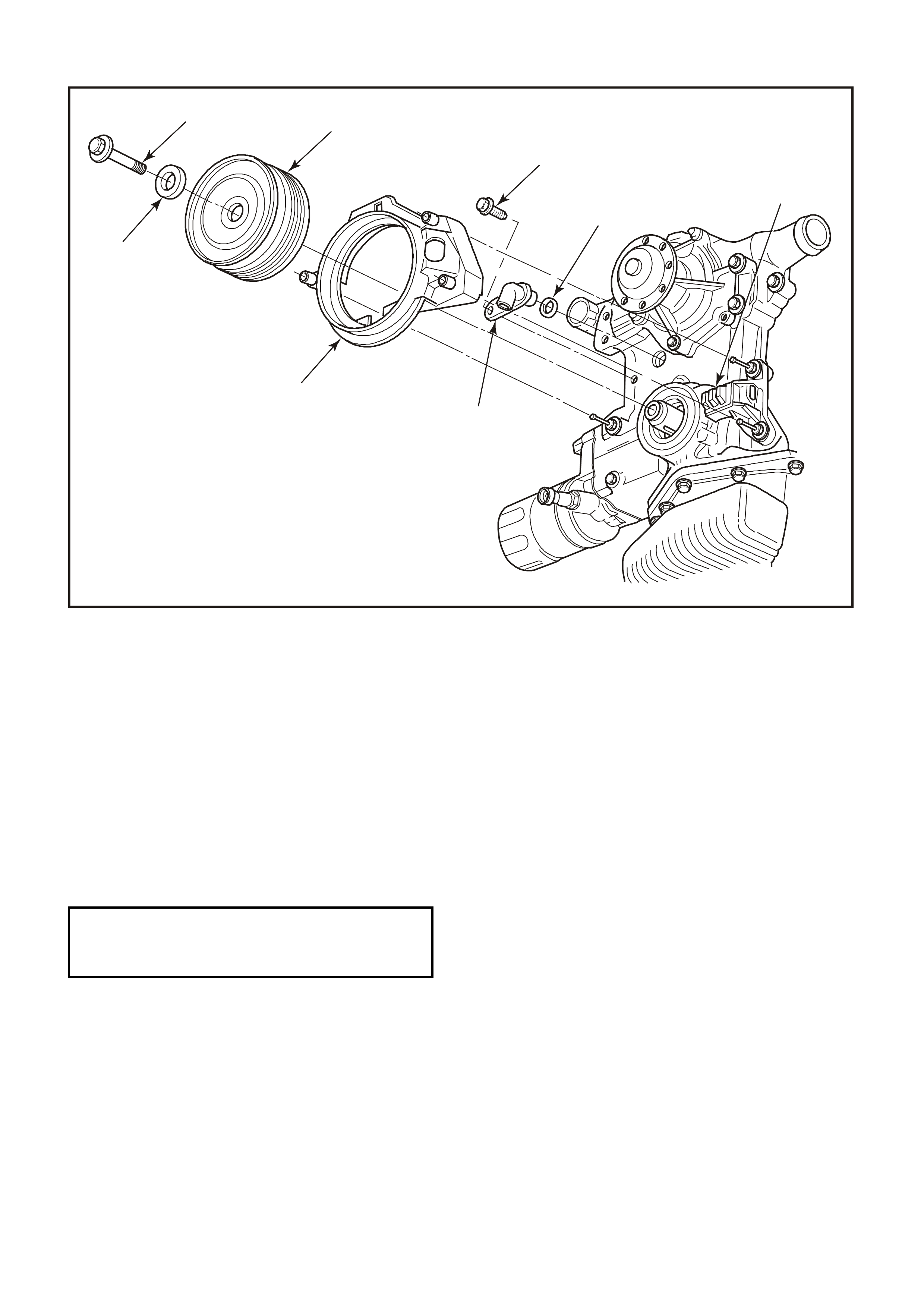
CRANKSHAFT SENSOR
REMOVE
1. Disconnect battery earth lead.
2. Using a 15 mm ring spanner on drive belt
tensioner pulley pivot bolt, rotate tensioner
pulley assembly anti-clockwise and remove
drive belt from generator drive pulley. Release
drive belt tensioner and remove drive belt.
3. Remove crankshaft balancer, Refer to
Section 6A1, ENGINE MECHANICAL - V6
ENGINE in the VT Series I Service Information.
4. Lift up retaining tang on crankshaft sensor
engine wiring harness connector and pull
connector from sensor assembly.
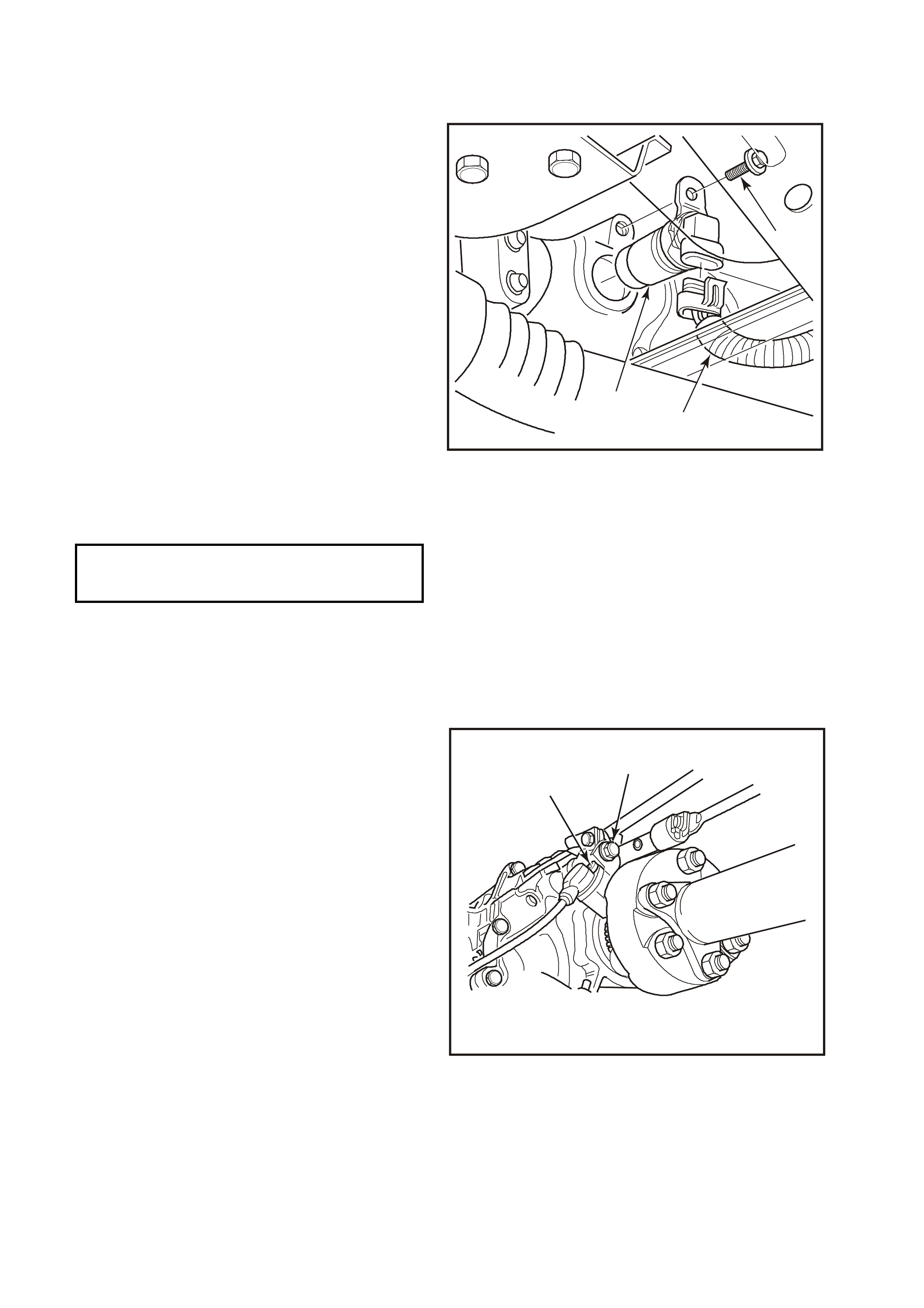
5. Using a prying device (3) behind crankshaft
position sensor shield (1), lever each corner of
the shield from front cover studs, remove
shield.
6. Remove crankshaft sensor bracket to front
cover attaching studs (2) and remove sensor
assembly (4).
REINSTALL
1. Install crankshaft sensor assembly (4) onto
front cover dowel pin.
2. Install and tighten sensor br acket to f ront cover
attaching studs (2) to the correct torque
specification.
Crankshaft Position Sensor
To Front Cover Attaching 20 - 30 N.m
Stud Torque Specification
3. Reinstall crankshaft position sensor shield (1)
onto front cover studs (2), ensuring deflector
retainers fully engage over ends of studs.
4. Reconnect wiring harness connector to
crankshaft sensor (4).
5. Reinstall crankshaft balancer, Refer to
Section 6A1, ENGINE MECHANICAL - V6
ENGINE in the VT Series I Service Information.
IMPORTANT:
Do not reinstall drive belt at this stage.
6. Rotate crankshaft so as to check that
interrupter rings do not contact sensor.
IMPORTANT:
If the interrupter rings contact the sensor at any
point during balancer rotation, the interrupter rings
have excessive runout and the balancer assembly
must be replaced.
7. Reinstall serpentine belt.
8. Reconnect battery earth lead.
9. Start engine and ensure engine operates
correctly.
3
4333
2
4
1
Figure 6C1-3-67
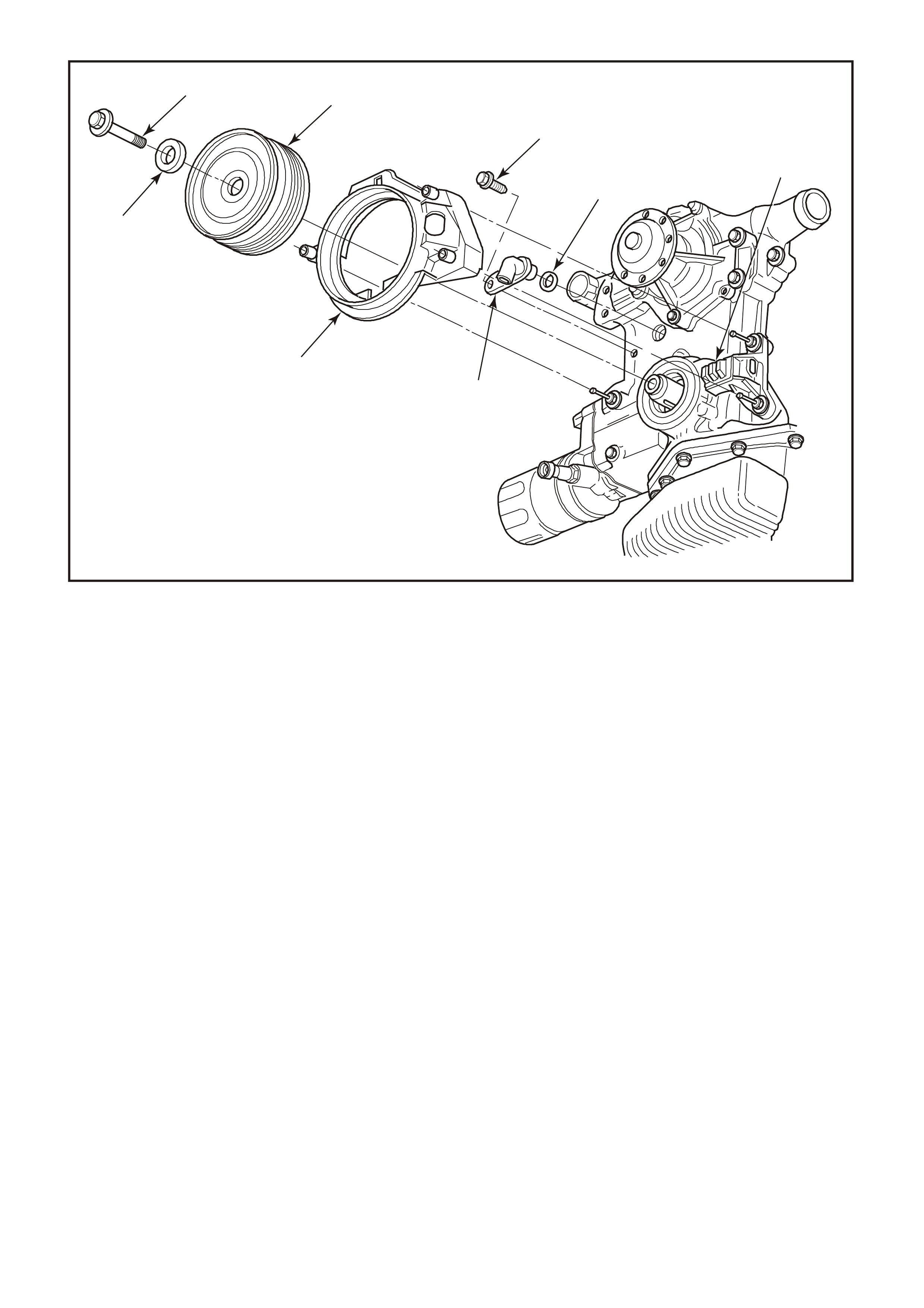
Figure 6C1-3-68 Camshaft/Crankshaft Position Sensors
1. Bolt.
2. Crankshaft Balancer.
3. Retaining Bolt.
4. O-Ring.
5. Crankshaft Position Sensor.
6. Camshaft Position Sensor.
7. Crankshaft Position Sensor Shield.
8. Washer.
2
3
4300
45
1
8
7
6
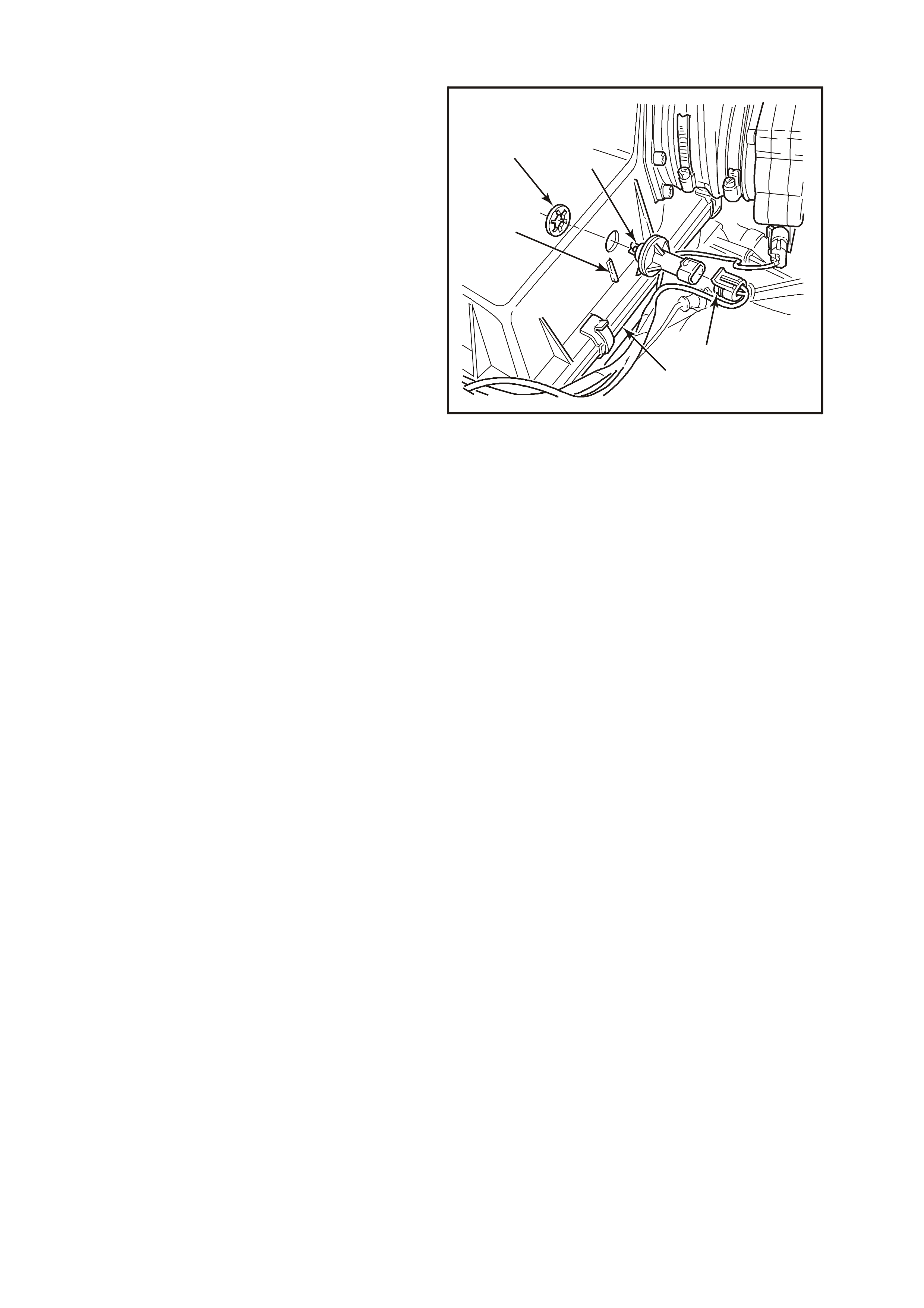
3.13 1-2 SHIFT SOLENOID
Figure 6C1-3-69 1-2 Shift Solenoid Location
REMOVE
1. Disconnect battery earth lead.
IMPORTANT:
To avoid personal injury from accidental hot oil spillage, perform fluid change only w hen transmission fluid is cold.
2. Raise vehicle and support on safety stands. Refer to Section 0A, GENERAL INFORMATION of the VT
Series I Service Information.
3. Clean all dirt from around oil pan and transmission case.
4. Place drain tray under transmission.
5. Loosen two bolts at the rear and one at the front of the oil pan. Rem ove the remaining bolts. W hile holding oil
pan, allow the front of the oil pan to drop away, emptying oil into a drain tray.
6. Remove remaining bolts, then lower pan and empty fluid from pan.
7. Remove old oil pan gasket and discard.
8. Disconnect 1-2 shift solenoid (367A) electrical connector.
9. Remove solenoid retainer (379) by using a small flat blade screwdriver. Pry the retainer down until it can be
grasped.
IMPORTANT:
Solenoid has a slight spring pressure behind it, and may pop out on its own after retainer is removed.
10. Remove solenoid assembly (367A) with O-ring seal. Ensure that 1-2 shift valve (366) remains in place.

REINSTALL
1. Push solenoid assembly (367A) into valve body.
2. Hold solenoid in place with finger pressure while installing retainer (379)
3. Reconnect 1-2 shift solenoid (367A) electrical connector.
4. Clean oil pan and case mating surfaces. Check that magnet is still magnetized, and attached to the oil pan.
5. Install new gasket and reinstall oil pan. Tighten bolts to the correct torque specification.
Transmission Oil Pan Bolt
Torque Specification 11
N.m
6. Lower vehicle and add approximately 4.8 litres of DEXRON â III automatic transmission fluid.
7. Reconnect battery earth lead.
8. Check transmission fluid level. Refer to "Fluid Checking Procedure" in Section 6C1-2A in VX Service
Information.
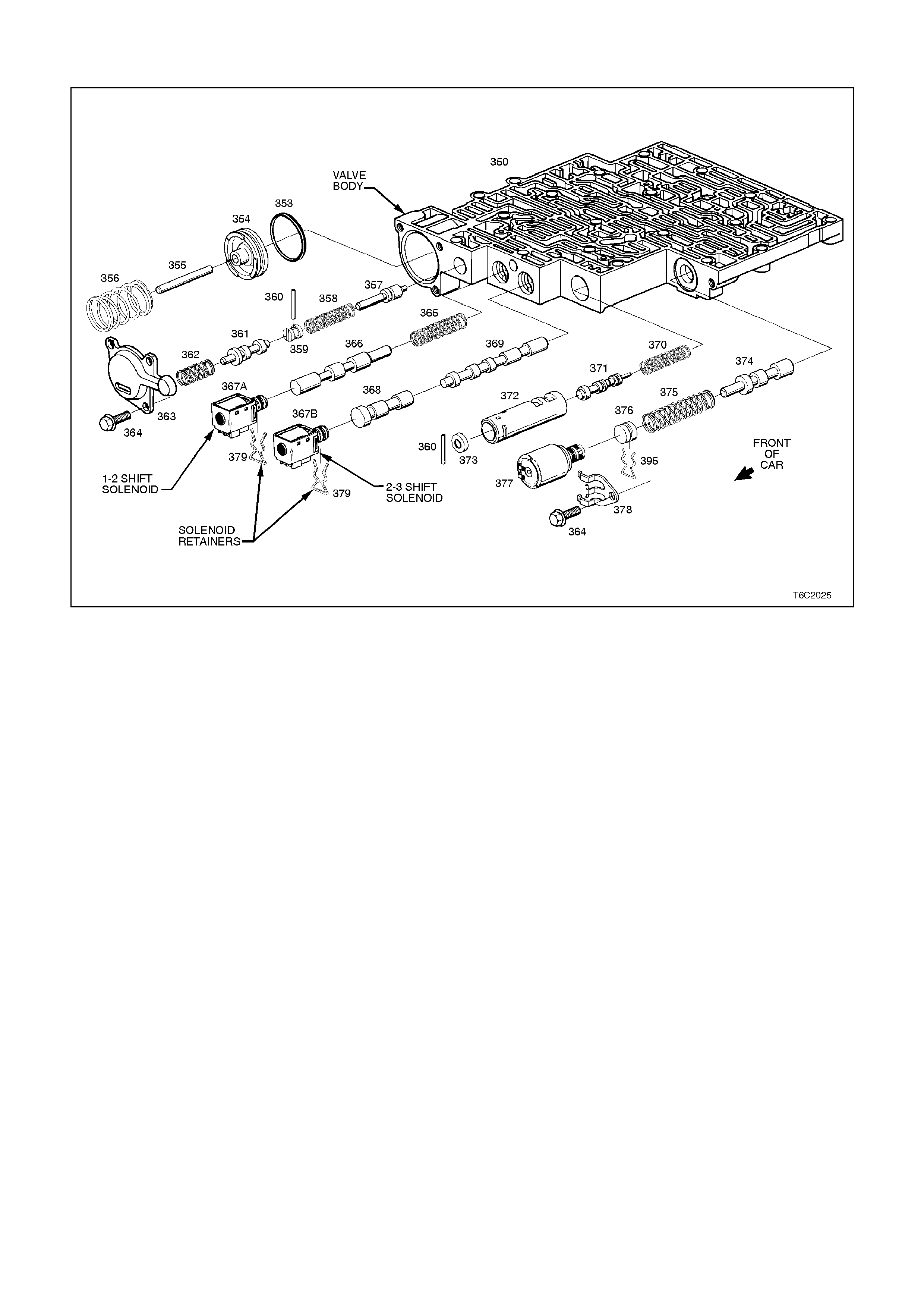
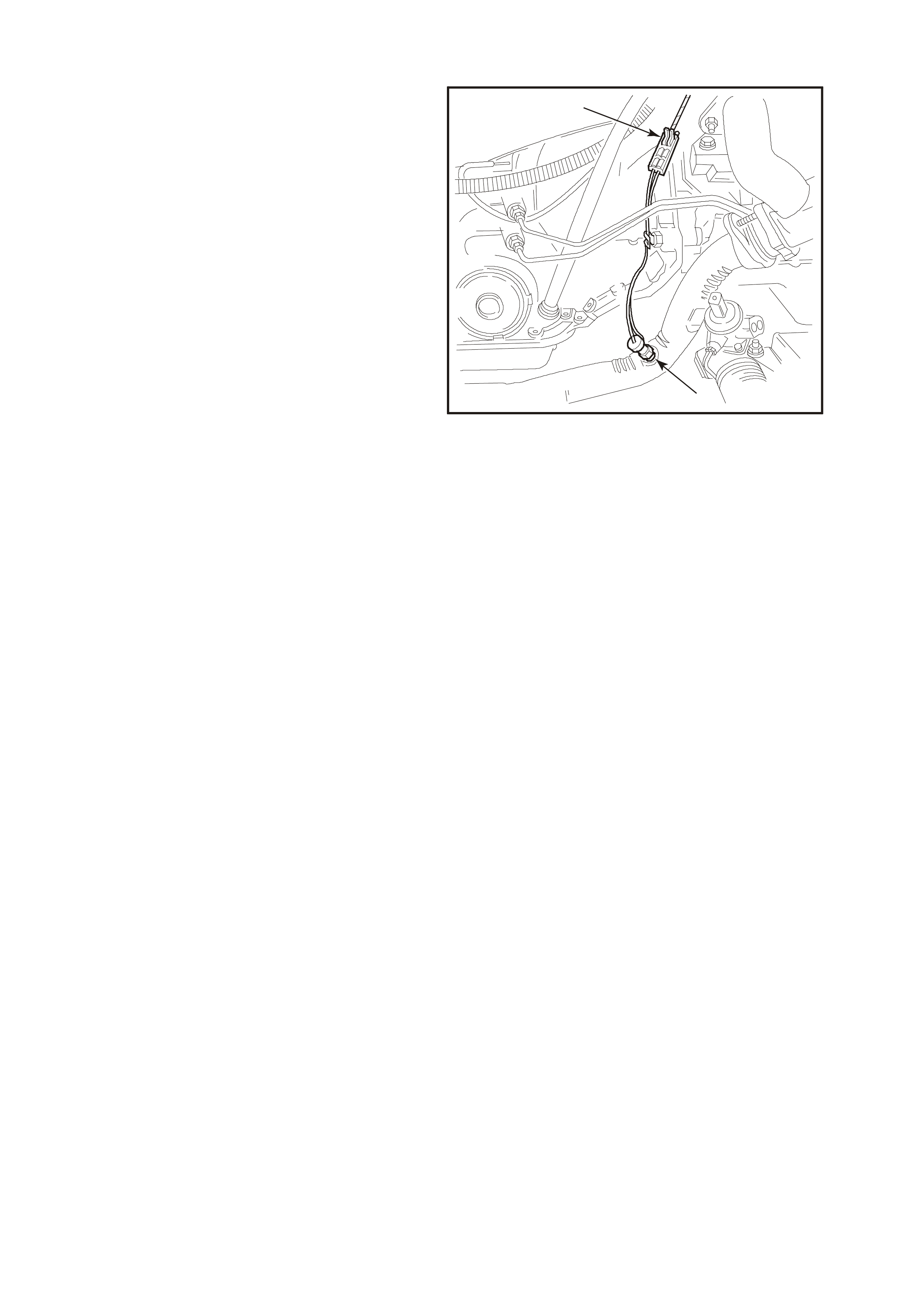
3.14 2-3 SHIFT SOLENOID
Figure 6C1-3-70 2-3 Shift Solenoid Location
REMOVE
1. Disconnect battery earth lead.
IMPORTANT:
To avoid personal injury from accidental hot oil spillage, perform fluid change only w hen transmission fluid is cold.
2. Raise vehicle and support on safety stands. Refer to Section 0A, GENERAL INFORMATION of the VT
Series I Service Information.
3. Clean all dirt from around oil pan and transmission case.
4. Place drain tray under transmission.
5. Loosen two bolts at the rear and one at the front of the oil pan. Rem ove the remaining bolts. W hile holding oil
pan , allow front of oil pan to drop away, emptying oil into a drain tray.
6. Remove remaining bolts, then lower oil pan and empty fluid from pan.
7. Remove old oil pan gasket and discard.
8. Disconnect 2-3 shift solenoid (367B) electrical connector.
9. Remove solenoid retainer (379) by using a small flat blade screwdriver. Pry the retainer down until it can be
grasped
10. Remove solenoid assembly (367B) with O-ring seal. Ensure that 2-3 shuttle valve 369 remains in place.

REINSTALL
1. Push solenoid assembly with O-ring seal (367B) into valve body
2. Install solenoid retainer (379).
3. Reconnect 2-3 shift solenoid electrical connector.
4. Clean oil pan and case mating surfaces. Check that magnet is still magnetized and attached to the oil pan.
5. Install new gasket and reinstall oil pan. Tighten bolts to the correct torque specification.
Transmission Oil Pan Bolt
Torque Specification 11
N.m
6. Lower vehicle and add approximately 4.8 litres of DEXRON â III automatic transmission fluid.
7. Reconnect battery earth lead.
8. Check transmission fluid level. Refer to "Fluid Checking Procedure" in Section 6C1-2A in VX Service
Information.
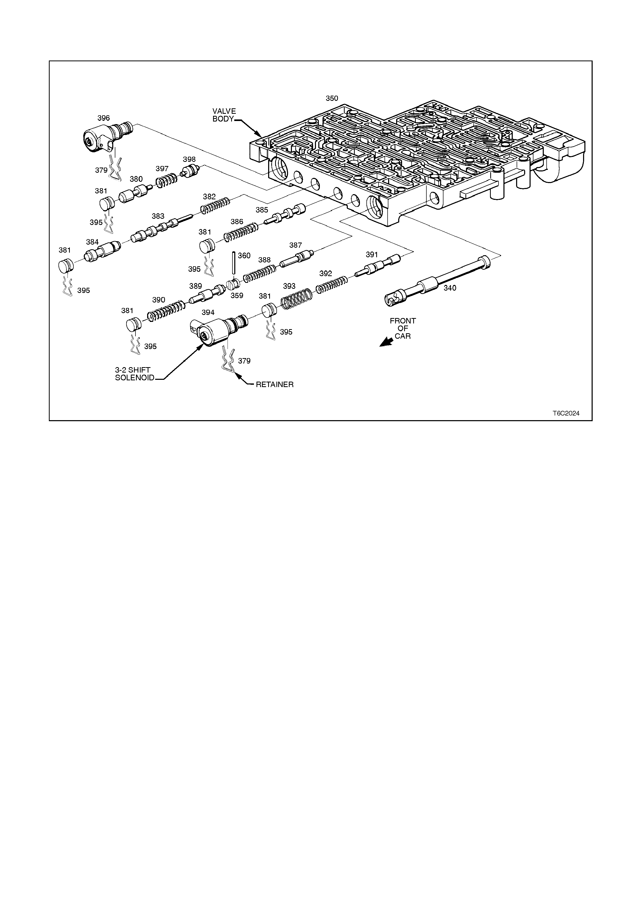
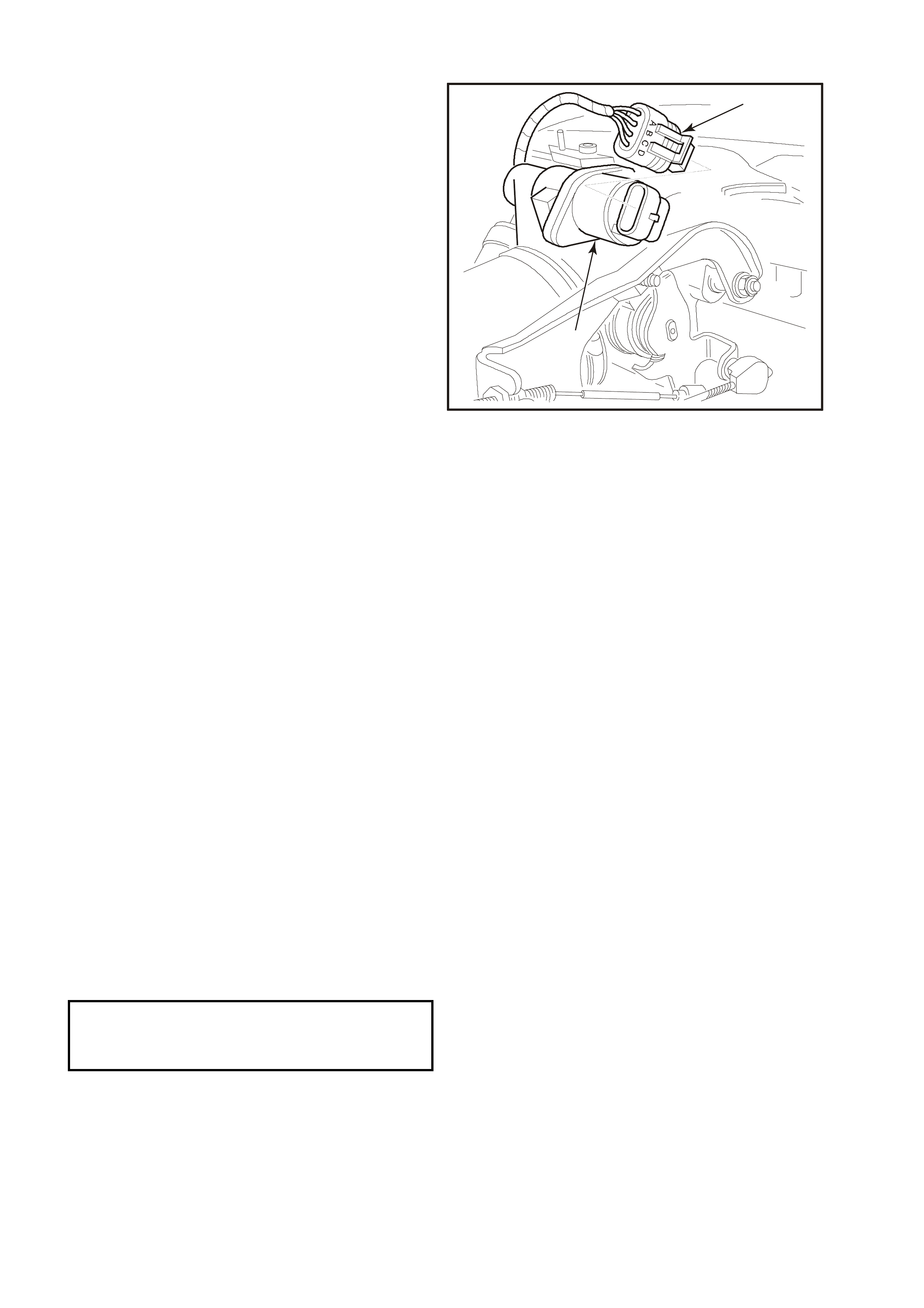
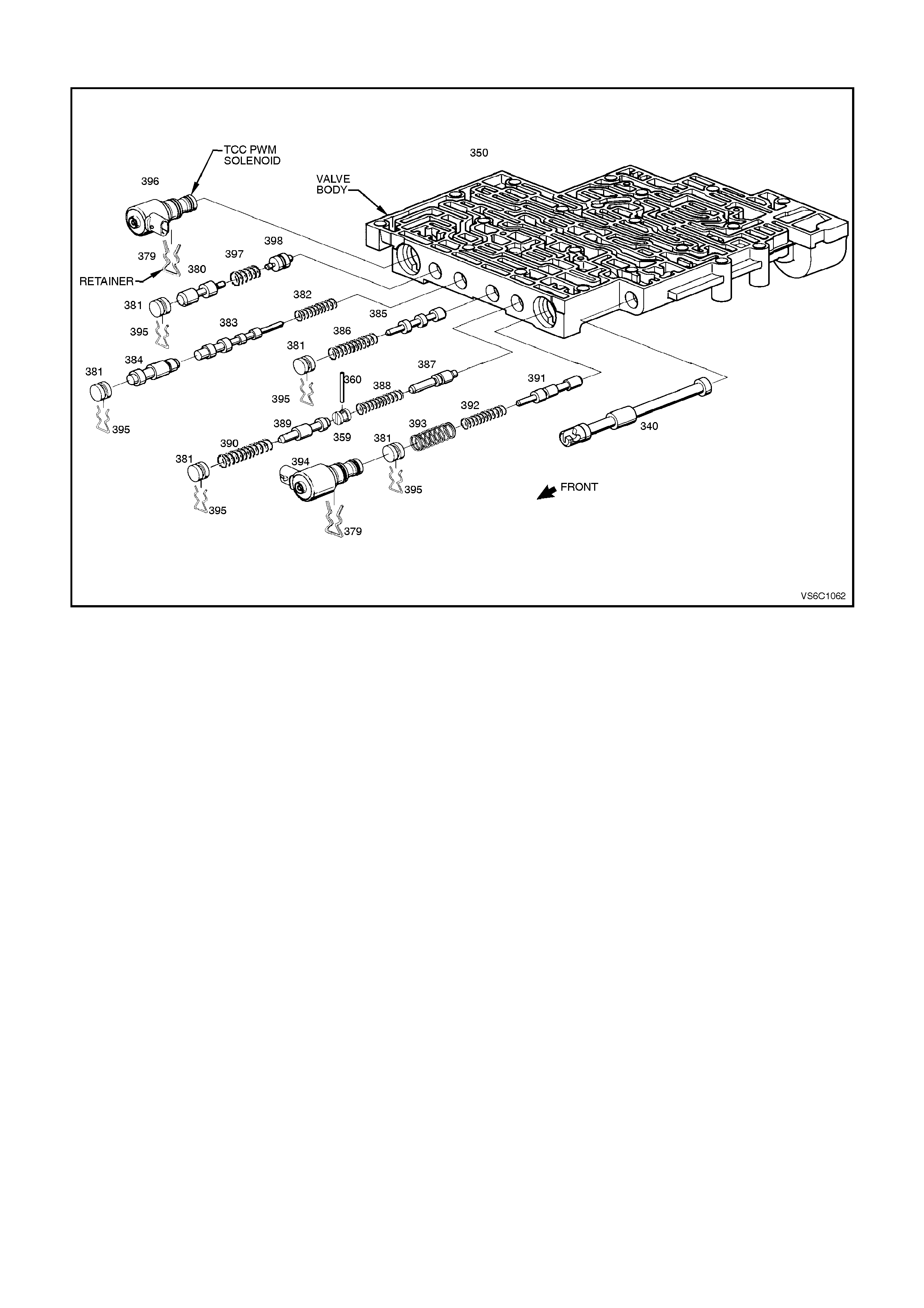
3.15 3-2 CONTROL SOLENOID
Figure 6C1-3-71 3-2 Shift Solenoid Location
REMOVE
1. Disconnect battery earth lead.
IMPORTANT:
To avoid personal injury from accidental hot oil spillage, perform fluid change only w hen transmission fluid is cold.
2. Raise vehicle and support on safety stands. Refer to Section 0A, GENERAL INFORMATION of the VT
Series I Service Information.
3. Clean all dirt from around oil pan and transmission case.
4. Place drain tray under transmission.
5. Loosen two bolts at the rear and one at the front of the oil pan. Rem ove the remaining bolts. W hile holding oil
pan, allow the front of the oil pan to drop away, emptying oil into a drain tray.
6. Remove remaining bolts, then lower pan and empty fluid from pan.
7. Remove old oil pan gasket and discard.
8. Remove strainer.
8. Disconnect 3-2 control solenoid (394) electrical connector.
9. Remove solenoid retainer (379) by using a split ring puller or similar hooked tool.
IMPORTANT:
Solenoid has spring pressure behind it and may pop out after retainer is removed.
9. Remove solenoid assembly (394) with O-ring seal.

REINSTALL
1. Push solenoid assembly with O-ring seal (394) into valve body
2. Hold solenoid firmly in place with finger pressure while installing retainer (379).
3. Reconnect 3-2 control solenoid electrical connector.
4. Install strainer.
5. Clean oil pan and case mating surfaces. Check that magnet is still magnetized, and attached to the oil pan.
6. Install new gasket and reinstall oil pan. Tighten bolts to the correct torque specification.
Transmission Oil Pan Bolt
Torque Specification 11
N.m
7. Lower vehicle and add approximately 4.8 litres of DEXRON â III automatic transmission fluid.
8. Reconnect battery earth lead.
9. Check transmission fluid level. Refer to "Fluid Checking Procedure" in Section 6C1-2A in VX Service
Information.
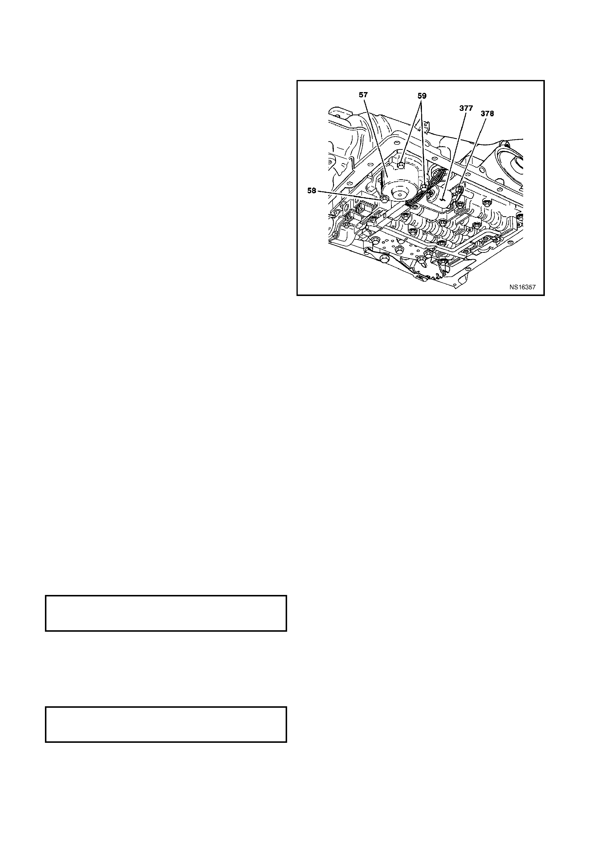
3.16 PRE S SURE CONTROL SOLENOID
REMOVE
1. Disconnect battery earth lead.
IMPORTANT:
To avoid personal injury from accidental hot oil
spillage, perform fluid change only when
transmission fluid is cold.
2. Raise vehicle and support on safety stands.
Refer to Section 0A, GENERAL
INFORMATION in the VT I Service Information.
3. Clean all dirt from around oil pan and
transmission case.
4. Place drain tray under transmission.
5. Loosen two bolts at the rear and one at the
front of the oil pan. Remove the remaining
bolts. While holding oil pan, allow the front of
the oil pan to drop away, emptying oil into a
drain tray.
6. Remove remaining bolts, then lower pan and
empty fluid from pan.
7. Remove old oil pan gasket and discard.
8. Remove strainer.
9. Remove three 1- 2 accumulator cover bolts (58)
(59)
IMPORTANT:
Accumulator will be full of fluid.
10. Remove 1-2 accumulator cover assembly (57).
11. Remove pressure control solenoid (377)
electrical connector.
12. Remove pressure control solenoid retainer bolt
(364), then retainer (378).
13. Remove pressure control solenoid assembly
(377).
Figure 6C1-3-72 Pressure Control Solenoid Location
REINSTALL
1. Install solenoid assem bly (377). Note: Solenoid has a flat cut out on one s ide of it's retaining f lange. Flat cutout
goes toward retaining bolt. Solenoid retainer has a matching flat to allow retainer to be properly installed
2. Install solenoid retainer (378).
3. Install solenoid retainer bolt (364). Tighten bolt to the correct torque specification.
Solenoid Retainer Bolt
Torque Specification 11
N.m
4. Install pressure control solenoid electrical connector.
5. Install 1-2 accumulator cover assembly (57).
6. Install accumulator cover bolts (58) (59) and tighten to the correct torque specification.
Accumulator Cover Bolt
Torque Specification 11
N.m
7. Install new strainer.
8. Clean oil pan and case mating surfaces. Check that magnet is still magnetized, and attached to the oil pan.
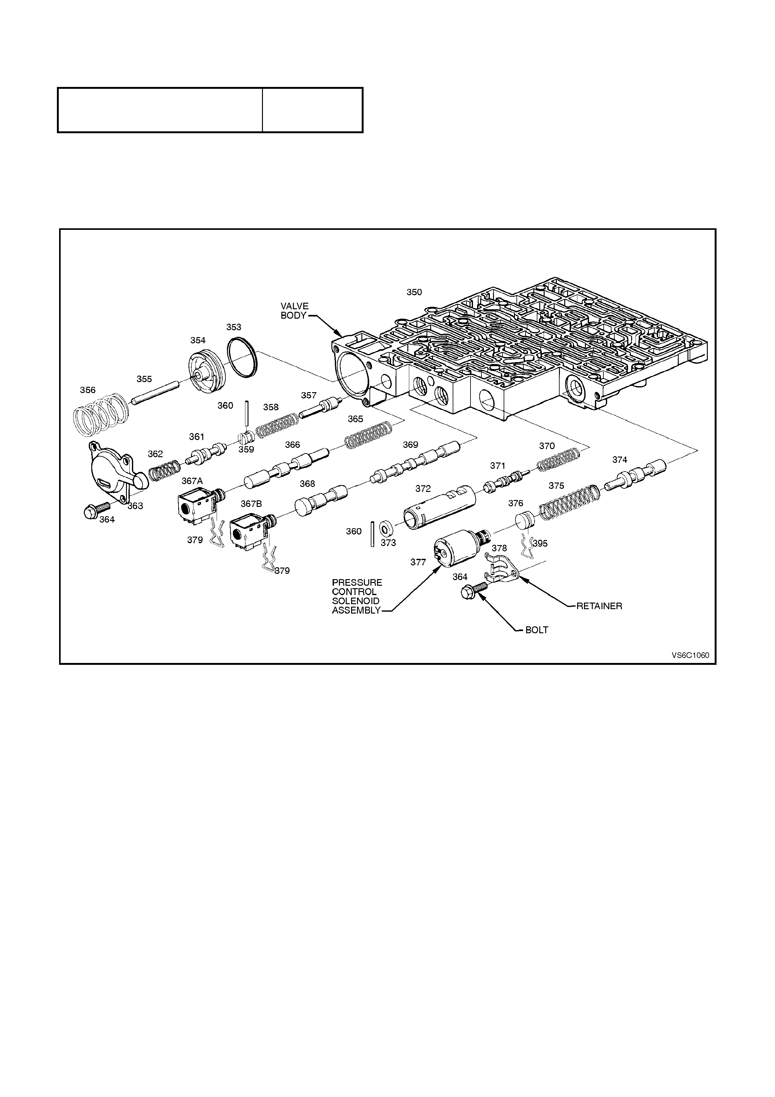
9. Install new gasket and reinstall oil pan. Tighten bolts to the correct torque specification.
Transmission Oil Pan Bolt
Torque Specification 11
N.m
10. Lower vehicle and add approximately 4.8 litres of DEXRON â III automatic transmission fluid.
11. Reconnect battery earth lead.
12. Check transmission fluid level. Refer to "Fluid Checking Procedure" in Section 6C1-2A in VX Service
Information.
Figure 6C1-3-73 Pressure Control Solenoid Assembly
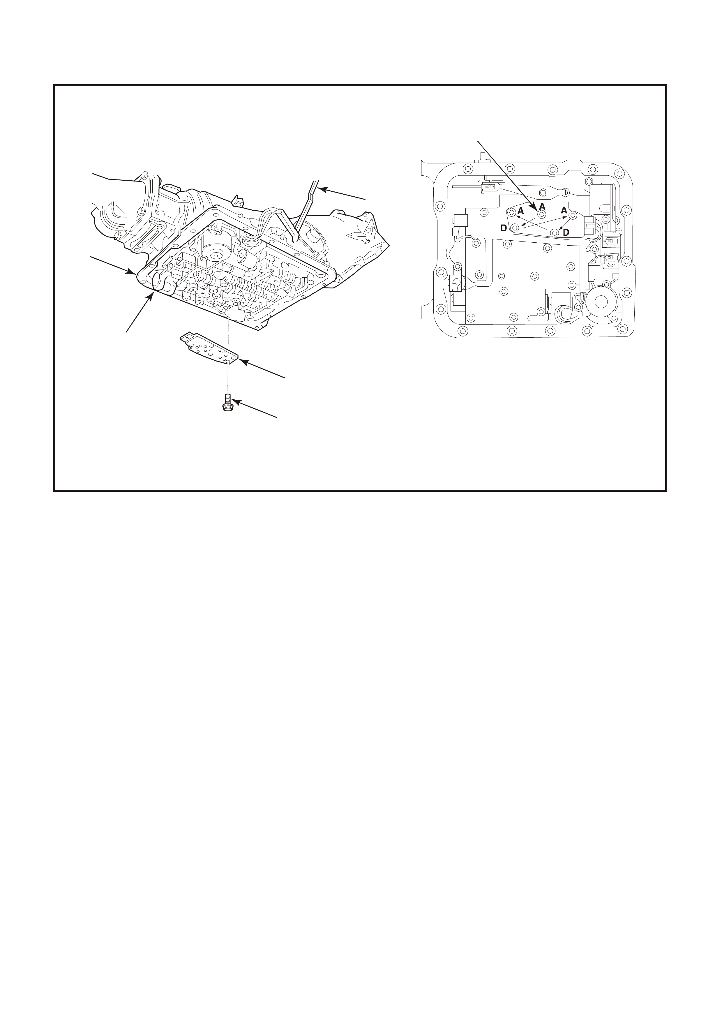
3.17 TRANSMISSION FLUID PRESSURE SWITCH ASSEMBLY (TFP) AND
TRANSMISSION FLUID TEMPERATURE (TFT) SENSOR
Figure 6C1-3-74 Transmission Fluid Pressure Switch Assembly (TFP)
1. Start Torque Sequence Here 60. Valve Assembly, Control Body
A. M6 x 1.0 x 65.0 – 11 N.m 69. Switch Assembly, Transmission Fluid Pressure
D. M6 x 1.0 x 17.7 – 11N.m 70. Bolt, Transmission Fluid Pressure Switch Assembly.
8. Case, Transmission
REMOVE
1. Disconnect battery earth lead.
IMPORTANT:
To avoid personal injury from accidental hot oil spillage, perform fluid change only w hen transmission fluid is cold.
2. Raise vehicle and support on safety stands. Refer to Section 0A, GENERAL INFORMATION of the VT
Series I Service Information.
3. Clean all dirt from around oil pan and transmission case.
4. Place drain tray under transmission.
5. Loosen two bolts at the rear and one at the front of the oil pan. Rem ove the remaining bolts. W hile holding oil
pan, allow the front of the oil pan to drop away, emptying oil into a drain tray.
6. Remove remaining bolts, then lower pan and empty fluid from pan.
7. Remove old oil pan gasket and discard.
8. Remove strainer.
9. Disconnect trans fluid pressure switch assembly electrical connector.
10. Remove five (5) trans fluid pressure switch assembly to valve body bolts (68 and 70).
10. Remove trans fluid pressure switch assembly (69).
1
66
8
60
69
4334
70

REINSTALL
1. Install trans fluid pressure switch assembly (69).
2. Install five (5) trans fluid pressure switch assembly retaining valve body bolts (68 and 70). Tighten bolts to the
correct torque specification
Transmission Fluid Pressure Switch
Assembly (TFP) Retaining Valve
Body Bolt Torque Specification
11 N.m
3. Reconnect trans fluid pressure switch assembly electrical connector.
4. Reinstall strainer.
5. Clean oil pan and case mating surfaces. Check that magnet is still magnetized, and attached to the oil pan.
6. Install new gasket and reinstall oil pan. Tighten bolts to the correct torque specification.
Transmission Oil Pan Bolt
Torque Specification 11
N.m
7. Lower vehicle and add approximately 4.8 litres of DEXRON â III automatic transmission fluid.
8. Reconnect battery earth lead.
9. Check transmission fluid level. Refer to "Fluid Checking Procedure" in Section 6C1-2A in VX Service
Information.

3.18 TCC "PWM" SOLENOID
Figure 6C1-3-75
REMOVE
1. Disconnect battery earth lead.
IMPORTANT:
To avoid personal injury from accidental hot oil spillage, perform fluid change only w hen transmission fluid is cold.
2. Raise vehicle and support on safety stands. Refer to Section 0A, GENERAL INFORMATION of the VT
Series I Service Information.
3. Clean all dirt from around oil pan and transmission case.
4. Place drain tray under transmission.
5. Loosen two bolts at the rear and one at the front of the oil pan. Rem ove the remaining bolts. W hile holding oil
pan, allow the front of the oil pan to drop away, emptying oil into a drain tray.
6. Remove remaining bolts, then lower pan and empty fluid from pan.
7. Remove old oil pan gasket and discard.
8. Remove strainer.
9. Remove TCC "PWM" solenoid (396) electrical connector.
10. Remove Solenoid retainer (379) by using a split ring puller or similar hooked tool.
11. Remove TCC "PWM" Solenoid assembly (396) with O-ring seal.

REINSTALL
1. Install TCC "PWM" Solenoid with O-ring assembly (396).
2. Install TCC "PWM" Solenoid retainer (379).
3. Install TCC "PWM" solenoid electrical connector.
4. Install strainer
5. Clean oil pan and case mating surfaces. Check that magnet is still magnetized, and attached to the oil pan.
6. Install new gasket and reinstall oil pan. Tighten bolts to the correct torque specification.
Transmission Oil Pan Bolt
Torque Specification 11
N.m
7. Lower vehicle and add approximately 4.8 litres of DEXRON â III automatic transmission fluid.
8. Reconnect battery earth lead.
9. Check transmission fluid level. Refer to "Fluid Checking Procedure" in Section 6C1-2A in VX Service
Information.
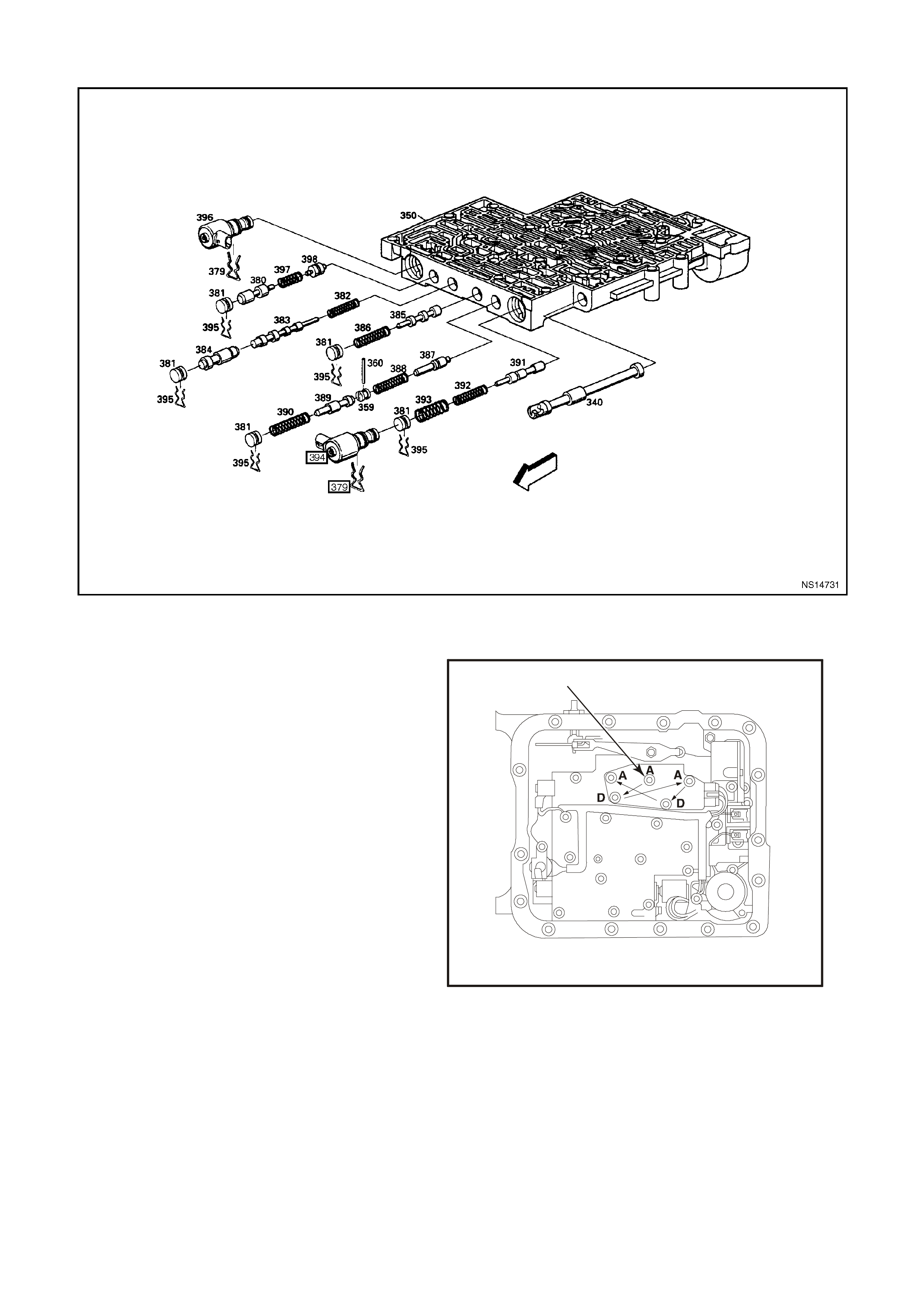
3.19 TCC ENABLE SOLENOID
Figure 6C1-3-76
REMOVE
1. Disconnect battery earth lead.
IMPORTANT:
To avoid personal injury from accidental hot oil
spillage, perform fluid change only when
transmission fluid is cold.
2. Raise vehicle and support on safety stands.
Refer to Section 0A, GENERAL
INFORMATION of the VT Series I Service
Information.
3. Clean all dirt from around oil pan and
transmission case.
4. Place drain tray under transmission.
5. Loosen two bolts at the rear and one at the
front of the oil pan. Remove the remaining
bolts. While holding oil pan, allow the front of
the oil pan to drop away, emptying oil into a
drain tray.
6. Remove remaining bolts, then lower pan and
empty fluid from pan.
7. Remove old oil pan gasket and discard.
8. Remove strainer.
9. Remove TCC "PWM" solenoid (396) electrical
connector.
1
4335
Figure 6C1-3-77
1. Start Torque Sequence Here
A. M6 x 1.0 x 65.0 –11 N.m
D. M6 x 1.0 x 17.7 – 11 N.m
10. Remove TCC "PWM" solenoid retainer (379) by using a split ring puller or similar hooked tool.
11. Remove TCC "PWM" solenoid assembly (396) with O-ring seal.
12. Remove TCC ENABLE solenoid assembly bolts (68).
13. Remove TCC ENABLE solenoid assembly (66) with O-ring seal.
14. Remove all electrical connectors from components.

15. Remove the three valve body bolts retaining the transmission wiring harness.
16. Remove three 1-2 accumulator cover bolts (58) (59).
17. Remove 1-2 accumulator cover assembly (57).
18. Remove pressure control solenoid (377) electrical connector.
19. Remove pressure control solenoid retainer (378).
20. Remove pressure control solenoid assembly (377).
21. Place a 12 point 1-5/16" deep well socket (or 34.5 mm I.D. pipe with a slight chamf er on the ins ide) over the top
of the transmission pass-thru connector.
IMPORTANT:
This may be difficult due to the clearance of the floor pan transmission tunnel and the transmission case.
22. Pry downward on the top of the socket or pipe Using a prybar or similar shaped tool, push the pass thru
connector down through and out of the transmission case.
REINSTALL
1. Coat TCC ENABLE Solenoid O-ring with petroleum jelly then install new wiring harness assembly (containing
new TCC ENABLE solenoid) into transmission case.
2. Install pressure control solenoid assembly (377).
IMPORTANT:
Solenoid has a flat cut out on one side of it's retaining flange. Flat cutout goes toward retaining bolt. Solenoid
retainer has a matching flat to allow retainer to be properly installed
3. Install pressure control solenoid retainer (378).
IMPORTANT:
Ensure that flat of the retainer is correctly placed into the cutout on the solenoid flange. Tighten retainer bolt to 11
N m.
4. Install pressure control solenoid (377) electrical connector.
5. Install 1-2 accumulator cover assembly (52).
6. Install three 1-2 accumulator cover bolts (58) (59). Tighten to the correct torque specification.
1-2 Accumulator Cover Bolt
Torque Specification 11
N.m
7. Install TCC "ON-OFF" solenoid assembly (66).
8. Install TCC "ON-OFF" solenoid bolts (68). Tighten to the correct torque specification.
TCC Solenoid Bolt
Torque Specification 11
N.m
9. Install TCC "PWM" Solenoid assembly (396).
10. Install TCC "PWM" Solenoid retainer (379).
11. Install TCC "PWM" solenoid electrical connector.
12. Install three valve body bolts retaining wiring harness. Tighten to the correct torque specification.
Valve Body Wiring
Harness Retaining Bolt
Torque Specification
11 N.m
13. Install all electrical connectors onto components.
14. Install new strainer and seal.
15. Clean oil pan and case mating surfaces. Check that magnet is still magnetized, and attached to the oil pan
within the square marked.
16. Install new gasket and reinstall oil pan. Tighten bolts to the correct torque specification.
Transmission Oil Pan Bolt
Torque Specification 11
N.m
17. Lower vehicle and add approximately 4.8 litres of DEXRON â III automatic transmission fluid.
18. Reconnect battery earth lead.
19. Check transmission fluid. Refer to "Fluid Checking Procedure" in Section 6C1-2A in VX Service Information.
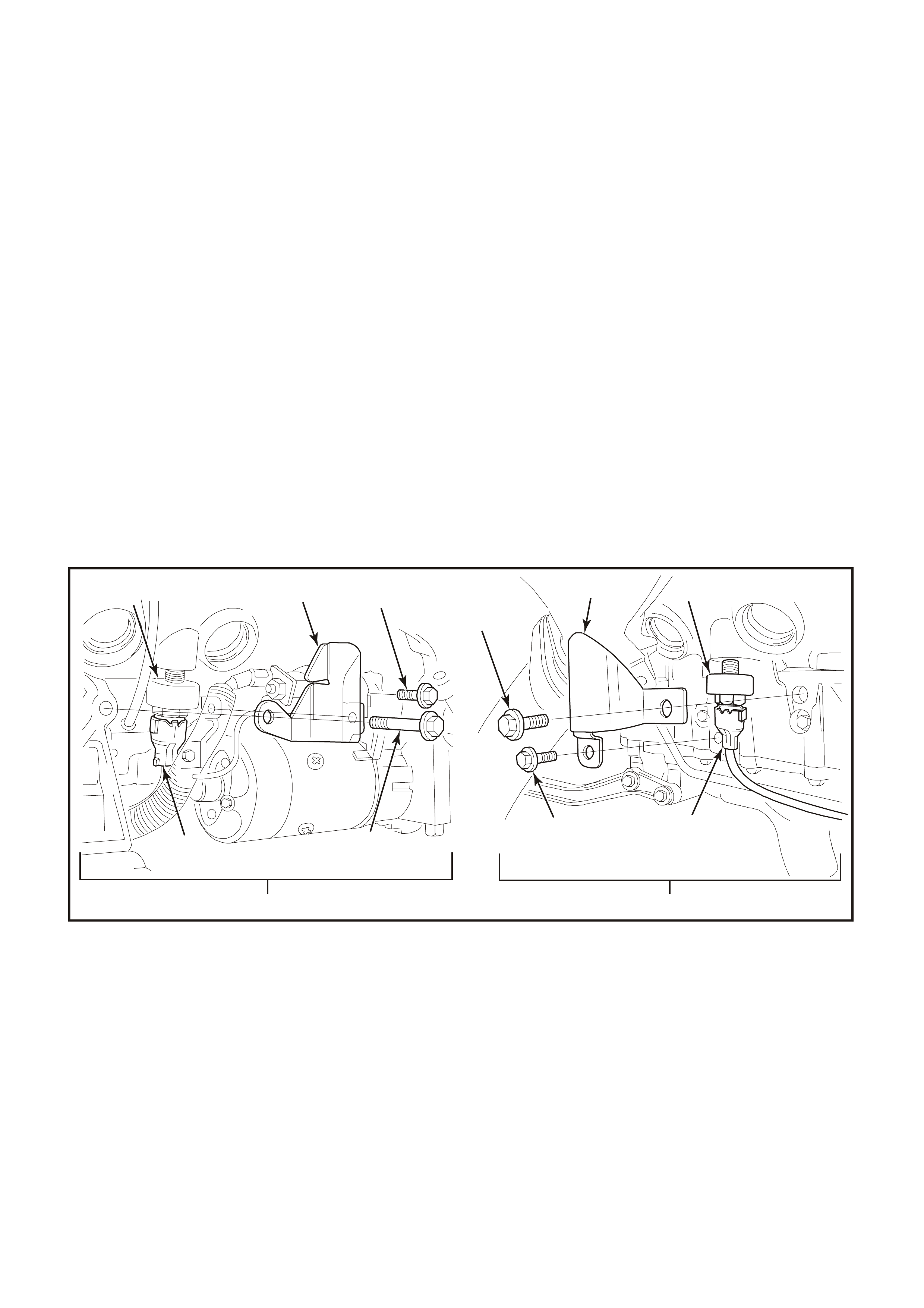
3.20 KNOCK SENSOR
CHECKING KNOCK SENSOR OPERATION
The PCM's k nock sens or input will reduce the EST spark advance when detonation is present. T his sens or signals
the PCM of engine noise, and the PCM determines if the noise is detonation, or normal mechanical noise. The
PCM can be "tricked" into thinking that detonation is present by lightly `rapping' on the engine with a small hammer.
To check the "knock retard" function of the ignition system, run the engine with the DLC diagnostic test terminal
NOT earthed. With the throttle fixed at a s teady 1600 - 1800 RPM, quick ly and repeatedly `r ap' on the engine block,
cylinder head, or inlet manifold with a small hammer. The RPM should drop, due to the timing advance being
reduced. When you stop `rapping' on the engine, the RPM should come back to the original starting point.
IMPORTANT:
Both k nock sensor s are threaded into the engine block cylinder cooling jack ets, which is a "wet" area of the engine
coolant system. When either k nock sensor is r emoved f rom the engine block engine coolant will drain out. ALLOW
ENGINE TO FULLY COOL DOWN TO AMBIENT TEMPERATURE BEFORE SERVICING KNOCK SENSOR.
Make sure to have a drain pan available to catch engine coolant.
REMOVE
1. Allow engine to cool to ambient temperature (less than 50 degrees Celsius), then remove radiator cap.
2. Disconnect battery earth lead.
3. Rais e fr ont of vehic le and support on saf ety stands. Refer to Section 0A, GENERAL INFORMATION of the VT
Series I Service Information for location of jacking points.
4. Squeeze together 'wide ends' on sensor wiring harness connector (4&8) (connector is oval shaped) and pull
connector from sensor (3&10).
IMPORTANT:
To achieve this step it m ay be necessary to rem ove the knock sensor heat shield attaching bolts (1&5, 7&11) and
heat shields (2&11).
Figure 6C1-3-78
1. Attaching Bolt. 7. Attaching Bolt.
2. Knock Sensor Shield. 8. Wiring Harness.
3. R.H Knock Sensor. 9. L.H Side View.
4. Wiring Harness Connector. 10. L.H Knock Sensor.
5. Attaching Bolt. 11. Knock Sensor Shield.
6. R.H Side View. 12. Attaching Bolt.
5. Place a suitable drain tray beneath the knock sensor location.
6. Using a 22 mm socket, universal joint and suitable length socket bars, loosen and remove knock sensor from
the cylinder block, taking extreme care to avoid any draining coolant if it is hot.
10 11
1
4
5
7
8
9
12 23
6
4253
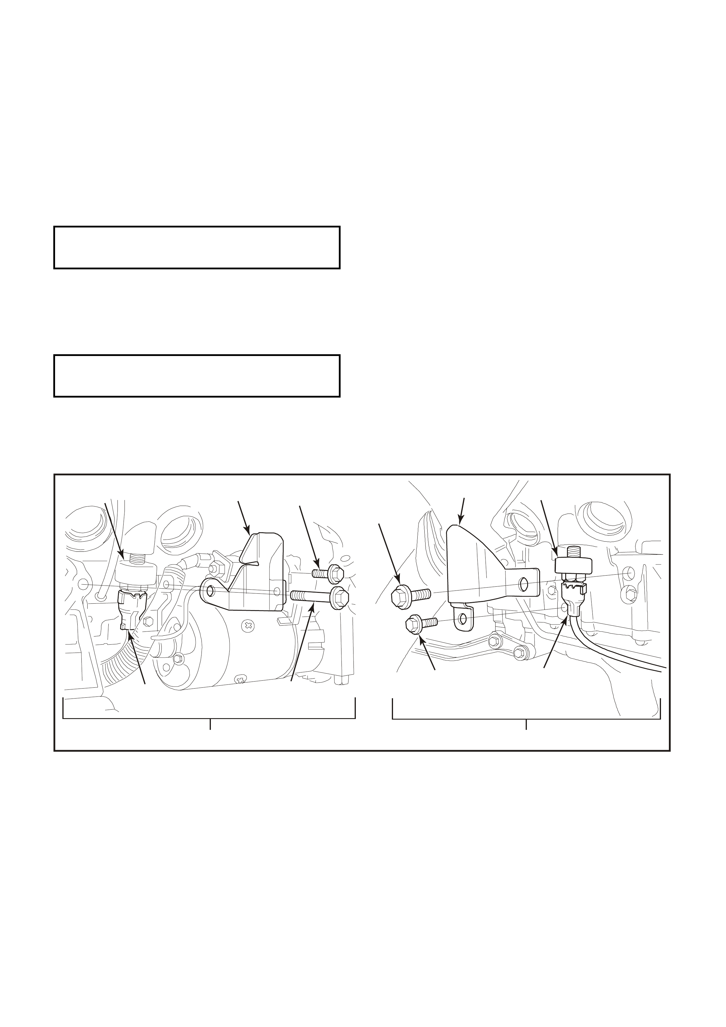
REINSTALL
1. Ensure that the threads in the sensor mounting hole in cylinder block are clean.
2. If reinstalling original sensor, inspect sealant on sensor threads. If worn away, apply a light coating of Loctite
242 (Holden's Specification HN1256 Class 2, Type 2) to sensor threads.
IMPORTANT:
On a new sensor, do not apply sealant to threads as thr eads are coated with a sealant during produc tion. Applying
additional sealant will affect the sensor's ability to detect engine knock.
3. Install sensor (3&10) and tighten to the correct torque specification.
IMPORTANT:
Ensure that knock sensor is never over tightened as damage to the sensor can occur.
Knock Sensor Tightening
Torque Specification 16 – 22
N.m
4. Reconnect wiring harness connector (4&8) to sensor. Ensure that connector is securely fitted onto sensor.
5. If removed, reinstall knock sensor heat shield (2&11) and attaching bolts (1&5,7&12). Tighten bolts to the
correct torque specification.
Knock Sensor Heat Shield Attaching
Bolt Torque Specification 25 - 35
N.m
6. Refill cooling system and pressure test for leaks, refer Section 6B1, ENGINE COOLING - V6 ENGINE in VX
Service Information.
7. Reconnect battery earth lead.
Figure 6C1-3-79
1. Attaching Bolt. 7. Attaching Bolt.
2. Knock Sensor Shield. 8. Wiring Harness.
3. R.H Knock Sensor. 9. L.H Side View.
4. Wiring Harness Connector. 10. L.H Knock Sensor.
5. Attaching Bolt. 11. Knock Sensor Shield.
6. R.H Side View. 12. Attaching Bolt.
10 11
1
4
5
7
8
9
12 23
6
4253
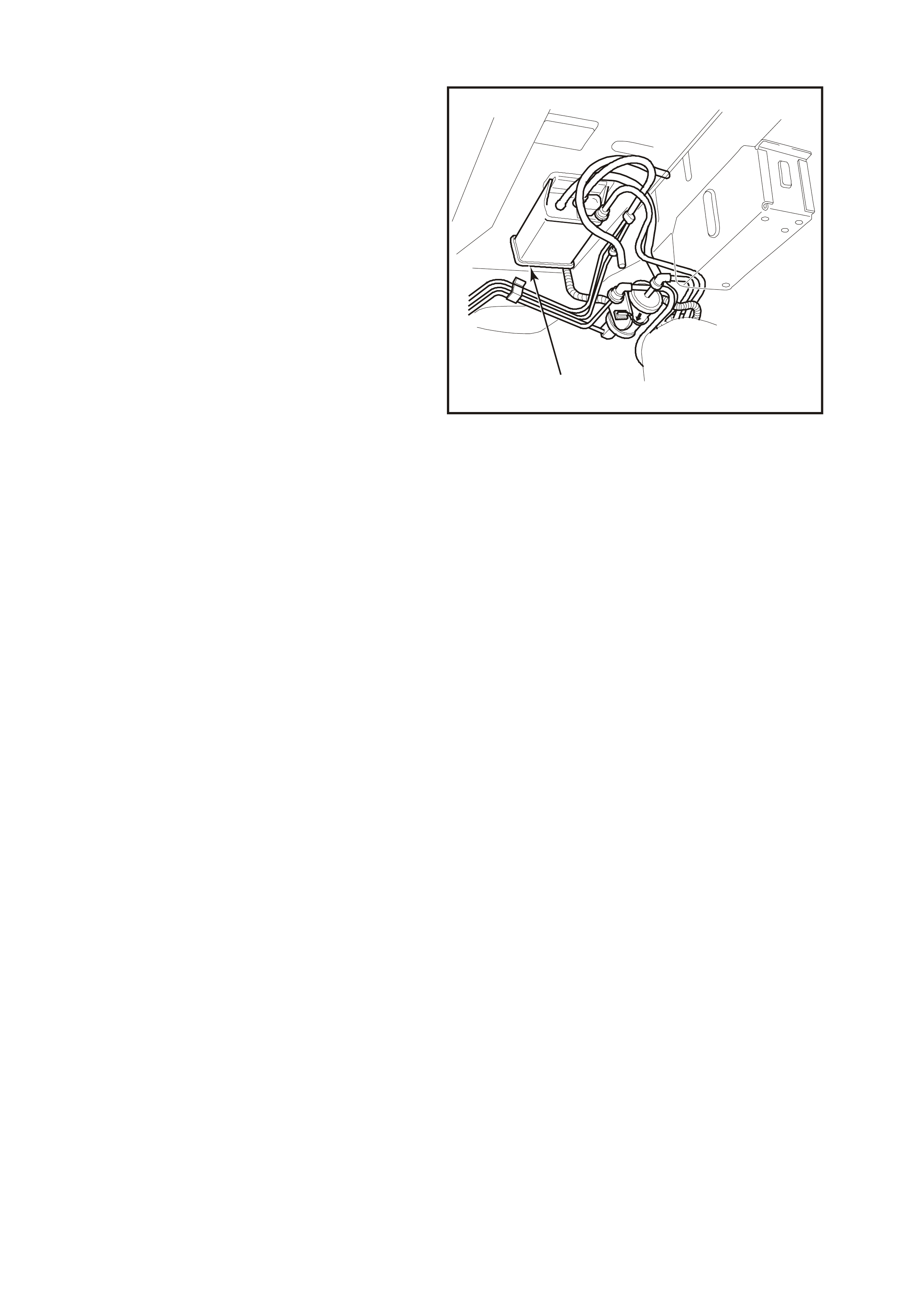
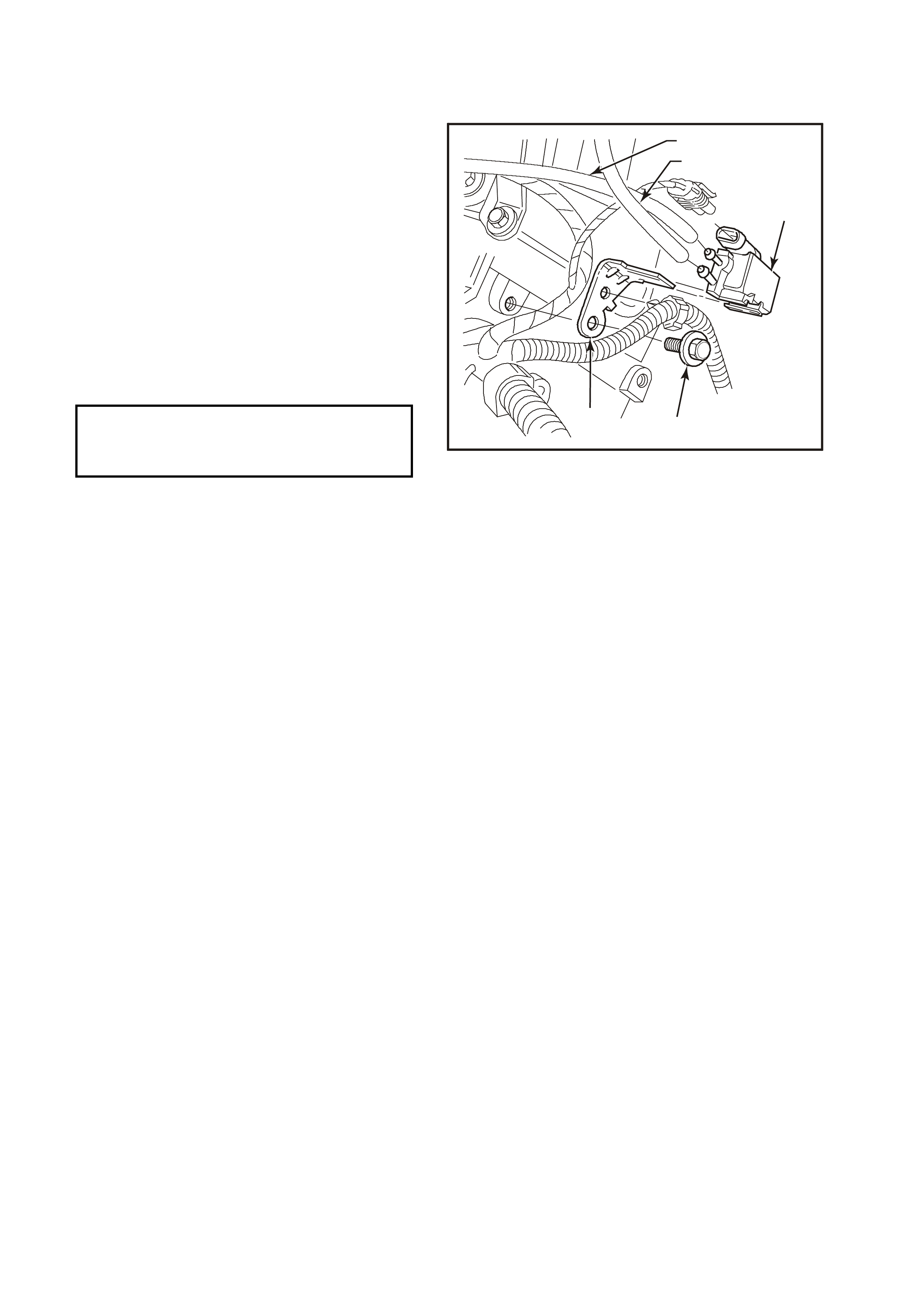
3.22 CANISTER PURGE SOLENOID
REMOVE
1. Disconnect battery earth lead.
2. Mark hoses on canister purge solenoid (top,
bottom), and pull hoses from solenoid (3).
3. Pull up on solenoid wiring harness connector
and pull connector from solenoid (3).
4. Rem ove bolt (4) f r om solenoid br acket (5) . T his
bolt attaches to the rear of the right hand
cylinder head, remove solenoid.
REINSTALL
1. Reinstall canister purge solenoid (3) to rear of
cylinder head and install bracket bolt (4).
Tighten bolt to the correct torque specification.
2. Reconnect hoses and wiring harness
connector to canister purge solenoid (3),
ensuring connections are correct.
3. Reconnect battery earth lead.
4256
12
54
3
Figure 6C1-3-81
Purge Control Solenoid
Attaching Bolt 30-40 N.m
Torque Specification
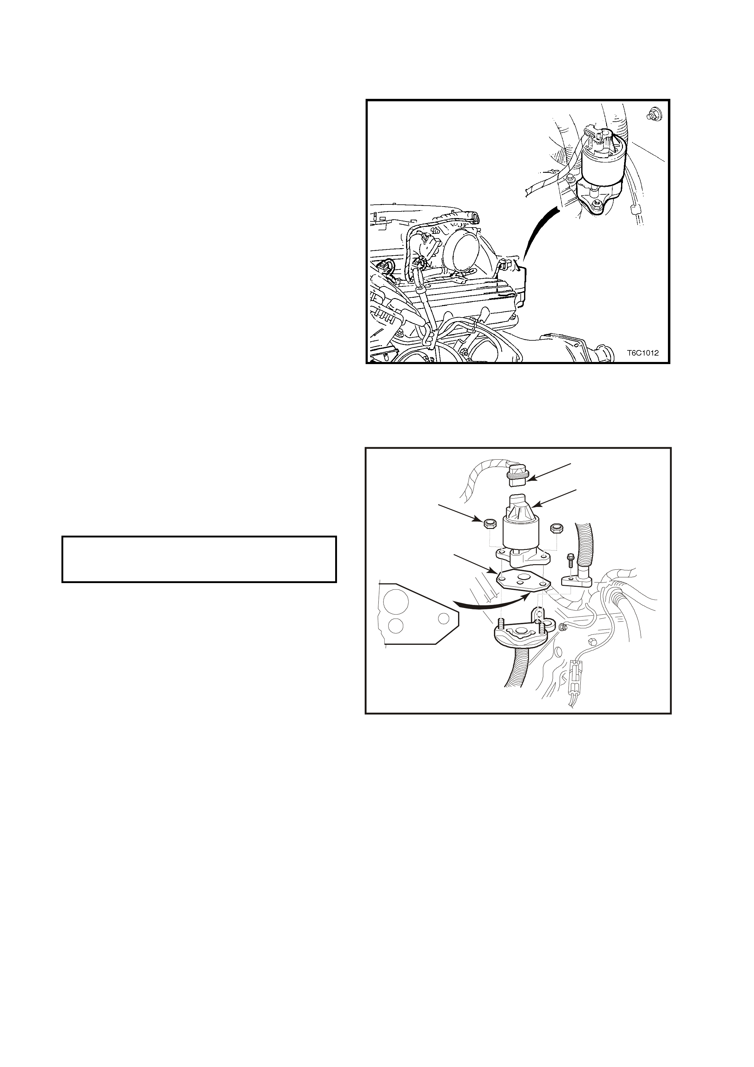
3.23 EXHAUST GAS RE CIRCULATION (EGR) VALVE
REMOVE
1. Remove four dome nuts securing the engine
dress cover assembly to the inlet manifold
studs, lift off and remove the cover assembly.
2. Electrical connector at EGR valve.
3. Two EGR valve retaining nuts.
4. EGR valve assembly.
6. Gasket.
IMPORTANT:
Make sure all of the old gasket meteral has been
removed from the EGR valve and the EGR valve
mounting surface sealing surface.
Figure 6C1-3-82 EGR Valve Location
REINSTALL
1. Install gasket.
2. Install EGR valve assembly and two retaining
nuts and tighten to the correct torque
specification.
.
3. Install electrical connector.
4. Reinstall engine dress cover.
2
1
4341
5
4
3
Figure 6C1-3-83 EGR Valve Removal View
EGR Retaining Nu t 30
Torque Specification N.m
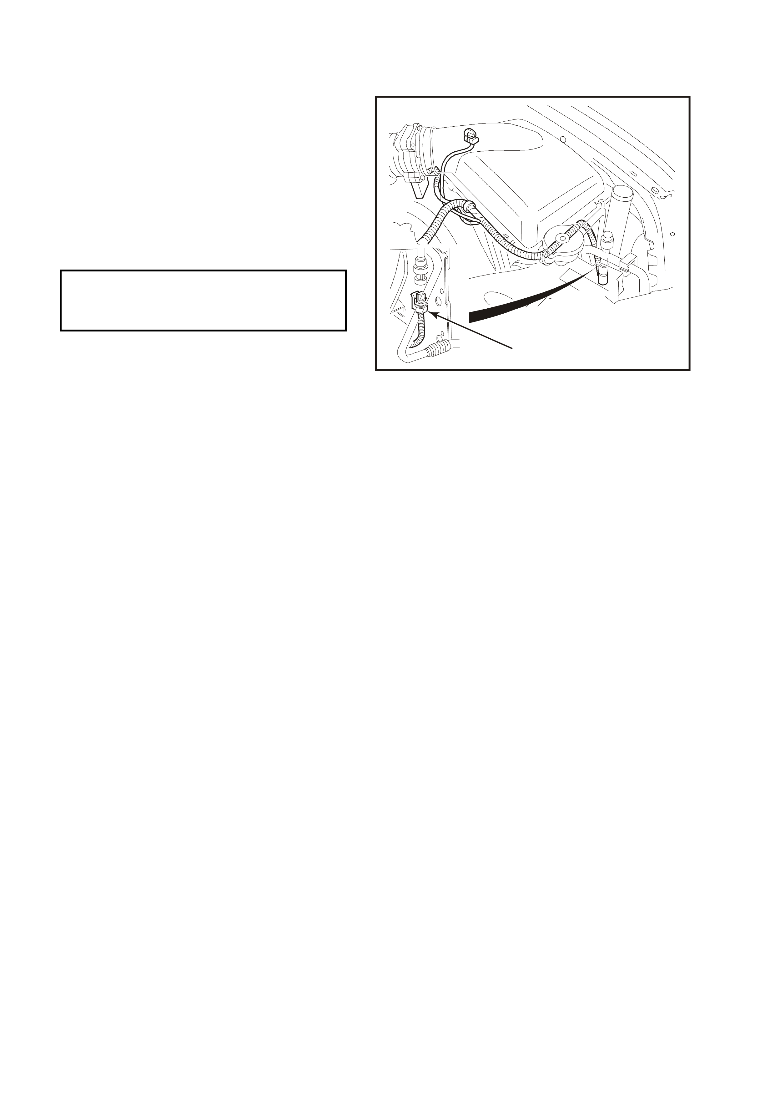
3.24 A/C REFRIGERANT PRESS URE SENSOR
REMOVE
1. Electrical connector at Sensor (1).
2. Sensor from High pressure line.
REINSTALL
1. Install Sensor to high pres sure line, and tighten
to the correct torque specification.
A/C Refrigerant
Pressure Sensor 5 – 7 N.m
Torque Specification
2. Install electrical connector to Sensor (1).
1
4261
Figure 6C1-3-84 A/C Refrigerant Pressure
Sensor Location