
SECTION 6C3-1 - GENERAL INFORMATION -
GEN III V8 ENGINE
IMPORTANT:
Before performing any Service Operation or other procedure described in this Section, refer to Section 00
CAUTIONS AND NOTES in this VX Service Information for correct workshop practices with regards to
safety and/or property damage.
1. GENERAL DESCRI PTION
The engine used in this vehicle uses an Powertrain Control Module (PCM) to control exhaust emissions while
maintaining excellent driveability and fuel economy. The PCM maintains a desired air/fuel ratio at precisely 14.7
to 1. To m aintain a 14.7 to 1 air fuel ratio the PCM monitors the output signal from two oxygen sensors. The PCM
will either add or subtract fuel pulses based on the oxygen sensors output signal. This method of feed back fuel
control is called CLOSED LOOP.
In addition to fuel control, the PCM also controls the following systems.
• The Ignition Dwell
• The Ignition Timing
• The Idle Speed
• The Engine Electric Cooling Fan
• The Fuel Pump
• The Instrument Panel Check Powertrain Lamp (CPL)
• The A/C Compressor Clutch
• The Automatic Transmission Functions
• The Manual Transmission Reverse Inhibit
• Theft Deterrent
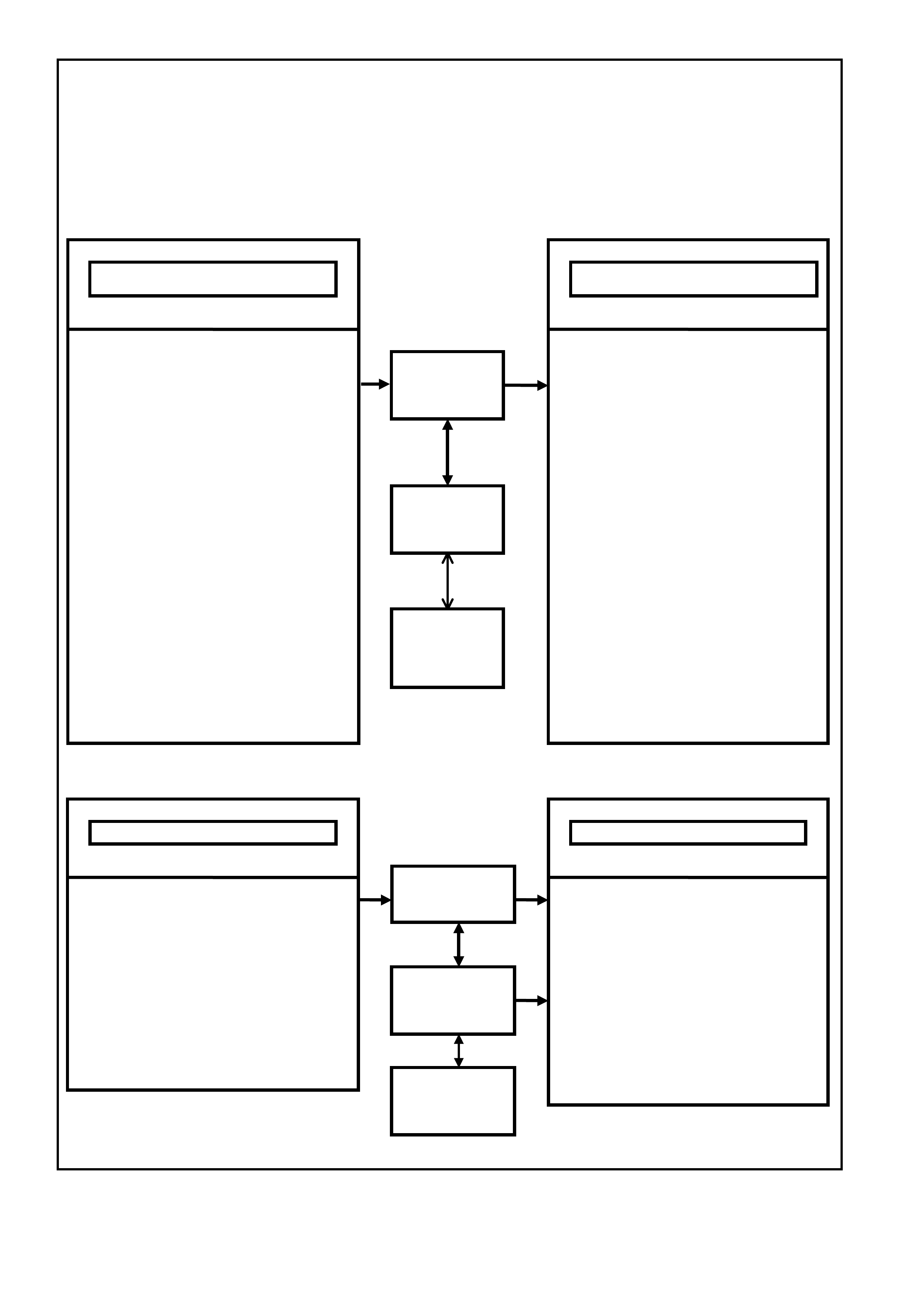
The PCM also interfaces with other vehicle control modules, such as the Powertrain Interface Module (PIM),
Instruments, and Body Control Module (BCM). The following diagram contains a list of the various operating
conditions sensed by the PCM, and the various systems controlled. Details of basic operation, diagnosis, and
service are covered in this Section.
The PCM has a built-in diagnostic system that identifies operational problems and alerts the driver by illuminating
the Check Powertrain Lamp (CPL) on the instrument panel. If the lamp illuminates while driving, it does not mean
that the engine should be stopped immediately, but the cause of the lam p illuminating should be checked as soon
as is reas onably pos sible. The PCM has built in bac k-up s ys tems that in all but the most severe faults will allow the
vehicle to operate in a near normal manner until repairs can be made.
Below the instrument panel is a Data Link Connector (DLC) which is used by the assembly plant for a computer
check-out of the powertrain management system. The DLC is also used in service to help diagnose the system
using Tech 2. Refer to Section 6C3-2, DIAGNOSIS of the VX Series Service Information for further details.
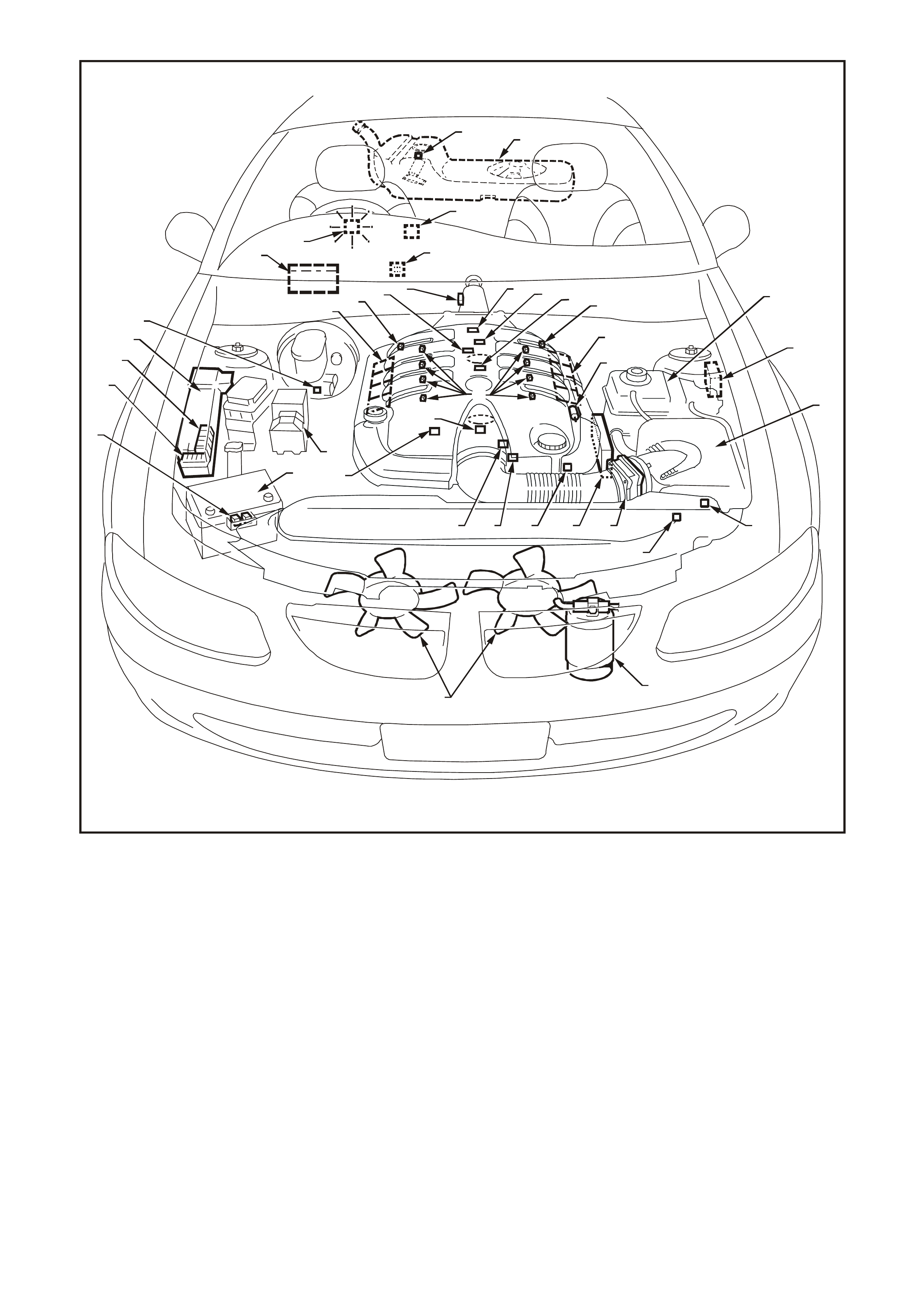
The locations of the Engine Management System (EMS) components of the system are shown in the following
Figures 6C3-1-2 through 6C3-1-5.
For the transmission Management System components and their locations, refer to Figure 6C1-1-6 of the VX
Series Service Information.
Note:
Some parameters may travel through one or more controllers for input or output controls.
ENGINE CONTROLS
TRANSMISSION CONTROLS
Figure 6C3-1-1 PCM Operating Conditions Sensed and Systems Controlled
• A/C Pressure Sensor
• A/C Request "ON" or "OFF"
• Battery Voltage
• Camshaft Position (CMP)
• Crankshaft Position (CKP)
• DLC Data Stream Input
• Engine Coolant Level Switch
• Engine Coolant Temperature (ECT)
• Engine Cooling Fan Response
• Engine Knock (KS)
• Engine Speed (RPM)
• Exhaust Gas Oxygen Content
• Intake Air Temperature (IAT)
• Mass Air Flow (MAF)
• Manifold Absolute Pressure (MAP)
• Oil Pressure Sensor
• Spark Retard Signal
• Stop Lamp Switch
• Throttle Position (TP)
• Transmission Gear Position
•
Theft Deterrent Signal
POWERTRAIN
CONTROL
MODULE (PCM)
• Air Conditioning Compressor
Clutch
• Canister Purge Solenoid
• Diagnostics
• - Check Powertrain Lamp (CPL)
• - DLC Data Stream Output
• - Field Service Mode
• Electric Engine Cooling Fan
• Electronic Spark Control (ESC)
• Electronic Spark Timing (EST)
• Fuel Control
- Fuel Injectors
- Fuel Pump
• Idle Air Control
• Torque Management
OPERATING PARAMETERS SENSED SYSTEMS CONTROLLED
• Battery Voltage
• Power/Economy Switch
• Engine Speed (Engine RPM)
• Engine Coolant Temperature (ECT)
• Stop Lamp Switch
• Throttle Position (TP Sensor)
• Transmission Fluid Temperature
(TFT)
• Transmission Gear Position
• Vehicle Speed Sensor (VSS)
• Transmission Fluid Pressure (TFP)
• Switch Assembly
• TCC Enable Solenoid
• 3-2 Shift Solenoid
• 1-2 Shift Solenoid
• 2-3 Shift Solenoid
• Diagnostics
• - Check Powertrain Lamp (CPL)
• - DLC Data Stream Output
• Manual Transmission Reverse
Inhibit
POWERTRAIN
CONTROL
MODULE (PCM)
OPERATING PARAMETERS SENSED SYSTEM CONTROLLED
POWERTRAIN
INTERFACE
MODUL E (PIM)
POWERTRAIN
INTERFACE
MODULE (PIM)
BODY
CONTROL
MODUL E (BC M)
BODY
CONTROL
MODULE (BCM)
T26C3001
1
2
3
4
5
6
7
9
10
11
12
13
14
151617 18
19
20 21
21
23
23
22
24
25
26
27
28
29
30
AB
C
D
F
E
8
Figure 6C3-1-2 Component Locations View GEN III V8 Engine
1. Engine Compartment Fusible Link Housing
2. Battery Harness Fusible Link Housing
3. Engine Compartment Relay Housing
4. Engine Compartment Relay Housing
5. Fuel Pressure Regulator (in Fuel Tank)
6. A/C Accumulator Tank
7. Brake Hydraulic Failure Switch
8. Fuel Injectors (8)
9. Idle Air Control (IAC) Valve
10. Check Powertrain Lamp (CPL)
11. Ignition Coil/Module Right Bank
12. Ignition Coil/Module Left Bank
13. Engine Fans (2)
14. Canister Purge Solenoid
15. Mass Air Flow (MAF) Sensor
16. Engine Coolant Temperature (ECT) Sensor
17. Throttle Position (TP) Sensor
18. Intake Air Temperature (IAT) Sensor
19. Vehicle Speed Sensor (VSS)
20. Camshaft Position (CMP) Sensor
21. Heated Oxygen (HO2S) Sensor (2)
22. Crankshaft Position (CKP) Sensor
23. Knock Sensors (KS) (2)
24. ECC In - Car Air Temperature Sensor
25. A/C Refrigerant Pressure Sensor
26. Powertrain Control Module (PCM)
27. Powertrain Interface Module (PIM) - Inside
vehicle behind left kick panel
28. Diagnostic Link Connector (DLC)
29. Oil Pressure Sensor
30. Manifold Absolute Pressure (MAP) Sensor
A Battery
B ABS
C BCM
D Fuel Tank
E Surge Tank (With Low Coolant Level Switch)
F Air Cleaner
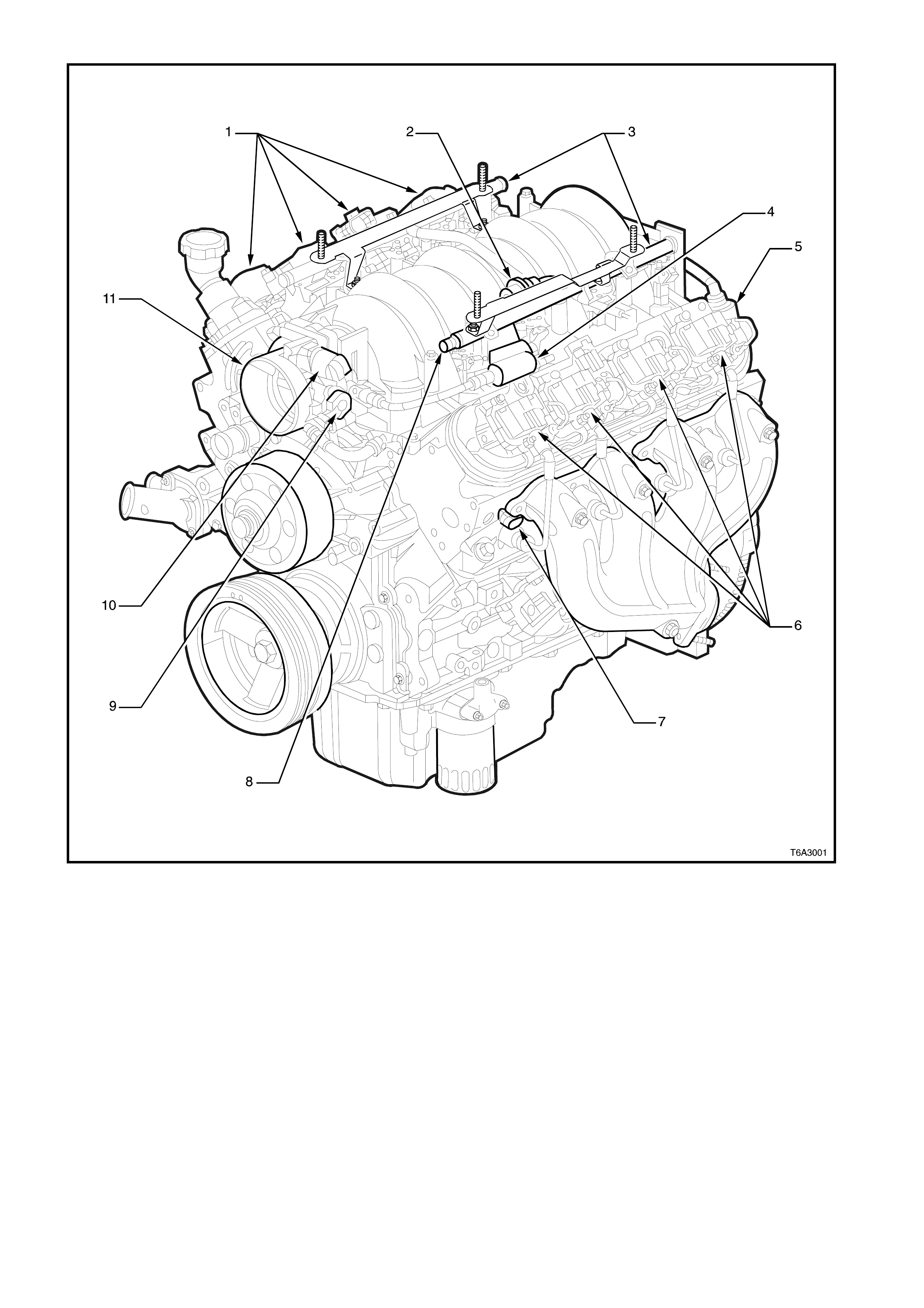
Figure 6C3-1-3 GEN III V8 Engine View Left-Hand Side
1. Right-Hand Ignition Coils/Modules
2. Fuel Pulse Dampener
3. Fuel Rail with Injectors
4. Evaporative Canister Purge Solenoid
5. Crankcase Vent
6. Left-Hand Ignition Coils/Modules
7. Engine Coolant Temperature (ECT) Sensor
8. Fuel Pressure Gauge Test Connector
9. Throttle Position (TP) Sensor
10. Idle Air Control (IAC) Valve
11. Throttle Body
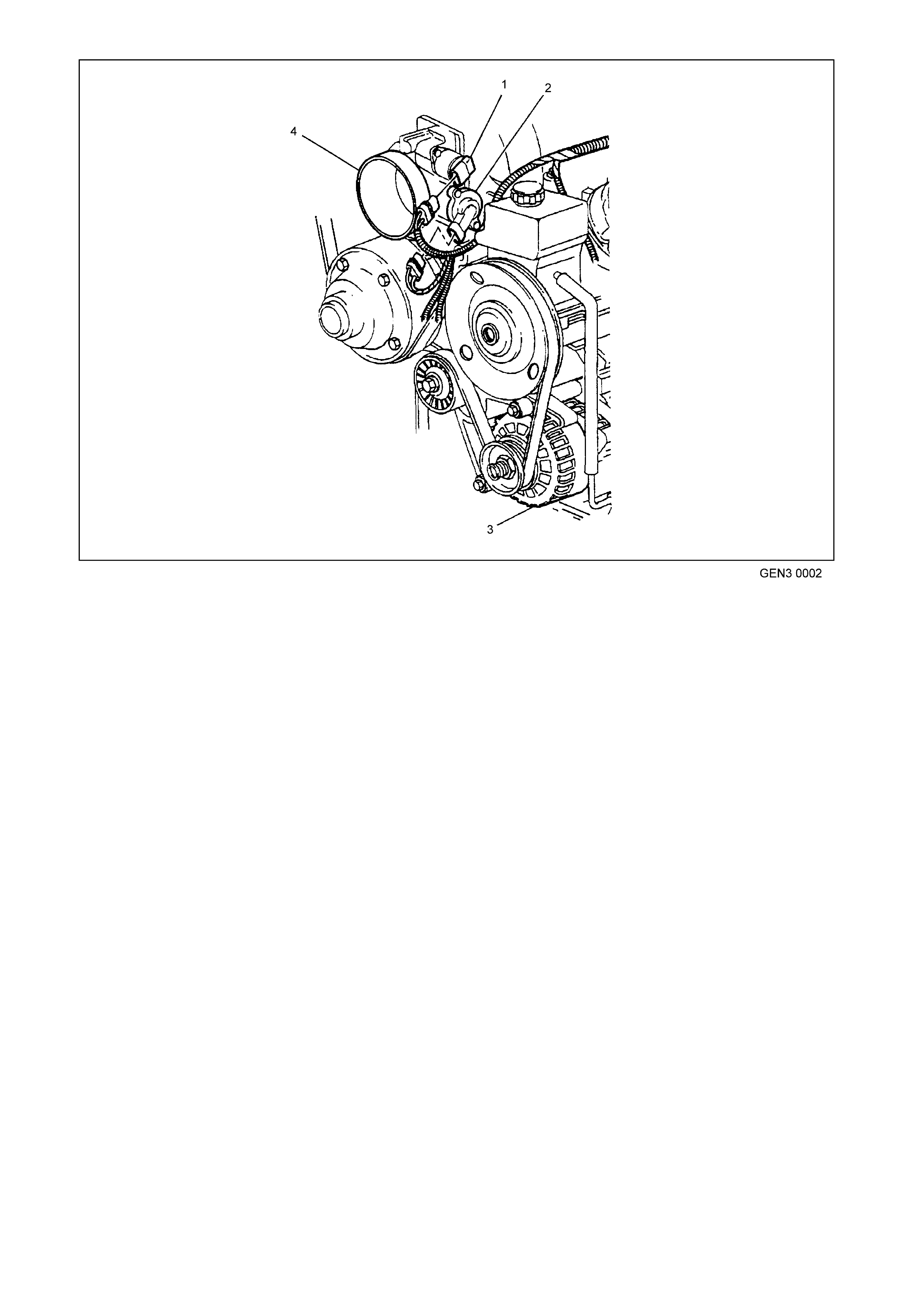
Figure 6C3-1-4 GEN III V8 Engine Front View
1. Idle Air Control (IAC) Valve
2. Throttle Position (TP) Sensor
3. Generator
4. Throttle Body
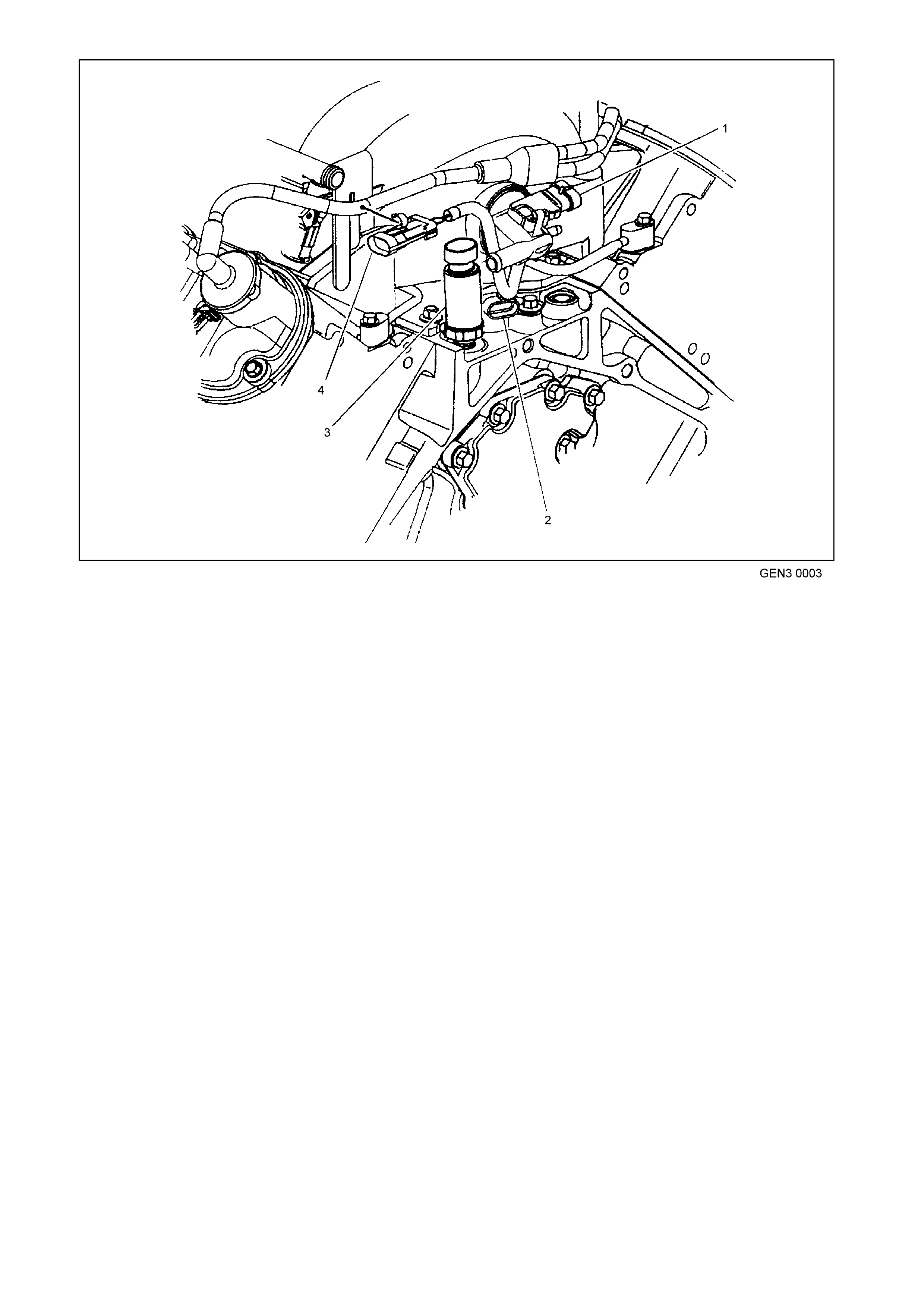
Figure 6C3-1-5 GEN III V8 Engine Rear View
1. Manifold Absolute Pressure (MAP) Sensor
2. Camshaft Position (CMP) Sensor
3. Oil Pressure Sensor
4. Connector to Knock Sensor Jumper Harness
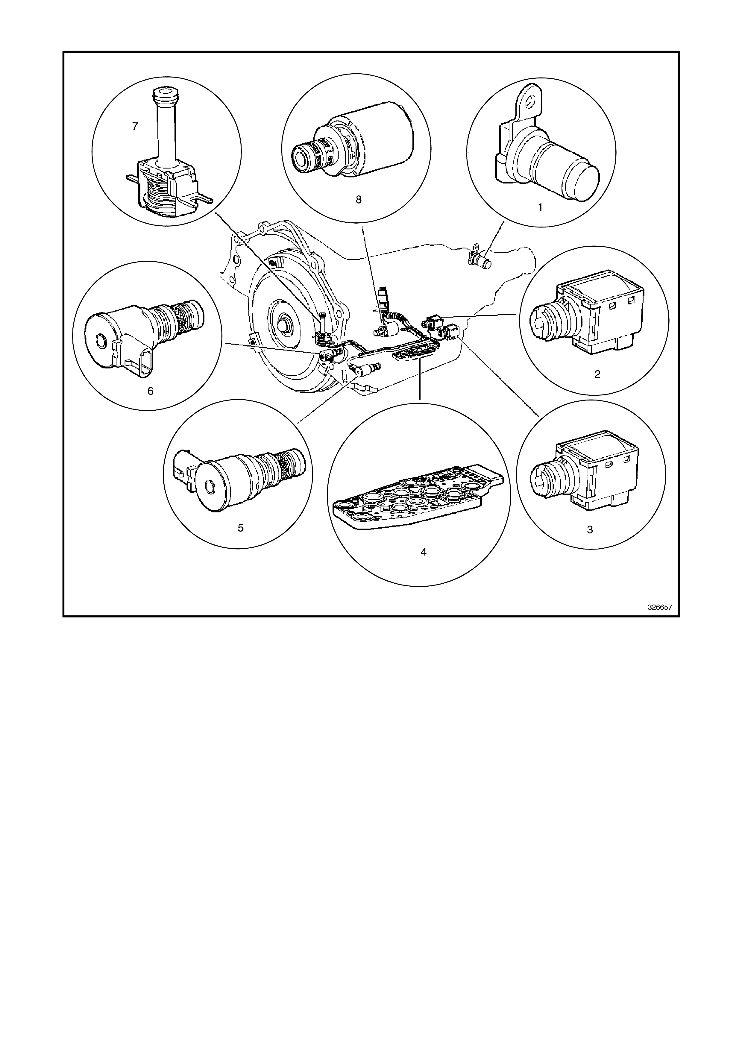
Figure 6C3-1-6 Automatic Transmission Internal Electronic Component Locations
1. Vehicle Speed Sensor (VSS)
2. Shift Solenoid B (SS) Valve
3. Shift Solenoid A (SS) Valve
4. Automatic Transmission Fluid Pressure (TFP) Manual Valve Position Switch
5. Shift Solenoid (SS) Valve Assembly
6. Torque Converter Clutch Pulse Width Modulation (TCC PWM) Solenoid Valve
7. Torque Converter Clutch (TCC) Solenoid Valve
8. Pressure Control Solenoid (PCS) Valve
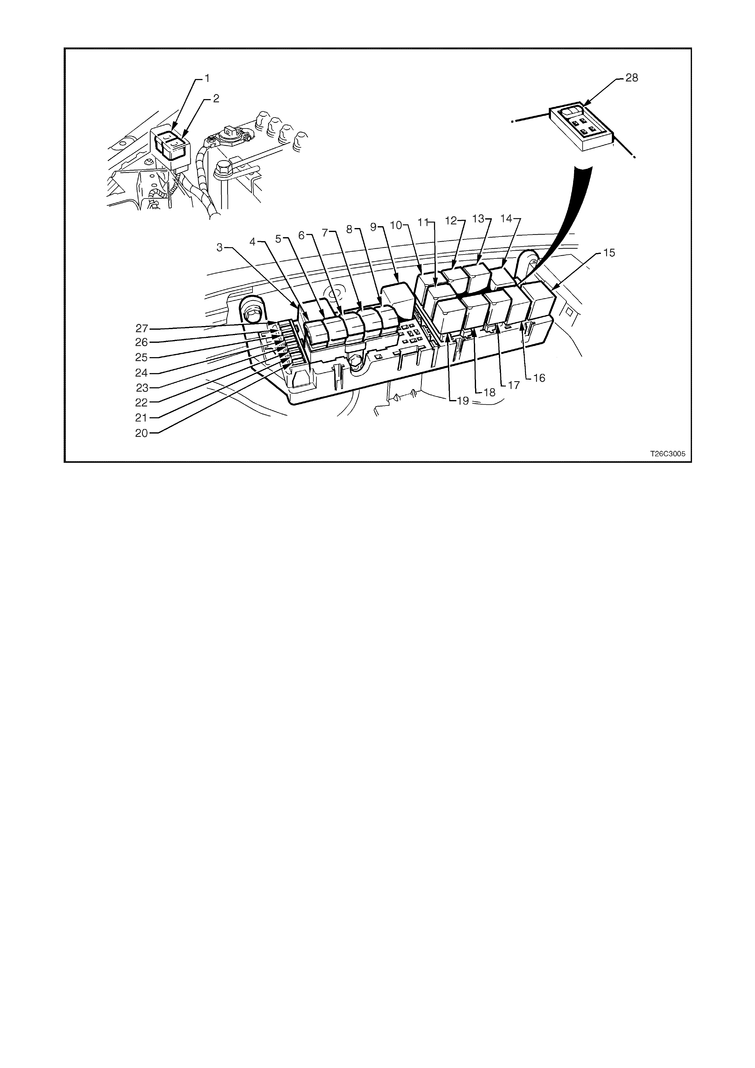
Figure 6C3-1-7 Engine Compartment Fuse/Relay Panel
1. Fan 1 Fusible Link FU 15. Start Relay
2. Fan 2 Fusible Link FT 16. Headlamp High Beam Relay
3. Engine Fan Relay (Low Speed) 17. Fuel Pump Relay
4. Lighting Fusible Link FQ 18. Front Wiper Relay
5. ABS Fusible Link FR 19. Headlamp Low Beam Relay
6. Engine Fusible Link FS 20. Injectors / Ignition Fuse F35
7. Main Fusible Link FJ 21. Injectors / Ignition Fuse F34
8. Blower Fusible Link FY 22. Engine Sensors Fuse F33
9. Engine Cont. (EFI) Relay 23. Automatic Transmission Fuse F32
10. Horn Relay 24. Engine Control / BCM Fuse F31
11. A/C Relay 25. LH Headlamp Fuse F30
12. Theft Horn Relay 26. RH Headlamp Fuse F29
13. Fog Lamp Relay 27. Fuel Pump Fuse F28
14. Engine Fan Relay (High Speed) 28. Throttle Relaxer Control Module Fuse F36
1.1 PO WERTRAIN CONTROL MODULE (PCM)
The Powertrain Control Module (PCM), is located
in the engine com partm ent. The PCM is the control
centre of the vehicle. It controls the following:
• Fuel metering system.
• Transmission shifting.
• Ignition timing.
• Knock Sensor (KS).
• Evaporative Emission Control System (EECS)
Purge.
• Cooling fan.
• A/C system.
• Check Powertrain Lamp (CPL).
• Theft Deterrent (Injector control).
The PCM constantly monitors the information from
various sensors, and controls the systems that
affect vehicle performance. The PCM also
perfor ms a diagnos tic function of the syst em. It can
recognise operational problems. The PCM also
alerts the driver through the Check Powertrain
Lamp (CPL) via the Class II serial data
communication line to the Powertrain Interface
Module (PIM). This is where the PIM converts the
Class II serial data communication to Universally
Asynchronous Receiving/Transmitting (UART).
This UART serial data communication is then sent
from the PIM to the Body Control Module (BCM)
then f rom the BCM to the Instr ument Panel Cluster .
When the PCM detects a malfunction, it stores a
Diagnostic Trouble Code (DTC).
GE N 3 0004
1
2
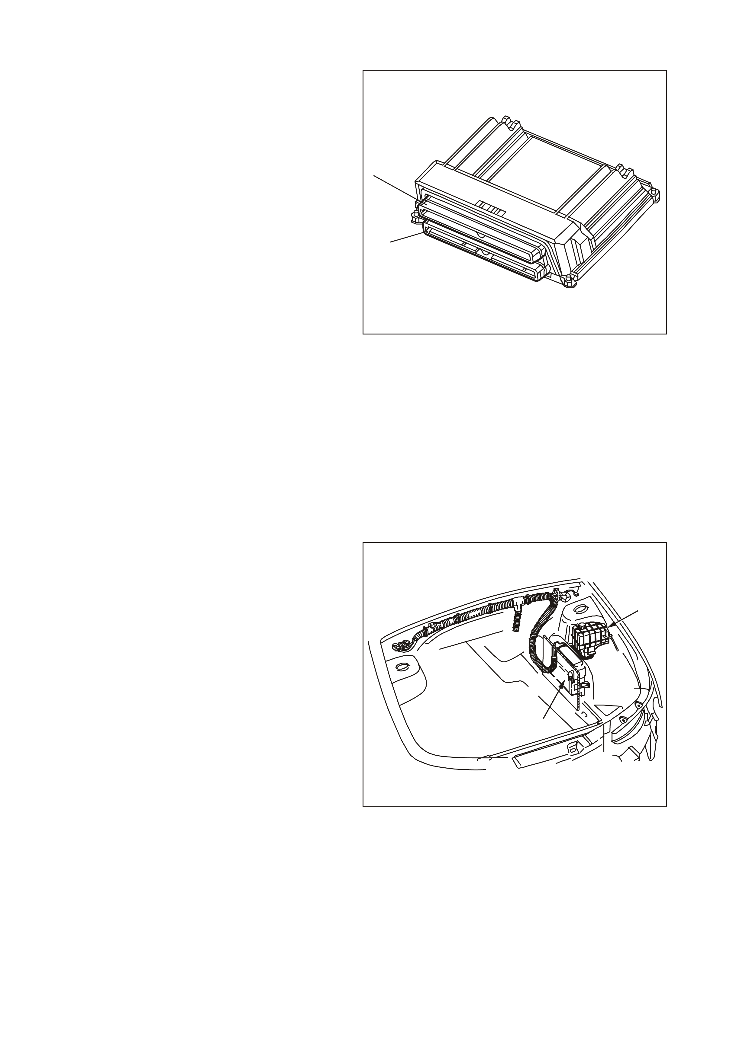
Figure 6C3-1-8 Powertrain Control Module
1. Connector J1 BLUE
2. Connector J2 RED
A stored DTC will identify the problem areas. This
will aid the technician in making repairs.
The PCM supplies either 5.0 or 12.0 volts to power
various sensors or switches. This is done through
resistanc e in the PCM. The resistanc e is so high in
value that a test lamp will not illuminate when
connected to the circuit. In some cases, even an
ordinary shop voltmeter will not give an accurate
reading because its resistance is too low.
Therefore, a digital multimeter (DMM) (J 39200)
with at least 10 megaohms input impedance is
required to ensure accurate voltage readings.
The PCM controls output circuits such as the
injector s, IAC, cooling fan relays, etc. by controlling
the earth or the power feed circuits through
transistor s or a device called a “ Driver” in the PCM.
The two exceptions to this are the fuel pump relay
control circuit and the automatic transmission
pressure control solenoid (PCS). The fuel pump
relay is the only PCM controlled circuit where the
PCM controls the +12 volts sent to the coil of the
relay. The earth side of the fuel pump relay coil is
connected to engine earth. The PCM supplies
current to the PCS and m onitors how m uch cur rent
returns to the PCM on a separate terminal. The
PCM also receives and transmits ser ial data via the
Powertrain Interface Module (PIM) and the serial
data bus.
GE N 3 0005
1
2
Figure 6C3-1-9 Powertrain Control Module
1. Coolant Surge Tank
2. Powertrain Control Module (PCM)

PCM POWER SUPPLIES
Battery voltage is applied to PCM terminals J1-20
and J1-57 at all times via fuse F31 and ignition
voltage is applied to PCM terminal J1-19 via fuse
F14 whenever the ignition switch is in the ON or
START position. The PCM is earthed from
terminals J1-01, J1-40, J2-01, and J2-40 to earth
points E5 and E15.
PCM FIVE VOLT REFERENCE CIRCUITS
The PCM has two five volt reference circuits. The
five volt reference circuit number one supplies five
volts to the following sensors:
• The Throttle Position (TP) Sensor
• The Manifold Absolute Pressure (MAP) Sensor
• Oil Pressure Sensor
The five volt reference circuit number two supplies
five volts to the following sensor:
• The A/C Pressure Sensor
The PCM monitors the voltage on the 5.0 volt
reference circuit. The following DTCs will set if the
voltage is out of range.
A failure in a f ive volt ref erenc e circ uit will set either
DTC P1635 or P1639.
DTC P1635 FIVE VOLT REFERENCE #1 CIRCUIT
Conditions for running DTC P1635
• The ignition is on.
Conditions for setting DTC P1635
• The five volt reference #1 circuit is out of range.
• All of the above conditions are present for greater than 2 seconds.
Action taken when DTC P1635 Sets
• The PCM illuminates the Check Powertrain Lamp when the diagnostic runs and fails.
• The PCM records the operating conditions at the time the diagnostic fails. The PCM stores this information in
the Freeze Frame/Failure Records.
Conditions for clearing the Check Powertrain Lamp and DTC P1635
• The PCM turns the Check Powertrain Lamp OFF after one ignition cycle that the diagnostic runs and does
not fail.
• A last test failed (Current DTC) clears when the diagnostic runs and does not fail.
DTC P1639 FIVE VOLT REFERENCE #2 CIRCUIT
Conditions for running DTC P1639
• The ignition is on.
Conditions for setting DTC P1639
• The five volt reference #2 circuit is out of range.
• All of the above conditions are present for greater than 2 seconds.
Action taken when DTC P1639 Sets
• The PCM illuminates the Check Powertrain Lamp when the diagnostic runs and fails.
• The PCM records the operating conditions at the time the diagnostic fails. The PCM stores this information in
the Freeze Frame/Failure Records.
Conditions for clearing the Check Powertrain Lamp and DTC P1639
• The PCM turns the Check Powertrain Lamp OFF after one ignition cycle that the diagnostic runs and does
not fail.
• A last test failed (Current DTC) clears when the diagnostic runs and does not fail.
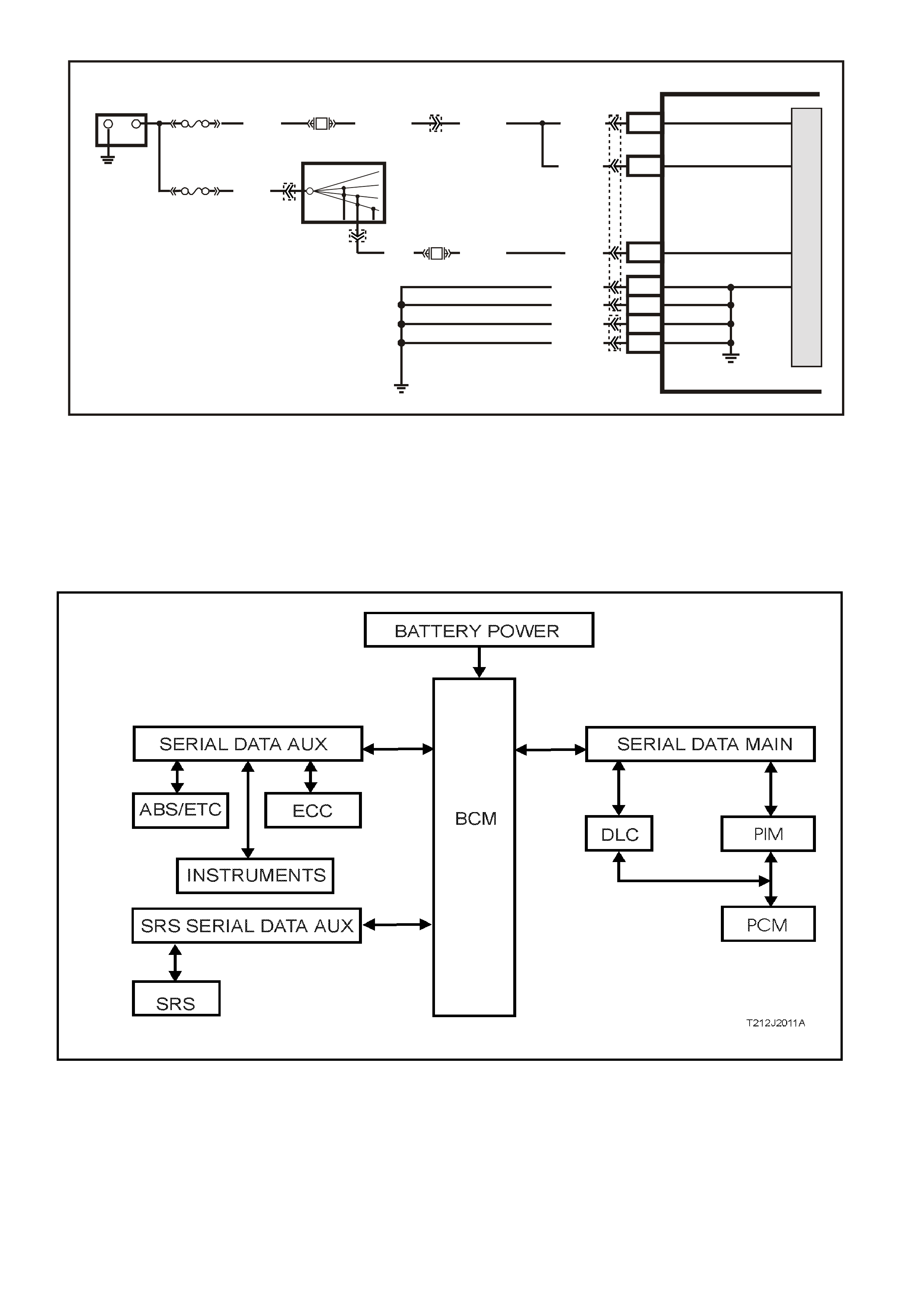
Figure 6C3-1-10 PCM Battery, Ignition and Earth Circuits
SERIAL DATA COMMUNICATION (BUS MASTER)
Various devices; system control modules of the vehicle, as well as TECH 2 communicate with each other. The
communication between control m odules and comm unication with the TECH 2 diagnostic scan tool is achieved on
the ser ial comm unication lines us ing serial data. Serial data transf ers inform ation in a linear fashion - over a single
line, one bit at a tim e. The ser ial data line is ref erred to as the ‘data bus’. Exc luding the GEN III V8 PCM, all control
modules communicating on the data bus communicate using UART communication.
Figure 6C3-1-11 System Overview - Serial Communication
UART is a 5 volt data line that toggles the voltage to earth ( 0 volts) at a f ixed bit pulse width during c om m unication.
UART trans mits data at the rate of 8.2 kilobits per sec ond (8192 bits/sec). With UART comm unication, when there
is no communication on the data line, the system voltage will be 5 volts.
G3PCM021PT
PCM
J1-20
J1-57
M
I
C
R
O
+-
BATTERY
FS
(1040) O (740)O/B (740)
O (740)
O (740)
J1-19 IGNITION
BATTERY
BATTERY
FJ
R (2H)
LOC . E 1
15a 15 50
30 OFF/ON
LOCK
ACC
IGN
START
IGNITION SWITCH
P (3)
YE122 YE112
YE123
YB44
YB44
F14 P (39)
J1-01
J1-40
J2-01
J2-40
LOC. E5/E15
EARTH
EARTH
EARTH
EARTH
B/R (750)
B/R (750)
B/R (750)
B/R (750)
F31
P/B (39)

The GEN III V8 PCM us es Class 2 comm unication.
This type of communication toggles the data line
from 0 volts to 7 volts at either a s hor t or long puls e
width at a rate of 10.4 kilobits per second
(average). With Class 2 communication, when
there is no communication on the data line, the
system voltage will be 0 volts.
As the ‘Class 2’ communication is different to
UART (different languages), communication
between the modules is incom patible, and as such,
requires a Powertrain Interface Module (PIM) to
convert Class 2 communication into UART, and
UART into Class 2 (a translator).
TECH 2 is able to communicate with both UART
and Class 2 control modules.
On all VX and WH Models, the BCM is the Bus
Master of the serial data communication system.
The BCM periodically polls (surveys) each device
on the data bus and requests status data.
T212J1012
11
0
1
00
1
0
1
0
5V
0V
UART
CLASS 2
11 1
111
000 0
000
7V
0V
Figure 6C3-1-12 Serial Data Digital Wave Form
On vehicles fitted with a GEN III V8, the devices (control modules) the BCM polls are:
• Powertrain Interface Module (PIM).
• Instrument cluster (INS).
• Antilock Brake/Electronic Traction Control System (ABS/ETC) Module.
• Supplemental Restraint System (SRS) Sensing and Diagnostic Module (SDM).
• Electronic Climate Control (ECC) Module.
• TECH 2.
The data provided by each device may be utilised by any device connected to the bus.
Each device has a unique response Message Identifier Word (MIW) for ease of identification.
The bus master ( BCM) polls each device with a serial data m essage which includes that devic es MIW . The device
responds by putting a s erial data m ess age onto the bus which includes its MIW and data, of which is retrieved and
utilised by any device requiring it.
The BCM polls each device for a status update, once every 300 milliseconds. The exception to this being the PIM
(GEN III V8) which is polled twice every 300 milliseconds. The PIM will construct a serial data message from
inform ation requested from the PCM via the Class 2 com munication. T his construc ted serial data mes sage is then
placed on the serial data bus.
When the ignition switch is turned from the OFF position to the ON position, the BCM will communicate with the
PCM via the PIM for theft deterrent purposes. If the BCM does not receive an OK TO START message from the
PIM within 0.5 seconds of ignition on, the auxiliary data bus is isolated via switching from the BCM.
The isolation of the auxiliary data bus during this period eliminates the possibility of a device failure other than the
BCM, or PIM, causing a problem on the serial data bus and inhibiting theft deterrent communications.
This period (short loop time) continues until the PIM responds with an acknowledgment or for a maximum of five
seconds after which the BCM will switch to the standard polling sequence and a no start condition will occur.
Following succ essful thef t deterrent com munications, the BCM begins sequential polling of devices on the bus and
normal system operation is established.
When the ignition switch is in the OFF position, the BCM continues to poll, allowing for TECH 2 communications
and external control of the bus prior to the ignition being switched on.
DIAGNOSTIC INFORMATION
The diagnostic tables and functional checks in the Service Information are designed to locate a faulty circuit or
component through logic based on the process of elimination. The tables in the Service Information are prepared
with the understanding that the vehicle:
• Functioned correctly at the time of assembly.
• There are no multiple faults.
• The problem currently exists.

The PCM perf orms a continual self-diagnosis on certain control functions. The PCM indicates the source of a fault
through the use of Diagnostic Trouble Codes (DTCs). The DTCs are four digit codes (P0XXX or P1XXX). W hen a
fault is detected by the PCM, a DTC will be set and stored in the memory of the PCM and the Check Powertrain
Lamp may illuminate.
RECORDING TEST RESULTS (DIAGNOSTIC EXECUTIVE)
The Diagnostic Exec utive is a unique segm ent of the PCM sof tware which is designed to co-or dinate and prioritise
the diagnostic procedures as well as define the protocol for recording and displaying their results. The main
responsibilities of the Diagnostic Executive are:
• DTC Information
DTC Information indicates the status of the diagnostic testing for a specific DTC. It contains information on
pass / fail status of the test, when the diagnostic test failed and if the DTC is requesting the illum ination of the
Check Powertrain Lamp.
• Freeze Frame / Failure Records
Freeze fram e / failur e records ar e stored any time a diagnostic tes t fails. T he PCM has the ability to store up to
six freeze frame / failure records. When a diagnostic test fails, records are stored in the first fail position. If a
different diagnostic test fails, a second fail record position. Additional failed diagnostic tests for different DTCs
also store fail records until the fail record memory is full. The PCM has the ability to store six freeze frame /
failure r ecords, if m ore than six DT C freeze fram e failure recor ds are stored, the f ail records are replaced on a
first in, first out basis.
The freeze frame / failure records data list has 32 parameters for data capture. W hen a DTC is set, the PCM
will capture all 32 parameters at the time the DTC is logged.
In addition to the regular data list parameters found in the freeze frame / failure records data list, there is
additional information available about the DTC diagnostics:
• First Odometer - Vehicle kilometre value when the DTC failure first recorded.
• Last Odometer - Vehicle kilometre value when the DTC fail is recorded.
• Fail Counter - Number of ignition cycles with failure (DTC was set).
• Pass Counter - Number of ignition cycles with diagnostic passes (DTC was not set again).
• Not Run Counter - Number of ignition cycles without diagnostic run (DTC conditions were not tested).
• System Status
T he System Status (I/M Flag) stores inf orm ation on which diagnostic s have run. If a system diagnostic has run,
the system status flag (yes/no) will be set.
• Warm-Up Cycles
Records the number of warm-up cycles that have been achieved since the DTC was set
GENIIIGB006
FREEZE FRAME
FAILURE RECORDS
PASS/FAIL REPORTS CHECK POWERTRAIN
LAMP CONTROL
OPERATING CONDITIONS DTC
IGNITION COUNTER D TC INFO RMAT ION
DTC STATUS
WARM-UPS
TRIPS
D TC INFO RMAT ION
SYSTEM STATUS
1COUNTER
0-40
COUNTER
0-80
2
3
4
5
6
History
MIL SVS or Message Requested
Last Test Failed
Test Failed Since Cleared
Not Run Since Cleared
Failed This Ignition
Oxygen Senors
Knock Sensors
Cooling Fan
Vehicle Speed
Idle Speed Control
A/C System
System Voltage
DIAGNOSTIC EXECUTIVE
Figure 6C3-1-13 Diagnostic Executive

TECH 2 SCAN TOOL: FREEZE FRAME / FAILURE RECORDS DATA DISPLAY
SCAN POSITION Q UNITS DISPLAYED R DATA VALUE S
ENGINE SPEED RPM 0 RPM
DESIRED IDLE SPEED RPM 0 RPM
ENG. COOLANT TEMP (E CT) DEGREES C VARIES
START UP ECT DEGREES C VARIES
THROTTLE POSI TI ON 0-100 % 0 %
ENGINE LOAD % %
BARO kPa kPa
BARO SENSOR VOLTS VOLTS VOLTS
MAP SENSOR kPa kPa
MAP SENSOR VOLTS VOLTS VOLTS
MASS AIR FLOW GRAM /SEC GRAM /SEC
FUEL SYSTEM STATUS OPEN LOOP/
CLOSED LOOP OPEN LOOP/
CLOSED LOOP
LEFT SHORT TERM FUEL TRIM
(BANK 1) % +0% to -0%
RIGHT SHORT TERM FUEL TRIM
(BANK 2) % +0% to -0%
LEFT LONG TERM FUEL TRIM
(BANK 1) % +0% to -0%
RIGHT LONG TERM FUEL TRIM
(BANK 2) % +0% to -0%
INJECTION PULSE BANK 1 mS mS
INJECTION PULSE BANK 2 mS mS
AIR FUEL RA TI O % 14.7:1
TRANSMISSION RANGE PARK, REVERSE,
NEUTRAL, DRIVE 4
OD, DRIVE 3 / D,
DRIVE 2, DRIVE 1,
INVALID
PARK, REVE RS E, NEUTRAL, DRIV E 4 OD, DRIV E 3 / D, DRI VE
2, DRIVE 1, INV A LID
CURRENT GEAR 1,2,3,4 1,2,3,4
AT Output S peed ( Auto Trans) RPM RPM
TCC BRAKE SWITCH ON / OFF ON / OFF
TCC SOLENOID ON / OFF ON / OFF
TCC PWM ON / OFF ON / OFF
VEHICLE SPEED km/h km/h
TIME FROM START TIME 0:00:00
FIRST ODOMETER km km
LAST ODOMETER km km
FAIL COUNT E R # #
PASS COUNTER # #
NOT RAN COUNTER # #
PCM PROGRAMMING
The PCM for this vehicle application does not
contain a removable PROM, instead it uses an
EEPROM (Flash Memory) which is non removable.
From the factory, the PCM is programmed with the
proper calibrations for vehicle operation. In the
event that the PCM is replaced, or an updated
calibration is required to correct a vehicle's
operating condition, the new PCM or the new
calibration will require the use of the Tech 2 scan
tool for down loading to the EEPROM (Flash
Memory). Down loading is accomplished through
the vehicle Data Link Connector (DLC) using the
Tech 2 scan tool.
The service replacement PCM EEPROM (Flash
Memory) will not be programmed. DTC P0601 and
P0602 indicates the Flash Memory is not
programmed or has malfunctioned.
NOTE: The PCM used in this vehicle application is
not interchangeable with any other V8 GEN III
program. Only the PCM part number for this
vehicle must be used.
Refer to Section 6C3-3 of the VX Series Service
Information for this service programming
procedure.
GE N 3 0005
1
2
Figure 6C3-1-14 Powertrain Control Module Location
1. Coolant Surge Tank
2. Powertrain Control Module (PCM)
DTC P0601 POWERTRAIN CONTROL, MODULE (PCM) MEMORY
Conditions for running DTC P0601
• The ignition switch is in the crank position or the run position.
Conditions for setting DTC P0601
• The PCM is unable to correctly read data from the EEPROM (flash memory).
Action taken when DTC P0601 Sets
• The PCM illuminates the Check Powertrain Lamp when the diagnostic runs and fails.
• The PCM records the operating conditions at the time the diagnostic fails. The PCM stores this information in
the Freeze Frame/Failure Records.
Conditions for clearing the Check Powertrain Lamp and DTC P0601
• A last test failed (Current DTC) clears when the diagnostic runs and does not fail.
• A History DTC clears after fourty consecutive warm-up cycles, if this or any other emission related
diagnostic does not report any failures.
• Use a Tech 2 tool in order to clear the CPL/DTC.
DTC P0602 POWERTRAIN CONTROL MODULE (PCM) NOT PROGRAMMED
Conditions for running DTC P0602
• The ignition switch is in the run position.
Conditions for setting DTC P0602
• No software data is present in the PCM.
Action taken when DTC P0602 Sets
• The PCM illuminates the Check Powertrain Lamp (CPL) when the diagnostic runs and fails.
• The PCM records the operating conditions at the time the diagnostic fails. The PCM stores this information in
the Freeze Frame/Failure Records.
Conditions for clearing the Check Powertrain Lamp and DTC P0602
• The PCM turns the Check Powertrain Lamp OFF after one ignition cycle that the diagnostic runs and does
not fail.
• A last test failed (Current DTC) clears when the diagnostic runs and does not fail.
• A History DTC clears after fourty consecutive warm-up cycles, if this or any other emission related
diagnostic does not report any failures.
• Use a Tech 2 tool in order to clear the CPL/DTC.
Techline

PCM/PIM/BCM SECURITY LINK
Once the PCM, PIM and or BCM have been replaced, the new module(s) m ust be security linked to each other
using the Tech 2 and TIS. If the procedure is not performed, the engine will not crank or run.
This linking procedure is found under the BODY CONTROL MODULE of TECH 2 and has to be performed as
follows:
Connect TECH 2 to DLC and select:
Diagnostic / (X) 2000 / VX Commodore / Body / Body Control Module / Security / BCM Link to PCM/PIM.
The proc edure ”BCM Link to PCM/PIM” will first ask to selec t the installed engine. If Gen III V8 is selec ted a T IS
program approval is required.
Connect TECH 2 to TIS terminal and select ”Program Approve”. After returning to the vehicle select again the
linking procedure. Now first BCM and PIM are linked and afterwards the PCM – PIM linking is performed
automatically.
For additional information regarding TECH 2 and TECH 2 test modes (including this linking procedure), refer to
TECH 2 DIAGNOSIS FOR BCM in Section 12J-1 LOW SERIES BCM or Sectio n 12J- 2 HIGH SERIES BCM in
the VX Service Information.
PCM MEMORY FUNCTIONS
The following list contain the two types of memory within the PCM.
• RAM
• EEPROM (Flash Memory)
RAM
Random Access Memory (RAM) is the microprocessor scratch pad. The processor can write into, or read from
this m emor y as needed. T his m em ory is volatile and needs a constant s upply of B+ voltage to be retained. If the
B+ voltage is lost, the memory is lost.
EEPROM (FLASH MEMORY)
A new Service Programming System (SPS) has been incorporated with this Gen III PCM. This SPS enables
technicians to directly update the data stored in the Powertrain Control Module (PCM). The part of the PCM
which contains the specif ic calibration data f or a particular vehicle and engine com bination is com m only ref erred
to as the EEPROM. EEPROM is an acronym for Electrically Erasable Programmable Read Only Memory. In
effect, the data in the memory matches the PCM to the vehicle to provide optimum performance, driveability,
and emissions control.
Sometim es EEPROM data is updated to modify engine operations. For example, the EEPROM calibration data
may be changed to adjust ignition timing in order to eliminate a potential detonation condition or improve idle
quality. Before the SPS was implemented, the procedure for updating EEPROM data was to simply replace the
PCM EEPROM unit.
The relative ease of changing engine data has led to increased use of aftermarket EPROMs designed to
enhance performance. Unfortunately, such HOT EEPROMs often cause engine emissions to exceed regulated
standards. In s uch ins tances, ins tallation of an af term ar ket EEPRO M is c onsidered tam pering. Governing bodies
ruled that emission-related control modules must be tamper resistant. These tamper-resistant EEPROMs are
soldered in place as an integral part of the PCM. Updating the EEPROM data is accomplished through flash
programming.
Flash programming refers to the SPS used to transfer (or download) PCM data from a computer terminal and
compact disk-read only memory (CD-ROM) to the vehicle’s PCM. The system is designed so that the vehicle
verification procedures are required to eliminate EEPROM tampering that could increase engine emission levels.
There are three main flash programming techniques listed below:
1. Direct Programming
This is where the vehicle’s Data Link Connector (DLC) is connected directly to a computer terminal. On
screen directions are then followed for downloading.
2. Remote Programming
Reprogramming information is downloaded from a computer terminal to a Tech 2 scan tool. The Tech 2
scan tool is then connected to the vehicle’s Data Link Connector (DLC). On screen directions are then
followed for downloading.
3. Off-Board Programming
The off-board programming method is used when a reprogrammable PCM must be programmed separate
from the vehicle. For example, an independent repair facility may find it necessary to replace a faulty PCM.
On flash programming equipped vehicles, the replacement PCM must be programmed with data for the
specific Vehicle Identification Number (VIN) or the vehicle may not operate properly.
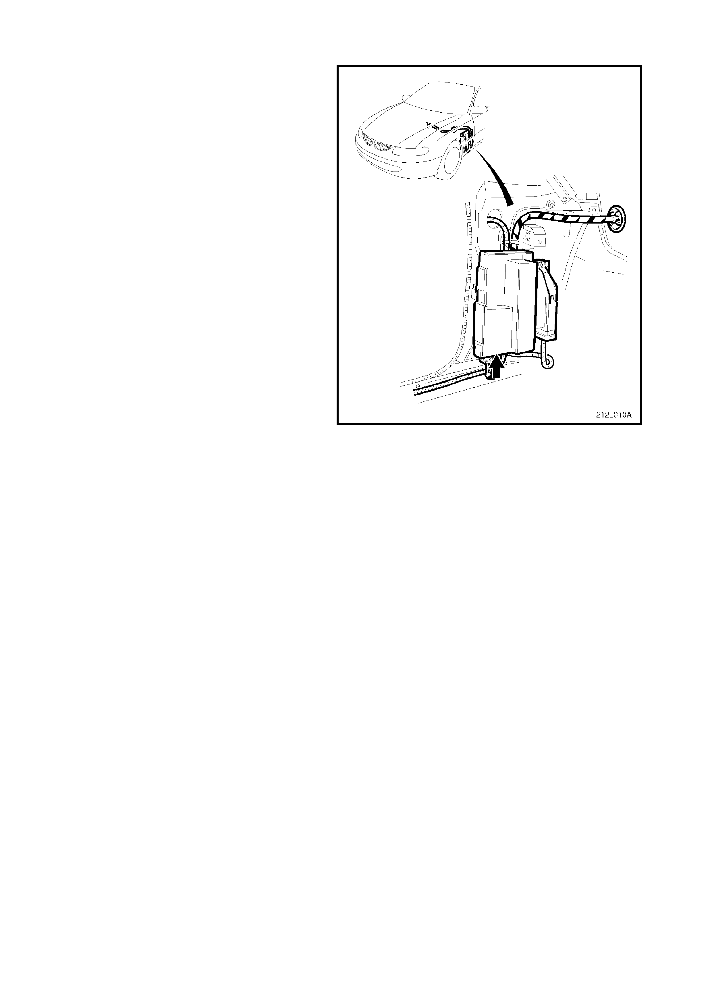
1.2 PO WERTRAIN INTERFACE MODULE (PIM)
The Powertrain Interface Module (PIM), is located
in the passenger compartment behind the left kick
panel. The PIM ac ts as a comm unication translator
between the PCM and other control modules that
use a different serial data protocol. T he GEN III V8
PCM uses Class II serial data to communicate,
while other control modules in the vehicle are
designed to transmit serial data via the
conventional Universal Asynchronous Receive and
Transmit (UART) protocol. Since these two types
of serial data are not compatible, the PIM is
required to transmit data in either direction
between the PCM and other control modules. The
PIM will interpret the serial data information and
translate UART to Class II or Class II to UART to
support the appropriate vehicle control module
operation. The PIM is also used to control the
operation of the starter relay.
Figure 6C3-1-15 PIM location
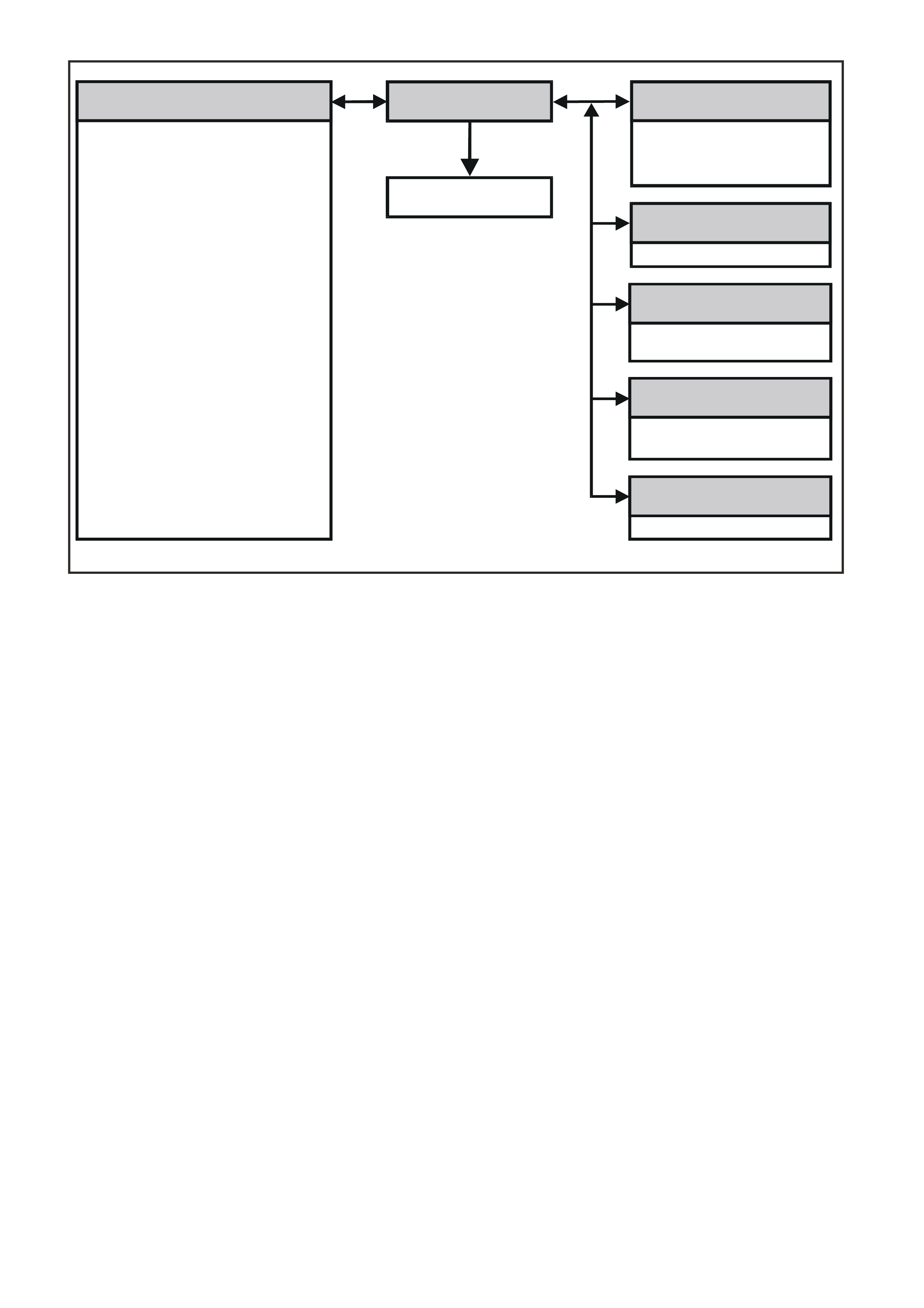
Figure 6C3-1-16 PIM Communication
POWERTRAIN
CONTROL MODULE POWERTRAIN
INTERFACE MODULE
STARTER
RELAY
ENGINE SPEED
COOLANT TEMPERATURE
BAROMETRIC PRESSURE
VEHICLE SPEED
A/C CLUTCH
A/C PRESSURE
LOW SPEED FAN REQUEST
LOW FAN RUN ON
THEFT STATUS
PCM DTC STATUS
CHECK POWERTRAIN LAMP
THROTTLE FAILURE
MAP FAILURE
FUEL USED
FUEL FLOW RATE (INSTANTANEOUS)
ENGINE TYPE
TRANSMISSION CODING
FUEL TYPE
ENGINE OIL CHANGE
TRANSMISSIN OIL CHANGE
SHIFT PATTERN
THROTTLE POSITION
HIGH COOLANT TEMPERATURE
LOW COOLANT LEVEL
OIL PRESSURE SWITCH
PRNDL SWITCH
COMMANDED GEAR
PCM CHIME
THEFT DETERRENT SIGNAL
PRIORITY KEY USER
A/C REQUEST
CRUISE CONTROL STATUS
ETC EQUIPPED
A/C REQUEST
CRUISE CONTROL
ENGAGED
SRS DEPLOYED
THIS IGNITION CYCLE
GEN321
BODY CONTROL
MODULE
ABS/ETC
MODULE
ECC
MODULE
INSTRUMENT
SRS SENSING AND
DIAGNOSTIC MODULE

PIM DIAGNOSTIC TROUBLE CODES
A PIM malfunction may affect vehicle operation and may interrupt starter motor operation. For PIM diagnosis
refer to Section 6C3-2A of this Service Information for PIM DTC diagnosis. There are four (4) PIM DTCs that
will set. Each of these DTCs have corresponding diagnostic tables.
The PIM does not have the mem ory to store any DTC information, so only a current DTC with the Tech 2 scan
tool can be displayed. Once the fault is corrected, the DTC is no longer active.
DTC DTC DESCRIPTION
B2002 Low Speed Fan No BCM Response
B2006 No Serial Data From PCM
B2007 Starter Relay Voltage High
B2009 EEPROM Checksum Error
There are twenty (20) other PIM DTCs that will also set whenever DTC B2006 sets. These DTCs indicate the
loss of part of the Class II serial data. If ther e is a problem with the Class II serial data circ uit, and the PIM does
not receive any of this information a DTC B2006 will set. The Powertrain On Board Diagnostic (OBD) System
Check will identify a problem with the serial data circuit or other circuits, and direct the technician in the proper
direction for diagnosis. There are no PIM DTC tables associated with these twenty (20) PIM DTCs, so always
diagnose the PCM first.
DTC DTC DESCRIPTION
B2017 No Throttle Position Sensor (TPS) Information
B2018 No A/C Clutch Information
B2019 No Engine Speed Information
B2020 No Vehicle Speed Information
B2021 No Commanded Gear Information
B2022 No Transmission Type
B2023 No Low Speed Fan Run On Information
B2024 No Low Speed Fan Request Information
B2025 No Engine Coolant Temp (ECT) Information
B2026 No Fuel Flow Rate Information
B2027 No Fuel Used Counter Information
B2028 No A/C Pressure Information
B2029 No PRNDL Information
B2030 No Engine Oil Information
B2031 No Oil Pressure Information
B2032 No Shift Information
B2033 No Check Powertrain Lamp Information
B2034 No Low Coolant Level Information
B2035 No Barometric Pressure Information
B2036 No PCM Information
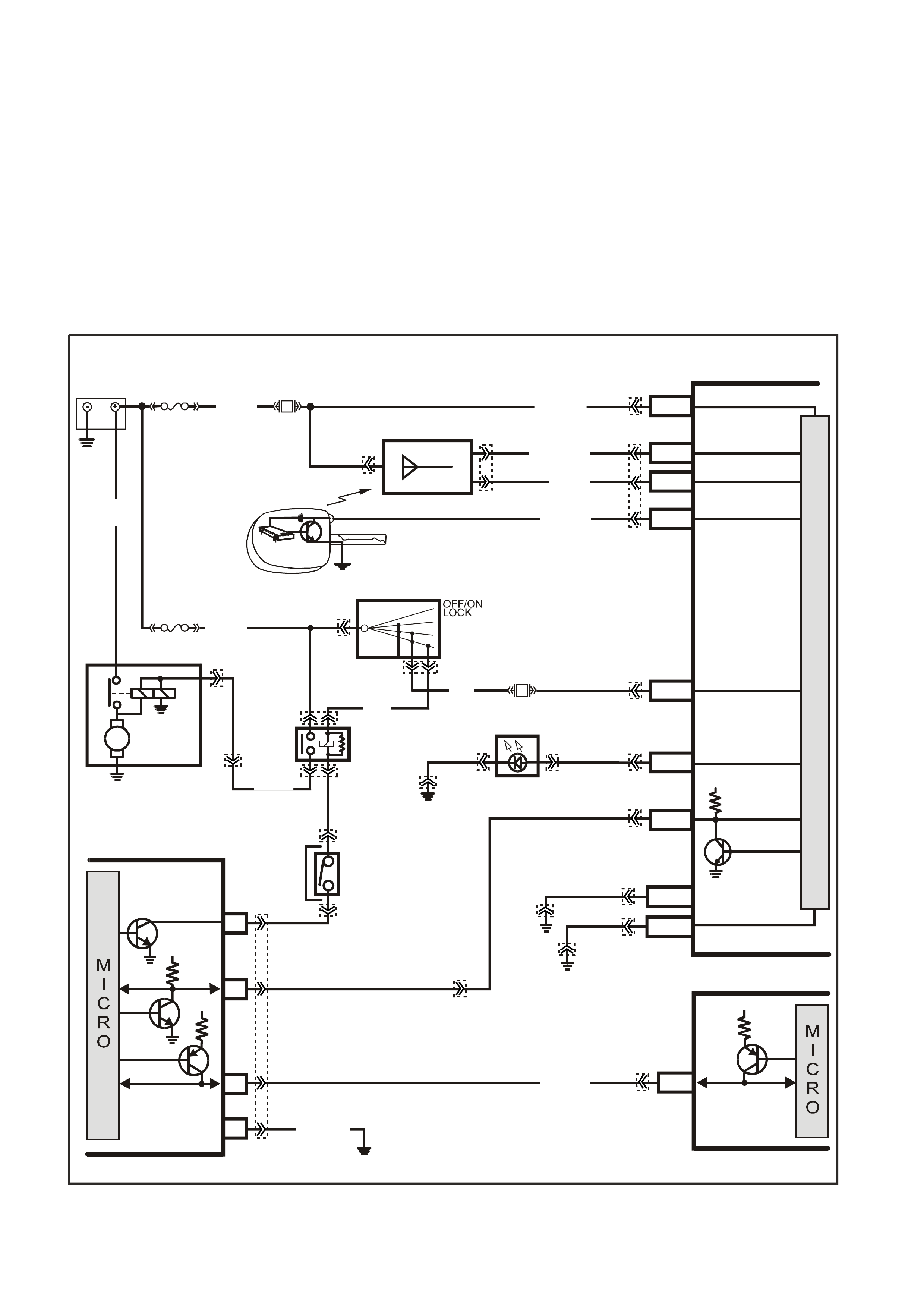
STARTER RELAY
The PIM also controls the operation of the starter relay. When the ignition switch is turned to on, the PIM will
enable the starter relay for one second, if the PIM does not receive the correct security code it will disable the
starter relay. If the PIM receives the correct security code from the BCM, the PIM will continue to enable the start
relay. Once the engine has started and the engine speed is above 500 RPM the PIM will disable the starter relay,
preventing starter engagement while the engine is running.
If the ser ial data bus between the BCM and the PIM should fail ( no polling from the BCM f or m ore than 10 minutes )
after s ucces sf ul theft deter rent com m unic ations, the PIM will allow subsequent star ts, however there will be a crank
delay of one second. If the PIM receives valid communication, normal operation will resume.
If the Class II serial data bus between the PIM and the PCM should fail (no communications for 20 seconds) after
successful theft deterrent communications, the PCM will allow subsequent starts, however there will be a crank
delay of one second. If communications between the PCM and the PIM are re-established, normal operation will
resume.
Figure 6C3-1-17 Starter Circuit
BATTERY MAIN POWER
HIGH SERIES
BCM TERMINALS
NOMINA TED FIRST
BCM
REMOTE
CODED KEY
V/R (229) E1/D12 KEY R EADER
BATTERY
FS
LOC.
E1
LOC. G1
F31
A5/A6O/B (740)
(1040)
REMOTE KEY
RECEIVER
Y (266) E8/D1 RECEIVER DATA
BR/G (271) E7/D11 RECE IVER EARTH
O/B
(740)
FJ
M
I
C
R
O
P
R
O
C
E
S
S
O
R
GY/BLU
(1434)
G3PCM040PT
THEFT DETERRENT
ALERT INDICA TOR
R/B
(1221)
E2/D2 SERIAL DATA
5V
R (2H)
E20/D6 IGNITION
NEUTRAL ST ART
BACK-UP SW.
(FOR AUTO TRANS)
(FOR MANUAL
TRANS)
GY
(434)
R (1)
V/W (6)
F14
START
RELAY
IGN ITIO N SWITC H
15a 15 50
30 ACC
IGN
START
V (5) P (3) P/B
(39)
A6/A8
LBLU
(263) THE FT LED
B/Y
(155)
LOC. E3
B/G
(151) B10/B11 HIGH CURRENT
EARTH
B/Y
(155) ELECTRONIC EARTH
A1/A5
LOC. E3
LOC. E3
PIM
UART
SERIAL
DATA
START
RELAY
5V
6
8
16
7V
7
CLASS 2
SERIAL DATA
B/R (750)
LOC. E5/E15
R/B
(1221)
7V
PCM
J1-58 CLASS 2
SERIAL DATA
Y (1049)
Y
(1049)
STARTER
MOTOR
M
YB215
YE112
YB35
YE104
YE8
YB35
YE114 YB56 YB56
YE49
YB44
YE49
YB44
YB95
YB175
YB164
YB176
YB165
YB175
YB164
YB175
YB164
YB174
YB163
YE114
YE114 YB176
YB165
YE122
YB176
YB165
YB95
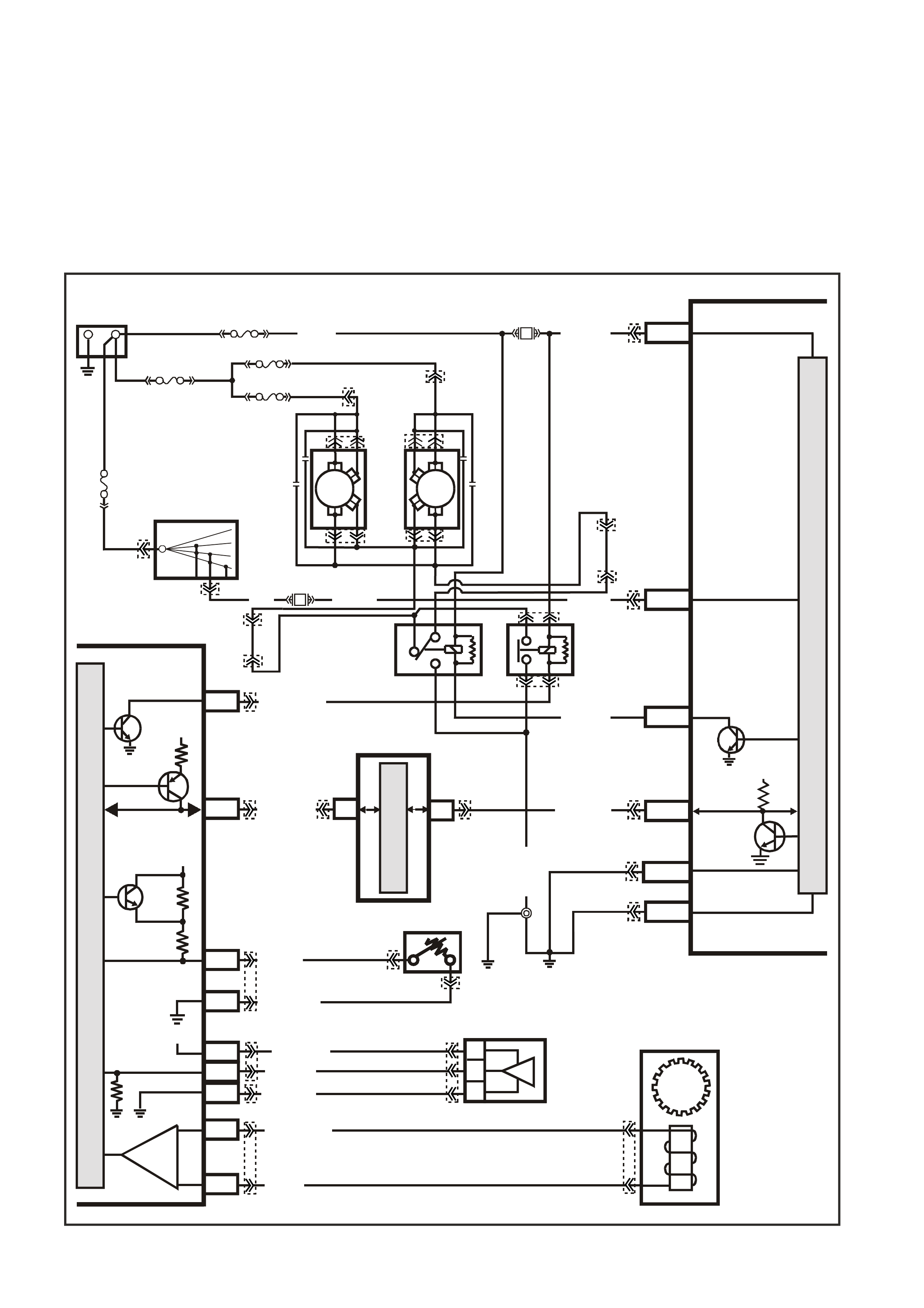
DTC B2002 LOW SPEED FAN NO BCM RESPONSE
Conditions for running DTC B2002
• The ignition is on.
Conditions for setting DTC B2002
• The PIM sends a Low Speed request signals to the BCM , with no response back from the BCM.
Action taken when DTC B2002 Sets
• The PIM will display the DTC only when current.
• The Check Powertrain Lamp (CPL) will not illuminate.
Conditions for clearing DTC B2002
• A current DTC will clear when the PIM receives a Low Speed Fan Response from the BCM.
Figure 6C3-1-18 Cooling Fan Circuit
R/B (1221) E2/D2
IGNITION
LOW
SPEED FAN
M
I
C
R
O
P
R
O
C
E
S
S
O
R
BATTERY MAIN POWER
HIGH SERIES
BCM TERMINALS
NOMINATED FIRST
BCM
15a 15 50
30 OFF/ON
LOCK
ACC
IGN
START
G3PCMO42PT
E20/D6
B7/B7
P (3)
IGNITION SWITCH
O/B (473)
87A
30
87
85
86
87
30
85
86
ENGINE
COOLING
FAN 1
ENGINE
COOLING
FAN RELAY
(LOW SPEED)
ENGINE
COOLING
FAN RELAY
(HIGH SPEED)
P/B (39)
O/Y
(250)
F14
R
YB
G
BLU/W (304)
R/B (1049)
HIGH
CURRENT EARTH
B/Y
(155) A1/A5 ELECTRONIC EARTH
B/G
(151)
LOC.
E2 LOC.
E3
B10/B11
B/R (157)
J1-58
GEN III PCM
PIM
J2-33
HIGH
SPEED FAN
BLUE
FUSIBLE
LINK
LOC.
E1
F31
A5/A6
O/B (740)
ENGINE
COOLING
FAN 2
+-
BATTERY
FS
FT FAN 2
FU FAN 1
(1040)
R
(203)
R
(001)
R
(001)
O/B
(208)
O/BLU
(204)
FJ
R
(001)
R
(2H)
6
7
M
I
C
R
O
CLASS 2 SERIAL DATA
UART SERIAL DATA
7V
CLASS 2
SERIAL DA TA
SERIAL
DATA
5V
GY /B (455)
J1-74 Y (41O)
COOLANT TEMP
SENSOR
ETC SENSOR
SIGNAL
A/C
PRESSURE
SIGNAL
5V
4k
348
Ω
Ω
J1-80
SENSOR
EARTH
SENSOR
EARTH
M
I
C
R
O
P
R
O
C
E
S
S
O
R
J2-21
J2-20
V
EHICLE SPEED
SENSOR
BLU/W (831)
T (832)
IC
V/W (415)
J2-57
J2-14
J1-45
G/O (469)
G/B (259)
A
/C PRESSURE
SENSOR
A
C
B
5V
P/B (39)
BLU/Y
(533)
YB176
YE118
YE104
YE43
YB175
YB164
YB175
YB174
YB176
YB165
YB195
YE113
YE65 YE65
YE123
YE122
YE123
YE122
YE122
YE123
YB44
YE119
YE119
YE140
YE139
YB44
YE104
YE118
YB215 YB215
YB163
YB164
YE43
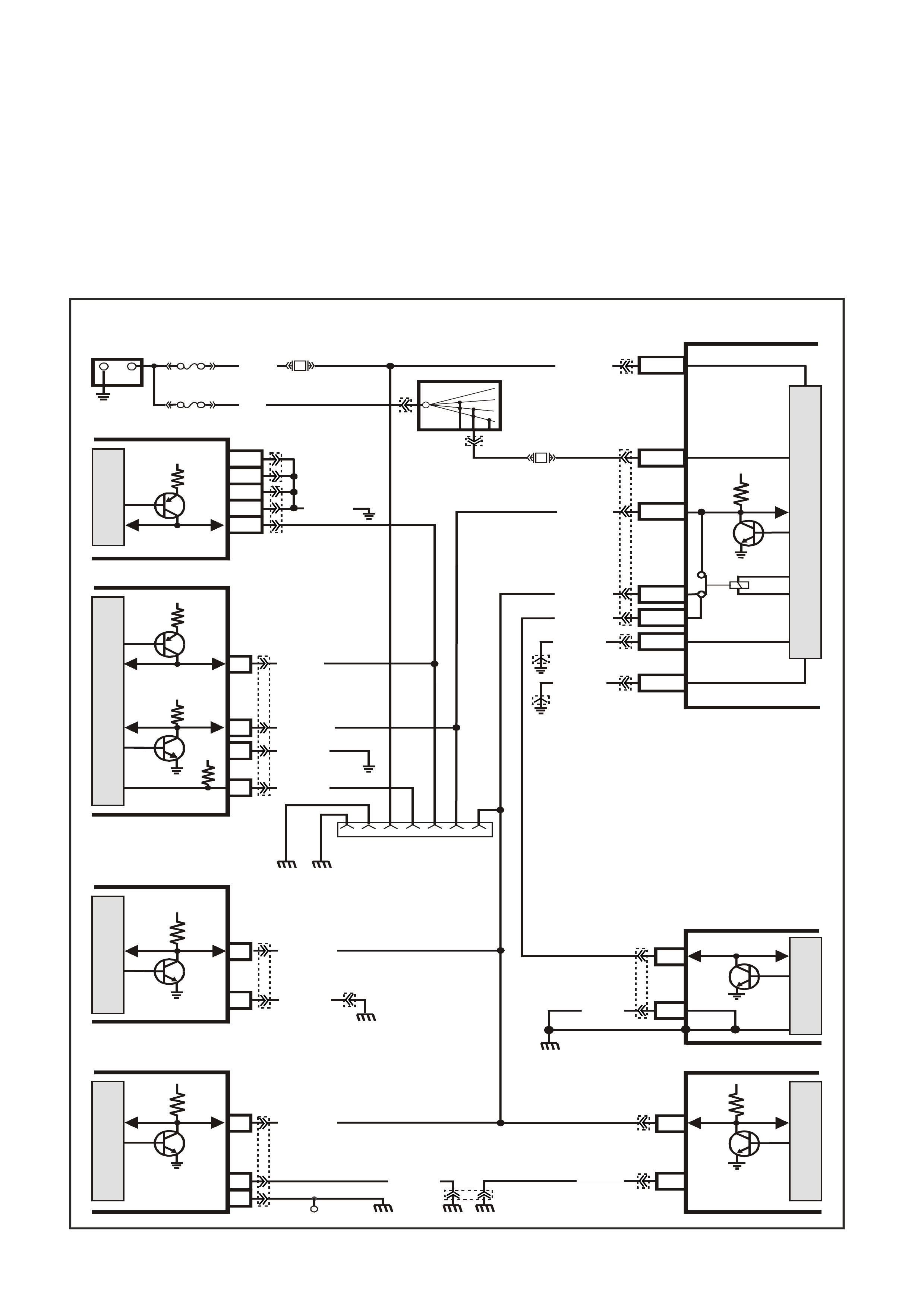
DTC B2006 NO SERIAL DATA FROM PCM
Conditions for running DTC B2006
• The ignition switch is on.
• The ignition voltage is between 5.0 and 17 volts.
Conditions for setting DTC B2006
• PIM does not receive any serial data communication from the PCM.
Action taken when DTC B2006 Sets
• The PIM will display the DTC only when current.
• The Check Powertrain Lamp (CPL) will not illuminate.
Conditions for clearing DTC B2006
• A current DTC will clear when the PIM receives serial data from the PCM.
Figure 6C3-1-19 Serial Data Circuit
B/Y
(155)
B
(150)
LOC. E3
642516 9 1
G3PCM039PT
INSTRUMENTS
ABS/ETC
SRS
ECC
BCM
DATA LINK
CONNECTOR
12
11
19
16
6
16
9
8
6
M
I
C
R
O
M
I
C
R
O
M
I
C
R
O
SERIAL
DATA
SERIAL
DATA SERIAL
DATA
5V
5V 5V
M
I
C
R
O
P
R
O
C
E
S
S
O
R
+
-
BATTERY
FS
F31
A5/A6
O/B (740)
(1040)
BATTERY MAIN POWER
HIGH SERIES
BCM TERMINALS
NOMINATED FIRST
FJ
LOC. E1
R (2)
F14
E20/D6
P/B
(39) IGNITION ON
15a 15 50
30 OFF/ON
LOCK
ACC
IGN
START
IGNITION SWITCH
P
(3)
B/Y (155)
B/G (151)
LOC. E3
LOC. E3
R/B (1221)
G/W (1220)
G/W (1220)
G/W (1220)
G/W (1220)
LOC.G11
LOC.E3
LOC.E2
LOC.E3 EARTH
SERIAL
DATA
B (305)
B/Y (155) 2
B (150)
B/O
(154) B/R
(157)
B/Y(155)
B/R ( 750)
W/B (451)
R/B (1221)
Y (1049)
PIM
M
I
C
R
O
UART
SERIAL
DATA
5V
7V
7V
12V
ELECTRONIC EARTH
HIGH CURRENT
EARTH
A1/A5
B10/B11
E2/D2
E9/D3
E3/D13
SERIAL
DATA
MAIN
SERIAL
DATA AUX.
5V
6
11
7
DIAG. ENABLE
CL ASS 2
SERIAL DATA
LOC. E5/E15
LOC. E5/E15
GEN III V8 PCM
J1-58
J2-01
J2-40
J1-40
J1-01
M
I
C
R
O
CL ASS 2
SERIAL DATA
B/R ( 750)
M
I
C
R
O
YB176
YB165
YB175
YB164
YB174
YB163
YB176
YB165
YB190
YB189
YB89
YE114
YB98
YB66
YE114
YB215
YE122
YE123
YB87
YE114
YE114
YB44
YB44

DTC B2007 STARTER RELAY VOLTAGE HIGH
Conditions for running DTC B2007
• The ignition switch is in the crank position.
• The ignition voltage is between 5.0 and 17 volts.
Conditions for setting DTC B2007
• PIM detects high voltage on the starter relay control circuit.
Action taken when DTC B2007 Sets
• The PIM will display the DTC only when current.
• The Check Powertrain Lamp (CPL) will not illuminate.
Conditions for clearing DTC B2007
• A current DTC will clear when the PIM no longer detects a high voltage on the starter relay circuit.
Figure 6C3-1-20 Starter Relay Circuit
BATTER Y MAIN POWE R
HIGH SERIES
BCM TERMINALS
NOMINA TED FIRST
BCM
REMOTE
CODED KEY
V/R (229) E1/D12 KEY R EADER
BATTERY
FS
LOC.
E1
LOC. G1
F31
A5/A6O/B (740)
(1040)
REMOTE KEY
RECEIVER
Y (266) E8/D1 RECEIVER DATA
BR/G (271) E7/D11 RECE IVER EARTH
O/B
(740)
FJ
M
I
C
R
O
P
R
O
C
E
S
S
O
R
GY/BLU
(1434)
G3PCM040PT
THEFT DETERRENT
ALERT INDICA TOR
R/B
(1221)
E2/D2 SERIAL DATA
5V
R (2H)
E20/D6 IGNITION
NEUTRAL ST ART
BACK-UP SW.
(FOR AUTO TRANS)
(FOR MANUAL
TRANS)
GY
(434)
R (1)
V/W (6 )
F14
START
RELAY
IGN ITIO N SWITC H
15a 15 50
30 ACC
IGN
START
V (5) P (3) P/B
(39)
A6/A8
LBLU
(263) THE FT LED
B/Y
(155)
LOC. E3
B/G
(151) B10/B11 HIGH CURRENT
EARTH
B/Y
(155) ELECTRONIC EARTH
A1/A5
LOC. E3
LOC. E3
PIM
UART
SERIAL
DATA
START
RELAY
5V
6
8
16
7V
7
CLASS 2
SERIAL DATA
B/R (750)
LOC. E5/E15
R/B
(1221)
7V
PCM
J1-58 CLASS 2
SERIAL DATA
Y (1049)
Y
(1049)
STARTER
MOTOR
M
YB215
YE112
YB35
YE104
YE8
YB35
YE114 YB56 YB56
YE49
YB44
YE49
YB44
YB95
YB175
YB164
YB176
YB165
YB175
YB164
YB175
YB164
YB174
YB163
YE114
YE114 YB176
YB165
YE122
YB176
YB165
YB95
DTC B2009 PIM EEPROM CHECKSUM ERROR
Conditions for running DTC B2009
• The ignition switch is in the crank position or run position.
Conditions for setting DTC B2007
• The PIM is unable to correctly read data from its memory.
Action taken when DTC B2007 Sets
• The PIM will display the DTC only when current.
• The Check Powertrain Lamp (CPL) will not illuminate.
Conditions for clearing DTC B2007
• A current DTC will clear when the PIM is able to correctly read data.
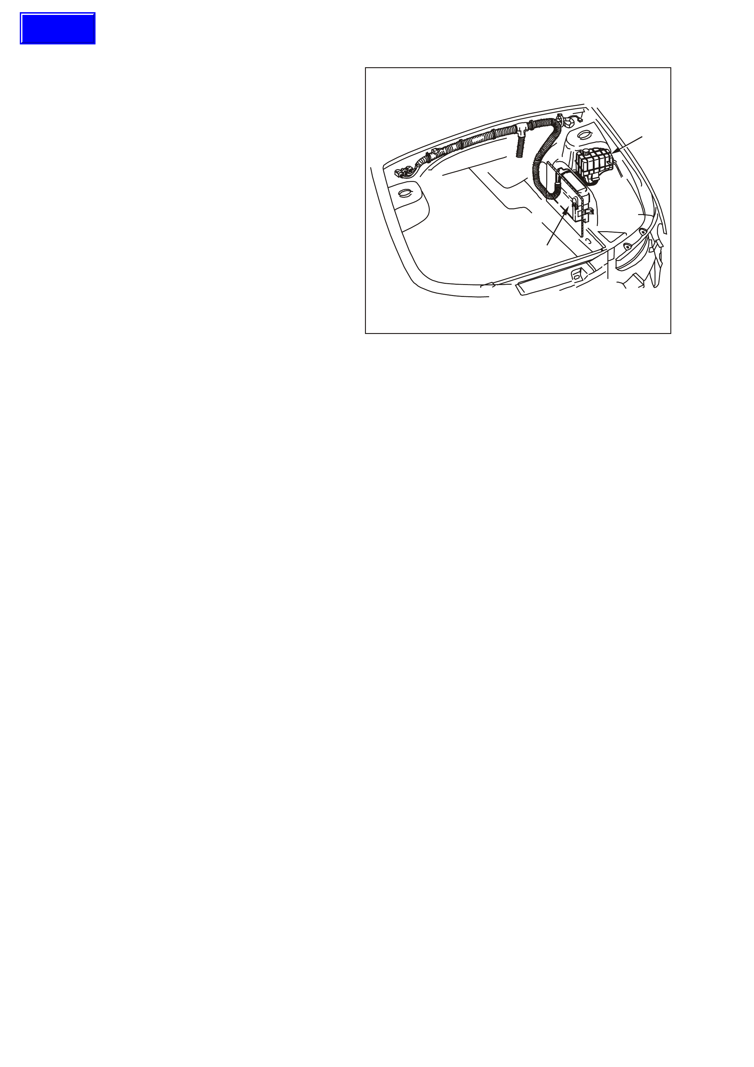
The only action taken if this DTC B2009 is set, is
replacement of the PIM assembly .
GE N 3 0006
1
32
Figure 6C3-1-21 Powertrain Interface Module (PIM)
1. Throttle Relaxer Control Module
2. Powertrain Interface Module
3. Left ‘A’ pillar
1.3 ENGINE INFORMATION SENSORS AND SIGNALS
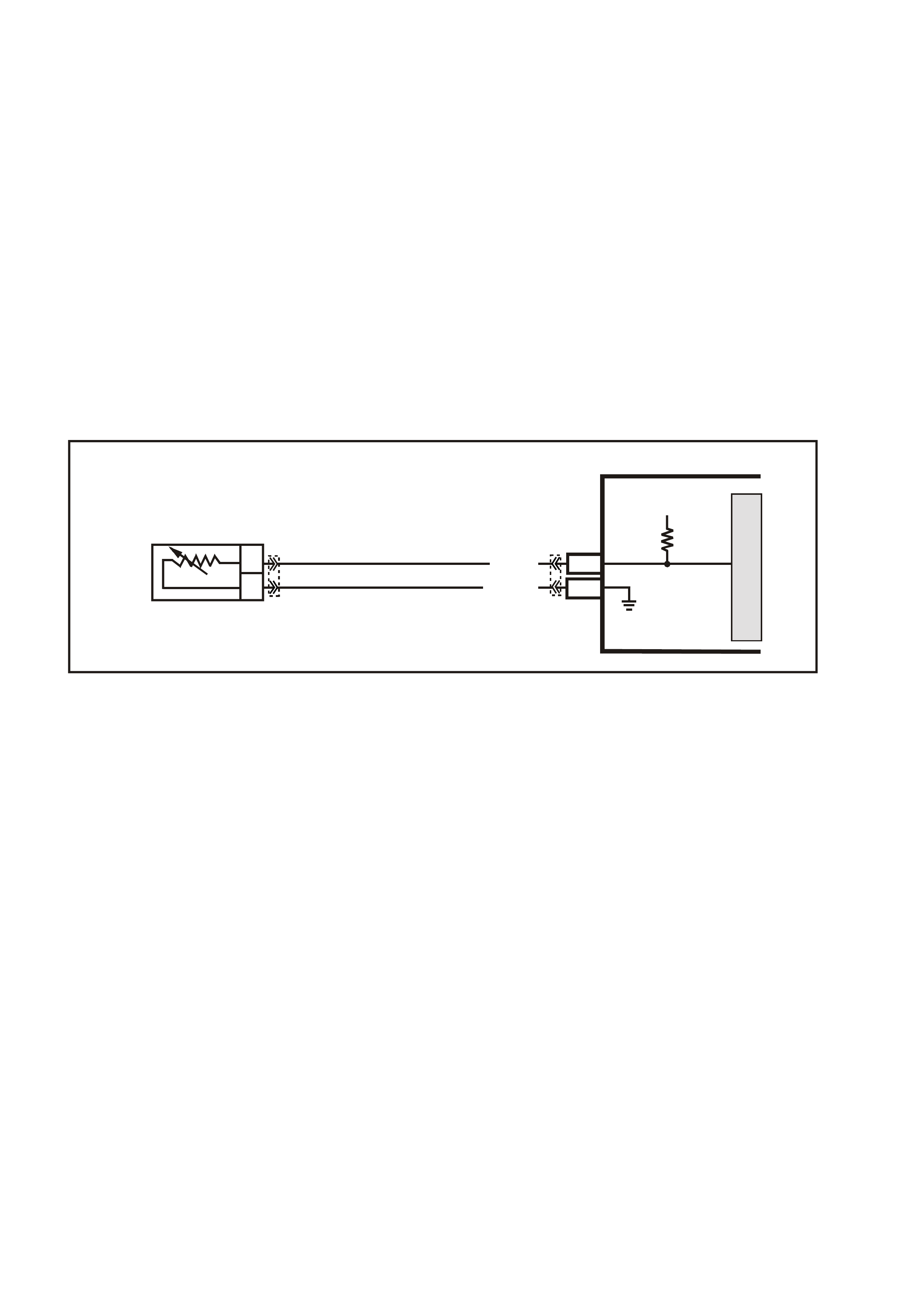
ENGINE COOLANT TEMPERATURE (ECT) SENSOR
The Engine Coolant Temperature (ECT) sensor is
a thermistor, (a resistor that changes value based
on temperature) mounted in the engine coolant
stream. Low engine coolant temperature produces
a high sens or res istance (29k ohm s at -20°C) while
high engine coolant temperature causes low
sensor resistance (180 ohms at 100°C).
The PCM supplies a 5 volt signal voltage to the
sensor through a resistor network in the PCM, and
monitors the circuit voltage, which will change
when connected to the sensor.
The circuit voltage will vary depending on the
resistance of the coolant temperature sensor. The
circuit voltage will be close to the 5 volt level when
the sensor is cold, and will decrease as the sensor
warms. Engine coolant temperature affects most
systems controlled by the PCM.
The PCM uses a dual pull up resistor network to
increase the r esolution through the entire operating
range of engine coolant temperature. When the
coolant temperature is less than 51°C both the 4K
and 348 ohm resistors ar e used. W hen the coolant
temperature reaches 51°C. The PCM switches a
short across the 4K resistor and only the 348 ohm
resistor is used.
As the engine warms, the sensor resistance
becomes less and the voltage at the PCM coolant
temperature sensor signal terminal should
decrease from approximately 4.5 volts when cold
to 0.9 volts at 51°C. At this temperature the PCM
switches the short across the 4k resistor, the
voltage will then rise to 3.5 volts. The voltage will
again decrease as the coolant temperature
increases until at normal engine operating
temperature (95°C), the voltage should be less
than 2.0 volts.
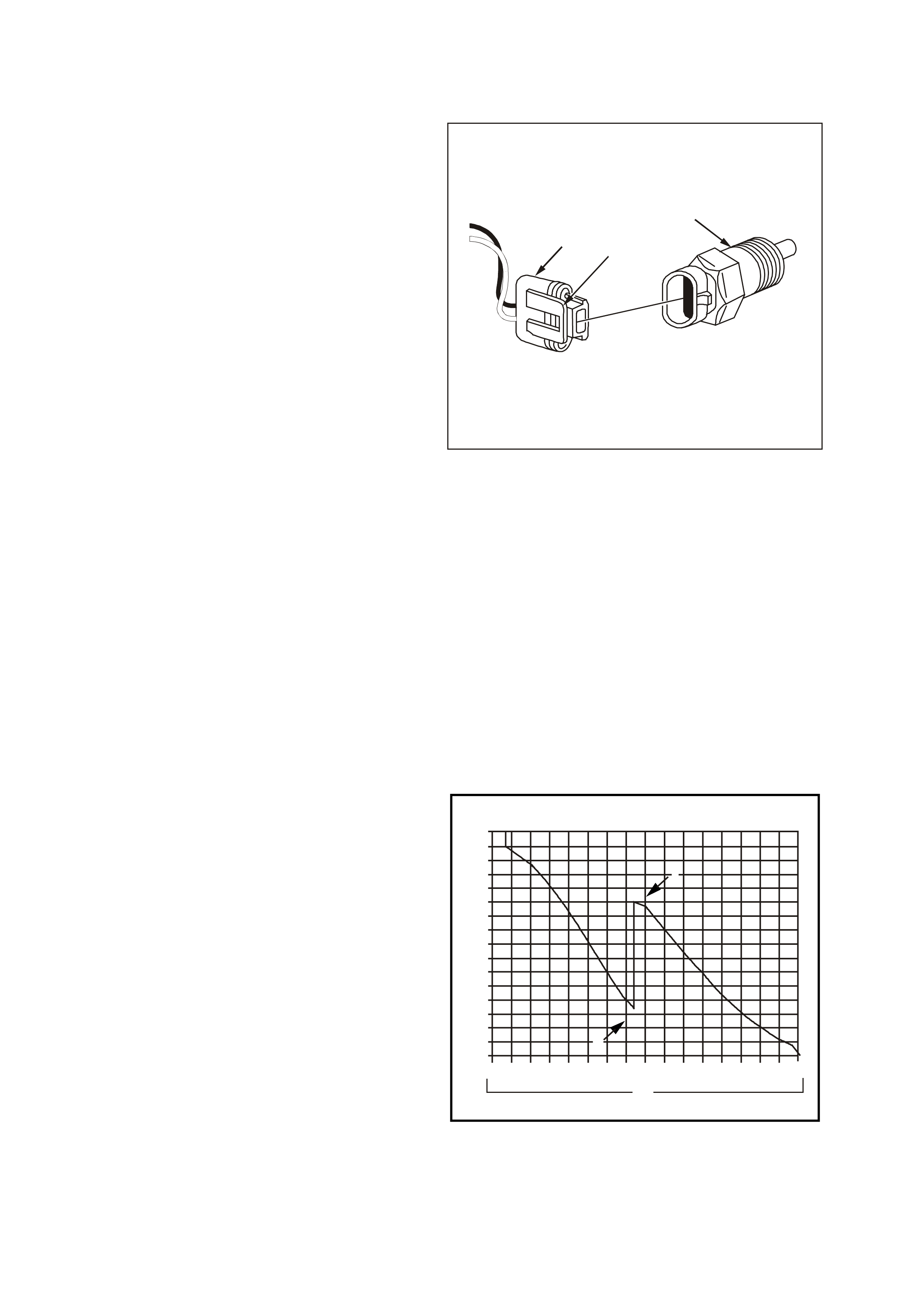
GE N 3 0008
12
3
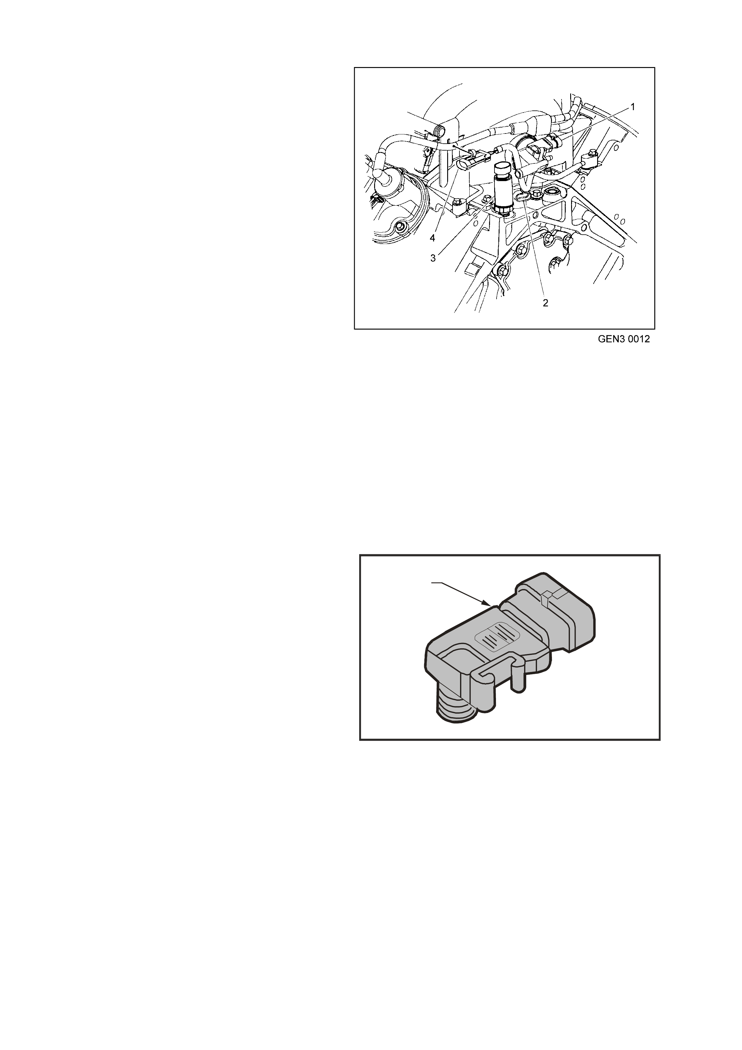
Figure 6C3-1-22 Engine Coolant Temperature
(ECT) Sensor
1. ECT Electrical Connector
2. Connector Tab
3. Engine Coolant Temperature (ECT) Sensor
The following DTCs will set when the PCM detects
a malfunction in the engine coolant temperature
sensor circuit:
DTC P0117: ECT Sensor Circuit Low Voltage.
DTC P0118: ECT Sensor Circuit High Voltage.
DTC P0125: ECT Excessive Time to Closed Loop
Fuel Control.
DTC P1114: ECT Sensor CKT Intermittent Low
Voltage.
DTC P1115: ECT Sensor CKT Intermittent High
Voltage.
DTC P1258: Engine Coolant Over Temp Fuel
Disable
5.72
4.90
4.48
4.16
3.84
3.52
3.20
2.58
2.88
2.24
1.92
1.60
1.28
0.96
0.64
0.32
0.00 -28 -16 -4 7 19 31 49 55 79 91 115 127 139103 15167-40
3
1
2
4
5
4210
ECT Temperature vs Voltage
1. Engine Coolant Temperature Vs. Voltage Table
2. Sensor Voltage Above 50°C
3. Temperature °C
4. Sensor Voltage Below 50°C
5. Volts
Section 6C3-4 of this Service Information contains
a table to check for sensor resistance values
relative to temperature.
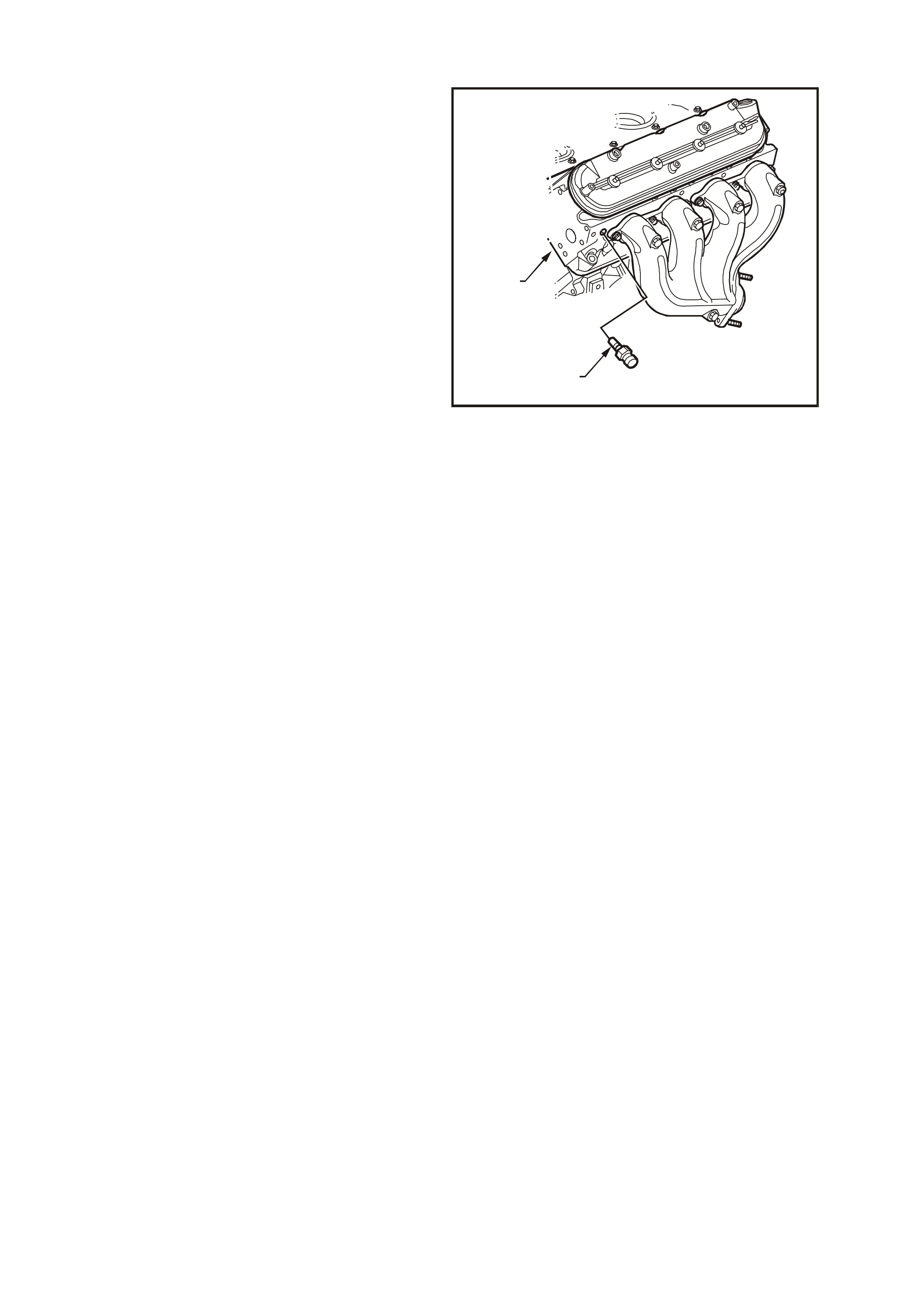
T6B3047
1
2
Figure 6C3-1-23 Engine Coolant Temperature
(ECT) Sensor Location
1. ECT Sensor
2. Left Cylinder Head
DTC P0117 ENGINE COOLANT TEMPERATURE SENSOR CIRCUIT LOW VOLTAGE
Conditions for running DTC P0117
• The engine run time is greater than 10 seconds.
Conditions for setting DTC P0117
• The engine coolant temperature is greater than 139°C.
• All conditions met for at least 45 seconds.
Action taken when DTC P0117 Sets
• The PCM illuminates the Check Powertrain Lamp when the diagnostic runs and fails.
• The PCM will substitute a coolant temperature default value.
The PCM arrives at this default value, by using current intake air temperature, then counting upward to 116°C
at a rate of approximately 7 degrees per minute.
• The PCM will turn on the electric engine cooling fans. This is a FAIL-SAFE action by the PCM to prevent a
possible engine overheat condition, since the DTC indicates an unknown actual coolant temperature.
• The PCM records the operating conditions at the time the diagnostic fails. The PCM stores this information in
the Freeze Frame/Failure Records.
Conditions for clearing the Check Powertrain Lamp and DTC P0117
• The PCM turns the Check Powertrain Lamp OFF when the diagnostic runs and does not fail.
• A last test failed (current DTC) clears when the diagnostic runs and does not fail.

DTC P0118 ENGINE COOLANT TEMPERATURE SENSOR CIRCUIT HIGH VOLTAGE
Conditions for running DTC P0118
• The engine run time is greater than 10 seconds.
Conditions for setting DTC P0118
• The engine coolant temperature is greater than –38.9°C.
• All conditions met for at least 45 seconds.
Action taken when DTC P0118 Sets
• The PCM illuminates the Check Powertrain Lamp when the diagnostic runs and fails.
• The PCM will substitute a coolant temperature default value.
The PCM arrives at this default value, by using current intake air temperature, then counting upward to 116°C
at a rate of approximately 7 degrees per minute.
• The PCM will turn on the electric engine cooling fans. This is a FAIL-SAFE action by the PCM to prevent a
possible engine overheat condition, since the DTC indicates an unknown actual coolant temperature.
• The PCM records the operating conditions at the time the diagnostic fails. The PCM stores this information in
the Freeze Frame/Failure Records.
Conditions for clearing the Check Powertrain Lamp and DTC P0118
• The PCM turns the Check Powertrain Lamp OFF when the diagnostic runs and does not fail.
• A last test failed (current DTC) clears when the diagnostic runs and does not fail.
DTC P0125 ENGINE COOLANT TEMPERATURE SENSOR EXCESS TIME TO CLOSED LOOP FUEL
CONTROL
Conditions for running DTC P0125
• DTCs P0112, P0113, O0117, P0118 are not set.
• The engine is operating.
• The engine coolant temperature is between -36°C and 40°C at engine start-up.
• The intake air temperature is greater than -7°C.
• The vehicle speed is greater than 1.6 km/h.
Conditions for setting DTC P0125
• The closed loop coolant temperature of 34°C is not reached within a predetermined time. The maximum
allowable time depends on the start-up coolant temperature and the amount of airflow into the engine. The
range for the time is from 2 minutes and 20 seconds to 22 minutes and 30 seconds.
Action taken when DTC P0125 Sets
• The PCM stores the DTC information into memory when the diagnostic runs and fails.
• The Check Powertrain Lamp will not be illuminated.
• The PCM records the operating conditions at the time the diagnostic fails. The PCM stores this information in
the Freeze Frame/Failure Records.
Conditions for clearing the Check Powertrain Lamp and DTC P0125
• A last test failed (current DTC) clears when the diagnostic runs and does not fail.

DTC P1114 ENGINE COOLANT TEMPERATURE SENSOR CIRCUIT INTERMITTENT LOW VOLTAGE
Conditions for running DTC P1114
• The engine run time is greater than 10 seconds.
Conditions for setting DTC P1114
• The engine coolant temperature is greater than 139°C fore at least one second.
Action taken when DTC P1114 Sets
• The PCM stores the DTC information into memory when the diagnostic runs and fails.
• The Check Powertrain Lamp will not be illuminated.
• The PCM records the operating conditions at the time the diagnostic fails. The PCM stores this information in
the Freeze Frame/Failure Records.
Conditions for clearing the Check Powertrain Lamp and DTC P1114
• A last test failed (current DTC) clears when the diagnostic runs and does not fail.
DTC P1115 ENGINE COOLANT TEMPERATURE SENSOR CIRCUIT INTERMITTENT HIGH VOLTAGE
Conditions for running DTC P1115
• The engine run time is greater than 60 seconds.
Conditions for setting DTC P1115
• The engine coolant temperature is less than -35°C for at least one second.
Action taken when DTC P1115 Sets
• The PCM stores the DTC information into memory when the diagnostic runs and fails.
• The Check Powertrain Lamp will not be illuminated.
• The PCM records the operating conditions at the time the diagnostic fails. The PCM stores this information in
the Freeze Frame/Failure Records.
Conditions for clearing the Check Powertrain Lamp and DTC P1115
• A last test failed (current DTC) clears when the diagnostic runs and does not fail.
DTC P1258 ENGINE COOLANT OVER TEMP FUEL DISABLED
Conditions for running DTC P1258
• DTCs P0117, P0118, are not set.
• The engine is running.
Conditions for setting DTC P1258
• The engine coolant temperature is greater than 132°C.
• The above conditions present for greater than 10 seconds.
Action taken when DTC P1258 Sets
• The PCM will randomly disable several injectors.
• The PCM illuminates the Check Powertrain Lamp when the diagnostic runs and fails.
• The PCM records the operating conditions at the time the diagnostic fails. The PCM stores this information in
the Freeze Frame/Failure Records.
Conditions for clearing the Check Powertrain Lamp and DTC P1258
• The PCM turns the Check Powertrain Lamp OFF when the diagnostic runs and does not fail.
• A last test failed (current DTC) clears when the diagnostic runs and does not fail.
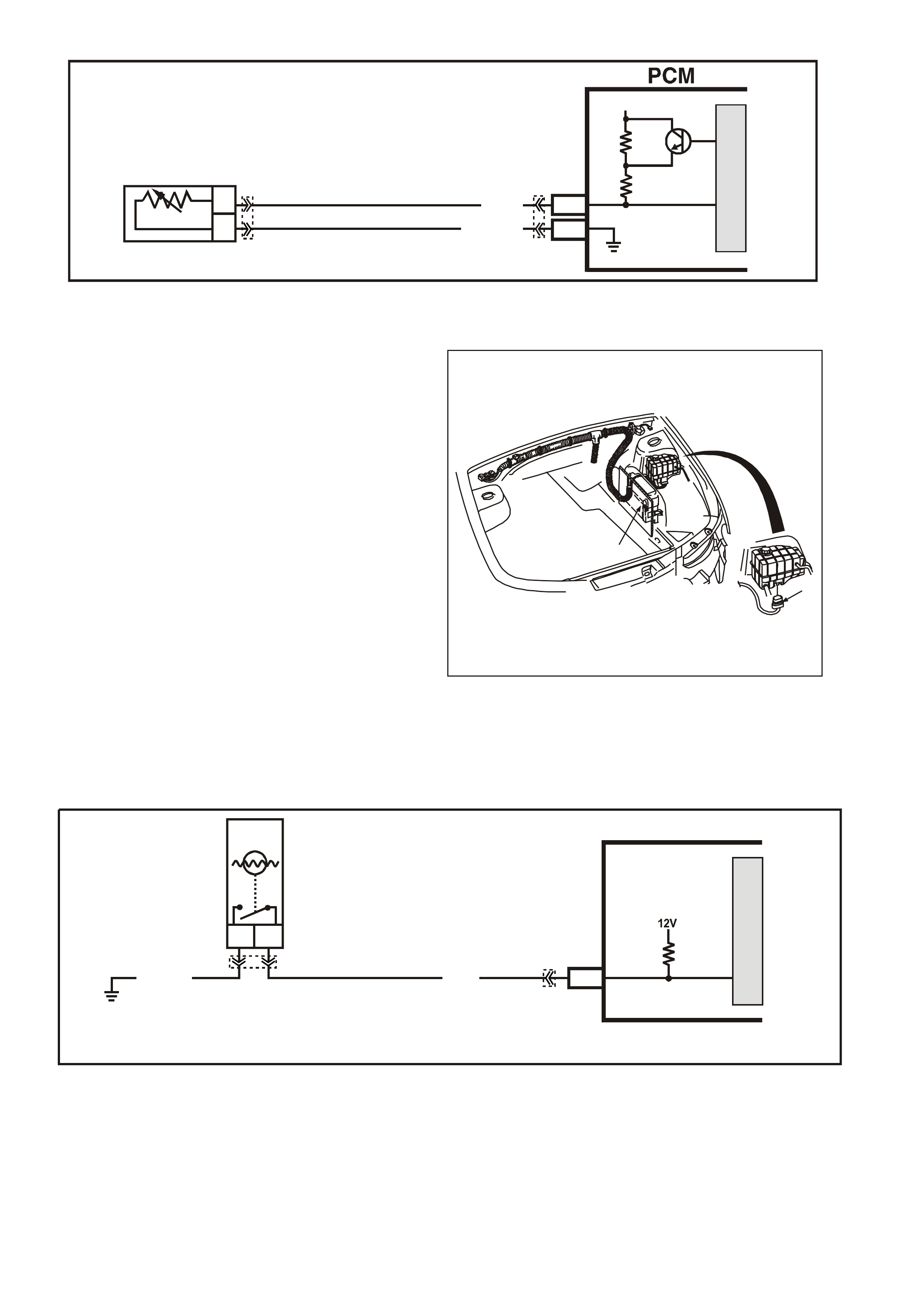
Figure 6C3-1-24 Engine Coolant Temperature (ECT) Sensor Circuit
ENGINE COOLANT LEVEL SWITCH
The engine coolant level switch is used to inform
the PCM when the coolant level is at a calibrated
low level.
The engine coolant level switch is a reed switch
and is used to inform the PCM when the coolant
level is at a calibrated low level. When the engine
coolant is at norm al operating level, the float inside
the surge tank will rise, the magnet in the float will
cause the reed s witc h contacts to close, pulling the
PCM supplied voltage low. When the coolant level
is low, the float will fall, the reed switch contacts
will open, causing the PCM voltage signal to go
high. The PCM will then send a serial data
mes sage to the instrum ent panel cluster instructing
the instrument panel cluster to turn ON the Low
Coolant Warning Lamp.
For diagnosis of the engine coolant level switch,
refer to Section 6C3-2C in this Service
Information.
The engine coolant level switch is located in the
coolant s urge tank. T he engine coolant level switch
is serviceable only by replacing the surge tank.
Refer to Section 6B3 Engine Cooling in VX
Service Information, for surge tank replacement.
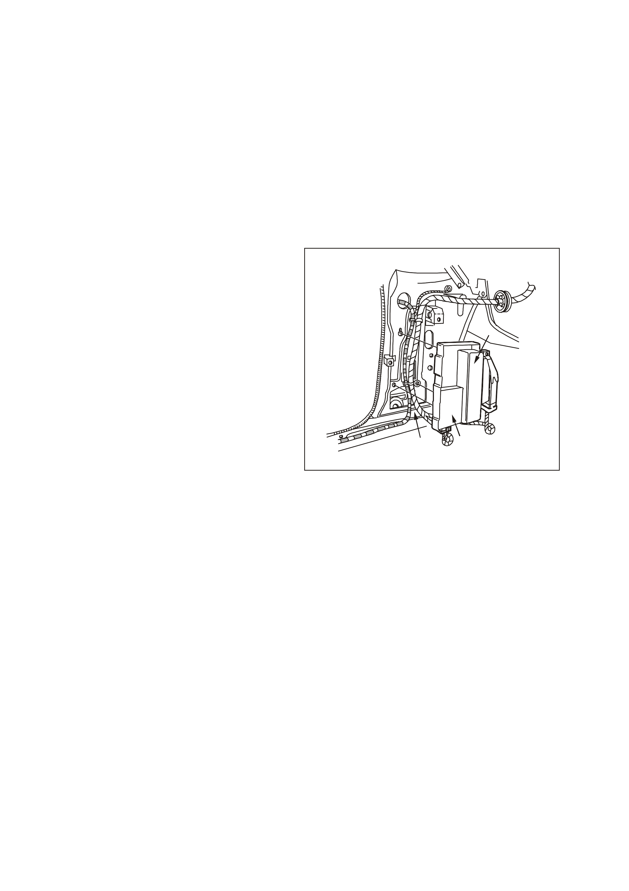
GE N 3 0153
2
1
Figure 6C3-1-25 Engine Coolant Level Switch Location
1. Engine Coolant Level Switch Electrical Connector
2. Powertrain Control Module (PCM)
Figure 6C3-1-26 Engine Coolant Level Switch Circuit
G3PCM004PT
J1-80
J1-74
B
A
ENGINE COOLANT
TEMPERATURE SENSOR
SENSOR EARTH
ETC SENSOR SIGNAL
5V
4k
348
Ω
Ω
Y (41 0)
GY/B (455)
YE65 YE122
M
I
C
R
O
G3PCM013PT
J1-30
BA
LOW COOLANT
LEVEL SWITCH
LOW COOLANT LEVEL
SWITCH SIGNAL
PCM
G (69)B/R (750)
LOC. E5/E15
M
I
C
R
O
YE122
YE131
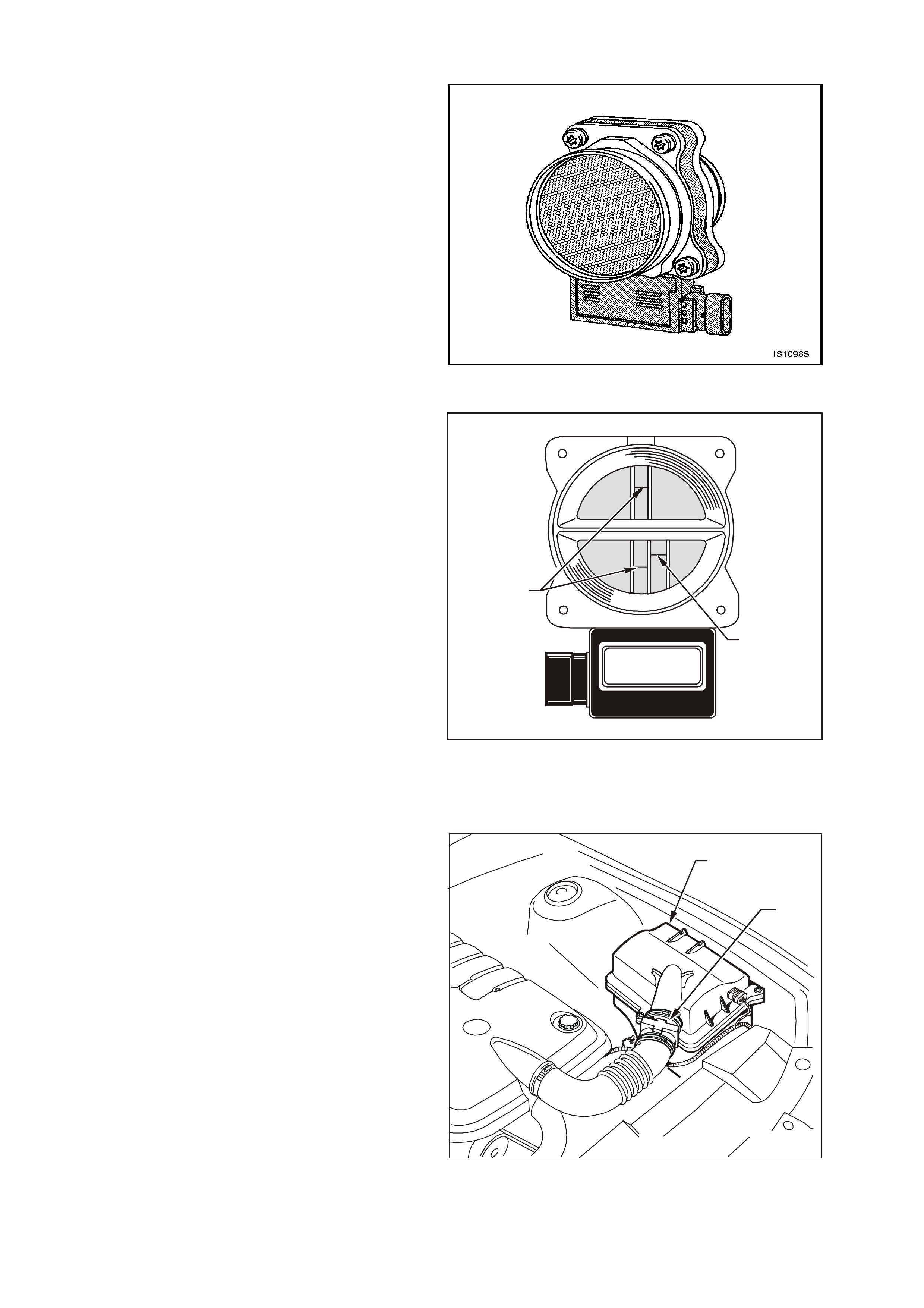
MASS AIR FLOW (MA F) SENSOR
The Mass Air Flow (MAF) sensor utilises a heated
element type of operation. A heated element in the
MAF is placed in the air flow stream of the engine
intake system. The heating element is maintained
at a constant temperature differential above the air
temperature. The amount of electrical power
required to maintain the heated element at the
proper tem perature is a direct function of the mass
flow rate of the air past the heated element.
The following DTCs are set when the PCM detects
a malfunction in the MAF sensor circuit:
• DTC P0101: Mass Air Flow System
Performance.
• DTC P0102: MAF Sensor Circuit Low
Frequency.
• DTC P0103: MAF Sensor Circuit High
Frequency.
Figure 6C3-1-27 Mass Air Flow (MAF) Sensor
Three sensing elements are used in this system.
One senses am bient air temperature and uses two
calibrated resistors to establish a voltage that is
always a function of ambient temperature. This
ambient sensor is mounted in the lower half of the
sensor housing. The other two sensing elements
are heated to a predetermined temperature that is
significantly above ambient air temperature. The
two heated elements are connected electrically in
parallel and mounted directly in the air flow stream
of the sens or housing. O ne sensor is in the top and
the other sensor is in the bottom of the sensor
housing. This is done so that the air meter is less
sensitive to upstream ducting configurations that
could skew the flow of air through the housing.
GE N 3 0010
1
2
Figure 6C3-1-28 Sensing Elements
1. Heater Sensing Elements
2. Ambient Temperature Sensor
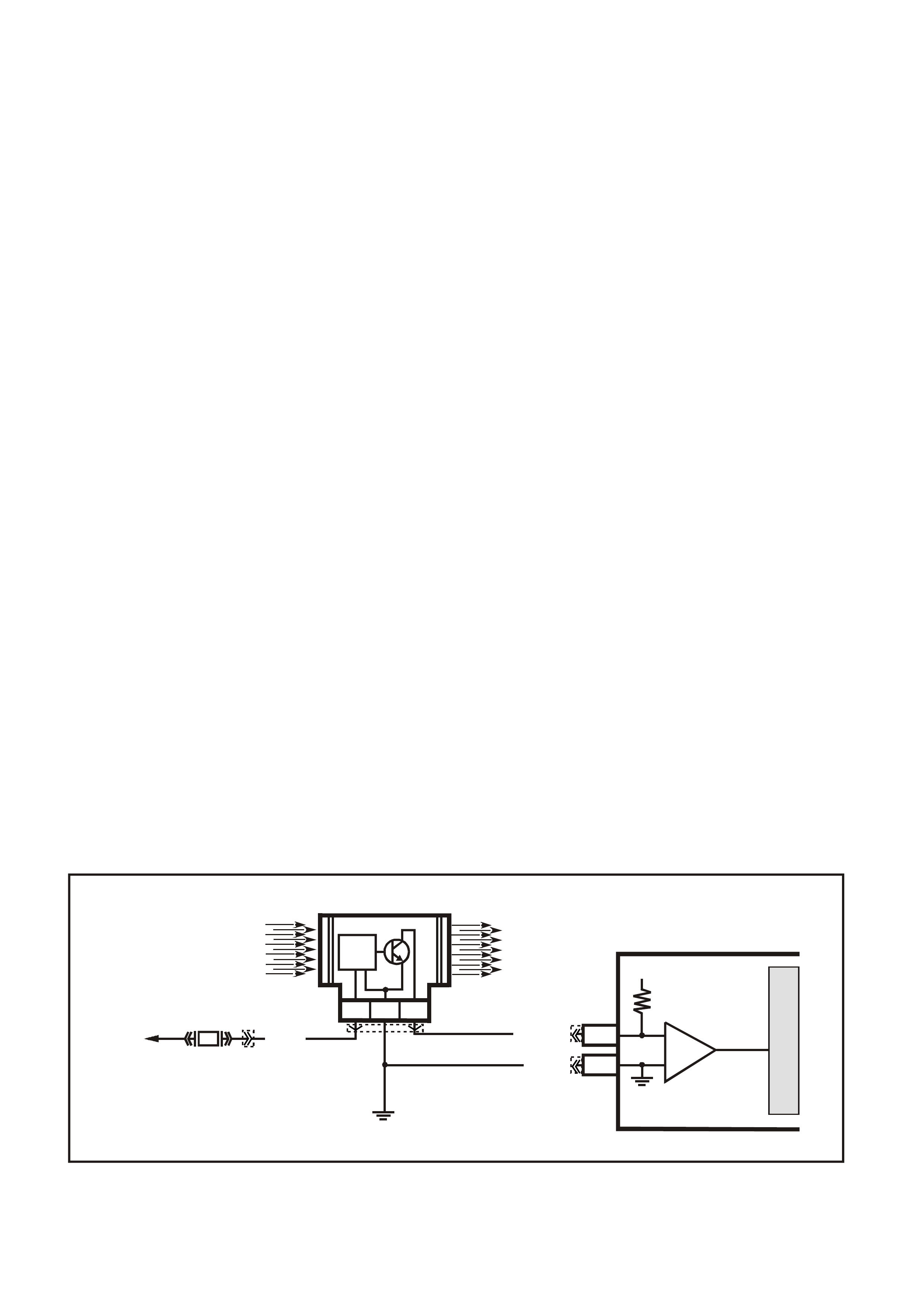
As air passes over the heated elements during
engine operation they begin to cool. By measuring
the amount of electrical power required to maintain
the heated elements at the predetermined
temperature above ambient temperature the mass
air flow rate can be determined.
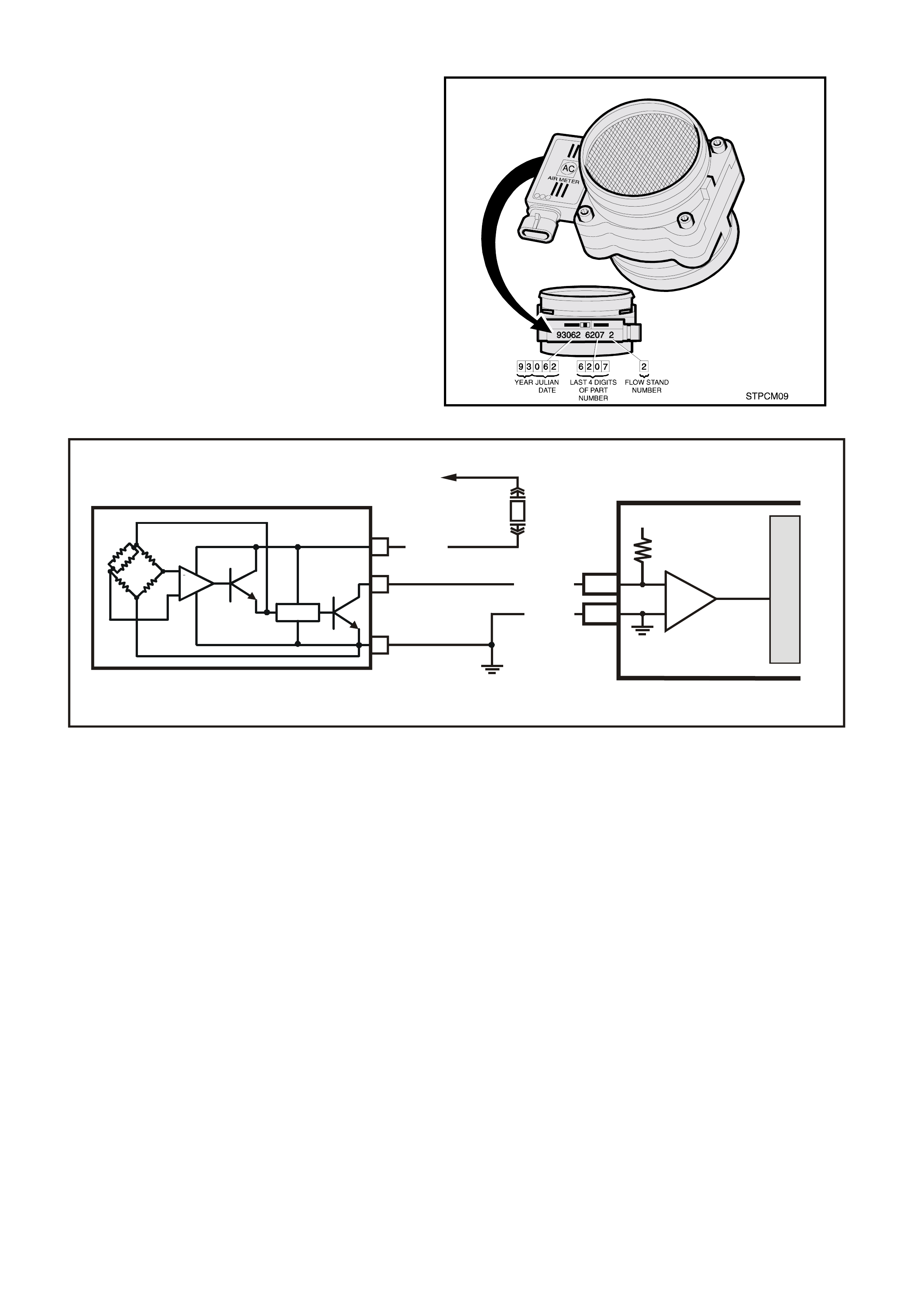
Once the mass air flow sensor has developed an
internal signal related to the mass air flow rate, it
must send this information to the PCM. In order to
preserve the accuracy and resolution of the small
voltage signal in the mass air flow sensor, it is
converted to a frequency signal by a voltage
oscillator and sent to the PCM.
T26C3002
2
1
Figure 6C3-1-29 MAF Sensor Location
1. Air Cleaner Housing
2. Mass Air Flow (MAF) Sensor
The s ignal that is sent from the MAF sensor is sent
in the form of a frequency output. A large quantity
of air passing through the sensor (such as when
accelerating) will be indicated as a high frequency
output. A small quantity of air passing through the
sensor will be indicated as a low frequency output
(such as when decelerating or at idle). The Tech 2
scan tool displays MAF sensor information in
frequency, and in grams per second. At idle the
readings should be low and increase with engine
RPM.
If a problem occurs in the MAF sensor circuit, the
PCM will store a DTC in its mem ory. The PCM will
turn on the Check Powertrain Lamp, indicating
there is a problem. If this occurs, the PCM will
calculate a s ubstitute mas s air f low signal based on
speed density RPM, MAP and IAT.
No field service adjustment is necessary or
possible with this MAF sensor.
Figure 6C3-1-30 MAF Sensor Identification
Figure 6C3-1-31 MAF Sensor Simplified Schematic Circuit
DTC P0101 MASS AIR FLOW SYSTEM PERFORMANCE
Conditions for running DTC P0101
• DTCs P0102, P0103, P0107, P0108, P0121, P0122, P0123 are not set.
• The engine is running.
• The throttle position angle is less than 50% and the engine vacuum (BARO-MAP) is greater than 65 kPa.
• The system voltage is greater than 11 volts but less than 16 volts.
• The change in throttle position is less than 3%.
• All above conditions stable for two seconds.
Conditions for setting DTC P0101
• The MAF frequency is 50% different from the speed density calculation.
• The conditions met for at least five seconds.
Action taken when DTC P0101 Sets
• The PCM illuminates the Check Powertrain Lamp when the diagnostic runs and fails.
• The PCM records the operating conditions at the time the diagnostic fails. The PCM stores this information in
the Freeze Frame/Failure Records.
• The PCM utilises speed density (RPM, MAP, IAT) for fuel management.
Conditions for clearing the Check Powertrain Lamp and DTC P0101
• The PCM turns the Check Powertrain Lamp OFF after one ignition cycle that the diagnostic runs and does not
fail.
• A last test failed (current DTC) clears when the diagnostic runs and does not fail.
G3PCM006A
J2-31
J1-01
PCM
MASS AIR FLOW
INPUT SIGNAL
EARTH
5 V
M
I
C
R
O
IC
A
B
C
EFI
RELAY
F33
BR/ W (792)
B/R (750)
LOC. E5/ E15
MASS AIR FLOW SENSOR
+
P (439)
DTC P0102 MA SS AIR FLOW SENSOR CIRCUIT LOW FREQUENCY
Conditions for running DTC P0102
• The engine speed is greater than 300 RPM.
• The system voltage is at least 110 volts.
Conditions for setting DTC P0102
• The MAF frequency is 50% different from the speed density calculation.
• The conditions met for at least five seconds.
Action taken when DTC P0102 Sets
• The PCM illuminates the Check Powertrain Lamp when the diagnostic runs and fails.
• The PCM utilises speed density (RPM, MAP, IAT) for fuel management.
• The PCM records the operating conditions at the time the diagnostic fails. The PCM stores this information in
the Freeze Frame/Failure Records.
• The PCM utilises speed density (RPM, MAP, IAT) for fuel management.
Conditions for clearing the Check Powertrain Lamp and DTC P0102
• The PCM turns the Check Powertrain Lamp OFF after one ignition cycle that the diagnostic runs and does not
fail.
• A last test failed (current DTC) clears when the diagnostic runs and does not fail.
DTC P0103 MA SS AIR FLOW SENSOR CIRCUIT HIGH FREQUENCY
Conditions for running DTC P0103
• The engine speed is greater than 300 RPM.
• The system voltage is at least 110 volts.
Conditions for setting DTC P0103
• The MAF frequency is greater than 11,250 Hz.
• The conditions met for at least one seconds.
Action taken when DTC P0103 Sets
• The PCM illuminates the Check Powertrain Lamp when the diagnostic runs and fails.
• The PCM utilises speed density (RPM, MAP, IAT) for fuel management.
• The PCM records the operating conditions at the time the diagnostic fails. The PCM stores this information in
the Freeze Frame/Failure Records.
• The PCM utilises speed density (RPM, MAP, IAT) for fuel management.
Conditions for clearing the Check Powertrain Lamp and DTC P0103
• The PCM turns the Check Powertrain Lamp OFF after one ignition cycle that the diagnostic runs and does not
fail.
• A last test failed (current DTC) clears when the diagnostic runs and does not fail.
Figure 6C3-1-32 Mass Air Flow Sensor Circuit
G3PCM006PT
IC
CIRCUIT
MASS AIR FLOW SENSOR
J2-31
J1-01
PCM
CBA
AIR FLOW
FROM
AIR FILTER
AIR FLOW
TO
THROTTLE BODY
EFI
RELAY
F33
P (43 9)
YE100
YE122
YE123
YE111
BR/W (792)
MASS AIR FLOW
INP U T SIG NAL
EARTH
5V
M
I
C
R
O
IC
B/R (750)
LOC. E5/E15
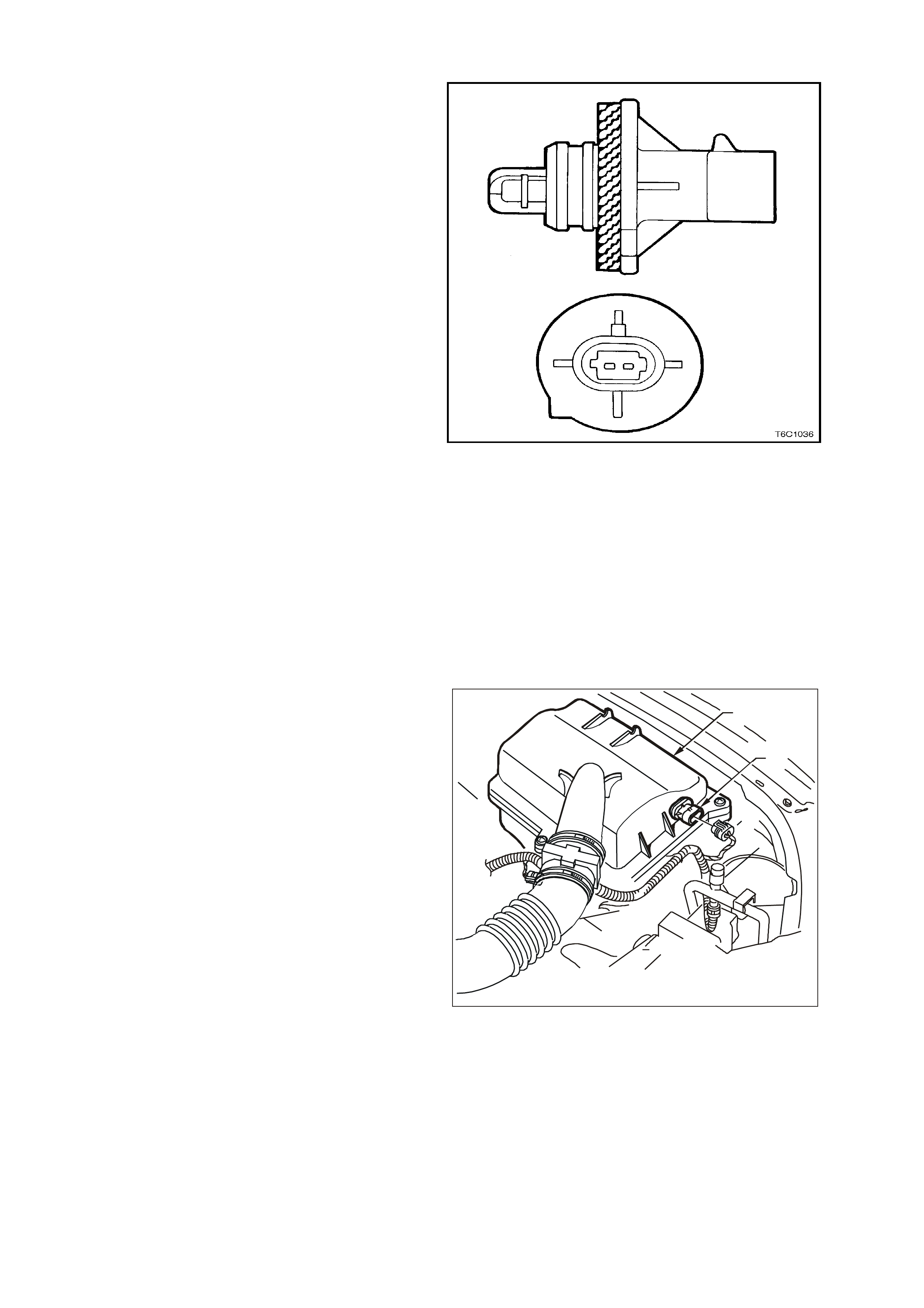
INTAKE AIR TEMPERATURE (IAT) SENSOR
The Intake Air Temperature (IAT) sensor is a
thermistor, (a resistor that changes resistance with
changes in temperature) mounted in the air c leaner
housing of the intake system. Low intake air
temperature produces high resistance in the
sensor, approximately 101k ohms at -40°C, while
high intake air temperature causes low sensor
resistance, approximately 80 ohms at 130°C.
The PCM:
1. Supplies a 5 volt signal voltage to the sensor
through a resistor in the PCM, and
2. Monitors the intake air temperature circuit
voltage, which will change when connected to
the intake air temperature sensor.
The circuit voltage will vary depending on the
resistance of the IAT sensor. The voltage will be
close to the 5 volt level when the sensor is cold,
and will decrease as the sensor warms.
The IAT sensor signal voltage is used by the PCM
to assist in calculating the fuel injector pulse width,
idle speed, canister purge and electronic spark
timing.
The following DTCs are set if the PCM detects a
malfunction in the IAT sensor circuit:
• DTC P0112: IAT Sensor Circuit Low Voltage.
• DTC P0113: IAT Sensor Circuit High Voltage.
• DTC P1111: IAT Sensor CKT Intermittent High
Voltage.
• DTC P1112: IAT Sensor CKT Intermittent Low
Voltage.
Figure 6C3-1-33 Intake Air Temperature (IAT) Sensor
T26C3004
2
1
Figure 6C3-1-34 IAT Sensor Location
1. Air Cleaner Housing
2. Intake Air Temperature (IAT) Sensor
3. A/C Refrigerant Pressure Sensor

DTC P0112 INTAKE AIR TEMPERATURE SENSOR CIRCUIT LOW VOLTAGE
Conditions for running DTC P0112
• DTC(s) P0101, P0102, P0103, P0117, P0118, are not set.
• The engine run time is greater than 30 seconds.
• The vehicle speed is less than 40 km/h.
Conditions for setting DTC P0112
• The Intake Air Temperature is greater than 139°C.
• The conditions met for at least 20 seconds.
Action taken when DTC P0112 Sets
• The PCM stores the DTC information into memory when the diagnostic runs and fails.
• The Check Powertrain Lamp will not be illuminated.
• The PCM will substitute a default Intake Air Temperature value of 25°C.
• The PCM records the operating conditions at the time the diagnostic fails. The PCM stores this information in
the Freeze Frame/Failure Records.
Conditions for clearing the Check Powertrain Lamp and DTC P0112
• A last test failed (current DTC) clears when the diagnostic runs and does not fail.
DTC P0113 INTAKE AIR TEMPERATURE SENSOR CIRCUIT HIGH VOLTAGE
Conditions for running DTC P0113
• DTC(s) P0101, P0102, P0103, P0117, P0118, are not set.
• The engine run time is greater than 100 seconds.
• The engine coolant temperature is greater than 0°C.
• The vehicle speed is less than 11 km/h.
Conditions for setting DTC P0113
• The Intake Air Temperature is at or below -35°C.
• The conditions met for at least 20 seconds.
Action taken when DTC P0113 Sets
• The PCM stores the DTC information into memory when the diagnostic runs and fails.
• The Check Powertrain Lamp will not be illuminated.
• The PCM will substitute a default Intake Air Temperature value of 25°C.
• The PCM records the operating conditions at the time the diagnostic fails. The PCM stores this information in
the Freeze Frame/Failure Records.
Conditions for clearing the Check Powertrain Lamp and DTC P0113
• A last test failed (current DTC) clears when the diagnostic runs and does not fail.
DTC P1111 INTAKE AIR TEMPERATURE SENSOR CIRCUIT INTERMITTENT HIGH VOLTAGE
Conditions for running DTC P1111
• DTC(s) P0101, P0102, P0103, P0117, P0118, are not set.
• The engine run time is greater than 100 seconds.
• The engine coolant temperature is greater than 0°C.
• The vehicle speed is less than 11 km/h.
• The Mass Air Flow is less than 15 g/s.
Conditions for setting DTC P1111
• The Intake Air Temperature is at or below -35°C.
• The conditions present for 0.3 seconds.
Action taken when DTC P1111 Sets
• The PCM stores the DTC information into memory when the diagnostic runs and fails.
• The Check Powertrain Lamp will not be illuminated.
• The PCM will substitute a default Intake Air Temperature value of 25°C.
• The PCM records the operating conditions at the time the diagnostic fails. The PCM stores this information in
the Freeze Frame/Failure Records.
Conditions for clearing the Check Powertrain Lamp and DTC P1111
• A last test failed (current DTC) clears when the diagnostic runs and does not fail.
DTC P1112 INTAKE AIR TEMPERATURE SENSOR CIRCUIT INTERMITTENT LOW VOLTAGE
Conditions for running DTC P1112
• DTC(s) P0101, P0102, P0103, P0117, P0118, are not set.
• The engine run time is greater than 30 seconds.
• The vehicle speed is less than 40 km/h.
Conditions for setting DTC P1112
• The Intake Air Temperature is at or below 139°C.
• The conditions present for 0.3 seconds.
Action taken when DTC P1112 Sets
• The PCM stores the DTC information into memory when the diagnostic runs and fails.
• The Check Powertrain Lamp will not be illuminated.
• The PCM will substitute a default Intake Air Temperature value of 25°C.
• The PCM records the operating conditions at the time the diagnostic fails. The PCM stores this information in
the Freeze Frame/Failure Records.
Conditions for clearing the Check Powertrain Lamp and DTC P1112
• A last test failed (current DTC) clears when the diagnostic runs and does not fail.
Figure 6C3-1-35 Intake Air Temperature Sensor Circuit
G3PCM002PT
J2-57
J2-25
A
B
INTAKE AIR
TEMPERATURE SENSOR
SENSOR EARTH
IAT SENSOR SI G NAL
PCM
5V
BR (47 2 )
G/O (469)
YE23 YE123
M
I
C
R
O
MANIFOLD ABSOLUTE PRESSURE (MAP) SENSOR
The Manifold Absolute Pressure (MAP) sensor
measures the changes in the intake manifold
pressure which result from engine load (intake
manifold vacuum) and RPM changes and converts
these into a voltage output.
The control module sends a 5-volt supply voltage
to the MAP sensor. As the manifold pressure
changes, the output voltage of the sensor also
changes. By monitoring the sensor output voltage,
the control module knows the manifold pressure.
A closed throttle during engine coast down would
produce a relatively low MAP output, while a wide
open throttle would produce a high output. This
high output is produced because the pressure
inside the manifold is the same as outside the
manifold during wide open throttle, so it measures
100% of outside air pressure (atmospheric
pressure). The MAP sensor is also used, to
measure barometric pressure, allowing the control
module to m ak e adjustm ents f or differ ent operating
altitudes.
With the engine running, the MAP output voltage
signal should vary from about 1.0 to 1.5 volts at
idle, to about 4.0 to 4.5 volts at wide open throttle.
This MAP output voltage signal is sent to the
control module MAP sensor input signal terminal.
With ignition on and engine stopped, the manifold
pressure is equal to atmospheric (or barometric)
pressure and the signal voltage output will be high,
close to 5 volts at s ea level. T his voltage is us ed by
the PCM as an indication of engine load and
atmos pheric pr essure, altitude and is referr ed to as
BARO.
Figure 6C3-1-36 Manifold Absolute Pressure (MAP)
Sensor Location
1. Manifold Absolute Pressure (MAP) Sensor
2. Camshaft Position (CMP) Sensor
3. Oil Pressure Sensor
4. Connector to Knock Sensor Jumper Harness
The MAP sensor is used for the following:
• Altitude determination.
• Ignition timing control.
• Speed density fuel management default.
MANIFOLD
ABSOLUTE
PRESSURE
SENSOR
GEN30011GB
Figure 6C3-1-37 Manifold Absolute Pressure (MAP) Sensor
1. MAP Sensor
1
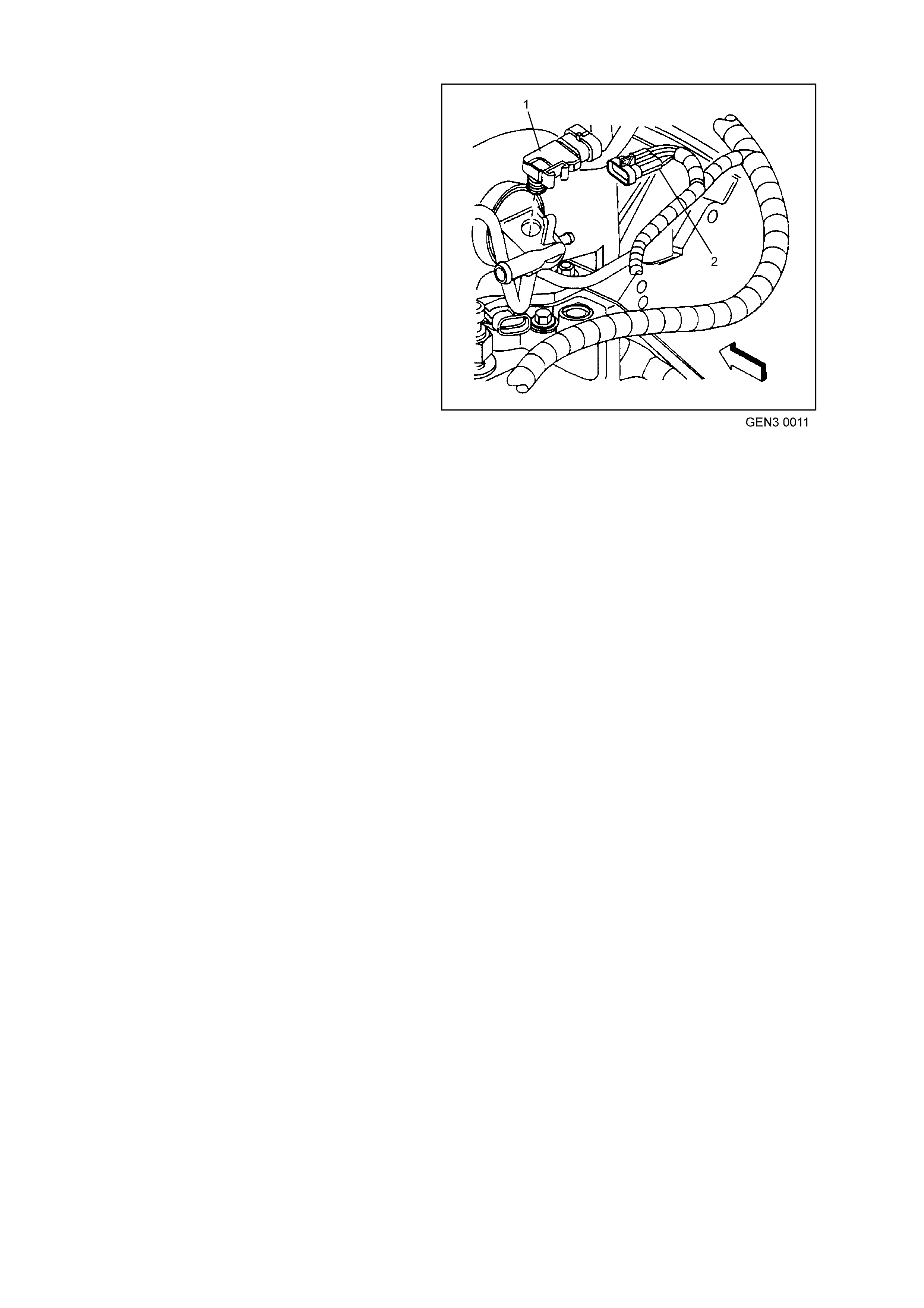
SPEED DENSITY SYSTEM
Three specific data sensors provide the PCM with
the basic information for the fuel management
portion of its operation. That is three specific
signals to the PCM establish the engine speed and
air dens ity factor s. The engine speed s ignal comes
from the ignition system. The PCM uses this
information to determine engine speed (RPM). Air
density is derived from IAT and MAP sensor inputs.
The IAT sensor measures the air temperature that
is entering the engine. The IAT signal works in
conjunction with the MAP sensor to determine air
density. As the intake manifold also increases and
additional f uel is r equir ed. T his inf or mation f r om the
IAT and MAP sensors is used by the PCM to
control injector pulse width.
The speed density system is only needed when
there is a Mass Air Flow (MAF) sensor m alfunc tion.
If the PCM detects a malfunction with the MAF
sensor circuit, the PCM will default to Speed
Density fuel management.
The following DTCs are set if the PCM detects a
malfunction in the MAP sensor circuit:
• DTC P0107: MAP Sensor Circuit Low Voltage.
• DTC P0108: MAP Sensor Circuit High
Voltage.
Figure 6C3-1-38 Manifold Absolute Pressure (MAP)
Sensor Location
1. Manifold Absolute Pressure (MAP) Sensor
2. MAP Sensor Harness Connector
DTC P0107 MANIFOLD ABSOLUTE PRESSURE SENSOR CIRCUIT LOW VOLTAGE
Conditions for running DTC P0107
• No TP or ECT sensor DTCs are set.
• The engine is running.
• The TP angle is above 20% when the engine speed is greater than 1200 RPM.
OR
• The TP angle is below 18% when the engine speed is below 1000 RPM.
Conditions for setting DTC P0107
• The MAP sensor voltage is less than 0.10 volts..
• The conditions met for at least two seconds.
Action taken when DTC P0107 Sets
• The PCM illuminates the Check Powertrain Lamp when the diagnostic runs and fails.
• The PCM records the operating conditions at the time the diagnostic fails. The PCM stores this information in
the Freeze Frame/Failure Records.
Conditions for clearing the Check Powertrain Lamp and DTC P0107
• The PCM turns the Check Powertrain Lamp OFF after one ignition cycle that the diagnostic runs and does not
fail.
• A last test failed (current DTC) clears when the diagnostic runs and does not fail.
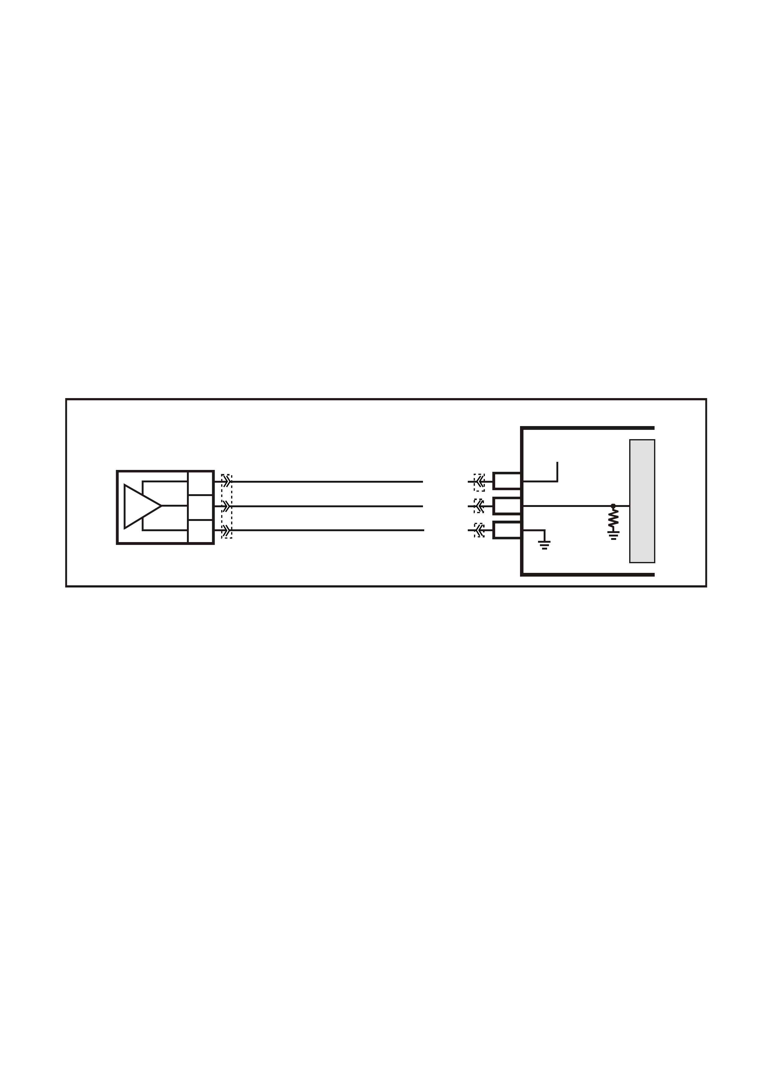
DTC P0108 MANIFOLD ABSOLUTE PRESSURE SENSOR CIRCUIT HIGH VOLTAGE
Conditions for running DTC P0108
• No TP or ECT sensor DTCs are set.
• The engine is running.
• The TP angle is above 20% when the engine speed is greater than 1000 RPM.
OR
• The TP angle is below 18% when the engine speed is below 1200 RPM.
Conditions for setting DTC P0108
• The MAP sensor voltage is greater than 4.3 volts.
• The conditions met for at least four seconds.
Action taken when DTC P0108 Sets
• The PCM illuminates the Check Powertrain Lamp when the diagnostic runs and fails.
• The PCM records the operating conditions at the time the diagnostic fails. The PCM stores this information in
the Freeze Frame/Failure Records.
Conditions for clearing the Check Powertrain Lamp and DTC P0108
• The PCM turns the Check Powertrain Lamp OFF after one ignition cycle that the diagnostic runs and does not
fail.
• A last test failed (current DTC) clears when the diagnostic runs and does not fail.
Figure 6C3-1-39 MAP Sensor Circuit
G3PCM010PT
PCM
M
I
C
R
O
J2-32
J1-54
C
B
A
MANIFOLD
ABSOLUTE
PRESSURE SENSOR
J1-48
YE27 YE122
YE122
SENSOR EARTH
MAP SENSOR
SIGNAL
REFERENCE
VOLTAGE
5V
V/W (414)
B (42 1)
LG (432)
YE123
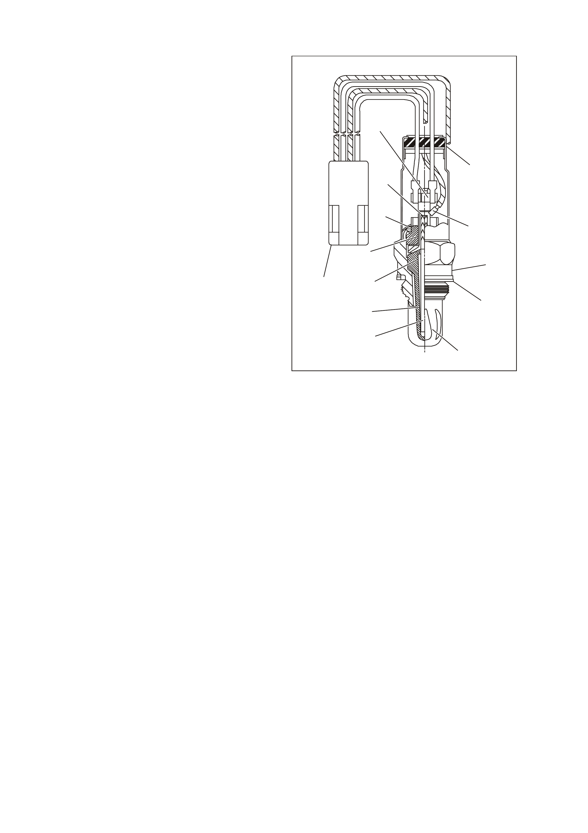
HEATED OXYGEN SENSORS (HO2S)
The GEN III V8 engine incorporates the use of
Heated Exhaust Gas Oxygen Sensors (HO2S).
The ox ygen sens ors are the k ey to closed-loop fuel
control. The PCM uses information from the
oxygen sensors to precisely fine tune its fuel
injector pulse width calculations, based on the
unused, left-over oxygen content in the exhaust.
The system uses, two four wire heated oxygen
sensors. The oxygen sensors have a Zirconia
element that, when heated to temperatures above
360°C, produces voltages based on the amount of
oxygen content surrounding the tip, as compared
to oxygen in the atmosphere.
The sensors are mounted in the exhaust pipe with
the sensing portion exposed to the exhaust gas
stream. When the sensor has reached an
operating temperature of more than 360°C, it acts
as a voltage generator, producing a rapidly
changing voltage of between 10 - 1000 millivolts.
This voltage output is dependent upon the oxygen
content in the exhaust gas, as compared to the
sensor's atm ospheric oxygen reference cavity. T he
reference cavity of an un-heated oxygen sensor is
exposed to the atm osphere through the body of the
oxygen sensor. The oxygen sensors have an
internal heating element that is used to heat the
Zirconia element faster inside the sensors, thereby
decreasing the amount of time before the fuel
control system can begin running in closed loop.
The heated oxygen sensors have four wires, with
two for the internal Positive Temperature Co-
efficient (PTC) thermistor type heater circuit. One
of these wires has 12 volts continually applied to
the heater elem ent whenever the ignition is on. The
other wire is for the heater element earth. When
the sensor is cold, maximum current
(approximately 4 amps) flows through the heater
circuit and gradually reduces to approximately 0.5
amps as the sensor reaches full operating
temperature. The other two sensor wires are for
the sensor's signal to the PCM, and the sensor
earth.
GEN3 0013
2
3
4
13
12
11
1
5
6
7
8
9
10
Figure 6C3-1-40 Heated Oxygen Sensor (HO2S) Cutaway
1. Four Wire In-Line Connector
2. Heater Termination
3. Water Shield Assembly
4. Sensor Lead
5. Flat Seat Shell
6. Seat Gasket
7. Outer Electrode and Protective Coating
8. Rod Heater
9. Inner Electrode
10. Zirconia Element
11. Insulator
12. Clip Ring
13. Gripper
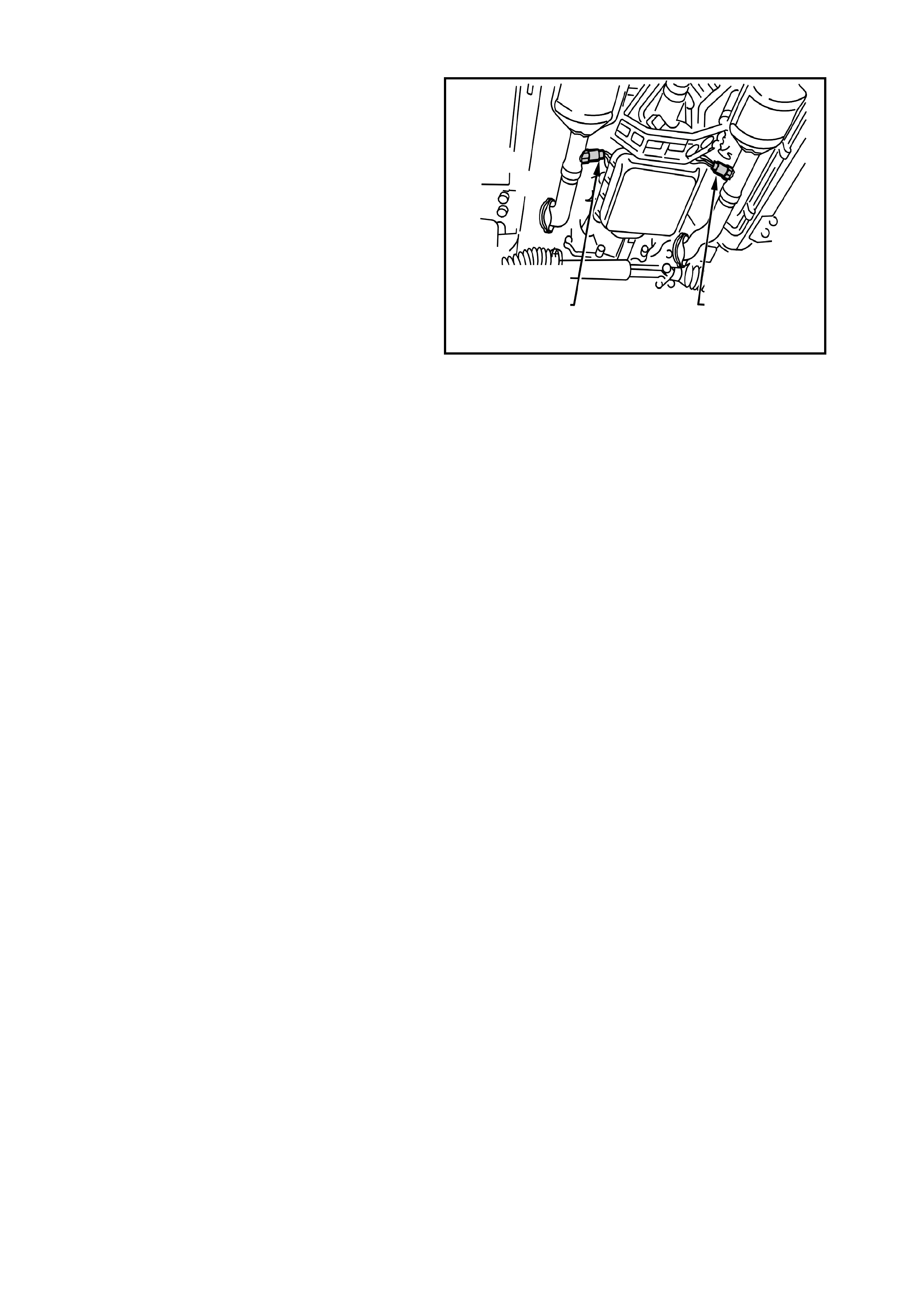
The reference cavity of a heated oxygen sensor is
exposed to the atmosphere by the air that passes
between the wire strands and insulation of the
oxygen sensor leads. The signal and heater leads
used on the oxygen sensor are of the stranded
type. Stranded leads have small spaces between
the wire strands and the insulation. These spaces
allow a satisfactory amount of air to pass through
the lead to maintain an adequate air reference.
When the sensor is cold, it produces either no
voltage, or an unusable, slowly changing one. Also
when cold, its internal electrical resistance is
extremely high – many million ohms. The PCM
always supplies a steady 450 millivolt, very low
current bias voltage to the oxygen sensor circuit.
When the sensor is cold and not producing any
voltage, the PCM detects only this steady bias
voltage. As the sensor begins heating, its internal
resistance decreases and it begins producing a
rapidly changing voltage that will overshadow the
PCM's supplied steady bias voltage. When the
PCM detects the changing voltage, it knows the
oxygen sensor is hot and its output voltage can be
used for fine-tuning the fuel injector pulse width.
The PCM monitors the oxygen sensor's changing
voltage for going above and below a mid-range
voltage band (approximately 300 - 600 millivolts),
to help decide when to operate in the closed-loop
mode.
When the fuel system is correctly operating in the
closed-loop mode, the oxygen sensor voltage
output is rapidly changing several times per
second, fluctuating from approximately 100mV
(high oxygen content – lean mixture) to 900mV
(low oxygen content – rich mixture). The PCM
monitors the changing voltage, and decides the
needed fuel mixture correction.
T6A3079GB
Figure 6C3-1-41 Heated Oxygen Sensor (HO2S) Locations
1. Left Hand Oxygen Sensor Bank 1 Sensor 1
2. Right Hand Oxygen Sensor Bank 2 Sensor 1
The oxygen sensors are mounted in the exhaust
pipes and are referred to as Bank 1 Sensor 1 (left
exhaust pipe) Bank 2 Sensor 1 (right exhaust
pipe).
The following DTCs set when the PCM detects a
HO2S signal circuit that is low:
DTC P0131: Bank 1 Sensor 1 HO2S.
DTC P0151: Bank 2 Sensor 1 HO2S.
The following DTCs set when the PCM detects a
HO2S signal circuit that is high:
DTC P0132: Bank 1 Sensor 1 HO2S.
DTC P0152: Bank 2 Sensor 1 HO2S.
The following DTCs set when the PCM detects no
HO2S activity:
DTC P0134: Bank 1 Sensor 1 HO2S.
DTC P0154: Bank 2 Sensor 1 HO2S.
A fault in the oxygen sensor heater element or its
ignition feed or earth results in an increase in time
to Closed Loop fuel control. This may cause
increased emissions, especially at start-up. The
following DTCs set when the PCM detects a
malfunction in the HO2S heater circuits:
• DTC P0135: Bank 1 Sensor 1 HO2S heater.
• DTC P0155: Bank 2 Sensor 1 HO2S heater.
1
2

RESPONSE TIME
Not only is it necessary for the oxygen sensors to produce voltage signals for rich or lean exhaust, it is also
important to respond quickly to changes. If the oxygen sensors respond slowly, the customer may complain of
poor fuel ec onomy, rough idle, surging or lack of perfor mance. T he PCM will s et a DTC that indicates degraded
HO2S performance if a HO2S response switching, transition time, or ratio problem is detected.
DTC P1133: Insufficient Switching Bank 1 Sensor 1.
DTC P1134: Transition Time Ratio Bank 1 Sensor 1.
DTC P1153: Insufficient Switching Bank 2 Sensor 1.
DTC P1154: Transition Time Ratio Bank 2 Sensor 1.
OXYGEN SENSOR CONTAMINANTS
Carbon
Black carbon or soot deposits result from over-rich air-fuel mixtures. However, carbon does not harm an oxygen
sensor. Deposits can be burned off in the vehicle by running the engine at part throttle for at least two minutes.
Silica
Certain RT V silicon gask et ma terials give off vapour as they cure that may contaminate the ox ygen s ensor. This
contam ination is us ually caused by the vapours being pulled from the PCV syst em , into the combus tion chamber
and pass ed on to the exhaust s ystem. T he sand lik e partic les fr om the RTV s ilica em bed in the m olec ules of the
oxygen sensor element and plug up the surface. With the outside of the oxygen sensor element not able to
sense all of the oxygen in the exhaus t system it results in lazy ox ygen sensor response and engine control. The
oxygen sensor will have a whitish appearance on the outside if it has been contaminated.
There is also a possibility of silica contamination caused by silicon in the fuel. Some oil companies have used
silicone to raise the octane rating of their fuel. Careless fuel handling practices with transport containers can
result in unacceptable concentrations of silicone in the fuel at the pump.
Silica contamination can be caused by silicon in lubricants used to install vacuum hoses on fittings. Do not use
silicon sealers on gaskets or exhaust joints.
Lead
Lead glazing of the sens ors can be introduc ed when regular, or leaded fuel is burned. It is diff icult to detect lead
contamination by visual inspection.
Other Substances
Oil deposits will ultimately prevent oxygen sensor operation. The sensor will have a dark brown appearance.
Causes of high oil consumption should be checked.
The additives in ethylene glycol can also affect oxygen sensor performance. This produces a whitish
appearance. If antifreeze enters the exhaust system , you will likely enc ounter other , m ore obvious, sym ptoms of
cooling system trouble. If for example the engine had a head gasket failure where coolant did enter the
combustion chamber it would be a good idea to check the oxygen sensor operation after the head gasket was
repaired.
Multiple Faults
If you encounter multiple or repeated oxygen sensor failures on the same vehicle, consider contamination.
Leaded fuel, silica contamination from uncured, low-grade (unapproved) RTV sealant, and high oil consum ption
are possible causes.
DTC P0131 HEATED OXYGEN SENSOR CIRCUIT LOW VOLTAGE BANK 1 SENSOR 1
Conditions for running DTC P0131
Criteria 1
• DTCs P0101, P0102, P0103, P0112, P0113, P0117, P0118, P0121, P0122, P0123, P0335, P0336, P0351-
P0358, P1258 are not set.
• The engine coolant temperature is greater than 48°C.
• The ignition voltage is greater than 9.0 volts.
• The fuel system is operating in Closed Loop.
• The fuel trim learn is enabled.
• The air/fuel ratio is between 14.5:1 and 14.7:1.
• The TP angle is between 0% and 70%.

Criteria 2
• DTCs P0101, P0102, P0103, P0112, P0113, P0117, P0118, P0121, P0122, P0123, P0335, P0336, P0351-
P0358, P1258 are not set.
• The ignition voltage is greater than 9.0 volts.
• The Power Enrichment mode is enabled for at least 0.5 seconds.
Conditions for setting DTC P0131
Criteria 1
• The HO2S signal voltage remains below 200 mV.
• The Criteria 1conditions are present for at least 33 seconds.
Criteria 2
• The HO2S signal voltage remains below 360 mV.
• The Criteria2 conditions are present for at least five seconds.
Action taken when DTC P0131 Sets
• The PCM illuminates the Check Powertrain Lamp when the diagnostic runs and fails.
• The PCM records the operating conditions at the time the diagnostic fails. The PCM stores this information in
the Freeze Frame/Failure Records.
• Open Loop Fueling.
Conditions for clearing the Check Powertrain Lamp and DTC P0131
• The PCM turns the Check Powertrain Lamp OFF after one ignition cycle that the diagnostic runs and does not
fail.
• A last test failed (current DTC) clears when the diagnostic runs and does not fail.
DTC P0132 HEATED OXYGEN SENSOR CIRCUIT HIGH VOLTAGE BANK 1 SENSOR 1
Conditions for running DTC P0132
Criteria 1
• DTCs P0101, P0102, P0103, P0112, P0113, P0117, P0118, P0121, P0122, P0123, P0335, P0336, P0351-
P0358, P1258 are not set.
• The ignition voltage is greater than 9.0 volts.
• The fuel system is operating in Closed Loop.
• The fuel trim learn is enabled.
• The air/fuel ratio is between 14.5:1 and 14.7:1.
Criteria 2
• DTCs P0101, P0102, P0103, P0112, P0113, P0117, P0118, P0121, P0122, P0123, P0335, P0336, P0351-
P0358, P1258 are not set.
• The ignition voltage is greater than 9.0 volts.
• Deceleration Fuel Cut-Off mode is enabled for greater than one second.
Conditions for setting DTC P0132
Criteria 1
• The HO2S signal voltage remains below 775 mV.
• The Criteria 1conditions are present for at least 33 seconds.
Criteria 2
• The HO2S signal voltage remains below 540 mV.
• The Criteria2 conditions are present for at least five seconds.
Action taken when DTC P0132 Sets
• The PCM illuminates the Check Powertrain Lamp when the diagnostic runs and fails.
• The PCM records the operating conditions at the time the diagnostic fails. The PCM stores this information in
the Freeze Frame/Failure Records.
• Open Loop Fueling.
Conditions for clearing the Check Powertrain Lamp and DTC P0132
• The PCM turns the Check Powertrain Lamp OFF after one ignition cycle that the diagnostic runs and does not
fail.
• A last test failed (current DTC) clears when the diagnostic runs and does not fail.

DTC P0133 HEATED OXYGEN SENSOR SLOW RESPONSE BANK 1 SENSOR 1
Conditions for running DTC P0133
• DTCs P0101, P0102, P0103, P0112, P0113, P0117, P0118, P0121, P0122, P0123, P0335, P0336, P0351-
P0358, P1258 are not set.
• The engine coolant temperature is greater than 65°C.
• The ignition voltage is greater than 9.0 volts.
• The fuel system is operating in Closed Loop.
• The engine speed is between 1000 RPM and 2300 RPM.
• The engine air flow is between 20 g/s and 50 g/s.
• The EVAP canister purge duty cycle is greater than 0%.
• The engine run time is greater than 120 seconds.
Conditions for setting DTC P0133
• The Lean to Rich response (below 300 mV to above 600 mV) average time is greater than 100 milliseconds.
• The Rich to Lean response (above 600 mV to below 300 mV) average time is greater than 100 milliseconds.
Action taken when DTC P0133 Sets
• The PCM illuminates the Check Powertrain Lamp when the diagnostic runs and fails.
• The PCM records the operating conditions at the time the diagnostic fails. The PCM stores this information in
the Freeze Frame/Failure Records.
• Open Loop Fueling.
Conditions for clearing the Check Powertrain Lamp and DTC P0133
• The PCM turns the Check Powertrain Lamp OFF after one ignition cycle that the diagnostic runs and does not
fail.
• A last test failed (current DTC) clears when the diagnostic runs and does not fail.
DTC P0134 HEATED OXYGEN SENSOR INSUFFICIENT ACTIVITY BANK 1 SENSOR 1
Conditions for running DTC P0134
• DTCs P0101, P0102, P0103, P0112, P0113, P0117, P0118, P0121, P0122, P0123, P0335, P0336, P0351-
P0358, P1258 are not set.
• The ignition voltage is greater than 9.0 volts.
• The fuel system is operating in Closed Loop.
• The engine run time is greater than 70 seconds.
• The engine coolant temperature is greater than 48°C.
Conditions for setting DTC P0134
• The HO2S signal voltage is steady between 350 mV and 550 mV.
• The conditions are present for at least 70 seconds.
Action taken when DTC P0134 Sets
• The PCM illuminates the Check Powertrain Lamp when the diagnostic runs and fails.
• The PCM records the operating conditions at the time the diagnostic fails. The PCM stores this information in
the Freeze Frame/Failure Records.
• Open Loop Fueling.
Conditions for clearing the Check Powertrain Lamp and DTC P0134
• The PCM turns the Check Powertrain Lamp OFF after one ignition cycle that the diagnostic runs and does not
fail.
• A last test failed (current DTC) clears when the diagnostic runs and does not fail.

DTC P0135 HEATED OXYGEN SENSOR HEATER CIRCUIT BANK 1 SENSOR 1
Conditions for running DTC P0135
• DTCs P0101, P0102, P0103, P0112, P0113, P0117, P0118, P0121, P0122, P0123, P0335, P0336, P0351-
P0358, P1258 are not set.
• The intake air temperature and the engine coolant temperature are less than 50°C and are within 8°C of each
other at engine start-up.
• The ignition voltage is between 10.0 volts and 18.0 volts.
• The engine air flow is less than 18 g/s.
Conditions for setting DTC P0135
• The HO2S voltage remains between 300 mV and 700 mV for a predetermined amount of time (depends on
engine coolant temperature and air flow).
Action taken when DTC P0135 Sets
• The PCM illuminates the Check Powertrain Lamp when the diagnostic runs and fails.
• The PCM records the operating conditions at the time the diagnostic fails. The PCM stores this information in
the Freeze Frame/Failure Records.
Conditions for clearing the Check Powertrain Lamp and DTC P0135
• The PCM turns the Check Powertrain Lamp OFF after one ignition cycle that the diagnostic runs and does not
fail.
• A last test failed (current DTC) clears when the diagnostic runs and does not fail.
DTC P0151 HEATED OXYGEN SENSOR CIRCUIT LOW VOLTAGE BANK 2 SENSOR 1
Conditions for running DTC P0151
Criteria 1
• DTCs P0101, P0102, P0103, P0112, P0113, P0117, P0118, P0121, P0122, P0123, P0335, P0336, P0351-
P0358, P1258 are not set.
• The engine coolant temperature is greater than 48°C.
• The ignition voltage is greater than 9.0 volts.
• The fuel system is operating in Closed Loop.
• The fuel trim learn is enabled.
• The air/fuel ratio is between 14.5:1 and 14.7:1.
• The TP angle is between 0% and 70%.
Criteria 2
• DTCs P0101, P0102, P0103, P0112, P0113, P0117, P0118, P0121, P0122, P0123, P0335, P0336, P0351-
P0358, P1258 are not set.
• The ignition voltage is greater than 9.0 volts.
• The Power Enrichment mode is enabled for at least 0.5 seconds.
Conditions for setting DTC P0151
Criteria 1
• The HO2S signal voltage remains below 200 mV.
• The Criteria 1conditions are present for at least 33 seconds.
Criteria 2
• The HO2S signal voltage remains below 360 mV.
• The Criteria2 conditions are present for at least five seconds.
Action taken when DTC P0151 Sets
• The PCM illuminates the Check Powertrain Lamp when the diagnostic runs and fails.
• The PCM records the operating conditions at the time the diagnostic fails. The PCM stores this information in
the Freeze Frame/Failure Records.
• Open Loop Fueling.
Conditions for clearing the Check Powertrain Lamp and DTC P0151
• The PCM turns the Check Powertrain Lamp OFF after one ignition cycle that the diagnostic runs and does not
fail.
• A last test failed (current DTC) clears when the diagnostic runs and does not fail.

DTC P0152 HEATED OXYGEN SENSOR CIRCUIT HIGH VOLTAGE BANK 2 SENSOR 1
Conditions for running DTC P0152
Criteria 1
• DTCs P0101, P0102, P0103, P0112, P0113, P0117, P0118, P0121, P0122, P0123, P0335, P0336, P0351-
P0358, P1258 are not set.
• The ignition voltage is greater than 9.0 volts.
• The fuel system is operating in Closed Loop.
• The fuel trim learn is enabled.
• The air/fuel ratio is between 14.5:1 and 14.7:1.
Criteria 2
• DTCs P0101, P0102, P0103, P0112, P0113, P0117, P0118, P0121, P0122, P0123, P0335, P0336, P0351-
P0358, P1258 are not set.
• The ignition voltage is greater than 9.0 volts.
• Deceleration Fuel Cut-Off mode is enabled for greater than one second.
Conditions for setting DTC P0152
Criteria 1
• The HO2S signal voltage remains below 775 mV.
• The Criteria 1conditions are present for at least 33 seconds.
Criteria 2
• The HO2S signal voltage remains below 540 mV.
• The Criteria2 conditions are present for at least five seconds.
Action taken when DTC P0152 Sets
• The PCM illuminates the Check Powertrain Lamp when the diagnostic runs and fails.
• The PCM records the operating conditions at the time the diagnostic fails. The PCM stores this information in
the Freeze Frame/Failure Records.
• Open Loop Fueling.
Conditions for clearing the Check Powertrain Lamp and DTC P0152
• The PCM turns the Check Powertrain Lamp OFF after one ignition cycle that the diagnostic runs and does not
fail.
• A last test failed (current DTC) clears when the diagnostic runs and does not fail.
DTC P0153 HEATED OXYGEN SENSOR SLOW RESPONSE BANK 2 SENSOR 1
Conditions for running DTC P0153
• DTCs P0101, P0102, P0103, P0112, P0113, P0117, P0118, P0121, P0122, P0123, P0335, P0336, P0351-
P0358, P1258 are not set.
• The engine coolant temperature is greater than 65°C.
• The ignition voltage is greater than 9.0 volts.
• The fuel system is operating in Closed Loop.
• The engine speed is between 1000 RPM and 2300 RPM.
• The engine air flow is between 20 g/s and 50 g/s.
• The EVAP canister purge duty cycle is greater than 0%.
• The engine run time is greater than 120 seconds.
Conditions for setting DTC P0153
• The Lean to Rich response (below 300 mV to above 600 mV) average time is greater than 100 milliseconds.
• The Rich to Lean response (above 600 mV to below 300 mV) average time is greater than 100 milliseconds.
Action taken when DTC P0153 Sets
• The PCM illuminates the Check Powertrain Lamp when the diagnostic runs and fails.
• The PCM records the operating conditions at the time the diagnostic fails. The PCM stores this information in
the Freeze Frame/Failure Records.
• Open Loop Fueling.
Conditions for clearing the Check Powertrain Lamp and DTC P0153
• The PCM turns the Check Powertrain Lamp OFF after one ignition cycle that the diagnostic runs and does not
fail.
• A last test failed (current DTC) clears when the diagnostic runs and does not fail.

DTC P0154 HEATED OXYGEN SENSOR INSUFFICIENT ACTIVITY BANK 1 SENSOR 1
Conditions for running DTC P0154
• DTCs P0101, P0102, P0103, P0112, P0113, P0117, P0118, P0121, P0122, P0123, P0335, P0336, P0351-
P0358, P1258 are not set.
• The ignition voltage is greater than 9.0 volts.
• The fuel system is operating in Closed Loop.
• The engine run time is greater than 70 seconds.
• The engine coolant temperature is greater than 48°C.
Conditions for setting DTC P0154
• The HO2S signal voltage is steady between 350 mV and 550 mV.
• The conditions are present for at least 70 seconds.
Action taken when DTC P0154 Sets
• The PCM illuminates the Check Powertrain Lamp when the diagnostic runs and fails.
• The PCM records the operating conditions at the time the diagnostic fails. The PCM stores this information in
the Freeze Frame/Failure Records.
• Open Loop Fueling.
Conditions for clearing the Check Powertrain Lamp and DTC P0154
• The PCM turns the Check Powertrain Lamp OFF after one ignition cycle that the diagnostic runs and does not
fail.
• A last test failed (current DTC) clears when the diagnostic runs and does not fail.
DTC P0155 HEATED OXYGEN SENSOR HEATER CIRCUIT BANK 1 SENSOR 1
Conditions for running DTC P0155
• DTCs P0101, P0102, P0103, P0112, P0113, P0117, P0118, P0121, P0122, P0123, P0335, P0336, P0351-
P0358, P1258 are not set.
• The intake air temperature and the engine coolant temperature are less than 50°C and are within 8°C of each
other at engine start-up.
• The ignition voltage is between 10.0 volts and 18.0 volts.
• The engine air flow is less than 18 g/s.
Conditions for setting DTC P0155
• The HO2S voltage remains between 300 mV and 700 mV for a predetermined amount of time (depends on
engine coolant temperature and air flow).
Action taken when DTC P0155 Sets
• The PCM illuminates the Check Powertrain Lamp when the diagnostic runs and fails.
• The PCM records the operating conditions at the time the diagnostic fails. The PCM stores this information in
the Freeze Frame/Failure Records.
Conditions for clearing the Check Powertrain Lamp and DTC P0155
• The PCM turns the Check Powertrain Lamp OFF after one ignition cycle that the diagnostic runs and does not
fail.
• A last test failed (current DTC) clears when the diagnostic runs and does not fail.

DTC P0171 FUEL SYSTEM LEAN BANK 1
Conditions for running DTC P0171
• DTCs P0101, P0102, P0103, P0107, P0108, P0112, P0113, P0117, P0118, P0121, P0122, P0123, P0335,
P0336, P0351-P0358, P1111, P1112, or P1258 are not set.
• The engine coolant temperature is between 50°C and 115°C.
• The Barometric pressure is greater than 74 kPa.
• The MAF is between 5.0 g/s and 90 g/s.
• The MAP pressure is between 26 kPa and 90 kPa.
• The IAT is between -20°C and 90°C.
• The engine speed is between 400 RPM and 3000 RPM.
• The TP sensor angle is less than 90%.
• The vehicle speed is less than 137 km/h.
Conditions for setting DTC P0171
• The average Long Term Fuel Trim cell values are above a predetermined threshold.
• All the above conditions are present for at least six seconds.
Action taken when DTC P0171 Sets
• The PCM illuminates the Check Powertrain Lamp when the diagnostic runs and fails.
• The PCM records the operating conditions at the time the diagnostic fails. The PCM stores this information in
the Freeze Frame/Failure Records.
Conditions for clearing the Check Powertrain Lamp and DTC P0171
• The PCM turns the Check Powertrain Lamp OFF after one drive trip that the diagnostic runs and does not fail
within the same conditions that the DTC last failed.
NOTE: If the failure was during a non-typical driving condition, the Check Powertrain Lamp may remain on
longrer than one drive trip. Review the Freeze Frame/Failure Records for the last failure conditions.
• A last test failed (current DTC) clears when the diagnostic runs and does not fail.
DTC P0172 FUEL SYSTEM RICH BANK 1
Conditions for running DTC P0172
• DTCs P0101, P0102, P0103, P0107, P0108, P0112, P0113, P0117, P0118, P0121, P0122, P0123, P0335,
P0336, P0351-P0358, P1111, P1112, or P1258 are not set.
• The engine coolant temperature is between 50°C and 115°C.
• The Barometric pressure is greater than 74 kPa.
• The MAF is between 5.0 g/s and 90 g/s.
• The MAP pressure is between 26 kPa and 90 kPa.
• The IAT is between -20°C and 90°C.
• The engine speed is between 400 RPM and 3000 RPM.
• The TP sensor angle is less than 90%.
• The vehicle speed is less than 137 km/h.
Conditions for setting DTC P0172
• The average Long Term Fuel Trim cell values are above a predetermined threshold.
• All the above conditions are present for at least 49 seconds.
Action taken when DTC P0172 Sets
• The PCM illuminates the Check Powertrain Lamp when the diagnostic runs and fails.
• The PCM records the operating conditions at the time the diagnostic fails. The PCM stores this information in
the Freeze Frame/Failure Records.
Conditions for clearing the Check Powertrain Lamp and DTC P0172
• The PCM turns the Check Powertrain Lamp OFF after one drive trip that the diagnostic runs and does not fail
within the same conditions that the DTC last failed.
NOTE: If the failure was during a non-typical driving condition, the Check Powertrain Lamp may remain on
longrer than one drive trip. Review the Freeze Frame/Failure Records for the last failure conditions.
• A last test failed (current DTC) clears when the diagnostic runs and does not fail.

DTC P0174 FUEL SYSTEM LEAN BANK 2
Conditions for running DTC P0174
• DTCs P0101, P0102, P0103, P0107, P0108, P0112, P0113, P0117, P0118, P0121, P0122, P0123, P0335,
P0336, P0351-P0358, P1111, P1112, or P1258 are not set.
• The engine coolant temperature is between 50°C and 115°C.
• The Barometric pressure is greater than 74 kPa.
• The MAF is between 5.0 g/s and 90 g/s.
• The MAP pressure is between 26 kPa and 90 kPa.
• The IAT is between -20°C and 90°C.
• The engine speed is between 400 RPM and 3000 RPM.
• The TP sensor angle is less than 90%.
• The vehicle speed is less than 137 km/h.
Conditions for setting DTC P0174
• The average Long Term Fuel Trim cell values are above a predetermined threshold.
• All the above conditions are present for at least six seconds.
Action taken when DTC P0174 Sets
• The PCM illuminates the Check Powertrain Lamp when the diagnostic runs and fails.
• The PCM records the operating conditions at the time the diagnostic fails. The PCM stores this information in
the Freeze Frame/Failure Records.
Conditions for clearing the Check Powertrain Lamp and DTC P0174
• The PCM turns the Check Powertrain Lamp OFF after one drive trip that the diagnostic runs and does not fail
within the same conditions that the DTC last failed.
NOTE: If the failure was during a non-typical driving condition, the Check Powertrain Lamp may remain on
longrer than one drive trip. Review the Freeze Frame/Failure Records for the last failure conditions.
• A last test failed (current DTC) clears when the diagnostic runs and does not fail.
DTC P0175 FUEL SYSTEM RICH BANK 2
Conditions for running DTC P0175
• DTCs P0101, P0102, P0103, P0107, P0108, P0112, P0113, P0117, P0118, P0121, P0122, P0123, P0335,
P0336, P0351-P0358, P1111, P1112, or P1258 are not set.
• The engine coolant temperature is between 50°C and 115°C.
• The Barometric pressure is greater than 74 kPa.
• The MAF is between 5.0 g/s and 90 g/s.
• The MAP pressure is between 26 kPa and 90 kPa.
• The IAT is between -20°C and 90°C.
• The engine speed is between 400 RPM and 3000 RPM.
• The TP sensor angle is less than 90%.
• The vehicle speed is less than 137 km/h.
Conditions for setting DTC P0175
• The average Long Term Fuel Trim cell values are above a predetermined threshold.
• All the above conditions are present for at least 49 seconds.
Action taken when DTC P0175 Sets
• The PCM illuminates the Check Powertrain Lamp when the diagnostic runs and fails.
• The PCM records the operating conditions at the time the diagnostic fails. The PCM stores this information in
the Freeze Frame/Failure Records.
Conditions for clearing the Check Powertrain Lamp and DTC P0175
• The PCM turns the Check Powertrain Lamp OFF after one drive trip that the diagnostic runs and does not fail
within the same conditions that the DTC last failed.
NOTE: If the failure was during a non-typical driving condition, the Check Powertrain Lamp may remain on
longrer than one drive trip. Review the Freeze Frame/Failure Records for the last failure conditions.
• A last test failed (current DTC) clears when the diagnostic runs and does not fail.

DTC P1133 HEATED OXYGEN SENSOR INSUFFICIENT SWITCHING BANK 1 SENSOR 1
Conditions for running DTC P1133
• DTCs P0101, P0102, P0103, P0107, P0108, P0112, P0113, P0117, P0118, P0121, P0122, P0123, P0335,
P0336, P0351-P0358, P1111, P1112, or P1258 are not set.
• The fuel system is operating in Closed Loop.
• The engine run time is greater than 2.0 seconds.
• The engine speed is greater than 1000 RPM but less than 2300 RPM.
• The ignition voltage is greater than 9.0 volts.
• The engine coolant temperature is greater than 65°C.
• The MAF is between 20 g/s and 50 g/s.
• The EVAP purge duty cycle is greater than 0%.
Conditions for setting DTC P1133
• The PCM determines that within 100 seconds the HO2S lean to rich switches are less than 10 and rich to lean
switches are less than 10.
Action taken when DTC P1133 Sets
• The PCM stores the DTC information into memory when the diagnostic runs and fails.
• The Check Powertrain Lamp will not be illuminated.
• The PCM records the operating conditions at the time the diagnostic fails. The PCM stores this information in
the Freeze Frame/Failure Records.
Conditions for clearing the Check Powertrain Lamp and DTC P1133
• A last test failed (current DTC) clears when the diagnostic runs and does not fail.
DTC P1134 HEATED OXYGEN SENSOR TRANSITION TIME RATIO BANK 1 SENSOR 1
Conditions for running DTC P1134
• DTCs P0101, P0102, P0103, P0107, P0108, P0112, P0113, P0117, P0118, P0121, P0122, P0123, P0335,
P0336, P0351-P0358, P1111, P1112, or P1258 are not set.
• The fuel system is operating in Closed Loop.
• The engine run time is greater than 2.0 seconds.
• The engine speed is greater than 1000 RPM but less than 2300 RPM.
• The ignition voltage is greater than 9.0 volts.
• The engine coolant temperature is greater than 65°C.
• The MAF is between 20 g/s and 50 g/s.
• The EVAP purge duty cycle is greater than 0%.
Conditions for setting DTC P1134
• The PCM determines that the HO2S transition time ratio is not at the expected value.
Action taken when DTC P1134 Sets
• The PCM stores the DTC information into memory when the diagnostic runs and fails.
• The Check Powertrain Lamp will not be illuminated.
• The PCM records the operating conditions at the time the diagnostic fails. The PCM stores this information in
the Freeze Frame/Failure Records.
Conditions for clearing the Check Powertrain Lamp and DTC P1134
• A last test failed (current DTC) clears when the diagnostic runs and does not fail.

DTC P1153 HEATED OXYGEN SENSOR INSUFFICIENT SWITCHING BANK 2 SENSOR 1
Conditions for running DTC P1153
• DTCs P0101, P0102, P0103, P0107, P0108, P0112, P0113, P0117, P0118, P0121, P0122, P0123, P0335,
P0336, P0351-P0358, P1111, P1112, or P1258 are not set.
• The fuel system is operating in Closed Loop.
• The engine run time is greater than 2.0 seconds.
• The engine speed is greater than 1000 RPM but less than 2300 RPM.
• The ignition voltage is greater than 9.0 volts.
• The engine coolant temperature is greater than 65°C.
• The MAF is between 20 g/s and 50 g/s.
• The EVAP purge duty cycle is greater than 0%.
Conditions for setting DTC P1153
• The PCM determines that within 100 seconds the HO2S lean to rich switches are less than 30 and rich to lean
switches are less than 30.
Action taken when DTC P1153 Sets
• The PCM stores the DTC information into memory when the diagnostic runs and fails.
• The Check Powertrain Lamp will not be illuminated.
• The PCM records the operating conditions at the time the diagnostic fails. The PCM stores this information in
the Freeze Frame/Failure Records.
Conditions for clearing the Check Powertrain Lamp and DTC P1153
• A last test failed (current DTC) clears when the diagnostic runs and does not fail.
DTC P1154 HEATED OXYGEN SENSOR TRANSITION TIME RATIO BANK 2 SENSOR 1
Conditions for running DTC P1154
• DTCs P0101, P0102, P0103, P0107, P0108, P0112, P0113, P0117, P0118, P0121, P0122, P0123, P0335,
P0336, P0351-P0358, P1111, P1112, or P1258 are not set.
• The fuel system is operating in Closed Loop.
• The engine run time is greater than 2.0 seconds.
• The engine speed is greater than 1000 RPM but less than 2300 RPM.
• The ignition voltage is greater than 9.0 volts.
• The engine coolant temperature is greater than 65°C.
• The MAF is between 20 g/s and 50 g/s.
• The EVAP purge duty cycle is greater than 0%.
Conditions for setting DTC P1154
• The PCM determines that the HO2S transition time ratio is not at the expected value.
Action taken when DTC P1154 Sets
• The PCM stores the DTC information into memory when the diagnostic runs and fails.
• The Check Powertrain Lamp will not be illuminated.
• The PCM records the operating conditions at the time the diagnostic fails. The PCM stores this information in
the Freeze Frame/Failure Records.
Conditions for clearing the Check Powertrain Lamp and DTC P1154
• A last test failed (current DTC) clears when the diagnostic runs and does not fail.
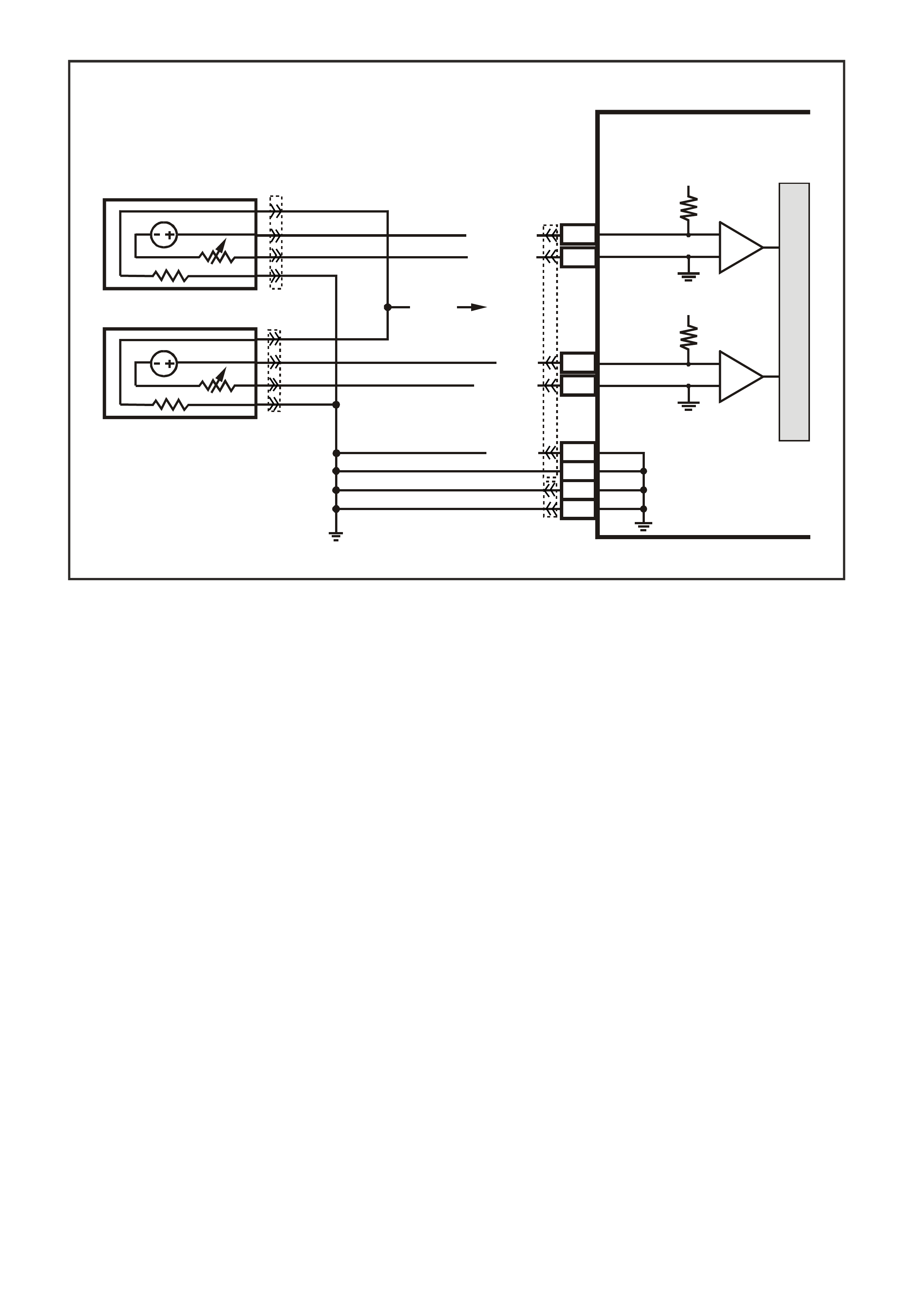
Figure 6C3-1-42 Heated Oxygen Sensor (HO2S) Circuits
D
D
B
B
A
A
C
C
GY/B (1413)
GY (1412)
RIGHT OXYGEN SENSOR
BANK TWO SENSOR ONE
LEFT OXYGEN SENSOR
BANK ONE SENSOR O NE
LOC. E5/E15
BLU/B (413)
V (412)
P (439)
TO F USE
F33
G3PCM003PT
J1-26
J1-66
J1-01
J1-40
J2-01
J2-40
J1-69
J1-29
PCM
RIGHT
OXYGEN
SENSOR
SIGNAL LO
LEFT
OXYGEN
SENSOR
SIGNAL LO
RIGHT
OXYGEN
SENSOR
SIGNAL HI
EARTH
EARTH
EARTH
EARTH
LEFT
OXYGEN
SENSOR
SIGNAL HI
IC
IC
45 0 mV
45 0 mV
M
I
C
R
O
B/R (750)
YE95
YE95
YE122
YE123

THROTTLE POSITION (TP) SENSOR
The Throttle Position (TP) sensor is connected to
the throttle shaft on the throttle body unit. It is a
potentiometer with one end connected to 5 volts
from the PCM and the other end to PCM earth. A
third wire connects from a sliding contact in the T P
sensor to the PCM allowing the PCM to measure
the voltage from the TP sensor. As the throttle is
moved ( acceler ator pedal m oved), the output of the
TP sensor changes. At a closed throttle position,
the output of the TP sensor is below 1.25V. As the
throttle valve opens, the output increases so that,
at wide-open throttle (WOT), the output voltage
should be about 4 volts.
By monitoring the output voltage from the TP
sensor, the PCM c an determ ine fuel delivery based
on throttle valve angle (driver demand). A broken
or loose T P sensor c an cause intermittent bursts of
fuel from the injectors, and an unstable idle,
because the PCM interprets the throttle is moving.
The TP sens or is not adjustable and ther e is no set
value for voltage at closed throttle because the
actual voltage at closed throttle can vary from
vehicle to vehicle due to tolerances. The PCM has
a special progr am built into it that can adjus t for the
tolerances in the T P sensor voltage reading at idle.
The PCM uses the reading at closed throttle idle
for the zero reading (0% throttle) so no adjustment
is necessary. Even if the TP sensor voltage
reading was to be changed by: tampering, throttle
body coking, sticking cable or any other reason,
the TP sensor will still be 0%. The PCM will learn
what the closed throttle value is every time the
throttle comes back to closed throttle.
Figure 6C3-1-43 Throttle Position (TP) Sensor
1. TP Sensor
2. Throttle Body
3. IAC Valve
The following DTCs are set when the PCM detects
a malfunction with the TP sensor circuits:
• DTC P0121: TP Sensor Circuit Insufficient
Activity.
• DTC P0122: TP Sensor Circuit Low Voltage.
• DTC P0123: TP Sensor Circuit High Voltage.
• DTC P1121: TP Sensor CKT Intermittent High
Voltage.
• DTC P1122: TP Sensor CKT Intermittent Low
Voltage.
GEN 3 00 15
C
B
A
21
3
Figure 6C3-1-44 TP Sensor - Typical
1. TP Sensor
2. Throttle Plate
3. Powertrain Control Module (PCM)

DTC P0121 THROTTLE POSITION SENSOR CIRCUIT INSUFFICIENT ACTIVITY
Conditions for running DTC P0121
• No MAP sensor or TP sensor DTCs.
• The engine run time is greater than 10 seconds.
• The engine coolant temperature is greater than 0°C.
• The IAC is between 0 and 255 counts.
• The MAP is less than 55 kPa.
OR
• The MAP is greater than 65 kPa.
• MAP is steady.
Conditions for setting DTC P0121
• The predicted throttle angle does not match the actual throttle angle.
• All conditions are met for at least 20 seconds.
Action taken when DTC P0121 Sets
• The PCM illuminates the Check Powertrain Lamp when the diagnostic runs and fails.
• The PCM records the operating conditions at the time the diagnostic fails. The PCM stores this information in
the Freeze Frame/Failure Records.
• The PCM uses a default TP sensor value.
Conditions for clearing the Check Powertrain Lamp and DTC P0121
• The PCM turns the Check Powertrain Lamp OFF when the diagnostic runs and does not fail.
• A last test failed (current DTC) clears when the diagnostic runs and does not fail.
DTC P0122 THROTTLE POSITION SENSOR CIRCUIT LOW VOLTAGE
Conditions for running DTC P0122
• The ignition switch is ON or in the engine is running.
Conditions for setting DTC P0122
• The TP sensor signal voltage is less than 0.2 volts.
Action taken when DTC P0122 Sets
• The PCM illuminates the Check Powertrain Lamp when the diagnostic runs and fails.
• The PCM records the operating conditions at the time the diagnostic fails. The PCM stores this information in
the Freeze Frame/Failure Records.
• The PCM uses a default TP sensor value.
• The transmission TCC will not apply.
• High transmission line pressure.
• Fixed transmission shift points, hard shifts and no fourth gear in hot mode.
Conditions for clearing the Check Powertrain Lamp and DTC P0122
• The PCM turns the Check Powertrain Lamp OFF when the diagnostic runs and does not fail.
• A last test failed (current DTC) clears when the diagnostic runs and does not fail.
DTC P0123 THROTTLE POSITION SENSOR CIRCUIT HIGH VOLTAGE
Conditions for running DTC P0123
• The ignition switch is ON or in the engine is running.
Conditions for setting DTC P0123
• The TP sensor signal voltage is greater than 4.8 volts.
• Conditions present for at least ten seconds.
Action taken when DTC P0123 Sets
• The PCM illuminates the Check Powertrain Lamp when the diagnostic runs and fails.
• The PCM records the operating conditions at the time the diagnostic fails. The PCM stores this information in
the Freeze Frame/Failure Records.
• The PCM uses a default TP sensor value.
• The transmission TCC will not apply.
• High transmission line pressure.
• Fixed transmission shift points, hard shifts and no fourth gear in hot mode.
Conditions for clearing the Check Powertrain Lamp and DTC P0123
• The PCM turns the Check Powertrain Lamp OFF when the diagnostic runs and does not fail.
• A last test failed (current DTC) clears when the diagnostic runs and does not fail.
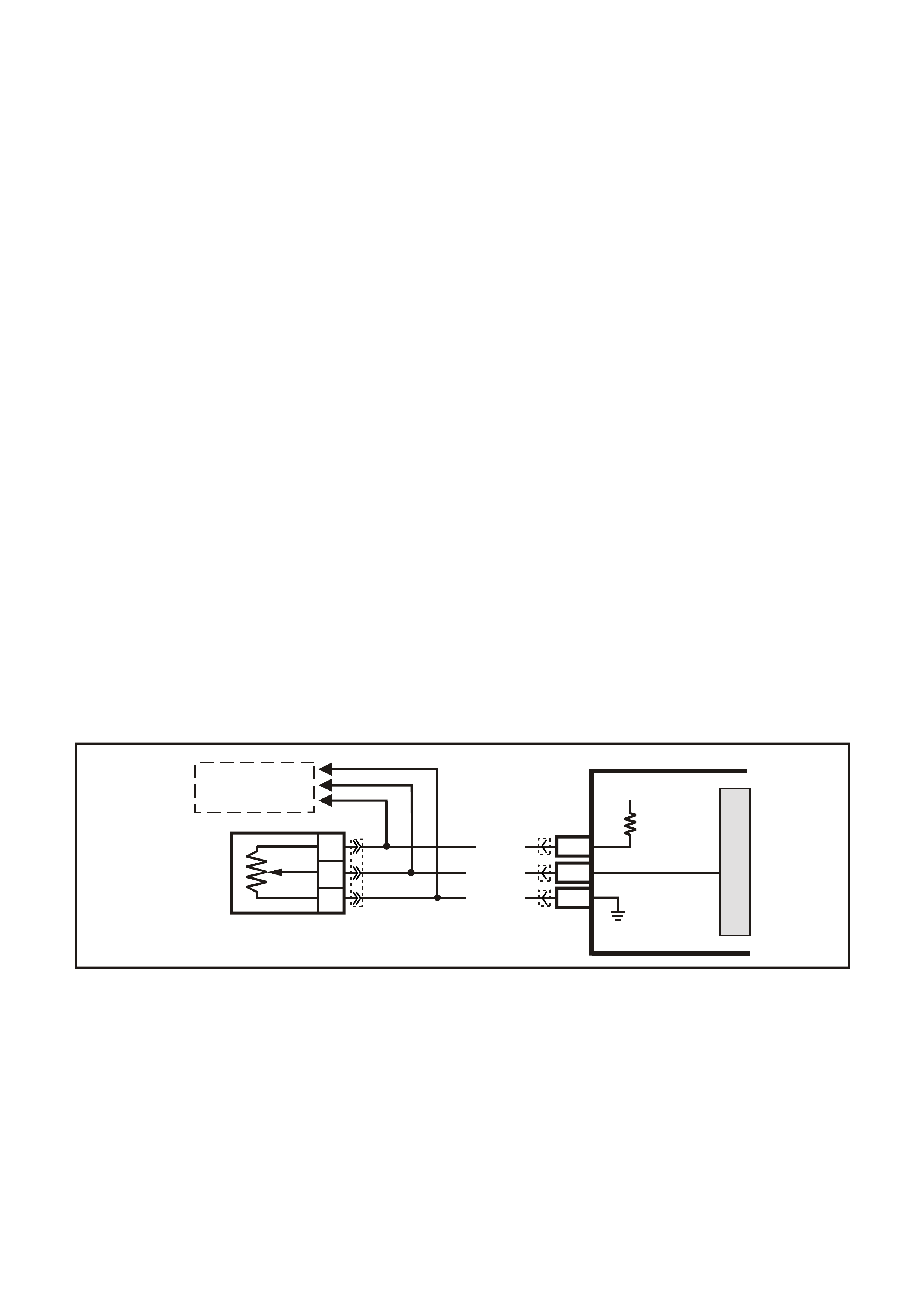
DTC P1121 THROTTLE POSITION SENSOR CIRCUIT INTERMITTENT HIGH VOLTAGE
Conditions for running DTC P1121
• The ignition switch is ON.
Conditions for setting DTC P1121
• The TP sensor signal voltage is greater than 4.8 volts.
Action taken when DTC P1121 Sets
• The PCM stores the DTC information into memory when the diagnostic runs and fails.
• The Check Powertrain Lamp will not be illuminated.
• The PCM records the operating conditions at the time the diagnostic fails. The PCM stores this information in
the Freeze Frame/Failure Records.
Conditions for clearing the Check Powertrain Lamp and DTC P1121
• A last test failed (current DTC) clears when the diagnostic runs and does not fail.
DTC P1122 THROTTLE POSITION SENSOR CIRCUIT INTERMITTENT HIGH VOLTAGE
Conditions for running DTC P1122
• The ignition switch is ON or the engine is running.
Conditions for setting DTC P1122
• The TP sensor signal voltage is less than 0.2 volts.
Action taken when DTC P1122 Sets
• The PCM stores the DTC information into memory when the diagnostic runs and fails.
• The Check Powertrain Lamp will not be illuminated.
• The PCM records the operating conditions at the time the diagnostic fails. The PCM stores this information in
the Freeze Frame/Failure Records.
Conditions for clearing the Check Powertrain Lamp and DTC P1122
• A last test failed (current DTC) clears when the diagnostic runs and does not fail.
Figure 6C3-1-45 Throttle Position Sensor Circuits
G3PCM005PT
SENSOR EARTH
TP SENSOR SIGNAL
TP SEN SOR
REFERENCE
VOLTAGE
PCM
5V
M
I
C
R
O
J1-08
J2-24
J1-60
A
C
B
THROTTLE
POSITION SENSOR
GY (416)
YE122
YE122YE30
YE123
BLU (417)
B/Y (452)
TO
THROTTLE RELAXER
MODULE
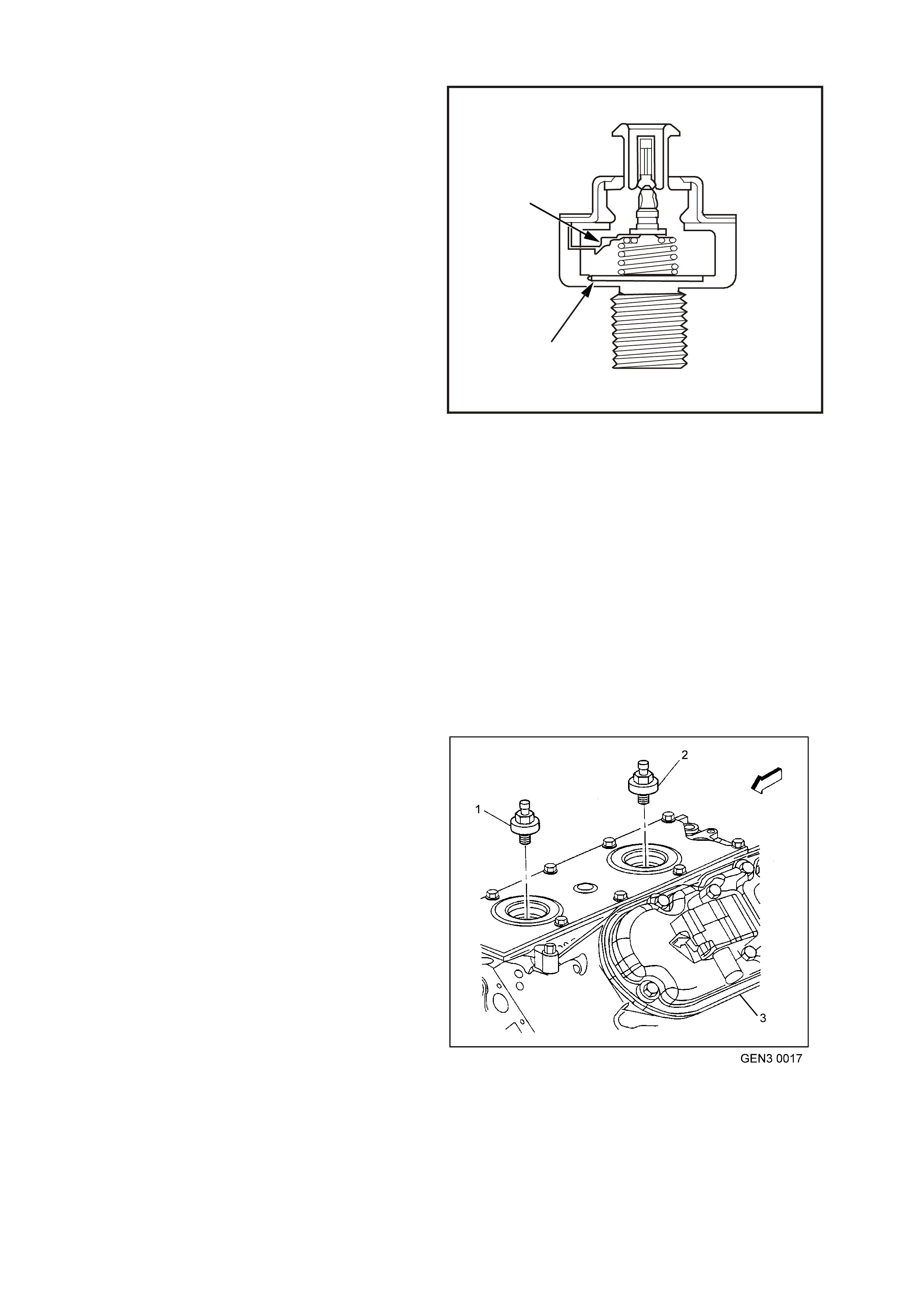
KNOCK SENSORS (KS)
Varying octane levels in today's petrol may cause
detonation in some engines. Detonation is caused
by an uncontrolled pressure in the combustion
chamber. This uncontrolled pressure could
produce a f lame f r ont oppos ite to that of the normal
flame front produced by the spark plug.
The rattling sound normally associated with
detonation is the result of two or more opposing
pressures (flame fronts) colliding within the
combustion chamber. Though light detonation is
sometimes considered normal, heavy detonation
could result in engine damage. Light detonation
occurs when the point of maximum pressure has
been exceeded. T o control spark knock , two knoc k
sensors are used on the GEN III V8 engine. This
system is des igned to retard spark tim ing up to 20°
to reduce spark knock in the engine. This allows
the engine to use maximum spark advance to
improve driveability and fuel economy.
The knock sensors detect abnormal mechanical
vibration (spark knocking) in the engine. There are
several calibrations of knock sensors because
each engine produces a different frequency of
mechanical noise. The knock sensor is specifically
chosen for this engine to best detec t engine knock ,
over all the other noises in the engine.
The knock sensor produces an AC output voltage
that increases with the severity of the knock. This
signal voltage inputs to the PCM. This AC signal
voltage to the PCM is proces sed by a Digital Signal
Noise Enhancement Filter (DSNEF) module. This
DSNEF module is used to determine if the AC
signal coming in is noise or actual detonation. This
DSNEF module is part of the PCM and cannot be
replaced.
1
2
4254
Figure 6C3-1-46 Knock (KS) Sensor
1. Piezo Crystal
2. Shunt Resister
The processed knock sensor signal is then
supplied to the PCM. The PCM then adjusts the
ignition control system to reduce the spark
advance. How muc h the tim ing is retar ded is based
upon the amount of time knock is detected. After
the detonation stops, the timing will gradually
return to its calibrated value of s park advance. T he
Knock Sensor system will only retard timing after
the following conditions are met:
• The engine run time is greater than 20
seconds.
• The engine speed is greater than 1650 RPM.
• T he engine coolant tem perature is greater than
70°C.
• T he manif old absolute pressur e is less than 60
kPa.
DTC P0325 indicates an internal PCM malfunction
related to the knock sensor system. DTCs P0327
and P0332 indicate that a knock sensor or knock
sensor circuit is malfunctioning.
Figure 6C3-1-47 Knock Sensor Location
1. Front Knock Sensor
2. Rear Knock Sensor
3. Left Cylinder Head

DTC P0325 KNOCK SENSOR SYSTEM
Conditions for running DTC P0325
• The engine run time is greater than 20 seconds.
• The engine speed is between 1650 and 3000 RPM.
• The MAP is at or about 48 kPa.
• The engine coolant temperature is greater than 70°C.
• The throttle angle is greater than 0.5%.
• The TP sensor angle is steady within 1%.
• Battery voltage is between 10 and 16 volts.
Conditions for setting DTC P0325
• A malfunction with the knock sensor system or circuits within the PCM are faulty.
• All above conditions present for at least three seconds.
Action taken when DTC P0325 Sets
• The PCM illuminates the Check Powertrain Lamp when the diagnostic runs and fails.
• The PCM records the operating conditions at the time the diagnostic fails. The PCM stores this information in
the Freeze Frame/Failure Records.
Conditions for clearing the Check Powertrain Lamp and DTC P0325
• The PCM turns the Check Powertrain Lamp OFF after one ignition cycle that the diagnostic runs and does not
fail.
• A last test failed (current DTC) clears when the diagnostic runs and does not fail.
DTC P0327 KNOCK SENSOR CIRCUIT FRONT SENSOR
Conditions for running DTC P0327
• The engine run time is greater than 20 seconds.
• The engine speed is between 1650 and 3000 RPM.
• The MAP is at or about 48 kPa.
• The engine coolant temperature is greater than 70°C.
• The throttle angle is greater than 0.5%.
• Battery voltage is between 10 and 16 volts.
Conditions for setting DTC P0327
• The PCM determines that the frequency is less than or greater than the expected amount for at least three
seconds.
Action taken when DTC P0327 Sets
• The PCM illuminates the Check Powertrain Lamp when the diagnostic runs and fails.
• The PCM records the operating conditions at the time the diagnostic fails. The PCM stores this information in
the Freeze Frame/Failure Records.
Conditions for clearing the Check Powertrain Lamp and DTC P0327
• The PCM turns the Check Powertrain Lamp OFF after one ignition cycle that the diagnostic runs and does not
fail.
• A last test failed (current DTC) clears when the diagnostic runs and does not fail.
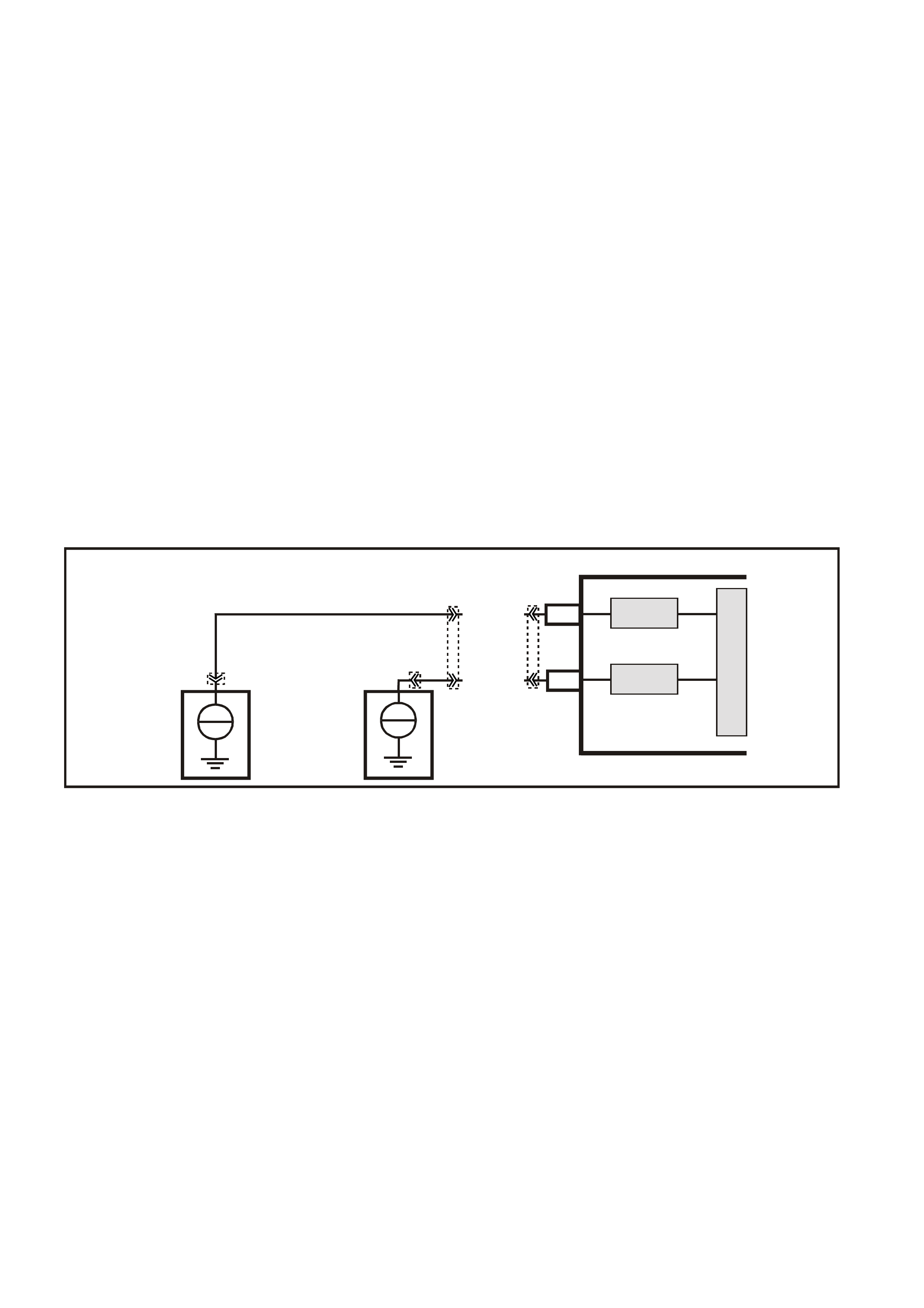
DTC P0332 KNOCK SENSOR CIRCUIT REAR SENSOR
Conditions for running DTC P0332
• The engine run time is greater than 20 seconds.
• The engine speed is between 1650 and 3000 RPM.
• The MAP is at or about 48 kPa.
• The engine coolant temperature is greater than 70°C.
• The throttle angle is greater than 0.5%.
• Battery voltage is between 10 and 16 volts.
Conditions for setting DTC P0332
• The PCM determines that the frequency is less than or greater than the expected amount for at least three
seconds.
Action taken when DTC P0332 Sets
• The PCM illuminates the Check Powertrain Lamp when the diagnostic runs and fails.
• The PCM records the operating conditions at the time the diagnostic fails. The PCM stores this information in
the Freeze Frame/Failure Records.
Conditions for clearing the Check Powertrain Lamp and DTC P0332
The PCM turns the Check Powertrain Lamp OFF after one ignition cycle that the diagnostic runs and does not fail.
• A last test failed (current DTC) clears when the diagnostic runs and does not fail.
Figure 6C3-1-48 Knock Sensor Circuit
G3VX007PT
PCM
M
I
C
R
O
DSNEF
DSNEF
FRONT KNOCK
SENSOR SIGNAL I NPUT
REAR KNOCK
SENSOR SIGNAL I NPUT
J1-51
J1-11
REAR
KNOCK
SENSOR
FRONT
KNOCK
SENSOR
+
-
+
-
BLU (815)
YE19
YE18
YE18
YE122
LBLU (826)

PARK, REVERSE, NEUTRAL, DRIVE, LOW (PRNDL) SWITCH
The transmission PRNDL switch is a mulit-signal
switch which sends signals to the PCM to indicate
gear lever position. Park, Reverse, Neutral, Drive,
3, 2, or 1. The PCM will then determine the signal
from the PRNDL switch and sends a command to
the instruments via the PIM and the serial data
normal mode message commanding the
instruments to turn ON the correct gear indicator
lamp for the gear that has been selected.
The PRNDL switch uses four discrete circuits to
pull four PCM voltages low in var ious combinations
to indicate each gear range. The voltage level of
the circuits is represented as CLOSED = earthed
(0V), and OPEN = open (12V). The four states
displayed represents P, A, B, and C inputs.
The Tech 2 scan tool will display all four circuits
(P, A, B, C) and the appr opriate open and c los ed to
represent the gear selected. If the gear selected
does not match the OPEN/ CLOSED state as
displayed in the table or on the scan tool, or the
appropriate instruments gear lamp does not light
up for the gear selected, there is a fault in the
PRNDL select circuit or in the Instrument Panel
(IP) cluster.
The PRNDL operation indicates to the PCM what
gear the shif t s elec tor is in. This inf or mation is used
for the IAC valve operation.
IMPORTANT:
Idle quality will be affected if the vehicle is driven
with the PRNDL switch disconnected. Having the
switch disconnec ted m ay also cause a VSS DT C to
set.
For additional details of the PRNDL switch
location and adjustment, refer to
Section 7C4 Automatic Transmission, On-
Vehicle Servicing in VX Service Information.
The following DTCs are set when the PCM detects
a malfunction with the transmission range switch:
• DTC P0705: Transmission Range Switch
Circuit.
• DTC P0706: Transmission Range Switch
Performance.
DTC P0705 TRANSMISSION RANGE SWITCH CIRCUIT
Conditions for running DTC P0705
• The ignition is on.
Conditions for setting DTC P0705
• The Transmission Range Switch inputs indicate an invalid combination.
• The above condition is present for longer than 30 seconds.
Action taken when DTC P0705 Sets
• The PCM stores the DTC information into memory when the diagnostic runs and fails.
• The Check Powertrain Lamp will not be illuminated.
• The PCM records the operating conditions at the time the diagnostic fails. The PCM stores this information in
the Freeze Frame/Failure Records.
Conditions for clearing the Check Powertrain Lamp and DTC P0705
• A last test failed (current DTC) clears when the diagnostic runs and does not fail.
• The PCM cancels the DTC default actions when the fault no longer exists and the ignition switch is OFF long
enough in order to power down the PCM.
GEAR
POSITION
SELECTED
SCAN TOOL PRNDL DISPLAY
(P, A, B, C)
P A B C
PARK (P) CLOSED
(0V) CLOSED
(0V) OPEN
(12V) OPEN
(12V)
REVERSE (R) OPEN
(12V) CLOSED
(0V) CLOSED
(0V) OPEN
(12V)
NEUTRAL (N) CLOSED
(0V) OPEN
(12V) CLOSED
(0V) OPEN
(12V)
DRIVE 4 (D) OPEN
(12V) OPEN
(12V) CLOSED
(0V) CLOSED
(0V)
DRIVE (3) CLOSED
(0V) CLOSED
(0V) CLOSED
(0V) CLOSED
(0V)
DRIVE 2 (2) OPEN
(12V) CLOSED
(0V) OPEN
(12V) CLOSED
(0V)
DRIVE 1 (1) CLOSED
(0V) OPEN
(12V) OPEN
(12V) CLOSED
(0V)
Figure 6C3-1-49 Transmiss i on Ra nge / PRNDL Switch
Valid Input Combinations
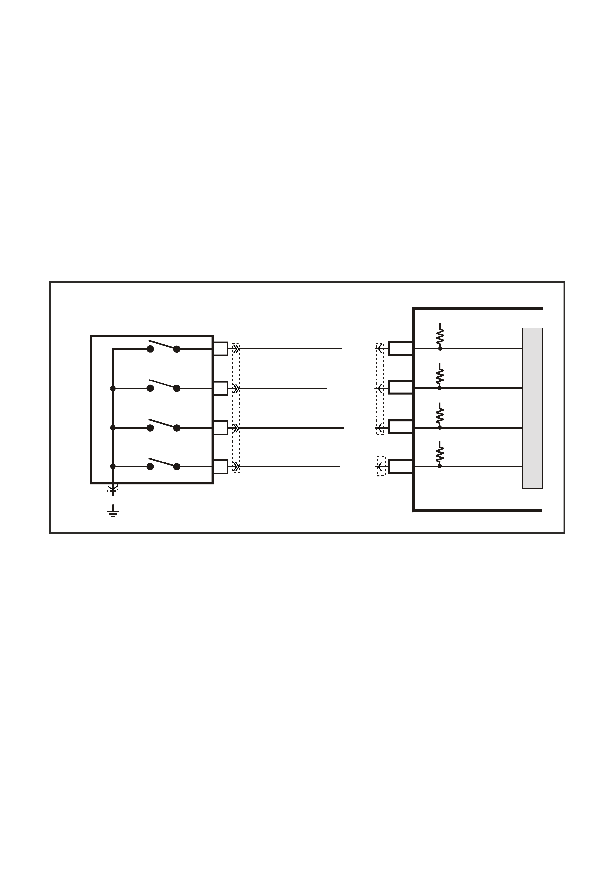
DTC P0706 TRANSMISSION RANGE SWITCH PERFORMANCE
Conditions for running DTC P0706
• The ignition is on.
Conditions for setting DTC P0706
• The Transmission Range Switch inputs indicate an invalid combination.
• The above condition is present for longer than 30 seconds.
Action taken when DTC P0706 Sets
• The PCM stores the DTC information into memory when the diagnostic runs and fails.
• The Check Powertrain Lamp will not be illuminated.
• The PCM records the operating conditions at the time the diagnostic fails. The PCM stores this information in
the Freeze Frame/Failure Records.
Conditions for clearing the Check Powertrain Lamp and DTC P0706
• A last test failed (current DTC) clears when the diagnostic runs and does not fail.
• The PCM cancels the DTC default actions when the fault no longer exists and the ignition switch is OFF long
enough in order to power down the PCM.
Figure 6C3-1-50 Transmission PRNDL Switch Circuit
G3PCM038PT
PCM
J1-32
J1-72
PRNDL P
PRNDL A
C
SWITCH P
SWITCH A
SWITCH B
SWITCH C
LOC. E5/E15
A
D
B
P. R. N. D. L. SWITC H
12V
12V
J2-62
J1-34
PRNDL B
PRNDL C
12V
12V
BLU/W (771)
Y (77 2)
GY (773)
W (776)
YE122
YE123
YB20
YB35
B/R (750)
M
I
C
R
O

A/C REQUEST SIGNAL A ND A/C CLUTCH CONTROL WITH ECC
The Electronic Climate Control (ECC) module request the PCM to turn the A/C compressor clutch on or off via
the PIM and the s erial data bus nor m al m ode m essage. T he ECC m odule m onitor s inf orm ation fr om it’s s ensors
and switches and determines if the A/C compres sor c lutch s hould be on or off. The ECC contr ol module will then
request the PCM to turn the A/C compressor clutch on or off when required.
The PCM on receiving a request to turn on the A/C compressor will:
1. Adjust the Idle Air Control ( IAC) valve position to c om pensate f or the additional load placed on the engine by
the air conditioning compressor.
2. Energise the A/C compressor relay, to operate the A/C compressor if the pressure in the A/C system is
within the correct operating range.
Low Pressure High Pressure RPM
Cut Out Cut In Cut Out Cut In Off On
180 240 2900 2000 4800 4000
The PCM on rec eiving a request to tur n on the A/C com pres sor, m onitors the A/C pressure, coolant tem perature
and RPM to determine A/C clutch operation.
There are two DTCs associated with the A/C system . DTC P1539 is set when, the PCM detects voltage on the
A/C clutch status terminal when the system has not requested A/C. A short to voltage at any point in the A/C
status circuit, or the A/C relay contacts are stuck.
DTC P1546 is set when the PCM activates the relay, voltage should be present at both the A/C compressor
clutch and the A/C clutch status circuit at the PCM. If the voltage is not present, DTC P1546 will set.
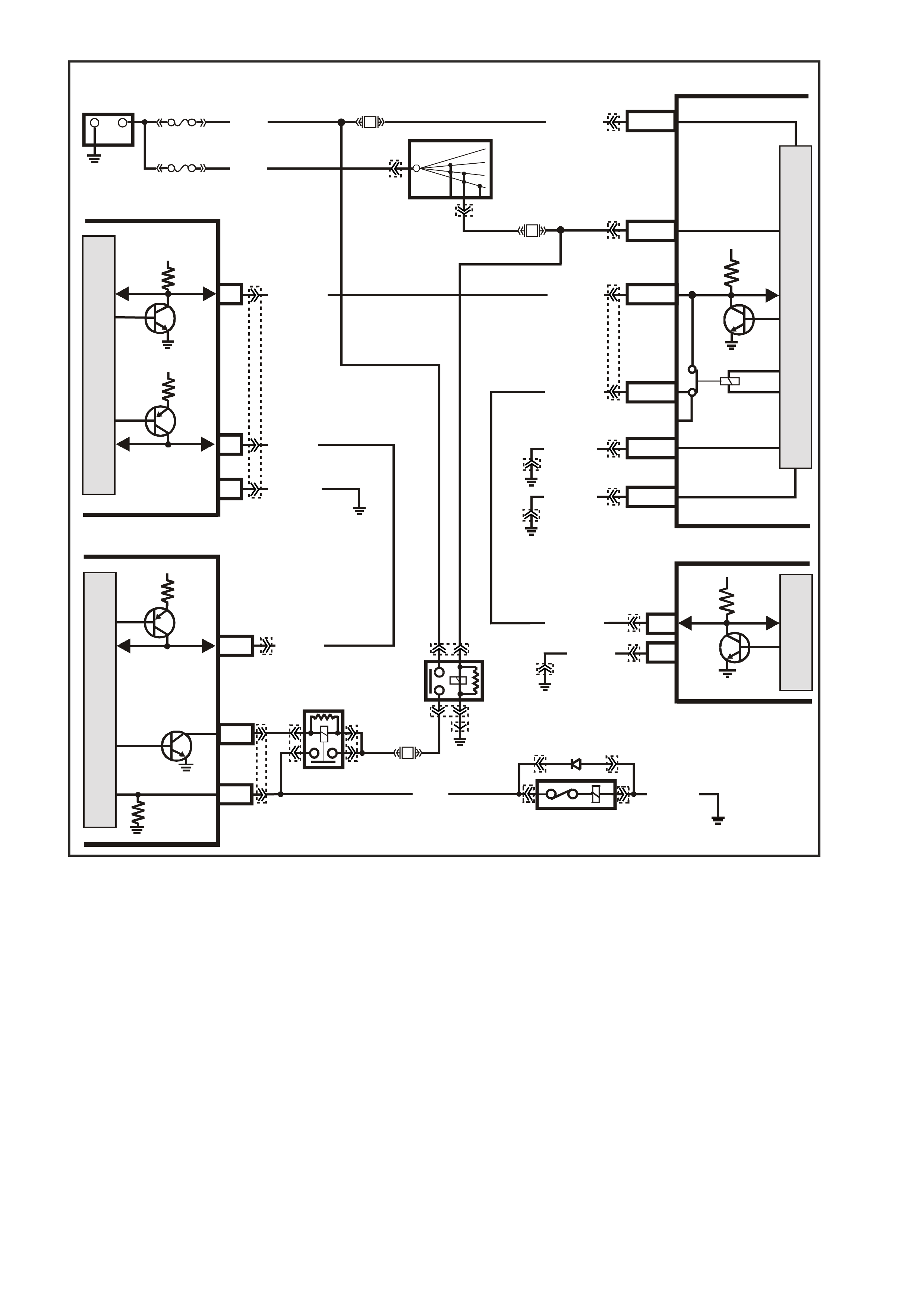
Figure 6C3-1-51 A/C Request Signal With ECC Circuit
G3PCM046PT
BCM
M
I
C
R
O
P
R
O
C
E
S
S
O
R
+-
BATTERY
FS
F31
A5/A6O/B (740)
(1040)
BATTERY MAIN POWER
FJ
LOC. E1
R (2H)
F14
E20/D6
P/B
(39) IGNITION ON
15a 15 50
30 OFF/ON
LOCK
ACC
IGN
START
IGNITION SWITCH
P
(3)
B/Y (155 )
B/G (151)
LOC. E3
LOC. E3
R/B (1221)
G/W (1220)
Y (1049)
R/B (1221)
PIM
SERIAL
DATA
5V
ELECTRONIC EARTH
HIGH CURRENT
EARTH
A1/A5
B10/B11
E2/D2
E9/E3
SERIAL
DATA
MAIN
SERIAL
DATA AUX.
5V
6
16 B/R ( 750)
LOC. E5/E15
LOC. E5/E15
7V
7
CLASS 2
SERIAL DATA
EARTH
ECC
6SERIAL
DATA
5V
LOC. E3
G/W (1220)
2
M
I
C
R
O
B/Y (155 )
M
I
C
R
O
7V
PCM
J1-58
CLASS 2
SERIAL DA TA
LG/B
(366)
O/Y
(479)
Y (1049)
J2-43
J2-18
A/C
CLUTCH
CONTROL
A/C RELA Y
STATUS
M
I
C
R
O
A
/C
COMPRESSOR
A/C
RELAY
EFI
RELAY
F33 LOC. E 3
G (59) B/R (750)
YB176
YB165
YB175
YB44
YB44 YB164
YB175
YB164
YB174
YB163
YB176
YB165
YB89
YB87YE114
YE120
YE105
YE39
YE114
YE39
YE101
YE101
YE123
YE122
YB215
YE39
YE105
YE120
YE114
YE114
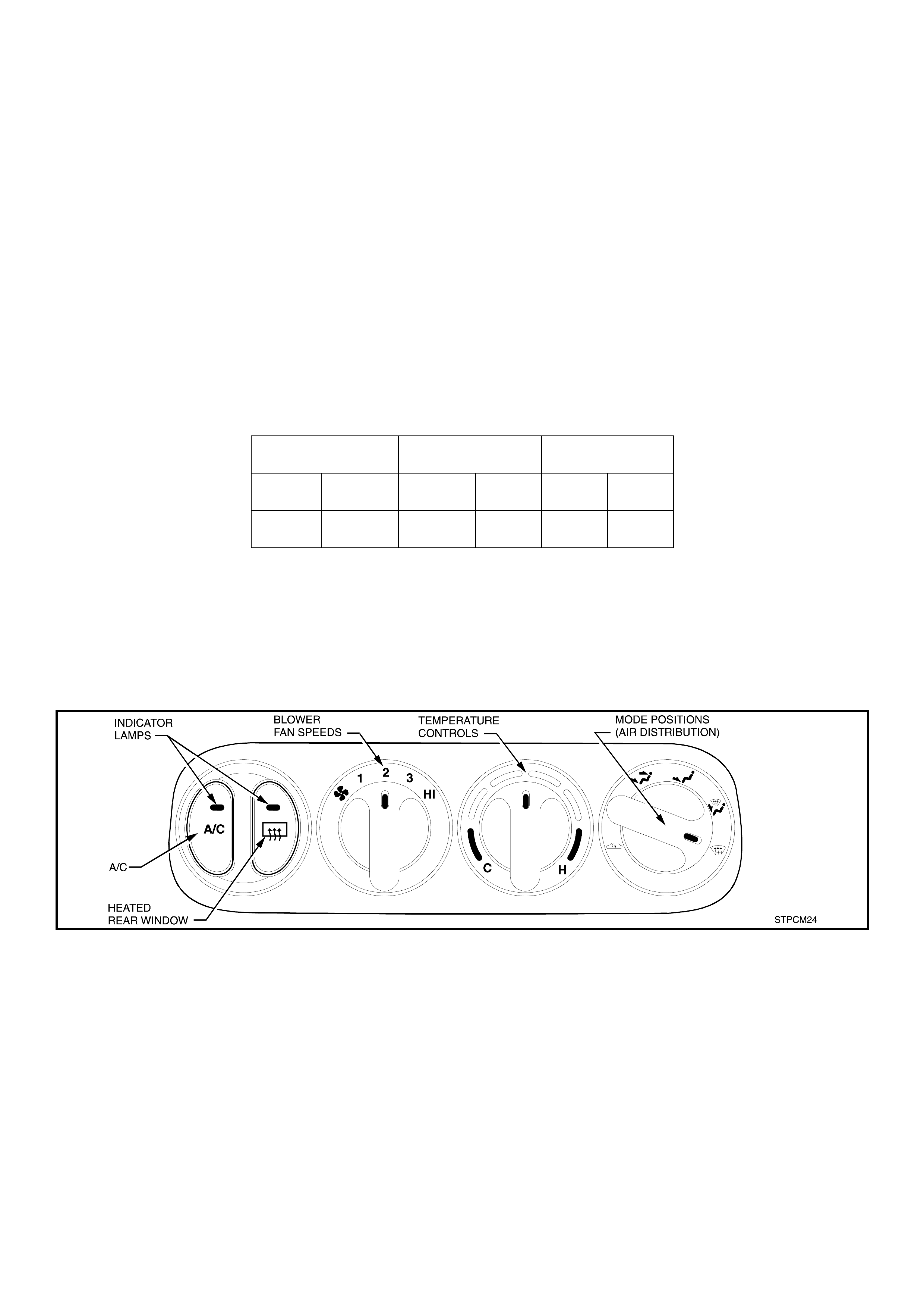
A/C REQUEST SIGNAL A ND A/C CLUTCH CONTROL WITHOUT ECC
The BCM request the PCM to turn the A/C compressor on or off via the PIM and the serial data bus normal
mode m essage. T he BCM monitors the voltage at BCM terminal D9 to determ ine the status of the m omentary
A/C Master switch. W hen the A/C master switch is pressed, 12 volts is applied to the BCM terminal D9. The
BCM sees this high voltage as an A/C master switch input signal.
On receiving the A/C m aster switch input signal, the BCM request the PCM to energise the A/C clutch via the
PIM and the serial data bus normal mode message, if the ignition is on and the blower motor is operating. If
the A/C master switch is pressed again the BCM will request the PCM to turn off the A/C compressor.
The operating status of the system will be remembered by the BCM, when the ignition is switched from on to
off or when the blower is switched off. If the blower is off and the A/C master switch is pressed, then the next
time the blower is switched on the air conditioning will be turned on. Turning the ignition off will cancel this
button press function.
The system will reset to off when the battery is disconnected.
The PCM uses this signal to:
1. Adjust the Idle Air Control (IAC) valve position to com pensate for the additional load placed on the engine
by the air conditioning compressor.
2. Energise the A/C compressor relay, to operate the A/C compressor if the pressure in the A/C system is
within the correct operating range.
Low Pressure High Pressure RPM
Cut Out Cut In Cut Out Cut In Off On
180 240 2900 2000 4800 4000
The PCM monitors the A/C pressure Sensor to determine A/C system pressure.
There are two DTCs associated with the A/C system . DTC P1539 is set when, the PCM detects voltage on the
A/C clutch status terminal when the system has not requested A/C. A short to voltage at any point in the A/C
status circuit, or the A/C relay contacts are stuck.
DTC P1546 is set when the PCM activates the relay, voltage should be present at both the A/C compressor
clutch and the A/C clutch status circuit at the PCM. If the voltage is not present, DTC P1546 will set.
Figure 6C3-1-52 Heater and Air Conditioning Controls
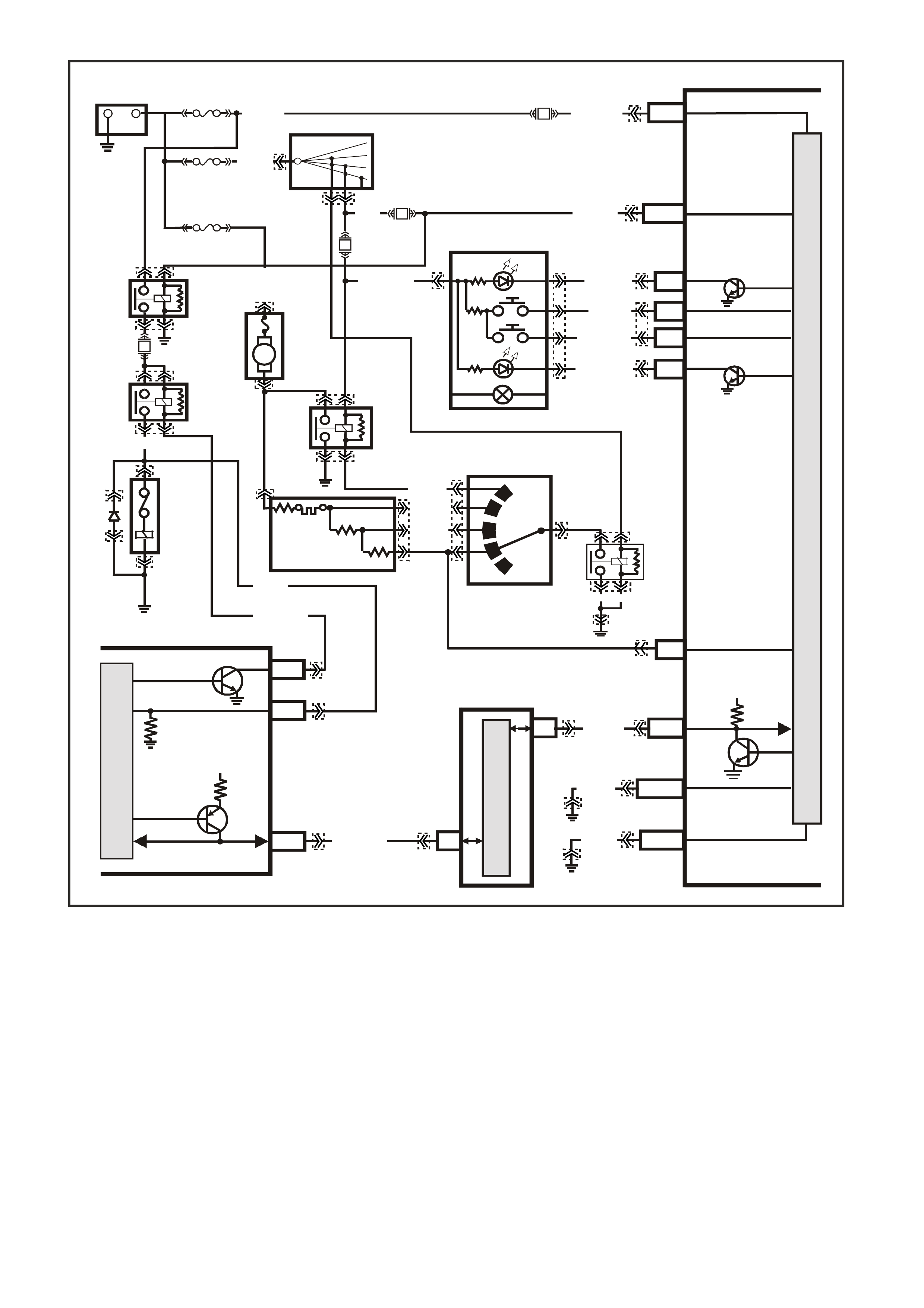
Figure 6C3-1-53 A/C Request Signal Without ECC
DTC P1539 A/C CLUTCH STATUS CIRCUIT HIGH VOLTAGE
Conditions for running DTC P1539
• The A/C clutch is not requested.
Conditions for setting DTC P1539
• Voltage is detected on the A/C status circuit for more than 15 seconds after the PCM has disengaged the A/C
clutch relay.
Action taken when DTC P1539 Sets
• The PCM stores the DTC information into memory when the diagnostic runs and fails.
• The Check Powertrain Lamp will not be illuminated.
• The PCM records the operating conditions at the time the diagnostic fails. The PCM stores this information in
the Freeze Frame/Failure Records.
Conditions for clearing the Check Powertrain Lamp and DTC P1539
• A last test failed (current DTC) clears when the diagnostic runs and does not fail.
D20
A1
D9
B8
A
/C MASTER
SWITCH
O (291)
B/R (292)
R/W (248)
R/BR (962)
BR
(4)
Y
(51)
LOC. E3
LOC. E3
LOC. E1
B3
BLOWER
MOTOR
RESISTORS
A/C
COMPRESSOR
A/C
RELAY
EFI
RELAY
BLOWER
MOTOR
HEATER AND A/C
CONTROLS
BLOWER
INHIBIT
RELAY
BLOWER
RELAY
DKG/Y (359)
Y/B (52)
R/G (245)
LOC.
E5/E15
4
3
2
1
R/Y (244)
O/G
(251)
DKG/Y
(359)
BATT ERY MAIN POWER
+
-
BATTERY
IGNITION SW ITCH
FY
F31
A5/A6
O/B (740)
FS
(1040)
BCM
IGNITION
DEMIST OUTPUT
DEMIST INPUT
A/C SWITCH INPUT
A/C LED OUTPUT
A/C BLOWER
INPUT
F14
F13
F33
E20/D6
P/B (39)
15a 15 50
30 OFF/ON
LOCK
ACC
IGN
START
P (3)
FJ
R (2H)
R (2A)
P/BLU (44)
M
I
C
R
O
P
R
O
C
E
S
S
O
R
G (59)
LOC. E3
LOC. E3
B/G (151)
B10/B11 HIGH
CURRENT
EARTH
E2/D2
R/B (1221)
SERIAL
DATA
5V
B/Y (155)
ELECTRONIC
EARTH
A1/A5
PIM
6
7
M
I
C
R
O
CLASS 2 SERIAL DATA
UART SERIAL DATA
7V
PCM
J1-58
CLASS 2
SERIAL DATA
Y (1049)
J2-43
J2-18
A/C CLUTCH CONTROL
A/C RELAY STA TUS
M
I
C
R
O
G3PCM047PT
G (59)
LG/B (366) B (1 50)
YB165
YB165
YB164
YB163
YB54
YB54
YB50
YB50 YB48
YB48
YB174
YB163
YB175
YB164
YB174
YB163
YB176
YB165
YE114
YE114
YB215YE122
YE123
YB2
YB2
YB64YE114
YB64
YB14
YB14
YB44
YB44
YE39
YE39
YE101
YE101
YE120
YE120
YE105
B/R
(750)
YE105
YE114
YB215
YE114
YB165
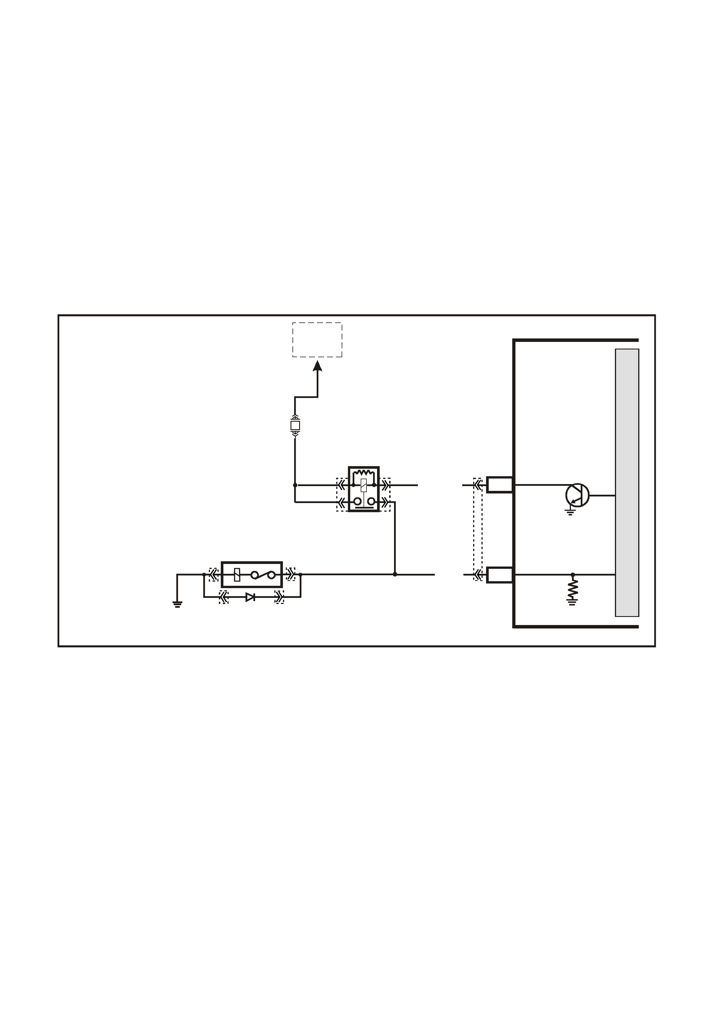
DTC P1546 A/C CLUTCH STATUS CIRCUIT HIGH VOLTAGE
Conditions for running DTC P1546
• The A/C clutch is requested.
Conditions for setting DTC P1546
• The PCM commands the A/C ON and the PCM does not detect a voltage on the A/C clutch status line for more
than five seconds.
Action taken when DTC P1546 Sets
• The PCM stores the DTC information into memory when the diagnostic runs and fails.
• The Check Powertrain Lamp will not be illuminated.
• The PCM records the operating conditions at the time the diagnostic fails. The PCM stores this information in
the Freeze Frame/Failure Records.
Conditions for clearing the Check Powertrain Lamp and DTC P1546
• A last test failed (current DTC) clears when the diagnostic runs and does not fail.
Figure 6C3-1-54 A/C Clutch Circuit
4360
PCM
A
/C RELAY
J2-43
LG/B (366)
YE101
YE105YE105
YE120 YE120
YE101
YE123
A/C CLUTCH
CONTROL
TO
EFI
RELAY
M
I
C
R
O
F33
LOC. E5/E15
B/R 750
A/C
COMPRESSOR
J2-18
G (59) A/C RELA Y STATUS

A/C REFRIGERANT PRESSURE SENSOR
The A/C Refrigerant Pressure Sensor is a sealed
gauge reference capacitive pressure sensor with
on board signal conditioning. It provides a 0 to five
volt output and requires a five volt regulated power
supply.
In operation the Sensor senses applied pressure
via the deflection of a two piece c eramic diaphr agm
with one half being a parrel plate capacitor.
Changes in capacitance influenced by the
refrigerant pressure under the ceramic diaphragm
are converted to an analogue output by the
Sensors integral signal electronics.
The pressure Sensor’s electronics are on a flexible
circuit board contained in the upper section of the
Sensor. They provide linear calibration of the
capacitance signal from the ceramic sensing
diaphragm.
Benefits of using the pressure Sensor over a
normal type pressure switch is that the Sensor is
constantly monitoring pressures and sending
signals to the Powertrain Control Module (PCM).
The norm al type pressure s witch only has an upper
and lower cut-out point. The PCM will disengage
the A/C compressor at Low or High refrigerant
pressures and control the operation of the engine
cooling fans.
If there is a failure in the A/C Pressure Sensor
circuit DTC P0530 will set.
T26C3004
1
Figure 6C3-1-55 A/C Refrigerant Pressure Sensor Location
1. A/C Refrigerant Pressure Sensor.
32
1
4347
4
5
Figure 6C3-1-56 A/C Refrigerant Pressure Sensor
Cut-Away View
1. Signal Electronics.
2. Pressure Port.
3. Ceramic Diaphragm.
4. Pressure Sensor.
5. High Side Charge Port.
Low Pressure Compressor Cut OFF at 180kPa
ON at 240 kPa
High Pressure Compressor Cut OFF at 2900 kPa
ON at 2400 kPa
Engine Cooling Fan Low ON at 1500 kPa
Speed OFF at 1250 kPa
Engine Cooling Fan High ON at 2600 kPa
Speed OFF at 2300 kPa
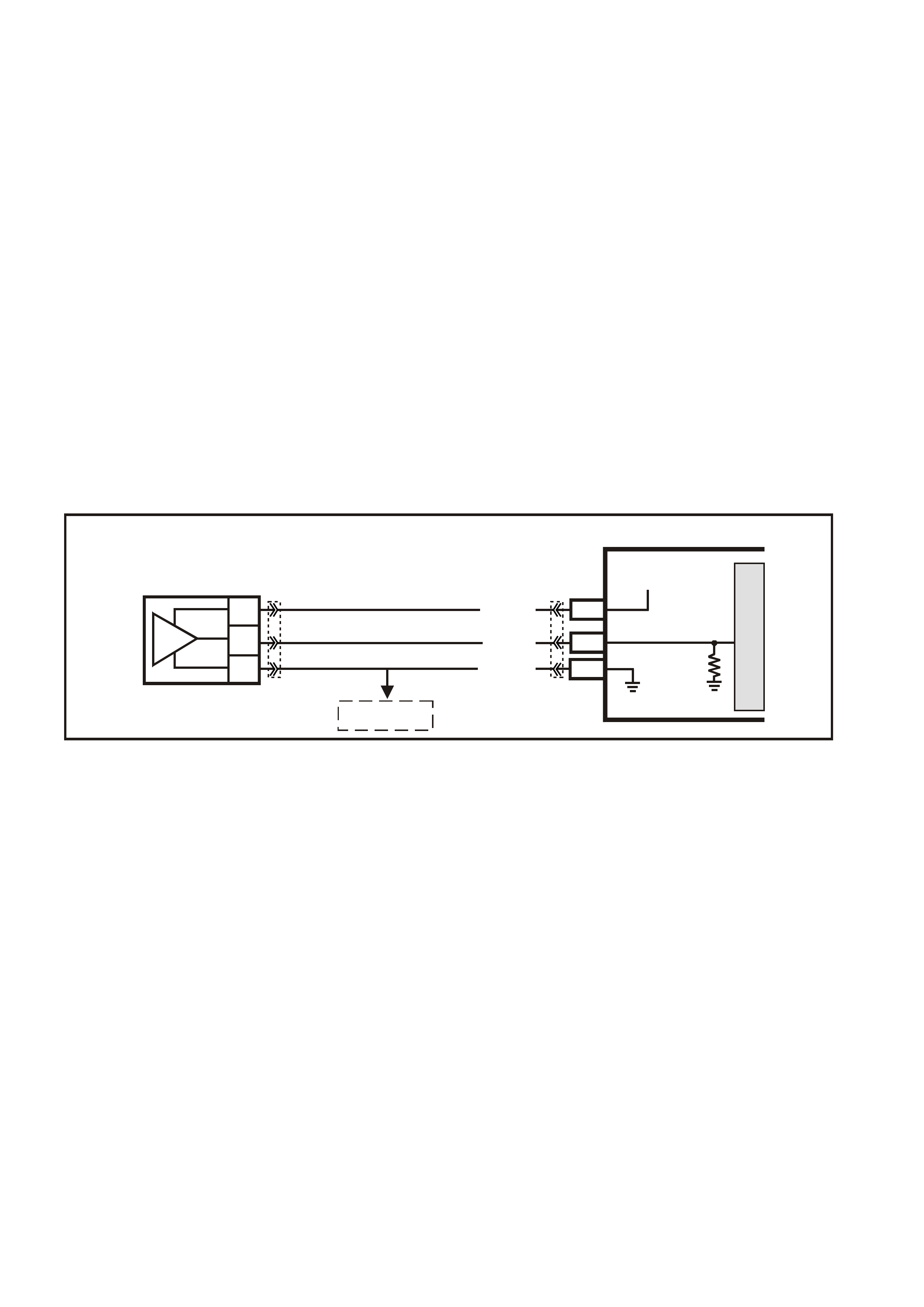
DTC P0530 A/C REFRIGERANT PRESSURE SENSOR CIRCUIT
Conditions for running DTC P0530
• The PCM detects an A/C request.
Conditions for setting DTC P0530
• A/C refrigerant pressure Sensor indicates A/C refrigerant pressure is at or below 25 kPa for five seconds.
OR
• A/C refrigerant pressure Sensor indicates A/C refrigerant pressure is at or above 3140 kPa for five seconds.
Action taken when DTC P0530 Sets
• The PCM stores the DTC information into memory when the diagnostic runs and fails.
• The Check Powertrain Lamp will not be illuminated.
• The PCM records the operating conditions at the time the diagnostic fails. The PCM stores this information in
the Freeze Frame/Failure Records.
Conditions for clearing the Check Powertrain Lamp and DTC P0530
• A last test failed (current DTC) clears when the diagnostic runs and does not fail.
Figure 6C3-1-57 A/C Refrigerant Pressure Sensor Circuit
G3PCM001PT
PCM
M
I
C
R
O
J2-14
J2-57
A/C
PRESSURE
SENSOR
J1-45
SENSOR EARTH
A/C PRESSURE
SENSOR SIGNAL
5V
V/W (415)
YE122
YE123YE113
G/O (469)
G/B (259)
C
B
A
TO
IAT SENSOR
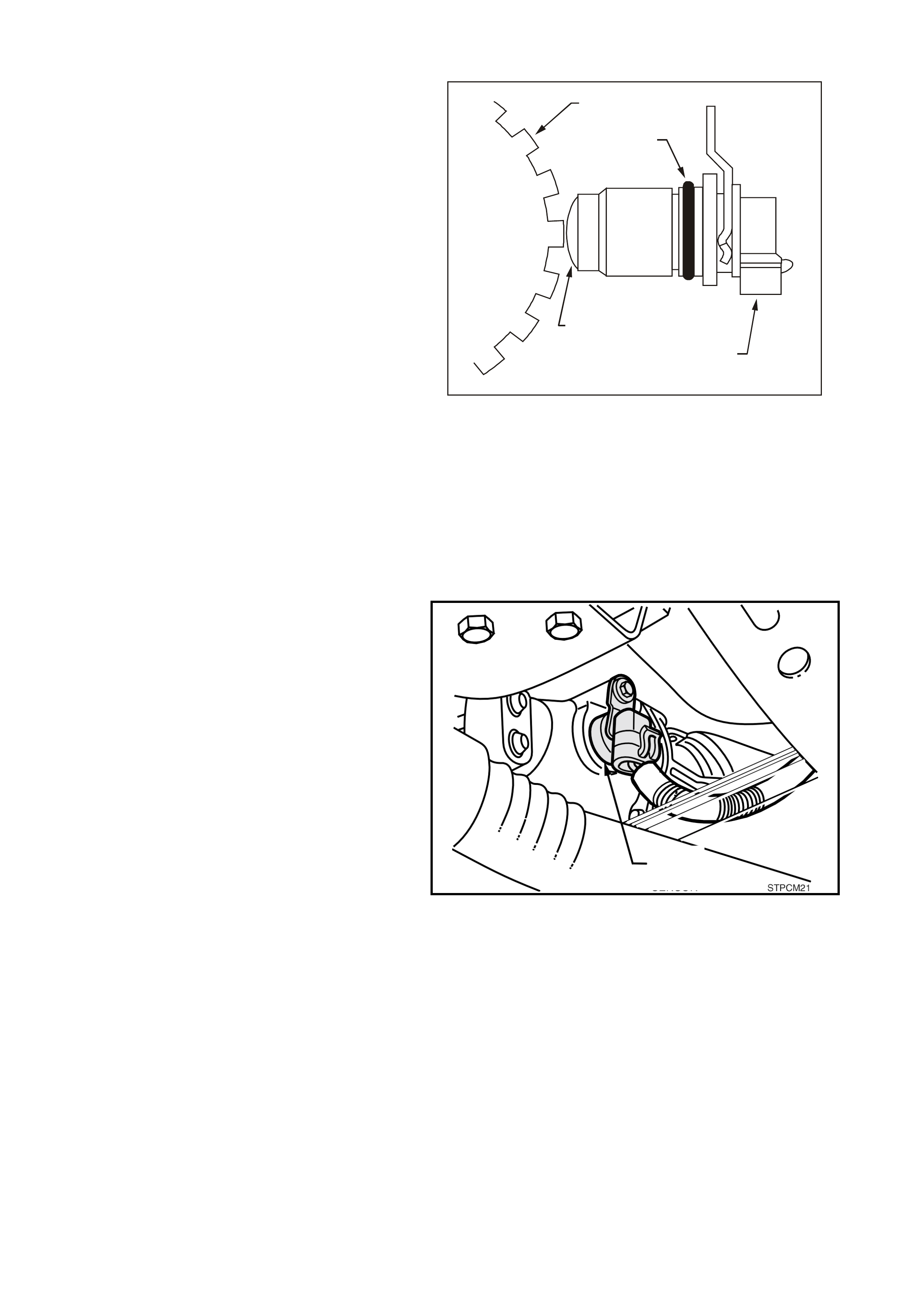
VEHICLE SPEED SENSOR (VSS)
The PCM receives vehicle speed information from
then Vehicle Speed Sensor (VSS) located on the
rear of the transmission. The VSS basically
consists of a magnetic core and a coil. As the
output shaft turns, the teeth on the output shaft
concentrate the magnetic field causing the
magnetic flux to increase and then decreases as
the teeth move in and out of the magnetic field,
inducing a voltage into the coil, first in a positive
and then in a negative direction.
This AC voltage produc ed in the VSS sensor circ uit
is fed into the PCM, the PCM filters and shapes
this signal. The PCM then counts the number of
pulses received in a given time, to determine the
vehicle speed.
Once the PCM has calculated the vehicle speed it
then pulses circuit 123 (Violet/W hite wire) to earth,
this will cause the 12 volts at terminal 17 of the
instruments to be pulled down to less than 0.2
volts. The instruments determines the vehicle
speed and the kilometers from the number of
pulses it receives. The PCM also transmits vehicle
speed information to other control modules via the
serial data bus normal mode message.
There are three DTCs associated with the VSS.
DTC P0502 will set when the output from the VSS
is to low. DTC P0503 will set when the VSS signal
is intermittent. DTC P0608 will set when the
commanded state of the
GE N3 0020
1
2
4
3
Figure 6C3-1-58 Vehicle Speed Sensor To
Reluctor Wheel
1. Reluctor Wheel (Rotor) 3. Electrical Connector
2. O-Ring 4. Magnetic Pickup
VSS output driver and the actual state of the driver
do not match.
Figure 6C3-1-59 VSS Location – Automatic Transmission
1. Vehicle Speed Sensor
1
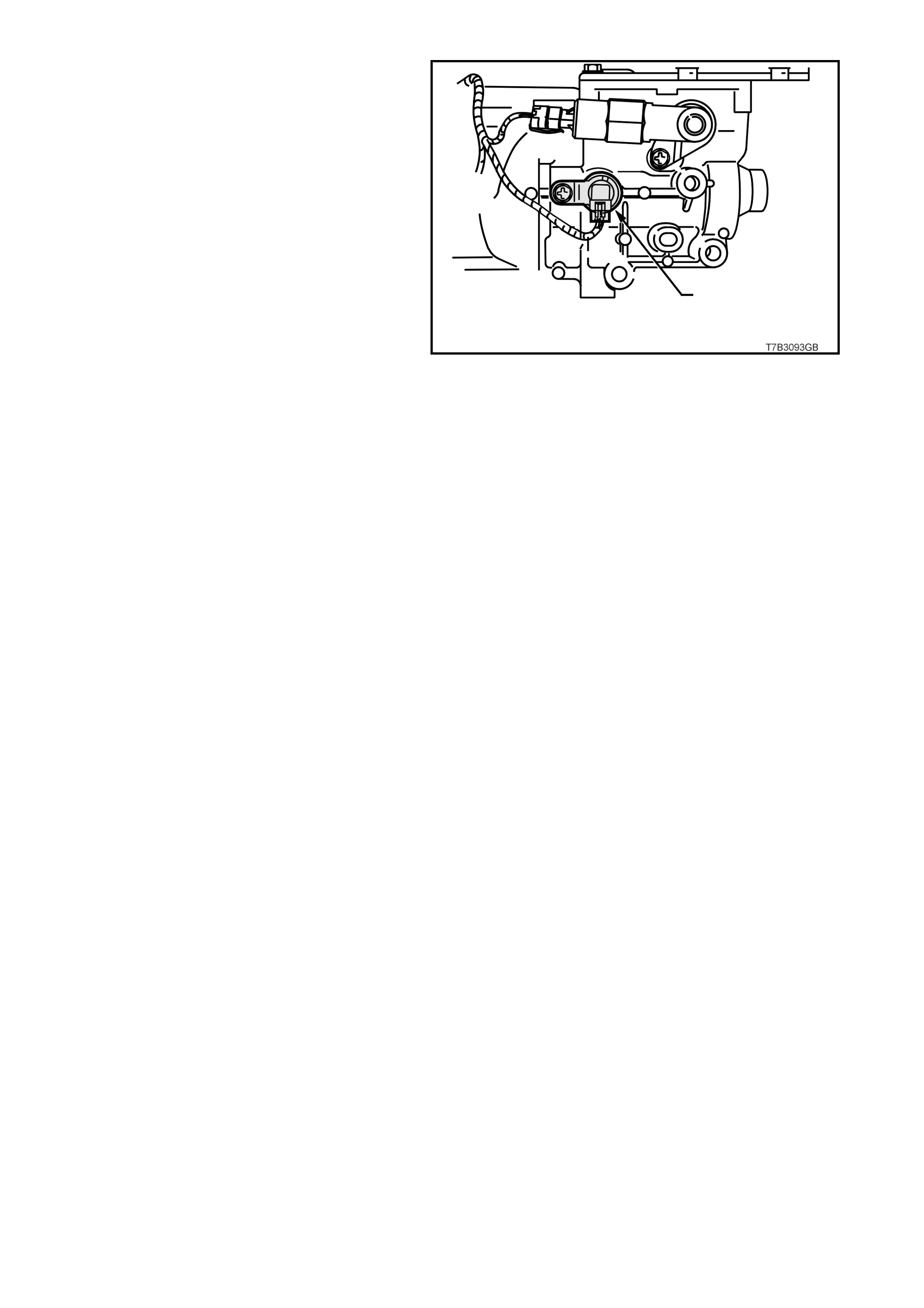
Figure 6C3-1-60 VSS Location – Manual Transmission
1. Vehicle Speed Sensor
DTC P0502 VEHICLE SPEED SENSOR CIRCUIT LOW INPUT
Conditions for running DTC P0502
• No MAP sensor DTCs P0107 or P0108.
• No Throttle Position DTCs P0122 or P0123.
• No TFP manual valve position switch DTC P1810.
• The transmission is not in park or neutral.
• The Throttle Position angle is greater than 15%.
• The engine vacuum is 0-105 kPa.
• The engine speed is greater than 3000 RPM.
• The engine torque is between 40 – 543 N.m.
Conditions for setting DTC P0502
• The transmission output speed is less than 150 RPM for at least three seconds.
Action taken when DTC P0502 Sets
• The PCM stores the DTC information into memory when the diagnostic runs and fails.
• The Check Powertrain Lamp will not be illuminated.
• The PCM commands first gear only .
• The PCM commands maximum line pressure.
• The PCM inhibits TCC engagement.
• The PCM freezes shift adapts from being updated.
• The PCM records the operating conditions at the time the diagnostic fails. The PCM stores this information in
the Freeze Frame/Failure Records.
Conditions for clearing the Check Powertrain Lamp and DTC P0502
• A last test failed (current DTC) clears when the diagnostic runs and does not fail.
DTC P0503 VEHICLE SPEED SENSOR CIRCUIT INTERMITTENT
Conditions for running DTC P0503
• No TFP manual valve position switch DTC P1810.
• The time since the last gear range change is greater than six seconds.
• The engine speed is greater than 300 RPM for five seconds.
• The engine is not in fuel cutoff.
• The transmission output speed rise does not exceed 600 RPM within six seconds.
Conditions for setting DTC P0503
• The transmission output speed drop is greater than 1300 RPM for three seconds when the transmission is not
in park or neutral.
1
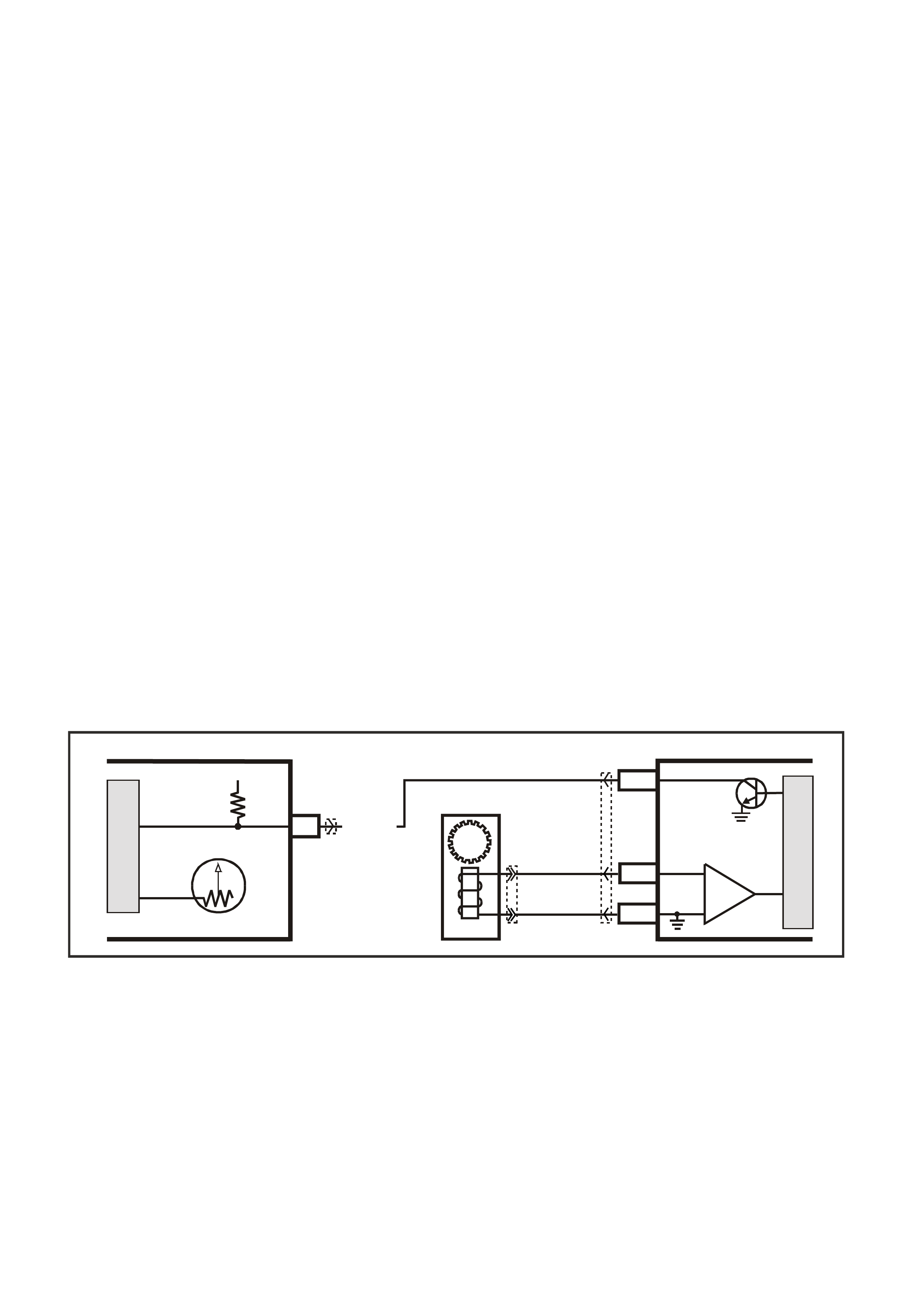
Action taken when DTC P0503 Sets
• The PCM stores the DTC information into memory when the diagnostic runs and fails.
• The Check Powertrain Lamp will not be illuminated.
• The PCM commands second gear only.
• The PCM commands maximum line pressure.
• The PCM inhibits 4th gear if the transmission is in hot mode.
• The PCM inhibits TCC engagement.
• The PCM freezes shift adapts from being updated.
• The PCM records the operating conditions at the time the diagnostic fails. The PCM stores this information in
the Freeze Frame/Failure Records.
Conditions for clearing the Check Powertrain Lamp and DTC P0503
• A last test failed (current DTC) clears when the diagnostic runs and does not fail.
DTC P0608 VEHICLE SPEED SENSOR OUTPUT CIRCUIT
Conditions for running DTC P0608
• The engine speed is greater than 600 RPM.
• The ignition voltage is between 6.0 and 16.0 volts.
Conditions for setting DTC P0608
• The PCM detects that the commanded state of the driver and the actual state of the control circuit do not
match.
• This condition must be present for at least ten seconds.
Action taken when DTC P0608 Sets
• The PCM stores the DTC information into memory when the diagnostic runs and fails.
• The Check Powertrain Lamp will not be illuminated.
• The PCM records the operating conditions at the time the diagnostic fails. The PCM stores this information in
the Freeze Frame/Failure Records.
Conditions for clearing the Check Powertrain Lamp and DTC P0608
• A last test failed (current DTC) clears when the diagnostic runs and does not fail.
Figure 6C3-1-61 Vehicle Speed Sensor Circuit
17
V/W (123)
YB66 YB195
YE123
12V IGN
VEHICLE SPEED
M
I
C
R
O
G3PCM016PT
INSTRUMENT
M
I
C
R
O
VEHICLE SPEED
PCM
J2-50
J2-21
J2-20
V
EHICLE SPEED
SENSOR
IC
BLU/W
(831)
T
(832)
SPEEDOMETER
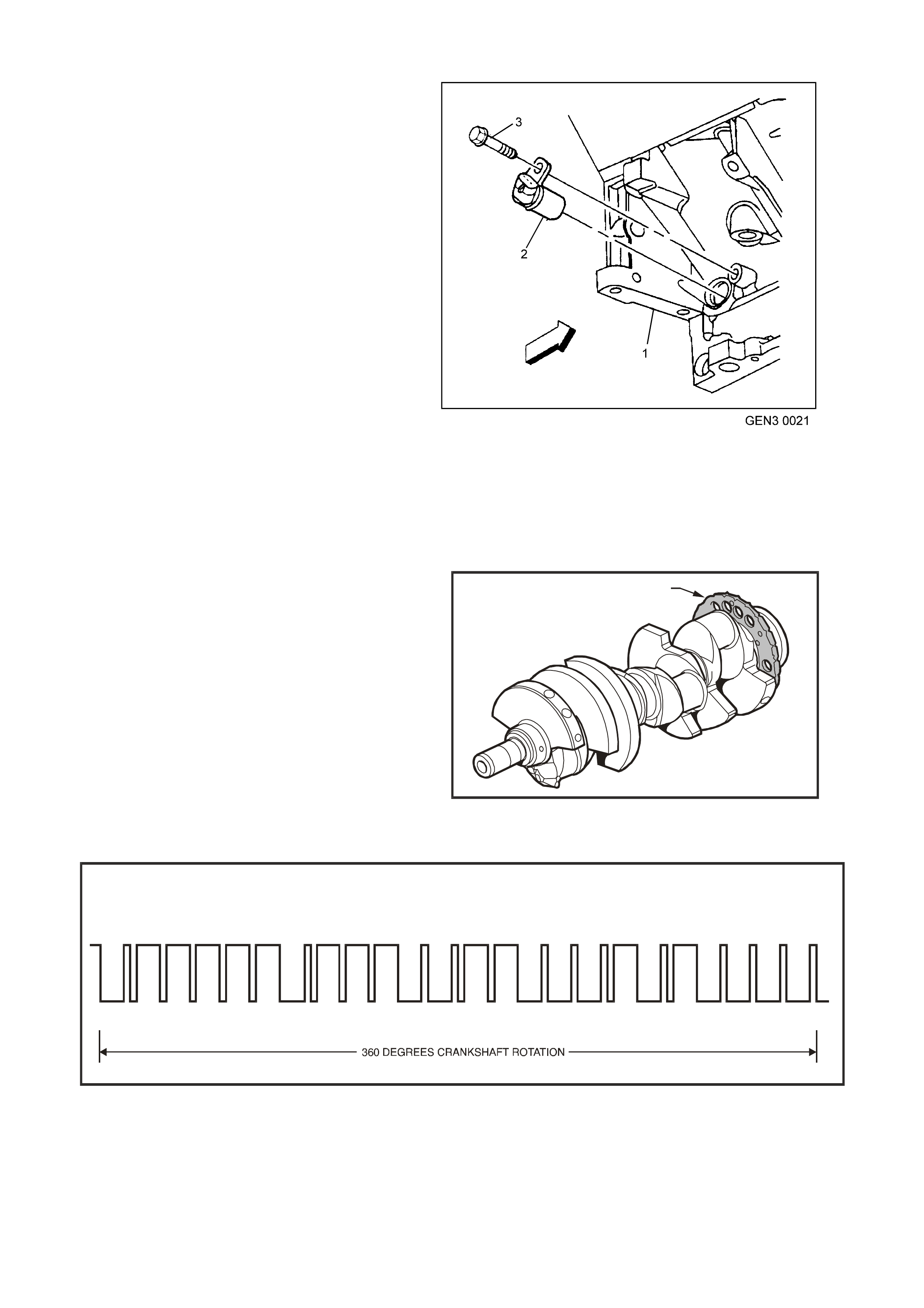
CRANKSHAFT POSITION (CKP) SENSOR
The Crankshaft Position Sensor (CKP) is mounted
in the right rear of the engine block behind the
starter. The CKP sensor works in conjunction with
a 24X reluctor wheel mounted on the rear of the
crankshaft. The CKP sensor has a battery power
supply, an earth, and a signal circuit.
As the crankshaft rotates, the reluctor wheel teeth
interrupt a magnetic field produced by a magnet
within the sensor. The sensor’s internal circuitry
detects this and produces a signal which the PCM
reads. The PCM uses this signal to accurately
measure crankshaft position and engine speed.
The reluctor wheel is mounted on the rear of the
crankshaft. The 24X reluctor wheel uses two
different width notches (12° and 3°) that are 15°
apart. This pulse width encoded pattern allows
cylinder position identification within 90 degrees of
crankshaft rotation. In some cases, cylinder
identification can be located in 45 degrees of
crankshaft rotation. This reluctor wheel also has
dual track notches that are out of phase. The duel
track design allows for quicker starts and accuracy.
NOTE: The engineer will not run if the PCM does
not receive a CKP signal. W ith no CKP signal, the
PCM will not issue any injector pulses.
Figure 6C3-1-62 Crankshaft Position Sensor (CKP) Location
1. Starter Mounting Pad on Engine Block
2. CKP Sensor
3. CKP Mounting Bolt
The PCM monitors the CKP sensor signal circuit
for m alfunctions. The PCM sets a DTC P0335 or a
DTC P0336 when the CKP sensor is out of the
normal operating range.
T6A3229GB
RELUCTOR
Figure 6C3-1-63 Crankshaft Position Sensor Reluctor
1. Reluctor
CRANKSHAFT POSITION SIGNAL
24X CR AN KS HA FT PO SIT ION SIGN AL A
102 108 123 138 162 177 183 198 222 237 252 258 282 288 312 327 342 357
345 360
0
1950
12 18 33 48 63 78
15 30 45 60 75 90 105 120 135 150 165 180 210 225 330240255270285300315
Figure 6C3-1-64 Crankshaft Position Sensor Signal
1

DTC P0335 CRANKSHAFT POSITION SENSOR CIRCUIT
Conditions for running DTC P0335
• DTCs P0101, P0102, P0103, P0341, P0342, P0343 are not set.
• The CMP sensor is transitioning.
• The ignition voltage is between 5 and 17.0 volts.
• The MAF is greater than 3 g/s.
Conditions for setting DTC P0335
• The PCM determines no signal from the CKP sensor for at least three seconds.
Action taken when DTC P0335 Sets
• The PCM illuminates the Check Powertrain Lamp when the diagnostic runs and fails.
• The PCM records the operating conditions at the time the diagnostic fails. The PCM stores this information in
the Freeze Frame/Failure Records.
Conditions for clearing the Check Powertrain Lamp and DTC P0335
• The PCM turns the Check Powertrain Lamp OFF when the diagnostic runs and does not fail.
• A last test failed (current DTC) clears when the diagnostic runs and does not fail.
DTC P0336 CRANKSHAFT POSITION SENSOR CIRCUIT PERFORMANCE
Conditions for running DTC P0336
• The ignition voltage is between 5 and 17.0 volts.
• The engine speed is greater than 400 RPM.
Conditions for setting DTC P0336
• The PCM determines no signal from the CKP sensor or the signal is out of range for at least one seconds.
Action taken when DTC P0336 Sets
• The PCM illuminates the Check Powertrain Lamp when the diagnostic runs and fails.
• The PCM records the operating conditions at the time the diagnostic fails. The PCM stores this information in
the Freeze Frame/Failure Records.
Conditions for clearing the Check Powertrain Lamp and DTC P0336
• The PCM turns the Check Powertrain Lamp OFF when the diagnostic runs and does not fail.
• A last test failed (current DTC) clears when the diagnostic runs and does not fail.
DTC P0654 ENGINE SPEED OUTPUT CIRCUIT
Conditions for running DTC P0654
• The engine speed is greater than 600 RPM.
• The ignition voltage is between 6.0 and 16.0 volts.
Conditions for setting DTC P0654
• The PCM detects that the commanded state of the driver and the actual state of the control circuit do not
match.
• All of the conditions are present for a minimum of 10.0 seconds.
Action taken when DTC P0654 Sets
• The PCM stores the DTC information into memory when the diagnostic runs and fails.
• The Check Powertrain Lamp will not be illuminated.
• The PCM records the operating conditions at the time the diagnostic fails. The PCM stores this information in
the Freeze Frame/Failure Records.
Conditions for clearing the Check Powertrain Lamp and DTC P0654
• A last test failed (current DTC) clears when the diagnostic runs and does not fail.
• Use a Tech 2 scan tool to clear the CPL/DTC.
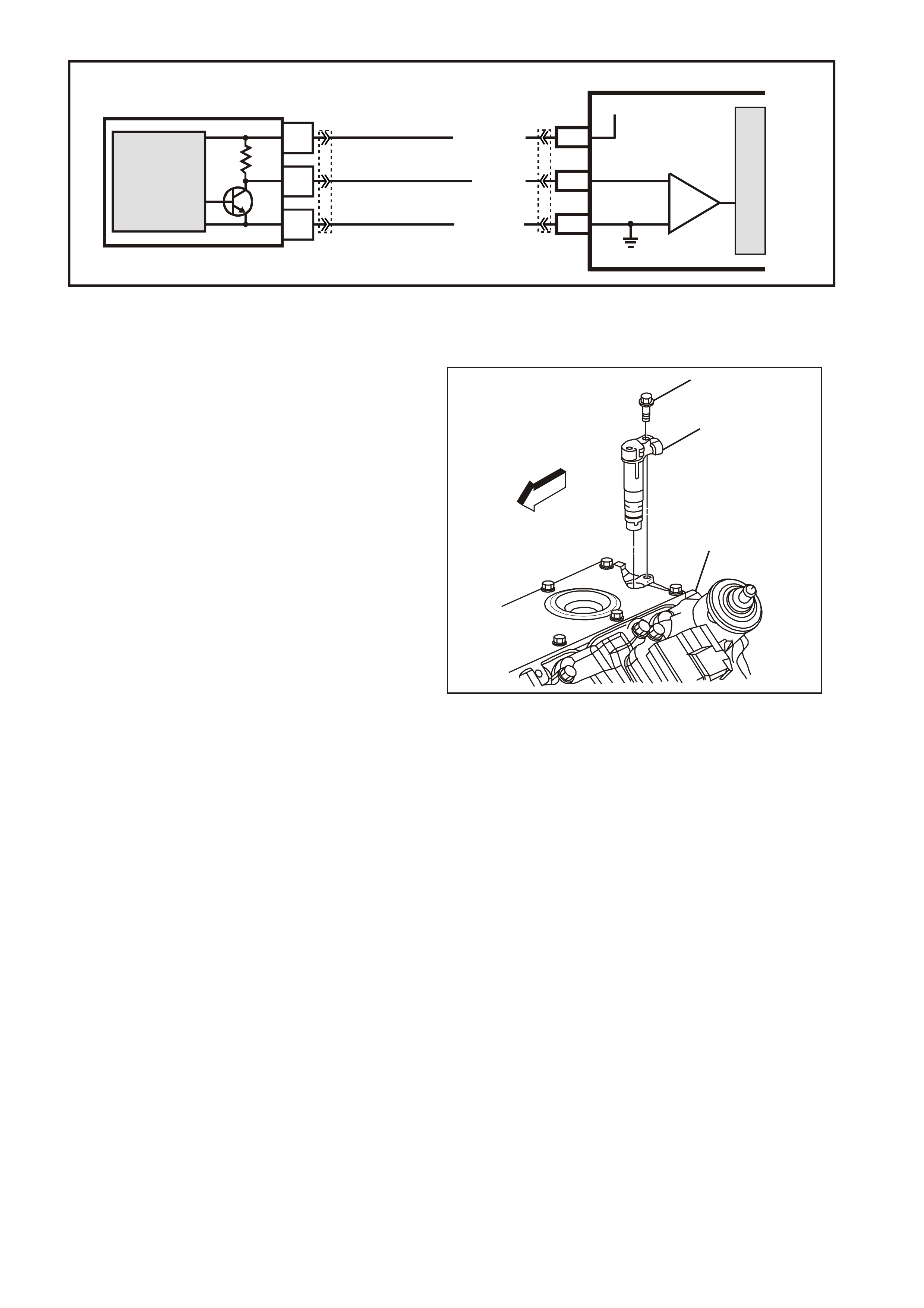
Figure 6C3-1-65 Crankshaft Position Sensor Circuit
CAMSHAFT POSITION (CMP) SENSOR
The Camshaft Position Sensor (CMP) is mounted
through the top of the engine block at the rear of
the valley cover and work s in conj unction with a 1X
reluctor wheel on the cam shaft. The reluctor wheel
is ins ide the engine, im m ediately in front of the r ear
cam bearing. The PCM provides a 12 volt power
supply to the CMP sensor as well as a earth and a
signal circuit.
The PCM uses the CMP signal in order to
determine whether a cylinder is on a firing or
exhaust stroke. As the camshaft rotates, the
reluctor wheel interrupts a magnetic field produced
by a magnet within the CMP sensor. The CMP
sensor’s internal circuitr y detects this and produces
a signal which the PCM reads. The PCM uses this
1X signal in combination with the Crankshaft
Position Sensor 24X signal in order to determine
the crankshaft position and stroke.
If the PCM is receiving a 24X Crankshaft Position
sensor signal, the engine will start even if there is
no CMP sensor signal. The PCM cannot
dete4rm ine when a particular c ylinder is on either a
firing or ex haust stroke by the 24X signal alone, the
PCM requires the CMP signal in order to determ ine
if the cylinder is on either the firing or exhaust
stroke.
GE N 3 0022
1
2
3
Figure 6C3-1-66 Camshaft Position Sensor (CMP) Location
1. CMP Mounting Bolt
2. CMP Sensor
3. Top Rear of Engine Block
If there is no CMP signal present the system
attempts synchronisation and looks for an increase
in MAF signal indicating the engine started. If the
PCM does not detect a MAF increase, the PCM
assumes if incorrectly synchronised to the exhaust
stroke and re-synchs to the opposite cam position.
A slightly longer cranking time may be a symptom
of this condition.
This diagnostic for the Camshaft Position Sensor
checks for camshaft position sensor signal. The
PCM also monitors the CMP sensor signal circuit
for malfunctions. The following DTCs are set when
the PCM detects a CMP sensor that is out of the
normal operating range:
• DTC P0341: Camshaft Position (CMP) Sensor
Circuit Performance.
• DTC P0342: Camshaft Position (CMP) Sensor
Circuit Low Voltage.
• DTC P0343: Camshaft Position (CMP) Sensor
Circuit High Voltage.
G3PCM012PT
PCM
M
I
C
R
O
A
C
B
CRANKSHAFT
POSITION
SENSOR
J1-02LBLU/W (646)
J1-21
SENSOR EARTH
12V
J1-12BLU (643)
CRANKSHAFT POSITION
SENSOR
SIGNAL
MAGNETO
RESISTIVE
INTEGRATED
CIRCUIT
IC
LBLU/B (647)
YE67 YE122
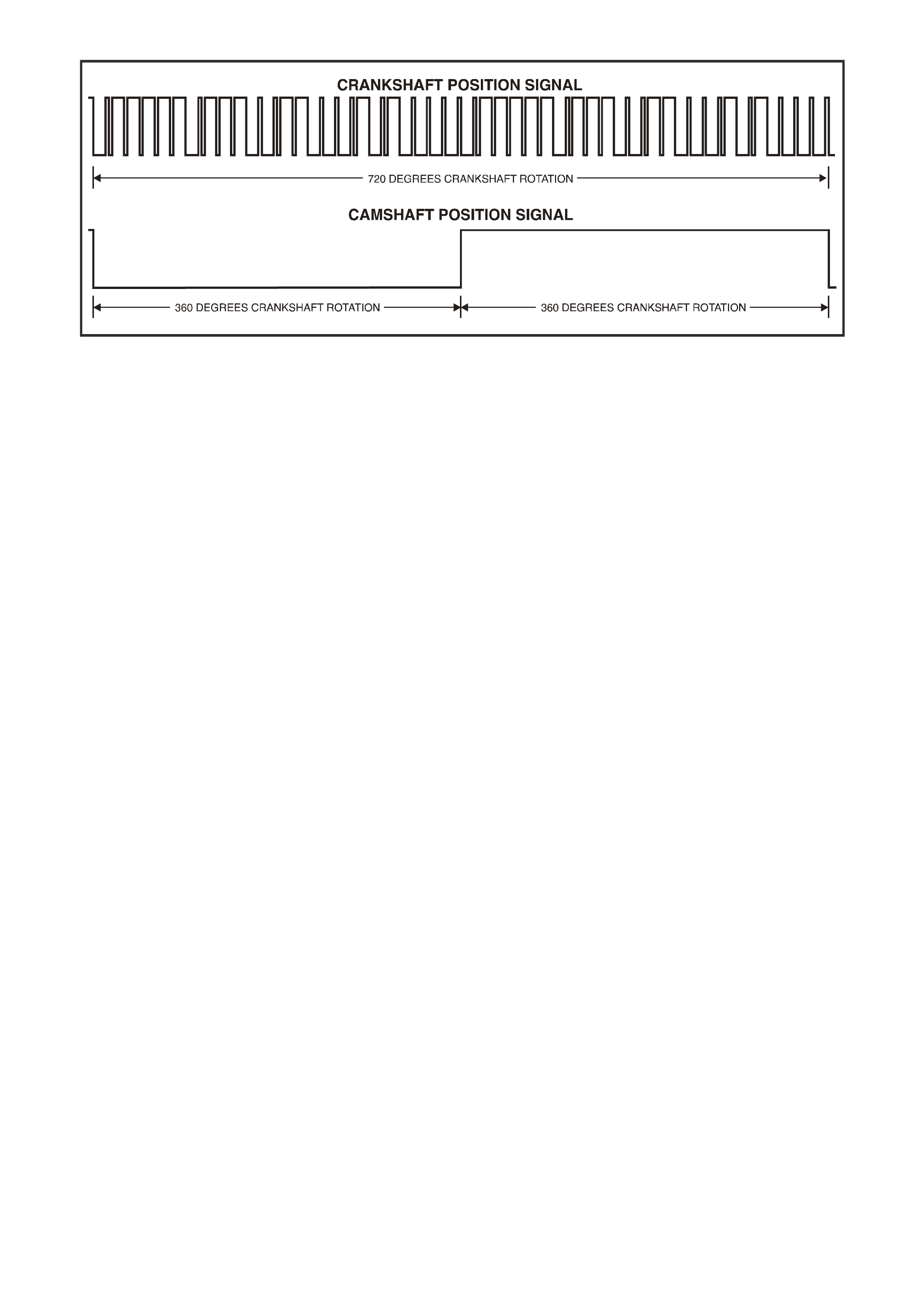
CMP
Figure 6C3-1-67 Camshaft and Crankshaft Position Sensor Signal
DTC P0341 CAMSHAFT POSITION SENSOR CIRCUIT PERFORMANCE
Conditions for running DTC P0341
• The ignition voltage is between 5 and 17.0 volts.
• The engine speed is greater than 400 RPM.
Conditions for setting DTC P0341
• The PCM detects that a CMP to CKP mismatch has occurred for at least 10 seconds.
Action taken when DTC P0341 Sets
• The PCM illuminates the Check Powertrain Lamp when the diagnostic runs and fails.
• The PCM records the operating conditions at the time the diagnostic fails. The PCM stores this information in
the Freeze Frame/Failure Records.
Conditions for clearing the Check Powertrain Lamp and DTC P0341
• The PCM turns the Check Powertrain Lamp OFF when the diagnostic runs and does not fail.
• A last test failed (current DTC) clears when the diagnostic runs and does not fail.
DTC P0342 CAMSHAFT POSITION SENSOR CIRCUIT LOW VOLTAGE
Conditions for running DTC P0342
• The ignition voltage is between 5 and 17.0 volts.
• The engine speed is greater than 400 RPM.
Conditions for setting DTC P0342
• The PCM detects the CMP sensor signal is low when the signal should be high for at least one second.
Action taken when DTC P0342 Sets
• The PCM illuminates the Check Powertrain Lamp when the diagnostic runs and fails.
• The PCM records the operating conditions at the time the diagnostic fails. The PCM stores this information in
the Freeze Frame/Failure Records.
Conditions for clearing the Check Powertrain Lamp and DTC P0342
• The PCM turns the Check Powertrain Lamp OFF when the diagnostic runs and does not fail.
• A last test failed (current DTC) clears when the diagnostic runs and does not fail.
DTC P0343 CAMSHAFT POSITION SENSOR CIRCUIT HIGH VOLTAGE
Conditions for running DTC P0343
• The ignition voltage is between 5 and 17.0 volts.
• The engine speed is greater than 400 RPM.
Conditions for setting DTC P0343
• The PCM detects the CMP sensor signal is stuck high when the signal should be low for at least one second.
Action taken when DTC P0343 Sets
• The PCM illuminates the Check Powertrain Lamp when the diagnostic runs and fails.
• The PCM records the operating conditions at the time the diagnostic fails. The PCM stores this information in
the Freeze Frame/Failure Records.

Conditions for clearing the Check Powertrain Lamp and DTC P0343
• The PCM turns the Check Powertrain Lamp OFF when the diagnostic runs and does not fail.
• A last test failed (current DTC) clears when the diagnostic runs and does not fail.
Figure 6C3-1-68 Camshaft Position Sensor Circuit
BATTERY VOLTAGE
The PCM continually monitors battery voltage.
When the battery voltage is low, the ignition system
may deliver a weak spark and the injector
mechanical movement takes longer to open the
injector.
The Powertrain Control Module will compensate
by:
1. Increasing the ignition coil dwell time if the
battery voltage is less than 12 volts.
2. Increasing the engine idle RPM if battery
voltage drops below 10 volts.
3. Inc reasing the injector puls e width if the battery
voltage drops below 10 volts.
On vehicles equipped with automatic transmission,
Diagnostic Trouble Code (DTC) P0563 will set
when the ignition is ON and PCM voltage is more
than 17 volts for about 5 seconds.
Diagnostic Trouble Code (DTC) P0562 will set
when the ignition is ON and PCM voltage is less
than 5 volts for about 5 seconds.
DTC P0562 SYSTEM VOLTAGE LOW
Conditions for running DTC P0562
• The engine is running longer than ten seconds.
• The engine speed is greater than 1000 RPM.
• The vehicle speed is greater than 8 km/h.
Conditions for setting DTC P0562
• The PCM senses sy stem voltage below 5.0 volts.
• All of the above conditions are present for five seconds.
Action taken when DTC P0562 Sets
• The PCM stores the DTC information into memory when the diagnostic runs and fails.
• The Check Powertrain Lamp will not be illuminated.
• The PCM will command a high idle speed.
• The transmission will default to third gear.
• The PCM will inhibit TCC operation.
• The PCM records the operating conditions at the time the diagnostic fails. The PCM stores this information in
the Freeze Frame/Failure Records.
Conditions for clearing the Check Powertrain Lamp and DTC P0562
• A last test failed (current DTC) clears when the diagnostic runs and does not fail.
G3PCM011PT
PCM
M
I
C
R
O
A
C
B
CAMSHAFT
POSITION
SENSOR
J2-39W/B(631)
J1-61
SENSOR EARTH
RW(632)
12V
J1-73
BR(633)
CAMSHAFT POSITION
SENSOR
SIGNAL
MAGNETO
RESISTIVE
INTEGRATED
CIRCUIT
IC
YE69 YE122
YE123
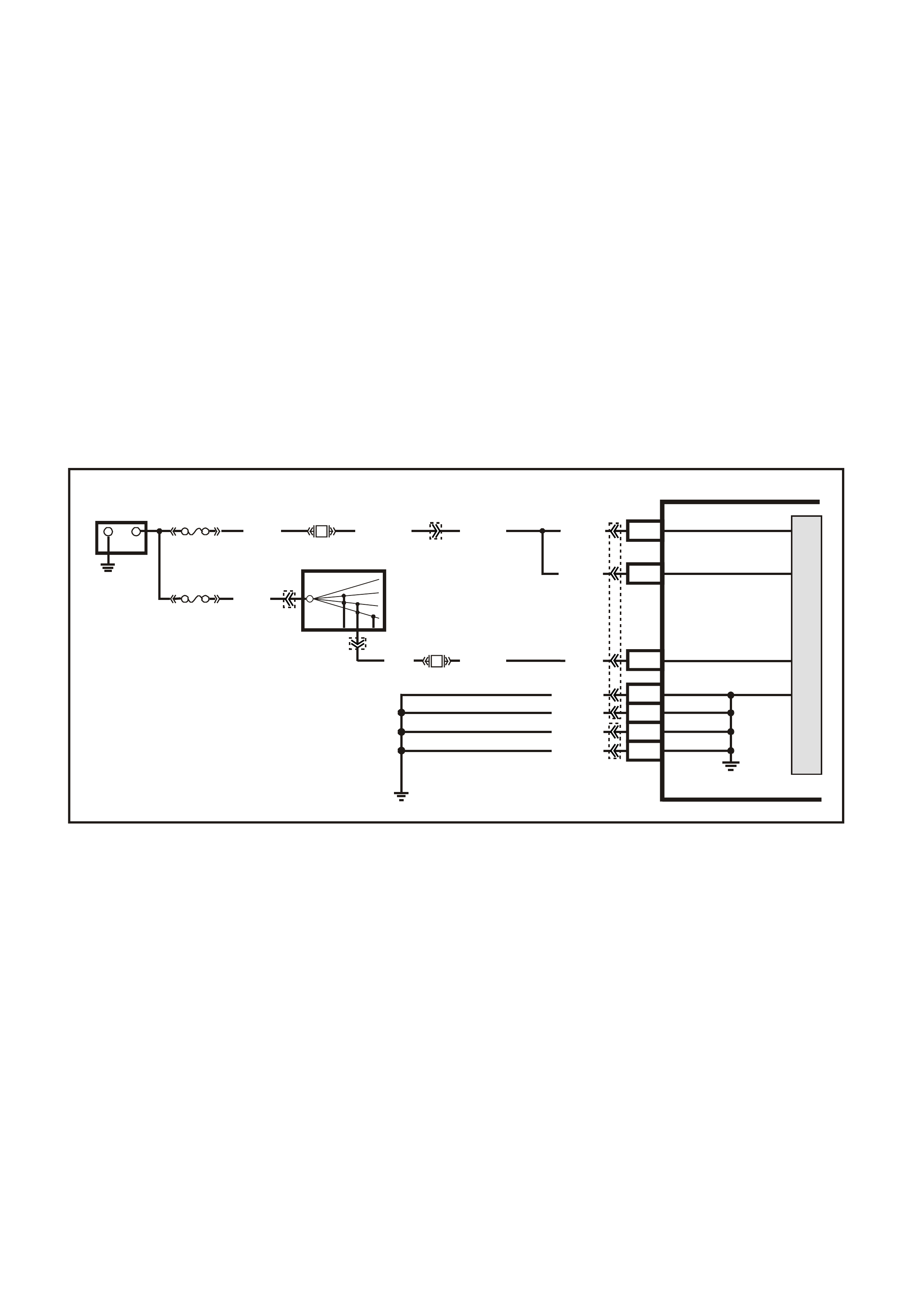
DTC P0563 SYSTEM VOLTAGE HIGH
Conditions for running DTC P0563
• The engine is running longer than 10 seconds.
Conditions for setting DTC P0563
• The PCM senses system voltage above 17 volts.
• All of the above conditions are present for five seconds.
Action taken when DTC P0563 Sets
• The PCM stores the DTC information into memory when the diagnostic runs and fails.
• The Check Powertrain Lamp will not be illuminated.
• The PCM will disable most outputs.
• The transmission will default to third gear.
• The PCM will inhibit TCC operation.
• The PCM will cycle the cooling fans ON and OFF every few seconds during the time the condition is present.
• The PCM records the operating conditions at the time the diagnostic fails. The PCM stores this information in
the Freeze Frame/Failure Records.
Conditions for clearing the Check Powertrain Lamp and DTC P0563
• A last test failed (current DTC) clears when the diagnostic runs and does not fail.
Figure 6C3-1-69 Battery Power Supply Circuit
G3PCM021PT
PCM
J1-20
J1-57
M
I
C
R
O
+-
BATTERY
FS
(1040) O (740)O/B (740)
O (740)
O (740)
J1-19 IGNITION
BATTERY
BATTERY
FJ
R (2H)
LOC . E 1
15a 15 50
30 OFF/ON
LOCK
ACC
IGN
START
IGNITION SWITCH
P (3)
YE122 YE112
YE123
YB44
YB44
F14 P (39)
J1-01
J1-40
J2-01
J2-40
LOC. E5/E15
EARTH
EARTH
EARTH
EARTH
B/R (750)
B/R (750)
B/R (750)
B/R (750)
F31
P/B (39)

TRANSMISSION POWER/ECONOMY SWITCH
The Power/Economy switch is used to modify
upshifts and shift times. The driver can select
either Economy or Power mode with the switch (1)
located on the centre console. A third mode,
Cruise, is available via a switch located on the
indicator stalk (where fitted).
Two green indicator lamps of 1.2 watts at 12 volts
are located in the instrument cluster and display
POWER or CRUISE when illuminated to inf orm the
driver of the mode that is enabled.
The PCM provides a voltage signal of about 12
volts, and monitors the status of this circuit. In the
Econom y pos ition, the switch is open and the PCM
voltage status signal remains high, about 12 volts.
The PCM does not allow shift point changes in the
Economy mode. When the transmission switch is
pressed to the Power position the switch is
momentarily closed and the PCM voltage status
signal is mom entarily pulled low, to about 0.5 volts.
The PCM senses this voltage momentary voltage
drop and enables Power mode (alternate shift
pattern tables to be utilised).
In the Power mode, the Torque Converter Clutch
(TCC) can be applied in 3rd and 4th gears. When
the TCC is applied in 3rd gear it will stay applied
until the normal 4th gear upshift criteria is met.
When the 3-4 upshift occurs, the TCC will be
released momentarily. Also, in the Power mode
while in D gear select position, the PCM will delay
the 1-2 and 2-3 shift while under light throttle. The
shift patterns will be the same in the Econom y and
Power modes if the T hrottle Position (T P) sensor is
between 80% - 100%. The Power mode should be
used when towing, as applying the TCC in 3rd and
4th gear reduces slippage in the TCC and thus
reduces heat build up.
In Cruise mode operation, when the driver
activates the cruise control, the POW ER lamp and
Power mode will turn OFF (if vehicle was in power
mode) and a CRUISE lamp will illuminate on the
instrum ent panel. T he trans m ission shif t pattern will
switch to cruise shift pattern. W hen in cruise m ode
the PCM will modify the transmission calibration so
that transmission shift activity is reduced.
W hen the k ey is turned O N, the PCM shift m ode is
set to the last mode that was previously selected
(Power/Econom y). The cruise control is set to OFF
at every key ON cycle.
For replacement of the Power/Economy switch,
refer to Section 7C4 Automatic Transmission -
On Vehicle Service in VX Service Information.
GE N 3 0154
1
Figure 6C3-1-70 Transmission Power/Economy Switch
1. Automatic Transmission Power/Economy Switch
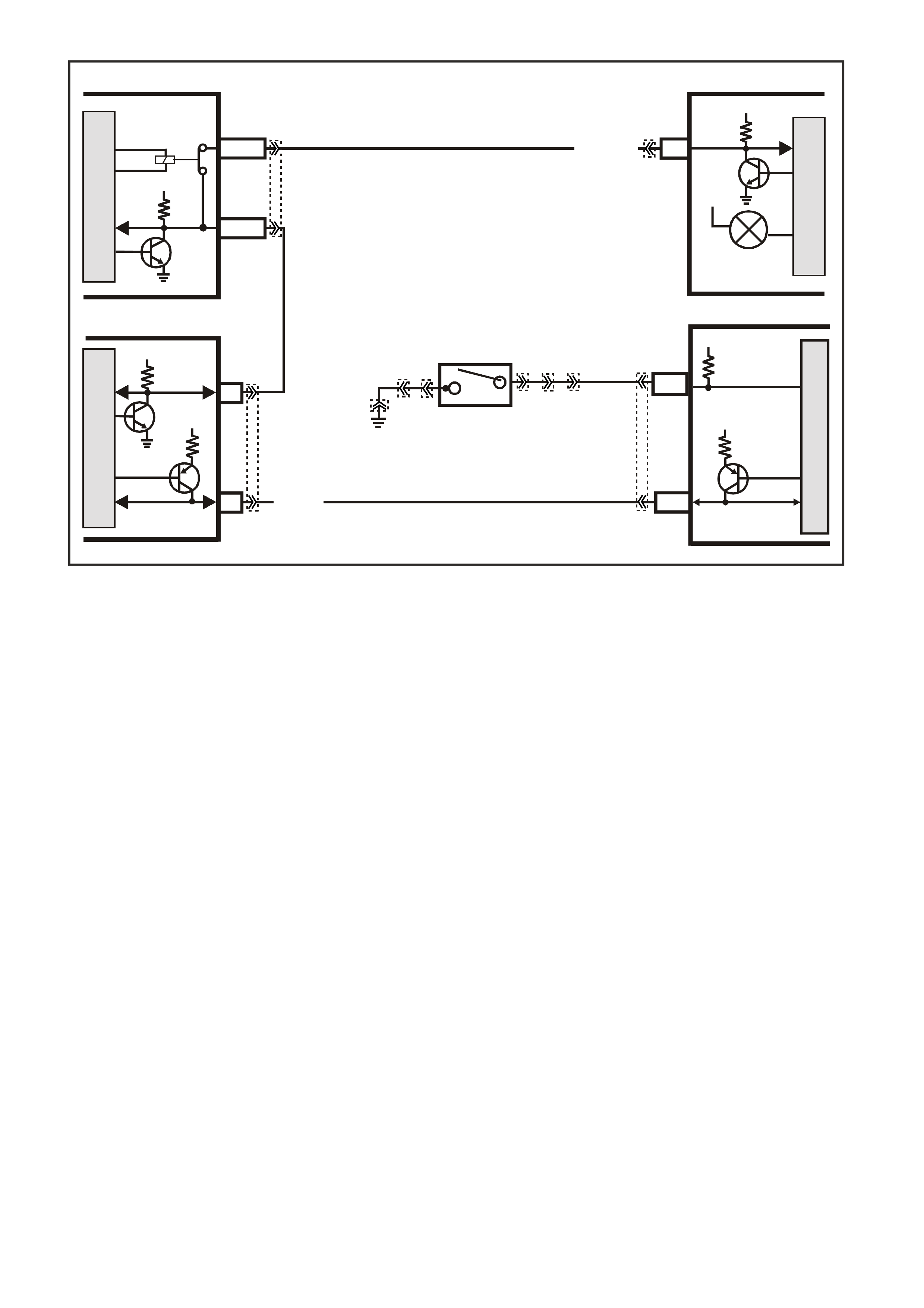
Figure 6C3-1-71 Power/Economy Switch Circuit
THEFT DETERRENT SYSTEM
The theft deterrent system on this Model uses a remote coded key to arm and disarm the system, as well as
electrically lock or unlock all doors and tailgate (station wagon), or operate the boot unlock mechanism (sedan
models).
The thef t deterrent alert indicator LED is us ed to indicate the state of the system . A flashing LED indicates that the
system is ar m ed and consequently the vehicle cannot be started. When the LED is turned off, the BCM is dis arm ed
and the engine can be started. The theft deterrent LED is incorporated into the trip computer module in the
instrument panel facia.
When the ignition switch is turned f rom of f to on, the BCM will trans mit secur ity inform ation to the PIM via the UART
serial data bus, circuit 1221. The PIM compares the received security information with it’s stored security
information and if the information matches, the PIM will enable the starter relay, and supply security information
(password) via Class II serial Data to the PCM. If the password matches the password stored in the PCM, the
system enables the f uel injection. T he PCM will r eturn on OK to start m essage to the BCM via the PIM, which tells
the BCM to switch fr om shor t loop m ode to the long loop m ode. If the PIM does not send a pass word or if the PCM
does not receive it, the vehicle will not star t unless the PCM is in Vehicle T heft Deterrent (VT D) Fail-Enable m ode.
The BCM will only transmit the corr ec t sec ur ity inform ation to the PIM if the BCM has been dis armed via the remote
coded k ey. If the BCM, PIM, or PCM lose com m unication with each other after the system has received the correct
password, the PCM goes into VTD Fail- Enable mode. T his allows the driver to res tart the vehicle on future ignition
cycles until communications between the BCM, PIM or PCM are restored. If the BCM, PIM or PCM lose
communication before the PCM receives the BCM password, the PCM disables the fuel injection until
communication is restored. In both cases DTC P1626 sets. The PCM will not disable the fuel injection once the
PCM enables the fuel within a given ignition cycle in order to prevent stalling as a result of theft deterrent system
faults.
NOTE 1:
Regardless of the engine configuration, it is very important that the remote coded key reader is aligned correctly
with the ignition lock ass embly. Misalignment with the rem ote coded key contact m ay occur resulting in interm ittent
or no engine cranking or starting.
NOTE 2:
Should the engine crank brief ly when the ignition s witch is turned to the START position (ie. due to m isaligned or a
faulty rem ote coded key reader) then pressing the unlock button on the rem ote coded k ey will also disar m the thef t
deterrent system.
Refer to Section 12J-1 Low Series BCM or Section 12J-2 High Series BCM in the VX Service Information for
further information and diagnosis.
4369
M
I
C
R
O
M
I
C
R
O
INSTRUMENTBCM
12 SERIAL
DATA
5V
POWER
ECONOMY
LAMP
12V
G/W (1220)
YB175
YB164
YB215 YE122
YE114
YE112
YB66
YB30
YB30
YB34 YB34
J1-58
M
I
C
R
O
CLASS 2
SERIAL DATA
PCM
7V
R/B (1221)
PIM
UART
SERIAL
DATA
5V
6
Y (1049)
7V
7
CLASS 2
SERIAL DA TA
M
I
C
R
O
E2/D2
E9/D3
SERIAL
DATA
MAIN
SERIAL
DATA AUX.
HIGH SERIES
BCM TERMINALS
NOMINATED FIRST
5V
J1-71
BLU
LOC. E 3
(774)
POWER/ECONOMY
SWITCH
12V
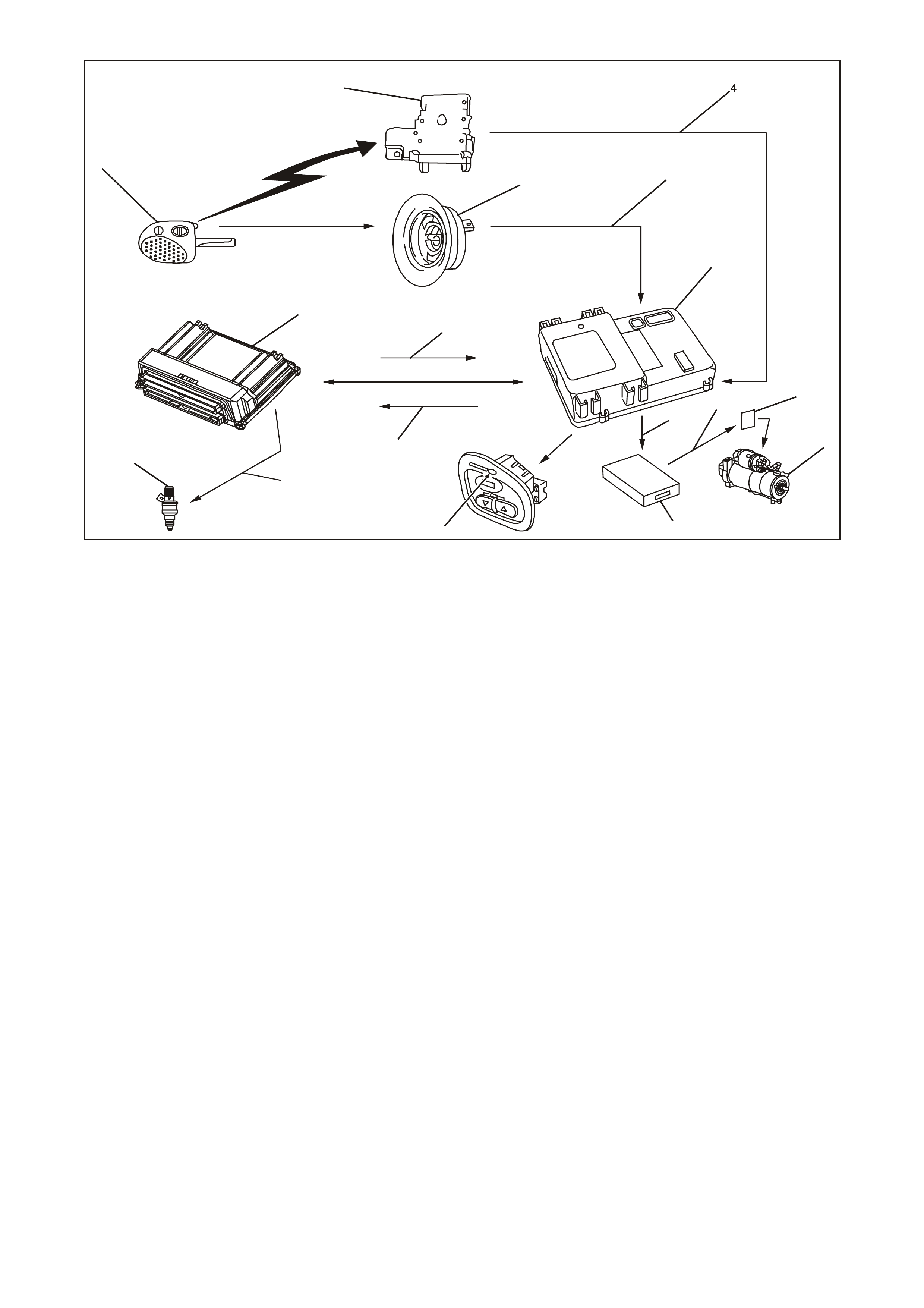
GEN3 0024
14
13
12
15
16
1
17
2
35
6
11 97
8
10
Figure 6C3-1-72 Theft Deterrent System
1. Remote Coded Key
2. Remote Receiver Module
3. Remote Coded Key Reader Assembly
4. Signal from Remote Receiver Module to BCM
5. Signal from Key Reader to BCM
6. Body Control Module (BCM)
7. Starter Relay
8. Starter Motor
9. Signal from PIM to Start Relay
10. Powertrain Interface Module (PIM)
11. Signal from BCM to PIM for Starter
12. Theft Deterrent Alert Indicator LED Control
13. OK to Start from BCM
14. Is It OK To Start Request from PCM
15. Signal from PCM for Injector Control
16. Fuel Injectors (8)
17. Powertrain Control Module (PCM)
DTC P1626 THEFT DETERRENT SYSTEM FUEL ENABLE CIRCUIT
Conditions for running DTC P1626
• The engine is cranking.
Conditions for setting DTC P1626
• The system has reached fuel enable decision point.
• The PCM is in Fail Enable Mode due to loss of communication with the PIM after the system received the
correct password earlier in the ignition cycle.
• The PCM does receive the password message from the PIM prior to the theft deterrent Fuel Decision Point.
Action taken when DTC P1626 Sets
• The PCM enables the fuel injection on future ignition cycles only if the PCM is in Fail-Enable Mode.
• The PCM illuminates the Check Powertrain Lamp when the diagnostic runs and fails.
NOTE: This DTC is usually set if communication is lost. The Check Powertrain Lamp may not operate.
• The PCM records the operating conditions at the time the diagnostic fails. The PCM stores this information in
the Freeze Frame/Failure Records.
Conditions for clearing the Check Powertrain Lamp and DTC P1626
• The PCM turns the Check Powertrain Lamp OFF after one ignition cycle that the diagnostic runs and does not
fail.
• A last test failed (current DTC) clears when the diagnostic runs and does not fail.

DTC P1630 THEFT DETERRENT POWERTRAIN CONTROL MODULE IN LEARN MODE
Conditions for running DTC P1630
• The PCM is in the learn password mode.
Conditions for setting DTC P1630
• The PCM is ready to learn a new password from the PIM, but the PIM is not sending a valid password or not
sending a password at all.
Action taken when DTC P1630 Sets
• The engine cranks but may not start.
• The PCM illuminates the Check Powertrain Lamp when the diagnostic runs and fails.
• The PCM records the operating conditions at the time the diagnostic fails. The PCM stores this information in
the Freeze Frame/Failure Records.
Conditions for clearing the Check Powertrain Lamp and DTC P1630
• A last test failed (current DTC) clears when the diagnostic runs and does not fail.
DTC P1631 THEFT DETERRENT PASSWORD INCORRECT
Conditions for running DTC P1631
• The ignition is on and the PCM is waiting for the correct password.
Conditions for setting DTC P1631
• The PCM detects an incorrect password from the PIM.
Action taken when DTC P1631 Sets
• The engine cranks but may not start.
• The PCM illuminates the Check Powertrain Lamp when the diagnostic runs and fails.
• The PCM records the operating conditions at the time the diagnostic fails. The PCM stores this information in
the Freeze Frame/Failure Records.
Conditions for clearing the Check Powertrain Lamp and DTC P1631
• A last test failed (current DTC) clears when the diagnostic runs and does not fail.
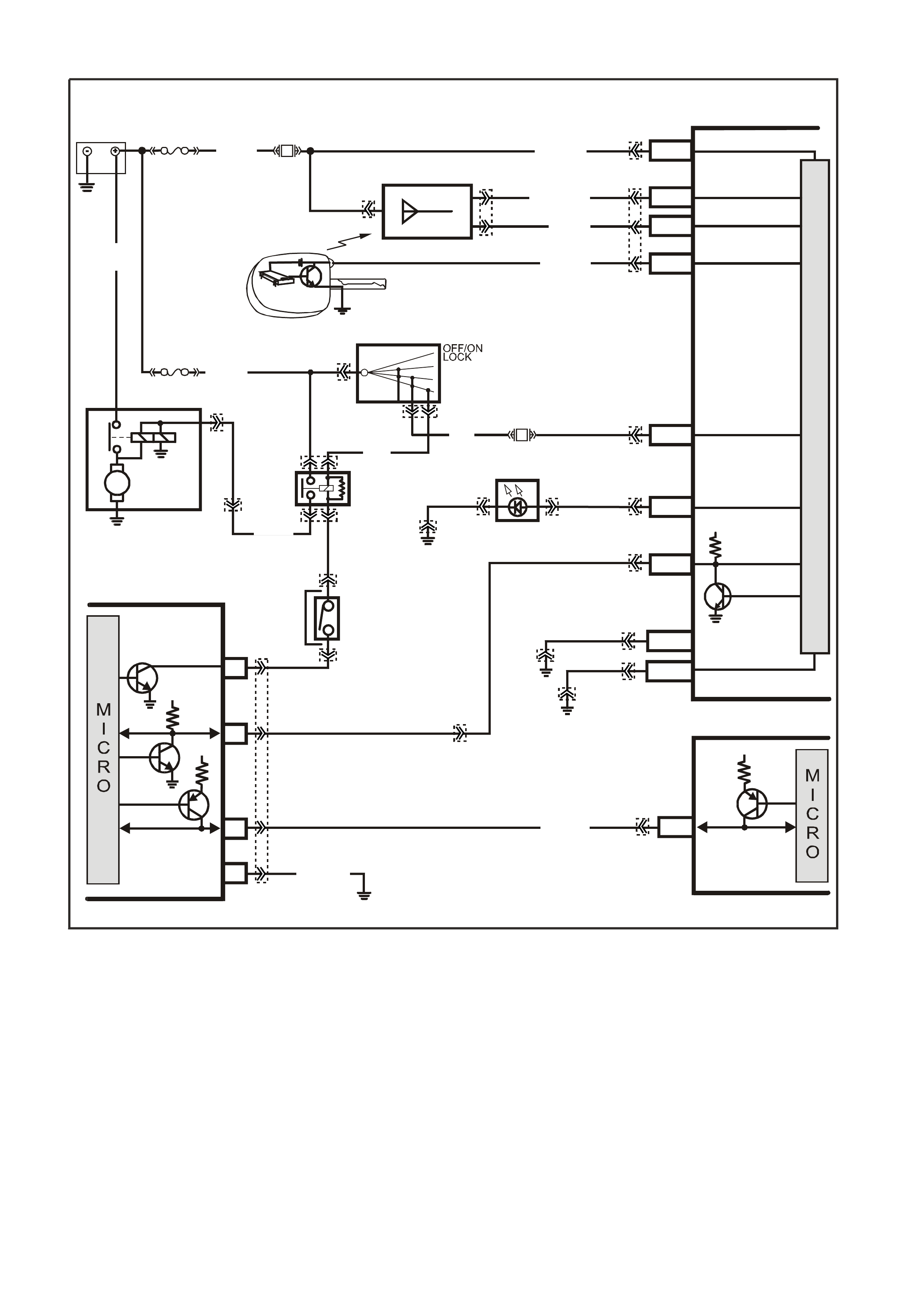
Figure 6C3-1-73 Theft Deterrent Circuit
BATTERY MAIN POWER
HIGH SERIES
BCM TERMINALS
NOMINA TED FIRST
BCM
REMOTE
CODED KEY
V/R (229) E1/D12 KEY R EADER
BATTERY
FS
LOC.
E1
LOC. G1
F31
A5/A6O/B (740)
(1040)
REMOTE KEY
RECEIVER
Y (266) E8/D1 RECEIVER DATA
BR/G (271) E7/D11 RECE IVER EARTH
O/B
(740)
FJ
M
I
C
R
O
P
R
O
C
E
S
S
O
R
GY/BLU
(1434)
G3PCM040PT
THEFT DETERRENT
ALERT INDICA TOR
R/B
(1221)
E2/D2 SERIAL DATA
5V
R (2H)
E20/D6 IGNITION
NEUTRAL ST ART
BACK-UP SW.
(FOR AUTO TRANS)
(FOR MANUAL
TRANS)
GY
(434)
R (1)
V/W (6)
F14
START
RELAY
IGN ITIO N SWITC H
15a 15 50
30 ACC
IGN
START
V (5) P (3) P/B
(39)
A6/A8
LBLU
(263) THE FT LED
B/Y
(155)
LOC. E3
B/G
(151) B10/B11 HIGH CURRENT
EARTH
B/Y
(155) ELECTRONIC EARTH
A1/A5
LOC. E3
LOC. E3
PIM
UART
SERIAL
DATA
START
RELAY
5V
6
8
16
7V
7
CLASS 2
SERIAL DATA
B/R (750)
LOC. E5/E15
R/B
(1221)
7V
PCM
J1-58 CLASS 2
SERIAL DATA
Y (1049)
Y
(1049)
STARTER
MOTOR
M
YB215
YE112
YB35
YE104
YE8
YB35
YE114 YB56 YB56
YE49
YB44
YE49
YB44
YB95
YB175
YB164
YB176
YB165
YB175
YB164
YB175
YB164
YB174
YB163
YE114
YE114 YB176
YB165
YE122
YB176
YB165
YB95
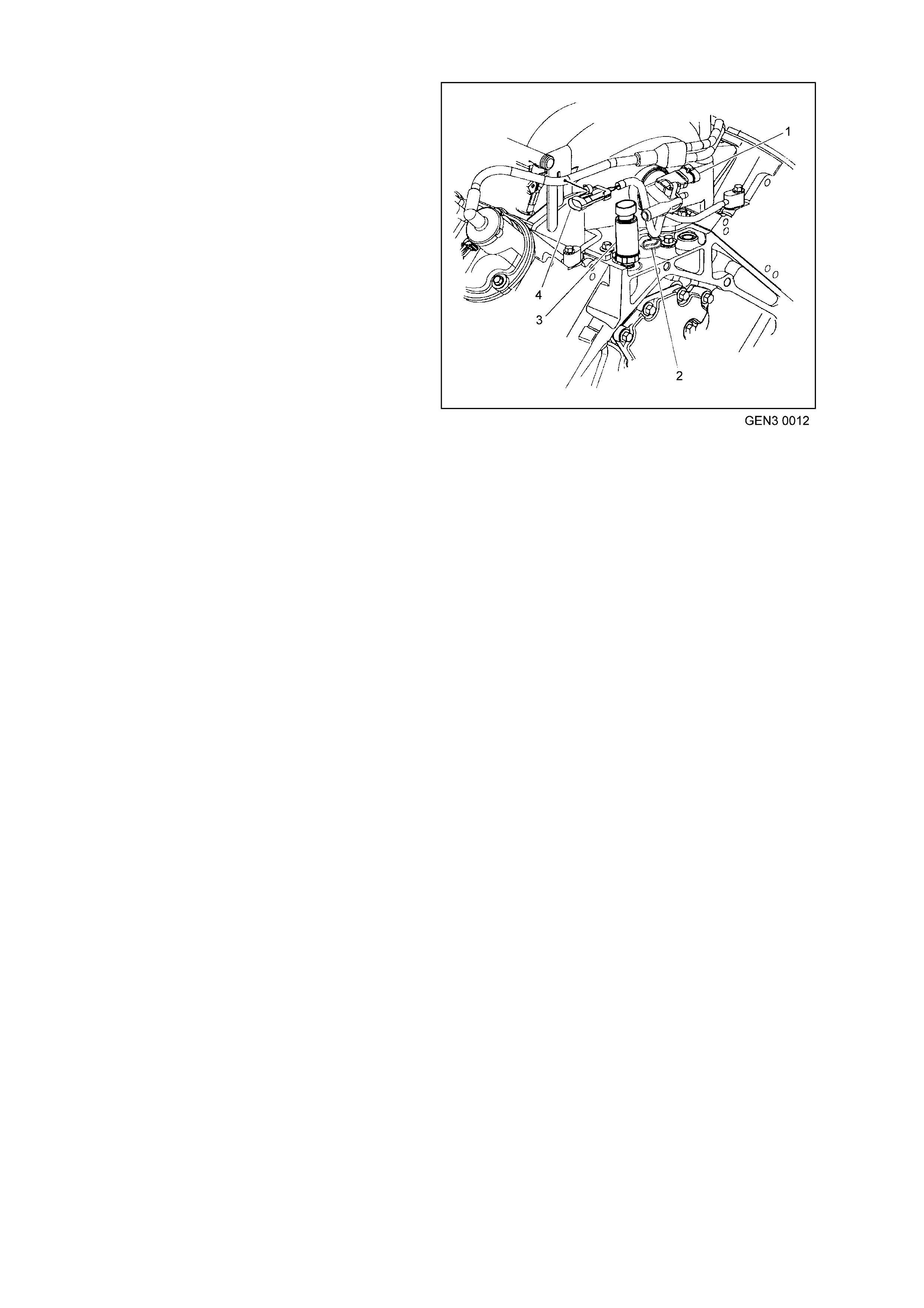
ENGINE OIL PRESSURE SENSOR
The Engine O il Pres s ur e s ensor is sc r ewed into the
oil gallery at the top rear of the engine block. The
sensor has a five volt reference voltage, an earth,
and a signal circuit. The PCM monitors the voltage
on the signal circuit. This voltage will vary
depending on engine oil pressure. T he oil pressure
sensor is used to determine when the oil pressure
is below a certain value. By monitoring the voltage,
the PCM calculates the engine oil pressure and
determines when to turn ON the low oil warning
lamp. The low oil warning lamp will be illuminated
for two seconds when the ignition is first turned on
as a bulb check. The PCM will only command the
instruments to turn the low oil warning lamp ON, if
the oil pressure is below a specified value. This
value increases with RPM. The PCM commands
the instruments to turn on the low oil warning lamp
via the serial data bus normal mode message.
When the PCM detects a malfunction in the oil
pressure sensor circuit, the following DTCs will set:
• DTC P0522: Engine Oil Pressure Circuit Low
Voltage
• DTC P0523 Engine Oil Pressure Circuit High
Voltage
Figure 6C3-1-74 Oil Pressure Sensor
1. Manifold Absolute Pressure (MAP) Sensor
2. Camshaft Position (CMP) Sensor
3. Oil Pressure Sensor
4. Connector to Knock Sensor Jumper Harness
DTC P0522 ENGINE OIL PRESSURE SENSOR LOW VOLTAGE
Conditions for running DTC P0522
• The engine is running.
Conditions for setting DTC P0522
• The engine oil pressure sensor voltage is less than 0.48 volts.
Action taken when DTC P0522 Sets
• The PCM illuminates the Check Powertrain Lamp when the diagnostic runs and fails.
• The PCM records the operating conditions at the time the diagnostic fails. The PCM stores this information in
the Freeze Frame/Failure Records.
• Oil warning lamp will illuminate.
Conditions for clearing the Check Powertrain Lamp and DTC P0522
• The PCM battery voltage is interrupted.
• A last test failed (Current DTC) will not clear when the diagnostic runs and does not fail.
DTC P0523 ENGINE OIL PRESSURE SENSOR HIGH VOLTAGE
Conditions for running DTC P0523
• The engine is running.
Conditions for setting DTC P0523
• The engine oil pressure sensor voltage is greater than 4.5 volts.
Action taken when DTC P0523 Sets
• The PCM illuminates the Check Powertrain Lamp when the diagnostic runs and fails.
• The PCM records the operating conditions at the time the diagnostic fails. The PCM stores this information in
the Freeze Frame/Failure Records.
• Oil warning lamp will illuminate.
Conditions for clearing the Check Powertrain Lamp and DTC P0523
• The PCM battery voltage is interrupted.
• A last test failed (Current DTC) will not clear when the diagnostic runs and does not fail.
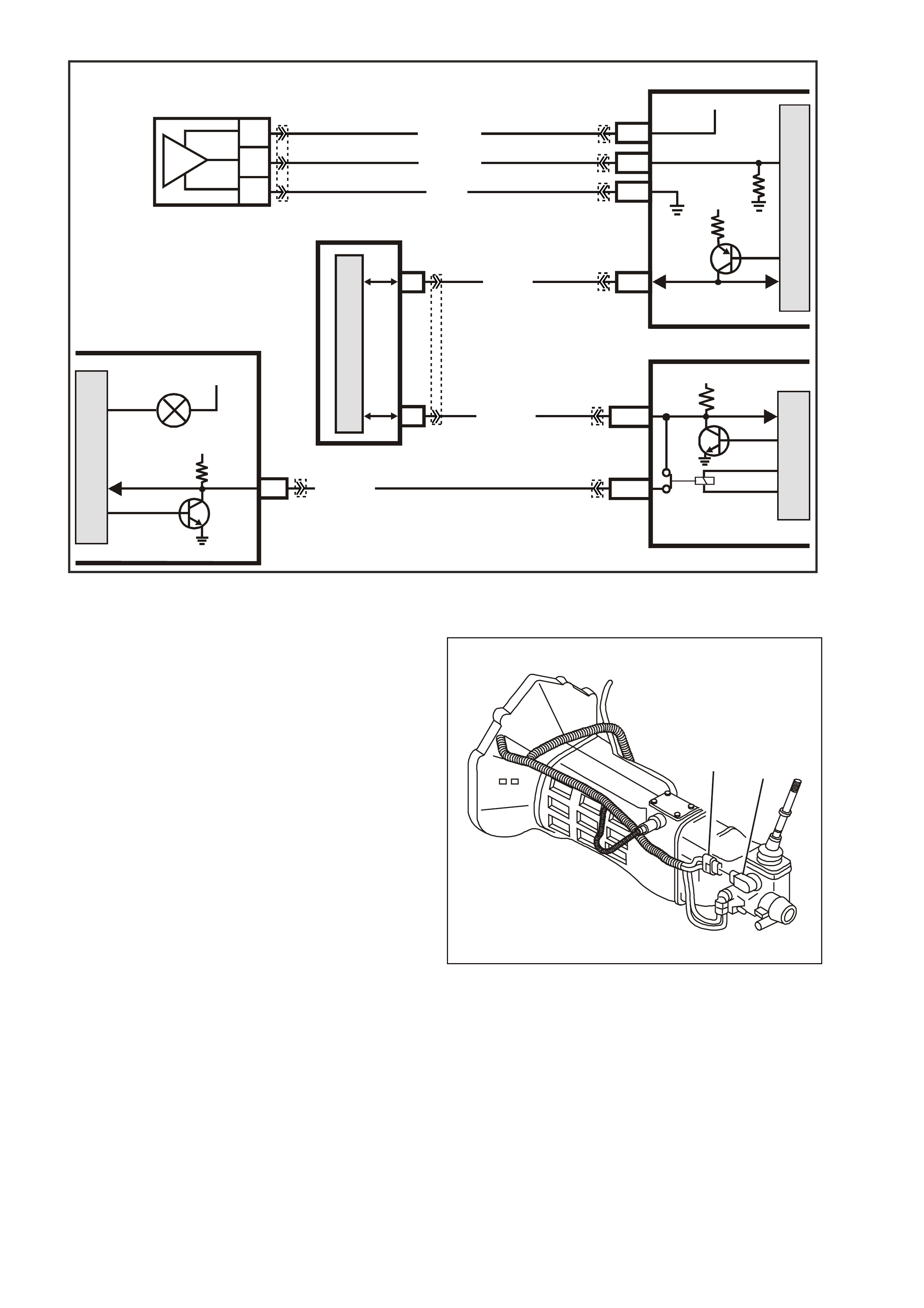
Figure 6C3-1-75 Oil Pressure Sensor Circuit
MANUAL TRANSMISSION REVERSE INHIBIT SOLENOID
The manual transmission is fitted with a reverse
inhibit mechanism that prevent the selection of
reverse gear when above road speed of 8 km/h. If
the engine is running and the vehicle speed is less
than 8 km/h, the reverse inhibit solenoid is
energised by the PCM, pulling the solenoid plunger
down, this allows the Reverse Inhibit plunger to
move, enabling selection of reverse gear.
Above 8 km /h, the PCM de-energisees the reverse
inhibit solenoid, causing the solenoid plunger to
block the movement of the spring loaded Reverse
Inhibit plunger. When activated, the rear offset
lever is blocked from rotating to the reverse
selection position.
GE N 3 0147
21
Figure 6C3-1-76 Reverse Inhibit Solenoid
1. Reverse Inhibit Solenoid
2. Reverse Inhibit Harness Connector
G3PCM008APT
PCM
J1-58
INSTRUMENT
12
SERIAL
DATA
5V
G/W (1220)
Y (1049)
R/B (1221)
12V IGN
OIL PRESSURE
PIM
6
7
CLASS 2
UART
7V
CLASS II
SERIAL DA TA
M
I
C
R
O
BCM
E2/D2
E9/D3
M
I
C
R
O
SERIAL
DATA
MAIN
HIGH SERIES
BCM TERMINALS
NOMINATED FIRST
SERIAL
DATA AUX.
5V
M
I
C
R
O
M
I
C
R
O
J2-58
J1-63
J1-07
SENSOR EARTH
OIL PRESSURE
SENSOR SIGNAL
5V
BLU/Y (334)
YE32 YE122
YE122
YB215
YB66
YB175
YB164
YB175
YB164
YE122
YE123
G (335)
BR/W (331)
C
B
A
OIL
PRESSURE
SENSOR
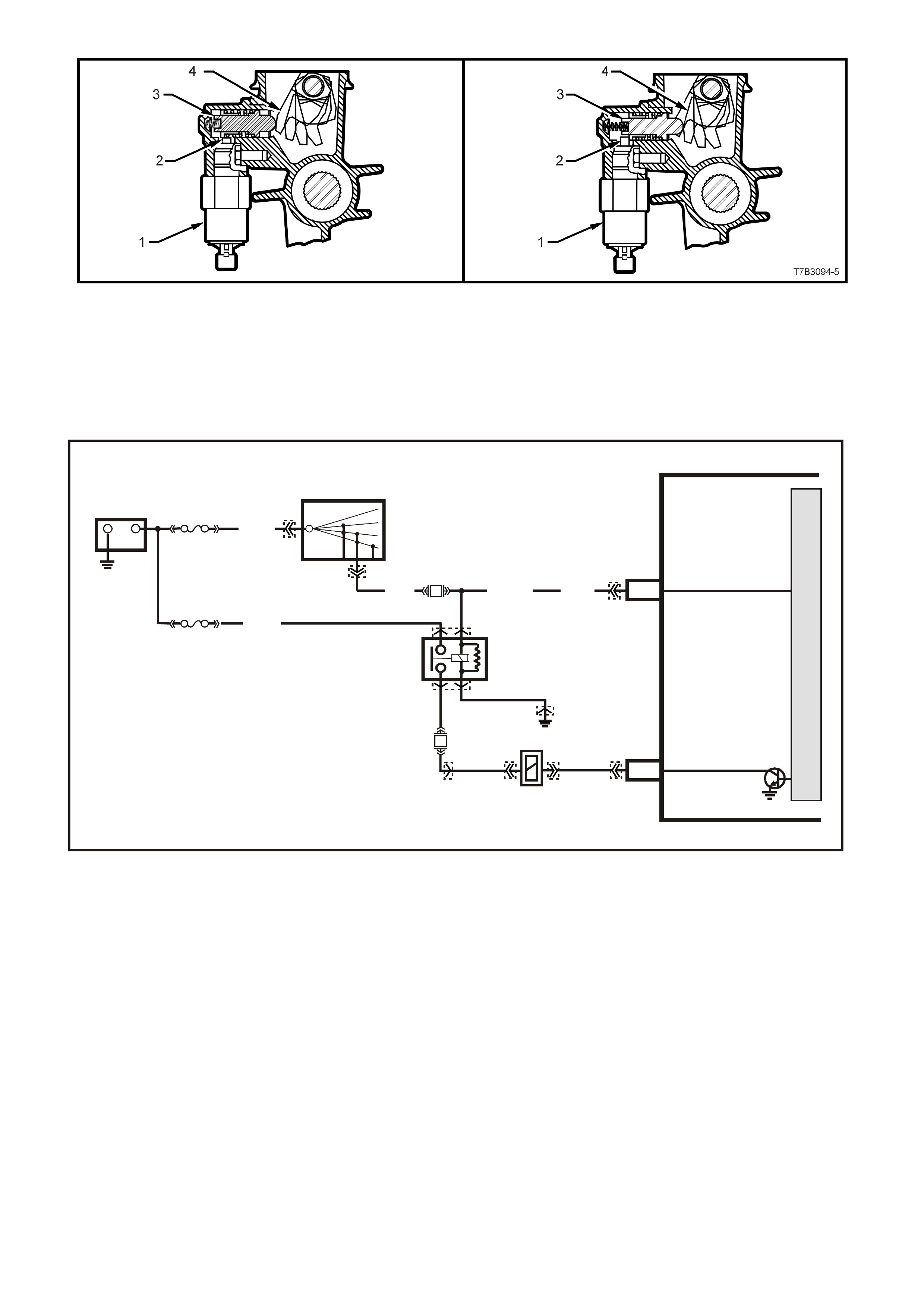
Road Speed Less Than 8 km/h Road Speed Greater Than 8 km/h
Figure 6C3-1-77 Reverse Inhibit Solenoid Operation View
1. Reverse Inhibit Solenoid.
2. Solenoid Plunger.
3. Reverse Inhibit Plunger.
4. Rear Offset Lever.
Figure 6C3-1-78 Reverse Inhibit Solenoid Circuit
G3PCM043PT
PCM
J1-19
J2-44
REVERSE INHIBIT
SOLENOID
IGNITION
M
I
C
R
O
+-
BATTERY
FS
LOC. E1
(1040)
FJ
R (2H)
15a 15 50
30 OFF/ON
LOCK
ACC
IGN
START
IGNITION SWITCH
REVERSE INHI BIT
SOLENOID
P (3) P/B (3 9) P (39)
YE122
YE39
YB44
YB44
YE39
YB125 YB125
YE123
YE114
YE110
B/W
152
O/Y
(479)
EFI
RELAY
F14
F32 LOC. E3
Y
(838)
P/BLU
(339)
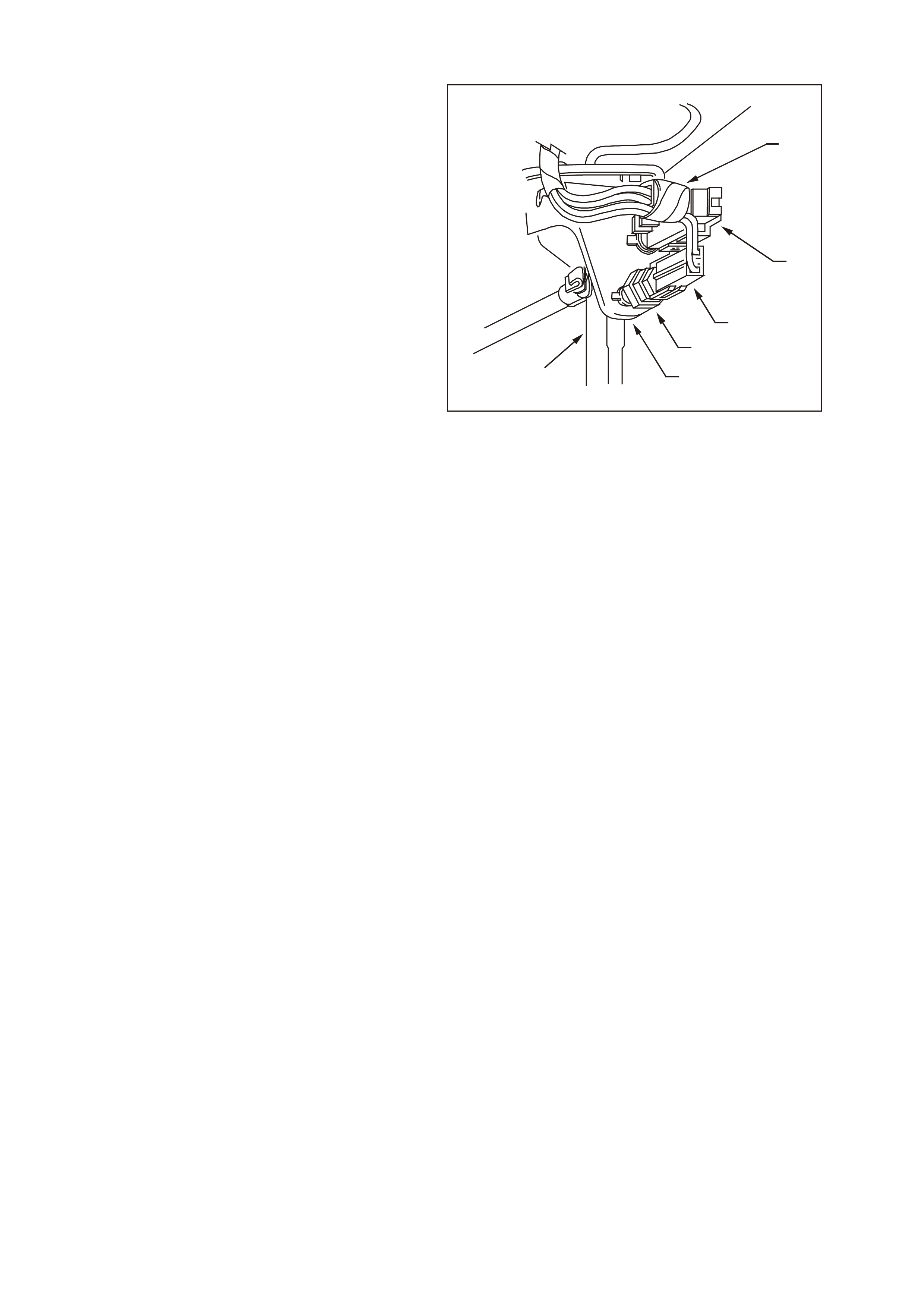
BRAKE PEDAL SWITCHES
There are two electrical switches mounted on the
brake pedal support bracket.
Stop Lamp Switch
The stop lamp switch (4) is a normally open switch
that supplies B+ from fuse F5 to the rear brake
lamps when the brake pedal is depressed. It also
supplies 12 volts to the cruise control actuator and
a brake applied 12 volt input signal to terminal 14
of the ABS or ABS/ETC control module.
Whenever the ABS or ABS/ETC control module
does not receive this signal at start up, the ABS or
ABS/ETC self test will begin as soon as vehicle
speed is at approximately 6km/h. If the driver
depresse s the brak e pedal during this initial ABS or
ABS/ETC cycle, the self test will not occur until the
vehicle speed is approximately 18 km/h. Also, if at
any time during Traction Control mode the brakes
are manually applied, this brake switch signals the
ABS or ABS/ETC control module to inhibit brake
intervention and allow for manual braking (engine
torque management may still occur if necessary).
This stop lam p switch 12 volt signal is also used to
signal the cruis e control m odule to dis engage when
the brake pedal is depressed. For all service
operations on the stop lamp switch, refer to
Section 12B Lighting Systems in VX Service
Information.
Cruise Control Release Switch
The cruise electrical release switch (2) is a
normally closed switch, and supplies a 12 volt
signal from the Low Traction Lamp (through a
resistor adjacent to the Low Traction Lamp) to the
PCM, Cruise Control Actuator, and the ABS or
ABS/ETC module. When the brake pedal is
depressed, the 12 volt supply signal is removed
from the PCM and the Cruise Control Actuator.
When the PCM determines that this 12 volt signal
has been removed, the PCM will disengage the
automatic transmission Torque Converter Clutch
(TCC) until this 12 volt signal is re-established to
the PCM. Also, the cruise control actuator will
deactivate the cruise control operation (the cruise
set speed will be retained in memory). Once the
brake pedal is released, the cruise set speed can
be re-established by selecting the cruise resume
switch.
GE N 3 0181
1
2
3
4
5
6
Figure 6C3-1-79 Brake Pedal Switches Location
1. Cruise Electrical Release Switch Connector
2. Cruise Electrical Release Switch
3. Stop Lamp Electrical Connector
4. Stop Lamp Switch
5. Brake Pedal Support Bracket
6. Brake Pedal Arm Assembly
Also, associated on this cruise electrical release switch (2) circuit is the ABS/ETC module Low Traction Lamp
control. The ABS or ABS/ET C m odule will supply an earth signal to the Low Traction Lamp when traction c ontrol
is being requested. When the PCM rec eives this ear th signal the PCM will inhibit TCC oper ation and activate the
engine torque management operation. The cruise control will also deactivate operation.
If there is a problem with the circuit between the Low Traction Lamp and the PCM, DTC P0719 or P0724 will set.
Both switches are used to signal the cruise control module so that if one should fail, the second switch will still
generate a signal to the cruise control module to disengage the cruise control operation. For all service
operations on the cruise electrical release switch, Refer to Section 12E CRUISE CONTROL in the VX Service
Information.

DTC P0719 BRAKE SWITCH CIRCUIT LOW INPUT
Conditions for running DTC P0719
• No VSS assembly DTCs P0502 or P0503.
• The ignition switch is in the RUN position.
Conditions for setting DTC P0719
• The PCM detects an open brake switch circuit (0 volts) for 15 minutes without changing for 2 seconds, and the
following events occur seven times:
- The vehicle speed is less than 8 km/h;
- Then the vehicle speed is 8 – 32 km/h for four seconds;
- Then the vehicle speed is greater than 32 km/h for six seconds.
Action taken when DTC P0719 Sets
• The PCM stores the DTC information into memory when the diagnostic runs and fails.
• The Check Powertrain Lamp will not be illuminated.
• The PCM disregards the brake switch input for TCC scheduling.
• The PCM records the operating conditions at the time the diagnostic fails. The PCM stores this information in
the Freeze Frame/Failure Records.
Conditions for clearing the Check Powertrain Lamp and DTC P0719
• A last test failed (current DTC) clears when the diagnostic runs and does not fail.
• The PCM cancels the DTC default actions when the fault no longer exists and the ignition switch is OFF long
enough to power down the PCM.
DTC P0724 BRAKE SWITCH CIRCUIT HIGH INPUT
Conditions for running DTC P0724
• No VSS assembly DTCs P0502 or P0503.
• The ignition switch is in the RUN position.
Conditions for setting DTC P0724
• The PCM detects an closed brake switch circuit (12 volts) without changing for 2 seconds, and the following
events occur seven times:
- Then the vehicle speed is greater than 32 km/h for six seconds.
- Then the vehicle speed is 8 – 32 km/h for four seconds;
- The vehicle speed is less than 8 km/h;
Action taken when DTC P0724 Sets
• The PCM stores the DTC information into memory when the diagnostic runs and fails.
• The Check Powertrain Lamp will not be illuminated.
• The PCM records the operating conditions at the time the diagnostic fails. The PCM stores this information in
the Freeze Frame/Failure Records.
Conditions for clearing the Check Powertrain Lamp and DTC P0724
• A last test failed (current DTC) clears when the diagnostic runs and does not fail.
• The PCM cancels the DTC default actions when the fault no longer exists and the ignition switch is OFF long
enough to power down the PCM.
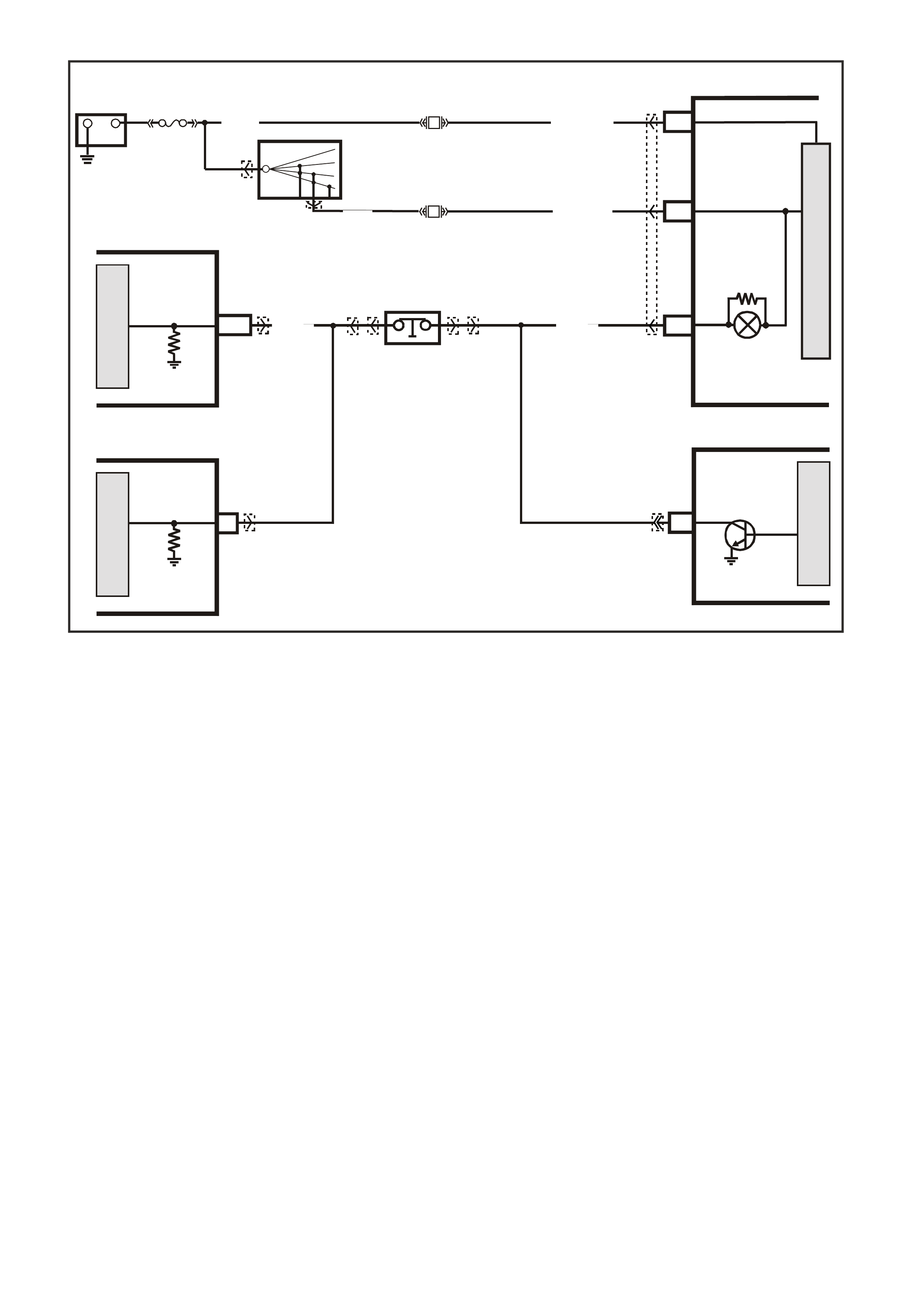
Figure 6C3-1-80 Brake Pedal Switches Location
BATTERY MAIN POWER
M
I
C
R
O
G3PCM018PT
+-
BATTERY
FJ
F21
20O/Y (1340)
R (2H)
F13
IGNITION
19P/BLU ( 44)
15a 15 50
30 OFF/ON
LOCK
ACC
IGN
START
IGNITION
SWITCH
P (3)
11 LOW
TRACTION
LAMP
LOW
TRACTION
BRAKE
SWITCH
INPUT
SIGNAL
BRAKE
SWITCH
INPUT
SIGNAL
PCM
M
I
C
R
O
M
I
C
R
O
M
I
C
R
O
J1-33 Y/R (88)
STOP LAMP
SWITCH B
(NC)
CRUISE CONTROL
MODULE ABS/ETC
INSTRUMENTS
D20
B/R (86)
YE56
YE122 YB65
YB12
YB44
YB44
YB12
YB65 YB66
YE98

1.4 FUEL CONTROL SYSTEM
SYSTEM OVERVIEW
An electric fuel pump, located in the fuel tank with
the fuel sender assembly, pumps fuel through an
in-line fuel f ilter to the fuel r ail assem bly. T he pump
provides fuel at a pressure greater than is needed
by the inj ectors . The f uel pres sure r egulator, part of
the fuel sender assembly, keeps fuel available to
the injectors at a regulated pressure. A separate
pipe returns unused fuel to the fuel tank.
COMPONENTS
Fuel Tank Vent Valve
The f uel tank vent valve is located in the r ear of the
vehicle near the fuel tank. The fuel tank vent valve
is a pressure/vacuum relief valve. When the fuel
tank pressure exceeds a specified pressure, the
valve opens allowing the tank pres sure to bleed off.
When the fuel tank is in a vacuum condition, the
vent valve opens when the vacuum is within a
specified range allowing fresh air to be pulled in.
Fuel Tank
The fuel tank is constructed from a special plastic
and is located under the rear compartment floor. It
is secured to the vehicle by three metal straps that
attach to the frame.
Fuel Tank Filler Pipe
The fuel tank filler pipe has a built-in resistor and
deflector in order to prevent refueling with leaded
fuel.
Fuel Filler Cap
NOTE: If a fuel filler cap requires replacem ent, use
only a fuel filler cap of the same type. Failure to
use the corr ect fuel f iller cap can r esult in a serious
malfunction of the fuel and evaporative systems.
The fuel filler cap incorporates a torque-limiting
device which prevents the cap from being over
tightened. To ins tall the cap, turn the cap clockwise
until you hear three audible clicks. This indicates
that the cap is correctly torqued and fully seated.
Figure 6C3-1-81 Fuel Filler Cap
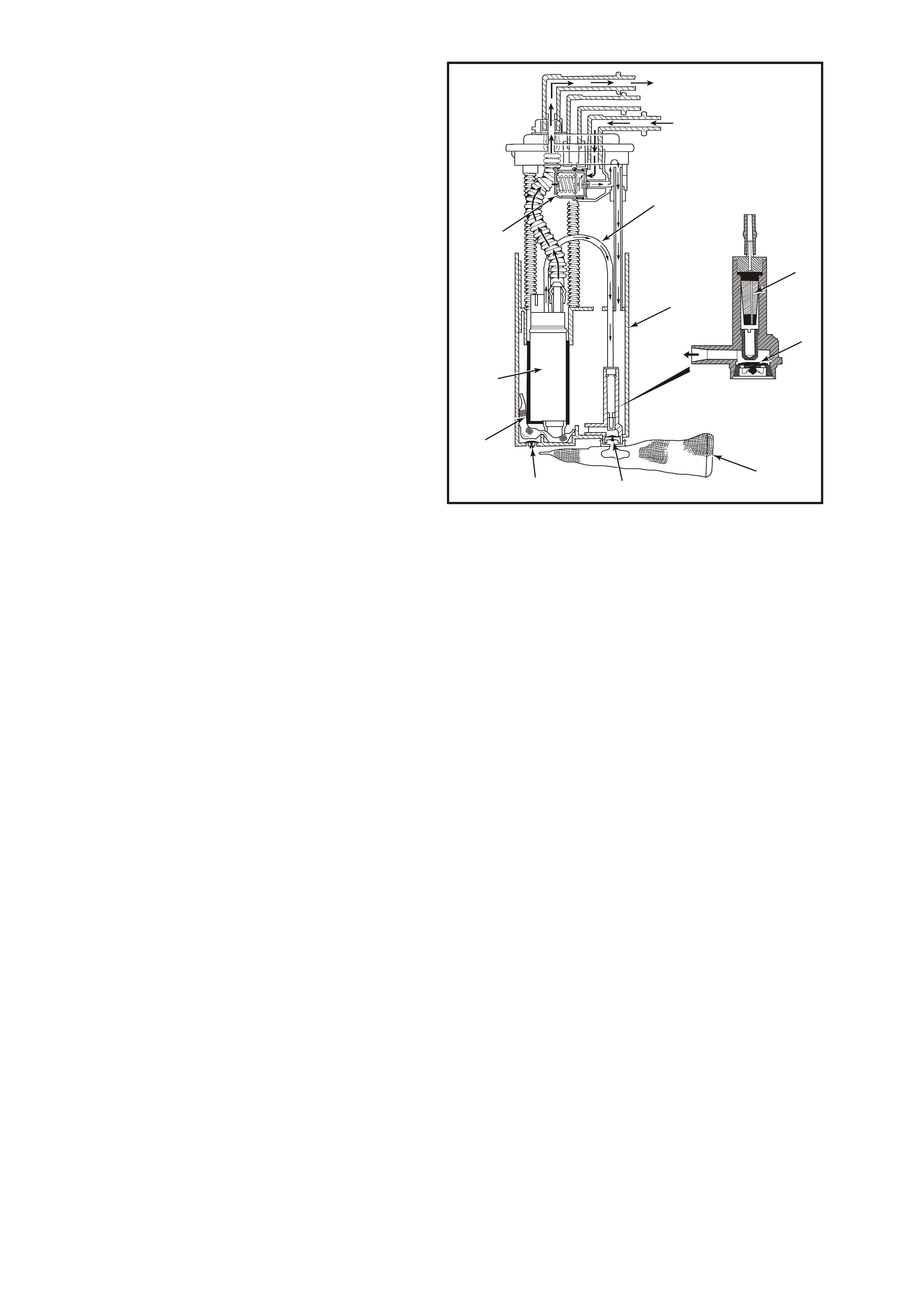
Fuel Sender Assembly
The fuel sender assembly, mounted inside the fuel
tank, is attached to the top of the fuel tank . The fuel
sender assembly consists of the following major
components:
• The fuel level sensor
• The fuel pump
• The fuel pressure regulator
• The fuel pump strainer
NOTE: T he only serviceable part of the fuel sender
assembly is the fuel lever sensor. All other
components require replacement of the complete
fuel sender assembly.
1
9
8
7
3
46
5
4
2
10
4354
Figure 6C3-1-82 Fuel Sender Assembly
1. Diverter Pipe. 6. External Filter Screen
2. Jet Pump Filter. 7. Secondary Umbrella Valve.
3. Reservoir. 8. Internal Filter Screen.
4. Primary Umbrella 9. Gerotor Fuel Pump.
Valve. 10. Fuel Pressure Regulator.
5. Jet Pump
Fuel Pump
The Gerotor fuel pump attaches to the fuel sender
assembly inside the fuel tank and is an electric
high pressure gear Gerotor fuel pump. The fuel
pump provides fuel to the fuel rail assembly at a
specified flow and pressure. Excess fuel returns to
the fuel tank by the return pipe.
The fuel pump delivers a constant flow of fuel to
the engine even during low fuel conditions and
aggressive vehicle manoeuvres. The PCM controls
the electric fuel pump operation through a fuel
pump relay. The fuel pump flex pipe has a quick-
connect f itting. The fuel return hose attaches to the
fuel pressure regulator. The fuel pump flex pipe
acts to dampen the fuel pulses and noise
generated by the fuel pump.
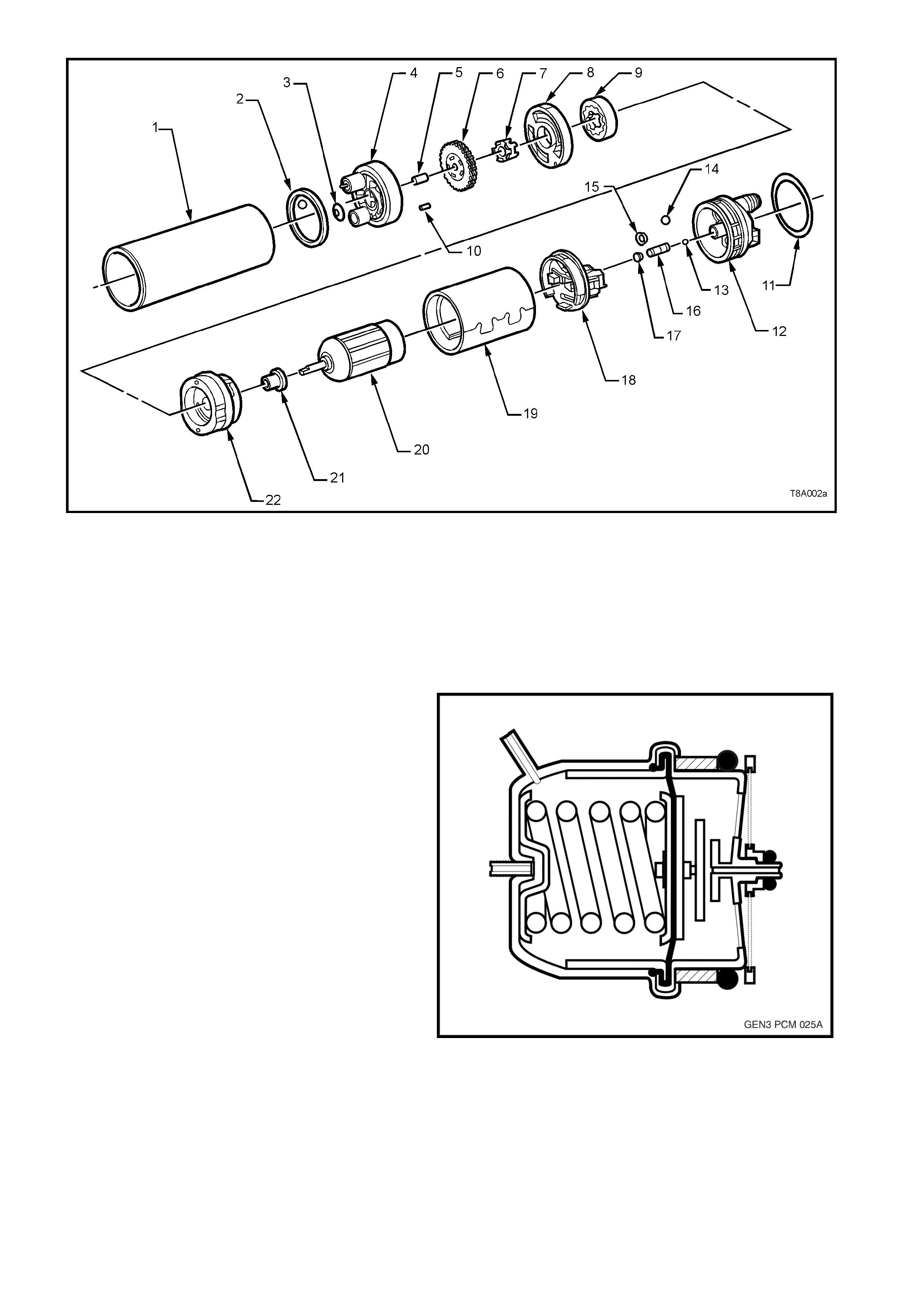
Figure 6C3-1-83 Gerotor Fuel Pump
1. Shell
2. Pump Inlet Seal
3. Umbrel l a Check Valve
4. Pump Inlet Body
5. Pilot Pin
6. Impeller
7. Driver
8. Inlet Plate
9. Gerotor Assembly
10. Alignment Pi n
11. O-Ring
12. End Cap
13. Relief Valve Ball
14. Check Valve Ball
15. Valve Seat
16. Relief Valve Spring
17. Relief Valve Retainer
18. Carrier Assem b l y
19. Field Magnet Assembl y
20. Armature
21. Bushing
22. Plat e & Ring
Assembly
Fuel Pressure Regulator Assembly
The fuel pressure regulator located on the fuel
modular sender and is a diaphragm operated relief
valve with fuel pump pressure on one side and
atmospheric pressure combined with mechanical
spring pressure on the other. The function of the
regulator is to maintain a regulated pressure at the
injectors at all times by controlling the flow into the
return line. With the ignition ON and the engine
OFF, system fuel pressure at the pressure test
connection should be 380-440 kPa
(55-62 psi).
If the pressure is too low, poor performance could
result. If the pressure is too high, excessive odor
and Diagnostic Trouble Codes (DTC) P0132,
P0152, P0172, or P0175 may result. Refer to Fuel
System Diagnosis in Section 6C3-2A of the VX
Series Service Information, for information on
diagnosing fuel pressure conditions.
Figure 6C3-1-84 Fuel Pressure Regulator
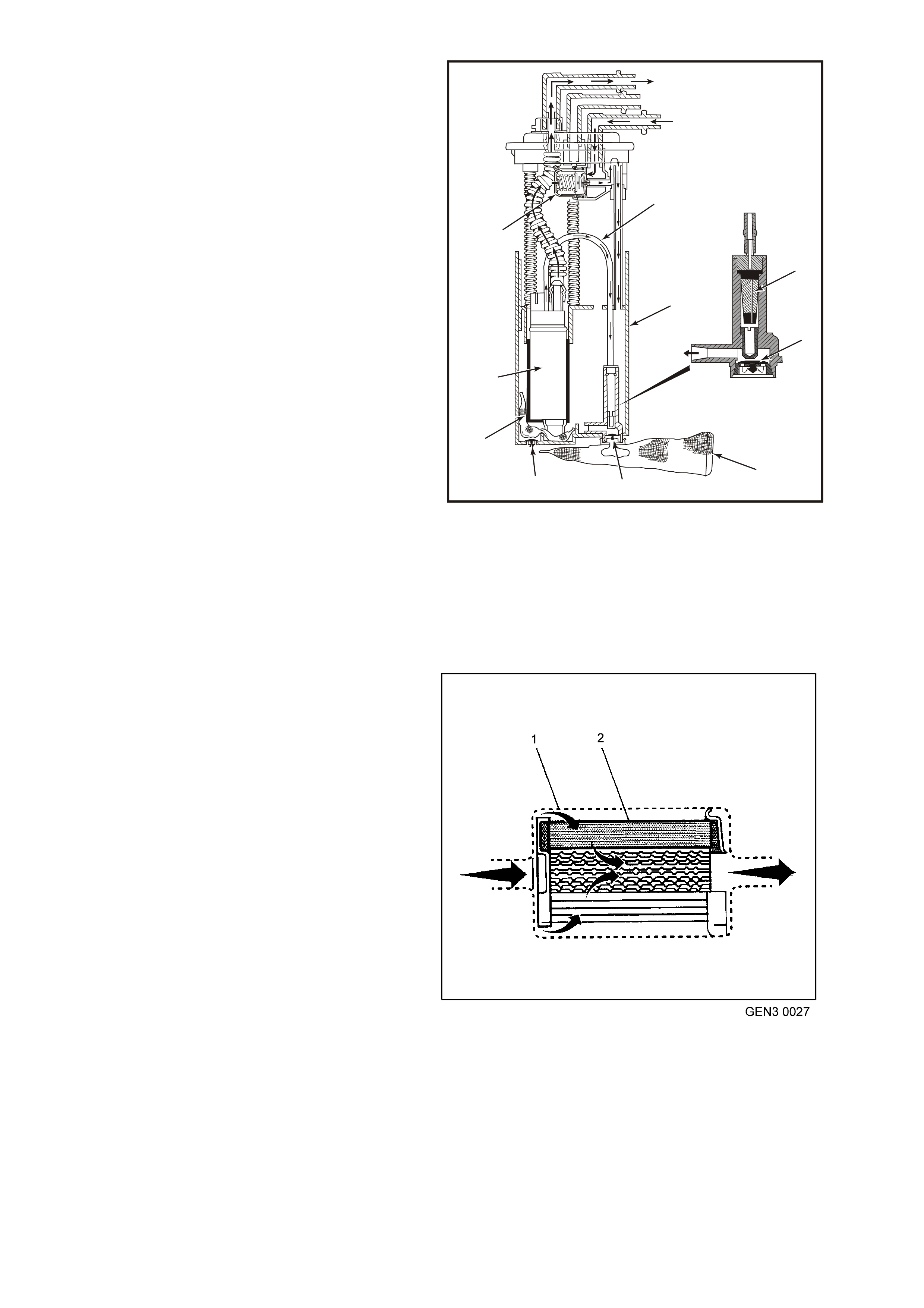
Fuel Pump Strainer
The f uel pump s trainer attaches to the lower end of
the fuel pump and the lower end of the fuel return
pipe. The fuel pump strainer is made of woven
plastic. T he f unctions of the f uel pum p st rainer is to
filter contaminants and to wick fuel.
The fuel pump strainer is self-cleaning and
normally requires no maintenance. Fuel stoppage
at this point indicates that the fuel tank contains an
abnormal amount of sediment or water. Clean the
fuel tank and replace fuel sender assembly.
1
9
8
7
3
46
5
4
2
10
4354
Figure 6C3-1-85 Fuel Sender Assembly
1. Diverter Pipe. 6. External Filter Screen
2. Jet Pump Filter. 7. Secondary Umbrella Valve.
3. Reservoir. 8. Internal Filter Screen.
4. Primary Umbrella 9. Gerotor Fuel Pump.
Valve. 10. Fuel Pressure Regulator.
5. Jet Pump
In-Line Fuel Filter
The fuel feed pipe has a steel f ilter installed ahead
of the fuel injection system. The paper filter
element (2) traps particles in the fuel that may
damage the injection system. T he filter housing (1)
is made to withstand maximum fuel system
pressure, exposure to fuel additives, and changes
in temperature. The inlet fitting is a quick-
disconnect and a the outlet is a threaded fitting
which is sealed with an O-ring. The fuel filter is to
be changed at prescribed service intervals, refer to
Section OB, Lubrication & Service in VX Service
Information. A restricted fuel filter should be
replaced.
Fuel Feed and Retur n Pipes
The fuel feed pipe c arries fuel f rom the fuel tank to
the fuel rail assembly. The fuel return pipe carries
fuel f rom the T -connec tor located on the outlet side
of the f uel f ilter back to the f uel tank. T he f uel pipes
consist of three sections:
• T he rear f uel pipe assem blies are located f rom
the top of the fuel tank to the chassis fuel
pipes. The rear fuel pipes are constructed of
nylon.
Figure 6C3-1-86 In-line Fuel Filter
1. Fuel Filter Housing
2. Paper Filter Element
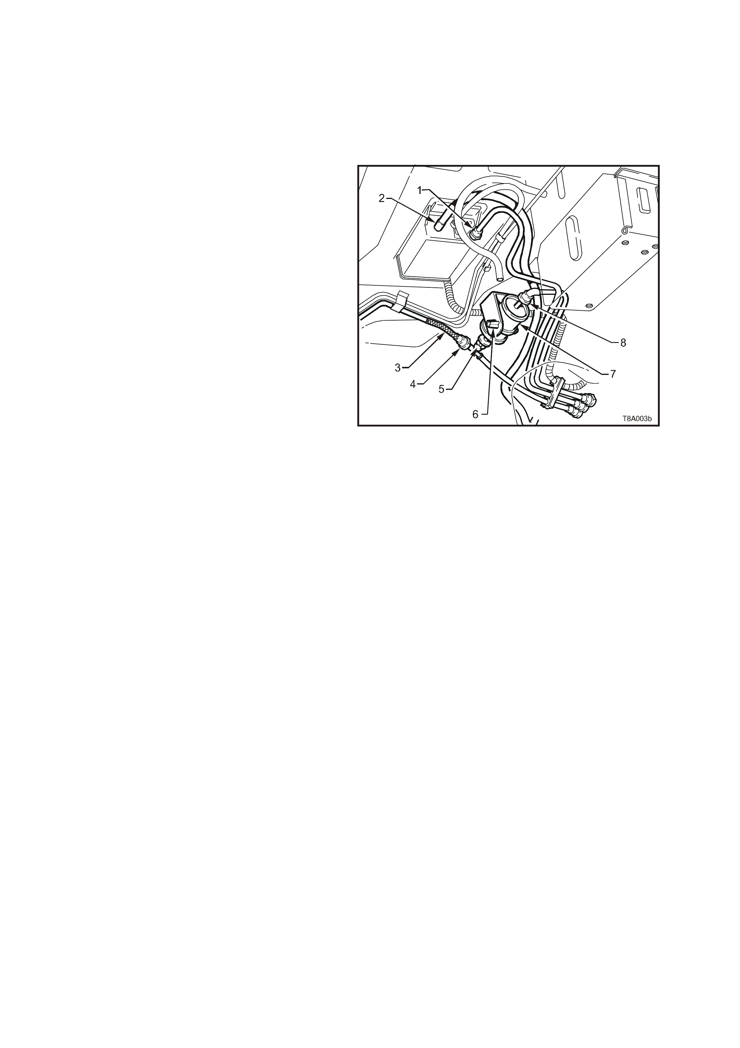
• The chassis fuel pipes are located under the
vehicle and connect the rear fuel pipes to the
engine compartment connecting fuel pipe.
These pipes are constructed of steel.
• The engine compartment connecting fuel pipe
connects the chassis fuel pipe to the engine
fuel rail. This fuel pipe is constructed of nylon
Nylon Fuel Pipes
IMPORTANT:
In order to Reduce the Risk of Fire and
Personal Injury:
• If nylon fuel pipes are nicked, scratched or
damaged during installation, Do Not
attempt to repair the sections of the nylon
fuel pipes. Replace them.
• When installing new fuel pipes, Do Not
hammer directly on the fuel harness body
clips as it may damage the nylon pipes
resulting in a possible leak.
• Always cover nylon vapour pipes with a wet
towel before using a torch near them. Also,
never expose the vehicle to temperatures
higher th an 115°C ( 239°F) fo r more t han on e
hour, or more than 90°C (194°F) for any
extended period.
• Before connecting fuel pipe fittings, always
apply a few drops of clean engine oil to the
male pipe ends. This will ensure proper
reconnection and prevent a possible fuel
leak. During normal operation, the O-rings
located in the female connector will swell
and may prevent proper reconnection if not
lubricated.
Nylon fuel pipes are designed to perform the sam e
job as the steel or flexible fuel pipes or hoses that
they replace. Nylon pipes are constructed to
withstand maximum fuel system pressure,
exposure to fuel additives, and changes in
temperature. There are three sizes of nylon pipes
used: 3/8” ID for the fuel feed, 5/16” ID for the fuel
return, and 1/2" ID for the vent
Heat resistant rubber hose and/or corrugated
plastic conduit pr otect the sec tions of the pipes that
are exposed to chafing, high temperature or
vibration.
NOTE:
Nylon fuel pipes are somewhat flexible and can be
formed around gradual turns under the vehicle.
However, if nylon fuel pipes are forced into sharp
bends, the pipes will kink and restrict the fuel flow.
Also, once exposed to fuel, nylon pipes may
become stiffer and are more likely to kink if bent
too far. Take special care when working on a
vehicle with nylon fuel pipes.
Figure 6C3-1-87 Fuel Filter Location View
1. Quick Connect, Fuel Tank Vapour Line to Canister
2. Hose, Filler Neck Breather
3. Flexible Line, Fuel Feed to Engine
4. Quick Connect, Fuel Feed Line
5. Quick Connect, Fuel Filter T-piece
6. Retaining Tangs, Fuel Filter Strap
7. Filter, Fuel
8. Quick Connect, Fuel Feed Line from Fuel Tank
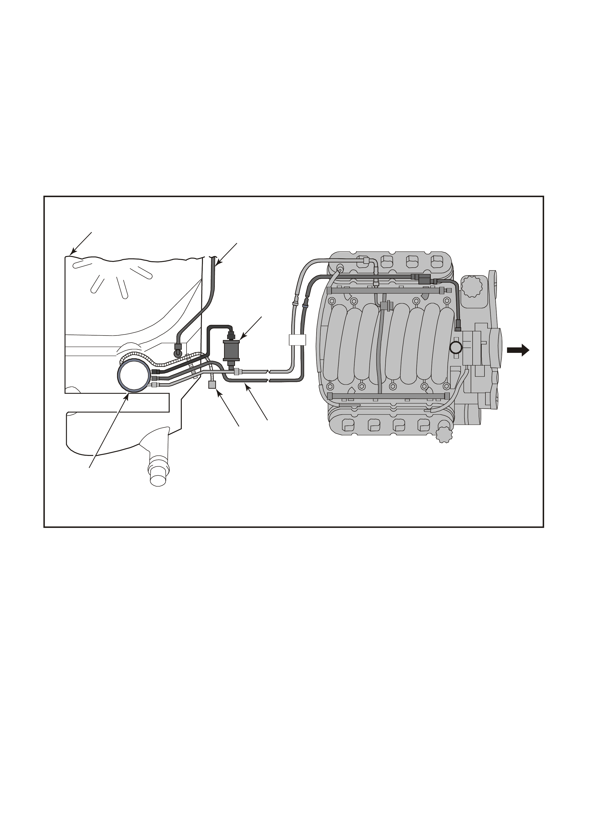
Quick-Connect Fittings
Quick -connect f ittings provide a simplif ied means of installing and connecting f uel system com ponents. The fittings
consist of a unique female connector and a compatible male pipe end. O-rings, located inside the female
connector, provide the fuel seal. Integral locking tabs or fingers hold the fittings together.
Fuel Pipe O-Rings
O-rings seal the threaded connec tions in the f uel s ystem and ar e made of spec ial material. Ser vice the O -r ing seals
with the correct service part.
Evaporative Pipes and Hoses
The evaporative pipes extend from the fuel sender assembly and the evaporative canister vent solenoid to the
evaporative canister. The evaporative purge pipe extends from the evaporative canister to the evaporative purge
valve in the engine compartment. The rear pipes and the engine compartment pipe are constructed of nylon. The
chassis evaporative purge pipe is constructed of steel.
Figure 6C3-1-88 Fuel Lines
1. Fuel Tank.
2. Vent Tube.
3. Fuel Filter.
4. Vapour Tube.
5. Fuel Pump Harness Connector.
6. Fuel Pump.
FUEL METERING MODES OF OPERATION
Modes Of Operation
The PCM looks at voltages from several sensors to determine how much fuel to give the engine. The fuel is
delivered under one of several conditions called modes. The PCM controls all modes.
Starting Mode
W ith the ignition s witch in the ON position (bef ore engaging the starter) , the PCM energises the fuel pump relay for
two seconds, allowing the fuel pum p to build system pressure. The PCM first checks speed density, then switches
to the Mass Air Flow (MAF) sensor. The PCM also uses the Engine Coolant T emperature (ECT ), Throttle Position
(TP) , and Manifold Absolute Press ure (MAP) sensor s to determine the proper air/fuel ratio for star ting. T his ranges
from 8.5:1 to 14.7:1 depending on coolant temperature. The PCM controls the amount of fuel delivered in the
starting mode by changing the pulse width of the injectors. This is done by pulsing the injectors for very short times.
4
3
2
1
5
6
4355

Sequential Fuel Inje ction Mode
When the engine is first cranked over, all injectors will be energised simultaneously. After the engine has been
started and a good camshaft signal has been processed, the PCM will energise each individual injector in the
normal firing order. This mode of operation helps to stabilise idle, reduce emissions and reduce fluctuations in the
fuel pressure.
Clear Flood Mode
If the engine floods, c lear the engine by pres sing the accelerator pedal down all the way. The PCM then pulses the
injectors at an air /fuel r atio of 20:1. T he PCM holds this injector rate as long as the throttle stays wide open and the
engine speed is below 300 RPM. If the throttle position becomes less than 80 percent, the PCM returns to the
starting mode.
Run Mode
The run mode has two conditions called O pen Loop, and Closed Loop. When the engine is fir st star ted, and engine
speed is above a predetermined RPM, the system begins Open Loop operation. The PCM ignores the signal from
the Heated O xygen Sensor (HO2S) and calculates the air/f uel ratio based on inputs from the ECT , MAF, MAP, and
TP sensors. The system stays in Open Loop until meeting the following conditions:
• Both HO2S have varying voltage output, showing that they are hot enough to operate properly. (This depends
on temperature.)
• The Engine Coolant Temperature (ECT) sensor is above a specified temperature.
• A specific amount of time has elapsed after starting the engine.
Specific values for the above conditions exist for each different engine, and are stored in the Electrically Erasable
Programmable Read Only Memory (EEPROM).
The system begins closed loop operation after reaching these values. In Closed Loop, the PCM calculates the
air/fuel ratio (injector on-time) based on the signal from various sensors, but mainly the HO2S. This allows the
air/fuel ratio to stay very close to 14.7:1.
Acceleration Mode
W hen the driver press es on the accelerator pedal, air flow into the cylinders increases rapidly, while f uel flow tends
to lag behind. To prevent possible hesitation, the PCM increases the pulse width to the injectors to provide extra
fuel acceleration. The PCM determines the amount of fuel required based on Throttle Position, Coolant
Temperature, Manifold Air Pressure, Mass Air Flow and Engine Speed.
Catalyst Protection Mode
During sustained heavy loads the PCM increases the pulse width to the injectors to provide extra fuel, to prevent
the catalytic converter from overheating.
Deceleration Mode
When the driver releases the accelerator pedal, air flow into the engine is reduced. The PCM looks at the
corresponding changes in Throttle Position, Manifold Air Pressure and Mass Air Flow. The PCM shuts OFF fuel
com pletely if the deceleration is very rapid, or f or long periods (suc h as long closed throttle coast- down) . The fuels
shuts OFF in order to protect the warm-up three-way catalytic converters.
Power Enrichment Mode
When battery voltage is low, the PCM compensates for the weak spark delivered by the ignition system in the
following ways:
• Increasing the amount of fuel delivered.
• Increasing the idle RPM.
• Increasing ignition dwell time.
Fuel Cut OFF Mode
To prevent possible engine damage from over-speed, the PCM cuts off fuel from the injectors when the engine
speed is above approximately 6200 RPM. Also, see Rapid Deceleration in Deceleration Mode.
Open Loop Mode
After the engine is running, the PCM will operate the fuel control system in the open loop mode. In open loop, the
PCM ignores the signal from the oxygen sensors, and calculates the air/fuel ratio injector pulse width based on
inputs from the CKP signal (RPM input) and these sensors: MAF, MAP, IAT, ECT and TP sensor.
The system will stay in the open loop mode until all the closed loop mode criteria have been met, or not at idle,
refer to open loop idle mode description.
In open loop, the calculated puls e width may give an air/fuel ratio other than 14.7 to 1. An example of this would be
when the engine is cold, because a richer mixture is needed to ensure good driveability.

Closed Loop Mode
In closed loop m ode, the PCM initially calculates injector pulse with based on the sam e sensors used in open loop.
The dif f er enc e is that in c losed loop, the PC M us es the ox ygen sensor signals to modif y and precisely fine tune the
fuel pulse width calculations in order to precisely maintain the 14.7 to 1 air/fuel ratio that allows the catalytic
converter to operate at its maximum conversion efficiency.
Power Enrichment (PE) Mode
The power enrichment mode delivers a rich mixture to the cylinders during a large throttle position change
command from the driver. During the power enrichment mode, the PCM will not make fueling changes based on
the oxygen sensor signals.
Battery Voltage Correction Mode
When battery voltage is low, the PCM compensates for the weak spark delivered by the ignition system in the
following ways:
• Increasing the amount of fuel delivered.
• Increasing the idle RPM.
• Increasing ignition dwell time.
Adaptive Learning
Adaptive learning is the ability of the PCM to determine and remember its most recent operating experience. The
PCM uses this remembered information to learn from experience and to m ake adjustm ents with respect to what it
learnt. If the engine were to develop a restricted fuel filter, the PCM will change the fuel injector pulse width richer
to com pensate f or this condition and will rem em ber to k eep this fuel inj ection puls e in m em ory until the res triction is
corrected. After the restriction has been fixed, the PCM will eventually go back to the original preprogrammed fuel
injection pulse. Adaptive learning is an on-going process that continues throughout the life of the engine.
Short Term Fuel Trim
Short T erm Fuel Trim (STFT) represents short term corrections to the fuel injector pulse width calculations, based
on the oxygen sensor input signals to the PCM.
When the engine is started cold, in open loop, the PCM will control the fuel injection pulse width based upon
various sensor inputs such as RPM, ECT, IAT, MAP, MAF and TP sensor until the oxygen sensors become hot
enough to operate properly. During this open loop period, both Short T erm Fuel T rim (STFT) and Long Term Fuel
Trim (LTFT) are disabled and will read 0% on a Tech 2 scan tool.
When the oxygen sensors have reached normal operating temperature, they will produce a varying voltage to the
PCM and provide a good indication of what has happened in the combustion chambers.
At this time the PCM will switch from open loop to closed loop and the STFT will start to constantly monitor the
oxygen sensor signals, so that the PCM can modify fuel injector pulse width with greater accuracy than in open
loop.
STFT monitors the oxygen sensor signals so that it can adjust the fuel injector pulse width to maintain an air/fuel
ratio of 14.7 to I f or m ax im um catalytic converter ef fic iency. An STFT value of 0% is equivalent to an air/f uel ratio of
14.7 to I and an average oxygen sensor signal voltage of 450 mV.
The normal position for STFT is 0%, any change from this value indicates the STFT is changing the fuel injector
pulse width. The amount of pulse width change depends upon how far the STFT value is from 0%. If the STFT
value is above 0%, the fuel injector pulse width is being increased, thus adding more fuel. If the STFT value is
below 0%, the fuel injector pulse width is being decreased, thus removing fuel.
If an engine has a r est ric ted f uel f ilter , the low fuel pr es s ure will res ult in les s f uel being inj ect ed and allows more air
into the charge than is needed to ignite the amount of fuel the fuel injector has injected, therefore, a lean air/fuel
ratio exists in the combustion chamber. After combustion has taken place, the exhaust gases still contain more
oxygen content than nor mal and the oxygen sensors r ead this as low voltage, say 200 m V. The STF T detects that
the oxygen sensor signals are low and will increase the value to richen up the air/fuel mixture. On a Tech 2 scan
tool it will display ST FT as a value above 0%. This STFT c hange will inc rease the injector pulse width allowing the
fuel injectors to stay open longer and inject more fuel.
If the additional fuel was injected and the oxygen sensor signal voltages are still low, the STFT will continue to
increase its value until the oxygen sensor signal voltages go above 450 mV. If the STFT continues to detect low
oxygen sensor signal voltages it will continue to try and compensate for the lean exhaust condition until it runs out
of its authority in the particular Long Term Fuel Trim (LTFT) cell it's operating in. At this point, the PCM will reset
STFT to 0% and go through this procedure again until it can control the system.
If after a specif ied am ount of resets have been tr ied and failed, the PCM k nows that it cannot control f or the failure
and the STFT will remain at its maximum value.
STFT values are based on the oxygen sensor signal voltage readings, therefore, STFT is used by the PCM to
make quick changes to the fuel injector pulse width over a short period of time.

Long Term Fuel Trim
LTFT is used to adjust for engine to engine variation and to adjust for engine aging. LT FT is a portion of the PCM
memor y used to adjust f uel delivery across all operating c onditions of the engine. The PCM m onitor s the ST FT and
will adjust the long term trend of the f uel injector pulse width if the STF T has been at a value f or a certain period of
time. LTFT is used to change the long term fuel injector pulse width and is only operational when the fuel control
system is in Closed Loop. A normal LTFT value is 0% and should follow the STFT value.
If an engine has a restricted f uel filter, the low fuel pres sure will result in less f uel being injected and will cause the
STFT value to go higher than 0%, say 2%. If this STFT value change does not compensate for the restricted fuel
filter, the PCM will continue to increase the STFT value. The STFT may climb as high as its maximum calibrated
value if there is a severe restriction. The PCM will continue to monitor STFT as it climbs, but it will not make any
changes to the f uel injector puls e width for a specif ic period of time. Af ter a specific period of time has elapsed and
the STFT value has remained above say +8%, the LTFT will move up to say 4% and wait again to detect if the
STFT has dr opped bac k down to 0%. If not, the ST F T will gradually move toward its m a ximum calibr ated value limit
until it gains control of the fuel injection system. If STFT and LTFT are both set at their maximum value limit, the
fuel control system is out of the limits of control and will set a Diagnostic Trouble Code and go into open loop
operation.
The PCM will k eep the latest LT FT values s tored in its LT FT m em or y' cells. MAP sensor r eadings and engine RPM
are used by the LTFT to determ ine what cell to read. LTFT values are stored in the PCM's long term m emory, for
use each time the engine's RPM and load matches one of the LTFT cells. All LTFT values are reset to 0% when
the PCM's long term memory power supply is disc onnected. The T ec h 2 sc an tool als o has the ability to reset LTF T
to 0% with a special command.
Long Term Fuel Trim Cell
The LTFT function of the PCM is divided up into cells 0-22 arranged by MAP sensor readings and Engine RPM.
Each cell corresponds to a region on a MAP vs. RPM table. Each region is calibrated to a LTFT value of 0%. A
value of 0% in a given block indicates no fuel adjustment is needed for that engine load condition. A higher
number, say + 4%, indicates that the PCM has detected a lean exhaust indication under those conditions, and is
adding fuel (increasing fuel injector pulse width) to compensate. Conversely, a lower number, say -6%, indicates
that the PCM has detected a rich exhaust indication under those load conditions, and is subtracting fuel
(decreasing fuel injector pulse width) to compensate.
As the vehicle is driven from a standing start and accelerated or decelerated from various engine speeds, the
engine's LTFT calibration will change from one cell to another cell. As the LTFT changes cell so does STFT,
however, STFT will only make short term corrections in whatever LTFT cell the engine is operating in. W hen the
engine is idling, it can be in one of two cells. Depending upon canister purge, the engine will idle in cell 20. If the
engine was running at idle and the canister purge was on, we would be in cells 16-19 depending on AC clutch
status and PRNDL position.
Whatever cell the engine is operating in, the PCM will read that cell's particular LTFT value and electronically adjus t
the fuel injector base pulse width to compensate for a rich or lean condition in the engine. If an engine has a
restricted fuel filter and the customer has driven the vehicle lik e this for quite som e time, the LTFT value would be
high, and the PCM would be compensating for this condition by adding more fuel. Because the STFT value is
above 0%, LTFT will also be greater than 0% in most of the cells to compensate for the lean exhaust. If you
suspect a driveability problem associated with an over rich or over lean condition, then use the STFT value to
detect what the fuel control system is doing at the present time. Use the LTFT to identify what the system has
learned over a greater period of time to compensate for the condition.
Use the LTFT cells to determine if the fuel control system is commanding rich or lean throughout the operating
range. If it is only rich or lean at idle or part throttle, look for components that would cause problems in these areas.
All LTFT cell values are reset to 0% when long term memory power to the PCM is removed
The Tech 2 scan tool has the ability to reset all LTFT cells to 0%.
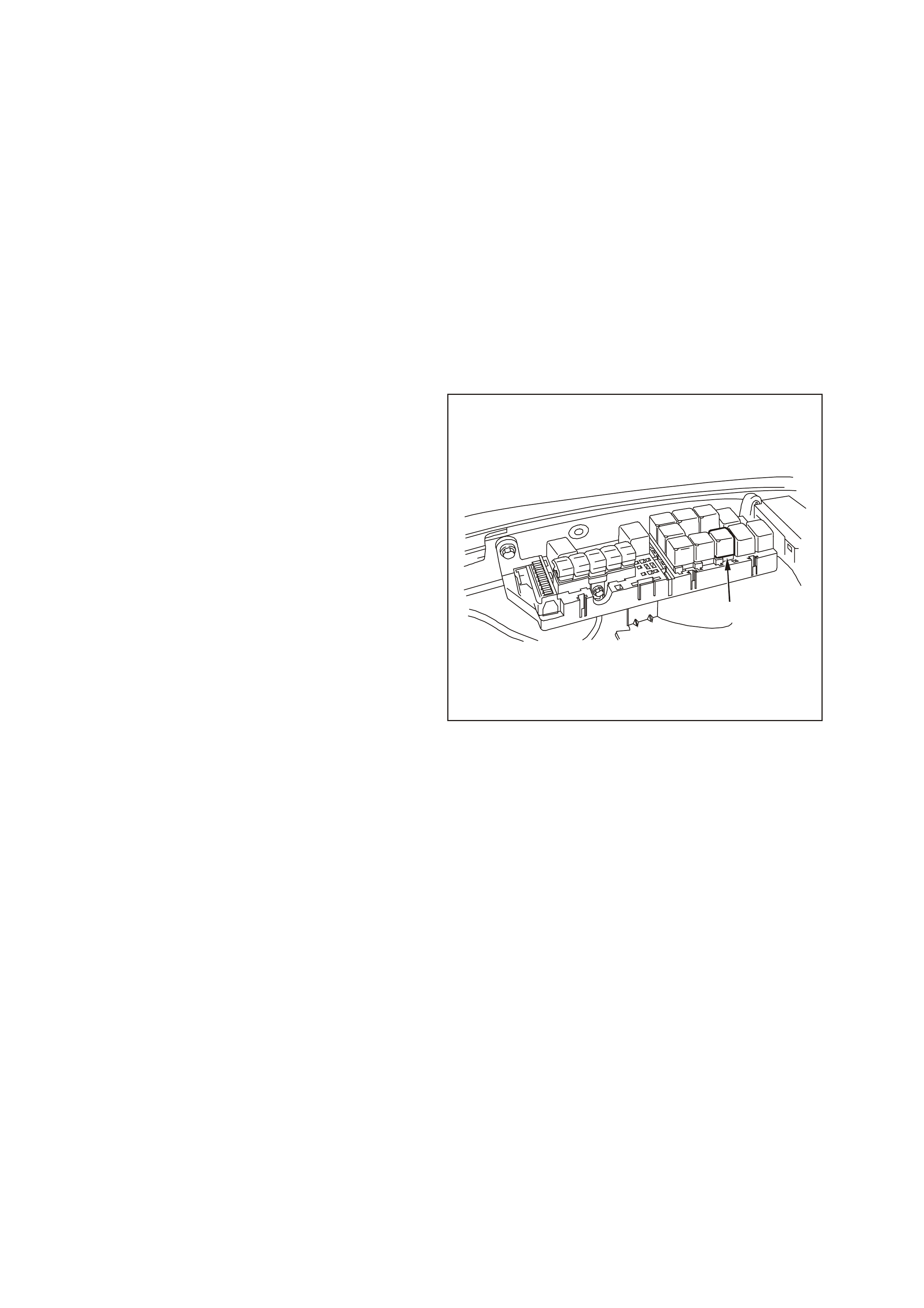
FUEL METERING SYSTEM COMPONENT DESCRIPTION
The fuel metering systems consists of the following parts:
• The fuel supply components(fuel tank, pump, pipes).
• The fuel pump electrical circuit.
• The fuel rail.
• The fuel injectors.
• The fuel pressure regulator.
• The throttle body.
• The Idle Ai r Control (IAC) valve.
• The Throttle Position (TP) Sensor.
System Overview
An electric fuel pump, located in the fuel tank with the fuel sender assembly, supplies fuel through an in-line fuel
filter at a pressure greater than is needed by the injectors. The fuel pressure regulator, part of the fuel sender
assembly, keeps fuel available to the injectors at a regulated pressure.
Fuel Pump Electrical Circuit
When the ignition switch is turned to the on or
crank position after having been off for at least 10
seconds, the PCM will immediately energise the
fuel pump relay to operate the fuel pump. This
builds up the fuel pressure quickly. If the engine is
not cranked within two seconds, the PCM will shut
the fuel pump relay off and wait until the engine is
cranking. As soon as the engine begins cranking,
the PCM will sense the engine turning from the
crankshaft position signal, and turn the relay on
again to run the fuel pump.
If there is a fault with the fuel pump relay control
circuit, DTC P0230 will set.
1
Figure 6C3-1-89 Fuel Pump Relay Location
1. Fuel Pump Relay
DTC P0230 FUEL PUMP CONTROL CIRCUIT
Conditions for running DTC P0230
• The engine speed is greater than 400 RPM.
• The ignition voltage is between 6.0 volts and 16.0 volts.
Conditions for setting DTC P0230
• The PCM detects that the commanded state of the circuit and the actual state of the circuit do not match.
• All of the above conditions present for at least ten seconds..
Action taken when DTC P0230 Sets
• The PCM illuminates the Check Powertrain Lamp when the diagnostic runs and fails.
• The PCM records the operating conditions at the time the diagnostic fails. The PCM stores this information in
the Freeze Frame/Failure Records.
Conditions for clearing the Check Powertrain Lamp and DTC P0230
• The PCM turns the Check Powertrain Lamp OFF after one ignition cycle that the diagnostic runs and does not
fail.
• A last test failed (current DTC) clears when the diagnostic runs and does not fail.
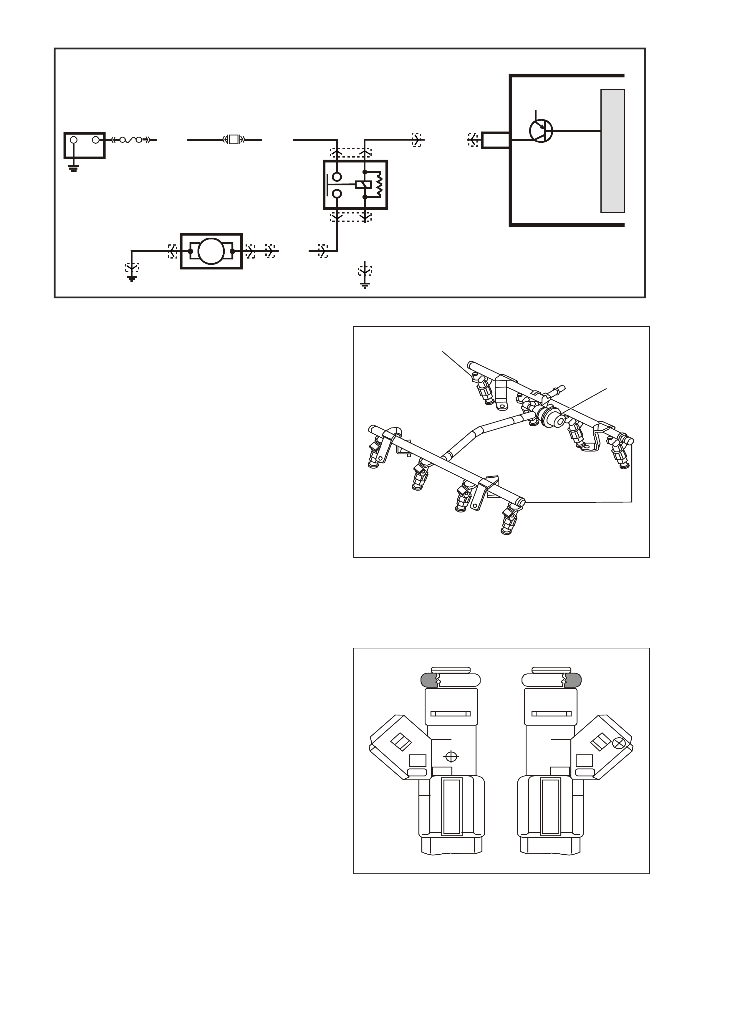
Figure 6C3-1-90 Fuel Pump Relay Circuit
Fuel Rail Assembly
The fuel rail assembly attaches to the engine
intake manifold and performs the following
functions:
• It positions the injectors (1) in the intake
manifold.
• It distributes fuel evenly to the injectors.
• It integrates the fuel pulse dampener into the
fuel metering system.
GE N 3 0029
1
2
3
Figure 6C3-1-91 Fuel Rail Assembly
1. Fuel Injector
2. Fuel Pulse Dampener
3. Fuel Rail
Fuel Injectors
The fuel injectors are electrically operated flow
control valves. They are supplied with battery
voltage from the ignition switch via fuse F14, the
EFI relay and fuse F34 and F35. The injectors are
controlled by the PCM providing the earth circuit.
The injectors are never fully energised on, as that
would flood the engine with too much fuel. The
PCM supplies the earth circuit in short pulses. The
longer the duration of the pulses (pulse width), the
more fuel in injected into the engine. Inside, the
injector s have a coil of electr ical wire that becom es
an electromagnet when energised. The resistance
of these windings is important for the PCM to
operate correctly.
The top-feed fuel injector assembly is a solenoid
operated device, controlled by the PCM, that
meter s press urised fuel to a single engine cylinder.
The PCM energises the injector solenoid, which
opens a ball valve, allowing fuel to flow past the
ball valve, and through a recessed flow director
plate.
GE N 3 0030
Figure 6C3-1-92 Fuel Injector
J2-09 FUEL PUMP RELAY
CONTROL
G3PCM022PT
B/BLU
YR32 YR32 YB39 YE114
YE110
YE123
YE96
YE96
YR44 YR44
(156)
LOC. E7 LOC. E3
IN - TANK
FUEL PUMP
FUEL PUMP
RELAY
G/W (465)
PCM
12V
M
I
C
R
O
+-
BATTERY
FS
LOC. E1
F28
(1040) O (240)
V (12 0)
B/W(152)
32
51
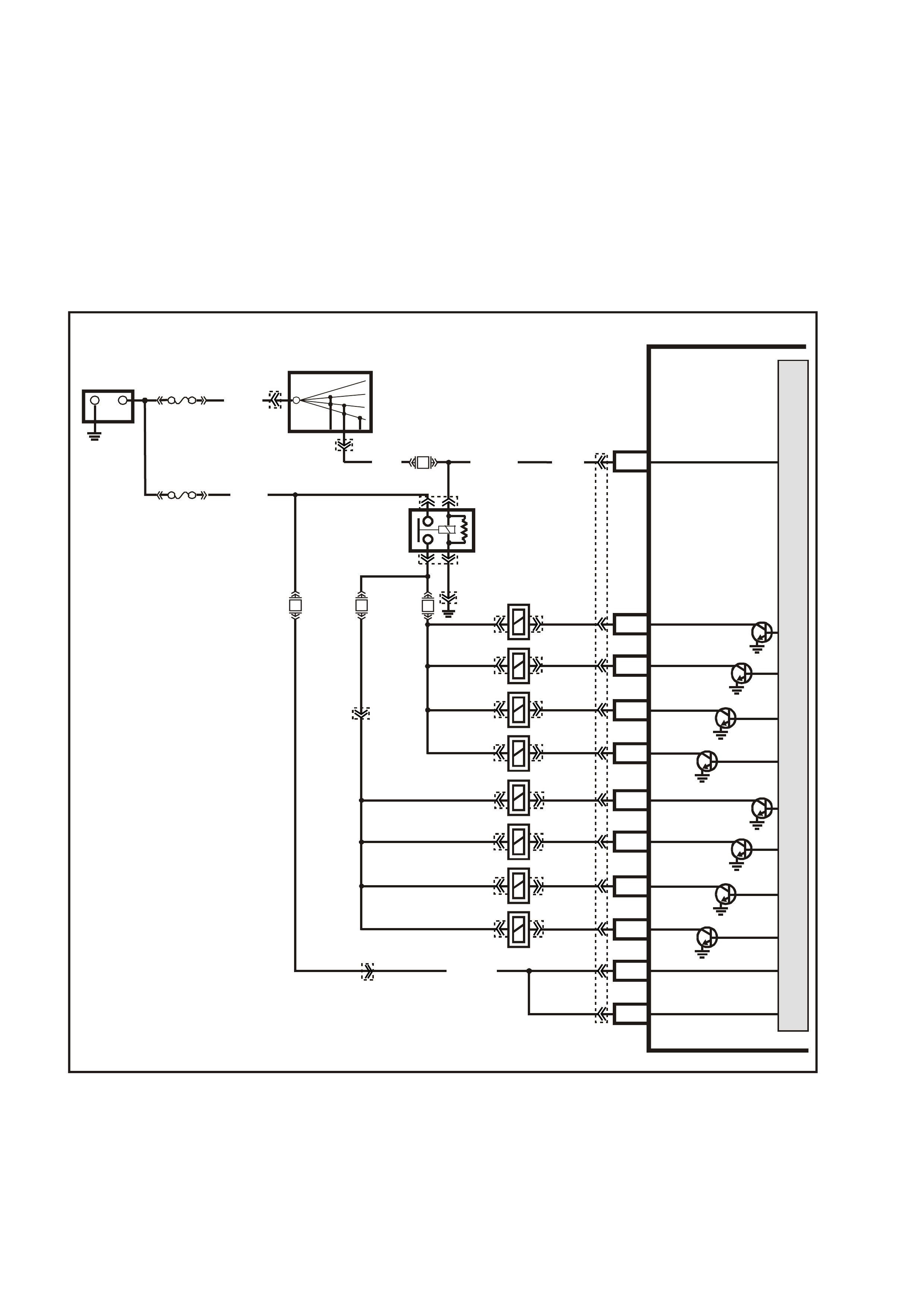
The director plate has multiple machine holes that
control the fuel flow, generating a conical spray
pattern of finely atomised fuel at the injector tip.
Fuel is directed at the intake valve, causing it to
become further atomised and vaporised before
entering the combustion c hamber. An injec tor s tuck
partly open can cause a loss of pressure after
engine shutdown. Consequently, longer cranking
time may result. There are no DTCs associated
with the injectors. Refer to Fuel Injector Balance
Test in Section 6C3-2C of the VX Series Service
Information for diagnosis of the injectors.
Figure 6C3-1-93 Fuel Injector Circuit
G3PCM017PT
PCM
J1-19
J1-36
J1-04
J1-03
J1-44
J1-76
J1-37
J1-20
J1-43
J1-77
J1-57
INJECTOR 1
INJECTOR 2
INJECTOR 7
INJECTOR 8
BATTERY
BATTERY
INJECTOR 5
INJECTOR 6
INJECTOR 3
INJECTOR 4
IGNITION
M
I
C
R
O
P
R
O
C
E
S
S
O
R
+
-
BATTERY
FS
(1040)
O/Y
(479)
B/W
(152)
FJ
LOC. E1
LOC. E3
R (2H)
15a 15 50
30 OFF/ON
LOCK
ACC
IGN
START
IGNITION SWITCH
P (3) P/B (39) P (39)
EFI
RELAY
F14
F35
F34F31 BLU
(841)
V
(843)
GY
(845)
P/B
(847)
G
(842)
BR/Y
(844)
Y
(846)
LG
(848)
O (740)
O/B
(740)
R
(481)
L/G
(482)
YE39
YB44
YB44
YE111
YE112
YE122
YE39
YE77 YE77
YE79 YE79
YE83 YE83
YE78 YE78
YE80 YE80
YE82 YE82
YE84 YE84
YE81 YE81
YE114
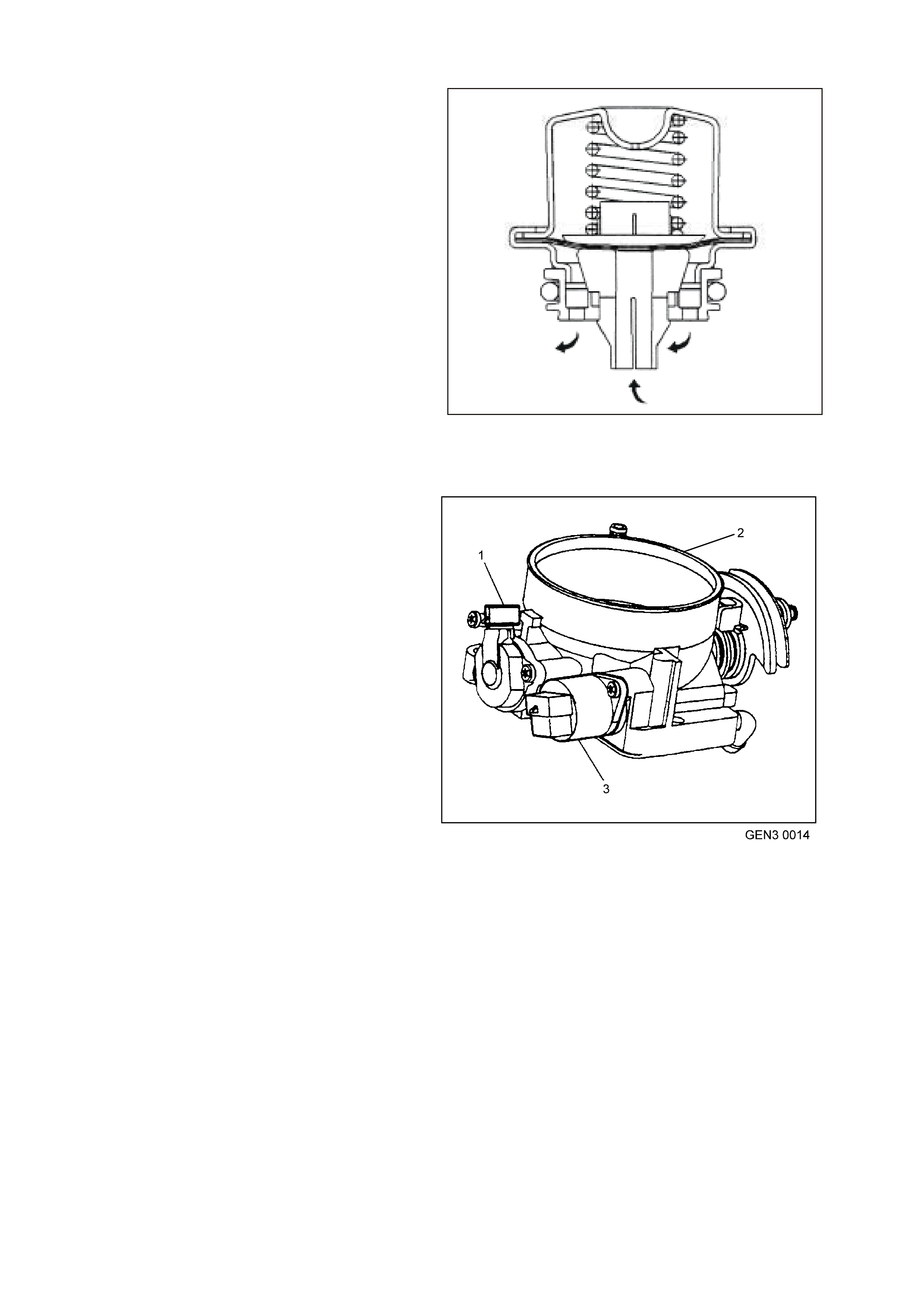
Fuel Pulse Dampener
The f uel pulse dam pener attaches inside a housing
on the fuel rail assembly. The fuel pulse dampener
is diaphragm operated, with fuel pump pr essure on
one side and spr ing pressur e of the other side. The
function of the dampener is to reduce fuel
pulsation.
NOTE: The procedure detailed in the Service
Information f or filter replac ement, must be f ollowed,
both in the sequence of removal and installation of
a replacement filter. Failure to observe these
instructions will most probably result in permanent
damage to the flexible line, resulting in
unnecessary parts replacement and expense.
GEN3 0031
Figure 6C3-1-94 Fuel Pulse Dampener
Accelerator Controls
The accelerator control system is cable operated.
Two different type of accelerator control cable
systems are used, one where Electronic Traction
Control (ETC) is fitted and the other without ETC.
Therefore use the specific cable for each
application. Cable adjustment is provided on the
throttle cable, refer to Section 6C3-3 of the VX
Series Service Information.
Throttle Body Assembly
The throttle body assembly attaches to the intake
manifold and controls air flow into the engine,
thereby controlling engine output. The driver opens
the throttle valve within the throttle body through
the accelerator controls. During engine idle, the
throttle valves are alm os t clos ed. A fixed air bypass
orifice and the Idle Air Control (IAC) valve (3)
control the air flow.
Engine coolant flows thr ough a coolant cavity in the
bottom of the throttle body and prevents throttle
valve icing during cool weather operation. The
throttle body also provides the location for
mounting the Throttle Position (TP) sensor (1).
Figure 6C3-1-95 Throttle Body Assembly
1. TP Sensor
2. Throttle Body Assembly
3. IAC Valve

Throttle Position (TP) Sensor
The T hrottle Pos ition (T P) sens or is mounted to the
throttle shaf t on the throttle body. The T P sensor is
a potentiometer which is supplied a 5 volt
reference and an earth circuit from the PCM. The
signal circuit connects from a sliding contact in the
TP sensor to the PCM. This allows the PCM to
measure the voltage from the TP sensor. As the
throttle is depressed, the output of the TP sensor
changes. At a closed throttle position, the output of
the TP sensor is below 1.25V. As the throttle valve
opens, the output increases. At a wide-open
throttle, the TP sensor output voltage should be
greater than 4 volts.
Speed Density System Description
Three specific data sensors provide the PCM with
the basic information for the fuel management
portion of its operation. That is, three specific
signals to the PCM establish the engine speed and
air dens ity factor s. The engine speed s ignal comes
from the ignition system.
The PCM uses this information to determine
engine speed (RPM). Air density is derived from
IAT and MAP sensor inputs. The IAT sensor
measures the air temperature that is entering the
engine. The IAT signal works in conjunction with
the MAP sensor to determine air density. As the
intake manifold also increases and additional fuel
is r equired. This inform ation from the IAT and MAP
sensors is used by the PCM to control injector
pulse width.
The speed density system is used to:
1. Monitor Mass Air Flow (MAF) sensor operation
(to determine if there is a MAF sensor
malfunction).
2. Tak e over fueling m anagement oper ation when
there is a Mass Air Flow (MAF) sensor
malfunction.
GE N 3 0032
1
2
3
4
5
67
Figure 6C3-1-96 Throttle Position (TP) Sensor
1. Throttle Body
2. IAC Valve O-Ring
3. IAC Valve
4. IAC Valve Attaching Screws
5. TP Sensor Attaching Screws
6. TP Sensor
7. TP Sensor Seal
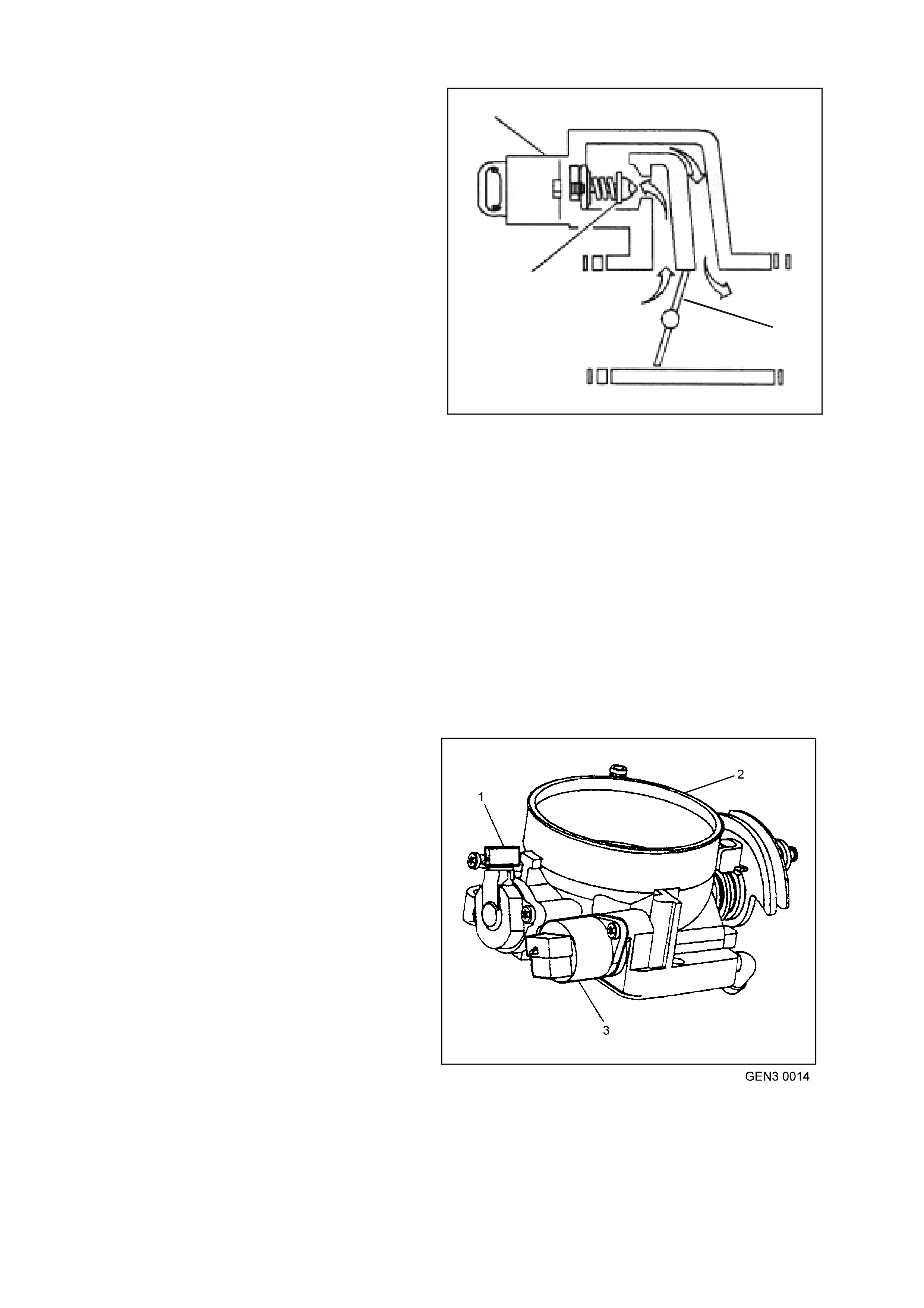
1.5 IDLE AIR CONTROL (IAC) VALVE
The purpos e of the Idle Air Contr ol (IAC) Valve is to
control engine idle speed, while preventing stalls
due to changes in engine load. The IAC valve,
mounted in the throttle body, controls a portion of
the bypas s air. An or ific e located in the throttle body
also supplies a constant amount of bypass air.
By moving a conical valve, known as a pintle, in
towards the seat (to decrease air f low); or out away
from the seat (to increase air flow), a controlled
amount of air can be bypassed. If engine speed is
too low, more air is bypassed to increase RPM. If
engine speed is too high, less air is bypassed to
decrease RPM.
The PCM moves the IAC valve in small steps,
called counts. These can be measured and
displayed by a Tech 2 scan tool, which plugs into
the Data Link Connector (DLC). The PCM
calculates the proper position of the IAC valve
during idle, based on battery voltage, coolant
temperature, engine load, and engine RPM. If the
RPM drops below specification and the throttle
valve is closed, the PCM senses a near stall
condition and calculates a new valve position in
order to prevent stalling.
• Engine idle speed is a function of total air flow
into the engine. Idle speed is based on IAC
valve pintle position + crankcase ventilation
valve flow + throttle valve opening + bypass
orifice air flow + calibrated vacuum loss
through accessories.
• Controlled idle speed is programmed into the
PCM, which determines the correct IAC valve
pintle position to maintain the desired idle
speed for all engine operating conditions and
loads.
GE N 3 0033
1
3
2
Figure 6C3-1-97 Idle Air Control (IAC) Valve Air Flow
1. IAC Valve
2. Throttle Plate
3. IAC Valve Pintle
• The minimum idle air rate is set at the factory
with a stop screw. This setting allows enough
air flow by the throttle valve to cause the IAC
valve pintle to be positioned a calibrated
number of s teps (c ounts), f rom the seat, dur ing
controlled idle operation.
IDLE AIR VALVE POSITION RESET
If the IAC valve is disconnected and reconnected
with the engine running, the idle speed may be
wrong. If this occurs, reset the IAC valve by
depressing the accelerator pedal slightly, start and
run the engine for five seconds, then turn the
ignition OFF for ten seconds.
Figure 6C3-1-98 IAC Valve Location
1. TP Sensor
2. Throttle Body
3. IAC Valve

DTC P0506 IDLE SPEED LOW
Conditions for running DTC P0506
• DTCs P0101, P0102, P0103, P0107, P0108, P0112, P0113, P0117, P0118, P0171, P0172, P0174, P0175,
P0443, are not set.
• The engine run time is greater than 60 seconds.
• The engine coolant temperature is greater than 60°C.
• The intake air temperature is greater than -10°C.
• The barometric pressure is greater than 65 kPa.
• The ignition voltage is between 9.0 and 17.0 volts.
• The vehicle speed is no more than 2 km/h.
Conditions for setting DTC P0506
• The actual idle speed is 100 RPM less than the desired idle speed.
• All of the above conditions are present for 15 seconds.
Action taken when DTC P0506 Sets
• The PCM illuminates the Check Powertrain Lamp when the diagnostic runs and fails.
• The PCM records the operating conditions at the time the diagnostic fails. The PCM stores this information in
the Freeze Frame/Failure Records.
Conditions for clearing the Check Powertrain Lamp and DTC P0506
• The PCM turns the Check Powertrain Lamp OFF after the first ignition cycle that the diagnostic runs and does
not fail.
• A last test failed (current DTC) clears when the diagnostic runs and does not fail.
DTC P0507 IDLE SPEED HIGH
Conditions for running DTC P0507
• DTCs P0101, P0102, P0103, P0107, P0108, P0112, P0113, P0117, P0118, P0171, P0172, P0174, P0175,
P0443, are not set.
• The engine run time is greater than 60 seconds.
• The engine coolant temperature is greater than 60°C.
• The intake air temperature is greater than -10°C.
• The barometric pressure is greater than 65 kPa.
• The ignition voltage is between 9.0 and 17.0 volts.
• The vehicle speed is no more than 2 km/h.
Conditions for setting DTC P0507
• The actual idle speed is 100 RPM more than the desired idle speed.
• All of the above conditions are present for 15 seconds.
Action taken when DTC P0507 Sets
• The PCM illuminates the Check Powertrain Lamp when the diagnostic runs and fails.
• The PCM records the operating conditions at the time the diagnostic fails. The PCM stores this information in
the Freeze Frame/Failure Records.
Conditions for clearing the Check Powertrain Lamp and DTC P0507
• The PCM turns the Check Powertrain Lamp OFF after the first ignition cycle that the diagnostic runs and does
not fail.
• A last test failed (current DTC) clears when the diagnostic runs and does not fail.
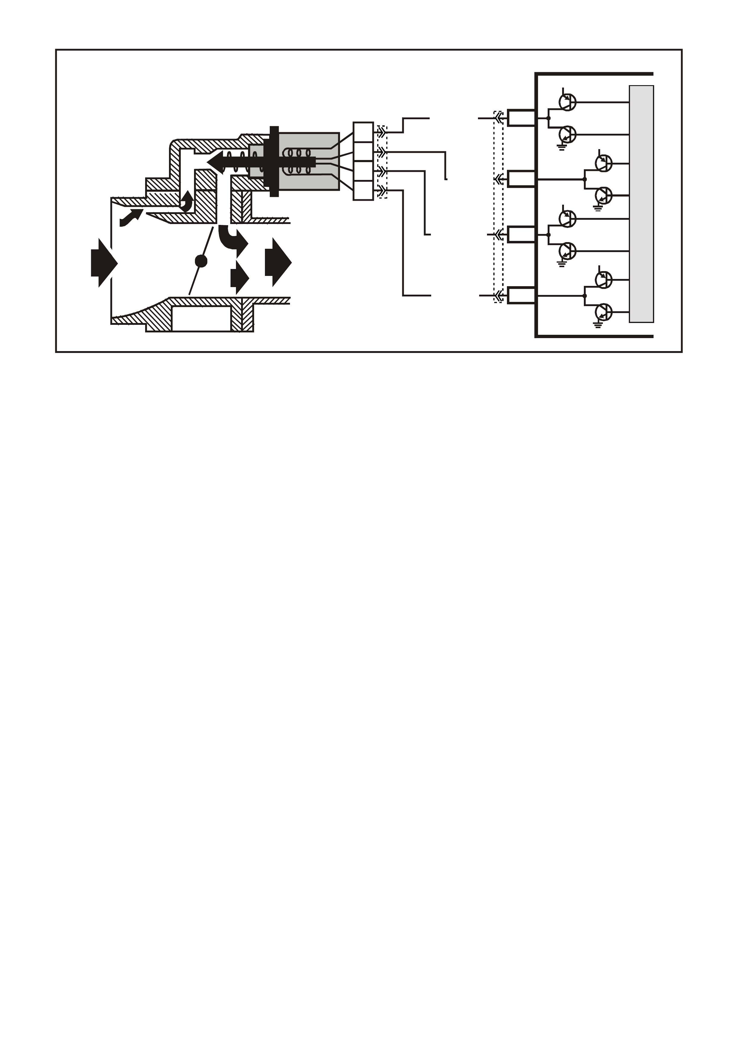
Figure 6C3-1-99 IAC Valve Circuits
G3PCM020PT
PCM
J2-77
J2-78
J2-79
J2-76
LG/B (444)
YE36
YE123
A
B
C
D
IAC VALVE
IAC
COIL B HI
IAC
COIL A HI
IAC
COIL B LO
IAC
COIL A LO
12V
12V
12V
12V
M
I
C
R
O
LG/W (443)
LBLU/B (442)
LBLU (441)
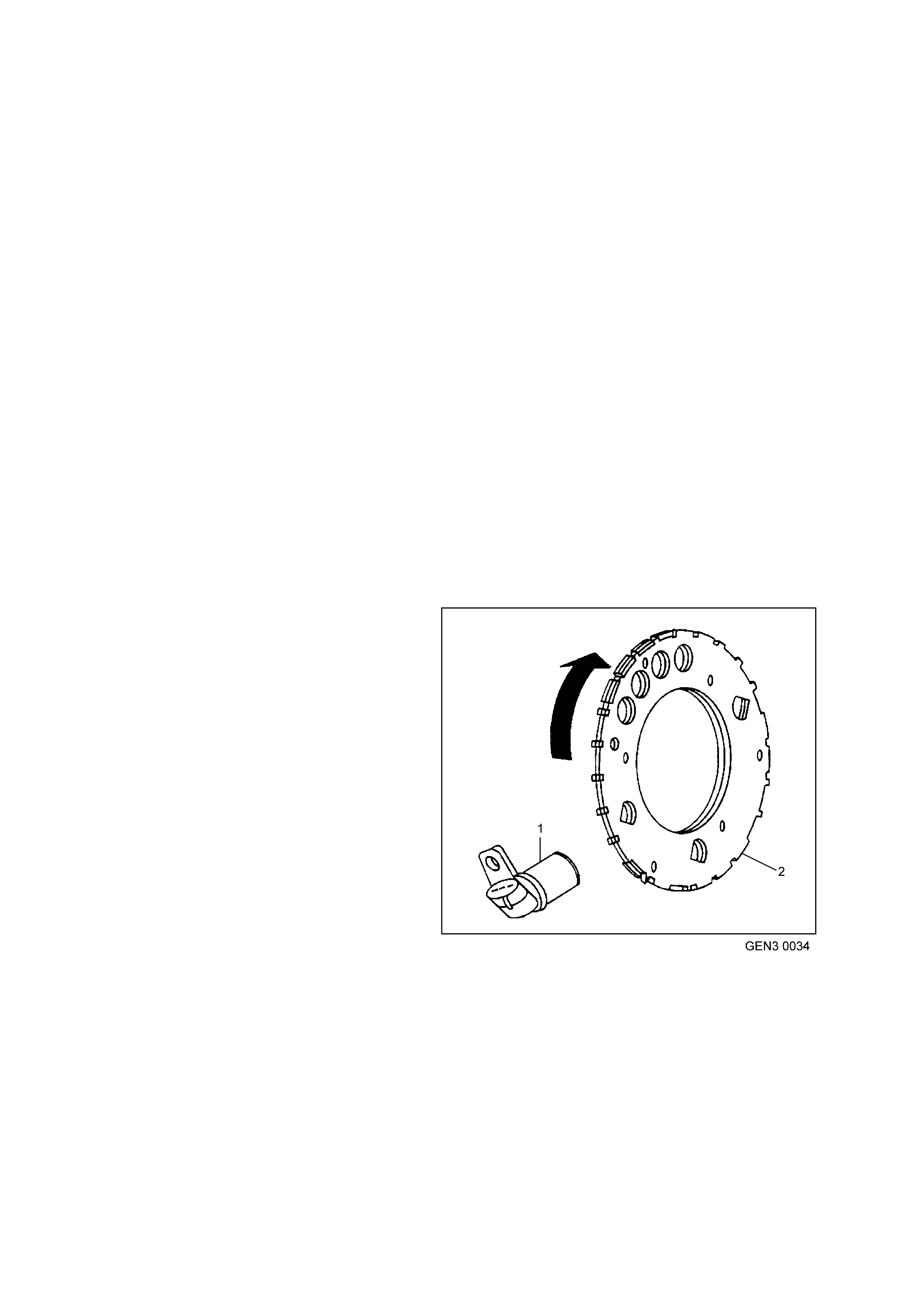
1.6 ELECTRONIC IGNITION SYSTEM
The ignition system on the GEN III V8 engine features a multiple coil ignition and is known as coil near plug. The
spark plug leads are short compared with a distributor ignition system. Eight ignition coils/modules are individually
mounted above each cylinder on the rocker covers and fire s equentially. Ther e is an Ignition Control (IC) circ uit for
each ignition coil/module. The eight ignition control circuits are connected to the PCM. All timing decisions are
made by the PCM, which triggers each coil/module individually. Each ignition coil/module has a power feed, an
earth circuit and a reference low circuit.
IGNITION SYSTEM OVERVIEW
The electronic ignition system provides a spark to ignite the compressed air/fuel mixture at the correct time. To
provide optim um engine perf orm ance, f uel econom y, and control of ex haust em is sions, the PCM contr ols the spar k
advance of the ignition system.
The electronic ignition system does not use the
conventional distributor and coil. The ignition system
consists of the following components/circuits:
• Eight ignition coils/modules
• Eight Ignition Control (IC) circuits
• Camshaft Position (CMP) sensor
• 1X Camshaft reluctor wheel
• Crankshaft Position (CKP) sensor
• 24X Crankshaft reluctor wheel
• Related connecting wires
• Powertrain Control Module (PCM)
COMPONENTS
Crankshaft Position Sensor (CKP) and Reluctor Wheel
The Crank shaft Position (CKP) Sensor is located in
the right rear of the engine, behind the starter and
is a dual magneto resistive type sensor. This
sensor is not speed dependent. The dual micro
switches monitor both notches of the reluctor wheel
for greater accuracy. The CKP sensor works in-
conjunction with a 24X reluctor wheel.
The reluctor wheel is mounted on the rear of the
crankshaft. The 24X reluctor wheels use two
different width notches that are 15 degrees apart.
This pulse width encoded pattern allows cylinder
position identification within 90 degrees of
crankshaft rotation. In some cases, cylinder
identification can be located in 45 degrees of
crankshaft rotation. This reluctor wheel also has
dual track notches that are 180 degrees out of
phase. The dual track design allows for quicker
starts and accuracy.
The PCM also receives a 4X signal from the
Crankshaft Position Sensor. The PCM utilises the
4X signal for the following:
• Misfire
• Tachometer output
• Spark control
• Fuel Control
• Certain diagnostics
Figure 6C3-1-100 Crankshaft Position Sensor and
Reluctor Wheel
1. CKP Sensor
2. Reluctor Wheel
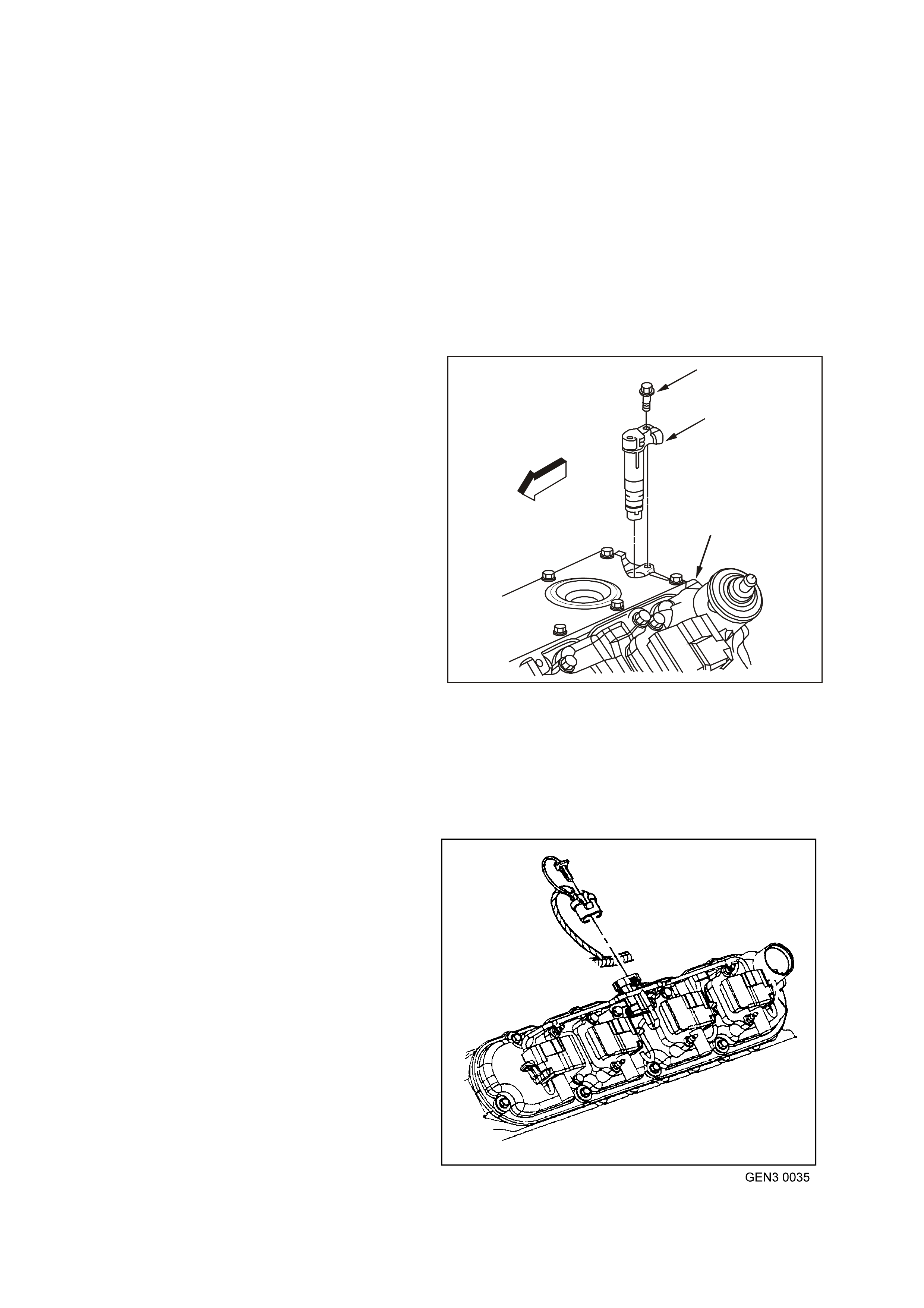
The CKP signal must be available for the engine to
start. The CMP signal is not needed to start and
operate the engine. The PCM can determine when
a particular cylinder is on either a firing or exhaust
stroke by the 24X signal. The CMP sensor is to
determ ine what strok e the engine is on. The system
will attem pt to synchronise and look for an increas e
in the MAF signal. An increase in the MAF signal
indicates the engine has started. If the PCM does
not detect an increase in the MAF signal, a re-sync
will occur to the opposite cam position. A slightly
longer cranking time may be a symptom of this
condition.
Camshaft Position Sensor (CMP)
The Camshaft Position (CMP) Sensor is mounted
through the top of the engine block at the rear of
the valley cover. The CMP sensor works in-
conjunction with a 1X reluctor wheel. The reluctor
wheel is located at the rear of the camshaft. The
CMP sensor is used to determine whether a
cylinder is on the firing or the exhaust stroke. As
the camshaft rotates, the reluctor wheel interrupts
a magnetic field produced by a magnet within the
sensor. The CMP sensor ’s internal circuitry detects
this and produces a signal which is used by the
PCM. The PCM uses this signal in combination
with the CKP 24X signal to determ ine to crank shaft
position and stroke.
The CKP signal m ust be available for the engine to
start. The CMP signal is not needed to start and
operate the engine. The PCM can determine when
a particular cylinder is on either a firing or exhaust
stroke by the 24X signal. The CMP sensor is to
determine what stroke the engine is on. The
system will attempt to synchronise and look for an
increase in the MAF signal. An increase in the MAF
signal indicates the engine has started. If the PCM
does not detect an increase in the MAF signal, a
re-sync will occur to the opposite cam position. A
slightly longer cranking time may be a symptom of
this condition.
GE N 3 0022
1
2
3
Figure 6C3-1-101 Camshaft Position (CMP) Sensor
1. CMP Mounting Bolt
2. CMP Sensor
3. Top Rear of Engine Block
Ignition Coils/ Module
The ignition system on this engine features a
m ultiple coil ignition and is k nown as coil near plug.
The secondary ignition wires are short compared
with a distributor ignition system wire. Eight ignition
coils/modules are individually mounted above each
cylinder on the rocker covers and fire sequentially.
There is an Ignition Control (IC) circuit for each
ignition coil/module. The eight ignition control
circuits are connected to the PCM. All timing
decisions are made by the PCM, which triggers
each coil/module individually.
The ignition coil/ modules are supplied with the
following circuits:
• Ignition feed circuit
• Ignition control circuit
• Earth circuit
• Reference low circuit
Figure 6C3-1-102 Ignition Coils/Module Location
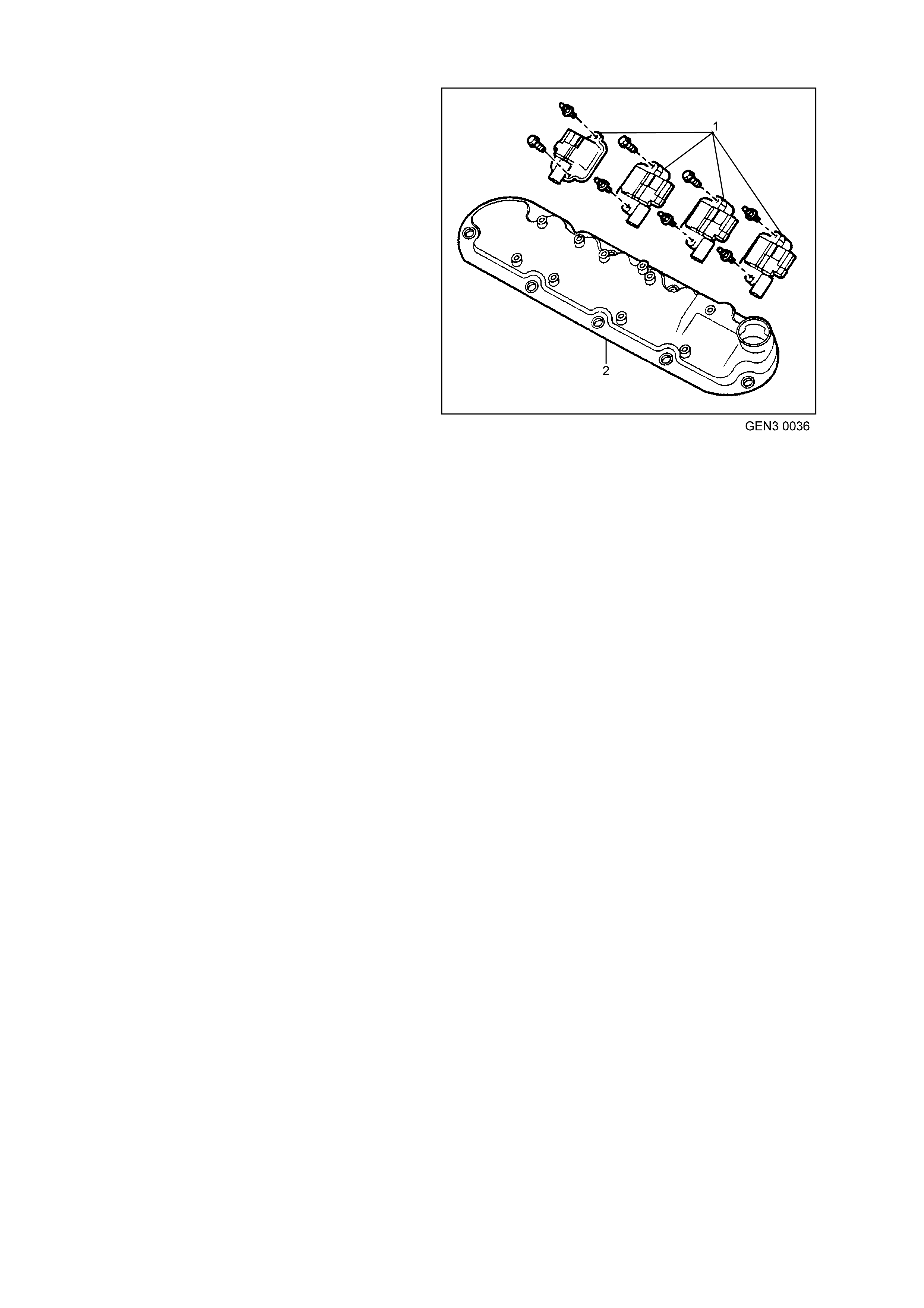
Ignition Coils
The ignition feed circuits are fused separately for
each bank of the engine. The two f uses also s upply
the injectors for that bank of the engine. Each
coil/module is serviced separately.
This system puts out very high ignition energy for
plug firing. Because the ignition wires are shorter,
less energy is lost to ignition wire resistance. Also,
since the f iring is sequential, each coil has far mor e
time to saturate as opposed to the three in a waste
spark arrangement. Furthermore, no energy is lost
to the resistance of a waste spark system.
CIRCUITS AFFECTING IGNITION CONTROL
To properly control ignition timing, the PCM relies
on the following information:
• Mass Air Flow
• Engine Load (manifold pressure or vacuum)
• Atmospheric (Barometric) Pressure
• Engine Coolant Temperature
• Intake Air Temperature
• Throttle Position Sensor
• Crankshaft Position Sensor
• Engine Speed
• Automatic Transmission Range from the
Transmission Range Switch
The PCM is responsible for maintaining correct
spark and fuel injection timing for all driving
conditions. To provide optimum driveability and
emissions. The PCM calculates the desired spark
advance from information received from the
sensors and triggers the appropriate ignition
coil/modules at the desired time to provide the
spark advance needed.
RESULTS OF INCORRECT OPERATION
An ignition control circuit that is open, earthed, or
short circuited will set an ignition control circuit
DTC. If a fault occurs in the IC output circuit when
the engine is running, the engine will experience a
misfire. DTC P0351 through DTC P0358 will set
when a malfunction is detected with an Ignition
Control circuit.
If the engine cranks but will not run or immediately
stalls, Engine Cranks But Will Not Run diagnostic
table must be used to determine if the failure is in
the ignition system or the fuel system. If DTC
P0341, P0342, P0343, P0335, P0336 is set, the
appropriate diagnostic trouble code table must be
used for diagnosis.
Figure 6C3-1-103 Ignition Coils/Modules
1. Ignition Coils/Modules
2. Engine Valve Cover

NOTEWORTHY IGNITION INFORMATION
There ar e im portant c onsiderations to point out when servicing the ignition sys tem . The following inform ation will list
some of these to help the technician in servicing the ignition system.
• The ignition coil’s secondar y voltage output capability is very high - more than 40,000 volts . Avoid body c ontact
with ignition high voltage secondary components when the engine is running, or personal injury may result.
• The 24X crank shaft position sensor is the m ost critic al part of the ignition system. If the sensor is dam aged so
that pulses are not generated, the engine will not start.
• Crankshaft position sensor clearance is very important. The sensor must not contact the rotating interrupter
ring at any time or sensor damage will result. If the interrupter ring is bent, the interrupter ring blades will
destroy the sensor.
• Ignition timing is not adjustable. There are no timing marks on the crankshaft balancer or timing chain cover.
• Be car eful not to dam age the s econdary ignition wires or boots when servicing the ignition s ystem. Rotate each
boot to dislodge it fr om the plug or c oil tower before pulling it f rom either a spark plug or the ignition coil. Never
pierce a sec ondary ignition wire or boot f or any testing pur poses! F uture problems will oc cur if pinpoints or test
lights are pushed through the insulating for testing.
DTC P0351 IGNITION CONTROL #1 CIRCUIT DTC P0352 IGNITION CONTROL #2 CIRCUIT
DTC P0353 IGNITION CONTROL #3 CIRCUIT DTC P0354 IGNITION CONTROL #4 CIRCUIT
DTC P0355 IGNITION CONTROL #5 CIRCUIT DTC P0356 IGNITION CONTROL #6 CIRCUIT
DTC P0357 IGNITION CONTROL #7 CIRCUIT DTC P0358 IGNITION CONTROL #8 CIRCUIT
Conditions for running DTC P0351 – P0358
• The ignition voltage is between 9.0 and 17.0 volts
Conditions for setting DTC P0351 – P0358
• The PCM detects the ignition control circuit is earthed, open or shorted to a voltage.
• All conditions met for at least 15 seconds.
Action taken when DTC DTC P0351 – P0358 Sets
• The PCM illuminates the Check Powertrain Lamp when the diagnostic runs and fails.
• The PCM records the operating conditions at the time the diagnostic fails. The PCM stores this information in
the Freeze Frame/Failure Records.
Conditions for clearing the Check Powertrain Lamp and DTC DTC P0351 – P0358
• The PCM turns the Check Powertrain Lamp OFF when the diagnostic runs and does not fail.
• A last test failed (current DTC) clears when the diagnostic runs and does not fail.
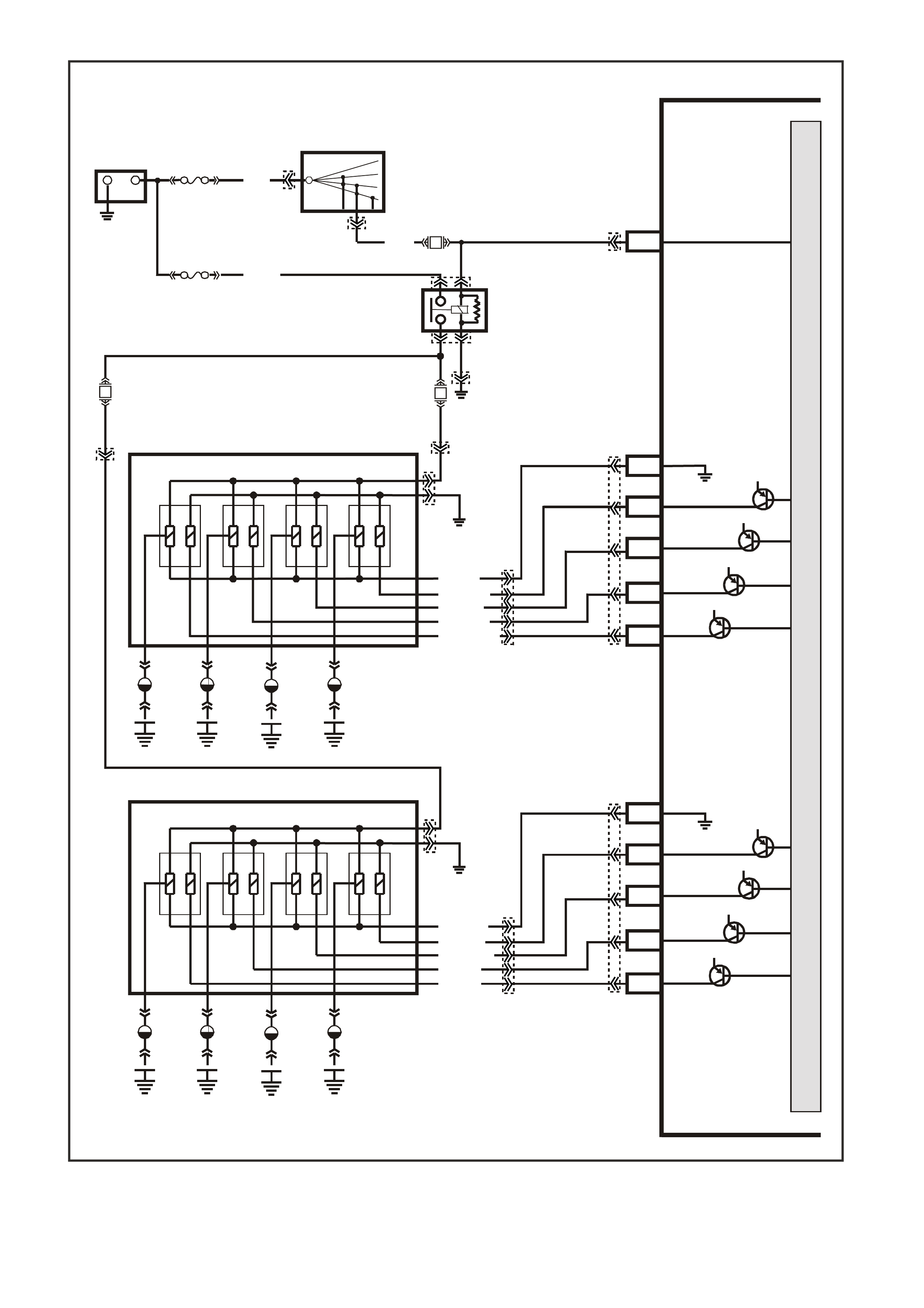
Figure 6C3-1-104 Ignition System Circuits
G3PCM037PT
PCM
J1-19
J2-67
J2-26
J2-61
J2-60
J2-29
J2-69
J2-28
J2-68
J2-66
J2-27
CYL. 2
IGNITION
REFERENCE LOW
IGNITION
REFERENCE LOW
CYL. 8
CYL. 6
CYL. 4
IGNITION
M
I
C
R
O
P
R
O
C
E
S
S
O
R
+-
BATTERY
FS
LOC. E3
(1040)
FJ
R (2)
15a 15 50
30 OFF/ON
LOCK
ACC
IGN
START
IGNITION SWITCH
P (3)
H
H
E
E
G
B
CYL 8
CYL 7
CYL 2
CYL 1
CYL 6
CYL 5
F
C
B
G
R.H IGNITION MODULE
L.H IGNITION MODULE
A
A
C
F
CYL 4
CYL 3
LOC.
E5/E15
LOC.
E5/E15
V (95 9)
BR (958)
Y/B (972)
W (971)
W (974)
BLU (973)
L/G (976)
G (975)
LBLU (978)
Y (97 7)
EFI
RELAY
F14
F35
F34
R
(481)B/W
(152)
L/G
(482)
SPARK PLUGS
SPARK PLUGS
12V
12V
12V
12V
CYL. 1
CYL. 7
CYL. 5
CYL. 3
12V
12V
12V
12V
YE122
YE39
YB44
YE39
YE114
YE111
YE124
YE124
YE125
YE125
YE111
YE123
YE123
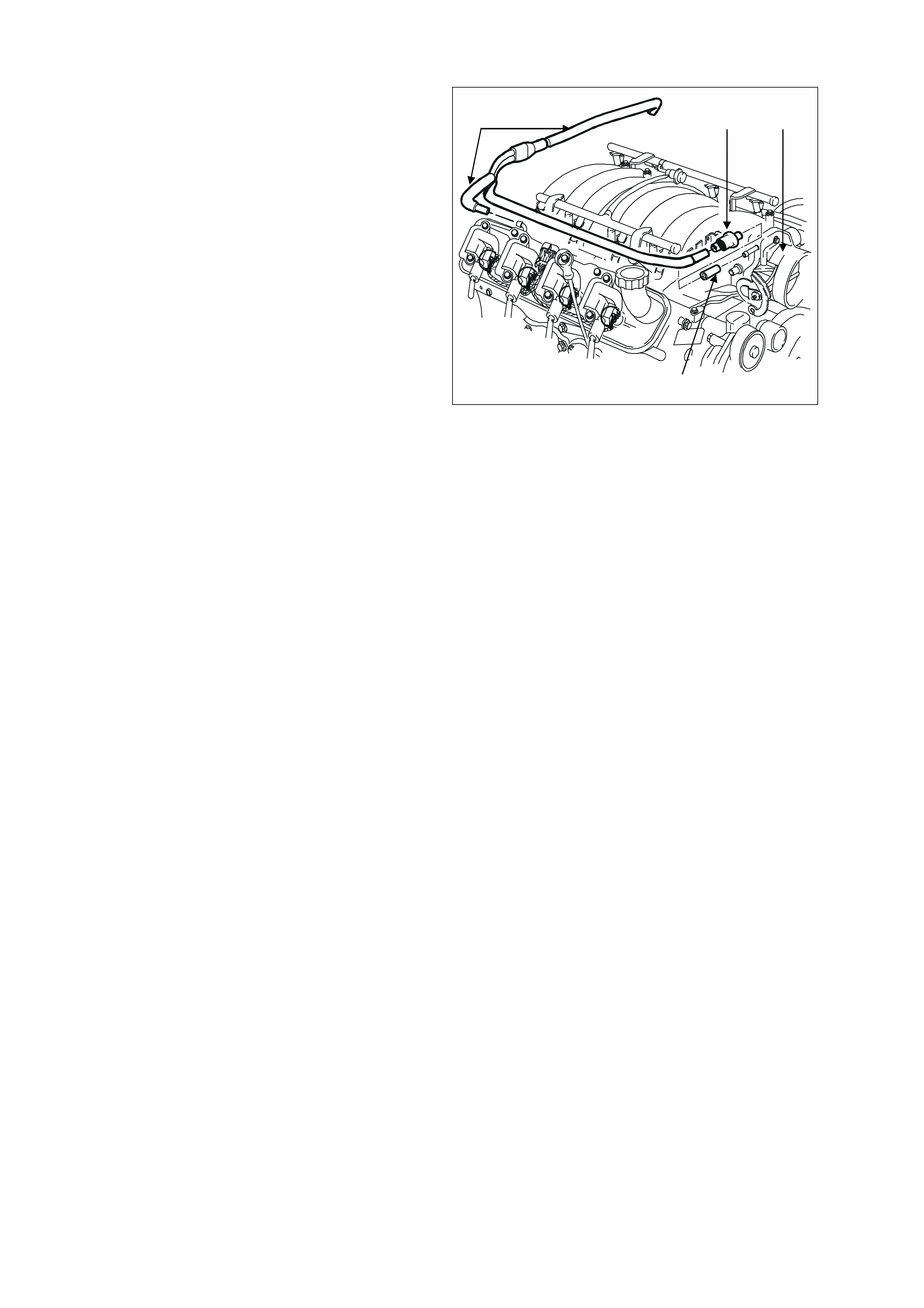
1.7 CRANKCASE VENTILATION SYSTEM
A closed crankcase ventilation system is used to
provide a more complete scavenging of crankcase
vapours. Fresh air from the throttle body is
supplied to the crankcase, mixed with blow-by
gases and then passed through a crankcase
ventilation valve into the intake manifold.
The primary control is through the crankcase
ventilation valve which meters the flow at a rate
depending on manifold vacuum. To maintain idle
quality, the crankcase ventilation valve restricts the
flow when intake manifold vacuum is high. If
abnormal operating conditions arise, the system is
designed to allow excessive amounts of blow-by
gases to back flow through the crankcase vent
tube into the engine air inlet to be consumed by
normal combustion.
The engine ventilation system was developed to
minimise oil consumption and ensure that oil
ingestion could not occur during high speed
cornering manoeuvres. Filtered fresh air is routed
from up stream of the throttle blade to the front of
the right rocker cover via a formed rubber hose.
To reduce the potential of oil pullover into the
throttle bore area due to bac k f low of the ventilation
system, the fitting in the right side rocker cover is
located between a shield from the rocker arms.
Blow-by gases are routed from the rear of both
rock er covers , through m oulded nylon lines to a tee
fitting located on the centreline of the engine at the
rear of the intake manifold. From there, a single
nylon line carries the gases through an externally
mounted, horizontal PCV valve and enters the
intake manifold behind the throttle body.
The dual draw system was developed to meet
vehicle manoeuvre requirements. During sustained
max imum lateral acc eler ations, the outboar d r ocker
cover may fill with oil. The dual draw system
passively switches, allowing the PCV valve to draw
on the rocker cover with the least resistance. This
results in the system drawing on the air filled, or
inboard rocker cover and eliminates oil pullover
due to drawing on the oil-filled outboard rocker
cover.
T20B009
Figure 6C3-1-105 Crankcase Ventilation System Routing
1. PCV Valve
2. Throttle Body
3. Fresh air
4. Return air
2
3
1 4
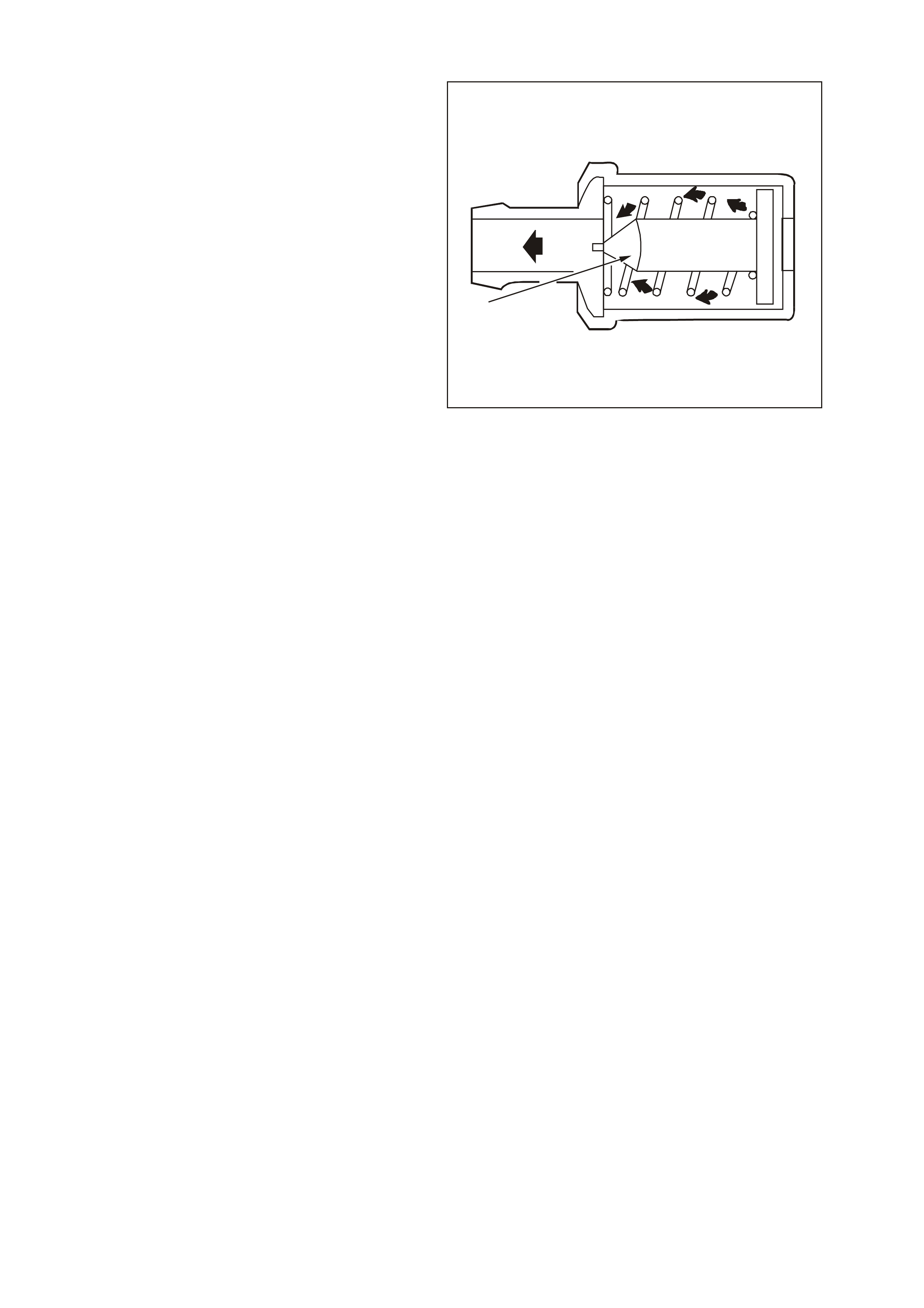
RESULTS OF INCORRECT OPERATION
A plugged PCV valve or hose may cause:
• Rough idle.
• Stalling or slow idle speed.
• Oil leaks.
• Sludge in engine.
A leaking valve or hose would cause:
• Rough idle.
• Stalling.
• High idle speed.
For replac ement of the PCV and related crank case
hoses, refer to Section 6E3 Emission Control -
GEN III V8 Engine in VX Service Information.
GE N 3 0038
1
Figure 6C3-1-106 PCV Cutaway
1. Check Valve
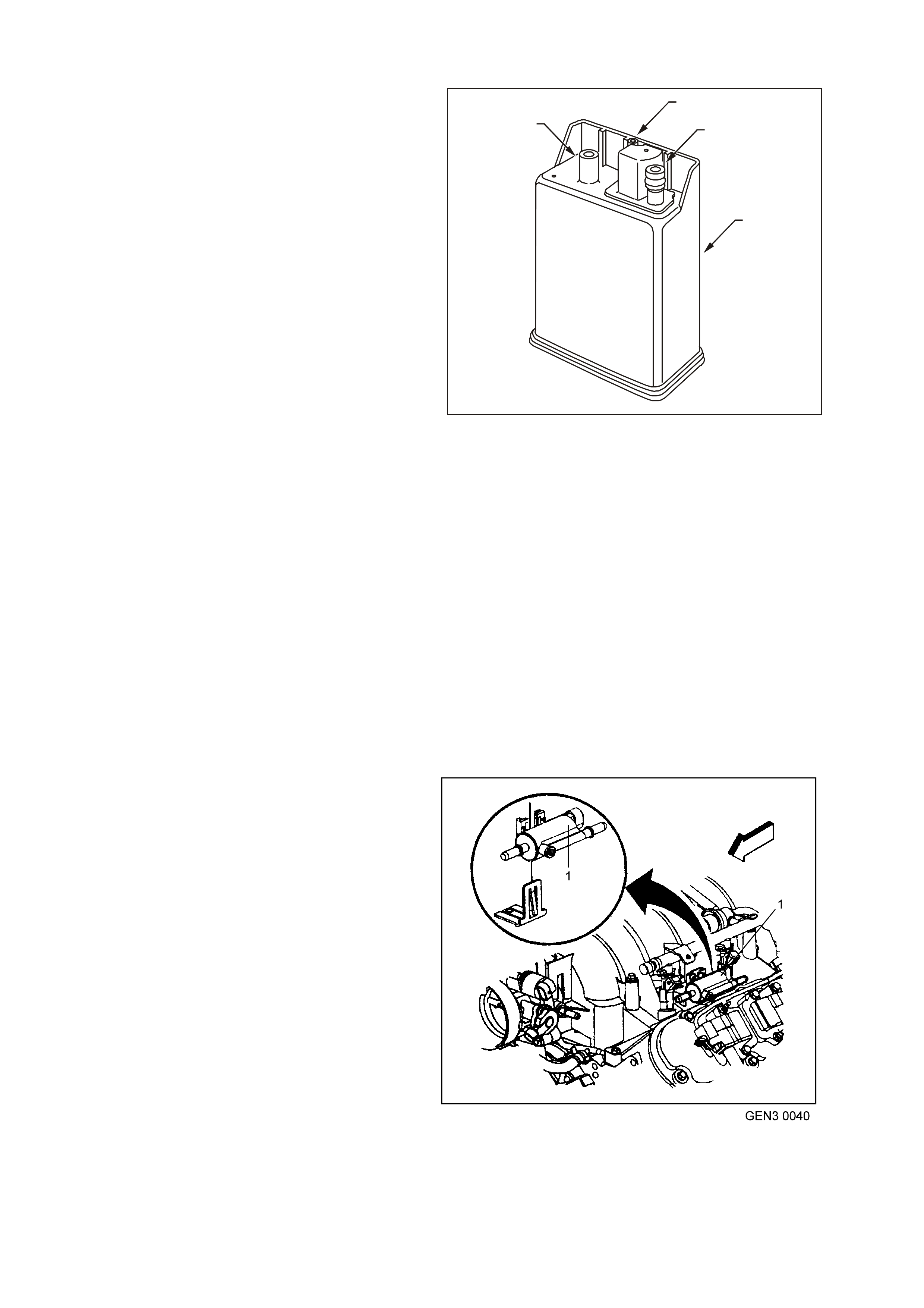
1.8 EVAPORATIVE EMISSION CONTROL SYSTEM
The Evaporative Emission Control System (EECS)
used on this vehicle is the charcoal canister
storage method. This method transfers fuel vapour
from the fuel tank to an activated carbon (charcoal)
storage device (canister located under the rear of
the vehicle) to hold the vapours when the vehicle is
not operating. W hen the engine is running, the fuel
vapour is purged from the carbon element by
intake air flow and consumed in the normal
combustion process.
The EECS purge solenoid valve allows manifold
vacuum to purge the canister. The Powertrain
Control Module (PCM) supplies an earth signal to
energise the EECS purge solenoid valve (purge
ON). The EECS purge solenoid control is Pulse
Width Modulated (PWM) or turned ON and OFF
several times a second.
The PCM controlled PWM output is commanded
when the appropriate conditions have been met:
• Engine coolant temperature is below 30°C at
cold start up.
• Engine has been running longer than
2 minutes.
or
• Engine coolant temperature is above 30°C at
warm start up.
• Engine has been running longer than
30 seconds.
• Engine is not in Decel Fuel Cutoff Mode.
• Throttle opening is less than 96%.
• Engine is in Closed Loop mode or Open Loop
mode.
A higher purge rate is used under conditions that
are likely to produce large amounts of vapour,
when the following conditions have been met:
GE N 3 0039
1
2
3
4
Figure 6C3-1-107 Fuel Vapour Canister
1. Air Vent Port
2. Canister Purge Port
3. Vapour From Fuel Tank Port
4. Vapour Canister
• Intake Air Temperature (IAT) is above 50°C.
or
• Engine Coolant Temperature (ECT) is above
100°C.
• Engine has been running for more than
15 minutes.
EECS purge PWM duty cycle varies according to
operating conditions determined by mass air flow,
fuel trim and intake air temperature. The EECS
purge will be re-enabled when TP angle decreases
below 96%.
The canister (located under the rear of the vehicle)
cannot be repaired, and is serviced only as an
assembly. Periodically check the canister at the
time or distance intervals specified in
Section OB Lubrication & Service in VX Service
Information or the Owner’s Handbook.
Figure 6C3-1-108 Canister Purge Solenoid Location
1. Evaporative Purge Solenoid
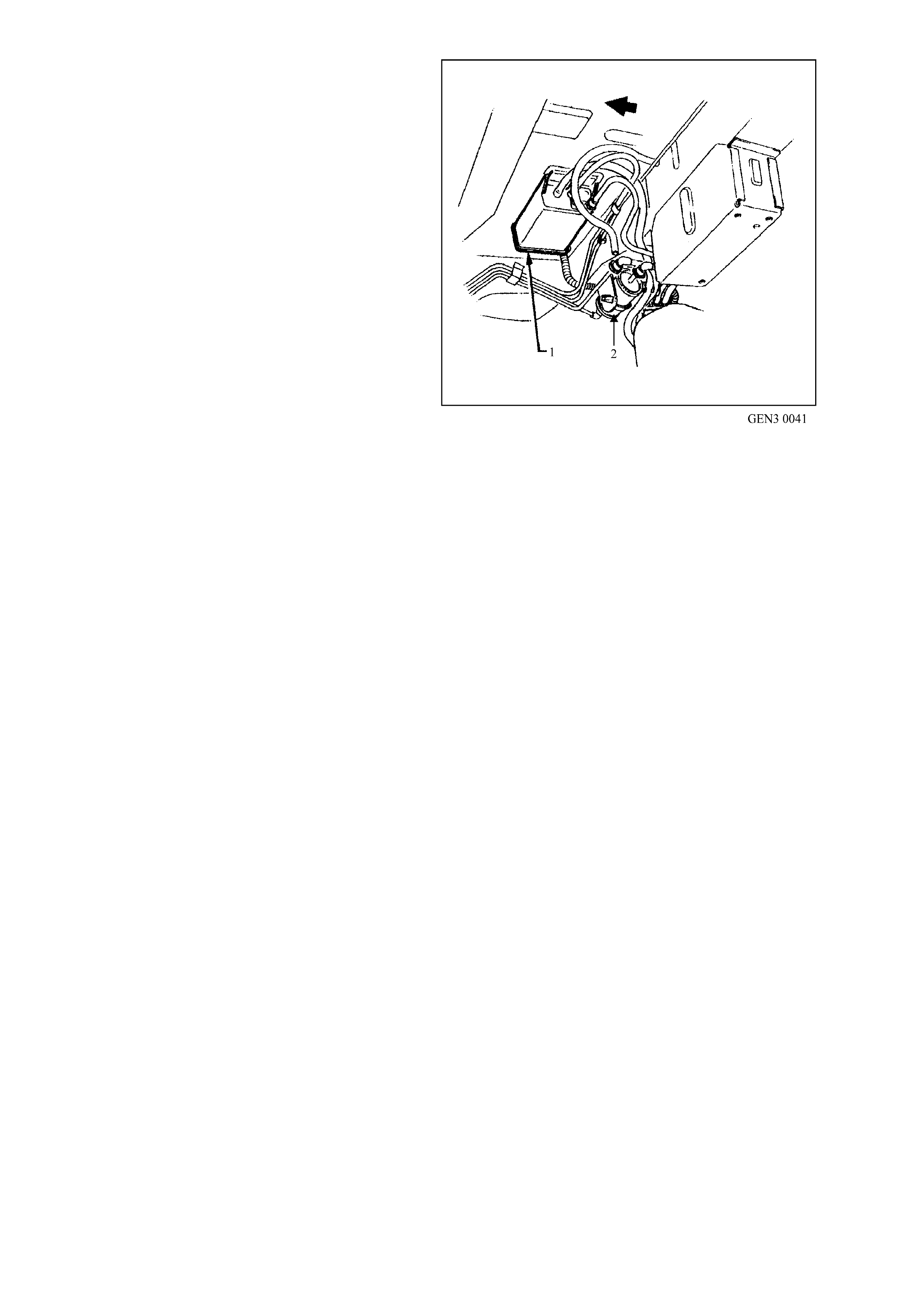
The fuel vapour canister is mounted in a bracket
underneath the vehicle, located by the fuel filter.
This canister is a three port design. Fuel vapour is
absorbed by the char coal within the canister. When
the engine is running at idle speed and above idle,
air is drawn into the canister through the air vent
port (atmospheric port) at the top of the canister
assembly. The air mixes with the fuel vapour and
the mixture is dr awn into the intak e manifold via the
canister purge line.
The upperm ost port on the c anister is controlled by
a PCM controlled canister purge solenoid. The
canister purge solenoid controls the manifold
vacuum signal from the throttle body. The port
below the canister purge port is the vapour inlet
from the fuel tank. The fresh air inlet port (air vent
port) on the canister is open to the atm osphere via
a hose that vents under the vehicle.
RESULTS OF INCORRECT OPERATION
• Poor idle, stalling and poor driveability can be
caused by:
- Inoperative canister purge solenoid
- Damaged canister.
- Hoses split, cracked and/or not connected to
the proper tubes.
- Throttle body and canister hoses
interchanged on the purge solenoid
connections.
NOTE: The canister connection is marked with
CAN.
• Evidence of fuel loss or fuel vapour odour can
be caused by:
- Liquid fuel leaking from fuel lines.
- Cracked or damaged canister.
- Disconnected, incorrectly routed, kinked,
deteriorated or damaged vapour hoses, or
control hoses.
Figure 6C3-1-109 Canister Location
1. Evaporative Canister (Under Vehicle by Fuel Tank)
2. Fuel Filter
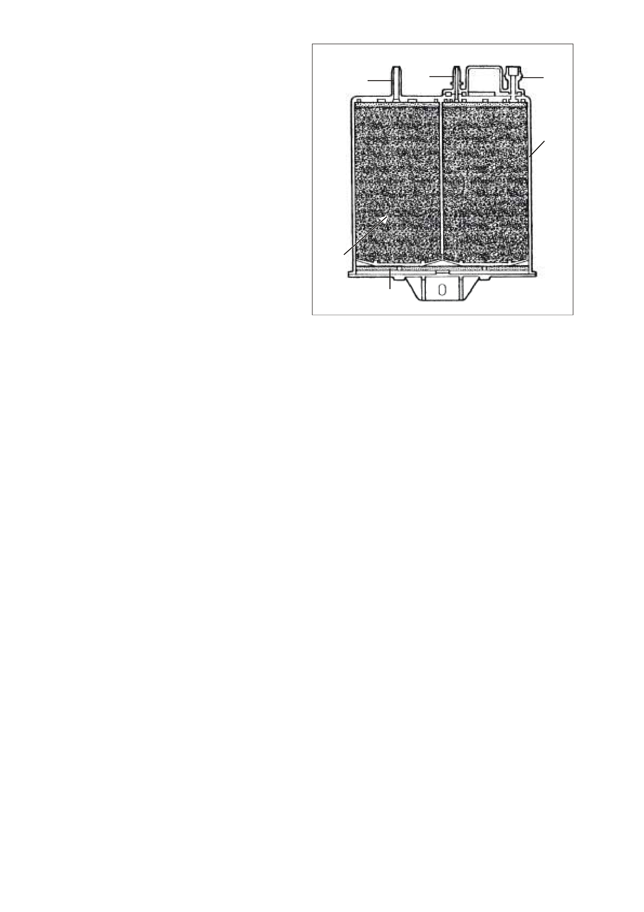
If the solenoid is stuc k open, or the control c ircuit is
shorted to earth, the canister will purge to the
intake manifold all the time. This can allow extra
fuel at idle or during warm-up, which can cause
rough or unstable idle or a rich fuel operation.
If the canister purge solenoid is always closed, the
canister can become over loaded with fuel,
resulting in fuel odour.
A failure in the Evaporative Canister purge
solenoid or Circuit will result in DTC P0443.
GEN 03 0042
123
4
6
5
Figure 6C3-1-110 Sectioned View of Canister
1. Air Vent Port
2. Canister Purge Port
3. Vapour From Fuel Tank Port
4. Evaporative Canister
5. Volume Compensator
6. Charcoal Bed
DTC P0443 EVAP PURGE SOLENOID CONTROL CIRCUIT
Conditions for running DTC P0443
• The engine speed is greater than 400 RPM.
• The ignition voltage is between 6.0 and 16.0 volts.
Conditions for setting DTC P0443
• The PCM detects that the commanded state of the circuit and the actual state of the circuit Dec not match.
• The conditions are present for at least ten seconds.
Action taken when DTC P0443 Sets
• The PCM illuminates the Check Powertrain Lamp when the diagnostic runs and fails.
• The PCM records the operating conditions at the time the diagnostic fails. The PCM stores this information in
the Freeze Frame/Failure Records.
Conditions for clearing the Check Powertrain Lamp and DTC P0443
• The PCM turns the Check Powertrain Lamp OFF after one ignition cycle that the diagnostic runs and does
not fail.
• A last test failed (current DTC) clears when the diagnostic runs and does not fail.
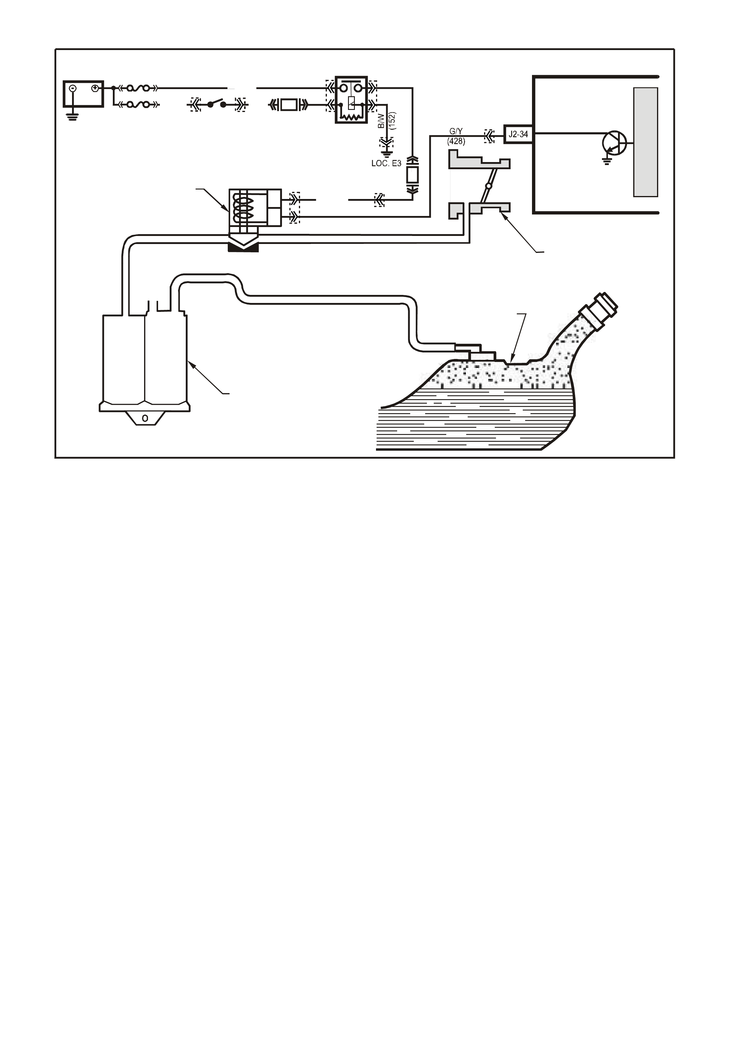
Figure 6C3-1-111 Evaporative Emission Control Schematic
G3PCM026PT
A
B
THROTTLE BODY
CANISTER PURGE
SOL EN OID VALVE
CARBON CANISTER
FUEL TANK
PCM
CANISTER PURGE
M
I
C
R
O
F33
F14
IGN SW
EFI
RELAY
BATTERY
FS
FJ
P (3 ) P/B
(39)
R (2H)
(1040)
P (439)
O/Y
(479)
YE99
YE39YE39
YE114
YB44 YB44 YE123
YE111
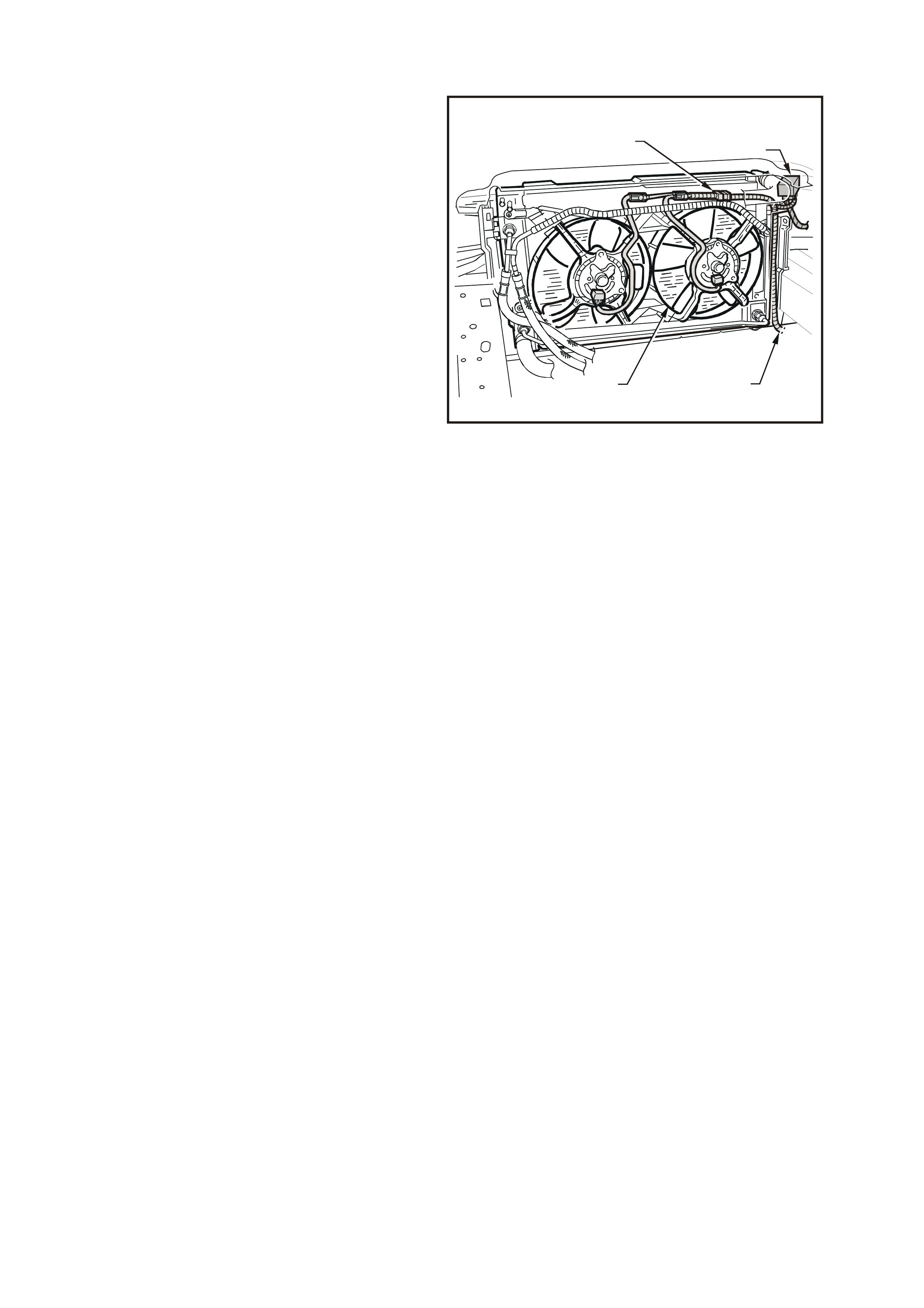
1.9 ELECTRIC COOLING FANS
The PCM determines operation of the two speed
engine cooling fans based on A/C request, A/C
system pressure, engine coolant temperature and
vehicle speed signal inputs. Each engine cooling
fan m otor has four term inals, two negative and two
positive terminals. The two negative terminals are
the relay controlled circuits for the fan operation.
The two positive terminals are the direct power
feed from a f usible link to the fan m otors. When an
earth signal is applied to one of the negative
term inals, the fan m otors will operate at low speed.
When an earth signal is applied to both negative
terminals, both fan will operate at high speed. The
engine cooling fan high s peed relay is controlled by
the PCM. The PCM controls the earth path for the
engine cooling fan high speed relay. Cooling fan
low speed is controlled by the PCM via the PIM
and serial data bus to the BCM.
The BCM controls the earth path for the engine
cooling fan low speed r elay. The engine cooling fan
high speed and the engine cooling fan low speed
relays are used to control the earth signal to the
electric motors that drive the fans. The PCM
determines operation of the two, two speed engine
cooling fans based on A/C request, engine coolant
temperature, A/C Refrigerant Pressure Sensor and
vehicle speed signal inputs.
There are also four (4) suppression capacitors
incorporated into the fan motor wiring circuits.
These suppression capacitors help eliminate fan
motor noise through the radio speakers. If these
capacitors are open, then noise will be present
through the radio speakers. If shorted to earth, the
fan motors could continuously run, or the fuse or
fusible link could fail.
4351
2
3
4
1
Figure 6C3-1-112 Engine Cooling Fan Assembly
1. Engine Cooling Fan Motor Connector
2. Engine Cooling Fusible Link Housing
3. Main W iring Harness
4. Engine Cooling Fan Assembly
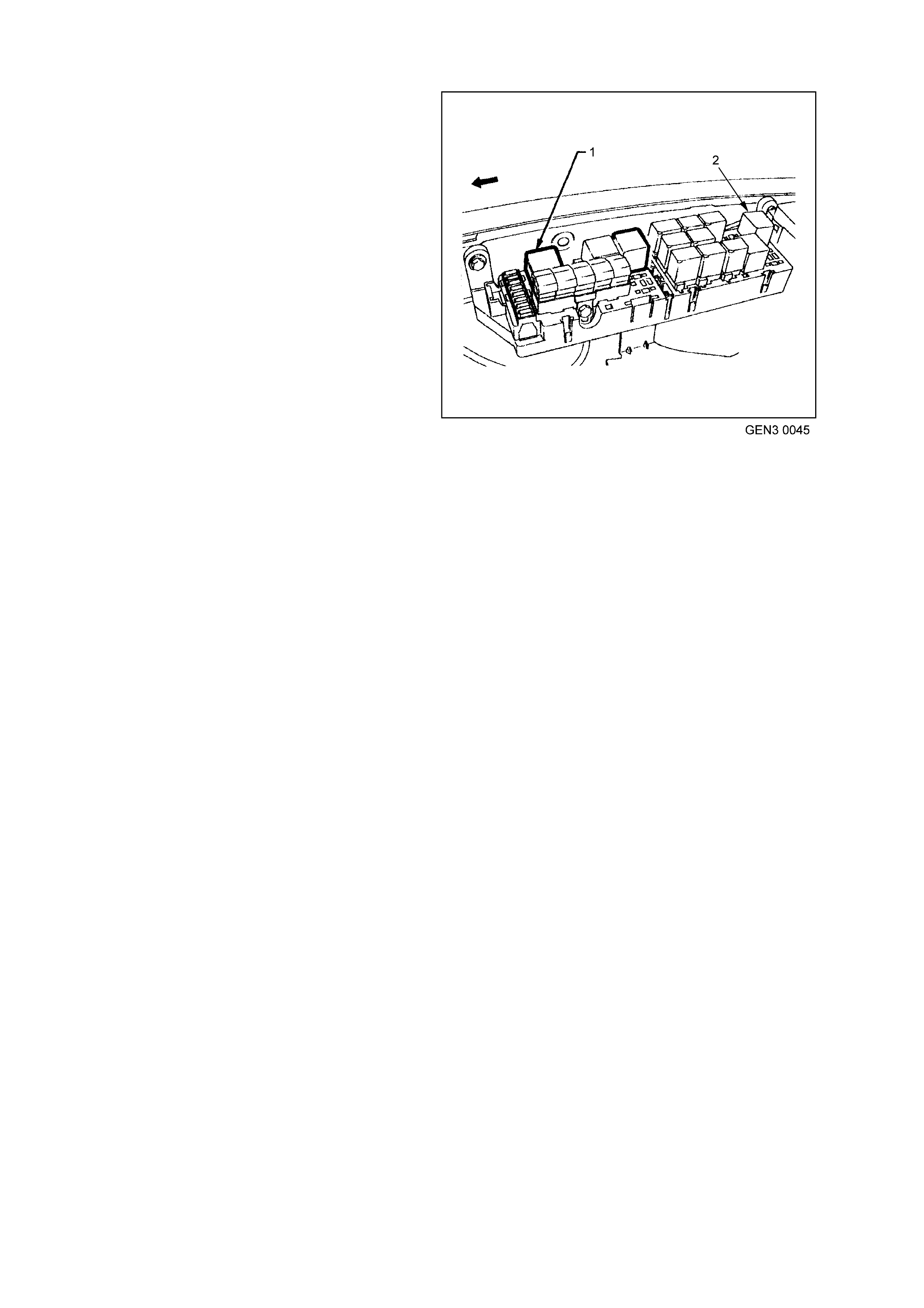
ENGINE COOLING FA N LOW SPEED
The engine cooling fan low speed relay is
energised by the BCM.
The cooling fan low speed relay will be turned ON
when:
• The A/C request indicated (YES) and either:
• the vehicle speed is less than 30 km/h.
or
• A/C pressure is greater than 1500 kPa
or
• The coolant temperature is greater than 98°C.
or
• If the coolant temperature is greater than
113°C, when the ignition is switched off, the
relay is energised for approximately four
minutes, this is known as Low Fan Run On.
or
• If an engine coolant tem perature s ensor f ault is
detected and a DTC such as DTC P0117,
P0118, P01114 or P01115 is set.
The c ooling fan low speed relay will be turned OFF
when any of the following conditions have been
met:
• An A/C request is not indicated (NO) and the
coolant temperature is less than 95°C.
or
• An A/C request is indicated (YES) and the
vehicle speed is greater than 50 km /h and A/C
pressur e is less than 1170 k Pa and the coolant
temperature is less than 98°C.
NOTE: The low speed cooling fan has a minimum,
run on time of 30 seconds.
Figure 6C3-1-113 Engine Fan Low Speed Relay Location
1. Engine Fan Low Speed Relay
2. Engine Fan High Speed Relay

ENGINE COOLING FAN HIGH SPEED
• The engine cooling fan high speed relay is controlled by the PCM. The PCM will only turn ON' the engine
cooling fan high speed relay fan if the engine cooling fan low speed relay has been "ON" for two seconds
and the following conditions are satisfied.
• There is a BCM message response fault which will cause a PIM DTC B2002.
• An engine coolant tem perature sensor fault is detected and a DT C such as DTC P0177, P0188, P01114 or
P01115 is set.
• Coolant temperature greater than 108°C.
• The A/C refrigerant pressure is greater than 2400 kPa.
If the low speed fan was OFF when the criteria was met to turn the high speed fan ON, the high speed fan will
com e O N 5 s ec onds after the low s peed f an is turned O N. If both the engine cooling f an relays are ON, the PCM
will turn OFF the high speed relay when:
• The engine coolant temperature is less than 102°C.
• A/C request not indicated (NO).
• A/C request indicated (YES) and A/C pressure is less than 1900 kPa.
Note: All cooling fans will be turned off if the vehicle speed is greater than 104 kph.
LOW SPEED RESPONSE
The engine cooling fan Low Speed Relay is energised by the BCM. When the PCM determines that the low
speed fan relay should be enabled, the PCM will send a message on the Class II serial data circuit to the PIM.
The PIM will intern convert the PCM Class 2 message to a UART message and supply this UART message to
the BCM. This message will request the BCM to supply the needed earth signal for the Low Speed Relay to
operate. After the BCM provides the earth signal for the Low Speed Relay, the BCM will send a message back
to the PIM conf irm ing that the earth s ignal was c om m anded. A failur e in this res ponse co m m unication will cause
a PIM DTC B2002 to set.
DTC P0481 COOLING FAN HIGH SPEED RELAY CONTROL
Conditions for running DTC P0481
• The engine speed is greater than 600 RPM.
• The ignition voltage is between 6.0 and 16.0 volts.
Conditions for setting DTC P0481
• The PCM detects that the commanded state of the driver and the actual state of the control circuit do not
match.
• The conditions must be present for a minimum of 10 seconds.
Action taken when DTC P0481 Sets
• The PCM illuminates the Check Powertrain Lamp when the diagnostic runs and fails.
• The PCM records the operating conditions at the time the diagnostic fails. The PCM stores this information in
the Freeze Frame/Failure Records.
Conditions for clearing the Check Powertrain Lamp and DTC P0481
• The PCM turns the Check Powertrain Lamp OFF after one ignition cycle that the diagnostic runs and does
not fail.
• A last test failed (current DTC) clears when the diagnostic runs and does not fail.

DTC B2002 LOW SPEED FAN NO BCM RESPONSE
Conditions for running DTC B2002
• The ignition is on.
Conditions for setting DTC B2002
• The PIM sends a Low Speed request signals to the BCM , with no response back from the BCM.
Action taken when DTC B2002 Sets
• The PIM will display the DTC only when current.
• The Check Powertrain Lamp (CPL) will not illuminate.
Conditions for clearing the Check Powertrain Lamp and DTC B2002
• A current DTC will clear when the PIM receives a Low Speed Fan Response from the BCM.

Figure 6C3-1-114 Engine Cooling Fan Circuit
R/B (1221) E2/D2
IGNITION
LOW
SPEED FAN
M
I
C
R
O
P
R
O
C
E
S
S
O
R
BATTERY MAIN POWER
HIGH SERIES
BCM TERMINALS
NOMINATED FIRST
BCM
15a 15 50
30 OFF/ON
LOCK
ACC
IGN
START
G3PCMO42PT
E20/D6
B7/B7
P (3)
IGNITION SWITCH
O/B (473)
87A
30
87
85
86
87
30
85
86
ENGINE
COOLING
FAN 1
ENGINE
COOLING
FAN RELAY
(LOW SPEED)
ENGINE
COOLING
FAN RELAY
(HIGH SPEED)
P/B (39)
O/Y
(250)
F14
R
YB
G
BLU/W (304)
R/B (1049)
HIGH
CURRENT EARTH
B/Y
(155) A1/A5 ELECTRONIC EARTH
B/G
(151)
LOC.
E2 LOC.
E3
B10/B11
B/R (157)
J1-58
GEN III PCM
PIM
J2-33
HIGH
SPEED FAN
BLUE
FUSIBLE
LINK
LOC.
E1
F31
A5/A6
O/B (740)
ENGINE
COOLING
FAN 2
+-
BATTERY
FS
FT FAN 2
FU FAN 1
(1040)
R
(203)
R
(001)
R
(001)
O/B
(208)
O/BLU
(204)
FJ
R
(001)
R
(2H)
6
7
M
I
C
R
O
CLASS 2 SERIAL DATA
UART SERIAL DATA
7V
CLASS 2
SERIAL DA TA
SERIAL
DATA
5V
GY /B (455)
J1-74 Y (41O)
COOLANT TEMP
SENSOR
ETC SENSOR
SIGNAL
A/C
PRESSURE
SIGNAL
5V
4k
348
Ω
Ω
J1-80
SENSOR
EARTH
SENSOR
EARTH
M
I
C
R
O
P
R
O
C
E
S
S
O
R
J2-21
J2-20
V
EHICLE SPEED
SENSOR
BLU/W (831)
T (832)
IC
V/W (415)
J2-57
J2-14
J1-45
G/O (469)
G/B (259)
A
/C PRESSURE
SENSOR
A
C
B
5V
P/B (39)
BLU/Y
(533)
YB176
YE118
YE104
YE43
YB175
YB164
YB175
YB174
YB176
YB165
YB195
YE113
YE65 YE65
YE123
YE122
YE123
YE122
YE122
YE123
YB44
YE119
YE119
YE140
YE139
YB44
YE104
YE118
YB215 YB215
YB163
YB164
YE43

1.10 A/C CLUTCH CONTROL
This vehicle uses two types of A/C clutch controls;
one with standard A/C and the other uses an
Electronic Climate Control (ECC) module.
ECC SYSTEM
With the ECC system, when the A/C is requested
the electronic climate control module will supply a
signal to the BCM. T he BCM will then send a serial
data request to the PCM. W hen the PCM receives
the serial data request on PCM terminal J1-58, it
indicates that air conditioning has been requested
and approximately 1/2 second after the PCM
receives this signal, it will energise the A/C control
relay. This serial data signal to the PCM is also
used to adjus t the idle speed bef ore turning O N the
A/C compressor relay. If this signal is not available
to the PCM, the A/C compressor will be
inoperative.
The BCM also supplies the earth signal from BCM
terminal 7 to the low speed cooling fan relay.
This A/C system also incorporates a A/C
Refrigerant Pressure Sensor. The A/C Refrigerant
Pressure Sensor signal indicates high side
refrigerant pressure to the PCM. The PCM uses
this inf or mation to adj ust the idle air c ontrol valve to
compensate for the higher engine loads present
with high A/C refrigerant pressures. A fault in the
A/C Refrigerant Pressure Sensor signal will cause
DTC P0530 to set.
The PCM will not energise the A/C control relay if
any of the following conditions are present:
• High coolant temperature
• Low A/C system pressure
• High A/C system pressure
• Wide open throttle
• High engine RPM
T26C3004
1
Figure 6C3-1-115 A/C Refrigerant Pressure
Sensor Location
1. A/C Refrigerant Pressure Sensor
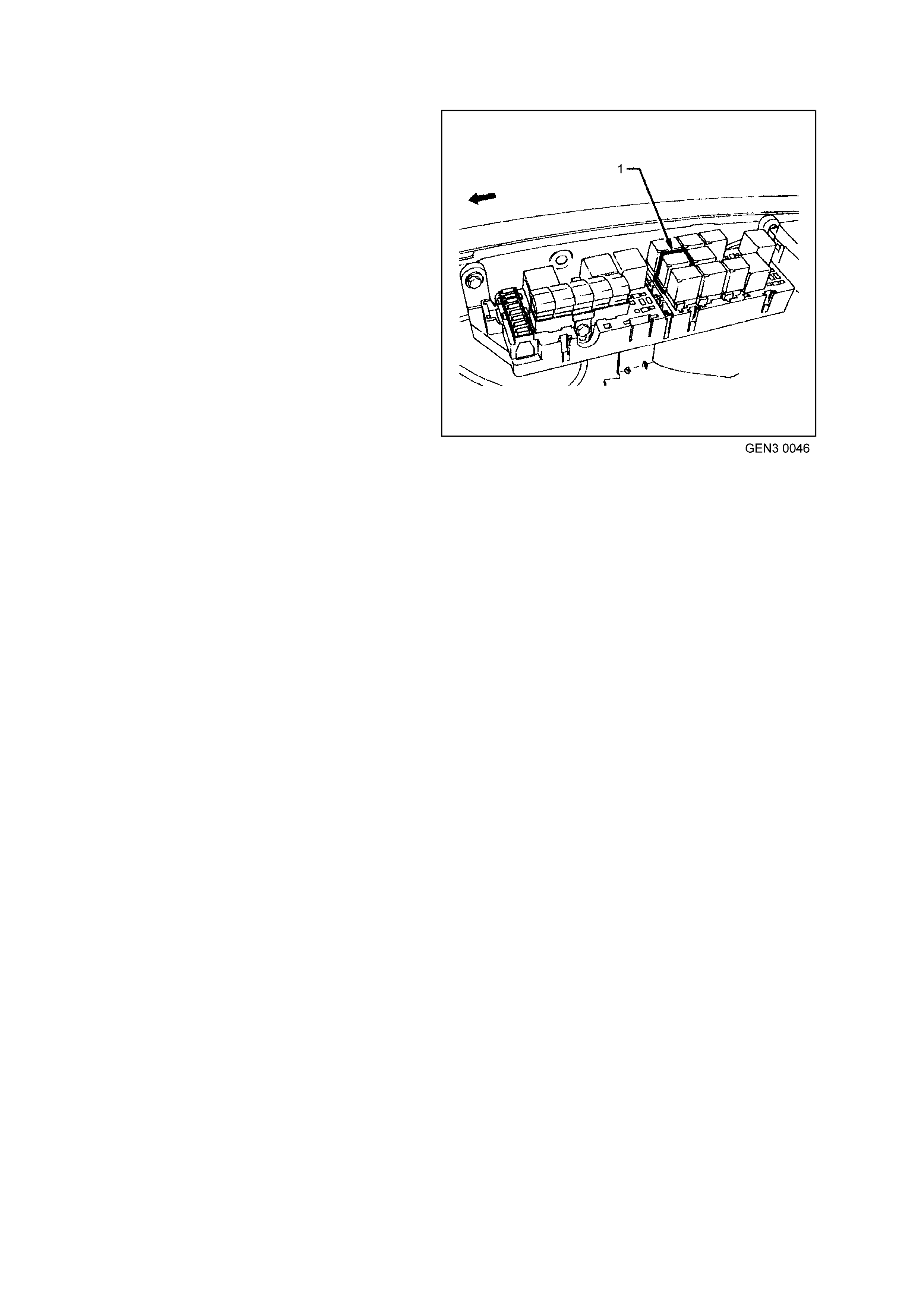
STANDARD A/C SYSTEM
On vehicles equipped with non ECC systems the
power flow is different. With the blower fan
switched ON and the air conditioning switched ON,
switched ignition voltage is supplied from fuse F13
through the A/C master switch and then to the
BCM. The BCM will then supply a ser ial data signal
to the PCM requesting A/C. If the BCM does not
receive a earth signal from the blower switch to
BCM terminal 3, the BCM will not supply the serial
data request for A/C. Once the PCM receives this
serial data signal, the PCM will energise the A/C
com pres sor relay. The BCM also supplies the earth
signal from BCM terminal 7 to the low speed
cooling fan relay.
This serial data signal to the PCM is also used to
adjust the idle speed before turning ON the A/C
compressor relay. If this signal is not available to
the PCM, the A/C compressor will be inoperative.
This system, like on the ECC system also
incorporates a A/C Refrigerant Pressure Sensor.
The A/C Refrigerant Pressure Sensor signal
indicates high side refrigerant pressure to the
PCM. The PCM uses this information to adjust the
idle air control valve to compensate for the higher
engine loads present with high A/C refrigerant
pressures. A fault in the A/C Refrigerant Pressure
Sensor signal will cause DTC P0530 to set.
Figure 6C3-1-116 A/C Relay Location
1. A/C Relay
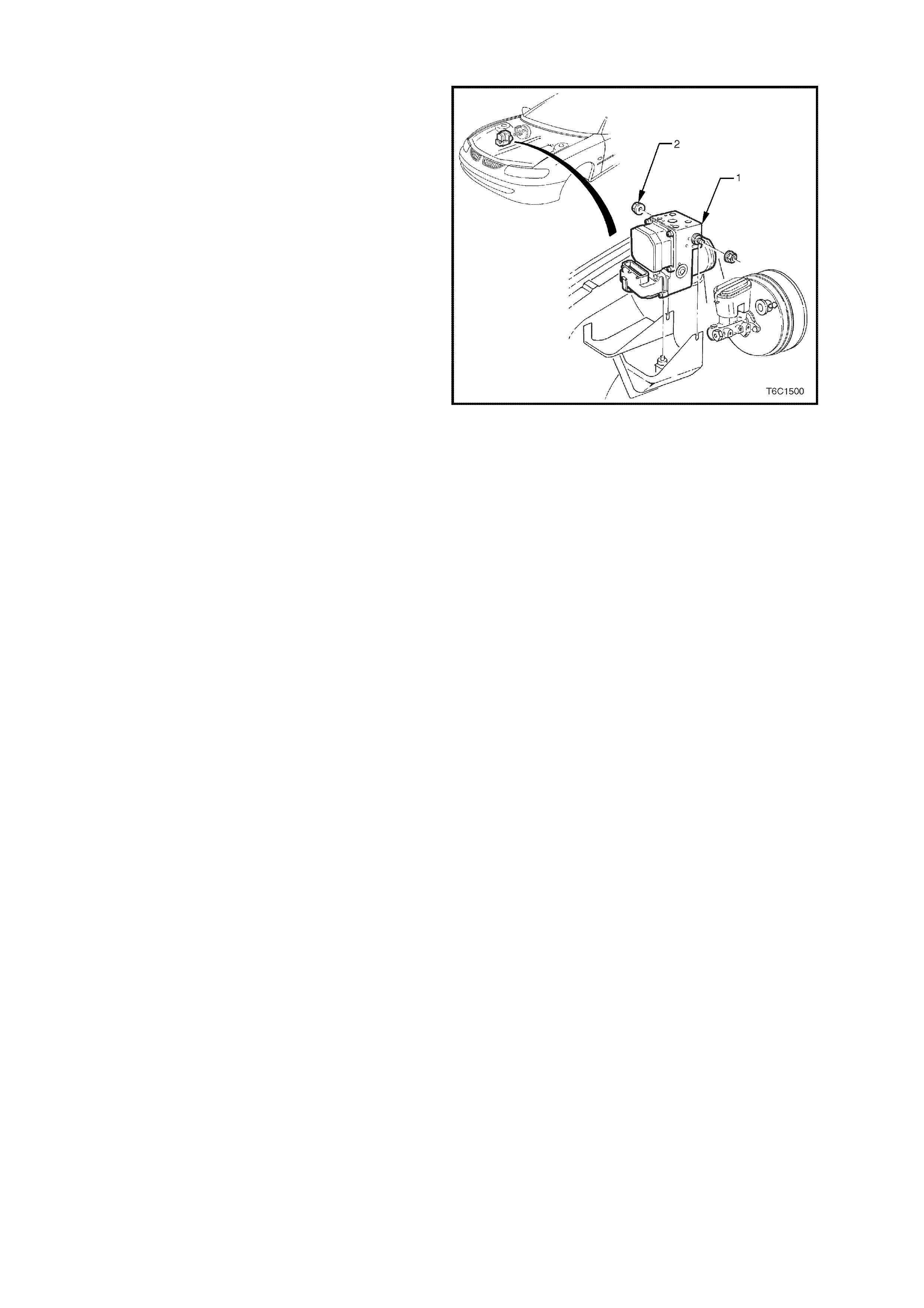
1.11 ELECTRONIC TRACTION CONTROL
When the ABS/ETC control module senses spin
from the drive wheels due to too much engine
torque for the road conditions, it enters the traction
control mode.
The ABS/ETC m odule monitors both front and rear
wheel speeds through the wheel speed sensors. If
at any time during acceleration the ABS/ETC
module detects drive wheel slip, it will request:
• The PCM, via the spark retard circuit, to retard
the amount of spark advance.
• The PCM, to restrict transmission downshifting.
• The throttle relaxer control module to reduce
the engine throttle opening by a certain
percentage to bring engine torque into a
specific range.
The throttle relaxer control module accomplishes
this by commanding the throttle relaxer to override
the accelerator pedal cable and physically reduce
the throttle body butterfly opening by winding the
throttle cable back.
This is achieved via two high speed Pulse Width
Modulated (PWM) circuits between the ABS/ETC
module and the thr ottle relaxer control m odule. T he
ABS/ETC control module sends a message to the
throttle relaxer control module on the requested
throttle position (DKR) circuit. The throttle relaxer
control module then reports the modified throttle
position opening back to the ABS/ETC control
module via the actual throttle position (DKI) circuit.
Simultaneously with engine spark retard and
throttle position intervention, the ABS/ETC control
module will activate the ABS isolation valves, turn
on the ABS pump motor and s upply brake pres s ure
to the over spinning wheel(s).
The isolation valves isolate the front brake
hydraulic circuits from the master cylinder and rear
brake hydraulic circuits. Once the rear brake
hydraulic circuits are isolated, pressure can be
applied to the rear wheels without affecting any
other brake hydraulic circuits. The ASS/ETC
module opens the priming valve, allowing fluid to
be drawn from the master cylinder to the pump
motor, turns on the ABS pump motor to apply
pressure, begins cycling the ABS assembly's inlet
and outlet valves, and closes the switching valve,
ensuring fluid is directed to the wheel not back into
the master cylinder.
The inlet and outlet valve cycling aids in obtaining
maximum road surface traction in the same
manner as the Anti-Lock Brake mode. The
difference between Traction Control and Anti-Lock
Brake mode is that brake fluid pressure is
increased to lessen wheel spin (Traction Control
mode), rather than reduced to allow greater wheel
spin (Anti-Lock Brake mode).
If at any time during Traction Control mode, the
brakes are manually applied, the brake switch
signals the ABS/ETC module to inhibit brake
intervention and allow for manual braking (throttle
reduction and spark retard intervention can still
occur if n ecessary).
Figure 6C3-1-117 ABS/ETC Module Location
1. ABS/ETC Hydraulic Modulator
2. Nut (2 Places) 5.0 - 12.0 N.m
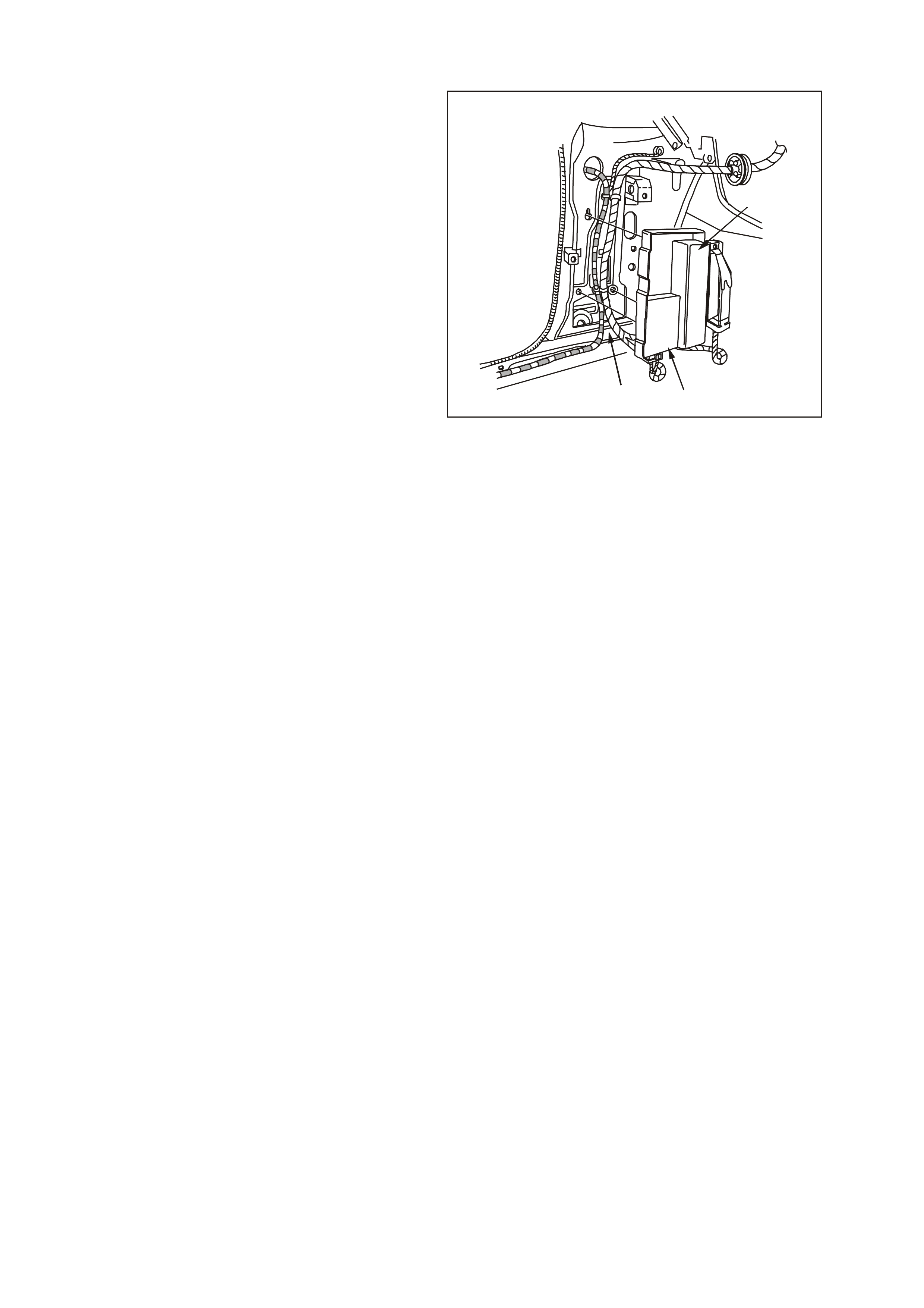
ENGINE SPARK AND THROTTLE POSITION INTERVENTION
Simultaneously to brake intervention, the ABS/ETC
control module communicates with the Powertrain
Control Module (PCM) and the throttle relaxer
control module requesting the PCM to retard the
spark advance and for the throttle relaxer control
module to reduce the throttle opening.
With the engine running, the PCM continually
supplies and m onitors a 12 volt pull- up to the s park
retard circuit. The ABS/ETC control module
requests spark retard by pulling this voltage low.
The PCM then responds by reducing the spark
advance of the engine and restricting transmission
downshifting.
The ABS/ETC control module constantly sends a
Pulse Width Modulated (PWM) signal at 90% with
a frequenc y of IOO HZ to the throttle relaxer control
module on the requested throttle position line
(DKR). This signal is to indicate to the throttle
relaxer control module that the traction control
system (ETC) is in a state of readiness.
With the engine idling, the ABS/ETC control
module constantly sends a Pulse W idth Modulated
(PWM) signal with a duty cycle of 90% to the
throttle relaxer control module via the requested
throttle position line (DKR). The throttle relaxer
control module responds on the actual throttle
position line (DKI) with a PWM signal with a duty
cycle of 9%.
When the ABS/ETC control module determines
that a reduction in throttle is required, it reduces
the PWM signal on the requested throttle position
line (DKR), from 90% (no throttle reduction) to as
low as approximately 14% (maximum throttle
reduction). The throttle relaxer control module then
drives the throttle relaxer motor, overriding the
accelerator pedal command (drivers foot), pulling
the throttle cable back, and thus, closing the
amount of throttle opening.
If there is a malfunction between the ABS/ETC
module and the PCM, an ABS/ET C DTC will set. If
there is a malfunction between the ABS/ETC
module and the throttle relaxer control module,
refer to Section 12L ABS & ABS/ETC in VX
Service Information.
For further description on the Anti-Lock Brake
(ABS) system, Electronic Traction Control (ETC)
system Throttle Relaxer Control Module
operation and DTC diagnosis, refer to
Section 12L ABS & ABS/ETC in VX Service
Information.
GE N 3 0006
1
32
Figure 6C3-1-118 Throttle Relaxer Control Module
1. Throttle Relaxer Control Module
2. Powertrain Interface Module
3. Left Front Kick Panel
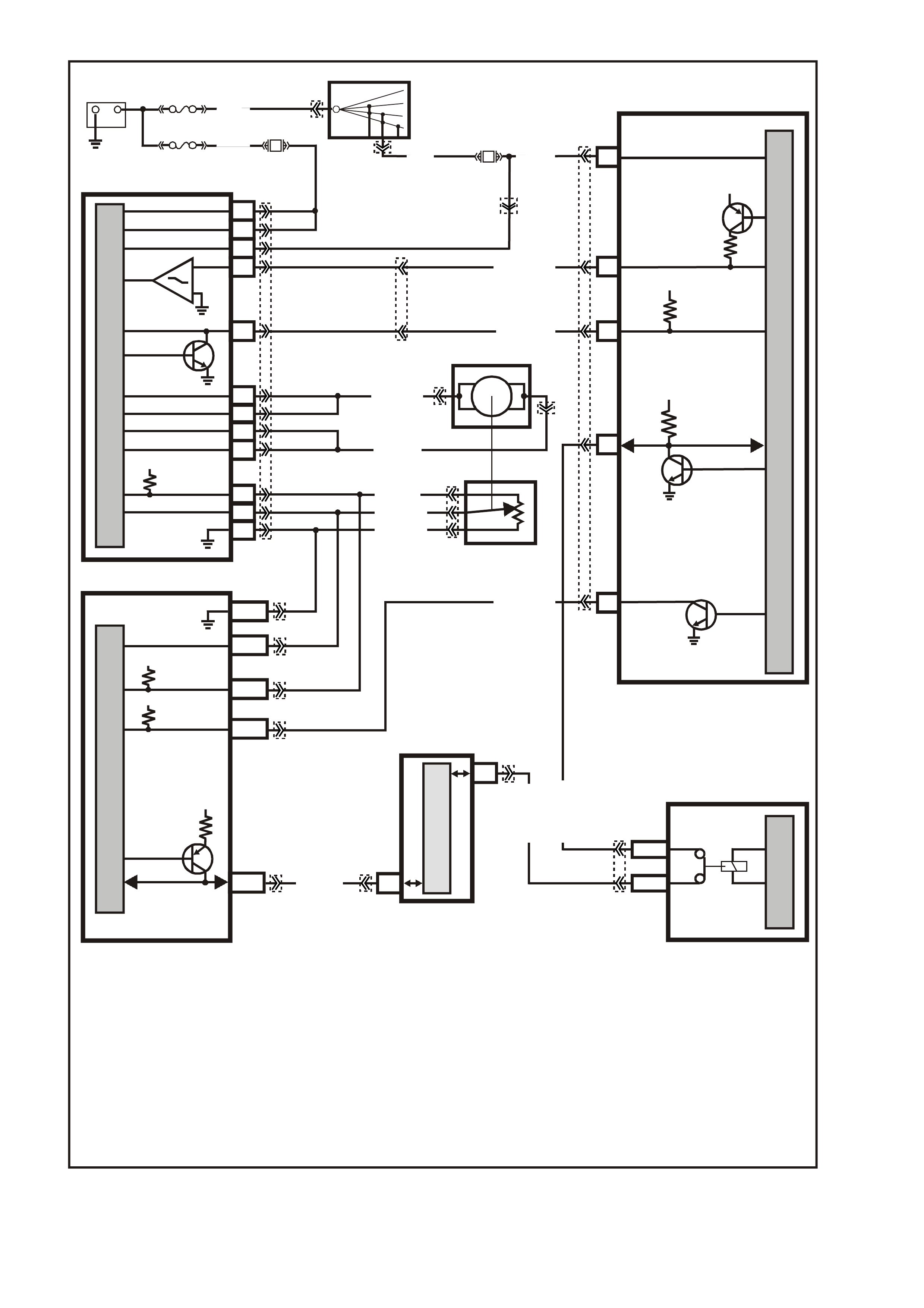
Figure 6C3-1-119 Throttle Relaxer and ABS/ECT Circuits
G3PCM035PT
HIGH SERIES
BCM TE RMIN ALS
NOMINATED FIRST
12V
12V
27
E2/D2
E9/D3
13
REQU ESTED
THROTTL E (DKR)
ACTUAL
THROTTL E (DKI)
O/W (1426)
B/W (1427)
M
I
C
R
O
P
R
O
C
E
S
S
O
R
MAIN POWER
15
ABS/ETC
CONTROL MODULE
BCM
37
35
M
I
C
R
O
DKR
IGNITION
BATTERY
BATTERY
DKI
MOTO R +
MOTO R +
MOTO R -
MOTO R -
Y (1049)
M
I
C
R
O
5V
41
22
A
C
B
40
49
43
26
53
5 VOLT REF.
TPS SIGNAL
TPS GROUND
THROTTLE
POSITION SENSOR
THROTTLE
RELAXER
5V
12V
J1-08
J2-53
5 VOLT REF.
SPARK RETARD
TPS SIGNAL
TPS GROUND
J2-24
J1-60
J1-58
CLASS 2
SERIAL DA TA
7V
M
I
C
R
O
PIM
6
7
M
I
C
R
O
CLASS 2 SERIAL DATA
UART SERIAL DATA
11
SERIAL
DATA
5V
28
SPARK
RETARD
GY (416)
R/B (466)
R/W (456) AB
BLU (417)
B/Y (452)
R/B (1221)
+-
BATTERY
FJ
LOC.
E1 FS
IGNITION
SWITCH
15a 15 50
30
OFF/ON
LOCK
ACC
IGN
START
F27
F36
P (3)
R (8 55)
1
24
51
TH R OTTLE R ELAX ER
CONTROL MODULE
R (2 H)
(1040)
R/Y
(480)
GY/B (1687)
G/W (1220)
PCM
YB44
YB44
YE127
YE127
YE30
YE98
YB215
YB215YE122
YE123
YE122
YE122
YB170
YE123
YB175
YB164
YE110
YE129
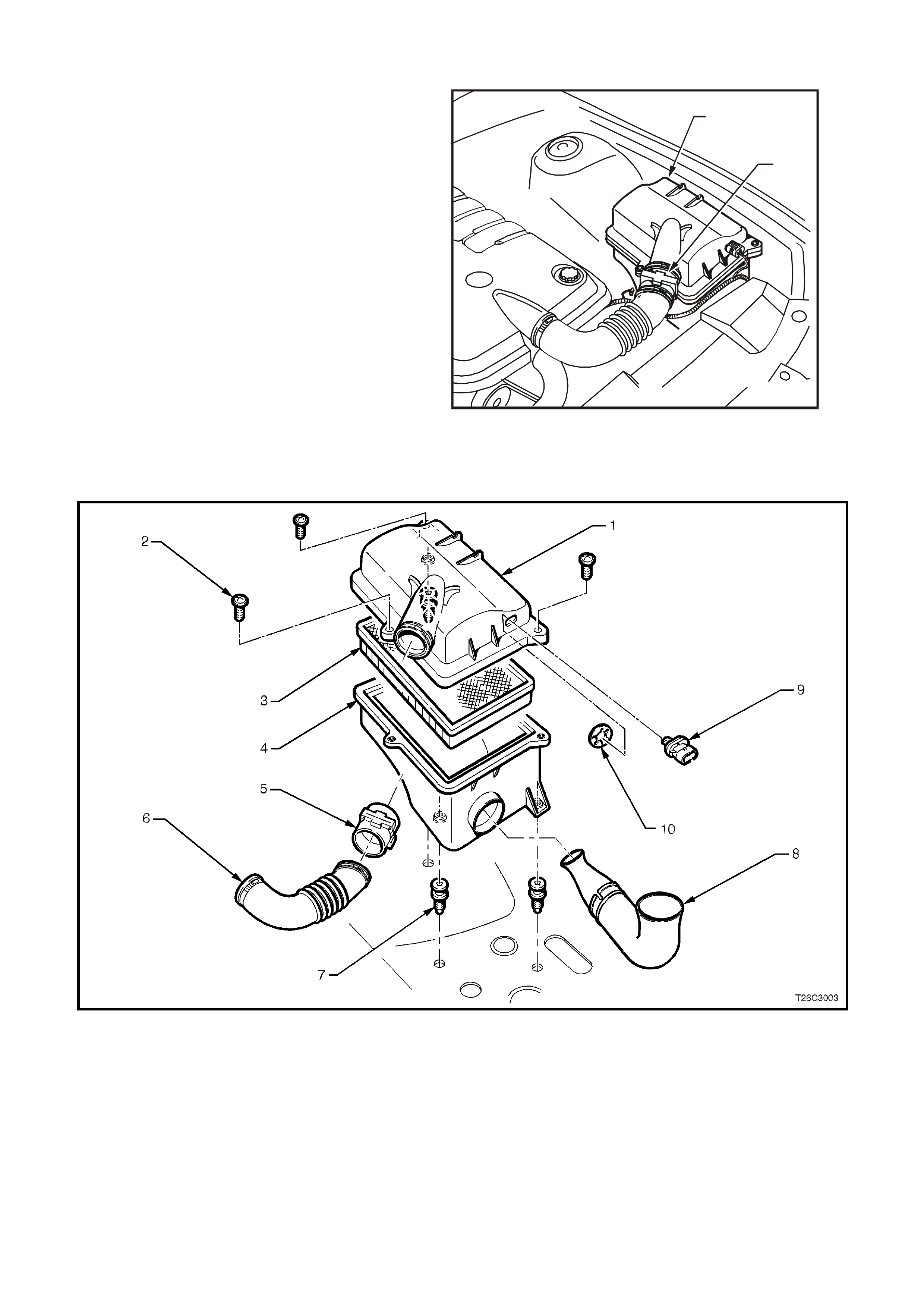
1.12 AIR INTAKE SYSTEM
The air intak e s ystem draws outs ide air through the
front of the air cleaner assembly and filter element
of the forward mounted air cleaner. The air is then
routed through the MAF s ensor and into the throttle
body to the intak e m anif old. T he air is then directed
into the intake manifold runners, through the
cylinder heads and into the cylinders.
If the Mass Air Flow (MAF) Sensor is installed
backwards, the system will run rich. An arrow
marked on the plastic portion of the sensor
indicates correct air flow direction. The arrow must
point toward the engine.
T26C3002
2
1
Figure 6C3-1-120 Air Cleaner Location
1. Air Cleaner Housing
2. Mass Air Flow (MAF) Sensor
Figure 6C3-1-121 Air Cleaner Housing Assembly
1. Air Cleaner Housing Upper Body
2. Air Cleaner Housing Top Cover Retaining Screws (3)
3. Air Cleaner Filter
4. Air Cleaner Housing Lower Body
5. Mass Air Flow (MAF) Sensor
6. Air Intake to Throttle Body
7. Air Cleaner Housing Retaining Screws (3)
8. Air Inlet to Air Cleaner Housing Duct
9. Intake Air Temperature (IAT) Sensor
10. Intake Air Temperature (IAT) Sensor Clip
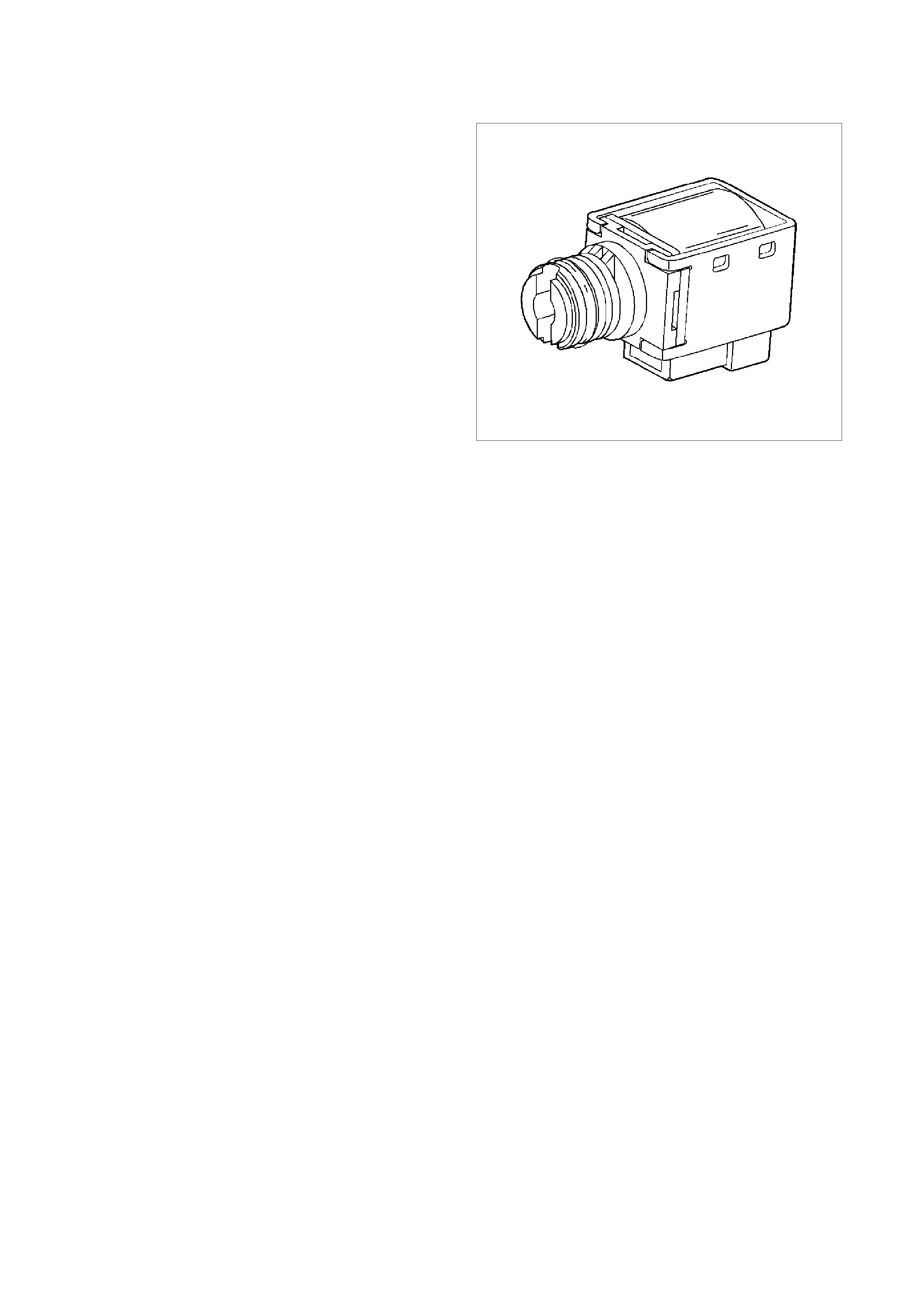
1.13 AUTOMATIC TRANSMISSION SENSORS & SIGNALS
1-2 (A) AND 2-3 (B) SHIFT SOLENOID VALVES
IMPORTANT:
The shift solenoid valve resistance should measure
19-24 ohm s minim um when m easured at 20°C (68°F ).
The shift solenoid current flow should not exceed 0.75
amps. The shift solenoid should energise at a voltage
of 7.5 volts or more (measured across the terminals).
The shift solenoid should de-energise when the
voltage is one volt or less.
If both solenoids lose power, only third gear engages.
The 1-2 and 2-3 shift solenoid valves (also called A
and B solenoids) are identical devices that control the
mo vement of the 1-2 and 2- 3 shift valves (the 3-4 shift
valve is not directly controlled by a shif t solenoid). The
solenoids are normally open exhaust valves that work
in four combinations to shift the transmission into
different gears.
The PCM energises each solenoid by grounding the
solenoid through an internal quad driver. This sends
current through the coil winding in the solenoid and
moves the internal plunger out of the exhaus t position.
When ON, the solenoid redirects fluid to move a shift
valve.
IMPORTANT:
The manual valve can hydraulically override the shift
solenoids. Only in D4 do the shift solenoid states
totally determine what gear the transmission is in. In
the other manual valve positions, the transmission
shifts hydraulically and the shift solenoid states
CATCH UP when the throttle position and the vehicle
speed fall into the correct ranges. Diagnostic trouble
codes P0751, P0753, P0756 and P0758 indicate shift
solenoid performance and circuit voltage faults.
The PCM-controlled shift solenoids eliminate the need
for throttle valve and governor pressures to control
shift valve operation.
8885
Figure 6C3-1-122 A&B Shift Solenoid
DTC P0751 1-2 SHIFT SOLENOID VALVE PERFORMANCE
Conditions for running DTC P0751
• No Throttle Position DTCs P0122 or P0123.
• No VSS assembly DTCs P0502 or P0503.
• No TCC solenoid valve DTC P0740.
• No TCC stuck ON DTC P0742.
• No 1-2 SS valve DTC P0753.
• No 2-3 SS valve DTC P0758.
• No 3-2 SS valve assembly DTC P0785.
• No TFP manual valve position switch DTC P1810.
• No TCC PWM solenoid valve DTC P1860.
• The engine speed is greater than 300 RPM for 5 seconds.
• The engine is not in fuel cutoff.
• The gear range is D.
• The Throttle Position angle is 10-35%.
• The Throttle Position angle is constant +/- 5%.
• The PCM commands a 1-2, 2-3, and 3-4 shift.
• The TCC is commanded ON.
• The vehicle speed is greater than 8 km/h.
• The transmission fluid temperature is 20-130°C.

Conditions for setting DTC P0751
• DTC P0751 sets if the following conditions occur three times:
- Within 2 seconds, the engine speed in 2nd gear is 80 RPM greater than the last speed in 1st gear.
- Within 2 seconds, the engine speed in 3rd gear is 50 RPM less than the last speed in 2nd gear.
- Within 2 seconds, the engine speed in 4th gear is 10 RPM greater than the last speed in 3rd gear.
• All of the above conditions are met and one of the following conditions occurs:
Condition 1
- The speed ratio is 0.95 to 1.2 (speed ratio is engine speed divided by transmission output speed).
- The TCC slip speed is 200-1000 RPM for 4 seconds.
Condition 2
- The speed ratio is 0.65 to 0.8.
- The TCC slip speed is -20 to +40 RPM for 4 seconds.
Action taken when DTC P0751 Sets
• The PCM illuminates the check powertrain lamp (CPL).
• The PCM commands D2 line pressure.
• The PCM inhibits 3-2 downshifts if the vehicle speed is greater than 48 km/h.
• The PCM freezes shift adapts from being updated.
• The PCM records the operating conditions at the time the diagnostic fails. The PCM stores this information in
the Freeze Frame/Failure Records.
Conditions for clearing the Check Powertrain Lamp and DTC P0751
• The PCM turns OFF the Check Powertrain Check Powertrain Lamp (CPL) during the first consecutive trip in
which the diagnostic test runs and passes.
• The PCM cancels the DTC default actions when the fault no longer exists and the ignition switch is OFF long
enough in order to power down the PCM.
• A last test failed (current DTC) clears when the diagnostic runs and does not fail.
DTC P0753 1-2 SHIFT SOLENOID CIRCUIT ELECTRICAL
Conditions for running DTC P0753
• The system voltage is between 8.0 and 18 volts.
• The engine speed is greater than 300 RPM for 5 seconds.
• The engine is not in fuel cutoff.
Conditions for setting DTC P0753
• The PCM commands the solenoid ON and the voltage input remains high (12 volts).
Or
• The PCM commands the solenoid OFF and the voltage input remains low (0 volts).
Action taken when DTC P0753 Sets
• The PCM illuminates the Check Powertrain Lamp when the diagnostic runs and fails.
• The PCM commands D2 line pressure.
• The PCM inhibits 3-2 downshift if the vehicle speed is greater than 48 km/h.
• The PCM freezes shift adapts from being updated.
• The PCM records the operating conditions at the time the diagnostic fails. The PCM stores this information in
the Freeze Frame/Failure Records.
Conditions for clearing the Check Powertrain Lamp and DTC P0753
• The PCM turns the Check Powertrain Lamp OFF during the first ignition cycle that the diagnostic runs and
does not fail.
• A last test failed (current DTC) clears when the diagnostic runs and does not fail.

DTC P0756 2-3 SHIFT SOLENOID VALVE PERFORMANCE
Conditions for running DTC P0756
• No Throttle Position DTCs P0122 or P0123.
• No VSS assembly DTCs P0502 or P0503.
• No TCC solenoid valve DTC P0740.
• No TCC stuck ON DTC P0742.
• No 1-2 SS valve DTC P0753.
• No 2-3 SS valve DTC P0758.
• No 3-2 SS valve assembly DTC P0785.
• No TFP manual valve position switch DTC P1810.
• No TCC PWM solenoid valve DTC P1860.
• The vehicle speed is greater than 8 km/h.
• The gear range is D4.
• The engine vacuum is 0-105 kPa.
• The engine torque is 0-542 N.m.
• The Throttle Position angle is 10-50%.
• The Throttle Position angle is constant +/- 7%.
• The PCM commands a 1-2, 2-3, and 3-4 shift.
• The engine speed is greater than 300 RPM for 5 seconds.
• The engine is not in fuel cutoff.
• The transmission fluid temperature is 20-130°C.
Conditions for setting DTC P0756
• DTC P0756 sets if the following conditions occur three times:
- Third gear is commanded for 2 to 6 seconds.
- The speed ratio, in 3rd gear, does not dr op more than 0.3 f rom the last speed ratio, in 2nd gear , (speed ratio
is engine speed divided by transmission output speed).
- The TCC slip speed, in 3rd gear, remains 400 RPM higher than the last TCC slip speed, in 2nd gear.
• All of the above conditions are met for 1.5 seconds and one of the following conditions occurs:
Condition 1
- First gear is commanded for 1.5 seconds.
- The TP angle is greater than 25%.
- The transmission output speed is 400-1500 RPM.
- The speed ratio is 0.7 to 3.0.
- The TCC slip speed is -2000 to 0 RPM for 1.5 seconds.
Condition 2
- Fourth gear is commanded for 1.5 seconds.
- The transmission output speed is 1000-3000 RPM.
- The speed ratio is 1.68 to 3.0.
- The TCC slip speed is 1000 to 3000 RPM for 1 second.
Action taken when DTC P0756 Sets
• The PCM illuminates the check powertrain lamp (CPL).
• The PCM commands 3rd gear only.
• The PCM inhibits TCC engagement.
• The PCM commands maximum line pressure.
• The PCM freezes shift adapts from being updated.
• The PCM records the operating conditions at the time the diagnostic fails. The PCM stores this information in
the Freeze Frame/Failure Records.
Conditions for clearing the Check Powertrain Lamp and DTC P0756
• The PCM turns OFF the Check Powertrain Check Powertrain Lamp (CPL) during the first consecutive trip in
which the diagnostic test runs and passes.
• The PCM cancels the DTC default actions when the fault no longer exists and the ignition switch is OFF long
enough in order to power down the PCM.
• A last test failed (current DTC) clears when the diagnostic runs and does not fail.
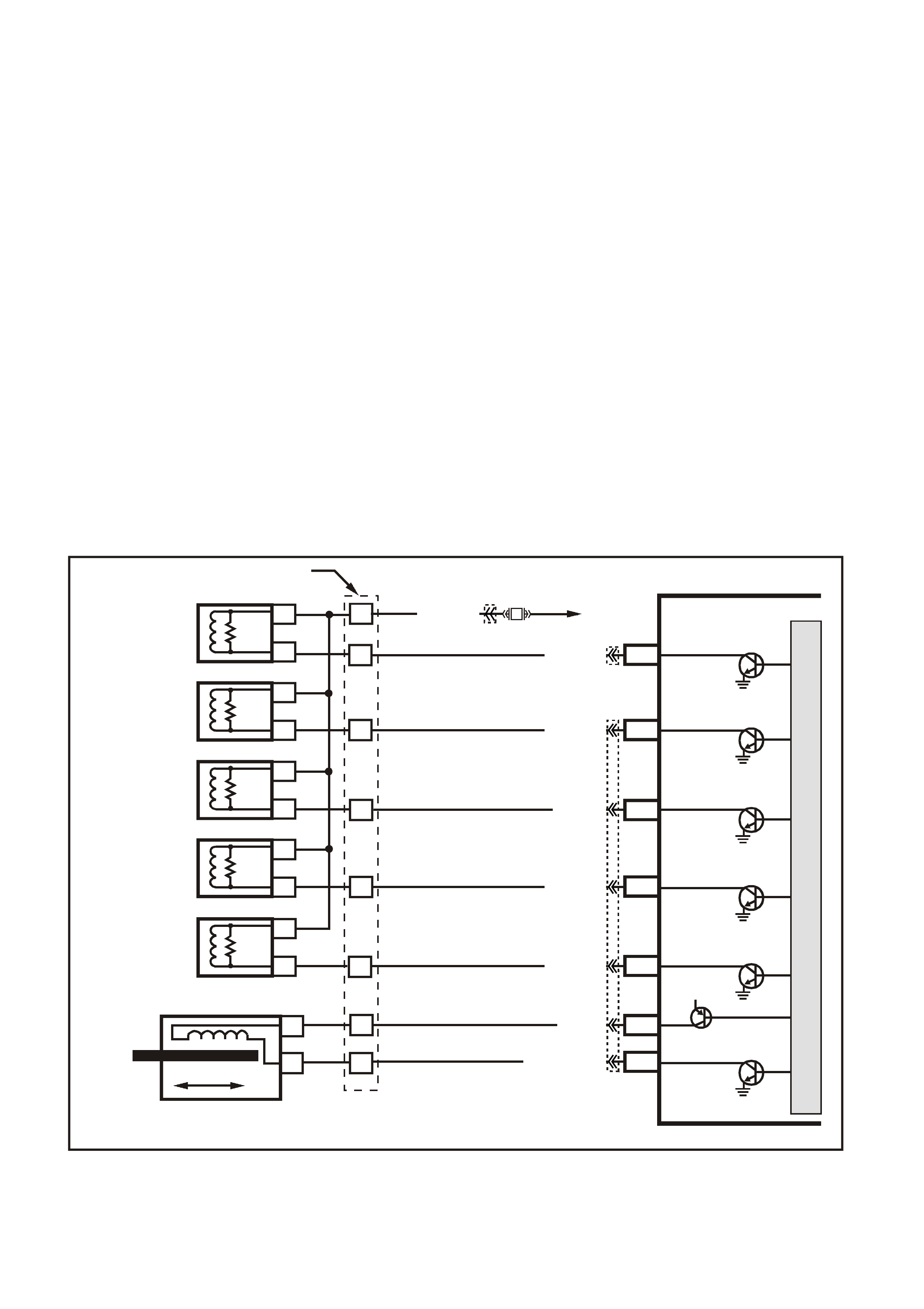
DTC P0758 2-3 SHIFT SOLENOID CIRCUIT ELECTRICAL
Conditions for running DTC P0758
• The system voltage is between 8.0 and 18 volts.
• The engine speed is greater than 300 RPM for 5 seconds.
• The engine is not in fuel cutoff.
Conditions for setting DTC P0758
• The PCM commands the solenoid ON and the voltage input remains high (12 volts).
Or
• The PCM commands the solenoid OFF and the voltage input remains low (0 volts).
Action taken when DTC P0758 Sets
• The PCM illuminates the Check Powertrain Lamp when the diagnostic runs and fails.
• The PCM commands 3rd gear only.
• The PCM commands maximum line pressure.
• The PCM inhibits TCC engagement.
• The PCM freezes shift adapts from being updated.
• The PCM records the operating conditions at the time the diagnostic fails. The PCM stores this information in
the Freeze Frame/Failure Records.
Conditions for clearing the Check Powertrain Lamp and DTC P0758
• The PCM turns the Check Powertrain Lamp OFF during the first ignition cycle that the diagnostic runs and
does not fail.
• A last test failed (current DTC) clears when the diagnostic runs and does not fail.
Figure 6C3-1-123 Transmission Solenoid Electrical Circuits
4356
PCM
J2-47
J2-48
J1-79
J2-42
J2-04
J2-08
J2-06
TCC PWM
SOLENOID
3-2 CONTROL
SOLENOID
1-2 SHIFT
SOLENOID A
2-3 SHIFT
SOLENOID B
PRESSURE
CONTROL
SOLENOID
LOW
PRESSURE CONTROL
SOLENOID HIGH
B
A
A
B
B
B
A
A
B
A
YB 129 T RANSMIS SION
PASS-THRU CONNECTOR
TORQUE
CONVERTER
CLUTCH (TCC)
(PWM)
SOLENOID
TORQUE
CONVERTER
CLUTCH (TCC)
ENABLE
SOLENOID
3-2 DOWNSHIFT
CONTROL
SOLENOID
1-2 SHIFT
SOLENOID A
2-3 SHIFT
SOLENOID B
PRESSURE
CONTROL
SOLENOID
C
D
U
S
T
E
A
B
P/BLU (339)
TCC ENABLE
SOLENOID
B
A
EFI
RELAY
F32
G/W (897)
YE122
YE123
LG (1222)
Y/B (1223)
GY/BLU (1229)
R (1228)
12V
M
I
C
R
O
P
R
O
C
E
S
S
O
R
BR (418)
GY/R (422)
YE110
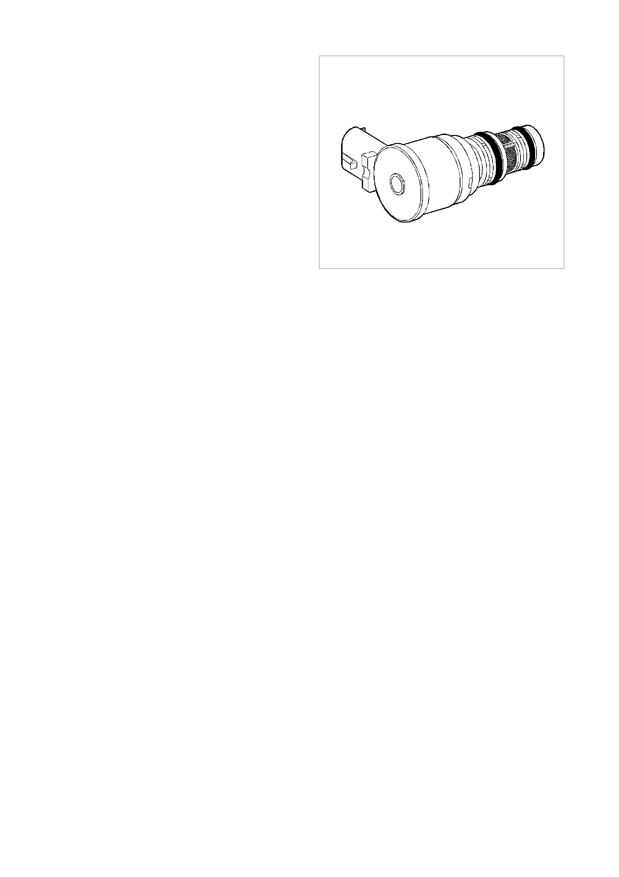
3-2 SHIFT SOLENOID VALVE ASSEMBLY
IMPORTANT:
The 3-2 shift solenoid valve assembly resistance
should be a minimum of 20-24 ohms at 20°C (68°F).
The 3-2 shift solenoid valve assembly is an ON/OFF
solenoid that is used in order to improve the 3-2
downshift. T he s olenoid regulates the release of the 3-
4 clutch and the 2-4 band apply.
If a voltage fault is detected in the 3-2 shift solenoid
circuit, diagnostic trouble code P0785 will set.
325350
Figure 6C3-1-124 3-2 Shift Solenoid
DTC P0785 3-2 SHIFT SOLENOID CIRCUIT ELECTRICAL
Conditions for running DTC P0758
• The system voltage is between 8.0 and 18 volts.
• The engine speed is greater than 300 RPM for 5 seconds.
• The engine is not in fuel cutoff.
Conditions for setting DTC P0758
• The PCM commands the solenoid ON and the voltage input remains high (12 volts).
Or
• The PCM commands the solenoid OFF and the voltage input remains low (0 volts).
Action taken when DTC P0758 Sets
• The PCM illuminates the Check Powertrain Lamp when the diagnostic runs and fails.
• The PCM commands a soft landing to 3rd gear.
• The PCMM commands maximum line pressure.
• The PCM inhibits TCC engagement.
• The PCM inhibit 4th gear if the transmissions in hot mode.
• The PCM freezes shift adapts from being updated.
• The PCM records the operating conditions at the time the diagnostic fails. The PCM stores this information in
the Freeze Frame/Failure Records.
Conditions for clearing the Check Powertrain Lamp and DTC P0758
• The PCM turns the Check Powertrain Lamp OFF during the first ignition cycle that the diagnostic runs and
does not fail.
• A last test failed (current DTC) clears when the diagnostic runs and does not fail.

Figure 6C3-1-125 Transmission Solenoid Electrical Circuits
4356
PCM
J2-47
J2-48
J1-79
J2-42
J2-04
J2-08
J2-06
TCC PWM
SOLENOID
3-2 CONTROL
SOLENOID
1-2 SHIFT
SOLENOID A
2-3 SHIFT
SOLENOID B
PRESSURE
CONTROL
SOLENOID
LOW
PRESSURE CONTROL
SOLENOID HIGH
B
A
A
B
B
B
A
A
B
A
YB 129 T RANSMIS SION
PASS-THRU CONNECTOR
TORQUE
CONVERTER
CLUTCH (TCC)
(PWM)
SOLENOID
TORQUE
CONVERTER
CLUTCH (TCC)
ENABLE
SOLENOID
3-2 DOWNSHIFT
CONTROL
SOLENOID
1-2 SHIFT
SOLENOID A
2-3 SHIFT
SOLENOID B
PRESSURE
CONTROL
SOLENOID
C
D
U
S
T
E
A
B
P/BLU (339)
TCC ENABLE
SOLENOID
B
A
EFI
RELAY
F32
G/W (897)
YE122
YE123
LG (1222)
Y/B (1223)
GY/BLU (1229)
R (1228)
12V
M
I
C
R
O
P
R
O
C
E
S
S
O
R
BR (418)
GY/R (422)
YE110
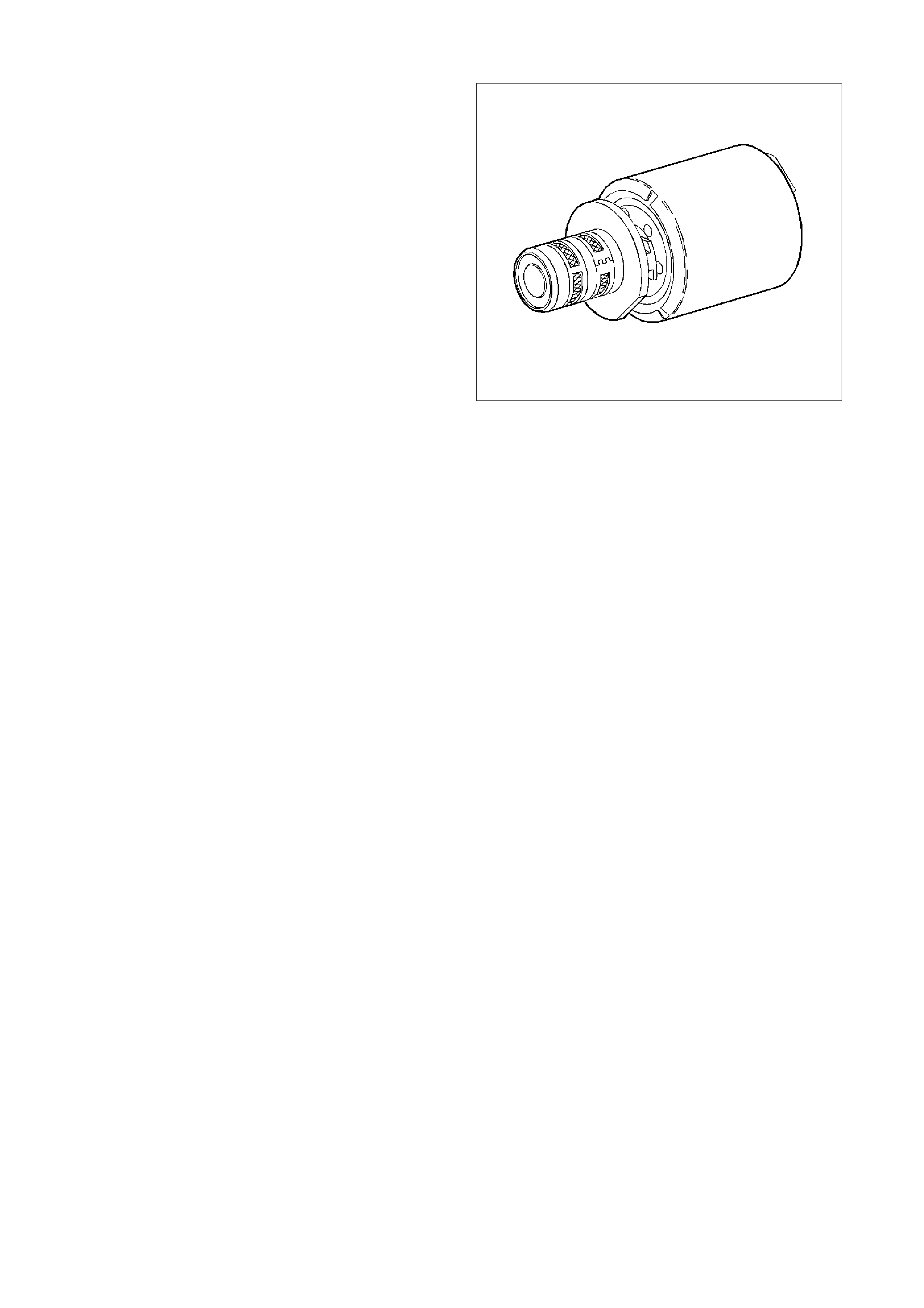
TRANSMISSION PRESSURE CONTROL SOLENOID
IMPORTANT:
Transmission pressure control solenoid resistance
should measure 3-5 ohms when measured at 20°C
(68°F).
The transmission pressure control solenoid is an
electronic pressure regulator that controls pressure
based on the current flow through its coil winding. The
magnetic field produced by the coil moves the
solenoid's internal valve which varies pressure to the
pressure regulator valve.
The PCM controls the pressure control solenoid by
commanding current between 100 and 1100
milliam ps. This c hanges the duty c ycle of the solenoid,
which can range between 5 percent and 95 percent
(typically less than 60 percent). 1100 milliamps
corresponds to minimum line pressure, and 100
milliamps c orr es ponds to max imum line pr es sur e If the
solenoid loses power, the transmission defaults to
maximum line pressure.
The PCM commands the line pressure values, using
inputs such as the throttle position sensor. The
pressure control solenoid takes the place of the
throttle valve or the vacuum modulator that was used
on the past model transmissions.
If the duty cycle drops below 5 percent or rises above
95 percent, DTC P0748 will set.
325352
Figure 6C3-1-126 Pressure Control Solenoid
DTC P0748 PC SOLENOID CIRCUIT ELECTRICAL
Conditions for running DTC P0748
• The system voltage is between 8.0 and 18 volts.
• The engine is running.
Conditions for setting DTC P0748
• The PC solenoid value duty cycle reaches its high limit (approximately 95%) or low limit (approximately 0%) for
200 milliseconds.
Action taken when DTC P0748 Sets
• The PCM does not illuminates the Check Powertrain Lamp.
• The PC solenoid valve is OFF.
• The PCM freezes shift adapts from being updated.
• The PCM records the operating conditions at the time the diagnostic fails. The PCM stores this information in
the Freeze Frame/Failure Records.
Conditions for clearing the Check Powertrain Lamp and DTC P0748
• A last test failed (current DTC) clears when the diagnostic runs and does not fail.
• The PCM cancels the DTC default actions when the fault no longer exists and the ignition switch is OFF long
enough in order to power down the PCM.

Figure 6C3-1-127 Transmission Solenoid Electrical Circuits
4356
PCM
J2-47
J2-48
J1-79
J2-42
J2-04
J2-08
J2-06
TCC PWM
SOLENOID
3-2 CONTROL
SOLENOID
1-2 SHIFT
SOLENOID A
2-3 SHIFT
SOLENOID B
PRESSURE
CONTROL
SOLENOID
LOW
PRESSURE CONTROL
SOLENOID HIGH
B
A
A
B
B
B
A
A
B
A
YB 129 T RANSMIS SION
PASS-THRU CONNECTOR
TORQUE
CONVERTER
CLUTCH (TCC)
(PWM)
SOLENOID
TORQUE
CONVERTER
CLUTCH (TCC)
ENABLE
SOLENOID
3-2 DOWNSHIFT
CONTROL
SOLENOID
1-2 SHIFT
SOLENOID A
2-3 SHIFT
SOLENOID B
PRESSURE
CONTROL
SOLENOID
C
D
U
S
T
E
A
B
P/BLU (339)
TCC ENABLE
SOLENOID
B
A
EFI
RELAY
F32
G/W (897)
YE122
YE123
LG (1222)
Y/B (1223)
GY/BLU (1229)
R (1228)
12V
M
I
C
R
O
P
R
O
C
E
S
S
O
R
BR (418)
GY/R (422)
YE110
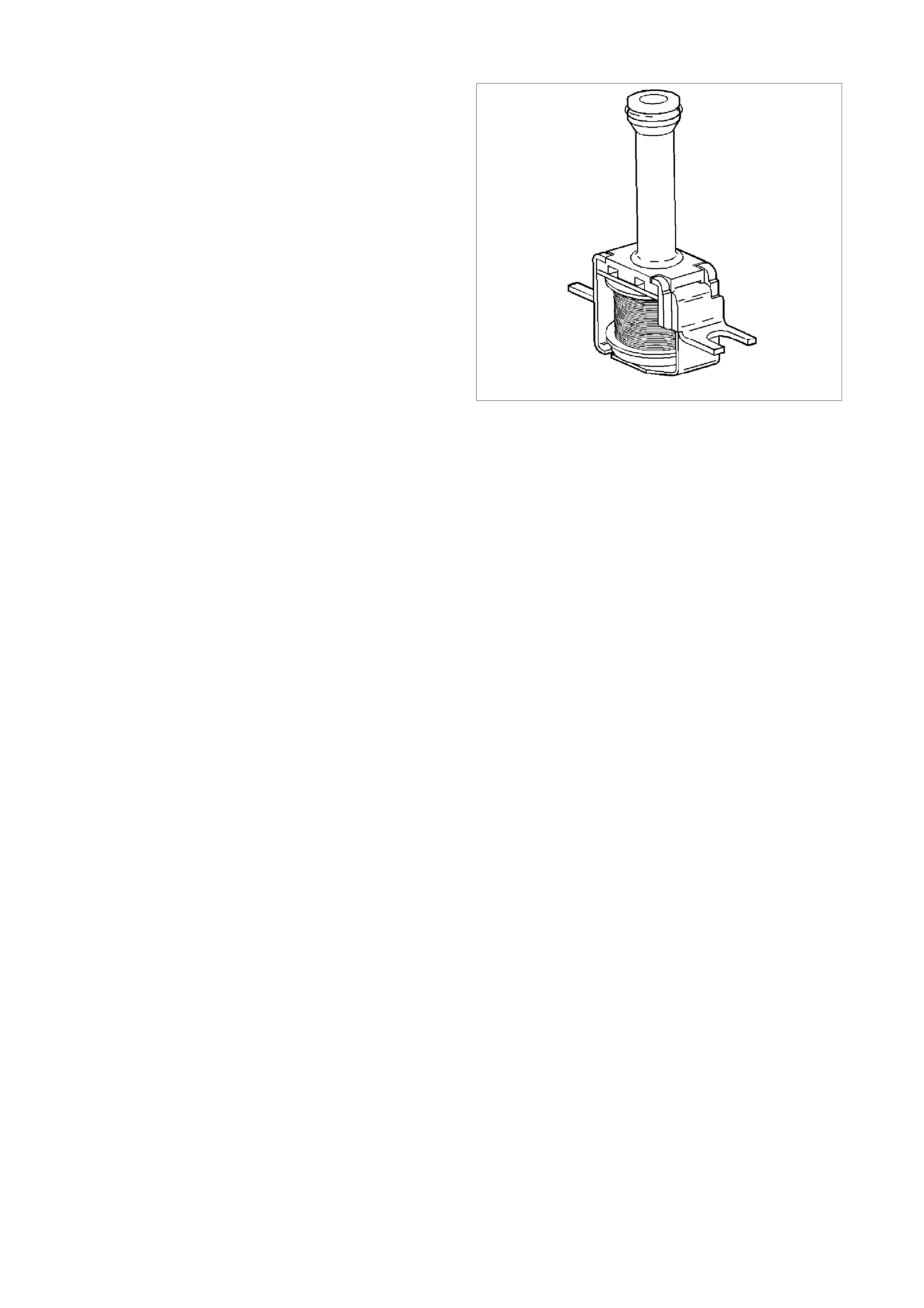
TORQUE CONVERTER CLUTCH SOLENOID VALVE
IMPORTANT:
The TCC solenoid resistance should be 21-26 ohms
minimum when measured at 20°C (68°F). If a fault is
detected in the TCC solenoid circuit, code P0740 will
set.
The torque converter clutch solenoid valve is a
normally open exhaust valve that is used to control
torque converter clutch apply and release. When
grounded (energised) by the PCM, the TCC solenoid
valve stops converter signal oil from exhausting. This
causes converter signal oil pressure to increase and
shifts the TCC solenoid valve into the apply position.
The brak e s witch is an input to the PCM, and the PCM
directly controls the TCC apply based on the brake
switch status.
8882
Figure 6C3-1-128
DTC P0740 TCC ENABLE SOLENOID CIRCUIT ELECTRICAL
Conditions for running DTC P0740
• The system voltage is between 8.0 and 18 volts.
• The engine speed is greater than 300 RPM for 5 seconds.
• The engine is not in fuel cutoff.
Conditions for setting DTC P0740
• The PCM commands the solenoid ON and the voltage input remains high (12 volts).
Or
• The PCM commands the solenoid OFF and the voltage input remains low (0 volts).
Action taken when DTC P0740 Sets
• The PCM does not illuminates the Check Powertrain Lamp.
• The PCM inhibits TCC engagement.
• The PCM inhibits 4th gear if the transmission is in hot mode.
• The PCM freezes shift adapts from being updated.
• The PCM records the operating conditions at the time the diagnostic fails. The PCM stores this information in
the Freeze Frame/Failure Records.
Conditions for clearing the Check Powertrain Lamp and DTC P0740
• A last test failed (current DTC) clears when the diagnostic runs and does not fail.
• The PCM cancels the DTC default actions when the fault no longer exists and the ignition switch is OFF long
enough in order to power down the PCM.

DTC P0742 TCC SYSTEM STUCK ON
Conditions for running DTC P0742
• No MAP sensor DTCs P0107 or P0108.
• No Throttle Position DTCs P0122 or P0123.
• No VSS assembly DTCs P0502 or P0503.
• No TCC solenoid valve DTC P0740.
• No TFP manual valve position switch DTC P1810.
• No TCC PWM solenoid valve DTC P1860.
• The Throttle Position angle is 10-45%.
• The engine speed is greater than 300 RPM for 5 seconds.
• The engine is not in fuel cutoff.
• The engine speed is 1000-3500 RPM.
• The engine torque is 54-542 N.m.
• The engine vacuum is 0-105 kPa.
• The speed ratio is 0.65-1.30 (the speed ratio is engine speed divided by output speed).
• The vehicle speed is 32-88 km/h.
• The commanded gear is not 1st.
• The gear range is D.
• The gear range does not change within 6 seconds.
• The PCM commands the TCC OFF.
Conditions for setting DTC P0742
• DTC P0742 sets if the following condition occurs three times:
- The TCC slip speed is -20 to +30 RPM for 4 seconds.
Action taken when DTC P0742 Sets
• The PCM illuminates the check powertrain lamp (CPL) during the second consecutive trip in which the
conditions for setting the DTC are met.
• The PCM freezes shift adapts from being updated.
• The PCM stores DTC P0742 in PCM history during the second consecutive trip in which the conditions for
setting the DTC are met.
Conditions for clearing the Check Powertrain Lamp and DTC P0742
• The PCM turns OFF the check powertrain lamp (CPL) during the first trip in which the diagnostic test runs and
passes.
• A scan tool clears the DTC from the PCM history.
• The PCM clears the DTC from the PCM history if the vehicle completes 40 warm-up cycles without an
emission-related diagnostic fault occurring.
• The PCM cancels the DTC default actions when the fault no longer exists and the ignition switch is OFF long
enough in order to power down the PCM.
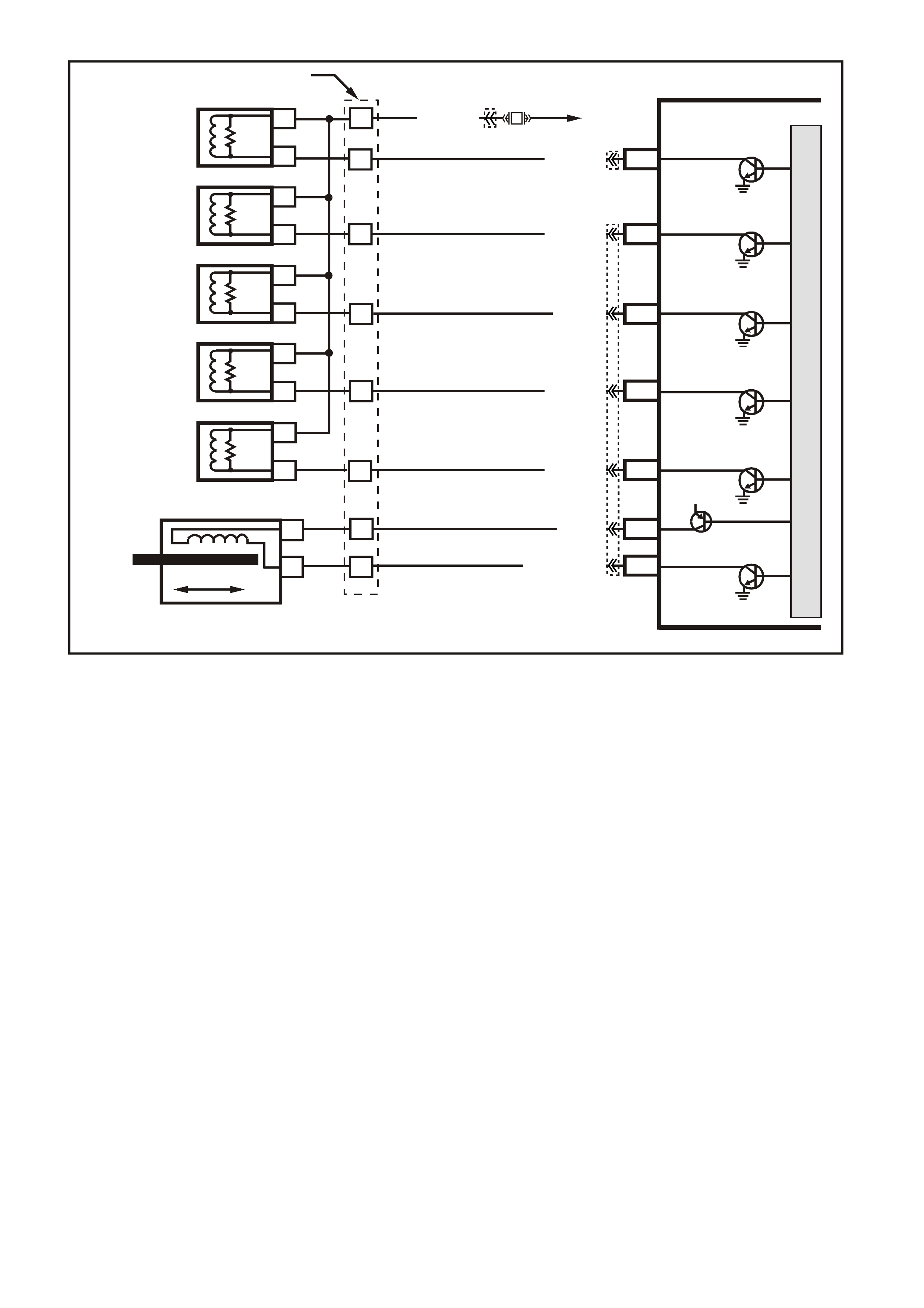
Figure 6C3-1-129 Transmission Solenoid Electrical Circuits
4356
PCM
J2-47
J2-48
J1-79
J2-42
J2-04
J2-08
J2-06
TCC PWM
SOLENOID
3-2 CONTROL
SOLENOID
1-2 SHIFT
SOLENOID A
2-3 SHIFT
SOLENOID B
PRESSURE
CONTROL
SOLENOID
LOW
PRESSURE CONTROL
SOLENOID HIGH
B
A
A
B
B
B
A
A
B
A
YB 129 T RANSMIS SION
PASS-THRU CONNECTOR
TORQUE
CONVERTER
CLUTCH (TCC)
(PWM)
SOLENOID
TORQUE
CONVERTER
CLUTCH (TCC)
ENABLE
SOLENOID
3-2 DOWNSHIFT
CONTROL
SOLENOID
1-2 SHIFT
SOLENOID A
2-3 SHIFT
SOLENOID B
PRESSURE
CONTROL
SOLENOID
C
D
U
S
T
E
A
B
P/BLU (339)
TCC ENABLE
SOLENOID
B
A
EFI
RELAY
F32
G/W (897)
YE122
YE123
LG (1222)
Y/B (1223)
GY/BLU (1229)
R (1228)
12V
M
I
C
R
O
P
R
O
C
E
S
S
O
R
BR (418)
GY/R (422)
YE110
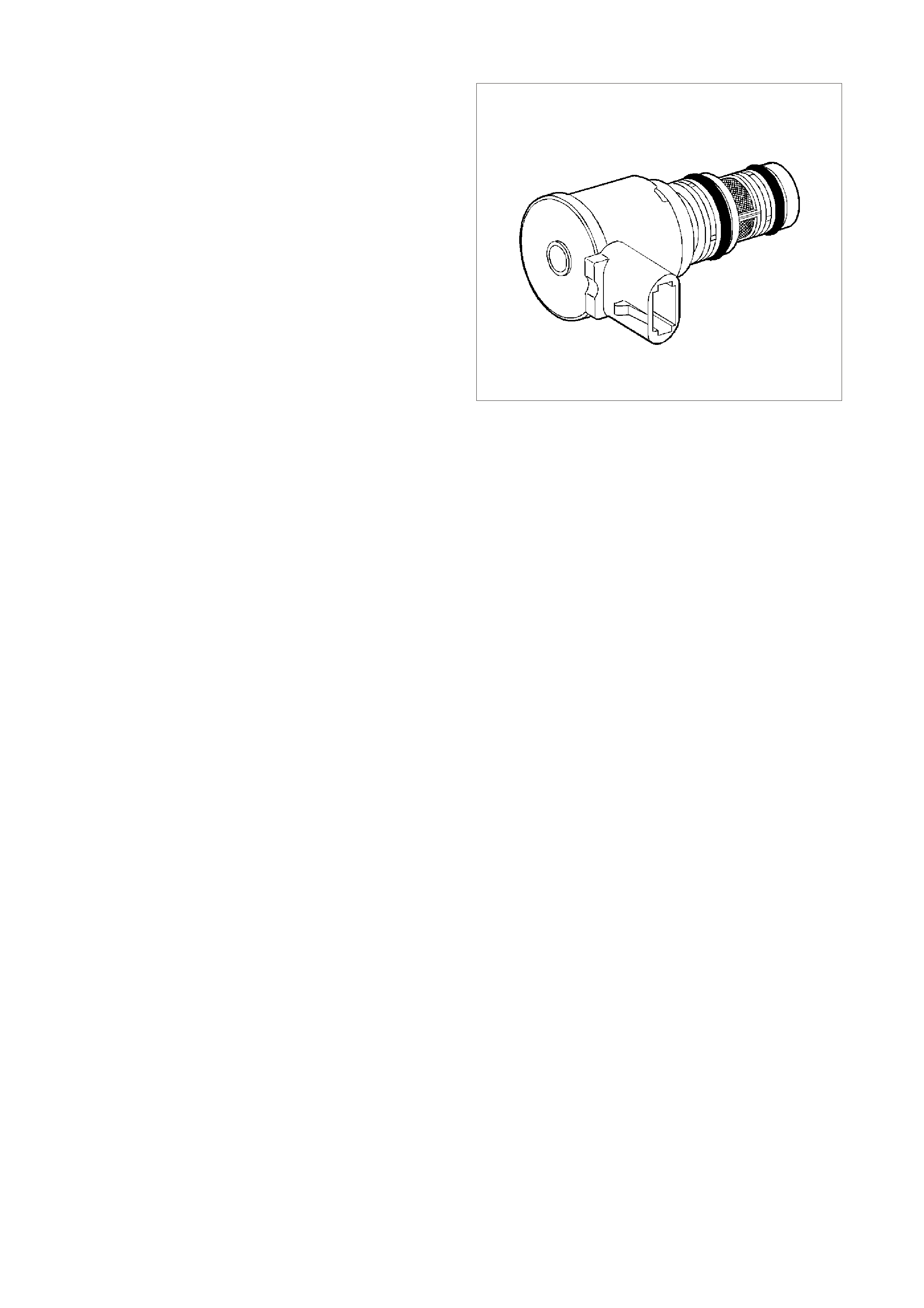
TORQUE CONVERTER CLUTCH PWM SOLENOID VALVE
IMPORTANT:
TCC PW M solenoid valve resistance should be 10-11
ohms when measured at 20°C (68°F), and 13-15
ohms when measured at 100°C (212°F).
The torque converter clutch PWM solenoid valve
controls the fluid acting on the converter clutch valve,
which then controls the TCC apply and release. This
solenoid is attached to the control valve body
assembly within the transmission.
The TCC PWM solenoid valve provides smooth
engagement of the torque converter clutch by
operating on a negative duty cycle a variable percent
of ON time.
If a fault is detected in the TCC PWM circuit, code
P1860 will set.
325355
Figure 6C3-1-130 TCC PWM Solenoid
DTC P1860 TCC PWM SOLENOID CIRCUIT
Conditions for running DTC P1860
• The system voltage is between 8.0 and 18 volts.
• The engine speed is greater than 300 RPM for 5 seconds.
• The engine is not in fuel cutoff.
• The PCM commands 1st gear.
• The TCC duty cycle is less than 10% or greater than 90%.
Conditions for setting DTC P1860
• The PCM commands the solenoid ON and the voltage input remains high (12 volts).
Or
• The PCM commands the solenoid OFF and the voltage input remains low (0 volts).
Action taken when DTC P1860 Sets
• The PCM illuminates the Check Powertrain Lamp when the diagnostic runs and fails.
• The PCM inhibits TCC engagement.
• The PCM inhibit 4th gear if the transmission is in hot mode.
• The PCM freezes shift adapts from being updated.
• The PCM records the operating conditions at the time the diagnostic fails. The PCM stores this information in
the Freeze Frame/Failure Records.
Conditions for clearing the Check Powertrain Lamp and DTC P1860
• The PCM turns the Check Powertrain Lamp OFF during the first ignition cycle that the diagnostic runs and
does not fail.
• A last test failed (current DTC) clears when the diagnostic runs and does not fail.

Figure 6C3-1-131 Transmission Solenoid Electrical Circuits
4356
PCM
J2-47
J2-48
J1-79
J2-42
J2-04
J2-08
J2-06
TCC PWM
SOLENOID
3-2 CONTROL
SOLENOID
1-2 SHIFT
SOLENOID A
2-3 SHIFT
SOLENOID B
PRESSURE
CONTROL
SOLENOID
LOW
PRESSURE CONTROL
SOLENOID HIGH
B
A
A
B
B
B
A
A
B
A
YB 129 T RANSMIS SION
PASS-THRU CONNECTOR
TORQUE
CONVERTER
CLUTCH (TCC)
(PWM)
SOLENOID
TORQUE
CONVERTER
CLUTCH (TCC)
ENABLE
SOLENOID
3-2 DOWNSHIFT
CONTROL
SOLENOID
1-2 SHIFT
SOLENOID A
2-3 SHIFT
SOLENOID B
PRESSURE
CONTROL
SOLENOID
C
D
U
S
T
E
A
B
P/BLU (339)
TCC ENABLE
SOLENOID
B
A
EFI
RELAY
F32
G/W (897)
YE122
YE123
LG (1222)
Y/B (1223)
GY/BLU (1229)
R (1228)
12V
M
I
C
R
O
P
R
O
C
E
S
S
O
R
BR (418)
GY/R (422)
YE110
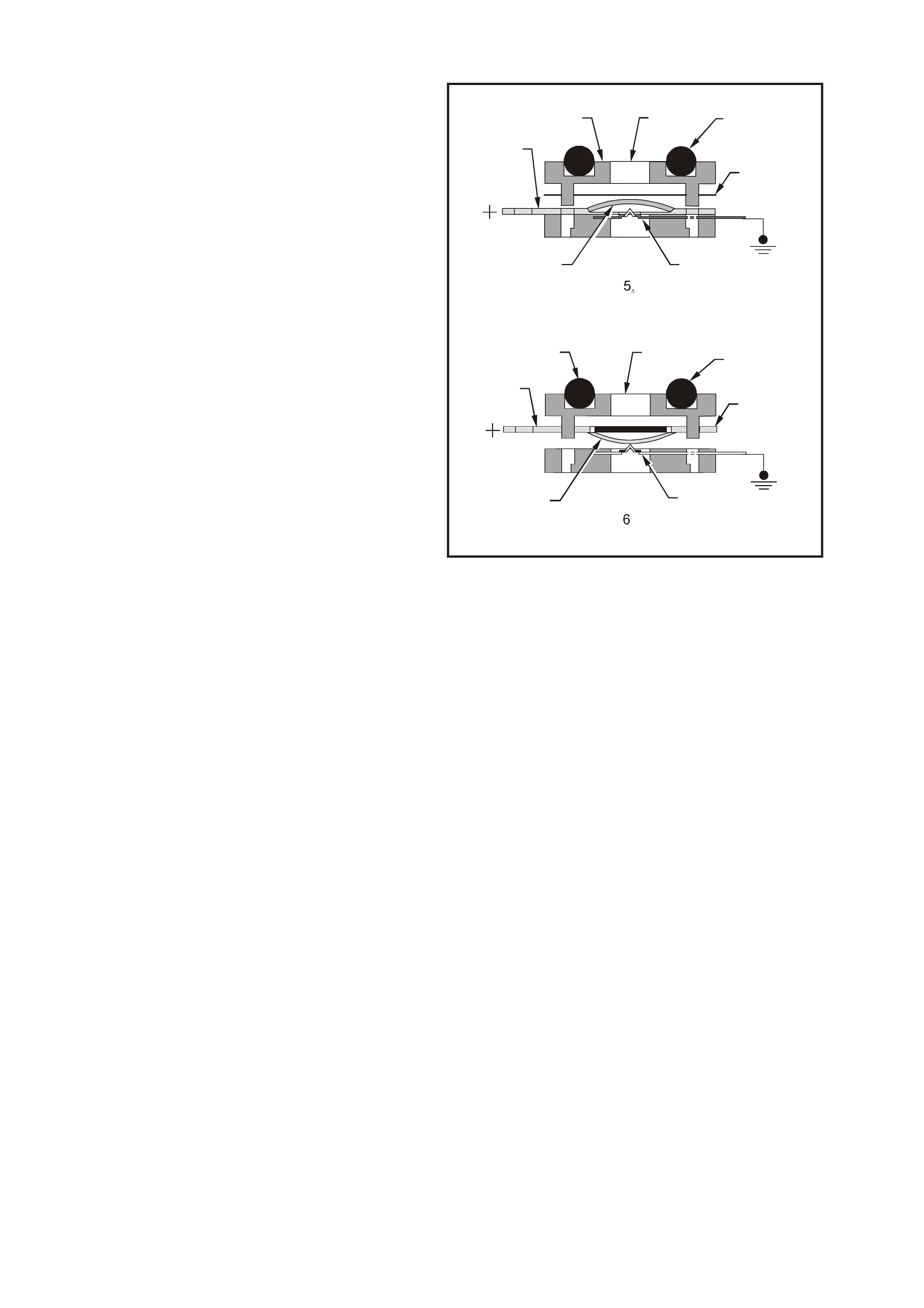
TRANSMISSION FLUID PRESSURE (TFP) MANUAL VALVE POSITION SWITCH ASSEMBLY
This gear range sensing device called a
Transmission Fluid Pressure (TFP) manual valve
position switch assembly is used by the PCM to
sense which gear range has been selected by the
vehicle operator. The TFP manual valve position
switch is located on the valve body and consists of
five pressure switches, two normally closed and
three normally open, combined into one unit.
The normally open fluid pressure switches are the
D4, LO and Reverse fluid pressure switches. They
are normally open and electrical current is stopped
at these switches when no fluid pressure is
present. Fluid pressure moves the diaphragm and
contact element until the contact element touches
both the positive contact and the earth contact.
This creates a closed circuit and allows current to
flow from the positive contact, through the switch
and to earth. The normally closed fluid pressure
switches are the D2 and D3 fluid pressure
switches. They are normally closed and electrical
current is free to flow from the positive contact to
the earth contact when no f luid pressur e is pres ent.
Fluid pressure moves the diaphragm to disconnect
the positive and earth contacts. This opens the
switch and stops current from flowing through the
switch.
The PCM applies system voltage to the TFP
manual valve position switch assembly on three
separate wires. An open circuit measures 12 Volts
while an earthed circuit measures 0 Volts. The
switches are opened or closed by fluid pressure.
The combination of which switches are open and
closed is used by the PCM to determine actual
manual valve position. The TFP manual valve
position switch assembly however cannot
distinguish between park and neutral because the
monitored valve body pressures are identical in
both cases.
4352
4
4
4
4
7
7
8
8
1
1
2
2
3
3
Figure 6C3-1-132 Transmission Fluid Pressure (TFP)
Manual Valve Position Switch
1. Fluid 5. Normal Open
2. O-Ring 6. Normal Closed
3. Diaphragm 7. Contact Element
4. Contact 8. Body
LO This switch will have hydraulic pressure
applied to it in manual 1st gear only and will
be closed.
REV This switch will have hydraulic pressure
applied to it in reverse only and will be
closed.
D2 This switch will have hydraulic pressure
applied to it in manual 1st and 2nd gear and
will be open.
D3 This switch will have hydraulic pressure
applied to it in m anual 1st, 2nd and 3rd gear
and will be open.
D4 This switch will have hydraulic pressure
applied to it in all drive gears except reverse
and will be closed.
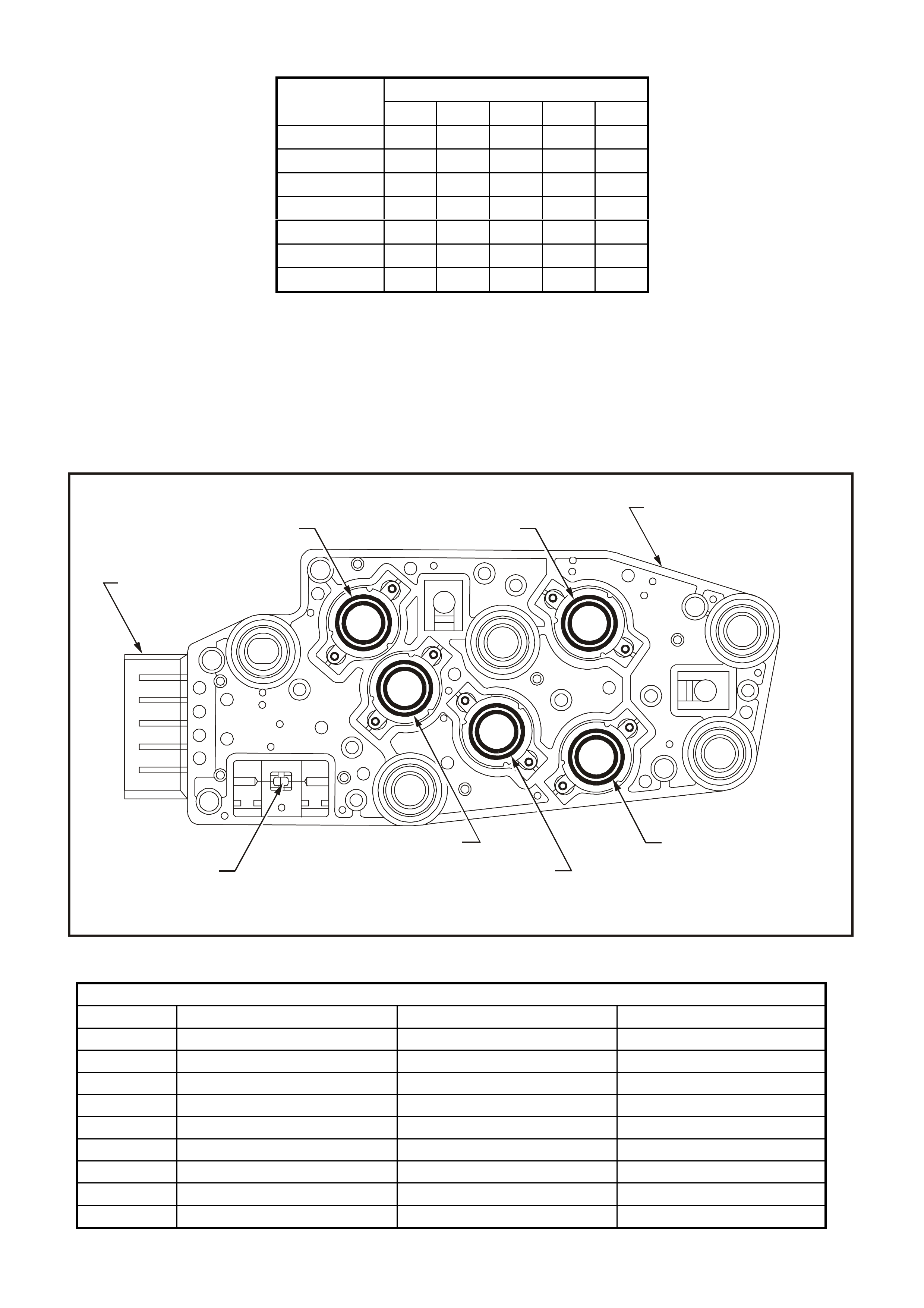
RANGE FLUID PRESSURE
INDICATOR REV D4 D3 D2 LO
PARK
REVERSE X
NEUTRAL
D X
3 X X
2 X X X
1 X X X X
Pressure Applied to TFP Manual Valve Switches
These TFP manual valve position switch inputs are used to help control line pressure, torque converter clutch
apply and shift solenoid operation. To monitor TFP manual valve position switch operation, the PCM compares
the actual voltage com bination of the s witches to a TFP m anual valve position switch c ombination T able stored in
its memory.
There are two possible combinations of the switches within the TFP manual valve position switch assembly that
do not represent an actual gear range. If either of these combinations are detected by the PCM, DTC 1810 will
set. DTC 1810 will also set if a valid gear range combination appears at the wrong time.
Figure 6C3-1-133 TFP Manual Valve Switch Assembly
VALID COMBINATION TABLE
RANGE SIGNAL A RANGE SIGNAL B RANGE SIGNAL C
PARK 12V / OPEN 0V / EARTHED 12V / OPEN
REVERSE 0V / EARTHED 0V / EARTHED 12V / OPEN
NEUTRAL 12V / OPEN 0V / EARTHED 12V / OPEN
D 12V / OPEN 0V / EARTHED 0V / EARTHED
3 12V / OPEN 12V / OPEN 0V / EARTHED
2 12V / OPEN 12V / OPEN 12V / OPEN
1 0V / EARTHED 12V / OPEN 12V / OPEN
ILLEGAL 0V / EARTHED 12V / OPEN 0V / EARTHED
ILLEGAL 0V / EARTHED 0V / EARTHED 0V / EARTHED
4353
D2
D4
D3
L
R
R
P
N
812
6
7
5
4
3
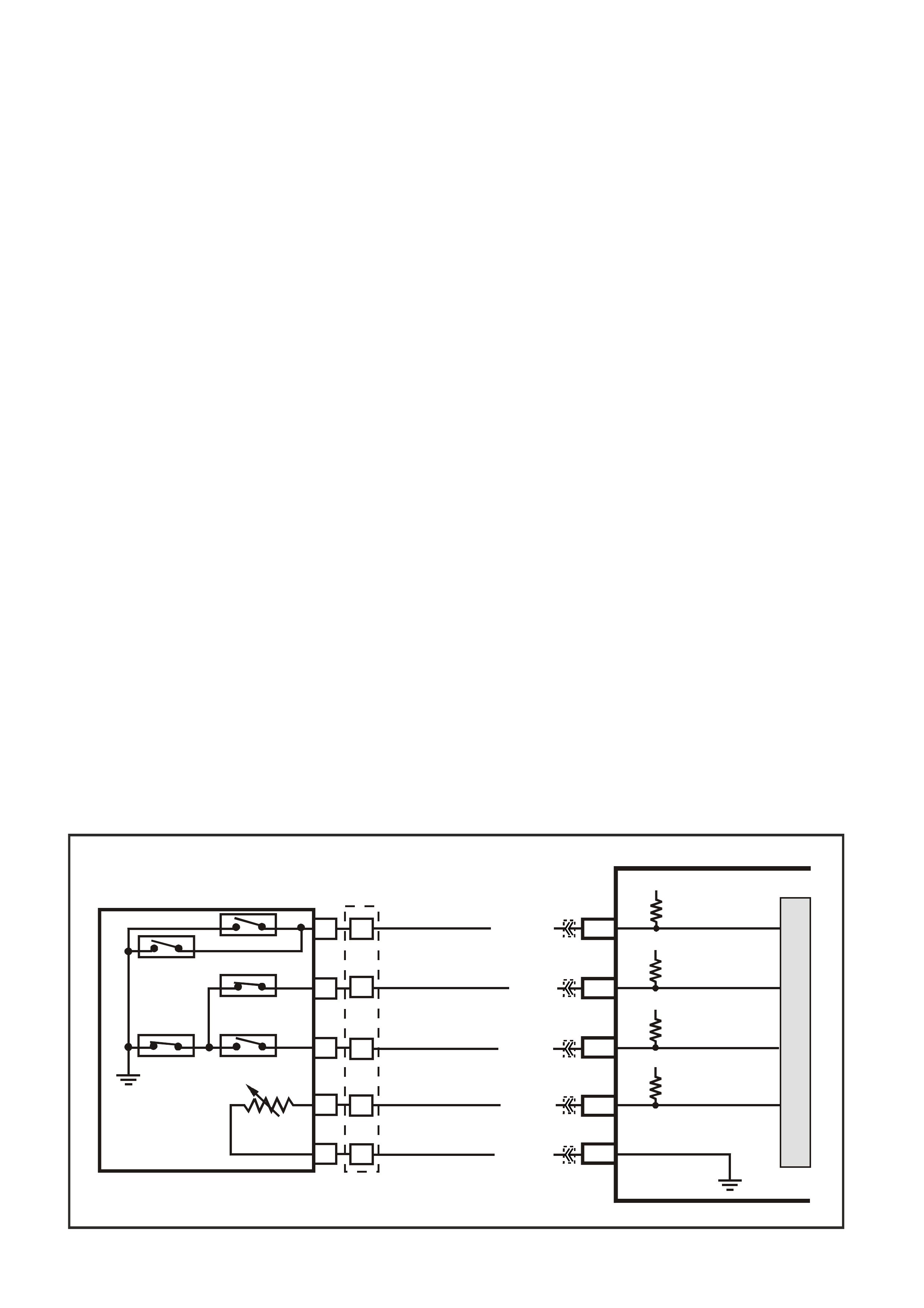
DTC P1810 TFP VALVE POSITION SWITCH CIRCUIT
Conditions for running DTC P1810
• No VSS assembly DTCs P0502 or P0503.
• The system voltage is between 8.0 and 18 volts.
• The engine speed is greater than 300 RPM for 5 seconds.
• The engine is not in fuel cutoff.
• The engine torque is 54-542 N.m.
• The engine vacuum is 0-105 kPa.
Conditions for setting DTC P1810
Condition1
• The PCM detects an invalid TFP manual valve position switch state foe 60 seconds.
Condition 2
• Then engine speed is less than 80 RPM for 0.1 seconds; then the engine speed is 80-55- RPM for 0.07
seconds; then the engine speed is greater the 550 RPM.
• The vehicle speed is less than 3 km/h.
• The PCM detects a gear range of 2, D or R during an engine start.
• All conditions are met for 5 seconds.
Condition 3
• The TP angle is 8-45%.
• The PCM commands 4th gear.
• The TCC is locked ON.
• The speed ratio is 0.65-0.8 (speed ratio is engine speed divided by transmission output speed).
• The PCM detects a gear range of P or N when operating in D.
• All conditions are met for 10 seconds.
Action taken when DTC P1810 Sets
• The PCM illuminates the Check Powertrain Lamp when the diagnostic runs and fails.
• The PCM commands D2 line pressure.
• The PCM commands D4 shift pattern.
• The PCM freezes shift adapts from being updated.
• The PCM records the operating conditions at the time the diagnostic fails. The PCM stores this information in
the Freeze Frame/Failure Records.
Conditions for clearing the Check Powertrain Lamp and DTC P1810
• The PCM turns the Check Powertrain Lamp OFF during the first ignition cycle that the diagnostic runs and
does not fail.
• A last test failed (current DTC) clears when the diagnostic runs and does not fail.
Figure 6C3-1-134 TFP Switch Assembly Circuit
G3PCM034PT
PCM
J2-63
J1-17
J2-51
J1-53
TFP SIGNAL A
TFP SIGNAL B
TRANSMISSION FLUID
TEMPERATURE (TFT)
SENSOR SIGNAL
SENSOR EARTH
N
C
REV (N.0.)
LO (N.0.)
D3 (N.C.)
D4 (N.O.)D2 (N.C.)
R
E
D
A
B
P
L
M
TRANSMISSION FLUID
TEMPERATURE
(TF T ) SENSOR
AUTOMATIC TRANSMISSION FLUID
PRESSURE SWITCH ASSEMBLY
BR/Y (1224)YE123
YE122
YE122
YE123
YE122
YB129
Y (1225)
GY (1226)
B/Y (1227)
B/W (1230)
12V
12V
5V
J1-18 TFP SIGN AL C
12V
M
I
C
R
O

VEHICLE SPEED SENSOR
IMPORTANT:
The sensor resistance is model dependent and varies
with speed from a minimum of 0.5 volts AC at 100
RPM to more than 100 volts AC at 8000 RPM.
The Vehicle Speed Sensor (or Transmission Output
Speed Sensor) controls shift points and calculates the
TCC slip. The speed sensor contains a coil that gives
off a continuous magnetic f ield. A r otor r otates past the
sensor and the rotor teeth break the magnetic field.
Each break in the field sends a pulse to the VSSB
(Vehicle Speed Sensor Buffer). The VSSB sends two
signals to the PCM. The first is a 2002 pulse per mile
(PPM) signal that is used by the engine. The second is
the transmission/transfer case 40 pulse per revolution
(PPR) signal that is used in order to control the
transmission.
The Vehicle Speed Sensor is located on the
transmission extension housing. Trans Output Speed
= Transfer Case Speed.
DTC P0502, P0503 and P0608 will set if a fault exists
in the vehicle speed sensor. Refer to front of this
Section for detailed information on the VSS.
DTC P1870 will set if there is a slipping condition with
the transmission.
62801
Figure 6C3-1-135 Vehicle Speed Sensor
DTC P1870 TRANSMISSION COMPONENT SLIPPING
Conditions for running DTC P1870
• No Throttle Position DTCs P0122 or P0123.
• No VSS DTCs P0502, P0503.
• No TCC solenoid valve DRTC P0740.
• No 1-2 SS valve DTC P0753.
• No 2-3 SS valve DTC P0758.
• No 3-2 SS valve assembly DTC P0785.
• No TCC PWM solenoid valve DTC P1860.
• The engine speed is greater than 300 RPM for 5 seconds.
• The engine is not in fuel cutoff.
• The vehicle speed is 56-105 km/h.
• The speed ratio is 0.67-0.90 (the speed ratio is the engine speed divided by the transmission output speed).
• The engine speed is 1200-3500 RPM.
• The engine torque is 54-542 N.m.
• The gear range is D4.
• The commanded gear is not 1st gear.
• The throttle position angle is 10-50%.
• The TFT is between 20-130°C.
• The shift solenoid performance diagnostic counters are zero.
Conditions for setting DTC P1870
DTC P1870 sets if the following conditions occur for three TCC cycles.
• The TCC is commanded ON for 5 seconds.
• The TCC is at maximum duty cycle for 1 second.
• The TCC slip speed is 80-8—RPM for 7 seconds.
IMPORTANT:
The following actions may occur before the DTC sets.
• If the TCC is commanded ON and at maximum duty cycle for 5 seconds, the Throttle Position angle is 10-40%,
and the transmission slip counter has incremented to either 1 or 2 (out of 3 to increment the fail counter for the
current ignition cycle), then the following slip conditions and actions may increment the fail counter for the
current ignition cycle:
These conditions must occur sequentially.
Condition 1
• If the TCC slip speed is 80-800 RPM for 7 seconds, then the PCM will command maximum line pressure and
freeze shift adapts from being updated.

Condition 2
• If condition 1 is met and the TCC slip speed is 80-800 RPM for 7 seconds, then the PCM will command the
TCC OFF for 1.5 seconds.
Condition 3
• If Condition 2 is met and the TCC slip speed is 80-8—RPM for 7 seconds, then the fail counter on the current
ignition cycle is incremented.
• The above slip conditions and actions may be disregarded if the TCC is commanded OFF at any time as a
result of a driving manoeuvre (sudden acceleration or deceleration).
Action taken when DTC P1870 Sets
• The PCM illuminates the Check Powertrain Lamp when the diagnostic runs and fails.
• The PCM inhibits TCC engagement.
• The PCM commands maximum line pressure.
• The PCM inhibits 4th gear if the transmission is in hot mode.
• The PCM freezes shift adapte from being updated.
• The PCM records the operating conditions at the time the diagnostic fails. The PCM stores this information in
the Freeze Frame/Failure Records.
Conditions for clearing the Check Powertrain Lamp and DTC P1870
• The PCM turns the Check Powertrain Lamp OFF during the first ignition cycle that the diagnostic runs and
does not fail.
• A last test failed (current DTC) clears when the diagnostic runs and does not fail.
AUTOMATIC TRANSMISSION FLUID TEMPERA TURE SENSOR
The Automatic Transm ission Fluid Temperature (TFT)
Sensor is part of the Automatic Transmission Fluid
Pressure (TFP) manual valve position switch
assembly. This sensor helps control torque converter
clutch apply and shift quality. The TFT sensor is a
resistor, or thermistor, which changes value based on
temperature. At low temperatures the resistance is
high and at high temperatures the resistance is low.
The PCM sends a 5 volt signal to the T FT sensor and
the PCM m easures the voltage drop in the c ircuit. You
will measure a high voltage when the transmission is
cold and a low voltage when the transmission is hot.
Refer to the Temperature vs Resistance table in
Section 6C3-4 Specifications of the VX Series
Service Information.
If the TFT sensor circuit has a f ault, DTC P0711, DTC
P0712 or P0713 is set. A DT C P0712 indic ates a shor t
circuit c ondition, while a DTC P0713 indicates an open
circuit condition. DTC P0218 is set if the transmission
is operating at a high temperature for a period of time.
DTC P0218 TRANSMISSION FLUID OVERTEMPERATURE
Conditions for running DTC P0218
• No TFT sensor DTCs P0711, P0712, P0713.
• The ignition switch is in the RUN position for 5 seconds.
Conditions for setting DTC P0218
• The TFT is greater than 130°C for 10 minutes (600 seconds).
Action taken when DTC P0218 Sets
• The PCM illuminates the Check Powertrain Lamp when the diagnostic runs and fails.
• The PCM freezes shift adapte from being updated.
• The PCM records the operating conditions at the time the diagnostic fails. The PCM stores this information in
the Freeze Frame/Failure Records.
Conditions for clearing the Check Powertrain Lamp and DTC P0218
• The PCM turns the Check Powertrain Lamp OFF during the first ignition cycle that the diagnostic runs and
does not fail.
• A last test failed (current DTC) clears when the diagnostic runs and does not fail.
• The PCM cancels the DTC default actions when the fault no longer exists and the ignition switch is OFF long
enough in order to power down the PCM.

DTC P0711 TFT SENSOR CIRCUIT RANGE/PERFORMANCE
Conditions for running DTC P0711
• No VSS assembly DTCs P0502, P0503.
• No transmission component slipping DTC P1870.
• The system voltage is between 8.0 volts and 18 volts.
• The engine is run-in g for 409 seconded (6.8 minutes).
• The vehicle speed is greater than 8 km/h for 409 seconds cumulative during the current ignition cycle.
• The TCC slip speed is greater than 120 RPM for 409 seconds cumulative during the current ignition cycle.
• The TFT at startup is between –40 and +21°C.
• The TFT is between –38 and +15°C.
• The engine coolant temperature (ECT) is greater than 70°C and has changed by 50°C since startup.
Conditions for setting DTC P0711
• The TFT does not change more than 1.50°C for 409 seconds since startup.
• The TFT changes more than 20°C in 200 milliseconds, 14 times within 7 seconds.
Action taken when DTC P0711 Sets
• The PCM stores the DTC information into memory when the diagnostic runs and fails.
• The Check Powertrain Lamp will not be illuminated.
• The PCM records the operating conditions at the time the diagnostic fails. The PCM stores this information in
the Freeze Frame/Failure Records.
IMPORTANT:
The actions listed below are in order of highest to lowest priority.
• The PCM determines a default TFT using the following matrix:
1 If any ECT DTCs P0117 or P0118 are set, then the default TFT is equal to 135°C.
2 If the ECT is 125°C or more, then the default TFT is equal to 135°C.
3 If the engine run time is less than 300 seconds and:
- No intak e air tem per ature (IAT ) DT Cs P0112 or P0113 are set and IAT is available, then the default T FT is
equal to IAT.
- Any IAT DTCs P0112 or P0113 are set or IAT is NOT available, then the default TFT is equal to 90°C.
4 If the engine run time is greater than 300 seconds and no IAT DTCs P0112 or P0113 are set and IAT is
available and ECT is between 40 and 125°C and:
- IAT at startup is less than 15°C, then the default TFT is equal to the ECT plus 5°C.
- IAT at startup is greater than 35°C, then the default TFT is equal to the ECT plus 10°C.
- IAT at startup is between 15 and 35°C, then the default TFT is equal to the ECT.
5 If the engine run tim e is greater than 300 s econds and any IAT DTCs P0112 or P0113 are set or IAT is NOT
available, then the default TFT is equal to the ECT.
6 If the engine run time is gr eater than 300 s ec onds and ECT is les s than 40°C or more, then the default T FT is
equal to 60°C.
• The PCM freezes shift adapts from being updated.
• The PCM stores DTC P0711 in PCM memory
Conditions for clearing the Check Powertrain Lamp and DTC P0711
• A last test failed (current DTC) clears when the diagnostic runs and does not fail.
• The PCM cancels the DTC default actions when the fault no longer exists and the ignition switch is OFF long
enough in order to power down the PCM.
DTC P0712 TFT SENSOR CIRCUIT LOW INPUT
Conditions for running DTC P0712
• The system voltage is between 8.0 volts and 18 volts.
• The ignition switch is in the RUN position.
Conditions for setting DTC P0712
• The TFT sensor indicates a signal voltage less than 0.2 volts for 10 seconds.
Action taken when DTC P0712 Sets
• The PCM stores the DTC information into memory when the diagnostic runs and fails.
• The Check Powertrain Lamp will not be illuminated.
• The PCM records the operating conditions at the time the diagnostic fails. The PCM stores this information in
the Freeze Frame/Failure Records.

IMPORTANT:
The actions listed below are in order of highest to lowest priority.
• The PCM determines a default TFT using the following matrix:
1. If any ECT DTCs P0117 or P0118 are set, then the default TFT is equal to 135°C.
2. If the ECT is 125°C or more, then the default TFT is equal to 135°C.
3. If the engine run time is less than 300 seconds and:
- No intak e air tem per ature (IAT ) DT Cs P0112 or P0113 are set and IAT is available, then the default T FT is
equal to IAT.
- Any IAT DTCs P0112 or P0113 are set or IAT is NOT available, then the default TFT is equal to 90°C.
4. If the engine run time is greater than 300 seconds and no IAT DTCs P0112 or P0113 are set and IAT is
available and ECT is between 40 and 125°C and:
- IAT at startup is less than 15°C, then the default TFT is equal to the ECT plus 5°C.
- IAT at startup is greater than 35°C, then the default TFT is equal to the ECT plus 10°C.
- IAT at startup is between 15 and 35°C, then the default TFT is equal to the ECT.
5. If the engine run tim e is greater than 300 seconds and any IAT DTCs P0112 or P0113 are set or IAT is NOT
available, then the default TFT is equal to the ECT.
6. If the engine run tim e is greater than 300 s econds and ECT is less than 40°C or m ore, then the def ault TFT
is equal to 60°C.
• The PCM freezes shift adapts from being updated.
• The PCM stores DTC P0712 in PCM history.
• The PCM stores the DTC information into memory when the diagnostic runs and fails.
• The Check Powertrain Lamp will not be illuminated.
• The PCM records the operating conditions at the time the diagnostic fails. The PCM stores this information in
the Freeze Frame/Failure Records.
IMPORTANT:
The actions listed below are in order of highest to lowest priority.
• The PCM determines a default TFT using the following matrix:
4. If any ECT DTCs P0117 or P0118 are set, then the default TFT is equal to 135°C.
5. If the ECT is 125°C or more, then the default TFT is equal to 135°C.
6. If the engine run time is less than 300 seconds and:
- No intak e air tem per ature (IAT ) DT Cs P0112 or P0113 are set and IAT is available, then the default T FT is
equal to IAT.
- Any IAT DTCs P0112 or P0113 are set or IAT is NOT available, then the default TFT is equal to 90°C.
5. If the engine run time is greater than 300 seconds and no IAT DTCs P0112 or P0113 are set and IAT is
available and ECT is between 40 and 125°C and:
- IAT at startup is less than 15°C, then the default TFT is equal to the ECT plus 5°C.
- IAT at startup is greater than 35°C, then the default TFT is equal to the ECT plus 10°C.
- IAT at startup is between 15 and 35°C, then the default TFT is equal to the ECT.
7. If the engine run tim e is greater than 300 seconds and any IAT DTCs P0112 or P0113 are set or IAT is NOT
available, then the default TFT is equal to the ECT.
8. If the engine run tim e is greater than 300 s econds and ECT is less than 40°C or m ore, then the def ault TFT
is equal to 60°C.
• The PCM freezes shift adapts from being updated.
• The PCM stores DTC P0712 in PCM memory
Conditions for clearing the Check Powertrain Lamp and DTC P0712
• A last test failed (current DTC) clears when the diagnostic runs and does not fail.
• The PCM cancels the DTC default actions when the fault no longer exists and the ignition switch is OFF long
enough in order to power down the PCM.

DTC P0713 TFT SENSOR CIRCUIT HIGH INPUT
Conditions for running DTC P0713
• The system voltage is between 8.0 volts and 18 volts.
• The ignition switch is in the RUN position.
Conditions for setting DTC P0713
• The TFT sensor indicates a signal voltage greater than 4.92 volts for 10 seconds.
Action taken when DTC P0713 Sets
• The PCM stores the DTC information into memory when the diagnostic runs and fails.
• The Check Powertrain Lamp will not be illuminated.
• The PCM records the operating conditions at the time the diagnostic fails. The PCM stores this information in
the Freeze Frame/Failure Records.
IMPORTANT:
The actions listed below are in order of highest to lowest priority.
• The PCM determines a default TFT using the following matrix:
1. If any ECT DTCs P0117 or P0118 are set, then the default TFT is equal to 135°C.
2. If the ECT is 125°C or more, then the default TFT is equal to 135°C.
3. If the engine run time is less than 300 seconds and:
- No intak e air temperature ( IAT ) DTCs P0112 or P0113 ar e se t and IAT is available, then the def ault TFT is
equal to IAT.
- Any IAT DTCs P0112 or P0113 are set or IAT is NOT available, then the default TFT is equal to 90°C.
4. If the engine run time is greater than 300 seconds and no IAT DTCs P0112 or P0113 are set and IAT is
available and ECT is between 40 and 125°C and:
- IAT at startup is less than 15°C, then the default TFT is equal to the ECT plus 5°C.
- IAT at startup is greater than 35°C, then the default TFT is equal to the ECT plus 10°C.
- IAT at startup is between 15 and 35°C, then the default TFT is equal to the ECT.
5. If the engine run tim e is greater than 300 seconds and any IAT DTCs P0112 or P0113 are set or IAT is NOT
available, then the default TFT is equal to the ECT.
6. If the engine run tim e is greater than 300 s econds and ECT is less than 40°C or m ore, then the def ault TFT
is equal to 60°C.
• The PCM freezes shift adapts from being updated.
• The PCM stores DTC P0712 in PCM memory
Conditions for clearing the Check Powertrain Lamp and DTC P0713
• A last test failed (current DTC) clears when the diagnostic runs and does not fail.
• The PCM cancels the DT C default actions when the fault no longer exists and the ignition switch is OFF long
enough in order to power down the PCM.
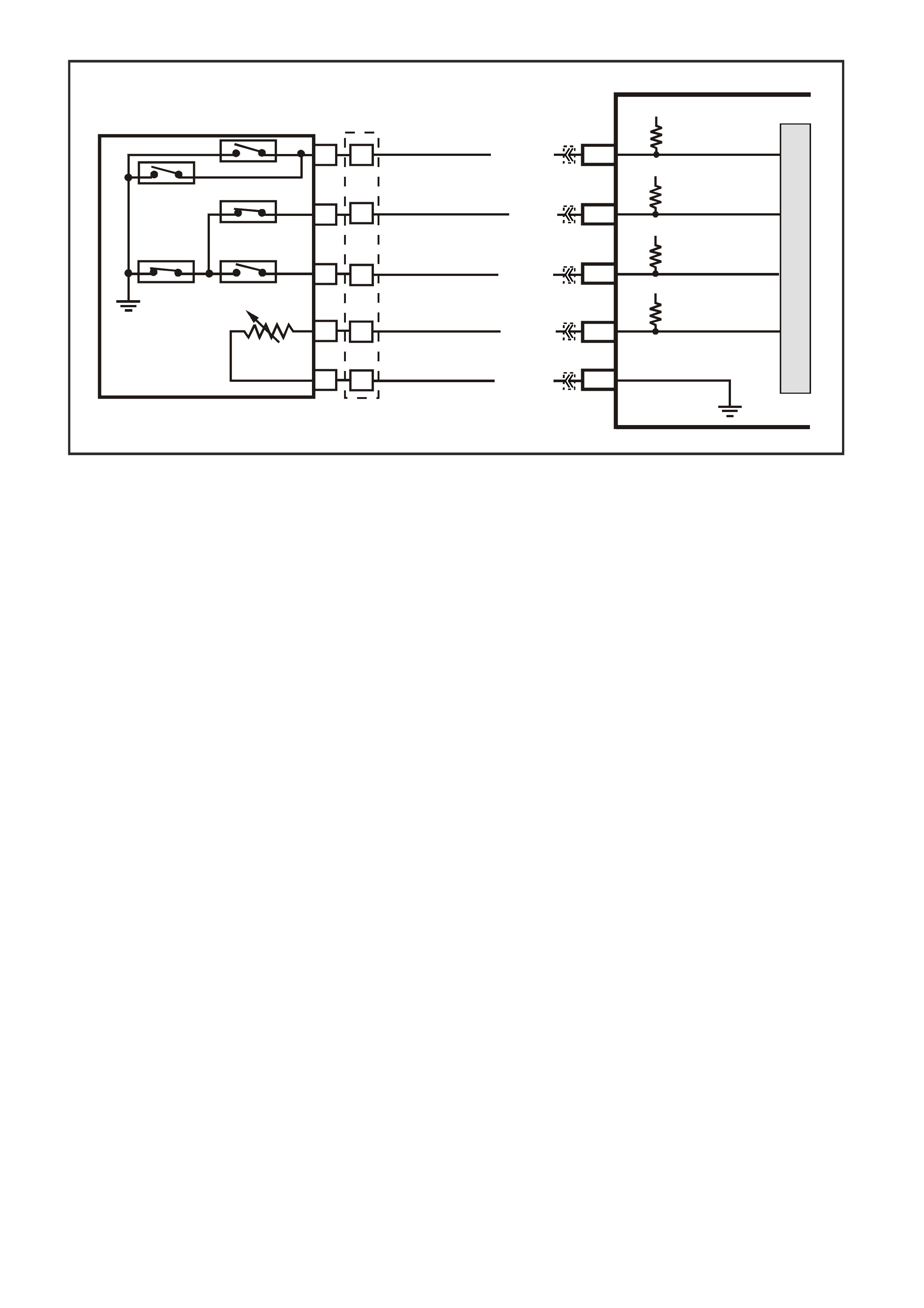
Figure 6C3-1-136 TFT Circuit
G3PCM034PT
PCM
J2-63
J1-17
J2-51
J1-53
TFP SIGNAL A
TFP SIGNAL B
TRANSMISSION FLUID
TEMPERATURE (TFT)
SENSOR SIGNAL
SENSOR EARTH
N
C
REV (N.0.)
LO (N.0.)
D3 (N.C.)
D4 (N.O.)D2 (N.C.)
R
E
D
A
B
P
L
M
TRANSMISSION FLUID
TEMPERATURE
(TF T ) SENSOR
AUTOMATIC TRANSMISSION FLUID
PRESSURE SWITCH ASSEMBLY
BR/Y (1224)YE123
YE122
YE122
YE123
YE122
YB129
Y (1225)
GY (1226)
B/Y (1227)
B/W (1230)
12V
12V
5V
J1-18 TFP SIGN AL C
12V
M
I
C
R
O
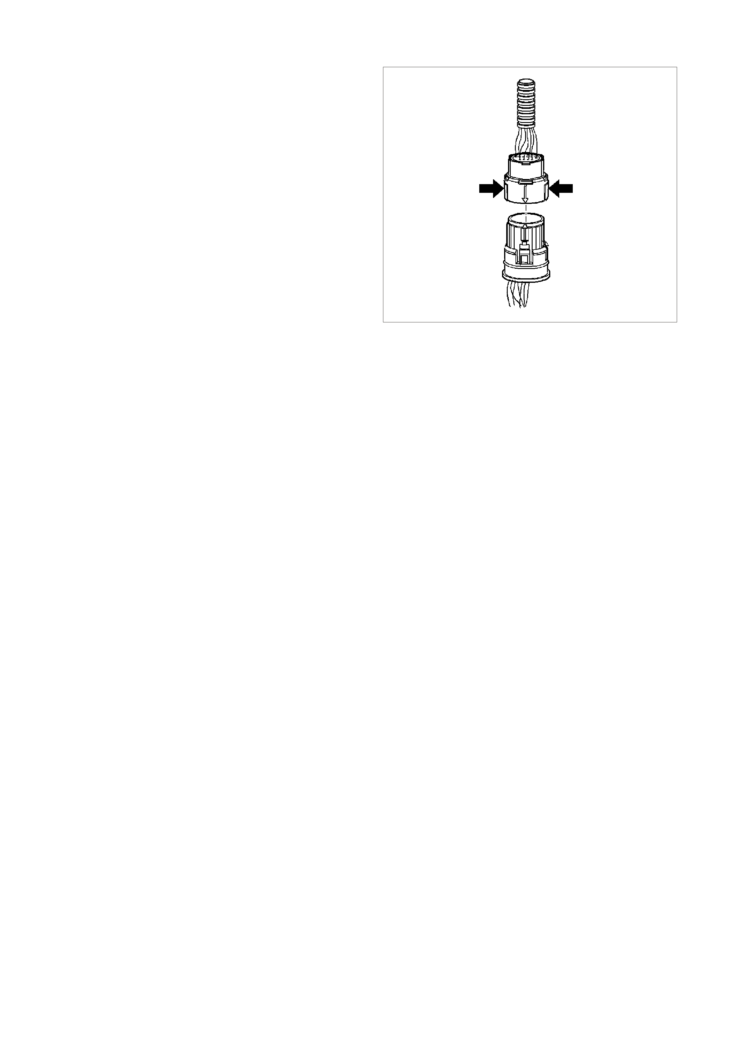
ELECTRICAL CONNECTOR
The transmission electrical connector is an important
part of the transmission operating system. Any
interference with the electrical connection can cause
the transmission to set Diagnostic Trouble Codes
(DTCs) or affect proper operation.
The following items can affect the electrical
connection:
• Bent pins in the connector from rough handling
during connection and disconnection.
• Wires backing away from the pins or coming
uncrimped (in either the internal or the external
wiring harness).
• Dirt contamination entering the connector when
disconnected.
• Pins in the internal wiring connector bac king out of
the connector or pushed out of the connector
during reconnection.
• Excessive transmission fluid leaking into the
connector, wicking up into the external wiring
harness and degrading the wire insulation.
• Moisture intrusion in the connector.
• Low pin retention in the external connector from
excessive connection and disconnection of the
wiring connector assembly.
• Pin corrosion from contamination.
• Damaged connector assembly.
13265
Figure 6C3-1-137
Remember the following points:
• In order to r emove the connector , squeeze the two
tabs toward each other and pull s traight up without
pulling by the wires.
• Limit twisting or wiggling the connector during
removal. Bent pins can occur.
• Do not pry the connector off with a screwdriver or
other tool.
• Visually inspect the seals to ensure that they are
not damaged during handling.
• In order to reinstall the external wiring connector,
first align the pins by lining up the arrows on each
half of the connector. Push the connector straight
down into the transmission without twisting or
angling the mating parts.
• The connector should click into place with a
positive feel and/or noise.
IMPORTANT:
Whenever the transmission external wiring connector
is disconnected from the internal harness and the
engine is operating, DTCs will set. Clear these DTCs
after reconnecting the external connector.

1.14 ABBREVIATIONS AND GLOSSARY OF TERMS
Abbreviations used in this Service Information CD are listed below in alphabetical order with an explanation of the
abbreviation.
POWERTRAIN MANAGEMENT
AC - ALTERNATING CURRENT - A current whose polarity is constantly changing between positive and negative.
A/C - AIR CONDITIONING
A/F - AIR/FUEL (A/F RATIO)
ANALOG SIGNAL - An electrical signal that varies in voltage within a given parameter.
BAROMETRIC PRESSURE - Atmospheric pressure. May be called BARO, or barometric absolute pressure.
BATTERY - Stores chemical energy and converts the chemical energy into electrical energy. This provides DC
current for the vehicle’s electrical systems.
CAT. CONV - CATALYTIC CONVERTER - A muffler-shaped device fitted in the exhaust system between the
engine and the m uffler. T he purpose of the catalytic converter is to chem ically convert engine producing gas es into
environmentally safe gases. HC, CO, and NOx emitted by the engine, are converted to water vapour, carbon
dioxide, and nitrogen.
CHECK POWERTRAIN LAM P (CPL) - A W arning indicator located on the instrument panel, and controlled by the
PCM. The lamp is illuminated by the PCM when it detects a fault in the engine management system, or when the
ignition is ON with the engine not running (bulb check).
CKT - CIRCUIT
CLOSED LOOP - A fuel control m ode of operation that us es the signal f rom the exhaus t oxygen sensor, in order to
control the air/fuel ratio precisely at a 14.7 to 1 ratio. This allows maximum efficiency of the catalytic converter.
CO - CARBON MONOXIDE - One of the pollutants found in the engine exhaust.
DIAGNOST IC TROUBLE CODE - The PCM c an detect faults in the engine m anagement system . If a fault occur s,
the PCM may turn on the Check Powertrain Lamp (CPL) and a two digit c ode number will set. A diagnostic trouble
code c an be read f rom the PCM thr ough the Check Powertrain Lam p (CPL) or with the Tech 2 s can tool. T his DT C
will indicate the area of the fault.
DIAGNOSTIC TEST ENABLE TERMINAL - A terminal in the Data Link Connector(DLC) that is earthed to get a
Diagnostic Trouble Code.
DIGITAL SIGNAL - An electrical signal that is either ON or OFF.
DLC - DATA LINK CONNECTOR - Used at the assembly plant to evaluate the engine management system. For
service to flash the Check Powertrain Lamp (CPL), use of Tech 2 scan tool and performing other system checks.
DLC DATA STREAM - An output from the PCM, initiated by the Tech 2 scan tool. This output is a digital signal,
used by assembly plant test equipment and the Tech 2 scan tool. This signal is transmitted from the PCM to the
Data Link Connector(DLC).
DMM (10 Meg.) - MULTIMETER - A multipurpose meter that has capability of measuring Voltage, Amps, and
Ohms.
DRIVER - An electronic device, usually a power transistor, that operates like an electrical switch turning a circuit
ON and OFF.
DUTY CYCLE - The time, in percentage, that a circuit is ON versus OFF .
FIELD SERVICE MODE - A PCM m ode of operation that is used during service. It is operational when the engine
is running and the DLC diagnostic test enable terminal is earthed.
ENGINE COOL AN T TEM PERATURE (ECT ) SENSOR - A s ensor that senses the engine coolant tem perature and
sends that information to the powertrain control module.
EECS - EVAPORATIVE EMISSIONS CONTROL SYSTEM - Used to prevent petrol vapours from the fuel tank
from entering into the atmosphere. The vapours are stored in a canister located under the vehicle. The canister
contains an activated charcoal element. The petrol vapours are purged from the canister into the manifold to be
burned in the engine.
EMI O R ELECT RICAL NOISE - An unwanted signal interfering with another needed s ignal. Comm on ex amples ar e
an electric razor's effect on a television or AM radio reception while driving under high voltage power lines.
EPROM - ERASABLE PROGRAMMABLE READ ONLY MEMORY - Type of Read Only Memory (ROM) that can
be erased with ultraviolet light and reprogrammed.
ESD - ELECTROSTATIC DISCHARGE - The discharge of static electricity, which has built up on an insulated
material.
EEPROM - ELECTRICALLY ERASABLE PROGRAMMABLE READ ONLY MEMORY - Type of read only
mem ory (ROM) that can be electr ically pr ogramm ed, eras ed and reprogram m ed using a scan tool. Also r eferred to
as Flash Memory.

FIELD SERVICE MODE - A PCM mode of operation that is used during service. The field service mode is
operational when the engine is running and the DLC diagnostic test enable terminal is earthed.
FUSE - A thin metal strip which melts through when excessive current flows through it, creating an open circuit,
protecting a circuit from damage.
HC - HYDROCARBONS (HC) - Any unburned fuel leaving the engine from incomplete combustion.
IAC VALVE - IDLE AIR CONTROL VALVE - Installed on the throttle body unit and controlled by the PCM to
regulate idle air flow and thus idle RPM.
IAT SENSOR - INTAKE AIR TEMPERATURE SENSOR - A sensor that enses intake manifold incoming air
temperature and sends the information to the PCM.
IDEAL M IXTURE - T he air/fuel ratio which provides the best perf ormanc e, while m aintaining ma ximum conversion
of exhaust emissions, typically 14.7 to 1 on petrol engines.
IGN - IGNITION
INPUTS - Information from sensors (MAF, TPS, etc.) and switches (A/C request, etc.) used by the PCM to
determine how to control its outputs.
INTERMITTENT - An electrical signal that occurs now and then; not continuously. In electrical circuits, refers to
occasional open, short, or earth in a circuit.
IPC - INSTRUMENT PANEL CLUSTER
LOW - A voltage less than a spec ific threshold. O perates the s am e as an earth and m ay, or may not, be connected
to chassis earth.
MAF - M ASS AIR FLOW SENSO R - A devic e that monitors the amount of air f low coming in the engine intak e. T he
MAF sensor sends a signal to the PCM.
N.C. - NORMALLY CLOSED - Switch contacts that are closed when they are in the normal operating position.
N.O. - NORMALLY OPEN - Switch contacts that are normally open when in the normal operating position.
NOx - NITROGEN OXIDE - One of the pollutants found in spark ignition engine exhaust. They are formed from
normal combustion and increase in severity with combustion temperatures.
OXYGEN SENSO R - The exhaust gas oxygen sensor is loc ated in the exhaust m anif old. T he O2 sens or m easur es
the oxygen in the exhaust m anifo ld af ter the com bus tion proces s. T he O2 s ensor produc es a small elec trical s ignal
based on the amount of oxygen in the exhaust gas.
OPEN LOOP - The PCM control of the fuel control system without the use of the oxygen sensor information.
OUTPUT – Functions that typically include solenoids and relays that are controlled by the PCM.
PIM - POW ERTRAIN INT ERFACE M ODULE - The PIM acts as a com munic ation translator between the PCM and
other onboard contr ollers that us e a diff erent s erial data pr otocol. T he GEN III V8 PCM uses the new Class II ser ial
data to c ommunicate, while other c ontroller s on the vehicle ar e designed to tr ans mit serial data via the c onventional
Universal Asynchronous Receive Transmit (UART) protocol. Since these two types of serial data are not
compatible, a translator or PIM is required to transmit data in either direction between the PCM and other controller.
PCM - POWERTRAIN CONTROL MODULE - A metal cased box, containing electronic circuitry, which electrically
monitors and controls the transmission system and emission systems on the engine management system. It also
turns ON the Check Powertrain Lamp (CPL) when a malfunction occurs in the system.
PCV - POSITIVE CRANKCASE VENT ILAT ION - Method of rebur ning crankc ase fum es, rather than passing them
directly into the atmosphere.
PROM - PROGRAMMABLE READ ONLY MEMORY - An electronic term used to describe the engine calibration
unit. A plug-in memory unit that instructs the PCM how to operate for a particular vehicle.
PULSE WIDTH MODULATED (PWM) - A digital signal turned ON and OFF for a percentage of available on-plus-
off cycle time. A signal that is 30% ON and 70% OFF would be called a 30% ON PWM signal.
QUAD DRIVER - A transistor, in the PCM, capable of operating four separate outputs. Outputs can be either ON-
OFF or pulse width modulated.
RAM - RANDOM ACCESS MEMORY - Is the micropr ocessors "sc ratch pad". The proc essor can write into or read
from this mem ory as needed. T his mem ory is volatile and needs a constant supply of voltage to be retained. If the
voltage is lost or removed, this memory is lost.
SERIAL DATA - Serial data is a series of rapidly changing voltage signals pulsed from high to low. These signals
are typically 5 volts (UART), 7 volts (Class II), and 12 or 0 volts (high or low) and are transmitted through a wire
often referred to as the Serial Data Circuit.
SFI - SEQUENTIAL FUEL INJECTION - Method of injecting fuel into the engine. A fuel injector is placed at each
inlet port of a cylinder head, directly in front of the intake valve, mounted in the intake manifold.
SOLENOID - An electromagnetic coil, which creates a magnetic field, when current flows through it and causes a
plunger or ball to move.
SWITCH - Opens and closes circuits, thereby controlling current flow.
TCC - TORQUE CONVERTER CLUTCH - A PCM contr olled s olenoid in an automatic tr ansmiss ion which pos itively
couples the transmission input shaft to the engine.

TECH 2 SCAN TOOL - The T ech 2 scan tool is a hand held c omputer designed tool to aid in diagnos is and repair
of autom otive sys tems with electronic c ontrols/interfac es. The T ech 2 scan tool connects to the vehicle’s Data Link
Connector (DLC).
TP SENSOR - THROTTLE POSITION - A sensor that sends a signal to the PCM. The PCM can determine, from
this signal, the current throttle position and the rate of throttle opening / closing.
VACUUM, MANIFOLD - A vacuum source from below the throttle plate.
VACUUM, PORTED - Vacuum source from a small port in the throttle body. With the throttle closed, there is no
vacuum bec ause the port is on the air cleaner s ide of the thr ottle blade and is expos ed to engine vacuum only after
the throttle is open.
VSS - VEHICLE SPEED SENSOR - A permanent magnet type sensor, which produces an AC voltage, which is
sent to the PCM to determine vehicle speed.
UART - UNIVERSAL ASYNCHRONOUS RECEIVE AND TRANSMIT - A method of communicating between
electronic devices.WOT - WIDE OPEN THROTTLE - A throttle position opening greater than 80%.
AUTOMATIC TRANSMISSION
AT - Automatic Transmission
BUMP - A sudden and forceful apply of a clutch or a band.
CHUGGLE - A bucking or jerk ing. This condition m ay be most noticeable when the converter clutch is engaged. It
is similar to the feel of towing a trailer.
DC - Direct Current
DELAYED - A c ondition where a shif t is ex pected but does not occ ur for a period of time. Th is could be described
as a clutch or band engagement that does not occur as quickly as expected during a part throttle or wide open
throttle application of the accelerator, or during m anual downshifting to a lower range. T his term is also defined as
LATE or EXTENDED.
DOUBLE BUMP (DOUBLE FEEL) - Two sudden and forceful applications of a clutch or a band downshifting
during a zero throttle coastdown.
DRIVE LINK NOISE - A whine or growl that increases or fades with vehicle speed and is most noticeable under a
light throttle acceleration. It may also be noticeable in PARK or NEUTRAL operating ranges with the vehicle
stationary.
EARLY - A condition where the shift occurs before the vehicle has reached proper speed. This condition tends to
labour the engine after the upshift.
END BUMP - A firmer feel at the end of a shift than at the start of the shift. This is also defined as END FEEL or
SLIP BUMP.
ENGINE BRAKING - A condition where the engine is used to slow the vehicle on closed throttle or low gear.
ETC - Electronic Traction Control
FINAL DRIVE NOISE - A hum related to vehicle speed which is most noticeable under a light throttle acceleration.
FIRM - A noticeably quick applic ation of a clutc h or band that is c onsidered nor m al with a medium to heavy throttle.
This apply should not be confused with HARSH or ROUGH.
FLARE - A quick increase in engine RPM along with a momentary loss of torque. This most generally occurs
during a shift. This condition is also defined as SLIPPING.
FULL THROTTLE DETENT DOWNSHIFT - A quick application of the accelerator pedal to its full travel, forcing a
downshift.
HARSH (ROUGH) - A more noticeable application of a clutch or band than FIRM. This condition is considered
undesirable at any throttle position.
HEAVY THROTTLE - Approximately 3/4 of accelerator pedal travel (75% throttle position).
HUNTING - A quick repeating series of upshifts and downshifts that causes a noticeable change in engine RPM,
such as a 4-3-4 shift pattern. This condition is also defined as BUSYNESS.
INITIAL FEEL - A distinctly firmer feel at the start of a shift than at the finish of the shift.
LATE - A shift that occurs when the engine RPM is higher than normal for a given amount of throttle.
LIGHT THROTTLE - Approximately 1/4 of accelerator pedal travel (25% throttle position).
MEDIUM THROTTLE - Approximately 1/2 of accelerator pedal travel (50% throttle position).
MINIMUM THROTTLE - The least amount of throttle opening required for an upshift.
OBD - On Board Diagnostic
OSS - Output (Shaft) Speed Sensor
PC - Pressure Control

PLAN ETARY GEAR NOISE - A whine related to vehic le speed, which is m ost noticeable in FIRST gear, SECOND
gear, FOURTH gear or REVERSE. The condition may become less noticeable, or go away , after an upshift.
PM - Permanent Magnet
PUMP NOISE - A high pitched whine that increases in intensity with engine RPM. This condition may also be
noticeable in all operating ranges with the vehicle stationary or moving.
RPM - Revolutions Per Minute
SHIFT CONDITION DEFINITIONS
SHUDDER - A repeating jerk ing condition similar to CHUGGLE but more severe and rapid. This condition m ay be
most noticeable during certain ranges of vehicle speed.
SLIPPING - A notic eable increase in engine RPM without a vehicle speed increas e. A slip usually oc curs during or
after initial clutch or band apply.
SOFT - A slow, almost unnoticeable clutch or band apply with very little shift feel.
SS - Shift Solenoid
SURGE - A repeating engine related condition of acceleration and deceleration that is less intense than
CHUGGLE.
TAP - Transmission Adaptive Pressure
TFP - Transmission Fluid Pressure
TFT - Transmission Fluid Temperature
TIE-UP - A condition where two opposing c lutch and/or bands ar e attem pting to apply at the same tim e caus ing the
engine to labour with a noticeable loss of engine RPM.
TORQUE CONVERTER NOISE - A whine usually noticed when a vehicle is stopped and the transmission is in
DRIVE or REVERSE. The noise will increase with engine RPM.
TV - Throttle Valve
WIDE OPEN THROTTLE (WOT) - Full travel of the accelerator pedal (100% throttle position).
ZERO THROTTLE COASTDOWN - A full release of the accelerator pedal while the vehicle is in motion and in
drive range.