
SECTION 6C3-2A - DIAGNOSTIC TABLES -
GEN III V8
IMPORTANT:
Before performing any Service Operation or other procedure described in this Section, refer to Section 00
CAUTIONS AND NOTES in this VX Service Information for correct workshop practices with regards to
safety and/or property damage.
SYSTEM COMPONENT LOCATIONS
T26C3001
1
2
3
4
5
6
7
9
10
11
12
13
14
151617 18
19
20 21
21
23
23
22
24
25
26
27
28
29
30
AB
C
D
F
E
8
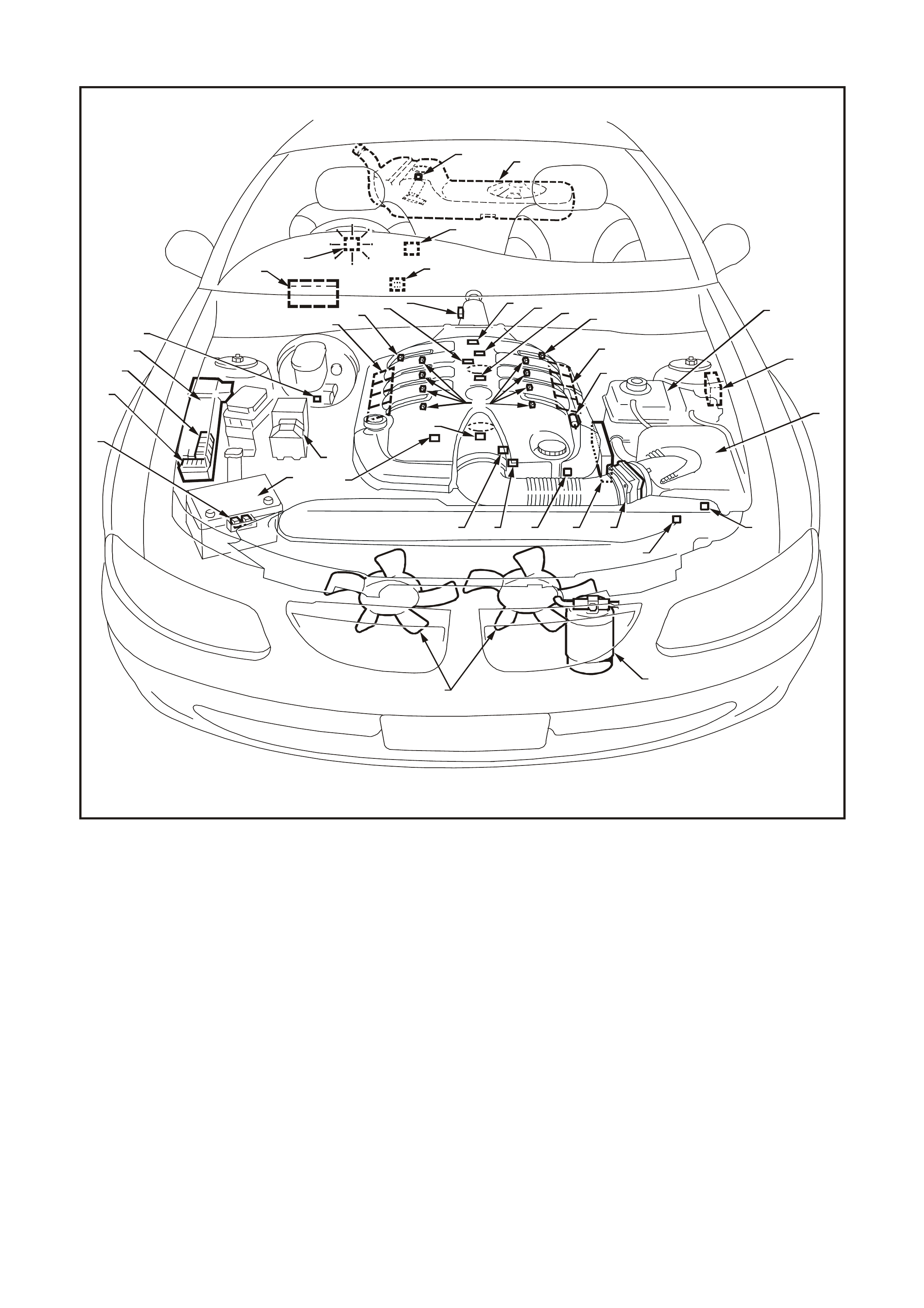
Figure 6C3-2A-1 Gen III V8 Engine Compartment Component Locations
1. Engine Compartment Fusible Link Housing 2. Battery Harness Fusible Link Housing
3. Engine Compartment Relay Housing 4. Engine Compartment Relay Housing
5. Fuel Pressure Regulator (in Fuel Tank) 6. A/C Accumulator Tank
7. Brake Hydraulic Failure Switch 8. Fuel Injectors (8)
9. Idle Air Control (IAC) Valve 10. Check Powertrain Lamp (CPL)
11. Ignition Coil/Module Right Bank 12. Ignition Coil/Module Left Bank
13. Engine Fans (2) 14. Canister Purge Solenoid
15. Mass Air Flow (MAF) Sensor 16. Engine Coolant Temperature (ECT) Sensor
17. Throttle Position (TP) Sensor 18. Intake Air Temperature (IAT) Sensor
19. Vehicle Speed Sensor (VSS) 20. Camshaft Position (CMP) Sensor
21. Heated Oxygen (HO2S) Sensor (2) 22. Crankshaft Position (CKP) Sensor
23. Knock Sensors (KS) (2) 24. ECC In - Car Air Temperature Sensor
25. A/C Refrigerant Pressure Sensor 26. Powertrain Control Module (PCM)
27. Powertrain Interface Module (PIM) - Inside
vehicle behind left kick panel 28. Diagnostic Link Connector (DLC)
29. Oil Pressure Sensor 30. Manifold Absolute Pressure (MAP) Sensor
A Battery B ABS
C BCM D Fuel Tank
E Surge Tank (With Low Coolant Level Switch) F Air Cleaner

Figure 6C3-2A-2GEN. III V8 Engine View LH
1. Right Hand Ignition Coils/Modules 7. Engine Coolant Temperature (ECT) Sensor
2. Fuel Pulse Dampener 8. Fuel Pressure Gauge Test Connector
3. Fuel Rail with Injectors 9. Throttle Position (TP) Sensor
4. EVAP Canister Purge Solenoid 10. Idle Air Control (IAC) Valve
5. Crankcase Vent 11. Throttle Body
6. Left Hand Ignition Coils/Modules
GEN3 0002
4
12
3
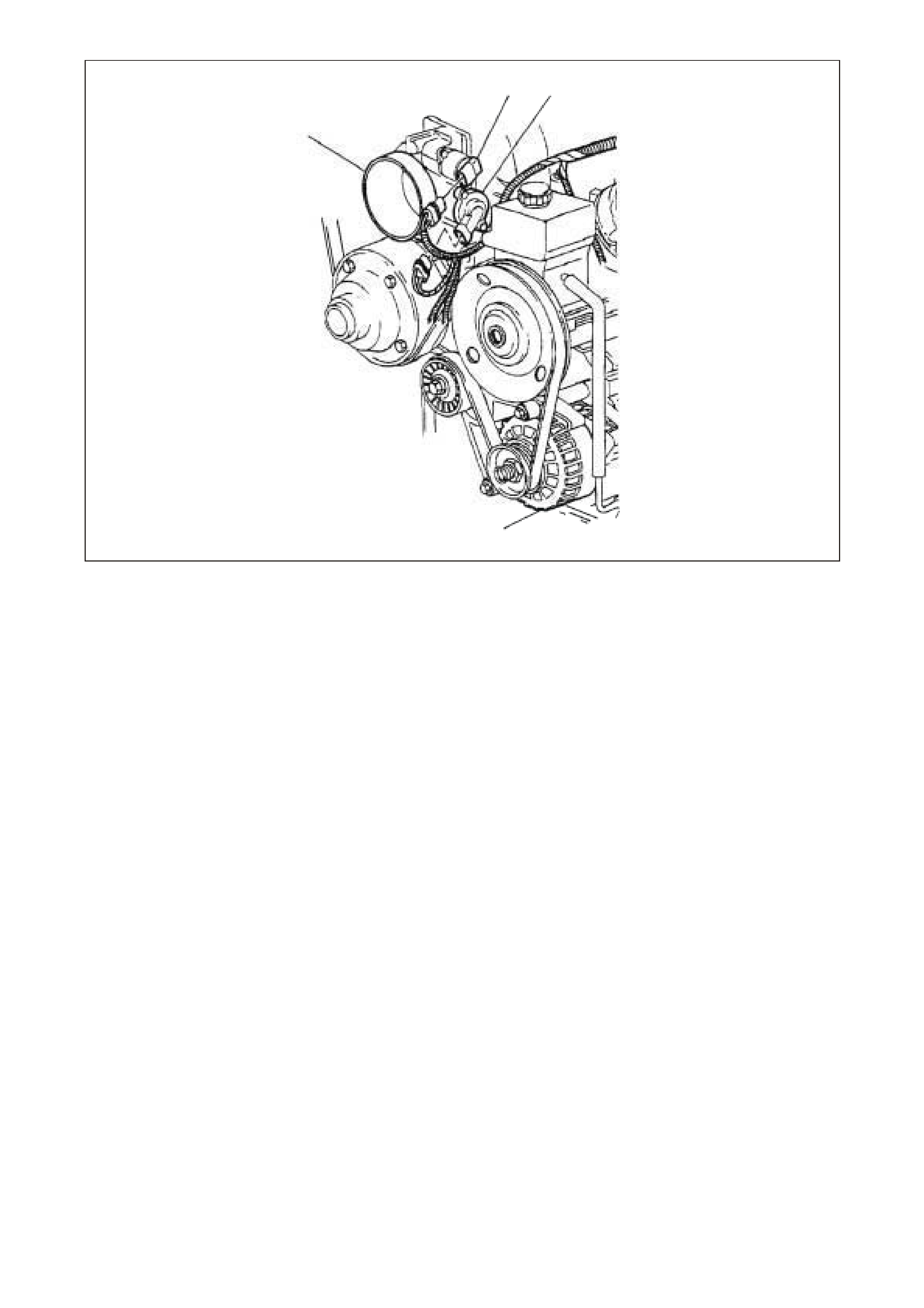
Figure 6C3-2A-3 GEN. III V8 Front of Engine View
1. Idle Air Control (IAC) Valve 3. Generator
2. Throttle Position (TP) Sensor 4. Throttle Body
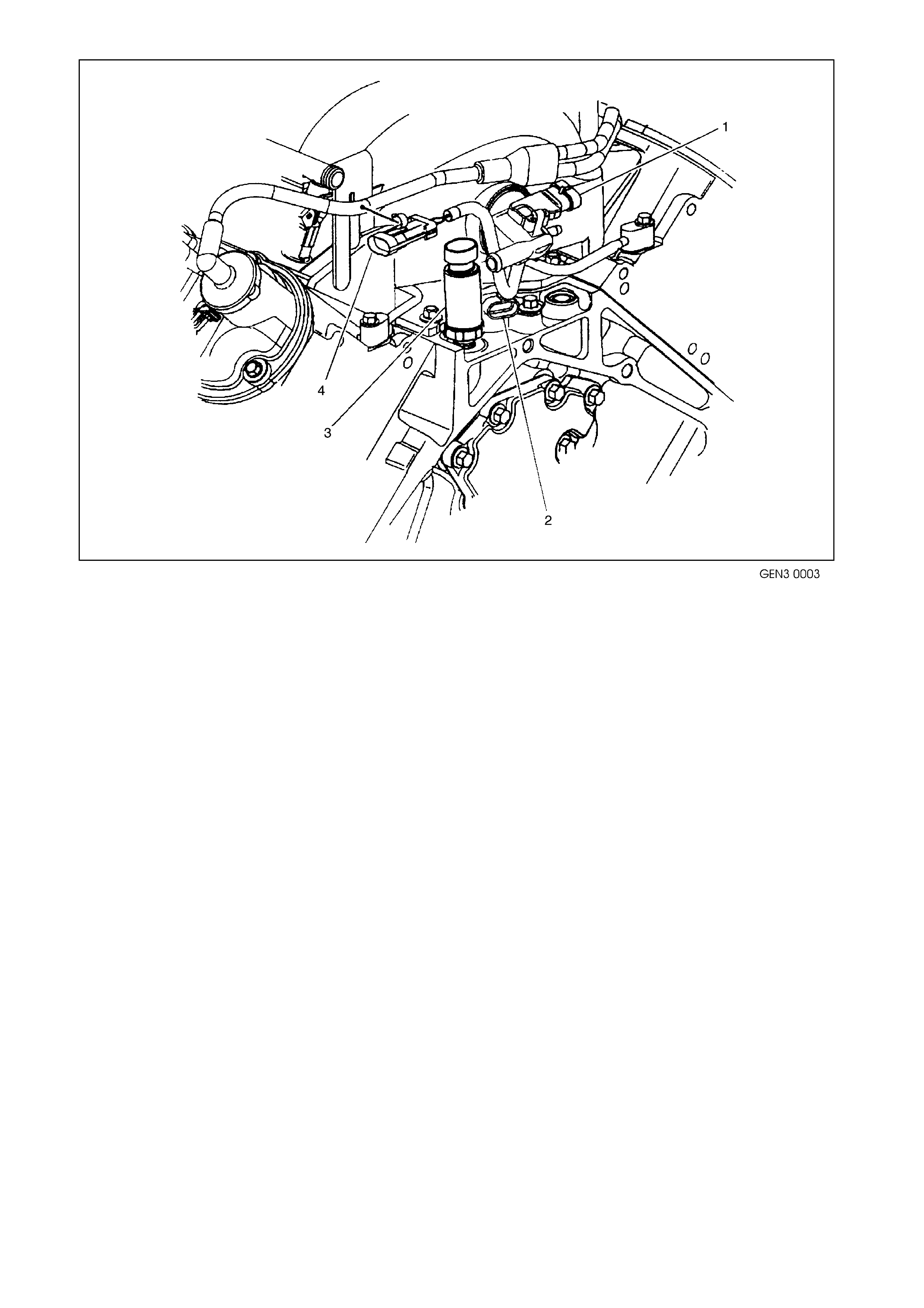
Figure 6C3-2A-4 GEN. III V8 Rear of Engine View
1. Manifold Absolute Pressure (MAP) Sensor 3. Oil Pressure Sensor
2. Camshaft Position (CMP) Sensor 4. Connector to Knock Sensor Jumper Harness
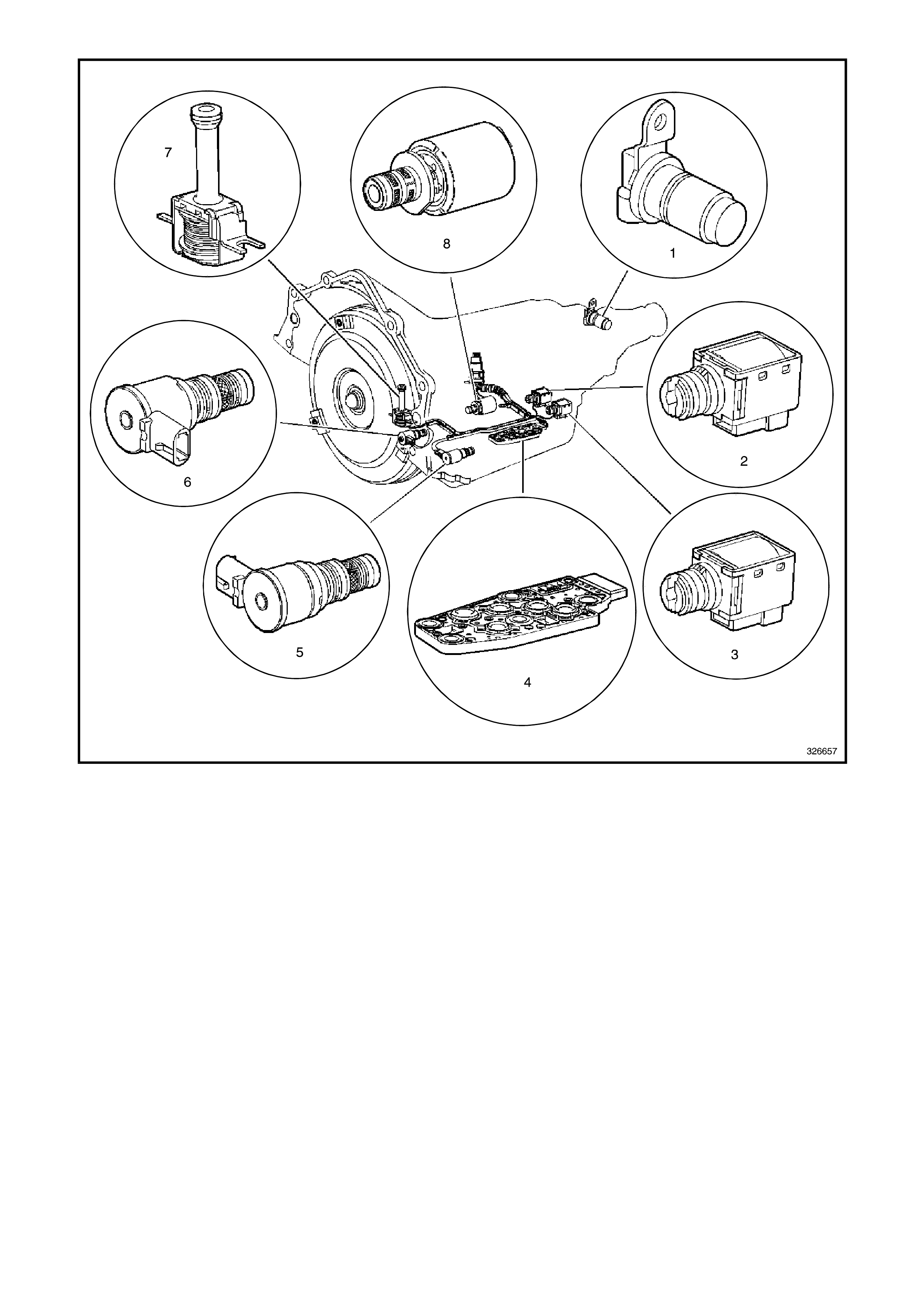
Figure 6C3-2A-5 Automatic Transmission Internal Electronic Component Locations
1. Vehicle Speed Sensor 5. Shift Solenoid (SS) Valve Assembly
2. Shift Solenoid B (SS) Valve 6. Torque Converter Clutch Pulse Width Modulation (TCC
PWM) Solenoid Valve
3. Shift Solenoid A (SS) Valve 7. Torque Converter Clutch (TCC) Solenoid Valve
4. Automatic Transmission Fluid Pressure (TFP) Manual
Valve Position Switch 8. Pressure Control Solenoid (PCS) Valve
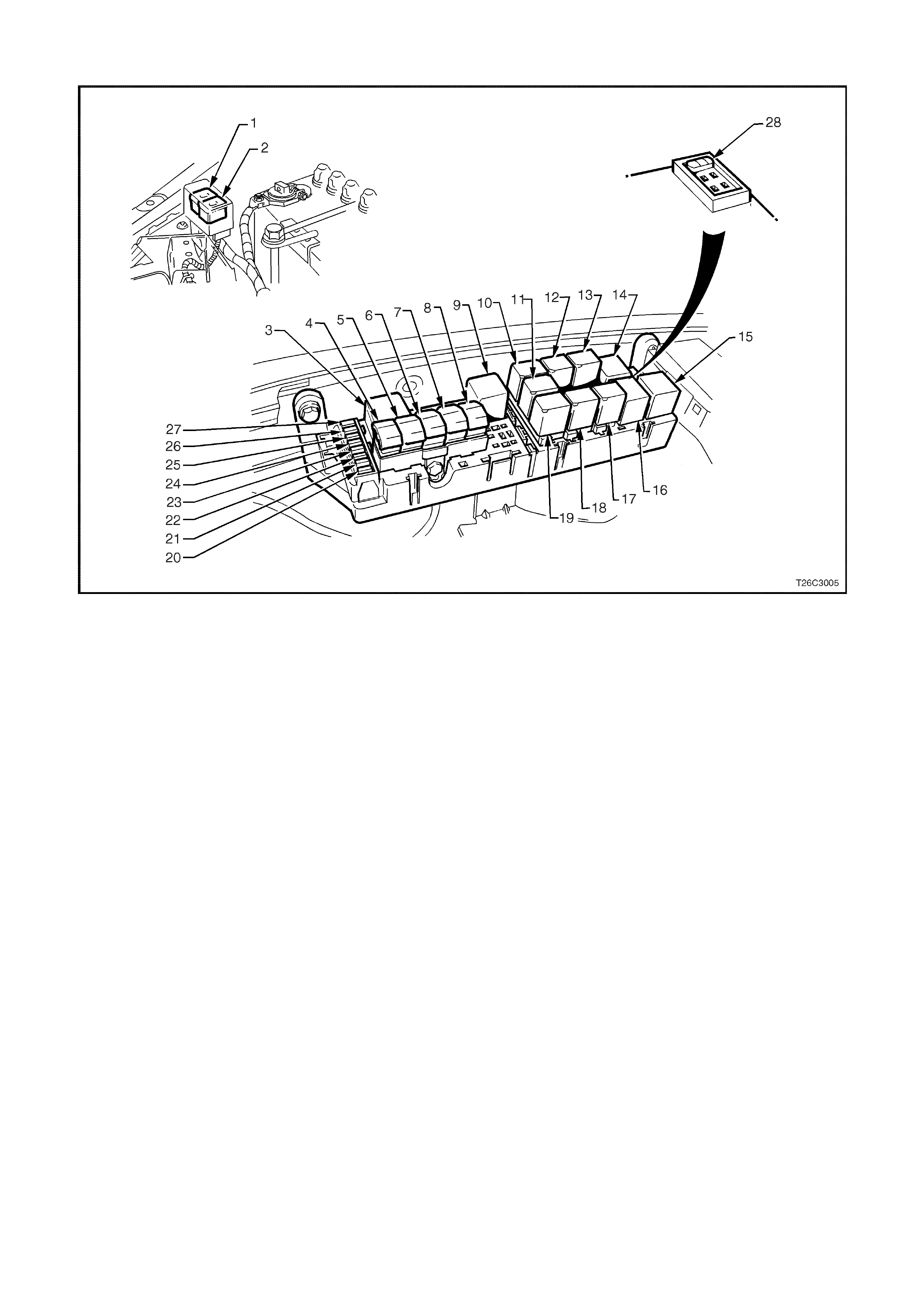
Figure 6C3-2A-6 Engine Compartment Fuse/Relay Panel
1. Fan 1 Fusible Link FU 15. Start Relay
2. Fan 2 Fusible Link FT 16. Headlamp High Beam Relay
3. Engine Fan Relay (Low Speed) 17. Fuel Pump Relay
4. Lighting Fusible Link FQ 18. Front Wiper Relay
5. ABS Fusible Link FR 19. Headlamp Low Beam Relay
6. Engine Fusible Link FS 20. Injectors/Ignition Fuse F35
7. Main Fusible Link FJ 21. Injectors/Ignition Fuse F34
8. Blower Fusible Link FY 22. Engine Sensors Fuse F33
9. Engine Cont. (EFI) Relay 23. Automatic Transmission Fuse F32
10. Horn Relay 24. Engine Control/BCM Fuse F31
11. A/C Relay 25. LH Headlamp Fuse F30
12. Theft Horn Relay 26. RH Headlamp Fuse F29
13. Fog Lamp Relay 27. Fuel Pump Fuse F28
14. Engine Fan Relay (High Speed) 28. Throttle Relaxer Control Module Fuse F36
PCM WIRING DIAGRAMS
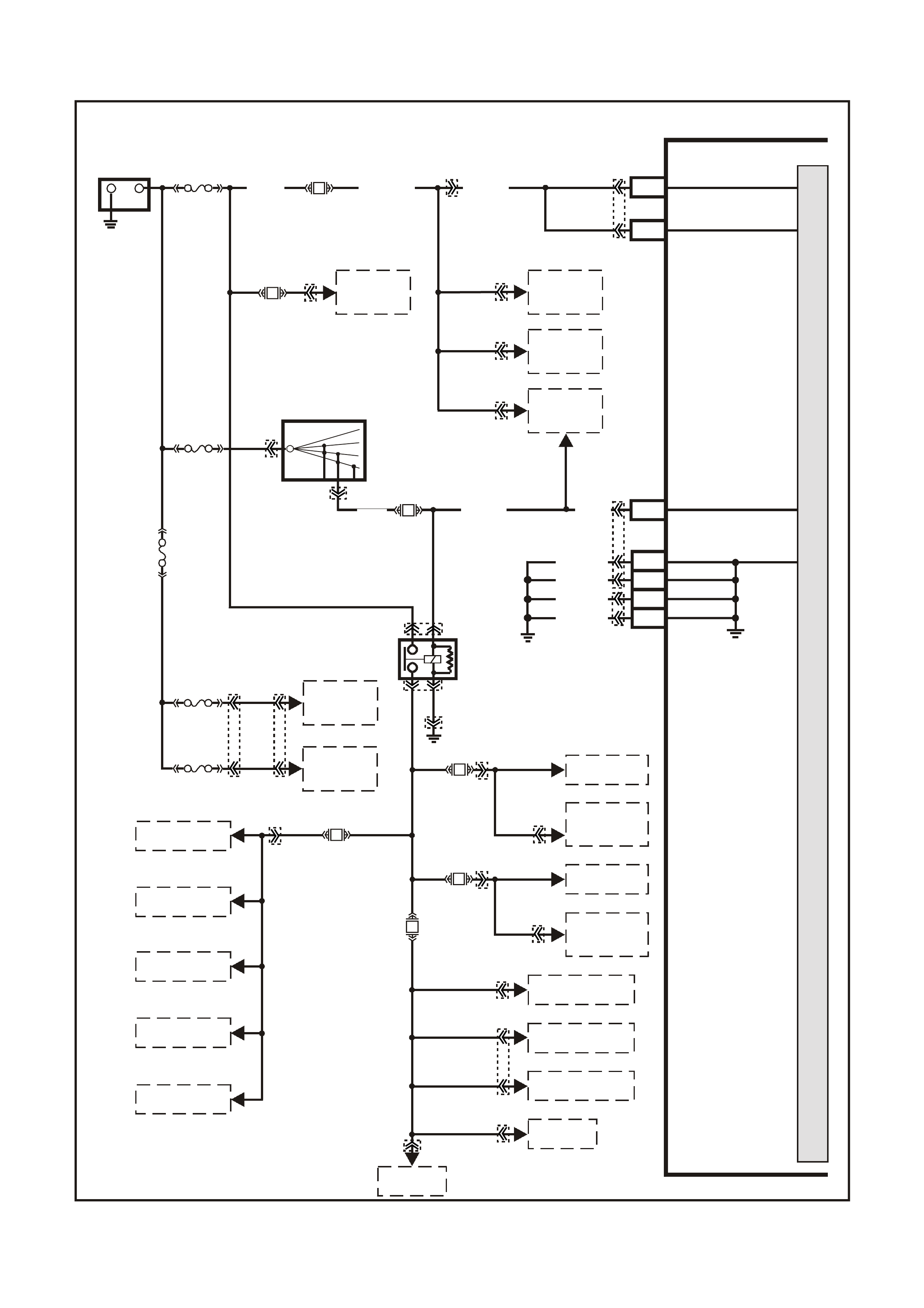
Figure 6C3-2A-7 Powertrain Controls Schematics (1 of 12) – Fused Power Circuits
G3PCM054PT
PCM
M
I
C
R
O
P
R
O
C
E
S
S
O
R
+-
BATTERY
LOC . E 1
FS
(1040)
O (740)O/B (740) J1-20
J1-57
BATTERY
BATTERY
F31
J1-19 IGNITION
FJ
BLUE
FUSIBLE
LINK
FU
FT
R
(2H)
15a 15 50
30 OFF/ON
LOCK
ACC
IGN
START
IGNITION SWITCH
P (3) F14
P (39)
P/B (39)
EFI RELAY
O/Y
(479)
LOC. E3
R
(481)
LG
(482)
P
(439)
P/BLU
(339)
O/BLU
(204)
R
(203)
O/B
(208)
B/W
(152)
F34
F35
F33
F32
TO R.H. BANK
INJECTORS
TO L.H. BANK
INJECTORS
TO R.H.
IGNITION
MODULES
TO L.H.
IGNITION
MODULES
TO R.H. HEATED
OXYGEN SENSOR
TO L.H. HEATED
OXYGEN SENSOR
TO A/C
RELAY
TO MAF
SENSOR
TO CANISTER
PURGE SOLENOID
TO 3-2
SOLENOID
TO 1-2 SHIFT
SOLENOID A
TO 2-3 SHIFT
SOLENOID B
TO TCC ENABLE
SOLENOID
TO TCC PWM
SOLENOID
F28
TO
FUEL PUMP
RELAY TO
DLC
TO REMOTE
RECEIVER
MODULE
TO BODY
CONTROL
MODULE
ENGINE
COOLING
FAN 2
ENGINE
COOLING
FAN 1
J1-01
J1-40
J2-01
J2-40
LOC. E5/E15
EARTH
EARTH
EARTH
EARTH
B/R (750)
B/R (750)
B/R (750)
B/R (750)
YE122
YE122
YE123
YE112
YB128
YB176
YB165
YB95
YB44
YE39
YE114
YE111
YE124
YE111
YE125
YE99
YE110
YE118 YE119
YE95
YE101
YE100
YE39
YE96
YB44
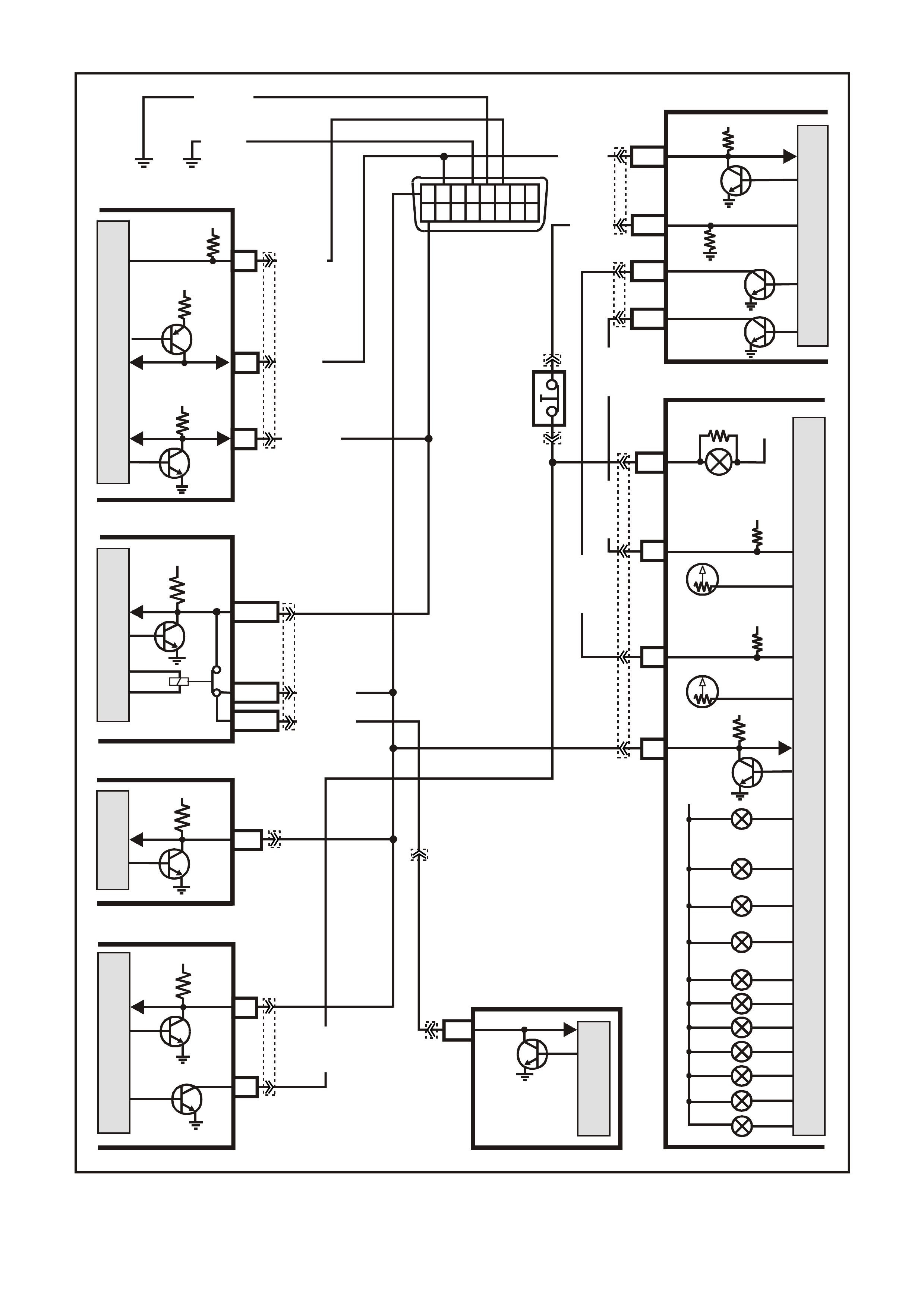
Figure 6C3-2A-8 Powertrain Control Schematics (2 of 12) – DLC and Instruments Lamps Circuits
G3PCM057APT
PCM
J1-58 CLASS 2
SERIAL
DATA
7V
BCM
E2/D2
E9/D3
E3/D13
M
I
C
R
O
SERIAL
DATA
MAIN
SERIAL
DATA AUX.
5V
W/G (1220)
Y/R (88)
G/W (1220)
HIGH SERIES
BCM TERMINALS
NOMINATED FIRST
DATA LINK
CONNECTOR
12345678
910111213141516
Y (1049)
LOC. E3
B/Y (155)
B (150)
INSTRUMENTS
ABS/ETC
11
SERIAL
DATA
5V
12 SERIAL
DATA
5V
M
I
C
R
O
CHECK
POWERTRAIN
OIL PRESSURE
POWER ECONOMY
LOW COOLANT
R
12V
P
N
D
3
1
2
SRS
ECC
9
6
M
I
C
R
O
M
I
C
R
O
SERIAL
DATA
SERIAL
DATA
5V
12V IGN
17
12V
VEHICLE
SPEED
18
12V
TACHO
SIGNAL
SPEEDOMETER
TACHO
TACHO
SIGNAL
VEHICLE
SPEED
J2-10
J2-50
V/W (123)
BR/R (121)BR (121)
M
I
C
R
O
P
R
O
C
E
S
S
O
R
LOW TR ACTION 20
BRAKE SWIT CH
J1-33
BR (86)
PIM
M
I
C
R
O
R/B (1221)
UART
SERIAL
DATA
5V
6
12V
11
DI AG. ENABL E
Y (1049)
7V
7
CLASS 2
SERIAL DA TA
W/B (451)
STOP LAMP
SWITCH B
(NC)
M
I
C
R
O
11 LOW
TRACTION
LAMP
YE122
YE123
YB12
YB12
YB66
YB191
YB190
YB189
YE98
YB87
YB175
YB164
YB215
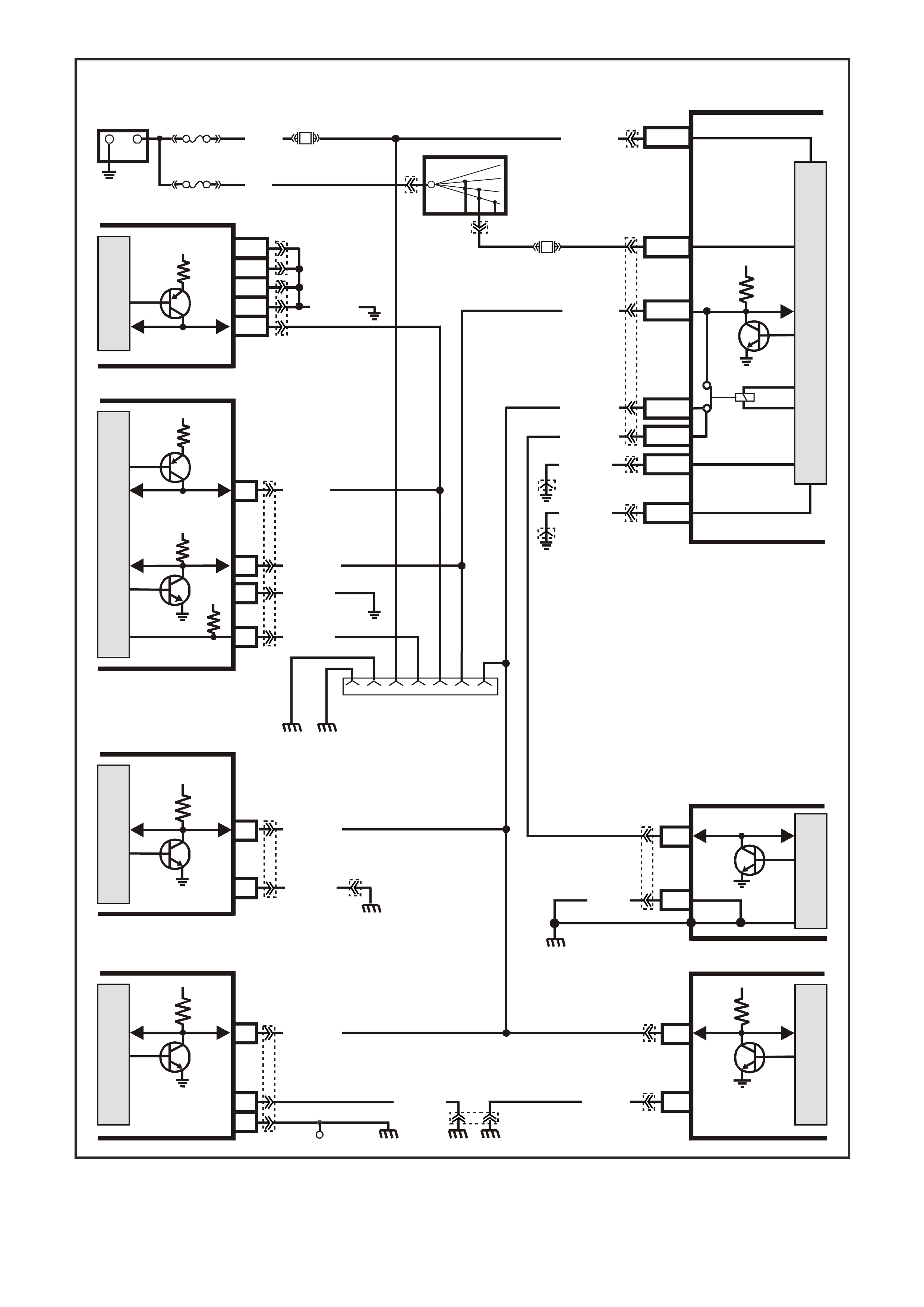
Figure 6C3-2A-9 Powertrain Control Schematics (3 of 12) – Serial Data Circuits
B/Y
(155)
B
(150)
LOC. E3
642516 9 1
G3PCM039PT
INSTRUMENTS
ABS/ETC
SRS
ECC
BCM
DATA LINK
CONNECTOR
12
11
19
16
6
16
9
8
6
M
I
C
R
O
M
I
C
R
O
M
I
C
R
O
SERIAL
DATA
SERIAL
DATA SERIAL
DATA
5V
5V 5V
M
I
C
R
O
P
R
O
C
E
S
S
O
R
+
-
BATTERY
FS
F31
A5/A6
O/B (740)
(1040)
BATTERY M AIN P OWER
HIGH SERIES
BCM TERMINALS
NOMINATED FIRS T
FJ
LOC. E1
R (2)
F14
E20/D6
P/B
(39) IGNITION ON
15a 15 50
30 OFF/ON
LOCK
ACC
IGN
START
IGNITION SWITCH
P
(3)
B/Y (155 )
B/G (151)
LOC. E3
LOC. E3
R/B (1221)
G/W (1220)
G/W (1220)
G/W (1220)
G/W (1220)
LOC.G11
LOC.E3
LOC.E2
LOC.E3 EARTH
SERIAL
DATA
B (305)
B/Y (155 ) 2
B (150)
B/O
(154) B/R
(157)
B/Y(155)
B/R ( 750)
W/B (451)
R/B (1221)
Y (1049)
PIM
M
I
C
R
O
UART
SERIAL
DATA
5V
7V
7V
12V
ELECTRONIC EARTH
HIGH CURRENT
EARTH
A1/A5
B10/B11
E2/D2
E9/D3
E3/D13
SERIAL
DATA
MAIN
SERIAL
DATA AUX.
5V
6
11
7
DI AG. ENABL E
CLASS 2
SERIAL DA TA
LOC. E5/E15
LOC. E5/E15
GEN III V8 PCM
J1-58
J2-01
J2-40
J1-40
J1-01
M
I
C
R
O
CLASS 2
SERIAL DA TA
B/R ( 750)
M
I
C
R
O
YB176
YB165
YB175
YB164
YB174
YB163
YB176
YB165
YB190
YB189
YB89
YE114
YB98
YB66
YE114
YB215
YE122
YE123
YB87
YE114
YE114
YB44
YB44
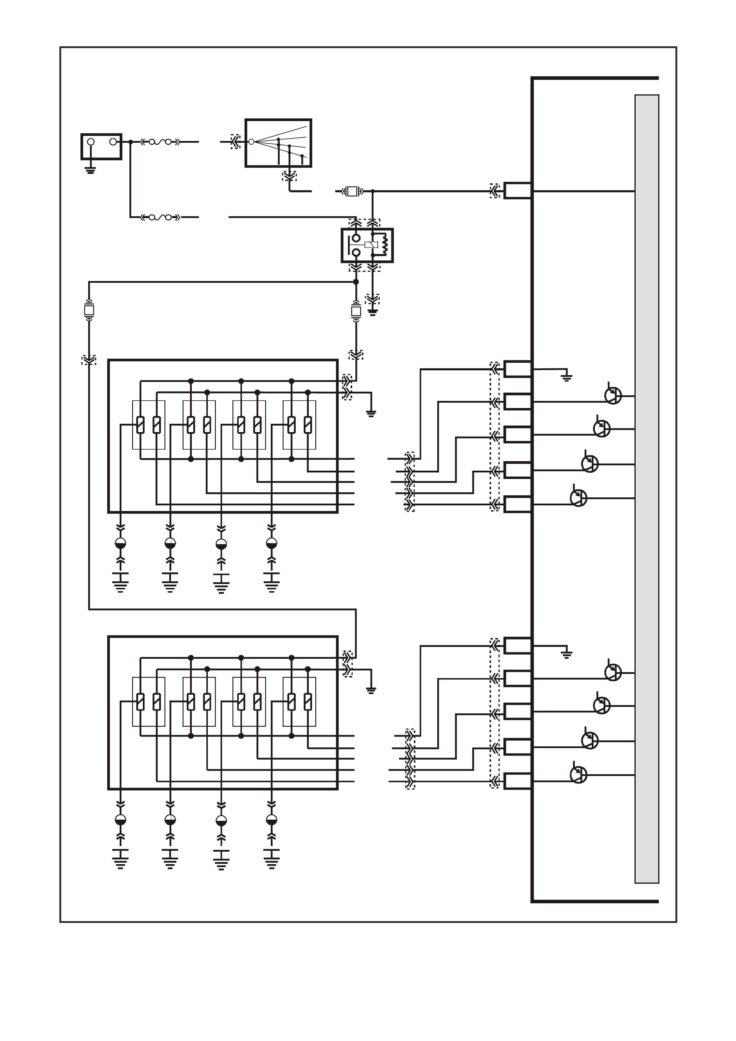
Figure 6C3-2A-10 Powertrain Control Schematics (4 of 12) – Ignition Modula Circuits
G3PCM037PT
PCM
J1-19
J2-67
J2-26
J2-61
J2-60
J2-29
J2-69
J2-28
J2-68
J2-66
J2-27
CYL. 2
IGNITION
REFERENCE LOW
IGNITION
REFERENCE LOW
CYL. 8
CYL. 6
CYL. 4
IGNITION
M
I
C
R
O
P
R
O
C
E
S
S
O
R
+-
BATTERY
FS
LOC. E3
(1040)
FJ
R (2)
15a 15 50
30 OFF/ON
LOCK
ACC
IGN
START
IGNITION SWITCH
P (3)
H
H
E
E
G
B
CYL 8
CYL 7
CYL 2
CYL 1
CYL 6
CYL 5
F
C
B
G
R.H IGNITION MODULE
L.H IGNITION MODULE
A
A
C
F
CYL 4
CYL 3
LOC.
E5/E15
LOC.
E5/E15
V (95 9)
BR (958)
Y/B (972)
W (971)
W (974)
BLU (973)
L/G (976)
G (975)
LBLU (978)
Y (97 7)
EFI
RELAY
F14
F35
F34
R
(481)B/W
(152)
L/G
(482)
SPARK PLUGS
SPARK PLUGS
12V
12V
12V
12V
CYL. 1
CYL. 7
CYL. 5
CYL. 3
12V
12V
12V
12V
YE122
YE39
YB44
YE39
YE114
YE111
YE124
YE124
YE125
YE125
YE111
YE123
YE123
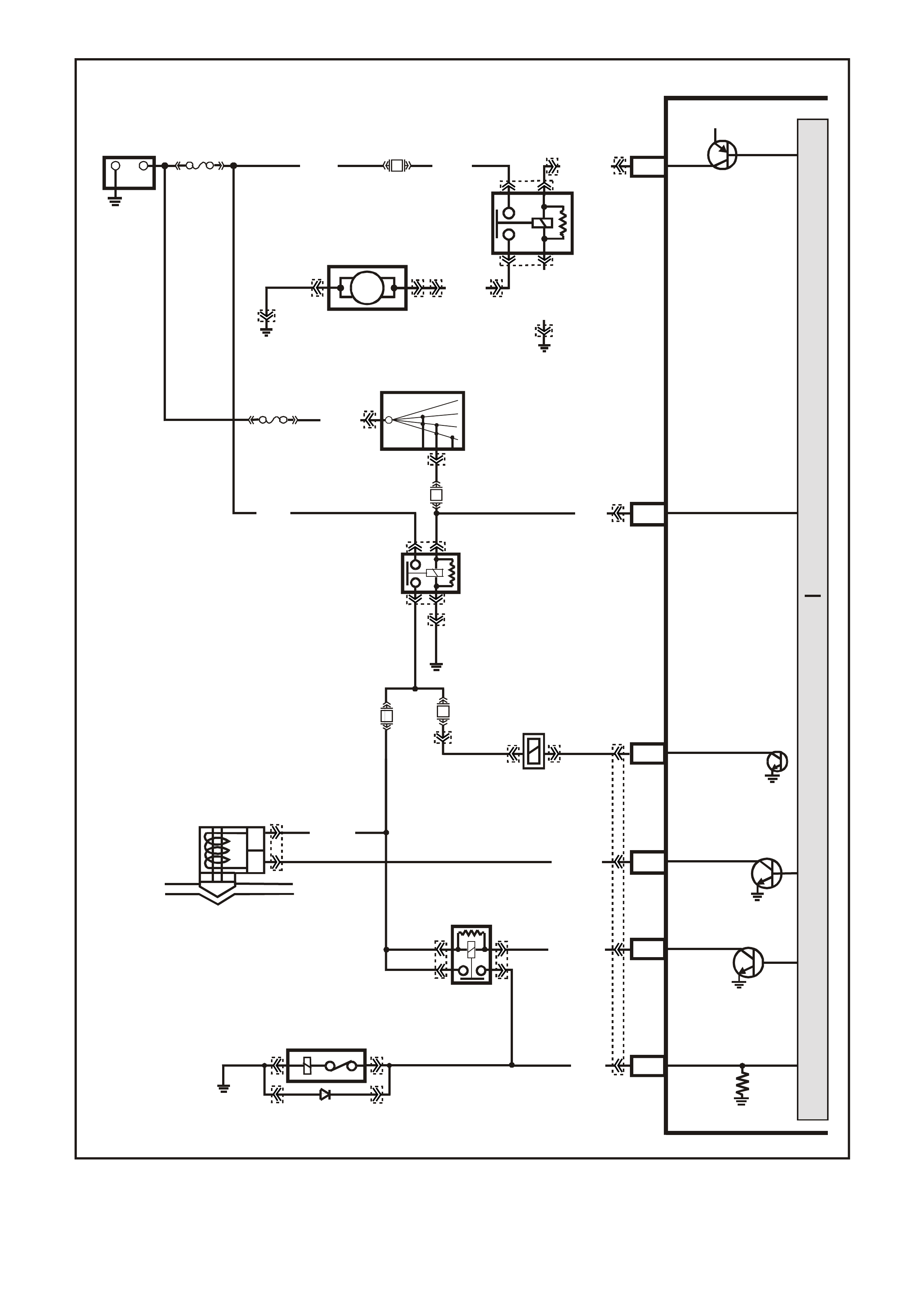
Figure 6C3-2A-11 Powertrain Control Schematics (5 of 12) – Fuel System,
Reverse Inhibit Canister Purge Solenoid, A/C Circuits
G3PCM055PT
PCM
IGNITION
J1-19
P (39 )
A/C RELAY
J2-43LG/B (366)
A/C CLUTCH
CONTROL
M
I
C
R
O
P
R
O
C
E
S
S
O
R
(1040)
R (2H)
F14
P/B
(39)
15a 15 50
30 OFF/ON
LOCK
ACC
IGN
START
IGNITION SWITCH
P
(3)
LOC. E3
F33
O/Y
(479)
B/W
(152)
EFI
RELAY
A
B
CANISTER PURGE
SOLENOID VALVE
CANISTER PURGE
J2-34
G/Y (428)
P (43 9)
B/R
(750)
LOC. E5/E15
A/C
COMPRESSOR
J2-18
G (59) A/C RELAY STA TUS
J2-44
REVERSE INHIBIT
SOLENOID
REVERSE INHIBIT
SOLENOID
F32
Y
(838)
P/BLU
(339)
J2-09 FUEL PUMP RELAY
CONTROL
B/BLU
(156)
LOC. E7 LOC. E3
IN - TANK
FUEL PUMP
FUEL PUMP
RELAY
G/W (465)
12V
+-
BATTERY
FS
LOC. E1
F28
(1040) O (240)
V (120 )
B/W(152)
32
51
FJ
YE105 YE105
YE101
YE99
Y123
YE101
YE110
YE114
YE122
YB44
YB44
YR44
YR32
YR44
YR32 YB39
YE96
YE96
YE110
YE123
YE114
YE39
YE39
YB125YB125
YE120YE120
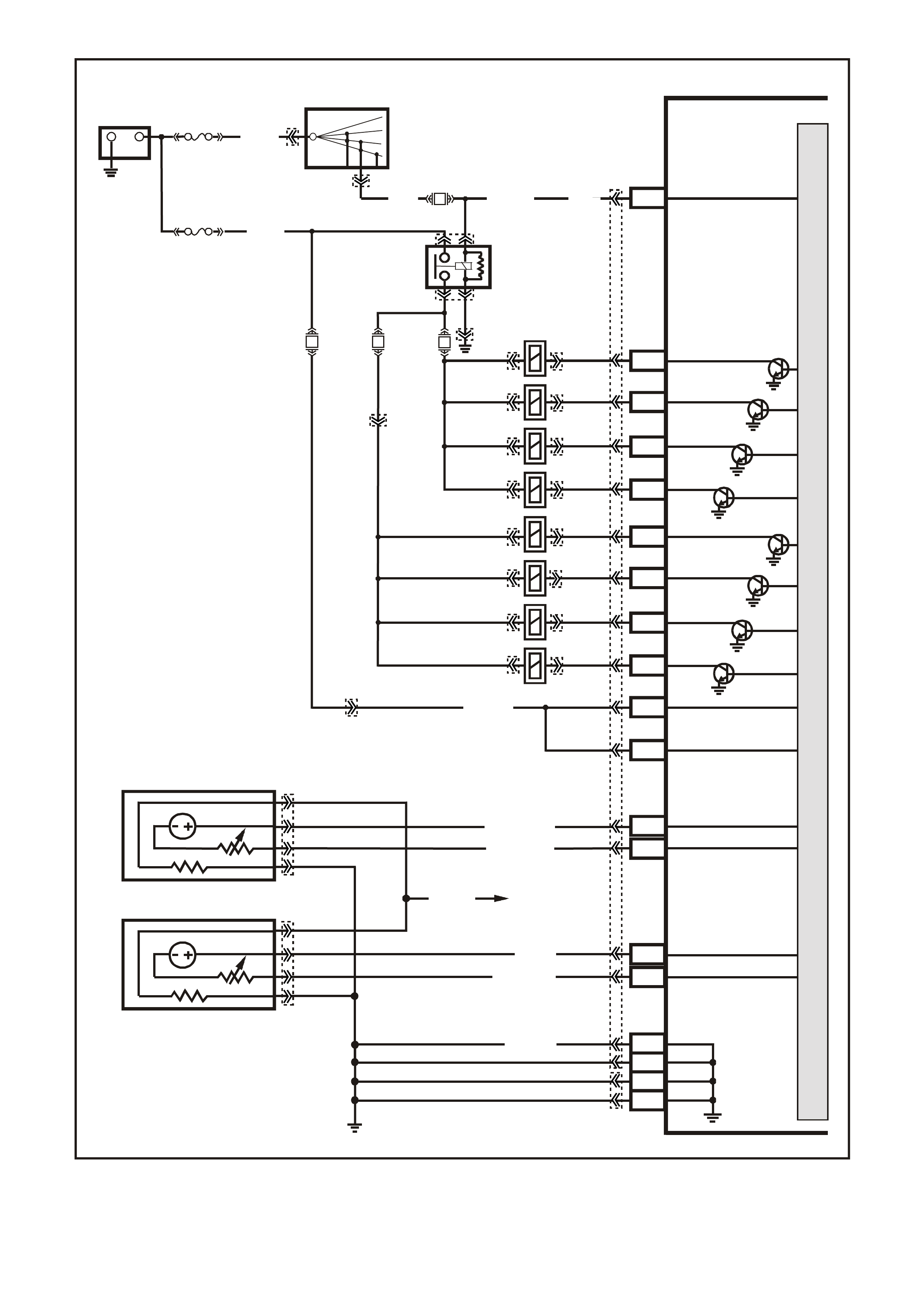
Figure 6C3-2A-12 Powertrain Control Schematics (6 of 12) – Injectors, Heated Oxygen Sensor Circuits
G3PCM053PT
PCM
M
I
C
R
O
P
R
O
C
E
S
S
O
R
J1-19
J1-36
J1-04
J1-03
J1-44
J1-76
J1-37
J1-20
J1-43
J1-77
J1-57
INJECTOR 1
INJECTOR 2
INJECTOR 7
INJECTOR 8
BATTERY
BATTERY
INJECTOR 5
INJECTOR 6
INJECTOR 3
INJECTOR 4
IGNITION
+-
BATTERY
FS
(1040)
O/Y
(479)
B/W
(152)
FJ
LOC. E1
LOC. E3
R (2H)
15a 15 50
30 OFF/ON
LOCK
ACC
IGN
START
IGNITION SWITCH
P (3) P/B (39) P (39)
EFI
RELAY
F14
F35
F34F31 BLU
(841)
V
(843)
GY
(845)
P/B
(847)
G
(842)
BR/Y
(844)
Y
(846)
LG
O (740)
O/B
(740)
R
(481)
L/G
(482)
J1-26
J1-66
D
D
B
B
A
A
C
C
J1-01
J1-40
J2-01
J2-40
GY/B (1413)
GY (1412)
RIGHT OXYGEN SENSOR
BANK TWO SENSOR ONE
LEFT OXYGEN SENS OR
BANK ONE SENSOR ONE
LOC. E5/E15
J1-69
J1-29
BLU/B (413)
V (41 2)
P (43 9)
TO FUSE
F33
RIGHT OXYGEN
SENSOR SIGNAL LO
LEFT OXYGEN
SENSOR SIGNAL LO
RIGHT OXYGEN
SENSOR SIGNAL HI
EARTH
EARTH
EARTH
EARTH
LEFT OXYGEN
SENSOR SIGNAL HI
B/R (750)
YE111
YE112
YE95
YE95
YE123
YE122
YB44
YB44
YB39
YB39
YE114
YE77 YE77
YE79 YE79
YE81 YE81
YE83 YE83
YE80 YE80
YE82 YE82
YE84 YE84
YE78 YE78
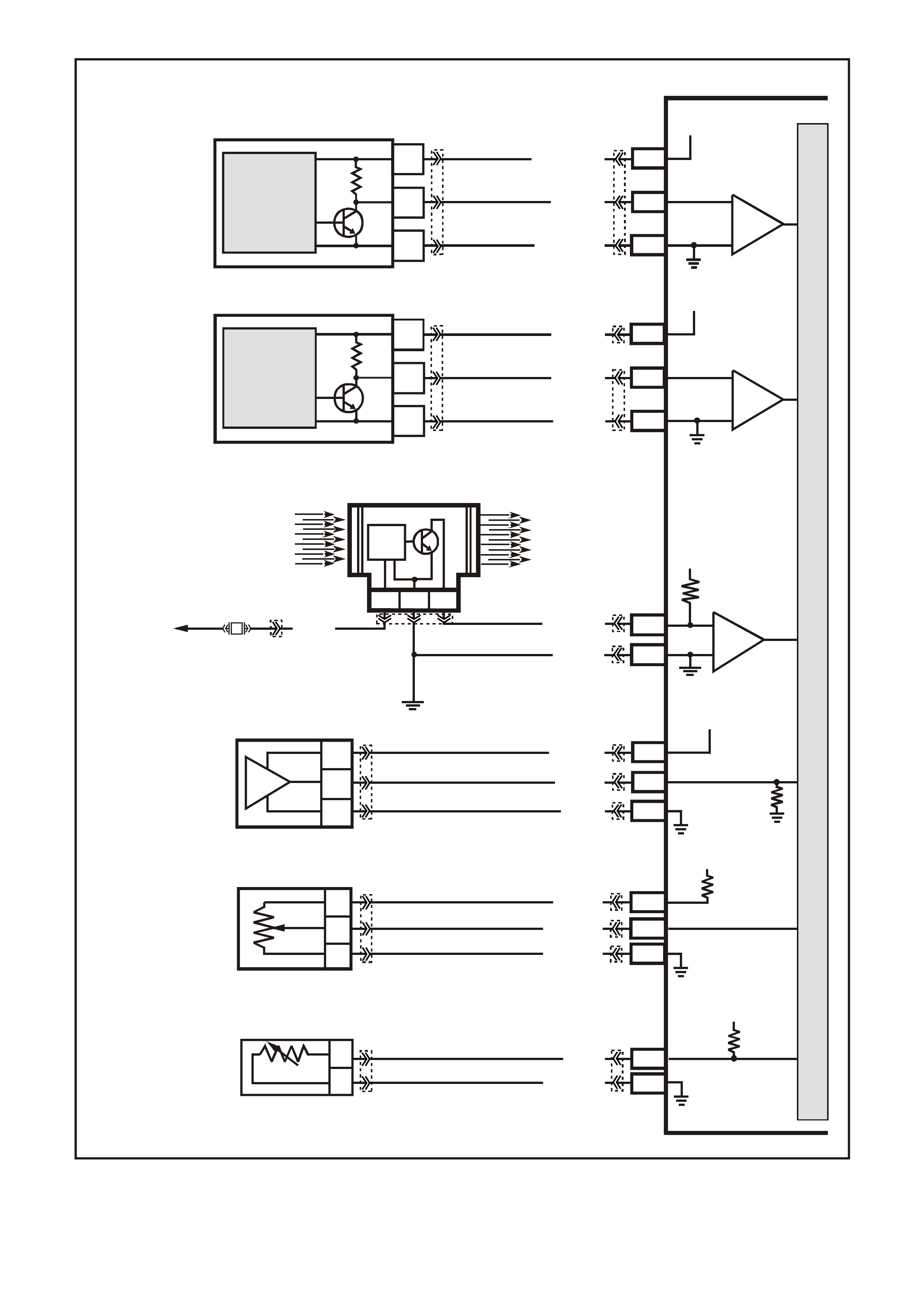
Figure 6C3-2A-13 Powertrain Control Schematics (7 of 12) – CKP, CMP, MAF, MAP, TP and ECT Circuits
G3PCM051PT
PCM
A
C
B
CRANKSHAFT
POSITION
SENSOR
J1-02
LBLU/W (646)
J1-21
SENSOR EARTH
LBLU/B (64 7)
12V
J1-12
BLU (643)
CRANKSHAFT
POSITION
SENSOR
SIGNAL
MAGNETO
RESISTIVE
INTEGRATED
CIRCUIT
IC
CAMSHAFT
POSITION
SENSOR
J1-61
SENSOR EARTH
R/W (632)
J2-39
W/B (631)
12V
J1-73
BR (633)
CAMSHAFT POSITION
SENSOR
SIGNAL
A
C
B
HALL EFF ECT
INTEGRATED
CIRCUIT
IC
IC
CIRCUIT
MASS A IR FLO W SE NSOR
J2-31
J1-01
CBA
AIR FLOW
FROM
AIR FILTER
AIR FLOW
TO
THROTTLE BODY
EFI
RELAY
P (43 9) BR/W (792)
MASS AIR
FLOW
INPUT
SIGNAL
EARTH
IC
B/R (750)
LOC. E5/E15
F33
J2-32
J1-54
C
B
A
MANIFOLD
ABSOLUTE
PRESSURE SENSOR
J1-48
SENSOR EARTH
MAP SENSOR
SIGNAL
5V
5V
V/W (414)
B (42 1)
LG (432)
SENSOR EARTH
TP SENSOR SIGNAL
TP SENSOR
REFERENCE
VOLTAGE
5V
J1-08
J2-24
J1-60
A
C
B
THROTTLE
POSITION SENSOR
GY (416)
BLU (417)
B/Y (452)
J1-80
J1-74
B
A
ENGINE COOLANT
TEMPERATURE
SENSOR
SENSOR EARTH
ETC SENSOR SIGNAL
Y (41 0)
GY/B (455)
5V
M
I
C
R
O
P
R
O
C
E
S
S
O
R
YE67
YE69 YE122
YE122
YE123
YE123
YE122
YE122
YE123
YE122
YE122
YE123
YE122
YE122
YE65
YE30
YE27
YE111
YE100
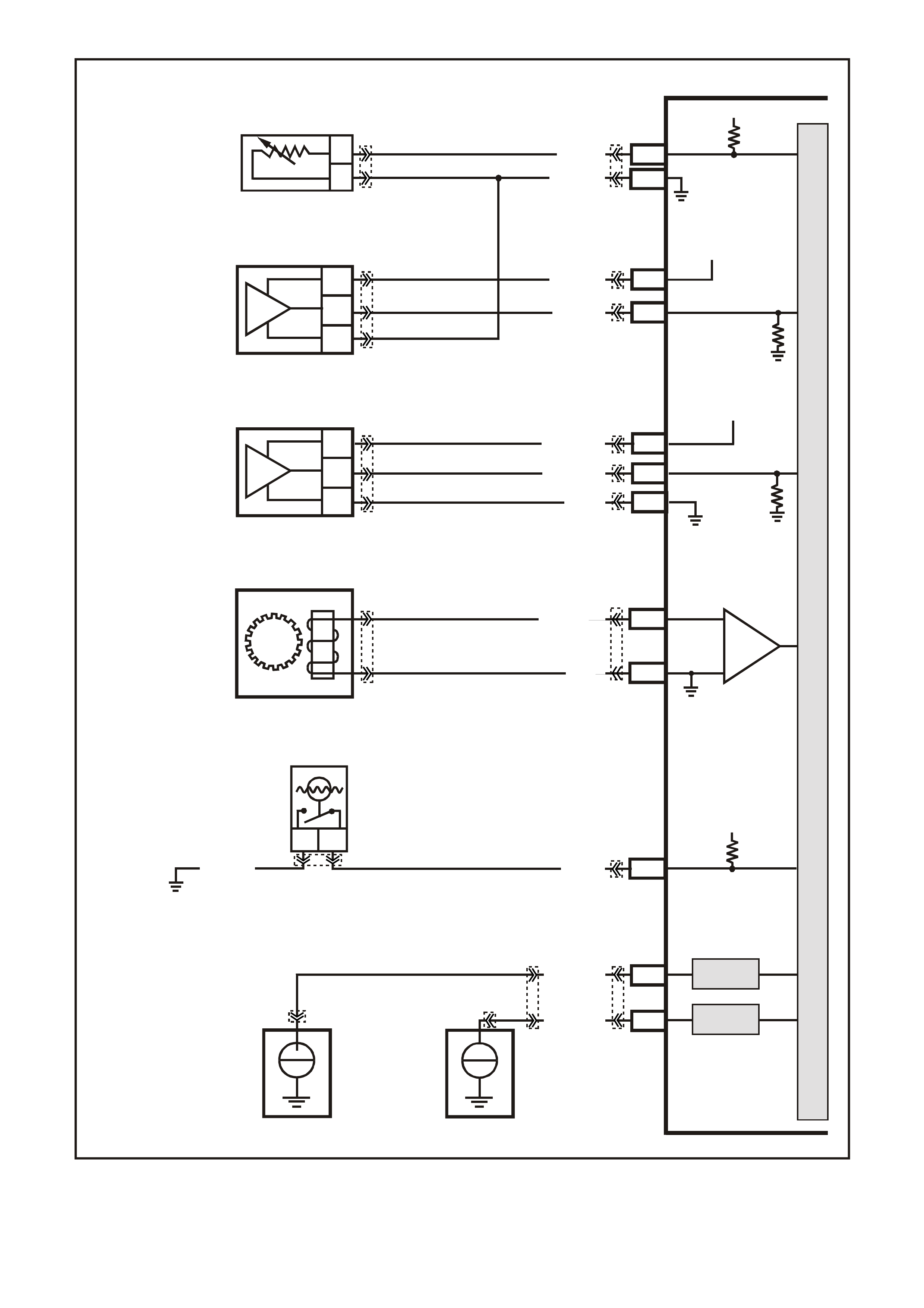
Figure 6C3-2A-14 Powertrain Control Schematics (8 of 12) – IAT, A/C Pressure Sensor, Oil Pressure,
VSS, Low Coolant and KS Circuits
G3PCM052PT
PCM
J2-57
J2-25
A
B
INTAKE AIR
TEMPERATURE
SENSOR
SENSOR EARTH
IAT SENSO R SIGN AL
5V
BR (472)
G/O (469)
J2-14
A/C
PRESSURE
SENSOR
J1-45 A/C PRESSURE
SENSOR SIGNAL
5V
V/W (415)
G/B (259)
C
B
A
OIL
PRESSURE
SENSOR
J2-58
J1-63
J1-07
SENSOR EARTH
OIL PRESSURE
SENSOR SIGNAL
5V
BLU/Y (334)
G (335)
BR/W (331)
C
B
A
J1-30
BA
LOW COOLANT
LEVEL SWITCH
LOW COOLANT LEVEL
SW ITCH SIG NAL
12V
G (69)
B/R (750)
LOC. E5/E15
VEHICLE SPEED
SENSOR
IC
VSS HI
VSS LO
J2-21
J2-20
BLU/W (831)
T (832)
DSNEF
DSNEF
FRONT KNOCK
SENSOR SIGNAL INPUT
REAR KNOC K
SENSOR SIGNAL INPUT
J1-51
J1-11
REAR
KNOCK
SENSOR
FRONT
KNOCK
SENSOR
+
-
+
-
BLU (815)
LBLU (826)
M
I
C
R
O
P
R
O
C
E
S
S
O
R
YE123
YE122
YE123
YE122
YE122
YE123
YE122
YE122
YE19
YE18
YE18
YE131
YB195
YE32
YE113
YE23
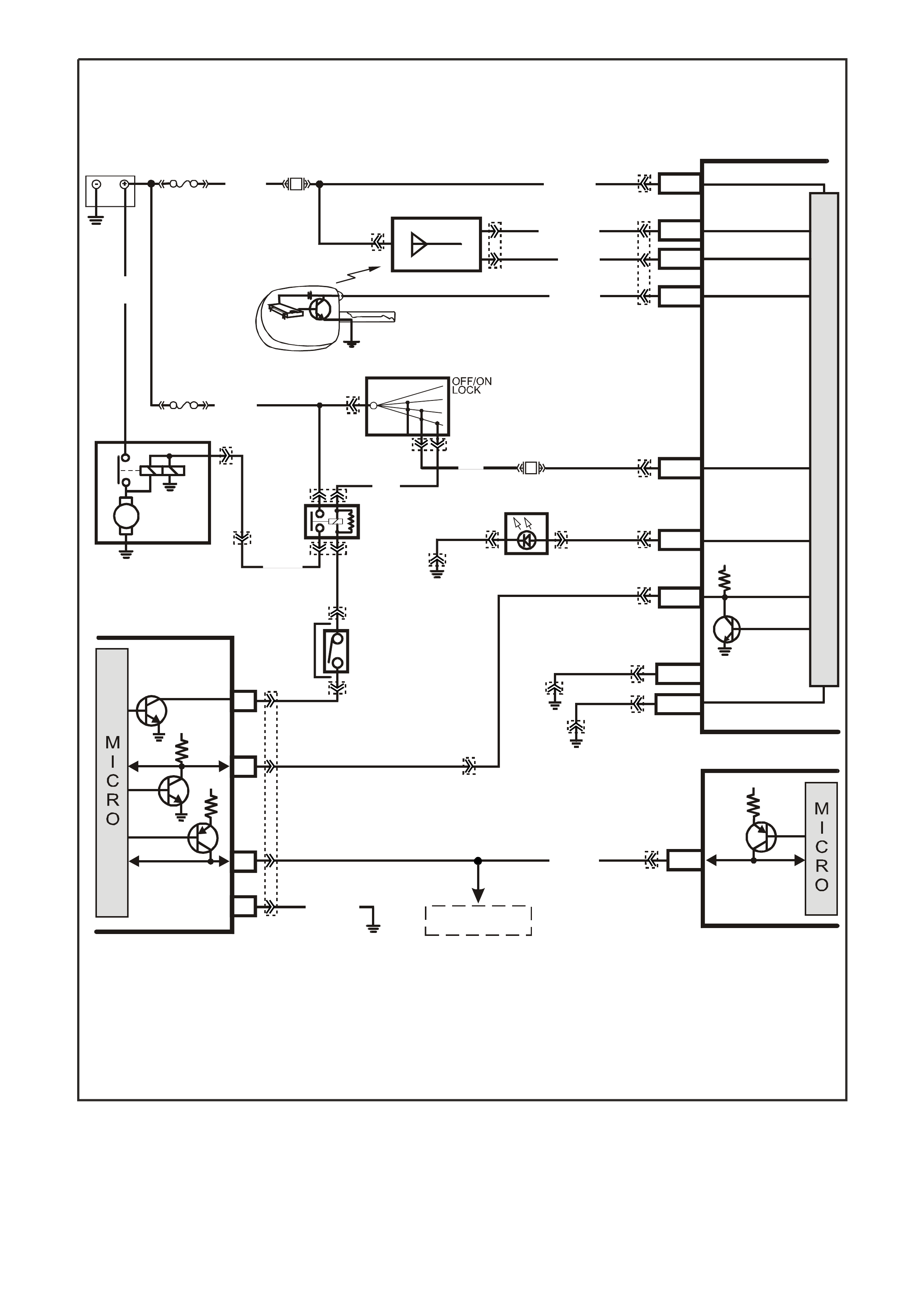
Figure 6C3-2A-15 Powertrain Control Schematics (9 of 12) – Start Relay Circuits
BAT TERY MAIN POWER
HIGH SERIES
BCM TERMINALS
NOMINA TED FIRST
BCM
REMOTE
CODED KEY
V/R (229) E1/D12 KEY R EADER
BATTERY
FS
LOC.
E1
LOC. G1
F31
A5/A6
O/B (740)
(1040)
REMOTE KEY
RECEIVER
Y (266) E8/D1 RECEIVER DATA
BR/G (271) E7/D11 RECE IVER EARTH
O/B
(740)
FJ
M
I
C
R
O
P
R
O
C
E
S
S
O
R
GY/BLU
(1434)
G3PCM045PT
THEFT DETERRENT
ALERT INDICA TOR
R/B
(1221)
E2/D2 SERIAL DATA
5V
R (2H)
E20/D6 IGNITION
NEUTRAL ST ART
BACK-UP SW.
(FOR AUTO TRANS)
(FOR MANUAL
TRANS)
GY
(434)
R (1)
V/W (6)
F14
START
RELAY
IGN ITIO N SWITC H
15a 15 50
30 ACC
IGN
START
V (5) P (3) P/B
(39)
A6/A8
LBLU
(263) THE FT LED
B/Y
(155)
LOC. E3
B/G
(151) B10/B11 HIGH CURRENT
EARTH
B/Y
(155) ELECTRONIC EARTH
A1/A5
LOC. E3
LOC. E3
PIM
UART
SERIAL
DATA
START
RELAY
5V
6
8
16
7V
7
CLASS 2
SERIAL DATA
B/R (750)
LOC. E5/E15
R/B
(1221)
7V
PCM
J1-58 CLASS 2
SERIAL DATA
Y (1049)
Y
(1049)
STARTER
MOTOR
M
YB215
YE112
YB35
YE104
YE8
YB35
YE114 YB56 YB56
YE49
YB44
YE49
YB44
YB95
YB175
YB164
YB176
YB165
YB175
YB164
YB175
YB164
YB174
YB163
YE114
YE114 YB176
YB165
YE122
YB176
YB165
YB95
TO
DLC TERMINAL 2
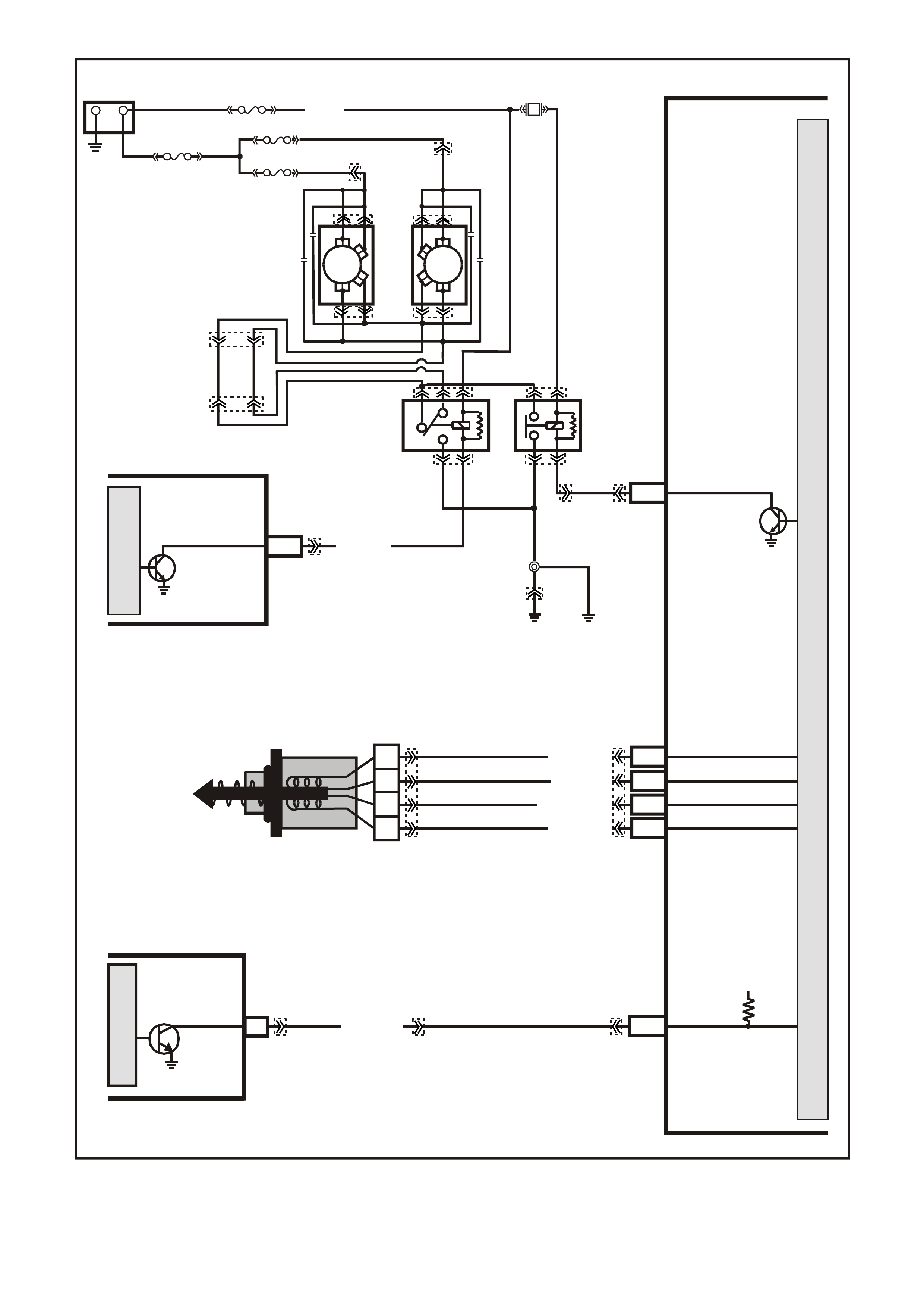
Figure 6C3-2A-16 Powertrain Control Schematics (10 of 12) – Engine Cooling Fans, IAC Valve Circuits
G3PCM056PT
PCM
M
I
C
R
O
P
R
O
C
E
S
S
O
R
87A
30
87
85
86
87
30
85
86
ENGINE
COOLING
FAN 1
ENGINE
COOLING
FAN RELAY
(LOW SPEED)
ENGINE
COOLING
FAN RELAY
(HIGH SPEED)
R
Y
B
G
O/B (473)
BLUE
FUSIBLE
LINK
LOC.
E1
F31
ENGINE
COOLING
FAN 2
+
-
BATTERY
FS
FT FAN 2
FU FAN 1
(1040)
R
(203)
(250)
O/Y
(533)
BLU/Y
Fan 1
340 Fan 2
300
R
(001)
R
(001)
O/B
(208)
O/BLU
(204)
BLU/W
(304) J2-33
HIGH
SPEED FAN
LOC.
E2
LOC.
E3
B/R
(157)
BCM
LOW SPEED FAN B7/B7
M
I
C
R
O
12V
J2-53 ETC DATA
CONTROL
( S PARK RETA R D)
GY/B (1687)
ABS/ETC
28
SPARK
RETARD
M
I
C
R
O
J2-77
J2-78
J2-79
J2-76
LG/B (444)
A
B
C
D
IAC VALVE
LG/W (443)
LBLU (441)
LBLU/B (44 2)
IAC COIL B LO
IAC COIL B HI
IAC COIL A LO
IAC COIL A HI
ØØ
YE140
YE139
YE119
YE103 YE43
YE43
YE110 YE123
YE103
YE104
YB163
YB174
YE114
YE36
YE98 YE129 YE123
YE123
YE118
YE119
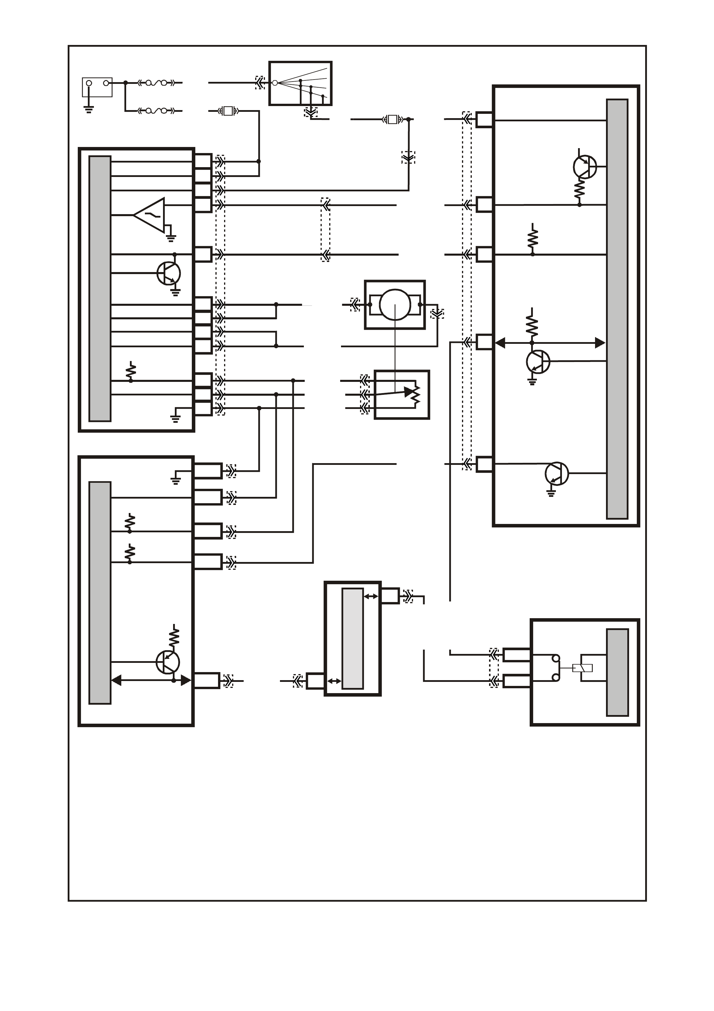
Figure 6C3-2A-17 Powertrain Control Schematics (11 of 12) – Throttle Relaxer, Tachometer Signal Circuits
G3PCM035PT
HIGH SERIES
BCM TE RMIN ALS
NOMINATED FIRST
12V
12V
27
E2/D2
E9/D3
13
REQUESTED
THROTTL E (DKR)
ACTUAL
THROTTL E (DKI)
O/W (1426)
B/W (1427)
M
I
C
R
O
P
R
O
C
E
S
S
O
R
MAIN POWER
15
ABS/ETC
CONTROL MODULE
BCM
37
35
M
I
C
R
O
DKR
IGNITION
BATTERY
BATTERY
DKI
MOTOR +
MOTOR +
MOTOR -
MOTOR -
Y (1049)
M
I
C
R
O
5V
41
22
A
C
B
40
49
43
26
53
5 VOLT REF.
TPS SIGNAL
TPS GROUND
THROTTLE
POSITION SENSOR
THROTTLE
RELAXER
5V
12V
J1-08
J2-53
5 VOLT REF.
SPARK RETARD
TPS SIGNAL
TPS GROUND
J2-24
J1-60
J1-58
CLASS 2
SERIAL DA TA
7V
M
I
C
R
O
PIM
6
7
M
I
C
R
O
CLASS 2 SERIAL DATA
UART SERIAL DATA
11
SERIAL
DATA
5V
28
SPARK
RETARD
GY (416)
R/B (466)
R/W (456) AB
BLU (417)
B/Y (452)
R/B (1221)
+-
BATTERY
FJ
LOC.
E1 FS
IGNITION
SWITCH
15a 15 50
30
OFF/ON
LOCK
ACC
IGN
START
F27
F36
P (3)
R (8 55)
1
24
51
TH R OTTLE R ELAX ER
CONTROL MODULE
R (2 H)
(1040)
R/Y
(480)
GY/B (1687)
G/W (1220)
PCM
YB44
YB44
YE127
YE127
YE30
YE98
YB215
YB215YE122
YE123
YE122
YE122
YB170
YE123
YB175
YB164
YE110
YE129
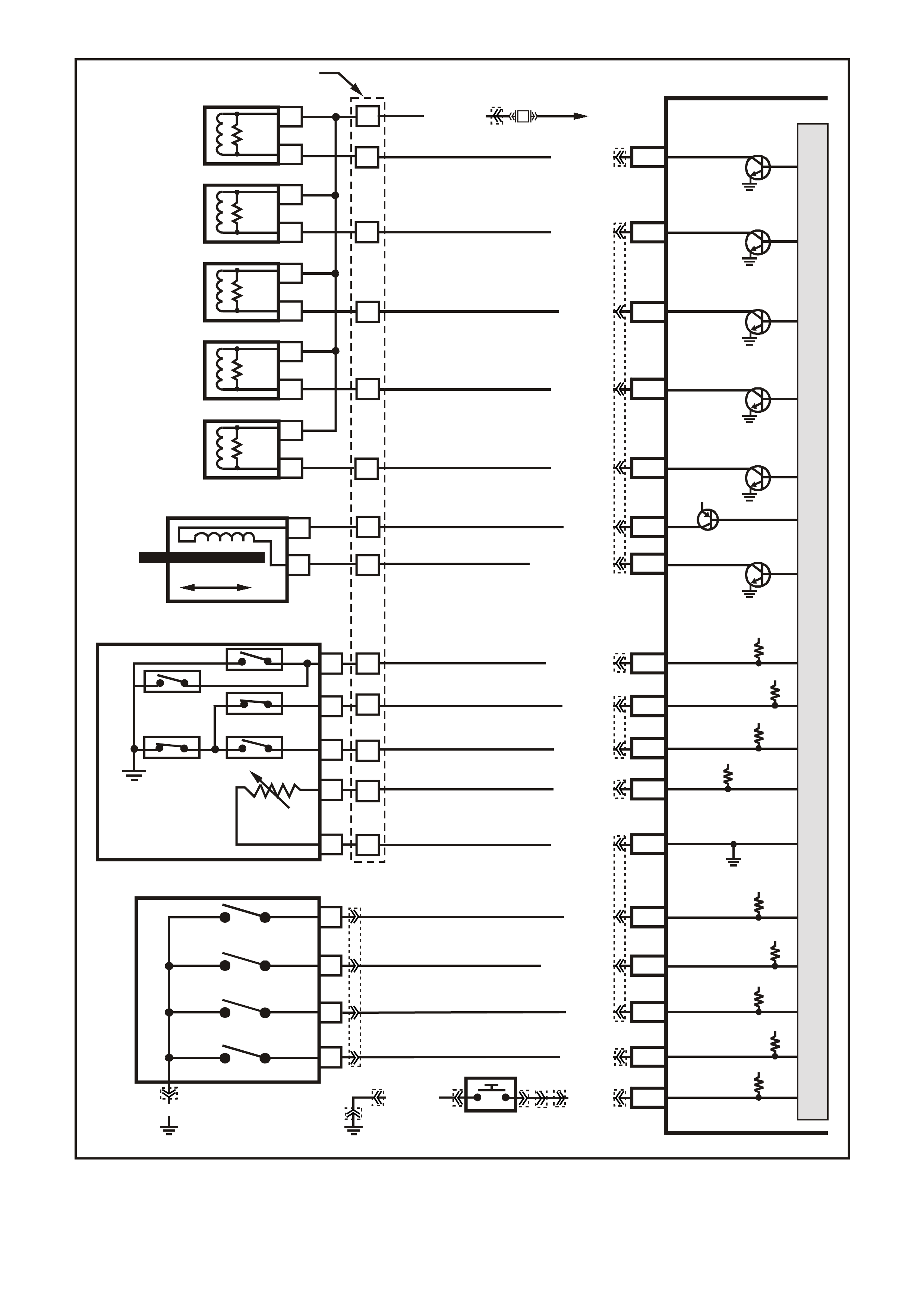
Figure 6C3-2A-18 Powertrain Control Schematics (12 of 12) – Transmission, Power/Economy Circuits
G3PCM050PT
PCM
J2-47
J2-48
J1-79
J2-42
J2-04
J2-08
J2-06
TCC PWM
SOLENOID
3-2 CONTROL
SOLENOID
1-2 SHIFT
SOLENOID A
2-3 SHIFT
SOLENOID B
PRESSURE
CONTROL
SOLENOID
LOW
PRESSURE CONTROL
SOLENOID HIGH
B
A
A
B
B
B
A
A
B
A
YB 129 TRANS MISSION
PASS-THRU CONNECTOR
TORQUE
CONVERTER
CLUTCH (TCC)
(PWM)
SOLENOID
TORQUE
CONVERTER
CLUTCH (TCC)
ENABLE
SOLENOID
3-2 DOWNSHIFT
CONTROL
SOLENOID
1-2 SHIFT
SOLENOID A
2-3 SHIFT
SOLENOID B
PRESSURE
CONTROL
SOLENOID
C
D
U
S
T
E
A
B
P/BLU (339)
J2-63
J1-17
J1-18
J1-53
TFP SIGNAL A
TFP SIGNAL B
TFP SIGNAL C
TRANSMISSION FLUID
TEMPERATURE (TFT)
SENSOR SIGNAL
SENSOR
EARTH
N
C
R
E
DP
TRANSMISSION FLUID
TEMPERATURE
(TF T ) SENSOR
AUTOMATIC TRANSMISSION FLUID PRESSURE
MANUAL VALVE POSITION SWITCH (TFP)
J1-71 POWER/ECONOMY
SWITCH
POWER/ECONOMY
SWITCH
TCC ENABLE
SOLENOID
B
A
EFI
RELAY
F32
G/W (897)
LG (1222)
Y/B (1223)
GY/BLU (1229)
R (1228)
BR/Y (1224)
Y (1225)
GY (1226)
J2-51
A
B
L
M
B/Y (1227)
B/W (1230)
12V
12V
12V
12V
12V
12V
12V
12V
12V
5V
M
I
C
R
O
P
R
O
C
E
S
S
O
R
J1-32
J1-72
A
SWITCH P
SWITCH A
SWITCH B
SWITCH C
LOC. E5/E15 LOC. E3
D
B
C
P R N D L SWITCH
J2-62
J1-34
BLU/W (771)
Y (77 2)
GY (773)
W (776)
B/R (750)
RANGE
SIGNAL P
RANGE
SIGNAL A
RANGE
SIGNAL B
RANGE
SIGNAL C
BLU (774)
B/G (151)
BR (418)
GY/R (422)
YB30
YB20
YE114
YB35 YB34
YB30
YE112
YE122
YE123
YE123
YE123
YE122
YE122
YE122
YE123
YB34
YE110

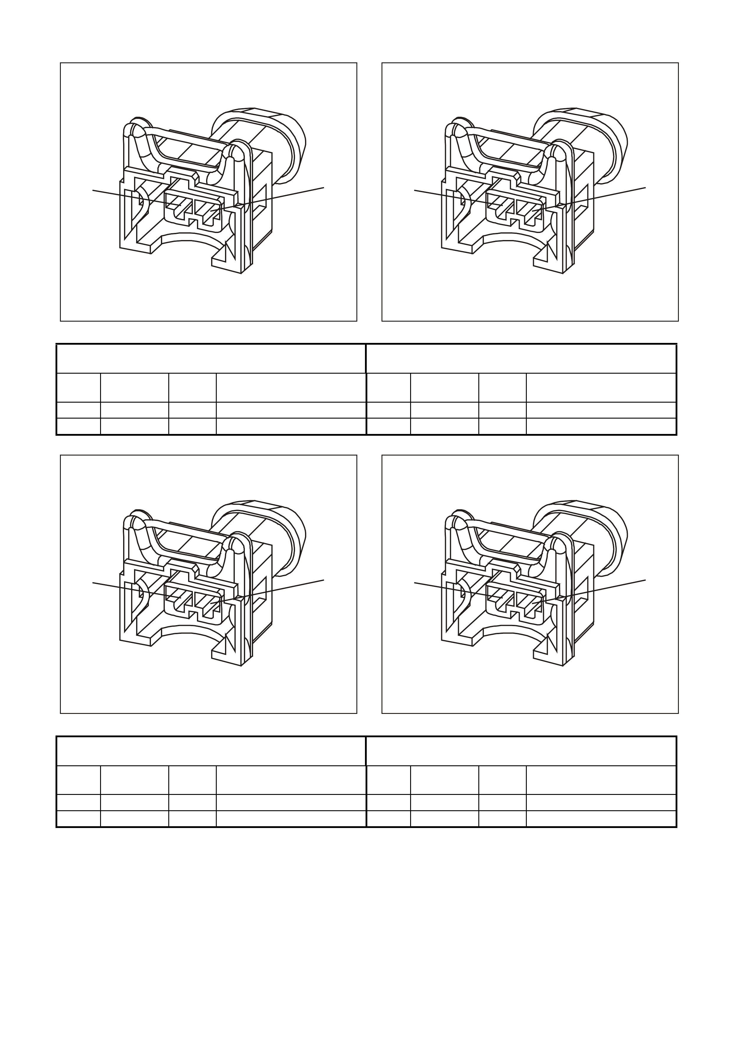
PCM CONNECTOR END VIEWS
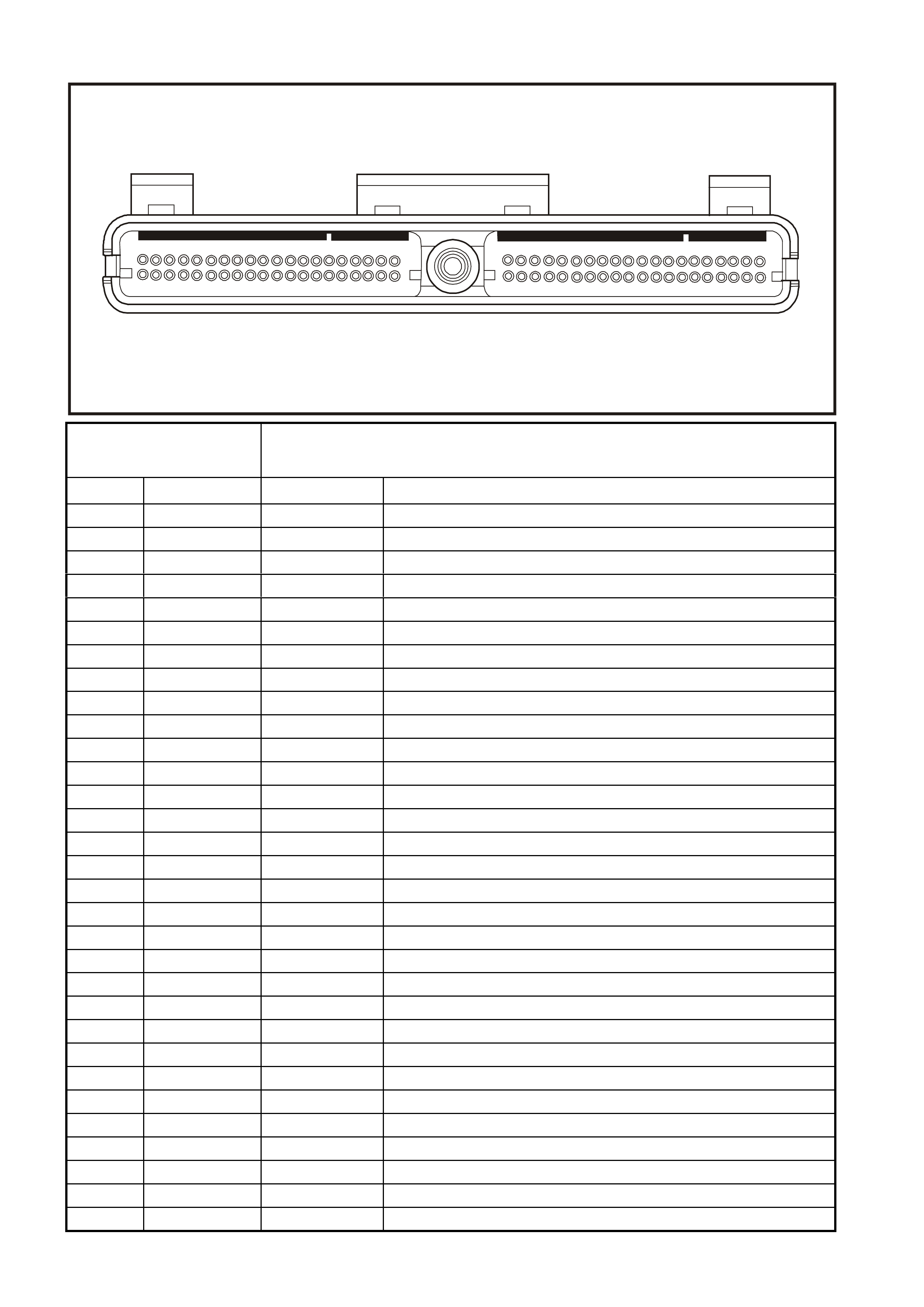
PCM CONNECTOR J1 (BLUE)
60
20
61
21
80
401
41
4547
Connector Part
Information • PCM Connector YE122 J1 (Blue)
• 80 Pin Connector
Pin Wire Color Circuit No. Function
1 Brown/Red 750 System Earth
2 LT Blue/White 646 Crankshaft Position Sensor Ignition Voltage Feed
3 Violet 843 Fuel Injector #3 Driver
4 Green 842 Fuel Injector #2 Driver
5 Not Used - -
6 Not Used - -
7 Blue/Yellow 334 Oil Pressure Sensor 5 Volt Reference
8 Grey 416 Throttle Position Sensor 5 Volt Reference
9 Not Used - -
10 Not Used - -
11 LBLU 826 Rear Knock Sensor Input Signal
12 Blue 643 Crankshaft Position Sensor Input Signal
13 Not Used - -
14 Not Used - -
15 Not Used - -
16 Not Used - -
17 Yellow 1225 Transmission Range B Input
18 Grey 1226 Transmission Range C Input
19 Pink 39 Ignition Positive Voltage
20 Orange 740 Battery Feed
21 LT Blue/Black 647 Crankshaft Position Sensor Reference Low
22 Not Used - -
23 Not Used - -
24 Not Used - -
25 Not Used - -
26 Grey/Black 1413 Bank 2 Sensor 1Heated Oxygen Sensor Signal Low
27 Not Used - -
28 Not Used - -
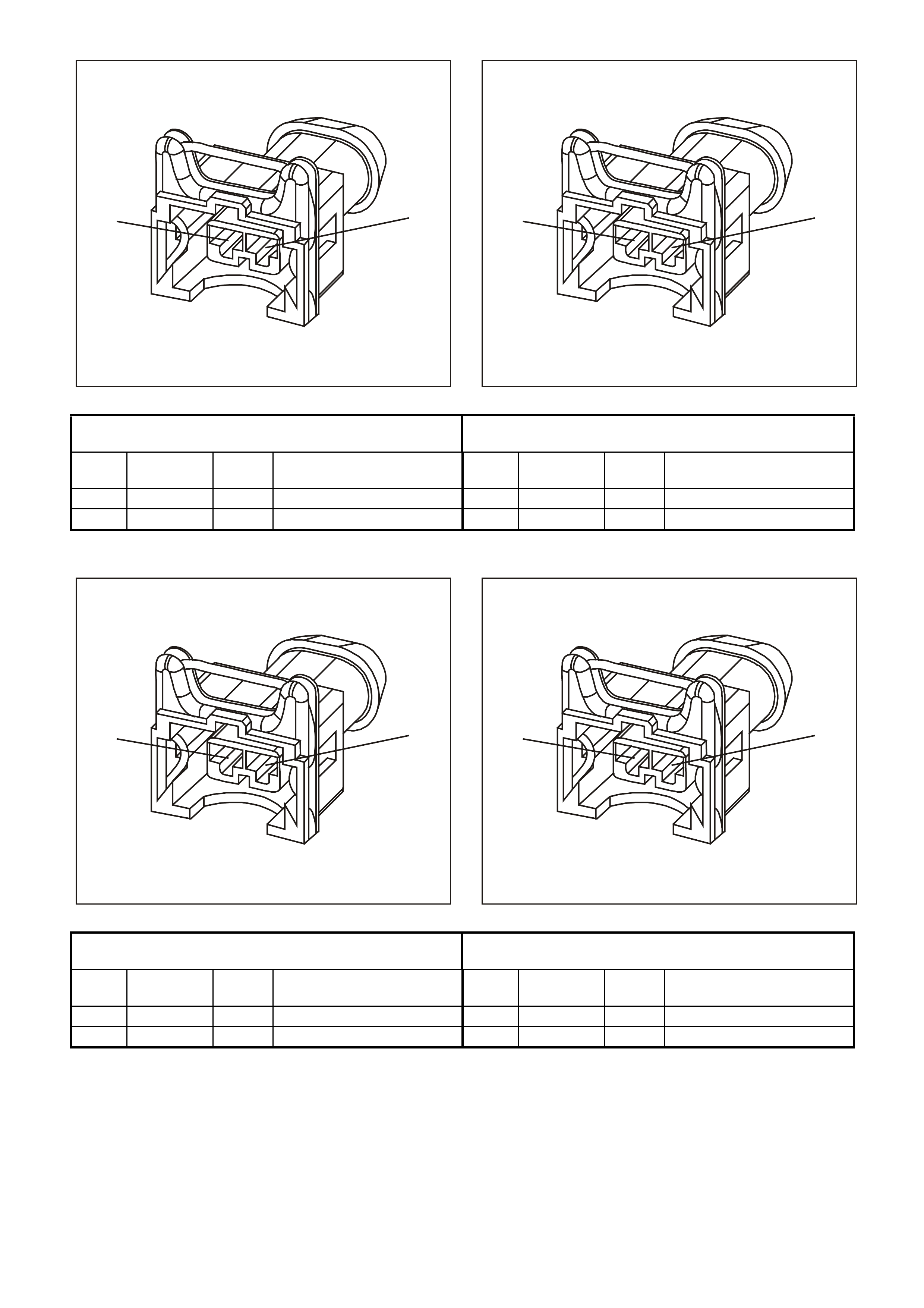
PCM CONNECTOR J1 (BLUE) CONTINUED
60
20
61
21
80
401
41
4547
Connector Part
Information • PCM Connector YE122 J1 (Blue)
• 80 Pin Connector
Pin Wire Color Circuit No. Function
29 Blue/Black 413 Bank 1 Sensor 1 Heated Oxygen Sensor Signal Low
30 Green 69 Engine Coolant Level switch Input Signal
31 Not Used - -
32 Blue/White 771 PRNDL A
33 Brown 86 Torque Converter Clutch/Cruise Brake Switch Input Signal
34 White 776 PRNDL P
35 Not Used - -
36 Blue 841 Fuel Injector #1 Driver
37 Yellow 846 Fuel Injector #6 Driver
38 Not Used - -
39 Not Used - -
40 Brown/Red 750 System Earth
41 Not Used - -
42 Not Used - -
43 Pink/Black 847 Fuel Injector #7 Driver
44 Brown/Yellow 844 Fuel Injector #4 Driver
45 Violet/White 415 A/C Refrigerant Pressure Sensor 5 Volt Reference
46 Not Used - -
47 Not Used - -
48 Violet/White 414 Manifold Absolute Pressure Sensor 5 Volt Reference
49 Not Used - -
50 Not Used - -
51 Blue 815 Front Knock Sensor Input Signal
52 Not Used - -
53 Black/White 1230 Transmission Fluid Temperature Sensor Earth
54 Black 421 Manifold Absolute Pressure Sensor Earth
55 Not Used - -
56 Not Used - -
57 Orange 740 Battery Feed
58 Yellow 1049 Serial Data (Class II)
PCM CONNECTOR J1 (BLUE) CONTINUED
60
20
61
21
80
401
41
4547
Connector Part
Information • PCM Connector YE122 J1 (Blue)
• 80 Pin Connector
Pin Wire Color Circuit No. Function
59 Not Used - -
60 Black/Yellow 452 Throttle Position Sensor Earth
61 Red/White 632 Camshaft Position Sensor Reference Low
62 Not Used - -
63 Green 335 Oil Pressure Sensor Earth
64 Not Used - -
65 Not Used - -
66 Grey 1412 Bank 2 Sensor 1 Heated Oxygen Sensor Signal High
67 Not Used - -
68 Not Used - -
69 Violet 412 Bank 1 Sensor 1 Heated Oxygen Sensor Signal High
70 Not Used - -
71 Blue 774 Power/Economy Switch Input
72 Yellow 772 PRNDL B
73 Brown 633 Camshaft Position Sensor Input Signal
74 Yellow 410 Engine Coolant Temperature Sensor Signal
75 Not Used - -
76 Grey 845 Fuel Injector #5 Driver
77 LT Green 848 Fuel Injector #8 Driver
78 Not Used - -
79 Green/White 897 3-2 Shift Solenoid Control
80 Grey/Black 455 Engine Coolant Temperature Sensor Earth
PCM CONNECTOR J2 (RED)
60
20
61
21
80
401
41
4547
Connector Part
Information • PCM Connector YE123 J2 (Red)
• 80 Pin Connector
Pin Wire Color Circuit No. Function
1 Brown/Red 750 System Earth
2 Not Used - -
3 Not Used - -
4 Brown 418 Torque Converter Clutch Pulse Width Modulation Solenoid Control
5 Not Used - -
6 Red 1228 Pressure Control Solenoid Signal High
7 Not Used - -
8 Grey/Blue 1229 Pressure Control Solenoid Signal Low
9 Green/W hite 465 Fuel Pump Relay Control
10 Brown 121 Tachometer Output Signal
11 Not Used - -
12 Not Used - -
13 Not Used - -
14 Green/Black 259 A/C Refrigerant Pressure Sensor Input Signal
15 Not Used - -
16 Not Used - -
17 Not Used - -
18 Green 59 A/C Clutch Status
19 Not Used - -
20 Tan 832 Vehicle Speed Sensor Signal Low
21 Blue/White 831 Vehicle Speed Sensor Signal High
22 Not Used - -
23 Not Used - -
24 Blue 417 Throttle Position Sensor Input Signal
25 Brown 472 Intake Air Temperature Sensor Signal
26 White 971 Ignition Coil/Module Control #1
27 Yellow 977 Ignition Coil/Module Control #7
28 LT Green 976 Ignition Coil/Module Control #6
29 White 974 Ignition Coil/Module Control #4
30 Not Used - -
31 Brown/White 792 Mass Air Flow Sensor Signal
32 LT Green 432 Manifold Absolute Pressure Sensor Input Signal
PCM CONNECTOR J2 (RED) CONTINUED
60
20
61
21
80
401
41
4547
Connector Part
Information
• PCM Connector YE123 J2 (Red)
• 80 Pin Connector
Pin Wire Color Circuit No. Function
33 Blue/White 304 Engine Cooling Fan Relay High Speed Control
34 Green/Yellow 428 Evaporative Emission Canister Purge Solenoid Control
35 Not Used - -
36 Not Used - -
37 Not Used - -
38 Not Used - -
39 White/Black 631 Camshaft Sensor Ignition Voltage Feed
40 Brown/Red 750 System Earth
41 Not Used - -
42 Grey/Red 422 Torque Converter Clutch Solenoid Control
43 LT Green/Black 366 A/C Clutch Relay Control
44 Yellow 838 Manual Transmission Reverse Lock-Out Control
45 Not Used - -
46 Not Used - -
47 Yellow/Black 1223 2-3 Shift Solenoid Control
48 LT Green 1222 1-2 Shift Solenoid Control
49 Not Used - -
50 Violet/White 123 Vehicle Speed Sensor Output Signal
51 Black/Yellow 1227 Transmission Fluid Temperature Sensor Input Signal
52 Not Used - -
53 Grey/Black 1687 Electronic Traction Control Retard Signal
54 Not Used - -
55 Not Used - -
56 Not Used - -
57 Green/Orange 469 Intake Air Temperature / A/C Refrigerant Pressure Sensor Earth
58 Brown/White 331 Oil Pressure Sensor Input Signal
59 Not Used - -
60 Brown 958 Ignition Reference Low
61 Violet 959 Ignition Reference Low
62 Grey 773 PRNDL C
63 Brown/Yellow 1224 Transmission Range A Input
PCM CONNECTOR J2 (RED) CONTINUED
60
20
61
21
80
401
41
4547
Connector Part
Information • PCM Connector YE123 J2 (Red)
• 80 Pin Connector
Pin Wire Color Circuit No. Function
64 Not Used - -
65 Not Used - -
66 LT Blue 978 Ignition Coil/Module Control #8
67 Yellow/Black 972 Ignition Coil/Module Control #2
68 Green 975 Ignition Coil/Module Control #5
69 Blue 973 Ignition Coil/Module Control #3
70 Not Used - -
71 Not Used - -
72 Not Used - -
73 Not Used - -
74 Not Used - -
75 Not Used - -
76 LT
Green/White 443 Idle Air Control Valve Coil B High
77 LT
Green/Black 444 Idle Air Control Valve Coil B Low
78 LT Blue/Black 442 Idle Air Control Valve Coil A Low
79 LT Blue 441 Idle Air Control Valve Coil A High
80 Not Used - -

PCM CONNECTOR TERMINAL DE FINITIONS
PCM CONNECTOR J1 (BLUE)
1 – SYSTEM EARTH – This terminal should have zero volts. This circuit is connected directly to the engine earth.
2 – CRANKSHAFT POSITION SENSOR IGNITION VOLTAGE FEED – This voltage should be always be B+
anytime the ignition is ON. It is a regulated voltage output from the PCM and supplies B+ to the CKP sensor.
3 – FUEL INJECTOR #3 DRIVER – W ith the engine OFF and the ignition ON, the voltage should be B+. W ith the
engine running at idle, the charging s ys tem inc reases the battery voltage slightly, s o this voltage will increase. With
higher engine RPM or more engine load, the resulting increase in injector pulse frequency or injector pulse width
will cause this voltage to become slightly less.
4 – FUEL INJECTOR #2 DRIVER – W ith the engine OFF and the ignition ON, the voltage should be B+. W ith the
engine running at idle, the charging s ys tem inc reases the battery voltage slightly, s o this voltage will increase. With
higher engine RPM or more engine load, the resulting increase in injector pulse frequency or injector pulse width
will cause this voltage to become slightly less.
5 – NOT USED
6 – NOT USED
7 – OIL PRESSURE SENSOR 5V REFERENCE – This voltage should always be 5 volts whenever the ignition is
ON. The reference voltage is a regulated voltage from the PCM, and supplies 5 volts to the oil pressure sensor.
8 – THROT TLE PO SITION SENSOR 5 VOL T REFERENCE – T his voltage should always be 5 volts whenever the
ignition is ON. The reference voltage is a regulated voltage from the PCM, and supplies 5 volts to the TP sensor.
9 – NOT USED
10 – NOT USED
11 – REAR KNOCK SENSOR INPUT SIGNAL – The knock sensor detects when detonation is occurring in the
combustion chambers. W hen detected, the PCM will reduce the amount of spark advance being delivered on the
EST output circuits to the ignition COIL/MODULES.
12 – CRANKSHAFT POSITION SENSOR INPUT SIGNAL – This terminal could be called the tech input. It
provides the PCM with RPM and crank shaft pos ition inform ation. T he PCM uses this signal to control fuel injection,
and spark timing.
13 – NOT USED
14 – NOT USED
15 – NOT USED
16 – NOT USED
17 – TRANSMISSION RANGE B INPUT – The PCM sends out a buffered B+ signal to the pressure switch
assembly., located in the automatic transmission valve body. The B+ signal must pass through either a normally
open or normally closed switch to reach earth. When the switches are closed, the signal should be near 0 volts.
The PCM monitors the status of these signals to determine which gear servo is actually receiving hydraulic apply
pressure.
18 – TRANSMISSION RANGE C INPUT – The PCM sends out a buffered B+ signal to the pressure switch
assembly located in the automatic transmission valve body. The B+ signal must pass through either a normally
open or normally closed switch to reach earth. When the switches are closed, the signal should be near 0 volts.
The PCM monitors the status of these signals to determine which gear servo is actually receiving hydraulic apply
pressure.
19 – IGNIT ION POSITIVE VO LTAG E – This is the wak e up s ignal to the PCM f rom the ignition s witch. It is not the
power supply to the PCM, it only tells the PCM that the ignition switch is ON. The voltage should equal the battery
voltage when the key is in either the RUN, or CRANK position.
20 – BATTERY FEED – T his supplies the PCM with full tim e B+ volts. This circuit stays hot even when the ignition
is turned OFF. The battery voltage feed circuit receives it’s voltage from fuse F31.
21 – CRANKSHAFT POSITION SENSOR REFERENCE LOW – This terminal should always be zero volts. It is
connected from the PCM to the CKP sensor and provides the earth signal needed for the sensor to operate.
22 – NOT USED
23 – NOT USED
24 – NOT USED
25 – NOT USED
26 – BANK 2 SENSOR 1 HEATED OXYGEN SENSO R SIGNAL LO W – This term inal should have zero volts. It is
connected f rom the PCM to the HO2S. T his term inal earth’s the PCM circuitry for the HO2S voltage monitor inside
the PCM.
27 – NOT USED
28 – NOT USED

29 – BANK 1 SENSOR 1 HEATED OXYGEN SENSO R SIGNAL LO W – This term inal should have zero volts. It is
connected f rom the PCM to the HO2S. T his term inal earth’s the PCM circuitry for the HO2S voltage monitor inside
the PCM.
30 – ENGINE COOLANT LEVEL SWITCH INPUT SIGNAL – This ter minal indicates to the PCM when the coolant
level is low. W hen the PCM receives this signal from the Engine Coolant Level switch, the PCM will turn ON a low
coolant warning lamp on the instrument panel.
31 – NOT USED
32 – PRNDL A – This circuit along with the circuits on PCM connec tor pins J1 34, 72 & J 2 62 indicate to the PCM
what transm ission gear the driver has selected. T he PCM will then send a com mand via the serial data line to the
instrument panel cluster (smart cluster) to indicate to the driver what gear has been selected.
33 – TORQUE CONVERTER CLUTCH/CRUISE BRAKE SWITCH INPUT SIGNAL – This signal indicates to the
PCM when the driver has depressed the brake pedal. The PCM will then disengage the TCC and or cruise if
activated. This circuit also indicates to the PCM and cruise control actuator when the ABS/ETC module is
requesting the Low Traction lamp ON.
34 – PRNDL P – T his circuit along with the circuits on PCM connector pins J1 32, 72 & J2 62 indicate to the PCM
what transmission gear the driver has selected. The PCM will then send a com mand via the serial data line to the
instrument panel cluster (smart cluster) to indicate to the driver what gear has been selected.
35 – NOT USED
36 – FUEL INJECTOR #1 DRIVER – With the engine OFF and the ignition ON, the voltage should be B+. With the
engine running at idle, the charging system increases battery voltage slightly, so this voltage will increase. With
higher engine RPM or more engine load, the resulting increase in injector pulse frequency or injector pulse width
will cause this voltage to become slightly less.
37 – FUEL INJECTOR #6 DRIVER – With the engine OFF and the ignition ON, the voltage should be B+. With the
engine running at idle, the charging system increases battery voltage slightly, so this voltage will increase. With
higher engine RPM or more engine load, the resulting increase in injector pulse frequency or injector pulse width
will cause this voltage to become slightly less.
38 – NOT USED
39 – NOT USED
40 – SYSTEM EARTH – This terminal should have zero volts. This circuit is connected directly to the engine earth.
41 – NOT USED
42 – NOT USED
43 – FUEL INJECTOR #7 DRIVER – With the engine OFF and the ignition O N, the voltage should be B+. With the
engine running at idle, the charging s ys tem inc reases the battery voltage slightly, s o this voltage will increase. With
higher engine RPM or more engine load, the resulting increase in injector pulse frequency or injector pulse width
will cause this voltage to become slightly less.
44 – FUEL INJECTOR #4 DRIVER – With the engine OFF and the ignition ON, the voltage should be B+. With the
engine running at idle, the charging s ys tem inc reases the battery voltage slightly, s o this voltage will increase. With
higher engine RPM or more engine load, the resulting increase in injector pulse frequency or injector pulse width
will cause this voltage to become slightly less.
45 – A/C REFRIGERANT PRESSURE SENSOR 5 VOLT REFERENCE – This voltage should always be 5 volts
anytim e the ignition is ON. It is a regulated voltage output from the PCM, and supplies 5 volts to the A/C Pressure
Sensor.
46 – NOT USED
47 – NOT USED
48 – MANIFOLD ABSOLUTE PRESSURE SENSOR 5 VOLT REFERENCE – This voltage should always be 5
volts anytime the ignition is ON. It is a regulated voltage output from the PCM and supplies 5 volts to the map
Sensor.
49 – NOT USED
50 – NOT USED
51 – FRONT KNOCK SENSOR – The Knock Sensor detects when detonation is occurring in the combustion
chambers. W hen detected, the PCM will reduce the amount of spark advance being delivered on the EST output
circuits to the ignition COIL/MODULES.
52 – NOT USED
53 – TRANSMISSION FLUID TEMPERATURE SENSOR EARTH – This terminal should be zero volts. It is
connected through the PCM circuitry to engine earth.
54 – MANIFOLD ABSOLUTE PRESSURE SENSOR EARTH – This terminal should have zero volts . T his circuit is
connected directly to the earth through the PCM.
55 – NOT USED
56 – NOT USED

57 – BATTERY FEED – T his supplies the PCM with full tim e B+ volts. This circuit stays hot even when the ignition
is turned off. The battery voltage feed circuit receives it’s voltage fuse F31.
58 – SERIAL DATA (CLASS II) –This is a dedicated line for the Tech 2 scan tool communication. The circuit
connects the PCM, PIM, ABS/ET C, and BCM. The Tec h 2 scan tool can talk to eac h of these m odules by sending
a message to a controller and asking only it to respond. The communication carried on Class II data streams are
prioritised. The normal voltage on this line is 0 volts, but when the Tech 2 scan tool is connected, the voltage will
about 7 volts indicating communication.
59 – NOT USED
60 – THROTTLE POSITION SENSOR EARTH – This terminal should have zero volts. This circuit is connected
directly to the earth through the PCM.
61 – CAMSHAFT POSITION SENSOR REFERENCE LOW – This terminal should always be zero volts. It is
connected from the PCM to the CMP sensor and provided the earth signal needed for the sensor to operate.
62 – NOT USED
63 – OIL PRESSURE SENSOR EARTH – This ter minal s hould always be zero volts. It is c onnected from the PCM
to the oil pressure sensor and provides the earth signal needed for the sensor to operate.
64 – NOT USED
65 – NOT USED
66 – BANK 2 SENSOR 1 OXYGEN SENSOR SIGNAL HIGH – With the ignition ON and the engine not running,
the voltage should be 350 – 450 millivolts (0.350 0.450 volts). This is the PCM supplied HO2S circuit bias voltage.
W hen the HO2S is hot and the engine is running, the voltage should be rapidly changing, somewhere between 10
– 1000 millivolts (0.010 – 1000 volts).
67 – NOT USED
68 – NOT USED
69 – BANK 1 SENSOR 1 HEATED OXYGEN SENSOR SIGNAL HIGH – W ith the ignition ON and the engine not
running, the voltage should be 350 – 450 millivolts (0.350 0.450 volts ). This is the PCM s upplied HO2S circuit bias
voltage. When the HO2S is hot and the engine is running, the voltage should be rapidly changing, somewhere
between 10 – 1000 millivolts (0.010 – 1000 volts).
70 – NOT USED
71 – POWER/ECONOM Y SWIT CH INPUT – T he PCM sends a signal of about 12 volts , and m onitors the status of
this circuit. In the ECONOMY position the switch is open, the PCM voltage status signal remains high – about 12
volts, and the PCM does not allow shift point changes. When the transmission switch is pressed to the POWER
position the switch is momentarily closed and the PCM voltage status signal is momentarily pulled low. The PCM
senses the momentary voltage signal drop and enables power mode shifting only if other criteria are met. These
criteria include throttle position and engine speed.
72 – PRNDL B – Th is circuit along with the circ uits on PCM connector pins J1 32, 34 & J2 62 indicate to the PCM
what transm ission gear the driver has selected. T he PCM will then send a com mand via the serial data line to the
instrument panel cluster (smart cluster) to indicate to the driver what gear has been selected.
73 – CAM SHAFT POSIT ION SENSOR INPUT SIGNAL – This s ignal indicates to the PCM when number 1 cylinder
is on the compression stroke.
74 – ENGINE COOLANT TEMPERATURE SENSOR SIGNAL – The PCM sends a 5 volt signal voltage to the
Engine Coolant Temperature sensor, which is a temperature variable resistor called thermistor. The sensor, being
also connected to earth, will alter the voltage according to engine coolant temperature. As the engine coolant
temper ature incr eases, the voltage s een on term inal C1 74 decr eases. At 0 degrees C engine coolant tem perature,
the voltage will be above 4 volts. At normal operating temperature, the voltage will be less than 2 volts. The PCM
uses this signal for fueling.
75 – NOT USED
76 – FUEL INJECTOR #5 DRIVER – With the engine OFF and the ignition O N, the voltage should be B+. With the
engine running at idle, the charging s ys tem inc reases the battery voltage slightly, s o this voltage will increase. With
higher engine RPM or more engine load, the resulting increase in injector pulse frequency or injector pulse width
will cause this voltage to become slightly less.
77 – FUEL INJECTOR #8 DRIVER – With the engine OFF and the ignition O N, the voltage should be B+. With the
engine running at idle, the charging s ys tem inc reases the battery voltage slightly, s o this voltage will increase. With
higher engine RPM or more engine load, the resulting increase in injector pulse frequency or injector pulse width
will cause this voltage to become slightly less.
78 – NOT USED
79 – 3-2 SHIFT SOLENOID CONTROL- The 3-2 shift solenoid is a normally closed, pulse width modulated
solenoid used to contr ol the 3-2 downshif t. The PCM oper ates the 3-2 s hift solenoid at a frequenc y of 50 Hz (cycles
per second). The solenoid is constantly fed B+ and the PCM controls the length of time the path to earth for the
electrical circuit is closed.
80 – ENGINE COOLANT TEM PERAT URE SENSOR EART H – This term inal should have zero volts. T his circuit is
connected directly to the earth through the PCM.

PCM CONNECTOR J2 (RED)
1 – SYSTEM EARTH – This terminal should have zero volts. This circuit is connected directly to the engine earth.
2 – TORQUE CONVERTER CLUTCH PULSE WIDTH MODULATION SOLENOID CONTROL – The PCM uses
the pulse width modulation (PWM) TCC apply solenoid to smoothly engage the torque converter clutch after the
TCC ENABLE s olenoid is energised. By varying the duty cycle puls e width m odulation, the PCM can slowly engage
the torque converter clutch, allowing very smooth TCC engagement.
3 – NOT USED
4 – NOT USED
5 – NOT USED
6 – PRESSURE CONTROL SOLENOID HIGH – The duty cycle, and amount of current flow to the TFP, is
controlled by the PCM. This circuit is the B+ supply line from the PCM to the TFP. The duty cycle and amperage
are controlled by the PCM.
7 – NOT USED
8 – PRESSURE CONT ROL SOLENOID LOW – The 4L60-E automatic transm ission uses an electric al solenoid to
control hydraulic pressure inside the transmission. This electrical solenoid allows the PCM to control line pressure,
similar to other automatic transmissions that use a throttle valve cable or vacuum modulator. The duty cycle, and
amount of cur rent f low to the PCS, are both controlled by the PCM. By m onitoring this line, the PCM can determ ine
if the commanded amperage has gone to the PCS and returned to the PCM.
9 – FUEL PUMP (FP) RELAY CONTROL – Turning the ignition ON causes the PCM to energise (+12V) the Fuel
Pump Relay. If no crankshaft reference input pulses are received, the PCM turns OFF the relay. As soon as the
PCM receives crankshaft reference input pulses, the PCM will turn the Fuel Pump Relay ON again.
10 – TACHOMETER OUTPUT SIGNAL – This signal is used to operate the tachometer located in the instrument
panel cluster. The PCM determines then signal based off of the CKP sensor.
11 – NOT USED
12 – NOT USED
13 – NOT USED
14 – A/C REFRIGERANT PRESSURE SENSOR INPUT SIGNAL – The signal that is sent from the pressure
sensor to the PCM indicates to the PCM what the A/C pressure is. Depending on the A/C pressure, this signal will
indicate to the PCM if A/C pressure is too LOW or too HIGH.
15 – NOT USED
16 – NOT USED
17 – NOT USED
18 – A/C CLUTCH STATUS – This circuit is a feed back signal to the PCM indicating that the A/C compressor
relay has supplied the s ignal to the c ompress or c lutch. The PCM uses this c irc uit to determine if there is a f ault with
the A/C compressor relay.
19 – NOT USED
20 – VEHICLE SPEED SENSOR SIGNAL LOW – T he transm ission has an output shaf t speed sensor used by the
PCM to calculate Vehicle Speed, and to help determine various transmission shifting functions. It is a magnetic
inductive sensor that generates an AC voltage signal sent to the PCM. If m easured with the digital AC multim eter,
no voltage will appear until the output shaft begins turning.
21 – VEHICLE SPEED SENSOR SIGNAL HIGH – The tr ansm ission has an output shaft s peed sensor used by the
PCM to calculate vehicle speed, and to help determine various automatic transmission shifting functions. It is a
magnetic inductive sensor that generates an AC voltage signal sent to the PCM. If measured with the digital AC
multimeter, no voltage will appear until the output shaft begins turning.
22 – NOT USED
23 – NOT USED
24 – THROTT LE POSIT ION SENSOR INPUT SIGNAL – The T P sensor input voltage, which f ollows actual throttle
changes, is variable from 0 to 5 volts. Typically the voltage is less than 1 volt at idle, and 4 to 5 volts at wide-open
throttle.
25 – INTAKE AIR TEM PERATURE SENSO R SIGNAL – T he PCM sends a 5 volt s ignal voltage to the IAT sensor ,
which is a tem perature – variable – resistor called a thermist or. T he sensor is also c onnected to earth, and will alter
the signal voltage ac cor ding to inc oming air temperatur e. As the air temperature inc r eas es, the voltage s een on this
term inal decreas es. At 0 degrees C, the voltage will be above 4 volts. At norm al operating temperature (10 degrees
C to 80 degrees C) the voltage will be less than 4 volts.
26 – IGNITION COIL/MODULE CONTROL #1 – This terminal is what triggers the ignition system coil/module for
cylinder #1. This terminal is connected from the PCM to the #1 ignition coil/module connector terminal G.
27 – IGNITION COIL/MODULE CONTROL #7 – This terminal is what triggers the ignition system coil/module for
cylinder #1. This terminal is connected from the PCM to the #7 ignition coil/module connector terminal B.
28 – IGNITION COIL/MODULE CONTROL #6 – This terminal is what triggers the ignition system coil/module for
cylinder #1. This terminal is connected from the PCM to the #6 ignition coil/module connector terminal F.

29 – IGNITION COIL/MODULE CONTROL #4 – This terminal is what triggers the ignition system coil/module for
cylinder #1. This terminal is connected from the PCM to the #4 ignition coil/module connector terminal C.
30 – NOT USED
31 – M ASS AIR FLOW SENSOR SIGNAL – The PCM supplies a 5-volt signal voltage to the mass air flow sensor
on this circuit. The mass air flow sensor pulses the 5-volt signal to earth. These earth pulses occur at a very fast
rate – f r om les s than 500 per s ec ond (500 Hz) with no airflow through the sens or , to upwards of many thousands of
pulses per s econd at high air f low rates such as dur ing acceleration. If meas ured, the voltage seen will be between
0.5 and 4.5 volts, depending on air flow through the sensor.
32 – MANIFOLD ABSOLUTE PRESSURE SENSOR INPUT SIGNAL – The voltage seen will vary with intake
manifold pressure. With the ignition ON but the engine not running (High manifold pressure), the voltage will be
above 4 volts . At this time the s ensor ac tually is meas ur ing the barometric pres s ur e, so this voltage will change with
both barometric pressure and altitude changes. W hen the engine is running at idle, the manifold pressure is quite
low because of engine vacuum, and the voltage will also be low, 1 to 2 volts. The voltage is variable, mostly from
engine vacuum changes, but can also change with barometric pressure or altitude changes. This input is typically
called the engine load input.
33 – ENGINE COOLING FAN RELAY HIGH SPEED CONTROL – This terminal will have battery voltage until the
PCM energises the high speed cooling fan relay by supplying the earth; then it will be close to zero. The input that
causes the PCM to ener gise the high speed fan relay is the engine coolant temper ature sensor. The PCM will also
energise the high speed fan relay in the Diagnostic Mode – i.e., ignition ON, engine stopped, and DLC diagnostic
test enable terminal earthed. (The Body Control Module operates the cooling fan low speed relay).
34 – EVAPORATIVE EMISSION CANISTER PURGE SOLENOID CONTROL – The PCM operates a normally
closed solenoid valve, which controls vacuum to purge the evaporative emissions storage canister of stored fuel
vapours. The PCM turns ON the pulse width modulated control of the purge solenoid to control purging of the
stored vapours . If the PCM is not energising the pur ge solenoid, the voltage m easur ed at this term inal s hould equal
battery voltage. If the PCM is controlling the solenoid, the measured voltage will be between battery voltage and
0.50 volts.
35 – NOT USED
36 – NOT USED
37 – NOT USED
38 – NOT USED
39 – CAMSHAFT SENSOR IGNITION VOLTAGE FEED – This voltage should be always be B+ anytime the
ignition is ON. It is a regulated voltage output from the PCM, and supplies B+ to the CMP sensor.
40 – SYSTEM EARTH – This terminal should have zero volts. This circuit is connected directly to the engine earth.
41 – NOT USED
42 – TORQUE CONVERTER CLUTCH SOLENOID CONTROL – The PCM is used to either open or provide a
path to earth for the torque converter solenoid. When the PCM provides a path to earth, the TCC solenoid is
considered ON and voltage should be near 0 volts. The PCM uses both the TCC enable solenoid and the TCC
PWM solenoid to control the torque converter clutch.
43 – A/C CLUTCH RELAY CONTROL – When the A/C is requested, the BCM will communicate to the PCM
through the PIM via the serial data line, requesting A/C. The PCM supplies the earth path on this terminal to
energise the A/C control relay. The voltage will be less than 1 volt when the PCM energises the relay. When the
PCM does energise the A/C control relay, the voltage will be more than 0.1, but less than 1 volt.
44 – MANUAL TRANSMISSION REVERSE LOCK-OUT CONTROL – If this vehicle is equipped with a manual
transmission, this solenoid will prevent the transmission from going into reverse gear when the vehicle speed is
above 8 Kmh. W hen the vehicle speed is below 8 Kmh the PCM will supply the earth signal to the solenoid which
will allow the transmission to be shifted into reverse gear. The PCM looks at the VSS input signal to determine
vehicle speed for reverse shifting. If there is a fault with this circuit, DTC P0801 will set.
45 – NOT USED
46 – NOT USED
47 – 2-3 SHIFT SOLENOID CONTROL – The PCM is used to either open or provide a path to earth for the 2-3
shift solenoid. When the PCM provides a path to earth, the 2-3 shift solenoid is considered ON and the voltage
should read 0 volts.
48 – 1-2 SHIFT SOLENOID CONTROL – The PCM is used to either open or provide a path to earth for the 1-2
shift solenoid. When the PCM provides a path to earth, the 1-2 shift solenoid is considered ON and the voltage
should read 0 volts.
49 – NOT USED
50 – VEHICLE SPEED SENSOR OUTPUT SIGNAL – The PCM alternately earth’s this signal, in pulses, when it
receives a vehicle speed signal from the vehicle speed sensor in the transm ission. This pulsing action takes place
about 6250 times per kilometre. The speedometer calculates vehicle speed based on the time between pulses.

51 – TRANSMISSION F LUID T EM PERAT URE SENSOR INPUT SIGN AL – The PCM s ends a 5 volt signal voltage
out to the transmission fluid temperature sensor, which is a temperature-variable-resistor called a thermistor. The
sensor, being als o connected to ear th, will alter the voltage accor ding to transm is sion fluid tem perature. As the fluid
temperature increases, the voltage seen on this terminal will decrease.
52 – NOT USED
53 – ELECTRONIC TRACTION CONTROL RETARD SIGNAL – The ABS/ETC module will send a N.m signal to
the PCM when torque reduction is r equested fr om the ABS/ET C m odule for traction contr ol. T his N.m signal s hould
match closely with Torque Achieved N.m signal, when traction control is being requested.
54 – NOT USED
55 – NOT USED
56 – NOT USED
57 – INTAKE AIR TEMPERATURE SENSOR & A/C REFRIGERANT PRESSURE SENSOR EARTH – This
terminal should be zero volts. It is connected through the PCM circuitry to engine earth.
58 – OIL PRESSURE SENSOR INPUT SIGNAL – T his s ignal indic ates to the PCM when the oil level is low. When
the PCM receives this predetermined voltage from the oil pressure sensor, the PCM will turn ON the oil warning
lamp.
59 – NOT USED
60 – IGNITION REFERENCE LOW – T his term inal should always be zero volts. It is the earth signal f or the ignition
coil/modules 1, 3, 5 & 7.
61 – IGNITION REFERENCE LOW – T his term inal should always be zero volts. It is the earth signal f or the ignition
coil/modules 2, 4, 6 & 8.
62 – PRNDL C – T his circ uit, along with the c ircuits on PCM connec tor pins J1 32, 34 & 72 , indicates to the PCM
what transm ission gear the driver has selected. T he PCM will then send a com mand via the serial data line to the
instrument panel cluster (smart cluster) to indicate to the driver what gear has been selected.
63 – TRANSMISSION RANGE A INPUT – The PCM sends out a buffered 12 volt signal to the pressure switch
assem bly, located in the autom atic tr ansm iss ion valve body. The 12 volt signal mus t pass through either a normally
open or normally closed switch to reach earth. When the switches are closed, the signal should be near 0 volts.
The PCM monitors the status of these signals to determine which gear servo is actually receiving hydraulic apply
pressure.
64 – NOT USED
65 – NOT USED
66 – IGNITION COIL/MODULE CONTROL #8 – This terminal is what triggers the ignition system coil/module for
cylinder #8. This terminal is connected from the PCM to the #8 ignition coil/module connector terminal G.
67 – IGNITION COIL/MODULE CONTROL #2 – This terminal is what triggers the ignition system coil/module for
cylinder #2. This terminal is connected from the PCM to the #2 ignition coil/module connector terminal B.
68 – IGNITION COIL/MODULE CONTROL #5 – This terminal is what triggers the ignition system coil/module for
cylinder #5. This terminal is connected from the PCM to the #5 ignition coil/module connector terminal C.
69 – IGNITION COIL/MODULE CONTROL #3 – This terminal is what triggers the ignition system coil/module for
cylinder #3. This terminal is connected from the PCM to the #3 ignition coil/module connector terminal F.
70 – NOT USED
71 – NOT USED
72 – NOT USED
73 – NOT USED
74 – NOT USED
75 – NOT USED
76 – IDLE AIR CONT ROL VALVE COIL B HIGH – T his term inal connec ts the Idle Air Contr ol valve, located on the
throttle body, to the PCM. It is diff icult to predict what the voltage will be, and the meas urement is unusable for any
service procedures.
77 – IDLE AIR CONTROL VALVE COIL B LOW – This ter m inal connec ts the Idle Air Control valve, loc ated on the
throttle body, to the PCM. It is diff icult to predict what the voltage will be, and the meas urement is unusable for any
service procedures.
78 – IDLE AIR CONTROL VALVE COIL A LOW – This term inal connec ts the Idle Air Control valve, located on the
throttle body, to the PCM. It is diff icult to predict what the voltage will be, and the meas urement is unusable for any
service procedures.
79 – IDLE AIR CONT ROL VALVE COIL A HIGH – This ter m inal connects the Idle Air Control valve, loc ated on the
throttle body, to the PCM. It is diff icult to predict what the voltage will be, and the meas urement is unusable for any
service procedures.
80 – NOT USED

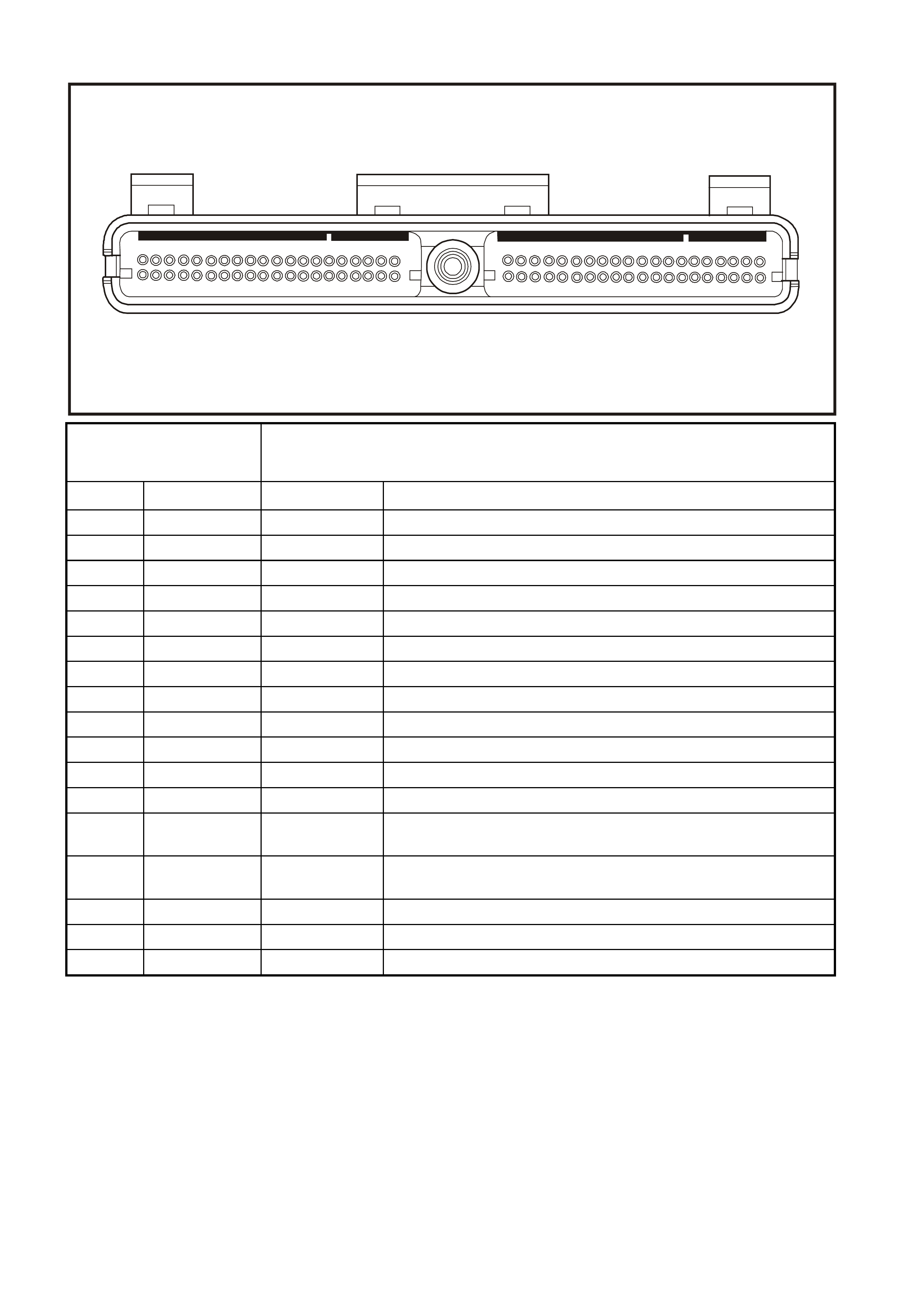
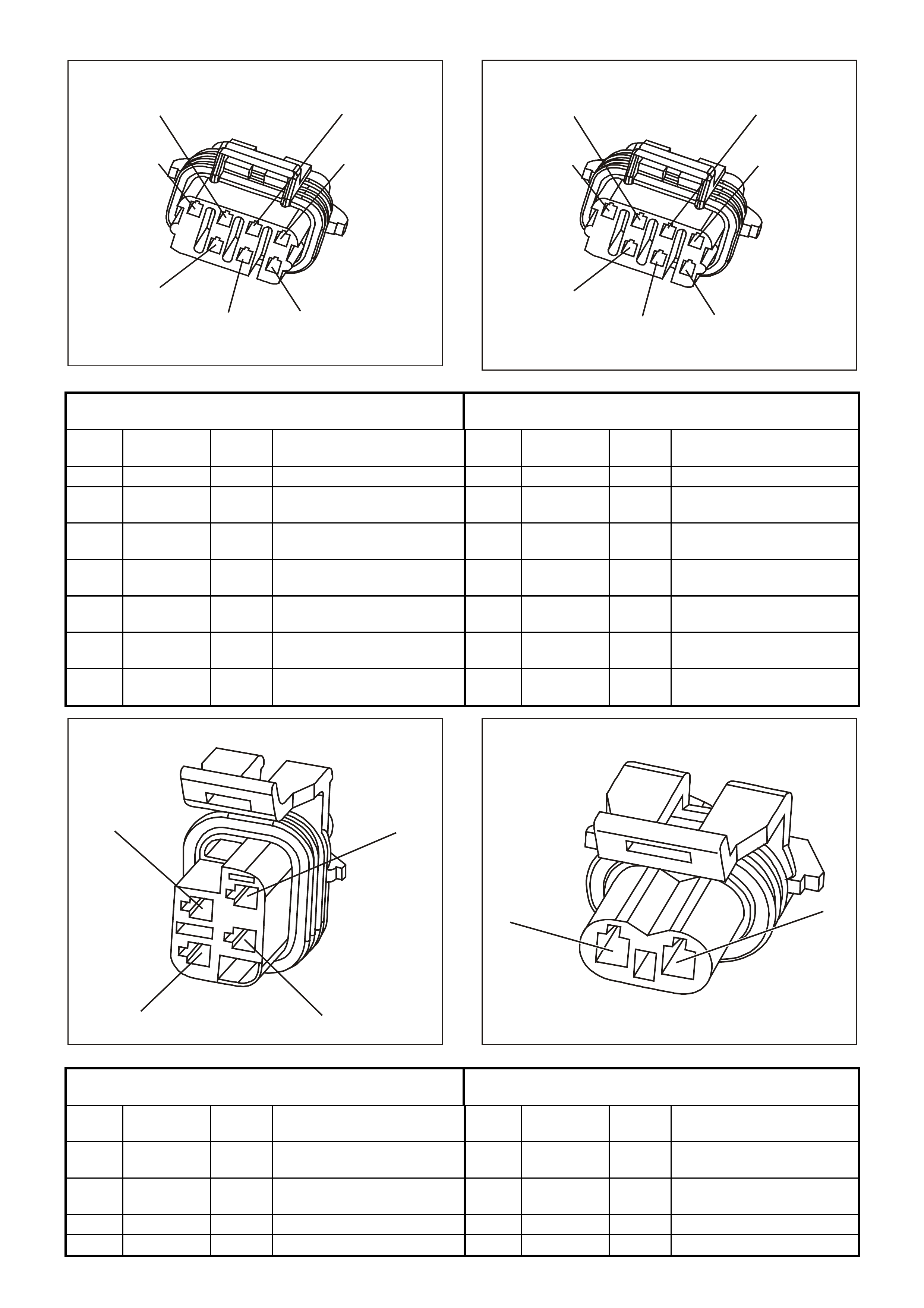
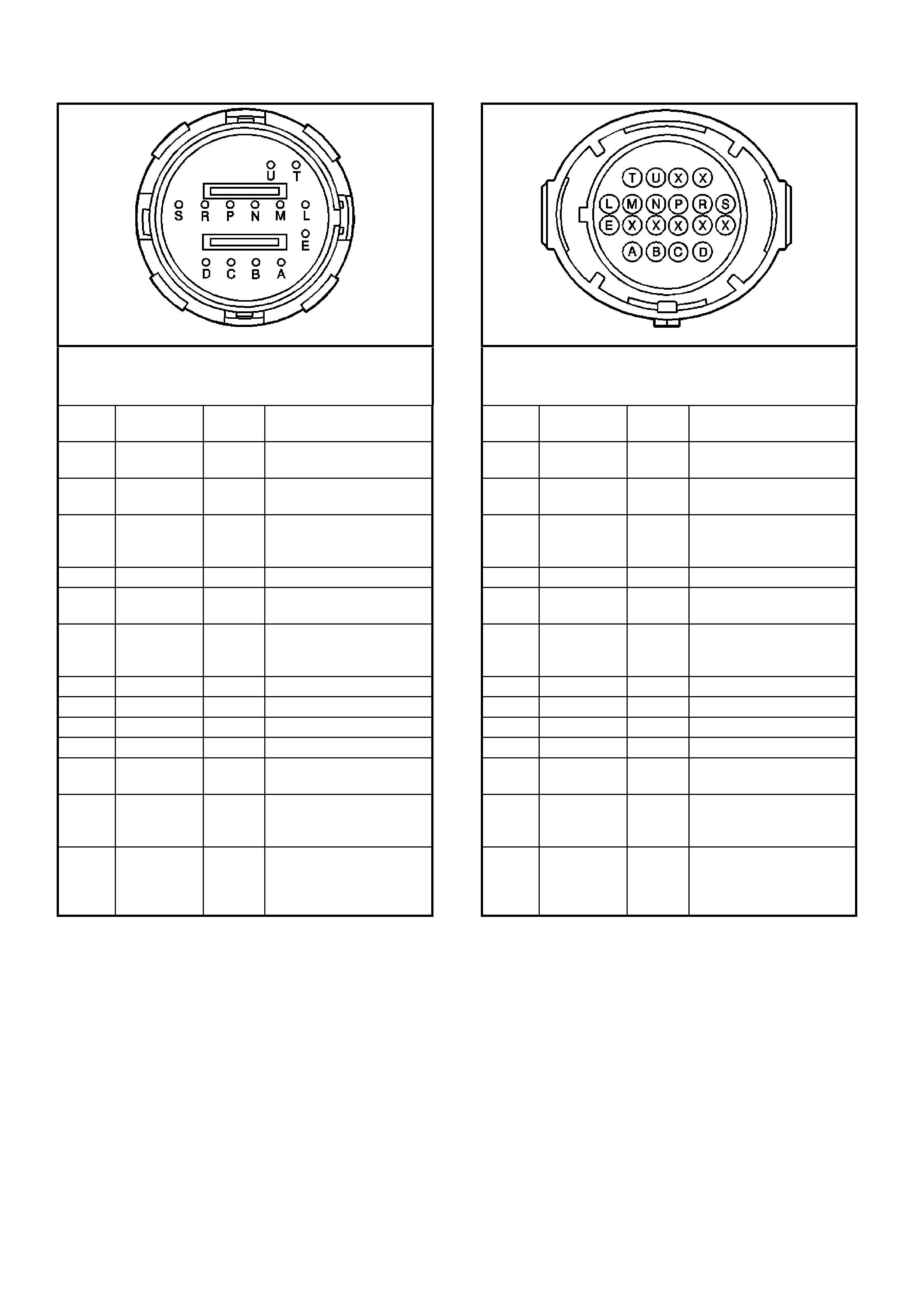
PIM CONNECTOR END VI EW
PIM CONNECTOR
Connector Part
Information • PIM Connector YB215
• 16 Pin Connector
Pin Wire Color Circuit No. Function
1 Not Used - -
2 Not Used - -
3 Not Used - -
4 Not Used - -
5 Not Used - -
6 Red/Black 1221 UART Serial Data
7 Yellow 1049 Class II Serial Data
8 Grey/Blue
(AUTO)
Grey
(MANUAL)
1434
(AUTO)
434
(MANUAL)
Starter Relay Control
9 Not Used - -
10 Not Used - -
11 White/Black 451 Diagnostic Test Enable
12 Not Used - -
13 Not Used - -
14 Not Used - -
15 Pink 39 Ignition Feed
16 Black/Red 750 System Earth
GEN3 0104
8
16
1
9

PIM CONNECTOR TERMINAL DEFINITIONS
PIM CONNECTOR
1 – NOT USED
2 – NOT USED
3 – NOT USED
4 – NOT USED
5 – NOT USED
6 – SERIAL DATA (UART) – This is a dedicated line for the Tech 2 scan tool communications. The circuit
connects the PIM, BCM, and ABS/ECT. The Tech 2 scan tool can talk to each of these modules by sending a
mes s age to a c ontro ller and as king only it to respond. T he c ommunication r ate is at 8192 baud. The normal voltage
on this circuit is about 5 volts, but when the Tech 2 scan tool is communicating with a controller, the voltage will
vary and if read with a DMM may read about 2.5 volts.
7 – SERIAL DATA (CLASS II) – This is a dedicated line for the Tech 2 scan tool communication. The circuit
connects the PCM, PIM, ABS/ET C, and BCM. The Tec h 2 scan tool can talk to eac h of these m odules by sending
a message to a controller and asking only it to respond. The communication carried on Class II data streams are
prioritised. The normal voltage on this line is 0 volts, but when the Tech 2 scan tool is connected, the voltage will
about 7 volts indicating communication.
8 – STARTER RELAY CONTROL – W hen the PIM receives the proper Theft Deterrent signal from the BCM, the
PIM will supply a earth signal to the Start Relay. This will allow the vehicle to crank.
If a improper Theft Deterrent signal is sensed by the PIM, then the PIM will not supply a earth signal to the Start
Relay, and the PIM will not send a message to the PCM to allow fuel injection.
9 – NOT USED
10 – NOT USED
11 – DIAGNOSTIC T EST ENABLE – T his terminal is connected to the DLC diagnostic test enable ter minal. W hen
the diagnostic tes t term inal is not ear thed, this term inal will have 5 volts on it. When the DLC diagnostic tes t enable
terminal is earthed, the resulting zero voltage at the PIM will instruct the PCM to operate in Diagnostic Mode.
12 – NOT USED
13 – NOT USED
14 – NOT USED
15 – IGNITION FEED – This is the power supply to the PIM from the ignition switch. The voltage should equal the
battery voltage when the key is in either the RUN, or CRANK position.
16 – SYSTEM EARTH – This terminal should have zero volts. This circuit is connected directly to the engine earth.
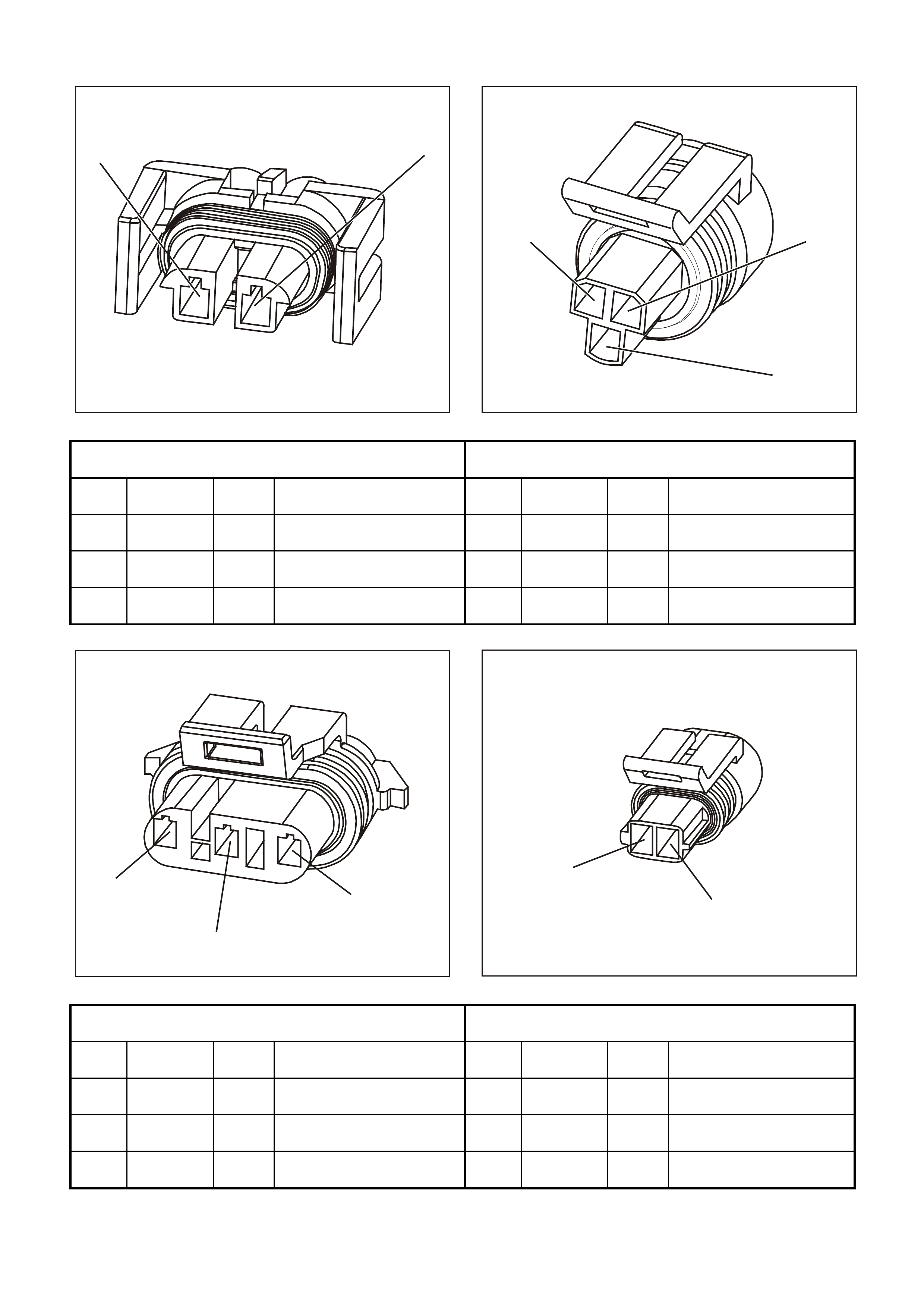
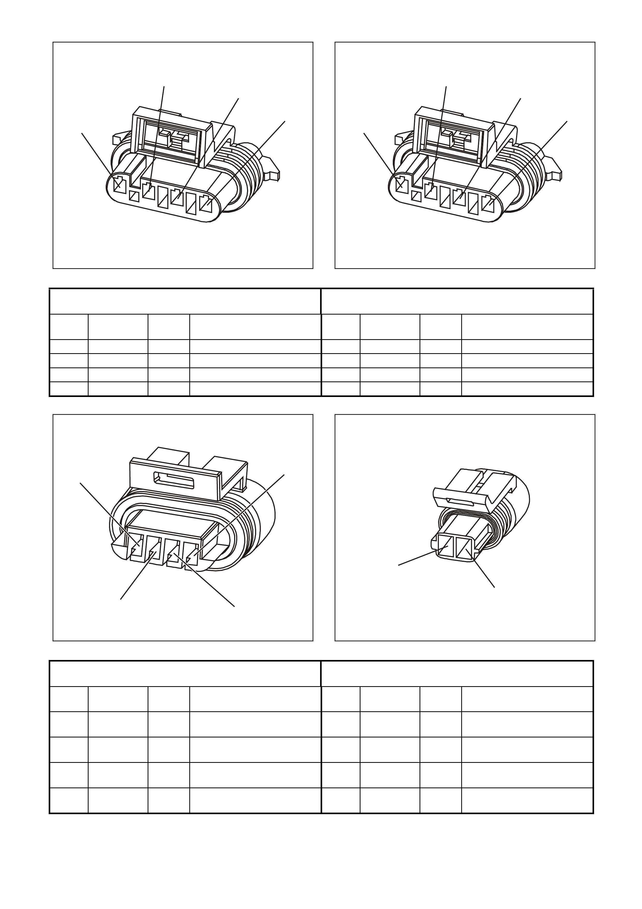
ENGINE CONTROL CONNECTOR END VIEWS
GE N 3 0073
21
2
3
1
A/C Compressor Clutch Connector
YE105 A /C Refrigerant Pressure Sensor Connector
YE113
Pin Wire Colour Circuit
No. Function Pin Wire Colour Circuit
No. Function
1 (B) B/R 750 A/C Compressor Clutch
Earth 1 (A) G/O 469 A/C Refrigerant Pressure
Sensor Earth
2 (A) G 59 A/C Compressor Clutc h
Control 2 (B) V/W 415 A/C Refrigerant Pressure
Sensor 5.0 V Reference
3 (C) G/B 259 A/C Refrigerant Pressure
Sensor Signal
GE N 3 0075
1
2
3
GE N 3 0076
1
2
Camshaft Position (CMP) Sensor Connector
YE69 Engine Coolant Temperature (ECT) Sensor Connector
YE65
Pin Wire
Colour Circuit
No. Function Pin Wire
Colour Circuit
No. Function
1 (A) BR 633 Camshaft Position (CMP)
Sensor Signal – Input 1 (A) GY/B 455 Coolant Temperature
Sensor Earth
2 (B) R/W 632 Camshaft Position (CMP)
Sensor Reference Low 2 (B) Y 410 Coolant Temperature
Sensor Signal
3 (C) W/B 631 Camshaft Position (CMP)
Sensor Ignition Feed
GE N 3 0075
1
2
3
GE N 3 0077
12
3
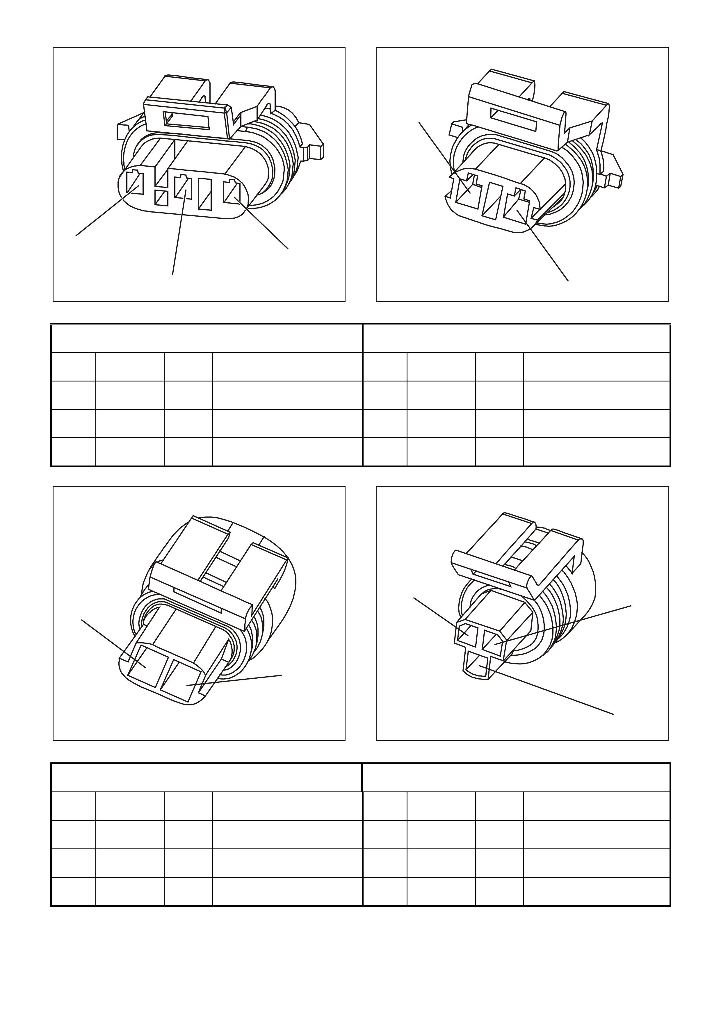
Crankshaft Position (CKP) Sensor Connector
YE67 Oil Pressure Sensor Connector
YE32
Pin Wire
Colour Circuit
No. Function Pin Wire
Colour Circuit
No. Function
1 (A) BLU 643 Crankshaft Position (CKP)
Sensor Signal – Input 1 (B) BLU/Y 334 Oil Pressure Sensor 5.0 V
Reference
2 (B) LBLU/B 647 Crankshaft Position (CKP)
Sensor Reference Low 2 (A) G 335 Oil Pressure Sensor
Reference Low
3 (C) LBLU/W 646 Crankshaft Position (CKP)
Sensor Ignition Feed 3 (C) BR/W 331 Oil Pressure Sensor –
Signal Input
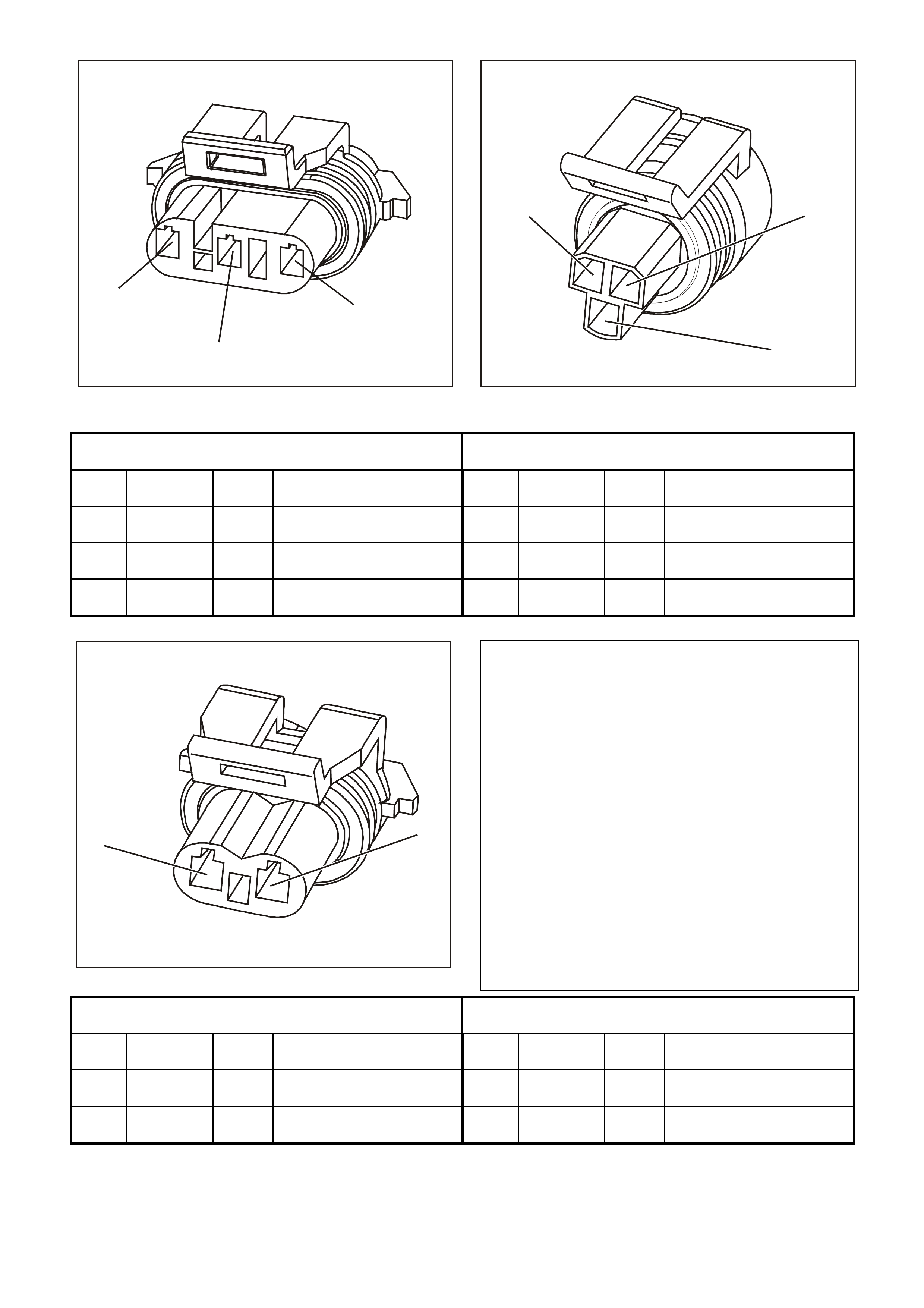
GE N 3 0078
12
Evaporative Emission (EVAP) Canister Purge Solenoid
Connector YE99 Engine Coolant Level Switch Connector
YE131
Pin Wire
Colour Circuit
No. Function Pin Wire
Colour Circuit
No. Function
1 (A) P 439 Canister Purge Solenoid
Ignition Feed 1 (A) B/R 750 Engine Coolant Level
Switch Earth
2 (B) G/Y 428 Canister Purge Solenoid
Control 2 (B) G 69 Engine Coolant Level
Switch Signal – Input
GE N 3 0080
12
GE N 3 0080
12
Fuel Injector #1 Connector
YE77 Fuel Injector #2 Connector
YE78
Pin Wire
Colour Circuit
No. Function Pin Wire
Colour Circuit
No. Function
1 (A) LG 482 Injector #1 Ignition Feed 1 (A) R 481 Injector #2 Ignition Feed
2 (B) BLU 841 Injector #1 Control 2 (B) G 842 Injector #2 Control
GE N 3 0080
12
GE N 3 0080
12
Fuel Injector #3 Connector
YE79 Fuel Injector #4 Connector
YE80
Pin Wire
Colour Circuit
No. Function Pin Wire
Colour Circuit
No. Function
1 (A) LG 482 Injector #3 Ignition Feed 1 (A) R 481 Injector #4 Ignition Feed
2 (B) V 843 Injector #3 Control 2 (B) BR/Y 844 Injector #4 Control
GE N 3 0080
12
GE N 3 0080
12
Fuel Injector #5 Connector
YE81 Fuel Injector #6 Connector
YE82
Pin Wire
Colour Circuit
No. Function Pin Wire
Colour Circuit
No. Function
1 (A) LG 482 Injector #5 Ignition Feed 1 (A) R 481 Injector #6 Ignition Feed
2 (B) GY 845 Injector #5 Control 2 (B) Y 846 Injector #6 Control
GE N 3 0080
12
GE N 3 0080
12
Fuel Injector #7 Connector
YE83 Fuel Injector #8 Connector
YE84
Pin Wire
Colour Circuit
No. Function Pin Wire
Colour Circuit
No. Function
1 (A) LG 482 Injector #7 Ignition Feed 1 (A) R 481 Injector #8 Ignition Feed
2 (B) P/B 847 Injector #7 Control 2 (B) LG 848 Injector #8 Control
GE N 3 0081
2
1
3
4
GE N 3 0081
2
1
3
4
Bank 1 Left Heated Oxygen (HO2S) Sensor Connector
YE95 Bank 2 Right Heated Oxygen (HO2S) Sensor Connector
YE95
Pin Wire
Colour Circuit
No. Function Pin Wire
Colour Circuit
No. Function
1 (A) BLU/B 413 HO2S Low 1 (A) GY/B 1413 HO2S Low
2 (B) V 412 HO2S High 2 (B) GY 1412 HO2S High
3 (C) B/R 750 HO2S Earth 3 (C) B/R 750 HO2S Earth
4 (D) P 439 HO2S Ignition Feed 4 (D) P 439 HO2S Ignition Feed
GE N 3 0082
41
32
GE N 3 0076
1
2
Idle Air Control (IAC) Valve Connector
YE36 Intake Air Temperature (IAT) Sensor Connector
YE23
Pin Wire
Colour Circuit
No. Function Pin Wire
Colour Circuit
No. Function
1 (A) LG/B 444 Idle Air Control (IAC) Valve
Coil B Signal – Low 1(A) G/O 469 Intake Air Temperature
(IAT) Sensor Earth
2 (B) LG/W 443 Idle Air Control (IAC) Valve
Coil B Signal – High 2 (B) BR 472 Intake Air Temperature
(IAT) Sensor Signal – Input
3 (C) LBLU/B 442 Idle Air Control (IAC) Valve
Coil A Signal – Low
4 (D) LBLU 441 Idle Air Control (IAC) Valve
Coil A Signal – High

GE N 3 0083
1
2
GE N 3 0084
1
Knock Sensor (KS) Two Way Harness Connector
YE19 Front Knock Sensor (KS) Connector
YE18
Pin Wire
Colour Circuit
No. Function Pin Wire
Colour Circuit
No. Function
1 (A) BLU 815 Front Knock Sensor Signal
Circuit 1 BLU 815 Front Knock Sensor (KS)
Signal Circuit
2 (B) LBLU 826 Rear Knock Sensor Signal
Circuit
GE N 3 0084
1
GE N 3 0085
1
2
3
Rear Knock Sensor (KS) Connector
YE18 Manifold Absolute Pressure (MAP) Sensor Connector
YE27
Pin Wire
Colour Circuit
No. Function Pin Wire
Colour Circuit
No. Function
1 LBLU 826 Rear Knock Sensor (KS)
Signal Circuit 1 (A) B 421 Manifold Absolute
Pressure (MAP) Sensor
Earth
2 (B) LG 432 Manifold Absolute
Pressure (MAP) Sensor
Signal
3 (C) V/W 414 Manifold Absolute
Pressure (MAP) Sensor
5.0 V Reference
GE N 3 0086
1
2
3
ABC
GE N 3 0087
1
2
Mass Air Flow (MAF) Sensor Connector
YE100 Manual Transmission Reverse Inhibit Connector YB125
Pin Wire
Colour Circuit
No. Function Pin Wire
Colour Circuit
No. Function
1 (A) BR/W 792 Mass Air Flow (MAF)
Sensor Signal 1 (B) P/BLU 339 Reverse Inhibit Ignition
Feed
2 (B) B/R 750 Mass Air Flow (MAF)
Sensor Earth 2 (A) Y 838 Reverse Inhibit Control
3 (C) P 439 Mass Air Flow (MAF)
Sensor Ignition Feed
GE N 3 0088
2
1
GE N 3 0103
1
2
3
Vehicle Speed Sensor (VSS) Connector
YB195 Throttle Position (TP) Sensor Connector
YE30
Pin Wire
Colour Circuit
No. Function Pin Wire
Colour Circuit
No. Function
1 (A) T 832 Vehicle Speed Sensor
(VSS) Signal – Low 1 (A) GY 416 Throttle Position (TP)
Sensor 5.0 V Reference
2 (B) BLU/W 831 Vehicle Speed Sensor
(VSS) Signal – High 2 (B) B/Y 452 Throttle Position (TP)
Sensor Earth
3 (C) BLU 417 Throttle Position (TP)
Sensor Signal
GE N 3 0089
5
4
3
21
6
7
GE N 3 0089
5
4
3
21
6
7
Right Bank Ignition Module Connector
YE124 Left Bank Ignition Module Connector
YE125
Pin Wire
Colour Circuit
No. Function Pin Wire
Colour Circuit
No. Function
1 (A) B/R 750 Ignition Module Earth 1 (A) B/R 750 Ignition Module Earth
2 (B) Y/B 972 Ignition Coil/Module #2
Control 2 (B) Y 977 Ignition Coil/Module #7
Control
3 (C) W 974 Ignition Coil/Module #4
Control 3 (C) G 975 Ignition Coil/Module #5
Control
4 (E) V 959 Ignition Coil/Module
Reference Low 4 (E) BR 958 Ignition Coil/Module
Reference Low
5 (F) LG 976 Ignition Coil/Module #6
Control 5 (F) BLU 973 Ignition Coil/Module #3
Control
6 (G) LBLU 978 Ignition Coil/Module #8
Control 6 (G) W 971 Ignition Coil/Module #1
Control
7 (H) R 481 Right Bank Coil/Module
Ignition Feed 7 (H) LG 482 Left Bank Coil/Module
Ignition Feed
GE N 3 0090
4
3
2
1
GE N 3 0078
12
PRNDL Switch Connector
YB20 Throttle Relaxer Connector
YE127
Pin Wire
Colour Circuit
No. Function Pin Wire
Colour Circuit
No. Function
1 (A) BLU/W 771 PRNDL Switch A Input 1 (B) R/B 466 Throttle Relaxer Power
Control
2 (B) GY 773 PRNDL Switch C Input 2 (A) R/W 456 Throttle Relaxer Earth
Control
3 (C) W 776 PRNDL Switch P Input
4 (D) Y 772 PRNDL Switch B Input
AUTOMATIC TRANSMISSION INLINE HARNESS CONNECTOR END VIEWS
Automatic Transmission Wiring Harness,
Transmission Side
YB 129
Pin Wire Color Circuit
No. Function
A LG 1222 1-2 Shift Solenoid (A)
Valve Control
B Y 1223 2-3 Shift Solenoid (B)
Valve Control
C V 1228 Pressure Control
Solenoid (PCS) Valve
HIGH
D LBLU 1229 PCS Valve LOW
E R 339 Transmission Solenoid
Power
L BR 1227 Transmission Fluid
Temperature (TFT)
Sensor HIGH
M GY 1230 TFT Sensor LOW
N P 1224 Range Signal A
P O 1226 Range Signal C
R DKBLU 1225 Range Signal B
S W 897 3-2 Shift Solenoid Valve
Assembly Control
T B 422 Torque Converter
Clutch Solenoid Valve
Control
U T 418 Torque Converter
Clutch Pulse Width
Modulation Solenoid
Valve Control
Automatic Transmission Wiring Harness,
Engine Side
YB 129
Pin Wire Color Circuit
No. Function
A LG 1222 1-2 Shift Solenoid (A)
Valve Control
B Y/B 1223 2-3 Shift Solenoid (B)
Valve Control
C R 1228 Pressure Control
Solenoid (PCS) Valve
HIGH
D GY/BLU 1229 PCS Valve LOW
E P/BLU 339 Transmission Solenoid
Power
L B/Y 1227 Transmission Fluid
Temperature (TFT)
Sensor HIGH
M B/W 1230 TFT Sensor LOW
N BR/Y 1224 Range Signal A
P GY 1226 Range Signal C
R Y 1225 Range Signal B
S G/W 897 3-2 Shift Solenoid Valve
Assembly Control
T GY/R 422 Torque Converter
Clutch Solenoid Valve
Control
U BR 418 Torque Converter
Clutch Pulse Width
Modulation Solenoid
Valve Control
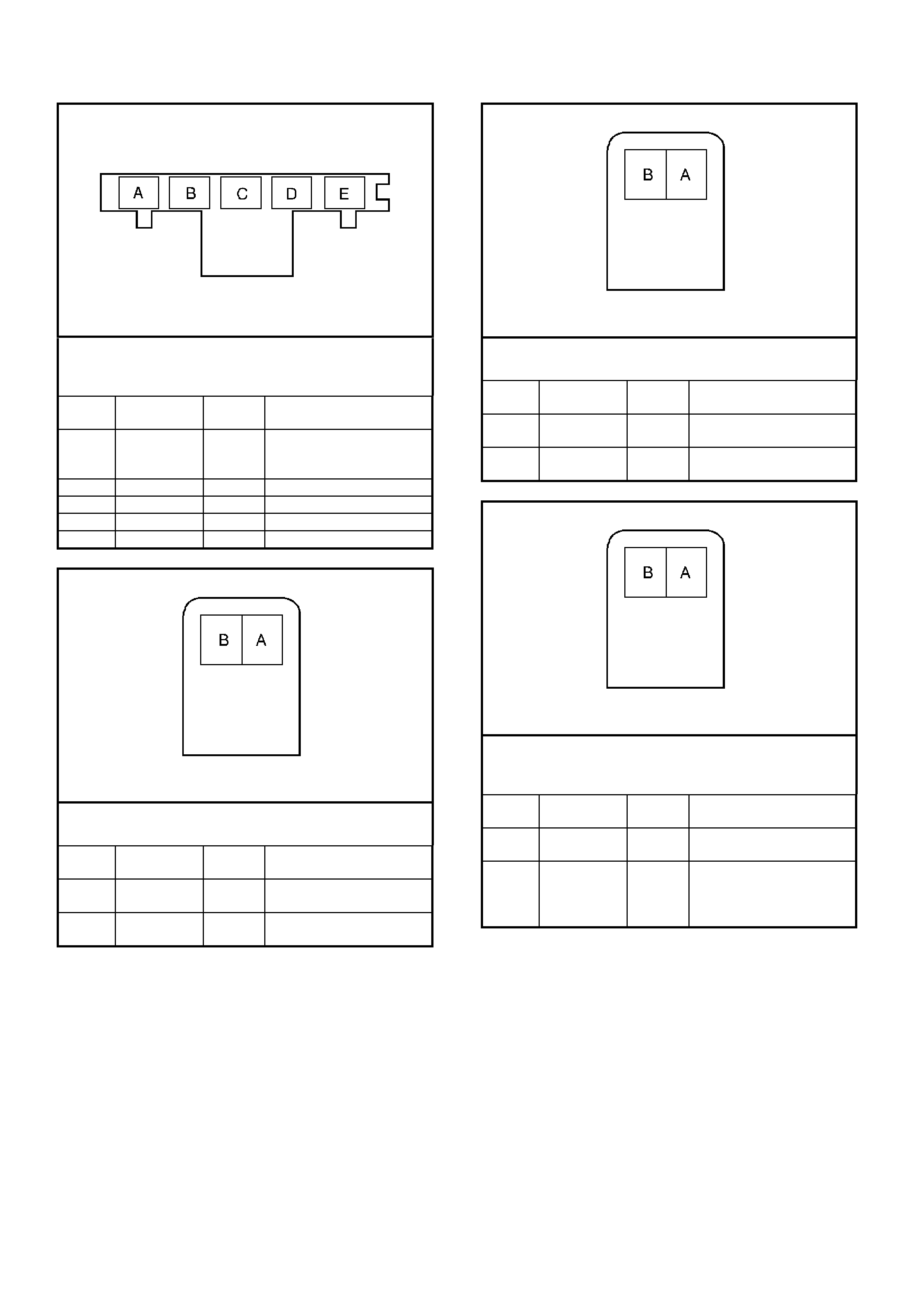
AUTOMATIC TRANSMISSION INTERNAL CONNECTOR END VIE WS
Automatic Transmission Fluid Pressure (TFP) Manual
Valve Position Switch Connector,
Wiring Harness Side
Pin Wire Color Circuit
No. Function
A BR 1227 Transmission Fluid
Temperature (TFT)
Sensor Signal
B GY 1230 TFT Sensor earth
C P 1224 Range Signal A Input
D O 1226 Range Signal C Input
E DKBLU 1225 Range Signal B Input
1-2 Shift Solenoid A (SS) Valve Connector,
Wiring Harness Side
Pin Wire Color Circuit
No. Function
A R 339 Transmission Solenoid
Power
B LG 1222 1-2 Shift Solenoid (A)
Valve Control
2-3 Shift Solenoid B (SS) Valve Connector,
Wiring Harness Side
Pin Wire Color Circuit
No. Function
A R 339 Transmission Solenoid
Power
B Y 1223 2-3 Shift Solenoid (B)
Valve Control
Torque Converter Clutch Pulse Width Modulated
(TCCPWM) Solenoid Valve Connector,
Wiring Harness Side
Pin Wire Color Circuit
No. Function
A R 339 Transmission Solenoid
Power
B T 418 Torque Converter
Clutch Pulse Width
Modulated Solenoid
Valve Control
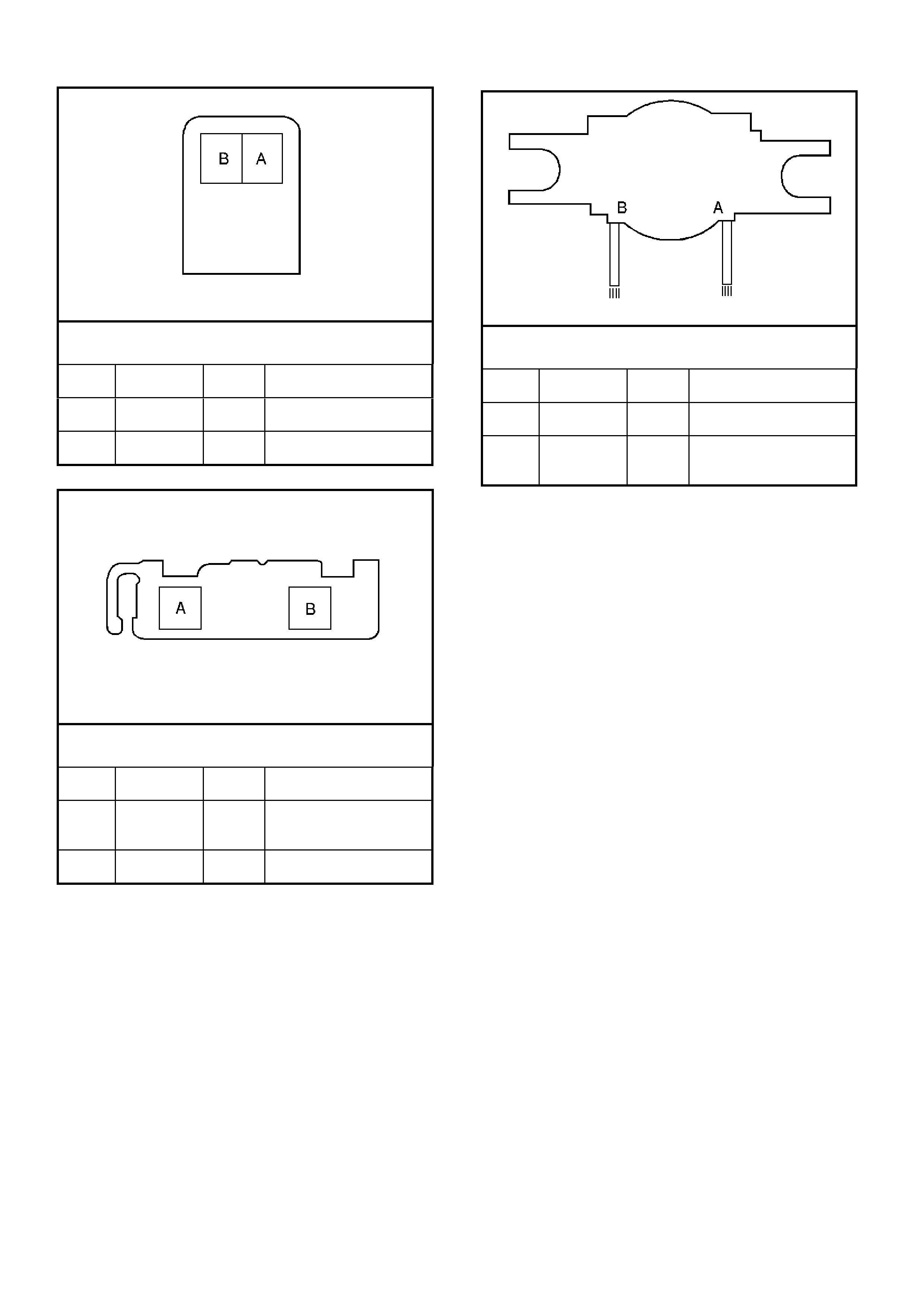
3-2 Shift Solenoid (SS) Valve Assembly Connector,
Wiring Harness Side
Pin Wire Color Circuit
No. Function
A W 897 3-2 Shift Solenoid Valve
Assembly Control
B R 339 Transmission Solenoid
Power
Pressure Control Solenoid (PCS) Valve Connector,
Wiring Harness Side
Pin Wire Color Circuit
No. Function
A V 1228 Pressure Control
Solenoid (PCS) Valve
HIGH Control
B LBLU 1229 PCS Valve LOW
Control
Torque Converter Clutch (TCC) Solenoid Valve
Connector, Wiring Harness Side
Pin Wire Color Circuit
No. Function
A R 339 Transmission Solenoid
Power
B B 422 Torque Converter
Clutch Solenoid Valve
Control

PCM GEN III V8 ENGINE DIAGNOSTIC TROUBLE CODES (DTC)
DTC
DESCRIPTION ILLUMINATE
CHECK
POWERTRAIN CPL
LAM P
P0101 MAF Sensor Performance Yes
P0102 MAF Sensor Circuit Low Frequency Yes
P0103 MAF Sensor Circuit High Frequency Yes
P0107 MAP Sensor Circuit Low Voltage Yes
P0108 MAP Sensor Circuit High Voltage Yes
P0112 IAT Sensor Circuit Low Voltage No
P0113 IAT Sensor Circuit High Voltage No
P0117 ECT Sensor Circuit Low Voltage Yes
P0118 ECT Sensor Circuit High Voltage Yes
P0121 TP Sensor Circuit Insufficient Activity Yes
P0122 TP Sensor Circuit Low Voltage Yes
P0123 TP Sensor Circuit High Voltage Yes
P0125 ECT Excessive Time to Closed Loop No
P0131 HO2S Circuit Low Voltage Bank 1 Sensor 1 Yes
P0132 HO2S Circuit High Voltage Bank 1 Sensor 1 Yes
P0133 HO2S Slow Response Bank 1 Sensor 1 Yes
P0134 HO2S Insufficient Activity Bank 1 Sensor 1 Yes
P0135 HO2S Heater Circuit Bank 1 Sensor 1 Yes
P0151 HO2S Circuit Low Voltage Bank 2 Sensor 1 Yes
P0152 HO2S Circuit High Voltage Bank 2 Sensor 1 Yes
P0153 HO2S Slow Response Bank 2 Sensor 1 Yes
P0154 HO2S Insufficient Activity Bank 2 Sensor 1 Yes
P0155 HO2S Heater Circuit Bank 2 Right Front Yes
P0171 Fuel Trim System Lean Bank 1 Yes
P0172 Fuel Trim System Rich Bank 1 Yes
P0174 Fuel Trim System Lean Bank 2 Yes
P0175 Fuel Trim System Rich Bank 2 Yes
P0218 Transmission Fluid Overtemperature No
P0230 Fuel Pump Control Circuit Yes
P0325 Knock Sensor System Yes
P0327 Knock Sensor Circuit Front Yes
P0332 Knock Sensor Circuit Rear Yes
P0335 CKP Sensor Circuit Yes
P0336 CKP Sensor Circuit Performance Yes
P0341 CMP Sensor Circuit Performance Yes
P0342 CMP Sensor Circuit Low Voltage Yes
P0343 CMP Sensor Circuit High Voltage Yes
P0351 Ignition Control #1 Circuit Yes
P0352 Ignition Control #2 Circuit Yes
P0353 Ignition Control #3 Circuit Yes
P0354 Ignition Control #4 Circuit Yes
P0355 Ignition Control #5 Circuit Yes
P0356 Ignition Control #6 Circuit Yes
P0357 Ignition Control #7 Circuit Yes
P0358 Ignition Control #8 Circuit Yes
P0443 EVAP Purge Solenoid Control Circuit Yes
P0481 High Speed Cooling Fan Relay Driver Circuit Yes
P0506 Idle Speed Low Yes
P0507 Idle Speed High Yes
P0522 Engine Oil Pressure Sensor Low Input Yes
P0523 Engine Oil Pressure Sensor High Input Yes
P0530 A/C Refrigerant Pressure Sensor Circuit No
P0562 System Voltage Low No
P0563 System Voltage High No
P0601 PCM Memory Yes
P0602 PCM Not Programmed Yes

PCM GEN III V8 ENGINE DIAGNOSTIC TROUBLE CODES (DTC) (CONTINUED)
DTC
DESCRIPTION ILLUMINATE
CHECK
POWERTRAIN CPL
LAM P
P0608 VSS Output Circuit No
P0654 Engine Speed Output Circuit No
P1111 IAT Sensor Intermittent High Voltage No
P1112 IAT Sensor Intermittent Low Voltage No
P1114 ECT Sensor Intermittent Low Voltage No
P1115 ECT Sensor Intermittent High Voltage No
P1121 TP Sensor Intermittent High Voltage No
P1122 TP Sensor Intermittent Low Voltage No
P1133 HO2S Insufficient Switching Bank 1 Sensor 1 No
P1134 HO2S Transition Time Ratio Bank 1 Sensor 1 No
P1153 HO2S Insufficient Switching Bank 2 Sensor 1 No
P1154 HO2S Transition Ratio Bank 2 Sensor 1 No
P1258 Engine Coolant Over Temp Fuel Disable Yes
P1539 A/C Clutch Status Circuit High Voltage No
P1546 A/C Clutch Status Circuit Low Voltage No
P1626 Theft Deterrent System Fuel Enable Circuit Yes
P1630 PCM In Learn Mode Yes
P1631 Theft Deterrent Password Incorrect Yes
P1635 5 Volt Reference #1 Circuit Yes
P1639 5 Volt Reference #2 Circuit Yes

PIM GEN III V8 ENGINE DIAGNOSTIC TROUBLE CODES (DTC)
DTC
DESCRIPTION ILLUMINATE
CHECK
POWERTRAIN CPL
LAM P
B2002 Low Speed Fan No BCM Response No
B2006 No Serial Data From PCM No
B2007 Starter Relay Voltage High No
B2009 EEPROM Checksum Error No

PCM GEN III V8 AUTOMATIC TRANSMISSION DIAGNOSTIC TROUBLE CODES (DTC)
DTC Description Default Action
P0218 Transmission Fluid Over temperature • The PCM freezes shift adapts from being updated
• The PCM illuminates the Check Powertrain Lamp
(CPL)
P0502 Vehicle Speed Sensor Circuit Low • The PCM commands first gear only
• The PCM commands maximum line pressure
• The PCM freezes shift adapts from being updated
• The PCM inhibits TCC engagement
P0503 Vehicle Speed Sensor Circuit Intermittent • The PCM commands second gear only
• The PCM commands maximum line pressure
• The PCM inhibits TCC engagement
• The PCM inhibits 4th gear if the transmission is in hot
mode
• The PCM freezes shift adapts from being updated
P0705 PRNDL Range Fault —
P0706 PRNDL Switch Fault —
P0711 TFT Sensor Circuit Range/Performance • The PCM uses a transmission fluid temperature
default value based on engine coolant, engine run time
and IAT at startup
• The PCM freezes shift adapts from being updated
P0712 TFT Sensor Circuit Low • The PCM uses a transmission fluid temperature
default value based on engine coolant, engine run time
and IAT at startup
• The PCM freezes shift adapts from being updated
P0713 TFT Sensor Circuit High • The PCM uses a transmission fluid temperature
default value based on engine coolant, engine run time
and IAT at startup
• The PCM freezes shift adapts from being updated
P0719 Brake Switch Circuit Low • The PCM disregards the brake switch input for TCC
scheduling
P0724 Brake Switch Circuit High —
P0740 TCC Enable Solenoid Circuit Electrical • The PCM inhibits TCC engagement
• The PCM inhibits 4th gear if the transmission is in hot
mode
• The PCM freezes shift adapts from being updated
P0742 TCC System Stuck On • The PCM freezes shift adapts from being updated
• The PCM illuminates the Check Powertrain Lamp
(CPL)
P0748 PC Solenoid Circuit Electrical • The PC solenoid valve is OFF
• The PCM freezes shift adapts from being updated
P0751 1-2 SS Valve Performance • The PCM commands D2 line pressure
• The PCM inhibits 3-2 downshifts if the vehicle speed is
greater than 48 km/h
• The PCM freezes shift adapts from being updated
• The PCM illuminates the Check Powertrain Lamp
(CPL)
P0753 1-2 SS Circuit Electrical • The PCM commands D2 line pressure
• The PCM inhibits 3-2 downshifts if the vehicle speed is
greater than 48 km/h
• The PCM freezes shift adapts from being updated
• The PCM illuminates the Check Powertrain Lamp
(CPL)
P0756 2-3 SS Valve Performance • The PCM commands third gear only
• The PCM commands maximum line pressure
• The PCM inhibits TCC engagement
• The PCM freezes shift adapts from being updated
• The PCM illuminates the Check Powertrain Lamp
(CPL)

PCM GEN III V8 AUTOMATIC TRANSMISSION DIAGNOSTIC TROUBLE CODES (DTC) (CONTINUED)
DTC Description Default Action
P0758 2-3 SS Circuit Electrical • The PCM commands 3rd gear only
• The PCM commands maximum line pressure
• The PCM inhibits TCC engagement
• The PCM freezes shift adapts from being updated
• The PCM illuminates the Check Powertrain Lamp
(CPL)
P0785 3-2 SS Circuit Electrical • The PCM commands a soft landing to 3rd gear
• The PCM inhibits TCC engagement
• The PCM commands maximum line pressure
• The PCM inhibits 4th gear if the transmission is in hot
mode
• The PCM freezes shift adapts from being updated
• The PCM illuminates the Check Powertrain Lamp
(CPL)
P1810 TFP Switch Circuit Fault • The PCM commands D2 line pressure
• The PCM commands a D4 shift pattern
• The PCM freezes shift adapts from being updated
• The PCM illuminates the Check Powertrain Lamp
(CPL)
P1860 TCC PWM Solenoid Circuit Electrical • The PCM inhibits TCC engagement
• The PCM inhibits 4th gear if the transmission is in hot
mode
• The PCM freezes shift adapts from being updated
• The PCM illuminates the Check Powertrain Lamp
(CPL)
P1870 Transmission Component Slipping • The PCM inhibits TCC engagement
• The PCM commands maximum line pressure
• The PCM inhibits 4th gear if the transmission is in hot
mode
• The PCM freezes shift adapts from being updated
• The PCM illuminates the Check Powertrain Lamp
(CPL)

GEN III V8 PCM -
POWERTRAIN OBD SYSTEM CHECK
CIRCUIT DESCRIPTION
The Powertrain OBD System Check is an organised approach to identifying a problem created by an electronic
engine control system malfunction. The Powertrain OBD System Check is the starting point for any driveability
complaint diagnosis. The Powertrain OBD System Check directs the service technician to the next logical step in
diagnosing a complaint. DO NOT PERFORM THIS CHECK IF NO DRIVEABILITY COMPLAINT EXISTS.
Understanding and using the table correctly will reduce the diagnostic time and prevent the replacement of good
parts.
IMPORTANT:
This vehicle is equipped with a Powertrain Control Module (PCM) utilising an Electrically Erasable Programmable
Read Only Memory (EEPROM). Program the new PCM when diagnostics call for replacement of the PCM.
Refer to Section 6C3-3 PCM Replacement Programming of the VX Series Service Information.
IMPORTANT:
This vehicle is equipped with a Powertrain Interface Module (PIM). This PIM is the vehicle serial data translator
between Class II and UART serial data.
DIAGNOSTIC AIDS
IMPORTANT:
If an intermittent condition exists, inspect the PCM wiring harnesses for improper installation of electrical
com ponents. Inspect f or afterm ark et theft deterr ent devices, lights, and c ellular phones. Ensure that no after mark et
equipment is connected to the Class II circuit. A cellular phone signal communication may cause an intermittent
condition.
G3PCM023PT
B/Y
(155)
B
(150)
LOC. E3
YB128
642516 9 1
ECC
BCM
DATA LINK
CONNECTOR
16
6SERIAL
DATA
5V
M
I
C
R
O
P
R
O
C
E
S
S
O
R
+
-
BATTERY
FS
F31
A5/A6
O/B (740)
(1040)
BATTERY M AIN P OWER
FJ
R (2)
F14
E20/D6
P/B
(39) IGNITION ON
15a 15 50
30 OFF/ON
LOCK
ACC
IGN
START
IGNITION SWITCH
P
(3)
B/Y (155 )
B/G (151)
LOC. E3
LOC. E3
R/B (1221)
G/W (1220)
G/W (1220)
2
B/R ( 750)
Y (1049)
R/B (1221)
PIM
SERIAL
DATA
7V
7V
12V
ELECTRONIC EARTH
HIGH CURRENT
EARTH
A1/A5
B10/B11
E2/D2
E9/D3
E3/D13
SERIAL
DATA
MAIN
SERIAL
DATA AUX.
5V
5V
6
11
7
DI AG. ENABL E
CLASS 2
SERIAL DA TA
LOC. E5/E15
LOC. E5/E15
GEN III V8 PCM
J1-58
J2-01
J2-40
J1-40
J1-01
M
I
C
R
O
CLASS 2
SERIAL DA TA
B/R ( 750)
M
I
C
R
O
B/Y (155 )
M
I
C
R
O
HIGH SERIES
BCM TERMINALS
NOMINATED FIRS T
YB44
YB44
YB176
YB175
YB164
YB163
YB174
YB165
YB89
YB87
YE114
YE114
YE114
YB215
YE122
YE123
YB176
YB165
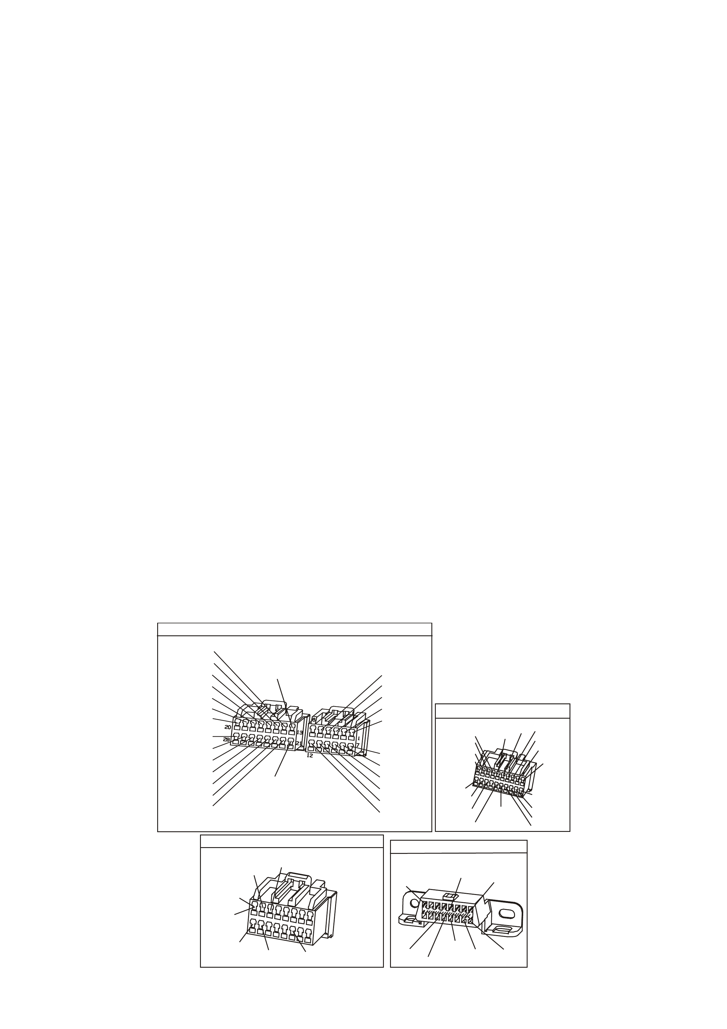
• The PIM will control the s tarter m otor operation, while the PCM will control the f uel injector PW M. If the PCM is
non-functional, the vehicle may crank but will not start.
• If BCM DTC 7 and or DTC 17 are set, more that likely the BCM is causing the problem. Refer to BCM DTC
tables in Section 12J- 1 Low Series BCM in VX Ser vice Inf orm ation or Sect ion 12J-2 High Series BCM in VX
Service Information.
• If multiple DTCs are set, inspect the EFI relay for proper operation. This relay protects the battery from a
parasitic draw.
• The following components are powered by the EFI relay:
- Injectors/Ignition coils
- Transmission
- EVAP Solenoid
- MAF Sensor
- Heated Oxygen Sensors
- A/C Relay
• It is benefic ial to review the Freeze Frame Data and/or Fail Records . Use the odometer inform ation and the f ail
counter in order to determine how frequently and how recently the DTC set. This information, and the other
operating conditions when the DTC set, may help diagnose an intermittent problem. Capturing the stored info
preserves data that the PCM will lose when instructed to Clear Info at the end of a diagnostic table, or if you
disconnect the PCM or replac e the PCM dur ing a diagnostic pr ocedur e. T he Tech 2 s can tool s tor es the data in
the Tech 2 scan tool’s memory. Review the captured info at the end of the diagnostic procedure in order to
catch the next DTC in the event there are multiple DTCs stored. Follow the order of priority as listed above.
• If the engine is m is-f iring and no DTCs ar e set, refer to Symptom s, Cuts O ut, Misses in Section 6C3-2B of the
VX Series Service Information.
TEST DESCRIPTION
The numbers below refer to the step numbers on the diagnostic table.
2. Use a properly functioning Tech 2 scan tool with the diagnostic tables in this section. DO NOT use the Clear
Info function unless instructed by a diagnostic procedure.
IMPORTANT:
Check for applicable Service Bulletins before proceeding with diagnosis. Do not turn the ignition OFF when
performing this Diagnostic table.
4. If the engine does not crank, there may be a problem with the Theft Deterrent system.
6. Compare actual control system data with the values in the Engine Tech 2 scan tool Data List to determine if
any parameter is not within limits. Keep in mind that a base engine problem (i.e. advanced cam timing) may
substantially alter sensor values. If the actual data does not correspond with the values in the Engine Tech 2
scan tool Data List, refer to the appropriate system/component diagnostic aids or test description.
YB175
B.C.M CONNECTOR 3
BERLINA & CALAIS
LBLU
Y/R
O/BLU
B
BLU/W
W/BLU
(43)
(39)
(97)
(83)
(94)
O/W
Y/B
B/R
(161)
(143)
(640)
(1150)
(260)
(1144)
(840)
Y
P/B
GY
LBLU
(494)
W
(160)
V/R
R/B
W/G
B/Y
GY/B
(229)
(1221)
(1220)
(556)
(96)
(261)
G/W
Y
Y/B
W
W/R
(266)
(1220)
(272)
(717)
(308)
BR/G
(271)
R/W
GY/R
(1391)
B.C.M CONNECTOR 3
EXECUTIVE
YB164
(83)
(97)
W/G
(229)
B/G
W/BLU
(266)
(1144)
P/BLU
G/W
BLU/W
(1220)
(494)
BR/G
GY
(1220)
B
GY
(1391)
LBLU
(151)
(271)
R/B
R/W
(1150)
(291)
V/R
(8)
O
P/B
B/R
Y
GY/R
(1221)
(94)
(39) (44)
(248)
10
20 1
11
POWE R TRAIN INTERFACE MODULE
Y B215
W/B
(451)
Y
(1049)
B/R
(750)
P
(39)
R/B
(1221)
GY/BLU
(1434)
GY
(434)
(AUTO)
(MAN) 1
9
16
8
DATA LINK CO NNECTO R
YB128
(863)
O/B BLU/B R/B
(1221)
(740)
16 9
(1220)
(155)
B/Y G/W
W/B
(451)
B
(150)
Y
(1049)
1
8

GEN III V8 PCM - POWERTRAIN OBD SYSTEM CHECK
Step Action Value(s) Yes No
1 Ignition ON engine OFF.
Does the Check Powertrain Lamp (CPL) illuminate for at
least two seconds?
Go to Step 2 Go to
Section 12C
in VX Service
Information for
CPL Diagnosis
2 1. Connect a Tech 2 scan tool to the Data Link
Connector (DLC).
2. Turn ON the ignition leaving the engine OFF.
Does the Tech 2 scan tool display Engine ID Information?
Go to Step 3 Go to Data Link
Connector
Diagnosis Table
in This Section
3 1. Ignition ON, engine OFF.
2. Using the Tech 2 scan tool, are any PCM DTC(s)
displayed?
Go to the
applicable DTC
table
Go to Step 4
4 1. Ignition ON and wait for a minimum of five seconds.
2. Turn the key to the crank position.
Does the engine crank?
Go to Step 5 Go to Starter
Cranking Circuit
Table in This
Section
5 Does the engine start and continue to run? Go to Step 6 Go to Engine
Cranks But Does
Not Run Table in
this Section
6 Compare the Tech 2 scan tool data with the values
shown in the Engine Scan Data Engine Stream.
Are the values normal or within typical ranges?
Go to Step 7 Go to Diagnostic
Aids and Test
Descriptions
7 1. Check and record, then clear all DTC(s) from PCM,
BCM, and PIM.
2. Retest vehicle.
NOTE:
Insure that the vehicle has been road tested long enough
to meet the customers complaint, or for all control module
system diagnostics to have run.
3. Using the Tech 2 scan tool, re-test for any
reoccurring
DTC(s).
Did any DTC(s) reset?
System OK Go to Step 1
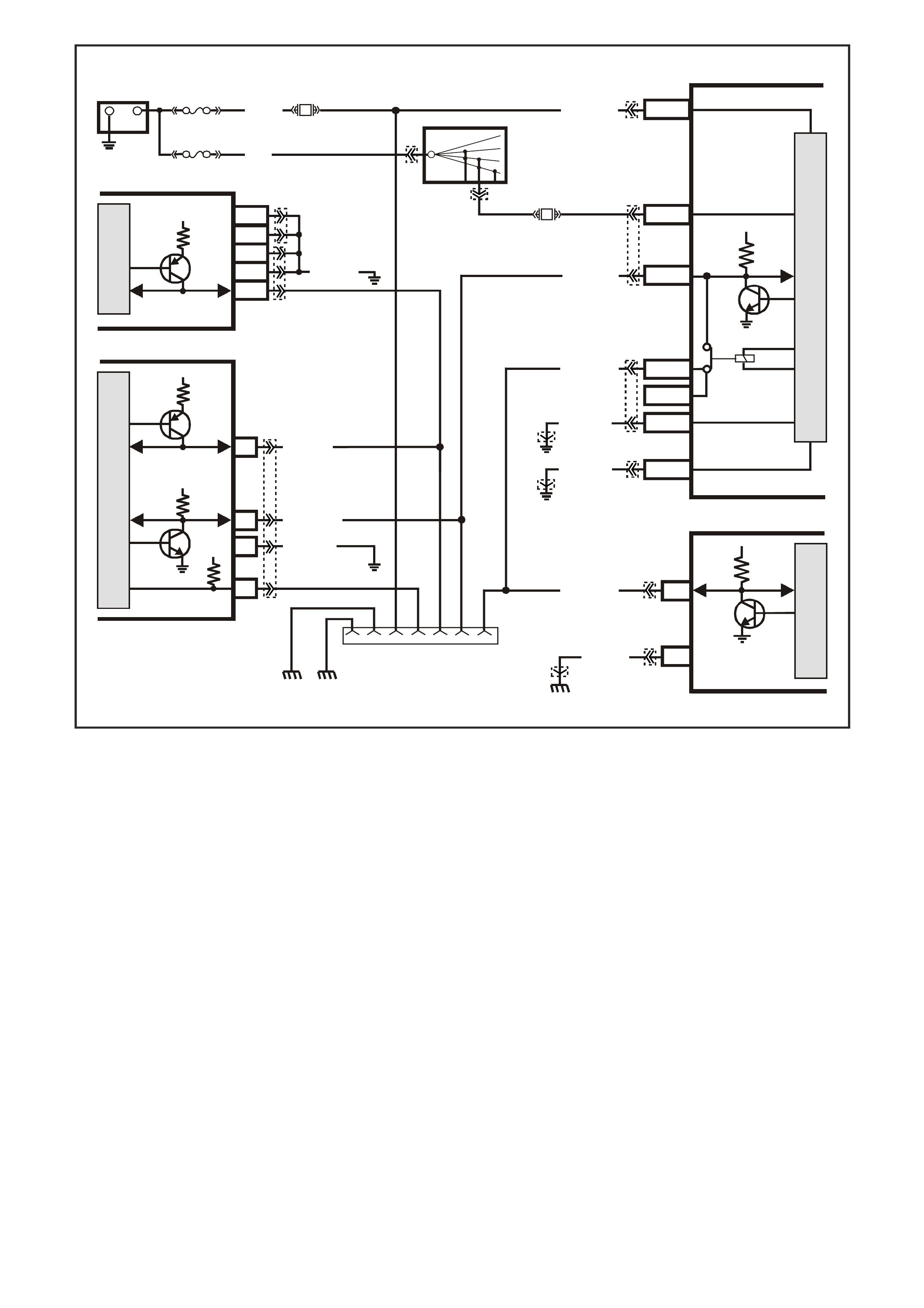
GEN III V8 PCM -
DATA LINK CONNECTOR DIAGNOSIS
CIRCUIT DESCRIPTION
Use a properly functioning Tech 2 scan tool with the diagnostic tables in this section. DO NOT use the Clear Info
function unless instructed by a diagnostic procedure.
IMPORTANT:
This vehicle, equipped with a Powertrain Control Module (PCM), utilises an Electrically Erasable Programmable
Read Only Memory (EEPROM). Program the new PCM when the diagnostics call for replacement of the PCM.
Refer to Section 6C3-3 PCM Replacement/ Programming of the VX Series Service Information.
DIAGNOSTIC AIDS
• If there is a fault with the PIM power feed or earth circuit, the Tech 2 scan tool will not communicate with the
PCM or BCM, or the PIM.
• If BCM DTC 007 is set, it indic ates there is a pr oblem (open) in circuit 1221 (UART serial data cir cuit) between
the BCM and the PIM.
• If PIM DT C B2006 is set, it indicates there is a problem ( open, short to ear th, or shor t to voltage) in circ uit 1049
(Class II Serial data circuit) between the PIM and the PCM.
• The following Table assumes the TECH 2 scan tool is fully functional.
G3PCM023PT
B/Y
(155)
B
(150)
LOC. E3
YB128
642516 9 1
ECC
BCM
DATA LINK
CONNECTOR
16
6SERIAL
DATA
5V
M
I
C
R
O
P
R
O
C
E
S
S
O
R
+
-
BATTERY
FS
F31
A5/A6
O/B (740)
(1040)
BAT TERY MAI N POWER
FJ
R (2)
F14
E20/D6
P/B
(39) IGNITION ON
15a 15 50
30 OFF/ON
LOCK
ACC
IGN
START
IGNITION SWITCH
P
(3)
B/Y (155)
B/G (151)
LOC. E3
LOC. E3
R/B (1221)
G/W (1220)
G/W (1220)
2
B/R ( 750)
Y (1049)
R/B (1221)
PIM
SERIAL
DATA
7V
7V
12V
ELECTRONIC EARTH
HIGH CURRENT
EARTH
A1/A5
B10/B11
E2/D2
E9/D3
E3/D13
SERIAL
DATA
MAIN
SERIAL
DATA AUX.
5V
5V
6
11
7
DI AG. ENABLE
CLASS 2
SERIAL DA TA
LOC. E5/E15
LOC. E5/E15
GEN III V8 PCM
J1-58
J2-01
J2-40
J1-40
J1-01
M
I
C
R
O
CLASS 2
SERIAL DA TA
B/R ( 750)
M
I
C
R
O
B/Y (155)
M
I
C
R
O
HIGH SERIES
BCM TERMINALS
NOMINATED FIRST
YB44
YB44
YB176
YB175
YB164
YB163
YB174
YB165
YB89
YB87
YE114
YE114
YE114
YB215
YE122
YE123
YB176
YB165
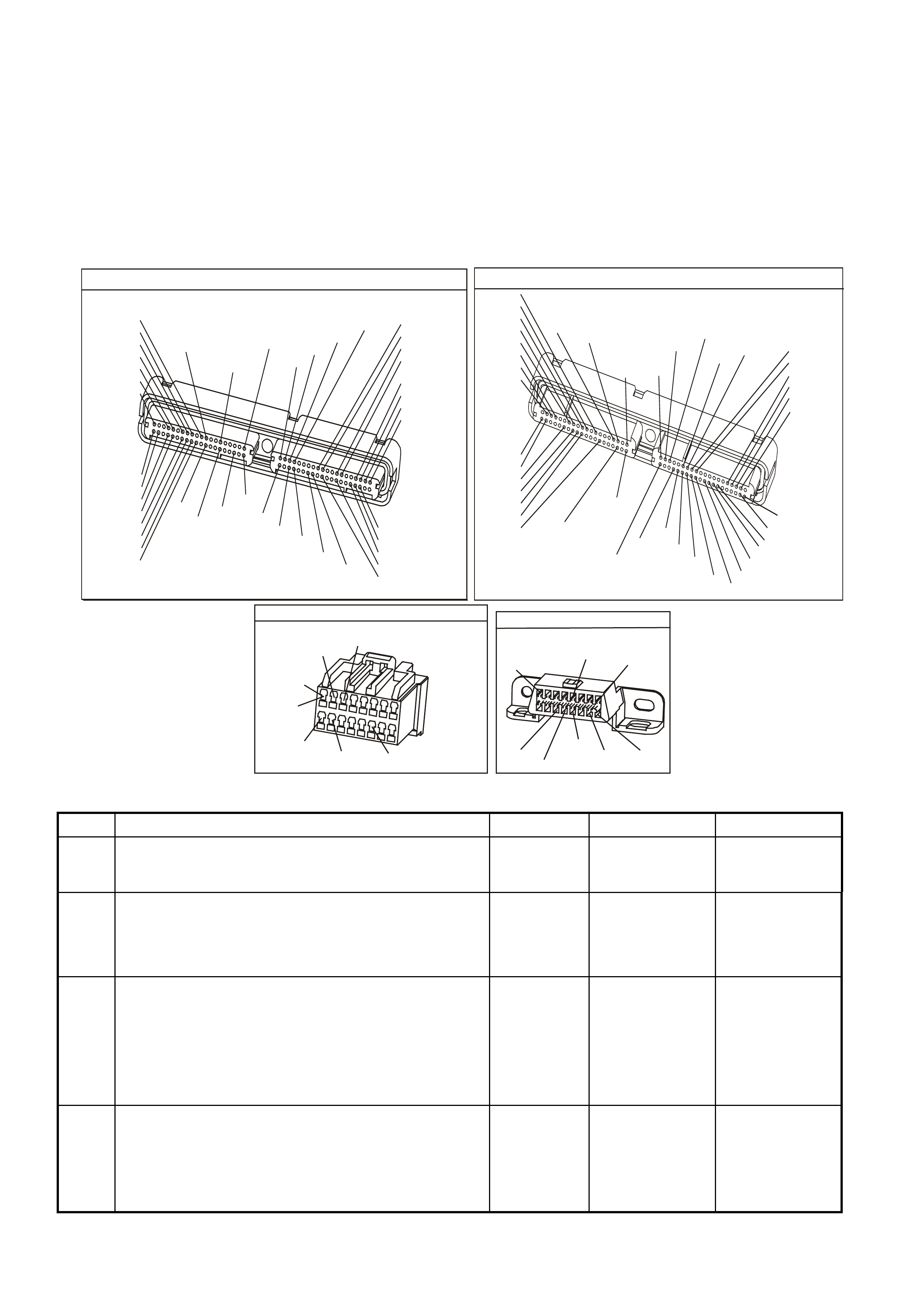
TEST DESCRIPTION
The numbers below refer to the step number on the diagnostic table.
3. This step checks to see if the PCM is receiving all of the power supplies.
4. This step is checking the Earth circuits at the PCM..
9. This step checks to see if the Class II serial data circuit is shorted to earth.
13. This step checks to see if the Class II serial data circuit is shorted to voltage.
14. This step checks the PIM earth circuit.
15. This step checks the PIM for ignition feed.
P.C.M CONNECTOR 1
YE122
(776)
(1049)
(897)
(1230)
(848)
(1226)
(772)
(647)
(632)
40
(844)
(815)
80
J1
P/B
(845)
V/W
BLU
O
(633)
(846)
B/Y
B/R
(416)
(86)
(69)
(455)
(740)
GY
BR
G
GY
(646)
(410)
GY
(842)
(1225)
V
Y
(750)
P
41
O
(774)
BR/Y
BLU
Y
B/R
B
BLU/Y
(841)
BLUE
(414)
G/W
BLU
LG
LBLU/B
1
(847)
(415)
(740)
(452)
BLU
BR
Y
(750)
(826)
(421)
Y
V/W
B/W
(334)
(771)
(39)
Y
R/W
LBLU
W
BLU/W
(843)
(643)
LBLU/W
G
GY/B
BLU/B
(413)
(1413)
(1412)
(412)
GY
V
GY/B
G
(335)
YE123
P.C.M CONNECTOR 2
(750)
(1228)
(1229)
(465)
(121)
(259)
G/B
BR
G/W
GY/BLU
R
B/R
(418)
BR
(59)
(832)
G
T
(831)
(417)
(472)
(976)(974)
(432)
(428)
(631)
BLUBR G/Y
BLU/W
LG
BR/W
W/B
LG W
(977)
Y
(971)
BLU/WW
B/R
(750)
(304)
(792)
(1223)
(1222)
(123)
(1227)
(469)
(331)
Y/B
LG
V/W
B/Y
G/OBR/W
(1687)
GY/B
(366)
LG/B
GY/R
(422)
V
(442)
(444)
(443)
(975)
(972)
(978)
(1224)
(973)
(959)
LG/W
LG/B
LBLU/B
GY
(773)
BR/Y
BLU
G
Y/B
LBLU
(958)
BR
(441)
LBLU
1
41
40
80
J2
RED
Y
(838)
POWER TRAIN INTERFACE MODULE
YB215
W/B
(451)
Y
(1049)
B/R
(750)
P
(39)
R/B
(1221)
GY/BLU
(1434)
GY
(434)
(AUTO)
(MAN)1
9
16
8
DATA LINK CONNECTOR
YB128
(863)
O/B BLU/BR/B
(1221)
(740)
16 9
(1220)
(155)
B/Y
G/W
W/B
(451)
B
(150)
Y
(1049)
1
8
GEN III V8 PCM - DATA LINK CONNECTOR DIAGNOSIS
Step Action Value(s) Yes No
1 Did you perform the Powertrain On-Board Diagnostic
(OBD) System Check? Go to Step 2 Go to Powertrain
OBD System
Check Table
2 1. Turn ON the ignition leaving the engine OFF.
2. Connect TECH 2 to the Diagnostic Link Connector
(DLC).
Does the TECH 2 scan tool power-up?
Go to Step 3 Go to Step 7
3 1. Ignition OFF.
2. Disconnect both PCM connectors.
3. Ignition ON.
4. Probe PCM battery feed circuits and ignition feed
circuits with a test light connected to earth.
Is the test light ON for all circuits?
Go to Step 4 Go to Step 21
4 1. Ignition OFF.
2. PCM connectors still disconnected.
3. Probe PCM earth circuits with a test light connected
to B+.
Is the test light ON for all earth circuits?
Go to Step 5 Go to Step 22

GEN III V8 PCM - DATA LINK CONNECTOR DIAGNOSIS (CONTINUED)
Step Action Value(s) Yes No
5 1. Ignition OFF.
2. Reconnect both PCM connectors.
3. Connect Tech 2 scan tool to DLC.
4. Ignition ON, engine OFF.
Does Tech 2 Tech 2 scan tool display Engine ID
Information?
Go to Step 8 Go to Step 6
6 Will the engine crank over? Go to Step 10 Go to Step 14
7 1. Turn ON the ignition leaving the engine OFF.
2. Probe the DLC terminal 16, circuit 740 (Orange/Black
wire), with a test lamp connected to the battery earth.
Is the test lamp illuminated?
Go to Step 8 Repair circuit 740
as required
(including fuse
F31)
8 Probe the DLC terminal 5, circuit 155 (Black/Yellow wire),
with a test lamp connected to B+.
Is the test lamp illuminated?
Go to Step 9 Repair circuit 155
as required.
9 Inspect the TECH 2 scan tool connections to the DLC,
including proper terminal tension at the DLC.
Is the action complete.
Go to Powertrain
OBD System
Check Table
10 Will the engine start and run? Go to Step 23 Go to Step 16
11 1. Disconnect PCM connector YE122 and PIM connector
YB215.
2. Check for an open in the Class II serial data circuit
1049 (Yellow wire) between PCM connector YE122,
terminal J1-58, and PIM connector YB215, terminal 7.
Was a problem found?
Repair open in
circuit 1049. Go to Step 12
12 1. Reconnect PCM and PIM connectors YE122 and
YB215.
2. Using test light connected to B+, probe the Class II
serial data circuit at the DLC, terminal 2, circuit 1049
(Yellow wire).
Is the test lamp illuminated?
Repair short to
earth in
circuit 1049
Go to Step 13
13 Using a test light connected to a known good earth, probe
the Class II serial data circuit at the DLC, terminal 2,
circuit 1049 (Yellow wire).
Is the test light illuminated?
Repair short to
voltage in
circuit 1049.
Verify repair
Replace PIM,
refer Section
6C3-3 Powertrain
Interface Module
Replacement
14 Disconnect the PIM connector YB215.
Check resistance between PIM connector YB215,
terminal 16, circuit 750 (Black/Red wire) and earth
location E5/E15.
Is value as specified?
Less than
5 Ω Go to Step 15 Repair earth
circuit as
necessary
15 With PIM connector YB215 disconnected, turn ignition
ON and measure voltage between PIM connector YB215
terminals 8 and 16.
Is voltage as specified?
Approx.
12 volts Go to Step 16 Repair circuit 39
as required
(including fuse
F14)
16 1. Connect the TECH 2 scan tool to the DLC.
2. Select Body / Powertrain Interface Module (PIM) /
Diagnostic Trouble Codes.
Is PIM DTC B2006 set?
Go to Step 11 Go to Step 17
17 In Step 13, were any other PIM DTC(s) set? Go to applicable
PIM DTC Table Go to Step 18

GEN III V8 PCM - DATA LINK CONNECTOR DIAGNOSIS (CONTINUED)
Step Action Value(s) Yes No
18 1. Turn OFF the ignition.
2. Disconnect PCM connectors YE122 and YE123.
3. Turn ON the ignition.
4. Probe each PCM battery and PCM ignition feed circuit
in PCM connectors, J1-20, J1-57 (circuit 740, Orange
wire) and J1-19 (circuit 39, Pink wire) using a test
lamp connected to a known good earth.
Does the test lamp illuminate at each terminal?
Go to Step 19 Repair circuits
740 and/or 39 as
necessary
19 1. Turn ignition OFF.
2. With both PCM connectors YE122 and YE123
disconnected, check resistance of PCM earth circuit
750 (Black/Red wire) between terminals J1-01, J1-40,
J2-01 and J2-40 and earth location E5/E15.
Is value as specified at each of the PCM connector
terminals?
Less than 5
Ω Go to Step 20 Repair fault in
earth circuit as
necessary
20 Inspect the PCM and PCM wiring harness connectors for
correct connection.
Was a problem found?
Repair
connections as
necessary
Replace PCM,
refer Section
6C3-3 Powertrain
Control Module
Replacement
21 Check for short to earth, and repair open in power circuit
that did not light test light.
Is action complete?
System OK
22 Repair open in earth circuit that did not light test light.
Is action complete? System OK
23 Repair open in Class II Serial Data circuit from DLC to
PCM .
Is action complete?
Verify Repair
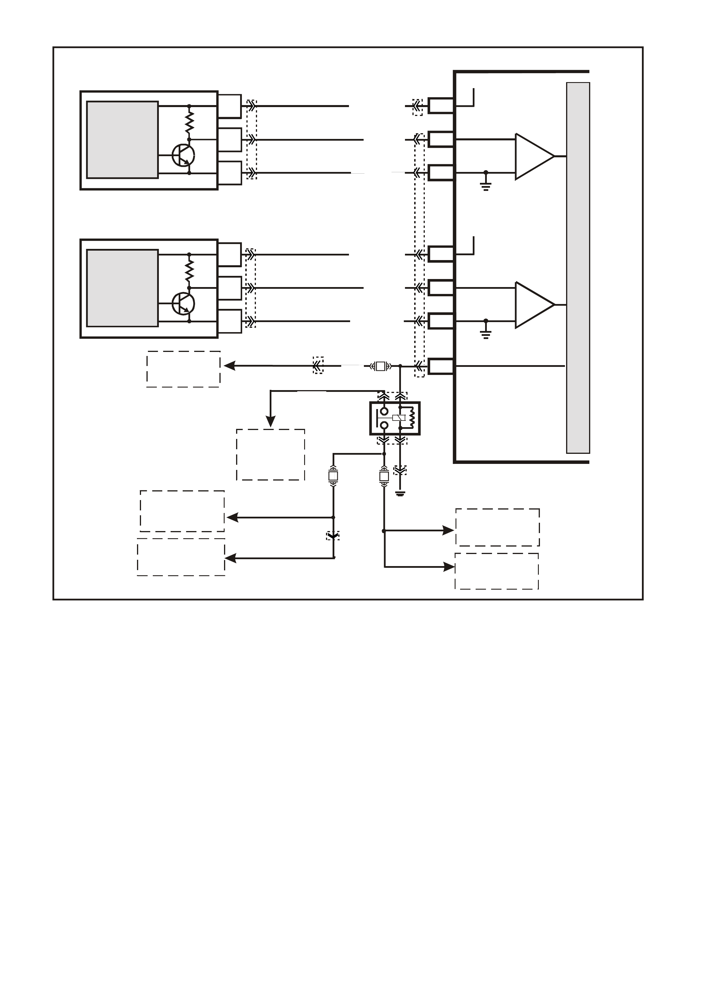
GEN III V8 PCM -
ENGINE CRANKS BUT DOE S NOT RUN
CIRCUIT DESCRIPTION
The Engine Cranks but does not run diagnostic table assumes that the battery condition and engine
cranking speed are OK. If the battery condition and the cranking speed are not OK, refer to
Section 12A BATTERY & CABLES in VX Service Information and Section 6D3-2 STARTING SYSTEM in VX
Service Information for diagnosis. Make sure that there is adequate fuel in the tank.
DIAGNOSTIC AIDS
• Check the duct work between the Mass Air Flow (MAF) Sensor and the throttle body for air leaks.
• A malfunctioning MAF Sensor may cause a no start or a stall after start. If you suspect this, disconnect the
MAF Sens or. T he PCM will def ault to the s peed dens ity (MAP, IAT, RPM) in order to c alculate the load and the
air flow.
• If this corrects the condition and the connections are OK, replace the MAF Sensor.
• If the steps above check OK, refer to Section 6C3-2B Symptoms of the VX Series Service Information.
TEST DESCRIPTION
The numbers below refer to the step numbers on the diagnostic table.
2. This step checks to see if any PIM DTC(s) are set.
7. The ignition feed circuit for the camshaft and crankshaft position sensors is internally connected within the
PCM. A short to earth on either circuit will cause a no start condition.
PCM
M
I
C
R
O
A
C
B
CAMSHAFT
POSITION
SENSOR
J2-39
W/B(631)
J1-61
SENSOR EARTH
RW(632)
12V
J1-73
BR(633)
CAMSHAFT POSITION
SENSOR
SIGNAL
MAGNETO
RESISTIVE
INTEGRATED
CIRCUIT
IC
YE69
YE123
4377
A
C
B
CRANKSHAFT
POSITION
SENSOR
J1-02LBLU/W (646)
J1-21
SENSOR EARTH
12V
J1-12BLU (643)
CRANKSHAFT POSITION
SENSOR
SIGNAL
MAGNETO
RESISTIVE
INTEGRATED
CIRCUIT
IC
LBLU/B (647)
YE67
YE122
(1040)
O/Y
(479)
B/W
(152)
LOC. E3
P (3)
EFI
RELAY
F14
F35
F34
R
(481)
L/G
(482)
YE39
YB44
YE111
YE39
YE114
TO
INJECTORS
2, 4, 6, 8
TO
IGNITION
SWITCH
TO
R.H
IGNITION MODULE
TO
FS
FUSIBLE
LINK
TO
L.H
IGNITION MODULE
TO
INJECTORS
1, 3, 5, 7
IGNITION
J1-19
P/B
(39)

CRANK SENSOR
(646)
LBLU/W
(647)
LBLU/B
(643)
BLU
CAM SENSOR
(631)
W/B
(632)
R/W
(633)
BR
GEN III V8 PCM - ENGINE CRANKS BUT DOES NOT RUN
Step Action Value(s) Yes No
1 Did you perform the Powertrain On-Board Diagnostic
(OBD) System Check? Go to Step 2 Go to Powertrain
OBD System
Check Table
2 Are any PIM DTC(s) set? Go to applicable
PIM DTC Tables Go to Step 3
3 1. Turn ON the ignition leaving the engine OFF.
2. Probe both sides of the fuses listed below using a test
lamp connected to earth.
- F31
- F33
- F34
- F35
Does the test lamp illuminate on both sides of all the
fuses?
Go to Step 4 Go to EFI Relay
Diagnosis Table
for further
diagnosis
4 Using Tech 2 scan tool, select the PCM Diagnostic
Trouble Code (DTC) option the DTC Information option.
Does the Tech 2 scan tool display any of the following
DTC(s) P0230, P0335, P0336, P0602 ?
Go to the
applicable DTC
table
Go to Step 5
5 Using the Tech 2 scan tool, Monitor the PCM theft status.
Does the Tech 2 scan tool display NO START? Go to Theft
Deterrent System
in Section 12J-1
LOW SERIES
BCM in VX
Service
Information or
Section 12J-2
HIGH SEREIS
BCM in VX
Service
Information.
Go to Step 6
6 Monitor the engine speed while cranking the engine.
Is engine RPM indicated on the Tech 2 scan tool? Go to Step 10 Go to Step 7
7 1. Disconnect the Crankshaft Position (CKP) Sensor
electrical connector.
2. Measure the voltage at the ignition feed circuit at the
CKP electrical connector using the DMM J39200.
Does the DMM display near the specified value?
B+ Go to Step 14 Go to Step 8
8 1. Disconnect the Camshaft Position (CMP) sensor
electrical connector.
2. Measure the voltage at the ignition feed circuit at the
CMP electrical connector using the DMM J39200.
Does the DMM display near the specified value?
B+ Go to Step 15 Go to Step 9
9 Inspect the camshaft and crankshaft position sensor
ignition feed circuits for a short to earth.
Did you find and correct the condition?
Go to Step 17 Go to Step 16
10 Check the engine coolant temperature using the Tech 2
scan tool.
Is the engine coolant temperature on the Tech 2 scan tool
close to the actual engine temperature?
Go to Step 11 Go to DTC
P0118 ECT
Sensor Circuit
High Voltage
Table

GEN III V8 PCM - ENGINE CRANKS BUT DOES NOT RUN (CONTINUED)
Step Action Value(s) Yes No
11 Enable the fuel pump using the Tech 2 scan tool.
Does the fuel pump operate? Go to Step 12 Go to Fuel Pump
Relay Circuit
Diagnosis Table
12 1. Turn OFF the ignition.
2. Install the fuel pressure gauge. Refer to Fuel System
Diagnosis of the VX Series Service Information.
3. Turn ON the ignition leaving the engine OFF.
4. Observe the fuel pressure.
Is the fuel pressure within the specific range?
380-420 kPa
(55-61 psi) Go to Step 13 Go to Fuel
System
Diagnosis Table
13 Perform the following additional checks:
• Check the ductwork between the Mass AirFlow
(MAF) Sensor and the throttle body for air leaks.
• Check that the throttle angle is at 0% at a closed
throttle. If the throttle angle is not at 0%, refer to DTC
P0122/P0123.
• A malfunctioning MAF Sensor may cause a no start
or a stall after a start. If you suspect this, disconnect
the MAF Sensor. The PCM will default to the speed
density (MAP, IAT, RPM) in order to calculate the
engine load and the intake air flow. If disconnecting
the MAF Sensor corrects the condition and the
connections are OK, replace the MAF Sensor.
• Inspect for an engine mechanical failure that causes
an engine not to start (i.e. timing chain, low
compression).
• Compare MAP/BARO parameters to another vehicle.
The parameter values should be close to each other.
Did you find and correct the condition?
Go to Step 17 Go to Hard Start
for diagnosis in
Section 6C3-2B
Symptoms in this
Section
14 Replace the CKP Sensor, refer to Section 6C3-3
Crankshaft Position Sensor Replacement of the VX
Series Service Information.
Is the action complete?
Go to Step 17
15 Replace the CMP Sensor, refer to Section 6C3-3
Camshaft Position Sensor Replacement of the VX Series
Service Information.
Is the action complete?
Go to Step 17
16 1. Replace PCM.
2. Refer to Section 6C3-3 of the VX Series Service
Information for PCM Programming and
PCM/PIM/BCM Security Link Procedure.
Is action complete?
Go to Step 17
17 1. Select the Diagnostic Trouble Codes (DTC) option
and the Clear DTC Information option using the
Tech 2 scan tool.
2. Attempt to start the engine.
Does the engine start and continue to run?
Go to Step 18 Go to Step 3
18 1. Idle the engine at the normal operating temperature.
2. Select the Diagnostic Trouble Codes (DTC) option,
the DTC Information option then the Failed This
Ignition option using the Tech 2 scan tool.
Are any DTC(s) displayed?
Go to the
applicable DTC
table
Go to Step 19
19 Using the Tech 2 scan tool, check for any other DTC(s)
Does the Tech 2 scan tool display any DTC(s) that you
have not diagnosed?
Go to the
applicable DTC
table
System OK
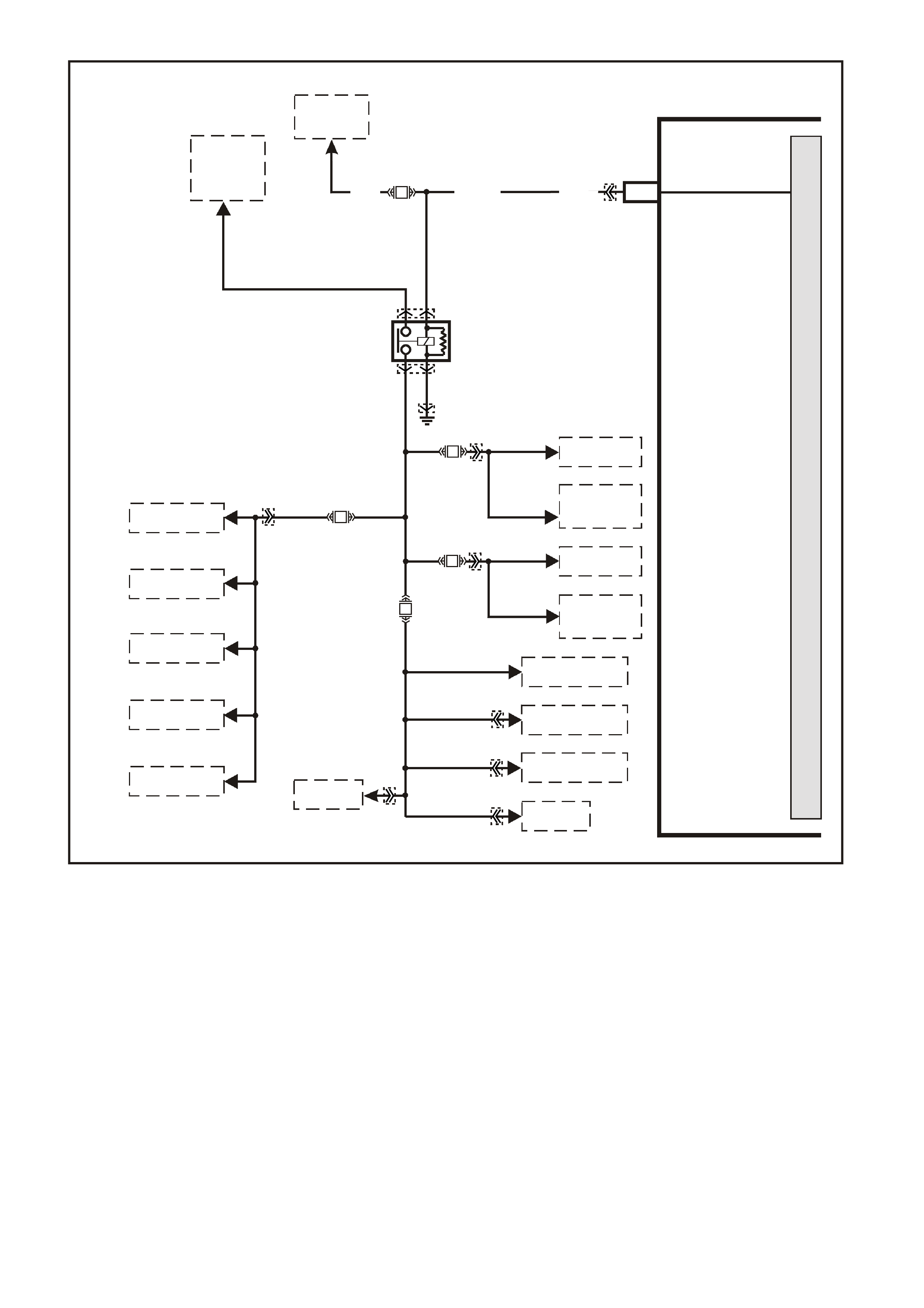
GEN III V8 PCM
EFI (ENGINE CONT.) RELAY DIAGNOSIS
NOTE: The EFI relay may be named Engine Cont. relay on later vehicles.
CIRCUIT DESCRIPTION
The EFI relay protects the battery from a parasitic draw. The following components are powered by the EFI relay:
• Injectors/Ignition coils
• Transmission
• A/C System
• EVAP Solenoid and EVAP Vent Valve
• MAF Sensor
• Heated Oxygen Sensors
4370
PCM
M
I
C
R
O
P
R
O
C
E
S
S
O
R
J1-19 IGNITION
P (3) F14
P (39)
YE122
YE39
YE39
YE114
YE111
YE111
YE95
YE95
YE101
YE100
YB129
P/B (39)
EFI RELAY
O/Y
(479)
LOC. E3
R
(481)
LG
(482)
P
(439)
P/BLU
(339)
B/W
(152)
F34
F35
F33
F32
TO R.H. BANK
INJECTORS
TO L.H. BANK
INJECTORS
TO R.H.
IGNITION
MODULES
TO L.H.
IGNITION
MODULES
TO R.H. HEATED
OXYGEN SENSOR
TO L.H. HEATED
OXYGEN SENSOR
TO A/C
RELAY
TO MAF
SENSOR
TO CANISTER
PURGE SOLENOID
TO 3-2
SOLENOID
TO 1-2 SHIFT
SOLENOID A
TO 2-3 SHIFT
SOLENOID B
TO TCC ENABLE
SOLENOID
TO TCC PWM
SOLENOID
TO
FS
FUSIBLE
LINK
TO
IGNITION
SWITCH

DIAGNOSTIC AIDS
• The following may cause an intermittent:
- Poor connections. Check for adequate terminal tension.
- Corrosion.
- Incorrectly routed harness.
- Rubbed through wire insulation.
- Broken wire inside the insulation.
TEST DESCRIPTION
The numbers below refer to the step numbers on the diagnostic table.
NOTE: For any test that requires probing the PCM or a component harness connector, use the Connector Test
Adapter Kit J35616-A. Using this kit prevents damage to the harness connector terminals.
2. This test checks the fusible link FS power feed to the EFI relay.
3. This test checks the fused power feed ignition circuit.
4. This test is checking the earth circuit of the EFI relay.
This step isolates the circuit from the EFI relay. All of the circuits at the relay are good if the test lamp illuminates.
E.F.I RELAY
YE39
B/W
P/B
O/Y
(152)
(39)
(479)
(1040)
ENGINE 12V BUS
GEN III V8 PCM - EFI (ENGINE CONT.) RELAY DIAGNOSIS
Step Action Value(s) Yes No
1 Did you perform the Powertrain On-Board Diagnostic
(OBD) System Check? Go to Step 2 Go to Powertrain
OBD System
Check Table
2 1. Turn OFF the ignition.
2. Remove the engine compartment Fuse/Relay panel
cover.
3. Remove the EFI (Engine Cont.) relay.
4. Probe the fusible link FS power feed circuit to the EFI
relay harness, terminal 87, with a test lamp, J34142-B,
connected to a earth.
Does the test lamp illuminate?
Go to Step 3 Go to Step 8
3 1. Turn ON the ignition leaving the engine OFF.
2. Probe the fused ignition feed circuit to the EFI relay
harness terminal 85 with the test lamp J34142-B
connected to a earth.
Does the test lamp illuminate?
Go to Step 4 Go to Step 9
4 1. Turn OFF the ignition.
2. Probe the earth circuit to the EFI relay harness
terminal 86 with the test lamp, J34142-B, connected to
B+.
Does the test lamp illuminate?
Go to Step 5 Go to Step 10

GEN III V8 PCM - EFI (ENGINE CONT.) RELAY DIAGNOSIS (CONTINUED)
Step Action Value(s) Yes No
5 1. Turn OFF the ignition
2. Jump the EFI relay B+ feed circuit terminal 87 and the
EFI relay load circuit terminal 30 together using a
fused jumper wire.
3. Probe the following fuses with a test lamp, J34142-B,
connected to earth:
- F32
- F33
- F34
- F35
Does the test lamp illuminate for all fuses?
Go to Step 6 Go to Step 11
6 Check for poor terminal contact at the EFI relay harness
connector.
Did you find and correct the condition?
System OK Go to Step 7
7 Replace the EFI relay.
Is the action complete? System OK
8 Repair the open in fusible link FS circuit to the EFI relay.
Is the action complete? System OK
9 Repair the fused ignition feed circuit to the EFI relay.
Replace fuse if open.
Is the action complete?
System OK
10 Repair the open in the earth circuit for the EFI relay.
Is the action complete? System OK
11 Repair open in the EFI relay load circuit, or open in
fuse(s) circuit that did not illuminate the test light.
Is the action complete?
System OK
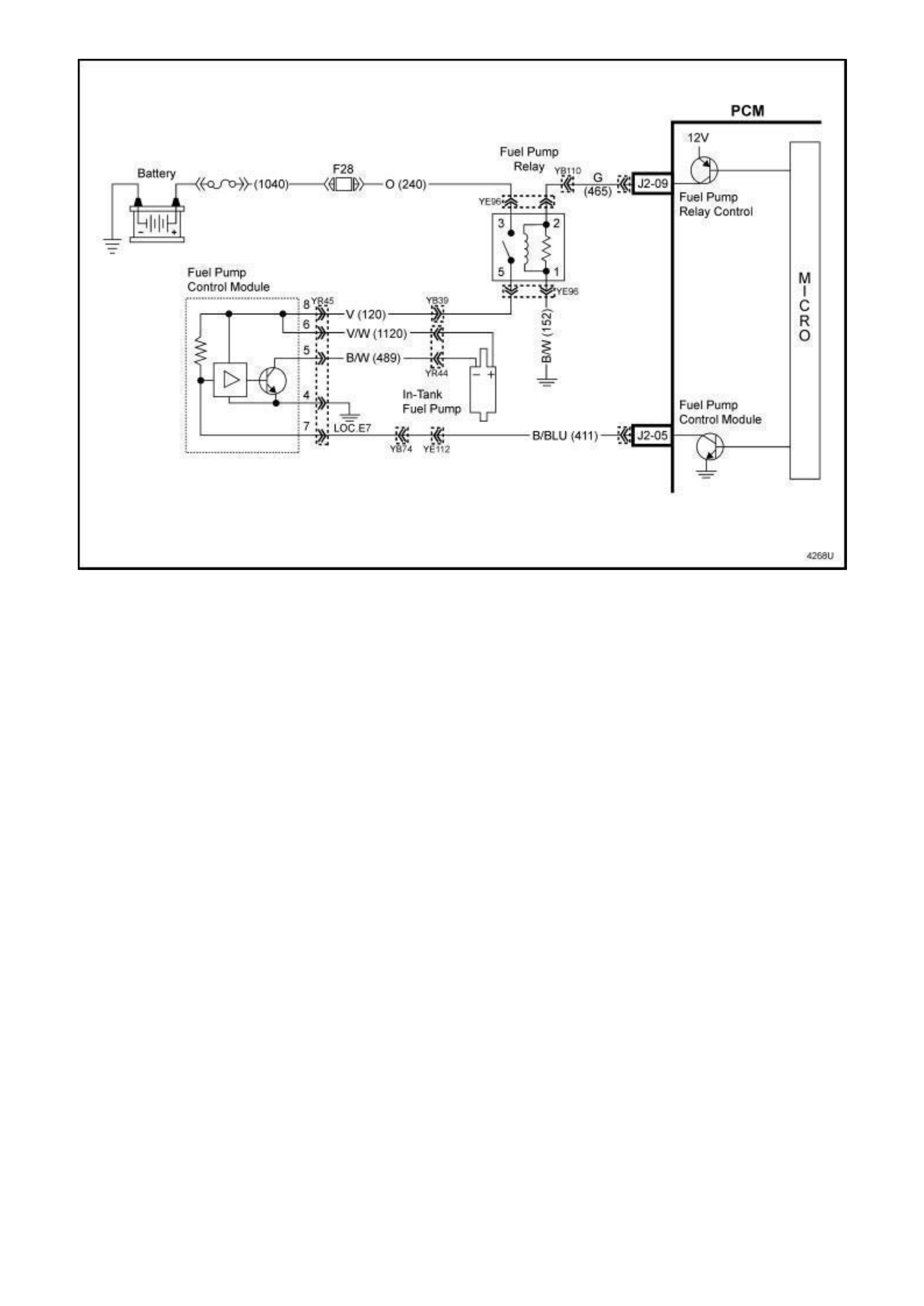
FUEL PUMP ELECTRICAL CIRCUIT
(WITH FUEL PUMP SPEED CONTROLLER)
The fuel control system used on the GEN III V8 is a “Returnless” or “Demand” system. The fuel system starts with
the fuel in the fuel tank. A single in-tank high pressure fuel pump with an integrated fuel pressure regulator (located
inside a modular fuel sender assembly) is used. From the high pressure pump, fuel flows through a fuel filter, then
back into the fuel tank via the fuel pressure regulator. Fuel is supplied to the fuel rail and injectors by a single feed
fuel line.
From Production Serial Number L732452 (06 June 2001), a "Fuel Pump Control Module" was added to the VU
GENIII V8 fuel system.
The Fuel Pump Control Module enables the PCM to command the fuel pump to run at reduced speed during while
idling (reducing fuel flow rate), but command maximum pump speed off-idle to ensure adequate fuel delivery under
all operating conditions. The PCM varies Fuel Pump speed by controlling the duty cycle ground on the Fuel Pump
PWM driver circuit to the Fuel Pump Control Module.
When the ignition switch is first turned "ON", the PCM energises the Fuel Pump Relay, which applies power to the
Fuel Pump Control Module. The Fuel Pump Relay will remain "ON" as long as the engine is cranking or running
and the PCM is receiving reference pulses. If no reference pulses are present, the PCM de-energises the Fuel
Pump Relay within 2 seconds after the ignition is turned "ON" or the engine is stopped.
Under idle conditions, the PCM will apply a 33% duty cycle ground signal to the Fuel Pump Control Module circuit
411. This duty cycle will command the Fuel Pump Control Module to run the fuel pump at about 9 volts, providing a
lower pump speed and reduced operating noise, with lower fuel flow (approximately 10 grams/sec.).
As the throttle is opened, the PCM will apply a 99% ground signal to circuit 411. This will cause the Fuel Pump
Control Module to switch internally and allow the Fuel Pump to run at maximum voltage providing high speed and
increased fuel flow (approximately 32 grams/sec.), system voltage applied to fuel pump).
The PCM will also command the Fuel Pump Control Module to switch to the high speed fuel pump operating mode,
when system voltage is low.
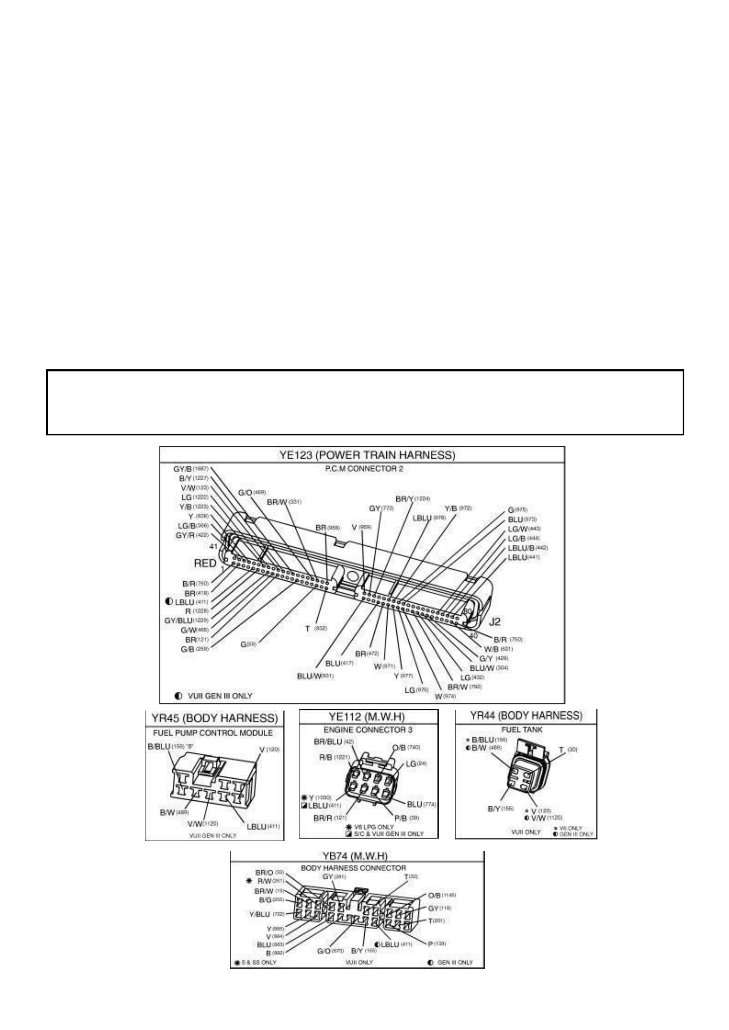
Test Description: The numbers below refer to the step numbers on the diagnostic table.
3. Checks that fuel pressure is sufficient for the vehicle to start.
4. Ensures that the Fuel Pump PWM driver circuit and the PCM are capable of controlling Fuel Pump speed.
5. Verifies that the Fuel Pump feed and earth circuits are OK between the Fuel Pump Control Module and the
Fuel Pump, and that the Fuel Pump can deliver adequate pressure to the fuel rail.
6. Checks the feed circuit to the Fuel Pump Control Module. The test lamp should light for approximately 3
seconds.
8. Ensures that the Fuel Pump PWM driver circuit is not shorted to earth.
13. Checks the ignition feed circuit to the Fuel Pump Relay contacts.
14. Checks the earth circuit for the Fuel Pump Relay coil.
15. Ensures that the Fuel Pump Relay driver circuit is OK and that the PCM is capable of controlling the Fuel Pump
Relay. Using the Tech 2 scan tool to command the Fuel Pump Relay allows only a 2 second "ON" time.
21. Checks the Fuel Pump Relay driver circuit for a short to earth.
26. If the Fuel Pump is operating but incorrect pressure is noted, the Fuel Pump wiring is OK. Go to Table A-4.3.
28. Determines weather the problem is being caused by an open in the Fuel Pump feed circuit or the Fuel Pump
earth circuit.
31. Ensures that the Fuel Pump speed control PWM circuit is OK and that the PCM can control the Fuel Pump
speed control PWM driver.
37. The fuel pump on this Supercharged Engine application is serviceable from the Modular Sender Assembly.
Refer to Section 6C3-3 SERVICE OPERATIONS in this Service Information for replacement procedures.
NOTICE:
When performing this diagnostic Table, make certain that the drive wheels are blocked and the parking
brake is firmly set.

FUEL PUMP ELECTRICAL CIRCUIT
STEP ACTION VALUE YES NO
1. Was the "On-Board Diagnostic" (OBD) System
Check performed?
Go to Step 2. Go to OBD
System Check
2. Are any DTC’s set? Go to DTC
Table first
Go to step 3
3. 1. Connect a Fuel Pressure Gauge to fuel pressure
tap fitting.
2. Turn the Ignition "ON".
3. Observe the fuel pressure gauge with the fuel
pump running
4. Note fuel pressure on Fuel Pressure Gauge.
Is the specified fuel pressure value indicated?
290 to 410
kPa
Go to Step 4 Go to Step 5
4. 1. With the Ignition 'OFF', jump pin 7 of connector
YR45 to ground.
2. Turn the ignition 'ON' and observe the fuel
pressure with the fuel pump running.
3. Turn the ignition 'OFF' and remove the ground
jumper wire from connector YR45.
Does the fuel pressure increase slightly from that
observed in step 3?
No problem
found
Go to Step 31
5. 1. Ignition "OFF".
2. Disconnect Fuel Pump Control Module.
3. Connect a fused jumper wire between Fuel
Pump Control Module harness connector
terminal 6 (Fuel Pump power feed circuit) and
+12. volts.
4. Connect a second jumper between the Fuel
Pump Control Module harness connector
terminal 5 (Fuel Pump earth circuit) and chassis
earth.
5. Note the fuel pressure on the Fuel Pressure
Gauge.
Is the specified fuel pressure value indicated?
290 to 410
kPa
Go to Step 6 Go to Step 26
6. 1. Ignition "OFF".
2. Disconnect the jumpers from the Fuel Pump
Control Module connector.
3. Connect a test light between the Fuel Pump
Control Module harness connector terminal 8
(Fuel Pump Control Module relay feed circuit)
and earth.
4. Ignition "ON".
5. Observe the test light.
Did the test light turn "ON"?
Go to Step 7 Go to Step 13
7. Probe terminal 4 (Fuel Pump Control Module earth
circuit) with a test light to +12 volts.
Is the test light "ON"?
Go to Step 8 Go to Step 25
8. 1. Ignition "OFF".
2. Disconnect the PCM connectors.
3. Probe the Fuel Pump Control Module PWM
driver circuit at the PCM connector with a test
light connected to +12 volts.
Is the test light "ON"?
Go to Step 9 Go to Step 10

STEP ACTION VALUE YES NO
9. Locate and repair short to earth in the Fuel Pump
Control Module PWM driver circuit .
Is action complete?
Go to Step 39
10. 1. Ignition "OFF".
2. Reconnect PCM connectors.
3. Install a volt/ohmmeter to measure voltage
between
the Fuel Pump Control Module connector
terminal 7 (Fuel Pump Control Module PWM
driver circuit ) and terminal 4 (earth circuit ).
4. Turn the ignition "ON" to command the Fuel
Pump Relay "ON".
Does the voltage measure at or above the specified
value while the Fuel Pump Relay is commanded
"ON"?
8 volts Go to Step 11 Go to Step 38
11. 1. Ignition "OFF".
2. Ignition "ON".
3. Using a test light, backprobe between the Fuel
Pump Control Module connector terminal 6 (Fuel
Pump power feed circuit ) and terminal 5 (Fuel
Pump earth circuit ).
4. Turn the ignition "ON" to command the Fuel
Pump Relay "ON".
5. Observe the test light.
Is the test light "ON" while the Fuel Pump Relay is
commanded "ON"?
Go to Step 12 Go to Step 34
12. 1. Check for poor connections at the Fuel Pump
Control Module.
2. If a problem is found, replace faulty terminals as
necessary.
Was a problem found?
Go to Step 38 Refer to
Diagnostic
Aids
13. 1. Ignition "OFF".
2. Disconnect the Fuel Pump Relay.
3. Ignition "ON".
4. Probe the Fuel Pump Relay fused power feed
circuit with a test light to earth.
Is the test light "ON"?
Go to Step 14 Go to Step 19
14. Connect test light between the Fuel Pump Relay
power feed circuit (terminal 3) and the Fuel Pump
Relay earth circuit.
Is the test light "ON"?
Go to Step 15 Go to Step 20
15. 1. Connect the test light between the Fuel Pump
Relay control circuit (terminal 2), and the Fuel
Pump Relay earth circuit (terminal 1).
2. Turn the ignition "ON" to command the Fuel
Pump Relay "ON".
Is the test light "ON" when the Fuel Pump Relay is
commanded "ON"?
Go to Step 16 Go to Step 21

STEP ACTION VALUE YES NO
16. 1. Connect a fused jumper wire between the Fuel
Pump Relay connector power feed circuit
(terminal 3) and the output power feed circuit
(terminal 5).
2. Probe the Fuel Pump Control Module Fuel
Pump power feed circuit at the Fuel Pump
Control Module harness connector (terminal 6)
with a test light to earth.
Is the test light "ON"?
Go to Step 17 Go to Step 24
17. 1. Check for a faulty terminal connection at the
Fuel Pump Relay.
2. If a problem is found, repair terminals as
necessary.
Was a problem found?
Go to Step 38 Go to Step 18
18. Replace the Fuel Pump Relay.
Is action complete?
Go to Step 38
19. Locate and repair open in Fuel Pump Relay fused
power feed circuit.
Is action complete?
Go to Step 38
20. Locate and repair open in Fuel Pump Relay earth
circuit.
Is action complete?
Go to Step 39
21. 1. Ignition "OFF".
2. Disconnect the PCM connectors.
3. Probe the Fuel Pump Relay control circuit at the
PCM connector with a test light to +12 volts.
Is test light "ON"?
Go to Step 22 Go to Step 23
22. Locate and repair short to earth in the Fuel Pump
Relay control circuit.
Is action complete?
Go to Step 38
23. 1. Check for the following conditions:
• Fuel Pump Relay control circuit for an open
between the Fuel Pump Relay and the PCM.
• Fuel Pump Relay control circuit for a poor terminal
connection at the PCM.
2. If a problem is found, repair as necessary.
Was a problem found?
Go to Step 38 Go to Step 38
24. Check for a open or poor connection in the Fuel
Pump Control Module Fuel Pump power feed circuit.
Was a problem found?
Go to Step 38 Go to Step 35
25. Locate and repair open in Fuel Pump Control
Module earth circuit.
Is action complete?
Go to Step 38
26. Remove the fuel tank filler cap and listen for the Fuel
Pump running.
Is the Fuel Pump running?
Go to
Table A-4.3
Go to Step 27

STEP ACTION VALUE YES NO
27. 1. Using fused jumper wires, jumper Fuel Pump
control module terminal 6 circuit to +12 volts,
and jumper terminal 5 circuit to earth.
2. Disconnect the Fuel Pump electrical connector
at fuel tank.
3. Connect a test light between the Fuel Pump
electrical connector power feed circuit , and fuel
pump earth circuit at PCM side of connector.
Is the test light "ON"?
Go to Step 37 Go to Step 28
28. Probe the Fuel Pump power feed circuit at the Fuel
Pump electrical connector with a test light connected
to chassis earth.
Is the test light "ON"?
Go to Step 30 Go to Step 29
29. Locate and repair open in the Fuel Pump power feed
circuit.
Is action complete?
Go to Step 38
30. Locate and repair open in the Fuel Pump earth
circuit.
Is action complete?
Go to Step 37
31. 1. Check for the following conditions:
• Fuel Pump PWM driver circuit for an open or short
to voltage between the Fuel Pump Control
Module and the PCM.
• Fuel Pump PWM driver circuit for a poor terminal
connection at the PCM.
If a problem is found, repair as necessary.
Was a problem found?
Go to Step 37 Go to Step 38
32. 1. Check terminal connections at the Fuel Pump
Control Module.
2. If a problem is found, repair faulty terminal(s) as
necessary.
Was a problem found?
Go to Step 37 Go to Step 35
33. Replace the Fuel Pump Control Module.
Is action complete?
Go to Step 37 Complete
Action
34. 1. Check terminal connections at the Fuel Pump.
2. If a problem is found, repair faulty terminal as
necessary.
Was a problem found?
Go to Step 37 Go to Step 35
35. Replace the Fuel Pump.
Is action complete?
Go to Step 37 Complete
Action
36. 1. Replace PCM.
2. Refer to Section 6C3-3 Service Operations in
this Service Information, for PCM Security Link
procedure.
Is action complete?
Go to Step 37 Complete
Action

STEP ACTION VALUE YES NO
37. 1. Turn the ignition "ON" to command the Fuel
Pump Relay "ON".
2. Observe the Fuel Pressure Gauge.
3. Note the fuel pressure on the Fuel Pressure
Gauge.
Is proper fuel pressure indicated?
290 to 410
kPa
Go to Step 38 Go to Step 5
38. 1. Ignition "OFF".
2. Fuel Pressure Gauge still installed.
3. Ignition "ON", engine idling.
4. Observe the Fuel Pressure Gauge at idle.
5. Raise engine speed to 2000rpm.
Is the fuel pressure slightly higher at 2000rpm than
at idle?
Repair
complete. If a
driveability
symptom
exists, Refer to
Section 6C3-
2B Symptoms.
Go to Step 31
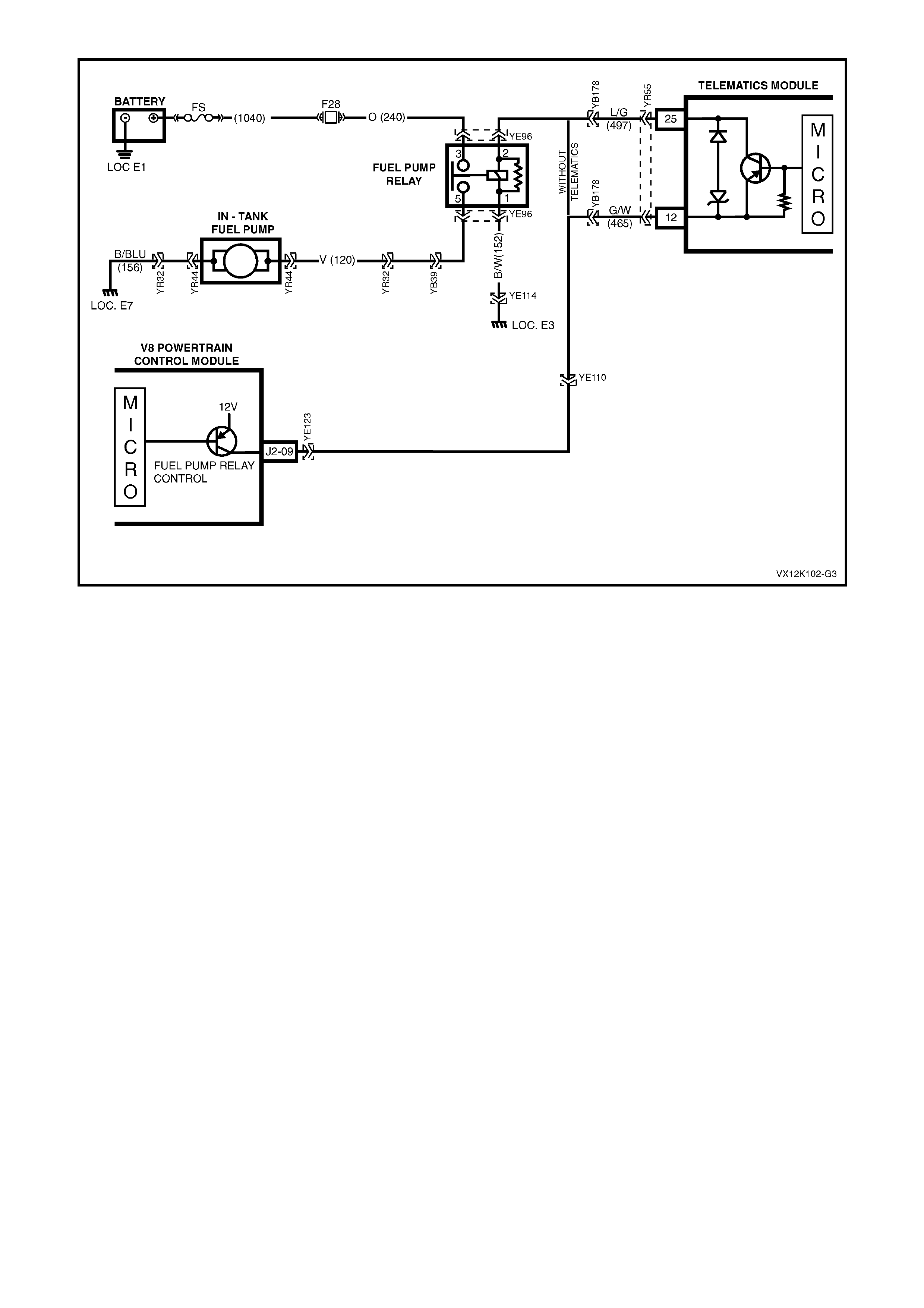
GEN III V8 PCM
FUEL PUMP RELAY CIRCUIT DIAGNOSIS
Circuit Description
W hen the igniti on s witc h is O N, the PCM ac t iv ates the in- tank fuel pump. The f uel pump rem ains ON as long as the
PCM receives reference pulses from the ignition system. If there are no reference pulses, the PCM turns the fuel
pump OFF after about 2-3 seconds.
The pump delivers fuel to the fuel rail and injectors, then to the pressure regulator, where the system pressure
remains at 380-440 kPa (55-62 psi). Excess fuel returns to the fuel tanks. When the engine is stopped, a Tech 2
scan tool in the output controls function can turn ON the fuel pump.
Improper fuel system pressure may result in one or many of the following symptoms:
• Cranks but will not run
• Cuts out, any feel like an ignition problem
• Poor fuel economy
• Loss of power
• Hesitation
• DTCs
Diagnostic Aids
• The following conditions may have caused the fuel pump fuse to open:
- The fuse was faulty
- There is an intermittent short in the fuel pump power feed circuit
- The fuel pump has an intermittent internal problem
• For an intermittent condition, refer to Section 6C3-2B Symptoms of the VX Series Service Information.
Test Description
The numbers below refer to the step numbers on the diagnostic table.
3. This test checks for the proper fused power feed to the fuel pump relay.
4. This test checks to see if the earth signal is present at the fuel pump relay.
5. The test lamp only illuminates for two seconds even though the Tech 2 scan tool commanded position is ON.
You will have to command the fuel pump OFF then ON to re-enable the PCM fuel pump control.
12. Inspect the fuel pump fuse for an open. If the fuse is open, check the circuit for a short to earth.
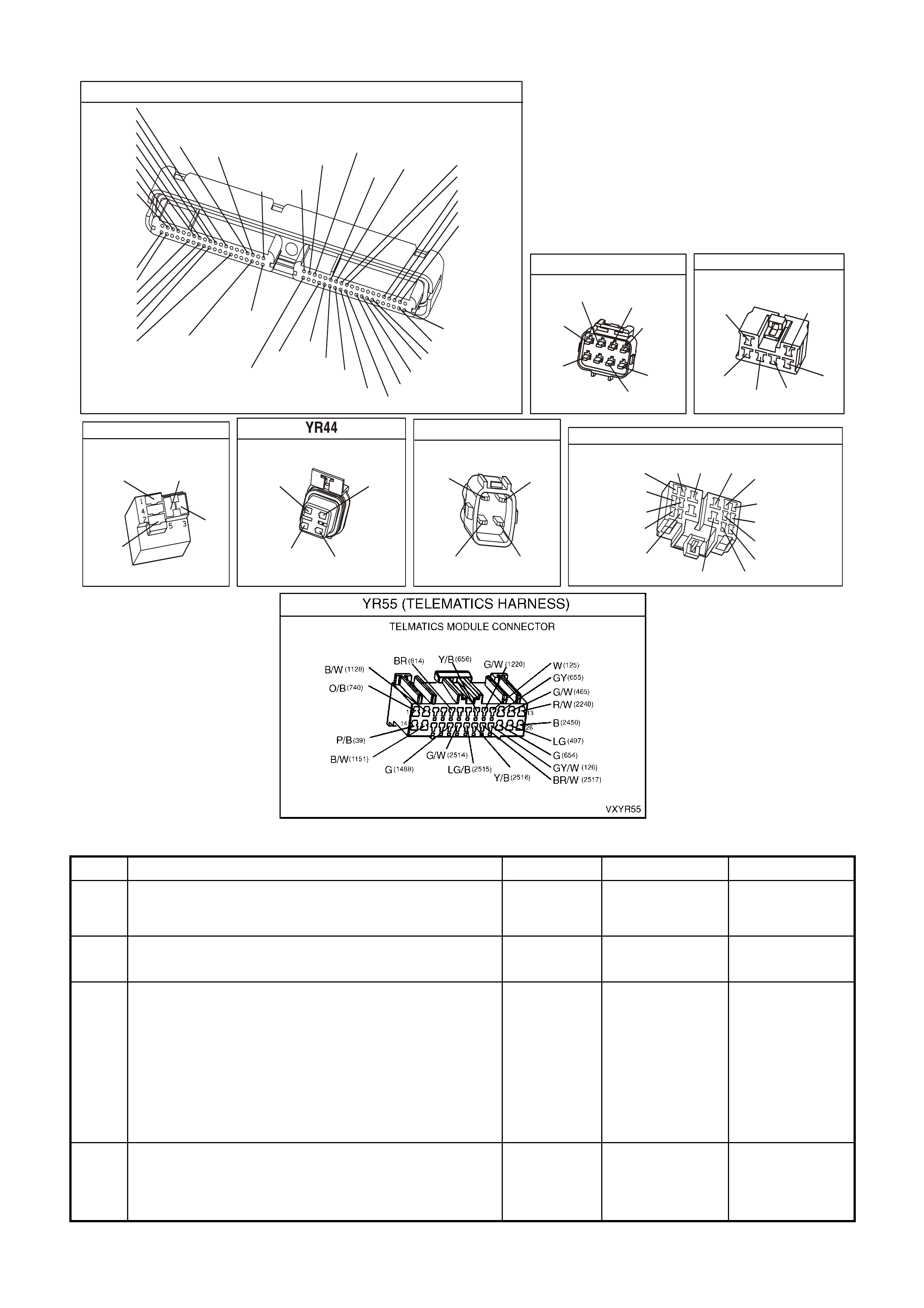
YE123
P.C.M CONNECTOR 2
(750)
(1228)
(1229)
(465)
(121)
(259)
G/B
BR
G/W
GY/BLU
R
B/R
(418)
BR
(59)
(832)
G
T
(831)
(417)
(472)
(976)(974)
(432)
(428)
(631)
BLUBR G/Y
BLU/W
LG
BR/W
W/B
LG W
(977)
Y
(971)
BLU/WW
B/R
(750)
(304)
(792)
(1223)
(1222)
(123)
(1227)
(469)
(331)
Y/B
LG
V/W
B/Y
G/OBR/W
(1687)
GY/B
(366)
LG/B
GY/R
(422)
V
(442)
(444)
(443)
(975)
(972)
(978)
(1224)
(973)
(959)
LG/W
LG/B
LBLU/B
GY
(773)
BR/Y
BLU
G
Y/B
LBLU
(958)
BR
(441)
LBLU
1
41
40
80
J2
RED
Y
(838)
ENGINE CONNECTOR 1
YE110
O/W
(304)
(1426)
BLU/W
G/W
(339)
P/BLU
(465)
(123)
V/W
(1427)
B/W
Y
(1049)
LOCATION E3 EARTH CONNECTOR
RIGHT HAND INNER FENDER
YE114
(151)
B/G
(157)
B/R
(150) (155)
BB/Y
(152)
B/W
(157)
B/R
FUEL PUMP RELAY
YE96
(465)
G/W
(152)
B/W
V
(120)
O
(240)
FUEL TANK
(156)
(155)
B/BLU
B/Y
(30)
(120)
T
V
FUEL TANK HARNESS CONNECTOR
YR32
(156)
(30)
(155)
(120)
B/BLU B/Y
T
V
BODY HARNESS CONNECTOR
YB39
V/R
(192)
O/Y
(1240)
(14)
(15)
(20)
(9)(540)
(24)
(46)
(199)
(116)
(115)
(120)
(200)
(117)
G
LBLU
BLU
BR
BLU/R
LG
O/B
BLU/O
BR/B
Y/BLU
BLU/B
V
LG
GEN III V8 PCM - FUEL PUMP RELAY CIRCUIT DIAGNOSIS
Step Action Value(s) Yes No
1 Did you perform the Powertrain On-Board Diagnostic
(OBD) System Check? Go to Step 2 Go to Powertrain
OBD System
Check Table
2 Check the fuel pump fuse.
Is the fuse open? Go to Step 9 Go to Step 3
3 1. Install a Tech 2 scan tool.
2. Disconnect the fuel pump relay from the engine
compartment fus e/re lay panel.
3. Turn ON the ignition leaving the engine OFF.
4. Probe the fused power feed circuit, in the fuel pump
relay harness connector term inal 3, with the test lamp,
J34142-B, connected to earth.
Does the test lamp illuminate?
Go to Step 4 Go to Step 12
4 Probe the earth circuit in the fuel pump relay harness
connector terminal 1, with the test lamp J34142-B
connected to B+.
Does the test lamp illuminate?
Go to Step 5 Go to Step 13

Step Action Value(s) Yes No
5 1. Probe the fuel pump relay control circuit, in the fuel
pump relay harness connector terminal 2, with the test
lamp, J34142-B, connected to earth.
2. Enable the fuel pump ON and OFF using the Tech 2
scan tool.
Does the test lamp turn ON and OFF?
Go to Step 6 Go to Step 11
6 Jumper the fused power feed circuit to the fuel pump
circuit (load), in the fuel pump relay harness connector
terminals 3 to 5, using a fused jumper wire.
Does the fuel pump operate?
Go to Step 18 Go to Step 7
7 1. Leave the fused jumper wire connected.
2. Disconnect the fuel pump harness connector at the
fuel pump.
3. Probe the power feed circuit, in the fuel pump harness
connector, with the test lamp, J34142-B, connected to
earth.
Does the test lamp illuminate?
Go to Step 8 Go to Step 14
8 1. Leave the fused jumper wire connected.
2. Connect the test lamp, J34142-B, between the fused
power feed circuit and the eart h circui t in the fuel
pump harness connector, terminals 3 and 1.
Does the test lamp illuminate?
Go to Step 25 Go to Step 15
9 1. Turn OFF the ignition.
2. Remove the fuel pump fuse.
3. Disconnect the fuel pump harness connector at the
fuel pump.
4. Probe the load circuit, terminal 5, for the fuel pump
relay, at the engine compart m ent fuse/r elay panel ,
with the test lamp, J34142-B, connected to B+.
Does the test lamp illuminate?
Go to Step 16 Go to Step 10
10 Probe the fused power feed circuit for the fuel pump
relay, at the engine compartment fuse/relay panel, with
the test lamp, J34142-B, connected to B+.
Does the test lamp illuminate?
Go to Step 20 Go to Step 21
11 1. Turn OFF the ignition.
2. Disconnect the PCM connectors.
3. Check the continuity of the fuel pump relay control
circuit, from the relay harness connector to the PCM
connector, using the DMM J39200.
Does the DMM display the specified value or lower?
5Ω Go to Step 23 For vehicles
without
Telematics Go to
Step 18.
For vehicles
withTelematics
Go to Step 12.
12 1. Turn OFF the ignition.
2. Check the continuity of the telematics module fuel
pump relay control circuit, from the telematics module
connector YR55 terminal 12 circuit 456 (Green/White
wire) to terminal 25 circuit 497 Light Green wire),
using the DMM J39200.
Does the DMM display the specified value or lower?
5Ω Go to Step 18 Replace
Telematics
Module.
Refer Section
12Q Telematics
in this Service
Information.
13 Repair the open fused power feed circuit to the relay.
Replace fuse if open.
Is the action complete?
Go to Step 27
14 Repair the open relay earth circuit.
Is the action complete? Go to Step 27
15 Repair the open circuit between the fuel pump relay and
fuel pump.
Is the action complete?
Go to Step 27
16 Repair the open in the earth circuit to the fuel pump.
Is the action complete? Go to Step 27

Step Action Value(s) Yes No
17 Repair the short to earth in the fuel pump relay load
circuit between the relay and the fuel pump.
Is the action complete?
Go to Step 27
18 Repair open or short to earth in the fuel pump relay
control circuit.
Is the action complete?
Go to Step 27
19 Check for poor connections at the relay.
Was a problem found? Go to Step 27 Go to Step 20
20 Replace the relay.
Is the action complete? Go to Step 27
21 Repair the short to earth in the fuel pump relay fused
power feed circuit between the relay and the fuse.
Is the action complete?
Go to Step 27
22 1. Turn OFF the ignition.
2. Re-install the fuel pump relay.
3. Install a new fuse.
4. Connect the fuel pump harness to the fuel pump.
5. Turn ON the ignition leaving the engine OFF.
6. Command the fuel pump relay ON using a Tech 2
Tech 2 scan tool.
Is the Fuel Pump fuse open?
Go to Step 25 Intermittent
conditions. Refer
to Diagnostic
Aids
23 Check for a poor connection at the PCM.
Did you find and correct the condition? Go to Step 27 Go to Step 24
24 1. Replace PCM.
2. Refer to Section 6C3-3 Service Operations in this
Volume, for PCM Programming and PCM/PIM/BCM
Security Link Procedure.
Is action complete?
Go to Step 27
25 1. Inspect the fuel pump harness at the fuel tank for a
short to earth.
2. If you find a short, repair the ci rcuit as nec essary .
Was a problem found?
Go to Step 27 Go to Step 26
26 Replace the fuel pump.
Is the action complete? Go to Step 27
27 1. Select the Diagnosis Trouble Codes (DTC) option and
the Clear DTC Information option using the Tech 2
Tech 2 scan tool.
2. Attempt to start the engine.
Does the engine start and continue to run?
Go to Step 28 Go to Step 2
28 1. Idle the engine until the normal operating temperature
is reached.
2. Select the Diagnosis Trouble Code (DTC) option.
Are any DTCs displayed?
Go to applicable
DTC table Go to Step 29
29 Using the Tech 2 scan tool, check for any other DTC
Does the Tech 2 scan tool display any DTC that you have
not diagnosed?
Go to applicable
DTC table System OK
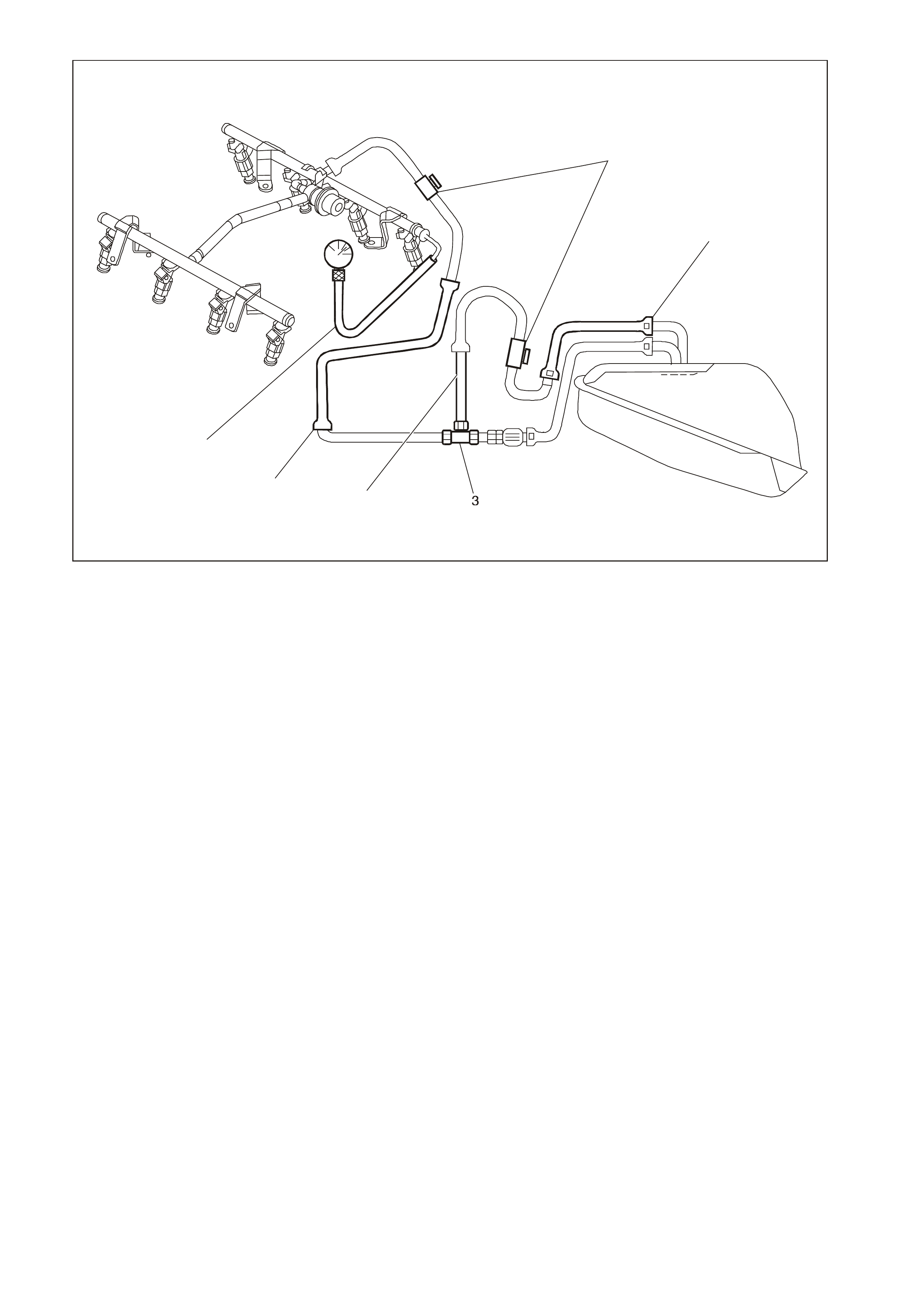
GEN3 0097
1
2
4
5
6
1. J 37287 Fuel Line Shut-off Adapter 4. Fuel Return Pipe
2. Rear Fuel Return Pipe 5. Fuel Feed Pipe
3. T-connector 6. J 34730-1A Fuel Pressure Gauge
GEN III V8 PCM -
FUEL SYSTEM DIAGNOSIS
CIRCUIT DESCRIPTION
When the ignition is turned O N, the Powertrain Control Module ( PCM) supplies power to the in- tank f uel pum p. T he
in-tank f uel pump remains ON as long as the engine is cr anking or running and the PCM r ec eives ref er enc e puls es.
If there are no reference pulses, the PCM turns the in-tank fuel pump OFF 2 seconds after the ignition switch is
turned ON or 2 seconds after the ignition stops running.
The electric fuel pump attaches to the fuel sender assembly inside the fuel tank. The fuel pump supplies fuel
through an in-pipe f uel filter to the fuel rail as sem bly. The fuel pump pr ovides fuel at a pr ess ure above the press ure
needed by the fuel injectors . The f uel pressure r egulator keeps the fuel available to the fuel inj ectors at a r egulated
pressure. The fuel pressure regulator attaches to the fuel sender assem bly return pipe. Unused fuel returns to the
fuel tank by a separate fuel return pipe. T he fuel return pipe attaches to a T -connector in the fuel feed pipe on the
outlet side of the fuel filter.
TEST DESCRIPTION
The numbers below refer to the step numbers on the diagnostic table.
2. When the ignition switch is ON and the fuel pump is running, the fuel pressure indicated by the fuel pressure
gauge should r ead 380-440 k Pa (55-62 ps i). T he spring pres sure ins ide the fuel pres sure r egulator contr ols the
fuel pressure.
3. A fuel system that drops more than 34 kPa (5 psi) in 10 minutes has a leak in one or more of the following
areas:
- The fuel pipes
- The fuel pump check valve
- The fuel pump flex pipe
- The valve or valve seat within the fuel pressure regulator
- The fuel injector(s)
4. A fuel system that drops more than 14 kPa (2 psi) in 10 minutes after being relieved to 69 kPa (10 psi)
indicates a leaking fuel pump check valve.

5. Fuel pressure that drops-off during acceleration, cruise, or hard cornering may cause a lean condition. A lean
condition can cause a loss of power, surging, or misfire. You can diagnose a lean condition using a Tech 2
scan tool. If an extremely lean condition occurs, the heated oxygen sensor(s) will stop toggling. The heated
oxygen sensor output voltage(s) will drop below 300 mV. The fuel injector pulse width will increase.
IMPORTANT:
Make sure the f uel system is not operating in the F uel Cut-Off Mode. T his can caus e false indications by the Tech
2 scan tool.
10. A rich condition may result from the fuel pressure being above 440 kPa (62 psi). A rich condition may cause
DTC P0132, DTC P0152, DTC P0172 or DTC P0175 to set. Driveability conditions associated with rich
conditions can include hard starting followed by black smoke and a strong sulfur smell in exhaust.
11. This test determ ines if the high fuel pres sure is due to a r estric ted fuel retur n pipe or if the high fuel pr essur e is
due to a faulty fuel pressure regulator.
12. A lean condition may result from the fuel pressure being below 380 kPa (55 psi). A lean condition may cause
DTC P0131, DTC P0151, DTC P0171 or DTC P0174 to set. Driveability conditions associated with lean
conditions can Include hard starting (when the engine is cold), hesitation, poor driveability, lack of power,
surging, and misfiring.
NOTE:
Do not allow the fuel pressure to exceed 500 kPa (72 psi). Fuel pressure in excess of 500 kPa (72 psi) may
damage the fuel pressure regulator.
13. Restricting the fuel r eturn pipe with the J 37287 f uel pipe s hut- of f adapter caus es the f uel pr ess ur e to ris e above
the regulated fuel pressure. Using a Tech 2 scan tool to pressurise the fuel system, the fuel pressure should
rise above 440 kPa (62 psi) as the valve on the fuel pipe shut-off adapter connected to the fuel return pipe
becomes partially closed.
18. Check the spark plug associated with a particular fuel injector for fouling or saturation in order to determine if
that particular fuel injector is leaking. If checking the spark plug associated with a particular fuel injector for
fouling or saturation does not determine that a particular fuel injector is leaking, use the following procedure:
1. Remove the fuel rail, but leave the fuel pipe connected to the fuel rail. Refer to
Section 6C3-3 Fuel Rail Assembly Replacement of the VX Series Service Information.
2. Lift the fuel rail just enough to leave the fuel injector nozzles in the fuel injector ports.
IMPORTANT:
In order to reduce the risk of fire and personal injury that may result from fuel spraying on the engine,
verify that the fuel rail is positioned over the fuel injector ports. Also verify that the fuel injector retaining
clips are intact.
3. Pressurise the fuel system by using the Tech 2 scan tool fuel pump enable.
4. Inspect the fuel injector nozzle for leaks.

GEN III V8 PCM - FUEL SYSTEM DIAGNOSIS
Step Action Value(s) Yes No
1 Did you perform the Powertrain On-Board Diagnostic
(OBD) System Check? Go to Step 2 Go to Powertrain
OBD System
Check Table
2 IMPORTANT: Wrap a shop towel around the fuel
pressure connection in order to reduce the risk of fire
and personal injury. The towel will absorb any fuel
leakage that may leak from the pressure gauge. Place
the towel in an approved container when the
connection of the fuel pressure gauge is complete.
1. Turn the ignition OFF.
2. Turn the air conditioning system OFF.
3. Install the J34730-1A fuel pressure gauge.
4. Place the bleed hose of the fuel pressure gauge into
an approved petrel container.
5. Turn the ignition ON.
6. Bleed the air out of the fuel pressure gauge.
7. Turn the ignition OFF for 10 seconds.
8. Turn the ignition ON.
IMPORTANT: The fuel pump will run for approximately 2
seconds. Cycle the ignition as necessary in order to
achieve the highest possible fuel pressure.
9. Observe the fuel pressure with the fuel pump running.
Is the fuel pressure within the specified limits?
380-440 kPa
(55-62 psi)
Go to Step 3 Go to Step 10
3 IMPORTANT: The fuel pressure may vary slightly when
the fuel pump stops running. After the fuel pump stops
running, the fuel pressure should stabilise and remain
constant.
Does the fuel pressure drop more than the specified
value in 10 minutes?
34 kPa
(5 psi) Go to Step 8 Go to Step 4
4 Relieve the fuel pressure to the upper specified value.
Does the fuel pressure drop more than the lower
specified value in 10 minutes?
69 kPa
(10 psi)
_________
14 kPa
(2 psi)
Go to Step 17 Go to Step 5
5 Do you suspect the fuel pressure of dropping off during
acceleration, cruise, or hard cornering? 300mV Go to Step 6 Go to Section
6C3-2B
Symptoms
6 Inspect the following items for a restriction:
• The fuel filter.
• The fuel feed pipe.
Did you find a restriction?
Go to Step 21 Go to Step 7
7 1. Remove the fuel sender assembly. Refer to Section
6C3-3 Fuel Sender Assembly Replacement of the VX
Series Service Information.
2. Inspect the following items:
- The fuel pump strainer for a restriction.
- The fuel pump flex pipe for leaks.
- The fuel pressure regulator for leaks.
- The fuel pressure regulator fuel return flex pipe for
leaks.
- Verify the fuel pump is correct for this vehicle.
Did you find a problem in any of these areas?
Go to Step 21 Go to Step 17

GEN III V8 PCM - FUEL SYSTEM DIAGNOSIS (CONTINUED)
Step Action Value(s) Yes No
8 1. Relieve the fuel pressure. Refer to Section 6C3-3 Fuel
Pressure Relief Procedure of the VX Series Service
Information.
2. Disconnect the fuel feed pipe from the fuel rail. Refer
to Section 6C3-3 Quick Connect Fitting(s) Service
(Metal Collar) of the VX Series Service Information.
3. Install the J37287 fuel pipe shut-off adapter between
the fuel feed pipe and the fuel rail.
4. Open the valve on the fuel feed pipe shut-off adapter
5. Pressurise the fuel system using a Tech 2 scan tool.
6. Place the bleed hose of the fuel pressure gauge into
an approved petrol container.
7. Bleed the air out of the fuel pressure gauge.
8. Wait for the fuel pressure to build.
9. Close the valve in the fuel feed pipe shut-off adapter.
Does the fuel pressure remain constant?
Go to Step 9 Go to Step 18
9 IMPORTANT: This step requires the aid of an assistant.
1. Open the valve in the fuel feed pipe shut-off adapter.
2. Relieve the fuel pressure. Refer to Section 6C3-3 Fuel
Pressure Relief Procedure of the VX Series Service
Information.
3. Raise the vehicle.
4. Disconnect the steel fuel return pipe at the nylon rear
return pipe. Refer to Section 6C3-3 Quick Connect
Fitting(s) Service (Plastic Collar) of the VX Series
Service Information.
5. Drain any remaining fuel from the pipes into an
approved petrol container.
6. Install the J37287 fuel pipe shut-off adapter between
the steel fuel return pipe and rear nylon return pipe.
7. Pressurise the fuel system using a Tech 2 scan tool.
8. Wait for the fuel pressure to build.
9. Close the valve in the fuel pipe shut-off adapter that is
connected to the fuel return pipe.
Does the fuel pressure remain constant?
Go to Step 16 Go to Step 17
10 Is the fuel pressure above the specific value? 440 kPa
(62 psi) Go to Step 11 Go to Step 12
11 1. Relieve the fuel pressure. Refer to Section 6C3-3 Fuel
Pressure Relief Procedure of the VX Series Service
Information.
2. Disconnect the steel fuel return pipe at the nylon rear
return pipe. Refer to Section 6C3-3 Quick Connect
Fitting(s) Service (Plastic Collar) of the VX Series
Service Information.
3. Drain any remaining fuel from the fuel pipes into an
approved petrol container.
4. Attach a length of flexible fuel hose to the steel fuel
return pipe attached to the T-connector.
5. Place the open end of the flexible fuel hose into an
approved petrol container.
6. Turn ON the fuel pump using a Tech 2 scan tool.
7. Observe the fuel flow with the fuel pump running.
Is there fuel flow?
Go to Step 20 Go to Step 19
12 Is the fuel pressure above the specified value? 0 kPa (0 psi) Go to Step 13 Go to Step 14

GEN III V8 PCM - FUEL SYSTEM DIAGNOSIS (CONTINUED)
Step Action Value(s) Yes No
13 IMPORTANT: This step requires the aid of an assistant.
1. Relieve the fuel pressure. Refer to Section 6C3-3 Fuel
Pressure Relief Procedure of the VX Series Service
Information.
2. Raise the vehicle.
3. Disconnect the steel fuel return pipe at the nylon rear
return pipe. Refer to Section 6C3-3 Quick Connect
Fitting(s) Service (Plastic Collar) of the VX Series
Service Information.
4. Drain any remaining fuel from the fuel pipes into an
approved petrol container.
5. Install the J37287 fuel pipe shut-off adapter between
the steel fuel return pipe and the nylon rear fuel return
pipe.
6. Open the valve on the fuel pipe shut-off adapter.
7. Pressurise the fuel system using a Tech 2 scan tool.
8. Place the bleed hose of the fuel pressure gauge into
an approved petrol container.
9. Bleed the air out of the fuel pressure gauge.
10. Slowly close the valve in the fuel pipe shut-off adapter
that is connected to the fuel return pipe.
NOTE: Do not allow the fuel pressure to exceed 500 kPa
(72 psi). Fuel pressure in excess of 500 kPa (72 psi) may
damage the fuel pressure regulator.
Does the fuel pressure rise above the specified value?
440 kPa
(62 psi) Go to Step 16 Go to Step 7
14 Refer to Fuel Pump Relay Circuit Diagnosis Table of the
VX Series Service Information in order to diagnose the
fuel pump electrical circuit.
Did you find a problem with the fuel pump electrical
circuit?
Go to Step 21 Go to Step 15
15 Inspect the following items:
• The fuel filter for obstructions.
• The fuel feed pipe.
• The fuel pump strainer for obstructions.
• The fuel pump flex pipe for leaks.
Did you find a problem in any of these areas?
Go to Step 21 Go to Step 17
16 Faulty fuel pressure regulator. Replace the fuel sender
assembly. Refer to Section 6C3-3 Fuel Sender Assembly
Service of the VX Series Service Information.
Is the action complete?
System OK
17 Faulty fuel pump.
Replace the fuel sender assembly, refer to Section 6C3-3
Fuel Sender Assembly Service of the VX Series Service
Information.
Is the action complete?
System OK
18 Locate and replace any leaking fuel injector(s).
Is the action complete? System OK
19 Locate and correct the restriction in the steel fuel return
pipe or the T-connector .
Is the action complete?
System OK
20 Inspect the nylon rear fuel return pipe for the restriction.
Did you find a restriction? Go to Step 21 Go to Step 16
21 Repair the problem as necessary.
Is the action complete? System OK
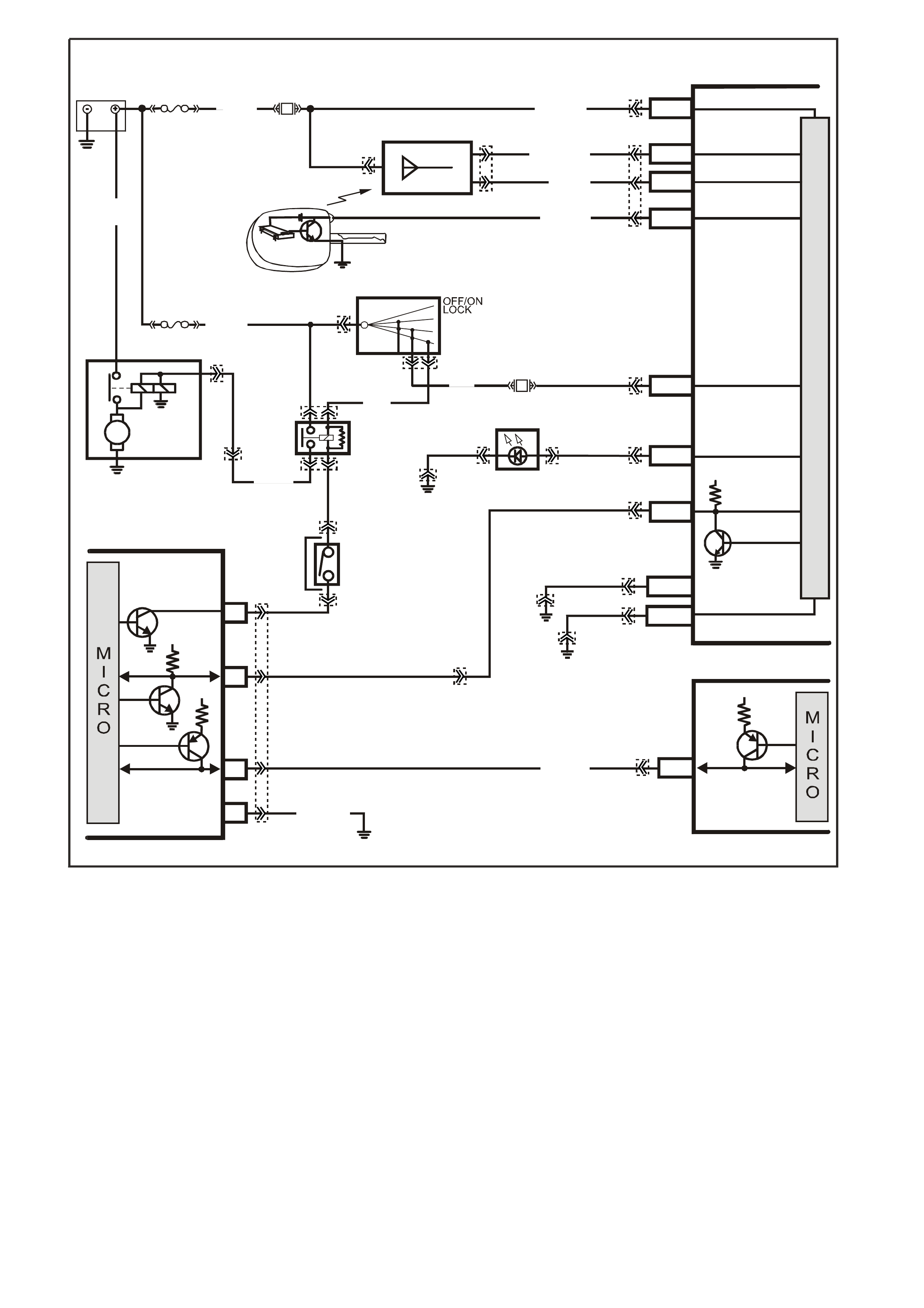
GEN III V8 PCM -
STARTER CRANKING CIRCUIT
CIRCUIT DESCRIPTION
When the ignition is turned to the ON position, battery power is supplied from a fusible link to the start relay
term inal 30. As the ignition s witch is turned to the START position, power is als o supplied from the ignition switch to
the star t relay term inal 85. T he Powertrain Interf ace Module (PIM) s upplies the earth signal needed to energise the
start relay and allows power to the starter motor.
When the BCM receives the cor re ct theft deterrent s ignal, the BCM will send a command via the serial data ( UART )
to the PIM to allow starter motor operation. At the same time the BCM will send a command via the serial data
(UART to the PIM, then Class II from PIM to PCM) circuit to the PCM to allow fuel injector pulses.
If the PCM determines that a improper theft deterrent signal was sent from the BCM, or no theft deterrent signal
was sent, the PCM will not allow fuel injection pulses. When the start relay receives this earth signal from the
PIM, the relay will be energised, allowing the starter motor to operate.
If there is a problem with the theft deterrent signal from the BCM to the PCM, or a earth or power feed problem at
the PIM, DTC 1626, 1630, or P1631 will set.
If there is a high voltage problem on the starter relay PIM control circuit, PIM DTC P007 will set.
BAT TERY M AIN PO WER
HIGH SERIES
BCM TERMINALS
NOMINA TED FIRST
BCM
REMOTE
CODED KEY
V/R (229) E1/D12 KE Y REA D ER
BATTERY
FS
LOC.
E1
LOC. G1
F31
A5/A6O/B (740)
(1040)
REMOTE KEY
RECEIVER
Y (266) E8/D1 RECEIVER DA TA
BR/G (271) E7/D11 RECEIVER EARTH
O/B
(740)
FJ
M
I
C
R
O
P
R
O
C
E
S
S
O
R
GY/BLU
(1434)
G3PCM040PT
THEFT DETERRENT
ALERT INDICA TOR
R/B
(1221)
E2/D2 SERIAL DATA
5V
R (2H)
E20/D6 IGNITION
NEUTRAL ST ART
BACK-UP SW.
(FOR AUTO TRANS)
(FOR MANUAL
TRANS)
GY
(434)
R (1)
V/W (6 )
F14
START
RELAY
IGN ITIO N SWITC H
15a 15 50
30 ACC
IGN
START
V (5) P (3) P/B
(39)
A6/A8
LBLU
(263) THE FT LED
B/Y
(155)
LOC. E3
B/G
(151) B10/B11 HIGH CURRENT
EARTH
B/Y
(155) ELECTRONIC EARTH
A1/A5
LOC. E3
LOC. E3
PIM
UART
SERIAL
DATA
START
RELAY
5V
6
8
16
7V
7
CLASS 2
SERIAL DATA
B/R (750)
LOC. E5/E15
R/B
(1221)
7V
PCM
J1-58 CLASS 2
SERIAL DATA
Y (1049)
Y
(1049)
STARTER
MOTOR
M
YB215
YE112
YB35
YE104
YE8
YB35
YE114 YB56 YB56
YE49
YB44
YE49
YB44
YB95
YB175
YB164
YB176
YB165
YB175
YB164
YB175
YB164
YB174
YB163
YE114
YE114 YB176
YB165
YE122
YB176
YB165
YB95
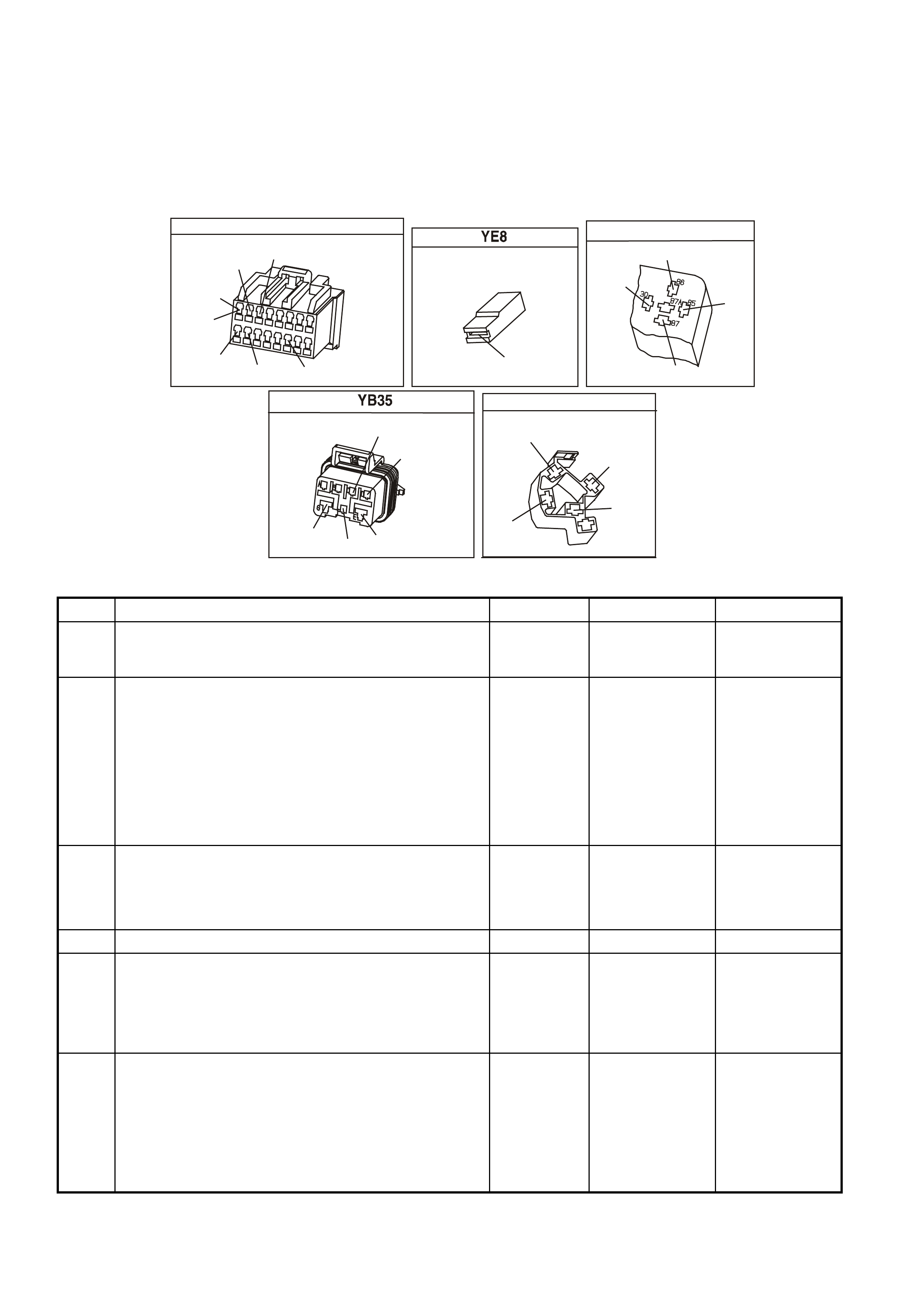
TEST DESCRIPTION
Numbers below refer to step numbers on the diagnostic table.
3. This step checks to see if DTC P1626, DTC P1630 or DTC P1631are set. Either of these DTC could prevent
the vehicle from starting.
6. This step checks to see if power is being applied to the starter motor. If the test light illuminates, the problem is
with the starter motor.
14. This step checks the adjustment of the Neutral start switch.
POWER TRAIN INTERFACE MODULE
YB215
W/B
(451)
Y
(1049)
B/R
(750)
P
(39)
R/B
(1221)
GY/BLU
(1434)
GY
(434)
(AUTO)
(MAN)1
9
16
8
STARTER MOTOR SOLENOID
V
(6)
YE49
START RELAY
V
(5)
(2)
GY
V/W
R
(434)
(6)
NEUTRAL START & BACK-UP SWITCH
(1434)
GY/BLU
(24)
LG
GY
(434)
(750)
B/R
(42)
BR/BLU
IGNITION SWITCH
YB44
BR
(4)
V
(5)
(2)
R
(3)
P
GEN III V8 PCM - STARTER CRANKING CIRCUIT
STEP ACTION VALUE YES NO
1 Did you perform the powertrain On-Board Diagnostic
(OBD) System Check? Go to Step 2 Go to Powertrain
OBD System
Check Table
2 1. Observe the Theft Deterrent LED on the Instrument
panel.
2. Key ON, engine OFF.
Is the Theft LED flashing?
Go to Theft
Deterrent
System. Section
12J-1 LOW
SERIES BCM or
Section 12J-2
HIGH SERIES
BCM in VX
Service
Information
Go to Step 3
3 1. Install a Tech 2 scan tool.
2. Using the Tech 2 scan tool, check for a DTC P1626,
DTC P1630, or DTC P1631.
Are any DTC(s) set?
Go to the
appropriate DTC
Table
Go to Step 4
4 Does the Tech 2 scan tool display PIM serial data? Go to Step 5 Go to Step 21
5 1. Ignition ON, engine OFF.
2. Using the Tech 2 scan tool, select the PIM Normal
Mode data list.
Does the PIM Normal Mode message display OK
START?
Go to Step 6 Go to Step 23
6 1. Ignition OFF.
2. Using a test light, probe the starter solenoid terminal S
with test light connected to earth.
3. Have an assistant turn the ignition switch to the
START position, note the test light.
Does the test light illuminate when the ignition switch is
turned to the START position?
Refer to
Section 6D3-2
Starting System
in VX Service
Information
Go to Step 7

GEN III V8 PCM - STARTER CRANKING CIRCUIT (CONTINUED)
STEP ACTION VALUE YES NO
7 Check fusible link FJ.
Was fusible link blown? Go to Step 17 Go to Step 8
8 1. Remove the start relay.
2. With a test light connected to earth probe the start
relay harness terminal 30.
3. Turn the ignition ON.
Does the test light illuminate?
Go to Step 9 Go to Step 19
9 1. With the start relay still removed and the test light
connected to earth, probe the start relay harness
terminal 85.
2. Turn the ignition to the start position.
Did the test light illuminate?
Go to Step 11 Go to Step 18
10 Check for an open circuit between the starter solenoid
and the start relay.
Was a problem found?
System OK Go to Step 12
11 1. Ignition OFF.
2. Remove the start relay.
3. Connect a test light between the relay harness
terminal 85 and terminal 86.
4. Turn the ignition switch to the START position.
Does the test light illuminate when the ignition switch is
turned to the START position?
Go to Step 10 Go to Step 13
12 Replace the start relay.
Is the action complete? System OK
13 Is the vehicle equipped with a manual transmission? Go to Step 16 Go to Step 14
14 1. Ignition ON engine OFF.
2. With a test light connected to B+, probe both of the
circuits at the neutral start switch.
Did the test light illuminate at both terminals?
Go to Step 20 Go to Step 15
15 Check the adjustment of the neutral start switch.
NOTE: If the test light illuminated at only one terminal
and adjustment of neutral start switch does not fix the
problem, replace the switch.
Does test lamp now illuminate at both terminals?
System OK Go to Step 21
16 Check for open in the start relay control circuit from the
PIM to the Start Relay.
Was a problem found?
System OK Go to Step 21
17 Repair the short to earth in the faulty circuit.
Replace the fusible link as necessary.
Is the action complete?
System OK
18 Repair the open in the ignition circuit.
Is the action complete? System OK
19 Check for an open circuit including the fusible link.
Is the action complete? System OK
20 Check for an open in circuit 1434 from PIM terminal 8 to
Start Relay terminal 86.
Was a problem found?
Verify Repair Go to Step 23
21 Check the PIM power feed circuit and earth circuit for
opens or shorts.
Was a problem found?
Verify Repair Go to Step 22

GEN III V8 PCM - STARTER CRANKING CIRCUIT (CONTINUED)
STEP ACTION VALUE YES NO
22 Check for an open, short to Earth or short to voltage in
the UART circuit.
Was a problem found?
Verify Repair Go to Step 23
23 Check for poor connection at PIM.
Was a problem found? Verify Repair Go to Step 24
24 Replace PIM, Refer to Section 6C3-3 Powertrain
Interface Module Replacement of the VX Series Service
Information.
Is action complete?
Verify Repair
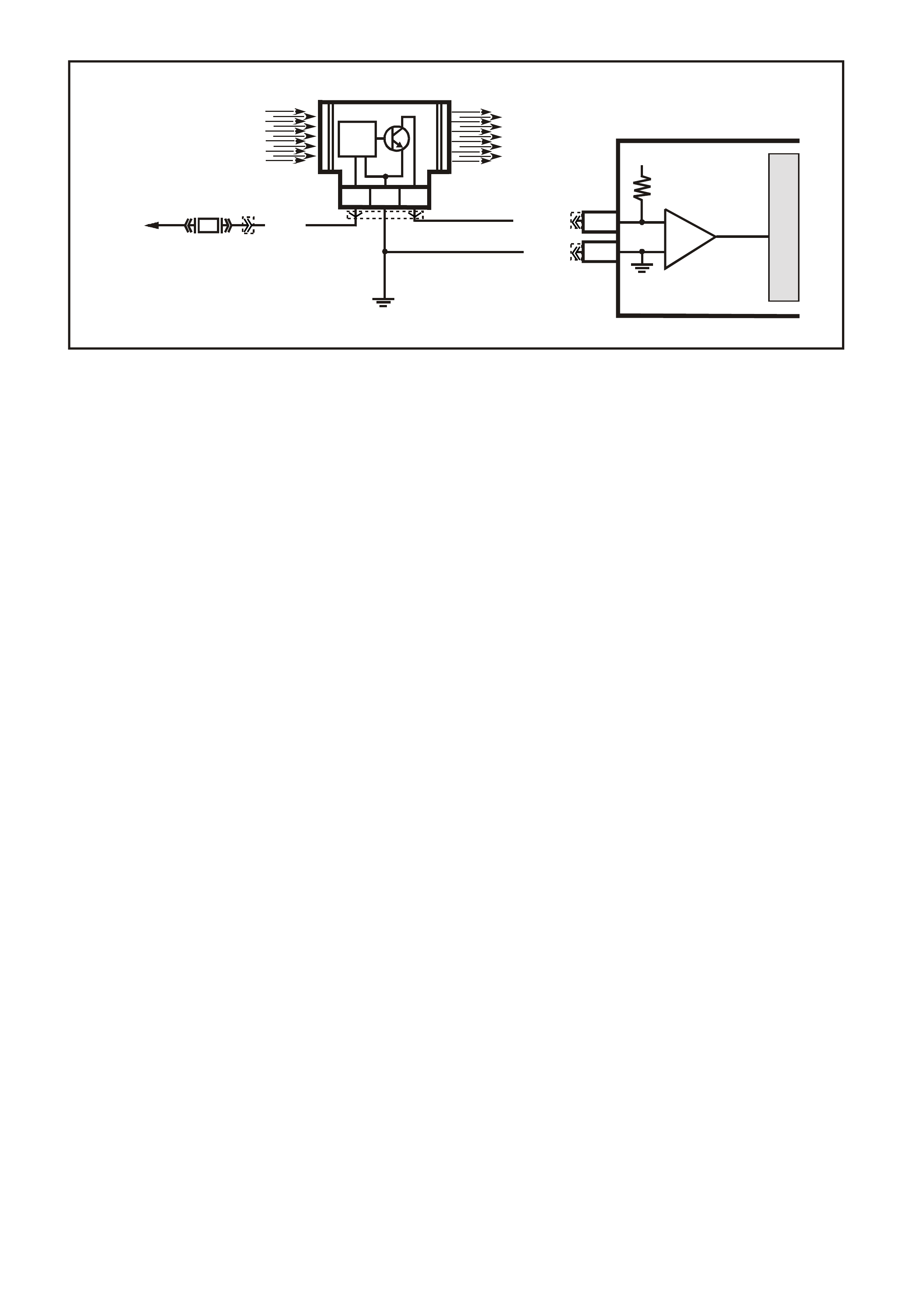
GEN III V8 PCM -
DTC P0101 MASS AIR FLOW SYSTEM PERFORMANCE
CIRCUIT DESCRIPTION
The Mass Air Flow (MAF) Sensor measures the am ount of air ingested by the engine. The direct m easurement of
the air entering the engine is more accurate than calculating the airflow from the MAP, the IAT and the engine
speed (speed/density). The MAF sensor has a battery feed, earth, and a signal circuit.
The MAF Sensor used on this engine is a hot wire type and is used to measure air flow rate. The MAF output
frequenc y is a f unc tion of the power r equired to k eep the air f low sens ing elements ( hot wire) at a f ixed temperatur e
above the ambient tem perature. Air f lowing thr ough the sensor cools the s ensing elements. T he amount of cooling
is pr oportional to the am ount of air f low. The MAF Sensor r equires a greater am ount of current in order to m aintain
the hot wires at a cons tant tem per ature as the air flow incr eases. T he MAF Sens or converts the changes in c urrent
draw to a frequency signal read by the PCM. The PCM calculates the air flow (grams per second) based on this
signal.
The PCM m onitors the MAF Sensor frequency. The PCM can determ ine if the sensor is stuck low, stuck high, not
providing the airf low value expected for a given operating condition, or that the signal appears to be stuck based on
a lack of signal variation expected during the normal operation. This diagnostic checks the range/performance of
the MAF Sensor.
The MAF system performance or rationality diagnostic uses the MAP, the IAT, and the engine speed to calculate
an expected airflow rate. The PCM then compares the rate to the actual measured airflow from the MAF Sensor.
The PCM only compares the actual MAF value and the calculated value during conditions where the values are
likely to match. This DTC sets if the actual MAF reading is not within a predetermined range of the calculated
reading.
CONDITIONS FOR RUNNING THE DTC
• DTCs P0102, P0103, P0107, P0108, P0121, P0122, P0123 are not set.
• The engine is running.
• The throttle position angle is less than 50% and the engine vacuum (BARO-MAP) is greater than 65 kPa.
• The system voltage is greater than 11 volts but less than 16 volts.
• The change in throttle position is less than 3%.
• All above conditions stable for two seconds.
CONDITIONS FOR SETTING THE DTC
• The MAF frequency is 50% different from the speed density calculation.
• The conditions met for at least five seconds.
ACTION TAKEN WHEN THE DTC SETS
• The PCM illuminates the Check Powertrain Lamp when the diagnostic runs and fails.
• The PCM records the operating conditions at the time the diagnostic fails. The PCM stores this information in
the Freeze Frame/Failure Records.
• The PCM utilises speed density (RPM, MAP, IAT) for fuel management.
G3PCM006PT
IC
CIRCUIT
MASS AIR FLOW SENSOR
J2-31
J1-01
PCM
CBA
AIR FLOW
FROM
AIR FILTER
AIR FLOW
TO
THROTTLE BODY
EFI
RELAY
F33
P (43 9)
YE100
YE122
YE123
YE111
BR/W (792)
MASS AIR FLOW
INP U T SIG NAL
EARTH
5V
M
I
C
R
O
IC
B/R (750)
LOC. E5/E15

CONDITIONS FOR CLEARING THE CPL/DTC
• The PCM turns the Check Powertr ain Lamp OF F after one ignition cycle that the diagnostic runs and does not
fail.
• A last test failed (current DTC) clears when the diagnostic runs and does not fail.
• Use a Tech 2 scan tool in order to clear the CPL/DTC.
DIAGNOSTIC AIDS
• Inspect the EFI relay for correct operation if you cannot find any problems with the ignition feed circuit to the
com ponent. Probe both sides of the fuse with a test lam p connected to earth in order to determ ine if a voltage
is supplied to the fuse. Refer to EFI Relay Diagnosis Table of the VX Series Service Information.
• The following may cause an intermittent:
- Incorrectly routed harness
- Rubbed through wire insulation
- Broken wire inside the insulation
• For an intermittent fault, refer to Section 6C3-2B Symptoms of the VX Series Service Information.
• Any un-metered air may cause this DTC to set. Check for the following:
- An engine vacuum leak
- The PCV system for vacuum leaks
- An incorrect PCV valve
- The engine oil dip stick not fully seated
TEST DESCRIPTION
The numbers below refer to the step numbers on the diagnostic table.
2. The MAF system performance or rationality diagnostic uses the MAP Sensor signal along with other inputs in
order to calculate an expected airflow rate.
The PCM then c ompares the expected flow rate to the actual m easur ed airflow from the MAF Sensor. The fir st
few steps of this table verify that the MAP Sensor is working properly. Correct any MAP Sensor DTCs first.
Refer to DT C P0107 MAP Sensor Circuit Low Voltage if the MAP Sensor voltage is less than .08 volts. Refer to
DTC P0108 MAP Sensor Circuit High Voltage if the MAP Sensor voltage is greater than 4.0 volts.
3. Twist the sensor towards the front of the vehicle and lift upward in order to remove the MAP sensor.
6. Using the Freeze Frame/Failure Records data may aid in locating an intermittent condition. If you cannot
duplicate the DTC, the information included in the Freeze Frame and/or Failure Records data can help
determine the distance traveled since the DTC sets. The Fail Counter and Pass Counter can also help
determ ine how many ignition cycles the diagnostic reported a pass and/or a f ail. Operate the vehicle within the
sam e freeze fram e conditions (RPM, load, vehicle s peed, temperature etc .) that you observed. T his will isolate
when the DTC failed. For any test that requires probing the PCM or component harness connectors, use the
Connector Test Adapter Kit J35616-A. Using this kit prevents any damage to the harness connector terminals.
7. Any un-m eter ed air causes this DT C to set. Chec k the PCV system for vacuum leaks. Also inspect the dip stic k
is seated correctly and the oil filler cap is tight.
8. This step verifies the signal circuit from the MAF Sensor electrical connector to the PCM.
9. This step verifies whether a earth and B+ circuit is available.
10. This step checks the signal circuit for an open.
11. This step checks the signal circuit for a short to B+.

YE123
P.C.M CONNECTOR 2
(750)
(1228)
(1229)
(465)
(121)
(259)
G/B
BR
G/W
GY/BLU
R
B/R
(418)
BR
(59)
(832)
G
T
(831)
(417)
(472)
(976)(974)
(432)
(428)
(631)
BLUBR G/Y
BLU/W
LG
BR/W
W/B
LG W
(977)
Y
(971)
BLU/WW
B/R
(750)
(304)
(792)
(1223)
(1222)
(123)
(1227)
(469)
(331)
Y/B
LG
V/W
B/Y
G/OBR/W
(1687)
GY/B
(366)
LG/B
GY/R
(422)
V
(442)
(444)
(443)
(975)
(972)
(978)
(1224)
(973)
(959)
LG/W
LG/B
LBLU/B
GY
(773)
BR/Y
BLU
G
Y/B
LBLU
(958)
BR
(441)
LBLU
1
41
40
80
J2
RED
Y
(838)
M.A.F SENSOR
YE100
(439)
(750)
(792)
B/R
PBR/W
YE111
ENGINE CONNECTOR 2
(482)
(481)
R
LG
GY
G
(434)
(129)
P
(439)
(59)
(366)
LG/B
GW/B
(451)
GEN III V8 PCM - DTC P0101 MASS AIR FLOW SYSTEM PERFORMANCE
STEP ACTION VALUE YES NO
1 Did you perform the Powertrain On-Board Diagnostic
(OBD) System Check? Go to Step 2. Go to Powertrain
OBD System
Check Table
2
If any MAP sensor DTCs are set, refer to the applicable
DTC before proceeding.
1. Idle the engine.
2. Monitor the MAP Sensor voltage parameter using a
Tech 2 scan tool.
Is the MAP Sensor voltage outside of the specified
range?
.08-4 volts Go to DTC
P0107 or P0108
Table
Go to Step 3
3 1. Turn OFF the ignition .
2. Remove the MAP Sensor from the intake manifold
leaving the electrical harness connected.
3. Connect a hand operated vacuum pump to the MAP
sensor.
4. Turn ON the ignition leaving the engine OFF.
5. Observe the MAP Sensor display while slowly
applying vacuum up to 20 inches Hg as indicated on
the pump gauge. Each 1 inch of vacuum applied
should result in a 3 to 4 kPa drop in the MAP sensor
value on the scan tool and the value should change
smoothly with each increase in vacuum.
Did the MAP Sensor value change smoothly through the
entire range of the test without any erratic readings?
Go to Step 4 Go to Step 19
4 Apply 20 inches Hg vacuum to the MAP sensor.
Is the MAP Sensor reading on the Tech 2 scan tool the
same or less than the specified value?
34 kPa Go to Step 5 Go to Step 19
5 Disconnect the vacuum source from the MAP Sensor.
Does the MAP Sensor reading return to the original
value?
Go to Step 6 Go to Step 19

GEN III V8 PCM- DTC P0101 MASS AIR FLOW SYSTEM PERFORMANCE (CONTINUED)
STEP ACTION VALUE YES NO
6 1. Turn ON the ignition leaving the engine OFF.
2. Review the Freeze Frame/Failure Records data
for this DTC and observe the parameters.
3. Turn OFF the ignition for 15 seconds.
4. Start the engine.
5. Operate the vehicle, within the conditions required for
this diagnostic to run, and as close to the conditions
recorded in the Freeze Frame/Failure Records as
possible. Special operating conditions that you need to
meet before the PCM will run this diagnostic, where
applicable, are listed in Conditions for Running the
DTC.
6. Select the Diagnostic Trouble Code (DTC) option, the
DTC Information option, and the Failed This Ignition
option, using the Tech 2 scan tool.
Does the Tech 2 scan tool indicate that this diagnostic
failed this ignition?
Go to Step 7 Go to Diagnostic
Aids
7 1. Check for the following conditions:
- Objects blocking the MAF Sensor inlet screen
- Intake manifold vacuum leaks
- Vacuum leaks at the throttle body
- Crankcase ventilation valve faulty, missing, or
incorrectly installed
2. If you find a condition, repair as necessary.
Did you find and correct the condition?
Go to Step 21 Go to Step 8
8 1. Turn OFF the ignition.
2. Disconnect the MAF Sensor connector.
3. Turn ON the ignition leaving the engine OFF.
4. Measure the voltage between the MAF Sensor signal
circuit and the battery earth using the DMM J39200.
Is the voltage near the specified value?
5.0 volts Go to Step 9 Go to Step 10
9 Connect a test lamp J34142-B between the MAF Sensor
ignition feed and the earth circuit at the MAF Sensor
harness connector.
Is the test lamp illuminated?
Go to Step 13 Go to Step 12
10 Is the voltage less than the specified value? 4.5V Go to Step 14 Go to Step 11
11 1. Turn OFF the ignition.
2. Disconnect the PCM RED connector.
3. Turn ON the ignition leaving the engine OFF.
4. Measure the voltage between the MAF Sensor signal
circuit and the battery earth using the DMM J39200.
Is the voltage near the specified value?
0.0V Go to Step 20 Go to Step 17
12 Connect a test lamp J34142-B between the MAF sensor
ignition feed circuit and the battery earth.
Is the test lamp illuminated?
Go to Step 15 Go to Step 16
13 1. Check for a poor connection at the MAF sensor.
2. If you find a poor connection, replace the faulty
terminal(s).
Did you find a poor connection?
Go to Step 21 Go to Step 18

GEN III V8 PCM - DTC P0101 MASS AIR FLOW SYSTEM PERFORMANCE (CONTINUED)
Step Action Value(s) Yes No
14 1. Check the MAF sensor signal circuit between the
PCM and the MAF sensor for the following:
- An open circuit
- A short to earth
- A short to the MAF sensor earth circuit
2. Repair the circuit if the MAF sensor signal circuit is
open or shorted.
Did you find the MAF sensor signal circuit open or
shorted?
Go to Step 21 Go to Step 20
15 Locate and repair the open in the earth circuit to the MAF
sensor.
Is the action complete?
Go to Step 21
16 Locate and repair the open in the ignition feed circuit to
the MAF sensor.
Is the action complete?
Go to Step 21
17 Locate and repair the short to voltage in the MAF sensor
signal circuit.
Is the action complete?
Go to Step 21
18 Replace the MAF sensor. Refer to Section 6C3-3 MAF
Sensor Replacement of the VX Series Service
Information.
Is the action complete?
Go to Step 21
19 Replace the MAP sensor. Refer to Section 6C3-3 MAP
Sensor Replacement of the VX Series Service
Information.
Is the action complete?
Go to Step 21
20 1. Replace PCM.
2. Refer to Section 6C3-3 of the VX Series Service
Information for PCM Programming and
PCM/PIM/BCM Security Link Procedure.
Is action complete?
Go to Step 21
21 1. Select the Diagnostic Trouble Code (DTC) option and
the Clear DTC Information option using the Tech 2
scan tool.
2. Idle the engine at the normal operating temperature.
3. Select the Diagnostic Trouble Code (DTC) option and
the Specific DTC option, then enter the DTC number
using the Tech 2 scan tool.
4. Operate the vehicle within the Conditions for Running
the DTC as specified in the supporting text, if
applicable.
Does the Tech 2 scan tool indicate that this DTC reset?
Go to Step 2 Go to Step 22
22 Using the Tech 2 scan tool, check for any other DTC.
Does the Tech 2 scan tool display and DTCs that you
have not diagnosed?
Go to the
applicable DTC
table
System OK

GEN III V8 PCM -
DTC P0102 MASS AIR FLOW SENSOR CIRCUIT LOW FREQUENCY
CIRCUIT DESCRIPTION
The Mass Air Flow (MAF) Sensor measures the amount of air entering the engine via the inlet tract. The direct
measurement of the air entering the engine is more accurate than calculating the airflow from the MAP, the IAT,
and the engine speed (speed/density). The MAF Sensor has a battery feed, a earth and a signal circuit.
The MAF Sensor used on this engine is a hot wire type. The MAF output frequency is a function of the power
required to keep the air flow sensing elements (hot wires) at a fixed temperature above the ambient temperature.
Air flowing through the sensor cools the sensing elem ents. The amount of cooling is proportional to the am ount of
air flow. The MAF Sensor requires a greater amount of current in order to maintain the hot wires at a constant
temper ature as the air f low increases. T he MAF Sensor conver ts the changes in current draw to a fr equency signal
read by the PCM. The PCM calculates the air flow (grams per second) based on this signal.
The PCM monitors the MAF Sensor frequency. The PCM determines if the sensor is stuck low, stuck high, not
providing the airf low value expected for a given operating condition, or that the signal appears to be stuck based on
a lack of signal variation expected during the normal operation. This diagnostic checks for too low an airflow rate.
This DTC sets when the PCM detects that the MAF Sensor frequency is below a predetermined value.
CONDITIONS FOR RUNNING THE DTC
• The engine speed is greater than 300 RPM.
• The system voltage is at least 110 volts.
CONDITIONS FOR SETTING THE DTC
• The MAF frequency is 50% different from the speed density calculation.
• The conditions met for at least five seconds.
ACTION TAKEN WHEN THE DTC SETS
• The PCM illuminates the Check Powertrain Lamp when the diagnostic runs and fails.
• The PCM utilises speed density (RPM, MAP, IAT) for fuel management.
• The PCM records the operating conditions at the time the diagnostic fails. The PCM stores this information in
the Freeze Frame/Failure Records.
• The PCM utilises speed density (RPM, MAP, IAT) for fuel management.
CONDITIONS FOR CLEARING THE CPL/DTC
• The PCM turns the Check Powertr ain Lamp OF F after one ignition cycle that the diagnostic runs and does not
fail.
• A last test failed (current DTC) clears when the diagnostic runs and does not fail.
• Use a Tech 2 scan tool in order to clear the CPL/DTC.
G3PCM006PT
IC
CIRCUIT
MASS AIR FLOW SENSOR
J2-31
J1-01
PCM
CBA
AIR FLOW
FROM
AIR FILTER
AIR FLOW
TO
THROTTLE BODY
EFI
RELAY
F33
P (43 9)
YE100
YE122
YE123
YE111
BR/W (792)
MASS AIR FLOW
INP U T SIG NAL
EARTH
5V
M
I
C
R
O
IC
B/R (750)
LOC. E5/E15

DIAGNOSTIC AIDS
• Inspect the EFI relay for proper operation if you cannot find any problems with the ignition feed circuit to the
com ponent. Probe both sides of the fuse with a test lam p connected to earth in order to determ ine if a voltage
is supplied to the fuse. Refer to EFI Relay Diagnosis of the VX Series Service Information.
• The following may cause an intermittent:
- Incorrectly routed wiring harness
- Rubbed through wire insulation
- Broken wire inside the insulation
• For an intermittent, refer to Section 6C3-2B Symptoms of the VX Series Service Information.
• Any un-metered air may cause this DTC to set. Check for the following:
- An engine vacuum leak
- The PCV system for vacuum leaks
- An incorrect PCV valve
- The engine oil dip stick not fully seated
- The engine oil fill cap loose or missing
TEST DESCRIPTION
The numbers below refer to the step numbers on the diagnostic table.
2. Monitoring the MAF sensor f requency will determ ine if the f ault is pres ent or the malf unction is inter mittent. For
any tes t that requires probing the PCM or com ponent harness c onnectors, use the Connector T est Adapter Kit
J35616-A. Using this kit will prevent any damage to the harness connector terminals.
3. Using the Freeze Frame/Failure Records data may aid in locating an intermittent condition. If you cannot
duplicate the DTC, the information included in the Freeze Frame/Failure Records data can help determ ine the
distance traveled since the DTC set. The Fail Counter and Pass Counter can also help determine how many
ignition cycles the diagnostic reported a pass and/or a fail.
Operate the vehicle within the same freeze fram e conditions (RPM, load, vehicle speed, temperature etc.) that
you observed. This will isolate when the DTC failed. For any test that requires probing the PCM or com ponent
harness connectors, use the Connector Test Adapter Kit J35616-A. Using this kit prevents any damage to the
harness connector terminals.
4. This s tep check s whether the MAF sensor signal circuit is open or shorted to a earth. If 5.0 volts is pres ent the
circuit is OK.
5. This step checks whether the B+ supply and the earth circuit are OK.
6. This step checks whether the B+ is available at the MAF Sensor.
10. Inspect the fuse for being open. Inspect the MAF sensor ignition feed circuit for a short to earth if the fuse is
open. Inspec t the EFI r elay f or proper operation if you can not f ind any problem s with the ignition feed c ircuit to
the component. Probe both sides of the fuse with a test lamp connected to an earth in order to determine if a
voltage is supplied to the fuse. Refer to EFI Relay Diagnosis Table of the VX Series Service Information for
further diagnos is of the ignition r elay. Multiple DTCs set when a m alfunc tion occu rs with the ignition relay or the
ignition feed circuit. The following DTCs may set: P0102, P0443, P0740, P1860, and HO2S heater DTCs.
12. Inspect for proper terminal tension/connections at the PCM harness before replacing the PCM.
YE 123
P.C.M CONNECTOR 2
(750)
(1228)
(1229)
(465)
(121)
(259)
G/B
BR
G/W
GY/BLU
R
B/R
(418)
BR
(59)
(832)
G
T
(831)
(417)
(472)
(976) (974)
(432)
(428)
(631)
BLU BR G/Y
BLU/W
LG
BR/W
W/B
LG W
(977)
Y
(971)
BLU/W W
B/R
(750)
(304)
(792)
(1223)
(1222)
(123)
(1227)
(469)
(331)
Y/B
LG
V/W
B/Y
G/O BR/W
(1687)
GY/B
(366)
LG/B
GY/R
(422)
V
(442)
(444)
(443)
(975)
(972)
(978)
(1224)
(973)
(959)
LG/W
LG/B
LBLU/B
GY
(773)
BR/Y
BLU
G
Y/B
LBLU
(958)
BR
(441)
LBLU
1
41
40
80
J2
RED
Y
(838)
M.A.F SENS OR
YE100
(439)
(750)
(792)
B/R
PBR/W
YE111
ENGINE CO NNEC TOR 2
(482)
(481)
R
LG
GY
G
(434)
(129)
P
(439)
(59)
(366)
LG/B
GW/B
(451)

GEN III V8 PCM - DTC P0102 MASS AIR FLOW SENSOR CIRCUIT LOW FREQUENCY
Step Action Value(s) Yes No
1 Did you perform the Powertrain On-Board Diagnostic
(OBD) System Check? Go to Step 2 Go to Powertrain
OBD System
Check Table
2
1. Install a Tech 2 scan tool.
2. Idle the engine.
3. Monitor the MAF Sensor frequency display on the
Tech 2 Engine Data List.
Is the MAF Sensor frequency below the specified value?
10 Hz Go to Step 4 Go to Step 3
3 1. Turn ON the ignition leaving the engine OFF.
2. Review the Freeze Frame/Failure Records data for
this DTC and observe the parameters.
3. Turn OFF the ignition for 15 seconds.
4. Start the engine.
5. Operate the vehicle, within the conditions required for
this diagnostic to run and as close to the conditions
recorded in the Freeze Frame/Failure Records as
possible. Special operating conditions that you need
to meet before the PCM will run this diagnostic, where
applicable, are listed in Conditions for Running the
DTC.
6. Select the Diagnostic Trouble Code (DTC) option, the
DTC Information and The Failed This Ignition option
using the Tech 2 scan tool.
Does the Tech 2 scan tool indicate that this diagnostic
failed this ignition?
Go to Step 4 Go to Diagnostic
Aids
4 1. Turn OFF the ignition.
2. Disconnect the MAF Sensor connector.
3. Turn ON the ignition leaving the engine OFF.
4. Measure the voltage between the MAF sensor signal
circuit and the battery earth using a DMM J39200.
Is the voltage near the specified value?
5.0V Go to Step 5 Go to Step 8
5 Connect a test lamp, J34142-B, between the MAF Sensor
ignition feed circuit and the earth circuit at the MAF
Sensor harness connector.
Is the test lamp illuminated?
Go to Step 7 Go to Step 6
6 Connect a test lamp, J34142-B, between the MAF Sensor
ignition feed circuit and the battery earth.
Is the test lamp illuminated?
Go to Step 9 Go to Step 10
7 1. Check for a poor connection at the MAF Sensor
harness terminals.
2. If you find a poor connection, replace the faulty
terminal(s).
Did you find a poor connection?
Go to Step 13 Go to Step 11
8 1. Check the MAF Sensor signal circuit between the
PCM and the MAF Sensor for the following:
- An open circuit
- Short to a earth
- Short to the MAF Sensor earth circuit
- Short to voltage
2. If you find the MAF Sensor signal circuit is open or
shorted, repair the circuit as necessary.
Did you find the MAF Sensor signal circuit open or
shorted?
Go to Step 13 Go to Step 12
9 Locate and repair the open in the earth circuit to the MAF
Sensor.
Is the action complete?
Go to Step 13

GEN III V8 PCM - DTC P0102 MASS AIR FLOW SENSOR CIRCUIT LOW FREQUENCY (CONTINUED)
Step Action Value(s) Yes No
10 Repair the ignition feed circuit to the MAF Sensor.
Is the action complete? Go to Step 13
11 Replace the MAF Sensor. Refer to Section 6C3-3 MAF
Sensor Replacement of the VX Series Service
Information.
Is the action complete?
Go to Step 13
12 1. Replace PCM.
2. Refer to Section 6C3-3 Service Operations of the VX
Series Service Information, for PCM Programming
and PCM/PIM/BCM Security Link Procedure.
Is action complete?
Go to Step 13
13 1. Select the Diagnostic Trouble Code (DTC) option and
the Clear DTC Information option using the Tech 2
scan tool.
2. Idle the engine at the normal operating temperature.
3. Select the Diagnostic Trouble Code (DTC) option and
the Specified DTC option, then enter the DTC number
using the Tech 2 scan tool.
4. Operate the vehicle within the Conditions for Running
the DTC as specified in the supporting text, if
applicable.
Does the Tech 2 scan tool indicate that this DTC reset?
Go to Step 2 Go to Step 14
14 Using the Tech 2 scan tool, check for any other DTC.
Does the Tech 2 scan tool display any DTCs that you
have not diagnosed?
Go to the
applicable DTC
table
System OK

GEN III V8 PCM -
DTC P0103 MASS AIR FLOW SENSOR CIRCUIT HIGH FREQUENCY
CIRCUIT DESCRIPTION
The Mass Air Flow (MAF) Sensor measures the amount of air entering the engine via the inlet tract. The direct
measurement of the air entering the engine is more accurate than calculating the airflow from the MAP, the IAT,
and the engine speed (speed/density). The MAF Sensor has a battery feed, a earth, and a signal circuit.
The MAF Sens or used on this engine is a hot wire type. This engine uses the MAF Sensor in order to m easure air
flow rate. The MAF output frequency is a func tion of the power required to keep the air flow sensing elements (hot
wires) at a fixed temperature above the ambient temperature. Air flowing through the sensor cools the sensing
elements. The amount of cooling is proportional to the amount of air flow. The MAF Sensor requires a greater
amount of current in order to maintain the hot wires at a constant temperature as the air flow increases. T he MAF
sensor converts the changes in current draw to a frequency signal read by the PCM. The PCM calculates the air
flow (grams per second) based on this signal.
The PCM monitors the MAF Sensor frequency. The PCM determines if the sensor is stuck low, stuck high, nor
providing the airf low value expected for a given operating condition, or that the signal appears to be stuck based on
a lack of signal variation expected during the norm al operation. This diagnostic checks for too high an airflow rate.
This DTC sets when the PCM detects that the MAF sensor frequency is above a predetermined value.
CONDITIONS FOR RUNNING THE DTC
• The engine speed is greater than 300 RPM.
• The system voltage is at least 110 volts.
CONDITIONS FOR SETTING THE DTC
• The MAF frequency is greater than 11,250 Hz.
• The conditions met for at least one seconds.
ACTION TAKEN WHEN THE DTC SETS
• The PCM illuminates the Check Powertrain Lamp when the diagnostic runs and fails.
• The PCM utilises speed density (RPM, MAP, IAT) for fuel management.
• The PCM records the operating conditions at the time the diagnostic fails. The PCM stores this information in
the Freeze Frame/Failure Records.
• The PCM utilises speed density (RPM, MAP, IAT) for fuel management.
CONDITIONS FOR CLEARING THE CPL/DTC
• The PCM turns the Check Powertr ain Lamp OF F after one ignition cycle that the diagnostic runs and does not
fail.
• Use a Tech 2 scan tool in order to clear the CPL/DTC.
G3PCM006PT
IC
CIRCUIT
MASS AIR FLOW SENSOR
J2-31
J1-01
PCM
CBA
AIR FLOW
FROM
AIR FILTER
AIR FLOW
TO
THROTTLE BODY
EFI
RELAY
F33
P (43 9)
YE100
YE122
YE123
YE111
BR/W (792)
MASS AIR FLOW
INP U T SIG NAL
EARTH
5V
M
I
C
R
O
IC
B/R (750)
LOC. E5/E15
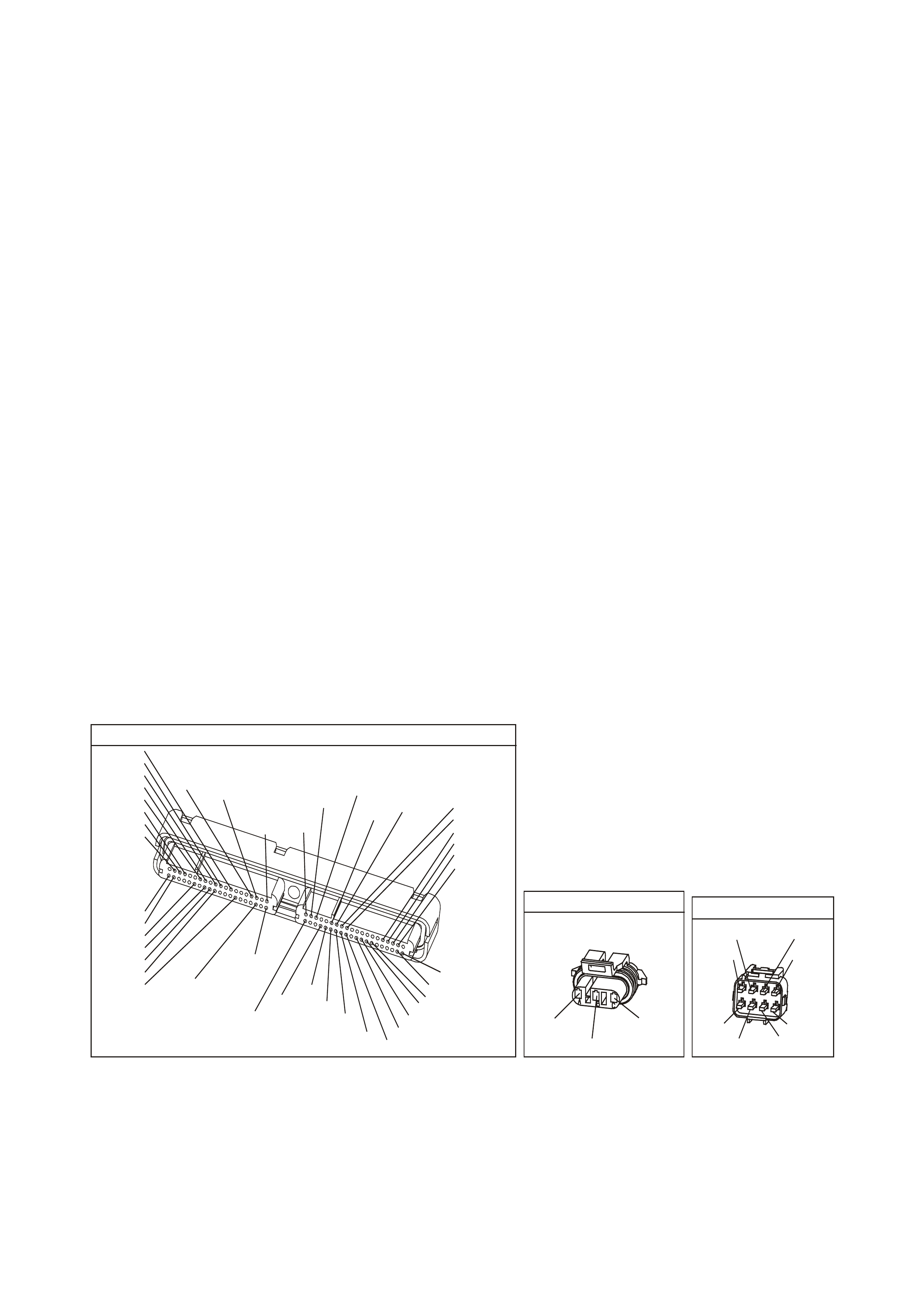
DIAGNOSTIC AIDS
• Water entering the air intake system that reaches the MAF Sensor could cause this DTC to set. The water
rapidly cools the hot wires in the sensor, causing a false indication of excessive airflow. Check the following
areas for evidence (witness marks) of water intrusion:
- Air system
- Intake air system
• Inspect the EFI relay for proper operation if you cannot find any problems with the ignition feed circuit to the
com ponent. Probe both sides of the fuse with a test lam p connected to earth in order to determ ine if a voltage
is supplied to the fuse. Refer to EFI Relay Diagnosis of the VX Series Service Information.
• The following may cause an intermittent:
- Incorrectly routed wiring harness
- Rubbed through wire insulation
- Broken wire inside the insulation
- A poor connection in the ignition feed circuit to the MAF Sensor can cause a DTC P0103 to set.
For an intermittent, refer to Section 6C3-2B Symptoms of the VX Series Service Information.
TEST DESCRIPTION
The numbers below refer to the step numbers on the diagnostic table.
2. Monitoring the MAF Sensor frequency determines if the fault is present or the malfunction is intermittent.
A poor connection at the MAF Sensor or at the fuse causes this DTC to set.
For any test that requires pr obing the PCM or com ponent har ness c onnectors , use the Connector T es t Adapter
Kit J35616-A. Using this kit prevents any damage to the harness connector terminals.
3. Using the Freeze Frame/Failure Records data may aid in locating an intermittent condition. If you cannot
duplicate the DT C, the inform ation included in the Fr eeze Frame/Failur e Records data can help deter mine how
many the distance traveled since the DTC set. The Fail Counter and Pass Counter can also help determine
how many ignition cycles the diagnostic reported a pass and/or a fail. Operate the vehicle within the same
freeze fram e conditions (RPM, load, vehicle speed, temperature etc.) that you observed. This will isolate when
the DTC failed. For any test that requires probing the PCM or component harness connectors, use the
Connector Test Adapter Kit J35616-A. Using this kit prevents any damage to the harness connector terminals.
4. T his step c heck s for elec tro-m agnetic interfer ence on the MAF Sensor s ignal circuit. T here should be no signal
indicated on the Tech 2 scan tool with the sensor disconnected.
YE 123
P.C.M CONNECTOR 2
(750)
(1228)
(1229)
(465)
(121)
(259)
G/B
BR
G/W
GY/BLU
R
B/R
(418)
BR
(59)
(832)
G
T
(831)
(417)
(472)
(976) (974)
(432)
(428)
(631)
BLU BR G/Y
BLU/W
LG
BR/W
W/B
LG W
(977)
Y
(971)
BLU/W W
B/R
(750)
(304)
(792)
(1223)
(1222)
(123)
(1227)
(469)
(331)
Y/B
LG
V/W
B/Y
G/O BR/W
(1687)
GY/B
(366)
LG/B
GY/R
(422)
V
(442)
(444)
(443)
(975)
(972)
(978)
(1224)
(973)
(959)
LG/W
LG/B
LBLU/B
GY
(773)
BR/Y
BLU
G
Y/B
LBLU
(958)
BR
(441)
LBLU
1
41
40
80
J2
RED
Y
(838)
M.A.F SENS OR
YE100
(439)
(750)
(792)
B/R
PBR/W
YE111
ENGINE CO NNEC TOR 2
(482)
(481)
R
LG
GY
G
(434)
(129)
P
(439)
(59)
(366)
LG/B
GW/B
(451)

GEN III V8 PCM - DTC P0103 MASS AIR FLOW SENSOR CIRCUIT HIGH FREQUENCY
Step Action Value(s) Yes No
1 Did you perform the powertrain On-Board Diagnostic
(OBD) System Check? Go to Step 2 Go to Powertrain
OBD System
Check Table
2
1. Idle the engine.
2. Monitor the MAF Sensor display on the Tech 2 scan
tool Engine Data List.
Is the MAF sensor frequency below the specified value?
11,250 Hz Go to Step 4 Go to Step 3
3 1. Turn ON the ignition leaving the engine OFF.
2. Review the Freeze Frame/Failure Records data for
this DTC and observe the parameters.
3. Turn OFF the ignition for 15 seconds.
4. Start the engine.
5. Operate the vehicle, within the conditions required for
this diagnostic to run, and as close to the conditions
recorded in the Freeze Frame/Failure Records as
possible. Special operating conditions that you need
to meet before the PCM will run this diagnostic, where
applicable, are listed in Conditions for Running the
DTC.
6. Select the Diagnostic Trouble Code (DTC) option, the
DTC Information option and The Failed This Ignition
option, using the Tech 2 scan tool.
Does the Tech 2 scan tool indicate that this diagnostic
failed this ignition?
Go to Step 4 Go to Diagnostic
Aids
4 1. Turn OFF the ignition.
2. Disconnect the MAF Sensor connector.
3. Idle the engine.
4. Monitor the MAF Sensor frequency using the Tech 2
scan tool.
Does the Tech 2 scan tool indicate a MAF Sensor
frequency?
Go to Step 7 Go to Step 5
5 1. Check for a poor connection at the MAF Sensor
harness terminals.
2. Replace the faulty terminal(s) if you find a poor
connection.
Did you find and correct the condition?
Go to Step 10 Go to Step 6
6 Replace the MAF Sensor. Refer to Section 6C3-3 MAF
Sensor Replacement of the VX Series Service
Information.
Is the action complete?
Go to Step 10
7 1. Check the MAF Sensor harness for incorrect routing
at the following locations:
- Near secondary ignition wires or components.
- Other high current components. Such as solenoids,
relays, and motors.
2. Correct the harness routing if you find incorrect
routing.
Did you find and correct the condition?
Go to Step 10 Go to Step 8
8 1. Check the MAF Sensor signal circuit terminal
connections at the PCM connector.
2. Replace the faulty terminal(s) if you find a poor
connection.
Did you find and correct the condition?
Go to Step 10 Go to Step 9

GEN III V8 PCM - DTC P0103 MASS AIR FLOW SENSOR CIRCUIT HIGH FREQUENCY (CONTINUED)
Step Action Value(s) Yes No
9 1. Replace PCM.
2. Refer to Section 6C3-3 of the VX Series Service
Information for PCM Programming and
PCM/PIM/BCM Security Link Procedure.
Is action complete?
Go to Step 10
10 1. Select the Diagnostic Trouble Code (DTC) option and
the Clear DTC Information option using the Tech 2
scan tool.
2. Idle the engine at the normal operating temperature.
3. Select the Diagnostic Trouble Code (DTC) option and
the Specific DTC option, then enter the DTC number
using the Tech 2 scan tool.
4. Operate the vehicle within the Conditions for Running
the DTC as specified in the supporting text, if
applicable.
Does the Tech 2 scan tool indicate that this DTC reset?
Go to Step 2 Go to Step 11
11 Using the Tech 2 scan tool, check for any other DTC.
Does the Tech 2 scan tool display any DTCs that you
have not diagnosed?
Go to applicable
DTC table System OK

GEN III V8 PCM -
DTC P0107 MANIFOLD ABSOLUTE PRESSURE SENSOR CIRCUIT LOW VOLTAGE
CIRCUIT DESCRIPTION
The Manifold Absolute Pressure (MAP) Sensor is mounted to the rear of the intake manifold. The MAP Sensor
measures the pressure changes within the intake manifold which is an indication of the engine load. The MAP
Sensor has a 5.0 volt reference, an earth, and a signal circuit.
The MAP Sensor contains a diaphragm which changes the resistance based on pressure. When the manifold
pressur e is low (high vacuum ), the sens or output voltage is low. When the manif old pressur e is high (low vacuum),
the sensor output voltage is high.
The MAP Sens or voltage (depending on altitude) can r ange from 1.0-1.5 volts at idle (high vacuum ) to 4.0-4.9 volts
at wide open throttle (low vacuum).
When the PCM senses a signal voltage lower than the normal operating range of the sensor, this DTC will set.
CONDITIONS FOR RUNNING THE DTC
• No TP or ECT sensor DTCs are set.
• The engine is running.
• The TP angle is above 20% when the engine speed is greater than 1200 RPM.
OR
• The TP angle is below 18% when the engine speed is below 1000 RPM.
CONDITIONS FOR SETTING THE DTC
• The MAP sensor voltage is less than 0.10 volts..
• The conditions met for at least two seconds.
ACTION TAKEN WHEN THE DTC SETS
• The PCM illuminates the Check Powertrain Lamp when the diagnostic runs and fails.
• The PCM records the operating conditions at the time the diagnostic fails. The PCM stores this information in
the Freeze Frame/Failure Records.
CONDITIONS FOR CLEARING THE CPL/DTC
• The PCM turns the Check Powertr ain Lamp OF F after one ignition cycle that the diagnostic runs and does not
fail.
• A last test failed (current DTC) clears when the diagnostic runs and does not fail.
• Use a Tech 2 scan tool in order to clear the CPL/DTC.
DIAGNOSTIC AIDS
• The following may cause an intermittent:
- Incorrectly routed wiring harness
- Rubbed through wire insulation
- Broken wire inside the insulation
• The PCM 5.0 volt ref erence c ircuits are internally connected within the PCM. If all the MAP Sensor circuits are
OK, inspect the following component/ circuits for malfunctions:
- A/C Refrigerant Pressure Sensor
For intermittent, refer to Section 6C3-2B Symptoms of the VX Series Service Information.
G3PCM010PT
PCM
M
I
C
R
O
J2-32
J1-54
C
B
A
MANIFOLD
ABSOLUTE
PRESSURE SENSOR
J1-48
YE27 YE122
YE122
SENSOR EARTH
MAP SENSOR
SIGNAL
REFERENCE
VOLTAGE
5V
V/W (414)
B (42 1)
LG (432)
YE123
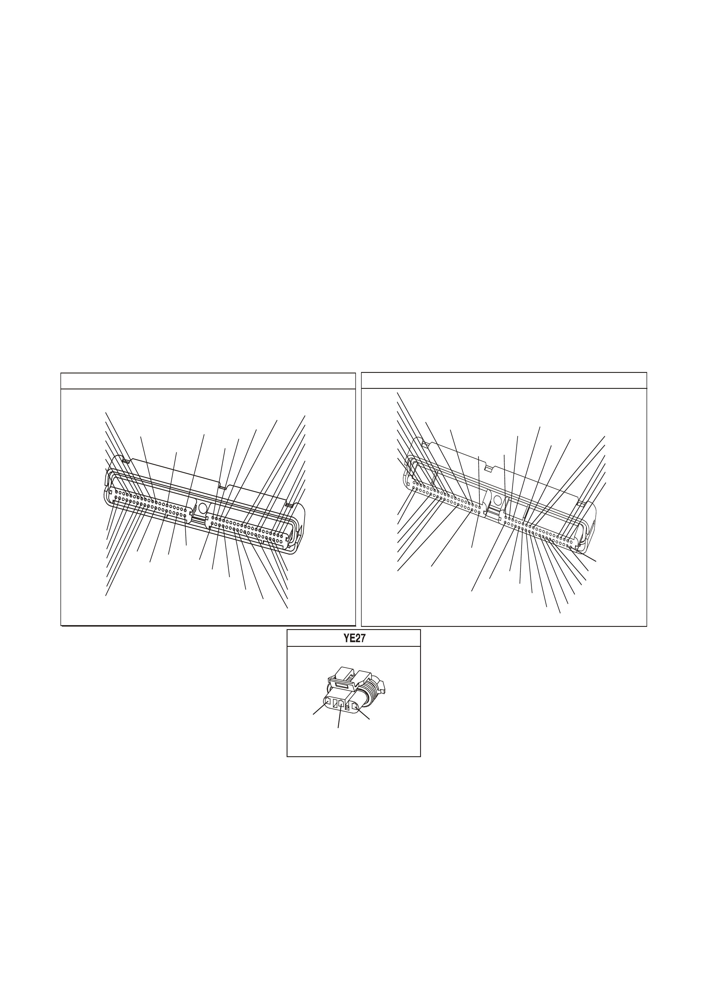
TEST DESCRIPTION
The numbers below refer to the step numbers on the diagnostic table.
2. If the DTC P1635 sets at the sam e time, this indicates that the 5.0 voltage referenc e c ircuit is either shor ted to
an earth or shorted to a voltage. The 5.0 volt ref erence circuit is internally connected within the PCM. The A/C
Refrigerant Pressure Sensor may be causing this DTC to set. Refer to DTC P1635 for further diagnosis.
3. This step determined if the malfunction is present.
4. Using the Freeze Frame/Failure Records data may aid in locating an intermittent condition. If you cannot
duplicate the DTC, the information included in the Freeze Fram e/Failure Records data can help determine the
distance traveled since the DTC set. The Fail Counter and Pass Counter can also help determine how many
ignition cycles the diagnostic reported a pass and/or fail.
Operate the vehicle within the sam e freeze fr ame conditions (RPM, load, vehicle speed, tem perature, etc.) that you
observed. This will isolate when the DTC failed.
5. If the Tech 2 scan tool displays 5.0 volts, the MAP Sensor signal, 5.0 volt reference circuit, and the PCM are
OK. For any test that requires probing the PCM or component harness connectors, use the Connector Test
Adapter Kit J 35616-A. Using this kit will prevent any damage to the harness connector terminals.
6. If the Tech 2 scan tool displays 5.0 volts, the MAP sensor signal circuit and the PCM is OK. For any test that
requires probing the PCM or com ponents harness connectors, use the Connector Test Adapter Kit J 35616-A.
Using this kit will prevent any damage to the harness connector terminals.
7. Dis connecting the PCM allows using the DMM J 39200 in order to check the c ontinuity of the circuits. This aids
in locating an open or shorted circuit.
P.C.M CO NNE CTOR 1
Y E122
(776)
(1049)
(897)
(1230)
(848)
(1226)
(772)
(647)
(632)
40
(844)
(815)
80
J1
P/B
(845)
V/W
BLU
O
(633)
(846)
B/Y
B/R
(416)
(86)
(69)
(455)
(740)
GY
BR
G
GY
(646)
(410)
GY
(842)
(1225)
V
Y
(750)
P
41
O
(774)
BR/Y
BLU
Y
B/R
B
BLU/Y
(841)
BLUE
(414)
G/W
BLU
LG
LBLU/B
1
(847)
(415)
(740)
(452)
BLU
BR Y
(750)
(826)
(421)
Y
V/W
B/W
(334)
(771)
(39)
Y
R/W
LBLU
W
BLU/W
(843)
(643)
LBLU/W
G
GY/B
BLU/B
(413)
(1413)
(1412)
(412)
GY
V
GY/B
G
(335)
YE123
P.C.M CO NNECTOR 2
(750)
(1228)
(1229)
(465)
(121)
(259)
G/B
BR
G/W
GY/BLU
R
B/R
(418)
BR
(59)
(832)
G
T
(831)
(417)
(472)
(976) (974)
(432)
(428)
(631)
BLU BR G/Y
BLU/W
LG
BR/W
W/B
LG W
(977)
Y
(971)
BLU/W W
B/R
(750)
(304)
(792)
(1223)
(1222)
(123)
(1227)
(469)
(331)
Y/B
LG
V/W
B/Y
G/O BR/W
(1687)
GY/B
(366)
LG/B
GY/R
(422)
V
(442)
(444)
(443)
(975)
(972)
(978)
(1224)
(973)
(959)
LG/W
LG/B
LBLU/B
GY
(773)
BR/Y
BLU
G
Y/B
LBLU
(958)
BR
(441)
LBLU
1
41
40
80
J2
RED
Y
(838)
M AP S ENSOR
(421)
B
(432)
LG
V/W
(414)

GEN III V8 PCM - DTC P0107 MANIFOLD ABSOLUTE PRESSURE SENSOR CIRCUIT LOW VOLTAGE
Step Action Value(s) Yes No
1 Did you perform the Powertrain On-Board Diagnostic
(OBD) System Check? Go to Step 2 Go to Powertrain
OBD System
Check Table
2
1. Install a Tech 2 scan tool.
2. Idle the engine.
3. Monitor the Failed This Ignition option under the DTC
Information option using the Tech 2 scan tool.
Did DTC P1635 fail this ignition cycle?
Go to DTC
P1635
5 Volt Reference
Circuit Table
Go to Step 3
3 Monitor the MAP Sensor voltage on Engine Data List on
the Tech 2 scan tool.
Is the MAP Sensor voltage below the specified value?
0.10V Go to Step 5 Go to Step 4
4 1. Turn ON the ignition leaving the engine OFF.
2. Review the Freeze Frame/Failure Records data for
this DTC and observe the parameters.
3. Turn OFF the ignition for 15 seconds.
4. Start the engine.
5. Operate the vehicle, within the conditions required for
this diagnostic to run, and as close to the conditions
recorded in the Freeze Frame/Failure Records as
possible. Special operating conditions that you need
to meet before the PCM will run this diagnostic, where
applicable, are listed in Conditions for Running the
DTC.
6. Select the Diagnostic Trouble Code (DTC) option, the
DTC Information option and The Failed This Ignition
option, using the Tech 2 scan tool.
Does the Tech 2 scan tool indicate that this diagnostic
failed this ignition?
Go to Step 5 Go to Diagnostic
Aids
5 1. Disconnect the MAP Sensor electrical connector.
2. Jumper the 5.0 volt reference circuit and the MAP
Sensor signal circuit together at the MAP Sensor
harness connector.
3. Observe the MAP Sensor voltage display on the scan
tool.
Is the MAP Sensor voltage near the specified value?
5.0V Go to Step 11 Go to Step 6
6 1. Connect a test lamp, J 34142-B, between B+ and the
MAP Sensor signal circuit at the MAP Sensor harness
connector.
2. Observe the MAP Sensor voltage display on the scan
tool.
Is the MAP Sensor voltage near the specified value?
5.0V Go to Step 7 Go to Step 9
7 1. Turn OFF the ignition.
2. Disconnect the PCM BLUE connector.
3. Check the 5.0 volt reference circuit for an open or
short to an earth.
4. If you find the 5.0 volt reference circuit is open or short
to an earth, repair the circuit as necessary.
Did you find the 5.0 volt reference circuit open or shorted
to an earth?
Go to Step 13 Go to Step 8
8 1. Check the 5.0 volt reference circuit for a poor
connection at the PCM.
2. Replace the terminal if necessary.
Did the terminal require replacement?
Go to Step 13 Go to Step 12

GEN III V8 PCM - DTC P0107 MANIFOLD ABSOLUTE PRESSURE SENSOR CIRCUIT LOW VOLTAGE (CONTINUED)
Step Action Value(s) Yes No
9 1. Turn OFF the ignition.
2. Disconnect the PCM RED connector.
3. Check the MAP sensor signal circuit for the following:
- Open circuit
- Short to an earth
- Short to sensor earth circuit
4. If you find the MAP Sensor signal circuit is open or
shorted to an earth, repair the circuit as necessary.
Did you find the MAP Sensor signal circuit open or
shorted to a earth?
Go to Step 13 Go to Step 10
10 Check the MAP Sensor signal circuit for a poor
connection at the PCM and replace the terminal if
necessary.
Did the terminal require replacement?
Go to Step 13 Go to Step 12
11 Replace the MAP Sensor. Refer to Section 6C3-3 MAP
Sensor Replacement of the VX Series Service
Information.
Is the action complete?
Go to Step 13
12 1. Replace PCM.
2. Refer to Section 6C3-3 of the VX Series Service
Information for PCM Programming and
PCM/PIM/BCM Security Link Procedure.
Is action complete?
Go to Step 13
13 1. Select the Diagnostic Trouble Code (DTC) option and
the Clear DTC Information option using the Tech 2
scan tool.
2. Idle the engine at the normal operating temperature.
3. Select the Diagnostic Trouble Code (DTC) option and
the Specified DTC option, then enter the DTC number
using the Tech 2 scan tool.
4. Operate the vehicle within the Conditions for Running
the DTC as specified in the supporting text, if
applicable.
Does the Tech 2 scan tool indicate that this DTC reset?
Go to Step 2 Go to Step 14
14 Using the Tech 2 scan tool, check for any other DTC.
Does the Tech 2 scan tool display any DTCs that you
have not diagnosed?
Go to the
applicable DTC
table
System OK

GEN III V8 PCM -
DTC P0108 MANIFOLD ABSOLUTE PRESSURE SENSOR CIRCUIT HIGH VOLTAGE
CIRCUIT DESCRIPTION
The Manifold Absolute Pressure (MAP) Sensor is mounted to the rear of the intake manifold. The MAP Sensor
measures the pressure changes within the intake manifold which is an indication of the engine load. The MAP
Sensor has a 5.0 volt reference, an earth, and a signal circuit.
The MAP Sensor contains a diaphragm which changes the resistance based on pressure. When the manifold
pressur e is low (high vacuum ), the sens or output voltage is low. When the manif old pressur e is high (low vacuum),
the sensor output voltage is high.
The MAP Sens or voltage (depending on altitude) can r ange from 1.0-1.5 volts at idle (high vacuum ) to 4.0-4.9 volts
at wide open throttle (low vacuum).
When the PCM senses a signal voltage higher than the normal operating range of the sensor, this DTC will set.
CONDITIONS FOR RUNNING THE DTC
• No TP or ECT sensor DTCs are set.
• The engine is running.
• The TP angle is above 20% when the engine speed is greater than 1000 RPM.
OR
• The TP angle is below 18% when the engine speed is below 1200 RPM.
CONDITIONS FOR SETTING THE DTC
• The MAP sensor voltage is greater than 4.3 volts.
• The conditions met for at least four seconds.
ACTION TAKEN WHEN THE DTC SETS
• The PCM illuminates the Check Powertrain Lamp when the diagnostic runs and fails.
• The PCM records the operating conditions at the time the diagnostic fails. The PCM stores this information in
the Freeze Frame/Failure Records.
CONDITIONS FOR CLEARING THE CPL/DTC
• The PCM turns the Check Powertr ain Lamp OF F after one ignition cycle that the diagnostic runs and does not
fail.
• A last test failed (current DTC) clears when the diagnostic runs and does not fail.
• Use a Tech 2 scan tool in order to clear the CPL/DTC.
DIAGNOSTIC AIDS
• The following may cause an intermittent:
- Incorrectly routed harness
- Rubbed through wire insulation
- Broken wire inside the insulation
• The PCM 5.0 volt ref erence c ircuits are internally connected within the PCM. If all the MAP Sensor circuits are
OK, inspect the following component/ circuits for malfunctions:
- A/C Refrigerant Pressure Sensor
For intermittent, refer to Section 6C3-2B Symptoms of the VX Series Service Information.
G3PCM010PT
PCM
M
I
C
R
O
J2-32
J1-54
C
B
A
MANIFOLD
ABSOLUTE
PRESSURE SENSOR
J1-48
YE27 YE122
YE122
SENSOR EARTH
MAP SENSOR
SIGNAL
REFERENCE
VOLTAGE
5V
V/W (414)
B (42 1)
LG (432)
YE123
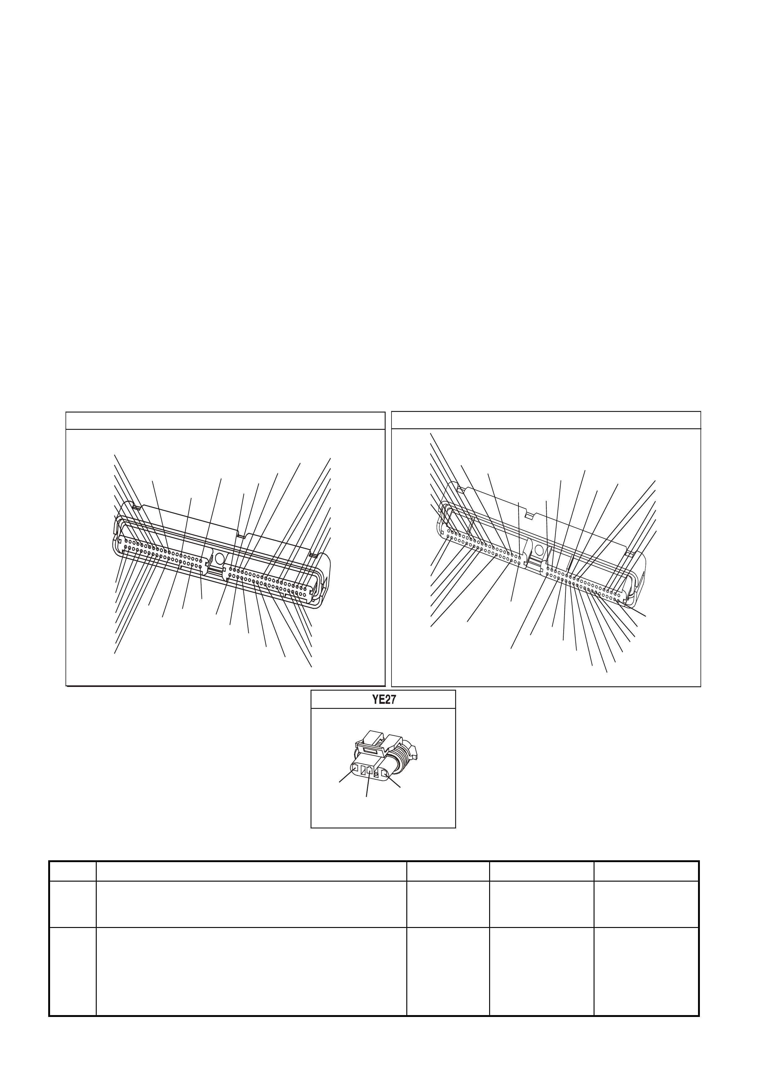
TEST DESCRIPTION
The numbers below refer to the step numbers on the diagnostic table.
2. If the DTC P1635 sets at the same time, this indicates that the 5.0 voltage reference circuit is either shorted to
an earth or shorted to a voltage. The 5.0 volt reference circuit is internally connected within the PCM. The A/C
Refrigerant Pressure Sensor may be causing this DTC to set. Refer to DTC P1635 for further diagnosis.
3. This step determined if the malfunction is present.
4. Using the Freeze Frame/Failure Records data may aid in locating an intermittent condition. If you cannot
duplicate the DTC, the information included in the Freeze Frame/Failure Records data can help determine the
distance traveled since the DTC set. The Fail Counter and Pass Counter can also help determine how many
ignition cycles the diagnostic reported a pass and/or fail. Operate the vehicle with the same freeze frame
conditions (RPM, load, vehicle speed, temperature, etc.) that you observed.
This will isolate when the DTC failed. For any test that requires probing the PCM or component harness
connectors, use the Connector Test Adapter Kit J 35616-A. Using this kit will prevent any damage to the
harness connector terminals.
5. This step checks whether the signal circuit is shorted to a voltage.
6. This step checks whether the earth circuit is available at the MAP Sensor. For any test that requires probing
the PCM or component harness connectors, use the Connector Test Adapter Kit J 35616-A. Using this kit will
prevent any damage to the harness connector terminals.
9. Remove the MAP Sensor and check if the vacuum is available to the sensor. Also, inspect the MAP Sensor
seal for nicks and cuts.
P.C.M CONNECTOR 1
YE122
(776)
(1049)
(897)
(1230)
(848)
(1226)
(772)
(647)
(632)
40
(844)
(815)
80
J1
P/B
(845)
V/W
BLU
O
(633)
(846)
B/Y
B/R
(416)
(86)
(69)
(455)
(740)
GY
BR
G
GY
(646)
(410)
GY
(842)
(1225)
V
Y
(750)
P
41
O
(774)
BR/Y
BLU
Y
B/R
B
BLU/Y
(841)
BLUE
(414)
G/W
BLU
LG
LBLU/B
1
(847)
(415)
(740)
(452)
BLU
BR
Y
(750)
(826)
(421)
Y
V/W
B/W
(334)
(771)
(39)
Y
R/W
LBLU
W
BLU/W
(843)
(643)
LBLU/W
G
GY/B
BLU/B
(413)
(1413)
(1412)
(412)
GY
V
GY/B
G
(335)
YE123
P.C.M CONNECTOR 2
(750)
(1228)
(1229)
(465)
(121)
(259)
G/B
BR
G/W
GY/BLU
R
B/R
(418)
BR
(59)
(832)
G
T
(831)
(417)
(472)
(976)(974)
(432)
(428)
(631)
BLU BR G/Y
BLU/W
LG
BR/W
W/B
LG W
(977)
Y
(971)
BLU/WW
B/R
(750)
(304)
(792)
(1223)
(1222)
(123)
(1227)
(469)
(331)
Y/B
LG
V/W
B/Y
G/OBR/W
(1687)
GY/B
(366)
LG/B
GY/R
(422)
V
(442)
(444)
(443)
(975)
(972)
(978)
(1224)
(973)
(959)
LG/W
LG/B
LBLU/B
GY
(773)
BR/Y
BLU
G
Y/B
LBLU
(958)
BR
(441)
LBLU
1
41
40
80
J2
RED
Y
(838)
MAP SENSOR
(421)
B
(432)
LG
V/W
(414)
GEN III V8 PCM - DTC P0108 MANIFOLD ABSOLUTE PRESSURE SENSOR CIRCUIT HIGH VOLTAGE
Step Action Value(s) Yes No
1 Did you perform the Powertrain On-Board Diagnostic
(OBD) System Check? Go to Step 2 Go to Powertrain
OBD System
Check Table
2
1. Install a Tech 2 scan tool.
2. Idle the engine.
3. Monitor the Failed This Ignition option under the DTC
Information option using the Tech 2 scan tool.
Did DTC P1635 fail this ignition cycle?
Go to DTC
P1635
5 Volt Reference
Circuit Table
Go to Step 3

GEN III V8 PCM - DTC P0108 MANIFOLD ABSOLUTE PRESSURE SENSOR CIRCUIT HIGH VOLTAGE (CONT)
Step Action Value(s) Yes No
3 IMPORTANT: If the engine idle is rough, unstable or
incorrect, repair the idle condition before using this table.
Refer to Section 6C3-2B Symptoms of the VX Series
Service Information.
Monitor the MAP Sensor voltage on Engine Data List on
the Tech 2 scan tool.
Is the MAP Sensor voltage below the specified value?
4.3V Go to Step 5 Go to Step 4
4 1. Turn ON the ignition leaving the engine OFF.
2. Review the Freeze Frame/Failure Records data for
this DTC and observe the parameters.
3. Turn OFF the ignition for 15 seconds.
4. Start the engine.
5. Operate the vehicle, within the conditions required for
this diagnostic to run, and as close to the conditions
recorded in the Freeze Frame/Failure Records as
possible. Special operating conditions that you need
to meet before the PCM will run this diagnostic, where
applicable, are listed in Conditions for Running the
DTC.
6. Select the Diagnostic Trouble Code (DTC) option, the
DTC Information option and The Failed This Ignition
option, using the Tech 2 scan tool.
Does the Tech 2 scan tool indicate that this diagnostic
failed this ignition?
Go to Step 5 Go to Diagnostic
Aids
5 1. Disconnect the MAP Sensor electrical connector.
2. Observe the MAP Sensor voltage display on the scan
tool.
Is the MAP Sensor voltage below the specified value?
1.0V Go to Step 6 Go to Step 7
6 Probe the Sensor earth circuit with a test lamp, J 34142-
B, to B+.
Is the test lamp illuminated?
Go to Step 8 Go to Step 10
7 1. Check the MAP sensor Signal circuit for a short to
voltage or a short to the 5.0 volt reference circuit.
2. Repair the MAP Sensor signal circuit if the circuit is
shorted.
Is the MAP Sensor signal circuit shorted?
Go to Step 16 Go to Step 12
8 Measure the voltage at the 5.0 volt reference circuit to the
battery earth using a DMM J 39200.
Is the voltage near the specified value?
5.0V Go to Step 9 Go to Step 15
9 Check for a plugged or leaking vacuum supply to the
MAP Sensor.
Is the vacuum supply OK?
Go to Step 13 Go to Step 14
10 1. Check for a poor sensor earth terminal connection at
the PCM connector.
2. Replace the faulty terminal if a problem is found.
Did the terminal require replacement?
Go to Step 16 Go to Step 11
11 1. Check continuity of the MAP Sensor earth circuit.
2. Repair the open or the poor connection if the MAP
sensor earth circuit measures over the specified
value.
Did you find and correct the condition?
5Ω Go to Step 16 Go to Step 12

GEN III V8 PCM - DTC P0108 MANIFOLD ABSOLUTE PRESSURE SENSOR CIRCUIT HIGH VOLTAGE (CONT)
Step Action Value(s) Yes No
12 1. Replace PCM.
2. Refer to Section 6C3-3 of the VX Series Service
Information for PCM Programming and
PCM/PIM/BCM Security Link Procedure.
Is action complete?
Go to Step 16
13 Replace the MAP Sensor. Refer to Section 6C3-3 MAP
Sensor Replacement of the VX Series Service
Information.
Is the action complete?
Go to Step 16
14 Repair the faulty vacuum supply.
Is the action complete? Go to Step 16
15 Repair the 5.0 volt reference circuit for a short to voltage.
Is the action complete. Go to Step 16
16 1. Select the Diagnostic Trouble Code (DTC) option and
the Clear DTC Information option using the Tech 2
scan tool.
2. Idle the engine at the normal operating temperature.
3. Select the Diagnostic Trouble Code (DTC) option and
the Specified DTC option, then enter the DTC number
using the Tech 2 scan tool.
4. Operate the vehicle within the Conditions for Running
the DTC as specified in the supporting text, if
applicable.
Does the Tech 2 scan tool indicate that this DTC reset?
Go to Step 2 Go to Step 17
17 Using the Tech 2 scan tool, check for any other DTC.
Does the Tech 2 scan tool display any DTCs that you
have not diagnosed?
Go to the
applicable DTC
table
System OK

GEN III V8 PCM -
DTC P0112 INTAKE AIR TEMPERATURE SENSOR CIRCUIT LOW VOLTAGE
CIRCUIT DESCRIPTION
The Intak e Air T em perature (IAT ) Sensor c ontains a sem ic onductor devic e which changes the r esistanc e based on
the temperature (a thermistor). The IAT Sensor is located in the air intake passage of the engine air induction
system. The IAT Sensor has a signal circ uit and an earth circuit. The PCM applies 5.0 volts on the signal circuit to
the sensor. The PCM monitors the changes in this voltage, caused by changes in the resistance of the sensor, in
order to determine intake air temperature.
When the intake air is cold, the sens or (t hermistor ) res ist ance is high. The PCM’s s ignal voltage is only pulled down
a sm all amount thr ough the sensor to an earth; ther efore, the PCM senses a high signal voltage (low temperature) .
When the intake air is warm, the sensor resistance is low. The signal voltage is pulled down a greater amount;
therefore, the PCM senses a low signal voltage (high temperature).
When the PCM senses a signal voltage lower than the normal operating range of the sensor, this DTC will set.
CONDITIONS FOR RUNNING THE DTC
• DTC(s) P0101, P0102, P0103, P0117, P0118, are not set.
• The engine run time is greater than 30 seconds.
• The vehicle speed is less than 40 km/h.
CONDITIONS FOR SETTING THE DTC
• The Intake Air Temperature is greater than 139°C.
• The conditions met for at least 20 seconds.
ACTION TAKEN WHEN THE DTC SETS
• The PCM stores the DTC information into memory when the diagnostic runs and fails.
• The Check Powertrain Lamp will not be illuminated.
• The PCM will substitute a default Intake Air Temperature value of 25°C.
• The PCM records the operating conditions at the time the diagnostic fails. The PCM stores this information in
the Freeze Frame/Failure Records.
CONDITIONS FOR CLEARING THE CPL/DTC
• A last test failed (current DTC) clears when the diagnostic runs and does not fail.
• Use a Tech 2 scan tool in order to clear the CPL/DTC.
DIAGNOSTIC AIDS
• The following may cause an intermittent:
- Incorrectly routed wiring harness
- Rubbed through wire insulation
- Broken wire inside the insulation
• If the engine has sat overnight, the Engine Coolant T em per ature and the engine Intak e Air T em perature values
should display within a few degrees of each other. If the temperatures are not within 3°C (5°F), refer to
Section 6C3-4 Temperature vs. Resistance Table of the VX Series Service Information.
• If you determine that the DTC occurs intermittently, performing the P1112 diagnostic table may isolate the
cause of the fault.
For intermittent, refer to Section 6C3-2B Symptoms of the VX Series Service Information.
G3PCM002PT
J2-57
J2-25
A
B
INTAKE AIR
TEMPERATURE SENSOR
SENSOR EARTH
IAT SENSO R SIGN AL
PCM
5V
BR (47 2 )
G/O (469)
YE23 YE123
M
I
C
R
O
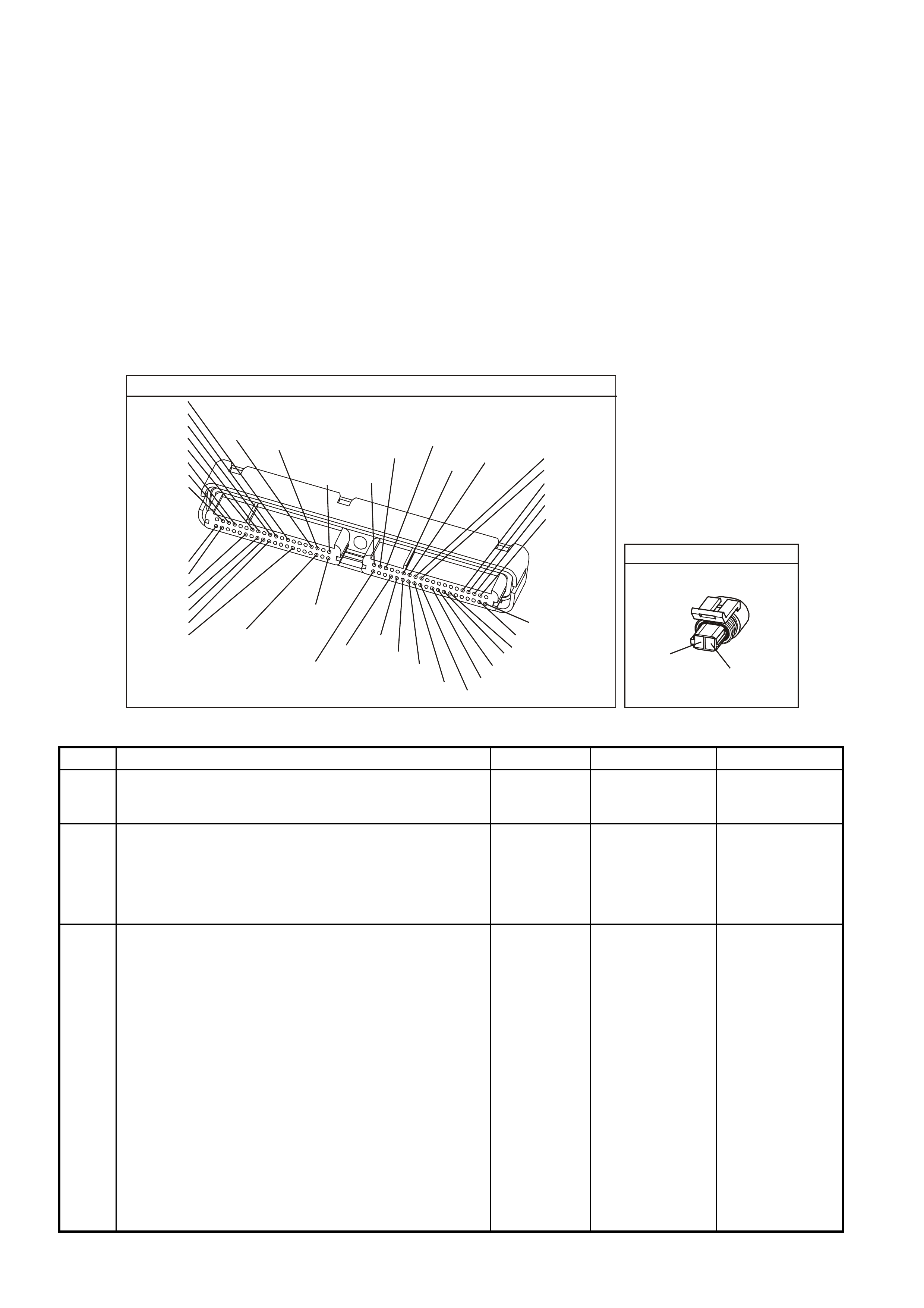
TEST DESCRIPTION
The numbers below refer to the step numbers on the diagnostic table.
2. This step determines if the malfunction is present.
3. Using the Freeze Frame/Failure Records data may aid in locating an intermittent condition. If you cannot
duplicate the DTC, the information included in the Freeze Frame/Failure Records data can help determine the
distance traveled since the DTC set. The Fail Counter and Pass Counter can also help determine how many
ignition cycles the diagnostic reported a pass and/or fail. Operate the vehicle with the same freeze frame
conditions (RPM, load, vehicle speed, temperature, etc.) that you observed.
This will isolate when the DTC failed. For any test that requires probing the PCM or component harness
connectors, use the Connector Test Adapter Kit J 35616-A. Using this kit will prevent any damage to the
harness connector terminals.
4. An intake air temperature below -30°C indicates the PCM and IAT wiring are OK.
5. Disconnecting the PCM allows using the DMM J 39200 in order to check continuity of the circuits. This aids in
locating an open or a shorted circuit.
YE123
P.C.M CONNECTOR 2
(750)
(1228)
(1229)
(465)
(121)
(259)
G/B
BR
G/W
GY/BLU
R
B/R
(418)
BR
(59)
(832)
G
T
(831)
(417)
(472)
(976)(974)
(432)
(428)
(631)
BLUBR G/Y
BLU/W
LG
BR/W
W/B
LG W
(977)
Y
(971)
BLU/WW
B/R
(750)
(304)
(792)
(1223)
(1222)
(123)
(1227)
(469)
(331)
Y/B
LG
V/W
B/Y
G/OBR/W
(1687)
GY/B
(366)
LG/B
GY/R
(422)
V
(442)
(444)
(443)
(975)
(972)
(978)
(1224)
(973)
(959)
LG/W
LG/B
LBLU/B
GY
(773)
BR/Y
BLU
G
Y/B
LBLU
(958)
BR
(441)
LBLU
1
41
40
80 J2
RED
Y
(838)
AIR TEMP SENSOR
YE23
B/R
(472)
G/O
(469)
GEN III V8 PCM - DTC P0112 INTAKE AIR TEMPERATURE SENSOR CIRCUIT LOW VOLTAGE
Step Action Value(s) Yes No
1 Did you perform the Powertrain On-Board Diagnostic
(OBD) System Check? Go to Step 2 Go to Powertrain
OBD System
Check Table
2
1. Install a Tech 2 scan tool.
2. Idle the engine.
3. Monitor the IAT display on the Tech 2 scan tool
Engine Data List.
Is the IAT above the specified value?
139°C Go to Step 4 Go to Step 3
3 1. Turn ON the ignition leaving the engine OFF.
2. Review the Freeze Frame/Failure Records data for
this DTC and observe the parameters.
3. Turn OFF the ignition for 15 seconds.
4. Start the engine.
5. Operate the vehicle, within the conditions required for
this diagnostic to run, and as close to the conditions
recorded in the Freeze Frame/Failure Records as
possible. Special operating conditions that you need
to meet before the PCM will run this diagnostic, where
applicable, are listed in Conditions for Running the
DTC.
6. Select the Diagnostic Trouble Code (DTC) option, the
DTC Information option and The Failed This Ignition
option using the Tech 2 scan tool.
Does the Tech 2 scan tool indicate that this diagnostic
failed this ignition?
Go to Step 4 Go to
Diagnostic Aids

GEN III V8 PCM - DTC P0112 INTAKE AIR TEMPERATURE SENSOR CIRCUIT LOW VOLTAGE (CONTINUED)
Step Action Value(s) Yes No
4 1. Disconnect the IAT sensor electrical connector.
2. Observe the IAT display on the Tech 2 scan tool.
Is the IAT at the specified value?
-39°C Go to Step 6 Go to Step 5
5 1. Turn OFF the ignition.
2. Disconnect the PCM RED connector.
3. Check the IAT Sensor signal circuit for a short to a
earth.
4. If you find the IAT sensor signal circuit is earthed,
repair the circuit as necessary.
Is the IAT Sensor signal circuit earthed?
Go to Step 8 Go to Step 7
6 Replace the IAT Sensor. Refer to Section 6C3-3 IAT
Sensor Replacement of the VX Series Service
Information.
Is the action complete?
Go to Step 8
7 1. Replace PCM.
2. Refer to Section 6C3-3 of the VX Series Service
Information for PCM Programming and
PCM/PIM/BCM Security Link Procedure.
Is action complete?
Go to Step 8
8 1. Select the Diagnostic Trouble Code (DTC) option and
the Clear DTC Information option using the Tech 2
scan tool.
2. Idle the engine at the normal operating temperature.
3. Select the Diagnostic Trouble Code (DTC) option and
the Specified DTC option, then enter the DTC number
using the Tech 2 scan tool.
4. Operate the vehicle within the Conditions for Running
the DTC as specified in the supporting text, if
applicable.
Does the Tech 2 scan tool indicate that this DTC reset?
Go to Step 2 Go to Step 9
9 Using the Tech 2 scan tool, check for any other DTC.
Does the Tech 2 scan tool display any DTCs that you
have not diagnosed?
Go to the
applicable DTC
table
System OK

GEN III V8 PCM -
DTC P0113 INTAKE AIR TEMPERATURE SENSOR CIRCUIT HIGH VOLTAGE
CIRCUIT DESCRIPTION
The Intak e Air T em perature (IAT ) Sensor c ontains a sem ic onductor devic e which changes the r esistanc e based on
the temperature (a thermistor). The IAT Sensor is located in the air intake passage of the engine air induction
system. The IAT Sensor has a signal circ uit and an earth circuit. The PCM applies 5.0 volts on the signal circuit to
the sensor. The PCM monitors the changes in this voltage, caused by changes in the resistance of the sensor, in
order to determine intake air temperature.
When the intake air is cold, the sens or (t hermistor ) res ist ance is high. The PCM’s s ignal voltage is only pulled down
a sm all amount through the sens or to an earth therefore, the PCM s enses a high signal voltage (low tem perature).
When the intake air is warm, the sensor resistance is low. The signal voltage is pulled down a greater amount
therefore, the PCM senses a low signal voltage (high temperature).
When the PCM senses a signal voltage lower than the normal operating range of the sensor, this DTC will set.
CONDITIONS FOR RUNNING THE DTC
• DTC(s) P0101, P0102, P0103, P0117, P0118, are not set.
• The engine run time is greater than 100 seconds.
• The engine coolant temperature is greater than 0°C.
• The vehicle speed is less than 11 km/h.
CONDITIONS FOR SETTING THE DTC
• The Intake Air Temperature is at or below -35°C.
• The conditions met for at least 20 seconds.
ACTION TAKEN WHEN THE DTC SETS
• The PCM stores the DTC information into memory when the diagnostic runs and fails.
• The Check Powertrain Lamp will not be illuminated.
• The PCM will substitute a default Intake Air Temperature value of 25°C.
• The PCM records the operating conditions at the time the diagnostic fails. The PCM stores this information in
the Freeze Frame/Failure Records.
CONDITIONS FOR CLEARING THE CPL/DTC
• A last test failed (current DTC) clears when the diagnostic runs and does not fail.
• Use a Tech 2 scan tool in order to clear the CPL/DTC.
DIAGNOSTIC AIDS
• The following may cause an intermittent:
- Incorrectly routed harness
- Rubbed through wire insulation
- Broken wire inside the insulation
• If the engine has sat overnight, the Engine Coolant T em per ature and the engine Intak e Air T em perature values
should display within a few degrees of each other. If the temperatures are not within 3°C (5°F), refer to
Section 6C3-4 Temperature vs. Resistance Table of the VX Series Service Information.
• If you determine that the DTC occurs intermittently, performing the P1111 diagnostic table may isolate the
cause of the fault.
For intermittent, refer to Section 6C3-2B Symptoms of the VX Series Service Information.
G3PCM002PT
J2-57
J2-25
A
B
INTAKE AIR
TEMPERATURE SENSOR
SENSOR EARTH
IAT SENSO R SIGN AL
PCM
5V
BR (47 2 )
G/O (469)
YE23 YE123
M
I
C
R
O
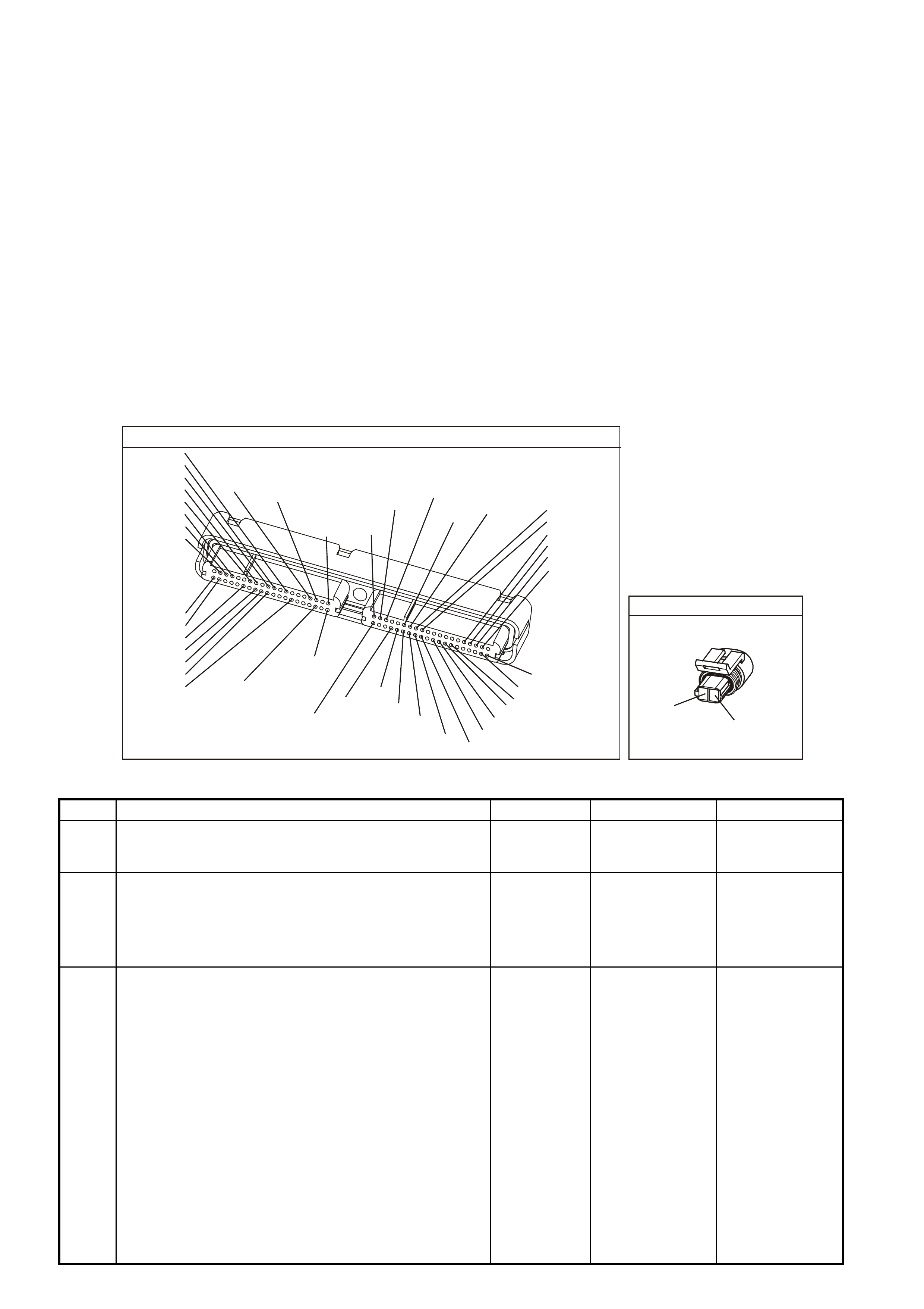
TEST DESCRIPTION
The numbers below refer to the step numbers on the diagnostic table.
2. This step determines if the malfunction is present. For any test that requires probing the PCM or component
harness connectors, use the Connector Test Adapter Kit J35616-A. Using this kit will prevent any damage to
the harness connector terminals.
3. Using the Freeze Frame/Failure Records data may aid in locating an intermittent condition. If you cannot
duplicate the DTC, the information included in the Freeze Frame/Failure Records data can help determine the
distance traveled since the DTC set. The Fail Counter and Pass Counter can also help determine how many
ignition cycles the diagnostic reported a pass and/or fail. Operate the vehicle with the same freeze frame
conditions (RPM, load, vehicle speed, temperature, etc.) that you observed.
This will isolate when the DTC failed. For any test that requires probing the PCM or component harness
connectors, use the Connector Test Adapter Kit J 35616-A. Using this kit will prevent any damage to the
harness connector terminals.
4. An intake air temperature above 140°C indicates the PCM and IAT wiring are OK.
5 An intake air temperature above 140°C indicates the PCM and IAT wiring are OK.
6. Disconnecting the PCM allows using the DMM J 39200 in order to check continuity of the circuits. This aids in
locating an open or a shorted circuit.
8 Disconnecting the PCM allows using the DMM J 39200 in order to check continuity of the circuits. This aids in
locating an open or a shorted circuit.
YE123
P.C.M CONNECTOR 2
(750)
(1228)
(1229)
(465)
(121)
(259)
G/B
BR
G/W
GY/BLU
R
B/R
(418)
BR
(59)
(832)
G
T
(831)
(417)
(472)
(976)(974)
(432)
(428)
(631)
BLUBR G/Y
BLU/W
LG
BR/W
W/B
LG W
(977)
Y
(971)
BLU/WW
B/R
(750)
(304)
(792)
(1223)
(1222)
(123)
(1227)
(469)
(331)
Y/B
LG
V/W
B/Y
G/OBR/W
(1687)
GY/B
(366)
LG/B
GY/R
(422)
V
(442)
(444)
(443)
(975)
(972)
(978)
(1224)
(973)
(959)
LG/W
LG/B
LBLU/B
GY
(773)
BR/Y
BLU
G
Y/B
LBLU
(958)
BR
(441)
LBLU
1
41
40
80
J2
RED
Y
(838)
AIR TEMP SENSOR
YE23
B/R
(472)
G/O
(469)
GEN III V8 PCM - DTC P0113 INTAKE AIR TEMPERATURE SENSOR CIRCUIT HIGH VOLTAGE
Step Action Value(s) Yes No
1 Did you perform the Powertrain On-Board Diagnostic
(OBD) System Check? Go to Step 2 Go to Powertrain
OBD System
Check Table
2
1. Install a Tech 2 scan tool.
2. Idle the engine.
3. Monitor the IAT sensor display on the Tech 2 scan
tool Engine Data List.
Is the IAT at or above the specified value?
-35°C Go to Step 4 Go to Step 3
3 1. Turn ON the ignition leaving the engine OFF.
2. Review the Freeze Frame/Failure Records data for
this DTC and observe the parameters.
3. Turn OFF the ignition for 15 seconds.
4. Start the engine.
5. Operate the vehicle, within the conditions required for
this diagnostic to run, and as close to the conditions
recorded in the Freeze Frame/Failure Records as
possible. Special operating conditions that you need
to meet before the PCM will run this diagnostic, where
applicable, are listed in Conditions for Running the
DTC.
6. Select the Diagnostic Trouble Code (DTC) option, the
Specific DTC option, then enter the DTC number
using the Tech 2 scan tool.
Does the Tech 2 scan tool indicate that this diagnostic
failed this ignition?
Go to Step 4 Go to
Diagnostic Aids

GEN III V8 PCM - DTC P0113 INTAKE AIR TEMPERATURE SENSOR CIRCUIT HIGH VOLTAGE (CONTINUED)
Step Action Value(s) Yes No
4 1. Disconnect the IAT Sensor electrical connector.
2. Jumper the IAT harness terminals together.
3. Observe the IAT parameter on the Tech 2 scan tool.
Is the IAT at the specified value?
139°C Go to Step 9 Go to Step 5
5 Jumper the IAT signal circuit to a known good earth.
Is the IAT at the specified value? 139°C Go to Step 8 Go to Step 6
6 1. Turn OFF the ignition.
2. Disconnect the PCM RED connector.
3. Check the IAT Sensor signal circuit for an open.
Is the IAT Sensor signal circuit open?
Go to Step 7 Go to Step 11
7 Repair the IAT Sensor signal circuit.
Is the action complete? Go to Step 12
8 1. Turn OFF the ignition.
2. Disconnect both the PCM connectors.
3. Check the IAT Sensor earth circuit for an open.
Is the IAT Sensor earth circuit open?
Go to Step 10 Go to Step 11
9 Replace the IAT Sensor. Refer to Section 6C3-3 IAT
Sensor Replacement of the VX Series Service
Information.
Is the action complete?
Go to Step 12
10 Repair the IAT Sensor earth circuit.
Is action complete? Go to Step 12
11 1. Replace PCM.
2. Refer to Section 6C3-3 of the VX Series Service
Information for PCM Programming and
PCM/PIM/BCM Security Link Procedure.
Is action complete?
Go to Step 12
12 1. Select the Diagnostic Trouble Code (DTC) option and
the Clear DTC Information option using the Tech 2
scan tool.
2. Idle the engine at the normal operating temperature.
3. Select the Diagnostic Trouble Code (DTC) option and
the Specified DTC option, then enter the DTC number
using the Tech 2 scan tool.
4. Operate the vehicle within the Conditions for Running
the DTC as specified in the supporting text, if
applicable.
Does the Tech 2 scan tool indicate that this DTC reset?
Go to Step 2 Go to Step 13
13 Select the Capture Info option and the Review Info option
using the Tech 2 scan tool.
Does the Tech 2 scan tool display any DTCs that you
have not diagnosed?
Go to the
applicable DTC
table
System OK
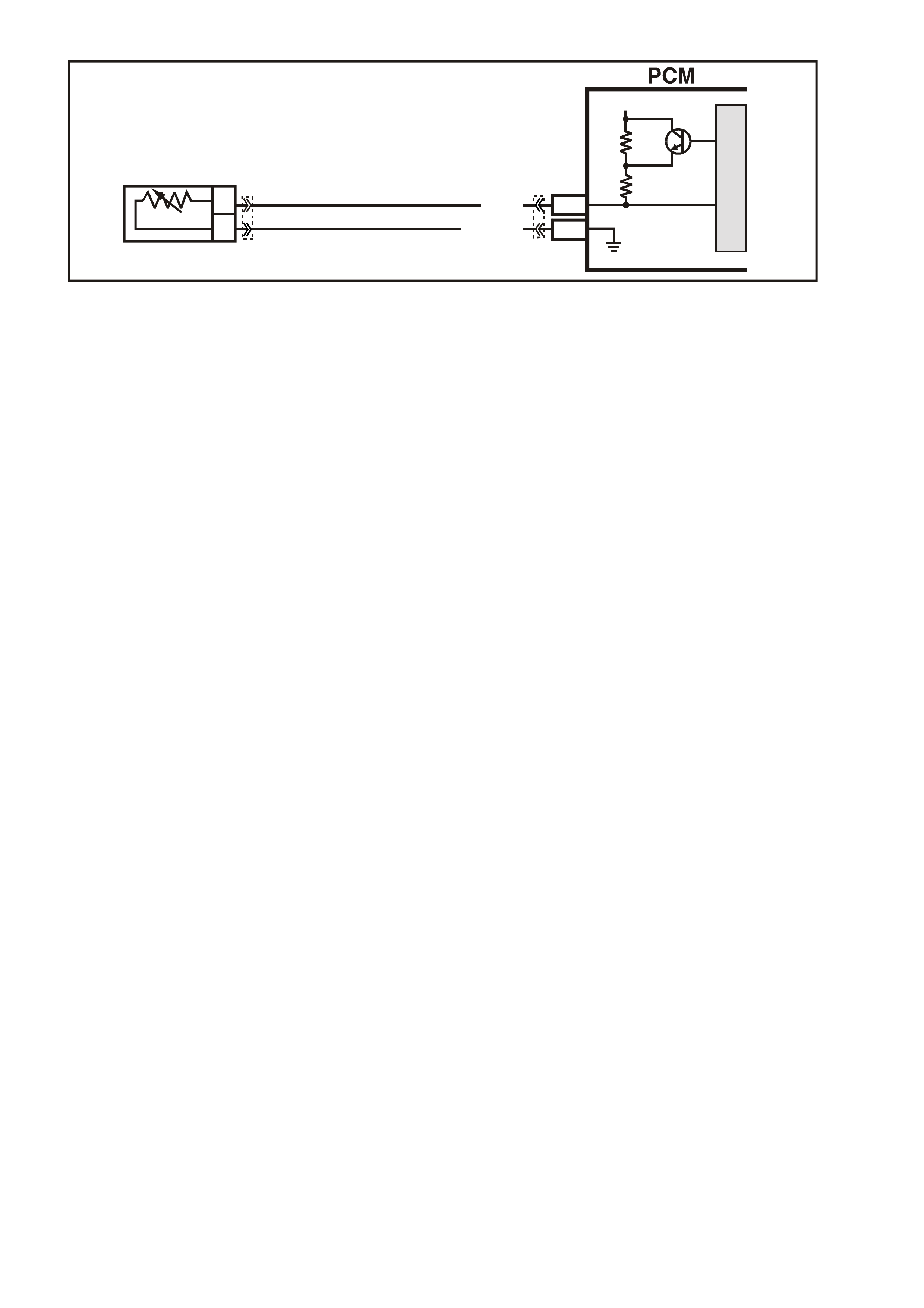
GEN III V8 PCM -
DTC P0117 ENGINE COOLANT TEMPERATURE SENSOR CIRCUIT LOW VOLTAGE
CIRCUIT DESCRIPTION
The Engine Coolant Temperature (ECT) Sensor contains a semiconductor device which changes the resistance
based on the temperature (a thermistor). The ECT Sensor is m ounted in the left bank cylinder head near the front
of the engine. T he ECT Sensor has a signal circ uit and a earth circuit. T he PCM applies a voltage (about 5.0 volts)
on the signal circuit to the sensor. The PCM monitors the changes in this voltage, caused by changes in the
resistance of the sensor, in order to determine the coolant temperature.
When the coolant is cold, the sensor (therm is tor) r esistanc e is high. T he PCMs s ignal voltage is only pulled down a
small amount through the sensor to an earth therefore, the PCM senses a high signal voltage (low temperature).
When the coolant is warm, the sensor resistance is low. The signal voltage is pulled down a greater amount
therefore, the PCM senses a low signal voltage (high temperature). At normal operating temperature, the voltage
should measure about 1.5-2.0 volts at the PCM.
When the PCM senses a signal voltage lower than the normal operating range of the sensor, this DTC will set.
CONDITIONS FOR RUNNING THE DTC
• The engine run time is greater than 10 seconds.
CONDITIONS FOR SETTING THE DTC
• The engine coolant temperature is greater than 139°C.
• All conditions met for at least 45 seconds.
ACTION TAKEN WHEN THE DTC SETS
• The PCM illuminates the Check Powertrain Lamp when the diagnostic runs and fails.
• The PCM will substitute a coolant temperature default value.
• The PCM arrives at this default value, by using current intake air temperature, then counting upward to 116°C
at a rate of approximately 7 degrees per minute.
• The PCM will turn on the electric engine cooling fans. This is a FAIL-SAFE action by the PCM to prevent a
possible engine overheat condition, since the DTC indicates an unknown actual coolant temperature.
• The PCM records the operating conditions at the time the diagnostic fails. The PCM stores this information in
the Freeze Frame/Failure Records.
CONDITIONS FOR CLEARING THE CPL/DTC
• The PCM turns the Check Powertrain Lamp OFF when the diagnostic runs and does not fail.
• A last test failed (current DTC) clears when the diagnostic runs and does not fail.
• Use a Tech 2 scan tool in order to clear the CPL/DTC.
DIAGNOSTIC AIDS
• The following may cause an intermittent:
- Incorrectly routed harness
- Rubbed through wire insulation
- Broken wire inside the insulation
• If the engine has s at overnight, the Engine Coolant T em perature and the engine Intak e Air T em per ature values
should display within a few degrees of each other. If the temperatures are not within 3°C (5°F), refer to
Section 6C3-4 Temperature vs. Resistance Table of the VX Series Service Information.
• If you determine that the DTC occurs intermittently, performing the P1111 diagnostic table may isolate the
cause of the fault.
• For intermittent, refer to Section 6C3-2B Symptoms of the VX Series Service Information.
G3PCM004PT
J1-80
J1-74
B
A
ENGINE COOLANT
TEMPERATURE SENSOR
SENSOR EARTH
ETC SENSOR SIGNAL
5V
4k
348
Ω
Ω
Y (41 0)
GY/B (455)
YE65 YE122
M
I
C
R
O
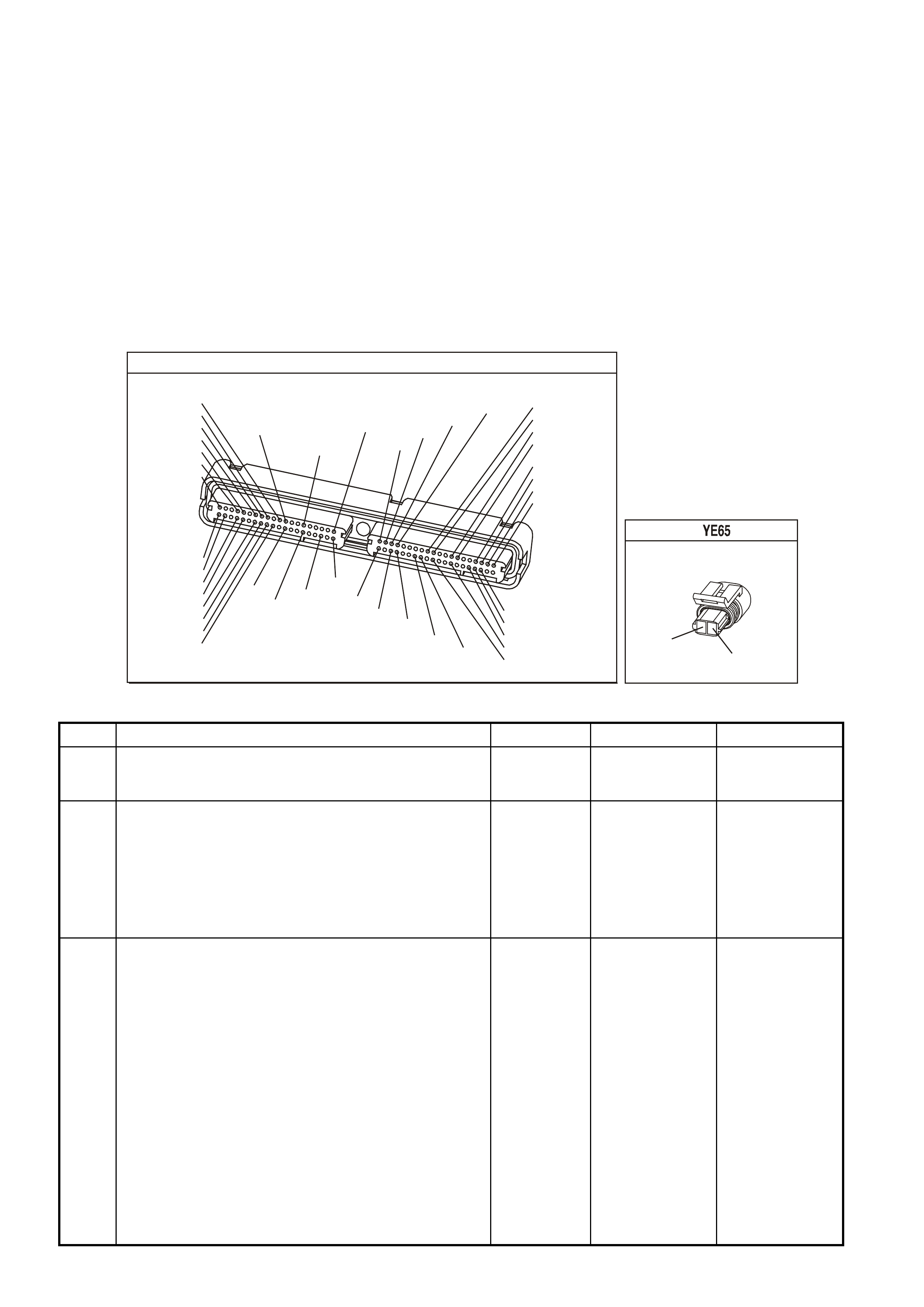
TEST DESCRIPTION
The numbers below refer to the step numbers on the diagnostic table.
2. This step determines if the malfunction is present.
3. Using the Freeze Frame/Failure Records data may aid in locating an intermittent condition. If you cannot
duplicate the DTC, the information included in the Freeze Frame/Failure Records data can help determine the
distance traveled since the DTC set. The Fail Counter and Pass Counter can also help determine how many
ignition cycles the diagnostic reported a pass and/or fail. Operate the vehicle with the same freeze frame
conditions (RPM, load, vehicle speed, temperature, etc.) that you observed. This will isolate when the DTC
failed. For any test that requires probing the PCM or component harness connectors, use the Connector Test
adapter Kit J 35616-A. Using this kit will prevent any damage to the harness connector terminals.
4. An engine coolant temperature below -30°C (-22°F) indicates the PCM and IAT wiring are OK.
5. Disconnecting the PCM allows using the DMM J 39200 in order to check continuity of the circuits. This aids in
locating an open or a shorted circuit.
7. Inspect for proper terminal tension/connections at the PCM harness before replacing the PCM.
P.C.M CONNECTOR 1
YE122
(776)
(1049)
(897)
(1230)
(848)
(1226)
(772)
(647)
(632)
40
(844)
(815)
80
J1
P/B
(845)
V/W
BLU
O
(633)
(846)
B/Y
B/R
(416)
(86)
(69)
(455)
(740)
GY
BR
G
GY
(646)
(410)
GY
(842)
(1225)
V
Y
(750)
P
41
O
(774)
BR/Y
BLU
Y
B/R
B
BLU/Y
(841)
BLUE
(414)
G/W
BLU
LG
LBLU/B
1
(847)
(415)
(740)
(452)
BLU
BR
Y
(750)
(826)
(421)
Y
V/W
B/W
(334)
(771)
(39)
Y
R/W
LBLU
W
BLU/W
(843)
(643)
LBLU/W
G
GY/B
BLU/B
(413)
(1413)
(1412)
(412)
GY
V
GY/B
G
(335)
COOLANT TEMP SENSOR
Y
(410)
GY/B
(455)
GEN III V8 PCM - DTC P0117 ENGINE COOLANT TEMPERATURE SENSOR CIRCUIT LOW VOLTAGE
Step Action Value(s) Yes No
1 Did you perform the Powertrain On-Board Diagnostic
(OBD) System Check? Go to Step 2 Go to Powertrain
OBD System
Check Table
2
IMPORTANT: If the engine is overheating, correct the
overheating condition before proceeding with this table.
1. Install a Tech 2 scan tool.
2. Idle the engine.
3. Monitor the IAT display on the Engine Data List of
the Tech 2 scan tool.
Is the IAT at or above the specified value?
139°C
(282°F) Go to Step 4 Go to Step 3
3 1. Turn ON the ignition leaving the engine OFF.
2. Review the Freeze Frame/Failure Records data for
this DTC and observe the parameters.
3. Turn OFF the ignition for 15 seconds.
4. Start the engine.
5. Operate the vehicle, within the conditions required for
this diagnostic to run, and as close to the conditions
recorded in the Freeze Frame/Failure Records as
possible. Special operating conditions that you need to
meet before the PCM will run this diagnostic, where
applicable, are listed in Conditions for Running the
DTC.
6. Select the Diagnostic Trouble Code (DTC) option, the
DTC Information option and The Failed This Ignition
option using the Tech 2 scan tool.
Does the Tech 2 scan tool indicate that this diagnostic
failed this ignition?
Go to Step 4 Go to Diagnostic
Aids

GEN III V8 PCM - DTC P0117 ENGINE COOLANT TEMPERATURE SENSOR CIRCUIT LOW VOLTAGE (CONT)
Step Action Value(s) Yes No
4 1. Disconnect the ECT Sensor electrical connector.
2. Observe the ECT parameter on the Tech 2 scan tool.
Is the ECT at or below specified value?
-30°C
(-22°F) Go to Step 6 Go to Step 5
5 1. Turn OFF the ignition.
2. Disconnect the PCM BLUE connector.
3. Check the ECT Sensor signal circuit for a short to a
earth.
4. If you find the ECT Sensor signal circuit is earthed,
repair the circuit as necessary.
Did you find and repair an earthed ECT signal circuit?
Go to Step 8 Go to Step 7
6 Replace the ECT Sensor. Refer to Section 6C3-3 ECT
Sensor Replacement of the VX Series Service
Information.
Is the action complete?
Go to Step 8
7 1. Replace PCM.
2. Refer to Section 6C3-3 of the VX Series Service
Information for PCM Programming and
PCM/PIM/BCM Security Link Procedure.
Is action complete?
Go to Step 8
8 1. Select the Diagnostic Trouble Code (DTC) option and
the Clear DTC Information option using the Tech 2
scan tool.
2. Idle the engine at the normal operating temperature.
3. Select the Diagnostic Trouble Code (DTC) option, the
DTC Information option and The Failed This Ignition
option using the Tech 2 scan tool.
4. Operate the vehicle within the Conditions for Running
the DTC as specified in the supporting text, if
applicable.
Does the Tech 2 scan tool indicate that this DTC reset?
Go to Step 2 Go to Step 9
9 Using the Tech 2 scan tool, check for any other DTCs.
Does the Tech 2 scan tool display any DTCs that you
have not diagnosed?
Go to the
applicable DTC
table
System OK

GEN III V8 PCM -
DTC P0118 ENGINE COOLANT TEMPERATURE SENSOR CIRCUIT HIGH VOLTAGE
CIRCUIT DESCRIPTION
The Engine Coolant Temperature(ECT) Sensor contains a semiconductor device which changes the resistance
based on the temperature (a thermistor). The ECT Sensor is m ounted in the left bank cylinder head near the front
of the engine. T he ECT Sensor has a signal circ uit and a earth circuit. T he PCM applies a voltage (about 5.0 volts)
on the signal circuit to the sensor. The PCM monitors the changes in this voltage, caused by changes in the
resistance of the sensor, in order to determine the coolant temperature.
When the coolant is cold, the sensor (therm is tor) r esistanc e is high. T he PCMs s ignal voltage is only pulled down a
small amount through the sensor to an earth therefore, the PCM senses a high signal voltage (low temperature).
When the coolant is warm, the sensor resistance is low. The signal voltage is pulled down a greater amount
therefore, the PCM senses a low signal voltage (high temperature). At normal operating temperature, the voltage
should measure about 1.5-2.0 volts at the PCM.
When the PCM senses a signal voltage higher than the normal operating range of the sensor, this DTC will set.
CONDITIONS FOR RUNNING THE DTC
• The engine run time is greater than 10 seconds.
CONDITIONS FOR SETTING THE DTC
• The engine coolant temperature is greater than –38.9°C.
• All conditions met for at least 45 seconds.
ACTION TAKEN WHEN THE DTC SETS
• The PCM illuminates the Check Powertrain Lamp when the diagnostic runs and fails.
• The PCM will substitute a coolant temperature default value.
• The PCM arrives at this default value, by using current intake air temperature, then counting upward to 116°C
at a rate of approximately 7 degrees per minute.
• The PCM will turn on the electric engine cooling fans. This is a FAIL-SAFE action by the PCM to prevent a
possible engine overheat condition, since the DTC indicates an unknown actual coolant temperature.
• The PCM records the operating conditions at the time the diagnostic fails. The PCM stores this information in
the Freeze Frame/Failure Records.
CONDITIONS FOR CLEARING THE CPL/DTC
• The PCM turns the Check Powertrain Lamp OFF when the diagnostic runs and does not fail.
• A last test failed (current DTC) clears when the diagnostic runs and does not fail.
• Use a Tech 2 scan tool in order to clear the CPL/DTC.
DIAGNOSTIC AIDS
• The following may cause an intermittent:
- Incorrectly routed harness
- Rubbed through wire insulation
- Broken wire inside the insulation
• If the engine has s at overnight, the Engine Coolant T em perature and the Engine Intake Air Tem perature values
should display within a few degrees of each other. If the temperatures are not within 3°C (5°F), refer to
Section 6C3-4 Temperature vs. Resistance of the VX Series Service Information.
• If you determine that the DTC occurs intermittently, performing the P1111 diagnostic table may isolate the
cause of the fault.
• For intermittent, refer to Section 6C3-2B Symptoms of the VX Series Service Information.
G3PCM004PT
J1-80
J1-74
B
A
ENGINE COOLANT
TEMPERATURE SENSOR
SENSOR EARTH
ETC SENSOR SIGNAL
5V
4k
348
Ω
Ω
Y (41 0)
GY/B (455)
YE65 YE122
M
I
C
R
O
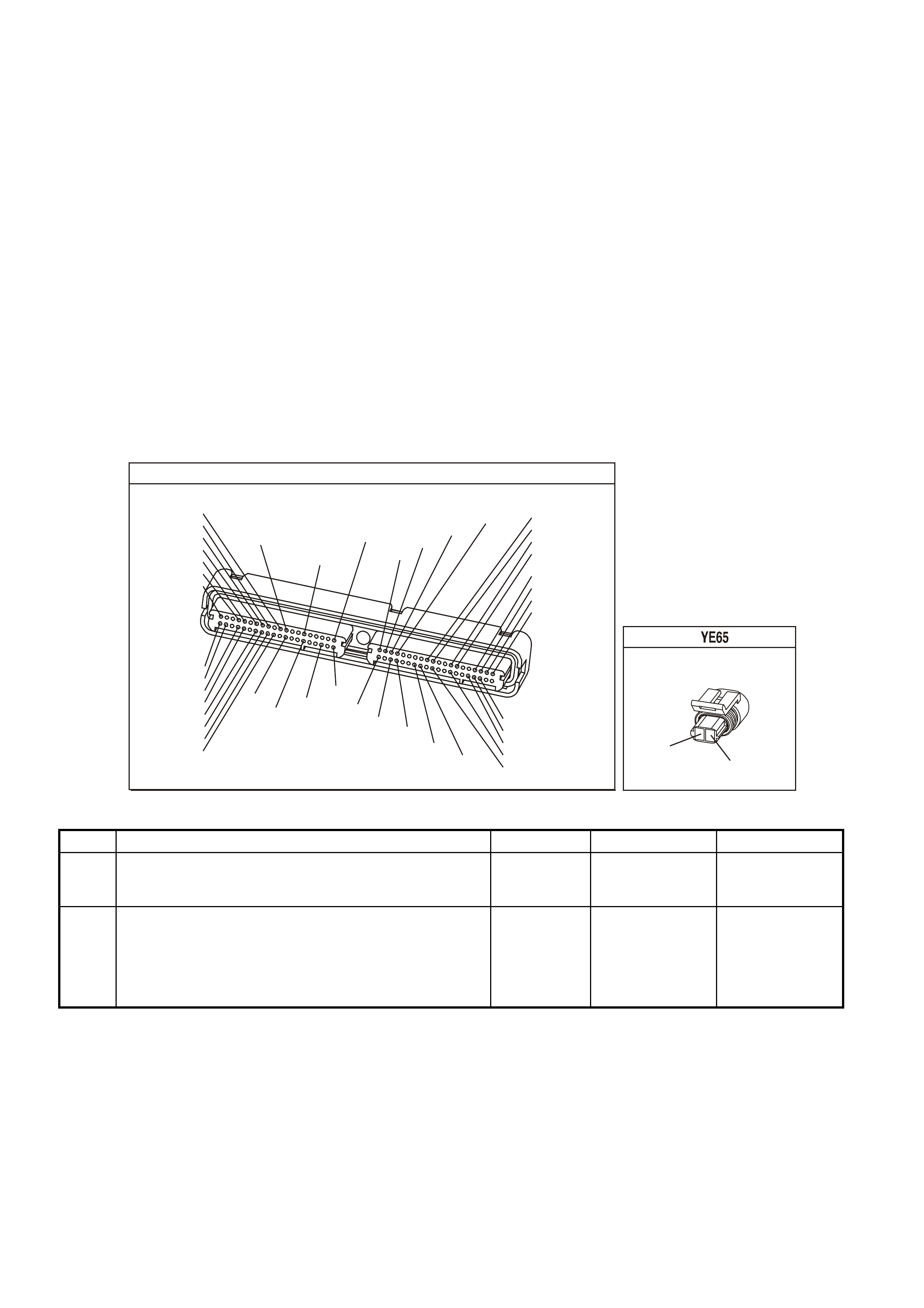
TEST DESCRIPTION
The numbers below refer to the step numbers on the diagnostic table.
2. This step determines if the malfunction is present. For any test that requires probing the PCM or component
harness connectors, use the Connector Test adapter Kit J 35616-A. Using this kit will prevent any damage to
the harness connector terminals.
3. Using the Freeze Frame/Failure Records data may aid in locating an intermittent condition. If you cannot
duplicate the DTC, the information included in the Freeze Frame/Failure Records data can help determine the
distance traveled since the DTC set. The Fail Counter and Pass Counter can also help determine how many
ignition cycles the diagnostic reported a pass and/or fail. Operate the vehicle with the same freeze frame
conditions (RPM, load, vehicle speed, temperature, etc.) that you observed. This will isolate when the DTC
failed. For any test that requires probing the PCM or component harness connectors, use the Connector Test
adapter Kit J 35616-A. Using this kit will prevent any damage to the harness connector terminals.
4. An engine coolant temperature above 140°C (284°F) indicates the PCM and IAT wiring are OK.
5. An engine coolant temperature above 140°C (284°F) indicates the PCM and IAT wiring are OK.
6. Disconnecting the PCM allows using the DMM J 39200 in order to check continuity of the circuits. This aids in
locating an open or a shorted circuit.
8. Disconnecting the PCM allows using the DMM J 39200 in order to check continuity of the circuits. This aids in
locating an open or a shorted circuit.
12. Inspect for proper terminal tension/connections at the PCM harness before replacing the PCM.
P.C.M CONNECTOR 1
YE122
(776)
(1049)
(897)
(1230)
(848)
(1226)
(772)
(647)
(632)
40
(844)
(815)
80
J1
P/B
(845)
V/W
BLU
O
(633)
(846)
B/Y
B/R
(416)
(86)
(69)
(455)
(740)
GY
BR
G
GY
(646)
(410)
GY
(842)
(1225)
V
Y
(750)
P
41
O
(774)
BR/Y
BLU
Y
B/R
B
BLU/Y
(841)
BLUE
(414)
G/W
BLU
LG
LBLU/B
1
(847)
(415)
(740)
(452)
BLU
BR
Y
(750)
(826)
(421)
Y
V/W
B/W
(334)
(771)
(39)
Y
R/W
LBLU
W
BLU/W
(843)
(643)
LBLU/W
G
GY/B
BLU/B
(413)
(1413)
(1412)
(412)
GY
V
GY/B
G
(335)
COOLANT TEMP SENSOR
Y
(410)
GY/B
(455)
GEN III V8 PCM - DTC P0118 ENGINE COOLANT TEMPERATURE SENSOR CIRCUIT HIGH VOLTAGE
Step Action Value(s) Yes No
1 Did you perform the Powertrain On-Board Diagnostic
(OBD) System Check? Go to Step 2 Go to Powertrain
OBD System
Check Table
2
1. Install a Tech 2 scan tool.
2. Idle the engine.
3. Monitor the ECT display on the Engine Data List of the
Tech 2 scan tool.
Is the ECT at or above the specified value?
-38.9°C
(-38.2°F) Go to Step 4 Go to Step 3

GEN III V8 PCM - DTC P0118 ENGINE COOLANT TEMPERATURE SENSOR CIRCUIT HIGH VOLTAGE
(CONTINUED)
Step Action Value(s) Yes No
3 1. Turn ON the ignition leaving the engine OFF.
2. Review the Freeze Frame/Failure Records data for
this DTC and observe the parameters.
3. Turn OFF the ignition for 15 seconds.
4. Start the engine.
5. Operate the vehicle, within the conditions required for
this diagnostic to run, and as close to the conditions
recorded in the Freeze Frame/Failure Records as
possible. Special operating conditions that you need to
meet before the PCM will run this diagnostic, where
applicable, are listed in Conditions for Running the
DTC.
6. Select the Diagnostic Trouble Code (DTC) option, the
DTC Information option and The Failed This Ignition
option using the Tech 2 scan tool.
Does the Tech 2 scan tool indicate that this diagnostic
failed this ignition?
Go to Step 4 Go to
Diagnostic Aids
4 1. Disconnect the ECT sensor electrical connector.
2. Jumper the ECT Sensor harness terminals together.
3. Observe the ECT parameter on the Tech 2 scan tool.
Is the ECT at the specified value?
140°C
(284°F) Go to Step 9 Go to Step 5
5 Jumper the ECT Sensor signal circuit to a known good
earth.
Is the ECT Sensors at the specified value?
140°C
(284°F) Go to Step 8 Go to Step 6
6 1. Turn OFF the ignition.
2. Disconnect the PCM BLUE connector.
3. Check the ECT Sensor signal circuit for a short to a
earth.
Is the ECT Sensor signal circuit earthed?
Go to Step 7 Go to Step 11
7 Repair the ECT Sensor signal circuit.
Is the action complete? Go to Step 14
8 1. Turn OFF the ignition.
2. Disconnect the PCM connectors.
3. Check the ECT Sensor earth circuit for an open.
Was a problem found?
Go to Step 10 Go to Step 11
9 Replace the ECT Sensor. Refer to Section 6C3-3 ECT
Sensor Replacement of the VX Series Service
Information.
Is the action complete?
Go to Step 14
10 Repair the ECT Sensor earth circuit.
Is the action complete? Go to Step 14
11 Check for a short to voltage on the signal circuit.
Did you find and correct the condition? Go to Step 14 Go to Step 12
12 Check for faulty connections at The PCM.
Did you find and correct the condition? Go to Step 14 Go to Step 13
13 1. Replace PCM.
2. Refer to Section 6C3-3 of the VX Series Service
Information for PCM Programming and
PCM/PIM/BCM Security Link Procedure.
Is action complete?
Go to Step 14

GEN III V8 PCM - DTC P0118 ENGINE COOLANT TEMPERATURE SENSOR CIRCUIT HIGH VOLTAGE
(CONTINUED)
Step Action Value(s) Yes No
14 1. Select the Diagnostic Trouble Code (DTC) option and
the Clear DTC Information option using the Tech 2
scan tool.
2. Idle the engine at the normal operating temperature.
3. Select the Diagnostic Trouble Code (DTC) option, the
DTC Information option and The Failed This Ignition
option using the Tech 2 scan tool.
4. Operate the vehicle within the Conditions for Running
the DTC as specified in the supporting text, if
applicable.
Does the Tech 2 scan tool indicate that this DTC reset?
Go to Step 2 Go to Step 15
15 Using the Tech 2 scan tool, check for any other DTCs.
Does the Tech 2 scan tool display any DTCs that you
have not diagnosed?
Go to the
applicable DTC
table
System OK

GEN III V8 PCM -
DTC P0121 THROTTLE POSITION SENSOR CIRCUIT INSUFFICIENT ACTIVITY
CIRCUIT DESCRIPTION
The T hrottle Pos ition (T P) Sensor is a potentiom eter. T he T P sensor is m ounted to the lef t side of the thr ottle body.
The TP Sensor provides a voltage signal that c hanges relative to throttle blade angle. T his signal voltage is one of
the most important inputs used by the PCM. The TP Sensor has a 5.0 volt reference, an earth and a signal circuit.
TP Sensor Signal voltage should be about 0.6 volt at idle. The TP Sensor voltage should increase to above 4.0
volts at wide open throttle (WOT).
This diagnostic compares actual throttle position from the TP Sensor to a predicted throttle position value. The
predicted throttle position is calculated from engine speed and other inputs. If the PCM detects the predicted
throttle position is below the actual TP sensor value, this DTC will set.
CONDITIONS FOR RUNNING THE DTC
• No MAP sensor or TP sensor DTCs.
• The engine run time is greater than 10 seconds.
• The engine coolant temperature is greater than 0°C.
• The IAC is between 0 and 255 counts.
• The MAP is less than 55 kPa.
OR
• The MAP is greater than 65 kPa.
• MAP is steady.
CONDITIONS OF SETTING THE DTC
• The predicted throttle angle does not match the actual throttle angle.
• All conditions are met for at least 20 seconds.
ACTION TAKEN WHEN THE DTC SETS
• The PCM illuminates the Check Powertrain Lamp when the diagnostic runs and fails.
• The PCM records the operating conditions at the time the diagnostic fails. The PCM stores this information in
the Freeze Frame/Failure Records.
• The PCM uses a default TP sensor value.
CONDITIONS FOR CLEARING THE CPL/DTC
• The PCM turns the Check Powertrain Lamp OFF when the diagnostic runs and does not fail.
• A last test failed (current DTC) clears when the diagnostic runs and does not fail.
• Use a Tech 2 scan tool in order to clear the CPL/DTC.
G3PCM005PT
SENSOR EARTH
TP SENSOR SIGNAL
TP SEN SOR
REFERENCE
VOLTAGE
PCM
5V
M
I
C
R
O
J1-08
J2-24
J1-60
A
C
B
THROTTLE
POSITION SENSOR
GY (416)
YE122
YE122YE30
YE123
BLU (417)
B/Y (452)
TO
THROTTLE RELAXER
MODULE

DIAGNOSTIC AIDS
• The following may cause an intermittent:
- Incorrectly routed harness
- Rubbed through wire insulation
- Broken wire inside the insulation
• The PCM 5.0 volt reference circuits are internally connected within the PCM. If all the TP sensor circuits are
OK, inspect the Fuel Tank Pressure Sensor for malfunctions.
• If it is determined that the DTC occurs intermittently, performing the DTC P1121 diagnostic table may isolate
the cause of the fault.
• For intermittent, refer to Section 6C3-2B Symptoms of the VX Series Service Information.
TEST DESCRIPTION
The numbers below refer to the step numbers on the diagnostic table.
2. If DTC P1635 sets at the same time, this indicates that the 5.0 volt reference circuit is either shorted to an earth
or shorted to a voltage. The 5.0 volt reference circuit is internally connected within the PCM.
3. The MAP value should change with the engine speed. If a MAP Sensor voltage changes, there is no
malfunction with the MAP Sensor.
4. This step checks for an intermittent connection at the sensor.
8. If the TP Sensor voltage changes, there is no malfunction with the TP Sensor wiring or the PCM.
9. Using Freeze Frame/Failure Records data may aid in locating an intermittent condition. If you cannot duplicate
the DTC, the information included in the Freeze Frame/Failure Records data can help determine the distance
traveled since the DTC set. The Fail Counter and Pass Counter can also help determine how many ignition
cycles the diagnostic reported a pass and/or a fail. Operate vehicle within the same freeze frame conditions
(RPM, load, vehicle speed, temperature etc.) that you observed. This will isolate when the DTC failed. For an
intermittent condition, refer to Section 6C3-2B Symptoms of the VX Series Service Information.
11. This checks the 5.0 volt reference circuit, signal circuit, and the PCM. If the Tech 2 scan tool displayed 5.0
volts, the TP Sensor circuits are OK.
THROTTLE POSITION SENSOR
YE30
(452)(416)
(417)
GY
B/Y
BLU
GEN III V8 PCM - DTC P0121 THROTTLE POSITION SENSOR CIRCUIT INSUFFICIENT ACTIVITY
Step Action Value(s) Yes No
1 Did you perform the Powertrain On-Board Diagnostic
(OBD) System Check? Go to Step 2 Go to Powertrain
OBD System
Check Table
2
1. Install a Tech 2 scan tool.
2. Idle the engine.
3. Monitor the Failed This Ignition option under the DTC
Information option using the Tech 2 scan tool.
Did the DTC P1635 fail this ignition?
Go to DTC
P1635 5 Volt
Reference Circuit
Go to Step 3
3 1. Start the engine.
2. Monitor the MAP Sensor voltage.
3. Increase the engine speed to the specified value.
Does the MAP Sensor voltage change when the engine
speed changed?
2000 RPM Go to Step 8 Go to Step 4
4 1. Turn ON the ignition leaving the engine OFF.
2. Move the MAP Sensor electrical connector, the
harness and the PCM connectors (by hand only) while
observing the Tech 2 scan tool display.
Is the MAP value affected by moving the harness or
connectors?
Go to Step 16 Go to Step 5

GEN III V8 PCM - DTC P0121 THROTTLE POSITION SENSOR CIRCUIT INSUFFICIENT ACTIVITY (CONT.)
Step Action Value(s) Yes No
5 1. Remove the MAP Sensor from the intake manifold but
leave the electrical harness connected.
2. Connect a hand operated vacuum pump to the MAP
Sensor.
3. Observe the MAP display while slowly applying
vacuum up to 20 inches Hg as indicated on the pump
gauge. Each 1 inch of vacuum applied should result in
a 3 to 4 kPa drop in the MAP Sensor valve on the
scan tool and the value should change smoothly with
each increase in the vacuum.
Did the MAP value change smoothly through the entire
range of the test without an erratic readiness.?
Go to Step 6 Go to Step 17
6 Apply 20 inches Hg vacuum to the MAP Sensor.
Is the MAP Sensor reading the same or less than the
specified value?
34 kPa Go to Step 7 Go to Step 17
7 Disconnect the vacuum source from the MAP Sensor.
Does the MAP Sensor reading return to its original value? Go to Step 8 Go to Step 17
8 1. Turn ON the ignition leaving the engine OFF.
2. Monitor the TP Sensor voltage while moving the
accelerator pedal from the closed throttle to a wide
open throttle.
Does the TP Sensor voltage go from below the specified
value to above the specified value?
Below 1.0V
to above
4.0V
Go to Step 9 Go to Step 10
9 1. Turn ON the ignition leaving the engine OFF.
2. Review the Freeze Frame/Failure Records data for
this DTC and record the parameters.
3. Turn OFF the ignition for 15 seconds.
4. Start the engine.
5. Operate the vehicle within the conditions required for
this diagnostic to run, and as close to the conditions
recorded in Freeze Frame/Failure Records as
possible. Special operating conditions that you need
meet before the PCM will run this diagnostic, where
applicable, are listed in Conditions for Running the
DTC.
6. Select the Diagnostic Trouble Code (DTC) option, the
DTC Information option and The Failed This Ignition
option using the Tech 2 scan tool.
Does the Tech 2 scan tool indicate that this diagnostic
failed this ignition?
Go to Step 10 Go to Diagnostic
Aids
10 1. Disconnect the TP Sensor.
2. Observe the TP Sensor display on the Tech 2 scan
tool.
Is the TP Sensor voltage near the specified value?
0.0V Go to Step 11 Go to Step 13
11 Jump the TP Sensor 5.0 volt reference circuit to the TP
Sensor signal circuit using a fused jumper wire.
Is the TP Sensor voltage near the specified value?
5.0V Go to Step 12 Go to Step 14
12 Replace the TP Sensor, refer to Section 6C3-3 TP
Sensor Replacement of the VX Series Service
Information.
Is the action complete?
Go to Step 18
13 Check for the following conditions:
• TP signal circuit for a short to voltage.
• TP Sensor earth circuit for high resistance between
the PCM and the TP Sensor.
• TP Sensor earth circuit for a poor connection.
If you find a problem, repair the wiring harness as
necessary.
Did you find and correct the condition?
Go to Step 18 Go to Step 15

GEN III V8 PCM - DTC P0121 THROTTLE POSITION SENSOR CIRCUIT INSUFFICIENT ACTIVITY (CONT.)
Step Action Value(s) Yes No
14 Check for the following conditions:
• TP Sensor signal circuit or 5 volt reference circuit for
a poor connection.
• TP Sensor signal circuit or 5 volt reference circuit for
high resistance between the PCM and the TP
sensor.
If you find a problem, repair the wiring harness as
necessary.
Did you find and correct the condition?
Go to Step 18 Go to Step 15
15 1. Replace PCM.
2. Refer to Section 6C3-3 of the VX Series Service
Information for PCM Programming and
PCM/PIM/BCM Security Link Procedure.
Is action complete?
Go to Step 18
16 Locate and repair the affected circuit.
Is the action complete? Go to Step 18
17 Replace the MAP Sensor. Refer to Section 6C3-3 MAP
Sensor Replacement of the VX Series Service
Information.
Is the action complete?
Go to Step 18
18 1. Select the Diagnostic Trouble Code (DTC) option and
the Clear DTC Information option using the Tech 2
scan tool.
2. Idle the engine at the normal operating temperature.
3. Select the Diagnostic Trouble Code (DTC) option and
the Specified DTC option, then enter the DTC number
using the Tech 2 scan tool.
4. Operate the vehicle within the Conditions for Running
the DTC as specified in the supporting text, if
applicable.
Does the Tech 2 scan tool indicate that this test reset?
Go to Step 2 Go to Step 19
19 Using the Tech 2 scan tool, check for any other DTCs
Does the Tech 2 scan tool display any DTCs that you
have not diagnosed?
Go to the
applicable DTC
table
System OK

GEN III V8 PCM
DTC P0122 THROTTLE POSITION SENSOR CIRCUIT LOW VOLTAGE
CIRCUIT DESCRIPTION
The Throttle Position ( T P) Sens or is a potentiometer. The T P Sensor is mounted to the left s ide of the thr ottle body.
The TP Sensor provides a voltage signal that c hanges relative to throttle blade angle. T his signal voltage is one of
the most important inputs used by the PCM. The TP Sensor has a 5.0 volt reference, an earth and a signal circuit.
TP Sensor Signal voltage should be about 0.6 volt at idle. The TP Sensor Signal voltage should increase to above
4.0 volts at wide open throttle (WOT).
When the PCM senses a signal voltage lower than the normal operating range of the sensor, this DTC will set.
CONDITIONS FOR RUNNING THE DTC
• The ignition switch is ON or in the engine is running.
CONDITIONS OF SETTING THE DTC
• The TP sensor signal voltage is less than 0.2 volts.
ACTION TAKEN WHEN THE DTC SETS
• The PCM illuminates the Check Powertrain Lamp when the diagnostic runs and fails.
• The PCM records the operating conditions at the time the diagnostic fails. The PCM stores this information in
the Freeze Frame/Failure Records.
• The PCM uses a default TP sensor value.
• The transmission TCC will not apply.
• High transmission line pressure.
• Fixed transmission shift points, hard shifts and no fourth gear in hot mode.
CONDITIONS FOR CLEARING THE CPL/DTC
• The PCM turns the Check Powertrain Lamp OFF when the diagnostic runs and does not fail.
• A last test failed (current DTC) clears when the diagnostic runs and does not fail.
• Use a Tech 2 scan tool in order to clear the CPL/DTC.
DIAGNOSTIC AIDS
• The following may cause an intermittent:
- Incorrectly routed harness
- Rubbed through wire insulation
- Broken wire inside the insulation
• The PCM 5.0 volt reference circuits are internally connected within the PCM. If all the TP Sensor circuits are
OK, inspect the Fuel Tank Pressure Sensor for malfunctions.
• If it is determined that the DTC occurs intermittently, performing the DTC P1121 diagnostic table may isolate
the cause of the fault.
• For intermittent, refer to Section 6C3-2B Symptoms of the VX Series Service Information.
G3PCM005PT
SENSOR EARTH
TP SENSOR SIGNAL
TP SEN SOR
REFERENCE
VOLTAGE
PCM
5V
M
I
C
R
O
J1-08
J2-24
J1-60
A
C
B
THROTTLE
POSITION SENSOR
GY (416)
YE122
YE122YE30
YE123
BLU (417)
B/Y (452)
TO
THROTTLE RELAXER
MODULE

TEST DESCRIPTION
The numbers below refer to the step numbers on the diagnostic table.
2. If DTC P1635 sets at the same tim e, this indic ates that the 5.0 volt refer ence circuit is either shorted to a earth
or shorted to a voltage. The 5.0 volt reference circuit is internally connected within the PCM.
3. This step verifies that a malfunction is present.
4. Using Freeze Frame/Failure Records data m ay aid in locating an interm ittent condition. If you cannot duplicate
the DTC, the information included in the Freeze Frame/Failure Records data can help determine the distance
traveled since the DTC set. The Fail Counter and Pass Counter can also help determine how many ignition
cycles the diagnostic reported a pass and/or a fail. Operate vehicle within the same freeze frame conditions
(RPM, load, vehicle speed, temperature etc.) that you observed. This will isolate when the DTC failed. For an
intermittent condition, refer to Section 6C3-2B Symptoms of the VX Series Service Information.
5. This determines if the short is caused from the ABS/ETC Control Module. After repairs are made, reconnect
the ABS/ETC Control Module and clear any DTCs that set when the ABS/ETC Control Module was
disconnected.
6. If the Tech 2 scan tool indicates 5.0 volts, the TP Sensor circuits and PCM are OK.
8. Disconnecting the PCM will allow using the DMM J 39200 to check continuity of the circuits. This will aid in
locating an open or shorted circuit.
10. Disconnecting the PCM will allow using the DMM J 39200 to check continuity of the circuits. This will aid in
locating an open or shorted circuit.
P.C.M CONNECTOR 1
Y E122
(776)
(1049)
(897)
(1230)
(848)
(1226)
(772)
(647)
(632)
40
(844)
(815)
80
J1
P/B
(845)
V/W
BLU
O
(633)
(846)
B/Y
B/R
(416)
(86)
(69)
(455)
(740)
GY
BR
G
GY
(646)
(410)
GY
(842)
(1225)
V
Y
(750)
P
41
O
(774)
BR/Y
BLU
Y
B/R
B
BLU/Y
(841)
BLUE
(414)
G/W
BLU
LG
LBLU/B
1
(847)
(415)
(740)
(452)
BLU
BR Y
(750)
(826)
(421)
Y
V/W
B/W
(334)
(771)
(39)
Y
R/W
LBLU
W
BLU/W
(843)
(643)
LBLU/W
G
GY/B
BLU/B
(413)
(1413)
(1412)
(412)
GY
V
GY/B
G
(335)
YE123
P.C.M CO NNECTOR 2
(750)
(1228)
(1229)
(465)
(121)
(259)
G/B
BR
G/W
GY/BLU
R
B/R
(418)
BR
(59)
(832)
G
T
(831)
(417)
(472)
(976) (974)
(432)
(428)
(631)
BLU BR G/Y
BLU/W
LG
BR/W
W/B
LG W
(977)
Y
(971)
BLU/W W
B/R
(750)
(304)
(792)
(1223)
(1222)
(123)
(1227)
(469)
(331)
Y/B
LG
V/W
B/Y
G/O BR/W
(1687)
GY/B
(366)
LG/B
GY/R
(422)
V
(442)
(444)
(443)
(975)
(972)
(978)
(1224)
(973)
(959)
LG/W
LG/B
LBLU/B
GY
(773)
BR/Y
BLU
G
Y/B
LBLU
(958)
BR
(441)
LBLU
1
41
40
80
J2
RED
Y
(838)
AUTOM ATIC THRO TTLE CONTROL R ELAXER MODULE
YB 170
O/W
BLU/W
(1427)
(417)
GY
BLU
(416)
(1426)
R/Y
(452)
R/W
(456)
(466)
B/R
R/B
(750)
(490)
B/Y
(855)
R
(456)
R/W
(466)
B/R
(490)
R/B
(750)
R/Y
29
1
28
55
THROTTLE POSITION SENS OR
YE 30
(452) (416)
(417)
GY
B/Y
BLU

GEN III V8 PCM - DTC P0122 THROTTLE POSITION SENSOR CIRCUIT LOW VOLTAGE
Step Action Value(s) Yes No
1 Did you perform the Powertrain On-Board Diagnostic
(OBD) System Check? Go to Step 2 Go to Powertrain
OBD System
Check Table
2
1. Install a Tech 2 scan tool.
2. Idle the engine.
3. Monitor the ECT display on the Engine Data List of the
Tech 2 scan tool.
Did the DTC P1635 fail this ignition?
Go to DTC
P1635
5 Volt Reference
Circuit Table
Go to Step 3
3 1. Turn ON the ignition leaving the engine OFF.
2. With the throttle closed, monitor the T P Sensor display
on the Tech 2 scan tool.
Is the TP Sensor voltage below the specified value?
0.2V Go to Step 5 Go to Step 4
4 1. Turn ON the ignition leaving the engine OFF.
2. Review the Freeze Frame/Failure Records data for
this DTC and record the parameters.
3. Turn OFF the ignition for 15 seconds.
4. Start the engine.
5. Operate the vehicle, within the conditions required for
this diagnostic to run, and as close to the conditions
recorded in Freeze Frame/Failure Records as
possible. Special operating conditions that you need
meet before the PCM will run this diagnostic, where
applicable, are listed in Conditions for Running the
DTC.
6. Select the Diagnostic Trouble Code (DTC) option, the
DTC Information option and The Failed This Ignition
option using the Tech 2 scan tool.
Does the Tech 2 scan tool indicate that this diagnostic
failed this ignition?
Go to Step 5 Go to
Diagnostic Aids
5 IMPORTANT: After you complete this diagnosis
reconnect the ABS/ETC Control Module. Also, clear the
ABS/ETC Control Module DTCs that set when the
ABS/ETC Control Module was disconnected.
1. Turn OFF the ignition.
2. Disconnect the Electronic Traction Control Module.
3. Turn ON the ignition.
Is the TP Sensor Signal voltage still below the specified
value?
0.2V Go to Step 6 Go to Section12L
in VX Service
Information for
further diagnosis
of the ABS/ETC
Control Module
6 1. Disconnect the TP sensor electrical connector.
2. Jumper the 5.0 volt reference circuit and the TP signal
circuit together at the TP sensor harness connector.
3. Observe the TP sensor voltage display on the scan
tool.
Is the TP sensor voltage above the specified value?
4.7V Go to Step 12 Go to Step 7
7 1. Connect the test lamp, J 34142-B, between B+ and
the TP sensor signal circuit at the TP sensor harness
connector.
2. Observe the TP Sensor voltage display on the scan
tool
Is the TP sensor voltage above the specified value?
4.7V Go to Step 8 Go to Step 10
8 1. Turn OFF the ignition.
2. Disconnect the PCM BLUE connector.
3. Check the 5.0 volt reference circuit for an open or
short to earth.
4. If the 5.0 volt reference circuit is open or shorted to
earth, repair the circuit as necessary.
Did you find and correct the condition?
Go to Step 14 Go to Step 9

GEN III V8 PCM - DTC P0122 THROTTLE POSITION SENSOR CIRCUIT LOW VOLTAGE
Step Action Value(s) Yes No
9 1. Check the 5.0 volt reference circuit for a poor
connection at the PCM.
2. If you find a poor connection replace the terminal as
necessary.
Did you find and correct the condition?
Go to Step 14 Go to Step 13
10 1. Turn OFF the ignition.
2. Disconnect the PCM RED connector.
3. Check for a short to voltage, open, or short to earth on
the TP Sensor signal circuit; also check for a short
circuit between the TP Sensor signal circuit and the
ABS/ETC Control Module.
4. If you find the TP Sensor signal circuit is open or
shorted, repair the circuit as necessary.
Did you find and correct the condition?
Go to Step 14 Go to Step 11
11 1. Check the 5.0 volt reference circuit for a poor
connection at the PCM.
2. If you find a poor connection replace the terminal as
necessary.
Did you find and correct the condition?
Go to Step 14 Go to Step 13
12 Replace the TP Sensor. Refer to Section 6C3-3 TP
Sensor Replacement of the VX Series Service
Information.
Is the action complete?
Go to Step 14
13 1. Replace PCM.
2. Refer to Section 6C3-3 of the VX Series Service
Information for PCM Programming and
PCM/PIM/BCM Security Link Procedure.
Is action complete?
Go to Step 14
14 1. Select the Diagnostic Trouble Code (DTC) option and
the Clear DTC Information option using the Tech 2
scan tool.
2. Idle the engine at the normal operating temperature.
3. Select the Diagnostic Trouble Code (DTC) option, the
DTC Information option and The Failed This Ignition
option using the Tech 2 scan tool.
4. Operate the vehicle within the Conditions for Running
the DTC as specified in the supporting text, if
applicable.
Does the Tech 2 scan tool indicate that this DTC reset?
Go to Step 2 Go to Step 15
15 Using the Tech 2 scan tool, check for any other DTCs.
Does the Tech 2 scan tool display any DTCs that you
have not diagnosed?
Go to the
applicable DTC
table
System OK
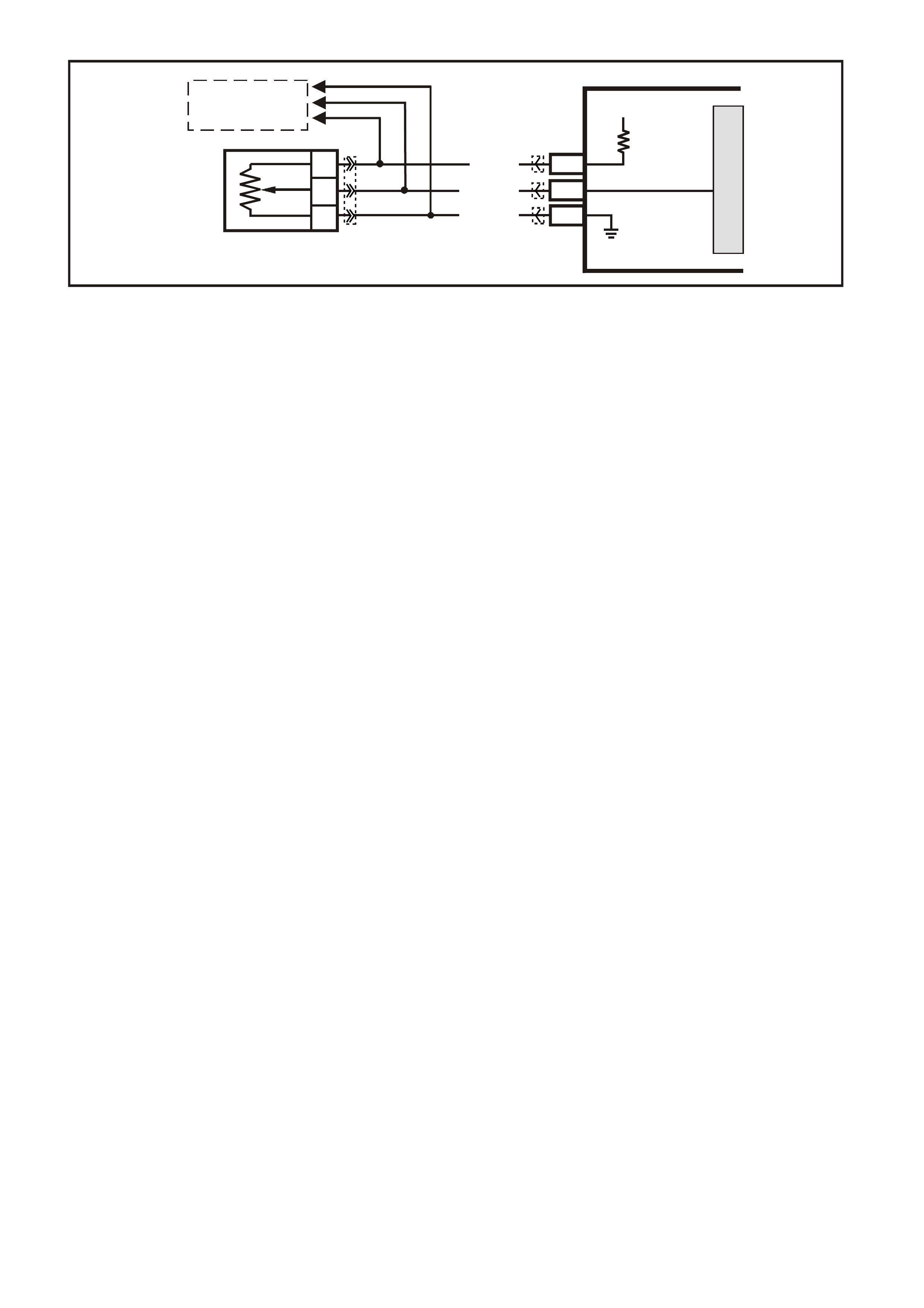
GEN III V8 PCM -
DTC P0123 THROTTLE POSITION SENSOR CIRCUIT HIGH VOLTAGE
CIRCUIT DESCRIPTION
The Throttle Position ( T P) Sens or is a potentiometer. The T P Sensor is mounted to the left s ide of the thr ottle body.
The TP Sensor provides a voltage signal that c hanges relative to throttle blade angle. T his signal voltage is one of
the most important inputs used by the PCM. The TP Sensor has a 5.0 volt reference, an earth and a signal circuit.
TP Sensor Signal voltage should be about 0.6 volt at idle. The TP Sensor voltage should increase to above 4.0
volts at wide open throttle (WOT).
When the PCM senses a signal voltage higher than the normal operating range of the sensor, this DTC will set.
CONDITIONS FOR RUNNING THE DTC
• The ignition switch is ON or in the engine is running.
CONDITIONS OF SETTING THE DTC
• The TP sensor signal voltage is greater than 4.8 volts.
• Conditions present for at least ten seconds.
ACTION TAKEN WHEN THE DTC SETS
• The PCM illuminates the Check Powertrain Lamp when the diagnostic runs and fails.
• The PCM records the operating conditions at the time the diagnostic fails. The PCM stores this information in
the Freeze Frame/Failure Records.
• The PCM uses a default TP sensor value.
• The transmission TCC will not apply.
• High transmission line pressure.
• Fixed transmission shift points, hard shifts and no fourth gear in hot mode.
CONDITIONS FOR CLEARING THE CPL/DTC
• The PCM turns the Check Powertrain Lamp OFF when the diagnostic runs and does not fail.
• A last test failed (current DTC) clears when the diagnostic runs and does not fail.
• Use a Tech 2 scan tool in order to clear the CPL/DTC.
DIAGNOSTIC AIDS
• The following may cause an intermittent:
- Incorrectly routed harness
- Rubbed through wire insulation
- Broken wire inside the insulation
• The PCM 5.0 volt reference circuits are internally connected within the PCM. If all the TP Sensor circuits are
OK, inspect the Fuel Tank Pressure Sensor for malfunctions.
• If it is determined that the DTC occurs intermittently, performing the DTC P1121 diagnostic table may isolate
the cause of the fault.
• For intermittent, refer to Section 6C3-2B Symptoms of the VX Series Service Information.
G3PCM005PT
SENSOR EARTH
TP SENSOR SIGNAL
TP SEN SOR
REFERENCE
VOLTAGE
PCM
5V
M
I
C
R
O
J1-08
J2-24
J1-60
A
C
B
THROTTLE
POSITION SENSOR
GY (416)
YE122
YE122YE30
YE123
BLU (417)
B/Y (452)
TO
THROTTLE RELAXER
MODULE
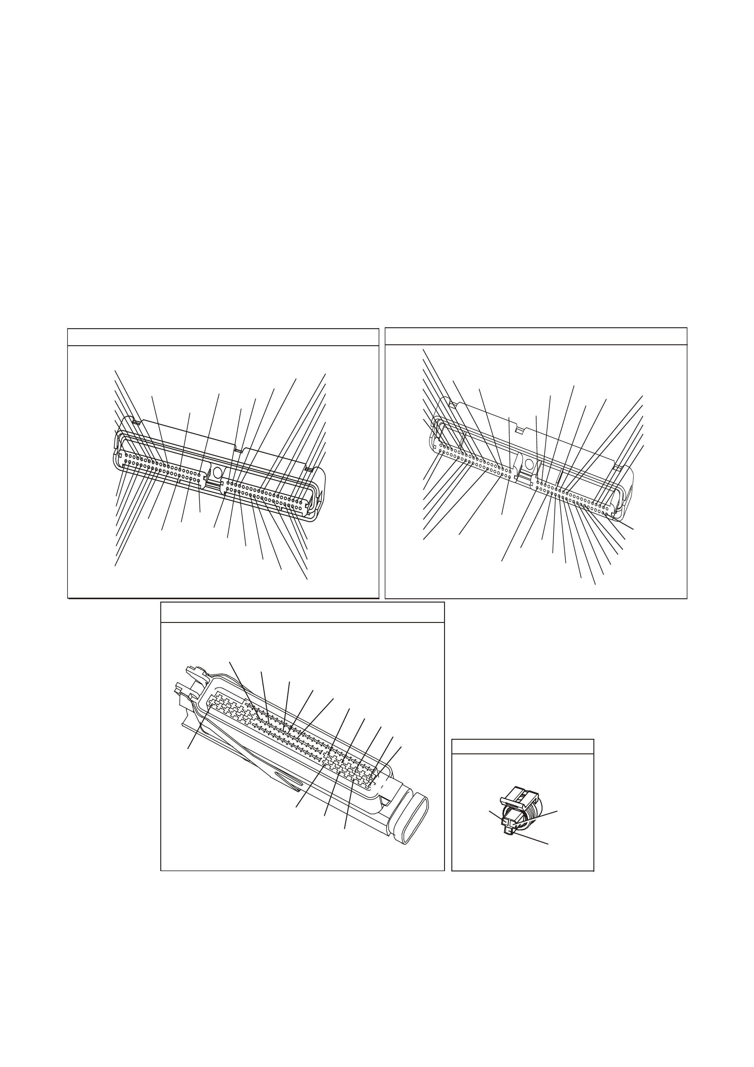
TEST DESCRIPTION
The numbers below refer to the step numbers on the diagnostic table.
2. If DTC P1635 sets at the same tim e, this indic ates that the 5.0 volt refer ence circuit is either shorted to a earth
or shorted to a voltage. The 5.0 volt reference circuit is internally connected within the PCM.
3. This step verifies that a malfunction is present.
4. Using Freeze Frame/Failure Records data may aid in locating an intermittent condition. If you cannot duplicate
the DTC, the information included in the Freeze Frame/Failure Records data can help determine the distance
traveled since the DTC set.
The Fail Counter and Pass Counter can also help determine how many ignition cycles the diagnostic reported
a pass and/or a fail. Operate vehicle within the same freeze frame conditions (RPM, load, vehicle speed,
temper ature etc.) that you observed. This will isolate when the DT C failed. For an intermittent condition, refer to
Section 6C3-2B Symptoms of the VX Series Service Information.
5. Vehicle equipped with Electronic Traction Control will have to disconnect the ABS/ETC Control Module. This
will determine if the short is caused from the ABS/ETC Control Module. After repairs are made, reconnect the
ABS/ETC Control Module and clear the DTCs that set when the ABS/ETC Control Module was disconnected.
7. This check s whether the earth circ uit is available to the T P Sensor. Chec k for poor electric al connections at the
TP Sensor.
P.C.M CONNECTOR 1
Y E122
(776)
(1049)
(897)
(1230)
(848)
(1226)
(772)
(647)
(632)
40
(844)
(815)
80
J1
P/B
(845)
V/W
BLU
O
(633)
(846)
B/Y
B/R
(416)
(86)
(69)
(455)
(740)
GY
BR
G
GY
(646)
(410)
GY
(842)
(1225)
V
Y
(750)
P
41
O
(774)
BR/Y
BLU
Y
B/R
B
BLU/Y
(841)
BLUE
(414)
G/W
BLU
LG
LBLU/B
1
(847)
(415)
(740)
(452)
BLU
BR Y
(750)
(826)
(421)
Y
V/W
B/W
(334)
(771)
(39)
Y
R/W
LBLU
W
BLU/W
(843)
(643)
LBLU/W
G
GY/B
BLU/B
(413)
(1413)
(1412)
(412)
GY
V
GY/B
G
(335)
YE123
P.C.M CO NNECTOR 2
(750)
(1228)
(1229)
(465)
(121)
(259)
G/B
BR
G/W
GY/BLU
R
B/R
(418)
BR
(59)
(832)
G
T
(831)
(417)
(472)
(976) (974)
(432)
(428)
(631)
BLU BR G/Y
BLU/W
LG
BR/W
W/B
LG W
(977)
Y
(971)
BLU/W W
B/R
(750)
(304)
(792)
(1223)
(1222)
(123)
(1227)
(469)
(331)
Y/B
LG
V/W
B/Y
G/O BR/W
(1687)
GY/B
(366)
LG/B
GY/R
(422)
V
(442)
(444)
(443)
(975)
(972)
(978)
(1224)
(973)
(959)
LG/W
LG/B
LBLU/B
GY
(773)
BR/Y
BLU
G
Y/B
LBLU
(958)
BR
(441)
LBLU
1
41
40
80
J2
RED
Y
(838)
AUTOM ATIC THRO TTLE CONTROL R ELAXER MODULE
YB 170
O/W
BLU/W
(1427)
(417)
GY
BLU
(416)
(1426)
R/Y
(452)
R/W
(456)
(466)
B/R
R/B
(750)
(490)
B/Y
(855)
R
(456)
R/W
(466)
B/R
(490)
R/B
(750)
R/Y
29
1
28
55
THROTTLE POSITION SENS OR
YE 30
(452) (416)
(417)
GY
B/Y
BLU

GEN III V8 PCM - DTC P0123 THROTTLE POSITION SENSOR CIRCUIT HIGH VOLTAGE
Step Action Value(s) Yes No
1 Did you perform the Powertrain On-Board Diagnostic
(OBD) System Check? Go to Step 2 Go to Powertrain
OBD System
Check Table
2
1. Install a Tech 2 scan tool.
2. Idle the engine.
3. Monitor the Failed This Ignition option under the DTC
Information option using the Tech 2 scan tool.
Did the DTC P1635 fail this ignition?
Go to DTC
P1635
5 Volt Reference
Circuit Table
Go to Step 3
3 1. Turn ON the ignition leaving the engine OFF.
2. With the throttle closed, observe the TP Sensor
voltage and percentage display on the Tech 2 scan
tool.
Is the TP Sensor voltage or the Throttle Angle above the
specified value?
4.7V, 0% Go to Step 5 Go to Step 4
4 1. Turn ON the ignition leaving the engine OFF.
2. Review the Freeze Frame/Failure Records data for
this DTC and record the parameters.
3. Turn OFF the ignition for 15 seconds.
4. Start the engine.
5. Operate the vehicle, within the conditions required for
this diagnostic to run, and as close to the conditions
recorded in Freeze Frame/Failure Records as
possible. Special operating conditions that you need
meet before the PCM will run this diagnostic, where
applicable, are listed in Conditions for Running the
DTC.
6. Select the Diagnostic Trouble Code (DTC) option, the
DTC Information option and The Failed This Ignition
option using the Tech 2 scan tool.
Does the Tech 2 scan tool indicate that this diagnostic
failed this ignition?
Go to Step 5 Go to
Diagnostic Aids
5 1. Turn OFF the ignition.
2. Disconnect the Traction Control Module.
3. Turn ON the ignition
Is the TP Sensor voltage above the specified value?
4.7V Go to Step 6 Go to Section
12L in VX
Service
Information for
further diagnosis
of the ABS/ETC
Control Module
6 1. Disconnect the TP Sensor electrical connector.
2. Observe the TP Sensor voltage display on the scan
tool.
Is the TP Sensor voltage below the specified value?
0.20V Go to Step 7 Go to Step 10
7 Probe the sensor earth circuit at the TP Sensor harness
connector with a test lamp, J 34142-B, connected to B+.
Does the test lamp illuminate?
Go to Step 8 Go to Step 11
8 Measure the voltage at the 5.0 volt reference circuit to
earth using the DMM J39200.
Is the voltage greater than the specified value?
5.0V Go to Step 14 Go to Step 9

GEN III V8 PCM - DTC P0123 THROTTLE POSITION SENSOR CIRCUIT HIGH VOLTAGE (CONTINUED)
Step Action Value(s) Yes No
9 Replace the TP Sensor. Refer to Section 6C3-3 TP
Sensor Replacement of the VX Series Service
Information.
Is the action complete?
Go to Step 15
10 1. Turn OFF the ignition.
2. Disconnect the PCM connectors.
3. Check for a short to voltage on the TP sensor signal
circuit; also check for a short circuit between the TP
sensor signal circuit and the ABS/ETC Control
Module.
4. If you find the TP Sensor signal circuit shorted, repair
the circuit as necessary.
Did you find and correct the condition?
Go to Step 15 Go to Step 13
11 1. Check for an open TP Sensor earth circuit.
2. If you find TP Sensor earth circuit open, repair the
circuit as necessary.
Did you find and correct the condition?
Go to Step 15 Go to Step 12
12 1. Turn OFF the ignition.
2. Disconnect the PCM connectors.
3. Check the TP Sensor earth circuit for a good
connection at the PCM.
4. If you find a poor connection at the TP Sensor earth
circuit, repair the circuit as necessary.
Did you find and correct the condition?
Go to Step 15 Go to Step 13
13 1. Replace PCM.
2. Refer to Section 6C3-3 of the VX Series Service
Information for PCM Programming and
PCM/PIM/BCM Security Link Procedure.
Is action complete?
Go to Step 15
14 Repair the 5 volt reference circuit for a short to voltage.
Refer to Section 12P Electrical Diagnosis/Repair
Procedures in VX Service Information.
Is the action complete?
Go to Step 15
15 1. Select the Diagnostic Trouble Code (DTC) option and
the Clear DTC Information option using the Tech 2
scan tool.
2. Idle the engine at the normal operating temperature.
3. Select the Diagnostic Trouble Code (DTC) option, the
DTC Information option and The Failed This Ignition
option using the Tech 2 scan tool.
4. Operate the vehicle within the Conditions for Running
the DTC as specified in the supporting text, if
applicable.
Does the Tech 2 scan tool indicate that this DTC reset?
Go to Step 2 Go to Step 16
16 Using the Tech 2 scan tool, check for any other DTCs.
Does the Tech 2 scan tool display any DTCs that you
have not diagnosed?
Go to the
applicable DTC
table
System OK

GEN III V8 ENGINE
DTC P0125 ENGINE COOLANT TEMPERATURE (ECT) SENSOR EXCESS TIME TO
CLOSED LOOP FUEL CONTROL
CIRCUIT DESCRIPTION
The PCM monitors the ECT Sensor in order to determine how long it takes the engine to reach the coolant
temper ature required f or Closed Loop operations. DT C P0125 sets if the PCM determines that the engine does not
reach Closed Loop tem peratur e in a specified am ount of tim e. T his test will not run if either the intake air or engine
coolant temperature is too low at start-up. The PCM will only run this DTC on a cold start and only per cold start.
CONDITIONS FOR RUNNING THE DTC
• DTCs P0112, P0113, O0117, P0118 are not set.
• The engine is operating.
• The engine coolant temperature is between -36°C and 40°C at engine start-up.
• The intake air temperature is greater than -7°C.
• The vehicle speed is greater than 1.6 km/h.
CONDITIONS FOR SETTING THE DTC
• The closed loop coolant temperature of 34°C is not reached within a predetermined time. The maximum
allowable time depends on the start-up coolant temperature and the amount of airflow into the engine. The
range for the time is from 2 minutes and 20 seconds to 22 minutes and 30 seconds.
ACTION TAKEN WHEN THE DTC SETS
• The PCM stores the DTC information into memory when the diagnostic runs and fails.
• The Check Powertrain Lamp will not be illuminated.
• The PCM records the operating conditions at the time the diagnostic fails. The PCM stores this information in
the Freeze Frame/Failure Records.
CONDITIONS FOR CLEARING THE CPL/DTC
• The Check Powertrain Lamp (CPL) will not be illuminated.
• A last test failed (current DTC) clears when the diagnostic runs and does not fail.
• Use a Tech 2 tool in order to clear the DTC.
G3PCM004PT
J1-80
J1-74
B
A
ENGINE COOLANT
TEMPERATURE SENSOR
SENSOR EARTH
ETC SENSOR SIGNAL
5V
4k
348
Ω
Ω
Y (41 0)
GY/B (455)
YE65 YE122
M
I
C
R
O
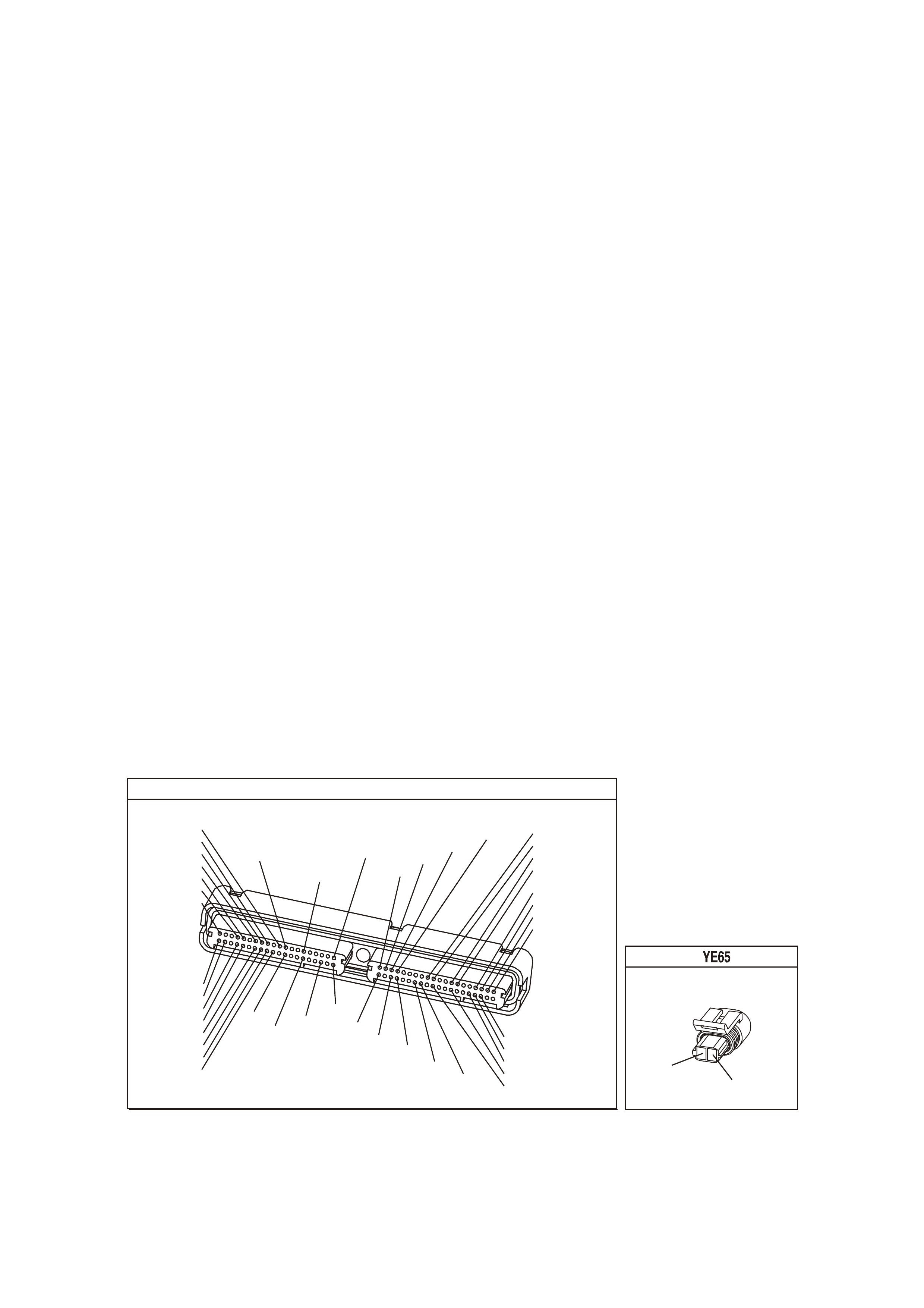
DIAGNOSTIC AIDS
Using the Freeze Frame/Failure Records data may aid in locating an interm ittent condition. If you cannot duplicate
the DTC, the information included in the Freeze Frame/Failure Records data can help determine the distance
traveled since the DT C set. The Fail Counter and Pass Counter can also help determine how m any ignition cycles
the diagnostic reported a pass and/or fail. Operate the vehicle within the same freeze fram e condition (RPM, load,
vehicle speed, temperature etc.) that you observed. This will isolate when the DTC failed. For an intermittent
condition, refer to Section 6C3-2B Symptoms of the VX Series Service Information.
• If the engine has sat overnight, the engine coolant temperature and intake air temperature values should
display within a few degrees of each other. If the temperatures are not within 3°C (5°F), refer to
Section 6C3-4 Temperature vs. Resistance of the VX Series Service Information.
• If you determine that the DTC occurs intermittently, performing the P1114 or P1115 diagnostic table may
isolate the cause of the fault.
• An engine coolant temperature exceeding 34°C (93°F) indicates that the engine is capable of reaching the
proper temperature, but not necessarily in the correct amount of time.
Repeat this diagnostic table on a cold engine, and measure the time required to reach the temperature
threshold. W hen starting a cold engine, measure the am ount of time it takes the engine to reach the specified
temperature. The engine to reach the specified temperature. The engine should reach the specified
temperature within 5 minutes or less. If the engine does not reach the specified temperature within 5 minutes,
check the following:
- Coolant level
- Thermostat operation
- Are fans on at all times?
Refer to Section 6B3 Engine Cooling in VX Service Information for additional information.
TEST DESCRIPTION
The numbers below refer to the step numbers on the diagnostic table.
2. An ECT failure could cause a DTC P0125 to set, so correct any ECT DTCs that are set. For any test that
requires probing the PCM or a component harness connector, use the Connector Test adapter Kit
J 35616-A. Using this kit prevents damage to the harness connector terminals.
6. If it is obvious that the engine is not reaching full operating temperature, for example the radiator hoses never
get very warm, or there is a compliant of little or no heat from the radiator, you can skip this step.
9. This DTC will not report a pass. The scan tool status for this DTC will never report a pass. The scan tool will
only display when the diagnostic fails. The repair is not complete if the scan tool indicates that the diagnostic
ran and failed.
P.C.M CO NNECTO R 1
YE1 22
(776)
(1049)
(897)
(1230)
(848)
(1226)
(772)
(647)
(632)
40
(844)
(815)
80
J1
P/B
(845)
V/W
BLU
O
(633)
(846)
B/Y
B/R
(416)
(86)
(69)
(455)
(740)
GY
BR
G
GY
(646)
(410)
GY
(842)
(1225)
V
Y
(750)
P
41
O
(774)
BR/Y
BLU
Y
B/R
B
BLU/Y
(841)
BLUE
(414)
G/W
BLU
LG
LBLU/B
1
(847)
(415)
(740)
(452)
BLU
BR Y
(750)
(826)
(421)
Y
V/W
B/W
(334)
(771)
(39)
Y
R/W
LBLU
W
BLU/W
(843)
(643)
LBLU/W
G
GY/B
BLU/B
(413)
(1413)
(1412)
(412)
GY
V
GY/B
G
(335)
COOLANT TEM P SENSOR
Y
(410)
GY/B
(455)

GEN III V8 ENGINE - DTC P0125 ENGINE COOLANT TEMPERATURE (ECT) SENSOR EXCESS TIME TO
CLOSED LOOP FUEL CONTROL
Step Action Value(s) Yes No
1 Did you perform the Powertrain On-Board Diagnostic
(OBD) System Check? Go to Step 2 Go to Powertrain
OBD System
Check Table
2 Are any Engine Coolant Temperature DTCs set? Go to applicable
DTC table Go to Step 3
3 1. Install a scan tool.
2. Turn ON the ignition leaving the engine OFF.
3. Disconnect the ECT Sensor.
Does the scan tool indicate the ECT sensor is at or below
the specified value?
-35°C
(-31°F) Go to Step 4 Go to DTC
P0117 ECT
Sensor Circuit
Low Voltage
Table
4 Jumper the terminals of the ECT Sensor harness
connector together using a jumper wire.
Does the scan tool indicate the ECT is at or above the
specified value?
139°C
(282°F) Go to Step 5 Go to DTC
P0118 ECT
Sensor Circuit
High Voltage
Table
5 1. Reconnect the ECT Sensor.
2. Idle the engine.
3. Observe the ECT Sensor display on the Engine Data
List of the scan tool.
IMPORTANT: Allow the engine to warm-up if it has not
already reached the specified temperature. 5 minutes is
the maximum amount of time it should take to reach this
temperature from a cold start. Less time is required if the
engine is already warm.
Does the scan tool indicate the engine coolant
temperature reaches the specified value?
34°C (93°F) The cooling
system must be
rechecked on a
cold start.
Refer to
Diagnostic Aids
Go to Step 6
6 Measure the resistance of the ECT Sensor using a DMM
J 39200. Refer to Temperature vs. Resistance Table in
Section 6C3-4 of the VX Series Service Information.
Is the ECT resistance close to the value indicated in the
Temperature Vs Resistance Table?
Go to Step 7 Go to Step 8
7 Check the following for an engine cooling system
problem:
• Thermostat operation
• Coolant level
• Coolant to water ratio
• Cooling fan operation etc.
Refer to Section 6B3 Engine Cooling in VX Service
Information.
Is the action complete?
Go to Step 9
8 Replace the ECT Sensor. Refer to Section 6C3-3 ECT
Sensor Replacement of the VX Series Service
Information.
Is the action complete?
Go to Step 9
9 1. Select the Diagnostic Trouble Code (DTC) option and
the Clear DTC Information option using the scan tool.
2. Idle the engine at the normal operating temperature.
3. Select the Diagnostic Trouble Code (DTC) option, the
DTC Information, The Failed This Ignition using the
Tech 2 scan tool.
4. Operate vehicle within the Conditions for Running the
DTC as specified in the supporting text, if applicable.
Does the scan tool indicate that this DTC reset?
Go to Step 2 Go to Step 10
10 Using the Tech 2 scan tool, check for any other DTCs.
Does the scan tool display any DTCs that you have not
diagnosed?
Go to the
applicable DTC
table
System OK
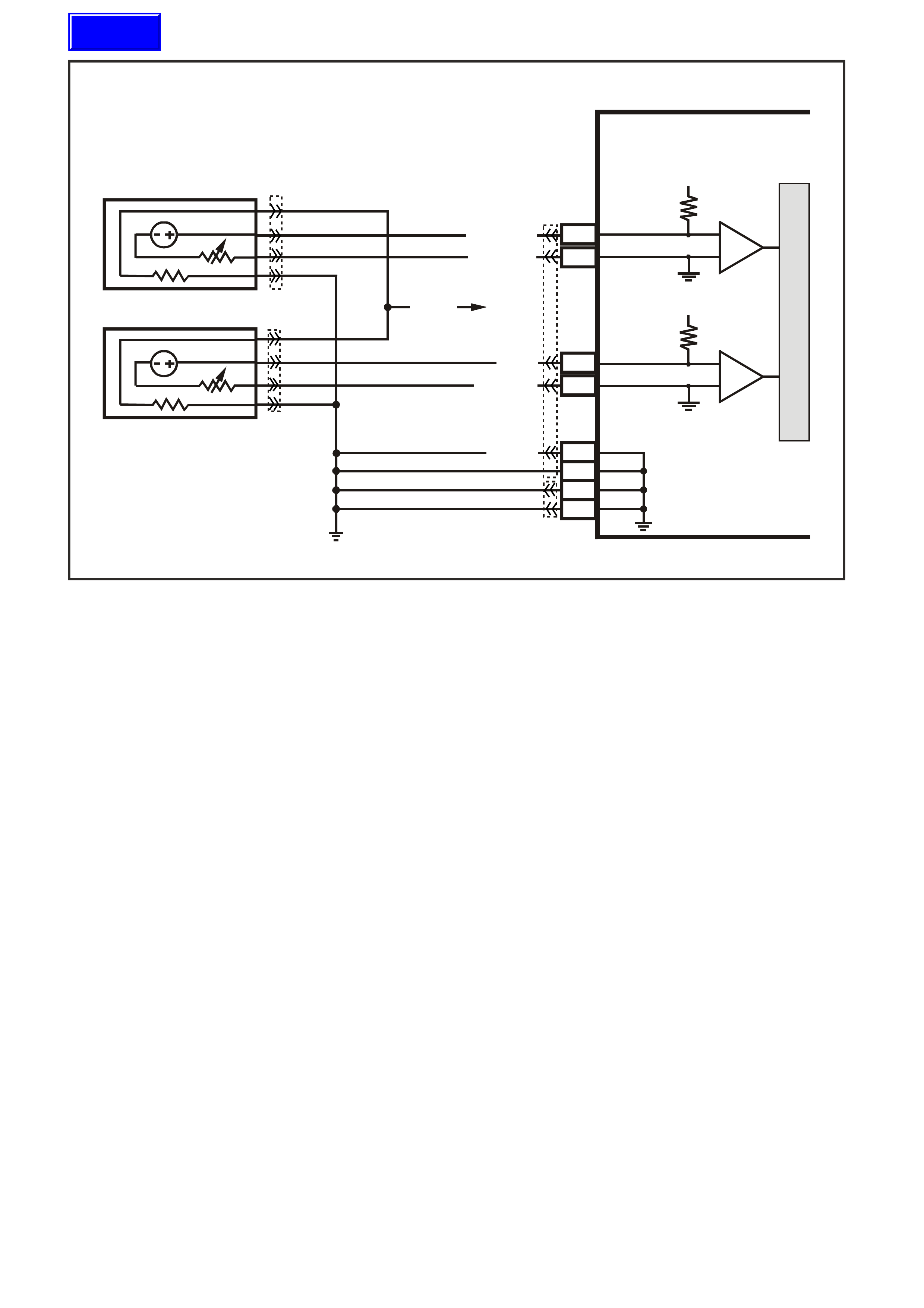
GEN III V8 PCM -
DTC P0131 HEATED OXYGEN SENSOR (HO2S) CIRCUIT LOW VOLTAGE
BANK 1 S ENSOR 1
CIRCUIT DESCRIPTION
The PCM supplies a voltage of about 450 m V between the HO2S high and low signal circuits. The oxygen sensor
varies the voltage over a r ange f r om about 1000 m V when the exhaus t is r ich, down through about 10 mV when the
exhaust is lean.
The PCM monitors and stores the Heated Oxygen Sensor (HO2S) voltage information. The PCM evaluates the
HO2S voltage samples in order to determine the amount of time the HO2S voltage was out of range. The PCM
compares the stored HO2S voltage samples, taken within each sample period, and determines if majority of the
samples are out of the operating range.
The PCM monitors the HO 2S voltage f or being fixed below a predeter mined voltage. If the PCM detec ts the voltage
is below a predetermined voltage, a DTC will set.
CONDITIONS FOR RUNNING THE DTC
Criteria 1
• DTCs P0101, P0102, P0103, P0112, P0113, P0117, P0118, P0121, P0122, P0123, P0335, P0336, P0351-
P0358, P1258 are not set.
• The engine coolant temperature is greater than 48°C.
• The ignition voltage is greater than 9.0 volts.
• The fuel system is operating in Closed Loop.
• The fuel trim learn is enabled.
• The air/fuel ratio is between 14.5:1 and 14.7:1.
• The TP angle is between 0% and 70%.
Criteria 2
• DTCs P0101, P0102, P0103, P0112, P0113, P0117, P0118, P0121, P0122, P0123, P0335, P0336, P0351-
P0358, P1258 are not set.
• The ignition voltage is greater than 9.0 volts.
• The Power Enrichment mode is enabled for at least 0.5 seconds.
D
D
B
B
A
A
C
C
GY/B (1413)
GY (1412)
RIGHT OXYGEN SENSOR
BANK TWO SENSOR ONE
LEFT OXYGEN SENSOR
BANK ONE SENSOR O NE
LOC. E5/E15
BLU/B (413)
V (412)
P (439)
TO F USE
F33
G3PCM003PT
J1-26
J1-66
J1-01
J1-40
J2-01
J2-40
J1-69
J1-29
PCM
RIGHT
OXYGEN
SENSOR
SIGNAL LO
LEFT
OXYGEN
SENSOR
SIGNAL LO
RIGHT
OXYGEN
SENSOR
SIGNAL HI
EARTH
EARTH
EARTH
EARTH
LEFT
OXYGEN
SENSOR
SIGNAL HI
IC
IC
45 0 mV
45 0 mV
M
I
C
R
O
B/R (750)
YE95
YE95
YE122
YE123
Techline

CONDITIONS FOR SETTING THE DTC
Criteria 1
• The HO2S signal voltage remains below 200 mV.
• The Criteria 1conditions are present for at least 33 seconds.
Criteria 2
• The HO2S signal voltage remains below 360 mV.
• The Criteria2 conditions are present for at least five seconds.
ACTION TAKEN WHEN THE DTC SETS
• The PCM illuminates the Check Powertrain Lamp when the diagnostic runs and fails.
• The PCM records the operating conditions at the time the diagnostic fails. The PCM stores this information in
the Freeze Frame/Failure Records.
• Open Loop Fueling.
CONDITIONS FOR CLEARING THE CPL/DTC
• The PCM turns the Check Powertr ain Lamp OF F after one ignition cycle that the diagnostic runs and does not
fail.
• A last test failed (current DTC) clears when the diagnostic runs and does not fail.
• Use a Tech 2 scan tool in order to clear the CPL/DTC.
DIAGNOSTIC AIDS
• The PCM sets this DTC when the vehicle runs out of fuel.
• Heated Ox ygen Sensor (HO2S) wire: Sensor pigtail m ay be in contact with the exhaust m anifold or the ex haust
system.
• An oxygen supply inside the HO2S is necessary for proper operation. The HO2S wires provides the supply of
oxygen. Inspect the HO2S wires and connections for breaks or contamination.
• Check for intermittent earth in signal wire between connector and sensor.
• Lean injector(s): Perform the Injector Balance Test.
• Fuel contam ination: W ater near the in-tank fuel pump inlet c an be delivered to the injectors. T he water causes
a lean exhaust and can set a DTC.
• Fuel pressure: System will be lean if fuel pressure is low. Refer to Fuel System Diagnosis Table of the VX
Series Service Information.
• Exhaust leaks: An exhaust leak near the HO2S can cause a lean condition.
• Vacuum or crankcase leaks can cause a lean condition.
• If the above are OK, the HO2S may be at fault.
• For an intermittent condition, refer to Section 6C3-2B Symptoms of the VX Series Service Information.
TEST DESCRIPTION
The numbers below refer to the step numbers on the diagnostic table.
2. If the HO2S voltage is fixed well below 200 mV this indicates a short to battery earth or chassis earth. If the
voltage is fixed near or above 200 mV, this indicates a short to a PCM earth. When the HO2S voltage is fix
near 200 m V, indica tes the DTC set when the fuel s ystem was in a Power Enr ichment mode of oper ations. This
DTC sets if the HO2S voltage is less than 360 mV during a Power Enrichment mode of operation.
3. Using the Freeze Frame/Failure Records data may aid in locating an intermittent condition. If you cannot
duplicate the DTC, the information included in the Freeze Frame/Failure Records data can help determ ine the
distance traveled since the DTC set. The Fail Counter and Pass Counter can also help determine how many
ignition cycles the diagnostic reported a pass and/or fail. Operate the vehicle within the same freeze frame
condition (RPM, load, vehicle speed, temperature etc.) that you observed. This will isolate when the DTC
failed.
4. Earthing the low side circuit of the HO2S should cause the HO2S voltage to display a bias voltage. A voltage
staying near 0.0 volts indicates the low circuit is open, or the high circuit is open or earthed.
5. Disconnecting the PCM allows using a DMM J 39200 in order to check continuity of the circuits. This aids in
locating an open or shorted circuit.
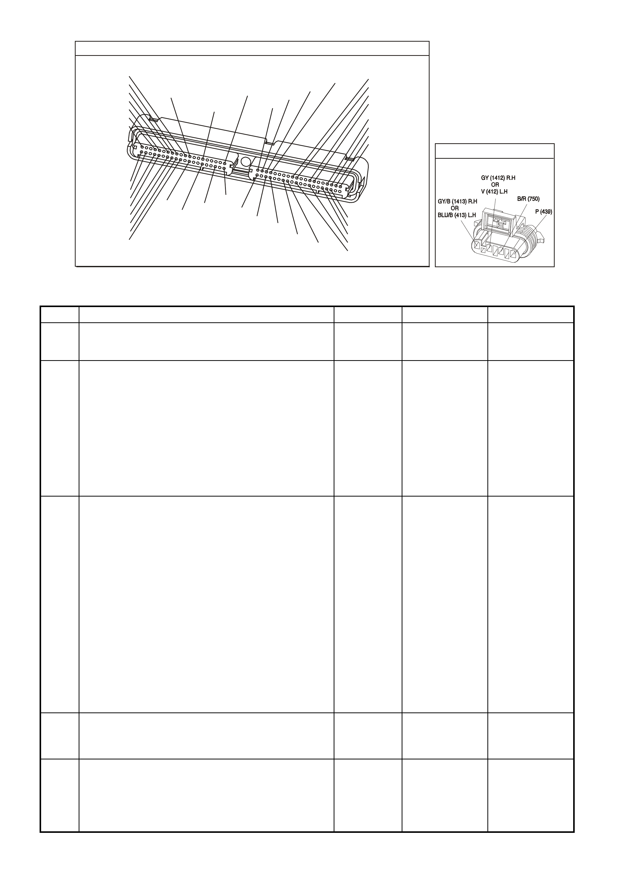
P.C.M CONNECTOR 1
YE122
(776)
(1049)
(897)
(1230)
(848)
(1226)
(772)
(647)
(632)
40
(844)
(815)
80
J1
P/B
(845)
V/W
BLU
O
(633)
(846)
B/Y
B/R
(416)
(86)
(69)
(455)
(740)
GY
BR
G
GY
(646)
(410)
GY
(842)
(1225)
V
Y
(750)
P
41
O
(774)
BR/Y
BLU
Y
B/R
B
BLU/Y
(841)
BLUE
(414)
G/W
BLU
LG
LBLU/B
1
(847)
(415)
(740)
(452)
BLU
BR
Y
(750)
(826)
(421)
Y
V/W
B/W
(334)
(771)
(39)
Y
R/W
LBLU
W
BLU/W
(843)
(643)
LBLU/W
G
GY/B
BLU/B
(413)
(1413)
(1412)
(412)
GY
V
GY/B
G
(335)
YE95
HEATED EXHAUST GAS SENSOR
GEN III V8 PCM - DTC P0131 HEATED OXYGEN SENSOR (HO2S) CIRCUIT LOW VOLTAGE BANK 1
SENSOR 1
Step Action Value(s) Yes No
1 Did you perform the Powertrain On-Board Diagnostic
(OBD) System Check? Go to Step 2 Go to Powertrain
OBD System
Check Table
2
IMPORTANT: Check the HO2S for being secure before
proceeding with this DTC. A sensor that is loose could
cause this DTC to set.
1. Install a Tech 2 scan tool.
2. Idle the engine at the normal operating temperature.
3. Operate the vehicle within parameters specified under
Conditions for Running the DTC in the supporting text.
4. Monitor the HO2S voltage display on the Engine Data
List using the Tech 2 scan tool.
Is the HO2S voltage less than the specified value?
200 mV Go to Step 4 Go to Step 3
3 1. Turn ON the ignition leaving the engine OFF.
2. Review the Freeze Frame/Failure Records data for
this DTC and observe the parameters.
3. Turn OFF the ignition for 15 seconds.
4. Idle the engine.
5. Operate the vehicle, within the conditions required for
this diagnostic to run, and as close to the conditions
recorded in the Freeze Frame/Failure Records as
possible. Special operating conditions that you need to
meet before the PCM will run this diagnostic, where
applicable, are listed in Conditions for Running the
DTC.
6. Select the Diagnostic Trouble Code (DTC), the DTC
Information option and The Failed This Ignition option
using the Tech 2 scan tool.
Does the Tech 2 scan tool indicate that this diagnostic
failed this ignition?
Go to Step 4 Go to Diagnostic
Aids
4 1. Disconnect the HO2S.
2. Jumper the HO2S low circuit (PCM side) to a earth.
Is the HO2S voltage within the specified range?
350-550 mV Go to Diagnostic
Aids Go to Step 5
5 1. Turn OFF the ignition.
2. Disconnect the PCM BLUE connector.
3. Check the HO2S signal circuit for a short to earth or a
short to the sensor earth circuit.
Is the HO2S signal circuit shorted?
Go to Step 6 Go to Step 7

GEN III V8 PCM - DTC P0131 HEATED OXYGEN SENSOR (HO2S) CIRCUIT LOW VOLTAGE BANK 1
SENSOR 1 (CONTINUED)
Step Action Value(s) Yes No
6 Repair the HO2S signal circuit.
Is the action complete? Go to Step 8
7 1. Replace PCM.
2. Refer to Section 6C3-3 of the VX Series Service
Information for PCM Programming and
PCM/PIM/BCM Security Link Procedure.
Is action complete?
Go to Step 8
8 1. Select the Diagnostic Trouble Code (DTC) option and
the Clear DTC Information option using the Tech 2
scan tool.
2. Idle the engine at the normal operating temperature.
3. Select the Diagnostic Trouble Code (DTC) option, the
DTC Information option and The Failed This Ignition
option using the Tech 2 scan tool.
4. Operate the vehicle within the Conditions for Running
the DTC as specified in the supporting text, if
applicable.
Does the Tech 2 scan tool indicate that this DTC reset?
Go to Step 2 Go to Step 9
9 Using the Tech 2 scan tool, check for any other DTCs.
Does the Tech 2 scan tool display any DTCs that you
have not diagnosed?
Go to the
applicable DTC
table
System OK

GEN III V8 PCM -
DTC P0132 HEATED OXYGEN SENSOR (HO2S) CIRCUIT HIGH VOLTAGE
BANK 1 S ENSOR 1
CIRCUIT DESCRIPTION
The PCM supplies a voltage of about 450 m V between the HO2S high and low signal circuits. The oxygen sensor
varies the voltage over a r ange f r om about 1000 m V when the exhaus t is r ich, down through about 10 mV when the
exhaust is lean.
The PCM monitors and stores the Heated Oxygen Sensor (HO2S) voltage information. The PCM evaluates the
HO2S voltage samples in order to determine the amount of time the HO2S voltage was out of range. The PCM
compares the stored HO2S voltage samples, taken within each sample period, and determines if majority of the
samples are out of the operating range.
The PCM monitors the HO2S voltage for being fixed above a predetermined voltage. If the PCM detects the
voltage is above the predetermined voltage, a DTC will set.
CONDITIONS FOR RUNNING THE DTC
Criteria 1
• DTCs P0101, P0102, P0103, P0112, P0113, P0117, P0118, P0121, P0122, P0123, P0335, P0336, P0351-
P0358, P1258 are not set.
• The ignition voltage is greater than 9.0 volts.
• The fuel system is operating in Closed Loop.
• The fuel trim learn is enabled.
• The air/fuel ratio is between 14.5:1 and 14.7:1.
Criteria 2
• DTCs P0101, P0102, P0103, P0112, P0113, P0117, P0118, P0121, P0122, P0123, P0335, P0336, P0351-
P0358, P1258 are not set.
• The ignition voltage is greater than 9.0 volts.
• Deceleration Fuel Cut-Off mode is enabled for greater than one second.
D
D
B
B
A
A
C
C
GY/B (1413)
GY (1412)
RIGHT OXYGEN SENSOR
BANK TWO SENSOR ONE
LEFT OXYGEN SENSOR
BANK ONE SENSOR O NE
LOC. E5/E15
BLU/B (413)
V (412)
P (439)
TO F USE
F33
G3PCM003PT
J1-26
J1-66
J1-01
J1-40
J2-01
J2-40
J1-69
J1-29
PCM
RIGHT
OXYGEN
SENSOR
SIGNAL LO
LEFT
OXYGEN
SENSOR
SIGNAL LO
RIGHT
OXYGEN
SENSOR
SIGNAL HI
EARTH
EARTH
EARTH
EARTH
LEFT
OXYGEN
SENSOR
SIGNAL HI
IC
IC
45 0 mV
45 0 mV
M
I
C
R
O
B/R (750)
YE95
YE95
YE122
YE123
Techline

CONDITIONS FOR SETTING THE DTC
Criteria 1
• The HO2S signal voltage remains below 775 mV.
• The Criteria 1conditions are present for at least 33 seconds.
Criteria 2
• The HO2S signal voltage remains below 540 mV.
• The Criteria2 conditions are present for at least five seconds.
ACTION TAKEN WHEN THE DTC SETS
• The PCM illuminates the Check Powertrain Lamp when the diagnostic runs and fails.
• The PCM records the operating conditions at the time the diagnostic fails. The PCM stores this information in
the Freeze Frame/Failure Records.
• Open Loop Fueling.
CONDITIONS FOR CLEARING THE CPL/DTC
• The PCM turns the Check Powertr ain Lamp OF F after one ignition cycle that the diagnostic runs and does not
fail.
• A last test failed (current DTC) clears when the diagnostic runs and does not fail.
• Use a Tech 2 scan tool in order to clear the CPL/DTC.
DIAGNOSTIC AIDS
• Check the HO2S electrical connections for evidence of water intrusion. Water present in the connector will
cause the B+ supply to the heater to bleed over to the signal circuit.
• Fuel pressure: The system goes rich if the pressure is too high. The PCM compensates for some increase.
However, if the fuel pressure is too high, a DTC may set. Refer to Fuel System Diagnosis Table of the VX
Series Service Information.
• Rich injector(s): Perform the Injector Balance Test.
• Leaking injector: Refer to the Fuel System Diagnosis Table of the VX Series Service Information.
• Evaporative emis sions (EVAP) c anis ter pur ge. Chec k for f uel s aturation. If full of fuel, chec k the c anis ter contr ol
and hoses. Refer to Section 6C3-1 EVAP Control System Description of the VX Series Service Information.
• MAF sensor: Disconnect the MAF sensor and see if the rich condition is correct. If so, check for proper
installation. If installation is OK, replac e the MAF sens or. If the MAF sensor is installed back war ds, the sys tem
goes rich. The plastic portion of the sensor has arrows cast into it indicating proper air flow direction. The
arrows must point towards the engine.
• An oxygen supply inside the HO2S is necessary for proper operation. The HO2S wires provides the supply of
oxygen. Inspect the HO2S wires and connections for breaks or contamination.
• TP sensor: An intermittent TP sensor output causes the system to go rich, due to a false indication of the
engine accelerating. For an intermittent condition, refer to Section 6C3-2B Symptoms of the VX Series
Service Information.
TEST DESCRIPTION
The numbers below refer to the step numbers on the diagnostic table.
2. This DTC also sets during a deceleration fuel cut-off . Inspect items which could cause a rich exhaust during a
deceleration (leaking injectors, stuck injectors, etc.). Refer to Conditions for Setting the DTC above.
T he engine must be at the norm al operating tem perature before perf orming this tes t. For any test that requires
probing the PCM or a com ponent har ness c onnector, us e the Connector T est adapter Kit J 35616-A. Using this
kit prevents damage to the harness connector terminals.
3. Using the Freeze Frame/Failure Records data may aid in locating an intermittent condition. If you can not
duplicate the DTC, the information included in the Freeze Fram e/Failure Records data can help determine the
distance traveled s ince the DT C set. T he Fail Counter and Pas s Counter c an also aid in determ ining how many
ignition cycles the diagnostic reported a pass and/or a fail. Operate the vehicle within the same freeze frame
conditions (RPM, load, vehicle speed, tem perature etc .) that the PCM recorded. T his will isolate when the DTC
failed. Refer to Section 6C3-2B Symptoms of the VX Series Service Information.
5. Earthing the low side circuit of the HO2S should cause the HO2S voltage to display a bias voltage.
9. Review the system mechanization. Check for a short between the HO2S signal circuit and any other wires
powered by this fuse that runs together inside the same harness.

P.C.M CONNECTOR 1
YE122
(776)
(1049)
(897)
(1230)
(848)
(1226)
(772)
(647)
(632)
40
(844)
(815)
80
J1
P/B
(845)
V/W
BLU
O
(633)
(846)
B/Y
B/R
(416)
(86)
(69)
(455)
(740)
GY
BR
G
GY
(646)
(410)
GY
(842)
(1225)
V
Y
(750)
P
41
O
(774)
BR/Y
BLU
Y
B/R
B
BLU/Y
(841)
BLUE
(414)
G/W
BLU
LG
LBLU/B
1
(847)
(415)
(740)
(452)
BLU
BR
Y
(750)
(826)
(421)
Y
V/W
B/W
(334)
(771)
(39)
Y
R/W
LBLU
W
BLU/W
(843)
(643)
LBLU/W
G
GY/B
BLU/B
(413)
(1413)
(1412)
(412)
GY
V
GY/B
G
(335)
YE95
HEATED EXHAUST GAS SENSOR
GEN III V8 PCM - DTC P0132 HEATED OXYGEN SENSOR (HO2S) CIRCUIT HIGH VOLTAGE BANK 1
SENSOR 1
Step Action Value(s) Yes No
1 Did you perform the Powertrain On-Board Diagnostic
(OBD) System Check? Go to Step 2 Go to Powertrain
OBD System
Check Table
2
1. Install a Tech 2 scan tool.
2. Idle the engine at the normal operating temperature.
3. Operate the vehicle within parameters specified under
Conditions for Running the DTC in the supporting text.
4. Monitor the HO2S voltage display on the Engine Data
List using the Tech 2 scan tool.
Is the HO2S voltage greater than the specified value?
775 mV Go to Step 4 Go to Step 3
3 1. Turn ON the ignition leaving the engine OFF.
2. Review the Freeze Frame/Failure Records data for
this DTC and observe the parameters.
3. Turn OFF the ignition for 15 seconds.
4. Idle the engine.
5. Operate the vehicle, within the conditions required for
this diagnostic to run, and as close to the conditions
recorded in the Freeze Frame/Failure Records as
possible. Special operating conditions that you need to
meet before the PCM will run this diagnostic, where
applicable, are listed in Conditions for Running the
DTC.
6. Select the Diagnostic Trouble Code (DTC), the DTC
Information option and The Failed This Ignition option
using the Tech 2 scan tool.
Does the Tech 2 scan tool indicate that this diagnostic
failed this ignition?
Go to Step 4 Go to
Diagnostic Aids
4 1. Turn ON the ignition leaving the engine OFF.
2. Remove the HO2S heater fuse while monitoring the
HO2S voltage using a Tech 2 scan tool.
Does the voltage drop to within the specified range when
the power to the heater is disconnected?
350-550 mV Go to Step 5 Go to Step 7
5 1. Reinstall the fuse.
2. Disconnect the HO2S.
3. Jumper the HO2S low signal (PCM side) circuit to a
earth.
Does the Tech 2 scan tool indicate the HO2S voltage
within the specified value?
350-550 mV Go to Step 10 Go to Step 6

GEN III V8 PCM - DTC P0132 HEATED OXYGEN SENSOR (HO2S) CIRCUIT HIGH VOLTAGE BANK 1
SENSOR 1 (CONTINUED)
Step Action Value(s) Yes No
6 1. Turn ON the ignition leaving the engine OFF.
2. Remove the HO2S heater fuse while monitoring the
HO2S voltage using a Tech 2 scan tool.
Does the voltage drop to within the specified range when
the power to the heater is disconnected?
350-550 mV Go to Step 9 Go to Step 8
7 1. Turn OFF the ignition.
2. Disconnect the PCM BLUE connector.
3. Disconnect the HO2S.
4. Turn ON the ignition.
5. Check for a voltage on the HO2S sensor signal circuit
at the PCM harness connector using the DMM
J 39200.
Is a voltage present?
Go to Step 8 Go to
Diagnostic Aids
8 Repair the short to voltage in the HO2S signal circuit.
Is the action complete? Go to Step 12
9 Repair the short between the HO2S signal circuit and the
HO2S heater B+ circuit.
Is the action complete?
Go to Step 12
10 Replace the HO2S.
Is the action complete? Go to Step 12
11 1. Replace PCM.
2. Refer to Section 6C3-3 of the VX Series Service
Information for PCM Programming and
PCM/PIM/BCM Security Link Procedure.
Is action complete?
Go to Step 12
12 1. Select the Diagnostic Trouble Code (DTC) option and
the Clear DTC Information option using the Tech 2
scan tool.
2. Idle the engine at the normal operating temperature.
3. Select the Diagnostic Trouble Code (DTC) option, the
DTC Information option and The Failed This Ignition
option using the Tech 2 scan tool.
4. Operate the vehicle within the Conditions for Running
the DTC as specified in the supporting text, if
applicable.
Does the Tech 2 scan tool indicate that this DTC reset?
Go to Step 2 Go to Step 13
13 Using the Tech 2 scan tool, check for any other DTCs.
Does the Tech 2 scan tool display any DTCs that you
have not diagnosed?
Go to the
applicable DTC
table
System OK
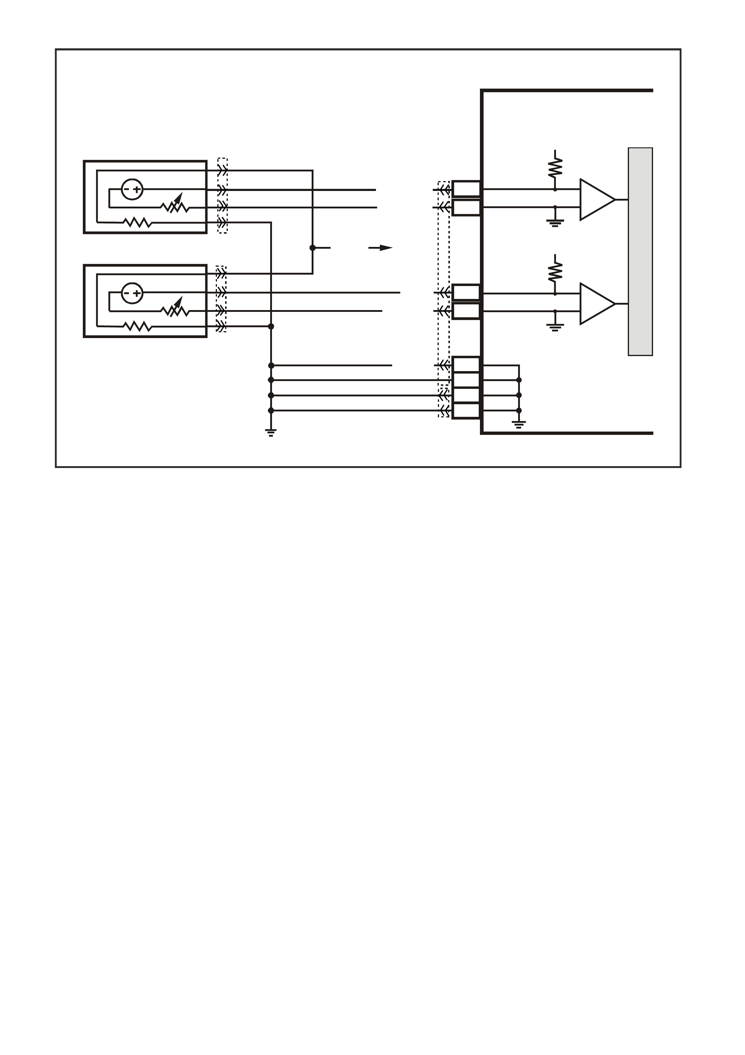
GEN III V8 PCM -
DTC P0133 HEATED OXYGEN SENSOR (HO2S) SLOW RESPONSE BANK 1 SENSOR 1
CIRCUIT DESCRIPTION
The PCM continuously monitors the Heated Oxygen Sensor (HO2S) activity for 100 seconds. During the monitor
period the PCM counts the number of times that the HO2S responds from rich to lean and from lean to rich and
adds the amount of time it took to complete all transactions. With this information, the PCM can determine the
average time for all transactions. If the average response time is too slow, the DTC will set.
The PCM determines the lean to rich transaction when the HO2S voltage changes from less than 300 mV to
greater than 600 m V. T he PCM determ ines the ric h to lean transac tion when the HO2S voltage changes from mor e
than 600 mV to less than 300 mV. An HO2S that responds too slowly is more likely defective. Replace the HO2S.
CONDITIONS FOR RUNNING THE DTC
• DTCs P0101, P0102, P0103, P0112, P0113, P0117, P0118, P0121, P0122, P0123, P0335, P0336, P0351-
P0358, P1258 are not set.
• The engine coolant temperature is greater than 65°C.
• The ignition voltage is greater than 9.0 volts.
• The fuel system is operating in Closed Loop.
• The engine speed is between 1000 RPM and 2300 RPM.
• The engine air flow is between 20 g/s and 50 g/s.
• The EVAP canister purge duty cycle is greater than 0%.
• The engine run time is greater than 120 seconds.
CONDITIONS FOR SETTING THE DTC
• The Lean to Rich response (below 300 mV to above 600 mV) average time is greater than 100 milliseconds.
• The Rich to Lean response (above 600 mV to below 300 mV) average time is greater than 100 milliseconds.
ACTION TAKEN WHEN THE DTC SETS
• The PCM illuminates the Check Powertrain Lamp when the diagnostic runs and fails.
• The PCM records the operating conditions at the time the diagnostic fails. The PCM stores this information in
the Freeze Frame/Failure Records.
• Open Loop Fueling.
D
D
B
B
A
A
C
C
GY/B (1413)
GY (1412)
RIGHT OXYGEN SENSOR
BANK TWO SENSOR ONE
LEFT OXYGEN SENSOR
BANK ONE SENSOR O NE
LOC. E5/E15
BLU/B (413)
V (412)
P (439)
TO F USE
F33
G3PCM003PT
J1-26
J1-66
J1-01
J1-40
J2-01
J2-40
J1-69
J1-29
PCM
RIGHT
OXYGEN
SENSOR
SIGNAL LO
LEFT
OXYGEN
SENSOR
SIGNAL LO
RIGHT
OXYGEN
SENSOR
SIGNAL HI
EARTH
EARTH
EARTH
EARTH
LEFT
OXYGEN
SENSOR
SIGNAL HI
IC
IC
45 0 mV
45 0 mV
M
I
C
R
O
B/R (750)
YE95
YE95
YE122
YE123
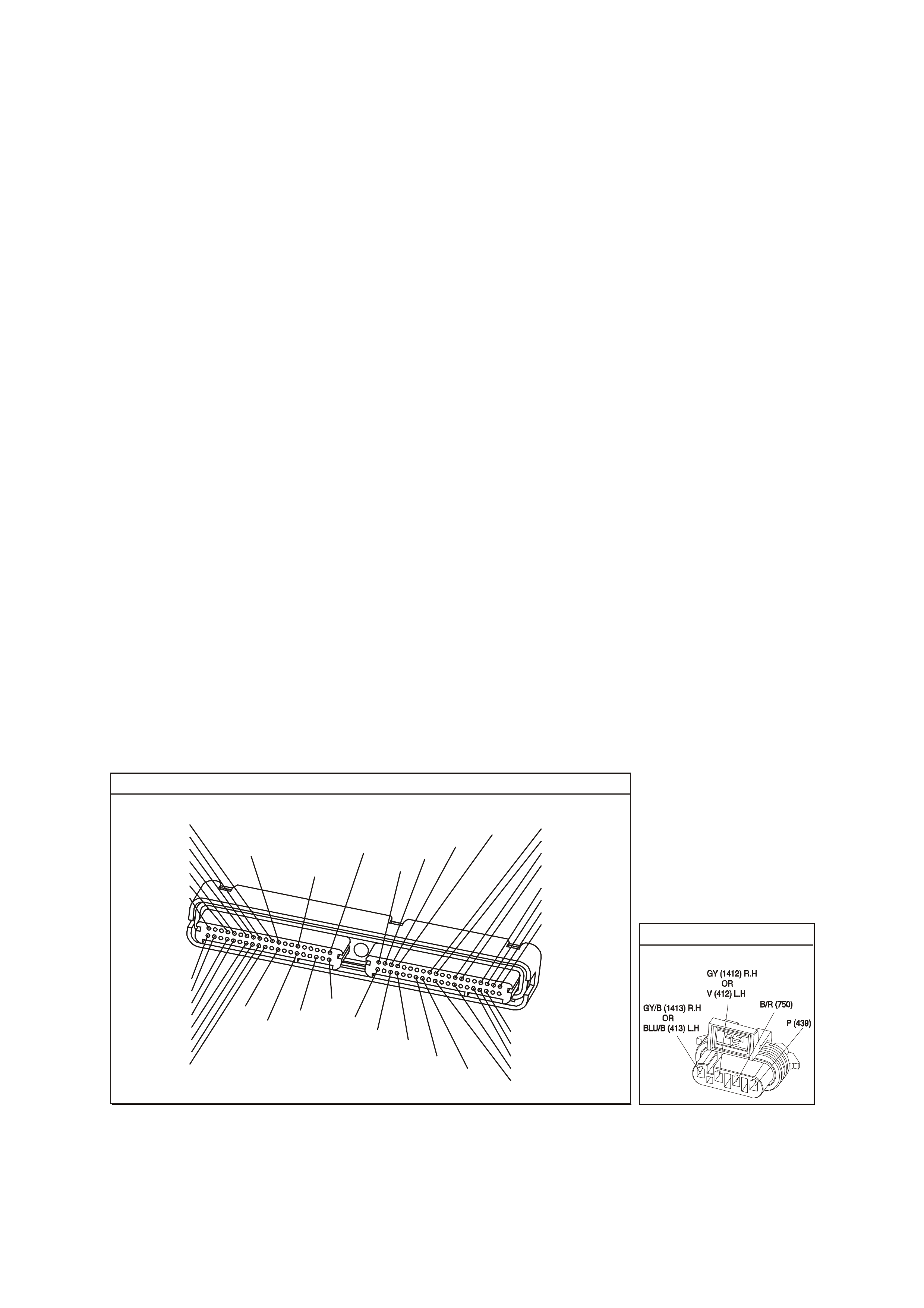
CONDITIONS FOR CLEARING THE CPL/DTC
• The PCM turns the Check Powertr ain Lamp OF F after one ignition cycle that the diagnostic runs and does not
fail.
• A last test failed (current DTC) clears when the diagnostic runs and does not fail.
• Use a Tech 2 scan tool in order to clear the CPL/DTC.
DIAGNOSTIC AIDS
• This diagnostic only runs once per ignition cycle.
• A malfunction in the HO2S heater circuits cause a DTC to set. Check HO2S heater circuit for intermittent
opens/connections.
• An oxygen supply inside the HO2S is necessary for proper operation. The HO2S wires provides the supply of
oxygen. Inspect the HO2S wires and connections for breaks or contamination. Refer to
Section 12P Electrical Diagnosis/ Repair Procedures, in the VT Series I Service Information.
• Using the Freeze Frame/Failure Records data may aid in locating an intermittent condition. If you cannot
duplicate the DTC, the information included in the Freeze Frame/Failure Records data can help determ ine the
distance traveled since the DTC set. The Fail Counter and Pass Counter can also help determine how many
ignition cycles the diagnostic reported a pass and/or fail. Operate the vehicle within the same freeze frame
conditions (RPM, load, vehicle speed, temperature etc.) that you observed. This will isolate when the DTC
failed. For an intermittent condition, refer to Section 6C3-2B Symptoms of the VX Series Service Information.
TEST DESCRIPTION
The numbers below refer to the step numbers on the diagnostic table.
2. T his step determines if the fault is pres ent. This test m ay tak e 5 minutes f or the diagnostic to run. For any test
that requires probing the PCM or a component harness connector, use the Connector Test adapter Kit J
35616-A. Using this kit prevents damage to the harness connector terminals.
3. When DTCs P0133 and P0153 are set at the same time, it is a good indication that a fuel contamination
problem is present.
4. An exhaust leak 15 - 30 CM (6-12 inches) away from the HO2S can cause a DTC to set.
5. This set checks whether a good earth circuit is available.
6. This step checks the integrity of the signal circuit to the PCM.
7. This step checks the integrity of the signal circuit to the PCM.
8. Certain RTV silicone gasket materials give off vapours that can contaminate the HO2S. There is also a
possibility of s ilicone contam ination caused by silic one in the fuel. If the sens ors appear to be contam inated by
silicone and all the silicone sealant is a non silicone base, advise the custom er to try a different fuel company.
A missing fuel filler restrictor indicates the customer may have used leaded fuel.
P.C.M CONNECTOR 1
Y E1 22
(776)
(1049)
(897)
(1230)
(848)
(1226)
(772)
(647)
(632)
40
(844)
(815)
80
J1
P/B
(845)
V/W
BLU
O
(633)
(846)
B/Y
B/R
(416)
(86)
(69)
(455)
(740)
GY
BR
G
GY
(646)
(410)
GY
(842)
(1225)
V
Y
(750)
P
41
O
(774)
BR/Y
BLU
Y
B/R
B
BLU/Y
(841)
BLUE
(414)
G/W
BLU
LG
LBLU/B
1
(847)
(415)
(740)
(452)
BLU
BR Y
(750)
(826)
(421)
Y
V/W
B/W
(334)
(771)
(39)
Y
R/W
LBLU
W
BLU/W
(843)
(643)
LBLU/W
G
GY/B
BLU/B
(413)
(1413)
(1412)
(412)
GY
V
GY/B
G
(335)
YE95
HE ATED EXHAUST GAS S ENSOR

GEN III V8 PCM - DTC P0133 HEATED OXYGEN SENSOR (HO2S) SLOW RESPONSE BANK 1 SENSOR 1
Step Action Value(s) Yes No
1 Did you perform the Powertrain On-Board Diagnostic
(OBD) System Check? Go to Step 2 Go to Powertrain
OBD System
Check Table
2
IMPORTANT: If any DTCs are set (except P0153), refer
to those DTCs before proceeding with this diagnostic
table.
1. Install a Tech 2 scan tool.
2. Idle the engine at the normal operating temperature.
3. Operate the vehicle, w ithin parameters specified under
Conditions for Running the DTC as specified in the
supporting text.
4. Monitor the Failed This Ignition option under the DTC
Information option using the Tech 2 scan tool.
Did DTC P0133 fail this ignition?
Go to Step 3 Go to Diagnostic
Aids
3 Did DTC P0153 also fail this ignition? Go to Step 8 Go to Step 4
4 1. Check for an exhaust system leak. After you inspect
the exhaust system, return to this diagnostic.
2. If you find an exhaust leak, repair the exhaust leak as
necessary
Did you isolate an exhaust leak?
Go to Step 2 Go to Step 5
5 Inspect the following items:
• Ensure that the HO2S is securely installed.
• Check for corrosion on the terminals.
• Check the terminals tension at the HO2S and at the
PCM.
• Check for damaged wiring.
Did you find a problem in any of the above areas?
Go to Step 9 Go to Step 6
6 1. Disconnect the Bank 1 HO2S .
2. Jumper the HO2S low (PCM side) signal circuit to a
earth.
3. Monitor the Bank 1 HO2S voltage on the Engine Data
List using the Tech 2 scan tool.
Does the Tech 2 scan tool indicate a voltage within the
specified range?
350-550 mV Go to Step 7 Go to Step 10
7 1. Jumper the Bank 1 HO2S high and low (PCM side)
signal circuit to a earth.
2. Monitor the Bank 1 HO2S voltage using the Tech 2
scan tool.
Does the Tech 2 scan tool indicate a voltage below
specified value?
200 mV Go to Step 12 Go to Diagnostic
Aids
8 IMPORTANT: Determine and correct the cause of the
contamination before replacing a sensor. Check for the
following conditions:
• Fuel contamination
• Use of improper RTV sealant
• Engine oil/coolant consumption
Replace the affected Heated Oxygen sensor.
Is the action complete?
Go to Step 13
9 Repair the conditions as necessary.
Is the action complete? Go to Step 13
10 Repair the open Bank 1 HO2S low signal circuit or the
earthed Bank 1 HO2S high signal circuits.
Is the action complete?
Go to Step 13

GEN III V8 PCM - DTC P0133 HEATED OXYGEN SENSOR (HO2S) SLOW RESPONSE BANK 1 SENSOR 1
(CONTINUED)
Step Action Value(s) Yes No
11 Repair the open Bank 1 HO2S high signal circuit or the
faulty PCM connections.
Is the action complete?
Go to Step 13
12 Replace the Bank 1 HO2S.
Is the action complete? Go to Step 13
13
1. Select the Diagnostic Trouble Code (DTC) option and
the Clear DTC Information option using the Tech 2
scan tool.
2. Idle the engine at the normal operating temperature.
3. Select the Diagnostic Trouble Code (DTC) option, the
DTC Information option and The Failed This Ignition
option using the Tech 2 scan tool.
4. Operate the vehicle, within the Conditions for Running
the DTC, as specified in the supporting text, if
applicable.
Does the Tech 2 scan tool indicate that this DTC reset?
Go to Step 2 Go to Step 14
14 Using the Tech 2 scan tool, check for any other DTCs.
Does the Tech 2 scan tool display any DTCs that you
have not diagnosed?
Go to the
applicable DTC
table
System OK
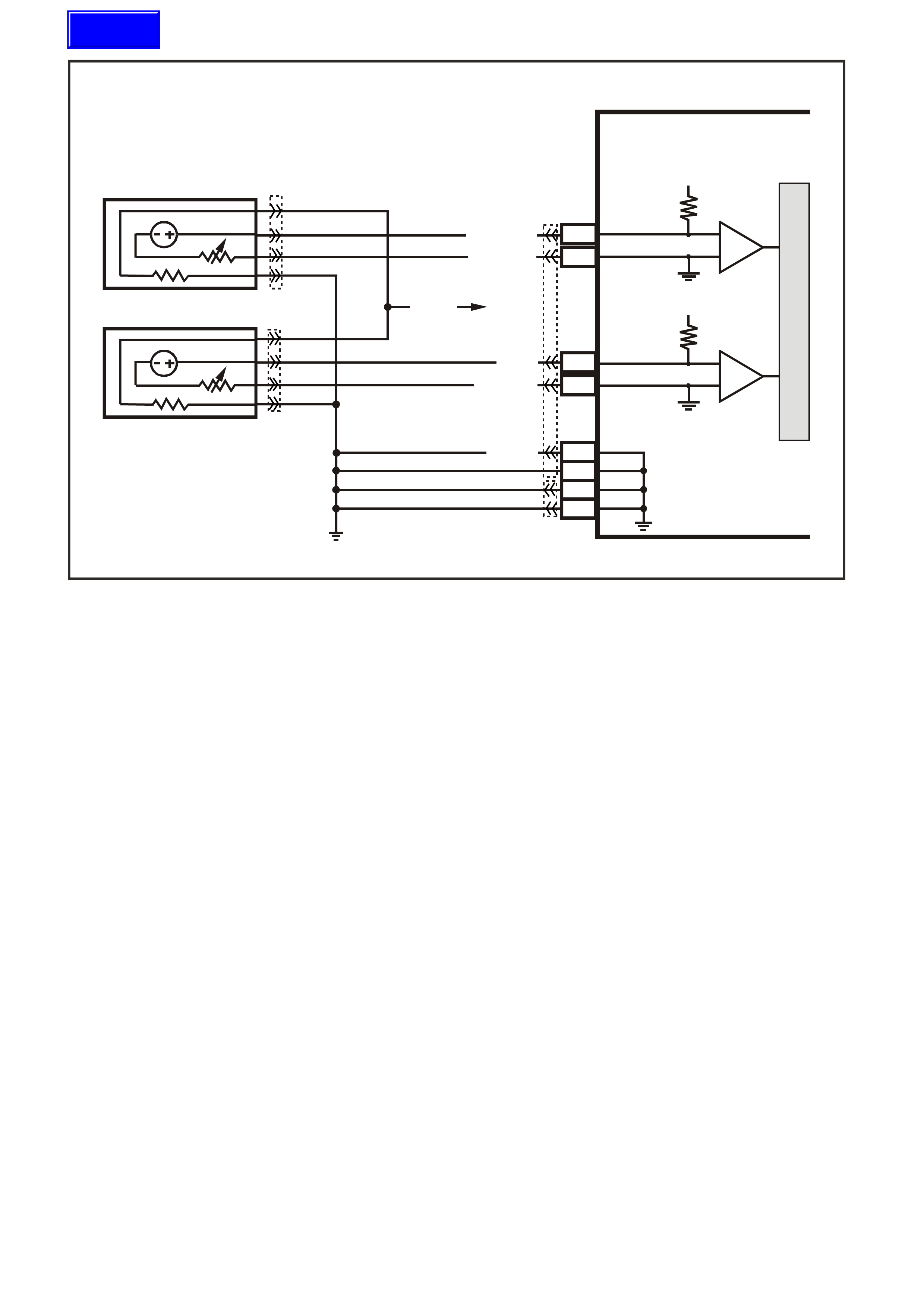
GEN III V8 PCM -
DTC P0134 HEATED OXYGEN SENSOR (HO2S) INSUFFICIENT ACTIVITY
BANK 1 S ENSOR 1
CIRCUIT DESCRIPTION
The PCM supplies a voltage of about 450 m V between the HO2S high and low signal circuits. The oxygen sensor
varies the voltage over a r ange f r om about 1000 m V when the exhaus t is r ich, down through about 10 mV when the
exhaust is lean.
The PCM monitors and stores the Heated Oxygen Sensor (HO2S) voltage information. The PCM evaluates the
HO2S voltage samples in order to determine the amount of time the HO2S voltage was out of range. The PCM
compares the stored HO2S voltage samples taken within each sample period and determines if majority of the
samples are out of the operating range.
The PCM monitors the HO2S voltage and detects if the voltage goes out of the bias range. If the PCM does not
detect the voltage went out of the bias range, the DTC will set.
CONDITIONS FOR RUNNING THE DTC
• DTCs P0101, P0102, P0103, P0112, P0113, P0117, P0118, P0121, P0122, P0123, P0335, P0336, P0351-
P0358, P1258 are not set.
• The ignition voltage is greater than 9.0 volts.
• The fuel system is operating in Closed Loop.
• The engine run time is greater than 70 seconds.
• The engine coolant temperature is greater than 48°C.
CONDITIONS FOR SETTING THE DTC
• The HO2S signal voltage is steady between 350 mV and 550 mV.
• The conditions are present for at least 70 seconds.
ACTION TAKEN WHEN THE DTC SETS
• The PCM illuminates the Check Powertrain Lamp when the diagnostic runs and fails.
• The PCM records the operating conditions at the time the diagnostic fails. The PCM stores this information in
the Freeze Frame/Failure Records.
• Open Loop Fueling.
D
D
B
B
A
A
C
C
GY/B (1413)
GY (1412)
RIGHT OXYGEN SENSOR
BANK TWO SENSOR ONE
LEFT OXYGEN SENSOR
BANK ONE SENSOR O NE
LOC. E5/E15
BLU/B (413)
V (412)
P (439)
TO F USE
F33
G3PCM003PT
J1-26
J1-66
J1-01
J1-40
J2-01
J2-40
J1-69
J1-29
PCM
RIGHT
OXYGEN
SENSOR
SIGNAL LO
LEFT
OXYGEN
SENSOR
SIGNAL LO
RIGHT
OXYGEN
SENSOR
SIGNAL HI
EARTH
EARTH
EARTH
EARTH
LEFT
OXYGEN
SENSOR
SIGNAL HI
IC
IC
45 0 mV
45 0 mV
M
I
C
R
O
B/R (750)
YE95
YE95
YE122
YE123
Techline

CONDITIONS FOR CLEARING THE CPL/DTC
• The PCM turns the Check Powertr ain Lamp OF F after one ignition cycle that the diagnostic runs and does not
fail.
• A last test failed (current DTC) clears when the diagnostic runs and does not fail.
• Use a Tech 2 scan tool in order to clear the CPL/DTC.
DIAGNOSTIC AIDS
• An oxygen supply inside the HO2S is necessary for proper operation. The HO2S wires provides the supply of
oxygen. Inspect the HO2S wires and connections for breaks or contamination. Refer to
Section 12P Electrical Diagnosis/ Repair Procedures in the VT Series I Service Information.
• Using the Freeze Frame/Failure Records data may aid in locating an intermittent condition. If you cannot
duplicate the DTC, the information included in the Freeze Frame/Failure Records data can help determ ine the
distance traveled since the DTC set. The Fail Counter and Pass Counter can also help determine how many
ignition cycles the diagnostic reported a pass and/or fail. Operate the vehicle within the same freeze frame
conditions (RPM, load, vehicle speed, temperature etc.) that you observed. This will isolate when the DTC
failed. For an intermittent condition, refer to Section 6C3-2B Symptoms of the VX Series Service Information.
TEST DESCRIPTION
The numbers below refer to the step numbers on the diagnostic table.
2. The engine must be at normal operating temperature before performing this test. For any test that requires
probing the PCM or a com ponent har ness c onnector, us e the Connector T est adapter Kit J 35616-A. Us ing this
kit prevents damage to the harness connector terminals.
3. Using the Freeze Frame/Failure Records data may aid in locating an intermittent condition. If you can not
duplicate the DTC, the information included in the Freeze Frame/Failure Records data can help determ ine the
distance traveled s ince the DT C set. T he Fail Counter and Pas s Counter c an also aid in determ ining how m any
ignition cycles the diagnostic reported a pass and/or a fail. Operate the vehicle within the same freeze frame
conditions (R PM, load, vehicle speed, tem perature etc.) that the PCM r ecorded. T his will isolate when the DTC
failed. Refer to Section 6C3-2B Symptoms of the VX Series Service Information.
4. If the Tech 2 scan tool indicates the HO2S voltage goes below 200 mV, this indicates the HO2S circuits and
PCM are OK.
5. This step checks whether the signal circuit from the PCM is OK.
6. Disconnecting the PCM allows using a DMM J 39200 in order to check continuity of the circuits. This aids in
locating an open or shorted circuit.
7. Disconnecting the PCM allows using a DMM J 39200 in order to check continuity of the circuits. This aids in
locating an open or shorted circuit.
P.C.M CONNECTOR 1
Y E1 22
(776)
(1049)
(897)
(1230)
(848)
(1226)
(772)
(647)
(632)
40
(844)
(815)
80
J1
P/B
(845)
V/W
BLU
O
(633)
(846)
B/Y
B/R
(416)
(86)
(69)
(455)
(740)
GY
BR
G
GY
(646)
(410)
GY
(842)
(1225)
V
Y
(750)
P
41
O
(774)
BR/Y
BLU
Y
B/R
B
BLU/Y
(841)
BLUE
(414)
G/W
BLU
LG
LBLU/B
1
(847)
(415)
(740)
(452)
BLU
BR Y
(750)
(826)
(421)
Y
V/W
B/W
(334)
(771)
(39)
Y
R/W
LBLU
W
BLU/W
(843)
(643)
LBLU/W
G
GY/B
BLU/B
(413)
(1413)
(1412)
(412)
GY
V
GY/B
G
(335)
YE95
HE ATED EXHAUST GAS S ENSOR

GEN III V8 PCM - DTC P0134 HEATED OXYGEN SENSOR (HO2S) INSUFFICIENT ACTIVITY
BANK 1 SENSOR 1
Step Action Value(s) Yes No
1 Did you perform the Powertrain On-Board Diagnostic
(OBD) System Check? Go to Step 2 Go to Powertrain
OBD System
Check Table
2
IMPORTANT: Check the HO2S for being secure before
proceeding with this DTC. A sensor that is loose could
cause this DTC to set.
1. Install a Tech 2 scan tool.
2. Idle the engine at the normal operating temperature
3. Operate the engine above 1200 RPM for two minutes.
4. Monitor the HO2S voltage display on the Engine Data
List using the Tech 2 scan tool .
Does the Tech 2 scan tool indicate the Bank 1 HO2S
voltage varying outside the specified value?
350-550 mV Go to Step 3 Go to Step 4
3 1. Turn ON the ignition leaving the engine OFF.
2. Review the Freeze Frame/Failure Records data for
this DTC and observe the parameters.
3. Turn OFF the ignition for 15 seconds.
4. Idle the engine.
5. Operate the vehicle, within the conditions required for
this diagnostic to run, and as close to the conditions
recorded in Freeze Frame/Failure Records a possible.
Special operating conditions that need to be met
before the PCM will run this diagnostic where
applicable, are listed in Conditions for Running the
DTC.
6. Select the Diagnostic Trouble Code (DTC) option, the
DTC Information option and The Failed This Ignition
option using the Tech 2 scan tool.
Does the Tech 2 scan tool indicate that this diagnostic
failed this ignition?
Go to Step 4 Go to Diagnostic
Aids
4 1. Turn ON the ignition leaving the engine OFF.
2. Disconnect the Bank 1 HO2S.
3. Jumper the HO2S high and low (PCM side) signal
circuits to a earth.
Monitor the Bank 1 HO2S voltage using the Tech 2 scan
tool.
Is the Bank 1 HO2S voltage below the specified value?
200 mV Go to Step 8 Go to Step 5
5 1. Remove the jumper wire.
2. Measure the voltage between the Bank 1 HO2S
heater earth circuit using a DMM J 39200.
Does the Bank 1 HO2S voltage measure above the
specified value?
375 mV Go to Step 6 Go to Step 7
6 1. Turn Off the ignition.
2. Disconnect the PCM BLUE connector.
3. Check the continuity of the Bank 1 HO2S low circuit.
4. Repair the open or the poor connection if the Bank 1
HO2S low circuit measures over the specified value.
Did you find and correct the Bank 1 HO2S 1 low circuit
condition?
2Ω Go to Step 13 Go to Step 9
7 1. Turn Off the ignition.
2. Disconnect the PCM connectors.
3. Check the continuity of the Bank 1 HO2S low circuit.
4. Repair the open or the poor connection if the Bank 1
HO2S low circuit measures over the specified value.
Did you find and correct the Bank 1 HO2S 1 low circuit
condition?
2Ω Go to Step 13 Go to Step 10

GEN III V8 PCM - DTC P0134 HEATED OXYGEN SENSOR (HO2S) INSUFFICIENT ACTIVITY
BANK 1 SENSOR 1 (CONTINUED)
Step Action Value(s) Yes No
8 Check for a poor Bank 1 HO2S signal or low circuit
terminal connection at the Bank 1 HO2S harness
connector and replace the terminal(s) if necessary.
Did any terminals require replacement?
Go to Step 13 Go to Step 11
9 Check for a poor Bank 1 HO2S low circuit terminal
connection at the PCM, and replace the terminal if
necessary.
Did any terminals require replacement?
Go to Step 13 Go to Step 12
10 Check for a poor Bank 1 HO2S signal circuit terminal
connection at the PCM, and replace the terminal if
necessary.
Did any terminals require replacement?
Go to Step 13 Go to Step 12
11 Replace the Bank 1 HO2S.
Is the action complete? Go to Step 13
12 1. Replace PCM.
2. Refer to Section 6C3-3 of the VX Series Service
Information for PCM Programming and
PCM/PIM/BCM Security Link Procedure.
Is action complete?
Go to Step 13
13 1. Select the Diagnostic Trouble Code (DTC) option and
the Clear DTC Information option using the Tech 2
scan tool.
2. Idle the engine at the normal operating temperature.
3. Select the Diagnostic Trouble Code (DTC) option, the
DTC Information option and The Failed This Ignition
option using the Tech 2 scan tool.
4. Operate the vehicle within the Conditions for Running
the DTC as specified in the supporting text, if
applicable.
Does the Tech 2 scan tool indicate that this DTC reset?
Go to Step 2 Go to Step 14
14 Using the Tech 2 scan tool, check for any other DTCs.
Does the Tech 2 scan tool display any DTCs that you
have not diagnosed?
Go to the
applicable DTC
table
System OK

GEN III V8 PCM -
DTC P0135 HEATED OXYGEN SENSOR (HO2S) HEATER CIRCUIT BANK 1 SENSOR 1
CIRCUIT DESCRIPTION
The PCM supplies a bias voltage (approximately 450 mV) on the Heated Oxygen Sensor (HO2S) signal high and
low circuits. W hen you turn the ignition to the ON position, battery voltage is supplied to the HO2S heater. As the
heater reaches the operating temperature, the HO2S voltage responds by changing from a bias voltage range to
the normal operation. Typically, as the HO2S reaches the operating temperature, the HO2S voltage goes from a
bias voltage to a voltage below 300 mV. Depending on the ex haust gas content, it is possible for the HO2S voltage
to go above 450 mV.
The PCM runs the heater test only on a cold start (depends on the cumulative air flow) and only once an ignition
cycle. When you start the engine the PCM monitors the HO2S voltage. When the HO2S voltage goes above or
below the bias range threshold, the PCM determines how much time it took. If the PCM detects that the process
took too long for the HO2S to enter into normal operating range, a DTC will set. The time the process takes the
HO2S to reach operating temperature is based on the amount of air that flows into the engine.
CONDITIONS FOR RUNNING THE DTC
• DTCs P0101, P0102, P0103, P0112, P0113, P0117, P0118, P0121, P0122, P0123, P0335, P0336, P0351-
P0358, P1258 are not set.
• The intake air tem perature and the engine coolant temperature are less than 50°C and are within 8°C of each
other at engine start-up.
• The ignition voltage is between 10.0 volts and 18.0 volts.
• The engine air flow is less than 18 g/s.
CONDITIONS FOR SETTING THE DTC
• The HO2S voltage remains between 300 mV and 700 mV for a predetermined amount of time (depends on
engine coolant temperature and air flow).
ACTION TAKEN WHEN THE DTC SETS
• The PCM illuminates the Check Powertrain Lamp when the diagnostic runs and fails.
• The PCM records the operating conditions at the time the diagnostic fails. The PCM stores this information in
the Freeze Frame/Failure Records.
D
D
B
B
A
A
C
C
GY/B (1413)
GY (1412)
RIGHT OXYGEN SENSOR
BANK TWO SENSOR ONE
LEFT OXYGEN SENSOR
BANK ONE SENSOR O NE
LOC. E5/E15
BLU/B (413)
V (412)
P (439)
TO F USE
F33
G3PCM003PT
J1-26
J1-66
J1-01
J1-40
J2-01
J2-40
J1-69
J1-29
PCM
RIGHT
OXYGEN
SENSOR
SIGNAL LO
LEFT
OXYGEN
SENSOR
SIGNAL LO
RIGHT
OXYGEN
SENSOR
SIGNAL HI
EARTH
EARTH
EARTH
EARTH
LEFT
OXYGEN
SENSOR
SIGNAL HI
IC
IC
45 0 mV
45 0 mV
M
I
C
R
O
B/R (750)
YE95
YE95
YE122
YE123

CONDITIONS FOR CLEARING THE CPL/DTC
• The PCM turns the Chec k Powertrain Lam p OFF after one ignition c ycle that the diagnostic r uns and does
not fail.
• A last test failed (current DTC) clears when the diagnostic runs and does not fail.
• Use a Tech 2 scan tool in order to clear the CPL/DTC.
DIAGNOSTIC AIDS
• Using the Freeze Frame/Failure Records data may aid in locating an intermittent condition. If you cannot
duplicate the DTC, the information included in the Freeze Frame/Failure Records data can help determ ine the
distance traveled since the DTC Set. The Fail Counter and Pass Counter can also help determine how may
ignition cycles the diagnostic reported a pass and/or a fail. Operate the vehicle within the same freeze frame
conditions (RPM, load, vehicle speed, temperature etc.) that you observed. This will isolate when the DTC
failed. For an intermittent condition, refer to Section 6C3-2B Symptoms of the VX Series Service Information.
• The heater diagnostic will only run on a cold start and run once per ignition cycle.
• Inspect the EFI relay for proper operation if you cannot find any problems with the ignition feed circuit to the
com ponent. Pr obe both side of the f use with a test lam p connec ted to earth in order to deter m ine if a voltage is
supplied to the fuse. Refer to EFI Relay Diagnosis Table of the VX Series Service Information.
• An oxygen supply inside the HO2S is necessary for proper operation. The HO2S wires provides the supply of
oxygen. Inspect the HO2S wires and connections for breaks or contamination.
TEST DESCRIPTION
The numbers below refer to the step numbers on the diagnostic table.
2. Allow the engine to cool before performing this test. If the sensor is at the operating temperature the HO2S
voltage will stay high or low. If the HO2S voltage stays between 300-700 mV indicates the HO2S heater is
inoperative. For any test that requires pr obing the PCM or a com ponent harnes s connector, use the Connec tor
Test adapter Kit J 35616-A. Using this kit will prevent damage to the harness connector terminals.
3. If more than one HO2S DTC is set, this is a good indication that the HO2S fuse is open. Check all the relate
circuits going to all the heated oxygen sensors for a short to earth. If all the wiring checks to be OK, it may be
necessary to disconnect each HO2S on at a time to locate a shorted sensor.
4. This step checks whether a B+ supply is available at the sensor.
5. This step checks whether a earth is available at the sensor.
6. This step checks whether the HO2S heater element is internally open.
7. Inspect the ignition feed circuits at the engine compartment Fuse/Relay panel for poor connections.
8. Check the earth circuits for an open if more then one heater DTC sets.
P.C.M CONNECTOR 1
Y E1 22
(776)
(1049)
(897)
(1230)
(848)
(1226)
(772)
(647)
(632)
40
(844)
(815)
80
J1
P/B
(845)
V/W
BLU
O
(633)
(846)
B/Y
B/R
(416)
(86)
(69)
(455)
(740)
GY
BR
G
GY
(646)
(410)
GY
(842)
(1225)
V
Y
(750)
P
41
O
(774)
BR/Y
BLU
Y
B/R
B
BLU/Y
(841)
BLUE
(414)
G/W
BLU
LG
LBLU/B
1
(847)
(415)
(740)
(452)
BLU
BR Y
(750)
(826)
(421)
Y
V/W
B/W
(334)
(771)
(39)
Y
R/W
LBLU
W
BLU/W
(843)
(643)
LBLU/W
G
GY/B
BLU/B
(413)
(1413)
(1412)
(412)
GY
V
GY/B
G
(335)
YE95
HE ATED EXHAUST GAS S ENSOR

GEN III V8 PCM - DTC P0135 HEATED OXYGEN SENSOR (HO2S) HEATER CIRCUIT BANK 1 SENSOR 1
Step Action Value(s) Yes No
1 Did you perform the Powertrain On-Board Diagnostic
(OBD) System Check ? Go to Step 2 Go to Powertrain
OBD System
Check Table
2 IMPORTANT: Allow the engine to cool for about one half
hour before proceeding with this table.
1. Turn OFF the ignition.
2. Install the Tech 2 scan tool.
3. Turn ON the ignition leaving the engine OFF.
4. Monitor the HO2S voltage display on the Engine Data
List of the Tech 2 scan tool.
Does the HO2S voltage go from a bias voltage to above
or below the specified range?
300-700 mV Go to
Diagnostic Aids Go to Step 3
3 Inspect the HO2S heater fuse for an open.
Is the HO2S heater fuse open? Go to Step 11 Go to Step 4
4 1. Raise the vehicle.
2. Disconnect the HO2S electrical connector.
3. Probe the ignition feed circuit at the HO2S electrical
connector (PCM side) using a test lamp, J34142-B,
connected to earth (a known good earth) do not use
the HO2S heater earth or the HO2S low circuits).
Does the test lamp illuminate?
Go to Step 5 Go to Step 7
5 Connect the test lamp, J34142-B, between the HO2S
ignition feed and the HO2S heater earth.
Does the test lamp illuminate?
Go to Step 6 Go to Step 8
6 Measure the resistance between the HO2S ignition feed
and the HO2S heater earth at the HO2S pigtail using a
DMM J39200.
Is the HO2S resistance within the specified range?
3.5 - 14.0Ω Go to Step 9 Go to Step 10
7 Repair the open in the HO2S ignition feed circuit to the
HO2S.
Is the action complete?
Go to Step 12
8 Repair the open in the HO2S heater earth circuit.
Is the action complete? Go to Step 12
9 1. Check for a poor connection at the HO2S harness
terminals.
2. If you find a poor connection, replace the terminals.
Did you find a poor connection?
Go to Step 12 Go to Step 10
10 Replace the HO2S.
Is the action complete? Go to Step 12 Go to Step 10
11 1. Locate and repair the short to earth in the HO2S
ignition feed circuit.
2. Replace the faulty fuse.
Is the action complete?
Go to step 12
12 1. Select the Diagnostic Trouble Code (DTC) option and
the Clear DTC Information option using the Tech 2
scan tool.
2. Idle the engine at the normal operating temperature.
3. Select the Diagnostic Trouble Code (DTC) option, the
DTC Information option and The Failed This Ignition
option using the Tech 2 scan tool.
4. Operate the vehicle within the Conditions for Running
the DTC as specified in the supporting text, if
applicable.
Does the Tech 2 scan tool indicate that this DTC reset?
Go to Step 2 Go to step 13
13 Using the Tech 2 scan tool, check for any other DTCs.
Does the Tech 2 scan tool display any DTCs that you
have not diagnosed?
Go to the
applicable DTC
table
System OK

GEN III V8 PCM -
DTC P0151 HEATED OXYGEN SENSOR (HO2S) CIRCUIT LOW VOLTAGE
BANK 2 S ENSOR 1
CIRCUIT DESCRIPTION
The PCM supplies a voltage of about 450 m V between the HO2S high and low signal circuits. The oxygen sensor
varies the voltage over a r ange f r om about 1000 m V when the exhaus t is r ich, down through about 10 mV when the
exhaust is lean.
The PCM monitors and stores the heated oxygen sensor (HO2S) voltage information. The PCM evaluates the
HO2S voltage samples in order to determine the amount of time the HO2S voltage was out of range. The PCM
compares the stored HO2S voltage samples, taken within each sample period, and determines if majority of the
samples are out of the operating range.
The PCM monitors the HO 2S voltage f or being fixed below a predeter mined voltage. If the PCM detec ts the voltage
is below a predetermined voltage, a DTC will set.
CONDITIONS FOR RUNNING THE DTC
Criteria 1
• DTCs P0101, P0102, P0103, P0112, P0113, P0117, P0118, P0121, P0122, P0123, P0335, P0336, P0351-
P0358, P1258 are not set.
• The engine coolant temperature is greater than 48°C.
• The ignition voltage is greater than 9.0 volts.
• The fuel system is operating in Closed Loop.
• The fuel trim learn is enabled.
• The air/fuel ratio is between 14.5:1 and 14.7:1.
• The TP angle is between 0% and 70%.
Criteria 2
• DTCs P0101, P0102, P0103, P0112, P0113, P0117, P0118, P0121, P0122, P0123, P0335, P0336, P0351-
P0358, P1258 are not set.
• The ignition voltage is greater than 9.0 volts.
• The Power Enrichment mode is enabled for at least 0.5 seconds.
D
D
B
B
A
A
C
C
GY/B (1413)
GY (1412)
RIGHT OXYGEN SENSOR
BANK TWO SENSOR ONE
LEFT OXYGEN SENSOR
BANK ONE SENSOR O NE
LOC. E5/E15
BLU/B (413)
V (412)
P (439)
TO F USE
F33
G3PCM003PT
J1-26
J1-66
J1-01
J1-40
J2-01
J2-40
J1-69
J1-29
PCM
RIGHT
OXYGEN
SENSOR
SIGNAL LO
LEFT
OXYGEN
SENSOR
SIGNAL LO
RIGHT
OXYGEN
SENSOR
SIGNAL HI
EARTH
EARTH
EARTH
EARTH
LEFT
OXYGEN
SENSOR
SIGNAL HI
IC
IC
45 0 mV
45 0 mV
M
I
C
R
O
B/R (750)
YE95
YE95
YE122
YE123

CONDITIONS FOR SETTING THE DTC
Criteria 1
• The HO2S signal voltage remains below 200 mV.
• The Criteria 1conditions are present for at least 33 seconds.
Criteria 2
• The HO2S signal voltage remains below 360 mV.
• The Criteria2 conditions are present for at least five seconds.
ACTION TAKEN WHEN THE DTC SETS
• The PCM illuminates the Check Powertrain Lamp when the diagnostic runs and fails.
• The PCM records the operating conditions at the time the diagnostic fails. The PCM stores this information in
the Freeze Frame/Failure Records.
• Open Loop Fueling.
CONDITIONS FOR CLEARING THE CPL/DTC
• The PCM turns the Check Powertr ain Lamp OF F after one ignition cycle that the diagnostic runs and does not
fail.
• A last test failed (current DTC) clears when the diagnostic runs and does not fail.
• Use a Tech 2 scan tool in order to clear the CPL/DTC.
DIAGNOSTIC AIDS
• Heated Ox ygen Sensor (HO2S) wire: Sensor pigtail m ay be in contact with the exhaust m anifold or the ex haust
system.
• An oxygen supply inside the HO2S is necessary for proper operation. The HO2S wires provides the supply of
oxygen. Inspect the HO2S wires and connections for breaks or contamination.
• Check for intermittent earth in signal wire between connector and sensor.
• Lean injector(s): Perform the Injector Balance Test.
• Fuel contam ination: W ater near the in-tank fuel pump inlet c an be delivered to the injectors. T he water causes
a lean exhaust and can set a DTC.
• Fuel pressure: System will be lean if fuel pressure is low. Refer to Fuel System Diagnosis Table of the VX
Series Service Information.
• Exhaust leaks: An exhaust leak near the HO2S can cause a lean condition.
• Vacuum or crankcase leaks can cause a lean condition.
• If the above are OK, the HO2S may be at fault.
• For an intermittent condition, refer to Section 6C3-2B Symptoms of the VX Series Service Information.
TEST DESCRIPTION
The numbers below refer to the step numbers on the diagnostic table.
2. If the HO2S voltage is fix well below 200 mV this indicates a short to battery earth or chassis earth. If the
voltage is fix near or above 200 mV, this indicates a s hort to a PCM earth. W hen the HO2S voltage is f ix near
200 mV, indicates the DTC set when the fuel system was in a Power Enrichment mode of operations. This
DTC sets if the HO2S voltage is less than 360 mV during a Power Enrichment mode of operation.
3. Using the Freeze Frame/Failure Records data may aid in locating an intermittent condition. If you cannot
duplicate the DTC, the information included in the Freeze Frame/Failure Records data can help determ ine the
distance traveled since the DTC set. The Fail Counter and Pass Counter can also help determine how many
ignition cycles the diagnostic reported a pass and/or fail. Operate the vehicle within the same freeze frame
condition (RPM, load, vehicle speed, temperature etc.) that you observed. This will isolate when the DTC
failed.
4. Earthing the low side circuit of the HO2S should cause the HO2S voltage to display a bias voltage. A voltage
staying near 0.0 volts indicates the low circuit is open, or the high circuit is open or earthed.
5. Disconnecting the PCM allows using a DMM J 39200 in order to check continuity of the circuits. This aids in
locating an open or shorted circuit.

P.C.M CONNECTOR 1
YE122
(776)
(1049)
(897)
(1230)
(848)
(1226)
(772)
(647)
(632)
40
(844)
(815)
80
J1
P/B
(845)
V/W
BLU
O
(633)
(846)
B/Y
B/R
(416)
(86)
(69)
(455)
(740)
GY
BR
G
GY
(646)
(410)
GY
(842)
(1225)
V
Y
(750)
P
41
O
(774)
BR/Y
BLU
Y
B/R
B
BLU/Y
(841)
BLUE
(414)
G/W
BLU
LG
LBLU/B
1
(847)
(415)
(740)
(452)
BLU
BR
Y
(750)
(826)
(421)
Y
V/W
B/W
(334)
(771)
(39)
Y
R/W
LBLU
W
BLU/W
(843)
(643)
LBLU/W
G
GY/B
BLU/B
(413)
(1413)
(1412)
(412)
GY
V
GY/B
G
(335)
YE95
HEATED EXHAUST GAS SENSOR
GEN III V8 PCM - DTC P0151 HEATED OXYGEN SENSOR (HO2S) CIRCUIT LOW VOLTAGE
BANK 2 SENSOR 1
Step Action Value(s) Yes No
1 Did you perform the Powertrain On-Board Diagnostic
(OBD) System Check? Go to Step 2 Go to Powertrain
OBD System
Check Table
2
IMPORTANT: Check the HO2S for being secure before
proceeding with this DTC. A sensor that is loose could
cause this DTC to set.
1. Install a Tech 2 scan tool.
2. Idle the engine at the normal operating temperature.
3. Operate the vehicle within parameters specified under
Conditions for Running the DTC in the supporting text.
4. Monitor the HO2S voltage display on the Engine Data
List using the Tech 2 scan tool.
Is the HO2S voltage less than the specified value?
200 mV Go to Step 4 Go to Step 3
3 1. Turn ON the ignition leaving the engine OFF.
2. Review the Freeze Frame/Failure Records data for
this DTC and observe the parameters.
3. Turn OFF the ignition for 15 seconds.
4. Idle the engine.
5. Operate the vehicle, within the conditions required for
this diagnostic to run, and as close to the conditions
recorded in the Freeze Frame/Failure Records as
possible. Special operating conditions that you need to
meet before the PCM will run this diagnostic, where
applicable, are listed in Conditions for Running the
DTC.
6. Select the Diagnostic Trouble Code (DTC) option, the
DTC Information option and The Failed This Ignition
option using the Tech 2 scan tool.
Does the Tech 2 scan tool indicate that this diagnostic
failed this ignition?
Go to Step 4 Go to
Diagnostic Aids
4 1. Disconnect the HO2S.
2. Jumper the HO2S low circuit (PCM side) to a earth.
Is the HO2S voltage within the specified range?
350-550 mV Go to
Diagnostic Aids Go to Step 5
5 1. Turn OFF the ignition.
2. Disconnect the PCM BLUE connector.
3. Check the HO2S signal circuit for a short to earth or a
short to the sensor earth circuit.
Is the HO2S signal circuit shorted?
Go to Step 6 Go to Step 7

GEN III V8 PCM - DTC P0151 HEATED OXYGEN SENSOR (HO2S) CIRCUIT LOW VOLTAGE
BANK 2 SENSOR 1 (CONTINUED)
Step Action Value(s) Yes No
6 Repair the HO2S signal circuit.
Is the action complete? Go to Step 8
7 1. Replace PCM.
2. Refer to Section 6C3-3 of the VX Series Service
Information for PCM Programming and
PCM/PIM/BCM Security Link Procedure.
Is action complete?
Go to Step 8
8 1. Select the Diagnostic Trouble Code (DTC) option and
the Clear DTC Information option using the Tech 2
scan tool.
2. Idle the engine at the normal operating temperature.
3. Select the Diagnostic Trouble Code (DTC) option, the
DTC Information option and The Failed This Ignition
option using the Tech 2 scan tool.
4. Operate the vehicle within the Conditions for Running
the DTC, as specified in the supporting text, if
applicable.
Does the Tech 2 scan tool indicate that this DTC reset?
Go to Step 2 Go to Step 9
9 Using the Tech 2 scan tool, check for any other DTCs.
Does the Tech 2 scan tool display any DTCs that you
have not diagnosed?
Go to the
applicable DTC
table
System OK

GEN III V8 PCM -
DTC P0152 HEATED OXYGEN SENSOR (HO2S) CIRCUIT HIGH VOLTAGE
BANK 2 S ENSOR 1
CIRCUIT DESCRIPTION
The PCM supplies a voltage of about 450 m V between the HO2S high and low signal circuits. The oxygen sensor
varies the voltage over a r ange f r om about 1000 m V when the exhaus t is r ich, down through about 10 mV when the
exhaust is lean.
The PCM monitors and stores the Heated Oxygen Sensor (HO2S) voltage information. The PCM evaluates the
HO2S voltage samples in order to determine the amount of time the HO2S voltage was out of range. The PCM
compares the stored HO2S voltage samples, taken within each sample period, and determines if majority of the
samples are out of the operating range.
The PCM monitors the HO2S voltage for being fixed above a predetermined voltage. If the PCM detects the
voltage is above the predetermined voltage, a DTC will set.
CONDITIONS FOR RUNNING THE DTC
Criteria 1
• DTCs P0101, P0102, P0103, P0112, P0113, P0117, P0118, P0121, P0122, P0123, P0335, P0336, P0351-
P0358, P1258 are not set.
• The ignition voltage is greater than 9.0 volts.
• The fuel system is operating in Closed Loop.
• The fuel trim learn is enabled.
• The air/fuel ratio is between 14.5:1 and 14.7:1.
Criteria 2
• DTCs P0101, P0102, P0103, P0112, P0113, P0117, P0118, P0121, P0122, P0123, P0335, P0336, P0351-
P0358, P1258 are not set.
• The ignition voltage is greater than 9.0 volts.
• Deceleration Fuel Cut-Off mode is enabled for greater than one second.
D
D
B
B
A
A
C
C
GY/B (1413)
GY (1412)
RIGHT OXYGEN SENSOR
BANK TWO SENSOR ONE
LEFT OXYGEN SENSOR
BANK ONE SENSOR O NE
LOC. E5/E15
BLU/B (413)
V (412)
P (439)
TO F USE
F33
G3PCM003PT
J1-26
J1-66
J1-01
J1-40
J2-01
J2-40
J1-69
J1-29
PCM
RIGHT
OXYGEN
SENSOR
SIGNAL LO
LEFT
OXYGEN
SENSOR
SIGNAL LO
RIGHT
OXYGEN
SENSOR
SIGNAL HI
EARTH
EARTH
EARTH
EARTH
LEFT
OXYGEN
SENSOR
SIGNAL HI
IC
IC
45 0 mV
45 0 mV
M
I
C
R
O
B/R (750)
YE95
YE95
YE122
YE123

CONDITIONS FOR SETTING THE DTC
Criteria 1
• The HO2S signal voltage remains below 775 mV.
• The Criteria 1conditions are present for at least 33 seconds.
Criteria 2
• The HO2S signal voltage remains below 540 mV.
• The Criteria2 conditions are present for at least five seconds.
ACTION TAKEN WHEN THE DTC SETS
• The PCM illuminates the Check Powertrain Lamp when the diagnostic runs and fails.
• The PCM records the operating conditions at the time the diagnostic fails. The PCM stores this information in
the Freeze Frame/Failure Records.
• Open Loop Fueling.
CONDITIONS FOR CLEARING THE CPL/DTC
• The PCM turns the Check Powertr ain Lamp OF F after one ignition cycle that the diagnostic runs and does not
fail.
• A last test failed (current DTC) clears when the diagnostic runs and does not fail.
• Use a Tech 2 scan tool in order to clear the CPL/DTC.
DIAGNOSTIC AIDS
• Check the HO2S electrical connections for evidence of water intrusion. Water present in the connector will
cause the B+ supply to the heater to bleed over to the signal circuit.
• Fuel pressure: The system goes rich if the pressure is too high. The PCM compensates for some increase.
However, if the fuel pressure is too high, a DTC may set. Refer to Fuel System Diagnosis Table of the VX
Series Service Information.
• Rich injector(s): Perform the Injector Balance Test.
• Leaking injector: Refer to the Fuel System Diagnosis of the VX Series Service Information.
• Evaporative em is sions ( EVAP) c anis ter pur ge. Chec k for f uel s aturation. If full of fuel, c hec k the c anis ter control
and hoses. Refer to Section 6C3-1 EVAP Control System Description of the VX Series Service Information.
• MAF Sensor: Disconnect the MAF Sensor and see if the rich condition is correct. If so, check for proper
installation. If installation OK, replace the MAF Sensor. If the MAF Sensor is installed backwards, the system
goes rich. The plastic portion of the sensor has arrows cast into it indicating proper air flow direction. The
arrows must point towards the engine.
• An oxygen supply inside the HO2S is necessary for proper operation. The HO2S wires provides the supply of
oxygen. Inspect the HO2S wires and connections for breaks or contamination.
• TP Sensor: An intermittent TP Sensor output causes the system to go rich, due to a false indication of the
engine accelerating. For an intermittent condition, refer to Section 6C3-2B Symptoms of the VX Series
Service Information.
TEST DESCRIPTION
The numbers below refer to the step numbers on the diagnostic table.
2. This DTC also sets during a deceleration fuel cut-off . Inspect items which could cause a rich exhaust during a
deceleration (leaking injectors, stuck injectors, etc.). Refer to Conditions for Setting the DTC above.
T he engine must be at the normal operating tem perature before per form ing this test. For any test that requires
probing the PCM or a com ponent har ness c onnector, us e the Connector T est adapter Kit J 35616-A. Us ing this
kit prevents damage to the harness connector terminals.
3. Using the Freeze Frame/Failure Records data may aid in locating an intermittent condition. If you can not
duplicate the DTC, the information included in the Freeze Frame/Failure Records data can help determ ine the
distance traveled s ince the DT C set. T he Fail Counter and Pas s Counter c an also aid in determ ining how m any
ignition cycles the diagnostic reported a pass and/or a fail. Operate the vehicle within the same freeze frame
conditions (R PM, load, vehicle speed, tem perature etc.) that the PCM r ecorded. T his will isolate when the DTC
failed. Refer to Section 6C3-2B Symptoms of the VX Series Service Information.
5. Earthing the low side circuit of the HO2S should cause the HO2S voltage to display a bias voltage.
9. Review the system mechanisation. Check for a short between the HO2S signal circuit and any other wires
powered by this fuse that runs together inside the same harness.
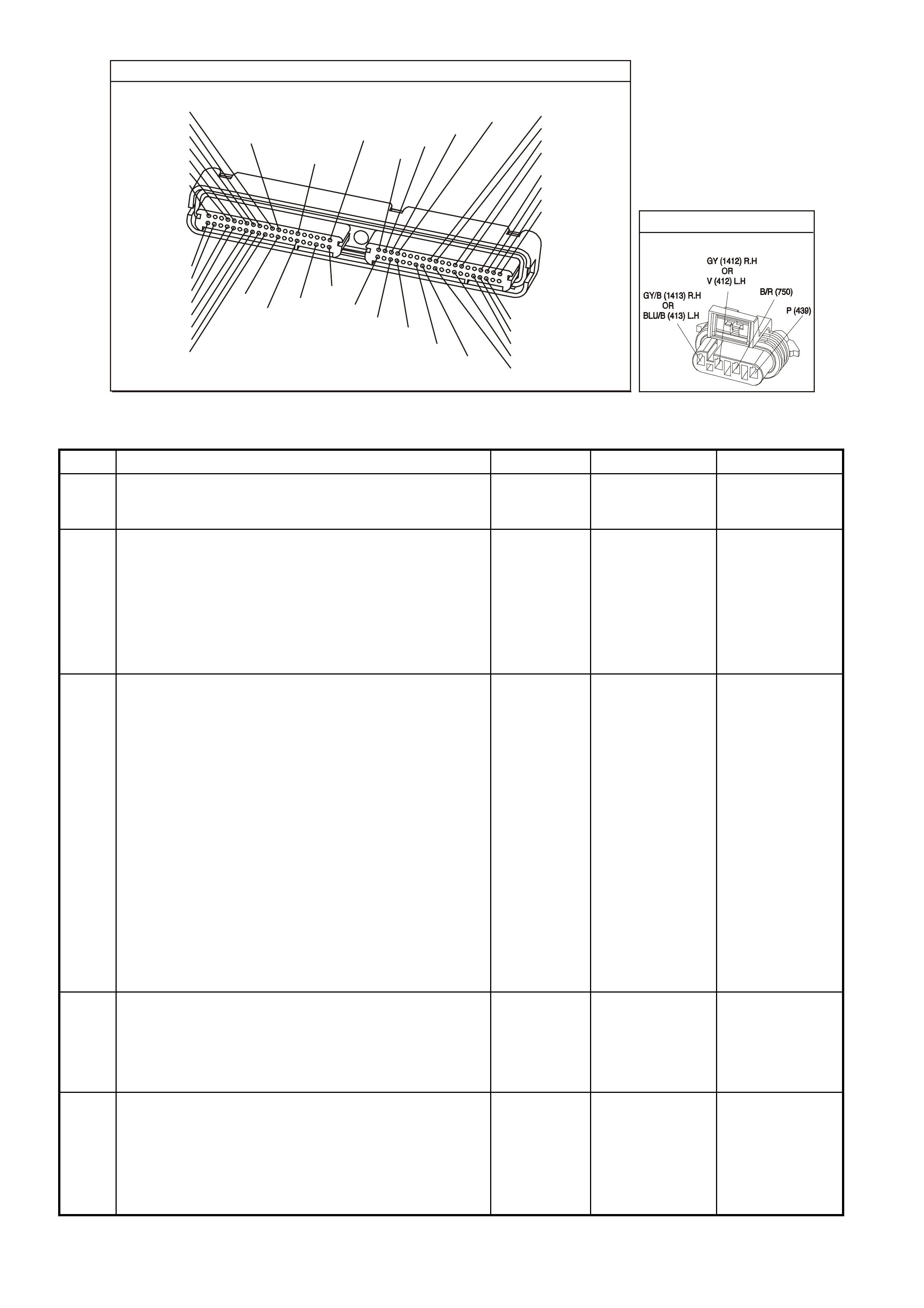
P.C.M CONNECTOR 1
YE122
(776)
(1049)
(897)
(1230)
(848)
(1226)
(772)
(647)
(632)
40
(844)
(815)
80
J1
P/B
(845)
V/W
BLU
O
(633)
(846)
B/Y
B/R
(416)
(86)
(69)
(455)
(740)
GY
BR
G
GY
(646)
(410)
GY
(842)
(1225)
V
Y
(750)
P
41
O
(774)
BR/Y
BLU
Y
B/R
B
BLU/Y
(841)
BLUE
(414)
G/W
BLU
LG
LBLU/B
1
(847)
(415)
(740)
(452)
BLU
BR
Y
(750)
(826)
(421)
Y
V/W
B/W
(334)
(771)
(39)
Y
R/W
LBLU
W
BLU/W
(843)
(643)
LBLU/W
G
GY/B
BLU/B
(413)
(1413)
(1412)
(412)
GY
V
GY/B
G
(335)
YE95
HEATED EXHAUST GAS SENSOR
GEN III V8 PCM - DTC P0152 HEATED OXYGEN SENSOR (HO2S) CIRCUIT HIGH VOLTAGE
BANK 2 SENSOR 1
Step Action Value(s) Yes No
1 Did you perform the Powertrain On-Board Diagnostic
(OBD) System Check? Go to Step 2 Go to Powertrain
OBD System
Check Table
2
1. Install a Tech 2 scan tool.
2. Idle the engine at the normal operating temperature.
3. Operate the vehicle within parameters specified under
Conditions for Running the DTC in the supporting text.
4. Monitor the HO2S voltage display on the Engine Data
List using the Tech 2 scan tool.
Is the HO2S voltage greater than the specified value?
775 mV Go to Step 4 Go to Step 3
3 1. Turn ON the ignition leaving the engine OFF.
2. Review the Freeze Frame/Failure Records data for
this DTC and observe the parameters.
3. Turn OFF the ignition for 15 seconds.
4. Idle the engine.
5. Operate the vehicle, within the conditions required for
this diagnostic to run, and as close to the conditions
recorded in the Freeze Frame/Failure Records as
possible. Special operating conditions that you need to
meet before the PCM will run this diagnostic, where
applicable, are listed in Conditions for Running the
DTC.
6. Select the Diagnostic Trouble Code (DTC) option, the
DTC Information option and The Failed This Ignition
option using the Tech 2 scan tool.
Does the Tech 2 scan tool indicate that this diagnostic
failed this ignition?
Go to Step 4 Go to Diagnostic
Aids
4 1. Turn ON the ignition leaving the engine OFF.
2. Remove the HO2S heater fuse while monitoring the
HO2S voltage using a Tech 2 scan tool.
Does the voltage drop to within the specified range when
the power to the heater is disconnected?
350-550 mV Go to Step 5 Go to Step 7
5 1. Reinstall the fuse.
2. Disconnect the HO2S.
3. Jumper the HO2S low signal (PCM side) circuit to a
earth.
Does the Tech 2 scan tool indicate the HO2S voltage
within the specified value?
350-550 mV Go to Step 10 Go to Step 6

GEN III V8 PCM - DTC P0152 HEATED OXYGEN SENSOR (HO2S) CIRCUIT HIGH VOLTA GE
BANK 2 SENSOR 1 (CONTINUED)
Step Action Value(s) Yes No
6 1. Turn ON the ignition leaving the engine OFF.
2. Remove the HO2S heater fuse while monitoring the
HO2S voltage using a Tech 2 scan tool.
Does the voltage drop to within the specified range when
the power to the heater is disconnected?
350-550 mV Go to Step 9 Go to Step 8
7 1. Turn OFF the ignition.
2. Disconnect the PCM BLUE connector.
3. Disconnect the HO2S.
4. Turn ON the ignition.
5. Check for a voltage on the HO2S sensor signal circuit
at the PCM harness connector using the DMM
J 39200.
Is the voltage present?
Go to Step 8 Go to Diagnostic
Aids
8 Repair the short to voltage in the HO2S signal circuit.
Is the action complete? Go to Step 12
9 Repair the short between the HO2S signal circuit and the
HO2S heater B+ circuit.
Is the action complete?
Go to Step 12
10 Replace the HO2S.
Is the action complete? Go to Step 12
11 1. Replace PCM.
2. Refer to Section 6C3-3 of the VX Series Service
Information for PCM Programming and
PCM/PIM/BCM Security Link Procedure.
Is action complete?
Go to Step 12
12 1. Select the Diagnostic Trouble Code (DTC) option and
the Clear DTC Information option using the Tech 2
scan tool.
2. Idle the engine at the normal operating temperature.
3. Select the Diagnostic Trouble Code (DTC) option, the
DTC Information option and The Failed This Ignition
option using the Tech 2 scan tool.
4. Operate the vehicle, within the Conditions for Running
the DTC, as specified in the supporting text, if
applicable.
Does the Tech 2 scan tool indicate that this DTC reset?
Go to Step 2 Go to Step 13
13 Using the Tech 2 scan tool, check for any other DTCs.
Does the Tech 2 scan tool display any DTCs that you
have not diagnosed?
Go to the
applicable DTC
table
System OK

GEN III V8 PCM -
DTC P0153 HEATED OXYGEN SENSOR (HO2S) SLOW RESPONSE BANK 2 SENSOR 1
CIRCUIT DESCRIPTION
The PCM continuously monitors the Heated Oxygen Sensor (HO2S) activity for 100 seconds. During the monitor
period the PCM counts the number of times that the HO2S responds from rich to lean and from lean to rich and
adds the amount of time it took to complete all transactions. With this information, the PCM can determine the
average time for all transactions. If the average response time is too slow, the DTC will set.
The PCM determines the lean to rich transaction when the HO2S voltage changes from less than 300 mV to
greater than 600 m V. T he PCM determ ines the ric h to lean transac tion when the HO2S voltage changes from mor e
than 600 mV to less than 300 mV. An HO2S that responds too slowly is more likely defective. Replace the HO2S.
CONDITIONS FOR RUNNING THE DTC
• DTCs P0101, P0102, P0103, P0112, P0113, P0117, P0118, P0121, P0122, P0123, P0335, P0336, P0351-
P0358, P1258 are not set.
• The engine coolant temperature is greater than 65°C.
• The ignition voltage is greater than 9.0 volts.
• The fuel system is operating in Closed Loop.
• The engine speed is between 1000 RPM and 2300 RPM.
• The engine air flow is between 20 g/s and 50 g/s.
• The EVAP canister purge duty cycle is greater than 0%.
• The engine run time is greater than 120 seconds.
CONDITIONS FOR SETTING THE DTC
• The Lean to Rich response (below 300 mV to above 600 mV) average time is greater than 100 milliseconds.
• The Rich to Lean response (above 600 mV to below 300 mV) average time is greater than 100 milliseconds.
D
D
B
B
A
A
C
C
GY/B (1413)
GY (1412)
RIGHT OXYGEN SENSOR
BANK TWO SENSOR ONE
LEFT OXYGEN SENSOR
BANK ONE SENSOR O NE
LOC. E5/E15
BLU/B (413)
V (412)
P (439)
TO F USE
F33
G3PCM003PT
J1-26
J1-66
J1-01
J1-40
J2-01
J2-40
J1-69
J1-29
PCM
RIGHT
OXYGEN
SENSOR
SIGNAL LO
LEFT
OXYGEN
SENSOR
SIGNAL LO
RIGHT
OXYGEN
SENSOR
SIGNAL HI
EARTH
EARTH
EARTH
EARTH
LEFT
OXYGEN
SENSOR
SIGNAL HI
IC
IC
45 0 mV
45 0 mV
M
I
C
R
O
B/R (750)
YE95
YE95
YE122
YE123
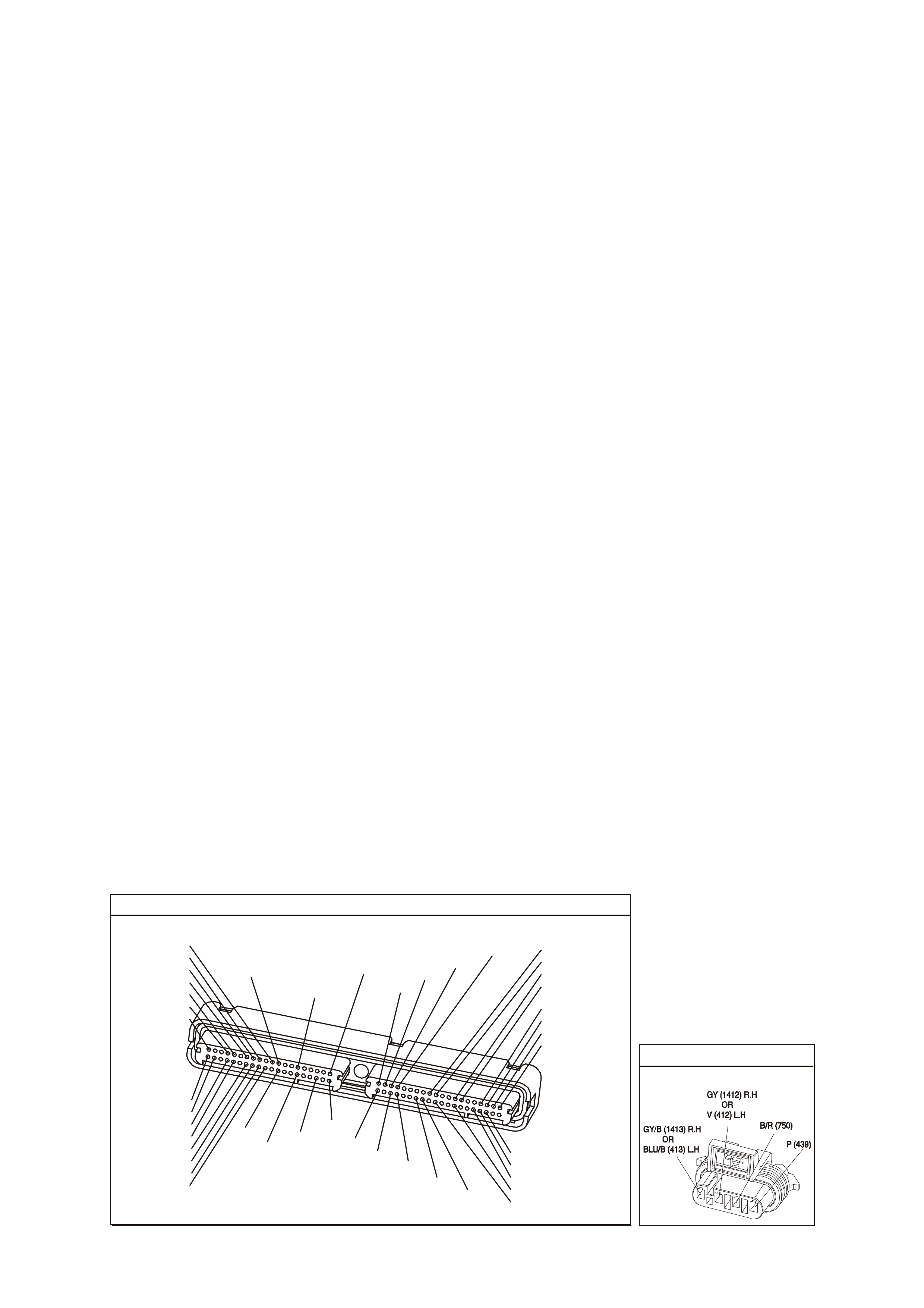
ACTION TAKEN WHEN THE DTC SETS
• The PCM illuminates the Check Powertrain Lamp when the diagnostic runs and fails.
• The PCM records the operating conditions at the time the diagnostic fails. The PCM stores this information in
the Freeze Frame/Failure Records.
• Open Loop Fueling.
CONDITIONS FOR CLEARING THE CPL/DTC
• The PCM turns the Chec k Powertrain Lamp OF F after one ignition cycle that the diagnostic runs and does not
fail.
• A last test failed (current DTC) clears when the diagnostic runs and does not fail.
• Use a Tech 2 scan tool in order to clear the CPL/DTC.
DIAGNOSTIC AIDS
• This diagnostic only runs once per ignition cycle.
• A malfunction in the HO2S heater circuits cause a DTC to set. Check HO2S heater circuit for intermittent
opens/connections.
• An oxygen supply inside the HO2S is necessary for proper operation. The HO2S wires provides the supply of
oxygen. Inspect the HO2S wires and connections for breaks or contamination. Refer to Electrical
Diagnosis/Repair Procedures in Section 12P in the VT Series I Service Information.
• Using the Freeze Frame/Failure Records data may aid in locating an intermittent condition. If you cannot
duplicate the DTC, the information included in the Freeze Frame/Failure Records data can help determ ine the
distance traveled since the DTC set. The Fail Counter and Pass Counter can also help determine how many
ignition cycles the diagnostic reported a pass and/or fail. Operate the vehicle within the same freeze frame
conditions (RPM, load, vehicle speed, temperature etc.) that you observed. This will isolate when the DTC
failed. For an intermittent condition, refer to Section 6C-2B Symptoms of the VX Series Service Information.
TEST DESCRIPTION
The numbers below refer to the step numbers on the diagnostic table.
2. T his step determines if the fault is pres ent. This test m ay tak e 5 minutes f or the diagnostic to run. For any test
that requires probing the PCM or a component harness connector, use the Connector Test Adapter Kit J
35616-A. Using this kit prevents damage to the harness connector terminals.
3. When DTCs P0133 and P0153 are set at the same time, it is a good indication that a fuel contamination
problem is present.
4. An exhaust leak 15 - 30 CM (6-12 inches) away from the HO2S can cause a DTC to set.
5. This set checks whether a good earth circuit is available.
6. This step checks the integrity of the signal circuit to the PCM.
7. This step checks the integrity of the signal circuit to the PCM.
8. Certain RTV silicone gasket materials give off vapors that can contaminate the HO2S. There is also a
possibility of s ilicone contam ination caused by silic one in the fuel. If the sens ors appear to be contam inated by
silicone and all the silicone sealant is a non silicone base, advise the custom er to try a different fuel company.
A missing fuel filler restrictor indicates the customer may have used leaded fuel.
P.C.M CONNECTOR 1
Y E1 22
(776)
(1049)
(897)
(1230)
(848)
(1226)
(772)
(647)
(632)
40
(844)
(815)
80
J1
P/B
(845)
V/W
BLU
O
(633)
(846)
B/Y
B/R
(416)
(86)
(69)
(455)
(740)
GY
BR
G
GY
(646)
(410)
GY
(842)
(1225)
V
Y
(750)
P
41
O
(774)
BR/Y
BLU
Y
B/R
B
BLU/Y
(841)
BLUE
(414)
G/W
BLU
LG
LBLU/B
1
(847)
(415)
(740)
(452)
BLU
BR Y
(750)
(826)
(421)
Y
V/W
B/W
(334)
(771)
(39)
Y
R/W
LBLU
W
BLU/W
(843)
(643)
LBLU/W
G
GY/B
BLU/B
(413)
(1413)
(1412)
(412)
GY
V
GY/B
G
(335)
YE95
HE ATED EXHAUST GAS S ENSOR

GEN III V8 PCM - DTC P0153 HEATED OXYGEN SENSOR (HO2S) SLOW RESPONSE BANK 2 SENSOR 1
Step Action Value(s) Yes No
1 Did you perform the Powertrain On-Board Diagnostic
(OBD) System Check? Go to Step 2 Go to Powertrain
OBD System
Check Table
2
IMPORTANT: If any DTCs are set (except P0153), refer
to those DTCs before proceeding with this diagnostic
table.
1. Install a Tech 2 scan tool.
2. Idle the engine at the normal operating temperature.
3. Operate the vehicle, w ithin parameters specified under
Conditions for Running the DTC, as specified, in the
supporting text.
4. Monitor the Failed This Ignition option under the DTC
Information option using the Tech 2 scan tool.
Did DTC P0153 fail this ignition?
Go to Step 3 Go to
Diagnostic Aids
3 Did DTC P0133 also fail this ignition? Go to Step 8 Go to Step 4
4 1. Check for an exhaust system leak. Refer to Section
8B Exhaust System in VX Service Information. After
you inspect the exhaust system, return to this
diagnostic.
2. If you find an exhaust leak, repair the exhaust leak as
necessary
Did you isolate an exhaust leak?
Go to Step 2 Go to Step 5
5 Inspect the following items:
• Ensure that the HO2S is securely installed.
• Check for corrosion on the terminals.
• Check the terminals tension at the HO2S and at the
PCM.
• Check for damaged wiring.
Did you find a problem in any of the above areas?
Go to Step 9 Go to Step 6
6 1. Disconnect the Bank 2 HO2S.
2. Jumper the HO2S low (PCM side) signal circuit to a
earth.
3. Monitor the Bank 2 HO2S voltage on the Engine Data
List using the Tech 2 scan tool.
Does the Tech 2 scan tool indicate a voltage within the
specified range?
350-550 mV Go to Step 7 Go to Step 10
7 1. Jumper the Bank 2 HO2S high and low (PCM side)
signal circuit to a earth.
2. Monitor the Bank 2 HO2S voltage using the Tech 2
scan tool.
Does the Tech 2 scan tool indicate a voltage below
specified value?
200mV Go to Step 12 Go to
Diagnostic Aids
8 IMPORTANT: Determine and correct the cause of the
contamination before replacing a sensor. Check for the
following conditions:
• Fuel contamination
• Use of improper RTV sealant
• Engine oil/coolant consumption
Replace the affected Heated Oxygen sensor Is the action
complete?
Go to Step 13
9 Repair the conditions as necessary.
Is the action complete? Go to Step 13
10 Repair the open Bank 2 HO2S low signal circuit or the
earthed Bank 2 HO2S high signal circuits.
Is the action complete?
Go to Step 13

GEN III V8 PCM - DTC P0153 HEATED OXYGEN SENSOR (HO2S) SLOW RESPONSE
BANK 2 SENSOR 1 (CONTINUED)
Step Action Value(s) Yes No
11 Repair the open Bank 2 HO2S high signal circuit or the
faulty PCM connections.
Is the action complete?
Go to Step 13
12 Replace the Bank 2 HO2S.
Is the action complete? Go to Step 13
13
1. Select the Diagnostic Trouble Code (DTC) option and
the Clear DTC Information option using the Tech 2
scan tool.
2. Idle the engine at the normal operating temperature.
3. Select the Diagnostic Trouble Code (DTC) option, the
DTC Information option and The Failed This Ignition
option using the Tech 2 scan tool.
4. Operate the vehicle, within the Conditions for Running
the DTC, as specified in the supporting text, if
applicable.
Does the Tech 2 scan tool indicate that this DTC reset?
Go to Step 2 Go to Step 14
14 Using the Tech 2 scan tool, check for any other DTCs.
Does the Tech 2 scan tool display any DTCs that you
have not diagnosed?
Go to the
applicable DTC
table
System OK
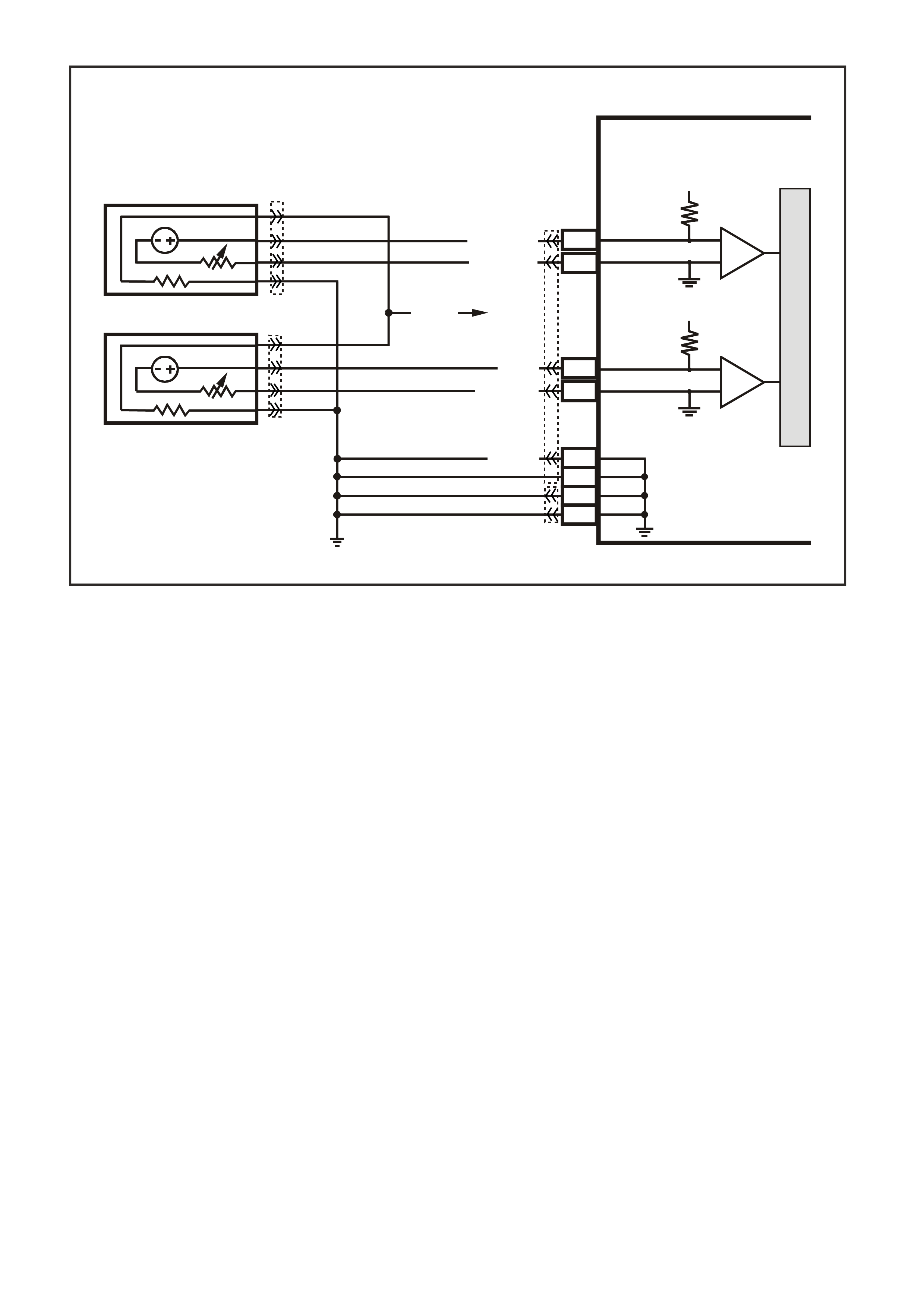
GEN III V8 PCM -
DTC P0154 HEATED OXYGEN SENSOR (HO2S) INSUFFICIENT ACTIVITY
BANK 2 S ENSOR 1
CIRCUIT DESCRIPTION
The PCM supplies a voltage of about 450 m V between the HO2S high and low signal circuits. The oxygen sensor
varies the voltage over a r ange f r om about 1000 m V when the exhaus t is r ich, down through about 10 mV when the
exhaust is lean.
The PCM monitors and stores the Heated Oxygen Sensor (HO2S) voltage information. The PCM evaluates the
HO2S voltage samples in order to determine the amount of time the HO2S voltage was out of range. The PCM
compares the stored HO2S voltage samples, taken within each sample period, and determines if majority of the
samples are out of the operating range.
The PCM monitors the HO2S voltage and detects if the voltage goes out of the bias range. If the PCM does not
detect the voltage went out of the bias range, the DTC will set.
CONDITIONS FOR RUNNING THE DTC
• DTCs P0101, P0102, P0103, P0112, P0113, P0117, P0118, P0121, P0122, P0123, P0335, P0336, P0351-
P0358, P1258 are not set.
• The ignition voltage is greater than 9.0 volts.
• The fuel system is operating in Closed Loop.
• The engine run time is greater than 70 seconds.
• The engine coolant temperature is greater than 48°C.
CONDITIONS FOR SETTING THE DTC
• The HO2S signal voltage is steady between 350 mV and 550 mV.
• The conditions are present for at least 70 seconds.
ACTION TAKEN WHEN THE DTC SETS
• The PCM illuminates the Check Powertrain Lamp when the diagnostic runs and fails.
• The PCM records the operating conditions at the time the diagnostic fails. The PCM stores this information in
the Freeze Frame/Failure Records.
• Open Loop Fueling.
D
D
B
B
A
A
C
C
GY/B (1413)
GY (1412)
RIGHT OXYGEN SENSOR
BANK TWO SENSOR ONE
LEFT OXYGEN SENSOR
BANK ONE SENSOR O NE
LOC. E5/E15
BLU/B (413)
V (412)
P (439)
TO F USE
F33
G3PCM003PT
J1-26
J1-66
J1-01
J1-40
J2-01
J2-40
J1-69
J1-29
PCM
RIGHT
OXYGEN
SENSOR
SIGNAL LO
LEFT
OXYGEN
SENSOR
SIGNAL LO
RIGHT
OXYGEN
SENSOR
SIGNAL HI
EARTH
EARTH
EARTH
EARTH
LEFT
OXYGEN
SENSOR
SIGNAL HI
IC
IC
45 0 mV
45 0 mV
M
I
C
R
O
B/R (750)
YE95
YE95
YE122
YE123
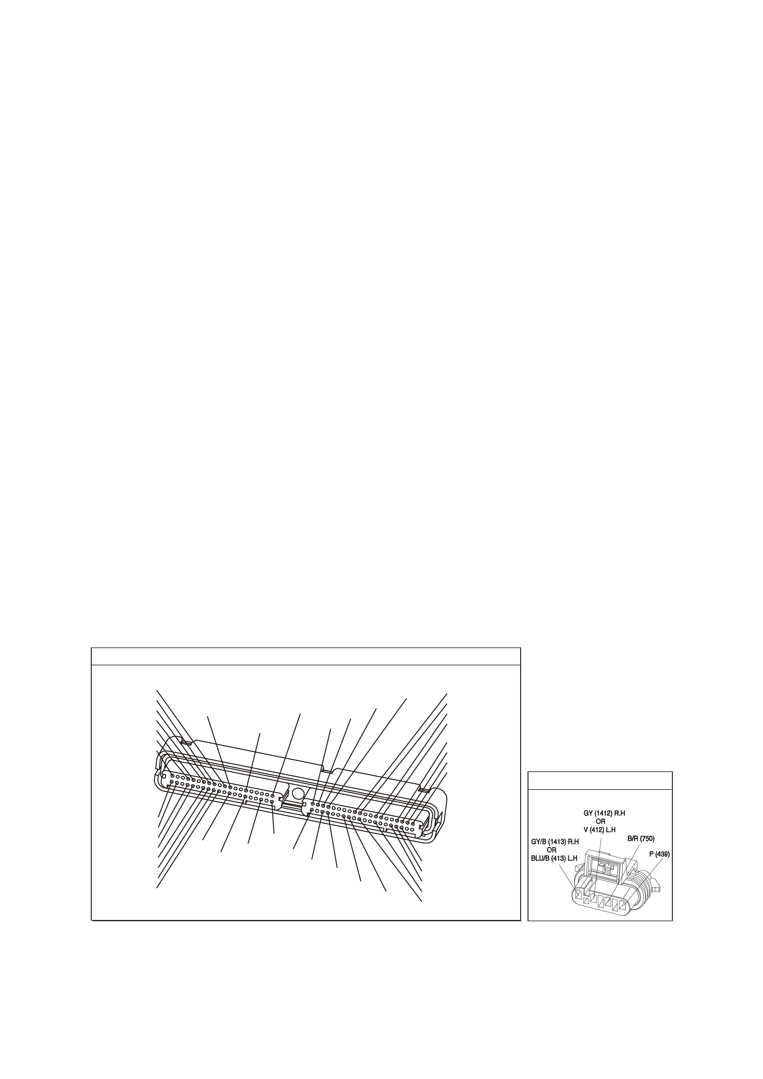
CONDITIONS FOR CLEARING THE CPL/DTC
• The PCM turns the Chec k Powertrain Lamp OF F after one ignition cycle that the diagnostic runs and does not
fail.
• A last test failed (current DTC) clears when the diagnostic runs and does not fail.
• Use a Tech 2 scan tool in order to clear the CPL/DTC.
DIAGNOSTIC AIDS
• An oxygen supply inside the HO2S is necessary for correct operation. The HO2S wires provide the supply of
oxygen. Inspect the HO2S wires and connections for breaks or contamination. Refer to Electrical
Diagnosis/Repair Procedures in Section 12P in the VT Series I Service Information.
• Using the Freeze Frame/Failure Records data may aid in locating an intermittent condition. If you cannot
duplicate the DTC, the information included in the Freeze Frame/Failure Records data can help determ ine the
distance traveled since the DTC set. The Fail Counter and Pass Counter can also help determine how many
ignition cycles the diagnostic reported a pass and/or fail. Operate the vehicle within the same freeze frame
conditions (RPM, load, vehicle speed, temperature etc.) that you observed. This will isolate when the DTC
failed.
• For an intermittent condition, refer to Section 6C3-2B Symptoms of the VX Series Service Information.
TEST DESCRIPTION
The numbers below refer to the step numbers on the diagnostic table.
2. The engine must be at normal operating temperature before performing this test. For any test that requires
probing the PCM or a component harnes s connec tor , use the Connec tor T es t Adapter Kit J 35616- A. Us ing this
kit prevents damage to the harness connector terminals.
3. Using the Freeze Frame/Failure Records data may aid in locating an intermittent condition. If you can not
duplicate the DTC, the information included in the Freeze Fram e/Failure Records data can help determine the
distance traveled s ince the DT C set. T he Fail Counter and Pas s Counter c an also aid in determ ining how many
ignition cycles the diagnostic reported a pass and/or a fail. Operate the vehicle within the same freeze frame
conditions (RPM, load, vehicle speed, tem perature etc .) that the PCM recorded. T his will isolate when the DTC
failed. refer to Section 6C3-2B Symptoms of the VX Series Service Information.
4. If the Tech 2 scan tool indicates thew HO2S voltage goes below 200 mV, this indicates the HO2S circuits and
PCM are OK.
5. This step checks whether the signal circuit from the PCM is OK.
6. Disconnecting the PCM allows using a DMM J 39200 in order to check continuity of the circuits. This aids in
locating an open or shorted circuit.
7. Disconnecting the PCM allows using a DMM J 39200 in order to check continuity of the circuits. This aids in
locating an open or shorted circuit.
P.C.M CONNECTOR 1
Y E1 22
(776)
(1049)
(897)
(1230)
(848)
(1226)
(772)
(647)
(632)
40
(844)
(815)
80
J1
P/B
(845)
V/W
BLU
O
(633)
(846)
B/Y
B/R
(416)
(86)
(69)
(455)
(740)
GY
BR
G
GY
(646)
(410)
GY
(842)
(1225)
V
Y
(750)
P
41
O
(774)
BR/Y
BLU
Y
B/R
B
BLU/Y
(841)
BLUE
(414)
G/W
BLU
LG
LBLU/B
1
(847)
(415)
(740)
(452)
BLU
BR Y
(750)
(826)
(421)
Y
V/W
B/W
(334)
(771)
(39)
Y
R/W
LBLU
W
BLU/W
(843)
(643)
LBLU/W
G
GY/B
BLU/B
(413)
(1413)
(1412)
(412)
GY
V
GY/B
G
(335)
YE95
HE ATED EXHAUST GAS S ENSOR

GEN III V8 PCM - DTC P0154 HEATED OXYGEN SENSOR (HO2S) INSUFFICIENT ACTIVITY
BANK 2 SENSOR 1
Step Action Value(s) Yes No
1 Did you perform the Powertrain On-Board Diagnostic
(OBD) System Check? Go to Step 2 Go to Powertrain
OBD System
Check Table
2
IMPORTANT: Check the HO2S for being secure before
proceeding with this DTC. A sensor that is loose could
cause this DTC to set.
1. Install a Tech 2 scan tool.
2. Idle the engine at the normal operating temperature
3. Operate the engine above 1200 RPM for two minutes.
4. Monitor the HO2S voltage display on the Engine Data
List using the Tech 2 scan tool .
Does the Tech 2 scan tool indicate the Bank 2 HO2S
voltage varying outside the specified value?
350-550 mV Go to Step 3 Go to Step 4
3 1. Turn ON the ignition leaving the engine OFF.
2. Review the Freeze Frame/Failure Records data for
this DTC and observe the parameters.
3. Turn OFF the ignition for 15 seconds.
4. Idle the engine.
5. Operate the vehicle, within the conditions required for
this diagnostic to run, and as close to the conditions
recorded in Freeze Frame/Failure Records a possible.
Special operating conditions that need to be met
before the PCM will run this diagnostic where
applicable, are listed in Conditions for Running the
DTC.
6. Select the Diagnostic Trouble Code (DTC) option, the
DTC Information option and The Failed This Ignition
optioning the Tech 2 scan tool.
Does the Tech 2 scan tool indicate that this diagnostic
failed this ignition?
Go to Step 4 Go to
Diagnostic Aids
4 1. Turn ON the ignition leaving the engine OFF.
2. Disconnect the Bank 2 HO2S.
3. Jumper the HO2S high and low (PCM side) signal
circuits to a earth.
4. Monitor the Bank 2 HO2S voltage using the Tech 2
scan tool.
Is the Bank 2 HO2S voltage below the specified value?
200 mV Go to Step 8 Go to Step 5
5 1. Remove the jumper wire.
2. Measure the voltage between the Bank 2 HO2S
heater earth circuit using a DMM J 39200.
Does the Bank 2 HO2S voltage measure above the
specified value?
375 mV Go to Step 6 Go to Step 7
6 1. Turn Off the ignition.
2. Disconnect the PCM BLUE connector.
3. Check the continuity of the Bank 2 HO2S low circuit.
4. Repair the open or the poor connection if the Bank 2
HO2S low circuit measures over the specified value.
Did you find and correct the Bank 2 HO2S low circuit
condition?
2Ω Go to Step 13 Go to Step 9
7 1. Turn Off the ignition.
2. Disconnect the PCM connectors.
3. Check the continuity of the Bank 2 HO2S low circuit.
4. Repair the open or the poor connection if the Bank 2
HO2S low circuit measures over the specified value.
Did you find and correct the Bank 2 HO2S low circuit
condition?
2Ω Go to Step 13 Go to Step 10

GEN III V8 PCM - DTC P0154 HEATED OXYGEN SENSOR (HO2S) INSUFFICIENT ACTIVITY
BANK 2 SENSOR 1 (CONTINUED)
Step Action Value(s) Yes No
8 Check for a poor Bank 2 HO2S signal or low circuit
terminal connection at the Bank 2 HO2S harness
connector and replace the terminal(s) if necessary.
Did any terminals require replacement?
Go to Step 13 Go to Step 11
9 Check for a poor Bank 2 HO2S low circuit terminal
connection at the PCM, and replace the terminal if
necessary.
Did any terminals require replacement?
Go to Step 13 Go to Step 12
10 Check for a poor Bank 2 HO2S signal circuit terminal
connection at the PCM, and replace the terminal if
necessary.
Did any terminals require replacement?
Go to Step 13 Go to Step 12
11 Replace the Bank 2 HO2S.
Is the action complete? Go to Step 13
12 1. Replace PCM.
2. Refer to Section 6C3-3 of the VX Series Service
Information for PCM Programming and
PCM/PIM/BCM Security Link Procedure.
Is action complete?
Go to Step 13
13 1. Select the Diagnostic Trouble Code (DTC) option and
the Clear DTC Information option using the Tech 2
scan tool.
2. Idle the engine at the normal operating temperature.
3. Select the Diagnostic Trouble Code (DTC) option, the
DTC Information option and The Failed This Ignition
option using the Tech 2 scan tool.
4. Operate the vehicle, within the Conditions for Running
the DTC, as specified in the supporting text, if
applicable.
Does the Tech 2 scan tool indicate that this DTC reset?
Go to Step 2 Go to Step 14
14 Using the Tech 2 scan tool, check for any other DTCs.
Does the Tech 2 scan tool display any DTCs that you
have not diagnosed?
Go to the
applicable DTC
table
System OK

GEN III V8 PCM -
DTC P0155 HEATED OXYGEN SENSOR (HO2S) HEATER CIRCUIT BANK 2 SENSOR 1
CIRCUIT DESCRIPTION
The PCM supplies a bias voltage (approximately 450 mV) on the Heated Oxygen Sensor (HO2S) signal high and
low circuits. W hen you turn the ignition to the On position, battery voltage is supplied to the HO2S heater. As the
heater reaches the operating temperature, the HO2S voltage responds by changing from a bias voltage range to
the normal operation. Typically, as the HO2S reaches the operating temperature, the HO2S voltage goes from a
bias voltage to a voltage below 300 mV. Depending on the ex haust gas content, it is possible for the HO2S voltage
to go above 450 mV.
The PCM runs the heater test only on a cold start (depends on the cumulative air flow) and only once an ignition
cycle. When you start the engine the PCM monitors the HO2S voltage. When the HO2S voltage goes above or
below the bias range threshold, the PCM determines how much time it took. If the PCM detects that the process
took too long for the HO2S to enter into normal operating range, a DTC will set. The time the process takes the
HO2S to reach operating temperature is based on the amount of air that flows into the engine.
CONDITIONS FOR RUNNING THE DTC
• DTCs P0101, P0102, P0103, P0112, P0113, P0117, P0118, P0121, P0122, P0123, P0335, P0336, P0351-
P0358, P1258 are not set.
• The intak e air temperature and the engine coolant temperature are less than 50°C and are within 8°C of each
other at engine start-up.
• The ignition voltage is between 10.0 volts and 18.0 volts.
• The engine air flow is less than 18 g/s.
CONDITIONS FOR SETTING THE DTC
• The HO2S voltage remains between 300 mV and 700 mV for a predetermined amount of time (depends on
engine coolant temperature and air flow).
ACTION TAKEN WHEN THE DTC SETS
• The PCM illuminates the Check Powertrain Lamp when the diagnostic runs and fails.
• The PCM records the operating conditions at the time the diagnostic fails. The PCM stores this information in
the Freeze Frame/Failure Records.
D
D
B
B
A
A
C
C
GY/B (1413)
GY (1412)
RIGHT OXYGEN SENSOR
BANK TWO SENSOR ONE
LEFT OXYGEN SENSOR
BANK ONE SENSOR O NE
LOC. E5/E15
BLU/B (413)
V (412)
P (439)
TO F USE
F33
G3PCM003PT
J1-26
J1-66
J1-01
J1-40
J2-01
J2-40
J1-69
J1-29
PCM
RIGHT
OXYGEN
SENSOR
SIGNAL LO
LEFT
OXYGEN
SENSOR
SIGNAL LO
RIGHT
OXYGEN
SENSOR
SIGNAL HI
EARTH
EARTH
EARTH
EARTH
LEFT
OXYGEN
SENSOR
SIGNAL HI
IC
IC
45 0 mV
45 0 mV
M
I
C
R
O
B/R (750)
YE95
YE95
YE122
YE123
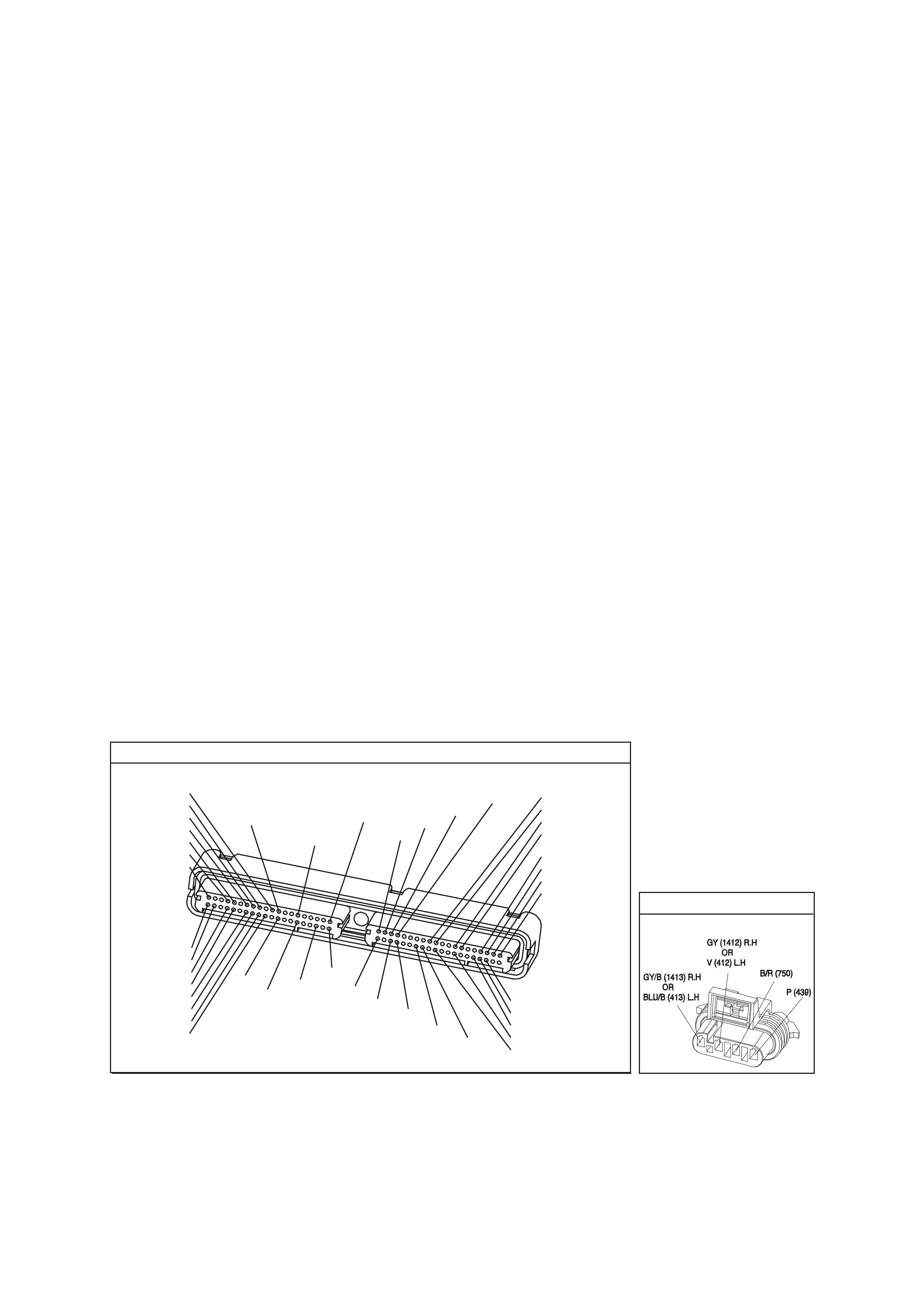
CONDITIONS FOR CLEARING THE CPL/DTC
• The PCM turns the Chec k Powertrain Lamp OF F after one ignition cycle that the diagnostic runs and does not
fail.
• A last test failed (current DTC) clears when the diagnostic runs and does not fail.
• Use a Tech 2 scan tool in order to clear the CPL/DTC.
DIAGNOSTIC AIDS
• Using the Freeze Frame/Failure Records data may aid in locating an intermittent condition. If you cannot
duplicate the DTC, the information included in the Freeze Fram e/Failure Records data can help determine the
distance traveled since the DTC Set. The Fail Counter and Pass Counter can also help determine how may
ignition cycles the diagnostic reported a pass and/or a fail. Operate the vehicle within the same freeze frame
conditions (RPM, load, vehicle speed, temperature etc.) that you observed. This will isolate when the DTC
failed. For an intermittent condition, refer to Section 6C3-2B Symptoms of the VX Series Service Information.
• The heater diagnostic will only run on a cold start and run once per ignition cycle.
• Inspect the EFI relay for proper operation if you cannot find any problems with the ignition feed circuit to the
com ponent. Probe both sides of the fuse with a test lam p connected to earth in order to determ ine if a voltage
is supplied to the fuse. Refer to EFI Relay Diagnosis Table of the VX Series Service Information.
• An oxygen supply inside the HO2S is necessary for proper operation. The HO2S wires provides the supply of
oxygen. Inspect the HO2S wires and connections for breaks or contamination.
TEST DESCRIPTION
The numbers below refer to the step numbers on the diagnostic table.
2. Allow the engine to cool before performing this test. If the sensor is at the operating temperature, the HO2S
voltage will stay high or low. If the HO2S voltage stays between 300-700 mV, this indic ates the HO2S heater is
inoperative. For any test that requires pr obing the PCM or a com ponent harnes s connector, use the Connec tor
Test Adapter Kit J 35616-A. Using this kit will prevent damage to the harness connector terminals.
3. If more than one HO2S DTC is set, this is a good indication that the HO2S fuse is open. Check all the relate
circuits going to all the heated oxygen sensors for a short to earth. If all the wiring checks to be OK, it may be
necessary to disconnect each HO2S on at a time to locate a shorted sensor.
4. This step checks whether a B+ supply is available at the sensor.
5. This step checks whether a earth is available at the sensor.
6. This step checks whether the HO2S heater element is internally open.
7. Inspect the ignition feed circuits at the engine compartment Fuse & Relay panel for poor connections.
8. Check the earth circuits for an open if more then one heater DTC sets.
P.C.M CONNECTOR 1
Y E1 22
(776)
(1049)
(897)
(1230)
(848)
(1226)
(772)
(647)
(632)
40
(844)
(815)
80
J1
P/B
(845)
V/W
BLU
O
(633)
(846)
B/Y
B/R
(416)
(86)
(69)
(455)
(740)
GY
BR
G
GY
(646)
(410)
GY
(842)
(1225)
V
Y
(750)
P
41
O
(774)
BR/Y
BLU
Y
B/R
B
BLU/Y
(841)
BLUE
(414)
G/W
BLU
LG
LBLU/B
1
(847)
(415)
(740)
(452)
BLU
BR Y
(750)
(826)
(421)
Y
V/W
B/W
(334)
(771)
(39)
Y
R/W
LBLU
W
BLU/W
(843)
(643)
LBLU/W
G
GY/B
BLU/B
(413)
(1413)
(1412)
(412)
GY
V
GY/B
G
(335)
YE95
HE ATED EXHAUST GAS S ENSOR

GEN III V8 PCM - DTC P0155 HEATED OXYGEN SENSOR (HO2S) HEATER CIRCUIT BANK 2 SENSOR 1
Step Action Value(s) Yes No
1 Did you perform the Powertrain On-Board Diagnostic
(OBD) System Check ? Go to Step 2 Go to Powertrain
OBD System
Check Table
2 IMPORTANT: Allow the engine to cool for about one half
hour before proceeding with this table.
1. Turn OFF the ignition.
2. Install the Tech 2 scan tool.
3. Turn ON the ignition leaving the engine OFF.
4. Monitor the HO2S voltage display on the Engine Data
List of the Tech 2 scan tool.
Does the HO2S voltage go from a bias voltage to above
or below the specified range?
300-700 mV Go to
Diagnostic Aids Go to Step 3
3 Inspect the HO2S heater fuse for an open.
Is the HO2S heater fuse open? Go to Step 11 Go to Step 4
4 1. Raise the vehicle.
2. Disconnect the HO2S electrical connector.
3. Probe the ignition feed circuit at the HO2S electrical
connector (PCM side) using a test lamp J34142-B
connected to earth (a known good earth. Do not use
the HO2S heater earth or the HO2S low circuits).
Does the test lamp illuminate?
Go to Step 5 Go to Step 7
5 Connect the test lamp, J34142-B, between the HO2S
ignition feed and the HO2S heater earth.
Does the test lamp illuminate?
Go to Step 6 Go to Step 8
6 Measure the resistance between the HO2S ignition feed
and the HO2S heater earth at the HO2S pigtail using a
DMM J39200.
Is the HO2S resistance within the specified range?
3.5 - 14.0Ω Go to Step 9 Go to Step 10
7 Repair the open in the HO2S ignition feed circuit to the
HO2S.
Is the action complete?
Go to Step 12
8 Repair the open in the HO2S heater earth circuit.
Is the action complete? Go to Step 12
9 1. Check for a poor connection at the HO2S harness
terminals.
2. If you find a poor connection, replace the terminals.
Did you find a poor connection?
Go to Step 12 Go to Step 10
10 Replace the HO2S.
Is the action complete? Go to Step 12
11 1. Locate and repair the short to earth in the HO2S
ignition feed circuit.
2. Replace the faulty fuse.
Is the action complete?
Go to step 12
12 1. Select the Diagnostic Trouble Code (DTC) option and
the Clear DTC Information option using the Tech 2
scan tool.
2. Idle the engine at the normal operating temperature.
3. Select the Diagnostic Trouble Code (DTC) option, the
DTC Information option and The Failed This Ignition
option using the Tech 2 scan tool.
4. Operate the vehicle within the Conditions for Running
the DTC as specified in the supporting text, if
applicable.
Does the Tech 2 scan tool indicate that this DTC reset?
Go to Step 2 Go to step 13
13 Using the Tech 2 scan tool, check for any other DTCs.
Does the Tech 2 scan tool display any DTCs that you
have not diagnosed?
Go to the
applicable DTC
table
System OK

GEN III V8 PCM -
DTC P0171 FUEL SYSTEM LEAN BANK 1
CIRCUIT DESCRIPTION
The PCM controls a Closed Loop air/fuel metering system in order to provide the best possible combination of
driveability, fuel economy, and emission control. The PCM monitors the heated oxygen sensor signal voltage and
adjusts the fuel delivery based on the signal voltage while in Closed Loop.
A change m ade to the f uel delivery changes the Long and Short T erm F uel Tr im values. T he Short T erm Fuel T r im
values change rapidly in response to the HO2S signal voltages. These changes fine tune the engine fueling. The
Long Term Fuel Trim values change in response to trends in Short Term Fuel Trim. The Long Term Fuel Trim
makes c oar se adj us tments to f ueling in or der to r e- centr e and res tor e c ontrol to Shor t T er m Fuel T r im. You can use
a Tech 2 scan tool in order to monitor the Short and Long Term Fuel Trim. The ideal fuel trim values are around
0%.
A positive Fuel Trim value indicates that the PCM is adding fuel in order to compensate for a lean condition. A
negative Fuel Trim value indicates that the PCM is reducing the amount of fuel in order to compensate for a rich
condition. If the PCM detects an excessively Rich or Lean condition, the PCM sets a DTC. The long term fuel trim
diagnostic parameter is an average of several of the long term speed load learn cells, which the PCM selects
based on the engine speed and the engine load.
CONDITIONS FOR RUNNING THE DTC
• DTCs P0101, P0102, P0103, P0107, P0108, P0112, P0113, P0117, P0118, P0121, P0122, P0123, P0335,
P0336, P0351-P0358, P1111, P1112, or P1258 are not set.
• The engine coolant temperature is between 50°C and 115°C.
• The Barometric pressure is greater than 74 kPa.
• The MAF is between 5.0 g/s and 90 g/s.
• The MAP pressure is between 26 kPa and 90 kPa.
• The IAT is between -20°C and 90°C.
• The engine speed is between 400 RPM and 3000 RPM.
• The TP sensor angle is less than 90%.
• The vehicle speed is less than 137 km/h.
D
D
B
B
A
A
C
C
GY/B (1413)
GY (1412)
RIGHT OXYGEN SENSOR
BANK TWO SENSOR ONE
LEFT OXYGEN SENSOR
BANK ONE SENSOR O NE
LOC. E5/E15
BLU/B (413)
V (412)
P (439)
TO F USE
F33
G3PCM003PT
J1-26
J1-66
J1-01
J1-40
J2-01
J2-40
J1-69
J1-29
PCM
RIGHT
OXYGEN
SENSOR
SIGNAL LO
LEFT
OXYGEN
SENSOR
SIGNAL LO
RIGHT
OXYGEN
SENSOR
SIGNAL HI
EARTH
EARTH
EARTH
EARTH
LEFT
OXYGEN
SENSOR
SIGNAL HI
IC
IC
45 0 mV
45 0 mV
M
I
C
R
O
B/R (750)
YE95
YE95
YE122
YE123

CONDITIONS FOR SETTING THE DTC
• The average Long Term Fuel Trim cell values are above a predetermined threshold.
• All the above conditions are present for at least six seconds.
ACTION TAKEN WHEN THE DTC SETS
• The PCM illuminates the Check Powertrain Lamp when the diagnostic runs and fails.
• The PCM records the operating conditions at the time the diagnostic fails. The PCM stores this information in
the Freeze Frame/Failure Records.
CONDITIONS FOR CLEARING THE CPL/DTC
• The PCM turns the CPL OFF after the first drive trips that the diagnostic runs and does not fail, within the same
conditions that the DTC last failed.
NOTE: If the last failure was during a non-typical driving condition, the CPL may remain ON longer than the three
drive trips. Review the Freeze Frame/Failure Records for the last failure conditions.
• A History DTC clears after forty consecutive warm-up cycles, if this or any other emission related diagnostic
does not report any failures.
• A last test failed (Current DTC) clears when the diagnostic runs and does not fail.
• PCM battery voltage is interrupted.
• Use a Tech 2 scan tool in order to clear the CPL/DTC.
DIAGNOSTIC AIDS
• This DTC sets if the engine runs out of fuel.
• A fuel delivery malfunction causes this DTC to set. Thoroughly inspect all items that cause a lean condition.
• For an intermittent condition, refer to Section 6C3-2B Symptoms of the VX Series Service Information.
TEST DESCRIPTION
The numbers below refer to the step numbers on the diagnostic table.
2. This step determines whether the fault is present. For any test that requires probing the PCM or a component
harness connector, use the Connector Test Adapter Kit J 35626-A. Using the kit prevents damage to the
harness connector terminals.
3. Using the Freeze Frame/Failure Records data may aid in locating an intermittent condition. If you cannot
duplicate the DTC, the information included in the Freeze Frame/Failure Records data can help determine the
distance traveled since the DTC set. The Fail Counter and Pass Counter can also help determine how many
ignition cycles the diagnostic reported a pass and/or a fail. Operate the vehicle within the same freeze frame
conditions (RPM, load, vehicle speed, temperature etc.) that you observed. This will isolate when the DTC
failed. For an intermittent condition, refer to Section 6C3-2B Symptoms of the VX Series Service Information.
4. If DTC 174 is also set indicates both banks of the engine are operating lean. Inspect the items that would
cause both banks to operate lean.
5. A vacuum leak causes DTCs P0171 and P0174 to set at the same time. Inspect all areas of the engine for a
vacuum leak. Also inspect the PCV valve for being the correct one for this application. Make sure the engine oil
fill cap is in place and that it is tight. Check that the engine oil dip stick is fully seated.
GEN III V8 PCM - DTC P0171 FUEL SYSTEM LEAN BANK 1
Step Action Value(s) Yes No
1 Did you perform the Powertrain On-Board Diagnostic
(OBD System Check? Go to Step 2 Go to Powertrain
OBD System
Check Table
2 IMPORTANT: If any DTCs are set, except P0171 and
P0174, refer to those DTCs before proceeding with this
diagnostic.
1. Install a Tech 2 scan tool.
2. Idle the engine at the normal operating temperature.
3. Fuel system in Closed Loop.
4. Monitor the LT FT Bank 1 display on the Fuel Trim
Data List using the Tech 2 scan tool.
Is the LT FT less than the specified value indicated?
24%LT Go to Step 3 Go to Step 4

GEN III V8 PCM - DTC P0171 FUEL SYSTEM LEAN BANK 1 (CONTINUED)
Step Action Value(s) Yes No
3 1. Turn ON the ignition leaving the engine OFF.
2. Review the Freeze Frame/Failure Records data for
this DTC and observe the parameters.
3. Turn OFF the ignition for 15 seconds.
4. Start the engine.
5. Operate the vehicle, within the conditions required for
this diagnostic to run, and as close to the conditions
recorded in Freeze Frame/Failure Records as
possible. Special operating conditions that need to be
met before the PCM will run diagnostic, where
applicable, are listed in Conditions for Running the
DTC.
6. Select the Diagnostic Trouble Code (DTC) option, the
DTC Information option and The Failed This Ignition
option using the Tech 2 scan tool.
Does the Tech 2 scan tool indicate that this diagnostic
failed this ignition?
Go to Step 4 Go to
Diagnostic Aids
4 Is DTC P0174 also set? Go to Step 5 Go to Step 6
5 Inspect the following items:
• Vacuum hoses for splits, kinks, and proper
connections. Refer to Vacuum Hose Routing
Diagrams in Section 6E3 Emission Control in VX
Service Information.
• Crankcase ventilation valve and/or system for leaks.
Refer to Crankcase Ventilation System Description in
Section 6C3-1 of the VX Series Service Information.
• Contaminated Fuel.
• PCM and sensor earths are clean, tight and in the
proper locations.
• Air induction system after MAF sensor for vacuum
leaks.
• Engine mechanical failure. Refer to Section 6A3
Engine Mechanical in VX Service Information.
Did you find any problems in any of the above areas?
Go to Step 7 Go to Fuel
System
Diagnosis Table
6 Inspect the following items:
• Bank 1 exhaust leaks and missing or loose exhaust
hardware.
• Bank 1 HO2S 1 is installed securely and the
electrical connector not contacting exhaust sy stem or
ignition wires.
• Engine mechanical failure. Refer to Section 6A3
Engine Mechanical in VX Service Information.
• Vacuum leaks that will only affect bank 1, such as
the intake manifold, the injector O rings, etc.
Was a problem found in any of the above areas?
Go to Step 7 Refer to Fuel
System
Diagnosis Table
in this Section
7 Repair or replace any faulty items found.
Is the action complete? Go to Step 8
8 1. Select the Diagnostic Trouble Code (DTC) option
and the Clear DTC Information option using the Tech
2 scan tool.
2. Idle the engine at the normal operating temperature.
3. Select the Diagnostic Trouble Code (DTC) option,
the DTC Information option and The Failed This
Ignition option using the Tech 2 scan tool.
4. Operate the vehicle, within the Conditions for
Running the DTC, as specified in the supporting text,
if applicable.
Does the Tech 2 scan tool indicate that this DTC reset?
Go to Step 2 Go to step 9
9 Using the Tech 2 scan tool, check for any other DTCs.
Does the Tech 2 scan tool display any DTCs that you
have not diagnosed?
Go to the
applicable DTC
table
System OK

GEN III V8 PCM -
DTC P0172 FUEL SYSTEM RICH BANK 1
CIRCUIT DESCRIPTION
The PCM controls a Closed Loop air/fuel metering system in order to provide the best possible combination of
driveability, fuel economy, and emission control. The PCM monitors the heated oxygen sensor signal voltage and
adjusts the fuel delivery based on the signal voltage while in Closed Loop. A change made to the fuel delivery
changes the Long and Short Term Fuel Trim values.
The Short Term Fuel Trim values change rapidly in response to the HO2S signal voltages. These changes fine
tune the engine fueling. The Long Term Fuel Trim values change in response to trends in Short Term Fuel Trim.
The Long Term Fuel Trim makes coarse adjustments to fueling in order to re-centre and restore control to Short
Term Fuel Trim.
You can us e a Tec h 2 scan tool in order to m onitor the Short and Long T erm Fuel T rim . The ideal fuel trim values
are around 0%. A positive Fuel Trim value indicates that the PCM is adding fuel in order to compensate for a lean
condition. A negative F uel T rim value indic ates that the PCM is reduc ing the am ount of f uel in order to c om pensate
for a rich condition. If the PCM detects an exc essively Ric h or Lean condition, the PCM sets a DT C. The long ter m
fuel trim diagnostic parameter is an average of several of the long term speed load learn cells which the PCM
selects based on the engine speed and the engine load.
CONDITIONS FOR RUNNING THE DTC
• DTCs P0101, P0102, P0103, P0107, P0108, P0112, P0113, P0117, P0118, P0121, P0122, P0123, P0335,
P0336, P0351-P0358, P1111, P1112, or P1258 are not set.
• The engine coolant temperature is between 50°C and 115°C.
• The Barometric pressure is greater than 74 kPa.
• The MAF is between 5.0 g/s and 90 g/s.
• The MAP pressure is between 26 kPa and 90 kPa.
• The IAT is between -20°C and 90°C.
• The engine speed is between 400 RPM and 3000 RPM.
• The TP sensor angle is less than 90%.
• The vehicle speed is less than 137 km/h.
D
D
B
B
A
A
C
C
GY/B (1413)
GY (1412)
RIGHT OXYGEN SENSOR
BANK TWO SENSOR ONE
LEFT OXYGEN SENSOR
BANK ONE SENSOR O NE
LOC. E5/E15
BLU/B (413)
V (412)
P (439)
TO F USE
F33
G3PCM003PT
J1-26
J1-66
J1-01
J1-40
J2-01
J2-40
J1-69
J1-29
PCM
RIGHT
OXYGEN
SENSOR
SIGNAL LO
LEFT
OXYGEN
SENSOR
SIGNAL LO
RIGHT
OXYGEN
SENSOR
SIGNAL HI
EARTH
EARTH
EARTH
EARTH
LEFT
OXYGEN
SENSOR
SIGNAL HI
IC
IC
45 0 mV
45 0 mV
M
I
C
R
O
B/R (750)
YE95
YE95
YE122
YE123

CONDITIONS FOR SETTING THE DTC
• The average Long Term Fuel Trim cell values are above a predetermined threshold.
• All the above conditions are present for at least 49 seconds.
ACTION TAKEN WHEN THE DTC SETS
• The PCM illuminates the Check Powertrain Lamp The PCM illuminates the Check Powertrain Lamp when the
diagnostic runs and fails.
• The PCM records the operating conditions at the time the diagnostic fails. The PCM stores this information in
the Freeze Frame/Failure Records.
CONDITIONS FOR CLEARING THE CPL/DTC
• The PCM turns the Check Powertrain Lamp OFF after one drive trip that the diagnostic runs and does not fail
within the same conditions that the DTC last failed.
NOTE: If the failure was during a non-typical driving condition, the Check Powertrain Lamp may remain on
longrer than one drive trip. Review the Freeze Frame/Failure Records for the last failure conditions.
• A last test failed (current DTC) clears when the diagnostic runs and does not fail.
• Use a Tech 2 scan tool in order to clear the CPL/DTC.
DIAGNOSTIC AIDS
• For an intermittent condition, refer to Section 6C3-2B Symptoms of the VX Series Service Information.
TEST DESCRIPTION
The numbers below refer to the step numbers on the diagnostic table.
2. This step determines whether the fault is present.
3. Using the Freeze Frame/Failure Records data may aid in locating an intermittent condition. If you cannot
duplicate the DTC, the information included in the Freeze Frame/Failure Records data can help determine the
distance traveled since the DTC set. The Fail Counter and Pass Counter can also help determine how many
ignition cycles the diagnostic reported a pass and/or a fail. Operate the vehicle within the same freeze frame
conditions(RPM, load, vehicle speed, temperature etc.) that you observed. This will isolate when the DTC
failed. For an intermittent condition, refer to Section 6C3-2B Symptoms of the VX Series Service Information.
4. If DTC P0175 is also set, then both banks are operating rich. Inspect items that would cause both banks to
operate rich.
5. Excessive fuel in the oil will cause DTCs P0172 and P0175 to set at the same time. Remove the PCV valve
from the intake manifold and plug with a suitable stopper. Also, disconnect the fresh air pipe from the rocker
cover and plug with a suitable stopper. If the long term and short term fuel trim values increase, indicates there
is fuel in the oil.
GEN III V8 PCM - DTC P0172 FUEL SYSTEM RICH BANK 1
Step Action Value(s) Yes No
1 Did you perform the Powertrain On-Board Diagnostic
(OBD System Check? Go to Step 2 Go to Powertrain
OBD System
Check Table
2 IMPORTANT: If any DTCs are set, except P0172 and
P0175, refer to those DTCs before proceeding with this
diagnostic.
1. Install a Tech 2 scan tool.
2. Idle the engine at the normal operating temperature.
3. Fuel system in Closed Loop.
4. Monitor the LT FT Bank 1 display on the Fuel Trim
Data List using the Tech 2 scan tool.
Is the LT FT greater than the specified value indicated?
-13%LT Go to Step 3 Go to Step 4

GEN III V8 PCM - DTC P0172 FUEL SYSTEM RICH BANK 1 (CONTINUED)
Step Action Value(s) Yes No
3 1. Turn ON the ignition leaving the engine OFF.
2. Review the Freeze Frame/Failure Records data for
this DTC and observe the parameters.
3. Turn OFF the ignition for 15 seconds.
4. Start the engine.
5. Operate the vehicle, within the conditions required
for this diagnostic to run, and as close to the
conditions recorded in Freeze Frame/Failure
Records as possible. Special operating conditions
that need to be met before the PCM will run
diagnostic, where applicable, are listed in Conditions
for Running the DTC.
6. Select the Diagnostic Trouble Code (DTC) option,
the DTC Information option and The Failed This
Ignition option using the Tech 2 scan tool.
Does the Tech 2 scan tool indicate that this diagnostic
failed this ignition?
Go to Step 4 Go to
Diagnostic Aids
4 Is DTC P0175 also set? Go to Step 5 Go to Step 6
5 Inspect the following items:
• Collapsed air intake duct.
• The air filter element for being restricted.
• MAF sensor for being installed in the proper direction
and for foreign objects blocking the inlet screen.
Refer to MAF Sensor Replacement in Section 6C3-3
of the VX Series Service Information.
• For fuel in the pressure regulator line. Refer to Fuel
System Diagnosis Table of the VX Series Service
Information.
• Check for the incorrect MAP/BARO display.
Compare to another vehicle.
• For excessive fuel in the crankcase. Change oil as
necessary.
Was a problem found in any of the above areas?
Go to Step 7 Go to Fuel
System
Diagnosis Table
6 IMPORTANT: When the fuel system check is finished,
return to this table.
Inspect the Bank 1 injectors for leaking, refer to Fuel
System Diagnosis Table of the VX Series Service
Information.
Are any injectors leaking?
Go to Step 9 Go to Step 8
7 Repair or replace any faulty items found.
Is the action complete? Go to Step 9
8 Replace the faulty HO2S.
Is the action complete? Go to Step 9
9 1. Select the Diagnostic Trouble Code (DTC) option and
the Clear DTC Information option using the Tech 2
scan tool.
2. Idle the engine at the normal operating temperature.
3. Select the Diagnostic Trouble Code (DTC) option, the
DTC Information option and The Failed This Ignition
option using the Tech 2 scan tool.
4. Operate the vehicle within the Conditions for Running
the DTC, as specified in the supporting text, if
applicable.
Does the Tech 2 scan tool indicate that this DTC reset?
Go to Step 2 Go to Step 10
10 Using the Tech 2 scan tool, check for any other DTCs.
Does the Tech 2 scan tool display any DTCs that you
have not diagnosed?
Go to the
applicable DTC
table
System OK

GEN III V8 PCM -
DTC P0174 FUEL SYSTEM LEAN BANK 2
CIRCUIT DESCRIPTION
The PCM controls a Closed Loop air/fuel metering system in order to provide the best possible combination of
driveability, fuel economy, and emission control. The PCM monitors the heated oxygen sensor signal voltage and
adjusts the fuel delivery based on the signal voltage while in Closed Loop. A change made to the fuel delivery
changes the Long and Short Term Fuel Trim values.
The Short Term Fuel Trim values change rapidly in response to the HO2S signal voltages. These changes fine
tune the engine fueling. The Long Term Fuel Trim values change in response to trends in Short Term Fuel Trim.
The Long Term Fuel Trim makes coarse adjustments to fueling in order to re-centre and restore control to Short
Term Fuel Trim.
You can us e a Tec h 2 scan tool in order to m onitor the Short and Long T erm Fuel T rim . The ideal fuel trim values
are around 0%. A positive Fuel Trim value indicates that the PCM is adding fuel in order to compensate for a lean
condition. A negative F uel T rim value indic ates that the PCM is reduc ing the am ount of f uel in order to c om pensate
for a rich condition. If the PCM detects an exc essively Ric h or Lean condition, the PCM sets a DT C. The long ter m
fuel trim diagnostic parameter is an average of several of the long term speed load learn cells which the PCM
selects based on the engine speed and the engine load.
CONDITIONS FOR RUNNING THE DTC
• DTCs P0101, P0102, P0103, P0107, P0108, P0112, P0113, P0117, P0118, P0121, P0122, P0123, P0335,
P0336, P0351-P0358, P1111, P1112, or P1258 are not set.
• The engine coolant temperature is between 50°C and 115°C.
• The Barometric pressure is greater than 74 kPa.
• The MAF is between 5.0 g/s and 90 g/s.
• The MAP pressure is between 26 kPa and 90 kPa.
• The IAT is between -20°C and 90°C.
• The engine speed is between 400 RPM and 3000 RPM.
• The TP sensor angle is less than 90%.
• The vehicle speed is less than 137 km/h.
D
D
B
B
A
A
C
C
GY/B (1413)
GY (1412)
RIGHT OXYGEN SENSOR
BANK TWO SENSOR ONE
LEFT OXYGEN SENSOR
BANK ONE SENSOR O NE
LOC. E5/E15
BLU/B (413)
V (412)
P (439)
TO F USE
F33
G3PCM003PT
J1-26
J1-66
J1-01
J1-40
J2-01
J2-40
J1-69
J1-29
PCM
RIGHT
OXYGEN
SENSOR
SIGNAL LO
LEFT
OXYGEN
SENSOR
SIGNAL LO
RIGHT
OXYGEN
SENSOR
SIGNAL HI
EARTH
EARTH
EARTH
EARTH
LEFT
OXYGEN
SENSOR
SIGNAL HI
IC
IC
45 0 mV
45 0 mV
M
I
C
R
O
B/R (750)
YE95
YE95
YE122
YE123

CONDITIONS FOR SETTING THE DTC
• The average Long Term Fuel Trim cell values are above a predetermined threshold.
• All the above conditions are present for at least six seconds.
ACTION TAKEN WHEN THE DTC SETS
• The PCM illuminates the Check Powertrain Lamp when the diagnostic runs and fails.
• The PCM records the operating conditions at the time the diagnostic fails. The PCM stores this information in
the Freeze Frame/Failure Records.
CONDITIONS FOR CLEARING THE CPL/DTC
• The PCM turns the Check Powertrain Lamp OFF after one drive trip that the diagnostic runs and does not fail
within the same conditions that the DTC last failed.
NOTE: If the failure was during a non-typical driving condition, the Check Powertrain Lamp may remain on
longrer than one drive trip. Review the Freeze Frame/Failure Records for the last failure conditions.
• A last test failed (current DTC) clears when the diagnostic runs and does not fail.
• Use a Tech 2 scan tool in order to clear the CPL/DTC.
DIAGNOSTIC AIDS
• This DTC sets if the engine runs out of fuel.
• A fuel delivery malfunction causes this DTC to set. Thoroughly inspect all items that cause a lean condition.
• For an intermittent condition, refer to Section 6C3-2B Symptoms of the VX Series Service Information.
TEST DESCRIPTION
The numbers below refer to the step numbers on the diagnostic table.
2. This step determines whether the fault is present. For any test that requires probing the PCM or a component
harness connector, use the Connector Test Adapter Kit J 35626-A. Using the kit prevents damage to the
harness connector terminals.
3. Using the Freeze Frame/Failure Records data may aid in locating an intermittent condition. If you cannot
duplicate the DTC, the information included in the Freeze Frame/Failure Records data can help determine the
distance traveled since the DTC set. The Fail Counter and Pass Counter can also help determine how many
ignition cycles the diagnostic reported a pass and/or a fail. Operate the vehicle within the same freeze frame
conditions (RPM, load, vehicle speed, temperature etc.) that you observed. This will isolate when the DTC
failed. For an intermittent condition, refer to Section 6C3-2B Symptoms of the VX Series Service Information.
4. If DTC P0174 is also set this indicates both banks of the engine are operating lean. Inspect the items that
would cause both banks to operate lean.
5. A vacuum leak causes DTCs P0171 and P0174 to set at the same time. Inspect all areas of the engine for a
vacuum leak. Also, inspect the PCV valve for being the correct one for this application. Make sure the engine
oil fill cap is in place and that it is tight. Check that the engine oil dip stick is fully seated.
GEN III V8 PCM - DTC P0174 FUEL SYSTEM LEAN BANK 2
Step Action Value(s) Yes No
1 Did you perform the Powertrain On-Board Diagnostic
(OBD System Check? Go to Step 2 Go to Powertrain
OBD System
Check Table
2 IMPORTANT: If any DTCs are set, except P0171 and
P0174, refer to those DTCs before proceeding with this
diagnostic.
1. Install a Tech 2 scan tool.
2. Idle the engine at the normal operating temperature.
3. Fuel system in Closed Loop.
4. Monitor the LT FT Bank 2 display on the Fuel Trim
Data List using the Tech 2 scan tool.
Is the LT FT less than the specified value indicated?
24%LT Go to Step 3 Go to Step 4

GEN III V8 PCM - DTC P0174 FUEL SYSTEM LEAN BANK 2 (CONTINUED)
Step Action Value(s) Yes No
3 1. Turn ON the ignition leaving the engine OFF.
2. Review the Freeze Frame/Failure Records data for
this DTC and observe the parameters.
3. Turn OFF the ignition for 15 seconds.
4. Start the engine.
5. Operate the vehicle, within the conditions required for
this diagnostic to run, and as close to the conditions
recorded in Freeze Frame/Failure Records as
possible. Special operating conditions that need to be
met before the PCM will run diagnostic, where
applicable, are listed in Conditions for Running the
DTC.
6. Select the Diagnostic Trouble Code (DTC) option, the
DTC Information option and The Failed This Ignition
option using the Tech 2 scan tool.
Does the Tech 2 scan tool indicate that this diagnostic
failed this ignition?
Go to Step 4 Go to
Diagnostic Aids
4 Is DTC P0171 also set? Go to Step 5 Go to Step 6
5 Inspect the following items:
• Vacuum hoses for splits, kinks, and proper
connections. Refer to Vacuum Hose Routing
Diagrams in Section 6E3 Emission Control of the VX
Series Service Information.
• Crankcase ventilation valve and/or system for leaks.
Refer to Crankcase Ventilation System Description in
Section 6C3-1 in VX Service Information.
• Contaminated Fuel.
• PCM and sensor earths are clean, tight and in the
proper locations.
• Air induction system after MAF sensor for vacuum
leaks.
• Engine mechanical failure. Refer to Section 6A3
Engine Mechanical Section 14A in VX Service
Information.
Did you find any problems in any of the above areas?
Go to Step 7 Go to Fuel
System
Diagnosis Table
6 Inspect the following items:
• Bank 2 exhaust leaks and missing or loose exhaust
hardware.
• Bank 2 HO2S 1 is installed securely and the
electrical connector not contacting exhaust sy stem or
ignition wires.
• Engine mechanical failure. Refer to Section 6A3
Engine Mechanical in Section 14A in VX Service
Information.
• Vacuum leaks that will only affect bank 2, such as
the intake manifold, the injector O rings, etc.
Was a problem found in any of the above areas?
Go to Step 7 Refer to Fuel
System
Diagnosis Table
in this Section
7 Repair or replace any faulty items found.
Is the action complete? Go to Step 8
8 1. Select the Diagnostic Trouble Code (DTC) option and
the Clear DTC Information option using the Tech 2
scan tool.
2. Idle the engine at the normal operating temperature.
3. Select the Diagnostic Trouble Code (DTC) option, the
DTC Information option and The Failed This Ignition
option using the Tech 2 scan tool.
4. Operate the vehicle, within the Conditions for Running
the DTC, as specified in the supporting text, if
applicable.
Does the Tech 2 scan tool indicate that this DTC reset?
Go to Step 2 Go to step 9
9 Using the Tech 2 scan tool, check for any other DTCs.
Does the Tech 2 scan tool display any DTCs that you
have not diagnosed?
Go to the
applicable DTC
table
System OK

GEN III V8 PCM -
DTC P0175 FUEL SYSTEM RICH BANK 2
CIRCUIT DESCRIPTION
The PCM controls a Closed Loop air/fuel metering system in order to provide the best possible combination of
driveability, fuel economy, and emission control. The PCM monitors the heated oxygen sensor signal voltage and
adjusts the fuel delivery based on the signal voltage while in Closed Loop. A change made to the fuel delivery
changes the Long and Short Term Fuel Trim values.
The Short Term Fuel Trim values change rapidly in response to the HO2S signal voltages. These changes fine
tune the engine fueling. The Long Term Fuel Trim values change in response to trends in Short Term Fuel Trim.
The Long Term Fuel Trim makes coarse adjustments to fueling in order to re-centre and restore control to Short
Term Fuel Trim.
You can us e a Tec h 2 scan tool in order to m onitor the Short and Long T erm Fuel T rim . The ideal fuel trim values
are around 0%. A positive Fuel Trim value indicates that the PCM is adding fuel in order to compensate for a lean
condition. A negative F uel T rim value indic ates that the PCM is reduc ing the am ount of f uel in order to c om pensate
for a rich condition. If the PCM detects an exc essively Ric h or Lean condition, the PCM sets a DT C. The long ter m
fuel trim diagnostic parameter is an average of several of the long term speed load learn cells, which the PCM
selects based on the engine speed and the engine load.
CONDITIONS FOR RUNNING THE DTC
• DTCs P0101, P0102, P0103, P0107, P0108, P0112, P0113, P0117, P0118, P0121, P0122, P0123, P0335,
P0336, P0351-P0358, P1111, P1112, or P1258 are not set.
• The engine coolant temperature is between 50°C and 115°C.
• The Barometric pressure is greater than 74 kPa.
• The MAF is between 5.0 g/s and 90 g/s.
• The MAP pressure is between 26 kPa and 90 kPa.
• The IAT is between -20°C and 90°C.
• The engine speed is between 400 RPM and 3000 RPM.
• The TP sensor angle is less than 90%.
• The vehicle speed is less than 137 km/h.
D
D
B
B
A
A
C
C
GY/B (1413)
GY (1412)
RIGHT OXYGEN SENSOR
BANK TWO SENSOR ONE
LEFT OXYGEN SENSOR
BANK ONE SENSOR O NE
LOC. E5/E15
BLU/B (413)
V (412)
P (439)
TO F USE
F33
G3PCM003PT
J1-26
J1-66
J1-01
J1-40
J2-01
J2-40
J1-69
J1-29
PCM
RIGHT
OXYGEN
SENSOR
SIGNAL LO
LEFT
OXYGEN
SENSOR
SIGNAL LO
RIGHT
OXYGEN
SENSOR
SIGNAL HI
EARTH
EARTH
EARTH
EARTH
LEFT
OXYGEN
SENSOR
SIGNAL HI
IC
IC
45 0 mV
45 0 mV
M
I
C
R
O
B/R (750)
YE95
YE95
YE122
YE123

CONDITIONS FOR SETTING THE DTC
• The average Long Term Fuel Trim cell values are above a predetermined threshold.
• All the above conditions are present for at least 49 seconds.
ACTION TAKEN WHEN THE DTC SETS
• The PCM illuminates the Check Powertrain Lamp when the diagnostic runs and fails.
• The PCM records the operating conditions at the time the diagnostic fails. The PCM stores this information in
the Freeze Frame/Failure Records.
CONDITIONS FOR CLEARING THE CPL/DTC
• The PCM turns the Check Powertrain Lamp OFF after one drive trip that the diagnostic runs and does not fail
within the same conditions that the DTC last failed.
NOTE: If the failure was during a non-typical driving condition, the Check Powertrain Lamp may remain on
longrer than one drive trip. Review the Freeze Frame/Failure Records for the last failure conditions.
• A last test failed (current DTC) clears when the diagnostic runs and does not fail.
• Use a Tech 2 scan tool in order to clear the CPL/DTC.
DIAGNOSTIC AIDS
• For an intermittent condition, refer to Section 6C3-2B Symptoms of the VX Series Service Information.
TEST DESCRIPTION
The numbers below refer to the step numbers on the diagnostic table.
2. This step determines whether the fault is present.
3. Using the Freeze Frame/Failure Records data may aid in locating an intermittent condition. If you cannot
duplicate the DTC, the information included in the Freeze Frame/Failure Records data can help determine the
distance traveled since the DTC set The Fail Counter and Pass Counter can also help determine how many
ignition cycles the diagnostic reported a pass and/or a fail. Operate the vehicle within the same freeze frame
conditions (RPM, load, vehicle speed, temperature etc.) that you observed. This will isolate when the DTC
failed. For an intermittent condition, refer to Section 6C3-2B Symptoms of the VX Series Service Information.
4. If DTC P0175 is also set, then both banks are operating rich. Inspect items that would cause both banks to
operate rich.
5. Excessive fuel in the oil will cause DTCs P0172 and P0175 to set at the same time. Remove the PCV valve
from the intake manifold and plug with a suitable stopper. Also, disconnect the fresh air pipe from the rocker
cover and plug with a suitable stopper. If the long term and short term fuel trim values increase, indicates there
is fuel in the oil.
GEN III V8 PCM - DTC P0175 FUEL SYSTEM RICH BANK 2
Step Action Value(s) Yes No
1 Did you perform the Powertrain On-Board Diagnostic
(OBD System Check? Go to Step 2 Go to Powertrain
OBD System
Check Table
2 IMPORTANT: If any DTCs are set, except P0172 and
P0175, refer to those DTCs before proceeding with this
diagnostic.
1. Install a Tech 2 scan tool.
2. Idle the engine at the normal operating temperature.
3. Fuel system in Closed Loop.
4. Monitor the LT FT Bank 2 display on the Fuel Trim
Data List using the Tech 2 scan tool.
Is the LT FT greater than the specified value indicated?
-13%LT Go to Step 3 Go to Step 4

GEN III V8 PCM - DTC P0175 FUEL SYSTEM RICH BANK 2 (CONTINUED)
Step Action Value(s) Yes No
3 1. Turn ON the ignition leaving the engine OFF.
2. Review the Freeze Frame/Failure Records data for
this DTC and observe the parameters.
3. Turn OFF the ignition for 15 seconds.
4. Start the engine.
5. Operate the vehicle, within the conditions required for
this diagnostic to run, and as close to the conditions
recorded in Freeze Frame/Failure Records as
possible. Special operating conditions that need to be
met before the PCM will run diagnostic, where
applicable, are listed in Conditions for Running the
DTC.
6. Select the Diagnostic Trouble Code (DTC) option, the
DTC Information option and The Failed This Ignition
option using the Tech 2 scan tool.
Does the Tech 2 scan tool indicate that this diagnostic
failed this ignition?
Go to Step 4 Go to
Diagnostic Aids
4 Is DTC P0172 also set? Go to Step 5 Go to Step 6
5 Inspect the following items:
• Collapsed air intake duct.
• Restricted air filter element.
• Correctly installed MAF Sensor. Check for direction
and objects blocking the inlet screen. Refer to MAF
Sensor Replacement in Section 6C3-3 of the VX
Series Service Information.
• Fuel in the pressure regulator line. Refer to Fuel
System Diagnosis Table of the VX Series Service
Information.
• Incorrect MAP/BARO display. Compare to another
vehicle.
• Excessive fuel in the crankcase. Change oil as
necessary.
Was a problem found in any of the above areas?
Go to Step 7 Go to Fuel
System
Diagnosis Table
6 IMPORTANT: When the fuel system check is finished,
return to this table.
Inspect the Bank 2 injectors for leaking, refer to Fuel
System Diagnosis Table of the VX Series Service
Information.
Are any injectors leaking?
Go to Step 9 Go to Step 8
7 Repair or replace any faulty items found.
Is the action complete? Go to Step 9
8 Replace the faulty HO2S.
Is the action complete? Go to Step 9
9 1. Select the Diagnostic Trouble Code (DTC) option and
the Clear DTC Information option using the Tech 2
scan tool.
2. Idle the engine at the normal operating temperature.
3. Select the Diagnostic Trouble Code (DTC) option, the
DTC Information option and The Failed This Ignition
option using the Tech 2 scan tool.
4. Operate the vehicle within the Conditions for Running
the DTC, as specified in the supporting text, if
applicable.
Does the Tech 2 scan tool indicate that this DTC reset?
Go to Step 2 Go to Step 10
10 Using the Tech 2 scan tool, check for any other DTCs.
Does the Tech 2 scan tool display any DTCs that you
have not diagnosed?
Go to the
applicable DTC
table
System OK
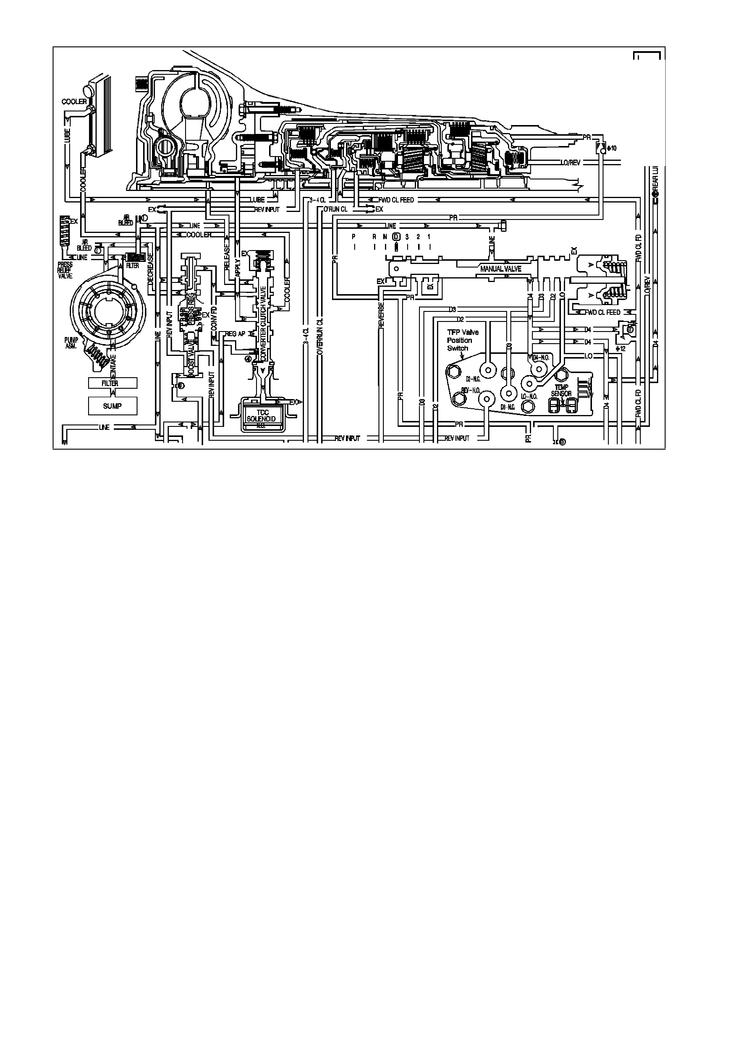
GEN III V8 PCM -
DTC P0218 TRANSMISSION FLUID OVERTEMPERATURE
CIRCUIT DESCRIPTION
The f low of transmis sion fluid starts in the bottom pan and is drawn through the filter , c ontrol valve body as sembly,
transm iss ion case and into the oil pum p as sem bly. The oil pum p ass em bly pressurises the f luid and direc ts it to the
pressur e regulator valve where it bec om es the m ain supply of fluid to the various components and hydraulic circuits
in the transmission.
Hot fluid exiting the torque c onverter f lows through the conver ter clutch apply valve and into the transm is sion cooler
lines to the oil cooler loc ated in the vehicle radiator (and auxiliar y cooler if equipped). From the cooler, fluid returns
to cool and lubricate the f ront of the tr ansmis sion. In forward drive r anges, D4 fluid f rom the m anual valve is routed
through an orificed cup plug in the rear of the transmission case to feed the rear lube fluid circuit.
W hen the Powertrain Control Module (PCM) detects a high transmission fluid temperature (TFT) for a long period
of time, then DTC P0218 sets.
CONDITIONS FOR RUNNING THE DTC
• No TFT sensor DTCs P0711, P0712, P0713.
• The ignition switch is in the RUN position for 5 seconds.
CONDITIONS FOR SETTING THE DTC
• The TFT is greater than 130°C for 10 minutes (600 seconds).
ACTION TAKEN WHEN THE DTC SETS
• The PCM illuminates the Check Powertrain Lamp when the diagnostic runs and fails.
• The PCM freezes shift adapte from being updated.
• The PCM records the operating conditions at the time the diagnostic fails. The PCM stores this information in
the Freeze Frame/Failure Records.
CONDITIONS FOR CLEARING THE CPL/DTC
• The PCM turns the Check Powertrain Lamp OFF during the first ignition cycle that the diagnostic runs and
does not fail.
• A last test failed (current DTC) clears when the diagnostic runs and does not fail.
• The PCM cancels the DTC default actions when the fault no longer exists and the ignition switch is OFF long
enough in order to power down the PCM.

DIAGNOSTIC AIDS
• The TFT displayed on the scan tool should rise steadily to a normal operating temperature, then stabilise.
• Verify the customer's driving habits, trailer towing, overloading the vehicle, etc.
TEST DESCRIPTION
The numbers below refer to the step numbers on the diagnostic table.
1. This step checks for air flow restrictions or damage which may result in the transmission overheating.
GEN III V8 PCM - DTC P0218 TRANSMISSION FLUID OVERTEMPERATURE
Step Action Value(s) Yes No
1 Was the Powertrain On-Board Diagnostic (OBD) System
Check performed? Go to Step 2 Go to Powertrain
OBD System
Check Table
2 1. Install the Tech 2 scan tool.
2. With the engine OFF, turn the ignition switch to the
RUN position.
IMPORTANT: Before clearing the DTC, use the Scan
Tool in order to record the Failure Records. Using the
Clear Info function erases the Failure Records from the
PCM.
3. Record th e DTC Failure Records.
4. Clear the DTC.
5. Perform the transmission fluid checking procedure,
refer to Section 7C4 Transmission Fluid Checking
Procedure in VX Service Information.
Was the Transmission Fluid Checking Procedure
performed?
Go to Step 3 Go to
Section 7C3
Transmission
Fluid Checking
Procedure in VX
Service
Information.
3 1. Inspect the engine cooling system and transmission
cooling system for the following conditions:
- Air flow restrictions
- Air flow blockage
- Debris
2. Inspect the transmission cooling system for damaged
cooler lines.
Was a condition found?
Go to Step 6 Go to Step 4
4 Perform the line pressure check procedure, refer to
Section 7C3 Line Pressure Check Procedure in VX
Service Information.
Was a condition found?
Go to Step 6 Go to Step 5
5 Inspect the torque converter stator for damage, refer to
Section 7C3 Torque Converter Diagnosis Procedure in
VX Service Information.
Was a condition found?
Go to Step 6 Go to
Diagnostic Aids
6 Perform the following procedure in order to verify the
repair:
1. Select DTC.
2. Select Clear Info.
3. With the engine OFF, turn the ignition switch to the
RUN position.
4. Verify that the Scan Tool indicates a TFT less than
129°C for at least five seconds.
Is the TFT less than 129°C for at least five seconds?
System OK Go to Step 1
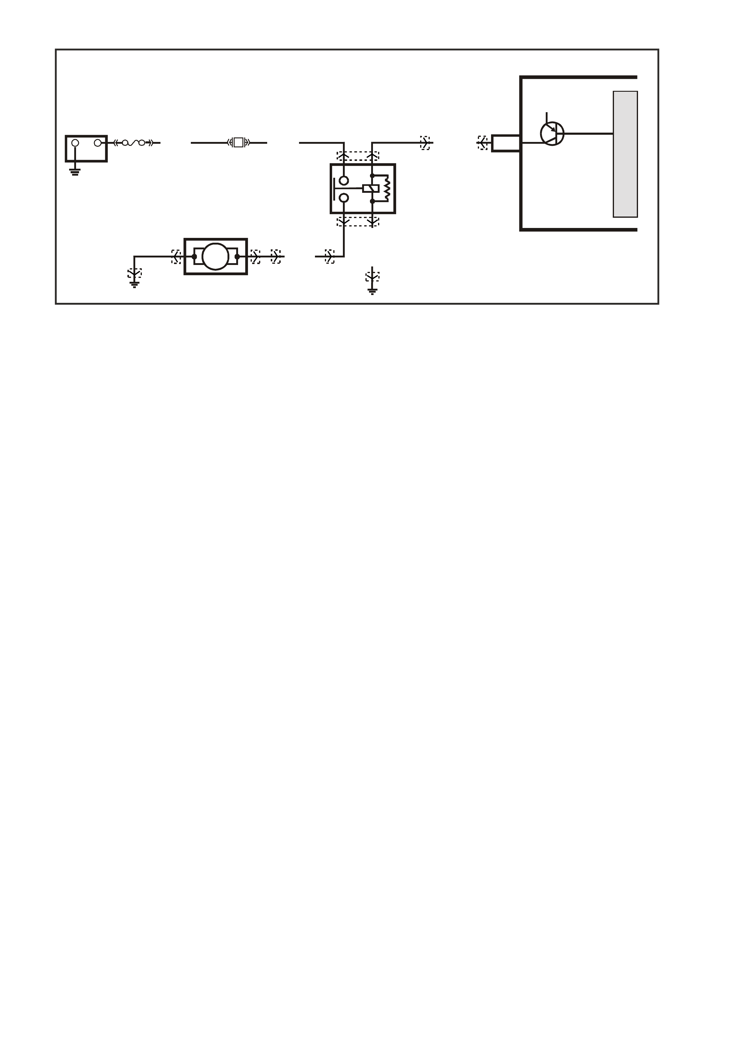
GEN III V8 PCM -
DTC P0230 FUEL PUMP CONTROL CIRCUIT
CIRCUIT DESCRIPTION
When you turn the ignition switch to the ON position, the PCM activates the in-tank fuel pump. The fuel pump
remains ON as long as the PCM receives reference pulses from the electronic ignition system. If there are no
reference pulses, the PCM turns the fuel pump OFF after about 2-3 seconds. The PCM controls the fuel pump
relay by applying B+ to the control circuit via an internal switch called a driver. The prim ary function of the driver is
to supply a voltage to the fuel pump relay. The driver has a fault line which the PCM monitors.
When the PCM commands the fuel pump ON, the voltage of the control circuit should be high (near battery
voltage). When the PCM commands the control circuit to the fuel pump OFF, the voltage potential of the circuit
should be low (near 0 volts) . This DT C sets when the PCM detects the f uel pump c ontrol circuit is shorted to ear th,
after the engine has been running. If the short occurs before key ON, the DTC will not set, and the fuel pump will
not operate.
CONDITIONS FOR RUNNING THE DTC
• The engine speed is greater than 400 RPM.
• The ignition voltage is between 6.0 volts and 16.0 volts.
CONDITIONS FOR SETTING THE DTC
• The PCM detects that the commanded state of the circuit and the actual state of the circuit do not match.
• All of the above conditions present for at least ten seconds..
ACTION TAKEN WHEN THE DTC SETS
• The PCM illuminates the Check Powertrain Lamp when the diagnostic runs and fails.
• The PCM records the operating conditions at the time the diagnostic fails. The PCM stores this information in
the Freeze Frame/Failure Records.
CONDITIONS FOR CLEARING THE CPL/DTC
• The PCM turns the Chec k Powertrain Lamp OF F after one ignition cycle that the diagnostic runs and does not
fail.
• A last test failed (current DTC) clears when the diagnostic runs and does not fail.
• Use a Tech 2 scan tool to clear the CPL/DTC.
J2-09 FUEL PUMP RELAY
CONTROL
G3PCM022PT
B/BLU
YR32 YR32 YB39 YE114
YE110
YE123
YE96
YE96
YR44 YR44
(156)
LOC. E7 LOC. E3
IN - TANK
FUEL PUMP
FUEL PUMP
RELAY
G/W (465)
PCM
12V
M
I
C
R
O
+-
BATTERY
FS
LOC. E1
F28
(1040) O (240)
V (12 0)
B/W(152)
32
51
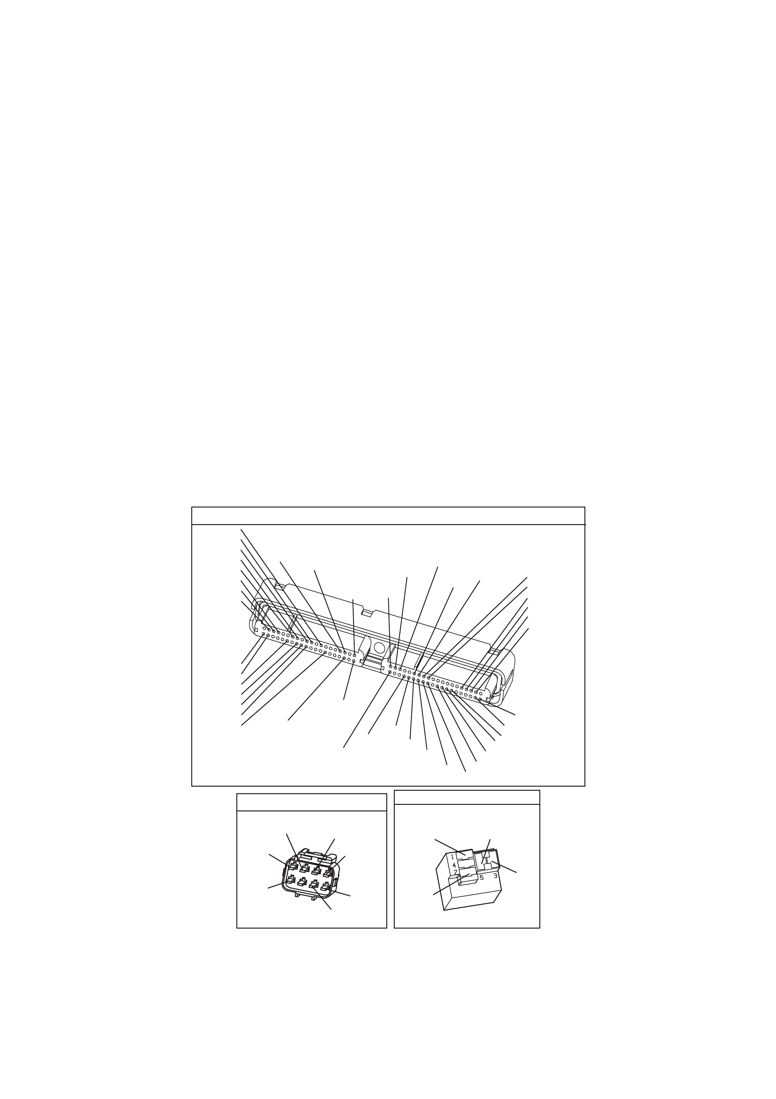
DIAGNOSTIC AIDS
• The following may cause an intermittent:
- Poor connections: Check for adequate terminal tension
- Corrosion
- Incorrectly routed harness
- Rubbed through wire insulation
- Broken wire inside the insulation
• Using the Freeze Frame/Failure Records data may aid in locating an intermittent condition. If you cannot
duplicate the DTC, the information included in the Freeze Fram e/Failure Records data can help determine the
distance traveled since the DTC set. The Fail Counter and Pass Counter also help determine how many
ignition cycle the diagnostic reported a pass and/or a fail. Operate the vehicle within the same freeze frame
conditions (RPM, load, vehicle speed, temperature etc.) that you observed. This will isolate when the DTC
failed.
• For an intermittent condition, refer to Section 6C3-2B Symptoms of the VX Series Service Information.
TEST DESCRIPTION
The numbers below refer to the step numbers on the diagnostic table.
2. Listen for an audible click when the relay operates. Command both the ON and the OFF states. Repeat the
commands as necessary.
3. This check can detect a partially shorted coil which would cause excessive current flow. Leaving the circuit
energised for 2 minutes allows the coil to warm up. When warm, the coil may short (goes above 0.75 Amp).
5. Identify and test the relay coil terminals in order to avoid improper diagnosis.
12. If you do not find any trouble in the control circuit or the connection at the PCM, the PCM may be
malfunctioning. However, this is an extremely unlikely failure. Before replacing the PCM, inspect for poor
connections at the PCM harness connectors.
13. The repair is not complete if the Tech 2 scan tool indicates that the diagnostic ran and failed.
YE 123
P.C.M CONNE CTOR 2
(750)
(1228)
(1229)
(465)
(121)
(259)
G/B
BR
G/W
GY/BLU
R
B/R
(418)
BR
(59)
(832)
G
T
(831)
(417)
(472)
(976) (974)
(432)
(428)
(631)
BLU BR G/Y
BLU/W
LG
BR/W
W/B
LG W
(977)
Y
(971)
BLU/W W
B/R
(750)
(304)
(792)
(1223)
(1222)
(123)
(1227)
(469)
(331)
Y/B
LG
V/W
B/Y
G/O BR/W
(1687)
GY/B
(366)
LG/B
GY/R
(422)
V
(442)
(444)
(443)
(975)
(972)
(978)
(1224)
(973)
(959)
LG/W
LG/B
LBLU/B
GY
(773)
BR/Y
BLU
G
Y/B
LBLU
(958)
BR
(441)
LBLU
1
41
40
80
J2
RED
Y
(838)
ENGINE CONNECTOR 1
YE110
O/W
(304)
(1426)
BLU/W
G/W
(339)
P/BLU
(465)
(123)
V/W
(1427)
B/W
Y
(1049)
FUEL PUMP RELAY
YE 96
(465)
G/W
(152)
B/W V
(120)
O
(240)

GEN III V8 PCM - DTC P0230 FUEL PUMP CONTROL CIRCUIT
Step Action Value(s) Yes No
1 Did you perform the Powertrain On-Board Diagnostic
(OBD) System Check ? Go to Step 2 Go to Powertrain
OBD System
Check Table
2 1. Turn ON the ignition leaving the engine OFF.
2. Command the fuel pump relay ON and OFF using a
Tech 2 scan tool.
Does the fuel pump relay turn ON and OFF when
commanded?
Go to Step 3 Go to Step 5
3 1. Turn OFF the ignition.
2. Disconnect the PCM RED connector.
3. Turn ON the ignition leaving the engine OFF.
4. Measure the current from the relay control circuit in
the PCM harness connector to B+ for 2 minutes using
the DMM J 39200. on the 10 AMP scale.
Does the current draw measure less than the specified
value shown (but not 0)?
0.75A Go to
Diagnostic Aids Go to Step 4
4 1. Turn OFF the ignition.
2. Remove the fuel pump relay from the engine
compartment fuse & relay panel.
3. Measure the resistance from the relay control circuit in
the PCM harness connector to a earth using a DMM
J 39200. Refer to the wiring schematic for the proper
terminal identification.
Does the DMM display infinite resistance?
Go to Step 11 Go to Step 10
5 1. Turn OFF the ignition.
2. Remove the fuel pump relay from the engine
compartment fuse & relay panel.
3. Connect the test lamp J 34142-B between the earth
circuit and the control circuit at the engine
compartment fuse & relay panel.
4. Turn ON the ignition leaving the engine OFF.
5. Command the fuel pump relay ON and OFF using a
Tech 2 scan tool.
Does the test lamp turn ON and OFF when commanded?
Go to Step 8 Go to Step 6
6 Check the resistance from the fuel pump relay earth
circuit at the fuse & relay panel to the battery earth using
the DMM J 39200.
Is the resistance within the specified range?
0-5Ω
Go to Step 7
Go to Step 9
7 1. Turn OFF the ignition.
2. Reconnect the relay.
3. Disconnect the PCM RED connector.
4. Turn ON the ignition leaving the engine OFF.
5. Probe the relay control circuit in the PCM harness
connector with a fused jumper wire connected to B+.
Does the relay operate?
Go to Step 12 Go to Step 10
8 Check the connections at the relay.
Did you find and correct the condition? Go to Step 13 Go to Step 11
9 Repair the open fuel pump relay earth circuit.
Is the action complete? Go to Step 13
10 Repair open or short to earth in the fuel pump relay
control circuit.
Is the action complete?
Go to Step 13
11 Replace the relay.
Is this action complete? Go to Step 13
12 1. Replace PCM.
2. Refer to Section 6C3-3 of the VX Series Service
Information for PCM Programming and PCM/PIM/BCM
Security Link Procedure.
Is action complete?
Go to Step 13

GEN III V8 PCM - DTC P0230 FUEL PUMP CONTROL CIRCUIT (CONTINUED)
Step Action Value(s) Yes No
13 1. Select the Diagnostic Trouble Code (DTC) option and
the Clear DTC Information option using the Tech 2
scan tool.
2. Idle the engine at the normal operating temperature.
3. Select the Diagnostic Trouble Code (DTC) option, the
DTC Information option and The Failed This Ignition
option using the Tech 2 scan tool.
4. Operate the vehicle, within the Conditions for Running
the DTC, as specified in the supporting text, if
applicable.
Does the Tech 2 scan tool indicate that this DTC reset?
Go to Step 2
Go to Step 14
14 Using the Tech 2 scan tool, check for any other DTCs.
Are any DTCs displayed that you have not diagnosed? Go to the
applicable DTC
table
System OK
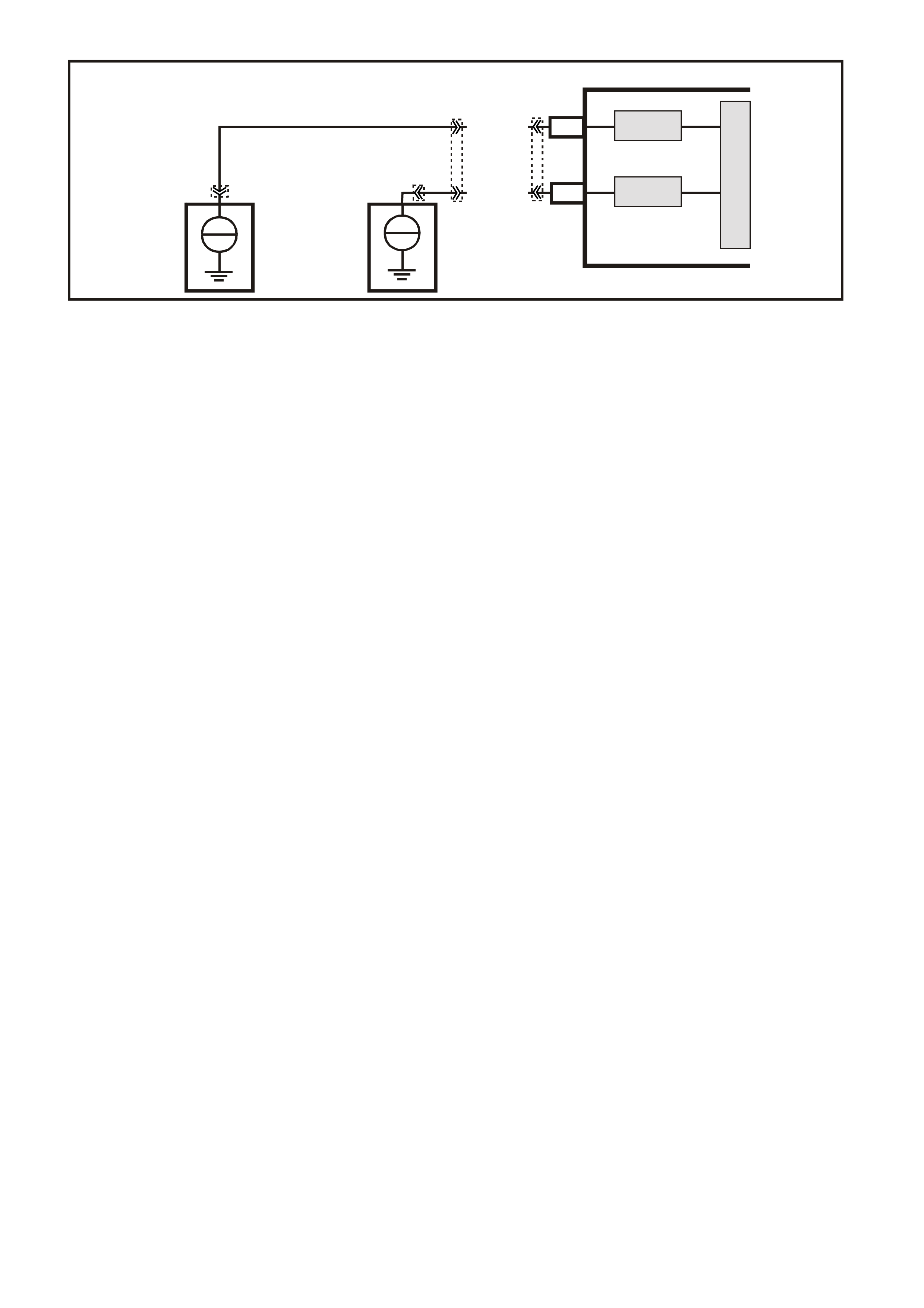
GEN III V8 PCM -
DTC P0325 KNOCK SENSOR SYSTEM
CIRCUIT DESCRIPTION
The KS system monitors both Knock Sensors in order to determine if detonation is present. If the KS system
determines that excessive knock (detonation) is present, the PCM retards the spark timing based on the signals
from the KS system. When knock is present, the KS system voltage input signal to the PCM goes low. The PCM
then retar ds timing until no k nock is pres ent. When the KS system is m alfunc tioning, the KS circuit voltage going to
the PCM goes low. The PCM interprets this low signal as spark knock.
CONDITIONS FOR RUNNING THE DTC
• The engine run time is greater than 20 seconds.
• The engine speed is between 1650 and 3000 RPM.
• The MAP is at or about 48 kPa.
• The engine coolant temperature is greater than 70°C.
• The throttle angle is greater than 0.5%.
• The TP sensor angle is steady within 1%.
• Battery voltage is between 10 and 16 volts.
CONDITIONS FOR SETTING THE DTC
• A malfunction with the knock sensor system or circuits within the PCM are faulty.
• All above conditions present for at least three seconds.
ACTION TAKEN WHEN THE DTC SETS
• The PCM illuminates the Check Powertrain Lamp when the diagnostic runs and fails.
• The PCM records the operating conditions at the time the diagnostic fails. The PCM stores this information in
the Freeze Frame/Failure Records.
CONDITIONS FOR CLEARING THE CPL/DTC
• The PCM turns the Chec k Powertrain Lamp OF F after one ignition cycle that the diagnostic runs and does not
fail.
• A last test failed (current DTC) clears when the diagnostic runs and does not fail.
• Use a Tech 2 scan tool in order to clear the CPL/DTC.
DIAGNOSTIC AIDS
• If the diagnostic test does not run, review the Conditions for Running the DTC.
• For an intermittent condition, refer to Section 6C3-2B Symptoms of the VX Series Service Information.
TEST DESCRIPTION
The number below refers to the step number on the diagnostic table.
2. This DTC indicates an internal PCM problem.
G3VX007PT
PCM
M
I
C
R
O
DSNEF
DSNEF
FRONT KNOCK
SENSOR SIGNAL I NPUT
REAR KNOCK
SENSOR SIGNAL I NPUT
J1-51
J1-11
REAR
KNOCK
SENSOR
FRONT
KNOCK
SENSOR
+
-
+
-
BLU (815)
YE19
YE18
YE18
YE122
LBLU (826)

GEN III V8 PCM - DTC P0325 KNOCK SENSOR SYSTEM
Step Action Value(s) Yes No
1 Did you perform the Powertrain On-Board Diagnostic
(OBD) System Check ? Go to Step 2 Go to Powertrain
OBD System
Check Table
2 1. Replace PCM.
2. Refer to Section 6C3-3 of the VX Series Service
Information for PCM Programming and
PCM/PIM/BCM Security Link Procedure.
Is action complete?
Go to Step 3
3 1. Select the Diagnostic Trouble Code (DTC) option and
the Clear DTC option using the Tech 2 scan tool.
2. Idle the engine at the normal operating temperature.
3. Select the Diagnostic Trouble Code (DTC) option, the
DTC Information option and The Failed This Ignition
option using the Tech 2 scan tool.
4. Operate vehicle within the Conditions for Running the
DTC as specified in the supporting test, if applicable.
Does the Tech 2 scan tool indicate that this DTC reset?
Go to Step 2 Go to Step 4
4 Using the Tech 2 scan tool, check for any other DTCs.
Does the Tech 2 scan tool display any DTCs that you
have not diagnosed?
Go to applicable
DTC table System OK

GEN III V8 PCM -
DTC P0327 KNOCK SENSOR CIRCUIT FRONT SENSOR
CIRCUIT DESCRIPTION
The Knoc k Sensor (KS) system detects engine detonation. The PCM retar ds the spark timing bas ed on the signals
from the knock sensors. The Knock Sensors produce an AC voltage. The Knock Sensor voltages are an input to
the PCM. The amount of AC voltage produced is proportional to the amount of knock.
An operating engine produces a normal amount of engine mechanical vibration (noise). The Knock Sensors
produce an AC voltage signal from this noise. When an engine operates, the PCM learns the minimum and
maximum frequency of the noise the engine produces. W hen the PCM determines that this frequency is less than
or greater than the expected amount, a Knock Sensor DTC will set.
CONDITIONS FOR RUNNING THE DTC
• The engine run time is greater than 20 seconds.
• The engine speed is between 1650 and 3000 RPM.
• The MAP is at or about 48 kPa.
• The engine coolant temperature is greater than 70°C.
• The throttle angle is greater than 0.5%.
• Battery voltage is between 10 and 16 volts.
CONDITIONS FOR SETTING THE DTC
• The PCM determines that the frequency is less than or greater than the expected amount for at least three
seconds.
ACTION TAKEN WHEN THE DTC SETS
• The PCM illuminates the Check Powertrain Lamp when the diagnostic runs and fails.
• The PCM records the operating conditions at the time the diagnostic fails. The PCM stores this information in
the Freeze Frame/Failure Records.
CONDITIONS FOR CLEARING THE CPL/DTC
• The PCM turns the Chec k Powertrain Lamp OF F after one ignition cycle that the diagnostic runs and does not
fail.
• A last test failed (current DTC) clears when the diagnostic runs and does not fail.
• Use a Tech 2 scan tool to clear the CPL/DTC.
DIAGNOSTIC AIDS
• Check the Knock Sensor for correct installation. A Knock Sensor that is loose or over torqued may cause the
DTC P0327 to set.
• For an intermittent, refer to Section 6C3-2B Symptoms of the VX Series Service Information.
G3VX007PT
PCM
M
I
C
R
O
DSNEF
DSNEF
FRONT KNOCK
SENSOR SIGNAL I NPUT
REAR KNOCK
SENSOR SIGNAL I NPUT
J1-51
J1-11
REAR
KNOCK
SENSOR
FRONT
KNOCK
SENSOR
+
-
+
-
BLU (815)
YE19
YE18
YE18
YE122
LBLU (826)
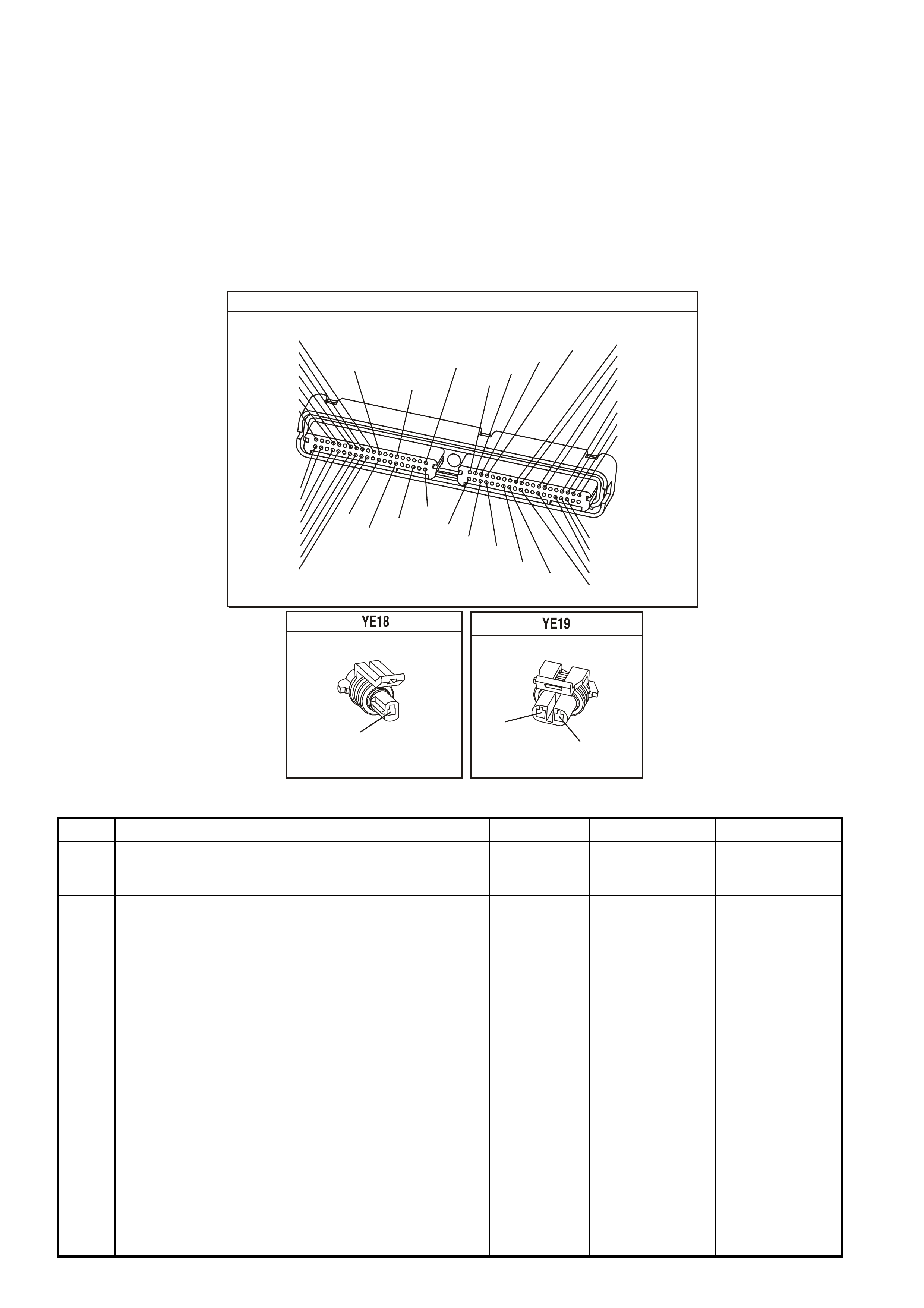
TEST DESCRIPTION
The numbers below refer to the step numbers on the diagnostic table.
2. This verifies the malfunction is present. The Tech 2 scan tool will display DTC Ran=Yes and Pass=Int if the
failure is intermittent. This indicates the diagnostic passed this ignition cycle and failed this ignition cycle. At this
point, the resistance of the Knock Sensors should be verified to be in the correct range. If the Knock Sensor
resistance’s are correct, check the KS system wiring connections.
3. When checking the KS system connections, start at the KS system jumper harness connector located behind
the intake manifold. Then, check the connections at the appropriate Knock Sensor. Freeze Frame/Failure
Records data does not include the parameter KS activity, however, other parameters may aid in locating the
conditions under which an intermittent occurred.
4. This test will isolate the Knock Sensor from the rest of the circuit. Tap on the engine block just below the intake
manifold between the timing chain cover and the valley cover.
P.C.M CONNECTOR 1
YE122
(776)
(1049)
(897)
(1230)
(848)
(1226)
(772)
(647)
(632)
40
(844)
(815)
80
J1
P/B
(845)
V/W
BLU
O
(633)
(846)
B/Y
B/R
(416)
(86)
(69)
(455)
(740)
GY
BR
G
GY
(646)
(410)
GY
(842)
(1225)
V
Y
(750)
P
41
O
(774)
BR/Y
BLU
Y
B/R
B
BLU/Y
(841)
BLUE
(414)
G/W
BLU
LG
LBLU/B
1
(847)
(415)
(740)
(452)
BLU
BR
Y
(750)
(826)
(421)
Y
V/W
B/W
(334)
(771)
(39)
Y
R/W
LBLU
W
BLU/W
(843)
(643)
LBLU/W
G
GY/B
BLU/B
(413)
(1413)
(1412)
(412)
GY
V
GY/B
G
(335)
KNOCK SENSOR CONNECTOR
BLU (FRONT SENSOR)
LBLU (REAR SENSOR)
KNOCK SENSOR HARNESS
(815)
BLU
(826)
LBLU
GEN III V8 PCM - DTC P0327 KNOCK SENSOR CIRCUIT FRONT SENSOR
Step Action Value(s) Yes No
1 Did you perform the Powertrain On-Board Diagnostic
(OBD) System Check ? Go to Step 2 Go to Powertrain
OBD System
Check Table
2 IMPORTANT: If an engine knock can be heard, repair the
engine mechanical problem before proceeding with this
diagnostic.
1. Turn On the ignition leaving the engine OFF.
2. Review the Freeze Frame/Failure Records data for
this DTC and observe the parameters.
3. Turn OFF the ignition for 15 seconds.
4. Start the engine.
5. Operate the vehicle, within the conditions required for
this diagnostic to run, and as close to the conditions
recorded in Freeze Frame/Failure Records as
possible. Special operating conditions that you need to
meet before the PCM will run this diagnostic, where
applicable, are listed in Conditions for Running the
DTC.
6. Select the Diagnostic Trouble Code (DTC) option, the
DTC Information option and The Failed This Ignition
option using the Tech 2 scan tool.
Does the Tech 2 scan tool indicate that this diagnostic
failed this ignition?
Go to Step 3 Refer to
Diagnostic Aids

GEN III V8 PCM - DTC P0327 KNOCK SENSOR CIRCUIT FRONT SENSOR (CONTINUED)
Step Action Value(s) Yes No
3 1. Disconnect the Knock Sensor electrical connector
YE19 located behind the intake manifold.
2. Measure the resistance of the front Knock Sensor by
connecting the DMM between the front Knock Sensor
signal circuit ,on the sensor side, and the engine block
using the DMM J 39200.
3. Set the DMM to the 400K ohm scale.
Is the resistance of the Knock Sensor within the specified
range?
93-107KΩ Go to Step 4 Go to Step 6
4 1. Connect the DMM between the front Knock Sensor
signal circuit, on the sensor side, and the engine
block.
2. Set the DMM to the AC voltage scale.
3. Tap on the front of the engine while observing the
signal indicated on the DMM.
Is any signal indicated on the DMM while tapping on the
engine near the Knock Sensor?
Go to Step 5 Go to Step 7
5 1. Disconnect the PCM BLUE connector.
2. Check the KS signal circuit between the PCM and the
Knock Sensor connector for the following:
- An open
- A short to voltage
- A short to earth
Was a problem found and corrected?
Go to Step 10 Go to Step 8
6 1. Remove the intake manifold. Refer to Section 6A3
Engine Mechanical in Section 14A in VX Service
Information.
2. Check for an open or a short to earth in the signal
circuit between the Knock Sensor jumper harness
connector, located at the back of the intake manifold,
and the Knock Sensor connector.
Was a problem found and corrected?
Go to Step 10 Go to Step 7
7 Replace the Knock Sensor. Refer to Section 6C3-3
Knock Sensor Replacement of the VX Series Service
Information.
Is the action complete?
Go to Step 10
8 Check the KS signal circuit for a poor terminal connection
at the PCM.
Was a problem found and corrected?
Go to Step 10 Go to Step 9
9 1. Replace PCM.
2. Refer to Section 6C3-3 of the VX Series Service
Information for PCM Programming and
PCM/PIM/BCM Security Link Procedure.
Is action complete?
Go to Step 10
10 1. Select the Diagnostic Trouble Code (DTC) option and
the Clear DTC Information option using the Tech 2
scan tool.
2. Idle the engine at the normal operating temperature.
3. Select the Diagnostic Trouble Code (DTC) option, the
DTC Information option and The Failed This Ignition
option using the Tech 2 scan tool.
4. Operate the vehicle, within the Conditions for Running
the DTC, as specified in the supporting text, if
applicable.
Does the Tech 2 scan tool indicate that this DTC reset?
Go to Step 2 Go to Step 11
11 Using the Tech 2 scan tool, check for any other DTCs.
Does the Tech 2 scan tool display any DTCs that you
have not diagnosed?
Go to the
applicable DTC
table
System OK

GEN III V8 PCM -
DTC P0332 KNOCK SENSOR CIRCUIT REAR SENSOR
CIRCUIT DESCRIPTION
The Knoc k Sensor (KS) system detects engine detonation. The PCM retar ds the spark timing bas ed on the signals
from the k noc k sens ors. T he k nock sensor s pr oduce an AC voltage. T he k nock sens or voltages ar e an input to the
PCM. The amount of AC voltage produced is proportional to the amount of knock.
An operating engine produces a normal amount of engine mechanical vibration (noise). The knock sensors
produce an AC voltage signal from this noise. When an engine operates, the PCM learns the minimum and
maximum frequency of the noise the engine produces. W hen the PCM determines that this frequency is less than
or greater than the expected amount, a knock sensor DTC will set.
CONDITIONS FOR RUNNING THE DTC
• The engine run time is greater than 20 seconds.
• The engine speed is between 1650 and 3000 RPM.
• The MAP is at or about 48 kPa.
• The engine coolant temperature is greater than 70°C.
• The throttle angle is greater than 0.5%.
• Battery voltage is between 10 and 16 volts.
CONDITIONS FOR SETTING THE DTC
• The PCM determines that the frequency is less than or greater than the expected amount for at least three
seconds.
ACTION TAKEN WHEN THE DTC SETS
• The PCM illuminates the Check Powertrain Lamp when the diagnostic runs and fails.
• The PCM records the operating conditions at the time the diagnostic fails. The PCM stores this information in
the Freeze Frame/Failure Records.
CONDITIONS FOR CLEARING THE CPL/DTC
• The PCM turns the Chec k Powertrain Lamp OF F after one ignition cycle that the diagnostic runs and does not
fail.
• A last test failed (current DTC) clears when the diagnostic runs and does not fail.
• Use a Tech 2 scan tool in order to clear the CPL/DTC.
DIAGNOSTIC AIDS
• Check the knock sensor for proper installation. A knock sensor that is loose or over torqued may cause the
DTC P0327 to set.
• For an intermittent, refer to Section 6C3-2B Symptoms of the VX Series Service Information.
G3VX007PT
PCM
M
I
C
R
O
DSNEF
DSNEF
FRONT KNOCK
SENSOR SIGNAL I NPUT
REAR KNOCK
SENSOR SIGNAL I NPUT
J1-51
J1-11
REAR
KNOCK
SENSOR
FRONT
KNOCK
SENSOR
+
-
+
-
BLU (815)
YE19
YE18
YE18
YE122
LBLU (826)
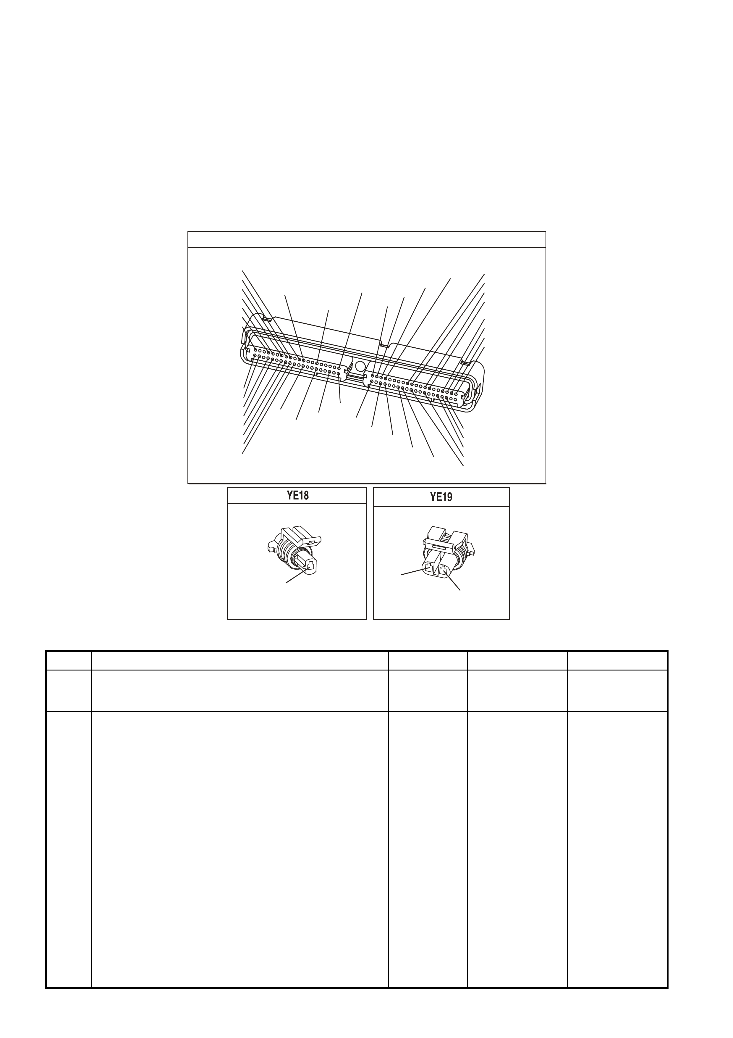
TEST DESCRIPTION
The numbers below refer to the step numbers on the diagnostic table.
2. This verifies the malfunction is present. The Tech 2 scan tool will display DTC Ran=Yes and Pass=Int if the
failure is intermittent. This indicates the diagnostic passed this ignition cycle and failed this ignition cycle. At this
point the resistance of the knock sensors should be verified to be in the correct range. If the knock sensor
resistance’s are correct, check the KS system wiring connections. When checking the KS system connections,
start at the KS system jumper harness connector located behind the intake manifold. Then check the
connections at the appropriate knock sensor. Freeze Frame/Failure Records data does not include the
parameter KS activity, however, other parameters may aid in locating the conditions under which an intermittent
occurred.
3. This test will isolate the Knock Sensor from the rest of the circuit.
4. Tap on the engine block just below the intake manifold between the timing chain cover and the valley cover.
P.C.M CONNECTOR 1
YE122
(776)
(1049)
(897)
(1230)
(848)
(1226)
(772)
(647)
(632)
40
(844)
(815)
80
J1
P/B
(845)
V/W
BLU
O
(633)
(846)
B/Y
B/R
(416)
(86)
(69)
(455)
(740)
GY
BR
G
GY
(646)
(410)
GY
(842)
(1225)
V
Y
(750)
P
41
O
(774)
BR/Y
BLU
Y
B/R
B
BLU/Y
(841)
BLUE
(414)
G/W
BLU
LG
LBLU/B
1
(847)
(415)
(740)
(452)
BLU
BR
Y
(750)
(826)
(421)
Y
V/W
B/W
(334)
(771)
(39)
Y
R/W
LBLU
W
BLU/W
(843)
(643)
LBLU/W
G
GY/B
BLU/B
(413)
(1413)
(1412)
(412)
GY
V
GY/B
G
(335)
KNOCK SENSOR CONNECTOR
BLU (FRONT SENSOR)
LBLU (REAR SENSOR)
KNOCK SENSOR HARNESS
(815)
BLU
(826)
LBLU
GEN III V8 PCM - DTC P0332 KNOCK SENSOR CIRCUIT REAR SENSOR
Step Action Value(s) Yes No
1 Did you perform the Powertrain On-Board Diagnostic
(OBD) System Check ? Go to Step 2 Go to Powertrain
OBD System
Check Table
2 IMPORTANT: If an engine knock can be heard, repair the
engine mechanical problem before proceeding with this
diagnostic.
1. Turn On the ignition leaving the engine OFF.
2. Review the Freeze Frame/Failure Records data for
this DTC and observe the parameters.
3. Turn OFF the ignition for 15 seconds.
4. Start the engine.
5. Operate the vehicle within the conditions required for
this diagnostic to run, and as close to the conditions
recorded in Freeze Frame/Failure Records as
possible. Special operating conditions that you need to
meet before the PCM will run this diagnostic where
applicable, are listed in Conditions for Running the
DTC.
6. Select the Diagnostic Trouble Code (DTC) option, the
DTC Information, The Failed This Ignition using the
Tech 2 scan tool.
Does the Tech 2 scan tool indicate that this diagnostic
failed this ignition?
Go to Step 3 Refer to
Diagnostic Aids

GEN III V8 PCM - DTC P0332 KNOCK SENSOR CIRCUIT REA R SENSOR (CONTINUED)
Step Action Value(s) Yes No
3 1. Disconnect the knock sensor electrical connector
located behind the intake manifold.
2. Measure the resistance of the rear knock sensor by
connecting the DMM between the rear knock sensor
signal circuit on the sensor side and the engine block
using the DMM J 39200.
3. Set the DMM to the 400K ohm scale.
Is the resistance of the knock sensor within the specified
range?
93-107KΩ Go to Step 4 Go to Step 6
4 1. Connect the DMM between the rear knock sensor
signal circuit on the sensor side and the engine block.
2. Set the DMM to the AC voltage scale.
3. Tap on the front of the engine while observing the
signal indicated on the DMM.
Is any signal indicated on the DMM while tapping on the
engine near the Knock Sensor?
Go to Step 5 Go to Step 7
5 1. Disconnect the PCM BLUE connector.
2. Check the KS signal circuit between the PCM and the
knock sensor connector for the following:
- An open
- A short to voltage
- A short to earth
Was a problem found and corrected?
Go to Step 10 Go to Step 8
6 1. Remove the intake manifold. Refer to Section 6A3
Engine Mechanical for procedure.
2. Check for an open or a short to earth in the signal
circuit between the knock sensor jumper harness
connector, located at the back of the intake manifold,
and the knock sensor connector.
Was a problem found and corrected?
Go to Step 10 Go to Step 7
7 Replace the Knock Sensor. Refer to Knock Sensor
Replacement in Section 6C3-3.
Is the action complete?
Go to Step 10
8 Check the KS signal circuit for a poor terminal connection
at the PCM.
Was a problem found and corrected?
Go to Step 10 Go to Step 9
9 1. Replace PCM.
2. Refer to Section 6C3-3 for PCM Programming and
PCM/PIM/BCM Security Link Procedure.
Is action complete?
Go to Step 10
10 1. Select the Diagnostic Trouble Code (DTC) option and
the Clear DTC Information option using the Tech 2
scan tool.
2. Idle the engine at the normal operating temperature.
3. Select the Diagnostic Trouble Code (DTC) option, the
DTC Information, The Failed This Ignition using the
Tech 2 scan tool.
4. Operate the vehicle within the Conditions for Running
the DTC as specified in the supporting text, if
applicable.
Does the Tech 2 scan tool indicate that this DTC reset?
Go to Step 2 Go to Step 11
11 Using the Tech 2 scan tool, check for any other DTCs.
Does the Tech 2 scan tool display any DTCs that you
have not diagnosed?
Go to the
applicable DTC
table
System OK

GEN III V8 PCM -
DTC P0335 CRANKSHAFT POSITION SENSOR CIRCUIT
CIRCUIT DESCRIPTION
The Crank shaf t Position Sensor (CKP) is m ounted in the right rear of the engine block behind the st arter. The CKP
Sensor work s in conj unction with a 24X reluc tor wheel m ounted on the rear of the crank s haft. The CKP Sensor has
a B+ power supply, an earth, and a signal circuit.
As the crankshaft rotates, the reluctor wheel teeth interrupt a magnetic field produced by a magnet within the
sensor. T he s ensor’s internal circ uitry detects this and pr oduces a s ignal which the PCM reads. T he PCM uses this
signal to accurately measure crankshaft velocity which is a variable used in order to detect misfire, spark and,
fueling.
CONDITIONS FOR RUNNING THE DTC
• DTCs P0101, P0102, P0103, P0341, P0342, P0343 are not set.
• The CMP sensor is transitioning.
• The ignition voltage is between 5 and 17.0 volts.
• The MAF is greater than 3 g/s.
CONDITIONS FOR SETTING THE DTC
• The PCM determines no signal from the CKP sensor for at least three seconds.
ACTION TAKEN WHEN THE DTC SETS
• The PCM illuminates the Check Powertrain Lamp when the diagnostic runs and fails.
• The PCM records the operating conditions at the time the diagnostic fails. The PCM stores this information in
the Freeze Frame/Failure Records.
CONDITIONS FOR CLEARING THE CPL/DTC
• The PCM turns the Check Powertrain Lamp OFF when the diagnostic runs and does not fail.
• A last test failed (current DTC) clears when the diagnostic runs and does not fail.
• Use a Tech 2 scan tool in order to clear the CPL/DTC.
DIAGNOSTIC AIDS
• The following problems may cause this DTC to set:
- Poor connections/terminal tension at the sensor.
- Crankshaft reluctor wheel damage or improper Installation.
- The sensor coming in contact with the reluctor wheel.
- The engine running out of fuel.
• Using Freeze Fram e/Failure Records data m ay aid in locating an intermittent condition. If you cannot duplicate
the DTC, the information included in the Freeze Frame/Failure Records data can aid in determining the
distance traveled since the DTC set. The Fail Counter and Pass Counter can also aid determining how many
ignition cycles the diagnostic reported a pass and/or a fail. Operate the vehicle within the same freeze frame
conditions (RPM, load, vehicle speed, temperature etc.) that you observed. This will isolate when the DTC
failed. For an intermittent condition, refer to Section 6C3-2B Symptoms of the VX Series Service Information.
• Excess crankshaft end play will cause the CKP Sensor reluctor wheel to move out of alignment with the CKP
sensor. This could result in any one of the following:
- A no start
- A start and stall
- Erratic performance
G3PCM012PT
PCM
M
I
C
R
O
A
C
B
CRANKSHAFT
POSITION
SENSOR
J1-02LBLU/W (646)
J1-21
SENSOR EARTH
12V
J1-12BLU (643)
CRANKSHAFT POSITION
SENSOR
SIGNAL
MAGNETO
RESISTIVE
INTEGRATED
CIRCUIT
IC
LBLU/B (647)
YE67 YE122
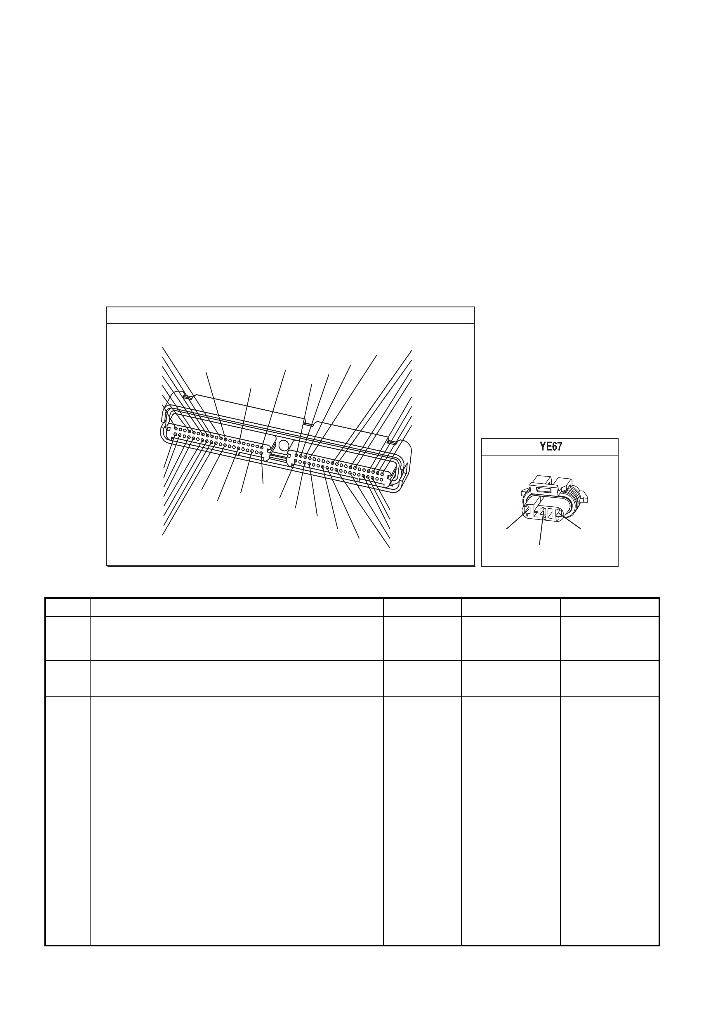
An improperly installed propeller shaft could cause excess crankshaft end play. Refer to
Section 6A3 Engine Mechanical in the VX Service Information for excess crankshaft end play diagnosis.
• For an intermittent, refer to Section 6C3-2B Symptoms of the VX Series Service Information.
TEST DESCRIPTION
The numbers below refer to the step numbers on the diagnostic table.
3. This step determines if the fault is present.
6. This step simulates a CKP Sensor signal to the PCM. If the PCM receives the signal, the fuel pump will operate
for about two seconds. If the fuel pump operates, the problem is either terminal contact at the CKP Sensor, the
CKP Sensor or, the CKP Sensor reluctor wheel.
7. This test determines if the CKP Sensor signal circuit or if the PCM is faulty.
12. To inspect the reluctor wheel, remove the starter and rotate the crankshaft while viewing the reluctor wheel
through the CKP Sensor hole. If you cannot determine if the reluctor wheel is damaged, the oil pan may have
to be removed.
15. Before replacing the PCM, check the PCM harness connections.
16. The repair is not complete if the Tech 2 scan tool indicates that the diagnostic ran and failed.
P.C.M CONNECTOR 1
YE122
(776)
(1049)
(897)
(1230)
(848)
(1226)
(772)
(647)
(632)
40
(844)
(815)
80
J1
P/B
(845)
V/W
BLU
O
(633)
(846)
B/Y
B/R
(416)
(86)
(69)
(455)
(740)
GY
BR
G
GY
(646)
(410)
GY
(842)
(1225)
V
Y
(750)
P
41
O
(774)
BR/Y
BLU
Y
B/R
B
BLU/Y
(841)
BLUE
(414)
G/W
BLU
LG
LBLU/B
1
(847)
(415)
(740)
(452)
BLU
BR
Y
(750)
(826)
(421)
Y
V/W
B/W
(334)
(771)
(39)
Y
R/W
LBLU
W
BLU/W
(843)
(643)
LBLU/W
G
GY/B
BLU/B
(413)
(1413)
(1412)
(412)
GY
V
GY/B
G
(335)
CRANK SENSOR
(646)
LBLU/W
(647)
LBLU/B
(643)
BLU
GEN III V8 PCM - DTC P0335 CRANKSHAFT POSITION SENSOR CIRCUIT
Step Action Value(s) Yes No
1 Did you perform the Powertrain On-Board Diagnostic
(OBD) System Check ? Go to Step 2 Go to Powertrain
OBD System
Check Table
2 Does the engine start and continue to run? Go to Step 3 Go to Step 4
3 1. Turn ON the ignition leaving the engine OFF.
2. Review the Freeze Frame/Failure Records data for
this DTC and record or document the parameters.
3. Turn OFF the ignition for 15 seconds.
4. Start the engine.
5. Operate the vehicle within the conditions required for
this diagnostic to run, and as close to the conditions
recorded in Freeze Frame/Failure Records as
possible. Special operating conditions that you need to
meet before the PCM will run this diagnostic, where
applicable, are listed in Conditions for Running the
DTC.
6. Select the Diagnostic Trouble Code (DTC) option, the
DTC Information option and The Failed This Ignition
option using the Tech 2 scan tool.
Does the Tech 2 scan tool indicate that this diagnostic
failed this ignition?
Go to Step 4 Go to
Diagnostic Aids

GEN III V8 PCM - DTC P0335 CRANKSHAFT POSITION SENSOR CIRCUIT (CONTINUED)
Step Action Value(s) Yes No
4 Caution: Before proceeding, remove fuses F34 & 35 for
the ignition coil and fuel injector feed circuits in order to
prevent personal injury from engine rotation, sparks, and
excessive engine fueling.
1. Turn ON the ignition leaving the engine OFF.
2. Lift the vehicle.
3. Disconnect the Crankshaft Position (CKP) Sensor.
4. Connect a test lamp to a earth.
5. Probe the CKP Sensor ignition feed circuit at the PCM
side of CKP Sensor harness connector.
Is the test lamp illuminated?
Go to Step 5 Go to Step 8
5 Connect the test lamp between the CKP sensor ignition
feed circuit and the CKP sensor earth circuit.
Is the test lamp illuminated?
Go to Step 6 Go to Step 9
6 Momentarily connect the test lamp between the CKP
sensor signal circuit and the CKP sensor ignition feed
circuit.
Does the fuel pump operate when ignition voltage was
applied to the CKP sensor signal circuit?
Go to Step 11
Go to Step 7
7 1. Connect the CKP sensor.
2. Disconnect the PCM BLUE connector.
3. Using test lead jumpers, from connector kit J 35616-A,
reconnect the reference Low and ignition feed circuits
from the PCM harness to PCM.
4. Probe the CKP sensor signal circuit with a DMM
J 39200 set to the 40V AC scale using the brown
jumper, from connector kit J 35616-A
5. Crank the engine.
Is the voltage within the specified range?
4.0-6.0V Go to Step 15 Go to Step 10
8 Check for an open or a short to earth in the CKP ignition
feed circuit.
Did you find and repair the condition?
Go to Step 16 Go to Step 15
9 Check for an open or a poor connection in the CKP earth
circuit.
Did you find and repair the condition?
Go to Step 16 Go to Step 15
10 Check the CKP Sensor signal circuit for the following:
• An open
• A short to earth
• A short to voltage
Did you find and repair the condition?
Go to Step 16 Go to Step 11
11 Remove the CKP Sensor and visually inspect the CKP
Sensor for the following conditions:
• Physical damage
• Loose or improper installation
• Wiring routed too closely to secondary ignition
components
• Poor connections/terminal tension at the sensor
Did you find and correct the condition?
Go to Step 16
Go to Step 12
12 Visually inspect the CKP Sensor reluctor wheel for
damage.
Did you find and correct the condition?
Go to Step 16 Go to Step 13
13 Check for poor connections/terminal tension at the CKP
sensor.
Did you find and correct the condition?
Go to Step 16 Go to Step 14

GEN III V8 PCM - DTC P0335 CRANKSHAFT POSITION SENSOR CIRCUIT (C0NTINUED)
Step Action Value(s) Yes No
14 Replace the CKP Sensor. Refer to Section 6C3-3
Crankshaft Position Sensor Replacement of the VX
Series Service Information.
Is the action complete?
Go to Step 16
15 1. Replace PCM.
2. Refer to Section 6C3-3 of the VX Series Service
Information for PCM Programming and
PCM/PIM/BCM Security Link Procedure.
Is action complete?
Go to Step 16
16 1. Select the Diagnostic Trouble Code (DTC) option and
the Clear DTC Information option using the Tech 2
scan tool.
2. Idle the engine at the normal operating temperature.
3. Select the Diagnostic Trouble Code (DTC) option, the
DTC Information option and The Failed This Ignition
option using the Tech 2 scan tool.
4. Operate the vehicle, within the Conditions for Running
the DTC, as specified in the supporting text, if
applicable.
Does the Tech 2 scan tool indicate that this DTC reset?
Go to Step 2
Go to Step 17
17 Using the Tech 2 scan tool, check for any other DTCs.
Are any DTCs displayed that you have not diagnosed? Go to the
applicable DTC
table
System OK
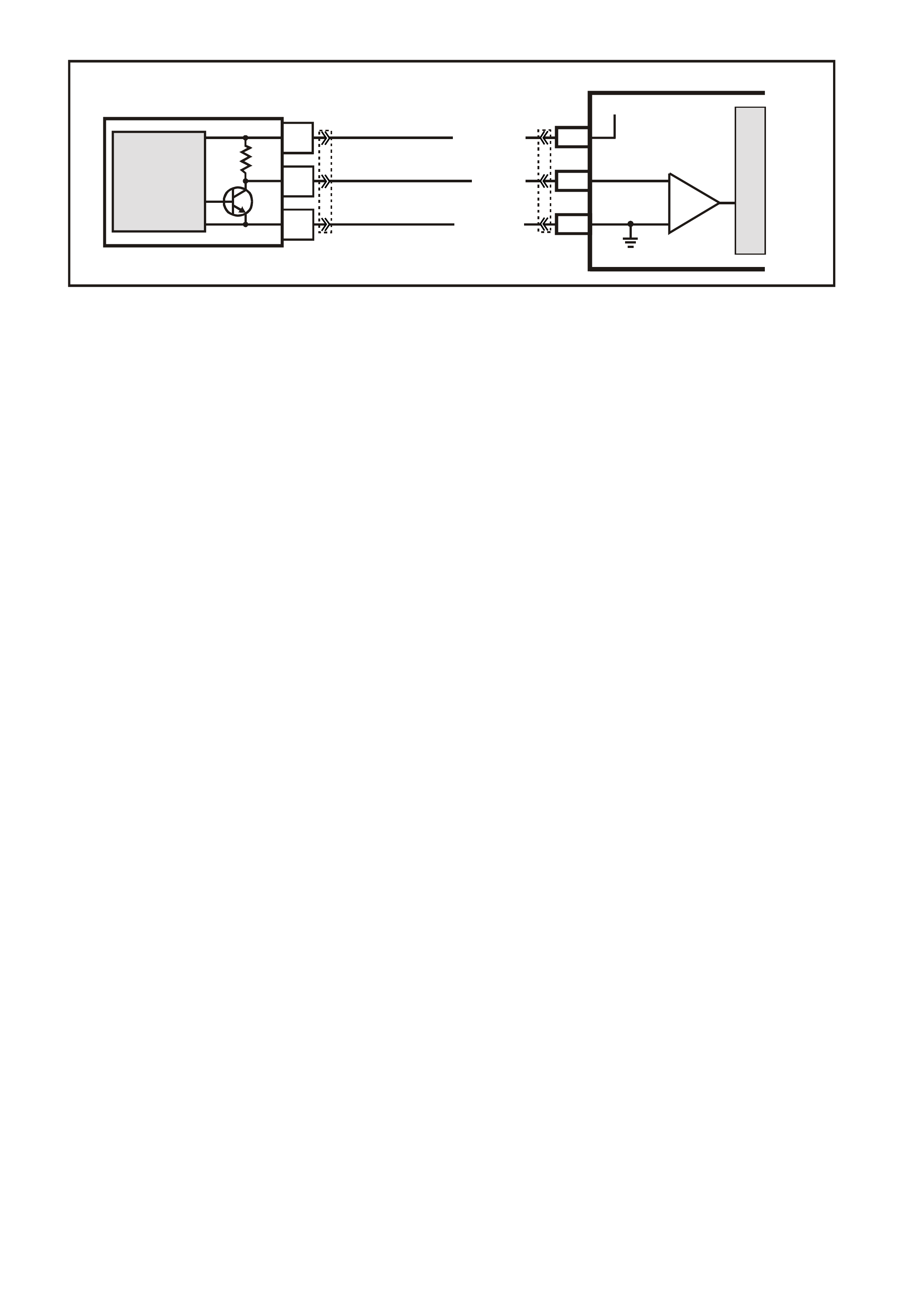
GEN III V8 PCM -
DTC P0336 CRANKSHAFT POSITION SENSOR CIRCUIT PERFORMANCE
CIRCUIT DESCRIPTION
The Crank shaf t Position Sensor (CKP) is m ounted in the right rear of the engine block behind the st arter. The CKP
sensor work s in conj unction with a 24X reluc tor wheel m ounted on the rear of the crank s haft. T he CKP Sensor has
a B+ power supply, a earth, and a signal circuit.
As the crankshaft rotates, the reluctor wheel teeth interrupt a magnetic field produced by a magnet within the
sensor. T he s ensor’s internal circ uitry detects this and pr oduces a s ignal which the PCM reads. T he PCM uses this
signal to accurately measure crankshaft velocity, which is a variable used in order to detect misfire, spark and,
fueling.
CONDITIONS FOR RUNNING THE DTC
• The ignition voltage is between 5 and 17.0 volts.
• The engine speed is greater than 400 RPM.
CONDITIONS FOR SETTING THE DTC
• The PCM determines no signal from the CKP sensor or the signal is out of range for at least one seconds.
ACTION TAKEN WHEN THE DTC SETS
• The PCM illuminates the Check Powertrain Lamp when the diagnostic runs and fails.
• The PCM records the operating conditions at the time the diagnostic fails. The PCM stores this information in
the Freeze Frame/Failure Records.
CONDITIONS FOR CLEARING THE CPL/DTC
• The PCM turns the Check Powertrain Lamp OFF when the diagnostic runs and does not fail.
• A last test failed (current DTC) clears when the diagnostic runs and does not fail.
• Use a Tech 2 scan tool in order to clear the CPL/DTC.
DIAGNOSTIC AIDS
• The following problems may cause this DTC to set:
- Poor connections/terminal tension at the sensor
- Crankshaft reluctor wheel damage or improper installation.
- The sensor coming in contact with the reluctor wheel.
- The engine running out of fuel.
• If the crankshaft rotates backwards, this DTC will set. This condition is only with vehicles equipped with a
manual transmission. This condition can occur when a vehicle is on an incline and the clutch is released and
an engine stall occurs.
• Using Fr eeze Frame/Failur e Records data may aid in locating an interm ittent condition. If you cannot duplicate
the DTC, the information included in the Freeze Frame/Failure Records data can aid in determining the
distance traveled since the DTC set. The Fail Counter and Pass Counter can also aid determining how many
ignition cycles the diagnostic reported a pass and/or a fail. Operate the vehicle within the same freeze frame
conditions (RPM, load, vehicle speed, temperature etc.) that you observed. This will isolate when the DTC
failed.
• Excess crankshaft end play will cause the CKP Sensor reluctor wheel to move out of alignment with the CKP
Sensor. This could result in any one of the following:
- A no start
- A start and stall
- Erratic performance
G3PCM012PT
PCM
M
I
C
R
O
A
C
B
CRANKSHAFT
POSITION
SENSOR
J1-02LBLU/W (646)
J1-21
SENSOR EARTH
12V
J1-12BLU (643)
CRANKSHAFT POSITION
SENSOR
SIGNAL
MAGNETO
RESISTIVE
INTEGRATED
CIRCUIT
IC
LBLU/B (647)
YE67 YE122
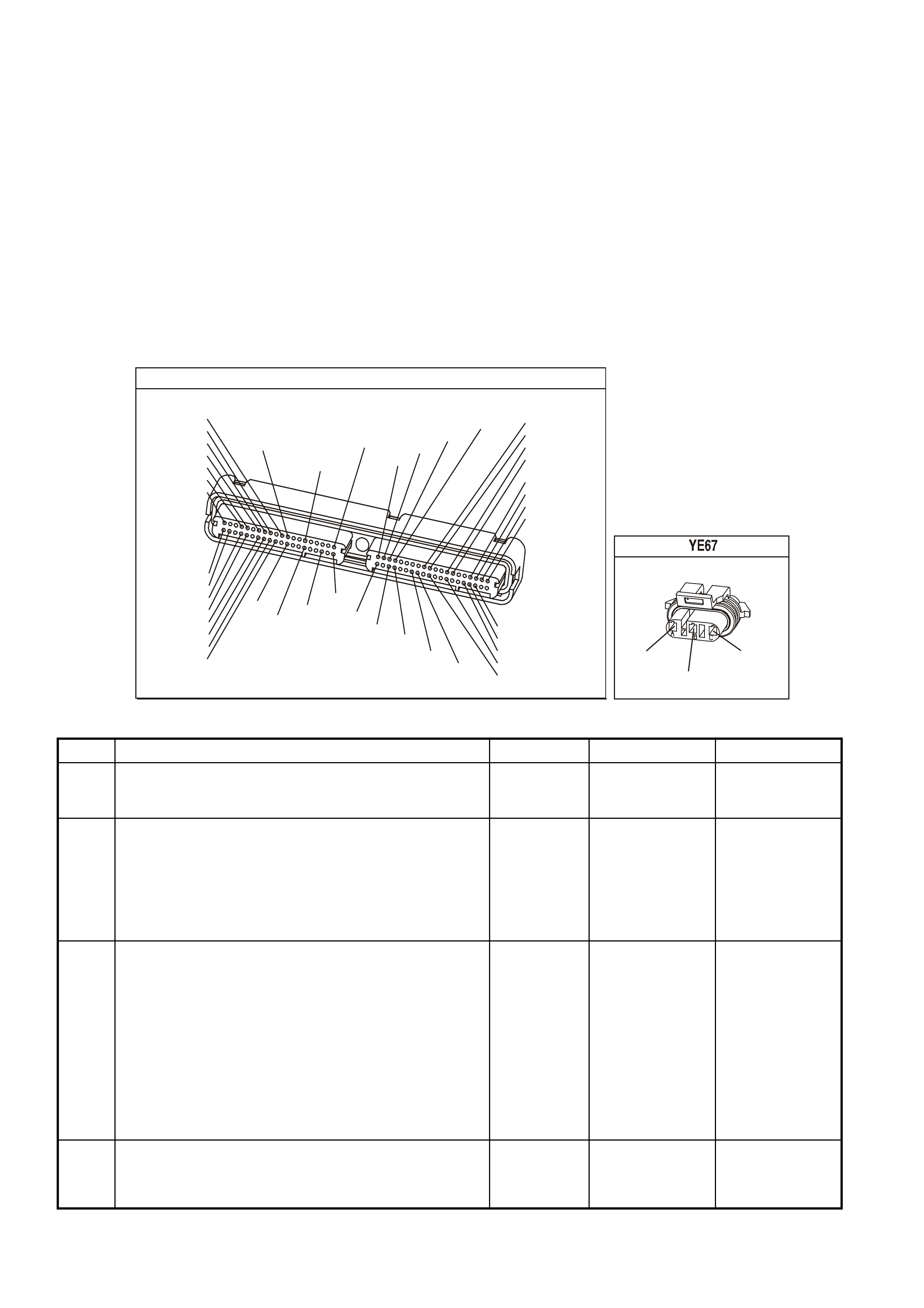
An improperly installed propeller shaft could cause excess crankshaft end play. Refer to
Section 6A3 Engine Mechanical in the VX Service Information for excess crankshaft end play diagnosis.
• For an intermittent, refer to Section 6C3-2B Symptoms of the VX Series Service Information.
TEST DESCRIPTION
The numbers below refer to the step numbers on the diagnostic table.
2. This step verifies that the malfunction is present.
3. This step checks for EMI (Electro Magnetic Interference) on the CKP sensor circuits.
6. Vertical lines across the face of the sensor could indicate foreign material passing between the CKP Sensor
and the reluctor wheel. Non vertical lines across the face of the sensor may indicate a crack in the CKP
Sensor. Either of these conditions causes this DTC to set
7. Damage to the reluctor wheel would affect the CKP Sensor output. To inspect the reluctor wheel, remove the
starter and rotate the crankshaft while viewing the reluctor wheel through the CKP sensor hole. If you cannot
determine if the reluctor wheel is damaged, the oil pan may have to be removed. If this condition exists, refer to
Section 6A3 Engine Mechanical in the VX Service Information for crankshaft replacement.
P.C.M CONNECTOR 1
YE122
(776)
(1049)
(897)
(1230)
(848)
(1226)
(772)
(647)
(632)
40
(844)
(815)
80
J1
P/B
(845)
V/W
BLU
O
(633)
(846)
B/Y
B/R
(416)
(86)
(69)
(455)
(740)
GY
BR
G
GY
(646)
(410)
GY
(842)
(1225)
V
Y
(750)
P
41
O
(774)
BR/Y
BLU
Y
B/R
B
BLU/Y
(841)
BLUE
(414)
G/W
BLU
LG
LBLU/B
1
(847)
(415)
(740)
(452)
BLU
BR
Y
(750)
(826)
(421)
Y
V/W
B/W
(334)
(771)
(39)
Y
R/W
LBLU
W
BLU/W
(843)
(643)
LBLU/W
G
GY/B
BLU/B
(413)
(1413)
(1412)
(412)
GY
V
GY/B
G
(335)
CRANK SENSOR
(646)
LBLU/W
(647)
LBLU/B
(643)
BLU
GEN III V8 PCM - DTC P0336 CRANKSHAFT POSITION SENSOR CIRCUIT PERFORMANCE
Step Action Value(s) Yes No
1 Did you perform the Powertrain On-Board Diagnostic
(OBD) System Check ? Go to Step 2 Go to Powertrain
OBD System
Check Table
2 IMPORTANT: IF DTC P0335 is also set, diagnose DTC
P0335 before proceeding with this DTC.
1. Install a Tech 2 scan tool.
2. Idle the engine for 2 minutes.
Does the Tech 2 scan tool indicate that DTC P0336 failed
this ignition?
Go to Step 3 Intermittent
condition.
Refer to
Diagnostic Aids
3 1. Visually Physically inspect all circuits going to the
Crankshaft Position Sensor for the following:
- Routed to close to secondary ignition wires or
components
- Routed to close to after-market add on electrical
equipment
- Routed to close to solenoids, relays and motors
2. If you find incorrect routing, correct the harness
routing.
Did you find and correct the condition?
Go to Step 9 Go to Step 4
4 1. Check the terminal contact at the CKP Sensor.
2. Repair/replace the terminal if you find a problem.
Did you find and correct the condition?
Go to Step 9 Go to Step 5

GEN III V8 PCM - DTC P0336 CRANKSHAFT POSITION SENSOR CIRCUIT PERFORMANCE (CONTINUED)
Step Action Value(s) Yes No
5 1. Check the terminal contact at the PCM for the CKP
Sensor circuits.
2. Repair/replace the terminal if you find a problem.
Did you find and correct the condition?
Go to Step 9 Go to Step 6
6 1. Remove the CKP Sensor. Refer to Section 6C3-3
Crankshaft Position Sensor Replacement of the VX
Series Service Information.
2. Inspect the CKP Sensor for signs of damage.
Did you find and correct the condition?
Go to
Section 6A3
Engine
Mechanical in VX
Service
Information.
Go to Step 7
7 Inspect the CKP reluctor wheel for damage.
Did you find and correct the condition? Go to
Section 6A3
Engine
Mechanical in VX
Service
Information.
Go to Step 8
8 Replace the CKP Sensor. Refer to Section 6C3-3
Crankshaft Position Sensor Replacement of the VX
Series Service Information.
Is the action complete?
Go to Step 9
9 1. Select the Diagnostic Trouble Code (DTC) option and
the Clear DTC Information option using the Tech 2
scan tool.
2. Idle the engine at the normal operating temperature.
3. Select the Diagnostic Trouble Code (DTC) option, the
DTC Information option and The Failed This Ignition
option using the Tech 2 scan tool.
4. Operate the vehicle, within the Conditions for Running
the DTC, as specified in the supporting text, if
applicable.
Does the Tech 2 scan tool indicate that this DTC reset?
Go to Step 2 Go to Step 10
10 Using the Tech 2 scan tool, check for any other DTCs.
Does the Tech 2 scan tool display any DTCs that you
have not diagnosed?
Go to the
applicable DTC
table
System OK

GEN III V8 PCM -
DTC P0341 CAMSHAFT POSITION SENSOR CIRCUIT PERFORMANCE
CIRCUIT DESCRIPTION
The Camshaft Position sensor is mounted through the top of the engine block at the rear of the valley cover. The
CMP sensor work s in conj unction with a 1X reluctor wheel on the cam shaf t. The reluctor wheel is inside the engine
imm ediately in front of the r ear cam bear ing. The PCM provides a 12 volt power supply to the CMP sensor as well
as a earth and a signal circuit.
The CMP sensor determines whether a cylinder is on a firing stroke or on an exhaust stroke. As the camshaft
rotates, the reluctor wheel interrupts a m agnetic f ield produc ed by a m agnet within the sens or. T he sensor s internal
circuitr y detects this and pr oduces a s ignal which the PCM reads. T he PCM uses this 1X signal in com bination with
the Crank shaft Pos ition sensor 24X signal in order to determ ine crankshaf t position and strok e. This diagnostic for
the Camshaft Position sensor checks for a loss of Camshaft Position sensor signal.
Observe that as long as the 24X signal is available, the engine starts even if there is no Cam shaft Position sensor
signal. The PCM can determine when a particular cylinder is on either a firing or exhaust stroke by the 24X signal
alone, but the PCM requires the cam signal in order to determine which (firing or exhaust). The system attempts
synchronisation and looks f or an inc rease in MAF signal indicating the engine star ted. If the PCM does not detect a
MAF increase, the PCM assumes it incorrectly synchronised to the exhaust stroke and re-synchs to the opposite
cam position. A slightly longer cranking time may be a symptom of this condition.
CONDITIONS FOR RUNNING THE DTC
• The ignition voltage is between 5 and 17.0 volts.
• The engine speed is greater than 400 RPM.
CONDITIONS FOR SETTING THE DTC
• The PCM detects that a CMP to CKP mismatch has occurred for at least 10 seconds.
• Action Taken When the DTC Sets
• The PCM illuminates the Check Powertrain Lamp when the diagnostic runs and fails.
• The PCM records the operating conditions at the time the diagnostic fails. The PCM stores this information in
the Freeze Frame/Failure Records.
CONDITIONS FOR CLEARING THE CPL/DTC
• The PCM turns the Check Powertrain Lamp OFF when the diagnostic runs and does not fail.
• A last test failed (current DTC) clears when the diagnostic runs and does not fail.
• Use a Tech 2 scan tool in order to clear the CPL/DTC.
DIAGNOSTIC AIDS
• The following mechanical problems may cause this DTC to set:
- Poor connections/terminal tension at the sensor
- Camshaft reluctor wheel damage
- The sensor coming in contact with the reluctor wheel
• Using Freeze Fram e/Failure Records data m ay aid in locating an intermittent condition. If you cannot duplicate
the DTC, the information included in the Freeze Frame/Failure Records data can aid in determining the
distance traveled since the DTC set. The Fail Counter and Pass Counter can also aid determining how many
ignition cycles the diagnostic reported a pass and/or a fail. Operate the vehicle within the same freeze frame
conditions (RPM, load, vehicle speed, temperature etc.) that you observed. This will isolate when the DTC
failed.
G3PCM011PT
PCM
M
I
C
R
O
A
C
B
CAMSHAFT
POSITION
SENSOR
J2-39W/B(631)
J1-61
SENSOR EARTH
RW(632)
12V
J1-73
BR(633)
CAMSHAFT POSITION
SENSOR
SIGNAL
MAGNETO
RESISTIVE
INTEGRATED
CIRCUIT
IC
YE69 YE122
YE123
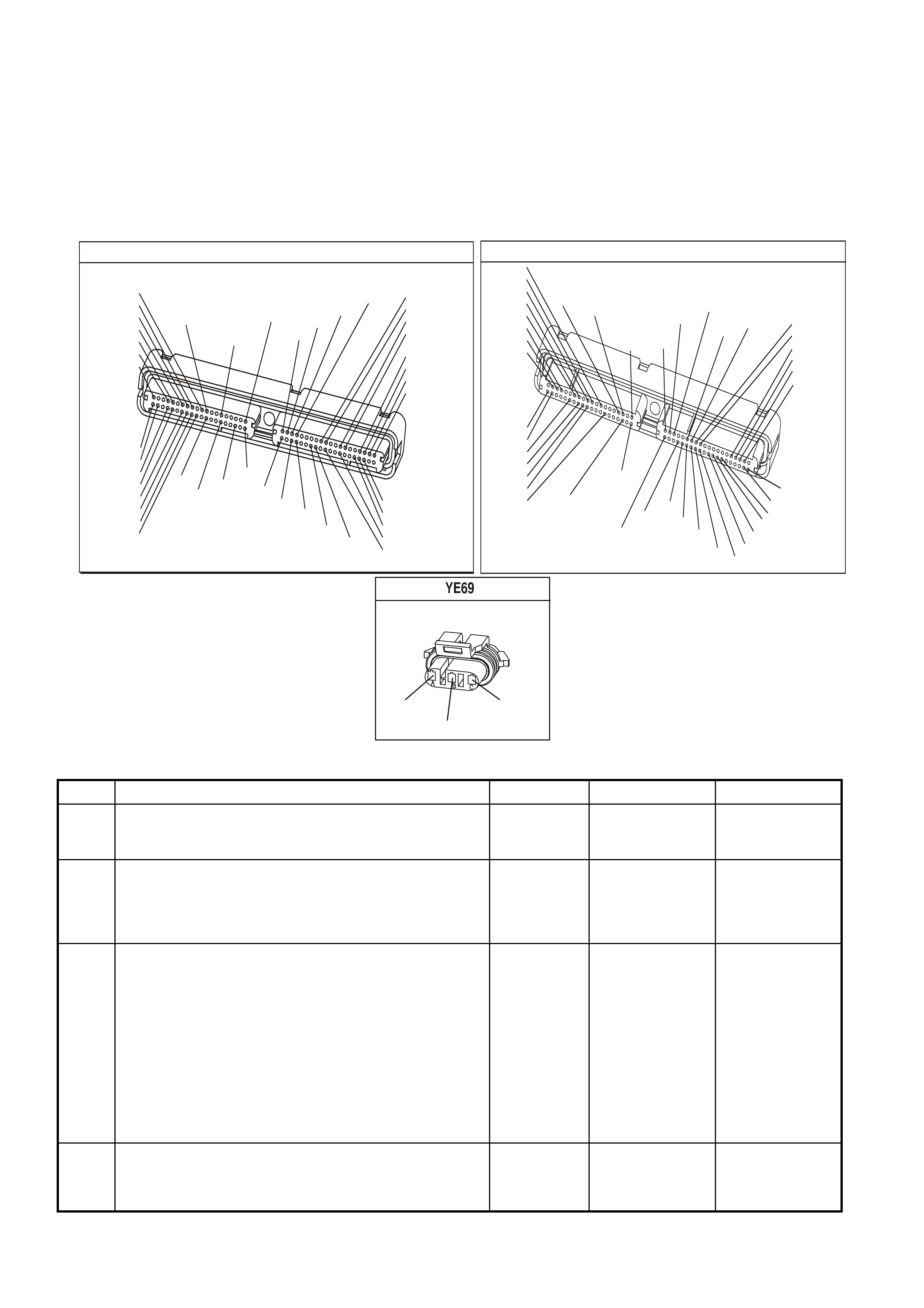
TEST DESCRIPTION
The numbers below refer to the step numbers on the diagnostic table.
2. This step verifies that the malfunction is present.
3. This step checks for EMI (Electro Magnetic Interference) on the CMP sensor circuits.
6. Vertical lines across the face of the sensor could indicate foreign material passing between the CMP sensor
and the reluctor wheel. This condition could cause this DTC to set.
7. Damage to the reluctor wheel would affect the CMP sensor output. If this condition exists, refer to
Section 6A3 Engine Mechanical in the VX Service Information for Camshaft replacement.
P.C.M CONNECTOR 1
YE122
(776)
(1049)
(897)
(1230)
(848)
(1226)
(772)
(647)
(632)
40
(844)
(815)
80
J1
P/B
(845)
V/W
BLU
O
(633)
(846)
B/Y
B/R
(416)
(86)
(69)
(455)
(740)
GY
BR
G
GY
(646)
(410)
GY
(842)
(1225)
V
Y
(750)
P
41
O
(774)
BR/Y
BLU
Y
B/R
B
BLU/Y
(841)
BLUE
(414)
G/W
BLU
LG
LBLU/B
1
(847)
(415)
(740)
(452)
BLU
BR
Y
(750)
(826)
(421)
Y
V/W
B/W
(334)
(771)
(39)
Y
R/W
LBLU
W
BLU/W
(843)
(643)
LBLU/W
G
GY/B
BLU/B
(413)
(1413)
(1412)
(412)
GY
V
GY/B
G
(335)
YE123
P.C.M CONNECTOR 2
(750)
(1228)
(1229)
(465)
(121)
(259)
G/B
BR
G/W
GY/BLU
R
B/R
(418)
BR
(59)
(832)
G
T
(831)
(417)
(472)
(976)(974)
(432)
(428)
(631)
BLUBR G/Y
BLU/W
LG
BR/W
W/B
LG W
(977)
Y
(971)
BLU/WW
B/R
(750)
(304)
(792)
(1223)
(1222)
(123)
(1227)
(469)
(331)
Y/B
LG
V/W
B/Y
G/O BR/W
(1687)
GY/B
(366)
LG/B
GY/R
(422)
V
(442)
(444)
(443)
(975)
(972)
(978)
(1224)
(973)
(959)
LG/W
LG/B
LBLU/B
GY
(773)
BR/Y
BLU
G
Y/B
LBLU
(958)
BR
(441)
LBLU
1
41
40
80
J2
RED
Y
(838)
CAM SENSOR
(631)
W/B
(632)
R/W
(633)
BR
GEN III V8 PCM - DTC P0341 CAMSHAFT POSITION SENSOR CIRCUIT PERFORMANCE
Step Action Value(s) Yes No
1 Did you perform the Powertrain On-Board Diagnostic
(OBD) System Check ? Go to Step 2 Go to Powertrain
OBD System
Check Table
2 1. Install a Tech 2 scan tool.
2. Idle the engine for 2 minutes.
Does the Tech 2 scan tool indicate that DTC P0341 failed
this ignition?
Go to Step 3 Intermittent
condition.
Refer to
Diagnostic Aids
3 1. Inspect all Camshaft Position sensor circuits for the
following:
- Routed to close to secondary ignition wires or
components
- Routed to close to after-market add on electrical
equipment
- Routed to close to solenoids, relays and motors
2. If you find incorrect routing, correct the harness
routing.
Did you find and correct the condition?
Go to Step 9 Go to Step 4
4 1. Check the terminal contact at the CMP sensor.
2. If you find a problem, Repair/replace the terminal(s).
Did you find and correct the condition?
Go to Step 9 Go to Step 5

GEN III V8 PCM - DTC P0341 CAMSHAFT POSITION SENSOR CIRCUIT PERFORMANCE (CONTINUED)
Step Action Value(s) Yes No
5 1. Check the terminal contact at the PCM for the CMP
sensor circuits.
2. Repair/replace the terminal if you find a problem.
Did you find and correct the condition?
Go to Step 9 Go to Step 6
6 1. Remove the CMP sensor. Refer to Section 6C3-3
Camshaft Position Sensor Replacement of the VX
Series Service Information.
2. Inspect the CMP sensor for signs of damage.
Did you find and correct the condition?
Go To Section
6A3 Engine
Mechanical in VX
Service
Information.
Go to Step 7
7 Inspect the CMP reluctor wheel for damage.
Did you find and correct the condition? Go To Section
6A3 Engine
Mechanical in VX
Service
Information.
Go to Step 8
8 Replace the CMP Sensor. Refer to Section 6C3-3
Camshaft Position Sensor Replacement of the VX Series
Service Information.
Is the action complete?
Go to Step 9
9 1. Select the Diagnostic Trouble Code (DTC) option and
the Clear DTC Information option using the Tech 2
scan tool.
2. Idle the engine at the normal operating temperature.
3. Select the Diagnostic Trouble Code (DTC) option, the
DTC Information, The Failed This Ignition using the
Tech 2 scan tool.
4. Operate the vehicle within the Conditions for Running
the DTC as specified in the supporting text, if
applicable.
Does the Tech 2 scan tool indicate that this DTC reset?
Go to Step 2 Go to Step 10
10 Using the Tech 2 scan tool, check for any other DTCs.
Does the Tech 2 scan tool display any DTCs that you
have not diagnosed?
Go to the
applicable DTC
table
System OK
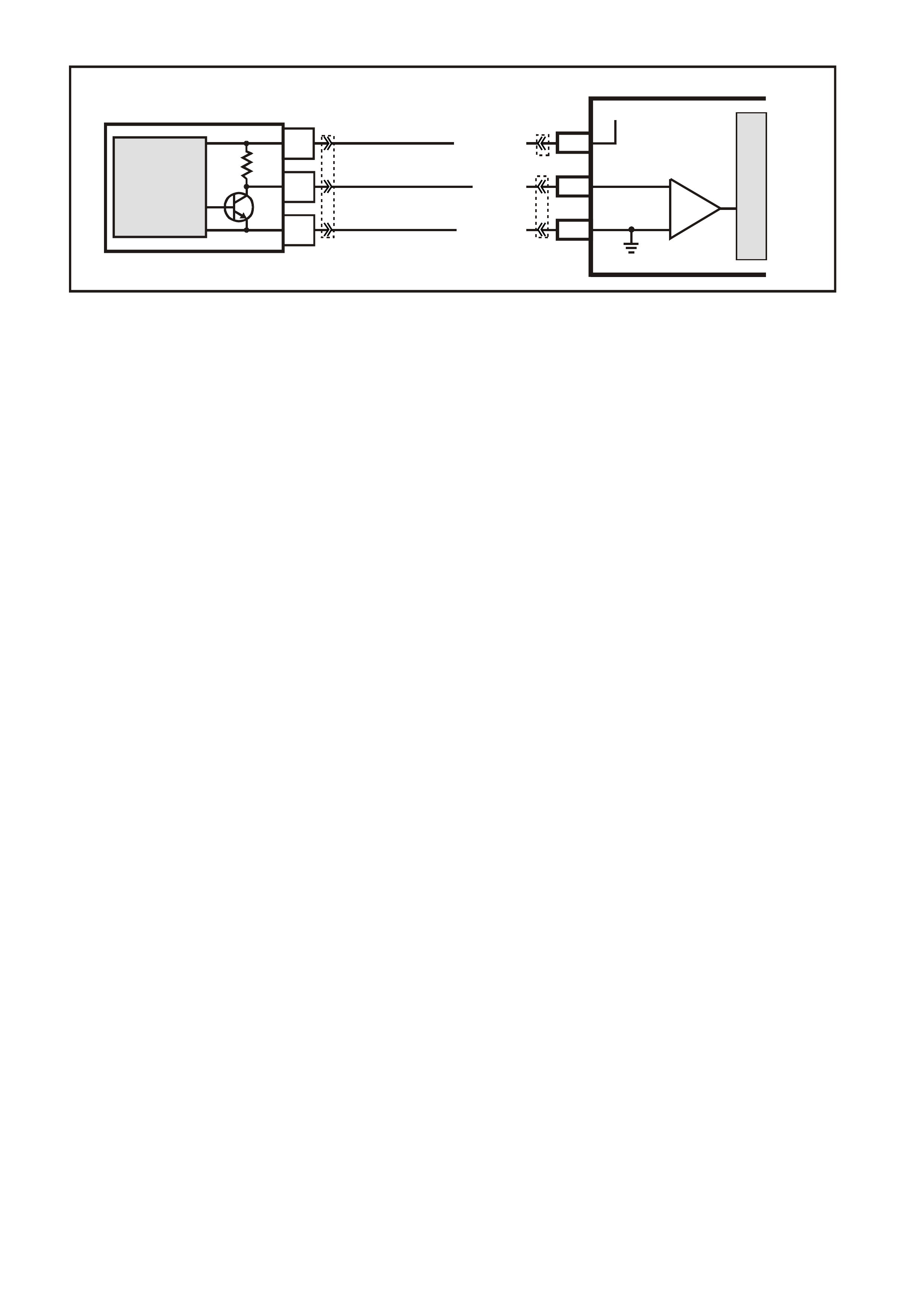
GEN III V8 PCM -
DTC P0342 CAMSHAFT POSITION SENSOR CIRCUIT LOW VOLTAGE
CIRCUIT DESCRIPTION
The Camshaft Position sensor is mounted through the top of the engine block at the rear of the valley cover. The
CMP sensor work s in conj unction with a 1X reluctor wheel on the cam shaf t. The reluctor wheel is inside the engine
imm ediately in front of the r ear cam bear ing. The PCM provides a 12 volt power supply to the CMP sensor as well
as a earth and a signal circuit.
The CMP sensor determines whether a cylinder is on a firing stroke or on an exhaust stroke. As the camshaft
rotates, the reluctor wheel interrupts a m agnetic f ield produc ed by a m agnet within the sens or. T he sensor s internal
circuitry detects this and produces a signal, which the PCM reads. The PCM uses this 1X signal in combination
with the Crankshaf t Pos ition s ens or 24X s ignal in order to deter mine crankshaf t pos ition and st roke. T his diagnostic
for the Camshaft Position sensor checks for a loss of Camshaft Position sensor signal.
Observe that as long as the 24X signal is available, the engine starts even if there is no Cam shaft Position sensor
signal. The PCM can determine when a particular cylinder is on either a firing or exhaust stroke by the 24X signal
alone, but the PCM requires the cam signal in order to determine which (firing or exhaust). The system attempts
synchronisation and looks f or an inc rease in MAF signal indicating the engine star ted. If the PCM does not detect a
MAF increase, the PCM assumes it incorrectly synchronised to the exhaust stroke and re-synchs to the opposite
cam position. A slightly longer cranking time may be a symptom of this condition.
CONDITIONS FOR RUNNING THE DTC
• The ignition voltage is between 5 and 17.0 volts.
• The engine speed is greater than 400 RPM.
CONDITIONS FOR SETTING THE DTC
• The PCM detects the CMP sensor signal is low when the signal should be high for at least one second.
ACTION TAKEN WHEN THE DTC SETS
• The PCM illuminates the Check Powertrain Lamp when the diagnostic runs and fails.
• The PCM records the operating conditions at the time the diagnostic fails. The PCM stores this information in
the Freeze Frame/Failure Records.
CONDITIONS FOR CLEARING THE CPL/DTC
• The PCM turns the Check Powertrain Lamp OFF when the diagnostic runs and does not fail.
• A last test failed (current DTC) clears when the diagnostic runs and does not fail.
• Use a Tech 2 scan tool in order to clear the CPL/DTC.
DIAGNOSTIC AIDS
• The following mechanical problems may cause this DTC to set:
- Poor connections/terminal tension at the sensor
- Camshaft reluctor wheel damage
- The sensor coming in contact with the reluctor wheel
• Using Freeze Fram e/Failure Records data m ay aid in locating an intermittent condition. If you cannot duplicate
the DTC, the information included in the Freeze Frame/Failure Records data can aid in determining the
distance traveled since the DTC set. The Fail Counter and Pass Counter can also aid determining how many
ignition cycles the diagnostic reported a pass and/or a fail. Operate the vehicle within the same freeze frame
conditions (RPM, load, vehicle speed, temperature etc.) that you observed. This will isolate when the DTC
failed.
G3PCM011PT
PCM
M
I
C
R
O
A
C
B
CAMSHAFT
POSITION
SENSOR
J2-39W/B(631)
J1-61
SENSOR EARTH
RW(632)
12V
J1-73
BR(633)
CAMSHAFT POSITION
SENSOR
SIGNAL
MAGNETO
RESISTIVE
INTEGRATED
CIRCUIT
IC
YE69 YE122
YE123
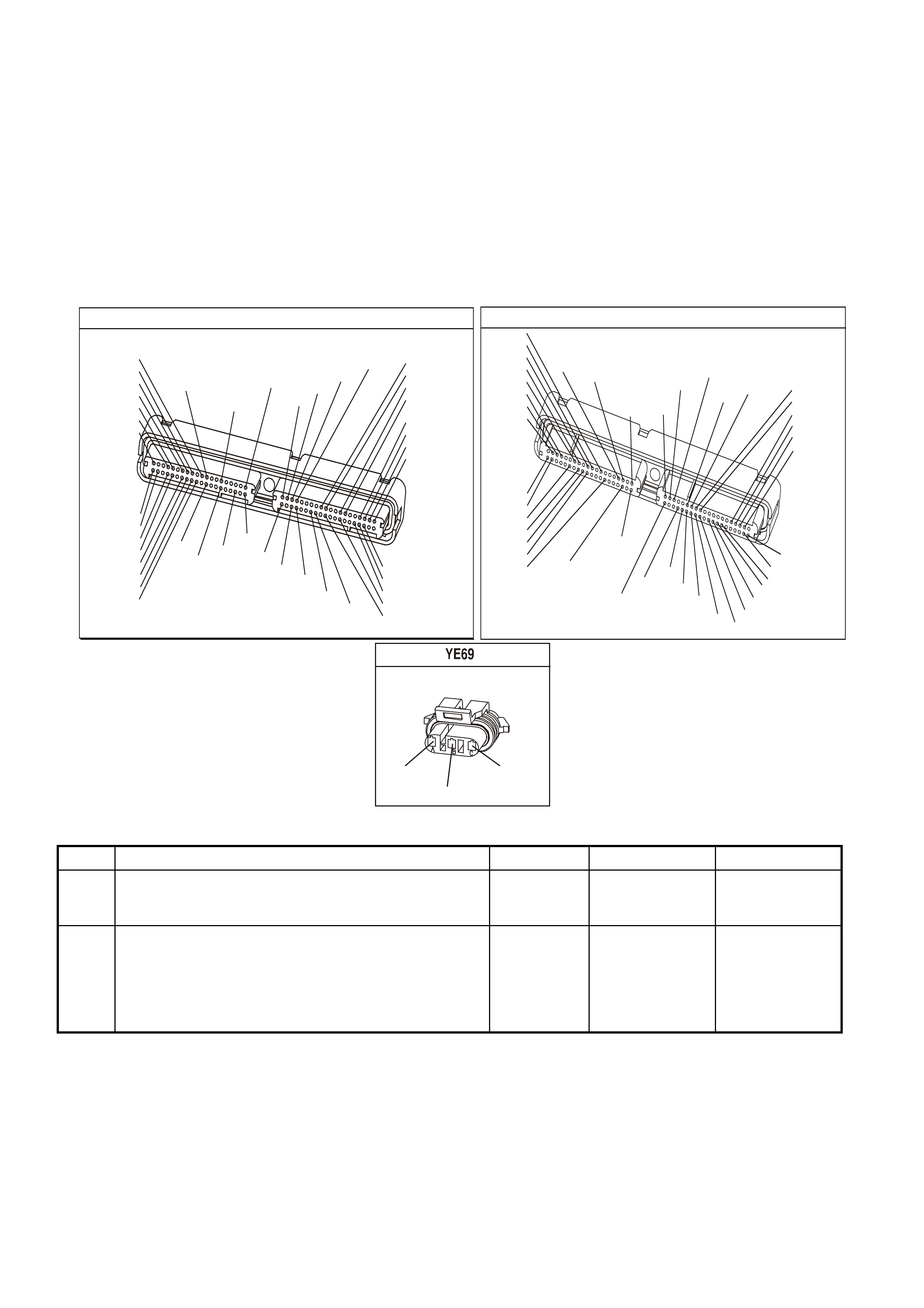
TEST DESCRIPTION
The numbers below refer to the step numbers on the diagnostic table.
2. This step verifies that the fault is present. The Camshaft activity counter will start at 0 with key ON, then
increment up to 65535 then back to 0 and increment up again.
4. This step tests the Camshaft Position sensor ignition feed circuit from the PCM to the CMP.
5. This step checks the Camshaft Position sensor earth circuit from the PCM to the CMP.
6. This step checks the Camshaft Position sensor signal circuit. Applying a voltage causes the CAM signal activity
counter to increment.
7. This step checks the Camshaft Position sensor ignition feed circuit from the PCM to the CMP.
9. This step checks the Camshaft Position sensor earth circuit from the PCM to the CMP.
P.C.M CONNECTOR 1
YE122
(776)
(1049)
(897)
(1230)
(848)
(1226)
(772)
(647)
(632)
40
(844)
(815)
80
J1
P/B
(845)
V/W
BLU
O
(633)
(846)
B/Y
B/R
(416)
(86)
(69)
(455)
(740)
GY
BR
G
GY
(646)
(410)
GY
(842)
(1225)
V
Y
(750)
P
41
O
(774)
BR/Y
BLU
Y
B/R
B
BLU/Y
(841)
BLUE
(414)
G/W
BLU
LG
LBLU/B
1
(847)
(415)
(740)
(452)
BLU
BR
Y
(750)
(826)
(421)
Y
V/W
B/W
(334)
(771)
(39)
Y
R/W
LBLU
W
BLU/W
(843)
(643)
LBLU/W
G
GY/B
BLU/B
(413)
(1413)
(1412)
(412)
GY
V
GY/B
G
(335)
YE123
P.C.M CONNECTOR 2
(750)
(1228)
(1229)
(465)
(121)
(259)
G/B
BR
G/W
GY/BLU
R
B/R
(418)
BR
(59)
(832)
G
T
(831)
(417)
(472)
(976)(974)
(432)
(428)
(631)
BLUBR G/Y
BLU/W
LG
BR/W
W/B
LG W
(977)
Y
(971)
BLU/WW
B/R
(750)
(304)
(792)
(1223)
(1222)
(123)
(1227)
(469)
(331)
Y/B
LG
V/W
B/Y
G/O BR/W
(1687)
GY/B
(366)
LG/B
GY/R
(422)
V
(442)
(444)
(443)
(975)
(972)
(978)
(1224)
(973)
(959)
LG/W
LG/B
LBLU/B
GY
(773)
BR/Y
BLU
G
Y/B
LBLU
(958)
BR
(441)
LBLU
1
41
40
80
J2
RED
Y
(838)
CAM SENSOR
(631)
W/B
(632)
R/W
(633)
BR
GEN III V8 PCM - DTC P0342 CAMSHAFT POSITION SENSOR CIRCUIT LOW VOLTAGE
Step Action Value(s) Yes No
1 Did you perform the Powertrain On-Board Diagnostic
(OBD) System Check? Go to Step 2 Go to Powertrain
OBD System
Check Table
2 1. Install a Tech 2 scan tool.
2. Idle the engine.
3. Monitor the CAM signal activity counter in the Engine
Data List using the Tech 2 scan tool.
Does the Tech 2 scan tool parameter increment?
Go to Step 3 Go to Step 4

GEN III V8 PCM - DTC P0342 CAMSHAFT POSITION SENSOR CIRCUIT LOW VOLTAGE (CONTINUED)
Step Action Value(s) Yes No
3 1. Turn ON the ignition leaving the engine OFF.
2. Review the Freeze Frame/Failure Records data for
this DTC and observe the parameters.
3. Turn OFF the ignition for 15 seconds.
4. Idle the engine.
5. Operate the vehicle within the conditions required for
this diagnostic to run, and as close to the conditions
recorded in Freeze Frame/Failure Records as
possible. Special operating conditions that you need to
meet before the PCM will run this diagnostic, where
applicable, are listed in Conditions for Running the
DTC.
6. Select the Diagnostic Trouble Code (DTC) option, the
DTC Information, The Failed This Ignition using the
Tech 2 scan tool.
Does the Tech 2 scan tool indicate that this diagnostic
failed this ignition?
Go to Step 4 Refer to
Diagnostic Aids
4 1. Turn Off the ignition.
2. Disconnect the Camshaft Position Sensor (CMP).
3. Turn ON the ignition leaving the engine OFF.
4. Measure the Camshaft Position sensor ignition feed
voltage using the DMM.
Does the DMM display near the specified value?
B+ Go to Step 5 Go to Step 7
5 Measure the Camshaft Position sensor ignition feed
circuit to the Camshaft Position sensor earth circuit using
the DMM.
Does the DMM display the specified voltage?
B+ Go to Step 6 Go to Step 9
6 1. Start the engine.
2. Monitor the CAM signal activity counter in the Engine
Data List using the Tech 2 scan tool.
3. Momentarily and repeatedly probe the signal circuit
with the test lamp connected to B+.
Does the CAM signal activity counter increment when the
test lamp contacts the signal circuit?
Go to Step 15 Go to Step 10
7 1. Turn OFF the ignition.
2. Disconnect the PCM connector C2 located on the
opposite side of the manufacturer’s logo.
3. Test the continuity of the CMP ignition feed circuit
using the DMM.
Is there continuity and is the resistance within the
specified range?
0-5Ω Go to Step 8 Go to Step 12
8 Inspect the CMP ignition feed circuit for the following:
• A earthed circuit
• A poor connection
Did you find and correct the condition?
Go to Step 19 Go to Step 16
9 1. Turn OFF the ignition.
2. Disconnect the PCM connector C1 located on the
same side as the manufacturer’s logo.
3. Test the continuity of the CMP earth circuit using the
DMM.
Is there continuity and is the resistance within the
specified range?
0-5Ω Go to Step 16 Go to Step 13
10 1. Turn OFF the ignition.
2. Disconnect the PCM connector C1 located on the
same side as the manufacturer’s logo.
3. Test the continuity of the CMP signal circuit using the
DMM.
Is the voltage less than the specified value?
0-5Ω Go to Step 11 Go to Step 14

GEN III V8 PCM - DTC P0342 CAMSHAFT POSITION SENSOR CIRCUIT LOW VOLTAGE (CONTINUED)
Step Action Value(s) Yes No
11 1. Turn ON the ignition leaving the engine OFF.
2. Test the CMP signal circuit for the following:
• A earthed circuit
• A circuit shorted to a voltage
Did you find and correct the condition?
Go to Step 19 Go to Step 16
12 1. Inspect the CMP ignition feed circuit for open.
2. If you find an open circuit, repair the CMP ignition feed
circuit.
Did you find and correct the condition?
Go to Step 19 Go to Step 16
13 Repair open in the CMP earth circuit.
Is the action complete? Go to Step 19
14 Repair open in the CMP signal circuit.
Is the action complete? Go to Step 19
15 1. Inspect for poor connections at the CMP harness
connector.
2. If you find a poor connection repair the connector as
necessary.
Did you find and correct the condition?
Go to Step 19 Go to Step 17
16 1. Inspect the PCM harness connector for poor
connections.
2. If you find a poor connection repair the connector as
necessary.
Did you find and correct the condition?
Go to Step 19 Go to Step 18
17 Replace the CMP sensor. Refer to Section 6C3-3
Camshaft Position Sensor Replacement of the VX Series
Service Information.
Is action complete?
Go to Step 19
18 1. Replace PCM.
2. Refer to Section 6C3-3 of the VX Series Service
Information for PCM Programming and
PCM/PIM/BCM Security Link Procedure.
Is action complete?
Go to Step 19
19 1. Select the Diagnostic Trouble Code (DTC) option and
the Clear DTC Information option using the Tech 2
scan tool.
2. Idle the engine at the normal operating temperature.
3. Select the Diagnostic Trouble Code (DTC) option, the
DTC Information, The Failed This Ignition using the
Tech 2 scan tool.
4. Operate the vehicle within the Conditions for Running
the DTC as specified in the supporting text, if
applicable.
Does the Tech 2 scan tool indicate that this DTC reset?
Go to Step 2 Go to Step 20
20 Using the Tech 2 scan tool, check for any other DTCs.
Does the Tech 2 scan tool display any DTCs that you
have not diagnosed?
Go to applicable
DTC Table System OK
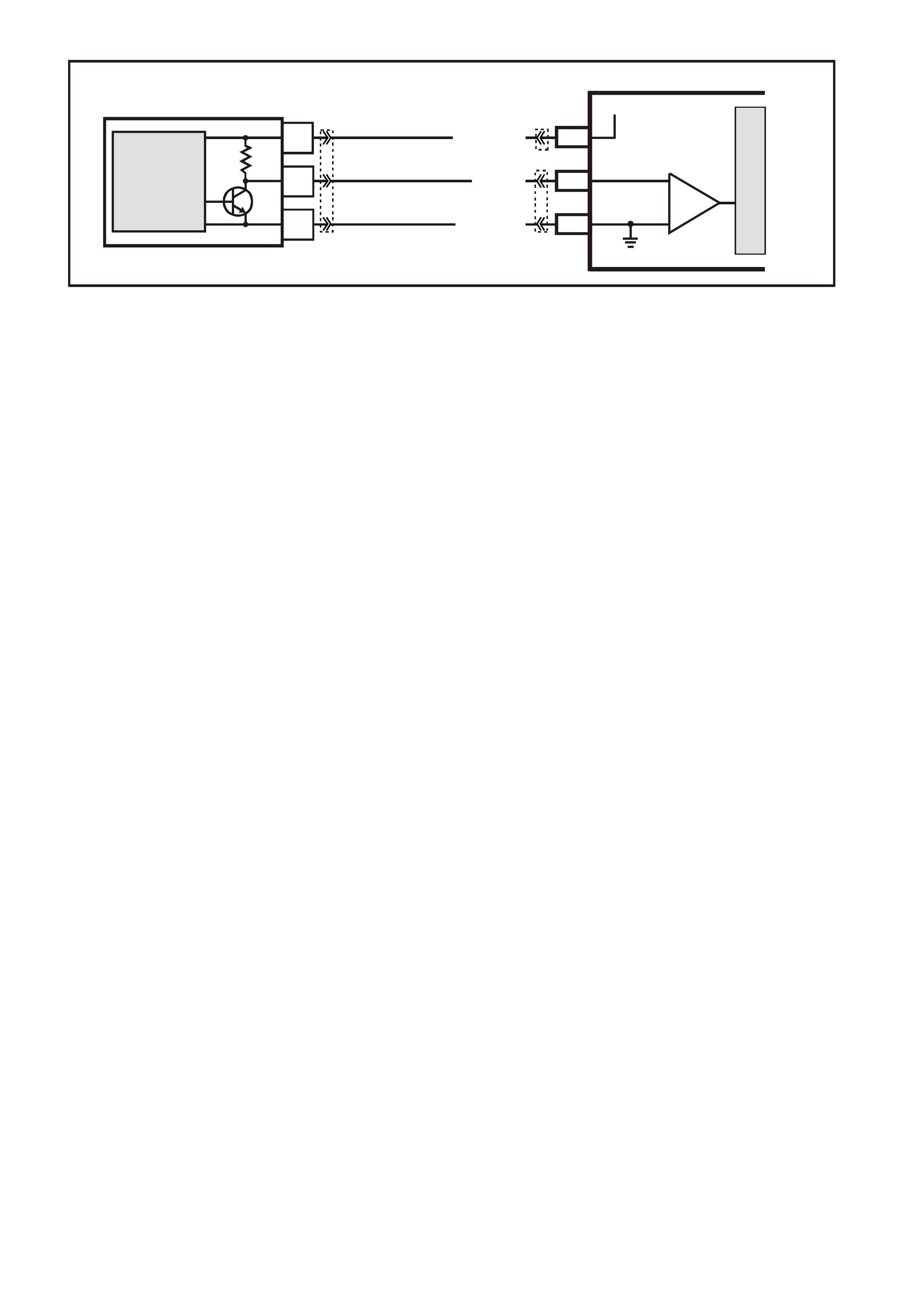
GEN III V8 PCM -
DTC P0343 CAMSHAFT POSITION SENSOR CIRCUIT HIGH VOLTAGE
CIRCUIT DESCRIPTION
The Camshaft Position (CMP) Sensor is mounted through the top of the engine block at the rear of the valley
cover. The CMP s ensor work s in conjunc tion with a 1X reluctor wheel on the cam shaf t. The r eluctor wheel is ins ide
the engine immediately in front of the rear cam bearing. The PCM provides a 12 volt power supply to the CMP
sensor as well as a earth and a signal circuit.
The CMP sensor determines whether a cylinder is on a firing stroke or on an exhaust stroke. As the camshaft
rotates, the reluctor wheel interrupts a m agnetic f ield produc ed by a m agnet within the sens or. T he sensor s internal
circuitry detects this and produces a signal, which the PCM reads. The PCM uses this 1X signal in combination
with the Crankshaf t Pos ition s ens or 24X s ignal in order to deter mine crankshaf t pos ition and st roke. T his diagnostic
for the Camshaft Position sensor checks for a loss of Camshaft Position sensor signal.
Observe that as long as the 24X signal is available, the engine starts even if there is no Cam shaft Position sensor
signal. The PCM can determine when a particular cylinder is on either a firing or exhaust stroke by the 24X signal
alone, but the PCM requires the cam signal in order to determine which (firing or exhaust). The system attempts
synchronisation and looks f or an inc rease in MAF signal indicating the engine star ted. If the PCM does not detect a
MAF increase, the PCM assumes it incorrectly synchronised to the exhaust stroke and re-synchs to the opposite
cam position. A slightly longer cranking time may be a symptom of this condition.
CONDITIONS FOR RUNNING THE DTC
• The ignition voltage is between 5 and 17.0 volts.
• The engine speed is greater than 400 RPM.
CONDITIONS FOR SETTING THE DTC
• The PCM detects the CMP sensor signal is stuck high when the signal should be low for at least one second.
ACTION TAKEN WHEN THE DTC SETS
• The PCM illuminates the Check Powertrain Lamp when the diagnostic runs and fails.
• The PCM records the operating conditions at the time the diagnostic fails. The PCM stores this information in
the Freeze Frame/Failure Records.
CONDITIONS FOR CLEARING THE CPL/DTC
• The PCM turns the Check Powertrain Lamp OFF when the diagnostic runs and does not fail.
• A last test failed (current DTC) clears when the diagnostic runs and does not fail.
• Use a Tech 2 scan tool in order to clear the CPL/DTC.
DIAGNOSTIC AIDS
• The following mechanical problems may cause this DTC to set:
- Poor connections/terminal tension at the sensor
- Camshaft reluctor wheel damage
- The sensor coming in contact with the reluctor wheel
• Using Freeze Fram e/Failure Records data m ay aid in locating an intermittent condition. If you cannot duplicate
the DTC, the information included in the Freeze Frame/Failure Records data can aid in determining the
distance traveled since the DTC set. The Fail Counter and Pass Counter can also aid determining how many
ignition cycles the diagnostic reported a pass and/or a fail. Operate the vehicle within the same freeze frame
conditions (RPM, load, vehicle speed, temperature etc.) that you observed. This will isolate when the DTC
failed.
G3PCM011PT
PCM
M
I
C
R
O
A
C
B
CAMSHAFT
POSITION
SENSOR
J2-39W/B(631)
J1-61
SENSOR EARTH
RW(632)
12V
J1-73
BR(633)
CAMSHAFT POSITION
SENSOR
SIGNAL
MAGNETO
RESISTIVE
INTEGRATED
CIRCUIT
IC
YE69 YE122
YE123
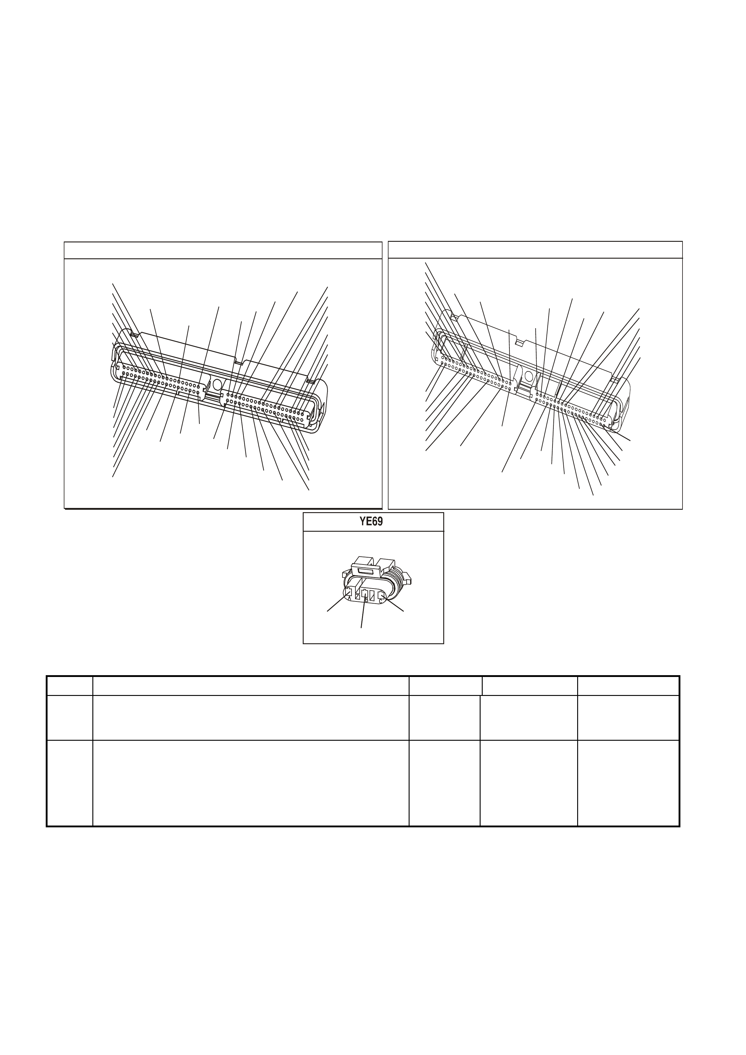
TEST DESCRIPTION
The numbers below refer to the step numbers on the diagnostic table.
2. This step verifies that the fault is present. The Camshaft activity counter will start at 0 with key ON, then
increment up to 65535 then back to 0 and increment up again.
4. This step tests the Camshaft Position sensor ignition feed circuit from the PCM to the CMP.
5. This step checks the Camshaft Position sensor earth circuit from the PCM to the CMP.
6. This step checks the Camshaft Position sensor signal circuit. Applying a voltage causes the CAM signal activity
counter to increment.
7. This step checks the Camshaft Position sensor ignition feed circuit from the PCM to the CMP.
9. This step checks the Camshaft Position sensor earth circuit from the PCM to the CMP.
P.C.M CONNECTOR 1
YE122
(776)
(1049)
(897)
(1230)
(848)
(1226)
(772)
(647)
(632)
40
(844)
(815)
80
J1
P/B
(845)
V/W
BLU
O
(633)
(846)
B/Y
B/R
(416)
(86)
(69)
(455)
(740)
GY
BR
G
GY
(646)
(410)
GY
(842)
(1225)
V
Y
(750)
P
41
O
(774)
BR/Y
BLU
Y
B/R
B
BLU/Y
(841)
BLUE
(414)
G/W
BLU
LG
LBLU/B
1
(847)
(415)
(740)
(452)
BLU
BR
Y
(750)
(826)
(421)
Y
V/W
B/W
(334)
(771)
(39)
Y
R/W
LBLU
W
BLU/W
(843)
(643)
LBLU/W
G
GY/B
BLU/B
(413)
(1413)
(1412)
(412)
GY
V
GY/B
G
(335)
YE123
P.C.M CONNECTOR 2
(750)
(1228)
(1229)
(465)
(121)
(259)
G/B
BR
G/W
GY/BLU
R
B/R
(418)
BR
(59)
(832)
G
T
(831)
(417)
(472)
(976)(974)
(432)
(428)
(631)
BLUBR G/Y
BLU/W
LG
BR/W
W/B
LG W
(977)
Y
(971)
BLU/WW
B/R
(750)
(304)
(792)
(1223)
(1222)
(123)
(1227)
(469)
(331)
Y/B
LG
V/W
B/Y
G/O BR/W
(1687)
GY/B
(366)
LG/B
GY/R
(422)
V
(442)
(444)
(443)
(975)
(972)
(978)
(1224)
(973)
(959)
LG/W
LG/B
LBLU/B
GY
(773)
BR/Y
BLU
G
Y/B
LBLU
(958)
BR
(441)
LBLU
1
41
40
80
J2
RED
Y
(838)
CAM SENSOR
(631)
W/B
(632)
R/W
(633)
BR
GEN III V8 PCM - DTC P0343 CAMSHAFT POSITION SENSOR CIRCUIT HIGH VOLTAGE
Step Action Value(s) Yes No
1 Did you perform the Powertrain On-Board Diagnostic (OBD)
System Check? Go to Step 2 Go to Powertrain
OBD System
Check Table
2 1. Install a Tech 2 scan tool.
2. Idle the engine.
3. Monitor the CAM signal activity counter in the Engine
Data List using the Tech 2 scan tool.
Does the Tech 2 scan tool parameter increment?
Go to Step 3 Go to Step 4

GEN III V8 PCM - DTC P0343 CAMSHAFT POSITION SENSOR CIRCUIT HIGH VOLTAGE (CONTINUED)
Step Action Value(s) Yes No
3 1. Turn ON the ignition leaving the engine OFF.
2. Review the Freeze Frame/Failure Records data for
this DTC and observe the parameters.
3. Turn OFF the ignition for 15 seconds.
4. Idle the engine.
5. Operate the vehicle within the conditions required for
this diagnostic to run, and as close to the conditions
recorded in Freeze Frame/Failure Records as
possible. Special operating conditions that you need to
meet before the PCM will run this diagnostic, where
applicable, are listed in Conditions for Running the
DTC.
6. Select the Diagnostic Trouble Code (DTC) option, the
DTC Information, The Failed This Ignition using the
Tech 2 scan tool.
Does the Tech 2 scan tool indicate that this diagnostic
failed this ignition?
Go to Step 4 Refer to
Diagnostic Aids
4 1. Turn Off the ignition.
2. Disconnect the Camshaft Position Sensor (CMP).
3. Turn ON the ignition leaving the engine OFF.
4. Measure the Camshaft Position sensor ignition feed
voltage using the DMM.
Does the DMM display near the specified value?
B+ Go to Step 5 Go to Step 7
5 Measure the Camshaft Position sensor ignition feed
circuit to the Camshaft Position sensor earth circuit using
the DMM.
Does the DMM display the specified voltage?
B+ Go to Step 6 Go to Step 9
6 1. Start the engine.
2. Monitor the CAM signal activity counter in the Engine
Data List using the Tech 2 scan tool.
3. Momentarily and repeatedly probe the signal circuit
with the test lamp connected to B+.
Dopes the CAM signal activity counter increment when
the test lamp contacts the signal circuit?
Go to Step 15 Go to Step 10
7 1. Turn OFF the ignition.
2. Disconnect the PCM connector C2 located on the
opposite side of the manufacturer’s logo.
3. Test the continuity of the CMP ignition feed circuit
using the DMM.
Is there continuity and is the resistance within the
specified range?
0-5Ω Go to Step 8 Go to Step 12
8 Inspect the CMP ignition feed circuit for the following:
• A earthed circuit
• A poor connection
Did you find and correct the condition?
Go to Step 19 Go to Step 16
9 1. Turn OFF the ignition.
2. Disconnect the PCM connector C1 located on the
same side as the manufacturer’s logo.
3. Test the continuity of the CMP earth circuit using the
DMM.
Is there continuity and is the resistance within the
specified range?
0-5Ω Go to Step 16 Go to Step 13
10 1. Turn OFF the ignition.
2. Disconnect the PCM connector C1 located on the
same side as the manufacturer’s logo.
3. Test the continuity of the CMP signal circuit using the
DMM.
Is the voltage less than the specified value?
0-5Ω Go to Step 11 Go to Step 14

GEN III V8 PCM - DTC P0343 CAMSHAFT POSITION SENSOR CIRCUIT HIGH VOLTAGE (CONTINUED)
Step Action Value(s) Yes No
11 1. Turn ON the ignition leaving the engine OFF.
2. Test the CMP signal circuit for the following:
• A earthed circuit
• A circuit shorted to a voltage
Did you find and correct the condition?
Go to Step 19 Go to Step 16
12 1. Inspect the CMP ignition feed circuit for an open.
2. If you find an open circuit, repair the CMP ignition feed
circuit.
Did you find and correct the condition?
Go to Step 19 Go to Step 16
13 Repair the CMP earth circuit for an open.
Is the action complete? Go to Step 19
14 Repair the CMP signal circuit for an open.
Is the action complete? Go to Step 19
15 1. Inspect for poor connections at the CMP harness
connector.
2. If you find a poor connection repair the connector as
necessary.
Did you find and correct the condition?
Go to Step 19 Go to Step 17
16 1. Inspect the PCM harness connector for poor
connections.
2. If you find a poor connection repair the connector as
necessary.
Did you find and correct the condition?
Go to Step 19 Go to Step 18
17 Replace the CMP sensor; refer to Section 6C3-3
Camshaft Position Sensor Replacement of the VX Series
Service Information.
Is action complete?
Go to Step 19
18 1. Replace PCM.
2. Refer to Section 6C3-3 of the VX Series Service
Information for PCM Programming and
PCM/PIM/BCM Security Link Procedure.
Is action complete?
Go to Step 19
19 1. Select the Diagnostic Trouble Code (DTC) option and
the Clear DTC Information option using the Tech 2
scan tool.
2. Idle the engine at the normal operating temperature.
3. Select the Diagnostic Trouble Code (DTC) option, the
DTC Information, The Failed This Ignition using the
Tech 2 scan tool.
4. Operate the vehicle within the Conditions for Running
the DTC as specified in the supporting text, if
applicable.
Does the Tech 2 scan tool indicate that this DTC reset?
Go to Step 2 Go to Step 20
20 Using the Tech 2 scan tool, check for any other DTCs.
Does the Tech 2 scan tool display any DTCs that you
have not diagnosed?
Go to applicable
DTC Table System OK
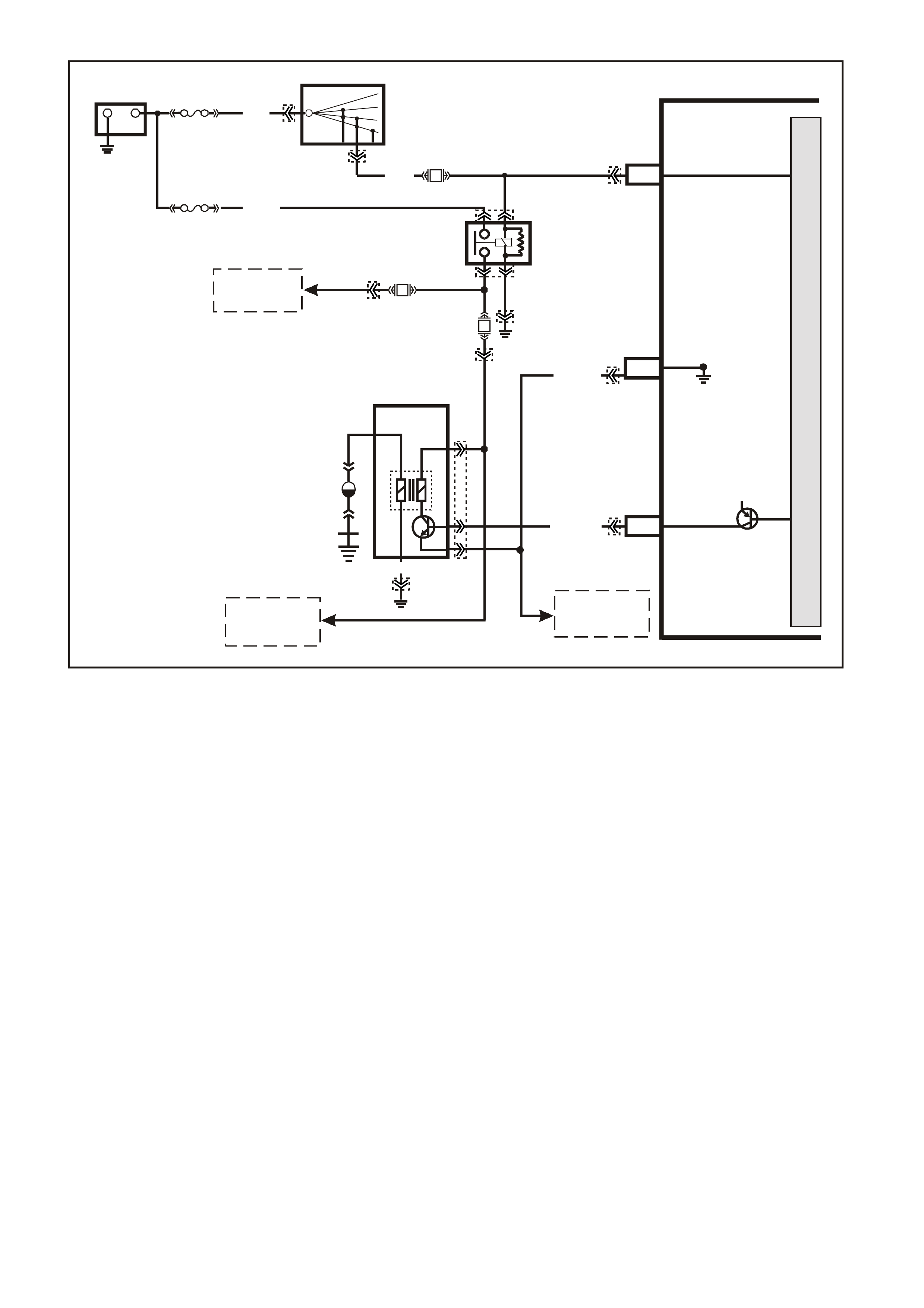
GEN III V8 PCM -
DTC P0351 IGNITION CONTROL #1 CIRCUIT
CIRCUIT DESCRIPTION
The ignition system on this engine uses an individual ignition coil/module for each cylinder. The PCM controls the
ignition system operation. T here are eight Ignition Control (IC) c ircuits, one per cylinder, that connect the PCM and
ignition coil/m odules. Eac h ignition coil/m odule has a power f eed, a chassis earth circuit and a re ferenc e low c ircuit.
The PCM c auses a spark to occur by earthing the IC c ircuit, which signals the ignition m odule to trigger the ignition
coil and fire the spark plug. Sequencing and timing ar e PCM controlled. This DTC sets when the IC circuit is out of
range.
CONDITIONS FOR RUNNING THE DTC
• The ignition voltage is between 9.0 and 17.0 volts
CONDITIONS FOR SETTING THE DTC
• The PCM detects the Ignition Control circuit is earthed, open or shorted to a voltage.
• All conditions met for less than 15 second.
ACTION TAKEN WHEN THE DTC SETS
• The PCM illuminates the Check Powertrain Lamp when the diagnostic runs and fails.
• The PCM records the operating conditions at the time the diagnostic fails. The PCM stores this information in
the Freeze Frame/Failure Records.
CONDITIONS FOR CLEARING THE CPL/DTC
• The PCM turns the Check Powertrain Lamp OFF when the diagnostic runs and does not fail.
• A last test failed (current DTC) clears when the diagnostic runs and does not fail.
• Use a Tech 2 scan tool in order to clear the CPL/DTC.
4361
PCM
J1-19
J2-26
J2-60
CYL. 1
IGNITION
REFERENCE LOW
IGNITION
+-
BATTERY
FS
LOC. E3
(1040)
FJ
R (2)
15a 15 50
30 OFF/ON
LOCK
ACC
IGN
START
IGNITION SWITCH
P (3)
W (971)
EFI
RELAY
F14
YE122
YE39
YE114
YE111
YE111
YB44
YB44
YE125
YE123
YE125
YE39
F35
B/W
(152)
12V
LOC. E5/E15
BR (750)
L/G
(482)
CYL 1
B/R (958)
M
I
C
R
O
P
R
O
C
E
S
S
O
R
TO
IGNITION COILS
2, 4, 6, AND 8
TO
IGNITION COILS
3, 5, AND 7
TO
IGNITION COILS
3, 5, AND 7
F34
R
(481)
IGNITION COIL
CYLINDER #1
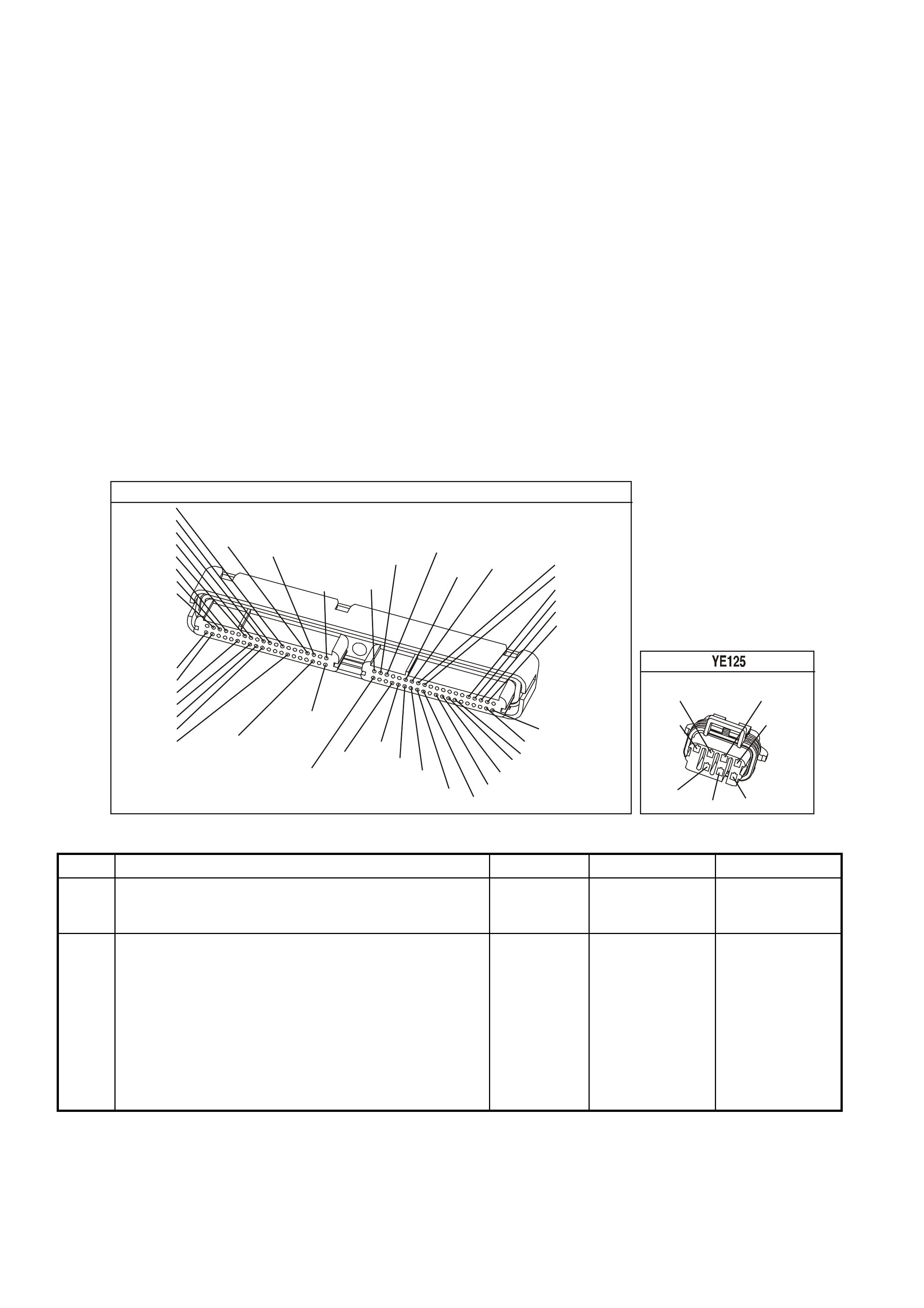
DIAGNOSTIC AIDS
• The following may be the cause of an intermittent:
- Poor connections. Check for adequate terminal tension.
- Corrosion
- Incorrectly routed harness
- Rubbed through wire insulation.
- Broken wire inside the insulation.
• Using the Freeze Frame/Failure Records data may aid in locating an intermittent condition. If you cannot
duplicate the DTC, the information included in the Freeze Frame/Failure Records data can help determine the
distance traveled since the DTC Set. The Fail Counter and Pass Counter can also help determine how may
ignition cycles the diagnostic reported a pass and/or a fail. Operate the vehicle within the same freeze frame
conditions (RPM, load, vehicle speed, temperature etc.) that you observed. This will isolate when the DTC
failed.
• For an intermittent condition, refer to Section 6C3-2B Symptoms of the VX Series Service Information.
TEST DESCRIPTION
The numbers below refer to the step numbers on the diagnostic table.
2. This step verifies that the fault is present.
4. This step checks the integrity of the IC circuit and the PCM output.
5. This step checks for a short to earth on the IC control circuit.
YE123
P.C.M CONNECTOR 2
(750)
(1228)
(1229)
(465)
(121)
(259)
G/B
BR
G/W
GY/BLU
R
B/R
(418)
BR
(59)
(832)
G
T
(831)
(417)
(472)
(976)(974)
(432)
(428)
(631)
BLUBR G/Y
BLU/W
LG
BR/W
W/B
LG W
(977)
Y
(971)
BLU/WW
B/R
(750)
(304)
(792)
(1223)
(1222)
(123)
(1227)
(469)
(331)
Y/B
LG
V/W
B/Y
G/O BR/W
(1687)
GY/B
(366)
LG/B
GY/R
(422)
V
(442)
(444)
(443)
(975)
(972)
(978)
(1224)
(973)
(959)
LG/W
LG/B
LBLU/B
GY
(773)
BR/Y
BLU
G
Y/B
LBLU
(958)
BR
(441)
LBLU
1
41
40
80
J2
RED
Y
(838)
L.H. IGNITION MODULE
(958)
(973)
BR
BLU
(971)
(482)
W
LG
B/R
(750)
Y
(977)
(975)
G
GEN III V8 PCM - DTC P0351 IGNITION CONTROL #1 CIRCUIT
Step Action Value(s) Yes No
1 Did you perform the Powertrain On-Board Diagnostic
(OBD) System Check ? Go to Step 2 Go to Powertrain
OBD System
Check Table
2 IMPORTANT: If all the Ignition Control (IC) DTCs are set
at the same time, inspect the IC earth circuits for an
open.
1. Install a Tech 2 scan tool.
2. Idle the engine.
3. Monitor the (IC) Ignition Control status for the cylinder
with the ignition control DTC using the Tech 2 scan
tool in the Engine Data List.
Does the Tech 2 scan tool indicate a Fault?
Go to Step 4 Go to Step 3

GEN III V8 PCM - DTC P0351 IGNITION CONTROL #1 CIRCUIT (CONTINUED)
Step Action Value(s) Yes No
3 1. Turn ON the ignition leaving the engine OFF.
2. Review the Freeze Frame/Failure Records data for
this DTC and observe the parameters.
3. Turn OFF the ignition for 15 seconds.
4. Start the engine.
5. Operate the vehicle, within the conditions required for
this diagnostic to run, and as close to the conditions
recorded in Freeze Frame/Failure Records as
possible. Special operating conditions that you need to
meet before the PCM will run this diagnostic, where
applicable, are listed in Conditions for Running the
DTC.
6. Select the Diagnostic Trouble Code (DTC) option, the
DTC Information option and The Failed This Ignition
option using the Tech 2 scan tool.
Does the Tech 2 scan tool indicate that this diagnostic
failed this ignition?
Go to Step 4 Go to
Diagnostic Aids
4 1. Turn OFF the engine.
2. Disconnect the ignition coil electrical harness.
3. Measure the frequency at the ignition control signal
circuit using the DMM J 39200 on the AC Hertz
setting.
4. Idle the engine.
Is the frequency within the specified range?
3.0-20 Hz Go to Step 8 Go to Step 5
5 Measure the voltage at the ignition control signal circuit
using the DMM J 39200.
Is the voltage greater than the specified value?
1.0 volts Go to Step 9 Go to Step 6
6 1. Turn OFF the ignition.
2. Disconnect the RED PCM connector.
3. Check the continuity from the IC circuit (at the ignition
coil harness connector) to the PCM connector using
the DMM J 39200.
Does the DMM indicate continuity?
Go to Step 7 Go to Step 10
7 Check the resistance from the IC circuit (at the ignition
coil harness connector) to earth using the DMM J 39200.
Does the DMM indicate OL?
Go to Step 11 Go to step 10
8 Replace the ignition coil. Refer to Section 6C3-3 Ignition
Coil Replacement of the VX Series Service Information.
Is the action complete?
Go to Step 13
9 Repair the Ignition Control circuit for a short to voltage.
Is the action complete? Go to Step 13
10 Repair the Ignition Control circuit for an open or earthed
circuit.
Is the action complete?
Go to Step 13
11 Check the terminal tension at the PCM and replace the
terminal if necessary.
Did you find and correct the condition?
Go to Step 13 Go to Step 12
12 1. Replace PCM.
2. Refer to Section 6C3-3 Service Operations of the VX
Series Service Informatione, for PCM Programming
and PCM/PIM/BCM Security Link Procedure.
Is action complete?
Go to Step 13

GEN III V8 PCM - DTC P0351 IGNITION CONTROL #1 CIRCUIT (CONTINUED)
Step Action Value(s) Yes No
13 1. Select the Diagnostic Trouble Code (DTC) option and
the Clear DTC Information option using the Tech 2
scan tool.
2. Idle the engine at the normal operating temperature.
3. Select the Diagnostic Trouble Code (DTC) option, the
DTC Information option and The Failed This Ignition
option using the Tech 2 scan tool.
4. Operate the vehicle, within the Conditions for Running
the DTC, as specified in the supporting text, if
applicable.
Does the Tech 2 scan tool indicate that this DTC reset?
Go to Step 2 Go to Step 14
14 Using the Tech 2 scan tool, check for any other DTCs.
Does the Tech 2 scan tool display any DTCs that you
have not diagnosed?
Go to the
applicable DTC
table
System OK
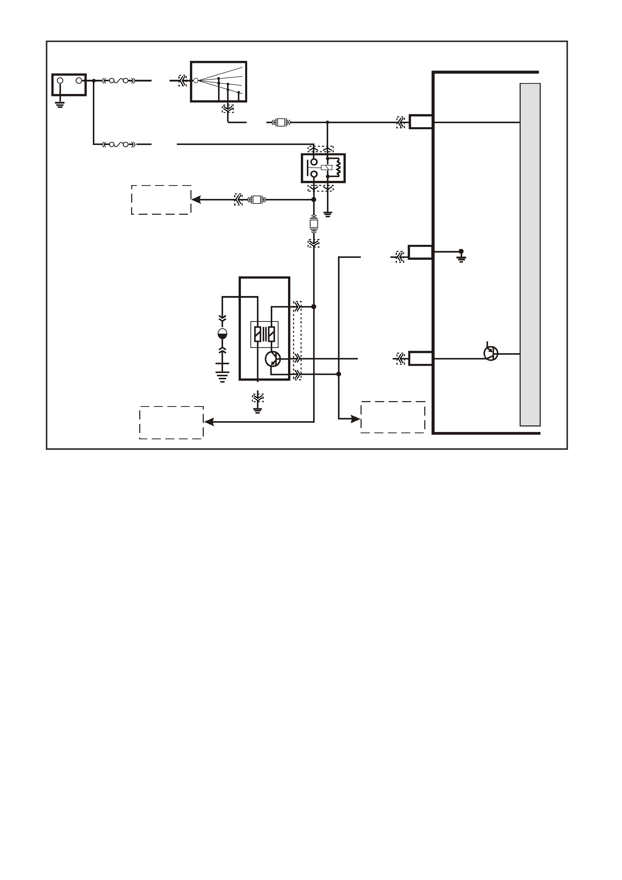
GEN III V8 PCM -
DTC P0352 IGNITION CONTROL #2 CIRCUIT
CIRCUIT DESCRIPTION
The ignition system on this engine uses an individual ignition coil/module for each cylinder. The PCM controls the
ignition system operation. T here are eight Ignition Control (IC) c ircuits, one per cylinder, that connect the PCM and
ignition coil/m odules. Eac h ignition coil/m odule has a power f eed, a chassis earth circuit and a re ferenc e low c ircuit.
The PCM c auses a spark to occur by earthing the IC c ircuit, which signals the ignition m odule to trigger the ignition
coil and fire the spark plug. Sequencing and timing ar e PCM controlled. This DTC sets when the IC circuit is out of
range.
CONDITIONS FOR RUNNING THE DTC
• The ignition voltage is between 9.0 and 17.0 volts
CONDITIONS FOR SETTING THE DTC
• The PCM detects the Ignition Control circuit is earthed, open or shorted to a voltage.
• All conditions met for less than 15 second.
ACTION TAKEN WHEN THE DTC SETS
• The PCM illuminates the Check Powertrain Lamp when the diagnostic runs and fails.
• The PCM records the operating conditions at the time the diagnostic fails. The PCM stores this information in
the Freeze Frame/Failure Records.
CONDITIONS FOR CLEARING THE CPL/DTC
• The PCM turns the Check Powertrain Lamp OFF when the diagnostic runs and does not fail.
• A last test failed (current DTC) clears when the diagnostic runs and does not fail.
• Use a Tech 2 scan tool in order to clear the CPL/DTC.
4362
PCM
J1-19
J2-67
J2-61
CYL. 2
IGNITION
REFERENCE LOW
IGNITION
+-
BATTERY
FS
LOC. E3
(1040)
FJ
R (2)
15a 15 50
30 OFF/ON
LOCK
ACC
IGN
START
IGNITION SWITCH
P (3)
YB44
YB44 YE122
Y39
YE39
YE111
YE111
YE124
YE124
YE123
YE123
Y/B (972)
EFI
RELAY
F14
F34
B/W
(152)
12V
LOC. E5/E15
BR (750)
R
(481)
CYL 2
V (95 9)
M
I
C
R
O
P
R
O
C
E
S
S
O
R
TO
IGNITION COILS
1, 3, 5, AND 7
TO
IGNITION COILS
4, 6, AND 8
TO
IGNITION COILS
4, 6, AND 8
F35
L/G
(482)
IGNITION COIL
CYLINDER #2
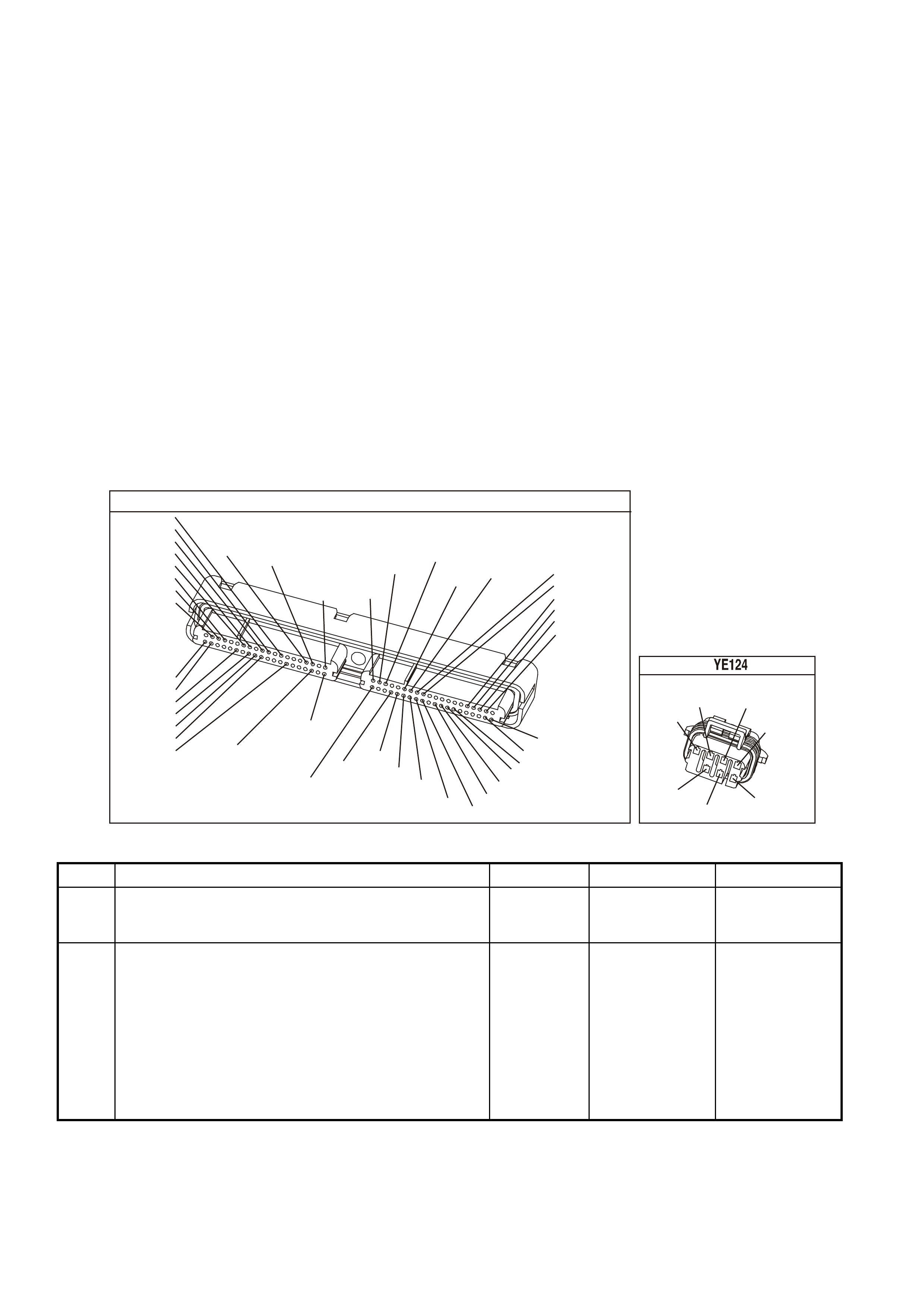
DIAGNOSTIC AIDS
• The following may be the cause of an intermittent:
- Poor connections. Check for adequate terminal tension.
- Corrosion
- Incorrectly routed harness
- Rubbed through wire insulation.
- Broken wire inside the insulation.
• Using the Freeze Frame/Failure Records data may aid in locating an intermittent condition. If you cannot
duplicate the DTC, the information included in the Freeze Frame/Failure Records data can help determine the
distance traveled since the DTC Set. The Fail Counter and Pass Counter can also help determine how may
ignition cycles the diagnostic reported a pass and/or a fail. Operate the vehicle within the same freeze frame
conditions (RPM, load, vehicle speed, temperature etc.) that you observed. This will isolate when the DTC
failed.
• For an intermittent condition, refer to Section 6C3-2B Symptoms of the VX Series Service Information.
TEST DESCRIPTION
The numbers below refer to the step numbers on the diagnostic table.
2. This step verifies that the fault is present.
4. This step checks the integrity of the IC circuit and the PCM output.
5. This step checks for a short to earth on the IC control circuit.
YE123
P.C.M CONNECTOR 2
(750)
(1228)
(1229)
(465)
(121)
(259)
G/B
BR
G/W
GY/BLU
R
B/R
(418)
BR
(59)
(832)
G
T
(831)
(417)
(472)
(976)(974)
(432)
(428)
(631)
BLUBR G/Y
BLU/W
LG
BR/W
W/B
LG W
(977)
Y
(971)
BLU/WW
B/R
(750)
(304)
(792)
(1223)
(1222)
(123)
(1227)
(469)
(331)
Y/B
LG
V/W
B/Y
G/O BR/W
(1687)
GY/B
(366)
LG/B
GY/R
(422)
V
(442)
(444)
(443)
(975)
(972)
(978)
(1224)
(973)
(959)
LG/W
LG/B
LBLU/B
GY
(773)
BR/Y
BLU
G
Y/B
LBLU
(958)
BR
(441)
LBLU
1
41
40
80
J2
RED
Y
(838)
R.H.IGNITION MODULE
LG
(976)
(959)
VR
(481)
LBLU
(978)
B/R
(750)
(972)
Y/B
(974)
W
GEN III V8 PCM - DTC P0352 IGNITION CONTROL #2 CIRCUIT
Step Action Value(s) Yes No
1 Did you perform the Powertrain On-Board Diagnostic
(OBD) System Check ? Go to Step 2 Go to Powertrain
OBD System
Check Table
2 IMPORTANT: If all the Ignition Control (IC) DTCs are set
at the same time, inspect the IC earth circuits for an
open.
1. Install a Tech 2 scan tool.
2. Idle the engine.
3. Monitor the (IC) Ignition Control status for the cylinder
with the ignition control DTC using the Tech 2 scan
tool in the Engine Data List.
Does the Tech 2 scan tool indicate Fault?
Go to Step 4 Go to Step 3

GEN III V8 PCM - DTC P0352 IGNITION CONTROL #2 CIRCUIT (CONTINUED)
Step Action Value(s) Yes No
3 1. Turn ON the ignition leaving the engine OFF.
2. Review the Freeze Frame/Failure Records data for
this DTC and observe the parameters.
3. Turn OFF the ignition for 15 seconds.
4. Start the engine.
5. Operate the vehicle within the conditions required for
this diagnostic to run, and as close to the conditions
recorded in Freeze Frame/Failure Records as
possible. Special operating conditions that you need to
meet before the PCM will run this diagnostic, where
applicable, are listed in Conditions for Running the
DTC.
6. Select the Diagnostic Trouble Code (DTC) option, the
DTC Information option and The Failed This Ignition
option using the Tech 2 scan tool.
Does the Tech 2 scan tool indicate that this diagnostic
failed this ignition?
Go to Step 4 Go To
Diagnostic Aids
4 1. Turn OFF the engine.
2. Disconnect the ignition coil electrical harness.
3. Measure the frequency at the ignition control signal
circuit using the DMM J 39200 on the AC Hertz
setting.
4. Idle the engine.
Is the frequency within the specified range?
3.0-20 Hz Go to Step 8 Go to Step 5
5 Measure the voltage at the Ignition Control signal circuit
using the DMM J 39200.
Is the voltage greater than the specified value?
1.0 volts Go to Step 9 Go to Step 6
6 1. Turn OFF the ignition.
2. Disconnect the RED PCM connector.
3. Check the continuity from the IC circuit (at the ignition
coil harness connector) to the PCM connector using
the DMM J 39200.
Does the DMM indicate continuity?
Go to Step 7 Go to Step 10
7 Check the resistance from the IC circuit (at the ignition
coil harness connector to earth using the DMM J 39200.
Does the DMM indicate OL?
Go to Step 11 Go to step 10
8 Replace the ignition coil. Refer to Section 6C3-3 Ignition
Coil Replacement of the VX Series Service Information.
Is the action complete?
Go to Step 13
9 Repair the Ignition Control circuit for a short to voltage.
Is the action complete? Go to Step 13
10 Repair the Ignition Control circuit for an open or earthed
circuit.
Is the action complete?
Go to Step 13
11 Check the terminal tension at the PCM and replace the
terminal if necessary.
Did you find and correct the condition?
Go to Step 13 Go to Step 12
12 1. Replace PCM.
2. Refer to Section 6C3-3 of the VX Series Service
Information for PCM Programming and
PCM/PIM/BCM Security Link Procedure.
Is action complete?
Go to Step 13

GEN III V8 PCM - DTC P0352 IGNITION CONTROL #2 CIRCUIT (CONTINUED)
Step Action Value(s) Yes No
13 1. Select the Diagnostic Trouble Code (DTC) option and
the Clear DTC Information option using the Tech 2
scan tool.
2. Idle the engine at the normal operating temperature.
3. Select the Diagnostic Trouble Code (DTC) option, the
DTC Information option and The Failed This Ignition
option using the Tech 2 scan tool.
4. Operate the vehicle, within the Conditions for Running
the DTC, as specified in the supporting text, if
applicable.
Does the Tech 2 scan tool indicate that this DTC reset?
Go to Step 2 Go to Step 14
14 Using the tech 2 scan tool, check for any other DTCs.
Does the Tech 2 scan tool display any DTCs that you
have not diagnosed?
Go to the
applicable DTC
table
System OK
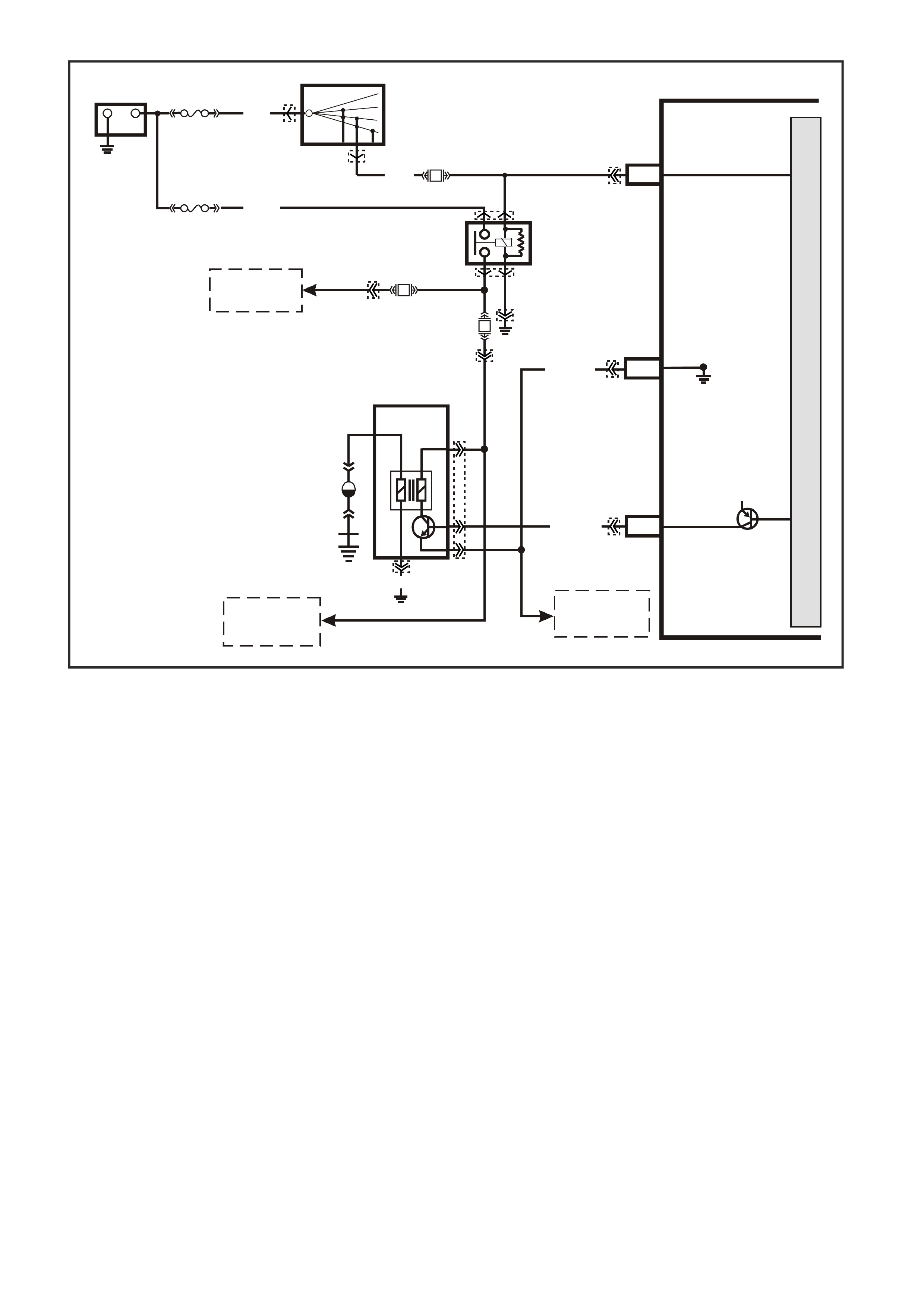
GEN III V8 PCM -
DTC P0353 IGNITION CONTROL #3
CIRCUITDESCRIPTION
The ignition system on this engine uses an individual ignition coil/module for each cylinder. The PCM controls the
ignition system operation. T here are eight Ignition Control (IC) c ircuits, one per cylinder, that connect the PCM and
ignition coil/m odules. Eac h ignition coil/m odule has a power f eed, a chassis earth circuit and a re ferenc e low c ircuit.
The PCM c auses a spark to occur by earthing the IC c ircuit, which signals the ignition m odule to trigger the ignition
coil and fire the spark plug. Sequencing and timing ar e PCM controlled. This DTC sets when the IC circuit is out of
range.
CONDITIONS FOR RUNNING THE DTC
• The ignition voltage is between 9.0 and 17.0 volts
CONDITIONS FOR SETTING THE DTC
• The PCM detects the Ignition Control circuit is earthed, open or shorted to a voltage.
• All conditions met for less than 15 second.
ACTION TAKEN WHEN THE DTC SETS
• The PCM illuminates the Check Powertrain Lamp when the diagnostic runs and fails.
• The PCM records the operating conditions at the time the diagnostic fails. The PCM stores this information in
the Freeze Frame/Failure Records.
CONDITIONS FOR CLEARING THE CPL/DTC
• The PCM turns the Check Powertrain Lamp OFF when the diagnostic runs and does not fail.
• A last test failed (current DTC) clears when the diagnostic runs and does not fail.
• Use a Tech 2 scan tool in order to clear the CPL/DTC.
4363
PCM
J1-19
J2-69
J2-60
CYL. 3
IGNITION
REFERENCE LOW
IGNITION
+
-
BATTERY
FS
LOC. E3
(1040)
FJ
R (2)
15a 15 50
30 OFF/ON
LOCK
ACC
IGN
START
IGNITION SWITCH
P (3)
BLU (973)
EFI
RELAY
F14
F35
B/W
(152)
12V
LOC. E5/E15
BR (750)
YE125
YE125
YE123
YE123
YE111
YE114
YE111
YE39
YE39
YE123
YB44
YB44
L/G
(482)
CYL 3
B/R (598)
M
I
C
R
O
P
R
O
C
E
S
S
O
R
TO
IGNITION COILS
2, 4, 6, AND 8
TO
IGNITION COILS
1, 5, AND 7
TO
IGNITION COILS
1, 5, AND 7
F34
R
(481)
IGNITION COIL
CYLINDER #3

DIAGNOSTIC AIDS
• The following may be the cause of an intermittent:
- Poor connections. Check for adequate terminal tension.
- Corrosion
- Incorrectly routed harness
- Rubbed through wire insulation.
- Broken wire inside the insulation.
• Using the Freeze Frame/Failure Records data may aid in locating an intermittent condition. If you cannot
duplicate the DTC, the information included in the Freeze Frame/Failure Records data can help determine the
distance traveled since the DTC Set. The Fail Counter and Pass Counter can also help determine how may
ignition cycles the diagnostic reported a pass and/or a fail. Operate the vehicle within the same freeze frame
conditions (RPM, load, vehicle speed, temperature etc.) that you observed. This will isolate when the DTC
failed.
• For an intermittent condition, refer to Section 6C3-2B Symptoms of the VX Series Service Information.
TEST DESCRIPTION
The numbers below refer to the step numbers on the diagnostic table.
2. This step verifies that the fault is present.
4. This step checks the integrity of the IC circuit and the PCM output.
5. This step checks for a short to earth on the IC control circuit.
YE123
P.C.M CONNECTOR 2
(750)
(1228)
(1229)
(465)
(121)
(259)
G/B
BR
G/W
GY/BLU
R
B/R
(418)
BR
(59)
(832)
G
T
(831)
(417)
(472)
(976)(974)
(432)
(428)
(631)
BLUBR G/Y
BLU/W
LG
BR/W
W/B
LG W
(977)
Y
(971)
BLU/WW
B/R
(750)
(304)
(792)
(1223)
(1222)
(123)
(1227)
(469)
(331)
Y/B
LG
V/W
B/Y
G/O BR/W
(1687)
GY/B
(366)
LG/B
GY/R
(422)
V
(442)
(444)
(443)
(975)
(972)
(978)
(1224)
(973)
(959)
LG/W
LG/B
LBLU/B
GY
(773)
BR/Y
BLU
G
Y/B
LBLU
(958)
BR
(441)
LBLU
1
41
40
80
J2
RED
Y
(838)
L.H. IGNITION MODULE
(958)
(973)
BR
BLU
(971)
(482)
W
LG
B/R
(750)
Y
(977)
(975)
G
GEN III V8 PCM - DTC P0353 IGNITION CONTROL #3 CIRCUIT
Step Action Value(s) Yes No
1 Did you perform the Powertrain On-Board Diagnostic
(OBD) System Check ? Go to Step 2 Go to Powertrain
OBD System
Check Table
2 IMPORTANT: If all the Ignition Control (IC) DTCs are set
at the same time, inspect the IC earth circuits for an
open.
1. Install a Tech 2 scan tool.
2. Idle the engine.
3. Monitor the (IC) Ignition Control status for the cylinder
with the ignition control DTC using the Tech 2 scan
tool in the Engine Data List.
Does the Tech 2 scan tool indicate Fault?
Go to Step 4 Go to Step 3

GEN III V8 PCM - DTC P0353 IGNITION CONTROL #3 CIRCUIT (CONTINUED)
Step Action Value(s) Yes No
3 1. Turn ON the ignition leaving the engine OFF.
2. Review the Freeze Frame/Failure Records data for
this DTC and observe the parameters.
3. Turn OFF the ignition for 15 seconds.
4. Start the engine.
5. Operate the vehicle, within the conditions required for
this diagnostic to run, and as close to the conditions
recorded in Freeze Frame/Failure Records as
possible. Special operating conditions that you need to
meet, before the PCM will run this diagnostic, are
listed in Conditions for Running the DTC.
6. Select the Diagnostic Trouble Code (DTC) option, the
DTC Information option and The Failed This Ignition
option using the Tech 2 scan tool.
Does the Tech 2 scan tool indicate that this diagnostic
failed this ignition?
Go to Step 4 Go To
Diagnostic Aids
4 1. Turn OFF the engine.
2. Disconnect the ignition coil electrical harness.
3. Measure the frequency at the ignition control signal
circuit using the DMM J 39200 on the AC Hertz
setting.
4. Idle the engine.
Is the frequency within the specified range?
3.0-20 Hz Go to Step 8 Go to Step 5
5 Measure the voltage at the ignition control signal circuit
using the DMM J 39200.
Is the voltage greater than the specified value?
1.0 volts Go to Step 9 Go to Step 6
6 1. Turn OFF the ignition.
2. Disconnect the RED PCM connector.
3. Check the continuity from the IC circuit (at the ignition
coil harness connector) to the PCM connector using
the DMM J 39200.
Does the DMM indicate continuity?
Go to Step 7 Go to Step 10
7 Check the resistance from the IC circuit (at the ignition
coil harness connector) to earth using the DMM J 39200.
Does the DMM indicate OL?
Go to Step 11 Go to step 10
8 Replace the ignition coil. Refer to Section 6C3-3 Ignition
Coil Replacement of the VX Series Service Information.
Is the action complete?
Go to Step 13
9 Repair the Ignition Control circuit for a short to voltage.
Is the action complete? Go to Step 13
10 Repair the Ignition Control circuit for an open or earthed
circuit.
Is the action complete?
Go to Step 13
11 Check the terminal tension at the PCM and replace the
terminal if necessary.
Did you find and correct the condition?
Go to Step 13 Go to Step 12
12 1. Replace PCM.
2. Refer to Section 6C3-3 of the VX Series Service
Information for PCM Programming and
PCM/PIM/BCM Security Link Procedure.
Is action complete?
Go to Step 13

GEN III V8 PCM - DTC P0353 IGNITION CONTROL #3 CIRCUIT (CONTINUED)
Step Action Value(s) Yes No
13 1. Select the Diagnostic Trouble Code (DTC) option and
the Clear DTC Information option using the Tech 2
scan tool.
2. Idle the engine at the normal operating temperature.
3. Select the Diagnostic Trouble Code (DTC) option, the
DTC Information option and The Failed This Ignition
option using the Tech 2 scan tool.
4. Operate the vehicle, within the Conditions for Running
the DTC, as specified in the supporting text.
Does the Tech 2 scan tool indicate that this DTC reset?
Go to Step 12 Go to Step 14
14 Using the Tech 2 scan tool, check for any other DTCs.
Does the Tech 2 scan tool display any DTCs that you
have not diagnosed?
Go to the
applicable DTC
table
System OK

GEN III V8 PCM -
DTC P0354 IGNITION CONTROL #4 CIRCUIT
CIRCUIT DESCRIPTION
The ignition system on this engine uses an individual ignition coil/module for each cylinder. The PCM controls the
ignition system operation. T here are eight Ignition Control (IC) c ircuits, one per cylinder, that connect the PCM and
ignition coil/m odules. Eac h ignition coil/m odule has a power f eed, a chassis earth circuit and a re ferenc e low c ircuit.
The PCM c auses a spark to occur by earthing the IC c ircuit, which signals the ignition m odule to trigger the ignition
coil and fire the spark plug. Sequencing and timing ar e PCM controlled. This DTC sets when the IC circuit is out of
range.
CONDITIONS FOR RUNNING THE DTC
• The ignition voltage is between 9.0 and 17.0 volts
CONDITIONS FOR SETTING THE DTC
• The PCM detects the Ignition Control circuit is earthed, open or shorted to a voltage.
• All conditions met for less than 15 second.
ACTION TAKEN WHEN THE DTC SETS
• The PCM illuminates the Check Powertrain Lamp when the diagnostic runs and fails.
• The PCM records the operating conditions at the time the diagnostic fails. The PCM stores this information in
the Freeze Frame/Failure Records.
CONDITIONS FOR CLEARING THE CPL/DTC
• The PCM turns the Check Powertrain Lamp OFF when the diagnostic runs and does not fail.
• A last test failed (current DTC) clears when the diagnostic runs and does not fail.
• Use a Tech 2 scan tool in order to clear the CPL/DTC.
4364
PCM
J1-19
J2-29
J2-61
CYL. 4
IGNITION
REFERENCE LOW
IGNITION
+
-
BATTERY
FS
LOC. E3
(1040)
FJ
R (2)
15a 15 50
30 OFF/ON
LOCK
ACC
IGN
START
IGNITION SWITCH
P (3)
W (974)
EFI
RELAY
F14
F34
B/W
(152)
12V
LOC. E5/E15
BR (750)
YE124
YE124
YE123
YE123
YE111
YE111
YE39
YE39
YE122
YB44
YB44
R
(481)
CYL 4
V (95 9)
M
I
C
R
O
P
R
O
C
E
S
S
O
R
TO
IGNITION COILS
1, 3, 5, AND 7
TO
IGNITION COILS
2, 6, AND 8
TO
IGNITION COILS
2, 6, AND 8
F35
L/G
(482)
IGNITION COIL
CYLINDER #4

DIAGNOSTIC AIDS
• The following may be the cause of an intermittent:
- Poor connections. Check for adequate terminal tension.
- Corrosion
- Incorrectly routed harness
- Rubbed through wire insulation.
- Broken wire inside the insulation.
• Using the Freeze Frame/Failure Records data may aid in locating an intermittent condition. If you cannot
duplicate the DTC, the information included in the Freeze Frame/Failure Records data can help determine the
distance traveled since the DTC Set. The Fail Counter and Pass Counter can also help determine how may
ignition cycles the diagnostic reported a pass and/or a fail. Operate the vehicle within the same freeze frame
conditions (RPM, load, vehicle speed, temperature etc.) that you observed. This will isolate when the DTC
failed.
• For an intermittent condition, refer to Section 6C3-2B Symptoms of the VX Series Service Information.
TEST DESCRIPTION
The numbers below refer to the step numbers on the diagnostic table.
2. This step verifies that the fault is present.
4. This step checks the integrity of the IC circuit and the PCM output.
5. This step checks for a short to earth on the IC control circuit.
YE123
P.C.M CONNECTOR 2
(750)
(1228)
(1229)
(465)
(121)
(259)
G/B
BR
G/W
GY/BLU
R
B/R
(418)
BR
(59)
(832)
G
T
(831)
(417)
(472)
(976)(974)
(432)
(428)
(631)
BLUBR G/Y
BLU/W
LG
BR/W
W/B
LG W
(977)
Y
(971)
BLU/WW
B/R
(750)
(304)
(792)
(1223)
(1222)
(123)
(1227)
(469)
(331)
Y/B
LG
V/W
B/Y
G/O BR/W
(1687)
GY/B
(366)
LG/B
GY/R
(422)
V
(442)
(444)
(443)
(975)
(972)
(978)
(1224)
(973)
(959)
LG/W
LG/B
LBLU/B
GY
(773)
BR/Y
BLU
G
Y/B
LBLU
(958)
BR
(441)
LBLU
1
41
40
80
J2
RED
Y
(838)
R.H.IGNITION MODULE
LG
(976)
(959)
VR
(481)
LBLU
(978)
B/R
(750)
(972)
Y/B
(974)
W
GEN III V8 PCM - DTC P0354 IGNITION CONTROL #4 CIRCUIT
Step Action Value(s) Yes No
1 Did you perform the Powertrain On-Board Diagnostic
(OBD) System Check ? Go to Step 2 Go to Powertrain
OBD System
Check Table
2 IMPORTANT: If all the Ignition Control (IC) DTCs are set
at the same time, inspect the IC earth circuits for an
open.
1. Install a Tech 2 scan tool.
2. Idle the engine.
3. Monitor the (IC) Ignition Control status for the cylinder
with the ignition control DTC using the Tech 2 scan
tool in the Engine Data List.
Does the Tech 2 scan tool indicate Fault?
Go to Step 4 Go to Step 3

GEN III V8 PCM - DTC P0354 IGNITION CONTROL #4 CIRCUIT (CONTINUED)
Step Action Value(s) Yes No
3 1. Turn ON the ignition leaving the engine OFF.
2. Review the Freeze Frame/Failure Records data for
this DTC and observe the parameters.
3. Turn OFF the ignition for 15 seconds.
4. Start the engine.
5. Operate the vehicle within the conditions required for
this diagnostic to run, and as close to the conditions
recorded in Freeze Frame/Failure Records as
possible. Special operating conditions that you need to
meet before the PCM will run this diagnostic, here
applicable, are listed in Conditions for Running the
DTC.
6. Select the Diagnostic Trouble Code (DTC) option, the
DTC Information option and The Failed This Ignition
option using the Tech 2 scan tool.
Does the Tech 2 scan tool indicate that this diagnostic
failed this ignition?
Go to Step 4 Go To
Diagnostic Aids
4 1. Turn OFF the engine.
2. Disconnect the ignition coil electrical harness.
3. Measure the frequency at the ignition control signal
circuit using the DMM J 39200 on the AC Hertz
setting.
4. Idle the engine.
Is the frequency within the specified range?
3.0-20 Hz Go to Step 8 Go to Step 5
5 Measure the voltage at the ignition control signal circuit
using the DMM J 39200.
Is the voltage greater than the specified value?
1.0 volts Go to Step 9 Go to Step 6
6 1. Turn OFF the ignition.
2. Disconnect the RED PCM connector.
3. Check the continuity from the IC circuit (at the ignition
coil harness connector) to the PCM connector using
the DMM J 39200.
Does the DMM indicate continuity?
Go to Step 7 Go to Step 10
7 Check the resistance from the IC circuit (at the ignition
coil harness connector) to earth using the DMM J 39200.
Does the DMM indicate OL?
Go to Step 11 Go to step 10
8 Replace the ignition coil. Refer to Section 6C3-3 Ignition
Coil Replacement of the VX Series Service Information.
Is the action complete?
Go to Step 13
9 Repair the Ignition Control circuit for a short to voltage.
Is the action complete? Go to Step 13
10 Repair the Ignition Control circuit for an open or earthed
circuit.
Is the action complete?
Go to Step 13
11 Check the terminal tension at the PCM and replace the
terminal if necessary.
Did you find and correct the condition?
Go to Step 13 Go to Step 12
12 1. Replace PCM.
2. Refer to Section 6C3-3 of the VX Series Service
Information for PCM Programming and
PCM/PIM/BCM Security Link Procedure.
Is action complete?
Go to Step 13

GEN III V8 PCM - DTC P0354 IGNITION CONTROL #4 CIRCUIT (CONTINUED)
Step Action Value(s) Yes No
13 1. Select the Diagnostic Trouble Code (DTC) option and
the Clear DTC Information option using the Tech 2
scan tool.
2. Idle the engine at the normal operating temperature.
3. Select the Diagnostic Trouble Code (DTC) option, the
DTC Information option and The Failed This Ignition
option using the Tech 2 scan tool.
4. Operate the vehicle within the Conditions for Running
the DTC as specified in the supporting text, if
applicable.
Does the Tech 2 scan tool indicate that this DTC reset?
Go to Step 2 Go to Step 14
14 Using the Tech 2 scan tool, check for any other DTCs.
Does the Tech 2 scan tool display any DTCs that you
have not diagnosed?
Go to the
applicable DTC
table
System OK

GEN III V8 PCM -
DTC P0355 IGNITION CONTROL #5 CIRCUIT
CIRCUIT DESCRIPTION
The ignition system on this engine uses an individual ignition coil/module for each cylinder. The PCM controls the
ignition system operation. T here are eight Ignition Control (IC) c ircuits, one per cylinder, that connect the PCM and
ignition coil/m odules. Eac h ignition coil/m odule has a power f eed, a chassis earth circuit and a re ferenc e low c ircuit.
The PCM c auses a spark to occur by earthing the IC c ircuit, which signals the ignition m odule to trigger the ignition
coil and fire the spark plug. Sequencing and timing ar e PCM controlled. This DTC sets when the IC circuit is out of
range.
CONDITIONS FOR RUNNING THE DTC
• The ignition voltage is between 9.0 and 17.0 volts
CONDITIONS FOR SETTING THE DTC
• The PCM detects the Ignition Control circuit is earthed, open or shorted to a voltage.
• All conditions met for less than 15 second.
ACTION TAKEN WHEN THE DTC SETS
• The PCM illuminates the Check Powertrain Lamp when the diagnostic runs and fails.
• The PCM records the operating conditions at the time the diagnostic fails. The PCM stores this information in
the Freeze Frame/Failure Records.
CONDITIONS FOR CLEARING THE CPL/DTC
• The PCM turns the Check Powertrain Lamp OFF when the diagnostic runs and does not fail.
• A last test failed (current DTC) clears when the diagnostic runs and does not fail.
• Use a Tech 2 scan tool in order to clear the CPL/DTC.
4365
PCM
J1-19
J2-68
J2-60
CYL. 5
IGNITION
REFERENCE LOW
IGNITION
+
-
BATTERY
FS
LOC. E3
(1040)
FJ
R (2)
15a 15 50
30 OFF/ON
LOCK
ACC
IGN
START
IGNITION SWITCH
P (3)
G (975)
EFI
RELAY
F14
F35
B/W
(152)
12V
LOC. E5/E15
BR (750)
YE125
YE125
YE122
YE123
YE111
YE114
YE111
YE39
YE39
YE122
YB44
YB44
L/G
(482)
CYL 5
BR (598)
M
I
C
R
O
P
R
O
C
E
S
S
O
R
TO
IGNITION COILS
2, 4, 6, AND 8
TO
IGNITION COILS
1, 3, AND 7
TO
IGNITION COILS
1, 3, AND 7
F34
R
(481)
IGNITION COIL
CYLINDER #5
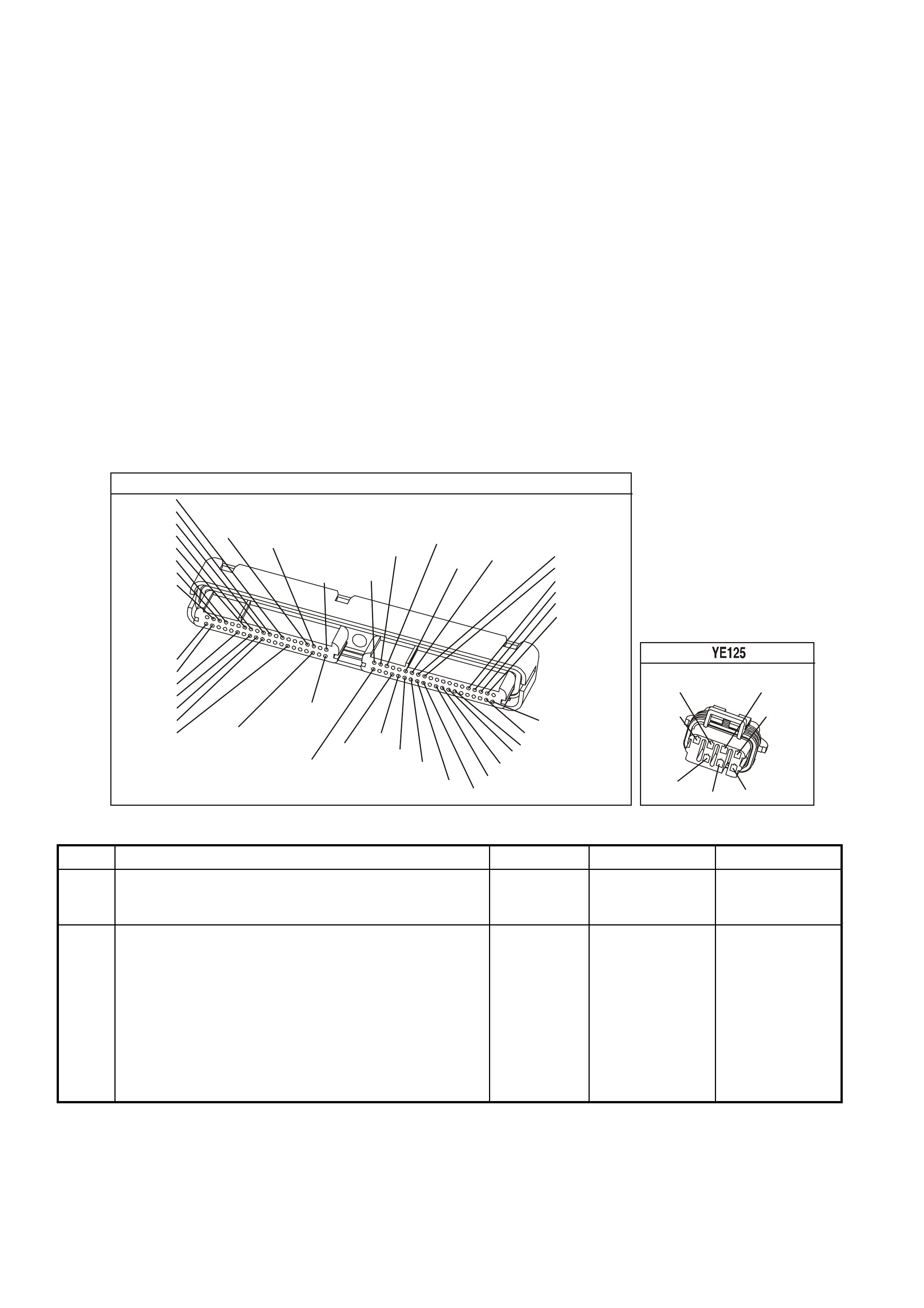
DIAGNOSTIC AIDS
• The following may be the cause of an intermittent:
- Poor connections. Check for adequate terminal tension.
- Corrosion
- Incorrectly routed harness
- Rubbed through wire insulation.
- Broken wire inside the insulation.
• Using the Freeze Frame/Failure Records data may aid in locating an intermittent condition. If you cannot
duplicate the DTC, the information included in the Freeze Frame/Failure Records data can help determine the
distance traveled since the DTC Set. The Fail Counter and Pass Counter can also help determine how may
ignition cycles the diagnostic reported a pass and/or a fail. Operate the vehicle within the same freeze frame
conditions (RPM, load, vehicle speed, temperature etc.) that you observed. This will isolate when the DTC
failed.
• For an intermittent condition, refer to Section 6C3-2B Symptoms of the VX Series Service Information.
TEST DESCRIPTION
The numbers below refer to the step numbers on the diagnostic table.
2. This step verifies that the fault is present.
4. This step checks the integrity of the IC circuit and the PCM output.
5. This step checks for a short to earth on the IC control circuit.
YE123
P.C.M CONNECTOR 2
(750)
(1228)
(1229)
(465)
(121)
(259)
G/B
BR
G/W
GY/BLU
R
B/R
(418)
BR
(59)
(832)
G
T
(831)
(417)
(472)
(976)(974)
(432)
(428)
(631)
BLUBR G/Y
BLU/W
LG
BR/W
W/B
LG W
(977)
Y
(971)
BLU/WW
B/R
(750)
(304)
(792)
(1223)
(1222)
(123)
(1227)
(469)
(331)
Y/B
LG
V/W
B/Y
G/O BR/W
(1687)
GY/B
(366)
LG/B
GY/R
(422)
V
(442)
(444)
(443)
(975)
(972)
(978)
(1224)
(973)
(959)
LG/W
LG/B
LBLU/B
GY
(773)
BR/Y
BLU
G
Y/B
LBLU
(958)
BR
(441)
LBLU
1
41
40
80
J2
RED
Y
(838)
L.H. IGNITION MODULE
(958)
(973)
BR
BLU
(971)
(482)
W
LG
B/R
(750)
Y
(977)
(975)
G
GEN III V8 PCM - DTC P0355 IGNITION CONTROL #5 CIRCUIT
Step Action Value(s) Yes No
1 Did you perform the Powertrain On-Board Diagnostic
(OBD) System Check ? Go to Step 2 Go to Powertrain
OBD System
Check Table
2 IMPORTANT: If all the Ignition Control (IC) DTCs are set
at the same time, inspect the IC earth circuits for an
open.
1. Install a Tech 2 scan tool.
2. Idle the engine.
3. Monitor the (IC) Ignition Control status for the cylinder
with the ignition control DTC using the Tech 2 scan
tool in the Engine Data List.
Does the Tech 2 scan tool indicate Fault?
Go to Step 4 Go to Step 3

GEN III V8 PCM - DTC P0355 IGNITION CONTROL #5 CIRCUIT (CONTINUED)
Step Action Value(s) Yes No
3 1. Turn ON the ignition leaving the engine OFF.
1. Review the Freeze Frame/Failure Records data for
this DTC and observe the parameters.
2. Turn OFF the ignition for 15 seconds.
3. Start the engine.
4. Operate the vehicle within the conditions required for
this diagnostic to run, and as close to the conditions
recorded in Freeze Frame/Failure Records as
possible. Special operating conditions that you need to
meet before the PCM will run this diagnostic, where
applicable, are listed in Conditions for Running the
DTC.
5. Select the Diagnostic Trouble Code (DTC) option, the
DTC Information, The Failed This Ignition using the
Tech 2 scan tool.
Does the Tech 2 scan tool indicate that this diagnostic
failed this ignition?
Go to Step 4 Go To
Diagnostic Aids
4 1. Turn OFF the engine.
2. Disconnect the ignition coil electrical harness.
3. Measure the frequency at the ignition control signal
circuit using the DMM J 39200 on the AC Hertz
setting.
4. Idle the engine.
Is the frequency within the specified range?
3.0-20 Hz Go to Step 8 Go to Step 5
5 Measure the voltage at the ignition control signal circuit
using the DMM J 39200.
Is the voltage greater than the specified value?
1.0 volts Go to Step 9 Go to Step 6
6 1. Turn OFF the ignition.
2. Disconnect the RED PCM connector.
3. Check the continuity from the IC circuit (at the ignition
coil harness connector) to the PCM connector using
the DMM J 39200.
Does the DMM indicate continuity?
Go to Step 7 Go to Step 10
7 Check the resistance from the IC circuit (at the ignition
coil harness connector to earth using the DMM J 39200.
Does the DMM indicate OL?
Go to Step 11 Go to step 10
8 Replace the ignition coil. Refer to Section 6C3-3 Ignition
Coil Replacement of the VX Series Service Information.
Is the action complete?
Go to Step 13
9 Repair the Ignition Control circuit for a short to voltage.
Is the action complete? Go to Step 13
10 Repair the Ignition Control circuit for an open or earthed
circuit.
Is the action complete?
Go to Step 13
11 Check the terminal tension at the PCM and replace the
terminal if necessary.
Did you find and correct the condition?
Go to Step 13 Go to Step 12
12 1. Replace PCM.
2. Refer to Section 6C3-3 of the VX Series Service
Information for PCM Programming and
PCM/PIM/BCM Security Link Procedure.
Is action complete?
Go to Step 13

GEN III V8 PCM - DTC P0355 IGNITION CONTROL #5 CIRCUIT (CONTINUED)
Step Action Value(s) Yes No
13 1. Select the Diagnostic Trouble Code (DTC) option and
the Clear DTC Information option using the Tech 2
scan tool.
2. Idle the engine at the normal operating temperature.
3. Select the Diagnostic Trouble Code (DTC) option, the
DTC Information, The Failed This Ignition using the
Tech 2 scan tool.
4. Operate the vehicle within the Conditions for Running
the DTC as specified in the supporting text, if
applicable.
Does the Tech 2 scan tool indicate that this DTC reset?
Go to Step 2 Go to Step 14
14 Using the Tech 2 scan tool, check for any other DTCs.
Does the Tech 2 scan tool display any DTCs that you
have not diagnosed?
Go to the
applicable DTC
table
System OK
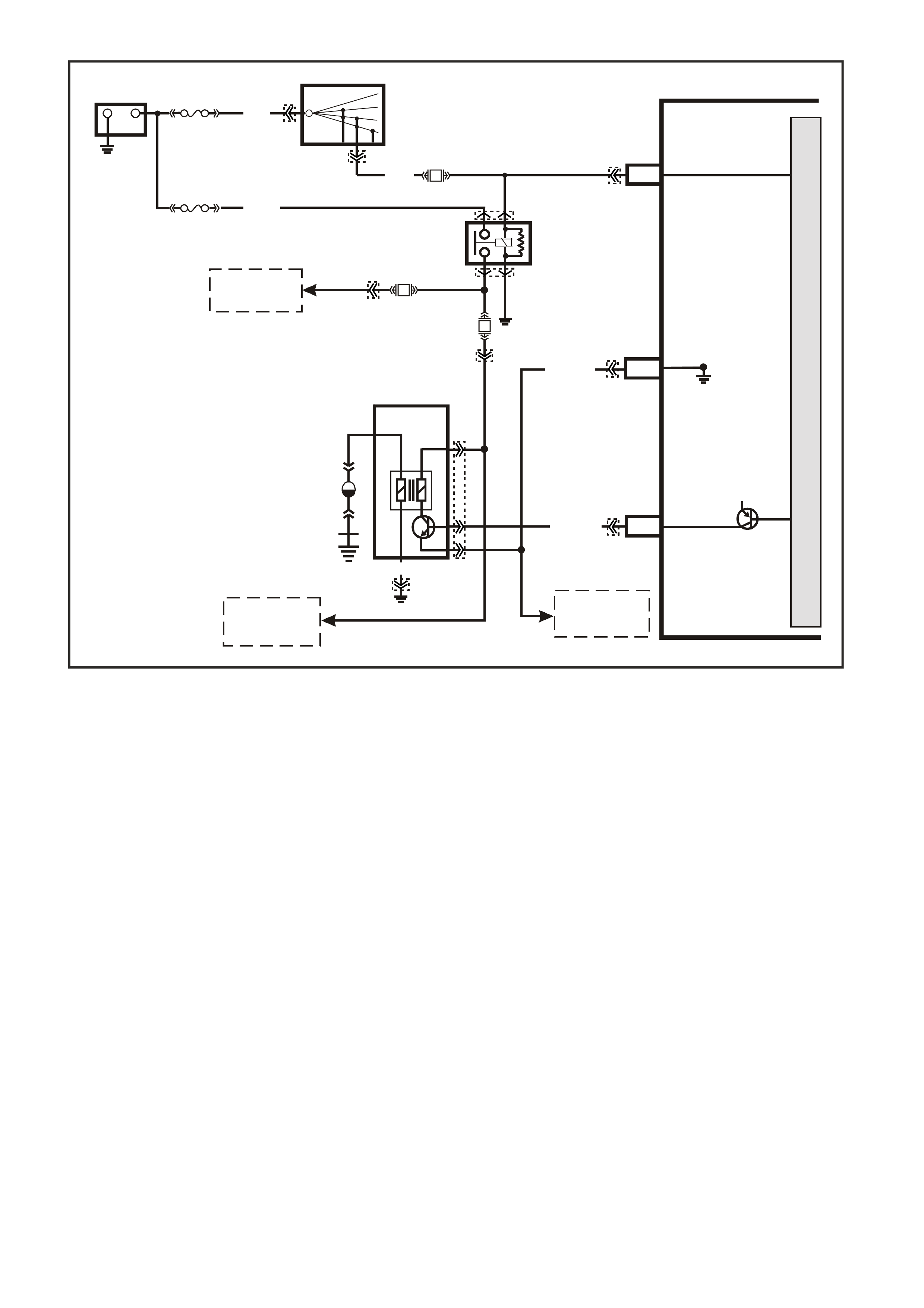
GEN III V8 PCM -
DTC P0356 IGNITION CONTROL #6 CIRCUIT
CIRCUIT DESCRIPTION
The ignition system on this engine uses an individual ignition coil/module for each cylinder. The PCM controls the
ignition system operation. T here are eight Ignition Control (IC) c ircuits, one per cylinder, that connect the PCM and
ignition coil/m odules. Eac h ignition coil/m odule has a power f eed, a chassis earth circuit and a re ferenc e low c ircuit.
The PCM c auses a spark to occur by earthing the IC c ircuit, which signals the ignition m odule to trigger the ignition
coil and fire the spark plug. Sequencing and timing ar e PCM controlled. This DTC sets when the IC circuit is out of
range.
CONDITIONS FOR RUNNING THE DTC
• The ignition voltage is between 9.0 and 17.0 volts
CONDITIONS FOR SETTING THE DTC
• The PCM detects the Ignition Control circuit is earthed, open or shorted to a voltage.
• All conditions met for less than 15 second.
ACTION TAKEN WHEN THE DTC SETS
• The PCM illuminates the Check Powertrain Lamp when the diagnostic runs and fails.
• The PCM records the operating conditions at the time the diagnostic fails. The PCM stores this information in
the Freeze Frame/Failure Records.
CONDITIONS FOR CLEARING THE CPL/DTC
• The PCM turns the Check Powertrain Lamp OFF when the diagnostic runs and does not fail.
• A last test failed (current DTC) clears when the diagnostic runs and does not fail.
• Use a Tech 2 scan tool in order to clear the CPL/DTC.
4366
PCM
J1-19
J2-28
J2-61
CYL. 6
IGNITION
REFERENCE LOW
IGNITION
+
-
BATTERY
FS
LOC. E3
(1040)
FJ
R (2)
15a 15 50
30 OFF/ON
LOCK
ACC
IGN
START
IGNITION SWITCH
P (3)
Y/B (972)
EFI
RELAY
F14
F34
B/W
(152)
12V
LOC. E5/E15
BR (750)
YE124
YE124
YE122
YE123
YE111
YE111
YE39
YE39
YE122
YB44
YB44
R
(481)
CYL 6
V (95 9)
M
I
C
R
O
P
R
O
C
E
S
S
O
R
TO
IGNITION COILS
1, 3, 5, AND 7
TO
IGNITION COILS
2, 4, AND 8
TO
IGNITION COILS
2, 4, AND 8
F35
L/G
(482)
IGNITION COIL
CYLINDER #6

DIAGNOSTIC AIDS
• The following may be the cause of an intermittent:
- Poor connections. Check for adequate terminal tension.
- Corrosion
- Incorrectly routed harness
- Rubbed through wire insulation.
- Broken wire inside the insulation.
• Using the Freeze Frame/Failure Records data may aid in locating an intermittent condition. If you cannot
duplicate the DTC, the information included in the Freeze Frame/Failure Records data can help determine the
distance traveled since the DTC Set. The Fail Counter and Pass Counter can also help determine how may
ignition cycles the diagnostic reported a pass and/or a fail. Operate the vehicle within the same freeze frame
conditions (RPM, load, vehicle speed, temperature etc.) that you observed. This will isolate when the DTC
failed.
• For an intermittent condition, refer to Section 6C3-2B Symptoms of the VX Series Service Information.
TEST DESCRIPTION
The numbers below refer to the step numbers on the diagnostic table.
2. This step verifies that the fault is present.
4. This step checks the integrity of the IC circuit and the PCM output.
5. This step checks for a short to earth on the IC control circuit.
YE123
P.C.M CONNECTOR 2
(750)
(1228)
(1229)
(465)
(121)
(259)
G/B
BR
G/W
GY/BLU
R
B/R
(418)
BR
(59)
(832)
G
T
(831)
(417)
(472)
(976)(974)
(432)
(428)
(631)
BLUBR G/Y
BLU/W
LG
BR/W
W/B
LG W
(977)
Y
(971)
BLU/WW
B/R
(750)
(304)
(792)
(1223)
(1222)
(123)
(1227)
(469)
(331)
Y/B
LG
V/W
B/Y
G/O BR/W
(1687)
GY/B
(366)
LG/B
GY/R
(422)
V
(442)
(444)
(443)
(975)
(972)
(978)
(1224)
(973)
(959)
LG/W
LG/B
LBLU/B
GY
(773)
BR/Y
BLU
G
Y/B
LBLU
(958)
BR
(441)
LBLU
1
41
40
80
J2
RED
Y
(838)
R.H.IGNITION MODULE
LG
(976)
(959)
VR
(481)
LBLU
(978)
B/R
(750)
(972)
Y/B
(974)
W
GEN III V8 PCM - DTC P0356 IGNITION CONTROL #6 CIRCUIT
Step Action Value(s) Yes No
1 Did you perform the Powertrain On-Board Diagnostic
(OBD) System Check ? Go to Step 2 Go to Powertrain
OBD System
Check Table
2 IMPORTANT: If all the Ignition Control (IC) DTCs are set
at the same time, inspect the IC earth circuits for an
open.
1. Install a Tech 2 scan tool.
2. Idle the engine.
3. Monitor the (IC) Ignition Control status for the cylinder
with the ignition control DTC using the Tech 2 scan
tool in the Engine Data List.
Does the Tech 2 scan tool indicate Fault?
Go to Step 4 Go to Step 3

GEN III V8 PCM - DTC P0356 IGNITION CONTROL #6 CIRCUIT (CONTINUED)
Step Action Value(s) Yes No
3 1. Turn ON the ignition leaving the engine OFF.
2. Review the Freeze Frame/Failure Records data for
this DTC and observe the parameters.
3. Turn OFF the ignition for 15 seconds.
4. Start the engine.
5. Operate the vehicle within the conditions required for
this diagnostic to run, and as close to the conditions
recorded in Freeze Frame/Failure Records as
possible. Special operating conditions that you need to
meet before the PCM will run this diagnostic, where
applicable, are listed in Conditions for Running the
DTC.
6. Select the Diagnostic Trouble Code (DTC) option, the
DTC Information, The Failed This Ignition using the
Tech 2 scan tool.
Does the Tech 2 scan tool indicate that this diagnostic
failed this ignition?
Go to Step 4 Go To Diagnostic
Aids
4 1. Turn OFF the engine.
2. Disconnect the ignition coil electrical harness.
3. Measure the frequency at the ignition control signal
circuit using the DMM J 39200 on the AC Hertz
setting.
4. Idle the engine.
Is the frequency within the specified range?
3.0-20 Hz Go to Step 8 Go to Step 5
5 Measure the voltage at the ignition control signal circuit
using the DMM J 39200.
Is the voltage greater than the specified value?
1.0 volts Go to Step 9 Go to Step 6
6 1. Turn OFF the ignition.
2. Disconnect the RED PCM connector.
3. Check the continuity from the IC circuit (at the ignition
coil harness connector) to the PCM connector using
the DMM J 39200.
Does the DMM indicate continuity?
Go to Step 7 Go to Step 10
7 Check the resistance from the IC circuit (at the ignition
coil harness connector to earth using the DMM J 39200.
Does the DMM indicate OL?
Go to Step 11 Go to step 10
8 Replace the ignition coil. Refer to Section 6C3-3 Ignition
Coil Replacement of the VX Series Service Information.
Is the action complete?
Go to Step 13
9 Repair the Ignition Control circuit for a short to voltage.
Is the action complete? Go to Step 13
10 Repair the Ignition Control circuit for an open or earthed
circuit.
Is the action complete?
Go to Step 13
11 Check the terminal tension at the PCM and replace the
terminal if necessary.
Did you find and correct the condition?
Go to Step 13 Go to Step 12
12 1. Replace PCM.
2. Refer to Section 6C3-3 of the VX Series Service
Information for PCM Programming and
PCM/PIM/BCM Security Link Procedure.
Is action complete?
Go to Step 13

GEN III V8 PCM - DTC P0356 IGNITION CONTROL #6 CIRCUIT (CONTINUED)
Step Action Value(s) Yes No
13 1. Select the Diagnostic Trouble Code (DTC) option and
the Clear DTC Information option using the Tech 2
scan tool.
2. Idle the engine at the normal operating temperature.
3. Select the Diagnostic Trouble Code (DTC) option, the
DTC Information, The Failed This Ignition using the
Tech 2 scan tool.
4. Operate the vehicle within the Conditions for Running
the DTC as specified in the supporting text, if
applicable.
Does the Tech 2 scan tool indicate that this DTC reset?
Go to Step 2 Go to Step 14
14 Using the Tech 2 scan tool, check for any other DTCs.
Does the Tech 2 scan tool display any DTCs that you
have not diagnosed?
Go to the
applicable DTC
table
System OK

GEN III V8 PCM -
DTC P0357 IGNITION CONTROL #7 CIRCUIT
CIRCUIT DESCRIPTION
The ignition system on this engine uses an individual ignition coil/module for each cylinder. The PCM controls the
ignition system operation. T here are eight Ignition Control (IC) c ircuits, one per cylinder, that connect the PCM and
ignition coil/m odules. Eac h ignition coil/m odule has a power f eed, a chassis earth circuit and a re ferenc e low c ircuit.
The PCM c auses a spark to occur by earthing the IC c ircuit, which signals the ignition m odule to trigger the ignition
coil and fire the spark plug. Sequencing and timing ar e PCM controlled. This DTC sets when the IC circuit is out of
range.
CONDITIONS FOR RUNNING THE DTC
• The ignition voltage is between 9.0 and 17.0 volts
CONDITIONS FOR SETTING THE DTC
• The PCM detects the Ignition Control circuit is earthed, open or shorted to a voltage.
• All conditions met for less than 15 second.
ACTION TAKEN WHEN THE DTC SETS
• The PCM illuminates the Check Powertrain Lamp when the diagnostic runs and fails.
• The PCM records the operating conditions at the time the diagnostic fails. The PCM stores this information in
the Freeze Frame/Failure Records.
CONDITIONS FOR CLEARING THE CPL/DTC
• The PCM turns the Check Powertrain Lamp OFF when the diagnostic runs and does not fail.
• A last test failed (current DTC) clears when the diagnostic runs and does not fail.
• Use a Tech 2 scan tool in order to clear the CPL/DTC.
4367
PCM
J1-19
J2-27
J2-60
CYL. 7
IGNITION
REFERENCE LOW
IGNITION
+
-
BATTERY
FS
LOC. E3
(1040)
FJ
R (2)
15a 15 50
30 OFF/ON
LOCK
ACC
IGN
START
IGNITION SWITCH
P (3)
Y (97 7)
EFI
RELAY
F14
F35
B/W
(152)
12V
LOC. E5/E15
BR (750)
YE125
YE125
YE123
YE123
YE111
YE111
YE39
YE39
YE114
YE122
YB44
YB44
L/G
(482)
CYL 7
BR (598)
M
I
C
R
O
P
R
O
C
E
S
S
O
R
TO
IGNITION COILS
2, 4, 6, AND 8
TO
IGNITION COILS
1, 3, AND 5
TO
IGNITION COILS
1, 3, AND 5
F34
R
(481)
IGNITION COIL
CYLINDER #7
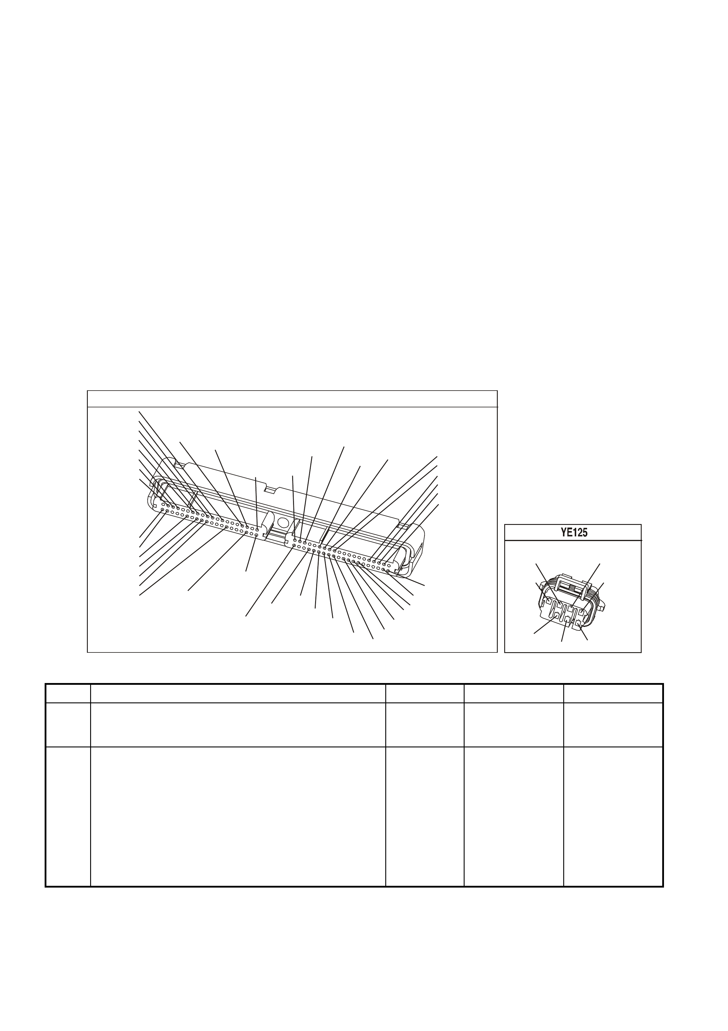
DIAGNOSTIC AIDS
• The following may be the cause of an intermittent:
- Poor connections. Check for adequate terminal tension.
- Corrosion
- Incorrectly routed harness
- Rubbed through wire insulation.
- Broken wire inside the insulation.
• Using the Freeze Frame/Failure Records data may aid in locating an intermittent condition. If you cannot
duplicate the DTC, the information included in the Freeze Frame/Failure Records data can help determine the
distance traveled since the DTC Set. The Fail Counter and Pass Counter can also help determine how may
ignition cycles the diagnostic reported a pass and/or a fail. Operate the vehicle within the same freeze frame
conditions (RPM, load, vehicle speed, temperature etc.) that you observed. This will isolate when the DTC
failed.
• For an intermittent condition, refer to Section 6C3-2B Symptoms of the VX Series Service Information.
TEST DESCRIPTION
The numbers below refer to the step numbers on the diagnostic table.
2. This step verifies that the fault is present.
4. This step checks the integrity of the IC circuit and the PCM output.
5. This step checks for a short to earth on the IC control circuit.
YE123
P.C.M CONNECTOR 2
(750)
(1228)
(1229)
(465)
(121)
(259)
G/B
BR
G/W
GY/BLU
R
B/R
(418)
BR
(59)
(832)
G
T
(831)
(417)
(472)
(976)(974)
(432)
(428)
(631)
BLUBR G/Y
BLU/W
LG
BR/W
W/B
LG W
(977)
Y
(971)
BLU/WW
B/R
(750)
(304)
(792)
(1223)
(1222)
(123)
(1227)
(469)
(331)
Y/B
LG
V/W
B/Y
G/O BR/W
(1687)
GY/B
(366)
LG/B
GY/R
(422)
V
(442)
(444)
(443)
(975)
(972)
(978)
(1224)
(973)
(959)
LG/W
LG/B
LBLU/B
GY
(773)
BR/Y
BLU
G
Y/B
LBLU
(958)
BR
(441)
LBLU
1
41
40
80
J2
RED
Y
(838)
L.H. IGNITION MODULE
(958)
(973)
BR
BLU
(971)
(482)
W
LG
B/R
(750)
Y
(977)
(975)
G
GEN III V8 PCM - DTC P0357 IGNITION CONTROL #7 CIRCUIT
Step Action Value(s) Yes No
1 Did you perform the Powertrain On-Board Diagnostic
(OBD) System Check ? Go to Step 2 Go to Powertrain
OBD System
Check Table
2 IMPORTANT: If all the Ignition Control (IC) DTCs are set
at the same time, inspect the IC earth circuits for an
open.
1. Install a Tech 2 scan tool.
2. Idle the engine.
3. Monitor the (IC) Ignition Control status for the cylinder
with the ignition control DTC using the Tech 2 scan
tool in the Engine Data List.
Does the Tech 2 scan tool indicate Fault?
Go to Step 4 Go to Step 3

GEN III V8 PCM - DTC P0357 IGNITION CONTROL #7 CIRCUIT (CONTINUED)
Step Action Value(s) Yes No
3 1. Turn ON the ignition leaving the engine OFF.
2. Review the Freeze Frame/Failure Records data for
this DTC and observe the parameters.
3. Turn OFF the ignition for 15 seconds.
4. Start the engine.
5. Operate the vehicle within the conditions required for
this diagnostic to run, and as close to the conditions
recorded in Freeze Frame/Failure Records as
possible. Special operating conditions that you need to
meet before the PCM will run this diagnostic, where
applicable, are listed in Conditions for Running the
DTC.
6. Select the Diagnostic Trouble Code (DTC) option, the
DTC Information, The Failed This Ignition using the
Tech 2 scan tool.
Does the Tech 2 scan tool indicate that this diagnostic
failed this ignition?
Go to Step 4 Go To
Diagnostic Aids
4 1. Turn OFF the engine.
2. Disconnect the ignition coil electrical harness.
3. Measure the frequency at the ignition control signal
circuit using the DMM J 39200 on the AC Hertz
setting.
4. Idle the engine.
Is the frequency within the specified range?
3.0-20 Hz Go to Step 8 Go to Step 5
5 Measure the voltage at the ignition control signal circuit
using the DMM J 39200.
Is the voltage greater than the specified value?
1.0 volts Go to Step 9 Go to Step 6
6 1. Turn OFF the ignition.
2. Disconnect the RED PCM connector.
3. Check the continuity from the IC circuit (at the ignition
coil harness connector) to the PCM connector using
the DMM J 39200.
Does the DMM indicate continuity?
Go to Step 7 Go to Step 10
7 Check the resistance from the IC circuit (at the ignition
coil harness connector to earth using the DMM J 39200.
Does the DMM indicate OL?
Go to Step 11 Go to step 10
8 Replace the ignition coil. Refer to Section 6C3-3 Ignition
Coil Replacement of the VX Series Service Information.
Is the action complete?
Go to Step 13
9 Repair the Ignition Control circuit for a short to voltage.
Is the action complete? Go to Step 13
10 Repair the Ignition Control circuit for an open or earthed
circuit.
Is the action complete?
Go to Step 13
11 Check the terminal tension at the PCM and replace the
terminal if necessary.
Did you find and correct the condition?
Go to Step 13 Go to Step 12
12 1. Replace PCM.
2. Refer to Section 6C3-3 of the VX Series Service
Information for PCM Programming and
PCM/PIM/BCM Security Link Procedure.
Is action complete?
Go to Step 13

GEN III V8 PCM - DTC P0357 IGNITION CONTROL #7 CIRCUIT (CONTINUED)
Step Action Value(s) Yes No
13 1. Select the Diagnostic Trouble Code (DTC) option and
the Clear DTC Information option using the Tech 2
scan tool.
2. Idle the engine at the normal operating temperature.
3. Select the Diagnostic Trouble Code (DTC) option, the
DTC Information, The Failed This Ignition using the
Tech 2 scan tool.
4. Operate the vehicle within the Conditions for Running
the DTC as specified in the supporting text, if
applicable.
Does the Tech 2 scan tool indicate that this DTC reset?
Go to Step 2 Go to Step 14
14 Using the Tech 2 scan tool, check for any other DTCs.
Does the Tech 2 scan tool display any DTCs that you
have not diagnosed?
Go to the
applicable DTC
table
System OK

GEN III V8 PCM -
DTC P0358 IGNITION CONTROL #8 CIRCUIT
CIRCUIT DESCRIPTION
The ignition system on this engine uses an individual ignition coil/module for each cylinder. The PCM controls the
ignition system operation. T here are eight Ignition Control (IC) c ircuits, one per cylinder, that connect the PCM and
ignition coil/m odules. Eac h ignition coil/m odule has a power f eed, a chassis earth circuit and a re ferenc e low c ircuit.
The PCM c auses a spark to occur by earthing the IC c ircuit, which signals the ignition m odule to trigger the ignition
coil and fire the spark plug. Sequencing and timing ar e PCM controlled. This DTC sets when the IC circuit is out of
range.
CONDITIONS FOR RUNNING THE DTC
• The ignition voltage is between 9.0 and 17.0 volts
CONDITIONS FOR SETTING THE DTC
• The PCM detects the Ignition Control circuit is earthed, open or shorted to a voltage.
• All conditions met for less than 15 second.
ACTION TAKEN WHEN THE DTC SETS
• The PCM illuminates the Check Powertrain Lamp when the diagnostic runs and fails.
• The PCM records the operating conditions at the time the diagnostic fails. The PCM stores this information in
the Freeze Frame/Failure Records.
CONDITIONS FOR CLEARING THE CPL/DTC
• The PCM turns the Check Powertrain Lamp OFF when the diagnostic runs and does not fail.
• A last test failed (current DTC) clears when the diagnostic runs and does not fail.
• Use a Tech 2 scan tool in order to clear the CPL/DTC.
4368
PCM
J1-19
J2-66
J2-61
CYL. 8
IGNITION
REFERENCE LOW
IGNITION
+
-
BATTERY
FS
LOC. E3
(1040)
FJ
R (2)
15a 15 50
30 OFF/ON
LOCK
ACC
IGN
START
IGNITION SWITCH
P (3)
YB (972)
EFI
RELAY
F14
F34
B/W
(152)
12V
LOC. E5/E15
BR (750)
YE124
YE124
YE123
YE123
YE111
YE111
YE39
YE39
YE114
YE122
YB44
YB44
R
(481)
CYL 8
V (95 9)
M
I
C
R
O
P
R
O
C
E
S
S
O
R
TO
IGNITION COILS
1, 3, 5, AND 7
TO
IGNITION COILS
2, 4, AND 6
TO
IGNITION COILS
2, 4, AND 6
F35
L/G
(482)
IGNITION COIL
CYLINDER #8

DIAGNOSTIC AIDS
• The following may be the cause of an intermittent:
- Poor connections. Check for adequate terminal tension.
- Corrosion
- Incorrectly routed harness
- Rubbed through wire insulation.
- Broken wire inside the insulation.
• Using the Freeze Frame/Failure Records data may aid in locating an intermittent condition. If you cannot
duplicate the DTC, the information included in the Freeze Frame/Failure Records data can help determine the
distance traveled since the DTC Set. The Fail Counter and Pass Counter can also help determine how may
ignition cycles the diagnostic reported a pass and/or a fail. Operate the vehicle within the same freeze frame
conditions (RPM, load, vehicle speed, temperature etc.) that you observed. This will isolate when the DTC
failed.
• For an intermittent condition, refer to Section 6C3-2B Symptoms of the VX Series Service Information
TEST DESCRIPTION
The numbers below refer to the step numbers on the diagnostic table.
2. This step verifies that the fault is present.
4. This step checks the integrity of the IC circuit and the PCM output.
5. This step checks for a short to earth on the IC control circuit.
YE123
P.C.M CONNECTOR 2
(750)
(1228)
(1229)
(465)
(121)
(259)
G/B
BR
G/W
GY/BLU
R
B/R
(418)
BR
(59)
(832)
G
T
(831)
(417)
(472)
(976)(974)
(432)
(428)
(631)
BLUBR G/Y
BLU/W
LG
BR/W
W/B
LG W
(977)
Y
(971)
BLU/WW
B/R
(750)
(304)
(792)
(1223)
(1222)
(123)
(1227)
(469)
(331)
Y/B
LG
V/W
B/Y
G/O BR/W
(1687)
GY/B
(366)
LG/B
GY/R
(422)
V
(442)
(444)
(443)
(975)
(972)
(978)
(1224)
(973)
(959)
LG/W
LG/B
LBLU/B
GY
(773)
BR/Y
BLU
G
Y/B
LBLU
(958)
BR
(441)
LBLU
1
41
40
80
J2
RED
Y
(838)
R.H.IGNITION MODULE
LG
(976)
(959)
VR
(481)
LBLU
(978)
B/R
(750)
(972)
Y/B
(974)
W
GEN III V8 PCM - DTC P0358 IGNITION CONTROL #8 CIRCUIT
Step Action Value(s) Yes No
1 Did you perform the Powertrain On-Board Diagnostic
(OBD) System Check ? Go to Step 2 Go to Powertrain
OBD System
Check Table
2 IMPORTANT: If all the Ignition Control (IC) DTCs are set
at the same time, inspect the IC earth circuits for an
open.
1. Install a Tech 2 scan tool.
2. Idle the engine.
3. Monitor the (IC) Ignition Control status for the cylinder
with the ignition control DTC using the Tech 2 scan
tool in the Engine Data List.
Does the Tech 2 scan tool indicate Fault?
Go to Step 4 Go to Step 3

GEN III V8 PCM – DTC P0358 IGNITION CONTROL #8 CIRCUIT (CONTINUED)
Step Action Value(s) Yes No
3 1. Turn ON the ignition leaving the engine OFF.
2. Review the Freeze Frame/Failure Records data for
this DTC and observe the parameters.
3. Turn OFF the ignition for 15 seconds.
4. Start the engine.
5. Operate the vehicle within the conditions required for
this diagnostic to run, and as close to the conditions
recorded in Freeze Frame/Failure Records as
possible. Special operating conditions that you need to
meet before the PCM will run this diagnostic, where
applicable, are listed in Conditions for Running the
DTC.
6. Select the Diagnostic Trouble Code (DTC) option, the
DTC Information, The Failed This Ignition using the
Tech 2 scan tool.
Does the Tech 2 scan tool indicate that this diagnostic
failed this ignition?
Go to Step 4 Go To
Diagnostic Aids
4 1. Turn OFF the engine.
2. Disconnect the ignition coil electrical harness.
3. Measure the frequency at the ignition control signal
circuit using the DMM J 39200 on the AC Hertz
setting.
4. Idle the engine.
Is the frequency within the specified range?
3.0-20 Hz Go to Step 8 Go to Step 5
5 Measure the voltage at the ignition control signal circuit
using the DMM J 39200.
Is the voltage greater than the specified value?
1.0 volts Go to Step 9 Go to Step 6
6 1. Turn OFF the ignition.
2. Disconnect the RED PCM connector.
3. Check the continuity from the IC circuit (at the ignition
coil harness connector) to the PCM connector using
the DMM J 39200.
Does the DMM indicate continuity?
Go to Step 7 Go to Step 10
7 Check the resistance from the IC circuit (at the ignition
coil harness connector to earth using the DMM J 39200.
Does the DMM indicate OL?
Go to Step 11 Go to step 10
8 Replace the ignition coil. Refer to Section 6C3-3 Ignition
Coil Replacement of the VX Series Service Information.
Is the action complete?
Go to Step 13
9 Repair the Ignition Control circuit for a short to voltage.
Is the action complete? Go to Step 13
10 Repair the Ignition Control circuit for an open or earthed
circuit.
Is the action complete?
Go to Step 13
11 Check the terminal tension at the PCM and replace the
terminal if necessary.
Did you find and correct the condition?
Go to Step 13 Go to Step 12
12 1. Replace PCM.
2. Refer to Section 6C3-3 of the VX Series Service
Information for PCM Programming and
PCM/PIM/BCM Security Link Procedure.
Is action complete?
Go to Step 13

GEN III V8 PCM – DTC P0358 IGNITION CONTROL #8 CIRCUIT (CONTINUED)
Step Action Value(s) Yes No
13 1. Select the Diagnostic Trouble Code (DTC) option and
the Clear DTC Information option using the Tech 2
scan tool.
2. Idle the engine at the normal operating temperature.
3. Select the Diagnostic Trouble Code (DTC) option, the
DTC Information, The Failed This Ignition using the
Tech 2 scan tool.
4. Operate the vehicle within the Conditions for Running
the DTC as specified in the supporting text, if
applicable.
Does the Tech 2 scan tool indicate that this DTC reset?
Go to Step 2 Go to Step 14
14 Using the Tech 2 scan tool, check for any other DTCs.
Does the Tech 2 scan tool display any DTCs that you
have not diagnosed?
Go to the
applicable DTC
table
System OK
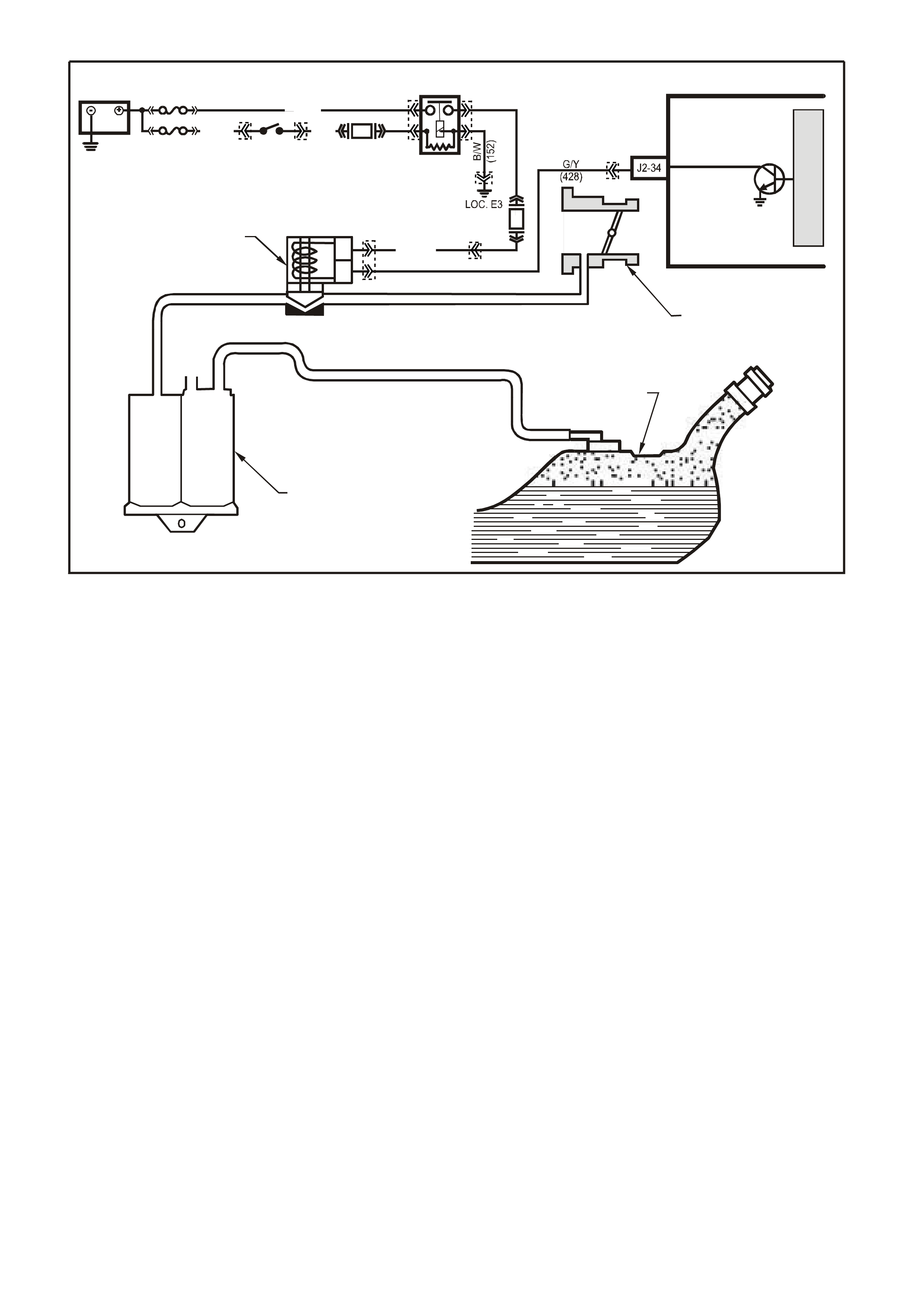
GEN III V8 PCM -
DTC P0443 EVAP PURGE SOLENOID CONTROL CIRCUIT
CIRCUIT DESCRIPTION
An ignition voltage is supplied directly to the EVAP solenoid relay coil. The PCM controls the solenoid by earthing
the control circuit via an internal switch called a driver. The prim ary function of the driver is to supply the earth for
the controlled component. Each driver has a fault line, which the PCM monitors. The voltage of the control circuit
should be low (near 0 volt), when the PCM com m ands a com ponent ON. T he voltage potential of the circ uit should
be high (near the battery voltage), when the PCM commands the control circuit to a components OFF. If the fault
detection circuit senses a voltage other than what the PCM is expected, the fault line status changes causing the
DTC to set.
CONDITIONS FOR RUNNING THE DTC
• The engine speed is greater than 400 RPM.
• The ignition voltage is between 6.0 and 16.0 volts.
CONDITIONS FOR SETTING THE DTC
• The PCM detects that the commanded state of the circuit and the actual state of the circuit does not match.
• The conditions are present for at least ten seconds.
ACTION TAKEN WHEN THE DTC SETS
• The PCM illuminates the Check Powertrain Lamp when the diagnostic runs and fails.
• The PCM records the operating conditions at the time the diagnostic fails. The PCM stores this information in
the Freeze Frame/Failure Records.
CONDITIONS FOR CLEARING THE CPL/DTC
• The PCM turns the Check Powertr ain Lamp OF F after one ignition cycle that the diagnostic runs and does not
fail.
• A last test failed (current DTC) clears when the diagnostic runs and does not fail.
• Use a Tech 2 scan tool in order to clear the CPL/DTC.
G3PCM026PT
A
B
THROTTLE BODY
CANISTER PURGE
SOL EN OID VALVE
CARBON CANISTER
FUEL TANK
PCM
CANISTER PURGE
M
I
C
R
O
F33
F14
IGN SW
EFI
RELAY
BATTERY
FS
FJ
P (3 ) P/B
(39)
R (2H)
(1040)
P (439)
O/Y
(479)
YE99
YE39YE39
YE114
YB44 YB44 YE123
YE111
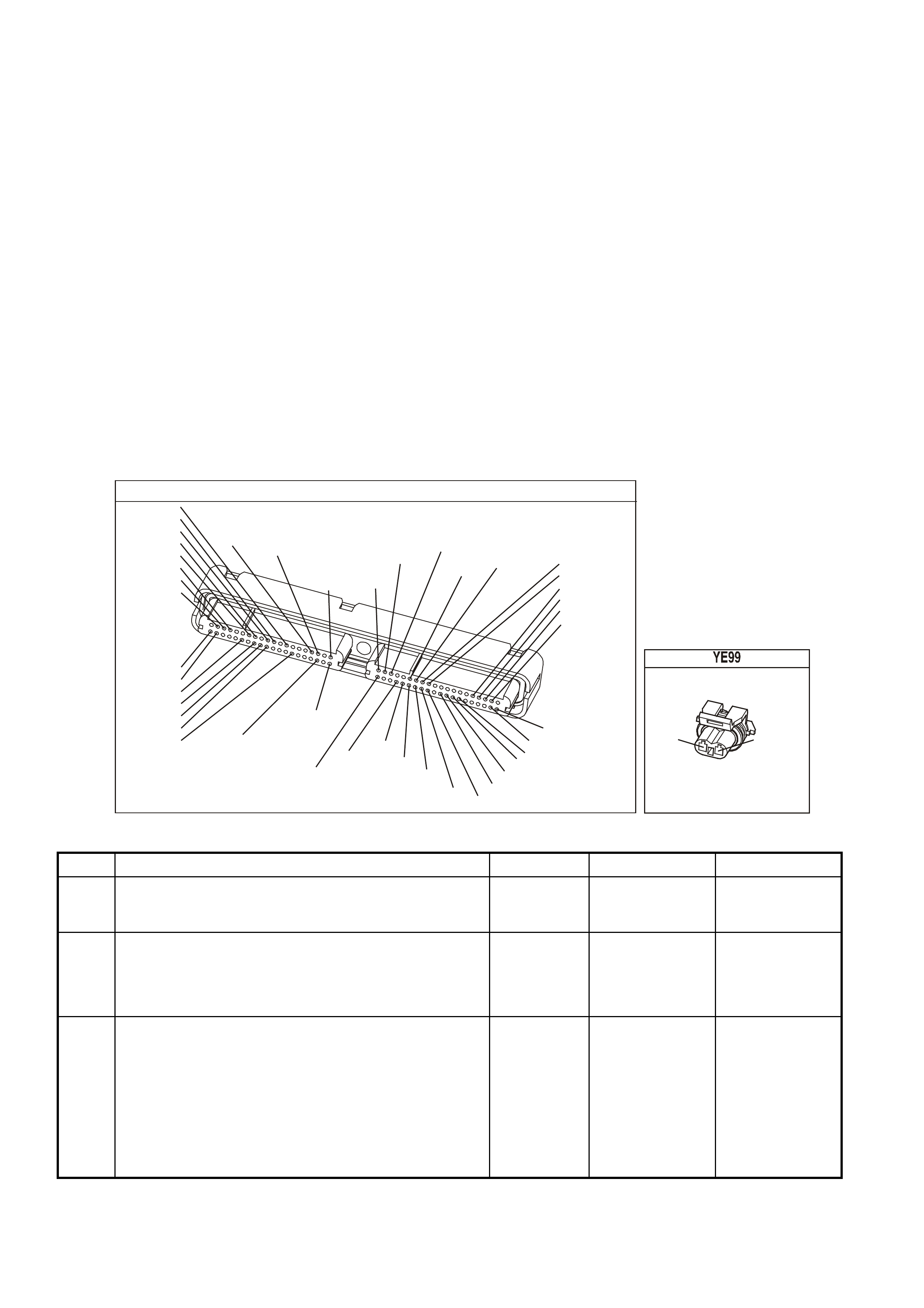
DIAGNOSTIC AIDS
• Using Freeze Frame/Failure Records data may aid in locating an intermittent condition. If you cannot duplicate
the DTC, the information included in the Freeze Frame/Failure Records data can aid in determining the
distance traveled since the DTC set. The Fail Counter and Pass Counter can also aid determining how many
ignition cycles the diagnostic reported a pass and/or fail. Operate the vehicle within the same freeze frame
conditions (RPM, load, vehicle speed, temperature etc.) that you observed. This will isolate when the DTC
failed.
• For an intermittent, refer to Section 6C3-2B Symptoms, of the VX Series Service Information.
TEST DESCRIPTION
The numbers below refer to the step numbers on the diagnostic table.
NOTE: The engine must be running in order to command the EVAP Purge Solenoid Valve ON and OFF.
2. Listen for an audible click when the solenoid operates. Be sure that both the ON and the OFF states are
commanded. Repeat the commands as necessary.
3. This check can detect a partial short which would cause excessive current flow. Leaving the circuit energised
for 2 minutes allows the coil to warm up. When warm, the coil may open (Amps drop to 0), or short (goes
above 0.75 Amp).
13. If no trouble is found in the control circuit or the connection at the PCM, the PCM may be faulty, however, this
is an extremely unlikely failure.
YE123
P.C.M CONNECTOR 2
(750)
(1228)
(1229)
(465)
(121)
(259)
G/B
BR
G/W
GY/BLU
R
B/R
(418)
BR
(59)
(832)
G
T
(831)
(417)
(472)
(976)(974)
(432)
(428)
(631)
BLUBR G/Y
BLU/W
LG
BR/W
W/B
LG W
(977)
Y
(971)
BLU/WW
B/R
(750)
(304)
(792)
(1223)
(1222)
(123)
(1227)
(469)
(331)
Y/B
LG
V/W
B/Y
G/O BR/W
(1687)
GY/B
(366)
LG/B
GY/R
(422)
V
(442)
(444)
(443)
(975)
(972)
(978)
(1224)
(973)
(959)
LG/W
LG/B
LBLU/B
GY
(773)
BR/Y
BLU
G
Y/B
LBLU
(958)
BR
(441)
LBLU
1
41
40
80
J2
RED
Y
(838)
CANNISTER PURGE
(439)(428)
PG/Y
B
A
GEN III V8 PCM - DTC P0443 EVAP PURGE SOLENOID CONTROL CIRCUIT
Step Action Value(s) Yes No
1 Did you perform the Powertrain On-Board Diagnostic
(OBD) System Check? Go to Step 2 Go to Powertrain
OBD System
Check Table
2
1. Idle the engine at the normal operating temperature.
2. Command the solenoid ON and OFF using the scan
tool.
Does the solenoid turn ON and OFF when commanded?
Go to Step 3 Go to Step 5
3 1. Turn OFF the ignition.
2. Disconnect the PCM RED connector.
3. Turn ON the ignition leaving the engine OFF.
4. Measure the current, from the solenoid control circuit
in the PCM harness connector, to earth for 2 minutes
using the DMM J 39200 on the 10 Amp scale.
Does the current draw measure less than the specified
value shown but not 0?
0.75 A Go to
Diagnostic Aids Go to Step 4

GEN III V8 PCM - DTC P0443 EVAP PURGE SOLENOID CONTROL CIRCUIT (CONTINUED)
Step Action Value(s) Yes No
4 1. Turn OFF the ignition.
2. Disconnect the solenoid.
3. Measure the resistance, from the solenoid control
circuit in the PCM harness connector, to earth using
the DMM J 39200.
Does the DMM display infinite resistance?
Go to Step 12 Go to Step 10
5 1. Turn OFF the ignition.
2. Disconnect the solenoid.
3. Connect the test lamp J 34142-B between the
terminals in the solenoid harness connector.
4. Idle the engine at the normal operating temperature.
5. Command the solenoid ON and OFF using the scan
tool.
Does the test lamp turn ON and OFF when commanded?
Go to Step 8 Go to Step 6
6 With the test lamp connected to earth, probe the ignition
feed circuit in the solenoid harness connector.
Is the test lamp illuminated?
Go to Step 7 Go to Step 11
7 1. Turn OFF the ignition.
2. Reconnect the solenoid.
3. Disconnect the RED PCM connector.
4. Turn ON the ignition leaving the engine OFF.
5. With a fused jumper wire connected to earth, probe
the solenoid control circuit in the PCM harness
connector.
Does the solenoid operate?
Go to Step 9 Go to Step 10
8 Check the connection at the solenoid?
Was a problem found and corrected? Go to Step 14 Go to Step 12
9 Check the connection at the PCM.
Was a problem found and corrected? Go to Step 14 Go to Step 13
10 Repair open or short to earth in the solenoid control
circuit.
Is the action complete?
Go to Step 14
11 Repair the faulty solenoid ignition feed circuit.
Is the action complete? Go to Step 14
12 Replace the solenoid.
Is the action complete? Go to Step 14
13 1. Replace PCM.
2. Refer to Section 6C3-3 Service Operations, of the VX
Series Service Information, for PCM Programming and
PCM/PIM/BCM Security Link Procedure.
Is action complete?
Go to Step 14
14 1. Select the Diagnostic Trouble Code (DTC) option and
the Clear DTC Information option using the Tech 2
scan tool.
2. Idle the engine at the normal operating temperature.
3. Select the Diagnostic Trouble Code (DTC) option, the
DTC Information option and The Failed This Ignition
option using the Tech 2 scan tool.
4. Operate the vehicle, within the Conditions for Running
the DTC, as specified in the supporting text, if
applicable.
Does the Tech 2 scan tool indicate that this DTC reset?
Go to Step 2 Go to Step 15
15 Using the Tech 2 scan tool, check for any other DTCs.
Does the Tech 2 scan tool display any DTCs that you
have not diagnosed?
Go to the
applicable DTC
table
System OK
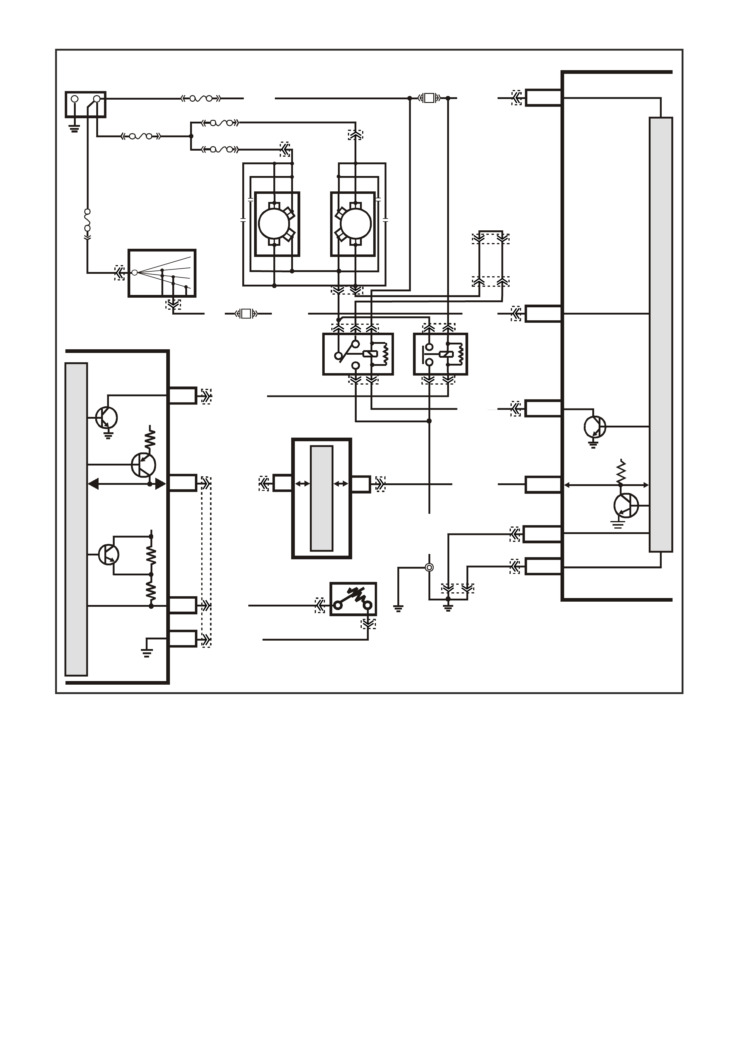
GEN III V8 PCM -
DTC P0481 COOLING FAN HIGH SPEED RELAY CONTROL
CIRCUIT DESCRIPTION
Ignition voltage is supplied directly to the cooling fan relay coil. The PCM controls the relay by earthing the control
circuit via an internal switch called a driver. The primary function of the driver is to supply the earth for the
controlled component. Each driver has a fault line which the PCM monitors. When the PCM commands a
component ON, the voltage of the control circuit should be low (near 0 volts). When the PCM commands the
control circuit to a component OFF, the voltage potential of the circuit should be high (near the battery voltage). If
the fault detection circuit senses a voltage other than what the PCM is expected, the fault line status changes
causing the DTC to set.
The relay controls the high current flow to the cooling fans. This allows the PCM driver to only have to control the
relatively low current used by the relay.
CONDITIONS FOR RUNNING THE DTC
• The engine speed is greater than 600 RPM.
• The ignition voltage is between 6.0 and 16.0 volts.
R/B (1221) E2/D2
IGNITION
LOW
SPEED FAN
M
I
C
R
O
P
R
O
C
E
S
S
O
R
BATT ERY MAIN POWER
HIGH SERIES
BCM TERMINALS
NOMINATED FIRST
BCM
15a 15 50
30 OFF/ON
LOCK
ACC
IGN
START
4359
E20/D6
B7/B7
P (3)
IGNITION SWITCH
O/B (473)
87A
30
87
85
86
87
30
85
86
ENGINE
COOLING
FAN 1
ENGINE
COOLING
FAN RELAY
(LOW SPEED)
ENGINE
COOLING
FAN RELAY
(HIGH SPEED)
P/B (39)
B/Y
(533)
O/Y
(250)
F14
R
YB
G
BLU/W (304)
R/B (1049)
HIGH
CURRENT EARTH
B/Y
(155) A1/A5 ELECTRONIC EARTH
B/G
(151)
LOC.
E2 LOC.
E3
B10/B11
B/R (157)
J1-58
GEN III PCM
PIM
J2-33
HIGH
SPEED FAN
BLUE
FUSIBLE
LINK
LOC.
E1
F31
A5/A6
O/B (740)
ENGINE
COOLING
FAN 2
+-
BATTERY
FS
FT FAN 2
FU FAN 1
(1040)
R
(203)
R
(001)
R
(001)
O/B
(208)
O/BLU
(204)
FJ
R
(001)
R
(2H)
6
7
M
I
C
R
O
CLASS 2 SERIAL DATA
UART SERIAL DATA
7V
CLASS 2
SERIAL DA TA
SERIAL
DATA
5V
GY /B (455)
J1-74 Y (41O)
COOLANT TEMP
SENSOR
ETC SENSOR
SIGNAL
5V
4k
348
Ω
Ω
J1-80
SENSOR
EARTH
M
I
C
R
O
P/B (39)
YE140
YE139
YB44
YB44
YE139
YE103
YE103 YE43
YE43
YE104
YB176
YB165
YB163
YB163
YB174
YB174
YB176
YB165
YE114
YE65
YB215YB215
YE65
YE122
YE123
YE118
YB176
YB165
YE140

CONDITIONS FOR SETTING THE DTC
• The PCM detects that the commanded state of the driver and the actual state of the control circuit do not
match.
• The conditions must be present for a minimum of 10 seconds.
ACTION TAKEN WHEN THE DTC SETS
• The PCM illuminates the Check Powertrain Lamp (CPL) when the diagnostic runs and fails.
• The PCM records the operating conditions at the time the diagnostic fails. The PCM stores this information in
the Freeze Frame/Failure Records.
CONDITIONS FOR CLEARING THE CPL/DTC
• The PCM turns the CPL OFF after the first ignition cycle that the diagnostic runs and does not fail.
• A last test failed (current DTC) clears when the diagnostic runs and does not fail.
• A History DTC clears after forty consecutive warm-up cycles, if this or any other emission related diagnostic
does not report any failures.
• Use a Tech 2 scan tool to clear the CPL/DTC.
DIAGNOSTIC AIDS
• Using the Freeze Frame/Failure Records data may aid in locating an intermittent condition. If you cannot
duplicate the DTC, the information included in the Freeze Frame/Failure Records data can aid in determining
the distance traveled since the DTC reported a pass and/or fail. Operate the vehicle within the same freeze
frame conditions (RPM, load, vehicle speed, temperature, etc.) that you observed. This will isolate when the
DTC failed.
• For an intermittent, refer to Section 6C3-2B Symptoms, of the VX Series Service Information.
TEST DESCRIPTION
The numbers below refer to the step numbers on the diagnostic table.
2. Listen for an audible clic k when the relay operates. Com mand both ON and O F F s tates . Repeat the commands
if necessary.
3. This check can detect a partially shorted coil which would cause excessive current flow. Leaving the circuit
energised for 2 minutes allows the coil to warm up. W hen warm, the coil may open (Am ps drop to 0), or short
(goes above 0.75 Amps).
13. If you do not find any trouble in the control circuit or the connection at the PCM, the PCM may be faulty.
14. The repair is not complete if the Tech 2 scan tool indicates that the diagnostic ran and failed.
Y E 123
P.C.M CONNECTOR 2
(750)
(1228)
(1229)
(465)
(121)
(259)
G/B
BR
G/W
GY/BLU
R
B/R
(418)
BR
(59)
(832)
G
T
(831)
(417)
(472)
(976) (974)
(432)
(428)
(631)
BLU BR G/Y
BLU/W
LG
BR/W
W/B
LG W
(977)
Y
(971)
BLU/W W
B/R
(750)
(304)
(792)
(1223)
(1222)
(123)
(1227)
(469)
(331)
Y/B
LG
V/W
B/Y
G/O BR/W
(1687)
GY/B
(366)
LG/B
GY/R
(422)
V
(442)
(444)
(443)
(975)
(972)
(978)
(1224)
(973)
(959)
LG/W
LG/B
LBLU/B
GY
(773)
BR/Y
BLU
G
Y/B
LBLU
(958)
BR
(441)
LBLU
1
41
40
80
J2
RED
Y
(838)
YE 43
B/R
(157)
BLU/W
(304)
O/B
(740)
O/Y
(250)

GEN III V8 PCM - DTC P0481 COOLING FAN HIGH SPEED RELAY CONTROL
Step Action Value(s) Yes No
1 Did you perform the Powertrain On-Board Diagnostic
(OBD) System Check? Go to Step 2 Go to Powertrain
OBD System
Check Table
2
1. Turn ON the ignition leaving the engine OFF.
2. Command the relay ON and OFF using a Tech 2 scan
tool.
Does the relay turn ON and OFF when commanded?
Go to Step 3 Go to Step 5
3 1. Turn OFF the ignition.
2. Disconnect the RED PCM connector.
3. Turn ON the ignition.
4. Measure current from the relay control circuit in the
PCM harness connector to earth for 2 minutes using
DMM J 39200 on 10 Amp scale.
Does the current draw measure less than the specified
value (but not 0)?
0.75A Go to
Diagnostic Aids Go to Step 4
4 1. Turn OFF the ignition.
2. Disconnect the relay.
3. Measure the resistance, from the relay control circuit
in the PCM harness connector, to earth using the
DMM J 39200.
Does the DMM display infinite resistance?
Go to Step 12 Go to Step 10
5 1. Turn OFF the ignition.
2. Disconnect the relay.
3. Connect the test lamp between the relay control circuit
and the relay B+ supply circuit, at the Fuse/Relay
panel.
4. Turn ON the ignition.
5. Command the relay ON and OFF using a Tech 2 scan
tool.
Does the test lamp turn ON and OFF with each
command?
Go to Step 8 Go to Step 6
6 Probe the relay B+ supply circuit at the Fuse/Relay panel
with the test lamp connected to earth.
Is the test lamp ON?
Go to Step 7 Go to Step 11
7 1. Turn OFF the ignition.
2. Reconnect the relay.
3. Disconnect the RED PCM connector.
4. Turn ON the ignition.
5. Probe the relay control circuit, in the PCM harness
connector, with a fused jumper wire connected to
earth.
Does the relay operate?
Go to Step 9 Go to Step 10
8 Check the connections at the relay.
Did you find and correct the condition? Go to Step 14 Go to Step 12
9 Check the connections at the PCM.
Did you find and correct the condition? Go to Step 14 Go to Step 13
10 Repair open or short to earth in the relay control circuit.
Is action complete? Go to Step 14
11 Repair the relay B+ supply circuit.
Is action complete? Go to Step 14
12 Replace the relay.
Is action complete? Go to Step 14

GEN III V8 PCM - DTC P0481 COOLING FAN HIGH SPEED RELAY CONTROL (CONTINUED)
Step Action Value(s) Yes No
13 1. Replace PCM.
2. Refer to Section 6C3-3, of the VX Series Service
Information, for PCM Programming and
PCM/PIM/BCM Security Link Procedure.
Is action complete?
Go to Step 14
14 1. Select the Diagnostic Trouble Code (DTC) option and
the Clear DTC Information option using the Tech 2
scan tool.
2. Idle the engine at the normal operating temperature.
3. Select the Diagnostic Trouble Code (DTC) option, the
DTC Information option and The Failed This Ignition
option using the Tech 2 scan tool.
4. Operate the vehicle, within the Conditions for Running
the DTC, as specified in the supporting text, if
applicable.
Does the Tech 2 scan tool indicate that this DTC reset?
Go to Step 2 Go to Step 15
15 Using the Tech 2 scan tool, check for any other DTCs.
Does the Tech 2 scan tool display any DTCs that you
have not diagnosed?
Go to the
applicable DTC
table
System OK
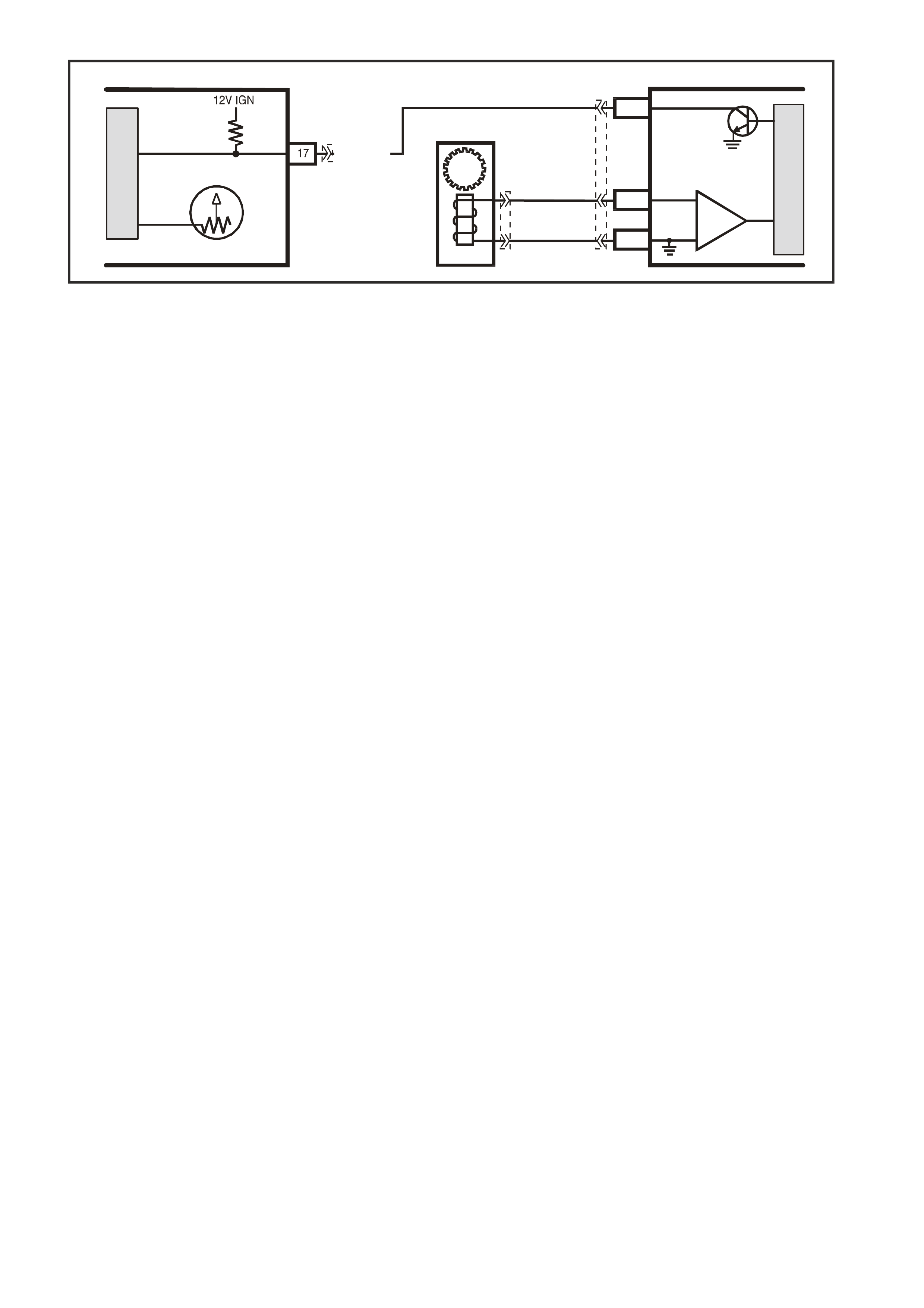
V/W (123)
VEHICLE SPEED
M
I
C
R
O
G3PCM016C
INSTRUMENT
M
I
C
R
O
VEHICLE SPEED
VSS HI
VSS LO
PCM
J2-50
J2-21
J2-20
VEHICLE SPEED
SENSOR
IC
BLU/W
(831)
T
(832)
SPEEDOMETER
YE123
YB195
YB66
GEN III V8 PCM
DTC P0500 VEHICLE SPEED SENSOR CIRCUIT
CIRCUIT DESCRIPTION
The Vehicle Speed Sensor (VSS) assembly provides vehicle speed information to the Powertrain Control Module
(PCM). The VSS assembly is a Permanent Magnet (PM) generator. The PM generator produces a pulsing AC
voltage as rotor teeth on the transmission output shaft pass through the sensor's magnetic field. The AC voltage
level and the number of pulses increase as the speed of the vehicle increases. The PCM converts the pulsing
voltage to v ehicle speed. T he PCM uses the Vehicle Spe ed Signal to determ ine shift tim ing and Torque Co nverter
Clutch (TCC) scheduling.
If the PCM detects a no vehicle speed when there is a high engine speed and a high MAP, then DTC P0500 sets.
CONDITIONS FOR RUNNING THE DTC
• DTCs P0107, P0108, P0117, P0118, P0121, P0122, P0123, P0125, P0506, P0507 are not set.
• The Engine Coolant Temperature is greater than 35 degrees C
• The engine speed is greater the 1000 RPM.
• The TP sensor angle is between 5 % and 100 %.
• The MAP is between 40 kPa and 100 kPa when the A/C is off.
• The MAP is between 45 kPa and 100 kPa when the A/C is on.
• All conditions are met for two seconds.
CONDITIONS FOR SETTING THE DTC
• The PCM detects the vehicle speed at 0 km/h for at least 100 seconds.
ACTION TAKEN WHEN THE DTC SETS
• The PCM stores the DTC information into memory when the diagnostic runs and fails.
• The Check Powertrain Lamp will be illuminated.
CONDITIONS FOR CLEARING THE DTC
• A last test failed (current DTC) clears when the diagnostic runs and does not fail.
DIAGNOSTIC AIDS
• Inspect the wiring at the PCM, the VSS connector and all other circuit connecting points for the following
conditions:
- A backed out terminal
- A damaged terminal
- Reduced terminal tension
- A chafed wire
- A broken wire inside the insulation
- Moisture intrusion
- Corrosion
• When diagnosing for an intermittent short or open condition, massage the wiring harness while watching the
test equipment for a change.
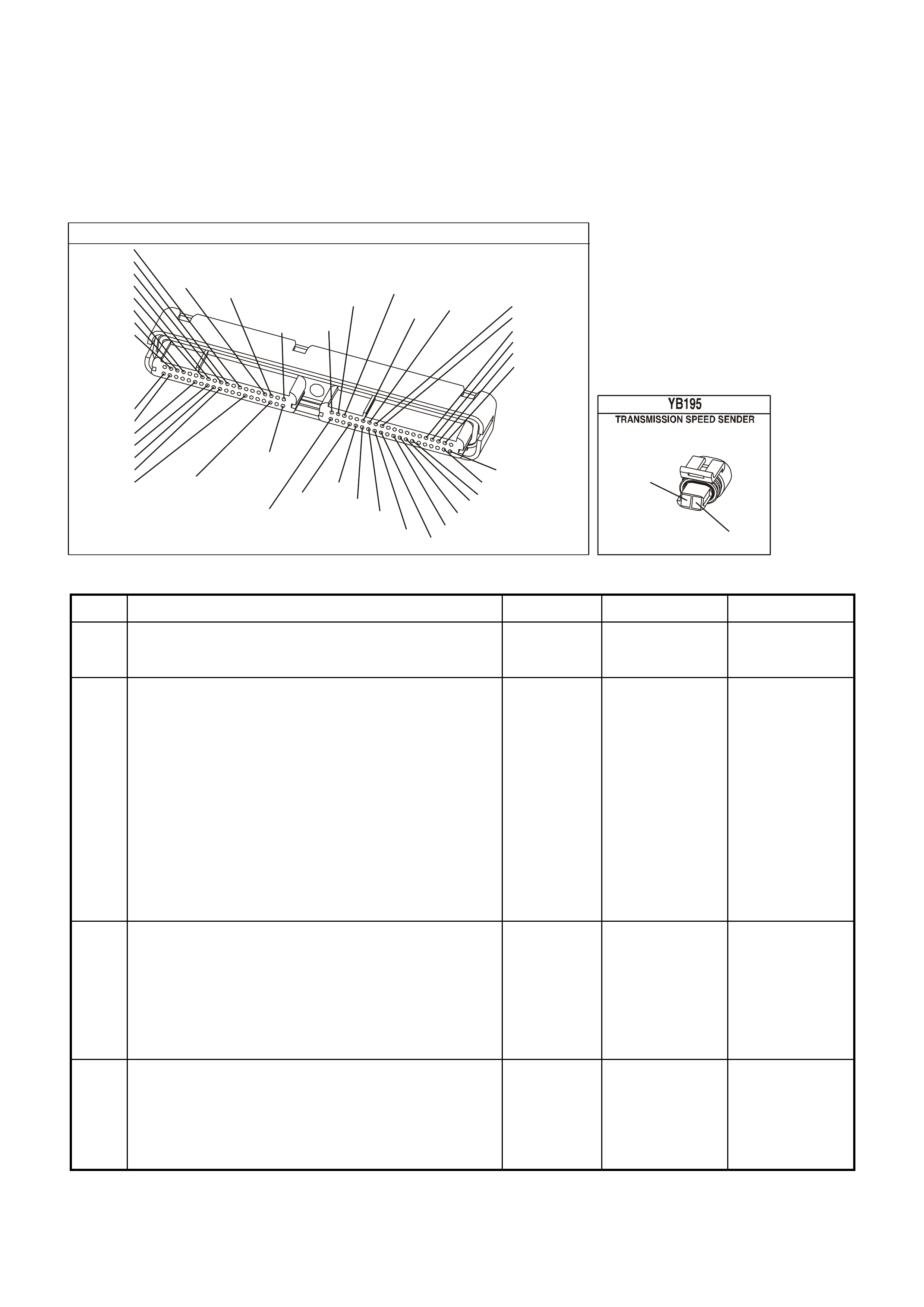
TEST DESCRIPTION
The numbers below refer to the step numbers on the diagnostic table.
2. Disable the Electronic Traction Control (ETC) system (if fitted) when performing this step. When the ignition key
is cycled to the OFF position and then cycled back ON, the traction control system defaults to ON.
3. This step tests the VSS assembly circuit.
4. This step tests the VSS assembly for a short to earth.
5. This step tests the integrity of the VSS assembly.
YE123
P.C.M CONNECTOR 2
(750)
(1228)
(1229)
(465)
(121)
(259)
G/B
BR
G/W
GY/BLU
R
B/R
(418)
BR
(59)
(832)
G
T
(831)
(417)
(472)
(976)(974)
(432)
(428)
(631)
BLUBR G/Y
BLU/W
LG
BR/W
W/B
LG W
(977)
Y
(971)
BLU/WW
B/R
(750)
(304)
(792)
(1223)
(1222)
(123)
(1227)
(469)
(331)
Y/B
LG
V/W
B/Y
G/O BR/W
(1687)
GY/B
(366)
LG/B
GY/R
(422)
V
(442)
(444)
(443)
(975)
(972)
(978)
(1224)
(973)
(959)
LG/W
LG/B
LBLU/B
GY
(773)
BR/Y
BLU
G
Y/B
LBLU
(958)
BR
(441)
LBLU
1
41
40
80
J2
RED
Y
(838)
(831)
BLU/W
T
(832)
GEN III V8 PCM - DTC P0500 VEHICLE SPEED SENSOR CIRCUIT
Step Action Value(s) Yes No
1 Was the Powertrain On-Board Diagnostic (OBD) System
Check performed? Go to Step 2 Go to Powertrain
OBD System
Check Table
2 1. Install the Tech 2 Scan Tool.
2. With the engine OFF, turn the ignition switch to the
ON position, engine OFF.
3. Clear the DTC, using Tech 2.
4. Raise the rear of the vehicle and support the final
drive assembly.
5. Start the engine.
6. Disable the traction control system (if fitted).
7. Place the transmission in any drive range.
With the drive wheels rotating, does the Tech 2
Transmission VSS display increase with the drive wheel
speed?
Go to
Diagnostic Aids Go to Step 3
3 1. Turn OFF the ignition.
2. Disconnect the powertrain wiring harness connector
from the VSS assembly.
3. Using the J 39200 digital multimeter (DMM) and the
J 35616 connector test adapter kit, measure the
resistance of the VSS assembly.
Does the resistance measure within the specified range?
1377-3355 Ω Go to Step 4 Go to Step 14
4 With the powertrain wiring harness connector still
disconnected from the VSS assembly, measure the
resistance from either terminal of the VSS assembly to
earth.
Does the resistance measure greater than the specified
value?
50 K Ω Go to Step 5 Go to Step 14

GEN III V8 PCM - DTC P0500 VEHICLE SPEED SENSOR CIRCUIT (CONTINUED)
Step Action Value(s) Yes No
5 1. Place the transmission in NEUTRAL.
2. Select AC volts on the J 39200 DMM.
3. Place the transmission in neutral and then rotate the
propeller shaft by hand.
4. Measure the AC voltage from terminal A and B of the
VSS assembly.
Does the voltage measure greater than the specified
value?
0.3 volts AC Go to Step 6 Go to Step 13
6 1. Reconnect the powertrain wiring harness connector to
the VSS assembly.
2. Disconnect the RED PCM connector.
3. Measure the resistance between the RED PCM
connector terminals 20 and 21.
Does the resistance measure within the specified range?
1377-3355 Ω Go to Step 7 Go to Step 8
7 With the RED PCM connector still disconnected, measure
the resistance from terminal 21 of the RED PCM
connector to earth.
Does the resistance measure greater than the specified
value?
50 K Ω Go to Step 9 Go to Step 10
8 Does the resistance in step 6 measure greater than the
specified value? 3355 Ω Go to Step 11 Go to Step 12
9 1. Reconnect the RED PCM connector.
2. Disconnect the powertrain wiring harness connector
from the VSS assembly.
3. Turn ON the ignition, with the engine OFF.
4. Test the High circuit 831 (BLU/W) of the VSS
assembly for a short to voltage.
5. Test the Low circuit 832 (T) of the VSS assembly for a
short to voltage.
Did you find and correct the condition?
Go to Step 16 Go to Step 15
10 1. Test the High circuit 831 (BLU/W) of the VSS
assembly for a short to earth.
Did you find and correct the condition?
Go to Step 16
11 1. Test the High circuit 831 (BLU/W) of the VSS
assembly for an open.
2. Test the Low circuit 832 (T) of the VSS assembly for
an open.
Did you find and correct the condition?
Go to Step 16
12 Test the High circuit 831 (BLU/W ) and the Low circuit 832
(T) of the VSS assembly for a short together.
Did you find and correct the condition?
Go to Step 16
13 1. Remove the VSS assembly.
Refer to Section 7C4 VEHICLE SPEED SENSOR
REPLACEMENT of the VT Series I Service
Information.
2. Inspect the output shaft speed sensor rotor for
damage or misalignment.
Did you find and repair the damaged condition?
Go to Step 16 Go to Step 14
14 Replace the VSS assembly.
Refer to Section 7C4 VEHICLE SPEED SENSOR
REPLACEMENT of the VT Series I Service Information.
Is the replacement complete?
Go to Step 16

GEN III V8 PCM - DTC P0500 VEHICLE SPEED SENSOR CIRCUIT (CONTINUED)
Step Action Value(s) Yes No
15 Replace the PCM.
Refer to Section 6C3-3 Service Operations – GEN III V8
Engine of the VX Series Service Information.
Is the replacement complete?
Go to Step 16
16 Perform the following procedure in order to verify the
repair:
1. Select Diagnostic Trouble Codes.
2. Select Clear DTC Information and then clear DTCs.
3. Operate the vehicle, so that the transmission output
speed is greater than 250 RPM for two seconds.
Was the above condition verified?
System OK Go to Step1

V/W (123)
VEHICLE SPEED
M
I
C
R
O
G3PCM016C
INSTRUMENT
M
I
C
R
O
VEHICLE SPEED
VSS HI
VSS LO
PCM
J2-50
J2-21
J2-20
VEHICLE SPEED
SENSOR
IC
BLU/W
(831)
T
(832)
SPEEDOMETER
YE123
YB195
YB66
GEN III V8 PCM
DTC P0502 VEHICLE SPEED SENSOR CIRCUIT LOW INPUT
CIRCUIT DESCRIPTION
The Vehicle Speed Sensor (VSS) assembly provides vehicle speed information to the Powertrain Control Module
(PCM). The VSS assembly is a Permanent Magnet (PM) generator. The PM generator produces a pulsing AC
voltage as rotor teeth on the transmission output shaft pass through the sensor's magnetic field. The AC voltage
level and the number of pulses increase as the speed of the vehicle increases. The PCM converts the pulsing
voltage to v ehicle speed. T he PCM uses the Vehicle Spe ed Signal to determ ine shift tim ing and Torque Co nverter
Clutch (TCC) scheduling.
If the PCM detects a low vehic le spe ed when th ere is a h igh engine s peed i n a drive gear rang e, then DT C P0502
sets.
CONDITIONS FOR RUNNING THE DTC
• No MAP sensor DTCs P0107 or P0108.
• No Throttle Position DTCs P0122 or P0123.
• No TFP manual valve position switch DTC P1810.
• The transmission is not in park or neutral.
• The Throttle Position angle is greater than 15%.
• The engine vacuum is 0-105 kPa.
• The engine speed is greater than 3000 RPM.
• The engine torque is between 40 – 543 N.m.
CONDITIONS FOR SETTING THE DTC
• The transmission output speed is less than 150 RPM for at least three seconds.
ACTION TAKEN WHEN THE DTC SETS
• The PCM stores the DTC information into memory when the diagnostic runs and fails.
• The Check Powertr ain Lam p will not be il luminated.
• The PCM commands first gear only.
• The PCM commands maximum line pressure.
• The PCM inhibits TCC engagement.
• The PCM freezes shift adapts from being updated.
• The PCM records the operating conditions at the time the diagnostic fails. The PCM stores this information in
the Freeze Frame/Failure Records.
CONDITIONS FOR CLEARING THE DTC
• A last test failed (current DTC) clears when the diagnostic runs and does not fail.
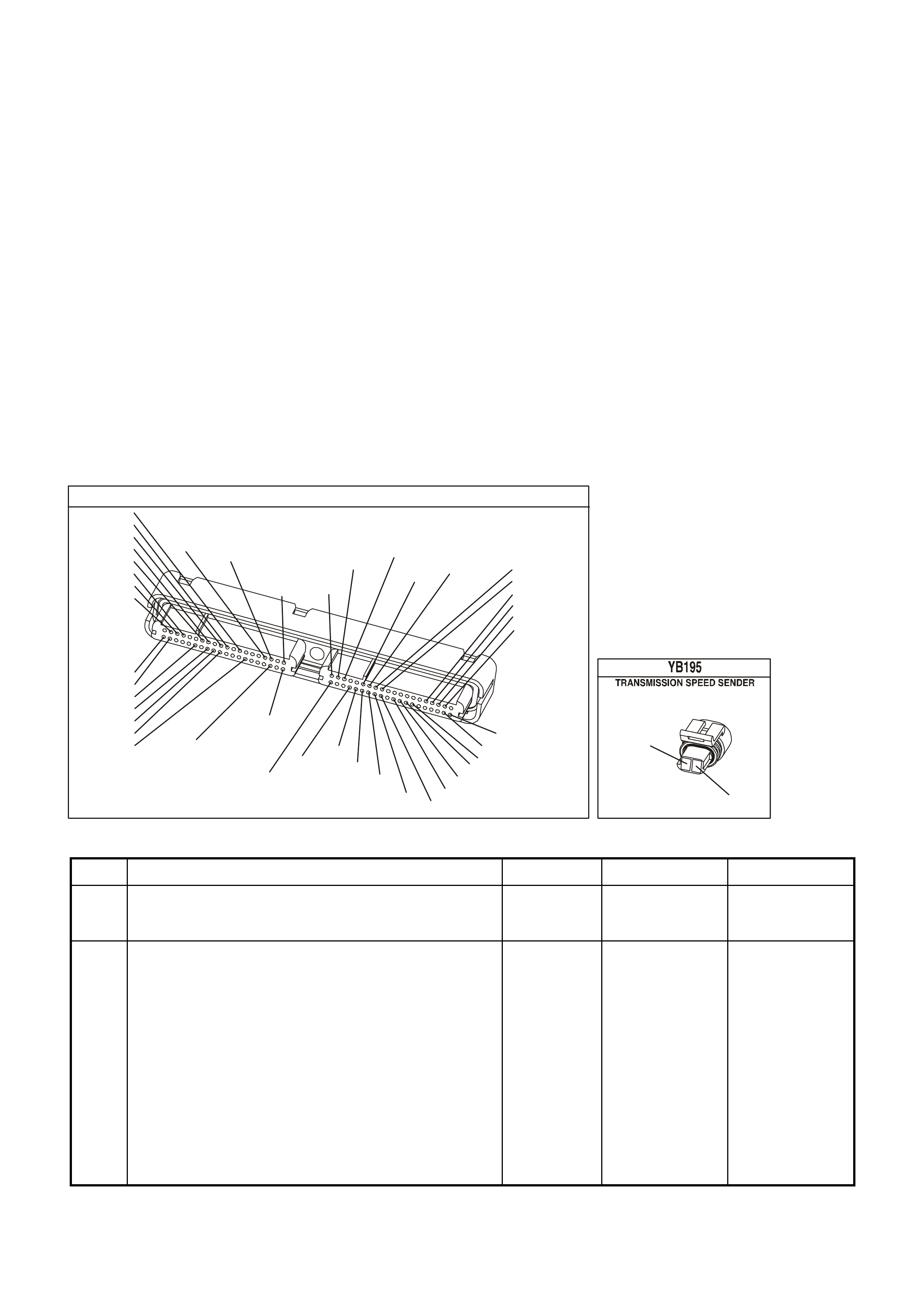
DIAGNOSTIC AIDS
• Inspect the wiring at the PCM, the VSS connector and all other circuit connecting points for the following
conditions:
- A backed out terminal
- A damaged terminal
- Reduced terminal tension
- A chafed wire
- A broken wire inside the insulation
- Moisture intrusion
- Corrosion
• When diagnosing for an intermittent short or open condition, massage the wiring harness while watching the
test equipment for a change.
TEST DESCRIPTION
The numbers below refer to the step numbers on the diagnostic table.
2. Disable the Electronic Traction Control (ETC) system (if fitted) when performing this step. When the ignition key
is cycled to the OFF position and then cycled back ON, the traction control system defaults to ON.
3. This step tests the VSS assembly circuit.
4. This step tests the VSS assembly for a short to earth.
5. This step tests the integrity of the VSS assembly.
YE123
P.C.M CONNECTOR 2
(750)
(1228)
(1229)
(465)
(121)
(259)
G/B
BR
G/W
GY/BLU
R
B/R
(418)
BR
(59)
(832)
G
T
(831)
(417)
(472)
(976)(974)
(432)
(428)
(631)
BLUBR G/Y
BLU/W
LG
BR/W
W/B
LG W
(977)
Y
(971)
BLU/WW
B/R
(750)
(304)
(792)
(1223)
(1222)
(123)
(1227)
(469)
(331)
Y/B
LG
V/W
B/Y
G/O BR/W
(1687)
GY/B
(366)
LG/B
GY/R
(422)
V
(442)
(444)
(443)
(975)
(972)
(978)
(1224)
(973)
(959)
LG/W
LG/B
LBLU/B
GY
(773)
BR/Y
BLU
G
Y/B
LBLU
(958)
BR
(441)
LBLU
1
41
40
80
J2
RED
Y
(838)
(831)
BLU/W
T
(832)
GEN III V8 PCM - DTC P0502 VEHICLE SPEED SENSOR CIRCUIT LOW
Step Action Value(s) Yes No
1 Was the Powertrain On-Board Diagnostic (OBD) System
Check performed? Go to Step 2 Go to Powertrain
OBD System
Check Table
2 1. Install the Tech 2 Scan Tool.
2. With the engine OFF, turn the ignition switch to the ON
position, engine OFF.
3. Clear the DTC, using Tech 2.
4. Raise the rear of the vehicle and support the final drive
assembly.
5. Start the engine.
6. Disable the traction control system (if fitted).
7. Place the transmission in any drive range.
With the drive wheels rotating, does the Tech 2
Transmission VSS display increase with the drive wheel
speed?
Go to
Diagnostic Aids Go to Step 3

GEN III V8 PCM - DTC P0502 VEHICLE SPEED SENSOR CIRCUIT (CONTINUED)
Step Action Value(s) Yes No
3 4. Turn OFF the ignition.
5. Disconnect the powertrain wiring harness connector
from the VSS assembly.
6. Using the J 39200 digital multimeter (DMM) and the
J 35616 connector test adapter kit, measure the
resistance of the VSS assembly.
Does the resistance measure within the specified range?
1377-3355 Ω Go to Step 4 Go to Step 14
4 With the powertrain wiring harness connector still
disconnected from the VSS assembly, measure the
resistance from either terminal of the VSS assembly to
earth.
Does the resistance measure greater than the specified
value?
50 K Ω Go to Step 5 Go to Step 14
5 5. Place the transmission in NEUTRAL.
6. Select AC volts on the J 39200 DMM.
7. Place the transmission in neutral and then rotate the
propeller shaft by hand.
8. Measure the AC voltage from terminal A and B of the
VSS assembly.
Does the voltage measure greater than the specified
value?
0.3 volts AC Go to Step 6 Go to Step 13
6 4. Reconnect the powertrain wiring harness connector to
the VSS assembly.
5. Disconnect the RED PCM connector.
6. Measure the resistance between the RED PCM
connector terminals 20 and 21.
Does the resistance measure within the specified range?
1377-3355 Ω Go to Step 7 Go to Step 8
7 With the RED PCM connector still disconnected, measure
the resistance from terminal 21 of the RED PCM
connector to earth.
Does the resistance measure greater than the specified
value?
50 K Ω Go to Step 9 Go to Step 10
8 Does the resistance in step 6 measure greater than the
specified value? 3355 Ω Go to Step 11 Go to Step 12
9 6. Reconnect the RED PCM connector.
7. Disconnect the powertrain wiring harness connector
from the VSS assembly.
8. Turn ON the ignition, with the engine OFF.
9. Test the High circuit 831 (BLU/W) of the VSS
assembly for a short to voltage.
10. Test the Low circuit 832 (T) of the VSS assembly for a
short to voltage.
Did you find and correct the condition?
Go to Step 16 Go to Step 15
10 2. Test the High circuit 831 (BLU/W) of the VSS
assembly for a short to earth.
Did you find and correct the condition?
Go to Step 16
11 3. Test the High circuit 831 (BLU/W) of the VSS
assembly for an open.
4. Test the Low circuit 832 (T) of the VSS assembly for
an open.
Did you find and correct the condition?
Go to Step 16
12 Test the High circuit 831 (BLU/W ) and the Low circuit 832
(T) of the VSS assembly for a short together.
Did you find and correct the condition?
Go to Step 16

GEN III V8 PCM - DTC P0502 VEHICLE SPEED SENSOR CIRCUIT (CONTINUED)
Step Action Value(s) Yes No
13 3. Remove the VSS assembly.
Refer to Section 7C4 VEHICLE SPEED SENSOR
REPLACEMENT of the VT Series I Service
Information.
4. Inspect the output shaft speed sensor rotor for
damage or misalignment.
Did you find and repair the damaged condition?
Go to Step 16 Go to Step 14
14 Replace the VSS assembly.
Refer to Section 7C4 VEHICLE SPEED SENSOR
REPLACEMENT of the VT Series I Service Information.
Is the replacement complete?
Go to Step 16
15 Replace the PCM.
Refer to Section 6C3-3 Service Operations – GEN III V8
Engine of the VX Series Service Information.
Is the replacement complete?
Go to Step 16
16 Perform the following procedure in order to verify the
repair:
4. Select Diagnostic Trouble Codes.
5. Select Clear DTC Information and then clear DTCs.
6. Operate the vehicle, so that the transmission output
speed is greater than 250 RPM for two seconds.
Was the above condition verified?
System OK Go to Step1

GEN III V8 PCM -
DTC P0503 VEHICLE SPEED SENSOR CIRCUIT INTERMITTENT
CIRCUIT DESCRIPTION
The Vehicle Speed Sensor (VSS) assembly provides vehicle speed information to the powertrain control module
(PCM). The VSS assembly is a permanent magnet (PM) generator. The PM generator produces a pulsing AC
voltage as rotor teeth on the transmission output shaft pass through the sensor's magnetic field.
The AC vo ltage leve l and the num ber of pulses incr ease as the speed of the vehicle inc reases. T he PCM conver ts
the pulsi ng voltag e to vehic le speed. T he PCM uses the Vehic le Spee d Signal to determ ine shift tim ing and t orque
convert er clutch ( TCC) schedulin g. W hen the PCM detec ts an unre alistic all y large dr op in veh icle spe ed, th en DT C
P0503 sets.
CONDITIONS FOR RUNNING THE DTC
• No TFP manual valve position switch DTC P1810.
• The time since the last gear range change is greater than six seconds.
• The engine speed is greater than 300 RPM for five seconds.
• The engine is not in fuel cutoff.
• The transmission output speed rise does not exceed 600 RPM within six seconds.
CONDITIONS FOR SETTING THE DTC
• The transm ission output sp eed drop is greater tha n 1300 RPM for three s econds when the transm ission is not
in park or neutral.
ACTION TAKEN WHEN THE DTC SETS
• The PCM stores the DTC information into memory when the diagnostic runs and fails.
• The Check Powertr ain Lam p will not be il luminated.
• The PCM commands second gear only.
• The PCM commands maximum line pressure.
• The PCM inhibits 4th gear if the transmission is in hot mode.
• The PCM inhibits TCC engagement.
• The PCM freezes shift adapts from being updated.
• The PCM records the operating conditions at the time the diagnostic fails. The PCM stores this information in
the Freeze Frame/Failure Records.
CONDITIONS FOR CLEARING THE DTC
• A last test failed (current DTC) clears when the diagnostic runs and does not fail.
17
V/W (123)
YB66 YB195
YE123
12V IGN
VEHICLE SPEED
M
I
C
R
O
G3PCM016PT
INSTRUMENT
M
I
C
R
O
VEHICLE SPEED
PCM
J2-50
J2-21
J2-20
V
EHICLE SPEED
SENSOR
IC
BLU/W
(831)
T
(832)
SPEEDOMETER
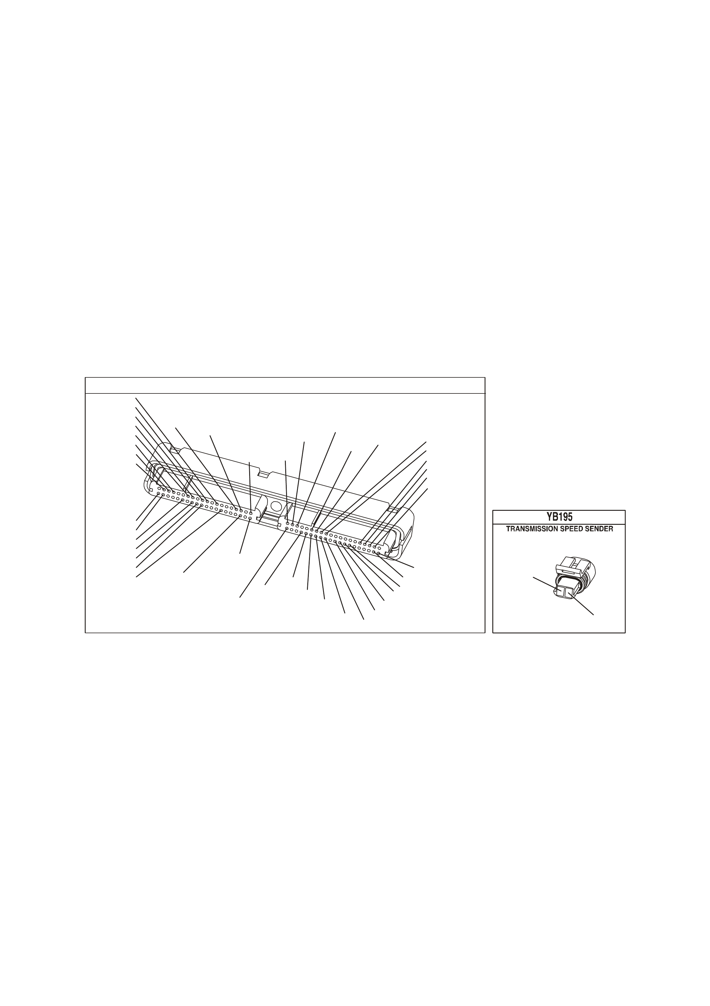
DIAGNOSTIC AIDS
• Inspect the wiring at the PCM, the VSS connector and all other circuit connecting points for the following
conditions:
- A backed out terminal
- A damaged terminal
- Reduced terminal tension
- A chafed wire
- A broken wire inside the insulation
- Moisture intrusion
- Corrosion
• When diagnosing for an intermittent short or open condition, massage the wiring harness while watching the
test equipment for a change.
TEST DESCRIPTION
The numbers below refer to the step numbers on the diagnostic table.
2. Disable the Electronic Traction Control (ETC) system (if fitted) when performing this step. When the ignition key
is cycled to the OFF position and then cycled back ON, the traction control system defaults to ON.
3. This step tests the VSS assembly circuit.
4. This step tests the VSS assembly for a short to earth.
5. This step tests the integrity of the VSS assembly.
Y E 123
P.C.M CONNECTOR 2
(750)
(1228)
(1229)
(465)
(121)
(259)
G/B
BR
G/W
GY/BLU
R
B/R
(418)
BR
(59)
(832)
G
T
(831)
(417)
(472)
(976) (974)
(432)
(428)
(631)
BLU BR G/Y
BLU/W
LG
BR/W
W/B
LG W
(977)
Y
(971)
BLU/W W
B/R
(750)
(304)
(792)
(1223)
(1222)
(123)
(1227)
(469)
(331)
Y/B
LG
V/W
B/Y
G/O BR/W
(1687)
GY/B
(366)
LG/B
GY/R
(422)
V
(442)
(444)
(443)
(975)
(972)
(978)
(1224)
(973)
(959)
LG/W
LG/B
LBLU/B
GY
(773)
BR/Y
BLU
G
Y/B
LBLU
(958)
BR
(441)
LBLU
1
41
40
80
J2
RED
Y
(838)
(831)
BLU/W
T
(832)

GEN III V8 PCM - DTC P0503 VEHICLE SPEED SENSOR CIRCUIT INTERMITTENT
Step Action Value(s) Yes No
1 Was the Powertrain On-Board Diagnostic (OBD) System
Check performed? Go to Step 2 Go to Powertrain
OBD System
Check Table
2 3. Install the Tech 2 Scan Tool.
4. With the engine OFF, turn the ignition switch to the
ON position, engine OFF.
8. Clear the DTC, using Tech 2.
9. Raise the rear of the vehicle and support the final
drive assembly.
10. Start the engine.
11. Disable the trac tion control system (if fitted).
12. Place the transmission in any drive range.
With the drive wheels rotating, does the Tech 2
Transmission VSS display increase with the drive wheel
speed?
Go to Diagnostic
Aids Go to Step 3
3 7. Turn OFF the ignition.
8. Disconnect the powertrain wiring harness connector
from the VSS assembly.
9. Using the J 39200 digital multimeter (DMM) and the
J 35616 connector test adapter kit, measure the
resistance of the VSS assembly.
Does the resistance measure within the specified range?
1377-3355 Ω Go to Step 4 Go to Step 14
4 With the powertrain wiring harness connector still
disconnected from the VSS assembly, measure the
resistance from either terminal of the VSS assembly to
earth.
Does the resistance measure greater than the specified
value?
50 K Ω Go to Step 5 Go to Step 14
5 9. Place the transmission in NEUTRAL.
10. Select AC volts on the J 39200 DMM.
11. Place the transmission in neutral and then rotate the
propeller shaft by hand.
12. Measure the AC voltage from terminal A and B of the
VSS assembly.
Does the voltage measure greater than the specified
value?
0.3 volts AC Go to Step 6 Go to Step 13
6 7. Reconnect the powertrain wiring harness connector to
the VSS assembly.
8. Disconnect the RED PCM connector.
9. Measure the resistance between the RED PCM
connector terminals 20 and 21.
Does the resistance measure within the specified range?
1377-3355 Ω Go to Step 7 Go to Step 8
7 With the RED PCM connector still disconnected, measure
the resistance from terminal 21 of the RED PCM
connector to earth.
Does the resistance measure greater than the specified
value?
50 K Ω Go to Step 9 Go to Step 10
8 Does the resistance in step 6 measure greater than the
specified value? 3355 Ω Go to Step 11 Go to Step 12

GEN III V8 PCM - DTC P0503 VEHICLE SPEED SENSOR CIRCUIT (CONTINUED)
Step Action Value(s) Yes No
9 11. Reconnect the RED PCM connector.
12. Disconnect the powertrain wiring harness connector
from the VSS assembly.
13. Turn ON the ignition, with the engine OFF.
14. Test the High circuit 831 (BLU/W) of the VSS
assembly for a short to voltage.
15. Test the Low circuit 832 (T) of the VSS assembly for a
short to voltage.
Did you find and correct the condition?
Go to Step 16 Go to Step 15
10 3. Test the High circuit 831 (BLU/W) of the VSS
assembly for a short to earth.
Did you find and correct the condition?
Go to Step 16
11 5. Test the High circuit 831 (BLU/W) of the VSS
assembly for an open.
6. Test the Low circuit 832 (T) of the VSS assembly for
an open.
Did you find and correct the condition?
Go to Step 16
12 Test the High circuit 831 (BLU/W ) and the Low circuit 832
(T) of the VSS assembly for a short together.
Did you find and correct the condition?
Go to Step 16
13 5. Remove the VSS assembly.
Refer to Section 7C4 VEHICLE SPEED SENSOR
REPLACEMENT of the VT Series I Service
Information.
6. Inspect the output shaft speed sensor rotor for
damage or misalignment.
Did you find and repair the damaged condition?
Go to Step 16 Go to Step 14
14 Replace the VSS assembly.
Refer to Section 7C4 VEHICLE SPEED SENSOR
REPLACEMENT of the VT Series I Service Information.
Is the replacement complete?
Go to Step 16
15 Replace the PCM.
Refer to Section 6C3-3 Service Operations – GEN III V8
Engine of the VX Series Service Information.
Is the replacement complete?
Go to Step 16
16 Perform the following procedure in order to verify the
repair:
7. Select Diagnostic Trouble Codes.
8. Select Clear DTC Information and then clear DTCs.
9. Operate the vehicle, so that the transmission output
speed is greater than 250 RPM for two seconds.
Was the above condition verified?
System OK Go to Step1

GEN III V8 PCM -
DTC P0506 IDLE SPEED LOW
CIRCUIT DESCRIPTION
The Idle Air Control (IAC) valve is a PCM controlled stepper m otor located on the throttle body. The stepper m otor
drives a valve pintle which protrudes into a pas sage that bypasses the throttle plates . The PCM c om m ands the IAC
valve pintle to extend which decreases the idle speed. The bypass air flow is reduced and the idle speed
decreases as the pintle approaches its set. The PCM retreats the IAC valve pintle away from its seat to increase
the idle speed. T he retracting of the IAC valve pintle allows m ore air to bypass the throttle plates. One of the PCMs
uses f or the IAC system is to m aintain a desir es idle speed. This DTC sets when the PCM detects an engine speed
outside of the IAC’s range of control
CONDITIONS FOR RUNNING THE DTC
• DTCs P0101, P0102, P0103, P0107, P0108, P0112, P0113, P0117, P0118, P0171, P0172, P0174, P0175,
P0443, are not set.
• The engine run time is greater than 60 seconds.
• The engine coolant temperature is greater than 60°C.
• The intake air temperature is greater than -10°C.
• The barometric pressure is greater than 65 kPa.
• The ignition voltage is between 9.0 and 17.0 volts.
• The vehicle speed is no more than 2 km/h.
CONDITIONS FOR SETTING THE DTC
• The actual idle speed is 100 RPM less than the desired idle speed.
• All of the above conditions are present for 15 seconds.
ACTION TAKEN WHEN THE DTC SETS
• The PCM illuminates the Check Powertrain Lamp (CPL) when the diagnostic runs and fails.
• The PCM records the operating conditions at the time the diagnostic fails. The PCM stores this information in
the Freeze Frame/Failure Records.
CONDITIONS FOR CLEARING THE CPL/DTC
• The PCM turns the CPL OFF after the first ignition cycle that the diagnostic runs and does not fail.
• A last test failed (current DTC) clears when the diagnostic runs and does not fail.
• Use a Tech 2 scan tool in order to clear the CPL/DTC.
G3PCM020PT
PCM
J2-77
J2-78
J2-79
J2-76
LG/B (444)
YE36
YE123
A
B
C
D
IAC VALVE
IAC
COIL B HI
IAC
COIL A HI
IAC
COIL B LO
IAC
COIL A LO
12V
12V
12V
12V
M
I
C
R
O
LG/W (443)
LBLU/B (442)
LBLU (441)
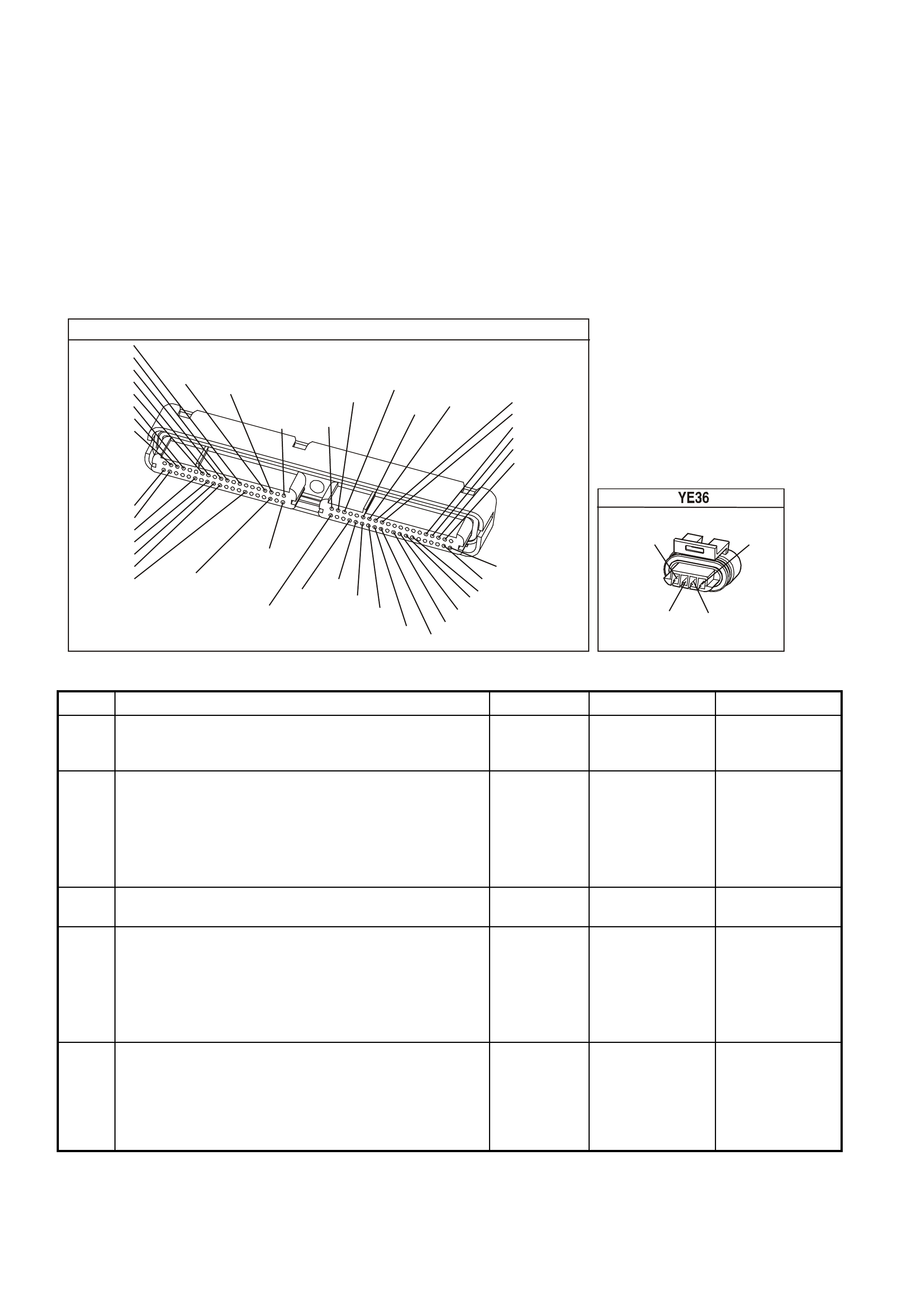
DIAGNOSTIC AIDS
• Using the Freeze Frame/Failure Records data may aid in locating an intermittent condition. If you cannot
duplicate the DTC, the information included in the Freeze Frame/Failure Records data can aid in determining
the distance traveled since the DTC reported a pass and/or fail. Operate the vehicle within the same freeze
frame conditions (RPM, load, vehicle speed, temperature, etc.) that you observed. This will isolate when the
DTC failed.
• For an intermittent, refer to Section 6C3-2B Symptoms, of the VX Series Service Information.
TEST DESCRIPTION
The numbers below refer to the step numbers on the diagnostic table.
2. This test determines whether or not the engine can achieve the commanded RPM, and if not, whether the RPM
is too high or too low.
YE123
P.C.M CONNECTOR 2
(750)
(1228)
(1229)
(465)
(121)
(259)
G/B
BR
G/W
GY/BLU
R
B/R
(418)
BR
(59)
(832)
G
T
(831)
(417)
(472)
(976)(974)
(432)
(428)
(631)
BLUBR G/Y
BLU/W
LG
BR/W
W/B
LG W
(977)
Y
(971)
BLU/WW
B/R
(750)
(304)
(792)
(1223)
(1222)
(123)
(1227)
(469)
(331)
Y/B
LG
V/W
B/Y
G/O BR/W
(1687)
GY/B
(366)
LG/B
GY/R
(422)
V
(442)
(444)
(443)
(975)
(972)
(978)
(1224)
(973)
(959)
LG/W
LG/B
LBLU/B
GY
(773)
BR/Y
BLU
G
Y/B
LBLU
(958)
BR
(441)
LBLU
1
41
40
80
J2
RED
Y
(838)
IDLE AIR CONTROL VALVE
(442)
(441) (444)
(443)
LBLU/B
LBLU LG/B
LG/W
GEN III V8 PCM - DTC P0506 IDLE SPEED LOW
Step Action Value(s) Yes No
1 Did you perform the Powertrain On-Board Diagnostic
(OBD) System Check? Go to Step 2 Go to Powertrain
OBD System
Check Table
2
1. Idle the engine.
2. Command the engine speed up to 1500 RPM, down to
500 RPM, up to 1500 RPM, and the EXIT using the
Tech 2 scan tool
Does the engine speed correspond, within 100 RPM, with
each command?
Go to
Diagnostic Aids Go to Step 3
3 Is the engine RPM greater than 100 RPM above desired
RPM? Go to Step 4 Go to Step 5
4 Check for the following conditions:
• Vacuum leaks.
• Throttle plates not closing properly.
• A faulty PCV valve.
Did you find and correct the condition?
Go to Step 13 Go to Step 6
5 Check for the following conditions:
• Excessive deposits in the throttle body.
• Parasitic load on the engine (i.e. transmission
problem etc.).
Did you find and correct the conditions?
Go to Step 13 Go to Step 6

GEN III V8 PCM - DTC P0506 IDLE SPEED LOW (CONTINUED)
Step Action Value(s) Yes No
6 1. Turn OFF the ignition.
2. Disconnect the IAC harness connector and install the
appropriate IAC node light from kit J 37027-A.
3. Idle the engine.
4. Command the RPM up to 1500, down to 500 and up
to 1500 using the Tech 2 scan tool while observ ing the
node light.
Does both of the LED’s on the node light cycle red and
green, but never OFF?
Go to Step 7 Go to Step 8
7 IMPORTANT: During the following test, it is possible to
overextend the IAC valve pintle until it falls out of the
worm drive. If this occurs, manually screw the pintle shaft
into the worm drive about 2 turns to get it started, align
the keyways on the shaft with the keys in the housing and
gradually retract the pintle using the IAC driver tool.
1. Turn OFF the ignition.
2. Remove the IAC valve.
3. Connect the IAC valve to the IAC Driver tool from kit
J37027-A.
4. Hold the IAC valve with a finger over the pintle in case
it is over extended. Using the driver tool retract and
extend the pintle.
Does the pintle move steadily with each flash of the IAC
driver light?
Go to Step 9 Go to Step 10
8 Check for the following conditions:
• Faulty connection
• Open circuit
• Short to earth
• Short to B+
Did you find and correct the condition?
Go to Step 13 Go to Step 11
9 Check the IAC passages.
Is the action complete? Go to Step 13
10 Replace the IAC valve. Refer to Section 6C3-3 Idle Air
Control Valve Replacement of the VX Series Service
Information.
Is the action complete?
Go to Step 13
11 Check the connections at the PCM.
Did you find and correct the condition? Go to Step 13 Go to Step 12
12 1. Replace PCM.
2. Refer to Section 6C3-3 of the VX Series Service
Information for PCM Programming and
PCM/PIM/BCM Security Link Procedure.
Is action complete?
Go to Step 13
13 1. Select the Diagnostic Trouble Code (DTC) option and
the Clear DTC Information option using the Tech 2
scan tool.
2. Idle the engine at the normal operating temperature.
3. Select the Diagnostic Trouble Code (DTC) option, the
DTC Information option and The Failed This Ignition
option using the Tech 2 scan tool.
4. Operate the vehicle, within the Conditions for Running
the DTC, as specified in the supporting text, if
applicable.
Does the Tech 2 scan tool indicate that this DTC reset?
Go to Step 2 Go to Step 14
14 Using the Tech 2 scan tool, check for any other DTCs.
Does the Tech 2 scan tool display any DTCs that you
have not diagnosed?
Go to the
applicable DTC
table
System OK
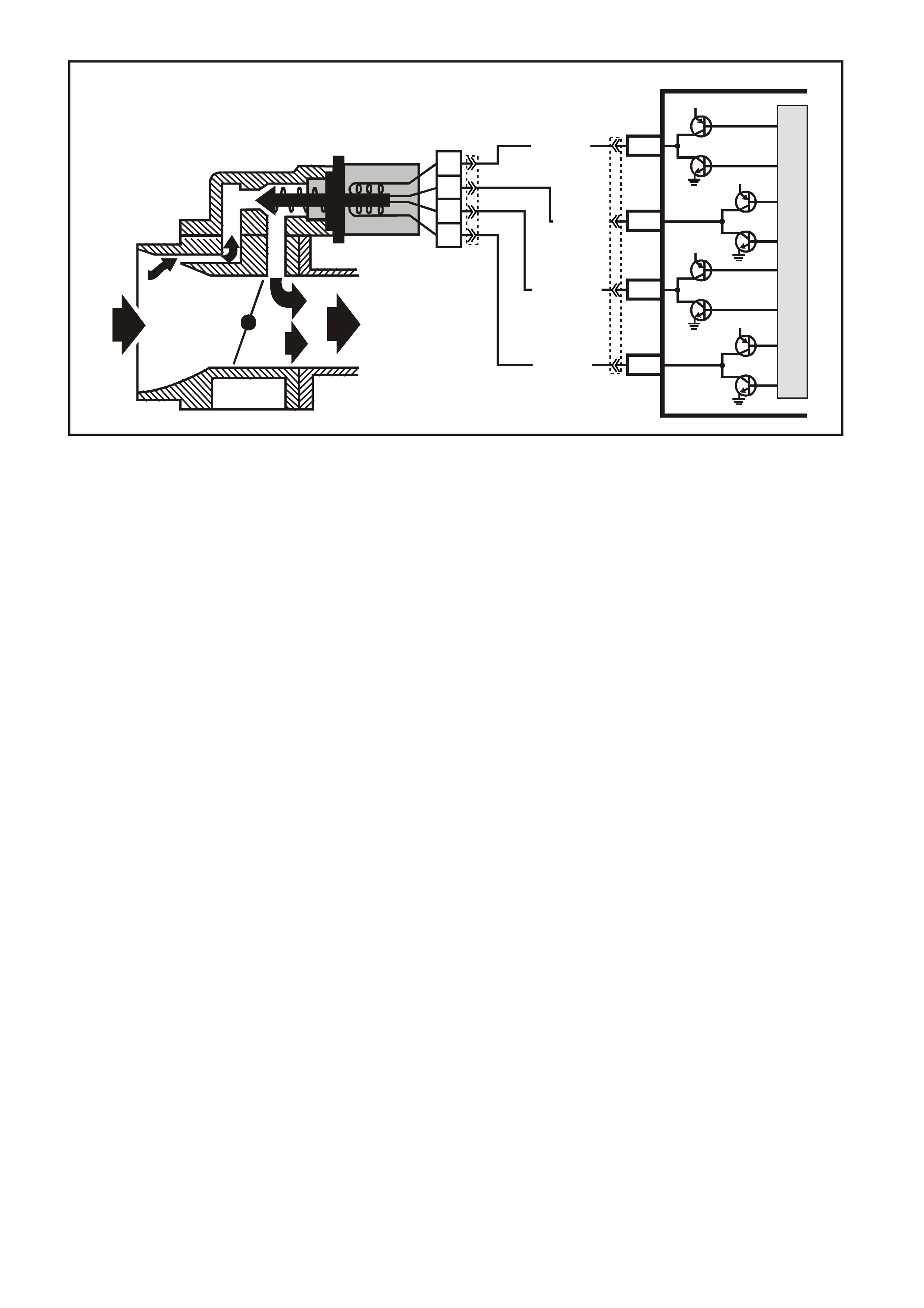
GEN III V8 PCM -
DTC P0507 IDLE SPEED HIGH
CIRCUIT DESCRIPTION
The Idle Air Control (IAC) valve is a PCM controlled stepper m otor located on the throttle body. The stepper m otor
drives a valve pintle which protrudes into a pas sage that bypasses the throttle plates . The PCM c om m ands the IAC
valve pintle to extend to decreas es the idle speed. T he bypass air flow is reduc ed and the idle speed decreases as
the pintle approac hes its seat. T he PCM retracts the IAC valve pintle away from its s eat to increase the idle speed.
The retracting of the IAC valve pintle allows more air to bypass the throttle plates. One of the PCMs uses for the
IAC system is to maintain a desired idle speed. This DTC sets when the PCM detects an engine speed outside of
the IAC’s range of control.
CONDITIONS FOR RUNNING THE DTC
• DTCs P0101, P0102, P0103, P0107, P0108, P0112, P0113, P0117, P0118, P0171, P0172, P0174, P0175,
P0443, are not set.
• The engine run time is greater than 60 seconds.
• The engine coolant temperature is greater than 60°C (140°F).
• The intake air temperature is greater than -10°C (14°F).
• The barometric pressure is greater than 65 kPa.
• The ignition voltage is between 9.0 and 17.0 volts.
• The vehicle speed is no more than 1.6 km/h (1 mph).
CONDITIONS FOR SETTING THE DTC
• The actual idle speed is 100 RPM less than the desired idle speed.
• All of the above conditions are present for 15 seconds.
ACTION TAKEN WHEN THE DTC SETS
• The PCM illuminates the Check Powertrain Lamp (CPL) when the diagnostic runs and fails.
• The PCM records the operating conditions at the time the diagnostic fails. The PCM stores this information in
the Freeze Frame/Failure Records.
CONDITIONS FOR CLEARING THE CPL/DTC
• The PCM turns the CPL OFF after the first ignition cycle that the diagnostic runs and does not fail.
• A last test failed (current DTC) clears when the diagnostic runs and does not fail.
• A History DTC clears after forty consecutive warm-up cycles, if this or any other emission related diagnostic
does not report any failures.
• Use a Tech 2 scan tool in order to clear the CPL/DTC.
G3PCM020PT
PCM
J2-77
J2-78
J2-79
J2-76
LG/B (444)
YE36
YE123
A
B
C
D
IAC VALVE
IAC
COIL B HI
IAC
COIL A HI
IAC
COIL B LO
IAC
COIL A LO
12V
12V
12V
12V
M
I
C
R
O
LG/W (443)
LBLU/B (442)
LBLU (441)
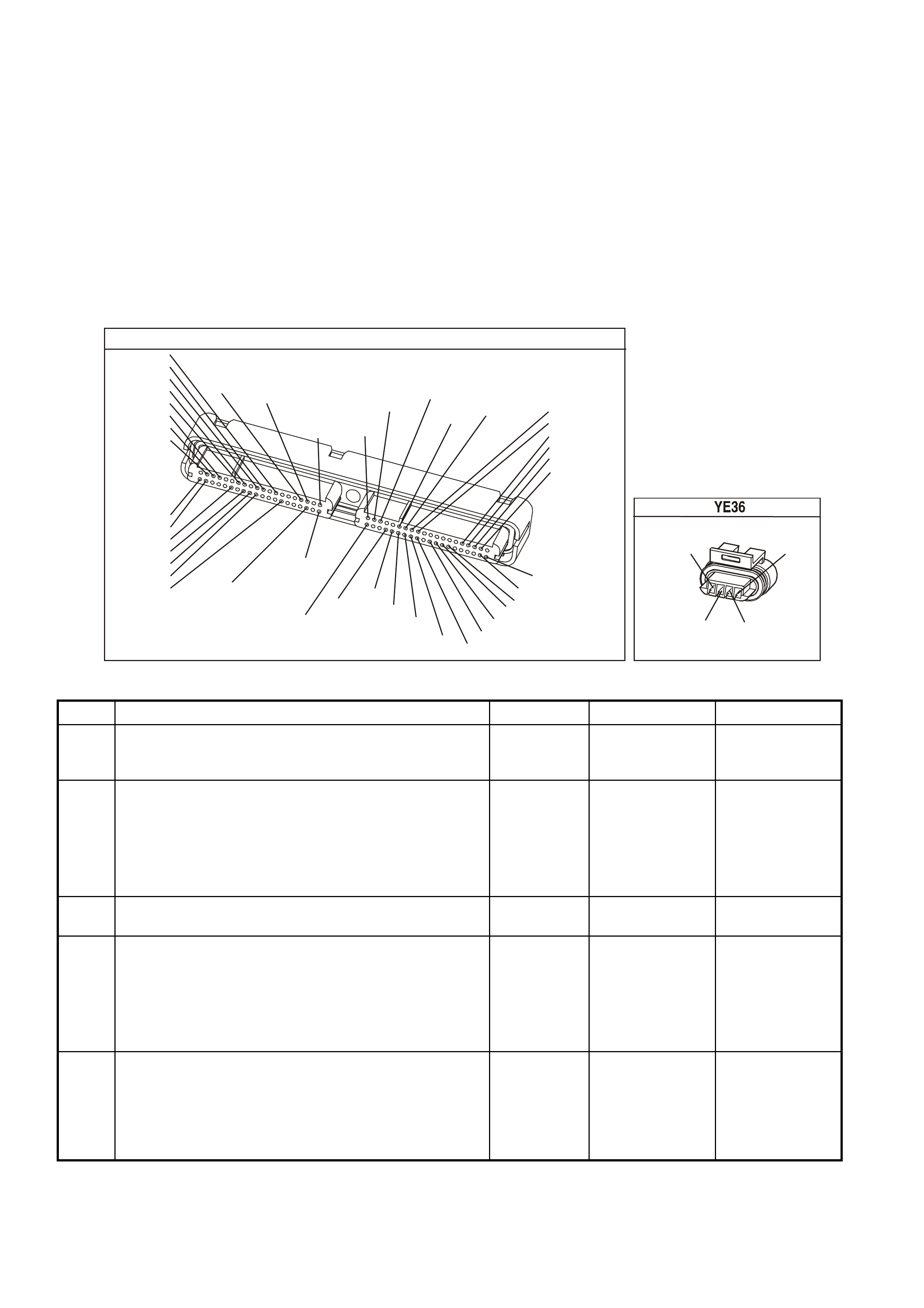
DIAGNOSTIC AIDS
• Using the Freeze Frame/Failure Records data may aid in locating an intermittent condition. If you cannot
duplicate the DTC, the information included in the Freeze Frame/Failure Records data can aid in determining
the distance traveled since the DTC reported a pass and/or fail. Operate the vehicle within the same freeze
frame conditions (RPM, load, vehicle speed, temperature, etc.) that you observed. This will isolate when the
DTC failed.
• For an intermittent, refer to Section 6C3-2B Symptoms of the VX Series Service Information.
TEST DESCRIPTION
The numbers below refer to the step numbers on the diagnostic table.
2. This test determines whether or not the engine can achieve the commanded RPM, and if not, whether the RPM
is too high or too low.
YE123
P.C.M CONNECTOR 2
(750)
(1228)
(1229)
(465)
(121)
(259)
G/B
BR
G/W
GY/BLU
R
B/R
(418)
BR
(59)
(832)
G
T
(831)
(417)
(472)
(976)(974)
(432)
(428)
(631)
BLUBR G/Y
BLU/W
LG
BR/W
W/B
LG W
(977)
Y
(971)
BLU/WW
B/R
(750)
(304)
(792)
(1223)
(1222)
(123)
(1227)
(469)
(331)
Y/B
LG
V/W
B/Y
G/O BR/W
(1687)
GY/B
(366)
LG/B
GY/R
(422)
V
(442)
(444)
(443)
(975)
(972)
(978)
(1224)
(973)
(959)
LG/W
LG/B
LBLU/B
GY
(773)
BR/Y
BLU
G
Y/B
LBLU
(958)
BR
(441)
LBLU
1
41
40
80
J2
RED
Y
(838)
IDLE AIR CONTROL VALVE
(442)
(441) (444)
(443)
LBLU/B
LBLU LG/B
LG/W
GEN III V8 PCM - DTC P0507 IDLE SPEED HIGH
Step Action Value(s) Yes No
1 Did you perform the Powertrain On-Board Diagnostic
(OBD) System Check? Go to Step 2 Go to Powertrain
OBD System
Check Table
2
1. Idle the engine.
2. Command the engine speed up to 1500 RPM, down to
500 RPM, up to 1500 RPM, and the EXIT using the
Tech 2 scan tool
Does the engine speed correspond, within 100 RPM, with
each command?
Go to
Diagnostic Aids Go to Step 3
3 Is the engine RPM greater than 100 RPM above Desired
RPM? Go to Step 4 Go to Step 5
4 Check for the following conditions:
• Vacuum leaks.
• Throttle plates not closing properly.
• A faulty PCV valve.
Did you find and correct the condition?
Go to Step 12 Go to Step 6
5 Check for the following conditions:
• Excessive deposits in the throttle body.
• Parasitic load on the engine (i.e. transmission
problem etc.).
Did you find and correct the conditions?
Go to Step 13 Go to Step 6

GEN III V8 PCM - DTC P0507 IDLE SPEED HIGH (CONTINUED)
Step Action Value(s) Yes No
6 1. Turn OFF the ignition.
2. Disconnect the IAC harness connector and install the
appropriate IAC node light from kit J 37027-A.
3. Idle the engine.
4. Command the RPM up to 1500, down to 500 and up
to 1500 using the Tech 2 scan tool while observ ing the
node light.
Does both of the LED’s on the node light cycle red and
green, but never OFF?
Go to Step 7 Go to Step 8
7 IMPORTANT: During the following test, it is possible to
overextend the IAC valve pintle until it falls out of the
worm drive. If this occurs, manually screw the pintle shaft
into the worm drive about 2 turns to get it started, align
the keyways on the shaft with the keys in the housing and
gradually retract the pintle using the IAC driver tool.
1. Turn OFF the ignition.
2. Remove the IAC valve.
3. Connect the IAC valve to the IAC Driver tool from kit
J37027-A.
4. Hold the IAC valve with a finger over the pintle in case
it is over extended. Using the driver tool retract and
extend the pintle.
Does the pintle move steadily with each flash of the IAC
driver light?
Go to Step 8 Go to Step 9
8 Check for the following conditions:
• Faulty connection
• Open circuit
• Short to earth
• Short to B+
Did you find and correct the condition?
Go to Step 12 Go to Step 10
9 Replace the IAC valve. Refer to Section 6C3-3 Idle Air
Control Valve Replacement of the VX Series Service
Information.
Is the action complete?
Go to Step 12
10 Check the connections at the PCM.
Did you find and correct the condition? Go to Step 12 Go to Step 11
11 1. Replace PCM.
2. Refer to Section 6C3-3 Service Operations of the VX
Series Service Information, for PCM Programming and
PCM/PIM/BCM Security Link Procedure.
Is action complete?
Go to Step 12
12 1. Select the Diagnostic Trouble Code (DTC) option and
the Clear DTC Information option using the Tech 2
scan tool.
2. Idle the engine at the normal operating temperature.
3. Select the Diagnostic Trouble Code (DTC) option, the
DTC Information option and The Failed This Ignition
option using the Tech 2 scan tool.
4. Operate the vehicle, within the Conditions for Running
the DTC, as specified in the supporting text, if
applicable.
Does the Tech 2 scan tool indicate that this DTC reset?
Go to Step 2 Go to Step 13
13 Using the Tech 2 scan tool, check for any other DTCs.
Does the Tech 2 scan tool display any DTCs that you
have not diagnosed?
Go to the
applicable DTC
table
System OK
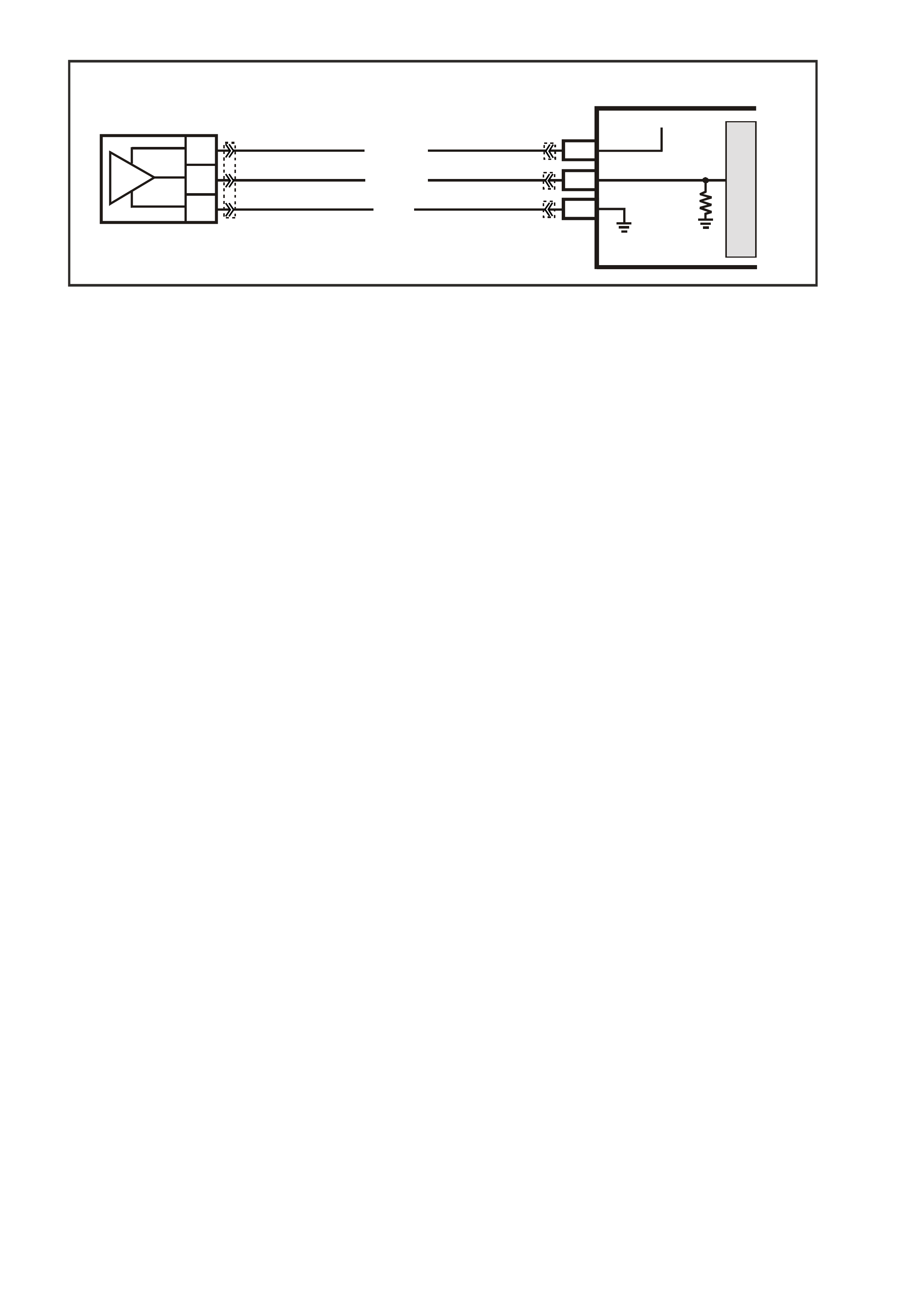
GEN III V8 PCM -
DTC P0522 ENGINE OIL PRESSURE SENSOR LOW VOLTAGE
CIRCUIT DESCRIPTION
The Engine Oil Pressure Sensor is mounted in the top rear of the engine. The Engine Oil Pressure Sensor
meas ures c hanges in engine oil pres sur e. The Engine O il Press ure Sensor has a 5.0 volt referenc e, an earth and a
signal circuit.
The Engine Oil Pressure Sensor changes resistance based on engine oil pressure.
The Engine Oil Pressure Sensor is used to determine when the oil level is below a certain threshold. W hen the oil
pressure reaches a predetermined value, the PCM will determine this as low oil pressure. The PCM will then send
a serial data message to the Instrument Panel (IP) cluster to turn ON the Low Oil Warning lamp.
When the PCM senses a signal voltage lower than the normal operating range of the sensor, this DTC will set.
CONDITIONS FOR RUNNING THE DTC
• Engine running.
CONDITIONS FOR SETTING THE DTC
• Engine Oil Pressure Sensor voltage is less than 0.48 volts.
ACTION TAKEN WHEN THE DTC SETS
• The PCM illuminates the Check Powertrain Lamp when the diagnostic runs and fails.
• The PCM records the operating conditions at the time the diagnostic fails. The PCM stores this information in
the Freeze Frame/Failure Records.
• Oil warning lamp will illuminate.
CONDITIONS FOR CLEARING THE CPL/DTC
• The PCM battery voltage is interrupted.
• A last test failed (Current DTC) will not clear when the diagnostic runs and does not fail.
• Use a scan tool to in order to clear the CPL/DTC.
DIAGNOSTIC AIDS
NOTE: Remove any debris from the PCM module connector surfaces before servicing the PCM module. Inspect
the PCM module connector when diagnosing/ replacing the modules. Ensure that the connectors are installed
correctly.
• The following may cause an intermittent:
- Incorrectly routed harness
- Rubbed through wire insulation
- Broken wire inside the insulation
• The PCM 5.0 volt ref erenc e circ uits are inter nally c onnected within the PCM. If all the Engine Oil sensor circuits
check to be OK, inspect related 5.0 volt reference circuits.
• If there is a failure with the Oil W arning Lamp, more than likely it is either a faulty bulb or a instrument cluster
fault.
G3PCM008PT
OIL
PRESSURE
SENSOR
PCM
J2-58
J1-63
J1-07
SENSOR EARTH
OIL PRESSURE
SENSOR SIGNAL
5V
BLU/Y (334)
YE122
YE123
YE122YE32
G (335)
BR/W (331)
M
I
C
R
O
C
B
A
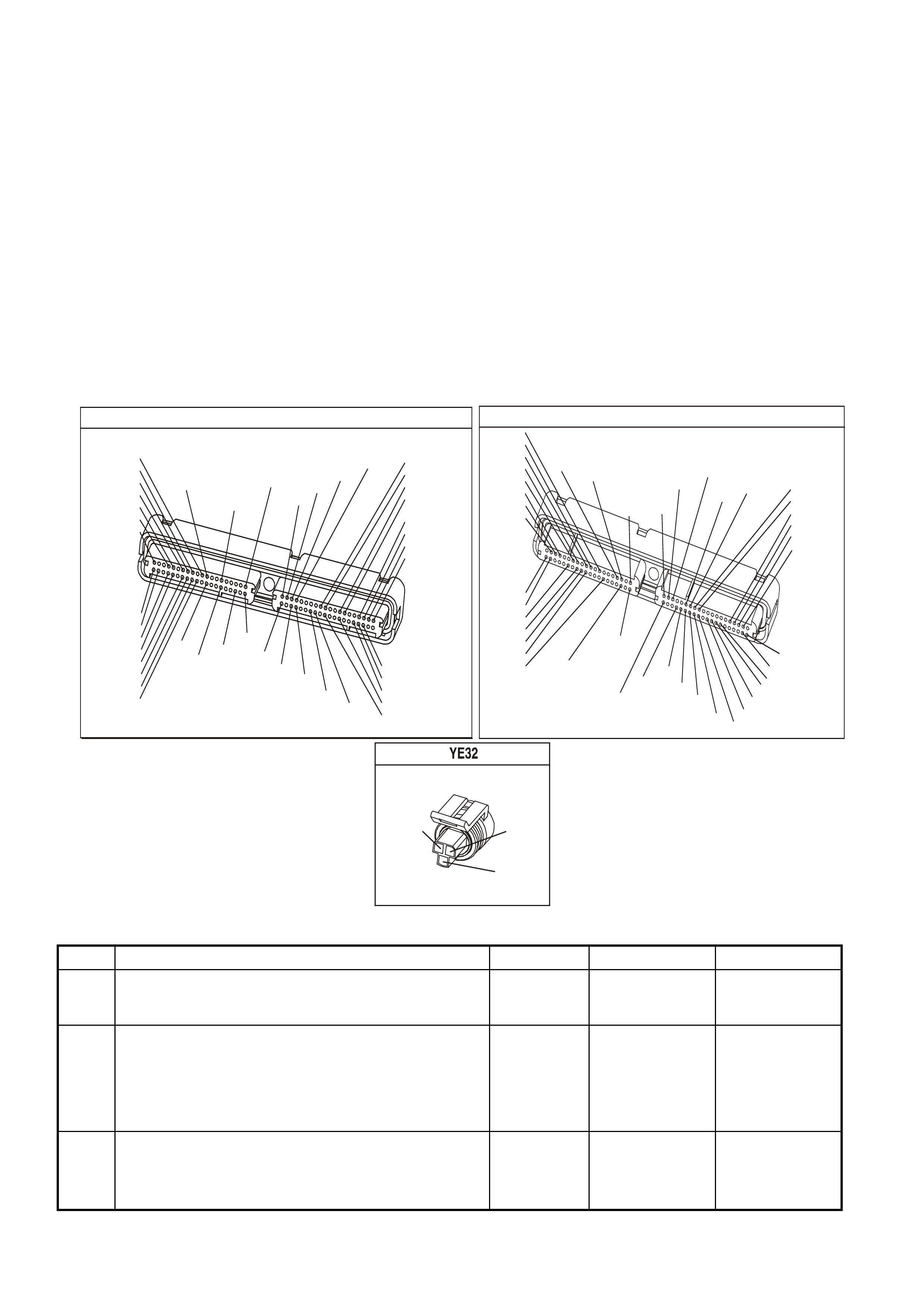
TEST DESCRIPTION
The numbers below refer to the step numbers on the diagnostic table.
3. This step determines if the malfunction is present. For any test that requires probing of the PCM or any
component harness connectors, use the Connector Test Adapter Kit J 35616-A. Using this kit prevents damage
to the harness connector terminals.
4. Using the Freeze Frame/Failure Records data may aid in locating an intermittent condition. If you cannot
duplicate the DTC, the information included in the Freeze Frame/Failure Records data can help determine the
distance traveled since the DTC set. The Fail Counter and Pass Counter can also help determine how many
ignition cycles the diagnostic reported a pass and/or a fail. Operate the vehicle within the same Freeze Frame
conditions (RPM, load, vehicle speed temperature etc.) that you observed. This will isolate when the DTC failed.
5. If the Tech 2 scan tool displays 5.0 volts, this indicates that the Engine Oil Pressure sensor signal 5.0 volt
reference circuit and PCM are OK.
6. If the Tech 2 scan tool displays 5.0 volts, this indicates that the Engine Oil Pressure sensor signal circuit and the
PCM are OK.
7. Disconnecting the PCM allows using the DMM J 39200 to check the continuity of the circuits. This aids in
locating an open or shorted circuit.
P.C.M CONNECTOR 1
YE122
(776)
(1049)
(897)
(1230)
(848)
(1226)
(772)
(647)
(632)
40
(844)
(815)
80
J1
P/B
(845)
V/W
BLU
O
(633)
(846)
B/Y
B/R
(416)
(86)
(69)
(455)
(740)
GY
BR
G
GY
(646)
(410)
GY
(842)
(1225)
V
Y
(750)
P
41
O
(774)
BR/Y
BLU
Y
B/R
B
BLU/Y
(841)
BLUE
(414)
G/W
BLU
LG
LBLU/B
1
(847)
(415)
(740)
(452)
BLU
BR
Y
(750)
(826)
(421)
Y
V/W
B/W
(334)
(771)
(39)
Y
R/W
LBLU
W
BLU/W
(843)
(643)
LBLU/W
G
GY/B
BLU/B
(413)
(1413)
(1412)
(412)
GY
V
GY/B
G
(335)
YE123
P.C.M CONNECTOR 2
(750)
(1228)
(1229)
(465)
(121)
(259)
G/B
BR
G/W
GY/BLU
R
B/R
(418)
BR
(59)
(832)
G
T
(831)
(417)
(472)
(976)(974)
(432)
(428)
(631)
BLUBR G/Y
BLU/W
LG
BR/W
W/B
LG W
(977)
Y
(971)
BLU/WW
B/R
(750)
(304)
(792)
(1223)
(1222)
(123)
(1227)
(469)
(331)
Y/B
LG
V/W
B/Y
G/OBR/W
(1687)
GY/B
(366)
LG/B
GY/R
(422)
V
(442)
(444)
(443)
(975)
(972)
(978)
(1224)
(973)
(959)
LG/W
LG/B
LBLU/B
GY
(773)
BR/Y
BLU
G
Y/B
LBLU
(958)
BR
(441)
LBLU
1
41
40
80
J2
RED
Y
(838)
OIL PRESSURE SENSOR
(335)
(334)
(331)
G
BLU/Y
BR/W
GEN III V8 PCM - DTC P0522 ENGINE OIL PRESSURE SENSOR LOW VOLTAGE
Step Action Value(s) Yes No
1 Did you perform the Powertrain On-Board Diagnostic
(OBD) System Check? Go to Step 2 Go to Powertrain
OBD System
Check Table
2 1. Install the Tech 2 scan tool.
2. Idle the engine.
3. Monitor the Failed This Ignition under DTC Status for
DTC P1635 using the Tech 2 scan tool.
Did DTC P1635 fail this ignition cycle?
Go to DTC
P1635 5 Volt
Reference #1
Circuit
Go to Step 3
3 Idle the engine and monitor the Engine Oil Pressure
voltage using the Tech 2 scan tool.
Is the Engine Oil Pressure voltage at or below the
specified value?
0.48V Go to Step 5 Go to Step 4

GEN III V8 PCM - DTC P0522 ENGINE OIL PRESSURE SENSOR LOW VOLTAGE (CONTINUED)
Step Action Value(s) Yes No
4 1. Turn ON the ignition leaving the engine OFF.
2. Review the Freeze Frame/Failure Records data for
this DTC and observe parameters.
3. Turn OFF the ignition for 15 seconds.
4. Operate the vehicle within the conditions required for
this diagnostic to run, and as close to the conditions
recorded in the Freeze Frame/Failure Records as
possible. Special operating conditions that you need to
meet before the PCM will run this diagnostic, where
applicable, are listed in Conditions for Running the
DTC.
5. Select the Diagnostic Trouble Code (DTC) option, the
DTC Information option and The Failed This Ignition
option using the Tech 2 scan tool.
Does the Tech 2 scan tool indicate that this diagnostic
failed this ignition.
Go to Step 5 Go to
Diagnostic Aids
5 1. Disconnect the Engine Oil Pressure sensor electrical
connector.
2. Jumper the 5.0 volt reference circuit and the engine oil
pressure signal circuit together at the Engine Oil
Pressure sensor harness connector.
3. Observe the Engine Oil Pressure voltage display on
the Tech 2 scan tool.
Is the Engine Oil Pressure voltage near the specified
value?
5.0V Go to Step 11 Go to Step 6
6 1. Connect a test lamp J 34142-B Between B+ and the
Engine Oil Pressure sensor signal circuit at the Engine
Oil Pressure sensor harness connector.
2. Observe the Engine Oil Pressure voltage display on
the Tech 2 scan tool.
Is the Engine Oil Pressure voltage at the specified value?
5.0V Go to Step 7 Go To Step 9
7 1. Turn OFF the ignition.
2. Disconnect the BLUE PCM connector.
3. Check the 5.0 volt reference circuit for an open or
short to earth.
4. Repair the 5.0 volt reference circuit if it is open or
shorted to earth.
Was the 5.0 volt reference circuit open or shorted to
earth?
Go to Step 13 Go to Step 8
8 1. Check the 5.0 volt reference circuit for a poor
connection at the PCM.
2. Replace the terminal if necessary.
Did the Terminal require replacement?
Go to Step 13 Go to Step 12
9 1. Turn OFF the ignition.
2. Disconnect the RED PCM connector.
3. Check the Engine Oil Pressure signal circuit for the
following:
• Open circuit
• Short to earth
• Short to sensor earth circuit.
4. Repair the Engine Oil Pressure sensor signal circuit if
it is open or shorted to earth.
Was the Engine Oil Pressure signal circuit open or
shorted to earth?
Go to Step 13 Go to Step 10

GEN III V8 PCM - DTC P0522 ENGINE OIL PRESSURE SENSOR LOW VOLTAGE (CONTINUED)
Step Action Value(s) Yes No
10 1. Check the Engine Oil Pressure Sensor signal circuit
for a poor connection at the PCM.
2. If you find a poor connection, replace the terminal.
Did the terminal require replacement?
Go to step 13 Go to Step 12
11 IMPORTANT: Before replacing the Engine Oil Pressure
sensor, perform an engine oil pressure check. Refer to
Section 6A3 Engine Mechanical in VX Service
Information.
Replace the Engine Oil Pressure sensor.
Is the action complete?
Go to Step 13
12 1. Replace PCM.
2. Refer to Section 6C3-3 Service Operations, of the VX
Series Service Information, for PCM Programming and
PCM/PIM/BCM Security Link Procedure.
Is action complete?
Go to Step 13
13 1. Select the Diagnostic Trouble Code (DTC) option and
the Clear DTC option using the Tech 2 scan tool.
2. Idle the engine at the normal operating temperature.
3. Select the Diagnostic Trouble Code (DTC) option, the
DTC Information option and The Failed This Ignition
option using the Tech 2 scan tool.
4. Operate vehicle, within the Conditions for Running this
DTC, as specified in the supporting text, if applicable.
Does the Tech 2 scan tool indicate that this DTC reset?
Go to Step 2 Go to Step 14
14 Using the Tech 2 scan tool, check for any other DTCs.
Does the Tech 2 scan tool display any DTCs that you
have not diagnosed?
Go to the
applicable DTC
table
System OK
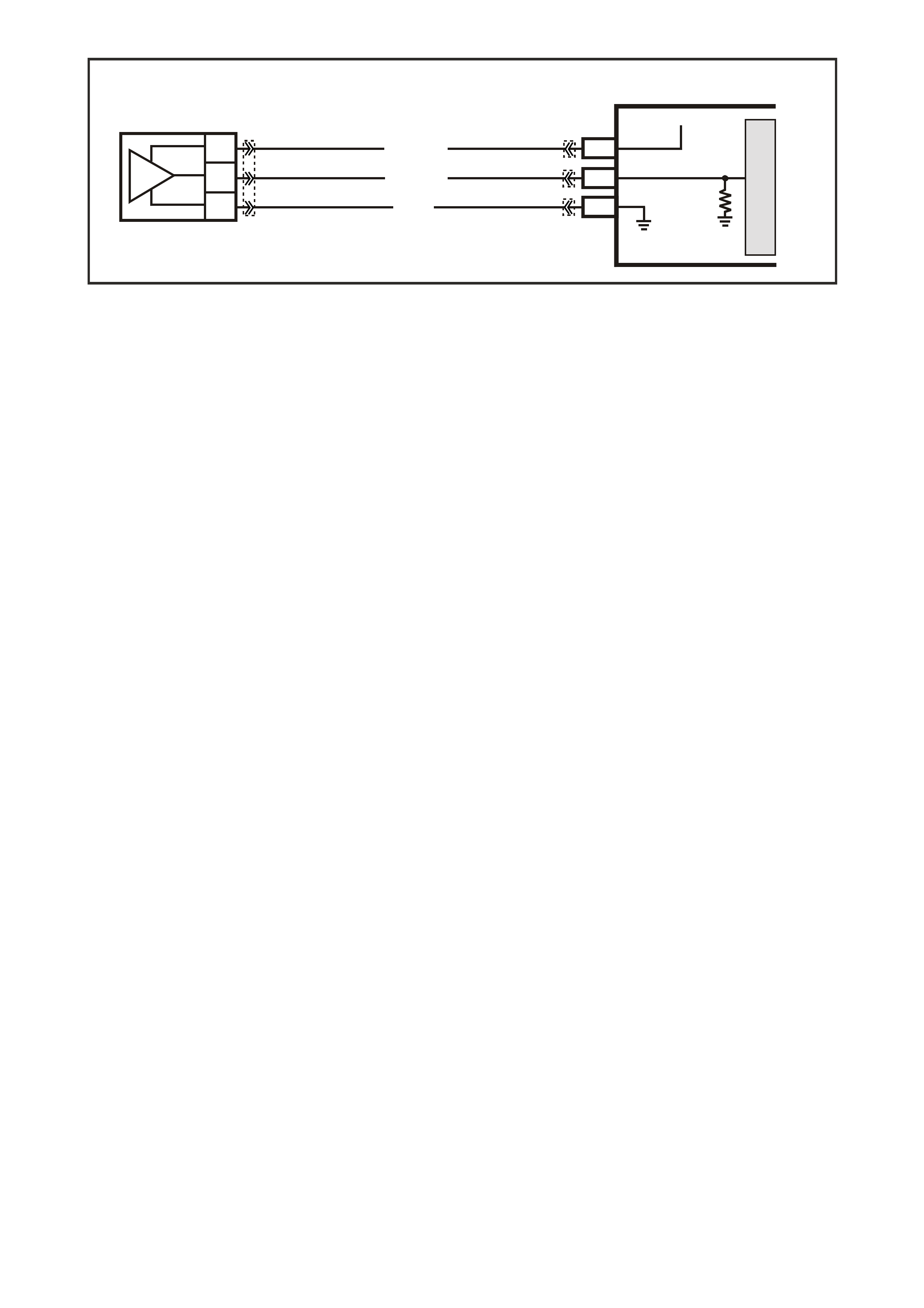
GEN III V8 PCM -
DTC P0523 ENGINE OIL PRESSURE SENSOR HIGH VOLTAGE
CIRCUIT DESCRIPTION
The Engine Oil Pressure Sensor is mounted in the top rear of the engine. The Engine Oil Pressure Sensor
meas ures changes in engine oil pressure . The Engine Oil Press ure Sensor has a 5.0 volt ref erence, a earth and a
signal circuit.
The Engine Oil Pressure Sensor changes resistance based on engine oil pressure.
The oil pr essure sensor is used to determ ine when the oil level is below a certain thres hold. When the oil pr essure
reaches a predetermined value, the PCM will determine this as low oil pressure. The PCM will then send a serial
data message to the instrument panel (IP) cluster to turn ON the Low Oil Warning lamp.
When the PCM senses a signal voltage higher than the normal operating range of the sensor, this DTC will set.
CONDITIONS FOR RUNNING THE DTC
• Engine running.
CONDITIONS FOR SETTING THE DTC
• Engine Oil Pressure Sensor voltage is greater than 4.5 volts.
ACTION TAKEN WHEN THE DTC SETS
• The PCM illuminates the Check Powertrain Lamp when the diagnostic runs and fails.
• The PCM records the operating conditions at the time the diagnostic fails. The PCM stores this information in
the Freeze Frame/Failure Records.
• Oil warning lamp will illuminate.
CONDITIONS FOR CLEARING THE CPL/DTC
• The PCM battery voltage is interrupted.
• A last test failed (Current DTC) will not clear when the diagnostic runs and does not fail.
• Use a Tech 2 scan tool in order to clear the CPL/DTC.
DIAGNOSTIC AIDS:
NOTE: Remove any debris from the PCM module connector surfaces before servicing the PCM module. Inspect
the PCM module connectors when diagnosing/replacing the modules. Ensure that the connectors are installed
correctly.
The following may cause an intermittent:
- Incorrectly routed harness
- Rubbed through wire insulation
- Broken wire inside the insulation
• The PCM 5.0 volt ref erenc e circ uits are inter nally c onnected within the PCM. If all the Engine Oil sensor circuits
check to be OK, inspect related 5.0 volt reference circuits. Refer to DTC P1635.
• If there is a failure with the Oil Warning Lamp, more than likely it is either a faulty bulb or a IP cluster problem.
G3PCM008PT
OIL
PRESSURE
SENSOR
PCM
J2-58
J1-63
J1-07
SENSOR EARTH
OIL PRESSURE
SENSOR SIGNAL
5V
BLU/Y (334)
YE122
YE123
YE122YE32
G (335)
BR/W (331)
M
I
C
R
O
C
B
A
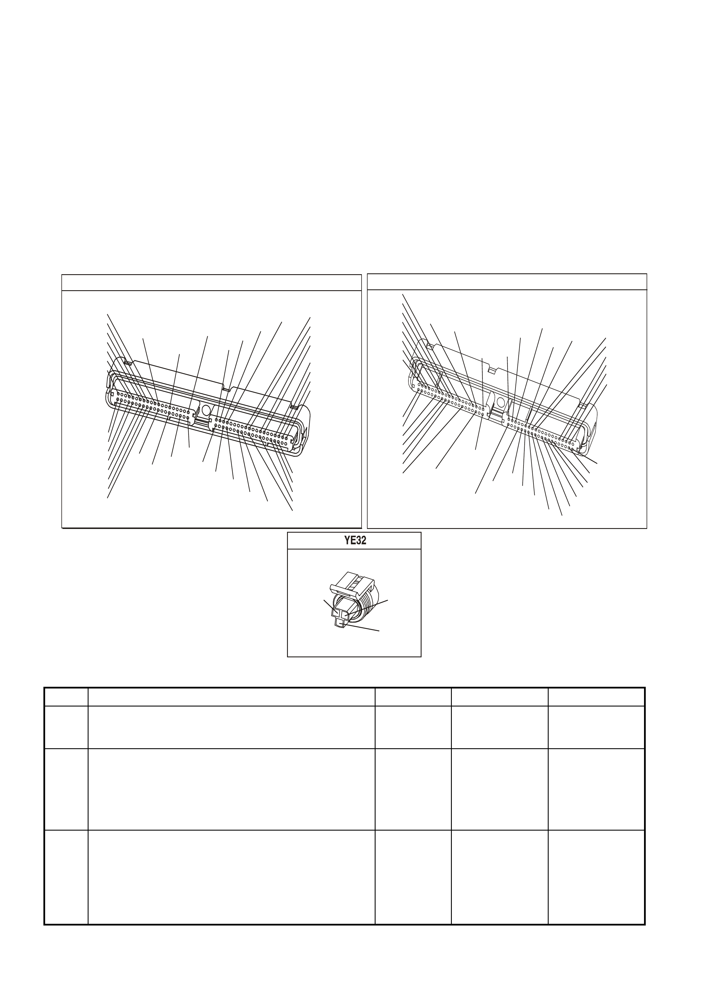
TEST DESCRIPTION
The numbers below refer to the step numbers on the diagnostic table.
3. This step determines if the malfunction is present. For any test that requires probing of the PCM or any
component harness connectors, use the Connector Test Adapter Kit J 35616-A. Using this kit prevents damage
to the harness connector terminals.
4. Using the Freeze Frame/Failure Records data may aid in locating an intermittent condition. If you cannot
duplicate the DTC, the information included in the Freeze Frame/Failure Records data can help determine the
distance traveled since the DTC set.
The Fail Counter and Pass Counter can also help determine how many ignition cycles the diagnostic reported
a pass and/or a fail. Operate the vehicle within the same Freeze Frame conditions (RPM, load, vehicle speed
temperature etc.) that you observed. This will isolate when the DTC failed.
5 This step checks if the signal circuit is shorted to a voltage.
6 This step checks if an earth circuit is available at the Engine Oil Pressure sensor.
P.C.M CONNECTOR 1
YE122
(776)
(1049)
(897)
(1230)
(848)
(1226)
(772)
(647)
(632)
40
(844)
(815)
80
J1
P/B
(845)
V/W
BLU
O
(633)
(846)
B/Y
B/R
(416)
(86)
(69)
(455)
(740)
GY
BR
G
GY
(646)
(410)
GY
(842)
(1225)
V
Y
(750)
P
41
O
(774)
BR/Y
BLU
Y
B/R
B
BLU/Y
(841)
BLUE
(414)
G/W
BLU
LG
LBLU/B
1
(847)
(415)
(740)
(452)
BLU
BR
Y
(750)
(826)
(421)
Y
V/W
B/W
(334)
(771)
(39)
Y
R/W
LBLU
W
BLU/W
(843)
(643)
LBLU/W
G
GY/B
BLU/B
(413)
(1413)
(1412)
(412)
GY
V
GY/B
G
(335)
YE123
P.C.M CONNECTOR 2
(750)
(1228)
(1229)
(465)
(121)
(259)
G/B
BR
G/W
GY/BLU
R
B/R
(418)
BR
(59)
(832)
G
T
(831)
(417)
(472)
(976)(974)
(432)
(428)
(631)
BLUBR G/Y
BLU/W
LG
BR/W
W/B
LG W
(977)
Y
(971)
BLU/WW
B/R
(750)
(304)
(792)
(1223)
(1222)
(123)
(1227)
(469)
(331)
Y/B
LG
V/W
B/Y
G/OBR/W
(1687)
GY/B
(366)
LG/B
GY/R
(422)
V
(442)
(444)
(443)
(975)
(972)
(978)
(1224)
(973)
(959)
LG/W
LG/B
LBLU/B
GY
(773)
BR/Y
BLU
G
Y/B
LBLU
(958)
BR
(441)
LBLU
1
41
40
80
J2
RED
Y
(838)
OIL PRESSURE SENSOR
(335)
(334)
(331)
G
BLU/Y
BR/W
GEN III V8 PCM - DTC P0523 ENGINE OIL PRESSURE SENSOR HIGH VOLTAGE
Step Action Value(s) Yes No
1 Did you perform the Powertrain On-Board Diagnostic
(OBD) System Check? Go to Step 2 Go to Powertrain
OBD System
Check Table
2 1. Install the Tech 2 scan tool.
2. Idle the engine.
3. Monitor the Failed This Ignition under DTC Status for
DTC P1635 using the Tech 2 scan tool.
Did DTC P1635 fail this ignition cycle?
Go to DTC
P1635 5 Volt
Reference #1
Circuit
Go to Step 3
3 1. Install the Tech 2 scan tool
2. Idle the engine.
3. Monitor the Engine Oil Pressure sensor voltage on the
Tech 2 scan tool.
Is the Engine Oil Pressure sensor voltage above
specified value?
4.5V Go to Step 5 Go to Step 4

GEN III V8 PCM - DTC P0523 ENGINE OIL PRESSURE SENSOR HIGH VOLTAGE (CONTINUED)
Step Action Value(s) Yes No
4 1. Turn ON the ignition leaving the engine OFF.
2. Review the Freeze Frame/Failure Records data for
this DTC and observe parameters.
3. Turn OFF the ignition for 15 seconds.
4. Start the engine and operate the vehicle within the
conditions required for this diagnostic to run, and as
close to the conditions recorded in the Freeze
Frame/Failure Records as possible. Special operating
conditions that need to meet before the PCM will run
this diagnostic, where applicable, are listed in
Conditions for Running the DTC.
5. Select the Diagnostic Trouble Code (DTC) option, the
DTC Information option and The Failed This Ignition
option using the Tech 2 scan tool.
Does the Tech 2 scan tool indicate that this diagnostic
failed this ignition.
Go to Step 5 Go to
Diagnostic Aids
5 1. Disconnect the Engine Oil Pressure sensor electrical
connector.
2. Observe the Engine Oil Pressure voltage display on
the Tech 2 scan tool.
Is the Engine Oil Pressure voltage near the specified
value?
1.0V Go to Step 6 Go to Step 7
6 Probe the sensor earth circuit with a test lamp J 34142-B
to B+.
Is the Test lamp illuminated?
Go to Step 8 Go To Step 9
7 1. Check the Engine Oil Pressure signal circuit for a
short to voltage or a short to the 5.0 volt reference
circuit.
2. Repair the Engine Oil Pressure Sensor signal circuit if
it is shorted.
Was the Engine Oil Pressure sensor signal circuit
shorted?
Go to Step 14 Go to Step 12
8 Measure the voltage at the 5.0 volt reference circuit to
earth using a DMM J 39200.
Is the voltage greater than the specified value?
5.0V Go to Step 13 Go to Step 9
9 1. Check for a poor sensor earth terminal connection at
the PCM connector.
2. If you find a problem, replace the faulty terminal.
Did the terminal require replacement?
Go to Step 14 Go to Step 10
10 1. Check the continuity of the Engine Oil Pressure
sensor earth circuit.
2. If you find a that the Engine Oil Pressure sensor earth
circuit measures over the specified value, repair the
open or the poor connection.
Was a condition found and corrected?
Go to step 14 Go to Step 11
11 1. Replace PCM.
2. Refer to Section 6C3-3 of the VX Series Service
Information for PCM Programming and
PCM/PIM/BCM Security Link Procedure.
Is action complete?
Go to Step 14
12 IMPORTANT: Before replacing the Engine Oil Pressure
sensor, perform the engine oil pressure check. Refer to
Section 6A3 Engine Mechanical in VX Service
Information.
Replace the Engine Oil Pressure sensor.
Is the action complete?
Go to Step 14

GEN III V8 PCM - DTC P0523 ENGINE OIL PRESSURE SENSOR HIGH VOLTAGE (CONTINUED)
Step Action Value(s) Yes No
13 Repair the 5.0 volt reference circuit for a short to voltage.
Is action complete? Go to Step 14
14 1. Select the Diagnostic Trouble Code (DTC) option and
the Clear DTC option using the Tech 2 scan tool.
2. Idle the engine at the normal operating temperature.
3. Select the Diagnostic Trouble Code (DTC) option, the
DTC Information option The Failed This Ignition option
using the Tech 2 scan tool.
4. Operate vehicle, within the Conditions for Running this
DTC, as specified in the supporting text, if applicable.
Does the Tech 2 scan tool indicate that this DTC reset?
Go to Step 2 Go to Step 15
15 Using the Tech 2 scan tool, check for any other DTCs.
Does the Tech 2 scan tool display any DTCs that you
have not diagnosed?
Go to the
applicable DTC
table
System OK
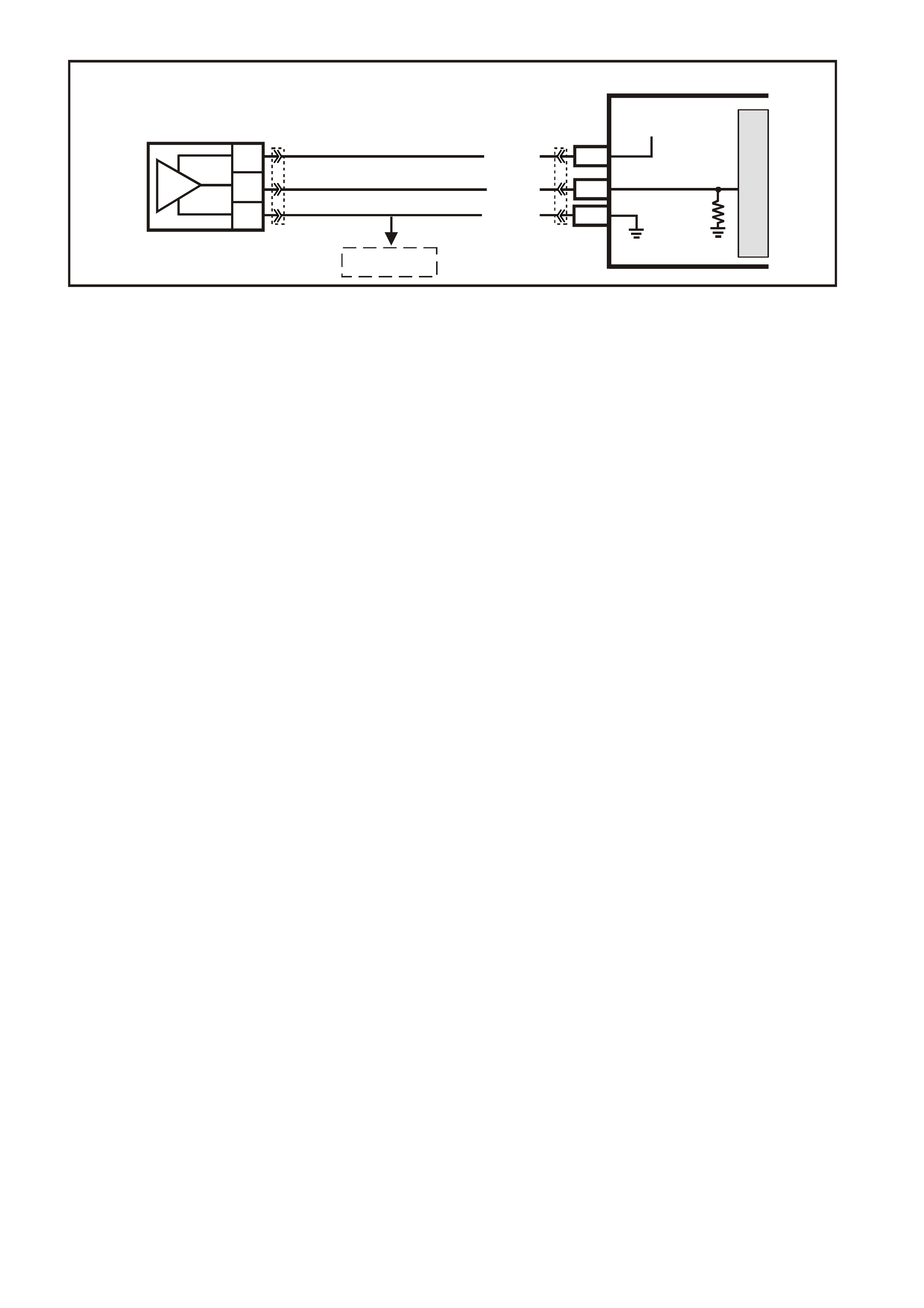
GEN III V8 PCM -
DTC P0530 A/ C REFRIGERANT PRESSURE SENSOR CIRCUIT
CIRCUIT DESCRIPTION
The A/C s ystem uses an A/C Ref rigerant Pressure Sensor m ounted in the high side of the A/C system to monitor
A/C refrigerant pressure. The PCM utilises this information in order to turn ON the engine coolant fans when the
A/C refrigerant pressure is high.
The A/C Refrigerant Pressure Sensor operates much like other 3-wire sensors. The PCM supplies a 5.0 volt
reference to the sensor. The sensor supplies a signal circuit to the PCM. As the A/C pressure increases or
decreases, the resistance of the sensor changes and varies the amount of signal returning to the PCM.
The PCM m onitor s the A/C Refriger ant Pres sure Sens or signal c ircuit a nd can d etermine when the A/C pres sur e is
too high or too lo w. T he PCM dis ables the A/C c ompress or clutch and sets a DTC P0530 when the pr essures are
out of range ( high or lo w) f or a predeter m ined tim e. The PCM d isables the A/C c om pr essor in or der to pre vent A/C
compressor damage.
CONDITIONS FOR RUNNING THE DTC
• The PCM detects an A/C request.
CONDITIONS FOR SETTING THE DTC
• A/C refrigerant pressure Sensor indicates A/C refrigerant pressure is at or below 25 kPa for five seconds.
OR
• A/C refrigerant pressure Sensor indicates A/C refrigerant pressure is at or above 3140 kPa for five seconds.
ACTION TAKEN WHEN THE DTC SETS
• The PCM stores the DTC information into memory when the diagnostic runs and fails.
• The Check Powertr ain Lam p will not be il luminated.
• The PCM records the operating conditions at the time the diagnostic fails. The PCM stores this information in
the Freeze Frame/Failure Records.
CONDITIONS FOR CLEARING THE CPL/DTC
• A last test failed (current DTC) clears when the diagnostic runs and does not fail.
• Use a Tech 2 scan tool in order to clear the CPL/DTC.
DIAGNOSTIC AIDS
• If the test did not f ail this i g nit ion cycle, m o ve the relat ed elec trical harn e ss and th e c onnec tors whi le monitoring
a Tech 2 scan tool.
• For an intermittent, refer to Section 6C3-2B Symp toms of the VX Series Service Information.
G3PCM001PT
PCM
M
I
C
R
O
J2-14
J2-57
A/C
PRESSURE
SENSOR
J1-45
SENSOR EARTH
A/C PRESSURE
SENSOR SIGNAL
5V
V/W (415)
YE122
YE123YE113
G/O (469)
G/B (259)
C
B
A
TO
IAT SENSOR
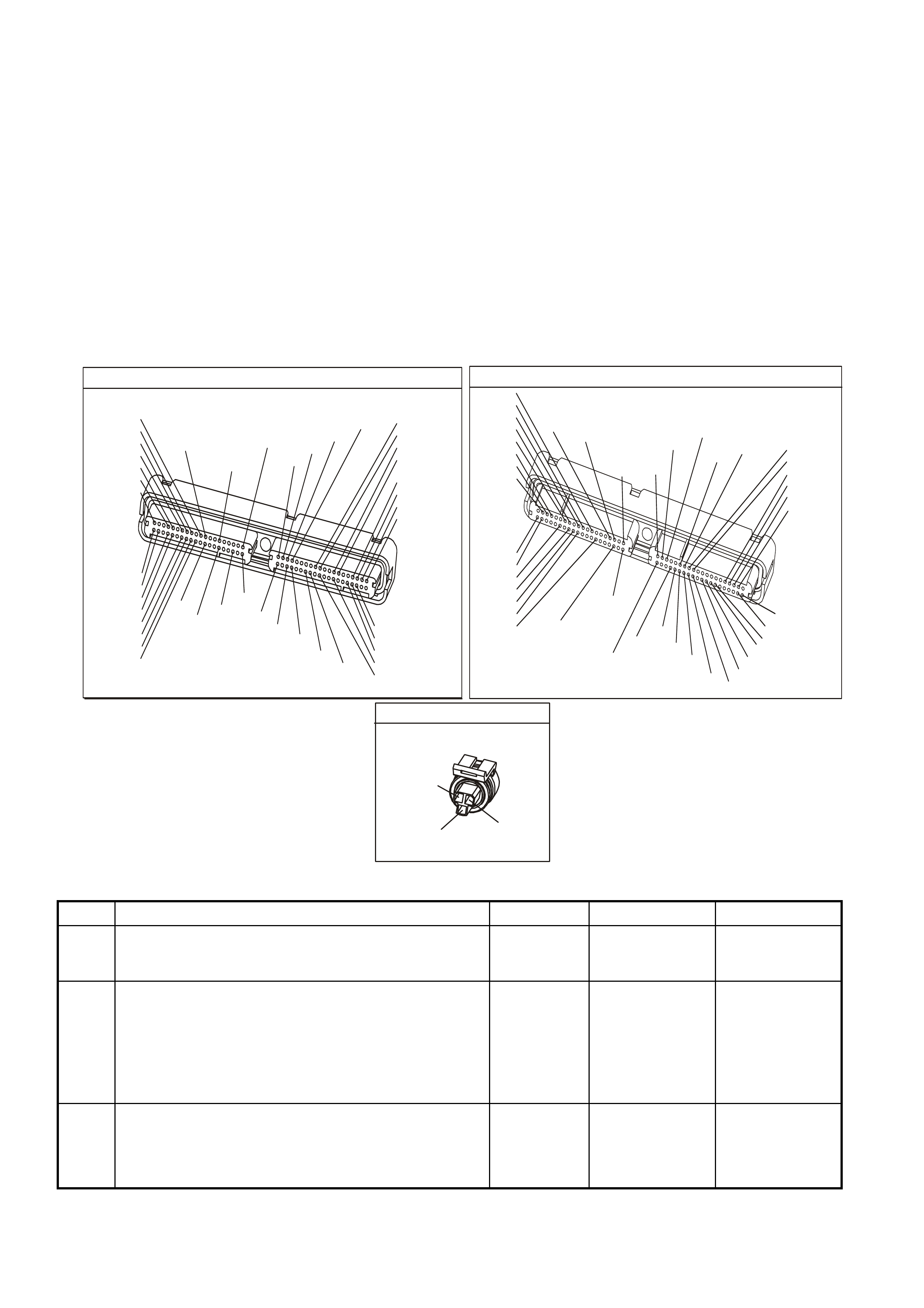
TEST DESCRIPTION
The numbers below refer to the step numbers on the diagnostic table.
3. The normal A/C pressure is between 700 and 1800 kPa. If the A/C pressure is within the range, review the
freeze frame data in order to determine when the DTC P0530 set.
5. If the A/C pressure/voltage stays high after disconnecting the A/C Refrigerant Pressure Sensor electrical
connector, this indicates the signal circuit is shorted to a voltage.
7. This step checks for a good earth circuit.
8. This step checks the integrity of the A/C Refrigerant Pressure Sensor signal circuit.
11. If you have thoroughly checked the 5.0 volt reference circuit (for opens, shorts to earth, PCM connectors etc.)
and checks OK, then replace the PCM.
IMPORTANT:
Inspect the PCM engine earths for being secure and clean.
12. If you have thoroughly checked the earth circuit for opens and the PCM connections are OK, then replace the
PCM.
P.C.M CONNECTOR 1
YE122
(776)
(1049)
(897)
(1230)
(848)
(1226)
(772)
(647)
(632)
40
(844)
(815)
80
J1
P/B
(845)
V/W
BLU
O
(633)
(846)
B/Y
B/R
(416)
(86)
(69)
(455)
(740)
GY
BR
G
GY
(646)
(410)
GY
(842)
(1225)
V
Y
(750)
P
41
O
(774)
BR/Y
BLU
Y
B/R
B
BLU/Y
(841)
BLUE
(414)
G/W
BLU
LG
LBLU/B
1
(847)
(415)
(740)
(452)
BLU
BR
Y
(750)
(826)
(421)
Y
V/W
B/W
(334)
(771)
(39)
Y
R/W
LBLU
W
BLU/W
(843)
(643)
LBLU/W
G
GY/B
BLU/B
(413)
(1413)
(1412)
(412)
GY
V
GY/B
G
(335)
YE123
P.C.M CONNECTOR 2
(750)
(1228)
(1229)
(465)
(121)
(259)
G/B
BR
G/W
GY/BLU
R
B/R
(418)
BR
(59)
(832)
G
T
(831)
(417)
(472)
(976)(974)
(432)
(428)
(631)
BLUBR G/Y
BLU/W
LG
BR/W
W/B
LG W
(977)
Y
(971)
BLU/WW
B/R
(750)
(304)
(792)
(1223)
(1222)
(123)
(1227)
(469)
(331)
Y/B
LG
V/W
B/Y
G/OBR/W
(1687)
GY/B
(366)
LG/B
GY/R
(422)
V
(442)
(444)
(443)
(975)
(972)
(978)
(1224)
(973)
(959)
LG/W
LG/B
LBLU/B
GY
(773)
BR/Y
BLU
G
Y/B
LBLU
(958)
BR
(441)
LBLU
1
41
40
80
J2
RED
Y
(838)
A/C PRESSURE SENSOR
YE113
(469)
(415)
(259)
G/B B
V/W
GEN III V8 PCM - DTC P0530 A/C REFRIGERANT PRESSURE SENSOR CIRCUIT
Step Action Value(s) Yes No
1 Did you perform the Powertrain On-Board Diagnostic
(OBD) System Check? Go to Step 2 Go to Powertrain
OBD System
Check Table
2
1. Install the Tech 2 scan tool
2. Idle the engine.
3. Monitor the Failed This Ignition option, under DTC
information option, for DTC P1639 using the Tech 2
scan tool.
Did DTC P1639 Fail This Ignition cycle?
Go to DTC
P1639
5 Volt Reference
Circuit Table
Go to Step 3
3 1. Turn ON the ignition leaving the engine OFF.
2. Monitor the A/C High Side using the Tech 2 scan tool
Does the Tech 2 scan tool indicate the A/C High Side
between the specified range?
700-1800
kPa
0.1-1.8V
Go to Step 4 Go to Step 5

GEN III V8 PCM - DTC P0530 A/C REFRIGERANT PRESSURE SENSOR CIRCUIT (CONTINUED)
Step Action Value(s) Yes No
4 1. Turn ON the ignition leaving the engine OFF.
2. Review the Freeze Frame data and observe the
parameters.
3. Operate the vehicle, within the Freeze Frame
conditions as obs erv ed.
Did the test Fail This Ignition cycle while operating the
vehicle in the conditions that you observed?
Go to Step 5 Refer to
Diagnostic Aids
5 Disconnect the A/C Refrigerant Pressure Sensor
electrical con nect or.
Does the Tech 2 scan tool indicate the A/C High Side
less than the specified value?
700 kPa
1.0V Go to Step 6 Go to Step 10
6 Measure the voltage, from the A/C Refrigerant Pressure
Sensor 5.0 volt reference circuit, to the battery earth
using the DMM J 39200.
Is the voltage near the specified value?
5.0V Go to Step 7 Go to Step 11
7 Measure the voltage, from the A/C Refrigerant Pressure
Sensor 5.0 volt reference circuit to the earth circuit using
the DMM J39200.
Is the voltage at the specified value.
5.0V Go to Step 8 Go to Step 12
8 Jumper the 5.0 volt reference circuit to the A/C
Refrigerant Pressure Sensor signal circuit using a fused
jumper wire.
Does the Tech 2 scan tool indicate the A/C High Side
pressure/voltage at the specified value?
3152 kPa
5.0V Go to Step 9 Go to Step 13
9 Repair the faulty A/C Refrigerant Pressure Sensor
connection or faulty sensor.
Is the action complete?
Go to Step 14
10 Repair the short to voltage in the A/C Refrigerant
Pressure Sensor signal circuit.
Is the action complete?
Go to Step 14
11 IMPORTANT: Inspect the PCM engine earths for being
secure and clean.
Repair the 5.0 volt reference circuit to the A/C Refrigerant
Pressure Sensor.
Is the action complete?
Go to Step 14
12 Repair the earth circuit to the A/C Refrigerant Pressure
Sensor.
Is the action complete?
Go to Step 14
13 Repair the signal circuit to the A/C Refrigerant Pressure
Sensor.
Is the action complete?
Go to Step 14
14 1. Select the Diagnostic Trouble Code (DTC) option and
the Clear DTC Information option using the Tech 2
scan tool.
2. Idle the engine at the normal operating temperature.
3. Select the Diagnostic Trouble Code (DTC) option, the
DTC Information option and The Failed This Ignition
option using the Tech 2 scan tool.
4. Operate the vehicle, within the Conditions for Running
the DTC, as specified in the supporting text, if
applicable.
Does the Tech 2 scan tool indicate that this DTC reset?
Go to Step 2 Go to Step 15
15 Using the Tech 2 scan tool, check for any other DTCs.
Does the Tech 2 scan tool display any DTCs that you
have not diagnosed?
Go to the
applicable DTC
table
System OK

GEN III V8 PCM -
DTC P0562 SYSTEM VOLTAGE LOW
CIRCUIT DESCRIPTION
The PCM continuously monitors the system voltage. The system voltage information is taken from the PCM’s
ignition feed circuit. Voltages below 8.0 volts or above 17.1 volts cause improper system operation and/or
com ponent damage. T he PCM operates in a def ault mode if a PCM voltage DTC sets . If the s ystem voltage is low,
the PCM raises the idle s peed in order to increas e the generator output. The PCM disables most outputs to protect
the hardware if the s ystem voltage is high. A T ech 2 scan tool will not display data if system voltage is outside this
range. Use a DMM in order to monitor the system voltage in order to check to see if the fault is currently present.
CONDITIONS FOR RUNNING THE DTC
• The engine is running longer than ten seconds.
• The engine speed is greater than 1000 RPM.
• The vehicle speed is greater than 8 km/h.
CONDITIONS FOR SETTING THE DTC
• The PCM senses system voltage below 5.0 volts.
• All of the above conditions are present for five seconds.
ACTION TAKEN WHEN THE DTC SETS
• The PCM stores the DTC information into memory when the diagnostic runs and fails.
• The Check Powertrain Lamp will not be illuminated.
• The PCM will command a high idle speed.
• The transmission will default to third gear.
• The PCM will inhibit TCC operation.
• The PCM records the operating conditions at the time the diagnostic fails. The PCM stores this information in
the Freeze Frame/Failure Records.
CONDITIONS FOR CLEARING THE CPL/DTC
• A last test failed (current DTC) clears when the diagnostic runs and does not fail.
• Use a Tech 2 scan tool in order to clear the CPL/DTC.
G3PCM021PT
PCM
J1-20
J1-57
M
I
C
R
O
+-
BATTERY
FS
(1040) O (740)O/B (740)
O (740)
O (740)
J1-19 IGNITION
BATTERY
BATTERY
FJ
R (2H)
LOC . E 1
15a 15 50
30 OFF/ON
LOCK
ACC
IGN
START
IGNITION SWITCH
P (3)
YE122 YE112
YE123
YB44
YB44
F14 P (39)
J1-01
J1-40
J2-01
J2-40
LOC. E5/E15
EARTH
EARTH
EARTH
EARTH
B/R (750)
B/R (750)
B/R (750)
B/R (750)
F31
P/B (39)
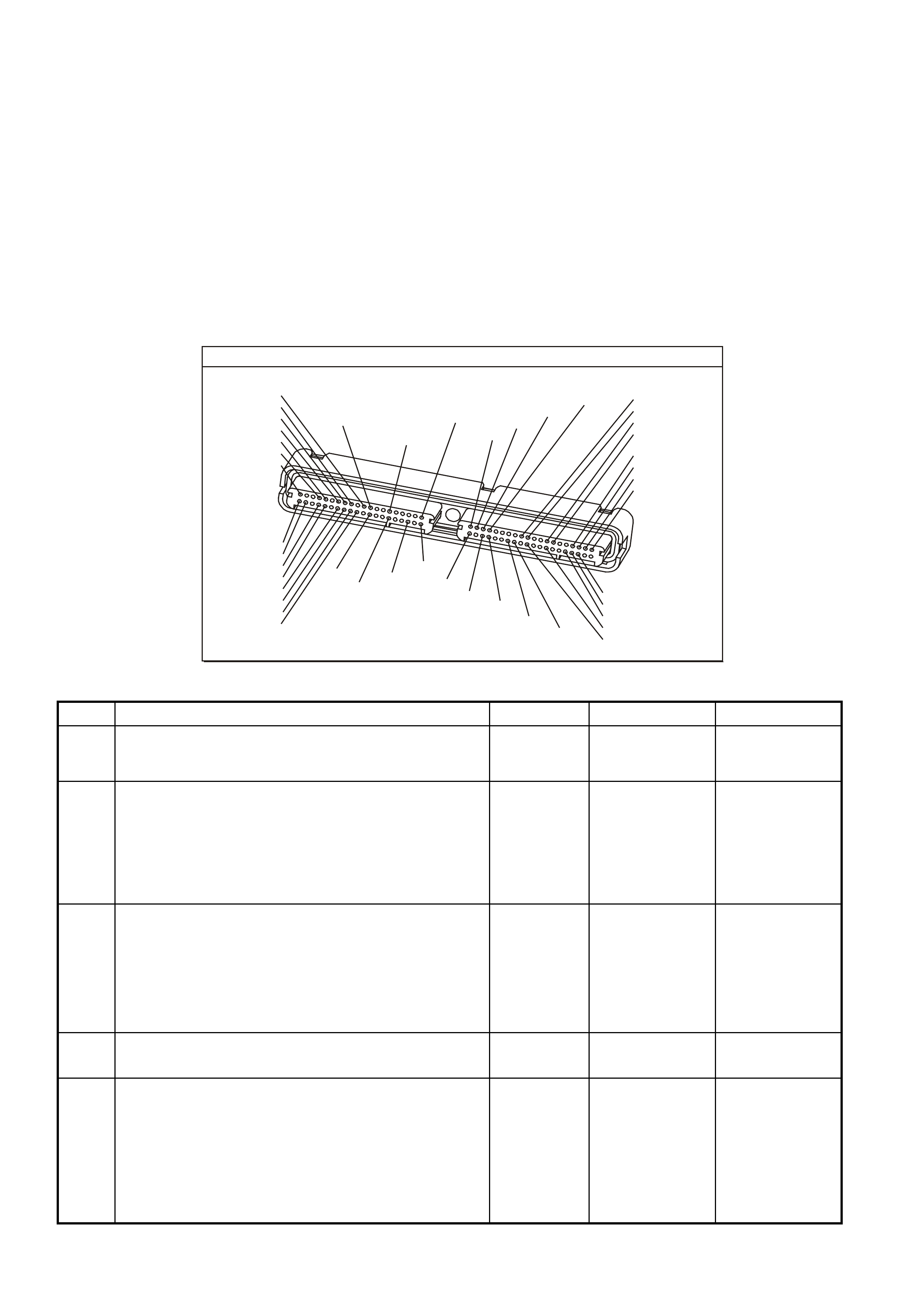
DIAGNOSTIC AIDS
• An extremely low voltage (below 7.5 volts) may cause the loss of serial data and the CPL may not function. An
open ignition feed circuit causes a No Start and the CPL will not illuminate. A low system voltage may cause
other DTCs to set.
• Using the Freeze Frame/Failure Records data may aid in locating an intermittent condition. If you cannot
duplicate the DTC, the information included in the Freeze Frame/Failure Records data can aid in determining
the distance traveled since the DTC reported a pass and/or fail. Operate the vehicle within the same freeze
frame conditions (RPM, load, vehicle speed, temperature, etc.) that you observed. This will isolate when the
DTC failed.
• For an intermittent, refer to Section 6C3-2B Symptoms, of the VX Series Service Information.
TEST DESCRIPTION
The numbers below refer to the step numbers on the diagnostic table.
2. This step checks the Charging system under load at idle. The voltage should remain above 8.0 volts.
P.C.M CONNECTOR 1
YE122
(776)
(1049)
(897)
(1230)
(848)
(1226)
(772)
(647)
(632)
40
(844)
(815)
80
J1
P/B
(845)
V/W
BLU
O
(633)
(846)
B/Y
B/R
(416)
(86)
(69)
(455)
(740)
GY
BR
G
GY
(646)
(410)
GY
(842)
(1225)
V
Y
(750)
P
41
O
(774)
BR/Y
BLU
Y
B/R
B
BLU/Y
(841)
BLUE
(414)
G/W
BLU
LG
LBLU/B
1
(847)
(415)
(740)
(452)
BLU
BR
Y
(750)
(826)
(421)
Y
V/W
B/W
(334)
(771)
(39)
Y
R/W
LBLU
W
BLU/W
(843)
(643)
LBLU/W
G
GY/B
BLU/B
(413)
(1413)
(1412)
(412)
GY
V
GY/B
G
(335)
GEN III V8 PCM - DTC P0562 SYSTEM VOLTAGE LOW
Step Action Value(s) Yes No
1 Did you perform the Powertrain On-Board Diagnostic
(OBD) System Check? Go to Step 2 Go to Powertrain
OBD System
Check Table
2
1. Start the engine.
2. Load the electrical system by turning ON the
headlights and the heater fan to High.
3. Measure the battery voltage at the battery using the
DMM J 39200.
Is the battery voltage less than the specified value?
8.0 V Go to Section
12A Battery &
Cables in VX
Service
Information
Go to Step 3
3 1. Turn OFF the ignition.
2. Disconnect the BLUE PCM connector.
3. Turn ON the ignition leaving the engine OFF.
4. Measure the voltage at the terminal for the ignition
feed circuit using the DMM J 39200.
Is the voltage less than the specified value?
8.0V Go to Step 7 Go to Step 4
4 Check for faulty connections at the PCM.
Did you find and correct the condition? Go to Step 8 Go to Step 5
5 1. Turn OFF the ignition.
2. Reconnect the PCM.
3. Turn ON the ignition leaving the engine OFF.
4. Monitor the Fail This Ignition option under the
Diagnostic Trouble Codes (DTC) option using the
scan tool.
Did this DTC fail this ignition?
Go to Step 6 DTC is
intermittent.
Go to
Diagnostic Aids.

GEN III V8 PCM - DTC P0562 SYSTEM VOLTAGE LOW (CONTINUED)
Step Action Value(s) Yes No
6 1. Replace PCM.
2. Refer to Section 6C3-3 Service Operations, of the VX
Series Service Information, for PCM Programming and
PCM/PIM/BCM Security Link Procedure.
Is action complete?
Go to Step 8
7 Repair the faulty ignition feed circuit to the PCM.
Is the action complete? Go to Step 8
8 1. Select the Diagnostic Trouble Code (DTC) option and
the Clear DTC Information option using the Tech 2
scan tool.
2. Idle the engine at the normal operating temperature.
3. Select the Diagnostic Trouble Code (DTC) option, the
DTC Information option and The Failed This Ignition
option using the Tech 2 scan tool.
4. Operate the vehicle within the Conditions for Running
the DTC, as specified in the supporting text, if
applicable.
Does the Tech 2 scan tool indicate that this DTC reset?
Go to Step 2 Go to Step 9
9 Using the Tech 2 scan tool, check for any other DTCs.
Does the Tech 2 scan tool display any DTCs that you
have not diagnosed?
Go to the
applicable DTC
table
System OK
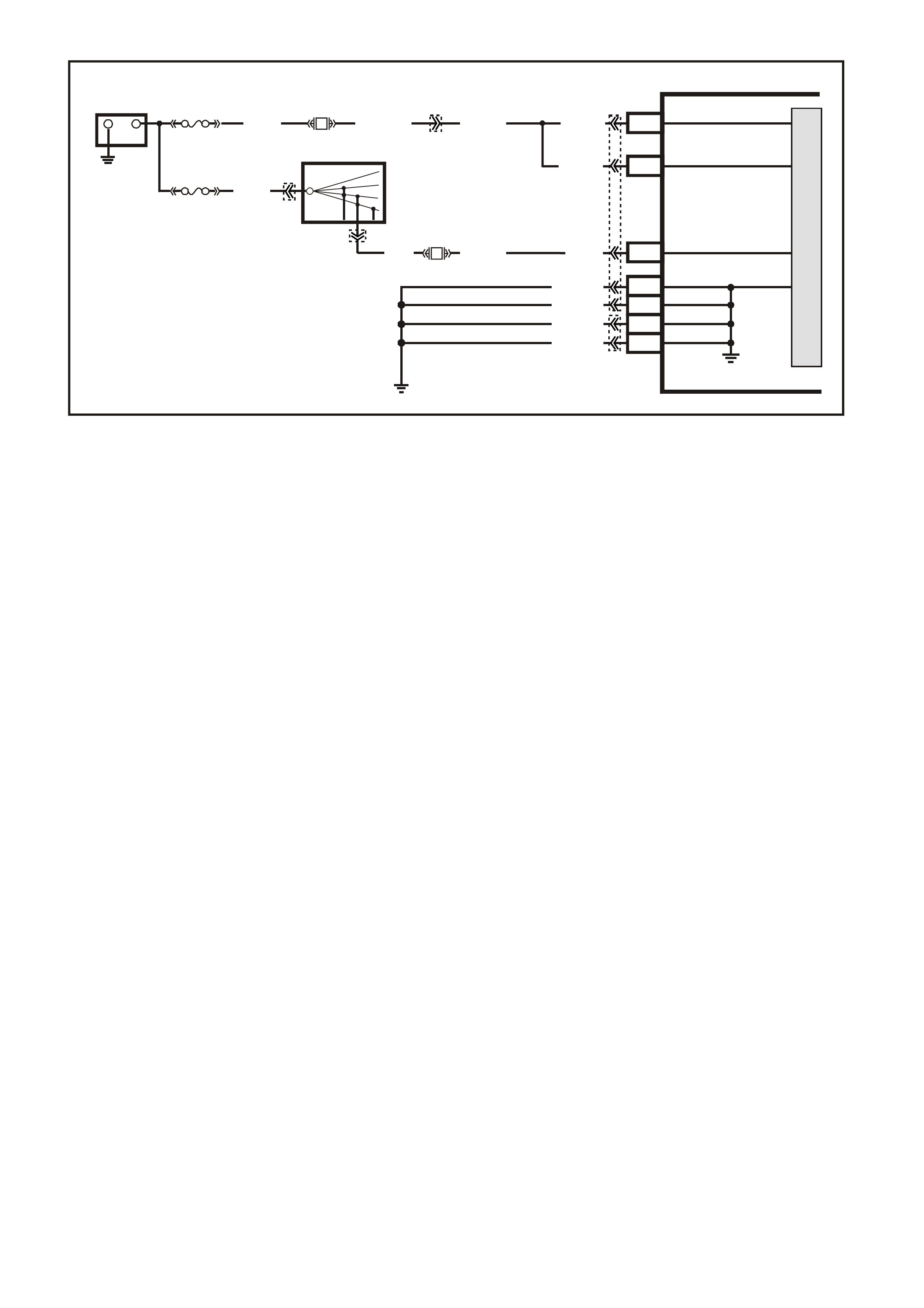
GEN III V8 PCM -
DTC P0563 SYSTEM VOLTAGE HIGH
CIRCUIT DESCRIPTION
The PCM continuously monitors the System Voltage. The System Voltage information is taken from the PCM’s
ignition feed circuit. Voltages below 8.0 volts or above 17.1 volts cause improper system operation and/or
com ponent damage. T he PCM operates in a def ault mode if a PCM voltage DTC sets . If the s ystem voltage is low,
the PCM raises the idle s peed in order to increas e the generator output. The PCM disables most outputs to protect
the hardware, if the system voltage is high. A Tec h 2 scan tool will not display data if system voltage is outs ide this
range. Use a DMM to monitor the system voltage to check if the fault is currently present.
CONDITIONS FOR RUNNING THE DTC
• The engine run time is longer than 10 seconds.
CONDITIONS FOR SETTING THE DTC
• The PCM senses system voltage above 17 volts.
• All of the above conditions are present for five seconds.
ACTION TAKEN WHEN THE DTC SETS
• The PCM stores the DTC information into memory when the diagnostic runs and fails.
• The Check Powertrain Lamp will not be illuminated.
• The PCM will disable most outputs.
• The transmission will default to third gear.
• The PCM will inhibit TCC operation.
• The PCM will cycle the cooling fans ON and OFF every few seconds during the time the condition is present.
• The PCM records the operating conditions at the time the diagnostic fails. The PCM stores this information in
the Freeze Frame/Failure Records.
CONDITIONS FOR CLEARING THE CPL/DTC
• A last test failed (current DTC) clears when the diagnostic runs and does not fail.
• Use a Tech 2 scan tool in order to clear the CPL/DTC.
DIAGNOSTIC AIDS
• Check the generator voltage sense circuit for high resistance or loose connections. These could cause an
intermittent overcharging condition.
Refer to Section 6D3 - 1 Charging System or Section 6D3 - 2 Starting System in the VT II Service Information.
• Using the Freeze Frame/Failure Records data may aid in locating an intermittent condition. If you cannot
duplicate the DTC, the information included in the Freeze Frame/Failure Records data can aid in determining
the distance traveled since the DTC reported a pass and/or fail. Operate the vehicle within the same freeze
frame conditions (RPM, load, vehicle speed, temperature, etc.) that you observed. This will isolate when the
DTC failed.
• For an intermittent, refer to Section 6C3-2B Symptoms, of the VX Series Service Information.
G3PCM021PT
PCM
J1-20
J1-57
M
I
C
R
O
+-
BATTERY
FS
(1040) O (740)O/B (740)
O (740)
O (740)
J1-19 IGNITION
BATTERY
BATTERY
FJ
R (2H)
LOC . E 1
15a 15 50
30 OFF/ON
LOCK
ACC
IGN
START
IGNITION SWITCH
P (3)
YE122 YE112
YE123
YB44
YB44
F14 P (39)
J1-01
J1-40
J2-01
J2-40
LOC. E5/E15
EARTH
EARTH
EARTH
EARTH
B/R (750)
B/R (750)
B/R (750)
B/R (750)
F31
P/B (39)

TEST DESCRIPTION
The numbers below refer to the step numbers on the diagnostic table.
2. This step checks for excessive generator output. The voltage should remain below 17.1 volts.
GEN III V8 PCM - DTC P0563 SYSTEM VOLTAGE HIGH
Step Action Value(s) Yes No
1 Did you perform the Powertrain On-Board Diagnostic
(OBD) System Check? Go to Step 2 Go to Powertrain
OBD System
Check Table
2
IMPORTANT: If DTC P1635 and/or P1639 are set, refer
to those DTCs for further diagnosis.
1. Turn OFF all the accessories.
2. Measure the battery voltage at the battery using the
DMM J 39200.
3. Operate the engine speed above 2000 RPM.
Is the battery voltage less than the specified value?
17.1 V Go to
Diagnostic Aids. Go to Step 3
3 Repair the Starting/Charging system.
Is the repair complete? Go to Step 4
4 1. Select the Diagnostic Trouble Code (DTC) option and
the Clear DTC Information option using the Tech 2
scan tool.
2. Idle the engine at the normal operating temperature.
3. Select the Diagnostic Trouble Code (DTC) option, the
DTC Information option and The Failed This Ignition
option using the Tech 2 scan tool.
4. Operate the vehicle, within the Conditions for Running
the DTC, as specified in the supporting text, if
applicable.
Does the Tech 2 scan tool indicate that this DTC reset?
Go to Step 2 Go to Step 5
5 Using the Tech 2 scan tool, check for any other DTCs.
Does the Tech 2 scan tool display any DTCs that you
have not diagnosed?
Go to the
applicable DTC
table
System OK
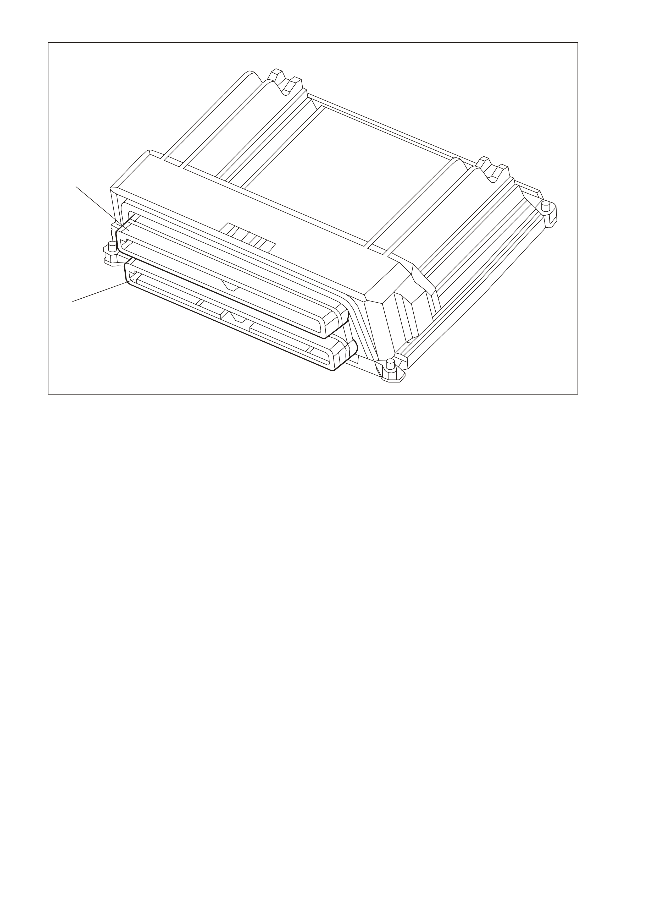
GEN3 0173
1
2
1. Connector J1 BLUE
2. Connector J2 RED
GEN III V8 PCM -
DTC P0601 POWERTRAIN CONTROL MODULE (PCM) MEMORY
CIRCUIT DESCRIPTION
The PCM EEPROM contains data which is essential to running the engine and transmission. The PCM
continuously checks the integrity of this data.
CONDITIONS FOR RUNNING THE DTC
• The ignition switch is in the crank position or the run position.
CONDITIONS FOR SETTING THE DTC
• The PCM is unable to correctly read data from the EEPROM (flash memory).
ACTION TAKEN WHEN THE DTC SETS
• The PCM illuminates the Check Powertrain Lamp when the diagnostic runs and fails.
• The PCM records the operating conditions at the time the diagnostic fails. The PCM stores this information in
the Freeze Frame/Failure Records.
CONDITIONS FOR CLEARING THE CPL/DTC
• A last test failed (Current DTC) clears when the diagnostic runs and does not fail.
• A History DTC clears after forty consecutive warm-up cycles, if this or any other emission related diagnostic
does not report any failures.
• Use a Tech 2 scan tool in order to clear the CPL/DTC.
DIAGNOSTIC AIDS
• Replace the PCM even if this DTC exists only in history.
• For an intermittent, refer to Section 6C3-2B Symptoms, of the VX Series Service Information.
TEST DESCRIPTION
The numbers below refer to the step numbers on the diagnostic table.
2. This DTC indicates an internal PCM problem.

GEN III V8 PCM - DTC P0601 POWERTRAIN CONTROL MODULE (PCM) MEMORY
Step Action Value(s) Yes No
1 Did you perform the Powertrain On-Board Diagnostic
(OBD) System Check? Go to Step 2 Go to Powertrain
OBD System
Check Table
2
1. Replace PCM.
2. Refer to Section 6C3-3 of the VX Series Service
Information for PCM Programming and
PCM/PIM/BCM Security Link Procedure.
Is action complete?
Go to Step 3
3 1. Select the Diagnostic Trouble Code (DTC) option and
the Clear DTC Information option using the Tech 2
scan tool.
2. Idle the engine at the normal operating temperature.
3. Select the Diagnostic Trouble Code (DTC) option, the
DTC Information option and The Failed This Ignition
option using the Tech 2 scan tool.
4. Operate the vehicle, within the Conditions for Running
the DTC, as specified in the supporting text, if
applicable.
Does the Tech 2 scan tool indicate that this DTC reset?
Go to Step 2 Go to Step 4
4 Using the Tech 2 scan tool, check for any other DTCs.
Does the Tech 2 scan tool display any DTCs that you
have not diagnosed?
Go to the
applicable DTC
table
System OK
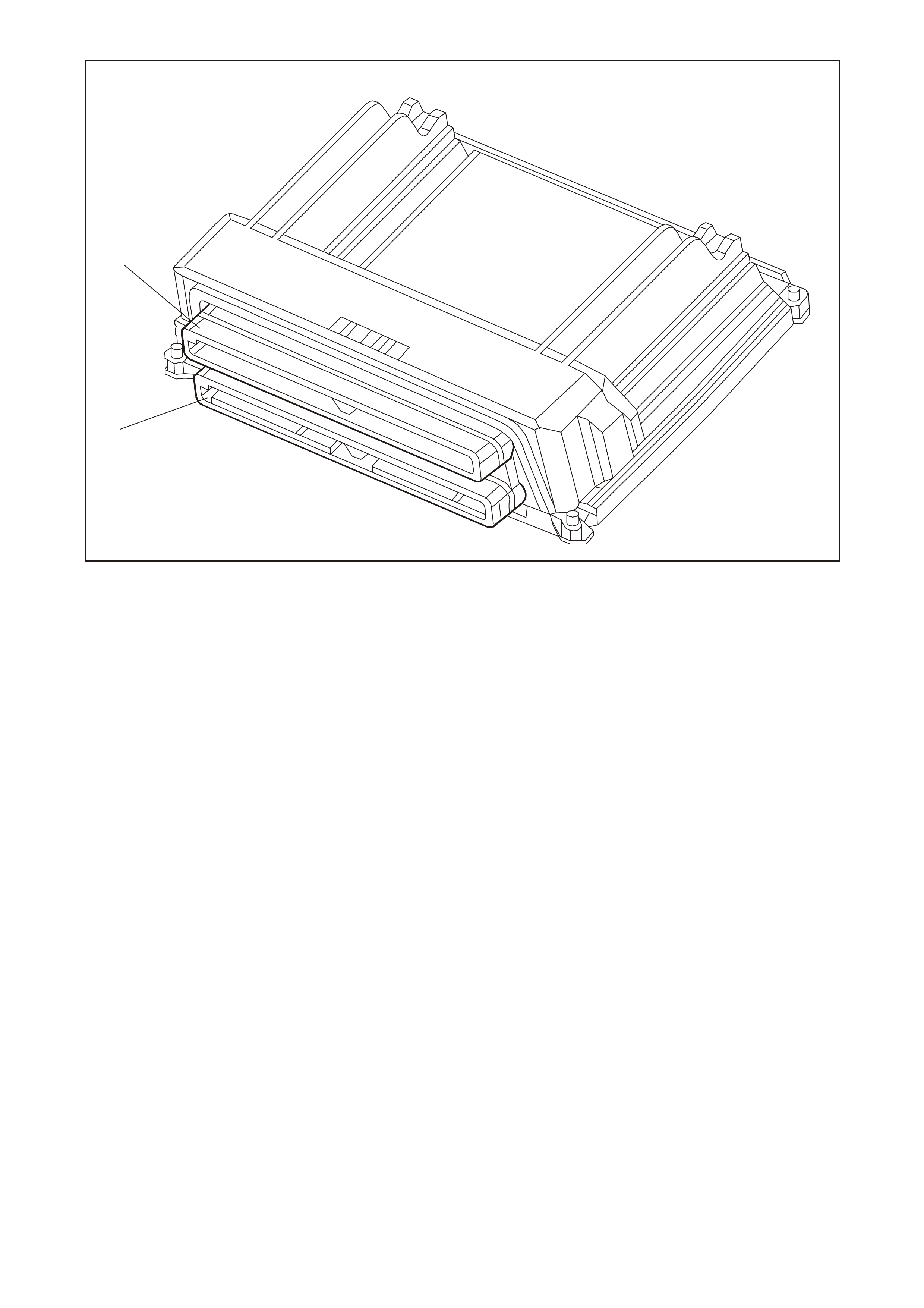
GEN3 0173
1
2
1. Connector J1 BLUE
2. Connector J2 RED
GEN III V8 PCM -
DTC P0602 POWERTRAIN CONTROL MODULE (PCM) NOT PROGRAMMED
CIRCUIT DESCRIPTION
This DTC indic ates that the PCMs inter nal EEPROM is not f lashed with any vehicle software. If you install a service
PCM and do not flash the EEPROM, the engine will not run. This DTC indicates that an un-flashed PCM causes
the engine cranks but will not run situation.
CONDITIONS FOR RUNNING THE DTC
• The ignition switch is in the run position.
CONDITIONS FOR SETTING THE DTC
• No software data is present in the PCM.
ACTION TAKEN WHEN THE DTC SETS
• The PCM illuminates the Check Powertrain Lamp (CPL) when the diagnostic runs and fails.
• The PCM records the operating conditions at the time the diagnostic fails. The PCM stores this information in
the Freeze Frame/Failure Records.
CONDITIONS FOR CLEARING THE CPL/DTC
• The PCM turns the Check Powertr ain Lamp OF F after one ignition cycle that the diagnostic runs and does not
fail.
• A last test failed (Current DTC) clears when the diagnostic runs and does not fail.
• A History DTC clears after forty consecutive warm-up cycles, if this or any other emission related diagnostic
does not report any failures.
• Use a Tech 2 scan tool in order to clear the CPL/DTC.
TEST DESCRIPTION
The numbers below refer to the step numbers on the diagnostic table.
3. If the flashing routine f ails, verify that the equipment used is f unctioning properly and that all cable connections
are clean and tight. Also, make sure that the software you download is correct for the PCM being flashed. If
everything checks out OK, and a second attempt fails, the PCM is faulty.

GEN III V8 PCM - DTC P0602 POWERTRAIN CONTROL MODULE (PCM) NOT PROGRAMMED
Step Action Value(s) Yes No
1 Did you perform the Powertrain On-Board Diagnostic
(OBD) System Check? Go to Step 2 Go to Powertrain
OBD System
Check Table
2 Program the PCM with the correct software. Refer to
PCM Programming in Section 6C3-3 of the VX Series
Service Information.
Does DTC P0602 reset?
Go to Step 3 Go to Step 5
3 1. Verify that the equipment being used is functioning
properly and that all the cable connections are clean
and tight.
2. Attempt to program the PCM again.
Does DTC P0602 reset?
Go to Step 4 Go to Step 5
4
1. Replace PCM.
2. Refer to Section 6C3-3 of the VX Series Service
Information for PCM Programming and
PCM/PIM/BCM Security Link Procedure.
Is action complete?
Go to Step 5
5 1. Select the Diagnostic Trouble Code (DTC) option and
the Clear DTC Information option using the Tech 2
scan tool.
2. Idle the engine at the normal operating temperature.
3. Select the Diagnostic Trouble Code (DTC) option, the
DTC Information option and The Failed This Ignition
option using the Tech 2 scan tool.
4. Operate the vehicle, within the Conditions for Running
the DTC, as specified in the supporting text, if
applicable.
Does the Tech 2 scan tool indicate that this DTC reset?
Go to Step 2 Go to Step 6
6 Using the Tech 2 scan tool, check for any other DTCs.
Does the Tech 2 scan tool display any DTCs that you
have not diagnosed?
Go to the
applicable DTC
table
System OK
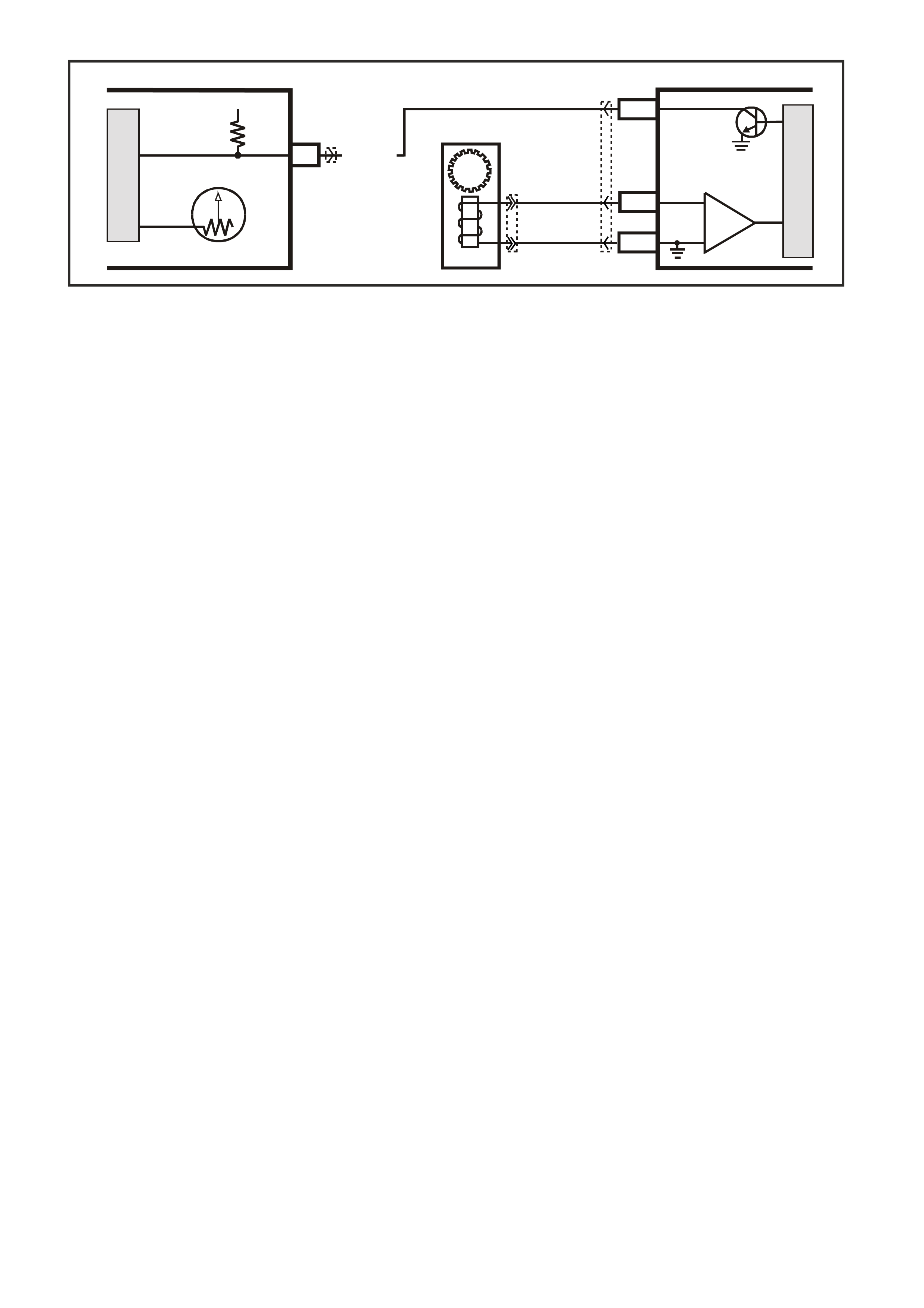
GEN III V8 PCM -
DTC P0608 VEHICLE SPEED OUTPUT CIRCUIT
CIRCUIT DESCRIPTION
Various components apply a voltage to the Vehicle Speed Output circuit. The PCM creates the Vehicle Speed
Output signal by rapidly earthing this circuit via an internal switch called a driver. The driver operates at the same
rate as the VSS signal input. The various com ponents recognise the voltage being pulled to earth as an indication
of vehicle speed.
The PCM driver supplies the earth f or the component being controlled. Each driver has a fault line which the PCM
monitors. When the PCM commands a component ON, the voltage of the control circuit should be LOW (near 0
volts). When the PCM com m ands the control c ircuit to a com ponent OFF, the voltage potential of the circuit should
be HIGH near battery voltage). If the fault detection circuit senses a voltage other than what is expected, the fault
line status changes causing the DTC to set.
CONDITIONS FOR RUNNING THE DTC
• The engine speed is greater than 600 RPM.
• The ignition voltage is between 6.0 and 16.0 volts.
CONDITIONS FOR SETTING THE DTC
• The PCM detects that the commanded state of the driver and the actual state of the control circuit do not
match.
• This condition must be present for at least ten seconds.
ACTION TAKEN WHEN THE DTC SETS
• The PCM stores the DTC information into memory when the diagnostic runs and fails.
• The Check Powertrain Lamp will not be illuminated.
• The PCM records the operating conditions at the time the diagnostic fails. The PCM stores this information in
the Freeze Frame/Failure Records.
CONDITIONS FOR CLEARING THE CPL/DTC
• A last test failed (current DTC) clears when the diagnostic runs and does not fail.
• Use a Tech 2 scan tool in order to clear the CPL/DTC.
DIAGNOSTIC AIDS
• Using the Freeze Frame/Failure Records data may aid in locating an intermittent condition. If you cannot
duplicate the DTC, the information included in the Freeze Frame/Failure Records data can aid in determining
the distance traveled since the DTC reported a pass and/or fail. Operate the vehicle within the same freeze
frame conditions (RPM, load, vehicle speed, temperature, etc.) that you observed. This will isolate when the
DTC failed.
• For an intermittent, refer to Section 6C3-2B Symptoms, of the VX Series Service Information.
• If vehic le is f itted with cr uise control, dis connecting the c ruis e m odule will isolate the cruis e control s ystem f rom
the rest of the vehicle systems.
17
V/W (123)
YB66 YB195
YE123
12V IGN
VEHICLE SPEED
M
I
C
R
O
G3PCM016PT
INSTRUMENT
M
I
C
R
O
VEHICLE SPEED
PCM
J2-50
J2-21
J2-20
V
EHICLE SPEED
SENSOR
IC
BLU/W
(831)
T
(832)
SPEEDOMETER
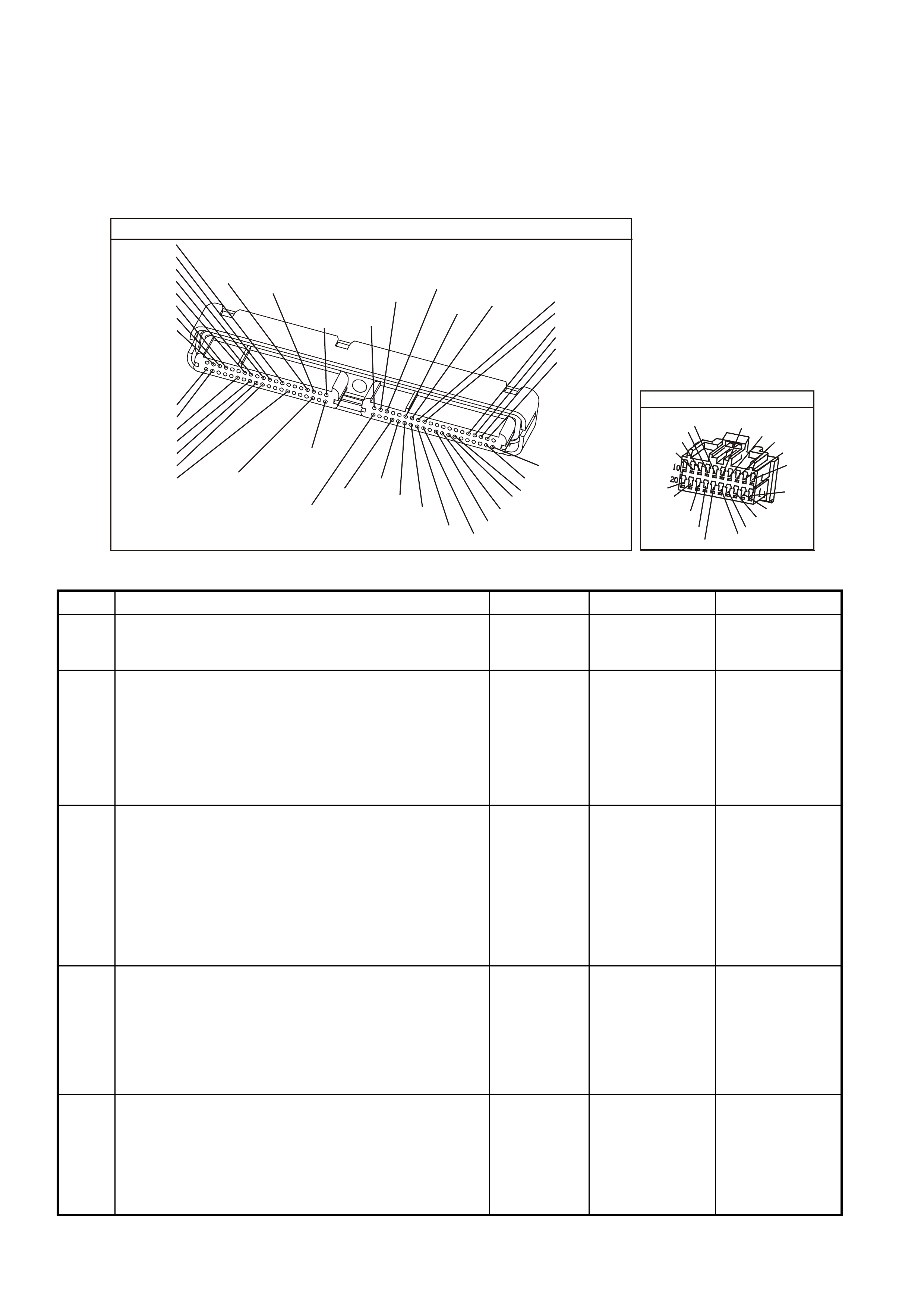
TEST DESCRIPTION
The numbers below refer to the step numbers on the diagnostic table.
3. This step determines if the PCM is capable of controlling the speedometer.
5. Further circuit diagnosis may require instrument panel removal. The circuit from the PCM to the speedometer
must be checked for being open, shorted to earth or, voltage. If you do not find any trouble, follow the
appropriate instrument panel diagnostic procedure.
7. The repair is not complete if the Tech 2 scan tool indicates that the DTC reset.
YE123
P.C.M CONNECTOR 2
(750)
(1228)
(1229)
(465)
(121)
(259)
G/B
BR
G/W
GY/BLU
R
B/R
(418)
BR
(59)
(832)
G
T
(831)
(417)
(472)
(976)(974)
(432)
(428)
(631)
BLUBR G/Y
BLU/W
LG
BR/W
W/B
LG W
(977)
Y
(971)
BLU/WW
B/R
(750)
(304)
(792)
(1223)
(1222)
(123)
(1227)
(469)
(331)
Y/B
LG
V/W
B/Y
G/O BR/W
(1687)
GY/B
(366)
LG/B
GY/R
(422)
V
(442)
(444)
(443)
(975)
(972)
(978)
(1224)
(973)
(959)
LG/W
LG/B
LBLU/B
GY
(773)
BR/Y
BLU
G
Y/B
LBLU
(958)
BR
(441)
LBLU
1
41
40
80
J2
RED
Y
(838)
YB66
INSTRUMENTS
T
BLU/B
BR/W
(234)
(25)
(14)
(10)
(875)
(155)
(1340)
G/W
(44)
(121)
(8)
(30)
BLU/Y
G
O/Y
P/BLU
BR/R
V/W
(33)
(946)
(1220)
(88)
(15)
(123)
(85)
(19)
GY
W
V/R
BR
BR/O
Y/R
B/Y
LBLU
BLU
GEN III V8 PCM - DTC P0608 VEHICLE SPEED OUTPUT CIRCUIT
Step Action Value(s) Yes No
1 Did you perform the Powertrain On-Board Diagnostic
(OBD) System Check? Go to Step 2 Go to Powertrain
OBD System
Check
2
1. Turn OFF the ignition.
2. Raise the drive wheels.
3. Start the engine.
4. Disable the traction control systems (if so equipped).
5. Allow the engine to idle in gear.
Does the vehicle speedometer indicate vehicle speed?
Go to
Diagnostic Aids Go to Step 3
3 1. Turn ON the ignition leaving the engine OFF.
2. Install a Tech 2 scan tool.
3. Using the Tech 2 scan tool, select F3: Body,
Instruments, F4: Miscellaneous Test, F7: Control
Tests, F0: Vehicle Speed.
4. Depress the ON up arrow key on the Tech 2 scan tool.
Does the speedometer read the same as the Tech 2 scan
tool commanded output?
Go to Step 6 Go to Step 4
4 1. Ignition OFF.
2. Disconnect the RED PCM connector.
3. Turn ON the ignition leaving the engine OFF.
4. Connect DMM between the PCM harness terminal for
VSS output and earth.
Is voltage at specified value?
B+ Go to Step 6 Go to Step 5
5 1. Check for open, short to earth in VSS output circuit.
Was a problem found? Go to Step 7 Further diagnosis
of circuit
required. Go to
Section 12C
Instruments in
VX Service
Information.

GEN III V8 PCM - DTC P0608 VEHICLE SPEED OUTPUT CIRCUIT (CONTINUED)
Step Action Value(s) Yes No
6 1. Replace PCM.
2. Refer to Section 6C3-3 Service Operations of the VX
Series Service Information, for PCM Programming and
PCM/PIM/BCM Security Link Procedure.
NOTE: If speedometer is still inoperative, refer to Section
12C in VX Service Information for further diagnosis.
Is action complete?
Go to Step 7
7 1. Select the Diagnostic Trouble Code (DTC) option and
the Clear DTC Information option using the Tech 2
scan tool.
2. Idle the engine at the normal operating temperature.
3. Select the Diagnostic Trouble Code (DTC) option, the
DTC Information option and The Failed This Ignition
option using the Tech 2 scan tool.
4. Operate the vehicle, within the Conditions for Running
the DTC, as specified in the supporting text, if
applicable.
Does the Tech 2 scan tool indicate that this DTC reset?
Go to Step 2 Go to Step 8
8 Using the Tech 2 scan tool, check for any other DTCs.
Does the Tech 2 scan tool display any DTCs that you
have not diagnosed?
Go to the
applicable DTC
table
System OK
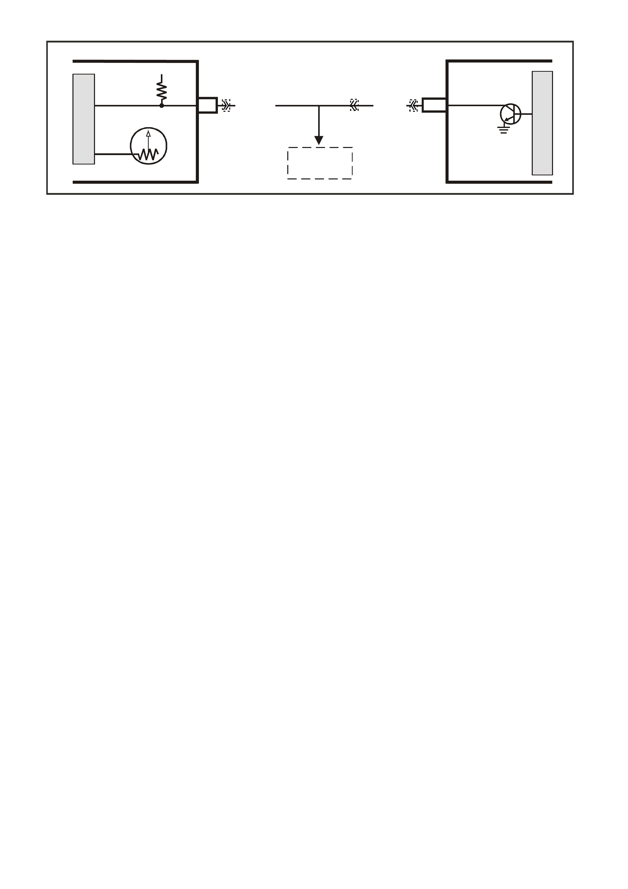
GEN III V8 PCM -
DTC P0654 ENGINE SPEED OUTPUT CIRCUIT
CIRCUIT DESCRIPTION
The PCM s upplies a voltage to the Engine Speed Output circ uit. The PCM creates the Engine Speed O utput signal
by rapidly earthing this circuit via an internal switch called a driver. The other com ponents on this circuit recognise
the voltage being pulled to earth as an indication of engine speed.
The PCM driver supplies the earth f or the component being controlled. Each driver has a fault line which the PCM
monitors. When the PCM commands a component ON, the voltage of the control circuit should be LOW (near 0
volts). When the PCM com m ands the control c ircuit to a com ponent OFF, the voltage potential of the circuit should
be HIGH (near battery voltage). If the fault detection circuit senses a voltage other than what is expected, the fault
line status changes causing the DTC to set.
CONDITIONS FOR RUNNING THE DTC
• The engine speed is greater than 600 RPM.
• The ignition voltage is between 6.0 and 16.0 volts.
CONDITIONS FOR SETTING THE DTC
• The PCM detects that the commanded state of the driver and the actual state of the control circuit do not
match.
• All of the conditions are present for a minimum of 10.0 seconds.
ACTION TAKEN WHEN THE DTC SETS
• The PCM stores the DTC information into memory when the diagnostic runs and fails.
• The Check Powertrain Lamp will not be illuminated.
• The PCM records the operating conditions at the time the diagnostic fails. The PCM stores this information in
the Freeze Frame/Failure Records.
CONDITIONS FOR CLEARING THE CPL/DTC
• A last test failed (current DTC) clears when the diagnostic runs and does not fail.
• Use a Tech 2 scan tool to clear the CPL/DTC.
DIAGNOSTIC AIDS
• Using the Freeze Frame/Failure Records data may aid in locating an intermittent condition. If you cannot
duplicate the DTC, the information included in the Freeze Frame/Failure Records data can aid in determining
the distance traveled since the DTC reported a pass and/or fail. Operate the vehicle within the same freeze
frame conditions (RPM, load, vehicle speed, temperature, etc.) that you observed. This will isolate when the
DTC failed.
• For an intermittent, refer to Section 6C3-2B Symptoms of the VX Series Service Information.
TEST DESCRIPTION
The numbers below refer to the step numbers on the diagnostic table.
NOTE: If the instrument panel is completely inoperative, refer to Section 12C in VX Service Information.
3. This step determines if the PCM is capable of controlling the tachometer.
5. Further circuit diagnosis may require instrument panel removal. Check the circuit from the PCM to the
tachometer for being open, shorted to earth or, voltage. If you can not find any trouble, follow the appropriate
instrument panel diagnostic procedure.
7. The repair is not complete if the Tech 2 scan tool indicates that the diagnostic ran and failed.
18
BR/R (121) BR (121)
12V IGN
TACHO SIGNAL
M
I
C
R
O
G3PCM049PT
INSTRUMENT
M
I
C
R
O
TACHO SIGNAL
PCM
J2-10
TACHO
YE123YB66
TO
ABS/TCS
MODULATOR
YE112

YE123
P.C.M CONNECTOR 2
(750)
(1228)
(1229)
(465)
(121)
(259)
G/B
BR
G/W
GY/BLU
R
B/R
(418)
BR
(59)
(832)
G
T
(831)
(417)
(472)
(976)(974)
(432)
(428)
(631)
BLUBR G/Y
BLU/W
LG
BR/W
W/B
LG W
(977)
Y
(971)
BLU/WW
B/R
(750)
(304)
(792)
(1223)
(1222)
(123)
(1227)
(469)
(331)
Y/B
LG
V/W
B/Y
G/O BR/W
(1687)
GY/B
(366)
LG/B
GY/R
(422)
V
(442)
(444)
(443)
(975)
(972)
(978)
(1224)
(973)
(959)
LG/W
LG/B
LBLU/B
GY
(773)
BR/Y
BLU
G
Y/B
LBLU
(958)
BR
(441)
LBLU
1
41
40
80
J2
RED
Y
(838)
YB66
INSTRUMENTS
T
BLU/B
BR/W
(234)
(25)
(14)
(10)
(875)
(155)
(1340)
G/W
(44)
(121)
(8)
(30)
BLU/Y
G
O/Y
P/BLU
BR/R
V/W
(33)
(946)
(1220)
(88)
(15)
(123)
(85)
(19)
GY
W
V/R
BR
BR/O
Y/R
B/Y
LBLU
BLU
GEN III V8 PCM - DTC P0654 ENGINE SPEED OUTPUT CIRCUIT
Step Action Value(s) Yes No
1 Did you perform the Powertrain On-Board Diagnostic
(OBD) System Check? Go to Step 2 Go to Powertrain
OBD System
Check Table
2
With the engine running, does the vehicle tachometer
indicate engine RPM? Go to Diagnostic
Aids Go to Step 3
3 1. Turn ON the ignition leaving the engine OFF.
2. Install a Tech 2 scan tool.
3. Using the Tech 2 scan tool, select F3: Body,
Instruments, F4: Miscellaneous Test, F7: Control
Tests, F1: Engine Speed.
4. Depress the ON up arrow key on the Tech 2 scan tool.
Does the tachometer read the same as the Tech 2
scan tool commanded output?
Go to Step 6 Go to Step 4
4 5. Ignition OFF.
6. Disconnect the PCM RED connector.
7. Turn ON the ignition leaving the engine OFF.
8. Connect DMM between the PCM harness terminal for
Tachometer output and earth.
Is voltage at specified value?
7 - 10 V Go to Step 6 Go to Step 5
5 Check for open, short to earth, or short to voltage in
Tachometer output circuit.
Was a problem found?
Go to Step 7 Further diagnosis
of circuit
required. Go to
Section 12C
Instruments in
VX Service
Information.
6 1. Replace PCM.
2. Refer to Section 6C3-3 of the VX Series Service
Information for PCM Programming and
PCM/PIM/BCM Security Link Procedure.
NOTE: If the Tachometer is still inoperative, refer to
Section 12C in VX Service Information or further
diagnosis.
Is action complete?
Go to Step 7

GEN III V8 PCM - DTC P0654 ENGINE SPEED OUTPUT CIRCUIT (CONTINUED)
Step Action Value(s) Yes No
7 1. Select the Diagnostic Trouble Code (DTC) option and
the Clear DTC Information option using the Tech 2
scan tool.
2. Idle the engine at the normal operating temperature.
3. Select the Diagnostic Trouble Code (DTC) option, the
DTC Information option and The Failed This Ignition
option using the Tech 2 scan tool.
4. Operate the vehicle, within the Conditions for Running
the DTC, as specified in the supporting text, if
applicable.
Does the Tech 2 scan tool indicate that this DTC reset?
Go to Step 2 Go to Step 8
8 Using the Tech 2 scan tool, check for any other DTCs.
Does the Tech 2 scan tool display any DTCs that you
have not diagnosed?
Go to the
applicable DTC
table
System OK
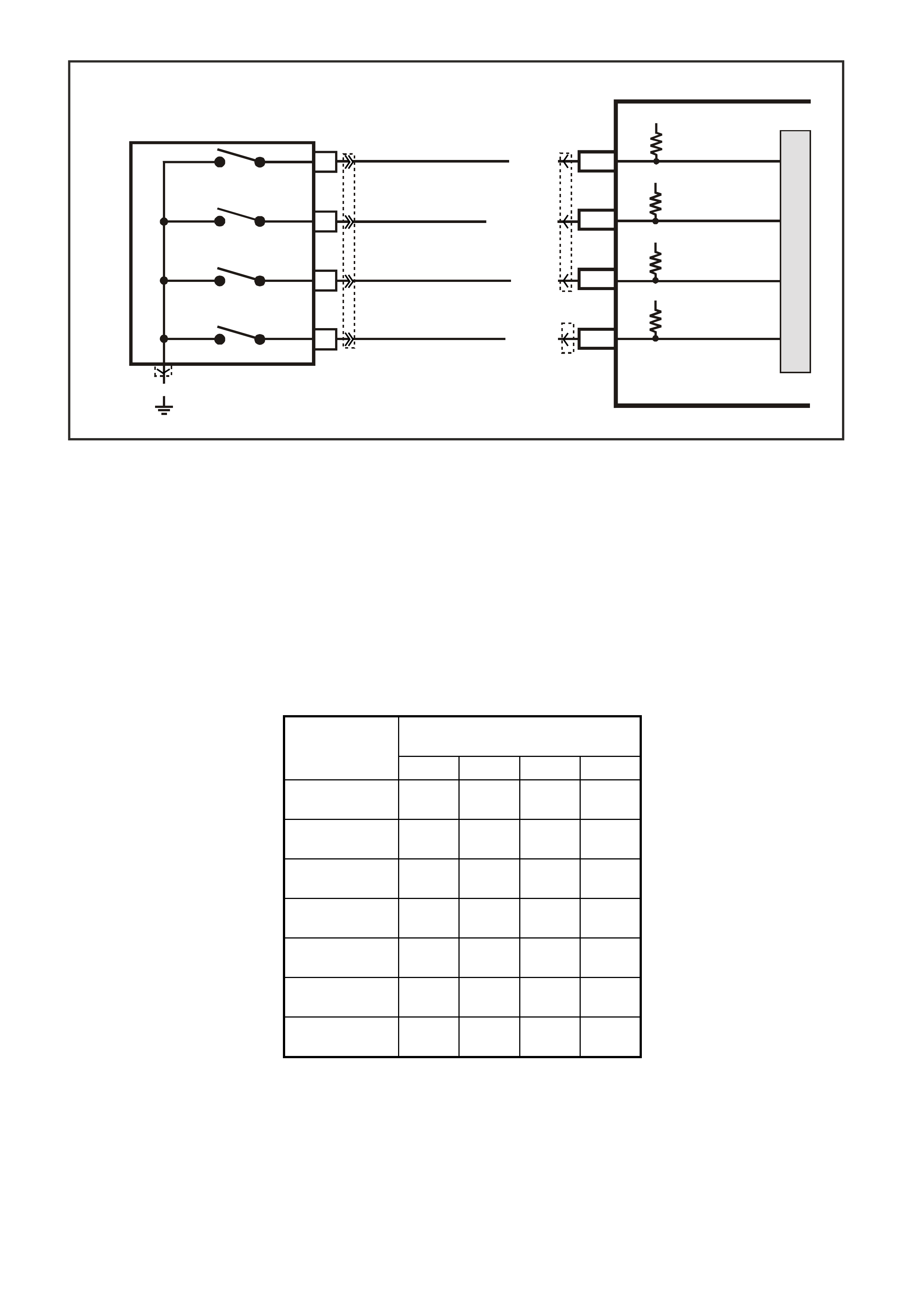
GEN III V8 PCM -
DTC P0705 TRANSMISSION RANGE SWITCH CIRCUIT
CIRCUIT DESCRIPTION
The Transmission Range (TR) Switch is part of the Transmission PRNDL switch mounted on the transmission
manual shaft. T he four inputs from the transm ission r ange switch indicate to the PCM which position is s elected by
the trans m ission selector lever . The input voltage level at the PCM is high (B+) when the transmiss ion range switch
is open and low when the switch is closed to earth. The state of each input is available for display on the Scan
Tool. The four parameters represent transmission range switch P (Parity), A, B, and C inputs respectively.
W hen the PCM detects an invalid transm ission range input com bination, then DTC P0705 sets. Valid trans mission
range input combinations are shown in the Transmission Range Switch Valid Combination table.
TRANSMISSION RANGE SWITCH VALID COMBINATION TABLE
Gear Selector
Position Scan Tool TR Switch P/A/B/C
Display
P A B C
Park (P) Closed
0 V Closed
0 V Open
12 V Open
12 V
Reverse (R) Open
12 V Closed
0 V Closed
0 V Open
12 V
Neutral (N) Closed
0 V Open
12 V Closed
0 V Open
12 V
D Open
12 V Open
12 V Closed
0 V Closed
0 V
3 Closed
0 V Closed
0 V Closed
0 V Closed
0 V
2 Open
12 V Closed
0 V Open
12 V Closed
0 V
1 Closed
0 V Open
12 V Open
12 V Closed
0 V
CONDITIONS FOR RUNNING THE DTC
• The ignition is ON.
CONDITIONS FOR SETTING THE DTC
• The Transmission Range Switch inputs indicate an invalid combination.
• The above condition is present for longer than 30 seconds.
G3PCM038PT
PCM
J1-32
J1-72
PRNDL P
PRNDL A
C
SWITCH P
SWITCH A
SWITCH B
SWITCH C
LOC. E5/E15
A
D
B
P. R. N. D. L. SWITCH
12V
12V
J2-62
J1-34
PRNDL B
PRNDL C
12V
12V
BLU/W (771)
Y (77 2)
GY (773)
W (776)
YE122
YE123
YB20
YB35
B/R (750)
M
I
C
R
O

ACTION TAKEN WHEN THE DTC SETS
• The PCM stores the DTC information into memory when the diagnostic runs and fails.
• The Check Powertrain Lamp will not be illuminated.
• The PCM records the operating conditions at the time the diagnostic fails. The PCM stores this information in
the Freeze Frame/Failure Records.
CONDITIONS FOR CLEARING THE DTC
• A last test failed (current DTC) clears when the diagnostic runs and does not fail.
• The PCM cancels the DTC default actions when the fault no longer exists and the ignition switch is OFF long
enough in order to power down the PCM.
DIAGNOSTIC AIDS
• Inspect the wiring at the PCM, the Transmission Range Switch and all other circuit connecting points for the
following conditions:
- A backed out terminal
- A damaged terminal
- Reduced terminal tension
- A chafed wire
- A broken wire inside the insulation
- Moisture intrusion
- Corrosion
• If af ter a c om plete ins pection and testing of the system the condition does not r eveal, observe the sc an tool T R
Switch P/A/B/C display while moving the connectors and wiring. A change in the TR Switch display should
identify the location of the condition.
TEST DESCRIPTION
Numbers below refer to the step numbers on the Diagnostic Table.
2. If the TR Switch display corresponds with all gear selector positions, the condition may be interm ittent. Ref er to
Diagnostic Aids for intermittent diagnosis.
3. Disc onnecting the Tr ansmis sion Range Switch connector will caus e the PCM to interpret all the circ uits as open
and the Sc an T ool P/A/B/C will dis play all Open 12 V. T his would indicate that cir cuits f rom the T R Switch to the
PCM and the PCM are all OK.
4. By r econnecting the TR Switch and all Sc an Tool TR Switch P/A/B/C dis play Open 12 V, the condition could be
in the engine earth circuit 750.
7. By providing the earth for each Transmission Range Switch circuit, the PCM should respond by changing the
TR Switch P/A/B/C display from Open 12 V to Closed 0 V. For the circuits that do not change, an open circuit
must exist.
12. Before replacing the PCM, ensure that all connectors, wiring and components have been tested.
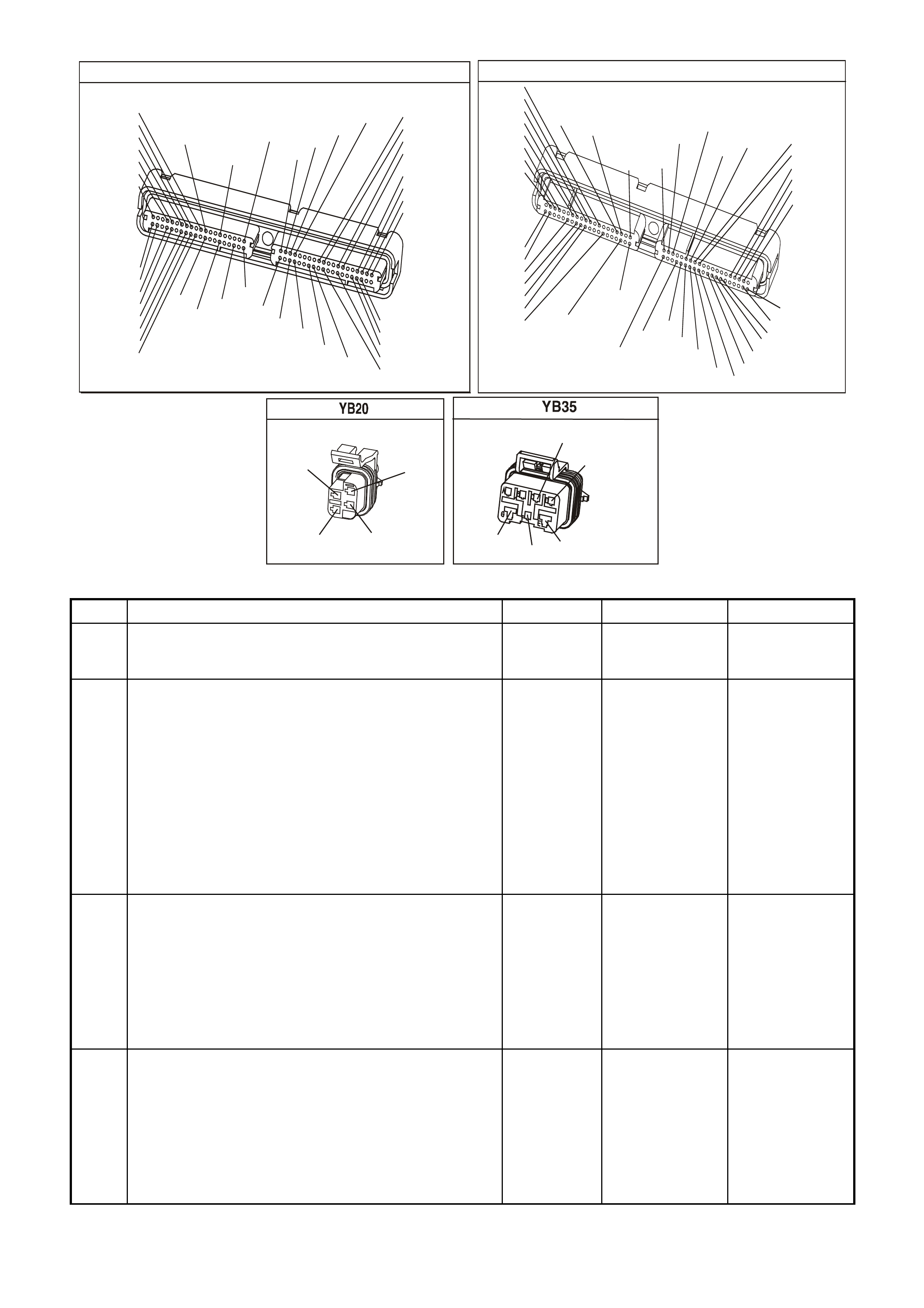
P.C.M CONNECTOR 1
YE122
(776)
(1049)
(897)
(1230)
(848)
(1226)
(772)
(647)
(632)
40
(844)
(815)
80
J1
P/B
(845)
V/W
BLU
O
(633)
(846)
B/Y
B/R
(416)
(86)
(69)
(455)
(740)
GY
BR
G
GY
(646)
(410)
GY
(842)
(1225)
V
Y
(750)
P
41
O
(774)
BR/Y
BLU
Y
B/R
B
BLU/Y
(841)
BLUE
(414)
G/W
BLU
LG
LBLU/B
1
(847)
(415)
(740)
(452)
BLU
BR
Y
(750)
(826)
(421)
Y
V/W
B/W
(334)
(771)
(39)
Y
R/W
LBLU
W
BLU/W
(843)
(643)
LBLU/W
G
GY/B
BLU/B
(413)
(1413)
(1412)
(412)
GY
V
GY/B
G
(335)
YE123
P.C.M CONNECTOR 2
(750)
(1228)
(1229)
(465)
(121)
(259)
G/B
BR
G/W
GY/BLU
R
B/R
(418)
BR
(59)
(832)
G
T
(831)
(417)
(472)
(976)(974)
(432)
(428)
(631)
BLUBR G/Y
BLU/W
LG
BR/W
W/B
LG W
(977)
Y
(971)
BLU/WW
B/R
(750)
(304)
(792)
(1223)
(1222)
(123)
(1227)
(469)
(331)
Y/B
LG
V/W
B/Y
G/O BR/W
(1687)
GY/B
(366)
LG/B
GY/R
(422)
V
(442)
(444)
(443)
(975)
(972)
(978)
(1224)
(973)
(959)
LG/W
LG/B
LBLU/B
GY
(773)
BR/Y
BLU
G
Y/B
LBLU
(958)
BR
(441)
LBLU
1
41
40
80
J2
RED
Y
(838)
PRNDL SWITCH
(772)
(776)
Y
W
(773)
(771)
BLU/W
GY
NEUTRAL START & BACK-UP SWITCH
(1434)
GY/BLU
(24)
LG
GY
(434)
(750)
B/R
(42)
BR/BLU
GEN III V8 PCM - DTC P0705 TRANSMISSION RANGE SWITCH CIRCUIT
Step Action Value(s) Yes No
1 Was the Powertrain On-Board Diagnostic (OBD) System
Check performed? Go to Step 2 Go to Powertrain
OBD System
Check Table
2 1. Install the Tech 2 Scan Tool.
2. Place the transmission in PARK.
3. Turn the ignition switch ON.
4. Observe the Scan Tool TR Switch P/A/B/C display
while selecting each gear position.
5. Compare the Scan Tool display, with each gear
position selected, to the Transmission Range Switch
Valid Combinations table.
Does the Scan Tool display match the Transmission
Range Switch Valid Combinations table for each gear
position?
Go to
Diagnostic Aids Go to Step 3
3 Disconnect the Transmission Range Switch 4-way
connector.
Does the Scan Tool TR Switch P/A/B/C display the
specified values?
P/
Open 12 V
A/
Open 12 V
B/
Open 12 V
C/
Open 12 V
Go to Step 4 Go to Step 7
4 Reconnect the Transmission Range Switch 4-way
connector.
Does the Scan Tool TR Switch P/A/B/C display the
specified values?
P/
Open 12 V
A/
Open 12 V
B/
Open 12 V
C/
Open 12 V
Go to Step 5 Go to Step 11

GEN III V8 PCM - DTC P0705 TRANSMISSION RANGE SWITCH CIRCUIT (CONTINUED)
Step Action Value(s) Yes No
5 Inspect the Transmission Neutral Start and Backup
Switch 5-way connector for being disconnected or poor
terminal contact at circuit earth 750 circuit .
Was a condition found?
Go to Step 10 Go to Step 6
6 Inspect circuit 750 from the Transmission Neutral Start
and Backup Switch 5-way connector for an open
condition.
Was an open condition found?
Go to Step 10 Go to Step 11
7 1. Use a fused jumper wire to earth each terminal of the
Transmission Range Switch 4-way connector, while
observing the Scan Tool TR Switch P/A/B/C display.
2. Note the display change as each circuit is earthed.
Does each of the Scan Tool TR Switch P/A/B/C display
change from Open 12 V to Closed 0 V when earthed?
Go to Step 11 Go to Step 8
8 For the circuit or circuits that did not change status in
Step 7, inspect the circuit, from the Transmission Range
Switch connector to the PCM, for an open condition or for
circuits being shorted together.
Was an open or shorted together condition found?
Go to Step 10 Go to Step 9
9 Inspect for poor connections at the PCM.
Was a condition found? Go to Step 10 Go to Step 12
10 Repair the wiring as necessary.
Is the repair complete? Go to Step 13 Go to Wiring
Repair
Procedures in
Section 8 in VX
Service
Information.
11 Replace the Transmission Range Switch. Refer to
Neutral Start and Back-up Lamp Switch Replacement.
Is the replacement complete?
Go to Step 13 Go to Section
7C4 Neutral Start
and Back-up
Lamp Switch
Replacement in
VX Service
Information.
12 Replace the PCM.
Refer to Powertrain Control Module in Service 6C3-3 of
the VX Series Service Information.
Is replacement the complete?
Go to Step 13 Go to Section
6C3-3 Powertrain
Control Module
Replacement
13 1. Clear the DTCs.
2. Observe the Scan Tool TR Switch P/A/B/C display
while selecting each gear position.
3. Compare the Scan Tool display, with each gear
position selected, to the Transmission Range Switch
Valid Combinations table.
Does the Scan Tool display match the Transmission
Range Switch Valid Combinations table for each gear
position?
System OK Go to Step 1

GEN III V8 PCM -
DTC P0706 TRANSMISSION RANGE SWITCH PERFORMANCE
CIRCUIT DESCRIPTION
The Transmission Range (TR) Switch is part of the Transmission PRNDL switch mounted on the transmission
manual shaft. T he four inputs from the transm ission r ange switch indicate to the PCM which position is s elected by
the transmission selector lever. The input voltage level at the PCM is high (B+), when the transmission range
switch is open and low, when the switch is closed to earth. The state of each input is available for display on the
Scan Tool. The four parameters represent transmission range switch P (Parity), A, B, and C inputs respectively.
W hen the PCM detects an invalid transm ission range input com bination, then DTC P0706 sets. Valid trans mission
range input combinations are shown in the Transmission Range Switch Valid Combination table.
TRANSMISSION RANGE SWITCH VALID COMBINATION TABLE
Gear Selector
Position Scan Tool TR Switch P/A/B/C
Display
P A B C
Park (P) Closed
0 V Closed
0 V Open
12 V Open
12 V
Reverse (R) Open
12 V Closed
0 V Closed
0 V Open
12 V
Neutral (N) Closed
0 V Open
12 V Closed
0 V Open
12 V
D Open
12 V Open
12 V Closed
0 V Closed
0 V
3 Closed
0 V Closed
0 V Closed
0 V Closed
0 V
2 Open
12 V Closed
0 V Open
12 V Closed
0 V
1 Closed
0 V Open
12 V Open
12 V Closed
0 V
CONDITIONS FOR RUNNING THE DTC
• The ignition is ON.
CONDITIONS FOR SETTING THE DTC
• The Transmission Range Switch inputs indicate an invalid combination.
• The above condition is present for longer than 30 seconds.
G3PCM038PT
PCM
J1-32
J1-72
PRNDL P
PRNDL A
C
SWITCH P
SWITCH A
SWITCH B
SWITCH C
LOC. E5/E15
A
D
B
P. R. N. D. L. SWITCH
12V
12V
J2-62
J1-34
PRNDL B
PRNDL C
12V
12V
BLU/W (771)
Y (77 2)
GY (773)
W (776)
YE122
YE123
YB20
YB35
B/R (750)
M
I
C
R
O

ACTION TAKEN WHEN THE DTC SETS
• The PCM stores the DTC information into memory when the diagnostic runs and fails.
• The Check Powertrain Lamp will not be illuminated.
• The PCM records the operating conditions at the time the diagnostic fails. The PCM stores this information in
the Freeze Frame/Failure Records.
CONDITIONS FOR CLEARING THE DTC
• A last test failed (current DTC) clears when the diagnostic runs and does not fail.
• The PCM cancels the DTC default actions when the fault no longer exists and the ignition switch is OFF long
enough in order to power down the PCM.
DIAGNOSTIC AIDS
• Inspect the wiring at the PCM, the Transmission Range Switch and all other circuit connecting points for the
following conditions:
- A backed out terminal
- A damaged terminal
- Reduced terminal tension
- A chafed wire
- A broken wire inside the insulation
- Moisture intrusion
- Corrosion
• If af ter a c om plete ins pection and testing of the system the condition does not r eveal, observe the sc an tool T R
Switch P/A/B/C display while moving the connectors and wiring. A change in the TR Switch display should
identify the location of the condition.
TEST DESCRIPTION
Numbers below refer to the step numbers on the Diagnostic Table.
2. If the TR Switch display corresponds with all gear selector positions, the condition may be intermittent. Refer
to Diagnostic Aids for intermittent diagnosis.
3. Disconnecting the Transmission Range Switch connector will cause the PCM to interpret all the circuits as
open and the Scan Tool P/A/B/C will display all Open 12 V. This would indicate that circuits from the TR
Switch to the PCM and the PCM are all OK.
4. By reconnecting the TR Switch and all Scan Tool TR Switch P/A/B/C display Open 12 V, the condition could
be in the engine earth circuit 750.
7. By providing the earth for each Transmission Range Switch circuit, the PCM should respond by changing the
TR Switch P/A/B/C display f rom Open 12 V to Closed 0 V. F or the circuits that do not change, an open c ircuit
must exist.
12. Before replacing the PCM, ensure that all connectors, wiring and components have been tested.

P.C.M CONNECTOR 1
YE122
(776)
(1049)
(897)
(1230)
(848)
(1226)
(772)
(647)
(632)
40
(844)
(815)
80
J1
P/B
(845)
V/W
BLU
O
(633)
(846)
B/Y
B/R
(416)
(86)
(69)
(455)
(740)
GY
BR
G
GY
(646)
(410)
GY
(842)
(1225)
V
Y
(750)
P
41
O
(774)
BR/Y
BLU
Y
B/R
B
BLU/Y
(841)
BLUE
(414)
G/W
BLU
LG
LBLU/B
1
(847)
(415)
(740)
(452)
BLU
BR
Y
(750)
(826)
(421)
Y
V/W
B/W
(334)
(771)
(39)
Y
R/W
LBLU
W
BLU/W
(843)
(643)
LBLU/W
G
GY/B
BLU/B
(413)
(1413)
(1412)
(412)
GY
V
GY/B
G
(335)
YE123
P.C.M CONNECTOR 2
(750)
(1228)
(1229)
(465)
(121)
(259)
G/B
BR
G/W
GY/BLU
R
B/R
(418)
BR
(59)
(832)
G
T
(831)
(417)
(472)
(976)(974)
(432)
(428)
(631)
BLUBR G/Y
BLU/W
LG
BR/W
W/B
LG W
(977)
Y
(971)
BLU/WW
B/R
(750)
(304)
(792)
(1223)
(1222)
(123)
(1227)
(469)
(331)
Y/B
LG
V/W
B/Y
G/O BR/W
(1687)
GY/B
(366)
LG/B
GY/R
(422)
V
(442)
(444)
(443)
(975)
(972)
(978)
(1224)
(973)
(959)
LG/W
LG/B
LBLU/B
GY
(773)
BR/Y
BLU
G
Y/B
LBLU
(958)
BR
(441)
LBLU
1
41
40
80
J2
RED
Y
(838)
PRNDL SWITCH
(772)
(776)
Y
W
(773)
(771)
BLU/W
GY
NEUTRAL START & BACK-UP SWITCH
(1434)
GY/BLU
(24)
LG
GY
(434)
(750)
B/R
(42)
BR/BLU
GEN III V8 PCM - DTC P0706 TRANSMISSION RANGE SWITCH PERFORMANCE
Step Action Value(s) Yes No
1 Was the Powertrain On-Board Diagnostic (OBD) System
Check performed? Go to Step 2 Go to Powertrain
OBD System
Check Table
2 1. Install the Tech 2 Scan Tool.
2. Place the transmission in PARK.
3. Turn the ignition switch ON.
4. Observe the Scan Tool TR Switch P/A/B/C display
while selecting each gear position.
5. Compare the Scan Tool display, with each gear
position selected, to the Transmission Range Switch
Valid Combinations table.
Does the Scan Tool display match the Transmission
Range Switch Valid Combinations table for each gear
position?
Go to
Diagnostic Aids Go to Step 3
3 Disconnect the Transmission Range Switch 4-way
connector.
Does the Scan Tool TR Switch P/A/B/C display the
specified values?
P/
Open 12 V
A/
Open 12 V
B/
Open 12 V
C/
Open 12 V
Go to Step 4 Go to Step 7
4 Reconnect the Transmission Range Switch 4-way
connector.
Does the Scan Tool TR Switch P/A/B/C display the
specified values?
P/
Open 12 V
A/
Open 12 V
B/
Open 12 V
C/
Open 12 V
Go to Step 5 Go to Step 11

GEN III V8 PCM - DTC P0706 TRANSMISSION RANGE SWITCH PERFORMANCE (CONTINUED)
Step Action Value(s) Yes No
5 Inspect the Transmission Neutral Start and Backup
Switch 5-way connector for being disconnected or poor
terminal contact at earth circuit 750.
Was a condition found?
Go to Step 10 Go to Step 6
6 Inspect circuit 750 (B/R) from the Transmission Neutral
Start and Backup Switch 5-way connector for an open
condition.
Was an open condition found?
Go to Step 10 Go to Step 11
7 1. Use a fused jumper wire to earth each terminal of the
Transmission Range Switch 4-way (YB 20) connector,
while observing the Scan Tool TR Switch P/A/B/C
display.
2. Note the display change as each circuit is earthed.
Does each of the Scan Tool TR Switch P/A/B/C display
change from Open 12 V to Closed 0 V when earthed?
Go to Step 11 Go to Step 8
8 For the circuit or circuits that did not change status in
Step 7, inspect the circuit, from the Transmission Range
Switch connector to the PCM, for an open condition or for
circuits being shorted together.
Was an open or shorted together condition found?
Go to Step 10 Go to Step 9
9 Inspect for poor connections at the PCM.
Was a condition found? Go to Step 10 Go to Step 12
10 Repair the wiring as necessary.
Is the repair complete? Go to Step 13 Go to
Wiring Repair
Procedures in
Section 8, in VX
Service
Information.
11 Replace the Transmission Range Switch. Refer to
Neutral Start and Back-up Lamp Switch Replacement.
Is the replacement complete?
Go to Step 13 Go to
Section 7C4
Neutral Start and
Back-up Lamp
Switch
Replacement in
VX Service
Information.
12 Replace the PCM.
Refer to Powertrain Control Module in Section 6C3-3 of
the VX Series Service Information.
Is replacement the complete?
Go to Step 13 Go to
Section 6C3-3
Powertrain
Control Module
Replacement
13 1. Clear the DTCs.
2. Observe the Scan Tool TR Switch P/A/B/C display
while selecting each gear position.
3. Compare the Scan Tool display, with each gear
position selected, to the Transmission Range Switch
Valid Combinations table.
Does the Scan Tool display match the Transmission
Range Switch Valid Combinations table for each gear
position?
System OK Go to Step 1

GEN III V8 PCM -
DTC P0711 TFT SENSOR CIRCUIT RANGE/PERFORMANCE
CIRCUIT DESCRIPTION
The autom atic Tr ansmiss ion Fluid Temper ature (TFT ) sensor is par t of the automatic Tr ansmiss ion Fluid Press ure
(TFP) manual valve position switch. The TFT sensor is a resistor, or thermistor, which changes value based on
temperature. The sensor has a negative-temperature coefficient. This means that as the temperature increases,
the resistance decreases, and as the temperature decreases, the resistance increases.
The Powertrain Control Module (PCM) supplies a 5-volt reference signal to the sensor on circuit 1227 and
meas ures the voltage dr op in the circuit. W hen the trans mission f luid is cold, the sensor res istance is high and the
PCM detects high signal voltage. As the fluid tem peratur e warm s to a norm al oper ating tem perature, the resis tance
becomes less and the signal voltage decreases. The PCM uses this information to control shift quality and torque
converter clutch apply.
When the PCM detects one of the following unusual conditions, then DTC P0711 sets.
• An unrealistically large change in transmission temperature
• A transmission temperature which remains constant for a period of time in which a measurable amount of
change is expected
CONDITIONS FOR RUNNING THE DTC
• No VSS assembly DTCs P0502, P0503.
• No transmission component slipping DTC P1870.
• The system voltage is between 8.0 volts and 18 volts.
• The engine is running g for 409 seconds (6.8 minutes).
• The vehicle speed is greater than 8 km/h for 409 seconds cumulative during the current ignition cycle.
• The TCC slip speed is greater than 120 RPM for 409 seconds cumulative during the current ignition cycle.
• The TFT at startup is between –40 and +21°C.
• The TFT is between –38 and +15°C.
• The engine coolant temperature (ECT) is greater than 70°C and has changed by 50°C since startup.
CONDITIONS FOR SETTING THE DTC
• The TFT does not change more than 1.50°C for 409 seconds since startup.
• The TFT changes more than 20°C in 200 milliseconds, 14 times within 7 seconds.
G3PCM034PT
PCM
J2-63
J1-17
J2-51
J1-53
TFP SIGNAL A
TFP SIGNAL B
TRANSMISSION FLUID
TEMPERATURE (TFT)
SENSOR SIGNAL
SENSOR EARTH
N
C
REV (N.0.)
LO (N.0.)
D3 (N.C.)
D4 (N.O.)D2 (N.C.)
R
E
D
A
B
P
L
M
TRANSMISSION FLUID
TEMPERATURE
(TF T ) SENSOR
AUTOMATIC TRANSMISSION FLUID
PRESSURE SWITCH ASSEMBLY
BR/Y (1224)YE123
YE122
YE122
YE123
YE122
YB129
Y (1225)
GY (1226)
B/Y (1227)
B/W (1230)
12V
12V
5V
J1-18 TFP SIGN AL C
12V
M
I
C
R
O

ACTION TAKEN WHEN THE DTC SETS
• The PCM stores the DTC information into memory when the diagnostic runs and fails.
• The Check Powertrain Lamp will not be illuminated.
• The PCM records the operating conditions at the time the diagnostic fails. The PCM stores this information in
the Freeze Frame/Failure Records.
IMPORTANT:
The actions listed below are in order of highest to lowest priority.
• The PCM determines a default TFT using the following matrix:
1 If any ECT DTCs P0117 or P0118 are set, then the default TFT is equal to 135°C.
2 If the ECT is 125°C or more, then the default TFT is equal to 135°C.
3 If the engine run time is less than 300 seconds and:
- No intak e air tem per ature (IAT ) DT Cs P0112 or P0113 are set and IAT is available, then the default T FT is
equal to IAT.
- Any IAT DTCs P0112 or P0113 are set or IAT is NOT available, then the default TFT is equal to 90°C.
4 If the engine run time is greater than 300 seconds and no IAT DTCs P0112 or P0113 are set and IAT is
available and ECT is between 40 and 125°C and:
- IAT at startup is less than 15°C, then the default TFT is equal to the ECT plus 5°C.
- IAT at startup is greater than 35°C, then the default TFT is equal to the ECT plus 10°C.
- IAT at startup is between 15 and 35°C, then the default TFT is equal to the ECT.
5 If the engine run tim e is greater than 300 seconds and any IAT DTCs P0112 or P0113 are set or IAT is NOT
available, then the default TFT is equal to the ECT.
6 If the engine run time is greater than 300 seconds and ECT is les s than 40°C or m ore, then the default T FT
is equal to 60°C.
• The PCM freezes shift adapts from being updated.
• The PCM stores DTC P0711 in PCM history.
CONDITIONS FOR CLEARING THE DTC
• A last test failed (current DTC) clears when the diagnostic runs and does not fail.
• The PCM cancels the DTC default actions when the fault no longer exists and the ignition switch is OFF long
enough in order to power down the PCM.
DIAGNOSTIC AIDS
• Inspect the wiring at the PCM, the transmission connector and all other circuit connecting points for the
following conditions:
- A backed out terminal
- A damaged terminal
- Reduced terminal tension
- A chafed wire
- A broken wire inside the insulation
- Moisture intrusion
- Corrosion
TEST DESCRIPTION
The numbers below refer to the step numbers on the diagnostic table.
5. T his step tes ts f or an interm ittent s hort or open c ondition in the engine wiring har ness. T he test light is us ed as a
resistor in the circuit.
6. This step determines if the PCM or the TFT sensor is causing a steady, unchanging TFT reading.
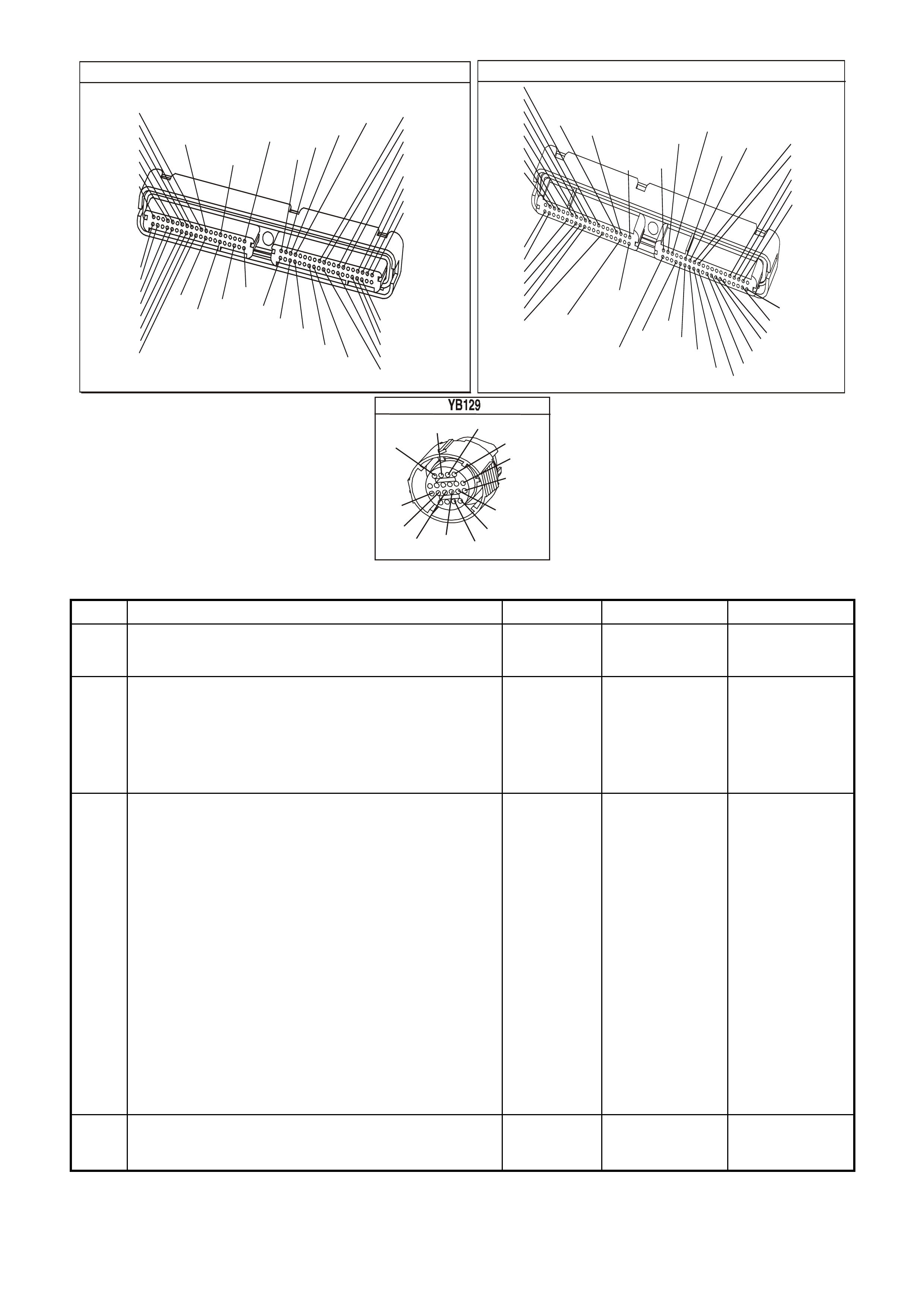
P.C.M CONNECTOR 1
YE122
(776)
(1049)
(897)
(1230)
(848)
(1226)
(772)
(647)
(632)
40
(844)
(815)
80
J1
P/B
(845)
V/W
BLU
O
(633)
(846)
B/Y
B/R
(416)
(86)
(69)
(455)
(740)
GY
BR
G
GY
(646)
(410)
GY
(842)
(1225)
V
Y
(750)
P
41
O
(774)
BR/Y
BLU
Y
B/R
B
BLU/Y
(841)
BLUE
(414)
G/W
BLU
LG
LBLU/B
1
(847)
(415)
(740)
(452)
BLU
BR
Y
(750)
(826)
(421)
Y
V/W
B/W
(334)
(771)
(39)
Y
R/W
LBLU
W
BLU/W
(843)
(643)
LBLU/W
G
GY/B
BLU/B
(413)
(1413)
(1412)
(412)
GY
V
GY/B
G
(335)
YE123
P.C.M CONNECTOR 2
(750)
(1228)
(1229)
(465)
(121)
(259)
G/B
BR
G/W
GY/BLU
R
B/R
(418)
BR
(59)
(832)
G
T
(831)
(417)
(472)
(976)(974)
(432)
(428)
(631)
BLUBR G/Y
BLU/W
LG
BR/W
W/B
LG W
(977)
Y
(971)
BLU/WW
B/R
(750)
(304)
(792)
(1223)
(1222)
(123)
(1227)
(469)
(331)
Y/B
LG
V/W
B/Y
G/O BR/W
(1687)
GY/B
(366)
LG/B
GY/R
(422)
V
(442)
(444)
(443)
(975)
(972)
(978)
(1224)
(973)
(959)
LG/W
LG/B
LBLU/B
GY
(773)
BR/Y
BLU
G
Y/B
LBLU
(958)
BR
(441)
LBLU
1
41
40
80
J2
RED
Y
(838)
TRANSMISSION CONNECTOR
GY/BLU
(1229)
R
(1228)
Y/B
(1223)
LG
(1222)
P/BLU
(339)
(1227)
B/Y
(1230)
B/W
GY/R
(422)
BR
(418)
BR/Y
(1224)
(1226)
GY
Y
(1225)
(897)
G/W
(V8)
B
(469) (V6)
OR
GEN III V8 PCM - DTC P0711 TFT SENSOR CIRCUIT RANGE/PERFORMANCE
Step Action Value(s) Yes No
1 Was the Powertrain On-Board Diagnostic (OBD) System
Check performed? Go to Step 2 Go to Powertrain
OBD System
Check Table
2 Perform the transmission fluid checking procedure. Refer
to Transmission Fluid Checking Procedure in Section
7C4, in VX Service Information.
Did you perform the fluid checking procedure?
Go to Step 3 Go to
Transmission
Fluid Checking
Procedure in
Section 7C4, in
VX Service
Information.
3 1. Install the Scan Tool.
2. With the engine OFF, turn the ignition switch to the
RUN position.
IMPORTANT: Before clearing the DTC, use the Scan
Tool in order to record the Failure Records. Using the
Clear Info function erases the Failure Records from the
PCM.
3. Record th e DTC Failure Records.
4. Clear the DTC.
5. Select TFT on the Scan Tool.
6. Drive the vehicle and observe the Scan Tool for either
of the following conditions:
- The TFT does not change more than 1.50°C in 409
seconds since startup
- The TFT changes more than 20°C in 200
CPLliseconds14 times within 7 seconds (unrealistic
change).
Did either of the conditions occur?
Go to Step 4 Go to Diagnostic
Aids
4 Did the Scan Tool display a condition in which the TFT
does not change by more than the specified value in 409
seconds since startup?
1.5°C Go to Step 6 Go to Step 5

GEN III V8 PCM - DTC P0711 TFT SENSOR CIRCUIT RANGE/PERFORMANCE (CONTINUED)
Step Action Value(s) Yes No
5 1. Turn the ignition OFF.
2. Disconnect the transmission 20-way connector.
3. Install the J 39775 jumper harness on the engine side
of the 20-way connector.
4. Using the J 35616 connector test adapter kit, connect
a test light from terminal L to terminal M.
5. Refer to AT Inline Harness Connector End View of the
VX Series Service Information.
6. Turn the ignition switch to the RUN positio n .
7. While observing the Scan Tool display, move or
massage the engine wiring harness from the BLUE
and RED PCM connectors to the transmission 20-way
connector.
Does the TFT change by more than the specified value?
20°C Go to Step 7 Go to Step 8
6 1. Turn the ignition OFF.
2. Disconnect the transmission 20-way connector.
3. Turn the ignition switch to the RUN positio n .
Does the Scan Tool display the same condition as in Step
4?
Go to Step 11 Go to Step 10
7 1. Inspect circuits 1227 (B/Y) and 1230 (B/W), of the
engine wiring harness, for an intermittent open or
short condition.
2. Repair the circuits if necessary.
Did you find an intermittent open or shorted condition?
Go to Step 12 Go to Step 11
8 Inspect circuits 1227 (BRN) and 1230 (GRY), of the
automatic transmission (A/T) wiring harness assembly,
for an intermittent open or short condition.
Refer to Test Procedures in Section 8, in VX Service
Information.
Did you find an intermittent open or shorted condition?
Go to Step 9 Go to Step 10
9 Replace the automatic transmission wiring harness
assembly.
Refer to Control Valve Body and Wiring Harness
replacement in Section 7C4, in VX Service Information.
Is the replacement complete?
Go to Step 12
10 Replace the TFT Sensor (this sensor is part of the TFP
manual valve position switch).
Refer to Control Valve Body and Wiring Harness
replacement in Section 7C4, in VX Service Information.
Is the replacement complete?
Go to Step 12
11 Replace the PCM.
Refer to Powertrain Control Module in Section 6C3-3, of
the VX Series Service Information.
Is the replacement complete?
Go to Step 12
12 Perform the following procedure in order to verify the
repair:
1. Select DTC.
2. Select Clear Info.
3. Drive the vehicle and ensure that the following
conditions are met:
- The TFT changes by more than 2.25°C for 11
seconds since startup
- The TFT does not change by more than 20°C within
200 milliseconds for a period of at least 11 seconds.
Were the above conditions verified?
Go to Step 1 System OK
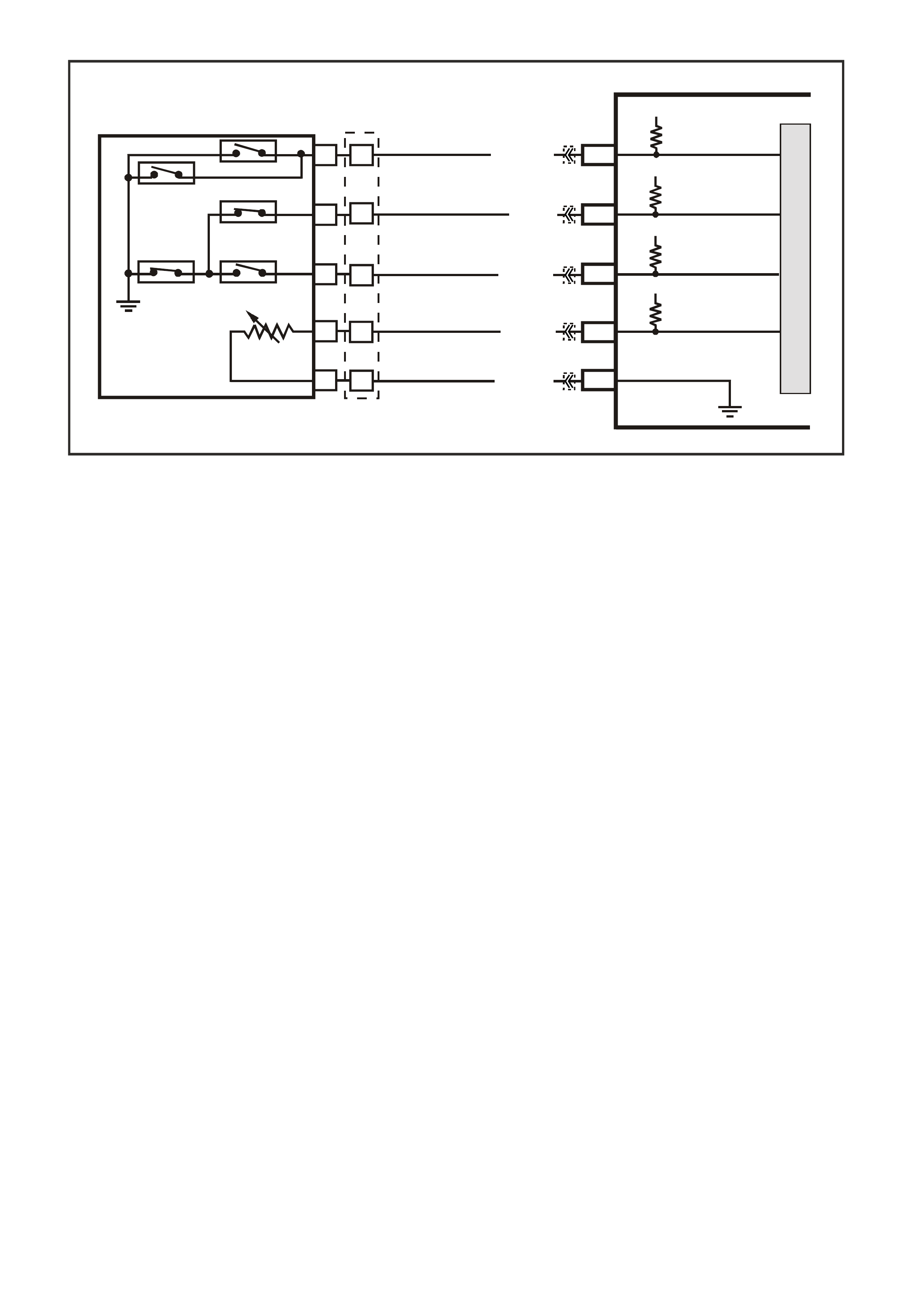
GEN III V8 PCM
DTC P0712 TFT SENSOR CIRCUIT LOW INPUT
CIRCUIT DESCRIPTION
The autom atic T ransm ission Fluid T emper ature (TF T) Sens or is part of the automatic T ransm ission Fluid Pressure
(TFP) manual valve position switch. The TFT sensor is a resistor, or thermistor, which changes value based on
temperature. The sensor has a negative-temperature coefficient. This means that as the temperature increases,
the resistance decreases, and as the temperature decreases, the resistance increases.
The Powertrain Control Module (PCM) supplies a 5-volt reference signal to the sensor on circuit 1227 and
meas ures the voltage dr op in the circuit. W hen the trans mission f luid is cold, the sensor res istance is high and the
PCM detects high signal voltage. As the fluid tem peratur e warm s to a norm al oper ating tem perature, the resis tance
becomes less and the signal voltage decreases. The PCM uses this information to control shift quality and torque
converter clutch apply.
When the PCM detects a c ontinuous s hort to earth, in the T FT signal c ircuit or in the T FT sens or, then DT C P0712
sets.
CONDITIONS FOR RUNNING THE DTC
• The system voltage is between 8.0 volts and 18 volts.
• The ignition switch is in the RUN position.
CONDITIONS FOR SETTING THE DTC
• The TFT sensor indicates a signal voltage less than 0.2 volts for 10 seconds.
ACTION TAKEN WHEN THE DTC SETS
• The PCM stores the DTC information into memory when the diagnostic runs and fails.
• The Check Powertrain Lamp will not be illuminated.
• The PCM records the operating conditions at the time the diagnostic fails. The PCM stores this information in
the Freeze Frame/Failure Records.
IMPORTANT:
The actions listed below are in order of highest to lowest priority.
• The PCM determines a default TFT using the following matrix:
1. If any ECT DTCs P0117 or P0118 are set, then the default TFT is equal to 135°C.
2. If the ECT is 125°C or more, then the default TFT is equal to 135°C.
3. If the engine run time is less than 300 seconds and:
- No intak e air tem per ature (IAT ) DT Cs P0112 or P0113 are set and IAT is available, then the default T FT is
equal to IAT.
- Any IAT DTCs P0112 or P0113 are set or IAT is NOT available, then the default TFT is equal to 90°C.
G3PCM034PT
PCM
J2-63
J1-17
J2-51
J1-53
TFP SIGNAL A
TFP SIGNAL B
TRANSMISSION FLUID
TEMPERATURE (TFT)
SENSOR SIGNAL
SENSOR EARTH
N
C
REV (N.0.)
LO (N.0.)
D3 (N.C.)
D4 (N.O.)D2 (N.C.)
R
E
D
A
B
P
L
M
TRANSMISSION FLUID
TEMPERATURE
(TF T ) SENSOR
AUTOMATIC TRANSMISSION FLUID
PRESSURE SWITCH ASSEMBLY
BR/Y (1224)YE123
YE122
YE122
YE123
YE122
YB129
Y (1225)
GY (1226)
B/Y (1227)
B/W (1230)
12V
12V
5V
J1-18 TFP SIGN AL C
12V
M
I
C
R
O

4. If the engine run time is greater than 300 seconds and no IAT DTCs P0112 or P0113 are set and IAT is
available and ECT is between 40 and 125°C and:
- IAT at startup is less than 15°C, then the default TFT is equal to the ECT plus 5°C.
- IAT at startup is greater than 35°C, then the default TFT is equal to the ECT plus 10°C.
- IAT at startup is between 15 and 35°C, then the default TFT is equal to the ECT.
5. If the engine run tim e is greater than 300 seconds and any IAT DTCs P0112 or P0113 are set or IAT is NOT
available, then the default TFT is equal to the ECT.
6. If the engine run time is greater than 300 seconds and ECT is les s than 40°C or m ore, then the default T FT
is equal to 60°C.
• The PCM freezes shift adapts from being updated.
• The PCM stores DTC P0712 in PCM history.
CONDITIONS FOR CLEARING THE DTC
• A last test failed (current DTC) clears when the diagnostic runs and does not fail.
• The PCM cancels the DTC default actions when the fault no longer exists and the ignition switch is OFF long
enough in order to power down the PCM.
DIAGNOSTIC AIDS
• Inspect the wiring at the PCM, the transmission connector and all other circuit connecting points for the
following conditions:
- A backed out terminal
- A damaged terminal
- Reduced terminal tension
- A chafed wire
- A broken wire inside the insulation
- Moisture intrusion
- Corrosion
• When diagnosing for an intermittent short or open condition, massage the wiring harness while watching the
test equipment for a change.
• Use the Temperature vs Resistance table when testing the TFT sensor at various temperature levels. Test the
TFT sensor in order to evaluate the possibility of a skewed (mis-scaled) sensor. A skewed sensor can result in
delayed garage shifts or TCC complaints.
• The scan tool displays the transmission fluid temperature in degrees. After the transmission is operating, the
fluid temperature should rise steadily to a normal operating temperature, then stabilise.
• Verify customer driving habits, trailer towing, etc. Trailer towing should occur in D3.
TEST DESCRIPTION
The numbers below refer to the step numbers on the diagnostic table.
4. This step creates an open in the TFT circuit in order to test for an internal fault.

P.C.M CONNECTOR 1
YE122
(776)
(1049)
(897)
(1230)
(848)
(1226)
(772)
(647)
(632)
40
(844)
(815)
80
J1
P/B
(845)
V/W
BLU
O
(633)
(846)
B/Y
B/R
(416)
(86)
(69)
(455)
(740)
GY
BR
G
GY
(646)
(410)
GY
(842)
(1225)
V
Y
(750)
P
41
O
(774)
BR/Y
BLU
Y
B/R
B
BLU/Y
(841)
BLUE
(414)
G/W
BLU
LG
LBLU/B
1
(847)
(415)
(740)
(452)
BLU
BR
Y
(750)
(826)
(421)
Y
V/W
B/W
(334)
(771)
(39)
Y
R/W
LBLU
W
BLU/W
(843)
(643)
LBLU/W
G
GY/B
BLU/B
(413)
(1413)
(1412)
(412)
GY
V
GY/B
G
(335)
YE123
P.C.M CONNECTOR 2
(750)
(1228)
(1229)
(465)
(121)
(259)
G/B
BR
G/W
GY/BLU
R
B/R
(418)
BR
(59)
(832)
G
T
(831)
(417)
(472)
(976)(974)
(432)
(428)
(631)
BLUBR G/Y
BLU/W
LG
BR/W
W/B
LG W
(977)
Y
(971)
BLU/WW
B/R
(750)
(304)
(792)
(1223)
(1222)
(123)
(1227)
(469)
(331)
Y/B
LG
V/W
B/Y
G/O BR/W
(1687)
GY/B
(366)
LG/B
GY/R
(422)
V
(442)
(444)
(443)
(975)
(972)
(978)
(1224)
(973)
(959)
LG/W
LG/B
LBLU/B
GY
(773)
BR/Y
BLU
G
Y/B
LBLU
(958)
BR
(441)
LBLU
1
41
40
80
J2
RED
Y
(838)
TRANSMISSION CONNECTOR
GY/BLU
(1229)
R
(1228)
Y/B
(1223)
LG
(1222)
P/BLU
(339)
(1227)
B/Y
(1230)
B/W
GY/R
(422)
BR
(418)
BR/Y
(1224)
(1226)
GY
Y
(1225)
(897)
G/W
(V8)
B
(469) (V6)
OR
GEN III V8 PCM - DTC P0712 TFT SENSOR CIRCUIT LOW INPUT
Step Action Value(s) Yes No
1 Was the Powertrain On-Board Diagnostic (OBD) System
Check performed? Go to Step 2 Go to Powertrain
OBD System
Check Table
2 Perform the transmission fluid checking procedure.
Refer to Transmission Fluid Checking Procedure in
Section 7C4, in VX Service Information.
Did you perform the fluid checking procedure?
Go to Step 3 Go to
Transmission
Fluid Checking
Procedure in
Section 7C4, in
VX Service
Information.
3 1. Install the Tech 2 Scan Tool.
2. With the engine OFF, turn the ignition switch to the
RUN position.
IMPORTANT: Before clearing the DTC, use the Scan
Tool in order to record the Failure Records. Using the
Clear Info function erases the Failure Records from the
PCM.
3. Record th e DTC Failure Records.
4. Clear the DTC.
5. Select TFT on the Scan Tool.
Does the Scan Tool display a TFT Sensor signal voltage
less than the specified value?
0.2 volts Go to Step 4 Go to
Diagnostic Aids
4
1. Turn the ignition OFF.
2. Disconnect the transmission 20-way connector.
3. With the engine OFF, turn the ignition switch to the
RUN position.
Does the Scan Tool display a TFT Sensor signal voltage
greater than the specified value?
4.92 volts
Go to Step 5
Go to Step 8

GEN III V8 PCM - DTC P0712 TFT SENSOR CIRCUIT LOW INPUT (CONTINUED)
Step Action Value(s) Yes No
5
1. Install the J 39775 jumper harness on the
transmission side of the 20-way connector.
2. Using the J 39200 digital multimeter (DMM) and the
J 35616 connector test adapter kit, measure the
resistance between terminal L and terminal M.
Is the resistance within the specified range?
3088-3942 Ω
at 20°C,
159-198 Ω at
100°C
Go to Diagnostic
Aids
Go to Step 6
6
Inspect circuit 1227 (BRN) of the automatic transmission
(A/T) wiring harness assembly for a short to earth
condition.
Did you find a short to earth condition?
Go to Step 10
Go to Step 7
7
1. Disconnect the A/T wiring harness assembly at the
TFT sensor.
2. Measure the resistance of the TFT sensor.
Is the resistance within the specified range?
3088-3942 Ω
at 20°C,
159-198 Ω at
100°C
Go to
Diagnostic Aids
Go to Step 9
8
1. Inspect circuit 1227 (B/Y) of the engine wiring harness
for a short to earth condition.
2. Repair the circuit if necessary.
Did you find a short to earth condition?
Go to Step 12
Go to Step 11
9
Replace the TFT sensor (this is part of the TFP manual
valve position switch).
Refer to Control Valve Body and Wiring Harness
replacement in Section 7C4, in VX Service Information.
Is the replacement complete?
Go to Step 12
10
Replace the automatic transmission wiring harness
assembly.
Refer to Control Valve Body and Wiring Harness
replacement in Section 7C4, in VX Service Information.
Is the replacement complete?
Go to Step 12
11
Replace the PCM.
Refer to Powertrain Control Module in Section 6C3-3 of
the VX Series Service Information.
Is the replacement complete?
Go to Step 12
12 Perform the following procedure in order to verify the
repair:
1. Select DTC.
2. Select Clear Info.
3. With the engine OFF, turn the ignition switch to the
RUN position.
4. Verify that the Scan Tool indicates a TFT Sensor
signal voltage greater than 0.2 volts for 10 seconds.
Was the above condition verified?
System OK
Go to Step 1

GEN III V8 PCM -
DTC P0713 TFT SENSOR CIRCUIT HIGH INPUT
CIRCUIT DESCRIPTION
The autom atic T ransm ission Fluid T emper ature (TF T) Sens or is part of the automatic T ransm ission Fluid Pressure
(TFP) manual valve position switch. The TFT sensor is a resistor, or thermistor, which changes value based on
temperature. The sensor has a negative-temperature coefficient. This means that as the temperature increases,
the resistance decreases, and as the temperature decreases, the resistance increases.
The Powertrain Control Module (PCM) supplies a 5-volt reference signal to the sensor on circuit 1227 and
meas ures the voltage dr op in the circuit. W hen the trans mission f luid is cold, the sensor res istance is high and the
PCM detects high signal voltage. As the fluid tem peratur e warm s to a norm al oper ating tem perature, the resis tance
becomes less and the signal voltage decreases. The PCM uses this information to control shift quality and torque
converter clutch apply.
When the PCM detects a c ontinuous s hort to earth, in the T FT signal c ircuit or in the T FT sens or, then DT C P0712
sets.
CONDITIONS FOR RUNNING THE DTC
• The system voltage is between 8.0 volts and 18 volts.
• The ignition switch is in the RUN position.
CONDITIONS FOR SETTING THE DTC
• The TFT sensor indicates a signal voltage greater than 4.92 volts for 10 seconds.
ACTION TAKEN WHEN THE DTC SETS
• The PCM stores the DTC information into memory when the diagnostic runs and fails.
• The Check Powertrain Lamp will not be illuminated.
• The PCM records the operating conditions at the time the diagnostic fails. The PCM stores this information in
the Freeze Frame/Failure Records.
IMPORTANT:
The actions listed below are in order of highest to lowest priority.
• The PCM determines a default TFT using the following matrix:
1. If any ECT DTCs P0117 or P0118 are set, then the default TFT is equal to 135°C.
2. If the ECT is 125°C or more, then the default TFT is equal to 135°C.
3. If the engine run time is less than 300 seconds and:
- No intake air temperatur e (I AT ) DT Cs P0112 or P0113 are s et and IAT is available, then the def ault TFT is
equal to IAT.
- Any IAT DTCs P0112 or P0113 are set or IAT is NOT available, then the default TFT is equal to 90°C.
G3PCM034PT
PCM
J2-63
J1-17
J2-51
J1-53
TFP SIGNAL A
TFP SIGNAL B
TRANSMISSION FLUID
TEMPERATURE (TFT)
SENSOR SIGNAL
SENSOR EARTH
N
C
REV (N.0.)
LO (N.0.)
D3 (N.C.)
D4 (N.O.)D2 (N.C.)
R
E
D
A
B
P
L
M
TRANSMISSION FLUID
TEMPERATURE
(TF T ) SENSOR
AUTOMATIC TRANSMISSION FLUID
PRESSURE SWITCH ASSEMBLY
BR/Y (1224)YE123
YE122
YE122
YE123
YE122
YB129
Y (1225)
GY (1226)
B/Y (1227)
B/W (1230)
12V
12V
5V
J1-18 TFP SIGN AL C
12V
M
I
C
R
O

4. If the engine run time is greater than 300 seconds and no IAT DTCs P0112 or P0113 are set and IAT is
available and ECT is between 40 and 125°C and:
- IAT at startup is less than 15°C, then the default TFT is equal to the ECT plus 5°C.
- IAT at startup is greater than 35°C, then the default TFT is equal to the ECT plus 10°C.
- IAT at startup is between 15 and 35°C, then the default TFT is equal to the ECT.
5. If the engine run tim e is greater than 300 seconds and any IAT DTCs P0112 or P0113 are set or IAT is NOT
available, then the default TFT is equal to the ECT.
6. If the engine run time is greater than 300 seconds and ECT is les s than 40°C or m ore, then the default T FT
is equal to 60°C.
• The PCM freezes shift adapts from being updated.
• The PCM stores DTC P0712 in PCM history.
CONDITIONS FOR CLEARING THE DTC
• A last test failed (current DTC) clears when the diagnostic runs and does not fail.
• The PCM cancels the DTC default actions when the fault no longer exists and the ignition switch is OFF long
enough in order to power down the PCM.
DIAGNOSTIC AIDS
• Inspect the wiring at the PCM, the transmission connector and all other circuit connecting points for the
following conditions:
- A backed out terminal
- A damaged terminal
- Reduced terminal tension
- A chafed wire
- A broken wire inside the insulation
- Moisture intrusion
- Corrosion
• When diagnosing for an intermittent short or open condition, massage the wiring harness while watching the
test equipment for a change.
• Use the T em perature vs Resist ance table when testing the TFT Sensor at var ious temper ature levels. Tes t the
TFT Sensor in or der to evaluate the possibility of a sk ewed ( mis- scaled) sensor . A s kewed sensor can result in
delayed garage shifts or TCC complaints.
• The scan tool displays the transmission fluid temperature in degrees. After the transmission is operating, the
fluid temperature should rise steadily to a normal operating temperature, then stabilise.
TEST DESCRIPTION
The numbers below refer to the step numbers on the diagnostic table.
3. This step verifies that a condition exists in the TFT sensor circuit.
4. This s tep s im ulates a TFT Sens or DTC P0712. If the PCM r ec ognises high temperatur e, the PCM and wiring are
functioning normally.
5. This step tests the TFT Sensor and automatic transmission (A/T) wiring harness assembly.

P.C.M CONNECTOR 1
YE122
(776)
(1049)
(897)
(1230)
(848)
(1226)
(772)
(647)
(632)
40
(844)
(815)
80
J1
P/B
(845)
V/W
BLU
O
(633)
(846)
B/Y
B/R
(416)
(86)
(69)
(455)
(740)
GY
BR
G
GY
(646)
(410)
GY
(842)
(1225)
V
Y
(750)
P
41
O
(774)
BR/Y
BLU
Y
B/R
B
BLU/Y
(841)
BLUE
(414)
G/W
BLU
LG
LBLU/B
1
(847)
(415)
(740)
(452)
BLU
BR
Y
(750)
(826)
(421)
Y
V/W
B/W
(334)
(771)
(39)
Y
R/W
LBLU
W
BLU/W
(843)
(643)
LBLU/W
G
GY/B
BLU/B
(413)
(1413)
(1412)
(412)
GY
V
GY/B
G
(335)
YE123
P.C.M CONNECTOR 2
(750)
(1228)
(1229)
(465)
(121)
(259)
G/B
BR
G/W
GY/BLU
R
B/R
(418)
BR
(59)
(832)
G
T
(831)
(417)
(472)
(976)(974)
(432)
(428)
(631)
BLUBR G/Y
BLU/W
LG
BR/W
W/B
LG W
(977)
Y
(971)
BLU/WW
B/R
(750)
(304)
(792)
(1223)
(1222)
(123)
(1227)
(469)
(331)
Y/B
LG
V/W
B/Y
G/O BR/W
(1687)
GY/B
(366)
LG/B
GY/R
(422)
V
(442)
(444)
(443)
(975)
(972)
(978)
(1224)
(973)
(959)
LG/W
LG/B
LBLU/B
GY
(773)
BR/Y
BLU
G
Y/B
LBLU
(958)
BR
(441)
LBLU
1
41
40
80
J2
RED
Y
(838)
TRANSMISSION CONNECTOR
GY/BLU
(1229)
R
(1228)
Y/B
(1223)
LG
(1222)
P/BLU
(339)
(1227)
B/Y
(1230)
B/W
GY/R
(422)
BR
(418)
BR/Y
(1224)
(1226)
GY
Y
(1225)
(897)
G/W
(V8)
B
(469) (V6)
OR
GEN III V8 PCM - DTC P0713 TFT SENSOR CIRCUIT HIGH INPUT
Step Action Value(s) Yes No
1 Was the Powertrain On-Board Diagnostic (OBD) System
Check performed? Go to Step 2 Go to Powertrain
OBD System
Check Table
2 Perform the transmission fluid checking procedure.
Refer to Transmission Fluid Checking Procedure in
Section 7C4, in VX Service Information.
Did you perform the fluid checking procedure?
Go to Step 3 Go to
Transmission
Fluid Checking
Procedure in
Section 7C4, in
VX Service
Information.
3 1. Install the Tech 2 Scan Tool.
2. With the engine OFF, turn the ignition switch to the
RUN position.
IMPORTANT: Before clearing the DTC, use the Scan
Tool in order to record the Failure Records. Using the
Clear Info function erases the Failure Records from the
PCM.
3. Record th e DTC Failure Records.
4. Clear the DTC.
Does the Scan Tool display a TFT Sensor signal voltage
greater than the specified value?
4.92 volts Go to Step 4 Go to
Diagnostic Aids
4
1. Turn the ignition OFF.
2. Disconnect the transmission 20-way connector.
3. Install the J39775 jumper harness on the engine side
of the 20-way connector.
4. Install a fused jumper wire from terminal L to terminal
M on the engine harness.
5. With the engine OFF, turn the ignition switch to the
RUN position.
Does the TFT Sensor signal voltage drop to less than the
specified value?
0.2 volts
Go to Step 5
Go to Step 9

GEN III V8 PCM - DTC P0713 TFT SENSOR CIRCUIT HIGH INPUT (CONTINUED)
Step Action Value(s) Yes No
5
1. Turn the ignition OFF.
2. Install the J 39775 jumper harness on the
transmission side of the 20-way connector.
3. Using the J 39200 digital multimeter (DMM) and the
J 35616 connector test adapter kit, measure the
resistance between terminal L and terminal M.
Is the resistance within the specified range?
3088-3942 Ω
at 20°C,
159-198 Ω at
100°C
Go to
Diagnostic Aids
Go to Step 6
6
Inspect circuits 1227 (BRN) and 452 (GRY) of the
automatic transmission (A/T) wiring harness assembly for
an open condition.
Did you find a short to earth condition?
Go to Step 11
Go to Step 7
7
1. Disconnect the A/T wiring harness assembly at the
TFT Sensor.
2. Measure the resistance of the TFT sensor.
Is the resistance within the specified range?
3088-3942 Ω
at 20°C,
159-198 Ω at
100°C
Go to
Diagnostic Aids
Go to Step 8
8
Replace the TFT Sensor (this is part of the TFP manual
valve position switch).
Refer to Control Valve Body and Wiring Harness
replacement in Section 7C4, in VX Service Information.
Is the replacement complete?
Go to Step 13
9
1. Inspect circuit 1227 (B/Y), of the engine wiring
harness, for an open or short to B+ condition.
2. Repair the circuit if necessary.
Did you find an open or short to B+ condition?
Go to Step 13
Go to Step 10
10
1. Inspect circuit 1230 (B/W) for an open condition.
2. Repair the circuit if necessary.
Did you find an open condition?
Go to Step 13 Go to Step 12
11
Replace the automatic transmission wiring harness
assembly.
Refer to Control Valve Body and Wiring Harness
replacement in Section 7C4, in VX Service Information.
Is the replacement complete?
Go to Step 13
12 Replace the PCM.
Refer to Powertrain Control Module in Section 6C3-3, of
the VX Series Service Information.
Is the replacement complete?
Go to Step 13
13 Perform the following procedure in order to verify the
repair:
1. Select DTC.
2. Select Clear Info.
3. With the engine OFF, turn the ignition switch to the
RUN position.
4. Verify that the Scan Tool indicates a TFT Sensor
signal voltage greater than 4.92 volts for 409 seconds
(6.8 minutes).
Was the above condition verified?
System OK
Go to Step 1
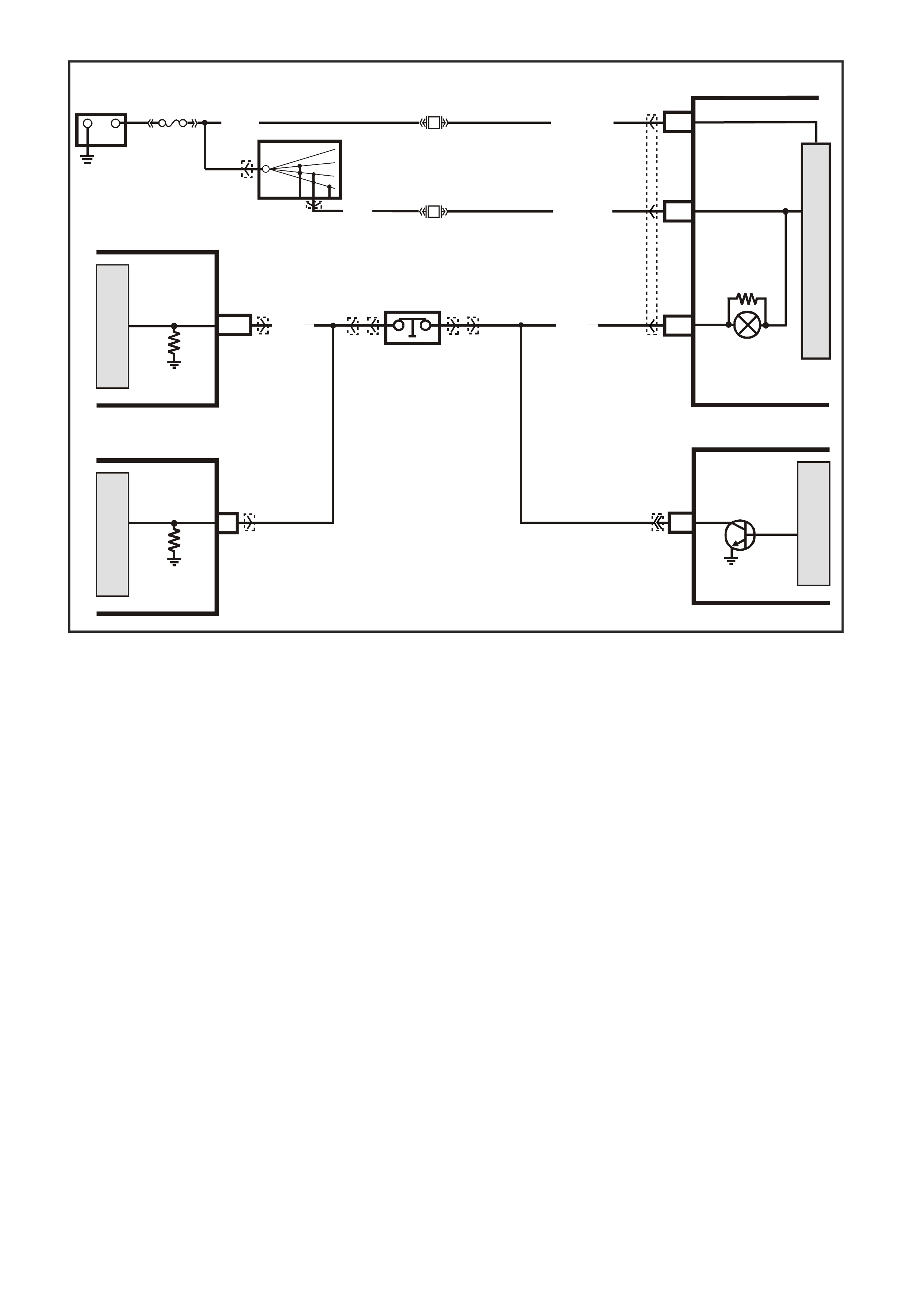
GEN III V8 PCM -
DTC P0719 BRAKE SWITCH CIRCUIT LOW INPUT
CIRCUIT DESCRIPTION
The brake switch indicates brake pedal status to the powertrain control module (PCM). The brake switch is a
normally-closed switch that supplies voltage on circuit 86 to the PCM. Applying the brake pedal opens the switch,
interrupting voltage to the PCM. W hen the brake pedal is released, the PCM receives a constant voltage signal. If
the PCM receives a zero voltage signal at the brake switch input, and the Torque Converter Clutch (TCC) is
engaged, the PCM de-energises the TCC solenoid valve. The PCM disregards the brake switch input for TCC
scheduling if there is a brake switch circuit fault (Refer to Diagnostic Aids).
When the PCM detects an open brake switch circuit (0 volts, low input) during accelerations, then DTC P0719 sets.
CONDITIONS FOR RUNNING THE DTC
• No VSS assembly DTCs P0502 or P0503.
• The ignition switch is in the RUN position.
CONDITIONS FOR SETTING THE DTC
• The PCM detects an open brake s witch circuit (0 volts ) for 15 m inutes without changing for 2 s econds, and the
following events occur seven times:
- The vehicle speed is less than 8 km/h;
- Then the vehicle speed is 8 – 32 km/h for four seconds;
- Then the vehicle speed is greater than 32 km/h for six seconds.
ACTION TAKEN WHEN THE DTC SETS
• The PCM stores the DTC information into memory when the diagnostic runs and fails.
• The Check Powertrain Lamp will not be illuminated.
• The PCM disregards the brake switch input for TCC scheduling.
• The PCM records the operating conditions at the time the diagnostic fails. The PCM stores this information in
the Freeze Frame/Failure Records.
BATTERY M AIN P OWER
M
I
C
R
O
G3PCM018PT
+-
BATTERY
FJ
F21
20O/Y (1340)
R (2H)
F13
IGNITION
19P/BLU ( 44)
15a 15 50
30 OFF/ON
LOCK
ACC
IGN
START
IGNITION
SWITCH
P (3)
11 LOW
TRACTION
LAMP
LOW
TRACTION
BRAKE
SWITCH
INPUT
SIGNAL
BRAKE
SWITCH
INPUT
SIGNAL
PCM
M
I
C
R
O
M
I
C
R
O
M
I
C
R
O
J1-33 Y/R (88)
STOP LAMP
SWITCH B
(NC)
CRUISE CONTROL
MODULE ABS/ETC
INSTRUMENTS
D20
B/R (86)
YE56
YE122 YB65
YB12
YB44
YB44
YB12
YB65 YB66
YE98
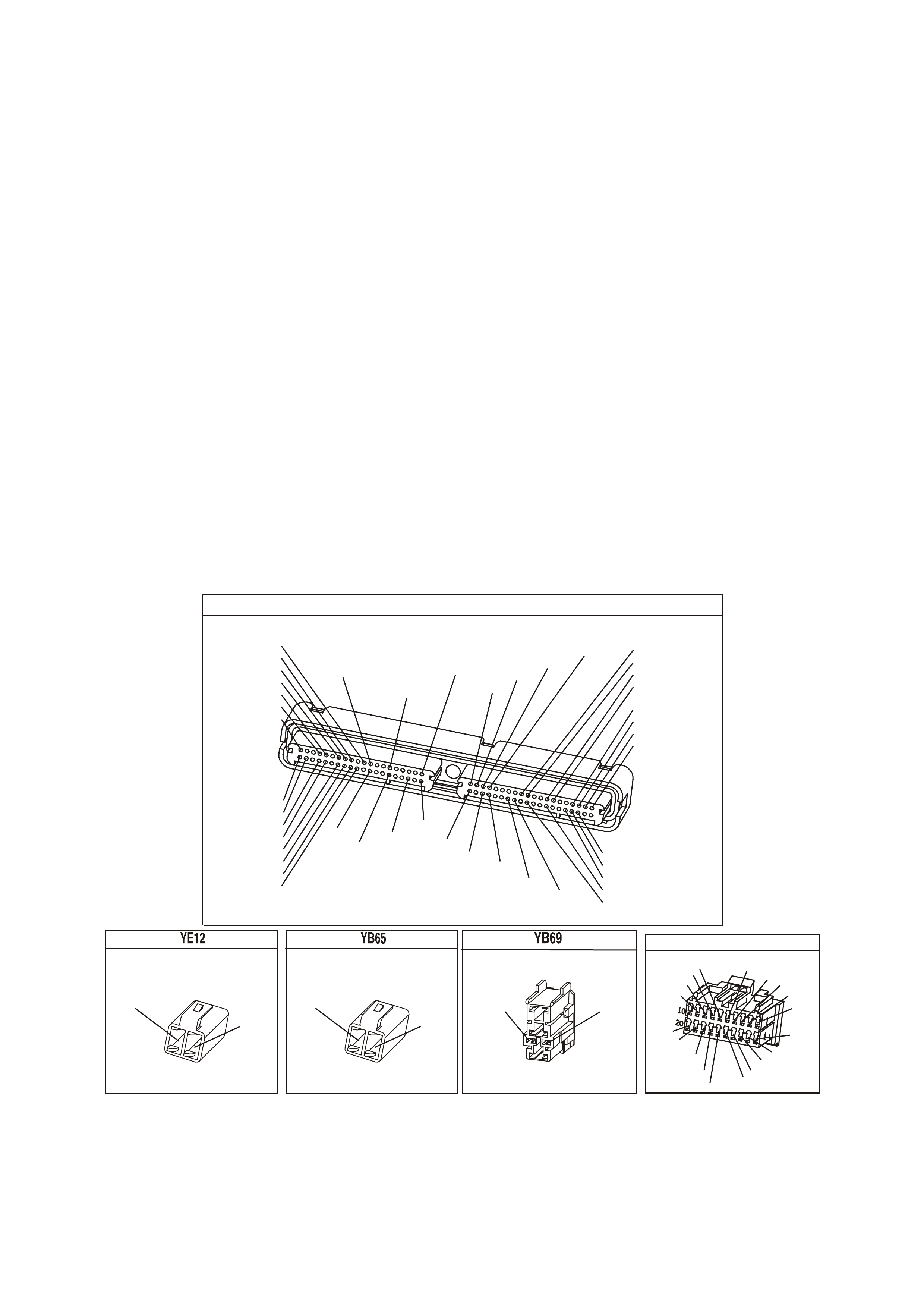
CONDITIONS FOR CLEARING THE DTC
• A last test failed (current DTC) clears when the diagnostic runs and does not fail.
• The PCM cancels the DTC default actions when the fault no longer exists and the ignition switch is OFF long
enough to power down the PCM.
DIAGNOSTIC AIDS
• Inspect the wiring at the PCM, the brake switch connector and all other circuit connecting points for the
following conditions:
- A backed out terminal
- A damaged terminal
- Reduced terminal tension
- A chafed wire
- A broken wire inside the insulation
- Moisture intrusion
- Corrosion
• When diagnosing for an intermittent short or open condition, massage the wiring harness while watching the
test equipment for a change.
• If the PCM detects a brake switch circuit fault, then the brake switch input is disregarded for TCC scheduling.
The PCM then uses throttle position and vehicle speed to determine TCC application and release.
• Use of these inputs may result in a noticeable harsh apply or abrupt release of the TCC.
• Ask about the customer's driving habits. Ask about unusual driving conditions (e.g. stop and go,
expressway, etc.).
• Inspect the brake switch for proper mounting and operation.
TEST DESCRIPTION
The number below refers to the step numbers on the diagnostic table.
3. This step isolates the brake switch as a source for setting the DTC.
P.C.M CONNECTOR 1
Y E1 22
(776)
(1049)
(897)
(1230)
(848)
(1226)
(772)
(647)
(632)
40
(844)
(815)
80
J1
P/B
(845)
V/W
BLU
O
(633)
(846)
B/Y
B/R
(416)
(86)
(69)
(455)
(740)
GY
BR
G
GY
(646)
(410)
GY
(842)
(1225)
V
Y
(750)
P
41
O
(774)
BR/Y
BLU
Y
B/R
B
BLU/Y
(841)
BLUE
(414)
G/W
BLU
LG
LBLU/B
1
(847)
(415)
(740)
(452)
BLU
BR Y
(750)
(826)
(421)
Y
V/W
B/W
(334)
(771)
(39)
Y
R/W
LBLU
W
BLU/W
(843)
(643)
LBLU/W
G
GY/B
BLU/B
(413)
(1413)
(1412)
(412)
GY
V
GY/B
G
(335)
STOP LAMPS SWITCH "B"
AUTO TRANSMISS ION
(88)
Y/R
B/R
(86)
STOP LAMPS SWITCH "B"
MANUAL TRANSMISS ION
(88)
Y/R
V/W
(78)
CLUTCH SWITCH
BRV/W
(78) (86)
YB 66
INSTRUMENTS
T
BLU/B
BR/W
(234)
(25)
(14)
(10)
(875)
(155)
(1340)
G/W
(44)
(121)
(8)
(30)
BLU/Y
G
O/Y
P/BLU
BR/R
V/W
(33)
(946)
(1220)
(88)
(15)
(123)
(85)
(19)
GY
W
V/R
BR
BR/O
Y/R
B/Y
LBLU
BLU

GEN III V8 PCM - DTC P0719 BRAKE SWITCH CIRCUIT LOW INPUT
Step Action Value(s) Yes No
1 Was the Powertrain On-Board Diagnostic (OBD) System
Check performed? Go to Step 2 Go to Powertrain
OBD System
Check Table.
2 1. Install the Tech 2 Scan Tool.
2. With the engine OFF, turn the ignition switch to the
RUN position.
IMPORTANT: Before clearing the DTC, use the Scan
Tool in order to record the Failure Records. Using the
Clear Info function erases the Failure Records from the
PCM.
3. Record th e DTC Failure Records.
4. Clear the DTC.
5. Select TCC Brake Switch on the Scan Tool.
6. Disconnect the brake switch connector from the brake
switch.
7. Connect a test lamp from circuit 88 (Y/R) of the brake
switch connector to earth.
Is the test lamp ON?
Go to Step 3 Go to Step 4
3 Install a fused jumper wire from circuit 88 (Y/R) to circuit
86 (BR) of the brake switch connector.
Did the TCC Brake Switch status change from Open to
Closed?
Go to Step 7 Go to Step 9
4 1. Remove the F13 fuse.
2. Inspect the fuse for an open.
Is the fuse open?
Go to Step 5 Go to Step 8
5 1. IMPORTANT: The condition that affects this circuit
may exist in other connecting branches of the circuit.
Refer to Power Distribution Diagrams in Section 14E,
in VX Service Information.
2. Inspect circuit 88 (Y/R) for a short to earth condition.
3. Repair the circuit if necessary.
Did you find a short to earth condition?
Go to Step 11 Go to Step 6
6 1. Inspect circuit 86 (BR) for a short to earth condition.
2. Repair the circuit if necessary.
Did you find a short to earth condition?
Go to Step 11 Go to Step 10
7 Replace the brake switch.
Refer to Section 12B Stop Lamp Switch Replacement in
Section 14C in VX Service Information.
Is the replacement complete?
Go to Step 11
8 1. IMPORTANT: The condition that affects this circuit
may exist in other connecting branches of the circuit.
Refer to Power Distribution Diagrams in Section 14E,
in VX Service Information.
2. Inspect circuit 88 (Y/R) for an open condition.
3. Repair the circuit if necessary.
Did you find an open condition?
Go to Step11
9 1. Inspect circuit 86 (BR) for an open condition.
2. Repair the circuit if necessary.
Did you find an open condition?
Go to Step 11 Go to Step 10
10 Replace the PCM.
Refer to Powertrain Control Module in Section 6C3-3 of
the VX Series Service Information.
Is the replacement complete?
Go to Step 11

GEN III V8 PCM - DTC P0719 BRA KE SWITCH CIRCUIT LOW INPUT (CONTINUED)
Step Action Value(s) Yes No
11
Perform the following procedure in order to verify the
repair:
1. Select DTC.
2. Select Clear Info.
3. With the engine OFF, turn the ignition switch to the
RUN position.
4. Apply and release the brake pedal.
5. Verify that the Scan Tool TCC Brake Switch status
indicates Closed (12 volts) for 2 seconds.
Was the above condition verified?
System OK
Go to Step 1
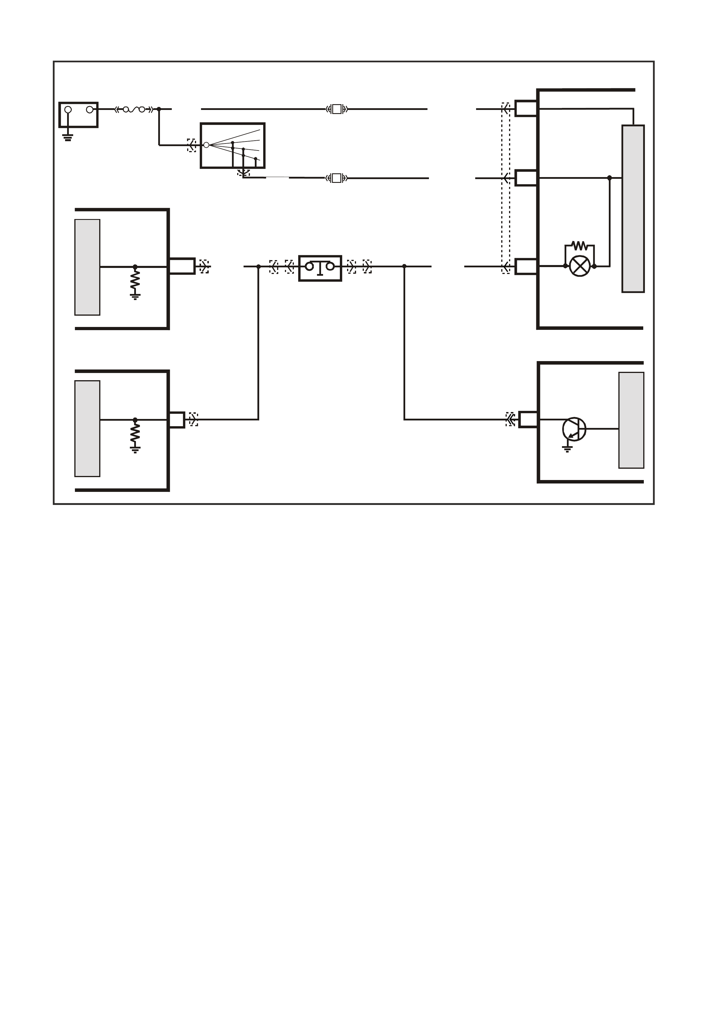
GEN III V8 PCM -
DTC P0724 BRAKE SWITCH CIRCUIT HIGH INPUT
CIRCUIT DESCRIPTION
The brake switch indicates brake pedal status to the powertrain control module (PCM). The brake switch is a
normally-closed switch that supplies voltage on circuit 86 to the PCM. Applying the brake pedal opens the switch,
interrupting voltage to the PCM. W hen the brake pedal is released, the PCM receives a constant voltage signal. If
the PCM receives a zero voltage signal at the brake switch input, and the Torque Converter Clutch (TCC) is
engaged, the PCM de-energises the TCC solenoid valve. The PCM disregards the brake switch input for TCC
scheduling, if there is a brake switch circuit fault (Refer to Diagnostic Aids).
W hen the PCM detects an closed brak e switch circuit (12 volts, high input) during decelerations, then DT C P0724
sets.
CONDITIONS FOR RUNNING THE DTC
• No VSS assembly DTCs P0502 or P0503.
• The ignition switch is in the RUN position.
CONDITIONS FOR SETTING THE DTC
• The PCM detects an closed brake switch circuit (12 volts) without changing for 2 seconds, and the following
events occur seven times:
- Then the vehicle speed is greater than 32 km/h for six seconds.
- Then the vehicle speed is 8 – 32 km/h for four seconds;
- The vehicle speed is less than 8 km/h;
ACTION TAKEN WHEN THE DTC SETS
• The PCM stores the DTC information into memory when the diagnostic runs and fails.
• The Check Powertrain Lamp will not be illuminated.
• The PCM records the operating conditions at the time the diagnostic fails. The PCM stores this information in
the Freeze Frame/Failure Records.
BATTERY M AIN P OWER
M
I
C
R
O
G3PCM018PT
+-
BATTERY
FJ
F21
20O/Y (1340)
R (2H)
F13
IGNITION
19P/BLU ( 44)
15a 15 50
30 OFF/ON
LOCK
ACC
IGN
START
IGNITION
SWITCH
P (3)
11 LOW
TRACTION
LAMP
LOW
TRACTION
BRAKE
SWITCH
INPUT
SIGNAL
BRAKE
SWITCH
INPUT
SIGNAL
PCM
M
I
C
R
O
M
I
C
R
O
M
I
C
R
O
J1-33 Y/R (88)
STOP LAMP
SWITCH B
(NC)
CRUISE CONTROL
MODULE ABS/ETC
INSTRUMENTS
D20
B/R (86)
YE56
YE122 YB65
YB12
YB44
YB44
YB12
YB65 YB66
YE98
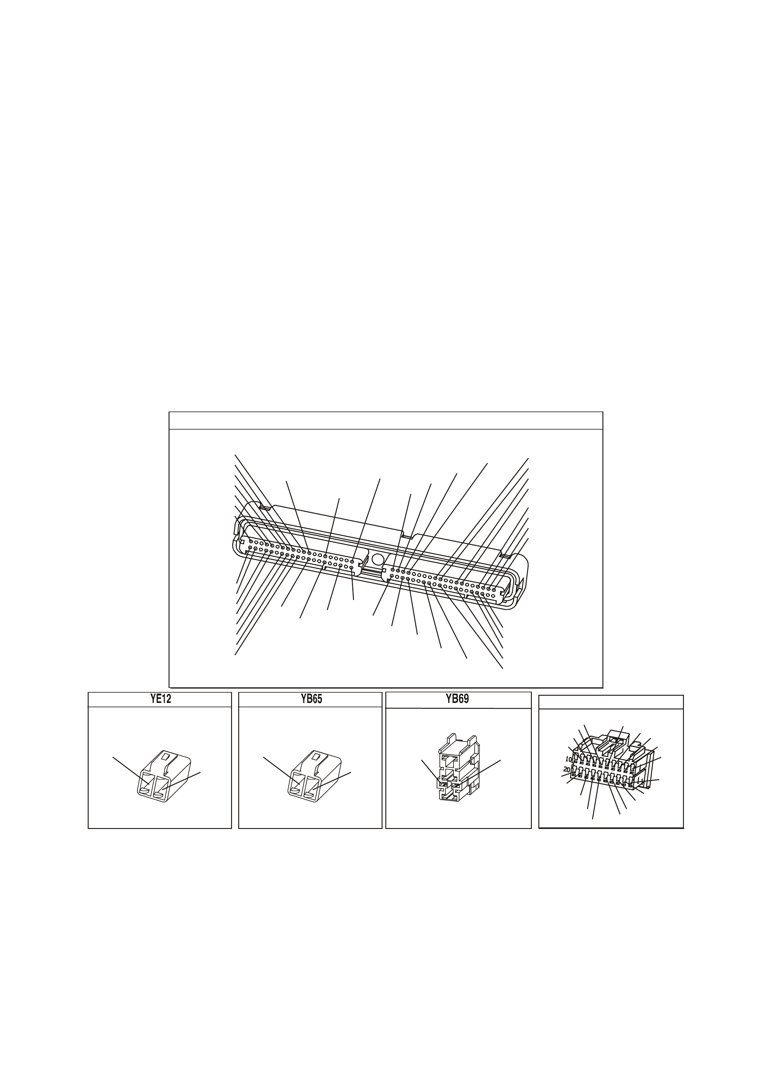
CONDITIONS FOR CLEARING THE DTC
• A last test failed (current DTC) clears when the diagnostic runs and does not fail.
• The PCM cancels the DTC default actions when the fault no longer exists and the ignition switch is OFF long
enough to power down the PCM.
DIAGNOSTIC AIDS
• Inspect the wiring at the PCM, the brake switch connector and all other circuit connecting points for the
following conditions:
- A backed out terminal
- A damaged terminal
- Reduced terminal tension
- A chafed wire
- A broken wire inside the insulation
- Moisture intrusion
- Corrosion
• When diagnosing for an intermittent short or open condition, massage the wiring harness while watching the
test equipment for a change.
• Ask about the customer’s driving habits or unusual driving conditions (e.g. stop & go, highway, etc.).
• Inspect the brake switch for proper mounting and operation.
TEST DESCRIPTION
The number below refers to the step numbers on the diagnostic table.
2. This step isolates the brake switch as a source for setting the DTC.
P.C.M CONNECTOR 1
Y E1 22
(776)
(1049)
(897)
(1230)
(848)
(1226)
(772)
(647)
(632)
40
(844)
(815)
80
J1
P/B
(845)
V/W
BLU
O
(633)
(846)
B/Y
B/R
(416)
(86)
(69)
(455)
(740)
GY
BR
G
GY
(646)
(410)
GY
(842)
(1225)
V
Y
(750)
P
41
O
(774)
BR/Y
BLU
Y
B/R
B
BLU/Y
(841)
BLUE
(414)
G/W
BLU
LG
LBLU/B
1
(847)
(415)
(740)
(452)
BLU
BR Y
(750)
(826)
(421)
Y
V/W
B/W
(334)
(771)
(39)
Y
R/W
LBLU
W
BLU/W
(843)
(643)
LBLU/W
G
GY/B
BLU/B
(413)
(1413)
(1412)
(412)
GY
V
GY/B
G
(335)
STOP LAMPS SWITCH "B"
AUTO TRANSMISS ION
(88)
Y/R
B/R
(86)
STOP LAMPS SWITCH "B"
MANUAL TRANSMISS ION
(88)
Y/R
V/W
(78)
CLUTCH SWITCH
BRV/W
(78) (86)
YB 66
INSTRUMENTS
T
BLU/B
BR/W
(234)
(25)
(14)
(10)
(875)
(155)
(1340)
G/W
(44)
(121)
(8)
(30)
BLU/Y
G
O/Y
P/BLU
BR/R
V/W
(33)
(946)
(1220)
(88)
(15)
(123)
(85)
(19)
GY
W
V/R
BR
BR/O
Y/R
B/Y
LBLU
BLU

GEN III V8 PCM - DTC P0724 BRAKE SWITCH CIRCUIT HIGH INPUT
Step Action Value(s) Yes No
1 Was the Powertrain On-Board Diagnostic (OBD) System
Check performed? Go to Step 2 Go to Powertrain
OBD System
Check Table.
2 1. Install the Tech 2 Scan Tool.
2. With the engine OFF, turn the ignition switch to the
RUN position.
IMPORTANT: Before clearing the DTC, use the Scan
Tool in order to record the Failure Records. Using the
Clear Info function erases the Failure Records from the
PCM.
3. Record th e DTC Failure Records.
4. Clear the DTC.
5. Select TCC Brake Switch on the Scan Tool.
6. Disconnect the brake switch connector from the brake
switch.
Did the TCC Brake Switch status change from Closed to
Open?
Go to Step 3 Go to Step 4
3 Replace the brake switch.
Is the replacement complete? Go to Step 6
4 1. Inspect circuit 86 (BR) for a short to earth condition.
2. Repair the circuit if necessary.
Did you find a short to B+ condition?
Go to Step 6 Go to Step 5
5 Replace the PCM.
Refer to Powertrain Control Module in Section 6C3-3, of
the VX Series Service Information.
Is the replacement complete?
Go to Step 6
6
Perform the following procedure in order to verify the
repair:
1. Select DTC.
2. Select Clear Info.
3. With the engine OFF, turn the ignition switch to the
RUN position.
4. Apply and release the brake pedal.
5. Verify that the Scan Tool TCC Brake Switch status
indicates Open (0 volts) for 2 seconds.
Was the above condition verified?
System OK
Go to Step 1

GEN III V8 PCM
DTC P0740 TCC ENABLE SOLENOID CIRCUIT ELECTRICAL
CIRCUIT DESCRIPTION
The Torque Converter Clutch (TCC) solenoid valve is an electrical device that is used with the Torque Converter
Clutch Pulse Width Modulation (TCC PWM) solenoid valve, in order to control TCC apply and release. The TCC
solenoid valve attaches to the transm iss ion case as sem bly extending into the pump c over. T he T CC solenoid valve
receives ignition voltage through circuit 339. The powertrain control module (PCM) controls the solenoid by
providing the earth path on circuit 422. T he PCM monitors the throttle position (TP) voltage, the vehicle speed and
other inputs in order to determine when to energise the TCC solenoid valve.
When the PCM detects a continuous open or a short to earth in the TCC solenoid valve circuit or in the TCC
solenoid valve, then DTC P0740 sets.
CONDITIONS FOR RUNNING THE DTC
• The system voltage is between 8.0 and 18 volts.
• The engine speed is greater than 300 RPM for 5 seconds.
• The engine is not in fuel cutoff.
CONDITIONS FOR SETTING THE DTC
• The PCM commands the solenoid ON and the voltage input remains high (12 volts).
Or
• The PCM commands the solenoid OFF and the voltage input remains low (0 volts).
4356
PCM
J2-47
J2-48
J1-79
J2-42
J2-04
J2-08
J2-06
TCC PWM
SOLENOID
3-2 CONTROL
SOLENOID
1-2 SHIFT
SOLENOID A
2-3 SHIFT
SOLENOID B
PRESSURE
CONTROL
SOLENOID
LOW
PRESSURE CONTROL
SOLENOID HIGH
B
A
A
B
B
B
A
A
B
A
YB 129 T RANSMIS SION
PASS-THRU CONNECTOR
TORQUE
CONVERTER
CLUTCH (TCC)
(PWM)
SOLENOID
TORQUE
CONVERTER
CLUTCH (TCC)
ENABLE
SOLENOID
3-2 DOWNSHIFT
CONTROL
SOLENOID
1-2 SHIFT
SOLENOID A
2-3 SHIFT
SOLENOID B
PRESSURE
CONTROL
SOLENOID
C
D
U
S
T
E
A
B
P/BLU (339)
TCC ENABLE
SOLENOID
B
A
EFI
RELAY
F32
G/W (897)
YE122
YE123
LG (1222)
Y/B (1223)
GY/BLU (1229)
R (1228)
12V
M
I
C
R
O
P
R
O
C
E
S
S
O
R
BR (418)
GY/R (422)
YE110
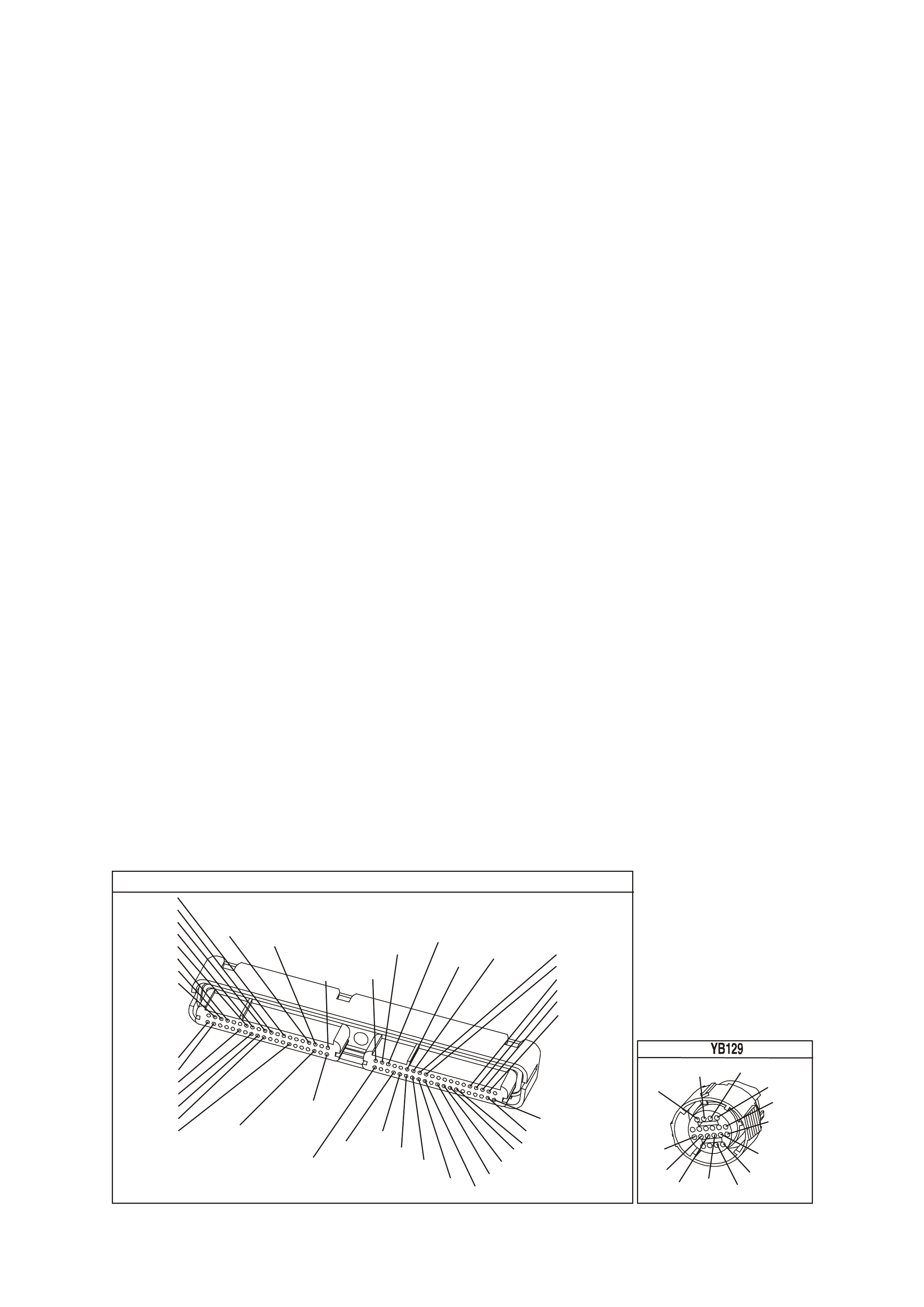
ACTION TAKEN WHEN THE DTC SETS
• The PCM does not illuminates the Check Powertrain Lamp.
• The PCM inhibits TCC engagement.
• The PCM inhibits 4th gear if the transmission is in hot mode.
• The PCM freezes shift adapts from being updated.
• The PCM records the operating conditions at the time the diagnostic fails. The PCM stores this information in
the Freeze Frame/Failure Records.
• The PCM inhibits 4th gear if the transmission is in hot mode.
• The PCM freezes shift adapts from being updated.
• The PCM stores DTC P0740 in PCM history during the second consecutive trip in which the conditions for
setting the DTC are met.
CONDITIONS FOR CLEARING THE DTC
• A last test failed (current DTC) clears when the diagnostic runs and does not fail.
• The PCM cancels the DTC default actions when the fault no longer exists and the ignition switch is OFF long
enough in order to power down the PCM.
DIAGNOSTIC AIDS
• Inspect the wiring at the PCM, the transmission connector and all other circuit connecting points for the
following conditions:
- A backed out terminal
- A damaged terminal
- Reduced terminal tension
- A chafed wire
- A broken wire inside the insulation
- Moisture intrusion
- Corrosion
• When diagnosing for an intermittent short or open condition, massage the wiring harness while watching the
test equipment for a change.
• With the TCC engaged, the TCC slip speed should be -20 to +40 RPM.
TEST DESCRIPTION
The numbers below refer to the step numbers on the diagnostic table.
2. This step tests for voltage to the solenoid.
4. This step tests the ability of the PCM and wiring to control the earth circuit.
6. This step tests the resistance of the TCC solenoid valve and the automatic transmission (A/T) wiring harness
assembly.
Y E 123
P.C.M CONNECTOR 2
(750)
(1228)
(1229)
(465)
(121)
(259)
G/B
BR
G/W
GY/BLU
R
B/R
(418)
BR
(59)
(832)
G
T
(831)
(417)
(472)
(976) (974)
(432)
(428)
(631)
BLU BR G/Y
BLU/W
LG
BR/W
W/B
LG W
(977)
Y
(971)
BLU/W W
B/R
(750)
(304)
(792)
(1223)
(1222)
(123)
(1227)
(469)
(331)
Y/B
LG
V/W
B/Y
G/O BR/W
(1687)
GY/B
(366)
LG/B
GY/R
(422)
V
(442)
(444)
(443)
(975)
(972)
(978)
(1224)
(973)
(959)
LG/W
LG/B
LBLU/B
GY
(773)
BR/Y
BLU
G
Y/B
LBLU
(958)
BR
(441)
LBLU
1
41
40
80
J2
RED
Y
(838)
TRANSMISSION CONNECTOR
GY/BLU
(1229)
R
(1228)
Y/B
(1223)
LG
(1222)
P/BLU
(339)
(1227)
B/Y
(1230)
B/W
GY/R
(422)
BR
(418)
BR/Y
(1224)
(1226)
GY
Y
(1225)
(897)
G/W
(V8)
B
(469) (V6)
OR

GEN III V8 PCM - DTC P0740 TCC ENABLE SOLENOID CIRCUIT ELECTRICAL
Step Action Value(s) Yes No
1 Was the Powertrain On-Board Diagnostic (OBD) System
Check performed? Go to Step 2 Go to Powertrain
OBD System
Check Table.
2
1. Install the Tech 2 Scan Tool.
2. With the engine OFF, turn the ignition switch to the
RUN position.
IMPORTANT: Before clearing the DTC, use the Scan
Tool in order to record the Freeze Frame and Failure
Records. Using the Clear Info function erases the Freeze
Frame and Failure Records from the PCM.
1. Record the DTC Freeze Frame and Failure Records.
2. Clear the DTC.
Are any of the following DTCs also set?
• P0753
• P0758
• P0785
• P1860
Go to Step 3
Go to Step 4
3
1. Inspect fuse F32.
2. If the fuse is open, inspect the following components
for a short to earth condition:
- Circuit 339 (P/BLU)
- The solenoids
- The A/T wiring harness assembly
3. Repair the circuit, the solenoids, and the harness if
necessary.
Did you find a short to earth condition?
Go to Step 12
Go to Step 4
4
1. Turn the ignition switch OFF.
2. Disconnect the transmission 20-way connector
(additional DTCs may set).
3. Install the J 39775 jumper harness on the engine side
of the 20-way connector.
4. With the engine OFF, turn the ignition switch to the
RUN position.
5. Connect a test lamp from cavity E of the J 39775
jumper harness to earth.
6. Refer to AT Inline Harness Connector End View of the
VX Series Service Information.
Is the test lamp ON?
Go to Step 6
Go to Step 5
5
IMPORTANT: The condition that affects this circuit may
exist in other connecting branches of the circuit. Refer to
Power Distribution Diagrams in Section 14E, in VX
Service Information.
Repair the open or short to earth in ignition feed circuit
339 (P/BLU) to the TCC solenoid valve.
Is the repair complete?
Go to Step 12
6
1. Install the test lamp from cavities E to T of the
J 39775 jumper harness.
2. Using the transmission Miscellaneous Tests function
on the Scan Tool, command the TCC solenoid valve
ON and OFF three times.
Does the test lamp turn ON, when the TCC solenoid
valve is commanded ON and OFF, when commanded
OFF?
Go to Step 8
Go to Step 7

GEN III V8 PCM - DTC P0740 TCC ENABLE SOLENOID CIRCUIT ELECTRICAL (CONTINUED)
Step Action Value(s) Yes No
7
1. Inspect circuit 422 (GY/R) of the engine wiring
harness, for an open, short to earth or short to power
condition.
2. Repair the circuit if necessary.
Did you find an open, short to earth or short to power
condition?
Go to Step 12
Go to Step 9
8
1. Install the J 39775 jumper harness on the
transmission side of the 20-way connector.
2. Using the J 39200 digital multimeter (DMM) and the
J 35616 connector test adapter kit, measure the
resistance between terminals T and E.
Is the resistance within the specified range?
21-33 Ω
Go to Step 10
Go to Step 11
9
Replace the PCM.
Refer to Powertrain Control Module in Section 6C3-3 of
the VX Series Service Information.
Is the replacement complete?
Go to Step 12
10
Measure the resistance between terminal E and earth,
and between terminal T and earth.
Are both readings greater than the specified value?
250 K Ω
Go to
Diagnostic Aids
Go to Step 11
11
Replace the automatic transmission wiring harness
assembly (this includes the TCC solenoid valve).
Refer to Control Valve Body and Wiring Harness
replacement in Section 7C4, in VX Service Information.
Is the replacement complete?
Go to Step 12
12
Perform the following procedure in order to verify the
repair:
1. Select DTC.
2. Select Clear Info.
3. Drive the vehicle in D with the TCC ON and OFF.
Ensure the following conditions are met:
- The PCM commands the TCC solenoid valve ON,
and the voltage input drops to zero.
- The PCM commands the TCC solenoid valve OFF,
and the voltage input increases to B+.
- All conditions are met for 5 seconds.
Were the above conditions verified?
System OK
Go to Step 1
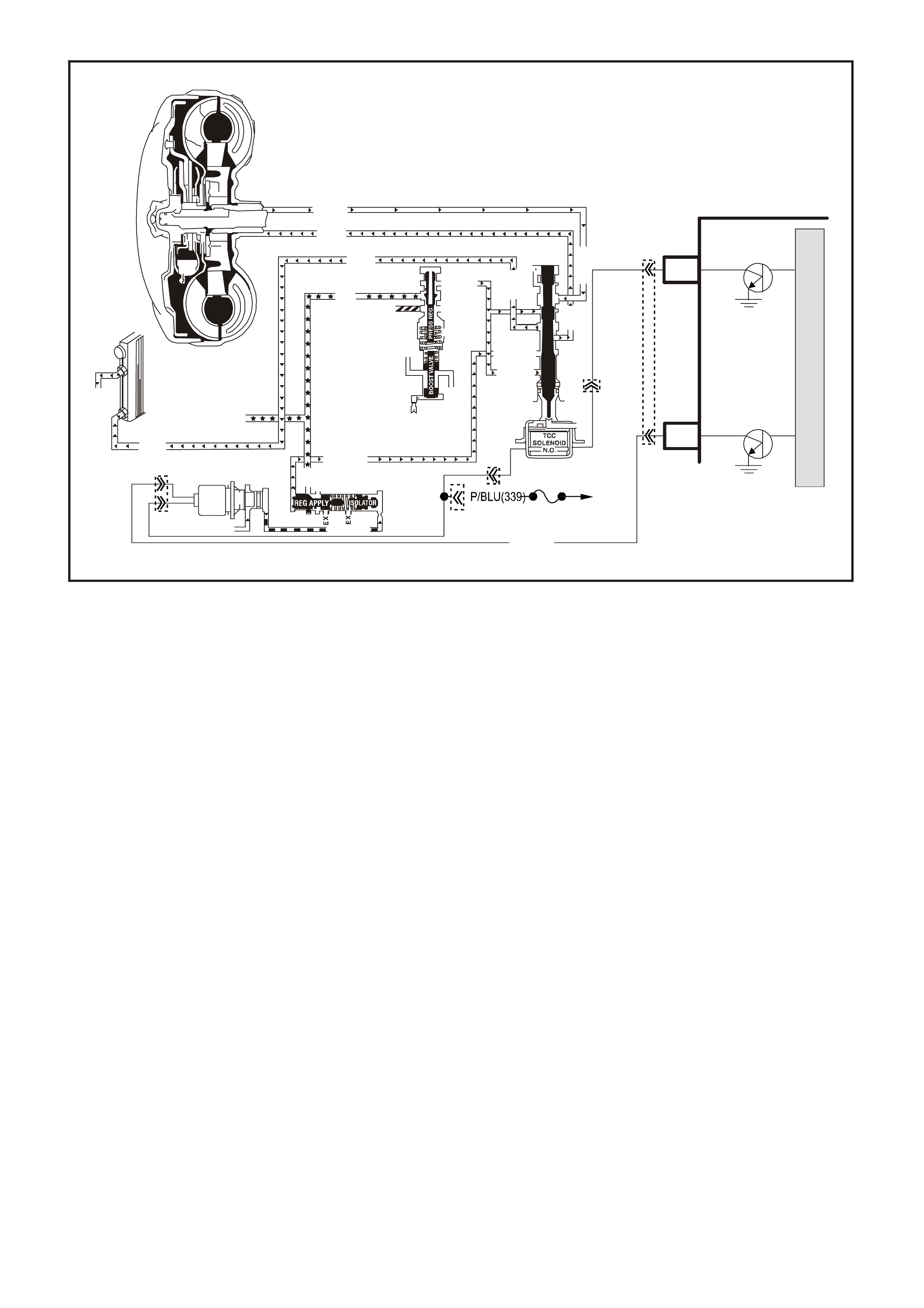
GEN III V8 PCM -
DTC P0742 TCC SYSTEM STUCK ON
CIRCUIT DESCRIPTION
The Torque Converter Clutch (TCC) solenoid valve is a normally-open exhaust valve that is used with the Torque
Converter Clutch Pulse Width Modulation (TCC PWM) solenoid valve in order to control fluid acting on the
converter clutch apply valve. The TCC solenoid valve attaches to the transmission case assembly extending into
the pump cover.
When energised by the powertrain control module (PCM), the TCC solenoid valve stops converter signal oil from
exhausting. This causes converter signal oil pressure to increase and move the converter clutch apply valve
against spring force and into the apply position. In this position, release fluid is open to an exhaust port and
converter feed fluid fills the apply fluid circuit. The converter feed fluid applies the TCC. W hen the PCM no longer
provides a earth path, the TCC solenoid valve de-energises and apply fluid exhausts, releasing the TCC.
When the PCM detects low torque converter slip when the PCM commands the TCC OFF, then DTC P0742 sets.
CONDITIONS FOR RUNNING THE DTC
• No MAP sensor DTCs P0107 or P0108.
• No Throttle Position DTCs P0122 or P0123.
• No VSS assembly DTCs P0502 or P0503.
• No TCC solenoid valve DTC P0740.
• No TFP manual valve position switch DTC P1810.
• No TCC PWM solenoid valve DTC P1860.
• The Throttle Position angle is 10-45%.
• The engine speed is greater than 300 RPM for 5 seconds.
• The engine is not in fuel cutoff.
• The engine speed is 1000-3500 RPM.
• The engine torque is 54-542 N.m
• The engine vacuum is 0-105 kPa.
• The speed ratio is 0.65-1.30 (the speed ratio is engine speed divided by output speed).
• The vehicle speed is 32-88 km/h.
• The commanded gear is not 1st.
M
I
C
R
O
PCM
Torque
Converter
Assembly
TCC Enable
Solenoid
4285-2
J2-42
GY/R
(422)
Ignition
Switch
Fuse
F32
BR 418
TCC
Pwm
Sol
(N.C.)
Cooler
Cooler
Cooler
Release
Apply
Cooler
Conv FD
Conv FD
Reg Apply
EX
EX
EX
Apply
Release
Decrease
Line
Line
Reg Ap
CC Signal
Reg Apply
Reg Apply Isolator
Torque Sig
Rev Input
Rev Input
AFL (Fr om Press Cont Sol)
Lube
Line (From Pump)
J2-04
TCC PWM
Solenoid
CONVERTER CLUTCH VALVE
YE123
YE110
YB129
YB129 YB129

• The gear range is D.
• The gear range does not change within 6 seconds.
• The PCM commands the TCC OFF.
CONDITIONS FOR SETTING THE DTC
• DTC P0742 sets if the following condition occurs three times:
- The TCC slip speed is -20 to +30 RPM for 4 seconds.
ACTION TAKEN WHEN THE DTC SETS
• The PCM illuminates the check powertrain lamp (CPL) during the second consecutive trip in which the
conditions for setting the DTC are met.
• The PCM freezes shift adapts from being updated.
• The PCM stores DTC P0742 in PCM history during the second consecutive trip in which the conditions for
setting the DTC are met.
CONDITIONS FOR CLEARING THE CPL/DTC
• The PCM turns OFF the check powertrain lamp (CPL) during the first trip in which the diagnostic test runs and
passes.
• A scan tool clears the DTC from the PCM history.
• The PCM clears the DTC from the PCM history if the vehicle completes 40 warm-up cycles without an
emission-related diagnostic fault occurring.
• The PCM cancels the DTC default actions when the fault no longer exists and the ignition switch is OFF long
enough in order to power down the PCM.
DIAGNOSTIC AIDS
• The TCC fluid mechanically applies the TCC, possibly causing an engine stall, under the following conditions:
- The TCC is mechanically stuck ON
- The parking brake is applied
- Any gear range is selected
• A stuck TP sensor may set DTC P0742.
TEST DESCRIPTION
The number below refers to the step numbers on the diagnostic table.
3. This step inspects the mechanical state of the TCC. When the PCM commands the TCC solenoid valve OFF,
the slip speed should increase.
GEN III V8 PCM - DTC P0742 TCC SYSTEM STUCK ON
Step Action Value(s) Yes No
1 Was the Powertrain On-Board Diagnostic (OBD) System
Check performed? Go to Step 2 Go to Powertrain
OBD System
Check Table.
2 1. Install the Tech 2 Scan Tool.
2. With the engine OFF, turn the ignition switch to the
RUN position.
IMPORTANT: Before clearing the DTC, use the Scan
Tool in order to record the Freeze Frame and Failure
Records. Using the Clear Info function erases the Freeze
Frame and Failure Records from the PCM.
3. Record the DTC Freeze Frame and Failure Records.
4. Clear the DTC.
5. Drive the vehicle in the D drive range in fourth gear
under steady acceleration, with a TP angle steady at
20%.
While the Scan Tool TCC Enable status is No, does the
Scan Tool display a TCC Slip Speed within the specified
range?
-20 to +30
RPM Go to Step 3 Go to
Diagnostic Aids

GEN III V8 PCM - DTC P0742 TCC SYSTEM STUCK ON
Step Action Value(s) Yes No
3 The TCC is hydraulically stuck ON. Inspect for the
following conditions:
• A restricted transmission cooler line.
• A clogged exhaust orifice in the TCC solenoid valve.
• The converter clutch apply valve is stuck in the apply
position.
• A misaligned or damaged valve body gasket.
• A restricted release passage.
Did you find and correct the condition?
Go to Step 4
4 Perform the following procedure in order to verify the
repair:
1. Select DTC.
2. Select Clear Info.
3. Drive the vehicle in D under the following conditions:
- Hold the throttle at 25% and accelerate to 88 km/h.
- Ensure that the Scan Tool TCC Slip Speed is 130 to
2000 RPM for 4 seconds, with the TCC OFF.
Were the above conditions verified?
System OK
Go to Step 1

GEN III V8 PCM
DTC P0748 PC SOLENOID CIRCUIT ELECTRICAL
CIRCUIT DESCRIPTION
The Pressure Control (PC) solenoid valve is an electronic device that regulates transmission line pressure based
on the current flow through its coil winding. The magnetic field produced by the coil moves the solenoid's internal
valve which varies pres sure to the press ure regulator valve. T he Powertrain Control Module (PCM) controls the PC
solenoid valve by applying a varying am ount of am perage to the solenoid. T he applied am per age can vary from 0.1
to 1.1 amps. Low amperage (0.1 amp) indicates high line pressure. High amperage (1.1 amps) indicates low line
pressure.
The duty cycle of the PC solenoid valve is expressed as a percentage of energised ON time. Zero percent
indicates zero ON tim e (non-energis ed) or no current flow. Approxim ately 60% at idle indic ates maxim um O N time
(energised) or high current flow. The PCM determ ines the appropriate line pressure for a given load by comparing
the throttle position (TP) voltage, the engine speed and other inputs.
When the PCM detects a continuous open or short to earth in the PC solenoid valve circuit or the PC solenoid
valve, then DTC P0748 sets.
CONDITIONS FOR RUNNING THE DTC
• The system voltage is between 8.0 and 18 volts.
• The engine is running.
CONDITIONS FOR SETTING THE DTC
• The PC solenoid value duty cycle reac hes its high lim it (approxim ately 95%) or low limit (appr oximately 0%) for
200 milliseconds.
ACTION TAKEN WHEN THE DTC SETS
• The PCM does not illuminates the Check Powertrain Lamp.
• The PC solenoid valve is OFF.
• The PCM freezes shift adapts from being updated.
• The PCM records the operating conditions at the time the diagnostic fails. The PCM stores this information in
the Freeze Frame/Failure Records.
4356
PCM
J2-47
J2-48
J1-79
J2-42
J2-04
J2-08
J2-06
TCC PWM
SOLENOID
3-2 CONTROL
SOLENOID
1-2 SHIFT
SOLENOID A
2-3 SHIFT
SOLENOID B
PRESSURE
CONTROL
SOLENOID
LOW
PRESSURE CONTROL
SOLENOID HIGH
B
A
A
B
B
B
A
A
B
A
YB 129 T RANSMIS SION
PASS-THRU CONNECTOR
TORQUE
CONVERTER
CLUTCH (TCC)
(PWM)
SOLENOID
TORQUE
CONVERTER
CLUTCH (TCC)
ENABLE
SOLENOID
3-2 DOWNSHIFT
CONTROL
SOLENOID
1-2 SHIFT
SOLENOID A
2-3 SHIFT
SOLENOID B
PRESSURE
CONTROL
SOLENOID
C
D
U
S
T
E
A
B
P/BLU (339)
TCC ENABLE
SOLENOID
B
A
EFI
RELAY
F32
G/W (897)
YE122
YE123
LG (1222)
Y/B (1223)
GY/BLU (1229)
R (1228)
12V
M
I
C
R
O
P
R
O
C
E
S
S
O
R
BR (418)
GY/R (422)
YE110
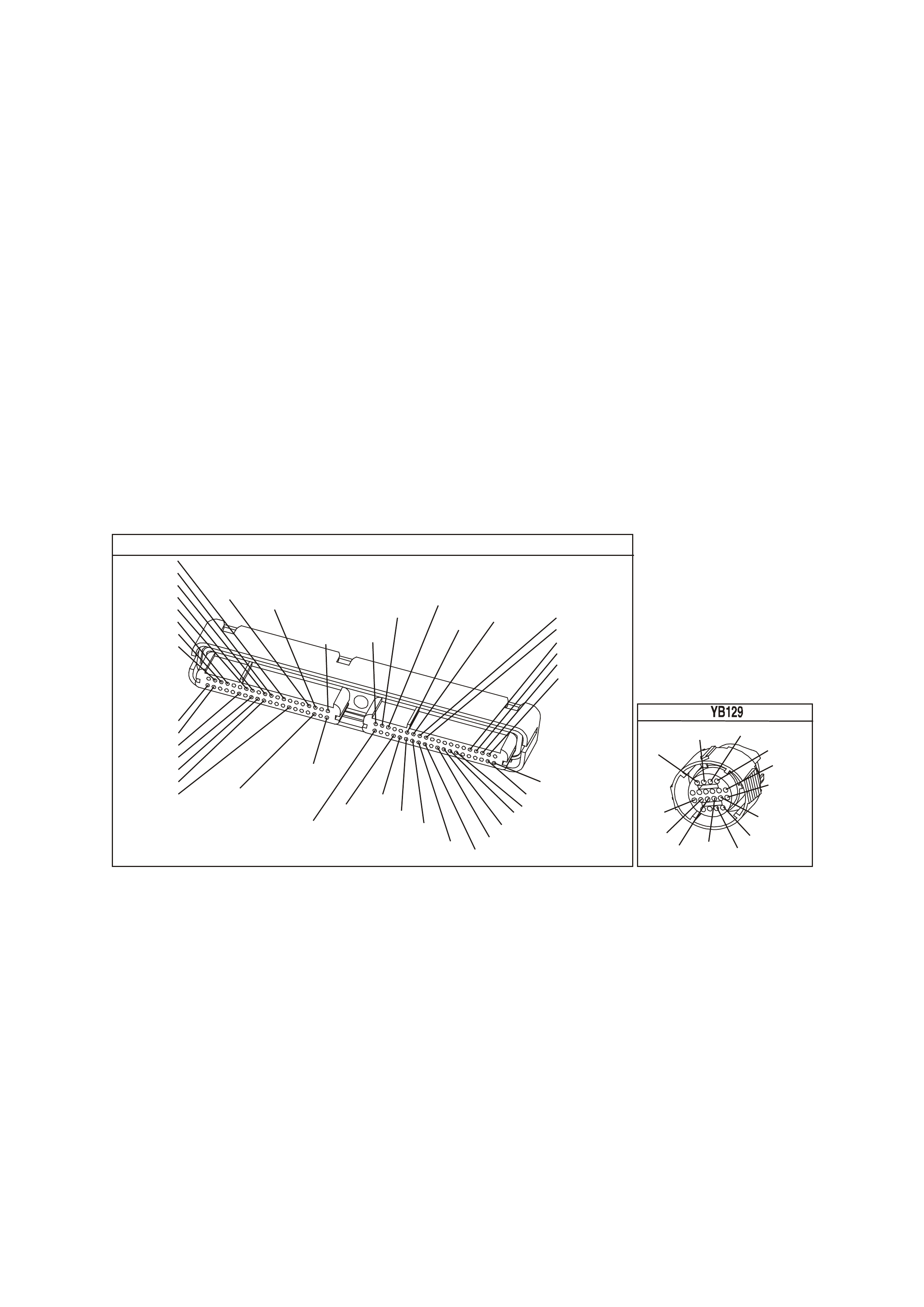
CONDITIONS FOR CLEARING THE DTC
• A last test failed (current DTC) clears when the diagnostic runs and does not fail.
• The PCM cancels the DTC default actions when the fault no longer exists and the ignition switch is OFF long
enough in order to power down the PCM.
DIAGNOSTIC AIDS
• Inspect the wiring at the PCM, the transmission connector and all other circuit connecting points for the
following conditions:
- A backed out terminal
- A damaged terminal
- Reduced terminal tension
- A chafed wire
- A broken wire inside the insulation
- Moisture intrusion
- Corrosion
• When diagnosing for an intermittent short or open condition, massage the wiring harness while watching the
test equipment for a change.
• DTC P0748 may set under low voltage conditions caused by high electrical system demands.
TEST DESCRIPTION
The numbers below refer to the step numbers on the diagnostic table.
2. This step tests the ability of the PCM to command the PC solenoid valve.
3. This step tests the PC solenoid valve and automatic transmission (A/T) wiring harness assembly for incorrect
resistance.
Y E 123
P.C.M CONNECTOR 2
(750)
(1228)
(1229)
(465)
(121)
(259)
G/B
BR
G/W
GY/BLU
R
B/R
(418)
BR
(59)
(832)
G
T
(831)
(417)
(472)
(976) (974)
(432)
(428)
(631)
BLU BR G/Y
BLU/W
LG
BR/W
W/B
LG W
(977)
Y
(971)
BLU/W W
B/R
(750)
(304)
(792)
(1223)
(1222)
(123)
(1227)
(469)
(331)
Y/B
LG
V/W
B/Y
G/O BR/W
(1687)
GY/B
(366)
LG/B
GY/R
(422)
V
(442)
(444)
(443)
(975)
(972)
(978)
(1224)
(973)
(959)
LG/W
LG/B
LBLU/B
GY
(773)
BR/Y
BLU
G
Y/B
LBLU
(958)
BR
(441)
LBLU
1
41
40
80
J2
RED
Y
(838)
TRANSMISSION CONNECTOR
GY/BLU
(1229)
R
(1228)
Y/B
(1223)
LG
(1222)
P/BLU
(339)
(1227)
B/Y
(1230)
B/W
GY/R
(422)
BR
(418)
BR/Y
(1224)
(1226)
GY
Y
(1225)
(897)
G/W
(V8)
B
(469) (V6)
OR

GEN III V8 PCM - DTC P0748 PC SOLENOID CIRCUIT ELECTRICAL
Step Action Value(s) Yes No
1 Was the Powertrain On-Board Diagnostic (OBD) System
Check performed? Go to Step 2 Go to Powertrain
OBD System
Check Table.
2 1. Install the Tech 2 Scan Tool.
2. With the engine OFF, turn the ignition switch to the
RUN position.
IMPORTANT: Before clearing the DTC, use the Scan
Tool in order to record the Failure Records. Using the
Clear Info function erases the Failure Records from the
PCM.
3. Record th e DTC Failure Records.
4. Clear the DTC.
5. Start the engine.
6. Using the Transmission Miscellaneous Tests function
on the Scan Tool , apply 100 milliamps through 1000
milliamps while observing Commanded PCS and
Actual PCS.
Is the Actual PCS always within the specified value of the
Commanded PCS?
160
milliamps Go to
Diagnostic Aids Go to Step 3
3 1. Turn the ignition OFF.
2. Disconnect the transmission 20-way (YB 129)
connector.
3. Install the J 39775 jumper harness on the
transmission side of the 20-way (YB 129) connector.
4. Using the J 39200 digital multimeter (DMM) and the
J 35616 connector test adapter kit, measure the
resistance between terminal C and terminal D.
Is the resistance within the specified range?
3-7 Ω Go to Step 8 Go to Step 4
4 Is the resistance greater than the specified value? 7 Ω. Go to Step 5 Go to Step 6
5 Inspect circuit 1228 (V) and circuit 1229 (LT BLU) of the
A/T wiring harness assembly, for an open condition.
Did you find an open condition?
Go to Step18 Go to Step 10
6 Is the resistance less than the specified value? 3 Ω Go to Step 7
7 Inspect circuit 1228 (V) and circuit 1229 (LT BLU), of the
A/T wiring harness assembly, for a shorted together
condition.
Did you find a shorted together condition?
Go to Step 18 Go to Step 10
8 Measure the resistance from terminal C to the
transmission case.
Is the resistance greater than the specified value?
250K Ω Go to Step 11 Go to Step 9
9 Inspect circuit 1228 (V) and circuit 1229 (LT BLU), of the
A/T wiring harness assembly, for a short to earth
condition.
Did you find a short to earth condition?
Go to Step 18 Go to Step 10
10 Replace the PC solenoid valve.
Refer to PC Solenoid Valve Replacement in Section 7C5,
in VX Service Information.
Is the replacement complete?
Go to Step 20
11 1. Disconnect the J 39775 jumper harness from the
transmission side of the 20-way (YB 129) connector.
2. Reconnect the transmission 20-way (YB 129)
connector.
3. Disconnect the PCM connector YE 123.
4. Using the J 39200 DMM and the J 35616 connector
test adapter kit, measure the resistance between
terminal 6 and terminal 8.
Is the resistance within the specified range?
3-7 Ω Go to Step 16 Go to Step 12

GEN III V8 PCM - DTC P0748 PC SOLENOID CIRCUIT ELECTRICAL (CONTINUED)
Step Action Value(s) Yes No
12 Is the resistance greater than the specified value? 7 Ω Go to Step 13 Go to Step 14
13 1. Inspect circuit 1228 (R) and circuit 1229 (GY/BLU) of
the engine wiring harness for an open condition.
2. Repair the circuits if necessary.
Did you find and correct an open condition?
Go to Step 20
14 Is the resistance less than the specified value? 3 Ω Go to Step 15
15 1. Inspect circuit 1228 (R) and circuit 1229 (GY/BLU), of
the engine wiring harness, for a shorted together
condition.
2. Repair the circuits if necessary.
Did you find and correct the shorted condition?
Go to Step 20
16 Using the J 39200 DMM and the J 35616 connector test
adapter kit, measure the resistance between connector
YE 123 terminal 6 to earth.
Is the resistance less than the specified value?
9 Ω Go to Step 17 Go to Step 19
17 1. Inspect circuit 1228 (R) and circuit 1229 (GY/BLU), of
the engine wiring harness, for a short to earth
condition.
2. Repair the circuits if necessary.
Did you find and correct the short to earth condition?
Go to Step 20
18 Replace the automatic transmission wiring harness
assembly.
Refer to Control Valve Body and Wiring Harness
replacement in Section 7C4, in VX Service Information.
Is the replacement complete?
Go to Step 20
19 Replace the PCM.
Refer to Powertrain Control Module in Section 6C3-3, of
the VX Series Service Information.
Is the replacement complete?
Go to Step 20
20 Perform the following procedure in order to verify the
repair:
1. Select DTC.
2. Select Clear Info.
3. Start the engine and ensure that the following
condition is met:
- The difference between the Scan Tool PC Solenoid
Actual Current and the PC Solenoid Reference
Current is less than 160 milliamps.
Was the above condition verified?
System OK
Go to Step 1

GEN III V8 PCM -
DTC P0751 1-2 SHIFT SOLENOID VALVE PERFORMANCE
CIRCUIT DESCRIPTION
The 1-2 Shift Solenoid (SS) valve controls the fluid f low ac ting on the 1-2 and 3-4 shift valves . The 1-2 SS valve is
a normally-open exhaust valve that is used with the 2-3 SS valve, in order to allow four different shifting
combinations.
W hen the PCM detects a 1-1-4-4 or a 2-2-3-3 shift pattern, depending on the state of the m echanical failure, then
DTC P0751 sets.
CONDITIONS FOR RUNNING THE DTC
• No Throttle Position DTCs P0122 or P0123.
• No VSS assembly DTCs P0502 or P0503.
• No TCC solenoid valve DTC P0740.
• No TCC stuck ON DTC P0742.
• No 1-2 SS valve DTC P0753.
• No 2-3 SS valve DTC P0758.
• No 3-2 SS valve assembly DTC P0785.
• No TFP manual valve position switch DTC P1810.
• No TCC PWM solenoid valve DTC P1860.
• The engine speed is greater than 300 RPM for 5 seconds.
• The engine is not in fuel cutoff.
• The gear range is D.
• The Throttle Position angle is 10-35%.
• The Throttle Position angle is constant +/- 5%.
• The PCM commands a 1-2, 2-3, and 3-4 shift.
• The TCC is commanded ON.
• The vehicle speed is greater than 8 km/h.
• The transmission fluid temperature is 20-130°C.

CONDITIONS FOR SETTING THE DTC
• DTC P0751 sets if the following conditions occur three times:
- Within 2 seconds, the engine speed in 2nd gear is 80 RPM greater than the last speed in 1st gear.
- Within 2 seconds, the engine speed in 3rd gear is 50 RPM less than the last speed in 2nd gear.
- Within 2 seconds, the engine speed in 4th gear is 10 RPM greater than the last speed in 3rd gear.
• All of the above conditions are met and one of the following conditions occurs:
Condition 1
- The speed ratio is 0.95 to 1.2 (speed ratio is engine speed divided by transmission output speed).
- The TCC slip speed is 200-1000 RPM for 4 seconds.
Condition 2
- The speed ratio is 0.65 to 0.8.
- The TCC slip speed is -20 to +40 RPM for 4 seconds.
ACTION TAKEN WHEN THE DTC SETS
• The PCM illuminates the check powertrain lamp (CPL).
• The PCM commands D2 line pressure.
• The PCM inhibits 3-2 downshifts if the vehicle speed is greater than 48 km/h.
• The PCM freezes shift adapts from being updated.
• The PCM stores DTC P0751 in PCM history.
CONDITIONS FOR CLEARING THE CPL/DTC
• The PCM turns OFF the Check Powertrain Check Powertrain Lamp (CPL) during the first consecutive trip in
which the diagnostic test runs and passes.
• The PCM cancels the DTC default actions when the fault no longer exists and the ignition switch is OFF long
enough in order to power down the PCM.
• A last test failed (current DTC) clears when the diagnostic runs and does not fail.
DIAGNOSTIC AIDS
• Verify that the transmission meets the specifications in the Shift Speed table.
• Other internal transmission failures may cause more than one shift to occur.
• Refer to the Shift Solenoid Valve State and Gear Ratio table in Section 6C3-4 of the VX Series Service
Information.
TEST DESCRIPTION
The number below refers to the step numbers on the diagnostic table.
2. This step tests that the PCM commanded all shifts, that all shift solenoid valves responded correctly, but that all
the shifts did not occur.
GEN III V8 PCM - DTC P0751 1-2 SHIFT SOLENOID VALVE PERFORMANCE
Step Action Value(s) Yes No
1 Was the Powertrain On-Board Diagnostic (OBD) System
Check performed? Go to Step 2 Go to Powertrain
OBD System
Check Table.
2 1. Install the Tech 2 Scan Tool.
2. With the engine OFF, turn the ignition switch to the
RUN position.
IMPORTANT: Before clearing the DTC, use the Scan
Tool in order to record the Freeze Frame and Failure
Records. Using the Clear Info function erases the Freeze
Frame and Failure Records from the PCM.
3. Record the DTC Freeze Frame and Failure Records.
4. Clear the DTC.
5. Drive the vehicle in D range under the following
conditions:
- Accelerate the vehicle, ensuring that the PCM
commands 1st, 2nd, 3rd and 4th gears.
Did you detect a 1-1-4-4 or 2-2-3-3 shift pattern?
Go to Step 3 Go to
Diagnostic Aids

3 Inspect the shift solenoid/hydraulic circuit for the following
conditions:
• An internal malfunction.
Damaged seals on the shift solenoid valves.
Refer to Shift Solenoid Leak Test in Section 7C4 in VX
Service Information.
Did you find and correct the condition?
Go to Step 4
4 Perform the following procedure in order to verify the
repair:
1. Select DTC.
2. Select Clear Info.
3. Drive the vehicle in D under the following conditions
(only if traffic and road conditions permit):
- Hold the throttle at 20% and accelerate to 88 km/h.
- If the throttle moves more than 5%, stop the vehicle
and start over.
4. Ensure the transmission properly shifts through all
gears as commanded by the PCM.
Did the transmission shift through all gears as
commanded by the PCM?
System OK Go to Step 1

GEN III V8 PCM
DTC P0753 1-2 SHIFT SOLENOID CIRCUIT ELECTRICAL
CIRCUIT DESCRIPTION
The 1-2 Shift Solenoid (SS) valve controls the fluid f low ac ting on the 1-2 and 3-4 shift valves . The 1-2 SS valve is
a normally-open exhaust valve that is used with the 2-3 SS valve in order to allow four different shifting
combinations. The solenoid attaches to the control valve body within the transmission. The 1-2 SS valve receives
ignition voltage through circuit 339. The powertrain control module (PCM) controls the solenoid by providing the
earth path on circuit 1222.
When the PCM detects a continuous open or short to earth in the 1-2 SS valve circuit or the 1-2 SS valve, then
DTC P0753 sets.
CONDITIONS FOR RUNNING THE DTC
• The system voltage is between 8.0 and 18 volts.
• The engine speed is greater than 300 RPM for 5 seconds.
• The engine is not in fuel cutoff.
CONDITIONS FOR SETTING THE DTC
• The PCM commands the solenoid ON and the voltage input remains high (12 volts).
Or
• The PCM commands the solenoid OFF and the voltage input remains low (0 volts).
4356
PCM
J2-47
J2-48
J1-79
J2-42
J2-04
J2-08
J2-06
TCC PWM
SOLENOID
3-2 CONTROL
SOLENOID
1-2 SHIFT
SOLENOID A
2-3 SHIFT
SOLENOID B
PRESSURE
CONTROL
SOLENOID
LOW
PRESSURE CONTROL
SOLENOID HIGH
B
A
A
B
B
B
A
A
B
A
YB 129 T RANSMIS SION
PASS-THRU CONNECTOR
TORQUE
CONVERTER
CLUTCH (TCC)
(PWM)
SOLENOID
TORQUE
CONVERTER
CLUTCH (TCC)
ENABLE
SOLENOID
3-2 DOWNSHIFT
CONTROL
SOLENOID
1-2 SHIFT
SOLENOID A
2-3 SHIFT
SOLENOID B
PRESSURE
CONTROL
SOLENOID
C
D
U
S
T
E
A
B
P/BLU (339)
TCC ENABLE
SOLENOID
B
A
EFI
RELAY
F32
G/W (897)
YE122
YE123
LG (1222)
Y/B (1223)
GY/BLU (1229)
R (1228)
12V
M
I
C
R
O
P
R
O
C
E
S
S
O
R
BR (418)
GY/R (422)
YE110

ACTION TAKEN WHEN THE DTC SETS
• The PCM illuminates the Check Powertrain Lamp when the diagnostic runs and fails.
• The PCM commands D2 line pressure.
• The PCM inhibits 3-2 downshift if the vehicle speed is greater than 48 km/h.
• The PCM freezes shift adapts from being updated.
• The PCM records the operating conditions at the time the diagnostic fails. The PCM stores this information in
the Freeze Frame/Failure Records.
• The PCM freezes shift adapts from being updated.
• The PCM stores DTC P0753 in the PCM history during the second consecutive trip in which the conditions f or
setting the DTC are met.
CONDITIONS FOR CLEARING THE CPL/DTC
• The PCM turns the Check Powertrain Lamp OFF during the first ignition cycle that the diagnostic runs and
does not fail.
• A last test failed (current DTC) clears when the diagnostic runs and does not fail.
DIAGNOSTIC AIDS
• Inspect the wiring at the PCM, the transmission connector and all other circuit connecting points for the
following conditions:
- A backed out terminal
- A damaged terminal
- Reduced terminal tension
- A chafed wire
- A broken wire inside the insulation
- Moisture intrusion
- Corrosion
• When diagnosing for an intermittent short or open condition, massage the wiring harness while watching the
test equipment for a change.
• An open ignition feed circuit can cause multiple DTCs to set.
• Refer to the Shift Solenoid Valve State and Gear Ratio table.
TEST DESCRIPTION
The numbers below refer to the step numbers on the diagnostic table.
4. This step tests the function of the 1-2 SS valve and the automatic transmission wiring harness assembly.
5. This step tests for power to the 1-2 SS valve from the ignition through the fuse.
7. This step tests the ability of the PCM and the wiring to control the earth circuit.
10. This step measures the resistance of the A/T wiring harness assembly and the 1-2 SS valve.
Y E 123
P.C.M CONNECTOR 2
(750)
(1228)
(1229)
(465)
(121)
(259)
G/B
BR
G/W
GY/BLU
R
B/R
(418)
BR
(59)
(832)
G
T
(831)
(417)
(472)
(976) (974)
(432)
(428)
(631)
BLU BR G/Y
BLU/W
LG
BR/W
W/B
LG W
(977)
Y
(971)
BLU/W W
B/R
(750)
(304)
(792)
(1223)
(1222)
(123)
(1227)
(469)
(331)
Y/B
LG
V/W
B/Y
G/O BR/W
(1687)
GY/B
(366)
LG/B
GY/R
(422)
V
(442)
(444)
(443)
(975)
(972)
(978)
(1224)
(973)
(959)
LG/W
LG/B
LBLU/B
GY
(773)
BR/Y
BLU
G
Y/B
LBLU
(958)
BR
(441)
LBLU
1
41
40
80
J2
RED
Y
(838)
TRANSMISSION CONNECTOR
GY/BLU
(1229)
R
(1228)
Y/B
(1223)
LG
(1222)
P/BLU
(339)
(1227)
B/Y
(1230)
B/W
GY/R
(422)
BR
(418)
BR/Y
(1224)
(1226)
GY
Y
(1225)
(897)
G/W
(V8)
B
(469) (V6)
OR

GEN III V8 PCM - DTC P0753 1-2 SHIFT SOLENOID CIRCUIT ELECTRICAL
Step Action Value(s) Yes No
1 Was the Powertrain On-Board Diagnostic (OBD) System
Check performed? Go to Step 2 Go to Powertrain
OBD System
Check Table.
2 1. Install the Tech 2 Scan Tool.
2. With the engine OFF, turn the ignition switch to the
RUN position.
IMPORTANT: Before clearing the DTC, use the Scan
Tool in order to record the Freeze Frame and Failure
Records. Using the Clear Info function erases the Freeze
Frame and Failure Records from the PCM.
3. Record the DTC Freeze Frame and Failure Records.
4. Clear the DTC.
Are any of the following DTCs also set?
• P0740
• P0758
• P0785
• P1860
Go to Step 3 Go to Step 4
3 1. Inspect fuse F32.
2. If the fuse is open, inspect the following components
for a short to earth condition:
- Circuit 339 (P/BLU)
- The solenoids
- The A/T wiring harness assembly
3. Repair the circuit, the solenoids, and the harness if
necessary.
Did you find a short to earth condition?
Go to Step 16 Go to Step 5
4 Using the transmission Miscellaneous Tests function on
the Scan Tool, command the 1-2 SS valve ON and OFF
three times while listening to the bottom of the
transmission pan (a stethoscope may be necessary).
Did the solenoid click when commanded?
Go to
Diagnostic Aids Go to Step 5
5 1. Turn the ignition OFF.
2. Disconnect the transmission 20-way (YB 129)
connector (additional DTCs may set).
3. Install the J 39775 jumper harness on the engine side
of the 20-way (YB 129) connector.
4. With the engine OFF, turn the ignition switch to the
RUN position.
5. Connect a test lamp, from J 39775 jumper harness
cavity E, to earth.
Is the test lamp ON?
Go to Step 7 Go to Step 6
6 IMPORTANT: The condition that affects this circuit may
exist in other connecting branches of the circuit. Refer to
Power Distribution Diagrams in Section 14E, in VX
Service Information.
Repair the open or short to earth in ignition feed circuit
339 (P/BLU) to the 1-2 SS valve.
Is the repair complete?
Go to Step 16
7 1. Install a test lamp, from J 39775 jumper harness cav ity
E, to cavity A.
2. Using the transmission Miscellaneous Tests function
on the Scan Tool, command the 1-2 SS valve ON and
OFF three times.
Is the test lamp ON when the 1-2 SS valve is
commanded ON, and OFF when commanded OFF?
Go to Step 10 Go to Step 8

GEN III V8 PCM - DTC P0753 1-2 SHIFT SOLENOID CIRCUIT ELECTRICAL (CONTINUED)
Step Action Value(s) Yes No
8 1. Inspect circuit 1222 (LG), of the powertrain wiring
harness, for an open, short to earth or short to power
condition.
2. Repair the circuit if necessary.
Did you find an open, short to earth or short to power
condition?
Go to Step 16 Go to Step 9
9 Replace the PCM.
Refer to Powertrain Control Module in Section 6C3-3.
Is the replacement complete?
Go to Step16
10 1. Install the J 39775 jumper harness on the
transmission side of the 20-way (YB 129) connector.
2. With the J 39200 digital multimeter (DMM) and the
J 35616 connector test adapter kit, measure the
resistance between terminals A and E.
Is the resistance within the range indicated?
19-31 Ω Go to Step 12 Go to Step 11
11 1. Disconnect the A/T wiring harness assembly from the
1-2 SS valve.
2. Measure the resistance of the 1-2 SS valve.
Is the resistance within the range indicated?
19-31 Ω Go to Step 14 Go to Step 15
12 Using the J 39200 DMM, measure the resistance
between terminal A and earth, and between terminal E
and earth.
Are both readings greater than the specified value?
250 K Ω Go to Diagnostic
Aids Go to Step 13
13 1. Disconnect the A/T wiring harness assembly from the
1-2 SS valve.
2. Using the J 39200 DMM, measure the resistance from
the component's terminals to earth.
Are both readings greater than the specified value?
250 K Ω Go to Step 14 Go to Step 15
14 Replace the automatic transmission wiring harness
assembly.
Refer to Control Valve Body and Wiring Harness
replacement in Section 7C4, in VX Service Information.
Is the replacement complete?
Go to Step 16
15 Replace the 1-2 SS valve.
Refer to 1-2 Shift Solenoid Valve Replacement in Section
7C5 in VX Service Information.
Is the replacement complete?
Go to Step 16
16 Perform the following procedure in order to verify the
repair:
1. Select DTC.
2. Select Clear Info.
3. Drive the vehicle in D and ensure the following
conditions are met:
- The PCM commands the 1-2 SS valve ON and the
voltage input drops to zero.
- The PCM commands the 1-2 SS valve OFF and the
voltage input increases to B+.
- All conditions are met for 5 seconds.
Were the above conditions verified?
System OK Go to Step 1
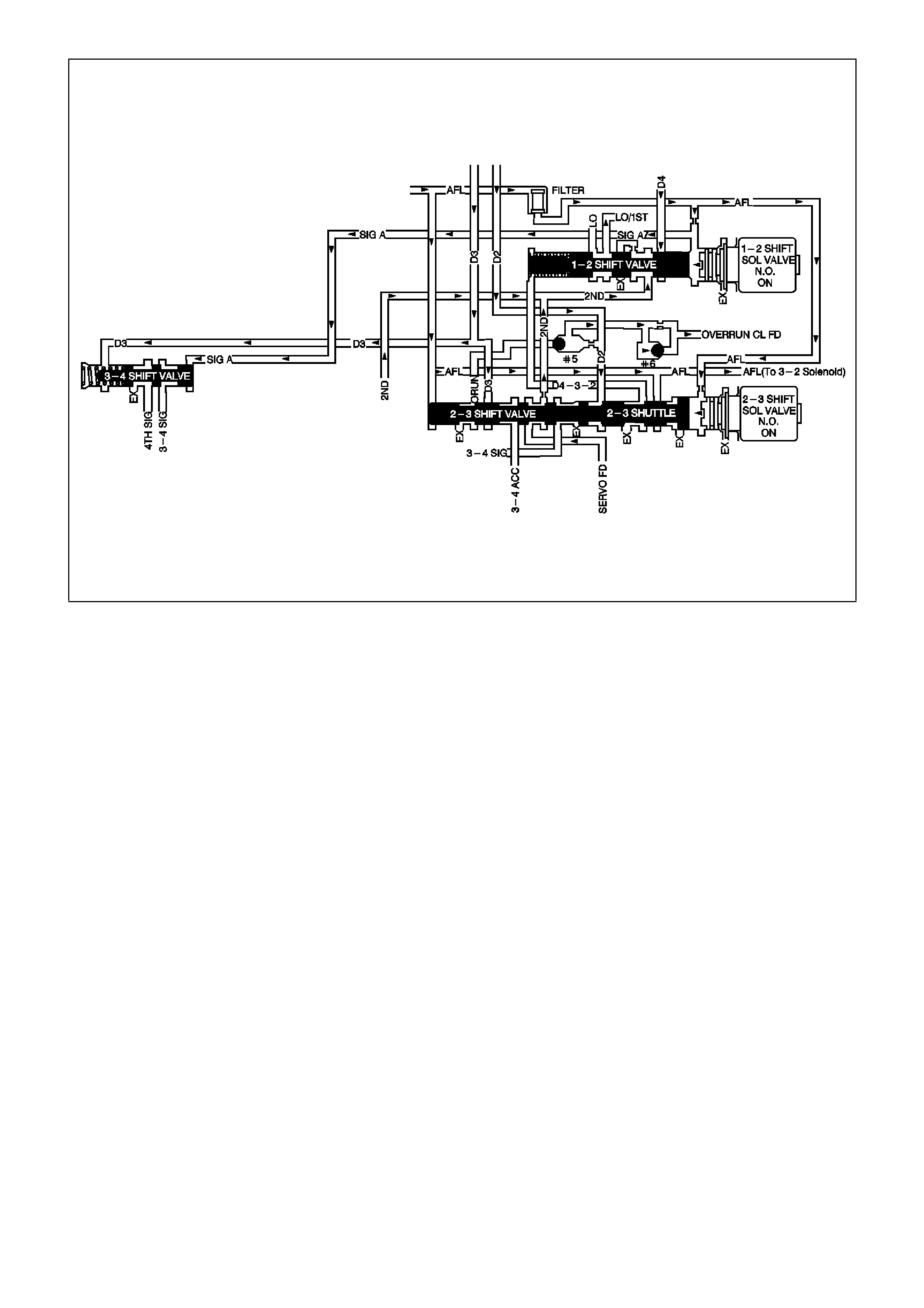
GEN III V8 PCM -
DTC P0756 2-3 SHIFT SOLENOID VALVE PERFORMANCE
CIRCUIT DESCRIPTION
The 2-3 Shift Solenoid (SS) valve controls the fluid flow acting on the 2-3 shift valves. The 2-3 SS valve is a
normally-open exhaust valve that is used with the 1-2 SS valve, in order to allow four different shifting
combinations.
W hen the PCM detects a 1-2-2-1 or a 4-3-3-4 shift pattern, depending on the state of the m echanical failure, then
DTC P0756 sets.
CONDITIONS FOR RUNNING THE DTC
• No Throttle Position DTCs P0122 or P0123.
• No VSS assembly DTCs P0502 or P0503.
• No TCC solenoid valve DTC P0740.
• No TCC stuck ON DTC P0742.
• No 1-2 SS valve DTC P0753.
• No 2-3 SS valve DTC P0758.
• No 3-2 SS valve assembly DTC P0785.
• No TFP manual valve position switch DTC P1810.
• No TCC PWM solenoid valve DTC P1860.
• The vehicle speed is greater than 8 km/h.
• The gear range is D4.
• The engine vacuum is 0-105 kPa.
• The engine torque is 0-542 N.m
• The Throttle Position angle is 10-50%.
• The Throttle Position angle is constant +/- 7%.
• The PCM commands a 1-2, 2-3, and 3-4 shift.
• The engine speed is greater than 300 RPM for 5 seconds.
• The engine is not in fuel cutoff.
• The transmission fluid temperature is 20-130°C.

CONDITIONS FOR SETTING THE DTC
• DTC P0756 sets if the following conditions occur three times:
- Third gear is commanded for 2 to 6 seconds.
- T he speed ratio, in 3rd gear, does not drop m ore than 0.3 f rom the last speed ratio, in 2nd gear, ( speed ratio
is engine speed divided by transmission output speed).
- The TCC slip speed, in 3rd gear, remains 400 RPM higher than the last TCC slip speed, in 2nd gear.
• All of the above conditions are met for 1.5 seconds and one of the following conditions occurs:
Condition 1
- First gear is commanded for 1.5 seconds.
- The TP angle is greater than 25%.
- The transmission output speed is 400-1500 RPM.
- The speed ratio is 0.7 to 3.0.
- The TCC slip speed is -2000 to 0 RPM for 1.5 seconds.
Condition 2
- Fourth gear is commanded for 1.5 seconds.
- The transmission output speed is 1000-3000 RPM.
- The speed ratio is 1.68 to 3.0.
- The TCC slip speed is 1000 to 3000 RPM for 1 second.
ACTION TAKEN WHEN THE DTC SETS
• The PCM illuminates the check powertrain lamp (CPL).
• The PCM commands 3rd gear only .
• The PCM inhibits TCC engagement.
• The PCM commands maximum line pressure.
• The PCM freezes shift adapts from being updated.
• The PCM records the operating conditions at the time the diagnostic fails. The PCM stores this information in
the Freeze Frame/Failure Records.
CONDITIONS FOR CLEARING THE CPL/DTC
• The PCM turns OFF the Check Powertrain Check Powertrain Lamp (CPL) during the first consecutive trip in
which the diagnostic test runs and passes.
• A scan tool clears the DTC from the PCM history.
• The PCM clears the DTC from the PCM history if the vehicle completes 40 warm-up cycles without an
emission-related diagnostic fault occurring.
• The PCM cancels the DTC default actions when the fault no longer exists and the ignition switch is OFF long
enough in order to power down the PCM.
DIAGNOSTIC AIDS
• Verify that the transmission meets the specifications in the Shift Speed table.
• Other internal transmission failures may cause more than one shift to occur.
• Refer to the Shift Solenoid Valve State and Gear Ratio table in Section 6C3-4 of the VX Series Service
Information.
TEST DESCRIPTION
The number below refers to the step numbers on the diagnostic table.
2. This st ep tests that the PCM com manded all shif ts, that all shift solenoid valves r esponded correctly, but that all
the shifts did not occur.

GEN III V8 PCM - DTC P0756 2-3 SHIFT SOLENOID VALVE PERFORMANCE
Step Action Value(s) Yes No
1 Was the Powertrain On-Board Diagnostic (OBD) System
Check performed? Go to Step 2 Go to Powertrain
OBD System
Check Table.
2 1. Install the Tech 2 Scan Tool.
2. With the engine OFF, turn the ignition switch to the
RUN position.
IMPORTANT: Before clearing the DTC, use the Scan
Tool in order to record the Freeze Frame and Failure
Records. Using the Clear Info function erases the Freeze
Frame and Failure Records from the PCM.
3. Record the DTC Freeze Frame and Failure Records.
4. Clear the DTC.
5. Drive the vehicle in D range under the following
conditions:
- Accelerate the vehicle, ensuring that the PCM
commands 1st, 2nd, 3rd and 4th gears.
Did you detect a 1-2-2-1 or 4-3-3-4 shift pattern?
Go to Step 3 Go to
Diagnostic Aids
3 Inspect the shift solenoid/hydraulic circuit for the following
conditions:
• An internal malfunction.
Damaged seals on the Shift Solenoid valves.
Refer to Shift Solenoid Leak Test in Section 7C4, in VX
Service Information.
Did you find and correct the condition?
Go to Step 4
4 Perform the following procedure in order to verify the
repair:
1. Select DTC.
2. Select Clear Info.
3. Drive the vehicle in D under the following conditions
(only if traffic and road conditions permit):
- Hold the throttle at 40% and accelerate to 64 km/h.
- Stop the vehicle, engine idling.
- Hold the throttle at 15% and accelerate to 80 km/h.
4. Ensure the transmission properly shifts through all
gears as commanded by the PCM.
Did the transmission shift through all gears as
commanded by the PCM?
System OK Go to Step 1
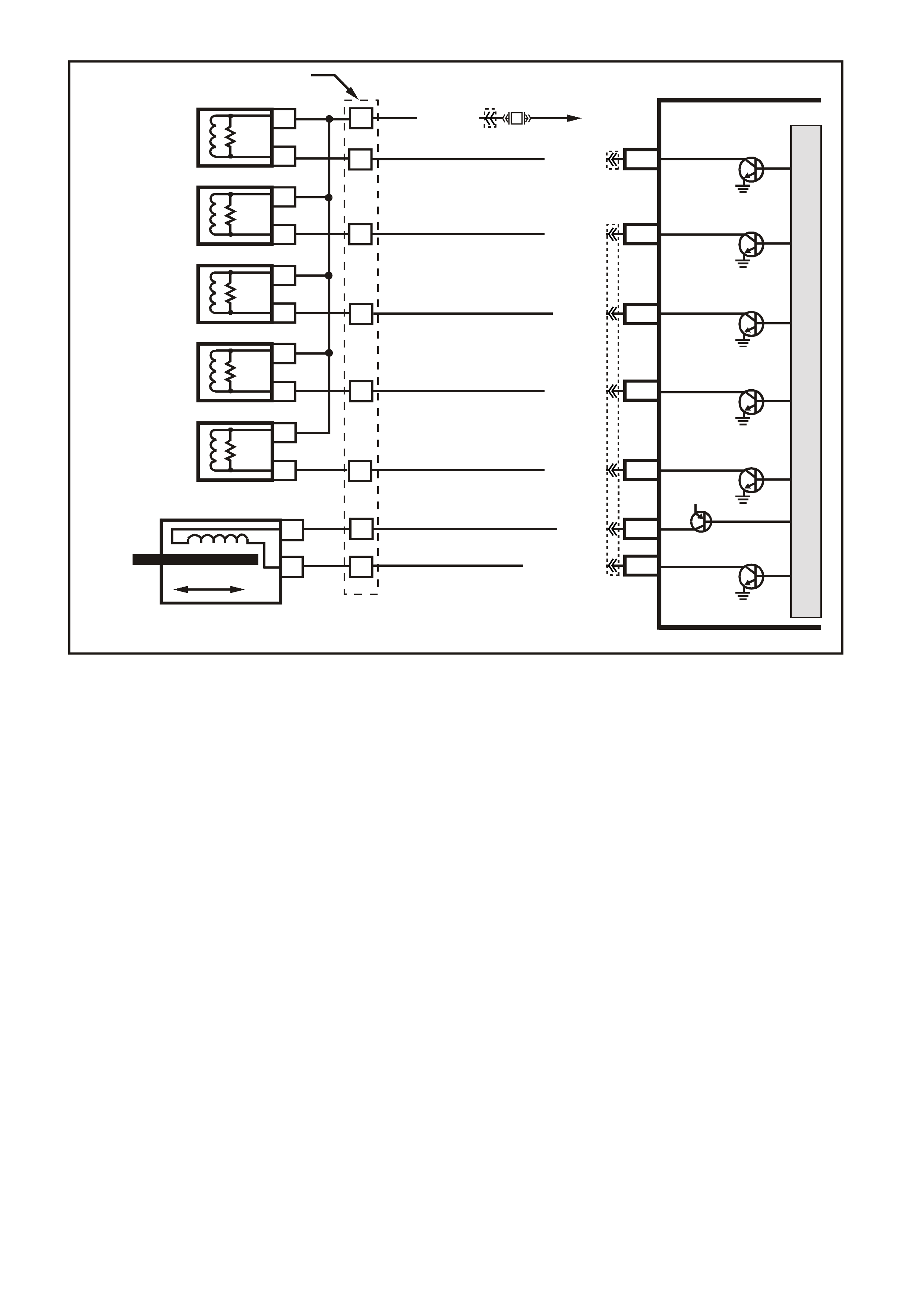
GEN III V8 PCM -
DTC P0758 2-3 SHIFT SOLENOID CIRCUIT ELECTRICAL
CIRCUIT DESCRIPTION
The 2-3 Shift Solenoid (SS) valve controls the fluid flow acting on the 2-3 shift valves. The 2-3 SS valve is a
norm ally-open exhaust valve that is used with the 1-2 SS valve in or der to allow four dif f erent shif ting com binations.
The solenoid attaches to the contro l valve body within the trans mission. T he 2-3 SS valve receives ignition voltage
through circuit 339. The Powertrain Control Module (PCM) controls the solenoid by providing the earth path on
circuit 1223.
When the PCM detects a continuous open or short to earth in the 2-3 SS valve circuit or the 2-3 SS valve, then
DTC P0758 sets.
CONDITIONS FOR RUNNING THE DTC
• The system voltage is between 8.0 and 18 volts.
• The engine speed is greater than 300 RPM for 5 seconds.
• The engine is not in fuel cutoff.
CONDITIONS FOR SETTING THE DTC
• The PCM commands the solenoid ON and the voltage input remains high (12 volts).
Or
• The PCM commands the solenoid OFF and the voltage input remains low (0 volts).
ACTION TAKEN WHEN THE DTC SETS
• The PCM illuminates the Check Powertrain Lamp when the diagnostic runs and fails.
• The PCM commands 3rd gear only.
• The PCM commands maximum line pressure.
• The PCM inhibits TCC engagement.
• The PCM freezes shift adapts from being updated.
• The PCM records the operating conditions at the time the diagnostic fails. The PCM stores this information in
the Freeze Frame/Failure Records.
4356
PCM
J2-47
J2-48
J1-79
J2-42
J2-04
J2-08
J2-06
TCC PWM
SOLENOID
3-2 CONTROL
SOLENOID
1-2 SHIFT
SOLENOID A
2-3 SHIFT
SOLENOID B
PRESSURE
CONTROL
SOLENOID
LOW
PRESSURE CONTROL
SOLENOID HIGH
B
A
A
B
B
B
A
A
B
A
YB 129 T RANSMIS SION
PASS-THRU CONNECTOR
TORQUE
CONVERTER
CLUTCH (TCC)
(PWM)
SOLENOID
TORQUE
CONVERTER
CLUTCH (TCC)
ENABLE
SOLENOID
3-2 DOWNSHIFT
CONTROL
SOLENOID
1-2 SHIFT
SOLENOID A
2-3 SHIFT
SOLENOID B
PRESSURE
CONTROL
SOLENOID
C
D
U
S
T
E
A
B
P/BLU (339)
TCC ENABLE
SOLENOID
B
A
EFI
RELAY
F32
G/W (897)
YE122
YE123
LG (1222)
Y/B (1223)
GY/BLU (1229)
R (1228)
12V
M
I
C
R
O
P
R
O
C
E
S
S
O
R
BR (418)
GY/R (422)
YE110
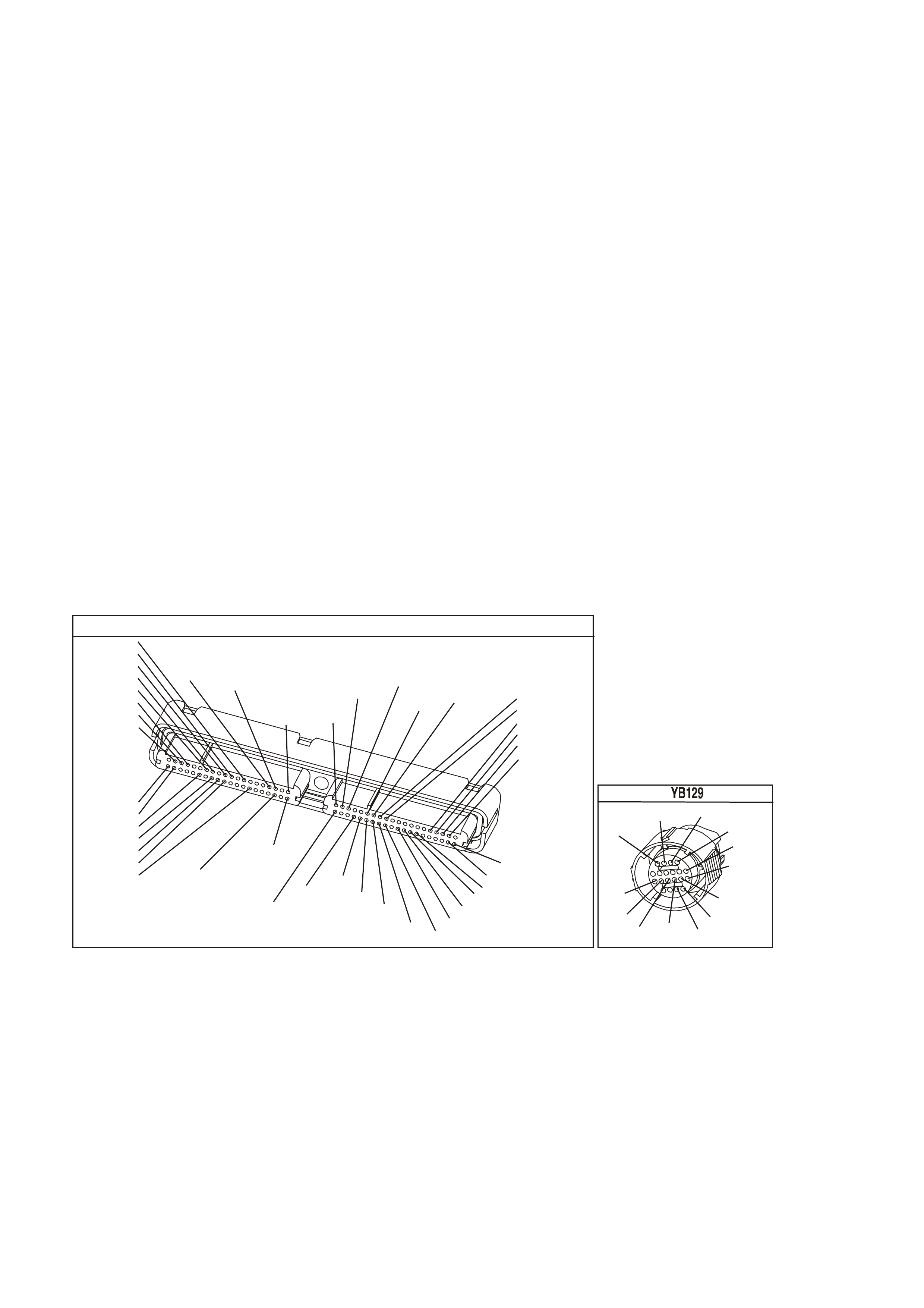
CONDITIONS FOR CLEARING THE CPL/DTC
• The PCM turns the Check Powertrain Lamp OFF during the first ignition cycle that the diagnostic runs and
does not fail.
• A last test failed (current DTC) clears when the diagnostic runs and does not fail.
DIAGNOSTIC AIDS
• Inspect the wiring at the PCM, the transmission connector and all other circuit connecting points for the
following conditions:
- A backed out terminal
- A damaged terminal
- Reduced terminal tension
- A chafed wire
- A broken wire inside the insulation
- Moisture intrusion
- Corrosion
• When diagnosing for an intermittent short or open condition, massage the wiring harness while watching the
test equipment for a change.
• Refer to the Shift Solenoid Valve State and Gear Ratio table in Section 6C3-4 of the VX Series Service
Information.
TEST DESCRIPTION
The numbers below refer to the step numbers on the diagnostic table.
4. This step tests the function of the 2-3 SS valve and the automatic transmission wiring harness assembly.
5. This step tests for power to the 2-3 SS valve from the ignition through the fuse.
7. This step tests the ability of the PCM and the wiring to control the earth circuit.
10. This step measures the resistance of the A/T wiring harness assembly and the 2-3 SS valve.
.
Y E 123
P.C.M CONNECTOR 2
(750)
(1228)
(1229)
(465)
(121)
(259)
G/B
BR
G/W
GY/BLU
R
B/R
(418)
BR
(59)
(832)
G
T
(831)
(417)
(472)
(976) (974)
(432)
(428)
(631)
BLU BR G/Y
BLU/W
LG
BR/W
W/B
LG W
(977)
Y
(971)
BLU/W W
B/R
(750)
(304)
(792)
(1223)
(1222)
(123)
(1227)
(469)
(331)
Y/B
LG
V/W
B/Y
G/O BR/W
(1687)
GY/B
(366)
LG/B
GY/R
(422)
V
(442)
(444)
(443)
(975)
(972)
(978)
(1224)
(973)
(959)
LG/W
LG/B
LBLU/B
GY
(773)
BR/Y
BLU
G
Y/B
LBLU
(958)
BR
(441)
LBLU
1
41
40
80
J2
RED
Y
(838)
TRANSMISSION CONNECTOR
GY/BLU
(1229)
R
(1228)
Y/B
(1223)
LG
(1222)
P/BLU
(339)
(1227)
B/Y
(1230)
B/W
GY/R
(422)
BR
(418)
BR/Y
(1224)
(1226)
GY
Y
(1225)
(897)
G/W
(V8)
B
(469) (V6)
OR

GEN III V8 PCM - DTC P0758 2-3 SHIFT SOLENOID CIRCUIT ELECTRICAL
Step Action Value(s) Yes No
1 Was the Powertrain On-Board Diagnostic (OBD) System
Check performed? Go to Step 2 Go to Powertrain
OBD System
Check Table.
2 1. Install the Tech 2 Scan Tool.
2. With the engine OFF, turn the ignition switch to the
RUN position.
IMPORTANT: Before clearing the DTC, use the Scan
Tool in order to record the Freeze Frame and Failure
Records. Using the Clear Info function erases the Freeze
Frame and Failure Records from the PCM.
3. Record the DTC Freeze Frame and Failure Records.
4. Clear the DTC.
Are any of the following DTCs also set?
• P0740
• P0753
• P0785
• P1860
Go to Step 3 Go to Step 4
3 1. Inspect fuse F32.
2. If the fuse is open, inspect the following components
for a short to earth condition:
- Circuit 339 (P/BLU)
- The solenoids
- The A/T wiring harness assembly
3. Repair the circuit, the solenoids, and the harness if
necessary.
Did you find a short to earth condition?
Go to Step 16 Go to Step 5
4 Using the transmission Miscellaneous Tests function on
the Scan Tool, command the 2-3 SS valve ON and OFF
three times while listening to the bottom of the
transmission pan (a stethoscope may be necessary).
Did the solenoid click when commanded?
Go to
Diagnostic Aids Go to Step 5
5 1. Turn the ignition OFF.
2. Disconnect the transmission 20-way (YB 129)
connector (additional DTCs may set).
3. Install the J 39775 jumper harness on the engine side
of the 20-way (YB 129) connector.
4. With the engine OFF, turn the ignition switch to the
RUN position.
5. Connect a test lamp from J 39775 jumper harness
cavity E to earth.
Is the test lamp ON?
Go to Step 7 Go to Step 6
6 IMPORTANT: The condition that affects this circuit may
exist in other connecting branches of the circuit. Refer to
Power Distribution Diagrams in Section 14E, in VX
Service Information.
Repair the open or short to earth in ignition feed circuit
339 (P/BLU) to the 2-3 SS valve.
Is the repair complete?
Go to Step 16
7 1. Install a test lamp, from J 39775 jumper harness cav ity
E, to cavity B.
2. Using the transmission Miscellaneous Tests function
on the Scan Tool, command the 2-3 SS valve ON and
OFF three times.
Is the test lamp ON when the 1-2 SS valve is
commanded ON, and OFF when commanded OFF?
Go to Step 10 Go to Step 8

GEN III V8 PCM - DTC P0758 2-3 SHIFT SOLENOID CIRCUIT ELECTRICAL (CONTINUED)
Step Action Value(s) Yes No
8 1. Inspect circuit 1223 (Y/B), of the powertrain wiring
harness, for an open, short to earth or short to power
condition.
2. Repair the circuit if necessary.
Did you find an open, short to earth or short to power
condition?
Go to Step 16 Go to Step 9
9 Replace the PCM.
Refer to Powertrain Control Module in Section 6C3-3, of
the VX Series Service Information.
Is the replacement complete?
Go to Step16
10 1. Install the J 39775 jumper harness on the
transmission side of the 20-way (YB 129) connector.
2. With the J 39200 digital multimeter (DMM) and the
J 35616 connector test adapter kit, measure the
resistance between terminals B and E.
Is the resistance within the range indicated?
19-31 Ω Go to Step 12 Go to Step 11
11 1. Disconnect the A/T wiring harness assembly from the
2-3 SS valve.
2. Measure the resistance of the 2-3 SS valve.
Is the resistance within the range indicated?
19-31 Ω Go to Step 14 Go to Step 15
12 Using the J 39200 DMM, measure the resistance
between terminal B and earth, and between terminal E
and earth.
Are both readings greater than the specified value?
250 K Ω Go to Diagnostic
Aids Go to Step 13
13 1. Disconnect the A/T wiring harness assembly from the
2-3 SS valve.
2. Using the J 39200 DMM, measure the resistance from
the component's terminals to earth.
Are both readings greater than the specified value?
250 K Ω Go to Step 14 Go to Step 15
14 Replace the automatic transmission wiring harness
assembly.
Refer to Control Valve Body and Wiring Harness
replacement in Section 7C4, in VX Service Information.
Is the replacement complete?
Go to Step 16
15 Replace the 2-3 SS valve.
Refer to 2-3 Shift Solenoid Valve Replacement in Section
7C5 in VX Service Information.
Is the replacement complete?
Go to Step 16
16 Perform the following procedure in order to verify the
repair:
1. Select DTC.
2. Select Clear Info.
3. Drive the vehicle in D and ensure the following
conditions are met:
- The PCM commands the 2-3 SS valve ON and the
voltage input drops to zero.
- The PCM commands the 1-2 SS valve OFF and the
voltage input increases to B+.
- All conditions are met for 5 seconds.
Were the above conditions verified?
System OK Go to Step 1

GEN III V8 PCM -
DTC P0785 3-2 SHIFT SOLENOID CIRCUIT ELECTRICAL
CIRCUIT DESCRIPTION
The 3- 2 Shift Solenoid (SS) valve is a norm ally- closed, 3-port, ON/O FF device that controls the 3-2 downshift. The
solenoid attaches to the control valve body within the transmission. The solenoid receives ignition voltage through
circuit 339. The Powertrain Control Module (PCM) controls the solenoid by providing an earth path on circuit 897.
During a 3-2 downshift, the 2-4 band applies as the 3- 4 clutch releases . The PCM varies the tim ing between the 3-
4 clutch release and the 2-4 band apply depending on the vehicle speed and the throttle position.
When the PCM detec ts a c ontinuous open or shor t to ear th in the 3-2 SS valve as s embly circuit or the 3-2 SS valve
assembly, then DTC P0785 sets.
CONDITIONS FOR RUNNING THE DTC
• The system voltage is between 8.0 and 18 volts.
• The engine speed is greater than 300 RPM for 5 seconds.
• The engine is not in fuel cutoff.
CONDITIONS FOR SETTING THE DTC
• The PCM commands the solenoid ON and the voltage input remains high (12 volts).
Or
• The PCM commands the solenoid OFF and the voltage input remains low (0 volts).
ACTION TAKEN WHEN THE DTC SETS
• The PCM illuminates the Check Powertrain Lamp when the diagnostic runs and fails.
• The PCM commands a soft landing to 3rd gear.
• The PCMM commands maximum line pressure.
• The PCM inhibits TCC engagement.
• The PCM inhibit 4th gear if the transmission is in hot mode.
• The PCM freezes shift adapts from being updated.
• The PCM records the operating conditions at the time the diagnostic fails. The PCM stores this information in
the Freeze Frame/Failure Records.
4356
PCM
J2-47
J2-48
J1-79
J2-42
J2-04
J2-08
J2-06
TCC PWM
SOLENOID
3-2 CONTROL
SOLENOID
1-2 SHIFT
SOLENOID A
2-3 SHIFT
SOLENOID B
PRESSURE
CONTROL
SOLENOID
LOW
PRESSURE CONTROL
SOLENOID HIGH
B
A
A
B
B
B
A
A
B
A
YB 129 T RANSMIS SION
PASS-THRU CONNECTOR
TORQUE
CONVERTER
CLUTCH (TCC)
(PWM)
SOLENOID
TORQUE
CONVERTER
CLUTCH (TCC)
ENABLE
SOLENOID
3-2 DOWNSHIFT
CONTROL
SOLENOID
1-2 SHIFT
SOLENOID A
2-3 SHIFT
SOLENOID B
PRESSURE
CONTROL
SOLENOID
C
D
U
S
T
E
A
B
P/BLU (339)
TCC ENABLE
SOLENOID
B
A
EFI
RELAY
F32
G/W (897)
YE122
YE123
LG (1222)
Y/B (1223)
GY/BLU (1229)
R (1228)
12V
M
I
C
R
O
P
R
O
C
E
S
S
O
R
BR (418)
GY/R (422)
YE110
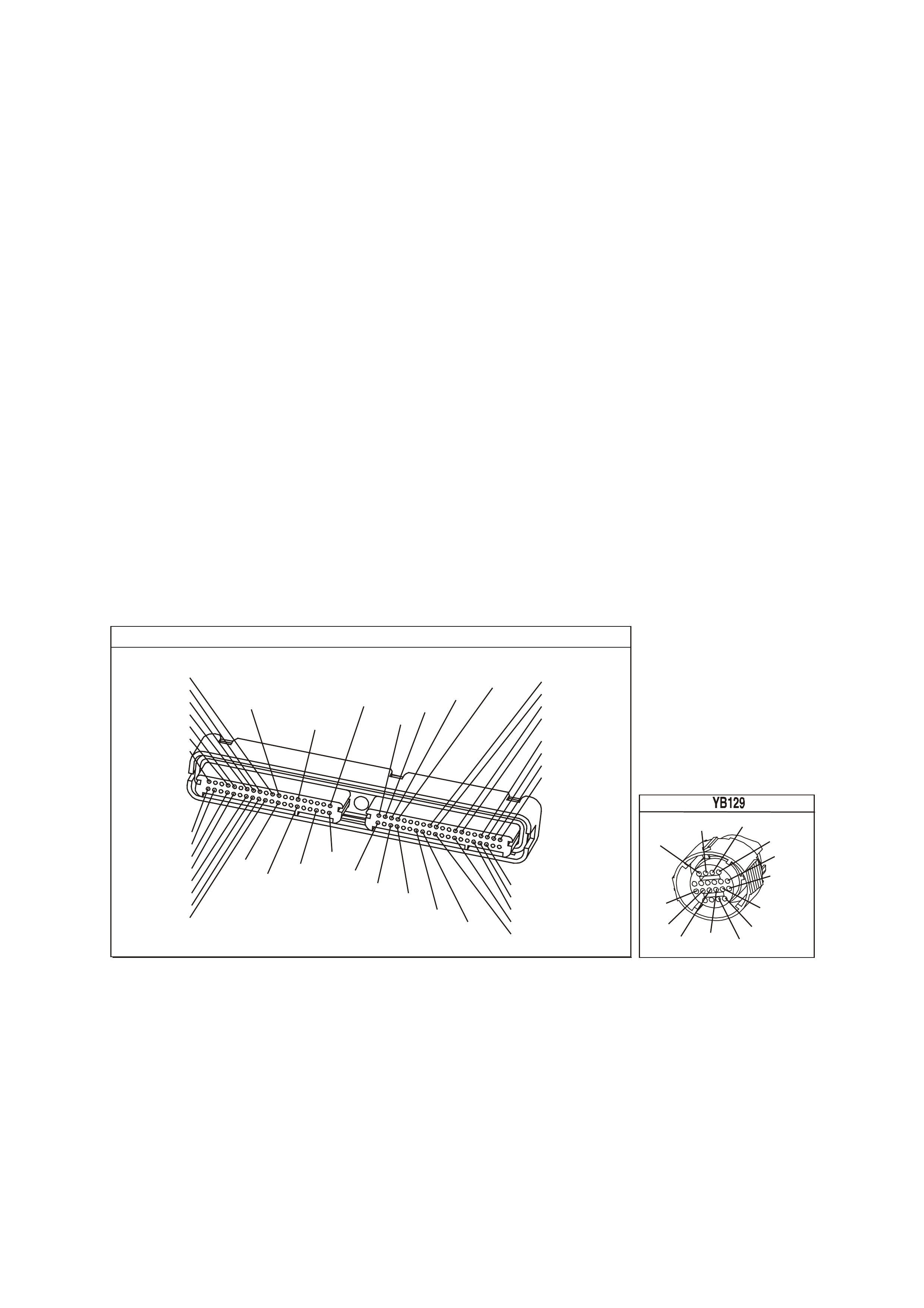
• The PCM inhibits fourth gear if the transmission is in hot mode.
• The PCM freezes shift adapts from being updated.
• The PCM stores DTC P0785 in the PCM history.
CONDITIONS FOR CLEARING THE CPL/DTC
• The PCM turns the Check Powertrain Lamp OFF during the first ignition cycle that the diagnostic runs and
does not fail.
• A last test failed (current DTC) clears when the diagnostic runs and does not fail.
DIAGNOSTIC AIDS
• Inspect the wiring at the PCM, the transmission connector and all other circuit connecting points for the
following conditions:
- A backed out terminal
- A damaged terminal
- Reduced terminal tension
- A chafed wire
- A broken wire inside the insulation
- Moisture intrusion
- Corrosion
• When diagnosing for an intermittent short or open condition, massage the wiring harness while watching the
test equipment for a change.
TEST DESCRIPTION
The numbers below refer to the step numbers on the diagnostic table.
4. This step tests the ability of the PCM to control the solenoid.
5. This step tests for power to the 3-2 SS valve assembly.
7. This step tests the ability of the PCM and the wiring to control the earth circuit.
10. This step measures the resistance of the A/T wiring harness assembly and the 3-2 SS valve assembly.
P.C.M CONNECTOR 1
Y E1 22
(776)
(1049)
(897)
(1230)
(848)
(1226)
(772)
(647)
(632)
40
(844)
(815)
80
J1
P/B
(845)
V/W
BLU
O
(633)
(846)
B/Y
B/R
(416)
(86)
(69)
(455)
(740)
GY
BR
G
GY
(646)
(410)
GY
(842)
(1225)
V
Y
(750)
P
41
O
(774)
BR/Y
BLU
Y
B/R
B
BLU/Y
(841)
BLUE
(414)
G/W
BLU
LG
LBLU/B
1
(847)
(415)
(740)
(452)
BLU
BR Y
(750)
(826)
(421)
Y
V/W
B/W
(334)
(771)
(39)
Y
R/W
LBLU
W
BLU/W
(843)
(643)
LBLU/W
G
GY/B
BLU/B
(413)
(1413)
(1412)
(412)
GY
V
GY/B
G
(335)
TRANSMISSION CONNECTOR
GY/BLU
(1229)
R
(1228)
Y/B
(1223)
LG
(1222)
P/BLU
(339)
(1227)
B/Y
(1230)
B/W
GY/R
(422)
BR
(418)
BR/Y
(1224)
(1226)
GY
Y
(1225)
(897)
G/W
(V8)
B
(469) (V6)
OR

GEN III V8 PCM - DTC P0785 3-2 SHIFT SOLENOID CIRCUIT ELECTRICAL
Step Action Value(s) Yes No
1 Was the Powertrain On-Board Diagnostic (OBD) System
Check performed? Go to Step 2 Go to Powertrain
OBD System
Check Table.
2 1. Install the Tech 2 Scan Tool.
2. With the engine OFF, turn the ignition switch to the
RUN position.
IMPORTANT: Before clearing the DTC, use the Scan
Tool in order to record the Freeze Frame and Failure
Records. Using the Clear Info function erases the Freeze
Frame and Failure Records from the PCM.
3. Record the DTC Freeze Frame and Failure Records.
4. Clear the DTC.
Are any of the following DTCs also set?
• P0740
• P0753
• P0758
• P1860
Go to Step 3 Go to Step 4
3 1. Inspect fuse F32.
2. If the fuse is open, inspect the following components
for a short to earth condition:
- Circuit 339 (P/BLU)
- The solenoids
- The A/T wiring harness assembly
3. Repair the circuit, the solenoids, and the harness if
necessary.
Did you find a short to earth condition?
Go to Step 16 Go to Step 5
4 IMPORTANT: the 3-2 shift solenoid valve will rapidly
apply when commanded ON by the Scan Tool.
Using the transmission Miscellaneous Tests function on
the Scan Tool, command the 3-2 SS valve ON and OFF
three times while listening to the bottom of the
transmission pan (a stethoscope may be necessary).
Did the solenoid click when commanded?
Go to
Diagnostic Aids Go to Step 5
5 1. Turn the ignition OFF.
2. Disconnect the transmission 20-way (YB 129)
connector (additional DTCs may set).
3. Install the J 39775 jumper harness on the engine side
of the 20-way (YB 129) connector.
4. With the engine OFF, turn the ignition switch to the
RUN position.
5. Connect a test lamp, from J 39775 jumper harness
cavity E, to earth.
Is the test lamp ON?
Go to Step 7 Go to Step 6
6 IMPORTANT: The condition that affects this circuit may
exist in other connecting branches of the circuit. Refer to
Power Distribution Diagrams in Section 14E in VX
Service Information.
Repair the open or short to earth in ignition feed circuit
339 (P/BLU) to the 3-2 SS valve assembly.
Is the repair complete?
Go to Step 16

GEN III V8 PCM - DTC P0785 3-2 SHIFT SOLENOID CIRCUIT ELECTRICAL (CONTINUED)
Step Action Value(s) Yes No
7 1. Install a test lamp, from J 39775 jumper harness cav ity
E, to cavity S.
IMPORTANT: The 3-2 shift solenoid will rapidly apply
when commanded ON by the Scan Tool.
2. Using the transmission Miscellaneous Tests function
on the Scan Tool, command the 3-2 SS valve ON and
OFF three times.
Is the test lamp ON, when the solenoid is commanded
ON and OFF, when the solenoid is commanded OFF?
Go to Step 10 Go to Step 8
8 1. Inspect circuit 897 (G/W), of the powertrain wiring
harness, for an open, short to earth or short to power
condition.
2. Repair the circuit if necessary.
Did you find an open, short to earth or short to power
condition?
Go to Step 16 Go to Step 9
9 Replace the PCM.
Refer to Powertrain Control Module in Section 6C3-3, of
the VX Series Service Information.
Is the replacement complete?
Go to Step16
10 1. Install the J 39775 jumper harness on the
transmission side of the 20-way (YB 129) connector.
2. With the J 39200 digital multimeter (DMM) and the
J 35616 connector test adapter kit, measure the
resistance between terminals S and E.
Is the resistance within the range indicated?
20-32 Ω Go to Step 12 Go to Step 11
11 1. Disconnect the A/T wiring harness assembly from the
3-2 SS valve assembly.
2. Measure the resistance of the 3-2 SS valve assembly.
Is the resistance within the range indicated?
20-32 Ω Go to Step 14 Go to Step 15
12 Measure the resistance between terminal S and earth,
and between terminal E and earth.
Are both readings greater than the specified value?
250 K Ω Go to
Diagnostic Aids Go to Step 13
13 1. Disconnect the A/T wiring harness assembly from the
3-2 SS valve assembly.
2. Measure the resistance from the component’s
terminals to earth.
Are both measurements greater than the specified value?
250 K Ω Go to Step 14 Go to Step 15
14 Replace the automatic transmission wiring harness
assembly.
Refer to Control Valve Body and Wiring Harness
replacement in Section 7C4, in VX Service Information.
Is the replacement complete?
Go to Step 16
15 Replace the 3-2 SS valve.
Refer to 3-2 Shift Solenoid Valve Replacement in Section
7C5, in VX Service Information.
Is the replacement complete?
Go to Step 16
16 Perform the following procedure in order to verify the
repair:
1. Select DTC.
2. Select Clear Info.
3. Drive the vehicle in 3 or D and perform a 3-2
downshift. Ensure the following conditions are met:
- The PCM commands the 3-2 SS valve ON and the
voltage input drops to zero.
- The PCM commands the 3-2 SS valve OFF and the
voltage input increases to B+.
- All conditions are met for 5 seconds.
Were the above conditions verified?
System OK Go to Step 1
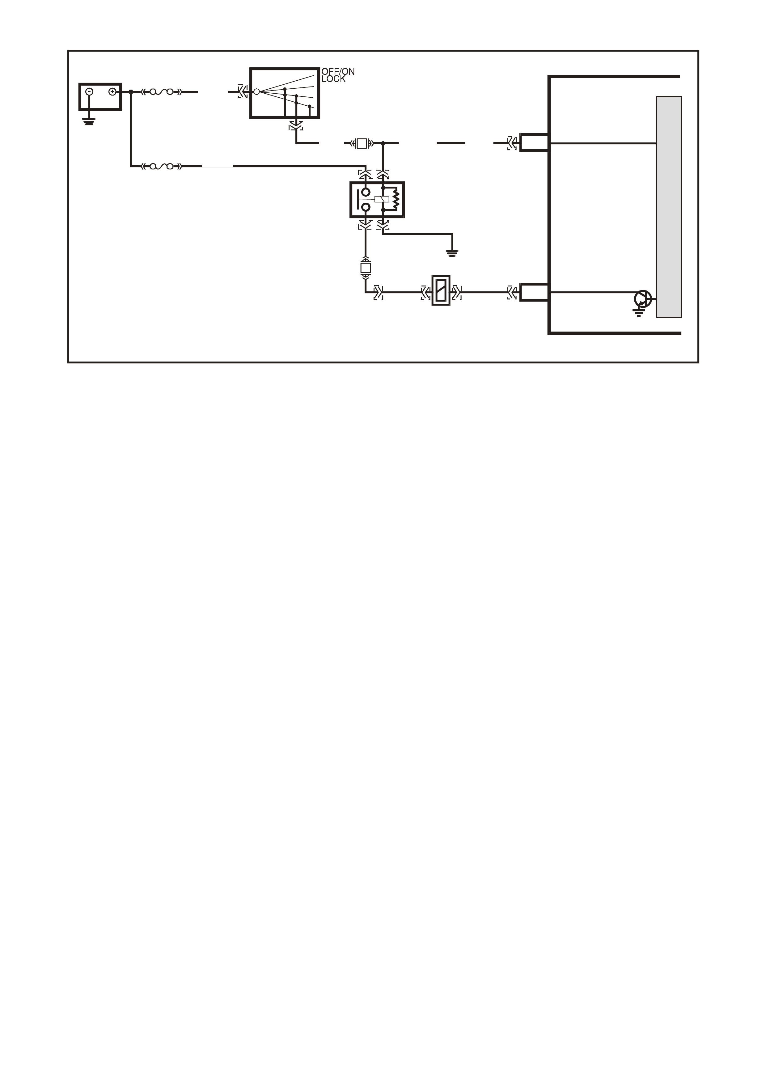
G3PCM043C
PCM
J1-19
J2-44
REVERSE INHIBIT
SOLENOID
IGNITION
M
I
C
R
O
BATTERY
FS
LOC. E1
(1040)
FJ
R (2H)
15a 15 50
30 ACC
IGN
START
IG NITION SWITCH
REVERSE INHIBIT
SOLENOID
P (3) P/B (3 9) P (39 )
B/W
152
O/Y
(479)
EFI
RELAY
F14
F32 LOC. E3
Y
(838)
P/BLU
(339)
YE122
YE123
YB125
YE39
YB44
YB44
YE39
YB125
YE110
GEN III V8 PCM
DTC P0801 REVERSE INHIBIT SOLENOID CIRCUIT FAULT
CIRCUIT DESCRIPTION
The EFI (Engine Control) relay supplies an ignition voltage through fuse F32 to the Reverse Inhibit Solenoid. The
PCM controls the solenoid by earthing the control circuit via an internal switch called a driver. The driver supplies
the earth f or the com ponent being contr olled. Eac h driver has a f ault line which the PCM m onitors. W hen the PC M
commands a component ON, the voltage of the control circuit should be low (near 0 volts). When the PCM
commands the control circuit to a com ponent OFF, the voltage potential of the circuit should be high (near battery
voltage).
When the Reverse Inhibit Solenoid is energised, the operator can shift the transmission into reverse. The PCM
enables the Re vers e Inh ibit So lenoi d when ever veh icle s peed is be low 3 km /h. When the veh icle s peed is ab ove 5
km/h, the PCM de-energises the solenoid, which prevents the operator from shifting the transmission into reverse.
CONDITIONS FOR RUNNING THE DTC
• The engine speed is greater than 600 RPM.
CONDITIONS FOR SETTING THE DTC
• The PCM d etects t he c om manded state of the c irc ui t and t he ac tua l state of the circuit do not match f or at least
10 seconds.
ACTION TAKEN WHEN THE DTC SETS
• The PCM stores the DTC information into memory when the diagnostic runs and fails.
• The Check Powertr ain Lam p will not be il luminated.
CONDITIONS FOR CLEARING THE DTC
• A last test failed (current DTC) clears when the diagnostic runs and does not fail.
DIAGNOSTIC AIDS
• Inspect t he wiring at t he PCM, the r everse in hibit sol enoid connector and all oth er circuit co nnecting p oints for
the following conditions:
- A backed out terminal
- A damaged terminal
- Reduced terminal tension
- A chafed wire
- A broken wire inside the insulation
- Moisture intrusion
- Corrosion
• When diagnosing for an intermittent short or open condition, massage the wiring harness while watching the
test equipment for a change.
• Low system volt age can cause this DTC to se t. W hen reviewing captured data, check if a low system voltage
condition was present at the time the DTC was stored in memory.
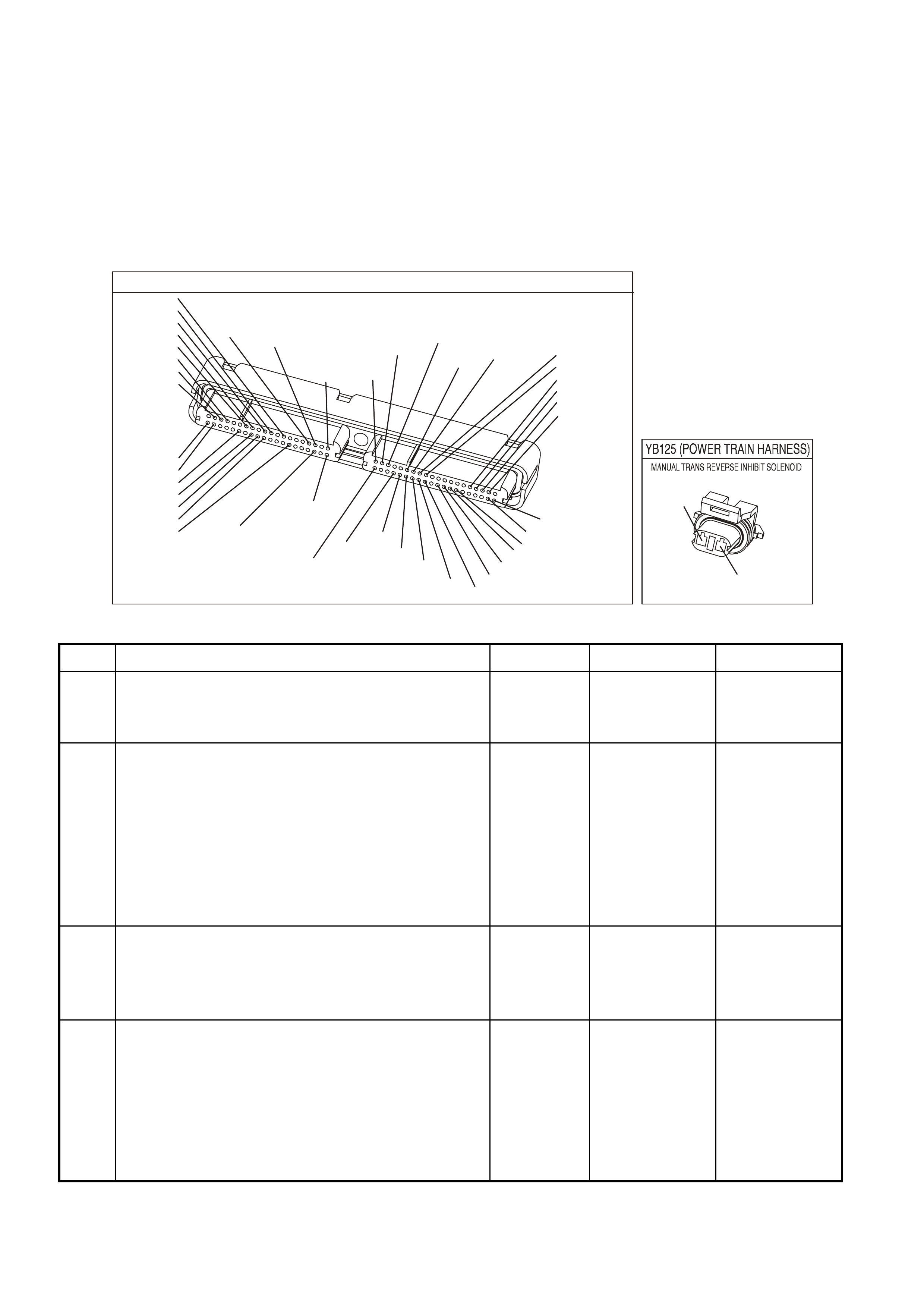
TEST DESCRIPTION
The numbers below refer to the step numbers on the diagnostic table.
2. This step checks to see if the transmission can be shifted into reverse while the speedometer is indicating
vehicle speed.
3. This step indicates if the Tech 2 scan tool will indicate the ON and OFF state of the reverse inhibit solenoid.
4. This step measures the current flow through the reverse inhibit solenoid.
6. This step checks to see if the PCM is commanding the solenoid ON and OFF.
8. This test checks if the reverse inhibit solenoid operates when earthed, with a fused jumper wire. If the solenoid
operates under these conditions then the PCM connector or PCM is faulty. If the solenoid does not operate
under these conditions then the solenoid ignition feed circuit is faulty.
YE123
P.C.M CONNECTOR 2
(750)
(1228)
(1229)
(465)
(121)
(259)
G/B
BR
G/W
GY/BLU
R
B/R
(418)
BR
(59)
(832)
G
T
(831)
(417)
(472)
(976)(974)
(432)
(428)
(631)
BLUBR G/Y
BLU/W
LG
BR/W
W/B
LG W
(977)
Y
(971)
BLU/WW
B/R
(750)
(304)
(792)
(1223)
(1222)
(123)
(1227)
(469)
(331)
Y/B
LG
V/W
B/Y
G/O BR/W
(1687)
GY/B
(366)
LG/B
GY/R
(422)
V
(442)
(444)
(443)
(975)
(972)
(978)
(1224)
(973)
(959)
LG/W
LG/B
LBLU/B
GY
(773)
BR/Y
BLU
G
Y/B
LBLU
(958)
BR
(441)
LBLU
1
41
40
80
J2
RED
Y
(838)
Y
P/BLU
(339)
(838)
GEN III V8 PCMDTC P0801 REVERSE INHIBIT SOLENOID CIRCUIT FAULT
Step Action Value(s) Yes No
1 Did you perform the Powertrain On-Board Diagnostic
(OBD) System Check? Go to Step 2 Go to Powertrain
OBD System
Check Table in
Section 6C3-2A
2
1. Raise drive wheels off ground and supp ort vehi cl e.
2. Install Tech 2 scan tool and select Engine Data.
3. Ignition ON, engine running.
4. Shift the transmission into first gear and slowly release
the clutch to allow the drive wheels to rotate to 5 - 15
km/h.
5. While speedometer is reading 5 - 15 km/h, depress
clutch and try to shift into reverse gear.
Were you unable to shift into reverse gear?
Go to Step 3 Go to Step 4
3 While the speedometer is reading 5 - 15 km/h, the Tech 2
scan tool should indicate Reverse Inhibit as OFF, and
when the speedometer is reduced to 3 km/h or lower the
Tech 2 scan tool should indicate ON.
Did the Tech 2 reading show as indicated?
Go to Step 4 Go to Step 6
4 1. Turn OFF the ignition.
2. Disconnect the RED PCM connector.
3. Turn ON the ignition.
4. Measure the current from the solenoid control circuit in
the PCM harness connector to earth for two minutes
using a DMM J 39200 on 10 amp scale.
Does the current-draw measure less than the value
shown (but not 0)?
1.5A No trouble found.
Go to Diagnostic
Aids
Go to Step 5

GEN III V8 PCMDTC P0801 REVERSE INHIBIT SOLENOID CIRCUIT FAULT (CONTINUED)
Step Action Value(s) Yes No
5 1. Turn OFF the ignition.
2. Disconnect the solenoid.
3. Measure the resistance from the solenoid control
circuit 838 (Y) in the PCM harness connector to earth
using a DMM J 39200.
Does the DMM display infinite resistance?
Go to Step 13 Go to Step 11
6 1. Turn OFF the ignition.
2. Disconnect the reverse inhibit solenoid.
3. Connect a test lamp J 34142-B between the terminals
in the solenoid harness connector.
4. Ignition ON engine running.
5. Rotate drive wheels to 5 - 15 km/h and then below 3
km/h.
Does the test lamp turn ON and OFF?
Go to Step 9 Go to Step 7
7 Probe the ignition feed circuit 339 (P/Blu) in the solenoid
harness connector with the test lamp connected to earth.
Does the test lamp illuminate?
Go to Step 8 Go to Step 12
8 1. Turn OFF the ignition.
2. Reconnect the solenoid.
3. Disconnect the RED PCM connector.
4. Turn ON the ignition.
5. Probe the solenoid control circuit 838 (Y) in the PCM
harness connector with a fused jumper wire connector
to earth.
Does the solenoid operate?
Go to Step 10 Go to Step 12
9 Check the conne ctio ns at the sole noid.
Did you find and correct the condition? Verify Repair Go to Step 13
10 Check the connection at the PCM.
Was a problem found? Verify Repair Go to Step 14
11 Repair open or short to earth or short to voltage in the
solenoid control circuit 838 (Y).
Is the repair complete?
Verify Repair
12 Repair the faulty solenoid ignition feed circuit 339 (P/Blu).
Is the repair complete? Verify Repair
13 Replace the solenoid.
Is action complete? Verify Repair
14 1. Replace PCM.
2. Refer to Section 6C3-3 for PCM reprogramming and
PCM/PIM Security Link Procedure.
Is action complete?
Verify Repair

GEN III V8 PCM -
DTC P1111 INTAKE AIR TEMPERATURE SENSOR CIRCUIT INTERMITTENT
HIGH VOLTAGE
CIRCUIT DESCRIPTION
The Intake Air Temperature (IAT) Sensor contains a semiconductor device which changes resistance based on
temperature (a thermistor). The IAT Sensor mounts in the air intake passage of the engine air induction system.
The IAT Sensor has a signal circuit and a earth circuit. The PCM applies a voltage (about 5.0 volts) on the signal
circuit to the s ensor. T he PCM m onitors changes in this voltage caused by changes in the resis tance of the sensor,
in order to determine the Intake Air Temperature.
W hen the intake air is cold, the sensor (thermistor) resistance is high, and the PCM’s signal voltage is only pulled
down a small am ount through the s ensor to earth. T he PCM senses a high signal voltage (low temperatur e). W hen
the intake air is warm, the sensor resistance is low, and the signal voltage is pulled down a greater amount. This
causes the PCM to sense a low signal voltage (high temperature).
This DTC sets when the PCM senses a signal voltage higher than the normal operating range of the sensor.
CONDITIONS FOR RUNNING THE DTC
• DTC(s) P0101, P0102, P0103, P0117, P0118, are not set.
• The engine run time is greater than 100 seconds.
• The engine coolant temperature is greater than 0°C.
• The vehicle speed is less than 11 km/h.
• The Mass Air Flow is less than 15 g/s.
CONDITIONS FOR SETTING THE DTC
• The Intake Air Temperature is at or below -35°C.
• All conditions are present for 0.3 seconds.
ACTIONS TAKEN WHEN THE DTC SETS
• The PCM stores the DTC information into memory when the diagnostic runs and fails.
• The Check Powertrain Lamp will not be illuminated.
• The PCM will substitute a default Intake Air Temperature value of 25°C.
• The PCM records the operating conditions at the time the diagnostic fails. The PCM stores this information in
the Freeze Frame/Failure Records.
CONDITIONS FOR CLEARING THE CPL/DTC
• A last test failed (current DTC) clears when the diagnostic runs and does not fail.
• Use a Tech 2 scan tool in order to clear the CPL/DTC.
DIAGNOSTIC AIDS
• If the engine has sat overnight, the engine coolant temperature and intake air temperature values should
display within a few degrees of each other. If the temperatures are not within 3°C (5°F), refer to Temperature
vs Resistance.
• For an intermittent, refer to Section 6C3-2B Symptoms, of the VX Series Service Information.
G3PCM002PT
J2-57
J2-25
A
B
INTAKE AIR
TEMPERATURE SENSOR
SENSOR EARTH
IAT SENSO R SIGN AL
PCM
5V
BR (47 2 )
G/O (469)
YE23 YE123
M
I
C
R
O

TEST DESCRIPTION
The numbers below refer to the step numbers on the diagnostic table.
2. If DTC P0113 failed this ignition, this indicates a hard failure is present. When a hard failure is present, both the
hard and intermittent DTCs set.
3. When moving related connectors, inspect the connectors for the following:
- Poor mating of the connector halves or a terminal not fully seated in the connector body (backed out).
- Improperly formed or damaged terminals. Carefully reform or replace all connector terminals in the related
circuits in order to insure proper terminals contact tension.
- Poor terminal to wire connection. Inspect for poor crimps, crimping over wire insulation rather than the wire.
- Dirt or corrosion on the terminals. Inspect the connector seals for being there and for being damaged.
4. When moving the related wiring harness, inspect the wiring for the following:
- Wire insulation that is rubbed through, causing an intermittent short.
- Wiring broken inside the insulation.
5. Using the Freeze Frame/Failure Records data may aid in locating an intermittent condition. If you cannot
duplicate the DTC, the information included in the Freeze Frame/Failure Records data can help determine the
distance traveled since the DTC set. The Fail Counter and Pass Counter can also help determine how many
ignition cycles the diagnostic reported a pass and/or fail. Operate the vehicle within the same freeze frame
condition (RPM, load, vehicle speed, temperature etc.) that you observed.
This will isolate when the DTC failed. For any test that requires probing the PCM or component harness
connectors, use the Connector Test Adapter Kit J 35616-A. Using this kit prevents any damage to the harness
connector terminals.
AIR TEMP SENSOR
YE23
B/R
(472)
G/O
(469)
GEN III V8 PCM - DTC P1111 INTAKE AIR TEMPERATURE SENSOR CIRCUIT INTERMITTENT
HIGH VOLTAGE
Step Action Value(s) Yes No
1 Did you perform the Powertrain On-Board Diagnostic
(OBD) System Check? Go to Step 2 Go to Powertrain
OBD System
Check Table
2 1. Turn ON the ignition leaving the engine OFF.
2. Observe the affected sensor value on a Tech 2 scan
tool while moving the related harness connectors (at
the component and the PCM)
Did DTC P0113 Fail This Ignition cycle?
Go to DTC P0113
IAT Sensor
Circuit High
Voltage
Go to Step 3
3 1. Turn ON the ignition leaving the engine OFF.
2. Observe the affected sensor value on a Tech 2 scan
tool while moving the related wiring harness.
Does the sensor value change abruptly while moving the
related electrical harness?
Go to Step 6 Go to Step 4
4 Observe the affected sensor value on a scan tool while
moving the related wiring harnesses.
Does the sensor value change abruptly while moving the
related electrical harnesses?
Go to Step 7 Go to Step 5

GEN III V8 PCM - DTC P1111 INTAKE AIR TEMPERATURE SENSOR CIRCUIT INTERMITTENT HIGH VOLTAGE
(CONTINUED)
Step Action Value(s) Yes No
5 1. Turn ON the ignition leaving the engine OFF.
2. Review the Freeze Frame/Failure Records data for
this DTC and observe the parameters.
3. Turn OFF the ignition for 15 seconds.
4. Start the engine.
5. Operate the vehicle within the conditions required for
this diagnostic to run, and as close to the conditions
recorded in the Freeze Frame/Failure Records as
possible. Special operating conditions that you need to
meet before the PCM will run this diagnostic, where
applicable, are listed in Conditions for Running the
DTC.
6. Select the Diagnostic Trouble Code (DTC) option, the
DTC Information option and The Failed This Ignition
option using the Tech 2 scan tool.
Does the Tech 2 scan tool indicate that this diagnostic
failed this ignition?
Go to Step 8 Refer to
Diagnostic Aids
6 Repair the damaged connectors/terminals.
Is the repair complete? Go to Step 9
7 Repair the faulty wiring.
Is the repair complete? Go to Step 9
8 1. Re-inspect all the related circuits and the connectors.
2. Replace the sensor/component if all the circuits have
been checked thoroughly and no faults can be found.
Is the action complete?
Go to Step 9
9 1. Select the Diagnostic Trouble Code (DTC) option and
the Clear DTC Information option using the Tech 2
scan tool.
2. Idle the engine at the normal operating temperature.
3. Select the Diagnostic Trouble Code (DTC) option, the
DTC Information option and The Failed This Ignition
option using the Tech 2 scan tool.
4. Operate the vehicle, within the Conditions for Running
the DTC, as specified in the supporting text, if
applicable.
3. Does the Tech 2 scan tool indicate that this DTC
reset?
Go to Step 2 Go to Step 10
10 Using the Tech 2 scan tool, check for any other DTCs.
Does the Tech 2 scan tool display any DTCs that you
have not diagnosed?
Go to the
applicable DTC
table
System OK
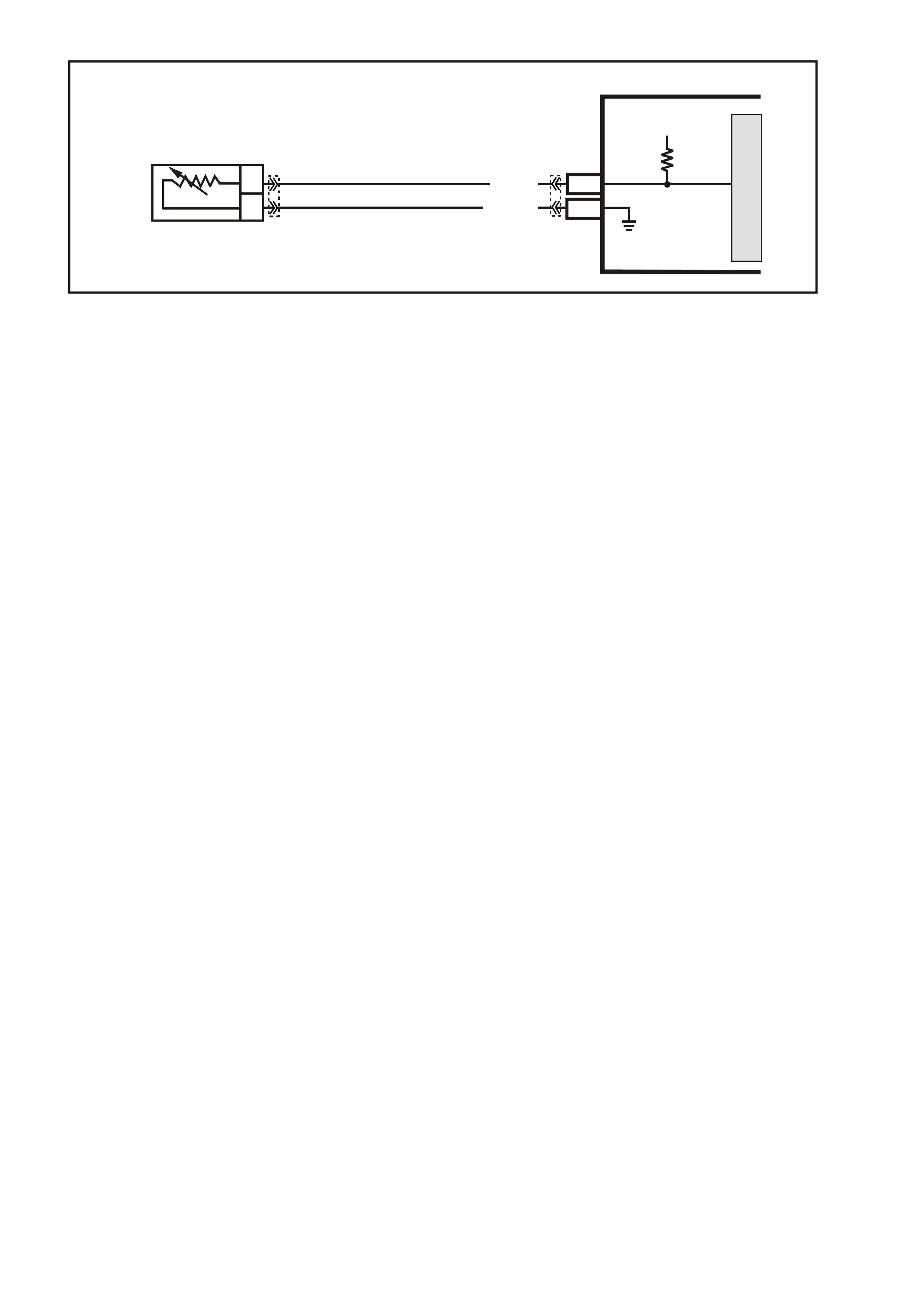
GEN III V8 PCM -
DTC P1112 INTAKE AIR TEMPERATURE SENSOR CIRCUIT INTERMITTENT
LOW VOLTAGE
CIRCUIT DESCRIPTION
The Intake Air Temperature (IAT) Sensor contains a semiconductor device which changes resistance based on
temperature (a thermistor). The IAT Sensor mounts in the air intake passage of the engine air induction system.
The IAT Sensor has a signal circuit and a earth circuit. The PCM applies a voltage (about 5.0 volts) on the signal
circuit to the s ensor. T he PCM monitors changes in this voltage c aused by c hanges in the resistanc e of the sensor
in order to determine the intake air temperature.
W hen the intake air is cold, the sensor (thermistor) resistance is high, and the PCM’s signal voltage is only pulled
down a small am ount through the s ensor to earth. T he PCM senses a high signal voltage (low temperatur e). W hen
the intake air is warm, the sensor resistance is low, and the signal voltage is pulled down a greater amount. This
causes the PCM to sense a low signal voltage (high temperature).
This DTC sets when the PCM senses a signal voltage higher than the normal operating range of the sensor.
CONDITIONS FOR RUNNING THE DTC
• DTC(s) P0101, P0102, P0103, P0117, P0118, are not set.
• The engine run time is greater than 30 seconds.
• The vehicle speed is less than 40 km/h.
CONDITIONS FOR SETTING THE DTC
• The Intake Air Temperature is at or below 139°C.
• The conditions present for 0.3 seconds.
ACTIONS TAKEN WHEN THE DTC SETS
• The PCM stores the DTC information into memory when the diagnostic runs and fails.
• The Check Powertrain Lamp will not be illuminated.
• The PCM will substitute a default Intake Air Temperature value of 25°C.
• The PCM records the operating conditions at the time the diagnostic fails. The PCM stores this information in
the Freeze Frame/Failure Records.
CONDITIONS FOR CLEARING THE CPL/DTC
• A last test failed (current DTC) clears when the diagnostic runs and does not fail.
• Use a Tech 2 scan tool in order to clear the CPL/DTC.
DIAGNOSTIC AIDS
• If the engine has sat overnight, the engine coolant temperature and intake air temperature values should
display within a few degrees of each other. If the temperatures are not within 3°C (5°F), refer to Temperature
vs Resistance.
• For an intermittent, refer to Section 6C3-2B Symptoms, of the VX Series Service Information.
G3PCM002PT
J2-57
J2-25
A
B
INTAKE AIR
TEMPERATURE SENSOR
SENSOR EARTH
IAT SENSO R SIGN AL
PCM
5V
BR (47 2 )
G/O (469)
YE23 YE123
M
I
C
R
O

TEST DESCRIPTION
The numbers below refer to the step numbers on the diagnostic table.
2. If DTC P0112 failed this ignition, this indicates a hard failure is present. When a hard failure is present, both the
hard and intermittent DTCs set.
3. When moving related connectors, inspect the connectors for the following:
- Poor mating of the connector halves or a terminal not fully seated in the connector body (backed out).
- Improperly formed or damaged terminals. Carefully reform or replace all connector terminals in the related
circuits in order to ensure correct terminal contact tension.
- Poor terminal to wire connection. Inspect for poor crimps, crimping over wire insulation rather than the wire.
- Dirt or corrosion on the terminals. Inspect the connector seals for being there and for being damaged.
4. When moving the related wiring harness, inspect the wiring for the following:
- Wire insulation that is rubbed through, causing an intermittent short.
- Wiring broken inside the insulation.
5. Using the Freeze Frame/Failure Records data may aid in locating an intermittent condition. If you cannot
duplicate the DTC, the information included in the Freeze Frame/Failure Records data can help determine the
distance traveled since the DTC set. The Fail Counter and Pass Counter can also help determine how many
ignition cycles the diagnostic reported a pass and/or fail. operate the vehicle within the same freeze frame
condition (RPM, load, vehicle speed, temperature etc.) that you observed.
This will isolate when the DTC failed. For any test that requires probing the PCM or component harness
connectors, use the Connector Test Adapter Kit J 35616-A. Using this kit prevents any damage to the harness
connector terminals
.
AIR TEMP SENSOR
YE23
B/R
(472)
G/O
(469)
GEN III V8 PCM - DTC P1112 INTAKE AIR TEMPERATURE SENSOR CIRCUIT INTERMITTENT
LOW VOLTAGE
Step Action Value(s) Yes No
1 Did you perform the Powertrain On-Board Diagnostic
(OBD) System Check? Go to Step 2 Go to Powertrain
OBD System
Check Table
2
1. Install a Tech 2 scan tool.
2. Idle the engine.
3. Monitor the Failed This Ignition option under the DTC
Information option using the Tech 2 scan tool
Did DTC P0112 Fail This Ignition cycle?
Go to DTC
P0112 IAT
Sensor Circuit
Low Voltage
Go to Step 3
3 1. Turn OFF the ignition leaving the engine OFF.
2. Observe the affected sensor value on a Tech 2 scan
tool while moving the related harness connectors (at
the component and the PCM)
Does the sensor value change abruptly while moving the
related connector is being moved?
Go to Step 6 Go to Step 4
4 Observe the affected sensor value on a Tech 2 scan tool
while moving the related wiring harness.
Does the sensor value change abruptly while moving the
related electrical harness?
Go to Step 7 Go to Step 5

GEN III V8 PCM - DTC P1112 INTAKE AIR TEMPERATURE SENSOR CIRCUIT INTERMITTENT LOW
VOLTAGE (CONTINUED)
Step Action Value(s) Yes No
5 1. Turn ON the ignition leaving the engine OFF.
2. Review the Freeze Frame/Failure Records data for
this DTC and observe the parameters.
3. Turn OFF the ignition for 15 seconds.
4. Start the engine.
5. Operate the vehicle, within the conditions required for
this diagnostic to run, and as close to the conditions
recorded in the Freeze Frame/Failure Records as
possible. Special operating conditions that you need to
meet before the PCM will run this diagnostic, where
applicable, are listed in Conditions for Running the
DTC.
6. Select the Diagnostic Trouble Code (DTC) option, the
DTC Information option and The Failed This Ignition
option using the Tech 2 scan tool.
Does the Tech 2 scan tool indicate that this diagnostic
failed this ignition?
Go to Step 8 Refer to
Diagnostic Aids
6 Repair the damaged connectors/terminals.
Is the repair complete? Go to Step 9
7 Repair the faulty wiring.
Is the repair complete? Go to Step 9
8 1. Re-inspect all the related circuits and the connectors.
2. Replace the sensor/component if all the circuits have
been checked thoroughly and no faults can be found.
Is the action complete?
Go to Step 9
9 1. Select the Diagnostic Trouble Code (DTC) option and
the Clear DTC Information option using the Tech 2
scan tool.
2. Idle the engine at the normal operating temperature.
3. Select the Diagnostic Trouble Code (DTC) option, the
DTC Information option and The Failed This Ignition
option using the Tech 2 scan tool.
4. Operate the vehicle within the Conditions for Running
the DTC, as specified in the supporting text, if
applicable.
Does the Tech 2 scan tool indicate that this DTC reset?
Go to Step 2 Go to Step 10
10 Using the Tech 2 scan tool, check for any other DTCs.
Does the Tech 2 scan tool display any DTCs that you
have not diagnosed?
Go to the
applicable DTC
table
System OK

GEN III V8 PCM -
DTC P1114 ENGINE COOLANT TEMPERATURE SENSOR CIRCUIT INTERMITTENT
LOW VOLTAGE
CIRCUIT DESCRIPTION
The Engine Coolant T em perature (ECT ) Sensor contains a semic onductor device which c hanges resistance based
on temperature (a therm istor). The ECT Sensor mounts in the left bank cylinder head near the front of the engine.
The ECT Sensor has a signal circuit and a earth circuit. T he PCM applies a voltage (about 5.0 volts) on the signal
circuit to the sensor. The PCM monitors changes in this voltage caused by the changes in the resistance of the
sensor in order to determine the engine coolant temperature.
When the engine coolant is cold, the sensor (thermistor) resistance is high, and the PCM’s signal voltage is only
pulled down a small am ount through the s ensor to earth. T he PCM senses a high signal voltage (low temperatur e).
W hen the intake air is warm, the sens or resistance is low, and the s ignal voltage is pulled down a gr eater amount.
This causes the PCM to sense a low signal voltage (high temperature).
This DTC sets when the PCM senses a signal voltage higher than the normal operating range of the sensor.
CONDITIONS FOR RUNNING THE DTC
• The engine run time is greater than 10 seconds.
CONDITIONS FOR SETTING THE DTC
• The engine coolant temperature is greater than 139°C fore at least one second.
ACTIONS TAKEN WHEN THE DTC SETS
• The PCM stores the DTC information into memory when the diagnostic runs and fails.
• The Check Powertrain Lamp will not be illuminated.
• The PCM records the operating conditions at the time the diagnostic fails. The PCM stores this information in
the Freeze Frame/Failure Records.
CONDITIONS FOR CLEARING THE CPL/DTC
• A last test failed (current DTC) clears when the diagnostic runs and does not fail.
• Use a Tech 2 scan tool in order to clear the CPL/DTC.
DIAGNOSTIC AIDS
• Electro-Magnetic Interference (EMI) can cause an intermittent DTC. Inspect the related circuits for being too
closed to secondary ignition wires and the generator.
• If the engine has sat overnight, the engine coolant temperature and intake air temperature values should
display within a few degrees of each other. If the temperatures are not within 3°C (5°F), refer to Temperature
vs. Resistance in Section 6C3-4 of the VX Series Service Information.
• For an intermittent, refer to Section 6C3-2B Symptoms, of the VX Series Service Information.
G3PCM004PT
J1-80
J1-74
B
A
ENGINE COOLANT
TEMPERATURE SENSOR
SENSOR EARTH
ETC SENSOR SIGNAL
5V
4k
348
Ω
Ω
Y (41 0)
GY/B (455)
YE65 YE122
M
I
C
R
O

TEST DESCRIPTION
The numbers below refer to the step numbers on the diagnostic table.
2. If DTC P0117 failed this ignition, this indicates a hard failure is present. When a hard failure is present, both the
hard and intermittent DTC’s set.
3. When moving related connectors, inspect the connectors for the following:
- Poor mating of the connector halves or a terminal not fully seated in the connector body (backed out).
- Improperly formed or damaged terminals. Carefully reform or replace all connector terminals in the related
circuits in order to ensure correct terminal contact tension.
- Poor terminal to wire connection. Inspect for poor crimps, crimping over wire insulation rather than the wire.
- Dirt or corrosion on the terminals. Inspect the connector seals for being there and for being damaged.
4. When moving the related wiring harness, inspect the wiring for the following:
- Wire insulation that is rubbed through, causing an intermittent short.
- Wiring broken inside the insulation.
5. Using the Freeze Frame/Failure Records data may aid in locating an intermittent condition. If you cannot
duplicate the DTC, the information included in the Freeze Frame/Failure Records data can help determine the
distance traveled since the DTC set. The Fail Counter and Pass Counter can also help determine how many
ignition cycles the diagnostic reported a pass and/or fail. Operate the vehicle within the same freeze frame
condition (RPM, load, vehicle speed, temperature etc.) that you observed.
This will isolate when the DTC failed. For any test that requires probing the PCM or component harness
connectors, use the Connector Test Adapter Kit J 35616-A. Using this kit prevents any damage to the harness
connector terminals.
COOLANT TEMP SENSOR
Y
(410)
GY/B
(455)
GEN III V8 PCM - DTC P1114 ENGINE COOLANT TEMPERATURE SENSOR CIRCUIT INTERMITTENT
LOW VOLTAGE
Step Action Value(s) Yes No
1 Did you perform the Powertrain On-Board Diagnostic
(OBD) System Check? Go to Step 2 Go to Powertrain
OBD System
Check Table
2 1. Install Tech 2 scan tool.
2. Idle the engine.
3. Monitor the Failed This Ignition option under the DTC
Information option using the scan tool.
Did DTC P0117 fail this ignition cycle?
Go to DTC
P0117 ECT
Sensor Circuit
Low Voltage
Go to Step 3
3 1. Turn ON the ignition leaving the engine OFF.
2. Observe the affected sensor value on the scan tool
while moving the related harness connectors (at the
component and the PCM).
Does the sensor value change abruptly while a related
connector is being moved?
Go to Step 6 Go to Step 4
4 Observe the affected sensor value on the scan tool while
moving the related wiring harnesses.
Does the sensor value change abruptly while moving the
related electrical harnesses?
Go to Step 7 Go to Step 5

GEN III V8 PCM - DTC P1114 ENGINE COOLANT TEMPERATURE SENSOR CIRCUIT INTERMITTENT
LOW VOLTAGE (CONTINUED)
Step Action Value(s) Yes No
5 1. Turn ON the ignition leaving the engine OFF.
2. Review the Freeze Frame/Failure Records data for
this DTC and observe the parameters.
3. Turn OFF the ignition for 15 seconds.
4. Start the engine.
5. Operate the vehicle within the conditions required for
this diagnostic to run, and as close to the conditions
recorded in the Freeze Frame/Failure Records as
possible. Special operating conditions that you need to
meet before the PCM will run this diagnostic, where
applicable, are listed in Conditions for Running the
DTC.
6. Select the Diagnostic Trouble Code (DTC) option, the
DTC Information option and The Failed This Ignition
option using the Tech 2 scan tool.
Does the Tech 2 scan tool indicate that this diagnostic
failed this ignition?
Go to Step 8 Go to
Diagnostic Aids
6 Repair the damaged connectors/terminals.
Is the repair complete? Go to Step 9
7 Repair the faulty wiring.
Is the repair complete? Go to Step 9
8 1. Re-inspect all the related circuits and the connectors.
2. Replace the sensor/component if all the circuits have
been checked thoroughly and no faults can be found.
Is the action complete?
Go to Step 9
9 1. Select the Diagnostic Trouble Code (DTC) option and
the Clear DTC Information option using the Tech 2
scan tool.
2. Idle the engine at the normal operating temperature.
3. Select the Diagnostic Trouble Code (DTC) option, the
DTC Information option and The Failed This Ignition
option using the Tech 2 scan tool.
4. Operate the vehicle, within the Conditions for Running
the DTC, as specified in the supporting text, if
applicable.
Does the Tech 2 scan tool indicate that this DTC reset?
Go to Step 2 Go to Step 10
10 Using the Tech 2 scan tool, check for any other DTC’s.
Does the Tech 2 scan tool display any DTCs that you
have not diagnosed?
Go to the
applicable DTC
table
System OK
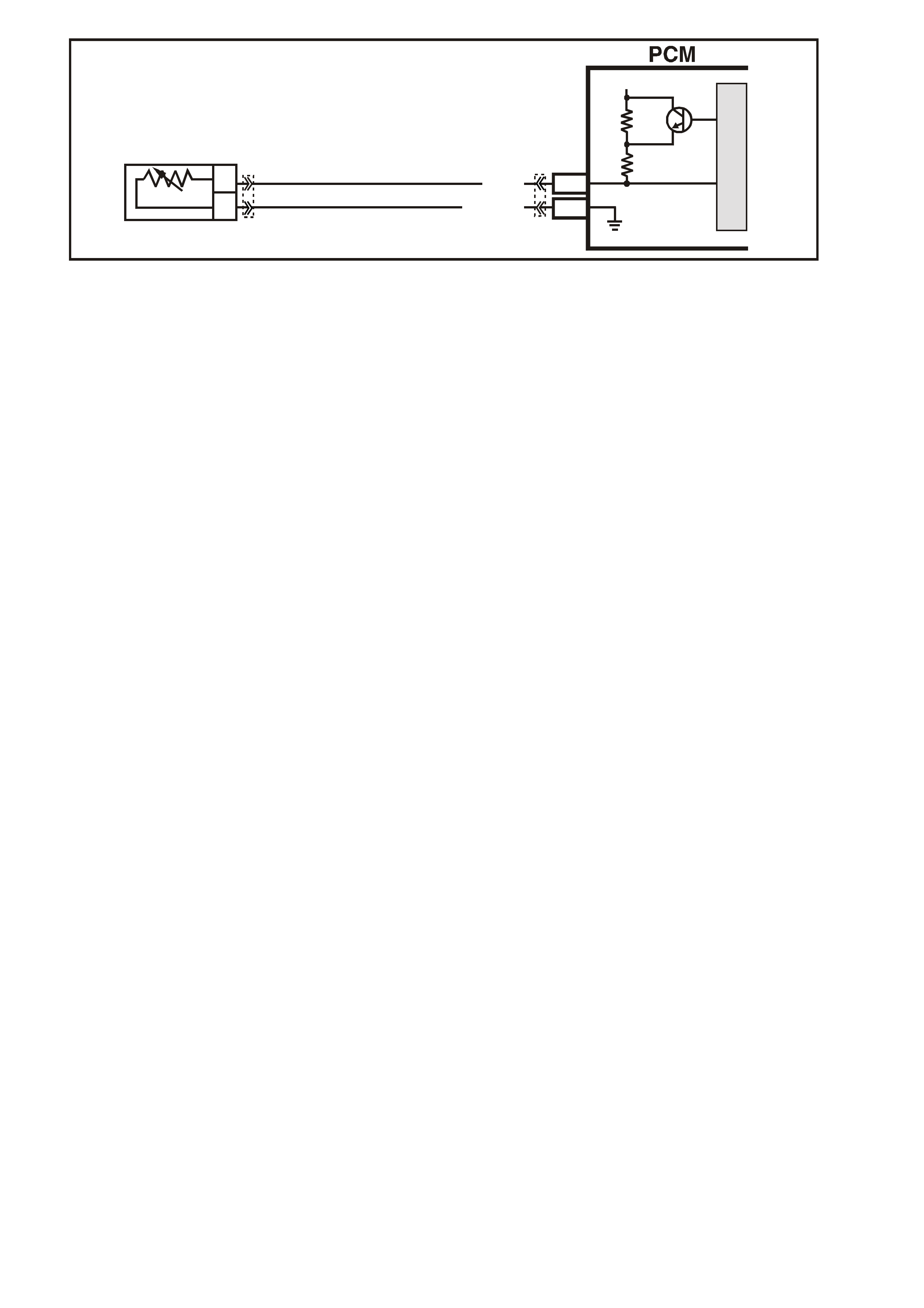
GEN III V8 PCM -
DTC P1115 ENGINE COOLANT TEMPERATURE SENSOR CIRCUIT INTERMITTENT
HIGH VOLTAGE
CIRCUIT DESCRIPTION
The Engine Coolant T em perature (ECT ) Sensor contains a semic onductor device which c hanges resistance based
on temperature (a therm istor). The ECT Sensor mounts in the left bank cylinder head near the front of the engine.
The ECT Sensor has a signal circuit and a earth circuit. T he PCM applies a voltage (about 5.0 volts) on the signal
circuit to the sensor. The PCM monitors changes in this voltage caused by the changes in the resistance of the
sensor in order to determine the engine coolant temperature.
When the engine coolant is cold, the sensor (thermistor) resistance is high, and the PCM’s signal voltage is only
pulled down a small am ount through the s ensor to earth. T he PCM senses a high signal voltage (low temperatur e).
W hen the intake air is warm, the sens or resistance is low, and the s ignal voltage is pulled down a gr eater amount.
This causes the PCM to sense a low signal voltage (high temperature).
This DTC sets when the PCM senses a signal voltage higher than the normal operating range of the sensor.
CONDITIONS FOR RUNNING THE DTC
• The engine run time is greater than 60 seconds.
CONDITIONS FOR SETTING THE DTC
• The engine coolant temperature is less than -35°C for at least one second.
ACTIONS TAKEN WHEN THE DTC SETS
• The PCM stores the DTC information into memory when the diagnostic runs and fails.
• The Check Powertrain Lamp will not be illuminated.
• The PCM records the operating conditions at the time the diagnostic fails. The PCM stores this information in
the Freeze Frame/Failure Records.
CONDITIONS FOR CLEARING THE CPL/DTC
• A last test failed (current DTC) clears when the diagnostic runs and does not fail.
• Use a Tech 2 scan tool in order to clear the CPL/DTC.
DIAGNOSTIC AIDS
• Electro-Magnetic Interference (EMI) can cause an intermittent DTC. Inspect the related circuits for being too
close to secondary ignition wires and the generator.
• If the engine has sat overnight, the engine coolant temperature and intake air temperature values should
display within a few degrees of each other. If the temperatures are not within 3°C (5°F), refer to Temperature
vs. Resistance Table in Section 6C3-4 of the VX Series Service Information.
• For an intermittent, refer to Section 6C3-2B Symptoms, of the VX Series Service Information.
TEST DESCRIPTION
The numbers below refer to the step numbers on the diagnostic table.
2. If DT C P0118 f ailed this ignition, this indicates a har d f ailur e is pr es ent. When a hard f ailure is pr es ent, both the
hard and intermittent DTC’s set.
3. When moving related connectors, inspect the connectors for the following:
- Poor mating of the connector halves or a terminal not fully seated in the connector body (backed out).
- Improperly formed or dam aged terminals. Carefully reform or replace all connector terminals in the related
circuits in order to ensure correct terminal contact tension.
- Poor terminal to wire connection. Inspect for poor crimps, crimping over wire insulation rather than the wire.
- Dirt or corrosion on the terminals. Inspect the connector seals for being there and for being damaged.
G3PCM004PT
J1-80
J1-74
B
A
ENGINE COOLANT
TEMPERATURE SENSOR
SENSOR EARTH
ETC SENSOR SIGNAL
5V
4k
348
Ω
Ω
Y (41 0)
GY/B (455)
YE65 YE122
M
I
C
R
O

4. When moving the related wiring harness, inspect the wiring for the following:
- Wire insulation that is rubbed through, causing an intermittent short.
- Wiring broken inside the insulation.
5. Using the Freeze Frame/Failure Records data may aid in locating an intermittent condition. If you cannot
duplicate the DTC, the information included in the Freeze Frame/Failure Records data can help determine the
distance traveled since the DTC set. The Fail Counter and Pass Counter can also help determine how many
ignition cycles the diagnostic reported a pass and/or fail. Operate the vehicle within the same freeze frame
condition (RPM, load, vehicle speed, temperature etc.) that you observed. This will isolate when the DTC
failed. For any test that requires probing the PCM or component harness connectors, use the Connector Test
Adapter Kit J 35616-A. Using this kit prevents any damage to the harness connector terminals.
COOLANT TEMP SENSOR
Y
(410)
GY/B
(455)
GEN III V8 PCM - DTC P1115 ENGINE COOLANT TEMPERATURE SENSOR CIRCUIT HIGH VOLTAGE
Step Action Value(s) Yes No
1 Did you perform the Powertrain On-Board Diagnostic
(OBD) System Check? Go to Step 2 Go to Powertrain
OBD System
Check Table
2
1. Install a Tech 2 scan tool.
2. Idle the engine.
3. Monitor the Failed This Ignition option under the DTC
Information option using the Tech 2 scan tool
Did DTC P0118 Fail This Ignition cycle?
Go to DTC
P0118 ECT
Sensor Circuit
High Voltage
Table
Go to Step 3
3 1. Turn ON the ignition leaving the engine OFF.
2. Observe the affected sensor value on a Tech 2 scan
tool while moving the related harness connectors (at
the component and the PCM)
Does the sensor value change abruptly while moving the
related connector is being moved?
Go to Step 6 Go to Step 4
4 Observe the affected sensor value on a Tech 2 scan tool
while moving the related wiring harness.
Does the sensor value change abruptly while moving the
related electrical harness?
Go to Step 7 Go to Step 5
5 1. Turn ON the ignition leaving the engine OFF.
2. Review the Freeze Frame/Failure Records data for
this DTC and observe the parameters.
3. Turn OFF the ignition for 15 seconds.
4. Start the engine.
5. Operate the vehicle within the conditions required for
this diagnostic to run, and as close to the conditions
recorded in the Freeze Frame/Failure Records as
possible. Special operating conditions that you need to
meet before the PCM will run this diagnostic, where
applicable, are listed in Conditions for Running the
DTC.
6. Select the Diagnostic Trouble Code (DTC) option, the
DTC Information option and The Failed This Ignition
option using the Tech 2 scan tool.
Does the Tech 2 scan tool indicate that this diagnostic
failed this ignition?
Go to Step 8 Go to
Diagnostic Aids
6 Repair the damaged connectors/terminals.
Is the repair complete? Go to Step 9

GEN III V8 PCM - DTC P1115 ENGINE COOLANT TEMPERATURE SENSOR CIRCUIT
HIGH VOLTAGE (CONTINUED)
Step Action Value(s) Yes No
7 Repair the faulty wiring.
Is the repair complete? Go to Step 9
8 1. Re-inspect all the related circuits and the connectors.
2. Replace the sensor/component if all the circuits have
been checked thoroughly and no faults can be found.
Is the action complete?
Go to Step 9
9 1. Select the Diagnostic Trouble Code (DTC) option and
the Clear DTC Information option using the Tech 2
scan tool.
2. Idle the engine at the normal operating temperature.
3. Select the Diagnostic Trouble Code (DTC) option, the
DTC Information option and The Failed This Ignition
option using the Tech 2 scan tool.
4. Operate the vehicle, within the Conditions for Running
the DTC, as specified in the supporting text, if
applicable.
Does the Tech 2 scan tool indicate that this DTC reset?
Go to Step 2 Go to Step 10
10 Using the Tech 2 scan tool, check for any other DTCs.
Does the Tech 2 scan tool display any DTCs that you
have not diagnosed?
Go to the
applicable DTC
table
System OK
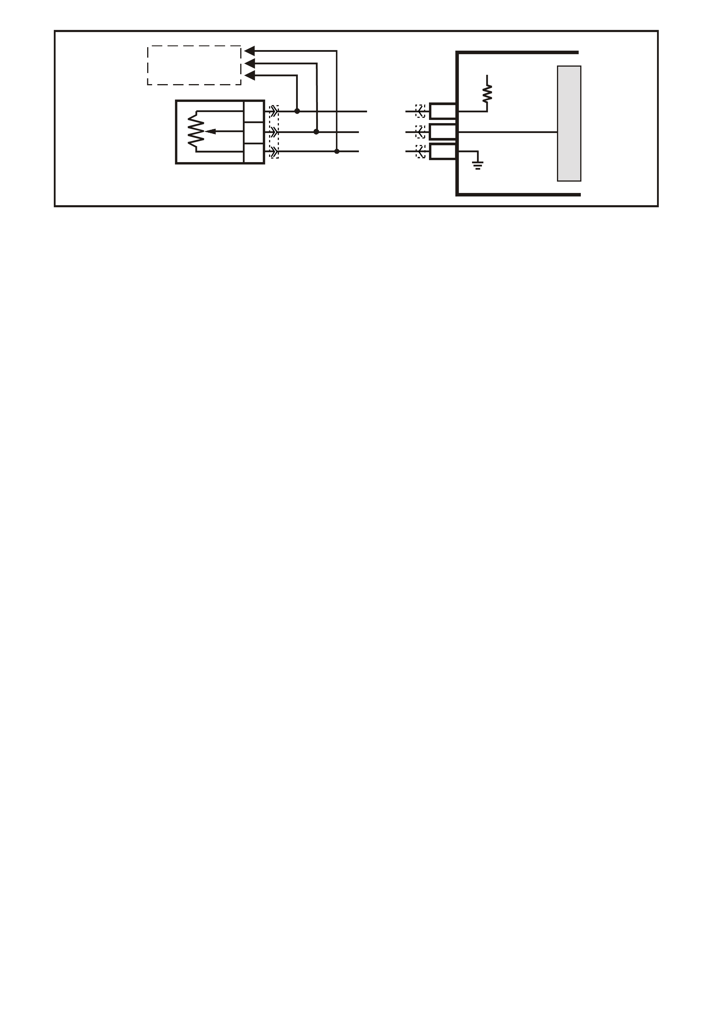
GEN III V8 PCM -
DTC P1121 THROTTLE POSITION SENSOR CIRCUIT INTERMITTENT HIGH VOLTAGE
CIRCUIT DESCRIPTION
The Throttle Position ( T P) Sens or is a potentiometer. The T P Sensor is mounted to the left s ide of the thr ottle body.
The TP Sensor provides a voltage signal that c hanges relative to throttle blade angle. T his signal voltage is one of
the most important inputs used by the PCM. The TP Sensor has a 5.0 volt reference, a earth and a signal circuit.
TP sens or signal voltage s hould be about 0.6 volt at idle. The TP Sensor voltage should increase to above 4.0 volts
at wide open throttle (WOT).
When the PCM senses a signal voltage higher than the normal operating range of the sensor, this DTC will set.
CONDITIONS FOR RUNNING THE DTC
• The ignition switch is ON.
CONDITIONS FOR SETTING THE DTC
• The TP sensor signal voltage is greater than 4.8 volts.
ACTIONS TAKEN WHEN THE DTC SETS
• The PCM stores the DTC information into memory when the diagnostic runs and fails.
• The Check Powertrain Lamp will not be illuminated.
• The PCM records the operating conditions at the time the diagnostic fails. The PCM stores this information in
the Freeze Frame/Failure Records.
CONDITIONS FOR CLEARING THE CPL/DTC
• A last test failed (current DTC) clears when the diagnostic runs and does not fail.
• Use a Tech 2 scan tool in order to clear the CPL/DTC.
DIAGNOSTIC AIDS
• An intermittent DTC can be caused by Electro-Magnetic Interference (EMI). Inspect related circuits for being
too close to secondary ignition wires and the alternator.
• For an intermittent, refer to Section 6C3-2B Symptoms, of the VX Series Service Information.
TEST DESCRIPTION
The numbers below refer to the step numbers on the diagnostic table.
2. If DT C P0123 f ailed this ignition, this indicates a har d f ailur e is pr es ent. When a hard f ailure is pr es ent, both the
hard and intermittent DTCs set.
3. When moving related connectors, inspect the connectors for the following:
- Poor mating of the connector halves or a terminal not fully seated in the connector body (backed out).
- Improperly formed or dam aged terminals. Carefully reform or replace all connector terminals in the related
circuits in order to ensure correct terminal contact tension.
- Poor terminal to wire connection. Inspect for poor crimps, crimping over wire insulation rather than the wire.
- Dirt or corrosion on the terminals. Inspect the connector seals for being there and for being damaged.
4. When moving the related wiring harness, inspect the wiring for the following:
- Wire insulation that is rubbed through, causing an intermittent short.
- Wiring broken inside the insulation.
5. Using the Freeze Frame/Failure Records data may aid in locating an intermittent condition. If you cannot
duplicate the DTC, the information included in the Freeze Fram e/Failure Records data can help determine the
distance traveled since the DTC set. The Fail Counter and Pass Counter can also help determine how many
ignition cycles the diagnostic reported a pass and/or fail. operate the vehicle within the same freeze frame
condition (RPM, load, vehicle speed, temperature etc.) that you observed. This will isolate when the DTC
failed. For any test that requires probing the PCM or component harness connectors, use the Connector Test
Adapter Kit J 35616-A. Using this kit prevents any damage to the harness connector terminals.
G3PCM005PT
SENSOR EARTH
TP SENSOR SIGNAL
TP SEN SOR
REFERENCE
VOLTAGE
PCM
5V
M
I
C
R
O
J1-08
J2-24
J1-60
A
C
B
THROTTLE
POSITION SENSOR
GY (416)
YE122
YE122YE30
YE123
BLU (417)
B/Y (452)
TO
THROTTLE RELAXER
MODULE

THROTTLE POSITION SENSOR
YE30
(452)(416)
(417)
GY
B/Y
BLU
GEN III V8 PCM - DTC P1121 THROTTLE POSITION SENSOR CIRCUIT INTERMITTENT HIGH VOLTAGE
Step Action Value(s) Yes No
1 Did you perform the Powertrain On-Board Diagnostic
(OBD) System Check? Go to Step 2 Go to Powertrain
OBD System
Check Table
2 1. Install the Tech 2 scan tool.
2. Start and idle the engine.
3. Using a Tech 2 scan tool, monitor Failed This Ignition
under DTC Status for DTC P0123.
Did DTC P0123 fail this ignition cycle?
Go to DTC
P0123 TP
Sensor Circuit
High Voltage
Table
Go to Step 3
3 1. Install the Tech 2 scan tool.
2. Turn the ignition ON, engine OFF.
3. Using a Tech 2 scan tool, observe affected sensor
values while moving related harness connectors (at
component and PCM).
Does sensor value change abruptly while a related
connector is being moved?
Go to Step 6 Go to Step 4
4 Using a Tech 2 scan tool, observe affected sensor value
while moving related wiring harnesses.
Does sensor value change abruptly while moving related
electrical harnesses?
Go to Step 7 Go to Step 5
5 1. Turn ON the ignition leaving the engine OFF.
2. Review the Freeze Frame/Failure Records data for
this DTC and observe the parameters.
3. Turn OFF the ignition for 15 seconds.
4. Start the engine.
5. Operate the vehicle, within the conditions required for
this diagnostic to run, and as close to the conditions
recorded in the Freeze Frame/Failure Records as
possible. Special operating conditions that you need to
meet before the PCM will run this diagnostic, where
applicable, are listed in Conditions for Running the
DTC.
6. Select the Diagnostic Trouble Code (DTC) option, the
DTC Information option and The Failed This Ignition
option using the Tech 2 scan tool.
Does the Tech 2 scan tool indicate that this diagnostic
failed this ignition?
Go to Step 8 Go to
Diagnostic Aids
6 Repair the damage connectors/terminals.
Is the repair complete? Go to Step 9
7 Repair the faulty wiring.
Is the repair complete? Go to Step 9
8 1. Re-inspect all the related circuits and the connectors.
2. Replace the sensor/component if all the circuits have
been checked thoroughly and no faults can be found.
Is the action complete?
Go to Step 9

GEN III V8 PCM - DTC P1121 THROTTLE POSITION SENSOR CIRCUIT INTERMITTENT
HIGH VOLTAGE (CONTINUED)
Step Action Value(s) Yes No
9 1. Select the Diagnostic Trouble Code (DTC) option and
the Clear DTC Information option using the Tech 2
scan tool.
2. Idle the engine at the normal operating temperature.
3. Select the Diagnostic Trouble Code (DTC) option, the
DTC Information option and The Failed This Ignition
option using the Tech 2 scan tool.
4. Operate the vehicle, within the Conditions for Running
the DTC, as specified in the supporting text, if
applicable.
Does the Tech 2 scan tool indicate that this DTC reset?
Go to Step 2 Go to Step 10
10 Using the Tech 2 scan tool, check for any other DTCs.
Does the Tech 2 scan tool display any DTCs that you
have not diagnosed?
Go to the
applicable DTC
table
System OK
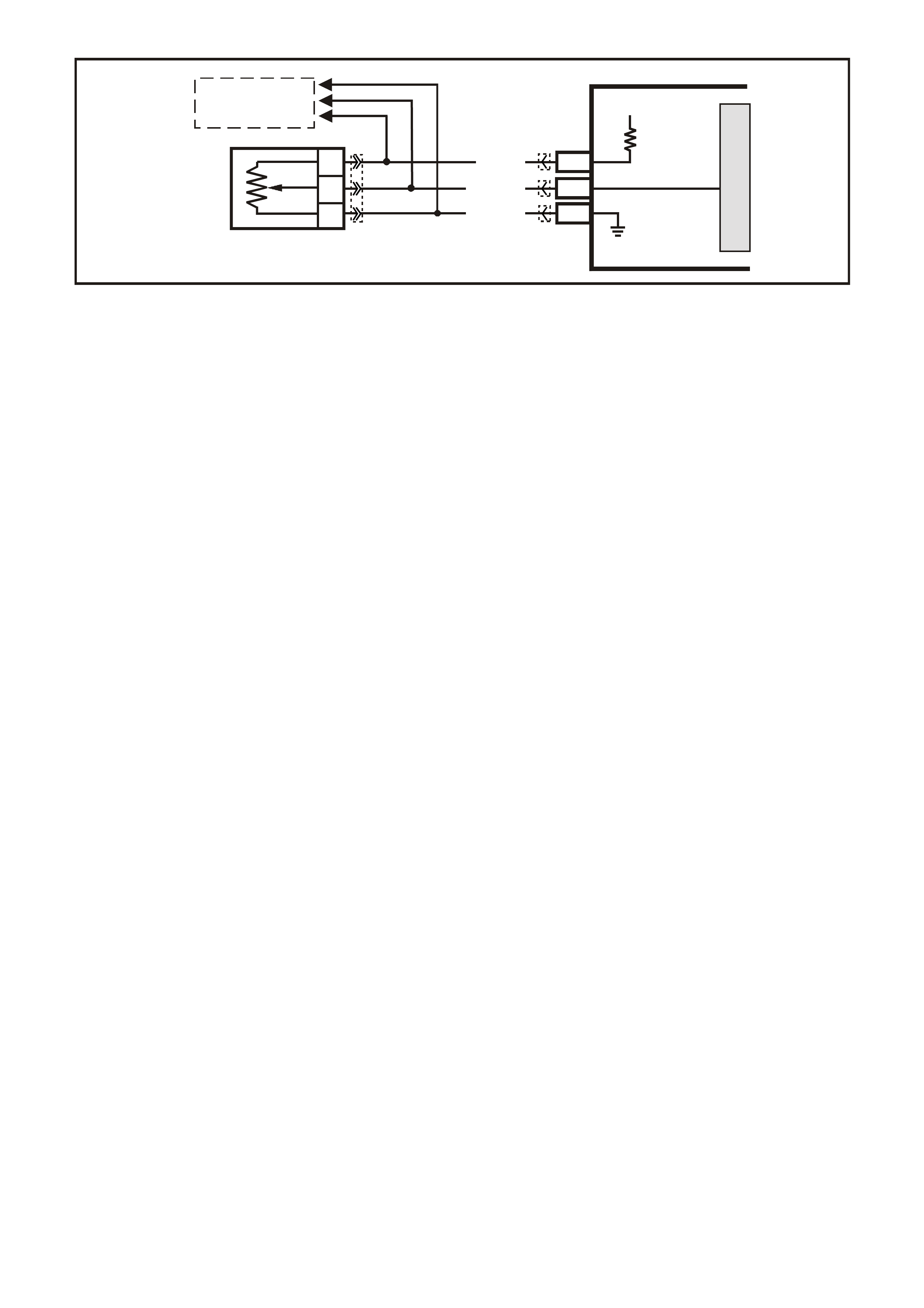
GEN III V8 PCM -
DTC P1122 THROTTLE POSITION SENSOR CIRCUIT INTERMITTENT LOW VOLTAGE
CIRCUIT DESCRIPTION
The Throttle Position ( T P) Sens or is a potentiometer. The T P Sensor is mounted to the left s ide of the thr ottle body.
The TP Sensor provides a voltage signal that c hanges relative to throttle blade angle. T his signal voltage is one of
the most important inputs used by the PCM. The TP Sensor has a 5.0 volt reference, a earth and a signal circuit.
TP Sensor signal voltage should be about 0.6 volt at idle. T he TP sensor voltage should increase to above 4.0 volts
at wide open throttle (WOT).
When the PCM senses a signal voltage higher than the normal operating range of the sensor, this DTC will set.
CONDITIONS FOR RUNNING THE DTC
• The ignition switch is ON or the engine is running.
CONDITIONS FOR SETTING THE DTC
• The TP sensor signal voltage is less than 0.2 volts.
ACTIONS TAKEN WHEN THE DTC SETS
• The PCM stores the DTC information into memory when the diagnostic runs and fails.
• The Check Powertrain Lamp will not be illuminated.
• The PCM records the operating conditions at the time the diagnostic fails. The PCM stores this information in
the Freeze Frame/Failure Records.
CONDITIONS FOR CLEARING THE CPL/DTC
• A last test failed (current DTC) clears when the diagnostic runs and does not fail.
• Use a Tech 2 scan tool in order to clear the CPL/DTC.
DIAGNOSTIC AIDS
• An intermittent DTC can be caused by Electro-Magnetic Interference (EMI). Inspect related circuits for being
too close to secondary ignition wires and the alternator.
• For an intermittent, refer to Section 6C3-2B Symptoms, of the VX Series Service Information.
TEST DESCRIPTION
The numbers below refer to the step numbers on the diagnostic table.
2. If DT C P0122 f ailed this ignition, this indicates a har d f ailur e is pr es ent. When a hard f ailure is pr es ent, both the
hard and intermittent DTC’s set.
3. When moving related connectors, inspect the connectors for the following:
- Poor mating of the connector halves or a terminal not fully seated in the connector body (backed out).
- Improperly formed or dam aged terminals. Carefully reform or replace all connector terminals in the related
circuits in order to ensure correct terminal contact tension.
- Poor terminal to wire connection. Inspect for poor crimps, crimping over wire insulation rather than the wire.
- Dirt or corrosion on the terminals. Inspect the connector seals for being there and for being damaged.
4. When moving the related wiring harness, inspect the wiring for the following:
- Wire insulation that is rubbed through, causing an intermittent short.
- Wiring broken inside the insulation.
5. Using the Freeze Frame/Failure Records data may aid in locating an intermittent condition. If you cannot
duplicate the DTC, the information included in the Freeze Frame/Failure Records data can help determ ine the
distance traveled since the DTC set. The Fail Counter and Pass Counter can also help determine how many
ignition cycles the diagnostic reported a pass and/or fail. Operate the vehicle within the same freeze frame
condition (RPM, load, vehicle speed, temperature etc.) that you observed. This will isolate when the DTC
failed. For any test that requires probing the PCM or component harness connectors, use the Connector Test
Adapter Kit J 35616-A. Using this kit prevents any damage to the harness connector terminals.
G3PCM005PT
SENSOR EARTH
TP SENSOR SIGNAL
TP SEN SOR
REFERENCE
VOLTAGE
PCM
5V
M
I
C
R
O
J1-08
J2-24
J1-60
A
C
B
THROTTLE
POSITION SENSOR
GY (416)
YE122
YE122YE30
YE123
BLU (417)
B/Y (452)
TO
THROTTLE RELAXER
MODULE

THROTTLE POSITION SENSOR
YE30
(452)(416)
(417)
GY
B/Y
BLU
GEN III V8 PCM - DTC P1121 THROTTLE POSITION SENSOR CIRCUIT INTERMITTENT HIGH VOLTAGE
Step Action Value(s) Yes No
1 Did you perform the Powertrain On-Board Diagnostic
(OBD) System Check? Go to Step 2 Go to Powertrain
OBD System
Check Table
2
1. Install the Tech 2 scan tool.
2. Start and idle the engine.
3. Using a Tech 2 scan tool, monitor Failed This Ignition
under DTC Status for DTC P0123.
Did DTC P0122 fail this ignition cycle?
Go to DTC
P0122 TP
Sensor Circuit
High Voltage
Table
Go to Step 3
3 1. Install the Tech 2 scan tool.
2. Turn the ignition ON, engine OFF.
3. Using a Tech 2 scan tool, observe affected sensor
values while moving related harness connectors (at
component and PCM).
Does sensor value change abruptly while a related
connector is being moved?
Go to Step 6 Go to Step 4
4 Using a Tech 2 scan tool, observe affected sensor value
while moving related wiring harnesses.
Does sensor value change abruptly while moving related
electrical harnesses?
Go to Step 7 Go to Step 5
5 1. Turn ON the ignition leaving the engine OFF.
2. Review the Freeze Frame/Failure Records data for
this DTC and observe the parameters.
3. Turn OFF the ignition for 15 seconds.
4. Start the engine.
5. Operate the vehicle, within the conditions required for
this diagnostic to run, and as close to the conditions
recorded in the Freeze Frame/Failure Records as
possible. Special operating conditions that you need to
meet before the PCM will run this diagnostic, where
applicable, are listed in Conditions for Running the
DTC.
6. Select the Diagnostic Trouble Code (DTC) option, the
DTC Information option and The Failed This Ignition
option using the Tech 2 scan tool.
Does the Tech 2 scan tool indicate that this diagnostic
failed this ignition?
Go to Step 8 Go to
Diagnostic Aids
6 Repair the damage connectors/terminals.
Is the repair complete? Go to Step 9
7 Repair the faulty wiring.
Is the repair complete? Go to Step 9
8 1. Re-inspect all the related circuits and the connectors.
2. Replace the sensor/component if all the circuits have
been checked thoroughly and no faults can be found.
Is the action complete?
Go to Step 9

GEN III V8 PCM - DTC P1121 THROTTLE POSITION SENSOR CIRCUIT INTERMITTENT HIGH VOLTAGE
Step Action Value(s) Yes No
9 1. Select the Diagnostic Trouble Code (DTC) option and
the Clear DTC Information option using the Tech 2
scan tool.
2. Idle the engine at the normal operating temperature.
3. Select the Diagnostic Trouble Code (DTC) option, the
DTC Information option and The Failed This Ignition
option using the Tech 2 scan tool.
4. Operate the vehicle, within the Conditions for Running
the DTC, as specified in the supporting text, if
applicable.
Does the Tech 2 scan tool indicate that this DTC reset?
Go to Step 2 Go to Step 10
10 Using the Tech 2 scan tool, check for any other DTCs.
Does the Tech 2 scan tool display any DTCs that you
have not diagnosed?
Go to the
applicable DTC
table
System OK

GEN III V8 PCM -
DTC P1133 HEATED OXYGEN SENSOR INSUFFICIENT SWITCHING BANK 1 SENSOR 1
CIRCUIT DESCRIPTION
The PCM monitors the Heated Oxygen Sensor (HO2S) activity for 100 seconds. During this monitor period, the
PCM counts the number of times that the HO2S switches from rich to lean and lean to rich. A DTC P1133 sets
when the PCM determines that the HO2S did not switch enough times.
A lean to rich switch is determined when the HO2S voltage changes from less than 300 mV to greater than 600
mV. A r ich to lean switch is determ ined when the HO2S voltage changes f rom more than 600 mV to less than 300
mV.
CONDITIONS FOR RUNNING THE DTC
• DTCs P0101, P0102, P0103, P0107, P0108, P0112, P0113, P0117, P0118, P0121, P0122, P0123, P0335,
P0336, P0351-P0358, P1111, P1112, or P1258 are not set.
• The fuel system is operating in Closed Loop.
• The engine run time is greater than 2.0 seconds.
• The engine speed is greater than 1000 RPM but less than 2300 RPM.
• The ignition voltage is greater than 9.0 volts.
• The engine coolant temperature is greater than 65°C.
• The MAF is between 20 g/s and 50 g/s.
• The EVAP purge duty cycle is greater than 0%.
CONDITIONS FOR SETTING THE DTC
• The PCM determ ines that within 100 seconds the HO2S lean to rich switches are less than 10 and r ic h to lean
switches are less than 10.
ACTIONS TAKEN WHEN THE DTC SETS
• The PCM stores the DTC information into memory when the diagnostic runs and fails.
• The Check Powertrain Lamp will not be illuminated.
• The PCM records the operating conditions at the time the diagnostic fails. The PCM stores this information in
the Freeze Frame/Failure Records.
D
D
B
B
A
A
C
C
GY/B (1413)
GY (1412)
RIGHT OXYGEN SENSOR
BANK TWO SENSOR ONE
LEFT OXYGEN SENSOR
BANK ONE SENSOR ONE
LOC. E5/E15
BLU/B (413)
V (412)
P (439)
TO F USE
F33
G3PCM003PT
J1-26
J1-66
J1-01
J1-40
J2-01
J2-40
J1-69
J1-29
PCM
RIGHT
OXYGEN
SENSOR
SIGNAL LO
LEFT
OXYGEN
SENSOR
SIGNAL LO
RIGHT
OXYGEN
SENSOR
SIGNAL HI
EARTH
EARTH
EARTH
EARTH
LEFT
OXYGEN
SENSOR
SIGNAL HI
IC
IC
450 mV
450 mV
M
I
C
R
O
B/R (750)
YE95
YE95
YE122
YE123
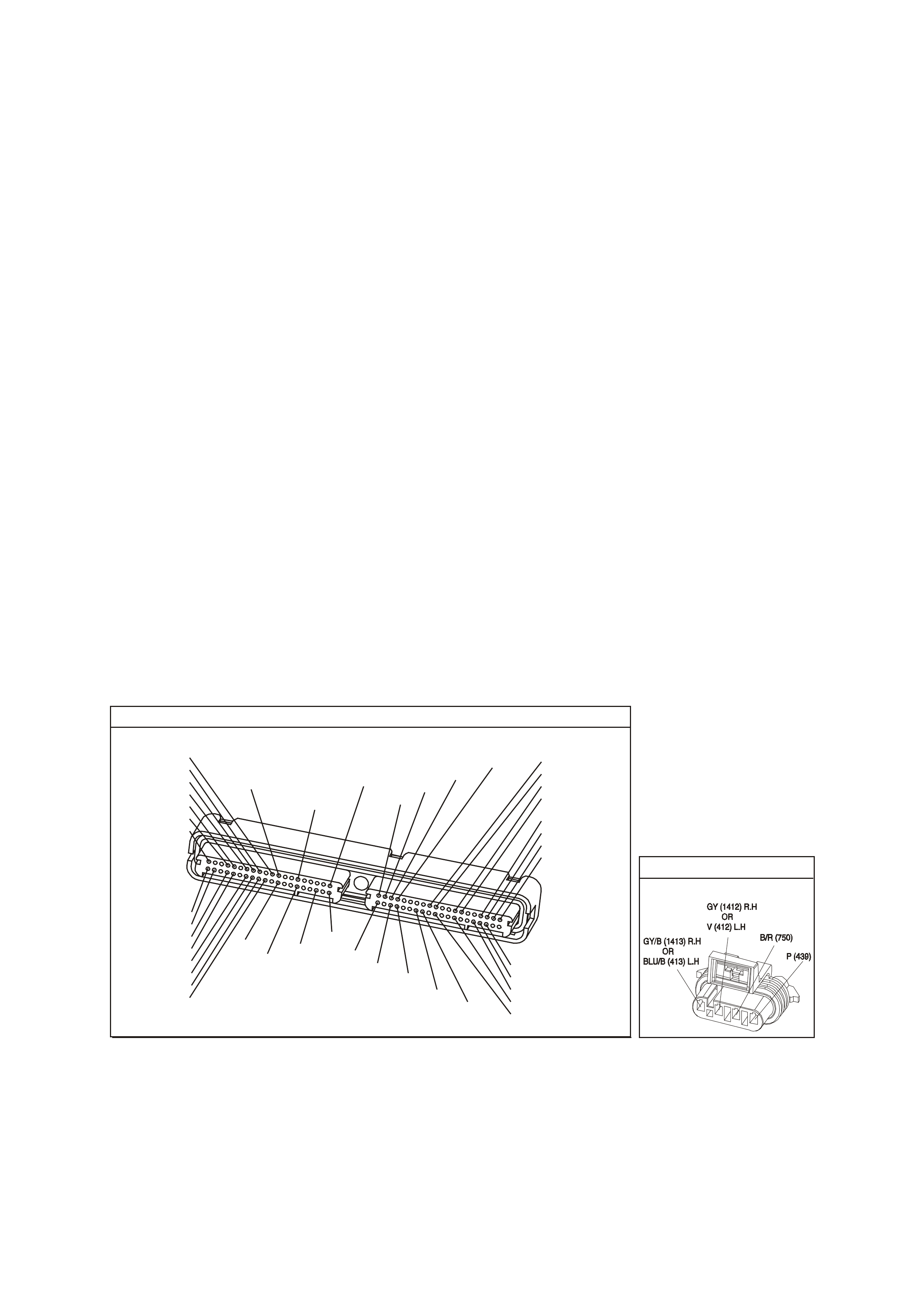
CONDITIONS FOR CLEARING THE CPL/DTC
• A last test failed (current DTC) clears when the diagnostic runs and does not fail.
• Use a Tech 2 scan tool in order to clear the CPL/DTC.
DIAGNOSTIC AIDS
• Inspect the HO2S signal circuit for being shorted to a PCM earth. The HO2S signal circuit shorted to a PCM
earth will not cause a HO2S low DTC to set, but will set a switching DTC.
• A malfunction in the HO2S heater circuit will cause a DTC P1133 to set. Check HO2S heater circuit for
intermittent opens/connection.
• An oxygen supply inside the HO2S is necessary for proper operation. This supply of oxygen is provided
through the HO2S wires. All HO2S wires and connections should be inspected for breaks or contamination.
• Using the Freeze Frame/Failure Records data may aid in locating an intermittent condition. If you cannot
duplicate the DTC, the information included in the Freeze Fram e/Failure Records data can help determine the
distance traveled since the DTC set. The Fail Counter and Pass Counter can also help determine how many
ignition cycles the diagnostic reported a pass and/or fail. Operate the vehicle within the same freeze frame
condition (RPM, load, vehicle speed, temperature etc.) that you observed. This will isolate when the DTC
failed. For any test that requires probing the PCM or component harness connectors, use the Connector Test
Adapter Kit J 35616-A. Using this kit prevents any damage to the harness connector terminals.
• For an intermittent, refer to Section 6C3-2B Symptoms, of the VX Series Service Information.
TEST DESCRIPTION
The numbers below refer to the step numbers on the diagnostic table.
2. This step determines if the fault is present. This test may take 5 minutes for the diagnostic to run.
3. DTCs P1133 and P1153 setting at the same time is a good indication that a fuel contamination condition is
present.
4. An exhaust leak 15 - 30 cm (6 - 12 inches) away from the HO2S can cause a DTC to set.
6. This step checks whether a good earth circuit is available.
7. This step checks the integrity of the signal circuit to the PCM.
8. Certain RTV silicon gas ket m aterials give of f vapors that c an contam inate the HO2S. Ther e is also a pos sibility
of silicone contamination caused by silicone in the f uel. If the sensors appear contaminated by silicone and all
the silicone sealant is non-silicone base, advise the customer to try a different fuel company. A missing fuel
filler restrictor, indicates the customer may have used leaded fuel.
P.C.M CONNECTOR 1
Y E1 22
(776)
(1049)
(897)
(1230)
(848)
(1226)
(772)
(647)
(632)
40
(844)
(815)
80
J1
P/B
(845)
V/W
BLU
O
(633)
(846)
B/Y
B/R
(416)
(86)
(69)
(455)
(740)
GY
BR
G
GY
(646)
(410)
GY
(842)
(1225)
V
Y
(750)
P
41
O
(774)
BR/Y
BLU
Y
B/R
B
BLU/Y
(841)
BLUE
(414)
G/W
BLU
LG
LBLU/B
1
(847)
(415)
(740)
(452)
BLU
BR Y
(750)
(826)
(421)
Y
V/W
B/W
(334)
(771)
(39)
Y
R/W
LBLU
W
BLU/W
(843)
(643)
LBLU/W
G
GY/B
BLU/B
(413)
(1413)
(1412)
(412)
GY
V
GY/B
G
(335)
YE95
HE ATED EXHAUST GAS S ENSOR

GEN III V8 PCM - DTC P1133 HEATED OXYGEN SENSOR INSUFFICIENT SWITCHING BANK 1 SENSOR 1
Step Action Value(s) Yes No
1 Did you perform the Powertrain On-Board Diagnostic
(OBD) System Check? Go to Step 2 Go to Powertrain
OBD System
Check Table
2
IMPORTANT: If any DTCs are set (except P1153), refer
to those DTCs before proceeding with this diagnostic
table.
1. Install the Tech 2 scan tool.
2. Idle the engine at the normal operating temperature.
3. Operate the vehicle, within the Conditions for Running
the DTC, as specified in the supporting text, if
applicable.
4. Monitor the Failed This Ignition option under the DTC
Information option using the Tech 2 scan tool.
Does the Tech 2 scan tool indicate DTC P1133 test
failed?
Go to Step 3 Go to
Diagnostic Aids
3 Did the Tech 2 scan tool also indicate P1153 test failed? Go to Step 8 Go to Step 4
4 1. Inspect the exhaust system for leaks.
2. If you find an exhaust leak, repair the exhaust as
necessary.
Did you isolate an exhaust leak?
Go to Step 13 Go to Step 5
5 Inspect the following items:
• Ensure that the HO2S is securely installed.
• Check for corrosion on the terminals.
• Check the terminal tension at the HO2S and at the
PCM.
• Check for damaged wiring.
Did you find a condition in any of the above areas?
Go to Step 9 Go to Step 6
6 1. Disconnect the Bank 1 HO2S .
2. Jumper the HO2S low (PCM side) signal circuit to a
earth.
3. Monitor the Bank 1 HO2S voltage using the Tech 2
scan tool.
Is the HO2S voltage within the specified value?
350-550 mV Go to Step 7 Go to Step 10
7 1. Jumper the Bank 1 HO2S 1 high and low (PCM side)
signal circuit to a earth.
2. Monitor the Bank 1 HO2S voltage using the Tech 2
scan tool.
Is the HO2S voltage below the specified value?
200 mV Go to Step 12 Go to Step 11
8 IMPORTANT: Before replacing a sensor, determine and
correct the cause of the contamination. Check for the
following conditions:
• Fuel contamination.
• Use of improper RTV sealant.
• Engine oil/coolant consumption.
Replace the affected Heated Oxygen Sensor.
Is the action complete?
Go to Step 13
9 Repair the condition as necessary.
Is the action complete? Go to Step 13
10 Repair the open Bank 1 HO2S low signal circuit or
earthed Bank 1 HO2S high signal circuit.
Is the action complete?
Go to Step 13
11 Repair the open Bank 1 HO2S high signal circuit or faulty
PCM connections.
Is the action complete?
Go to Step 13

GEN III V8 PCM - DTC P1133 HEATED OXYGEN SENSOR INSUFFICIENT SWITCHING
BANK 1 SENSOR 1 (CONTINUED)
Step Action Value(s) Yes No
12 Replace the Bank 1 HO2S.
Is the action complete? Go to Step 13
13 1. Select the Diagnostic Trouble Code (DTC) option and
the Clear DTC Information option using the Tech 2
scan tool.
2. Idle the engine at the normal operating temperature.
3. Select the Diagnostic Trouble Code (DTC) option, the
DTC Information option and The Failed This Ignition
option using the Tech 2 scan tool.
4. Operate the vehicle, within the Conditions for Running
the DTC, as specified in the supporting text, if
applicable.
Does the Tech 2 scan tool indicate that this DTC reset?
Go to Step 12 Go to Step 14
14 Using the Tech 2 scan tool, check for any other DTC’s.
Does the Tech 2 scan tool display any DTCs that you
have not diagnosed?
Go to the
applicable DTC
table
System OK

GEN III V8 PCM -
DTC P1134 HEATED OXYGEN SENSOR TRANSITION TIME RATIO BANK 1 SENSOR 1
CIRCUIT DESCRIPTION
The PCM monitors the Heated Oxygen Sensor (HO2S) activity for 100 seconds. During this monitor period the
PCM counts the number of times that the HO2S responds from rich to lean and from lean to rich and adds the
amount of time it took to complete all transitions.
W ith this inform ation, an average time f or all transitions can be determ ined. The PCM then divides the rich to lean
average by the lean to rich average to obtain a ratio. A DTC P1134 sets if the HO2S ratio is not within range.
CONDITIONS FOR RUNNING THE DTC
• DTCs P0101, P0102, P0103, P0107, P0108, P0112, P0113, P0117, P0118, P0121, P0122, P0123, P0335,
P0336, P0351-P0358, P1111, P1112, or P1258 are not set.
• The fuel system is operating in Closed Loop.
• The engine run time is greater than 2.0 seconds.
• The engine speed is greater than 1000 RPM but less than 2300 RPM.
• The ignition voltage is greater than 9.0 volts.
• The engine coolant temperature is greater than 65°C.
• The MAF is between 20 g/s and 50 g/s.
• The EVAP purge duty cycle is greater than 0%.
CONDITIONS FOR SETTING THE DTC
• The PCM determines that the HO2S transition time ratio is not at the expected value.
ACTIONS TAKEN WHEN THE DTC SETS
• The PCM stores the DTC information into memory when the diagnostic runs and fails.
• The Check Powertrain Lamp will not be illuminated.
• The PCM records the operating conditions at the time the diagnostic fails. The PCM stores this information in
the Freeze Frame/Failure Records.
CONDITIONS FOR CLEARING THE CPL/DTC
• A last test failed (current DTC) clears when the diagnostic runs and does not fail.
• Use a Tech 2 scan tool in order to clear the CPL/DTC.
D
D
B
B
A
A
C
C
GY/B (1413)
GY (1412)
RIGHT OXYGEN SENSOR
BANK TWO SENSOR ONE
LEFT OXYGEN SENSOR
BANK ONE SENSOR ONE
LOC. E5/E15
BLU/B (413)
V (412)
P (439)
TO F USE
F33
G3PCM003PT
J1-26
J1-66
J1-01
J1-40
J2-01
J2-40
J1-69
J1-29
PCM
RIGHT
OXYGEN
SENSOR
SIGNAL LO
LEFT
OXYGEN
SENSOR
SIGNAL LO
RIGHT
OXYGEN
SENSOR
SIGNAL HI
EARTH
EARTH
EARTH
EARTH
LEFT
OXYGEN
SENSOR
SIGNAL HI
IC
IC
450 mV
450 mV
M
I
C
R
O
B/R (750)
YE95
YE95
YE122
YE123
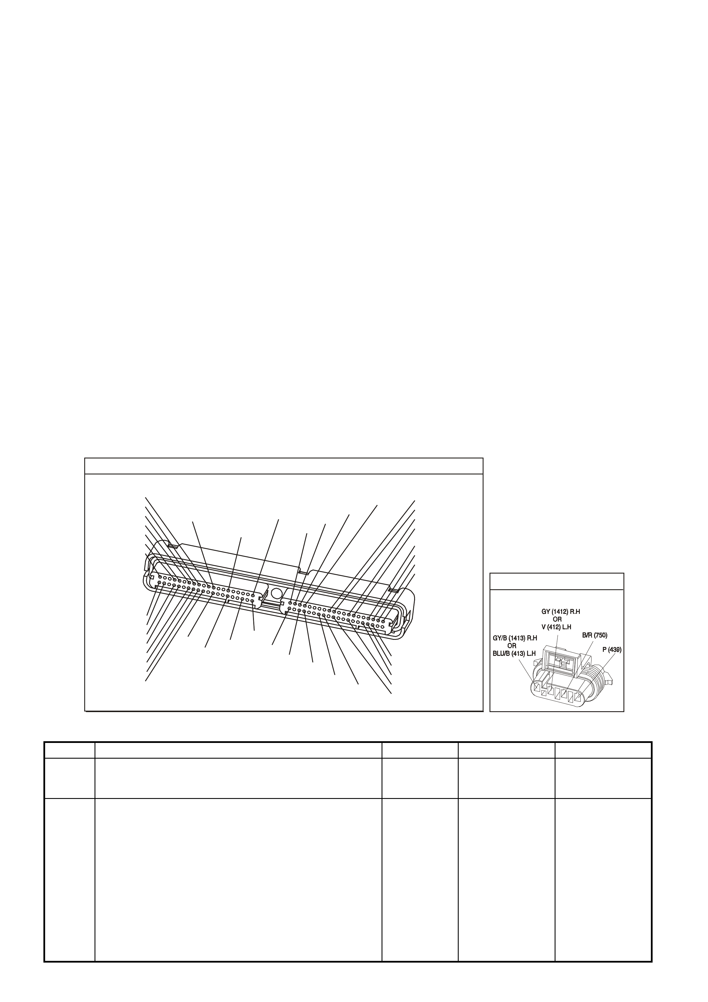
DIAGNOSTIC AIDS
• An oxygen supply inside the HO2S is necessary for proper operation. This supply of oxygen is provided
through the HO2S wires. All HO2S wires and connections should be inspected for breaks or contamination.
• Using the Freeze Frame/Failure Records data may aid in locating an intermittent condition. If you cannot
duplicate the DTC, the information included in the Freeze Fram e/Failure Records data can help determine the
distance traveled since the DTC set. The Fail Counter and Pass Counter can also help determine how many
ignition cycles the diagnostic reported a pass and/or fail. Operate the vehicle within the same freeze frame
condition (RPM, load, vehicle speed, temperature etc.) that you observed. This will isolate when the DTC
failed.
For any test that requires pr obing the PCM or com ponent har ness c onnectors , use the Connector T es t Adapter
Kit J 35616-A. Using this kit prevents any damage to the harness connector terminals.
• For an intermittent, refer to Section 6C3-2B Symptoms, of the VX Series Service Information.
TEST DESCRIPTION
The numbers below refer to the step numbers on the diagnostic table.
2. This step determines if the fault is present. This test may take 5 minutes for the diagnostic to run.
3. DTCs P1134 and P1154 setting at the same time is a good indication that a fuel contamination condition is
present.
4. An exhaust leak 15 - 30 cm (6 - 12 inches) away form the HO2S can cause a DTC to set.
6. This step checks whether a good earth circuit is available.
7. This step checks the integrity of the signal circuit to the PCM.
8. Certain RTV silicon gas ket m aterials give of f vapors that c an contam inate the HO2S. Ther e is also a pos sibility
of silicone contamination caused by silicone in the f uel. If the sensors appear contaminated by silicone and all
the silicone sealant is non-silicone base, advise the customer to try a different fuel company. A missing fuel
filler restrictor, indicates the customer may have used leaded fuel.
P.C.M CONNECTOR 1
Y E1 22
(776)
(1049)
(897)
(1230)
(848)
(1226)
(772)
(647)
(632)
40
(844)
(815)
80
J1
P/B
(845)
V/W
BLU
O
(633)
(846)
B/Y
B/R
(416)
(86)
(69)
(455)
(740)
GY
BR
G
GY
(646)
(410)
GY
(842)
(1225)
V
Y
(750)
P
41
O
(774)
BR/Y
BLU
Y
B/R
B
BLU/Y
(841)
BLUE
(414)
G/W
BLU
LG
LBLU/B
1
(847)
(415)
(740)
(452)
BLU
BR Y
(750)
(826)
(421)
Y
V/W
B/W
(334)
(771)
(39)
Y
R/W
LBLU
W
BLU/W
(843)
(643)
LBLU/W
G
GY/B
BLU/B
(413)
(1413)
(1412)
(412)
GY
V
GY/B
G
(335)
YE95
HE ATED EXHAUST GAS S ENSOR
GEN III V8 PCM - DTC P1134 HEATED OXYGEN SENSOR TRANSITION TIME RATIO BANK 1 SENSOR 1
Step Action Value(s) Yes No
1 Did you perform the Powertrain On-Board Diagnostic
(OBD) System Check? Go to Step 2 Go to Powertrain
OBD System
Check Table
2
IMPORTANT: If any DTCs are set (except P1154), refer
to those DTCs before proceeding with this diagnostic
table.
1. Install the Tech 2 scan tool.
2. Idle the engine at the normal operating temperature.
3. Operate the vehicle, within the Conditions for Running
the DTC, as specified in the supporting text, if
applicable.
4. Monitor the Failed This Ignition option under the DTC
Information option using the Tech 2 scan tool.
Does the Tech 2 scan tool indicate DTC P1134 test
failed?
Go to Step 3 Go to
Diagnostic Aids

GEN III V8 PCM - DTC P1134 HEATED OXYGEN SENSOR TRANSITION TIME RATIO
BANK 1 SENSOR 1 (CONTI
Step Action Value(s) Yes No
3 Did the Tech 2 scan tool also indicate P1154 test failed? Go to Step 8 Go to Step 4
4 1. Inspect the exhaust system for leaks.
2. If you find an exhaust leak, repair the exhaust as
necessary.
Did you isolate an exhaust leak?
Go to Step 13 Go to Step 5
5 Inspect the following items:
• Ensure that the HO2S is securely installed.
• Check for corrosion on the terminals.
• Check the terminal tension at the HO2S and at the
PCM.
• Check for damaged wiring.
Did you find a condition in any of the above areas?
Go to Step 9 Go to Step 6
6 1. Disconnect the Bank 1 HO2S.
2. Jumper the HO2S low (PCM side) signal circuit to
earth.
3. Monitor the Bank 1 HO2S voltage using the Tech 2
scan tool.
Is the HO2S voltage within the specified value?
350-550 mV Go to Step 7 Go to Step 10
7 1. Jumper the Bank 1 HO2S high and low (PCM side)
signal circuit to earth.
2. Monitor the Bank 1 HO2S voltage using the Tech 2
scan tool.
Is the HO2S voltage below the specified value?
200 mV Go to Step 12 Go to Step 11
8 IMPORTANT: Before replacing a sensor, determine and
correct the cause of the contamination. Check for the
following conditions:
• Fuel contamination.
• Use of improper RTV sealant.
• Engine oil/coolant consumption.
Replace the affected Heated Oxygen Sensor.
Is the action complete?
Go to Step 13
9 Repair the condition as necessary.
Is the action complete? Go to Step 13
10 Repair the open Bank 1 HO2S low signal circuit or
earthed Bank 1 HO2S high signal circuit.
Is the action complete?
Go to Step 13
11 Repair the open Bank 1 HO2S high signal circuit or faulty
PCM connections.
Is the action complete?
Go to Step 13
12 Replace the Bank 1 HO2S .
Is the action complete? Go to Step 13
13 1. Select the Diagnostic Trouble Code (DTC) option and
the Clear DTC Information option using the Tech 2
scan tool.
2. Idle the engine at the normal operating temperature.
3. Select the Diagnostic Trouble Code (DTC) option, the
DTC Information option and The Failed This Ignition
option using the Tech 2 scan tool.
4. Operate the vehicle, within the Conditions for Running
the DTC, as specified in the supporting text, if
applicable.
Does the Tech 2 scan tool indicate that this DTC reset?
Go to Step 2 Go to Step 14
14 Using the Tech 2 scan tool, check for any other DTCs.
Does the Tech 2 scan tool display any DTCs that you
have not diagnosed?
Go to the
applicable DTC
table
System OK
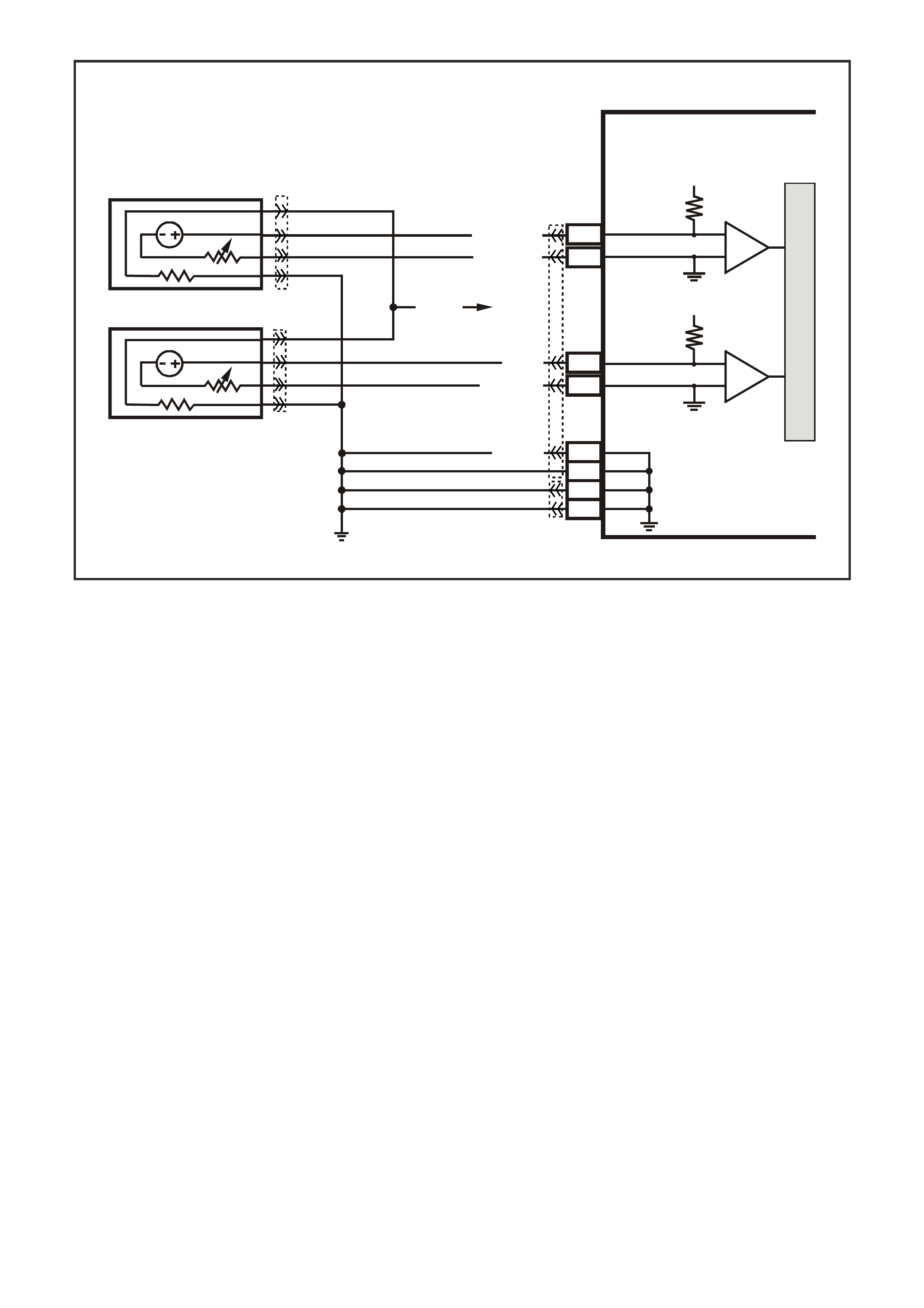
GEN III V8 PCM -
DTC P1153 HEATED OXYGEN SENSOR INSUFFICIENT SWITCHING BANK 2 SENSOR 1
CIRCUIT DESCRIPTION
The PCM monitors the Heated Oxygen Sensor (HO2S) activity for 100 seconds. During this monitor period the
PCM counts the number of times that the HO2S switches from rich to lean and lean to rich. A DTC P1153 sets
when the PCM determines that the HO2S did not switch enough times.
A lean to rich switch is determined when the HO2S voltage changes from less than 300 mV to greater than 600
mV. A r ich to lean switch is determ ined when the HO 2S voltage changes from more than 600 m V to less than 300
mV.
CONDITIONS FOR RUNNING THE DTC
• DTCs P0101, P0102, P0103, P0107, P0108, P0112, P0113, P0117, P0118, P0121, P0122, P0123, P0335,
P0336, P0351-P0358, P1111, P1112, or P1258 are not set.
• The fuel system is operating in Closed Loop.
• The engine run time is greater than 2.0 seconds.
• The engine speed is greater than 1000 RPM but less than 2300 RPM.
• The ignition voltage is greater than 9.0 volts.
• The engine coolant temperature is greater than 65°C.
• The MAF is between 20 g/s and 50 g/s.
• The EVAP purge duty cycle is greater than 0%.
CONDITIONS FOR SETTING THE DTC
• The PCM determ ines that within 100 seconds the HO2S lean to rich switches are less than 30 and r ic h to lean
switches are less than 30.
ACTIONS TAKEN WHEN THE DTC SETS
• The PCM stores the DTC information into memory when the diagnostic runs and fails.
• The Check Powertrain Lamp will not be illuminated.
• The PCM records the operating conditions at the time the diagnostic fails. The PCM stores this information in
the Freeze Frame/Failure Records.
D
D
B
B
A
A
C
C
GY/B (1413)
GY (1412)
RIGHT OXYGEN SENSOR
BANK TWO SENSOR ONE
LEFT OXYGEN SENSOR
BANK ONE SENSOR ONE
LOC. E5/E15
BLU/B (413)
V (412)
P (439)
TO F USE
F33
G3PCM003PT
J1-26
J1-66
J1-01
J1-40
J2-01
J2-40
J1-69
J1-29
PCM
RIGHT
OXYGEN
SENSOR
SIGNAL LO
LEFT
OXYGEN
SENSOR
SIGNAL LO
RIGHT
OXYGEN
SENSOR
SIGNAL HI
EARTH
EARTH
EARTH
EARTH
LEFT
OXYGEN
SENSOR
SIGNAL HI
IC
IC
450 mV
450 mV
M
I
C
R
O
B/R (750)
YE95
YE95
YE122
YE123
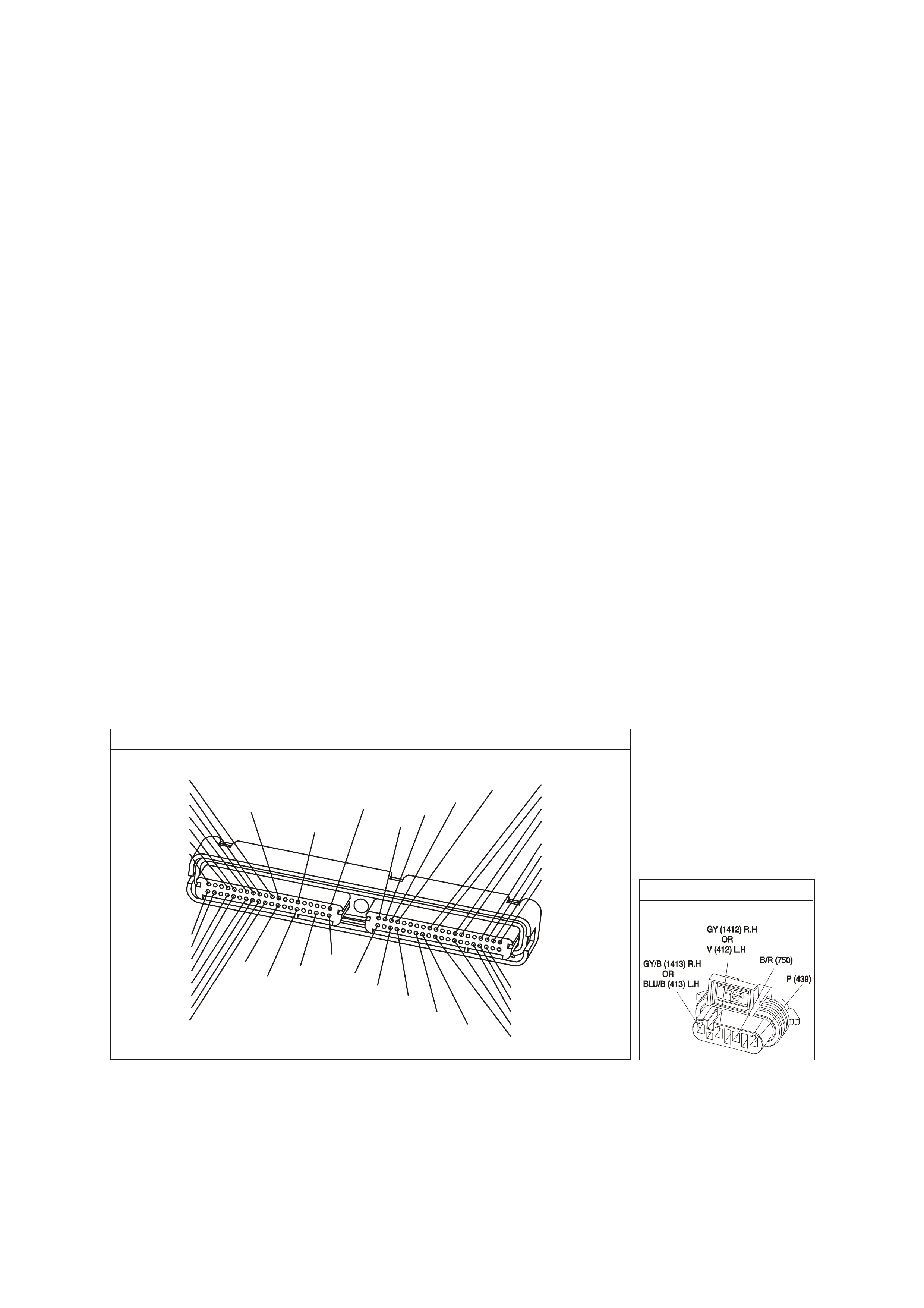
CONDITIONS FOR CLEARING THE CPL/DTC
• A last test failed (current DTC) clears when the diagnostic runs and does not fail.
• Use a Tech 2 scan tool in order to clear the CPL/DTC.
DIAGNOSTIC AIDS
• Inspect the HO2S signal circuit for being shorted to a PCM earth. The HO2S signal circuit shorted to a PCM
earth will not cause a HO2S low DTC to set, but will set a switching DTC.
• A malfunction in the HO2S heater circuit will cause a DTC P1153 to set. Check HO2S heater circuit for
intermittent opens/connection.
• An oxygen supply inside the HO2S is necessary for proper operation. This supply of oxygen is provided
through the HO2S wires. All HO2S wires and connections should be inspected for breaks or contamination.
Refer to Electrical Diagnosis/Repair Procedures in Section 12P, in the VT Series I Service Information.
• Using the Freeze Frame/Failure Records data may aid in locating an intermittent condition. If you cannot
duplicate the DTC, the information included in the Freeze Frame/Failure Records data can help determ ine the
distance traveled since the DTC set. The Fail Counter and Pass Counter can also help determine how many
ignition cycles the diagnostic reported a pass and/or fail. Operate the vehicle within the same freeze frame
condition (RPM, load, vehicle speed, temperature etc.) that you observed. This will isolate when the DTC
failed. For any test that requires probing the PCM or component harness connectors, use the Connector Test
Adapter Kit J 35616-A. Using this kit prevents any damage to the harness connector terminals.
• For an intermittent, refer to Section 6C3-2B Symptoms, of the VX Series Service Information.
TEST DESCRIPTION
The numbers below refer to the step numbers on the diagnostic table.
2. This step determines if the fault is present. This test may take 5 minutes for the diagnostic to run.
3. DTCs P1133 and P1153 setting at the same time is a good indication that a fuel contamination condition is
present.
4. An exhaust leak 15 - 30 cm (6 - 12 inches) away from the HO2S can cause a DTC to set.
6. This step checks whether a good earth circuit is available.
7. This step checks the integrity of the signal circuit to the PCM.
8. Certain RTV silicon gas ket m aterials give of f vapors that c an contam inate the HO2S. Ther e is also a pos sibility
of silicone contamination caused by silicone in the f uel. If the sensors appear contaminated by silicone and all
the silicone sealant is non-silicone base, advise the customer to try a different fuel company. A missing fuel
filler restrictor, indicates the customer may have used leaded fuel.
P.C.M CONNECTOR 1
Y E1 22
(776)
(1049)
(897)
(1230)
(848)
(1226)
(772)
(647)
(632)
40
(844)
(815)
80
J1
P/B
(845)
V/W
BLU
O
(633)
(846)
B/Y
B/R
(416)
(86)
(69)
(455)
(740)
GY
BR
G
GY
(646)
(410)
GY
(842)
(1225)
V
Y
(750)
P
41
O
(774)
BR/Y
BLU
Y
B/R
B
BLU/Y
(841)
BLUE
(414)
G/W
BLU
LG
LBLU/B
1
(847)
(415)
(740)
(452)
BLU
BR Y
(750)
(826)
(421)
Y
V/W
B/W
(334)
(771)
(39)
Y
R/W
LBLU
W
BLU/W
(843)
(643)
LBLU/W
G
GY/B
BLU/B
(413)
(1413)
(1412)
(412)
GY
V
GY/B
G
(335)
YE95
HE ATED EXHAUST GAS S ENSOR

GEN III V8 PCM - DTC P1153 HEATED OXYGEN SENSOR INSUFFICIENT SWITCHING BANK 2 SENSOR 1
Step Action Value(s) Yes No
1 Did you perform the Powertrain On-Board Diagnostic
(OBD) System Check? Go to Step 2 Go to Powertrain
OBD System
Check Table
2
IMPORTANT: If any DTCs are set (except P1133), refer
to those DTCs before proceeding with this diagnostic
table.
1. Install the Tech 2 scan tool.
2. Idle the engine at the normal operating temperature.
3. Operate the vehicle, within the Conditions for Running
the DTC, as specified in the supporting text, if
applicable.
4. Monitor the Failed This Ignition option under the DTC
Information option using the Tech 2 scan tool.
Does the Tech 2 scan tool indicate DTC P1153 test
failed?
Go to Step 3 Go to
Diagnostic Aids
3 Did the Tech 2 scan tool also indicate P1133 test failed? Go to Step 8 Go to Step 4
4 1. Inspect the exhaust system for leaks.
2. If you find an exhaust leak, repair the exhaust as
necessary.
Did you isolate an exhaust leak?
Go to Step 13 Go to Step 5
5 Inspect the following items:
• Ensure that the HO2S is securely installed.
• Check for corrosion on the terminals.
• Check the terminal tension at the HO2S and at the
PCM.
• Check for damaged wiring.
Did you find a condition in any of the above areas?
Go to Step 9 Go to Step 6
6 1. Disconnect the Bank 2 HO2S.
2. Jumper the HO2S low (PCM side) signal circuit to a
earth.
3. Monitor the Bank 2 HO2S voltage using the Tech 2
scan tool.
Is the HO2S voltage within the specified value?
350-550 mV Go to Step 7 Go to Step 10
7 1. Jumper the Bank 2 HO2S high and low (PCM side)
signal circuit to earth.
2. Monitor the Bank 2 HO2S voltage using the Tech 2
scan tool.
Is the HO2S voltage below the specified value?
200 mV Go to Step 12 Go to Step 11
8 IMPORTANT: Before replacing a sensor, determine and
correct the cause of the contamination. Check for the
following conditions:
• Fuel contamination.
• Use of improper RTV sealant.
• Engine oil/coolant consumption.
Replace the affected Heated Oxygen Sensor.
Is the action complete?
Go to Step 13
9 Repair the condition as necessary.
Is the action complete? Go to Step 13
10 Repair the open Bank 2 HO2S low signal circuit or
earthed Bank 2 HO2S high signal circuit.
Is the action complete?
Go to Step 13
11 Repair the open Bank 2 HO2S.
Is the action complete? Go to Step 13

GEN III V8 PCM - DTC P1153 HEATED OXYGEN SENSOR INSUFFICIENT SWITCHING
BANK 2 SENSOR 1 (CONTINUED)
Step Action Value(s) Yes No
12 Replace the Bank 2 HO2S.
Is the action complete? Go to Step 13
13 1. Select the Diagnostic Trouble Code (DTC) option and
the Clear DTC Information option using the Tech 2
scan tool.
2. Idle the engine at the normal operating temperature.
3. Select the Diagnostic Trouble Code (DTC) option, the
DTC Information option and The Failed This Ignition
option using the Tech 2 scan tool.
4. Operate the vehicle, within the Conditions for Running
the DTC, as specified in the supporting text, if
applicable.
Does the Tech 2 scan tool indicate that this DTC reset?
Go to Step 2 Go to Step 14
14 Using the Tech 2 scan tool, check for any other DTCs.
Does the Tech 2 scan tool display any DTCs that you
have not diagnosed?
Go to the
applicable DTC
table
System OK

GEN III V8 PCM -
DTC P1154 HEATED OXYGEN SENSOR TRANSITION TIME RATIO BANK 2 SENSOR 1
CIRCUIT DESCRIPTION
The PCM monitors the Heated Oxygen Sensor (HO2S) activity for 100 seconds. During this monitor period, the
PCM counts the number of times that the HO2S responds from rich to lean and from lean to rich and adds the
amount of time it took to complete all transitions.
W ith this inform ation, an average time f or all transitions can be determ ined. The PCM then divides the rich to lean
average by the lean to rich average to obtain a ratio. A DTC P1134 sets if the HO2S ratio is not within range.
CONDITIONS FOR RUNNING THE DTC
• DTCs P0101, P0102, P0103, P0107, P0108, P0112, P0113, P0117, P0118, P0121, P0122, P0123, P0335,
P0336, P0351-P0358, P1111, P1112, or P1258 are not set.
• The fuel system is operating in Closed Loop.
• The engine run time is greater than 2.0 seconds.
• The engine speed is greater than 1000 RPM but less than 2300 RPM.
• The ignition voltage is greater than 9.0 volts.
• The engine coolant temperature is greater than 65°C.
• The MAF is between 20 g/s and 50 g/s.
• The EVAP purge duty cycle is greater than 0%.
CONDITIONS FOR SETTING THE DTC
• The PCM determines that the HO2S transition time ratio is not at the expected value.
ACTIONS TAKEN WHEN THE DTC SETS
• The PCM stores the DTC information into memory when the diagnostic runs and fails.
• The Check Powertrain Lamp will not be illuminated.
• The PCM records the operating conditions at the time the diagnostic fails. The PCM stores this information in
the Freeze Frame/Failure Records.
CONDITIONS FOR CLEARING THE CPL/DTC
• A last test failed (current DTC) clears when the diagnostic runs and does not fail.
• Use a Tech 2 scan tool to clear the CPL/DTC.
D
D
B
B
A
A
C
C
GY/B (1413)
GY (1412)
RIGHT OXYGEN SENSOR
BANK TWO SENSOR ONE
LEFT OXYGEN SENSOR
BANK ONE SENSOR ONE
LOC. E5/E15
BLU/B (413)
V (412)
P (439)
TO F USE
F33
G3PCM003PT
J1-26
J1-66
J1-01
J1-40
J2-01
J2-40
J1-69
J1-29
PCM
RIGHT
OXYGEN
SENSOR
SIGNAL LO
LEFT
OXYGEN
SENSOR
SIGNAL LO
RIGHT
OXYGEN
SENSOR
SIGNAL HI
EARTH
EARTH
EARTH
EARTH
LEFT
OXYGEN
SENSOR
SIGNAL HI
IC
IC
450 mV
450 mV
M
I
C
R
O
B/R (750)
YE95
YE95
YE122
YE123
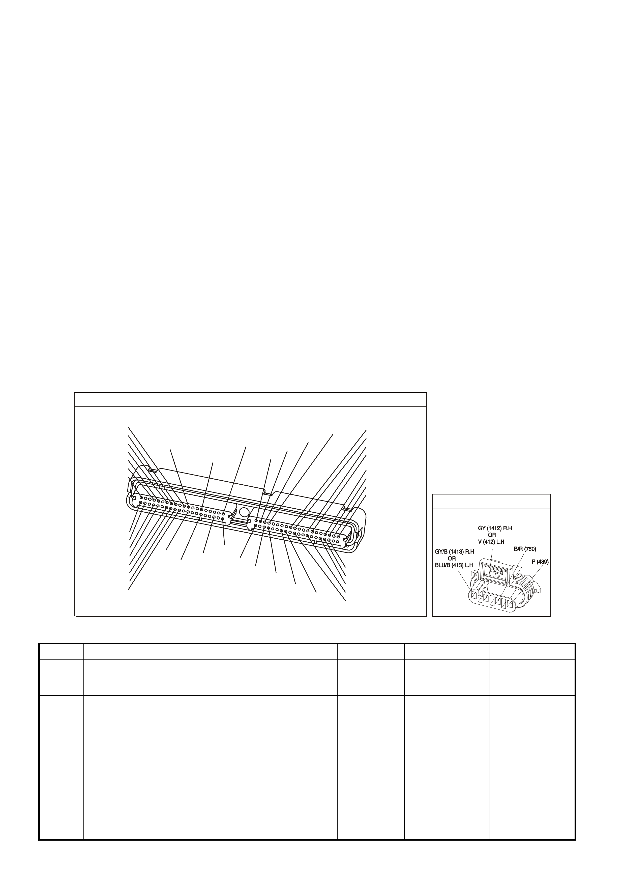
DIAGNOSTIC AIDS
• An oxygen supply inside the HO2S is necessary for proper operation. This supply of oxygen is provided
through the HO2S wires. All HO2S wires and connections should be inspected for breaks or contamination.
• Using the Freeze Frame/Failure Records data may aid in locating an intermittent condition. If you cannot
duplicate the DTC, the information included in the Freeze Frame/Failure Records data can help determine the
distance traveled since the DTC set. The Fail Counter and Pass Counter can also help determine how many
ignition cycles the diagnostic reported a pass and/or fail. Operate the vehicle within the same freeze frame
condition (RPM, load, vehicle speed, temperature etc.) that you observed. This will isolate when the DTC
failed. For any test that requires probing the PCM or component harness connectors, use the Connector Test
Adapter Kit J 35616-A. Using this kit prevents any damage to the harness connector terminals.
• For an intermittent, refer to Section 6C3-2B Symptoms, of the VX Series Service Information.
TEST DESCRIPTION
The numbers below refer to the step numbers on the diagnostic table.
2. This step determines if the fault is present. This test may take 5 minutes for the diagnostic to run. For any test
that requires probing the PCM or a component harness connector, use the Connector Test Adapter Kit J
35616-A. Using this kit will prevent damage to the harness connector terminals.
3. DTCs P1134 and P1154 setting at the same time is a good indication that a fuel contamination condition is
present.
4. An exhaust leak 15 - 30 cm (6 - 12 inches) away form the HO2S can cause a DTC to set.
6. This step checks whether a good earth circuit is available.
7. This step checks the integrity of the signal circuit to the PCM.
8. Certain RTV silicon gasket materials give off vapors that can contaminate the HO2S. There is also a possibility
of silicone contamination caused by silicone in the fuel. If the sensors appear contaminated by silicone and all
the silicone sealant is non-silicone base, advise the customer to try a different fuel company. A missing fuel
filler restrictor, indicates the customer may have used leaded fuel.
P.C.M CONNECTOR 1
YE122
(776)
(1049)
(897)
(1230)
(848)
(1226)
(772)
(647)
(632)
40
(844)
(815)
80
J1
P/B
(845)
V/W
BLU
O
(633)
(846)
B/Y
B/R
(416)
(86)
(69)
(455)
(740)
GY
BR
G
GY
(646)
(410)
GY
(842)
(1225)
V
Y
(750)
P
41
O
(774)
BR/Y
BLU
Y
B/R
B
BLU/Y
(841)
BLUE
(414)
G/W
BLU
LG
LBLU/B
1
(847)
(415)
(740)
(452)
BLU
BR
Y
(750)
(826)
(421)
Y
V/W
B/W
(334)
(771)
(39)
Y
R/W
LBLU
W
BLU/W
(843)
(643)
LBLU/W
G
GY/B
BLU/B
(413)
(1413)
(1412)
(412)
GY
V
GY/B
G
(335)
YE95
HEATED EXHAUST GAS SENSOR
GEN III V8 PCM - DTC P1154 HEATED OXYGEN SENSOR TRANSITION TIME RATIO BANK 2 SENSOR 1
Step Action Value(s) Yes No
1 Did you perform the Powertrain On-Board Diagnostic
(OBD) System Check? Go to Step 2 Go to Powertrain
OBD System
Check Table
2
IMPORTANT: If any DTCs are set (except P1134), refer
to those DTCs before proceeding with this diagnostic
table.
1. Install the Tech 2 scan tool.
2. Idle the engine at the normal operating temperature.
3. Operate the vehicle, within the Conditions for Running
the DTC, as specified in the supporting text, if
applicable.
4. Monitor the Failed This Ignition option under the DTC
Information option using the Tech 2 scan tool.
Does the Tech 2 scan tool indicate DTC P1154 test
failed?
Go to Step 3 Go to
Diagnostic Aids

GEN III V8 PCM - DTC P1154 HEATED OXYGEN SENSOR TRANSITION TIME RATIO
BANK 2 SENSOR 1 (CONTINUED)
Step Action Value(s) Yes No
3 Did the Tech 2 scan tool also indicate P1134 test failed? Go to Step 8 Go to Step 4
4 1. Inspect the exhaust system for leaks.
2. If you find an exhaust leak, repair the exhaust as
necessary.
Did you isolate an exhaust leak?
Go to Step 13 Go to Step 5
5 Inspect the following items:
• Ensure that the HO2S is securely installed.
• Check for corrosion on the terminals.
• Check the terminal tension at the HO2S and at the
PCM.
• Check for damaged wiring.
Did you find a condition in any of the above areas?
Go to Step 9 Go to Step 6
6 1. Disconnect the Bank 2 HO2S.
2. Jumper the HO2S low (PCM side) signal circuit to a
earth.
3. Monitor the Bank 2 HO2S voltage using the Tech 2
scan tool.
Is the HO2S voltage within the specified value?
350-550 mV Go to Step 7 Go to Step 10
7 1. Jumper the Bank 2 HO2S high and low (PCM side)
signal circuit to earth.
2. Monitor the Bank 2 HO2S voltage using the Tech 2
scan tool.
Is the HO2S voltage below the specified value?
200 mV Go to Step 12 Go to Step 11
8 IMPORTANT: Before replacing a sensor, determine and
correct the cause of the contamination. Check for the
following conditions:
• Fuel contamination.
• Use of improper RTV sealant.
• Engine oil/coolant consumption.
Replace the affected Heated Oxygen Sensor.
Is the action complete?
Go to Step 13
9 Repair the condition as necessary.
Is the action complete? Go to Step 13
10 Repair the open Bank 2 HO2S low signal circuit or
earthed Bank 2 HO2S high signal circuit.
Is the action complete?
Go to Step 13
11 Repair the open Bank 2 HO2S high signal circuit or faulty
PCM connections.
Is the action complete?
Go to Step 13
12 Replace the Bank 2 HO2S .
Is the action complete? Go to Step 13
13 1. Select the Diagnostic Trouble Code (DTC) option and
the Clear DTC Information option using the Tech 2
scan tool.
2. Idle the engine at the normal operating temperature.
3. Select the Diagnostic Trouble Code (DTC) option, the
DTC Information option and The Failed This Ignition
option using the Tech 2 scan tool.
4. Operate the vehicle, within the Conditions for Running
the DTC, as specified in the supporting text, if
applicable.
Does the Tech 2 scan tool indicate that this DTC reset?
Go to Step 2 Go to Step 14
14 Using the Tech 2 scan tool, check for any other DTCs.
Does the Tech 2 scan tool display any DTCs that you
have not diagnosed?
Go to the
applicable DTC
table
System OK

GEN III V8 PCM -
DTC P1258 ENGINE COOLANT OVER TEMP FUEL DISABLED
CIRCUIT DESCRIPTION
In order to reduce the engine temperature, the PCM has the ability to disable a number of fuel injectors during an
engine over tem perature condition. The PCM c onsiders the engine over tem perature whenever the ECT reaches a
predeterm ined temperature. T his DTC sets in order to show that the PCM detected an over tem perature condition
and that the system engaged the protection mode.
CONDITION FOR RUNNING THE DTC
• DTCs P0117, P0118, are not set.
• The engine is running.
CONDITION FOR SETTING THE DTC
• The engine coolant temperature is greater than 132°C.
• The above conditions present for greater than 10 seconds.
ACTION TAKEN WHEN THE DTC SETS
• The PCM will randomly disable several injectors.
• The PCM illuminates the Check Powertrain Lamp when the diagnostic runs and fails.
• The PCM records the operating conditions at the time the diagnostic fails. The PCM stores this information in
the Freeze Frame/Failure Records.
CONDITIONS FOR CLEARING THE CPL/DTC
• The PCM turns the Check Powertrain Lamp OFF when the diagnostic runs and does not fail.
• A last test failed (current DTC) clears when the diagnostic runs and does not fail.
• Use a Tech 2 scan tool in order to clear the CPL/DTC.
DIAGNOSTIC AIDS
IMPORTANT:
If an overheating condition exists, repair the overheat condition and change the engine oil and filter.
• Using the Freeze Frame/Failure Records data may aid in locating an intermittent condition. If you cannot
duplicate the DTC, the information included in the Freeze Fram e/Failure Records data can help determine the
distance traveled since the DTC set. The Fail Counter and Pass Counter can also help determine how many
ignition cycles the diagnostic reported a pass and/or fail. Operate the vehicle within the same freeze frame
condition (RPM, load, vehicle speed, temperature etc.) that you observed. This will isolate when the DTC
failed. For any test that requires probing the PCM or component harness connectors, use the Connector Test
Adapter Kit J 35616-A. Using this kit prevents any damage to the harness connector terminals.
• For an intermittent, refer to Section 6C3-2B Symptoms, of the VX Series Service Information.
TEST DESCRIPTION
The number below refers to the step number on the diagnostic table.
2. A cooling system problem will enable the engine protection mode. Refer to Section 6B3 Engine Cooling, in
VX Service Information for further diagnosis.
G3PCM004PT
J1-80
J1-74
B
A
ENGINE COOLANT
TEMPERATURE SENSOR
SENSOR EARTH
ETC SENSOR SIGNAL
5V
4k
348
Ω
Ω
Y (41 0)
GY/B (455)
YE65 YE122
M
I
C
R
O

GEN III V8 PCM - DTC P1258 ENGINE COOLANT OVER TEMP FUEL DISABLED
Step Action Value(s) Yes No
1 Did you perform the Powertrain On-Board Diagnostic
(OBD) System Check? Go to Step 2 Go to Powertrain
OBD System
Check Table
2 Select the Diagnostic Trouble Code (DTC) option, the
DTC Information option and The Failed This Ignition
option using the Tech 2 scan tool.
Does the Tech 2 scan tool display any DTCs related to
the Engine Coolant Temperature (ECT) sensor that you
have not diagnosed?
Go to the
applicable DTC Go to Section
6B3 Engine
Cooling in VX
Service
Information.
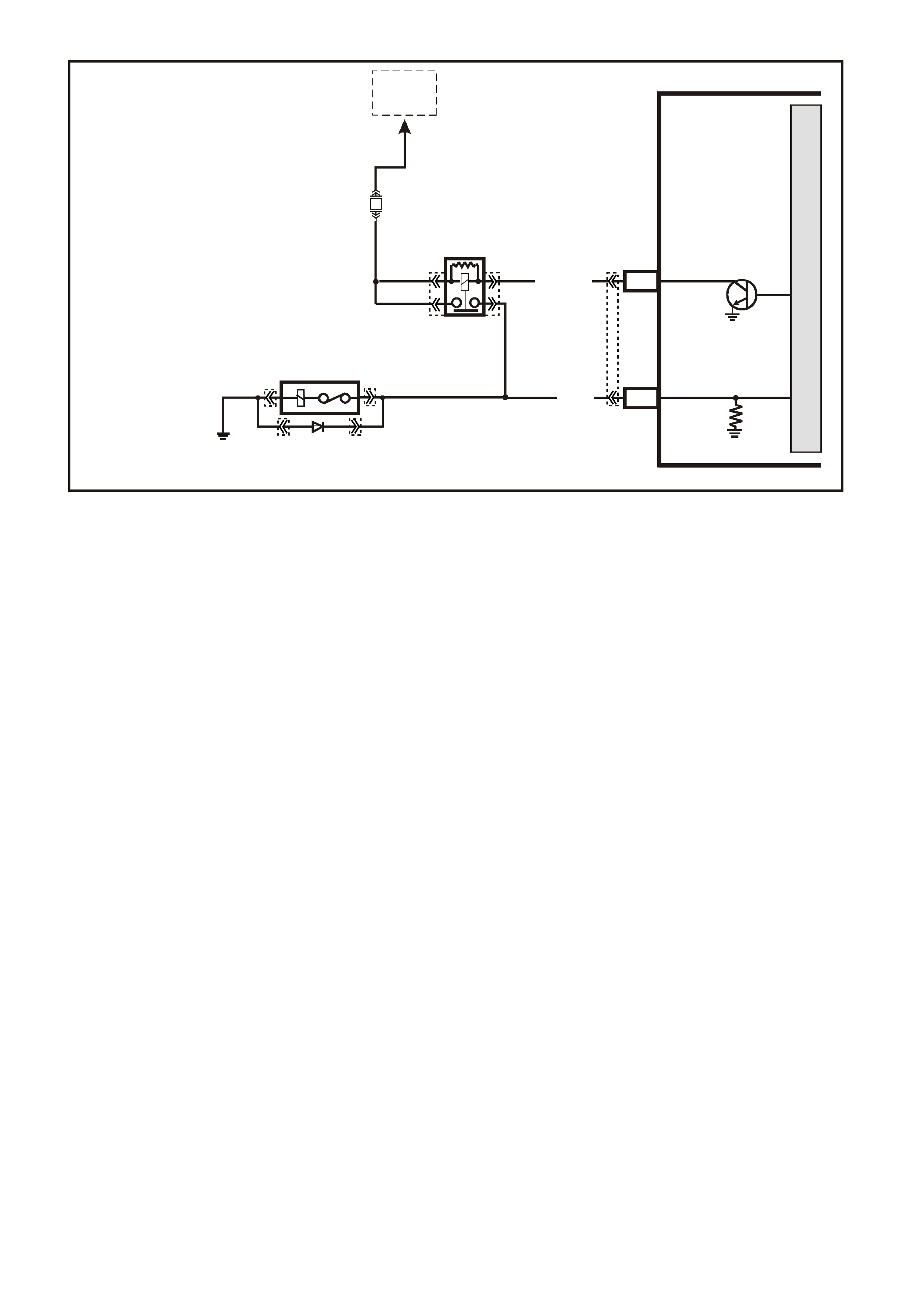
GEN III V8 PCM -
DTC P1539 A/C CLUTCH STATUS CIRCUIT HIGH VOLTAGE
CIRCUIT DESCRIPTION
The PCM activates the A/C clutch relay when the PCM detects an A/C request. Voltage is present at both the A/C
compressor clutch and the A/C clutch status terminal at the PCM when the relay is activated.
A DT C P1539 s ets if the PCM detec ts voltage on the A/C c lutc h status ter minal when the system has not r equested
the A/C.
A short to voltage at any point in the A/C status circuit, or the A/C relay contacts are stuck, sets a DTC P1539.
CONDITIONS FOR RUNNING THE DTC
• The A/C clutch is not requested.
CONDITIONS FOR SETTING THE DTC
• Voltage is detected on the A/C status circuit for more than 15 seconds after the PCM has disengaged the A/C
clutch relay.
ACTION TAKEN WHEN THE DTC SETS
• The PCM stores the DTC information into memory when the diagnostic runs and fails.
• The Check Powertrain Lamp will not be illuminated.
• The PCM records the operating conditions at the time the diagnostic fails. The PCM stores this information in
the Freeze Frame/Failure Records.
CONDITIONS FOR CLEARING THE CPL/DTC
• A last test failed (current DTC) clears when the diagnostic runs and does not fail.
• Use a Tech 2 scan tool in order to clear the CPL/DTC.
DIAGNOSTIC AIDS
• The A/C status circuit goes to the A/C compressor clutch and to the A/C clutch relay. Inspect all circuits going
to these components.
• For an intermittent, refer to Section 6C3-2B Symptoms, of the VX Series Service Information.
4360
PCM
A
/C RELAY
J2-43
LG/B (366)
YE101
YE105YE105
YE120 YE120
YE101
YE123
A/C CLUTCH
CONTROL
TO
EFI
RELAY
M
I
C
R
O
F33
LOC. E5/E15
B/R 750
A/C
COMPRESSOR
J2-18
G (59) A /C RELAY STA TUS

TEST DESCRIPTION
The number below refer to the step number on the diagnostic table.
2. If the PCM detects a voltage on the A/C status circuit with the A/C OFF, the Tech 2 scan tool indicates the A/C
status as ON.
3. If the Tech 2 scan tool displayed YES in the RAN column and INT in the FAIL column, this indicates an
intermittent condition is present. Inspect the A/C status circuit for an intermittent short to B+. Refer to
Symptoms). Using the Freeze Frame/Failure Records data aids in locating an intermittent condition. If you can
not duplicate the DTC, the information included in the Freeze Frame/Failure Records data determines the
distance traveled since the DTC set. The Fail Counter and the Pass Counter can also be used to determine
how many ignition cycles the diagnostic reported a pass and/or a fail. Operate the vehicle within the same
freeze frame condition (RPM, load, vehicle speed, temperature etc.) that the PCM recorded. This isolated when
the DTC failed.
4. The relay is shorted internally if the Tech 2 scan tool indicates that the test passed.
7. This DTC will not report a pass. The Tech 2 scan tool status for this DTC will never report a pass. The Tech 2
scan tool will only display when the diagnostic fails. The repair is not complete if the Tech 2 scan tool indicates
that the diagnostic ran and failed.
A/C RELAY
YE101
(366)
(439)
LG/B
P
G
P
(59)
(439)
GEN III V8 PCM - DTC P1539 A/C CLUTCH STATUS CIRCUIT HIGH VOLTAGE
Step Action Value(s) Yes No
1 Did you perform the Powertrain On-Board Diagnostic
(OBD) System Check? Go to Step 2 Go to Powertrain
OBD System
Check Table
2
IMPORTANT: Diagnose DTC P1545 first if it is set.
1. Install a Tech 2 scan tool.
2. Idle the engine with the A/C OFF.
3. Monitor the A/C Status display on the Engine Data List
using a Tech 2 scan tool.
Does the Tech 2 scan tool indicate the A/C Status is ON?
Go to Step 4 Go to Step 3
3 1. Turn ON the ignition leaving the engine OFF.
2. Review the Freeze Frame/Failure Records data for
this DTC and observe the parameters.
3. Turn OFF the ignition for 15 seconds.
4. Idle the engine.
5. Operate the vehicle, within the conditions required for
this diagnostic to run, and as close to the conditions
recorded in the Freeze Frame/Failure Records as
possible. Special operating conditions that need to be
met before the PCM will run this diagnostic, where
applicable, are listed in Conditions for Running the
DTC.
6. Select the Diagnostic Trouble Code (DTC) option, the
DTC Information option and The Failed This Ignition
option using the Tech 2 scan tool.
Does the Tech 2 scan tool indicate that this diagnostic
failed this ignition?
Go to Step 4 Refer to
Diagnostic Aids
4 1. Turn OFF the ignition.
2. Remove the A/C clutch relay.
3. Idle the engine for 30 seconds.
4. Monitor the Failed This Ignition option under the DTC
Information option using the Tech 2 scan tool.
Does the Tech 2 scan tool indicate that DTC P1539
failed?
Go to Step 5 Go to Step 6

GEN III V8 PCM - DTC P1539 A/ C CLUTCH STATUS CIRCUIT HIGH VOLTAGE (CONTINUED)
Step Action Value(s) Yes No
5 Repair the short to B+ on the A/C clutch status circuit.
Is the action complete? Go to Step 7
6 Repair the faulty A/C clutch relay.
Is the action complete? Go to Step 7
7 1. Select the Diagnostic Trouble Code (DTC) option and
the Clear DTC Information option using the Tech 2
scan tool.
2. Idle the engine at the normal operating temperature.
3. Select the Diagnostic Trouble Code (DTC) option, the
DTC Information option and The Failed This Ignition
option using the Tech 2 scan tool.
4. Operate the vehicle, within the Conditions for Running
the DTC, as specified in the supporting text, if
applicable.
Does the Tech 2 scan tool indicate that this DTC reset?
Go to Step 2 Go to Step 8
8 Using the Tech 2 scan tool, check for any other DTCs.
Does the Tech 2 scan tool display any DTCs that you
have not diagnosed?
Go to the
applicable DTC
table
System OK

GEN III V8 PCM -
DTC P1546 A/C CLUTCH STATUS CIRCUIT LOW VOLTAGE
CIRCUIT DESCRIPTION
The PCM will activate the A/C clutch relay when the PCM detects that A/C has been requested. When the PCM
activates the relay, voltage should be pres ent at both the A/C com pres sor c lutch and the A/C clutch s tatus cir cuit at
the PCM.
CONDITIONS FOR RUNNING THE DTC
• The A/C clutch is requested.
CONDITIONS FOR SETTING THE DTC
• The PCM com m ands the A/C O N and the PCM does not detect a voltage on the A/C clutch status line for more
than five seconds.
ACTION TAKEN WHEN THE DTC SETS
• The PCM stores the DTC information into memory when the diagnostic runs and fails.
• The Check Powertrain Lamp will not be illuminated.
• The PCM records the operating conditions at the time the diagnostic fails. The PCM stores this information in
the Freeze Frame/Failure Records.
CONDITIONS FOR CLEARING THE CPL/DTC
• A last test failed (current DTC) clears when the diagnostic runs and does not fail.
• Use a Tech 2 scan tool in order to clear the CPL/DTC.
DIAGNOSTIC AIDS
Before replacing any components, check for the following:
• Incorrectly routed harness.
• Rubbed through wire insulation.
• Broken wire inside the insulation.
• For an intermittent, refer to Section 6C3-2B Symptoms, of the VX Series Service Information.
4360
PCM
A
/C RELAY
J2-43
LG/B (366)
YE101
YE105YE105
YE120 YE120
YE101
YE123
A/C CLUTCH
CONTROL
TO
EFI
RELAY
M
I
C
R
O
F33
LOC. E5/E15
B/R 750
A/C
COMPRESSOR
J2-18
G (59) A /C RELAY STA TUS
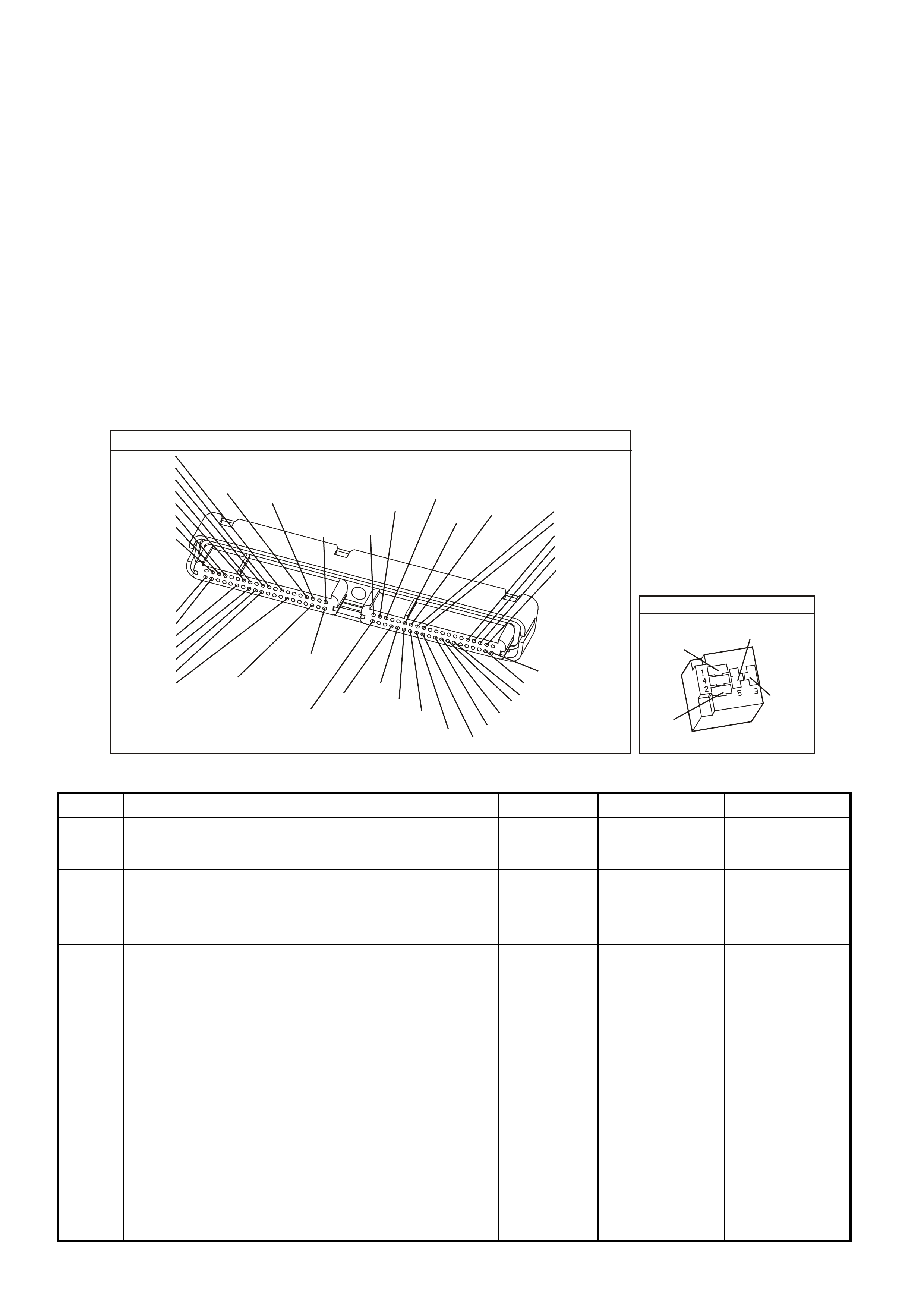
TEST DESCRIPTION
The number below refer to the step number on the diagnostic table.
2. This step checks the operation of the A/C compressor clutch. The PCM disables the A/C compressor clutch
when this DTC is set.
3. Using the Freeze Frame/Failure Records data may aid in locating an intermittent condition. If you cannot
duplicate the DTC, the information included in the Freeze Frame/Failure Records data can help determine the
distance traveled since the DTC set. The Fail Counter and Pass Counter can also help determine how many
ignition cycles the diagnostic reported a pass and/or fail. Operate the vehicle within the same freeze frame
condition (RPM, load, vehicle speed, temperature etc.) that you observed. This will isolate when the DTC
failed.
4. This step checks whether the ignition voltage is available at the relay.
5. This step determines if the A/C relay is at fault or the A/C status circuit is at fault. If the A/C clutch engages, this
indicates that the A/C Status circuit is OK.
6. If the A/C Status is displayed as OFF, this indicates the A/C status circuit is open between the splice and the
PCM. If the A/C Status is displayed as ON, this indicates a faulty connection at the A/C compressor relay or a
faulty relay.
12. This DTC will not report a pass. The Tech 2 scan tool status for this DTC will never report a pass. The Tech 2
scan tool will only display when the diagnostic fails. The repair is not complete if the Tech 2 scan tool indicates
that the diagnostic ran and failed.
YE123
P.C.M CONNECTOR 2
(750)
(1228)
(1229)
(465)
(121)
(259)
G/B
BR
G/W
GY/BLU
R
B/R
(418)
BR
(59)
(832)
G
T
(831)
(417)
(472)
(976)(974)
(432)
(428)
(631)
BLUBR G/Y
BLU/W
LG
BR/W
W/B
LG W
(977)
Y
(971)
BLU/WW
B/R
(750)
(304)
(792)
(1223)
(1222)
(123)
(1227)
(469)
(331)
Y/B
LG
V/W
B/Y
G/O BR/W
(1687)
GY/B
(366)
LG/B
GY/R
(422)
V
(442)
(444)
(443)
(975)
(972)
(978)
(1224)
(973)
(959)
LG/W
LG/B
LBLU/B
GY
(773)
BR/Y
BLU
G
Y/B
LBLU
(958)
BR
(441)
LBLU
1
41
40
80
J2
RED
Y
(838)
A/C RELAY
YE101
(366)
(439)
LG/B
P
G
P
(59)
(439)
GEN III V8 PCM - DTC P1546 A/C CLUTCH STATUS CIRCUIT LOW VOLTAGE
Step Action Value(s) Yes No
1 Did you perform the Powertrain On-Board Diagnostic
(OBD) System Check? Go to Step 2 Go to Powertrain
OBD System
Check Table
2
1. Install the Tech 2 scan tool.
2. Idle the engine with the A/C ON for the specified
length of time.
Does the A/C clutch operate properly?
5 minutes Go to Step 3 Go to Step 4
3 1. Turn ON the ignition leaving the engine OFF.
2. Review Freeze Frame/Failure Records data for DTC
and note parameters.
3. Turn OFF the ignition for 15 seconds.
4. Idle the engine.
5. Operate the vehicle, within the conditions required for
this diagnostic to run, and as close to the conditions
recorded in Freeze Frame/Failure Records as
possible. Special operating conditions that you need to
meet before the PCM will run the diagnostic, where
applicable, are listed in Conditions for Setting the
DTC.
6. Select the Diagnostic Trouble Code (DTC) option, the
DTC Information option and The Failed This Ignition
option using the Tech 2 scan tool.
Does the Tech 2 scan tool indicate that this diagnostic
failed this ignition?
Go to Step 4 Refer to
Diagnostic Aids

GEN III V8 PCM - DTC P1546 A / C CLUTCH STATUS CIRCUIT LOW VOLTAGE (CONTINUED)
Step Action Value(s) Yes No
4 1. Turn OFF the ignition.
2. Disconnect the A/C clutch relay.
3. Turn ON the ignition leaving the engine off.
4. Probe the ignition feed circuit, at the A/C relay terminal
(switch side of relay), with a test lamp to earth.
Does the test lamp illuminate?
Go to Step 5 Go to Step 9
5 Jump the ignition feed circuit to the A/C clutch status
circuit (load), at the engine compartment fuse & relay
panel, using a fused jumper wire.
Does the A/C clutch engage?
Go to Step 6 Go to Step 10
6 Monitor the A/C Status display on the Engine Data List
using the Tech 2 scan tool with the fused jumper still
installed.
Does the Tech 2 scan tool indicate the A/C Status as
ON?
Go to Step 7 Go to Step 8
7 Repair the faulty A/C clutch relay connection or faulty A/C
clutch relay.
Is the action complete?
Go to Step 12
8 Check for an open A/C clutch status circuit from the
splice to the PCM.
Did you find and repair the condition?
Go to Step 12 Go to Step 11
9 Repair the open ignition feed circuit to A/C relay.
Is the action complete? Go to Step 12
10 Repair the open in A/C status circuit form the A/C relay to
splice.
Is the action complete?
Go to Step 12
11 1. Replace PCM.
2. Refer to Section 6C3-3, of the VX Series Service
Information, for PCM Programming and
PCM/PIM/BCM Security Link Procedure.
Is action complete?
Go to Step 12
12 1. Select the Diagnostic Trouble Code (DTC) option and
the Clear DTC Information option using the Tech 2
scan tool.
2. Idle the engine at the normal operating temperature.
3. Select the Diagnostic Trouble Code (DTC) option, the
DTC Information option and The Failed This Ignition
option using the Tech 2 scan tool.
4. Operate the vehicle, within the Conditions for Running
the DTC, as specified in the supporting text, if
applicable.
Does the Tech 2 scan tool indicate that this DTC reset?
Go to Step 2 Go to Step 13
13 Using the Tech 2 scan tool, check for any other DTCs.
Does the Tech 2 scan tool display any DTCs that you
have not diagnosed?
Go to the
applicable DTC
table
System OK
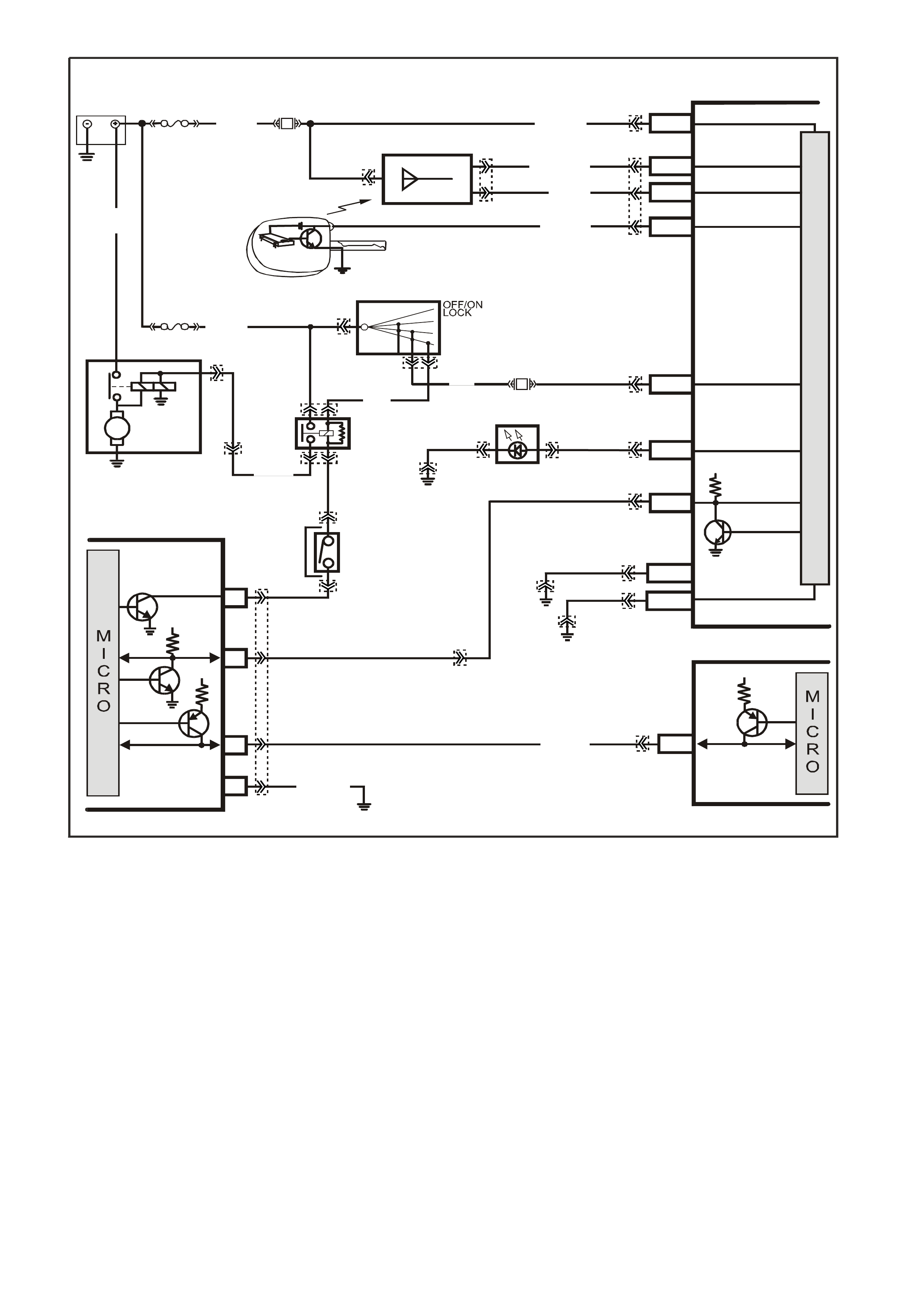
GEN III V8 PCM -
DTC P1626 THEFT DETERRENT SYSTEM FUEL ENABLE CIRCUIT
CIRCUIT DESCRIPTION
The Vehicle Theft Deterrent (VTD) system consists of the following components:
• Powertrain Control Module (PCM)
• Powertrain Interface Module (PIM)
• Body Control Module (BCM)
• Ignition Lock and Key
After the Body Control Module (BCM) has conf irm ed the correc t key has been used, the BCM sends a password to
the PIM via the UART Serial Data circuit. The PIM will operate the starter m otor, and supply another password via
Class II Serial Data to the PCM. When this password matches the password stored in the PCM, the system
enables the fuel injection. If the BCM does not send a password or if the PCM does not receive it, the vehicle will
not start unless the PCM is in VTD Fail-Enable mode.
If the BCM and PCM loose communications with each other after the system has received the correct password,
the PCM goes into VT D Fail-Enable m ode. This allows the dr iver to restart the vehic le on future ignition cyc les until
communications between the BCM and PCM are restored. If the BCM and PCM loose comm unications before the
PCM receives the BCM password, the PCM disables the fuel injection until comm unications is restored in order to
prevent vehicle theft. In both cases DTC P1626 sets. The PCM will not disable the fuel injection once the PCM
enables the fuel within a given ignition cycle in order to prevent stalling as a result of theft deterrent system faults.
BATTERY MAIN POWER
HIGH SERIES
BCM TERMINALS
NOMINA TED FIRST
BCM
REMOTE
CODED KEY
V/R (229) E1/D12 KEY READER
BATTERY
FS
LOC.
E1
LOC. G1
F31
A5/A6O/B (740)
(1040)
REMOTE KEY
RECEIVER
Y (266) E8/D1 RECEIVER DATA
BR/G (271) E7/D11 RECEIVER EARTH
O/B
(740)
FJ
M
I
C
R
O
P
R
O
C
E
S
S
O
R
GY/BLU
(1434)
G3PCM040PT
THEFT DETERRENT
ALERT INDICA TOR
R/B
(1221)
E2/D2 SERIAL DATA
5V
R (2H)
E20/D6 IGNITION
NEUTRAL ST ART
BACK-UP SW.
(FOR AUTO TRANS)
(FOR MANUAL
TRANS)
GY
(434)
R (1)
V/W (6 )
F14
START
RELAY
IGN ITIO N SWITC H
15a 15 50
30 ACC
IGN
START
V (5) P (3) P/B
(39)
A6/A8
LBLU
(263) THE FT LED
B/Y
(155)
LOC. E3
B/G
(151) B10/B11 HIGH CURRENT
EARTH
B/Y
(155) ELECTRONIC EARTH
A1/A5
LOC. E3
LOC. E3
PIM
UART
SERIAL
DATA
START
RELAY
5V
6
8
16
7V
7
CLASS 2
SERIAL DAT A
B/R (750)
LOC. E5/E15
R/B
(1221)
7V
PCM
J1-58 CLASS 2
SERIAL DATA
Y (1049)
Y
(1049)
STARTER
MOTOR
M
YB215
YE112
YB35
YE104
YE8
YB35
YE114 YB56 YB56
YE49
YB44
YE49
YB44
YB95
YB175
YB164
YB176
YB165
YB175
YB164
YB175
YB164
YB174
YB163
YE114
YE114 YB176
YB165
YE122
YB176
YB165
YB95

CONDITIONS FOR RUNNING THE DTC
• The engine is cranking.
CONDITIONS FOR SETTING THE DTC
• The system has reached fuel enable decision point.
• The PCM is in Fail Enable Mode due to loss of communication with the PIM after the system received the
correct password earlier in the ignition cycle.
• The PCM does receive the password message from the PIM prior to the theft deterrent Fuel Decision Point.
ACTION TAKEN WHEN THE DTC SETS
• The PCM enables the fuel injection on future ignition cycles only if the PCM is in Fail-Enable Mode.
• The PCM illuminates the Check Powertrain Lamp when the diagnostic runs and fails.
NOTE: This DTC is usually set if communication is lost. The Check Powertrain Lamp may not operate.
• The PCM records the operating conditions at the time the diagnostic fails. The PCM stores this information in
the Freeze Frame/Failure Records.
CONDITIONS FOR CLEARING THE CPL/DTC
• The PCM turns the Chec k Powertrain Lamp OF F after one ignition cycle that the diagnostic runs and does not
fail.
• A last test failed (current DTC) clears when the diagnostic runs and does not fail.
• Use a Tech 2 scan tool in order to clear the CPL/DTC.
DIAGNOSTIC AIDS
• The m ost likely cause of DT C P1626 is a loss of s erial data comm unication fr om the PIM to PCM. Check for a
loss of power or earth to the PIM or for other causes of communication loss. Check for the following:
- Open Class II circuit
- Earthed Class II circuit
- Shorted to voltage Class II circuit
- PIM Ignition feed fault
- PIM earth fault
• Using the Freeze Frame/Failure Records data may aid in locating an intermittent condition.
• If you cannot duplicate the DTC, the information included in the Freeze Frame/Failure Records data can help
determine the distance traveled since the DTC set. The Fail Counter and Pass Counter can also help
determine how many ignition cycles the diagnostic reported a pass and/or fail. Operate the vehicle within the
same freeze frame condition (RPM, load, vehicle speed, temperature etc.) that you observed. This will isolate
when the DTC failed.
• For an intermittent, refer to Section 6C3-2B Symptoms, of the VX Series Service Information.
TEST DESCRIPTION
The numbers below refer to the step number on the diagnostic table.
2. An engine that does not start and a DTC P1626 that is set, indicates that there is a Class II Serial Data circuit
problem. There may be several PIM DTCs set if the Class II Serial Data circuit has malfunctioned.
3. If both PCM DTC P1626, and P1630 are set, check for a fault with either the PIM power feed or PIM earth
circuits.
4. An engine that does not crank indicates there is a problem with the Body Control Module or the Powertrain
Interface Module. If a BCM or PIM DTCs are set, refer to that DTC for diagnosis.
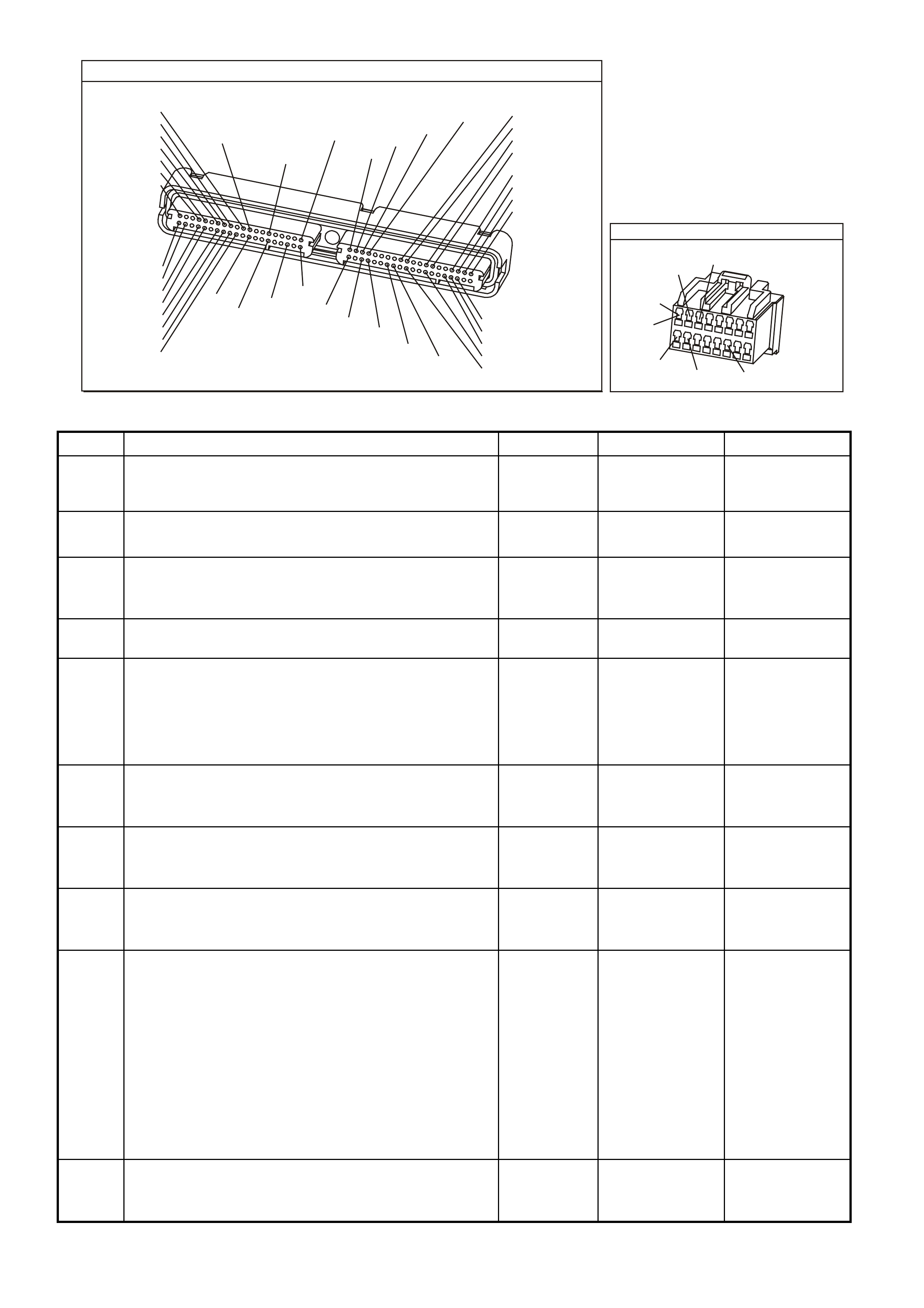
P.C.M CONNECTOR 1
YE122
(776)
(1049)
(897)
(1230)
(848)
(1226)
(772)
(647)
(632)
40
(844)
(815)
80
J1
P/B
(845)
V/W
BLU
O
(633)
(846)
B/Y
B/R
(416)
(86)
(69)
(455)
(740)
GY
BR
G
GY
(646)
(410)
GY
(842)
(1225)
V
Y
(750)
P
41
O
(774)
BR/Y
BLU
Y
B/R
B
BLU/Y
(841)
BLUE
(414)
G/W
BLU
LG
LBLU/B
1
(847)
(415)
(740)
(452)
BLU
BR
Y
(750)
(826)
(421)
Y
V/W
B/W
(334)
(771)
(39)
Y
R/W
LBLU
W
BLU/W
(843)
(643)
LBLU/W
G
GY/B
BLU/B
(413)
(1413)
(1412)
(412)
GY
V
GY/B
G
(335)
POWER TRAIN INTERFACE MODULE
YB215
W/B
(451)
Y
(1049)
B/R
(750)
P
(39)
R/B
(1221)
GY/BLU
(1434)
GY
(434)
(AUTO)
(MAN)1
9
16
8
GEN III V8 PCM - DTC P1626 THEFT DETERRENT SYSTEM FUEL ENABLE CIRCUIT
Step Action Value(s) Yes No
1 Did you perform the Powertrain On-Board Diagnostic
(OBD) System Check? Go to Step 2 Go to Powertrain
OBD System
Check Table
2
Crank the engine.
Does the engine crank and run? Go to Step 9 Go to Step 3
3 Using Tech 2 scan tool, check for PCM DTC P1626, and
P1630.
Are both DTCs set?
Go to Step 5 Go to Step 4
4 Are any PIM DTCs set? Go to appropriate
PIM DTC Go to Step 7
5 1. Ignition OFF.
2. Remove PIM connector.
3. Check for open, or short to earth in power feed and
earth circuits to PIM.
Was a problem found?
Go to Step 9 Go to Step 6
6 Replace PIM. Refer Section 6C3 of the VX Series Service
Information.
Is action complete?
Go to Step 9
7 Check for poor connection in Class II Serial Data circuit
from PCM to PIM.
Was a problem found?
Go to Step 8 Go to Step 9
8 Repair open, short to earth, or short to voltage in Class II
Serial Data circuit.
Is action complete?
Go to Step 9
9 1. Select the Diagnostic Trouble Code (DTC) option and
the Clear DTC Information option using the Tech 2
scan tool.
2. Idle the engine at the normal operating temperature.
3. Select the Diagnostic Trouble Code (DTC) option, the
DTC Information option and The Failed This Ignition
option using the Tech 2 scan tool.
4. Operate the vehicle, within the Conditions for Running
the DTC, as specified in the supporting text, if
applicable.
Does the Tech 2 scan tool indicate that this DTC reset?
Go to Step 2 Go to Step 10
10 Using the Tech 2 scan tool, check for any other DTCs.
Does the Tech 2 scan tool display any DTCs that you
have not diagnosed?
Go to the
applicable DTC
table
System OK
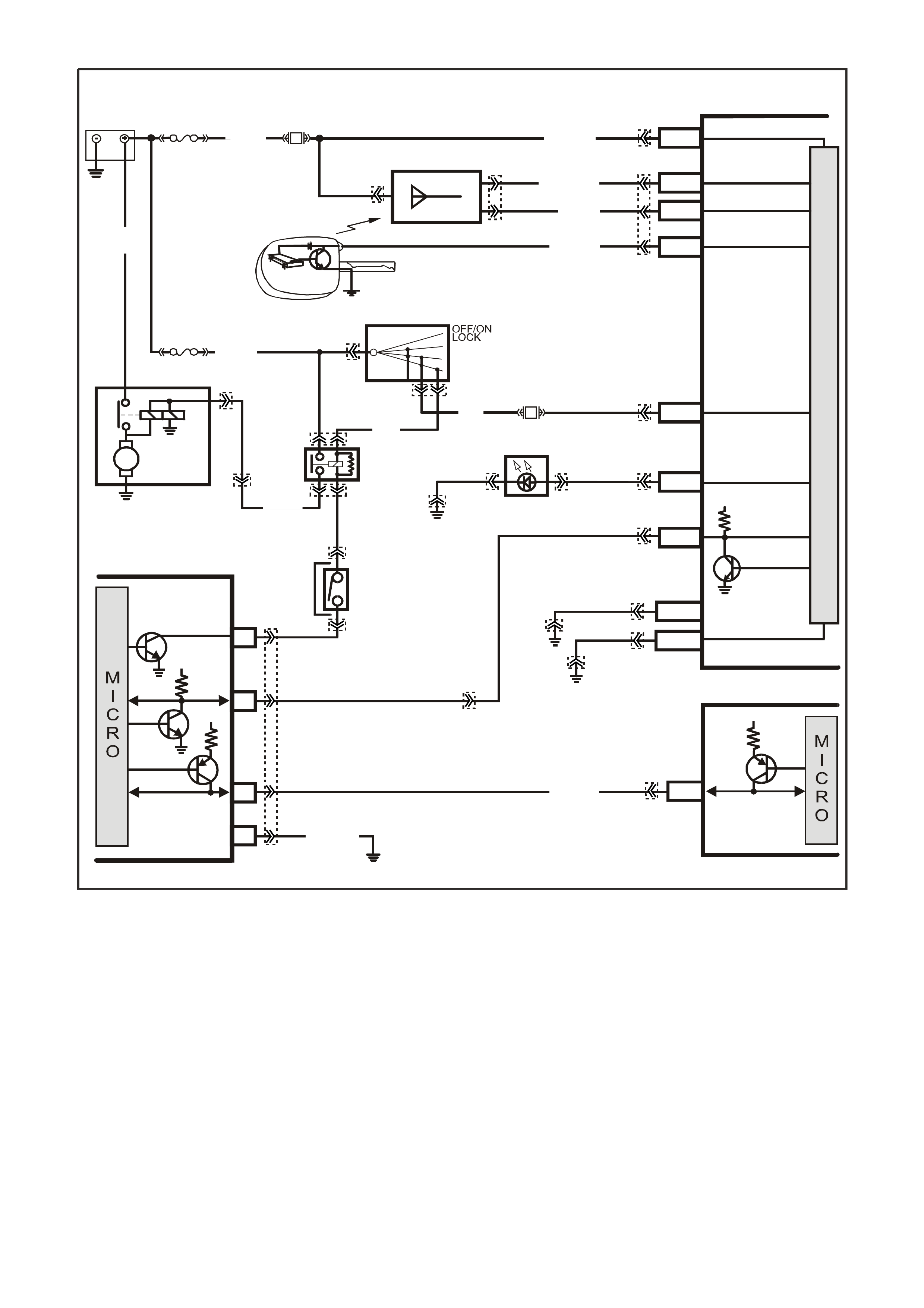
GEN III V8 PCM -
DTC P1630 THEFT DETERRENT POWERTRAIN CONTROL MODULE IN LEARN MODE
CIRCUIT DESCRIPTION
This diagnostic tes t check s for the Enable Pass word Learning Flag indicating the PCM is in learn pass word mode.
This mode allows the PCM to learn the pas sword from the Powertrain Interf ace Module (PIM) at as sembly or when
serviced. The password needs to be learned whenever the PCM, or the PIM is replaced.
CONDITIONS FOR RUNNING THE DTC
• The PCM is in the learn password mode.
CONDITIONS FOR SETTING THE DTC
• The PCM is ready to learn a new password from the PIM, but the PIM is not sending a valid password or not
sending a password at all.
BAT TERY MAIN POWER
HIGH SERIES
BCM TERMINALS
NOMINA TED FIRST
BCM
REMOTE
CODED KEY
V/R (229) E1/D12 KEY R EAD ER
BATTERY
FS
LOC.
E1
LOC. G1
F31
A5/A6O/B (740)
(1040)
REMOTE KEY
RECEIVER
Y (266) E8/D1 RECEIVER DATA
BR/G (271) E7/D11 RECEIVER EARTH
O/B
(740)
FJ
M
I
C
R
O
P
R
O
C
E
S
S
O
R
GY/BLU
(1434)
G3PCM040PT
THEFT DETERRENT
ALERT INDICA TOR
R/B
(1221)
E2/D2 SERIAL DATA
5V
R (2H)
E20/D6 IGNITION
NEUTRAL ST ART
BACK-UP SW.
(FOR AUTO TRANS)
(FOR MANUAL
TRANS)
GY
(434)
R (1)
V/W (6 )
F14
START
RELAY
IGN ITIO N SWITC H
15a 15 50
30 ACC
IGN
START
V (5) P (3) P/B
(39)
A6/A8
LBLU
(263) THE FT LED
B/Y
(155)
LOC. E3
B/G
(151) B10/B11 HIGH CURRENT
EARTH
B/Y
(155) ELECTRONIC EARTH
A1/A5
LOC. E3
LOC. E3
PIM
UART
SERIAL
DATA
START
RELAY
5V
6
8
16
7V
7
CLASS 2
SERIAL DATA
B/R (750)
LOC. E5/E15
R/B
(1221)
7V
PCM
J1-58 CLASS 2
SERIAL DATA
Y (1049)
Y
(1049)
STARTER
MOTOR
M
YB215
YE112
YB35
YE104
YE8
YB35
YE114 YB56 YB56
YE49
YB44
YE49
YB44
YB95
YB175
YB164
YB176
YB165
YB175
YB164
YB175
YB164
YB174
YB163
YE114
YE114 YB176
YB165
YE122
YB176
YB165
YB95
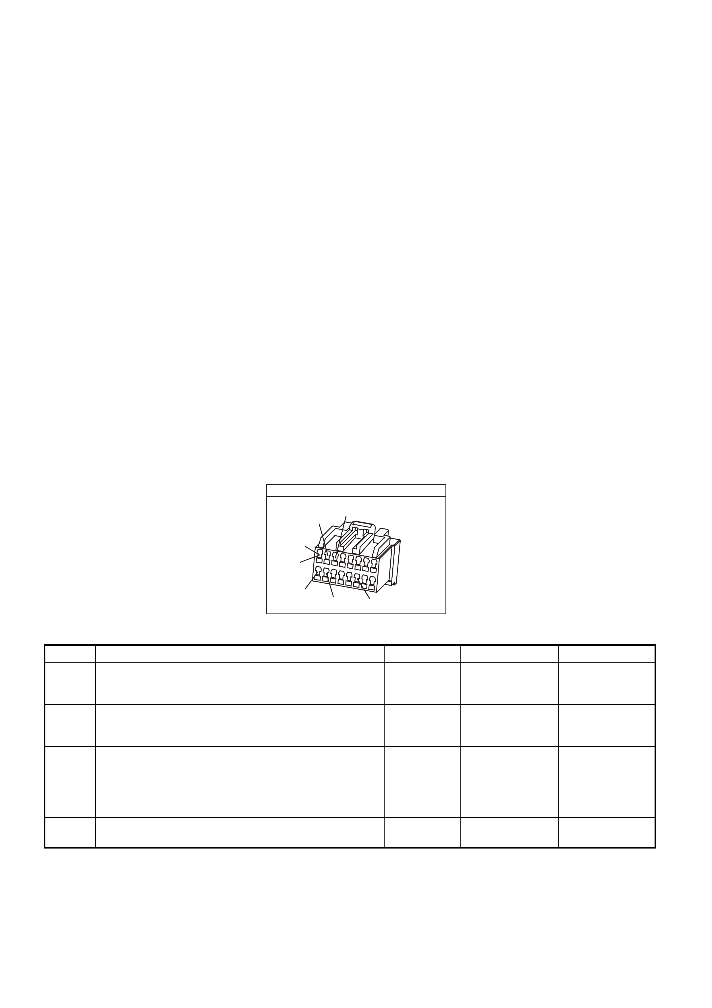
ACTION TAKEN WHEN THE DTC SETS
• The engine cranks but may not start.
• The PCM illuminates the Check Powertrain Lamp when the diagnostic runs and fails.
• The PCM records the operating conditions at the time the diagnostic fails. The PCM stores this information in
the Freeze Frame/Failure Records.
CONDITION FOR CLEARING THE CPL/DTC
• A last test failed (current DTC) clears when the diagnostic runs and does not fail.
• Use a Tech 2 scan tool in order to clear the CPL/DTC.
DIAGNOSTIC AIDS
• The PCM in learn mode is a DTC for the personnel at the assembly plant, dealership, and the outside garage
as an indication that the system enables the learn mode. This means the PCM is now ready to learn a new
password from the PIM. This DTC set because the PIM never sent a valid password to the PCM while in learn
mode. When this occurs, the vehicle is vulnerable to vehicle theft.
• Also, if there is a problem with the UART serial data line between the BCM and PIM, this may cause this
condition.
• Inspect the BCM for DTCs that may apply to the UART circuit. If any are found, refer to these DTC first.
• If both PCM DTCs P1626, and P1630 are set, check PIM power feed and earth circuits for opens or shorts. If
problem was found with PIM earth circuit, repair earth circuit, then power down PCM (key OFF) for 30 seconds.
Key ON and retest.
TEST DESCRIPTION
The numbers below refer to the step numbers on the diagnostic table.
2. If both PIM DTC P1626, and P1630 are set, check for a fault with either the PIM power feed or PIM earth
circuits.
5. If a PIM, or BCM was replaced and were not linked, this may set the DTC. Performing the link procedure will
assure that all controllers are linked together.
POWER TRAIN INTERFACE MODULE
YB215
W/B
(451)
Y
(1049)
B/R
(750)
P
(39)
R/B
(1221)
GY/BLU
(1434)
GY
(434)
(AUTO)
(MAN)1
9
16
8
GEN III V8 PCM - DTC P1630 THEFT DETERRENT POWERTRAIN CONTROL MODULE IN LEARN MODE
Step Action Value(s) Yes No
1 Did you perform the Powertrain On-Board Diagnostic
(OBD) System Check? Go to Step 2 Go to Powertrain
OBD System
Check Table
2 Using Tech 2 scan tool, check for DTC P1626, and
P1630.
Are both DTCs set?
Go to Step 3 Go to Step 5
3 1. Ignition OFF.
2. Remove PIM connector.
3. Check for open or short to earth in power feed and
earth circuits to PIM.
Was a problem found?
Go to Step 6 Go to Step 4
4 Replace PIM
Is action complete? Go to Step 6

GEN III V8 PCM - DTC P1630 THEFT DETERRENT POWERTRAIN CONTROL MODULE IN LEARN MODE (CONTINUED)
Step Action Value(s) Yes No
5 1. Using Tech 2 scan tool, link PCM to PIM. Refer to
Section 6C3-3 of the VX Series Serv ice Information for
linking procedure.
2. Attempt to start vehicle.
Does vehicle crank and start?
Go to Step 6 Go to Body
Control Module
diagnostics.
Refer to Section
12J-1 Low Series
BCM or
Section 12J-2
High Series BCM
in VX Service
Information.
6 1. Select the Diagnostic Trouble Code (DTC) option and
the Clear DTC Information option using the Tech 2
scan tool.
2. Idle the engine at the normal operating temperature.
3. Select the Diagnostic Trouble Code (DTC) option, the
DTC Information option and The Failed This Ignition
option using the Tech 2 scan tool.
4. Operate the vehicle, within the Conditions for Running
the DTC, as specified in the supporting text, if
applicable.
Does the Tech 2 scan tool indicate that this DTC reset?
Go to Step 2 Go to Step 7
7 Using the Tech 2 scan tool, check for any other DTCs.
Does the Tech 2 scan tool display any DTCs that you
have not diagnosed?
Go to the
applicable DTC
table
System OK

GEN III V8 PCM -
DTC P1631 THEFT DETERRENT PASSWORD INCORRECT
CIRCUIT DESCRIPTION
This test checks for mismatched passwords between the PIM and PCM. Whenever replacing the PIM or PCM,
follow the Theft Learn procedure in order for the system to learn the new password.
CONDITIONS FOR RUNNING THE DTC
• The ignition is on and the PCM is waiting for the correct password.
CONDITIONS FOR SETTING THE DTC
• The PCM detects an incorrect password from the PIM.
ACTION TAKEN WHEN THE DTC SETS
• The engine cranks but may not start.
• The PCM illuminates the Check Powertrain Lamp when the diagnostic runs and fails.
• The PCM records the operating conditions at the time the diagnostic fails. The PCM stores this information in
the Freeze Frame/Failure Records.
BAT TERY MAIN PO WER
HIGH SERIES
BCM TERMINALS
NOMINA TED FIRST
BCM
REMOTE
CODED KEY
V/R (229) E1/D12 KE Y REA D ER
BATTERY
FS
LOC.
E1
LOC. G1
F31
A5/A6O/B (740)
(1040)
REMOTE KEY
RECEIVER
Y (266) E8/D1 RECEIVER DATA
BR/G (271) E7/D11 RECEIVER EARTH
O/B
(740)
FJ
M
I
C
R
O
P
R
O
C
E
S
S
O
R
GY/BLU
(1434)
G3PCM040PT
THEFT DETERRENT
ALERT INDICA TOR
R/B
(1221)
E2/D2 SERIAL DATA
5V
R (2H)
E20/D6 IGNITION
NEUTRAL ST ART
BACK-UP SW.
(FOR AUTO TRANS)
(FOR MANUAL
TRANS)
GY
(434)
R (1)
V/W (6 )
F14
START
RELAY
IGN ITIO N SWITC H
15a 15 50
30 ACC
IGN
START
V (5) P (3 ) P/B
(39)
A6/A8
LBLU
(263) THE FT LED
B/Y
(155)
LOC. E3
B/G
(151) B10/B11 HIGH CURRENT
EARTH
B/Y
(155) ELECTRONIC EARTH
A1/A5
LOC. E3
LOC. E3
PIM
UART
SERIAL
DATA
START
RELAY
5V
6
8
16
7V
7
CLASS 2
SERIAL DATA
B/R (750)
LOC. E5/E15
R/B
(1221)
7V
PCM
J1-58 CLASS 2
SERIAL DATA
Y (1049)
Y
(1049)
STARTER
MOTOR
M
YB215
YE112
YB35
YE104
YE8
YB35
YE114 YB56 YB56
YE49
YB44
YE49
YB44
YB95
YB175
YB164
YB176
YB165
YB175
YB164
YB175
YB164
YB174
YB163
YE114
YE114 YB176
YB165
YE122
YB176
YB165
YB95

CONDITIONS FOR CLEARING THE CPL/DTC
• A last test failed (current DTC) clears when the diagnostic runs and does not fail.
• Use a Tech 2 scan tool in order to clear the CPL/DTC.
DIAGNOSTIC AIDS
IMPORTANT:
Remove any debris from the PCM module connector surfaces before servicing the PCM module.
• The PCM in learn mode is a DTC for the personnel at the assembly plant, dealership, and the outside garage
as an indication that the system enables the learn mode. This means the PCM is now ready to learn a new
password from the PIM while in the learn mode. When this occurs, the vehicle is vulnerable to vehicle theft.
• If using a Tech 2 scan tool and TIS for password linking, refer to BCM mode of Tech 2 scan tool for linking
procedure. This Tech 2 scan tool operation will take approximately 2 minutes to perform. If no Tech 2 scan tool
and TIS is available, the following DTC P1631 diagnostic table must be followed.
TEST DESCRIPTION
The numbers below refer to the step numbers on the diagnostic table.
2. The 1 hour and 30 second time criteria is a minimum required amount of time. The time limit can exceed this
limit without interfering with the Auto Learn Procedure. Use a Tech 2 scan tool (Auto Learn Timer equals
Inactive) in order to determine when the 1 hour has expired.
4. If DTC P1631 is set, this indicates that you did not follow the procedure correctly. Perform the Re-learn
procedure again.
GEN III V8 PCM - DTC P1631 THEFT DETERRENT PASSWORD INCORRECT
Step Action Value(s) Yes No
1 Did you perform the Powertrain On-Board Diagnostic
(OBD) System Check? Go to Step 2 Go to Powertrain
OBD System
Check Table.
2 IMPORTANT:
• Check for any Theft Deterrent BCM or PIM DTCs
being set before proceeding with this table. If a BCM
or PIM DTC is set, refer to the appropriate DTC.
• Maintain the battery voltage while the PCM is in the
Learn Procedure. Follow this procedure exactly as
indicated or you will have to repeat the procedure
from the beginning.
• Performing the following procedure causes a DTC
P1630 to set when you complete the procedure. This
is the intended functionality. When P1630 sets, turn
OFF the ignition for 30 seconds, then turn ON the
ignition and P1630 clears. If the DTC P1630 does
not clear, go to the DTC P1630 table.
NOTE: Ensure the battery is fully charged.
1. Turn ON the ignition leaving the engine OFF for 1 hour
and 10 minutes.
2. Turn OFF the ignition for 30 seconds.
3. Turn ON the ignition leaving the engine OFF for 1 hour
and 10 minutes.
4. Turn OFF the ignition for 30 seconds.
5. Turn ON the Ignition leaving the engine OFF for 1
hour and 10 minutes or until DTC P1630 sets.
6. Turn OFF the ignition for 30 seconds.
7. Turn ON the ignition leaving the engine OFF and wait
30 seconds.
8. Attempt to start the engine.
Does the engine start and operate normally?
Go to Step 3 Go to Step 4
3 IMPORTANT: Monitor all DTC status parameters and
note any additional DTCs before Clearing DTCs.
1. Clear the PCM DTCs.
2. Turn OFF the ignition for 30 seconds.
3. Attempt to start the engine.
Does the engine start and operate normally?
System OK Go to Step 4
4 Are DTCs P1626, P1630, or P1631 set? Go to applicable
DTC table Go to Step 2
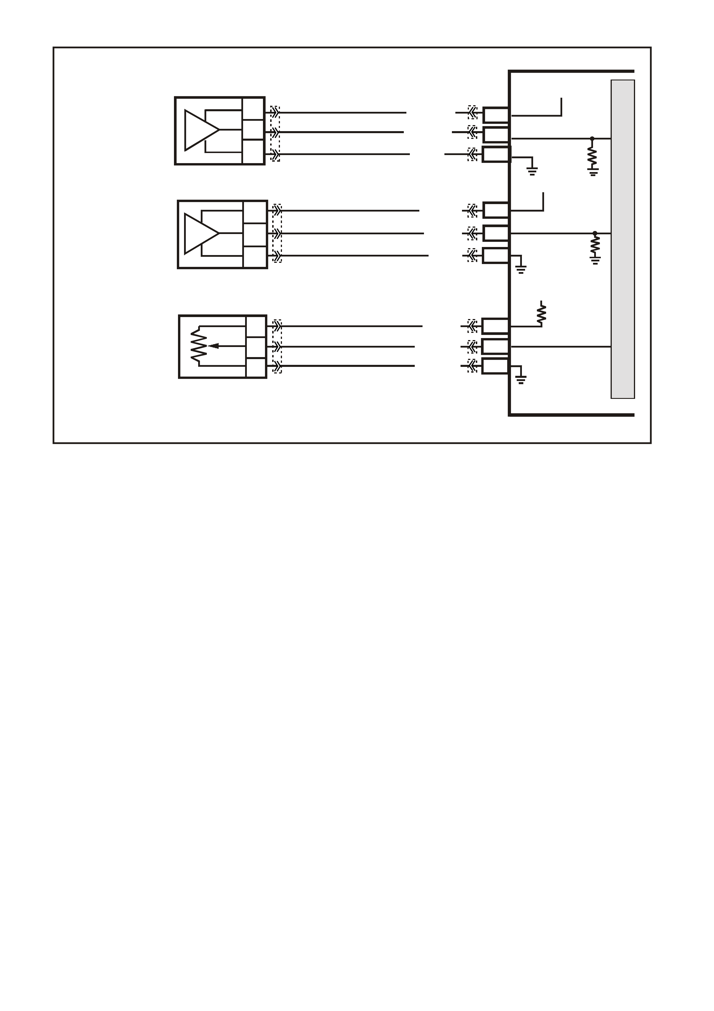
GEN III V8 PCM -
DTC P1635 5 VOLT REFERENCE #1 CIRCUIT
CIRCUIT DESCRIPTION
The PCM uses a common 5.0 volt reference circuit as a sensor feed. This circuit supplies 5 volts to the following
sensors:
• The TP Sensor
• The MAP sensor
• Oil Pressure Sensor
The PCM monitors the voltage on the 5.0 volt reference circuit. This DTC sets if the voltage is out of range.
CONDITIONS FOR RUNNING THE DTC
• The ignition is on.
CONDITIONS FOR SETTING THE DTC
• The five volt reference #1 circuit is out of range.
• All of the above conditions are present for greater than 2 seconds.
ACTION TAKEN WHEN THE DTC SETS
• The PCM illuminates the Check Powertrain Lamp when the diagnostic runs and fails.
• The PCM records the operating conditions at the time the diagnostic fails. The PCM stores this information in
the Freeze Frame/Failure Records.
CONDITIONS FOR CLEARING THE CPL/DTC
• The PCM turns the Chec k Powertrain Lamp OF F after one ignition cycle that the diagnostic runs and does not
fail.
• A last test failed (Current DTC) clears when the diagnostic runs and does not fail.
• Use a Tech 2 scan tool in order to clear the CPL/DTC.
4358
PCM
J2-32
J1-54
C
B
A
MANIFOLD
ABSOLUTE
PRESSURE SENSO R
J1-48
SENSOR EARTH
MAP SENSOR
SIGNAL
5V
V/W (414)
B (4 21 )
LG (432)
SENSOR EARTH
TP SENSOR SIGNAL
TP SEN S OR
REFERENCE
VOLTAGE
5V
J1-08
J2-24
J1-60
A
C
B
THROTTLE
POSITION SENSOR
GY (416)
BLU (417)
B/Y (452)
M
I
C
R
O
P
R
O
C
E
S
S
O
R
B
C
A
OIL
PRESSURE
SENSOR
J1-07
J2-58
J1-63
5V
OIL PRESSURE
SENSOR SIGNAL
SENSOR EARTH
BLU/Y (334)
YE122
YE122
YE122
YE122
YE122
YE30
YE32
YE27 YE122
YE123
YE123
YE123
BR/W (331)
G (335)
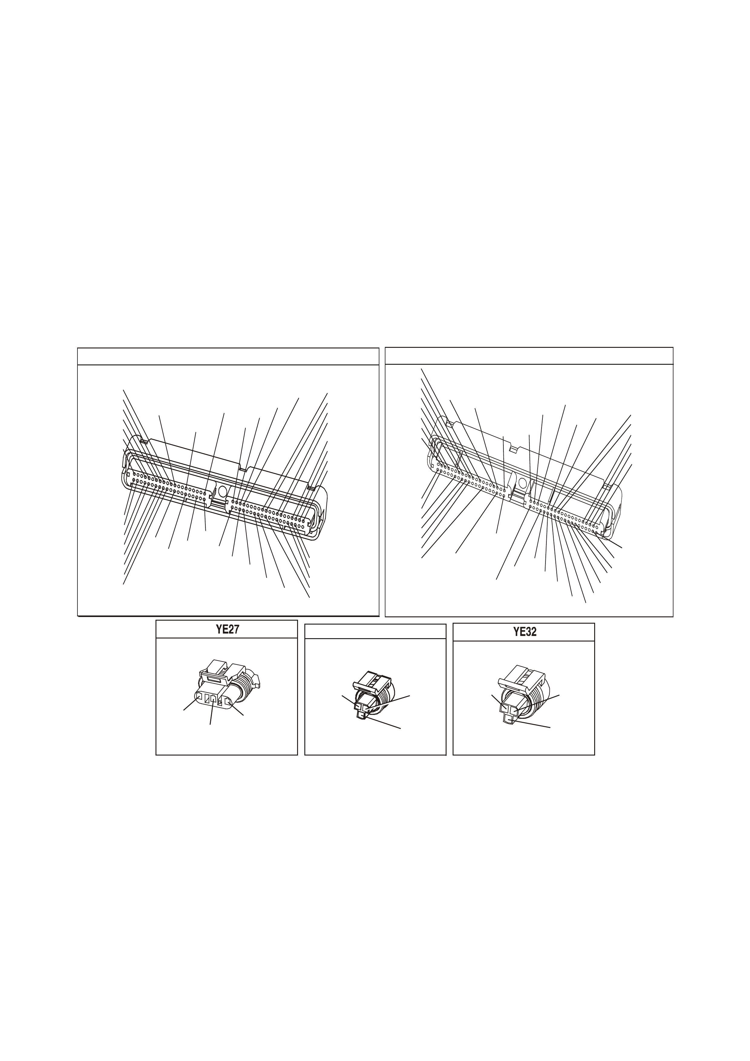
DIAGNOSTIC AIDS
• The Throttle Relaxer Control Module is also spliced into the TP circuits. If there is a problem with the Throttle
Relaxer Module or circuits, this could set this DTC. Inspect to determine that this is not causing the problem.
• Using the Freeze Frame/Failure Records data may aid in locating an intermittent condition. If you cannot
duplicate the DTC, the information included in the Freeze Fram e/Failure Records data can help determine the
distance traveled since the DTC set. The Fail Counter and Pass Counter can also help determine how many
ignition cycles the diagnostic reported a pass and/or fail. Operate the vehicle within the same freeze frame
condition (RPM, load, vehicle speed, temperature etc.) that you observed. This will isolate when the DTC
failed.
• For an intermittent, refer to Section 6C3-2B Symptoms, of the VX Series Service Information.
TEST DESCRIPTION
The numbers below refer to the step numbers on the diagnostic table.
2. The 5.0 volt reference circuit for the sensors listed are tied together inside the PCM. This step separates the
5.0 volt reference circuits and isolates the 5.0 volt reference circuit which is shorted to voltage.
3. The 5.0 volt reference circuit for the sensors listed are tied together inside the PCM. This step separates the
5.0 volt reference circuits and isolates the 5.0 volt reference circuit which is shorted to earth.
4. This step isolates the 5.0 volt reference circuit from the sensor signal circuit.
P.C.M CONNE CTOR 1
YE122
(776)
(1049)
(897)
(1230)
(848)
(1226)
(772)
(647)
(632)
40
(844)
(815)
80
J1
P/B
(845)
V/W
BLU
O
(633)
(846)
B/Y
B/R
(416)
(86)
(69)
(455)
(740)
GY
BR
G
GY
(646)
(410)
GY
(842)
(1225)
V
Y
(750)
P
41
O
(774)
BR/Y
BLU
Y
B/R
B
BLU/Y
(841)
BLUE
(414)
G/W
BLU
LG
LBLU/B
1
(847)
(415)
(740)
(452)
BLU
BR Y
(750)
(826)
(421)
Y
V/W
B/W
(334)
(771)
(39)
Y
R/W
LBLU
W
BLU/W
(843)
(643)
LBLU/W
G
GY/B
BLU/B
(413)
(1413)
(1412)
(412)
GY
V
GY/B
G
(335)
YE123
P.C.M CONNECTOR 2
(750)
(1228)
(1229)
(465)
(121)
(259)
G/B
BR
G/W
GY/BLU
R
B/R
(418)
BR
(59)
(832)
G
T
(831)
(417)
(472)
(976) (974)
(432)
(428)
(631)
BLU BR G/Y
BLU/W
LG
BR/W
W/B
LG W
(977)
Y
(971)
BLU/W W
B/R
(750)
(304)
(792)
(1223)
(1222)
(123)
(1227)
(469)
(331)
Y/B
LG
V/W
B/Y
G/O BR/W
(1687)
GY/B
(366)
LG/B
GY/R
(422)
V
(442)
(444)
(443)
(975)
(972)
(978)
(1224)
(973)
(959)
LG/W
LG/B
LBLU/B
GY
(773)
BR/Y
BLU
G
Y/B
LBLU
(958)
BR
(441)
LBLU
1
41
40
80
J2
RED
Y
(838)
M AP S ENSOR
(421)
B
(432)
LG
V/W
(414)
THROTTLE POSITION SENSOR
YE 30
(452) (416)
(417)
GY
B/Y
BLU
OIL PRESSURE SENSOR
(335)
(334)
(331)
G
BLU/Y
BR/W

GEN III V8 PCM - DTC P1635 5 VOLT REFERENCE #1 CIRCUIT
Step Action Value(s) Yes No
1 Did you perform the Powertrain On-Board Diagnostic
(OBD) System Check? Go to Step 2 Go to Powertrain
OBD System
Check Table
2
1. Turn OFF the ignition.
2. Disconnect the PCM BLUE harness connector.
3. Turn ON the ignition leaving the engine OFF.
4. Connect the DMM J 39200 to earth.
5. Probe the PCM harness connector 5.0 volt reference
circuits for the following components using the an
Adapter from the connector test Adapter kit
J 35616-A.
- The TP Sensor
- The MAP sensor
- The Oil Pressure sensor
Do any of the circuits measure at or greater than
specified value?
5.0 V Go to Step 4 Go to Step 3
3 1. Turn OFF the ignition.
2. Connect a test lamp to B+
3. Turn ON the ignition leaving the engine OFF.
4. Probe the PCM harness connector 5.0 volt reference
circuits for the following components using the an
Adapter from the connector test Adapter kit J 35616-A.
- The TP Sensor
- The MAP sensor
- The Oil Pressure sensor
Did the test lamp illuminate for any of the circuits?
Go to Step 5 Go to Diagnostic
Aids
4 1. Disconnect the electrical connector at the sensor that
measured greater than the specified value.
2. Using a DMM, probe the affected 5.0 volt reference
circuit, at the PCM harness connector, using the test
Adapter kit J 35616-B.
Does the DMM display a voltage at or greater than the
specified value?
5.0V Go to Step 8 Go to Step 6
5 1. Disconnect the electrical connector at the sensor that
illuminated the test lamp.
2. Using a DMM, probe the affected 5.0 volt reference
circuit, at the PCM harness connector, using the test
Adapter kit J 35616-B.
Does the DMM display a voltage greater than the
specified value?
Go to Step 9 Go to Step 7
6 1. Connect a DMM J 39200 to earth.
2. Turn ON the ignition leaving the engine OFF.
3. Measure the voltage on the signal circuit at the
affected sensor.
Does the DMM display a voltage greater than the
specified value?
0.0 V Go to Step 10 Go to Step 12
7 1. Connect a test lamp to B+.
2. Turn ON the ignition leaving the engine OFF.
3. Probe the signal circuit at the affected sensor.
Is the test lamp illuminated?
Go to Step 11 Go to Step 12
8 Repair the short to voltage on the appropriate 5.0 volt
reference circuit. Inspect the Throttle Relaxer Control
Module circuit also for short if TP sensor was the
problem.
Is the action complete?
Go to Step 13

GEN III V8 PCM - DTC P1635 5 VOLT REFERENCE #1 CIRCUIT (CONTINUED)
Step Action Value(s) Yes No
9 Repair the short to earth on the appropriate 5.0 volt
reference circuit. Inspect the Throttle Relaxer Control
Module circuit also for short if TP sensor was the
problem.
Is the action complete?
Go to Step 13
10 Repair the short to voltage on the appropriate sensor
signal circuit.
Is the action complete?
Go to Step 13
11 Repair the short to earth on the appropriate sensor signal
circuit.
Is the action complete?
Go to Step 13
12 1. Replace PCM.
2. Refer to Section 6C3-3, of the VX Series Service
Information, for PCM Programming and
PCM/PIM/BCM Security Link Procedure.
Is action complete?
Go to Step 12
13 1. Select the Diagnostic Trouble Code (DTC) option and
the Clear DTC Information option using the Tech 2
scan tool.
2. Idle the engine at the normal operating temperature.
3. Select the Diagnostic Trouble Code (DTC) option, the
DTC Information option and The Failed This Ignition
option using the Tech 2 scan tool.
4. Operate the vehicle, within the Conditions for Running
the DTC, as specified in the supporting text, if
applicable.
Does the Tech 2 scan tool indicate that this DTC reset?
Go to Step 2 Go to Step 14
14 Using the Tech 2 scan tool, check for any other DTCs.
Does the Tech 2 scan tool display any DTCs that you
have not diagnosed?
Go to the
applicable DTC
table
System OK
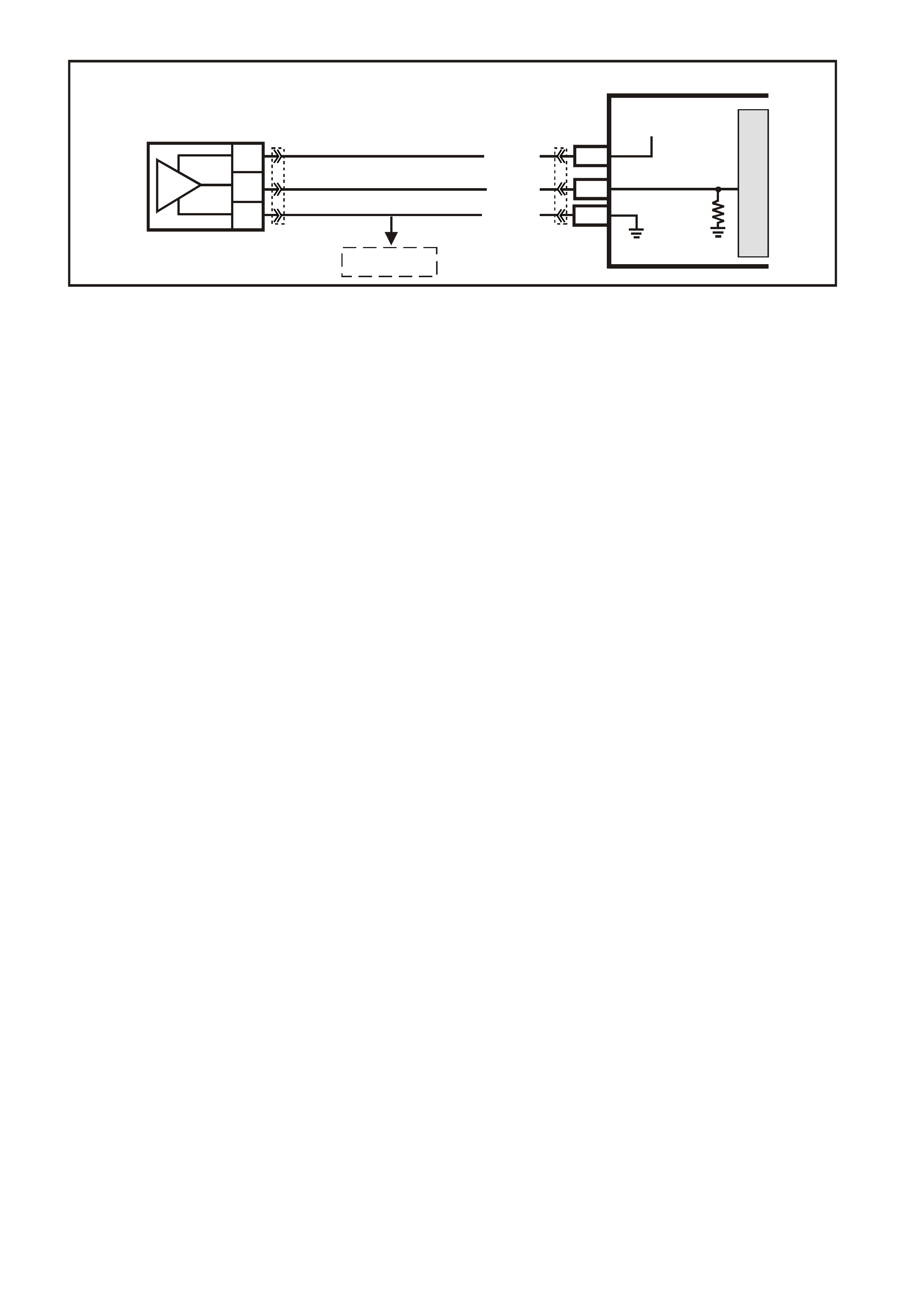
GEN III V8 PCM -
DTC P1639 5 VOLT REFERENCE #2 CIRCUIT
CIRCUIT DESCRIPTION
The PCM uses a common 5.0 volt reference circuit as a sensor feed to the A/C Pressure Sensor.
The PCM monitors the voltage on the 5.0 volt reference circuit. This DTC sets if the voltage is out of range.
CONDITIONS FOR RUNNING THE DTC
• The ignition is on.
CONDITIONS FOR SETTING THE DTC
• The five volt reference #2 circuit is out of range.
• All of the above conditions are present for greater than 2 seconds.
ACTION TAKEN WHEN THE DTC SETS
• The PCM illuminates the Check Powertrain Lamp when the diagnostic runs and fails.
• The PCM records the operating conditions at the time the diagnostic fails. The PCM stores this information in
the Freeze Frame/Failure Records.
CONDITIONS FOR CLEARING THE CPL/DTC
• The PCM turns the Chec k Powertrain Lamp OF F after one ignition cycle that the diagnostic runs and does not
fail.
• A last test failed (Current DTC) clears when the diagnostic runs and does not fail.
• Use a Tech 2 scan tool in order to clear the CPL/DTC.
DIAGNOSTIC AIDS
• Using the Freeze Frame/Failure Records data may aid in locating an intermittent condition. If you cannot
duplicate the DTC, the information included in the Freeze Frame/Failure Records data can help determ ine the
distance traveled since the DTC set. The Fail Counter and Pass Counter can also help determine how many
ignition cycles the diagnostic reported a pass and/or fail. Operate the vehicle within the same freeze frame
condition (RPM, load, vehicle speed, temperature etc.) that you observed. This will isolate when the DTC
failed.
• For an intermittent, refer to Section 6C3-2B Symptoms, of the VX Series Service Information.
TEST DESCRIPTION
The numbers below refer to the step numbers on the diagnostic table.
2. This step checks to see if the A/C Pressure Sensor is functioning properly.
3. This step checks to see if the A/C Pressure Sensor voltage is above or below the correct operating range.
G3PCM001PT
PCM
M
I
C
R
O
J2-14
J2-57
A/C
PRESSURE
SENSOR
J1-45
SENSOR EARTH
A/C PRESSURE
SENSOR SIGNAL
5V
V/W (415)
YE122
YE123YE113
G/O (469)
G/B (259)
C
B
A
TO
IAT SENSOR
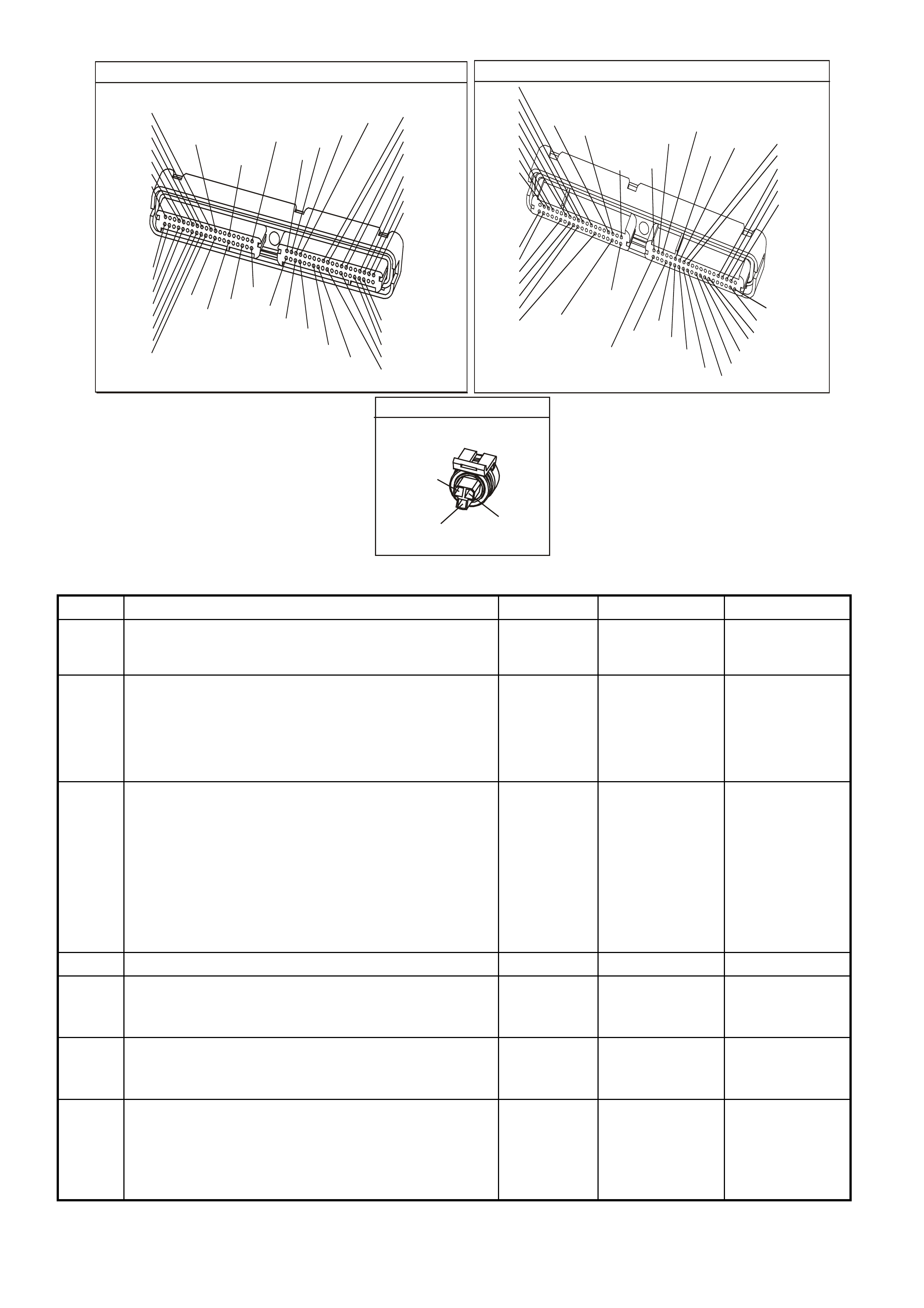
P.C.M CONNECTOR 1
YE122
(776)
(1049)
(897)
(1230)
(848)
(1226)
(772)
(647)
(632)
40
(844)
(815)
80
J1
P/B
(845)
V/W
BLU
O
(633)
(846)
B/Y
B/R
(416)
(86)
(69)
(455)
(740)
GY
BR
G
GY
(646)
(410)
GY
(842)
(1225)
V
Y
(750)
P
41
O
(774)
BR/Y
BLU
Y
B/R
B
BLU/Y
(841)
BLUE
(414)
G/W
BLU
LG
LBLU/B
1
(847)
(415)
(740)
(452)
BLU
BR
Y
(750)
(826)
(421)
Y
V/W
B/W
(334)
(771)
(39)
Y
R/W
LBLU
W
BLU/W
(843)
(643)
LBLU/W
G
GY/B
BLU/B
(413)
(1413)
(1412)
(412)
GY
V
GY/B
G
(335)
YE123
P.C.M CONNECTOR 2
(750)
(1228)
(1229)
(465)
(121)
(259)
G/B
BR
G/W
GY/BLU
R
B/R
(418)
BR
(59)
(832)
G
T
(831)
(417)
(472)
(976)(974)
(432)
(428)
(631)
BLUBR G/Y
BLU/W
LG
BR/W
W/B
LG W
(977)
Y
(971)
BLU/WW
B/R
(750)
(304)
(792)
(1223)
(1222)
(123)
(1227)
(469)
(331)
Y/B
LG
V/W
B/Y
G/OBR/W
(1687)
GY/B
(366)
LG/B
GY/R
(422)
V
(442)
(444)
(443)
(975)
(972)
(978)
(1224)
(973)
(959)
LG/W
LG/B
LBLU/B
GY
(773)
BR/Y
BLU
G
Y/B
LBLU
(958)
BR
(441)
LBLU
1
41
40
80
J2
RED
Y
(838)
A/C PRESSURE TRANSDUCER
YE113
(469)
(415)
(259)
G/B B
V/W
GEN III V8 PCM - DTC P1639 5 VOLT REFERENCE #2 CIRCUIT
Step Action Value(s) Yes No
1 Did you perform the Powertrain On-Board Diagnostic
(OBD) System Check? Go to Step 2 Go to Powertrain
OBD System
Check Table
2 1. Install a Tech 2 scan tool.
2. Idle the engine.
3. Monitor the A/C Pressure Sensor kPa.
Is the A/C Pressure Sensor kPa within the specified
range?
25 to 3140
kPa Go to Diagnostic
Aids Go to Step 3
3
1. Disconnect the A/C Pressure Sensor electrical
connector.
2. Ignition ON, engine OFF.
3. Using a DMM, probe the A/C Pressure Sensor 5.0 volt
reference circuit at the A/C Pressure Sensor harness
connector with the Adapters from the
J 35616-A terminal kit using a DMM J 39200
connected to earth.
Is the voltage at or between the specified value?
4.8 - 5.4V Go to Diagnostic
Aids Go to Step 4
4 Is the voltage above the specified value? 5.4 V Go to Step 5 Go to Step 6
5 Check for short to voltage for the A/C Pressure Sensor 5
volt reference circuit.
Was a problem found?
Verify Repair Go to Step 7
6 Check for an open or short to earth for the A/C Pressure
Sensor 5 volt reference circuit.
Was a problem found?
Verify Repair Go to Step 7
7 1. Replace PCM.
2. Refer to Section 6C3-3 of the VX Series Service
Information for PCM Programming and
PCM/PIM/BCM Security Link Procedure.
Is action complete?
Go to Step 8

GEN III V8 PCM - DTC P1639 5 VOLT REFERENCE #2 CIRCUIT (CONTINUED)
Step Action Value(s) Yes No
8 1. Select the Diagnostic Trouble Code (DTC) option and
the Clear DTC Information option using the Tech 2
scan tool.
2. Idle the engine at the normal operating temperature.
3. Select the Diagnostic Trouble Code (DTC) option, the
DTC Information option and The Failed This Ignition
option using the Tech 2 scan tool.
4. Operate the vehicle, within the Conditions for Running
the DTC, as specified in the supporting text, if
applicable.
Does the Tech 2 scan tool indicate that this DTC reset?
Go to Step 2 Go to Step 9
9 Using the Tech 2 scan tool, check for any other DTCs.
Does the Tech 2 scan tool display any DTCs that you
have not diagnosed?
Go to the
applicable DTC
table
System OK

GEN III V8 PCM
DTC P1810 TFP VALVE POSITION SWITCH CIRCUIT CIRCUIT DESCRIPTION
The automatic Transmission Fluid Pressure (TFP) manual valve position switch consists of five pressure switches
(two norm ally-closed and three norm ally-open) and a T ransm iss ion Fluid T em perature ( TF T) Sensor c om bined into
one unit.
The combined unit mounts on the valve body. The Powertrain Control Module (PCM) supplies the battery voltage
for each range signal. By earthing one or more of the circuits through various combinations of the pressure
switches, the PCM detects which manual valve position you select.
The PCM compares the actual voltage combination of the switches to a TFP manual valve position switch
combination table stored in PCM memory.
The TFP manual valve position switch cannot distinguish between PARK and NEUTRAL because the monitored
valve body pressures are identical. With the engine OFF and the ignition switch in the RUN position, the TFP
manual valve position switch indicates PARK/NEUTRAL.
Disconnecting the transm ission 20-way (YB 129) connector rem oves the earth potential for the thr ee range signals
to the PCM. In this case, with the engine OFF, and the ignition switch in the RUN position, D2 will be indicated.
W hen the PCM detects an invalid state of the TFP manual valve position switch or the T FP manual valve position
switch circuit, by deciphering the TFP manual valve position switch inputs, then DTC P1810 sets.
CONDITIONS FOR RUNNING THE DTC
• No VSS assembly DTCs P0502 or P0503.
• The system voltage is between 8.0 and 18 volts.
• The engine speed is greater than 300 RPM for 5 seconds.
• The engine is not in fuel cutoff.
• The engine torque is 54-542 N.m
• The engine vacuum is 0-105 kPa.
CONDITIONS FOR SETTING THE DTC
Condition1
• The PCM detects an invalid TFP manual valve position switch state foe 60 seconds.
Condition 2
• Then engine speed is less than 80 RPM for 0.1 seconds; then the engine speed is 80-55- RPM for 0.07
seconds; then the engine speed is greater the 550 RPM.
• The vehicle speed is less than 3 km/h.
• The PCM detects a gear range of 2, D or R during an engine start.
• All conditions are met for 5 seconds.
G3PCM034PT
PCM
J2-63
J1-17
J2-51
J1-53
TFP SIGNAL A
TFP SIGNAL B
TRANSMISSION FLUID
TEMPERATURE (TFT)
SENSOR SIGNAL
SENSOR EARTH
N
C
REV (N.0.)
LO (N.0.)
D3 (N.C.)
D4 (N.O.)D2 (N.C.)
R
E
D
A
B
P
L
M
TRANSMISSION FLUID
TEMPERATURE
(TF T ) SENSOR
AUTOMATIC TRANSMISSION FLUID
PRESSURE SWITCH ASSEMBLY
BR/Y (1224)YE123
YE122
YE122
YE123
YE122
YB129
Y (1225)
GY (1226)
B/Y (1227)
B/W (1230)
12V
12V
5V
J1-18 TFP SIGN AL C
12V
M
I
C
R
O

Condition 3
• The TP angle is 8-45%.
• The PCM commands 4th gear.
• The TCC is locked ON.
• The speed ratio is 0.65-0.8 (speed ratio is engine speed divided by transmission output speed).
• The PCM detects a gear range of P or N when operating in D.
• All conditions are met for 10 seconds.
ACTION TAKEN WHEN THE DTC SETS
• The PCM illuminates the Check Powertrain Lamp when the diagnostic runs and fails.
• The PCM commands D2 line pressure.
• The PCM commands D4 shift pattern.
• The PCM freezes shift adapts from being updated.
• The PCM records the operating conditions at the time the diagnostic fails. The PCM stores this information in
the Freeze Frame/Failure Records.
CONDITIONS FOR CLEARING THE CPL/DTC
• The PCM turns the Check Powertrain Lamp OFF during the first ignition cycle that the diagnostic runs and
does not fail.
• A last test failed (current DTC) clears when the diagnostic runs and does not fail.
DIAGNOSTIC AIDS
• Refer to the TFP Manual Valve Position Switch Logic table for the normal range signals and the invalid
combinations. In the table, Closed is 0 volts, Open is 12 volts.
• Inspect the wiring at the PCM, the transmission connector and all other circuit connecting points for the
following conditions:
- A backed out terminal
- A damaged terminal
- Reduced terminal tension
- A chafed wire
- A broken wire inside the insulation
- Moisture intrusion
- Corrosion
• When diagnosing for an intermittent short or open condition, massage the wiring harness while watching the
test equipment for a change.
• Refer to Section 6C3-2C TFP Manual Valve Position Switch Resistance Check or
Functional Test Proce dure of the VX Series Service Information for further information.
TFP MANUAL VALVE POSITION SWITCH LOGIC
Gear
Position Range
Signal A Range
Signal B Range
Signal C
Park Open 12 V Closed 0 V Open 12 V
Reverse Closed 0 V Closed 0 V Open 12 V
Neutral Open 12 V Closed 0 V Open 12 V
D Open 12 V Closed 0 V Closed 0 V
3 Open 12 V Open 12 V Closed 0 V
2 Open 12 V Open 12 V Open 12 V
1 Closed 0 V Open 12 V Open 12 V
Invalid Closed 0 V Open 12 V Closed 0 V
Invalid Closed 0 V Closed 0 V Closed 0 V
TEST DESCRIPTION
The numbers below refer to the step numbers on the diagnostic table.
3. This step tests the indicated range signal to the manual valve actually selected.
4. This step tests for correct voltage from the PCM to the transmission 20-way connector.
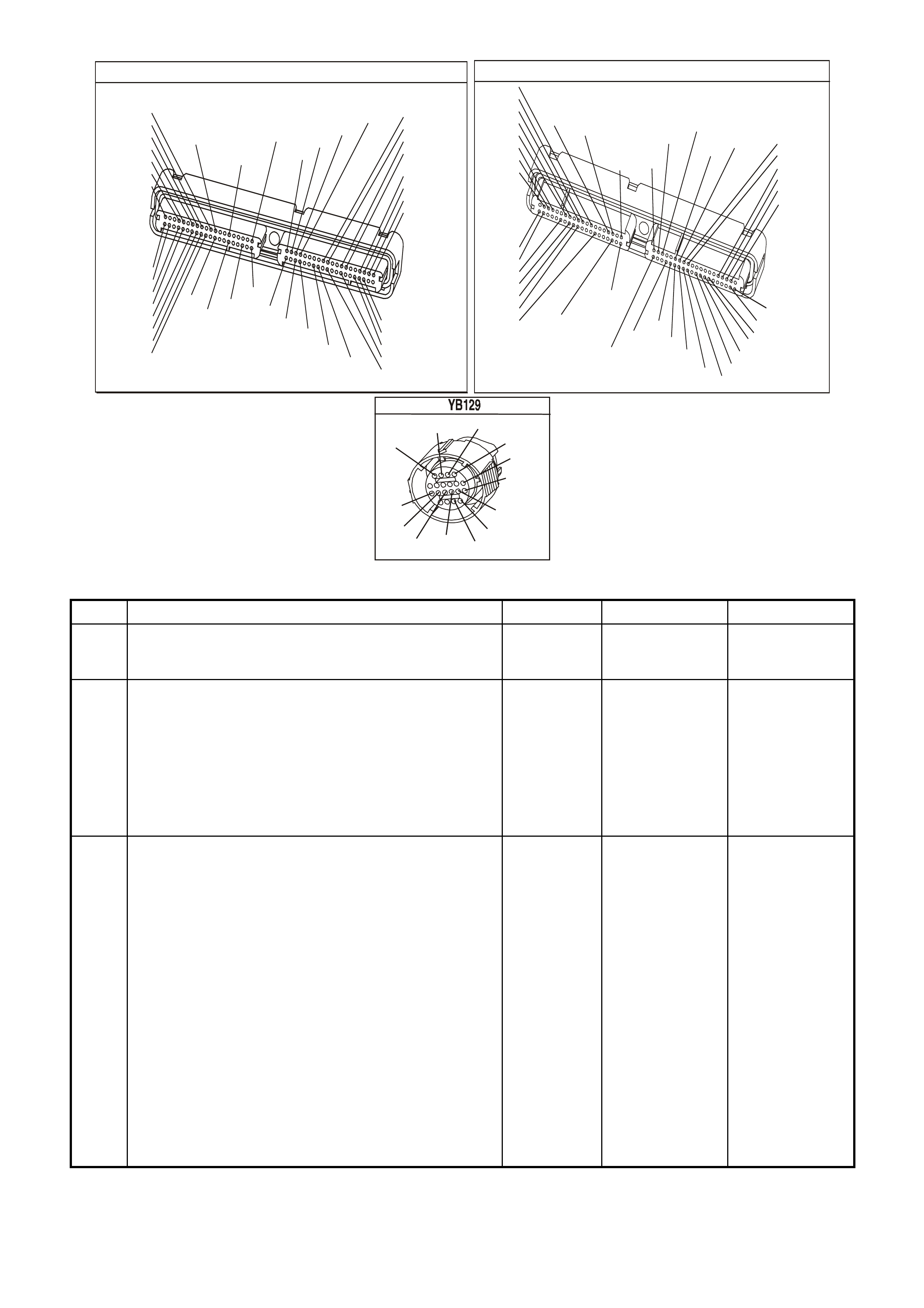
P.C.M CONNECTOR 1
YE122
(776)
(1049)
(897)
(1230)
(848)
(1226)
(772)
(647)
(632)
40
(844)
(815)
80
J1
P/B
(845)
V/W
BLU
O
(633)
(846)
B/Y
B/R
(416)
(86)
(69)
(455)
(740)
GY
BR
G
GY
(646)
(410)
GY
(842)
(1225)
V
Y
(750)
P
41
O
(774)
BR/Y
BLU
Y
B/R
B
BLU/Y
(841)
BLUE
(414)
G/W
BLU
LG
LBLU/B
1
(847)
(415)
(740)
(452)
BLU
BR
Y
(750)
(826)
(421)
Y
V/W
B/W
(334)
(771)
(39)
Y
R/W
LBLU
W
BLU/W
(843)
(643)
LBLU/W
G
GY/B
BLU/B
(413)
(1413)
(1412)
(412)
GY
V
GY/B
G
(335)
YE123
P.C.M CONNECTOR 2
(750)
(1228)
(1229)
(465)
(121)
(259)
G/B
BR
G/W
GY/BLU
R
B/R
(418)
BR
(59)
(832)
G
T
(831)
(417)
(472)
(976)(974)
(432)
(428)
(631)
BLUBR G/Y
BLU/W
LG
BR/W
W/B
LG W
(977)
Y
(971)
BLU/WW
B/R
(750)
(304)
(792)
(1223)
(1222)
(123)
(1227)
(469)
(331)
Y/B
LG
V/W
B/Y
G/OBR/W
(1687)
GY/B
(366)
LG/B
GY/R
(422)
V
(442)
(444)
(443)
(975)
(972)
(978)
(1224)
(973)
(959)
LG/W
LG/B
LBLU/B
GY
(773)
BR/Y
BLU
G
Y/B
LBLU
(958)
BR
(441)
LBLU
1
41
40
80
J2
RED
Y
(838)
TRANSMISSION CONNECTOR
GY/BLU
(1229)
R
(1228)
Y/B
(1223)
LG
(1222)
P/BLU
(339)
(1227)
B/Y
(1230)
B/W
GY/R
(422)
BR
(418)
BR/Y
(1224)
(1226)
GY
Y
(1225)
(897)
G/W
(V8)
B
(469) (V6)
OR
GEN III V8 PCM - DTC P1810 TFP VALVE POSITION SWITCH CIRCUIT
Step Action Value(s) Yes No
1 Was the Powertrain On-Board Diagnostic (OBD) System
Check performed? Go to Step 2 Go to Powertrain
OBD System
Check Table.
2 Perform the following inspections:
• Ensure that the transmission linkage from the select
lever to the manual valve is adjusted correctly. Refer
to Selector Linkage Adjustment in Section 7C4 in VX
Service Information.
• Perform the fluid checking procedure, refer Section
7C4, in VX Service Information.
Did you perform the inspections?
Go to Step 3
3 1. Install the Tech 2 Scan Tool.
2. With the engine OFF, turn the ignition switch to the
RUN position.
IMPORTANT: Before clearing the DTC, use the Scan
Tool in order to record the Freeze Frame and Failure
Records. Using the Clear Info function erases the Freeze
Frame and Failure Records from the PCM.
3. Record the DTC Freeze Frame and Failure Records.
4. Clear the DTC.
5. While the engine is idling at normal operating
temperature, apply the brake pedal.
6. Select each transmission range: P, R, N, D, 3, 2 and
1.
Refer to Section 6C3-4 TFP Manual Valve Position
Switch Logic table of the VX Series Service Information.
Does each selected transmission range match the Scan
Tool TFP Switch A/B/C display?
Go to
Diagnostic Aids Go to Step 4

GEN III V8 PCM - DTC P1810 TFP VALVE POSITION SWITCH CIRCUIT (CONTINUED)
Step Action Value(s) Yes No
4 1. Turn the ignition OFF.
2. Disconnect the transmission 20-way connector
(additional DTCs may set).
3. Install the J 39775 jumper harness on the engine side
of the 20-way connector.
4. With the engine OFF, turn the ignition switch to the
RUN position.
5. Using the J 39200 digital multimeter (DMM) and the
J 35616 connector test adapter kit, check the voltage
at connector terminals N, R and P.
Is B+ displayed on all three circuits?
Go to Step 6 Go to Step 5
5 Inspect the circuits that did not indicate B+ for an open or
short to earth condition.
Refer to Test Procedures in Section 8, in VX Service
Information.
Did you find an open or short to earth condition?
Go to Step 8 Go to Step 7
6 In order to verify that circuit 1224 (BR/Y), circuit 1225 (Y)
and circuit 1226 (GY) are not shorted together, use a
fused jumper wire to earth on each circuit while
monitoring the Scan Tool TFP Switch A/B/C display.
When a range signal circuit is earthed, are any other
range signal circuits affected?
Go to Step 8 Go to TFP
Manual Valve
Position Switch
Resistance
Check in Section
6C3-2C of the VX
Series Service
Information
7 Replace the PCM.
Refer to Powertrain Control Module in Section 6C3-3, of
the VX Series Service Information.
Is the replacement complete?
Go to Step 9
8 Repair the affected wiring as necessary.
Refer to Wiring Repair Procedures in Section 8, in VX
Service Information.
Is the repair complete?
Go to Step 9
9 Perform the following procedure in order to verify the
repair:
1. Select DTC.
2. Select Clear Info.
3. Operate the vehicle under the following conditions:
- W ith the engine OFF, turn the ignition switch to the
RUN position for at least 2 seconds.
- Start the vehicle and idle for 5 seconds.
- Drive in D until the TCC locks for 10 seconds.
- Run the engine for at least 60 seconds from start
up.
Were the above conditions verified?
System OK Go to Step 1

GEN III V8 PCM
DTC P1860 TCC PWM SOLENOID CIRCUIT
CIRCUIT DESCRIPTION
The Torque Converter Clutch Pulse W idth Modulation (TCC PWM) solenoid valve controls the fluid acting on the
converter c lutch valve. The converter clutch valve controls the T CC application and release. T he s olenoid attac hes
to the control valve body within the transmission. The solenoid receives ignition voltage through circuit 339. The
powertrain control module (PCM) controls the solenoid by providing an earth path on circuit 418.
Current flows through the solenoid coil according to the duty cycle (percentage of ON and OFF time). The TCC
PWM solenoid valve provides a smooth engagement of the Torque Converter Clutch by operating during a duty
cycle percent of ON time.
When the PCM detects a continuous open or short to earth in the TCC PWM solenoid valve circuit or the TCC
PWM solenoid valve, then DTC P1860 sets.
CONDITIONS FOR RUNNING THE DTC
• The system voltage is between 8.0 and 18 volts.
• The engine speed is greater than 300 RPM for 5 seconds.
• The engine is not in fuel cutoff.
• The PCM commands 1st gear.
• The TCC duty cycle is less than 10% or greater than 90%.
CONDITIONS FOR SETTING THE DTC
• The PCM commands the solenoid ON and the voltage input remains high (12 volts).
Or
• The PCM commands the solenoid OFF and the voltage input remains low (0 volts).
4356
PCM
J2-47
J2-48
J1-79
J2-42
J2-04
J2-08
J2-06
TCC PWM
SOLENOID
3-2 CONTROL
SOLENOID
1-2 SHIFT
SOLENOID A
2-3 SHIFT
SOLENOID B
PRESSURE
CONTROL
SOLENOID
LOW
PRESSURE CONTROL
SOLENOID HIGH
B
A
A
B
B
B
A
A
B
A
YB 129 T RANSMIS SION
PASS-THRU CONNECTOR
TORQUE
CONVERTER
CLUTCH (TCC)
(PWM)
SOLENOID
TORQUE
CONVERTER
CLUTCH (TCC)
ENABLE
SOLENOID
3-2 DOWNSHIFT
CONTROL
SOLENOID
1-2 SHIFT
SOLENOID A
2-3 SHIFT
SOLENOID B
PRESSURE
CONTROL
SOLENOID
C
D
U
S
T
E
A
B
P/BLU (339)
TCC ENABLE
SOLENOID
B
A
EFI
RELAY
F32
G/W (897)
YE122
YE123
LG (1222)
Y/B (1223)
GY/BLU (1229)
R (1228)
12V
M
I
C
R
O
P
R
O
C
E
S
S
O
R
BR (418)
GY/R (422)
YE110
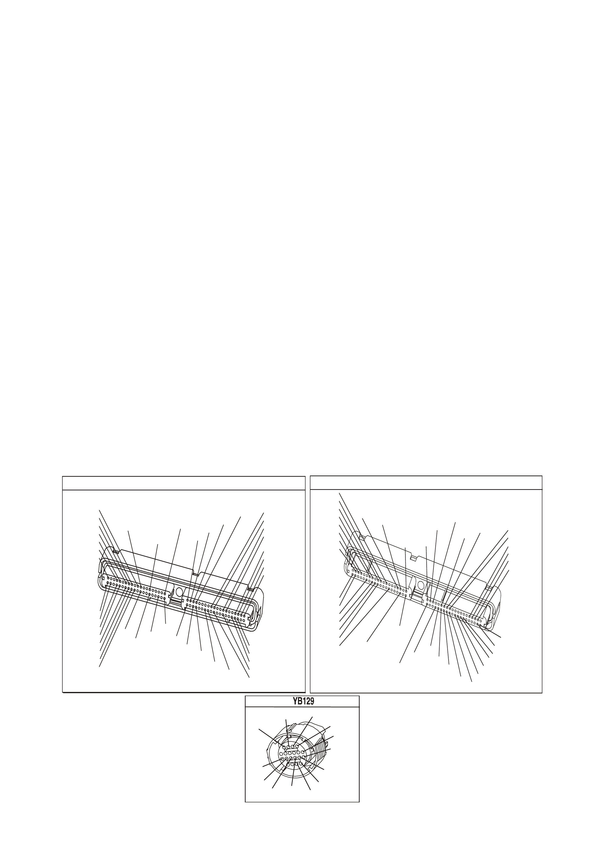
ACTION TAKEN WHEN THE DTC SETS
• The PCM illuminates the Check Powertrain Lamp when the diagnostic runs and fails.
• The PCM inhibits TCC engagement.
• The PCM inhibit 4th gear if the transmission is in hot mode.
• The PCM freezes shift adapts from being updated.
• The PCM records the operating conditions at the time the diagnostic fails. The PCM stores this information in
the Freeze Frame/Failure Records.
CONDITIONS FOR CLEARING THE CPL/DTC
• The PCM turns the Check Powertrain Lamp OFF during the first ignition cycle that the diagnostic runs and
does not fail.
• A last test failed (current DTC) clears when the diagnostic runs and does not fail.
DIAGNOSTIC AIDS
• Inspect the wiring at the PCM, the transmission connector and all other circuit connecting points for the
following conditions:
- A backed out terminal
- A damaged terminal
- Reduced terminal tension
- A chafed wire
- A broken wire inside the insulation
- Moisture intrusion
- Corrosion
• When diagnosing for an intermittent short or open condition, massage the wiring harness while watching the
test equipment for a change.
TEST DESCRIPTION
The numbers below refer to the step numbers on the diagnostic table.
4. This step tests for voltage to the solenoid.
6. This step tests the ability of the PCM and wiring to control the earth circuit.
8. This step tests the resistance of the TCC PWM solenoid valve and the automatic transmission (A/T) wiring
harness assembly.
P.C.M CONNE CTOR 1
YE122
(776)
(1049)
(897)
(1230)
(848)
(1226)
(772)
(647)
(632)
40
(844)
(815)
80
J1
P/B
(845)
V/W
BLU
O
(633)
(846)
B/Y
B/R
(416)
(86)
(69)
(455)
(740)
GY
BR
G
GY
(646)
(410)
GY
(842)
(1225)
V
Y
(750)
P
41
O
(774)
BR/Y
BLU
Y
B/R
B
BLU/Y
(841)
BLUE
(414)
G/W
BLU
LG
LBLU/B
1
(847)
(415)
(740)
(452)
BLU
BR Y
(750)
(826)
(421)
Y
V/W
B/W
(334)
(771)
(39)
Y
R/W
LBLU
W
BLU/W
(843)
(643)
LBLU/W
G
GY/B
BLU/B
(413)
(1413)
(1412)
(412)
GY
V
GY/B
G
(335)
YE123
P.C.M CONNECTOR 2
(750)
(1228)
(1229)
(465)
(121)
(259)
G/B
BR
G/W
GY/BLU
R
B/R
(418)
BR
(59)
(832)
G
T
(831)
(417)
(472)
(976) (974)
(432)
(428)
(631)
BLU BR G/Y
BLU/W
LG
BR/W
W/B
LG W
(977)
Y
(971)
BLU/W W
B/R
(750)
(304)
(792)
(1223)
(1222)
(123)
(1227)
(469)
(331)
Y/B
LG
V/W
B/Y
G/O BR/W
(1687)
GY/B
(366)
LG/B
GY/R
(422)
V
(442)
(444)
(443)
(975)
(972)
(978)
(1224)
(973)
(959)
LG/W
LG/B
LBLU/B
GY
(773)
BR/Y
BLU
G
Y/B
LBLU
(958)
BR
(441)
LBLU
1
41
40
80
J2
RED
Y
(838)
TRANSMISSION CONNECTOR
GY/BLU
(1229)
R
(1228)
Y/B
(1223)
LG
(1222)
P/BLU
(339)
(1227)
B/Y
(1230)
B/W
GY/R
(422)
BR
(418)
BR/Y
(1224)
(1226)
GY
Y
(1225)
(897)
G/W
(V8)
B
(469) (V6)
OR

GEN III V8 PCM - DTC P1860 TCC PWM SOLENOID CIRCUIT
Step Action Value(s) Yes No
1 Was the Powertrain On-Board Diagnostic (OBD) System
Check performed? Go to Step 2 Go to Powertrain
OBD System
Check Table.
2 1. Install the Tech 2 Scan Tool.
2. With the engine OFF, turn the ignition switch to the
RUN position.
IMPORTANT: Before clearing the DTC, use the Scan
Tool in order to record the Freeze Frame and Failure
Records. Using the Clear Info function erases the Freeze
Frame and Failure Records from the PCM.
3. Record the DTC Freeze Frame and Failure Records.
4. Clear the DTC.
Are any of the following DTCs also set?
• P0740
• P0753
• P0758
• P0785
Go to Step 3 Go to Step 4
3 1. Inspect fuse F32.
2. If the fuse is open, inspect the following components
for a short to earth condition:
- Circuit 339 (P/BLU)
- The solenoids
- The A/T wiring harness assembly
3. Repair the circuit, the solenoids, and the harness if
necessary.
Did you find a short to earth condition?
Go to Step 15 Go to Step 4
4 1. Turn the ignition OFF.
2. Disconnect the transmission 20-way connector
(additional DTCs may set).
3. Install J 39775 jumper harness on the engine side of
the 20-way connector.
4. With the engine OFF, turn the ignition switch to the
RUN position.
5. Connect a lest lamp from J 39775 jumper harness
cavity E to earth.
Is the test lamp on?
Go to Step 6 Go to Step 5
5 IMPORTANT: The condition that affects this circuit may
exist in other connecting branches of the circuit. Refer to
Power Distribution Diagrams in Section 14E, in VX
Service Information.
Repair the open or short to earth in ignition feed circuit
339 (P/BLU) to the TCC PWM solenoid valve.
Is the repair complete?
Go to Step 15
6 1. Install the test lamp from cavity E to cavity U of the
J 39775 jumper harness.
2. Using the transmission Miscellaneous Tests function
on the Scan Tool, command the TCC PWM solenoid
valve ON and OFF three times.
Does the test lamp turn ON when the TCC PWM solenoid
valve is commanded ON, and OFF when commanded
OFF?
Go to Step 8 Go to Step 7
7 1. Inspect circuit 418 (BR) of the powertrain wiring
harness for an open, short to earth or short to power
condition.
2. Repair the circuit if necessary.
Did you find an open, short to earth or short to power
condition?
Go to Step 15 Go to Step 9

GEN III V8 PCM - DTC P1860 TCC PWM SOLENOID CIRCUIT (CONTINUED)
Step Action Value(s) Yes No
8 1. Install J 39775 jumper harness on the transmission
side of the 20-way (YB 129) connector.
2. Using the J 39200 digital multimeter (DMM) and the
J 35616 connector test adapter kit, measure the
resistance between terminals E and U.
Is the resistance within the specified range?
10-15 Ω Go to Step 11 Go to Step 10
9 Replace the PCM.
Refer to Section 6C3-3 Powertrain Control Module
Replacement, of the VX Series Service Information.
Is the replacement complete?
Go to Step 15
10 1. Disconnect the A/T wiring harness assembly at the
TCC PWM solenoid valve.
2. Measure the resistance of the TCC PWM solenoid
valve.
Is the resistance within the specified range?
10-15 Ω Go to Step 13 Go to Step 14
11 Measure the resistance between terminal E and earth,
and between terminal U and earth.
Are both readings greater than the specified value?
250 K Ω Go to
Diagnostic Aids Go to Step 12
12 1. Disconnect the A/T wiring harness assembly at the
TCC PWM solenoid valve.
2. Measure the resistance between each of the
component terminals and earth.
Are both readings greater than the specified value?
250 K Ω Go to Step 13 Go to Step 14
13 Replace the automatic transmission wiring harness
assembly.
Refer to Control Valve Body and Wiring Harness
replacement in Section 7C4, in VX Service Information.
Is the replacement complete?
Go to Step 15
14 Replace the TCC PWM solenoid valve.
Refer to TCC PWM Solenoid Valve Replacement in
Section 7C4 in VX Service Information.
Is the replacement complete?
Go to Step 15
15 • Perform the following procedure in order to verify the
repair:
1. Select DTC.
2. Select Clear Info.
3. Drive the vehicle in D with the TCC ON. Ensure
the following conditions are met:
- The PCM commands the TCC PWM solenoid
valve ON, and the voltage input drops to zero.
- The PCM commands the TCC PWM solenoid
valve OFF, and the voltage input increases to
B+.
- All conditions met for 5 seconds.
Were the above conditions verified?
System OK Go to Step 1
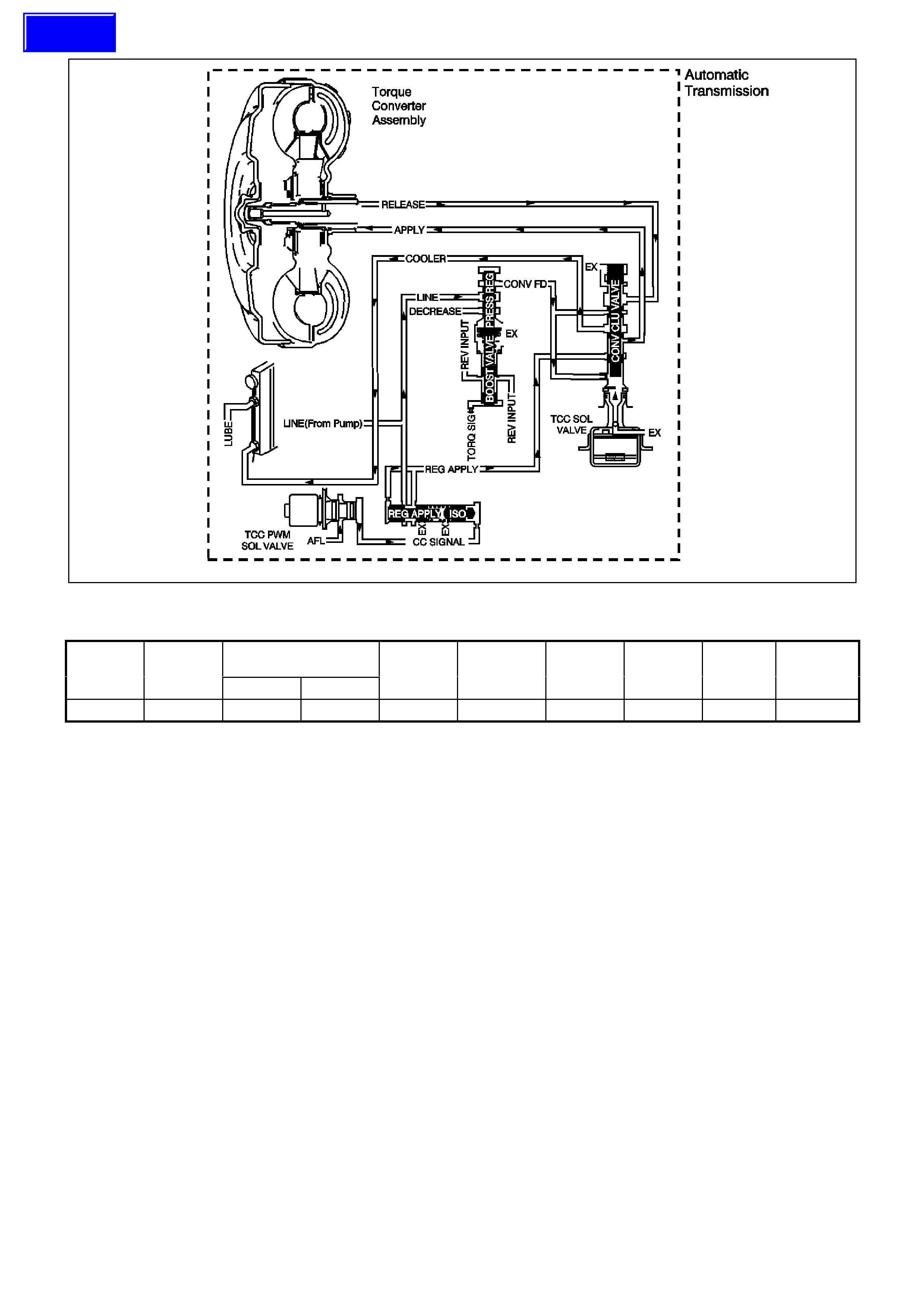
GEN III V8 PCM
DTC P1870 TRANSMISSION COMPONENT SLIPPING
Shift Solenoid TCC TCC PWM Forward 3-4 Torque
Converter
Range Gear 1-2 (A) 2-3 (B) Solenoid Solenoid 2-4 Band Clutch Clutch Clutch
Overdrive 4th ON OFF ON 90% (ON) Applied Applied Applied Applied
CIRCUIT DESCRIPTION
The Powertrain Control Module (PCM) monitors the difference between engine speed and transmission output
speed. In drive 3 range, with the TCC engaged, the engine speed should closely match the transmission output
speed. In D drive range, with the TCC engaged, the TCC slip speed should be -20 to +40 RPM. The table above
indicates solenoid states and transmission components that apply, during 4th gear, with the TCC commanded ON.
When the PCM detects excessive TCC slip when the TCC should be engaged, then DTC P1870 sets.
CONDITIONS FOR RUNNING THE DTC
• No Throttle Position DTCs P0122 or P0123.
• No VSS DTCs P0502, P0503.
• No TCC solenoid valve DRTC P0740.
• No 1-2 SS valve DTC P0753.
• No 2-3 SS valve DTC P0758.
• No 3-2 SS valve assembly DTC P0785.
• No TCC PWM solenoid valve DTC P1860.
• The engine speed is greater than 300 RPM for 5 seconds.
• The engine is not in fuel cutoff.
• The vehicle speed is 56-105 km/h.
• The speed ratio is 0.67-0.90 (the speed ratio is the engine speed divided by the transmission output speed).
• The engine speed is 1200-3500 RPM.
• The engine torque is 54-542 N.m
• The gear range is D4.
• The commanded gear is not 1st gear.
• The throttle position angle is 10-50%.
• The TFT is between 20-130°C.
• The shift solenoid performance diagnostic counters are zero.
Techline

CONDITIONS FOR SETTING THE DTC
DTC P1870 sets if the following conditions occur for three TCC cycles.
• The TCC is commanded ON for 5 seconds.
• The TCC is at maximum duty cycle for 1 second.
• The TCC slip speed is 80-8—RPM for 7 seconds.
IMPORTANT:
The following actions may occur before the DTC sets.
• If the TCC is commanded ON and at maximum duty cycle for 5 seconds, the Throttle Position angle is 10-40%,
and the transmission slip counter has incremented to either 1 or 2 (out of 3 to increment the fail counter for the
current ignition cycle), then the following slip conditions and actions may increment the fail counter for the
current ignition cycle:
These conditions must occur sequentially.
Condition 1
• If the TCC slip speed is 80-800 RPM for 7 seconds, then the PCM will command maximum line pressure and
freeze shift adapts from being updated.
Condition 2
• If condition 1 is met and the TCC slip speed is 80-800 RPM for 7 seconds, then the PCM will command the
TCC OFF for 1.5 seconds.
Condition 3
• If Condition 2 is met and the TCC slip speed is 80-8—RPM for 7 seconds, then the fail counter on the current
ignition cycle is incremented.
• The above slip conditions and actions may be disregarded if the TCC is commanded OFF at any time as a
result of a driving manoeuvre (sudden acceleration or deceleration).
ACTION TAKEN WHEN THE DTC SETS
• The PCM illuminates the Check Powertrain Lamp when the diagnostic runs and fails.
• The PCM inhibits TCC engagement.
• The PCM commands maximum line pressure.
• The PCM inhibits 4th gear if the transmission is in hot mode.
• The PCM freezes shift adapte from being updated.
• The PCM records the operating conditions at the time the diagnostic fails. The PCM stores this information in
the Freeze Frame/Failure Records.
CONDITIONS FOR CLEARING THE CPL/DTC
• The PCM turns the Check Powertrain Lamp OFF during the first ignition cycle that the diagnostic runs and
does not fail.
• A last test failed (current DTC) clears when the diagnostic runs and does not fail.
DIAGNOSTIC AIDS
• Internal transmission failures may set DTC P1870.
TEST DESCRIPTION
The number below refers to the step numbers on the diagnostic table.
3. This step tests the torque converter for slippage while in a commanded lock-up state.
GEN III V8 PCM - DTC P1870 TRANSMISSION COMPONENT SLIPPING
Step Action Value(s) Yes No
1 Was the Powertrain On-Board Diagnostic (OBD) System
Check performed? Go to Step 2 Go to Powertrain
OBD System
Check Table.
2 Perform the transmission fluid checking procedure. Refer
to Transmission Fluid Checking Procedure in Section
7C4, in VX Service Information.
Did you perform the fluid checking procedure?
Go to Step 3 Go to
Transmission
Fluid Checking
Procedure in
Section 7C4, in
VX Service
Information.

GEN III V8 PCM - DTC P1870 TRANSMISSION COMPONENT SLIPPING (CONTINUED)
Step Action Value(s) Yes No
3 1. Install the Scan Tool.
2. With the engine OFF, turn the ignition switch to the
RUN position.
IMPORTANT: Before clearing the DTC, use the Scan
Tool in order to record the Freeze Frame and Failure
Records. Using the Clear Info function erases the Freeze
Frame and Failure Records from the PCM.
3. Record the DTC Freeze Frame and Failure Records.
4. Clear the DTC.
5. Drive the vehicle in D with the TCC commanded ON.
Is the Scan Tool TCC Slip Speed between the specified
range for 7 seconds?
80-800 RPM Go to Step 4 Go to
Diagnostic Aids
4 1. Inspect the torque converter clutch (TCC) solenoid
valve for the following conditions:
- Internal malfunction (such as sediment or damage)
- Damaged seals
2. Inspect the torque converter clutch pulse width
modulation (TCC PW M) solenoid valve for the
following conditions:
- Internal malfunction (such as sediment or damage)
- Damaged seals
Did you find a condition?
Go to Step 13 Go to Step 5
5 1. Inspect the 1-2 shift solenoid (A) valve for the
following conditions:
- Internal malfunction (such as sediment or damage)
- Damaged seals
2. Refer to Shift Solenoid Leak Test in Section 7C4, in
VX Service Information.
3. Inspect the 2-3 shift solenoid (B) valve for the
following conditions:
- Internal malfunction (such as sediment or damage)
- Damaged seals
Refer to Shift Solenoid Leak Test in Section 7C4, in VX
Service Information.
Did you find a condition?
Go to Step13 Go to Step 6
6 Inspect the valve body assembly for a stuck regulator
apply valve.
Refer to Unit Repair in Section 7C5, in VX Service
Information.
Did you find a condition?
Go to Step 13 Go to Step 7
7 Inspect the torque converter assembly for the following
conditions:
• Stator roller clutch not holding
• Internal damage
Did you find a condition?
Go to Step 13 Go to Step 8

GEN III V8 PCM - DTC P1870 TRANSMISSION COMPONENT SLIPPING (CONTINUED)
Step Action Value(s) Yes No
8 Inspect the oil pump assembly for the following
conditions:
• Stuck converter clutch valve
• Converter clutch valve assembled backwards
• Incorrectly positioned converter clutch valve retaining
ring
• Incorrectly positioned pump to case gasket
• Restricted orifice cup plugs
• Damaged orifice cup plugs
• Over-tightened, or unevenly tightened pump body to
cover bolts
Refer to Section 7C5 Unit Repair, in VX Service
Information.
Did you find a condition?
Go to Step 13 Go to Step 9
9 Inspect the input housing and shaft assembly for the
following conditions:
• Cut turbine shaft o-ring seal
• Damaged turbine shaft o-ring seal
• Restricted turbine shaft retainer and ball assembly
• Damaged turbine shaft retainer and ball assembly
Refer to Section 7C5 Unit Repair in VX Service
Information.
Did you find a condition?
Go to Step 13 Go to Step 10
10 Inspect the 2-4 band assembly for the following
conditions:
• Worn 2-4 band
• Damaged 2-4 band
• Incorrectly positioned 2-4 band
• Incorrectly assembled 2-4 band
• The band anchor pin is not engaged.
• Restricted apply passages in the 2-4 servo assembly
• Blocked apply passages in the 2-4 servo assembly
• Nicks or burrs on the servo pin
• Nicks or burrs on the pin bore in the case
• Damaged fourth servo piston
• Incorrectly assembled fourth servo piston
• Damaged band apply pin
• Incorrect band apply pin
• Damaged servo bore in the case
• Missing piston seals
• Cut piston seals
• Damaged piston seals
• Porosity in the pistons
• Porosity in the cover
• Porosity in the case
• Damaged piston seal grooves
• Plugged orifice cup plug
• Missing orifice cup plug
Refer to Section 7C5 Unit Repair, in VX Service
Information.
Did you find a condition?
Go to Step 13 Go to Step 11

GEN III V8 PCM - DTC P1870 TRANSMISSION COMPONENT SLIPPING (CONTINUED)
Step Action Value(s) Yes No
11 Inspect the forward clutch assembly for the following
conditions:
• Worn clutch plates
• Porosity in the forward clutch piston
• Damaged forward clutch piston
• Missing forward clutch piston inner and outer seals
• Cut forward clutch piston inner and outer seals
• Damaged forward clutch piston inner and outer seals
• Missing input housing to forward clutch housing O-
ring seal
• Cut input housing to forward clutch housing O-ring
seal
• Damaged input housing to forward clutch housing O-
ring seal
• Damaged forward clutch housing
• Damaged forward clutch housing retainer and ball
assembly
• Forward clutch housing retainer and ball assembly is
not sealing.
Refer to Section 7C5 Unit Repair, in VX Service
Information.
Did you find a condition?
Go to Step 13 Go to Step 12
12 Inspect the 3-4 clutch assembly for the following
conditions:
• Worn clutch plates
• Porosity in the 3-4 clutch piston
• Damaged 3-4 clutch piston
• Missing 3-4 clutch inner and outer seals
• Cut 3-4 clutch inner and outer seals
• Damaged 3-4 clutch inner and outer seals
• Damaged 3-4 clutch spring assembly
• Damaged 3-4 clutch apply ring
• Damaged piston seal grooves
• Plugged orifice cup plug
• Missing orifice cup plug
Refer to Section 7C5 Unit Repair, in VX Service
Information.
Did you find a condition?
Go to Step 13 Go to Diagnostic
Aids
13 Perform the following procedure in order to verify the
repair:
1. Select DTC.
2. Select Clear Info.
3. Operate the vehicle under the following conditions:
- Drive the vehicle in D, with the TCC ON, and a
throttle position of 10-50%.
- Ensure that the Scan Tool TCC Slip Speed is -20 to
+40 RPM for at least 7 seconds.
Were the above conditions verified?
System OK Go to Step 1
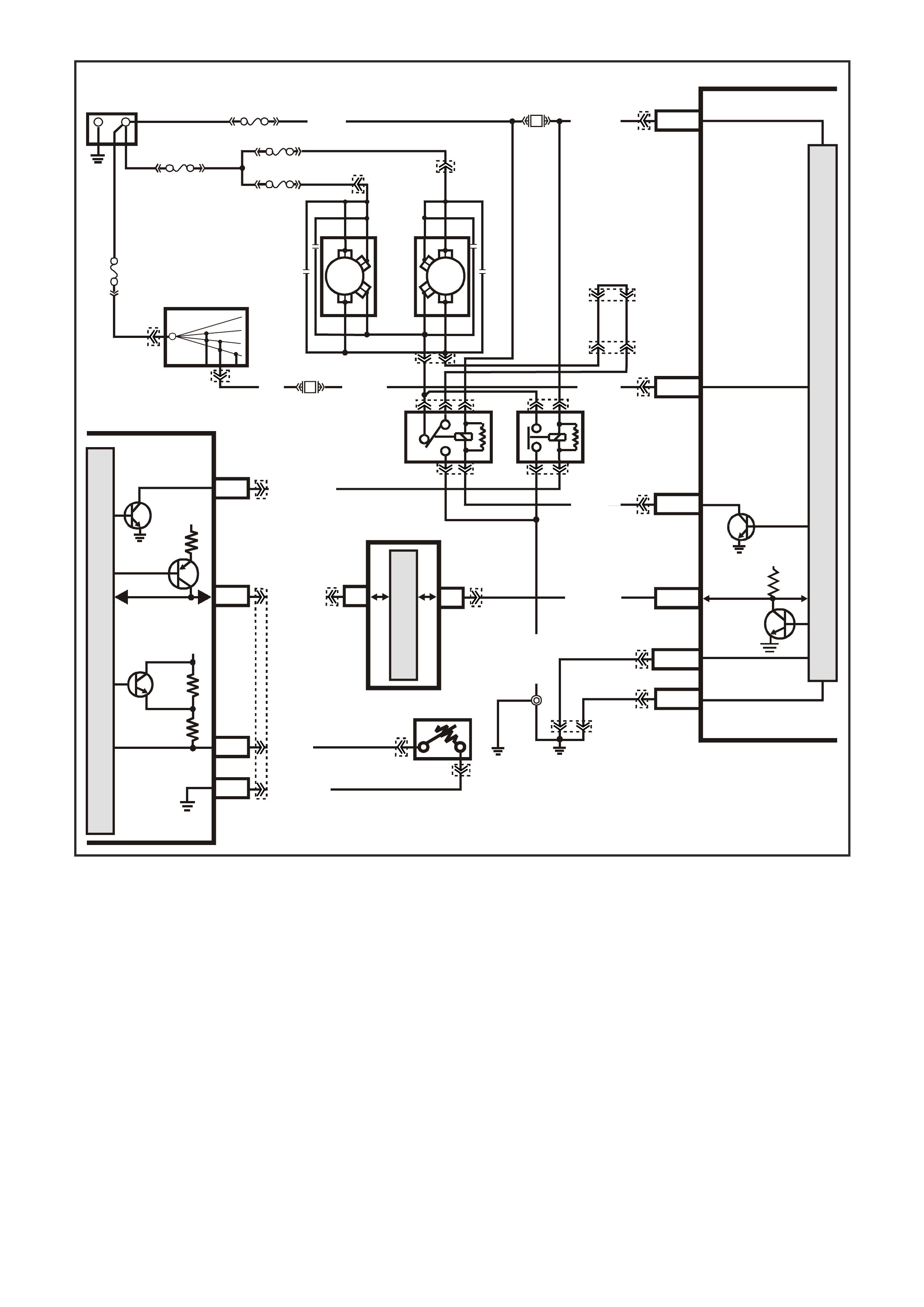
GEN III V8 PIM -
DTC B2002 LOW SPEED FAN NO BCM RESPONSE
CIRCUIT DESCRIPTION
The PCM determines operation of the two speed engine cooling fans based on A/C request, engine coolant
temperature, A/C pressure sensor, and vehicle speed.
The engine cooling f an Low Speed Relay is ener gised by the BCM. W hen the PCM deter mines that the low speed
fan relay should be enabled, the PCM will send a message on the Class II serial data circuit to the PIM. The PIM
will inturn convert the PCM Class II message to a UART message and supply this UART message to the BCM.
This PCM message will request the BCM to supply the needed earth signal for the Low Speed Relay to operate.
After the BCM provides the earth signal for the Low Speed Relay, the BCM will send a message back to the PIM
confir ming that the earth signal was com manded. T he PIM will convert this m essage from the BCM to Class II and
supply to the PCM.
CONDITIONS FOR RUNNING THE DTC
• The ignition is on.
CONDITIONS FOR SETTING THE DTC
• The PIM sends a Low Speed request signals to the BCM , with no response back from the BCM.
R/B (1221) E2/D2
IGNITION
LOW
SPEED FAN
M
I
C
R
O
P
R
O
C
E
S
S
O
R
BATT ERY MAIN POWER
HIGH SERIES
BCM TERMINALS
NOMINATED FIRST
BCM
15a 15 50
30 OFF/ON
LOCK
ACC
IGN
START
4359
E20/D6
B7/B7
P (3)
IGNITION SWITCH
O/B (473)
87A
30
87
85
86
87
30
85
86
ENGINE
COOLING
FAN 1
ENGINE
COOLING
FAN RELAY
(LOW SPEED)
ENGINE
COOLING
FAN RELAY
(HIGH SPEED)
P/B (39)
B/Y
(533)
O/Y
(250)
F14
R
YB
G
BLU/W (304)
R/B (1049)
HIGH
CURRENT EARTH
B/Y
(155) A1/A5 ELECTRONIC EARTH
B/G
(151)
LOC.
E2 LOC.
E3
B10/B11
B/R (157)
J1-58
GEN III PCM
PIM
J2-33
HIGH
SPEED FAN
BLUE
FUSIBLE
LINK
LOC.
E1
F31
A5/A6
O/B (740)
ENGINE
COOLING
FAN 2
+-
BATTERY
FS
FT FAN 2
FU FAN 1
(1040)
R
(203)
R
(001)
R
(001)
O/B
(208)
O/BLU
(204)
FJ
R
(001)
R
(2H)
6
7
M
I
C
R
O
CLASS 2 SERIAL DATA
UART SERIAL DATA
7V
CLASS 2
SERIAL DA TA
SERIAL
DATA
5V
GY /B (455)
J1-74 Y (41O)
COOLANT TEMP
SENSOR
ETC SENSOR
SIGNAL
5V
4k
348
Ω
Ω
J1-80
SENSOR
EARTH
M
I
C
R
O
P/B (39)
YE140
YE139
YB44
YB44
YE139
YE103
YE103 YE43
YE43
YE104
YB176
YB165
YB163
YB163
YB174
YB174
YB176
YB165
YE114
YE65
YB215YB215
YE65
YE122
YE123
YE118
YB176
YB165
YE140

ACTION TAKEN WHEN THE DTC SETS
• The PIM will display the DTC only when current.
• The Check Powertrain Lamp (CPL) will not illuminate.
CONDITIONS FOR CLEARING THE DTC
• A current DTC will clear when the PIM receives a Low Speed Fan Response from the BCM.
DIAGNOSTIC AIDS
• For an intermittent, refer to Section 6C3-2B Symptoms, of the VX Series Service Information.
TEST DESCRIPTION
The numbers below refer to the step numbers on the diagnostic table.
2. The test is determining if any BCM DTCs may be set. There may be a BCM DTC that is related to this circuit,
and diagnosing this BCM DTC first may resolve the fault.
3. An open or short to earth on the UART serial data circuit will disable any communication between the PIM and
BCM.
GEN III V8 PIM - DTC B2002 LOW SPEED FAN NO BCM RESPONSE
Step Action Value(s) Yes No
1 Did you perform the Powertrain On-Board Diagnostic
(OBD) System Check? Go to Step 2 Go to Powertrain
OBD System
Check Table
2 Are any BCM DTCs set? Go to appropriate
BCM DTC
Refer to
Section 12J-1
Low Series BCM
or
Section 12J-2
High Series BCM
in VX Service
Information.
Go to Step 3
3 1. Engine at idle speed.
2. Using a Tech 2 scan tool, select LOW FAN.
Does the Tech 2 scan tool BCM Response display
change from FAN OFF to FAN ON when the test is
enabled?
Go to Step 4 Go to
Functional Check
table for Electric
Fan Control for
further diagnosis
of the cooling fan
circuits
4 Does Tech 2 scan tool BCM Response display change
from FAN OFF to FAN ON when test is enabled? DTC B2002 is
intermittent.
Refer to
Diagnostic Aids
Refer to
Section 12J-1
Low Series BCM
or
Section 12J-2
High Series BCM
in VX Service
Information.
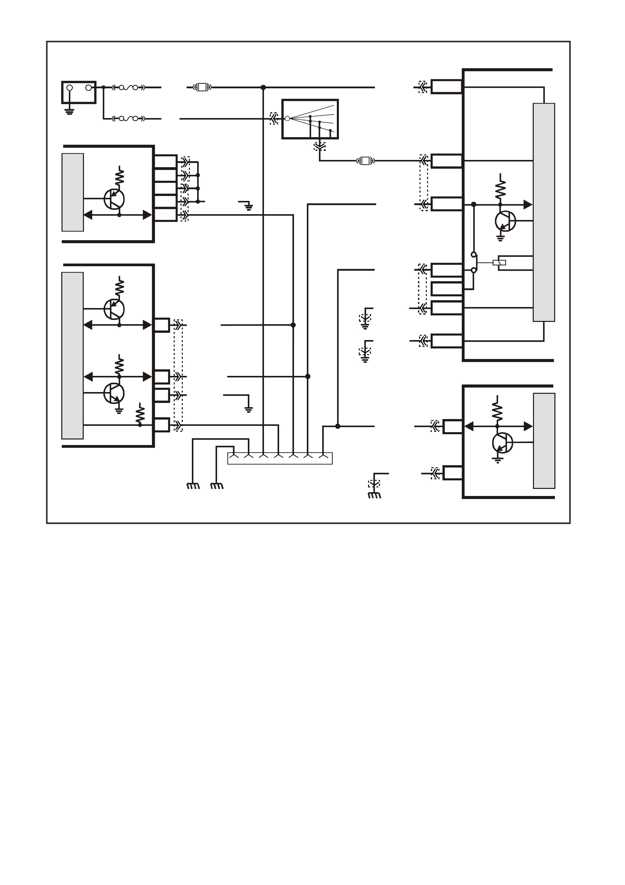
GEN III V8 PIM -
DTC B2006 NO SERIAL DATA FROM PCM
CIRCUIT DESCRIPTION
The PIM receives inform ation from the PCM on the Class II serial data circuit. If there is a problem with this c ircuit
or the PCM is not com municating, the PIM will detect this lack of information and will set a DTC. Also, if there is a
problem with the serial data circuit, performing the Powertrain OBD System Check will lead you to the Data Link
Connector Diagnosis, where the problem for which set this DTC will be diagnosed.
CONDITIONS FOR RUNNING THE DTC
• The ignition switch is on.
• The ignition voltage is between 5.0 and 17 volts.
CONDITIONS FOR SETTING THE DTC
• PIM does not receive any serial data communication from the PCM.
ACTION TAKEN WHEN THE DTC SETS
• The PIM will display the DTC only when current.
• The Check Powertrain Lamp (CPL) will not illuminate.
CONDITIONS FOR CLEARING THE DTC
• A current DTC will clear when the PIM receives serial data from the PCM.
G3PCM023PT
B/Y
(155)
B
(150)
LOC. E3
YB128
642516 9 1
ECC
BCM
DATA LINK
CONNECTOR
16
6SERIAL
DATA
5V
M
I
C
R
O
P
R
O
C
E
S
S
O
R
+
-
BATTERY
FS
F31
A5/A6
O/B (740)
(1040)
BATTERY M AIN P OWER
FJ
R (2)
F14
E20/D6
P/B
(39) IGNITION ON
15a 15 50
30 OFF/ON
LOCK
ACC
IGN
START
IGNITION SWITCH
P
(3)
B/Y (155 )
B/G (151)
LOC. E3
LOC. E3
R/B (1221)
G/W (1220)
G/W (1220)
2
B/R ( 750)
Y (1049)
R/B (1221)
PIM
SERIAL
DATA
7V
7V
12V
ELECTRONIC EARTH
HIGH CURRENT
EARTH
A1/A5
B10/B11
E2/D2
E9/D3
E3/D13
SERIAL
DATA
MAIN
SERIAL
DATA AUX.
5V
5V
6
11
7
DI AG. ENABL E
CLASS 2
SERIAL DA TA
LOC. E5/E15
LOC. E5/E15
GEN III V8 PCM
J1-58
J2-01
J2-40
J1-40
J1-01
M
I
C
R
O
CLASS 2
SERIAL DA TA
B/R ( 750)
M
I
C
R
O
B/Y (155 )
M
I
C
R
O
HIGH SERIES
BCM TERMINALS
NOMINATED FIRS T
YB44
YB44
YB176
YB175
YB164
YB163
YB174
YB165
YB89
YB87
YE114
YE114
YE114
YB215
YE122
YE123
YB176
YB165

DIAGNOSTIC AIDS
• The following problems may cause this DTC to set:
- Poor connections/terminal tension at the PCM
- Poor connections/terminal tension at the PIM
• For an intermittent, refer to Section 6C3-2B Symptoms, of the VX Series Service Information.
TEST DESCRIPTION
The numbers below refer to the step numbers on the diagnostic table.
1. The test confirms that the Powertrain OBD System Check has been performed
2. Diagnosis of this DTC will be perform ed using the Data Link Connector Diagnostic Table, found in the front of
this s ection. If there is an open, short to earth, or short to voltage in the Clas s II serial data circuit between the
PCM and the PIM, this will cause PIM DTC B2006 to set.
GEN III V8 PIM - DTC B2006 NO SERIAL DATA FROM PCM
Step Action Value(s) Yes No
1 Did you perform the Powertrain On-Board Diagnostic
(OBD) System Check? Go to Step 2 Go to Powertrain
OBD System
Check Table
2 Refer to Data Link Connector Diagnosis in the front of the
VX Series Service Information for diagnosis of this PIM
DTC.
Is action complete?
Verify Repair
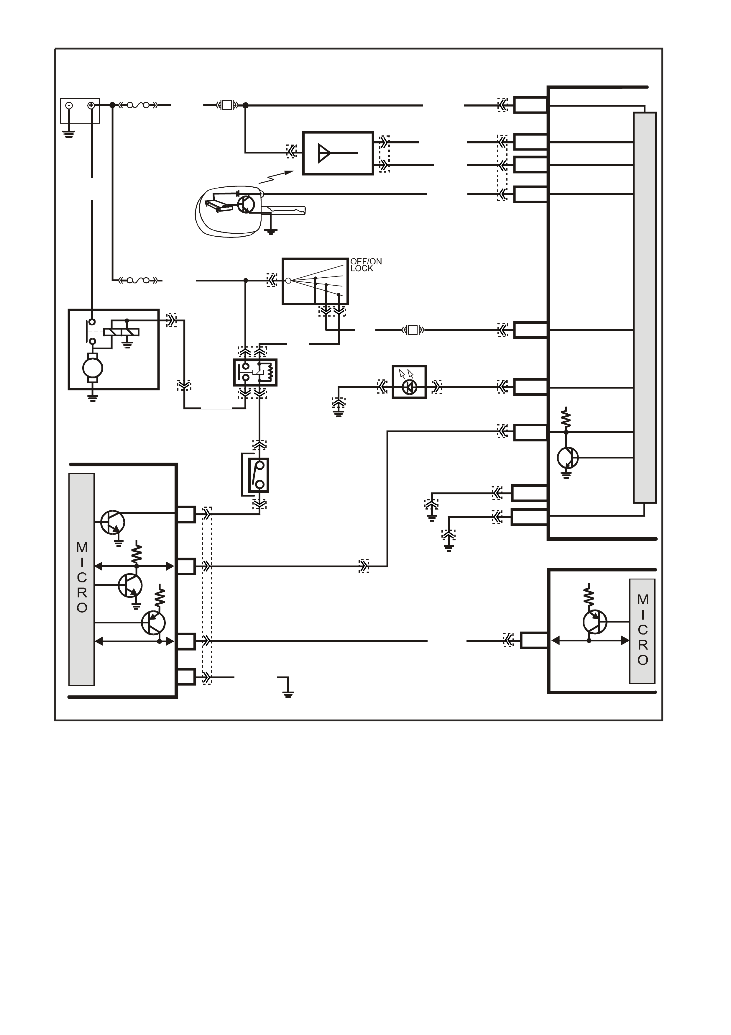
GEN III V8 PIM -
DTC B2007 STARTER RELAY VOLTAGE HIGH
CIRCUIT DESCRIPTION
When the key is turned to the crank position, power is supplied to the starter relay terminal 85. The PIM after
receiving the proper theft deterrent signal from the BCM will supply an earth signal the starter relay terminal 86.
This will energise the star ter relay and allow the starter m otor to operate. If there is a problem with the starter r elay
coil (shorted internally) or the starter relay control circuit (shorted to voltage) that is allowing 12 volts on the starter
relay control circuit, this will cause the PIM to set DTC B2007.
CONDITIONS FOR RUNNING THE DTC
• The ignition switch is in the crank position.
• The ignition voltage is between 5.0 and 17 volts.
CONDITIONS FOR SETTING THE DTC
• PIM detects high voltage on the starter relay control circuit.
BAT TERY MAIN POWER
HIGH SERIES
BCM TERMINALS
NOMINA TED FIRST
BCM
REMOTE
CODED KEY
V/R (229) E1/D12 KEY R EADER
BATTERY
FS
LOC.
E1
LOC. G1
F31
A5/A6O/B (740)
(1040)
REMOTE KEY
RECEIVER
Y (266) E8/D1 RECEIVER DATA
BR/G (271) E7/D11 RECE IVER EARTH
O/B
(740)
FJ
M
I
C
R
O
P
R
O
C
E
S
S
O
R
GY/BLU
(1434)
G3PCM040PT
THEFT DETERRENT
ALERT INDICA TOR
R/B
(1221)
E2/D2 SERIAL DATA
5V
R (2H)
E20/D6 IGNITION
NEUTRAL ST ART
BACK-UP SW.
(FOR AUTO TRANS)
(FOR MANUAL
TRANS)
GY
(434)
R (1)
V/W (6)
F14
START
RELAY
IGN ITIO N SWITC H
15a 15 50
30 ACC
IGN
START
V (5) P (3) P/B
(39)
A6/A8
LBLU
(263) THE FT LED
B/Y
(155)
LOC. E3
B/G
(151) B10/B11 HIGH CURRENT
EARTH
B/Y
(155) ELECTRONIC EARTH
A1/A5
LOC. E3
LOC. E3
PIM
UART
SERIAL
DATA
START
RELAY
5V
6
8
16
7V
7
CLASS 2
SERIAL DATA
B/R (750)
LOC. E5/E15
R/B
(1221)
7V
PCM
J1-58 CLASS 2
SERIAL DATA
Y (1049)
Y
(1049)
STARTER
MOTOR
M
YB215
YE112
YB35
YE104
YE8
YB35
YE114 YB56 YB56
YE49
YB44
YE49
YB44
YB95
YB175
YB164
YB176
YB165
YB175
YB164
YB175
YB164
YB174
YB163
YE114
YE114 YB176
YB165
YE122
YB176
YB165
YB95
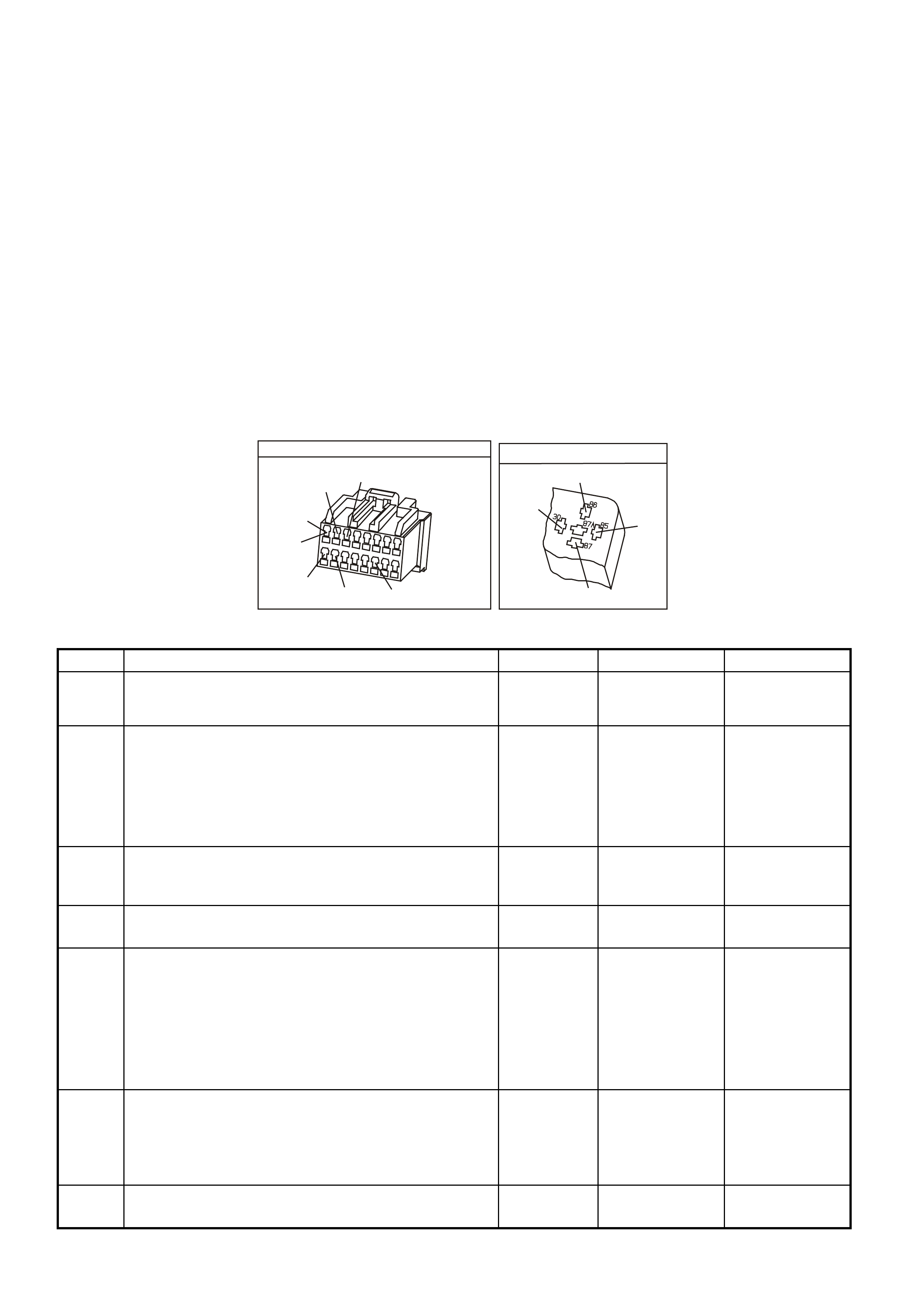
ACTION TAKEN WHEN THE DTC SETS
• The PIM will display the DTC only when current.
• The Check Powertrain Lamp (CPL) will not illuminate.
CONDITIONS FOR CLEARING DTC B2007
• A current DTC will clear when the PIM no longer detects a high voltage on the starter relay circuit.
DIAGNOSTIC AIDS
• The following may cause an intermittent:
- Incorrectly routed harness
- Rubbed through wire insulation
- Broken wire inside the insulation
• For an intermittent, refer to Section 6C3-2B Symptoms, of the VX Series Service Information.
TEST DESCRIPTION
The numbers below refer to the step numbers on the diagnostic table.
2. This test checks to see it the relay is causing the high voltage problem.
5. This test checks to see it the PIM is causing the problem.
POWER TRAIN INTERFACE MODULE
YB215
W/B
(451)
Y
(1049)
B/R
(750)
P
(39)
R/B
(1221)
GY/BLU
(1434)
GY
(434)
(AUTO)
(MAN)1
9
16
8
YE49
START RELAY
V
(5)
(2)
GY
V/W
R
(434)
(6)
GEN III V8 PIM - DTC B2007 STARTER RELAY VOLTAGE HIGH
Step Action Value(s) Yes No
1 Did you perform the Powertrain On-Board Diagnostic
(OBD) System Check? Go to Step 2 Go to Powertrain
OBD System
Check Table
2 1. Ignition OFF.
2. Disconnect the PIM harness connector.
3. Ignition ON.
4. Using test light connected to earth, probe PIM harness
connector terminal for starter relay control.
Does test light illuminate?
Go to Step 3 Go to Step 5
3 While test light is still connected to PIM harness
connector, disconnect the starter relay.
Is test light still illuminated?
Go to Step 4 Go to Step 7
4 Repair short to voltage in the starter relay control circuit.
Is action complete? Verify Repair
5 1. Ignition OFF.
2. Reconnect the PIM harness connector.
3. Using scan tool, clear PIM DTCs.
4. Crank engine.
5. Using scan tool, check to see if PIM DTC B2007 has
reset.
Did PIM DTC B2007 reset?
Go to Step 6 System OK
6 1. Replace PIM.
2. Refer to Section 6C3-3, of the VX Series Service
Information, for PIM replacement and PCM/PIM/BCM
Security Link Procedure.
Is action complete?
System OK
7 Replace starter relay.
Is action complete? System OK
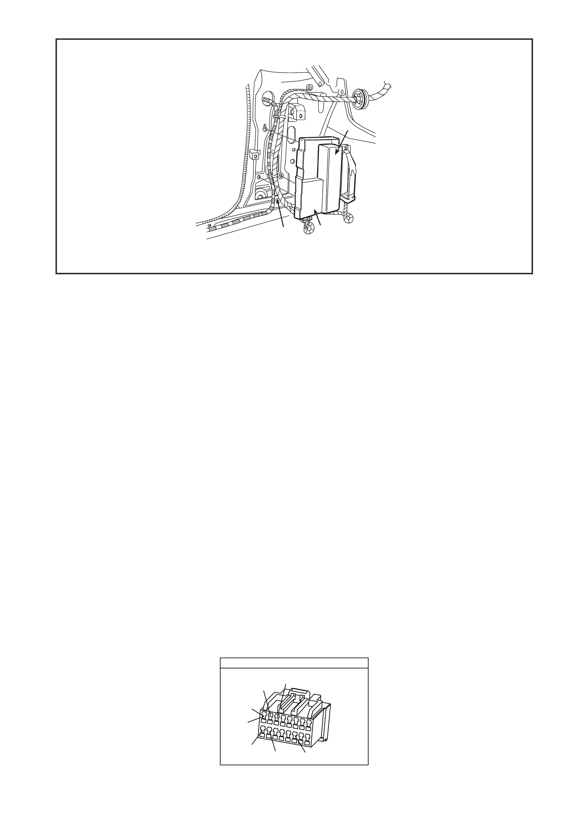
1. Throttle Relaxer Control Module
2. Powertrain Interface Module
3. Left A Pillar
GEN III V8 PIM -
DTC B2009 EEPROM CHECKSUM ERROR
CIRCUIT DESCRIPTION
The PIM EEPROM contains data which is essential to running the engine. The PIM continuously checks the
integrity of this data.
CONDITIONS FOR RUNNING THE DTC
• The ignition switch is in the crank position or run position.
CONDITIONS FOR SETTING THE DTC
• The PIM is unable to correctly read data from its memory.
ACTION TAKEN WHEN THE DTC SETS
• The PIM will display the DTC only when current.
• The Check Powertrain Lamp (CPL) will not illuminate.
CONDITIONS FOR CLEARING DTC B2007
• A current DTC will clear when the PIM is able to correctly read data.
DIAGNOSTIC AIDS
• For an intermittent, refer to Section 6C3-2B Symptoms, of the VX Series Service Information.
TEST DESCRIPTION
The number below refers to the step numbers on the diagnostic table.
2. This DTC indicates an internal PIM problem.
POWE R TRAIN INTERFACE MODULE
Y B215
W/B
(451)
Y
(1049)
B/R
(750)
P
(39)
R/B
(1221)
GY/BLU
(1434)
GY
(434)
(AUTO)
(MAN) 1
9
16
8
1
32
4357

GEN III V8 PCM - DTC B2009 EEPROM CHECKSUM ERROR
Step Action Value(s) Yes No
1 Did you perform the Powertrain On-Board Diagnostic
(OBD) System Check? Go to Step 2 Go to Powertrain
OBD System
Check Table
2
1. Replace PIM.
2. Refer to Section 6C3-3 Service Operations, of the VX
Series Service Information, for PIM replacement and
PCM/PIM/BCM Security Link Procedure.
Is action complete?
Go to Step 3
3 1. Select the Diagnostic Trouble Code (DTC) option and
the Clear DTC Information option using the Tech 2
scan tool.
2. Idle the engine at the normal operating temperature.
3. Select the Diagnostic Trouble Code (DTC) option
using the Tech 2 scan tool.
Does the Tech 2 scan tool indicate that this DTC reset?
Go to Step 2 Go to Step 4
4 Using the Tech 2 scan tool, check for any other DTCs.
Does the Tech 2 scan tool display any DTCs that you
have not diagnosed?
Go to the
applicable DTC
table
System OK